HL Publish Final - TVSFPE · 6.4 Engineering Project Controls ... Figure 7. Chip feed cyclone...
116
U.S. C HEMICAL S AFETY AND H AZARD I NVESTIGATION B OARD INVESTIGATION REPORT ALUMINUM DUST EXPLOSION (1 Killed, 6 Injured) Photo: Andrew Hancock, Huntington (IN) Herald-Press HAYES LEMMERZ INTERNATIONAL–HUNTINGTON, INC. A WHOLLY OWNED SUBSIDIARY OF HAYES LEMMERZ INTERNATIONAL, INC. HUNTINGTON, INDIANA OCTOBER 29, 2003 KEY ISSUES: • ALUMINUM DUST HAZARD AWARENESS • DUST COLLECTOR EXPLOSION PROTECTION • INCIDENT INVESTIGATION • MANAGEMENT OF CHANGE REPORT NO. 2004-01-I-IN SEPTEMBER 2005
Transcript of HL Publish Final - TVSFPE · 6.4 Engineering Project Controls ... Figure 7. Chip feed cyclone...

U.S. CHEMICAL SAFETY AND HAZARD INVESTIGATION BOARD
INVESTIGATION REPORT ALUMINUM DUST EXPLOSION
(1 Killed, 6 Injured)
Photo: Andrew Hancock, Huntington (IN) Herald-Press
HAYES LEMMERZ INTERNATIONAL–HUNTINGTON, INC. A WHOLLY OWNED SUBSIDIARY OF
HAYES LEMMERZ INTERNATIONAL, INC. HUNTINGTON, INDIANA
OCTOBER 29, 2003
KEY ISSUES:
• ALUMINUM DUST HAZARD AWARENESS
• DUST COLLECTOR EXPLOSION PROTECTION
• INCIDENT INVESTIGATION
• MANAGEMENT OF CHANGE
REPORT NO. 2004-01-I-IN
SEPTEMBER 2005

Hayes Lemmerz International September 2005
ii
Contents
ACRONYMS AND ABBREVIATIONS .................................................................................................. VIII
EXECUTIVE SUMMARY........................................................................................................................... IX
1.0 INTRODUCTION.............................................................................................................................. 1
1.1 Background......................................................................................................................................... 1
1.2 Investigative Process .......................................................................................................................... 1
1.3 Hayes Lemmerz International............................................................................................................ 2
1.4 Hayes Lemmerz International - Huntington, Inc............................................................................... 3
1.5 Premelt Systems, Inc. ......................................................................................................................... 4
1.6 Process Description ............................................................................................................................ 5
1.6.1 Scrap Collection and Dewatering ......................................................................................... 6
1.6.2 Chip Drying........................................................................................................................... 7
1.6.3 Chip Melting ......................................................................................................................... 8
1.6.4 Dust Collection ................................................................................................................... 11
1.6.5 Fume/Smoke Ventilation System ....................................................................................... 15
2.0 INCIDENT DESCRIPTION............................................................................................................ 18
2.1 Fume Hood Duct Fire....................................................................................................................... 18
2.2 Chip Feed Restart ............................................................................................................................. 18
2.3 Fireball at Furnace 5......................................................................................................................... 19
2.4 Roof Blown Open............................................................................................................................. 19
2.5 Employee Evacuation....................................................................................................................... 20
2.6 Structural Fire................................................................................................................................... 21
2.7 Emergency Response ....................................................................................................................... 21
2.8 Injuries and Damage......................................................................................................................... 22

Hayes Lemmerz International September 2005
iii
2.8.1 Injuries................................................................................................................................. 22
2.8.2 Exterior Damage ................................................................................................................. 23
2.8.3 Interior Damage .................................................................................................................. 25
2.8.4 Post-Incident Chip Processing............................................................................................ 26
3.0 ANALYSIS ...................................................................................................................................... 27
3.1 Dust Explosions and Aluminum Dust ............................................................................................. 27
3.1.1 Dust Explosions .................................................................................................................. 27
3.1.2 Aluminum Dust................................................................................................................... 28
3.2 Dust Collector Explosions................................................................................................................ 30
3.3 Dust Explosion Scenario .................................................................................................................. 30
3.3.1 Ignition in the Dust Collector. ............................................................................................ 33
3.3.2 Propagation to the Drop Box .............................................................................................. 34
3.3.3 Propagation to the Dry Chip Hopper.................................................................................. 36
3.3.4 Propagation Through Ducting ............................................................................................ 36
3.3.5 Secondary Deflagration ...................................................................................................... 37
3.3.6 Ignition in Fume Separator ................................................................................................. 38
3.3.7 Subsequent Explosions ....................................................................................................... 40
3.3.8 Fuel for the Explosion......................................................................................................... 40
3.3.9 Ignition Source .................................................................................................................... 41
3.4 Alternate Scenarios .......................................................................................................................... 48
3.5 Pre-existing Conditions.................................................................................................................... 48
3.5.1 Chip Feed Duct System Erosion......................................................................................... 48
3.5.2 Housekeeping...................................................................................................................... 48
3.6 Dust Collection System.................................................................................................................... 50
3.6.1 Dust Load ............................................................................................................................ 50

Hayes Lemmerz International September 2005
iv
3.6.2 Dust Collector Project......................................................................................................... 51
3.6.3 Operating Experience.......................................................................................................... 52
3.7 Explosion Protection ........................................................................................................................ 53
3.7.1 Explosion Venting............................................................................................................... 53
3.7.2 Explosion Isolation ............................................................................................................. 54
4.0 PREVIOUS INCIDENTS ................................................................................................................ 56
4.1 Incident Investigation Program........................................................................................................ 56
4.1.1 Duct Fires ............................................................................................................................ 56
4.1.2 Dust Flashes ........................................................................................................................ 57
4.1.3 Smoldering Fume Hood......................................................Error! Bookmark not defined.
5.0 REGULATORY ANALYSIS.......................................................................................................... 58
5.1 Indiana Fire Code ............................................................................................................................. 58
5.1.1 Combustible Dusts .............................................................................................................. 58
5.1.2 Code History ....................................................................................................................... 59
5.1.3 NFPA Metal Dust Codes .................................................................................................... 59
5.1.4 Code Application to Hayes-Lemmerz ................................................................................ 60
5.1.5 Code Enforcement............................................................................................................... 61
5.2 Workplace Safety Regulations & Enforcement............................................................................... 62
5.2.1 OSHA Standards Addressing Combustible Dust Hazards................................................. 62
5.2.2 IOSHA Action Pertaining to the Incident .......................................................................... 63
5.2.3 Personal Protective Equipment........................................................................................... 63
5.2.4 Inspection History at Hayes Huntington ............................................................................ 64
5.3 Industry Guidelines .......................................................................................................................... 65
5.3.1 Risk Insurance Provider Inspections .................................................................................. 66
5.3.2 CSB Combustible Dust Hazard Study................................................................................ 67

Hayes Lemmerz International September 2005
v
6.0 MANAGEMENT SYSTEMS.......................................................................................................... 68
6.1 Overview of Management Systems ................................................................................................. 68
6.2 Management of Change ................................................................................................................... 68
6.3 Hazard Evaluation ............................................................................................................................ 69
6.4 Engineering Project Controls ........................................................................................................... 69
6.5 Procedures and Training .................................................................................................................. 70
6.6 Corporate Best Practices .................................................................................................................. 71
7.0 KEY FINDINGS .............................................................................................................................. 72
8.0 ROOT AND CONTRIBUTING CAUSES ..................................................................................... 75
8.1 Root Causes ...................................................................................................................................... 75
8.2 Contributing Causes ......................................................................................................................... 75
9.0 RECOMMENDATIONS ................................................................................................................. 76
9.1 Recommendations to Communicate the Findings From the Investigation..................................... 78
10.0 REFERENCES................................................................................................................................. 81
APPENDIX A: Analytical Results................................................................................................................ 85
APPENDIX B: Initiating Event Analysis .................................................................................................... 93

Hayes Lemmerz International September 2005
vi
Figures
Figure 1. Satellite image of Hayes-Huntington facility, taken before the explosion.................................... 4
Figure 2. Scrap (chip) process flow diagram. ................................................................................................ 6
Figure 3. Close-up photograph of wet chip sample. ...................................................................................... 7
Figure 4. Photo of furnace 5 sidewell, showing fume hood, ingots, and dry chip hopper. .......................... 9
Figure 5. Vortex box and chip discharge pipe above furnace sidewell. ....................................................... 9
Figure 6. Diagram of furnace 5 chip feed. ................................................................................................... 10
Figure 7. Chip feed cyclone separator.......................................................................................................... 11
Figure 8. Dust collection diagram. ............................................................................................................... 12
Figure 9. Drop box side panel with outlet duct............................................................................................ 13
Figure 10. Diagram of the dust collector. .................................................................................................... 14
Figure 11. Fume separator and draft fan. ..................................................................................................... 16
Figure 12. Layout of dust collection, furnaces, and ducts............................................................................ 17
Figure 13. Damaged roof above furnace 5................................................................................................... 20
Figure 14. Melted wheels near furnace 5 after the fire................................................................................ 21
Figure 15. Damage overview and location of employees.. ......................................................................... 23
Figure 16. Dust collector and drop box panels destroyed by aluminum dust explosion. ........................... 24
Figure 17. Remains of stack testing contractor’s trailer after fire............................................................... 24
Figure 18. Bulged door on dry chip hopper. ................................................................................................ 25
Figure 19. Wet chip hopper target box, with bulged access door ............................................................... 26
Figure 20. Sequence of events for CSB dust explosion scenario................................................................ 32
Figure 21. Explosion vent panel and maintenance door blown out on dust collector. ............................... 33
Figure 22. Drop box fragment, with blown explosion vent panel............................................................... 34
Figure 23. Air inlet on the south side of the dust collector. ........................................................................ 34
Hayes Lemmerz International September 2005
vii
Figure 24. Drop box fragment after impact with building wall .................................................................. 35
Figure 25 Beam slightly deflected by drop box impact................................................................................ 36
Figure 26. Interior of main duct between the chip equipment and the drop box........................................ 37
Figure 27. Fume hood exhaust fan cover damaged by overpressure. ......................................................... 38
Figure 28. Cleanout door blown open on duct from furnace 5 fume hood to fume separator. .................. 39
Figure 29. Interior of fume duct to fume separator ..................................................................................... 39
Figure 30. Ruptured gas cylinder in the contractor trailer........................................................................... 40
Figure 31. Unused spark box and cyclone ................................................................................................... 44
Figure 32. Dust Collector Filter Cartridge................................................................................................... 46
Figure 33. Typical chip and dust accumulation on floors.. ......................................................................... 49
Figure 34. Dust accumulation on roof trusses. ............................................................................................ 50
Figure 35. Interior of dust collector draft fan housing, showing significant erosion damage.................... 53
Tables
Table 1. Comparative Explosibility of Various Dusts.................................................................................. 30

Hayes Lemmerz International September 2005
viii
Acronyms and Abbreviations
CSB U.S. Chemical Safety and Hazard Investigation Board
EMT Emergency medical technician
HLI Hayes Lemmerz International, Inc.
IFC International Fire Code
ICC International Code Council
IOSHA Indiana Occupational Safety and Health Administration
KST Explosion severity
MOC Management of change
MEC Minimum explosive concentration
Mm Millimeter
NFPA National Fire Protection Association
OSHA U.S. Occupational Safety and Health Administration
PPE Personal protective equipment

Hayes Lemmerz International September 2005
ix
Executive Summary
An aluminum dust explosion and fire on October 29, 2003 at the Hayes Lemmerz
International−Huntington, Inc. (Hayes) facility, Huntington, Indiana killed one employee and burned two
other employees, one critically. Three other Hayes employees and one contractor received minor injuries.
The facility manufactures cast aluminum alloy wheels. The U.S. Chemical Safety and Hazard
Investigation Board (CSB) determined that the dust that exploded originated in a scrap re-melting system.
The explosion completely destroyed the dust collection equipment outside the building and damaged
equipment inside the building. The explosion also lifted a portion of the building roof above one furnace
and ignited a fire that burned for several hours.
CSB identified the following root causes of the incident:
• Hayes did not perform a review to address why the chip system was releasing excess dust. The
hazards of aluminum dust were neither identified nor addressed.
• Hayes did not ensure the proper design of the dust collector system.
• Hayes did not ensure that the dust collector design and installation followed the guidance in National
Fire Protection Association (NFPA) 651.
• Hayes had no formal, documented program to investigate and implement corrective action for
incidents involving fires in the foundry area, especially those fueled by aluminum dust.

Hayes Lemmerz International September 2005
x
CSB also determined that the following factors contributed to injuries and damage:
• Employees did not wear flame-retardant clothing when performing routine work near the melt
furnace.
• Housekeeping and maintenance in the chip-processing and dust collector areas were inadequate.
• Facility personnel received no formal training for operating and maintaining the chip-processing and
dust collection systems.
In this report, CSB makes the recommendations to Hayes, a few of which are listed below:
1. Develop and implement a means of handling and processing aluminum chips that minimizes the
risk of dust explosions.
2. Implement a program to provide regular training for all facility employees on the fire and
explosion hazards of aluminum dust.
3. Develop and implement written operating procedures for chip processing and train all affected
employees. Ensure that procedures address maintenance and housekeeping.
To Premelt Systems, CSB recommends that they communicate the findings and recommendations of this
investigation to owners/operators of facilities to which Premelt supplies similar aluminum chip-melting
systems, including specific information that the chip drying process liberates small particles of aluminum,
and that such particles may be explosive.
CSB also makes recommendations to the Aluminum Association and the Fire Protection Research
Foundation to jointly research improved explosion protection for dust collectors in aluminum dust
service.

Hayes Lemmerz International September 2005
1
1.0 Introduction
1.1 Background
At about 8:30 pm on Wednesday, October 29, 2003, an aluminum dust explosion and fire occurred at the
Hayes Lemmerz International–Huntington, Inc. (Hayes) facility in Huntington, Indiana. One employee
was engulfed in fire and died within hours. Two other employees were burned, one critically. Four
individuals (three Hayes employees and one contractor) received minor injuries.
The explosion occurred in the scrap reprocessing area, near one of the furnaces in the aluminum casting
plant, completely destroying dust collection equipment located outside the building (adjacent to the
aluminum melt furnace area). Equipment inside the building received minor damage. The explosion also
lifted a portion of the building roof above one furnace and ignited a fire; insulation and other combustible
materials burned for several hours. There were no offsite injuries or damages.
Because of the death and injuries and the recent history of other industrial dust explosions, the U.S.
Chemical Safety and Hazard Investigation Board (CSB) launched an investigation to determine root and
contributing causes and make recommendations to prevent similar occurrences.
The dust that exploded came from equipment in and connected to a process used to re-melt chips of
aluminum scrap from wheel machining operations. The CSB investigation focused on applicability of
fire prevention standards, dust generation and hazard awareness, engineering project management, safety
reviews for new and modified systems, and operating and maintenance practices.
1.2 Investigative Process
At CSB’s request, the local fire department and highway patrol had secured the site on October 29 during
efforts to extinguish the fire. CSB investigators arrived on the scene late in the evening on October 30,
one day after the explosion. CSB presided at a meeting on October 31 of Hayes personnel and inspectors

Hayes Lemmerz International September 2005
2
from the Indiana Occupational Safety and Health Administration (IOSHA). CSB and IOSHA then
conducted concurrent, independent investigations of the incident.
In the course of its investigation to determine the underlying root causes of this incident, CSB
photographed and diagrammed equipment and blast damage; analyzed samples of materials in the scrap
processing area; interviewed eyewitnesses and management personnel at all organizational levels of the
company; interviewed the chip melt system designers; and reviewed relevant standards, regulations,
aluminum industry guidance, and Hayes’ management practices.
CSB contracted with Safety Consulting Engineers, Inc., of Schaumburg, Illinois, to test samples of
material from the site for explosivity. Refer to Appendix A for test results.
At the same time it was investigating Hayes, CSB was investigating two other serious dust explosions that
occurred in early 2003—West Pharmaceutical Services in Kinston, North Carolina, and CTA Acoustics in
Corbin, Kentucky. Those two accidents resulted in 13 fatalities. The three CSB teams assigned to the
dust explosions compared findings, especially in the areas of dust hazard awareness and available
industry guidance.
1.3 Hayes Lemmerz International
Hayes Lemmerz International, Inc. (HLI) is the parent company of various subsidiaries that manufacture
automotive components. HLI began operation in 1908 as Hayes Wheels, a supplier of wooden-spoke
wheels for Model T Fords. The company acquired wheel maker Lemmerz in 1997.
On October 29, 2003, HLI’s North American Business Unit had five subsidiary plants in the United
States, four of which produced aluminum wheels. One of those subsidiaries is Hayes Lemmerz

Hayes Lemmerz International September 2005
3
International-Huntington, Inc., based in Huntington, Indiana. HLI emerged from Chapter 111 protection
in spring 2003.
HLI also has facilities in South America, Asia, Africa, and Europe. The company supplies wheels to
nearly every major automotive manufacturer for use on new vehicles.
1.4 Hayes Lemmerz International–Huntington, Inc.
The Hayes facility in Huntington manufactures cast aluminum alloy wheels. It has operated since 1984
and employs about 300 people. In 1985, Hayes (then known as Kelsey-Hayes) purchased the plant from
CMI International, a company specializing in automotive castings. The Hayes facility is located
alongside other manufacturing facilities in a light industrial park outside Huntington, Indiana. The entire
facility—including the foundry furnaces, casting machines, and finishing equipment—is housed in a
single, 220,000-square-foot steel-frame, steel-clad industrial building (Figure 1).
The wheel production operation is highly automated, with robots performing repetitive tasks—including
those that involve molten aluminum (such as casting), as well as some lifting and most machining. The
production line operated 24 hours per day, 6 days per week.
1 Chapter 11 refers to a reorganization bankruptcy, usually involving a corporation or partnership. A Chapter 11
debtor usually proposes a plan of reorganization to keep its business open and pay creditors over time. The company filed for bankruptcy protection in December 2001.

Hayes Lemmerz International September 2005
4
Figure 1. Satellite image of Hayes-Huntington facility, taken before the explosion.
1.5 Premelt Systems, Inc.
Aluminum scrap process at Hayes was designed and provided by the company eventually known as
Premelt Systems, Inc. (Premelt). Premelt designed and installed its first chip-melting system in 1964 at
an appliance manufacturing facility. Premelt has built more than 50 aluminum chip de-oiling and melting
systems, including five for Hayes. In addition to the system at Huntington, Premelt designed and
furnished the scrap-processing systems for the HLI aluminum wheel casting plants in Gainesville,
Georgia, and La Mirada, California.2 HLI discontinued using the Premelt chip reprocessing systems in
all of its facilities shortly after the explosion on October 29, 2003.3
2 According to Premelt, the company also provided chip-processing to HLI facilities in Somerset, Kentucky and Howell, Michigan. However, these facilities are no longer in operation. 3 Although the Huntington facility is no longer operating the Premelt chip system, the facility continues to collect,
chip, and dewater scrap aluminum for offsite processing.

Hayes Lemmerz International September 2005
5
At present, Premelt is a division of Lectrotherm, Inc., North Canton, Ohio. Premelt engineers custom
design each installation. Premelt supplies the equipment, and its personnel oversee installation and
startup of the systems. Premelt supplies a maintenance and operating manual with each chip- melting
system.
1.6 Process Description
The Hayes Huntington facility manufactures cast aluminum automotive wheels. The wheels are rough
cast, then finished by machining, coating, and polishing. The machining activities create scrap aluminum.
A chip-processing system, provided by Premelt, was installed in 1995 to process the scrap aluminum for
remelting in one of the facility’s melt furnaces. The October 29 explosion involved portions of the chip-
processing system. Figure 2 shows a simplified block flow diagram of the system. Shaded equipment
was designed and supplied by Premelt. Non-shaded equipment was designed and provided by others.

Hayes Lemmerz International September 2005
6
Figure 2. Scrap (chip) process flow diagram.
1.6.1 Scrap Collection and Dewatering
Scrap from finishing is collected in bins at machining stations and various other locations throughout the
wheel-manufacturing facility. 3 This scrap contains a cutting oil and water emulsion from the machining
processes. The bulk of the aluminum scrap is in the form of 1/8- to 3/16-inch wide strips (turnings from
wheel machining) of less than 1/64-inch thickness. These strips are mechanically chopped into pieces
about ¼- inch long (called “wet chips”) and spun in a centrifuge to remove the cutting emulsion. Prior to
the explosion, these chips (Figure 3) were conveyed by high-velocity air through steel pipes to a hopper in
the foundry area adjacent to one of five reverberating furnaces4 (two of those furnaces were equipped for
chip melting). Because any fine particles in the wet chip stream adhere to the surface of the chips, no
significant amount of dust is associated with wet chip handling or transfer.
4 A reverberating furnace is a direct-fired, open-hearth furnace fired with an open flame above the melt directed
down (reverberated) to the melt surface.

Hayes Lemmerz International September 2005
7
Figure 3. Close-up photograph of wet chip sample.
1.6.2 Chip Drying
The wet chips do not actually look wet, but they retain a surface coating of cutting oil sufficient to cause
particulate emissions (smoke) from the furnace. In the chip processing system at Hayes, a rotary kiln
dryer dried the chips to remove the cutting oil.5 The tumbling in the dryer loosened small particles stuck
to the chips and broke some chips. These actions likely created aluminum dust in various particle sizes.6
The dryer burner was designed to operate with incomplete combustion. To accomplish this, the air
damper was automatically controlled so the amount of air allowed into the process was less than what
would be needed to completely combust the fuel gas. This ensured that little or no free7 oxygen was in
the dryer chamber, because free oxygen at elevated temperatures inside the dryer could cause accelerated
5 A kiln is a general term for any type of oven used to dry ores, ceramics, cement, wood or other materials. The
dryer at the Hayes facility had a rotating inner core that tumbled the chips as they were dried by a gas-fired hot-air stream. The dryer temperature was controlled at 550-630º F (288-332 º C).
6 CSB testing of dry chip samples showed that they contained aluminum dust particles of less than 200 mesh, i.e. less than 74 μm in diameter (3 thousandths of an inch [0.003 inches]). This size particle is approximately equivalent to powdered milk (Eckoff ) and is in the explosive range for aluminum dust.
7 “Free” oxygen is available for reacting with other materials, such as fuel (for burning) or aluminum (for oxidation.)

Hayes Lemmerz International September 2005
8
oxidation of the aluminum chips. Since the chips were very thin, surface oxidation could cause chips to
break into smaller pieces, increasing the amount of dust produced in the dryer.
The dryer exhaust routed through a high-temperature afterburner to burn off the evaporated cutting oil
and any unburned fuel gas.
1.6.3 Chip Melting
From the dryer, the chips were transferred by pressurized air to a dry chip hopper, where they were held
until fed to one of two furnaces. Screw conveyors at the bottom of the dry chip hopper fed aluminum
chips to a duct, where they were blown through a 6-inch-diameter pipe to the melt furnace. Furnace 5
was the primary furnace used for melting the aluminum chips, while furnace 4 was used when furnace 5
was out of service for maintenance.
The chip-melting furnaces have a sidewell, a protruding structure that is an open-top chamber containing
a pool of molten aluminum (Figure 4). The sidewell is used for fluxing8 the aluminum melt and removing
dross.9 It also received the dry chips through an associated vortex box. A vertical submerged pump in
the sidewell created a liquid vortex of molten aluminum (similar to the swirl in a pool of draining liquid),
into which the chips were fed.10 The vortex quickly drew the chips into the molten aluminum (instead of
having them float on the surface), where they melted rather than burned.11 A hood covered the sidewell
to draw smoke generated above the sidewell (Figure 5).
8 Fluxing is the process of adding a mineral to the molten aluminum to facilitate the removal of dirt and
contaminants. 9 Dross is scum that forms on the surface of molten metal as a result of oxidation. 10 The vortex, a conical whirlpool, is created by rapidly circulating the molten aluminum around inside the sidewell. 11 The melting point of pure aluminum is 1,220 °F (660 °C). The auto-ignition temperature for aluminum chips is
not reported in the literature; however, small aluminum particles ignited at temperatures as low as 840 °F (450 °C). Babrauskas (2003).

Hayes Lemmerz International September 2005
9
Figure 4. Photo of furnace 5 sidewell, showing fume hood, ingots, and dry chip hopper.
Figure 5. Vortex box and chip discharge pipe above furnace sidewell.

Hayes Lemmerz International September 2005
10
The hood connected to a cyclone separator with an induction12 fan located outside the building. See
Figure 6 for a diagram of the furnace chip feed.
Air/dust to drop box
Dry chips blown from hopper
Spark box
Smoke/fumesto fume
separator
Cyclone air/chip separator
Vortex pump
Vortex box
Side well
Fume hood
Chips fall into molten aluminum
vortex
Unused cyclone
Figure 6. Diagram of furnace 5 chip feed.
Above the vortex box, the dry chip feed enters a cyclone separator (Figure 7) that disengages the chips
from the air stream. Their weight then causes them to fall into the vortex. The transport air and fines13
exit the top of the cyclone.
12 An induction fan pulls air through a system and is located at the exhaust of the dust collector. By contrast, a
forced draft fan pushes air through the system and is located at the air inlet. 13 Dust and other particles, that are too small to be separated in the cyclone.

Hayes Lemmerz International September 2005
11
Figure 7. Chip feed cyclone separator.
1.6.4 Dust Collection
About three years after installing the chip melt system, Hayes added a dust collection system. The
collection system consisted of ducts connected to the top of the feed cyclones, a drop box, dust collector
and draft fan (Figure 8). The chip feed transfer air was transported from the top of the cyclone through
ducts into the drop box, and then into the dust collector.
The system operated on a “push-pull” balance. Chips and dust were pushed from the dry chip hopper into
the cyclone; dust and air were pulled into the dust collector by the draft fan. If clogged filter cartridges in
the dust collector impeded the airflow through the dust collector, it would direct air and dust out of the

Hayes Lemmerz International September 2005
12
bottom of the cyclone. The dust could ignite on the hot aluminum and/or accumulate around the vortex
box.
The drop box, dust collector, and fan were located outside the building. Spark boxes installed in the
ducts near the furnaces used a baffle plate to deflect large embers or heavy objects that might cause a
spark in the duct system.14 The dust collector, located outside the foundry building, operated with slight
negative pressure. Steel ducts connected the dust collector system to the chip feed cyclones at furnaces 4
and 5, the dry chip hopper, the dryer hood, and the wet chip hopper. These ducts merged into a single 20-
inch duct that passed through the building wall and entered the drop box. An additional duct connected
the dry chip hopper directly to the drop box.
Figure 8. Dust collection diagram.
14 For example, iron or steel objects could cause sparks if they strike the steel walls of a duct or the drop box at
sufficient velocity. The spark boxes are open at the bottom. Material dropped out of the bottom of the box falls freely approximately 10 feet to the foundry area floor.

Hayes Lemmerz International September 2005
13
The drop box was a carbon steel container about 6 feet square and 8 feet tall, with a tapered lower section
below a square chamber and a manual cleanout valve. The box trapped heavy particles before they
entered the dust collector. As the dusty air entered the drop box, the sudden decrease in velocity caused
heavier particles to fall to the bottom of the box.
From the top of the drop box, the air flowed through a short rectangular duct (Figure 9) into the bottom
side of the dust collector (Figure 10). The dust collector used 24 pleated filter cartridges to collect fine
dust from the air stream. Automatic air-pulse jets within the dust collector dislodged accumulated dust
from the filters; the dust then fell to the conical bottom of the dust collector for removal through a manual
valve. The pulse jets used high pressure air from the facility’s compressed air system and operated on a
90-second cycle.
Figure 9. Drop box side panel (arrow) with outlet duct (box).

Hayes Lemmerz International September 2005
14
Clean Air Outlet(on opposite side at the top of the unit)
Pulse Jet System
Figure 10. Diagram of the dust collector (explosion vents not shown).

Hayes Lemmerz International September 2005
15
The draft fan drew air from the top side of the dust collector and exhausted the air to the atmosphere. A
pressure gauge on the dust collector monitored the pressure drop across the filter cartridges. Maintenance
personnel stated that they used that gauge to determine when the cartridges required cleaning. The dust
collector included explosion relief vents (blowout panels) on three sides that were intended to open if the
aluminum dust accidentally ignited (see Section 3.1). Doors on the collector housing provided
maintenance access.
1.6.5 Fume/Smoke Ventilation System
A fume hood was installed above the sidewell of the furnace to draw smoke out of the building. Some
wheels were machined after they were painted, therefore the chips also contained acrylic paint that burned
off when the chips entered the molten aluminum. Trace amounts of cutting oil that remained on the chips
also generated smoke, as did fluxing and drossing activities.
A circular steel duct connected the fume hood to the fume separator located outside the building. The
fume separator (Figure 11) was a carbon steel box about 3 feet square and 8 feet tall, containing two
cyclones.15 This device separated smoke and other particles from the fume hood exhaust before drawing it
through the draft fan and exhausting to the atmosphere. An automatic valve in the base of the separator
dropped accumulated solids into a drum for disposal.
A layout (plan view) of the furnaces, ducts, and dust collection equipment is shown in Figure 12.
15 The fume separator cyclones are similar to the chip feed cyclone. The fumes from the furnace fume hood enter at
an angle into a cylindrical container with a conical bottom. Centrifugal forces cause smoke and other fine particles to separate out of the air stream. These particles fall out the bottom of the cyclone into a collection drum. Cleaned air exits via a stack at the top of the separator.

Hayes Lemmerz International September 2005
16
Figure 11. Fume separator and draft fan.

Hayes Lemmerz International September 2005
17
Figure 12. Layout of dust collection, furnaces, and ducts. Some ducts and equipment omitted for clarity.

Hayes Lemmerz International September 2005
18
2.0 Incident Description
2.1 Fume Hood Duct Fire
At about 2:30 pm on October 29, 2003, Hayes maintenance personnel shut down the chip feed system
because of a smoldering fire located near furnace 5 inside the duct connecting the fume hood to the fume
separator (see Figure 4, item 7). The glowing red duct alerted employees to the fire. According to plant
personnel interviewed by CSB, fires in this duct were not uncommon. On this particular day, employees
followed the usual practice for dealing with these fires by shutting down the dry chip feed and the fume
hood draft fan (but not the dust collector draft fan), and allowing the fire to burn itself out. Employees
judged that the fire was out when the duct had cooled, and they found burnt material that had broken free
in the fume separator solids drum. They then opened the fume duct and cleaned out the remaining residue
within reach. The October 29 duct fire had been out for at least 2 hours before maintenance personnel
restarted the dry chip feed.16
2.2 Chip Feed Restart
At about 8:20 pm, three Hayes maintenance personnel restarted the dry chip feed system. Employees
reported that after the restart, chips fed steadily to the furnace 5 sidewell for about 10 minutes. At that
point one of the employees—who was standing on the north side of the furnace, about 10 feet from his
coworkers —noticed chips falling out of the spark box (see Figure 6) in the dust collector duct.
16 CSB concluded that the only likely connection between this fire and the incident later that evening was the fact
that restarting the chip feed system afterwards placed the maintenance employees in the vicinity of furnace 5 at the time of the explosion.

Hayes Lemmerz International September 2005
19
Maintenance personnel were familiar with this phenomenon, which typically indicated that a crust had
formed in the vortex, impeding chip feed and that chips were overflowing into the dust duct.17
2.3 Fireball at Furnace 5
The mechanic who noticed the chips falling from the spark box turned to tell his coworkers to stop the dry
chip feed. As he turned, a fireball erupted from beneath the furnace fume hood. The fireball ignited his
clothing18 and totally engulfed another mechanic standing near the sidewell vortex pump. The flames
also singed a third mechanic, who was standing near the system control panel.
2.4 Roof Blown Open
The fireball expanded, rose upward, and blew open the roof of the building (Figure 13). A contractor was
on the roof, having just finished testing emissions19 at furnace 4 and was moving his equipment to furnace
5, when the explosion occurred. As recorded in CSB interviews, he heard a boom, was knocked down as
the roof panels beneath his feet heaved upward, and saw flames erupt through the roof. The contractor
ran east approximately 200 feet, descended at ladder and attempted to call 911. He was not seriously
injured.
17 The clearance between the end of the chip feed pipe and the surface of the molten aluminum vortex was only a
few inches. It was common for the surface of the vortex to cool down and begin to solidify into a crust, especially during chip feed startup. This crust prevented the chips from entering the melt. The chips bridged across the gap, and the pipe quickly filled up with chips. Maintenance personnel stated that human intervention was needed to clear the blockage.
18 The Hayes facility had a standard practice of requiring personnel to wear all natural fiber clothing (as opposed to synthetics such as nylon and polyester.) Injured employees were wearing cotton clothing at the time of the incident. Employees wore fire retardant aprons during drossing and fluxing activities, but not during routine maintenance or operations tasks.
19 The contractors were testing the furnace stack emissions as part of the Hayes air emissions permit requirements.

Hayes Lemmerz International September 2005
20
Figure 13. Damaged roof above furnace 5.
Outside the building, another stack emission-testing contractor was working in a mobile laboratory trailer
parked near the drop box. He said he heard a “boom,” and was knocked down as the trailer lurched
backward. The contractor looked out the trailer door to see the dust collector totally involved in a bright,
hot fire. Something was lodged against the rear door of the trailer, making that exit impossible to use.
He was forced to exit the side trailer door, which was closer to the fire than the rear door, but he also
escaped serious injury.
2.5 Employee Evacuation
Within minutes of the explosion, employees used the intercom system to report the emergency. The plant
emergency alarm sounded, and employees evacuated the plant. Coworkers assisted burn victims until
emergency medical technicians (emergency responders) arrived. A headcount accounted for all
employees and contractors.
Approximate position of the contractor on the roof at the time of the explosion

Hayes Lemmerz International September 2005
21
2.6 Structural Fire
The fireball ignited roofing material and insulation, along with a small accumulation of combustible
material stored behind the kiln dryer control panel. North-west of the furnace sidewell, plastic pallets
containing rejected aluminum wheels waiting to be re-melted were also ignited, and some of those wheels
eventually melted (Figure 14).
Figure 14. Melted wheels near furnace 5 after the fire.
2.7 Emergency Response
The Huntington fire chief resided close to the industrial park, and heard the explosion. Within minutes,
he was at the nearby firehouse. Within 5 to 10 minutes of the explosion, he was on the scene. Because of
prior visits to the plant, he knew that the Hayes plant worked with molten aluminum, and understood the
proper techniques and materials for fighting aluminum fires. The fire was contained and extinguished in
about 2 hours using Class D20 fire extinguishers. The fire chief reported that he inspected the facility for
any signs of a natural gas fire and found the gas piping intact.
20 Class D extinguishers are rated for metal fires and typically use sodium chloride or some other noncombustible
salt as a smothering agent.

Hayes Lemmerz International September 2005
22
Fire department emergency responders attended the burn victims. There were no injuries to emergency
responders in this event, and no fire equipment was damaged or lost. Full-time fire fighters staff the
Huntington fire department.
2.8 Injuries and Damage
Figure 15 shows the location of most of the interior and exterior damage and the location of employees at
the time of the explosion. One stack-testing contractor was on the roof above furnace 5; the other was in
a trailer just southeast of the drop box. Not shown in the figure are damage to the wall south of the kiln
dryer and the exterior wall southwest of the kiln, water damage inside the compressor room south of the
kiln, and damage to the wet chip hopper.
2.8.1 Injuries
The employee who was closest to the furnace sidewell was totally engulfed in flames and died of thermal
burn injuries the day after the incident. A second employee received serious burns over nearly half his
body. He remained in critical condition for days and was hospitalized for weeks. The third injured
employee received only minor localized burns and returned to work to assist investigators the day after
the explosion. Four additional workers (three Hayes employees and one contractor) received treatment by
emergency responders for minor injuries on the scene; none of these workers required hospitalization.

Hayes Lemmerz International September 2005
23
Figure 15. Damage overview and location of employees (plan view). Roof over entire area sustained
damage.
2.8.2 Exterior Damage
The explosion vent panels in the dust collector were blown open, and three of four maintenance doors
were blown open or off. The ensuing fire completely consumed the aluminum dust and combustible filter
cartridge materials inside the dust collector, destroying it (Figure 16). The drop box was split open at the
seams into four large pieces; one piece was thrown 20 feet to the south and lodged against the back of the
contractor’s mobile lab trailer (Figure 17). Another large fragment apparently hit the side of the foundry
building, slightly deforming a vertical steel wall support beam near furnace 5.

Hayes Lemmerz International September 2005
24
Overpressure caused the fume separator exhaust fan housing to bulge and disconnected the supply duct.
The fume separator housing was undamaged, though its paint burned off.
Figure 16. Dust collector (left) and drop box panels destroyed by aluminum dust explosion.
Figure 17. Remains of stack testing contractor’s trailer after fire.

Hayes Lemmerz International September 2005
25
The facility air compressor room adjacent to the furnace area was damaged when the wall panel was
blown out, and a water line ruptured causing water damage to some compressors. Exterior vent panels
near the compressor room were blown out.
2.8.3 Interior Damage
Inside the building, the large, approximately 200 lb sidewell doors on furnace 4, which were closed
before the explosion, were blown off by the pressure wave. One of the doors was found on the ground
about 50 feet from the furnace. Overpressure also caused the dust collector duct to disconnect from the
furnace 4 cyclone.
The fire damaged the chip system control console. Internal overpressure bulged the access doors on the
side of the dry chip hopper and on the wet chip hopper inlet target box21 (Figure 18 and 19).
Figure 18. Bulged door on dry chip hopper.
21 A target box is a steel box, containing “wear plates”, designed such that the chips blown into the hopper hit the
plates, lose velocity, and fall into the hopper. The target box prevents the chips from eroding the wall of the hopper. The wear plates require periodic replacement.

Hayes Lemmerz International September 2005
26
Figure 19. Wet chip hopper target box, with bulged access door (arrow).
Much of the roof above furnace 5 and the chip handling system was blown off. The west wall was
deflected inward from the impact of drop box fragments. The explosion damaged the south wall adjacent
to the compressor room, caused minor damage to the building walls, and caused significant roof damage
(several trusses needed replacement.) A structural engineer verified the building was safe prior to re-
entry by inspectors and employees. The total value of the property losses resulting from the incident were
not known when this report was published.
2.8.4 Post-Incident Chip Processing
Although wheel-casting operations were suspended for several days, the plant was in full production one
week after the explosion. Hayes decided not to repair the dry chip-processing system and dismantled it
soon after the initial phase of the investigation was completed. Following the incident, Hayes arranged
for a contractor to collect the wet chips for processing offsite. Now, that aluminum is returned to Hayes
as ingots for remelting in one of the five furnaces.

Hayes Lemmerz International September 2005
27
3.0 Analysis
The purpose of CSB incident investigations is to determine root causes and make recommendations to
prevent similar incidents from occurring. CSB focuses on underlying systemic issues. In this case,
investigators used a comprehensive, logical approach, and the process of elimination to postulate
scenarios for this incident, based on collective evidence.
CSB evaluated and reviewed all available facts to develop the scenarios, and to determine root and
contributing causes and remedies. The CSB investigators measured and photographed on-scene damage
and equipment, and obtained samples of chips and dust in and around processing equipment.
Investigators also relied on inspection of the equipment and the explosion scene, witness interviews, and
records and documents provided by Hayes and others. CSB had aluminum dust samples tested for
explosiveness and other characteristics.
3.1 Dust Explosions and Aluminum Dust
The following background information is helpful in understanding the nature of aluminum dust
explosions. This report then presents possible incident scenarios and analysis results.
3.1.1 Dust Explosions
Dust explosions have been documented as early as the late 18th century, when an Italian count reported
his analysis of an explosion in a baker’s flour warehouse.22 Much has been learned about dust explosions
since that time. Among the known facts are:
22 Eckoff (1997)

Hayes Lemmerz International September 2005
28
• Dust clouds, when ignited, can produce deflagrations, which are flame fronts that move at speeds
below the speed of sound.23 Although not technically explosions, these deflagrations are
commonly referred to as dust explosions.24
• Typically, for dust explosions to occur, all of the following conditions must be present:
combustible dust is suspended or lofted in air; the dust ignites; and the dust is confined such that
damaging pressures can accumulate.
• If lofted into a cloud and ignited, accumulated dust can become explosive. Dust layers can ignite
and will smolder, but if disturbed, they may transition to a dust explosion. This phenomenon,
known as a “secondary dust explosion”, refers to settled layers of dust that are lofted by some
event or another explosion to create an explosive cloud.
• The explosive suspension of most dusts appears as an opaque cloud and, for many materials, is
much denser than the amount considered “breathable”.
• The finer the dust particle and the more easily the dust oxidizes, the greater the explosion
potential.
3.1.2 Aluminum Dust
The explosive properties of aluminum dust are in the literature, including the National Fire Protection
Association (NFPA) fire prevention standards. In NFPA 68, Guide for Venting Deflagrations
(2002a), aluminum is ranked among the most explosive of metal dusts. Preliminary data collected by the
CSB indicate that nearly one fourth of all dust explosions in the United States in the last 25 years
involved metal dusts, and that aluminum accounted for the majority of these events.25 Metals account for
23 In contrast, a detonation flame front moves at speeds greater than the speed of sound. 24 For purposes of this report, “dust explosion” includes deflagrations. 25 Data presented at CSB public hearing June 22, 2005.

Hayes Lemmerz International September 2005
29
about 19 % of dust explosions worldwide.26 This data indicates that metal dusts are particularly
hazardous and all appropriate precautions need to be taken to prevent dust explosions.
Dust explosivity is typically expressed using the deflagration constant, KST.27 This constant is determined
experimentally by measuring how fast the pressure rises when dust of a known concentration is ignited in
a container of a specific volume (20 liters). The higher the KST, the more severe a dust explosion can be.
Three “dust hazard classes” indicate relative explosiveness. For comparison, Table 1 shows KST values
for a few known explosive dusts and a sample collected from the scene of the incident. Pure aluminum
has a high KST and is rated as a Class ST-328 dust.
Actual explosivity values vary significantly with the size and shape of dust particles, the concentration of
dust in the air, and the degree of surface oxidation (which, for metals, reduces flammability.)
CSB determined the aluminum dust that accumulated on surfaces in the building was explosive—though
lower in explosivity than reported for pure aluminum powder. CSB samples were primarily of
accumulations outside equipment, and included chips and dust with a wide distribution of particle sizes.
These samples29 generated pressure up to 155 pounds per square inch gage in the test chamber; sufficient
to have caused the damage observed at Hayes. The dust in the dust collector was likely comprised mainly
of finer particles,30 therefore exhibiting a higher explosivity. The explosion and fire completely
consumed this material.
26 CCPS (2005) 27 KST = (dP/dt)max x V1/3, where (dP/dt)max is the maximum measured rate of pressure rise and V is the container
volume. 28 ST-1, ST-2, and ST-3 are hazard classes assigned to dusts by NFPA to indicate relative explosiveness. ST-3 dusts
are the most explosive, with KST values above 300 bar-m/sec. 29 The tests were run on material that passed through a 200-mesh screen, which has openings approximately 75 µm
across. 30 The cyclone separators and drop box cause heavier particles, including chips, to separate out and fall into the
furnace or into a container under the drop box. The material that flows into the dust collector is composed of the finer particles. The bulk material spilling out of a chip transfer line leak has not been through the cyclone separator and contains the full range of particle sizes ( Zalosh et al.,, 2005).

Hayes Lemmerz International September 2005
30
Table 1. Comparative Explosivity of Various Dusts
Dust Type Average Particle Size (microns)
KST (bar-meter/sec)
Dust Hazard Class
Surface dust sample* from Hayes <85 131 ST-1
Pure aluminum powder** 29 415 ST-3
Coal** <10 to 38 55-108 ST-1
Wheat flour** 57 87 ST-1
Wood dust** 43 102 ST-2
*This sample was collected from the top of an electrical enclosure, about 6 feet above the floor near furnace 5.
**SOURCE: Eckhoff, 1997.
3.2 Dust Collector Explosions
Collective data on dust explosions in the United States, United Kingdom, and Germany indicate that more
than one fourth of all dust explosions occur in dust collectors. Within the United States, the ratio is
higher at more than 40 percent. Zalosh, et al. (2005) states that:
Three possible reasons for the high occurrence of dust collector explosions are: 1) they [dust
collectors] are almost omnipresent in particulate handling facilities, 2) they inherently concentrate
the smaller particles, which are easier to ignite than the mostly larger particles in other
equipment, and 3) they often employ pulse jet cleaning, which by nature, periodically generates
dust clouds inside the collector. Data from the German compilation of dust explosions indicate
that the most frequent ignition sources have been mechanical sparks (41 percent), smoldering
nests (11 percent), electrostatic discharges (10 percent) and mechanical heating via friction
(7 percent).
3.3 Dust Explosion Scenario
CSB believes that the scenario presented in this report is the one that is supported by the totality of the
evidence and therefore it is the most likely explanation of the events of October 29, 2003.

Hayes Lemmerz International September 2005
31
CSB determined through witness accounts, damage patterns, and other available evidence that the
fireball31 that erupted from the furnace sidewell was likely the result of an aluminum dust explosion in the
dust collector system. According to the findings, the explosion originated in the dust collector after chips
had been feeding to furnace 5 for about 10 minutes. The explosion propagated from the dust collector to
the drop box, causing the drop box to rupture before breaking into several fragments. A pressure wave
then traveled to the furnace 5 sidewell via the duct connected to the drop box, lofting and igniting
accumulated dust in the vortex box. The pressure wave also caused minor to moderate damage in other
equipment connected to the dust collector system.
Figure 20 is a schematic showing the approximate order of events in the above scenario. Evidence
supporting this proposed scenario follows the schematic.
31 Employees reported that it was common to see a flare-up or bright flash above the sidewell whenever chip feed
was started. However, eyewitnesses reported the fireball in this incident was significantly larger than they had seen in the past, and was orange, in contrast to the bright white flashes seen in the past.

Hayes Lemmerz International September 2005
32
Ignition in the dust collector
Dust collector overpressured & engulfed in fire
Drop box exploded
Contractor trailer ignited
Dust in building lofted and ignited, roof blown open
Pressure wave entered dust duct
system
Fireball exited chip feed pipe at furnace 5
Propagation to the fume separator
Dry chip hopper damaged by overpressure
Doors blown off furnace 4 side well
Wet chip hopper target box damaged
by overpressure
Figure 20. Sequence of events for CSB dust explosion scenario.

Hayes Lemmerz International September 2005
33
3.3.1 Ignition in the Dust Collector.
A witness in the contractor trailer (which was near the dust collector) emerged from the side-door of the
trailer within seconds after the explosion. He stated that the dust collector was already involved in a very
intense, bright fire (typical of aluminum powder fires). CSB concluded that the drop box had exploded at
this point because:
• The drop box otherwise would have blocked the contractor’s view of the dust collector from the
trailer.
• A large drop box fragment was lodged against the trailer door, supporting the contractor’s
statements that the rear door was blocked.
The explosion vent panels and maintenance doors (Figure 21) on the dust collector were blown open by
the internal deflagration.
Figure 21. Explosion vent panel and maintenance door (arrows) blown out on dust collector.

Hayes Lemmerz International September 2005
34
3.3.2 Propagation to the Drop Box
The drop box was pushed away from the dust collector, indicating that the pressure wave traveled into the
drop box from the dust collector. The single explosion vent panel was blown and the drop box ruptured
(Figure 22). The short duct connecting the drop box to the dust collector was pulled out and away from
the dust collector (Figure 23), also indicating that the pressure wave traveled toward the drop box.
Figure 22. Drop box fragment, with blown explosion vent panel.
Figure 23. Air inlet (arrow) on the south side of the dust collector.

Hayes Lemmerz International September 2005
35
The drop box may have experienced significantly higher pressure than the dust collector, since an
explosion propagating between two containers can result in a phenomenon referred to in literature as
pressure piling.32 However, the drop box was a much weaker structure than the dust collector, lacking
substantial framing and joined only by small corner welds, and it was relatively unprotected by explosion
venting. The drop box failed mainly along the seams and fractured into several large pieces.33 One of the
larger fragments impacted the building wall and was found resting below the impact point (Figure 24). The
impact slightly bent the vertical steel wall support beam inward (Figure 25).
Figure 24. Drop box fragment after impact with building wall
32 Eckoff (1997) attributes the pressure piling effect to increases in the pressure of an unburnt dust cloud in a second
vessel. The second vessel’s internal pressure from the deflagration is increased above the pressure created by the expanding gases from the first vessel.
33 CSB calculations indicate that the rupture pressure for the drop box was between 2 and 5 pounds per square inch gage.

Hayes Lemmerz International September 2005
36
Figure 25 Beam slightly deflected by drop box impact. Arrows on either side of the point of impact show
the direction of bending
3.3.3 Propagation to the Dry Chip Hopper
A 6-inch pipe attached to the drop box roof and the dry chip hopper (Figure 12) provided a direct path for
pressure to travel to the dry chip hopper and damage the access door. This pressure was sufficient to
bulge the door of the dry chip hopper (Figure 18).
3.3.4 Propagation Through Ducting
By lofting and igniting dust settled in the ducts (Figure 26), the deflagration also propagated upstream to
the furnace 5 chip feed cyclone. CSB concluded that the deflagration traveled down the chip feed pipe
and into the vortex box, causing the large fireball to erupt into the room. Witnesses recalled seeing the
fireball exit the fume hood and wrap around the furnace. CSB also observed molten aluminum on the
front of the victim’s safety glasses and splashed onto nearby equipment—further indication that a
pressure wave was directed into the vortex box and down into the sidewell.

Hayes Lemmerz International September 2005
37
Figure 26. Interior of main duct between the chip equipment and the drop box with significant dust and
chip accumulation.
3.3.5 Secondary Deflagration
CSB observed aluminum dust settled on most horizontal surfaces, including overhead beams, ledges, and
the top surfaces of equipment in the area of furnace 5. Some beam and piping surfaces directly above the
furnace sidewell had little or no accumulated dust on top of them after the explosion. However, CSB
found neither documentation nor witnesses that these surfaces had been cleaned in several years. CSB
determined that the fireball emerging from the fume hood at furnace 5 lofted and ignited dust that had
accumulated on surfaces directly above the furnace. This caused a secondary dust deflagration that
expanded upward and blew open the building roof.
CSB concluded that the outside dust collector explosion and interior deflagration occurred at the same
time or in rapid succession. This conclusion was partly based on the accounts from the two contractors,
who were the only direct eyewitnesses to both events.

Hayes Lemmerz International September 2005
38
3.3.6 Ignition in Fume Separator
The erupting fireball above the sidewell entered the fume hood, causing burning material to be pulled by
the fume separator draft fan along the ducting into the fume separator. This material likely ignited
deflagrations inside the ducting and fan housing severe enough to damage the draft fan housing and duct
(Figure 27). The cleanout door was blown open on the duct between the fume hood and the fume
separator (Figure 28). CSB found that the duct leading to the fume separator contained hard deposits and
dust, which likely were the fuel for the fires in this duct (Figure 29).
Figure 27. Fume hood exhaust fan cover damaged by overpressure.

Hayes Lemmerz International September 2005
39
Figure 28. Cleanout door blown open on duct from furnace 5 fume hood to fume separator. Insulation
from the roof rests on the duct (Figure 4 shows the location of this duct in the building).
Figure 29. Interior of fume duct to fume separator (near the cleanout door.)

Hayes Lemmerz International September 2005
40
3.3.7 Subsequent Explosions
Employees and the Huntington fire chief reported that a series of smaller explosions occurred about 11
minutes after the initial explosion. The fire chief concluded that some of these small explosions could
have been the four tires on the contractor trailer failing. After the fire department extinguished the fire,
investigators also discovered the remains of high-pressure gas cylinders used for instrument calibration,
which had been in the contractor trailer. Figure 30 shows one of the cylinders, lying in the remains of the
trailer.
Figure 30. Ruptured gas cylinder in the contractor trailer.
3.3.8 Fuel for the Explosion
The Huntington fire chief inspected the natural gas piping in the areas damaged by the explosion and fire.
The piping was intact with no evidence of leaking. Eyewitnesses did not smell natural gas odorant before
the explosion. 34
34 Gas companies add a strong odorant that smells like rotten eggs to natural gas to help people detect a leak. Pure
natural gas has no odor.

Hayes Lemmerz International September 2005
41
No other fuels capable of producing the explosion damage were present in the damaged area other than
aluminum dust.
By design, the greatest accumulation of aluminum dust was in the dust collector. To be explosive, dust
must be suspended in air. The dust/air suspension must also contain more than a minimum explosive
concentration (MEC).
Premelt designed the chip system to feed at 3,500 pounds of chips per hour. CSB testing (Appendix A)
indicated that the fraction of dust in the chip feed was below 0.7 % by weight. CSB estimated that the
dust flow was, at most, about 25 pounds per hour. Therefore the air flowing through the ducts or drop
box during normal operations would not exceed the MEC for aluminum dust.35
CSB concluded that the location most likely to contain an explosive suspension of aluminum dust was the
interior of the dust collector on the inlet side of the air filters. This area might have an explosive
concentration whenever the pulse jets operated, blowing aluminum dust off the filters from the inside-out.
Within a few seconds,36 the dust would settle into the tapered bottom of the dust collector.
3.3.9 Ignition Source
The exact point of origin and ignition source for a combustible dust explosion is often very difficult to
determine. Dust explosions often involve secondary dust explosions; the largest explosion is not always
the initiating event. Further, the ignition source itself often lasts only a short time and either is over
35 The MEC for similar aluminum grit is 50 grams per cubic meter (0.0031 pounds per cubic foot). CSB estimated
the concentration of dust in the ducting and drop box to be at or below 1.5 grams per cubic meter (0.000092 pounds per cubic foot).
36 CSB investigators observed that when small quantities of the dust at Hayes were hand-lofted, the dust completely settled in less than 5 seconds.

Hayes Lemmerz International September 2005
42
by the time damage occurs, or evidence of the source is destroyed in the ensuing explosions and fires. In
most explosions, the possible ignition source must be deduced or determined indirectly by process of
elimination.
CSB considered several possible sources for ignition of the dust in the dust collector or chip system in the
Hayes incident. These included:
• Thermite reaction
• Impact spark
• Burning ember
• Electrostatic discharge
• Electrical fault
• Hot surface
These potential ignition sources are consistent with historically prevalent causes of ignition for dust
clouds, as reported by Babrauskas.37 They are each discussed below.
3.3.9.1 Thermite Reaction
When aluminum contacts iron oxide at high temperature38 or at sufficient velocity for frictional heating, a
reaction can occur that releases sufficient energy to ignite most flammable mixtures. The typical thermite
reaction is:
Fe2O3 + 2Al → Al2O3 + 2Fe
37 Babrauskas (2003) p. 152 38 Above 500 ºC (932 ºF). Babrauskas (2003) p. 481

Hayes Lemmerz International September 2005
43
A common mechanism for thermite reactions is a large aluminum particle striking rusty steel or iron, or a
piece of rusty metal striking a coating of aluminum powder on a hard surface. After the explosion at
Hayes, the interior of the dust ducts were found to have a light coating of aluminum. Although aluminum
dust deposits were not noted in the dust collector and drop box remains after the explosion, this does not
rule out the possibility such deposits were present before the explosion and then eliminated by the blast or
the subsequent fire. Employees stated that metal pieces, such as screws, small tools, and other items,
were sometimes found in the dry chip feed and drop box. Therefore, CSB deduced that a thermite
reaction initiated by a rusty piece of metal striking a surface in the drop box or dust collector was a
possible ignition source.
3.3.9.2 Impact Spark
When steel objects strike steel or an abrasive surface with enough momentum, the impact can generate a
spark. A common example is the spark observed when a steel hammer strikes a steel nail. For this
reason, refineries and other workplaces that may have flammable atmospheres often use tools of bronze or
other non-sparking metals.
As stated above, employees sometimes found steel objects in the chip feed system and small items such
as screws in the drop box. The dry chip stream had no magnetic separator to remove such objects.
Investigators theorized that a steel object could strike the drop box with enough momentum to cause an
impact spark. If the spark landed on combustible material, that material might ignite and become a
smoldering nest. The drop box was designed with a manual slide valve to allow dumping of accumulated
material. Employees stated that the drop box was not regularly cleaned. Therefore, a pile of dust, chips,
and other material likely accumulated in the drop box. If these materials were ignited, an ember could
eventually be carried into the dust collector and ignite an explosive mixture. CSB investigators did not
rule out an impact spark as a possible ignition source.

Hayes Lemmerz International September 2005
44
3.3.9.3 Burning Ember
Routine operation of the aluminum melt furnace requires periodic fluxing and drossing to remove
impurities from the molten aluminum. Employees recalled that these activities sometimes lofted
significant amounts of burning embers.39 At least two openings (one at the bottom of the spark box and
another on an unused cyclone separator above and close to the sidewell) existed where such embers could
be pulled into the dust stream (Figure 31).
Figure 31. Unused spark box and cyclone, with openings (see arrows) where sparks could be pulled into
the dust stream by the airflow.
However, Hayes added a direct duct from the dry chip hopper to the drop box (see Figure 12) in an effort
to vent what employees described as “positive pressure” within the dry chip hopper. In correspondence
with CSB, Hayes opined that embers might migrate from the kiln dryer to the dry chip hopper. CSB
believes that such an ember could have been pulled by the draft fan into the drop box.
39 No witnesses stated that fluxing or drossing activities occurred on the day of the explosion.

Hayes Lemmerz International September 2005
45
Finally, hydrocarbon deposits from cutting oil residue or other combustibles reportedly accumulated
inside the fume hood. These deposits could break off, fall onto the molten aluminum in the sidewell,
ignite, and release embers. CSB investigators believe that an ember pulled into the dust collector system
was a possible ignition source.
3.3.9.4 Electrostatic Discharge
The phenomenon of electrostatic charge accumulation on powders and dust particles is well documented
in literature. Whenever these particles rub together or against other surfaces, static charge accumulates
similar to when a person walks across a carpet in winter. The amount of charge generated depends on
many things, including the relative humidity within the equipment, particle size, chemical composition,
and the type of surfaces. 40
Aluminum dust particles will generate static charge during transfer, as demonstrated in CSB testing (see
Appendix A). However, to ignite a dust cloud a discharge must occur within an ignitable dust mixture.
CSB consulted with experts in the field of electrostatics and aluminum dust collectors. Experts generally
agree that sufficient charge could be generated to ignite an aluminum dust cloud. However, the
conductive nature of aluminum particles makes it likely the charge would dissipate before ignition could
occur.
The filter medium used in the dust collector at Hayes was a pleated cellulose cartridge on a steel cage
frame, with steel end pieces (Figure 32). Each cartridge was mounted in the dust collector housing on a
threaded rod through its center. The pleated filter media was non-conductive material similar to paper. A
thick foam gasket separated each cartridge from its steel support plate. Further, a washer used to help
hold the cartridge in place had a non-conductive coating on one side. The features of the cartridges and
40 Ebadat (2003)

Hayes Lemmerz International September 2005
46
installation provided an opportunity for static charge accumulation. The conductive aluminum particles
in and on the filter would tend to dissipate that charge to the ground via the central rod.
The dust collector pulse jets lofted aluminum dust into the air stream every 90 seconds, resulting in dust
concentration within the explosive range. If a static discharge were to occur, the most likely location
would be the across the hold-down washer, since this is the smallest insulated gap in the cartridge
assembly. It is unlikely that such a static discharge with sufficient energy would occur within that dust
cloud created by the pulse jets. CSB concluded that electrostatic discharge is unlikely to be a credible
cause for igniting the explosion in the dust collector.
Figure 32. Dust Collector Filter Cartridge
3.3.9.5 Electrical Fault
A faulty electrical circuit, damaged wire, or other electrical component can cause sparking or arcing,
which in the presence of an explosive mixture, can ignite an explosion. However, no electrical

Hayes Lemmerz International September 2005
47
components were in the drop box, ducting, or dust collector where an explosive dust cloud might be
present41. Therefore, investigators did not believe that electrical fault was a likely ignition source.
3.3.9.6 Hot Surface
As noted in section1.6.3, the melting point of aluminum is 1,220° F, which is above the temperature at
which aluminum powders self-ignite (about 800 °F).42 Any small particles of aluminum (dust, flakes,
chips) that landed on the surface of the molten aluminum in furnace 5 sidewell would immediately ignite.
For this reason, the chips were fed into a vortex to ensure they were incorporated into the melt instead of
incinerating.
If dust accumulated on a ledge in the vortex box or other surface were disturbed and fell onto the molten
aluminum, that material would immediately ignite. Ignited materials could enter the cyclone and be
pulled into the dust duct. CSB believes (based on analysis of the system design and employee
statements) that the bright white flashes employees typically saw during chip feed startup were the result
of dust that accumulated in the feed pipes during system outages, and ignited as it exited the feed pipe.
However, an eyewitness reported that he saw chips falling out of the spark box just before the explosion;
it is likely that the chip feed pipe was completely filled with chips. This chip-filled pipe would likely
prevent a flame from progressing up through the cyclone into the dust collector system, similar to how an
industrial packed-column flame arrestor works.43 CSB investigators believe it unlikely a small fire from
the vortex box would travel through the chip feed into the dust duct before being extinguished.
Therefore, CSB does not consider the hot surface of the molten aluminum to be a likely cause for igniting
the explosion in the dust collector.
41 The pulse jet solenoids and timer were electrically operated, however these were located outside the dust collector
housing. The only component of this system that penetrated the dust collector housing was small pneumatic tubing.
42 Eckhoff (2003)
43 A flame arrestor is a piece of equipment designed to slow a flame front traveling through a pipe, cooling the gases below ignition temperature, and extinguishing the flame. Source: Grossel (2002)

Hayes Lemmerz International September 2005
48
3.4 Alternate Scenarios
CSB investigators developed a detailed fault tree to examine potential causes of the incident. For a
potential scenario to be considered likely, it had to have two outcomes: injuries near furnace 5 and injury
to the contractor in the trailer outside the building. The complete fault tree, along with a brief
explanation, is included in Appendix B.
Hayes presented an alternate scenario in which the chip feed may have spontaneously self-cleared,
causing a sudden onrush of chips into the vortex box and dislodging accumulated dust on surfaces inside
the vortex box. In this scenario, a small deflagration of the dislodged dust may have propagated to and
ignited the explosion within the dust collector.
3.5 Pre-existing Conditions
3.5.1 Chip Feed Duct System Erosion
Aluminum chips are thin, curly, ragged pieces with many exposed sharp edges. The pneumatic transfer
of the abrasive chips eroded the circular duct and deteriorated the transfer piping and equipment. Holes
wore through the ducts and chip hopper components. Maintenance personnel frequently replaced sections
of ducts and installed temporary patches when replacement parts were not immediately available. CSB
found numerous locations in the system where temporary patches were installed or locations where holes
wore through the pipes. Dust and chips blew though un-repaired leaks.
3.5.2 Housekeeping
Whenever a hole developed, chips and dust were expelled, and deposited on nearby surfaces. Hayes hired
a contractor to clean the top of the furnace and inside the ductwork. However, following the October 29
incident, investigators observed significant accumulations of chips and dust on most horizontal surfaces
(including floors, the tops of the chip hoppers, piping supports, and cable trays); in some areas, the
material was up to several inches deep (Figure 33). Employees stated that this was typical of conditions

Hayes Lemmerz International September 2005
49
before the incident. Managers and employees CSB interviewed indicated that they were not aware such
accumulations presented an explosion hazard.
Figure 33. Typical chip and dust accumulation on floors.
The 4-inch blade of a trowel is buried in the pile.
Investigators observed that a layer of dust topped off piles of spilled chips they found throughout the
furnace 5 area. Surfaces above the furnace (e.g., ducts, beams, ledges) were covered with even finer dust,
which had been carried aloft in air currents. In many areas, dust layers were at least 2 inches thick.
(Figure 34). In a dust release of mixed particle sizes, the smaller particles stay aloft longer on air currents
and are carried higher. CSB found that dusts on the higher ledges appeared as fine as talcum powder
(commercial talc particles are typically in the range of 10 to 20 microns [4-8 ten thousandths of an inch]
in diameter.)

Hayes Lemmerz International September 2005
50
Figure 34. Dust accumulation on roof trusses.
3.6 Dust Collection System
3.6.1 Dust Load
Premelt Systems manufactured and installed the chip-processing system at Hayes in 1995.44 The system
operated without a dust collector for 3 years; the top outlets of the feed cyclones were open to the room.
Employees stated that after the chip system was in operation for some time, they saw dust in the air,
which migrated into working areas. Employees recalled seeing suspended dust in the air at all times.
Premelt representatives stated that the chip systems they designed typically do not generate significant
dust. However, the small amount of dust the system did generate would require routine removal to
prevent hazardous accumulations. CSB was not able to directly observe an operating Premelt chips
processing system. However, CSB conducted telephone interviews with the operator of a similar system
at a facility in Ohio. He stated that the chip system at his facility had cyclones open to the work area, had
44 Premelt supplied the wet chip transfer to the dryer, kiln dryer, hoppers, and chip feed system. The wet chip
collection, dewatering, and crushing equipment was supplied by others.

Hayes Lemmerz International September 2005
51
no dust collector, and that there was not appreciable visible dust coming from the system. He further
stated that minor accumulations of dust in the work area were periodically cleaned.
Through samples of the dry chips and interviews of Premelt and Hayes personnel, CSB finds that the
process of transporting and drying aluminum chips results in the production of some amount of fine
aluminum particles. CSB feels that the potential for dust generation and the hazards of aluminum dust
explosions should be communicated to all owners and operators of Premelt chip processing systems.
According to witnesses and documents reviewed by CSB, after the chip system was put in service,
Premelt suggested to Hayes that a vibratory screen separator at the dryer outlet and a dust collector to
collect the dust from the cyclones would be beneficial to the operation at Huntington. Premelt provided
price quotations for this equipment in 1996 and again early in 1998.
3.6.2 Dust Collector Project
In 1998, corporate acquisition of another facility made a dust collector and drop box available to Hayes.
Hayes installed the equipment on the chip-processing system to reduce dust in the foundry area.
According to documents obtained by CSB, Premelt provided an opinion about the capacity of the dust
collector and a Premelt technician connected the dust collector controls to the existing chip system control
panel. However, Premelt personnel stated that they were not asked to evaluate the overall dust collector
system design, including the points of connection to the chip feed system. Documents supplied by Hayes
suggest that the involvement of Premelt during the dust collector installation was limited to interfacing
the controls.
Hayes arranged to have both a representative for Donaldson Torit (the manufacturer of the dust collector)
and a local engineering firm45 assist in designing the dust collection system. The Hayes purchase
specifications included a requirement that the system be designed according to NFPA standards.
45 The engineering firm is no longer in existence. CSB attempted, unsuccessfully, to locate the engineer or anyone
associated with this firm to obtain records of the project.

Hayes Lemmerz International September 2005
52
However, Hayes did not maintain documentation of the work the local engineering firm performed. Thus,
CSB could not determine whether the dust was sampled and tested, or whether calculations were
performed to determine how adequate the ducts, fans, and vents were for the conditions of the actual
process.
Hayes was unable to produce documentation, and employees could not recall whether they verified that
NFPA standards were met when the dust collector was installed. There also was no evidence that the chip
transfer system flow balance was adjusted after the dust collector was installed (see section1.6.3).
3.6.3 Operating Experience
The facility preventive maintenance program included a weekly dust collector inspection, where
employees recorded readings on a differential pressure gauge (which indicated pressure drops across the
dust collector and whether the cartridges were dirty). Records indicate that the pressure drop was
recorded each shift as part of the facility’s air permit requirements. However, there is no indication that
the gauge was calibrated or verified as functioning properly; therefore, this reading may not have
accurately indicated the status of filters. Employees stated that, at the time of cleanings, cartridges were
completely filled with dust to the point that pleats in the filters were not visible, and the filters were
almost too heavy for one person to lift.
Employees could not recall the last time cleaning occurred; the most recent documented cleaning was 4
months before the explosion. Maintenance records include dates when the vacuum gauge was read, but
no record of action. If the gauge was plugged—indicating a false reading—the filters likely would have
been clogged, as well. Clogged filters result in high pressure drops across the dust collector and low air
velocity.
According to the designer of the Premelt equipment, low air velocity to the dust collector would result in
dust being deposited in the ducts and flow imbalance at the chip feed pipe. If the airflow to the dust
collector were not equal to or greater than the chip transfer airflow, dust and air would flow to the vortex

Hayes Lemmerz International September 2005
53
box. Dust flowing into the vortex box would accumulate and/or be ignited on the surface of the molten
aluminum.
The condition of the dust collector draft fan (Figure 35) was another indication that dust collector
maintenance was inadequate. CSB found that the fan housing was eroded, which is typically caused by
dust leaking through or past the filters.
Figure 35. Interior of dust collector draft fan housing, showing significant erosion damage (arrow)
3.7 Explosion Protection
3.7.1 Explosion Venting
The dust collector and drop box were equipped with explosion relief vent panels designed to open should
deflagration cause overpressure. This venting is intended to relieve pressure in a safe direction, and to

Hayes Lemmerz International September 2005
54
prevent deflagration pressure from exceeding the design pressure46 of the dust collector and attached
equipment.47 , The vent panels and three maintenance doors on the dust collector were blown open during
the deflagration, as shown in Figure 21. The top section of the housing was dislodged and the cleanout
section was distorted; this damage shows that the venting was not sufficient to prevent structural damage
to the dust collector caused by the overpressure generated in this incident.48 The total destruction of the
drop box clearly shows that the vent panel on the drop box (Figure 22) was inadequate for venting the
overpressure generated.
3.7.2 Explosion Isolation
Explosion isolation typically consists of a pressure sensor connected to a fast-acting valve, designed to
close rapidly in the event pressure rises in the dust collector. This was to prevent the explosion from
propagating back into the building. However, because aluminum powder explosions are particularly
energetic, designing an effective explosion isolation system for aluminum powder is problematic.49
NFPA 484 (see section 5.1.3) indicates that explosion isolation is not mandatory for aluminum dust
applications; however, design guidance is provided for explosion protection in NFPA 68 if an isolation
system is used.
A slide valve was installed in the 20-inch line outside the building, upstream of the drop box (Figure 8).
The purchase specification for the dust collector installation required an isolation valve with a high
temperature activator; however, employees were not aware that this valve was intended to fulfill that
requirement. Employees stated they believed this valve was intended to close when the dust collector
pulse jets activated (about every 90 seconds). Because of operational problems, the valve actuator was
46 Design pressure is the internal pressure that a container is designed to withstand, and is typically significantly
lower than the pressure that will cause damage to the container. 47 NFPA 68. 2002. NFPA 68 was first issued in the 1950s and has been in its current format since 1998. 48 No samples remained of the dust actually deposited in the dust collector. Coupled with the lack of data on the
actual operating conditions for the dust collector, CSB was unable to calculate the theoretical explosion vent area for the dust collector.
49 Snoeys, 2004

Hayes Lemmerz International September 2005
55
eventually disconnected. Maintenance personnel stated they manually closed the valve whenever they
changed filters in the dust collector. CSB concluded that this valve, as observed, did not provide
explosion isolation.
Sources50 have reported that a combination of explosion isolation and suppression (using an inert material
to cool and extinguish dust explosions within a vessel or duct) may be effective for protecting against
aluminum dust explosions. NFPA 69 (2002b) contains design considerations for suppressing
deflagrations, however it does not address the feasibility of such suppression for aluminum dust. Other
sources (members of the NFPA-484 committee) have stated that these systems may not be entirely
effective due to the high flame speed of aluminum dust. CSB believes further research in this area is
warranted in order to improve aluminum dust collector safety.
50 Going and Snoeys, 2002 and Zalosh, et al. , 2005.

Hayes Lemmerz International September 2005
56
4.0 Previous Incidents
4.1 Incident Investigation Program
Smaller incidents and “near misses” often foreshadow serious accidents. If companies learn from and
respond to smaller events, they can prevent more serious incidents. Events occurred throughout the
history of the Huntington dry chip system that might have alerted Hayes to the potential for a dust
explosion. However, Hayes management was not made aware of, and did not investigate those events.
An effective incident investigation program includes written procedures to ensure that fires, accidents,
and “near misses” are reported, documented, evaluated, and addressed, and lessons learned are shared
with affected employees.51 Such a program also includes training for all employees on what constitutes a
near miss, and the importance of reporting and investigating these events. CSB believes that an incident
investigation program could have led Hayes management to consult guidance for preventing dust
explosions available in standards and literature. The following describe some of the events witnesses
recounted to CSB investigators.
4.1.1 Duct Fires
The duct fire that occurred several hours before the explosion was, by employee accounts, a frequent
event treated with varying degrees of concern. In some cases, employees simply shut down the dry chip
feed and fume exhaust systems, and waited for a smoldering fire to go out. According to employees and
fire department records, the fire department was called on a few of these occasions. Firefighters would
stand by and observe the smoldering material until it burned out. Typically, employees would open and
clean the duct after determining the fire was out.
51 CCPS, Guidelines for Investigating Chemical Process Incidents, AIChE, 1992.

Hayes Lemmerz International September 2005
57
These fires illustrate that aluminum dust or other materials in the system were combustible, yet the
incidents were not reported to management, or investigated for root causes. Contrary to written
statements from Hayes that, employees were trained on an accepted approach to duct fires, each employee
CSB interviewed recounted a different approach to handling these fires. Hayes had no record of any of
these fire events, including those involving fire department responses.
4.1.2 Dust Flashes
The bright flashes employees saw when the chip feed was started (see footnote31, Section 3.3) were also
warnings of aluminum dust’s combustible nature, yet employees treated the flashes as “normal”. Through
interviews, CSB learned that some members of management were aware of the flashes, but these events
were not documented, investigated, or addressed.
4.1.3 Smoldering Fire
Perhaps the most serious near-miss incident involved the furnace 5 fume hood. Two employees recalled
that on one occasion they discovered a large portion of the fume hood glowing red. They traced the cause
to accumulated dust and chips smoldering on top of the hood. They attempted to rake the smoldering
debris off the hood. As they disturbed the debris, the two employees dispersed dust into the air, initiating
a deflagration. Although both employees related that the incident “shook them up”, neither was hurt.
Employees also reported small fires occurring in the roof rafters over the years. The Huntington fire
department had records of responding to some of these fires. The fact that Hayes management had no
record of—and in some cases was not aware of—these incidents and that they did not investigate them
indicates lack of an effective incident recognition and investigation management system.

Hayes Lemmerz International September 2005
58
5.0 Regulatory Analysis
5.1 Fire Codes and Standards
Published fire standards protect the public and property by conveying basic facility safety requirements.
Two standards are commonly used in the United States:
• Uniform Fire Code52, published by NFPA.
• International Fire Code (IFC), published by the International Code Council (ICC).
Both standards address the hazards of combustible dusts. States, localities, and cities typically set
minimum fire safety standards by adopting a code or by incorporating one by reference into regulations or
administrative requirements.
5.1.1 Combustible Dusts
Both the Uniform Fire Code and IFC have a distinct approach to addressing dust hazards:
• The Uniform Fire Code (UFC) is based on NFPA standards. The standards are in directive
language and are highly prescriptive. Several different NFPA standards set out extensive and
specific minimum technical measures for managing the hazards of agricultural dusts, powdered
metals, coal dust, sawdust, chemical dust, and plastic dust.
• Unlike the extensive hazard coverage in various NFPA standards, IFC contains only a single page
on combustible dust. IFC Chapter 13, “Combustible Dust-Producing Operations”, contains
limited housekeeping and ignition source precautions.
52 The Uniform Fire Code, also known as NFPA 1 (2003) is a compilation of NFPA fire safety and life safety
standards, adopted in its current form in 2003. The Uniform Fire Code is a registered trademark of the Western Fire Chiefs Association.

Hayes Lemmerz International September 2005
59
Chapter 13 references various NFPA standards for combustible dust hazards. Instead of
mandating compliance with these standards, however, IFC “authorizes” the “code official” (the
government authority having jurisdiction) to enforce “applicable provisions” of NFPA standards
on a case-by-case basis. IFC promotes enforcement by requiring that a government authority
issue an operating permit to facilities that use or generate combustible dust.
5.1.2 Indiana Fire Code History
From 1985 to 2003, the state of Indiana operated under the Indiana Fire Prevention Code, which consisted
of various NFPA standards, adopted by reference. The Indiana code contained very limited guidance on
combustible dust hazards. In 2003, Indiana adopted the IFC and mandated enforcement of the NFPA
standards that are referenced in IFC Chapter 13. The state excluded IFC paragraph 1301.2 (which
requires permits for combustible dust-producing operations) when the IFC was adopted. In fact, Indiana
does not require fire permits in any chapter of the fire code, except those applying to amusement parks
and entertainment centers.
5.1.3 NFPA Metal Dust Codes
NFPA 484, Standard for Combustible Metals, Metal Powders, and Metal Dusts (2002c), adopted in 2002,
combines several earlier standards on metal dusts, including NFPA 651, and is the current NFPA standard
for aluminum powders and dusts. The following activities are among the specific measures
recommended in both NFPA 651 and NFPA 484 that were not in place at Hayes:
• Daily cleaning of the dry dust collector.
• Weekly inspections of bonding and grounding for dust collection equipment.
• Elimination of unused capped outlets, pockets, or other dead-end spaces that might allow dust
accumulations.
• Separation of the dust collector from occupied buildings.

Hayes Lemmerz International September 2005
60
NFPA 654, Standard for the Prevention of Fire and Dust Explosions From the Manufacturing,
Processing, and Handling of Combustible Particulate Solids (2000), addresses combustible dusts in
general industry. This standard—which applies to plastics, rubbers, and other nonmetallic combustible
dusts—includes guidelines for housekeeping and management of change (MOC). NFPA 654 (which does
not apply to Hayes) contains the following guidance for managing change in processes that handle
combustible dust:
The management of change procedures shall ensure that the following issues are
addressed prior to any change:
1. The technical basis for the proposed change.
2. The safety and health implications.
3. Whether the change is permanent or temporary.
4. Modifications to operating and maintenance procedures.
5. Employee training requirements.
6. Authorization requirements for the proposed change.
NFPA has recently revised NFPA 484 to include change management and to make the standard easier to
navigate. Previously, CSB had found that the way information in NFPA 484 was organized led to
confusion on the various recommendations pertaining to aluminum dust versus aluminum powder.53
5.1.4 NFPA Standards Applicability for Hayes-Lemmerz
When installing the dust collector system at the Huntington facility, Hayes specified in their purchase
order that the system comply with NFPA standards. At that time, the relevant standard was NFPA 651,
Standard for the Machining and Finishing of Aluminum and the Production and Handling of Aluminum
Powder. This standard provided recommendations for preventing fires and explosions involving
53 Aluminum powder is a manufactured product. Aluminum dust is an undesirable waste material that may be
generated by activities in a manufacturing process.
Hayes Lemmerz International September 2005
61
aluminum powder and dusts. It also referenced other NFPA standards that address explosion venting,
isolation, and electrical classification. Hayes indicated in their purchase specification for the dust
collector project that the “collector must have the necessary explosion doors/vents installed necessary to
meet all safety regulations per NFPA, OSHA and the equipment manufacturer.” The document also stated
that the system was to be designed with “involvement of Hayes Wheels Engineering”. However, the
project engineer stated in interviews that he had not researched the applicable standards. Further, there is
no evidence that Hayes required the system designer to certify that the dust collector met the standards.
5.1.5 Recognized and Generally Accepted Good Engineering Practice
The OSHA Process Safety Management standard (29 CFR 1910.119) and, the EPA Risk Management
Program regulation (40 CFR 68)54 require that facility owners ensure their equipment conforms to
Recognized and Generally Accepted Good Engineering Practice (RAGAGEP). NFPA standards are a
commonly used RAGAGEP source. Such source documents represent the practices to which a facility
owner is often held accountable, through regulatory citation or civil liability, when an accident occurs.55
5.1.6 Code Enforcement
Inspections conducted by local fire authorities typically enforce the fire regulations. The Huntington fire
inspector reported to CSB that he only recently began to inspect industrial facilities but expected to
inspect all industrial facilities in the city about every three years. The focus of these inspections is on fire
extinguishers, fire exits, sprinkler systems, and other “life safety” issues. The local fire inspector had not
inspected the Hayes Huntington facility prior to this incident.
The Indiana Office of the Fire Marshal has fire inspectors with the authority to inspect any facility except
for single- and two-family dwellings. Priorities include schools, hotels, nursing homes, hospitals and
54 The Hayes facility at Huntington was not covered by either of these cited standards, however, CSB believes these
standards to be indicators of the importance of RAGAGEP issues in accident prevention. 55 Vernon, 2002.

Hayes Lemmerz International September 2005
62
other structures used by the public, but not industrial facilities. By request, the state inspectors assist local
authorities with local inspections.
Both state and local officials reported to CSB that inspectors have very little knowledge of combustible
dust hazards, and such hazards are not the focus of industrial inspections. While local officials have
received periodic training on the IFC, there was no training on the subject of combustible dust.
5.2 Workplace Safety Regulations & Enforcement
Indiana regulates workplace safety through a state plan approved by the federal OSHA. IOSHA enforces
federal occupational safety and health standards in Indiana. IOSHA has not promulgated any separate
state regulations. IOSHA Industrial Safety Division conducts inspections and issues enforcement
citations for general industry.
5.2.1 Federal OSHA Standards Addressing Combustible Dust Hazards
The following OSHA standards address the hazards of combustible dusts:
• 29 CFR 1910.263, Bakery Equipment.
• 29 CFR 1910.265, Sawmills.
• 29 CFR 1910.272, Grain Handling.
29 CFR 1910.272(j)(3) requires that grain-handling facilities implement a written housekeeping program
that sets the frequency and methods for controlling dust on exposed surfaces. These facilities must
remove dust in priority areas whenever it exceeds 1/8th inch.
In addition, 29 CFR 1910.307, Hazardous (Classified) Locations, defines the requirements for electrical
equipment where combustible dusts are present. Certain other OSHA standards address potential ignition
sources for combustible dusts. Federal OSHA has adopted certain NFPA standards (which IOSHA

Hayes Lemmerz International September 2005
63
enforces), but has not adopted NFPA 651 or 484—which address the hazards of aluminum dusts such as
what was found at Hayes. There is no federal safety regulation specifically addressing the prevention of
combustible dust explosions in general industry. The broader CSB study on combustible dust hazards
addresses this and other similar issues.
5.2.2 IOSHA Action Pertaining to the Incident
Following the October 29, 2003 incident, IOSHA issued citations to Hayes, one of which cited what is
commonly referred to as the “general duty clause”. This clause, defined in Section 5 of the Occupational
Safety and Health Act of 1970 (29 USC 654), requires employers to furnish a place of employment free
of recognized hazards. It is independent of other specific OSHA safety and health standards.
IOSHA also cited Hayes for inadequate housekeeping and for violation of the Hazard Communication
Standard, because Hayes did not train its employees about the hazards of combustible dust. As part of a
settlement agreement with IOSHA following this incident, Hayes agreed to suspend operation of
pneumatic conveyance systems for dry aluminum chips. HLI also agreed to suspend similar operations at
other subsidiaries. The Huntington plant has agreed to employ different methods of chip reclamation to
reduce the possibility of aluminum dust explosions. Hayes also agreed to obtain and use relevant
combustible dust standards. Finally, Hayes agreed to engage a dust explosion expert to provide training
on explosive dusts and firefighting protocols for such hazards to members of the Huntington Fire
Department and employees of IOSHA.
5.2.3 Personal Protective Equipment
OSHA standard 29 CFR 1910.132, General Requirements (“Personal Protective Equipment”), requires
employers to evaluate and assess hazards to which its employees may be exposed (including health and
physical hazards such as fire and explosion). The standard also requires employers to provide or require
appropriate personal protective equipment (PPE).

Hayes Lemmerz International September 2005
64
CSB reviewed the record of the PPE hazard assessment conducted at Huntington. This document only
indicates that melt operators exposed to hot surfaces should use flame-retardant jackets (“greens”). The
maintenance personnel wore their “greens” during cleanout of the fume duct earlier in the day, however
none of the injured employees were wearing flame-retardant work clothing at the time of the incident.
The Aluminum Association, Inc. (see section 5.3), advocates such apparel for workers in foundry and
casting operations. Likewise, federal OSHA has interpreted the standard56 to include requiring workers
who potentially may be exposed to flash fires to wear flame-retardant clothing.
Laboratory tests have demonstrated that burn injuries are more severe when clothing ignites and that use
of flame-retardant clothing can reduce the severity and extent of burns.57 Historically, the conflicting
demands of protecting against flash fire and molten aluminum splashing complicated fabric selection for
aluminum foundry workers. However new fibers such as Vinex are reported in literature to protect against
flash fire and repel molten aluminum and may provide improved protection for aluminum foundry
workers.58
Following the October 29, 2003 incident, IOSHA cited Hayes for failing to provide flame-retardant work
clothing to maintenance personnel under 29 CFR 1910.132.
5.2.4 Inspection History at Hayes Huntington
Federal OSHA maintains records of IOSHA inspections, that are available through the agency’s
website.59 A facility search of this database revealed records of four IOSHA inspections of the Hayes
Huntington facility. In at least one case, IOSHA issued citations for serious safety violations; however,
these citations did not involve hazardous dust or other issues pertinent to the October 29 incident. There
56 OSHA Standard Interpretation 03/27/1998, fire-retardant PPE requirements and PPE hazard assessment. 57 Dale, et al., Instrumented Mannequin Evaluation of Thermal Protective Clothing, Performance of Protective
Clothing, Fourth Ed., 1992. 58 CSB does not promote or recommend a specific fiber or apparel. Vinex is a registered trademark of Westex, Inc.,
Chicago, Illinois. 59 http://www.osha.gov/pls/imis/establishment.html

Hayes Lemmerz International September 2005
65
were no citations regarding combustible dusts or housekeeping, nor were there any citations pertaining to
the scrap-processing system.
5.3 Industry Guidelines
Hayes is a member of the North American Die Casting Association (NADCA). NADCA provides safety
literature for members, but has not published guidelines for handling aluminum dust or chips. However,
The Aluminum Association, Inc.60 publishes guidelines on safe handling of aluminum scrap and dusts.
These include:
• Guidelines for Handling Aluminum Fines Generated During Various Aluminum Fabricating
Operations, Publication F1 (2000).
• Recommendations for Storage and Handling of Aluminum Powders and Paste, Publication TR-2
(1990).
60 Hayes is not a member of the Aluminum Association, however the Association lists similar casting companies
among its membership.

Hayes Lemmerz International September 2005
66
These publications are available to the public for a nominal fee, and include guidance on design and
operation of systems that involve aluminum dust and powders. Specific recommendations address:
• Adherence to referenced NFPA standards for aluminum dust.
• Constructing ductwork and dust collectors using non-sparking metal.
• Daily removal of dust from dust collectors.
• Control over ignition sources, including smoking and welding.61
• Bonding and grounding of equipment and containers.
• Housekeeping to minimize dust accumulation
• Use of flame-retardant work clothing.
5.3.1 Risk Insurance Provider Inspections
Hayes management stated that various providers of risk insurance inspected the Huntington facility
annually. These inspections typically addressed fire equipment; however, Hayes personnel stated that
insurance carriers never identified aluminum dust hazards as an issue of concern. CSB reviewed the
carriers’ Property Conservation Reports dating from September 1997 through April 2003. These reports
identified a fire and explosion of a propane storage tank as the worst-case loss scenario. None of the
insurance carrier reports contained any reference to the dust collection system or housekeeping practices
in the chip-processing area. One carrier recognized the chip-processing system in its May 2000 summary
of the facility occupancy and use. However, the report said:
“… 95 to 98 percent of the chips are not powder-sized, which relieves suspicion about the
potential for an explosive powder.”
61 Prior IOSHA citations addressed hot work permitting. CSB observed employees on several occasions walking
through many areas of the facility carrying lit cigarettes.

Hayes Lemmerz International September 2005
67
Considering that Premelt designed the system for a dry chip flow of 3,500 pounds per hour, 2 percent
powder-sized material would equate to about 70 pounds of dust per hour in the dry chip flow. Using the
CSB estimate of the actual dust flow (25 pounds per hour), the dust collector system could be handling
more than 600 pounds of dust per day. CSB further estimated that enough aluminum (about a third of a
pound) to be explosive if lofted, could collect in the dust collector in less than a minute.
The preceding calculation demonstrates that the quantity of dust being handled was sufficient to make
explosions in the dust collector a very credible concern, therefore the insurance carrier’s assertion about
the potential for an explosive powder was erroneous.
CSB investigators compared findings from this incident investigation with other concurrent CSB dust
explosion investigations (the West Pharmaceutical Services polyethylene powder explosion in January
2003 and the CTA Acoustics phenolic resin dust explosion in February 2003). Insurance carrier audits
also failed to raise the issue of combustible dust explosion hazards in those cases. These circumstantial
findings suggest the need to instill greater awareness of these hazards in the risk insurance community.
While it is not the responsibility of insurance carriers to ensure prevention programs are carried out at
clients’ facilities, those companies typically inspect the facilities on an annual basis. An inspector who is
knowledgeable about combustible dust hazards could recognize and inform facility management of
potential risks.
5.3.2 CSB Combustible Dust Hazard Study
During the course of this and other investigations, CSB identified gaps, on a national level, in the current
understanding of dust explosion risks and shortcomings in approaches for prevention of explosions. CSB
commissioned a comprehensive study to define the nature and scope of dust explosion risks in industry
and identify initiatives to prevent dust fires and explosions. Such initiatives may include regulatory
action, better voluntary consensus standards, or other measures that industry, labor, government, and
other parties could take.

Hayes Lemmerz International September 2005
68
6.0 Management Systems
6.1 Overview of Management Systems
Management systems include policies, procedures, work instructions, records, and other activities critical
to accomplishing management objectives. Such systems are a key component of good management
practices and chemical process safety.62
Hayes management was familiar with management system concepts and design. As an original
equipment supplier for major automotive manufacturers, Hayes obtained certification that it met the
requirements of QS-9001, the product quality standard for the automotive industry. CSB understands the
purpose and scope of QS-9001 and acknowledges that it has no direct bearing on this incident. By
mentioning it in this report, CSB intends to demonstrate that Hayes management and staff, throughout the
organization, have a clear understanding of management systems. However, management personnel
stated that these requirements were applied only to systems that directly affected the quality of final
products. Support systems such as scrap processing were not subject to the quality standards. Therefore,
the management systems and written procedures in place to ensure quality wheels were not applied to
chip processing system.
6.2 Management of Change
MOC is one key element of effective management systems. The intent of MOC is to assess and control
the effects of process changes on safety and product quality and other critical aspects of facility
performance. Hayes had an MOC procedure as part of its QS-9001 quality assurance program, but did
not apply it to changes in the chip-processing system or other systems that did not directly affect product
quality. The chip handling and dust collector projects should have been subject to an MOC review that
includes looking at engineering calculations and documents to determine if they met applicable safety,
62 CCPS, Technical Management of Chemical Process Safety, 1989

Hayes Lemmerz International September 2005
69
fire, and engineering codes and standards. Hayes specified that the installer meet NFPA requirements,
but did not take an active review role in ensuring the requirements of the codes and standards were met.
The existence of MOC guidance in NFPA 654 and inclusion as a key element in widely used industry
quality standards (such as QS-9001) indicates that industry recognizes the value of managing change.
6.3 Hazard Evaluation
Premelt Systems, Inc., which specializes in scrap melting systems designed and supplied the wet and dry
chip-processing systems. According to the designer, the systems are based on a design used for over 40
years with few modifications. Hayes modified the chip-melting system by adding the dust collector to the
system, and produced no documents indicating that they performed any formal, comprehensive hazard
evaluation.
A hazard review of the scrap system might have revealed significant hazards, especially if the review was
repeated after the system was operating. In such a review, experienced employees with hands-on
knowledge can discuss the difficulties inherent in operating and maintaining a system—which provides
an opportunity to recount past incidents, such as those at the Huntington facility mentioned earlier in this
report. NFPA 484, Annex A63, which is available today, provides guidance on performing hazard
evaluation of processes that produce aluminum dust (NFPA, 2002c).
6.4 Engineering Project Controls
Hayes management stated they had a formal engineering control and approval process with various levels
of review. It was applied only to “major capital projects” and incorporated only an informal review of
safety issues. Expense projects, maintenance modifications, projects that did not require capital funding,
63 NFPA states that the Annex is explanatory material for informational purposes.

Hayes Lemmerz International September 2005
70
and projects that did not affect the quality of the finished product—including the chip-melting and dust
collector installation projects—were not subject to an extensive internal engineering review.
Hayes relied on the chip system supplier, an outside engineering firm, and the dust collector
manufacturer’s representative to provide the necessary engineering expertise for designing and installing
the chip-processing and dust collector systems. Premelt has provided chip-processing systems for
decades and remains a leading company in this field. Hayes assigned engineers to coordinate the
installations; however, these individuals (by their own admission) did not have the depth of knowledge
necessary to fully understand chip-processing and dust collection systems. Since Hayes did not retain any
engineering documentation for the dust collector project, it is unclear if any engineer with dust collection
expertise performed a review. Such an engineer would likely have known the hazards of combustible
dust collection and been familiar with the applicable NFPA standards.
6.5 Procedures and Training
Hayes had written procedures for operating the chip-processing and dust collector systems. Hayes did not
conduct formal training for employees on operating these systems. When the systems were first put in
service, certain individuals were made familiar with the systems. Knowledge of how the systems were
intended to function deteriorated as the information was passed informally through various personnel
changeovers. Methods of responding to non-routine situations varied from person to person. Employees
did not refer to the written procedures, and some were unaware that the procedures existed. No one
recorded critical systems operating parameters (pressures, flow rates, temperatures, etc.) and there were
no written emergency operating procedures.
The lack of formal training for the chip and dust collection systems’ operators and maintenance personnel
led to acceptance of abnormal conditions—the “normalization of deviations,”64 such as flashes during
64 Vaughn, 1996

Hayes Lemmerz International September 2005
71
chip feed startup and fires in the fume exhaust ducts. When the systems were installed, personal
involvement by the project engineer ensured proper operation, such as maintaining a balance between the
dust collector air flow and the chip transfer air flow (see section 1.6.3). Over the years, the knowledge of
process controls was lost as this engineer left the company, and employees changed assignments.
Likewise, employees no longer understood the importance of dust collector cleaning and maintenance of
good airflow through the system.
6.6 Corporate Best Practices
Hayes had an established program of hosting “best practice” meetings within various divisions of its
North American facilities. These meetings addressed a variety of production, quality, and maintenance
issues, and provided opportunities for sharing lessons learned. Although Hayes had chip-melting
systems in use at three facilities, none had held best practice meetings to discuss these systems.
Through the implementation of quality programs such as QS-9001, industry has learned that — to be
effective—management systems (even informal ones) require a degree of structure. This systematic
approach to management systems is one of the eight basic principles of the ISO 9001 program.65 The
Hayes best practice meeting program was informal, not defined in a written procedure, and had no
accountability process in place to ensure the uniform implementation of best practices. Further, there were
no written records kept of the lessons shared at those meetings.
65 http://www.iso.org/iso/en/iso9000-14000/iso9000/qmp.html

Hayes Lemmerz International September 2005
72
7.0 Key Findings
CSB makes the following key findings in this investigation.
1. Aluminum dust sampled from various areas in the chip system was proven, through standard
testing protocols, to be explosive.
2. Metal dusts, particularly aluminum, present a significant explosion hazard.
3. The explosion that occurred on October 29, 2003 was likely the result of a dust explosion in the
dust collector system for the aluminum scrap processing area.
4. The damage patterns, employee statements, and analysis indicate that ignition of the lofted dust
occurred in the dust collector.
5. A single explosion, likely originating in the dust collector, caused the deflagration that erupted
around the furnace 5 sidewell and injured the three Hayes maintenance personnel (one fatally).
6. A secondary deflagration of dust accumulated on overhead surfaces caused the pressure wave and
fireball that damaged the building roof.
7. The process of transporting and drying aluminum chips results in the production of fine particles
of aluminum, which can be explosive.
8. Inadequate housekeeping in the foundry area and insufficient maintenance of the chip feed ducts
lead to the dust accumulation that fueled the secondary deflagration.
9. Infrequent cleaning of the dust collector filters likely contributed to the size of the explosion
outside and the extent of dust collector system and chip system damage.

Hayes Lemmerz International September 2005
73
10. The dust collector was not separated from the foundry building and personnel (including the
trailer used by the stack-testing contractor) by at least 50 feet, as recommended in NFPA 484.
This lack of separation increased the risk of injury to personnel in the event the dust collector
exploded.
11. Explosion protection in the dust collector and drop box was not adequate for existing conditions.
12. There was no explosion isolation device installed to prevent deflagrations from traveling through
ducts back into the foundry building.
13. Additional research is needed in the area of explosion protection (venting, isolation and
suppression) for aluminum dust collector applications.
14. The kiln dryer was a significant source of aluminum dust.
15. High velocity pneumatic transfer of dry chips resulted in frequent duct leaks caused by erosion.
These leaks resulted in accumulations of chips and dust throughout the furnace 5 area.
16. Previous incidents involving fires and deflagrations in the scrap processing area were not reported
by employees, or investigated by management. Corrective action to prevent recurrence of these
incidents was not implemented.
17. Maintenance personnel in the foundry area were not wearing flame retardant work clothing at the
time of the explosion.
18. Hayes did not ensure that NFPA requirements as set forth in its purchase specifications were
applied in the design and installation of the dust collector system.
19. Formal written maintenance procedures and employee training were not in place to ensure proper
maintenance of the scrap processing and dust collection systems.
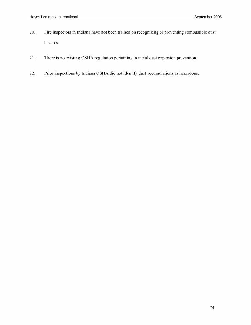
Hayes Lemmerz International September 2005
74
20. Fire inspectors in Indiana have not been trained on recognizing or preventing combustible dust
hazards.
21. There is no existing OSHA regulation pertaining to metal dust explosion prevention.
22. Prior inspections by Indiana OSHA did not identify dust accumulations as hazardous.

Hayes Lemmerz International September 2005
75
8.0 Root and Contributing Causes
8.1 Root Causes
1. Hayes did not perform a review to address why the chip system was releasing excess dust. The
hazards of aluminum dust were neither identified nor addressed.
2. Hayes did not use a management-of-change review to ensure the proper design of the dust
collector system.
3. Hayes did not ensure that NFPA 651 guidance for dust collector location and explosion protection
were applied.
4. Hayes had no formal, documented program to investigate and implement corrective action for
incidents involving fires in the foundry area, especially those fueled by aluminum dust.
8.2 Contributing Causes
1. Hayes did not require maintenance personnel, who were potentially exposed to flash fires, to wear
flame-retardant work clothing when performing routine activities.
2. Maintenance and housekeeping in the chip-processing area were inadequate, leading to
significant flammable dust accumulations that contributed to secondary deflagrations at furnace
no. 5.
3. Hayes did not implement a formal training program for personnel involved in operating and
maintaining the chip-processing system and dust collector system.
4. Hayes did not ensure adequate cleaning and maintenance for the dust collector system.

Hayes Lemmerz International September 2005
76
9.0 Recommendations
Hayes Lemmerz International, Huntington, Indiana (Hayes)
1. Develop and implement a means of handling and processing aluminum chips that minimizes the
risk of dust explosions. (2004-01-I-IN-R1) Refer to:
• The Aluminum Association Pamphlet F-1, Guidelines for Handling Aluminum Fines
Generated During Various Aluminum Fabricating Operations.
• NFPA 484, Standard for Combustible Metals, Metal Powders, and Metal Dusts.
2. Implement a program to provide regular training for all facility employees on the fire and
explosion hazards of aluminum dust. (2004-01-I-IN-R2)
3. Develop and implement policies and procedures for conducting engineering, hazard, and
management of change (MOC) reviews of plant projects and modifications to support systems
such as chip processing. In particular, ensure that a hazard analysis is conducted during the
design phase, as well as during the engineering and construction phases, and when changes are
made to the system. (2004-01-I-IN-R3)
4. Implement a program to conduct management reviews of incidents and near-miss incidents,
including duct fires and dust flashes. Apply this program to all plant areas, including support
areas such as chip processing. Address the root causes of the incidents and near-misses and
implement and track corrective measures. (2004-01-I-IN-R4)
5. Develop and implement written operating procedures for chip processing and train all affected
employees. Ensure that procedures address maintenance and housekeeping. (2004-01-I-IN-R5)

Hayes Lemmerz International September 2005
77
Hayes-Lemmerz International (HLI)
1. Conduct regular audits of all North American facilities that produce, process, or handle aluminum
chips or dust, in light of the findings of this report. Emphasize engineering, hazard, and MOC
reviews and compliance with NFPA-484. (2004-01-I-IN-R6) Ensure that:
• Audits are documented and contain findings and recommendations,
• Audit findings are shared with the work force at the facility.
• Audit recommendations are tracked and implemented.
2. Communicate the findings and recommendations of this report to the work force at Hayes and
other HLI facilities with similar operations. (2004-01-I-IN-R7)
Premelt Systems
Communicate the findings and recommendations of this investigation to owners/operators of facilities to
which Premelt supplies similar aluminum chip-melting systems. Include in your communication specific
information that the chip drying process liberates small particles of aluminum, and that such particles may
be explosive. (2004-01-I-IN-R8)
Indiana Occupational Safety and Health Administration
Develop and distribute an educational bulletin on the prevention of metal dust explosions.
(2004-01-I-IN-R9)
Indiana Department of Homeland Security
Provide training for fire inspectors in Indiana jurisdictions on the recognition and prevention of aluminum
dust explosion hazards. (2004-01-I-IN-R10)

Hayes Lemmerz International September 2005
78
Fire Protection Research Foundation
Conduct research into the feasibility and design of improved explosion protection for aluminum dust
collector applications, including explosion venting, isolation and suppression systems. Coordinate this
research activity with the Aluminum Association, Inc. (2004-01-I-IN-R11)
Aluminum Association, Inc.
Conduct research into the feasibility and design of improved explosion protection for aluminum dust
collector applications, including explosion venting, isolation and suppression systems. Coordinate this
research activity with the Fire Protection Research Foundation. (2004-01-I-IN-R12)
9.1 Recommendations to Communicate the Findings From the Investigation
In an effort to widely distribute lessons learned from investigations, CSB recommends that organizations
communicate relevant findings and recommendations to their memberships. CSB intends for those
organizations to use multiple avenues to communicate, such as having presentations at conferences,
placing summaries of reports and links to full CSB reports on their websites, developing and holding
training sessions that highlight report findings, and summarizing relevant findings in newsletters or direct
mailings to members. CSB encourages the organizations to use all their existing methods of
communication and explore new ways to more widely distribute these messages.
The Aluminum Association, Inc.
Communicate the findings and recommendations of this report to your members (2004-01-I-IN-R13):
Risk Insurance Management Society, Inc.
Communicate the findings and recommendations of this report to your members (2004-01-I-IN-R14):

Hayes Lemmerz International September 2005
79
North American Die Casting Association
Communicate the findings and recommendations of this report to your members (2004-01-I-IN-R15)
International Union, United Automobile, Aerospace and Agricultural Implement Workers of America (UAW)
Communicate the findings and recommendations of this report to your membership who work in facilities
with similar combustible dust hazards. (2004-01-I-IN-R16)
United Steelworkers of America (USWA)
Communicate the findings and recommendations of this report to your membership who work in facilities
with similar combustible dust hazards. (2004-01-I-IN-R17)
National Association of State Fire Marshals
Communicate findings, recommendations and sections applicable to fire codes and standards to your
membership. (2004-01-I-IN-R18)
National Fire Protection Association
Communicate findings, recommendations and sections applicable to fire codes and standards to your
membership. (2004-01-I-IN-R19)
International Code Council
Communicate findings, recommendations and sections applicable to fire codes and standards to your
membership. (2004-01-I-IN-R20)

Hayes Lemmerz International September 2005
80
By the
U.S. Chemical Safety and Hazard Investigation Board
Carolyn W. Merritt
Chair
John S. Bresland
Member
Gary L. Visscher
Member
September 27, 2005

Hayes Lemmerz International September 2005
81
References
American Society for Testing and Materials (ASTM), 2003. Standard Test Method for Pressure and Rate
of Pressure Rise for Combustible Dusts, ASTM E1226-00.
Avallone, Eugene A., and Theodore Baumeister III, 1987. Marks’ Standard Handbook for Mechanical
Engineers, Ninth Edition, McGraw-Hill.
Babrauskas, Vytenis, 2003. Ignition Handbook, Fire Science Publishers.
Barton, J. A., and H. D. Seaton, 1986. “Preventing Dust Explosions—A Case History,” Chemistry in
Britain, July 1986.
Barton, John, 2002. Dust Explosion Prevention and Protection: A Practical Guide, Gulf Professional
Publishing.
Bulwark Protective Apparel, 2002. Flame Resistant Protective Apparel, An Industry Update 2001/2002.
Center for Chemical Process Safety (CCPS), 1992. Guidelines for Investigating Chemical Process
Incidents, AIChE.
CCPS, 1989. Technical Management of Chemical Process Safety, AIChE.
Chantrathi, Kris and John Going, 2000. “Dust Deflagration Extinction”, Process Safety Progress, Vol.
19, No. 3, Fall 2000.
Clague, T. E., 1972. “Dust Explosion Mechanisms,” Birmingham University Chemical Engineer,
Vol. 23.
Constance, John, n.d. Understanding Dust Collector Explosion Protection, The Engineers Collaborative,
Inc., www.engcollab.com/articles/unterstanding1.htm.

Hayes Lemmerz International September 2005
82
Dahn, C. James, Abdolla Kashani, and Jacob Finkelshtein, 2000. “Dust Explosibility of Aluminum,
Coated Aluminum Powder and Mixtures,” Advances in Powder Metallurgy and Particulate
Materials, pp. 10-39–10-51.
Dale, James D., and Elizabeth M. Crown, Mark Y. Ackerman, Ewen Long, and Katherine B. Rigakis,
Instrumented Mannequin Evaluation of Thermal Protective Clothing, Performance of Protective
Clothing, 4th Ed., 1992.
Eckoff, R.K., 1997. Dust Explosions in the Process Industries, Second Edition., Butterworth Heineman.
Epstein, Seymour G., n.d. The Aluminum Association’s Molten Metal Safety Program, The Aluminum
Association, Inc.
Goings, John E. and Jef Snoeys, 2002. “Explosion Protection with Metal Dust Fuels”, Process Safety
Progress, Vol. 21, No. 4., December 2002.
Grossel, Stanley S. 2002. Deflagration and Detonation Flame Arresters , CCPS, AIChE. 2002.
Kletz, Trevor, 2004. “Safety Recommendations for Small Businesses and/or Plants,” Process Safety
Progress, Vol. 23, No. 2., June 2004.
Lembo, F., and P. DallaValle, et al., 2001. “Aluminum Airborne Particles Explosions: Risk Assessment
and Management at Northern Italian Factories,” European Safety and Reliability International
Conference, Torino, Italy, September 16–20, 2001, Italian Association of Chemical Engineering.
National Fire Protection Association (NFPA), 2003 Uniform Fire Code, NFPA 1.
NFPA, 2002a. Guide for Venting Deflagrations, NFPA 68.
NFPA, 2002b. Standard on Explosion Prevention Systems, NFPA 69.
NFPA, 2002c. Standard for Combustible Metals, Metal Powders, and Metal Dusts, NFPA 484.

Hayes Lemmerz International September 2005
83
NFPA, 2000. Standard for the Prevention of Fire and Dust Explosions From the Manufacturing,
Processing, and Handling of Combustible Particulate Solids, NFPA 654.
NFPA, 1998. Standard for the Machining and Finishing of Aluminum and the Production and Handling
of Aluminum Powder, NFPA 651.
Ogle, R. A., J. K. Beddow, L. D. Chen, and P. B Butler 1988. “An Investigation of Aluminum Dust
Explosions,” Combustible Science and Technology, Vol. 61.
Petersen, Dan, Techniques of Safety Management: A Systems Approach, 1998. Third Ed., American
Society of Safety Engineers.
Snoeys, Jef, and John Going, Olav Roald Hansen, and Brian Wilkins, 2004. “Modeling of Dust
Explosions in Industrial Processes: Use of Explosion Simulations for Explosion Isolation Design.
2004 Loss Prevention Conference, paper 49d, American Institute of Chemical Engineers (AIChE)
The Aluminum Association, Inc., 2000. Guidelines for Handling Aluminum Fines Generated During
Various Aluminum Fabricating Operations, Publication F1.
The Aluminum Association, Inc., 1990. Recommendations for Storage and Handling of Aluminum
Powders and Paste, Publication TR-2.
The United States Chemical Safety and Hazard Investigation Board (CSB) 2004. Investigation Report:
Dust Explosion, West Pharmaceutical Services, Kinston, NC, January 29, 2003.
CSB 2005. Investigation Report: Combustible Dust Fire and Explosion, CTA Acoustics, Corbin, KY,
February 20, 2003.
Vaughn, Diane, 1996. The Challenger Launch Decision: Risky Technology, Culture, and Deviance at
NASA, University of Chicago Press.

Hayes Lemmerz International September 2005
84
Vernon, Jack, 2002. “Defining and Maintaining a REGAGEP Program,” Presentation to the EPA Region
6, April 16, 2002, ABS Consulting.
http://www.epa.gov/Arkansas/6en/a/psm-rmp-presentations/q-ragagep-mko-4.pdf
Zalosh, Robert, Stanley Grossel, Russell Kahn, and Daniel Sliva, 2005. “Dust Explosion Scenarios and
Case Histories in the CCPS Guidelines for Safe Handling of Powders and Bulk Solids”, 39th AIChE
Loss Prevention Symposium Session on Dust Explosions, Atlanta, April 2005.

Hayes Lemmerz International September 2005
85
Appendix A
APPENDIX A: Analytical Results
Hayes Lemmerz International September 2005
86
Appendix A
Analytical Results
1.0 Background
CSB contracted with Safety Consulting Engineers, Inc. (SCE) to test samples aluminum chips and dust
collected from the Hayes Lemmerz incident site. The objective of the testing was to determine explosion
and ignition characteristics of the dusts found in the CSB samples. The results of this testing enabled
CSB to identify aluminum dust associated with the chip melting process as the fuel for the October 29,
2003 explosion, and to evaluate possible ignition sources.
1.1 Safety Consulting Engineers, Inc.
SCE is an independent testing laboratory and consulting firm located in Schaumburg, Illinois66. The SCE
laboratory is equipped to perform chemical analysis, explosivity testing, electrostatic measurements and
other tests of combustible dusts according to methods established by the American Society for Testing
and Materials (ASTM).
1.2 Samples
CSB collected many samples of dust and chips that were deposited in the portion of the foundry area
involved in the incident, on ledges, the tops of equipment, the floor and on other horizontal surfaces. A
total of 16 samples were sent to SCE for testing. Ultimately, only those samples that CSB estimated to
most resemble the material in the dust collector were tested.
66 http://www.sceinc.com

Hayes Lemmerz International September 2005
87
2.0 Testing
2.1 Test methods
SCE performed the following tests. Please refer to the corresponding ASTM standard test methods67 for
details on the methods and equipment used.
• Micrographic analysis at 100x magnification.
• Particle size analysis (ASTM D1921-96)
• Dust explosion severity (ASTM E1226-00)
• Electrostatic chargeability (not an ASTM test method)
• Volume resistivity (ASTM D257-99)
2.2 Test Results
2.2.1 Micrographic Analysis
A small quantity of each of the16 samples was viewed at 100x magnification under a microscope. In
general, the samples appeared to be flakes and strips of aluminum, with fine, to very fine particles
included. The shape of the aluminum particles under magnification is important; experiments have
shown that aluminum flakes tend to produce a lower explosivity than spherical particles.68 Nearly all the
samples included a small fraction of what appeared to be plastic particles of varying shapes and sizes.
This finding is consistent with the fact that some of the wheels produced at Hayes are machined after they
are coated with clear or opaque acrylic powder coating.
67 ASTM test standards are available at http://www.astm.org. 68 Eapen (2003)

Hayes Lemmerz International September 2005
88
2.2.2 Particle Size Analysis
This test was conducted according to ASTM D1921-96, “Standard Test Methods for Particle Size (Sieve
Analysis) of Plastic Materials. Selected samples containing aluminum chips and dust were passed
through various sieve sizes and weighed to determine the weight fraction, as a percent of the total sample
weight, of material retained in each sieve.
The resulting particle size distribution is given in Table 1.
Table 1. Results of particle size distribution analysis
Sieve Mesh Size
(mesh #)*
Sieve opening (μm) Percentage retained**
Sample A
Percentage retained**
Sample B
8 2360 81.31 49.66
50 300 17.83 10.86
100 150 0.14 9.22
Remainder (-100 mesh) <150 0.72 30.26
*Larger mesh size corresponds to a smaller particle size that can pass through the sieve. **Material either passes through a sieve or is retained above it. Retained material, therefore, is of larger particle sizes than the openings in the sieve mesh.
Sample A was collected from inside the dry chip hopper. Investigators observed that this sample was
predominantly chips with very little dust evident. Sample B was collected from the duct leading to the
drop box from the furnace 5 feed cyclone. As was expected, this sample had a higher percentage of
smaller particles.

Hayes Lemmerz International September 2005
89
2.2.3 Dust Explosion Severity
The explosion severity test was performed according to ASTM E1226-00, “Standard Test Method for
Pressure and Rate of Pressure Rise for Combustible Dusts”. The material was tested in a standard 20-
liter chamber. The objective of the testing was to determine:
• Pmax: the maximum absolute pressure inside the vessel at the time of ignition reached during the
course of a deflagration for the optimum concentration of the dust tested.
• (dP/dt)max: the maximum rate of pressure increase per unit time reached for the optimum
concentration of dust tested.
• KSt: the deflagration index, calculated as follows:
KSt = (dP/dt)max x V1/3
Where V is the volume of the test vessel in m3
Various samples of dust were placed in into the test chamber, lofted by air pulse and ignited by electrical
arc. Pressure is measured over time to calculate the deflagration constant.
The results of the testing are given in Table 2.

Hayes Lemmerz International September 2005
90
Table 2. Explosion severity test results
Sample Dust concentration tested
(g/m3)
Pmax
(psi)
(dp/dt)max
(psi/sec)
Kst (max)
(bar-m/sec)
A 500 126 3150 59
B 250 123 3600
B 500 125 4770
B 750 155 7000 131
B 1000 152 5940
C 500 143 6510 122
D 500 134 5355 101
Lycopodium
(reference
material)
500 121 7360 134
2.2.4 Electrostatic Chargeability
No ASTM test method was available for this analysis. The procedure was as follows: Dusts were poured
through a funnel into a stainless steel inclined chute. The dusts fell into a metal pail on an electrically
isolated table, and connected to an electrometer by a static detecting head. The static charge generated by
the movement of dust down the steel chute was then measured.

Hayes Lemmerz International September 2005
91
Table 3. Electrostatic Chargeability Results
Sample Charge per mass
μC/m2
Char per Volume
μC/m3
Streaming Current
μC/sec
E (Outside the drop box) 0.85 30.57 0.002
F (Chip feed) 0.220 136.48 0.026
Measurable static charge was generated on the sieved material. Whether this would be sufficient ignite a
dust cloud depends upon the minimum ignition energy of the dust cloud and the rate at which the charge
dissipates from the material.
2.2.5 Volume and Surface Resistivity and Charge Relaxation Time
Resistivity is a measure of a material’s ability to hold a static charge. The greater the resistivity, the more
likely that a material will accumulate and retain sufficient charge to ignite a flammable mixture. Tests for
volume resistivity were conducted according to ASTM D257-99, “Standard Test Method for D-C
Resistance or Conductance of Insulation Materials.”
Charge relaxation time is the time required for the voltage to drop to about 37 % of the initial value. This,
too, is a measure of the material’s ability to hold a static charge.
The resistivity tests are performed by placing the material to be tested between electrodes, applying a
known voltage to the electrodes, and measuring the current passing through the material.
Eight samples were sieved to 100 mesh (150 μm) and tested. The results were as follows:
• Volume resistivity ranged from 1.7 x 10¹² ohm-cm to 1.5 x 10¹⁴ ohm-cm.

Hayes Lemmerz International September 2005
92
• Surface resistivity ranged from 1.2 x 10¹³ to 6.4 x 10¹³ ohm.
• Charge relaxation time ranged from less than 1 second (for 6 of the 8 samples) to more than 2
minutes for two of the samples. The latter two samples were taken from the dust duct and from
within the chip dryer.
Material with charge resistivity greater than 1 x 10⁶ ohm is considered electrically insulative69. The
conclusion drawn from these results is that the dust in the dust collector at Hayes could possibly have
accumulated and retained sufficient charge to ignite a dust cloud, provided that the dust collector and
internal components were not well grounded.
69 Pratt (1997)

Hayes Lemmerz International September 2005
93
Appendix B
APPENDIX B: Initiating Event Analysis

Hayes Lemmerz International September 2005
94
Appendix B
Investigative Analysis
CSB used structured brainstorming and analytical tools, that included constructing an incident timeline
and fault tree analysis techniques, to organize the evidence and evaluate possible scenarios. The results of
this analysis are presented here.
1.0 Timeline
A timeline is a graphical tool that is particularly useful in organizing the facts of an event into sequential
order. Facts obtained through interviews, observations, photography and other means are placed on a
diagram in the relative order in which they occurred. CSB developed an incident timeline based on fire
department records, witness statements and call records obtained from the emergency dispatcher. If the
actual or approximate time of an event is known from the evidence, it is listed with the event description.

Hayes Lemmerz International September 2005
95
1995 Huntington chip system installed
1963Larry Areaux forms
Premelt.First aluminum chip
system built.
1984Huntington facility begins production
1939NFPA 651 issued
1985Kelsey-Hayes
purchases Huntington facility
1993 Mike Brand Joins Hayes
1994Premelt designs chip
system for Hayes Gainesville, GA plant
1995Gianesville, GA chip
system installed
1995 Chip system ordered
for Huntington
1995 Dryer afterburner
deflagration
1995 Multi-clone relocated
1998Huntington dust
collector installed
October 1999Mike Brand leaves
Hayes
March 2000Insurance carrier risk
evaluation
2001Lectrotherm acquires
Premelt
December 2001Hayes Lemmerz files
Chapter 11
2002NFPA 484 issued
January 2003Near miss
investigation program begun at Huntington
2003Indiana adopts IFC
2000
June 2003Hayes Lemmerz
emerges from Chapter 11
12/6/2001Fire department called
out for fire at melt area: Fire in "dust bin
ducting"
9/28/2001Fire department called
out again for fire at melt area: fire in duct from furnace to dust
collector
12/2003Indiana OSHA inspection of
Huntington facility
Historical Events
Hayes Lemmerz Timeline
Next Page

Hayes Lemmerz International September 2005
96
Hayes Lemmerz International September 2005
97
3.0 Fault Tree Analysis
CSB investigators constructed a fault tree to analyze the incident for possible causes. A fault tree is a top-
down, logic-driven technique for postulating all possible causes of an event. The team begins with the
top level event and develops possible causes for that event. Each of those causes is, in turn, treated as an
event for which causes are proposed. The tree development continues in this manner until a root cause or
basic event is reached for which there is no further development within the scope of the investigation.
The fault tree is constructed using “AND gates” and “OR gates.” If there are two or more conditions that
must exist in order for an event to occur, the event and the conditions are connected by an “AND gate.”
An “OR gate” is used when any one or more of a number of conditions listed could lead to the event, but
it is not necessary for ALL conditions to be present.
Once the tree is constructed, the team analyzes the branches of the tree and rules out (marks as false) any
branches that are contradictory to the available evidence.

Hayes Lemmerz International September 2005
98
Page Index Event
1 Start 1 Fatality, Multiple Injuries
2 A Injuries in melt area at furnace 5
3 B Injuries at contractor trailer
4 C Maintenance workers restarting chip system
5 D Flame Front from Chip Feed System
6 E Explosion in Dust Collector System
7 F Explosion Originated in Drop Box
8 G Flame Front from Vortex Sidewell
9 H Ignition Occurs
Legend
S2Injuries inmelt area atfurnace 5
S3Injuries atcontractortrailer
S11 FATALITY
MULTIPLE INJURIES
A B
AND Gate
OR Gate
Index
START
Terminus
TrueEvent
Off-pageconnector
FalseEvent

Hayes Lemmerz International September 2005
99
A1(S2)
Injuries InMelt Area AtFurnace 5
A4Flame front from
fume system
A7Flame front fromdust collection
system
A5Flame front fromchip feed system
A2Deflagration at
Furnace 5 sidewell
A3Personnel Present
(maintenance workersat Furnace 5
restarting chipfeed)
A13Deflagration inMulti-Cyclone
A14Deflagration in Fume
Duct
E
D
Ruled Out. Ductingfuel-depleted duringfire earlier in the
day
A15Deflagration in
Fume Hood
Ruled out:eyewitnessesreported no
evidence of fumehood fire justprior to event
A8Deflagrationin Fume System
A10Explosion in
dustcollectionSystem
A12Dust Collector
ExplosionProtection LTA
AND Gate
OR Gate
A6Flame front fromvortex sidewell
A
C
B13
A9Flow path existsfrom fume system
to sidewell
G
A20explosive dust
in multi-cyclone
A21Ignition inmulti-cyclone
A18Explosionventing LTA
(none on dirtyair side of
dust collectorhousing)
A17Dust collectorlocation LTA.Dust collector<50 m frombuilding
A16Dust collectormaintenance
LTA (Excessivefuel in dustcollector)
A19NFPA 651/484guidance not
applied
Management ofChange LTA
A11No functioning
explosionisolation valve
in dustcollector duct
Design LTA
Ruled out.No crediblesource forexplosivedust in
multi-cyclone

Hayes Lemmerz International September 2005
100
B1(S3)
Injuries AtContractorTrailer
B3Trailer on
fire
B8Dust collectorexplosion /
fire
B5Flaming debris
lands ontrailer
B6Radiant Heatfrom nearby
fire
B7Building roofblown off / on
fire
B13Deflagrationat furnace 5sidewell
B9Secondary dustdeflagration
B14Accumulated duston surfaces abovefurnace 5 lofted
and ignited
B15Dust escapesfrom system
B16Housekeeping
LTA
B12IgnitionOccurs
A2
B10Combustible materials
in building roof
B2Contractor in
trailer performingstack testing
B4Trailer
located 15feet from dust
collector
B
NPFA 651/484Guidelines forseparation not
applied
Secondarydeflagration causesroof damage, near-injury to other
contractor
Chip TransferSystem
MaintenanceLTA
H
B11Excess
combustiblematerial (filter
media andaluminum dust)indust collector
Dust collectormaintenance LTA

Hayes Lemmerz International September 2005
101
C2Fire in Fume HoodExhaust Duct toMulti-cyclone C3
Common practice toshut down, burn out(and cleanout) whenfire discovered in
ductwork
No formal(written)
procedure forhandling duct
fires
C4Combustible MaterialAccumulated in Duct
C5Accumulated solids
ignited
C8Spark from Fume Hood
Duct fires notadequately
investigated ordocumented
C9Incompletelycombusted
hydrocarbons infume hood exhaust
condensed inductwork
C10Aluminum dust andfines pulled intoduct by multi-cyclone fan
Dust escapes fromchip feed at vortex
box
Reduced draft atdust collector
Dust collectorfilter cartridges
loaded up
Dust CollectorMaintenance LTA
C
C1(A3)
Personnel Present(Maintenance
Workers at Furnace5 Restarting Chip
System)
C11Paint and ResidualCutting Oil on Chips
C7Hot Vapor From
Fume Hood
C12No Spark Box on Fume
Hood Exhaust
C13Fluxing or dross
removal in sidewellproduces embers
IncidentInvestigationProgram LTA
C6Fume DuctMaintenance
LTA

Hayes Lemmerz International September 2005
102
D1(A5)
Flame Front fromChip Feed System
D9Chip feed fanoverspeed
D3Explosion in dry
chip hopper
D4Exposion in cyclone
or feed duct
Ruled out: noevidence of feed fan
malfunction
Ruled out: internalinspection of dry
chip hopper did notreveal burning
D
D8Feed fan start
causes pulse thatlifts dust settled
in feed pipe
Ruled Out: Systemrunning at steady-
state for 10 minutesprior to explosion
D7Dust settled infeed pipe whilechip system idle
D6Dust in feedpipe lofted
D10Dust in drychip feed
D12Fines not
separated fromdry chips
No vibratoryseparator atdryer outlet
D11Chip dryer
liberates and/orcreates fines
G9
D13Ignitionoccurs
D3Explosion in dry
chip hopper
Ruled out: internalinspection of drychip hopper did not
reveal burning
H

Hayes Lemmerz International September 2005
103
E1(A10)
Explosion in DustCollector System
E
E2Explosion Originated
in Dust Duct
E3Explosion Originatedin Dust Collector
E4Explosion Originated
in Drop Box
E8Explosive mixture ofaluminum dust and
air in DustCollector
E7Ignition occurs
E5IgnitionOccurs
E9Dust settled in
duct
Air flow to dustCollector draftinadequate tokeep dustsuspended.
F
E6Explosivemixture of
aluminum dustand air indust duct
E10Lofting Event
H
H
E11Pulse Jet automaticcleaning lofts dust
every 60 or 90 seconds
Dust CollectorMaintenance LTA
E12Fines (dust) flowfrom cyclones todrop box & dust
collector
Dust ductconnected to
cyclone air outletdegrades cycloneperformance,
causes carryoverof fines
Management ofChange LTA
No crediblelofting eventsfor dust duct
itself
Chip systemdesigner not
involved in ductdesign
F9
F8
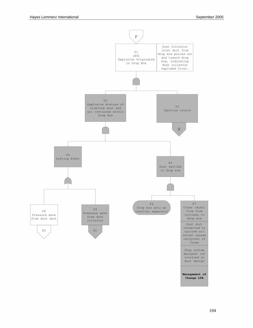
Hayes Lemmerz International September 2005
104
F1(E4)
Explosion Originatedin Drop Box
F2Explosive mixture ofaluminum dust and
air contained withinDrop Box
F3Ignition occurs
F
Dust Collectorinlet duct from
drop box pulled outand toward dropbox, indicatingdust collectorexploded first.
H
F4Lofting Event
F5Dust settledin drop box
F6Drop box acts asinertial separator
F7Fines (dust)flow from
cyclones todrop box
Dust ductconnected tocyclone airoutlet causescarryover of
fines
Chip systemdesigner notinvolved induct design
Management ofChange LTA
F8Pressure wavefrom dust duct
F9Pressure wavefrom dustcollector
E1E2

Hayes Lemmerz International September 2005
105
G1(A6)
Flame Front fromVortex Sidewell(preceeding maindeflagration)
G
G2Natural gasdeflagrationfrom firebox
G7Dust lofted whenemployee air-
blows chips fromthermocouple at
sidewell
Ruled out:furnace at
melttemperature;natural gas
cannotaccumulationin furnace
Ruled out: air-blowing occurredseveral minutes
beforedeflagration
G4Molten metalpresent toignite dust
cloud
G6Dust
accumulated onsurfaces
inside vortexbox, sidewelland fume hood
G9Dust in DryChip Feed
G10Housekeeping
LTA
G8Unknown lofting
event
D10
G3Dust dislodgedfrom vortexbox or fume
hood
G5Lofting Event
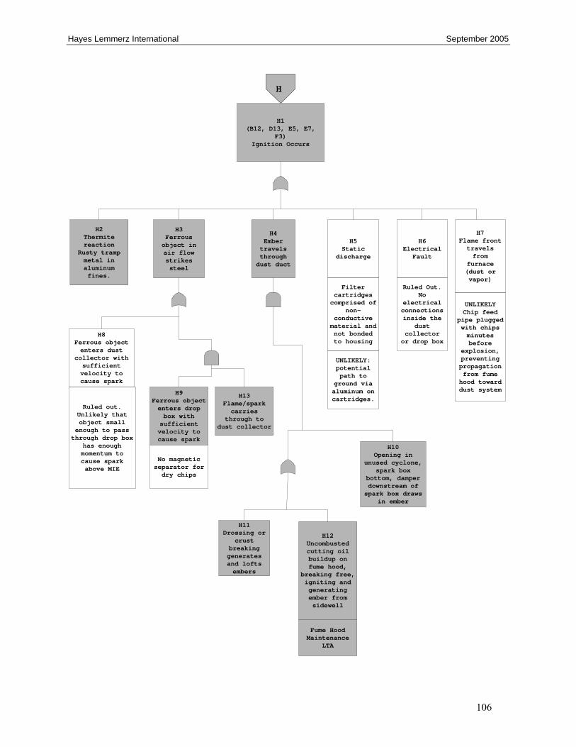
Hayes Lemmerz International September 2005
106
H3Ferrous object in air flow strikes steel
H4Ember travels through
dust duct
H5Static
discharge
H6Electrical
Fault
H7Flame front travels from
furnace (dust or vapor)
Ruled Out. No
electrical connections inside the
dust collector
or drop box
UNLIKELY Chip feed
pipe plugged with chips minutes before
explosion, preventing propagation from fume hood toward dust system
H2Thermite reaction
Rusty tramp metal in aluminum fines.
H8Ferrous object enters dust
collector with sufficient velocity to cause spark
H9Ferrous object enters drop box with
sufficient velocity to cause spark
Ruled out. Unlikely that object small
enough to pass through drop box
has enough momentum to cause spark above MIE
H11Drossing or
crust breaking generates and lofts embers
Filter cartridges
comprised of non-
conductive material and not bonded to housing
H10Opening in
unused cyclone, spark box
bottom, damper downstream of spark box draws
in ember
H12Uncombusted cutting oil buildup on fume hood,
breaking free, igniting and generating ember from sidewell
H1(B12, D13, E5, E7,
F3)Ignition Occurs
H
No magnetic separator for dry chips
H13Flame/spark carries
through to dust collector
UNLIKELY: potential path to
ground via aluminum on cartridges.
Fume Hood Maintenance
LTA