Højspændingskoblingsudstyr – Del 202: … · High -voltage switchgear and controlgear - Part...
21
Dansk standard DS/EN 62271-202 2. udgave 2014-10-14 Højspændingskoblingsudstyr – Del 202: Fabriksfremstillede under- stationer til højspænding/lavspænding High-voltage switchgear and controlgear – Part 202: High-voltage/low-voltage prefabricated substation
Transcript of Højspændingskoblingsudstyr – Del 202: … · High -voltage switchgear and controlgear - Part...

Dansk standard
DS/EN 62271-202
2. udgave 2014-10-14
Højspændingskoblingsudstyr –
Del 202: Fabriksfremstillede under-stationer til højspænding/lavspænding
High-voltage switchgear and controlgear – Part 202: High-voltage/low-voltage prefabricated substation
DS/EN 62271-202 København DS projekt: M263932 ICS: 29.130.10 Første del af denne publikations betegnelse er: DS/EN, hvilket betyder, at det er en europæisk standard, der har status som dansk standard. Denne publikations overensstemmelse er: IDT med: IEC 62271-202 ED 2:2014. IDT med: EN 62271-202:2014. DS-publikationen er på engelsk. Denne publikation erstatter: DS/EN 62271-202:2007.
DS-publikationstyper Dansk Standard udgiver forskellige publikationstyper. Typen på denne publikation fremgår af forsiden. Der kan være tale om: Dansk standard
• standard, der er udarbejdet på nationalt niveau, eller som er baseret på et andet lands nationale standard, eller • standard, der er udarbejdet på internationalt og/eller europæisk niveau, og som har fået status som dansk standard
DS-information • publikation, der er udarbejdet på nationalt niveau, og som ikke har opnået status som standard, eller • publikation, der er udarbejdet på internationalt og/eller europæisk niveau, og som ikke har fået status som standard, fx en
teknisk rapport, eller • europæisk præstandard DS-håndbog • samling af standarder, eventuelt suppleret med informativt materiale
DS-hæfte • publikation med informativt materiale
Til disse publikationstyper kan endvidere udgives
• tillæg og rettelsesblade DS-publikationsform Publikationstyperne udgives i forskellig form som henholdsvis
• fuldtekstpublikation (publikationen er trykt i sin helhed) • godkendelsesblad (publikationen leveres i kopi med et trykt DS-omslag) • elektronisk (publikationen leveres på et elektronisk medie)
DS-betegnelse Alle DS-publikationers betegnelse begynder med DS efterfulgt af et eller flere præfikser og et nr., fx DS 383, DS/EN 5414 osv. Hvis der efter nr. er angivet et A eller Cor, betyder det, enten at det er et tillæg eller et rettelsesblad til hovedstandarden, eller at det er indført i hovedstandarden. DS-betegnelse angives på forsiden. Overensstemmelse med anden publikation: Overensstemmelse kan enten være IDT, EQV, NEQ eller MOD
• IDT: Når publikationen er identisk med en given publikation. • EQV: Når publikationen teknisk er i overensstemmelse med en given publikation, men
præsentationen er ændret. • NEQ: Når publikationen teknisk eller præsentationsmæssigt ikke er i overensstemmelse med en
given standard, men udarbejdet på baggrund af denne. • MOD: Når publikationen er modificeret i forhold til en given publikation.

EUROPEAN STANDARD
NORME EUROPÉENNE
EUROPÄISCHE NORM
EN 62271-202
June 2014
ICS 29.130.10 Supersedes EN 62271-202:2007
English Version
High-voltage switchgear and controlgear - Part 202: High-voltage/low-voltage prefabricated substation
(IEC 62271-202:2014)
Appareillages à haute tension - Partie 202: Postes préfabriqués haute tension/basse tension
(CEI 62271-202:2014)
Hochspannungs-Schaltgeräte und -Schaltanlagen - Teil 202: Fabrikfertige Stationen für
Hochspannung/Niederspannung (IEC 62271-202:2014)
This European Standard was approved by CENELEC on 2014-05-01. CENELEC members are bound to comply with the CEN/CENELEC Internal Regulations which stipulate the conditions for giving this European Standard the status of a national standard without any alteration.
Up-to-date lists and bibliographical references concerning such national standards may be obtained on application to the CEN-CENELEC Management Centre or to any CENELEC member.
This European Standard exists in three official versions (English, French, German). A version in any other language made by translation under the responsibility of a CENELEC member into its own language and notified to the CEN-CENELEC Management Centre has the same status as the official versions.
CENELEC members are the national electrotechnical committees of Austria, Belgium, Bulgaria, Croatia, Cyprus, the Czech Republic, Denmark, Estonia, Finland, Former Yugoslav Republic of Macedonia, France, Germany, Greece, Hungary, Iceland, Ireland, Italy, Latvia, Lithuania, Luxembourg, Malta, the Netherlands, Norway, Poland, Portugal, Romania, Slovakia, Slovenia, Spain, Sweden, Switzerland, Turkey and the United Kingdom.
European Committee for Electrotechnical Standardization Comité Européen de Normalisation Electrotechnique
Europäisches Komitee für Elektrotechnische Normung
CEN-CENELEC Management Centre: Avenue Marnix 17, B-1000 Brussels
© 2014 CENELEC All rights of exploitation in any form and by any means reserved worldwide for CENELEC Members.
Ref. No. EN 62271-202:2014 E
EN 62271-202:2014 - 2 -
Foreword
The text of document 17C/595/FDIS, future edition 2 of IEC 62271-202, prepared by SC 17C “High-voltage switchgear and controlgear assemblies” of IEC TC 17 “Switchgear and controlgear" was submitted to the IEC-CENELEC parallel vote and approved by CENELEC as EN 62271-202:2014. The following dates are fixed:
• latest date by which the document has to be implemented at national level by publication of an identical national standard or by endorsement
(dop) 2014-11-01
• latest date by which the national standards conflicting with the document have to be withdrawn
(dow) 2017-05-01
This document supersedes EN 62271-202:2007. EN 62271-202:2014 includes the following significant technical changes with respect to EN 62271-202:2007:
a) regarding temperature-rise test an alternative method for liquid filled transformers is (re)introduced and the temperature-rise test method for dry-type transformers is specified more precisely;
b) testing procedure for short time and peak withstand current tests are specified more precisely;
c) assessment of electromagnetic fields is considered including a type test (optional) according CLC/TR 62271-208:2010;
d) influence of the product on the environment is considered (Clause 12);
e) internal arc test requirements have been adapted to EN 62271-200:2012 and requirements for the assessment of pressure relief volumes below the floor / ground has been assigned;
f) the method for defining the load factor in an enclosure for liquid filled transformers is extended with different temperature rises for the transformer outside the enclosure (Annex DD);
g) for the calculation of the load factor of dry-type transformers in an enclosure the insulation systems according to EN 60076-1:2011, Tables B.1 and B.2 are worked out in detail. Attention is drawn to the possibility that some of the elements of this document may be the subject of patent rights. CENELEC [and/or CEN] shall not be held responsible for identifying any or all such patent rights.
Endorsement notice
The text of the International Standard IEC 62271-202:2014 was approved by CENELEC as a European Standard without any modification.
In the official version, for Bibliography, the following notes have to be added for the standards indicated:
IEC 60059:1999 NOTE Harmonized as EN 60059:1999.
IEC 60068 (Series) NOTE Harmonized as EN 60068 (Series).
IEC 60076 (Series) NOTE Harmonized as EN 60076 (Series).
IEC 60243-1:2013 NOTE Harmonized as EN 60243-1:2013.
IEC 61936-1:2010 NOTE Harmonized as EN 61936-1:2010.
IEC 62271-4:2013 NOTE Harmonized as EN 62271-4:2013.
IEC/TS 62271-304:2008 NOTE Harmonized as CLC/TS 62271-304:2008.
ISO 1460 NOTE Harmonized as EN ISO 1460.

- 3 - EN 62271-202:2014
ISO 1461 NOTE Harmonized as EN ISO 1461.
ISO 2081 NOTE Harmonized as EN ISO 2081.
ISO 2409 NOTE Harmonized as EN ISO 2409.
ISO 3231:1993 NOTE Harmonized as EN ISO 3231:1997.
ISO 7784 (Series) NOTE Harmonized as EN ISO 7784 (Series).
ISO 9227 NOTE Harmonized as EN ISO 9227.
ISO 10546 NOTE Harmonized as EN ISO 1460.
ISO 11997 (Series) NOTE Harmonized as EN ISO 11997 (Series).
ISO 12944 (Series) NOTE Harmonized as EN ISO 12944 (Series).
ISO 13732-1:2006 NOTE Harmonized as EN ISO 13732-1:2008.
EN 62271-202:2014 - 4 -
Annex ZA (normative)
Normative references to international publications with their corresponding European publications
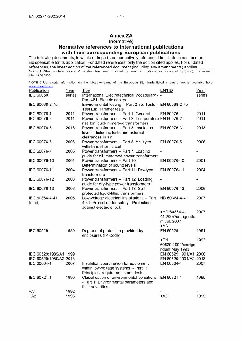
The following documents, in whole or in part, are normatively referenced in this document and are indispensable for its application. For dated references, only the edition cited applies. For undated references, the latest edition of the referenced document (including any amendments) applies. NOTE 1 When an International Publication has been modified by common modifications, indicated by (mod), the relevant EN/HD applies. NOTE 2 Up-to-date information on the latest versions of the European Standards listed in this annex is available here: www.cenelec.eu Publication Year Title EN/HD Year IEC 60050 series International Electrotechnical Vocabulary -
Part 461: Electric cables - series
IEC 60068-2-75 - Environmental testing -- Part 2-75: Tests - Test Eh: Hammer tests
EN 60068-2-75 -
IEC 60076-1 2011 Power transformers -- Part 1: General EN 60076-1 2011 IEC 60076-2 2011 Power transformers -- Part 2: Temperature
rise for liquid-immersed transformers EN 60076-2 2011
IEC 60076-3 2013 Power transformers -- Part 3: Insulation levels, dielectric tests and external clearances in air
EN 60076-3 2013
IEC 60076-5 2006 Power transformers -- Part 5: Ability to withstand short circuit
EN 60076-5 2006
IEC 60076-7 2005 Power transformers -- Part 7: Loading guide for oil-immersed power transformers
- -
IEC 60076-10 2001 Power transformers -- Part 10: Determination of sound levels
EN 60076-10 2001
IEC 60076-11 2004 Power transformers -- Part 11: Dry-type transformers
EN 60076-11 2004
IEC 60076-12 2008 Power transformers -- Part 12: Loading guide for dry-type power transformers
- -
IEC 60076-13 2006 Power transformers -- Part 13: Self-protected liquid-filled transformers
EN 60076-13 2006
IEC 60364-4-41 (mod)
2005 Low-voltage electrical installations -- Part 4-41: Protection for safety - Protection against electric shock
HD 60364-4-41 2007
+HD 60364-4-41:2007/corrigendum Jul. 2007
2007
+AA IEC 60529 1989 Degrees of protection provided by
enclosures (IP Code) EN 60529 1991
+EN 60529:1991/corrigendum May 1993
1993
IEC 60529:1989/A1 1999 EN 60529:1991/A1 2000 IEC 60529:1989/A2 2013 EN 60529:1991/A2 2013 IEC 60664-1 2007 Insulation coordination for equipment
within low-voltage systems -- Part 1: Principles, requirements and tests
EN 60664-1 2007
IEC 60721-1 1990 Classification of environmental conditions -- Part 1: Environmental parameters and their severities
EN 60721-1 1995
+A1 1992 - - +A2 1995 +A2 1995

- 5 - EN 62271-202:2014
IEC 60721-2-2 2012 Classification of environmental conditions -- Part 2-2: Environmental conditions appearing in nature -- Precipitation and wind
EN 60721-2-2 2013
IEC 60721-2-4 1987 Classification of environmental conditions -- Part 2: Environmental conditions appearing in nature - Solar radiation and temperature
HD 478.2.4 S1 1989
+A1 1988 - - IEC 60947-1 2007 Low-voltage switchgear and controlgear --
Part 1: General rules EN 60947-1 2007
IEC 61180-1 1992 High-voltage test techniques for low-voltage equipment -- Part 1: Definitions, test and procedure requirements
EN 61180-1 1994
IEC 61439-1 2011 Low-voltage switchgear and controlgear assemblies -- Part 1: General rules
EN 61439-1 2011
IEC 61439-2 2011 Low-voltage switchgear and controlgear assemblies -- Part 2: Power switchgear and controlgear assemblies
EN 61439-2 2011
IEC 62262 2002 Degrees of protection provided by enclosures for electrical equipment against external mechanical impacts (IK code)
EN 62262 2002
IEC 62271-1 2007 High-voltage switchgear and controlgear -- Part 1: Common specifications
EN 62271-1 2008
IEC 62271-200 2011 High-voltage switchgear and controlgear -- Part 200: AC metal-enclosed switchgear and controlgear for rated voltages above 1 kV and up to and including 52 kV
EN 62271-200 2012
IEC 62271-201 2006 High-voltage switchgear and controlgear -- Part 201: AC insulation-enclosed switchgear and controlgear for rated voltages above 1 kV and up to and including 52 kV
EN 62271-201 2006
+EN 62271-201:2006/corrigendum Nov. 2006
2006
IEC 62271-202 2014 High-voltage switchgear and controlgear -- Part 202: High-voltage/low-voltage prefabricated substation
EN 62271-202 2014
ISO 1052 1982 Steels for general engineering purposes - - ISO 1182 Reaction to fire tests for products – Non-
combustibility test EN ISO 1182 2010
ISO 1716 Reaction to fire tests for products – Determination of the gross heat of combustion (calorific value)
EN ISO 1716 2010
ISO 6508-1 Metallic materials -- Rockwell hardness test -- Part 1: Test method (scales A, B, C, D, E, F, G, H, K, N, T)
EN ISO 6508-1 2005
IEC/TR 62271-208 2009 High-voltage switchgear and controlgear -- Part 208: Methods to quantify the steady state, power-frequency electromagnetic fields generated by HV switchgear assemblies and HV/LV prefabricated substations
CLC/TR 62271-208 2010
IEC/TR 62271-300 2006 High-voltage switchgear and controlgear - Part 300: Seismic qualification of alternating current circuit-breakers
- -

EN 62271-202:2014 - 6 -
IEC/TS 60815-1 2008 Selection and dimensioning of high-voltage insulators intended for use in polluted conditions - Part 1: Definitions, information and general principles
- -
ISO/IEC Guide 51 1999 Safety aspects - Guidelines for their inclusion in standards
- -

IEC 62271-202 Edition 2.0 2014-03
INTERNATIONAL STANDARD NORME INTERNATIONALE
High-voltage switchgear and controlgear – Part 202: High-voltage/low-voltage prefabricated substation Appareillage à haute tension – Partie 202: Postes préfabriqués haute tension/basse tension
IEC
622
71-2
02:2
014-
03(e
n-fr)
®
colourinside

– 2 – IEC 62271-202:2014 © IEC 2014
CONTENTS
FOREWORD ........................................................................................................................... 8 INTRODUCTION ................................................................................................................... 10 1 General ......................................................................................................................... 11
1.1 Scope .............................................................................................................. 11 1.2 Normative references ....................................................................................... 11
2 Normal and special service conditions ........................................................................... 13 2.1 Normal service conditions ................................................................................ 13
2.1.1 Indoor switchgear and controlgear .................................................. 13 2.1.1.101 Low-voltage switchgear and controlgear ......................................... 13 2.1.1.102 Transformer .................................................................................... 13 2.1.2 Outdoor switchgear and controlgear ............................................... 14
2.2 Special service conditions ................................................................................ 14 2.2.1 Altitude ........................................................................................... 14 2.2.2 Pollution ......................................................................................... 14 2.2.3 Temperature and humidity .............................................................. 15 2.2.4 Vibrations, shock or tilting............................................................... 15 2.2.5 Wind speed .................................................................................... 15 2.2.6 Other parameters ........................................................................... 15
3 Terms and definitions .................................................................................................... 15 4 Ratings .......................................................................................................................... 17
4.1 Rated voltage (Ur) ........................................................................................... 18 4.2 Rated insulation level ....................................................................................... 18 4.3 Rated frequency (fr) ......................................................................................... 19 4.4 Rated normal current and temperature rise ...................................................... 19
4.4.1 Rated normal current (Ir) ................................................................ 19 4.4.2 Temperature rise ............................................................................ 19 4.4.3 Particular points of Table 3 ............................................................. 19
4.5 Rated short-time withstand current (Ik) ............................................................ 19 4.5.101 Rated short-time withstand current of high voltage switchgear
and controlgear and high voltage interconnection (Ik) ..................... 20 4.5.102 Rated short-time phase to earth withstand current (Ike) .................. 20 4.5.103 Rated short-time withstand currents of low voltage switchgear
and controlgear and low voltage interconnection (Icw) .................... 20 4.6 Rated peak withstand current (Ip) .................................................................... 20
4.6.101 Rated peak withstand current (Ip) ................................................... 20 4.6.102 Rated peak phase to earth withstand current (Ipe) .......................... 20 4.6.103 Rated peak withstand currents of low voltage switchgear and
controlgear and low voltage interconnection (Ipk) ........................... 20 4.7 Rated durations of short circuit (tk) .................................................................. 20
4.7.101 Rated duration of short circuit (tk) ................................................... 21 4.7.102 Rated duration of phase to earth short circuit (tke) ......................... 21 4.7.103 Rated duration of short circuits for low voltage switchgear and
controlgear and low voltage interconnection ................................... 21 4.7.104 Rated duration of short circuits for transformers ............................. 21
4.8 Rated supply voltage of closing and opening devices and auxiliary and control circuits (Ua) .......................................................................................... 21
4.9 Rated supply frequency of closing and opening devices and of auxiliary circuits ............................................................................................................. 21
IEC 62271-202:2014 © IEC 2014 – 3 –
4.10 Rated pressure of compressed gas supply for controlled pressure systems ........................................................................................................... 21
4.11 Rated filling levels for insulation and/or operation ............................................ 21 4.101 Rated maximum power and class of enclosure ................................................. 22
4.101.1 Rated maximum power of the prefabricated substation ................... 22 4.101.2 Rated class of enclosure ................................................................ 22
4.102 Ratings of the internal arc classification ........................................................... 22 4.102.1 General .......................................................................................... 22 4.102.2 Types of accessibility (A, B, AB) ..................................................... 22 4.102.3 Rated arc fault currents (IA, IAe) .................................................... 22 4.102.4 Rated arc fault duration (tA, tAe) .................................................... 23
5 Design and construction ................................................................................................ 23 5.1 Requirements for liquids in switchgear and controlgear .................................... 23 5.2 Requirements for gases in switchgear and controlgear .................................... 23 5.3 Earthing of switchgear and controlgear ............................................................ 24 5.4 Auxiliary and control equipment ....................................................................... 25 5.5 Dependent power operation ............................................................................. 25 5.6 Stored energy operation ................................................................................... 25 5.7 Independent manual or power operation (independent unlatched
operation) ........................................................................................................ 25 5.8 Operation of releases ....................................................................................... 25 5.9 Low- and high-pressure interlocking and monitoring devices ............................ 25 5.10 Nameplates...................................................................................................... 25 5.11 Interlocking devices ......................................................................................... 25 5.12 Position indication ............................................................................................ 26 5.13 Degree of protection provided by enclosures ................................................... 26 5.14 Creepage distances for outdoor insulators ....................................................... 26 5.15 Gas and vacuum tightness ............................................................................... 26 5.16 Liquid tightness ................................................................................................ 26 5.17 Fire hazard (flammability) ................................................................................ 26 5.18 Electromagnetic compatibility (EMC) ................................................................ 26 5.101 Protection of the prefabricated substation against mechanical stress ............... 26 5.102 Protection of the environment due to internal defects ....................................... 27 5.103 Internal arc fault ............................................................................................... 27 5.104 Enclosure ........................................................................................................ 28
5.104.1 General .......................................................................................... 28 5.104.2 Fire behaviour ................................................................................ 28 5.104.3 Corrosion ........................................................................................ 29 5.104.4 Covers and doors ........................................................................... 30 5.104.5 Ventilation openings ....................................................................... 30 5.104.6 Partitions ........................................................................................ 30
5.105 Other provisions............................................................................................... 31 5.105.1 Provisions for dielectric tests on cables .......................................... 31 5.105.2 Accessories .................................................................................... 31 5.105.3 Operation aisle ............................................................................... 31 5.105.4 Labels ............................................................................................ 31
5.106 Sound emission ............................................................................................... 31 5.107 Electromagnetic fields ...................................................................................... 31
6 Type tests ..................................................................................................................... 31
– 4 – IEC 62271-202:2014 © IEC 2014
6.1 General ............................................................................................................ 31 6.1.1 Grouping of tests ............................................................................ 32 6.1.2 Information for identification of specimens ...................................... 32 6.1.3 Information to be included in type-test reports ................................ 32
6.2 Dielectric tests ................................................................................................. 33 6.2.1 Ambient air conditions during tests ................................................. 33 6.2.2 Wet test procedure ......................................................................... 33 6.2.3 Conditions of switchgear and controlgear during dielectric
tests ............................................................................................... 33 6.2.4 Criteria to pass the test .................................................................. 33 6.2.5 Application of the test voltage and test conditions ........................... 33 6.2.6 Tests of switchgear and controlgear of Ur ≤ 245 kV ........................ 33 6.2.7 Tests of switchgear and controlgear of Ur > 245 kV ........................ 33 6.2.8 Artificial pollution tests for outdoor insulators .................................. 33 6.2.9 Partial discharge tests .................................................................... 33 6.2.10 Dielectric tests on auxiliary and control circuits. .............................. 34 6.2.11 Voltage test as condition check ...................................................... 34 6.2.101 Tests on the high-voltage interconnection ....................................... 34 6.2.102 Tests on low-voltage interconnection .............................................. 35
6.3 Radio interference voltage (r.i.v.) test .............................................................. 36 6.4 Measurement of the resistance of circuits ........................................................ 36 6.5 Temperature-rise tests ..................................................................................... 36
6.5.101 General .......................................................................................... 36 6.5.102 Test conditions ............................................................................... 37 6.5.103 Test methods .................................................................................. 38 6.5.104 Measurements ................................................................................ 41 6.5.105 Acceptance criteria ......................................................................... 42
6.6 Short-time withstand current and peak withstand current tests ......................... 43 6.7 Verification of the protection ............................................................................ 43 6.8 Tightness tests ................................................................................................ 43 6.9 Electromagnetic compatibility tests (EMC) ....................................................... 43 6.10 Additional tests on auxiliary and control circuits ............................................... 44
6.10.1 General .......................................................................................... 44 6.10.2 Functional tests .............................................................................. 44 6.10.3 Electrical continuity of earthed metallic parts test ........................... 44 6.10.4 Verification of the operational characteristics of auxiliary
contacts .......................................................................................... 44 6.10.5 Environmental tests ........................................................................ 44 6.10.6 Dielectric test ................................................................................. 44
6.11 X-radiation test procedures for vacuum interrupters ......................................... 44 6.101 Calculations and mechanical tests ................................................................... 44
6.101.1 Wind pressure ................................................................................ 44 6.101.2 Roof loads ...................................................................................... 45 6.101.3 Mechanical impacts ........................................................................ 45
6.102 Internal arc test ................................................................................................ 45 6.102.1 General .......................................................................................... 45 6.102.2 Test conditions ............................................................................... 45 6.102.3 Arrangement of the equipment ........................................................ 46 6.102.4 Test procedure ............................................................................... 46

IEC 62271-202:2014 © IEC 2014 – 5 –
6.102.5 Criteria to pass the test .................................................................. 46 6.102.6 Test report ...................................................................................... 47 6.102.7 Transferability of tests results ......................................................... 48
6.103 Measurement or calculation of electromagnetic fields ...................................... 48 7 Routine tests ................................................................................................................. 48
Replacement: ................................................................................................................ 49 7.101 Dielectric test on the high voltage interconnection............................................ 49 7.102 Voltage withstand tests on auxiliary circuits ..................................................... 49 7.103 Functional tests ............................................................................................... 49 7.104 Verification of correct wiring ............................................................................. 49 7.105 Tests after assembly on site ............................................................................ 49
8 Guide to the selection of prefabricated substation ......................................................... 49 Replacement: ................................................................................................................ 49 8.101 General ............................................................................................................ 49 8.102 Selection of rated values .................................................................................. 50 8.103 Selection of class of enclosure ......................................................................... 50 8.104 Internal arc fault ............................................................................................... 50
8.104.1 General .......................................................................................... 50 8.104.2 Causes and preventive measures ................................................... 51 8.104.3 Supplementary protective measures ............................................... 51 8.104.4 Considerations for the selection and installation ............................. 53 8.104.5 Internal arc test .............................................................................. 53 8.104.6 IAC classification ............................................................................ 53
8.105 Summary of technical requirements, ratings and optional tests ........................ 54 9 Information to be given with enquiries, tenders and orders ............................................ 58
9.1 Information with enquiries and orders .............................................................. 58 9.2 Information with tenders ................................................................................... 59
10 Transport, storage, installation, operation, maintenance ................................................ 60 10.1 Conditions during transport, storage and installation ........................................ 60 10.2 Installation ....................................................................................................... 60
10.2.1 Unpacking and lifting ...................................................................... 61 10.2.2 Assembly ........................................................................................ 61 10.2.3 Mounting ........................................................................................ 61 10.2.4 Connections ................................................................................... 61 10.2.5 Final installation inspection ............................................................. 61 10.2.6 Basic input data by the user ........................................................... 61 10.2.7 Basic input data by the manufacturer .............................................. 61
10.3 Operation ......................................................................................................... 61 10.4 Maintenance .................................................................................................... 62 10.101 Dismantling, recycling and disposal at the end-of-service life ........................... 62
11 Safety ............................................................................................................................ 62 11.101 Electrical aspects ............................................................................................. 62 11.102 Mechanical aspects ......................................................................................... 62 11.103 Thermal aspects .............................................................................................. 62 11.104 Internal arc aspects ......................................................................................... 62
12 Influence of the product on the environment .................................................................. 63 Annex AA (normative) Internal arc fault – Method to verify the internal arc
classification (IAC) ........................................................................................................ 64

– 6 – IEC 62271-202:2014 © IEC 2014
AA.1 General ............................................................................................................ 64 AA.2 Room simulation .............................................................................................. 64 AA.3 Indicators (for assessing the thermal effects of the gases) ............................... 64
AA.3.1 General .......................................................................................... 64 AA.3.2 Arrangement of indicators ............................................................... 65
AA.4 Tolerances for geometrical dimensions of test arrangements ........................... 66 AA.5 Test parameters ............................................................................................... 67 AA.6 Test procedure ................................................................................................. 67
Annex BB (normative) Test to verify the sound level of a prefabricated substation ............... 76 BB.1 Purpose ........................................................................................................... 76 BB.2 Test specimen ................................................................................................. 76 BB.3 Test method ..................................................................................................... 76 BB.4 Measurements ................................................................................................. 76 BB.5 Presentation and calculation of the results ....................................................... 76
Annex CC (normative) Mechanical impact test ..................................................................... 78 CC.1 Test for the verification of the resistance to mechanical impact ........................ 78 CC.2 Apparatus for the verification of the protection against mechanical
damage............................................................................................................ 78 Annex DD (informative) Rating of transformers in an enclosure .......................................... 80
DD.1 General ............................................................................................................ 80 DD.2 Liquid-filled transformer ................................................................................... 80 DD.3 Dry-type transformer ........................................................................................ 81 DD.4 Example........................................................................................................... 85
Annex EE (informative) Examples of earthing circuits .......................................................... 88 Annex FF (informative) Characteristics of enclosure materials ............................................. 91
FF.1 Metals .............................................................................................................. 91 FF.1.1 Coatings ......................................................................................... 91 FF.1.2 Paints ............................................................................................. 91
FF.2 Concrete .......................................................................................................... 91 Bibliography .......................................................................................................................... 93 Figure 101 – Measurement of transformer temperature rise in ambient air: ∆t1 ..................... 37 Figure 102 – Measurement of transformer temperature rise in an enclosure: ∆t2 .................. 37 Figure 103 – Diagram of the preferred temperature-rise test method .................................... 39 Figure 104 – Diagram of the alternative temperature-rise test method .................................. 40 Figure 105 – Diagram for open-circuit test ............................................................................ 41 Figure AA.1 – Mounting frame for vertical indicators ............................................................. 68 Figure AA.2 – Horizontal indicators ....................................................................................... 68 Figure AA.3 – Arrangement of indicators ............................................................................... 71 Figure AA.4 – Selection of tests on high voltage switchgear for class IAC-A ......................... 72 Figure AA.5 – Selection of tests on high voltage switchgear for class IAC-B ......................... 73 Figure AA.6 – Selection of tests on high voltage interconnections for class IAC-A ................ 74 Figure AA.7 – Selection of tests on high voltage interconnections for class IAC-B ................ 75 Figure CC.1 – Impact test apparatus ..................................................................................... 79 Figure DD.1 – Liquid-filled transformer load factor in an enclosure ....................................... 81 Figure DD.2 – Dry-type transformer load factor outside of the enclosure ............................... 81
IEC 62271-202:2014 © IEC 2014 – 7 –
Figure DD.3 – Insulation class 105 °C (A) dry-type transformers load factor in an enclosure .............................................................................................................................. 82 Figure DD.4 – Insulation class 120 °C (E) dry-type transformers load factor in an enclosure .............................................................................................................................. 82 Figure DD.5 – Insulation class 130 °C (B) dry-type transformers load factor in an enclosure .............................................................................................................................. 83 Figure DD.6 – Insulation class 155 °C (F) dry-type transformers load factor in an enclosure .............................................................................................................................. 83 Figure DD.7 – Insulation class 180 °C (H) dry-type transformers load factor in an enclosure .............................................................................................................................. 84 Figure DD.8 – Insulation class 200 °C (H) dry-type transformers load factor in an enclosure .............................................................................................................................. 84 Figure DD.9 – Insulation class 220 °C (H) dry-type transformers load factor in an enclosure .............................................................................................................................. 85 Figure EE.1 – Example of earthing circuits ............................................................................ 88 Figure EE.2 – Example of earthing circuits ............................................................................ 89 Figure EE.3 – Example within the framework serving as the main earthing conductor ........... 90 Table 101 – Synthetic material characteristics ...................................................................... 29 Table 102 – Locations, causes and examples of measures decreasing the probability of internal arcs ...................................................................................................................... 52 Table 103 – Single phase-to-earth arc fault current depending on the network neutral earthing ................................................................................................................................ 54 Table 104 – Summary of technical requirements and ratings for prefabricated substations (1 of 4) ............................................................................................................... 55 Table FF.1 – Treatment of coatings ...................................................................................... 91 Table FF.2 – Tests of coatings .............................................................................................. 91 Table FF.3 – Test of concrete ............................................................................................... 92

– 8 – IEC 62271-202:2014 © IEC 2014
INTERNATIONAL ELECTROTECHNICAL COMMISSION _____________
HIGH-VOLTAGE SWITCHGEAR AND CONTROLGEAR –
Part 202: High-voltage/low-voltage prefabricated substation
FOREWORD 1) The International Electrotechnical Commission (IEC) is a worldwide organization for standardization comprising
all national electrotechnical committees (IEC National Committees). The object of IEC is to promote international co-operation on all questions concerning standardization in the electrical and electronic fields. To this end and in addition to other activities, IEC publishes International Standards, Technical Specifications, Technical Reports, Publicly Available Specifications (PAS) and Guides (hereafter referred to as “IEC Publication(s)”). Their preparation is entrusted to technical committees; any IEC National Committee interested in the subject dealt with may participate in this preparatory work. International, governmental and non-governmental organizations liaising with the IEC also participate in this preparation. IEC collaborates closely with the International Organization for Standardization (ISO) in accordance with conditions determined by agreement between the two organizations.
2) The formal decisions or agreements of IEC on technical matters express, as nearly as possible, an international consensus of opinion on the relevant subjects since each technical committee has representation from all interested IEC National Committees.
3) IEC Publications have the form of recommendations for international use and are accepted by IEC National Committees in that sense. While all reasonable efforts are made to ensure that the technical content of IEC Publications is accurate, IEC cannot be held responsible for the way in which they are used or for any misinterpretation by any end user.
4) In order to promote international uniformity, IEC National Committees undertake to apply IEC Publications transparently to the maximum extent possible in their national and regional publications. Any divergence between any IEC Publication and the corresponding national or regional publication shall be clearly indicated in the latter.
5) IEC itself does not provide any attestation of conformity. Independent certification bodies provide conformity assessment services and, in some areas, access to IEC marks of conformity. IEC is not responsible for any services carried out by independent certification bodies.
6) All users should ensure that they have the latest edition of this publication.
7) No liability shall attach to IEC or its directors, employees, servants or agents including individual experts and members of its technical committees and IEC National Committees for any personal injury, property damage or other damage of any nature whatsoever, whether direct or indirect, or for costs (including legal fees) and expenses arising out of the publication, use of, or reliance upon, this IEC Publication or any other IEC Publications.
8) Attention is drawn to the Normative references cited in this publication. Use of the referenced publications is indispensable for the correct application of this publication.
9) Attention is drawn to the possibility that some of the elements of this IEC Publication may be the subject of patent rights. IEC shall not be held responsible for identifying any or all such patent rights.
International Standard IEC 62271-202 has been prepared by subcommittee 17C: High-voltage switchgear and controlgear assemblies, of IEC technical committee 17: Switchgear and controlgear.
This second edition cancels and replaces the first edition published in 2006. This edition constitutes a technical revision.
This edition includes the following significant technical changes with respect to the previous edition:
a) regarding temperature-rise test an alternative method for liquid filled transformers is (re)introduced and the temperature-rise test method for dry-type transformers is specified more precisely;
b) testing procedure for short time and peak withstand current tests are specified more precisely;
c) assessment of electromagnetic fields is considered including a type test (optional) according IEC/TR 62271-208:2009;

IEC 62271-202:2014 © IEC 2014 – 9 –
d) influence of the product on the environment is considered (Clause 12); e) internal arc test requirements have been adapted to IEC 62271-200:2011 and
requirements for the assessment of pressure relief volumes below the floor / ground has been assigned;
f) the method for defining the load factor in an enclosure for liquid filled transformers is extended with different temperature rises for the transformer outside the enclosure (Annex DD);
g) for the calculation of the load factor of dry-type transformers in an enclosure the insulation systems according to IEC 60076-1:2011, Tables B.1 and B.2 are worked out in detail.
The text of this standard is based on the following documents:
FDIS Report on voting
17C/595/FDIS 17C/598/RVD
Full information on the voting for the approval of this standard can be found in the report on voting indicated in the above table.
This publication has been drafted in accordance with the ISO/IEC Directives, Part 2.
This standard should be read in conjunction with IEC 62271-1:2007 and its Amendment 1:2011, to which it refers and which is applicable, unless otherwise specified. In order to simplify the indication of corresponding requirements, the same numbering of clauses and subclauses is used as in IEC 62271-1. Amendments to these clauses and subclauses are given under the same numbering, whilst additional subclauses are numbered from 101.
A list of all parts of the IEC 62271 series can be found, under the general title High-voltage switchgear and controlgear, on the IEC website.
The committee has decided that the contents of this publication will remain unchanged until the stability date indicated on the IEC web site under "http://webstore.iec.ch" in the data related to the specific publication. At this date, the publication will be
• reconfirmed, • withdrawn, • replaced by a revised edition, or • amended.
IMPORTANT – The 'colour inside' logo on the cover page of this publication indicates that it contains colours which are considered to be useful for the correct understanding of its contents. Users should therefore print this document using a colour printer.

– 10 – IEC 62271-202:2014 © IEC 2014
INTRODUCTION
Prefabricated substations are defined as a type-tested assembly comprising an enclosure containing in general transformers, low-voltage and high-voltage switchgear, connections and auxiliary equipment to supply low-voltage energy from a high-voltage system or vice versa. These substations are in locations accessible to the public and should ensure protection to persons according to the specified service conditions.
This means that, in addition to the specified characteristics, ratings and relevant test procedures, particular attention has been paid to the specification concerning the protection of persons, both operators and general public. Use of type-tested components and suitable design and construction of the enclosure ensure this protection. The correct design and performance of the prefabricated substation are verified by means of relevant type tests described in this standard, including internal arc tests.
IEC 62271-202:2014 © IEC 2014 – 11 –
HIGH-VOLTAGE SWITCHGEAR AND CONTROLGEAR –
Part 202: High-voltage/low-voltage prefabricated substation
1 General
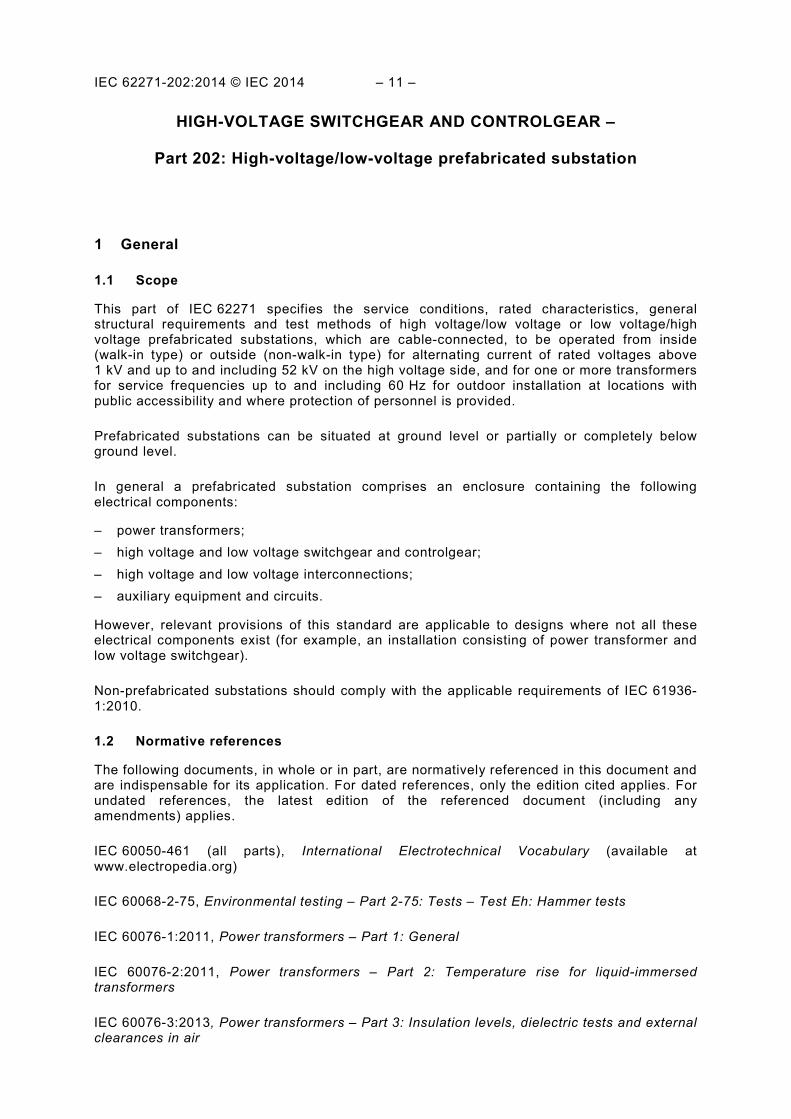
1.1 Scope
This part of IEC 62271 specifies the service conditions, rated characteristics, general structural requirements and test methods of high voltage/low voltage or low voltage/high voltage prefabricated substations, which are cable-connected, to be operated from inside (walk-in type) or outside (non-walk-in type) for alternating current of rated voltages above 1 kV and up to and including 52 kV on the high voltage side, and for one or more transformers for service frequencies up to and including 60 Hz for outdoor installation at locations with public accessibility and where protection of personnel is provided.
Prefabricated substations can be situated at ground level or partially or completely below ground level.
In general a prefabricated substation comprises an enclosure containing the following electrical components:
– power transformers; – high voltage and low voltage switchgear and controlgear; – high voltage and low voltage interconnections; – auxiliary equipment and circuits.
However, relevant provisions of this standard are applicable to designs where not all these electrical components exist (for example, an installation consisting of power transformer and low voltage switchgear).
Non-prefabricated substations should comply with the applicable requirements of IEC 61936-1:2010.
1.2 Normative references
The following documents, in whole or in part, are normatively referenced in this document and are indispensable for its application. For dated references, only the edition cited applies. For undated references, the latest edition of the referenced document (including any amendments) applies.
IEC 60050-461 (all parts), International Electrotechnical Vocabulary (available at www.electropedia.org)
IEC 60068-2-75, Environmental testing – Part 2-75: Tests – Test Eh: Hammer tests
IEC 60076-1:2011, Power transformers – Part 1: General
IEC 60076-2:2011, Power transformers – Part 2: Temperature rise for liquid-immersed transformers
IEC 60076-3:2013, Power transformers – Part 3: Insulation levels, dielectric tests and external clearances in air
– 12 – IEC 62271-202:2014 © IEC 2014
IEC 60076-5:2006, Power transformers – Part 5: Ability to withstand short circuit
IEC 60076-7:2005, Power transformers – Part 7: Loading guide for oil-immersed power transformers
IEC 60076-10:2001, Power transformers – Part 10: Determination of sound levels
IEC 60076-11:2004, Power transformers – Part 11: Dry-type transformers
IEC 60076-12:2008, Power transformers – Part 12: Loading guide for dry-type power transformers
IEC 60076-13:2006, Power transformers – Part 13: Self-protected liquid-filled transformers
IEC 60364-4-41:2005, Low-voltage electrical installations – Part 4-41: Protection for safety – Protection against electric shock
IEC 60529:1989, Degrees of protection provided by enclosures (IP Code) Amendment 1:1999 Amendment 2:2013
IEC 60664-1:2007, Insulation coordination for equipment within low-voltage systems – Part 1: Principles, requirements and tests
IEC 60721-1:1990, Classification of environmental conditions – Part 1: Environmental parameters and their severities Amendment 1:1992 Amendment 2:1995
IEC 60721-2-2:2012, Classification of environmental conditions – Part 2-2: Environmental conditions appearing in nature – Precipitation and wind
IEC 60721-2-4:1987, Classification of environmental conditions – Part 2: Environmental conditions appearing in nature – Solar radiation and temperature Amendment 1:1988
IEC/TS 60815-1:2008, Selection and dimensioning of high-voltage insulators intended for use in polluted conditions – Part 1: Definitions, information and general principles
IEC 60947-1:2007, Low-voltage switchgear and controlgear – Part 1: General rules
IEC 61180-1:1992, High-voltage test techniques for low-voltage equipment – Part 1: Definitions, test and procedure requirements
IEC 61439-1:2011, Low-voltage switchgear and controlgear assemblies – Part 1: General rules
IEC 61439-2:2011, Low-voltage switchgear and controlgear assemblies – Part 2: Power switchgear and controlgear assemblies
IEC 62262:2002, Degrees of protection provided by enclosures for electrical equipment against external mechanical impacts (IK code)
IEC 62271-1:2007, High-voltage switchgear and controlgear – Part 1: Common specifications Amendment 1:2011

IEC 62271-202:2014 © IEC 2014 – 13 –
IEC 62271-200:2011, High-voltage switchgear and controlgear – Part 200: AC metal-enclosed switchgear and controlgear for rated voltages above 1 kV and up to and including 52 kV
IEC 62271-201:2006, High-voltage switchgear and controlgear – Part 201: AC insulation enclosed switchgear and controlgear for rated voltages above 1 kV and up to and including 52 kV
IEC/TR 62271-208:2009, High-voltage switchgear and controlgear – Part 208: Methods to quantify the steady state, power-frequency electromagnetic fields generated by HV switchgear assemblies and HV/LV prefabricated substations
IEC/TR 62271-300:2006, High-voltage switchgear and controlgear – Part 300: Seismic qualification of alternating current circuit-breakers
ISO/IEC Guide 51:1999, Safety aspects – Guidelines for their inclusion in standards
ISO 1052:1982, Steels for general engineering purposes
ISO 1182:2010, Reaction to fire tests for products – Non-combustibility tests
ISO 1716:2010, Reaction to fire tests for products – Determination of the gross heat of combustion (calorific value)
ISO 6508-1:2005, Metallic materials – Rockwell hardness test – Part 1: Test method (scales A, B, C, D, E, F, G, H, K, N, T)
2 Normal and special service conditions
Clause 2 of IEC 62271-1:2007 is applicable, except as follows.
2.1 Normal service conditions
Unless otherwise specified in this standard, the prefabricated substation is designed to be used under normal service conditions for outdoor switchgear and controlgear according to IEC 62271-1:2007.
Inside the enclosure it is assumed that normal indoor conditions prevail according to IEC 62271-1:2007. However, the ambient temperature inside the enclosure of the prefabricated substation will be different from the ambient temperature as defined in 3.111.
If the ambient temperature inside the substation is higher than the limits fixed for the components in their respective product standards, de-rating may be necessary.
2.1.1 Indoor switchgear and controlgear
Subclause 2.1.1 of IEC 62271-1:2007 is applicable.
Additional subclauses:
2.1.1.101 Low-voltage switchgear and controlgear Subclause 7.1 of IEC 61439-1:2011 is applicable.
2.1.1.102 Transformer
IEC 60076-1:2011 is applicable.