Historical Stereo Music Reviews - americanradiohistory.com · "At 7vz ips, the response was within...
68
the authoritative magazine about high fidelity STEREO EQUIPMENT & RECORD REVIEWS JULY 1969 60 4 The Technical Quality of Records Historical Stereo Music Reviews AUDIO MEASUREMENTS: Methods & Instruments www.americanradiohistory.com AmericanRadioHistory.Com
Transcript of Historical Stereo Music Reviews - americanradiohistory.com · "At 7vz ips, the response was within...

the authoritative magazine about high fidelity
STEREO EQUIPMENT & RECORD REVIEWS
JULY 1969 60 4
The Technical Quality of Records Historical Stereo Music Reviews
AUDIO MEASUREMENTS: Methods & Instruments
www.americanradiohistory.comAmericanRadioHistory.Com

Scott introduces AM high fidelity
POWERFUL NEW SCOTT 382C AM/FM STEREO RECEIVER MAKES BOTH FM AND AM
LISTENING A PLEASURE
Ready for an incredible listening experience? Then try the AM section of the new Scott 382C. It pulls in stations so strongly ... eliminates interference and drift so thor- oughly ... delivers sound of such clarity ... that you'll think you're listening to the FM section. The only differ- ence is the programming!
Until now, the high fidelity fan has either had to miss out on programming available only on AM or he has had to forego good sound. Now, using all the latest FET and Integrated Circuit techniques, Scott engineers have de- signed a brilliant new AM section. The result ... the new Scott 382C AM/FM Stereo Receiver, the first high fidelity AM ever available! In AM or FM stereo, the 382C re- ceives both strong and weak stations perfectly. Weak stations burst forth loud and clear. Strong stations never distort.
Scott introduces 4 AM circuit innovations New Scott 4 -pole LC filter improves selectivity. Use
of IC's and FET's in the AM IF amplifier gives better signal/noise ratio, lower distortion, and better signal - handling capacity. New FET mixer gives improved cross modulation rejection and adjacent -station interference.
New Scott transistor oscillator dramatically reduces drift and pulling.
Listen to the AM section of the new 382C at your dealer. You'll hear an incredible improvement in AM sound. Then switch to FM or records ... the 382C is identical in de- sign to the 342C FM stereo receiver introduced so suc- cessfully a few months back. In addition to the totally new AM section the 382C has all these advanced 342C features: (1) Perfectune ... a light that snaps on automatically when you're perfectly tuned to an FM station. (2) Quartz crystal lattice filter IF section ... your 382C will never need realignment. (3)"Wire-Wrap"
a permanent connection technique that eliminates solder joints. (4) New IC multiplex section ... for better stereo performance and reliability. (5) Printed circuit modules . . . which snap into the main chassis.
382C SPECIFICATIONS: Power (±1 dB), 110 Watts; IHF Dynamic Power @ 4 Ohms, 45 Watts per channel; IHF Continuous Power @ 4 Ohms, 33 Watts per channel; IHF Continuous Power @ 8 Ohms, 25 Watts per channel; Selectivity, 40 dB; Frequency response ±1 dB, 20-20,000 Hz; Hum and noise, phono, -55 dB; Cross modulation rejection, 80 dB; Usable sensitivity, 1.9 AT; Tuner stereo separation, 30 dB; FM IF limiting stages, 9; Capture ratio, 2.5 dB; Signal to noise, 65 dB; Phono sensitivity, 3 mV; Dimensions: 1594," L x 5" H x 11W" D. 382C 110 -Watt AM/FM Stereo Receiver ... ONLY $299.95. 342C 110 -Watt FM Stereo Receiver ... $269.95. Walnut finish case optional extra.
C3 SC OTT H. H. Scott, Inc., Dept. 35-07 Maynard, Mass. 01754 Export: Scott International, Maynard, Mass. 01754 e 1969, H. H. Scott, Inc.
1
Check No. 100 on Reader Service Card
www.americanradiohistory.comAmericanRadioHistory.Com

"At 7vz ips, the response was within +0.5 db, -2.0 db from 20 to 20,000 Hz. This has never been equalled by any other recorder we have tested."
.. Stereo Review
"So good is the servo control that it has proved extremely difficult in practice to measure any waver of wow or flutter; for quite long intervals the meter drops below the point at which reliable readings are possible ... Studer and his team have truly produced a tape recorder landmark."
... Audio Record Review
"This recorder is a masterpiece of electronic and mechanical engineering."
... Hi-Fi Sound
"This is the flattest machine we have ever tested."
... Audio
This is the REVOX A77 priced from $499.00
R EVOX For literature and dealer information: New York State's Residents Call: 516-484-4650 (Collect) All other Continental U.S.A. Enquirers call: 800-645-2074
(Free WATS Service) APO/FPO and overseas enquirers circle No. 1 on R.S.C.
REVOX CORPORATION P.O. Box 196 Roslyn Heights, New York 11577
In Canada, contact: TRI -TEL ASSOCIATES LTD., Toronto
AUDIO . JULY 1969
Check No. 1 on Reader Service Card
1
www.americanradiohistory.comAmericanRadioHistory.Com

July 1969 Vol. 53, No. 7 Number 70 in a series of discussions
by Electro -Voice engineers
CARL GOY Senior Electronics Engineer
There's a new way to dial your favorite FM station now being introduced. It has just two moving parts -a potentiometer and a meter. The key component in this unusual system is a device called a varactor.
A varactor is simply a diode whose capacity varies inversely with voltage applied across the junction. For instance, as the voltage rises from about 4 to 24 volts, capacity drops from about 20 to 10 pf. Increasing the control voltage serves to increase the frequency of the tuned circuit and accomplishes the same basic task as opening the plates of a conventional air variable capacitor.
In the case of a new Electro -Voice FM receiver, Model 1482, pairs of varactors are used to achieve the desired capacity in each circuit. A total of four "gangs" are employed including an antenna tuning capacitor, two interstage RF tuning capacitors, and the RF oscillator capa- citor. Because each dual varactor is only about 1/4" square in size, the bulk of the tuning ap- paratus can be sharply reduced.
To control the voltage across the varactors a single potentiometer is needed. Precision multi - turn pots are employed with about 15 turns from minimum to maximum voltage. In the receiver in question, a total of ten of these potentiometers are used, with nine mounted on a push-button array. Each push button selects and varies a potentiometer to provide tuning to any point on the dial, thus permitting FM push- button tuning of high accuracy and repeat- ability. In addition, one potentiometer is connected to a conventional tuning knob to permit normal manual tuning.
Performance of the tuner with varactor tuning is quite similar to that optimally achieved with ordinary air variable capacitors. But in addition to the saving in size and increase in flexibility of component location, it is also easier to pro- vide higher "Q" in the RF stages to achieve better selectivity. Elimination of mechanical parts and linkages insures better long-term re- liability. The hermetically sealed diodes also are preferable in high humidity environments.
As a result of the use of varactors, a completely new tuning indicator has also been introduced. Rather than a pointer on a string, a sensitive D'Arsonval drum meter is employed, driven from the same voltage used to control the varactors. Similar in appearance to a "ribbon type" automotive speedometer, it instantly pro- vides accurate readout of frequency for either manual or push-button tuning on both AM and FM.
For reprints of other discussions /n this series, or technical data on any E -V product, write:
ELECTRO -VOICE, INC., Dept. 793A 602 Cecil St., Buchanan, Michigan 49107
Je.re-rolez A SUBSIDIARY OF GULFON INDUSTRIES, INC.
AUDIO Successor to RADlO, Est. 1911
ARTHUR P. SALSBERG, Editor C. G. McPRouu, Publisher EDWARD TATNALL CANBY, Associate Editor
JOHN HUBBARD RICHARD CLIFF Art Director Design
LEONARD FELDMAN
BERTRAM STANLEIGH SHERWOOD L. WEINGARTEN
BERT WHYTE
Contributing Editors HERMAN BURSTEIN JOSEPH GIOVANELLI
ALEXANDER ROSNER
FEATURE ARTICLES
GERSHAN T. THALBERG
Publishing Director SANFORD L. CAHN
Marketing Director R. KENNETH BAXTER
Production Manager JUDITH S. ZUCKER
Advertising Manager MARY CLAFFEY
Subscription Manager
The Technical Quality of Records 10 Bert Whyte Historical Stereo 14 Edward Tatnall Canby
Audio Measurements: Methods and Instruments A Primer on Sound Level Meters
A New Use for Intermodulation Tests Preamplifier Measurements
Audio/FM Test Equipment Sampler
22 Bernard Katz 26 Norman H. Crowhurst 32 James Bongiorno 38
ABZ's of Stereo FM- The Sum and Difference System 50 Leonard Feldman Why You Say It .. .
"Magnetic Tape Recorder" 56 Webb Garrison
EQUIPMENT PROFILES
Sony Turntable System 42 PS -1800 Heathkit Speaker System 44 AS -48
ADC Stereo Phono Cartridge 48 Model 25
RECORD/TAPE REVIEWS
Classical Light Listening
Tape Reviews
52 Edward Tatnall Canby 58 Sherwood L. Weingarten 62 Bert Whyte
AUDIO IN GENERAL
Audioclinic What's New in Audio
Tape Guide Letters
Editor's Review Classified
Advertising Index
4 Joseph Giovanelli 8
16 Herman Burstein 18 20 64 66
AUDIO (title registered U. S. Pat. Off.) is published monthly by North American Publishing Co., I. J. Borowsky, President; Frank Nemeyer, C. G. McProud, Arthur Sitner, and Roger Damio, Vice Presidents. Subscription rates-U. S. Possessions, Canada, and Mexico, $5.00 for one year; $9.00 for two years; all other countries, $8.00 per year. Printed in U.S.A. at Philadelphia, Pa. All rights reserved. Entire contents copyrighted 1969 by North American Publishing Co. Second dass postage paid at Phila., Pa. REGIONAL SALES OFFICES: Gershan T. Thalberg and Sanford L. Cahn, 41 East 42nd St., New York, N. Y. 10017; Telephone (212) 687-8924. Louis Weber, 5201 N. Harlem Ave., Chicago, Ill. 60656; (312) 775-0755. Jay Martin, 15010 Ventura Blvd., Sherman Oaks, Calif.; (213) 981-7852. REPRESENTATIVE: Matsushita Inc., 709, Kitano Arms, Hirakawa-Cho, Chiyoda-Ku Tokyo, Japan.
AUDIO Editorial and Publishing Offices, 134 N. 13th St., Philadelphia, Pa. 19107 Postmaster: Send Form 3579 to the above address.
2 Check No. 2 on Reader Service Card AUDIO JULY 1969
www.americanradiohistory.comAmericanRadioHistory.Com

Acoustic Research AR -3a speaker systems are important professional tools to composer/arranger Don Ellis.
Don Ellis creates music that ranges from the ancient sitar to a novel four -valve quarter -tone trumpet specially made for him. His work is well exemplified by Electric Bath (Columbia 9585),
which was Album of the Year (1968) in Down Beat, placed second in Playboy's annual poll, and
third in Melody Maker; the record was also nominated for a Grammy Award.
Mr. Ellis' high-fidelity system in his studio consists of an AR turntable, a Bogen -Lenco B62
turntable, an AR amplifier, a JBL 600 amplifier, a Koss Pro 600A headset, Revox and Crown tape recorders, and a pair of AR -3a speaker systems.
Mr. Ellis advises AR that the turntables, amplifiers, and tape recorders are all capable of highest -quality reproduction, so that making comparisons of different tapes and records can be done dependably with any of them. However, he finds that only AR -3a speaker systems are accurate enough to use in his work.
Acoustic Research Inc. 24 Thorndike Street, Cambridge, Massachusetts 02141
Overseas Inquiries: Write to AR International at above address
Check No. 3 on Reader Service Card
www.americanradiohistory.comAmericanRadioHistory.Com

Coming in
August 1969
Focus on Commercial Sound
- Articles on microphones,
amplifiers, and speaker sys-
tems for commercial sound
applications.
Primer on Sound Level Me-
ters, Pt. 2-Bernard Katz con-
tinues his primer on SLMs by
exploring how data are inter-
preted.
The Composite Stereo FM
Signal - The 17 paragraphs
listed under section 73.322 of
the FCC rules that launched
stereo FM are examined by
Leonard Feldman.
PLUS:
Equipment Profiles, Record
and Tape Reviews, Audio -
clinic, Tape Guide, and other
regular departments.
ABOUT THE COVER:
Some measurement terms men-
tioned in this issue, which focuses
on audio measurement methods
and instruments, are printed on
faces of alphabet blocks. See arti-
cles starting on page 22.
Audioclinic If you have a problem or question on audio, write to Mr. Joseph Giovanelli at AUDIO, 134 North Thirteenth Street, Philadelphia, Pa. 19107.
JOSEPH GIOVANELLI
Bass Boost & Speaker Damage
Q. I am confused with treble and bass settings on my receiver. I have read that too much of an increase in bass is harmful for speaker systems. Is this true? What would you consider a safe setting for bass on the plus side? I am now using a setting of normal bass and a -3 treble. Is this a good setting? However, does a minus treble setting increase bass? - Frank E. Scirocco, Jersey City, N. J.
A. Because most of the power out- put of an audio amplifier is used to produce bass, it is especially important that the woofer is capable of handling as high a percentage of total amplifier power as possible. This is even more important when the bass control is advanced.
The factors which determine tone control settings, therefore, have little to do with the speaker's ability to han- dle bass, except for the case in which the woofer is capable of handling, say, only ten watts of power and its asso- ciated amplifier is capable of supplying 50 watts. Under such circumstances, the bass might need to be cut some- what, especially if you plan to run the equipment at high volume levels. When the speaker system is able to handle anything which the power amplifier can supply, factors such as room acoustics and your taste become important in determining just how the bass and treble controls should be set.
If your room is highly reflective or if your tweeter is quite "hot," you might very well want to cut back on the treble. It is a matter of judgment. The action of the treble control does not in- fluence the amount of bass you have present in your loudspeaker. It affects the overall sound balance between highs and lows. Further, adding bass does not result in a reduction of treble response.
Your equipment is for your own en- joyment. Set the controls where you find that the sound is pleasing to your ear. There is no "right" setting for them. It really does not matter if the sound you like would not have been heard in the original recording session. Tone controls are placed on amplifiers to be used.
Installing Shielded Ignition Cable
Q. How do you install ignition cable? -Earle Stevens, Patterson, N. J.
A. If you are using shielded ignition wire, ground the shield to as many places on the engine body as is conve- nient. When using such cable, we are attempting to suppress ignition inter- ference to FM sets or mobile communi- cations equipment. If the shield is grounded at one end only, the remain- ing shield length can become inductive. Therefore, it will do little to shield the radiation.
Also, keep the runs of such wire to as short a length as possible. Try to avoid having the lines as multiples of a quar- ter wavelength at the frequency of in- terest.
Defective Headphones?
Q. I have had two sets of headphones, each of which failed after a short time Why?-Leonides O. Florin, Miami, Fla.
A. It is possible that you have been unlucky enough to obtain two defective sets of phones.
However, phones are delicate items, and they can be damaged by overload- ing them. If you play the phones really loud, loud enough to damage your ears, you will probably ruin most pairs of phones within a very short time. If you use them for quiet listening, however, you are not damaging them.
Here is the exception. When you switch from "tuner" to "phono," is there a loud transient click in your speaker or phones? If there is, the peak energy of such a click may be the cause of headphone damage. I used the switching to "phono" as an example. Any transient can damage headphones. Do your controls work smoothly or is one of them dirty, and, therefore, noisy? The transient clicks and pops brought about by such noisy controls may damage headphones.
Antennas & Portable Radios
Q. My radio receiver is battery op- erated. What type of outdoor antenna would you recommend for both FM and shortwave? We are located right out- side of the metropolitan New York City area. I live in a one-story dwelling.- Roy W. Hoffman, North Bergen, N. J.
A. I do not recommend that you add much in the way of an antenna for the shortwave portion of the receiver. If you do, you will have lots of what we call "birdies" on your hands. These are whistles created by overloaded circuits and the introduction of image re- sponses. As good as your radio may be, or any radio fitting this general descrip-
4 Check No. 5 on Reader Service Card * www.americanradiohistory.comAmericanRadioHistory.Com

o o aeo P2O epe d
gyred drive system 3 precision heads for instant off -the -tape monitoring Mike -line mixing tape lifter Ali -pushbutton controls, automatic. shutoff Stereo echo for special sound effects
Ever see a sonic boom?
You're looking at our A-12000 tape deck.
Most pecpie would rather listen to it. Even though
it's already started its own sonic boom.
Anc no wonder: the A-12000 is our standard
'Dur -track model, with all the famous TEAC
.craftsmanship at an ear -boggling low
cost. And plenty of unique features,
like the popular ADD recording for simultaneous playback
and recording on separate
tracks. This is the
machine that breaks
the price barrier to your sound investment.
Without breaking you.
T E AC, 7EAC Corporation of America 2000 Colorado Avenue Santa Monica, California 90404
www.americanradiohistory.comAmericanRadioHistory.Com

These are not the finest ADC speaker systems. They're just the finest you can buy
at these prices.
Audio Dynamics is famous for speaker systems costing $300 to $500 designed for the most critical audiophiles who can afford the very finest compo- nents. But, if your appreciation of superb sound is somewhat limited by your budget, then we unhesi- tatingly recommend any of these under -$100 ADC models. While they obviously cannot have every qual- ity feature that goes into our deluxe ADC systems, they have many more of these features than you'll find in speakers at comparable prices. In short, these speaker systems are the best buys for your money at even $20 or $30 more. See them and hear them at your hi-fi dealer or write for detailed specifications.
r
Please send
specifications on ADC speaker systems.
AUDIO DYNAMICS- - - -1 CORPORATION NEW MILFORD, CONNECTICUT 06776
Name
Address
City
State Zip
Quality Magnetic Cartridges Home Entertainment Electronics Hi Fidelity Speaker Systems
ADC404 (left) Top -rated compact bookshelf unit that won impressive independent ratings. Matches the capabilities of most any amplifier. Fundamental resonance extremely low. Suggest- ed resale $55.00
Specifications: Impedance 8 ohms. Frequency Response: 45-20,000 cps ± 3 db, average listening room. Bass Unit: High compliance 6" linear travel piston cone. Treble Unit: High flux, mylar dome with wide dispersion. Dimensions: Only 117/4"Hx73"W x81/4"D.
ADC210 (center) We challenged our engineers to create a $100 speaker that would outperform competitive speakers in this range. To make it more diffi- cult we told them it would also have to sell for $25 less. The ADC 210 is it. Suggested resale $74,50
Specifications: Impedance 8 ohms. 6 to 60 watt maximum. Frequency response 35 to 18,000 Hz ± 4 db. High flux long throw 8" woofer and cone tweeter. Removable grille for customizing to any decor. Dimen- sions: 231/4" H x 13" W x 11" D.
ADC303A and 303AX (right) The 303A is the top -rated winner of the most impressive independent test in large system categories. (The 303AX is an advanced version.) Both are systems of exceptional accuracy, with a lack of distortion and coloration not available at or near this price range. Suggested re- sale 303A-$89.95; 303AX $99.95
Specifications: Impedance 8 ohms. Frequency Response: 33-20,000 cps ± 3 db, in average listening room. Power Requirements: 6 watt min. 60 watt max. Woofer: 8" (303A) or 10" (303AX) high compliance. Tweeter: Hi -flux mylar dome with wide dispersion. Removable grille for customizing to any decor. Dimensions: 223/4" H x 13" W x 113/4" D.
tion, not gt. enough 1.
expect to: with the builftio have some of 4 not, then try adt%Ui length and see what
Even the FM mighteL lem if you have a good locò s'e
reception. I would put up á this radio, but would not consio. a Yagi.
Receiver Sensitivity Q. I am using a stereo cartridge rated
at .08 mV output. Because this does not match the receiver's 2.5 mV input sensitivity, would this have any detre- mental effect on my phonograph's play- back capability?
What would happen if a 3.0 mV car- tridge or even higher were connected to the receiver's 2.5 mV phono input jack? Would the cartridge's higher output overdrive the phono input and cause playback distortion?
My tape deck preamplifiers also put out 1.2 V at maximum output into the receiver's 150 -mV tape monitor jack. Is there much significance to matching each source's output precisely to the input sensitivity of the stage to which it is connected?-E. T., APO San Fran- cisco, Calif.
A. If your cartridge has only 0.8 mV output and if your amplifier requires 2.5 mV to drive it to full output power, then your amplifier cannot be so driven with your cartridge. Furthermore, this will result in a reduced signal-to-noise ratio. You will either have to replace the cartridge or you will have to think in terms of a different receiver or in terms of a low -gain preamplifier ahead of the receiver's phonograph input.
Because the 3.0 mV output of a car- tridge is so close to the 2.5 mV sensi- tivity of your phono input, the circuitry should not be overloaded. If it were, the receiver design would be poor indeed- at least in terms of the phonograph cir- cuit. You might run into trouble if you use a cartridge having 6 to 8 mV out- put. That signal level might overload the front end of the preamplifier sec- tion, ahead of the volume control.
The case of your tape deck is some- thing different. While your monitor will accept as little as 150 mV of signal, chances are that this input is at the volume control. Therefore, your tape machine will cause no trouble because all you need to do is turn down the vol- ume. You may find that most of the action of the control takes place near the bottom end, but you can learn to control that.
6 Check No. 6 on Reader Service Card
www.americanradiohistory.comAmericanRadioHistory.Com

There's a lot more enjoyment coming your way from the brand new Pioneer OUTPERFORMERS. We are introducing an exciting array o' all rew products; compacts, tapedecks, stereo receivers, tuners, amplifiers, speaker systems, turntables End headphones that will delight even the mos- discrm- inating listener. Illustrated here is the brand new SX-140 Stereo Receiver. Pleasing in every detail, a smarty styled. midnight black front panel with 3 -dimes on sub- dued illumination graces -he esthetic handcrafted cabinet. Its FET front-end provides excel ent sel- ectivity and delivers clear, interference-f-ee recep- tion. Frequency response s 20 - 70 kFz; inputs;
magnetic phono, tape monitor and auxiliary. Out- stand.ng sensitivity. Music power is a solid 40 watts ('HF with stereo channel separation at better than 83 di (phono).
Friced at only $189.95, the Pioneer SX-440 is an ideal component for the budgèt minded or the aJdicphile. You'll discover qualities of sound you never knew existed with the full line of OUTPER- FüRMERS which only Pioneer can bring you.
See and hear the PIONEER OUTPERFORMERS at ycur franchised Pioneer dealer. Write for details.
PIONEER ELECTRONICS U.S.A. CORPORATION 141 Srri h St., Farmingdale, N.Y., 11735 (51.6) 694-7720
{y1 PIoNEFR erEREC PECE{VER MODEI. SJS-e4C ,:JgQ
F= 88 90_ 9e 96 98 IL j AM SS A @D 9a la 1
SPEnKEP
POWER
Ae
8Ei6G'roge
PIONEER .iD West Coast Regional Office: 1335 West 134th St. Gardena, Calif. 90249 (213) 323-2374 and 321-1076
AUDIO JULY 1969 Check No. 7 on Reader Service Card
In Canada: S. H. Parker Co. Ontario
7
www.americanradiohistory.comAmericanRadioHistory.Com

NEW I M ANALYZER
ADVANCES
STATE OF THE ART
Extended measuring range and high- speed readings are the outstanding features of a unique new Intermodula- tion Distortion Analyzer introduced by Crown International recently. The American firm is known for its line of Crown precision professional tape re- corders.
This analyzer was developed to meet the production line requirements of the Crown DC300 lab standard amplifier. The first need was for accu- rate measuring capability through 0.01%. This analyzer guarantees a re- sidual IM level of less than 0.005%, with seven full-scale ranges from 100% to 0.1%.
The second requirement was for an instrument simple enough to be oper- ated by production -line personnel and rapid enough to make sequential read- ings across the entire power band. The Crown analyzer meets the challenge by reducing measuring time from minutes per reading to just seconds. This is accomplished by a "tracking" func- tion, using two meters and a ganged input/output gain control. The input level is set using the calibrate meter, and distortion is immediately read on the percentage distortion meter. Suc- cessive readings at 5db increments take under five seconds each. The entire operation is completed in less than one minute.
Solid state construction, utilizing FETs, makes the Crown analyzer high- ly stable and uniquely compact, meas- uring 7x19x7 inches. Rack mount list price is $595. Write for spec sheet to CROWN, Dept. A-7 , Box 1000, Elkhart, Indiana, 46514.
Check No. 8 on Reader Service Card
What's New In Audio
Indoor/Outdoor Speaker Electro -Voice's new Musicaster lA
and IIA portable speaker systems re- tain the bass reflex -type enclosures of previous Musicaster models, but incor- porate improved weatherproofing: a 1/2" "Acoustifoam" barrier sandwiched between the silicon -treated 12" diam- eter speaker and the front grille. The new material is said to increase inter- nal damping, thereby improving the system's bass performance. In addition,
the Musicaster's lightweight polyester enclosure has been restyled.
Nominal impedance of both Musi - casters is 8 ohms. Frequency response of the Model IA is 80 to 10,000 Hz; Model IIA is 80 to 16,000 Hz. Both have power -handling capacities of 30 watts of program material and 60 watts peak. Weighing 30 lbs., they are priced under $100.00.
Check No. 22 on Reader Service Card
Stereo Reverb Unit A new reverberation unit for use
with stereo or mono systems has been introduced by Gibbs Special Products Corp., a subsidiary of Hammond Corp.
Featuring a 10 -watt solid-state am- plifier designed for reverberation pur- poses, distortion is said to be under 3% at 1000 Hz. Both input and output im- pedances are 8 ohms. Front -panel con- trols include tone, volume, and reverb- eration %, plus on -off switches for reverberation and for power. The rear panel has terminals for connecting am- plifier leads and for an auxiliary re- verberation speaker. $70.00.
Check No. 23 on Reader Service Card
Video Tape Recorder The new Sony Corporation of Amer-
ica Model EV-320 video tape recorder features electronic editing, which al- lows sequences from the source to be inserted into a prerecorded master tape by pushbutton control. The inserted portion, in either color or monochrome, is said to be practically indiscernible from the original tape. Another feature of the recorder is that it does not re- quire an external sync generator for editing or replay. $4900.
Check No. 24 on Reader Service Card
Man -Size Speaker Epicure Products, Inc. introduces its
Model 1000 "Tower," a 61/2 -ft. high by 18 -in. square speaker system.
The company has incorporated four of its standard non -directional modules, in an eight -cu. -ft. acoustic suspen- sion -type sealed enclosure, with one
module on each of the "Tower's" four faces. According to the manufacturer, the speaker system produces a spheri- cal sound field from 20 to 15,000 Hz ±3 dB. Minimum power requirement is 20 watts; maximum power handling capacity is 250 watts (rms) continuous.
Check No. 26 on Reader Service Card
Cassette & Cartridge News Robins Industries has a host of new
cassette and eight -track cartridge ac- cessories, including bulk erasers and tape -head demagnetizers for both for- mats, cassette splicers, storage cabinets, and carrying cases.
Ampex Stereo Tapes' prerecorded stereo cassette catalog lists more than 1500 selections from 64 record labels. It is issued separately from the company's standard catalog due to the growth of the cassette library. Added recently are the Golden Records library of chil- dren's stories and fairy tales on cas- settes, which hold up to eight minutes of material on each side ($1.98).
Superscope Inc., exclusive U.S. dis- tributor of Sony tape recorders, has formed a new recording division to pro- duce and market under its own label pre-recorded stereo cassettes, 8 -track cartridge tapes, and reel-to-reel tapes.
Panasonic plans to introduce a cas- sette adaptor pack which will enable cassettes to be played in all Panasonic eight -track car stereo units.
AUDIO JULY 1969
www.americanradiohistory.comAmericanRadioHistory.Com

unínue: ivoIutionary
Sound Effect Amplifier.
Unique "S.E.A." Sound Effect Amplifier tone control system of models 5001 and 5003 eliminates conventional bass and treble controls. Provides individual control of the five different
frequencies that comprise the total tonal spectrum; 60, 250, 1000, 5000 and 15000 Hz.
In introducing the striking all solid state 60 watt 5001 and 140 watt 5003 AM/FM Multiplex Stereo Tuner Amplifiers, JVC brings the stereo fan a new dimension in stereo enjoyment-the complete con- trol of sound effects. This exciting innovation is made possible through the incorporation of a built-in Sound Effect Ampli- fier (S.E.A.), a versatile component that divides the audio range into five different frequencies. It en- ables the 5001 and 5003 to be tailored to the acous- tical characteristics of any room, or to match the sound characteristics of any cartridge or speaker system, functions that were once reserved for ex- pensive studio equipment. But even without the built-in S.E.A. system, the 5001 and 5003 would be outstanding values. They offer improved standards in FM sensitivity and selectivity by utilizing the latest FET circuitry with four IF limiters in the frontend of the 5001 and five in the 5003. They both deliver a wide 20 to 20,000Hz power bandwidth while holding distortion down to less than 1%. They feature com- pletely automatic stereo switching with a separation figure of better than 35dB. They allow two speaker
systems to be used either independently or simul- taneously. Indicative of their unchallenged per- formance is their refined styling. All controls are arranged for convenient operation. The attractive black window remains black when the power is off, but reveals both dial scales and tuning meter when the power is on. For the creative stereo fan, the JVC 5001 and 5003 are unquestionably the finest medium and high powered receivers available today.
How the SEA System Works
Glance at the two charts appearing on this page. In
looking at the ordinary amplifier frequency charac- teristics where only bass and treble lone controls are provided, you can see how response in all fre- quency ranges at the low and high levels is clipped off. Compare this chart with the one showing the SEA frequency response characteristics, and the difference is obvious. No clipping occurs in the SEA system. It offers full control of sound in 60, 250,1,000, 5,000 and 15,000Hz frequency ranges from -10 to +10db. For the first time ever, you have the power to determine the kind of sound you want to hear.
For additional information and a copy of our new full color catalog write Dept. AM:
JVC America, Inc., A Subsidiary of Victor Company of Japan, Ltd., c/o Delmonico International Corp. 50-35 56th Road. Maspeth, N.Y. 11378-Subsidiary of Elgin National Industries, Inc
Im S.E.A. Frequency Control Characteristics
-t -
!trtfr`IJ :'.íA\.ìt11N Ow'
,'41ttt//I \.4III/MIIIIlililIAIN r. 'NFIYINIUME 50.14,
(®,Ordinary Amplifier Frequency Characteristic
AUDIO JULY 1969
Manufactured by Victor Company of Japan, Ltd.
Check No. 9 on Reader Service Card 9
www.americanradiohistory.comAmericanRadioHistory.Com

AMA
musnzm BERT WHYTE
The Technical Quality of Records
The phonograph record has been with us now for over 70 years, and in spite of the incursions of the various tape formats it remains the principal source of selective music for home en- tertainment. Over the years the basic methods of record manufacturing have undergone various improvements, and today's records have benefitted greatly from many new and highly sophisti- cated technologies. The phonograph record, as the handmaiden of high fidel- ity, however, has been praised and damned with equal fervor for its faults and virtues. A great body of informa- tion concerning records has been built up, some of which is fact and a high proportion of which is sheer fancy (or fantasy).
The performance charactertics of disc recordings are something quite ephemeral for the average audiophile. As a general rule, he exaggerates both the positive and negative aspects of the disc as seen from his limited technical horizon. He feels he can certainly dis- tinguish a good from a bad recording, but his subjective evaluation is often colored by his involvement in the purely musical aspects, which blunts his perception of technical factors. It is his privilege to enjoy the music. That is what records are all about. Be he wouldn't be an audiophile and own high -quality component equipment if he wasn't interested in the technical quality of the recording. Surrounded on all sides by critics and "experts," who inundate him with opinions which are more folklore than fact, he ascribes qualities to recordings which simply do not exist. Of course, one must hasten to add that the quality of his equip- ment and his acoustic environment profoundly affect what he hears.
Lately there has been a spate of letters in the hi-fi press relating to alleged technical shortcomings of rec- ords, some of which is fully warranted and some of which is quite unfounded. It would seem a propitious time to dis-
cuss certain technical aspects and manufacturing techniques of current commercial stereo discs.
Record Noise
There would seem to be little ques- tion that the most common complaint leveled at the stereo disc is "record noise." This encompasses the whole annoying gamut of "ticks, pops, crackles, and swishes," as well as re- sidual tape noise and extraneous hums and other low -frequency noise compon- ents. It is important to note that these defects are not inherent in the product. With the exception of tape noise, which can be controlled with the Dolby sys- tem, the other noises are the result of improper quality control, decreased processing time, and (to a certain ex- tent) economic factors.
The "tick, pops, et al" can also be electrostatic in origin, or caused by various forms of dirt attracted to the record because of the static charge. The various anti -static devices and chem- icals are too well-known to require discussion here. Suffice to say that some authorities question the efficacy of these products or, at best, consider them very transitory in their action. Some phono cartridge manufacturers still contend that the chemical prod- ucts gum up the record grooves. A few years ago, one manufacturer stated that even without the use of the chem- icals, a waxy deposit would build up on the stylus after a few dozen play- backs. To remove it, he said, one should use a fine camel's hair brush dipped in isopropyl or caprylic alcohol. If the chemicals were used, he considered such cleaning mandatory after every six playbacks.
You have all opened factory -sealed records and, upon withdrawing the record from it's shuck, found it covered with tiny shreds of paper, lint and other assorted dirt, due to electrostatic attraction. Now this is not a plug, but you may have noted that when you open an RCA Victor record the sur- faces are usually free of such dirt or, at the most, there are a few specks. This is because they make their records with a special compound that is anti- static. The usual record compound consists of polyvinyl chloride, carbon black, and lead stearate, which acts as an inhibitor to prevent the formation of hydrochloric acid during the press- ing process. RCA adds a further chem- ical called "Catenac," whose molecules occupy the interstices between the long -chain vinyl molecules. If it were possible to "dissolve" the normal com- ponents of the disc you would find the "Catenac" distributed like a skein or
network, which would be anti -static. What floored me, however, is that I
was under the impression that RCA's advertised "Miracle Surface" was an exclusive process. Now I learn that Dow Chemical will supply their vinyl powder with "Catenac" to any com- pany for an extra penny per pound! You can press approximately 21/3
records per pound of vinyl, figuring about 5 ounces for the actual dies and 2 ounces of disposable "flash." This works out to less than half a cent per record. I can see where a half cent per disc would be significant in a million - seller pop recording. But it would seem that in these days of Dolby noise - reduction, other manufacturers would spend that extra half cent on their classical products to ensure that static noises wouldn't intrude.
One of the least known types of rec- ord noise is a low -frequency sound called "mold grain" by the professional, and often mistaken for rumble in the recording by audiophiles and some pros who should know better. The master lacquer is cut on machines that are built on a massive, Gibraltar -like scale, where the chances of impressing audi- ble rumble on a recording are quite re- mote. The final record part, which will become the stamper, is nickel -plated in the electroplating bath. The plating builds up smoothly on the recorded side, but on the back of the stamper the metallic crystals build in random fashion so that at the conclusion of the electroplating process the back is quite rough and uneven. The back must be ground down smoothly so as to make intimate contact with the die in the press. During this grinding operation many very tiny discrete bumps or nodules are impressed on the recorded grooves. If the record is held obliquely to a point source of light the record appears to have an "orange peel" look which is termed "mold grain." This mold grain is noticeable on almost all pressings, in greater or lesser degree.
If you have a speaker system with good low -frequency response, the more severe cases of mold grain will sound like rumble. It is interesting to observe that mold -grain noise falls off at the inner diameters of a record, as there are fewer disturbances passing the stylus per unit time at the inner as op- posed to the outer diameters. Mold grain is also the reason why the many test records that feature a "silent groove". to test your record player for rumble are not very accurate. The only sure way to use an unmodulated groove to test for rumble is to have several minutes of the groove cut on a lacquer, using a good cutter, say, a Neumann or Scully lathe. The lacquer is, of course,
10 AUDIO JULY 1969
www.americanradiohistory.comAmericanRadioHistory.Com

IF YOU REALLY VALUE YOUR RECORDS
DON'T UNDERRATE THE GRAM!
(... a commentary on the critical role of tracking forces in
evaluating trackability and trackability claims)
TRACKABILITY: The "secret" of High Trackability is tó enable the stylus tip to follow the hyper -complex record groove up to and beyond the theoretical cutting limits of modern recordings-not only at select and discrete frequencies, but across the entire audible spectrum-and at light tracking forces that are below both the threshold of audible record wear and excessive stylus tip wear.
The key parameter is "AT LIGHT TRACKING FORCES!"
A general rule covering trackability is: the higher the tracking force, the greater the ability of the stylus to stay in the groove. Unfortunately, at higher forces you are trading trackability for trouble. At a glance, the difference between / gram and 1, 11/, or 2 grams may not appear significant. You could not possibly detect the difference by touch. But your record can! And so can the stylus!
TRACKING FORCES: Perhaps it will help your visualization of the forces involved to trans- late "grams" to actual pounds per square inch of pressure on the record groove. For example, using 3/4 gram of force as a reference (with a .2 mil x .7 mil radius elliptical stylus) means that 60,000 lbs. (30 tons) per square inch is the resultant pressure on the groove walls. At one gram, this increases to 66,000 lbs. per square inch, an increase of three tons per square inch-and at 11 grams, the force rises to 75,000 lbs. per square inch, an increase of 7112 tons per square inch. At two grams, or 83,000 lbs. per square inch, 111 tons per square inch have been added over the 3 gram force. At 21 grams, or 88,000 lbs. per square inch, a whopping 14 tons per square inch have been added! The table below indicates the tracking force in grams and pounds, ranging from / gram to 2112 grams-plis their respective resultant pressures in pounds per square inch.
TRACKING FORCE GROOVE WALL PRESSURE
GRAMS POUNDS POUNDS PER SQUARE INCH
(See Note No. 1)
3/4 .0017 60,000 1 .0022 66,000 +10% (over 3/4 gram) 11/2 .0033 75,000 +25% (over 3/4 gram) 2 .0044 83,000 +38% (over 3/4 gram) 21/2 .0055 88,000 +47% (over 314 gram)
SPECIAL NOTE: The Shure V-15 Type II "Super -Track" Cartridge is capable of tracking the majority of records at / gram; however state-of-the-art advances in the recording industry have brought about a growing number of records which require 1 gram tracking force in order to fully capture the expanded dynamic range of the recorded material. (34 gram track- ing requires not only a cartridge capable of effectively tracking at 3&
gram, but also a high quality manual arm [such as the Shure -SME)
or a high quality automatic turntable arm capable of tracking at 3'4 gram.)
TESTS: Our tests, and the tests of many independent authorities (see Note No. 2), have indicated two main points: A. At tracking forces over 2 or 21/ grams, vinylite record wear is
dramatically increased. Much of the "high fidelity" is shaved off of the record groove walls at both high and low ends after a rela- tively few playings.
B. At tracking forces over 11 grams, stylus wear is increased to a marked degree. When the stylus is worn, the chisel -like edges not only damage the record grooves-but tracing distortion over 3000 Hz by a worn stylus on a brand new record is so gross that many instrumental sounds become a burlesque of themselves. Also, styli replacements are required much more frequently. The chart below indicates how stylus tip life increased exponentially between 11 and 3ó grams-and this substantial increase in stylus life signifi- cantly extends the life of your records.
RELATIVE AVERAGE TIP LIFE VS. TRACKING FORCE
100% 1 10°0
2a e
7p,e
120%
.... -
3 2 1%
STYLUS FORCE-GRAMS/STYLUS TIP: DIAMOND
No cartridge that we have tested (and we have repeatedly tested random off -the -dealer -shelf samples of all makes and many models of cartridges) can equal the Shure V-15 Type II in fulfilling all of the re- quirements of a High Trackability cartridge-both initially and after prolonged testing, especially at record -and -stylus saving low tracking forces. In fact, our next -to -best cartridges-the lower cost M91 Series -are comparable to, or superior to, any other cartridge tested in meeting all these trackability requirements, regardless of price.
NOTES: 1. From calculations for an elliptical stylus with .2 mil x .7 mil radius
contact points, using the Hertzian equation for indentors.
2. See HiFi/Stereo Review, October 1968; High Fidelity, November 1968; Shure has conducted over 10,000 hours of wear tests.
V-15 TYPE II SUPER -TRACK HIGH FIDELITY PHONOGRAPH CARTRIDGE
Write: Shure Brothers, Inc., 222 Hartrey Avenue, Evanston, Illinois 60204
AUDIO JULY 1969 Check No. 11 on Reader Service Card
11
www.americanradiohistory.comAmericanRadioHistory.Com

unprocessed, and as such cannot have any mold grain. The big trick here is to find someone or some company that will cut such a lacquer for you.
Warpage
A pet peeve of many music lovers seems to be record warpage. There are three kinds of warpage that can afflict the vinyl pressing and degrade it's per- formance. "Dish" warpage is the case where the record is shaped like a shal- low bowl and appears to be due to minute differences in the press die and stamper thickness tolerances from outer to inner diameter. If a "dish" warped record is played by itself on a turntable or record changer back-to- back, then slippage may result due to insufficient friction. "Saddle" warpage is where the record is actually bówed along one diameter, and is almost al- ways due to improper storage in ware- house, store, or home, or to warped paper components used in record packaging. "Saddle" warpage can cause record slippage as well as a once - around "wow" in pitch. "Pinch" warp- age results from improper removal of the record from the press. If the record is still warm, it can be easily twisted by the edge by the press operator, result- ing in a permanent set at the edge. The obvious cure for this would be to remove the record from the press at a lower temperature, or in some fashion ensure more careful handling of the record at this critical point. Pinch warpage is unquestionably the most annoying of the three types of warp- age. In extreme cases it can cause a lightweight tone arm to leave the rec- ord altogether; in moderate degree it can cause an unpleasant once -around "wobble" in pitch.
Although not as common as it once was, spindle hole eccentricity-the off - center record otherwise known as a "swinger" - still can be a cause of tracking troubles and other problems. Although a stamper may be accurately centered to begin with, wear and tear in actual use may result in it's shifting to one side. NAB specifications call for a spindle hole concentricity within .005 inches of the recorded groove spiral. As long as these tolerances are maintained the effect on most music is negligible. However, on sustained organ or piano passages, an alert listener might hear some wow at an inner diameter.
There was a notion current some years ago (and may still be for all I know) that a thicker record gave bet- ter high -frequency response than a thinner one. Wishful thinkers often cited European records as being thicker and that this also meant better sur-
faces. Both ideas are pure hokum. The only thing a thicker record may do for you is get you into trouble if you use certain record changers, though it is conceivable that thicker records could withstand stresses caused by improper album storage better than thinner rec- ords and, therefore, be less susceptible to this cause of warpage. Record man- ufacturers should follow the RIAA recommendation of .075 inches, ±.010.
Transformeritis
A professional audio engineer who is a good friend of mine says I am al- ways accusing him of being cynical. I tell him this is because he is forever reminding me that the audio business is full of folklore and that many of the most cherished ideas of the legions of ,self-appointed "experts" verge on fan- tasy. He paraphrases the late Sir Win- ston by saying that "never have so many known so little."
"Take the latest notion that is mak- ing the rounds," said my friend. The "experts" have decided that trans- formers are for the birds; that no self- respecting audio system should tolerate these obsolete devices. Any iron is anathema to them and they mumble learnedly of hysteresis effect, phase shifts, etc. They claim their radar -sharp ears can easily discern the difference between sound reproduced through transformers and direct -coupled tran- sistor output stages. "Whoa," I said, "I'm not getting involved in that argu- ment." "Neither am I," said my friend, "but I want to show that some of their
statements are pretty far-fetched by revealing to them what happens to a recording before they get the finished disc and play it back on their 100% Simon-pure solid-state stereo system." Just take a little trip from micro- phone to cutting lathe. First stop is the recording console where the pre - amps, combining network, booster am- plifier and program amplifier contri- buted six transformers. Then on to the tape recorder where the input and output adds two more transformers. The remix console has six trans- formers divided between input, booster, and program amplifiers, with another two possible if a Pultec or other type of equalizer were used. The two -track record and playback add another two transformers. Finally, the lacquer transfer channel adds two transformers for the program amplifier, two for the correlator and two for the power ampli- fier. A grand total of 24 horrible lumps of iron degrading their recording."
I said that I understood that many of these stages were now transistorized. "True," he observed, "many studios have installed solid-state consoles, and other transistorized gear, but there still are plenty of transformers around.
Remember, too, that many of the finest recordings of the past few years, that have been lavishly praised by our experts, have been made with all trans- formers in the recording chain. Now I am not trying to make a case for the use of transformers," my engineer friend noted, "I just get a bit tired of all this folklore and these people with their intractable opinions." Amen. Æ.
12 AUDIO JULY 1969
www.americanradiohistory.comAmericanRadioHistory.Com

The Professionals. Bill Bell is known as "The Ear." He's the owner of Bell Sound Studios, Hollywood. Bill does commercials, some of the best. You've heard a lot of them. He orchestrates each one, every element of sound from the soft spoken solo voice of Marvin Miller to the high dB blare of acid rock.
Bill's fussy about sound, and so are his engineers. So are the advertising agency production men, the creative people and the account executives. If you're going to take three or more hours to get the right sound in sixty seconds of commercial, you want to make sure the sound is the best possible.
So, as a starter, Bill uses Altec "The Voice of the Theatre"® speaker sys-
tems, sixteen of them. Forgoodreasons: First, the 15" low frequency speaker is the finest made. It has a 101/2 pound magnet structure, a casi aluminum frame and a 3" edge -wound voice coil of cop- per ribbon,. All this gives a really effi- cient bass, outstanding transient response and higher power handling capabilities. Second, there's the 18"
massive cast -aluminum sectoral horn. It has a very wide sound dispersion angle at all frequencies.
But third, and the big reason, is the driver. It works from 500 to 22,000 Hz in the A7-500. (The A7 crosses at 800 Hz.) It's so efficient, there's need for only one crossover in the system which eliminates those high frequency peaks
and dips. All this means the crispest, cleanest, most undistorted sound you can get from low end through the high.
In his custom consoles, Bill Bell also uses Altec audio controls. Again, because he thinks they're the best. After over thirty years of developing sound systems for the broadcast and motion picture industries, that's a nice reputa- tion for Altec to have.
For complete specs on all of our sound equipment, just write Altec Lansing, 1515 So. Manchester Ave., Anaheim, Calif. 92803.
ALTE[ LANSING -
A DIVISION OF 6TFZ7 LINO ALTEC, INC.
AUDIO JULY 1969 Check Ma. 13 on Reader Service Card 13
www.americanradiohistory.comAmericanRadioHistory.Com

......,...................v.v,v.v....ar.-s............r....v..,...........-........v.v.oj .
HISTORICAL
STEREO Edward Tatnall Canby
FVERY COIN has its other side. Back in our March issue ("It's a Gamble!" p. 66) I re-
marked rather loudly that musical comparisons on records were "hard work" and the best policy was to avoid them. Find a good version, play straight through it and forget all the others. Well ... sometimes. And sometimes not.
If you look at it differently (as I am now) , then record comparisons can be great! And now they are tak- ing on an added new dimension. We have entered the era of the stereo reissue.
It was just ten years ago that the first batch of stereo discs hit the market (after that abortive start in December of 1958). Now, at last, these earlier stereo recordings are returning in force, updated with the latest improvements. They have a double value, quite aside from the price. First, stereo being still the most recent major upheaval in the disc field, they are wholly modern as no older mono or even simulated - stereo recording can ever hope to be. Moreover, they are actually in large part brand new, since they share with the new releases those refine- ments in disc mastering and proc- essing that have so dramatically improved stereo in these ten years. Only the original tapes are old. And the musical performances, of course. That's where music history comes in.
I had Brahms on my mind (Ser- kin and the First Piano Concerto) when I made the remark about comparisons in March. I meant com- parisons -in -detail, A -B phrase by phrase, the way record reviewers must sometimes do it. That is never easy. Now Brahms is again on my mind as I think on slightly different lines, of the sort of comparison that comes easily, by memory alone. If you get to know one performance really by heart, then how different any other can be! It hits you, with- out an effort at all. You couldn't miss.
This time I have on my turntable the Brahms Second Symphony and the Academic Festival Overture, as conducted by Sir Thomas Beecham on a Seraphim stereo reissue (S.
60083). What is so astonishing about this record is that, though Sir Thomas has been a'mouldering in his grave these many years, ten to one you couldn't possibly tell this from new material. The old man's ghost is more potent than he ever was himself.
Now this is odd, because with the technical differences in fi between new and old reduced virtually to the esoteric, what's left on these stereo reissues is the music. It stands out. And at last we can make historical comparisons on par, in sonic equal- ity. No more "antique" sound to confuse the issue. As we move fur- ther away from 1959, this aspect is going to grow more and more in- teresting.
Sir Thomas Beecham was never a man for the musical background. Behind that shrewd old face with its elegant pointed beard and quizzi- cal smile was a character of musical steel, if an eccentric one. Every re- cording of his has punch and preci- sion. Plenty are oddball, or simply dated; out of his own time, not ours. He dominated classical recording all the way from the early electrical
era until stereo, for which he can- nily saved himself before taking off for parts unknown. His perfor- mances have a classic quality, the distillation of a lifetime of music going back to 1905 when his con- ducting first came into prominence. Some sixty years of history are packed into the modern sound of those last recordings. It is something to hear.
Oh, so you think you couldn't tell the difference? Not so. All you need is a bit of listening.
True, back in 78 days with no more than two or three versions of most works available we bought just one, and played it until we knew it cold to the last note, not to men- tion every scratch and all the side breaks. (Agonizing in a concert to
hear those breaks not happen.) In contrast, the concert goer never hears any performance more than once. Quite a difference. But LP changed that. You could acquire, cheaply, a "repeat" in a different version, and you often did. Get the new model. And so you perhaps began to catch onto the idea that- even for you-there could be more than one way to skin a musical cat. You heard it with your own little ears.
Like cars, you buy your versions mostly consecutively, one after the other. But unlike cars, the old rec- ords usually stay in operation. And get played. Amortize the cost; the more plays you get, the less the ex- pense, yes? So comparison becomes almost involuntary. You can't help making them.
Naturally if you haven't the habit of listening to Brahms you can't tell him from Beethoven, nor one Brahms version from the next. Why should you? It's like Fords and Chevrolets; unless you study their personalities every day (make, model and year) you can't tell one from another, nor sometimes even the rear from the front. (That's why they put those red lights in back, some women have been known to mutter.) Observation counts, by eye or by ear. Observation is education. Wanna know all about recorded music? Play it.
Beecham didn't like Brahms, and said so. He was a crusty old bird, if humorous; British as they come, he nevertheless was partial to all things French, and decidedly anti -Teu- tonic. World War I period. He was an Impressionist, if a sturdy one; he played plenty of Debussy, Delius, even Berlioz, Massenet, Gounod, Bizet. For him, Brahms was just another of those heavyweight late - Romantic Germans, all turgid, fussy fugues and counterpoint. He had the sense, of course, to know when to stop in this sort of opinion (though it was by no means uncommon early in the century). And the Second Symphony was one work he would often play, the only Brahms Sym- phony he recorded-twice. The first time was in 1936. The second is very much alive on our Seraphim re- issue.
So-listen. The playing is beauti- fully polished and conscientious, for Beecham never made the mistake of underrating an important work. But how different, how dated! His tempi are astonishingly slow by present
(Continued on page 16)
14 AUDIO JULY 1969
www.americanradiohistory.comAmericanRadioHistory.Com

A 14" Woofer In A Bookshelf System Gives
Floor Speaker Sound In Less Space At Lower Cost
New Heathkit® AS -48 ...Only $169.95 Two custom -designed JBL® speakers 14" woofer for clear, solid bass response 2" direct radiator tweeter delivers clean, transparent highs Extended 40-20,000
Hz frequency response Handles up to 50 watts program material High ef- ficiency permits use with lower power amplifiers High frequency level control
Rich pecan finish cabinet Vertical or horizontal installation Easy, one evening assembly
Until now, if you wanted a speaker system that performed like a floor system, you bought a floor system ... and paid the price - in money and less living space. You don't have to anymore ... we've taken the performance of an expensive, space -consuming floor system and put it on the bookshelf - the new Heathkit AS -48.
Two Custom -Designed Speakers . built by famous JBL to Heath's exacting specifications. A 14" woofer is extremely rare in a bookshelf system, but the AS -48 has one - and it really delivers. A massive 111/2
pound magnet assembly and a 4" edgewound copper ribbon voice coil combine with a special inert, self -damping cone material to produce clean, crisp bass down to 40 Hz ... without doubling or annoying dis- tortion from overload. An RLC-type crossover network sends all fre- quencies above 2000 Hz to the 2" direct radiator tweeter. The combination of a 1'/4 pound magnet structure and rigid cone produce natural, un -
The New Heathkit AS -38 Bookshelf System also has JBL speakers... a 12" woofer and 2" tweeter. 45-20 kHz response... handles up to 40 watts program... handsome walnut finish.
Kit AS -38, 49 lbs
colored highs up to 20,000 Hz. The total result is a sound no other book- shelf system can match, at any price.
Engineered For Discriminating Audiophiles. Heath engineers didn't stop with just an excellent choice of speakers for the AS -48. They included a precision, three -position high frequency level control that lets you balance the highs to compensate for room acoustics or speaker placement. A switch is used in place of the usual continuously variable control to insure exact balance between each system. The AS -48 will handle up to 50 watts of program material, making it the ideal system for use with the higher power amplifiers and receivers popular today. It also boasts very high efficiency, and will deliver creditable results when driven with as little as 8 watts. The one-piece ducted port cabinet is another example of total engineering ... it results in an enclosure that is always "tuned" - air leakage through the back panel is eliminated. Assembly is also made easier ... all components mount from the front of the rich pecan finish cabinet, and the AS -48 goes together in an evening. Measures only 14" high x 23'/z" wide x 12" deep ... installs either vertically or horizontally. Put the superb performance of a floor system on your bookshelf now ... with the new Heathkit AS -48.
Kit AS -48, 57 Ibs $169.95*
- HEATH COMPANY, Dept. 41-7 Benton Harbor, Mich. 49022
Enclosed is $ plus shipping. Please send models
Please send FREE 1969 Heathkit catalog.
Name
Address
City State Zip
Prices & specifications subject to change without notice. HF -224 *Mail order prices; F.O.B. factory.
AUDIO JULY 1969
$144.95*
Check No. 15 on Reader Service Card 15
www.americanradiohistory.comAmericanRadioHistory.Com

Tape Guide HERMAN BURSTEIN
If you have a problem or question on tape recording write to Mr. Herman Burstein at AUDIO, 134 North Thir- teenth Street, Philadelphia, Pa. 19107. Please enclose a stamped, self- addressed envelope. All letters are
answered.
Lubricated Tape
Q. Most of the tapes I buy do not indicate whether they have a built-in lubricant. I would like to go the econ- omy route on my tapes: but not if it will cause my recording equipment to wear out more quickly. My questions are: How important is the lubricant in recording tape? Are the tapes I am re- ferring to good quality tapes? Will these tapes help prolong the life of my tape recording equipment? - Andrew Kalafut, Lubbock, Texas
A. The lubricant is all-important in order to minimize wear of the tape heads, which can be quite expensive to replace. At the same time, the tape should not contain excessive lubricant, for this may permit slippage between the tape and the pressure roller and capstan, resulting in wow and inaccu- rate tape speed. When you go to cheap tapes you take an increasing chance of getting one with an improper amount of lubricant.
Converting to Four Tracks
Q. I have a *** tape recorder and would like to change it so that it can erase, record, and play back four tracks in line-that is where four tracks are recorded on one side of the tape, and on the other side you can not record. What would I have to do besides buy new record, erase, and playback heads to make this work with my machine?- Don Simons, Northridge, Calif.
A. I am afraid I am not clear as to what you want to do, because you speak of recording on one side of the tape. Any and every tape machine records only on one side of the tape. Let me assume that what you want to achieve is conventional 4 -track recording. Now the question arises, are you interested in mono or stereo? Inasmuch as you make no reference to stereo, let me further assume that you are interested in recording four tracks of mono on the tape. As you realize, your first task is
to equip the machine with new heads, namely quarter -track in place of half- track heads. Next, you will have to in- stall a switching arrangement in your record amplifier and in your playback amplifier permitting you to alternate between the upper gaps of each head (tracks 1 and 4) and the lower gaps of each head (tracks 3 and 2).
Taping TV Sound
Q. I am interested in taping TV sound, but have not had too much suc- cess. One way I tried was to splice into the audio output transformer. Another way was to connect to the speaker ter- minals. Both ways resulted in a fuzzy sound or intercarrier buzz. What is the right way? - Edward Durben, Little Ferry, N. J.
A. The quality of sound you get de- pends in good part on the quality of your TV set. If the design of the set makes for minimum intercarrier buzz, and if the set is properly aligned, then you can get good TV sound. But if not, then you simply can't, and wherever you take off the sound and whatever else you might do, the buzz will still be there. Further keep in mind that some buzz is transmitted by the TV station, so that no matter what you do you can't get away from it. Apart from the question of buzz, you are apt to get better TV sound at the volume control than at the secondary of the output transformer.
Refurbishing a Vintage Machine Q. I own a * * * tape recorder, which
I bought about 12 years ago. This is a professional machine with deck and separate amplifiers. It has worked well all these years, but now it distorts quite a bit on recordling, although playback is still very good. I suspect the record head is worn out. I realize there have been many advances in electronics and tape recorders over the last few years, but my machine represents a sizeable investment, and I would like to keep it going as long as possible. Do you have any suggestions on how to check the record head, and where to get a re- placement if it is worn out? Also, are there any things that can be done to modernize the unit? I have had trouble with the pressure pad system. With four pads acting on the tape it some- times causes a slow -down. (There are four heads-two erase, one playback, and one record). As I write this, I think that what I am really asking is: Do you think this vintage machine, even though it costs over $800, is worth fix- ing?-H. D. Sarge, Huntingdon Valley, Pa.
A. While a worn record head is a possible cause of distortion in record- ing, other factors are just as likely or more likely to be the cause, such as a faulty capacitor or resistor in the re- cording circuit, distortion or reduced amplitude of the bias current, misad- justment of the record -level indicator (resulting in excessive recording level), and soon. It seems that a visit to an authorized service shop is indicated. Write to the manufacturer for informa- tion as to the authorized service shop nearest you. You can also get informa- tion on replacement heads from him. Another source of information on re- placement heads is Nortronics, which makes an extensive line of such heads.
I really can't advise you on whether to invest an appreciable sum in bring- ing your tape machine up to par. As you recognize, there have been many improvements over the years, and you have to judge for yourself whether you want to postpone taking advantage of these improvements for another sev- eral years, such as the ability to obtain as good or better performance on a quarter -track basis as formerly obtain- ed on a half-track basis; or to obtain about as good performance at 3.75 ips as formerly obtained at 7.5 ips.
Ï HISTORICAL STEREO
standards. A Beecham trait, also common in older days. The big tunes, the colorful harmonies, the great dramatic climaxes, these come through splendidly, for he liked, them. But during the equally impor- tant segments that are, indeed, all I
themes, counterpoint, and complex development, we seem to hear Sir T. mumbling to himself; just between you and me we could skip all this; but let's get on with it. He does. Yet with incredible skill he manages ?
to make it sound pedantic.
(Continued from page 14)
As for that lesser and amiable piece, the Academic Festival Over- [7
ture (a very German work, to be sure) , Beecham's version is plain outrageous, a grisly parody, all schlimy with schmalz, dripping with unctuousness and German beer.: German student songs, my eye! (the , piece is full of them) . Lucky I know ; a dozen or so other versions for corn- parison; or I might think Brahms really meant it this way.
That's what you can hear in this great historical stereo, and in many another of the sort, Beecham and
7t
others. Any old ear can hear the differences. Æ 4
16 AUDIO JULY 1969
www.americanradiohistory.comAmericanRadioHistory.Com

Sony separates the sound from the noise.
ESP Automatic Tape Reverse. A special sensing circuit in- dicates the absence of any recorded signal at the end of a tape and automatically re- verses the tape direction within ten seconds.
Positive Head Protection. An auto- matic tape lifter protects heads from wear during fast -forward and reverse.
Automatic Sentinel Shut -Off. When tape is not threaded, or end of reel is reached, Automatic Sentinel Shut-off disconnects power to tape mechanism without disconnecting power to pre amplifier.
Noise -Reduction System. This exclusive Sony circuit automatically reduces the gain of the playback amplifier during quiet passages of the recorded mater ,al which is when background noise and tape hiss is most predominant. So -y "SNR" provides the purest playback of all recorded tapes-automatically.
Three Motors. Two high -torque spooling motors plus a two -speed hysteresis syn- chronous capstan drive motor.
Feather -Touch Push -Button Operation. Relay -operated solenoid controls for all tape -motion modes. Four -digit tape counter. Stereo headphone jack. Two speeds. Two VU meters. Four -track stereophonic and monophonic recording and playback. And more.
Non -Magnetizing Record Head. Head magnetization build-up-the most common cause of tape hiss-is elimi- nated by an exclusive Sony circuit which prevents any transient surge of bias cur- rent to the record head.
Sony Model 666-D. Priced under $575.00. For your free copy of our latest tape recorder catalog, please write to Mr. Phillips, Sony/Superscope, Inc., 8142 Vineland Avenue, Sun Valley, California 91352.
SONY SUPER COPE Mly.e,wA..
i1969, SUPERSCOPE. INC. Check ND. 17 on Reader Service Card You never heard it so good.
www.americanradiohistory.comAmericanRadioHistory.Com

get the
NEWS FREE!
The McIntosh Catalog gives all the details on the new McIn- tosh solid state equipment. In addition, you'll receive abso- lutely free a complete up-to- date FM Station Directory.
FREE SEND TODAY
Letters FM Alignment
Is there some reason why you did not describe alignment of the detector and r.f. stages by use of a harmonic or intermodulation distortion analyzer in your recent articles on FM Alignment?
Although my experience is somewhat limited, I have found that the use of a distortion analyzer yields the best re- sults in terms of minimum distortion and therefore maximum fidelity. This seems to be especially true when align- ing high -quality tuners (or receivers) which have a number of adjustments in the r.f. stage. After all, both of us will probably agree that with today's super- sensitive receivers (tuners) it is much better to sacrifice some peak voltage for a cleaner modulating waveform. Fur- thermore, in theory at least, alignment of the detector stage can best be achieved through the use of a distortion analyzer.
Granted, this technique necessitates the use of a distortion analyzer, a high - quality sine wave generator and a FM generator capable of accepting outside modulation. Nevertheless, any techni- cian who specializes in high-fidelity servicing will certainly have the first two pieces of equipment and should be seriously thinking about the latter. Then, too, any technically minded "audiophile" will own the analyzer and generator and be feverishly looking for a "good buy" on the FM generator.
RONALD N. TOMMASINI Garden Grove, Calif.
The use of a distortion analyzer in alignment of the i.f. and detector sec- tions of an FM tuner is a valid ap- proach, and one which is becoming increasingly popular. In inexperienced hands, however, this approach can prove to be disastrous. The final distor- tion reading (in this case, the sum of distortion and noise) is based upon a 100% output reference which is first set up by calibraion. It is possible to ro- tate all the slugs in the i.f. transformers for a really low "minimum" of "distor- tion" while all the novice is really do- ing is de -tuning everything so that the overall gain and audio recovery are really upset. Under these conditions, the user may think he has achieved a distortion of, say .05% when all he has actually done is reduce the output (by severe alignment) by 10 or more dB.
A compromise approach would be to
do the entire alignment by the more conventional sweep IS curve approach and then check distortion, perhaps just touching up the i.f. coils, especially the primary and secondary of the ratio -de- tector (or discriminator) for optimum or lowest distortion. Even then, refer- ence output should be re -checked to make sure it has not been attenuated in the process. Ed.
Sinatra Discography I read with interest your review of
"The Music of Alec Wilder" in the Feb. 1969 issue of AUDIO. You men- tioned the set of three 12 -inch 78's is- sued by Columbia, and said you thought it was the only time Sinatra led an orchestra on records. This same record- ing was also issued a good many years ago on a Columbia 12 -inch LP (CL 884) with the reverse side containing the numbers by the Alec Wilder Octet listed for the Odyssey record which you reviewed.
WILLIAM C. RICHTER Palo Alto, Calif.
Regarding your review of the album of Alec Wilder conducted by Frank Sinatra, there is another album on which Sinatra conducts an orchestra: Reprise R9-6045, "Frank Sinatra Con- ducts Music from Pictuers and Plays." It was recorded in September, 1962, and is still available.
STEVE KELLER Cedar Rapids, Iowa
Price Correction In the February 1969 issue, Monitor
MCSC 2128 is listed as being priced at $4.79. This record is one of Monitor's 2000 series and lists at $2.50. What is really interesting about the record [Piano Music of Mendelssohn, Anton Kuerti], is that: one, it is a recording of a solo piano by a professional re- cording engineer who is also a profes- sional pianist, David Hancock; and two, it is one of a handful of commer- cially available records made with the Cambridge wide -range ribbon micro- phones, and little or no "gimmicking" or doctoring of the recorded sound. In this era of spiked sound, the disc is extremely interesting.
KARL C. THOMAS State College, Pa.
Your report on the Ampex Model 1461 [AuDIo, April 1969] machine was very good. Let me correct one item, though: You list the unit at $485, while it is priced at only $429.
JOHN PAGLIONE Littleton, Colo.
v
Check No. 18 on Reader Service Card
18 AUDIO JULY 1969
www.americanradiohistory.comAmericanRadioHistory.Com

If you have heard the BOSE 901 Direct/Reflecting'" speaker system. or if you have read the reviews. you already know that the 901 a the longest step forward in speakér de- sign in perhaps two decades. Since the superiority of the 901 (ccvered by patents issued and pending) de- rives from an interrelated group of advances, each depending on the others for its full potential. we hope you will be interested in a fullar ex- planation than is possible in a single issue. This discussion is one cf a series on the theoretical and tech- nological basis of the performance of the BOSE 901,
We've mentioned previously that the "spatial p-operty of the sour c inci- dent on a listener is a Parameter ranking in importance with the fre- quency soectrum of the incident energy for the subjective apprecia- tion of music."' By `spatial property', we mean the directions from wh ch the sound arrives at the listeier-» not the directions in vsr)7tek1,)1e aoittt leaves the speaker.
Yet though it is as impo s quency response. spatial propertlY has played little part it the design of speakers prior to the 9J1. Meas- urements of a speaker, on -axis it an anechoic environment, deliberately avoid spatial property (`room et' ects )
because in order to measure spa: al characteristics, the speaker and the room must be considered as a sys- tem. No way was previously known to distinguish the contribution of the speaker from that of the room.
BOSE puts you in the REVERBERANT FIELD
In a rc-orn, ' the Sound Pressure Level drops o-1 as tale distance from tt e
sct. rce incr-usas until the cirect fie d beconas smal er than the reverber- art fie d Eeycnd this point, the in- tenait- is independent of distance ar c its va- ation w th room position is a
funrtti-n orly of the standing wame patter in 'he room." `his becomes sic sifizant for loudspeaker design "k'ier we examine the sound fisc in con cerf 'sali and find that for v r- tuly .si sears. the reverberant tiwc is do eirart Even for a large hal sc ch as Simphony Hall il Bostons. the reverberart field equaMs the di - red f eid at atout 19 feet from tyre scut rce " In -he reverberant field. "since the energy in this field arrivas at any pwirt v a reflection; from the surfaces of the room, the angles o' inrdcaca of the arriving sound energy are w dely distributed.
s
pill
!Lem nme_m\:1 BQSTON SYMPHONY HALL
FLOOR PLAN
Cc eve ntianal speaker design how - er r w stilts in the dominance of the, direct field from the loudspeakers wit'' -v the consequent localization of stereo sound in two pointe and the noticeable lack of fullness or open- ness of the reproduced sound."'
THE 17451: CORP. EA3T NATICI' INDUSTRIAL PAF[K: NATICK, h11ASSACHUSET-S 01760
How Tie 901 Incorporates TI ese Findings
The use of :he Dioct'Reflecting technigaa in t 901, with or ly 11% di -ect sound, ' desigred to `àimulate th s con r srt hat experience by placing the listening area in t -e reverberant field. rat ser th n the cìect field. The stereoplonic hxperience of the lis- te ser is uniform throughout the room. Tt e spe akers - nish as poi'st sources - even ro a I.ener directly in front of one speaker Instead, they project the image of the musical perormance across 'tre entire wall behind the speake These spatia characteristics are cembinei witt three other essential acvance s to f 'educe he fu I range of benef is off:: -ed by :he 9C1 They wil be be su: ects cf other issues. M ranwin le. if -rou`d like to hear what spatial grope? means, ask your franchised BO dealer fo an A -B ccmpar :on of the 901 with the best cenven'i)nai speakers ne carries, re- g rdles s of sire or pi ice.
You can hear :'e difference new.
*From *ON THE DESIGV. ME4SURE- M _NT .VD E'e'4LUATON ,DF LOUD- SPEAKE3S'. Cu A. G. 3ose a paper presented at the 1968 convention of the 4udío Engineering Society. Copies .f the complete ¡oaper are available fron'. the Bose Corp. for fiféy cents.
AUDIO JULY 196`1 Check No. 19 an Reader Service Card
www.americanradiohistory.comAmericanRadioHistory.Com

EDITOR'S REVIEW
Winners
Everything's coming up Columbia Records. Al- most, anyway, according to awards made by the Schwann Catalog for favorite 1968 recordings of its readers. Here are the winners:
Classical (2): R. Strauss-Elektra-Nilsson, Resnik, Georg Solti and the Vienna Philharmonic, London Rec- ords, and The Glory of Gabrieli-E. Power Biggs- Columbia Records.
Popular: Bookends-Simon and Garfunkel-Columbia Records.
Musical Show: Hair-RCA Records.
Folk: John Wesley Harding- Bob Dylan - Columbia Records.
Country & Western: At Folsom Prison-Johnny Cash- Columbia Records.
Electronic Music: Switched -On Bach-Carlos-Co- lumbia Records.
Fifteen FM radio stations were named winners in the fifth annual competition for Major Edwin H. Armstrong Awards. CHUM of Toronto, Ontario, Canada captured two first -place awards, one in the news category, and a second in the educational category. Other commercial stations receiving awards were: WNCN, New York City, for its musical entry; WFBM, Indianapolis, Ind., for its community service entry. Non-commercial FM stations winning top awards were: WUHY, Phila- delphia, Pa., for its musical entry; WAMU, Wash- ington, D. C., for its educational entry; WHA, University of Wisconsin, Madison, Wis., for its news entry; WBUR, Boston University, Boston, Mass., for its community service entry.
Runner-up awards were issued to: (Commercial stations) WQXR, New York City, musical pro- gramming; WLIB, New York City, educational programming; KMET, Los Angeles, Calif. and KPLX, San Jose, Calif., community service pro- gramming; KNX, Los Angeles, Calif., news pro- gramming. (Non-commercial stations) WRVR, New York City, musical programming and com- munity service; WGBH, Boston, Mass., educa- tional; WUHY, Philadelphia, Pa. and KPFK, N. Hollywood, Calif., for community service; and WMAQ, Chicago, Ill., for news programming.
... and Sinners
Last March we reported the use of the specifi- cation, IHF ±1 dB, by some manufacturers. Since then, the Institute of High Fidelity issued a reso- lution in which it urged non-member and member manufacturers and importers of power amplifiers and/or receivers to state power ratings as set forth in its standard, IHF-A-201, though any other rat- ing could be used additionally. It was further re- solved that manufacturers and importers discon- tinue using the IHF initials when a non-IHF standard is used, including such tolerance as "±x dB." Also, IHF-sponsored Hi-Fi Show rules were amended so that IHF power ratings must be displayed with prominence and in type size equal to that used for other ratings. In effect, the IHF appears to be pressing for "equal treatment," while condoning the use of multiple ratings.
Video Cartridge A color video tape recorder for home use that
employs a cartridge or magazine was introduced by the Sony Corporation in Japan, it was reported. Features of the recorder, which is not yet on the market, include pushbutton loading and unloading of the cartridge, two sound tracks, and direct con- nection capability to a conventional TV receiver for playback purposes.
In the Gutter An industry magazine's advertisement made us
chuckle a while back. It was a two -page -spread ad for STEEL Magazine that announced it was changing its binding method from side stitch to saddle stitch (which AUDIO also employs) . It pictured how part of a girl's face was distorted with side -stitch binding due to the center por- tion being "lost" in the "gutter." (The photo simulated one that is spread across two pages; the "gutter" is the space along the inside mar- gins of facing pages.) The headline of the ad was: "Another nice girl lost in the gutter," while the copy observed that words printed across facing pages could have letters lost in the gutter area due to the use of side -stitch binding of a magazine. (The word, "fidelity," for example, could appear as "fidity" to the reader.) Another nice attribute of saddle -stitched magazines that was pointed out was that the magazine stays open without holding it down with your hands.
As a result of the above, saddle -stitched maga- zines are easier to read. We hope that this answers the questions of readers who inquire why AUDIO uses this method of binding.
A. P. S.
20 Check No. 21 on Reader Service Card
www.americanradiohistory.comAmericanRadioHistory.Com

Words are inherently limited in stimulating the emotions aroused by music. This is especially so in describing how high fidelity components perform.
With cartridges, for example, we speak of flat frequency response, high compliance, low mass, stereo separation. Words like these enlighten the technically minded. But they do little or nothing for those who seek only the sheer pleasure of listening.
We kept both aspects in mind when developing the XV -15 series of cartridges. We made the technical measurements. And we listened.
We listened especially for the ability of these cartridges to reproduce the entire range
of every instrument. With no loss of power. In the case of strings, this meant a cartridge that could recreate the exact nuances that distinguish a violin from a viola. A mandolin from a lute. A cello in its lower register from a double bass in its higher register.
We call this achievement "100% string power." When you play your records with an XV -15, you won't be
concerned with even that simple phrase. Instead, you'll just feel and enjoy the renewed experience
of what high fidelity is really all about. PICKERING
THE NEW PICKERING XV -151750E. PREMIER MODEL OF THE XV -15 SERIES.TRACKS AT 1/2 TO 1 GRAM. DYNAMIC COUPLING FACTOR OF 750 FOR
USE IN FINEST TONEARMS. $60.00.OTH ER XV -15 CARTRIDGES FROM $29.95. PICKERING & CO.,PLAINVIEW, L.I., N.Y.
www.americanradiohistory.comAmericanRadioHistory.Com

A Primer on Sound Level Meters BERNARD KATZ*
Part I: Introduction to Sound Level Meter Construction
THE SOUND LEVEL METER iS an instrument to measure sound, as implied by its name. There
il
TABLE OF SOUND LEVEL METER TERMS
is a good deal more that can be said, COMPONENT such as: Does the meter really mea- sure the acoustical energy? How ac- curate is the measurement? How does the meter reading relate to what we hear? What else can be measured with a Sound Level Meter?
All Sound Level Meters have at least three components. The first is the input transducer, or microphone. It converts sound pressure fluctua- tions into an electrical signal propor- tional to the sound signal's ampli- tude. The next item in the chain is an amplifier that takes this rather weak signal and magnifies it suffici- ently so that it can drive an indicat- ing device. Figure 1 shows this chain of components, while Fig. 2 illustrates a more detailed block diagram. You cannot take any micro- phone and hook it up to an ampli- fier/meter and read the sound pressure level, however. Sound pres- sure is a very carefully defined quantity, which we will examine.
The key to sound level measure- ments is the transducer, or micro- phone. Ideally, you would like to have a microphone that has: 1) flat frequency response, 2) excellent sta- bility, 3) excellent linearity, 4) very low distortion, 5) good conversion efficiency, 6) easy calibration, 7)
*B & K Instruments, Inc., Cleveland, Ohio
FUNCTION
Microphone Generates an electrical signal proportional to sound pressure and waveform (frequency characteristics). The microphone consists of a thin metallic diaphragm mounted close to a
rigid backplate. Diaphragm and backplate are electrically in- sulated from each other and function as the electrodes of a
simple capacitor. The capacitor is charged by a polarizing voltage.
Impedance Translator
The low capacitance of the microphone requires a high input impedance and an impedance translator is therefore intro- duced between microphone and input amplifier. Typically, this circuit has a gain of 0.8 dB. Input impedance, 4 giga ohms, output impedance, 25 ohms.
Amplifier Increases the magnitude of a signal. The amplification (or gain) may be stated in terms of a multiplier (X 10, X 100,
X 3.16, etc.) or as a logarithmic function (20 dB, 40 dB, 10 dB, etc.).
Attenuator Decreases the amplitude of a signal. The attenuation (or loss)
may he stated in terms of a multiplier (X 0.1, X 0.01, X 0.316, etc. or as a logarithmic function (-20 dB, -40 dB, -10 dB, etc.).
Meter Indicates the timer -averaged magnitude of a signal by means of a scale and pointer arrangement (all instantaneous values of a signal are continuously integrated over some finite time interval such as 0.3 or 1.0 sec.).
Filter, Octave -Band
Separates signals on the basis of their frequency in Hertz (Hz).
It introduces relatively small insertion loss to signals in the frequency band and relatively large loss to signals of other frequencies. The bandwidth of an octave -band filter is de- fined as 0.707 times the center frequency of the filter. The band limits are 1.414 and 0.707 times the center frequency.
Weighting Network, Sound Level
Alters the frequency response of a Sound Level Meter by a
prescribed amount for comparison purposes. The weighting networks are labeled A, B, C.
Reference Internal signal source that is highly amplitude -stabilized for Stabilized Oscillator calibrating the internal voltage gain of the Sound Level Meter.
22 AUDIO JULY 1969
www.americanradiohistory.comAmericanRadioHistory.Com

conformance to published standards, 8) rugged construction, and 9) known and detailed parameters. The closest we have come to the forego- ing is the "Precision Condenser Microphone."' This condenser mi- crophone comes complete with its own "birth certificate" giving its name, serial number, and individual calibrations of frequency response.
There are two drawbacks to the use of condenser microphones: (1) They require a diaphragm d.c. polar- ization voltage of 200 volts. (2) They are high -impedance devices requiring extremely high -input -im- pedance translators.2
There are other microphone types that can be used for sound level meters. The development of ceramic elements has reached the point where fairly stable ceramic micro- phone elements are being manufac- tured, for example. They can be constructed at lower cost, and may be used directly with long cables, and they do not require polarization voltage. On the minus side, ceramic microphones cannot be made at the same close tolerances as condenser microphones and are somewhat vi- bration -sensitive, so they are used to meet less exacting requirements. A frequency -response curve and certificate of calibration may also accompany the ceramic -transducer - constructed sound level meter.
The second component of the Sound Level Meter-the amplifier -is usually divided into two seg- ments. There are several reasons for this: (1) the signal amplification needed is more than can be achieved practically with one amplifier; and (2) various filters and weighting net- works can be placed between the two amplifiers.
What are weighting networks? To answer this, let us look at a family of curves called Equal Loudness Contours (Fig. 3) . Although the re- sponse of the human ear depends on many other characteristics besides frequency, the modern Sound Level
' Precision condenser microphones have a 20 -year performance history with the National Bureau of Standards.
°Typical values for field effect transistor input impedance translators (FET followers) are 4 giga -ohms to 25 ohms (a 160,000,000: 1 ratio).
Meter usually contains weighting networks similar to the human ear's frequency response. The curves in Fig. 3 indicate the sensitivity of the average ear to pure tones at various sound level intensities versus fre- quency. The weighting network fil- ters (A, B, C shown in Fig. 4) cor- respond to the ear's sensitivity at various loudness contours, 40 phons
(A scale) , 70 phons (B scale) , flat (C scale).
In practice, the simplest physical measurement of sounds is the over- all sound pressure level. A "flat" measurement of this sort tells noth- ing about the frequency distribution, nor gives any indication of the hu- man perception of the signal. The use of the internationally standard -
Fig. 1-A Sound Level Meter with a simpli- fied block diagram.
Impedance Microphone Translator
200 V D. C.
Polarization
140
Z 130
120
110
c 100
e 90
80
70
60
50
4
30
20
voltage
Amplifier I
Attenuator
(Li) Reference Stabilized Oscillator
Amplifier Microphone
1/1 -Octave Filters
Fig. 2-Block diagram of a typical Sound Level Meter.
Fig. 3-Equal loudness contours.
Decibel Meter
Decibel
Meter
Normal Binaura Min'mum Audib e
Field (MAF)
20 Hz 30 40 60 80 100 200 300 400 600 8001000 c/s
2kHz3 4 6 8 10 15 (kc/s) Frequency
AUDIO JULY 1969 23
www.americanradiohistory.comAmericanRadioHistory.Com
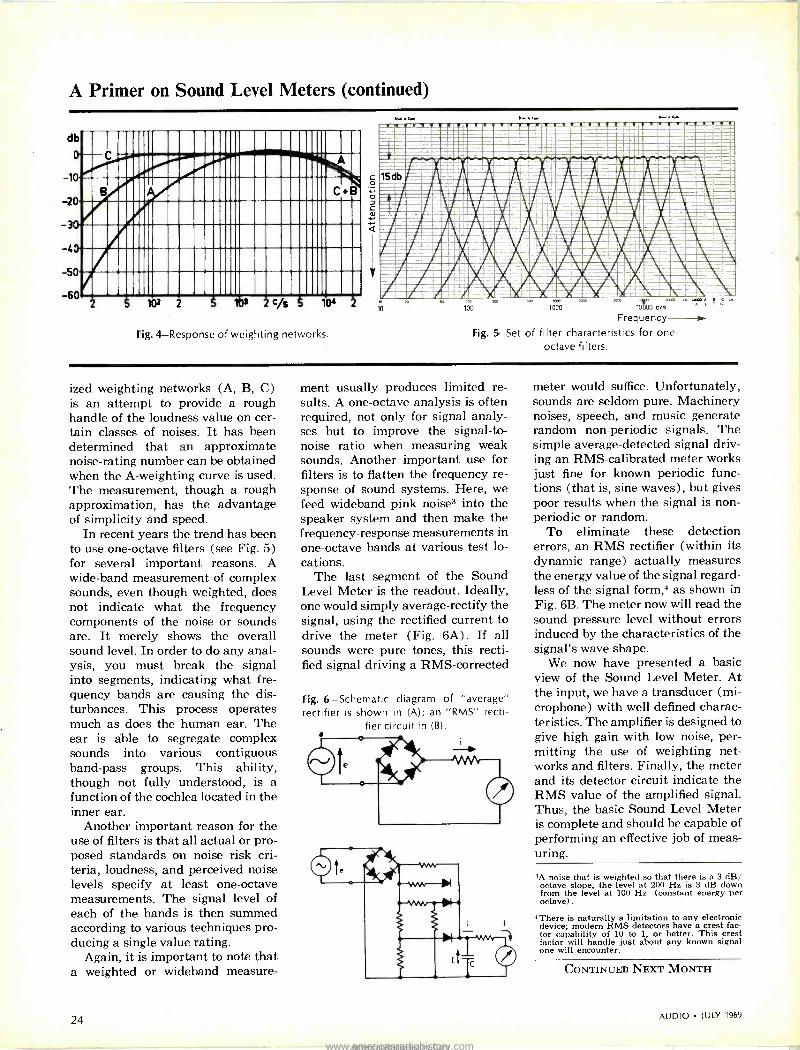
A Primer on Sound Level Meters (continued)
db n1111111 IIIIII1IIIIIII11
1
0 ,NÍIII!I/:i111111llllli:1 -20 Idilllllllllllillllll _3, Il115II1111111I11131311111I1111
11151111111111111111111111111111111111
50 50 FI1111111111111111111111111111111
2311111113111111111111111111111111 -60 102 2 10
Fig. 4-Response of weighting networks.
c o ó D
w..
1
psi =--:szeMBaeam :=Nemmrmmosam_ SdbM
AIÀIAA
bud
=OzErm
;===; vmmia=asan,aramoni
111/1N/111 AILAWILTMéeIMIL irvsZ,iA
Visauso,mmv'=
:.=asa = lür' . . 1 ,äk=-1b 100 Zoo
Frequency -
Fig. 5-Set of filter characteristics for one - octave filters.
,000
ized weighting networks (A, B, C) is an attempt to provide a rough handle of the loudness value on cer- tain classes of noises. It has been determined that an approximate noise -rating number can be obtained when the A -weighting curve is used. The measurement, though a rough approximation, has the advantage of simplicity and speed.
In recent years the trend has been to use one -octave filters (see Fig. 5) for several important reasons. A wide -band measurement of complex sounds, even though weighted, does not indicate what the frequency components of the noise or sounds are. It merely shows the overall sound level. In order to do any anal- ysis, you must break the signal into segments, indicating what fre- quency bands are causing the dis- turbances. This process operates much as does the human ear. The ear is able to segregate complex sounds into various contiguous band-pass groups. This ability, though not fully understood, is a function of the cochlea located in the inner ear.
Another important reason for the use of filters is that all actual or pro- posed standards on noise risk cri- teria, loudness, and perceived noise levels specify at least one -octave measurements. The signal level of each of the bands is then summed according to various techniques pro- ducing a single value rating.
Again, it is important to note that a weighted or wideband measure-
ment usually produces limited re- sults. A one -octave analysis is often required, not only for signal analy- ses but to improve the signal-to- noise ratio when measuring weak sounds. Another important use for filters is to flatten the frequency re- sponse of sound systems. Here, we feed wideband pink noise3 into the speaker system and then make the frequency -response measurements in one -octave bands at various test lo- cations.
The last segment of the Sound Level Meter is the readout. Ideally, one would simply average -rectify the signal, using the rectified current to drive the meter (Fig. 6A) . If all sounds were pure tones, this recti- fied signal driving a RMS-corrected
Fig. 6 -Schematic diagram of "average" rectifier is shown in (A); an "RMS" recti-
fier circuit in (B).
meter would suffice. Unfortunately, sounds are seldom pure. Machinery noises, speech, and music generate random non -periodic signals. The simple average -detected signal driv- ing an RMS-calibrated meter works just fine for known periodic func- tions (that is, sine waves), but gives poor results when the signal is non - periodic or random.
To eliminate these detection errors, an RMS rectifier (within its dynamic range) actually measures the energy value of the signal regard- less of the signal form,4 as shown in Fig. 6B. The meter now will read the sound pressure level without errors induced by the characteristics of the signal's wave shape.
We now have presented a basic view of the Sound Level Meter. At the input, we have a transducer (mi- crophone) with well defined charac- teristics. The amplifier is designed to give high gain with low noise, per- mitting the use of weighting net- works and filters. Finally, the meter and its detector circuit indicate the RMS value of the amplified signal. Thus, the basic Sound Level Meter is complete and should be capable of performing an effective job of meas- uring.
,A noise that is weighted so that there is a 3 dB/ octave slope, the level at 200 Hz is 3 dB down from the level at 100 Hz. (constant energy per octave).
*There is naturally a limitation to any electronic device; modern RMS detectors have a crest fac- tor capability of 10 to 1, or better. This crest factor will handle just about any known signal one will encounter.
CONTINUED NEXT MONTH
24 AUDIO JULY 1969
www.americanradiohistory.comAmericanRadioHistory.Com

"The finest loudspeakers I've ever listened to, regardless of size, type or price:'
That's how Ronald M. Benrey, electron- ics editor of Popular Science, described a pair of Rectilinear III speaker systems in the May 1968 issue of his magazine, in an article on "The Stereo System I
Wish I Owned." Mr. Benrey went on to justify his
ranking of the Rectilinear Ill's: ''They produce beautiful bass tones
without boom, accurate midrange tones without a trace of coloration, and crys- tal-clear treble tones without a hint of harshness. And they do it at any vol- ume, including 'window -raffling' sound levels."
Of course, one expert's opinion may differ considerably from another's. But here's what Julian D. Hirsch wrote in the "Equipment Test Reports" of Stereo Re- view, December 1967:
"The Rectilinear Ill ranks as one of the most natural -sounding speaker sys- tems I have ever used in my home. Over a period of several months, we have had the opportunity to compare it with a number of other speakers. We have found speakers that can outpoint the Rectilinear Ill on any individual charac- teristics-frequency range, smoothness, distortion, efficiency, dispersion, or transient response. However ... none of the speakers combine all of these properties in such desirable pro- portions as the Rectilinear Ill."
Summing up his test report, Mr. Hirsch concluded: "In our opinion, we have never heard better sound reproduction in our home, from any speaker of any size or price."
Of course, both Mr. Benrey and Mr. Hirsch write for the readers of popular, large -circulation magazines. But here's what Larry Zide wrote for the more specialized audience of The American Record Guide ("Sound Ideas" column, October 1968):
"The transient response of the speaker is superb ...the overall quality is extreme in its fidelity to 'live' music. The bass is solid and firm, the midrange is clear and neutral, and highs are bell - like in their cleanliness.
"It all comes down to this: there are only a handful of speakers that I find
completely satisfactory ... I have had these Rectilinear III units for a month now. Lately I have found myself listen- ing to them just for the pleasure of it. They are among the very best speakers on the market today."
Of course, all of the opinions above appeared in publications that accept advertising. But here's what Buyer's Guide magazine wrote in their August 1968 issue, just in case you're more in- clined to trust a consumer review with- out ads:
"Rectilinear Ill_ has had tremendous impact on the hi-fi industry... This speaker's virtue is the fact that it is the first and only full -range dynamic speaker system that possesses sound quality which is directly comparable to electrostatic speakers.
" ... Flute and violin concertos as well as string quartet were reproduced with honest clarity... Piano and organ music were effortlessly reproduced in a manner that suggested the instruments were being performed live. Jazz and rock music were unpretentious and true sounding..."
To such unanimity from such varied sources we need only add the dimen- sions and price of the Rectilinear Ill: 35" by 18" by 12" deep, $279.00 in oiled walnut.
(For further information, see your audio dealer or write directly to Rectilinear Research Corporation, 30 Main Street, Brooklyn, N.Y. 11201.)
Rec tilinear III
AUDIO JULY 1969
Check No. 25 on Reader Service Card
25
www.americanradiohistory.comAmericanRadioHistory.Com

A New Use for intermodulation Tests NORMAN CROWHURST
Selection of specific pairs of frequencies will permit the determination of various kinds of distortion not found by simple harmonic or conventional IM distortion methods.
MEASURING DISTORTION has al- ways presented a variety of problems. Back in the days
when fidelity meant extent of the fre- quency range, in both directions, the part played by harmonic distortion was identified as inconsequential, provided it was less than 5 per cent! This was verified by checking how little distortion could be detected, when it was alternately added and removed, using a single -tone signal.
Quickly after that, enthusiasts dis- covered that forms of distortion from equipment measuring less than 5 per cent could spoil reproduction. This was when intermodulation distortion first achieved notoriety.
Meanwhile, the talking picture business (as it was known then) had introduced the SMPE test for its own reasons. Harmonic distortion is difficult to measure, from almost any recorded medium, but especially from film. The overall gain, from re- cording through processing to play- back, can change, without causing distortion per se. But the distortion meter sees this gain change as dis- tortion. And speed fluctuations that might not matter as flutter or wow, can also show on the meter as distor- tion.
Added to this was the fact that the most prominent form of distortion that beset film recording was the kind their engineers went after de- tecting: that which occurs due to a variation of gain around the large envelope of a low -frequency wave.
The fact that the SMPE was use- ful for its particular test purpose led to trying it for other purposes, for some of which it was also useful. Am-
plifiers with inferior output trans- formers are likely to cause it. But there are other forms of distortion that do not coincide with the occur- rence of the SMPE form, and which that test would not detect.
Meanwhile, directed to detecting the more common form of distortion, the CCIF method was devised in European countries. This uses two higher frequencies and then you look (or listen) for the buzz, the differ- ence frequency between them, as a distortion product. As many writers, including myself, have repeatedly pointed out, this test only detects asymmetrical distortion - the same kind of transfer nonlinearity that produces second harmonic of a sin- gle test frequency.
That this difference -frequency product is related to the practical effects on reproduction, more defi- nitely than is harmonic distortion, can easily be demonstrated. But the fact remains that, using say 7000 and 8000 Hz as test frequencies, and looking for 1000 Hz as the distortion product, only discovers the equiva- lent of second -harmonic curvature.
Intermodulation Testing Discarded
With the advent of feedback and push-pull amplifiers, this kind of curvature, if not nonexistent, is much less serious than some other forms. This is why, after giving the various known forms of test a workout under practical conditions, the people who specify amplifier and receiver test methods have reverted to harmonic distortion as the more practical to use.
But before this happened, Emory
Cook, of binaural record fame, de- vised a test for detecting distortion in record -playing equipment that used the CCIF method a little dif- ferently, and usefully for his pur- pose. He applied one of the test tones as a steady note, and keyed the other to correspond with the Morse code for N (- ).
These test tones differed by 1000 Hz. He then keyed a 1000 -Hz tone with the code for A ( -) , so ar- ranged that the two codes interlaced exactly (Fig. 1) . In using the test, you ignored the higher frequency sounds, which changed, so as to ap- ply the test at different frequencies, and concentrated your attention on the 1000 -Hz tone.
The 1000 -Hz reference tone was applied at a level that, if the inter - mod on playback was exactly 2 per cent, you would hear a steady -sound- ing 1000 -Hz tone, because the inter- laced effects would have exactly the same level. If the A signal predomi- nated, the distortion was less than 2 per cent, if the N signal did, it was more.
As the major form of distortion was likely to be the equivalent of second harmonic, due to incorrect tracking or a side force on the pick- up, this test served its purpose well.
One reason for needing a test of this kind, as opposed to a simple har- monic test, remains. This is espe- cially true for measuring the perfor- mance of a tape recorder, in both the record and playback functions. If you try to measure distortion by har- monic measurement, any fluctuation of speed or amplitude will appear as out -of -balance, and show up errone- ously as harmonic distortion.
26 AUDIO JULY 1969
www.americanradiohistory.comAmericanRadioHistory.Com

The difference -frequency method is ideal for this purpose, if its limi- tations could be overcome. This is why we decided to take a second look at this possibility. The first step was to analyze mathematically the products of various orders of dis- tortion.
We really want to check mid -band distortion, so we'll assume the test signals are 1000 and 1100 Hz. Curva- ture that would produce second -har- monic distortion will produce the second harmonics of these two fre- quencies, 2000 and 2200 Hz, along with the sum and difference frequen- cies, 2100 and 100 Hz.
The 100 Hz is used to detect the distortion, because it is easier to sep- arate from the original frequencies.
Now suppose there is symmetrical distortion of the lowest order, that would produce third harmonic of a single tone. This would produce the third harmonics, 3000 and 3300 Hz, of the original frequencies, which we will designate f, and f to show deri- vation of other product frequencies. It will also generate two difference frequencies, 2f, - f, and 2f, - f,, which are 900 and 1200 Hz, and two sum frequencies, 2f, + f, and f, + 2f2, which are 3100 and 3200 Hz.
The difference frequencies are dif- ficult to separate from the original frequencies, and the sum frequencies are almost identical with the har-
monics. The method has no advan- tage over harmonic measurement, using this choice of frequencies.
Next suppose that asymmetrical distortion includes fourth harmonic as well as second. In addition to the components listed for second, the distortion will contain two fourth harmonics, 4000 and 4400 Hz, three difference frequencies, 3f, - f 21, - 2f,, and 3f,, - f ,, which are 1900, 2000, and 2300 Hz, and three sum frequencies, 3f, + f 2f, + 2f, and f, + 3f2, which are 4100, 4200 and 4300 Hz.
Here one of the difference frequen- cies is relatively easy to separate, being twice the frequency used to de- tect the presence of pure second - harmonic curvature. The others are close to the other harmonic products, and difficult to separate.
Finally, suppose that symmetrical distortion produces the next order, which would yield third and fifth harmonics from a single frequency. This would produce in addition to those listed for the lowest order sym- metrical, the fifth harmonics, 5000 and 5500 Hz, along with four differ- ence frequencies, 4f, - f,, 3f, - 2f2, 3f, - 2f,, and 4f,, - f,, which are 2900, 800, 1300, and 3400 Hz, and four sum frequencies, 4f, + f2, 3f, + 2f,, 2f, + 3f, and f, + 4f,, which are 5100, 5200, 5300, and 5400 Hz.
Again, these difference frequencies
are difficult to separate from the orig- inal frequencies, and the sum fre- quencies are close to the simple har- monics.
But why should the test frequen- cies used be restricted to those used to give the convenient detection fre- quency for first -order asymmetrical distortion? By changing our test fre- quencies, the difference products for various orders can be moved about.
A New Method Added Based on this premise, we decided
to use, as a detection frequency, 250 Hz. This was chosen, rather than a frequency as low as 100 Hz, to get further away from low -frequency roll -off, and into a region of good audibility (for aural detection) .
For the lower test frequency, we decided to use 1500 Hz, with what- ever higher frequency would yield 250 Hz as one of the difference prod- ucts for each particular order of dis- tortion. This avoids any direct oc- tave relationship, gives good spacing to enable the detection frequency to be separated from the test frequen- cies, and yet measures the distortion at frequencies that are representa- tively mid -band.
We have tabulated the results, to show sets of test frequencies for de- tecting each of the four distortion products. For each set of test fre- quencies, we have listed all the dis -
Table of Product Frequencies for Various Distortion Components Two -Frequency Input (CCIF-Type)
Test Frequencies
Second Harmonic Group Diff. Harm. Sum
Third Harmonic Group Diff. Harm. Sum
Fourth Harmonic Group Diff. Harm. Sum
Fifth Harmonic Group Diff. Harm. Sum
1500 250 3000 3250 1250 4500 4750 500 6000 6250 1000 7500 7750 1750 3500 2000 5250 5000 2750 7000 6500 2250 8750 8000
3750 6750 4250 8250 5500 8500
1500 1250 3000 4250 250 4500 5750 2500 6000 7250 1000 7500 8750 2750 5500 4000 8250 7000 1750 11000 8500 5250 13750 10000
6750 9750 3250 11250 9500 12500
1500 125 300 3125 1375 4500 4625 250 6000 6125 1250 7500 7625 1625 3250 1750 4875 4750 2875 6500 6250 1875 8125 7750
3375 6375 4375 7875 5000 8000
1500 625 3000 3625 875 4500 5125 1250 6000 6625 250 7500 8125 2125 4250 2750 6375 5750 2375 8500 7250 3375 10625 8750
4875 7875 3875 9375 7000 10000
AUDIO JULY 1969 27
www.americanradiohistory.comAmericanRadioHistory.Com

Fig. 1-The component signals for the A -N
code test, introduced by Emory Cook (see
/. A.E.S., Vol. 2, No. 1,
page 50, Jan. 1954).
FIRST TEST TONE- CONTINUOUS
SECOND TEST
REFERENCE
TONE- N -CODED
TONE A -CODED
Fig. 2-Basic test setup for applying this method to detect other orders of distortion.
CONSTANT TEST SIGNAL
KEYED TEST SIGNAL
A -N CODE GENERATOR
REFERENCE TONE
GATE
rJ
GATE
CC
X
RECORDER PLAYER
(being tested)
LOW-PASS FILTER (If nec.)
w
w
Fig. 3-The Lissajous pat- terns needed to secure correct frequency ratios for proper detection of the various distortion or- ders. The numbers along the bottom and sides in- dicate the frequencies in those directions to pro- duce the steady pattern
indicated.
e ; ,-1500-
T 0
T -
(-1500-+
(-1500-+
1500->
T
1.0
1
tortion products of the combination. In each case, the higher order in- cludes the frequencies from the lower order of the same kind (which are not listed, to avoid unnecessary dup- lication) .
This means the symmetrical fifth curvature will generate those listed for third, as well, and the asymmetri- cal fourth willeenerate those listed for second, as well. However, the fre- quencies associated with the lower order may undergo phase reversal or cancellation at certain levels of mea- surement, if both orders of distortion are present together.
To make the tests meaningful, a 250 -Hz signal is generated as a ref- erence and, borrowing from Cook's method, this reference tone is keyed with A -code, while the second test tone is keyed with the N -code. To obtain an exact reading of various orders of distortion, the reference signal can be varied in amplitude by means of a calibrated attenuator, in- dicating equivalent percentage di-
rectly, when the setting is nulled to yield an apparently steady tone, without either A or N code predomi- nating.
There may be slight clicks due to phase shift of the 250 -Hz tone heard at the keying moments, but these will not be audibly related to the tone for which you are listening. They will sound like keying clicks (even if they are electronically generated).
Figure 2 shows the complete setup in block schematic form. For low or- ders of distortion, such that the 250 - Hz level would be very much lower than that of the test tones, a steep roll -off filter can reduce the level of higher -frequency output products, after playback, to low enough level not to interfere with listening to the 250 -Hz tone.
To ensure that the code signal dis- appears when null is achieved, the distortion product for which you are listening must have a frequency identical to the reference tone. Only a small error in test frequency rela-
tionship, particularly for the higher order measurements, will rapidly shift the frequency, so the code is audible as a change in pitch.
If all the frequencies change in step, as by a variation in recorder speed, either during recording or playback, this will not affect the dis- tortion products and the reference frequencies being identical, because the same frequency ratios will pre- vail.
Calibration Procedure
A relatively simple way to set up the correct frequencies, using fine frequency adjustment, is to employ Lissajous figures to relate the ref- erence tone to the lower test tone, and to relate the upper test tone to the lower test tone. Figure 3 shows the complete set of Lissajous figures for the purpose.
Frequency should be adjusted so these patterns hold absolutely steady on the oscilloscope screen. Finding the more complicated ones may re -
28 Check No. 29 on Reader Service Card - www.americanradiohistory.comAmericanRadioHistory.Com

match your auto -turntable to the quality of a Sherwood 6000
The No -Compromise "Sound Center" for Limited Space. Now get maximum performance in a mini -space! Sherwood's new 6000 is the full -feature, 120 -watt music power AM/FM "STEREO SOUND CENTER" tiat provides unlimited choice of matching components. Choose any automatic turntable*-any magnetic cartridge. Mount pelectly on the pre-cut oiled walnut cabinet. Choose any speaker. Big or little, low or high efficiency. Your Sherwood 6000 has the power to spare for clean, pure, wall-to-wall sound. Compare features. FET FM tuner for ultra -sensitivity. Front -panel tape dubbing and headphone jacks. Stereo and mono extension speakers. As the high-performance heart of the finest component system, :he Sherwood 6000 takes no more space than "compromise compacts." It's the modern solution to big sound in small space. Features: 120 watts music power, 1.8 iv IHF sensitivity -95 db crossmodulation rejection, automatic FM stereo switching, zero -center tuning meter, front and rear panel tape inputs/outputs, mono speaker outpu:. Perfect match for your 6000-Sherwood's new Berkshire II speaker system: slim 9" deep cabinet with 12" woofer, 5" mid range, 160° "omni-polar" tweeter, 28-22,000 Hz response.
INNOVATORS IN FINEST QUALITY TUNERS / AMPLIFIERS / RECEIVERS / SPEAKERS
4300 North California Avenue, Chicago, Illinois 60618 Write Dept. 7_ A
*Any of the Dual (current models) or Garrard SL55 or SL65.
wow
-------_""""`._
1'i
www.americanradiohistory.comAmericanRadioHistory.Com

quire some practice. The easiest way to identify the patterns is by noting carefully three things about each:
(1) counting the rows of crossings across the pattern, vertically and horizontally;
(2) checking that the two "loose ends" are at either left or right side, or at opposite corners; but not at the top or bottom;
(3) noting the slope of the line parts that cross near the center of the pattern.
A little more explanation of the patterns will help understand this procedure. With 1500 Hz as the ref- erence frequency (for Lissajous pat- terns) presented horizontally, the 250 -Hz reference tone gives the pat- tern at the top of Fig. 3, which is not difficult to identify; for the patterns that represent closer frequency -ratio intervals, the other factors we de- scribed tells the following things about the ratio between frequencies displayed.
The number of crossings across the screen tells the magnitude of the highest common factor of both fre- quencies. The 1500:1750 pattern is really a 6:7 pattern, and the highest common factor of the frequencies is one sixth of one and one seventh of the other. Consequently there are five crossovers vertically and six crossovers horizontally, across the pattern (not counting the outside
edges) . In each case, one less than the relevant multiple of the common factor.
The 1500:2125 pattern is really a 12:17 pattern, the highest common factor in frequency being 125 Hz. So there are eleven crossings vertically (five above and five below the center line row) and sixteen horizontally (two sets of four on either side of the center line, on which no crossings fall) .
Counting crossings, in rows each way, is the most reliable check. The others help confirm the finding. Lo- cating the loose ends determines which frequeny has the odd numeral of the basic number ratio. The odd numeral pertaining to the vertical deflection frequency causes both loose ends to be either left or right. The odd numeral pertaining to the horizontal frequency causes both loose ends to be either top or bottom.
If both numerals of the basic ratio are odd, the loose ends appear at opposite corners. Both numerals of a basic number ratio cannot be even, because this would mean the ratio is not basic, both numerals having a common factor of 2.
If, for example, the basic fre- quency ratio happens to be 7:8, in- stead of 6:7, both loose ends would appear either top or bottom, "al- though otherwise the pattern would look quite similar (in line density)
Fig. 4-A more complete illustration of the test setup discussed in the text.
SCOPE
HOR VER
NEW IM TEST SET
0
01) FIXED FREQUENCY
FINE TUNING
0 0 9 0 FREQUENCY
coo
47- '/ A -N CODE
GENERATOR
REFERENCE FREQUENCY
0
O
GATE
' GATE
C.7w (7)X - w
PRESET ATTEN. FOR
FUNCTION
s,,. 1 3 40
CALIBRATED ATTEN. ó
0
INPUT TEST
.
SIGNAL ATTEN
TO RECORDER
PLAYBACK SI NAL
LOW- PASS
FILTER
LISTENING DETECTOR
to the 6:7 pattern. The frequencies thus represented might be 1500 and 1715 Hz.
And if the basic ratio should be 5:7, the loose ends would be at op- posite corners, although the frequen- cies would be further off, an example being 1500 and 2100 Hz. The density would be similar to the 5:6 or 6:7 patterns.
The final check feature is the slope of the lines crossing the middle of the pattern. For example, a 12:19 pattern would be quite similar to the 12:17 pattern in that both loose ends would be at one side, and the density would be similar. But the crossing of the center line would be slightly steeper. The frequency of the upper frequency would be 2375 Hz. Here the crossing count is the more re- liable check.
With this help, it should be easy to identify each pattern. Using spe- cially built oscillators, of which one is switchable in frequency, the ad- justments will need to be made as a setup procedure only.
When setting up your frequencies, first check that the reference fre- quency is precisely one sixth of the lower test frequency. Being precisely 250 or 1500 Hz doesn't matter, so long as the ratio is correct. Then for each higher test frequency, adjust its frequency on a preset fine tuner that is switched to change test frequency, until the desired stationary pattern is obtained.
The rest of the test setup can in- clude a preset attenuation in the ref- erence -frequency input to the mixer, so that the same setting on the cali- brated attenuator represents the same percentage of that order of dis- tortion as on other positions for other orders. Figure 4 shows the controls for the complete test setup, including the output filter.
In testing a recorder that uses the same amplifier for record and play- back, voice announcements may be used to record the settings, so the distortion levels can be identified on playback. With a recorder where the playback can monitor recording, the adjustment can be made and the reading obtained directly, without any need for replaying.
30 AUDIO JULY 1969
www.americanradiohistory.comAmericanRadioHistory.Com

THE CASE OF THE MYSTERIOUS HIDDEN MUSIC...
70
I I
ELECTRONIC SUSPENSION SYSTEM
convent'onal two -wire system.
\.MnnNveA,
300 100 500 loo 1000 1500 2000 3000 1000 5000 7000 10000 15000 20000 2500(
FREQUENCY Nr
. and how it was solved by an LWE Electronic Suspension speaker.
THE MYSTERY: When we recently introduced our patented Electronic Suspension speakers many new owners uttered this strange comment, "Suddenly I heard music on my records I've never heard before. I felt like I was standing right in the recording studio. Where did this won- derful `hidden' music come from?" THE SOLUTION: We discovered that most of this "hidden" music is in the bass range below 100 Hz. This is where the response of con- ventional speakers drops off rapidly - except for resonant peaks which produce only an artifical boomy sound. The above chart shows the frequency response of a standard LWE I Speaker* - with and without Electronic Suspension. Here's the evidence that proved Electronic Suspension produces a smoother, non -resonant response extending below 20 Hz. - far superior to that of any conventional two -wire speaker. THE MORAL: LWE outperforms any comparable priced speaker on the market today. Prices range from $75 (LWE Instant Kit) to $550 (LWE II). Hear LWE at your dealer or write today for LWE's "Sound of Excellence" brochure. Simply a great buy.
ACOUSTRON CORPORATION / 2418 Bartlett Street Houston, Texas 77006 / Phone: (713) 524-7407
AUDIO JULY 1969
`LWE I is a 3 -way system in oiled walnut with 05" woofer and horn tweeter, $250. Optional base, $12.00.
Check No. 31 on Reader Service Card 31
www.americanradiohistory.comAmericanRadioHistory.Com

Preamplìtìer
Measurements
James Bongiorno*
The author examines methods used to test audio preamplifiers, emphasizing how to avoid traps that can cause erroneous measurements
IT'S NOT UNCOMMON TODAY to find component stereo amplifiers with total harmonic distortion ratings of
0.3 or 0.4 per cent; some are even lower. As a consequence, measurement equipment and techniques that were once most satisfactory for laboratory test purposes no longer give valid re- sults in many instances.
The purpose of this article is to ex- plore test methods for preamplifiers, (where distortion figures are particu- larly low) that will produce accurate, meaningful measurements.
In examining preamplifiers - the audio amplifier section that precedes the power amplifier (whether it is a separate control amplifier or part of an integrated amplifier or receiver)-we are dealing with only low-level voltage measurements. Thus, this component or section of a component covers every- thing up to the final power amplifier, which requires high-level power mea- surements.
The most important specifications for a preamplifier are: frequency re- sponse, noise, distortion, overload level, and overload recovery. Frequency re- sponse is probably the easiest to mea- sure since only an accurate voltmeter and a good generator are required (ideally, however, a scope should be used to monitor all measurements). Before making such tests (for high- level input) the oscillator should be checked to determine its variation in decibels. This procedure should be made with the volume control at its electrical center and the unit driven to its rated output. Figure 1 shows the test setup.
With the volume control at its elec- trical center, the greatest amount of capacitance will be in the circuit, which would affect the response accordingly. `Consulting Engineer
The standard practice of terminating the test cable with 100k ohms in paral- lel with 1000 pF is not subjecting the unit to the normal working environ- ment. This setup is supposed to show the influence of a 25- or 30 -ft. audio cable on a preamp's response. How- ever, most persons who use a separate preamp/power amp setup use only 3
or 4 ft. of cable. (Besides which, any- one using the real long cables should be using a terminated system to avoid high -frequency losses.)
Frequency Response Measurements
Checking frequency response using a preamp's phono input differs dramati- cally from that for a high-level input. The termination for a phono input should be similar to that of a phono cartridge. Whereas the phono front end might perform well when driven from the low impedance of the oscillator be- cause all the feedback voltage "sees" a virtual short circuit, this may not be the case when driven by a cartridge. The inductance of the cartridge-say, 700 mil-looks at 20 kHz like about 90k ohms in parallel with a cable ca- pacitance of about 80 pF terminated with 47k ohms. Thus, the feedback would be looking back at a complex impedance of around 23k ohms.
Most preamps would not be seri- ously affected since there should be sufficient loop gain to overcome this load. But some preamplifiers do not enjoy this margin. Therefore, the proper way to measure phono response is to use a test record, such as the CBS STR-100, and a calibrated cartridge.
It is very easy to calibrate any car- tridge by simply using a millivolt meter terminated with 47k ohms, and using the test record to obtain the response
of the record -cartridge combination, as in Fig. 2. Once this is done, it is easy to check the phono -amplifier response against the source response. Any devia- tion will be the amplifier's error. This will also hold true if the input imped- ance of the amplifier is other than 47k ohms, especially at high frequencies (due to input capacitance). Again, any deviations in response will be the error of the amplifier. Figure 3 shows how this is done. If you want to check the input impedance of the amplifier, simply insert a shielded 47k -ohm re- sistor in series with the input and mea- sure the response from 20 Hz to 20 kHz, as in Fig. 4. Any deviations in response, measured at the amplifier input after the 47k -ohm series resistor, signifies a change of input impedance.
It is also preferable to use the tape output for all front end measurements. If the tape output is not isolated with an emitter follower, then care must be exercised not to load the tape output, which would cause errors in measure- ments. Again, a short cable must be used.
Hum and Noise The next area of measurement con-
troversy is hum and noise. This is probably the most improperly spec'd and improperly measured parameter of them all. The practice of presenting a short circuit to the phono input is unfortunate because the preamp will never be operated under this condi- tion. Even using a shielded 10k -ohm resistor is meaningless because the ac- tual noise contribution will be a result of: (1) source resistance; (2) ambient temperature; (3) operating current (primarily of the input transistor); and (4) the effective bandwidth. Num- bers (2) and (4) are fairly constant, while (1) and (3) are variable.
The RIAA curve results in an ap- proximate bandwidth of around 5 kHz, but there might be some difference in noise data due to the high -frequency response of the network. Some manu- facturers continue the rolloff after 20 kHz, as shown in Fig. 5, while others bring it back around as shown by the dótted curve. While the first gets rid of one evil, it introduces another one. Rolling off the response above 20 kHz will reduce the noise contribu- tion above 20 kHz, but will cause both the transient response and the overload recovery to suffer. Bringing the re- sponse back will preserve the good transient response and overload recov- ery, but it allows some noise contribu- tion above 20 kHz. For proper noise measurements in the audio band, how- ever, a filter must be used so this dis -
32 AUDIO JULY 1969
www.americanradiohistory.comAmericanRadioHistory.Com

The nonesuch
Shapes, shows, and stores sound spectra like no single instrument should.
By rights, no bandpass filter set should be able to do what B & K's Model 123 does.
But here it is doing it. Shaping sound spectra by dividing input into 36 one-third octave bands. What other instrument shapes it so fine?
Then vertical attenuators, mounted in two rows on the front panel, form a visual configuration of the set-in spectrum shape. What other instrument shows it so clearly?
And finally, a detachable memory bar recreates any previously recorded spectrum in seconds. What other instrument stores it for recall so easily?
See? The 123 shouldn't exist. But it does. Maybe you can find a use for it in the lab, sound studio, or classroom.
Write. We'll send you the vital statistics. Judge for yourself whether we've created a monster or a miracle.
B K INSTRUMENTS, INC. Gruel 8a Kjaer Precision Instruments
5111 West 164th Street Cleveland, Ohio 44142 Phone 1216) 267-4800 TWX 1810) 421-8266
'ì
Model 123 variable bandpass filter set with separate one-third octave control. Frequency range from 22 Hz to 45 kHz. Down to 11 Hz with Model 1620 extension filter set.
Also available, the "Second Generation" None- such ... with all the features you've asked for!
AUDIO JULY 1969 Check No. 33 on Reader Service Card
33
www.americanradiohistory.comAmericanRadioHistory.Com

Sansui 5000. 180 watts S449.95
SANSUI ELECTRONICS CORP. Woodside, Nev Yyk, 11377 Lps Pr geles, Ca ifon a 20(07
SIh SUI ELECTRIC CO.. LTD.. Tokyo. Ja pan Eu wean Office Frankfurt a.M.. West 3erreiw Electrcric Distributors (Car ada). ants.* Co u rbia
34 Check No. 34 on Reader Service Card
AUDIO IULY 1969
www.americanradiohistory.comAmericanRadioHistory.Com

Sansui Stereo Control Amplifier AU -222 46 watts
I w Sansui Stereo Control Amplifier AU -555 60 watts
Sansui Stereo Control Amplifier AU -777 70 watts
"and new speaker systems, new power amplifiers, and multi -channel dividers"
Check No. 35 on Reader Service Card AUDIO JULY 1969 35
www.americanradiohistory.comAmericanRadioHistory.Com

Fig. 1-High-level frequency response. Fig. 2-Cartridge calibra-
tion. Fig. 3-Measuring a preamp's phono response using a previ-
ously calibrated cartridge. Fig. 4-Measuring phono input imped-
ance. The oscillator is swept from 20 Hz to 20 kHz. Meter indication
should be half of the oscillator's output. Fig. 6-Measuring phono
noise. Adjust coil for inductance of approximately 700 mH at 20
kHz. Fig. 7- Measuring high-level distortion. Fig. 8-Measuring
high- frequency distortion on phono. Eliminate the filter
for low- frequency measurements.
OSCILLATOR
FROM MAIN OUTPUT
HIGH LEVEL
INPUT
ri,
4 FEET MAX.
©©(3
A.F. VOLT METER
PREAMP "ELECTRICAL SET AT
ELECTRICAL CENTER =
SCOPE
2
TEST RECORD
3
A.F.VOLTMETER SCOPE
PREAMP
TEST RECORD 'n'' TO PHONO
H INPUT
FROM TAPE
OUTPUT
0@0® PREAMP
47K
Y
H
A.F. VOLTMETER SCOPE
H 0
cussion is academic with respect to measurements. This filter should be a sharp cutoff 20 -kHz filter and should not load the device being tested.
The biggest test discrepancy lies in the effective source resistance. Con- trary to popular belief, any amplifier will have it's lowest noise figure when its input is short circuited. However, this is not the operating mode of the unit, as previously mentioned. A fur- ther error is generally made in inter- pretation. The only proper and mean- ing ful way to spec noise is to reference it below a specific input signal right at the input.
If the equivalent input noise is 1 ft,v,
then the signal-to-noise ratio will be 1 p,v with respect to a given input sig- nal! The gain of the unit has to be taken into account also, and this is the real fault. An example will clear this up, hopefully. Two units, A and B, have gains of 48 dB and 60 dB, respec- tively. If each has a rated output of 1
volt rms, then the input sensitivity is 4 mV and 1 mV, respectively. Now if unit A had 2 ft,V of input noise and unit B 1 f,t,V, which is quieter? In truth, unit B is quieter. But, depending on how the manufacturer rates the prod- uct, unit A can be made to look quieter. For example, if the manufacturers specs unit A as having a noise figure of 66 dB (2 i.t,V re: 4 mV), then unit A specs better than B. What the con- sumer isn't told is that, while the sig- nal-to-noise ratio of unit B only specs at 60 dB (1 ft,V re: 1 mV) , it is actually twice as good as B because it has 12 dB or four times as much gain. This makes
its signal-to-noise ratio 72 dB below 4 mV. This could be corrected by speci- fying noise in microvolts referred to a 1 -mV signal.
Consider, too, the fact that most cartridges don't put out the amount of signal that is implied because most cartridges are rated at a recorded ve- locity of either 3.54 or 5 cm per second. In other words, a cartridge rated for 5 mV output probably produces about 1 mV per centimeter. If the highest peak modulation on a record groove is around 40 centimeters, then the aver- age recording level will be around 26 dB lower (and probably more). There- fore, 1 mV represents a good average, and to get a signal-to-noise ratio of 60 dB we must have no more than 1 /IV of noise at the input.
In reality we will not get the 1 ftV mentioned above. The proper way to spec and measure noise is to present the input of the amplifier with the ac- tual source condition that it will see in actual use, as in Fig. 6. What better way to measure noise than to have the input loaded by the cartridge itself or its equivalent? With the cartridge con- nected, the lowest source resistance the input will see at high frequencies is around 2Ok ohms, which is a far cry from a short circuit! When using this technique the small hum contributions from the cartridge must be taken into account, of course. It should be obvious that this method results in a noise fig- ure which even though it is correct, will be significantly worse than one speci- fied with an unrealistic source.
Measuring noise on the high-level
inputs should be done with the volume control at its electrical center, which will provide the highest or worst -case source resistance. It should be under- stood that at this setting the noise fig- ure must be at least 30 dB higher than the incoming signal, and not the as- sumed 6 dB, as has often been stated. The 6 -dB margin would only apply if the preamp were run wide open or at full volume, which is obviously never the case.
For example, assume that the gain from the volume control to the loud- speaker is around, say, 20 dB for the high-level section plus 26 dB for the power amp = 46 dB total. Further as- sume that the signal-to-noise ratio is 80 dB below full output. This may seem fine, but we are not operating at full power. As a matter of fact, for most speaker systems we will be operating at least 26 dB below full power which, below a reference of 50 watts is around 125 mW. We have therefore lost 26 dB in noise figure and are now operating with a 54 dB noise figure. In view of this, it becomes clear that the high- level stages are just as important as the low-level ones in designing for low noise.
Distortion Measuring the distortion products of
low-level signals is difficult. If one is not extremely careful, the results can be grossly inaccurate. Not only is a scope necessary, there is also a special technique that should be used for proper evaluation. For measuring total harmonic distortion (THD), a distor-
36 AUDIO JULY 1969
www.americanradiohistory.comAmericanRadioHistory.Com

4
OSCILLATOR
SHIELDED 47K RESISTOR
6
NOTE: REMOVE STYLUS &
WRAP CARTRIDGE COMPLETELY IN FOIL.
CARTRIDGE
OR
A. F. VOLTMETER Il e
TO PHONO INPUT
Lo0o® PREAMP
SHIELDED COIL
180-750 mH. 620 Sl '
MILLER *9009
o o
o
A.F.VOLTMETER
FROM TAPE
PREAMP
SCOPE
V
o
H o
SCOPE
FILTER (24 dB / OCTAVE
LOW PASS )
7
OSCILLATOR d '/.
8
OSCILLATOR
TO PHONO INPUT
DISTORTION ANALYZER
7-)(
FROM MAIN OUTPUT
PREAMP
FROM TAPE
OUTPUT
PREAMP
00
DISTORTION ANALYZER
FILTER
(24 dB/OCTAVE HIGH PASS)
SCOPE
SCOPE
tion analyzer and a scope should be used, the latter in X -Y fashion to ob- tain lissajous patterns. Either input- output or output -output can be used. I prefer the latter because it eleminates any chance of ground loops and also eliminates most phase errors due to the measuring equipment.
The test setup is shown in Fig. 7. The accuracy of this method will be dependent solely upon the accuracy and residual distortion of the measur- ing equipment. With component ampli- fiers' great reduction of distortion dur- ing the past few years, measuring equipment should have a residual dis- tortion of less than .01 per cent.
dB
.20
.10
0
-10
-2o
100 1k 10k 100k FREQUENCY (Hz)
Fig. 5-Solid curve shows required equali- zation for RIAA response, while dotted curve shows preferred response for better
transient performance.
The Hewlett-Packard 331A -334A series of distortion analyzers has served me well in this respect. The unit has a 4 -MHz bandwidth, to boot, which is necessary for wideband measure- ments. This is where other analyzers fail, especially the low-cost kits: they don't have anywhere near the required bandwidth for measurments on sophis- ticated electronic equipment. The price
of the H -P starts at around $640, un- fortunately, which places it out of the experimenter's class.
When measuring high-level inpuits no special precautions are necessary other than avoiding overload, espe- cially the tone controls, as there should be more than adequate noise margin. However, I always measure tone -con- trol sections at the extremes because most controls today are negative -feed- back controls, which sometimes add considerable distortion when in the boost positions, where feedback is re- duced to achieve more gain.
Measuring distortion of the phono front end is tedious, and takes lots of patience. Also, consideration must be made of the RIAA curve which has an equalization spread of around 38 dB from 20 Hz to 20 kHz. This means that the 20 -Hz gain will be approximately 80 times the 20 kHz gain. Although there won't be any problems measuring the low -frequency distortion, it might be impossible to measure the high fre- quencies unless a filter is used. Since most of the noise in the front end is 1/f or low -frequency noise, it will be amplified 80 times as much as the high - frequency test signal. Also, due to the 38 dB difference in gain, the signal-to- noise ratio of the oscillator will auto- matically be degraded by this factor of 38 dB. In addition, any residual flux in the area will probably leak right into the setup and its cables, creating fur- ther problems.
When making these measurements all transformers should be oriented for lowest hum, along with cable orienta-
tion. Also turn off any Variacs in use. A good rule to follow is to turn off anything that has a transformer in it other than the specific equipment used for the test. It should be borne in mind that it only takes a couple of micro- volts of hum to wipe out a 1 -mV test signal completely. The filter should be a 1000 -Hz high-pass device with a 24 -dB -per -octave slope. Any distortion contributed by the filter will be meas- ured as total distortion and will be in- distinguishable from that of the front end. Therefore, the filter must have Practically zero distortion. Also, the filter should be located at the tape out- put and, as stated before, it should not load the device being tested. Figure 8 shows the equipment setup. Of course, anyone in possession of a wave analy- zer with 80 dB of rejection can consider himself very fortunate.
There is another method of measur- ing distortion which uses a null tech- nique. The method is useful but is susceptible to external fields if not properly shielded, and phase adjust- ments must be made. However, two great advantages do exist with the null method. One is that the generator doesn't have to have .01 per cent dis- tortion since the method is a cancella- tion technique. Secondly, frequency drift in the oscillator will not throw the null off as it will with a distortion an- alyzer.
Probably the hardest task is obtain- ing meaningful intermodulation (IM) measurements. There are two kinds of IM products: amplitude modulation
(Continued on page 61)
AUDIO JULY 1969 37
www.americanradiohistory.comAmericanRadioHistory.Com

AUDIO/FM INSTRUMENT SAMPLER The average hi-fi buff is never satisfied with the perfor- mance of his equipment, but unless he knows how to measure it and unless he has the equipment with which he can make meaningful measurements, he can never be sure that his dissatisfaction is not purely in his imagina- tion. The well-equipped experimenter/hobbyist should have in his "shop" an audio generator, a sensitive a.f. voltmeter, and a distortion meter of some type-har- monic or IM-and possibly a wow -and -flutter meter. With these and a collection of test records and tapes, he should be able to "prove the performance" to his own
satisfaction, and he should also be able to find out what trouble (if any) does exist.
This sampling covers most of the suggested instruments, but does not include the usual volt -ohm -meter, which is assumed to be in every hobbyist's home, nor does it in- clude any oscilloscopes, which are most useful, but which are not in the list of "must" equipment for the non- professional.
For further information, check the indicated Reader Service Card numbers on the card following page 66.
AUDIO -FREQUENCY GENERATORS
Barker & Williamson Audio Oscillator, Model 210 covers from 10 to 100,000 Hz in four ranges. Output up to 10 V into 600 -ohm load with distortion less than 0.2°/o at 5-V output. Response is
flat within ±1 dB over entire range. Price, $326.25.
Check No. 70 on Reader Service Card
General Radio Co. Model 1311-A Audio Oscillator provides eleven frequencies selectable by a single dial, with a
vernier offering ± 20/o variation from the indicated frequency. Range is from 50 to 10,000 Hz, and output is continu- ously adjustable from 0 to 1, 3, 10, 30, or 100 V, while distortion is less than 0.590 at any linear load. Price, $295.00.
Check No. 73 on Reader Service Card
Century General Corp.'s MINIGEN MT
#4110 provides three stable frequen- cies -400, 1000 and 10,000 Hz-from a
housing Y/s x 4 x 1'/, in. Output is continuously variable from 0 to 2.5 V. Price, $14.95.
Check No. 71 on Reader Service Card
EICO Model 378 Audio Generator pro- vides switch -selected frequencies from 1 Hz to 110 kHz in four ranges. Out- put is continuously adjustable from 0
to 10 V into a high -Z load, in eight steps. Meter is calibrated in volts and dB, and 600 -ohm termination is se- lectable by a switch. Price, $59.95 in kit form, $79.95 wired.
Check No. 72 on Reader Service Card
Heathkit Model IG -72 Audio Genera- tor. 10 Hz to 100 kHz with less than 0.1°/o distortion. Output from 0 to 10 volts continuously variable through eight ranges. $44.50 kit, $64.95 wired.
Check No. 74 on Reader Service Card
Hewlett Packard Model 209A Sine/ Square oscillator. 4 Hz to 2 MHz con- tinuously variable over six ranges. Out- put is 5 V into 600 ohms, 10 V open circuit. $320.00.
Check No. 75 on Reader Service Card
Lafayette Model TE -22 Sine/Square wave audio generator. Continuously variable output over four frequency ranges from 20 Hz to 200 kHz. $32.50.
Check No. 76 on Reader Service Card
RCA Model WA -504A solid-state sine/ square audio generator. 20 Hz to 200 kHz in four ranges. Has a 10:1 step at- tenuator and continuously variable out- put control. $95.00.
Check No. 77 on Reader Service Card
38 AUDIO JULY 1969
www.americanradiohistory.comAmericanRadioHistory.Com

RADIO -FREQUENCY GENERATORS
Knight -Kit KG -687 Sweep/Marker Gen- erator, for alignment of FM and TV receivers. Covers from 3 to 220 MHz in' five bands, all on fundamentals. Variable sweep width, with marker sig- nals post -injected from 2 to 75 MHz. $120.00 (kit).
Check No. 78 on Reader Service Card
Lafayette TE -20 r.f. Signal Generator. Covers from 120 kHz to 130 MHz in 6 bands, plus a calibrated harmonic band from 130 to 260 MHz. 400 -Hz audio oscillator with separate output provides modulation, or external os- cillator may be used. $27.95.
Check No. 79 on Reader Service Card
STEREO MULTIPLEX GENERATORS
EICO 342 FM/MX Generator. Provides r.f. carrier with MX modulation or composite output, with 1000 -Hz modu- lation, and with or without 19 -kHz crystal -controlled pilot, or pilot signal is available separately. $175.00, wired.
Check No. 81 on Reader Service Card
Heathkit IG -37 Stereo Generator. Pro- vides 400, 1000, and 5000 Hz modula- tion of r.f. signal, with 19, 38, and 67 kHz for thorough multiplex testing. Incorporates three 20 -dB switched at- tenuators plus continuously variable controls. $79.95 (kit).
Check No. 82 on Reader Service Cord
DISTORTION METERS & ANALYZERS
Barker & Williamson Model 410 Distor- tion Meter. Measures audio distortion in five ranges to 1°/o full scale over band from 20 to 20,000 Hz. Also mea- sures a.f. signal in twelve full scale ranges from mV to 300 V. $347.25.
Check No. 85 on Reader Service Card
Crown Model IMA Intermodulation Analyzer. Solid-state unit measures to 0.1°/a full scale. Features built-in 60 - and 7000 -Hz internal oscillators and ultra -low residual of less than .005°/o. Accepts external modulation, and has outputs for 'scope inputs. $595.00.
Check No. 86 on Reader Service Card
RCA WR -52A FM Signal Simulator. Pro- vides 400, 1000, and 5000 -Hz audio, and 19- and 38 -kHz crystal -controlled frequencies in choice of right or left stereo, mono FM, internal test, and 60 - Hz FM sweep. Meter permits setting of signal levels. $248.00.
Check No. 83 on Reader Service Card
EICO Model 902 IM./Harmonic Distor- tion Meter. Provides IM generator sig- nals, individually adjustable as to level, and measures both IM and harmonic distortion to 0.3°/o full scale. Covers range from 20 to 20,000 Hz in three ranges. $250.00 (wired only).
Check No. 87 on Reader Service Card
Heathkit IM -12 Harmonic Distortion Meter. Measures distortion over range from 20 to 20,000 Hz in three bands on meter scales of 1, 3, 10, 30, and 100°/o. Also serves as a.f. voltmeter with ranges from 1 to 30 V. $65.00 (kit); $115.00 (wired).
Check No. 88 on Reader Service Card
Hewlett Packard Model 331A Distortion Analyzer. High -quality instrument mea- sures from 5 Hz to 600 kHz with full- scale sensitivity of 0.1°/o. Input sen- sitivity 0.3 V for 100°/o set -level refer- ence. Also serves as a.f. voltmeter with 0.3 -mV input sensitivity for full-scale indication. $650.00.
Check No. 90 on Reader Service Card
Measurements Model 188 FM Signal Generator. Provides accurately metered r.f. signal over range from 86 to 108 MHz, individually calibrated. Output from 0.1 to 100,000 µV, using mutual inductance attenuator. Internal fre- quency modulation at 400, 1000, and 10,000 Hz, or will accept stereo MX signal from external generator. $700.00.
Check No. 80 on Reader Service Card
H. H. Scott Type 830 Multiplex Gen- erator. Provides composite signal out- put up to 5 V (rms) maximum, pilot signal alone, with oscilloscope connec- tions for vertical and horizontal. Fully adjustable for pilot level and phase, and ideal for both laboratory or pro- duction testing. $600.00.
Check No. 84 on Reader Service Card
Waveforms 5246A Distortion Filter Set. Measures distortion at eight frequen- cies, including those required in FCC Proof -of -Performance reports. Resolu- tion is 0.1°/o full scale. $500.00. Model 514A is similar but includes audio oscillator module which provides full range of frequencies from 20 Hz to 10 MHz. $700.00.
Check No. 91 on Reader Service Card
Heathkit IM -22 Audio Analyzer: Serves as sensitive a.f. voltmeter and inter - modulation analyzer, with built-in gen- erators for test signal,. Provides inter- nal loads of 4, 8, 16, and 600 ohms when desired, or measures from un- loaded output. $69.00 (kit).
Check No. 89 on Reader Service Card
AUDIO JULY 1969 39
www.americanradiohistory.comAmericanRadioHistory.Com

WOW & FLUTTER METERS
Gotham Audio Corp. is the importer - distributor for the Woelke ME -104 Wow and Flutter Meter, which con- tains a 3150 -Hz generator (CCIR stan- dard) for the source, and a self -cali- brating meter with ranges of 0.3, 1.0, and 3.0°/o over a linear range from 0.5 to 500 Hz (-3 dB) $365.00. Model ME - 102B is similar, but with full-scale meter ranges of 0.1, 0.3, and 1.0°/o. $475.00.
Check No. 92 on Reader Service Card
AUDIO RMS VOLTMETERS B & K Instruments Type 2409 Electronic Voltmeter measures a.f. from 2 Hz to 200 kHz within 0.2 dB, with full-scale ranges in 10 -dB steps from 10 mV to 1000 V. Internal amplifier provides up to 60 dB gain from a 10-megohm input to a 50 -ohm output with a maximum of 10 V. $338.00.
Check No. 94 on Reader Service Card
EICO Model 250 a.c. VTVM and Am- plifier. Twelve voltage ranges from 1
mV to 300 V. full scale. Input impe- dance, 10 megohms shunted by 12 pF. Voltage -regulated supply ensures ac- curacy to ±3°/o of full-scale indication. Provides 5-V output from amplifier, with maximum gain of 60 dB. $59.95 (kit), $89.95 (wired).
Check No. 95 on Reader Service Card
Heathkit IM -38 a.c. VTVM. Ten ranges from 10 mV full scale to 300 V full scale. Response is flat from 10 Hz to 500 kHz, and input impedance is 10 Megohms. $39.50 (kit); $54.95 (wired).
Check No. 96 on Reader Service Card
SOUND LEVEL METERS
B & K Type 2203 Precision Sound Level Meter is portable, fully solid-state, and battery operated. Includes attached condenser microphone, and covers a
full-scale range from 22 to 134 dB SPL. Integral weighting networks and speed of indication controllable by switch. Provides for attachable octave filter set. $770.00.
Check No. 99 on Reader Service Card
Hewlett Packard Model 8052A Impulse Sound Level Meter can be used as a
conventional sound -level meter, or can measure impulses of very short dura- tion. Also serves as a sensitive a.f. voltmeter. Measures 100 -µsec pulse within 1 dB of true peak level. $670.00. Attachable Octave Filter Set, Model 8055A, $520.00.
Check No. 101 on Reader Service Card
MISCELLANEOUS Test Records. CBS Laboratories offers a
series of test records: STR-100 is cut with a 500 -Hz turnover, and is flat above the transition frequency. It of- fers separate right and left sweep -fre- quency groups, spot -frequency groups, and playback -loss groups, reference level bands, and tone -arm resonance bands. $8.50. STR-110 is designed for testing with square waves, and to test tracking and intermodulation. Cut with 2.5 -deg. vertical angle. $10.00. STR-111 is identical, except it is cut with 15 - deg. vertical angle. $10.00. STR-120 is
a wide -range pickup -response -test rec- ord, with sweeps from 500 to 50,000 Hz, both right and left, as well as similar
p. . t?
}I I
sweeps from 10 to 500 Hz. $10.00. STR- 130 is cut in conformity to the RIAA characteristic, with both sweep and spot frequency bands on each channel. $10.00. STR-140 is a pink -noise acousti- cal test record, $10.00. BTR-150 provides both lateral and stereo reference tones, a flutter measurement section and VU - meter calibration signals. $10.00. STR- 160 is designed for checking vertical tracking angle of cartridges. $10.00.
Check No. 105 on Reader Service Card
Test Tapes. Tapes for checking per- formance of tape recorders are avail- able from Ampex in a variety of types. The most useful are: 31321-04, a 71/2-ips 4 -track tape with reference and azi- muth -adjustment tones and a series of
ReVox Corporation imports the W.H.M. Wow and Flutter Meter, Model 3. It contains a 3 -kHz generator, and pro- vides a linear range from 0.2 to 200 Hz (-3 dB) and a "wow" range from 0.2 to 10 Hz (-3 dB). Full-scale meter ranges of 0.2 and 1.0°/o are provided. $190.00.
Check No. 93 on Reader Service Card
Hewlett Packard Model 400 EL. Com- pletely solid state, this unit has twelve full-scale ranges from 1 mV to 300 V at an input impedance of 10 Megohms. Meter scale is linear from -10 to +2 dB, with secondary scale in rms volts. $335.00. Model 400 E is similar with linear voltage scale, $325.00.
Check No. 97 on Reader Service Card
RCA a.c. VTVM, Type WV -76A, has nine a.c. ranges from 10 mV to 100 V full scale, with separate dB scale. Input probe switchable from low -capacitance probe to direct input to increase fre- quency range to 1.5 MHz. May be used as a preamplifier with 38 dB gain. $79.95.
Check No. 98 on Reader Service Card
General Radio Type 1565 Sound -Level Meter covers the range from 44 to 140 dB, with switchable weighting net- works. Self-contained, battery -operated, with ceramic microphone attached. Ac- cepts connector from vibration pickup or other transducer, or from a cable to a remotely placed microphone. $315.00.
Check No. 133 on Reader Service Card
H. H. Scott Type 412 Sound Level Meter measures from 20 to 150 dB, and includes weighting networks. Uses cer- amic microphone, and has built-in electro -acoustic calibrator and large meter. Eight transistors and four sub- miniature tubes result in long useful life from built-in battery supply. Check No. 102 on Reader Service Card
frequencies for response measurement, $21.95; 31331-01, a full -track 3°/rips tape with similar signals, $21.95; and 31326-01, a full -track 71/o-ips flutter -test tape, $21.95.
Check No. 106 on Reader Service Card
Audiotester tape, available from Audio - tex, checks both stereo and mono ma- chines for alignment, resonances, equalization, IM, and distortion. In four types: 30-206 (standard, full -track), $4.95; 30-206 (professional), $8.25; 30- 210 (4 -track), $6.50; 30-211 for porta- bles (3 -in. reel), $4.95.
Check No. 107 on Reader Service Card
Integrated Controls Inc. meter ex- pander increases the voltage and cur -
rent sensitivity of any a.f. voltmeter up to 60 dB in three switchable ranges- x10, x100, and x1000-and is designed for troubleshooting low-level solid- state circuits. The unit is self-contained, battery operated, and provides an out- put up to 2.5 V. $50.00.
Check No. 134 on Reader Service Card
Amphenol Model 880 Stereo Com- mander combines seven instruments- audio generator, IM analyzer, a.f. volt- meter, MX generator, impedance bridge, marker oscillator, and r.f. sweep oscillator in one compact and portable package. Operates from 117-V a.c., and weighs only slightly over 8 lbs. $329.95. Check No. 135 on Reader Service Card
40 AUDIO JULY 1969
www.americanradiohistory.comAmericanRadioHistory.Com

If you think all watts are alike,you may get apples the next time you buy oranges.
Which is our way of saying that all amplifi- ers and receivers aren't rated the same way.
The several dif- ferent methods of rating an ampli- fier's power ca- pacity are so far apart that an amplifier rated at 250 watts by one system actually puts out only 50 watts by another.
Look fcr our dealer members' window
decal and our manufacturer members'
identifying product tag.
It's not a Question of "Right" and "Wrong" We don't mean that some power rating sys-
tems are "wrong" and others are "right." What we are saying is that one component may appear to be more "powerful" (i.e. deliver more watts) than another, when the real difference may be in the methods used to measure their respective outputs.
Let's end the confusion by defining the three main rating methods :
"RMS" Rating-The standard laboratory method. The output of an amplifier is measured at a single given frequency. Not especially useful in measuring a component's capacity to Specifications stated in terms such as "100 watt 1HF ±1 db" are not true ratings.
reproduce a complicated signal like music. EIA Rating-Derived by measuring output at
a single frequency. But permits a higher distor- tion factor (5 %) , and thus results in a much higher wattage number than the comparable IHF rating ( usually at 1%) .
IHF Rating-Arrived at in accordance with the published Institute of High Fidelity Stand- ard, which sets forth two methods of power mea- surement : "continuous power" method (same as RMS method above) and "dynamic or music power" method. Additionally, it specifies that measurements are to be made with all amplifier channels driven. These two methods, as set forth in the publication IHF-A-201, are accepted as the industry standard by quality manufacturers.
The IHF Method is More Musically Inclined Clearly, the IHF rating of an amplifier or re-
ceiver is more meaningful to anyone buying high fidelity equipment, because it uses conditions that the listener encounters, while still maintain- taining strict limits where distortion is con- cerned.
So it makes sense to check the IHF power rat- ing when you're looking for an amplifier or re- ceiver. The specification sheets of our member manufacturers carry this rating. As the common yardstick of the industry, it best reflects the con- cerns of those who developed the concept and craft of high fidelity.
NSTITUTE OF
HIGH FIDELITY
The organization of the quality sound equipment makers and dealers.
AUDIO JULY 1969 41
www.americanradiohistory.comAmericanRadioHistory.Com

Equipment Profiles
This Month:
Sony Model PS -1800 Turntable System
Heathkit Model AS -48 Speaker System
Audio Dynamics Model ADC -25 Stereo
Cartridge
Sony Model PS -1800 Servo Turntable System
MANUFACTURER'S SPECIFICATIONS:
Speed: '331/3 and 45 rpm. Speed -Control Range: ±4°/o. Starting Response Time: Within 0.5 sec. Wow and Flutter: Less than .08°/o. Rumble: Over 60 dB. Dimensions: 195/16 W x 71/16 H x 161% D. Weight: 21 lbs.
Price: Under $200.
The new Sony Model PS -1800 servo turntable system, with a good tone arm and a handy shut-off/arm-return fea- ture, belongs right alongside other top- quality turntables. It's a handsome, well coordinated component package.
The PS -1800, complete in its walnut base and hinged plastic lid, is an out- standing example of good engineering -from the top of the dust cover to the rubber feet at the bottom of its hand- some oiled -walnut base. The two -speed unit, electrically switchable between 331% and 45 rpm, has a fine -speed con- trol that can vary the speed ±4%. A built-in strobe system enables one to exactly set the speed right and keep it there regardless of load or line varia- tions. A thumb -wheel adjustment varies the speed, while a coarser (screw- driver) adjustment is available under the chassis.
The turntable is belt -driven by a slow -speed (300 rpm) d.c. motor which is servo -controlled via an electronic network. Since rumble is a function of mass and velocity squared, a reduction in the rotating speed will reduce the motor -caused rumble by the square, everything else being equal. This pre- sumes good bearings and no eccentrici- ties. The motor in this case is quiet and well suspended. Its pully drives a neo- prene belt which runs around an 8 -in. diameter turntable wall which is part of the 12 -in., two -pound, die-cast, alu- minum -alloy platen assembly. The
Fig. 1-The Sony PS -1800 turntable system. Note the reject/off button on the front of
the wood base.
platen sits almost flush with the cast base into which the tone arm is also mounted. A machined ball built into the tip of the platen's shaft rides on Teflon at the bottom of the well. A start/speed selector control, conveni- ently located just in front of the tone arm's head, starts the motor and gently lets down the arm via a hydraulic arm lift. Pushing an illuminated, red push- button built into the front face of the walnut base causes the one -arm to lift, return to its rest position, and shut off the entire system. The shut-off, lift and return also takes place automatically when the tone arm reaches the lead -out grooves at the end of a record.
A unique feature of the automatic arm return is the magnetic proximity sensing mechanism. Sony calls it "Magnetodiode." An advantage of this method, which in the initial stage is electronic rather than mechanical, is that the arm can be handled manually at anytime - even in the lead -out grooves-since manual operation over- rides the gentle, automatic arm -nudge to get back to rest position. In fact, one
doesn't feel the slightest force on the arm when it is held in the middle of its cycle. And, of course, there is no drag on the arm since the arm return opera- tion is initiated electronically.
The tone arm in this package is stat- ically balanced, using one counter- weight for see -saw balance and another, graduated one, for tracking force. A fish -line weight/pulley arrangement provides anti -skating force. The static balance, as opposed to dynamic balance using springs, means the unit cannot be used "upside down," but neither will the tracking force settings change with time. The tone arm is 9 -in. long from pivot to stylus, with a 9/18 in. overhang and a tracking error of just over 1 de- gree. It can accommodate just about any cartridge weighing between 4.5 and 11 grams. The arm has a slide to adjust the stylus overhang precisely for mini- mum tracking error. Accurate built-in stylus force markings on the rotatable counterweight make it easy to balance the arm and set the proper tracking force. The turntable/arm assembly is spring mounted into the base. Since it is not especially heavy, its suspension is soft.
Performance We installed an Ortofon Model SL -
15 -T stereo cartridge into the Sony PS -1800 system for our lab tests. Flut- ter measured better than 0.04%, while wow was a low 0.03%. The best part was rumble, however. This was a very impressive -41 dB, unweighted, using the NAB measurement method. As many readers know, this is a measure of the electrical effect of low -frequency noise, and does not take into account one's hearing perception. In effect, the unweighted figure might be said to em- phasize subsonic frequencies, which, if unusually powerful, could cause audi- ble distortion effects in systems with extended low -frequency response. A "weighted"* rumble measurement, on the other hand, considers the fact that the higher the rumble frequency the better we hear it. Using an "A" weight- ing network to provide us with rumble measurements weighted in favor of noise that is audible, the Sony PS -1800 turntable system with the aforemen- tioned cartridge measured -67 dB (weighted), which is exceptionally good. Since rumble is also a function of the cartridge used for measurement, a cartridge which doesn't have a good low -frequency response will yield even more impressive rumble figures.
The tonearm handled and performed very well, adding to the overall capa- bility of the integrated unit. It exhib- ited no reasonances in the audible
(Text continues on page 44)
42 AUDIO JULY 1969
www.americanradiohistory.comAmericanRadioHistory.Com
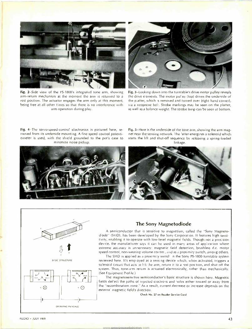
Fig. 2-Side view of the PS -1800's integrated tone arm, showing arm -return mechanism at the moment the arm is returned to a
rest position. The actuator engages the arm only at this moment, being free at all other times so that there is no interference with
arm operation during play.
Fig. 4-The servo -speed -control electronics is pictured here, re- moved from its underside mounting. A fine -speed -control potenti- ometer is used, with the shield grounded to the pot's case to
minimize noise pickup.
Fig. 3-Looking down into the turntable's drive motor pulley reveals the drive elements. The motor pulley (top) drives the underside of the platter, which is removed and turned over (right-hand corner), via a neoprene belt. Strobe markings may be seen on the platter, as well as a balance weight. The strobe lamp can be seen at bottom.
Fig. 5-Here is the underside of the tone arm, showing the arm mag- net near the sensing network. The latter energizes a solenoid which starts the lift and shut-off sequence by releasing a spring -loaded
linkage.
BASIC STRUCTURE
,.........,.
R. O
The Sony Magnetodiode A semiconductor that is sensitive to magnetism, called the "Sony Magneto -
diode" (SMD), has been developed by the Sony Corporation. It features high sensi- tlivity, enabling it to operate with low-level magnetic fields. Though not a precision device, the manufacturer says it can be used in many areas of application where extreme accuracy is unnecessary: magnetic field detection, brushless d.c. motor speed control, non -wearing volume control, and as a proximity switch, among others.
The SMD is applied as a proximity switch in the Sony PS -1800 turntable system reviewed here. It's employed as a sensing device which, when activated, triggers a
solenoid circuit that acts to lift the arm, return it to a rest position, and shut off the system. Thus, tone -arm return is actuated electronically, rather than mechanically. (See Equipment Profile.)
The magnetosensitive semiconductor's basic structure is shown here. Magnetic fields deflect the paths of injected electrons and -holes either toward or away from the "recombination zone." As a result, current decrease or increase depends on the external magnetic field's direction.
Check No. 27 on Reader Service Card
OPERATING PRINCIPLE
AUDIO JULY 1969 43
www.americanradiohistory.comAmericanRadioHistory.Com

spectrum. The pivot friction is very low, enabling use of low -mass cartridges tracking at below 1 gram. The unit's relative immunity to external shock and vibration and acoustic feedback is also very good.
Considering the operating conveni- ence features which make the unit so pleasurable to use, coupled with im- pressively good performance, the Sony PS -1800 can be termed a great inte- grated turntable. At its price of under $200 (which includes turntable, tone arm, wood base, and dust cover) , it is also a great btiy for use with any better -than -average stereo hi-fi system where playing records only singly is desirable.
Check No. 42 on Reader Service Card
° For the information of new readers, Fletcher and Munson proved in the early 1930s that loud- ness depends on frequency as well as on in- tensity. Robinson and Dadson did similar work in later years, resulting in equal loudness con- tours, which are illustrated in this issue's Primer on Sound Level Meters. These curves use a unit of loudness level, the pion, comparing loudness of a reference note to that of a given note. The weighting network used by AUDIO, "A" weight- ing, whose frequency response is also illustrated in the aforementioned article, is one of three filters employed with many noise meters to ob- tain subjective measurements. It simulates fre- quency discrimination of hearing at low levels of sound. Rumble would be more apparent at higher listening levels, naturally. For example, using these International Electrotechnical Com- mission (I.E.C.)-recommended weighted response curves, a 60 Hz signal would be about 30 dBs below the 1000 Hz's zero dB point with an "A" weighting network, whereas it would only be about 10 dB down with a "B" weighting network, which is used to measure loud noise. Though recognized internationally, these weighting curves do not provide us with what is felt to be an ideal response for our purpose, but it does serve satis- factorily and will have to do until another widely accepted standard is developed. Readers should never compare one weighted rumble figure with another unless each uses the same standard, not to mention the same test setup.
Errata
Last month's profile of the Thorens TD -125 "electronic" turntable stated
that its 46 -dB NAB rumble measure-
ment, referenced to 7 cm/sec peak velocity at 1000 Hz, was 11 dB better than the NAB minimum standard of -35 dB. This is the old NAB Standard,
of course, which was superseded by a
new NAB Standard a few years ago,
taking into account stereophonic disc playing and reproducing equipment. Thus, the measurement should have
been referenced against the latest
standard, which is 5 cm/sec peak
velocity at 1000 Hz. Accordingly, the Thorens TD -125 rumble measurement
should have read -43 dB (NAB),
which is 8 dB better than what the NAB
Standard defines as minimum. How- ever, it is possible that the TD 125 is
even better than noted because we
may well be measuring the record's
low -frequency noise (rumble, mold
grain, and what -have -you).
Also, on double-checking our mea-
surements with a mint copy of a CBS
Labs BTR-150 test record, we measured
the TD -125's weighted ("A" weighting) low -frequency noise as -70 dB, as
contrasted with the -64 dB figure published last month. In tracking down the discrepancy, we discovered that the
test disc used last month exhibited con- siderably more noise when playing out- side grooves (which we coincidentally used during weighted rumble measure-
ments) than when playing inside
grooves. On re -testing with the old test record, measurements made while using its inside grooves approached the figure produced with the new test
disc. As a result of the above, we were
driven to investigate measurement re-
sults garnered from a number of dif- ferent brands of test records, as well as some copies of each. Interestingly, they differed widely from brand to brand and, in some instances, between pressings of the same label. For ex-
ample, on a few of the test records, we could not measure beyond the middle -30 dB below the reference level, which indicates that one could employ a test record that exhibits greater low -frequency noise than pro- duced by the turntable under test.
In view of the improvements made
in modern turntables (not to mention other components), it is therefore clear
that many of the currently available test
records are inadequate. Certainly, test records should be developed that ex-
hibit less low -frequency noise than present-day ones do. What we would like to see is a return to the old 1953
NAB definition of a test record, which included a requirement that the record be at least 8 dB quieter in low -fre- quency noise than the turntable being measured. Based on measurements we
made on the TD -125, as well as on the
Sony 1800, rumble content of the test
record should then not be worse than -51 dB unweighted.
Heathkit Model AS -48 Bookshelf Speaker System Kit
MANUFACTURER'S SPECIFICATIONS:
Frequency response: 40 to 20,000 Hz.
Crossover frequency: 2000 Hz. Nominal input impedance: 8 ohms. Power rating:
50 watts program material. Speakers:
(Heath by JBL) low -frequency, 14", 8 ohm; high -frequency, 2", 8 ohm. Enclosure:
tuned -port, damped reflex. No. 1 grade
oak veneer on high -density pressed -wood base, with solid oak grille frame. Pecan
finish. Net weight, 42 lbs. Dimensions: 14" H x 23h/2' W x 12" D. Price: $169.95
(kit).
The Heath Company has made it possible for the hi-fi listener to as- semble a good-sized bookshelf speaker system, using JBL mechanisms, at a saving in cost. When the average home constructor builder puts together a speaker system himself, from scratch, he might end up with a poorly designed compromise. Doing the job right in- volves a thorough knowledge of the characteristics of the speaker mecha -
Fig. 1
nisms selected, a knowledge of cross- over networks, and a sufficient familiar- ity with acoustics to be able to come up with a cabinet design which brings out the finest qualities of the speakers se- lected. And add to this, furniture finish- ing. It also involves a number of deci- sions as to whether one should build a completely enclosed cabinet, a bass re- flex with the usual port, or a ducted - port design. The latter has a number of advantages, not the least of which is the improved bass response commensurate with the enclosure size. The choice of interior damping material is also im- portant, as well as the amount and the placement.
Fig. 2- The Heathkit AS -48 with grille removed shows speakers and port tube.
All the design work has been done in
the case of the AS -48, all the parts arc packaged, and the builder is assured of a fine product when he is finished, and that's not more than two hours per system.
Construction The assembly of this kit starts with
the preparation of the cabinet, which is finished on four sides in an attrac- tive pecan finish in the Mediterranean style. The cabinet is completely en- closed except for the port in the baffle and an opening in the back for the crossover network, which is gasketed to seal up the opening when completed.
44 Check No. 45 on Reader Service Card
www.americanradiohistory.comAmericanRadioHistory.Com

Music lovers, take control!
Specs You Cari Brag About. Fre- quency response: 20-22,000 Hz @ 71 ips, 20-17,000 Hz 33/4, 20- 10,000 Hz @ 1'/s. Wow and flutter: 0.09%. Signal-to-noise ratio: 52 db.
Three Heads. Allows monitoring of either input source or the actual recording made on the tape.
Non -Magnetizing Record Head. Head magnetization build-up, the most common cause of tape hiss, is elim- inated by an exclusive Sony circuit which prevents any transient bias surge to the record head.
Full -Size Professional VU Meters. These internally lighted instruments provide the preci- sion metering for really serious recording. Calibrated to NAB standards.
Built-in Sound -on -Sound and Echo. Switching networks on the front panel facilitate professional echo and multiple sound -on - sound recordings without requir- ing external patch cords and mixer.
More Sony Excellence. Ultra -high -frequency bias. (Sony achieves lowest recording distortion ttrougn use of ultra -high bias frequency -160 KHz!) Scrape flutter filter eliminates tape modulation dis- tortion. Automatic shut-off. Pause control with lock. Vibration -free motor. Four -digit tape counter. Automatic tape lifters for fast -forward and rewind reduce head wear. Retractomatic pinch roller for easy tape threading. Variety of inputs and outputs. Vertical or horizontal operation.
Professional Slide Controls. Two finger- tip controls are posi- tioned vertically side by side for immediate precision adjustment of recording volume. Easi- er to read, easier to establish interchannel volume relationship than with conventional knobs.
Noise -Suppressor Switch. Special filter eliminates undesirable hiss that may exist on pre-recorded tapes.
Sony Model 630-D Solid -State Stereo Tape Deck. Buy it for less than $299.50, complete with handsome walnut base and dust cover. Also available: The Sony Model 630 Solid -State Three - Head Professional Stereo Tape System, with stereo control cen- ter, stereo power amplifiers, microphones, and lid -integrated full -range stereo extension speakers, for less than $449.50. For a free copy of our latest cat- alog, please write Mr. Phillips, Sony/ Superscope, 8142 Vine- land Avenue, Sun Valley, Cali- fornia 91352.
SONY® SUPER CUPE
+1969,SUPERSCOPE.INC. You never heard it so good.
www.americanradiohistory.comAmericanRadioHistory.Com

100 80
60
40
30
É 20 C Q
Ú 10
z 8
5 10 100 1k
FREQUENCY (Hz)
One first cuts the fiberglas padding into specified sizes, then after applying glue to specified places on the inside of the cabinet, the fiberglas pieces are put in place. Access to the baffle and the in- side of the cabinet is provided by re- moving the grille, which is held in place by spring clips which fit into pre -drilled holes in the sides of the enclosure. To ensure against possible irritation of the skin from the fiberglas, plastic gloves are provided-two with each speaker system. The various pieces of fiberglas are put in place through the opening for the 14 -in. woofer, being worked in- to place before pressing down to con- tact the glue strips on the inside. All of the preparing takes about 30 minutes.
Next, you will assemble the cross- over network. This involves another 30 minutes to mount the switch, two chokes-one a single value and the other with three values-two capaci- tors, and two resistors. When this is done, you mount it in the cabinet, using predrilled holes and some foam gasket- ing strips to maintain airtightness, and you have four wires extending from the crossover chassis-two for the woofer, and two for the tweeter.
The two leads for the tweeter are fed up through the small hole and attached to the tweeter mechanism, which is then put in place and fastened with three wood screws. The other two leads are brought up through the large hole, attached to the woofer, and then it is similarly mounted, and the job is done. The cardboard duct for the port is already installed in the cabinet. It measures 4 in. in diameter by 11 in. long, and thus extends nearly to the back wall of the enclosure.
A dress ring of adhesive dark paper is applied around the tweeter basket, and the grille is fitted into place.
The entire assembly is easy to per- form, and the kit instructions are simple and lucid, as one would expect from Heath. Complete diagrams make every operation clear, even to the novice.
tOk 20k
Fig. 3-Measured impedance of the speaker system at the input terminals. The curve shows the balanced low -frequency peaks, which are
normal for reflex and ducted -port speakers. The nominal impedance of the system is 8 ohms.
The crossover network consists of two 8-p,F capacitors, three resistors, and two chokes. The woofer is perma- nently connected across the input at all times, relying on its high damping and its long cone travel to provide a me- chanical rolloff at 2000 Hz. The tweeter is connected in series with one of the capacitors across the line in the HIGH position, and through taps on the 3-mH choke in the MED and LOw positions, while the capacitor has shunting re- sistors across it in the two latter posi- tions. In addition, the other capacitor, a resistor, and the 2.5 mH choke are in series across the tweeter to shape the crossover frequency to the desired 2000 Hz. It is an unusual crossover net- work, in our opinion, but it does its job well.
Performance
Figure 2 shows the AS -48 with the grille removed, illustrating the loca- tions of the two speaker mechanisms and the port tube. The three -position switch is accessible from the back, and two 8-32 screws with large knurled nuts are used for the connections.
To investigate the efficiency of the crossover network, we measured the impedance of the system, which shows a typical reflex pattern, as shown in Fig. 3. Note the two peaks in the curve below 100 Hz. This is close to the classic impedance curve for a reflex speaker, with the peaks of about equal value distributed to either side of the free -air resonance of the woofer, then dropping down to about the nominal value, remaining there within a factor of two up to the traditional 20,000 Hz.
This speaker system should defi- nitely be rated as a high -efficiency type, since it provides adequate room level with an input of only a bit over one watt, while ten watts is too loud to stay in the room with. Dispersion is excellent, dropping only 6 dB at an angle of 60 deg. from the axis at 8000 Hz, so that it is practically impossible
Fig. 4-Tone bursts are shown from left to right for signals of 1000, 6000, and 12,000 Hz.
to detect any droop as you walk across the room in front of the speaker. Re- sponse is down about 5 dB at 40 Hz, although still audible at 30, and with no doubling. At the upper end, output is still measureable to 20 kHz, with strong audibility to over 15 kHz.
The "h.f. balance" switch on the crossover chassis affects the range above 2000 Hz gradually, with in in- crease or decrease of 3 dB at 8000 Hz as the switch is turned from MED to HIGH or Low. This permits adjustment of the response to suit the acoustic en- vironment of your listening room, and starting with the switch in the MED
position, you will soon decide whether your room needs more or less highs, and you can boost or lower them as re- quired. In the average room, however, the speaker system is well balanced at the MID position.
Overall listening gives considerable satisfaction over a wide range of pro- gram material. The system exhibits the solidity of a heavily damped woofer (due to its 111/2 -lb. magnet structure) and to the rigidity of the cabinet. Add to this the luxurious appearance and you will find that you have assembled a fine system at a most reasonable price. You can change the grille cloth easily to match the decor of your room, since the grille frame can be removed without tools.
After thorough listening tests, we took some photos of tone bursts, just to verify what we heard. Note that the bursts are quite clean, starting with no overshoot, and stopping quite abruptly. These photos are about what tone - bursts should look like-not as perfect as the source, yet distinguishably clean, both at the start and at the finish of each burst. The signal frequencies used were 1000, 6000, and 12,000 Hz, with suitable lengths of bursts in each case.
In all, the model AS -48 top -of -the - line Heathkit speaker system is a fine performing, high -efficiency non -floor - standing unit.
Check No. 44 on Reader Service Card
46 AUDIO JULY 1969
www.americanradiohistory.comAmericanRadioHistory.Com

ENTERTAINMENT DIMENSIONS Keaetzv THE TOTAL ENTERTAINMENT PACKAGE
ENTERTAINMENT DIMENSIONS is a single convenient shop at home service for all your record, tape, book and stereo equipment needs. We offer all of the services of a retail store, at less than discount store prices, with the greatest selection and flexibility available. As a LIFETIME member of ENTERTAINMENT DIMENSIONS you will receive a FREE SCHWANN record cstalog listing over 30,000 selections, all of which are available, a- all times, for at least 35% off on every U.S. or foreign label. Upon request a
FREE HARRISON 4 or 8 track catalog of pre-recorded tapes will also be sent to you with savings of 25-33% on all tapes. All albums and tapes are guaranteed to be new.
LIFETIME membership fee is only $5.00,whi:h includes your choice of one of the FREE records below plus valuable FREE catalogs and special monthly offers. And join i; all you will ever have to do, absolutely no purchase obligations, no stop order forms, nothing will ever be sent until you send iì an order.
L.P.'s LIST $3.98 4.98 5.98
4 TR LIST $6.95
7.95 8 TR LIST $5.98 6.98
BRAHMS: SYMPHONY NO. 2 in D Major.
Opus 73
CLUB PRICE $2.49
3.09 3.79
CLUB PRICE $4.65
5.35 CLUB PRICE
$4.48 5.28
ì
One of the most valuable features of membership is the speed and care your orders receive. All orders are processed and shipped within 24 hours - never any delays.
Save even more by taking advantage of our fantastic specials. Nationally advertised turntables, regularly $109 now only $71.00, SAVE $38.50! All A&M $4.98 list records for only $2.50 each, including such artists as Herb Alpert and the Tijuana Brass, Sergio Mendes and Brasil 66, The Procol Harum, Phil Ochs, Baja Marimba Band and Claudine Longet.
Our book division will double your benefits by offering you EVERY BOOK IN PRINT hard or soft cover original publishers editions at 250/0 off list price. Never book club editions. Text and technical books at 10°/o discount.
ENTERTAINMENT DIMENSIONS features practically every nation- ally advertised brand name manufacturer of stereo component equipment at 25-50°/o discounts from compacts to complete systems.
Gift memberships are available with full lifetime privileges for only $2.50 each. Three can enroll for just $10.00 and five for only $15.30. Just fill out the gift membership on the coupon below.
You must be fully delighted with ENTERTAINMENT DIMENSIONS or notify Js within 30 days for full refund.
ENTERTAINMENT DIMENSIONS, INC. DEPT. A79 264 W. 40tú St., N.Y., N.Y. 10018
$5.00 enclosed entitles me to: Free Record No. Free Catalog, Order Form plus Special Monthly Discount Offers. No further obligations, and Savings of 25-80%.
INCLUDE FREE TAPE CATALOG of 4 track tapes
Cot 8 track tapes
ADDRESS
STATE
GIFT MEMBERSHIPS
ADDRESS
ADDRESS
STATE ZIP
STATE ZIP
Time t$ ertwiedipii
frarr!a Ó -'II
Illii
crtimv
' w
`
'
Cy
\ .;, , No. 100 No. 101 No. 102 No. 103 No. 104 No..105
AUDIO JULY 1969 47
www.americanradiohistory.comAmericanRadioHistory.Com

Audio Dynamics Model ADC 25 Stereo Pickup System
MANUFACTURER'S
SPECIFICATIONS:
Type: Induced magnet. Sensitivity: 4 mV at 5.5 cm/sec recorded velocity. Tracking Force Range: 1/2 to 11/4 gms. Frequency Re-
sponse: 10 to 24,000 Hz ±2 dB. Channel Separation: 30 dB from 50 to 10,000 Hz.
Vertical Tracking Angle: 15 deg. Recom- mended Load Impedance: 47,000 ohms. Price: $100.00 (including three inter- changeable styli).
The ADC 25 stereo pickup system makes it possible to interchange your styli without changing tone -arm heads, and while this has been possible here- tofore if the user of almost any car- tridge thought of it, this is the first time, to our knowledge, that the manu- facturer thought of it for you and pro- vided the complete cartridge and three interchangeable styli in one package, ready for your choices. The different styli provide the capability of matching the groove with the stylus for optimum performance.
Most hi-fi enthusiasts have a "stable" of different cartridges, and when they find a particular record that doesn't sound just right with one cartridge, they are likely to change cartridges in the search for the one that does give the de- sired sound quality. This, of course, introduces another variable, assuming that the cartridges are of different manufacture, as is almost sure to be the case. However, with the ADC 25 sys- tem, the excellent qualities of one car- tridge can be used to explore the possibility of better performance sim- ply by changing the stylus.
The three styli furnished with the ADC 25 are: 0.3 x 0.9 -mil elliptical; 0.3 x 0.7 -mil elliptical, and 0.6 conical. Each is color coded for recognition. The
Fig. 2-Close-up of the stylus assembly shows the tiny magnetic tube at the lower end which induces the magnetic field from the imbedded magnet to the four pole pieces in the cartridge
body (see Fig. 3).
Fig. 3-The cartridge body, showing the pole pieces of the coil assembly.
theory of the different styli is that one may select the optimum shape and size for each different type of groove, con- sidering that different records may be cut with slightly different cutting styli, or pressed with differently worn stamp - ers, or be worn differently by previously used playing styli. For example, if a record were played previously with a certain stylus for a number of times, it would be worn in a certain pattern. Suppose, then, that one played it with a stylus that rode slightly higher in the groove than previous ones did, or even possibly one which rode lower in the groove, it is likely that there would be a difference in the quality of reproduc- tion of the record.
Another example of the proper choice of the playing stylus is in the use of the 0.6 -mil conical one for recordings like the RCA Dynagroove records, which are compensated for use with spherical (conical) styli so that the in- ner grooves do not exhibit the distortion often encountered with some types of records when played with conical styli. These records actually sounded better when played with the conical stylus that they did with either of the ellipti- cal ones.
The cartridge itself employs the "in- duced magnet" principle of operation. The magnet is imbedded in the plastic molded housing of the cartridge in such a position that it "induces" its magne- tism into a soft iron collar around the end of the stylus arm. The end of the stylus arm with the collar is shown in Fig. 2. The movement of the collar in accordance with the movements of the stylus tip induces signals into the coils related to the pole pieces shown in Fig. 3, which are positioned at 90 -deg. an- gles to each other. The 45-45 move- ments of the soft iron collar therefore induce signals into the two channels proportionate to the groove modula- tions.
Performance We measured frequency response
and crosstalk with the 0.3 x 0.7 stylus on a CBS STR-100 test record that had been played quite a number of times. Then we secured a completely new STR-100 record and repeated the mea-
surements. The results are shown in Fig. 4. These comparative figures show what a difference a number of plays on a test record can make. Both frequency response and separation measured con- siderably better with the new record. The measured output per channel was 0.9 mV/cm/sec, which is close to specs, and both channels were alike within ±0.2 dB. Frequency response varied not more than ±0.6 dB over the entire range in either channel. Separation was exceptionally good, especially at the high end of the frequency spectrum.
We must admit that we were sur- prised at the difference in performance obtained with the different styli. Some of the more flamboyant records of re- cent release, and played only slightly, actually sounded better with the 0.3 x 0.7 elliptical stylus than they did with either of the other two. Some relatively old records which had been played many times sounded cleaner when
Frequency Response
o. a j -f0
W
Crosstalk
Ce
-40
20 10 1k
FREQUENCY (Hz)
Fig. 4-Frequency response and cross -talk curves. The solid lines represent measure- ments made with an old STR-100 test rec-
ord, while the dotted curves were made using a brand new test record of the same type. The inset photos are square -wave responses to a 3.54 cm/sec left -channel - only signal at left, and to a 5.0 cm/sec
lateral signal at right.
10k 20k
played with the conical stylus than with either of the elliptical points. At least, we were able to be convinced of the theory of choosing the correct stylus for each record, if one wants absolutely the optimum results.
It would seem, however, that the in- convenience of changing the stylus from record to record might be a nui- sance to some persons. But for the serious listener who plays records man- ually (whether on a manual or an auto- matic turntable), who is willing to try out all his records and to code them with the optimum stylus for each one, might well be rewarded by better per- formance for each. This is one example where "you pays yer money and takes yer choice," and you are provided with three choices.
Check No. 48 on Reader Service Card
48 AUDIO JULY 1969
www.americanradiohistory.comAmericanRadioHistory.Com

NEW !
Acoustical Tests
and Aleaslieerlis-
we*--->"
c.ÿ 7
-- .
Acoustical Tests and Measurements Don Davis The author covers in great detail a variety of tests needed to determine sound quality in large listen- ing areas: concert halls, auditoriums, factories, bus stations, and similar locations. This is a prac- tical book, written on a technician level, though neophytes will find the text and illustrations easy to understand. Chapters include: Instrumentation for Acoustical Tests, Charts and Criteria, How to Measure Ambient Noise, How to Measure Rever- beration Time, Pulse Testing, Testing the Sound System, How to Write the Survey Report, and Measuring Specifications. 192 pages. No. 121 $4.95
Sound in the Theatre Harold Burris -Meyer and Vincent Mallory First book of its kind ... nothing like it has ever been published before! It is an authoritative text on electronic sound control for theatres, audi- toriums, concert halls and other large enclosed areas where the source and the audience are present together. Contains complete procedures: For planning, assembling and testing sound con- trol installations - Articulating sound control with other elements of production - Operation and maintenance of sound control equipment. Describes and illustrates 32 specific problems. No. 126 $6.95
SAVE Monthly Special
Save over 351 with this collection of AUDIO books.
Maintaining Hi-Fi Equipment ($2.90) 7th AUDIO Anthology ($3.95)
Troubleshooting High Fidelity Amplifiers ($2.95 ) Total Value of All Three Books ... $9.80 YOUR COST ONLY... $6.50 Postpaid
in U.S.A. & Canada; Circle OS -500 This offer good only on direct order to the publisher
TAPE RECORDER
Maintaining HI-FI Equipment Joseph Marshall A valuable reference for anyone whose living or hobby is servicing hi-fi equipment. Outlines the professional approach for servicing all types of hi-fi components. Covers trouble -shooting of electronic, mechanical and acoustic problems. 224 pages. No. 58 Paperback $2.90
The 7th AUDIO Anthology Continuing the tradition of the Anthology series, this volume contains the most sought after mate- rial from AUDIO during 1962 and 1963-the period when transistors were "growing up" and when new methods and techniques were being used in the applications of the science of high fidelity. This volume should be in the library of everyone who wants to know why and how. No. 135 $3.95
TROUBLESHOOTING High Fidelity Amplifiers Mannie Horowitz Written specifically for the serviceman and audio hobbyist who wants to get into the profitable field of stereo hi-fi service. 12 fact -filled chapters with a plain and simple approach to trouble -shooting all types of stereo and mono amplifiers-a direct text on curing both vacuum tube and transistor- ized amplifier ills. Easy to read-includes data on test instruments and procedures. 128 pages. No. 128 $2.95
HI-FI TROUBLES How You Can Avoid Them How You Can Cure Them Herman Burstein
Here are the problems you face in maintain- ing your audio system in peak condition. Tells you how to locate troubles, what to do about them and how to do it-and, just as important: what NOT to do. Helps you to achieve the best in listening pleasure from your equipment. No. 120 $3.95
Getting The Most Out of Your Tape Recorder Herman Burstein Written in "plain talk" for the man who has, or wishes to buy, a tape recorder. It answers the myriad questions raised by tape recording en- thusiasts. Its chapters cover every phase of op- eration and maintenance-from adding a tape recorder to the hi-fi system, to a thorough dis- sertation on microphones. Lots of practical in- formation on how to buy. 176 pages. No. 251 $4.25
AUDIO Bookshelf 134 N. 13th Street, Phila., Pa. 19107
* All U.S.A. and Canadian orders shipped postpaid.
Please rush me the books circled below. I am enclosing the full remit-
tance of $ (No C.O.D. or billing)
58 120 121 126 128 251 OS500 135
Name
Address
City State Zip
AUDIO JULY 1969 49
www.americanradiohistory.comAmericanRadioHistory.Com

ABZs of
Stereo FM
LEONARD FELDMAN
Sum -and -Difference Stereo FM Transmission Systems
On April 19, 1961, the long-awaited decision was handed down by the Fed- eral Communications Commission: A system for stereo FM broadcasting had been chosen and stations could begin stereocasts starting June 1, 1961. With less than three months to get ready, several stations vied for the honor of getting on the air first. To this day, at least three stations claim to have gone on the air shortly after midnight on June 1 of that year. "Getting ready" was complicated by the fact that the FCC chose the system that high-fidelity manufacturers had pretty much dis- counted at the time. Murray Crosby had been championing his system since 1959, long before the field tests were even authorized by the FCC, and every- one thought that its superior stereo performance would make it a "shoo-in" -but this was not the case.
It was Crosby, however, who com- bined the sub -carrier concept with the "sum -and -difference" concept, thereby creating a truly "compatible" system which serves both monophonic and
stereo listener with a "balanced" pro- gram. Here's how the sum -and -differ- ence technique -works:
Referring to Fig. 1, suppose that sine -wave "L" represents the program content of the left channel and sup- pose that the sine -wave of higher fre- quency, labelled "R," represents the program content of the right channel. For convenience in illustrating, we have made "R" a sine wave of twice the frequency of "L," but there need be no frequency or amplitude relationship between the "L" and "R" signals. In the diagram representing "R," we have also shown an inverted "R," which has been labelled (-R). Now, -R simply means R that is 180 degrees out of phase, or completely inverted in polar- ity. If we electrically add L to R (by means of an audio mixer, say, having a gain of unity), we produce a wave- form such as that shown in Fig. 1C, identified as L + R, or the sum of the left and right program signals. Let's pause here, for a moment, and con- sider what L + R really is.
If your amplifier has a "stereo- mono" mode switch and you set it to "mono," you are really adding the L and R signals together to form L + R, a monophonic equivalent of the stereo program material. Thus, if the FM sta- tion studio were to "mix" L and R to- gether and broadcast it conventionally, listeners would hear a totally mono- phonic program and would be unable to detect the fact that the record or tape source was really recorded in stereo. Returning to Fig. 1, just as it is possible to ADD two signals together electrically, it is also possible to SUB- TRACT one signal from another. If we were to pass the R signal through a
Fig. 1-Stereo-channel signals undergo addition and subtraction before
-R (- R)
A
L- R
-- - - - -(L - R)
D
2L+X + (L R) _
transmission.
(L + R) - (L - R) _ X-X+2R= 2R
phase inverter, we would obtain -R, as shown by the dotted line waveform of Fig. 1B. Subtracting one signal from another is the same as adding the in- verted or negative -polarity signal to the first. If you were to plot the results graphically (as we did), you would come up with the waveform shown in Fig. 1D, or "L - R." Also shown in Fig. 1D is an inverted L -R or - (L - R) which is easily produced by phase in- verting this new waveform, just as was done to produce -R. In all compatible stereo broadcasting systems worthy of consideration, the L -R signal is
broadcast via a superaudible sub - carrier. Thus, the mono listener hears only L + R, or a fully balanced mono- phonic program, while the stereo lis- tener goes on to further processing of both the L + R and the L -R signals, as follows:
First, the L -R program must be demodulated or detected from its sub - carrier (you could not hear the L -R program as it is recovered from the regular FM detection process, since it is really in the form of modulations of a superaudible sub -carrier) . Having recovered the L -R as recognizable audio information, it is first added to L + R, the mono signal. Fig. lE shows what happens graphically as well as algebraically. What you get is simply 2L. Next, if L -R is subtracted from the mono L + R signal, you recover 2R, as shown in Fig. 1F. The factor 2
need not concern us, as it represents an amplitude level and can be adjusted to anything you like by means of your volume control. The important thing is that Fig. lE contains the waveform shape of L without a trace of R, while the waveform of Fig. 1F contains the correct waveform for R without a trace of L present.
The difference between the Crosby system and the approved FCC system lies only in the nature of the sub -car- rier used to transmit this vital L -R signal, not in the concept of sum -and - difference compatibility which would exist with either system. Crosby pro- posed that the sub -carrier have a frequency of 50 kHz and that this sub - carrier, in turn, be frequency modu- lated ±25 kHz with the L -R infor- mation. In order to accomplish this, two changes in previously approved transmission rules would have had to take place. First, main channel modu- lation would have to be "backed off" by 6 dB, or 50%, to ±37.5 kHz, since Crosby wished to utilize 50% modu- lation for his FM modulated 50 -kHz sub -carrier for best signal-to-noise per- formance. Secondly, because frequency modulation of the sub -carrier was to
50 AUDIO JULY 1969
www.americanradiohistory.comAmericanRadioHistory.Com

KHz
75
%
100
90
80
-----_< IN
EL OF
MONOI CHANNELN MODULATION
TRANSMISSION
LEVEL OF MAIN CHANNEL MODULATION
70 USING CROSBY SYSTEM
z 60 o - SUB CARRIER CENTER FREQUENCY =50
KHz
37.5 < 50
40
cc
cg 30
cg L+ R L- R 20
10
0 5 10 15 20 25 30 35 40 45 50 55 60 65 70 75
MODULATING FREQUENCIES KHz
Fig. 2-Spectrum distribution in the Crosby stereo FM system.
extend all the way down to 25 kHz and up to 75 kHz, there would be no room left for the previously approved SCA or background -music private point-to-point communications.
These two problems are easily under- stood by examining tse spectrum dis- tribution diagram of the "Crosby System" shown in Fig. 2. The FCC, in its report and order of April 19, 1961, admitted that the Crosby system was capable of better stereo performance than any other proposed system- insofar as signal-to-noise ratio was concerned. On the other hand, the monophonic listener would have a poorer signal-to-noise ratio by about 6 dB and a broadcaster would have had to choose between income -producing, non-public SCA (background music) operation or stereo, since the two ser -
Fig. 4-Development of "suppressed car- rier" sidebands consists of (A) a 38 -kHz carrier which is amplitude modulated in (B). The carrier itself is finally removed, leaving only the sidebands, shown in (C).
f
e P
J
or
v
11 tr.
J
et
(A)
(B)
(C)
vices could not take place simultane- ously. The fact that the STEREO listener (on whose behalf the decision was ostensibly made) suffers a signal- to-noise ratio degradation of over 13 dB (compared to what "might have been" with the Crosby system) seems not to have weighed too heavily in the FCC decision!
The system which was actually ap- proved utilizes a sub -carrier principle, too. In this case, however, the sub - carrier frequency is set at 38 kHz and the modulation of this sub -carrier is one of AMPLITUDE rather than fre- quency. Further, after L -R has been used to amplitude modulate the sub - carrier, the 38 -kHz sub -carrier itself is stripped away or "suppressed," leaving only the "sidebands" of the sub -carrier. The situation is much akin to regular AM broadcasting (except that in this case the "r.f." frequency is 38 kHz). Figure 4 shows the step-by-step de- velopment of the "suppressed -carrier, double-sideband" technique by which the L -R information is applied to the main, FM carrier. Note, that while the modulation of the sub -carrier is of the "AM" type, the product of this modulation (as represented in Fig. 3C) actually frequency modulates the main carrier, so that the transmission over the air is totally FM.
Figure 3 shows the spectrum distri- bution of the approved stereo FM transmission system. As usual, main channel program material occupies fre- quencies from 50 Hz to 15,000 Hz. The suppressed sub -carrier sidebands (con- taining the L -R information) occupy frequencies extending from 23 kHz all the way up to 53 kHz. Note, however, that there is no energy at 38 kHz, the so-called carrier frequency, since the carrier itself has been suppressed as noted earlier. The student of AM tech- nology will realize that the extremes of frequency (23 kHz and 53 kHz) arise out of the well-known fact that when a carrier is amplitude modulated,
KHz %
100
67.590 b oa
80
10 z á60
37.5 W 50
W 40
30
z 20
7.52 10
0
L+ R
"MAIN -
CHANNEL" AUDIO
19 KHz PILOT
CARRIER
38 KHz (SUPPRESSED)
,/i
LOWER L -R
SIDEBANDS
UPPER L - R
SIDEBANOS
IF SCA
(BACKGROUND MUSIC) CHANNEL IS DESIRED, MODULATION OF MAIN AND SUB - CHANNELS MUST BE REDUCED TO 80% INSTEAD OF 90%
5 10 15 20 25 30 35 40 45 50 55 60 65 70
MODULATING FREQUENCIES Fig. 3 -Spectrum distribution in the FCC -approved stereo FM
system.
an upper and lower sideband are cre- ated above and below the center fre- quency by an amount equal to the modulating frequency itself. Thus, if we amplitude modulate the 38 -kHz sub -carrier with a tone at 1 kHz, side - bands will occur at 37 kHz and 39 kHz. Since the highest frequency ever trans- mitted is to be 15 kHz, the most ex- treme sidebands will occur at 23 kHz (38 kHz - 15 kHz) and 53 kHz (38 kHz + 15 kHz).
In addition to the sidebands, it is necessary to transmit a "pilot" carrier
Fig. 5 - Oscilloscope photo shows how "left" and "right" channel signals "inter-
leave."
at 19 kHz. This additional unvarying signal will be used to reconstitute the suppressed carrier at the receiver, and we shall discuss its function in greater detail in future installments.
One of the advantages of this system is obvious immediately. Since the high- est frequency required by the "side - bands" is only 53 kHz (as opposed to 75 kHz in the all -FM Crosby system), this leaves room for at least one, and possibly two, SCA private communi- cations sub -channels for background music, subscriber services and other similar uses.
The more interesting feature of the system is a process known as "inter- leaving," which really is a natural "bonus" of the entire system. Note that in Fig. 4, the amplitudes as well as the frequency distribution of all the signal elements are given. By simply adding
(Continued on page 62)
75
AUDIO JULY 1969 51
www.americanradiohistory.comAmericanRadioHistory.Com

Classical Record Reviews Edward Tatnall Canby
Franz Berwald: Sinfonie Singulière; Sym- phony in E Flat. London Symphony, Sixten Ehrling. London CS 6602 stereo. ($5.95)
Franz Berwald, the elderly Swedish radical of the middle 19th century, born before Schubert but sounding more like a cross between Berlioz and Mendelssohn, has at last gone into an international revival. A fascinating composer, all fresh early Romanticism but full of later -type experimentation of a sort wholly unappreciated in his own day (not a one of his symphonies was performed, if I am right). Most of all, Berwald was electric, full of ten- sions, high strung, jittery, his music expressing these feelings in the most marvelously jagged, bouncing rhythms, delicate but explosive. Very out of style
AGDTO
MUSIC REVIER'
in the leisurely 1850s. Very in, right now.
These two performances of the most important pair of symphonies, the two last, are good but not tops. The elec- tricity just isn't there often enough. They are ever so slightly mushy, slack, though the warmth is good and the playing earnest under a dedicated Swedish conductor. The golden London sound also helps to obscure the sharp- ness of detail.
I rather suspect simply a lack of re- hearsal and prior public performance here as the main problem. The music just isn't worked up to the proper genial electric tension.
Performance: B- Sound: B
STEREO
Classical 52
Light Listening 58
Tape Reviews 62
Mozart: Excerpts from Zaide, Lo Sposo Deluso, L'Oca del Cairo. Soloists, Mo- zarteums Kammerchor, Camerata Aca- demics des Salsburger Mozarteums, Paumgartner. World Series PHC 2-015 (2 discs) sim. stereo ($5.00)
For anyone who knows even a part of a Mozart opera and loves it, these recordings can only be described as touching, even pathetic. Here are sur- viving segments of three major operas that poor little Mozart, opera's great- est genius, began to compose and never finished. Politics, politics. Being Mo- zart, they are, as far as they go, en- tirely polished and professional, right out of his familiar best if perhaps not quite Don Giovanni.
The music begins, the familiar Mo -
VV 90 92 ,.:14 9.8 .. 96 8 530 600 700
30 40
Try the Sony station countdown test
52 AUDIO JULY 1969
www.americanradiohistory.comAmericanRadioHistory.Com

AUDIO JULY 1969
zart characters (with strange and un- familiar names) appear on our mental stage, the action gets underway and the complicated plot unrolls-arias, recita- tives, big vocal ensemble numbers, the whole bit. You get all involved. Then suddenly-nothing. There isn't any more. Right in the middle.
The major work, carried to the im- pressive length of three full LP sides, is the unfinished Zaide, K. 344, a Ger- man opera composed for Vienna just as the German opera company there fell
.apart. Never completed. Swinging back to Italian, Mozart began two works, L'Oca del Cairo ("The Goose of Cairo," believe it or not) and a buffa with a stock Italian lightweight title, "The Husband Deceived" (Or the Rivalry of Three Ladies for One Lover) . Only fragments of these, but impressively worked out at length, great quantities of futile Mozart. Heart -breaking to see how much went for nothing.
It is more than we can expect to find a first-rate stage -type reconstruction of these basically unworkable (from the stage viewpoint) opera torsos. The Salsburg Mozarteum forces, under the circumstances, did a noble job of musi- cal museum -work. The music does come to life and animation, decidedly. That, indeed, is the poignant thing. But we still must rate the performances ob-
jectively as so-so Mozart by existing highest standards for the complete operas. No matter-lucky we get any- thing at all.
The recordings evidently are out of the postwar period a good while back. Very adequately restored and put into moderate synthetic stereo, but not ex- actly impressive as sound, even so. Again-no matter.
Note that there are other superb Mozart items in this same Philips series, notably the Masonic Music, which I have been hoping Philips (or Mercury -World Series) would reissue. Maybe, with luck. Now those perfor- mances are really first rate....
Performance: B- Sound: C+
Sibelius: Symphony No. 2; Symphony No. 5; Night Ride and Sunrise. New Phil- harmonia Orch., Georges Pretre. RCA LSC 3063; LSC 2997 stereo ($5.95 ea.)
Sibelius: Symphonies No. 3, 6. Vienna Philharmonic Orch., Maazel. London CS 6561 stereo ($5.95)
A Sibelius revival? Seems that way. Here we have two pairs of symphonies (plus a tone poem), the two familiar works, Nos. 2 and 5, on RCA, the two least familiar, the ones nobody ever
hears, on London. That leaves the re- doubtable No. 4, the most "modern" of them all, and the two lesser known outer works, one at each end. They'll be along any day.
I spent a long and fascinating time with these six big LP sides. These are superior recordings all, upper -bracket in both the technical sense and the musical. And yet they are surprisingly different, and the subtle interactions between recording technique, conduc- tor and composer are not easy to ana- lyze. Without much question I found the London -Maazel efforts musically the most satisfactory. Georges Pretre's encounters with RCA's sound and the New Philharmonia Orchestra have their major points of value, and these two are the hi-fi man's choice.
London's Maazel and the experi- enced Vienna orchestra without the slightest doubt have recorded the true musical Sibelius, with a naturalness, an earnestness and a musical tension that is somehow missing in the Pretre jobs. Among , recent stereo offerings, Maazel's Sibelius is the best I know. Moreover, the two unfamiliar sym- phonies are far from unworthy. As you might guess, they are merely of a less direct appeal than the famous No. 2 and No. 5. No. 3 is excellent and new to me, but it was No. 6 that really
100 102 104 106 108 MHz
1000 1200 1400 1600 kHz 60 70 80 90 100
TUNING
Start at 88 MHz on the nine -inch long dial of the Sony 6060 and tune your way slowly to 108 MHz.
Stations you were never able to enjoy before will pop out all along the dial. And when you tune to 96.3,
you'll hear the station that is broadcasting on 96.3. That's how precisely the dial is calibrated. But there's more to the 6060 than just logging stations. It's how they sound once you get them.
If it's a stereo station, the music is rich and full. Strong stations won't overpower weak ones. Adja-
cent stations don't overlap. And the same magnificent FM reception you hear today, you'll hear years
and years from now. Sony solid-state i.f. filters make sure of this. They never need to be realigned.
The Sony 6060 is a superb performer: FM stereo, FM and AM broadcasts, records and tapes.
Here's why: 110 watts IHF power into 8 ohms; distortion, less than 0.2% at rated output; sensitivity,
1.8 uV; selectivity, 80 dB; capture ratio, 1.5 dB and spurious signal rejection, 90 dB.
A host of conveniences enhance your pleasure: automatic stereo reception; zero -center tuning
meter; front panel headphone jack; switches for tape monitoring, muting, speaker selection, tape or
aux. input, loudness that works.
Next time you visit your Hi-Fi dealer, take a trip from 88 MHz to 108 MHz. You'll make some
delightful discoveries along the way. Sony 6060, $399.50 suggested list. Other Sony receivers from
$279.50 to $699.50. Sony Corporation of America, 47-47 Van Dam St., Long Island City, N.Y. 11101.
SONY® 6060 STEREO RECEIVER Check No. 50 on Reader Service Card
www.americanradiohistory.comAmericanRadioHistory.Com

WHY YOU SAY IT... Magnetic Tape Recorder
Probably from an early German expression for "to tear," in Old English a nar- row strip of cloth was called taeppe. Strips produced by tearing weren't uniform, so
special ones were woven from linen and silk. Such tapes were used for tying garments, as measuring lines, and to mark the finish of races.
About 1884 automatic tele- graph systems adopted the use of long paper strips for printing messages. Such a rib- bon took the ancient name of
"a strip of cloth." From this and similar usages tape was borrowed to designate a strip of the marvelous material that is basic to use of your re- corder.
Such tape is called mag- netic as a result of a chain of
influences that stretch across many centuries.
Ultimately, the term stems from the name of a city near the mouth of a river in Asia Minor. Very early, Magnesia ad Maeandrum (Magnesia on the Maeander River) be- came famous as the source of
a mineral endowed with magi- cal power. Known to Greeks as Magnetis, the heavy stuff drew iron to itself.
For centuries there was no practical use for it. Eventually someone found that when he rubbed a needle with a piece of stone from Magnesia, the nature of the needle was changed. Arranged so it could swing freely, such an instru- ment pointed to the north. So the magnete became the mariner's most important t
tool, essential to manufacture of compass needles.
Quality and strength of
natural magnets vary widely. But with the invention of the electromagnet, technicians had a precision tool. Until this century, practical applica- tions were limited to the metal trades. Development of
magnetic tape, whose mole- cules can be structured and re -arranged by magnetic en- ergy, opened a whole new field of communication.
So the now -deserted site of
ancient Magnesia is often vis- ited by archeologists who use magnetic tape to record their observations.
Whether used on an archae- ological dig or in a sound stu- dio, the recorder itself shows that words are slippery. For the name of the modern in- strument stems from Old French recorder (to bring to remembrance). Like Spanish recordar and Italian record - arsi, the verb comes from Lat- in recordare (to think over, to be mindful of).
In ancient and medieval times, if a person wished to be mindful of something he wrote it down. That's how the court recorder got his name. Such a fellow was appointed by the mayor and aldermen of London to sit in a courtroom and "keep the proceedings in mind."
From lawyer with pen in hand, the name passed to early devices using wax cyl- inders to preserve sounds, and then through a whole series of "memory machines."
-WEBB GARRISON
J
CLASSICAL RECORDS (Continued)
Western music, as Christian as any- thing out of Rome, or for that matter, Salt Lake City. Quite an ear -opener.
Performance: A Sound: A-
Joseph Haydn: Trumpet Concerto. Michael
Haydn: Horn Concerto. Alan Stringer,
Barry Tuckwell; Academy of St. Martin -in -
the -Fields, Marriner. Argo ZRG 543 stereo
($5.95)
Virtuoses Horn (Concertos by Rosetti, J.
Haydn, Mozart). Hermann Baumann; Con-
certo Amsterdam, Schröder. Telefunken
SLT 43102B Ex stereo ($5.95)
Enjoy solo brass music? Here are two imports and five brief concerti, all out of a single period and style, the later 18th century, the time of Haydn and
Mozart, both of whom are included. Haydn's younger brother Michael was a close colleague of Mozart's at Salz- burg. Antoni Rosetti's real name was Franz Anton Rösler; the Italianized pseudonym sounded fancier. He is a gifted composer of easy, tuneful melody in the 18th -century manner.
Both records are impeccably per- formed and well recorded in truly civ- ilized fashion; among the five works those by Mozart and Joseph Haydn do not in fact stand out particularly. In this graceful concerto idiom there was no need for earth shaking profundity and the two lesser composers were fully equal to their respective tasks. To be sure, the somewhat clumsy bray of the French horn was not ideal for this sort of music. The next century found bet- ter uses for the instrument's dark, woodsy color. But these composers manage very nicely to keep the pon- derous hornist busy and his music sprightly in spite of a total lack of valves (at the time) and limited choice of notes.
The single trumpet work, the cele- brated Haydn concerto, was composed for the first such instrument that could play "all the notes," a keyed affair which was soon replaced by the valved trumpet now in general use.
Performances: B+ Sound: B
Takemitsu: Coral Island (Soprano and Orch.); Water Music; Vocalism Ai (Mag- netic Tape). Yomiuri Nippon Symphony Orch., Matsumi Masuda, sop., Wagasugi. RCA Victrola VICS 1334 stereo ($2.98)
The Japanese do seem to have an in- herent inbred delicacy of taste in ar-
56 AUDIO JULY 1969
www.americanradiohistory.comAmericanRadioHistory.Com

tistic and decorative matters. I found all these works by a young Japanese - international composer to be sensitively expressed, gracefully shaped and, some- how, innately beautiful. Too many of our own similar efforts are innately gross.
The first work, a long "live" fantasy on Japanese poetics, is one of those extremely contemplative, totally disso- nant musical structures where silence, and brief, single sounds are as impor- tant as sonic continuity in the usual sense.
The tape pieces, taking account of a different medium, no longer based on the fixed musical scale but free to roam sonically free, pitch blending into color -noise, are of an appropriately dif- ferent sound, as is quite, proper. I par- ticularly enjoyed the Water Music, built from recorded water sounds. (cf. Tod Dockstader's American water music of a similar structure on the Owl label). Vocalism Ai, the Japanese word for love spoken in a thousand ways and made into a tape montage, would likely be a corny mess in anyone else's hands. It comes off well here, being Japanese.
Performance: A? Sound: B+
Anyone who wants the best and is worried about spending an extra $20 ought to have his ears examined.
Look at what you're getting for the extra $20. Papst hysteresis motor. Cartridge in- sert with slotted lead screw for precise stylus overhang adjustment. Feathertouch pushbuttons. All Miracord 50H exclusives.
You also get piston -damped cueing; effective anti -skate; dynamically -balanced
arm. Now consider what the leading ex- perts say about the Miracord 50H. That $20 bill looks pretty tiny now, doesn't it?
Miracord 50H, $159.50 at your favorite hi -fidelity dealer. Benjamin Electronic Sound Corp., Farmingdale, NewYork 11735. Available in Canada. MIRACORD 50H
Check No. 36 on Reader Service Card
Don't listen to the experts...
An expert hears music one way; you hear it another. Nothing is more personal
than a man's relationship with his music. So no one can recommend a certain sound, or speaker to you. No one knows that much about you. That's why University offers the widest selec- tion of speaker systems in the industry - be- cause as a listener you are your own expert. And because every expert also has his own price range, the University line starts at less than $50 and extends beyond $300. There's only one way to choose. Look and listen, until one particular sound, style, and price reaches out and grabs you. If you look and listen closely enough - chances are you'll choose University.
UUNIVERSITY®SOUND A D l V/ S/ O N OF L T V L/ N G ALTEC. INC 9500 W. Reno Oklahoma City, Oklahoma
listen to the speakers (Pictured: Senior Ill, Estoril, Laredo speaker, with the Studio Pro 120A-world's only certified receiver-all by University Sound.)
AUDIO JULY 1969 Check No. 57 on Reader Service Card 57
www.americanradiohistory.comAmericanRadioHistory.Com

Light Listening Sherwood L. Weingarten
Anthologies of Hits
The only time the recording industry figuratively removes the cellophane blindfold of LPs is when it offers an- thologies of hits, those compendiums of "A" sides that ensure the listener he's purchasing gilt-edged material- or, at least, renditions with which he's familiar.
A prime example of a true prize package is THE BEST OF EARL GRANT (Decca, DXSB-7204), a two - disc set with 22 tunes. Pseudo -jazz that's actually pop, the offerings by the 38 -year -old meander through a broad musical hallway. But Grant's organ (and piano) performances always run a sawed-off gamut: From great to greatest.
There are those who might fault him for sounding, vocally, like a phantasm of Nat King Cole, yet none would ques- tion his individual keyboard style. Whatever your melodic taste -buds de- sire, assuming you don't abhor the organ, there's something more here to please you.
"Sweet Sixteen Bars," for instance, begins slow but builds to an organ-ized crescendo-with Grant grunting oc- casionally a la Errol Garner or Oscar Peterson, or oh-yeahing like Ray Charles, who not incidentally com- posed the piece. "Saints," in contrast, is a Dixie cup of joy, with a heavy grass sound from the right channel meshing neatly with the bluesy piano from the left. A choral display of soul adds body to the number, played more slowly than the usual Southland slug- fest. "Ebb Tide" is a novelty, a soft - keyed arrangement complete with simulated bird calls produced by high organ notes; "More" offers a Brazilian
FREE!
Product Information ...
Simply complete the Reader Ser-
vice Card (back of issue), noting the reader service number on advertisements and editorial ma- terial. We'll handle the rest.
beat, and "I Can't Stop Loving You," one of the vocals, starts with a soap- opry organ that leads to a jumpin' Memphis Sound. A gospel -like entry is "A Closer Walk," with the chorus interjecting a staccato assist; "House of Bamboo" goes calypso, and "Stand By Me" is funky, with a superb inter- play by a raspy tenor sax.
But the best instrumental selection is "It Was a Very Good Year," a cool pop sound that showcases Grant's piano artistry. Vocals include "01' Man River," revamped for speed; "Sermon - ette," a hand -clapping, jazzy bright- ener; "Volare," on which Grant sings in Berlitz Italian, and "If I Only Had Time," kind of a soul/Cole goodie. The lone negative factor on the LP is an organ rendition of "Beyond the Reef," which might be termed the bland lead- ing the bland.
Will success spoil Buck Hunter? Yup!
The selling power of anthologies has resulted in record manufacturers some- times filling follow-up products with material that falls far short of first efforts. Case in point: THE RIGHT- EOUS BROTHERS GREATEST HITS, VOL. 2 (Verve, V6-5071), with the flip side unable to hold a musical candle to Side One or either side of the first volume. Still, for the most part, Bill Medley and Bobby Hatfield (who since split) formed a Dynamic Duo capable of producing harmonic, soar- ing soul-despite the fact that both are white.
Of the 11 songs, tops are "What Now My Love?" (with its syncopated, al- most march -like rhythm, plus vocal interaction that finds one soloing, then the other, then both) and "Let the Good Times Roll" (featuring a wild rock beat and brassy backdrop, with the vocal racing to a near -hysterical shouting climax). Also excellent are "My Prayer," highly reminiscent of the Platters' hit version, and "Bye -Bye Love," an updated rendition of the Everly Brothers' smash that has stereo jumping like a bullfrog in a swamp.
The one mistake on the first side is "You're My Soul and Inspiration," an over -orchestrated tune that sounds as if the "brothers" are being smothered in an echo chamber. A heavy -voiced chorus doesn't help the tune, which spotlights spoken lyrics and some softer segments that do pass musical muster. The shallow second side is highlighted by "I Just Want to Make Love to You," a bluesy piece with stereo counterpoint; "This Little Girl of Mine," a rocker, and "Loving You," the one really slow, string -accompanied ballad.
Another compendium, THE BEST OF NINA SIMONE (Philips, PHS
600-298) , shows the thrush's prowess with meaningful lyrics and her ability to make lengthy tunes seem too brief.
"Mississippi Goddam," a Simone original that runs 4:45, is met with enthusiastic applause from an obvi- ously receptive audience. It is, accord- ing to its composer, "a show tune-but the show hasn't been written for it yet." The singer -pianist, who switched to RCA after these tracks were cut, be- gins the album with the George and Ira Gershwin classic that initially thrust her into the lime light, "I Loves You, Porgy." It's a mournful tune that ling- ers in the mind long after the final bars fade from the stereo. Completing the first side are "See -Line Woman," which quakes from an Afro -calypso rhythm coupled with hand -clapping, and "Sinnerman," an old folk tune ar- ranged by the singer, who offers a frenzied, somewhat nasal, gospel -based sparkler that runs an incredible 10:15.
The flip, with 6 tunes, includes a second Simone original, "Four Wom- en," plus a trio of successes borrowed from a wide musical range. "I Put a Spell on You" is lifted from the ghetto - aimed antics of Screamin' Jay Hawk- ins, but becomes a slightly incongruous combination of soul and strings, and "Pirate Jenny," a Kurt Weill-Bertholt Brecht stage marvel, is a 6:42 con- temporary art song.
"Wild Is the Wind," the best num- ber on the LJ, is a glossy Dimitri Tiomkin-Ned Washington movie mel- ody changed into blues, with classical riffs and slowed tempo. It makes it- brilliantly.
Romantic melodies from a blind pianist; mild "jazz" that rarely veers from prescribed notes; pleasant music for the casual fan. Each phrase depicts THE BEST OF GEORGE SHEAR- ING, VOL. 2 (Capitol, SKAO 139).
Standards of playing are high; most- ly standards are played. Witness Alec Wilder's "I'll Be Around," aided by woodwinds; "Autumn Leaves," one of two tunes featuring Duophonic Sound "electronically reprocessed for stereo listening," and "I'll Take Romance," a typical Shearing quintet sound-al- most generating excitement. "I'll Re- member April," extracted from a live performance; "Misty," the Erroll Gar- ner beauty, and the Henry Mancini - Johnny Mercer modern classic, "Days of Wine and Roses," are other cloud- floaters. "When Your Lover Has Gone" is easily the jazziest, but even this does not reach third steam inventive- ness.
But the best tune, despite some acoustical flaws, is "Dancing on the Ceiling." Although marred by a little surface noise and an occasional tinny
58 AUDIO JULY 1969
www.americanradiohistory.comAmericanRadioHistory.Com

sound, the Rodgers and Hart compo- sition becomes an imaginative display of musicianship. Shearing more than usual plays in high registers, perhaps in keeping with the ceiling notion. This contrasts particularly with the almost - Baroque sound midway through the song, which runs 5:27. And another color is injected by pizzicato strings.
A different type of anthology, con- taining 10 authentic back -country mel- odies, is THE 1968 MEMPHIS COUN- TRY BLUES FESTIVAL (Sire -Lon- don, SES 97003). Five artists, each ac- companying himself on guitar, turn in stellar performances-if you're willing accept the coarseness of true blues. And apparently many are, for the blues bag is the current "in" sound.
Quality, because of the live recording and the very nature of the local per- formers, is uneven-certainly not stu- dio slick. But the earthiness of it all, including introductions by emcee Jim Crosthwait, illustrates an honesty diffi- cult to match.
Nathan Beauregard, a blind singer whose age is estimated at 102, puts on an amazing show, considering his years. In a quivering voice, with diction sometimes unclear, he gallops through "Highway 61" and "Kid Gal Blues," being met with applause and the ring- ing of cowbells. Bukka (Booker T. Washington) White, who spends al- most as much time introducing him- self as singing, offers three: "Hello Central, Give Me 49," "Baby, Please Don't Go" and "My Mother Died." The last, written especially for this recording, unfortunately tends to fade in and out as he moves toward, then away from the microphone. Furry Lewis tells of his arrival at the festi- val, then tunes up squeakily, and fin- ally slips into his lone number, "Furry's Blues Number Two."
Rev. Robert Wilkins, a slide -guitar expert, is joined by two sons on "What Do You Think About Jesus?"-which features responsive shouting much like a black Southern church service. Tam- bourine accompaniment is found on "In Heaven, Sitting Down," a spiritual totally woven into a blues framework. Wilkins, who originally toured with medicine shows, limits his work to sec- ular music now, refusing to play "straight blues" for a paying audience. "Mississippi" Joe Callicott, who also introduces himself (too far from the mike), sings "You Don't Know My Mind" and "Great Long Ways from Home," the latter joined by a hand - clapping audience.
Those who dislike the rough edges of authenticity might consider this ama- teurish; buffs will revel in it.
If you're settling for less than an Ortofon, you're making do with less than the best! The SL -15T - for the better automatic turntable. $75.00 The S-15 - for the transcription turn- table. $80.00
Endorsed by Elpa because it successfully meets the str;ngent stand- ards of performance Elpa demands. Write for full details on The Complete Ortofon line of Cartridges and Tone Arms. Elpa Marketing Industries, Inc., New Hyde Park, N. Y. 11040
Check No. 58 on Reader Service Card
Hard to believe it will sell for less
than $200! A complete professional type cassette stereo system, includes AM -FM and FM stereo tuner. This Crown mini -compact is small enough to play anywhere (built-in AC and DC), with sound big enough to fill a
concert hall.
etJ See your local Crown Dealer or write INDUSTRIAL SUPPLIERS COMPANY,
755 Folsom Street, San Francisco, California 94107.
AUDIO JULY 1969 Check No. 59 on Reader Service Card 59
www.americanradiohistory.comAmericanRadioHistory.Com

More LIGHT LISTENING
"Hair"-London Style
Good things, the cliche says, come in threes. HAIR (Atco, SD -7002), the sa- tirical musical that rocks while rolling into the Establishment, seems to prove it.
As a hippie production, the show originally opened off-Broadway. RCA's cast recording helped it gain respecta- bility and move uptown, where RCA also recorded the expanded version. This, the third LP, captures the sound of the original London cast.
The pungent songs, which sling pois- on darts at the hypocrisy of the Big Three no-no's-sex, religion. and poli- tics, retain the youthful zest the Great White Way rendition became famed for. And the fact that all the per- formers are unknown this side of the Atlantic merely adds to the possible enjoyment, attention focusing on the composition and not the personalities.
British accents are notably absent, and speech patterns for the most part are clear (there are exceptions, parts of "Black Boys" and "White Boys," plus "Abie Baby" and the title tune). The entire tone is one of frenzy-even the ballads seem to carry an urgency with them-and captures distinctly what the liner notes choose to call a crystallization of "the revolt of youth," a characterization of "the lack of com- munication between the generations."
"Abie Baby" is probably the best number on this third go -round, the lyrics about the slowness in the coming of equality for all races superimposed on a twee -do, wop, wop vocal accompa- niment that spoofs the rhythm and blues ditties of yesteryear. Inferior to the American version, however, are the "Black Boys" and "White Boys" seg- ments, which turn out to be a melange of sound, apparently a pastiche of soul rather than an almost direct parody of The Supremes and The Temptations as in the U.S.
Let the squeamish beware, though, for there is a sprinkling of obscenities. Hi-fi enthusiasts will observe an excess of sound stemming from the left chan- nel, while the right goes virtually un- used. And if one wants only a tepid sound, the emphasis on jazz-rock may be more than the ears can stand (not counting the lengthy introductory pas- sage via oscillator) . But those who de- sire an unusual listening experience, or an insight into what is happening, baby, this disc will be rewarding.
Jack Ames left Kapp for g re- cording studios at RCA, but )ld bosses had some good tapes sue' "ed away (betteu in fact, than sore ti f the new ones he's been turning out) .
Eleven oldies show pup on JACK JONES IN HOLLYWOOD (KS -3590) ,
an album marked by a contrast in ar- rangements. Nelson Riddle set up a pair ("`All the Things You Are" and "You Made Me Love You") that sound like leftovers from antique Sinatra discs, but these are radically different than-and not nearly as exciting as- those reworked by jazz -oriented Marty Paich. Other arrangers are Ralph Car- michael, Pete King, and Jack Elliott. Jones, by the way, is in fine voice.
Simplicity in arrangements and a careful attention to lyrical beauty make NANA MOUSKOURI SINGS OVER & OVER (Fontana, SRF 67594) one of the most delightful LPs of the year.
The Greek singer, whose flawless English and magnificent phraseology are a female counterpart to Sina'tra's virtuosity, presents a dozen winners recorded in Paris and London. Back- ing the plain -looking, glasses -wearing brunette with angelic voice is an en- semble called the Athenians (consist- ing of George Petsilas and Philippe Papatheodorou, guitars; Constantin Troupsios, bass guitar, and Spyridon Livieratos, percussion).
Gordon Lightfoot's "Song for a Win- ter's Night" becomes pure poetry, both lyrically and musically. A slight Latin background, and vocal accompaniment that doesn't interfere, makes the tune especially moving. Similarly, Ewan MacColl's beautiful ballad, "The First Time Ever," increases in intensity through its simplicity. And "Scarbor- ough Fair/Canticle" is as meaningful and every bit as good as the hit Simon & Garfunkel version.
In contrast, Tom Paxton's "The Last Thing on My Mind," with the Athe- nians also lending vocal support, is a country -pop spectacle, and "Erene," one of two tunes written by guitarist Petsilas, is an up -tempo swinger with the flavor of a Greek dance and a vocal backdrop that resembles jazz stylings of the Swingle Singers.
"Try to Remember" offers an echo harmony and mellow guitar ripple, while "The Lily of the West," the singer's own composition, is a soft tune with driving beat superimposed on a mixture of English ballad style and western motif.
The album's title is particularly pointed, for the LP can be heard "over and over" with the pleasure increasing geometrically each time.
Bert Kaempfert and His Orchestra are throwbacks to the days when dancers held their partners. Thus, with velvety smoothness as the goal, fox trots grab the lion's share of WARM AND WONDERFUL (Decca, DL 75089).
The 11 tunes include oldies ("I May Be Wrong," "Some of These Days"), recent hits ("Can't Take My Eyes Off You," "This Guy's in Love With You") ,
and six Kaempfert originals-including one novelty tune, "The Maltese Mel- ody," which features strains of bull- fight music. Strings, muffled and muted horns, and a vocal chorus join harmon- iously to make it all an easy -listening pleasure.
Charlie Byrd, once among the light jazz greats, has added a string of com- mercial "in" gimmicks to his latest LP. Including electric guitar, Fender bass, electric piano, flute, English horn, and recorder. And yet THE GREAT BYRD (Columbia, CS9747) eliminates improvisation almost entirely, focusing on melodies from the top of the hit charts.
Two tunes come across well ("Wichi- ta Lineman" and "Hey Jude") , but neither equals any of the performances on his previous soft, soft album, "Deli- cately." On the other hand, "Those Were the Days" is instrumentally clut- tered, and Byrd makes an unfortunate switch from guitar to mandolins. The theme from "Rosemary's Baby" is even more of a disaster, though, with a large ensemble creating a demoniac ava- lanche of noise.
Most of Byrd's fingerwork sounds as if he's picking with gloves on in an attempt to keep his virtuosity hidden, afraid to shake up those who prefer Instant Mediocrity.
The best stereo effects in a while are offered by Somethin' Cool, a vocal quar- tet, on VOICES IN LATIN (Pulsar, AR -10601). Half the 10 tunes were written by one of the group, Barbara Moore, who also arranged the melodies.
Following the style of the Anita Kerr Singers (and, on "Tea for Three," the Swingle Singers) , the four voices are so rich in quality they create an illusion of a much larger ensemble. The voices switch smoothly from one chan- nel to the other without the obvious, sharp break that often becomes annoy- ing in lesser recordings. Witness espe- cially Donovan's "Sunshine Superman" and the Bacharach-David success, "The Look of Love." "Biding My Time" probably illuminates the best instru- mentation (though it is excellent on all bands). Clearly defined are piano, guitar and percussion work.
SAVE by subscribing to AUDIO Magazine
Act Now! Complete the postpaid
subscription card on page 67.
60 AUDIO JULY 1969
www.americanradiohistory.comAmericanRadioHistory.Com

Preamp Measurements (Continued from page 37)
and frequency modulation, and there is no instrument that can measure both. A wave analyzer will be needed, too, to make useful measurements in either case. The two most popular test meth- ods used are the SMPTE and CCIF methods. The SMPTE method con- sists of adding a low frequency to a high frequency in a ratio, usually 4 to 1 (60 and 7000 Hz.). After the signal goes through the amplifier, the low fre- quency is removed, the resultant is rectified, and then the high frequency is removed. The amplitude modulation left over is the IM product. This method, however, is insensitive to the FM sidebands created.
The CCIF method is used to detect the FM sidebands by adding two rela- tively closely spaced frequencies, say, 5000 and 5100 Hz, in equal ratios. Then, after going through the ampli- fier, the two frequencies are filtered and the FM sidebands are measured with a wave analyzer.
Neither method can give the total picture. Thus, this is where great care should be exercised in interpreting the results. It might be noted, interestingly, that the algebraic sum of the products of both methods used separately might be used as a basis for stating the total IM products. For example, if one method produced 0.2 per cent IM and the other produced 0.3 per cent IM, would it not be reasonable to assume that the total IM products might be around 0.36 per cent. It must be stated, however, that summing all these indi- vidual products does not take into con- sideration all the different phases of the individual sidebands, which would be virtually impossible to do. Also, to get a meaningful interpretation of IM results, one would have to know which kinds of sidebands are most objection- able-FM or AM.
Without visual examination of the distortion products on an oscilloscope, we wouldn't have any indication of the nature of the distortion, a most impor- tant consideration. Is the distortion mostly second harmonic, which is not as disturbing as higher odd harmonics, or is it all higher -order products, which could be most unpleasant sounding even if the indicated percentage is low? The visual indication will also show the presence of noise and hum, as well as their respective amplitudes, inde- pendent of the analyzer.
Overload It is unusual to find a unit today that
has poor overload response. Nonethe-
less, overload characteristics shdiujd be checked, and must be stated with a reference. The main reference may be the largest possible groove modulation that can be put on a record. At least one manufacturer shows that his cart- ridge will track 30 cm. at 1000 Hz, and if we assume that a few records may contain peaks of around 40 cm. this would be a realistic reference. Combin- ing this with a sensitive magnetic cart- ridge's output level would give us a practical reference level.
Assuming the highest output that a magnetic cartridge develops is 12 mV at 3.54 cm per sec., this converts to approximately 3.4 mV per cm. Multi- plying this by 40 cm. yields about 136 mV of output. This gives some indica- tion of what a preamp's phono input must handle. It is most unfortunate, however, that a lot of manufacturers sacrifice sensitivity to get overload. At least one says that 250 mV won't over- load his front end. Although the spec is correct, this is at a reduced sensitiv- ity of 16 mV for rated output. Anyone for turning the volume control wide open?
Another big problem facing pream- plifiers is overload recovery. Here is where a lot of front ends fall flat on their faces, so to speak. This is known as blocking. I call it "gulp distortion." The condition arises from rectification in the input stage and the feedback loop, and results in unpleasant sound reproduction. I have seen some units that will block for more than half a second when subjected to high -fre- quency overloads, for example. A prop- erly designed front end with a high enough initial overload will be free of this. It is very easy to observe this, as all you have to do is overload the front end for a few cycles and watch the de- cay on the scope. The effect is pre- dominant at high frequencies, and could have a bad effect on transient response.
One final area concerning preamps that needs mentioning is filters. It is difficult to design good filters that won't ring. Filters that ring produce a terrible transient response, and also add a lot of color of their own to the sound. If you'd like to see this just insert a square wave into the amplifier and look at it on a scope. Tune the square wave through a couple of octaves above and below the filter cut-off point. The square wave shows up both the ringing and the poor transient response.
A future article will examine meas- urement practices for solid-state power amplifiers.
When you're number one in tape recorders you don't make the number -two tape.
It costs a few pennies more. But Sony professional -qual- ity recording .tape makes a world of difference in how much better your recorder sounds-and keeps on sound- ing. That's because Sony tape is permanently lubri- cated by an exclusive Lubri- Cushion process. Plus, its extra -heavy Oxi-Coating won't shed or sliver. Sony tape is available in all sizes of reels and cassettes. And remember, Sony profes- sional -quality recording tape is made by the world's most respected manufactur- er of recording equipment.
You newrr heard it so good.
.1%8 SUPERSCOPE, INC.
SONY SUPERSCOPE®
Sun Valley, California 91352
AUDIO JULY 1969
Check No. 61 on Reader Service Card 61
www.americanradiohistory.comAmericanRadioHistory.Com

ABZs of STEREO FM (Continued from page 51)
up the percentages, one might draw the conclusion that 190% of allowable deviation or modulation is taking place (90% -- 90% + 10%) ! Actually, in practice, modulation never exceeds the allowable 100%, which corresponds to ±75 kHz.
The scope photo of Fig. 5 shows all the signal elements needed to modu- late the FM transmitter. If you look carefully, you can see a low -frequency sine wave (about 400 Hz) and a higher - frequency sine wave seemingly "occu- pying the same space at the same time" instead of adding to each other as you might expect. It is this feature of the approved system that has come to be known as "interleaving," and if you follow the "square wave" sketches of Fig. 6, the principle will become clearer.
Suppose that Fig. 6A represents the L signal, while Fig. 6B corresponds to tse R signal: further assume each has an amplitude of "1" when it is maxi- mum positive or negative. L + R is then the algebraic addition of the in- stantaneous values of L and R, and is shown in Fig. 6C. It has a peak value of "2."
L - R, the algebraic difference be- tween L and R is depicted in Fig. 6D, and has a peak value of "2." Remem- ber that L -R is not itself transmitted, but is instead used to create L -R sidebands of a suppressed 38 -kHz sub - carrier. Therefore the L -R sidebands are as shown in Fig. 6E. If we add the L + R representation (Fig. 6C) to the L -R sideband representation (Fig. 6E) on a "real-time" basis, we come up with the composite shown in Fig. 6F. Observe that the maximum amplitude of this composite never exceeds "2" be- cause whenever L + R dips to "zero" the L -R sideband picture rises to "2." Conversely, whenever the L -R sidebands equal "zero," the L + R waveform reaches its maximum value of "1." This "interleaving" will take place so long as we deal with signals which are the sum -and -difference of L and R, regardless of the waveform of either L and R alone.
Our illustration used square waves because they're a lot easier to add and subtract graphically than are sine waves. If you don't believe it always works, however, you're welcome to try it by plotting a pair of sine waves of different frequencies and going through the steps corresponding to Figs. 6A through F.
The point of all this is that, as a result of interleaving, it is possible for
+2- +1-
o
-1-
+2- +1-
o
-2-
+2- +1-
-1-
+2- +1-
o
-1-
/I'
(L + R)
(L - R)
(L - R SIDEBANDS)
(L + R) + (L - R SIDEBANDS)
(A)
(B)
(C)
(D)
(E)
(F)
Fig 6-The interleaving principle permits almost full modulation of the main carrier
by (L + R) and L - R sideband signals.
the main -channel information to modu- late the transmitter to 90% of 75 kHz. A 10% "backing off" of main channel modulation to make room for the pilot carrier means a little less than 1 dB of deterioration of signal-to-noise for the monophonic listener when a station "goes stereo." This point apparently weighed heavily in the minds of the commissioners who approved the cur- rently used system. The adage about not getting anything for nothing still applies, however, for with all the "pro- tection" afforded the mono listener (most of whom will, hopefully, have stereo FM someday), the stereo lis- tener was NOT given the most noise - free system that he might have had, technologically speaking. Æ
Recorded Tape Reviews BERT WHYTE
Bouzoukee: The Music of Greece. Ampex/Nonesuch NSE2004,
open reel, 33/4 ips ($5.95)
This issue comes in the middle of the European travel season. If you are booked for Greece this tape will give you an authentic foretaste of the famed Bouzoukee music, and perhaps you can practice your dancing. It certainly has an irresistable beat and after a few selections you feel like you should be sipping some Ouzo in Athens. Nice clean recording, good transient re- sponse and acoustic ambiance.
Roma Oggi: Tony Mottola, Guitar and Orch. Ampex/Project 3, PJX5032,
open reel, 33/4 ips ($6.95)
You can almost taste the garlic with this tape! Tony Mottola is his usual nimble -fingered self, with his guitar leading the orchestra in a potpourri. of Italian hits. Along with your pasta and Chianti you can be regaled with such items as "Come Prima," "Forget Do- mani," "A Man Without Love" and, of course, the inevitable "Volare," among eight other tunes. Although at 3% ips, the sound here is big and bright with good transient response on Tony's guitar, and the reverb is not overdone, nor is directionality. Nothing really sensational, but good substantial music - making.
Percy Faith: Those Were The Days. Columbia 18-10-0568, 8 -track cartridge ($6.95)
This is by far the best Columbia 8 - track cartridge I have heard. The sound was quite clean and fairly wide in range, there was very little print - through or crosstalk, and hiss (while still noticeable) was far less than usual. Musically the tape is good, too, char- acterized by excellent arrangements and some really fine choral work. Good engineering of vocal/orchestral bal- ances and in a spacious acoustic frame- work. Percy gives us such hits as "Zorba"; "Promises, Promises"; `Little Green Apples"; and the title song "Those Were The Days," with seven other similar types. Topnotch back- ground material.
62 AUDIO JULY 1969
www.americanradiohistory.comAmericanRadioHistory.Com

Tchaikovsky: Symphony No. 2 in C Minor, "Little Russian." Claudio Abbado conduct- ing the New Philharmonic Orchestra. Am- pex/DGG, DGC9381, open reel, 71/2 ips, EX -Plus ($7.95)
Deutsche Grammophon temporarily abandons their German orchestras to record the New Philharmonia Orches- tra, which no longer is under exclusive contract to EMI and is presumably free to record for anyone with sufficient wherewithal. The result here is a very rewarding recording of one of Tchai- kovsky's most ingratiating symphonies, the 2nd, known also as the "Little Rus- sian." Abbado, who keeps on growing in stature as one of the better of the "young new breed" of conductors, fur- nishes an admirable performance char- acterized by clarity of detail and taut control of all elements. It is exciting and he uses great dynamic contrast, yet he is not given to fustian excesses as is so often the case with the Tchai- kovsky symphonies.
It is interesting to note the differ- ences between the British engineering we are accustomed to with this orches- tra, and the German recording tech- niques. In general, this recording is on the American style - highly detailed sound miked fairly close in spacious acoustics. It is a big robust sound with plenty of presence and wide dynamic range. Directionality is somewhat more pronounced than with most British stereo and there was an excellent cen- ter -channel phantom image. Very clean in general with tight percussion of con- siderable impact.
The one sour note is that once again in spite of the EX -Plus processing the hiss level is too high at a room -filling playback level. I'm wondering what can possibly account for this at Ampex, as this has been happening with increas- ing frequency with Deutsche Grammo- phon tapes, which usually are reason- ably quiet. Perhaps for some reason, more generations of copies are inter- vening between master and consumer product?
AUDIO ENGINEERS Product Management
A challenging position is available on the staff of a leading national communication and sound organization. Guide engineering development and field application of highly advanced sound sys- tem Product line. Audio design background and professional system application experience required.
Contact: Vice President, Sales
EXECUTONE. INC. 47-37 Austell Place, Long Island City, N. Y.
(212) 392-4800
4ñiispeed ill
Tape Recorder Effects Generator Var speed will vary the motor frequency of a studio recorder from 25 to 80 cycles and synchronize at 30, 48, 50 and 60 cycles. Plugs directly into Ampex models 350-440, Scully models 280-282 and adapts to most other studio recorders.
INVALUABLE FOR Sound effects
Correcting off speed tapes
Variable sound delay and changing pitch
Playing 33/4 IPS tapes on 71/2 IPS machines
Operating 60 cycle recorders on 50 cycles
Synchronizing film tracks $395.00
A MARTIN AUDIO CORP. 320 WEST 46th / NEW YORK, NEW YORK 10036 / 212 CO -5-6470
Check No. 38 on Reader Service Card
THE
NEW
teik SEE IT AT YOUR
NAGRA DEALER UNITED STATES DISTRIBUTION - SERVICE - SALES
NAGRA MAGNETIC RECORDERS, INC. 565 FIFTH AVENUE NEW YORK, NEW YORK 10017
Canada Distribution - Service - Sales Southern California - Service - Sales
BRAUN ELECTRIC CANADA. LTD. 3310 ELMBANK ROAD
MALTON ONTARIO, CANADA
RYDER MAGNETIC SALES CORP. 1147 NO. VINE STREET
HOLLYWOOD, CALIF. 90038
AUDIO JULY 1969 Check No. 63 on Reader Service Card 63
www.americanradiohistory.comAmericanRadioHistory.Com

CLASSIFIED Rates: 250 per word per insertion for
word for commercial advertisements.
less 15°/o; 6 times, less 20°/o; 12 time
the second month preceding the date
orders under $10.00.
noncommercial advertisements; 500 per
Frequency discounts as follows: 2 times,
s, less 30°/o. Closing date is the FIRST of
of issue. Payment must accompany all
SERVICES HIGH FIDELITY SPEAKERS REPAIRED
AMPRITE SPEAKER SERVICE
168 W. 23rd St., New York, N. Y. 10011
CH 3-4812
PROTECT YOUR LPS-Heavy poly sleeves for jackets 5¢, Round bottom for records 3'/z¢ ea. New LP jackets, White 20g, Colors 25¢. Min. order $5.00. House of Records, Box 323A, Hillburn, N. Y. 10931.
SURVEILLANCE Countermeasures Bro- chure $1.00. Neg-Eye, Box 1036, Anderson, Indiana 46015.
CUSTOM STYLUS and cartridge re -tipping, repairing. (Weathers, Ortofon, Edison, Shure, etc.) Box 322A, Tuckahoe, N. Y.
10707, 914 -SP 9-1297.
FREE LITERATURE: Address labels, busi- ness cards, printing, Rubber Stamps. Jor- dan's, 552 West O'Connor, Lima, Ohio 45801.
DON'T THROW YOUR OLD CARTRIDGES AWAY. Send us $50.00 and any old used
cartridge and we will ship you via air pre- paid anywhere any one of the following Top Stereo Cartridges: Shure V-15 Type II,
Empire 999VE, ADC 25, Stanton 681EE.
These are NEW and include diamond stylus. Write for lowest quotations on all stereo components. Defa Electronics, 2207
Broadway, New York, N. Y. 10024.
JAPAN PRODUCTS SERVICE. US $5 per in- quiry or US $30 yearly. Intercontinental, CPO 1717, Tokyo, Japan.
SOUND AND TAPE CLUB being formed in Metro. NY -Hudson Valley. For member- ship details write Jacobson, #1500, 2 Penn Place, NYC 10001.
LETTERHEAD DESIGNS created for busi- ness stationery. Reasonable rates. Free de- tails. Knarr, Box 1042 -MA, Oil City, Pa.
16301.
EQUIPMENT WANTED WANTED: Marantz 7T Approx. $200-215. 2518 Elmwood, Abilene, Texas 79605.
INSTRUCTION EARN YOUR Degree in Electronics Engi- neering through combination correspond- ence -classroom educational program. Free
catalog. Grantham Electronics Engineering Institute, 1505 N. Western, Hollywood, California 90027.
LEARN Electronic Organ Servicing at home. All makes including transistors. Ex-
perimental kit - trouble -shooting. Ac- credited NHSC, Free Booklet. Niles Bryant School, 3631 Stockton, Dept. H, Sacra- mento, Calif. 95820.
FOR SALE
HARPSICHORD: Same as owned by Phila- delphia Orchestra and RCA Victor. In kit form for home workshop assembly, $150. Clavichord kit, $100. Free brochure. Write: Zuckermann Harpsichords, Dept. R., 115
Christopher St., New York, N. Y. 10014.
NEW low prices on all stereo components and tape recorders. Write for our quote. Stereo Corp. of America, 2122 Utica Av- enue, Brooklyn, New York 11234.
HARTLEY Speakers now available in Tokyo, Hong Kong, Manila, Noumea, Johannes- burg. Hartley Concertmasters on demon- stration in Los Angeles and Daly City, Calif.; Albuquerque, N. M.; Logan, Utah; Holland, Mich.; Newtown Square, Pa.;
Miami, Fla.; West Orange, N. J.; Port Jer- vis, N. Y.; and Mattydale, N. Y. Write Hartley Products Corp., Box 68A, Ho-Ho- Kus, N. J. 07423.
"CROWN" SS822 Two -Track Stereo, 4
mixed inputs, 2 microphone preamplifiers, 3 heads, 3 motors, & 3 speeds $895.00. TAPESONIC two -track solid-state stereo Model 70-TRSH 3 speeds, 3 motors, 3
heads; 4 mixed inputs. One year old $550.00. WIEGAND AUDIO LABORA- TORIES, 3402 Windsor Road, Wall, N. J.
07719.
TAPE RECORDER SALE. Brand new na- tionally -advertised brands, $10 above cost. Amazing discounts on stereo components. Arkay Electronics, 1028-H Commonwealth Avenue, Boston, Mass. 02215.
GARRARD record changers, hi-fi com- ponents, cartridges, needles, Scott, Fisher, Dual, AR. Write for Unbelievable Prices. Gregg Electronics, Post Office Box 184, Glen Head, New York 11545.
SOLID-STATE 50 -WATT RMS plug-in d.c. through 25 kHz operational power ampli- fier kit, model 4440K. Price $30.00, Plus $1.00 postage. Send for free catalog and 50 operational amplifier applications to: Opamp Labs., 172 So. Alta Vista Blvd., Los
Angeles, California 90036.
ACOUSTIC RESEARCH, Dyna, Koss, Shure discount specialists. Write for free catalog. SCS Corp., 95 Vassar St., Cambridge, Mass. 02139.
24 -TRACK? -Modular tape recording am- plifier with bias and erase buffer. Dop Audio, 601 S. Vermont, Los Angeles, Calif. 90005 (213) DU 8-7104.
ORGAN OWNERS, BUILDERS & TECHNI- CIANS. We sell new and used consoles, electronic kits, manuals, pedals, speakers, reverbs and percussions. Buy direct and save. Write for catalog. Newport Organs, 300 W. Coast Highway, Suite D, Newport Beach, Calif. 92660.
OLDIES -45 RPM. Original hits. Over 3000 available. Catalog 250. C & S Record Sales, Box 197, Wampsville, N. Y. 13163.
ACOUSTIC RESEARCH products now avail- able to overseas personnel, diplomats, and citizens of foreign countries. Write for full product and dealer information. AR International, Dept. SR, 24 Thorndike St.,
Cambridge, Mass. 02141.
DISC RECORDING EQUIPMENT: Com- plete mono and stereo cutting systems featuring rebuilt Scully, Neumann, Van Eps, and Fairchild lathes and new W.A.L. amplifiers. Priced from $2500.00. Wiegand Audio Laboratories, 3402 Windsor Road, Wall, N. J. 07719.
SCULLY Professional Tape Recorders, from 1 to 24 tracks, complete recording studio packages designed to order featuring W.A.L. console systems and other lead- ing professional audio products. Phone 201-681-6443. Wiegand Audio Labora- tories, 3402 Windsor Road, Wall, N. J.
07719.
FOR SALE: Uher 4000, accessories. List $500-. New condition, $185. 2518 Elm- wood, Abilene, Texas 79605.
64 AUDIO JULY 1969
www.americanradiohistory.comAmericanRadioHistory.Com

FOR SALE
WANTED: V -Disc. Stephen Bedwell, 5850 Spring Garden Road, Halifax, Nova Scotia, Canada.
CASH FOR YOUR unwanted LP's and pre- recorded tapes. Record House. Hillburn, New York 10931.
SMALL CONSOLE, professional mixers, pair Altec M20's, other condenser mikes, etc.
QUOTES: COMPONENTS, Box 18026,
Seattle, Washington 98118.
REL PRECEDENT 646C tuner classic in su-
perb condition. Best offer over $200. Bob Tucker, 316 St. James Place, Philadelphia, Pa.
ALTEC 1567-A Mixer -Amplifier. Complete, Exc. Condition. Best offer over $225.00. Bob Cusack Recording Service, 7909 Dear- born, Prairie Village, Kansas 66208.
DISC MASTERING SYSTEM -Fairchild 760
lathe (stereo adaptable), Grampian Feed-
back system, Conax, limiters, equalizers, hot stylus, etc., as new. Reasonable. Helf- frich, R.D.2, Allentown, Pa. 18103 or call 215-395-5511.
RECORDS, TAPES, MOVIES, BOOKS. Big
discounts. Unlimited selection. Send 25¢ for movie or book catalogs; 50¢ for rec-
ord or tape catalogs. (Refundable with first order.) All merchandise shipped postpaid anywhere. MURPHY'S RECORDS, P.O. Box
358A, LaPlace, La. 70068.
BLANK RECORDING CARTRIDGES for Four and Eight track units. Free catalogue. Carmaster, 306 W. 100 St., New York City.
MUSIC ADAPTER for uninterrupted com- mercial -free background music. 6 -tran- sistor circuit uses standard components. Inexpensive and easy to build. Connects easily to any FM tuner. Complete plans and 3x4'/2" printed circuit board $4.50. Wallace Enterprise, Inc., Dept. A, 83-15 98th Street, Woodhaven, N. Y. 11421.
EXCITING lighting effects color organs. Write N.E.L. CO., P.O. Box 186, Marseilles, III. 61341.
TEAC 40105 tape recorder. Year old; guar- anteed to meet specifications. $350. Major R. Daisley, Box 5282, APO San Francisco, 96235.
ALTEC GRAPHIC EQUALIZER, with rack and console panels, Model 9062A, cost $630. Also, Universal Audio FET limiter, Model 1176, cost $489. Both, perfect, for $750. Michael Ritter, 5689 Vicente St.,
Oakland, Calif. 94609.
FREE 40 -PAGE CATALOG offers hundreds of recordings of rare Renaissance, Baroque and Classical music. Some records priced as low as $1.00 each! All late recordings in
stereo only. MHS RECORDS, Box 932 -AU, New York, New York 10023.
TWO KLIPSCHORNS (corner horns) like new. One-half original price. Telephone Arbor, 212-869-1880.
SYLVANIA TV'S, stereos, components - model number. Furniture, 933 W. 7th Street, St. Paul, Minn. 55102.
USED BARGAINS: KLH-Six, Ten, Nine; Empire -Cavalier; McIntosh -275, C-22, 240 -
first come basis. The Sound Gallery, 47
Greenwich Ave., Greenwich, Connecticut 06830.
EQUALIZER. Passive. Unlimited Applica- tions. MEGATRONICS, 214-05 Richland Avenue, Flushing, N. Y. 11364.
HELP WANTED MANUFACTURERS REPS, several territories open, either product A) high -quality loud- speakers for O.E.M. Original equipment manufacturer. B) Speaker and enclosure system for stereo components dealers, franchise to be opened at dealer level, ground floor opportunity for bright-eyed industrious representative, protected ter- ritory. Reply by letter only, stating sales
or audio experience, G. T. Research, Inc.,
354 Shawnee Dr., Bricktown, N. J. 08723.
TECHNICAL WRITERS AND EDITORS WANTED. Free-lance, part-time. Various electronics topics. Competitive rates. Send resume. ELECTRONIC WRITERS & EDI- TORS, INC., P.O. Box 504, New Hyde Park, N. Y. 11040.
SITUATION WANTED WOULD LIKE TO WORK as a record dis- tributor assistant. Call (215) KI 6-0220.
ANNOUNCER with 7 years experience, 3rd class Phone with Broadcast Endorsement. Desire to do Folk Music program (which I'm presently doing) in the West, North- west or East -FM Station Only. Box AJ9-2.
Noreko CASSETTE RECORDER If our price for NORELCO is not the LOWEST we will re- fund difference with- in 10
Érchase. S CASSET LIFETIME GUARANTEE ! (Unbreakable Boa) C-30 t/2 Hr. .79 Postage 8% of Total Pur. C-60 1 Hr. .99 chase (over $20 we pay) C-90 11/2 Hr. 1.39 FREE Music Catalogs: C-120 2 Hr. 1.69 4 track open reel - or -
B track- or _canettes. Also blank tape and Re- corder discount catalog.
1776 Columbia Rd.. N.W. Wash.. D. C. 20009 AXIDIE
Check No. 64 on Reader Service Card
ASK... YOUR DEALER
FOR AlArRRDo Oerrlopstivatiop
It'll turn you on!
Mikado Model 2410... has everything you'll ever need in a music system. 20 Watts AM/FM/FM MPX Tuner amplifier complete with Garrard automatic changer and two speakers. Fits most pocket books $189.95
Mikado Model 2425... This 60 Watts AM/FM/FM MPX Tuner amplfier is one of the outstanding buys on the market to- day. Engineered to give you 99% pure sound. This is 1% or less harmonic dis- tortion across the entire bandwidth (20- 20,000 CPS) at 10 Watts RMS per channel or 20 Watts both channels. Compare this unit with receivers selling for $400 or more. Our price $179.95
Mikado Model 2420... This remarkable low-cost receiver packs a lot of power ... 40 Watts. Performs as low as 1% har- monic distortion. Fully equipped with headphone jack, stereo indicator, tape monitor and comes in a hand rubbed walnut cabinet. Price $129.95
If your dealer is not carrying Mikado now, arrange it with him to accept with- out obligation (on consignment) a Mi- kado set of your choice for your free demonstration. Then, call our sales man- ager person to person collect with the name and address of your dealer.
Over 10,000 people have turned onto Mikado, Why not you!
MIKA ELECTRONICS CORP.
1072 Bryant St., San Francisco, Calif. 94103
Telephone (415) 861-1811
Check No. 65 on Reader Service Card
AUDIO JULY 1969 65
www.americanradiohistory.comAmericanRadioHistory.Com

Build this exciting Schober Consolette Organ k only $925
*Includes finished walnut console. (Only $716 if you build
your own console.) Amplifier, speaker system, optional
accessories extra.
You couldn't touch an organ like this in a store
for less than $1800-and there never has been
an organ of the Consolette II's graceful small
size with 22 such pipelike, versatile voices, f ive -
octave big -organ keyboards, and 17 pedals! It sings and schmaltzes for standards, pops, old-
time favorites, speaks with authority for hymns
and the lighter classics, all with a range of vari-
ety and satisfying authenticity you've never found before in an instrument under church or theatre size. If you've dreamed of an organ of your own,
to make your own beautiful music, even if your home or budget is limited, you'll get more joy from a Schober Consolette II than any other "home size" organ-kit or no kit.
You can learn to play it. And you can build it, from Schober Kits, world famous for ease of as-
sembly without the slightest knowledge of elec- tronics or music, for design and parts quality from the ground up, and - above all - for the highest praise from musicians everywhere.
Send right now for the full -color Schober catalog, containing specifications of all five Schober Or-
gan models, beginning at $599.50. No charge, no
obligation. If you like music, you owe yourself a
Schober Organ!
TheYChd 1Organ Corp., Dept. A E-28 43 West 61st Street, New York, N.Y. 10023
Please send me Schober Organ Catalog and free 7 -inch "sample" record.
Enclosed please find $1.00 for 12 -inch L.P. record of Schober Organ music.
NAME
ADDRESS
CITY STATE ZIP_ J
Check No. 66 on Reader Service Card
Advertising Index
Acoustic Research, Inc. 3
Altec Lansing 13
Audio Dynamics Corp. 6
B & K Instruments, Inc. 33
Benjamin Electronic Sound Corp 57
Bose, Inc. 19
Bozak 54
Classified 64
Crown International 8
Crown Radio Corporation 59
Dolby Laboratories, Inc. SS
Electro -Voice, Inc. Cover IV, 2
Elpa Marketing Industries 59
Entertainment Dimensions 47
Erath Company, The L. W. 31
Executone, Inc. 63
Heath Company 15
Hi -Fidelity Center 66
Institute of High Fidelity 41
JVC America, Inc. 9
Martin Audio Corp. 63
McIntosh Laboratory, Inc. 18
Mikado Electronics 65
Nagra Magnetic Recorders, Inc. 63
Pickering & Co., Inc. 21
Pioneer Electronic U.S.A. Corp. 7
Rectilinear Research Corp. 25
ReVox Corporation 1
Sansui Electronics Corp. 34-35 Saxitone 65
Schober Organ Corp. 66
Scott, H. H., Inc. Cover II
Sherwood Electronic Labs, Inc. 29 Shure Brothers,Inc. 11
Sony Corporation of America 52-53 Sony/Superscope 17, 45, 61
Stanton Magnetics Cover III
TEAC Corporation of America 5
University Sound 57
We Owe lJhé S`7,a,rpe31 JOencit3
-9n ..9own
YOU SAVE MORE
ON H -FI COMPONENTS & TAPE RECORDERS We invite your test of our "We Will Not Be Undersold Policy." 15 -day money -back guarantee.' 2-yr. unconditional guarantee parts & labor no charge, at local warranty station or factory. Trade-ins-highest allow. Send your list. Most items shipped promptly from our $250,000 inventory, fully insured. Our specialty-APO & Export. 23rd yr. dependable service-world wide.
Rated 51 service-satisfaction according to nationwide survey.
W ite for Our Price First, You'll Be Glad You Didl
HI -FIDELITY CENTER
-The House 0f Low Low Preis" 239- V East 149th St. New York, N.Y. 10451
Check No. 40 on Reader Service Card
Industry News Altec Lansing: Hewett S. Morris,
former V-P/Marketing, named Presi- dent of Altec Lansing Division, with Alvis A. Ward now Chairman of the Board and President of the newly - formed Ling Altec Group. Other pro- motions include A. K. Davis to V -P/ Manufacturing, W. H. Johnson to Div. V-P/Marketing, and J. J. Noble to V-P/Engineering. Benjamin Sound: Nat Gold named Director of Market- ing. Delmonico: Raymond J. Gin - cavage succeeds Herbert Kabat as President. Fairfax: Tom Forry ap- pointed V-P/Marketing. Harman- Kardon: Milt Dienes appointed Direc- tor of Marketing/High Fidelity Prod- ucts; Burt Brooks named Sales Mana- ger. Leon Kuby to Director of Mer- chandising and Advertising. Craig Stevenson appointed Marketing Mana- ger of H -K's Professional Audio Div.
Marantz: Arthur D. Gaines named Director of Marketing. Nortronics: Mervin Kronfield named General Sales Manager. H. H. Scott: Victor H. Pomper elected President, with Her- mon H. Scott, Chairman of the Board. Other promotions announced were: William F. Glaser to Vice President/ Marketing, Victor Brociner to Vice President/Planning. Sterling Hi - Fidelity: Jack Passero appointed Na- tional Sales Manager. Superscope: Paul Markoff upped to General Sales Manager for Superscope and Marantz. Jay Menduke appointed General Man- ager of Superscope-New York. United Audio: Murray Rosenberg joins company as Director/Marketing.
66 AUDIO JULY 1969
www.americanradiohistory.comAmericanRadioHistory.Com

, -
You can tell it's the Markgräfliches Opernhaus when you listen with a Stanton.
The Markgräfliches Opernhaus in Bayreuth, built 1745-48, Germany's only large baroque theater preserved in its original condition.
The ultimate test of a stereo cartridge isn't the sound of the music.
It's the sound of the hall. Many of today's smoother, better -tracking cartridges can
reproduce instrumental and vocal timbres with considerable naturalism. But something is often missing. That nice, undistorted sound seems to be coming from the speakers, or from nowhere in particular, rather than from the concert hall or opera stage.
It's. easy to blame the recording, but often it's the cartridge.
PHOTOGRAPH El PUNY ,GH
The acoustical characteristics that distinguish one hall from another, or any hall from your listening room, represent the subtlest frequency and phase components of the recorded waveform. They end up as extremely fine undulations of the record groove, even finer than the higher harmonics of most instruments.
When a cartridge reproduces these undulations with the utmost precision, you can hear the specific acoustics of the Markgräfliches Opernhaus in Bayreuth, or of any other hall. If it doesn't, you can't.
The Stanton does.
"The tracking was excellent and distinctly better in this respect than any other cartridge we have tested... The frequencyresponse of the Stanton 68IEE was the flattest of the cartridges tested, within ±1 dB over most of the audio range." Hirsch -Houck Laboratories, HiFi/Stereo Review, July, 1968.
The spec:ifications. Frequency response, from 10 Hz to 10kHz, ±'I, dB. From 10kHz to 20kHz, individually calibrated.Nominal output, 0.7mV/cm/sec. Nominal channel separation, 35dß. Load resistance, 47K ohms. Cable capacitance, 275 pF. DC resistance, 1K ohms. Inductance, 500mH. Stylus tip, .0002" x .0009" elliptical. Tracking force, 3/4 to 1'%r gm. Cartridge weight, 5.5 gm. Brush weight (self-supporting), 1 gm. Each Stanton 681 is tested and measured against the laboratory standard for frequency response, channel separation, output, etc. The results are written by hand on the specifications enclosed with every cartridge. The 681EE, with elliptical stylus and the "Longhair" brush that cleans record grooves before they reach the stylus, costs $60. The 681T, identical but with interchangeable elliptical and conical styli both included, costs $75.
For free literature, write to Stanton Magnetics, Inc.. Plainview, L.I., N.Y. 11803.
Check No. 103 on Reader Service Card
www.americanradiohistory.comAmericanRadioHistory.Com

Low -noise, thick -film hybrid circuit phono -
preamp module plugs in.
Conservatively rated power supply module for
stable performance plugs in.
Wide separation stereo multiplex module
with automatic - stereo switching
plugs in.
Complete, accurate stereo control center module plugs in.
Exclusive E -V "mother" board replaces hand wiring and hand soldering of
most signal circuits with uniform, precise, etched circuit. Pre -tested modules simply plug in. Insures laboratory
standard performance. Simplifies and speeds maintenance if needed.
AM tuner module (AM models) plugs in.
All -silicon transistor stereo power amplifer
module plugs in. Choice of 40 or 80 watts
IHF (15 or 30 watts continuous sine wave
per channel).
Sensitive, low distortion Field Effect
Transistor (FET) tuner and selective,
full bandwidth Integrated Circuit
(IC) IF module plugs in.
Electro -Voice invents the wireless!
Model E -V 1282 shown with CWR1 walnut case, $22.00 extra.
E -V 1181 40 watt stereo FM modular receiver- $199.95 E -V 1182 40 watt AM/stereo FM modular receiver - $222.00
E -V 1281 80 watt stereo FM modular receiver - $244.00 E -V 1282 80 watt AM/stereo FM modular receiver - $266.00
All power ratings are IHF dynamic power at 8 ohms. (40 watt units equal 50 watts music power ± 1 db. 80 watt units equal 100 watts music power ± 1 db.)
FREE! Call anytime day or night (800) 243-0355 toll -free for name of nearest Electro -Voice high fidelity specialist. In Connecticut call (collect) 853-3600.
ELECTRO -VOICE, INC., Dept. 794A, 602 Cecil St., Buchanan, Michigan 49107teWeir ced Check No. 104 on Reader Service Card
A SUBSIDIARY OF GULTON INDUSTRIES, INC.
www.americanradiohistory.comAmericanRadioHistory.Com


![TW AUDiO Presets KDSP Preset guide EN 1 · 10 dB -S dB -10 dB -20 dB — -25 dB -30 dB -40 dB O dB MUTE Options Magnitude [-12 12] Layer I 16Hz Layer 2 Layer 3 Delay ms 1.715 m -12d8](https://static.fdocuments.in/doc/165x107/60d3e9cc1ee64b29d6441834/tw-audio-presets-kdsp-preset-guide-en-1-10-db-s-db-10-db-20-db-a-25-db-30.jpg)