HiPath_3000_5000_V7.0_System_Description_Issue_4 - Especificações técnicas.pdf
526
www.siemens.com/enterprise Administration HiPath 3000/5000 V7 IP systems System Description P31003-H3570-Y100-4-7618
-
Upload
daniel-macario -
Category
Documents
-
view
291 -
download
1
Transcript of HiPath_3000_5000_V7.0_System_Description_Issue_4 - Especificações técnicas.pdf
Administration
HiPath 3000/5000 V7IP systems
System Description
P31003-H3570-Y100-4-7618
www.siemens.com/enterprise

www.siemens.com/enterprise
Copyright © Siemens Enterprise Communications GmbH & Co. KG 2007Hofmannstr. 51, D-81359 München
Reference No.: P31003-H3570-Y100-4-7618
The information provided in this document contains merely general descriptions or characteristics of performance which in case of actual use do not always apply as described or which may change as a result of further development of the products. An obligation to provide the respective characteristics shall only exist if expressly agreed in the terms of contract. Subject to availability. Right of modification reserved. The trademarks used are owned by Siemens Enterprise Communications GmbH & Co. KG or their respective owners.
3000sbTOC.fm
For internal use only Table of Contents
Table of Contents 0
1 Introduction. . . . . . . . . . . . . . . . . . . . . . . . . . . . . . . . . . . . . . . . . . . . . . . . . . . . . . . . . . 1-11.1 About This Manual . . . . . . . . . . . . . . . . . . . . . . . . . . . . . . . . . . . . . . . . . . . . . . . . . . . . 1-11.2 Overview of HiPath 3000/5000 7V. . . . . . . . . . . . . . . . . . . . . . . . . . . . . . . . . . . . . . . . 1-21.3 Highlights with V7.0 and Later . . . . . . . . . . . . . . . . . . . . . . . . . . . . . . . . . . . . . . . . . . . 1-41.4 Highlights with V6.0 and Later . . . . . . . . . . . . . . . . . . . . . . . . . . . . . . . . . . . . . . . . . . . 1-61.5 Features. . . . . . . . . . . . . . . . . . . . . . . . . . . . . . . . . . . . . . . . . . . . . . . . . . . . . . . . . . . . 1-7
1.5.1 Automatic, Time-Dependent Class-of-Service (COS) Changeover . . . . . . . . . . . 1-71.5.2 Caller-Specific Ringer Signaling . . . . . . . . . . . . . . . . . . . . . . . . . . . . . . . . . . . . . . 1-81.5.3 Whisper . . . . . . . . . . . . . . . . . . . . . . . . . . . . . . . . . . . . . . . . . . . . . . . . . . . . . . . . 1-91.5.4 Privacy Release Key (MULAP) . . . . . . . . . . . . . . . . . . . . . . . . . . . . . . . . . . . . . . 1-101.5.5 Protocol Extensions for HiPath ProCenter Agile . . . . . . . . . . . . . . . . . . . . . . . . . 1-111.5.6 CSTA Interface . . . . . . . . . . . . . . . . . . . . . . . . . . . . . . . . . . . . . . . . . . . . . . . . . . 1-11
1.5.6.1 ComScendo On a Button Suite . . . . . . . . . . . . . . . . . . . . . . . . . . . . . . . . . . 1-121.5.7 IP Mobility . . . . . . . . . . . . . . . . . . . . . . . . . . . . . . . . . . . . . . . . . . . . . . . . . . . . . . 1-13
1.5.7.1 Teleworking . . . . . . . . . . . . . . . . . . . . . . . . . . . . . . . . . . . . . . . . . . . . . . . . . 1-131.5.7.2 Desk Sharing . . . . . . . . . . . . . . . . . . . . . . . . . . . . . . . . . . . . . . . . . . . . . . . . 1-13
1.5.8 IP Mobility Enhancement (Emergency Number) . . . . . . . . . . . . . . . . . . . . . . . . . 1-141.5.9 Internet Telephony – ITS Provider Features . . . . . . . . . . . . . . . . . . . . . . . . . . . . 1-151.5.10 Telephones for Internet Telephony . . . . . . . . . . . . . . . . . . . . . . . . . . . . . . . . . . 1-20
1.5.10.1 DSL Terminals . . . . . . . . . . . . . . . . . . . . . . . . . . . . . . . . . . . . . . . . . . . . . . 1-201.5.10.2 DSL Terminal Features . . . . . . . . . . . . . . . . . . . . . . . . . . . . . . . . . . . . . . . 1-20
1.5.11 Signaling and Payload Encryption (SPE) . . . . . . . . . . . . . . . . . . . . . . . . . . . . . 1-231.5.11.1 Scenarios Supported . . . . . . . . . . . . . . . . . . . . . . . . . . . . . . . . . . . . . . . . . 1-231.5.11.2 Telephones Supported . . . . . . . . . . . . . . . . . . . . . . . . . . . . . . . . . . . . . . . . 1-241.5.11.3 HiPath ComScendo Security License. . . . . . . . . . . . . . . . . . . . . . . . . . . . . 1-24
1.5.12 Licensing . . . . . . . . . . . . . . . . . . . . . . . . . . . . . . . . . . . . . . . . . . . . . . . . . . . . . . 1-261.6 Application and Networking Scenarios . . . . . . . . . . . . . . . . . . . . . . . . . . . . . . . . . . . 1-28
1.6.1 HiPath 3000 Standalone (TDM) . . . . . . . . . . . . . . . . . . . . . . . . . . . . . . . . . . . . . 1-281.6.2 HiPath 3000 Standalone (TDM and IP). . . . . . . . . . . . . . . . . . . . . . . . . . . . . . . . 1-281.6.3 HiPath 3000 Networked over IP with HiPath 5000 . . . . . . . . . . . . . . . . . . . . . . . 1-291.6.4 HiPath 3000 Networked over IP with HiPath 5000 (with VPN) . . . . . . . . . . . . . . 1-301.6.5 HiPath 3000 Networked over IP with HiPath 4000 and HiPath 5000 . . . . . . . . . 1-311.6.6 HiPath 3000 as a Branch on HiPath 4000 (Small Remote Site) . . . . . . . . . . . . . 1-321.6.7 Establishing Virtual Private Networks (Site-to-Site VPNs) . . . . . . . . . . . . . . . . . 1-34
1.7 Migration . . . . . . . . . . . . . . . . . . . . . . . . . . . . . . . . . . . . . . . . . . . . . . . . . . . . . . . . . . 1-351.7.1 HiPath 3000 . . . . . . . . . . . . . . . . . . . . . . . . . . . . . . . . . . . . . . . . . . . . . . . . . . . . 1-35
1.7.1.1 Standalone . . . . . . . . . . . . . . . . . . . . . . . . . . . . . . . . . . . . . . . . . . . . . . . . . . 1-351.7.2 HiPath 33x0 and 35X0 with EVM . . . . . . . . . . . . . . . . . . . . . . . . . . . . . . . . . . . . 1-351.7.3 HiPath 37x0. . . . . . . . . . . . . . . . . . . . . . . . . . . . . . . . . . . . . . . . . . . . . . . . . . . . . 1-361.7.4 HG 1500 V3.0 . . . . . . . . . . . . . . . . . . . . . . . . . . . . . . . . . . . . . . . . . . . . . . . . . . . 1-36
P31003-H3570-Y100-4-7618, 2007-10-31HiPath 3000/5000 V7, System Description 0-1
Table of Contents For internal use only
3000sbTOC.fm
1.7.5 Peripheral Boards. . . . . . . . . . . . . . . . . . . . . . . . . . . . . . . . . . . . . . . . . . . . . . . . . 1-371.7.6 optiClient 130 . . . . . . . . . . . . . . . . . . . . . . . . . . . . . . . . . . . . . . . . . . . . . . . . . . . . 1-371.7.7 optiPoint 400/410/420/600 . . . . . . . . . . . . . . . . . . . . . . . . . . . . . . . . . . . . . . . . . . 1-371.7.8 optiClient Attendant . . . . . . . . . . . . . . . . . . . . . . . . . . . . . . . . . . . . . . . . . . . . . . . 1-371.7.9 CMI. . . . . . . . . . . . . . . . . . . . . . . . . . . . . . . . . . . . . . . . . . . . . . . . . . . . . . . . . . . . 1-381.7.10 Licenses . . . . . . . . . . . . . . . . . . . . . . . . . . . . . . . . . . . . . . . . . . . . . . . . . . . . . . . 1-381.7.11 Networking . . . . . . . . . . . . . . . . . . . . . . . . . . . . . . . . . . . . . . . . . . . . . . . . . . . . . 1-39
1.8 Sales-Oriented Documentation . . . . . . . . . . . . . . . . . . . . . . . . . . . . . . . . . . . . . . . . . . 1-401.9 Technical Documentation . . . . . . . . . . . . . . . . . . . . . . . . . . . . . . . . . . . . . . . . . . . . . . 1-411.10 Privacy and Data Security. . . . . . . . . . . . . . . . . . . . . . . . . . . . . . . . . . . . . . . . . . . . . 1-421.11 Feedback/Comments . . . . . . . . . . . . . . . . . . . . . . . . . . . . . . . . . . . . . . . . . . . . . . . . 1-431.12 Copyright. . . . . . . . . . . . . . . . . . . . . . . . . . . . . . . . . . . . . . . . . . . . . . . . . . . . . . . . . . 1-43
2 HiPath 3000 System Overview . . . . . . . . . . . . . . . . . . . . . . . . . . . . . . . . . . . . . . . . . . . 2-12.1 System-Related Capacity Limits . . . . . . . . . . . . . . . . . . . . . . . . . . . . . . . . . . . . . . . . . . 2-32.2 HiPath 3800 . . . . . . . . . . . . . . . . . . . . . . . . . . . . . . . . . . . . . . . . . . . . . . . . . . . . . . . . . 2-6
2.2.1 Hardware Overview . . . . . . . . . . . . . . . . . . . . . . . . . . . . . . . . . . . . . . . . . . . . . . . . 2-62.2.1.1 Board Slots . . . . . . . . . . . . . . . . . . . . . . . . . . . . . . . . . . . . . . . . . . . . . . . . . . . 2-8
2.2.2 Distribution of PCM Segments . . . . . . . . . . . . . . . . . . . . . . . . . . . . . . . . . . . . . . . 2-102.2.3 Static Traffic Capacity . . . . . . . . . . . . . . . . . . . . . . . . . . . . . . . . . . . . . . . . . . . . . 2-142.2.4 Central Components. . . . . . . . . . . . . . . . . . . . . . . . . . . . . . . . . . . . . . . . . . . . . . . 2-15
2.2.4.1 CBSAP. . . . . . . . . . . . . . . . . . . . . . . . . . . . . . . . . . . . . . . . . . . . . . . . . . . . . . 2-152.2.4.2 LUNA2 . . . . . . . . . . . . . . . . . . . . . . . . . . . . . . . . . . . . . . . . . . . . . . . . . . . . . . 2-162.2.4.3 LIMS. . . . . . . . . . . . . . . . . . . . . . . . . . . . . . . . . . . . . . . . . . . . . . . . . . . . . . . . 2-202.2.4.4 CSAPE. . . . . . . . . . . . . . . . . . . . . . . . . . . . . . . . . . . . . . . . . . . . . . . . . . . . . . 2-20
2.2.5 Peripheral Components . . . . . . . . . . . . . . . . . . . . . . . . . . . . . . . . . . . . . . . . . . . . 2-212.2.5.1 Subscriber Line Modules . . . . . . . . . . . . . . . . . . . . . . . . . . . . . . . . . . . . . . . . 2-212.2.5.2 Trunk Boards . . . . . . . . . . . . . . . . . . . . . . . . . . . . . . . . . . . . . . . . . . . . . . . . . 2-232.2.5.3 Boards for Tie Trunk Traffic . . . . . . . . . . . . . . . . . . . . . . . . . . . . . . . . . . . . . . 2-242.2.5.4 Options. . . . . . . . . . . . . . . . . . . . . . . . . . . . . . . . . . . . . . . . . . . . . . . . . . . . . . 2-25
2.2.6 Additional System Data . . . . . . . . . . . . . . . . . . . . . . . . . . . . . . . . . . . . . . . . . . . . 2-262.2.6.1 Heat Dissipation and Power Consumption . . . . . . . . . . . . . . . . . . . . . . . . . . 2-262.2.6.2 Specifications for the Uninterruptible Power Supply LUNA2 . . . . . . . . . . . . . 2-26
2.3 HiPath 3550 . . . . . . . . . . . . . . . . . . . . . . . . . . . . . . . . . . . . . . . . . . . . . . . . . . . . . . . . 2-272.3.1 Hardware Overview . . . . . . . . . . . . . . . . . . . . . . . . . . . . . . . . . . . . . . . . . . . . . . . 2-272.3.2 Static Traffic Capacity . . . . . . . . . . . . . . . . . . . . . . . . . . . . . . . . . . . . . . . . . . . . . 2-292.3.3 Central Components. . . . . . . . . . . . . . . . . . . . . . . . . . . . . . . . . . . . . . . . . . . . . . . 2-30
2.3.3.1 CBCC . . . . . . . . . . . . . . . . . . . . . . . . . . . . . . . . . . . . . . . . . . . . . . . . . . . . . . 2-302.3.3.2 UPSC-D . . . . . . . . . . . . . . . . . . . . . . . . . . . . . . . . . . . . . . . . . . . . . . . . . . . . . 2-322.3.3.3 LIM. . . . . . . . . . . . . . . . . . . . . . . . . . . . . . . . . . . . . . . . . . . . . . . . . . . . . . . . . 2-33
2.3.4 Peripheral Components . . . . . . . . . . . . . . . . . . . . . . . . . . . . . . . . . . . . . . . . . . . . 2-342.3.4.1 Subscriber Line Modules . . . . . . . . . . . . . . . . . . . . . . . . . . . . . . . . . . . . . . . . 2-342.3.4.2 Trunk Boards . . . . . . . . . . . . . . . . . . . . . . . . . . . . . . . . . . . . . . . . . . . . . . . . . 2-352.3.4.3 Boards for Tie Trunk Traffic . . . . . . . . . . . . . . . . . . . . . . . . . . . . . . . . . . . . . . 2-362.3.4.4 Options. . . . . . . . . . . . . . . . . . . . . . . . . . . . . . . . . . . . . . . . . . . . . . . . . . . . . . 2-37
P31003-H3570-Y100-4-7618, 2007-10-310-2 HiPath 3000/5000 V7, System Description
3000sbTOC.fm
For internal use only Table of Contents
2.3.5 Additional System Data. . . . . . . . . . . . . . . . . . . . . . . . . . . . . . . . . . . . . . . . . . . . 2-382.3.5.1 Heat Dissipation and Power Consumption . . . . . . . . . . . . . . . . . . . . . . . . . . 2-382.3.5.2 Specifications for the Uninterruptible Power Supply. . . . . . . . . . . . . . . . . . . 2-38
2.3.6 Additional Power Supply from the EPSU2 . . . . . . . . . . . . . . . . . . . . . . . . . . . . . 2-392.4 HiPath 3350 . . . . . . . . . . . . . . . . . . . . . . . . . . . . . . . . . . . . . . . . . . . . . . . . . . . . . . . 2-41
2.4.1 Hardware Overview. . . . . . . . . . . . . . . . . . . . . . . . . . . . . . . . . . . . . . . . . . . . . . . 2-412.4.2 Static Traffic Capacity . . . . . . . . . . . . . . . . . . . . . . . . . . . . . . . . . . . . . . . . . . . . 2-422.4.3 Central Components . . . . . . . . . . . . . . . . . . . . . . . . . . . . . . . . . . . . . . . . . . . . . . 2-43
2.4.3.1 CBCC . . . . . . . . . . . . . . . . . . . . . . . . . . . . . . . . . . . . . . . . . . . . . . . . . . . . . . 2-432.4.3.2 PSUP . . . . . . . . . . . . . . . . . . . . . . . . . . . . . . . . . . . . . . . . . . . . . . . . . . . . . . 2-452.4.3.3 UPSC-D . . . . . . . . . . . . . . . . . . . . . . . . . . . . . . . . . . . . . . . . . . . . . . . . . . . . 2-452.4.3.4 LIM . . . . . . . . . . . . . . . . . . . . . . . . . . . . . . . . . . . . . . . . . . . . . . . . . . . . . . . . 2-46
2.4.4 Peripheral Components. . . . . . . . . . . . . . . . . . . . . . . . . . . . . . . . . . . . . . . . . . . . 2-472.4.4.1 Subscriber Line Modules . . . . . . . . . . . . . . . . . . . . . . . . . . . . . . . . . . . . . . . 2-472.4.4.2 Trunk Boards . . . . . . . . . . . . . . . . . . . . . . . . . . . . . . . . . . . . . . . . . . . . . . . . 2-482.4.4.3 Boards for Tie Trunk Traffic . . . . . . . . . . . . . . . . . . . . . . . . . . . . . . . . . . . . . 2-492.4.4.4 Options . . . . . . . . . . . . . . . . . . . . . . . . . . . . . . . . . . . . . . . . . . . . . . . . . . . . . 2-49
2.4.5 Additional System Data. . . . . . . . . . . . . . . . . . . . . . . . . . . . . . . . . . . . . . . . . . . . 2-512.4.5.1 Heat Dissipation and Power Consumption . . . . . . . . . . . . . . . . . . . . . . . . . . 2-512.4.5.2 Specifications for the Uninterruptible Power Supply. . . . . . . . . . . . . . . . . . . 2-51
2.5 HiPath 3250 . . . . . . . . . . . . . . . . . . . . . . . . . . . . . . . . . . . . . . . . . . . . . . . . . . . . . . . 2-522.6 HiPath 3150 . . . . . . . . . . . . . . . . . . . . . . . . . . . . . . . . . . . . . . . . . . . . . . . . . . . . . . . 2-522.7 HiPath 3500 . . . . . . . . . . . . . . . . . . . . . . . . . . . . . . . . . . . . . . . . . . . . . . . . . . . . . . . 2-53
2.7.1 Hardware Overview. . . . . . . . . . . . . . . . . . . . . . . . . . . . . . . . . . . . . . . . . . . . . . . 2-532.7.2 Static Traffic Capacity . . . . . . . . . . . . . . . . . . . . . . . . . . . . . . . . . . . . . . . . . . . . 2-542.7.3 Central Components . . . . . . . . . . . . . . . . . . . . . . . . . . . . . . . . . . . . . . . . . . . . . . 2-55
2.7.3.1 CBRC . . . . . . . . . . . . . . . . . . . . . . . . . . . . . . . . . . . . . . . . . . . . . . . . . . . . . . 2-552.7.3.2 UPSC-DR . . . . . . . . . . . . . . . . . . . . . . . . . . . . . . . . . . . . . . . . . . . . . . . . . . . 2-572.7.3.3 LIM . . . . . . . . . . . . . . . . . . . . . . . . . . . . . . . . . . . . . . . . . . . . . . . . . . . . . . . . 2-58
2.7.4 Peripheral Components . . . . . . . . . . . . . . . . . . . . . . . . . . . . . . . . . . . . . . . . . . . 2-592.7.4.1 Subscriber Line Modules . . . . . . . . . . . . . . . . . . . . . . . . . . . . . . . . . . . . . . . 2-592.7.4.2 Trunk Boards . . . . . . . . . . . . . . . . . . . . . . . . . . . . . . . . . . . . . . . . . . . . . . . . 2-602.7.4.3 Boards for Tie Trunk Traffic . . . . . . . . . . . . . . . . . . . . . . . . . . . . . . . . . . . . . 2-612.7.4.4 Options . . . . . . . . . . . . . . . . . . . . . . . . . . . . . . . . . . . . . . . . . . . . . . . . . . . . . 2-61
2.7.5 Additional System Data. . . . . . . . . . . . . . . . . . . . . . . . . . . . . . . . . . . . . . . . . . . . 2-622.7.5.1 Heat Dissipation and Power Consumption . . . . . . . . . . . . . . . . . . . . . . . . . . 2-622.7.5.2 Specifications for the Uninterruptible Power Supply. . . . . . . . . . . . . . . . . . . 2-62
2.7.6 Additional Power Supply from the EPSU2-R . . . . . . . . . . . . . . . . . . . . . . . . . . . 2-632.7.7 Expansion Cabinet Rack ECR . . . . . . . . . . . . . . . . . . . . . . . . . . . . . . . . . . . . . . 2-64
2.8 HiPath 3300 . . . . . . . . . . . . . . . . . . . . . . . . . . . . . . . . . . . . . . . . . . . . . . . . . . . . . . . 2-652.8.1 Hardware Overview. . . . . . . . . . . . . . . . . . . . . . . . . . . . . . . . . . . . . . . . . . . . . . . 2-652.8.2 Static Traffic Capacity . . . . . . . . . . . . . . . . . . . . . . . . . . . . . . . . . . . . . . . . . . . . 2-662.8.3 Central Components . . . . . . . . . . . . . . . . . . . . . . . . . . . . . . . . . . . . . . . . . . . . . . 2-67
2.8.3.1 CBRC . . . . . . . . . . . . . . . . . . . . . . . . . . . . . . . . . . . . . . . . . . . . . . . . . . . . . . 2-67
P31003-H3570-Y100-4-7618, 2007-10-31HiPath 3000/5000 V7, System Description 0-3
Table of Contents For internal use only
3000sbTOC.fm
2.8.3.2 UPSC-DR. . . . . . . . . . . . . . . . . . . . . . . . . . . . . . . . . . . . . . . . . . . . . . . . . . . . 2-692.8.3.3 LIM. . . . . . . . . . . . . . . . . . . . . . . . . . . . . . . . . . . . . . . . . . . . . . . . . . . . . . . . . 2-70
2.8.4 Peripheral Components . . . . . . . . . . . . . . . . . . . . . . . . . . . . . . . . . . . . . . . . . . . . 2-712.8.4.1 Subscriber Line Modules . . . . . . . . . . . . . . . . . . . . . . . . . . . . . . . . . . . . . . . . 2-712.8.4.2 Trunk Boards . . . . . . . . . . . . . . . . . . . . . . . . . . . . . . . . . . . . . . . . . . . . . . . . . 2-722.8.4.3 Boards for Tie Trunk Traffic . . . . . . . . . . . . . . . . . . . . . . . . . . . . . . . . . . . . . . 2-722.8.4.4 Options. . . . . . . . . . . . . . . . . . . . . . . . . . . . . . . . . . . . . . . . . . . . . . . . . . . . . . 2-73
2.8.5 Additional System Data . . . . . . . . . . . . . . . . . . . . . . . . . . . . . . . . . . . . . . . . . . . . 2-742.8.5.1 Heat Dissipation and Power Consumption . . . . . . . . . . . . . . . . . . . . . . . . . . 2-742.8.5.2 Specifications for the Uninterruptible Power Supply . . . . . . . . . . . . . . . . . . . 2-74
2.8.6 Expansion Cabinet Rack ECR . . . . . . . . . . . . . . . . . . . . . . . . . . . . . . . . . . . . . . . 2-752.9 Recommendations for CMA and CMS Utilization . . . . . . . . . . . . . . . . . . . . . . . . . . . 2-762.10 HiPath Cordless Office . . . . . . . . . . . . . . . . . . . . . . . . . . . . . . . . . . . . . . . . . . . . . . . 2-80
2.10.1 Introduction. . . . . . . . . . . . . . . . . . . . . . . . . . . . . . . . . . . . . . . . . . . . . . . . . . . . . 2-802.10.2 System Configuration . . . . . . . . . . . . . . . . . . . . . . . . . . . . . . . . . . . . . . . . . . . . 2-822.10.3 Multi-SLC and Cross-System Networking . . . . . . . . . . . . . . . . . . . . . . . . . . . . . 2-832.10.4 Notes on the planning of networked HiPath 3000 systems
with the network-wide roaming feature. . . . . . . . . . . . . . . . . . . . . . . . . . . . . . . . . 2-852.10.5 Components of HiPath Cordless Office . . . . . . . . . . . . . . . . . . . . . . . . . . . . . . . 2-87
2.10.5.1 Mobile Telephones. . . . . . . . . . . . . . . . . . . . . . . . . . . . . . . . . . . . . . . . . . . . 2-872.10.5.2 Base Stations . . . . . . . . . . . . . . . . . . . . . . . . . . . . . . . . . . . . . . . . . . . . . . . 2-87
2.11 Technical specificationsHiPath 3000 . . . . . . . . . . . . . . . . . . . . . . . . . . . . . . . . . . . . 2-892.12 Interfaces . . . . . . . . . . . . . . . . . . . . . . . . . . . . . . . . . . . . . . . . . . . . . . . . . . . . . . . . . 2-902.13 Interface-to-Interface Ranges . . . . . . . . . . . . . . . . . . . . . . . . . . . . . . . . . . . . . . . . . . 2-922.14 Numbering plans . . . . . . . . . . . . . . . . . . . . . . . . . . . . . . . . . . . . . . . . . . . . . . . . . . . . 2-93
2.14.1 Default Numbers for HiPath 3000/5000 . . . . . . . . . . . . . . . . . . . . . . . . . . . . . . . 2-932.14.2 ISDN Numbering Plan (E.164) V7 or Later. . . . . . . . . . . . . . . . . . . . . . . . . . . . . 2-94
2.15 Technical Specifications and Compliance to HiPath 3000 . . . . . . . . . . . . . . . . . . . . 2-962.15.1 CE Compliance (not for U.S.) . . . . . . . . . . . . . . . . . . . . . . . . . . . . . . . . . . . . . . 2-962.15.2 Compliance with U.S. and Canadian Standards (For U.S. and Canada Only). . 2-962.15.3 SAFETY International . . . . . . . . . . . . . . . . . . . . . . . . . . . . . . . . . . . . . . . . . . . . 2-96
2.16 Environmental Conditions . . . . . . . . . . . . . . . . . . . . . . . . . . . . . . . . . . . . . . . . . . . . . 2-972.16.1 Electrical Operating Conditions . . . . . . . . . . . . . . . . . . . . . . . . . . . . . . . . . . . . . 2-972.16.2 Mechanical Operating Conditions. . . . . . . . . . . . . . . . . . . . . . . . . . . . . . . . . . . . 2-97
3 HiPath 5000 System Overview . . . . . . . . . . . . . . . . . . . . . . . . . . . . . . . . . . . . . . . . . . . 3-13.1 Introduction . . . . . . . . . . . . . . . . . . . . . . . . . . . . . . . . . . . . . . . . . . . . . . . . . . . . . . . . . . 3-13.2 Software Structure . . . . . . . . . . . . . . . . . . . . . . . . . . . . . . . . . . . . . . . . . . . . . . . . . . . . 3-33.3 HiPath 5000 Server PC. . . . . . . . . . . . . . . . . . . . . . . . . . . . . . . . . . . . . . . . . . . . . . . . . 3-6
3.3.1 Prerequisites for a Single-PC Solution . . . . . . . . . . . . . . . . . . . . . . . . . . . . . . . . . 3-73.4 Server Networking. . . . . . . . . . . . . . . . . . . . . . . . . . . . . . . . . . . . . . . . . . . . . . . . . . . . . 3-9
3.4.1 Features of IP Networking . . . . . . . . . . . . . . . . . . . . . . . . . . . . . . . . . . . . . . . . . . . 3-93.4.2 IP Network and Application Server Requirements . . . . . . . . . . . . . . . . . . . . . . . . 3-11
3.4.2.1 Adequate Connection Bandwidth. . . . . . . . . . . . . . . . . . . . . . . . . . . . . . . . . . 3-113.4.2.2 Bandwidth . . . . . . . . . . . . . . . . . . . . . . . . . . . . . . . . . . . . . . . . . . . . . . . . . . . 3-11
P31003-H3570-Y100-4-7618, 2007-10-310-4 HiPath 3000/5000 V7, System Description
3000sbTOC.fm
For internal use only Table of Contents
3.4.2.3 Requirements of Delay Times . . . . . . . . . . . . . . . . . . . . . . . . . . . . . . . . . . . 3-133.4.2.4 Provision of QoS in Data Networks . . . . . . . . . . . . . . . . . . . . . . . . . . . . . . . 3-133.4.2.5 Quality Assurance Procedures to be Supported. . . . . . . . . . . . . . . . . . . . . . 3-143.4.2.6 Maximum Package Losses. . . . . . . . . . . . . . . . . . . . . . . . . . . . . . . . . . . . . . 3-143.4.2.7 Minimization of Broadcast/Multicast Traffic . . . . . . . . . . . . . . . . . . . . . . . . . 3-143.4.2.8 Requirements for Standalone Systems: . . . . . . . . . . . . . . . . . . . . . . . . . . . . 3-143.4.2.9 Adaptation of QoS Classes to Oscar . . . . . . . . . . . . . . . . . . . . . . . . . . . . . . 3-15
4 HiPath 3000/5000 in the LAN Network . . . . . . . . . . . . . . . . . . . . . . . . . . . . . . . . . . . . 4-14.1 Network Analysis . . . . . . . . . . . . . . . . . . . . . . . . . . . . . . . . . . . . . . . . . . . . . . . . . . . . . 4-1
4.1.1 Protocols (H.323, CorNet IP). . . . . . . . . . . . . . . . . . . . . . . . . . . . . . . . . . . . . . . . . 4-24.1.1.1 H.323 . . . . . . . . . . . . . . . . . . . . . . . . . . . . . . . . . . . . . . . . . . . . . . . . . . . . . . . 4-24.1.1.2 SIP (Session Initiation Protocol) . . . . . . . . . . . . . . . . . . . . . . . . . . . . . . . . . . . 4-24.1.1.3 CorNet IP . . . . . . . . . . . . . . . . . . . . . . . . . . . . . . . . . . . . . . . . . . . . . . . . . . . . 4-2
4.2 QoS - Quality of Service . . . . . . . . . . . . . . . . . . . . . . . . . . . . . . . . . . . . . . . . . . . . . . . 4-74.2.1 Goals of QoS. . . . . . . . . . . . . . . . . . . . . . . . . . . . . . . . . . . . . . . . . . . . . . . . . . . . . 4-74.2.2 QoS in the Router? . . . . . . . . . . . . . . . . . . . . . . . . . . . . . . . . . . . . . . . . . . . . . . . . 4-7
4.3 HiPath’s Network Analysis Service . . . . . . . . . . . . . . . . . . . . . . . . . . . . . . . . . . . . . . . 4-84.4 LIM Board for LAN Connection . . . . . . . . . . . . . . . . . . . . . . . . . . . . . . . . . . . . . . . . . . 4-94.5 HG 1500 V3.0 . . . . . . . . . . . . . . . . . . . . . . . . . . . . . . . . . . . . . . . . . . . . . . . . . . . . . . 4-10
4.5.1 Protocols . . . . . . . . . . . . . . . . . . . . . . . . . . . . . . . . . . . . . . . . . . . . . . . . . . . . . . . 4-144.5.1.1 Protocols Used . . . . . . . . . . . . . . . . . . . . . . . . . . . . . . . . . . . . . . . . . . . . . . . 4-16
4.5.2 Security/Firewall/Packet Filter . . . . . . . . . . . . . . . . . . . . . . . . . . . . . . . . . . . . . . . 4-174.5.3 IP Networking . . . . . . . . . . . . . . . . . . . . . . . . . . . . . . . . . . . . . . . . . . . . . . . . . . . 4-18
4.5.3.1 IP Networking . . . . . . . . . . . . . . . . . . . . . . . . . . . . . . . . . . . . . . . . . . . . . . . . 4-194.5.4 Voice over IP (VoIP) . . . . . . . . . . . . . . . . . . . . . . . . . . . . . . . . . . . . . . . . . . . . . . 4-21
4.5.4.1 General Parameters for Voice over IP . . . . . . . . . . . . . . . . . . . . . . . . . . . . . 4-224.5.4.2 Voice Coding . . . . . . . . . . . . . . . . . . . . . . . . . . . . . . . . . . . . . . . . . . . . . . . . 4-224.5.4.3 DTMF Handling . . . . . . . . . . . . . . . . . . . . . . . . . . . . . . . . . . . . . . . . . . . . . . 4-234.5.4.4 Voice Quality . . . . . . . . . . . . . . . . . . . . . . . . . . . . . . . . . . . . . . . . . . . . . . . . 4-234.5.4.5 Environmental Requirements for VoIP . . . . . . . . . . . . . . . . . . . . . . . . . . . . . 4-25
4.5.5 Fax over IP with HG 1500 V3.0. . . . . . . . . . . . . . . . . . . . . . . . . . . . . . . . . . . . . . 4-274.5.6 Fax over vCAPI . . . . . . . . . . . . . . . . . . . . . . . . . . . . . . . . . . . . . . . . . . . . . . . . . . 4-294.5.7 Modem via IP . . . . . . . . . . . . . . . . . . . . . . . . . . . . . . . . . . . . . . . . . . . . . . . . . . . 4-304.5.8 HiPath Feature Access (HFA) . . . . . . . . . . . . . . . . . . . . . . . . . . . . . . . . . . . . . . . 4-304.5.9 Internet Gateway. . . . . . . . . . . . . . . . . . . . . . . . . . . . . . . . . . . . . . . . . . . . . . . . . 4-31
4.5.9.1 PPP, PPPoE and PPTP . . . . . . . . . . . . . . . . . . . . . . . . . . . . . . . . . . . . . . . . 4-324.5.9.2 Network Address Translation (NAT) . . . . . . . . . . . . . . . . . . . . . . . . . . . . . . . 4-334.5.9.3 Access Protection. . . . . . . . . . . . . . . . . . . . . . . . . . . . . . . . . . . . . . . . . . . . . 4-334.5.9.4 Multilink. . . . . . . . . . . . . . . . . . . . . . . . . . . . . . . . . . . . . . . . . . . . . . . . . . . . . 4-344.5.9.5 Short-Hold . . . . . . . . . . . . . . . . . . . . . . . . . . . . . . . . . . . . . . . . . . . . . . . . . . 4-344.5.9.6 IP Control Protocol (IPCP) . . . . . . . . . . . . . . . . . . . . . . . . . . . . . . . . . . . . . . 4-344.5.9.7 Compression of IP Headers . . . . . . . . . . . . . . . . . . . . . . . . . . . . . . . . . . . . . 4-344.5.9.8 Data Compression . . . . . . . . . . . . . . . . . . . . . . . . . . . . . . . . . . . . . . . . . . . . 4-344.5.9.9 IP Accounting . . . . . . . . . . . . . . . . . . . . . . . . . . . . . . . . . . . . . . . . . . . . . . . . 4-35
P31003-H3570-Y100-4-7618, 2007-10-31HiPath 3000/5000 V7, System Description 0-5
Table of Contents For internal use only
3000sbTOC.fm
4.5.9.10 vCAPI. . . . . . . . . . . . . . . . . . . . . . . . . . . . . . . . . . . . . . . . . . . . . . . . . . . . . . 4-364.5.9.11 Enhanced B Channels (HXGM3 with 2 × PDM1) . . . . . . . . . . . . . . . . . . . . 4-37
4.5.10 Virtual Private Network (VPN) . . . . . . . . . . . . . . . . . . . . . . . . . . . . . . . . . . . . . . 4-384.5.10.1 Secure Mode . . . . . . . . . . . . . . . . . . . . . . . . . . . . . . . . . . . . . . . . . . . . . . . . 4-394.5.10.2 Security Policy . . . . . . . . . . . . . . . . . . . . . . . . . . . . . . . . . . . . . . . . . . . . . . . 4-404.5.10.3 Security Associations. . . . . . . . . . . . . . . . . . . . . . . . . . . . . . . . . . . . . . . . . . 4-414.5.10.4 Tunnel . . . . . . . . . . . . . . . . . . . . . . . . . . . . . . . . . . . . . . . . . . . . . . . . . . . . . 4-414.5.10.5 Data Security . . . . . . . . . . . . . . . . . . . . . . . . . . . . . . . . . . . . . . . . . . . . . . . . 4-42
4.5.11 System Client and H.323 Client . . . . . . . . . . . . . . . . . . . . . . . . . . . . . . . . . . . . . 4-434.5.12 Bandwidth Management. . . . . . . . . . . . . . . . . . . . . . . . . . . . . . . . . . . . . . . . . . . 4-444.5.13 Displaying, Adding and Configuring PKI Servers . . . . . . . . . . . . . . . . . . . . . . . . 4-444.5.14 Telematics Using the vCAPI Client. . . . . . . . . . . . . . . . . . . . . . . . . . . . . . . . . . . 4-45
4.5.14.1 vCAPI and Smartset . . . . . . . . . . . . . . . . . . . . . . . . . . . . . . . . . . . . . . . . . . 4-454.5.15 vCAPI and TAPI . . . . . . . . . . . . . . . . . . . . . . . . . . . . . . . . . . . . . . . . . . . . . . . . 4-46
4.5.15.1 vCAPI and Fax. . . . . . . . . . . . . . . . . . . . . . . . . . . . . . . . . . . . . . . . . . . . . . . 4-474.5.15.2 vCAPI and File Transfer. . . . . . . . . . . . . . . . . . . . . . . . . . . . . . . . . . . . . . . . 4-484.5.15.3 vCAPI and Internet . . . . . . . . . . . . . . . . . . . . . . . . . . . . . . . . . . . . . . . . . . . 4-48
4.5.16 Routing . . . . . . . . . . . . . . . . . . . . . . . . . . . . . . . . . . . . . . . . . . . . . . . . . . . . . . . . 4-494.5.17 Call Charge Allocation and Callback . . . . . . . . . . . . . . . . . . . . . . . . . . . . . . . . . 4-504.5.18 Internet Access. . . . . . . . . . . . . . . . . . . . . . . . . . . . . . . . . . . . . . . . . . . . . . . . . . 4-51
4.5.18.1 HG 1500 V3.0 and Access to the Internet via a Network Provider . . . . . . . 4-524.5.18.2 Internet Access via T-DSL (T-ISDN DSL) . . . . . . . . . . . . . . . . . . . . . . . . . . 4-524.5.18.3 IP Address Mapping. . . . . . . . . . . . . . . . . . . . . . . . . . . . . . . . . . . . . . . . . . . 4-53
4.5.19 Remote Control . . . . . . . . . . . . . . . . . . . . . . . . . . . . . . . . . . . . . . . . . . . . . . . . . 4-544.5.19.1 Safety Mechanisms ("Security"). . . . . . . . . . . . . . . . . . . . . . . . . . . . . . . . . . 4-544.5.19.2 Firewall. . . . . . . . . . . . . . . . . . . . . . . . . . . . . . . . . . . . . . . . . . . . . . . . . . . . . 4-554.5.19.3 Alive Monitoring with Keep Alive . . . . . . . . . . . . . . . . . . . . . . . . . . . . . . . . . 4-56
4.5.20 Overview of Management Tools. . . . . . . . . . . . . . . . . . . . . . . . . . . . . . . . . . . . . 4-564.5.20.1 Multi-Gateway Administration (MGA). . . . . . . . . . . . . . . . . . . . . . . . . . . . . . 4-58
4.5.21 Quality of Service in HG 1500 . . . . . . . . . . . . . . . . . . . . . . . . . . . . . . . . . . . . . . 4-584.6 IP Trunking . . . . . . . . . . . . . . . . . . . . . . . . . . . . . . . . . . . . . . . . . . . . . . . . . . . . . . . . . 4-62
4.6.1 Overview. . . . . . . . . . . . . . . . . . . . . . . . . . . . . . . . . . . . . . . . . . . . . . . . . . . . . . . . 4-624.6.2 Features of IP Networking . . . . . . . . . . . . . . . . . . . . . . . . . . . . . . . . . . . . . . . . . . 4-634.6.3 Network-Wide Features with IP Networking . . . . . . . . . . . . . . . . . . . . . . . . . . . . . 4-664.6.4 Special Features of Windows Networks . . . . . . . . . . . . . . . . . . . . . . . . . . . . . . . . 4-68
4.6.4.1 Routing and Name Resolution. . . . . . . . . . . . . . . . . . . . . . . . . . . . . . . . . . . . 4-684.7 IP Payload Switching . . . . . . . . . . . . . . . . . . . . . . . . . . . . . . . . . . . . . . . . . . . . . . . . . 4-694.8 Applications over IP . . . . . . . . . . . . . . . . . . . . . . . . . . . . . . . . . . . . . . . . . . . . . . . . . . 4-71
4.8.1 Call Detail Recording Central (CDRC) via IP . . . . . . . . . . . . . . . . . . . . . . . . . . . . 4-714.8.1.1 TFTP Client in HiPath 3000/5000 . . . . . . . . . . . . . . . . . . . . . . . . . . . . . . . . . 4-714.8.1.2 TCP Client in HiPath 3000/5000 . . . . . . . . . . . . . . . . . . . . . . . . . . . . . . . . . . 4-724.8.1.3 TFTP Server in HiPath 3000/5000. . . . . . . . . . . . . . . . . . . . . . . . . . . . . . . . . 4-72
4.8.2 CSTA via IP . . . . . . . . . . . . . . . . . . . . . . . . . . . . . . . . . . . . . . . . . . . . . . . . . . . . . 4-734.9 Administration & Fault Management . . . . . . . . . . . . . . . . . . . . . . . . . . . . . . . . . . . . . . 4-75
P31003-H3570-Y100-4-7618, 2007-10-310-6 HiPath 3000/5000 V7, System Description
3000sbTOC.fm
For internal use only Table of Contents
4.9.1 Overview . . . . . . . . . . . . . . . . . . . . . . . . . . . . . . . . . . . . . . . . . . . . . . . . . . . . . . . 4-754.9.2 SNMP Functionality. . . . . . . . . . . . . . . . . . . . . . . . . . . . . . . . . . . . . . . . . . . . . . . 4-76
4.9.2.1 Introduction. . . . . . . . . . . . . . . . . . . . . . . . . . . . . . . . . . . . . . . . . . . . . . . . . . 4-764.9.2.2 Overview of SNMP Functions. . . . . . . . . . . . . . . . . . . . . . . . . . . . . . . . . . . . 4-764.9.2.3 Using SNMP . . . . . . . . . . . . . . . . . . . . . . . . . . . . . . . . . . . . . . . . . . . . . . . . . 4-78
4.9.3 Administering HiPath 3000/5000 via the LAN Interface . . . . . . . . . . . . . . . . . . . 4-834.9.4 Remote Administration of HiPath 3000/5000 via PPP . . . . . . . . . . . . . . . . . . . . 4-844.9.5 Remote Administration of Plus Products via PPP. . . . . . . . . . . . . . . . . . . . . . . . 4-85
4.10 Scenarios. . . . . . . . . . . . . . . . . . . . . . . . . . . . . . . . . . . . . . . . . . . . . . . . . . . . . . . . . 4-894.10.1 Example 1 . . . . . . . . . . . . . . . . . . . . . . . . . . . . . . . . . . . . . . . . . . . . . . . . . . . . . 4-904.10.2 Example 2 . . . . . . . . . . . . . . . . . . . . . . . . . . . . . . . . . . . . . . . . . . . . . . . . . . . . . 4-914.10.3 Example 3 . . . . . . . . . . . . . . . . . . . . . . . . . . . . . . . . . . . . . . . . . . . . . . . . . . . . . 4-924.10.4 Example 4 . . . . . . . . . . . . . . . . . . . . . . . . . . . . . . . . . . . . . . . . . . . . . . . . . . . . . 4-934.10.5 Example 5 . . . . . . . . . . . . . . . . . . . . . . . . . . . . . . . . . . . . . . . . . . . . . . . . . . . . . 4-944.10.6 Example 6 . . . . . . . . . . . . . . . . . . . . . . . . . . . . . . . . . . . . . . . . . . . . . . . . . . . . . 4-954.10.7 Example 7 . . . . . . . . . . . . . . . . . . . . . . . . . . . . . . . . . . . . . . . . . . . . . . . . . . . . . 4-964.10.8 Example 8 . . . . . . . . . . . . . . . . . . . . . . . . . . . . . . . . . . . . . . . . . . . . . . . . . . . . . 4-984.10.9 Example 9 . . . . . . . . . . . . . . . . . . . . . . . . . . . . . . . . . . . . . . . . . . . . . . . . . . . . . 4-99
5 Serviceability. . . . . . . . . . . . . . . . . . . . . . . . . . . . . . . . . . . . . . . . . . . . . . . . . . . . . . . . . 5-15.1 Overview . . . . . . . . . . . . . . . . . . . . . . . . . . . . . . . . . . . . . . . . . . . . . . . . . . . . . . . . . . . 5-15.2 System Administration Options . . . . . . . . . . . . . . . . . . . . . . . . . . . . . . . . . . . . . . . . . 5-2
5.2.1 System Administration from a System Telephone . . . . . . . . . . . . . . . . . . . . . . . . 5-35.2.2 System Administration using the Service PC . . . . . . . . . . . . . . . . . . . . . . . . . . . . 5-3
5.3 Options in the Service Department . . . . . . . . . . . . . . . . . . . . . . . . . . . . . . . . . . . . . . . 5-65.3.1 Customer Database Backup (CDB Backup) . . . . . . . . . . . . . . . . . . . . . . . . . . . . 5-6
5.3.1.1 Customer Data Backup Without HiPath Software Manager . . . . . . . . . . . . . . 5-65.3.1.1.1 Automatic Customer Data Backup. . . . . . . . . . . . . . . . . . . . . . . . . . . . . . 5-65.3.1.1.2 Manual Customer Data Backup with HiPath 3000. . . . . . . . . . . . . . . . . . 5-7
5.3.1.2 Customer Data Backup with HiPath Software Manager . . . . . . . . . . . . . . . . 5-75.3.2 Relocate/Transfer Application Processor Software (APS) . . . . . . . . . . . . . . . . . . 5-8
5.3.2.1 APS Replacement/Transfer for HiPath 3000 Systems Without HiPath Software Manager . . . . . . . . . . . . . . . . . . . . . . . . . . . . . . . . . . . . . . . . . . . . . . . . . . . . . 5-8
5.3.2.1.1 Transferring an APS of HiPath 3000 by Replacing the MMC . . . . . . . . . 5-85.3.2.1.2 APS Transfer . . . . . . . . . . . . . . . . . . . . . . . . . . . . . . . . . . . . . . . . . . . . . 5-8
5.3.2.2 APS Transfer for HiPath 3000 Systems With HiPath Software Manager . . . 5-95.3.3 Determining System Information and Installed Software Components (HiPath
Inventory Manager) . . . . . . . . . . . . . . . . . . . . . . . . . . . . . . . . . . . . . . . . . . . . . . 5-105.3.4 Backing Up System Components (Backup Manager) . . . . . . . . . . . . . . . . . . . . 5-115.3.5 Diagnostics Options . . . . . . . . . . . . . . . . . . . . . . . . . . . . . . . . . . . . . . . . . . . . . . 5-12
5.3.5.1 Recording HiPath 3000 Board Status. . . . . . . . . . . . . . . . . . . . . . . . . . . . . . 5-125.3.5.1.1 Central Control Boards. . . . . . . . . . . . . . . . . . . . . . . . . . . . . . . . . . . . . . 5-125.3.5.1.2 Power Supplies . . . . . . . . . . . . . . . . . . . . . . . . . . . . . . . . . . . . . . . . . . . 5-135.3.5.1.3 Peripheral Boards . . . . . . . . . . . . . . . . . . . . . . . . . . . . . . . . . . . . . . . . . 5-13
5.3.5.2 Recording HiPath 3000 Trunk Status . . . . . . . . . . . . . . . . . . . . . . . . . . . . . 5-15
P31003-H3570-Y100-4-7618, 2007-10-31HiPath 3000/5000 V7, System Description 0-7
Table of Contents For internal use only
3000sbTOC.fm
5.3.5.3 Recording Station Status . . . . . . . . . . . . . . . . . . . . . . . . . . . . . . . . . . . . . . . . 5-165.3.5.4 Recording the Status of the HiPath 3000 V.24 Interfaces . . . . . . . . . . . . . . . 5-175.3.5.5 Trace Options for HiPath 3000 . . . . . . . . . . . . . . . . . . . . . . . . . . . . . . . . . . . 5-185.3.5.6 HiPath Manager PCM Trace Monitor for HiPath 5000. . . . . . . . . . . . . . . . . . 5-195.3.5.7 Eventlog for HiPath 3000 . . . . . . . . . . . . . . . . . . . . . . . . . . . . . . . . . . . . . . . 5-205.3.5.8 Testing Telephones . . . . . . . . . . . . . . . . . . . . . . . . . . . . . . . . . . . . . . . . . . . 5-205.3.5.9 Event Viewer for HiPath 5000 (Eventlog) . . . . . . . . . . . . . . . . . . . . . . . . . . . 5-215.3.5.10 HiPath 5000 State Viewer . . . . . . . . . . . . . . . . . . . . . . . . . . . . . . . . . . . . . . 5-225.3.5.11 HiPath Fault Management . . . . . . . . . . . . . . . . . . . . . . . . . . . . . . . . . . . . . 5-235.3.5.12 Licensing Analysis . . . . . . . . . . . . . . . . . . . . . . . . . . . . . . . . . . . . . . . . . . . 5-24
5.3.5.12.1 Analysis Using Customer License Manager (CLM). . . . . . . . . . . . . . . . 5-245.3.5.12.2 Analysis Using Customer License Agent (CLA) . . . . . . . . . . . . . . . . . . 5-24
5.3.5.13 Analysis Using HiPath Software Manager and HiPath Inventory Manager 5-255.3.6 HiPath 3000 Error Messages (Entries in the Eventlog for HiPath 3000) . . . . . . . 5-265.3.7 HiPath 5000 Error Messages (Event Viewer Entries for HiPath 5000) . . . . . . . . 5-265.3.8 Error Correction . . . . . . . . . . . . . . . . . . . . . . . . . . . . . . . . . . . . . . . . . . . . . . . . . . 5-27
5.3.8.1 Automatic Error Correction . . . . . . . . . . . . . . . . . . . . . . . . . . . . . . . . . . . . . . 5-275.3.8.2 Manual Error Correction Without HiPath 3000/5000 Manager E . . . . . . . . . . 5-275.3.8.3 Manual Error Correction With HiPath 3000/5000 Manager E . . . . . . . . . . . . 5-28
5.3.9 Remote Service . . . . . . . . . . . . . . . . . . . . . . . . . . . . . . . . . . . . . . . . . . . . . . . . . . 5-295.3.9.1 HiPath 3000 Connection Options. . . . . . . . . . . . . . . . . . . . . . . . . . . . . . . . . . 5-305.3.9.2 HiPath 5000 Connection Options. . . . . . . . . . . . . . . . . . . . . . . . . . . . . . . . . . 5-315.3.9.3 Remote System Administration . . . . . . . . . . . . . . . . . . . . . . . . . . . . . . . . . . . 5-315.3.9.4 Remote Correction of System Software (APS) . . . . . . . . . . . . . . . . . . . . . . . 5-325.3.9.5 Remote Error Signaling . . . . . . . . . . . . . . . . . . . . . . . . . . . . . . . . . . . . . . . . . 5-325.3.9.6 Remote Administration and Access Using PPP. . . . . . . . . . . . . . . . . . . . . . . 5-32
5.3.10 Access Security . . . . . . . . . . . . . . . . . . . . . . . . . . . . . . . . . . . . . . . . . . . . . . . . . 5-345.3.10.1 Logon With User Name and Password . . . . . . . . . . . . . . . . . . . . . . . . . . . . 5-345.3.10.2 Pre-determined User Groups and Their Access Rights. . . . . . . . . . . . . . . . 5-365.3.10.3 System Access Options . . . . . . . . . . . . . . . . . . . . . . . . . . . . . . . . . . . . . . . . 5-385.3.10.4 Customer Data Security. . . . . . . . . . . . . . . . . . . . . . . . . . . . . . . . . . . . . . . . 5-39
5.3.11 Automatic Logging of Administration Procedures. . . . . . . . . . . . . . . . . . . . . . . . 5-405.3.11.1 Logging . . . . . . . . . . . . . . . . . . . . . . . . . . . . . . . . . . . . . . . . . . . . . . . . . . . . 5-40
5.3.11.1.1 Format Identification and Command Entry . . . . . . . . . . . . . . . . . . . . . . 5-405.3.11.2 Issuing and Saving Log Data . . . . . . . . . . . . . . . . . . . . . . . . . . . . . . . . . . . . 5-43
6 Middleware . . . . . . . . . . . . . . . . . . . . . . . . . . . . . . . . . . . . . . . . . . . . . . . . . . . . . . . . . . . 6-16.1 HiPath TAPI 120 V2.0 . . . . . . . . . . . . . . . . . . . . . . . . . . . . . . . . . . . . . . . . . . . . . . . . . . 6-1
6.1.1 HiPath TAPI 170 V2.0 . . . . . . . . . . . . . . . . . . . . . . . . . . . . . . . . . . . . . . . . . . . . . . 6-16.1.2 Data Synchronization . . . . . . . . . . . . . . . . . . . . . . . . . . . . . . . . . . . . . . . . . . . . . . . 6-26.1.3 Features . . . . . . . . . . . . . . . . . . . . . . . . . . . . . . . . . . . . . . . . . . . . . . . . . . . . . . . . . 6-36.1.4 System Connection Hardware . . . . . . . . . . . . . . . . . . . . . . . . . . . . . . . . . . . . . . . . 6-46.1.5 Software and Hardware Requirements . . . . . . . . . . . . . . . . . . . . . . . . . . . . . . . . . 6-56.1.6 Installation Medium and Order of Installation . . . . . . . . . . . . . . . . . . . . . . . . . . . . . 6-6
6.2 HiPath CAP 3.0 . . . . . . . . . . . . . . . . . . . . . . . . . . . . . . . . . . . . . . . . . . . . . . . . . . . . . . . 6-7
P31003-H3570-Y100-4-7618, 2007-10-310-8 HiPath 3000/5000 V7, System Description
3000sbTOC.fm
For internal use only Table of Contents
6.3 HiPath CAP Management . . . . . . . . . . . . . . . . . . . . . . . . . . . . . . . . . . . . . . . . . . . . . . 6-96.3.1 HiPath CAP Client/Server Architecture . . . . . . . . . . . . . . . . . . . . . . . . . . . . . . . . 6-11
6.4 CAP TAPI Service Provider . . . . . . . . . . . . . . . . . . . . . . . . . . . . . . . . . . . . . . . . . . . . 6-12
7 Access Points . . . . . . . . . . . . . . . . . . . . . . . . . . . . . . . . . . . . . . . . . . . . . . . . . . . . . . . . 7-17.1 HiPath AP 1120 . . . . . . . . . . . . . . . . . . . . . . . . . . . . . . . . . . . . . . . . . . . . . . . . . . . . . . 7-17.2 HiPath AP 1120 SIP . . . . . . . . . . . . . . . . . . . . . . . . . . . . . . . . . . . . . . . . . . . . . . . . . . 7-2
8 Workpoints . . . . . . . . . . . . . . . . . . . . . . . . . . . . . . . . . . . . . . . . . . . . . . . . . . . . . . . . . . 8-18.1 OpenStage Product Family (V7 R3 or Later) . . . . . . . . . . . . . . . . . . . . . . . . . . . . . . . . 8-3
8.1.1 Gigabit variant of the OpenStage workpoints . . . . . . . . . . . . . . . . . . . . . . . . . . . . 8-48.1.2 OpenStage workpoints . . . . . . . . . . . . . . . . . . . . . . . . . . . . . . . . . . . . . . . . . . . . . 8-5
8.1.2.1 OpenStage 20 . . . . . . . . . . . . . . . . . . . . . . . . . . . . . . . . . . . . . . . . . . . . . . . . 8-58.1.2.2 OpenStage 40 . . . . . . . . . . . . . . . . . . . . . . . . . . . . . . . . . . . . . . . . . . . . . . . . 8-78.1.2.3 OpenStage 60 . . . . . . . . . . . . . . . . . . . . . . . . . . . . . . . . . . . . . . . . . . . . . . . 8-108.1.2.4 OpenStage 80 . . . . . . . . . . . . . . . . . . . . . . . . . . . . . . . . . . . . . . . . . . . . . . . 8-128.1.2.5 Connections on the bottom of the telephone . . . . . . . . . . . . . . . . . . . . . . . . 8-14
8.1.3 OpenStage Add-On Devices. . . . . . . . . . . . . . . . . . . . . . . . . . . . . . . . . . . . . . . . 8-198.1.3.1 OpenStage Key Module . . . . . . . . . . . . . . . . . . . . . . . . . . . . . . . . . . . . . . . 8-198.1.3.2 OpenStage BLF . . . . . . . . . . . . . . . . . . . . . . . . . . . . . . . . . . . . . . . . . . . . . . 8-208.1.3.3 Possible Configurations for the Add-On Devices . . . . . . . . . . . . . . . . . . . . . 8-20
8.1.4 OpenStage accessories . . . . . . . . . . . . . . . . . . . . . . . . . . . . . . . . . . . . . . . . . . . 8-218.1.4.1 External local power supply . . . . . . . . . . . . . . . . . . . . . . . . . . . . . . . . . . . . . 8-218.1.4.2 Acoustic unit . . . . . . . . . . . . . . . . . . . . . . . . . . . . . . . . . . . . . . . . . . . . . . . . . 8-238.1.4.3 Headset . . . . . . . . . . . . . . . . . . . . . . . . . . . . . . . . . . . . . . . . . . . . . . . . . . . . 8-248.1.4.4 USB expansion. . . . . . . . . . . . . . . . . . . . . . . . . . . . . . . . . . . . . . . . . . . . . . . 8-25
8.2 optiClient 130 V5.0/V5.1 . . . . . . . . . . . . . . . . . . . . . . . . . . . . . . . . . . . . . . . . . . . . . . 8-268.3 optiPoint 410 and optiPoint 420 Product Family . . . . . . . . . . . . . . . . . . . . . . . . . . . . 8-28
8.3.1 optiPoint 410 and optiPoint 410 S telephones . . . . . . . . . . . . . . . . . . . . . . . . . . 8-318.3.1.1 optiPoint 410 entry, optiPoint 410 entry S . . . . . . . . . . . . . . . . . . . . . . . . . . 8-318.3.1.2 optiPoint 410 economy, optiPoint 410 economy S . . . . . . . . . . . . . . . . . . . 8-338.3.1.3 optiPoint 410 economy plus, optiPoint 410 economy plus S . . . . . . . . . . . . 8-358.3.1.4 optiPoint 410 standard, optiPoint 410 standard S . . . . . . . . . . . . . . . . . . . . 8-378.3.1.5 optiPoint 410 advance, optiPoint 410 advance S . . . . . . . . . . . . . . . . . . . . 8-39
8.3.2 optiPoint 420 and optiPoint 420 S telephones . . . . . . . . . . . . . . . . . . . . . . . . . . 8-418.3.2.1 optiPoint 420 economy, optiPoint 420 economy S . . . . . . . . . . . . . . . . . . . 8-418.3.2.2 optiPoint 420 economy plus, optiPoint 420 economy plus S . . . . . . . . . . . . 8-438.3.2.3 optiPoint 420 standard, optiPoint 420 standard S . . . . . . . . . . . . . . . . . . . . 8-458.3.2.4 optiPoint 420 advance, optiPoint 420 advance S . . . . . . . . . . . . . . . . . . . . 8-47
8.3.3 optiPoint 410 and optiPoint 420 add-on devices. . . . . . . . . . . . . . . . . . . . . . . . . 8-498.3.3.1 optiPoint self labeling key module . . . . . . . . . . . . . . . . . . . . . . . . . . . . . . . . 8-508.3.3.2 optiPoint 410 display module . . . . . . . . . . . . . . . . . . . . . . . . . . . . . . . . . . . . 8-518.3.3.3 Possible Configurations for the Add-On Devices . . . . . . . . . . . . . . . . . . . . . 8-52
8.4 optiPoint 150 S . . . . . . . . . . . . . . . . . . . . . . . . . . . . . . . . . . . . . . . . . . . . . . . . . . . . . 8-538.5 optiPoint 600 office . . . . . . . . . . . . . . . . . . . . . . . . . . . . . . . . . . . . . . . . . . . . . . . . . . 8-568.6 optiPoint 500 Product Family . . . . . . . . . . . . . . . . . . . . . . . . . . . . . . . . . . . . . . . . . . . 8-59
P31003-H3570-Y100-4-7618, 2007-10-31HiPath 3000/5000 V7, System Description 0-9
Table of Contents For internal use only
3000sbTOC.fm
8.6.1 optiPoint 500 Telephones without Display . . . . . . . . . . . . . . . . . . . . . . . . . . . . . . 8-618.6.2 optiPoint 500 Telephones with Display. . . . . . . . . . . . . . . . . . . . . . . . . . . . . . . . . 8-628.6.3 Comparison of Features on all optiPoint 500 Telephones . . . . . . . . . . . . . . . . . . 8-658.6.4 optiPoint 500 Add-On Devices . . . . . . . . . . . . . . . . . . . . . . . . . . . . . . . . . . . . . . . 8-66
8.6.4.1 optiPoint key module . . . . . . . . . . . . . . . . . . . . . . . . . . . . . . . . . . . . . . . . . . . 8-668.6.4.2 optiPoint BLF . . . . . . . . . . . . . . . . . . . . . . . . . . . . . . . . . . . . . . . . . . . . . . . . 8-678.6.4.3 optiPoint application module (V5.0 SMR-06 or Later) . . . . . . . . . . . . . . . . . . 8-678.6.4.4 Possible Configurations for the Add-On Devices . . . . . . . . . . . . . . . . . . . . . 8-68
8.6.5 optiPoint 500 Adapter . . . . . . . . . . . . . . . . . . . . . . . . . . . . . . . . . . . . . . . . . . . . . . 8-698.6.6 Restrictions for Using optiPoint Adapters . . . . . . . . . . . . . . . . . . . . . . . . . . . . . . 8-73
8.7 Accessories for optiPoint Telephone Solutions . . . . . . . . . . . . . . . . . . . . . . . . . . . . . 8-758.7.1 Local Power Supply for optiset E, optiPoint 500 and optiPoint 600 office . . . . . . 8-758.7.2 optiPoint 410 and optiPoint 420 local power supply . . . . . . . . . . . . . . . . . . . . . . . 8-758.7.3 Headsets . . . . . . . . . . . . . . . . . . . . . . . . . . . . . . . . . . . . . . . . . . . . . . . . . . . . . . . 8-768.7.4 Part Numbers . . . . . . . . . . . . . . . . . . . . . . . . . . . . . . . . . . . . . . . . . . . . . . . . . . . . 8-78
8.8 optiset E . . . . . . . . . . . . . . . . . . . . . . . . . . . . . . . . . . . . . . . . . . . . . . . . . . . . . . . . . . . 8-798.9 optiPoint 600 office Product Family. . . . . . . . . . . . . . . . . . . . . . . . . . . . . . . . . . . . . . . 8-79
8.9.1 optiPoint 600 office . . . . . . . . . . . . . . . . . . . . . . . . . . . . . . . . . . . . . . . . . . . . . . . . 8-808.9.1.1 optiPoint 600 office as System Telephone. . . . . . . . . . . . . . . . . . . . . . . . . . . 8-818.9.1.2 optiPoint 600 office as IP Telephone . . . . . . . . . . . . . . . . . . . . . . . . . . . . . . . 8-818.9.1.3 Advantages at a Glance. . . . . . . . . . . . . . . . . . . . . . . . . . . . . . . . . . . . . . . . . 8-828.9.1.4 General Local Features . . . . . . . . . . . . . . . . . . . . . . . . . . . . . . . . . . . . . . . . . 8-838.9.1.5 Accessories . . . . . . . . . . . . . . . . . . . . . . . . . . . . . . . . . . . . . . . . . . . . . . . . . . 8-84
8.10 optiPoint WL2 professional/optiPoint WL2 professional S . . . . . . . . . . . . . . . . . . . . 8-858.10.1 Gigaset SL1 professional Handset . . . . . . . . . . . . . . . . . . . . . . . . . . . . . . . . . . . 8-91
8.10.1.1 Technical specifications . . . . . . . . . . . . . . . . . . . . . . . . . . . . . . . . . . . . . . . . 8-928.10.2 Gigaset SL2 professional Handset . . . . . . . . . . . . . . . . . . . . . . . . . . . . . . . . . . . 8-93
8.10.2.1 Technical specifications . . . . . . . . . . . . . . . . . . . . . . . . . . . . . . . . . . . . . . . . 8-958.10.3 Gigaset M1 professional Handset . . . . . . . . . . . . . . . . . . . . . . . . . . . . . . . . . . . 8-96
8.10.3.1 Technical specifications . . . . . . . . . . . . . . . . . . . . . . . . . . . . . . . . . . . . . . . . 8-988.10.4 Gigaset M2 professional Handset . . . . . . . . . . . . . . . . . . . . . . . . . . . . . . . . . . . 8-99
8.10.4.1 Technical specifications . . . . . . . . . . . . . . . . . . . . . . . . . . . . . . . . . . . . . . . 8-1018.11 optiPoint WL2 professional . . . . . . . . . . . . . . . . . . . . . . . . . . . . . . . . . . . . . . . . . . . 8-1028.12 Attendant Consoles. . . . . . . . . . . . . . . . . . . . . . . . . . . . . . . . . . . . . . . . . . . . . . . . . 8-108
8.12.1 HiPath Attendant B Braille Console . . . . . . . . . . . . . . . . . . . . . . . . . . . . . . . . . 8-1088.12.2 optiClient Attendant (V8) . . . . . . . . . . . . . . . . . . . . . . . . . . . . . . . . . . . . . . . . . 8-109
8.12.2.1 optiClient Attendant as a central attendant console. . . . . . . . . . . . . . . . . . 8-1148.12.2.2 optiClient BLF V1. . . . . . . . . . . . . . . . . . . . . . . . . . . . . . . . . . . . . . . . . . . . 8-115
8.12.3 optiPoint Attendant . . . . . . . . . . . . . . . . . . . . . . . . . . . . . . . . . . . . . . . . . . . . . 8-117
9 Applications . . . . . . . . . . . . . . . . . . . . . . . . . . . . . . . . . . . . . . . . . . . . . . . . . . . . . . . . . . 9-19.1 Overview . . . . . . . . . . . . . . . . . . . . . . . . . . . . . . . . . . . . . . . . . . . . . . . . . . . . . . . . . . . . 9-19.2 List of Approved Applications . . . . . . . . . . . . . . . . . . . . . . . . . . . . . . . . . . . . . . . . . . . . 9-29.3 HiPath ProCenter E/S/A V5.1 . . . . . . . . . . . . . . . . . . . . . . . . . . . . . . . . . . . . . . . . . . . . 9-39.4 HiPath ProCenter Agile V6.0. . . . . . . . . . . . . . . . . . . . . . . . . . . . . . . . . . . . . . . . . . . . . 9-5
P31003-H3570-Y100-4-7618, 2007-10-310-10 HiPath 3000/5000 V7, System Description
3000sbTOC.fm
For internal use only Table of Contents
9.5 HiPath ProCenter Agile Standard V6.5 . . . . . . . . . . . . . . . . . . . . . . . . . . . . . . . . . . . . 9-79.6 HiPath ProCenter Office V1.3 . . . . . . . . . . . . . . . . . . . . . . . . . . . . . . . . . . . . . . . . . . 9-129.7 HiPath ProCenter Compact V2.0. . . . . . . . . . . . . . . . . . . . . . . . . . . . . . . . . . . . . . . . 9-159.8 HiPath ComAssistant V1.0 . . . . . . . . . . . . . . . . . . . . . . . . . . . . . . . . . . . . . . . . . . . . 9-159.9 HiPath Xpressions
(HiPath Xpressions V3.0/HiPath Xpressions V4.0) . . . . . . . . . . . . . . . . . . . . . . . . . . 9-169.9.1 HiPath Xpressions Compact V2.0 . . . . . . . . . . . . . . . . . . . . . . . . . . . . . . . . . . . . 9-22
9.10 Phone Mail LDN (Long Distance Network) . . . . . . . . . . . . . . . . . . . . . . . . . . . . . . . 9-239.11 HiPath SimplyPhone for Outlook V3.1 and
HiPath SimplyPhone for Notes V3.1 and V4.0. . . . . . . . . . . . . . . . . . . . . . . . . . . . . . 9-249.12 HiPath Hospitality Service Center Compact V2.0 . . . . . . . . . . . . . . . . . . . . . . . . . . 9-259.13 HiPath Hospitality Service Center Business V2.0 . . . . . . . . . . . . . . . . . . . . . . . . . . 9-259.14 HiPath Hotel Standard V4.1. . . . . . . . . . . . . . . . . . . . . . . . . . . . . . . . . . . . . . . . . . . 9-259.15 HiPath Hotel Advanced V4.2 . . . . . . . . . . . . . . . . . . . . . . . . . . . . . . . . . . . . . . . . . . 9-269.16 HiPath Accounting Management V2.0. . . . . . . . . . . . . . . . . . . . . . . . . . . . . . . . . . . 9-279.17 HiPath Fault Management V2.0. . . . . . . . . . . . . . . . . . . . . . . . . . . . . . . . . . . . . . . . 9-309.18 TeleData Office V3.0 . . . . . . . . . . . . . . . . . . . . . . . . . . . . . . . . . . . . . . . . . . . . . . . . 9-32
10 Capacities . . . . . . . . . . . . . . . . . . . . . . . . . . . . . . . . . . . . . . . . . . . . . . . . . . . . . . . . . 10-110.1 Capacities of HiPath Systems . . . . . . . . . . . . . . . . . . . . . . . . . . . . . . . . . . . . . . . . . 10-110.2 Overview of Additional Hardware. . . . . . . . . . . . . . . . . . . . . . . . . . . . . . . . . . . . . . 10-17
11 Output Formats for Call Detail Recording . . . . . . . . . . . . . . . . . . . . . . . . . . . . . . . 11-1
A Identifying System Power Requirement . . . . . . . . . . . . . . . . . . . . . . . . . . . . . . . . . . .A-1A.1 HiPath 3800 Boards Power Requirement . . . . . . . . . . . . . . . . . . . . . . . . . . . . . . . . . . A-2A.2 HiPath 3550 Boards Power Requirement . . . . . . . . . . . . . . . . . . . . . . . . . . . . . . . . . . A-4A.3 HiPath 3350 Boards Power Requirement . . . . . . . . . . . . . . . . . . . . . . . . . . . . . . . . . . A-6A.4 HiPath 3500 Boards Power Requirement . . . . . . . . . . . . . . . . . . . . . . . . . . . . . . . . . . A-8A.5 HiPath 3300 Boards Power Requirement . . . . . . . . . . . . . . . . . . . . . . . . . . . . . . . . . A-10A.6 Workpoint Clients, Key Modules and Adapter Power Requirements . . . . . . . . . . . . A-11A.7 Check Whether the Output of a Power Supply Unit is Sufficient . . . . . . . . . . . . . . . . A-14A.8 Identifying the Primary System Power Requirement . . . . . . . . . . . . . . . . . . . . . . . . . A-17
Index . . . . . . . . . . . . . . . . . . . . . . . . . . . . . . . . . . . . . . . . . . . . . . . . . . . . . . . . . . . . . . . . . Z-1
P31003-H3570-Y100-4-7618, 2007-10-31HiPath 3000/5000 V7, System Description 0-11

Table of Contents For internal use only
3000sbTOC.fm
P31003-H3570-Y100-4-7618, 2007-10-310-12 HiPath 3000/5000 V7, System Description
3000sb1.fm
For internal use only IntroductionAbout This Manual
1 Introduction
HiPath 3000/5000 V7, P31003-H3570-Y100-4-7618
1.1 About This Manual
This manual describes the features and hardware of HiPath 3000/5000, which consists of the following systems:
● HiPath 3000
– HiPath 3350/3300
– HiPath 3550/3500
– HiPath 3800
● HiPath 5000
>Country-specific features and released applications may vary.The Sales Information is therefore the only document that contains a binding de-scription of the available features and the hardware scope for your country.
P31003-H3570-Y100-4-7618, 2007-10-31HiPath 3000/5000 V7, System Description 1-1
Introduction For internal use only
3000sb1.fm
Overview of HiPath 3000/5000 7V
1.2 Overview of HiPath 3000/5000 7V
The systems included in 7V can be used in the following scenarios:
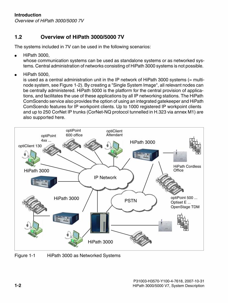
● HiPath 3000, whose communication systems can be used as standalone systems or as networked sys-tems. Central administration of networks consisting of HiPath 3000 systems is not possible.
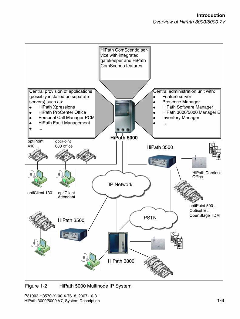
● HiPath 5000,is used as a central administration unit in the IP network of HiPath 3000 systems (= multi-node system, see Figure 1-2). By creating a "Single System Image", all relevant nodes can be centrally administered. HiPath 5000 is the platform for the central provision of applica-tions, and facilitates the use of these applications by all IP networking stations. The HiPath ComScendo service also provides the option of using an integrated gatekeeper and HiPath ComScendo features for IP workpoint clients. Up to 1000 registered IP workpoint clients and up to 250 CorNet IP trunks (CorNet-NQ protocol tunnelled in H.323 via annex M1) are also supported here.
Figure 1-1 HiPath 3000 as Networked Systems
optiPoint 4xx ...
optiClient 130HiPath 3000
optiClient Attendant
HiPath 3000
PSTN
IP Network
HiPath 3000
HiPath Cordless Office
optiPoint 500 ...Optiset E ...OpenStage TDM
optiPoint 600 office
HiPath 3000
P31003-H3570-Y100-4-7618, 2007-10-311-2 HiPath 3000/5000 V7, System Description
3000sb1.fm
For internal use only IntroductionOverview of HiPath 3000/5000 7V
Figure 1-2 HiPath 5000 Multinode IP System
optiPoint 410 ...
optiClient 130
HiPath 3500
optiClient Attendant
HiPath 3800
PSTN
IP Network
HiPath 3500
Central administration unit with: ● Feature server ● Presence Manager ● HiPath Software Manager● HiPath 3000/5000 Manager E● Inventory Manager● ...
Central provision of applications (possibly installed on separate servers) such as: ● HiPath Xpressions ● HiPath ProCenter Office● Personal Call Manager PCM● HiPath Fault Management ● ...
HiPath Cordless Office
optiPoint 500 ...Optiset E ...OpenStage TDM
optiPoint 600 office
HiPath 5000
HiPath ComScendo ser-vice with integrated gatekeeper and HiPath ComScendo features
P31003-H3570-Y100-4-7618, 2007-10-31HiPath 3000/5000 V7, System Description 1-3
Introduction For internal use only
3000sb1.fm
Highlights with V7.0 and Later
1.3 Highlights with V7.0 and Later
● OpenStage TDM: OpenStage is a new product family designed for business communica-tion. Their attractive design and multi-functional click wheel together with the user friendly LC display make these products convenient and easy to use.
● ISDN numbering plan (E.164)A new numbering plan for addressing telephone networks that specifies the individual com-ponents of a telephone number and the number of digits it may contain. This feature en-hances integration in networks with HiPath 4000, in applications and, in the future, with In-ternet telephony service providers. The plan can be configured using Manager E.
● Number of key modules increased to 250Key modules are add-on devices that can be attached to the side of telephones to increase the number of programmable keys for each telephone. The number of key modules that can be connected to HiPath 3800 systems has increased from 100 to 250.
● Path optimization in networked HiPath 3000/5000 systemsPath optimization, in other words transit traffic with identical source and destination sys-tems (switched or forwarded traffic, for instance), is performed in HiPath 3000/5000 sys-tems networked over IP. This means that channels are no longer blocked.
● Call forwarding to voice mailboxesWhen calls are forwarded from one station (A) to another station (B), you can configure whether unanswered calls are recorded on station A or station B’s voice mailbox. The func-tion is configured at station A using Manager E.
● LDAP diagnosisIf a query sent to an LDAP server is not returned or is incorrectly returned, one of the fol-lowing error messages is shown on the Optiset E or optiPoint display:
– "Server not reachable"
– "Server busy"
– "Server error"
If a result is not returned for a query, the error message "No result" is displayed.
HG 1500 provides an error report via an event log or customer trace and an SNMP trap (configurable).
● Remote upgrade conceptHiPath system software can be upgraded remotely. During this process, customer data is adapted to the new software.
P31003-H3570-Y100-4-7618, 2007-10-311-4 HiPath 3000/5000 V7, System Description
3000sb1.fm
For internal use only IntroductionHighlights with V7.0 and Later
● Analog CLIPA calling party’s number (CLI) is transmitted to HiPath systems with analog trunks and shown on the telephone display. The TMANI and TLANI boards collect and forward the req-uisite data.
● Extended Fast Connect (EFC)In HiPath 3000/5000 V7, the CorNet IP protocol has been expanded to include the Extend-ed Fast Connect (EFC) protocol variant. EFC is required to enable end-to-end payload "IP/IP e2e payload via enterprise proxy" to be used for Internet telephony. End-to-end payload "IP/IP e2e payload via enterprise proxy" for Internet telephony is supported in HiPath 3000/5000 V7 R2 and later systems. This means that for IP telephony no data packets have to be processed by digital signal processors of the system. The calls are routed via LANs, routers and Internet Telephony Service Providers (ITSP). HiPath 3000 sets up a call to the remote station. The maximum number of simultaneous call types depends on the codec used and on the available bandwidth of the Internet telephony connection. All IP workpoints (HFA) in a system and all IP workpoints (HFA) in a network must support the EFC protocol. Where necessary, optiPoint 410, optiPoint 420 and optiClient 130 IP workpoints must be updated to EFC-enabled software. optiPoint 400, optiPoint 600 office (CorNet IP mode) and optiPocket are not EFC-enabled and are therefore no longer sup-ported by HiPath 3000/5000 V7.
● Direct payload to the Internet telephony service providerDirect payload is based on EFC: Calls are switched directly to the Internet telephony ser-vice provider via the customer LAN and the router. B channels are therefore not used on the HG 1500 board between IP telephones and the Internet telephony service provider. Previously, each IP telephone seized two B channels on HG 1500. This restriction no long-er applies. TDM telephones still use one B channel respectively.
● CSTA monitoring of Internet telephony service provider trunksThis function enables Internet telephony service provider trunks to be integrated in appli-cations that are connected to the HiPath system via the CSTA interface. This means that for CSTAs, there are no longer any differences between TDM trunks and Internet telephony service provider trunks.
P31003-H3570-Y100-4-7618, 2007-10-31HiPath 3000/5000 V7, System Description 1-5
Introduction For internal use only
3000sb1.fm
Highlights with V6.0 and Later
1.4 Highlights with V6.0 and Later
● Direct Dial-In (DDI) for Internet telephony:The Internet telephony service provider (ITSP) provides a system phone number with a DDI phone number range.
● Networked systems can be connected to the ITSP: A HiPath system can be registered at an ITSP and integrated in an IP network at the same time. Networked systems can use SIP phone numbers for both incoming and outgoing calls. Each extension in networked sys-tems can be assigned an MSN/DDI by the ITSP or can answer calls with the default station number.
● Four SIP providers simultaneously: You can connect up to four ITSPs to a HiPath system at the same time. You can assign priorities to the ITSPs with LCR using the phone number dialed and the time.
● STUN support: HiPath provides a STUN client that operates together with a STUN server in the ITSP for NAT traversal. An external router connected to HiPath is used for ITSP ac-cess.
P31003-H3570-Y100-4-7618, 2007-10-311-6 HiPath 3000/5000 V7, System Description
3000sb1.fm
For internal use only IntroductionFeatures
1.5 Features
1.5.1 Automatic, Time-Dependent Class-of-Service (COS) Changeover
In the past, class-of-service changeover was only capable of distinguishing between day ser-vice and night answer. This type of changeover applied to all stations
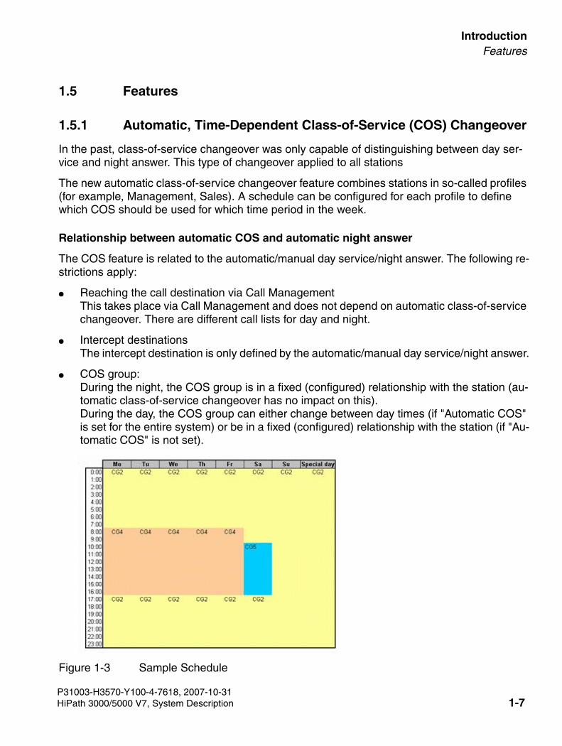
The new automatic class-of-service changeover feature combines stations in so-called profiles (for example, Management, Sales). A schedule can be configured for each profile to define which COS should be used for which time period in the week.
Relationship between automatic COS and automatic night answer
The COS feature is related to the automatic/manual day service/night answer. The following re-strictions apply:
● Reaching the call destination via Call ManagementThis takes place via Call Management and does not depend on automatic class-of-service changeover. There are different call lists for day and night.
● Intercept destinationsThe intercept destination is only defined by the automatic/manual day service/night answer.
● COS group:During the night, the COS group is in a fixed (configured) relationship with the station (au-tomatic class-of-service changeover has no impact on this). During the day, the COS group can either change between day times (if "Automatic COS" is set for the entire system) or be in a fixed (configured) relationship with the station (if "Au-tomatic COS" is not set).
Figure 1-3 Sample Schedule
P31003-H3570-Y100-4-7618, 2007-10-31HiPath 3000/5000 V7, System Description 1-7
Introduction For internal use only
3000sb1.fm
Features
1.5.2 Caller-Specific Ringer Signaling
Different types of caller-specific ringing signals are available in V6.0 or later.
In addition to external ringer signaling, internal ringer signaling can then be configured for every station. Every internal call set up by this station (calling station) is signaled by a specific ring type at station B (called station). The ring frequency at the destination is based on the caller’s ring frequency. A station is assigned a specific ring frequency for this with Manager E. As in the existing field for external calls ("ringer signaling"), the new ring frequencies for the internal ring frequency are controlled via Manager E (not via Manager C).
The various ring frequencies are implemented at the station called if this is a HFA station (Up0E or IP). Analog stations are always called with frequency 1.
CMI handsets
Only handsets with ringer melodies are supported. The calling number ID is sent to the Gigaset so that the melody selection function in the internal phonebook (VIP) is supported; this depends on whether this feature is supported by the relevant caller.
The various internal ring frequencies only operate between endpoints that are registered in the same system or node.
Seven additional ring frequencies are added to the existing ring frequency. These frequencies have different default values and every station is displayed by default with frequency 1.
P31003-H3570-Y100-4-7618, 2007-10-311-8 HiPath 3000/5000 V7, System Description
3000sb1.fm
For internal use only IntroductionFeatures
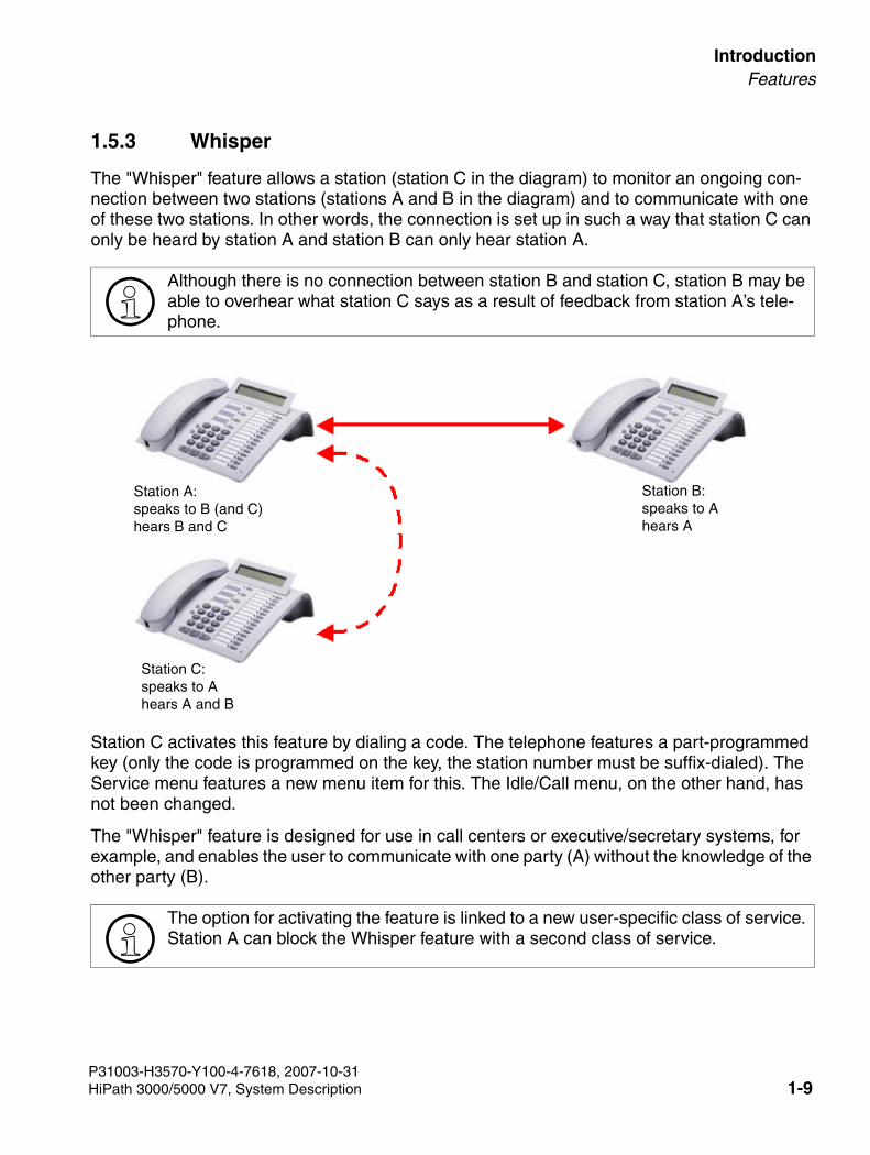
1.5.3 Whisper
The "Whisper" feature allows a station (station C in the diagram) to monitor an ongoing con-nection between two stations (stations A and B in the diagram) and to communicate with one of these two stations. In other words, the connection is set up in such a way that station C can only be heard by station A and station B can only hear station A.
Station C activates this feature by dialing a code. The telephone features a part-programmed key (only the code is programmed on the key, the station number must be suffix-dialed). The Service menu features a new menu item for this. The Idle/Call menu, on the other hand, has not been changed.
The "Whisper" feature is designed for use in call centers or executive/secretary systems, for example, and enables the user to communicate with one party (A) without the knowledge of the other party (B).
>Although there is no connection between station B and station C, station B may be able to overhear what station C says as a result of feedback from station A’s tele-phone.
>The option for activating the feature is linked to a new user-specific class of service. Station A can block the Whisper feature with a second class of service.
Station C:speaks to Ahears A and B
Station A:speaks to B (and C)hears B and C
Station B:speaks to Ahears A
P31003-H3570-Y100-4-7618, 2007-10-31HiPath 3000/5000 V7, System Description 1-9
Introduction For internal use only
3000sb1.fm
Features
Restrictions
● If neither of the participants in the original call (station A or B) is a TDM station, the HiPath switching network is not involved at the time of activation and changeover is impossible without briefly interrupting the connection between A and B.
● Stations A and C must be in the same node.
● Station C can only activate this feature in idle/standby status.
● Destination terminals for the Whisper feature (station A) can only be terminals with displays controlled by the system (Optiset, optiPoint, optiClient). As in HiPath 4000, CMI is not supported.
1.5.4 Privacy Release Key (MULAP)
Version 6.0 and later incorporates a new status called "Privacy Release". A new key was cre-ated in the database for this. This key is supported by the following workpoint clients:
● Optiset E
● optiPoint 500
● optiPoint 600 (TDM only)
● optiClient 130
● OpenStage 20 TDM, OpenStage 40 TDM
The Privacy Release (MULAP) feature lets you release a busy MULAP line for a conference during a call simply by pressing the "Privacy Release MULAP" button. This is indicated by a flashing light on the stations of other MULAP members who can then join the call by pressing the flashing MULAP button. This creates a conference which is signaled by tones and display messages.
All members of a MULAP group can program a Privacy Release button on their stations. The Privacy Release feature also works when a subscriber is participating in a conference, even if the subscriber in question initiated the conference.
The Privacy Release button can be configured via Manager E.
P31003-H3570-Y100-4-7618, 2007-10-311-10 HiPath 3000/5000 V7, System Description
3000sb1.fm
For internal use only IntroductionFeatures
1.5.5 Protocol Extensions for HiPath ProCenter Agile
You can use a "multiple pilot station number" to access the same UCD group with different sta-tion numbers. This function is implemented by configuring a virtual station in Call Management.
The "multiple pilot station number" is treated like a "call forwarding" number. Information about the "multiple pilot station number" is "delivered" by the last call forwarding destination and "queued" in the relevant UCD group.
1.5.6 CSTA Interface
The station can address the associated CSTA application (if this was previously registered at the HiPath system) by selecting an application ID. A registered application can address a sta-tion directly (for example, to confirm an action on the display).
Internet telephony service provider trunks can be integrated in CSTA applications. This means that for CSTAs, there are no longer any differences between TDM trunks and Internet telephony service provider trunks.
You can start an I/O session with a feature code or function key. You can use the function key to start, resume, and stop an I/O session; the function key LED indicates the status of the I/O session (standby, active, suspended).
During an I/O session, a subscriber can operate the application using the following navigation keys:
● the keypad
● plus/minus keys
● the alphanumeric keyboard (Optiset Memory)
● the programmable keys and softkeys (CMI)
Up to ten applications can be simultaneously logged on to a system.
A single I/O session can only be used by one station at a time. If a session is interrupted ("sus-pended" status), a second I/O session cannot be started; the interrupted session must first be ended.
Internet telephony service provider trunks can be integrated in applications that are connected to the HiPath system via the CSTA interface.
P31003-H3570-Y100-4-7618, 2007-10-31HiPath 3000/5000 V7, System Description 1-11
Introduction For internal use only
3000sb1.fm
Features
1.5.6.1 ComScendo On a Button Suite
ComScendo On a Button Suite is a new feature set for HiPath 3000 V6.0 or later that offers new labor-saving features for users of optiPoint telephones with displays.
The following CTI functions are part of the ComScendo On a Button Suite and can be activated at the touch of a button:
● EasyLookup Access to the corporate directory (LDAP) from a terminal, regardless of cur-rent call status.Sample applications:
– Display the name of a mobile caller by pressing this button (if the number is stored in the directory)
– Search for colleagues in the same room/alternative numbers
– Determine e-mail addresses on the basis of stored numbers/names
● EasySee: This function displays the corporate directory "phone card" on the PC Web browser.Sample application:
– Display the ID of an unknown called party in ringing or talk state. Answers questions such as: Who am I talking to? What organization does this person belong to?
● EasyMail: This function automatically opens a blank e-mail on your monitor addressed to all current called parties or conference members (provided that they are stored in the di-rectory).Sample application:
– "Please confirm the discussed procedure by e-mail."
● EasyShare: This function opens a Microsoft Netmeeting session for all called parties and ComScendo on a Button Suite users stored in the directory.Sample application:
– Initiate a telephone conference to discuss a document.
Prerequisite: ComScendo on a Button Suite must be installed for all called parties partici-pating in a conference.
The ComScendo On a Button Suite functions are based on HiPath CAP V3.0 XML Phone Ser-vices and programmed on station buttons. The EasyLookup, EasySee, EasyMail, and Easy-Share functions can be programmed on separate buttons or you can program a "ComScendo on a Button Suite" menu on one button and use this to select the individual functions.
P31003-H3570-Y100-4-7618, 2007-10-311-12 HiPath 3000/5000 V7, System Description
3000sb1.fm
For internal use only IntroductionFeatures
1.5.7 IP Mobility
The mobility option integrates mobile terminals in the enterprise’s communication processes and offers users the following basic functions:
● The One Number Service offers availability under a single call number regardless of loca-tion and irrespective of the mobile unit used.
● Mobile staff have access to their familiar telephone features and communication platform regardless of their location and the terminal used.
New features in HiPath 3000/5000 support teleworking and desk sharing concepts.
1.5.7.1 Teleworking
The Teleworking option is the solution for staff who have a permanent workplace off the com-pany campus. The Teleworking option offers both the One Number Service, and access to Hi-Path telephony features on a fixed telephone at the home workplace. As well as any analog telephones, system telephones from the optiPoint or Optiset E series can also be used at the home workplace.
1.5.7.2 Desk Sharing
The DeskSharing option is the hoteling solution and provides desks for employees whose jobs require them to change locations within the company campus. DeskSharing desks can be used by several employees, ensuring that the best possible use is made of the available desks.
DeskSharing offers the following basic function:
Employees who do not have a fixed desk can reserve a desk and telephone for a specific peri-od. This reservation is made by means of a Web user interface from any PC or by means of a check-in station in the foyer of a DeskSharing area. Employees can book themselves in at their temporarily reserved desk. Check-in takes place either at the check-in station in the foyer of a DeskSharing area or by check by phone from any phone within the DeskSharing area. When employees check in, the properties and features of their home telephone are automatically re-located to the reserved station.
P31003-H3570-Y100-4-7618, 2007-10-31HiPath 3000/5000 V7, System Description 1-13
Introduction For internal use only
3000sb1.fm
Features
1.5.8 IP Mobility Enhancement (Emergency Number)
In an IP network, a mobile station can log on either at home or at any other remote network node. In the case of an emergency call from a HFA-IP telephone that is registered at a remote network node, the emergency destination of the remote network node cannot be called. In-stead, only the emergency destination of the HiPath 3000 node where the telephone is physi-cally installed is called.
The emergency number valid for the IP telephone must be a destination in the HiPath network. The emergency destination can either be connected as a standard telephone with the HiPath 3000 network node, or as a virtual device in which call forwarding to an emergency destination (e.g. to the CO) is activated.
An emergency prefix must be stored in the HFA-IP telephone. This number can be used to reach the emergency destination from anywhere within the network. Emergency numbers for police or fire services (112 or 110 in Germany, for instance) are dialed with a prefix by the sub-scriber.
This function is already supported by the telephones and optiClient terminals.
>A direct call to an emergency destination in the public network is not possible be-cause telecom providers do not support this type of access.
>It is important that the emergency numbers are configured both in the home system and in the destination system. In the case of varying emergency numbers in different countries (e.g. the emergency number 911 is valid in the U.S., while 112 must be di-aled in Germany), the emergency number of the country in question must also be configured in the system in the destination country.
P31003-H3570-Y100-4-7618, 2007-10-311-14 HiPath 3000/5000 V7, System Description
3000sb1.fm
For internal use only IntroductionFeatures
1.5.9 Internet Telephony – ITS Provider Features
Information about Internet telephony features can be found in the feature description.
Connection to Internet telephony service providers over the SIP protocol
The Internet telephony service provider (ITSP) market is rapidly expanding together with the number of services and business models available.
The standards issued by the standards organizations SIP Forum and ETSI/TISPAN are pur-posely drafted with sufficient leeway to support vendors in the rapid development of new tech-nology. Moreover, the individual providers design their network-based routing functions to suit each specific business model.
Supported ITSP connections
HiPath 3000/5000 V6.0 or later supports:
● ITSP connections with single-number registration. This is currently the provider interface offered most often for the private customer segment and for smaller communication solu-tions for medium-sized companies.
● Internet telephony system connections for larger-scale system configurations. In this case, the customer receives a phone number range from the ITSP.
HiPath platforms with ITSP connections are subject to intensive tests to guarantee secure and high-quality communication.
Released ITSPs
You will find an up-to-date list of released ITSPs under the current link: HTTP://wiki.siemens-enterprise.com/index.php/Collaboration_with_VoIP_Providers
Support is restricted exclusively to the ITSPs listed.
>In HiPath 3000/5000 V7 R2 and later systems, "IP/IP e2e payload via enterprise proxy" is supported for Internet telephony. This means that for Internet telephony no data packets have to be processed by digital signal processors of the system. The calls are routed via LANs, routers and Internet Telephony Service Providers (ITSP). HiPath 3000/5000 sets up a call to the remote station. This means that no gateway channels (DSP channels) are required for ITSP connections. The maximum number of simultaneous calls depends on the codec used and on the available bandwidth of the Internet connection.
P31003-H3570-Y100-4-7618, 2007-10-31HiPath 3000/5000 V7, System Description 1-15
Introduction For internal use only
3000sb1.fm
Features
HiPath 3000/5000 7V supports the following features with ITSP connections
HiPath 3000/5000 7V can be used by standalone systems as well as networked systems to connect to Internet telephony service providers:
● The system supports up to four simultaneously active Internet telephony service providers (ITSP) for LCR. Although four different Internet telephony service providers (ITSP) may be registered si-multaneously, more connections may be possible depending on bandwidth. The maximum number of simultaneous calls is calculated based on the upstream rate and the bandwidth required for each call (128 Kbps).[Number of calls = upstream rate (in Kbps) / 128 Kbps]
● Up to 30 user IDs (SIP client user accounts) can be configured for Internet telephony user connections with single-number registration.
● S0 connections and Internet telephony connections can be used in parallel in all network-ing solutions (HiPath 3000/5000 systems connected to each other or to HiPath 2000 sys-tems) to connect to ITSP analog lines. HiPath 3000 V6.0 SMR-9 or later supports the si-multaneous use of connections over CorNet IP and ITSP ports.
● Internet access: ADSL, SDSL: HG 1500 V3.0 is operated in the LAN behind an external router with firewall or NAT functionality.
Points to be considered
The following issues must be considered:
● Network Address Translation (NAT) is the conversion of IP addresses in the LAN for the Internet. NAT can be enabled and disabled in HiPath 3000/5000.Certain services – such as VoIP or video telephony – embed subscribers’ IP addresses in their data packets, however, instead of just noting them in the packet headers.These services are only compatible with NAT within a VPN or require the use of additional protocols (for example, STUN) or infrastructure components to bypass problems with NAT (=NAT Traversal) for connections to an Internet telephony provider.
● For operation behind a router/firewall:If an ITSP provides a STUN server for NAT traversal, none of the routers implemented sup-ports the "symmetric NAT" variant. The use of STUN protocols is not required and the fire-wall reconfiguration is not necessary if the ITSPs perform NAT traversal over infrastructure components in the provider network, such as, session border controllers (SBC). "SIP-aware" firewalls also feature a NAT traversal function.
● Simple Traversal of UDP over NATs (STUN)STUN is a simple client/server-based network protocol designed to identify the existence of NAT firewalls and routers. A central STUN client on the first HG 1500 V3.0 (signaling gateway) connects with a STUN server at the Internet telephony service provider (ITSP).The STUN server provides information about how the Internet connection is perceived ex-
P31003-H3570-Y100-4-7618, 2007-10-311-16 HiPath 3000/5000 V7, System Description
3000sb1.fm
For internal use only IntroductionFeatures
ternally. HiPath 3000/5000 uses this information to send packets to an ITSP or called party in the Internet to ensure that even HiPath 3000/5000 systems behind a NAT device can be reached from the Internet. The settings for an upstream NAT firewall or a NAT router do not have to be changed for this.
Note: A signaling gateway can perform STUN requests on behalf of media gateways. The mechanism that sends IP packages on behalf of other devices is known as "IP Spoofing".
By deliberately using special filters, some network infrastructure components can check the assignment of incoming packets and take the necessary action if the assignment is in-correct, for example, trigger an alarm (e-mail), reject the packet or even block the port (for example, by SNMP access to switches).
Network administrators must configure exceptions so that the STUN protocol can be used for NAT traversal even in such an environment.
ITSP features
● Special number/emergency calls/fax and modem calls
– Emergency numbers (110, 112) are not fully supported by ITSPs because the local network cannot be uniquely assigned during breakout into the public network. These connections must be set up over S0 accesses.
– Special number are not transferred by all ITSPs.We recommend transferring the following special numbers by default over ISDN:
● LCR must be adapted by the service team to fulfill requirements for routing trunk calls to selected service providers/services (for example, 0180, 0800, etc.).
● Bandwidth controlAll connections to the Internet telephony service provider (ITSP) use HiPath 3000/5000 DSP resources, as do connections with an analog/IP gateway (for example, ISDN connec-tions) or when using music on hold. Please refer to the notes in this manual in Section 2.1, "System-Related Capacity Limits" and in the service manual under Dynamic configuration rules.
0137 Televoting
0138 Televoting
0900 Premium-rate services
118xy Information services
116 116 Emergency cancellation number for EC cards, credit cards, etc.
>If a system is only operated over an Internet telephony connection, routing can also be configured in the ITSP direction for emergency calls and special numbers. You must first ensure that the ITSP supports these services.
P31003-H3570-Y100-4-7618, 2007-10-31HiPath 3000/5000 V7, System Description 1-17
Introduction For internal use only
3000sb1.fm
Features
Restrictions in voice quality can occur in connections that are not QoS-capable (in general, ADSL connections). High voice quality is generally achieved if a non-QoS-capable Internet telephony connection is used exclusively for voice connections to the ITSP.Connection can suffer temporary interruptions as a result of the provider’s network avail-ability. Please note the ITSP’s terms and conditions. If connections are not set up over SIP, they can be established by HiPath 3000/5000 7V (HG 1500 V3.0) over ISDN. The router used by the customer must be able to guarantee good voice quality over QoS functions and bandwidth control mechanisms.Although four different Internet telephony service providers (ITSP) may be registered si-multaneously, more connections may be possible depending on bandwidth. The maximum number of simultaneous calls is calculated based on the upstream rate and the bandwidth required for each call (128 Kbps)..[Number of calls = upstream rate (in Kbps) / 128 Kbps]
● Calling party identification:The CLIP and CLIR features are implemented differently in the individual ITSPs. Restric-tions may occur in call number display or entries may occur in the missed calls list. The CLIP no Screening feature is currently not supported. The B station’s display/missed calls list shows the station number of the line to the ITSP - not that of the calling A station.
● Connections with breakout into the fixed network//mobile telephone system or from the fixed network/mobile telephone system:Provider-internal connections (destination is busy/not registered)Internal connections to a busy or unregistered station are generally signaled correctly.
● Calls to other ITSPsThese calls are technically feasible, however, the individual providers match the routing functions in their network with the relevant business model. For more information, consult the relevant ITSP.
● Call data evaluationThe SIP protocol records itemized call data by time. Evaluation is possible using external applications, such as, Teledata Office.
● DTMF transmission over IPDTMF signals are transmitted in the voice channel. The G.711 codec is required for secure transmission to the provider.
● Fax transmissionsFax transmissions are not supported by every provider. We recommend using ISDN for fax transmissions (default setting).With HiPath 3000/5000, V6 G.711 gateway channels can be used for fax transmissions over ITSP connections. The ITSP must guarantee a continuous data stream for this. T.38 to ITSPs is not supported.
P31003-H3570-Y100-4-7618, 2007-10-311-18 HiPath 3000/5000 V7, System Description
3000sb1.fm
For internal use only IntroductionFeatures
● Modem transmissions and ISDN data services (for example, the use of EC cash devices) are not supported.
● CSTA monitoring is not supported for connections to ITSPs.Applications that provide this feature are consequently not supported (for example, call centers).
P31003-H3570-Y100-4-7618, 2007-10-31HiPath 3000/5000 V7, System Description 1-19
Introduction For internal use only
3000sb1.fm
Features
1.5.10 Telephones for Internet Telephony
1.5.10.1 DSL Terminals
The HiPath 3000/5000 IP system supports the following DSL terminals:
● optiPoint 410 S
● optiPoint 420 S
● optiPoint 150 S
1.5.10.2 DSL Terminal Features
Actively supported features
Terminals actively support the following DSL features:
● CLIP (Calling Line Identification Presentation)optiPoint 150 S only supports the feature in standalone systems.
● CLIR (Calling Line Identification Restriction)optiPoint 150 S does not supports this feature.
● COLP (Connected Line Identification Presentation)
● COLR (Connected Line Identification Restriction)optiPoint 150 S does not supports this feature.
● Consultation hold
● Call hold
● Toggle
● Transfer (Screened and Unscreened Transfer) The optiPoint 410 S and optiPoint 420 S phone family supports the Unscreened Transfer feature.
● DISA (Direct Inward System Access): Features cannot be activated for the SIP telephone.
● Inband DTMFoptiPoint 150 S only supports the G.711 codec.
P31003-H3570-Y100-4-7618, 2007-10-311-20 HiPath 3000/5000 V7, System Description
3000sb1.fm
For internal use only IntroductionFeatures
Passively supported features
Although Internet telephony stations may not activate the following features, they may be pas-sively involved:
● Call forwarding (forwarding to an Internet telephony station is supported)
● Conference (Internet telephony stations may be passively involved)
● Park (Internet telephony stations may be parked; from the perspective of the Internet tele-phony station, this is similar to "Call hold")
● Live Call Recording (Internet telephony stations may be passively involved)
● Whisper (Internet telephony stations may be passively involved)optiPoint 150 S does not supports this feature.
● Automatic COS changeover (Internet telephony stations support automatic COS changeover)
● Internal traffic restriction groups (Internet telephony stations can be entered in ITR groups)
Features supported by optiPoint 150 S
The following telephone-specific optiPoint 150 S features are supported for operation on Hi-Path 3000/5000, V6.0 SMR-09 or later:
● Missed calls list, telephone
● Do not disturb (DND)
● Call duration display
● Local numbering plan
● Microphone on/off
● Language selection
Restrictions for Internet telephony stations
The following restrictions apply to Internet telephony stations:
● Internet telephony stations are configured on HiPath 3000/5000 7V as DSS1 (functional telephones) and therefore cannot be supervised by the system (no monitoring). Internet telephony stations cannot use applications that require monitoring (for example, HiPath ComAssistant).
● Internet telephony stations cannot be integrated into call pickup groups, hunt groups, team, top or MULAP groups.
P31003-H3570-Y100-4-7618, 2007-10-31HiPath 3000/5000 V7, System Description 1-21
Introduction For internal use only
3000sb1.fm
Features
● Internet telephony stations cannot activate or use system features that can be operated with codes.
● Music is played when an Internet telephony station is on hold. Music is not played and a ring tone is not applied for the Internet telephony station when unscreened transfer is per-formed between the Internet telephony station and another station.
● The display on the Internet telephony station is not refreshed if an Internet telephony sta-tion is unparked by a different party to the one who parked it.
● SIP terminals are not supported by the deployment tool (DLS interface, DLI) in HiPath Xpressions Compact boards (HiPath 3000).
● optiPoint 150 S allows you to toggle between two external calls. The active call can be cleared down by briefly pressing the hookswitch. Simply replace the optiPoint 150 S hand-set to connect the two external parties to each other (this can lead to increased call charg-es). A connection of this kind can only be cleared down at the system by disconnecting the relevant trunks or by resetting (restarting) the system.
● In some situations, you cannot use terminal-specific features on HiPath 3000/5000 7V. This includes features that are available over the terminal’s menu interface. The features available with the HiPath 3000/5000 7V basic system have general release status.
Native SIP only supports:
● Basic call
P31003-H3570-Y100-4-7618, 2007-10-311-22 HiPath 3000/5000 V7, System Description
3000sb1.fm
For internal use only IntroductionFeatures
1.5.11 Signaling and Payload Encryption (SPE)
Signaling and user data is encrypted with the symmetrical AES algorithm with a key length of 128 bits. All stations use the same key (pre-shared secret) for a specific period. Encryption can be activated or deactivated for all stations together; encrypted data can only be transferred if all terminals in the LAN support encryption and if no analog terminals, particularly fax ma-chines, are connected to the LAN over converters.
A ComScendo security license is required for each terminal that should support encryption. Not all terminals have the necessary technical prerequisites.
1.5.11.1 Scenarios Supported
Only CorNet IP "IP/IP e2e payload via enterprise proxy" connections can be encrypted with Hi-Path 3000/5000 V6.0 or higher and HiPath 4000 V3.0 or higher. The "central gatekeeper archi-tecture" means that simultaneous encryption can only be activated for all CorNet IP workpoints and gateways (HG1500) in a HiPath 3000, HiPath 3000 network or HiPath 3000/5000 net-worked system.
The following scenarios are supported:
● HiPath 3000 standalone
● HiPath 3000 network
● HiPath 3000/5000 networked system
● HiPath 3000/4000/5000 networked system
>The DLS (Deployment and License Server) distributes the PSS (Pre-Shared Se-crets). For this reason, it must always be available in the data network.
HiPath 3000/5000 V6.0 or later only supports SRTP "IP/IP e2e payload via enter-prise proxy" encryption for CorNet IP scenarios. This version is not designed for si-multaneous CorNet IP encryption and SIP interface usage.
Furthermore, encryption cannot be activated for each station/gateway connection. As a result, call encryption and signaling can only be activated for all components (gateways/clients) connected to a system or network.
P31003-H3570-Y100-4-7618, 2007-10-31HiPath 3000/5000 V7, System Description 1-23
Introduction For internal use only
3000sb1.fm
Features
1.5.11.2 Telephones Supported
The following system telephones support SRTP "IP/IP e2e payload via enterprise proxy" en-cryption in HiPath 3000/5000 7V:
● optiPoint 410 eco plus, (software V5.1 or later)
● optiPoint 410 standard, (software V5.1 or later)
● optiPoint 410 advanced, (software V5.1 or later)
● optiPoint 420 eco plus, (software V5.1 or later)
● optiPoint 420 standard, (software V5.1 or later)
● optiPoint 420 advanced, (software V5.1 or later)
● optiClient 130, (software V5.1 or later)
Due to the increased telephone resources required for data encryption/decryption, only eco+ and higher models from the optiPoint 410/420 range support encryption.
The following telephones can no longer be used at the HiPath 3000 when the encryption feature is activated:
● optiPoint 400
● optiPoint 410 (lower than eco plus)
● optiPoint 600 including the office model (IP connection)
● optiPocket 130
● H.323 telephones (including AP120)
● SIP telephones (including optiPoint 410/420 S, optiClient 130 S, AP 1120 SIP)
1.5.11.3 HiPath ComScendo Security License
SRTP encryption in HiPath 3000/5000 7V is verified using HiPath ComScendo security licens-es.
The number of ComScendo security licenses depends on the number of ComScendo and B channel licenses already available in the entire HiPath 3000/5000 networked system.
P31003-H3570-Y100-4-7618, 2007-10-311-24 HiPath 3000/5000 V7, System Description

3000sb1.fm
For internal use only IntroductionFeatures
Mixed HiPath 3000/5000 7V and HiPath 4000 V3.0 networks.
The basic requirement for "IP/IP e2e payload via enterprise proxy" security encryption is HiPath 3000/5000 V6.0 or later and HiPath 4000 V3.0 or later. The system upgrade is software-based. The hardware can continue to be used depending on the version. A ComScendo security li-cense is available for security. The licenses are for IP stations and B channels for the IP net-work.
P31003-H3570-Y100-4-7618, 2007-10-31HiPath 3000/5000 V7, System Description 1-25
Introduction For internal use only
3000sb1.fm
Features
1.5.12 Licensing
Versions 5.0 and later of HiPath 3000 and HiPath 5000 use a new, centralized licensing proce-dure known as the License Management System. The procedure is used in all HiPath products, for example communication systems, workpoint clients, and applications.
To license a product you must first establish a connection with the Central License Server (CLS) via the Customer License Manager (CLM). The customer-specific data entered is used to uniquely identify the product configuration for which the relevant license file is to be supplied in encrypted format. The license file contains the licenses for all licensed products.
The CLM is responsible for activating the license file and allocating it to the Customer License Agent (CLA). This is where the license data is validated. Distribution of the licenses to the indi-vidual products using HiPath 3000/5000 Manager E can then begin.
All licenses that can be ordered for HiPath 3000 7V are handled by HiPath License Manage-ment.
The following licenses are available for HiPath 3000 7V:
● optiClient Attendant V8 / upgrade to optiClient Attendant V8
● ComScendo license for IP workpoints (including SIP)
● ComScendo security license for IP workpoints and B channels
● S2M License for releasing B channels
● HG 1500 B channels
● HG 1500 VPN (Virtual Private Network)
● HG 1500 LWCA (Light Weight Certification Authority)
● BS4 License for releasing traffic channels
● License for an Xpressions Compact-based announcement
● HiPath TAPI 120 V2.0, HiPath TAPI 170 V2.0
Please refer to the relevant sales information for information on licenses for applications and IP clients that can be connected.
P31003-H3570-Y100-4-7618, 2007-10-311-26 HiPath 3000/5000 V7, System Description
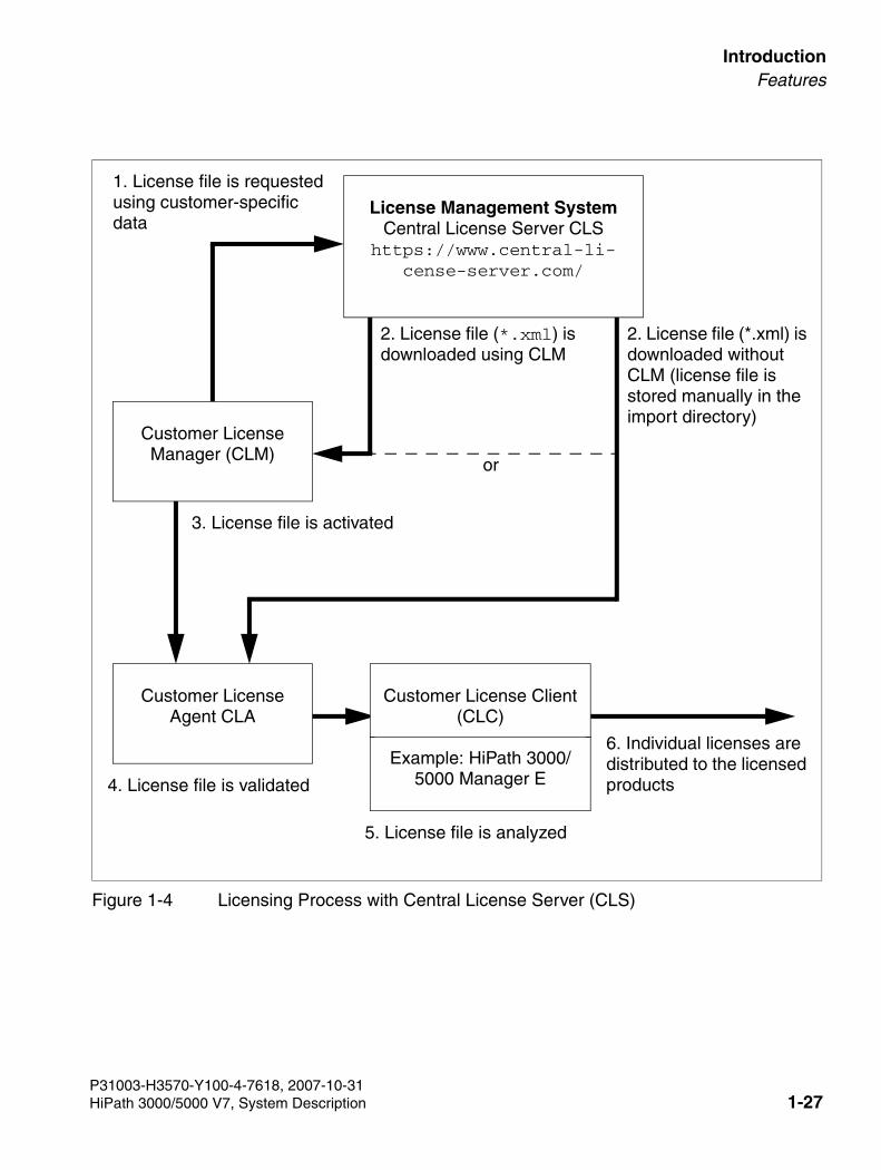
3000sb1.fm
For internal use only IntroductionFeatures
Figure 1-4 Licensing Process with Central License Server (CLS)
2. License file (*.xml) is downloaded using CLM
1. License file is requested using customer-specific data
Customer License Agent CLA
4. License file is validated
5. License file is analyzed
Customer License Client (CLC)
Example: HiPath 3000/5000 Manager E
6. Individual licenses are distributed to the licensed products
3. License file is activated
License Management SystemCentral License Server CLS
https://www.central-li-cense-server.com/
Customer LicenseManager (CLM)
or
2. License file (*.xml) is downloaded without CLM (license file is stored manually in the import directory)
P31003-H3570-Y100-4-7618, 2007-10-31HiPath 3000/5000 V7, System Description 1-27
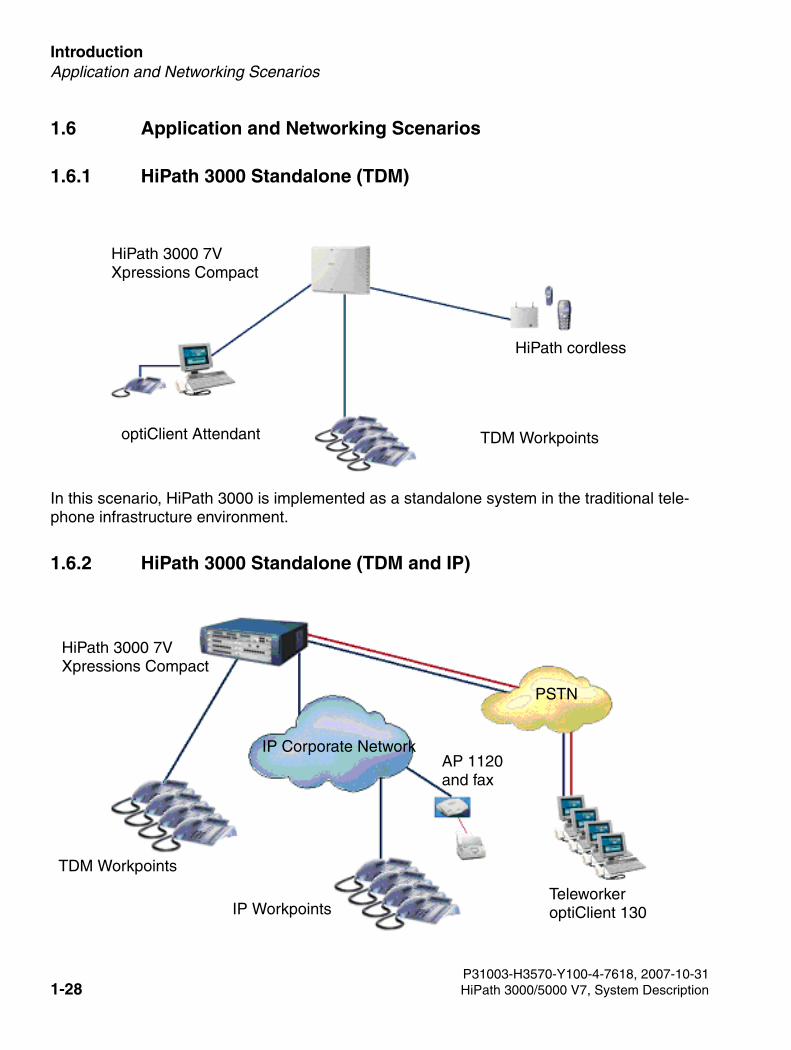
Introduction For internal use only
3000sb1.fm
Application and Networking Scenarios
1.6 Application and Networking Scenarios
1.6.1 HiPath 3000 Standalone (TDM)
In this scenario, HiPath 3000 is implemented as a standalone system in the traditional tele-phone infrastructure environment.
1.6.2 HiPath 3000 Standalone (TDM and IP)
optiClient Attendant
HiPath 3000 7VXpressions Compact
HiPath cordless
TDM Workpoints
HiPath 3000 7VXpressions Compact
TDM Workpoints
IP WorkpointsTeleworkeroptiClient 130
PSTN
IP Corporate NetworkAP 1120 and fax
P31003-H3570-Y100-4-7618, 2007-10-311-28 HiPath 3000/5000 V7, System Description
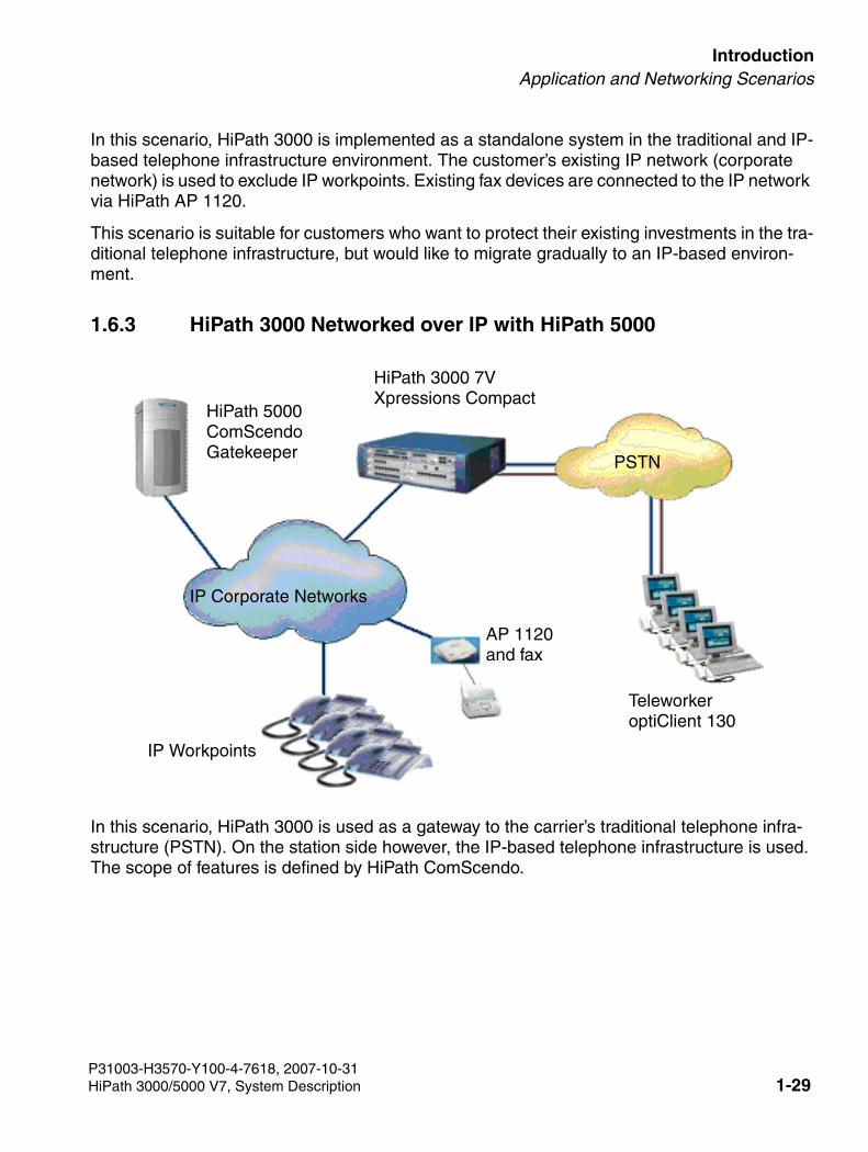
3000sb1.fm
For internal use only IntroductionApplication and Networking Scenarios
In this scenario, HiPath 3000 is implemented as a standalone system in the traditional and IP-based telephone infrastructure environment. The customer’s existing IP network (corporate network) is used to exclude IP workpoints. Existing fax devices are connected to the IP network via HiPath AP 1120.
This scenario is suitable for customers who want to protect their existing investments in the tra-ditional telephone infrastructure, but would like to migrate gradually to an IP-based environ-ment.
1.6.3 HiPath 3000 Networked over IP with HiPath 5000
In this scenario, HiPath 3000 is used as a gateway to the carrier’s traditional telephone infra-structure (PSTN). On the station side however, the IP-based telephone infrastructure is used. The scope of features is defined by HiPath ComScendo.
HiPath 5000ComScendoGatekeeper
PSTN
IP Corporate Networks
HiPath 3000 7VXpressions Compact
TeleworkeroptiClient 130
IP Workpoints
AP 1120 and fax
P31003-H3570-Y100-4-7618, 2007-10-31HiPath 3000/5000 V7, System Description 1-29
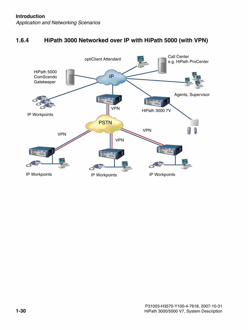
Introduction For internal use only
3000sb1.fm
Application and Networking Scenarios
1.6.4 HiPath 3000 Networked over IP with HiPath 5000 (with VPN)
IPHiPath 5000ComScendoGatekeeper
optiClient AttendantCall Centere.g. HiPath ProCenter
Agents, Supervisor
IP Workpoints
HiPath 3000 7V
IP Workpoints IP Workpoints
IP Workpoints
VPN
VPNVPN
VPN
PSTN
P31003-H3570-Y100-4-7618, 2007-10-311-30 HiPath 3000/5000 V7, System Description
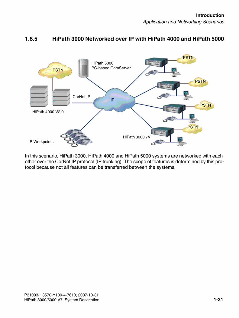
3000sb1.fm
For internal use only IntroductionApplication and Networking Scenarios
1.6.5 HiPath 3000 Networked over IP with HiPath 4000 and HiPath 5000
In this scenario, HiPath 3000, HiPath 4000 and HiPath 5000 systems are networked with each other over the CorNet IP protocol (IP trunking). The scope of features is determined by this pro-tocol because not all features can be transferred between the systems.
HiPath 5000PC-based ComServerPSTN
IP
PSTN
PSTN
PSTN
PSTN
IP Workpoints
HiPath 4000 V2.0
HiPath 3000 7V
CorNet IP
P31003-H3570-Y100-4-7618, 2007-10-31HiPath 3000/5000 V7, System Description 1-31
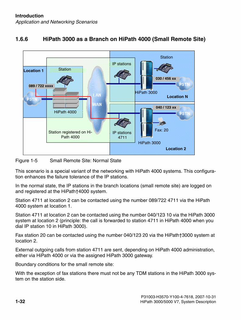
Introduction For internal use only
3000sb1.fm
Application and Networking Scenarios
1.6.6 HiPath 3000 as a Branch on HiPath 4000 (Small Remote Site)
Figure 1-5 Small Remote Site: Normal State
This scenario is a special variant of the networking with HiPath 4000 systems. This configura-tion enhances the failure tolerance of the IP stations.
In the normal state, the IP stations in the branch locations (small remote site) are logged on and registered at the HiPath†4000 system.
Station 4711 at location 2 can be contacted using the number 089/722 4711 via the HiPath 4000 system at location 1.
Station 4711 at location 2 can be contacted using the number 040/123 10 via the HiPath 3000 system at location 2 (principle: the call is forwarded to station 4711 in HiPath 4000 when you dial IP station 10 in HiPath 3000).
Fax station 20 can be contacted using the number 040/123 20 via the HiPath†3000 system at location 2.
External outgoing calls from station 4711 are sent, depending on HiPath 4000 administration, either via HiPath 4000 or via the assigned HiPath 3000 gateway.
Boundary conditions for the small remote site:
With the exception of fax stations there must not be any TDM stations in the HiPath 3000 sys-tem on the station side.
Station
Station
IP stations
IP stations
Location 1
Location 2
Location N
Station registered on Hi-Path 4000
HiPath 3000
HiPath 3000
HiPath 4000
089 / 722 xxxx
030 / 456 xx
040 / 123 xx
Fax: 20
4711
P31003-H3570-Y100-4-7618, 2007-10-311-32 HiPath 3000/5000 V7, System Description
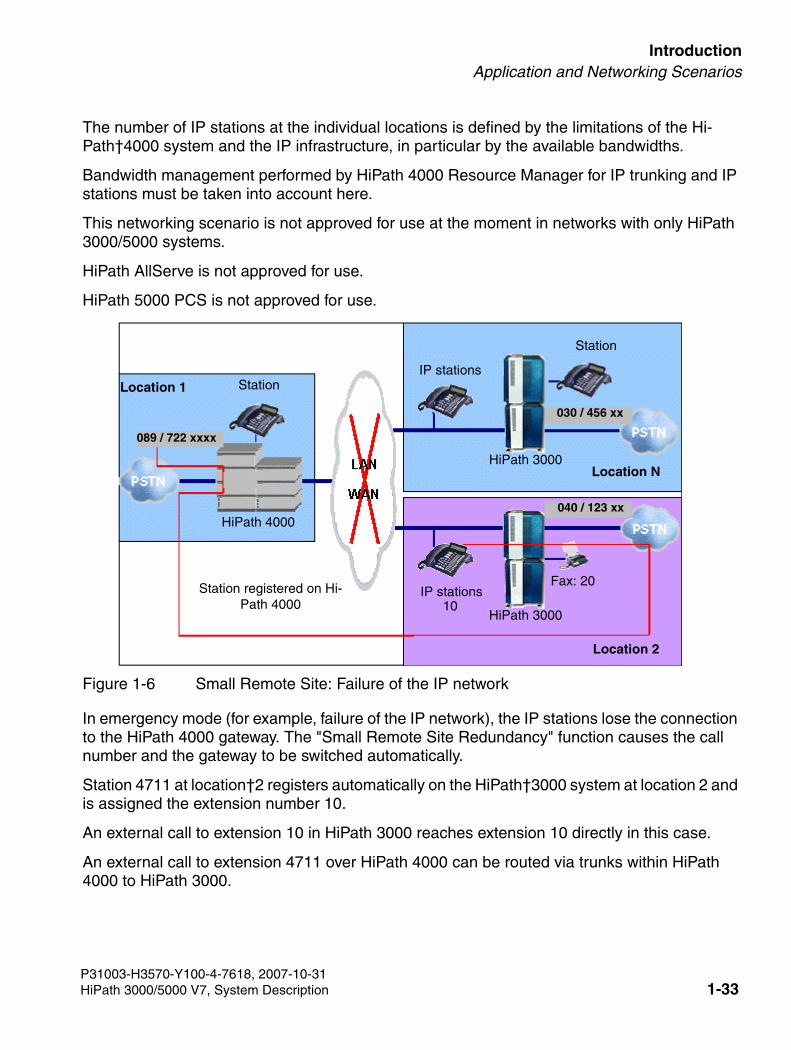
3000sb1.fm
For internal use only IntroductionApplication and Networking Scenarios
The number of IP stations at the individual locations is defined by the limitations of the Hi-Path†4000 system and the IP infrastructure, in particular by the available bandwidths.
Bandwidth management performed by HiPath 4000 Resource Manager for IP trunking and IP stations must be taken into account here.
This networking scenario is not approved for use at the moment in networks with only HiPath 3000/5000 systems.
HiPath AllServe is not approved for use.
HiPath 5000 PCS is not approved for use.
Figure 1-6 Small Remote Site: Failure of the IP network
In emergency mode (for example, failure of the IP network), the IP stations lose the connection to the HiPath 4000 gateway. The "Small Remote Site Redundancy" function causes the call number and the gateway to be switched automatically.
Station 4711 at location†2 registers automatically on the HiPath†3000 system at location 2 and is assigned the extension number 10.
An external call to extension 10 in HiPath 3000 reaches extension 10 directly in this case.
An external call to extension 4711 over HiPath 4000 can be routed via trunks within HiPath 4000 to HiPath 3000.
Station
Station
IP stations
IP stations
Location 2
Location N
Location 1
Station registered on Hi-Path 4000
HiPath 3000
HiPath 3000
HiPath 4000
089 / 722 xxxx
Fax: 20
10
030 / 456 xx
040 / 123 xx
P31003-H3570-Y100-4-7618, 2007-10-31HiPath 3000/5000 V7, System Description 1-33
Introduction For internal use only
3000sb1.fm
Application and Networking Scenarios
1.6.7 Establishing Virtual Private Networks (Site-to-Site VPNs)
HiPath 3000 is a secure solution for establishing site-to-site VPNs. The solution uses the cost-effective public network infrastructure to network locations (headquarters, regional offices or branch offices). HiPath 3000 systems can be networked with each other and mixed HiPath 2000/3000 networks are also possible with HiPath 3000 V5.0 or later. Connection to the Inter-net can be established using Internet dedicated lines or xDSL connections with a permanent IP address. Even Internet connections with a dynamic IP address can be used via DynDNS. Data and voice (TDM and VoIP) are tunneled over the Internet. HiPath 3000 checks authenti-cation of the VPN partners, encrypts and decrypts the data packets sent and received by the relevant workpoints and applications, and ensures data confidentiality and integrity.
Advantages of VPN site-to-site networking:
● Secure business processes
● Secure integration of external partners in the company network
● Access to company information for field service
P31003-H3570-Y100-4-7618, 2007-10-311-34 HiPath 3000/5000 V7, System Description
3000sb1.fm
For internal use only IntroductionMigration
1.7 Migration
1.7.1 HiPath 3000
HiPath 3000 V6.0 or later offers new features, such as "Extended Number of CDR Entries". These new features require additional memory which is provided by the new 64-MB MMC card. New control boards are essential to guarantee the function of the 64-MB MMC card.
The new control boards, including the 64-MB MMC card, are included with the upgrade items for HiPath 3000 7V (HiPath 3300, HiPath 3350, HiPath 3500, HiPath 3550). The control boards for HiPath 33x0/35x0 are also equipped with the new Entry Voice Mail (EVM) feature.
1.7.1.1 Standalone
If a gateway is added to a standalone system (e.g. HiPath 3800 V6.0), the alive monitoring must be activated. This ensures that the allocation of resources is controlled via the gatekeeper.
1.7.2 HiPath 33x0 and 35X0 with EVM
With V6.0 or later, 33x0 and 35x0 systems are delivered with mainboards equipped with the entry voicemail module EVM. Xpressions Compact should be marketed for requirements above and beyond this. In version 6.0 or later the LIM module is included in the base package.
Xpressions Compact only is marketed for existing customers.
With Version V5.0, new S2m boards requiring a license are provided for the 35x0 model. These require the marketing of B channel licenses and release over the license server. Existing cus-tomers can continue to use the existing S2m boards that do not require a license by upgrading to version 5.0 (a license is not required for version V5.0). Mixed mode in a single system is pos-sible.
>Provisions have not been made for a software-only update from an older version to 7V. Updates of this kind are not possible.HiPath 3000 V5.0 or later only supports 64-MB multimedia cards (MMC64). MMC16s (16 MB) are not supported. The MMC is checked during system startup. Startup is aborted if an MMC16 is de-tected.
P31003-H3570-Y100-4-7618, 2007-10-31HiPath 3000/5000 V7, System Description 1-35
Introduction For internal use only
3000sb1.fm
Migration
1.7.3 HiPath 37x0
HiPath 37x0 cannot be upgraded to HiPath 3000 7V.
1.7.4 HG 1500 V3.0
HG1500 V3.0 hardware can be implemented in a HiPath 3000 7V system environment. The HG1500 software must be updated for this.
● HXGS3The HXGS3 variant is designed for installation in wall-mounted HiPath 3350 and HiPath 3550 systems. The board features two slots for extension modules. However, only one slot is supported and released.
● HXGR3The HXGR3 variant is designed for HiPath 3300 and HiPath 3500 systems installed in 19" racks. This variant features a front panel. The card features two slots for extension mod-ules. However, only one slot is supported and released.
● STMI2The STMI2 variant can be used with HiPath 3800.
● PDM1 extension moduleThe PDM1 module provides an additional eight B channels (one DSP and SDRAM pair) for basic HXGR3, HXGS3 and HXGM3 modules. HXGR3 and HXGS3 can accommodate one PDM1 module each, while HXGM3 can accommodate two PDM1 modules.
Installing a fan kit for HG 1500 V3.0 in HiPath 3350/3550
A fan must be installed in HiPath 3350 and HiPath 3550 if an HXGS3 board is inserted in the top slot sequence (slot four in HiPath 3350 and slots four, six, and eight in HiPath 3550).
A fan is not required for the lower slot sequence (slot five for HiPath 3350 and slots five, seven, and nine for HiPath 3550).
P31003-H3570-Y100-4-7618, 2007-10-311-36 HiPath 3000/5000 V7, System Description
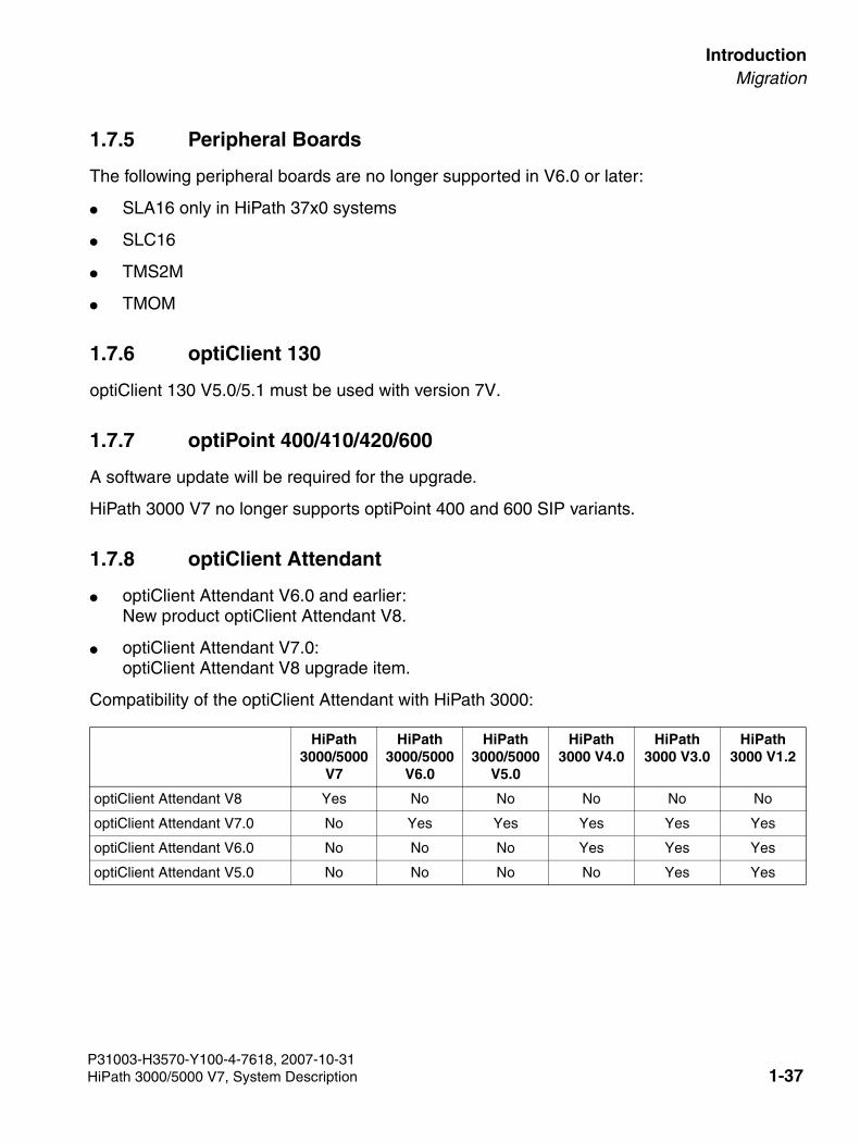
3000sb1.fm
For internal use only IntroductionMigration
1.7.5 Peripheral Boards
The following peripheral boards are no longer supported in V6.0 or later:
● SLA16 only in HiPath 37x0 systems
● SLC16
● TMS2M
● TMOM
1.7.6 optiClient 130
optiClient 130 V5.0/5.1 must be used with version 7V.
1.7.7 optiPoint 400/410/420/600
A software update will be required for the upgrade.
HiPath 3000 V7 no longer supports optiPoint 400 and 600 SIP variants.
1.7.8 optiClient Attendant
● optiClient Attendant V6.0 and earlier:New product optiClient Attendant V8.
● optiClient Attendant V7.0:optiClient Attendant V8 upgrade item.
Compatibility of the optiClient Attendant with HiPath 3000:
HiPath 3000/5000
V7
HiPath 3000/5000
V6.0
HiPath 3000/5000
V5.0
HiPath 3000 V4.0
HiPath 3000 V3.0
HiPath 3000 V1.2
optiClient Attendant V8 Yes No No No No No
optiClient Attendant V7.0 No Yes Yes Yes Yes Yes
optiClient Attendant V6.0 No No No Yes Yes Yes
optiClient Attendant V5.0 No No No No Yes Yes
P31003-H3570-Y100-4-7618, 2007-10-31HiPath 3000/5000 V7, System Description 1-37
Introduction For internal use only
3000sb1.fm
Migration
1.7.9 CMI
New BS4 base stations that require a license are supplied with Version V5.0. These require the marketing of CMI licenses and release via the license server. By upgrading to Version V5.0, existing customers can continue to use the existing BS3 base stations that do not require a li-cense with 5.0. BS3x base stations continue to be supported with Version V5.0. Mixed mode in a single system is possible.
The base station BS4 operates at HiPath 3000 V5.0 or later with SLC16N, SLCN, and direct connection (not with SLC16).
The cordless telephones Gigaset 3000 Comfort and Micro, Gigaset 4000 Comfort and Micro are supported.
1.7.10 Licenses
The following HiPath 3000 licenses can be migrated to the 7V license structure via HiPath Li-cense Management:
● HG 1500: Existing HG 1500 licenses can be upgraded to 7V via CLS.– IP user licenses for workpoints in accordance with ComScendo license for IP work-
points– B Channels – LWCA (Light Weight Certification Authority)
License migration from V6.0 to V7
The following HiPath 3000 licenses can be migrated to the 7V license structure via HiPath Li-cense Management:
● ComScendo license for IP workpoints
● S2M license for releasing B channels (in Germany, for example, at least 30 B channels for each S2M)
● HG 1500 B channels
● HG 1500 LWCA (Light Weight Certification Authority)
● Cordless base station BS4
● License for a HiPath Xpressions Compact-based announcement
The license server supports the direct migration of licenses from V4.0 to 7V, from V5.0 to 7V and from V6.0 to 7V.
P31003-H3570-Y100-4-7618, 2007-10-311-38 HiPath 3000/5000 V7, System Description
3000sb1.fm
For internal use only IntroductionMigration
1.7.11 Networking
With HiPath 3000/5000 V5.0/V6.0:
HiPath 3000 V5.0 or V6.0 and V7 cannot be operated in mixed mode via IP trunking. Systems with V5.0/V6.0 software must be upgraded to V7.
With HiPath 3000 V3.0/V4.0:
The CorNet N protocol can be used in TDM-based networks. This means that HiPath 3000 V3.0/V4.0/V5.0/V6.0/V7 and Hicom 150 E/H can be operated in mixed mode.
Only the CorNet IP protocol is used for IP Interworking. All nodes must be upgraded to the same software version.
With HiPath 4000:
When migrating from TDM-based networks, it is possible to set the CorNet N or CorNet NQ pro-tocol. This means that Hicom 300/HiPath 4000 can be operated in mixed mode with HiPath 3000 V3.0/V4.0/V5.0/V6.0/V7 and Hicom 150 E/H.
Only the CorNet IP protocol is used for IP Interworking with HiPath 4000 V2.0/V3.0. All HiPath 3000 nodes must be upgraded to at least V5.0.
A new procedure for configuring networking with HiPath 4000 is available and must be used with V7 or later. See the configuration examples.
P31003-H3570-Y100-4-7618, 2007-10-31HiPath 3000/5000 V7, System Description 1-39
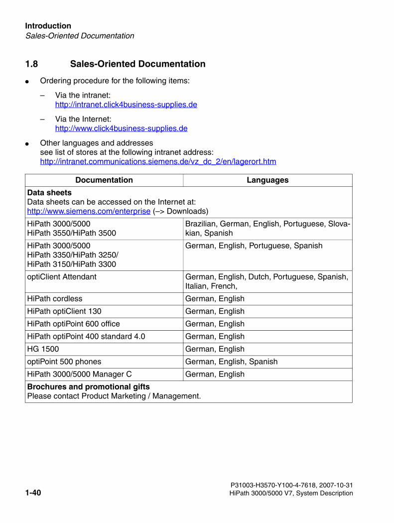
Introduction For internal use only
3000sb1.fm
Sales-Oriented Documentation
1.8 Sales-Oriented Documentation
● Ordering procedure for the following items:
– Via the intranet:http://intranet.click4business-supplies.de
– Via the Internet:http://www.click4business-supplies.de
● Other languages and addressessee list of stores at the following intranet address: http://intranet.communications.siemens.de/vz_dc_2/en/lagerort.htm
Documentation Languages
Data sheetsData sheets can be accessed on the Internet at:http://www.siemens.com/enterprise (–> Downloads)
HiPath 3000/5000HiPath 3550/HiPath 3500
Brazilian, German, English, Portuguese, Slova-kian, Spanish
HiPath 3000/5000 HiPath 3350/HiPath 3250/HiPath 3150/HiPath 3300
German, English, Portuguese, Spanish
optiClient Attendant German, English, Dutch, Portuguese, Spanish, Italian, French,
HiPath cordless German, English
HiPath optiClient 130 German, English
HiPath optiPoint 600 office German, English
HiPath optiPoint 400 standard 4.0 German, English
HG 1500 German, English
optiPoint 500 phones German, English, Spanish
HiPath 3000/5000 Manager C German, English
Brochures and promotional giftsPlease contact Product Marketing / Management.
P31003-H3570-Y100-4-7618, 2007-10-311-40 HiPath 3000/5000 V7, System Description
3000sb1.fm
For internal use only IntroductionTechnical Documentation
1.9 Technical Documentation
You can select and download the following documents (HTML and PDF):
● User documentation
● Administrator documentation
● Service documentation
● Sales documentation
from the following Web site:
https://netinfo2.icn.siemens.de/edoku3/search_en.htm
P31003-H3570-Y100-4-7618, 2007-10-31HiPath 3000/5000 V7, System Description 1-41
Introduction For internal use only
3000sb1.fm
Privacy and Data Security
1.10 Privacy and Data Security
Handling personal data
This telephone system uses and processes personal data (as in call detail recording, tele-phone displays and customer data records).
In Germany, the processing and use of such data is subject to various regulations, including those of the Federal Data Protection Law (Bundesdatenschutzgesetz, BDSG). Observe all ap-plicable laws in other countries.
The objective of privacy legislation is to prevent infringements of an individual’s right to privacy based on the use or misuse of personal data.
By protecting data against misuse during all stages of processing, privacy legislation also pro-tects the material interests of the individual and of third parties.
Guidelines applicable to employees of Siemens Enterprise Communications GmbH & Co. KG
Employees of Siemens Enterprise Communications GmbH & Co. KG are bound to safeguard trade secrets and personal data under the terms of the company’s work rules.
The following rules must be observed to ensure that the statutory provisions relating to service (on-site or remote) are strictly followed. This safeguards the interests of the customer and offers added personal protection.
Guidelines governing the handling of data
A conscientious and responsible approach helps protect data and ensure privacy:
● Ensure that only authorized persons have access to customer data.
● Use the password features of the system with no exceptions. Never give passwords to an unauthorized person orally or in writing.
● Ensure that no unauthorized person can ever process (store, modify, transmit, disable or delete) or use customer data.
● Prevent unauthorized persons from gaining access to data media such as backup copies or log printouts. This applies to service calls as well as storage and transport.
● Ensure that data media that are no longer needed are completely destroyed and that doc-uments are not stored or left in places which are accessible to the public.
● Work closely with your customer contact; this promotes trust and reduces your workload.
P31003-H3570-Y100-4-7618, 2007-10-311-42 HiPath 3000/5000 V7, System Description
3000sb1.fm
For internal use only IntroductionFeedback/Comments
1.11 Feedback/Comments
To continually improve this system description, the editorial team welcomes your comments. We would particularly like to know your views on the following:
● Areas that require more detail. Areas that are too detailed.
● Areas that need more graphics to aid understanding.
● Areas that are difficult to understand.
● Issues you would like to include.
Outside of the U.S., please send your comments to:
Siemens Enterprise Communications GmbH & Co. KGFachredaktionESY HD 242Hofmannstr. 51D-81359 Munich GERMANYFax.: + 49 89 722 33959
Also include your address, telephone and fax number so we can contact you if necessary. In the U.S., please refer to the reader comment form at the back of this document for information on how to submit comments about this manual.
1.12 Copyright
Copyright Siemens Enterprise Communications GmbH & Co. KG. This publication and all of its parts are protected by copyright laws. Any use of this publication outside of the strict terms de-fined in the copyright laws is not permitted without the prior consent of the publisher and is liable to prosecution. This applies in particular to the reproduction, translation, microfilming or editing of this publication in any form, as well as to saving and processing in electronic systems.
P31003-H3570-Y100-4-7618, 2007-10-31HiPath 3000/5000 V7, System Description 1-43

Introduction For internal use only
3000sb1.fm
Copyright
P31003-H3570-Y100-4-7618, 2007-10-311-44 HiPath 3000/5000 V7, System Description
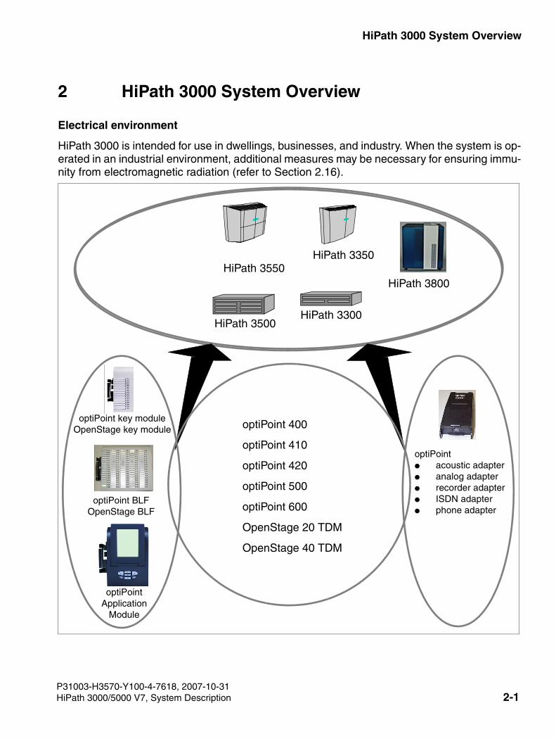
3000sb2.fm
For internal use only HiPath 3000 System Overview
2 HiPath 3000 System Overview
Electrical environment
HiPath 3000 is intended for use in dwellings, businesses, and industry. When the system is op-erated in an industrial environment, additional measures may be necessary for ensuring immu-nity from electromagnetic radiation (refer to Section 2.16).
HiPath 3300
HiPath 3350HiPath 3550
optiPoint● acoustic adapter● analog adapter● recorder adapter● ISDN adapter● phone adapter
optiPoint BLFOpenStage BLF
optiPoint key moduleOpenStage key module
HiPath 3500
optiPoint Application
Module
optiPoint 400
optiPoint 410
optiPoint 420
optiPoint 500
optiPoint 600
OpenStage 20 TDM
OpenStage 40 TDM
HiPath 3800
P31003-H3570-Y100-4-7618, 2007-10-31HiPath 3000/5000 V7, System Description 2-1
HiPath 3000 System Overview For internal use only
3000sb2.fm
System families and accompanying models
The individual housing designs and the variable connecting capabilities allow the following Hi-Path 3000 systems to cover a wide customer range.
This system description contains information on all systems. Information on marketing individ-ual models in different countries can be obtained at the responsible locations.
● System for free-standing installation and installation in 19" cabinets:
– HiPath 3800
● Wall-mountable systems
– HiPath 3550
– HiPath 3350
● Systems for installation in 19" cabinets
– HiPath 3500
– HiPath 3300
Refer to Section 2.1, "System-Related Capacity Limits" for information on the capacity limits of the different HiPath 3000 systems.
>Starting with Version 3.0, all models in the HiPath 3000system family (not HiPath 3250 and HiPath 3150) can be operated either as conventional telecommunications systems (TC systems) or as IP systems only. In this case, the IP stations connect directly via the HG 1500 boards.
P31003-H3570-Y100-4-7618, 2007-10-312-2 HiPath 3000/5000 V7, System Description
3000sb2.fm
For internal use only HiPath 3000 System OverviewSystem-Related Capacity Limits
2.1 System-Related Capacity Limits
The following assumptions are used as a basis for calculating the maximum capacity limits:
● HiPath 3800: two board slots are reserved for trunks.
● HiPath 3550, HiPath 3500: two S0 interfaces on the central board + one board slot are re-served for trunks.
● HiPath 3350, HiPath 3300: two S0 interfaces on the central board are reserved for trunks.
● Traffic capacity: 0.15 erlangs
Deviating capacity limits can be determined for sales purposes.
Section 10.2 contains the system-specific maximum limits for UP0/E workpoint clients and the associated key modules and adapters.
P31003-H3570-Y100-4-7618, 2007-10-31HiPath 3000/5000 V7, System Description 2-3
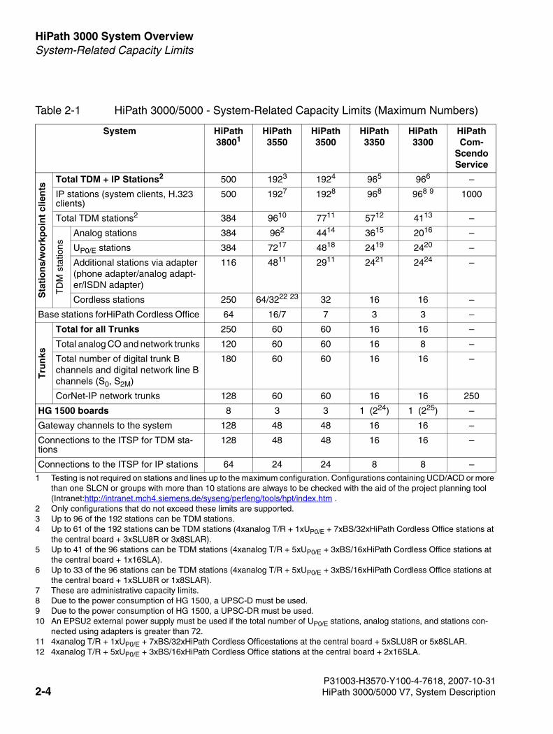
HiPath 3000 System Overview For internal use only
3000sb2.fm
System-Related Capacity Limits
Table 2-1 HiPath 3000/5000 - System-Related Capacity Limits (Maximum Numbers)
System HiPath 38001
1 Testing is not required on stations and lines up to the maximum configuration. Configurations containing UCD/ACD or more than one SLCN or groups with more than 10 stations are always to be checked with the aid of the project planning tool (Intranet:http://intranet.mch4.siemens.de/syseng/perfeng/tools/hpt/index.htm .
HiPath 3550
HiPath 3500
HiPath 3350
HiPath 3300
HiPath Com-
Scendo Service
Sta
tio
ns/
wo
rkp
oin
t cl
ien
ts
Total TDM + IP Stations2
2 Only configurations that do not exceed these limits are supported.
500 1923
3 Up to 96 of the 192 stations can be TDM stations.
1924
4 Up to 61 of the 192 stations can be TDM stations (4xanalog T/R + 1xUP0/E + 7xBS/32xHiPath Cordless Office stations at the central board + 3xSLU8R or 3x8SLAR).
965
5 Up to 41 of the 96 stations can be TDM stations (4xanalog T/R + 5xUP0/E + 3xBS/16xHiPath Cordless Office stations at the central board + 1x16SLA).
966
6 Up to 33 of the 96 stations can be TDM stations (4xanalog T/R + 5xUP0/E + 3xBS/16xHiPath Cordless Office stations at the central board + 1xSLU8R or 1x8SLAR).
–
IP stations (system clients, H.323 clients)
500 1927
7 These are administrative capacity limits.
1928 968
8 Due to the power consumption of HG 1500, a UPSC-D must be used.
968 9
9 Due to the power consumption of HG 1500, a UPSC-DR must be used.
1000
Total TDM stations2 384 9610
10 An EPSU2 external power supply must be used if the total number of UP0/E stations, analog stations, and stations con-nected using adapters is greater than 72.
7711
11 4xanalog T/R + 1xUP0/E + 7xBS/32xHiPath Cordless Officestations at the central board + 5xSLU8R or 5x8SLAR.
5712
12 4xanalog T/R + 5xUP0/E + 3xBS/16xHiPath Cordless Office stations at the central board + 2x16SLA.
4113 –
TD
M s
tatio
ns
Analog stations 384 962 4414 3615 2016 –
UP0/E stations 384 7217 4818 2419 2420 –
Additional stations via adapter (phone adapter/analog adapt-er/ISDN adapter)
116 4811 2911 2421 2424 –
Cordless stations 250 64/3222 23 32 16 16 –
Base stations forHiPath Cordless Office 64 16/7 7 3 3 –
Tru
nks
Total for all Trunks 250 60 60 16 16 –
Total analog CO and network trunks 120 60 60 16 8 –
Total number of digital trunk B channels and digital network line B channels (S0, S2M)
180 60 60 16 16 –
CorNet-IP network trunks 128 60 60 16 16 250
HG 1500 boards 8 3 3 1 (224) 1 (225) –
Gateway channels to the system 128 48 48 16 16 –
Connections to the ITSP for TDM sta-tions
128 48 48 16 16 –
Connections to the ITSP for IP stations 64 24 24 8 8 –
P31003-H3570-Y100-4-7618, 2007-10-312-4 HiPath 3000/5000 V7, System Description
3000sb2.fm
For internal use only HiPath 3000 System OverviewSystem-Related Capacity Limits
13 4xanalog T/R + 5xUP0/E + 3xBS/16xHiPath Cordless Officestations at the central board + 2xSLU8R or 2x8SLAR. 14 4xanalog T/R at the central board + 5x8SLAR. 15 4xanalog T/R at the central board + 2x16SLA. 16 4xanalog T/R at the central board + 2x8SLAR. 17 8xUP0/E at the central board + 5xSLU8 + 1xSLMO24. 18 8xUP0/E at the central board + 5xSLU8R. 19 8xUP0/E at the central board + 2xSLU8. 20 8xUP0/E at the central board + 2xSLU8R. 21 A UPSC-D/UPSC-DR must be used if the total number of UP0/E stations and stations connected using adapters is greater
than 24. 22 Due to the 5V power supply unit, one SLC16/SLC16N and a maximum of two HG 1500 V3.0 boards can be used. 23 64 HiPath Cordless Office stations on SLC16/SLC16N or 32 HiPath Cordless Office stations on the central board. 24 The system may be configured with two HG 1500 boards if PDM1 is not used. 25 The system may be configured with two HG 1500 boards if PDM1 is not used.
P31003-H3570-Y100-4-7618, 2007-10-31HiPath 3000/5000 V7, System Description 2-5
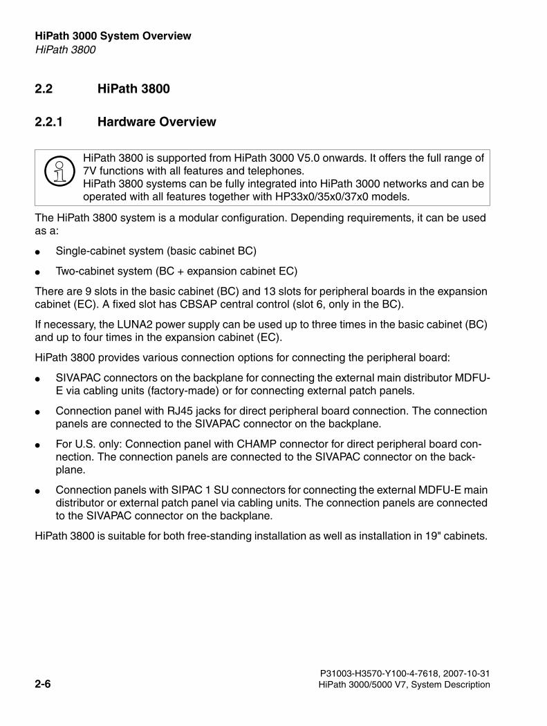
HiPath 3000 System Overview For internal use only
3000sb2.fm
HiPath 3800
2.2 HiPath 3800
2.2.1 Hardware Overview
The HiPath 3800 system is a modular configuration. Depending requirements, it can be used as a:
● Single-cabinet system (basic cabinet BC)
● Two-cabinet system (BC + expansion cabinet EC)
There are 9 slots in the basic cabinet (BC) and 13 slots for peripheral boards in the expansion cabinet (EC). A fixed slot has CBSAP central control (slot 6, only in the BC).
If necessary, the LUNA2 power supply can be used up to three times in the basic cabinet (BC) and up to four times in the expansion cabinet (EC).
HiPath 3800 provides various connection options for connecting the peripheral board:
● SIVAPAC connectors on the backplane for connecting the external main distributor MDFU-E via cabling units (factory-made) or for connecting external patch panels.
● Connection panel with RJ45 jacks for direct peripheral board connection. The connection panels are connected to the SIVAPAC connector on the backplane.
● For U.S. only: Connection panel with CHAMP connector for direct peripheral board con-nection. The connection panels are connected to the SIVAPAC connector on the back-plane.
● Connection panels with SIPAC 1 SU connectors for connecting the external MDFU-E main distributor or external patch panel via cabling units. The connection panels are connected to the SIVAPAC connector on the backplane.
HiPath 3800 is suitable for both free-standing installation as well as installation in 19" cabinets.
>HiPath 3800 is supported from HiPath 3000 V5.0 onwards. It offers the full range of 7V functions with all features and telephones.HiPath 3800 systems can be fully integrated into HiPath 3000 networks and can be operated with all features together with HP33x0/35x0/37x0 models.
P31003-H3570-Y100-4-7618, 2007-10-312-6 HiPath 3000/5000 V7, System Description
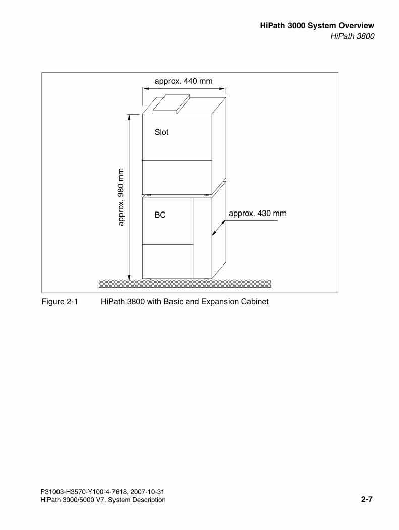
3000sb2.fm
For internal use only HiPath 3000 System OverviewHiPath 3800
Figure 2-1 HiPath 3800 with Basic and Expansion Cabinet
BC
approx. 440 mm
appr
ox. 9
80 m
m
Slot
approx. 430 mm
P31003-H3570-Y100-4-7618, 2007-10-31HiPath 3000/5000 V7, System Description 2-7
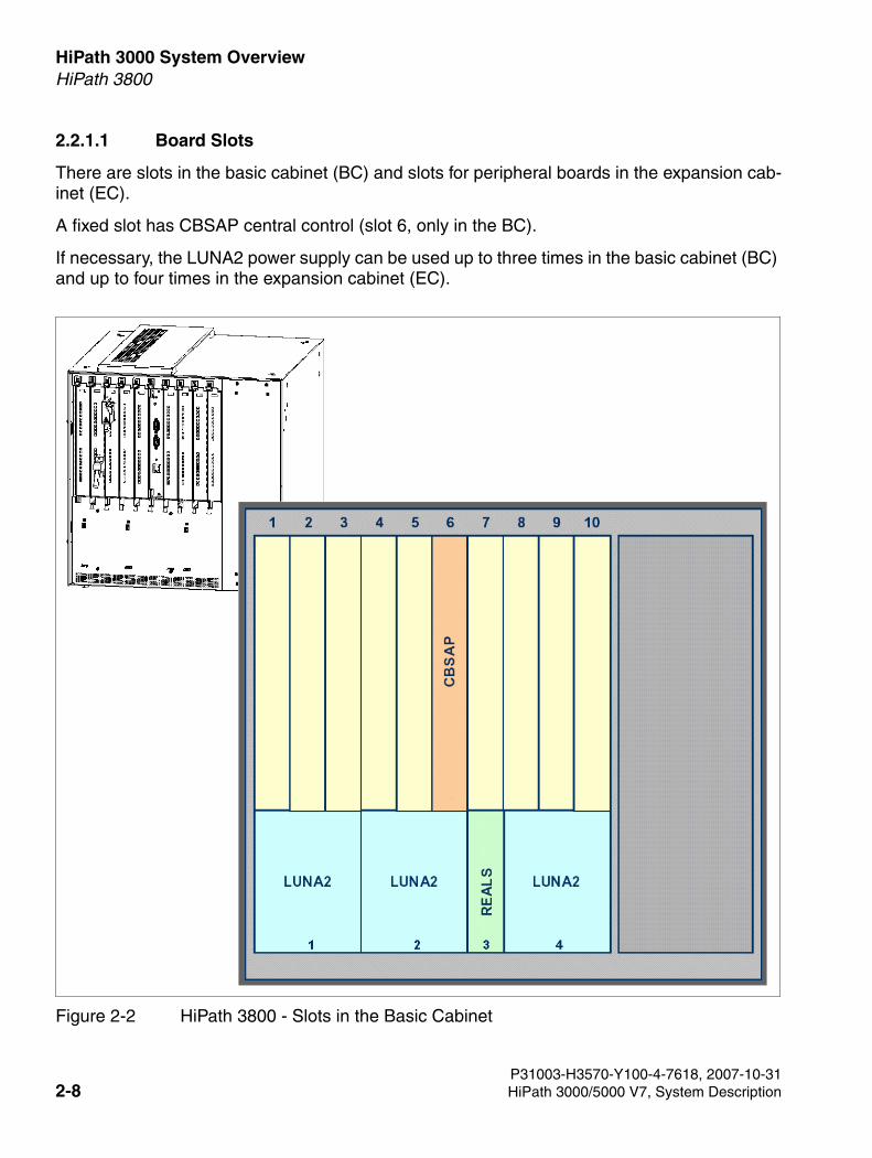
HiPath 3000 System Overview For internal use only
3000sb2.fm
HiPath 3800
2.2.1.1 Board Slots
There are slots in the basic cabinet (BC) and slots for peripheral boards in the expansion cab-inet (EC).
A fixed slot has CBSAP central control (slot 6, only in the BC).
If necessary, the LUNA2 power supply can be used up to three times in the basic cabinet (BC) and up to four times in the expansion cabinet (EC).
Figure 2-2 HiPath 3800 - Slots in the Basic Cabinet
P31003-H3570-Y100-4-7618, 2007-10-312-8 HiPath 3000/5000 V7, System Description
3000sb2.fm
For internal use only HiPath 3000 System OverviewHiPath 3800
Figure 2-3 HiPath 3800 - Slots in the Expansion Cabinet
Not
use
d
P31003-H3570-Y100-4-7618, 2007-10-31HiPath 3000/5000 V7, System Description 2-9
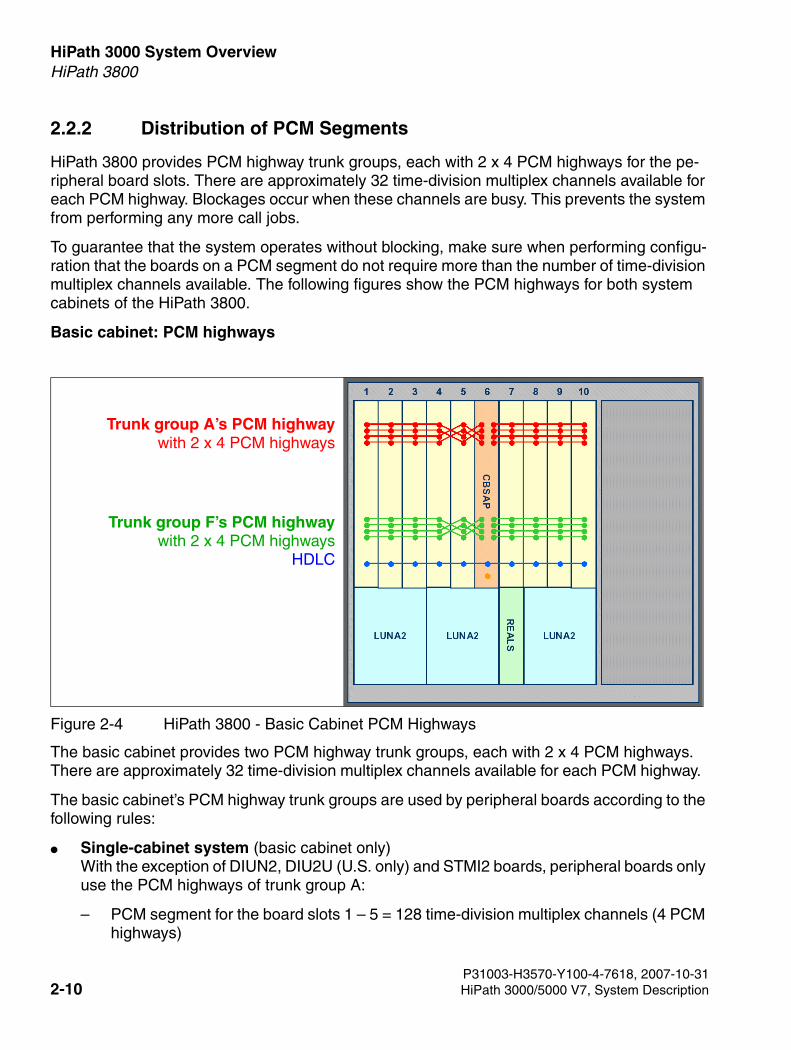
HiPath 3000 System Overview For internal use only
3000sb2.fm
HiPath 3800
2.2.2 Distribution of PCM Segments
HiPath 3800 provides PCM highway trunk groups, each with 2 x 4 PCM highways for the pe-ripheral board slots. There are approximately 32 time-division multiplex channels available for each PCM highway. Blockages occur when these channels are busy. This prevents the system from performing any more call jobs.
To guarantee that the system operates without blocking, make sure when performing configu-ration that the boards on a PCM segment do not require more than the number of time-division multiplex channels available. The following figures show the PCM highways for both system cabinets of the HiPath 3800.
Basic cabinet: PCM highways
The basic cabinet provides two PCM highway trunk groups, each with 2 x 4 PCM highways. There are approximately 32 time-division multiplex channels available for each PCM highway.
The basic cabinet’s PCM highway trunk groups are used by peripheral boards according to the following rules:
● Single-cabinet system (basic cabinet only) With the exception of DIUN2, DIU2U (U.S. only) and STMI2 boards, peripheral boards only use the PCM highways of trunk group A:
– PCM segment for the board slots 1 – 5 = 128 time-division multiplex channels (4 PCM highways)
Figure 2-4 HiPath 3800 - Basic Cabinet PCM Highways
Trunk group A’s PCM highwaywith 2 x 4 PCM highways
Trunk group F’s PCM highwaywith 2 x 4 PCM highways
HDLC
P31003-H3570-Y100-4-7618, 2007-10-312-10 HiPath 3000/5000 V7, System Description
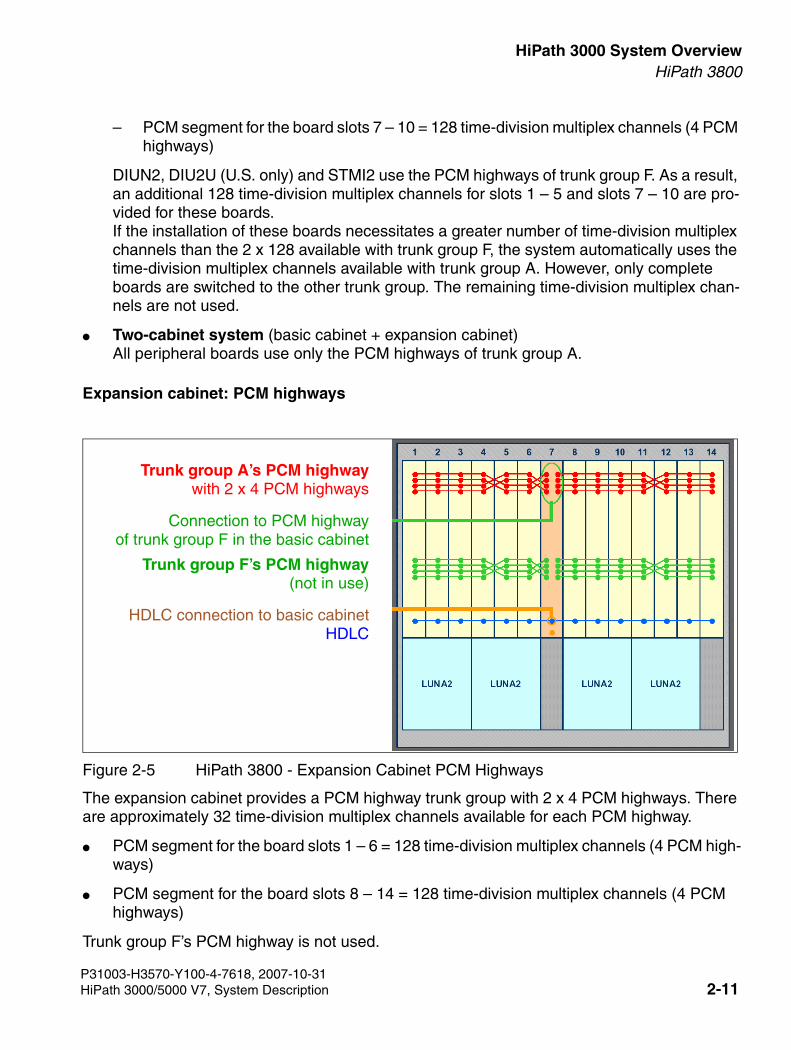
3000sb2.fm
For internal use only HiPath 3000 System OverviewHiPath 3800
– PCM segment for the board slots 7 – 10 = 128 time-division multiplex channels (4 PCM highways)
DIUN2, DIU2U (U.S. only) and STMI2 use the PCM highways of trunk group F. As a result, an additional 128 time-division multiplex channels for slots 1 – 5 and slots 7 – 10 are pro-vided for these boards. If the installation of these boards necessitates a greater number of time-division multiplex channels than the 2 x 128 available with trunk group F, the system automatically uses the time-division multiplex channels available with trunk group A. However, only complete boards are switched to the other trunk group. The remaining time-division multiplex chan-nels are not used.
● Two-cabinet system (basic cabinet + expansion cabinet) All peripheral boards use only the PCM highways of trunk group A.
Expansion cabinet: PCM highways
The expansion cabinet provides a PCM highway trunk group with 2 x 4 PCM highways. There are approximately 32 time-division multiplex channels available for each PCM highway.
● PCM segment for the board slots 1 – 6 = 128 time-division multiplex channels (4 PCM high-ways)
● PCM segment for the board slots 8 – 14 = 128 time-division multiplex channels (4 PCM highways)
Trunk group F’s PCM highway is not used.
Figure 2-5 HiPath 3800 - Expansion Cabinet PCM Highways
Trunk group A’s PCM highwaywith 2 x 4 PCM highways
Connection to PCM highwayof trunk group F in the basic cabinet
Trunk group F’s PCM highway(not in use)
HDLC connection to basic cabinetHDLC
P31003-H3570-Y100-4-7618, 2007-10-31HiPath 3000/5000 V7, System Description 2-11
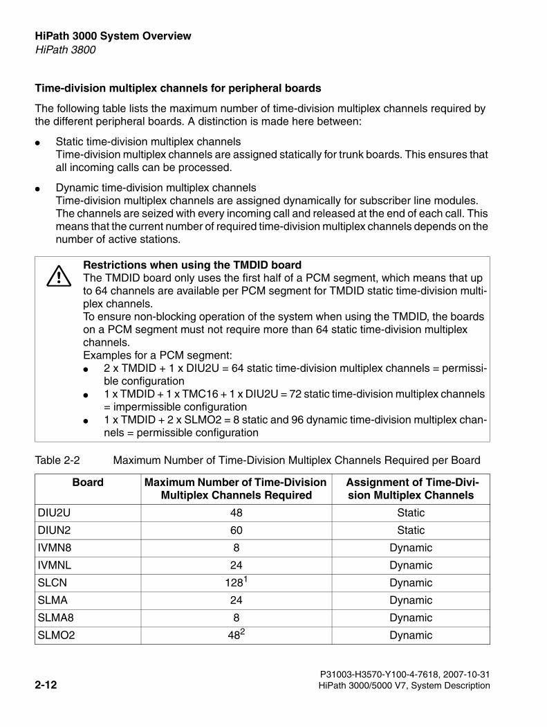
HiPath 3000 System Overview For internal use only
3000sb2.fm
HiPath 3800
Time-division multiplex channels for peripheral boards
The following table lists the maximum number of time-division multiplex channels required by the different peripheral boards. A distinction is made here between:
● Static time-division multiplex channels Time-division multiplex channels are assigned statically for trunk boards. This ensures that all incoming calls can be processed.
● Dynamic time-division multiplex channels Time-division multiplex channels are assigned dynamically for subscriber line modules. The channels are seized with every incoming call and released at the end of each call. This means that the current number of required time-division multiplex channels depends on the number of active stations.
7Restrictions when using the TMDID board The TMDID board only uses the first half of a PCM segment, which means that up to 64 channels are available per PCM segment for TMDID static time-division multi-plex channels. To ensure non-blocking operation of the system when using the TMDID, the boards on a PCM segment must not require more than 64 static time-division multiplex channels. Examples for a PCM segment: ● 2 x TMDID + 1 x DIU2U = 64 static time-division multiplex channels = permissi-
ble configuration ● 1 x TMDID + 1 x TMC16 + 1 x DIU2U = 72 static time-division multiplex channels
= impermissible configuration ● 1 x TMDID + 2 x SLMO2 = 8 static and 96 dynamic time-division multiplex chan-
nels = permissible configuration
Table 2-2 Maximum Number of Time-Division Multiplex Channels Required per Board
Board Maximum Number of Time-Division Multiplex Channels Required
Assignment of Time-Divi-sion Multiplex Channels
DIU2U 48 Static
DIUN2 60 Static
IVMN8 8 Dynamic
IVMNL 24 Dynamic
SLCN 1281 Dynamic
SLMA 24 Dynamic
SLMA8 8 Dynamic
SLMO2 482 Dynamic
P31003-H3570-Y100-4-7618, 2007-10-312-12 HiPath 3000/5000 V7, System Description
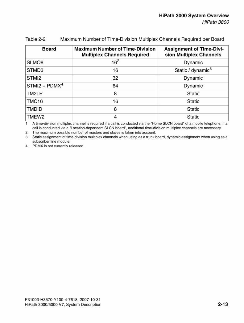
3000sb2.fm
For internal use only HiPath 3000 System OverviewHiPath 3800
SLMO8 162 Dynamic
STMD3 16 Static / dynamic3
STMI2 32 Dynamic
STMI2 + PDMX4 64 Dynamic
TM2LP 8 Static
TMC16 16 Static
TMDID 8 Static
TMEW2 4 Static1 A time-division multiplex channel is required if a call is conducted via the "Home SLCN board" of a mobile telephone. If a
call is conducted via a "Location-dependent SLCN board", additional time-division multiplex channels are necessary. 2 The maximum possible number of masters and slaves is taken into account. 3 Static assignment of time-division multiplex channels when using as a trunk board, dynamic assignment when using as a
subscriber line module. 4 PDMX is not currently released.
Table 2-2 Maximum Number of Time-Division Multiplex Channels Required per Board
Board Maximum Number of Time-Division Multiplex Channels Required
Assignment of Time-Divi-sion Multiplex Channels
P31003-H3570-Y100-4-7618, 2007-10-31HiPath 3000/5000 V7, System Description 2-13
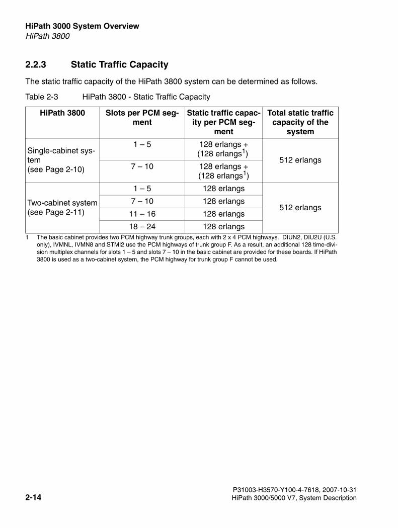
HiPath 3000 System Overview For internal use only
3000sb2.fm
HiPath 3800
2.2.3 Static Traffic Capacity
The static traffic capacity of the HiPath 3800 system can be determined as follows.
Table 2-3 HiPath 3800 - Static Traffic Capacity
HiPath 3800 Slots per PCM seg-ment
Static traffic capac-ity per PCM seg-
ment
Total static traffic capacity of the
system
Single-cabinet sys-tem(see Page 2-10)
1 – 5 128 erlangs + (128 erlangs1)
1 The basic cabinet provides two PCM highway trunk groups, each with 2 x 4 PCM highways. DIUN2, DIU2U (U.S. only), IVMNL, IVMN8 and STMI2 use the PCM highways of trunk group F. As a result, an additional 128 time-divi-sion multiplex channels for slots 1 – 5 and slots 7 – 10 in the basic cabinet are provided for these boards. If HiPath 3800 is used as a two-cabinet system, the PCM highway for trunk group F cannot be used.
512 erlangs7 – 10 128 erlangs +
(128 erlangs1)
Two-cabinet system(see Page 2-11)
1 – 5 128 erlangs
512 erlangs7 – 10 128 erlangs
11 – 16 128 erlangs
18 – 24 128 erlangs
P31003-H3570-Y100-4-7618, 2007-10-312-14 HiPath 3000/5000 V7, System Description
3000sb2.fm
For internal use only HiPath 3000 System OverviewHiPath 3800
2.2.4 Central Components
2.2.4.1 CBSAP
Introduction
The (Central Board Synergy Access Platform) board performs all central control and switching functions for HiPath 3800.
Subboards
The following subboards can be used depending on the application:
● CMS clock module (optional)
● MMC multimedia card
● IMODN integrated modem card new (optional)
● LIMS LAN interface module (optional) Includes 2 Ethernet (10BaseT) LAN connections (8-pin RJ45 jacks):
– LAN1 (administration via HiPath 3000/5000 Manager E and CTI functions)
– LAN2 (not assigned)
● MPPI music on hold (optional)
V.24 interfaces (9-pin SUB-D connectors)
● Service (X50) = for connecting the service PC
● Application (X51) = for connecting a printer or application
P31003-H3570-Y100-4-7618, 2007-10-31HiPath 3000/5000 V7, System Description 2-15
HiPath 3000 System Overview For internal use only
3000sb2.fm
HiPath 3800
2.2.4.2 LUNA2
Introduction
LUNA2 (Line-powered Unit for Network-based Architecture No. 2) is used as the central power supply in HiPath 3800. Depending on the system configuration, up to three LUNA2 boards can be used in the basic cabinet and up to four in the expansion cabinet.
When configuring the HiPath 3800 as a two-cabinet system, two LUNA2 boards in the basic cabinet and three in the expansion cabinet are sufficient to provide the specified maximum con-figuration limits. For information on how to calculate the number of LUNA2 modules required, see Page 2-19.
You can use a third LUNA2 in the basic cabinet and a fourth in the expansion cabinet to
● ensure error-free operation if one LUNA2 module fails (redundant LUNA2).
● load a connected battery pack or battery cabinet.
LUNA2 combines power supply and battery management functions. No other components are required if it is operated as a power supply. To maintain short-term battery emergency operation after a power failure, that is, to use uninterruptible power supply functions, you must also con-nect a battery pack for each system cabinet or a BSG 48/38 battery cabinet (including battery charger).
LUNA2 is used in models for all countries.
Permitted batteries
S30122-K5950-Y200: Battery pack 4 x 12 V/7 Ah This is the only battery pack approved for operation with LUNA2.
P31003-H3570-Y100-4-7618, 2007-10-312-16 HiPath 3000/5000 V7, System Description
3000sb2.fm
For internal use only HiPath 3000 System OverviewHiPath 3800
Part Numbers
● LUNA2: S30122-K7686-L1, S30122-K7686-M1 For production-related reasons, two different LUNA2 modules with the same functionality are used. Technically identical, the two models have minor mechanical differences and are fully compatible with each other.
● Battery pack 4 x 12 V/7 Ah: S30122-K5950-Y200(The connecting cable for the LUNA2 is integrated with the battery pack.)
● BSG upright battery housing 48/38: S30122-K5950-F300 (Page 2-18)
– Battery cable for BSG 48/38: C39195-Z7985-B10 (One battery cable is required for each system cabinet to be connected.)
– Battery 12 V/38 Ah: S30122-X5950-F320(Four batteries necessary for each BSG 48/38.)
Technical specifications
● Nominal voltage range: 110 VAC - 240 VAC
● Nominal frequency: 50 Hz - 60 Hz
● Output voltage (battery charging voltage, if a LUNA2 is used as a battery charger): –54.7 VDC; –53.5 VDC (for gell cell batteries, currently not released)
● Output current (battery charge current, if a LUNA2 is used as a battery charger): max. 2 A
P31003-H3570-Y100-4-7618, 2007-10-31HiPath 3000/5000 V7, System Description 2-17
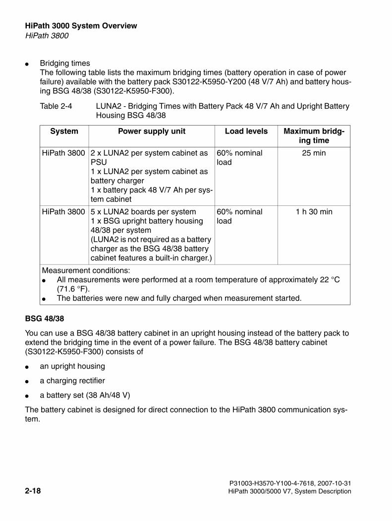
HiPath 3000 System Overview For internal use only
3000sb2.fm
HiPath 3800
● Bridging times The following table lists the maximum bridging times (battery operation in case of power failure) available with the battery pack S30122-K5950-Y200 (48 V/7 Ah) and battery hous-ing BSG 48/38 (S30122-K5950-F300).
BSG 48/38
You can use a BSG 48/38 battery cabinet in an upright housing instead of the battery pack to extend the bridging time in the event of a power failure. The BSG 48/38 battery cabinet (S30122-K5950-F300) consists of
● an upright housing
● a charging rectifier
● a battery set (38 Ah/48 V)
The battery cabinet is designed for direct connection to the HiPath 3800 communication sys-tem.
Table 2-4 LUNA2 - Bridging Times with Battery Pack 48 V/7 Ah and Upright Battery Housing BSG 48/38
System Power supply unit Load levels Maximum bridg-ing time
HiPath 3800 2 x LUNA2 per system cabinet as PSU 1 x LUNA2 per system cabinet as battery charger 1 x battery pack 48 V/7 Ah per sys-tem cabinet
60% nominal load
25 min
HiPath 3800 5 x LUNA2 boards per system 1 x BSG upright battery housing 48/38 per system (LUNA2 is not required as a battery charger as the BSG 48/38 battery cabinet features a built-in charger.)
60% nominal load
1 h 30 min
Measurement conditions:● All measurements were performed at a room temperature of approximately 22 °C
(71.6 °F). ● The batteries were new and fully charged when measurement started.
P31003-H3570-Y100-4-7618, 2007-10-312-18 HiPath 3000/5000 V7, System Description
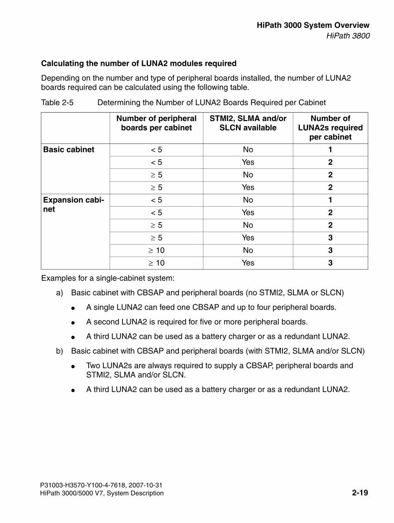
3000sb2.fm
For internal use only HiPath 3000 System OverviewHiPath 3800
Calculating the number of LUNA2 modules required
Depending on the number and type of peripheral boards installed, the number of LUNA2 boards required can be calculated using the following table.
Examples for a single-cabinet system:
a) Basic cabinet with CBSAP and peripheral boards (no STMI2, SLMA or SLCN)
● A single LUNA2 can feed one CBSAP and up to four peripheral boards.
● A second LUNA2 is required for five or more peripheral boards.
● A third LUNA2 can be used as a battery charger or as a redundant LUNA2.
b) Basic cabinet with CBSAP and peripheral boards (with STMI2, SLMA and/or SLCN)
● Two LUNA2s are always required to supply a CBSAP, peripheral boards and STMI2, SLMA and/or SLCN.
● A third LUNA2 can be used as a battery charger or as a redundant LUNA2.
Table 2-5 Determining the Number of LUNA2 Boards Required per Cabinet
Number of peripheral boards per cabinet
STMI2, SLMA and/or SLCN available
Number of LUNA2s required
per cabinet
Basic cabinet < 5 No 1
< 5 Yes 2
5 No 2
5 Yes 2
Expansion cabi-net
< 5 No 1
< 5 Yes 2
5 No 2
5 Yes 3
10 No 3
10 Yes 3
P31003-H3570-Y100-4-7618, 2007-10-31HiPath 3000/5000 V7, System Description 2-19
HiPath 3000 System Overview For internal use only
3000sb2.fm
HiPath 3800
2.2.4.3 LIMS
The LAN Interface Module for SAPP LIMS (S30807-Q6721-X) is an optional plug-in card for the CBSAP central control board in HiPath 3800.
The board provides two Ethernet (10BaseT) LAN connections via two 8-pin RJ45 jacks:
● LAN1 (administration via HiPath 3000/5000 Manager E and CTI functions)
● LAN2 (not assigned)
The LIMS module can be used for administration via HiPath 3000/5000 Manager E and for CTI functions (TAPI 120 V2.0). However, bear in mind that the number of BHCAs (Busy Hour Call Attempts = number of connection attempts during busy traffic hours) is restricted to 400 at a maximum of six TAPI ports. The use of "power dialers" is not approved.
You cannot operate the LIMS module and an STMI2 board simultaneously in a HiPath 3800.
2.2.4.4 CSAPE
The cPCI cassette CSAPE (Central Shelf Access Point Emergency) can be installed in the ba-sic cabinet in HiPath 3800 V6.0 or later. The cPCI cassette features two fan drawers, the AC power supply ACPCI (part number S30124-X5166-X), and two slide-in shelves for the embed-ded application server (EAS).
CSAPE is required to operate HiPath All-in-One applications. For information on the applica-tions supported, refer to the product documentation for HiPath All-in-One.
The cPCI cassette CSAPE is only mechanically installed in the system, that is, there are no electrical connections between the system and the cPCI cassette CSAPE. HiPath 3800 com-municates exclusively with HiPath All-in-One over the IP network.
P31003-H3570-Y100-4-7618, 2007-10-312-20 HiPath 3000/5000 V7, System Description
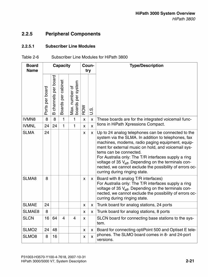
3000sb2.fm
For internal use only HiPath 3000 System OverviewHiPath 3800
2.2.5 Peripheral Components
2.2.5.1 Subscriber Line Modules
Table 2-6 Subscriber Line Modules for HiPath 3800
Board Name
Capacity Coun-try
Type/Description
Por
ts p
er b
oard
B c
hann
els
per
boar
d
Boa
rds
per
cabi
net
Max
. num
ber
ofbo
ards
per
sys
tem
RO
W
U.S
.
IVMN8 8 8 1 1 x x These boards are for the integrated voicemail func-tions in HiPath Xpressions Compact.IVMNL 24 24 1 1 x x
SLMA 24 x x Up to 24 analog telephones can be connected to the system via the SLMA. In addition to telephones, fax machines, modems, radio paging equipment, equip-ment for external music on hold, and voicemail sys-tems can be connected.For Australia only: The T/R interfaces supply a ring voltage of 35 Veff. Depending on the terminals con-nected, we cannot exclude the possibility of errors oc-curring during ringing state.
SLMA8 8 x x Board with 8 analog T/R interfaces)For Australia only: The T/R interfaces supply a ring voltage of 35 Veff. Depending on the terminals con-nected, we cannot exclude the possibility of errors oc-curring during ringing state.
SLMAE 24 x x Trunk board for analog stations, 24 ports
SLMAE8 8 x x Trunk board for analog stations, 8 ports
SLCN 16 64 4 4 x SLCN board for connecting base stations to the sys-tem.
SLMO2 24 48 x x Board for connecting optiPoint 500 and Optiset E tele-phones. The SLMO board comes in 8- and 24-port versions.
SLMO8 8 16 x x
P31003-H3570-Y100-4-7618, 2007-10-31HiPath 3000/5000 V7, System Description 2-21
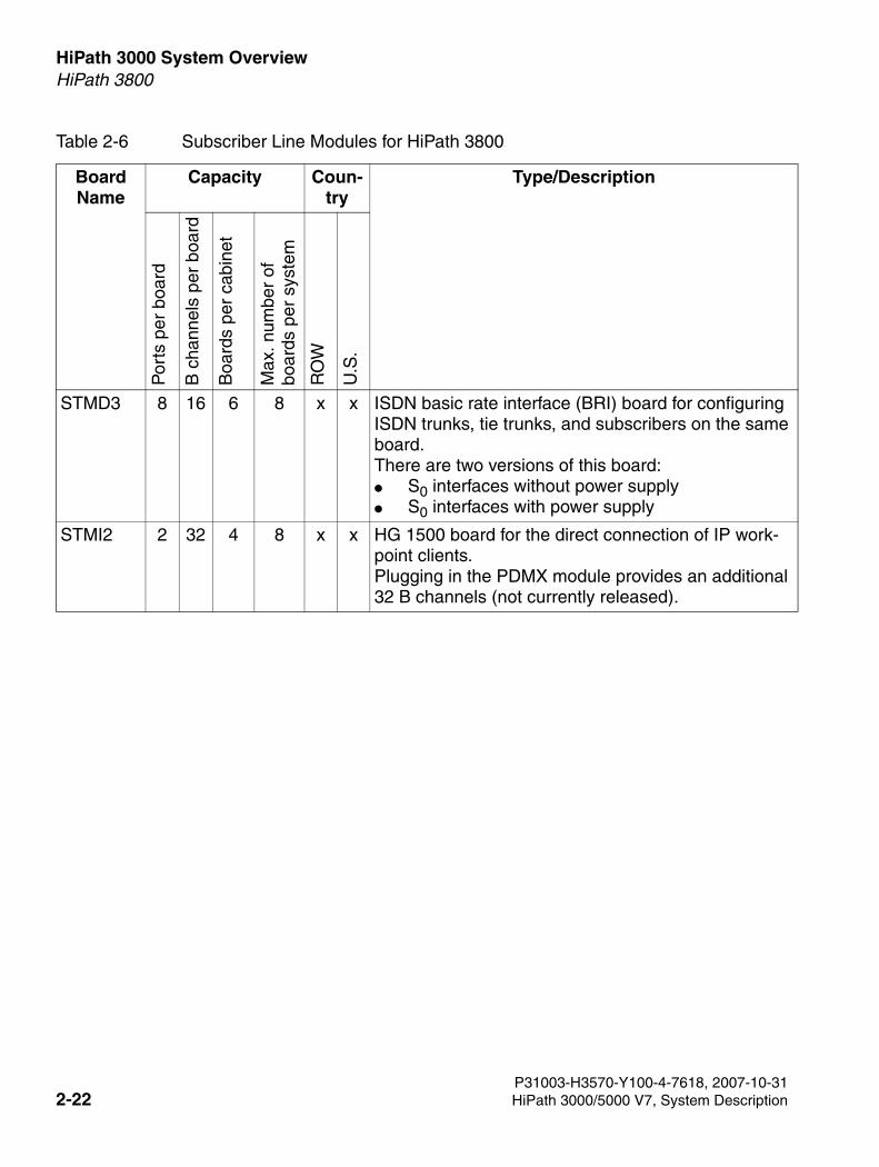
HiPath 3000 System Overview For internal use only
3000sb2.fm
HiPath 3800
STMD3 8 16 6 8 x x ISDN basic rate interface (BRI) board for configuring ISDN trunks, tie trunks, and subscribers on the same board.There are two versions of this board: ● S0 interfaces without power supply ● S0 interfaces with power supply
STMI2 2 32 4 8 x x HG 1500 board for the direct connection of IP work-point clients. Plugging in the PDMX module provides an additional 32 B channels (not currently released).
Table 2-6 Subscriber Line Modules for HiPath 3800
Board Name
Capacity Coun-try
Type/DescriptionP
orts
per
boa
rd
B c
hann
els
per
boar
d
Boa
rds
per
cabi
net
Max
. num
ber
ofbo
ards
per
sys
tem
RO
W
U.S
.
P31003-H3570-Y100-4-7618, 2007-10-312-22 HiPath 3000/5000 V7, System Description
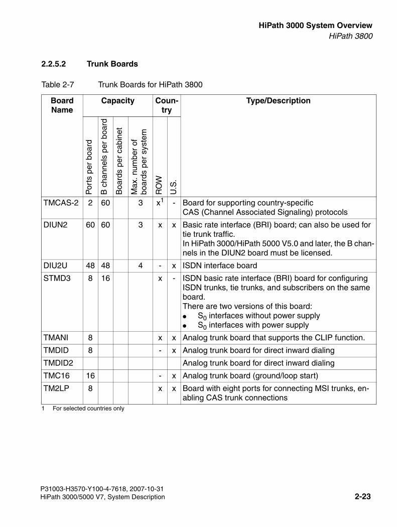
3000sb2.fm
For internal use only HiPath 3000 System OverviewHiPath 3800
2.2.5.2 Trunk Boards
Table 2-7 Trunk Boards for HiPath 3800
Board Name
Capacity Coun-try
Type/Description
Por
ts p
er b
oard
B c
hann
els
per
boar
d
Boa
rds
per
cabi
net
Max
. num
ber
ofbo
ards
per
sys
tem
RO
W
U.S
.
TMCAS-2 2 60 3 x1
1 For selected countries only
- Board for supporting country-specificCAS (Channel Associated Signaling) protocols
DIUN2 60 60 3 x x Basic rate interface (BRI) board; can also be used for tie trunk traffic.In HiPath 3000/HiPath 5000 V5.0 and later, the B chan-nels in the DIUN2 board must be licensed.
DIU2U 48 48 4 - x ISDN interface board
STMD3 8 16 x - ISDN basic rate interface (BRI) board for configuring ISDN trunks, tie trunks, and subscribers on the same board. There are two versions of this board: ● S0 interfaces without power supply ● S0 interfaces with power supply
TMANI 8 x x Analog trunk board that supports the CLIP function.
TMDID 8 - x Analog trunk board for direct inward dialing
TMDID2 Analog trunk board for direct inward dialing
TMC16 16 - x Analog trunk board (ground/loop start)
TM2LP 8 x x Board with eight ports for connecting MSI trunks, en-abling CAS trunk connections
P31003-H3570-Y100-4-7618, 2007-10-31HiPath 3000/5000 V7, System Description 2-23
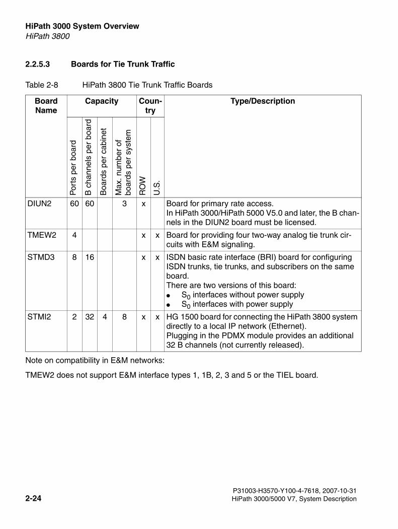
HiPath 3000 System Overview For internal use only
3000sb2.fm
HiPath 3800
2.2.5.3 Boards for Tie Trunk Traffic
Note on compatibility in E&M networks:
TMEW2 does not support E&M interface types 1, 1B, 2, 3 and 5 or the TIEL board.
Table 2-8 HiPath 3800 Tie Trunk Traffic Boards
Board Name
Capacity Coun-try
Type/Description
Por
ts p
er b
oard
B c
hann
els
per
boar
d
Boa
rds
per
cabi
net
Max
. num
ber
ofbo
ards
per
sys
tem
RO
W
U.S
.
DIUN2 60 60 3 x Board for primary rate access. In HiPath 3000/HiPath 5000 V5.0 and later, the B chan-nels in the DIUN2 board must be licensed.
TMEW2 4 x x Board for providing four two-way analog tie trunk cir-cuits with E&M signaling.
STMD3 8 16 x x ISDN basic rate interface (BRI) board for configuring ISDN trunks, tie trunks, and subscribers on the same board. There are two versions of this board: ● S0 interfaces without power supply ● S0 interfaces with power supply
STMI2 2 32 4 8 x x HG 1500 board for connecting the HiPath 3800 system directly to a local IP network (Ethernet). Plugging in the PDMX module provides an additional 32 B channels (not currently released).
P31003-H3570-Y100-4-7618, 2007-10-312-24 HiPath 3000/5000 V7, System Description
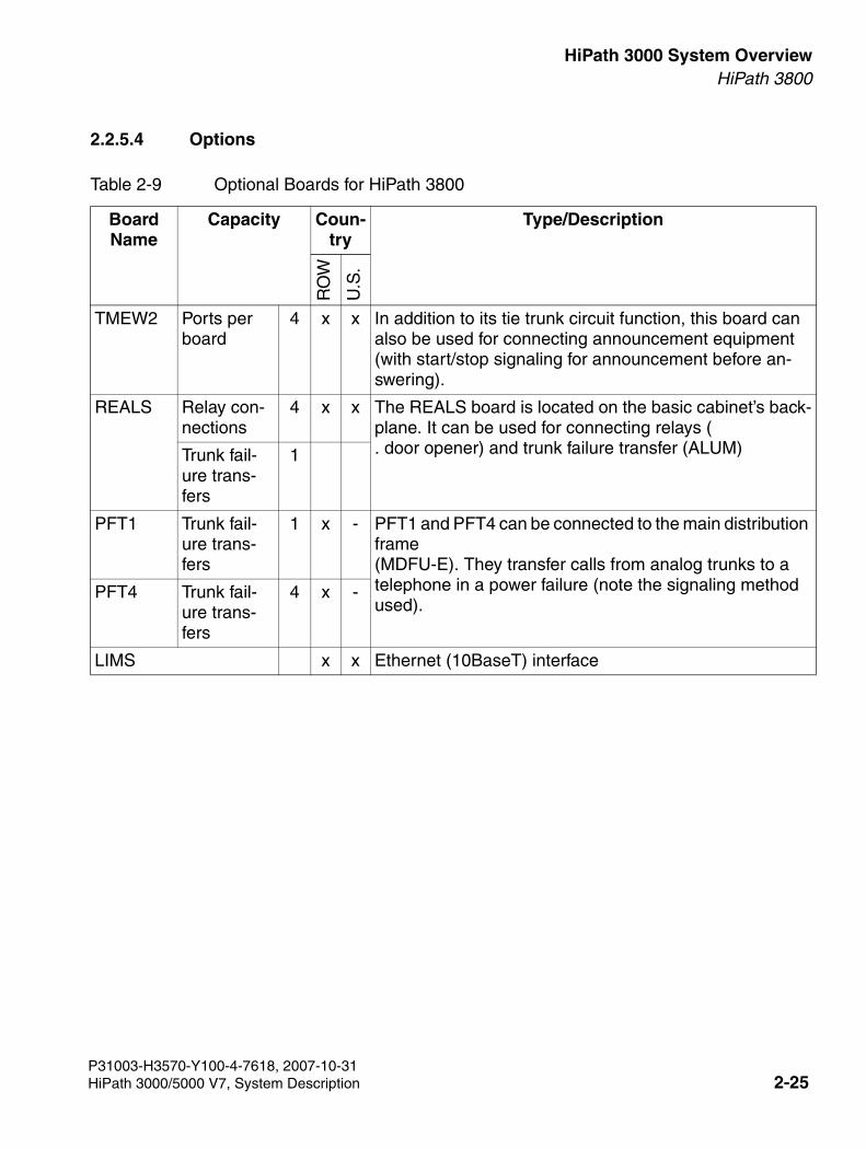
3000sb2.fm
For internal use only HiPath 3000 System OverviewHiPath 3800
2.2.5.4 Options
Table 2-9 Optional Boards for HiPath 3800
Board Name
Capacity Coun-try
Type/Description
RO
W
U.S
.
TMEW2 Ports per board
4 x x In addition to its tie trunk circuit function, this board can also be used for connecting announcement equipment (with start/stop signaling for announcement before an-swering).
REALS Relay con-nections
4 x x The REALS board is located on the basic cabinet’s back-plane. It can be used for connecting relays (. door opener) and trunk failure transfer (ALUM) Trunk fail-
ure trans-fers
1
PFT1 Trunk fail-ure trans-fers
1 x - PFT1 and PFT4 can be connected to the main distribution frame (MDFU-E). They transfer calls from analog trunks to a telephone in a power failure (note the signaling method used).
PFT4 Trunk fail-ure trans-fers
4 x -
LIMS x x Ethernet (10BaseT) interface
P31003-H3570-Y100-4-7618, 2007-10-31HiPath 3000/5000 V7, System Description 2-25

HiPath 3000 System Overview For internal use only
3000sb2.fm
HiPath 3800
2.2.6 Additional System Data
Information not available.
2.2.6.1 Heat Dissipation and Power Consumption
Information not available.
2.2.6.2 Specifications for the Uninterruptible Power Supply LUNA2
Refer to Section 2.2.4.2 for details on LUNA2.
P31003-H3570-Y100-4-7618, 2007-10-312-26 HiPath 3000/5000 V7, System Description
3000sb2.fm
For internal use only HiPath 3000 System OverviewHiPath 3550
2.3 HiPath 3550
2.3.1 Hardware Overview
Structure
The HiPath 3550 housing intended for wall mounting contains one shelf with six slot levels. The slot levels, numbered in ascending order from the attachment side, have the following assign-ments:
● Slot levels 1-3: peripheral boards (two slots per level)
● Slot level 4: CBCC control board only
● Slot level 6: optional boards (up to 5 modules)
The power supply unit is located on the back of the subrack.
The connecting cables to the peripherals (telephones, trunk connections) can be connected di-rectly.
P31003-H3570-Y100-4-7618, 2007-10-31HiPath 3000/5000 V7, System Description 2-27
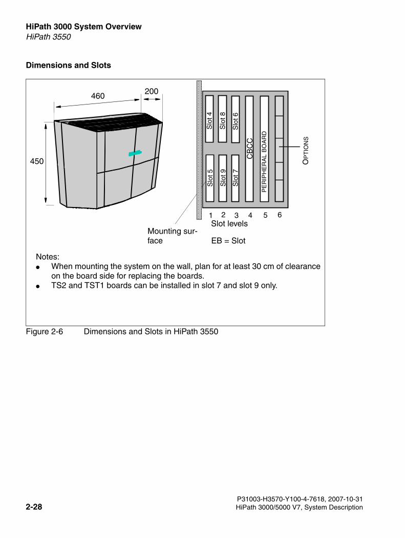
HiPath 3000 System Overview For internal use only
3000sb2.fm
HiPath 3550
Dimensions and Slots
Figure 2-6 Dimensions and Slots in HiPath 3550
Mounting sur-face
460 200
450
EB = Slot
Notes:● When mounting the system on the wall, plan for at least 30 cm of clearance
on the board side for replacing the boards.● TS2 and TST1 boards can be installed in slot 7 and slot 9 only.
Slot levels
Slo
t 4S
lot 5
Slo
t 821 63 4 5
Slo
t 9
Slo
t 6S
lot 7
CB
CC
PE
RIP
HE
RA
L B
OA
RD
OP
TIO
NS
P31003-H3570-Y100-4-7618, 2007-10-312-28 HiPath 3000/5000 V7, System Description
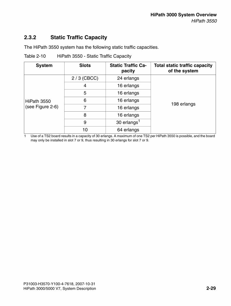
3000sb2.fm
For internal use only HiPath 3000 System OverviewHiPath 3550
2.3.2 Static Traffic Capacity
The HiPath 3550 system has the following static traffic capacities.
Table 2-10 HiPath 3550 - Static Traffic Capacity
System Slots Static Traffic Ca-pacity
Total static traffic capacity of the system
HiPath 3550(see Figure 2-6)
2 / 3 (CBCC) 24 erlangs
198 erlangs
4 16 erlangs
5 16 erlangs
6 16 erlangs
7 16 erlangs
8 16 erlangs
9 30 erlangs1
1 Use of a TS2 board results in a capacity of 30 erlangs. A maximum of one TS2 per HiPath 3550 is possible, and the board may only be installed in slot 7 or 9, thus resulting in 30 erlangs for slot 7 or 9.
10 64 erlangs
P31003-H3570-Y100-4-7618, 2007-10-31HiPath 3000/5000 V7, System Description 2-29
HiPath 3000 System Overview For internal use only
3000sb2.fm
HiPath 3550
2.3.3 Central Components
2.3.3.1 CBCC
Introduction
The CBCC (Central Board with Coldfire Com) board performs all central control and switching functions for HiPath 3550.
This description relates to the following outputs of the Central Control CBCC:
● CBCC S30810-Q2935-A401) Implemented from V6.0 Rel. 10 and later. Major new CTI functions:
– Integration of subboard LIM functionality
– Increasing the ringing voltage of the subscriber interfaces (T/R) to approx. 65 Veff
– Removal of the second V.24 interface (option V24/1)
● CBCC S30810-Q2935-A301: Implemented in V5.0 and later:Major new function: CLIP
Subboards
The following subboards (some of which are optional) can be used depending on the applica-tion:
● CMS clock module small [optional]
– supports all two-channel cordless connections to the HiPath 3550, HiPath 3350, Hi-Path 3500 and HiPath 3300 systems.
– supports all 4, 8 and 12-channel CMI connections using the SLC16 board of the Hi-Path 3550 system.
– provides the master clock for digital networking.
Section 2.9 contains additional information on when CMS is used.
● Clock Module ADPCM (CMA) [optional]
– supports the four-channel CMI connection over a base station to the HiPath 3550, Hi-Path 3350, HiPath 3500, and HiPath 3300 systems.
– in the same way as the CMS clock module small, provides the master clock for digital networking.
Section 2.9 contains additional information on when CMA is used.
P31003-H3570-Y100-4-7618, 2007-10-312-30 HiPath 3000/5000 V7, System Description
3000sb2.fm
For internal use only HiPath 3000 System OverviewHiPath 3550
● MMC multimedia cardThis plug-in memory card contains the CDB backup and the version-specific APS. Please note that the MMC may only be replaced by a multimedia card approved by Siemens Enterprise Communications GmbH & Co. KG. Cards that have not been ap-proved may have a different internal structure which can affect temporal access and certain features (CDB backup and APS transfer, for instance).
● IMODN Integrated Modem Card New [optional]This plug-in card allows remote service (analog mode up to 33.6 Kbps), without having to use an external modem.
● MPPI (Music on Hold) [optional]
● Entry Voice Mail (EVM) [optional]
● LIM LAN interface module (option, only for CBCC S30810-Q2935-A301) This subboard makes available an Ethernet (10BaseT/10 Mbps) LAN connection using an 8-pin RJ45 jack (see Section 2.3.3.3).
Interfaces
● Ethernet (10BaseT/10 MBit)-LAN interface, only in CBCC S30810-Q2935-A401The LIM module can be used for administration via HiPath 3000/5000 Manager E and for CTI functions (TAPI 120 V2.0). However, bear in mind that the number of BHCAs (Busy Hour Call Attempts = number of connection attempts during busy traffic hours) is restricted to 400 at a maximum of six TAPI ports. The use of "power dialers" is not approved.
The Ethernet LAN interface is deactivated by the system software as soon as an HG 1500 board is inserted.
● Eight digital UP0/E subscriber lines For example, UP0/E workpoint clients or BS3/1 base stations for HiPath Cordless Office can be connected here.
● Four analog T/R subscriber interfaces For U.S. only: These interfaces do not support the connection of external extensions via OPS (Off-Premises Station) signaling. CBCC S30810-Q2935-A401: The T/R interfaces supply a ring voltage of appr. 65 Veff. CBCC S30810-Q2935-A301: The T/R interfaces supply a ring voltage of appr. 35 Veff. De-pending on the terminals connected, we cannot exclude the possibility of errors occurring during ringing state.
● Two digital S0 interfaces (CO (default) or station)
● Backplane (CUC or CUP) connection via slots 1 (X11), 2 (X5) and 3 (X6)
● Music on hold: MPPI, EXM
P31003-H3570-Y100-4-7618, 2007-10-31HiPath 3000/5000 V7, System Description 2-31
HiPath 3000 System Overview For internal use only
3000sb2.fm
HiPath 3550
● Options bus (O bus)
● V.24 interfaceCBCC S30810-Q2935-A301: A second V.24 interface can be implemented via the option V24/1.
2.3.3.2 UPSC-D
Introduction
This board combines the power supply and battery management functions. No other compo-nents are required if operated as a power supply. To maintain short-term battery emergency operation after a power failure, that is, to use uninterruptible power supply functions, you must also connect a battery pack.
An EPSU2 external power supply must be used if the total number of UP0/E stations, analog stations, and stations connected using adapters is greater than 72.
Additional power can be made available by connecting the external EPSU2 power supply (see Section 2.3.6). For this, the EPSU2’s DC connection needs to be connected to the special –48 VDC input on the UPSC-D. The UPSC-D’s internal -48-V output is deactivated when the ex-ternal power supply is connected.
Technical specifications
● Nominal voltage range: 100 VAC - 240 VAC
● Nominal frequency: 50 Hz - 60 Hz
● Ring generator: 75 VAC, 20/25/50 Hz
● Partial voltages: +5 VDC, –48 V
● Battery charger: 4 x 12 V (40.8 V-55.2 V)
● Power consumption: 180 W
● Bridging times The following table lists the maximum bridging times (battery operation in case of power failure) available with the battery pack S30122-K5928-X (48 V/1.2 Ah).
>Please note that only one MPPI module may be connected. In other words, you can connect either MPPI S30122-K5380-X200 via X4 or MPPI S30122-K7275-B via X19/X20.
P31003-H3570-Y100-4-7618, 2007-10-312-32 HiPath 3000/5000 V7, System Description
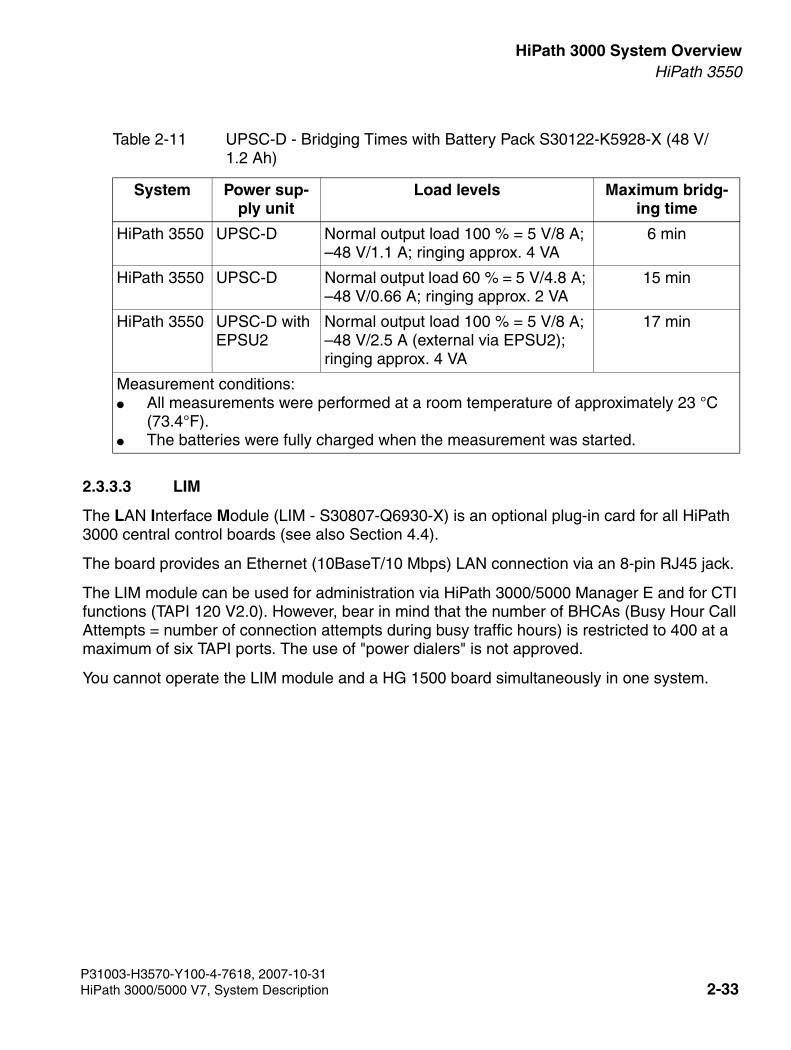
3000sb2.fm
For internal use only HiPath 3000 System OverviewHiPath 3550
2.3.3.3 LIM
The LAN Interface Module (LIM - S30807-Q6930-X) is an optional plug-in card for all HiPath 3000 central control boards (see also Section 4.4).
The board provides an Ethernet (10BaseT/10 Mbps) LAN connection via an 8-pin RJ45 jack.
The LIM module can be used for administration via HiPath 3000/5000 Manager E and for CTI functions (TAPI 120 V2.0). However, bear in mind that the number of BHCAs (Busy Hour Call Attempts = number of connection attempts during busy traffic hours) is restricted to 400 at a maximum of six TAPI ports. The use of "power dialers" is not approved.
You cannot operate the LIM module and a HG 1500 board simultaneously in one system.
Table 2-11 UPSC-D - Bridging Times with Battery Pack S30122-K5928-X (48 V/1.2 Ah)
System Power sup-ply unit
Load levels Maximum bridg-ing time
HiPath 3550 UPSC-D Normal output load 100 % = 5 V/8 A; –48 V/1.1 A; ringing approx. 4 VA
6 min
HiPath 3550 UPSC-D Normal output load 60 % = 5 V/4.8 A; –48 V/0.66 A; ringing approx. 2 VA
15 min
HiPath 3550 UPSC-D with EPSU2
Normal output load 100 % = 5 V/8 A; –48 V/2.5 A (external via EPSU2); ringing approx. 4 VA
17 min
Measurement conditions:● All measurements were performed at a room temperature of approximately 23 °C
(73.4°F). ● The batteries were fully charged when the measurement was started.
P31003-H3570-Y100-4-7618, 2007-10-31HiPath 3000/5000 V7, System Description 2-33
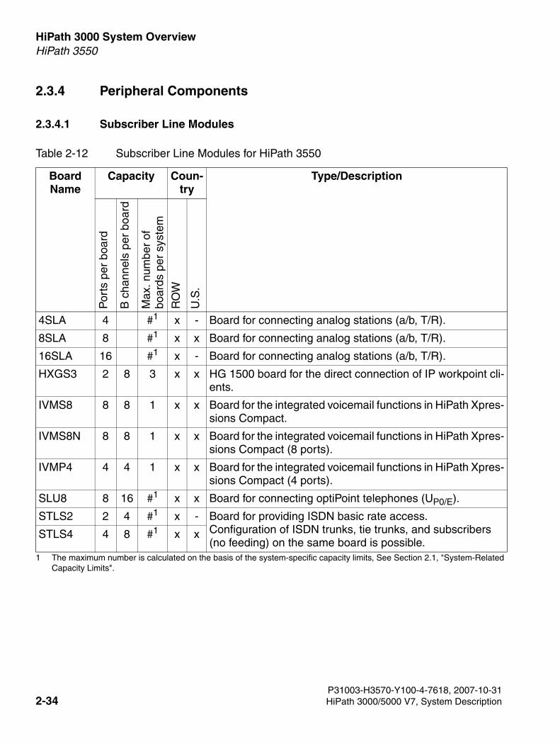
HiPath 3000 System Overview For internal use only
3000sb2.fm
HiPath 3550
2.3.4 Peripheral Components
2.3.4.1 Subscriber Line Modules
Table 2-12 Subscriber Line Modules for HiPath 3550
Board Name
Capacity Coun-try
Type/Description
Por
ts p
er b
oard
B c
hann
els
per
boar
d
Max
. num
ber
ofbo
ards
per
sys
tem
RO
W
U.S
.
4SLA 4 #1
1 The maximum number is calculated on the basis of the system-specific capacity limits, See Section 2.1, "System-Related Capacity Limits".
x - Board for connecting analog stations (a/b, T/R).
8SLA 8 #1 x x Board for connecting analog stations (a/b, T/R).
16SLA 16 #1 x - Board for connecting analog stations (a/b, T/R).
HXGS3 2 8 3 x x HG 1500 board for the direct connection of IP workpoint cli-ents.
IVMS8 8 8 1 x x Board for the integrated voicemail functions in HiPath Xpres-sions Compact.
IVMS8N 8 8 1 x x Board for the integrated voicemail functions in HiPath Xpres-sions Compact (8 ports).
IVMP4 4 4 1 x x Board for the integrated voicemail functions in HiPath Xpres-sions Compact (4 ports).
SLU8 8 16 #1 x x Board for connecting optiPoint telephones (UP0/E).
STLS2 2 4 #1 x - Board for providing ISDN basic rate access. Configuration of ISDN trunks, tie trunks, and subscribers (no feeding) on the same board is possible.
STLS4 4 8 #1 x x
P31003-H3570-Y100-4-7618, 2007-10-312-34 HiPath 3000/5000 V7, System Description
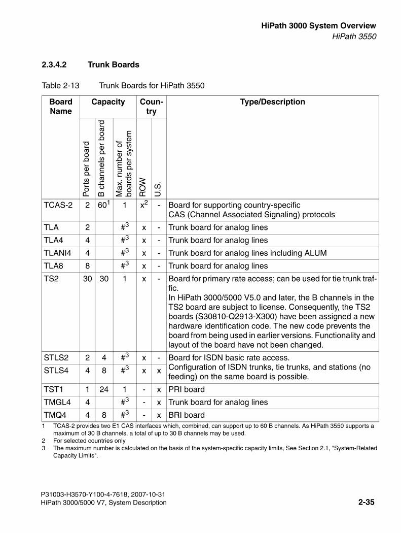
3000sb2.fm
For internal use only HiPath 3000 System OverviewHiPath 3550
2.3.4.2 Trunk Boards
Table 2-13 Trunk Boards for HiPath 3550
Board Name
Capacity Coun-try
Type/Description
Por
ts p
er b
oard
B c
hann
els
per
boar
d
Max
. num
ber
ofbo
ards
per
sys
tem
RO
W
U.S
.
TCAS-2 2 601
1 TCAS-2 provides two E1 CAS interfaces which, combined, can support up to 60 B channels. As HiPath 3550 supports a maximum of 30 B channels, a total of up to 30 B channels may be used.
1 x2
2 For selected countries only
- Board for supporting country-specificCAS (Channel Associated Signaling) protocols
TLA 2 #3
3 The maximum number is calculated on the basis of the system-specific capacity limits, See Section 2.1, "System-Related Capacity Limits".
x - Trunk board for analog lines
TLA4 4 #3 x - Trunk board for analog lines
TLANI4 4 #3 x - Trunk board for analog lines including ALUM
TLA8 8 #3 x - Trunk board for analog lines
TS2 30 30 1 x - Board for primary rate access; can be used for tie trunk traf-fic. In HiPath 3000/5000 V5.0 and later, the B channels in the TS2 board are subject to license. Consequently, the TS2 boards (S30810-Q2913-X300) have been assigned a new hardware identification code. The new code prevents the board from being used in earlier versions. Functionality and layout of the board have not been changed.
STLS2 2 4 #3 x - Board for ISDN basic rate access. Configuration of ISDN trunks, tie trunks, and stations (no feeding) on the same board is possible.
STLS4 4 8 #3 x x
TST1 1 24 1 - x PRI board
TMGL4 4 #3 - x Trunk board for analog lines
TMQ4 4 8 #3 - x BRI board
P31003-H3570-Y100-4-7618, 2007-10-31HiPath 3000/5000 V7, System Description 2-35
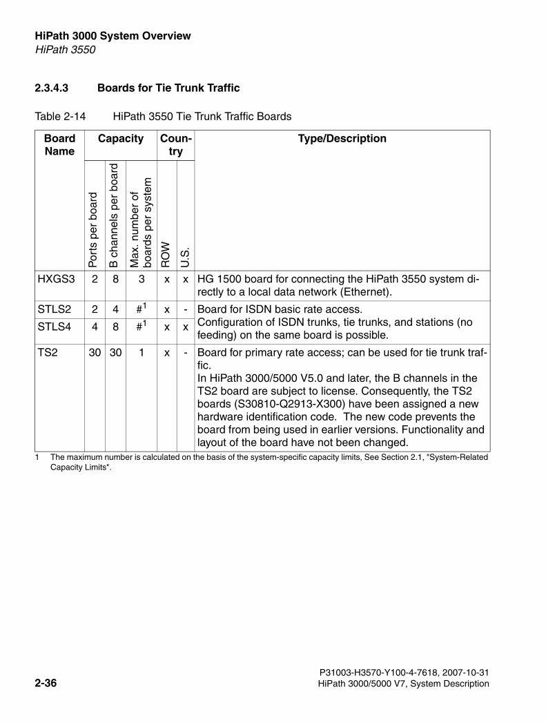
HiPath 3000 System Overview For internal use only
3000sb2.fm
HiPath 3550
2.3.4.3 Boards for Tie Trunk Traffic
Table 2-14 HiPath 3550 Tie Trunk Traffic Boards
Board Name
Capacity Coun-try
Type/Description
Por
ts p
er b
oard
B c
hann
els
per
boar
d
Max
. num
ber
of
boar
ds p
er s
yste
m
RO
W
U.S
.
HXGS3 2 8 3 x x HG 1500 board for connecting the HiPath 3550 system di-rectly to a local data network (Ethernet).
STLS2 2 4 #1
1 The maximum number is calculated on the basis of the system-specific capacity limits, See Section 2.1, "System-Related Capacity Limits".
x - Board for ISDN basic rate access. Configuration of ISDN trunks, tie trunks, and stations (no feeding) on the same board is possible.
STLS4 4 8 #1 x x
TS2 30 30 1 x - Board for primary rate access; can be used for tie trunk traf-fic. In HiPath 3000/5000 V5.0 and later, the B channels in the TS2 board are subject to license. Consequently, the TS2 boards (S30810-Q2913-X300) have been assigned a new hardware identification code. The new code prevents the board from being used in earlier versions. Functionality and layout of the board have not been changed.
P31003-H3570-Y100-4-7618, 2007-10-312-36 HiPath 3000/5000 V7, System Description
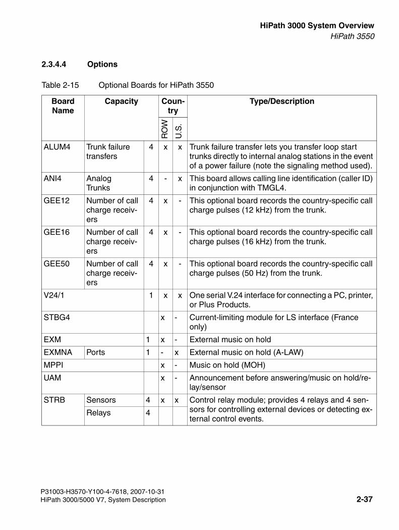
3000sb2.fm
For internal use only HiPath 3000 System OverviewHiPath 3550
2.3.4.4 Options
Table 2-15 Optional Boards for HiPath 3550
Board Name
Capacity Coun-try
Type/Description
RO
W
U.S
.
ALUM4 Trunk failure transfers
4 x x Trunk failure transfer lets you transfer loop start trunks directly to internal analog stations in the event of a power failure (note the signaling method used).
ANI4 Analog Trunks
4 - x This board allows calling line identification (caller ID) in conjunction with TMGL4.
GEE12 Number of call charge receiv-ers
4 x - This optional board records the country-specific call charge pulses (12 kHz) from the trunk.
GEE16 Number of call charge receiv-ers
4 x - This optional board records the country-specific call charge pulses (16 kHz) from the trunk.
GEE50 Number of call charge receiv-ers
4 x - This optional board records the country-specific call charge pulses (50 Hz) from the trunk.
V24/1 1 x x One serial V.24 interface for connecting a PC, printer, or Plus Products.
STBG4 x - Current-limiting module for LS interface (France only)
EXM 1 x - External music on hold
EXMNA Ports 1 - x External music on hold (A-LAW)
MPPI x - Music on hold (MOH)
UAM x - Announcement before answering/music on hold/re-lay/sensor
STRB Sensors 4 x x Control relay module; provides 4 relays and 4 sen-sors for controlling external devices or detecting ex-ternal control events.
Relays 4
P31003-H3570-Y100-4-7618, 2007-10-31HiPath 3000/5000 V7, System Description 2-37
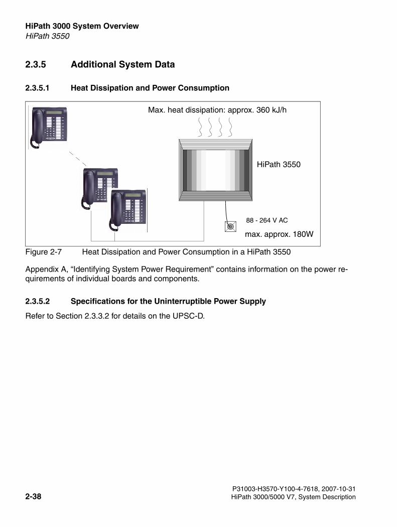
HiPath 3000 System Overview For internal use only
3000sb2.fm
HiPath 3550
2.3.5 Additional System Data
2.3.5.1 Heat Dissipation and Power Consumption
Figure 2-7 Heat Dissipation and Power Consumption in a HiPath 3550
Appendix A, “Identifying System Power Requirement” contains information on the power re-quirements of individual boards and components.
2.3.5.2 Specifications for the Uninterruptible Power Supply
Refer to Section 2.3.3.2 for details on the UPSC-D.
88 - 264 V AC
max. approx. 180W
HiPath 3550
Max. heat dissipation: approx. 360 kJ/h
P31003-H3570-Y100-4-7618, 2007-10-312-38 HiPath 3000/5000 V7, System Description
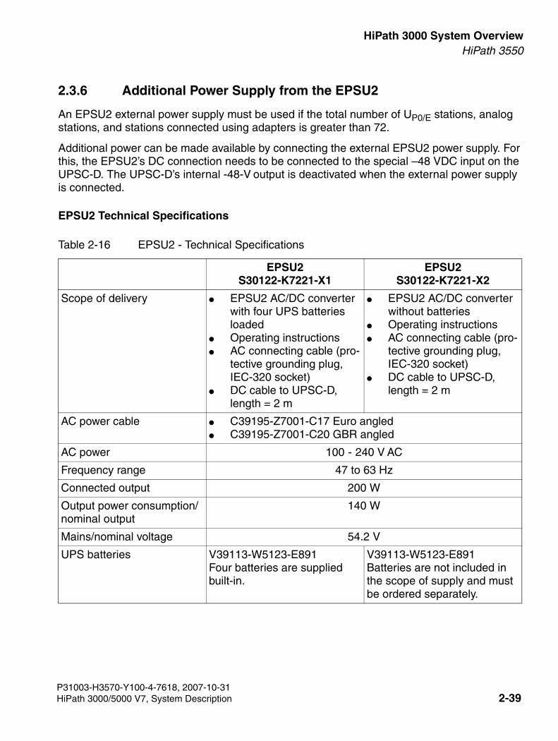
3000sb2.fm
For internal use only HiPath 3000 System OverviewHiPath 3550
2.3.6 Additional Power Supply from the EPSU2
An EPSU2 external power supply must be used if the total number of UP0/E stations, analog stations, and stations connected using adapters is greater than 72.
Additional power can be made available by connecting the external EPSU2 power supply. For this, the EPSU2’s DC connection needs to be connected to the special –48 VDC input on the UPSC-D. The UPSC-D’s internal -48-V output is deactivated when the external power supply is connected.
EPSU2 Technical Specifications
Table 2-16 EPSU2 - Technical Specifications
EPSU2S30122-K7221-X1
EPSU2S30122-K7221-X2
Scope of delivery ● EPSU2 AC/DC converter with four UPS batteries loaded
● Operating instructions● AC connecting cable (pro-
tective grounding plug, IEC-320 socket)
● DC cable to UPSC-D, length = 2 m
● EPSU2 AC/DC converter without batteries
● Operating instructions● AC connecting cable (pro-
tective grounding plug, IEC-320 socket)
● DC cable to UPSC-D, length = 2 m
AC power cable ● C39195-Z7001-C17 Euro angled● C39195-Z7001-C20 GBR angled
AC power 100 - 240 V AC
Frequency range 47 to 63 Hz
Connected output 200 W
Output power consumption/nominal output
140 W
Mains/nominal voltage 54.2 V
UPS batteries V39113-W5123-E891Four batteries are supplied built-in.
V39113-W5123-E891Batteries are not included in the scope of supply and must be ordered separately.
P31003-H3570-Y100-4-7618, 2007-10-31HiPath 3000/5000 V7, System Description 2-39
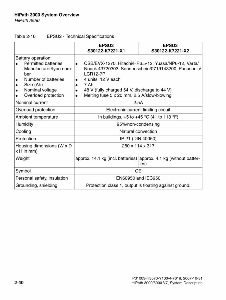
HiPath 3000 System Overview For internal use only
3000sb2.fm
HiPath 3550
Battery operation:● Permitted batteries
Manufacturer/type num-ber
● Number of batteries● Size (Ah)● Nominal voltage● Overload protection
● CSB/EVX-1270, Hitachi/HP6.5-12, Yuasa/NP6-12, Varta/Noack 43720303, Sonnenschein/0719143200, Panasonic/LCR12-7P
● 4 units, 12 V each● 7 Ah● 48 V (fully charged 54 V, discharge to 44 V)● Melting fuse 5 x 20 mm, 2.5 A/slow-blowing
Nominal current 2.5A
Overload protection Electronic current limiting circuit
Ambient temperature In buildings, +5 to +45 °C (41 to 113 °F)
Humidity 95%/non-condensing
Cooling Natural convection
Protection IP 21 (DIN 40050)
Housing dimensions (W x D x H in mm)
250 x 114 x 317
Weight approx. 14.1 kg (incl. batteries) approx. 4.1 kg (without batter-ies)
Symbol CE
Personal safety, insulation EN60950 and IEC950
Grounding, shielding Protection class 1, output is floating against ground.
Table 2-16 EPSU2 - Technical Specifications
EPSU2S30122-K7221-X1
EPSU2S30122-K7221-X2
P31003-H3570-Y100-4-7618, 2007-10-312-40 HiPath 3000/5000 V7, System Description
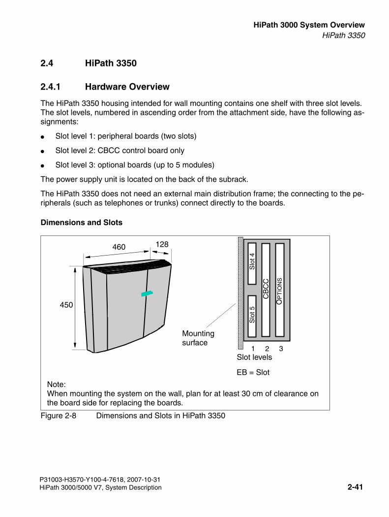
3000sb2.fm
For internal use only HiPath 3000 System OverviewHiPath 3350
2.4 HiPath 3350
2.4.1 Hardware Overview
The HiPath 3350 housing intended for wall mounting contains one shelf with three slot levels. The slot levels, numbered in ascending order from the attachment side, have the following as-signments:
● Slot level 1: peripheral boards (two slots)
● Slot level 2: CBCC control board only
● Slot level 3: optional boards (up to 5 modules)
The power supply unit is located on the back of the subrack.
The HiPath 3350 does not need an external main distribution frame; the connecting to the pe-ripherals (such as telephones or trunks) connect directly to the boards.
Dimensions and Slots
Figure 2-8 Dimensions and Slots in HiPath 3350
21Slot levels
3
CB
CC
Slo
t 4S
lot 5
OP
TIO
NS
Mounting surface
460
450
128
EB = Slot
Note: When mounting the system on the wall, plan for at least 30 cm of clearance on the board side for replacing the boards.
P31003-H3570-Y100-4-7618, 2007-10-31HiPath 3000/5000 V7, System Description 2-41
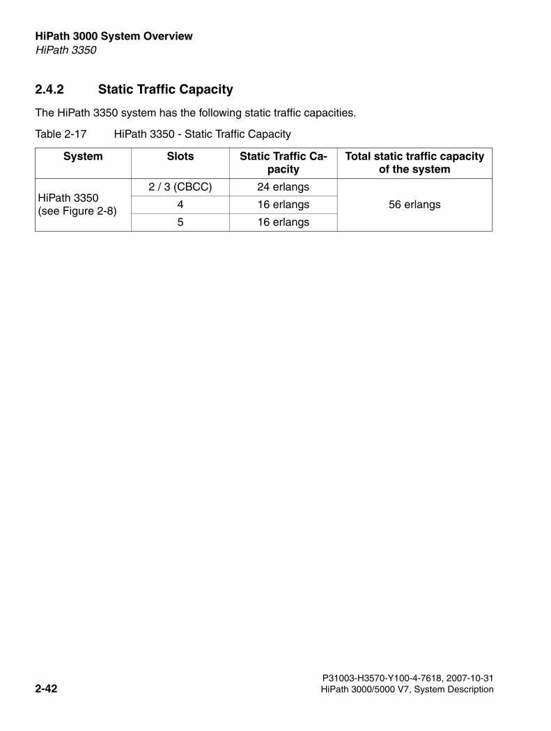
HiPath 3000 System Overview For internal use only
3000sb2.fm
HiPath 3350
2.4.2 Static Traffic Capacity
The HiPath 3350 system has the following static traffic capacities.
Table 2-17 HiPath 3350 - Static Traffic Capacity
System Slots Static Traffic Ca-pacity
Total static traffic capacity of the system
HiPath 3350(see Figure 2-8)
2 / 3 (CBCC) 24 erlangs
56 erlangs4 16 erlangs
5 16 erlangs
P31003-H3570-Y100-4-7618, 2007-10-312-42 HiPath 3000/5000 V7, System Description
3000sb2.fm
For internal use only HiPath 3000 System OverviewHiPath 3350
2.4.3 Central Components
2.4.3.1 CBCC
Introduction
The CBCC (HiPath 3550Central Board with Coldfire Com) board performs all central con-trol and switching functions for .
This description relates to the following outputs of the Central Control CBCC:
● CBCC S30810-Q2935-A401: Implemented from V6.0 Rel. 10 and later. Major new CTI functions:
– Integration of subboard LIM functionality
– Increasing the ringing voltage of the subscriber interfaces (T/R) to approx. 65 Veff
– Removal of the second V.24 interface (option V24/1)
● CBCC S30810-Q2935-A301: Implemented in V5.0 and later:Major new function: CLIP
Subboards
The following subboards (some of which are optional) can be used depending on the applica-tion:
● CMS clock module small [optional]
– supports all two-channel cordless connections to the HiPath 3550, HiPath 3350, Hi-Path 3500 and HiPath 3300 systems.
– supports all 4, 8 and 12-channel CMI connections using the SLC16 board of the Hi-Path 3550 system.
– provides the master clock for digital networking.
Section 2.9 contains additional information on when CMS is used.
● Clock Module ADPCM (CMA) [optional]
– supports the four-channel CMI connection over a base station to the HiPath 3550, Hi-Path 3350, HiPath 3500, and HiPath 3300 systems.
– in the same way as the CMS clock module small, provides the master clock for digital networking.
Section 2.9 contains additional information on when CMA is used.
P31003-H3570-Y100-4-7618, 2007-10-31HiPath 3000/5000 V7, System Description 2-43
HiPath 3000 System Overview For internal use only
3000sb2.fm
HiPath 3350
● MMC multimedia cardThis plug-in memory card contains the CDB backup and the version-specific APS. Please note that the MMC may only be replaced by a multimedia card approved by Siemens Enterprise Communications GmbH & Co. KG. Cards that have not been ap-proved may have a different internal structure which can affect temporal access and certain features (CDB backup and APS transfer, for instance).
● IMODN Integrated Modem Card New [optional]This plug-in card allows remote service (analog mode up to 33.6 Kbps), without having to use an external modem.
● MPPI (Music on Hold) [optional]
● Entry Voice Mail (EVM) [optional]
● LIM LAN interface module (option, only for CBCC S30810-Q2935-A301) This subboard makes available an Ethernet (10BaseT/10 Mbps) LAN connection using an 8-pin RJ45 jack (see Section 2.3.3.3).
Interfaces
● Ethernet (10BaseT/10 MBit)-LAN interface, only in CBCC S30810-Q2935-A401The LIM module can be used for administration via HiPath 3000/5000 Manager E and for CTI functions (TAPI 120 V2.0). However, bear in mind that the number of BHCAs (Busy Hour Call Attempts = number of connection attempts during busy traffic hours) is restricted to 400 at a maximum of six TAPI ports. The use of "power dialers" is not approved.
The Ethernet LAN interface is deactivated by the system software as soon as an HG 1500 board is inserted.
● Eight digital UP0/E subscriber lines For example, UP0/E workpoint clients or BS3/1 base stations for HiPath Cordless Office can be connected here.
● Four analog T/R subscriber interfaces For U.S. only: These interfaces do not support the connection of external extensions via OPS (Off-Premises Station) signaling. CBCC S30810-Q2935-A401: The T/R interfaces supply a ring voltage of appr. 65 Veff. CBCC S30810-Q2935-A301: The T/R interfaces supply a ring voltage of appr. 35 Veff. De-pending on the terminals connected, we cannot exclude the possibility of errors occurring during ringing state.
● Two digital S0 interfaces (CO (default) or station)
● Backplane (CUC or CUP) connection via slots 1 (X11), 2 (X5) and 3 (X6)
● Music on hold: MPPI, EXM
P31003-H3570-Y100-4-7618, 2007-10-312-44 HiPath 3000/5000 V7, System Description
3000sb2.fm
For internal use only HiPath 3000 System OverviewHiPath 3350
● Options bus (O bus)
● V.24 interfaceCBCC S30810-Q2935-A301: A second V.24 interface can be implemented via the option V24/1.
2.4.3.2 PSUP
The power supply point PSUP is intended for use in HiPath 3350. The device plugs into a spe-cial slot and is secured by screws. It connects to the power outlet using a modular power cord. A monitoring LED indicates the presence of the 5 V output voltage.
Technical specifications
● Nominal voltage range: 100 VAC - 240 VAC
● Nominal frequency: 50 Hz - 60 Hz
● Ring generator: 75 VAC, 20/25/50 Hz
● Partial voltages: +5 VDC, –48 V
● Power consumption: 60 W
2.4.3.3 UPSC-D
Introduction
This board combines the power supply and battery management functions. No other compo-nents are required if operated as a power supply. To maintain short-term battery emergency operation after a power failure, that is, to use uninterruptible power supply functions, you must also connect a battery pack.
Technical specifications
● Nominal voltage range: 100 VAC - 240 VAC
● Nominal frequency: 50 Hz - 60 Hz
● Ring generator: 75 VAC, 20/25/50 Hz
● Partial voltages: +5 VDC, –48 V
● Battery charger: 4 x 12 V (40,8 V-55,2 V)
>Please note that only one MPPI module may be connected. In other words, you can connect either MPPI S30122-K5380-X200 via X4 or MPPI S30122-K7275-B via X19/X20.
P31003-H3570-Y100-4-7618, 2007-10-31HiPath 3000/5000 V7, System Description 2-45
HiPath 3000 System Overview For internal use only
3000sb2.fm
HiPath 3350
● Power consumption: approx. 90W
● Bridging times The following table lists the maximum bridging times (battery operation in case of power failure) available with the battery pack S30122-K5928-X (48 V/1.2 Ah).
2.4.3.4 LIM
The LAN Interface Module (LIM - S30807-Q6930-X) is an optional plug-in card for all HiPath 3000 central control boards (see also Section 4.4).
The board provides an Ethernet (10BaseT/10 Mbps) LAN connection via an 8-pin RJ45 jack.
The LIM module can be used for administration via HiPath 3000/5000 Manager E and for CTI functions (TAPI 120 V2.0). However, bear in mind that the number of BHCAs (Busy Hour Call Attempts = number of connection attempts during busy traffic hours) is restricted to 400 at a maximum of six TAPI ports. The use of "power dialers" is not approved.
You cannot operate the LIM module and a HG 1500 board simultaneously in one system.
Table 2-18 UPSC-D - Bridging Times with Battery Pack S30122-K5928-X (48 V/1.2 Ah)
System Power sup-ply unit
Load levels Maximum bridg-ing time
HiPath 3350 UPSC-D Normal output load = 5 V/3 A; –48 V/0.5 A; ringing approx. 2 VA
19 min
Measurement conditions:● All measurements were performed at a room temperature of approximately 23 °C
(73.4°F). ● The batteries were fully charged when the measurement was started.
P31003-H3570-Y100-4-7618, 2007-10-312-46 HiPath 3000/5000 V7, System Description
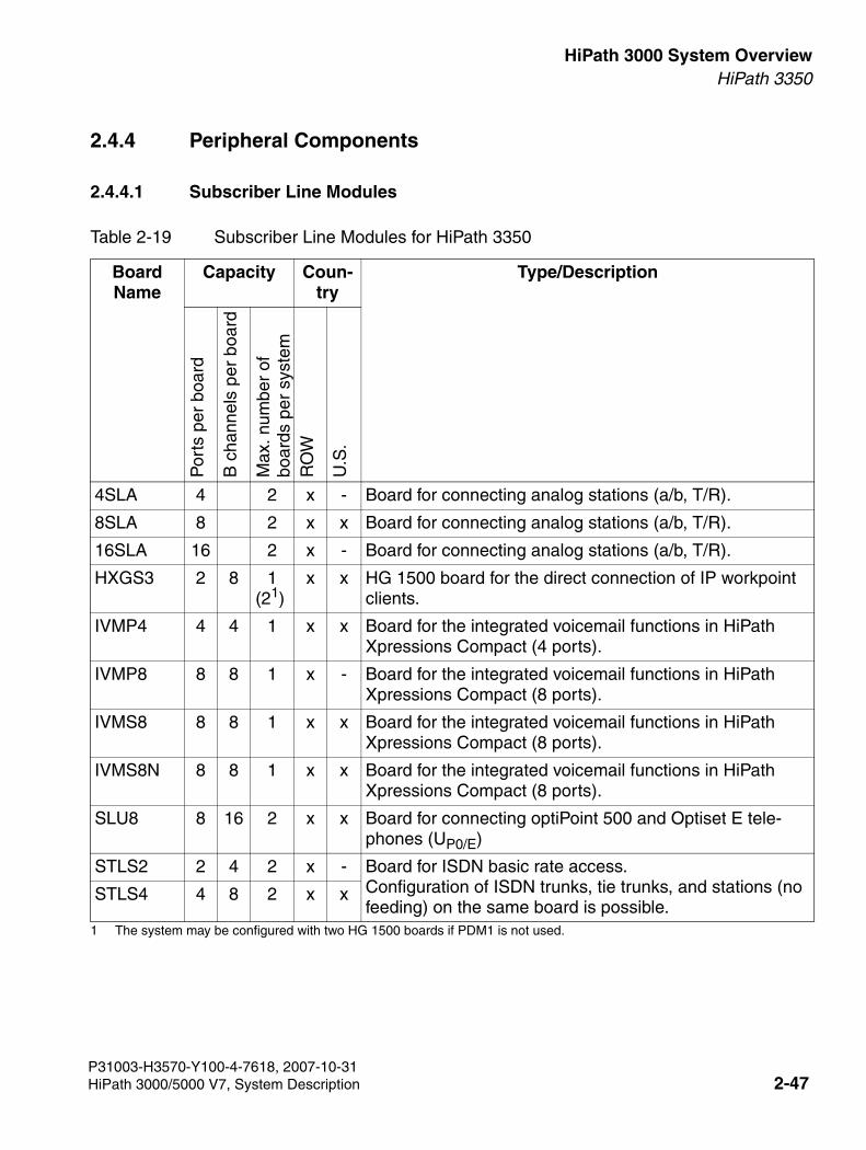
3000sb2.fm
For internal use only HiPath 3000 System OverviewHiPath 3350
2.4.4 Peripheral Components
2.4.4.1 Subscriber Line Modules
Table 2-19 Subscriber Line Modules for HiPath 3350
Board Name
Capacity Coun-try
Type/Description
Por
ts p
er b
oard
B c
hann
els
per
boar
d
Max
. num
ber
of
boar
ds p
er s
yste
mR
OW
U.S
.
4SLA 4 2 x - Board for connecting analog stations (a/b, T/R).
8SLA 8 2 x x Board for connecting analog stations (a/b, T/R).
16SLA 16 2 x - Board for connecting analog stations (a/b, T/R).
HXGS3 2 8 1 (21)
1 The system may be configured with two HG 1500 boards if PDM1 is not used.
x x HG 1500 board for the direct connection of IP workpoint clients.
IVMP4 4 4 1 x x Board for the integrated voicemail functions in HiPath Xpressions Compact (4 ports).
IVMP8 8 8 1 x - Board for the integrated voicemail functions in HiPath Xpressions Compact (8 ports).
IVMS8 8 8 1 x x Board for the integrated voicemail functions in HiPath Xpressions Compact (8 ports).
IVMS8N 8 8 1 x x Board for the integrated voicemail functions in HiPath Xpressions Compact (8 ports).
SLU8 8 16 2 x x Board for connecting optiPoint 500 and Optiset E tele-phones (UP0/E)
STLS2 2 4 2 x - Board for ISDN basic rate access. Configuration of ISDN trunks, tie trunks, and stations (no feeding) on the same board is possible.
STLS4 4 8 2 x x
P31003-H3570-Y100-4-7618, 2007-10-31HiPath 3000/5000 V7, System Description 2-47
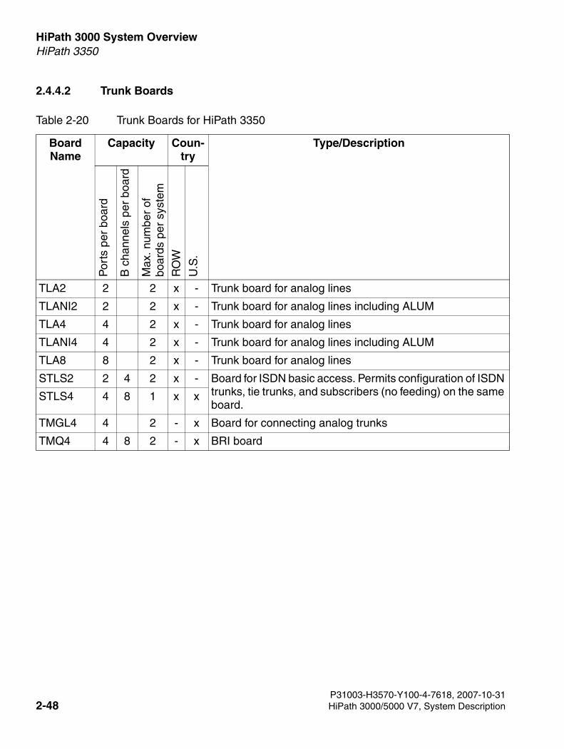
HiPath 3000 System Overview For internal use only
3000sb2.fm
HiPath 3350
2.4.4.2 Trunk Boards
Table 2-20 Trunk Boards for HiPath 3350
Board Name
Capacity Coun-try
Type/Description
Por
ts p
er b
oard
B c
hann
els
per
boar
d
Max
. num
ber
of
boar
ds p
er s
yste
m
RO
W
U.S
.
TLA2 2 2 x - Trunk board for analog lines
TLANI2 2 2 x - Trunk board for analog lines including ALUM
TLA4 4 2 x - Trunk board for analog lines
TLANI4 4 2 x - Trunk board for analog lines including ALUM
TLA8 8 2 x - Trunk board for analog lines
STLS2 2 4 2 x - Board for ISDN basic access. Permits configuration of ISDN trunks, tie trunks, and subscribers (no feeding) on the same board.
STLS4 4 8 1 x x
TMGL4 4 2 - x Board for connecting analog trunks
TMQ4 4 8 2 - x BRI board
P31003-H3570-Y100-4-7618, 2007-10-312-48 HiPath 3000/5000 V7, System Description
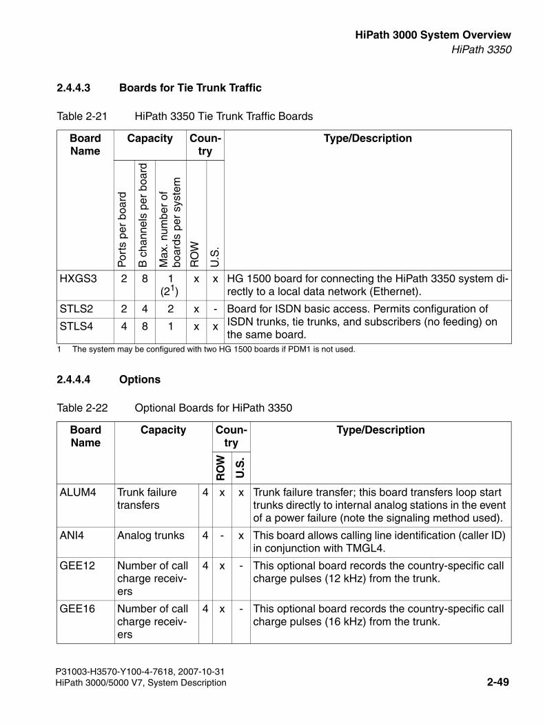
3000sb2.fm
For internal use only HiPath 3000 System OverviewHiPath 3350
2.4.4.3 Boards for Tie Trunk Traffic
2.4.4.4 Options
Table 2-21 HiPath 3350 Tie Trunk Traffic Boards
Board Name
Capacity Coun-try
Type/Description
Por
ts p
er b
oard
B c
hann
els
per
boar
d
Max
. num
ber
of
boar
ds p
er s
yste
m
RO
W
U.S
.
HXGS3 2 8 1 (21)
1 The system may be configured with two HG 1500 boards if PDM1 is not used.
x x HG 1500 board for connecting the HiPath 3350 system di-rectly to a local data network (Ethernet).
STLS2 2 4 2 x - Board for ISDN basic access. Permits configuration of ISDN trunks, tie trunks, and subscribers (no feeding) on the same board.
STLS4 4 8 1 x x
Table 2-22 Optional Boards for HiPath 3350
Board Name
Capacity Coun-try
Type/Description
RO
W
U.S
.
ALUM4 Trunk failure transfers
4 x x Trunk failure transfer; this board transfers loop start trunks directly to internal analog stations in the event of a power failure (note the signaling method used).
ANI4 Analog trunks 4 - x This board allows calling line identification (caller ID) in conjunction with TMGL4.
GEE12 Number of call charge receiv-ers
4 x - This optional board records the country-specific call charge pulses (12 kHz) from the trunk.
GEE16 Number of call charge receiv-ers
4 x - This optional board records the country-specific call charge pulses (16 kHz) from the trunk.
P31003-H3570-Y100-4-7618, 2007-10-31HiPath 3000/5000 V7, System Description 2-49
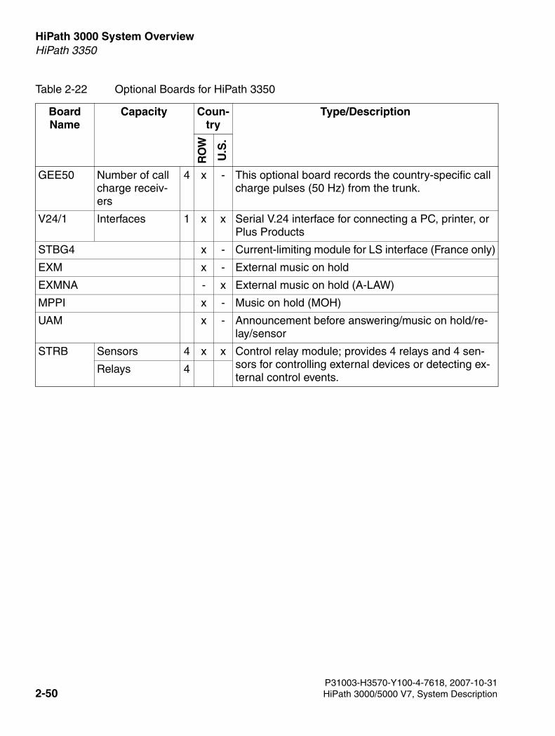
HiPath 3000 System Overview For internal use only
3000sb2.fm
HiPath 3350
GEE50 Number of call charge receiv-ers
4 x - This optional board records the country-specific call charge pulses (50 Hz) from the trunk.
V24/1 Interfaces 1 x x Serial V.24 interface for connecting a PC, printer, or Plus Products
STBG4 x - Current-limiting module for LS interface (France only)
EXM x - External music on hold
EXMNA - x External music on hold (A-LAW)
MPPI x - Music on hold (MOH)
UAM x - Announcement before answering/music on hold/re-lay/sensor
STRB Sensors 4 x x Control relay module; provides 4 relays and 4 sen-sors for controlling external devices or detecting ex-ternal control events.
Relays 4
Table 2-22 Optional Boards for HiPath 3350
Board Name
Capacity Coun-try
Type/Description
RO
W
U.S
.
P31003-H3570-Y100-4-7618, 2007-10-312-50 HiPath 3000/5000 V7, System Description
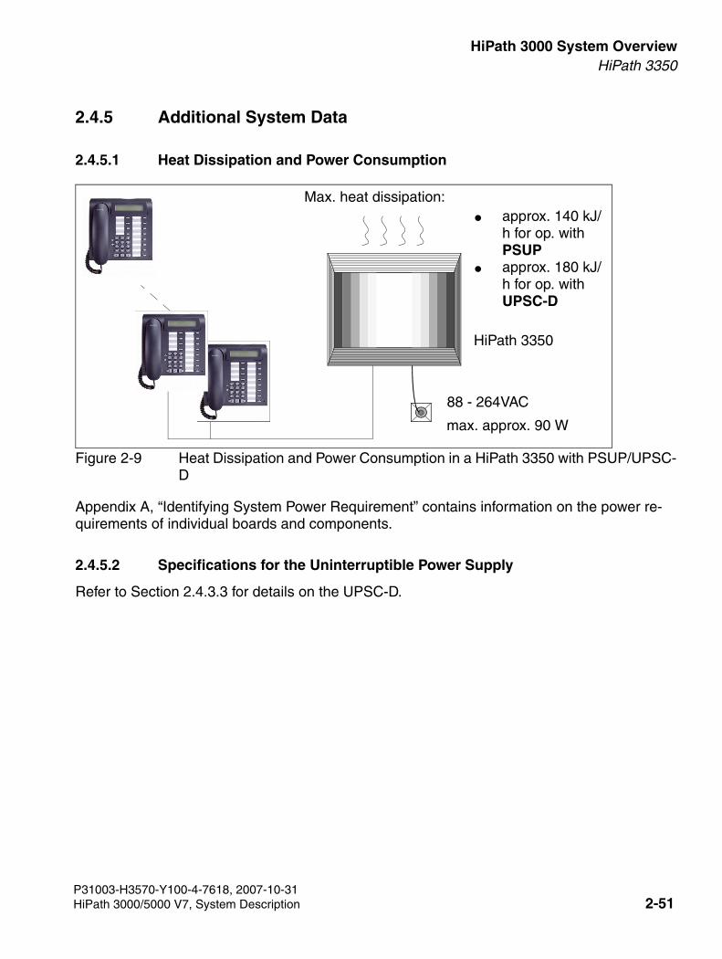
3000sb2.fm
For internal use only HiPath 3000 System OverviewHiPath 3350
2.4.5 Additional System Data
2.4.5.1 Heat Dissipation and Power Consumption
Figure 2-9 Heat Dissipation and Power Consumption in a HiPath 3350 with PSUP/UPSC-D
Appendix A, “Identifying System Power Requirement” contains information on the power re-quirements of individual boards and components.
2.4.5.2 Specifications for the Uninterruptible Power Supply
Refer to Section 2.4.3.3 for details on the UPSC-D.
88 - 264VAC
● approx. 140 kJ/h for op. with PSUP
● approx. 180 kJ/h for op. with UPSC-D
Max. heat dissipation:
max. approx. 90 W
HiPath 3350
P31003-H3570-Y100-4-7618, 2007-10-31HiPath 3000/5000 V7, System Description 2-51
HiPath 3000 System Overview For internal use only
3000sb2.fm
HiPath 3250
2.5 HiPath 3250
HiPath 3250 is replaced by HiPath 540.
2.6 HiPath 3150
HiPath 3150 is replaced by HiPath 520.
P31003-H3570-Y100-4-7618, 2007-10-312-52 HiPath 3000/5000 V7, System Description
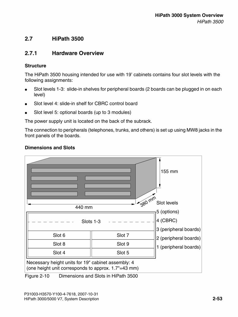
3000sb2.fm
For internal use only HiPath 3000 System OverviewHiPath 3500
2.7 HiPath 3500
2.7.1 Hardware Overview
Structure
The HiPath 3500 housing intended for use with 19’ cabinets contains four slot levels with the following assignments:
● Slot levels 1-3: slide-in shelves for peripheral boards (2 boards can be plugged in on each level)
● Slot level 4: slide-in shelf for CBRC control board
● Slot level 5: optional boards (up to 3 modules)
The power supply unit is located on the back of the subrack.
The connection to peripherals (telephones, trunks, and others) is set up using MW8 jacks in the front panels of the boards.
Dimensions and Slots
Figure 2-10 Dimensions and Slots in HiPath 3500
Necessary height units for 19" cabinet assembly: 4 (one height unit corresponds to approx. 1.7"=43 mm)
Slot 4 Slot 5
Slot 8 Slot 9
Slot 6 Slot 7
Slots 1-3
Slot levels
5 (options)
4 (CBRC)
3 (peripheral boards)
2 (peripheral boards)
1 (peripheral boards)
440 mm 380 mm
155 mm
P31003-H3570-Y100-4-7618, 2007-10-31HiPath 3000/5000 V7, System Description 2-53
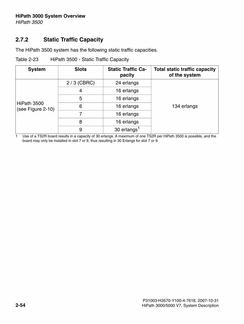
HiPath 3000 System Overview For internal use only
3000sb2.fm
HiPath 3500
2.7.2 Static Traffic Capacity
The HiPath 3500 system has the following static traffic capacities.
Table 2-23 HiPath 3500 - Static Traffic Capacity
System Slots Static Traffic Ca-pacity
Total static traffic capacity of the system
HiPath 3500(see Figure 2-10)
2 / 3 (CBRC) 24 erlangs
134 erlangs
4 16 erlangs
5 16 erlangs
6 16 erlangs
7 16 erlangs
8 16 erlangs
9 30 erlangs1
1 Use of a TS2R board results in a capacity of 30 erlangs. A maximum of one TS2R per HiPath 3500 is possible, and the board may only be installed in slot 7 or 9, thus resulting in 30 Erlangs for slot 7 or 9.
P31003-H3570-Y100-4-7618, 2007-10-312-54 HiPath 3000/5000 V7, System Description
3000sb2.fm
For internal use only HiPath 3000 System OverviewHiPath 3500
2.7.3 Central Components
2.7.3.1 CBRC
Introduction
The CBRC (Central Board Rack with Coldfire Com) board performs all central control and switching functions for HiPath 3300.
This description relates to the following versions of the Central Control CBRC:
● CBRC S30810-Q2935-Z401) Implemented from V6.0 Rel. 10 and later. Major new functions:
– Integration of subboard LIM functionality
– Increasing the ringing voltage of the subscriber interfaces (T/R) to approx. 65 Veff
● CBRC S30810-Q2935-Z301) Implemented in V5.0 and later:Major new function: CLIP
Subboards
The following subboards (some of which are optional) can be used depending on the applica-tion:
● Clock Module Small CMS [optional]
– supports all two-channel cordless connections to the HiPath 3550, HiPath 3350, Hi-Path 3500 and HiPath 3300 systems.
– provides the master clock for digital networking.
Section 2.9 contains additional information on when CMS is used.
● Clock Module ADPCM (CMA) [optional]
– supports the four-channel CMI connection over a base station to the HiPath 3550, Hi-Path 3350, HiPath 3500, and HiPath 3300 systems.
– in the same way as the CMS clock module small, provides the master clock for digital networking.
Section 2.9 contains additional information on when CMA is used.
● Multimedia Card MMCThis plug-in memory card contains the CDB backup and the version-specific APS. Please note that the MMC may only be replaced by a multimedia card approved by
P31003-H3570-Y100-4-7618, 2007-10-31HiPath 3000/5000 V7, System Description 2-55
HiPath 3000 System Overview For internal use only
3000sb2.fm
HiPath 3500
Siemens Enterprise Communications GmbH & Co. KG. Cards that have not been ap-proved may have a different internal structure which can affect temporal access and certain features (CDB backup and APS transfer, for instance).
● IMODN Integrated Modem Card New [optional]This plug-in card allows remote service (analog mode up to 33.6 Kbps), without having to use an external modem.
● MPPI (Music on Hold) [optional]
● Entry Voice Mail (EVM) [optional]
● LIM LAN interface module [option, only for CBRC S30810-Q2935-Z301] This subboard makes available an Ethernet (10BaseT/10 Mbps) LAN connection using an 8-pin RJ45 jack (see Section 2.8.3.3).
Interfaces
● Ethernet (10BaseT/10 MBit)-LAN interface, only in CBRC S30810-Q2935-Z401The LIM module can be used for administration via HiPath 3000/5000 Manager E and for CTI functions (TAPI 120 V2.0). However, bear in mind that the number of BHCAs (Busy Hour Call Attempts = number of connection attempts during busy traffic hours) is restricted to 400 at a maximum of six TAPI ports. The use of "power dialers" is not approved.
The Ethernet LAN interface is deactivated by the system software as soon as an HG 1500 board is inserted.
● Eight digital UP0/E subscriber lines For example, UP0/E workpoint clients or BS3/1 base stations for HiPath Cordless Office can be connected here.
● Four analog T/R subscriber interfaces For U.S. only: These interfaces do not support the connection of external extensions via OPS (Off-Premises Station) signaling. CBRC S30810-Q2935-Z401: The interfaces supply a ring voltage of appr. 65 Veff. CBRC S30810-Q2935-Z301: The interfaces supply a ring voltage of appr. 35 Veff. De-pending on the terminals connected, we cannot exclude the possibility of errors occurring during ringing state.
● Two digital S0 interfaces (CO (default) or station)
● Backplane (CUCR or CUPR) connection via slots 1 (X11), 2 (X5) and 3 (X6)
● Music on hold: MPPI, EXMR
● Options bus (O bus)
● V.24 interface
P31003-H3570-Y100-4-7618, 2007-10-312-56 HiPath 3000/5000 V7, System Description
3000sb2.fm
For internal use only HiPath 3000 System OverviewHiPath 3500
2.7.3.2 UPSC-DR
Introduction
This board combines the power supply and battery management functions. No other compo-nents are required if operated as a power supply. To maintain short-term battery emergency operation after a power failure, that is, to use uninterruptible power supply functions, you must also connect a battery pack.
An EPSU2-R external power supply must be used if the total number of UP0/E stations, analog stations, and stations connected using adapters is greater than 72.
Additional power can be made available by connecting the external EPSU2-R power supply (see Section 2.7.6) To do this, connect the DC port on the EPSU2-R to the special –48 V DC input on the UPSC-DR. The UPSC-DR’s internal -48-V output is deactivated when the external power supply is connected.
Technical specifications
● Nominal voltage range: 100 VAC - 240 VAC
● Nominal frequency: 50 Hz - 60 Hz
● Ring generator: 75 VAC, 20/25/50 Hz
● Partial voltages: +5 VDC, –48 V
● Battery charger: 4 x 12 V (40,8 V-55,2 V)
● Power consumption: approx. 180W
P31003-H3570-Y100-4-7618, 2007-10-31HiPath 3000/5000 V7, System Description 2-57
HiPath 3000 System Overview For internal use only
3000sb2.fm
HiPath 3500
● Bridging times The following table lists the maximum bridging times (battery operation in case of power failure) available with four batteries V39113-W5123-E891 (4 x 12 V/7 Ah batteries).
2.7.3.3 LIM
The LAN Interface Module (LIM - S30807-Q6930-X) is an optional plug-in card for all HiPath 3000 central control boards (see also Section 4.4).
The board provides an Ethernet (10BaseT/10 Mbps) LAN connection via an 8-pin RJ45 jack.
The LIM module can be used for administration via HiPath 3000/5000 Manager E and for CTI functions (TAPI 120 V2.0). However, bear in mind that the number of BHCAs (Busy Hour Call Attempts = number of connection attempts during busy traffic hours) is restricted to 400 at a maximum of six TAPI ports. The use of "power dialers" is not approved.
You cannot operate the LIM module and a HG 1500 board simultaneously in one system.
Table 2-24 UPSC-DR - Bridging Times with four Batteries V39113-W5123-E891 (4 x 12 V/7 Ah Batteries)
System Power sup-ply unit
Load levels Maximum bridg-ing time
HiPath 3500 UPSC-DR Normal output load 100 % = 5 V/8 A; –48 V/1.1 A; ringing approx. 4 Va
1h 30min
HiPath 3500 UPSC-DR Normal output load 60 % = 5 V/4.8 A; –48 V/0.66 A; ringing approx. 2 Va
2h 20min
HiPath 3500 UPSC-DR with EPSU2-R
Normal output load 100 % = 5 V/8 A; –48 V/3 A (external via EPSU2-R); ringing approx. 4 Va
1h 30min
HiPath 3500 UPSC-DR with EPSU2-R
Normal output load 60 % = 5 V/4.8 A; –48 V/1.8 A (external via EPSU2-R); ringing approx. 2 Va
2h 40min
Measurement conditions:● All measurements were performed at a room temperature of approximately 23 °C
(73.4 °F). ● The batteries were fully charged when the measurement was started.
P31003-H3570-Y100-4-7618, 2007-10-312-58 HiPath 3000/5000 V7, System Description
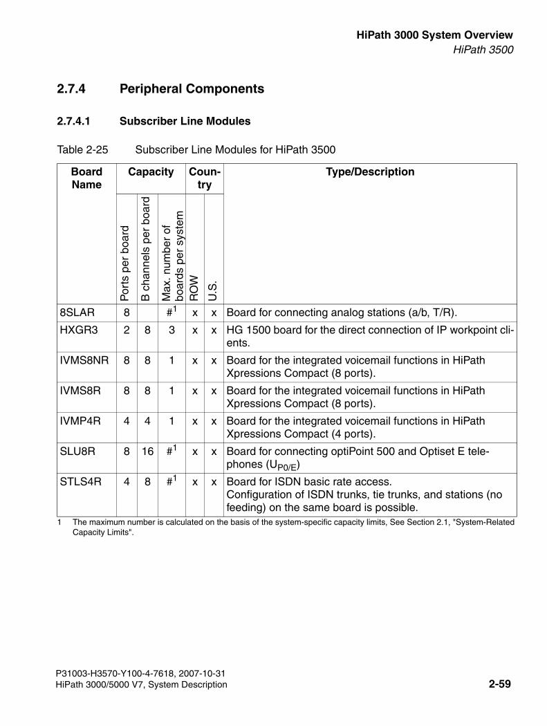
3000sb2.fm
For internal use only HiPath 3000 System OverviewHiPath 3500
2.7.4 Peripheral Components
2.7.4.1 Subscriber Line Modules
Table 2-25 Subscriber Line Modules for HiPath 3500
Board Name
Capacity Coun-try
Type/Description
Por
ts p
er b
oard
B c
hann
els
per
boar
d
Max
. num
ber
of
boar
ds p
er s
yste
mR
OW
U.S
.
8SLAR 8 #1
1 The maximum number is calculated on the basis of the system-specific capacity limits, See Section 2.1, "System-Related Capacity Limits".
x x Board for connecting analog stations (a/b, T/R).
HXGR3 2 8 3 x x HG 1500 board for the direct connection of IP workpoint cli-ents.
IVMS8NR 8 8 1 x x Board for the integrated voicemail functions in HiPath Xpressions Compact (8 ports).
IVMS8R 8 8 1 x x Board for the integrated voicemail functions in HiPath Xpressions Compact (8 ports).
IVMP4R 4 4 1 x x Board for the integrated voicemail functions in HiPath Xpressions Compact (4 ports).
SLU8R 8 16 #1 x x Board for connecting optiPoint 500 and Optiset E tele-phones (UP0/E)
STLS4R 4 8 #1 x x Board for ISDN basic rate access. Configuration of ISDN trunks, tie trunks, and stations (no feeding) on the same board is possible.
P31003-H3570-Y100-4-7618, 2007-10-31HiPath 3000/5000 V7, System Description 2-59
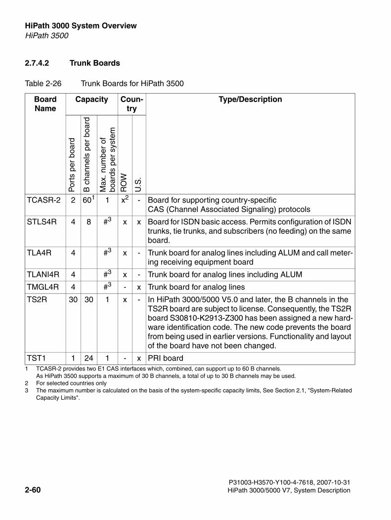
HiPath 3000 System Overview For internal use only
3000sb2.fm
HiPath 3500
2.7.4.2 Trunk Boards
Table 2-26 Trunk Boards for HiPath 3500
Board Name
Capacity Coun-try
Type/Description
Por
ts p
er b
oard
B c
hann
els
per
boar
d
Max
. num
ber
of
boar
ds p
er s
yste
m
RO
W
U.S
.
TCASR-2 2 601
1 TCASR-2 provides two E1 CAS interfaces which, combined, can support up to 60 B channels. As HiPath 3500 supports a maximum of 30 B channels, a total of up to 30 B channels may be used.
1 x2
2 For selected countries only
- Board for supporting country-specificCAS (Channel Associated Signaling) protocols
STLS4R 4 8 #3
3 The maximum number is calculated on the basis of the system-specific capacity limits, See Section 2.1, "System-Related Capacity Limits".
x x Board for ISDN basic access. Permits configuration of ISDN trunks, tie trunks, and subscribers (no feeding) on the same board.
TLA4R 4 #3 x - Trunk board for analog lines including ALUM and call meter-ing receiving equipment board
TLANI4R 4 #3 x - Trunk board for analog lines including ALUM
TMGL4R 4 #3 - x Trunk board for analog lines
TS2R 30 30 1 x - In HiPath 3000/5000 V5.0 and later, the B channels in the TS2R board are subject to license. Consequently, the TS2R board S30810-K2913-Z300 has been assigned a new hard-ware identification code. The new code prevents the board from being used in earlier versions. Functionality and layout of the board have not been changed.
TST1 1 24 1 - x PRI board
P31003-H3570-Y100-4-7618, 2007-10-312-60 HiPath 3000/5000 V7, System Description
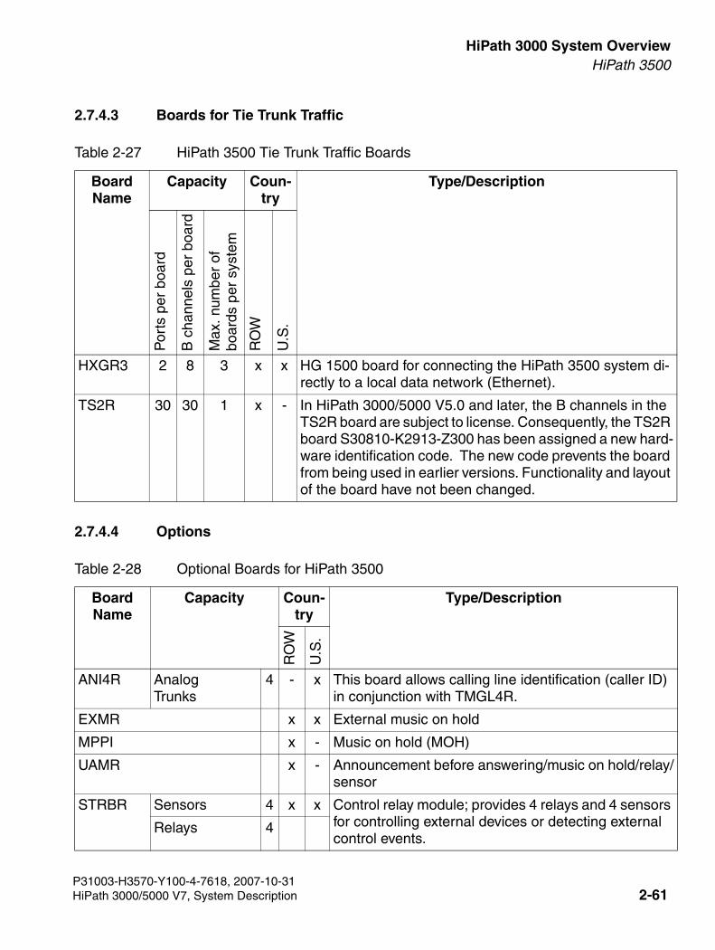
3000sb2.fm
For internal use only HiPath 3000 System OverviewHiPath 3500
2.7.4.3 Boards for Tie Trunk Traffic
2.7.4.4 Options
Table 2-27 HiPath 3500 Tie Trunk Traffic Boards
Board Name
Capacity Coun-try
Type/Description
Por
ts p
er b
oard
B c
hann
els
per
boar
d
Max
. num
ber
of
boar
ds p
er s
yste
m
RO
W
U.S
.
HXGR3 2 8 3 x x HG 1500 board for connecting the HiPath 3500 system di-rectly to a local data network (Ethernet).
TS2R 30 30 1 x - In HiPath 3000/5000 V5.0 and later, the B channels in the TS2R board are subject to license. Consequently, the TS2R board S30810-K2913-Z300 has been assigned a new hard-ware identification code. The new code prevents the board from being used in earlier versions. Functionality and layout of the board have not been changed.
Table 2-28 Optional Boards for HiPath 3500
Board Name
Capacity Coun-try
Type/Description
RO
W
U.S
.
ANI4R Analog Trunks
4 - x This board allows calling line identification (caller ID) in conjunction with TMGL4R.
EXMR x x External music on hold
MPPI x - Music on hold (MOH)
UAMR x - Announcement before answering/music on hold/relay/sensor
STRBR Sensors 4 x x Control relay module; provides 4 relays and 4 sensors for controlling external devices or detecting external control events.
Relays 4
P31003-H3570-Y100-4-7618, 2007-10-31HiPath 3000/5000 V7, System Description 2-61
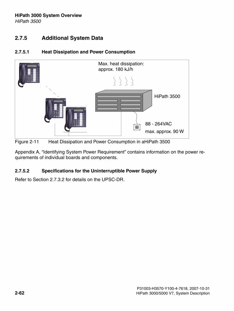
HiPath 3000 System Overview For internal use only
3000sb2.fm
HiPath 3500
2.7.5 Additional System Data
2.7.5.1 Heat Dissipation and Power Consumption
Figure 2-11 Heat Dissipation and Power Consumption in aHiPath 3500
Appendix A, “Identifying System Power Requirement” contains information on the power re-quirements of individual boards and components.
2.7.5.2 Specifications for the Uninterruptible Power Supply
Refer to Section 2.7.3.2 for details on the UPSC-DR.
88 - 264VAC
Max. heat dissipation: approx. 180 kJ/h
max. approx. 90 W
HiPath 3500
P31003-H3570-Y100-4-7618, 2007-10-312-62 HiPath 3000/5000 V7, System Description
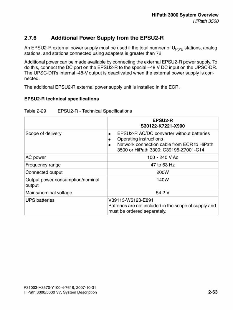
3000sb2.fm
For internal use only HiPath 3000 System OverviewHiPath 3500
2.7.6 Additional Power Supply from the EPSU2-R
An EPSU2-R external power supply must be used if the total number of UP0/E stations, analog stations, and stations connected using adapters is greater than 72.
Additional power can be made available by connecting the external EPSU2-R power supply. To do this, connect the DC port on the EPSU2-R to the special –48 V DC input on the UPSC-DR. The UPSC-DR’s internal -48-V output is deactivated when the external power supply is con-nected.
The additional EPSU2-R external power supply unit is installed in the ECR.
EPSU2-R technical specifications
Table 2-29 EPSU2-R - Technical Specifications
EPSU2-RS30122-K7221-X900
Scope of delivery ● EPSU2-R AC/DC converter without batteries ● Operating instructions● Network connection cable from ECR to HiPath
3500 or HiPath 3300: C39195-Z7001-C14
AC power 100 - 240 V Ac
Frequency range 47 to 63 Hz
Connected output 200W
Output power consumption/nominal output
140W
Mains/nominal voltage 54.2 V
UPS batteries V39113-W5123-E891Batteries are not included in the scope of supply and must be ordered separately.
P31003-H3570-Y100-4-7618, 2007-10-31HiPath 3000/5000 V7, System Description 2-63

HiPath 3000 System Overview For internal use only
3000sb2.fm
HiPath 3500
2.7.7 Expansion Cabinet Rack ECR
When installing the system, an ECR in the 19’’ cabinet is required if
emergency battery operation is necessary during a power failure or if the system requires un-interruptible power.
The necessary batteries are installed in the ECR.
the internal system power supply unit for HiPath 3500 or HiPath 3300 is not sufficient enough to provide power to the overall telephone configuration (corded or cordless telephones).
In this case, the EPSU2-R external power supply unit should be installed in the ECR.
There are switches for the line and battery voltage on the front panel as well as a fuse for pro-tecting the battery circuit.
The jacks for the line and battery voltage are located on the rear of the housing. The line voltage is only fed through and can be interrupted using a switch.
P31003-H3570-Y100-4-7618, 2007-10-312-64 HiPath 3000/5000 V7, System Description
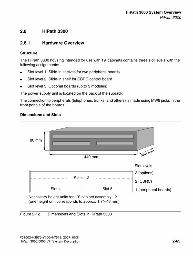
3000sb2.fm
For internal use only HiPath 3000 System OverviewHiPath 3300
2.8 HiPath 3300
2.8.1 Hardware Overview
Structure
The HiPath 3300 housing intended for use with 19’ cabinets contains three slot levels with the following assignments:
● Slot level 1: Slide-in shelves for two peripheral boards
● Slot level 2: Slide-in shelf for CBRC control board
● Slot level 3: Optional boards (up to 3 modules)
The power supply unit is located on the back of the subrack.
The connection to peripherals (telephones, trunks, and others) is made using MW8 jacks in the front panels of the boards.
Dimensions and Slots
Figure 2-12 Dimensions and Slots in HiPath 3300
80 mm
440 mm 380 mm
Slot 4 Slot 5
Slots 1-3
Slot levels
Necessary height units for 19" cabinet assembly: 2 (one height unit corresponds to approx. 1.7"=43 mm)
3 (options)
2 (CBRC)
1 (peripheral boards)
P31003-H3570-Y100-4-7618, 2007-10-31HiPath 3000/5000 V7, System Description 2-65
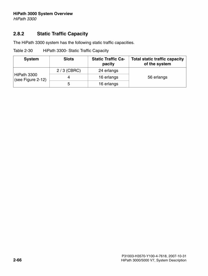
HiPath 3000 System Overview For internal use only
3000sb2.fm
HiPath 3300
2.8.2 Static Traffic Capacity
The HiPath 3300 system has the following static traffic capacities.
Table 2-30 HiPath 3300- Static Traffic Capacity
System Slots Static Traffic Ca-pacity
Total static traffic capacity of the system
HiPath 3300(see Figure 2-12)
2 / 3 (CBRC) 24 erlangs
56 erlangs4 16 erlangs
5 16 erlangs
P31003-H3570-Y100-4-7618, 2007-10-312-66 HiPath 3000/5000 V7, System Description

3000sb2.fm
For internal use only HiPath 3000 System OverviewHiPath 3300
2.8.3 Central Components
2.8.3.1 CBRC
Introduction
The CBRC (HiPath 3300Central Board Rack with Coldfire Com) board performs all central control and switching functions for .
This description relates to the following versions of the Central Control CBRC:
● CBRC S30810-Q2935-Z401: Implemented in V6.0 Rel. 10 and later. Major new functions:
– Integration of subboard LIM functionality
– Increasing the ringing voltage of the subscriber interfaces (T/R) to approx. 65 Veff
● CBRC S30810-Q2935-Z301: Implemented in V5.0 and later:Major new function: CLIP
Subboards
The following subboards (some of which are optional) can be used depending on the applica-tion:
● Clock Module Small CMS [optional]
– supports all two-channel cordless connections to the HiPath 3550, HiPath 3350, Hi-Path 3500 and HiPath 3300 systems.
– provides the master clock for digital networking.
Section 2.9contains additional information on when CMS is used.
● Clock Module ADPCM (CMA) [optional]
– supports the four-channel CMI connection over a base station to the HiPath 3550, Hi-Path 3350, HiPath 3500, and HiPath 3300 systems.
– in the same way as the CMS clock module small, provides the master clock for digital networking.
Section 2.9contains additional information on when CMA is used.
● Multimedia Card MMCThis plug-in memory card contains the CDB backup and the version-specific APS. Please note that the MMC may only be replaced by a multimedia card approved by
P31003-H3570-Y100-4-7618, 2007-10-31HiPath 3000/5000 V7, System Description 2-67

HiPath 3000 System Overview For internal use only
3000sb2.fm
HiPath 3300
Siemens Enterprise Communications GmbH & Co. KG. Cards that have not been ap-proved may have a different internal structure which can affect temporal access and certain features (CDB backup and APS transfer, for instance).
● IMODN Integrated Modem Card New [optional]This plug-in card allows remote service (analog mode up to 33.6 Kbps), without having to use an external modem.
● MPPI (Music on Hold) [optional]
● Entry Voice Mail (EVM) [optional]
● LIM LAN interface module [option, only for CBRC S30810-Q2935-Z301] This subboard makes available an Ethernet (10BaseT/10 Mbps) LAN connection using an 8-pin RJ45 jack (see Section 2.8.3.3).
Interfaces
● Ethernet (10BaseT/10 MBit)-LAN interface, only in CBRC S30810-Q2935-Z401The LIM module can be used for administration via HiPath 3000/5000 Manager E and for CTI functions (TAPI 120 V2.0). However, bear in mind that the number of BHCAs (Busy Hour Call Attempts = number of connection attempts during busy traffic hours) is restricted to 400 at a maximum of six TAPI ports. The use of "power dialers" is not approved.
The Ethernet LAN interface is deactivated by the system software as soon as an HG 1500 board is inserted.
● Eight digital UP0/E subscriber lines For example, UP0/E workpoint clients or BS3/1 base stations for HiPath Cordless Office can be connected here.
● Four analog T/R subscriber interfaces For U.S. only: These interfaces do not support the connection of external extensions via OPS (Off-Premises Station) signaling. CBRC S30810-Q2935-Z401) The interfaces supply a ring voltage of appr. 65 Veff. CBRC S30810-Q2935-Z301: The T/R interfaces supply a ring voltage of appr. 35 Veff. De-pending on the terminals connected, we cannot exclude the possibility of errors occurring during ringing state.
● Two digital S0 interfaces (CO (default) or station)
● Backplane (CUCR or CUPR) connection via slots 1 (X11), 2 (X5) and 3 (X6)
● Music on hold: MPPI, EXMR
● Options bus (O bus)
● V.24 interface
P31003-H3570-Y100-4-7618, 2007-10-312-68 HiPath 3000/5000 V7, System Description
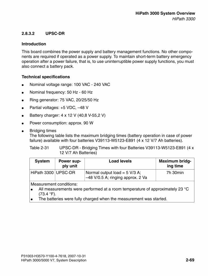
3000sb2.fm
For internal use only HiPath 3000 System OverviewHiPath 3300
2.8.3.2 UPSC-DR
Introduction
This board combines the power supply and battery management functions. No other compo-nents are required if operated as a power supply. To maintain short-term battery emergency operation after a power failure, that is, to use uninterruptible power supply functions, you must also connect a battery pack.
Technical specifications
● Nominal voltage range: 100 VAC - 240 VAC
● Nominal frequency: 50 Hz - 60 Hz
● Ring generator: 75 VAC, 20/25/50 Hz
● Partial voltages: +5 VDC, –48 V
● Battery charger: 4 x 12 V (40,8 V-55,2 V)
● Power consumption: approx. 90 W
● Bridging times The following table lists the maximum bridging times (battery operation in case of power failure) available with four batteries V39113-W5123-E891 (4 x 12 V/7 Ah batteries).
Table 2-31 UPSC-DR - Bridging Times with four Batteries V39113-W5123-E891 (4 x 12 V/7 Ah Batteries)
System Power sup-ply unit
Load levels Maximum bridg-ing time
HiPath 3300 UPSC-DR Normal output load = 5 V/3 A; –48 V/0.5 A; ringing approx. 2 Va
7h 30min
Measurement conditions:● All measurements were performed at a room temperature of approximately 23 °C
(73.4 °F). ● The batteries were fully charged when the measurement was started.
P31003-H3570-Y100-4-7618, 2007-10-31HiPath 3000/5000 V7, System Description 2-69

HiPath 3000 System Overview For internal use only
3000sb2.fm
HiPath 3300
2.8.3.3 LIM
The LAN Interface Module (LIM - S30807-Q6930-X) is an optional plug-in card for all HiPath 3000 central control boards (see also Section 4.4).
The board provides an Ethernet (10BaseT/10 Mbps) LAN connection via an 8-pin RJ45 jack.
The LIM module can be used for administration via HiPath 3000/5000 Manager E and for CTI functions (TAPI 120 V2.0). However, bear in mind that the number of BHCAs (Busy Hour Call Attempts = number of connection attempts during busy traffic hours) is restricted to 400 at a maximum of six TAPI ports. The use of "power dialers" is not approved.
You cannot operate the LIM module and a HG 1500 board simultaneously in one system.
P31003-H3570-Y100-4-7618, 2007-10-312-70 HiPath 3000/5000 V7, System Description
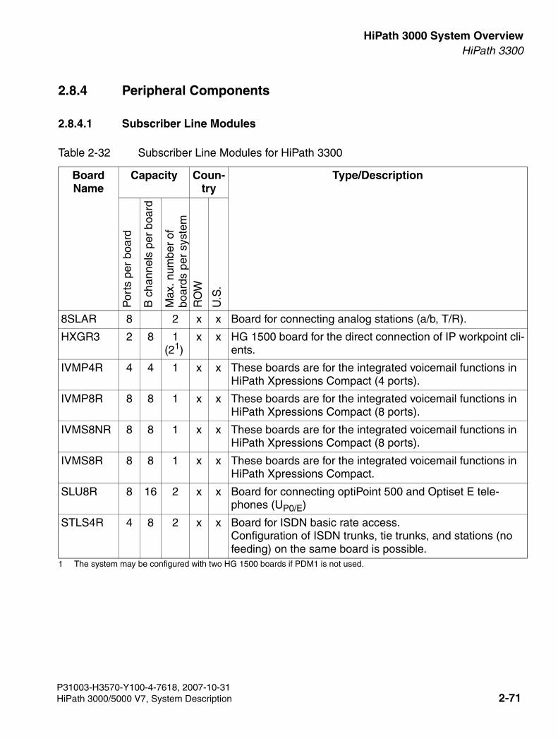
3000sb2.fm
For internal use only HiPath 3000 System OverviewHiPath 3300
2.8.4 Peripheral Components
2.8.4.1 Subscriber Line Modules
Table 2-32 Subscriber Line Modules for HiPath 3300
Board Name
Capacity Coun-try
Type/Description
Por
ts p
er b
oard
B c
hann
els
per
boar
d
Max
. num
ber
of
boar
ds p
er s
yste
mR
OW
U.S
.
8SLAR 8 2 x x Board for connecting analog stations (a/b, T/R).
HXGR3 2 8 1 (21)
1 The system may be configured with two HG 1500 boards if PDM1 is not used.
x x HG 1500 board for the direct connection of IP workpoint cli-ents.
IVMP4R 4 4 1 x x These boards are for the integrated voicemail functions in HiPath Xpressions Compact (4 ports).
IVMP8R 8 8 1 x x These boards are for the integrated voicemail functions in HiPath Xpressions Compact (8 ports).
IVMS8NR 8 8 1 x x These boards are for the integrated voicemail functions in HiPath Xpressions Compact (8 ports).
IVMS8R 8 8 1 x x These boards are for the integrated voicemail functions in HiPath Xpressions Compact.
SLU8R 8 16 2 x x Board for connecting optiPoint 500 and Optiset E tele-phones (UP0/E)
STLS4R 4 8 2 x x Board for ISDN basic rate access. Configuration of ISDN trunks, tie trunks, and stations (no feeding) on the same board is possible.
P31003-H3570-Y100-4-7618, 2007-10-31HiPath 3000/5000 V7, System Description 2-71
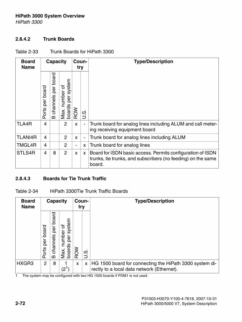
HiPath 3000 System Overview For internal use only
3000sb2.fm
HiPath 3300
2.8.4.2 Trunk Boards
2.8.4.3 Boards for Tie Trunk Traffic
Table 2-33 Trunk Boards for HiPath 3300
Board Name
Capacity Coun-try
Type/Description
Por
ts p
er b
oard
B c
hann
els
per
boar
d
Max
. num
ber
of
boar
ds p
er s
yste
m
RO
W
U.S
.
TLA4R 4 2 x - Trunk board for analog lines including ALUM and call meter-ing receiving equipment board
TLANI4R 4 2 x - Trunk board for analog lines including ALUM
TMGL4R 4 2 - x Trunk board for analog lines
STLS4R 4 8 2 x x Board for ISDN basic access. Permits configuration of ISDN trunks, tie trunks, and subscribers (no feeding) on the same board.
Table 2-34 HiPath 3300Tie Trunk Traffic Boards
Board Name
Capacity Coun-try
Type/Description
Por
ts p
er b
oard
B c
hann
els
per
boar
d
Max
. num
ber
of
boar
ds p
er s
yste
m
RO
W
U.S
.
HXGR3 2 8 1 (21)
1 The system may be configured with two HG 1500 boards if PDM1 is not used.
x x HG 1500 board for connecting the HiPath 3300 system di-rectly to a local data network (Ethernet).
P31003-H3570-Y100-4-7618, 2007-10-312-72 HiPath 3000/5000 V7, System Description
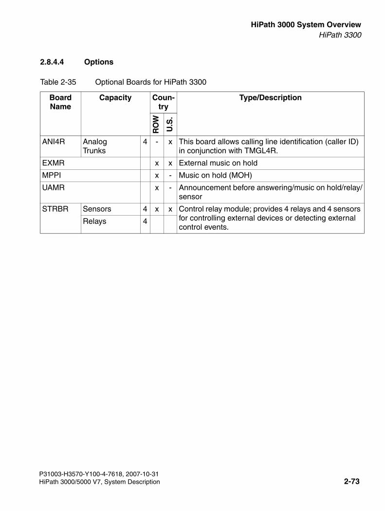
3000sb2.fm
For internal use only HiPath 3000 System OverviewHiPath 3300
2.8.4.4 Options
Table 2-35 Optional Boards for HiPath 3300
Board Name
Capacity Coun-try
Type/Description
RO
W
U.S
.
ANI4R Analog Trunks
4 - x This board allows calling line identification (caller ID) in conjunction with TMGL4R.
EXMR x x External music on hold
MPPI x - Music on hold (MOH)
UAMR x - Announcement before answering/music on hold/relay/sensor
STRBR Sensors 4 x x Control relay module; provides 4 relays and 4 sensors for controlling external devices or detecting external control events.
Relays 4
P31003-H3570-Y100-4-7618, 2007-10-31HiPath 3000/5000 V7, System Description 2-73
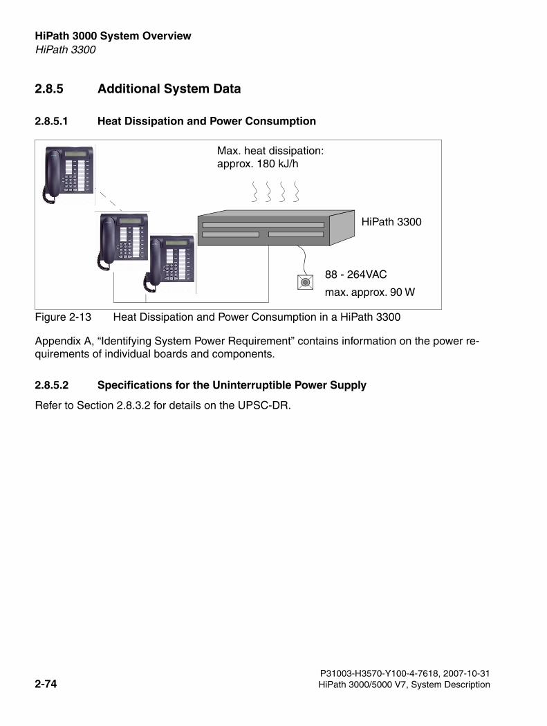
HiPath 3000 System Overview For internal use only
3000sb2.fm
HiPath 3300
2.8.5 Additional System Data
2.8.5.1 Heat Dissipation and Power Consumption
Figure 2-13 Heat Dissipation and Power Consumption in a HiPath 3300
Appendix A, “Identifying System Power Requirement” contains information on the power re-quirements of individual boards and components.
2.8.5.2 Specifications for the Uninterruptible Power Supply
Refer to Section 2.8.3.2 for details on the UPSC-DR.
88 - 264VAC
Max. heat dissipation: approx. 180 kJ/h
max. approx. 90 W
HiPath 3300
P31003-H3570-Y100-4-7618, 2007-10-312-74 HiPath 3000/5000 V7, System Description

3000sb2.fm
For internal use only HiPath 3000 System OverviewHiPath 3300
2.8.6 Expansion Cabinet Rack ECR
When the system is installed, the expansion cabinet rack ECR is required in a 19’’ cabinet if
emergency battery operation is necessary during a power failure or if the system requires un-interruptible power.
The necessary batteries are installed in the ECR.
the internal system power supply unit for HiPath 3500 or HiPath 3300 is not sufficient enough to provide power to the overall telephone configuration (corded or cordless telephones).
In this case, the EPSU2-R external power supply unit should be installed in the ECR.
There are switches for the line and battery voltage on the front panel as well as a fuse for pro-tecting the battery circuit.
The jacks for the line and battery voltage are located on the rear of the housing. The line voltage is only fed through and can be interrupted using a switch.
P31003-H3570-Y100-4-7618, 2007-10-31HiPath 3000/5000 V7, System Description 2-75
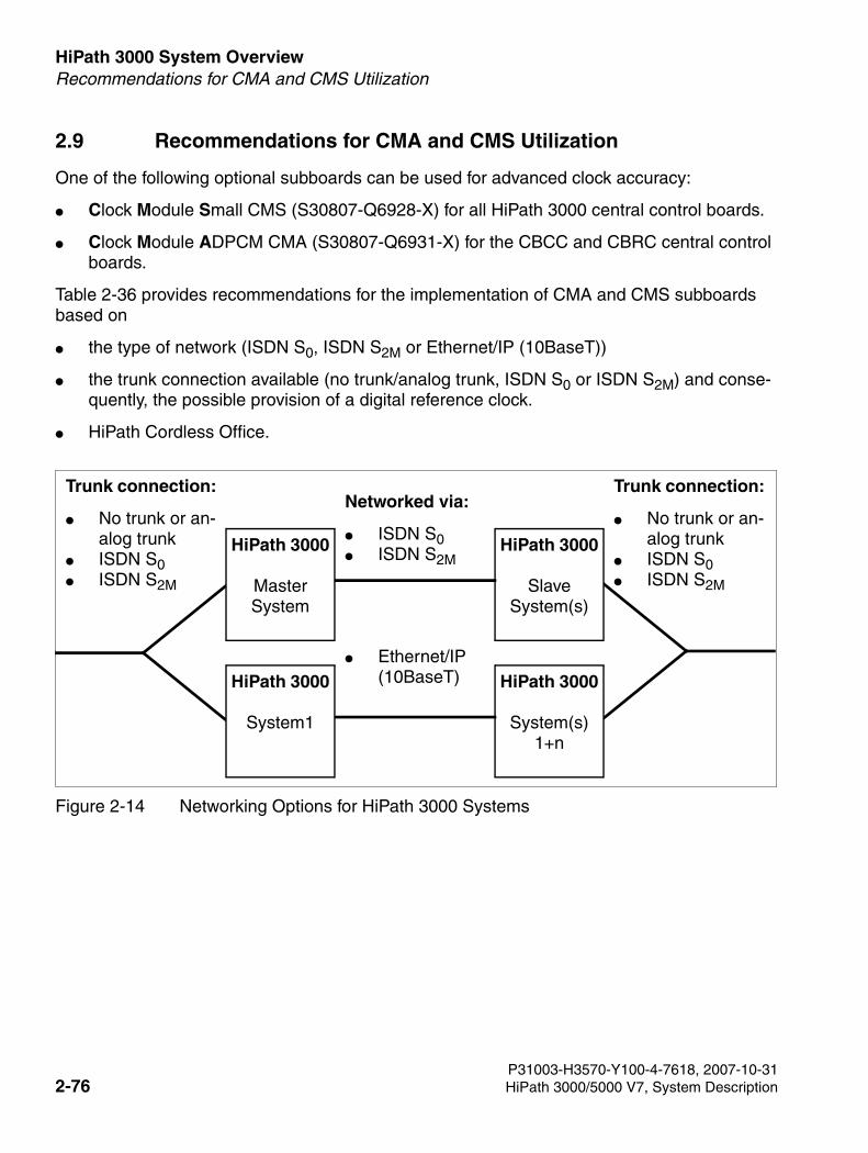
HiPath 3000 System Overview For internal use only
3000sb2.fm
Recommendations for CMA and CMS Utilization
2.9 Recommendations for CMA and CMS Utilization
One of the following optional subboards can be used for advanced clock accuracy:
● Clock Module Small CMS (S30807-Q6928-X) for all HiPath 3000 central control boards.
● Clock Module ADPCM CMA (S30807-Q6931-X) for the CBCC and CBRC central control boards.
Table 2-36 provides recommendations for the implementation of CMA and CMS subboards based on
● the type of network (ISDN S0, ISDN S2M or Ethernet/IP (10BaseT))
● the trunk connection available (no trunk/analog trunk, ISDN S0 or ISDN S2M) and conse-quently, the possible provision of a digital reference clock.
● HiPath Cordless Office.
Figure 2-14 Networking Options for HiPath 3000 Systems
Trunk connection:
● No trunk or an-alog trunk
● ISDN S0 ● ISDN S2M
Trunk connection:
● No trunk or an-alog trunk
● ISDN S0 ● ISDN S2M
Networked via:
● ISDN S0 ● ISDN S2M
● Ethernet/IP (10BaseT)
HiPath 3000
SlaveSystem(s)
HiPath 3000
System(s) 1+n
HiPath 3000
System1
HiPath 3000
MasterSystem
P31003-H3570-Y100-4-7618, 2007-10-312-76 HiPath 3000/5000 V7, System Description
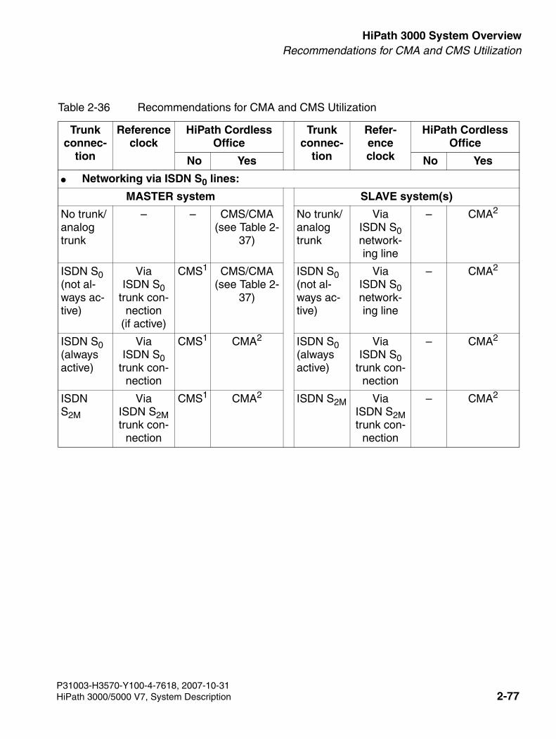
3000sb2.fm
For internal use only HiPath 3000 System OverviewRecommendations for CMA and CMS Utilization
Table 2-36 Recommendations for CMA and CMS Utilization
Trunk connec-
tion
Reference clock
HiPath Cordless Office
Trunk connec-
tion
Refer-ence clock
HiPath Cordless Office
No Yes No Yes
● Networking via ISDN S0 lines:
MASTER system SLAVE system(s)
No trunk/analog trunk
– – CMS/CMA(see Table 2-
37)
No trunk/analog trunk
Via ISDN S0 network-ing line
– CMA2
ISDN S0(not al-ways ac-tive)
Via ISDN S0
trunk con-nection
(if active)
CMS1 CMS/CMA(see Table 2-
37)
ISDN S0(not al-ways ac-tive)
Via ISDN S0 network-ing line
– CMA2
ISDN S0(always active)
Via ISDN S0
trunk con-nection
CMS1 CMA2 ISDN S0(always active)
Via ISDN S0
trunk con-nection
– CMA2
ISDN S2M
Via ISDN S2M trunk con-
nection
CMS1 CMA2 ISDN S2M Via ISDN S2M trunk con-
nection
– CMA2
P31003-H3570-Y100-4-7618, 2007-10-31HiPath 3000/5000 V7, System Description 2-77
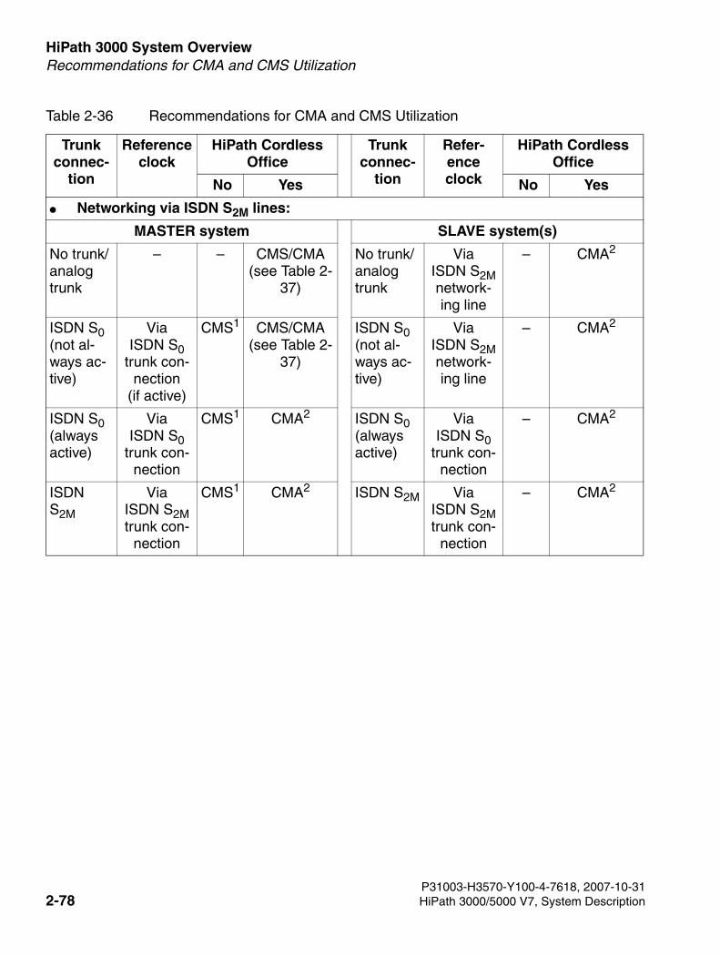
HiPath 3000 System Overview For internal use only
3000sb2.fm
Recommendations for CMA and CMS Utilization
● Networking via ISDN S2M lines:
MASTER system SLAVE system(s)
No trunk/analog trunk
– – CMS/CMA(see Table 2-
37)
No trunk/analog trunk
Via ISDN S2M network-ing line
– CMA2
ISDN S0(not al-ways ac-tive)
Via ISDN S0
trunk con-nection
(if active)
CMS1 CMS/CMA(see Table 2-
37)
ISDN S0(not al-ways ac-tive)
Via ISDN S2M network-ing line
– CMA2
ISDN S0(always active)
Via ISDN S0
trunk con-nection
CMS1 CMA2 ISDN S0(always active)
Via ISDN S0
trunk con-nection
– CMA2
ISDN S2M
Via ISDN S2M trunk con-
nection
CMS1 CMA2 ISDN S2M Via ISDN S2M trunk con-
nection
– CMA2
Table 2-36 Recommendations for CMA and CMS Utilization
Trunk connec-
tion
Reference clock
HiPath Cordless Office
Trunk connec-
tion
Refer-ence clock
HiPath Cordless Office
No Yes No Yes
P31003-H3570-Y100-4-7618, 2007-10-312-78 HiPath 3000/5000 V7, System Description
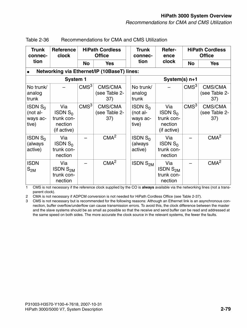
3000sb2.fm
For internal use only HiPath 3000 System OverviewRecommendations for CMA and CMS Utilization
● Networking via Ethernet/IP (10BaseT) lines:
System 1 System(s) n+1
No trunk/analog trunk
– CMS3 CMS/CMA(see Table 2-
37)
No trunk/analog trunk
– CMS3 CMS/CMA(see Table 2-
37)
ISDN S0(not al-ways ac-tive)
Via ISDN S0
trunk con-nection
(if active)
CMS3 CMS/CMA(see Table 2-
37)
ISDN S0(not al-ways ac-tive)
Via ISDN S0
trunk con-nection
(if active)
CMS3 CMS/CMA(see Table 2-
37)
ISDN S0(always active)
Via ISDN S0
trunk con-nection
– CMA2 ISDN S0(always active)
Via ISDN S0
trunk con-nection
– CMA2
ISDN S2M
Via ISDN S2M trunk con-
nection
– CMA2 ISDN S2M Via ISDN S2M trunk con-
nection
– CMA2
1 CMS is not necessary if the reference clock supplied by the CO is always available via the networking lines (not a trans-parent clock).
2 CMA is not necessary if ADPCM conversion is not needed for HiPath Cordless Office (see Table 2-37). 3 CMS is not necessary but is recommended for the following reasons: Although an Ethernet link is an asynchronous con-
nection, buffer overflow/underflow can cause transmission errors. To avoid this, the clock difference between the master and the slave systems should be as small as possible so that the receive and send buffer can be read and addressed at the same speed on both sides. The more accurate the clock source in the relevant systems, the fewer the faults.
Table 2-36 Recommendations for CMA and CMS Utilization
Trunk connec-
tion
Reference clock
HiPath Cordless Office
Trunk connec-
tion
Refer-ence clock
HiPath Cordless Office
No Yes No Yes
P31003-H3570-Y100-4-7618, 2007-10-31HiPath 3000/5000 V7, System Description 2-79
HiPath 3000 System Overview For internal use only
3000sb2.fm
HiPath Cordless Office
2.10 HiPath Cordless Office
2.10.1 Introduction
For Version 1.2 and later of HiPath 3000, HiPath Cordless Office can be used on all systems of this product line.
Direct connection
The BS3/1 (S30807-H5482-X) and BS4 (S30807-U5491-X) base stations can be connected di-rectly to the UP0/E interfaces on the central control boards in the HiPath 3550, HiPath 3350, Hi-Path 3500, and HiPath 3300. The connection must be made via one UP0/E interface each. A mix of base stations of types BS3/1 and BS4 is supported.
To ensure the operation of a maximum of one base station on the central control board’s UP0/
E interfaces of the HiPath 3550, HiPath 3350, HiPath 3500, and HiPath 3300, a BS3/S (X30807-X5482-X100) single-cell base station can be used. In this case, it is not possible to expand with additional base stations.
However, base stations cannot be simultaneously connected to the SLC16/SLC16N board and the CBCC within one HiPath 3550 system.
Connecting cordless boards
Base stations can be connected to the UP0/E interfaces of the following cordless boards:
● SLC16N with HiPath 3550
● SLCN in HiPath 3800
>The base stations BS3/1 (S30807-H5482-X), BS3/3 (S30807-H5485-X), and BS3/S (X30807-X5482-X100) are being phased out and can not longer be ordered. Use the successor product BS4 (S30807-U5491-X) instead of the types specified.You can continue to operate the base stations specified in conjunction with HiPath 3000. A mix of base stations of types BS3/1, BS3/3, and BS4 is also supported.
>The SLC16 (S30810-Q2922-X) board is no longer supported in HiPath 3000/5000 V6.0 and later systems.
P31003-H3570-Y100-4-7618, 2007-10-312-80 HiPath 3000/5000 V7, System Description
3000sb2.fm
For internal use only HiPath 3000 System OverviewHiPath Cordless Office
A mix of BS3/1 (S30807-H5482-X), BS3/3 (S30807-H5485-X) and BS4 (S30807-U5491-X) base station types may be used on the cordless boards listed.
You can install up to four SLCN boards in HiPath 3800. All four boards provide full cordless functionality (roaming and seamless connection handover) because the radio fields on the cordless boards are synchronized in a single system (see Section 2.10.3).
The HiPath 3000 product line does not currently support the network-wide handover feature.
P31003-H3570-Y100-4-7618, 2007-10-31HiPath 3000/5000 V7, System Description 2-81
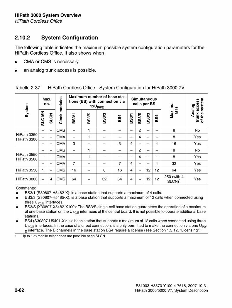
HiPath 3000 System Overview For internal use only
3000sb2.fm
HiPath Cordless Office
2.10.2 System Configuration
The following table indicates the maximum possible system configuration parameters for the HiPath Cordless Office. It also shows when
● CMA or CMS is necessary.
● an analog trunk access is possible.
Tabelle 2-37 HiPath Cordless Office - System Configuration for HiPath 3000 7V
Sys
tem
Max. no.
Clo
ck m
od
ule
s Maximum number of base sta-tions (BS) with connection via
1xUP0/E
Simultaneous calls per BS
Max
. no
.M
Ts
An
alo
gtr
un
k ac
cess
of
the
syst
em
SL
C16
N
SL
CN
BS
3/1
BS
3/S
BS
3/3
BS
4
BS
3/1
BS
3/S
BS
3/3
BS
4
HiPath 3350HiPath 3300
– – CMS – 1 – – – 2 – – 8 No
– – CMA – 1 – – – 4 – – 8 Yes
– – CMA 3 – – 3 4 – – 4 16 Yes
HiPath 3550HiPath 3500
– – CMS – 1 – – – 2 – – 8 No
– – CMA – 1 – – – 4 – – 8 Yes
– – CMA 7 – – 7 4 – – 4 32 Yes
HiPath 3550 1 – CMS 16 – 8 16 4 – 12 12 64 Yes
HiPath 3800 – 4 CMS 64 – 32 64 4 – 12 12250 (with 4
SLCN)1
1 Up to 128 mobile telephones are possible at an SLCN.
Yes
Comments:● BS3/1 (S30807-H5482-X): is a base station that supports a maximum of 4 calls. ● BS3/3 (S30807-H5485-X): is a base station that supports a maximum of 12 calls when connected using
three UP0/E interfaces. ● BS3/S (X30807-X5482-X100): The BS3/S single-cell base station guarantees the operation of a maximum
of one base station on the UP0/E interfaces of the central board. It is not possible to operate additional base stations.
● BS4 (S30807-U5491-X): is a base station that supports a maximum of 12 calls when connected using three UP0/E interfaces. In the case of a direct connection, it is only permitted to make the connection via one UP0/
E interface. The B channels in the base station BS4 require a license (see Section 1.5.12, "Licensing").
P31003-H3570-Y100-4-7618, 2007-10-312-82 HiPath 3000/5000 V7, System Description
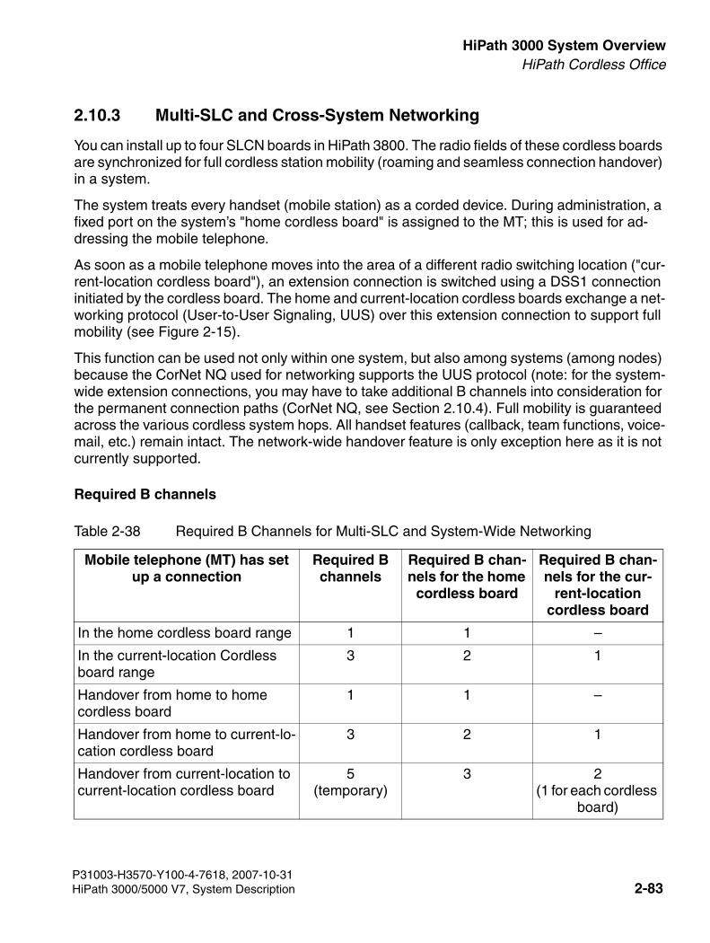
3000sb2.fm
For internal use only HiPath 3000 System OverviewHiPath Cordless Office
2.10.3 Multi-SLC and Cross-System Networking
You can install up to four SLCN boards in HiPath 3800. The radio fields of these cordless boards are synchronized for full cordless station mobility (roaming and seamless connection handover) in a system.
The system treats every handset (mobile station) as a corded device. During administration, a fixed port on the system’s "home cordless board" is assigned to the MT; this is used for ad-dressing the mobile telephone.
As soon as a mobile telephone moves into the area of a different radio switching location ("cur-rent-location cordless board"), an extension connection is switched using a DSS1 connection initiated by the cordless board. The home and current-location cordless boards exchange a net-working protocol (User-to-User Signaling, UUS) over this extension connection to support full mobility (see Figure 2-15).
This function can be used not only within one system, but also among systems (among nodes) because the CorNet NQ used for networking supports the UUS protocol (note: for the system-wide extension connections, you may have to take additional B channels into consideration for the permanent connection paths (CorNet NQ, see Section 2.10.4). Full mobility is guaranteed across the various cordless system hops. All handset features (callback, team functions, voice-mail, etc.) remain intact. The network-wide handover feature is only exception here as it is not currently supported.
Required B channels
Table 2-38 Required B Channels for Multi-SLC and System-Wide Networking
Mobile telephone (MT) has set up a connection
Required B channels
Required B chan-nels for the home
cordless board
Required B chan-nels for the cur-
rent-location cordless board
In the home cordless board range 1 1 –
In the current-location Cordless board range
3 2 1
Handover from home to home cordless board
1 1 –
Handover from home to current-lo-cation cordless board
3 2 1
Handover from current-location to current-location cordless board
5(temporary)
3 2(1 for each cordless
board)
P31003-H3570-Y100-4-7618, 2007-10-31HiPath 3000/5000 V7, System Description 2-83
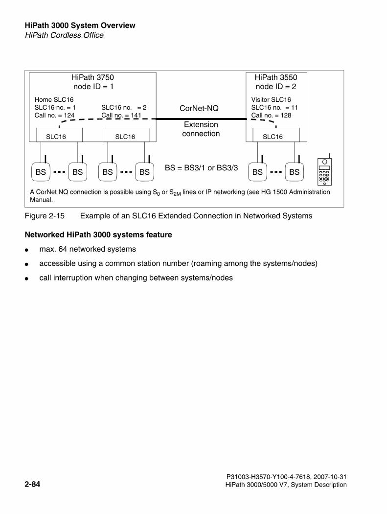
HiPath 3000 System Overview For internal use only
3000sb2.fm
HiPath Cordless Office
Networked HiPath 3000 systems feature
● max. 64 networked systems
● accessible using a common station number (roaming among the systems/nodes)
● call interruption when changing between systems/nodes
Figure 2-15 Example of an SLC16 Extended Connection in Networked Systems
BS
SLC16
BS
CorNet-NQHome SLC16SLC16 no. = 1Call no. = 124
Visitor SLC16SLC16 no. = 11Call no. = 128
HiPath 3750 node ID = 1
HiPath 3550node ID = 2
Extensionconnection
BS
SLC16
BS
SLC16 no. = 2Call no. = 141
BS
SLC16
BS BS = BS3/1 or BS3/3
A CorNet NQ connection is possible using S0 or S2M lines or IP networking (see HG 1500 Administration Manual.
P31003-H3570-Y100-4-7618, 2007-10-312-84 HiPath 3000/5000 V7, System Description
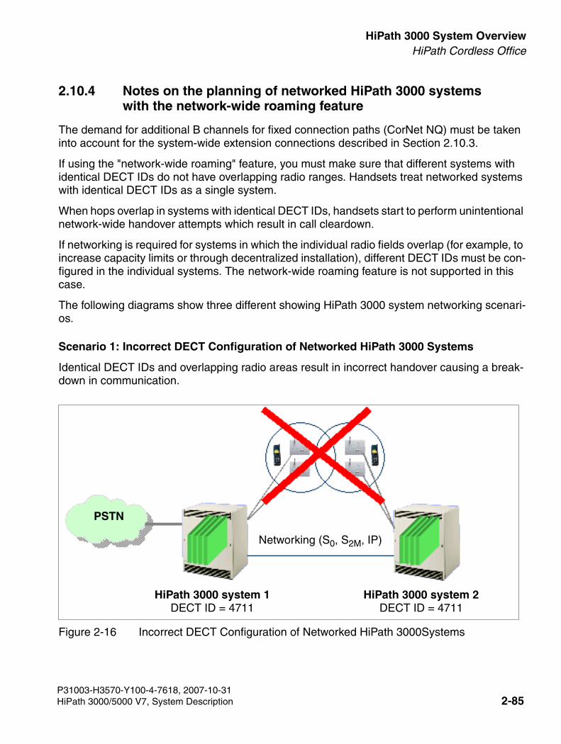
3000sb2.fm
For internal use only HiPath 3000 System OverviewHiPath Cordless Office
2.10.4 Notes on the planning of networked HiPath 3000 systems with the network-wide roaming feature
The demand for additional B channels for fixed connection paths (CorNet NQ) must be taken into account for the system-wide extension connections described in Section 2.10.3.
If using the "network-wide roaming" feature, you must make sure that different systems with identical DECT IDs do not have overlapping radio ranges. Handsets treat networked systems with identical DECT IDs as a single system.
When hops overlap in systems with identical DECT IDs, handsets start to perform unintentional network-wide handover attempts which result in call cleardown.
If networking is required for systems in which the individual radio fields overlap (for example, to increase capacity limits or through decentralized installation), different DECT IDs must be con-figured in the individual systems. The network-wide roaming feature is not supported in this case.
The following diagrams show three different showing HiPath 3000 system networking scenari-os.
Scenario 1: Incorrect DECT Configuration of Networked HiPath 3000 Systems
Identical DECT IDs and overlapping radio areas result in incorrect handover causing a break-down in communication.
Figure 2-16 Incorrect DECT Configuration of Networked HiPath 3000Systems
PSTN
Networking (S0, S2M, IP)
HiPath 3000 system 1DECT ID = 4711
HiPath 3000 system 2DECT ID = 4711
P31003-H3570-Y100-4-7618, 2007-10-31HiPath 3000/5000 V7, System Description 2-85
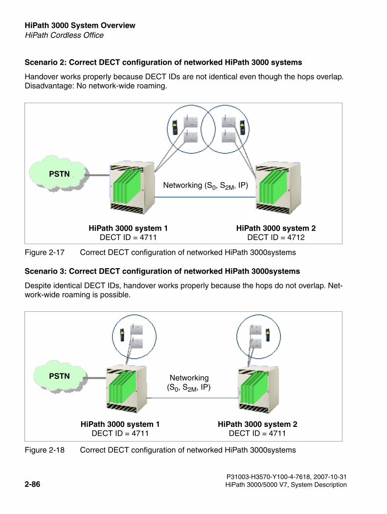
HiPath 3000 System Overview For internal use only
3000sb2.fm
HiPath Cordless Office
Scenario 2: Correct DECT configuration of networked HiPath 3000 systems
Handover works properly because DECT IDs are not identical even though the hops overlap. Disadvantage: No network-wide roaming.
Scenario 3: Correct DECT configuration of networked HiPath 3000systems
Despite identical DECT IDs, handover works properly because the hops do not overlap. Net-work-wide roaming is possible.
Figure 2-17 Correct DECT configuration of networked HiPath 3000systems
Figure 2-18 Correct DECT configuration of networked HiPath 3000systems
PSTNNetworking (S0, S2M, IP)
HiPath 3000 system 1DECT ID = 4711
HiPath 3000 system 2DECT ID = 4712
PSTN
HiPath 3000 system 1DECT ID = 4711
HiPath 3000 system 2DECT ID = 4711
Networking(S0, S2M, IP)
P31003-H3570-Y100-4-7618, 2007-10-312-86 HiPath 3000/5000 V7, System Description
3000sb2.fm
For internal use only HiPath 3000 System OverviewHiPath Cordless Office
2.10.5 Components of HiPath Cordless Office
2.10.5.1 Mobile Telephones
The mobile telephones in the Gigaset series can be used from 2000.
2.10.5.2 Base Stations
Types
● BS3/1 (S30807-H5482-X): is a base station that supports a maximum of four calls simul-taneously.
● BS3/3 (S30807-H5485-X): The base station can only be operated on the SLC16 or SLC16N board. The connection via at least two UP0/E interfaces is essential. It supports a maximum of 12 calls when connected using three UP0/E interfaces.
● BS3/S (X30807-X5482-X100): The BS3/S single-cell base station guarantees the opera-tion of a maximum of one base station on the UP0/E interfaces of the central board. It is not possible to operate additional base stations.
● BS4 (S30807-U5491-X): is a base station that supports a maximum of 12 calls when con-nected using three UP0/E interfaces. In the case of a direct connection, it is only permitted to make the connection via one UP0/E interface. The B channels in the base station BS4 require a license. Cannot be connected to SLC16.
P31003-H3570-Y100-4-7618, 2007-10-31HiPath 3000/5000 V7, System Description 2-87
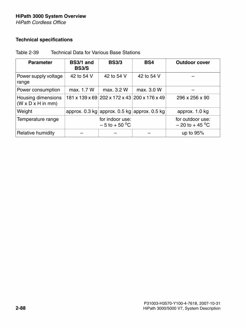
HiPath 3000 System Overview For internal use only
3000sb2.fm
HiPath Cordless Office
Technical specifications
Table 2-39 Technical Data for Various Base Stations
Parameter BS3/1 andBS3/S
BS3/3 BS4 Outdoor cover
Power supply voltage range
42 to 54 V 42 to 54 V 42 to 54 V –
Power consumption max. 1.7 W max. 3.2 W max. 3.0 W –
Housing dimensions (W x D x H in mm)
181 x 139 x 69 202 x 172 x 43 200 x 176 x 49 296 x 256 x 90
Weight approx. 0.3 kg approx. 0.5 kg approx. 0.5 kg approx. 1.0 kg
Temperature range for indoor use:– 5 to + 50 oC
for outdoor use:– 20 to + 45 oC
Relative humidity – – – up to 95%
P31003-H3570-Y100-4-7618, 2007-10-312-88 HiPath 3000/5000 V7, System Description
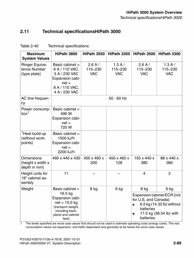
3000sb2.fm
For internal use only HiPath 3000 System OverviewTechnical specificationsHiPath 3000
2.11 Technical specificationsHiPath 3000
Table 2-40 Technical specifications
Maximum System Values
HiPath 3800 HiPath 3550 HiPath 3350 HiPath 3500 HiPath 3300
Ringer Equiva-lence Number (type plate)
Basic cabinet =6 A / 110 VAC,3 A / 230 VAC
Expansion cabi-net =
8 A / 110 VAC,4 A / 230 VAC
2.6 A / 115–230
VAC
1.3 A / 115–230
VAC
2.6 A / 115–230
VAC
1.3 A / 115–230
VAC
AC line frequen-cy
50 - 60 Hz
Power consump-tion1
1 The levels specified are worst case values that should not be used to estimate operating costs (energy costs). The real consumption values are expansion- and traffic-dependant and generally lie far below the worst case values.
Basic cabinet =490 W
Expansion cabi-net =
720 W1Heat build-up (without work-points)
Basic cabinet =1500 kJ/h
Expansion cabi-net =
2200 kJ/h
Dimensions(height x width x depth in mm)
490 x 440 x 430 450 x 460 x 200
450 x 460 x 128
155 x 440 x 380
88 x 440 x 380
Height units for 19" cabinet as-sembly
11 – – 4 2
Weight Basic cabinet = 16.5 kg
Expansion cabi-net = 15.0 kg
(transport weight, including back-
plane and cabinet feet)
8 kg 6 kg 8 kg 6 kg
Expansion cabinet ECR (not for U.S. and Canada): ● 6.5 kg (14.32 lb) without
batteries ● 17.5 kg (38.54 lb) with
batteries
P31003-H3570-Y100-4-7618, 2007-10-31HiPath 3000/5000 V7, System Description 2-89
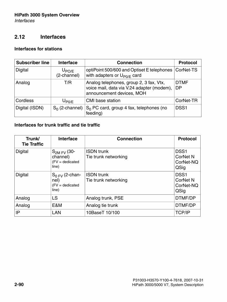
HiPath 3000 System Overview For internal use only
3000sb2.fm
Interfaces
2.12 Interfaces
Interfaces for stations
Interfaces for trunk traffic and tie traffic
Subscriber line Interface Connection Protocol
Digital UPO/E (2-channel)
optiPoint 500/600 and Optiset E telephones with adapters or UP0/E card
CorNet-TS
Analog T/R Analog telephones, group 2, 3 fax, Vtx, voice mail, data via V.24 adapter (modem), announcement devices, MOH
DTMFDP
Cordless UP0/E CMI base station CorNet-TR
Digital (ISDN) S0 (2-channel) S0 PC card, group 4 fax, telephones (no feeding)
DSS1
Trunk/Tie Traffic
Interface Connection Protocol
Digital S2M FV (30-channel)(FV = dedicated line)
ISDN trunkTie trunk networking
DSS1CorNet NCorNet-NQQSig
Digital S0 FV (2-chan-nel)(FV = dedicated line)
ISDN trunkTie trunk networking
DSS1CorNet NCorNet-NQQSig
Analog LS Analog trunk, PSE DTMF/DP
Analog E&M Analog tie trunk DTMF/DP
IP LAN 10BaseT 10/100 TCP/IP
P31003-H3570-Y100-4-7618, 2007-10-312-90 HiPath 3000/5000 V7, System Description
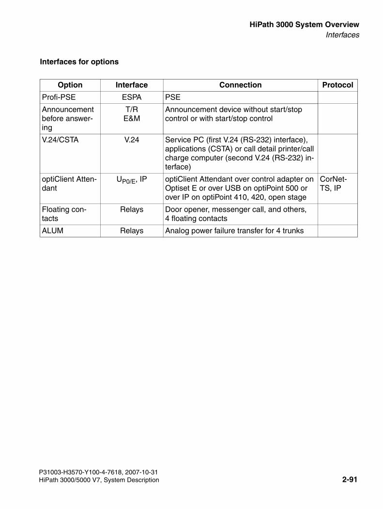
3000sb2.fm
For internal use only HiPath 3000 System OverviewInterfaces
Interfaces for options
Option Interface Connection Protocol
Profi-PSE ESPA PSE
Announcement before answer-ing
T/RE&M
Announcement device without start/stop control or with start/stop control
V.24/CSTA V.24 Service PC (first V.24 (RS-232) interface), applications (CSTA) or call detail printer/call charge computer (second V.24 (RS-232) in-terface)
optiClient Atten-dant
UP0/E, IP optiClient Attendant over control adapter on Optiset E or over USB on optiPoint 500 or over IP on optiPoint 410, 420, open stage
CorNet-TS, IP
Floating con-tacts
Relays Door opener, messenger call, and others,4 floating contacts
ALUM Relays Analog power failure transfer for 4 trunks
P31003-H3570-Y100-4-7618, 2007-10-31HiPath 3000/5000 V7, System Description 2-91
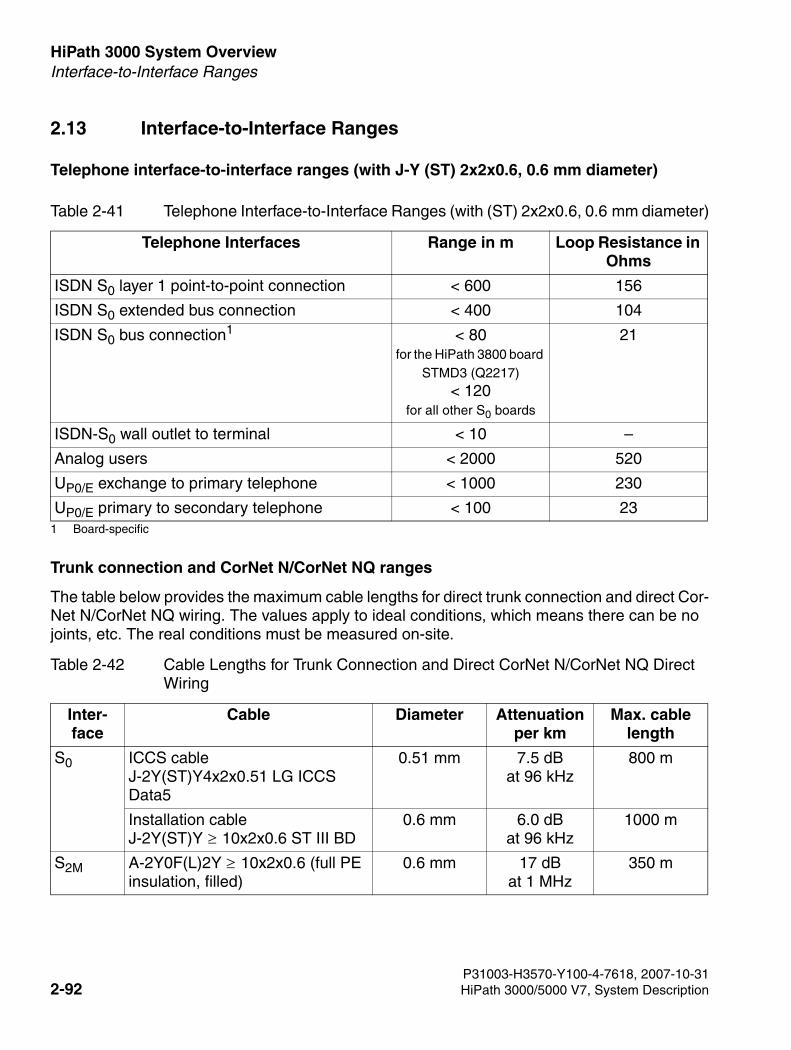
HiPath 3000 System Overview For internal use only
3000sb2.fm
Interface-to-Interface Ranges
2.13 Interface-to-Interface Ranges
Telephone interface-to-interface ranges (with J-Y (ST) 2x2x0.6, 0.6 mm diameter)
Trunk connection and CorNet N/CorNet NQ ranges
The table below provides the maximum cable lengths for direct trunk connection and direct Cor-Net N/CorNet NQ wiring. The values apply to ideal conditions, which means there can be no joints, etc. The real conditions must be measured on-site.
Table 2-41 Telephone Interface-to-Interface Ranges (with (ST) 2x2x0.6, 0.6 mm diameter)
Telephone Interfaces Range in m Loop Resistance in Ohms
ISDN S0 layer 1 point-to-point connection < 600 156
ISDN S0 extended bus connection < 400 104
ISDN S0 bus connection1
1 Board-specific
< 80for the HiPath 3800 board
STMD3 (Q2217)< 120
for all other S0 boards
21
ISDN-S0 wall outlet to terminal < 10 –
Analog users < 2000 520
UP0/E exchange to primary telephone < 1000 230
UP0/E primary to secondary telephone < 100 23
Table 2-42 Cable Lengths for Trunk Connection and Direct CorNet N/CorNet NQ Direct Wiring
Inter-face
Cable Diameter Attenuation per km
Max. cable length
S0 ICCS cableJ-2Y(ST)Y4x2x0.51 LG ICCS Data5
0.51 mm 7.5 dBat 96 kHz
800 m
Installation cableJ-2Y(ST)Y 10x2x0.6 ST III BD
0.6 mm 6.0 dBat 96 kHz
1000 m
S2M A-2Y0F(L)2Y 10x2x0.6 (full PE insulation, filled)
0.6 mm 17 dBat 1 MHz
350 m
P31003-H3570-Y100-4-7618, 2007-10-312-92 HiPath 3000/5000 V7, System Description
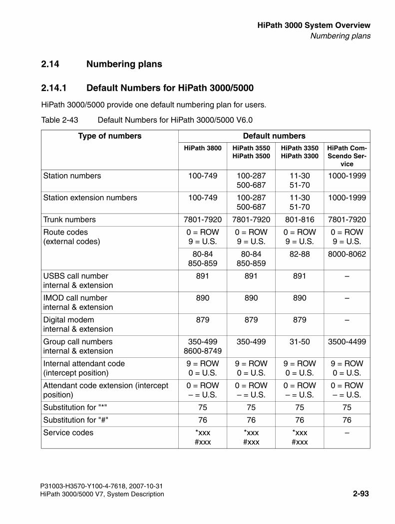
3000sb2.fm
For internal use only HiPath 3000 System OverviewNumbering plans
2.14 Numbering plans
2.14.1 Default Numbers for HiPath 3000/5000
HiPath 3000/5000 provide one default numbering plan for users.
Table 2-43 Default Numbers for HiPath 3000/5000 V6.0
Type of numbers Default numbersHiPath 3800 HiPath 3550
HiPath 3500HiPath 3350HiPath 3300
HiPath Com-Scendo Ser-
vice
Station numbers 100-749 100-287500-687
11-3051-70
1000-1999
Station extension numbers 100-749 100-287500-687
11-3051-70
1000-1999
Trunk numbers 7801-7920 7801-7920 801-816 7801-7920
Route codes(external codes)
0 = ROW9 = U.S.
0 = ROW9 = U.S.
0 = ROW9 = U.S.
0 = ROW9 = U.S.
80-84850-859
80-84850-859
82-88 8000-8062
USBS call number internal & extension
891 891 891 –
IMOD call number internal & extension
890 890 890 –
Digital modem internal & extension
879 879 879 –
Group call numbers internal & extension
350-4998600-8749
350-499 31-50 3500-4499
Internal attendant code (intercept position)
9 = ROW0 = U.S.
9 = ROW0 = U.S.
9 = ROW0 = U.S.
9 = ROW0 = U.S.
Attendant code extension (intercept position)
0 = ROW– = U.S.
0 = ROW– = U.S.
0 = ROW– = U.S.
0 = ROW– = U.S.
Substitution for "*" 75 75 75 75
Substitution for "#" 76 76 76 76
Service codes *xxx#xxx
*xxx#xxx
*xxx#xxx
–
P31003-H3570-Y100-4-7618, 2007-10-31HiPath 3000/5000 V7, System Description 2-93
HiPath 3000 System Overview For internal use only
3000sb2.fm
Numbering plans
2.14.2 ISDN Numbering Plan (E.164) V7 or Later
ISDN numbering plan (E.164)
The ISDN numbering plan (E.164) is a new numbering plan for addressing telephone networks. It specifies the different parts of the telephone number and the number of permissible digits (country code, network area code, system phone number). The ISDN numbering plan (E.164):
● improves integration in networks with HiPath 4000
● establishes connections to Internet telephony service providers
The plan can be configured using Manager E.
When networking with the ISDN numbering plan (E.164), you must ensure that HiPath 3000/5000 is permitted to transmit the number of the called station (dialing information) with the Type Of Number TON = unknown and that the networked system always transmits a fixed Type Of Number TON (and not another type).
Objective of E.164 networking
The objective of networking with E.164 is to transmit all station numbers in a network in an in-ternational format, in a network with HiPath 4000, for instance. Station numbers, however, should be shown on displays in the most suitable format.
The stations can be reached via a public station number, in other words, the national or inter-national E.164 station number (internal calling party number in ISDN format, for instance), with-out having to first dial a node number. Each station is represented by its E.164 number that can be displayed in the most suitable format.
● Telephone numbers in the HiPath 5000 RSM network are shortened to the station number.
● Maintaining the port number list, which contains all ISDN numbers of all nodes in the Hi-Path 5000 RSM network. The numbers of nodes outside the HiPath 5000 RSM network (HiPath 4000, for instance) are not entered. These numbers are shortened to the most suit-able format using the location station number.
SIP
When E.164 numbering is activated, the internal number is transmitted in E.164 format. SIP stations are registered using the full E.164 number (location number + internal number, 4923026673665, for instance).
If an Internet telephony service provider is to be used and the Internet telephony service pro-vider’s station number is made available in an E.164 network, the station allocation must be en-tered. The shortest dialable station number is always used for the allocation.
In HG 1500, the SIP station number is allocated to the extension (the internal extension is usu-ally entered here).
P31003-H3570-Y100-4-7618, 2007-10-312-94 HiPath 3000/5000 V7, System Description
3000sb2.fm
For internal use only HiPath 3000 System OverviewNumbering plans
Example: If the Internet telephony service provider is connected to the node at the Witten site and a subscriber from Munich should use an SIP number, the number 008972212345 is en-tered during allocation in the HG 1500 at the Witten site. The shortest dialable station number is always entered. This is also the shortest number that the customer would dial on a telephone (the number the subscriber in Witten uses to call the subscriber in Munich).
Calling party identification:
HiPath 3000/5000 supports correct calling party identification when networking systems that have the same system phone number.
If nodes with different system phone numbers are used in the network, the full system phone number is retained in the calling party’s number.
In networks with different system phone numbers, calling party numbers are displayed correctly if open numbering is used (different area codes).
P31003-H3570-Y100-4-7618, 2007-10-31HiPath 3000/5000 V7, System Description 2-95
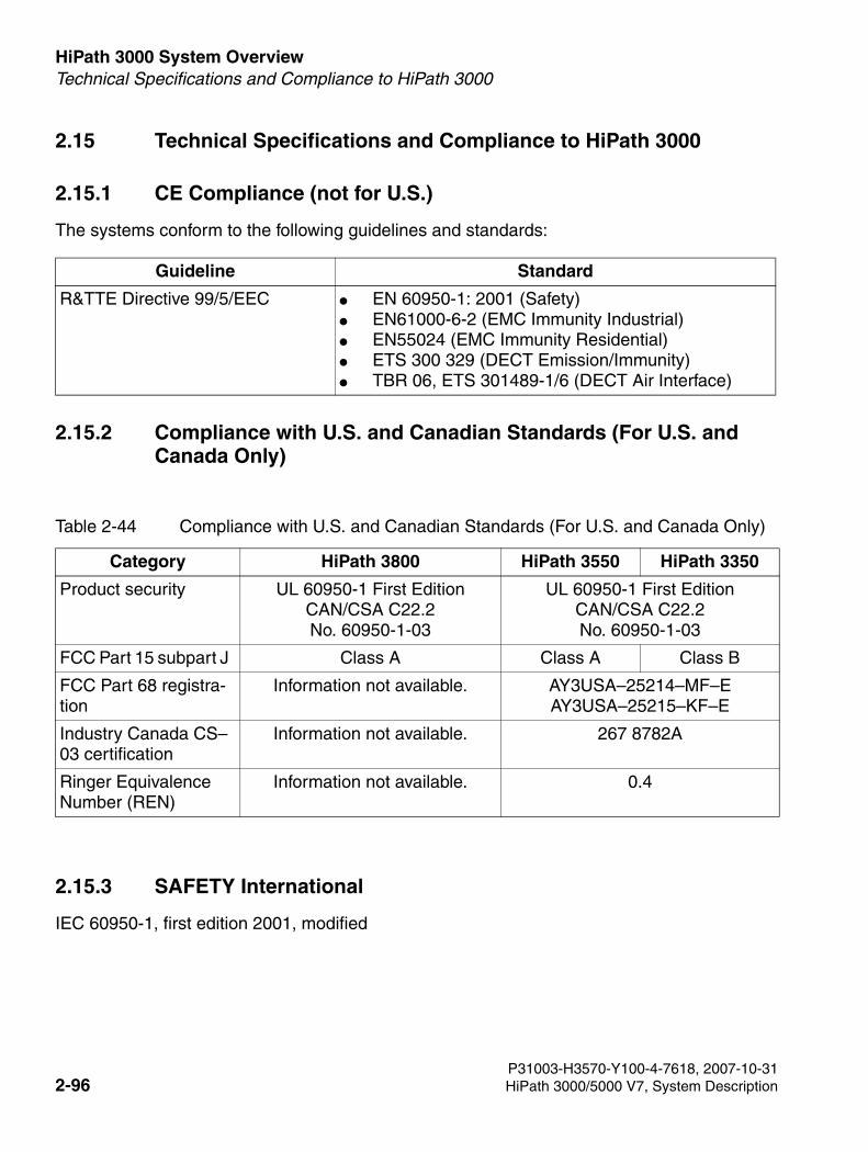
HiPath 3000 System Overview For internal use only
3000sb2.fm
Technical Specifications and Compliance to HiPath 3000
2.15 Technical Specifications and Compliance to HiPath 3000
2.15.1 CE Compliance (not for U.S.)
The systems conform to the following guidelines and standards:
2.15.2 Compliance with U.S. and Canadian Standards (For U.S. and Canada Only)
2.15.3 SAFETY International
IEC 60950-1, first edition 2001, modified
Guideline Standard
R&TTE Directive 99/5/EEC ● EN 60950-1: 2001 (Safety)● EN61000-6-2 (EMC Immunity Industrial) ● EN55024 (EMC Immunity Residential) ● ETS 300 329 (DECT Emission/Immunity) ● TBR 06, ETS 301489-1/6 (DECT Air Interface)
Table 2-44 Compliance with U.S. and Canadian Standards (For U.S. and Canada Only)
Category HiPath 3800 HiPath 3550 HiPath 3350
Product security UL 60950-1 First EditionCAN/CSA C22.2No. 60950-1-03
UL 60950-1 First EditionCAN/CSA C22.2No. 60950-1-03
FCC Part 15 subpart J Class A Class A Class B
FCC Part 68 registra-tion
Information not available. AY3USA–25214–MF–EAY3USA–25215–KF–E
Industry Canada CS–03 certification
Information not available. 267 8782A
Ringer Equivalence Number (REN)
Information not available. 0.4
P31003-H3570-Y100-4-7618, 2007-10-312-96 HiPath 3000/5000 V7, System Description
3000sb2.fm
For internal use only HiPath 3000 System OverviewEnvironmental Conditions
2.16 Environmental Conditions
2.16.1 Electrical Operating Conditions
● Operating limitsRoom temperature: + 5 ...+ 40 °C (41 ... 104 °F) absolute humidity: 2 to 25 g H2O/m3
Relative humidity: 5 - 80%
● System ventilation is by convection. Automatic ventilation is required when using the HG 1500 in HiPath 3550 and HiPath 3350.
2.16.2 Mechanical Operating Conditions
The systems are intended for stationary use.
7CautionAvoid exposing the system to direct sunlight and heaters (excessive heat may dam-age the system).Systems subject to condensation must be dried off before being put into service. Putting a system into service with condensation still present should be avoided at all costs.
P31003-H3570-Y100-4-7618, 2007-10-31HiPath 3000/5000 V7, System Description 2-97

HiPath 3000 System Overview For internal use only
3000sb2.fm
Environmental Conditions
P31003-H3570-Y100-4-7618, 2007-10-312-98 HiPath 3000/5000 V7, System Description
3000sb3.fm
For internal use only HiPath 5000 System OverviewIntroduction
3 HiPath 5000 System Overview
3.1 Introduction
HiPath 5000 is operated as a central administration unit in an IP network of HiPath 3000 sys-tems. By creating a "Single System Image", all relevant nodes can be centrally administered.
HiPath 5000 ComScendo must always be operated together with HiPath 5000 RSM ("central administration").
HiPath 5000 is the platform for the central provision of applications, and facilitates the use of these applications by all IP networking stations.
With the HiPath ComScendo service, there is also the option of using an integrated gatekeeper and HiPath ComScendo features for IP workpoint clients. Up to 1000 registered IP workpoint clients and up to 250 CorNet-IP trunks (CorNet-NQ protocol tunnelled in H.323 via annex M1) are also supported here.
The HiPath ComScendo Service is effectively a fully-fledgedHiPath 3000node that is only con-figured as software on a PC. Apart from TDM-specific features (for example, the connection of UP0/E stations, trunks and special stations such as door openers, etc.), all HiPath 3000/5000 features are available. The HiPath ComScendo Service is administered via HiPath 3000/5000 Manager E, while the HG 1500 resources are administered via Web-based Management (WBM).
Cross-platform use of HiPath ComScendo features (IP networking), for example in conjunction with HiPath 4000, is implemented via CorNet-IP (CorNet-NQ protocol tunnelled in H.323 via an-nex M1). HG 1500 in HiPath 3000 and HG3550 V2.0 in HiPath 4000 are prerequisites for IP networking over CorNet IP.
Parts of the following setup for HiPath 5000 are optional and can be installed both on the HiPath 5000 server and on a separate PC.
● Feature Server (central administration service in a HiPath 3000/5000 network)
● Presence Manager (service for LED signaling of call processing station statuses and net-work-wide DSS keys)
● HiPath ComScendo service (gatekeeper and HiPath ComScendo features for IP workpoint clients)
● HiPath 3000/5000 Manager E (MS Windows-based tool for the administration of all service and customer-specific data by Service)
● HiPath 3000/5000 Manager C (MS Windows-based tool for the administration of customer-specific data by the customer)
P31003-H3570-Y100-4-7618, 2007-10-31HiPath 3000/5000 V7, System Description 3-1
HiPath 5000 System Overview For internal use only
3000sb3.fm
Introduction
● HiPath Software Manager (Web-based tool for upgrades (Upgrade Manager for HiPath ComScendo Service and HG 1500) and backups (Backup Manager for HiPath ComScen-do Service, HG 1500 and databases))
● Inventory Manager (service for detecting software components installed and system infor-mation in a HiPath 3000/5000 network)
● Customer License Agent CLA (service for analyzing and decrypting a HiPath License Man-agement license file)
● Central License Manager CLM (CLA front-end for reading in licenses in online and offline mode)
● Personal Call Manager PCM (Web-based application for the configuration and administra-tion of personal call forwarding operations)
● HiPath FM Desktop V3.0 (Java-based application for error signaling)
● GetAccount (application that prepares generated call data records for further processing.)
P31003-H3570-Y100-4-7618, 2007-10-313-2 HiPath 3000/5000 V7, System Description
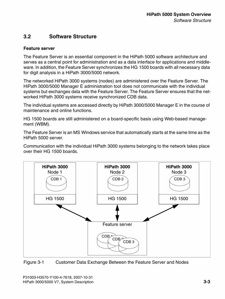
3000sb3.fm
For internal use only HiPath 5000 System OverviewSoftware Structure
3.2 Software Structure
Feature server
The Feature Server is an essential component in the HiPath 5000 software architecture and serves as a central point for administration and as a data interface for applications and middle-ware. In addition, the Feature Server synchronizes the HG 1500 boards with all necessary data for digit analysis in a HiPath 3000/5000 network.
The networked HiPath 3000 systems (nodes) are administered over the Feature Server. The HiPath 3000/5000 Manager E administration tool does not communicate with the individual systems but exchanges data with the Feature Server. The Feature Server ensures that the net-worked HiPath 3000 systems receive synchronized CDB data.
The individual systems are accessed directly by HiPath 3000/5000 Manager E in the course of maintenance and online functions.
HG 1500 boards are still administered on a board-specific basis using Web-based manage-ment (WBM).
The Feature Server is an MS Windows service that automatically starts at the same time as the HiPath 5000 server.
Communication with the individual HiPath 3000 systems belonging to the network takes place over their HG 1500 boards.
Figure 3-1 Customer Data Exchange Between the Feature Server and Nodes
Feature server
HiPath 3000Node 1
HG 1500
HiPath 3000Node 2
HG 1500
CDB 1 CDB 2
CDB 1CDB 2
CDB 3
HiPath 3000Node 3
HG 1500
CDB 3
P31003-H3570-Y100-4-7618, 2007-10-31HiPath 3000/5000 V7, System Description 3-3
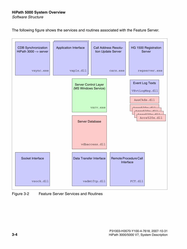
HiPath 5000 System Overview For internal use only
3000sb3.fm
Software Structure
The following figure shows the services and routines associated with the Feature Server.
Figure 3-2 Feature Server Services and Routines
CDB SynchronizationHiPath 3000 –> server
vsync.exe
Application Interface
vaplx.dll
Call Address Resolu-tion Update Server
cars.exe
HG 1500 Registration Server
regserver.exe
Server Control Layer(MS Windows Service)
vsrv.exe
Server Database
vdbaccess.dll
Socket Interface
vsock.dll
Data Transfer Interface
vadmtftp.dll
Remote Procedure Call Interface
FCT.dll
Event Log Texts
VEvtLogMsg.dll
AssCkds.dll
Accs520x.dllAccs520x.dllAccs520x.dllAccs520x.dll
P31003-H3570-Y100-4-7618, 2007-10-313-4 HiPath 3000/5000 V7, System Description
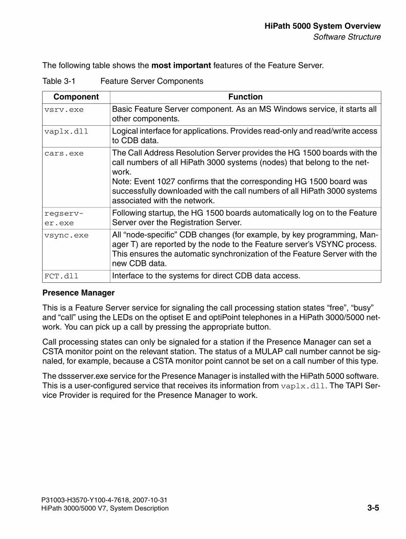
3000sb3.fm
For internal use only HiPath 5000 System OverviewSoftware Structure
The following table shows the most important features of the Feature Server.
Presence Manager
This is a Feature Server service for signaling the call processing station states “free”, “busy” and “call” using the LEDs on the optiset E and optiPoint telephones in a HiPath 3000/5000 net-work. You can pick up a call by pressing the appropriate button.
Call processing states can only be signaled for a station if the Presence Manager can set a CSTA monitor point on the relevant station. The status of a MULAP call number cannot be sig-naled, for example, because a CSTA monitor point cannot be set on a call number of this type.
The dssserver.exe service for the Presence Manager is installed with the HiPath 5000 software. This is a user-configured service that receives its information from vaplx.dll. The TAPI Ser-vice Provider is required for the Presence Manager to work.
Table 3-1 Feature Server Components
Component Function
vsrv.exe Basic Feature Server component. As an MS Windows service, it starts all other components.
vaplx.dll Logical interface for applications. Provides read-only and read/write access to CDB data.
cars.exe The Call Address Resolution Server provides the HG 1500 boards with the call numbers of all HiPath 3000 systems (nodes) that belong to the net-work. Note: Event 1027 confirms that the corresponding HG 1500 board was successfully downloaded with the call numbers of all HiPath 3000 systems associated with the network.
regserv-er.exe
Following startup, the HG 1500 boards automatically log on to the Feature Server over the Registration Server.
vsync.exe All “node-specific” CDB changes (for example, by key programming, Man-ager T) are reported by the node to the Feature server’s VSYNC process. This ensures the automatic synchronization of the Feature Server with the new CDB data.
FCT.dll Interface to the systems for direct CDB data access.
P31003-H3570-Y100-4-7618, 2007-10-31HiPath 3000/5000 V7, System Description 3-5
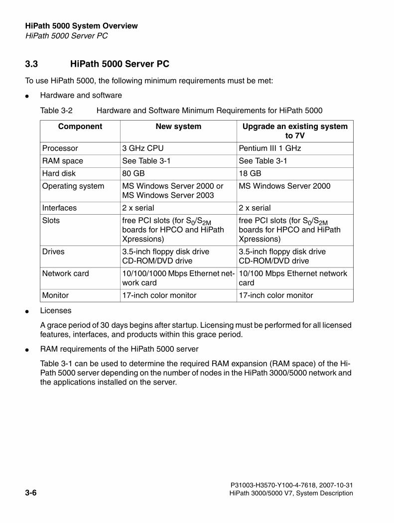
HiPath 5000 System Overview For internal use only
3000sb3.fm
HiPath 5000 Server PC
3.3 HiPath 5000 Server PC
To use HiPath 5000, the following minimum requirements must be met:
● Hardware and software
● Licenses
A grace period of 30 days begins after startup. Licensing must be performed for all licensed features, interfaces, and products within this grace period.
● RAM requirements of the HiPath 5000 server
Table 3-1 can be used to determine the required RAM expansion (RAM space) of the Hi-Path 5000 server depending on the number of nodes in the HiPath 3000/5000 network and the applications installed on the server.
Table 3-2 Hardware and Software Minimum Requirements for HiPath 5000
Component New system Upgrade an existing system to 7V
Processor 3 GHz CPU Pentium III 1 GHz
RAM space See Table 3-1 See Table 3-1
Hard disk 80 GB 18 GB
Operating system MS Windows Server 2000 or MS Windows Server 2003
MS Windows Server 2000
Interfaces 2 x serial 2 x serial
Slots free PCI slots (for S0/S2M boards for HPCO and HiPath Xpressions)
free PCI slots (for S0/S2M boards for HPCO and HiPath Xpressions)
Drives 3.5-inch floppy disk drive CD-ROM/DVD drive
3.5-inch floppy disk drive CD-ROM/DVD drive
Network card 10/100/1000 Mbps Ethernet net-work card
10/100 Mbps Ethernet network card
Monitor 17-inch color monitor 17-inch color monitor
P31003-H3570-Y100-4-7618, 2007-10-313-6 HiPath 3000/5000 V7, System Description
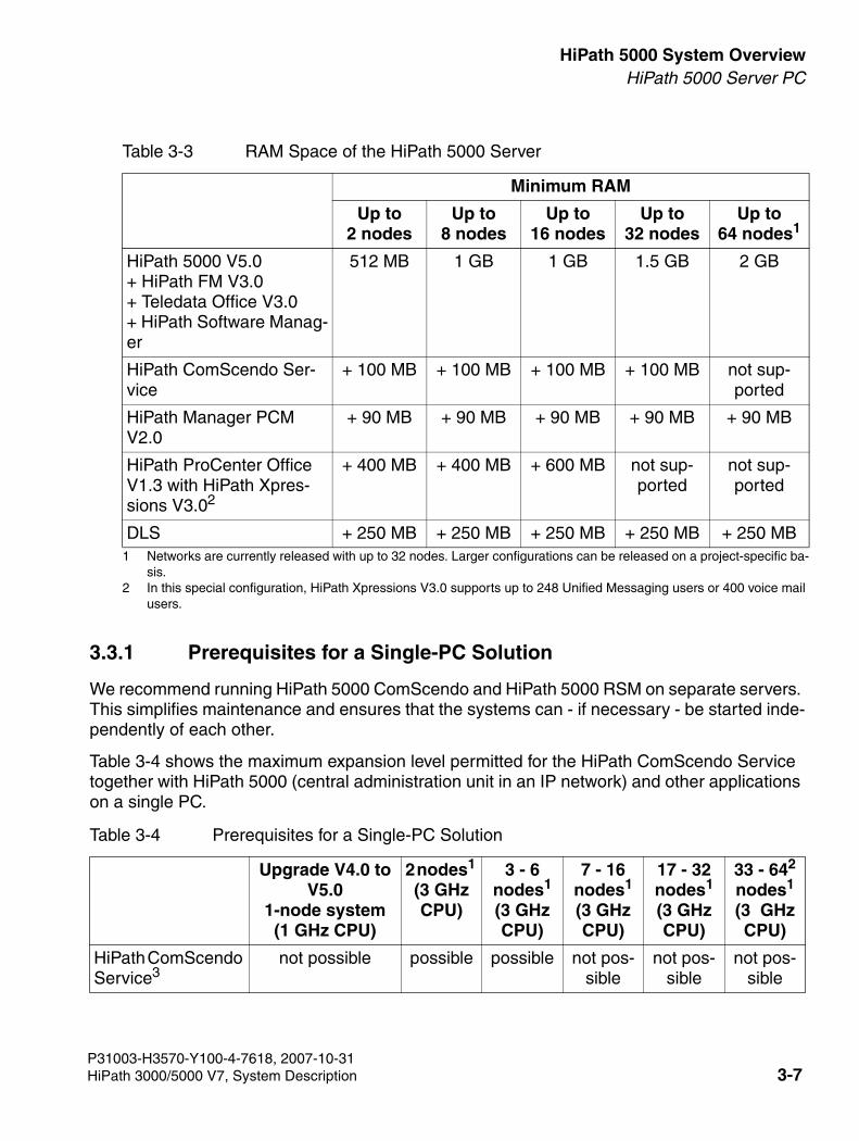
3000sb3.fm
For internal use only HiPath 5000 System OverviewHiPath 5000 Server PC
3.3.1 Prerequisites for a Single-PC Solution
We recommend running HiPath 5000 ComScendo and HiPath 5000 RSM on separate servers. This simplifies maintenance and ensures that the systems can - if necessary - be started inde-pendently of each other.
Table 3-4 shows the maximum expansion level permitted for the HiPath ComScendo Service together with HiPath 5000 (central administration unit in an IP network) and other applications on a single PC.
Table 3-3 RAM Space of the HiPath 5000 Server
Minimum RAM
Up to2 nodes
Up to8 nodes
Up to16 nodes
Up to32 nodes
Up to64 nodes1
1 Networks are currently released with up to 32 nodes. Larger configurations can be released on a project-specific ba-sis.
HiPath 5000 V5.0+ HiPath FM V3.0 + Teledata Office V3.0 + HiPath Software Manag-er
512 MB 1 GB 1 GB 1.5 GB 2 GB
HiPath ComScendo Ser-vice
+ 100 MB + 100 MB + 100 MB + 100 MB not sup-ported
HiPath Manager PCM V2.0
+ 90 MB + 90 MB + 90 MB + 90 MB + 90 MB
HiPath ProCenter Office V1.3 with HiPath Xpres-sions V3.02
2 In this special configuration, HiPath Xpressions V3.0 supports up to 248 Unified Messaging users or 400 voice mail users.
+ 400 MB + 400 MB + 600 MB not sup-ported
not sup-ported
DLS + 250 MB + 250 MB + 250 MB + 250 MB + 250 MB
Table 3-4 Prerequisites for a Single-PC Solution
Upgrade V4.0 to V5.0
1-node system (1 GHz CPU)
2 nodes1 (3 GHz CPU)
3 - 6 nodes1 (3 GHz CPU)
7 - 16 nodes1 (3 GHz CPU)
17 - 32 nodes1 (3 GHz CPU)
33 - 642 nodes1 (3 GHz CPU)
HiPath ComScendo Service3
not possible possible possible not pos-sible
not pos-sible
not pos-sible
P31003-H3570-Y100-4-7618, 2007-10-31HiPath 3000/5000 V7, System Description 3-7
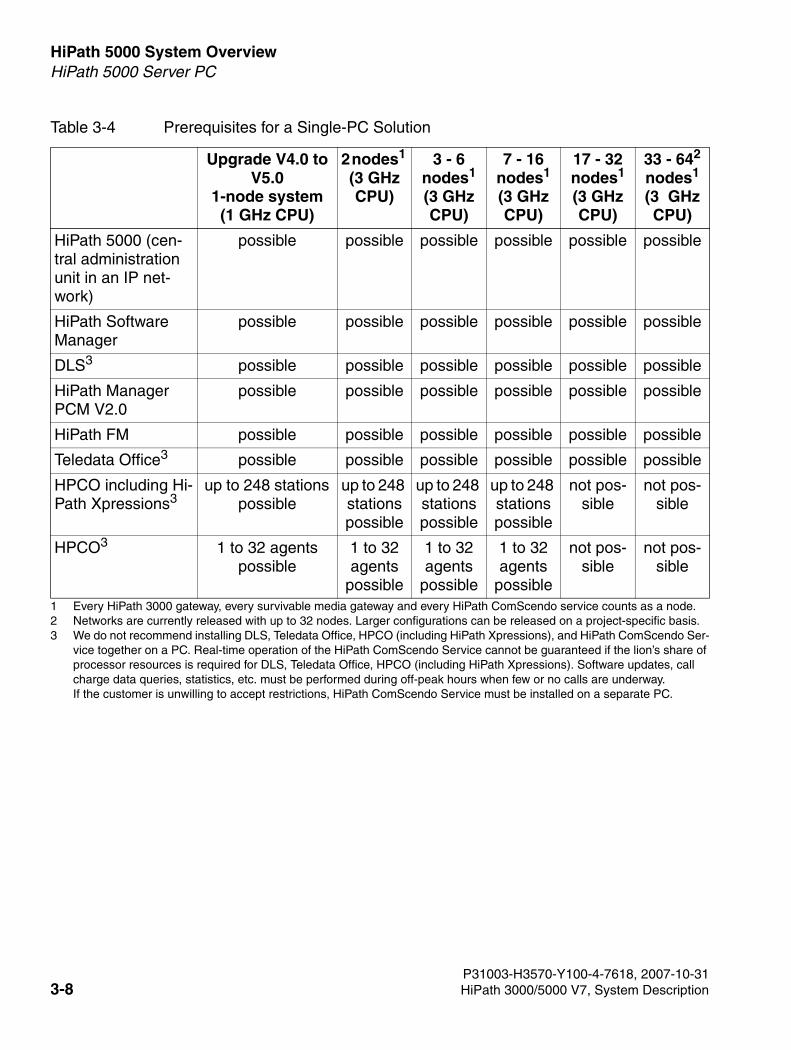
HiPath 5000 System Overview For internal use only
3000sb3.fm
HiPath 5000 Server PC
HiPath 5000 (cen-tral administration unit in an IP net-work)
possible possible possible possible possible possible
HiPath Software Manager
possible possible possible possible possible possible
DLS3 possible possible possible possible possible possible
HiPath Manager PCM V2.0
possible possible possible possible possible possible
HiPath FM possible possible possible possible possible possible
Teledata Office3 possible possible possible possible possible possible
HPCO including Hi-Path Xpressions3
up to 248 stations possible
up to 248 stations possible
up to 248 stations possible
up to 248 stations possible
not pos-sible
not pos-sible
HPCO3 1 to 32 agents possible
1 to 32 agents
possible
1 to 32 agents
possible
1 to 32 agents
possible
not pos-sible
not pos-sible
1 Every HiPath 3000 gateway, every survivable media gateway and every HiPath ComScendo service counts as a node. 2 Networks are currently released with up to 32 nodes. Larger configurations can be released on a project-specific basis. 3 We do not recommend installing DLS, Teledata Office, HPCO (including HiPath Xpressions), and HiPath ComScendo Ser-
vice together on a PC. Real-time operation of the HiPath ComScendo Service cannot be guaranteed if the lion’s share of processor resources is required for DLS, Teledata Office, HPCO (including HiPath Xpressions). Software updates, call charge data queries, statistics, etc. must be performed during off-peak hours when few or no calls are underway. If the customer is unwilling to accept restrictions, HiPath ComScendo Service must be installed on a separate PC.
Table 3-4 Prerequisites for a Single-PC Solution
Upgrade V4.0 to V5.0
1-node system (1 GHz CPU)
2 nodes1 (3 GHz CPU)
3 - 6 nodes1 (3 GHz CPU)
7 - 16 nodes1 (3 GHz CPU)
17 - 32 nodes1 (3 GHz CPU)
33 - 642 nodes1 (3 GHz CPU)
P31003-H3570-Y100-4-7618, 2007-10-313-8 HiPath 3000/5000 V7, System Description
3000sb3.fm
For internal use only HiPath 5000 System OverviewServer Networking
3.4 Server Networking
3.4.1 Features of IP Networking
Transparent for End Users
● No special telephones are required, as the conversion of voice into IP packets takes place in the LAN gateway rather than in the telephone.
● The transfer of the general network features has no effect on the way the telephones are used, and therefore does not restrict the convenience of the telephone functions in any way.
● DTMF signals: DTMF signals are supported. It is therefore possible to have suffix dialing or to listen to voice mail over the IP network.
Support of Network-wide Features
HiPath 5000 supports the CorNet NQ protocol; in this process CorNet NQ-specific features are transmitted over the IP network (tunnelling).
The following applies: The features that are currently transmitted in a HiPath 3000 corporate network are also supported by HiPath 5000 with some enhancements in comparison to con-ventional networking. (see General Features).
Central Attendant Console
A central attendant console may be deployed in HiPath 2000/3000/5000 networks. Platform-wide busy signaling is also possible.
(See optiClient Attendant)
Automatic Routing
HiPath 5000 can perform automatic routing to a backup or alternative network for new connec-tions. A voice network (such as ISDN dial-up connection) can also be used as a backup net-work. This ensures that the high availability of HiPath is not affected by the use of IP networks for the transfer of voice and fax connections. Automatic routing is initiated if
● the communication platform selected is not accessible (for example because of an error or overload in the IP network).
>NoteThe cross-communication platform busy signaling feature is only available with opti-Client Attendant. HiPath 5000 (Presence Manager) is not necessary for this purpose.
P31003-H3570-Y100-4-7618, 2007-10-31HiPath 3000/5000 V7, System Description 3-9
HiPath 5000 System Overview For internal use only
3000sb3.fm
Server Networking
● there is no more capacity available in LAN accesses (maximum number of B channels for LAN gateway exceeded)
● a connection is explicitly requested (for example a modem connection)
Network Management
All communication platforms are administered using an enhanced version of HiPath 3000 Man-ager E. The HiPath 3000 Manager E tool is included in the scope of delivery and is installed on the HiPath 5000 server. From here, it is possible to have central administration of all communi-cation platforms in a shared database. An application running permanently on the feature serv-er is used for the automatic administration and maintenance of the IP routing tables and the transmission of data to the individual communication platforms (see HiPath 3000 Manager E)
Network management - including troubleshooting and trace activation - can be performed both locally and remotely.
>NoteISDN lines are required as a trunk connection for routing data connections/VoIP con-nections over the integrated ISDN router.
P31003-H3570-Y100-4-7618, 2007-10-313-10 HiPath 3000/5000 V7, System Description
3000sb3.fm
For internal use only HiPath 5000 System OverviewServer Networking
3.4.2 IP Network and Application Server Requirements
3.4.2.1 Adequate Connection Bandwidth
The customer network must fulfill the following requirements to ensure that voice information is transmitted successfully via LAN:
● Switched LAN with 10/100 Mbps
● Fixed IP addresses
● Each component must have its own port at the switch (no HUBs as concentrators)
● Pure Microsoft TCP/IP network (not a Novell network with SPX)
● QoS, ToS and DiffServ (see below)
Although use in shared environments is possible, it is neither approved nor recommended, as there is no guarantee of quality. The HiPath server can also be operated in networks with rout-ing components
3.4.2.2 Bandwidth
The bandwidth for voice must be available in the network at all times. For this reason, network measurement and analysis is carried out before installing the components.
Why Measure the Network?
The following data is required to calculate the required bandwidth for voice transmission in an IP network in relation to the number of simultaneous connections:
Bandwidth for voice information
All values refer to the lowest packet assembly level. The bandwidths in the WAN are only valid if the multilink and segmenting parameters have not been set.
>Because of the data traffic between the HiPath DB server components and the serv-er, routing connections are always open (no short-hold in the WAN).
Type Bandwidth for each connection (full duplex)1
1 All values refer to the lowest packet assembling level for HG 1500 V2. Because of its expanded functionality HG 1500 V3 can differ from this. See HG1500 V3 release note.
Voice with ITU G.711 50 Kbps in LAN
Voice with ITU G.723.1 22 Kbps in LAN; 19 Kbps in the WAN
P31003-H3570-Y100-4-7618, 2007-10-31HiPath 3000/5000 V7, System Description 3-11
HiPath 5000 System Overview For internal use only
3000sb3.fm
Server Networking
Bandwidth Requirements for Additional Services:
The specified values represent the load in relation to a maximum call volume of 1400 BHCA (this is the maximum traffic with a connected call center solution).
Bandwidth Requirements for Administration (valid only for HPCO):
The specified bandwidth represents the worst case scenario. In other words, an entire CDB is sent to the server from the HiPath node every 30 seconds (max.) as a result of the synchroni-zation process configured in the system.
It is difficult to define an accurate value at the moment due to the lack of data from the field.However, the bandwidth requirement will, in practice, be well below 132 Kbps, or there will be short-term peaks during which this value will be required by the network.
In practice, the most frequent application is the call up of key programming by users. A block of 64 KB is transferred in this process. An accepted period of 30 seconds for the transmission pro-cess results in bandwidth requirements of 18 Kbps.
Type Record size Bandwidth requirement
Busy signal (optiClient Attendant)
300 bytes 3 Kbps
Call detail records 200 bytes 1 Kbps
ACD information 3.5 KB 10 Kbps
Type Record size Bandwidth requirement
Synch by Hicom per TFTP 607232 bytes 132 Kbps
P31003-H3570-Y100-4-7618, 2007-10-313-12 HiPath 3000/5000 V7, System Description
3000sb3.fm
For internal use only HiPath 5000 System OverviewServer Networking
Accordingly, the minimum bandwidth required is as follows:
The necessary bandwidth must be calculated using N as the number of simultaneous connec-tions:
N = number of simultaneous voice connections
When configuring fax or modem transmissions using the formula described above (outband transmission) the following are also required for each configured connection:
● For fax group 3 (V.17, 14 Kbps): approx. 20 Kbps
● For modem connections (V.34, 33.6 Kbps): approx. 40 Kbps
3.4.2.3 Requirements of Delay Times
For natural communication, the delay should amount to a maximum of 50 ms (one-way delay) for voice connections (network delay). Delays of more than 50 ms in one direction impair natural communication. The effect is similar to that experienced with voice connections over satellite. The maximum number of 15 buffer stations (HOPs) may not be exceeded.
Priority control is a particularly efficient means of reducing the delay (see next section). Please proceed with caution if the network is operated using lines with a low bit rate (for example, con-nection of a branch to headquarters at a rate of 128 Kbps). The maximum number of trunk lines can be determined by calculating the necessary bandwidth.
3.4.2.4 Provision of QoS in Data Networks
To guarantee the Quality of Service (QoS) described in the two previous sections, the following standards must be met:
● All the components involved in transmitting voice data must support min. IEEE 802.1q (lay-er 2).
● In addition, all components require routing according to the Diffserv standard RFC 2474 and the ToS standard (Type of Service) RFC 791.
Required bandwidth Formula (Kbps) of approximate values
With ITU G.711 .. N x 90 (voice)+ N x 4 (BLF+CDR)+ 10 (ACD/TAPI)
With ITU G723.1 .. N x 22 or 19 (voice)+ N x 4 (BLF+CDR)+ 10 (ACD/TAPI)
P31003-H3570-Y100-4-7618, 2007-10-31HiPath 3000/5000 V7, System Description 3-13
HiPath 5000 System Overview For internal use only
3000sb3.fm
Server Networking
3.4.2.5 Quality Assurance Procedures to be Supported
● Quality of Service (QoS) procedures in accordance with IEEE 802.1q (layer 2)
● Type of Service (ToS) in accordance with RFC 791 (layer 3), packet prioritization
● Differentiated Services (DiffServ - DS) procedure in accordance with RFC 2474 (layer 3)
3.4.2.6 Maximum Package Losses
A maximum packet loss of 3% is tolerated. The reduced voice quality associated with packet loss is greater for G.723.1 and G.729 than for G.711.
3.4.2.7 Minimization of Broadcast/Multicast Traffic
In accordance with the rules of good network design, broadcast/multicast traffic should be kept to a minimum. The use of routers/layer 3 switches to structure the network (for example VPM) or the use of layer 2 switches can help detect multicasting traffic.
3.4.2.8 Requirements for Standalone Systems:
● Switched or shared LAN (Ethernet IEE 802.3/802.3 u) with 10 or 100 Mbps
● Pure Microsoft TCP/IP network (not a Novell network with IPX/SPX)
● Fixed IP addresses (no DHCP)
● The bandwidth required for transferring additional services (CDR and ACD/TAPI informa-tion) must be taken into account. If the bandwidth is sufficient, a second protocol (e.g. No-vell) may be possible.
P31003-H3570-Y100-4-7618, 2007-10-313-14 HiPath 3000/5000 V7, System Description
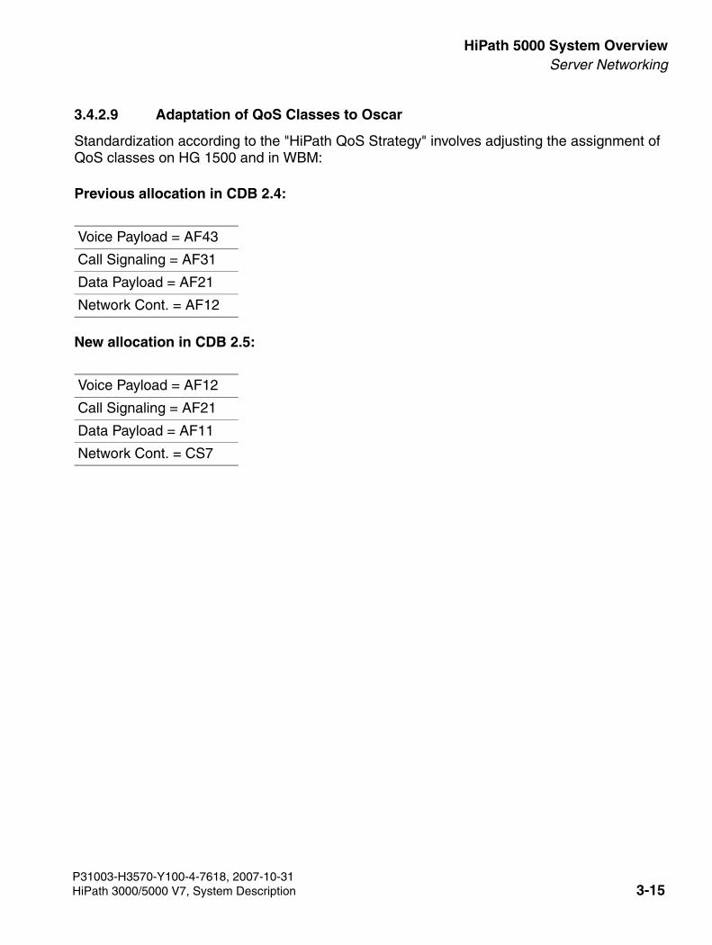
3000sb3.fm
For internal use only HiPath 5000 System OverviewServer Networking
3.4.2.9 Adaptation of QoS Classes to Oscar
Standardization according to the "HiPath QoS Strategy" involves adjusting the assignment of QoS classes on HG 1500 and in WBM:
Previous allocation in CDB 2.4:
New allocation in CDB 2.5:
Voice Payload = AF43
Call Signaling = AF31
Data Payload = AF21
Network Cont. = AF12
Voice Payload = AF12
Call Signaling = AF21
Data Payload = AF11
Network Cont. = CS7
P31003-H3570-Y100-4-7618, 2007-10-31HiPath 3000/5000 V7, System Description 3-15
HiPath 5000 System Overview For internal use only
3000sb3.fm
Server Networking
P31003-H3570-Y100-4-7618, 2007-10-313-16 HiPath 3000/5000 V7, System Description
3000sb4.fm
For internal use only HiPath 3000/5000 in the LAN NetworkNetwork Analysis
4 HiPath 3000/5000 in the LAN Network
4.1 Network Analysis
Several protocols are used in data communications (X.25, Frame Relay, ATM and TCP/IP). The network layer IP (Internet Protocol) forms the key Internet protocol which enables interopera-bility with other networks and protocols such as Ethernet, X.25, Frame Relay and ATM. This is why IP is often used as a synonym for the entire technology. The protocols TCP, UDP and RTP are used for the different applications and requirements in the Internet such as "File Transfer (FTP)", "E-mail (SMTP)" and "WWW". The RTP (Real Time Protocol) is used for transmitting voice data. The term "Voice over IP (VoIP)" describes how the IP protocol is used to transport voice information.
Different protocols already exist which result from various standardization bodies and endeav-ors. The main standards are as follows:
● H.323
● H.450.x
● SIP (Session Initiation Protocol, for Internet conferencing and telephony)
● MGCP (Media Gateway Control Protocol)
Whereas H.323 and H.450 are "real" ITU-T standards, SIP is an "industry (de facto) standard)" from the IETF (Internet Engineering Task Force). MGCP emerged from the SGCP (Simple Gateway Control Protocol) and the IPDC (Internet Protocol Device Control) and has been sub-mitted as a proposal to the ITU-T and the IETF.
SIP is an easy-to-implement standard which was developed to control Internet multimedia con-ferences, particularly to support voice communication.
MGCP describes the connection setup and cleardown of intelligent telephones in networks with packet transmission.
P31003-H3570-Y100-4-7618, 2007-10-31HiPath 3000/5000 V7, System Description 4-1
HiPath 3000/5000 in the LAN Network For internal use only
3000sb4.fm
Network Analysis
4.1.1 Protocols (H.323, CorNet IP)
4.1.1.1 H.323
As a collective term, H.323 comprises the following topics:
● Signaling (H.245, etc.)
● Video transmission
● Voice data transmission/voice compression such as– G.723.1 (5.3/6.3 Kbps)– G.729A (8 Kbps)
● Data applications (application sharing, T.120)
This shows that this standard comprises considerably more than necessary for pure voice data transmission via data networks. H.323 was developed for multimedia applications.
4.1.1.2 SIP (Session Initiation Protocol)
Version 6.0 now permits networking via SIP, which is also supported by HiPath 2000, HiPath 3000/5000, and HiPath 4000 (see Section 1.5.9, “Internet Telephony – ITS Provider Features”). The two main aspects of SIP networking support are:
● supports SIP Q for connecting to SIP-Q-enabled systems and trunks
● supports SIP networking to VoIP trunks and other SIP-enabled systems based on the orig-inal SIP (for example, OpenScape based on Microsoft’s LiveCommunication server and Vovida/Cisco)
4.1.1.3 CorNet IP
IP interworking is based on the CorNet N protocol tunneled within H. 323 Protocol.
Bandwidth requirement
HG 1500 is designed to optimize bandwidth utilization. It implements the following functions for this:
● Silence suppression
● Transmission of background noise during pauses between speech, thereby saving band-width
● Dynamic voice/fax recognition/modem
P31003-H3570-Y100-4-7618, 2007-10-314-2 HiPath 3000/5000 V7, System Description
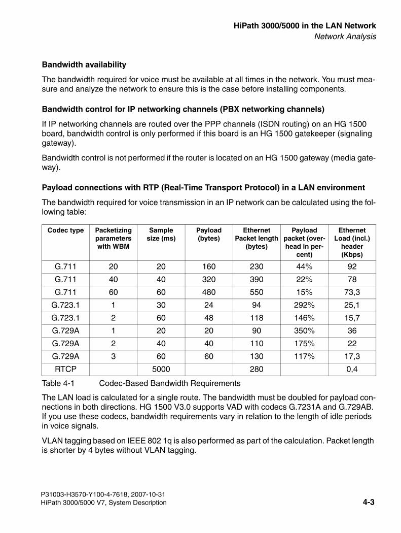
3000sb4.fm
For internal use only HiPath 3000/5000 in the LAN NetworkNetwork Analysis
Bandwidth availability
The bandwidth required for voice must be available at all times in the network. You must mea-sure and analyze the network to ensure this is the case before installing components.
Bandwidth control for IP networking channels (PBX networking channels)
If IP networking channels are routed over the PPP channels (ISDN routing) on an HG 1500 board, bandwidth control is only performed if this board is an HG 1500 gatekeeper (signaling gateway).
Bandwidth control is not performed if the router is located on an HG 1500 gateway (media gate-way).
Payload connections with RTP (Real-Time Transport Protocol) in a LAN environment
The bandwidth required for voice transmission in an IP network can be calculated using the fol-lowing table:
The LAN load is calculated for a single route. The bandwidth must be doubled for payload con-nections in both directions. HG 1500 V3.0 supports VAD with codecs G.7231A and G.729AB. If you use these codecs, bandwidth requirements vary in relation to the length of idle periods in voice signals.
VLAN tagging based on IEEE 802 1q is also performed as part of the calculation. Packet length is shorter by 4 bytes without VLAN tagging.
Codec type Packetizingparameters with WBM
Sample size (ms)
Payload(bytes)
Ethernet Packet length
(bytes)
Payload packet (over-head in per-
cent)
Ethernet Load (incl.)
header(Kbps)
G.711 20 20 160 230 44% 92
G.711 40 40 320 390 22% 78
G.711 60 60 480 550 15% 73,3
G.723.1 1 30 24 94 292% 25,1
G.723.1 2 60 48 118 146% 15,7
G.729A 1 20 20 90 350% 36
G.729A 2 40 40 110 175% 22
G.729A 3 60 60 130 117% 17,3
RTCP 5000 280 0,4
Table 4-1 Codec-Based Bandwidth Requirements
P31003-H3570-Y100-4-7618, 2007-10-31HiPath 3000/5000 V7, System Description 4-3
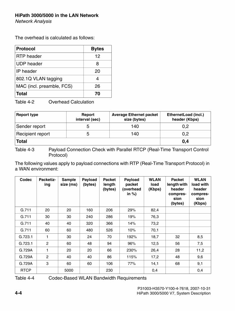
HiPath 3000/5000 in the LAN Network For internal use only
3000sb4.fm
Network Analysis
The overhead is calculated as follows:
The following values apply to payload connections with RTP (Real-Time Transport Protocol) in a WAN environment:
Protocol Bytes
RTP header 12
UDP header 8
IP header 20
802.1Q VLAN tagging 4
MAC (incl. preamble, FCS) 26
Total 70
Table 4-2 Overhead Calculation
Report type Report interval (sec)
Average Ethernet packet size (bytes)
EthernetLoad (incl.)header (Kbps)
Sender report 5 140 0,2
Recipient report 5 140 0,2
Total 0,4
Table 4-3 Payload Connection Check with Parallel RTCP (Real-Time Transport Control Protocol)
Codec Packetiz-ing
Sample size (ms)
Payload(bytes)
Packet length(bytes)
Payload packet
(overhead in %)
WLANload
(Kbps)
Packetlength with
header compres-
sion(bytes)
WLANload with header
compres-sion
(Kbps)
G.711 20 20 160 206 29% 82,4
G.711 30 30 240 286 19% 76,3
G.711 40 40 320 366 14% 73,2
G.711 60 60 480 526 10% 70,1
G.723.1 1 30 24 70 192% 18,7 32 8,5
G.723.1 2 60 48 94 96% 12,5 56 7,5
G.729A 1 20 20 66 230% 26,4 28 11,2
G.729A 2 40 40 86 115% 17,2 48 9,6
G.729A 3 60 60 106 77% 14,1 68 9,1
RTCP 5000 230 0,4 0,4
Table 4-4 Codec-Based WLAN Bandwidth Requirements
P31003-H3570-Y100-4-7618, 2007-10-314-4 HiPath 3000/5000 V7, System Description
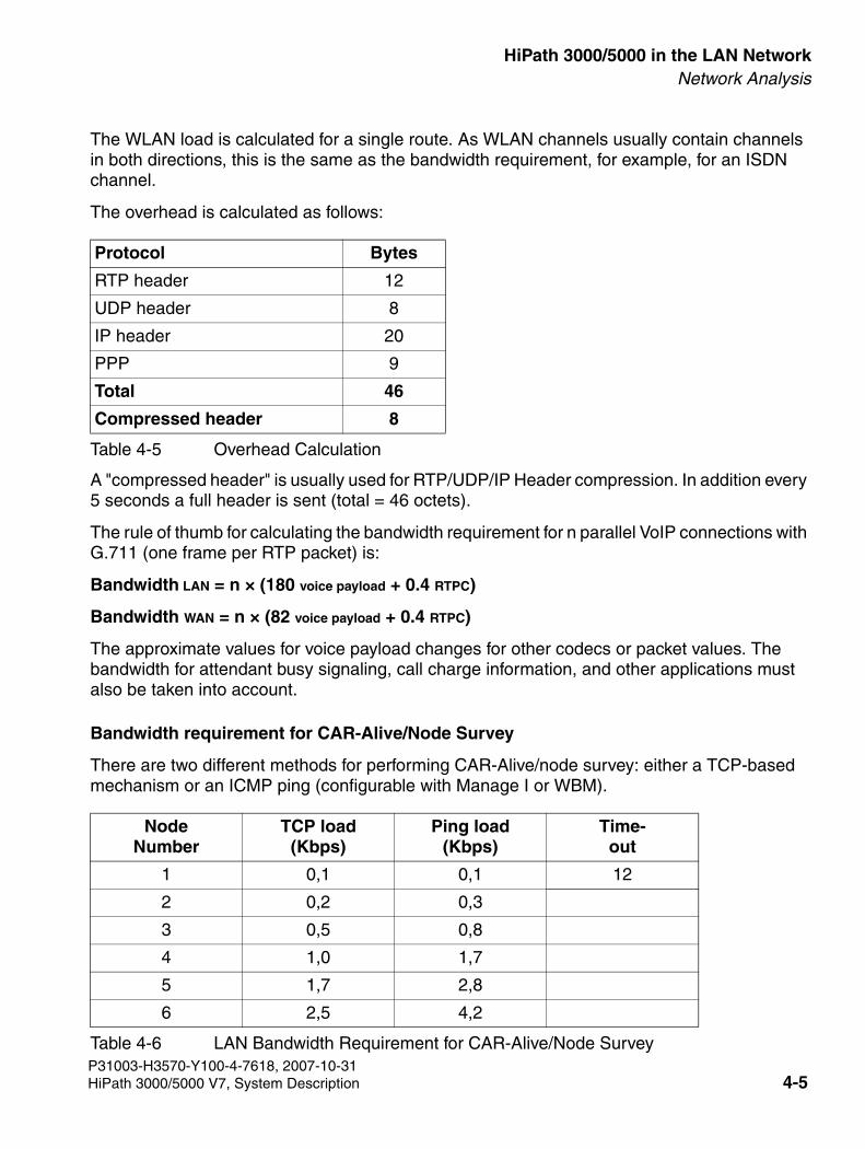
3000sb4.fm
For internal use only HiPath 3000/5000 in the LAN NetworkNetwork Analysis
P31003-H3570-Y100-4-7618, 2007-10-31
The WLAN load is calculated for a single route. As WLAN channels usually contain channels in both directions, this is the same as the bandwidth requirement, for example, for an ISDN channel.
The overhead is calculated as follows:
A "compressed header" is usually used for RTP/UDP/IP Header compression. In addition every 5 seconds a full header is sent (total = 46 octets).
The rule of thumb for calculating the bandwidth requirement for n parallel VoIP connections with G.711 (one frame per RTP packet) is:
Bandwidth LAN = n × (180 voice payload + 0.4 RTPC)
Bandwidth WAN = n × (82 voice payload + 0.4 RTPC)
The approximate values for voice payload changes for other codecs or packet values. The bandwidth for attendant busy signaling, call charge information, and other applications must also be taken into account.
Bandwidth requirement for CAR-Alive/Node Survey
There are two different methods for performing CAR-Alive/node survey: either a TCP-based mechanism or an ICMP ping (configurable with Manage I or WBM).
Protocol Bytes
RTP header 12
UDP header 8
IP header 20
PPP 9
Total 46
Compressed header 8
Table 4-5 Overhead Calculation
Node Number
TCP load(Kbps)
Ping load(Kbps)
Time-out
1 0,1 0,1 12
2 0,2 0,3
3 0,5 0,8
4 1,0 1,7
5 1,7 2,8
6 2,5 4,2
Table 4-6 LAN Bandwidth Requirement for CAR-Alive/Node Survey
HiPath 3000/5000 V7, System Description 4-5
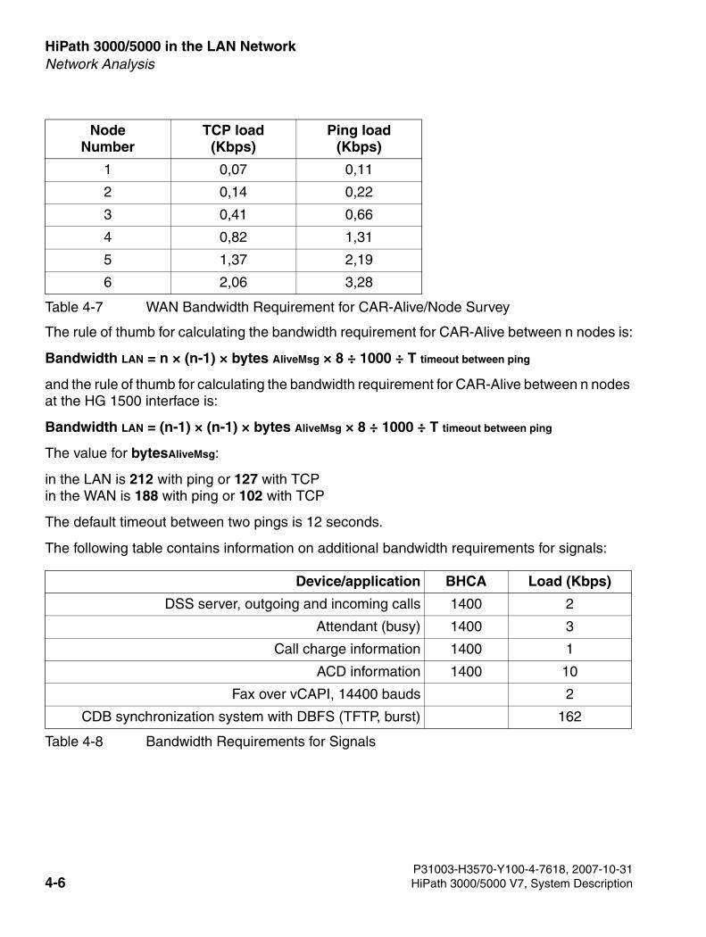
HiPath 3000/5000 in the LAN Network For internal use only
3000sb4.fm
Network Analysis
The rule of thumb for calculating the bandwidth requirement for CAR-Alive between n nodes is:
Bandwidth LAN = n × (n-1) × bytes AliveMsg × 8 ÷ 1000 ÷ T timeout between ping
and the rule of thumb for calculating the bandwidth requirement for CAR-Alive between n nodes at the HG 1500 interface is:
Bandwidth LAN = (n-1) × (n-1) × bytes AliveMsg × 8 ÷ 1000 ÷ T timeout between ping
The value for bytesAliveMsg:
in the LAN is 212 with ping or 127 with TCPin the WAN is 188 with ping or 102 with TCP
The default timeout between two pings is 12 seconds.
The following table contains information on additional bandwidth requirements for signals:
Node Number
TCP load(Kbps)
Ping load(Kbps)
1 0,07 0,11
2 0,14 0,22
3 0,41 0,66
4 0,82 1,31
5 1,37 2,19
6 2,06 3,28
Table 4-7 WAN Bandwidth Requirement for CAR-Alive/Node Survey
Device/application BHCA Load (Kbps)
DSS server, outgoing and incoming calls 1400 2
Attendant (busy) 1400 3
Call charge information 1400 1
ACD information 1400 10
Fax over vCAPI, 14400 bauds 2
CDB synchronization system with DBFS (TFTP, burst) 162
Table 4-8 Bandwidth Requirements for Signals
P31003-H3570-Y100-4-7618, 2007-10-314-6 HiPath 3000/5000 V7, System Description
3000sb4.fm
For internal use only HiPath 3000/5000 in the LAN NetworkQoS - Quality of Service
4.2 QoS - Quality of Service
4.2.1 Goals of QoS
4.2.2 QoS in the Router?
● QoS functions control router priorities and timing.
● Router queues are optimized for routing and are not suitable for QoS monitoring of voice transmission
● Fragmentation (if used) takes time and thereby increases the risk of packet loss
● Time-controlled hierarchical policies not available
● No feedback due to insufficient monitoring
● Architecture not suitable for specialized VoIP control functions
Subject Cross Reference
Goals of QoS Section 4.2.1 on page 4-7
QoS in the Router? Section 4.2.2 on page 4-7
Problems: ● IP does not guarantee any bandwidths● QoS is not part of H.323
Consequences ● Time problems due to large E-mail attachments and web surfing● Network congestion due to multiple requests for the same web page● Reduced voice quality due to
– Delay– Jitter– Packet loss
Goals: ● QoS is required in the WAN/LAN for– Optimum voice quality for every connection– Fewer interruptions
P31003-H3570-Y100-4-7618, 2007-10-31HiPath 3000/5000 V7, System Description 4-7
HiPath 3000/5000 in the LAN Network For internal use only
3000sb4.fm
HiPath’s Network Analysis Service
4.3 HiPath’s Network Analysis Service
Product Description
Network analysis examines whether the customer’s communications network is able to support Siemens Business over IP solutions. The assessment is carried out on the basis of product-specific parameters. The customer receives a final report which documents not only the net-work structure but also operative parameters (capacity, delay, jitter).
Customer Benefits and Profitability
● Preparation of the network for future applications (VoIP)● Determination of current traffic flows and volumes, baselining● Support in decision-making process when introducing VoIP solutions
Technical Specifications
Network Analysis features specification
● Inspection of customer networks to determine suitability for Siemens Voice over IP solu-tions
● Recording of the relevant parameters over a defined period.● Assessment based on product specifications● Interpretation of the recorded results with suggestions for further measures● Final report with recommendations
Configuration Instructions
Used for the development of Siemens VoIP solutions
Use only possible in SNMP-based IP data networks (router, IP switches, hubs)
Positioning within the Product Range
HiPath services
P31003-H3570-Y100-4-7618, 2007-10-314-8 HiPath 3000/5000 V7, System Description
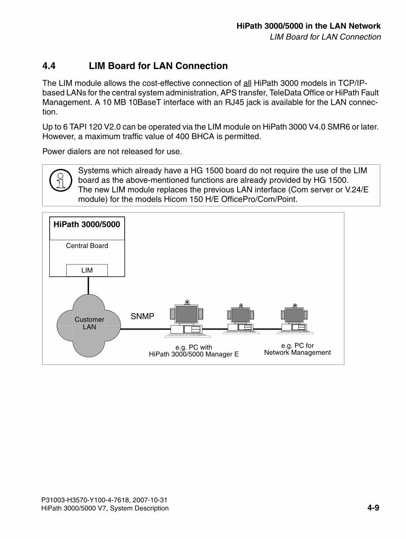
3000sb4.fm
For internal use only HiPath 3000/5000 in the LAN NetworkLIM Board for LAN Connection
4.4 LIM Board for LAN Connection
The LIM module allows the cost-effective connection of all HiPath 3000 models in TCP/IP-based LANs for the central system administration, APS transfer, TeleData Office or HiPath Fault Management. A 10 MB 10BaseT interface with an RJ45 jack is available for the LAN connec-tion.
Up to 6 TAPI 120 V2.0 can be operated via the LIM module on HiPath 3000 V4.0 SMR6 or later. However, a maximum traffic value of 400 BHCA is permitted.
Power dialers are not released for use.
>Systems which already have a HG 1500 board do not require the use of the LIM board as the above-mentioned functions are already provided by HG 1500.The new LIM module replaces the previous LAN interface (Com server or V.24/E module) for the models Hicom 150 H/E OfficePro/Com/Point.
HiPath 3000/5000
e.g. PC withHiPath 3000/5000 Manager E
Central Board
LIM
CustomerLAN
e.g. PC forNetwork Management
SNMP
P31003-H3570-Y100-4-7618, 2007-10-31HiPath 3000/5000 V7, System Description 4-9
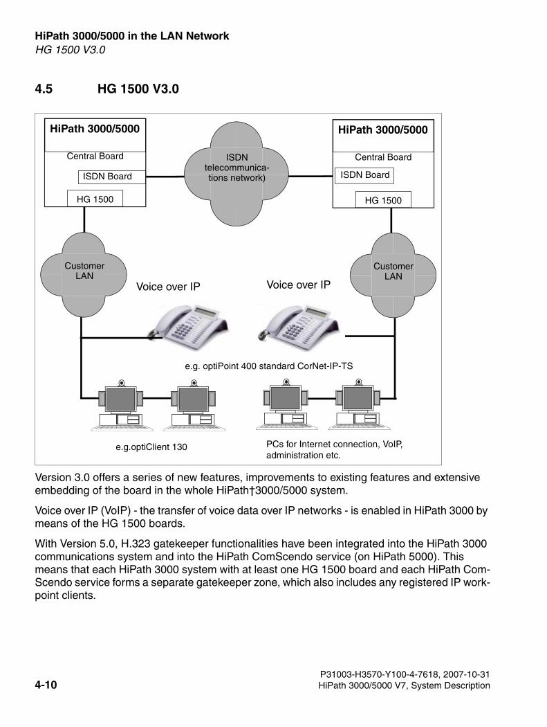
HiPath 3000/5000 in the LAN Network For internal use only
3000sb4.fm
HG 1500 V3.0
4.5 HG 1500 V3.0
Version 3.0 offers a series of new features, improvements to existing features and extensive embedding of the board in the whole HiPath†3000/5000 system.
Voice over IP (VoIP) - the transfer of voice data over IP networks - is enabled in HiPath 3000 by means of the HG 1500 boards.
With Version 5.0, H.323 gatekeeper functionalities have been integrated into the HiPath 3000 communications system and into the HiPath ComScendo service (on HiPath 5000). This means that each HiPath 3000 system with at least one HG 1500 board and each HiPath Com-Scendo service forms a separate gatekeeper zone, which also includes any registered IP work-point clients.
HiPath 3000/5000
Central Board
ISDN Board
HG 1500
CustomerLAN
ISDNtelecommunica-tions network)
HiPath 3000/5000
Central Board
HG 1500
CustomerLAN
ISDN Board
Voice over IP Voice over IP
e.g.optiClient 130 PCs for Internet connection, VoIP,administration etc.
e.g. optiPoint 400 standard CorNet-IP-TS
P31003-H3570-Y100-4-7618, 2007-10-314-10 HiPath 3000/5000 V7, System Description
3000sb4.fm
For internal use only HiPath 3000/5000 in the LAN NetworkHG 1500 V3.0
The H.323 communication between networked HiPath 3000 systems (nodes) must be consid-ered as gatekeeper to gatekeeper communication. Registration between HG 1500 modules of networked systems is not performed. The CorNet-NQ protocol, tunnelled in H.323 via annex M1 is used.
The splitting of HG 1500 resources into signaling and payload resources is an important feature of Version 6.0.
Signaling resources
This includes all node signaling data necessary for Voice over IP for IP-supported (LAN, intra-net, Internet) and line-switched networks (ISDN, PSTN). These resources are centrally provid-ed by a single HG 1500 board, the signaling gateway (= Gatekeeper HG 1500), regardless of how many HG 1500 boards are available at the node. A HG 1500 board is defined as a gate-keeper HG 1500 using HiPath 3000 Manager E.
Payload resources
The node resources required for transferring VoIP voice data (payload) between IP-supported and circuit-switched networks are provided by the media gateway. One or more HG 1500 boards may be used.
Payload resources are not necessary for direct transmission between IP-supported networks.
In the case of systems with only one HG 1500 board, this board operates both as a signaling gateway and as a media gateway when configured appropriately by HiPath 3000 Manager E.
In the case of systems with more than one HG 1500 board, payload resources are monitored by the node-central resource manager. This is a self-configuring service. Signaling resources are centrally provided by the first HG 1500 board. This signaling gateway also accesses other media gateway resources (codecs, B channels) and signaling data (for example RTP, RTCP). This gives IP workpoint clients and other gateways access to central payload resources of all HG 1500 boards in a node.
Resources for functions which are not based on H.323 (for example, routing channels, vCAPI channels), are provided as before by each HG 1500 board. In systems with several HG 1500 boards, resources are provided exclusively by media gateways for performance reasons.
P31003-H3570-Y100-4-7618, 2007-10-31HiPath 3000/5000 V7, System Description 4-11
HiPath 3000/5000 in the LAN Network For internal use only
3000sb4.fm
HG 1500 V3.0
New features of the HG 1500 V3.0
● Transparent B channel for ISDN B channel protocols
● Flexible port number administration
● Dynamic jitter buffer
● SNTP functionality in the LAN
● Read rights to dynamic parameters of HiPath3000 manager in WBM
● Improved firewall function (stateful inspection, DoS, application level gateways)
● T.38 fax protocol standard support
● Support for HFA workpoints such as optiPoint410 standard or optiPoint600 office
● Logging of QoS data (Quality of Service)
● Licensing system as for HiPath 3000/5000
● Improved software management
● Cooperation with HiPath 4000 V2.0, for example, DMC (Direct Media Connection)
● Full VPN support (Virtual Private Network)
● HG†1500†V3.0 as module of a PCS (PC-based communication server)
● STMI2 board with 32 B channels onboard, expandable to 64 channels
DMC
This flag enables or disables the feature "DMC Interworking with HiPath 4000 Systems" (in short "DMC"). In a network with HiPath 4000, DMC enhances the voice quality between IP com-ponents (endpoints, gateways).
DMC is only supported by the CorNet-NQ/CorNet-IP networking protocol.
DMC should be disabled in a homogeneous HiPath 3000/5000 network. If a network with Hi-Path 4000 systems (version 2.0 or later) exists in which DMC is configured, the DMC feature should be enabled in the HiPath 3000/5000 systems.
The HFA endpoints (optiPoint/optiClient) registered at the HiPath 3000/5000 system and the HiPath 3000 system itself are then in a position to accept DMC connections set up by the Hi-Path 4000 and its HFA endpoints. Even if the DMC feature is enabled, DMC is not performed between HiPath 3000/5000 systems.
If DMC is enabled, the percentage of available DSP channel resources decreases. In other words, in a HiPath 3000 system only 80% of the channels provided for each DSP are available for connections (for example, 6 channels instead of 8, 12 channels instead of 16, 48 channels instead of 60).
P31003-H3570-Y100-4-7618, 2007-10-314-12 HiPath 3000/5000 V7, System Description
3000sb4.fm
For internal use only HiPath 3000/5000 in the LAN NetworkHG 1500 V3.0
Hardware notes
HG 1500 is:
● the HXGS3 board in HiPath 3550 and HiPath 3350
● the HXGR3 board in HiPath 3500 and HiPath 3300
The power supply comes from the system.
System requirements
● HiPath 3000/5000 or later
● At least one Euro ISDN basic connection (connection to the network or another HiPath system)
● At least one free slot in the basic system
System environment
● Shared/switched LAN 10/1000 Base T
● Client/server and peer-to-peer networks with TCP/IP protocol
P31003-H3570-Y100-4-7618, 2007-10-31HiPath 3000/5000 V7, System Description 4-13
HiPath 3000/5000 in the LAN Network For internal use only
3000sb4.fm
HG 1500 V3.0
4.5.1 Protocols
This section contains an overview of H.323 standards regarding signaling and media protocol that are relevant to HG 1500 V3.0.
H.225.0 Q.931 Call Setup
This protocol defines signaling between two endpoints for call setup and cleardown.
H.225.0 RAS Control
RAS (Registration, Admission and Status) defines signaling between client and gatekeeper for detection and registration purposes.
H.245 Signaling
This protocol defines the declaration of capabilities and exchange of control messages be-tween endpoints. It is used for specifying channel usage and functions.
H.323
This is a standard for packet-oriented multimedia communication systems and was developed by the ITU (International Telecommunication Union. HG 1500 V3.0 uses H.323 V4.0 but can also communicate with earlier versions of the H.323 protocol (backward compatibility is guar-anteed).
Fast Connect (fast start) is supported. The Fast Connect feature lets HG 1500 V3.0 set up a multimedia channel without waiting for an H.245 connection.
RTP and RTCP
RTP (Real-time Transport Protocol) manages the transfer of real-time packets from an end-point to one or more endpoints.
A header containing a time stamp and a sequence number is added to every UDP packet. With appropriate buffering at the receiving station, timing and sequence information enables the ap-plication to:
● eliminate double packets,
● rearrange nonsequential packets,
● synchronize data,
● achieve continuous playback despite varying latencies.
P31003-H3570-Y100-4-7618, 2007-10-314-14 HiPath 3000/5000 V7, System Description
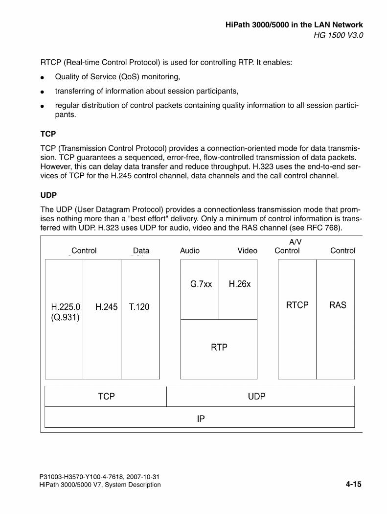
3000sb4.fm
For internal use only HiPath 3000/5000 in the LAN NetworkHG 1500 V3.0
RTCP (Real-time Control Protocol) is used for controlling RTP. It enables:
● Quality of Service (QoS) monitoring,
● transferring of information about session participants,
● regular distribution of control packets containing quality information to all session partici-pants.
TCP
TCP (Transmission Control Protocol) provides a connection-oriented mode for data transmis-sion. TCP guarantees a sequenced, error-free, flow-controlled transmission of data packets. However, this can delay data transfer and reduce throughput. H.323 uses the end-to-end ser-vices of TCP for the H.245 control channel, data channels and the call control channel.
UDP
The UDP (User Datagram Protocol) provides a connectionless transmission mode that prom-ises nothing more than a "best effort" delivery. Only a minimum of control information is trans-ferred with UDP. H.323 uses UDP for audio, video and the RAS channel (see RFC 768).
Control Control ControlData Audio VideoA/V
P31003-H3570-Y100-4-7618, 2007-10-31HiPath 3000/5000 V7, System Description 4-15
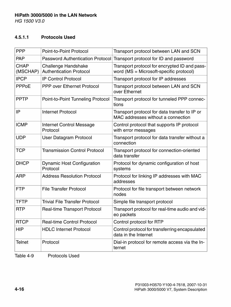
HiPath 3000/5000 in the LAN Network For internal use only
3000sb4.fm
HG 1500 V3.0
4.5.1.1 Protocols Used
PPP Point-to-Point Protocol Transport protocol between LAN and SCN
PAP Password Authentication Protocol Transport protocol for ID and password
CHAP(MSCHAP)
Challenge Handshake Authentication Protocol
Transport protocol for encrypted ID and pass-word (MS = Microsoft-specific protocol)
IPCP IP Control Protocol Transport protocol for IP addresses
PPPoE PPP over Ethernet Protocol Transport protocol between LAN and SCN over Ethernet
PPTP Point-to-Point Tunneling Protocol Transport protocol for tunneled PPP connec-tions
IP Internet Protocol Transport protocol for data transfer to IP or MAC addresses without a connection
ICMP Internet Control Message Protocol
Control protocol that supports IP protocol with error messages
UDP User Datagram Protocol Transport protocol for data transfer without a connection
TCP Transmission Control Protocol Transport protocol for connection-oriented data transfer
DHCP Dynamic Host Configuration Protocol
Protocol for dynamic configuration of host systems
ARP Address Resolution Protocol Protocol for linking IP addresses with MAC addresses
FTP File Transfer Protocol Protocol for file transport between network nodes
TFTP Trivial File Transfer Protocol Simple file transport protocol
RTP Real-time Transport Protocol Transport protocol for real-time audio and vid-eo packets
RTCP Real-time Control Protocol Control protocol for RTP
HIP HDLC Internet Protocol Control protocol for transferring encapsulated data in the Internet
Telnet Protocol Dial-in protocol for remote access via the In-ternet
Table 4-9 Protocols Used
P31003-H3570-Y100-4-7618, 2007-10-314-16 HiPath 3000/5000 V7, System Description
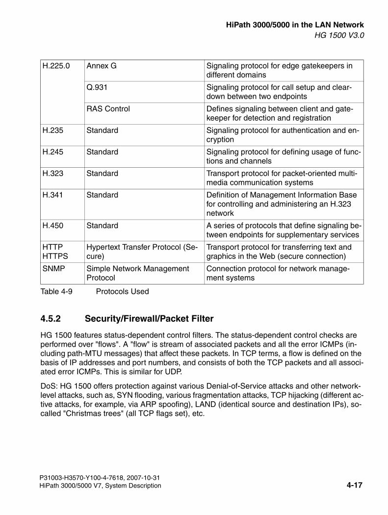
3000sb4.fm
For internal use only HiPath 3000/5000 in the LAN NetworkHG 1500 V3.0
4.5.2 Security/Firewall/Packet Filter
HG 1500 features status-dependent control filters. The status-dependent control checks are performed over "flows". A "flow" is stream of associated packets and all the error ICMPs (in-cluding path-MTU messages) that affect these packets. In TCP terms, a flow is defined on the basis of IP addresses and port numbers, and consists of both the TCP packets and all associ-ated error ICMPs. This is similar for UDP.
DoS: HG 1500 offers protection against various Denial-of-Service attacks and other network-level attacks, such as, SYN flooding, various fragmentation attacks, TCP hijacking (different ac-tive attacks, for example, via ARP spoofing), LAND (identical source and destination IPs), so-called "Christmas trees" (all TCP flags set), etc.
H.225.0 Annex G Signaling protocol for edge gatekeepers in different domains
Q.931 Signaling protocol for call setup and clear-down between two endpoints
RAS Control Defines signaling between client and gate-keeper for detection and registration
H.235 Standard Signaling protocol for authentication and en-cryption
H.245 Standard Signaling protocol for defining usage of func-tions and channels
H.323 Standard Transport protocol for packet-oriented multi-media communication systems
H.341 Standard Definition of Management Information Base for controlling and administering an H.323 network
H.450 Standard A series of protocols that define signaling be-tween endpoints for supplementary services
HTTPHTTPS
Hypertext Transfer Protocol (Se-cure)
Transport protocol for transferring text and graphics in the Web (secure connection)
SNMP Simple Network Management Protocol
Connection protocol for network manage-ment systems
Table 4-9 Protocols Used
P31003-H3570-Y100-4-7618, 2007-10-31HiPath 3000/5000 V7, System Description 4-17
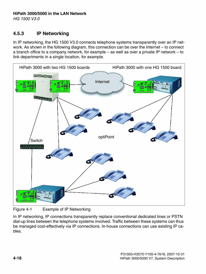
HiPath 3000/5000 in the LAN Network For internal use only
3000sb4.fm
HG 1500 V3.0
4.5.3 IP Networking
In IP networking, the HG 1500 V3.0 connects telephone systems transparently over an IP net-work. As shown in the following diagram, this connection can be over the Internet – to connect a branch office to a company network, for example – as well as over a private IP network – to link departments in a single location, for example.
In IP networking, IP connections transparently replace conventional dedicated lines or PSTN dial-up lines between the telephone systems involved. Traffic between these systems can thus be managed cost-effectively via IP connections. In-house connections can use existing IP ca-bles.
Figure 4-1 Example of IP Networking
optiPointSwitch
HiPath 3000 with one HG 1500 boardHiPath 3000 with two HG 1500 boards
Internet
P31003-H3570-Y100-4-7618, 2007-10-314-18 HiPath 3000/5000 V7, System Description
3000sb4.fm
For internal use only HiPath 3000/5000 in the LAN NetworkHG 1500 V3.0
4.5.3.1 IP Networking
In combination with HG 1500 V3.0, HiPath AllServe integrates the connected nodes – HiPath 3000 systems with one or more HG 1500 V3.0s – to form a transparent, integrated communi-cations system. All the networked nodes, whether connected locally or via the Internet, behave like a single, complete system with closed numbering.
The majority of HiPath AllServe functions are available system-wide on all components con-nected via IP networking. The following list shows the main functions.
● Central attendant console
A specific system terminal (subscriber) can be configured as an attendant or intercept po-sition. Any incoming call to the system will arrive here automatically if no subscriber can be assigned to it, although the call may originally have come in on any one of the nodes con-nected via IP networking.
The central attendant console can then forward these calls to the required subscriber. Again, it is not important to which node in the HiPath AllServe this subscriber is connected.
Once the attendant queue reaches a predefined length, calls can be automatically forward-ed to an overflow destination.
Cross-node busy signaling is available when using optiClient Attendant.
● Virtual ports
Virtual ports are used for the signaling of statuses and calls on all systems. They are not linked to physical terminal interfaces. The corresponding boards must not be inserted. Vir-tual ports have their own internal and external phone numbers and can therefore be called. They can be programmed for signaling on DSS keys and be added to call pickup groups.
● DISA Internal (Direct Inward System Access Internal)
Using DISA internal (not to be confused with DISA external) enables a subscriber in a Hi-Path AllServe node to activate specific features in a different node:
● Release of the door opener using the relay option
● Follow me
● Relay on/off
● Night service
● Disconnecting from a hunt group/group call
● System Speed Dialing
The local speed dialing directories of all nodes are updated using a redundant central speed dialing directory on the HiPath AllServe server. This provides all IP telephones con-nected to the HG 1500 V3.0 with the same speed dialing as SCN telephones.
P31003-H3570-Y100-4-7618, 2007-10-31HiPath 3000/5000 V7, System Description 4-19
HiPath 3000/5000 in the LAN Network For internal use only
3000sb4.fm
HG 1500 V3.0
● CO Call Privileges and Toll Restriction
The CO call privileges configured for each HiPath AllServe node are handed over as before in converted form via CorNet-N. The allowed numbers and denied numbers lists for a sub-scriber can only be analyzed in the HiPath AllServe node in which the subscriber is config-ured. The dial plan can be used to specify where the toll restriction is to be executed. Please note that in this process all allowed numbers and denied numbers lists are mapped to "Can access local public network". This in turn is mapped to denied numbers list 1 in a subsequent node. Consequently, it is possible that in a subsequent node a toll restriction with denied numbers list 1 will be set up again or added.
● Least Cost Routing (LCR)
In a HiPath AllServe environment, LCR is possible via CO trunks as well as IP connections. The dial plans for single HiPath AllServe nodes can be configured separately. If so config-ured, "Fallback to SCN" function can be used to forward a call automatically to an SCN con-nection if the IP connection fails.
When an external call is forwarded to another node (transit break-in), the caller’s number is converted automatically to the international format.
In a HiPath AllServe environment, the previously used route codes are replaced by port numbers. This type of configuration is better suited for a LAN environment.
● Music on Hold (MOH)
In a HiPath server node, a PCM/IOM channel can be permanently connected to MOH. This channel is permanently connected to a DSP channel that forwards MOH unidirectionally to one or more IP clients or other HG 1500 boards. MOH for IP clients always requires only one DSP channel. (Normal clients cannot benefit from this; for MOH, they require an addi-tional a PCM/IOM and a DSP channel respectively.)
The channel for MOH is automatically assigned by the system.
● Direct Station Select (DSS) and Busy Lamp Field (BLF)
In HiPath AllServe versions 3.0 and later, the DSS function – signaling the switching states of subscribers – is available at all terminals in the system, even those on other nodes, through the HiPath AllServe server. This provides a system-wide call pickup solution, and is completely transparent to the terminal user programming the DSS keys.
● CorNet IP
HiPath AllServe supports the CorNet IP protocol, which is used for tunneling CorNet fea-tures by IP. This makes the functional scope of the CorNet protocol available to IP terminals as well. More information about these functions can be found in the "HiPath 5000 RSM System Description" manual in chapter 3, "Features".
P31003-H3570-Y100-4-7618, 2007-10-314-20 HiPath 3000/5000 V7, System Description
3000sb4.fm
For internal use only HiPath 3000/5000 in the LAN NetworkHG 1500 V3.0
4.5.4 Voice over IP (VoIP)
Voice over IP (VoIP) enables voice data to be transmitted over an IP network, both internally and via the Internet.
Voice over IP (VoIP) is an outstanding feature of HG 1500 V3.0. In combination with the clients connected to the LAN, the board makes it possible to use not only VoIP but also the telephony features of the system. In particular, this feature can be used for teleworking. This means that full Voice over IP functionality is available at the teleworking PC. H.323 clients (for example Net-Meeting) can also be used.
As of the HiPath 3000 V3.0 software version in combination with new boards (HXGS3, HXGM3, HXGR3), login is no longer performed under "Voice Gateway" in HiPath 3000 Manag-er I but in HiPath 3000 Manager E.
The following combinations of VoIP connections via the HG 1500 V3.0 are possible:
● IP to IP, for example, subscriber C to subscriber D or subscriber D to subscriber F.
● IP to local SCN, for example, subscriber D to subscriber B.
● Local SCN to IP, for example, subscriber B to subscriber C.
● IP to PSTN, for example, subscriber C to subscriber E.
● PSTN to IP, for example, subscriber E to subscriber D.
Interworking is fully supported.
With the exception of IP to IP connections, one DSP channel per connection is required for each HG 1500 V3.0 involved. Conferencing requires one DSP channel for each SCN subscrib-er.
This can lead to significant call charge savings if an appropriate IP network is available. The user can also avail of telephony features, such as name transmission and callback, in the usual way.
The hardware prerequisite for IP networking is that the systems involved must have at least one of the following HG 1500 V3.0 boards:
>Internet telephony features are described in detail in the feature description.
>In IP networking, SCN to SCN connections (local or PST) also can be run transpar-ently via the HG 1500 V3.0. This is described in Section 4.5.3, "IP Networking".
P31003-H3570-Y100-4-7618, 2007-10-31HiPath 3000/5000 V7, System Description 4-21
HiPath 3000/5000 in the LAN Network For internal use only
3000sb4.fm
HG 1500 V3.0
● HXGM: Up to eight boards can be installed in an HiPath 3700/3750. With two PDM1 ex-pansion modules, each HXGM offers up to 32 IP channels for voice connections (Voice over IP).
● HXGS (wall housing) or HXGR (19" housing): Up to four boards can be installed in HiPath 3500/3550 and up to two in HiPath 3300/3350. Both boards can process up to 16 IP chan-nels for voice connections with a single PDM1 expansion module.
The IP networked systems and the HG 1500 V3.0 boards are administered with two different tools:
● HiPath 3000 Manager E: Extending the existing HiPath 3000 customer database to include information for IP networking.
● HG 1500 V3.0 WBM: Performing HG 1500 V3.0 board settings.
4.5.4.1 General Parameters for Voice over IP
Before configuring system clients and H.323 clients, you must configure the valid parameters for both variants in HiPath 3000 Manager E:
● Echo:You can define here how to compensate for the echoes that occur in connections to con-ventional telephones via the voice gateway.
● Traffic statistics:This is where you define whether to record traffic statistics which can then be queried via SNMP.
● Encoding:This parameter is used to select which voice coding will be implemented.
4.5.4.2 Voice Coding
HiPath 3000/5000 supports voice compression according to the G.729 and G723.1 standards. G.723.1 facilitates the use of teleworking via ISDN for example, and reduces the load on the existing data network. G.723.1 reduces the VoIP bandwidth requirement for voice communica-tion. This enables a bidirectional voice connection via an ISDN B channel. This, in turn, facili-tates the connection of teleworkstations or branch offices to the company network via a 64 KB connection. However, it is not advisable to operate other applications (such as Application Sharing, File Transfer) in addition to a bidirectional VoIP connection simultaneously via 64 Kbps since this generally leads to a deterioration in voice quality. It is recommended that both B chan-nels of an S0 connection are used for this purpose.
>The IP address used for IP networking is always that of the first LAN interface. If IP networking is routed via another interface, such as LAN2, use IP routing entries to ensure that the LAN1 interface can be reached.
P31003-H3570-Y100-4-7618, 2007-10-314-22 HiPath 3000/5000 V7, System Description
3000sb4.fm
For internal use only HiPath 3000/5000 in the LAN NetworkHG 1500 V3.0
The HG 1500 V3.0 supports codecs for compression and decompression of voice signals in ac-cordance with industry standards G.711 A-law, G.711 µ-law, G.723, G.729A and G.729AB. The codecs can be arranged according to their priority. The gateway automatically attempts to use a codec with the highest possible priority for each connection.
The HG 1500 V3.0 supports the following codecs:
● G.711 (A-law and µ-law) voice coding – an ITU (International Telecommunication Union) standard for voice coding at 56 or 64 Kbps
● G.723.1 voice compression – an ITU standard for voice coding at 5.3 or 6.4 Kbps
● G.729A and G.729AB voice compression – an ITU standard for voice coding at 8 Kbps
4.5.4.3 DTMF Handling
DTMF (Dual-Tone Multifrequency) is the type of audio signal used for tone dialing in accor-dance with ITU-T standard Q.24. It can be used for call setup and for signaling during a call.
HG 1500 V3.0 supports the detection and processing of DTMF (Dual Tone Multi Frequency) signals in accordance with Q.24 regarding signaling for VoIP calls. In particular, it supports the following functions:
● Detection of DTMF signals
● Conversion of DTMF signals into user input signals in accordance with H.245
● Generation of DTMF signals for PSTN
● Speech protection using Bellcore test tapes
● Sending and receiving DTMF signals via vCAPI
4.5.4.4 Voice Quality
Various HG 1500 V3.0 functions ensure optimum voice quality during VoIP connections. Fur-ther details are described below.
Quality of Service (QoS)
QoS enables voice packets to be given higher priority than other packets in the IP network so that voice quality is influenced as little as possible by other data traffic.
To ensure the best possible quality especially for voice connections, the HG 1500 V3.0 sup-ports various QoS protocols:
● IEEE802.1p tags (layer 2)
● Type of Service (ToS) prioritization (RFC 791, layer 3)
P31003-H3570-Y100-4-7618, 2007-10-31HiPath 3000/5000 V7, System Description 4-23
HiPath 3000/5000 in the LAN Network For internal use only
3000sb4.fm
HG 1500 V3.0
● Differentiated Services (DiffServ; RFC 2474, layer 3)
The gateway observes these standards for routed packets and makes them available for appli-cations on the gateway, such as vCAPI.
Echo suppression
The HG 1500 V3.0 supports echo suppression in accordance with G.168 to ensure acceptable voice quality in the WAN. Echo suppression is effective for round trip delays of up to 48 msec.
Dynamic jitter buffer
The dynamic jitter buffer eliminates the distortion caused by fluctuations in the arrival of voice and video packets. Individual packet delays can be a result of network overload or internal pro-cessing within the LAN endpoints.
The HG 1500 V3.0 jitter buffer can be configured for the connection requirements of a specific network.
Voice Activity Detection
VAD (Voice Activity Detection) checks all incoming signals for voice signals. If a signal exceeds a preset level, the VAD recognizes it as voice and anything under that level as silence.
The HG 1500 V3.0 provides VAD and silence suppression for all supported codecs. When no voice signal is detected, a background noise is inserted at each end of the line to emulate tra-ditional telephone line conditions.
P31003-H3570-Y100-4-7618, 2007-10-314-24 HiPath 3000/5000 V7, System Description
3000sb4.fm
For internal use only HiPath 3000/5000 in the LAN NetworkHG 1500 V3.0
4.5.4.5 Environmental Requirements for VoIP
To ensure voice transfer quality and avoid unacceptable delays, the networks being used must meet certain requirements.
Environmental Requirements in the LAN
LANs used for VoIP must meet the following specifications:
● At least 256 Kbps transmission capacity per networked unit
● Not more than 50 msec delay in one direction (One Way Delay) Not more than 150 msec total delay
● Not more than 1% packet loss
● QoS support – IEEE 802.1p, DiffServ (RFC 2474) or ToS (RFC 791)
● Every HG 1500 V3.0 must be connected via a switch or a dedicated port of a router.
● It is recommended that the VoIP application be connected via a separate VLAN to reduce collisions with other transmissions. If all involved devices support VLAN (in accordance with IEEE 802.1q), all VoIP traffic can be placed in a separate VLAN. For administration access in this case, LAN switches must provide individual computers with access to multi-ple VLAN segments.
● Not more than 20% of the available bandwidth should be used.
● Not more than 10% of the total data traffic should be broadcast packets.
● The error rate should not amount to more than 1% of data traffic and should not tend to increase.
Environmental Requirements in the WAN
LANs that are linked over WANs and share the same VoIP functionality must meet the following minimum requirements:
● Each LAN must each be connected to the Internet via xDSL with a fixed IP address.
● QoS support – IEEE 802.1p, DiffServ (RFC 2474) or ToS (RFC 791) – over the entire con-nection
● The bandwidth required for the calls must always be available in both directions, to the net-work and to the user.
● Not more than 50 msec delay in one direction (One Way Delay) Not more than 150 msec total delay
● Not more than 3% packet loss
● Not more than 3% error rate
P31003-H3570-Y100-4-7618, 2007-10-31HiPath 3000/5000 V7, System Description 4-25
HiPath 3000/5000 in the LAN Network For internal use only
3000sb4.fm
HG 1500 V3.0
● Not more than 10% jitter
● As little broadcast and multicast traffic in the network as possible. If necessary this can be achieved by structuring the network – using VPN, for instance – with Layer 3 switches and routers, or with Layer 2 switches that recognize multicasting.
● Not more than 40% network load (without VoIP traffic)
● Less than 40 broadcast packets per second if possible
Environmental requirements for fax/modem over G.711
Fax/modem over G.711 can be enabled if the IP network satisfies the following requirements:
If the above values are not observed in the IP network, the fax or modem transmission may be interrupted.
Value Time
Jitter <= 20 msec
Delay (one way) <= 50 msec
Delay (round trip) <= 100 msec
Packet drop <= 0.05%
Table 4-10 Prerequisites for Modem over G.711
P31003-H3570-Y100-4-7618, 2007-10-314-26 HiPath 3000/5000 V7, System Description
3000sb4.fm
For internal use only HiPath 3000/5000 in the LAN NetworkHG 1500 V3.0
4.5.5 Fax over IP with HG 1500 V3.0
Fax over IP guarantees the compatibility of traditional analog fax devices in IP telephony net-works. The following scenarios must be taken into account when using the real-time communi-cation system HiPath 3000 with the HG 1500 V3.0 board.
For Fax over IP the IP network must meet certain quality criteria that are determined in the net-work analysis as otherwise interruptions can occur in the fax transmission. Otherwise the con-nection and marketing of separate trunk lines should be provided for each node.
In general, an IP trunking network is when two or more HiPath 3000 systems are networked to each other over the integrated HG 1500 V3.0 board. The HG 1500 V3.0 board supports two functions for transferring the fax information.
● Fax over G.711 ("IP/IP e2e payload via enterprise proxy" connection)
The advantage of E.711 is that (unlike T.38) high speed faxes (in other words faxes with a transmission rate > 14400 bps) can also use this higher transmission rate on a good net-work, while high speed faxes must be slowed down to a speed of 14400 bps when T.38 is used.
● T.38
T.38 is an ITU standard that describes how two fax machines communicate over IP. This standard refers to a real-time transmission of fax documents because the formats for trans-mitting the signalling and user data between two gateways are described here. The image data (T.4 or T.6 format) and control messages (T.30 format) are packed in spe-cial T.38 messages and sent via the IP network. The packets are either used with TCP (Transmission Control Protocol) or UDP (User Datagram Protocol).
The advantage of T.38 is that it is more resistant to packet loss and jitter in less than perfect network conditions. For more information, refer to the service manual.
The functions were tested on the following devices:
– Siemens HF2323
– Siemens Fax 790
– Canon Fax B155,
– Hewlett-Packard OfficeJet Model 635,
– OKI OKIFAX 4580,
– OKI OKIFAX 4550,
>At present HG 1500 V3.0 only permits transmission with UDP and not with TCP.
P31003-H3570-Y100-4-7618, 2007-10-31HiPath 3000/5000 V7, System Description 4-27
HiPath 3000/5000 in the LAN Network For internal use only
3000sb4.fm
HG 1500 V3.0
– Samsung SF-350,
– Philips magic 2 primo
UDP
This protocol is an non-secure connection. IP packets are sent without knowing whether they are received. Thus, this procedure has a number of disadvantages. If you are not sure that the information has been received, then greater effort is required to secure this infor-mation.
Security mechanisms
● FEC procedure (Forward Error Correction)
In this procedure, every "mandatory message" is given a number of previously com-pressed packets. The number of FEC packets sent with the message is indicated in a supplementary field that can change at any time. To enable the remote station better to identify the packet sequence, each "mandatory message" is given a "sequence number".
● Redundancy procedure
In this procedure, additional IFP pages are sent with a "mandatory message". The number of "redundancy messages" is defined in advance and cannot change during transmission. The "mandatory message" is given a "sequence number" to enable the packets to be identified clearly.
P31003-H3570-Y100-4-7618, 2007-10-314-28 HiPath 3000/5000 V7, System Description
3000sb4.fm
For internal use only HiPath 3000/5000 in the LAN NetworkHG 1500 V3.0
4.5.6 Fax over vCAPI
In the case of Fax over vCAPI, virtual fax devices are connected to a LAN and the HG 1500 V3.0s replace the S0 cards in the customer PCs. These virtual stations are installed at a PC and exchange their fax information over a separate specially developed interface. The CAPI protocol was used as a basis to provide the same functionality as a PC card. This information is then processed in the HG 1500 V3.0, packetized into T.30 messages and converted by a spe-cial component (DSP) into 3.1 kHz audio PCM signals.
vCAPI Connections
The virtual fax device is installed as a software application in a PC. A special driver is used for connection to the HG 1500 V3.0. Starting up the application activates the PC and the HG 1500 V3.0 board and enables the fax functionality.
The only restriction that applies concerns the number of VCapi PCs that can send faxes simul-taneously. The HXGS board supports two simultaneous faxes and the HXGM board supports three simultaneous faxes.
P31003-H3570-Y100-4-7618, 2007-10-31HiPath 3000/5000 V7, System Description 4-29
HiPath 3000/5000 in the LAN Network For internal use only
3000sb4.fm
HG 1500 V3.0
4.5.7 Modem via IP
As for the encapsulation of voice transmission on IP routes, the HG 1500 V3.0 can also route analog data between modems over an IP connection.
This function enables connections to be made between traditional analog modems in IP net-works. The HG 1500 board supports different functions for transferring the information:
Modem over G.711 Voice Codec (recommended)
Like faxes, modems can be used to switch a transparent connection over two networked sys-tems with the G.711 voice codec. Special limits in terms of delay, jitter, and packet loss network parameters must be taken into account for the IP network. This function does not support compressed transmission (G.723). The transport and security protocols that can be used depend on the modems in operation and not on the HG 1500
V.90 Standard
The V.90 Standard (56K) is supported in the "modem over G.711" procedure. Please note, however, that an approximate speed of 56 Kbps is only reached in the downstream direction
Bit Rate Adaptation V.110
The HG 1500 supports V.110 bit rate adaptation to guarantee remote access with GSM termi-nals using asynchronous PPP. However, this only supports the conversion of GSM-specific data transmission speed of 9600 bps into the ISDN bit stream of 64 Kbps.
4.5.8 HiPath Feature Access (HFA)
HiPath Feature Access (HFA) provides telephones connected via IP (such as optiPoint 400) and compatible telephony software (such as optiClient 130) with all the functions that can also be used by optiPoint telephones in SCN. For this purpose, CorNet TS protocol – with which the terminals are addressed – is tunneled over IP.
In connection with a HG 1500 V3.0, IP telephones are then equivalent to the classic optiPoint telephones on a HiPath system.
P31003-H3570-Y100-4-7618, 2007-10-314-30 HiPath 3000/5000 V7, System Description
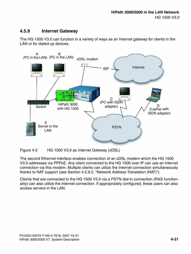
3000sb4.fm
For internal use only HiPath 3000/5000 in the LAN NetworkHG 1500 V3.0
4.5.9 Internet Gateway
The HG 1500 V3.0 can function in a variety of ways as an Internet gateway for clients in the LAN or for dialed-up devices.
Figure 4-2 HG 1500 V3.0 as Internet Gateway (xDSL)
The second Ethernet interface enables connection of an xDSL modem which the HG 1500 V3.0 addresses via PPPoE. Any client connected to the HG 1500 over IP can use an Internet connection via this modem. Multiple clients can utilize the Internet connection simultaneously thanks to NAT support (see Section 4.5.9.2, "Network Address Translation (NAT)").
Clients that are connected to the HG 1500 V3.0 via a PSTN dial-in connection (RAS function-ality) can also utilize the Internet connection. If appropriately configured, these users can also access servers in the LAN.
(Laptop with ISDN adapter)
Server in the LAN
(PC with ISDN adapter)
HiPath 3000 with HG 1500
xDSL modem(PC in the LAN)(PC in the LAN)
Switch
PSTN
Internet
P31003-H3570-Y100-4-7618, 2007-10-31HiPath 3000/5000 V7, System Description 4-31
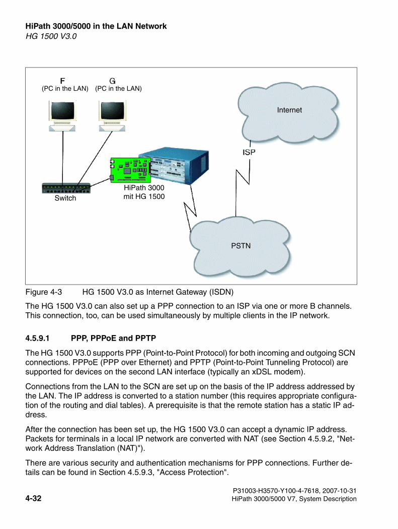
HiPath 3000/5000 in the LAN Network For internal use only
3000sb4.fm
HG 1500 V3.0
The HG 1500 V3.0 can also set up a PPP connection to an ISP via one or more B channels. This connection, too, can be used simultaneously by multiple clients in the IP network.
4.5.9.1 PPP, PPPoE and PPTP
The HG 1500 V3.0 supports PPP (Point-to-Point Protocol) for both incoming and outgoing SCN connections. PPPoE (PPP over Ethernet) and PPTP (Point-to-Point Tunneling Protocol) are supported for devices on the second LAN interface (typically an xDSL modem).
Connections from the LAN to the SCN are set up on the basis of the IP address addressed by the LAN. The IP address is converted to a station number (this requires appropriate configura-tion of the routing and dial tables). A prerequisite is that the remote station has a static IP ad-dress.
After the connection has been set up, the HG 1500 V3.0 can accept a dynamic IP address. Packets for terminals in a local IP network are converted with NAT (see Section 4.5.9.2, "Net-work Address Translation (NAT)").
There are various security and authentication mechanisms for PPP connections. Further de-tails can be found in Section 4.5.9.3, "Access Protection".
Figure 4-3 HG 1500 V3.0 as Internet Gateway (ISDN)
(PC in the LAN) (PC in the LAN)
SwitchHiPath 3000 mit HG 1500
Internet
PSTN
P31003-H3570-Y100-4-7618, 2007-10-314-32 HiPath 3000/5000 V7, System Description
3000sb4.fm
For internal use only HiPath 3000/5000 in the LAN NetworkHG 1500 V3.0
4.5.9.2 Network Address Translation (NAT)
Network Address Translation (NAT) is the conversion of IP addresses in the LAN for the Inter-net. HG 1500 V3.0 provides NAT for Internet connections via a second Ethernet interface as well as for PPP connections via B channels.
As far as the Internet is concerned, the entire LAN appears to be a single IP address and can therefore use a common dial-up connection to an ISP, for example. Additionally, direct IP at-tacks from the Internet on terminals in the LAN are not possible.
NAT can be enabled and disabled in the HG 1500 V3.0. Certain services – such as VoIP or vid-eo telephony – embed subscribers’ IP addresses in their data packets, however, instead of just noting them in the packet headers. They are only compatible with NAT within a VPN.
4.5.9.3 Access Protection
A variety of security functions are available to prevent unauthorized usage:
Checking Caller Numbers
Connections from the PSTN can be checked against a list of known users using the caller num-ber. Users whose connections do not transmit a caller number (for example analog telephones) can call an MSN that is set up especially for them.
Callback
All users can be configured so that they can be called back. Thus, PPP connections are only possible from a predefined connection.
User Account and Password
After setting up a connection, the user account and password can be checked using PAP (Pass-word Authentication Protocol), CHAP (Challenge Handshake Authentication Protocol) or MSC-HAP (Microsoft Challenge Handshake Authentication Protocol.
HG 1500 V3.0 also supports these protocols as a client when dialing in to a RAS server (for example with an ISP).
IP Address Filter for Communication with the LAN
IP address filters can be defined to prevent attacks on devices in the LAN, both from insecure (external) networks and from within the LAN. When IP filtering is activated, access is only pos-sible from address ranges that have explicit permission, and this access is only possible to specified addresses. Optionally, access can be further limited to a specific protocol port.
P31003-H3570-Y100-4-7618, 2007-10-31HiPath 3000/5000 V7, System Description 4-33
HiPath 3000/5000 in the LAN Network For internal use only
3000sb4.fm
HG 1500 V3.0
MAC Address Filters for Using the Gateway from within the LAN
MAC address filters can limit access to the router from devices within the LAN. When MAC fil-tering is activated, only devices within the LAN whose IP and MAC addresses have explicit per-mission to do so may set up a connection via the HG 1500 V3.0. (This function cannot be de-fined with dynamic IP address allocation in the LAN via BootP or DHCP).
Access Protection for Administrative Access
General administrative access and access to accounting data can each be separately limited to specific IP addresses, regardless of any other IP filters.
4.5.9.4 Multilink
The HG 1500 V3.0 can set up static or dynamic PPP connections with a remote station via sev-eral B channels simultaneously.
A static multilink uses the same number of B channels for the duration of the connection. A dy-namic multilink adds or removes channels depending on current channel load. These parame-ters can be configured.
4.5.9.5 Short-Hold
After a preconfigured time period with no data transfer over a PPP connection, the HG 1500 V3.0 can clear down the connection automatically.
4.5.9.6 IP Control Protocol (IPCP)
The HG 1500 V3.0 supports the IP Control Protocol (IPCP) for dynamic handling of IP address-es during connection setup.
4.5.9.7 Compression of IP Headers
Significant protocol overhead can develop, especially during voice data transmission where user data in a packet is typically short. To improve the situations, the HG 1500 V3.0 supports the compression of IP headers according to RFC 2507 and RFC 2508. The compression is ne-gotiated during the configuration of the connection with the receiver in accordance with RFC 1332 and RFC 2509.
4.5.9.8 Data Compression
User data in a PPP connection can be compressed with the STAC or the MPPC algorithm. The compression for each channel is negotiated separately with the remote station.
P31003-H3570-Y100-4-7618, 2007-10-314-34 HiPath 3000/5000 V7, System Description
3000sb4.fm
For internal use only HiPath 3000/5000 in the LAN NetworkHG 1500 V3.0
4.5.9.9 IP Accounting
HG 1500 V3.0 saves information about transferred data for the purposes of IP connection ac-counting.
Accounting data is saved for:
● PPP connections via SCN
● DSL connections
● Routing via the LAN2 Ethernet interface
The following information is saved:
● Data volume (sent and received)
● IP addresses (sender and recipient)
● Port number of the recipient
● TCP or UDP protocol ID
● Time (start of transfer and last activity)
● For PPP connections: Address and station number of PPP peer
Reading the Accounting Data
The Accounting Server (ACC) saves the data in the gateway. This data can be read out by the IP Accounting Client – an application on a PC – by means of a TCP connection, and then pro-cessed - for billing, for example. The IP accounting client is a supplementary product; instructions for its use are described in the accompanying documentation.
The IP Accounting Client must be connected to the gateway via a permanent IP connection.
To ensure data protection, a user name and password must be entered before the read-out. It addition, it is also possible to specify that reading is only possible from certain IP addresses.
IP Accounting must be activated and the connection parameters set for the IP Accounting Cli-ent before it can be used. Both configurations are described in the HG 1500 V3.0 Configuration Manual.
>For poor connections, we recommend using the MPPC algorithm, which is very use-ful for resynchronization.Further information on both algorithms can be found in RFC 1974 (STAC) or RFC 2118 (MPPC)
P31003-H3570-Y100-4-7618, 2007-10-31HiPath 3000/5000 V7, System Description 4-35
HiPath 3000/5000 in the LAN Network For internal use only
3000sb4.fm
HG 1500 V3.0
4.5.9.10 vCAPI
PC software usually accesses ISDN lines via CAPI (Common ISDN Application Interface). CAPI requires an ISDN adapter be directly connected to the relevant computer.
CAPI access is possible via local networks using vCAPI (Virtual CAPI). vCAPI functions ac-cording to the client/server principle: Client software is installed on the PC as a DLL and for-wards all CAPI requests transparently to the server, which is a process on the HG 1500 V3.0.
This way, all PCs connected via a LAN to the gateway can transparently utilize all the CAPI-enabled software (e.g. CAPI-enabled software for Fax Group 3) in order to access the HG 1500 V3.0 ISDN connections, and do not need additional hardware.
Incoming connections can be forwarded directly to a PC’s vCAPI client using up to 100 call numbers reserved for this purpose. Each station number is assigned to an IP address. To the CAPI software on that PC, these incoming calls appear to be calls on a physical local ISDN adapter.
The HG 1500 V3.0 vCAPI implementation supports CAPI 2.0.
P31003-H3570-Y100-4-7618, 2007-10-314-36 HiPath 3000/5000 V7, System Description
3000sb4.fm
For internal use only HiPath 3000/5000 in the LAN NetworkHG 1500 V3.0
4.5.9.11 Enhanced B Channels (HXGM3 with 2 × PDM1)
When the "Enhanced B Channels" feature is enabled in WBM, the board supports up to 32 B channels instead of the usual 16. Up to two PDM1 modules must be connected for this. The feature is supported in HiPath 3000 V3.0/V4.0 and HG 1500 V3.0 SMR4 or later.
Possible scenarios when using 32 B channels:
● networking two or more systems with IP trunking,
● mixed configuration with IP trunking and HFA clients,
● straightforward HFA scenario.
Restrictions when operating with 32 B channels per board:
● No VPN and no firewall functions are possible (when enabling the "Enhanced B Channels" feature in WBM, the VPN and firewall functionalities are automatically disabled). All other features (for example vCAPI) can be used after the "Enhanced B Channels" feature has been enabled.
● Channel bundling only up to a maximum of 16 B channels to the system for static and dy-namic data-PPP-multilink connections (up to one B channel group with 16 B channels is permitted).
● Channel bundling only up to a maximum of 8 B channels to the system for static and dy-namic Voice-over-PPP-multilink connections (up to one B channel group with 8 B channels is permitted).
P31003-H3570-Y100-4-7618, 2007-10-31HiPath 3000/5000 V7, System Description 4-37

HiPath 3000/5000 in the LAN Network For internal use only
3000sb4.fm
HG 1500 V3.0
4.5.10 Virtual Private Network (VPN)
Virtual Private Networks (VPN) connect individual computers and local networks via the Inter-net to form a closed virtual network. Communication in a VPN is tunneled through the Internet (encapsulated) and is protected from tapping and access by third parties such as Internet users and providers that are not a part of the VPN. A VPN enables an intranet to be extended beyond the LAN, for example to home workstations or branch offices, without requiring a dedicated line.
Figure 4-4 VPN - Sample Configuration
A VPN provides the following key functions:
● The tunnel endpoints (gateway or teleworker PC) are reliably identified.
● Exchanged data is protected from tapping during transmission.
● Exchanged data is protected from being modified during transmission.
HiPath 3000 with HG 1500
HiPath 3000 with HG 1500
Teleworker A
VPN tunnel
Switch
Switch
LAN B
LAN C
P31003-H3570-Y100-4-7618, 2007-10-314-38 HiPath 3000/5000 V7, System Description
3000sb4.fm
For internal use only HiPath 3000/5000 in the LAN NetworkHG 1500 V3.0
A VPN therefore guarantees that data actually comes from where it appears to have come from. that they are transferred from there unaltered; and that they are not made known to a third party on the way.
The HG 1500 V3.0 provides this function based on IPsec – a secure implementation of the IP protocol on level 3. This ensures that the VPN is transparent to applications as well as hard-ware.
The VPN security functions are available for LAN connections (for example LAN B and LAN C in Figure 4-5). In this case, they are completely transparent to the computers participating in the LANs. They can also be used for connecting individual computers (teleworkers), for exam-ple, teleworker A in LAN B in Figure 4-5). in this case, the VPN client software installed on the teleworker PC must be compatible with the VPN functions of HG 1500 V3.0.
A VPN (Virtual Private Network) is a network where communication is protected as far as hu-manly possible against tapping, clandestine modification and the misrepresentation of fake tun-nel endpoints.
The required protocols are available in the HG 1500 V3.0. Before a VPN can be created, how-ever, the gateway itself, and especially its administration, must be made secure against attacks.
4.5.10.1 Secure Mode
Unless special measures are taken, HG 1500 V3.0 operates in non-secure mode. This means, among other things, that administration access is not encrypted during transmission over the network.
The gateway recognizes the following security modes:
● Factory mode: has no configuration data.
● Insecure mode: gateway is configured, SSL and VPN are disabled. Insecure data trans-mission is possible.
● Activation of SSL: intermediate status between introduction of secure mode and configu-ration of SSL. Access is only possible via CLI at the V.24 interface; no data transmission is allowed.
● Secure administration: SSL is enabled. Access via CLI at the V.24 interface and WBM (via HTTPS) are possible. User data is transferred in insecure mode, and configuration data and software images are transferred in secure mode.
● Secure mode: SSL and VPN are active and configured. Access via CLI at the V.24 interface and WBM (via HTTPS) are possible. Secure and insecure data transmission are possible according to the security policy configured.
P31003-H3570-Y100-4-7618, 2007-10-31HiPath 3000/5000 V7, System Description 4-39
HiPath 3000/5000 in the LAN Network For internal use only
3000sb4.fm
HG 1500 V3.0
Since a gateway in insecure mode would represent a weak point in the VPN, it must be placed in secure mode before the VPN can be configured. This requires a certain degree of effort to prevent any hackers from getting into the system during this phase of the process and under-mining the subsequent steps taken.
The following steps must be taken for the gateway to be in secure mode:
1. Connect a terminal (or a PC with a terminal emulation program) to the V.24 interface of the gateway.
2. Restart the gateway with the CLI command reset secure. When this is done, all user settings are lost and all user data transmissions are interrupted until the gateway is recon-figured.
At this point, the gateway is in "activation of SSL" mode. In this mode it can only be config-ured using CLI at the V.24 interface – WBM, Telnet, HiPath 3000 Manager E and SNMP are disabled.
3. The gateway must be set up for SSL mode. First, the CLI command create SSL cer-tificate must be used to generate a server certificate with which the gateway can iden-tify itself to SSL clients. After that, SSL can be activated with the enable ssl command.
At this point, the gateway is in "secure administration" mode and can only be configured using CLI at the V.24 interface or WBM via HTTPS – Telnet, HiPath 3000 Manager E and SNMP are disabled.
4. Start the browser for access to WBM and enter the gateway address with the protocol "ht-tps://" (you can enter the port number "443" after the gateway address). The browser dis-plays the previously configured server certificate which must be manually checked and ap-proved. It can now also be installed in the browser to avoid future requests for it.
Use WBM to set up the VPN as described in the following section.
4.5.10.2 Security Policy
The security policy determines the procedure for IP packets. The following actions are possible:
● rejecting
● forwarding (normal routing without VPN functionality)
● tunneling (forwarding over the VPN)
The handling of IP packets can be specified in the HG 1500 V3.0 according to IP address, port number and protocol (TCP or UDP). For tunneled packets, you must determine:
● which algorithms for encryption and authentication are permissible on the connection,
● the period of validity for the security association.
P31003-H3570-Y100-4-7618, 2007-10-314-40 HiPath 3000/5000 V7, System Description
3000sb4.fm
For internal use only HiPath 3000/5000 in the LAN NetworkHG 1500 V3.0
4.5.10.3 Security Associations
A Security Association (SA) combines an encryption algorithm and its parameters with a ses-sion key and the key’s period of validity This ensures the security of a VPN connection session.
VPN connections with the HG 1500 V3.0 always require three SAs: one for initial mutual verifi-cation of identity and exchange of keys, and one for each direction of the connection once it is set up. The SAs are negotiated using the IKE (Internet Key Exchange) in accordance with RFC2409. The required keys are exchanged with the Diffie-Hellman algorithm using Oakley Group 2 or 5. Hash procedures available are SHA-1 and MD5.
Both the main mode and the aggressive mode are supported for negotiating the IKE security association. HG 1500 uses main mode if the peer also offers main mode. Teleworkers who use pre-shared keys must configure aggressive mode.
The period of validity for negotiated security associations can be limited by time or transmitted data volumes.
4.5.10.4 Tunnel
HG 1500 V3.0 supports up to 256 tunnels per board.
A tunnel is a secure VPN connection to another VPN gateway or a VPN client. The HG 1500 V3.0 establishes tunnels on level 3 based on IPsec.
Tunnel Configuration
For a tunnel to be set up, each terminal must be authenticated by the device at the other side. Otherwise an LDAP server is used. The HG 1500 V3.0 supports procedures that use public keys as well as procedures based on shared secrets – similar to passwords.
For authentication using public keys, the HG 1500 V3.0 can have CA (Certificate Authority) au-thentication certificates assigned to it manually. However, it can also obtain CRLs (Certificate Revocation Lists) automatically from an LDAP server.
The HG 1500 V3.0 supports X.509 certificates for authentication of VPN subscribers. The HG 1500 V3.0 supports DSA and RSA as public key algorithms.
HG 1500 V3.0 as Certification Authority CA
As long as no other CA is available, the HG 1500 V3.0 can, to a certain degree, act as a CA. It can generate pairs of public and private keys, issue and sign relevant certificates, and save keys and their corresponding certificates to files.
>HG 1500 V3.0 also supports key exchange using the Oakley Group 1. However, this is cryptographically weaker than the other supported groups 2 and 5 so we would therefore advise against using it.
P31003-H3570-Y100-4-7618, 2007-10-31HiPath 3000/5000 V7, System Description 4-41
HiPath 3000/5000 in the LAN Network For internal use only
3000sb4.fm
HG 1500 V3.0
There is, however, no option to automatically transfer such certificates to clients; every such transfer must be manually performed – with disks, for example.
Any subsequent certificate management, such as monitoring the period of validity or allocating certificates to client data, must also be done manually.
The HG 1500 V3.0 can create CRLs (Certificate Revocation Lists) of certificates that are con-sidered insecure and therefore are declared invalid before the end of the normal period of va-lidity. These lists must be distributed manually.
HG 1500 V3.0 can work with certificates from external CAs. However, they can also issue cer-tificates which can be used by other tunnel endpoints to authenticate themselves in a VPN. This function is called "Lightweight CA" and requires a separate license.
4.5.10.5 Data Security
The HG 1500 V3.0 supports ESP to protect utility data during transmission over the VPN.
DES, Triple DES (3DES) and AES are available as encryption algorithms.
HMAC-SHA1 and HMAC-MD5 are supported as MAC algorithms (MAC – Message Authenti-cation Code).
The HG 1500 V3.0 supports X.509 certificates as well as DSA and RSA, two public key algo-rithms, and pre-shared keys for authenticating VPN subscribers.
P31003-H3570-Y100-4-7618, 2007-10-314-42 HiPath 3000/5000 V7, System Description
3000sb4.fm
For internal use only HiPath 3000/5000 in the LAN NetworkHG 1500 V3.0
4.5.11 System Client and H.323 Client
System Client
You can configure clients such as optiPoint 400 or optiClient 130 V4.0 with payload switching capability. While calls are signaled via HiPath 3000, voice transfer between two payload switch-ing clients occurs directly via the LAN. Using this procedure saves DSP resources. The transfer can occur via HG 1500 V3.0 and across all nodes provided the required conditions are met by all the stations involved.
H.323 Client
A H.323 client on the network PC provides you with voice services that can also be used over the Internet (prerequisite: fixed IP addresses for all subscribers and the HG 1500 V3.0). No HiPath 3000 features are supported.
P31003-H3570-Y100-4-7618, 2007-10-31HiPath 3000/5000 V7, System Description 4-43
HiPath 3000/5000 in the LAN Network For internal use only
3000sb4.fm
HG 1500 V3.0
4.5.12 Bandwidth Management
Bandwidth management controls the bandwidth for Voice over IP between two nodes with HG 1500 V3.0 which are routed via ISDN (not usually required for LAN connections).
Five simultaneous calls can be made via one B channel if the audio codec is set to "G.723". However, the standard packetizing setting must be increased from 1 to 3. An additional B chan-nel is automatically set up from the sixth call onwards (prerequisite: two or more channels are entered for the ISDN partner). RTP compression is determined automatically and it cannot be configured.
If data is transferred to a routed ISDN channel at the same time as Voice over IP, the "MTU Size Fragmentation" of the relevant ISDN partner must be activated.
The compression of IP headers can be activated and the "PPP Default Header" can be deac-tivated to save additional bytes.
The value for packetizing should be set to three when Voice over IP and data transfer are per-formed simultaneously.
4.5.13 Displaying, Adding and Configuring PKI Servers
If you want to create a PKI (Public Key Infrastructure), you must configure suitable PKI servers in HG 1500 V3.0. PKI server data includes the server’s name and IP address and the server type (LDAP).
>The entire bandwidth can be split between voice and data or reserved.
P31003-H3570-Y100-4-7618, 2007-10-314-44 HiPath 3000/5000 V7, System Description
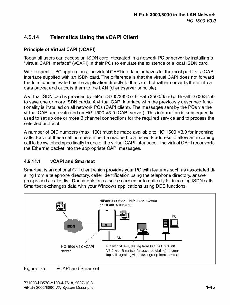
3000sb4.fm
For internal use only HiPath 3000/5000 in the LAN NetworkHG 1500 V3.0
4.5.14 Telematics Using the vCAPI Client
Principle of Virtual CAPI (vCAPI)
Today all users can access an ISDN card integrated in a network PC or server by installing a "virtual CAPI interface" (vCAPI) in their PCs to emulate the existence of a local ISDN card.
With respect to PC applications, the virtual CAPI interface behaves for the most part like a CAPI interface supplied with an ISDN card. The difference is that the virtual CAPI does not forward the functions activated by the application directly to the card, but rather converts them into a data packet and outputs them to the LAN (client/server principle).
A virtual ISDN card is provided by HiPath 3300/3350 or HiPath 3500/3550 or HiPath 3700/3750 to save one or more ISDN cards. A virtual CAPI interface with the previously described func-tionality is installed on all network PCs (CAPI client). The messages sent by the PCs via the virtual CAPI are evaluated on HG 1500 V3.0 (CAPI server). This information is subsequently used to set up one or more B channel connections for the required service and to process the selected protocol.
A number of DID numbers (max. 100) must be made available to HG 1500 V3.0 for incoming calls. Each of these call numbers must be mapped to a network address to allow an incoming call to be switched specifically to one of the virtual CAPI interfaces. The virtual CAPI reconverts the Ethernet packet into the appropriate CAPI messages.
4.5.14.1 vCAPI and Smartset
Smartset is an optional CTI client which provides your PC with features such as associated di-aling from a telephone directory, caller identification using the telephone directory, answer groups and a caller list. Documents can also be opened automatically for incoming ISDN calls. Smartset exchanges data with your Windows applications using DDE functions.
Figure 4-5 vCAPI and Smartset
LAN
0ABCDEFMNOGHIPQRSTUV
↵←→↑↓
1234567890ABCDEFMNOJKLGHIPQRSTUVWXYZ
0ABCDEFMNOGHIPQRSTUV
↵←→↑↓
1234567890ABCDEFMNOJKLGHIPQRSTUVWXYZ
PC
ISDN
PC with vCAPI, dialing from PC via HG 1500 V3.0 with Smartset (associated dialing). Incom-ing call signaling via answer group from terminal
HG 1500 V3.0 vCAPI server
HiPath 3300/3350, HiPath 3500/3550or HiPath 3700/3750
P31003-H3570-Y100-4-7618, 2007-10-31HiPath 3000/5000 V7, System Description 4-45
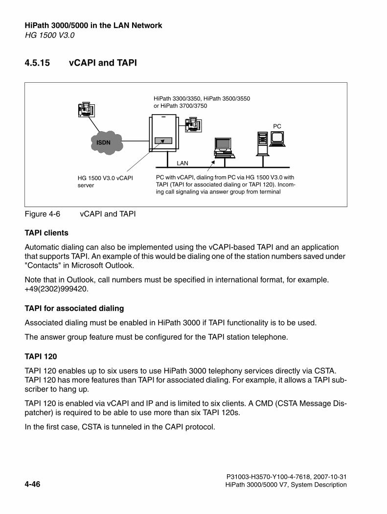
HiPath 3000/5000 in the LAN Network For internal use only
3000sb4.fm
HG 1500 V3.0
4.5.15 vCAPI and TAPI
TAPI clients
Automatic dialing can also be implemented using the vCAPI-based TAPI and an application that supports TAPI. An example of this would be dialing one of the station numbers saved under "Contacts" in Microsoft Outlook.
Note that in Outlook, call numbers must be specified in international format, for example. +49(2302)999420.
TAPI for associated dialing
Associated dialing must be enabled in HiPath 3000 if TAPI functionality is to be used.
The answer group feature must be configured for the TAPI station telephone.
TAPI 120
TAPI 120 enables up to six users to use HiPath 3000 telephony services directly via CSTA. TAPI 120 has more features than TAPI for associated dialing. For example, it allows a TAPI sub-scriber to hang up.
TAPI 120 is enabled via vCAPI and IP and is limited to six clients. A CMD (CSTA Message Dis-patcher) is required to be able to use more than six TAPI 120s.
In the first case, CSTA is tunneled in the CAPI protocol.
Figure 4-6 vCAPI and TAPI
LAN
0ABCDEFMNOGHIPQRSTUV
↵←→↑↓
1234567890ABCDEFMNOJKLGHIPQRSTUVWXYZ
0ABCDEFMNOGHIPQRSTUV
↵←→↑↓
1234567890ABCDEFMNOJKLGHIPQRSTUVWXYZ
PC
ISDN
PC with vCAPI, dialing from PC via HG 1500 V3.0 with TAPI (TAPI for associated dialing or TAPI 120). Incom-ing call signaling via answer group from terminal
HG 1500 V3.0 vCAPI server
HiPath 3300/3350, HiPath 3500/3550or HiPath 3700/3750
P31003-H3570-Y100-4-7618, 2007-10-314-46 HiPath 3000/5000 V7, System Description
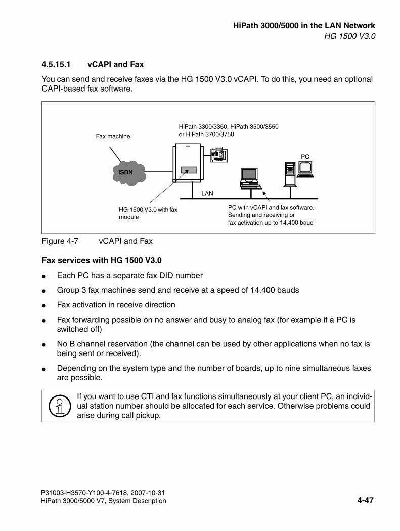
3000sb4.fm
For internal use only HiPath 3000/5000 in the LAN NetworkHG 1500 V3.0
4.5.15.1 vCAPI and Fax
You can send and receive faxes via the HG 1500 V3.0 vCAPI. To do this, you need an optional CAPI-based fax software.
Fax services with HG 1500 V3.0
● Each PC has a separate fax DID number
● Group 3 fax machines send and receive at a speed of 14,400 bauds
● Fax activation in receive direction
● Fax forwarding possible on no answer and busy to analog fax (for example if a PC is switched off)
● No B channel reservation (the channel can be used by other applications when no fax is being sent or received).
● Depending on the system type and the number of boards, up to nine simultaneous faxes are possible.
Figure 4-7 vCAPI and Fax
>If you want to use CTI and fax functions simultaneously at your client PC, an individ-ual station number should be allocated for each service. Otherwise problems could arise during call pickup.
LAN
0ABCDEFMNOGHIPQRSTUV
↵←→↑↓
1234567890ABCDEFMNOJKLGHIPQRSTUVWXYZ
PC
ISDN
PC with vCAPI and fax software. Sending and receiving or fax activation up to 14,400 baud
HG 1500 V3.0 with fax module
Fax machine
HiPath 3300/3350, HiPath 3500/3550or HiPath 3700/3750
P31003-H3570-Y100-4-7618, 2007-10-31HiPath 3000/5000 V7, System Description 4-47
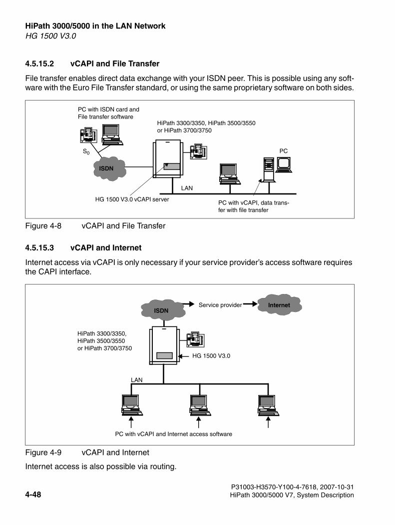
HiPath 3000/5000 in the LAN Network For internal use only
3000sb4.fm
HG 1500 V3.0
4.5.15.2 vCAPI and File Transfer
File transfer enables direct data exchange with your ISDN peer. This is possible using any soft-ware with the Euro File Transfer standard, or using the same proprietary software on both sides.
4.5.15.3 vCAPI and Internet
Internet access via vCAPI is only necessary if your service provider’s access software requires the CAPI interface.
Internet access is also possible via routing.
Figure 4-8 vCAPI and File Transfer
Figure 4-9 vCAPI and Internet
S0
LAN
0ABCDEFMNOGHIPQRSTUV
↵←→↑↓
1234567890ABCDEFMNOJKLGHIPQRSTUVWXYZ
0ABCDEFMNOGHIPQRSTUV
↵←→↑↓
1234567890ABCDEFMNOJKLGHIPQRSTUVWXYZ
PC
ISDN
PC with vCAPI, data trans-fer with file transfer
HG 1500 V3.0 vCAPI server
PC with ISDN card and File transfer software
HiPath 3300/3350, HiPath 3500/3550or HiPath 3700/3750
LAN
HG 1500 V3.0
PC with vCAPI and Internet access software
0ABCDEFMNOGHIPQRSTUV
↵←→↑↓
1234567890ABCDEFMNOJKLGHIPQRSTUVWXYZ
Service provider InternetISDN
HiPath 3300/3350,HiPath 3500/3550or HiPath 3700/3750
P31003-H3570-Y100-4-7618, 2007-10-314-48 HiPath 3000/5000 V7, System Description
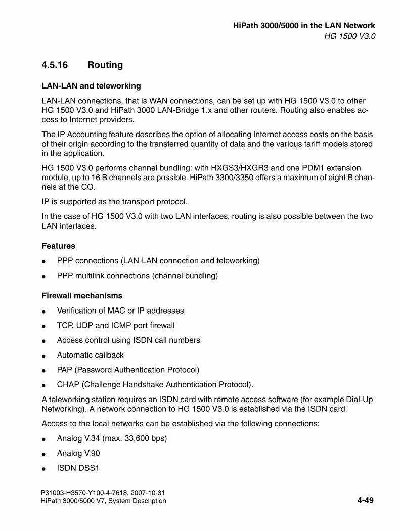
3000sb4.fm
For internal use only HiPath 3000/5000 in the LAN NetworkHG 1500 V3.0
4.5.16 Routing
LAN-LAN and teleworking
LAN-LAN connections, that is WAN connections, can be set up with HG 1500 V3.0 to other HG 1500 V3.0 and HiPath 3000 LAN-Bridge 1.x and other routers. Routing also enables ac-cess to Internet providers.
The IP Accounting feature describes the option of allocating Internet access costs on the basis of their origin according to the transferred quantity of data and the various tariff models stored in the application.
HG 1500 V3.0 performs channel bundling: with HXGS3/HXGR3 and one PDM1 extension module, up to 16 B channels are possible. HiPath 3300/3350 offers a maximum of eight B chan-nels at the CO.
IP is supported as the transport protocol.
In the case of HG 1500 V3.0 with two LAN interfaces, routing is also possible between the two LAN interfaces.
Features
● PPP connections (LAN-LAN connection and teleworking)
● PPP multilink connections (channel bundling)
Firewall mechanisms
● Verification of MAC or IP addresses
● TCP, UDP and ICMP port firewall
● Access control using ISDN call numbers
● Automatic callback
● PAP (Password Authentication Protocol)
● CHAP (Challenge Handshake Authentication Protocol).
A teleworking station requires an ISDN card with remote access software (for example Dial-Up Networking). A network connection to HG 1500 V3.0 is established via the ISDN card.
Access to the local networks can be established via the following connections:
● Analog V.34 (max. 33,600 bps)
● Analog V.90
● ISDN DSS1
P31003-H3570-Y100-4-7618, 2007-10-31HiPath 3000/5000 V7, System Description 4-49
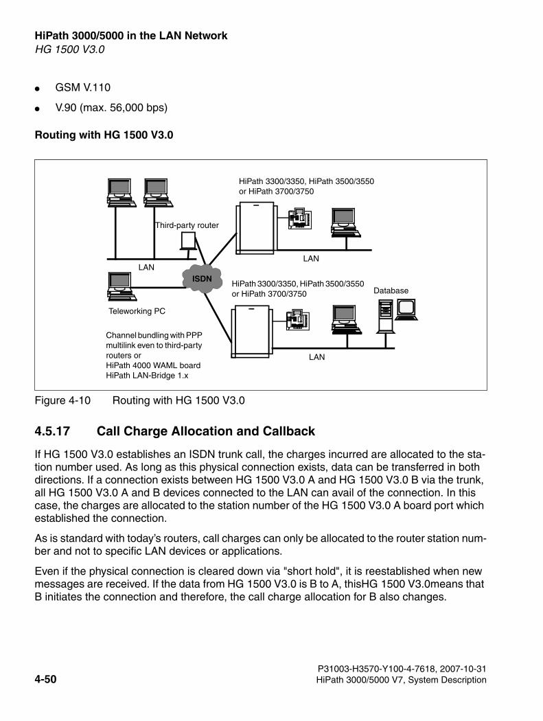
HiPath 3000/5000 in the LAN Network For internal use only
3000sb4.fm
HG 1500 V3.0
● GSM V.110
● V.90 (max. 56,000 bps)
Routing with HG 1500 V3.0
4.5.17 Call Charge Allocation and Callback
If HG 1500 V3.0 establishes an ISDN trunk call, the charges incurred are allocated to the sta-tion number used. As long as this physical connection exists, data can be transferred in both directions. If a connection exists between HG 1500 V3.0 A and HG 1500 V3.0 B via the trunk, all HG 1500 V3.0 A and B devices connected to the LAN can avail of the connection. In this case, the charges are allocated to the station number of the HG 1500 V3.0 A board port which established the connection.
As is standard with today’s routers, call charges can only be allocated to the router station num-ber and not to specific LAN devices or applications.
Even if the physical connection is cleared down via "short hold", it is reestablished when new messages are received. If the data from HG 1500 V3.0 is B to A, thisHG 1500 V3.0means that B initiates the connection and therefore, the call charge allocation for B also changes.
Figure 4-10 Routing with HG 1500 V3.0
LAN
LAN
0ABCDEFMNOGHIPQRSTUV
↵←→↑↓
1234567890ABCDEFMNOJKLGHIPQRSTUVWXYZ
0ABCDEFMNOGHIPQRSTUV
↵←→↑↓
1234567890ABCDEFMNOJKLGHIPQRSTUVWXYZ
Third-party router
Channel bundling with PPP multilink even to third-party routers or HiPath 4000 WAML board HiPath LAN-Bridge 1.x
Database
LAN ISDN
Teleworking PC
HiPath 3300/3350, HiPath 3500/3550or HiPath 3700/3750
HiPath 3300/3350, HiPath 3500/3550 or HiPath 3700/3750
P31003-H3570-Y100-4-7618, 2007-10-314-50 HiPath 3000/5000 V7, System Description
3000sb4.fm
For internal use only HiPath 3000/5000 in the LAN NetworkHG 1500 V3.0
When the "Callback" function is activated, charges incurred by the called HG 1500 V3.0 are al-located, as this called party rejects the incoming call and actively re-establishes the connection (callback without a connection). In other words, no B channel is set up. Identification is per-formed via the station number entered in Setup or, in the case of analog stations, via the DID number entered under "ISDN peer".
4.5.18 Internet Access
One or more client PCs can directly access the Internet using a Web browser. The connection from the LAN is set up via ISDN or DSL. In general, access is possible from all PCs. (Please note that this is not allowed for all tariffs of every provider.)
Internet access takes place via the HG 1500 V3.0 to the Internet provider, using the IP trans-port protocol.
All clients use the same provider.
Features
● Static or dynamic IP addresses
● Routing function with NAT/SUA (Network Address Translation/Single User Access)
● PPP multilink (channel bundling)
● PPPoE (for DSL)
● PPTP (for DSL)
● PAP (Password Authentication Protocol)
● CHAP (Challenge Handshake Authentication Protocol)
>In some cases (for example when short hold is deactivated), dial-up connections can be only be initiated manually.
P31003-H3570-Y100-4-7618, 2007-10-31HiPath 3000/5000 V7, System Description 4-51
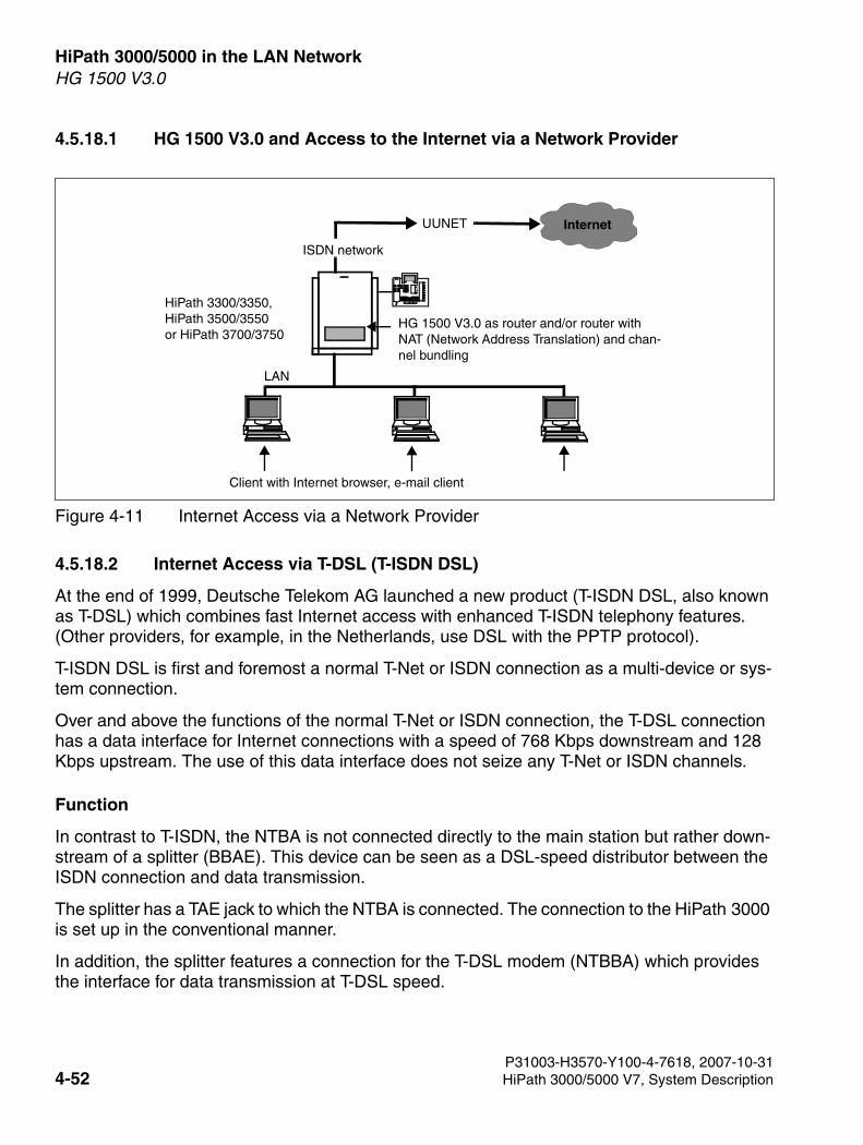
HiPath 3000/5000 in the LAN Network For internal use only
3000sb4.fm
HG 1500 V3.0
4.5.18.1 HG 1500 V3.0 and Access to the Internet via a Network Provider
4.5.18.2 Internet Access via T-DSL (T-ISDN DSL)
At the end of 1999, Deutsche Telekom AG launched a new product (T-ISDN DSL, also known as T-DSL) which combines fast Internet access with enhanced T-ISDN telephony features. (Other providers, for example, in the Netherlands, use DSL with the PPTP protocol).
T-ISDN DSL is first and foremost a normal T-Net or ISDN connection as a multi-device or sys-tem connection.
Over and above the functions of the normal T-Net or ISDN connection, the T-DSL connection has a data interface for Internet connections with a speed of 768 Kbps downstream and 128 Kbps upstream. The use of this data interface does not seize any T-Net or ISDN channels.
Function
In contrast to T-ISDN, the NTBA is not connected directly to the main station but rather down-stream of a splitter (BBAE). This device can be seen as a DSL-speed distributor between the ISDN connection and data transmission.
The splitter has a TAE jack to which the NTBA is connected. The connection to the HiPath 3000 is set up in the conventional manner.
In addition, the splitter features a connection for the T-DSL modem (NTBBA) which provides the interface for data transmission at T-DSL speed.
Figure 4-11 Internet Access via a Network Provider
LAN
ISDN network
HG 1500 V3.0 as router and/or router with NAT (Network Address Translation) and chan-nel bundling
Client with Internet browser, e-mail client
0ABCDEFMNOGHIPQRSTUV
↵←→↑↓
1234567890ABCDEFMNOJKLGHIPQRSTUVWXYZ
UUNET Internet
HiPath 3300/3350,HiPath 3500/3550or HiPath 3700/3750
P31003-H3570-Y100-4-7618, 2007-10-314-52 HiPath 3000/5000 V7, System Description
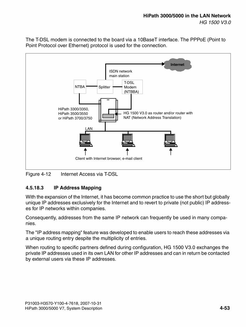
3000sb4.fm
For internal use only HiPath 3000/5000 in the LAN NetworkHG 1500 V3.0
The T-DSL modem is connected to the board via a 10BaseT interface. The PPPoE (Point to Point Protocol over Ethernet) protocol is used for the connection.
4.5.18.3 IP Address Mapping
With the expansion of the Internet, it has become common practice to use the short but globally unique IP addresses exclusively for the Internet and to revert to private (not public) IP address-es for IP networks within companies.
Consequently, addresses from the same IP network can frequently be used in many compa-nies.
The "IP address mapping" feature was developed to enable users to reach these addresses via a unique routing entry despite the multiplicity of entries.
When routing to specific partners defined during configuration, HG 1500 V3.0 exchanges the private IP addresses used in its own LAN for other IP addresses and can in return be contacted by external users via these IP addresses.
Figure 4-12 Internet Access via T-DSL
LAN
ISDN networkmain station
HG 1500 V3.0 as router and/or router with NAT (Network Address Translation)
Client with Internet browser, e-mail client
Internet
SplitterT-DSLModem(NTBBA)
NTBA
HiPath 3300/3350,HiPath 3500/3550or HiPath 3700/3750
P31003-H3570-Y100-4-7618, 2007-10-31HiPath 3000/5000 V7, System Description 4-53
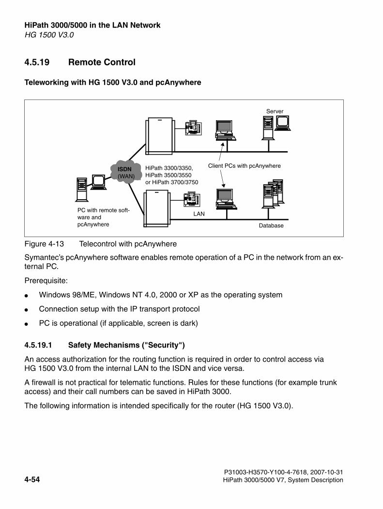
HiPath 3000/5000 in the LAN Network For internal use only
3000sb4.fm
HG 1500 V3.0
4.5.19 Remote Control
Teleworking with HG 1500 V3.0 and pcAnywhere
Symantec’s pcAnywhere software enables remote operation of a PC in the network from an ex-ternal PC.
Prerequisite:
● Windows 98/ME, Windows NT 4.0, 2000 or XP as the operating system
● Connection setup with the IP transport protocol
● PC is operational (if applicable, screen is dark)
4.5.19.1 Safety Mechanisms ("Security")
An access authorization for the routing function is required in order to control access via HG 1500 V3.0 from the internal LAN to the ISDN and vice versa.
A firewall is not practical for telematic functions. Rules for these functions (for example trunk access) and their call numbers can be saved in HiPath 3000.
The following information is intended specifically for the router (HG 1500 V3.0).
Figure 4-13 Telecontrol with pcAnywhere
0ABCDEFMNOGHIPQRSTUV
↵←→↑↓
1234567890ABCDEFMNOJKLGHIPQRSTUVWXYZ
0ABCDEFMNOGHIPQRSTUV
↵←→↑↓
1234567890ABCDEFMNOJKLGHIPQRSTUVWXYZ
Client PCs with pcAnywhere
PC with remote soft-ware and pcAnywhere
ISDN(WAN)
Database
Server
LAN
HiPath 3300/3350,HiPath 3500/3550or HiPath 3700/3750
P31003-H3570-Y100-4-7618, 2007-10-314-54 HiPath 3000/5000 V7, System Description
3000sb4.fm
For internal use only HiPath 3000/5000 in the LAN NetworkHG 1500 V3.0
Station number verification (incoming only)
Verification of the station number of the calling station (station authentication, configurable) and the IP address to prevent unauthorized external connections via ISDN.
Verification of the IP address (configurable) of internal LAN subscribers.
4.5.19.2 Firewall
A firewall is a barrier which protects against unauthorized access. In this case, the internal LAN (LAN1), for example, is to be protected against external access (such as Internet-based access via DSL).
The objective of a firewall configuration is to allow individual, specified computers to access an insecure network (for example Internet). At the same time, it prevents access in the reverse di-rection (from the Internet to these computers). The board features two different protection mechanisms for implementing this security.
The firewall in this case is a so-called authorization firewall. In other words, as soon as the fire-wall is activated, only configured components can access board services. All board services are automatically denied to unregistered LAN components.
Firewall (Permit Firewall)
In the case of a permit firewall, only configured components can access board services (when the firewall is activated). All board services are automatically denied to unregistered LAN com-ponents. The board features different protection mechanisms for implementing this security.
● Stateful packet filtering for communication with the LANStateful packet filtering analyzes and, if necessary, rejects packets based on their source and target IP address addresses and the ports used (TCP, UDP, and ICMP port firewall). The IP addresses can be network addresses or individual hosts.
● Denial of Service ProtectionDenial of Service Protection offers protection against a broad variety of Denial of Service attacks (and other attacks on the network gateway) such as SYN flooding, various frag-mentation attacks, TCP hijacking (various active attacks, for example ARP spoofing), LAND (identical source and destination IPs), Christmas Tree attacks (all TCP flags are set), etc.
7WARNING: The activation and deactivation of firewall parameters may severely re-strict the functionality of the board (for example LAN-based administration may not be possible any more) or may enable access to sensitive data.
P31003-H3570-Y100-4-7618, 2007-10-31HiPath 3000/5000 V7, System Description 4-55
HiPath 3000/5000 in the LAN Network For internal use only
3000sb4.fm
HG 1500 V3.0
● MAC verification
MAC address filters can limit access from devices within the LAN. If MAC filtering is en-abled, devices such as these can only set up connections from the LAN via HG 1500 V3.0 whose IP and MAC addresses are explicitly released for this purpose.
4.5.19.3 Alive Monitoring with Keep Alive
The Keep Alive Test is used for HXG3 boards located in different network nodes. This test sends a ping signal to the other HXG3 boards and then waits for a return signal. If a return sig-nal is not received from an HXG3 board (for example, because the IP connection is down) then the board is considered out of service. If this happens during call setup, a message is sent to the HiPath 3000 to set the call up again.
The connection is automatically cleared down if the connection exists already and the Keep Alive Test fails. This is especially important for data connections to ensure that the applications involved can react appropriately and do not stall.
4.5.20 Overview of Management Tools
The following four different tools support administrators in performing their tasks:
● Web-Based Management (WBM) via an integrated HTTP server
Provides a step-by-step configuration and easy access to all management functions. WBM is the primary management tool.
● Command line (CLI) via a serial V.24 interface or Telnet
The command line is designed as the secondary management tool and provides a limited function scope. It can be used to modify certain configuration data, update and restart the system and to diagnose the system configuration.
Security-relevant settings (such as SSL configurations) cannot be made via Telnet.
● SNMP-supported management via an SNMP agent
SNMP-supported management enables gateway integration in network management sys-tems. Systems like this can manage devices from other manufacturers.
HG 1500 V3.0 supports SNMP versions 1 and 2. Information such as statistics can be read and some important data can be modified using SNMP. Traps are also supported.
>An external firewall should be used if the demands for security on the firewall are higher (for example, if Internet and VPN traffic is being transferred to Internet gate-ways at the same time).
P31003-H3570-Y100-4-7618, 2007-10-314-56 HiPath 3000/5000 V7, System Description
3000sb4.fm
For internal use only HiPath 3000/5000 in the LAN NetworkHG 1500 V3.0
● HTTP applications via a command interface
HG 1500 V3.0 configuration data can be read out and modified and commands can be ex-ecuted via the HTTP port. This applies to insecure (HTTP) and secure (HTTPS) connec-tions.
The Universal Resource Identifier (URI) in the HTTP sequence is recognized by the gate-way board as an administration command. The HTTP header contains information re-quired for authentication.
In addition to the HG 1500 V3.0 management tools, the HiPath 3000 Manager E is available.
● HiPath 3000 Manager E
The HiPath 3000 Manager E is an independent application installed on a PC. It displays the relevant parts of the network as a virtual HiPath system. (Some HG 1500 V3.0 settings can be configured both with this application and HG 1500 V3.0 tools, depending on the ver-sion of the HiPath environment.)
P31003-H3570-Y100-4-7618, 2007-10-31HiPath 3000/5000 V7, System Description 4-57
HiPath 3000/5000 in the LAN Network For internal use only
3000sb4.fm
HG 1500 V3.0
4.5.20.1 Multi-Gateway Administration (MGA)
The configuration of a large number of gateways, in particular, can cost administrators consid-erable time and effort, and so can – even only minor – modifications to a configuration.
HG 1500 V3.0 therefore supports the distribution of configurations from a master gateway to any number of slave gateways.
Prerequisites
In order to use Multi-Gateway Administration (MGA), no special hardware or software prereq-uisites are required on the gateways involved. However, the following conditions for configura-tion must be met:
● All slave gateways must be able to be accessed by the master gateway via IP.
● The port used for WBM must have the same number on each gateway (usually 8085) and must be accessible from the master gateway. Therefore, access must not be blocked by a firewall, for example.
● All slave gateways must have a user access for MGA. All accesses must have the same name and password. This access must have root access privileges.
● The slave gateways must be entered on the master gateway. (The list of slave gateways can also be imported by another master gateway, if necessary)
Using MGA
The administrator first configures the master gateway as required. He then uses a command to transfer this configuration data to slave gateways. The administrator can specify individually to which slave gateways the data will be transferred and also select which configuration tables will be transferred.
4.5.21 Quality of Service in HG 1500
Quality of Service encompasses various methods for guaranteeing certain transmission prop-erties in packet-oriented networks (IP).
It is thus important, for example, to ensure a minimum bandwidth for Voice over IP for the entire duration of the transfer operation. If multiple applications with equal rights are operating via IP, then the available bandwidth for the transmission path (for example an ISDN B channel, 64 Kbps) is split. In this case, a voice connection may experience packet losses which can reduce voice quality.
P31003-H3570-Y100-4-7618, 2007-10-314-58 HiPath 3000/5000 V7, System Description
3000sb4.fm
For internal use only HiPath 3000/5000 in the LAN NetworkHG 1500 V3.0
HG 1500 V3.0 uses various different procedures to implement Quality of Service.
On layer 2 (in accordance with OSI, Ethernet), you can activate an extension (IEEE 802.1p) to the standard Ethernet format (DIX V2). This adds more information to the Ethernet header in-cluding a 3-bit data field. This field carries priority information on the data packet. For all packets that reach the board from the LAN, both Ethernet formats (IEEE 802.1p and DIX V2) are un-derstood; for all packets that are sent from the board to the LAN, the format can be selected via "Basic Settings > IEEE 802.1p". You should check whether all components in the network sup-port this format before this parameter is activated. Otherwise, it may not be possible to access HG 1500 V3.0 from the LAN anymore.
The Ethernet header is not transported when switching to another transport medium (for example ISDN). An IP router (like the HG 1500 V3.0’s router) can, however, use the infor-mation contained in the IP header for prioritization. Straightforward IP routers that connect two network segments, for example, can use the IP level prioritization. In the "Type of Service" field, either three bit (IP precedence based on RFC 791, older standard) or six bit (Differentiated Ser-vices or DiffServ, based on RFC 2474) are evaluated for the creation of various classes. HG 1500 V3.0’s IP router provides various bandwidths for these classes, so that voice packets can be processed first. The procedure adopted by HG 1500 V3.0 can be set under "Basic set-tings > QoS procedures" (Autodetect is set by default).
For the DiffServ parameter, various so-called codepoints ("Basic Settings > AF/EF Code-points") are defined, and based on these codepoints two different procedures are used for pro-cessing the payload of different marked data flows:
The "Expedited Forwarded (EF)" procedure (based on RFC 2598) guarantees a constant bandwidth for data in this class. If this defined value is reached, all packets that exceed this bandwidth are rejected. A separate class is defined for EF on HG 1500 V3.0. For this class, the bandwidth can be defined as a percentage for every ISDN peer (QoS bandwidth for EF).
The "Assured Forwarding (AF)" procedure (based on RFC 2597) guarantees a minimum band-width for the data of one (of many) classes. Lower priority classes share the bandwidth not used by EF or the classes with higher priority. In addition, the speed at which packets are rejected if the system is unable to forward them fast enough can be defined for every class by means of the Dropping Level setting. Nothing is thus to be gained by buffering voice packages for an ex-tended period of time (this only increases the delay). In the case of secure data transfer (for example file transfer), on the other hand, a large buffer is advantageous as packets are oth-erwise sent repeatedly between the two terminals.
Four classes are reserved for AF on the HG 1500 V3.0: AF1x (high priority), AF2x, AF3x and AF4x (low priority), where "x" stands for one of three dropping levels: low (1), medium (2) and high (3). In the case of "low", packets are buffered over an extended period, in the case of "high", packets are promptly rejected if they cannot be forwarded. Unmarked IP packets (ToS field=00) are handled in the same way as the lowest priority.
P31003-H3570-Y100-4-7618, 2007-10-31HiPath 3000/5000 V7, System Description 4-59
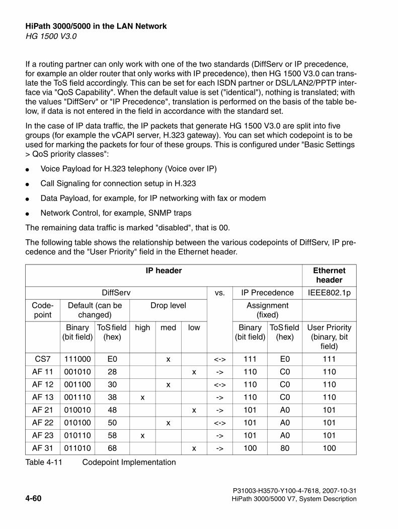
HiPath 3000/5000 in the LAN Network For internal use only
3000sb4.fm
HG 1500 V3.0
If a routing partner can only work with one of the two standards (DiffServ or IP precedence, for example an older router that only works with IP precedence), then HG 1500 V3.0 can trans-late the ToS field accordingly. This can be set for each ISDN partner or DSL/LAN2/PPTP inter-face via "QoS Capability". When the default value is set ("identical"), nothing is translated; with the values "DiffServ" or "IP Precedence", translation is performed on the basis of the table be-low, if data is not entered in the field in accordance with the standard set.
In the case of IP data traffic, the IP packets that generate HG 1500 V3.0 are split into five groups (for example the vCAPI server, H.323 gateway). You can set which codepoint is to be used for marking the packets for four of these groups. This is configured under "Basic Settings > QoS priority classes":
● Voice Payload for H.323 telephony (Voice over IP)
● Call Signaling for connection setup in H.323
● Data Payload, for example, for IP networking with fax or modem
● Network Control, for example, SNMP traps
The remaining data traffic is marked "disabled", that is 00.
The following table shows the relationship between the various codepoints of DiffServ, IP pre-cedence and the "User Priority" field in the Ethernet header.
IP header Ethernet header
DiffServ vs. IP Precedence IEEE802.1p
Code-point
Default (can be changed)
Drop level Assignment (fixed)
Binary (bit field)
ToS field (hex)
high med low Binary (bit field)
ToS field (hex)
User Priority(binary, bit
field)
CS7 111000 E0 x <-> 111 E0 111
AF 11 001010 28 x -> 110 C0 110
AF 12 001100 30 x <-> 110 C0 110
AF 13 001110 38 x -> 110 C0 110
AF 21 010010 48 x -> 101 A0 101
AF 22 010100 50 x <-> 101 A0 101
AF 23 010110 58 x -> 101 A0 101
AF 31 011010 68 x -> 100 80 100
Table 4-11 Codepoint Implementation
P31003-H3570-Y100-4-7618, 2007-10-314-60 HiPath 3000/5000 V7, System Description
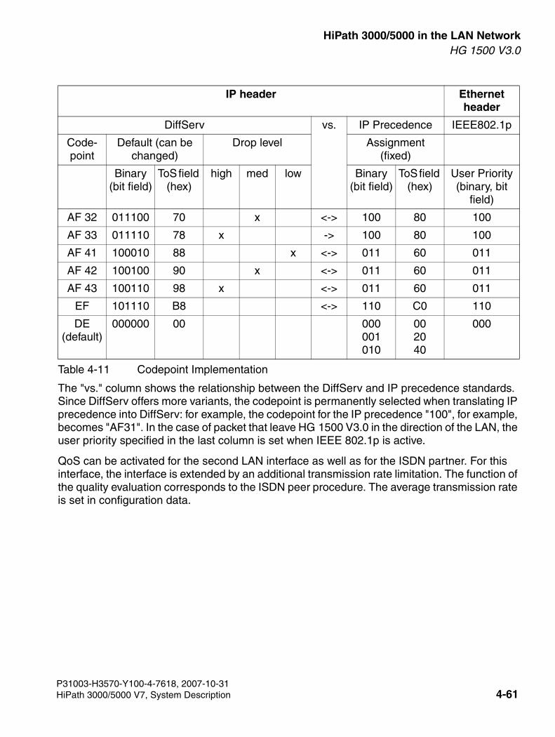
3000sb4.fm
For internal use only HiPath 3000/5000 in the LAN NetworkHG 1500 V3.0
The "vs." column shows the relationship between the DiffServ and IP precedence standards. Since DiffServ offers more variants, the codepoint is permanently selected when translating IP precedence into DiffServ: for example, the codepoint for the IP precedence "100", for example, becomes "AF31". In the case of packet that leave HG 1500 V3.0 in the direction of the LAN, the user priority specified in the last column is set when IEEE 802.1p is active.
QoS can be activated for the second LAN interface as well as for the ISDN partner. For this interface, the interface is extended by an additional transmission rate limitation. The function of the quality evaluation corresponds to the ISDN peer procedure. The average transmission rate is set in configuration data.
AF 32 011100 70 x <-> 100 80 100
AF 33 011110 78 x -> 100 80 100
AF 41 100010 88 x <-> 011 60 011
AF 42 100100 90 x <-> 011 60 011
AF 43 100110 98 x <-> 011 60 011
EF 101110 B8 <-> 110 C0 110
DE(default)
000000 00 000001010
002040
000
IP header Ethernet header
DiffServ vs. IP Precedence IEEE802.1p
Code-point
Default (can be changed)
Drop level Assignment (fixed)
Binary (bit field)
ToS field (hex)
high med low Binary (bit field)
ToS field (hex)
User Priority(binary, bit
field)
Table 4-11 Codepoint Implementation
P31003-H3570-Y100-4-7618, 2007-10-31HiPath 3000/5000 V7, System Description 4-61
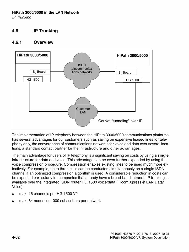
HiPath 3000/5000 in the LAN Network For internal use only
3000sb4.fm
IP Trunking
4.6 IP Trunking
4.6.1 Overview
The implementation of IP telephony between the HiPath 3000/5000 communications platforms has several advantages for our customers such as saving on expensive leased lines for tele-phony only, the convergence of communications networks for voice and data over several loca-tions, a standard contact partner for the infrastructure and other advantages.
The main advantage for users of IP telephony is a significant saving on costs by using a single infrastructure for data and voice. This advantage can be even further expanded by using the voice compression procedure, Compression enables existing lines to be used much more ef-fectively. For example, up to three calls can be conducted simultaneously on a single ISDN channel if an optimized compression algorithm is used. A considerable reduction in costs can be expected particularly for companies that already have a broad-band intranet. IP trunking is available over the integrated ISDN router HG 1500 voice/data (Hicom Xpress@ LAN Data/Voice).
● max. 16 channels per HG 1500 V2
● max. 64 nodes for 1000 subscribers per network
HiPath 3000/5000
S0 Board
HG 1500
CustomerLAN
ISDNtelecommunica-tions network)
HiPath 3000/5000
HG 1500
S0 Board
CorNet “tunneling” over IP
P31003-H3570-Y100-4-7618, 2007-10-314-62 HiPath 3000/5000 V7, System Description
3000sb4.fm
For internal use only HiPath 3000/5000 in the LAN NetworkIP Trunking
HG 1500 has been extended to include the following features:
● Quality of Service (IEEE 802.1d)
● Type of Service (RFC 791)
● Differentiated Services (RFC 2474)
● Assured Forwarding, AF (RFC 2597)
● Expedited Forwarding, EF (RFC 2598)
● Compression to ITU G.723.1 or ITU G.711, adjustable
4.6.2 Features of IP Networking
Transparency for End Users
● Special workpoint clients (terminals) are not required because voice data is not converted into IP packages in the workpoint client, but rather in the LAN gateway.
● Network-wide features are transferred which means that use of the workpoint clients has not changed and consequently, the user-friendliness of the telephone has not been affect-ed.
● DTMF signals are supported. Consequently, you can perform suffix-dialing or listen to your voicemail over the IP network.
Fax (Group 3) and analog Modem as well as Data Transmission with X.75 over IP
Implementation of the integrated router HG 1500 means that analog fax and modem connec-tions as well as data connections of the type X.75 can be transmitted between IP-networked communications platforms without the need for additional hardware. The system recognizes the connection type required on the basis of the configured station type (fax, modem or speech) and automatically establishes a connection in the IP network.
The following connection types are supported:
● Real-time fax transmission is supported in accordance with the ITU-T standard T.30 (fax group 3). Faxes are transmitted between the networked communications platforms at a maximum speed of 14.4 kbps (V.17).
>Compression to ITU G.723.1 and QoS IEEE 802.1 d can be adjusted for each board. The B channels used for networking, the channels for routing and the channels pro-vided for the IP clients are shared out amongst the total number of available B chan-nels.
P31003-H3570-Y100-4-7618, 2007-10-31HiPath 3000/5000 V7, System Description 4-63
HiPath 3000/5000 in the LAN Network For internal use only
3000sb4.fm
IP Trunking
● Data can be transmitted via modem over the IP network at a speed of 33.6 kbps using the ITU-T standard V.42.
● Data transmission to the ITU-T standard X.75
Support of Network-wide Features
The CorNet N protocol is supported for IP networking. which means that CorNet-N-specific fea-tures are transmitted over the IP network (tunnelling).
The following applies: Overall, the features that are transmitted today in the HiPath 3000/5000 Corporate Network, are also transmitted in the IP network although the old network has been enhanced in certain respects (see Section 4.6.3, “Network-Wide Features with IP Network-ing”).
Central Attendant Console
A central, system-wide attendant console can be configured within the IP network. The net-work-wide busy signal option is possible here.
Automatic Routing
Automatic routing to a backup or alternative network can be executed for new connections. A voice network (ISDN, for example) can also operate as a backup network. This ensures that the high availability of the HiPath 3000/5000 will not be affected when IP networks are being used by voice and fax connections. Automatic routing is initiated if
● the communications platform called is not available (due to faults or an overload in the IP network for example).
● no further capacity available for LAN access (maximum number of B channels for LAN gateway exceeded).
● explicitly requested for connections (fax or modem connections, for example).
>The network-wide busy signal is only available with optiClient Attendant.
>ISDN lines are required as a trunk connection for routing data connections/VoIP con-nections over the integrated ISDN router.
P31003-H3570-Y100-4-7618, 2007-10-314-64 HiPath 3000/5000 V7, System Description
3000sb4.fm
For internal use only HiPath 3000/5000 in the LAN NetworkIP Trunking
Standard Numbering Plan
Telephone numbers are converted into the IP addresses of the remote communications plat-form (HiPath 3000) within the LAN access (HG 1500). A “routing table” which assigns the cor-rect IP address to each destination call number or destination node number must be created to ensure that the IP address of the correct target node is implemented.
A network with either open or closed numbering should be configured for this purpose. When using closed numbering, each call number in the network can have up to six digits whereas in open numbering, the node number + call number together must not exceed six digits.
Standard Compliance
● Connection protocol
“Voice over IP” to ITU H.323
● Voice transmission - Audio Codecs
– ITU G.711
– ITU G.723.1
– ITU 6.729
● Echo suppression
in accordance with ITU-T G.165
● Prioritization of data – Quality of Service (QoS)
– IEEE 802.1d
– RFC2474 Differentiated Services (DiffServ)
– RFC791 Type of Service (TOS)
P31003-H3570-Y100-4-7618, 2007-10-31HiPath 3000/5000 V7, System Description 4-65
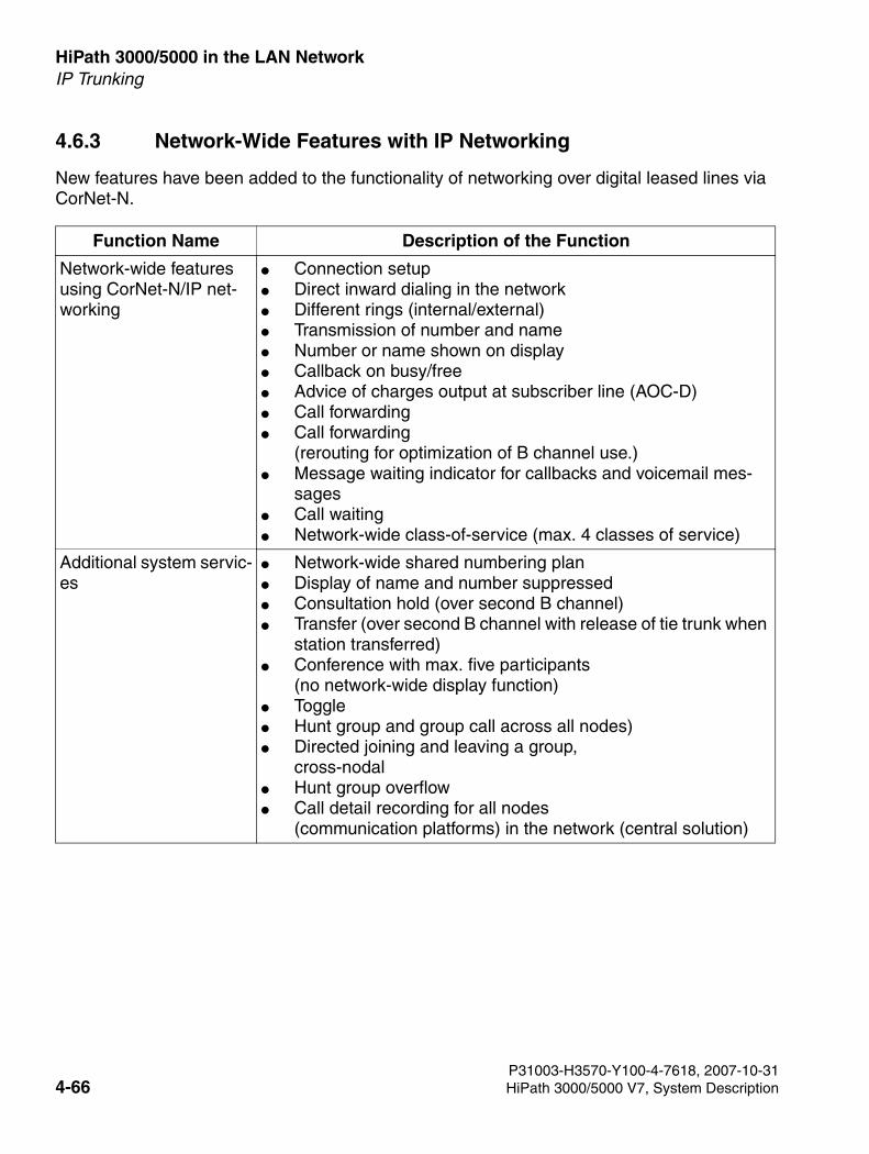
HiPath 3000/5000 in the LAN Network For internal use only
3000sb4.fm
IP Trunking
4.6.3 Network-Wide Features with IP Networking
New features have been added to the functionality of networking over digital leased lines via CorNet-N.
Function Name Description of the Function
Network-wide features using CorNet-N/IP net-working
● Connection setup● Direct inward dialing in the network● Different rings (internal/external)● Transmission of number and name● Number or name shown on display● Callback on busy/free● Advice of charges output at subscriber line (AOC-D)● Call forwarding● Call forwarding
(rerouting for optimization of B channel use.)● Message waiting indicator for callbacks and voicemail mes-
sages● Call waiting● Network-wide class-of-service (max. 4 classes of service)
Additional system servic-es
● Network-wide shared numbering plan● Display of name and number suppressed● Consultation hold (over second B channel)● Transfer (over second B channel with release of tie trunk when
station transferred)● Conference with max. five participants
(no network-wide display function) ● Toggle● Hunt group and group call across all nodes)● Directed joining and leaving a group,
cross-nodal● Hunt group overflow● Call detail recording for all nodes
(communication platforms) in the network (central solution)
P31003-H3570-Y100-4-7618, 2007-10-314-66 HiPath 3000/5000 V7, System Description
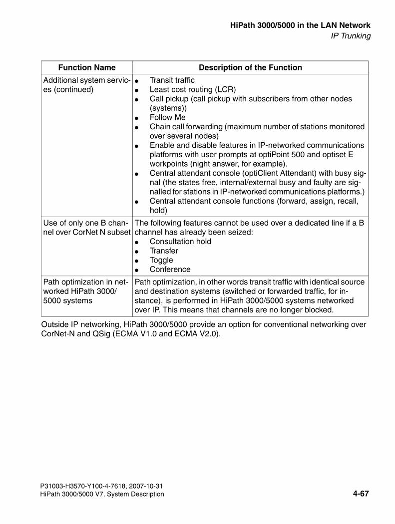
3000sb4.fm
For internal use only HiPath 3000/5000 in the LAN NetworkIP Trunking
Outside IP networking, HiPath 3000/5000 provide an option for conventional networking over CorNet-N and QSig (ECMA V1.0 and ECMA V2.0).
Additional system servic-es (continued)
● Transit traffic● Least cost routing (LCR)● Call pickup (call pickup with subscribers from other nodes
(systems))● Follow Me ● Chain call forwarding (maximum number of stations monitored
over several nodes)● Enable and disable features in IP-networked communications
platforms with user prompts at optiPoint 500 and optiset E workpoints (night answer, for example).
● Central attendant console (optiClient Attendant) with busy sig-nal (the states free, internal/external busy and faulty are sig-nalled for stations in IP-networked communications platforms.)
● Central attendant console functions (forward, assign, recall, hold)
Use of only one B chan-nel over CorNet N subset
The following features cannot be used over a dedicated line if a B channel has already been seized:● Consultation hold● Transfer● Toggle● Conference
Path optimization in net-worked HiPath 3000/5000 systems
Path optimization, in other words transit traffic with identical source and destination systems (switched or forwarded traffic, for in-stance), is performed in HiPath 3000/5000 systems networked over IP. This means that channels are no longer blocked.
Function Name Description of the Function
P31003-H3570-Y100-4-7618, 2007-10-31HiPath 3000/5000 V7, System Description 4-67
HiPath 3000/5000 in the LAN Network For internal use only
3000sb4.fm
IP Trunking
4.6.4 Special Features of Windows Networks
4.6.4.1 Routing and Name Resolution
For example: when routing from HG 1500 V3.0 to HG 1500 V3.0 and for peer-to-peer connec-tions (Windows for Workgroup Network for IP routing), you must create an LMHOSTS/HOSTS file on the client PCs. This is stored in the Windows directory under Windows 95, and in the directory WINNT\SYSTEM32\DRIVERS\ETC under Windows NT or 2000. The file LM-HOSTS.SAM in the directory can be expanded but must not have an extension (LMHOSTS).
Sample entry:
192.168.10.10 HG1500
192.168.10.20 PC1
Do not forget to press Return after the last entry.
Once the LMHOSTS/HOSTS file has been created, a ping command with the name (for example Ping HG 1500) should be transmitted to the partner. Since browsing is not transferred in the case of routers (broadcast messages), the other PC can only be found by right-clicking the "Network Neighborhood" and "Find Computer" icons. Once the computer has been found, the network resources can be accessed. The other PC cannot be accessed by opening the network neighborhood.
>Names should contain no more than eight characters since some operating systems run into problems if there are more than eight characters in the name.Modifications in LMHOSTS/HOSTS are only effective after the computer has been re-booted. Under Windows 95 and 98 you can also use the command NBTSTAT -R.
P31003-H3570-Y100-4-7618, 2007-10-314-68 HiPath 3000/5000 V7, System Description
3000sb4.fm
For internal use only HiPath 3000/5000 in the LAN NetworkIP Payload Switching
4.7 IP Payload Switching
Introduction
IP payload switching optimizes communication between LAN-based IP workpoint clients.
In HiPath 3000 V1.2 and lower, two B-channels (with two DSP resources) in the HiPath HG 1500 and HiPath 3000/5000-internal switching network were seized for internal network calls.
In HiPath 3000/5000 V3.0 and later, VoIP voice data (payload) is transferred directly between two IP workpoint clients in the network. When this happens, both IP workpoint clients have full access to all system features.
Payload switching is also implemented for IP networking (PBX routing).
By ceasing to use B-channels, we have managed to preserve HG 1500 resources and facilitate a higher volume of network-internal call traffic.
A B-channel is still required on the HG 1500 for connections to the following stations and lines:
● UP0/E stations (optiset E, optiPoint 500)
● Analog stations
● ISDN stations
● Trunks and tie lines (MSI, S0, S2M)
Example: a consultation call to an optiPoint 500 telephone is set up during an existing connec-tion between two IP workpoint clients. A HG 1500 B-channel is necessary for this consultation call.
In the case of conferences, the number of B channels seized corresponds to the number of sta-tions and IP workpoint clients involved.
A HG 1500 DSP resource is permanently reserved for playing music-on-hold.
Example: a license was acquired for two B channels and six clients. Six optiPoint 400 standards were logged on. The following scenario is possible in this case: two stations can conduct an external call, while two stations are listening to Music on Hold and two stations are talking to each other.
P31003-H3570-Y100-4-7618, 2007-10-31HiPath 3000/5000 V7, System Description 4-69
HiPath 3000/5000 in the LAN Network For internal use only
3000sb4.fm
IP Payload Switching
Prerequisites
The following components are necessary for using payload switching:
● IP workpoint clients
– optiClient 130 V5.0/V5.1 V4.0
– optiPoint 400/410/420 and optiPoint 600
optiPoint 300 advance and the optiPoint IP adapter (supported up to and including V1.2) are not supported.
● HG 1500 boards with Digital Signal Processor DSP (voice and data)
P31003-H3570-Y100-4-7618, 2007-10-314-70 HiPath 3000/5000 V7, System Description
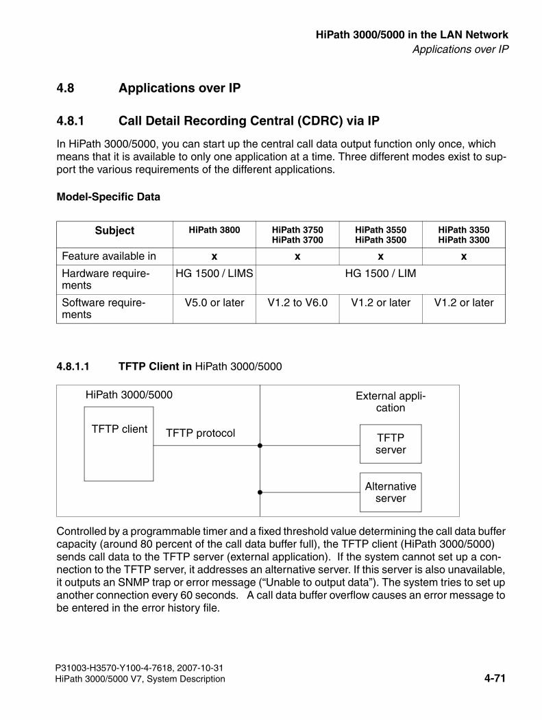
3000sb4.fm
For internal use only HiPath 3000/5000 in the LAN NetworkApplications over IP
4.8 Applications over IP
4.8.1 Call Detail Recording Central (CDRC) via IP
In HiPath 3000/5000, you can start up the central call data output function only once, which means that it is available to only one application at a time. Three different modes exist to sup-port the various requirements of the different applications.
Model-Specific Data
4.8.1.1 TFTP Client in HiPath 3000/5000
Controlled by a programmable timer and a fixed threshold value determining the call data buffer capacity (around 80 percent of the call data buffer full), the TFTP client (HiPath 3000/5000) sends call data to the TFTP server (external application). If the system cannot set up a con-nection to the TFTP server, it addresses an alternative server. If this server is also unavailable, it outputs an SNMP trap or error message (“Unable to output data”). The system tries to set up another connection every 60 seconds. A call data buffer overflow causes an error message to be entered in the error history file.
Subject HiPath 3800 HiPath 3750HiPath 3700
HiPath 3550HiPath 3500
HiPath 3350HiPath 3300
Feature available in x x x x
Hardware require-ments
HG 1500 / LIMS HG 1500 / LIM
Software require-ments
V5.0 or later V1.2 to V6.0 V1.2 or later V1.2 or later
TFTP client
HiPath 3000/5000 External appli-cation
TFTP protocol TFTP server
Alternative server
P31003-H3570-Y100-4-7618, 2007-10-31HiPath 3000/5000 V7, System Description 4-71
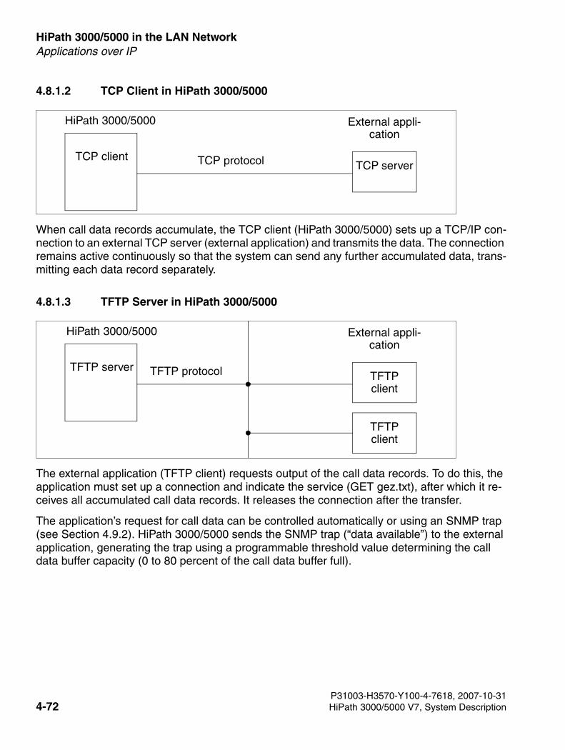
HiPath 3000/5000 in the LAN Network For internal use only
3000sb4.fm
Applications over IP
4.8.1.2 TCP Client in HiPath 3000/5000
When call data records accumulate, the TCP client (HiPath 3000/5000) sets up a TCP/IP con-nection to an external TCP server (external application) and transmits the data. The connection remains active continuously so that the system can send any further accumulated data, trans-mitting each data record separately.
4.8.1.3 TFTP Server in HiPath 3000/5000
The external application (TFTP client) requests output of the call data records. To do this, the application must set up a connection and indicate the service (GET gez.txt), after which it re-ceives all accumulated call data records. It releases the connection after the transfer.
The application’s request for call data can be controlled automatically or using an SNMP trap (see Section 4.9.2). HiPath 3000/5000 sends the SNMP trap (“data available”) to the external application, generating the trap using a programmable threshold value determining the call data buffer capacity (0 to 80 percent of the call data buffer full).
TCP client
HiPath 3000/5000 External appli-cation
TCP protocol TCP server
TFTP server
HiPath 3000/5000 External appli-cation
TFTP protocol TFTP client
TFTP client
P31003-H3570-Y100-4-7618, 2007-10-314-72 HiPath 3000/5000 V7, System Description
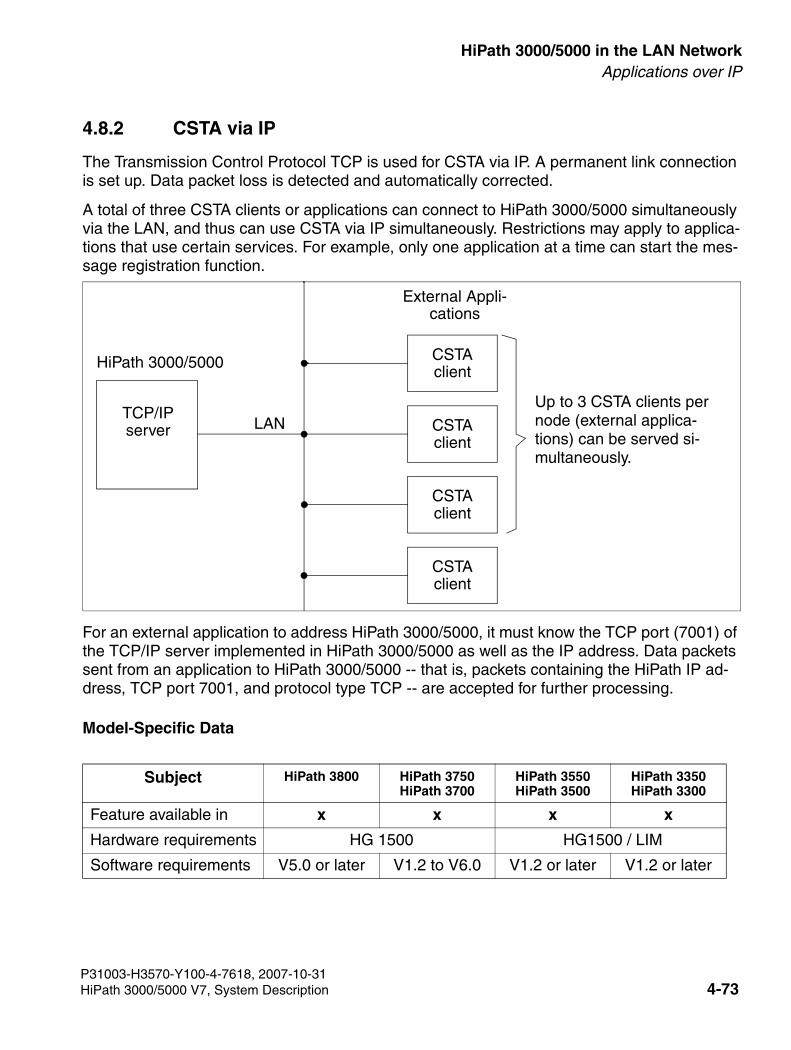
3000sb4.fm
For internal use only HiPath 3000/5000 in the LAN NetworkApplications over IP
4.8.2 CSTA via IP
The Transmission Control Protocol TCP is used for CSTA via IP. A permanent link connection is set up. Data packet loss is detected and automatically corrected.
A total of three CSTA clients or applications can connect to HiPath 3000/5000 simultaneously via the LAN, and thus can use CSTA via IP simultaneously. Restrictions may apply to applica-tions that use certain services. For example, only one application at a time can start the mes-sage registration function.
For an external application to address HiPath 3000/5000, it must know the TCP port (7001) of the TCP/IP server implemented in HiPath 3000/5000 as well as the IP address. Data packets sent from an application to HiPath 3000/5000 -- that is, packets containing the HiPath IP ad-dress, TCP port 7001, and protocol type TCP -- are accepted for further processing.
Model-Specific Data
Subject HiPath 3800 HiPath 3750HiPath 3700
HiPath 3550HiPath 3500
HiPath 3350HiPath 3300
Feature available in x x x x
Hardware requirements HG 1500 HG1500 / LIM
Software requirements V5.0 or later V1.2 to V6.0 V1.2 or later V1.2 or later
TCP/IP server
HiPath 3000/5000 CSTA client
CSTA client
CSTA client
CSTA client
Up to 3 CSTA clients per node (external applica-tions) can be served si-multaneously.
External Appli-cations
LAN
P31003-H3570-Y100-4-7618, 2007-10-31HiPath 3000/5000 V7, System Description 4-73
HiPath 3000/5000 in the LAN Network For internal use only
3000sb4.fm
Applications over IP
LIM / LIMS
LIM/LIMS is released in HiPath 3800 for administration, fault management and accounting. No other features or protocols are supported via LIMS!
LIM for HiPath 33x0 and HiPath 35x0 can be used for CTI/CSTA applications in conjunction with TAPI 120 (up to 6 stations). No other features or protocols are supported via LIM!
Dependencies/restrictions
SimplyPhone for Outlook is supported via LIM from Version 6.0 or later.
P31003-H3570-Y100-4-7618, 2007-10-314-74 HiPath 3000/5000 V7, System Description
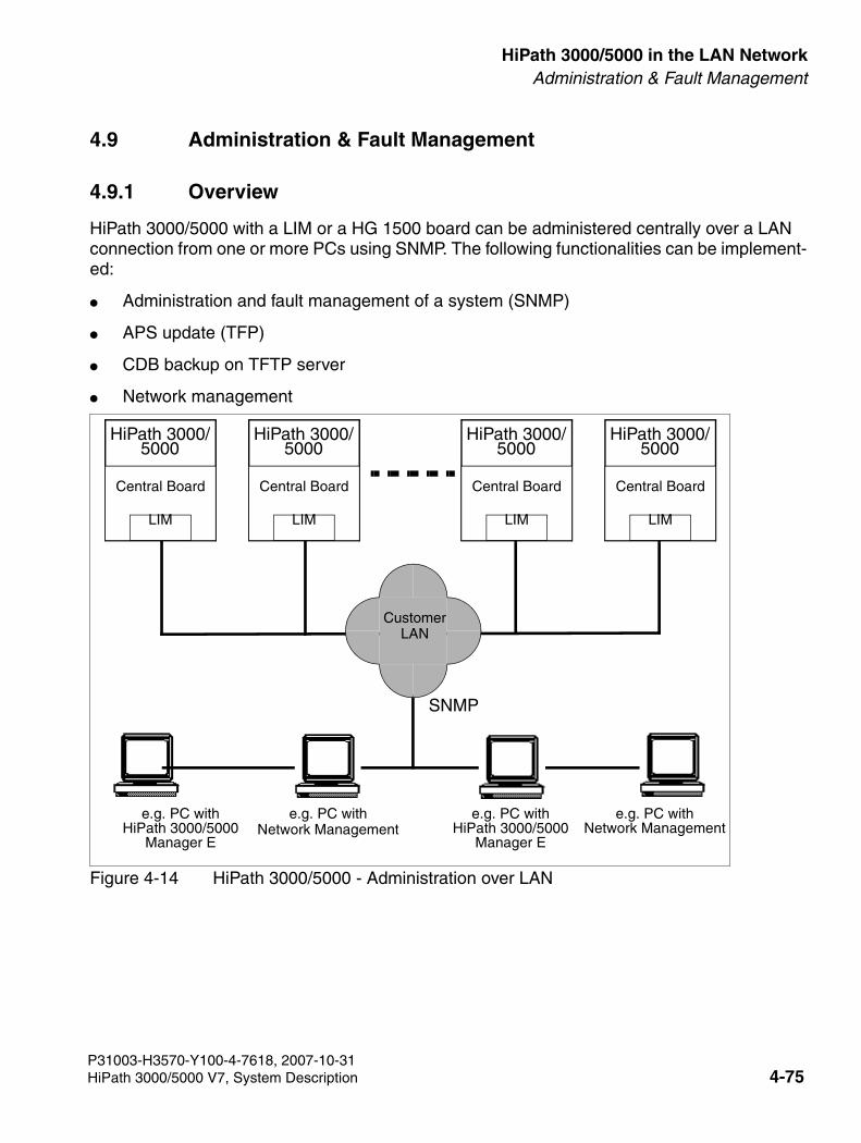
3000sb4.fm
For internal use only HiPath 3000/5000 in the LAN NetworkAdministration & Fault Management
4.9 Administration & Fault Management
4.9.1 Overview
HiPath 3000/5000 with a LIM or a HG 1500 board can be administered centrally over a LAN connection from one or more PCs using SNMP. The following functionalities can be implement-ed:
● Administration and fault management of a system (SNMP)
● APS update (TFP)
● CDB backup on TFTP server
● Network management
Figure 4-14 HiPath 3000/5000 - Administration over LAN
e.g. PC withHiPath 3000/5000
Manager E
SNMP
HiPath 3000/5000
Central Board
LIM
CustomerLAN
e.g. PC withNetwork Management
e.g. PC withNetwork Management
e.g. PC withHiPath 3000/5000
Manager E
HiPath 3000/5000
Central Board
LIM
HiPath 3000/5000
Central Board
LIM
HiPath 3000/5000
Central Board
LIM
P31003-H3570-Y100-4-7618, 2007-10-31HiPath 3000/5000 V7, System Description 4-75
HiPath 3000/5000 in the LAN Network For internal use only
3000sb4.fm
Administration & Fault Management
4.9.2 SNMP Functionality
4.9.2.1 Introduction
As part of the TCP/IP protocol family, the Simple Network Management Protocol (SNMP) is an easy-to-use platform for performing management tasks in the HiPath 3000/5000 system soft-ware. SNMP is used as a kind of management agent in HiPath 3000/5000, making it possible to monitor and administer LAN components (including HiPath 3000/5000 itself) from a central location. This involves
● addressing HiPath 3000/5000 via the TCP/IP protocol family.
● external management applications, such as HP Open View and IBM Tivoli, to access data in HiPath 3000/5000 (using SNMP messages, such as GET, SET, TRAP).
● implementing remote maintenance tasks (online port status, enabling and disabling ports, determining free ports) (HiPath Fault Management)
● transmitting service-related class B errors
● visualizing the operating status of HiPath 3000/5000 systems.
4.9.2.2 Overview of SNMP Functions
Management Information Bases (MIBs)
MIBs define the volume of data that can be administered via SNMP. They are data models that describe the network elements to be administered in a very specific form.
HiPath 3000/5000 supports
● standard MIB II (according to the RFC1213 Internet standard), which provides Internet and router functions;
● parts of the RMON 1/2 standard MIBs (RFC 1757, RFC 2021), which support
– Error history
– Trap configuration
– TFTP configuration
– General system information
P31003-H3570-Y100-4-7618, 2007-10-314-76 HiPath 3000/5000 V7, System Description
3000sb4.fm
For internal use only HiPath 3000/5000 in the LAN NetworkAdministration & Fault Management
● a user-specific MIB that processes HiPath-specific statistic data (feature counters) and in-ternal error messages (error history), covering the following areas:
– ControlGroup – status variables, general configuration, supplementary TFTP configu-ration data
– SystemInfoGroup – system configuration and status
– StatisticsGroup – statistic data on features
– ErrorHistoryGroup – Error history in HiPath formatError messages are forwarded in the form of SNMP traps via the LAN to a specific ex-ternal management application. The SNMP traps form the error history data structure (time stamp, error class, error description).
These components use the IP protocol according to OSI layer 3 and the UDP protocol accord-ing to layer 4. The SNMP protocol stack uses port numbers. The system supports the SNMP protocol version 1.0.
SNMP Messages
The following commands control SNMP messages for communication between the SNMP management agent (HiPath 3000/5000) and external applications:
● GET – retrieve data from agent
● GET NEXT – read out data sequentially
● SET – write data
● TRAP – alarm messages issued by the SNMP agent
There is an integrated mechanism for generating SNMP traps in the event of class B errors. The SNMP management agent evaluates the error messages. In the case of defined errors, it generates specific traps and transmits them in the form of IP data records to a configurable IP address (a total of five SNMP V1.0-compatible applications are supported, including HP Open View Network Node Manager for example).
P31003-H3570-Y100-4-7618, 2007-10-31HiPath 3000/5000 V7, System Description 4-77
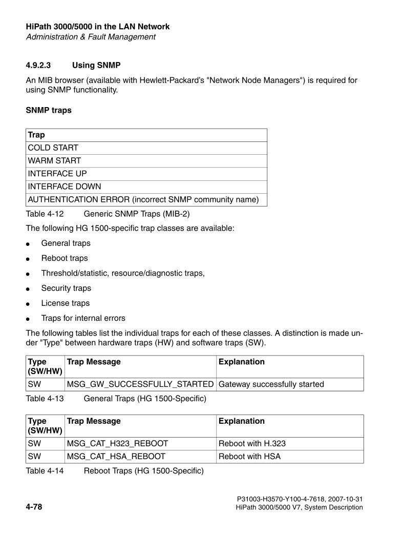
HiPath 3000/5000 in the LAN Network For internal use only
3000sb4.fm
Administration & Fault Management
4.9.2.3 Using SNMP
An MIB browser (available with Hewlett-Packard’s "Network Node Managers") is required for using SNMP functionality.
SNMP traps
The following HG 1500-specific trap classes are available:
● General traps
● Reboot traps
● Threshold/statistic, resource/diagnostic traps,
● Security traps
● License traps
● Traps for internal errors
The following tables list the individual traps for each of these classes. A distinction is made un-der "Type" between hardware traps (HW) and software traps (SW).
Trap
COLD START
WARM START
INTERFACE UP
INTERFACE DOWN
AUTHENTICATION ERROR (incorrect SNMP community name)
Table 4-12 Generic SNMP Traps (MIB-2)
Type (SW/HW)
Trap Message Explanation
SW MSG_GW_SUCCESSFULLY_STARTED Gateway successfully started
Table 4-13 General Traps (HG 1500-Specific)
Type (SW/HW)
Trap Message Explanation
SW MSG_CAT_H323_REBOOT Reboot with H.323
SW MSG_CAT_HSA_REBOOT Reboot with HSA
Table 4-14 Reboot Traps (HG 1500-Specific)
P31003-H3570-Y100-4-7618, 2007-10-314-78 HiPath 3000/5000 V7, System Description
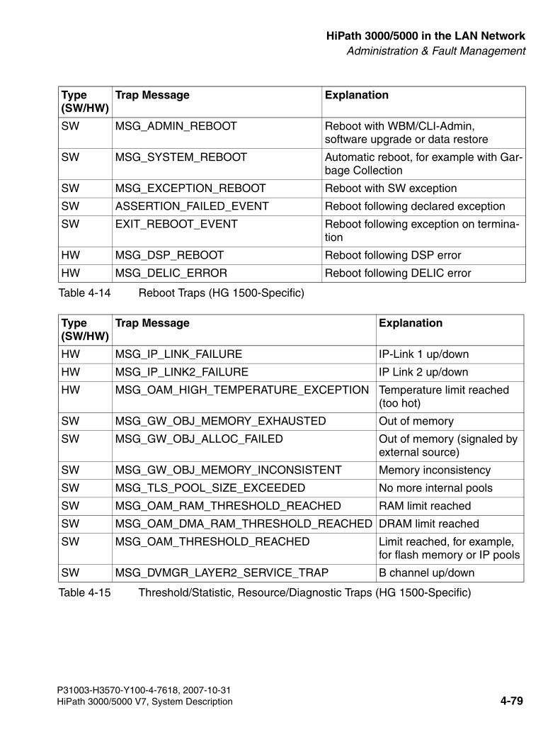
3000sb4.fm
For internal use only HiPath 3000/5000 in the LAN NetworkAdministration & Fault Management
SW MSG_ADMIN_REBOOT Reboot with WBM/CLI-Admin, software upgrade or data restore
SW MSG_SYSTEM_REBOOT Automatic reboot, for example with Gar-bage Collection
SW MSG_EXCEPTION_REBOOT Reboot with SW exception
SW ASSERTION_FAILED_EVENT Reboot following declared exception
SW EXIT_REBOOT_EVENT Reboot following exception on termina-tion
HW MSG_DSP_REBOOT Reboot following DSP error
HW MSG_DELIC_ERROR Reboot following DELIC error
Type (SW/HW)
Trap Message Explanation
HW MSG_IP_LINK_FAILURE IP-Link 1 up/down
HW MSG_IP_LINK2_FAILURE IP Link 2 up/down
HW MSG_OAM_HIGH_TEMPERATURE_EXCEPTION Temperature limit reached (too hot)
SW MSG_GW_OBJ_MEMORY_EXHAUSTED Out of memory
SW MSG_GW_OBJ_ALLOC_FAILED Out of memory (signaled by external source)
SW MSG_GW_OBJ_MEMORY_INCONSISTENT Memory inconsistency
SW MSG_TLS_POOL_SIZE_EXCEEDED No more internal pools
SW MSG_OAM_RAM_THRESHOLD_REACHED RAM limit reached
SW MSG_OAM_DMA_RAM_THRESHOLD_REACHED DRAM limit reached
SW MSG_OAM_THRESHOLD_REACHED Limit reached, for example, for flash memory or IP pools
SW MSG_DVMGR_LAYER2_SERVICE_TRAP B channel up/down
Table 4-15 Threshold/Statistic, Resource/Diagnostic Traps (HG 1500-Specific)
Type (SW/HW)
Trap Message Explanation
Table 4-14 Reboot Traps (HG 1500-Specific)
P31003-H3570-Y100-4-7618, 2007-10-31HiPath 3000/5000 V7, System Description 4-79
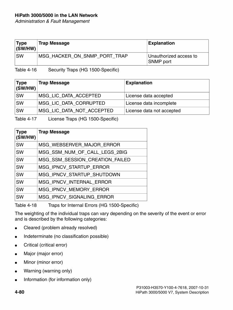
HiPath 3000/5000 in the LAN Network For internal use only
3000sb4.fm
Administration & Fault Management
P31003-H3570-Y100-4-7618, 2007-10-31
The weighting of the individual traps can vary depending on the severity of the event or error and is described by the following categories:
● Cleared (problem already resolved)
● Indeterminate (no classification possible)
● Critical (critical error)
● Major (major error)
● Minor (minor error)
● Warning (warning only)
● Information (for information only)
Type (SW/HW)
Trap Message Explanation
SW MSG_HACKER_ON_SNMP_PORT_TRAP Unauthorized access to SNMP port
Table 4-16 Security Traps (HG 1500-Specific)
Type (SW/HW)
Trap Message Explanation
SW MSG_LIC_DATA_ACCEPTED License data accepted
SW MSG_LIC_DATA_CORRUPTED License data incomplete
SW MSG_LIC_DATA_NOT_ACCEPTED License data not accepted
Table 4-17 License Traps (HG 1500-Specific)
Type (SW/HW)
Trap Message
SW MSG_WEBSERVER_MAJOR_ERROR
SW MSG_SSM_NUM_OF_CALL_LEGS_2BIG
SW MSG_SSM_SESSION_CREATION_FAILED
SW MSG_IPNCV_STARTUP_ERROR
SW MSG_IPNCV_STARTUP_SHUTDOWN
SW MSG_IPNCV_INTERNAL_ERROR
SW MSG_IPNCV_MEMORY_ERROR
SW MSG_IPNCV_SIGNALING_ERROR
Table 4-18 Traps for Internal Errors (HG 1500-Specific)
4-80 HiPath 3000/5000 V7, System Description
3000sb4.fm
For internal use only HiPath 3000/5000 in the LAN NetworkAdministration & Fault Management
General traps, such as MSG_GW_SUCCESSFULLY_STARTED, are sent as "information".
Reboot traps are always "critical", "major" or "minor" errors.
Threshold/resource traps occur as follows: When an event is received, the trap is sent as either "Warning", "Minor" or "Major". If the trap recurs, reminders are sent (at increasing intervals) with a weighting that is at least the same or higher than the initial trap. If the event was corrected (for example, "Link up" or sufficient RAM was provided), the trap is sent with the category "Cleared".
SNMP Functions
The SNMP functions include:
● With MIB browser and standard MIB (based on RFC1213):
– querying and modifying standard MIB 2 parameters
● With MIB browser and private MIB:
– querying and modifying HG 1500 V3.0’s private MIB parameters
● With HiPath 3000 Manager E:
– defining communities of standard parameters (classes of service)
– defining trap communities and stations to which the traps are sent
– defining the trap level for various trap groups (error sensitivity)
● With trap receiver:
– receiving traps
MIBs also contain a brief commentary explaining the meaning of each parameter.
The following is a list of some parameters:
● mgmt > mib-2 > system > sysUpTime: time since the last HG 1500 V3.0 startup
● HLB2MIB > siemensUnits > pn > hlb2mib > controlGrouphlb20 > sysSoftwareVersion: board software release
● mgmt->mib-2->ip->ipRouteTable: HG 1500 V3.0 routing table
HG 1500 V3.0 sends SNMP traps (diagnostic and error messages) to the stations configured under "SNMP > Trap Communities". These messages are transmitted in accordance with the severity levels set under "SNMP".
P31003-H3570-Y100-4-7618, 2007-10-31HiPath 3000/5000 V7, System Description 4-81
HiPath 3000/5000 in the LAN Network For internal use only
3000sb4.fm
Administration & Fault Management
Examples of traps generated by HG 1500 V3.0:
1. Generic traps (cannot be deactivated):
● warm start
● cold start
● authentication failure
2. Enterprise traps (can be configured)
● data init (WARNING - forced data reinitialization)
● memory low (WARNING - memory resources below the threshold)
● duplicate mac (MINOR - duplicated MAC address)
● ip firewall (WARNING - IP firewall violation)
● mac firewall (WARNING - MAC firewall violation)
● isdn access (WARNING - ISDN access verification)
SNMP information can also be sent as e-mail to a mail address configured with the WBM.
P31003-H3570-Y100-4-7618, 2007-10-314-82 HiPath 3000/5000 V7, System Description
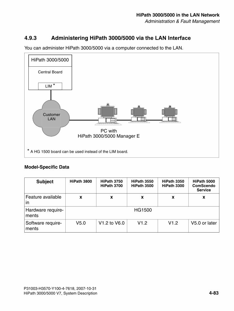
3000sb4.fm
For internal use only HiPath 3000/5000 in the LAN NetworkAdministration & Fault Management
4.9.3 Administering HiPath 3000/5000 via the LAN Interface
You can administer HiPath 3000/5000 via a computer connected to the LAN.
Model-Specific Data
Subject HiPath 3800 HiPath 3750HiPath 3700
HiPath 3550HiPath 3500
HiPath 3350HiPath 3300
HiPath 5000 ComScendo
Service
Feature available in
x x x x x
Hardware require-ments
HG1500
Software require-ments
V5.0 V1.2 to V6.0 V1.2 V1.2 V5.0 or later
HiPath 3000/5000
PC withHiPath 3000/5000 Manager E
Central Board
LIM *
CustomerLAN
* A HG 1500 board can be used instead of the LIM board.
P31003-H3570-Y100-4-7618, 2007-10-31HiPath 3000/5000 V7, System Description 4-83
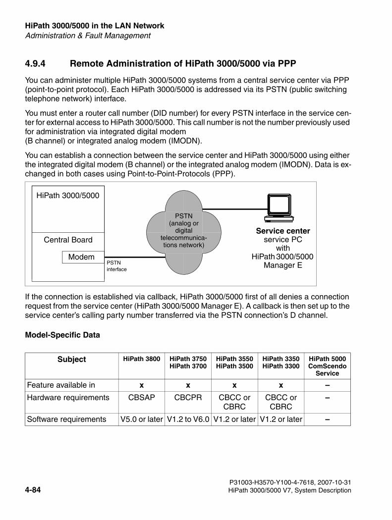
HiPath 3000/5000 in the LAN Network For internal use only
3000sb4.fm
Administration & Fault Management
4.9.4 Remote Administration of HiPath 3000/5000 via PPP
You can administer multiple HiPath 3000/5000 systems from a central service center via PPP (point-to-point protocol). Each HiPath 3000/5000 is addressed via its PSTN (public switching telephone network) interface.
You must enter a router call number (DID number) for every PSTN interface in the service cen-ter for external access to HiPath 3000/5000. This call number is not the number previously used for administration via integrated digital modem (B channel) or integrated analog modem (IMODN).
You can establish a connection between the service center and HiPath 3000/5000 using either the integrated digital modem (B channel) or the integrated analog modem (IMODN). Data is ex-changed in both cases using Point-to-Point-Protocols (PPP).
If the connection is established via callback, HiPath 3000/5000 first of all denies a connection request from the service center (HiPath 3000/5000 Manager E). A callback is then set up to the service center’s calling party number transferred via the PSTN connection’s D channel.
Model-Specific Data
Subject HiPath 3800 HiPath 3750HiPath 3700
HiPath 3550HiPath 3500
HiPath 3350HiPath 3300
HiPath 5000 ComScendo
Service
Feature available in x x x x –
Hardware requirements CBSAP CBCPR CBCC orCBRC
CBCC orCBRC
–
Software requirements V5.0 or later V1.2 to V6.0 V1.2 or later V1.2 or later –
HiPath 3000/5000
Service centerservice PC
withHiPath 3000/5000
Manager E
Central Board
Modem
PSTN(analog or
digitaltelecommunica-tions network)
PSTNinterface
P31003-H3570-Y100-4-7618, 2007-10-314-84 HiPath 3000/5000 V7, System Description
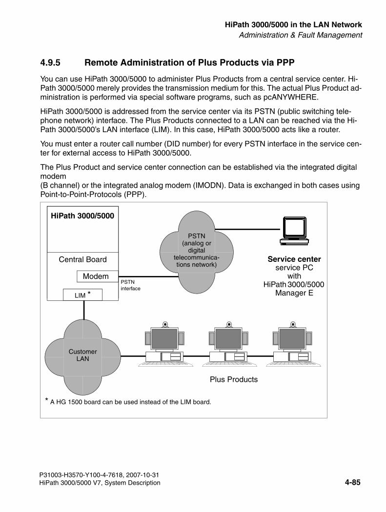
3000sb4.fm
For internal use only HiPath 3000/5000 in the LAN NetworkAdministration & Fault Management
4.9.5 Remote Administration of Plus Products via PPP
You can use HiPath 3000/5000 to administer Plus Products from a central service center. Hi-Path 3000/5000 merely provides the transmission medium for this. The actual Plus Product ad-ministration is performed via special software programs, such as pcANYWHERE.
HiPath 3000/5000 is addressed from the service center via its PSTN (public switching tele-phone network) interface. The Plus Products connected to a LAN can be reached via the Hi-Path 3000/5000’s LAN interface (LIM). In this case, HiPath 3000/5000 acts like a router.
You must enter a router call number (DID number) for every PSTN interface in the service cen-ter for external access to HiPath 3000/5000.
The Plus Product and service center connection can be established via the integrated digital modem (B channel) or the integrated analog modem (IMODN). Data is exchanged in both cases using Point-to-Point-Protocols (PPP).
HiPath 3000/5000
Plus Products
Service centerservice PC
withHiPath 3000/5000
Manager E
Central Board
Modem
LIM *
CustomerLAN
PSTN(analog or
digitaltelecommunica-tions network)
PSTNinterface
* A HG 1500 board can be used instead of the LIM board.
P31003-H3570-Y100-4-7618, 2007-10-31HiPath 3000/5000 V7, System Description 4-85
HiPath 3000/5000 in the LAN Network For internal use only
3000sb4.fm
Administration & Fault Management
Access Mechanism
A list of up to twenty remote structures controls access from the service center to the customer LAN and vice versa. Each remote structure contains the following information:
● The IP address of the service center (= PSTN partner in the service center) for setting up connections from the customer LAN to the service center and for the automatic transmis-sion of error messages (SNMP traps).
● The DID number (part of the numbering plans) for direct identification of this remote struc-ture.
● Up to five PSTN remote numbers marked as incoming (for identifying the remote structure - when dialing the router call number) and/or outgoing (for use as callback address).
● Short hold mode Yes/No
– If "Short hold = Yes" is selected, an inactive PSTN connection is cleared down after a set time (short hold timeout). If there are new data packets to be transmitted, the con-nection is set up once again (transparent for the user). This mechanism is also known as a background connection setup or cleardown. Costs are only incurred when the line is actually used.
– If “Short hold = No” is selected, a PSTN connection remains permanently active until the end criterion is received.
● Short hold (sec.) This parameter describes the length of time in seconds after which an inactive PSTN con-nection is cleared down.
● Callbk Yes/No
– If “Callbk = Yes” is selected, a connection request is first of all denied. Then the first station number marked as outgoing in the remote structure found is called back. Three attempts are made to set up the connection, then the next outgoing station number is used. The system stops trying to set up the callback after three unsuccessful attempts.
– If “Callbk = No” is selected, the connection is set up immediately.
● Remote analog modemIf you select “Yes”, the V.34 protocol in the B channel is used for an outgoing connection via the ISDN line.
P31003-H3570-Y100-4-7618, 2007-10-314-86 HiPath 3000/5000 V7, System Description
3000sb4.fm
For internal use only HiPath 3000/5000 in the LAN NetworkAdministration & Fault Management
● IP mapping Yes/NoIf a number of different customers have the same IP address, you can use address map-ping to achieve unique IP address assignment in the various customer LANs.
– If “IP mapping = Yes” is selected, you can map an IP address which is assigned to mul-tiple customers to a unique “virtual” IP address. You can perform IP mapping for up to twenty address entries.
Examples:IP data transfer from the customer LAN to the service center via the PSTN interface: IP customer LAN is transformed by HiPath 3000/5000 into an IP virtual LAN.IP data transfer from the service center to the customer LAN via the PSTN interface: IP virtual LAN is transformed by HiPath 3000/5000 into an IP customer LAN.
– If “IP mapping = No” is selected, IP address mapping is not available.
● Security mechanisms for connection setupUse the PAP (PPP authentication protocol) and/or CHAP (challenge-handshake authenti-cation protocol) to determine whether
– the Plus Product (client) must be authenticated at HiPath 3000/5000 (host) or
– the HiPath 3000/5000 (host) must be authenticated at the Plus Product (client).
Authentication is based on the user ID and the password.
Model-Specific Data
Subject HiPath 3800 HiPath 3750HiPath 3700
HiPath 3550HiPath 3500
HiPath 3350HiPath 3300
HiPath 5000 ComScendo
Service
Feature available in x x x x –
Hardware requirements HG1500 –
Software requirements V5.0 or later V1.2 to V6.0 V1.2 or later V1.2 or later –
P31003-H3570-Y100-4-7618, 2007-10-31HiPath 3000/5000 V7, System Description 4-87
HiPath 3000/5000 in the LAN Network For internal use only
3000sb4.fm
Administration & Fault Management
● Support for the External Gatekeeper
The gatekeeper registers the H.323 clients and administers their rights and services. It converts the clients’ call numbers into logical names or IP addresses and vice versa. It also registers the gateways and can be networked with adjacent gatekeepers.
● Quality of Service (QoS)
To guarantee the bandwidth required for Voice over IP, IP packets can be marked and are thereby transported with priority in the LAN/WAN.
● Networking of more than one System via IP
SeveralHiPath 3000/5000 telephone systems can be connected to each other with Voice over IP (H.323) for telephony.
● Authentication
If you set up an external connection via HG 1500, you can use the PAP (Password Authen-tication Protocol) and CHAP (Challenge Handshake Authentication Protocol) procedures to authenticate the other party to increase security in data networks.
● Second LAN connection (optional)
A second LAN connection is set up to decouple the DSL WAN connection. A routing func-tion is used to connect the first LAN.
● DSL support (optional)
The configuration database is extended to include an additional interface. The information necessary for dialing into the DSL network is provided here. The enhanced configuration parameters can be entered over the HiPath 3000 Manager I. The DSL functionality is only available for the second LAN connection.
P31003-H3570-Y100-4-7618, 2007-10-314-88 HiPath 3000/5000 V7, System Description
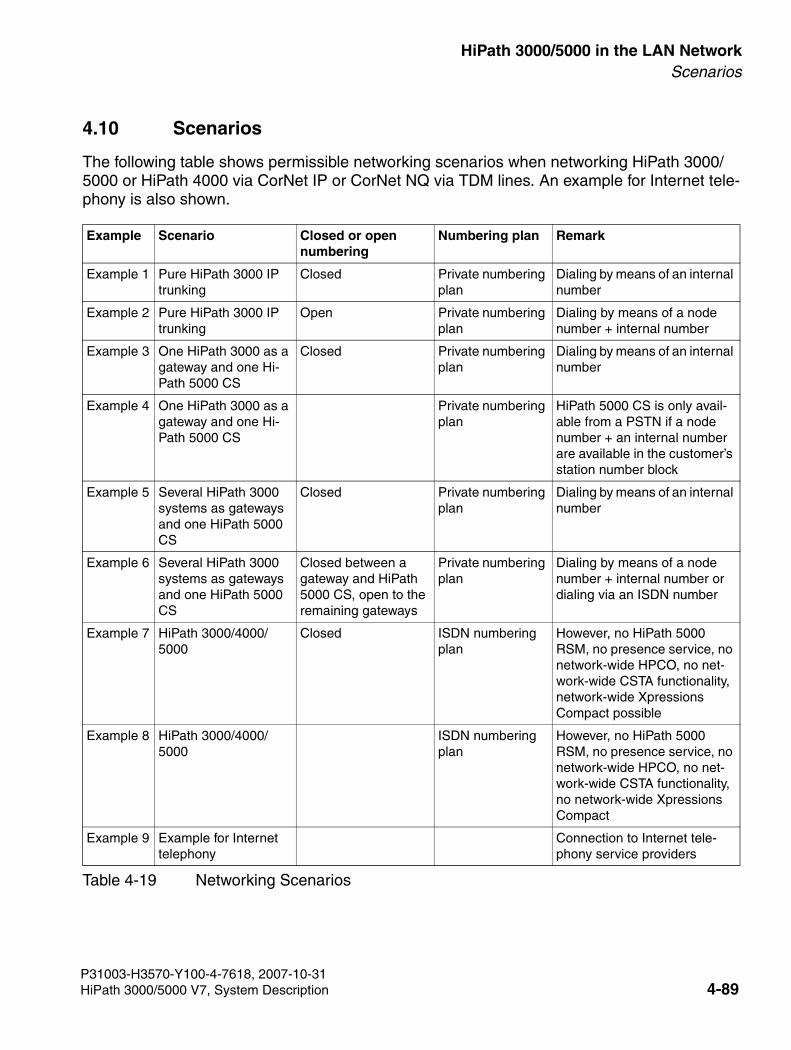
3000sb4.fm
For internal use only HiPath 3000/5000 in the LAN NetworkScenarios
4.10 Scenarios
The following table shows permissible networking scenarios when networking HiPath 3000/5000 or HiPath 4000 via CorNet IP or CorNet NQ via TDM lines. An example for Internet tele-phony is also shown.
Example Scenario Closed or open numbering
Numbering plan Remark
Example 1 Pure HiPath 3000 IP trunking
Closed Private numbering plan
Dialing by means of an internal number
Example 2 Pure HiPath 3000 IP trunking
Open Private numbering plan
Dialing by means of a node number + internal number
Example 3 One HiPath 3000 as a gateway and one Hi-Path 5000 CS
Closed Private numbering plan
Dialing by means of an internal number
Example 4 One HiPath 3000 as a gateway and one Hi-Path 5000 CS
Private numbering plan
HiPath 5000 CS is only avail-able from a PSTN if a node number + an internal number are available in the customer’s station number block
Example 5 Several HiPath 3000 systems as gateways and one HiPath 5000 CS
Closed Private numbering plan
Dialing by means of an internal number
Example 6 Several HiPath 3000 systems as gateways and one HiPath 5000 CS
Closed between a gateway and HiPath 5000 CS, open to the remaining gateways
Private numbering plan
Dialing by means of a node number + internal number or dialing via an ISDN number
Example 7 HiPath 3000/4000/5000
Closed ISDN numbering plan
However, no HiPath 5000 RSM, no presence service, no network-wide HPCO, no net-work-wide CSTA functionality, network-wide Xpressions Compact possible
Example 8 HiPath 3000/4000/5000
ISDN numbering plan
However, no HiPath 5000 RSM, no presence service, no network-wide HPCO, no net-work-wide CSTA functionality, no network-wide Xpressions Compact
Example 9 Example for Internet telephony
Connection to Internet tele-phony service providers
Table 4-19 Networking Scenarios
P31003-H3570-Y100-4-7618, 2007-10-31HiPath 3000/5000 V7, System Description 4-89
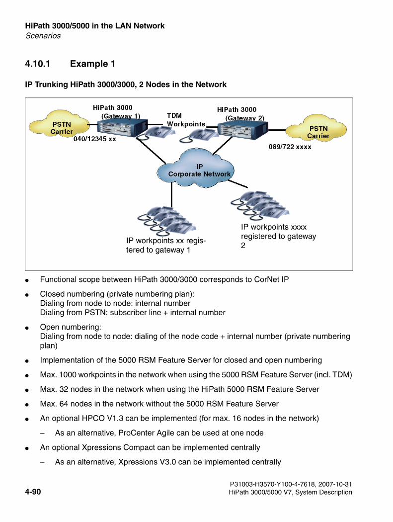
HiPath 3000/5000 in the LAN Network For internal use only
3000sb4.fm
Scenarios
4.10.1 Example 1
IP Trunking HiPath 3000/3000, 2 Nodes in the Network
● Functional scope between HiPath 3000/3000 corresponds to CorNet IP
● Closed numbering (private numbering plan): Dialing from node to node: internal numberDialing from PSTN: subscriber line + internal number
● Open numbering:Dialing from node to node: dialing of the node code + internal number (private numbering plan)
● Implementation of the 5000 RSM Feature Server for closed and open numbering
● Max. 1000 workpoints in the network when using the 5000 RSM Feature Server (incl. TDM)
● Max. 32 nodes in the network when using the HiPath 5000 RSM Feature Server
● Max. 64 nodes in the network without the 5000 RSM Feature Server
● An optional HPCO V1.3 can be implemented (for max. 16 nodes in the network)
– As an alternative, ProCenter Agile can be used at one node
● An optional Xpressions Compact can be implemented centrally
– As an alternative, Xpressions V3.0 can be implemented centrally
IP workpoints xx regis-tered to gateway 1
IP workpoints xxxx registered to gateway 2
P31003-H3570-Y100-4-7618, 2007-10-314-90 HiPath 3000/5000 V7, System Description
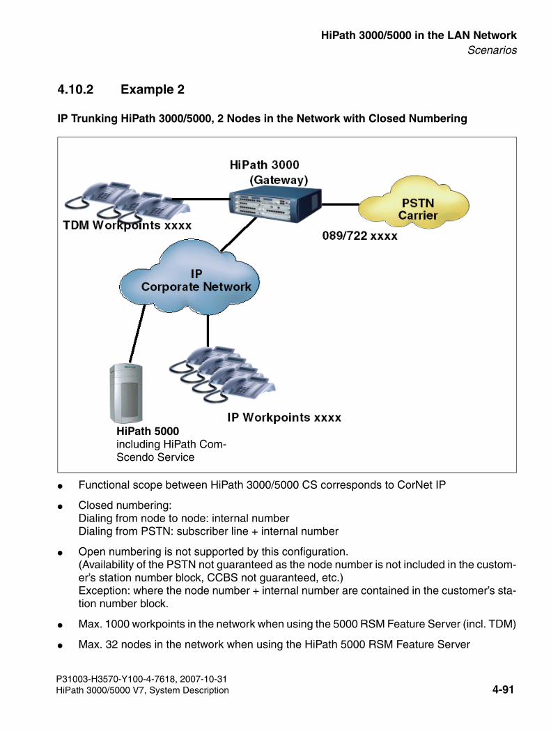
3000sb4.fm
For internal use only HiPath 3000/5000 in the LAN NetworkScenarios
4.10.2 Example 2
IP Trunking HiPath 3000/5000, 2 Nodes in the Network with Closed Numbering
● Functional scope between HiPath 3000/5000 CS corresponds to CorNet IP
● Closed numbering:Dialing from node to node: internal numberDialing from PSTN: subscriber line + internal number
● Open numbering is not supported by this configuration. (Availability of the PSTN not guaranteed as the node number is not included in the custom-er’s station number block, CCBS not guaranteed, etc.) Exception: where the node number + internal number are contained in the customer’s sta-tion number block.
● Max. 1000 workpoints in the network when using the 5000 RSM Feature Server (incl. TDM)
● Max. 32 nodes in the network when using the HiPath 5000 RSM Feature Server
HiPath 5000including HiPath Com-Scendo Service
P31003-H3570-Y100-4-7618, 2007-10-31HiPath 3000/5000 V7, System Description 4-91

HiPath 3000/5000 in the LAN Network For internal use only
3000sb4.fm
Scenarios
● Max. 64 nodes in the network without the 5000 RSM Feature Server
● An optional HPCO V1.3 can be implemented (for max. 16 nodes in the network)
– As an alternative, ProCenter Agile can be used at one node
● An optional Xpressions Compact can be implemented centrally
– As an alternative, Xpressions V3.0 can be implemented centrally
4.10.3 Example 3
IP Trunking HiPath 3000/3000/5000, Gateway 2 and HiPath 5000 CS at Location 2 with Closed Numbering, Gateway 1 at Location 1 Establishes Open Numbering to Location 2
● Functional scope between HiPath 3000/5000 CS corresponds to CorNet IP
● In this example, the private numbering plan should be used. Node numbers that are unique throughout the network should be configured for each location.
● The workpoints of gateway 2 and HiPath 5000 CS establish a closed numbering plan at location 2. Dialing from gateway 2 to 5000 CS: node number + internal number.Dialing gateway 2 or 5000 CS from the PSTN: subscriber line (location 2) + internal num-ber.
Location 1
Call no. 1001
HiPath 5000including HiPath Com-Scendo Service
Call no. 1000Call no. 10
Location 2:closed numbering
Node 20
Node 21
Node 22IP workpoint on HiPath 5000 CS
P31003-H3570-Y100-4-7618, 2007-10-314-92 HiPath 3000/5000 V7, System Description
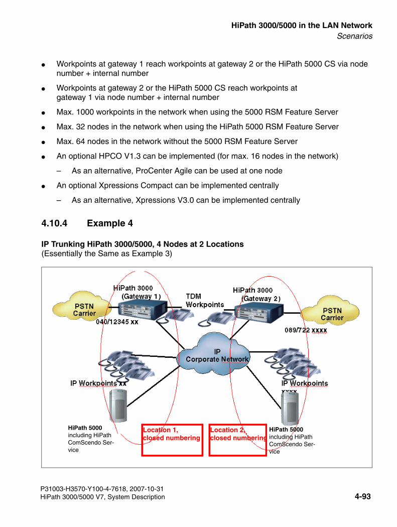
3000sb4.fm
For internal use only HiPath 3000/5000 in the LAN NetworkScenarios
● Workpoints at gateway 1 reach workpoints at gateway 2 or the HiPath 5000 CS via node number + internal number
● Workpoints at gateway 2 or the HiPath 5000 CS reach workpoints at gateway 1 via node number + internal number
● Max. 1000 workpoints in the network when using the 5000 RSM Feature Server
● Max. 32 nodes in the network when using the HiPath 5000 RSM Feature Server
● Max. 64 nodes in the network without the 5000 RSM Feature Server
● An optional HPCO V1.3 can be implemented (for max. 16 nodes in the network)
– As an alternative, ProCenter Agile can be used at one node
● An optional Xpressions Compact can be implemented centrally
– As an alternative, Xpressions V3.0 can be implemented centrally
4.10.4 Example 4
IP Trunking HiPath 3000/5000, 4 Nodes at 2 Locations(Essentially the Same as Example 3)
Location 1, closed numbering
Location 2, closed numbering
HiPath 5000including HiPath ComScendo Ser-vice
HiPath 5000including HiPath ComScendo Ser-vice
P31003-H3570-Y100-4-7618, 2007-10-31HiPath 3000/5000 V7, System Description 4-93
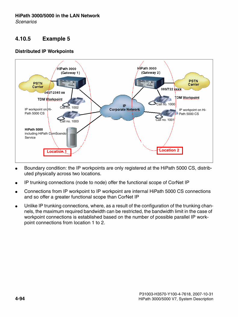
HiPath 3000/5000 in the LAN Network For internal use only
3000sb4.fm
Scenarios
4.10.5 Example 5
Distributed IP Workpoints
● Boundary condition: the IP workpoints are only registered at the HiPath 5000 CS, distrib-uted physically across two locations.
● IP trunking connections (node to node) offer the functional scope of CorNet IP
● Connections from IP workpoint to IP workpoint are internal HiPath 5000 CS connections and so offer a greater functional scope than CorNet IP
● Unlike IP trunking connections, where, as a result of the configuration of the trunking chan-nels, the maximum required bandwidth can be restricted, the bandwidth limit in the case of workpoint connections is established based on the number of possible parallel IP work-point connections from location 1 to 2.
IP workpoint on Hi-Path 5000 CS
Location 2Location 1
IP workpoint on Hi-Path 5000 CS
Call no. 1002
Call no. 1003
HiPath 5000including HiPath ComScendo Service
Call no. 1000
Call no. 1001
P31003-H3570-Y100-4-7618, 2007-10-314-94 HiPath 3000/5000 V7, System Description
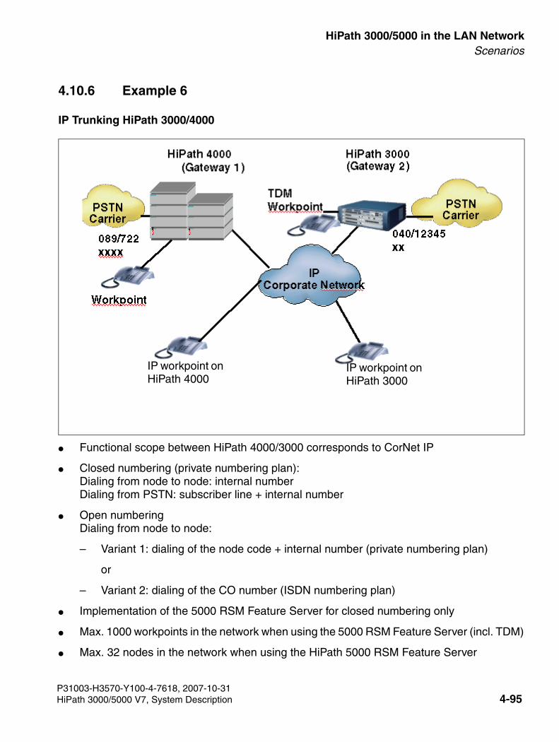
3000sb4.fm
For internal use only HiPath 3000/5000 in the LAN NetworkScenarios
4.10.6 Example 6
IP Trunking HiPath 3000/4000
● Functional scope between HiPath 4000/3000 corresponds to CorNet IP
● Closed numbering (private numbering plan):Dialing from node to node: internal numberDialing from PSTN: subscriber line + internal number
● Open numberingDialing from node to node:
– Variant 1: dialing of the node code + internal number (private numbering plan)
or
– Variant 2: dialing of the CO number (ISDN numbering plan)
● Implementation of the 5000 RSM Feature Server for closed numbering only
● Max. 1000 workpoints in the network when using the 5000 RSM Feature Server (incl. TDM)
● Max. 32 nodes in the network when using the HiPath 5000 RSM Feature Server
IP workpoint on HiPath 4000
IP workpoint on HiPath 3000
P31003-H3570-Y100-4-7618, 2007-10-31HiPath 3000/5000 V7, System Description 4-95
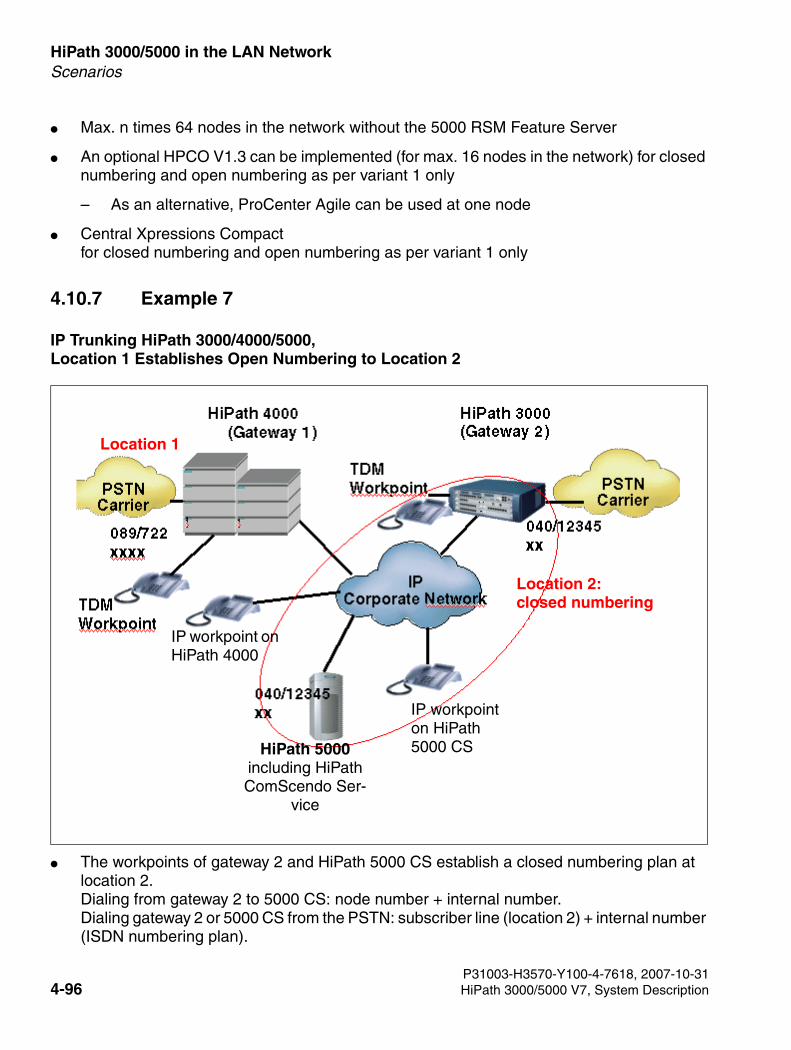
HiPath 3000/5000 in the LAN Network For internal use only
3000sb4.fm
Scenarios
● Max. n times 64 nodes in the network without the 5000 RSM Feature Server
● An optional HPCO V1.3 can be implemented (for max. 16 nodes in the network) for closed numbering and open numbering as per variant 1 only
– As an alternative, ProCenter Agile can be used at one node
● Central Xpressions Compact for closed numbering and open numbering as per variant 1 only
4.10.7 Example 7
IP Trunking HiPath 3000/4000/5000, Location 1 Establishes Open Numbering to Location 2
● The workpoints of gateway 2 and HiPath 5000 CS establish a closed numbering plan at location 2. Dialing from gateway 2 to 5000 CS: node number + internal number.Dialing gateway 2 or 5000 CS from the PSTN: subscriber line (location 2) + internal number (ISDN numbering plan).
Location 2:closed numbering
Location 1
IP workpoint on HiPath 4000
HiPath 5000including HiPath ComScendo Ser-
vice
IP workpoint on HiPath 5000 CS
P31003-H3570-Y100-4-7618, 2007-10-314-96 HiPath 3000/5000 V7, System Description
3000sb4.fm
For internal use only HiPath 3000/5000 in the LAN NetworkScenarios
● Workpoints at gateway 1 reach workpoints at gateway 2 or the HiPath 5000 CS via an ISDN numbering plan, i.e. they dial the CO number
● Workpoints at gateway 2 or the HiPath 5000 CS reach workpoints at gateway 1 via an ISDN numbering plan, i.e. they dial the CO number
● The HiPath 5000 RSM Feature Server cannot be implemented if an ISDN numbering plan is used
● Max. 64 nodes in the network
● HPCO cannot be implemented as there is an ISDN numbering plan
● As an alternative, ProCenter Agile can be used at one node
● Xpressions Compact cannot be implemented centrally as there is an ISDN numbering plan
P31003-H3570-Y100-4-7618, 2007-10-31HiPath 3000/5000 V7, System Description 4-97
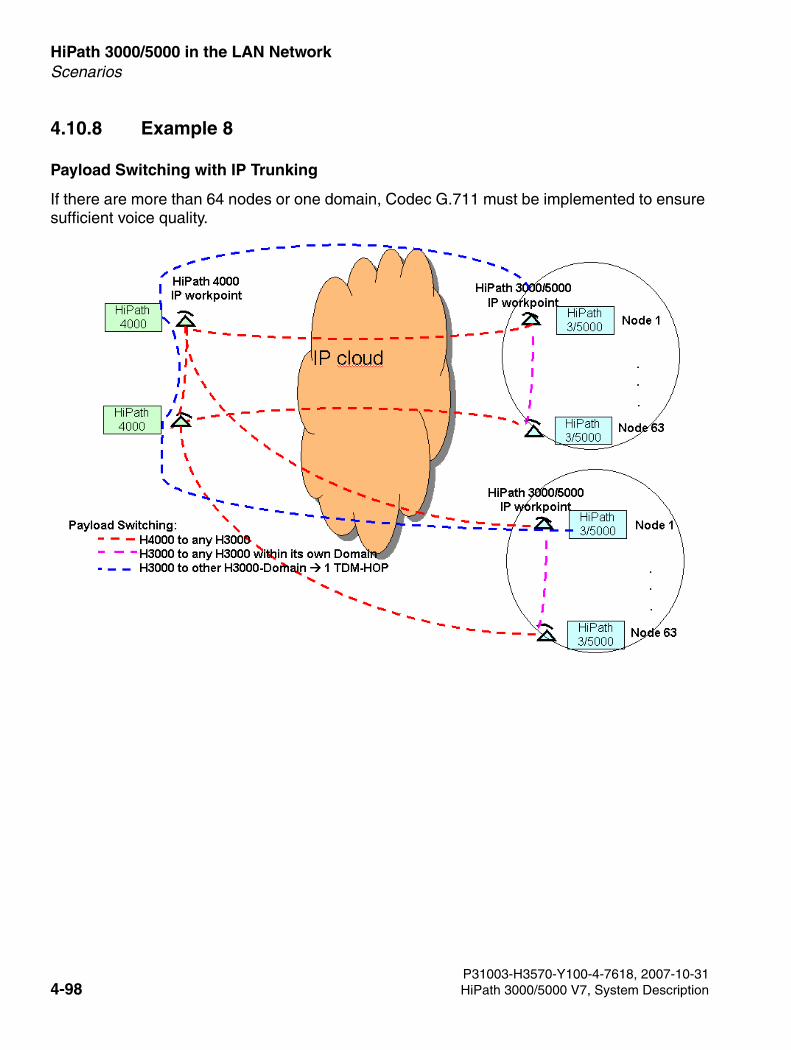
HiPath 3000/5000 in the LAN Network For internal use only
3000sb4.fm
Scenarios
4.10.8 Example 8
Payload Switching with IP Trunking
If there are more than 64 nodes or one domain, Codec G.711 must be implemented to ensure sufficient voice quality.
P31003-H3570-Y100-4-7618, 2007-10-314-98 HiPath 3000/5000 V7, System Description
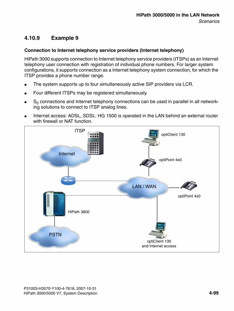
3000sb4.fm
For internal use only HiPath 3000/5000 in the LAN NetworkScenarios
4.10.9 Example 9
Connection to Internet telephony service providers (Internet telephony)
HiPath 3000 supports connection to Internet telephony service providers (ITSPs) as an Internet telephony user connection with registration of individual phone numbers. For larger system configurations, it supports connection as a Internet telephony system connection, for which the ITSP provides a phone number range.
● The system supports up to four simultaneously active SIP providers via LCR.
● Four different ITSPs may be registered simultaneously.
● S0 connections and Internet telephony connections can be used in parallel in all network-ing solutions to connect to ITSP analog lines.
● Internet access: ADSL, SDSL: HG 1500 is operated in the LAN behind an external router with firewall or NAT function.
Internet
optiClient 130and Internet access
ITSPoptiClient 130
optiPoint 4x0
LAN / WAN
PSTN
HiPath 3800
optiPoint 4x0
P31003-H3570-Y100-4-7618, 2007-10-31HiPath 3000/5000 V7, System Description 4-99
HiPath 3000/5000 in the LAN Network For internal use only
3000sb4.fm
Scenarios
P31003-H3570-Y100-4-7618, 2007-10-314-100 HiPath 3000/5000 V7, System Description
3000sb5.fm
For internal use only ServiceabilityOverview
5 Serviceability
5.1 Overview
Introduction
This chapter describes the options available to the service technician and the customer for
● performing system administration tasks on site
● performing system administration tasks from a remote location (remote operation)
● performing service and maintenance tasks
● identifying faults
Chapter Contents
This chapter discusses the topics listed in the table.
Subject
System Administration Options Page 5-2
● System Administration from a System Telephone Page 5-3
● System Administration using the Service PC Page 5-3
Options in the Service Department Page 5-6
● Customer Database Backup (CDB Backup) Page 5-6
● Relocate/Transfer Application Processor Software (APS) Page 5-8
● Diagnostics Options Page 5-12
● Error Correction Page 5-27
● Remote Service Page 5-29
● Access Security Page 5-34
● Automatic Logging of Administration Procedures Page 5-40
P31003-H3570-Y100-4-7618, 2007-10-31HiPath 3000/5000 V7, System Description 5-1
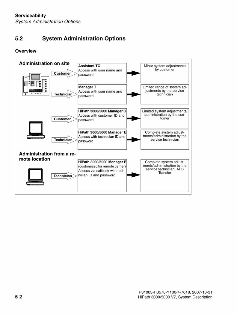
Serviceability For internal use only
3000sb5.fm
System Administration Options
5.2 System Administration Options
Overview
Minor system adjustments by customer
Limited range of system ad-justments by the service
technician
Limited system adjustments/administration by the cus-
tomer
Complete system adjust-ments/administration by the
service technician
Complete system adjust-ments/administration by the
service technician, APS Transfer
0
ABCDEFMNOGHI
PQRSTUV
↵ ←→↑↓
1234567890
ABCDEFMNOJKLGHI
PQRSTUVWXYZ
Customer
Technician
Technician
Assistant TCAccess with user name and password
Manager TAccess with user name and password
HiPath 3000/5000 Manager CAccess with customer ID and password
HiPath 3000/5000 Manager EAccess with technician ID and password
HiPath 3000/5000 Manager E(customized for remote center) Access via callback with tech-nician ID and password
Customer
Technician
Administration on site
Administration from a re-mote location
P31003-H3570-Y100-4-7618, 2007-10-315-2 HiPath 3000/5000 V7, System Description
3000sb5.fm
For internal use only ServiceabilitySystem Administration Options
5.2.1 System Administration from a System Telephone
All systems in the HiPath 3000/5000 product family can be administered to the full extent via a system telephone. The rights of the individual user will determine the extent to which he or she can perform administration tasks. Information on the various user groups and their access rights is contained in Section 5.3.10.2.
Administration by the Technician using Manager T
This data area is password-protected to limit access to trained service technicians. With just a few exceptions, all system settings are available. Manager T gives you the ability to make changes spontaneously on site, that is, without requiring any other tools.
You can only enter the service menu with a user ID and password.
Administration by the Customer using Assistant TC
This gives customers the option to perform a defined range of system settings themselves. These include, for example, configuring and changing speed-dialing destinations, and assign-ing names for stations and lines.
To protect individual customer data such as speed-dialing destinations or call detail information, it is not possible to enter the service menu unless you have user ID and password.
5.2.2 System Administration using the Service PC
Service tools with Windows user interface and integrated help functions are available for the economical modification of larger volumes of data and for setting specific system data. The rights of the individual user will determine the extent to which he or she can perform adminis-tration tasks. Information on the various user groups and their access rights is contained in Section 5.3.10.2.
You can access the communications platform using:
● ISDN adapter on the system telephone (64 kbps B-channel access)
● V.24 (RS-232) interface on the system (9600/19200 baud)
● Internal S0 bus (64 kbps/CAPI 2.0)
● Remote access over an ISDN trunk (64 kbps B-channel access)
● Remote access over an analog trunk (integrated 14400 baud modem)
P31003-H3570-Y100-4-7618, 2007-10-31HiPath 3000/5000 V7, System Description 5-3
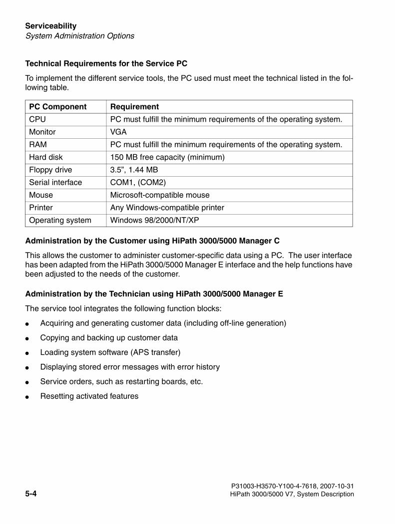
Serviceability For internal use only
3000sb5.fm
System Administration Options
Technical Requirements for the Service PC
To implement the different service tools, the PC used must meet the technical listed in the fol-lowing table.
Administration by the Customer using HiPath 3000/5000 Manager C
This allows the customer to administer customer-specific data using a PC. The user interface has been adapted from the HiPath 3000/5000 Manager E interface and the help functions have been adjusted to the needs of the customer.
Administration by the Technician using HiPath 3000/5000 Manager E
The service tool integrates the following function blocks:
● Acquiring and generating customer data (including off-line generation)
● Copying and backing up customer data
● Loading system software (APS transfer)
● Displaying stored error messages with error history
● Service orders, such as restarting boards, etc.
● Resetting activated features
PC Component Requirement
CPU PC must fulfill the minimum requirements of the operating system.
Monitor VGA
RAM PC must fulfill the minimum requirements of the operating system.
Hard disk 150 MB free capacity (minimum)
Floppy drive 3.5”, 1.44 MB
Serial interface COM1, (COM2)
Mouse Microsoft-compatible mouse
Printer Any Windows-compatible printer
Operating system Windows 98/2000/NT/XP
P31003-H3570-Y100-4-7618, 2007-10-315-4 HiPath 3000/5000 V7, System Description
3000sb5.fm
For internal use only ServiceabilitySystem Administration Options
● Creation and printing of:
– Key labels for optiPoint 500 and optiset E telephones
– Customer data printouts
– Main distribution frame layout
● User and password administration for after sales service.
● Database conversion routine.
Access to the system using HiPath 3000/5000 Manager E is only possible with a valid user name and associated password that have been entered in the system.
Online mode has been integrated to enable you to perform changes quickly. Its functionality corresponds to the Manager T user interface.
Because sensitive system data can be processed, users are required to undergo the relevant training course before using the HiPath 3000/5000 Manager E.
P31003-H3570-Y100-4-7618, 2007-10-31HiPath 3000/5000 V7, System Description 5-5
Serviceability For internal use only
3000sb5.fm
Options in the Service Department
5.3 Options in the Service Department
5.3.1 Customer Database Backup (CDB Backup)
A distinction is made here between
● backup of customer data without HiPath Software Manager and
● backup of customer data with HiPath Software Manager.
5.3.1.1 Customer Data Backup Without HiPath Software Manager
Definition
CDB backup refers to saving the customer database CDB to the multimedia card MMC (HiPath 3000) or copying the cyclic RAM data and saving it in two PDS (Permanent Data Service) files (HiPath 5000).
5.3.1.1.1 Automatic Customer Data Backup
HiPath 3000
A two-stage concept guarantees automatic customer data backup.
A complete CDB backup version can be found on the MMC at any time. Deltas to this backup are stored in an SRAM area (with battery backup) in the central control board. If the SRAM area is full, the customer data is automatically backed up. This means that the entire CDB, in-cluding SRAM content, is copied from the SDRAM in the central control board to the MMC. The current CDB is simultaneously stored on the MMC along with the “old” CDB, which is not delet-ed until the current CDB is completely stored on the MMC.
In case of a power outage, the SDRAM content that has no battery backup is completely lost. However, by reaccessing the CDB backup on the MMC, the system’s database can be restored to the state it was in prior to the power outage.
Regardless of the volume of changes to the database, HiPath 3000 always performs an auto-matic complete CDB backup at midnight, system-time.
P31003-H3570-Y100-4-7618, 2007-10-315-6 HiPath 3000/5000 V7, System Description
3000sb5.fm
For internal use only ServiceabilityOptions in the Service Department
HiPath 5000
On the communication server, RAM data is copied automatically every three minutes and stored in the file hicom.pds. This file contains the complete data description of the HiPath 5000 with emulated HG 1500 boards. This includes:
● Customer data
● Trace
● Error history
● Call detail data
● Status data
5.3.1.1.2 Manual Customer Data Backup with HiPath 3000
You can perform a manual CDB backup using HiPath 3000/5000 Manager E (in online mode) or Manager T.
5.3.1.2 Customer Data Backup with HiPath Software Manager
Definition
The HiPath Software Manager supports, among other things, the backup of customer databas-es (Backup Manager) from all HiPath 3000/5000 systems in the same customer network (see also Section 5.3.4, "Backing Up System Components (Backup Manager)").
The CDB backups are stored in a directory which must be defined in advance. The data backup can either be started manually immediately or performed at a predefined time. A cyclic backup, which saves the customer data at a set time every day, is also possible.
P31003-H3570-Y100-4-7618, 2007-10-31HiPath 3000/5000 V7, System Description 5-7
Serviceability For internal use only
3000sb5.fm
Options in the Service Department
5.3.2 Relocate/Transfer Application Processor Software (APS)
For system software updates, a distinction is made between
● HiPath 3000 systems without HiPath Software Manager and
● HiPath 3000 systems with HiPath Software Manager.
For networked HiPath 3000 systems with HiPath 5000 Server, an APS update can only be per-formed with HiPath Software Manager.
5.3.2.1 APS Replacement/Transfer for HiPath 3000 Systems Without HiPath Software Manager
Two memory areas for the application processor software are reserved on the MMC. To be able to store two complete APS and to keep the transfer time as low as possible, part of an APS is stored in a compressed format. The APS is decompressed after it has been transferred from the MMC into the SDRAM area of the central control board.
5.3.2.1.1 Transferring an APS of HiPath 3000 by Replacing the MMC
5.3.2.1.2 APS Transfer
Options
The APS Transfer feature is available with the HiPath 3000/5000 Manager E. It facilitates
● an on-site APS transfer by connecting directly using the V.24 interface.
● an APS transfer via remote service from a central service center using the integrated an-alog or digital modem or via LAN.
>APS replacement/transfer is not possible with HiPath 5000. You must perform a complete software upgrade.
>APS replacement is only possible within a version and if a logical, compatible CDB is available.
P31003-H3570-Y100-4-7618, 2007-10-315-8 HiPath 3000/5000 V7, System Description
3000sb5.fm
For internal use only ServiceabilityOptions in the Service Department
5.3.2.2 APS Transfer for HiPath 3000 Systems With HiPath Software Manager
Definition
The HiPath Software Manager supports, among other things, updates of the system software (Upgrade Manager) of all HiPath 3000 systems in the same customer network. An update of the software of installed HG 1500 boards (HG 1500 V3.0 SMR-3 or later) can also be per-formed.
The following options are available under the menu item “Upgrade”:
● upgrade all HG 1500 boards and HiPath 3000 systems
● upgrade HG 1500 boards (HG 1500 V3.0 SMR-3 or later)
● upgrade all HiPath 3000 systems Note: The file format “*.fli” must be selected for APS transfer using HiPath Software Man-ager.
The software (APS and/or HG 1500) is updated in two steps. First, the new software is loaded to a system memory known as the "shadow area". This occurs in the background independently of the system status.
In the second step, the new software version must be made available, in other words, the switch from the current software version to the new software version must take place. The current soft-ware is replaced by the software in the shadow area and thus deleted. The changeover can either be started immediately once the software has been loaded or performed at a predefined time.
P31003-H3570-Y100-4-7618, 2007-10-31HiPath 3000/5000 V7, System Description 5-9
Serviceability For internal use only
3000sb5.fm
Options in the Service Department
5.3.3 Determining System Information and Installed Software Components (HiPath Inventory Manager)
Definition
HiPath Inventory Manager is a service for detecting the installed software components and sys-tem information in a HiPath 3000/5000 network. System information is only determined upon initial start-up of the service.
The relevant information can be displayed in table format by clicking one of the following but-tons:
● Master Setup Information including version and installation date of the master setup.
● HiPath 3000 Hardware and software information regarding the HiPath 3000 systems in the network and the installed HG 1500 boards.
● HiPath Applications Information regarding the following software components:
– MS Windows components (MS Internet Explorer, DNS server, DHCP server)
– Media Streaming
– TAPI
– CCMC, CCMS, CMD, CSP
– Administration
– HiPath 5000 Server
– GetAccount
– HiPath 3000/5000 Manager E
– Common Software
● Operating System Information regarding the current operating system.
All information can be updated at any time via the "Update data" button.
The system information is automatically determined when the HiPath Inventory Manager ser-vice is started for the first time. A cyclic update can be performed every ≥ 1 days. The system information can be queried manually at any time. This should always be done before an update/upgrade, for example.
P31003-H3570-Y100-4-7618, 2007-10-315-10 HiPath 3000/5000 V7, System Description
3000sb5.fm
For internal use only ServiceabilityOptions in the Service Department
5.3.4 Backing Up System Components (Backup Manager)
Definition
The HiPath Software Manager allows the following system components and databases of a Hi-Path 3000/5000 network to be backed up:
● Full backup (= default setting) This option creates a data backup for all HiPath 3000 systems and HG 1500 boards in the HiPath 3000/5000 network as well as databases (Feature Server, SQL Server).
● Backup HiPath 3000 With this menu item, all HiPath 3000 systems in the HiPath 3000/5000 network are dis-played in an overview. It is possible to back up the data of a specific system or of all dis-played HiPath 3000 systems.
● Database backup With this menu item, all databases (Feature Server, SQL Server) are displayed in an over-view. It is possible to back up the data of one or of all database(s).
P31003-H3570-Y100-4-7618, 2007-10-31HiPath 3000/5000 V7, System Description 5-11
Serviceability For internal use only
3000sb5.fm
Options in the Service Department
5.3.5 Diagnostics Options
5.3.5.1 Recording HiPath 3000 Board Status
5.3.5.1.1 Central Control Boards
Run LED
A RUN LED that displays the system’s operating capacity is located on the central control board.
Options Available?
You can call up the following options using the HiPath 3000/5000 Manager E:
● CMA
● CMS
● LIM
● IMODN
● MPPI, UAM (only with HiPath 3550, HiPath 3350) or UAMR (only with HiPath 3500, HiPath 3300)The presence of one of these announcement and music modules is displayed as "Option 5". The ALUM4 option cannot be displayed.
P31003-H3570-Y100-4-7618, 2007-10-315-12 HiPath 3000/5000 V7, System Description
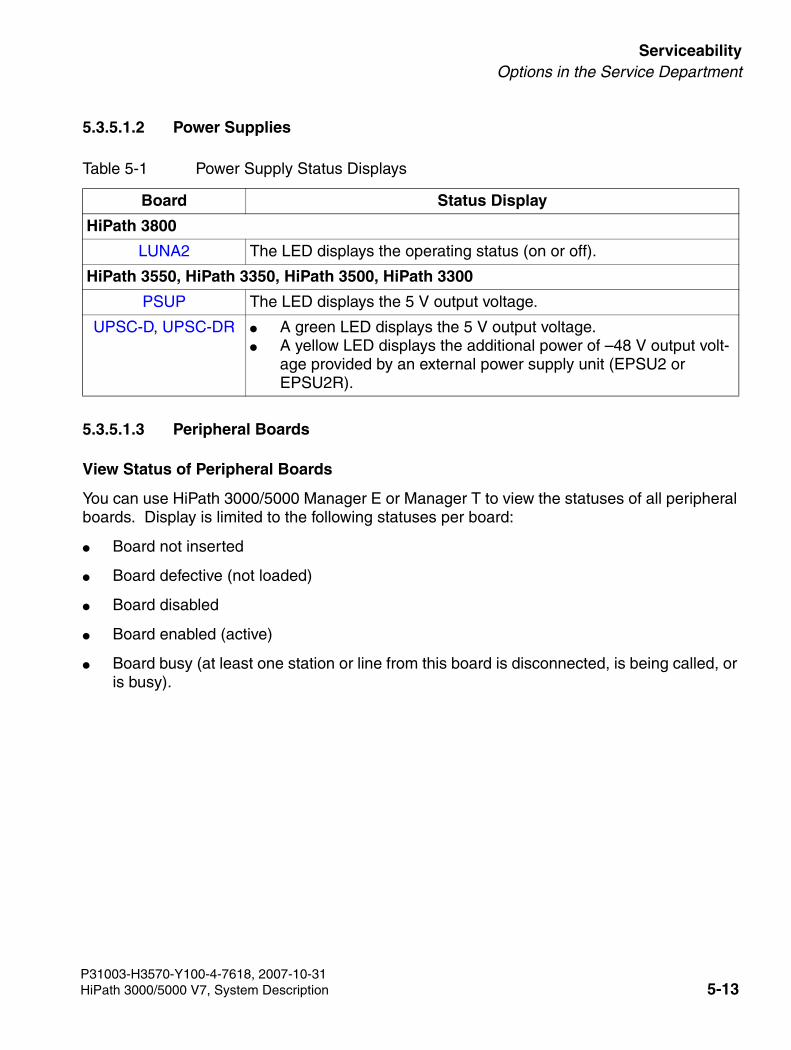
3000sb5.fm
For internal use only ServiceabilityOptions in the Service Department
5.3.5.1.2 Power Supplies
5.3.5.1.3 Peripheral Boards
View Status of Peripheral Boards
You can use HiPath 3000/5000 Manager E or Manager T to view the statuses of all peripheral boards. Display is limited to the following statuses per board:
● Board not inserted
● Board defective (not loaded)
● Board disabled
● Board enabled (active)
● Board busy (at least one station or line from this board is disconnected, is being called, or is busy).
Table 5-1 Power Supply Status Displays
Board Status Display
HiPath 3800
LUNA2 The LED displays the operating status (on or off).
HiPath 3550, HiPath 3350, HiPath 3500, HiPath 3300
PSUP The LED displays the 5 V output voltage.
UPSC-D, UPSC-DR ● A green LED displays the 5 V output voltage.● A yellow LED displays the additional power of –48 V output volt-
age provided by an external power supply unit (EPSU2 or EPSU2R).
P31003-H3570-Y100-4-7618, 2007-10-31HiPath 3000/5000 V7, System Description 5-13
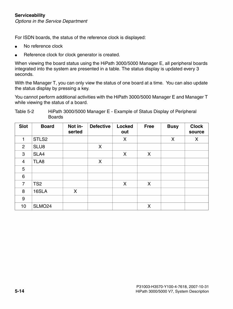
Serviceability For internal use only
3000sb5.fm
Options in the Service Department
For ISDN boards, the status of the reference clock is displayed:
● No reference clock
● Reference clock for clock generator is created.
When viewing the board status using the HiPath 3000/5000 Manager E, all peripheral boards integrated into the system are presented in a table. The status display is updated every 3 seconds.
With the Manager T, you can only view the status of one board at a time. You can also update the status display by pressing a key.
You cannot perform additional activities with the HiPath 3000/5000 Manager E and Manager T while viewing the status of a board.
Table 5-2 HiPath 3000/5000 Manager E - Example of Status Display of Peripheral Boards
Slot Board Not in-serted
Defective Locked out
Free Busy Clock source
1 STLS2 X X X
2 SLU8 X
3 SLA4 X X
4 TLA8 X
5
6
7 TS2 X X
8 16SLA X
9
10 SLMO24 X
P31003-H3570-Y100-4-7618, 2007-10-315-14 HiPath 3000/5000 V7, System Description
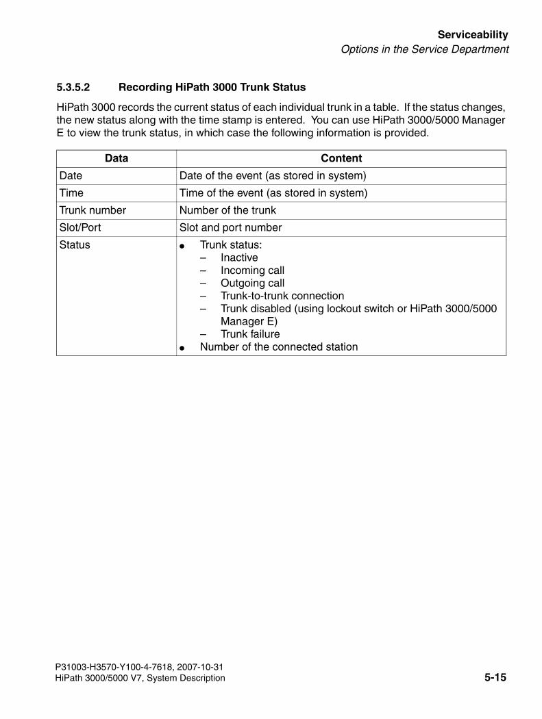
3000sb5.fm
For internal use only ServiceabilityOptions in the Service Department
5.3.5.2 Recording HiPath 3000 Trunk Status
HiPath 3000 records the current status of each individual trunk in a table. If the status changes, the new status along with the time stamp is entered. You can use HiPath 3000/5000 Manager E to view the trunk status, in which case the following information is provided.
Data Content
Date Date of the event (as stored in system)
Time Time of the event (as stored in system)
Trunk number Number of the trunk
Slot/Port Slot and port number
Status ● Trunk status: – Inactive– Incoming call– Outgoing call– Trunk-to-trunk connection– Trunk disabled (using lockout switch or HiPath 3000/5000
Manager E)– Trunk failure
● Number of the connected station
P31003-H3570-Y100-4-7618, 2007-10-31HiPath 3000/5000 V7, System Description 5-15
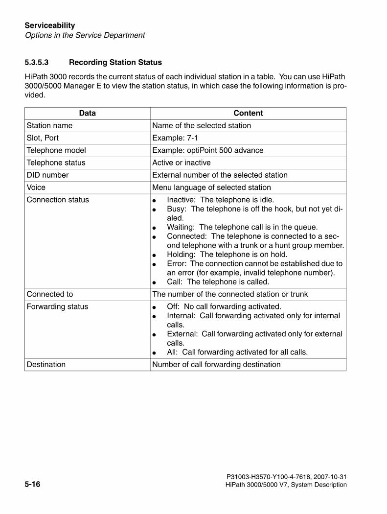
Serviceability For internal use only
3000sb5.fm
Options in the Service Department
5.3.5.3 Recording Station Status
HiPath 3000 records the current status of each individual station in a table. You can use HiPath 3000/5000 Manager E to view the station status, in which case the following information is pro-vided.
Data Content
Station name Name of the selected station
Slot, Port Example: 7-1
Telephone model Example: optiPoint 500 advance
Telephone status Active or inactive
DID number External number of the selected station
Voice Menu language of selected station
Connection status ● Inactive: The telephone is idle.● Busy: The telephone is off the hook, but not yet di-
aled.● Waiting: The telephone call is in the queue.● Connected: The telephone is connected to a sec-
ond telephone with a trunk or a hunt group member.● Holding: The telephone is on hold.● Error: The connection cannot be established due to
an error (for example, invalid telephone number).● Call: The telephone is called.
Connected to The number of the connected station or trunk
Forwarding status ● Off: No call forwarding activated. ● Internal: Call forwarding activated only for internal
calls. ● External: Call forwarding activated only for external
calls. ● All: Call forwarding activated for all calls.
Destination Number of call forwarding destination
P31003-H3570-Y100-4-7618, 2007-10-315-16 HiPath 3000/5000 V7, System Description
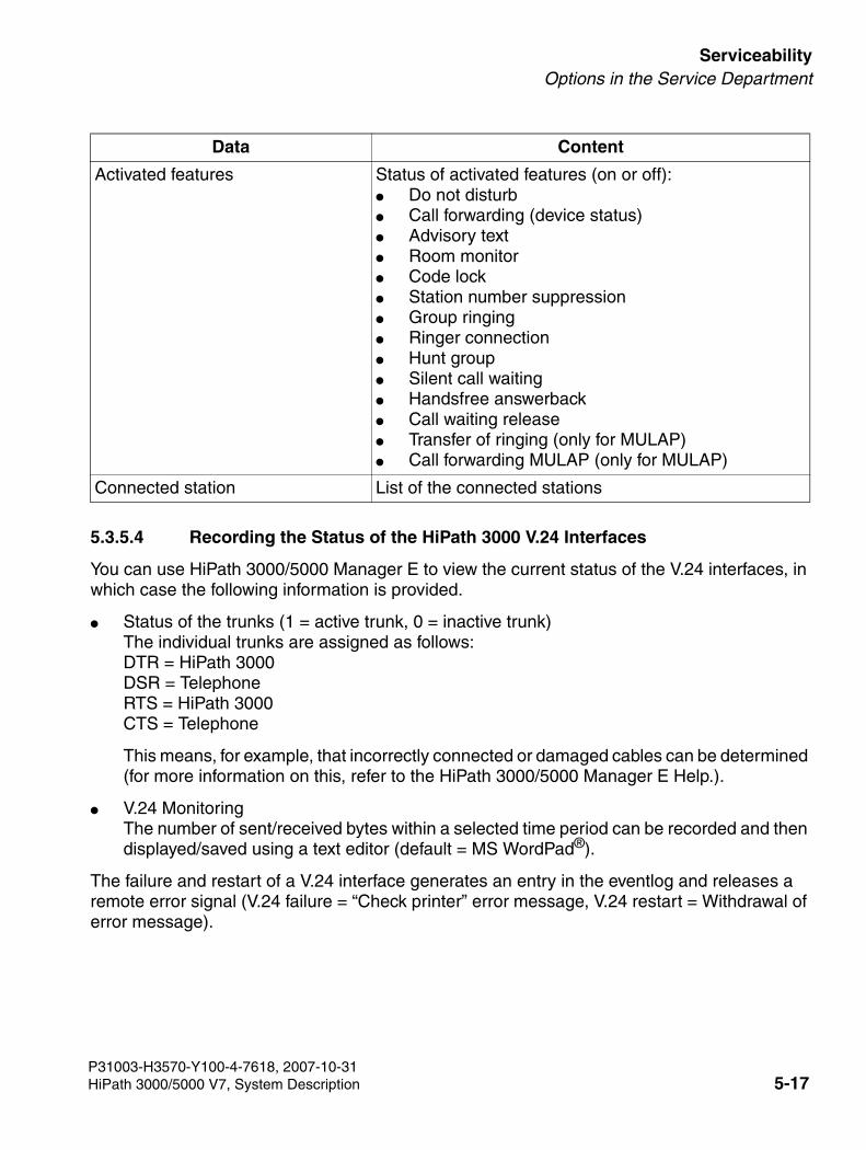
3000sb5.fm
For internal use only ServiceabilityOptions in the Service Department
5.3.5.4 Recording the Status of the HiPath 3000 V.24 Interfaces
You can use HiPath 3000/5000 Manager E to view the current status of the V.24 interfaces, in which case the following information is provided.
● Status of the trunks (1 = active trunk, 0 = inactive trunk)The individual trunks are assigned as follows:DTR = HiPath 3000DSR = TelephoneRTS = HiPath 3000 CTS = Telephone
This means, for example, that incorrectly connected or damaged cables can be determined (for more information on this, refer to the HiPath 3000/5000 Manager E Help.).
● V.24 Monitoring The number of sent/received bytes within a selected time period can be recorded and then displayed/saved using a text editor (default = MS WordPad®).
The failure and restart of a V.24 interface generates an entry in the eventlog and releases a remote error signal (V.24 failure = “Check printer” error message, V.24 restart = Withdrawal of error message).
Activated features Status of activated features (on or off): ● Do not disturb● Call forwarding (device status)● Advisory text● Room monitor● Code lock● Station number suppression● Group ringing● Ringer connection● Hunt group● Silent call waiting● Handsfree answerback● Call waiting release● Transfer of ringing (only for MULAP)● Call forwarding MULAP (only for MULAP)
Connected station List of the connected stations
Data Content
P31003-H3570-Y100-4-7618, 2007-10-31HiPath 3000/5000 V7, System Description 5-17
Serviceability For internal use only
3000sb5.fm
Options in the Service Department
5.3.5.5 Trace Options for HiPath 3000
Tracing ISDN Activities
This feature allows the user to trace ISDN telephones (subscriber ports) and ISDN trunks (trunk ports) in real time. ISDN activities are routed to HiPath 3000/5000 Manager E and saved in a trace file. Only the ISDN sequences are displayed on the monitor, not the content of the ISDN messages.
The call is made via HiPath 3000/5000 Manager E: Maintenance, "Call Monitoring" tab. The Start button starts Call Monitoring, whereupon the data of all available ports in the system is read out.
If the trace session is over, you can start the ISDN Message Decoder (ISDN Tracer) and use it to convert the trace file into a readable format (only English). You can also read out the trace data using remote service.
The ISDN Message Decoder is a 32 bit application which converts the ISDN layer 3 messages and information elements into a readable format. Since you cannot find out from the trace file whether it deals with an information element from a Euro ISDN or a QSig configuration, you have to select the protocol. You may select the following settings from the main menu:
● Raw (default setting)
● Euro ISDN
● QSig V1
● CorNet-NQ
With the “Raw” setting, the Hex values are only decoded, not interpreted. With the other two settings, the Hex values are decoded and interpreted per feature (CC, AOC, ...).
Tracing Call-related Activities
You can trace all activities from any telephone, trunk, etc., that is released by a call. These in-clude consultation calls, conference calls, and hunt groups, for example.
>Special user rights are required for activating the Trace setting in the Maintenance menu, that are exclusively reserved by the user group Development.
P31003-H3570-Y100-4-7618, 2007-10-315-18 HiPath 3000/5000 V7, System Description
3000sb5.fm
For internal use only ServiceabilityOptions in the Service Department
5.3.5.6 HiPath Manager PCM Trace Monitor for HiPath 5000
Communication between the different HiPath 5000 applications is organized using various buff-er tables and messages. You can monitor the individual entries in the different buffer tables, ex-changed immediate messages, program and communication messages for the relevant com-ponent in a separate trace window, in other words, a separate window is opened for each component (application).
The trace windows can be viewed using the Trace Monitor and swapped out for further process-ing.
Trace messages can be displayed for the following HiPath 5000 applications:
● Feature Server Two trace files are available:
– \winnt\system32\carlogfile.txt provides details on which HG 1500 boards have logged on to the network and when.
– \winnt\system32\rgtracefile.txt provides details on when the individual HG 1500 boards were assigned a station num-ber.
● Presence Manager Two trace files are available:
– \winnt\system32\dssdiagnosefile.txt
– \winnt\system32\dsslogfile.txt
● HiPath Manager PCM AdministrationAdministration of the configuration parameters for component control by the user, for gen-eral parameters, for call charge evaluation and analysis.
● HiPath Manager PCM Configuration of call handling and call forwarding using definable profiles.
● HiPath GetAccountInternal component that is responsible for evaluating and saving call charges and for im-mediate printing.
>This documentation does not cover interpretation of the trace window contents by the Trace Monitor. Trace files are used for problem analysis and are interpreted by Service Support during servicing.The description below can be used to determine the work steps required for Trace Monitor navigation and control and for swapping out the trace contents to a file.
P31003-H3570-Y100-4-7618, 2007-10-31HiPath 3000/5000 V7, System Description 5-19
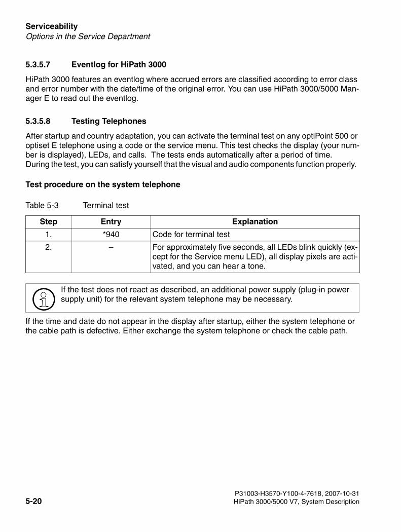
Serviceability For internal use only
3000sb5.fm
Options in the Service Department
5.3.5.7 Eventlog for HiPath 3000
HiPath 3000 features an eventlog where accrued errors are classified according to error class and error number with the date/time of the original error. You can use HiPath 3000/5000 Man-ager E to read out the eventlog.
5.3.5.8 Testing Telephones
After startup and country adaptation, you can activate the terminal test on any optiPoint 500 or optiset E telephone using a code or the service menu. This test checks the display (your num-ber is displayed), LEDs, and calls. The tests ends automatically after a period of time. During the test, you can satisfy yourself that the visual and audio components function properly.
Test procedure on the system telephone
If the time and date do not appear in the display after startup, either the system telephone or the cable path is defective. Either exchange the system telephone or check the cable path.
Table 5-3 Terminal test
Step Entry Explanation
1. *940 Code for terminal test
2. – For approximately five seconds, all LEDs blink quickly (ex-cept for the Service menu LED), all display pixels are acti-vated, and you can hear a tone.
>If the test does not react as described, an additional power supply (plug-in power supply unit) for the relevant system telephone may be necessary.
P31003-H3570-Y100-4-7618, 2007-10-315-20 HiPath 3000/5000 V7, System Description
3000sb5.fm
For internal use only ServiceabilityOptions in the Service Department
5.3.5.9 Event Viewer for HiPath 5000 (Eventlog)
Introduction
The Event Viewer (Eventlog) is one of the tools supplied with NT-based operating systems (Microsoft Windows NT, Microsoft Windows 2000, Microsoft Windows XP, etc.). The Event Viewer administers logs that record information on programs, security, and system events on the computer. You can use it to display and administer eventlogs, to gather information on hard-ware and software problems, and to monitor security events.
You can use this standard tool to obtain status information for the HiPath 5000 server and any application server present.
All events associated with the server(s) and its (their) applications are saved. The events pro-vide a quick and, above all, time-specific overview of all relevant actions (status, information, warning, error, etc.).
The tool itself handles the event entries. You can specify the length of the event file, the validity of events in days, the reaction when the maximum size has been reached, and the display filter, for example.
You can save the resulting event file (log file) under any name.
Starting the Event Viewer
Start the Event Viewer from the Windows Start menu: Start/Programs/Administrative Tools/Event Viewer
P31003-H3570-Y100-4-7618, 2007-10-31HiPath 3000/5000 V7, System Description 5-21
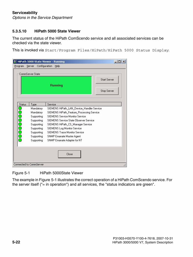
Serviceability For internal use only
3000sb5.fm
Options in the Service Department
5.3.5.10 HiPath 5000 State Viewer
The current status of the HiPath ComScendo service and all associated services can be checked via the state viewer.
This is invoked via Start/Program Files/HiPath/HiPath 5000 Status Display.
The example in Figure 5-1 illustrates the correct operation of a HiPath ComScendo service. For the server itself ("= in operation") and all services, the "status indicators are green".
Figure 5-1 HiPath 5000State Viewer
P31003-H3570-Y100-4-7618, 2007-10-315-22 HiPath 3000/5000 V7, System Description
3000sb5.fm
For internal use only ServiceabilityOptions in the Service Department
5.3.5.11 HiPath Fault Management
HiPath 3000 and HiPath 5000 systems have a separate SNMP agent that allows access to var-ious system data that is stored in its MIB or Management Information database. The MIB pro-vides basic system information, status information, event-related data, and information on in-stalled hardware (slots) and configured connections (ports).
HiPath Fault Management can read information from the HiPath 3000 and HiPath 5000 system MIB via SNMP requests. This allows the system to permanently monitor the status of the net-work components and to include changes of status in the network administrator information.
A graphic map of the network displays the topology and the current status of the network com-ponents.
For detailed information, refer to the product-specific documentation for HiPath Fault Manage-ment.
SNMP Functionality
Simple Network Management Protocol (SNMP) represents a convenient platform within the TCP/IP protocol family for management tasks in the HiPath 3000 and HiPath 5000 software. SNMP is used more or less as a management agent on HiPath 3000 and HiPath 5000 and han-dles central monitoring and administration of LAN network components, including the HiPath 3000 and HiPath 5000. This involves
● address the HiPath 3000 and HiPath 5000 over the TCP/IP protocol family.
● access data from external management applications such as HiPath Fault Management.
● implement remote maintenance jobs (such as online port status, disabling and enabling ports, and determining free ports).
● transmitting service-related class B errors
● visualize the operating status of a HiPath 3000 and HiPath 5000.
P31003-H3570-Y100-4-7618, 2007-10-31HiPath 3000/5000 V7, System Description 5-23
Serviceability For internal use only
3000sb5.fm
Options in the Service Department
5.3.5.12 Licensing Analysis
5.3.5.12.1 Analysis Using Customer License Manager (CLM)
The CLM installation directory (for example, C:\Program Files\licensing\license manager) contains the Trace directory among other things. Each time the TomCat Web serv-er is started, a new subdirectory is created to which the trace output is then written. Trace out-put can be viewed using MS Internet Explorer.
5.3.5.12.2 Analysis Using Customer License Agent (CLA)
The CLA offers two analysis options:
Log files
The Customer License Agent (CLA) manages a configuration log and error log. Both logs are viewed using the CLM. This provides a good overview of an error situation that helps to narrow down an error to a specific area, for example.
Trace files
The CLA records detailed information about its internal processes in a text file that is stored in the bin subdirectory of its installation directory. The degree of detail (off, low, standard, all) and the size (in MB) of this recorded information can be defined using the Customer License Man-ager (CLM).
>This documentation does not cover interpretation of the analysis data. Trace files, log files, etc. are used for problem analysis and are interpreted by Service Support during servicing.
P31003-H3570-Y100-4-7618, 2007-10-315-24 HiPath 3000/5000 V7, System Description
3000sb5.fm
For internal use only ServiceabilityOptions in the Service Department
5.3.5.13 Analysis Using HiPath Software Manager and HiPath Inventory Manager
Trace files
The installation directory of the Common Web Service (default = C:\Program Files\sie-mens\hipath\commonweb) contains, among other things, the Trace directory, in which the trace files for the Web applications HiPath Software Manager and HiPath Inventory Manager are stored.
This directory name is saved in a registry key during installation. If this key cannot be accessed, the trace files are stored in the temporary system directory (as the Common Web Service is started as a system service). Under MS Windows 2000, this directory normally has the name C:\WINNT\temp, while under MS Windows 2003 it is called C:\WINDOWS\temp.
Each time a Web application is started by the Common Web Service (TomCat Web server), a separate subdirectory is created. This subdirectory contains the trace files in XML format. The subdirectory name follows the convention date_<DATE>_time_<TIME>.
>This documentation does not cover interpretation of the analysis data. Trace files, log files, etc. are used for problem analysis and are interpreted by Service Support during servicing.
P31003-H3570-Y100-4-7618, 2007-10-31HiPath 3000/5000 V7, System Description 5-25
Serviceability For internal use only
3000sb5.fm
Options in the Service Department
5.3.6 HiPath 3000 Error Messages (Entries in the Eventlog for HiPath 3000)
Classification
Accrued errors are classified according to error class and error number. The three different er-ror classes are described below:
● Error Class A = Customer-related errorHiPath 3000/5000 Manager E fails to issue a signal/message. Class A errors are indicated on the optiPoint Attendant display. The customer can correct them without service support.
The following error messages are implemented at present:
– “Printer Alarm” (caused by empty paper tray, for example)
– “Fan Failure” (caused by failure of the fan with HiPath 3500 or HiPath 3300)
– “Revisor Alarm” (caused by overflow in the MMC log area, for example).
– "Too Many Key Modules" (caused by attaching more than the maximum possible num-ber of optiPoint key modules)
● Error Class B = Service-related errorsClass B errors are signaled to the HiPath 3000/5000 Manager E, and can be automatically forwarded to a service center. Errors of this class are, for example, failure of the boards, individual ports, or trunks. You can generally correct these errors by replacing the hardware, reconfiguring the customer database, or by working together with the carrier.
● Error Class C = Development-related errorsHiPath 3000/5000 Manager E fails to issue a signal/message. Class C errors require diagnosis and problem analysis by specialists.
5.3.7 HiPath 5000 Error Messages (Event Viewer Entries for HiPath 5000)
Event Viewer Entries for HiPath 5000
● Feature server events
● GetAccount events
● HiPath Manager PCM events
P31003-H3570-Y100-4-7618, 2007-10-315-26 HiPath 3000/5000 V7, System Description

3000sb5.fm
For internal use only ServiceabilityOptions in the Service Department
5.3.8 Error Correction
5.3.8.1 Automatic Error Correction
One of the below recovery actions is assigned to each error in the error memory. These recov-ery actions are programmed to automatically correct errors that occur.
● Hard restart
● Reload board
● Reload CDB backup
● Port lockout
● Power failure transfer (loop start)
● None
A watchdog activates continuous loops.
If no recovery measure is assigned or if the one that is assigned fails, a service technician has to correct the error manually.
5.3.8.2 Manual Error Correction Without HiPath 3000/5000 Manager E
Manually Activating Restart (Reset)/Reload
Pressing the reset button on the central control board
● initiates a Reset (Hard restart of the entire system with the current CDB) if the button is pressed for less than 5 seconds. The Run LED lights up when the Reset button is pressed.
● initiates a Reload if the button is pressed longer than 5 seconds. The Run LED disappears after approximately five seconds as verification that the reload has been initiated. The en-tire content of the customer database is replaced by its default version. All country and cus-tomer-specific settings are lost.
Locking out and Releasing Boards and Ports
You can lock out and release ports using the lockout switch located on the board. The lockout prevents renewed seizure after the current connection has finished. It creates
● a port lockout in an outgoing direction on analog trunk boards.
● a port lockout in outgoing and incoming directions on trunk boards.
● a lockout of the entire board for subscriber line modules.
P31003-H3570-Y100-4-7618, 2007-10-31HiPath 3000/5000 V7, System Description 5-27
Serviceability For internal use only
3000sb5.fm
Options in the Service Department
5.3.8.3 Manual Error Correction With HiPath 3000/5000 Manager E
Initiating Restart (Reset)
This initiates an immediate hard restart of the entire system with the current CDB.
Initiating Reload Card
This the single board (loading Loadware) to reload.
Locking out and Releasing Boards and Ports
HiPath 3000/5000 Manager E enables you to lock out an entire subscriber line module or line circuit module and individual ports. The lockout prevents renewed seizure after the current con-nection has finished. Lockout or release settings are also retained after a reset.
You cannot lock out the first SLMO/SLU board because administration through the Manager T uses its first two ports.
If you try to lock out the last active trunk, you will be notified that remote service through the service center is no longer possible.
You cannot use HiPath 3000/5000 Manager E to release boards and ports locked out with the lockout switch.
ALUM
You cannot initiate a power failure transfer to analog telephones using HiPath 3000/5000 Man-ager E.
P31003-H3570-Y100-4-7618, 2007-10-315-28 HiPath 3000/5000 V7, System Description
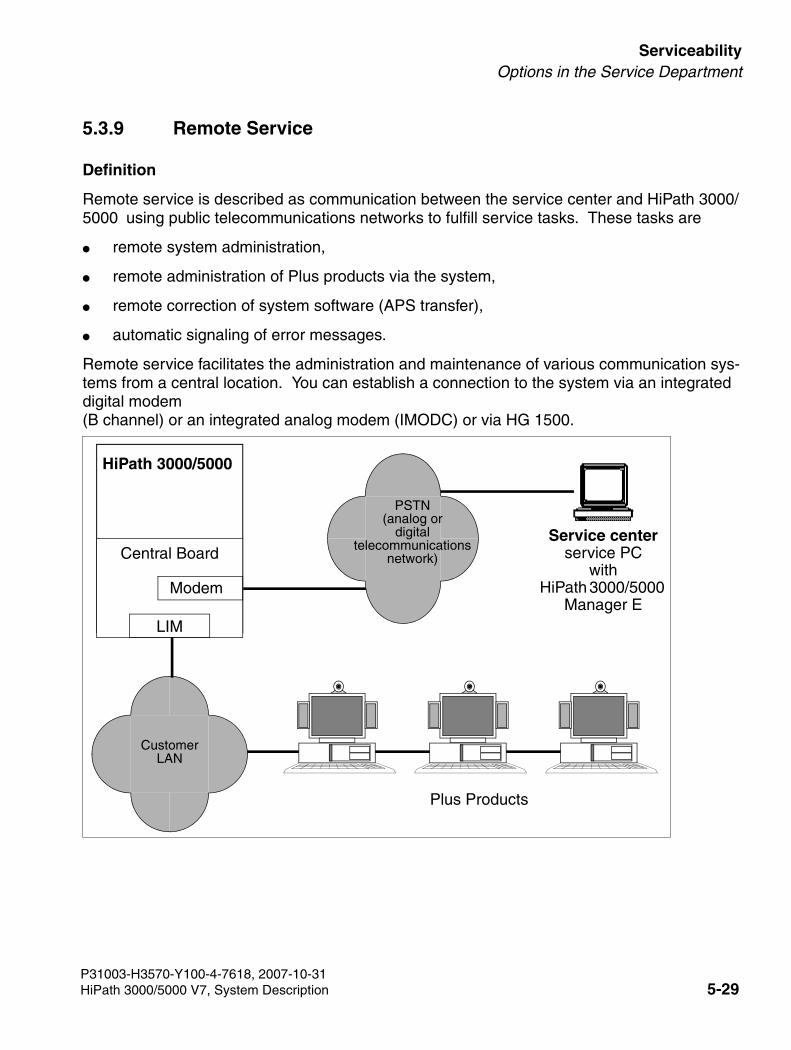
3000sb5.fm
For internal use only ServiceabilityOptions in the Service Department
5.3.9 Remote Service
Definition
Remote service is described as communication between the service center and HiPath 3000/5000 using public telecommunications networks to fulfill service tasks. These tasks are
● remote system administration,
● remote administration of Plus products via the system,
● remote correction of system software (APS transfer),
● automatic signaling of error messages.
Remote service facilitates the administration and maintenance of various communication sys-tems from a central location. You can establish a connection to the system via an integrated digital modem (B channel) or an integrated analog modem (IMODC) or via HG 1500.
HiPath 3000/5000
Plus Products
Service centerservice PC
withHiPath 3000/5000
Manager E
Central Board
Modem
LIM
CustomerLAN
PSTN(analog or
digitaltelecommunications
network)
P31003-H3570-Y100-4-7618, 2007-10-31HiPath 3000/5000 V7, System Description 5-29
Serviceability For internal use only
3000sb5.fm
Options in the Service Department
5.3.9.1 HiPath 3000 Connection Options
● HG 1500 All HiPath 3000 systems can be accessed remotely with a LAN-LAN link via the HG 1500 board.
● Integrated analog modem IMODN This modem enables remote access to all systems in the HiPath 3000 product line. Access is achieved using any trunks, tie trunks, and all subscriber lines. IMODN is designed as a plug-in card.
The IMODN is treated as a pseudo port. It receives a number in the system that can be reached internally through direct internal dialing (DID). You can cancel the DID number manually to prevent external access.
● Integrated digital modem (B channel) An integrated B channel modem is available with all systems in the HiPath 3000/5000 prod-uct line. This type of modem facilitates remote access using both digital trunks, tie trunks, as well as S0 subscriber lines. Data transmission is supported according to Protocol X.75.
The digital modem is treated as a pseudo port. It receives a number in the system that can be reached internally and through direct internal dialing. You can cancel the DID number manually to prevent external access.
Access to the analog/digital modem
The customer must enable the access to both modems by entering a six-digit PIN code. If the service center is to make a connection to the HiPath 3000/5000 over a modem, it may be nec-essary to enter this individual code. It depends on which trunk type is used for the modem ac-cess. The following applies to the system default:
● Access over ISDN trunk = enable procedure: customer must enter PIN code.
● Access over another trunk = login without code: PIN code is not necessary.
If necessary, the system administration (only by using Manager T) can reset the PIN code back to the default value.
7CautionBe sure to disconnect the system from the power supply before removing or in-serting integrated analog modems (IMODN).
P31003-H3570-Y100-4-7618, 2007-10-315-30 HiPath 3000/5000 V7, System Description
3000sb5.fm
For internal use only ServiceabilityOptions in the Service Department
5.3.9.2 HiPath 5000 Connection Options
In general, the connection to HiPath 5000 is established via special software programs, such as pcANYWHERE. Please refer to the relevant product documentation for information on pos-sible applications.
If the customer agrees, Remote Access Service RAS can also be used, provided this service is active on the HiPath 5000 server.
5.3.9.3 Remote System Administration
Remote Administration with HiPath 3000/5000 Manager E
To establish a remote connection between HiPath 3000/5000 and the service center (HiPath 3000/5000 Manager E), the following options are available:
● Callback
● Service call via code
● Automatic error signaling
Any one of these options establishes a connection using the integrated digital modem (B chan-nel) or the integrated analog modem (IMODN).
Callback
HiPath 3000/5000 can manage up to 6 different callback indices (callback passwords and their relevant callback numbers), in which case the first callback connection is also the destination of the automatic error signaling. For each callback connection, you can select either the digital modem (B channel) or the analog modem (IMODN).
Service call via code
You can use any telephone to initiate a HiPath 3000/5000 service call to the service center by selecting the connection setup option “Service call using a code” and activating the feature “Re-mote access immediately after installation”. In contrast to the usual callback procedure, this callback (service call) is not activated by HiPath 3000/5000 Manager E itself, but by any tele-phone you choose. Callback initialization is essentially skipped.
The service call destinations are the six callback indices that also apply to callback. You are not required to enter the relevant passwords.
Automatic error signaling
Error Class B errors can be transferred to a service center automatically. For more information on this, see Section 5.3.9.5.
P31003-H3570-Y100-4-7618, 2007-10-31HiPath 3000/5000 V7, System Description 5-31
Serviceability For internal use only
3000sb5.fm
Options in the Service Department
DTMF Remote Administration
This feature facilitates remote system administration by transmitting DTMF signals. The user interface (menu prompt) is the same as that of the Manager T for system administration on site. DTMF remote administration can be performed using either the analog or digital trunks.
5.3.9.4 Remote Correction of System Software (APS)
The service center performs the APS transfer.
5.3.9.5 Remote Error Signaling
Error Class B errors can be transferred to a service center automatically. To do this, the “Error signaling” flag has to be activated and a number entered under the callback index 1.
The error report consists of one header and the error information that is transmitted in binary form. The header contains a unique identifier that recognizes the customer system that sent the error reports.
5.3.9.6 Remote Administration and Access Using PPP
You can establish a connection between the system/Plus product and the service center using either the integrated digital modem (B channel) or the integrated analog modem (IMODN). Data is exchanged in both cases using Point-to-Point-Protocols (PPP).
For more detailed information on the possible functions, see Chapter 4, "HiPath 3000/5000 in the LAN Network".
Remote System Administration
You can also operate HiPath 3000/5000 Manager E in conjunction with the relevant infrastruc-ture (RDT network, router) using PPP.
For more information on this, see Section 4.9.4.
Remote Administration of Plus Products
You can use HiPath 3000/5000 to administer Plus Products from a central service center. Hi-Path 3000/5000 merely provides the transmission medium for this. The actual Plus Product administration is performed via special software programs, such as pcANYWHERE.
For more information on this, see Section 4.9.5.
P31003-H3570-Y100-4-7618, 2007-10-315-32 HiPath 3000/5000 V7, System Description
3000sb5.fm
For internal use only ServiceabilityOptions in the Service Department
Remote Error Signaling Using SNMP
Plus products and the HiPath 3000/5000 can transmit error messages (SNMP traps) to the ser-vice center.
For more information on this, see Section 4.9.2.
P31003-H3570-Y100-4-7618, 2007-10-31HiPath 3000/5000 V7, System Description 5-33
Serviceability For internal use only
3000sb5.fm
Options in the Service Department
5.3.10 Access Security
5.3.10.1 Logon With User Name and Password
Security
To ensure that authorized users have access to the HiPath 3000/5000 and to prevent unautho-rized accesses, users must be identified by a user name and authorized by a password. This applies to all local and remote administration and maintenance procedures using HiPath 3000/5000 Manager E, Manager T, HiPath 3000/5000 Manager C, Assistant TC, and AMHOST.
After the first system startup and during country initialization, you can select between the fol-lowing security options:
● variable password (default)
● fixed password concept
Variable Password
Up to 16 users can be assigned their own user ID with individual name, password, and a user group consisting of six pre-determined user groups. Only the data authorized for the relevant user group can be read and administered.
During the first login, the system requests the identity of the user and asks for a new password (max. 15 characters from the optiPoint 500 character set). This then overwrites the default user name (31994) and default password (31994). This first user is then automatically assigned to the user group “System Maintenance”. The system informs the user that no user is configured in the system and that the user has been assigned with “System Maintenance” authorization. Using HiPath 3000/5000 Manager E or Manager T, additional users and their passwords can be configured in the user administration.
If a user forgets a password, it has to be deleted and reconfigured by a different authorized user. If all authorized users forget their passwords, the system must be regenerated.
Fixed Password
When using the fixed password, only fixed user groups with unchangeable default user names and default passwords are used. Also, new users cannot be configured in the user administra-tion.
P31003-H3570-Y100-4-7618, 2007-10-315-34 HiPath 3000/5000 V7, System Description
3000sb5.fm
For internal use only ServiceabilityOptions in the Service Department
Changing Password Types
Only with Manager T can you change from a variable password to a fixed password type and vice versa. To do this, you have to re-initialize the country settings. This switches the entire content of the customer database (including user names and passwords) to a default state.
If you perform country initialization in a system with a variable password, the previously created user names and passwords remain intact as long as you do not subsequently change the pass-word type.
If a CDB is read from a system in which the default user names and passwords were changed, this CDB cannot be loaded into a HiPath 3000/5000 system that was changed to a fixed pass-word type. Before reading this CDB, you have to set up a user (user name and password) in the system that matches a user group with a fixed password. Once this user has been set up, the CDB can be read from the HiPath 3000/5000. With this user name and ID, you can now load the CDB into the system switched to the fixed password type.
P31003-H3570-Y100-4-7618, 2007-10-31HiPath 3000/5000 V7, System Description 5-35
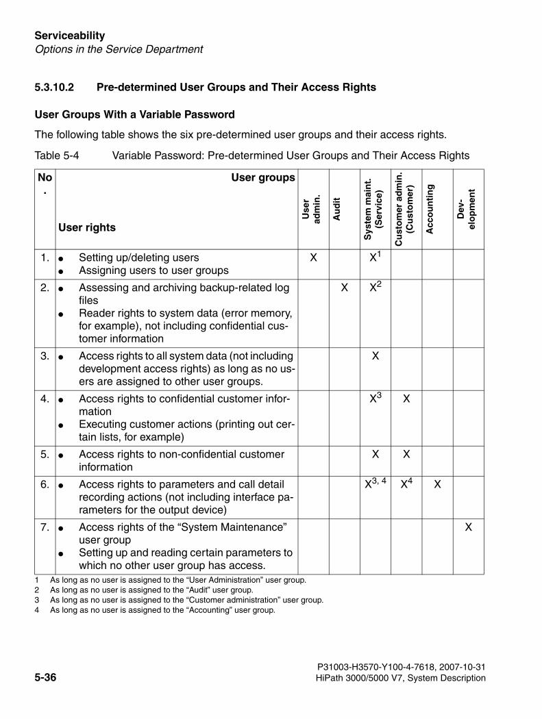
Serviceability For internal use only
3000sb5.fm
Options in the Service Department
5.3.10.2 Pre-determined User Groups and Their Access Rights
User Groups With a Variable Password
The following table shows the six pre-determined user groups and their access rights.
Table 5-4 Variable Password: Pre-determined User Groups and Their Access Rights
No.
User groups
User rights
Use
r ad
min
.
Au
dit
Sys
tem
mai
nt.
(Ser
vice
)
Cu
sto
mer
ad
min
.(C
ust
om
er)
Acc
ou
nti
ng
Dev
-el
op
men
t
1. ● Setting up/deleting users● Assigning users to user groups
X X1
1 As long as no user is assigned to the “User Administration” user group.
2. ● Assessing and archiving backup-related log files
● Reader rights to system data (error memory, for example), not including confidential cus-tomer information
X X2
2 As long as no user is assigned to the “Audit” user group.
3. ● Access rights to all system data (not including development access rights) as long as no us-ers are assigned to other user groups.
X
4. ● Access rights to confidential customer infor-mation
● Executing customer actions (printing out cer-tain lists, for example)
X3
3 As long as no user is assigned to the “Customer administration” user group.
X
5. ● Access rights to non-confidential customer information
X X
6. ● Access rights to parameters and call detail recording actions (not including interface pa-rameters for the output device)
X3, 4 X4
4 As long as no user is assigned to the “Accounting” user group.
X
7. ● Access rights of the “System Maintenance” user group
● Setting up and reading certain parameters to which no other user group has access.
X
P31003-H3570-Y100-4-7618, 2007-10-315-36 HiPath 3000/5000 V7, System Description
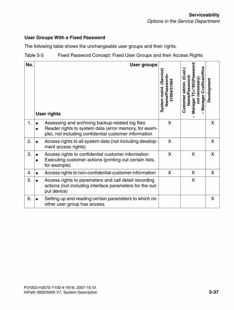
3000sb5.fm
For internal use only ServiceabilityOptions in the Service Department
User Groups With a Fixed Password
The following table shows the unchangeable user groups and their rights.
Table 5-5 Fixed Password Concept: Fixed User Groups and their Access Rights
No. User groups
User rights
Sys
tem
mai
nt.
(S
ervi
ce)
Nam
e/P
assw
ord
=31
994/
3199
4
Cu
sto
mer
ad
min
. (C
ust
.)N
ame/
Pas
swo
rd:
–M
anag
er T
C=*
95/(
Pas
swo
rdn
ot
nec
essa
ry)
– M
anag
er C
=off
ice/
off
ice
Dev
elo
pm
ent
1. ● Assessing and archiving backup-related log files ● Reader rights to system data (error memory, for exam-
ple), not including confidential customer information
X X
2. ● Access rights to all system data (not including develop-ment access rights)
X X
3. ● Access rights to confidential customer information ● Executing customer actions (printing out certain lists,
for example)
X X X
4. ● Access rights to non-confidential customer information X X X
5. ● Access rights to parameters and call detail recording actions (not including interface parameters for the out-put device)
X
6. ● Setting up and reading certain parameters to which no other user group has access.
X
P31003-H3570-Y100-4-7618, 2007-10-31HiPath 3000/5000 V7, System Description 5-37
Serviceability For internal use only
3000sb5.fm
Options in the Service Department
5.3.10.3 System Access Options
The user’s access rights, in other words the data that the user may read or manage, always depend on the user group to which the user is assigned.
Service Tools
● Manager T and Assistant TC Log on by entering your user name and password (independently of the lock code)The system can only be accessed using the first two UP0/E connections from the first SLMO/SLU board in the system.
● HiPath 3000/5000 Manager E and HiPath 3000/5000 Manager C (local)Log on by entering your user name and password
● HiPath 3000/5000 Manager E (remote), direct connectionLog on by entering your user name and passwordThe system can be accessed directly using the integrated digital modem (B channel) or the integrated analog modem. However, the user is required to establish a 5 digit access code beforehand.
● HiPath 3000/5000 Manager E (remote), callback connectionLog on by entering your user name and passwordThe system can be accessed using the integrated digital modem (B channel) or the inte-grated analog modem. However, you have to set up a callback index beforehand.
● HiPath Software Manager Log on by entering your user name and password
AMHOST
The AMHOST (Administration and Maintenance via HOST) feature allows Plus products to read certain system information and to change it, if necessary. To enable Plus products to ac-cess the system, you have to set up a user without a user group in the HiPath 3000/5000 default user administration. Enter “AMHOST” as the user name and “77777” as the default user pass-word.
You can only change this password if the system is configured using a variable password. In this case, delete the “AMHOST” user and reconfigure the system with the same user name and a new password.
P31003-H3570-Y100-4-7618, 2007-10-315-38 HiPath 3000/5000 V7, System Description
3000sb5.fm
For internal use only ServiceabilityOptions in the Service Department
5.3.10.4 Customer Data Security
When saving a customer database on the hard disk, a user table (part of the user administra-tion) with user name and encrypted passwords are also saved. This guarantees access secu-rity when the customer database is opened offline later on.
When opening the customer database offline, you are requested to enter your user name and password. The data that you enter is compared to the data in the user table. In this case, the user group verified during this process also determines the access rights.
When loading an offline customer database into HiPath 3000/5000, the user table that goes with it should not be loaded into the system. Otherwise, the system-specific user administration would be distorted.
P31003-H3570-Y100-4-7618, 2007-10-31HiPath 3000/5000 V7, System Description 5-39
Serviceability For internal use only
3000sb5.fm
Options in the Service Department
5.3.11 Automatic Logging of Administration Procedures
Definition
All accesses to customer-related data in the HiPath 3000/5000 are automatically logged in an area of the MMC (LOG area) reserved for this purpose. The information recorded includes who the user is, the data manipulated by the user, and the time. An authorized user (member of the “Audit” user group) can transfer the system data to a PC and assess it.
5.3.11.1 Logging
A log entry contains the following information:
● Date and time
● User name and user group
● Type of activity (format identification) and activity (command entry)
5.3.11.1.1 Format Identification and Command Entry
The following format information is logged:
● Manager T (1)All activities are logged, regardless of system access. The respective code with the most important parameters is recorded as the command entry (station/number, for example).
● Assistant TC (2) Same as Manager T (1)
● Session Information (3) The system access is logged, regardless whether it is logged using Manager T, HiPath 3000/5000 Manager E, or other HiPath systems. Possible command entries are: A0-1 = Login procedureA0-2 = Logout procedureA0-3 = Unauthorized login attempt
● HiPath 3000/5000 Manager E Database (4)Access to the database is logged using HiPath 3000/5000 Manager E. Possible command entries are: A1-1 = Database read A1-2 = Regeneration of CDB (Load CDB into the system)A1-3 = Write database
P31003-H3570-Y100-4-7618, 2007-10-315-40 HiPath 3000/5000 V7, System Description
3000sb5.fm
For internal use only ServiceabilityOptions in the Service Department
● Program Systems (5)APS transfers and system boots (first bootup, for example) are recorded. Possible com-mand entries are: – A2-1 = APSXF started– A2-2 = APSXF ended – A2-3 = APS boot (APS stamp also included)
● HiPath 3000/5000 Manager E Maintenance (6) Maintenance activities which can be assigned with the following command entries are logged: – B1-1 = Read error memory– B1-2 = Delete error memory– B2-1 = Out of service– B3-1 = Read Direct Memory Access– B3-2 = Write Direct Memory Access– B4-1 = Delete base station status overload– B4-2 = Delete base station restart– B5-1 = Digital loopback change– B6-1 = Trunk rolling change– B7-1 = Read trunk status– B8-1 = Delete trunk error counter
● Simulated or pseudo Manager T format (7)The HiPath 3000/5000 Manager E records the offline changes of a CDB as a “simulated” Manager T command. For data areas subject to change by HiPath 3000/5000 Manager E, pseudo areas are generated. When loading an offline CDB into the system, the following simulated commands are logged as command entries: C1 = Pseudo area “System parameter”– C1-1 System fags/CMI– C1-2 System intercept/AC– C1-3 Tones and calls– C1-4 Direction flag special (Variable direction#) – C1-5 System settings– C1-6 Host Link Interface– C1-7 Relocate activationC2 = Pseudo area “System timer”– C2-1 System timerC3 = Pseudo area “S0 configuration”– C3-1 Station bus– C3-2 Line supervision– C3-3 Mode
P31003-H3570-Y100-4-7618, 2007-10-31HiPath 3000/5000 V7, System Description 5-41
Serviceability For internal use only
3000sb5.fm
Options in the Service Department
C4 = Pseudo area “Lines”– C4-1 Loop start parameter (Variable Slot/Line#) C5 = Pseudo area “Digit analysis”– C5-1 Internal number (Variable Stn#, Grp#)– C5-2 Service codesC6 = Pseudo area “Summer time”– C6-1 Summer timeC7 = Pseudo area “Directions”– C7-1 Direction flags (Variable direction#) C8 = Pseudo area “Door setup”– C8-1 Door setup (Variable door#) C9 = Pseudo area “UCD Flags”– C9-1 UCD FlagsC10 = Pseud area “Delete system counter”– C10-1 Delete system counter
● HiPath 3000/5000 Manager E online (8)Archives from the log file and the user administration are logged. Possible command en-tries are: – D1-1 = Archive– D2-1 = New user– D2-2 = Delete user– D3-1 = Change password
>Logging External Accesses (Solutions, Applications)Plus products used with “AMHOST” can only make limited changes. Because these changes ’automatically’ run simultaneously (Check In and Check Out for hotel solu-tions, for example), these are not logged. Only the session information (user name is “amhost”) with the command entries “Login procedure” and “Logout procedure” are logged.
P31003-H3570-Y100-4-7618, 2007-10-315-42 HiPath 3000/5000 V7, System Description
3000sb5.fm
For internal use only ServiceabilityOptions in the Service Department
5.3.11.2 Issuing and Saving Log Data
Data is automatically logged in an area (LOG area) on the MCC reserved for this purpose. It cannot be switched off.
If approximately 80 % of the MMC log area capacity is exceeded, a Class A error is issued. This error is dealt with like all Class A errors and is displayed on the optiPoint Attendant as “Re-visor Alarm.”
The log should now be read out and archived, in other words it should be saved in an archive file (file extension = arc). If an archive is not created, the oldest datablock is overwritten if there is a danger of overflow.
You can only issue log entries using HiPath 3000/5000 Manager E. You cannot retrieve the log entries from the system until you have logged on as a user with “Revisor” rights.
Archive
If you request an archive (storage), the system checks whether or not there is already an ar-chive file (file extension = arc). If it is a file with log data from a previous archive, the file must match the current customer. In case of a positive result, the system log entries are retrieved and attached to the existing data in the archive file. At the same time, the data in the system is deleted. If malfunctions occur during this procedure (for example, line interruption), the entire procedure ends and the archive has to be restarted.
If no archive is requested, the revisor can retrieve, view, and print the log entries. However, log entries remain in the system.
Multimedia Card (MMC)
When replacing the multimedia card, the following applies:
● If the memory area for logging data is empty, logging restarts.
● If the memory area for logging data is not empty, logging continues.
P31003-H3570-Y100-4-7618, 2007-10-31HiPath 3000/5000 V7, System Description 5-43
Serviceability For internal use only
3000sb5.fm
Options in the Service Department
Example of a Log Printout
The following assumption applies as an example: The first system boot up has taken place. Customer-specific programming was completed.
The sample printout (without consideration of headers and footers) refers to the following infor-mation concerning administration procedures:
● The Revisor (“rev” user in “R” (Revision) user group) has generated an initial archive.
● The Service (“serv” user in “S” (system maintenance) user group) has read out the system database, changed 20 station names, and written them again to the system.
● The Customer (“pnkm” user in “A” (Administration) user group) has changed two additional station names.
● The Revisor has retrieved the most recent log entries and printed them out.
1050 00-11-25 15:57:10 rev(R) (6)D1-1 Archive
1051 00-11-25 15:58:22 rev(R) (3)A0-2 Logout procedure
1052 00-11-26 09:20:15 serv(S) (3)A0-1 Login procedure
1053 00-11-26 09:21:35 serv(S) (4)A1-1 Database read
1054 00-11-26 09:21:52 serv(S) (7)14-12-*(20) Station name
1055 00-11-26 09:22:45 serv(S) (4)A1-3 Write database
1056 00-11-26 09:23:25 serv(S) (3)A0-2 Logout procedure
1057 00-11-26 10:10:15 pnkm(A) (3)A0-1 Login procedure
1058 00-11-26 10:11:15 pnkm(A) (2)14-12-”30” Station name
1059 00-11-26 10:11:35 pnkm(A) (2)14-12-”31” Station name
1060 00-11-26 10:12:15 pnkm(A) (3)A0-2 Logout procedure
1061 00-11-27 11:20:30 rev(R) (3)A0-1 Login procedure
P31003-H3570-Y100-4-7618, 2007-10-315-44 HiPath 3000/5000 V7, System Description
3000sb6.fm
For internal use only MiddlewareHiPath TAPI 120 V2.0
6 Middleware
6.1 HiPath TAPI 120 V2.0
The 1st party CTI functionality is available for all HiPath 3000 models in conjunction with HG 1500. Up to six TAPI 120 can be operated without a license. Licenses are mandatory for any additional TAPI 120s installed. The software, installation manual, and additional information (data sheet) can be found on the Internet at http://www.siemens.com/enterprise.
6.1.1 HiPath TAPI 170 V2.0
This TAPI driver supports Microsoft TAPI 2.1 (Windows NT 4.0) and TAPI 3.0 (Windows 2000/XP). The software is enabled by a license server. Test software, installation, manual and addi-tional information (data sheet) can be found on the Internet at http://www.siemens.com/enter-prise.
Server Operatingsystems
Windows NT 4.0 (SP 6 or higher) or Windows 2000
Clients Operating sys-tems
Windows†98, Windows NT 4.0 (SP 6 or higher), Windows 2000 or Windows XP Professional
Connectionvariants
V.24, S0 or LAN
Basic software package
10 clients, 4 expansion packages up to 10, 25, 50 and 100 clients
CSTA CSTAInterfaces
Depending on the model, up to four interfaces are available
Applications Several applications can run in parallel, but they cannot send conflicting commands or be mutually exclusive
Monitor points 1000Four monitor points are required, for example, to monitor a sta-tion with four applications over CSTA
Call numberlength
Maximum of 6 digits
Load behavior incoming calls are rejected (busy) as soon as a traffic volume of 1400 BHCA is exceeded. This happens when more than four calls are received within ten seconds. This does not affect call traffic within the node
P31003-H3570-Y100-4-7618, 2007-10-31HiPath 3000/5000 V7, System Description 6-1
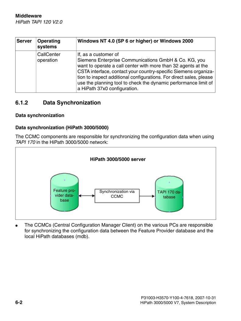
Middleware For internal use only
3000sb6.fm
HiPath TAPI 120 V2.0
6.1.2 Data Synchronization
Data synchronization
Data synchronization (HiPath 3000/5000)
The CCMC components are responsible for synchronizing the configuration data when using TAPI 170 in the HiPath 3000/5000 network:
● The CCMCs (Central Configuration Manager Client) on the various PCs are responsible for synchronizing the configuration data between the Feature Provider database and the local HiPath databases (mdb).
CallCenteroperation
If, as a customer of Siemens Enterprise Communications GmbH & Co. KG, you want to operate a call center with more than 32 agents at the CSTA interface, contact your country-specific Siemens organiza-tion to inspect additional configurations. For direct sales, please use the planning tool to check the dynamic performance limit of a HiPath 37x0 configuration.
Server Operatingsystems
Windows NT 4.0 (SP 6 or higher) or Windows 2000
Feature pro-vider data-
base
TAPI 170 da-tabase
HiPath 3000/5000 server
Synchronization via CCMC
P31003-H3570-Y100-4-7618, 2007-10-316-2 HiPath 3000/5000 V7, System Description
3000sb6.fm
For internal use only MiddlewareHiPath TAPI 120 V2.0
6.1.3 Features
The following features are available depending on the system used and the support of the TAPI applications:
Features of the Components TSP/CMD
● Outgoing connection setup, incoming call acceptance, ending calls
● Call status display, call number display
● Call logging
● Call pick-up (group), consultation hold, toggle, call transfer, conference
● Speed transfer, redirect and call hold
● Touchtone dialing (DTMF) during conversation
● Call detail information
● Description of display
● Hookswitch status setting/retrieval
● Volume control for handset, speaker and headset
● Set LED mode
● Park/unpark
● Dynamic generation of lines via the application
● Call center features
– Retrieve/set/delete mailbox indicator (message waiting)
– Retrieve/set/delete call forwarding/do not disturb
– Additional information for forwarded/ redirected/switched calls
– Playing Music On Hold and recorded announcements (RCA)
– Trunk and UCD monitoring
– Call detail recording (with respect to call status)
– Unique call identification (in the general domain)
– Call data exchange between TAPI applications (in the general domain)
P31003-H3570-Y100-4-7618, 2007-10-31HiPath 3000/5000 V7, System Description 6-3
Middleware For internal use only
3000sb6.fm
HiPath TAPI 120 V2.0
TSP (TAPI Extended Services) Features
● Central recording of call charges
● Support of ACD proxy request handler
● Telephone Data Service (TDS)
● Heartbeat/loopback
● AMHOST
6.1.4 System Connection Hardware
TAPI 170 for HiPath 3000/5000 or in the HiPath Network
The CTI components are usually connected to one another or to the system(s) via TCP/IP.
TAPI 170 as a Standalone Solution
Alternatively, the TSP/CMD components can be connected to one another or to the system as follows:
● via the DIVA Pro 2.0. ISDN card supplied
● via a V24 interface with a null modem cable (part number: C39195-Z7267-C13); in order to achieve the best performance possible, the baud rate used can be increased to 19200 bauds.
● via TCP/IP (recommended default).
P31003-H3570-Y100-4-7618, 2007-10-316-4 HiPath 3000/5000 V7, System Description
3000sb6.fm
For internal use only MiddlewareHiPath TAPI 120 V2.0
6.1.5 Software and Hardware Requirements
Hardware Requirements for Server and Client PCs
The hardware requirements valid here are those specified in Microsoft’s PC documentation for Windows NT 4.0 or Windows 2000. For more information see the Windows documentation.
Software Requirements for the Server PC
● Windows NT Server 4.0 Service Pack 4 and later
● or Windows 2000 Server
● or Windows 2000 Advanced Server
Software Requirements for Client PCs
● Windows 98
● or Windows ME
● or Windows NT Server 4.0 Service Pack 4 and later
● or Windows NT Workstation 4.0 Service Pack 4 and later
● or Windows 2000 Server
● or Windows 2000 Advanced Server
● or Windows 2000 Professional
● or Windows XP Office
The Windows NT Service Pack can be downloaded in the Internet at:
> http://www.microsoft.com/downloads/
Other Requirements
● Network protocol: TCP/IP must be configured.
● The server PC and the client PC must belong to a Windows NT or Windows 2000 domain.
● When using Windows NT4 (to read the MAC ID), NETBIOS must be activated.
>When using TAPI 170 for HiPath 3000/5000 network, the server PC will normally only operate under Windows 2000.
P31003-H3570-Y100-4-7618, 2007-10-31HiPath 3000/5000 V7, System Description 6-5
Middleware For internal use only
3000sb6.fm
HiPath TAPI 120 V2.0
6.1.6 Installation Medium and Order of Installation
Depending on the TAPI 170 system variant, the following applies:
Installation of TAPI 170 for HiPath 3000/5000 or HiPath 5000
The installation files for TAPI 170 are included in the installation media for HiPath 5000 or Hi-Path 3000/5000 software installation.
The order in which the components are installed is automatically selected by the installation program. The components to be installed can be specified during installation. After installing the components, the necessary parameters may be individually configured before carrying out further installations. However, the components can also be configured at a later time.
Installation of TAPI 170 (Standalone)
An installation CD with the title
HiPath TAPI 170 V2.0
is included. Since the installation comprises components from various manufacturers, it is es-sential that the installation is performed in the following order.
Order of Installation
1. Component installation
2. Component configuration
P31003-H3570-Y100-4-7618, 2007-10-316-6 HiPath 3000/5000 V7, System Description
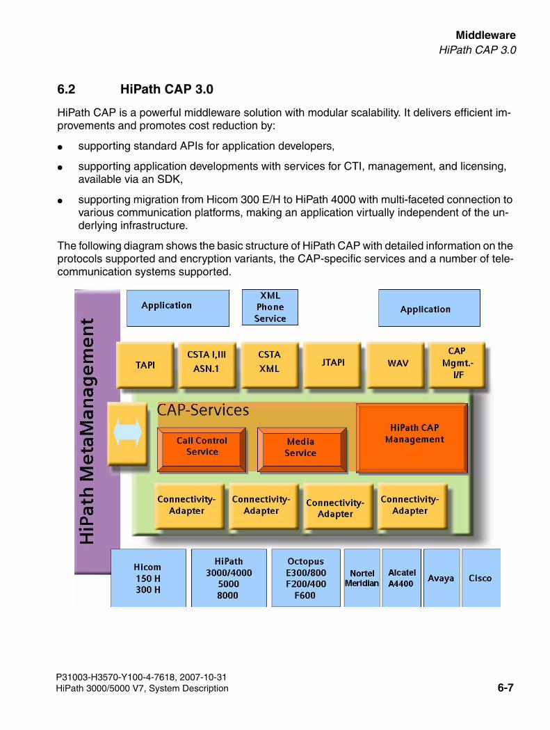
3000sb6.fm
For internal use only MiddlewareHiPath CAP 3.0
6.2 HiPath CAP 3.0
HiPath CAP is a powerful middleware solution with modular scalability. It delivers efficient im-provements and promotes cost reduction by:
● supporting standard APIs for application developers,
● supporting application developments with services for CTI, management, and licensing, available via an SDK,
● supporting migration from Hicom 300 E/H to HiPath 4000 with multi-faceted connection to various communication platforms, making an application virtually independent of the un-derlying infrastructure.
The following diagram shows the basic structure of HiPath CAP with detailed information on the protocols supported and encryption variants, the CAP-specific services and a number of tele-communication systems supported.
P31003-H3570-Y100-4-7618, 2007-10-31HiPath 3000/5000 V7, System Description 6-7
Middleware For internal use only
3000sb6.fm
HiPath CAP 3.0
Highlights
● Standard protocols and APIs: Microsoft TAPI 2.x/3.0, JTAPI, CSTA III ASN.1, CSTA XML, Microsoft Wave API
● Call Control Service (SCC) for CTI
– multi-domain features
– harmonization of the call models for Hicom 300 H, HiPath 3000, HiPath 4000, HiPath 5000, HiPath 8000, Octopus E300/800 Rel. 6.5/10, Realitis, Alcatel, Nortel Meridian, Cisco, and Avaya - for TAPI- and CSTA-based applications
● Media Service (MEB) for CTI
– media streaming as a new HiPath CAP feature for applications
● Fault Management Service
– integration in HiPath Management (not dependent on CAP Management)
● License, User, and Configuration Management Services
– uniform license structure
– integrated License and User Management tool
– connection to the HiPath License Server (CLS)
– feature as a service for licensing HiPath CAP and applications in the same manner
● Support for special features
– LiRus, AP emergency, XML PhoneServices
P31003-H3570-Y100-4-7618, 2007-10-316-8 HiPath 3000/5000 V7, System Description
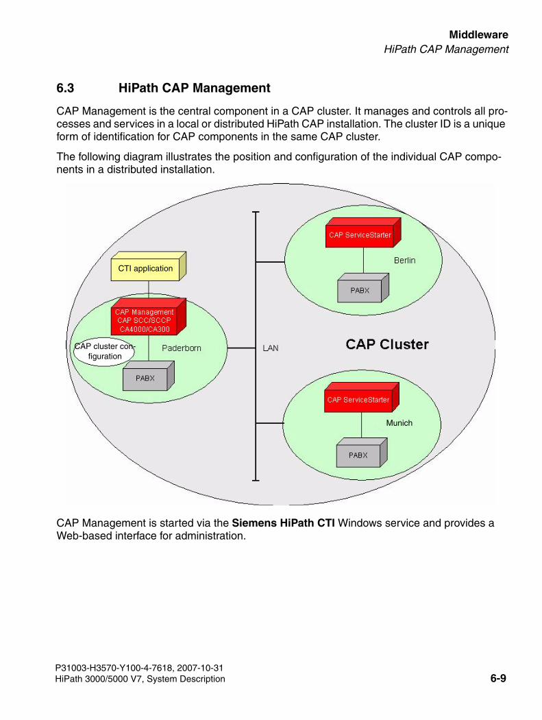
3000sb6.fm
For internal use only MiddlewareHiPath CAP Management
6.3 HiPath CAP Management
CAP Management is the central component in a CAP cluster. It manages and controls all pro-cesses and services in a local or distributed HiPath CAP installation. The cluster ID is a unique form of identification for CAP components in the same CAP cluster.
The following diagram illustrates the position and configuration of the individual CAP compo-nents in a distributed installation.
CAP Management is started via the Siemens HiPath CTI Windows service and provides a Web-based interface for administration.
CTI application
CAP cluster con-figuration
Munich
P31003-H3570-Y100-4-7618, 2007-10-31HiPath 3000/5000 V7, System Description 6-9
Middleware For internal use only
3000sb6.fm
HiPath CAP Management
CAP Management tasks
● Administration of central and distributed components
● Administration of users
● Administration of devices
● Administration of licenses
● License inspection and access control for users and devices
● Administration of status information for the various processes and services
HiPath CAP Management services
CAP Management can be split into different services that have different tasks:
● Configuration Management (SCM)
● User Management (SUM)
● License Management (SLM)
● CallIdRepository
● Address Translation Service (SAT)
● Open LDAP Server
● Fault Management (SFM) (independent of CAP Management)
P31003-H3570-Y100-4-7618, 2007-10-316-10 HiPath 3000/5000 V7, System Description
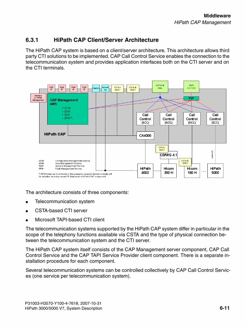
3000sb6.fm
For internal use only MiddlewareHiPath CAP Management
6.3.1 HiPath CAP Client/Server Architecture
The HiPath CAP system is based on a client/server architecture. This architecture allows third party CTI solutions to be implemented. CAP Call Control Service enables the connection to the telecommunication system and provides application interfaces both on the CTI server and on the CTI terminals.
The architecture consists of three components:
● Telecommunication system
● CSTA-based CTI server
● Microsoft TAPI-based CTI client
The telecommunication systems supported by the HiPath CAP system differ in particular in the scope of the telephony functions available via CSTA and the type of physical connection be-tween the telecommunication system and the CTI server.
The HiPath CAP system itself consists of the CAP Management server component, CAP Call Control Service and the CAP TAPI Service Provider client component. There is a separate in-stallation procedure for each component.
Several telecommunication systems can be controlled collectively by CAP Call Control Servic-es (one service per telecommunication system).
P31003-H3570-Y100-4-7618, 2007-10-31HiPath 3000/5000 V7, System Description 6-11
Middleware For internal use only
3000sb6.fm
CAP TAPI Service Provider
CAP Call Control Service runs in conjunction with CAP Management, which facilitates the ad-ministration of the individual servers. In addition, all telephone numbers are protected with a password via CAP Management.
CAP Call Control Service runs in conjunction with CAP Management, which facilitates the ad-ministration of the individual servers. In addition, all telephone numbers are protected with a password via CAP Management.
Connections are established between HiPath 3000/5000 and CAP Call Control Service indi-rectly via CAP Management. CAP Management is responsible for authentication (by means of a password) and the determination of the CAP Call Control Server responsible for a line. This means that reconfigurations on the telecommunication systems are transparent for HiPath 3000/5000 and the client applications on the basis of this service provider.
For example, if telephone numbers are moved from once telecommunication system to another, and become the responsibility of a different CAP Call Control server (with a different IP ad-dress/port number), then the relevant configuration can only be implemented via CAP Manage-ment.Conversely, there is no need to configure client applications in the HiPath CAP system. This means that the IP addresses of clients can change, for example through dynamic assignment via DHCP. The client and CAP Call Control Service are dynamically assigned via CAP Man-agement at every login.
6.4 CAP TAPI Service Provider
HiPath CAP is a software platform for Computer Telephony Integration (CTI) on telecommuni-cation systems. HiPath 3000/5000 links the CTI client applications. HiPath 3000/5000 supports all telecommunication systems accessible over HiPath CAP.
The HiPath CAP system uses interfaces to supply the telecommunication system functionality that can be used in any CTI applications.
>Further information about CAP can be found in the relevant manuals:● HiPath CAP 3.0, Installation and Administration Manual● HiPath CAP 3.0, CAP TAPI Service Provider,
Installation and Administration Manual
P31003-H3570-Y100-4-7618, 2007-10-316-12 HiPath 3000/5000 V7, System Description
3000sb55.fm
For internal use only Access PointsHiPath AP 1120
7 Access Points
7.1 HiPath AP 1120
The system connects up to two telephones and/or fax devices to a corporate or carrier VoIP network over a 10/100 BaseT Ethernet port. HiPath AP 1120 lets users upgrade simply, trans-parently, and cost-effectively to an IP-based telephony infrastructure without having to forego existing analog devices. The devices can dynamically recognize the most common IP telepho-ny codecs and fax protocols, including T.38 (UDP). These can be remotely administered and upgraded using the Unit Manager Network.
HiPath AP 1120 connects up to two telephones and/or fax devices to a corporate or carrier VoIP network over a 10/100 BaseT Ethernet port.
The devices recognize dynamically the most up-to-date IP telephony CODECs and fax proto-cols:
● T.38 (UDP)
● G.711
● G.723
● G.722
These can be remotely administered and upgraded using the Unit Manager Network.
>Voice quality in G.722 is very good in internal traffic, but poor in external traffic be-cause this protocol is not supported on all public routes.
>The AP1120 can be used to transmit both voice (G.711) and fax (T.38) signals. The settings on the HG 1500 V3.0 should be identical with the settings in AP 1120.
P31003-H3570-Y100-4-7618, 2007-10-31HiPath 3000/5000 V7, System Description 7-1

Access Points For internal use only
3000sb55.fm
HiPath AP 1120 SIP
7.2 HiPath AP 1120 SIP
AP1120 SIP is an IP-to-analog adapter for fax/modem. It is used when a fax is required at a location that only has an IP connection.
AP 1120 SIP features two analog interfaces and is supplied with the Cornet IP software forHiPath 4000 as well as with the H.323 or SIP software for HiPath 3000/5000, HiPath 4000,and HiPath 8000.
P31003-H3570-Y100-4-7618, 2007-10-317-2 HiPath 3000/5000 V7, System Description
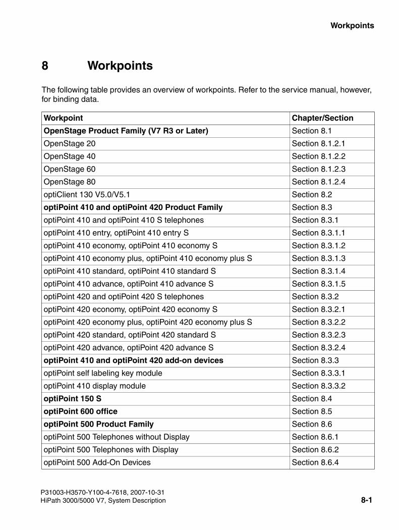
3000sb7.fm
For internal use only Workpoints
8 Workpoints
The following table provides an overview of workpoints. Refer to the service manual, however, for binding data.
Workpoint Chapter/Section
OpenStage Product Family (V7 R3 or Later) Section 8.1
OpenStage 20 Section 8.1.2.1
OpenStage 40 Section 8.1.2.2
OpenStage 60 Section 8.1.2.3
OpenStage 80 Section 8.1.2.4
optiClient 130 V5.0/V5.1 Section 8.2
optiPoint 410 and optiPoint 420 Product Family Section 8.3
optiPoint 410 and optiPoint 410 S telephones Section 8.3.1
optiPoint 410 entry, optiPoint 410 entry S Section 8.3.1.1
optiPoint 410 economy, optiPoint 410 economy S Section 8.3.1.2
optiPoint 410 economy plus, optiPoint 410 economy plus S Section 8.3.1.3
optiPoint 410 standard, optiPoint 410 standard S Section 8.3.1.4
optiPoint 410 advance, optiPoint 410 advance S Section 8.3.1.5
optiPoint 420 and optiPoint 420 S telephones Section 8.3.2
optiPoint 420 economy, optiPoint 420 economy S Section 8.3.2.1
optiPoint 420 economy plus, optiPoint 420 economy plus S Section 8.3.2.2
optiPoint 420 standard, optiPoint 420 standard S Section 8.3.2.3
optiPoint 420 advance, optiPoint 420 advance S Section 8.3.2.4
optiPoint 410 and optiPoint 420 add-on devices Section 8.3.3
optiPoint self labeling key module Section 8.3.3.1
optiPoint 410 display module Section 8.3.3.2
optiPoint 150 S Section 8.4
optiPoint 600 office Section 8.5
optiPoint 500 Product Family Section 8.6
optiPoint 500 Telephones without Display Section 8.6.1
optiPoint 500 Telephones with Display Section 8.6.2
optiPoint 500 Add-On Devices Section 8.6.4
P31003-H3570-Y100-4-7618, 2007-10-31HiPath 3000/5000 V7, System Description 8-1
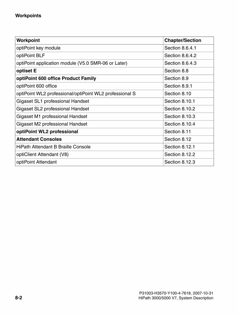
Workpoints For internal use only
3000sb7.fm
optiPoint key module Section 8.6.4.1
optiPoint BLF Section 8.6.4.2
optiPoint application module (V5.0 SMR-06 or Later) Section 8.6.4.3
optiset E Section 8.8
optiPoint 600 office Product Family Section 8.9
optiPoint 600 office Section 8.9.1
optiPoint WL2 professional/optiPoint WL2 professional S Section 8.10
Gigaset SL1 professional Handset Section 8.10.1
Gigaset SL2 professional Handset Section 8.10.2
Gigaset M1 professional Handset Section 8.10.3
Gigaset M2 professional Handset Section 8.10.4
optiPoint WL2 professional Section 8.11
Attendant Consoles Section 8.12
HiPath Attendant B Braille Console Section 8.12.1
optiClient Attendant (V8) Section 8.12.2
optiPoint Attendant Section 8.12.3
Workpoint Chapter/Section
P31003-H3570-Y100-4-7618, 2007-10-318-2 HiPath 3000/5000 V7, System Description
3000sb7.fm
For internal use only WorkpointsOpenStage Product Family (V7 R3 or Later)
8.1 OpenStage Product Family (V7 R3 or Later)
The OpenStage product family represents a new generation of workpoints for powerful busi-ness communication.
For all workpoints the choice of connection variants in HiPath 3000/5000 is as follows:
● V7 R3 or later: CorNet IP connection (also as Gigabit variant, Page 8-4)
● TDM connection
The three dialog keys and the display along with the following control elements guarantee con-venient and interactive operation:
● 3-way navigator: OpenStage 20
● Illuminated touch/sensor keys for selecting functions and one 5-way navigator: OpenStage 40
● Illuminated touch/sensor keys for selecting functions and one TouchGuide: OpenStage 60 and OpenStage 80
The freely-assignable touch/sensor keys in the graphic display of the workpoints OpenStage 40, OpenStage 60 and OpenStage 80 can be assigned call numbers or any given key functions. The self-labeling function allows the currently stored call number or function to be displayed.
>The SIP connection variant is not supported by HiPath 3000/5000.
P31003-H3570-Y100-4-7618, 2007-10-31HiPath 3000/5000 V7, System Description 8-3
Workpoints For internal use only
3000sb7.fm
OpenStage Product Family (V7 R3 or Later)
8.1.1 Gigabit variant of the OpenStage workpoints
The connection variant CorNet IP is also available in a Gigabit variant.
The integrated Ethernet switch of this OpenStage workpoint enables the workstation PC to be connected to the local network for example. In the Gigabit variant larger data packets (example: video or audio data packets) can also be transferred to the workstation PC which is connected via the OpenStage workpoint to the network
This enables costs to be saved in the area of inhouse cabling and the IP network and at the same time allows the performance of the network to be increased. In addition the use of a Gi-gabit network gives an improved voice quality. This is especially evident for calls made in speak-erphone mode, since the data-intensive echo compensation of the OpenStage workpoints in conjunction with the full duplex characteristic in a Gigabit network can be executed more quickly and smoothly in a Gigabit network.
To enable the Gigabit Ethernet switch to be usefully employed, it is vital for the entire corporate network to support Gigabit technology. It is vital to use type “CAT 5E” or even better type “CAT 6” network cables to connect the workpoints. Older types of cable may under some circum-stances cause significant speed losses.
P31003-H3570-Y100-4-7618, 2007-10-318-4 HiPath 3000/5000 V7, System Description
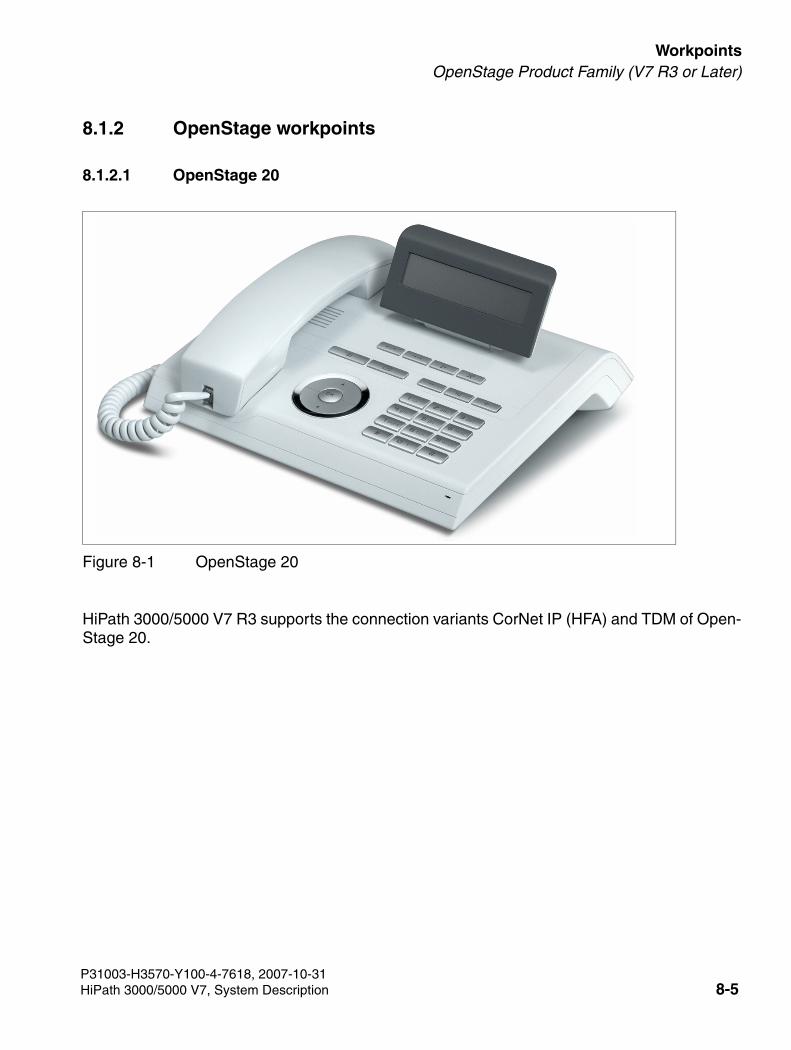
3000sb7.fm
For internal use only WorkpointsOpenStage Product Family (V7 R3 or Later)
8.1.2 OpenStage workpoints
8.1.2.1 OpenStage 20
HiPath 3000/5000 V7 R3 supports the connection variants CorNet IP (HFA) and TDM of Open-Stage 20.
Figure 8-1 OpenStage 20
P31003-H3570-Y100-4-7618, 2007-10-31HiPath 3000/5000 V7, System Description 8-5
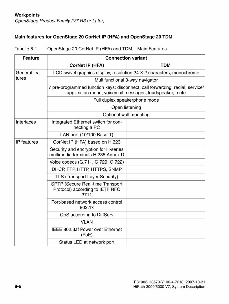
Workpoints For internal use only
3000sb7.fm
OpenStage Product Family (V7 R3 or Later)
Main features for OpenStage 20 CorNet IP (HFA) and OpenStage 20 TDM
Tabelle 8-1 OpenStage 20 CorNet IP (HFA) and TDM – Main Features
Feature Connection variant
CorNet IP (HFA) TDM
General fea-tures
LCD swivel graphics display, resolution 24 X 2 characters, monochrome
Multifunctional 3-way navigator
7 pre-programmed function keys: disconnect, call forwarding, redial, service/application menu, voicemail messages, loudspeaker, mute
Full duplex speakerphone mode
Open listening
Optional wall mounting
Interfaces Integrated Ethernet switch for con-necting a PC
LAN port (10/100 Base-T)
IP features CorNet IP (HFA) based on H.323
Security and encryption for H-series multimedia terminals H.235 Annex D
Voice codecs (G.711, G.729, G.722)
DHCP, FTP, HTTP, HTTPS, SNMP
TLS (Transport Layer Security)
SRTP (Secure Real-time Transport Protocol) according to IETF RFC
3711
Port-based network access control 802.1x
QoS according to DiffServ
VLAN
IEEE 802.3af Power over Ethernet (PoE)
Status LED at network port
P31003-H3570-Y100-4-7618, 2007-10-318-6 HiPath 3000/5000 V7, System Description
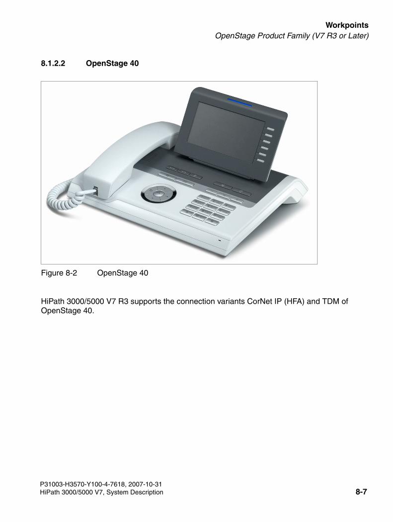
3000sb7.fm
For internal use only WorkpointsOpenStage Product Family (V7 R3 or Later)
8.1.2.2 OpenStage 40
HiPath 3000/5000 V7 R3 supports the connection variants CorNet IP (HFA) and TDM of OpenStage 40.
Figure 8-2 OpenStage 40
P31003-H3570-Y100-4-7618, 2007-10-31HiPath 3000/5000 V7, System Description 8-7
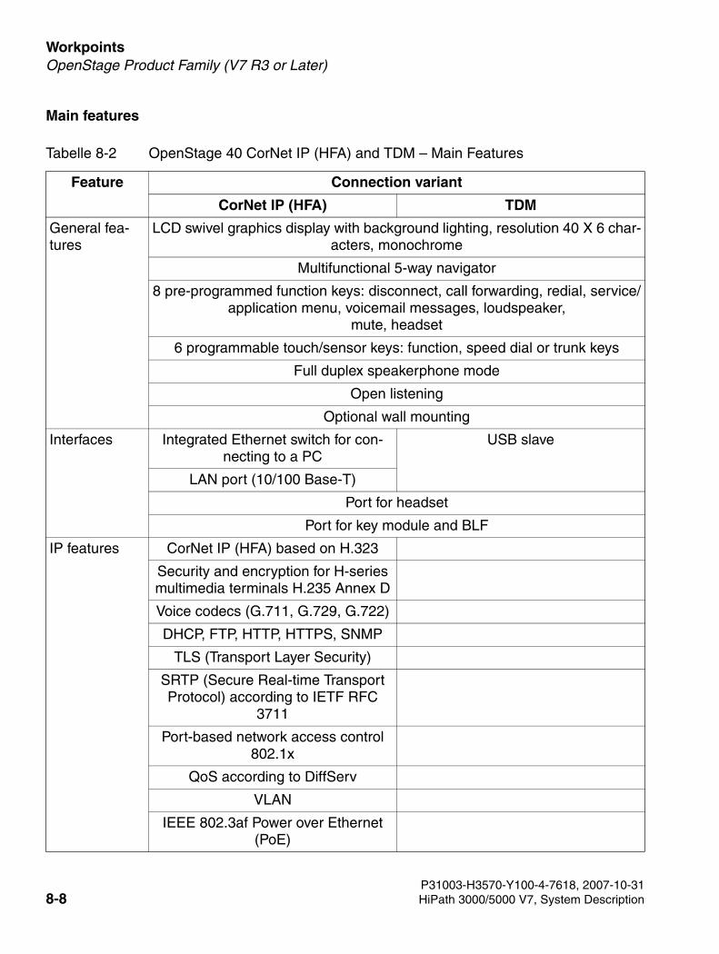
Workpoints For internal use only
3000sb7.fm
OpenStage Product Family (V7 R3 or Later)
Main features
Tabelle 8-2 OpenStage 40 CorNet IP (HFA) and TDM – Main Features
Feature Connection variant
CorNet IP (HFA) TDM
General fea-tures
LCD swivel graphics display with background lighting, resolution 40 X 6 char-acters, monochrome
Multifunctional 5-way navigator
8 pre-programmed function keys: disconnect, call forwarding, redial, service/application menu, voicemail messages, loudspeaker,
mute, headset
6 programmable touch/sensor keys: function, speed dial or trunk keys
Full duplex speakerphone mode
Open listening
Optional wall mounting
Interfaces Integrated Ethernet switch for con-necting to a PC
USB slave
LAN port (10/100 Base-T)
Port for headset
Port for key module and BLF
IP features CorNet IP (HFA) based on H.323
Security and encryption for H-series multimedia terminals H.235 Annex D
Voice codecs (G.711, G.729, G.722)
DHCP, FTP, HTTP, HTTPS, SNMP
TLS (Transport Layer Security)
SRTP (Secure Real-time Transport Protocol) according to IETF RFC
3711
Port-based network access control 802.1x
QoS according to DiffServ
VLAN
IEEE 802.3af Power over Ethernet (PoE)
P31003-H3570-Y100-4-7618, 2007-10-318-8 HiPath 3000/5000 V7, System Description
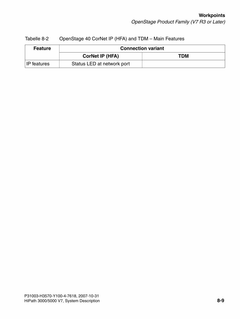
3000sb7.fm
For internal use only WorkpointsOpenStage Product Family (V7 R3 or Later)
IP features Status LED at network port
Tabelle 8-2 OpenStage 40 CorNet IP (HFA) and TDM – Main Features
Feature Connection variant
CorNet IP (HFA) TDM
P31003-H3570-Y100-4-7618, 2007-10-31HiPath 3000/5000 V7, System Description 8-9
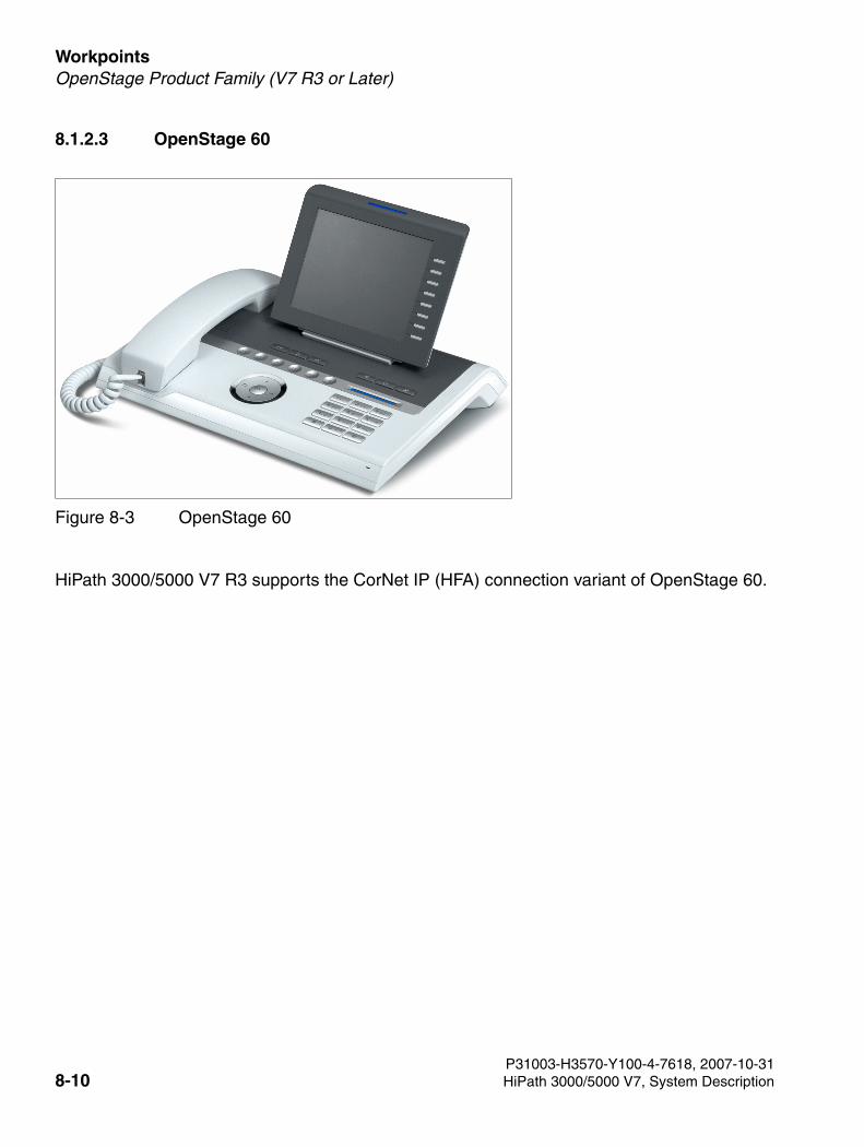
Workpoints For internal use only
3000sb7.fm
OpenStage Product Family (V7 R3 or Later)
8.1.2.3 OpenStage 60
HiPath 3000/5000 V7 R3 supports the CorNet IP (HFA) connection variant of OpenStage 60.
Figure 8-3 OpenStage 60
P31003-H3570-Y100-4-7618, 2007-10-318-10 HiPath 3000/5000 V7, System Description
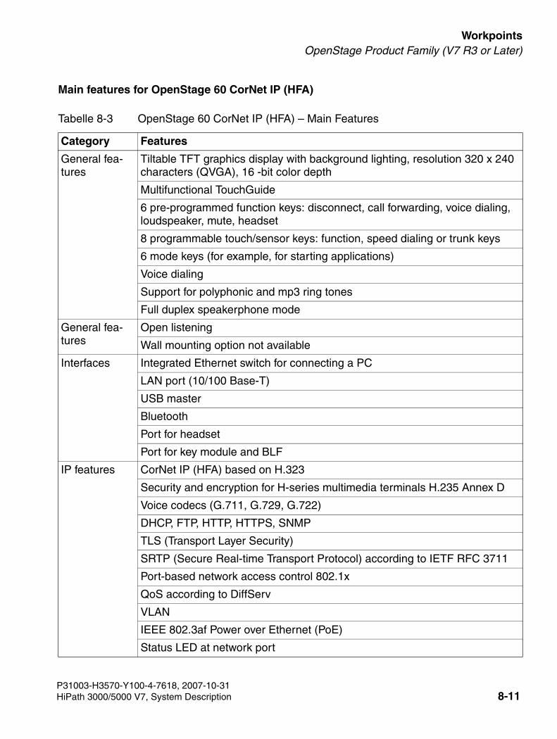
3000sb7.fm
For internal use only WorkpointsOpenStage Product Family (V7 R3 or Later)
Main features for OpenStage 60 CorNet IP (HFA)
Tabelle 8-3 OpenStage 60 CorNet IP (HFA) – Main Features
Category Features
General fea-tures
Tiltable TFT graphics display with background lighting, resolution 320 x 240 characters (QVGA), 16 -bit color depth
Multifunctional TouchGuide
6 pre-programmed function keys: disconnect, call forwarding, voice dialing, loudspeaker, mute, headset
8 programmable touch/sensor keys: function, speed dialing or trunk keys
6 mode keys (for example, for starting applications)
Voice dialing
Support for polyphonic and mp3 ring tones
Full duplex speakerphone mode
General fea-tures
Open listening
Wall mounting option not available
Interfaces Integrated Ethernet switch for connecting a PC
LAN port (10/100 Base-T)
USB master
Bluetooth
Port for headset
Port for key module and BLF
IP features CorNet IP (HFA) based on H.323
Security and encryption for H-series multimedia terminals H.235 Annex D
Voice codecs (G.711, G.729, G.722)
DHCP, FTP, HTTP, HTTPS, SNMP
TLS (Transport Layer Security)
SRTP (Secure Real-time Transport Protocol) according to IETF RFC 3711
Port-based network access control 802.1x
QoS according to DiffServ
VLAN
IEEE 802.3af Power over Ethernet (PoE)
Status LED at network port
P31003-H3570-Y100-4-7618, 2007-10-31HiPath 3000/5000 V7, System Description 8-11
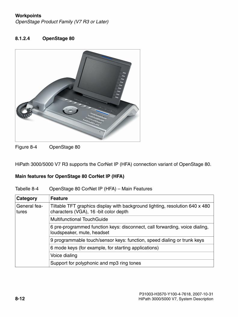
Workpoints For internal use only
3000sb7.fm
OpenStage Product Family (V7 R3 or Later)
8.1.2.4 OpenStage 80
HiPath 3000/5000 V7 R3 supports the CorNet IP (HFA) connection variant of OpenStage 80.
Main features for OpenStage 80 CorNet IP (HFA)
Figure 8-4 OpenStage 80
Tabelle 8-4 OpenStage 80 CorNet IP (HFA) – Main Features
Category Feature
General fea-tures
Tiltable TFT graphics display with background lighting, resolution 640 x 480 characters (VGA), 16 -bit color depth
Multifunctional TouchGuide
6 pre-programmed function keys: disconnect, call forwarding, voice dialing, loudspeaker, mute, headset
9 programmable touch/sensor keys: function, speed dialing or trunk keys
6 mode keys (for example, for starting applications)
Voice dialing
Support for polyphonic and mp3 ring tones
P31003-H3570-Y100-4-7618, 2007-10-318-12 HiPath 3000/5000 V7, System Description
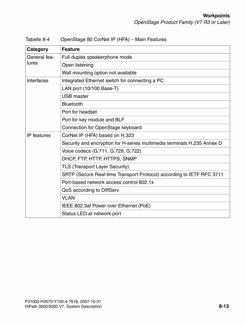
3000sb7.fm
For internal use only WorkpointsOpenStage Product Family (V7 R3 or Later)
General fea-tures
Full duplex speakerphone mode
Open listening
Wall mounting option not available
Interfaces Integrated Ethernet switch for connecting a PC
LAN port (10/100 Base-T)
USB master
Bluetooth
Port for headset
Port for key module and BLF
Connection for OpenStage keyboard
IP features CorNet IP (HFA) based on H.323
Security and encryption for H-series multimedia terminals H.235 Annex D
Voice codecs (G.711, G.729, G.722)
DHCP, FTP, HTTP, HTTPS, SNMP
TLS (Transport Layer Security)
SRTP (Secure Real-time Transport Protocol) according to IETF RFC 3711
Port-based network access control 802.1x
QoS according to DiffServ
VLAN
IEEE 802.3af Power over Ethernet (PoE)
Status LED at network port
Tabelle 8-4 OpenStage 80 CorNet IP (HFA) – Main Features
Category Feature
P31003-H3570-Y100-4-7618, 2007-10-31HiPath 3000/5000 V7, System Description 8-13
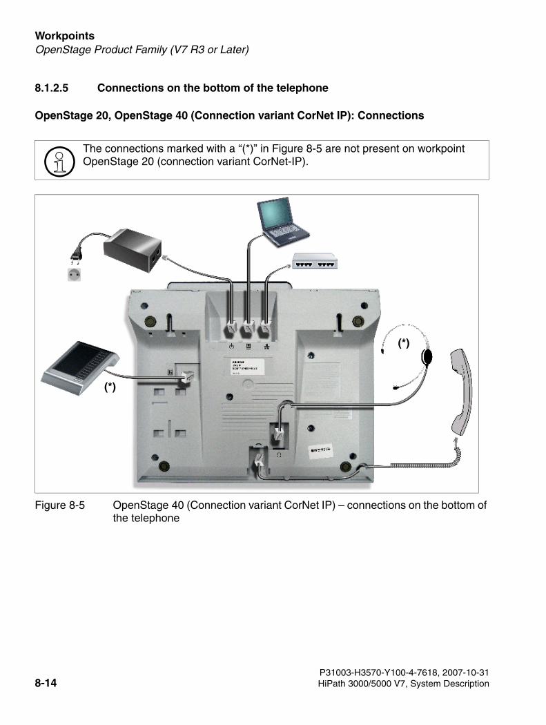
Workpoints For internal use only
3000sb7.fm
OpenStage Product Family (V7 R3 or Later)
8.1.2.5 Connections on the bottom of the telephone
OpenStage 20, OpenStage 40 (Connection variant CorNet IP): Connections
>The connections marked with a “(*)” in Figure 8-5 are not present on workpoint OpenStage 20 (connection variant CorNet-IP).
Figure 8-5 OpenStage 40 (Connection variant CorNet IP) – connections on the bottom of the telephone
(*)
(*)
P31003-H3570-Y100-4-7618, 2007-10-318-14 HiPath 3000/5000 V7, System Description
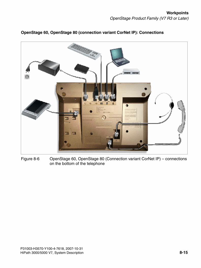
3000sb7.fm
For internal use only WorkpointsOpenStage Product Family (V7 R3 or Later)
OpenStage 60, OpenStage 80 (connection variant CorNet IP): Connections
Figure 8-6 OpenStage 60, OpenStage 80 (Connection variant CorNet IP) – connections on the bottom of the telephone
P31003-H3570-Y100-4-7618, 2007-10-31HiPath 3000/5000 V7, System Description 8-15
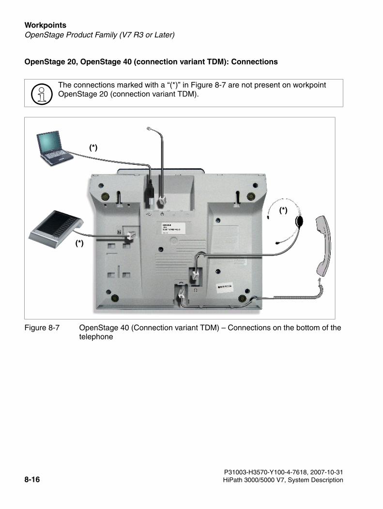
Workpoints For internal use only
3000sb7.fm
OpenStage Product Family (V7 R3 or Later)
OpenStage 20, OpenStage 40 (connection variant TDM): Connections
>The connections marked with a “(*)” in Figure 8-7 are not present on workpoint OpenStage 20 (connection variant TDM).
Figure 8-7 OpenStage 40 (Connection variant TDM) – Connections on the bottom of the telephone
(*)
(*)
(*)
P31003-H3570-Y100-4-7618, 2007-10-318-16 HiPath 3000/5000 V7, System Description
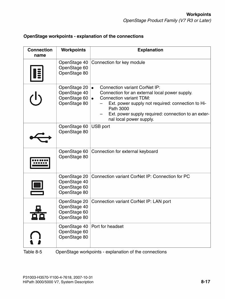
3000sb7.fm
For internal use only WorkpointsOpenStage Product Family (V7 R3 or Later)
OpenStage workpoints - explanation of the connections
Connection name
Workpoints Explanation
OpenStage 40 OpenStage 60OpenStage 80
Connection for key module
OpenStage 20OpenStage 40OpenStage 60OpenStage 80
● Connection variant CorNet IP: Connection for an external local power supply.
● Connection variant TDM: – Ext. power supply not required: connection to Hi-
Path 3000 – Ext. power supply required: connection to an exter-
nal local power supply.
OpenStage 60OpenStage 80
USB port
OpenStage 60OpenStage 80
Connection for external keyboard
OpenStage 20OpenStage 40OpenStage 60OpenStage 80
Connection variant CorNet IP: Connection for PC
OpenStage 20OpenStage 40OpenStage 60OpenStage 80
Connection variant CorNet IP: LAN port
OpenStage 40OpenStage 60OpenStage 80
Port for headset
Table 8-5 OpenStage workpoints - explanation of the connections
P31003-H3570-Y100-4-7618, 2007-10-31HiPath 3000/5000 V7, System Description 8-17

Workpoints For internal use only
3000sb7.fm
OpenStage Product Family (V7 R3 or Later)
OpenStage 20OpenStage 40OpenStage 60OpenStage 80
Headset port
Connection name
Workpoints Explanation
Table 8-5 OpenStage workpoints - explanation of the connections
P31003-H3570-Y100-4-7618, 2007-10-318-18 HiPath 3000/5000 V7, System Description
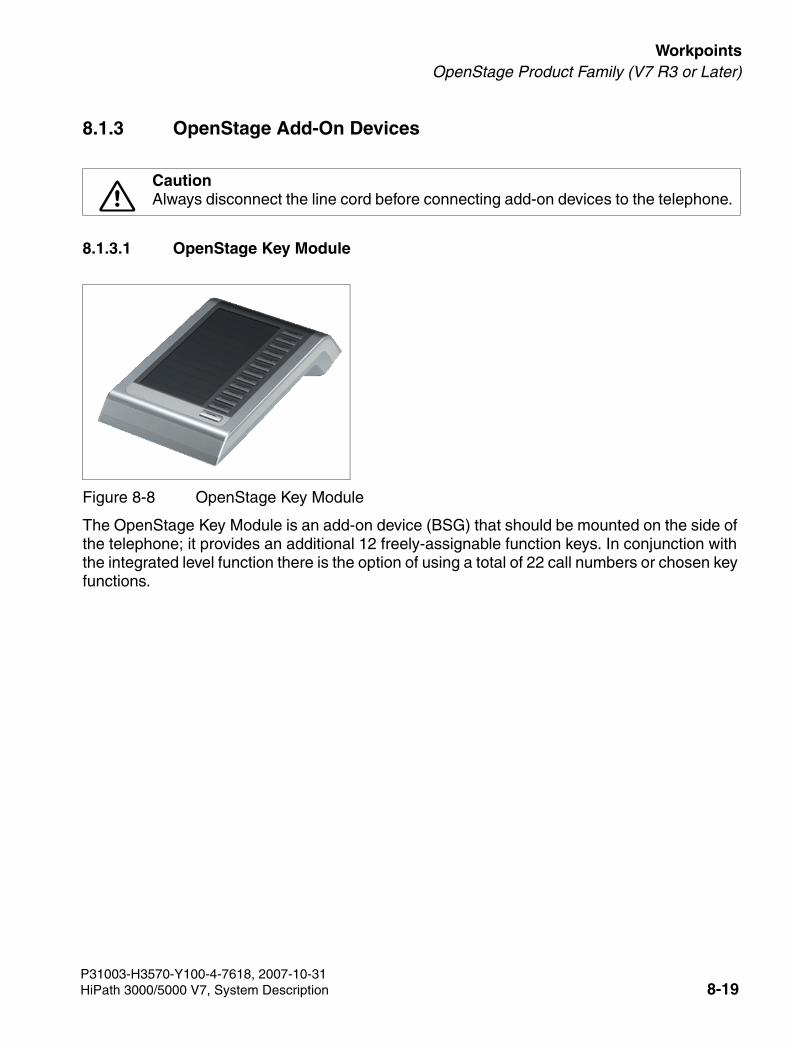
3000sb7.fm
For internal use only WorkpointsOpenStage Product Family (V7 R3 or Later)
8.1.3 OpenStage Add-On Devices
8.1.3.1 OpenStage Key Module
The OpenStage Key Module is an add-on device (BSG) that should be mounted on the side of the telephone; it provides an additional 12 freely-assignable function keys. In conjunction with the integrated level function there is the option of using a total of 22 call numbers or chosen key functions.
7CautionAlways disconnect the line cord before connecting add-on devices to the telephone.
Figure 8-8 OpenStage Key Module
P31003-H3570-Y100-4-7618, 2007-10-31HiPath 3000/5000 V7, System Description 8-19
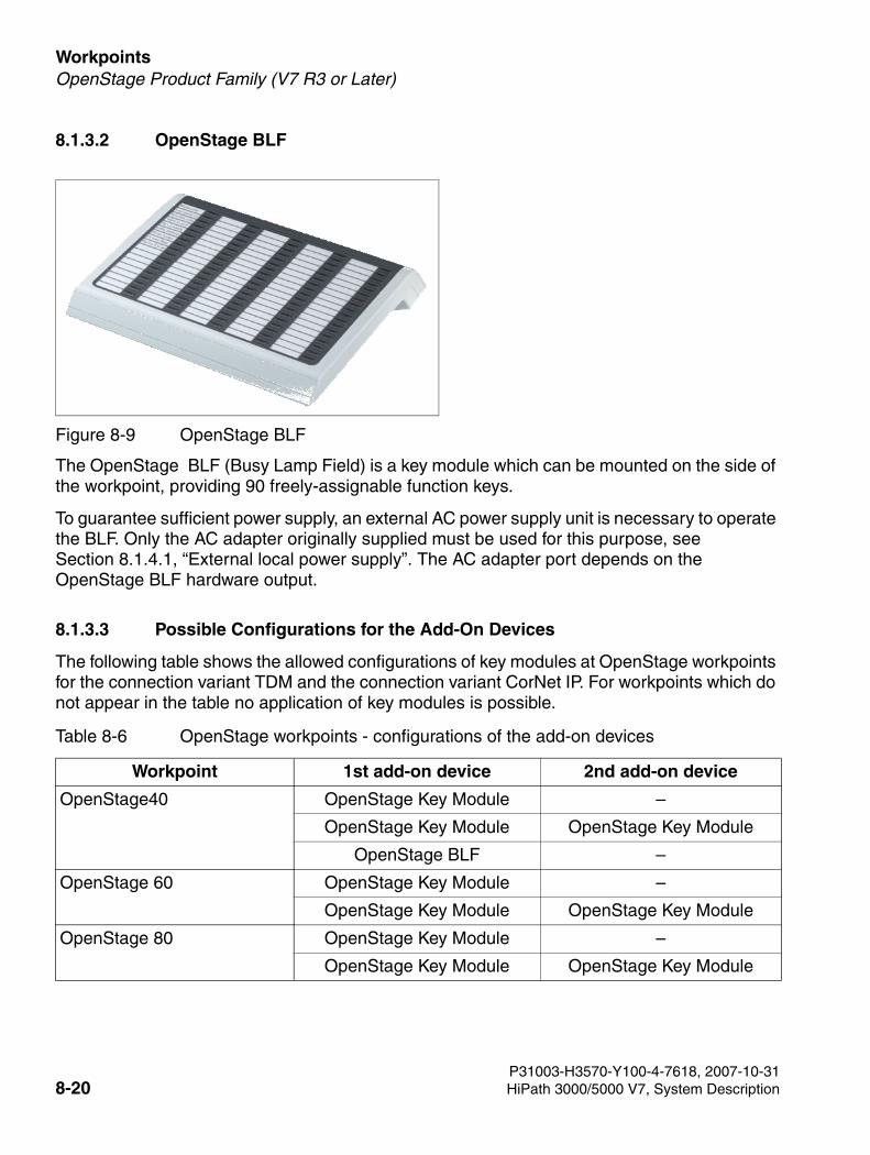
Workpoints For internal use only
3000sb7.fm
OpenStage Product Family (V7 R3 or Later)
8.1.3.2 OpenStage BLF
The OpenStage BLF (Busy Lamp Field) is a key module which can be mounted on the side of the workpoint, providing 90 freely-assignable function keys.
To guarantee sufficient power supply, an external AC power supply unit is necessary to operate the BLF. Only the AC adapter originally supplied must be used for this purpose, see Section 8.1.4.1, “External local power supply”. The AC adapter port depends on the OpenStage BLF hardware output.
8.1.3.3 Possible Configurations for the Add-On Devices
The following table shows the allowed configurations of key modules at OpenStage workpoints for the connection variant TDM and the connection variant CorNet IP. For workpoints which do not appear in the table no application of key modules is possible.
Figure 8-9 OpenStage BLF
Table 8-6 OpenStage workpoints - configurations of the add-on devices
Workpoint 1st add-on device 2nd add-on device
OpenStage40 OpenStage Key Module –
OpenStage Key Module OpenStage Key Module
OpenStage BLF –
OpenStage 60 OpenStage Key Module –
OpenStage Key Module OpenStage Key Module
OpenStage 80 OpenStage Key Module –
OpenStage Key Module OpenStage Key Module
P31003-H3570-Y100-4-7618, 2007-10-318-20 HiPath 3000/5000 V7, System Description
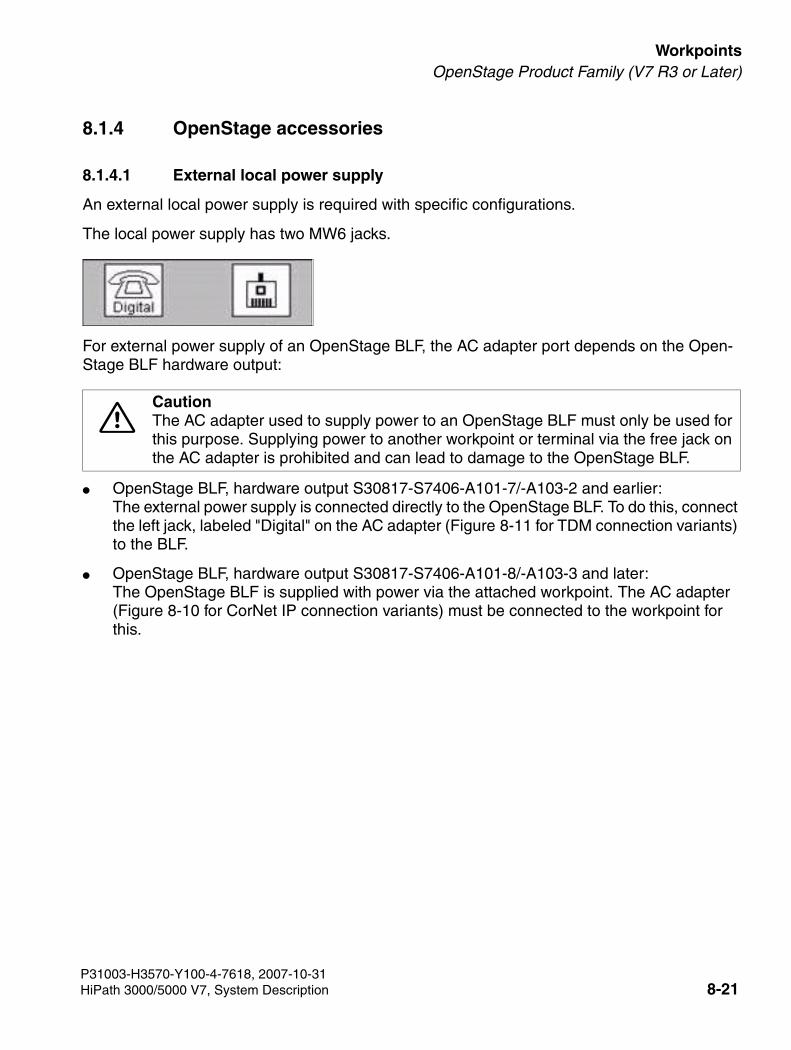
3000sb7.fm
For internal use only WorkpointsOpenStage Product Family (V7 R3 or Later)
8.1.4 OpenStage accessories
8.1.4.1 External local power supply
An external local power supply is required with specific configurations.
The local power supply has two MW6 jacks.
For external power supply of an OpenStage BLF, the AC adapter port depends on the Open-Stage BLF hardware output:
● OpenStage BLF, hardware output S30817-S7406-A101-7/-A103-2 and earlier: The external power supply is connected directly to the OpenStage BLF. To do this, connect the left jack, labeled "Digital" on the AC adapter (Figure 8-11 for TDM connection variants) to the BLF.
● OpenStage BLF, hardware output S30817-S7406-A101-8/-A103-3 and later: The OpenStage BLF is supplied with power via the attached workpoint. The AC adapter (Figure 8-10 for CorNet IP connection variants) must be connected to the workpoint for this.
7CautionThe AC adapter used to supply power to an OpenStage BLF must only be used for this purpose. Supplying power to another workpoint or terminal via the free jack on the AC adapter is prohibited and can lead to damage to the OpenStage BLF.
P31003-H3570-Y100-4-7618, 2007-10-31HiPath 3000/5000 V7, System Description 8-21
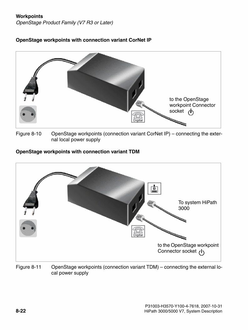
Workpoints For internal use only
3000sb7.fm
OpenStage Product Family (V7 R3 or Later)
OpenStage workpoints with connection variant CorNet IP
OpenStage workpoints with connection variant TDM
Figure 8-10 OpenStage workpoints (connection variant CorNet IP) – connecting the exter-nal local power supply
Figure 8-11 OpenStage workpoints (connection variant TDM) – connecting the external lo-cal power supply
to the OpenStage workpoint Connector socket
to the OpenStage workpoint Connector socket
To system HiPath 3000
P31003-H3570-Y100-4-7618, 2007-10-318-22 HiPath 3000/5000 V7, System Description
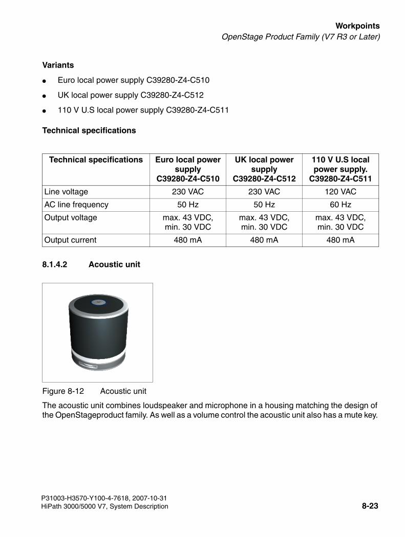
3000sb7.fm
For internal use only WorkpointsOpenStage Product Family (V7 R3 or Later)
Variants
● Euro local power supply C39280-Z4-C510
● UK local power supply C39280-Z4-C512
● 110 V U.S local power supply C39280-Z4-C511
Technical specifications
8.1.4.2 Acoustic unit
The acoustic unit combines loudspeaker and microphone in a housing matching the design of the OpenStageproduct family. As well as a volume control the acoustic unit also has a mute key.
Technical specifications Euro local power supply
C39280-Z4-C510
UK local power supply
C39280-Z4-C512
110 V U.S local power supply.
C39280-Z4-C511
Line voltage 230 VAC 230 VAC 120 VAC
AC line frequency 50 Hz 50 Hz 60 Hz
Output voltage max. 43 VDC,min. 30 VDC
max. 43 VDC,min. 30 VDC
max. 43 VDC,min. 30 VDC
Output current 480 mA 480 mA 480 mA
Figure 8-12 Acoustic unit
P31003-H3570-Y100-4-7618, 2007-10-31HiPath 3000/5000 V7, System Description 8-23
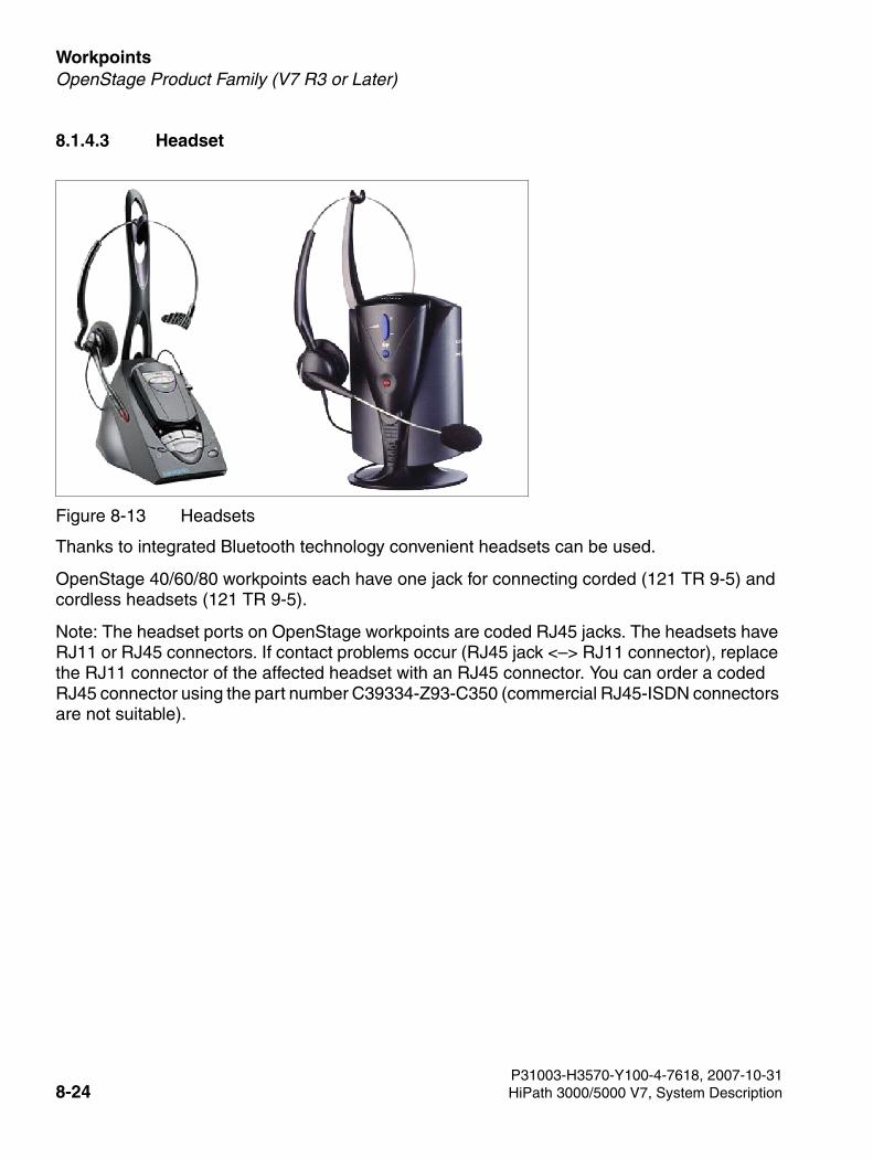
Workpoints For internal use only
3000sb7.fm
OpenStage Product Family (V7 R3 or Later)
8.1.4.3 Headset
Thanks to integrated Bluetooth technology convenient headsets can be used.
OpenStage 40/60/80 workpoints each have one jack for connecting corded (121 TR 9-5) and cordless headsets (121 TR 9-5).
Note: The headset ports on OpenStage workpoints are coded RJ45 jacks. The headsets have RJ11 or RJ45 connectors. If contact problems occur (RJ45 jack <–> RJ11 connector), replace the RJ11 connector of the affected headset with an RJ45 connector. You can order a coded RJ45 connector using the part number C39334-Z93-C350 (commercial RJ45-ISDN connectors are not suitable).
Figure 8-13 Headsets
P31003-H3570-Y100-4-7618, 2007-10-318-24 HiPath 3000/5000 V7, System Description
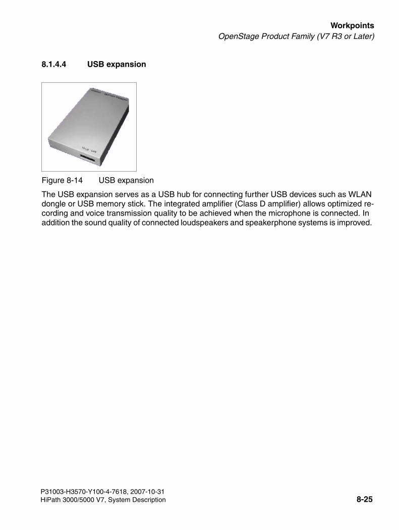
3000sb7.fm
For internal use only WorkpointsOpenStage Product Family (V7 R3 or Later)
8.1.4.4 USB expansion
The USB expansion serves as a USB hub for connecting further USB devices such as WLAN dongle or USB memory stick. The integrated amplifier (Class D amplifier) allows optimized re-cording and voice transmission quality to be achieved when the microphone is connected. In addition the sound quality of connected loudspeakers and speakerphone systems is improved.
Figure 8-14 USB expansion
P31003-H3570-Y100-4-7618, 2007-10-31HiPath 3000/5000 V7, System Description 8-25
Workpoints For internal use only
3000sb7.fm
optiClient 130 V5.0/V5.1
8.2 optiClient 130 V5.0/V5.1
The optiClient 130 V5.0/V5.1 is a PC-based multimedia application that offers connection ser-vices for different communication media over a LAN (network). Voice, video, or chat connec-tions can be managed and controlled using the optiClient 130 V5.0/V5.1. For voice connec-tions, this means that the optiClient 130 V5.0/V5.1 can be used on a PC like a telephone.
Modular Structure
The optiClient 130 V5.0/V5.1 has a modular structure for the functional elements which can be extended or replaced to change the scope of functions available.
● The basic module of the optiClient 130 V5.0/V5.1 is the main bar. The main bar does not provide any communication functions itself, but instead serves as a central component that works together with the various modules to define the communication functions and display of the optiClient 130 V5.0/V5.1.
● Interface modules are the modules that allow the available functions to be operated in win-dows and dialogs. Examples of interface modules are: telephone windows, directories, call list management, etc.
● Provider modules determine which communication systems or communication service pro-viders the optiClient 130 V5.0/V5.1 can be connected to.
● Manager modules run in the background and are not visible. They assume general com-munication control functions. Examples of manager modules include the Keyboard Man-ager and Screen Saver Manager.
Requirements for the PC
● Windows 2000 (SP4 or higher) or Windows XP operating system (SP 1)
● Processor: recommended from 1 GHz
● RAM memory: at least 512 MB
P31003-H3570-Y100-4-7618, 2007-10-318-26 HiPath 3000/5000 V7, System Description
3000sb7.fm
For internal use only WorkpointsoptiClient 130 V5.0/V5.1
Documentation
German and English documentation is available for optiClient V5 Step 2.
Other languages - French, Italian, Spanish, Portuguese, Dutch documentation – at present only available for optiClient V5 Step 1.
New Features
● Support for HiPath 3000
● Contact list/personal internal phonebook
● Contact list
● Web browser
● Migration tool
● Small Remote Site Redundancy
P31003-H3570-Y100-4-7618, 2007-10-31HiPath 3000/5000 V7, System Description 8-27
Workpoints For internal use only
3000sb7.fm
optiPoint 410 and optiPoint 420 Product Family
8.3 optiPoint 410 and optiPoint 420 Product Family
Introduction
The IP telephones in the optiPoint 410/optiPoint 410 S and optiPoint 420/optiPoint 420 S fam-ilies allow users to conduct telephone calls in the simple, familiar way over a data network.
The three dialog keys and the display guarantee convenient and interactive operation (not avail-able for optiPoint 410 entry and optiPoint 410 entry S). Furthermore, the key lamp principle vi-sualizes the activated functions.
The difference between the optiPoint 410/optiPoint 410 S and optiPoint 420/optiPoint 420 S families lies in the design of the function key panels:
● optiPoint 410/optiPoint 410 S families: the function keys have panels with labeling strips on which the function or currently saved phone number can be entered.
● optiPoint 420/optiPoint 420 S families: the function keys are self-labeling keys. Self-label-ing means that each key is assigned a display (1 line with 12 characters) in which the func-tion or currently saved phone number is shown.
You can use the optiPoint self-labeling key module add-on device to increase the number of available function keys for the standard and advance telephones. The optiPoint key module and optiPoint BLF can also be used together with the optiPoint 410/optiPoint 410 S and optiPoint 420/optiPoint 420 S families.
The optiPoint 410 display is used as the key module on the standard and advance telephone types. Its graphical LCD display (320 x 240 dots), the touchscreen and the navigation keys mean that many functions can be used intuitively and therefore more effectively.
The use of different optiPoint 500 adapters guarantees flexibility for the expansion of the tele-phone workstation (not for the entry, economy and economy plus telephones).
Differences between the optiPoint 410/optiPoint 420 and optiPoint 410 S/optiPoint 420 S fami-lies:
● optiPoint 410/optiPoint 420 families: All HiPath 3000/5000 features that are offered in the display dialog, in the service menu, and on function keys are available (except for Relo-cate).
● optiPoint 410 S/optiPoint 420 S families: The associated telephones support the SIP (Ses-sion Initiation Protocol). The SIP (Session Initiation Protocol) protocol is an ASCII-based signaling protocol used to configure sessions in an IP network. Note: The term "Internet telephony" as used in this document refers to making telephone calls via IP-supported networks (Voice over IP) and signaling via SIP.
P31003-H3570-Y100-4-7618, 2007-10-318-28 HiPath 3000/5000 V7, System Description
3000sb7.fm
For internal use only WorkpointsoptiPoint 410 and optiPoint 420 Product Family
The following features for Internet telephony stations are actively supported:
– CLIP (Calling Line Identification Presentation)
– CLIR (Calling Line Identification Restriction)
– COLP (Connected Line Identification Presentation)
– COLR (Connected Line Identification Restriction)
– Consultation hold
– Call hold
– Toggle
– Transfer (Screened transfer)
– DISA (Direct Inward System Access): Features cannot be activated for the SIP tele-phone.
– Inband DTMF
Although Internet telephony stations may not activate the following features, they may be passively involved:
– Call forwarding (forwarding to an Internet telephony station is supported)
– Conference (Internet telephony stations may be passively involved)
– Park (Internet telephony stations may be parked; from the perspective of the Internet telephony station, this is similar to "Call hold")
– Live Call Recording (Internet telephony stations may be passively involved)
– Whisper (Internet telephony stations may be passively involved)
– Automatic COS changeover (Internet telephony stations support automatic COS changeover)
– Internal traffic restriction groups (Internet telephony stations can be entered in ITR groups)
The following restrictions apply to Internet telephony stations:
– Internet telephony stations are configured on HiPath 3000/5000 7V as DSS1 (function-al telephones) and therefore cannot be supervised by the system (no monitoring). In-ternet telephony stations cannot use applications that require monitoring (for example, HiPath ComAssistant).
– Internet telephony stations cannot be integrated into call pickup groups, hunt groups, team, top or MULAP groups.
P31003-H3570-Y100-4-7618, 2007-10-31HiPath 3000/5000 V7, System Description 8-29
Workpoints For internal use only
3000sb7.fm
optiPoint 410 and optiPoint 420 Product Family
– Internet telephony stations cannot activate or use system features that can be operat-ed with codes.
– Music is played when an Internet telephony station is on hold. Music is not played and a ring tone is not applied for the Internet telephony station when unscreened transfer is performed between the Internet telephony station and another station.
– The display on the Internet telephony station is not refreshed if an Internet telephony station is unparked by a different party to the one who parked it.
– SIP terminals are not supported by the deployment tool (DLS interface DLI) in HiPath Xpressions Compact boards (HiPath 3000).
– In some situations, you cannot use terminal-specific features on HiPath 3000/5000 7V. This includes features that are available over the terminal’s menu interface. The fea-tures available with the HiPath 3000/5000 7V basic system have general release sta-tus.
P31003-H3570-Y100-4-7618, 2007-10-318-30 HiPath 3000/5000 V7, System Description
3000sb7.fm
For internal use only WorkpointsoptiPoint 410 and optiPoint 420 Product Family
8.3.1 optiPoint 410 and optiPoint 410 S telephones
8.3.1.1 optiPoint 410 entry, optiPoint 410 entry S
Main features
● Protocols
– H.323, HFA/V3 + V4, CorNet IP, SIP
– HTTP, DHCP, SNMP, FTP
– H.235 (security)
– QoS to DIFFSERV and IEEE 802.1 p/Q
● Voice compression G.711, G.722, G.723 and G.729 A/B
● Power over LAN (in accordance with Cisco and standard pre802.3af)
● CTI (for example, via TAPI 3rd party)
● 1 Ethernet (10/100BaseT) interface (self-configuring) for LAN connection
● 8 function keys with LED
● 2 control keys (plus/minus) for volume and pitch
● Suitable for wall mounting
● No modularity (no connecting capability for adapters or add-on devices), no display
P31003-H3570-Y100-4-7618, 2007-10-31HiPath 3000/5000 V7, System Description 8-31
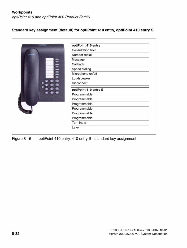
Workpoints For internal use only
3000sb7.fm
optiPoint 410 and optiPoint 420 Product Family
Standard key assignment (default) for optiPoint 410 entry, optiPoint 410 entry S
Figure 8-15 optiPoint 410 entry, 410 entry S - standard key assignment
optiPoint 410 entry
Consultation hold
Number redial
Message
Callback
Speed dialing
Microphone on/off
Loudspeaker
Disconnect
optiPoint 410 entry S
Programmable
Programmable
Programmable
Programmable
Programmable
Programmable
Terminate
Level
P31003-H3570-Y100-4-7618, 2007-10-318-32 HiPath 3000/5000 V7, System Description
3000sb7.fm
For internal use only WorkpointsoptiPoint 410 and optiPoint 420 Product Family
8.3.1.2 optiPoint 410 economy, optiPoint 410 economy S
Main features
● Protocols
– H.323, HFA/V3 + V4, CorNet IP, SIP
– HTTP, DHCP, SNMP, FTP
– H.235 (Security)
– QoS to DIFFSERV and IEEE 802.1 p/Q
● Voice compression G.711, G.722, G.723 and G.729 A/B
● Power over LAN (in accordance with Cisco and standard pre802.3af)
● CTI (for example, via TAPI 3rd party)
● 1 Ethernet (10/100BaseT) interface (self-configuring) for LAN connection
● 12 function keys with LED
● Alphanumeric LCD swivel display with 2 lines, 24 characters each
● Three dialog keys for interactive prompting “Yes”, “Back”, and “Next”
● Open listening
● 2 setting keys (plus/minus) for volume, pitch and display contrast
● Suitable for wall mounting
● No modularity (no connecting capability for adapters or add-on devices)
P31003-H3570-Y100-4-7618, 2007-10-31HiPath 3000/5000 V7, System Description 8-33
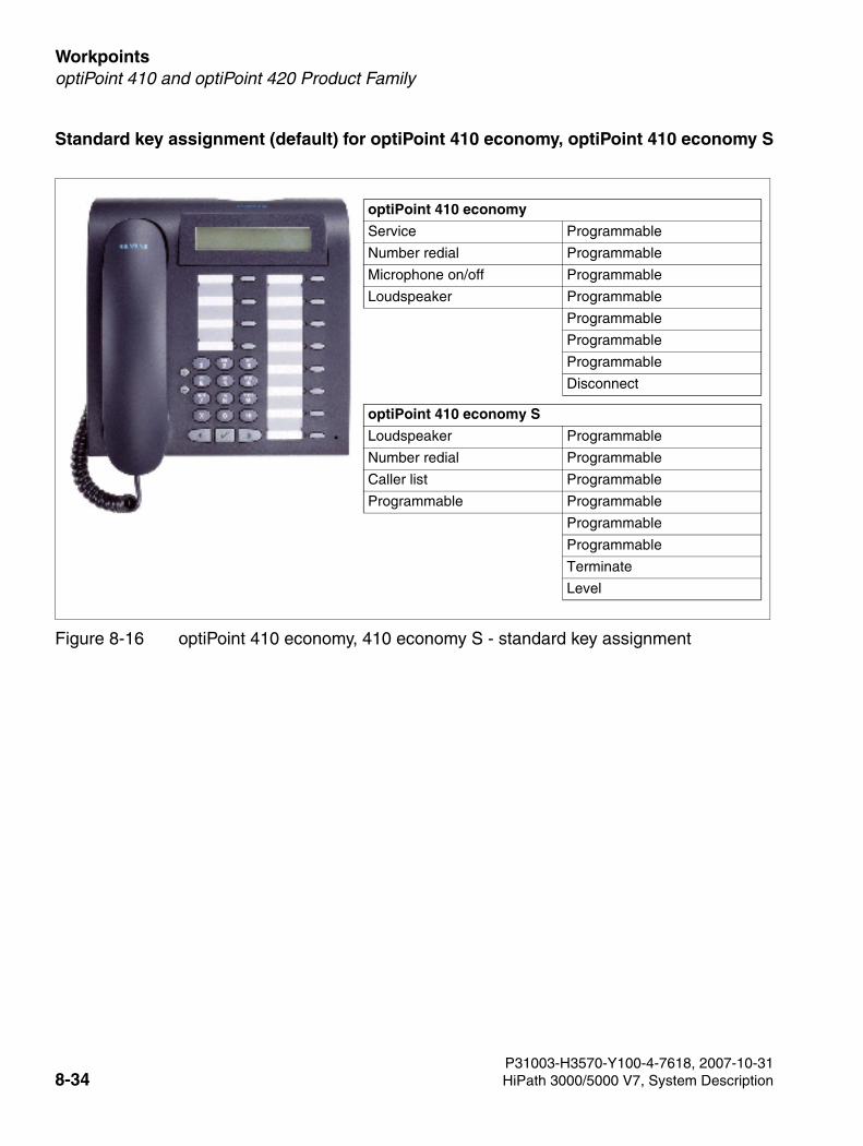
Workpoints For internal use only
3000sb7.fm
optiPoint 410 and optiPoint 420 Product Family
Standard key assignment (default) for optiPoint 410 economy, optiPoint 410 economy S
Figure 8-16 optiPoint 410 economy, 410 economy S - standard key assignment
optiPoint 410 economy
Service Programmable
Number redial Programmable
Microphone on/off Programmable
Loudspeaker Programmable
Programmable
Programmable
Programmable
Disconnect
optiPoint 410 economy S
Loudspeaker Programmable
Number redial Programmable
Caller list Programmable
Programmable Programmable
Programmable
Programmable
Terminate
Level
P31003-H3570-Y100-4-7618, 2007-10-318-34 HiPath 3000/5000 V7, System Description
3000sb7.fm
For internal use only WorkpointsoptiPoint 410 and optiPoint 420 Product Family
8.3.1.3 optiPoint 410 economy plus, optiPoint 410 economy plus S
Main features
● Protocols
– H.323, HFA/V3 + V4, CorNet IP, SIP
– HTTP, DHCP, SNMP, FTP
– H.235 (Security)
– QoS to DIFFSERV and IEEE 802.1 p/Q
● Voice compression G.711, G.722, G.723 and G.729 A/B
● Power over LAN (in accordance with Cisco and standard pre802.3af)
● CTI (for example, via TAPI 1st Party)
● 1 Ethernet (10/100BaseT) interface (self-configuring) for LAN connection
● 1 Ethernet (10/100BaseT) interface (self-configuring) for the PC connection
● 12 function keys with LED
● Alphanumeric LCD swivel display with 2 lines, 24 characters each
● Three dialog keys for interactive prompting “Yes”, “Back”, and “Next”
● Open listening
● Port for headset (121 TR 9-5)
● 2 setting keys (plus/minus) for volume, pitch and display contrast
● Suitable for wall mounting
● No modularity (no connecting capability for adapters or add-on devices [Add-On Devic-es][Add-on devices])
P31003-H3570-Y100-4-7618, 2007-10-31HiPath 3000/5000 V7, System Description 8-35
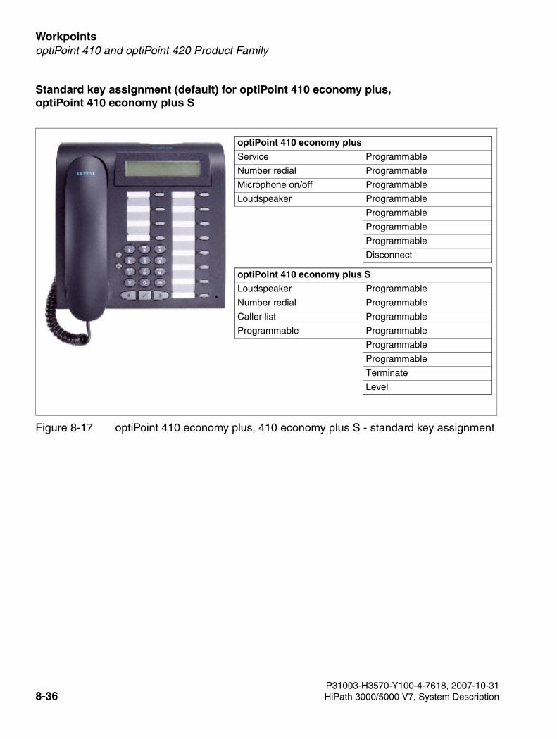
Workpoints For internal use only
3000sb7.fm
optiPoint 410 and optiPoint 420 Product Family
Standard key assignment (default) for optiPoint 410 economy plus, optiPoint 410 economy plus S
Figure 8-17 optiPoint 410 economy plus, 410 economy plus S - standard key assignment
optiPoint 410 economy plus
Service Programmable
Number redial Programmable
Microphone on/off Programmable
Loudspeaker Programmable
Programmable
Programmable
Programmable
Disconnect
optiPoint 410 economy plus S
Loudspeaker Programmable
Number redial Programmable
Caller list Programmable
Programmable Programmable
Programmable
Programmable
Terminate
Level
P31003-H3570-Y100-4-7618, 2007-10-318-36 HiPath 3000/5000 V7, System Description
3000sb7.fm
For internal use only WorkpointsoptiPoint 410 and optiPoint 420 Product Family
8.3.1.4 optiPoint 410 standard, optiPoint 410 standard S
Main features
● Protocols
– H.323, HFA/V3 + V4, CorNet IP, SIP
– HTTP, DHCP, SNMP, FTP
– H.235 (Security)
– QoS to DIFFSERV and IEEE 802.1 p/Q
● Voice compression G.711, G.722, G.723 and G.729 A/B
● Power over LAN (in accordance with Cisco and standard pre802.3af)
● CTI (for example, via TAPI 1st Party)
● 1 Ethernet (10/100BaseT) interface (self-configuring) for LAN connection
● 1 Ethernet (10/100BaseT) interface (self-configuring) for the PC connection
● 12 function keys with LED
● Alphanumeric LCD swivel display with 2 lines, 24 characters each
● 3 dialog keys for interactive prompting “Yes”, “Back”, and “Next”
● Full duplex speakerphone mode with echo suppression for adapting to the room
● Port for headset (121 TR 9-5)
● 2 setting keys (plus/minus) for volume, pitch, speaker quality and display contrast
● Modularity:
– 2 adapter slots (option bays)
– 1 interface for max. 2 add-on devices
● Suitable for wall mounting
P31003-H3570-Y100-4-7618, 2007-10-31HiPath 3000/5000 V7, System Description 8-37

Workpoints For internal use only
3000sb7.fm
optiPoint 410 and optiPoint 420 Product Family
Standard key assignment (default) for optiPoint 410 standard, optiPoint 410 standard S
Figure 8-18 optiPoint 410 standard, 410 standard S - standard key assignment
optiPoint 410 standard
Service Programmable
Number redial Programmable
Microphone on/off Programmable
Loudspeaker Programmable
Programmable
Programmable
Programmable
Disconnect
optiPoint 410 standard S
Loudspeaker Programmable
Number redial Programmable
Caller list Programmable
Programmable Programmable
Programmable
Programmable
Terminate
Level
P31003-H3570-Y100-4-7618, 2007-10-318-38 HiPath 3000/5000 V7, System Description
3000sb7.fm
For internal use only WorkpointsoptiPoint 410 and optiPoint 420 Product Family
8.3.1.5 optiPoint 410 advance, optiPoint 410 advance S
Main features
● Protocols
– H.323, HFA/V3 + V4, CorNet IP, SIP
– HTTP, DHCP, SNMP, FTP
– H.235 (Security)
– QoS to DIFFSERV and IEEE 802.1 p/Q
● Voice compression G.711, G.722, G.723 and G.729 A/B
● Power over LAN (in accordance with Cisco and standard pre802.3af)
● CTI (for example, via TAPI 1st Party)
● 1 Ethernet (10/100BaseT) interface (self-configuring) for LAN connection
● 1 Ethernet (10/100BaseT) interface (self-configuring) for the PC connection
● 1 integrated USB 1.1 interface
● 19 function keys with LED
● Graphic display (swivel) with 4 lines, 24 characters each
● 3 dialog keys for interactive prompting “Yes”, “Back”, and “Next”
● Full duplex speakerphone mode with echo suppression for adapting to the room
● Port for headset (121 TR 9-5)
● 2 setting keys (plus/minus) for volume, pitch, speaker quality and display contrast
● Modularity:
– 1 adapter slot (option bay)
– 1 interface for max. 2 add-on devices
● Suitable for wall mounting
P31003-H3570-Y100-4-7618, 2007-10-31HiPath 3000/5000 V7, System Description 8-39
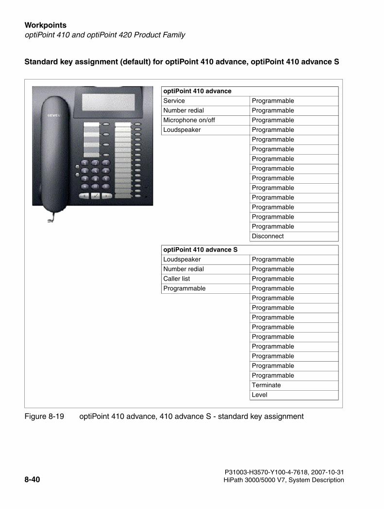
Workpoints For internal use only
3000sb7.fm
optiPoint 410 and optiPoint 420 Product Family
Standard key assignment (default) for optiPoint 410 advance, optiPoint 410 advance S
Figure 8-19 optiPoint 410 advance, 410 advance S - standard key assignment
optiPoint 410 advance
Service Programmable
Number redial Programmable
Microphone on/off Programmable
Loudspeaker Programmable
Programmable
Programmable
Programmable
Programmable
Programmable
Programmable
Programmable
Programmable
Programmable
Programmable
Disconnect
optiPoint 410 advance S
Loudspeaker Programmable
Number redial Programmable
Caller list Programmable
Programmable Programmable
Programmable
Programmable
Programmable
Programmable
Programmable
Programmable
Programmable
Programmable
Programmable
Terminate
Level
P31003-H3570-Y100-4-7618, 2007-10-318-40 HiPath 3000/5000 V7, System Description
3000sb7.fm
For internal use only WorkpointsoptiPoint 410 and optiPoint 420 Product Family
8.3.2 optiPoint 420 and optiPoint 420 S telephones
The IP telephones of the optiPoint 420 and optiPoint 420 S family feature self-labeling keys. Self-labeling means that each key is assigned a display (1 line with 12 characters) where the currently-stored function or station number is shown.
8.3.2.1 optiPoint 420 economy, optiPoint 420 economy S
Main features
● Protocols
– H.323, HFA/V3 + V4, CorNet IP, SIP
– HTTP, DHCP, SNMP, FTP
– H.235 (Security)
– QoS to DIFFSERV and IEEE 802.1 p/Q
● Voice compression G.711, G.722, G.723 and G.729 A/B
● Power over LAN (in accordance with Cisco and standard pre802.3af)
● CTI (for example, via TAPI 1st Party)
● 1 Ethernet (10/100BaseT) interface (self-configuring) for LAN connection
● 12 function keys with LED and systems self-labeling keys
● Graphic display (swivel) with 2 lines, 24 characters each
● 3 dialog keys for interactive prompting “Yes”, “Back”, and “Next”
● Open listening
● 2 setting keys (plus/minus) for volume, pitch and display contrast
● Suitable for wall mounting
● No modularity (no connecting capability for adapters or add-on devices)
P31003-H3570-Y100-4-7618, 2007-10-31HiPath 3000/5000 V7, System Description 8-41
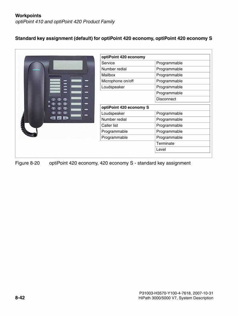
Workpoints For internal use only
3000sb7.fm
optiPoint 410 and optiPoint 420 Product Family
Standard key assignment (default) for optiPoint 420 economy, optiPoint 420 economy S
Figure 8-20 optiPoint 420 economy, 420 economy S - standard key assignment
optiPoint 420 economy
Service Programmable
Number redial Programmable
Mailbox Programmable
Microphone on/off Programmable
Loudspeaker Programmable
Programmable
Disconnect
optiPoint 420 economy S
Loudspeaker Programmable
Number redial Programmable
Caller list Programmable
Programmable Programmable
Programmable Programmable
Terminate
Level
P31003-H3570-Y100-4-7618, 2007-10-318-42 HiPath 3000/5000 V7, System Description
3000sb7.fm
For internal use only WorkpointsoptiPoint 410 and optiPoint 420 Product Family
8.3.2.2 optiPoint 420 economy plus, optiPoint 420 economy plus S
Main features
● Protocols
– H.323, HFA/V3 + V4, CorNet IP, SIP
– HTTP, DHCP, SNMP, FTP
– H.235 (Security)
– QoS to DIFFSERV and IEEE 802.1 p/Q
● Voice compression G.711, G.722, G.723 and G.729 A/B
● Power over LAN (in accordance with Cisco and standard pre802.3af)
● CTI (for example, via TAPI 1st Party)
● 1 Ethernet (10/100BaseT) interface (self-configuring) for LAN connection
● 1 Ethernet (10/100BaseT) interface (self-configuring) for the PC connection
● 12 function keys with LED and self-labeling keys
● Graphic display (swivel) with 2 lines, 24 characters each
● 3 dialog keys for interactive prompting “Yes”, “Back”, and “Next”
● Open listening
● Port for headset (121 TR 9-5)
● 2 setting keys (plus/minus) for volume, pitch and display contrast
● Suitable for wall mounting
● No modularity (no connecting capability for adapters or add-on devices)
P31003-H3570-Y100-4-7618, 2007-10-31HiPath 3000/5000 V7, System Description 8-43
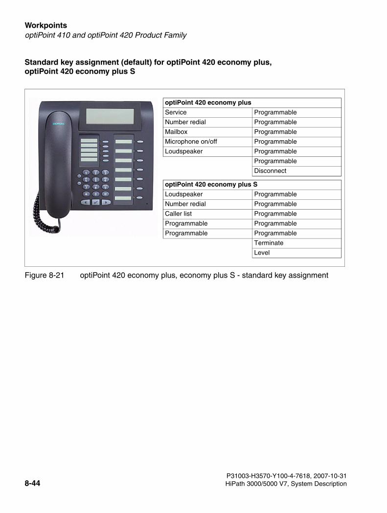
Workpoints For internal use only
3000sb7.fm
optiPoint 410 and optiPoint 420 Product Family
Standard key assignment (default) for optiPoint 420 economy plus, optiPoint 420 economy plus S
Figure 8-21 optiPoint 420 economy plus, economy plus S - standard key assignment
optiPoint 420 economy plus
Service Programmable
Number redial Programmable
Mailbox Programmable
Microphone on/off Programmable
Loudspeaker Programmable
Programmable
Disconnect
optiPoint 420 economy plus S
Loudspeaker Programmable
Number redial Programmable
Caller list Programmable
Programmable Programmable
Programmable Programmable
Terminate
Level
P31003-H3570-Y100-4-7618, 2007-10-318-44 HiPath 3000/5000 V7, System Description
3000sb7.fm
For internal use only WorkpointsoptiPoint 410 and optiPoint 420 Product Family
8.3.2.3 optiPoint 420 standard, optiPoint 420 standard S
Main features
● Protocols
– H.323, HFA/V3 + V4, CorNet IP, SIP
– HTTP, DHCP, SNMP, FTP
– H.235 (Security)
– QoS to DIFFSERV and IEEE 802.1 p/Q
● Voice compression G.711, G.722, G.723 and G.729 A/B
● Power over LAN (in accordance with Cisco and standard pre802.3af)
● CTI (for example, via TAPI 1st Party)
● 1 Ethernet (10/100BaseT) interface (self-configuring) for LAN connection
● 1 Ethernet (10/100BaseT) interface (self-configuring) for the PC connection
● 12 function keys with LED and self-labeling keys
● Graphic display (swivel) with 2 lines, 24 characters each
● 3 dialog keys for interactive prompting “Yes”, “Back”, and “Next”
● Full duplex speakerphone mode with echo suppression for adapting to the room
● Port for headset (121 TR 9-5)
● 2 setting keys (plus/minus) for volume, pitch, speaker quality and display contrast
● Modularity:
– 2 adapter slots (option bays)
– 1 interface for max. 2 add-on devices
● Suitable for wall mounting
P31003-H3570-Y100-4-7618, 2007-10-31HiPath 3000/5000 V7, System Description 8-45
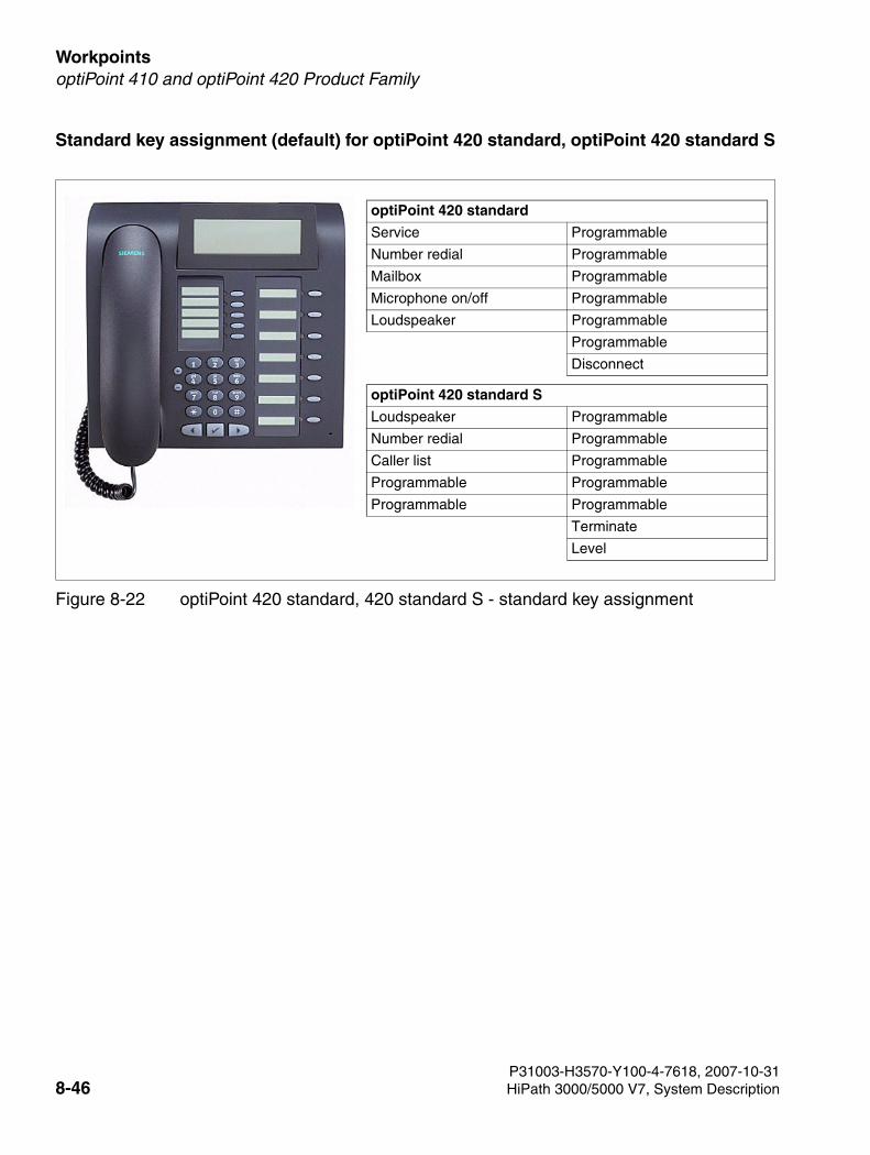
Workpoints For internal use only
3000sb7.fm
optiPoint 410 and optiPoint 420 Product Family
Standard key assignment (default) for optiPoint 420 standard, optiPoint 420 standard S
Figure 8-22 optiPoint 420 standard, 420 standard S - standard key assignment
optiPoint 420 standard
Service Programmable
Number redial Programmable
Mailbox Programmable
Microphone on/off Programmable
Loudspeaker Programmable
Programmable
Disconnect
optiPoint 420 standard S
Loudspeaker Programmable
Number redial Programmable
Caller list Programmable
Programmable Programmable
Programmable Programmable
Terminate
Level
P31003-H3570-Y100-4-7618, 2007-10-318-46 HiPath 3000/5000 V7, System Description
3000sb7.fm
For internal use only WorkpointsoptiPoint 410 and optiPoint 420 Product Family
8.3.2.4 optiPoint 420 advance, optiPoint 420 advance S
Main features
● Protocols
– H.323, HFA/V3 + V4, CorNet IP, SIP
– HTTP, DHCP, SNMP, FTP
– H.235 (Security)
– QoS to DIFFSERV and IEEE 802.1 p/Q
● Voice compression G.711, G.722, G.723 and G.729 A/B
● Power over LAN (in accordance with Cisco and standard pre802.3af)
● CTI (for example, via TAPI 1st Party)
● 1 Ethernet (10/100BaseT) interface (self-configuring) for LAN connection
● 1 Ethernet (10/100BaseT) interface (self-configuring) for the PC connection
● 1 integrated USB 1.1 interface
● 18 function keys with LED and self-labeling keys
● Graphic display (swivel) with 4 lines, 24 characters each
● 3 dialog keys for interactive prompting “Yes”, “Back”, and “Next”
● Full duplex speakerphone mode with echo suppression for adapting to the room
● Port for headset (121 TR 9-5)
● 2 setting keys (plus/minus) for volume, pitch, speaker quality and display contrast
● Modularity:
– 1 adapter slot (option bay)
– 1 interface for max. 2 add-on devices
● Suitable for wall mounting
P31003-H3570-Y100-4-7618, 2007-10-31HiPath 3000/5000 V7, System Description 8-47
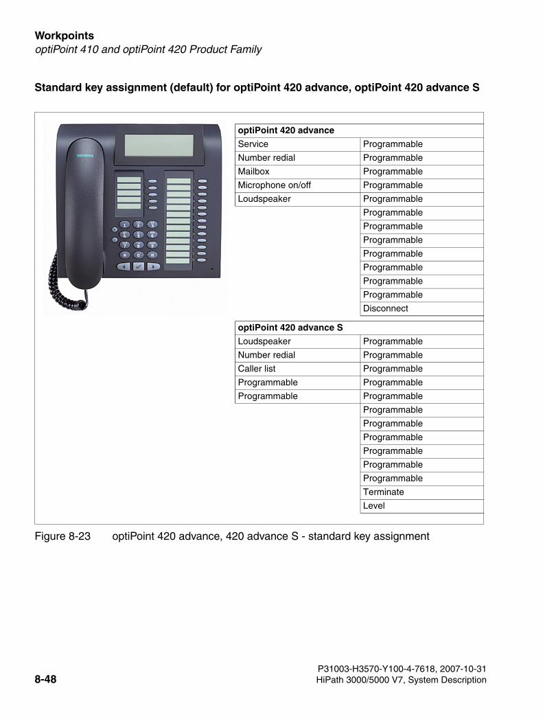
Workpoints For internal use only
3000sb7.fm
optiPoint 410 and optiPoint 420 Product Family
Standard key assignment (default) for optiPoint 420 advance, optiPoint 420 advance S
Figure 8-23 optiPoint 420 advance, 420 advance S - standard key assignment
optiPoint 420 advance
Service Programmable
Number redial Programmable
Mailbox Programmable
Microphone on/off Programmable
Loudspeaker Programmable
Programmable
Programmable
Programmable
Programmable
Programmable
Programmable
Programmable
Disconnect
optiPoint 420 advance S
Loudspeaker Programmable
Number redial Programmable
Caller list Programmable
Programmable Programmable
Programmable Programmable
Programmable
Programmable
Programmable
Programmable
Programmable
Programmable
Terminate
Level
P31003-H3570-Y100-4-7618, 2007-10-318-48 HiPath 3000/5000 V7, System Description
3000sb7.fm
For internal use only WorkpointsoptiPoint 410 and optiPoint 420 Product Family
8.3.3 optiPoint 410 and optiPoint 420 add-on devices
The user usually installs the add-on devices. The installation instructions are on the “Electronic Operating Instructions” CD.
7CautionAlways disconnect the line cord before connecting add-on devices to the telephone.
>A maximum of two add-on device may be fitted to an optiPoint 410/optiPoint 410 S or optiPoint 420/optiPoint 420 S telephone (not optiPoint 410 entry, optiPoint 410 entry S, optiPoint 410 economy, optiPoint 410 economy S, optiPoint 410 economy plus, optiPoint 410 economy plus S, optiPoint 420 economy, optiPoint 420 economy S, optiPoint 420 economy plus and optiPoint 420 economy plus S). In addition to the two ad-on device described below, optiPoint key module, optiPoint BLF and optiPoint application module (V5.0 SMR-06 or Later) can also be used. Table 8-7 shows the possible add-on device configurations.
P31003-H3570-Y100-4-7618, 2007-10-31HiPath 3000/5000 V7, System Description 8-49
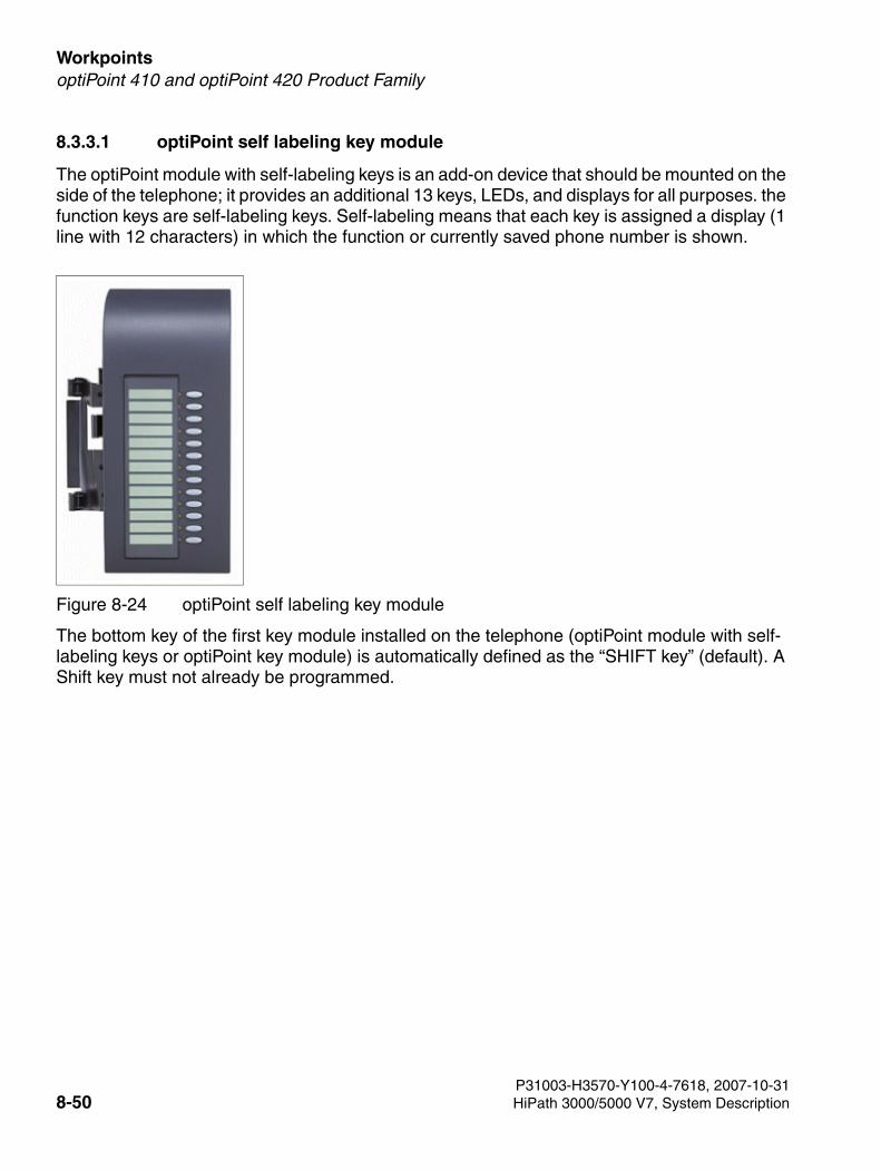
Workpoints For internal use only
3000sb7.fm
optiPoint 410 and optiPoint 420 Product Family
8.3.3.1 optiPoint self labeling key module
The optiPoint module with self-labeling keys is an add-on device that should be mounted on the side of the telephone; it provides an additional 13 keys, LEDs, and displays for all purposes. the function keys are self-labeling keys. Self-labeling means that each key is assigned a display (1 line with 12 characters) in which the function or currently saved phone number is shown.
The bottom key of the first key module installed on the telephone (optiPoint module with self-labeling keys or optiPoint key module) is automatically defined as the “SHIFT key” (default). A Shift key must not already be programmed.
Figure 8-24 optiPoint self labeling key module
P31003-H3570-Y100-4-7618, 2007-10-318-50 HiPath 3000/5000 V7, System Description
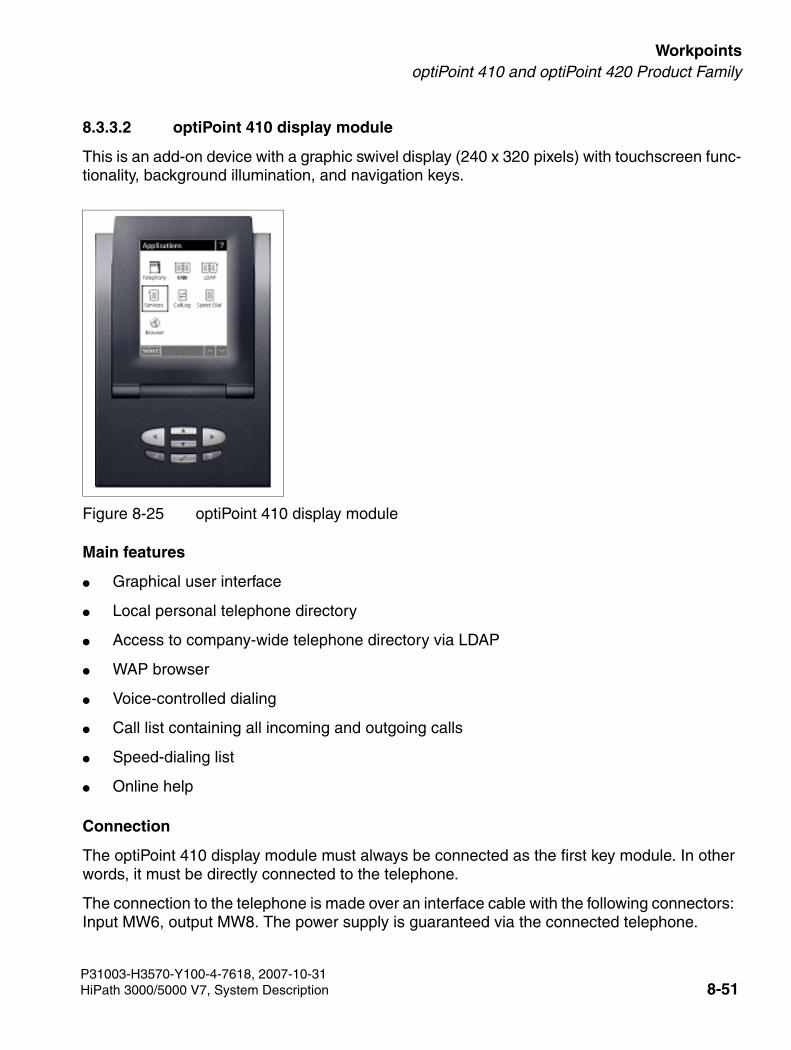
3000sb7.fm
For internal use only WorkpointsoptiPoint 410 and optiPoint 420 Product Family
8.3.3.2 optiPoint 410 display module
This is an add-on device with a graphic swivel display (240 x 320 pixels) with touchscreen func-tionality, background illumination, and navigation keys.
Main features
● Graphical user interface
● Local personal telephone directory
● Access to company-wide telephone directory via LDAP
● WAP browser
● Voice-controlled dialing
● Call list containing all incoming and outgoing calls
● Speed-dialing list
● Online help
Connection
The optiPoint 410 display module must always be connected as the first key module. In other words, it must be directly connected to the telephone.
The connection to the telephone is made over an interface cable with the following connectors: Input MW6, output MW8. The power supply is guaranteed via the connected telephone.
Figure 8-25 optiPoint 410 display module
P31003-H3570-Y100-4-7618, 2007-10-31HiPath 3000/5000 V7, System Description 8-51

Workpoints For internal use only
3000sb7.fm
optiPoint 410 and optiPoint 420 Product Family
8.3.3.3 Possible Configurations for the Add-On Devices
The following table shows the possible configurations for add-on devices on telephones from the optiPoint 410/optiPoint 410 S and the optiPoint 420/optiPoint 420 S families. For telephones which do not appear in the table no application of key modules is possible.
Table 8-7 Key module configurations on optiPoint 410/410 S and optiPoint 420/420 S
optiPoint 410/optiPoint 410 S telephone
optiPoint 420/optiPoint 420 S telephone
1st add-on device 2nd add-on device
optiPoint410standard optiPoint 410 standard S
optiPoint 410 advance optiPoint 410 advance S
optiPoint 420 standard optiPoint 420 standard S
optiPoint 420 advance optiPoint 420 advance S
optiPoint key module –
optiPoint key module optiPoint key module
optiPoint key module optiPoint BLF
optiPoint 410 display module –
optiPoint 410 display module optiPoint key module
optiPoint 410 display module optiPoint BLF
optiPoint 410 display module optiPoint self labeling key module
optiPoint BLF –
optiPoint BLF optiPoint BLF1
1 Configuration with two optiPoint BLF’s only with HiPath 3800
optiPoint self labeling key module
–
optiPoint self labeling key module
optiPoint self labeling key module
optiPoint 410 standard
optiPoint 410 advance
optiPoint 420 standard
optiPoint 420 advance
optiPoint application module –
optiPoint application module optiPoint key module
optiPoint application module optiPoint BLF
optiPoint application module optiPoint self labeling key module
P31003-H3570-Y100-4-7618, 2007-10-318-52 HiPath 3000/5000 V7, System Description
3000sb7.fm
For internal use only WorkpointsoptiPoint 150 S
8.4 optiPoint 150 S
optiPoint 150 S is the cost-effective entry model for Voice over IP telephony using SIP (Session Initiation Protocol). Note: The term "Internet telephony" as used in this document refers to making telephone calls via IP-supported networks (Voice over IP) and signaling via SIP.
The following features for Internet telephony stations are actively supported:
● CLIP (Calling Line Identification Presentation) Exclusively in standalone systems.
● COLP (Connected Line Identification Presentation)
● Consultation hold
● Call hold
● Toggle
● Transfer (Screened and Unscreened Transfer)
● DISA (Direct Inward System Access): No features can be activated for optiPoint 150 S.
● Inband DTMF optiPoint 150 S only supports the G.711 codec.
Although Internet telephony stations may not activate the following features, they may be pas-sively involved:
● Call forwarding (forwarding to an Internet telephony station is supported)
● Conference (Internet telephony stations may be passively involved)
● Park (Internet telephony stations may be parked; from the perspective of the Internet tele-phony station, this is similar to "Call hold")
● Live Call Recording (Internet telephony stations may be passively involved)
● Automatic COS changeover (Internet telephony stations support automatic COS changeover)
● Internal traffic restriction groups (Internet telephony stations can be entered in ITR groups)
The following telephone-specific optiPoint 150 S features are supported for operation on Hi-Path 3000/5000, V6.0 SMR-09 or later:
● Missed calls list, telephone
● Do not disturb (DND)
● Call duration display
● Local numbering plan
P31003-H3570-Y100-4-7618, 2007-10-31HiPath 3000/5000 V7, System Description 8-53
Workpoints For internal use only
3000sb7.fm
optiPoint 150 S
● Microphone on/off
● Language selection
The following restrictions apply to Internet telephony stations:
● Internet telephony stations are configured on HiPath 3000/5000 7V as DSS1 (functional telephones) and therefore cannot be supervised by the system (no monitoring). Internet telephony stations cannot use applications that require monitoring (for example, HiPath ComAssistant).
● Internet telephony stations cannot be integrated into call pickup groups, hunt groups, team, top or MULAP groups.
● Internet telephony stations cannot activate or use system features that can be operated with codes.
● Music is played when an Internet telephony station is on hold. Music is not played and a ring tone is not applied for the Internet telephony station when unscreened transfer is per-formed between the Internet telephony station and another station.
● The display on the Internet telephony station is not refreshed if an Internet telephony sta-tion is unparked by a different party to the one who parked it.
● SIP terminals are not supported by the deployment tool (DLS interface DLI) in HiPath Xpressions Compact boards (HiPath 3000).
● optiPoint 150 S allows you to toggle between two external calls. The active call can be cleared down by briefly pressing the hookswitch. Simply replace the optiPoint 150 S hand-set to connect the two external parties to each other (this can lead to increased call charg-es). A connection of this kind can only be cleared down at the system by disconnecting the relevant trunks or by resetting (restarting) the system.
● In some situations, you cannot use terminal-specific features on HiPath 3000/5000 7V. This includes features that are available over the terminal’s menu interface. The features available with the HiPath 3000/5000 7V basic system have general release status.
Main features
● Protocols
– SIP
– HTTP, DHCP, SNMP, FTP
– QoS according to VLAN, TOS, and DiffServ
● Voice compression G.711 µ-law, G.711 a-law, G.723.1, G.729 AB
● Power over LAN according to IEEE802.3AF
P31003-H3570-Y100-4-7618, 2007-10-318-54 HiPath 3000/5000 V7, System Description
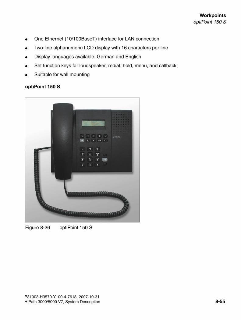
3000sb7.fm
For internal use only WorkpointsoptiPoint 150 S
● One Ethernet (10/100BaseT) interface for LAN connection
● Two-line alphanumeric LCD display with 16 characters per line
● Display languages available: German and English
● Set function keys for loudspeaker, redial, hold, menu, and callback.
● Suitable for wall mounting
optiPoint 150 S
Figure 8-26 optiPoint 150 S
P31003-H3570-Y100-4-7618, 2007-10-31HiPath 3000/5000 V7, System Description 8-55
Workpoints For internal use only
3000sb7.fm
optiPoint 600 office
8.5 optiPoint 600 office
optiPoint 600 office is the first convergence telephone with UP0/E- and IP interface (CorNet-IP).
In UP0/E mode optiPoint 600 office is the high-end product for completing the optiPoint 500 fam-ily and the successor to the Optiset E memory.
In CorNet IP mode it functions as a high-end IP phone in the optiPoint 400 family.
Main features
● 19 function keys with LED
● Alphanumeric LCD swivel display with 8 lines, 24 characters each, touchscreen. backlight-ing, which remains on for around 5 s.
● 3 dialog keys for interactive prompting “Yes”, “Back”, and “Next”
● Full duplex speakerphone mode with echo suppression for adapting to the room
● 2 setting keys (plus/minus) for volume, pitch, speaker quality and display contrast
● Interfaces and slots:
– 1 integrated USB 1.1 interface
– 1 adapter slot (option bay)
– 1 interface for max. 2 add-on devices
– 1 headset port (121 TR9-5)
● Suitable for wall mounting
● In UP0/E mode (UP0/E interface): SW download via PPP
● In CorNet IP mode (IP interface, 10/100BaseT): WAP accessStandards supported: H.323, Hicom Feature Access, G.711, G.723.1, QoS, SNMP, HTTP, DHCP, FTP, LDAP (Data base access I/F)
P31003-H3570-Y100-4-7618, 2007-10-318-56 HiPath 3000/5000 V7, System Description
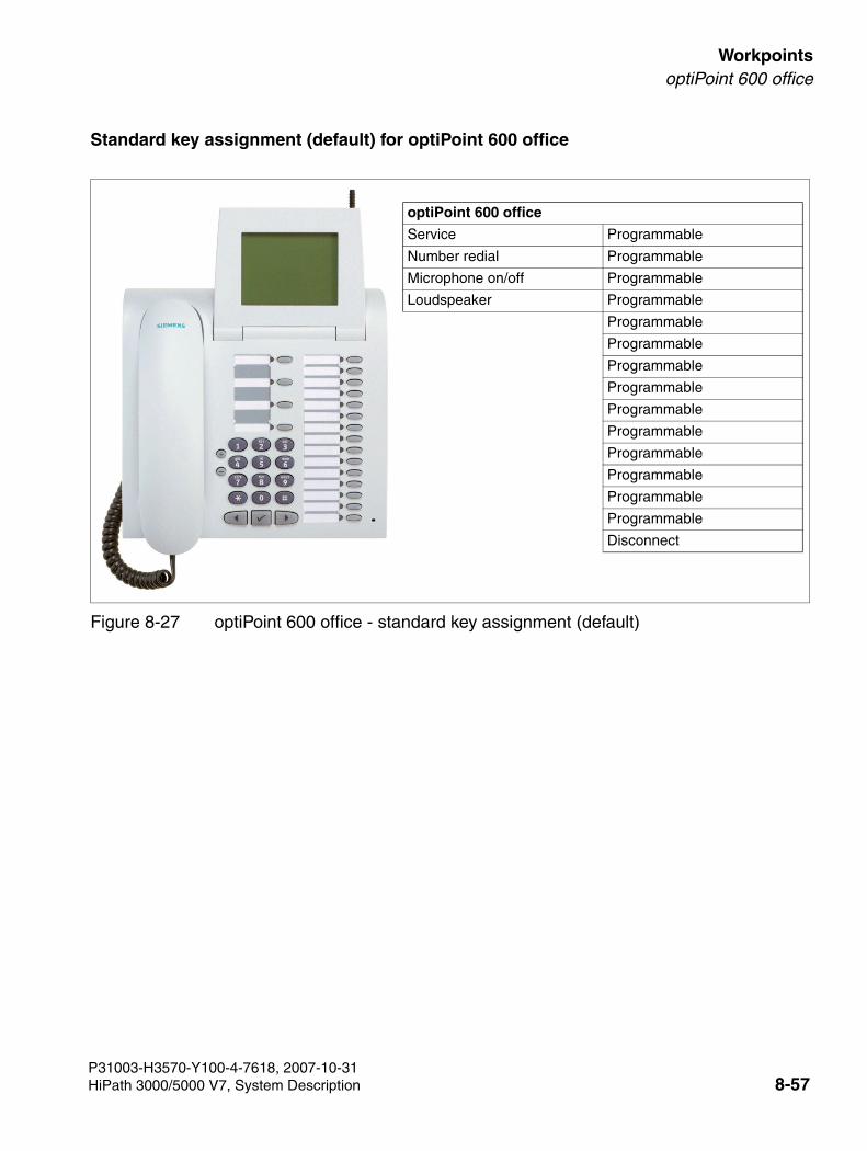
3000sb7.fm
For internal use only WorkpointsoptiPoint 600 office
Standard key assignment (default) for optiPoint 600 office
Figure 8-27 optiPoint 600 office - standard key assignment (default)
optiPoint 600 office
Service Programmable
Number redial Programmable
Microphone on/off Programmable
Loudspeaker Programmable
Programmable
Programmable
Programmable
Programmable
Programmable
Programmable
Programmable
Programmable
Programmable
Programmable
Disconnect
P31003-H3570-Y100-4-7618, 2007-10-31HiPath 3000/5000 V7, System Description 8-57
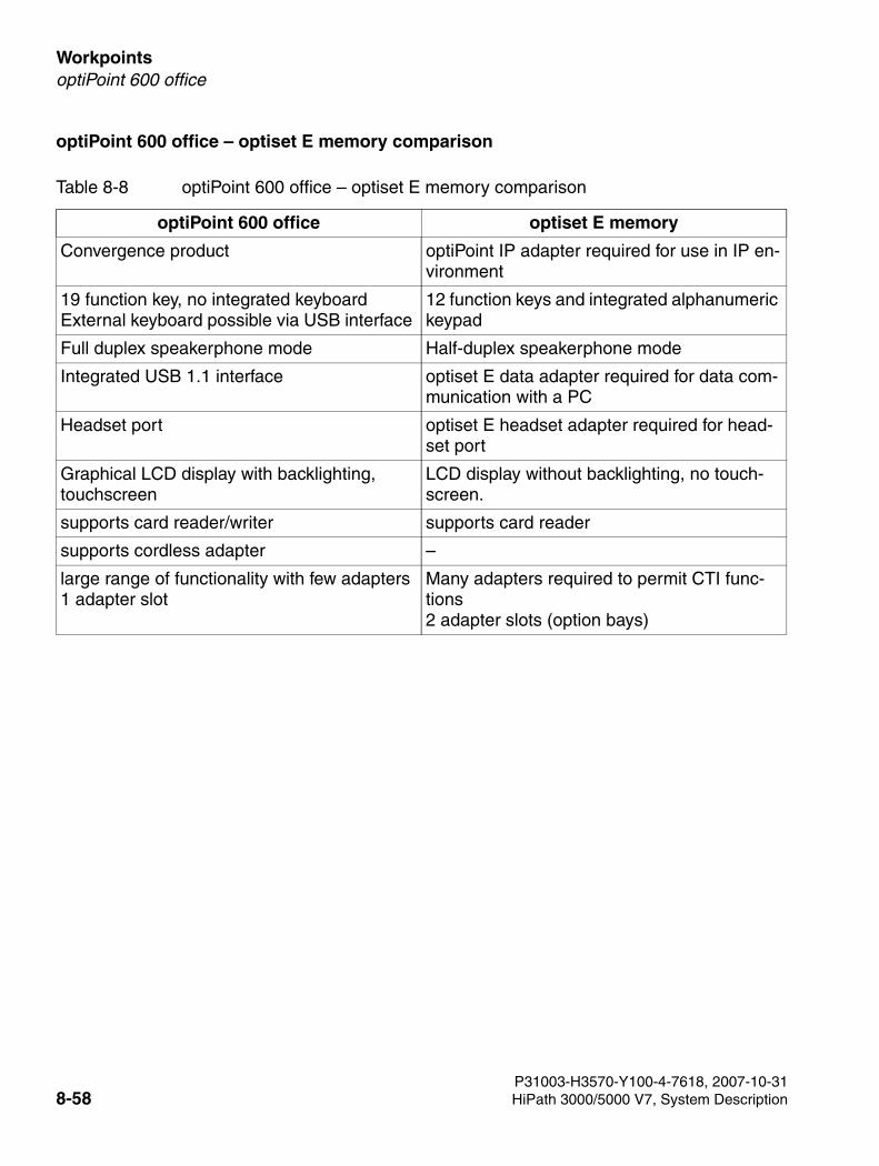
Workpoints For internal use only
3000sb7.fm
optiPoint 600 office
optiPoint 600 office – optiset E memory comparison
Table 8-8 optiPoint 600 office – optiset E memory comparison
optiPoint 600 office optiset E memory
Convergence product optiPoint IP adapter required for use in IP en-vironment
19 function key, no integrated keyboardExternal keyboard possible via USB interface
12 function keys and integrated alphanumeric keypad
Full duplex speakerphone mode Half-duplex speakerphone mode
Integrated USB 1.1 interface optiset E data adapter required for data com-munication with a PC
Headset port optiset E headset adapter required for head-set port
Graphical LCD display with backlighting, touchscreen
LCD display without backlighting, no touch-screen.
supports card reader/writer supports card reader
supports cordless adapter –
large range of functionality with few adapters 1 adapter slot
Many adapters required to permit CTI func-tions 2 adapter slots (option bays)
P31003-H3570-Y100-4-7618, 2007-10-318-58 HiPath 3000/5000 V7, System Description
3000sb7.fm
For internal use only WorkpointsoptiPoint 500 Product Family
8.6 optiPoint 500 Product Family
Introduction
optiPoint 500 telephones handle the digital communication of voice and data (voice communi-cation only for optiPoint 500 entry and optiPoint 500 economy). The three dialog keys and the display guarantee convenient and interactive operation. Furthermore, the key lamp principle vi-sualizes the activated functions.
With the exception of optiPoint 500 entry and optiPoint 500 economy, the optiPoint 500 tele-phones have a USB 1.1 interface. This allows for PC-supported telephoning and Internet ac-cess over the USB interface of a PC.
The add-on devices optiPoint key module and optiPoint BLF allow you to increase the number of available function keys.
The various optiPoint 500 adapters allow flexible extension of the telephone workstation. Addi-tional devices (such as personal computers, fax equipment, telephones, headsets) can be con-nected quickly because it is easy to connect them to the underside of the telephones (not optiPoint 500entry and optiPoint 500 economy) and because the adapters are "plug’n’play".
The optiPoint 500 product family includes the following telephones:
>The optiPoint 500 telephones described in this section are compatible with the op-tiset E telephones. It is possible to operate both telephone families on one SLMO board. You can also use telephones from the two families in mixed host-client con-figurations (earlier called the master-slave or primary-secondary configuration).
Telephone (product name) Remark
optiPoint 500 entry Telephone without display
optiPoint 500 economy Telephone with display
optiPoint 500 basic Telephone with display
optiPoint 500 standard Telephone with display
optiPoint 500 advance Telephone with display
P31003-H3570-Y100-4-7618, 2007-10-31HiPath 3000/5000 V7, System Description 8-59
Workpoints For internal use only
3000sb7.fm
optiPoint 500 Product Family
Key Programming
HiPath 3000/5000 < V3.0 does not automatically detect optiPoint 500 telephones; it treats them as if they were optiset E telephones:
Because optiPoint 500 advance has more function keys (4 + 15) than any optiset E telephones (max. 4 + 8), the system generates an optiset E advance plus/comfort with optiset E key module for the optiPoint 500 advance. HiPath 3000/5000 Manager E also recognizes this combination.Use the 4 + 8 function keys of the optiset E advance plus/comfort and the first 7 keys of the optiset E key module to program the 4 + 15 function keys of the optiPoint 500 advance.
>Double key assignment The programmable function keys of the optiPoint 500 telephones and the optiPoint key modules can have double assignments if only numbers without LED support are saved on the first level. It is also possible to program numbers without LED support on the second level. These can be internal station numbers, DID numbers and num-bers from a HiPath network. When the Shift function is pressed, the LED lights the Shift key. This signals that the phone numbers on the second key level are available. The Shift function is deacti-vated after 5 s or after you press a phone number or if the you press the Shift key again.The optiPoint BLF function keys cannot have double assignments.
optiPoint 500 telephone Generation/detection by HiPath 3000/5000 and HiPath 3000/5000 Manager E
optiPoint 500 entry –> optiset E basic
optiPoint 500 economy –> optiset E advance plus/comfort
optiPoint 500 basic –> optiset E advance plus/comfort
optiPoint 500 standard –> optiset E advance plus/comfort
optiPoint 500 advance –> optiset E advance plus/comfort + optiset E key module
P31003-H3570-Y100-4-7618, 2007-10-318-60 HiPath 3000/5000 V7, System Description
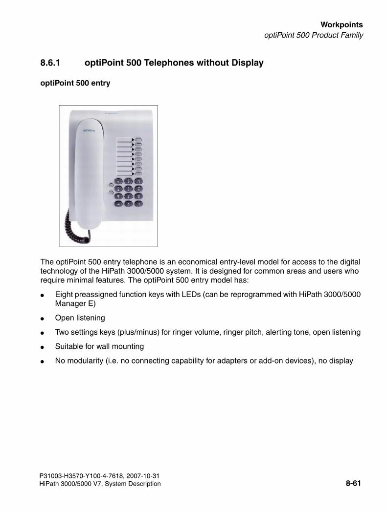
3000sb7.fm
For internal use only WorkpointsoptiPoint 500 Product Family
8.6.1 optiPoint 500 Telephones without Display
optiPoint 500 entry
The optiPoint 500 entry telephone is an economical entry-level model for access to the digital technology of the HiPath 3000/5000 system. It is designed for common areas and users who require minimal features. The optiPoint 500 entry model has:
● Eight preassigned function keys with LEDs (can be reprogrammed with HiPath 3000/5000 Manager E)
● Open listening
● Two settings keys (plus/minus) for ringer volume, ringer pitch, alerting tone, open listening
● Suitable for wall mounting
● No modularity (i.e. no connecting capability for adapters or add-on devices), no display
P31003-H3570-Y100-4-7618, 2007-10-31HiPath 3000/5000 V7, System Description 8-61
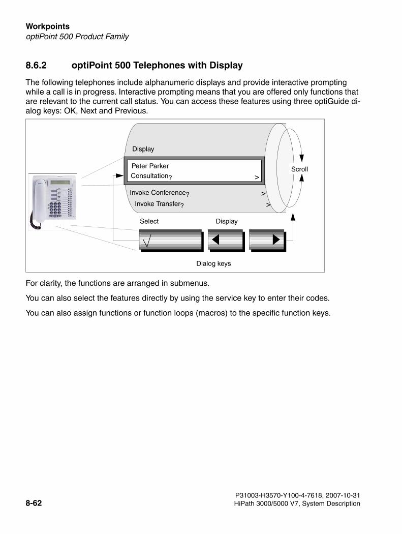
Workpoints For internal use only
3000sb7.fm
optiPoint 500 Product Family
8.6.2 optiPoint 500 Telephones with Display
The following telephones include alphanumeric displays and provide interactive prompting while a call is in progress. Interactive prompting means that you are offered only functions that are relevant to the current call status. You can access these features using three optiGuide di-alog keys: OK, Next and Previous.
For clarity, the functions are arranged in submenus.
You can also select the features directly by using the service key to enter their codes.
You can also assign functions or function loops (macros) to the specific function keys.
Invoke Conference? >
Peter Parker
Consultation? >
Invoke Transfer? >
Display
Select Display
Dialog keys
Scroll
P31003-H3570-Y100-4-7618, 2007-10-318-62 HiPath 3000/5000 V7, System Description
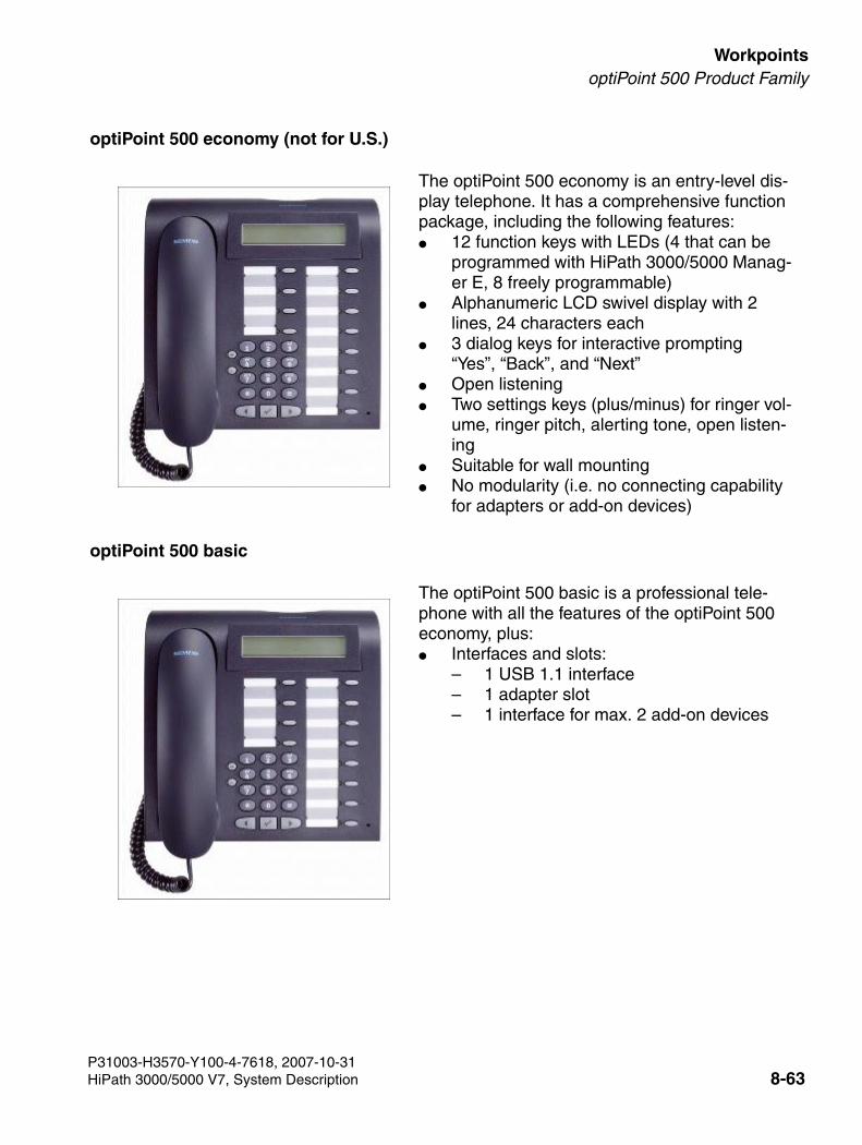
3000sb7.fm
For internal use only WorkpointsoptiPoint 500 Product Family
optiPoint 500 economy (not for U.S.)
optiPoint 500 basic
The optiPoint 500 economy is an entry-level dis-play telephone. It has a comprehensive function package, including the following features: ● 12 function keys with LEDs (4 that can be
programmed with HiPath 3000/5000 Manag-er E, 8 freely programmable)
● Alphanumeric LCD swivel display with 2 lines, 24 characters each
● 3 dialog keys for interactive prompting “Yes”, “Back”, and “Next”
● Open listening ● Two settings keys (plus/minus) for ringer vol-
ume, ringer pitch, alerting tone, open listen-ing
● Suitable for wall mounting ● No modularity (i.e. no connecting capability
for adapters or add-on devices)
The optiPoint 500 basic is a professional tele-phone with all the features of the optiPoint 500 economy, plus: ● Interfaces and slots:
– 1 USB 1.1 interface– 1 adapter slot– 1 interface for max. 2 add-on devices
P31003-H3570-Y100-4-7618, 2007-10-31HiPath 3000/5000 V7, System Description 8-63
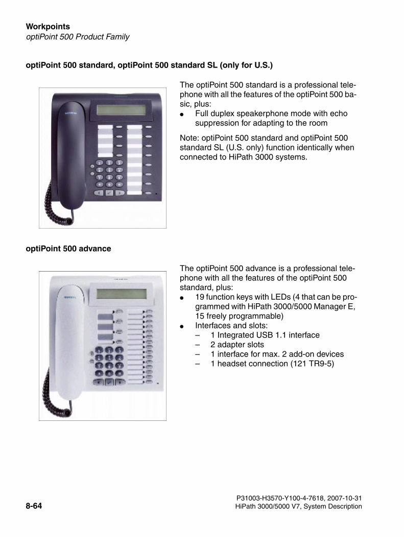
Workpoints For internal use only
3000sb7.fm
optiPoint 500 Product Family
optiPoint 500 standard, optiPoint 500 standard SL (only for U.S.)
optiPoint 500 advance
The optiPoint 500 standard is a professional tele-phone with all the features of the optiPoint 500 ba-sic, plus:● Full duplex speakerphone mode with echo
suppression for adapting to the room
Note: optiPoint 500 standard and optiPoint 500 standard SL (U.S. only) function identically when connected to HiPath 3000 systems.
The optiPoint 500 advance is a professional tele-phone with all the features of the optiPoint 500 standard, plus:● 19 function keys with LEDs (4 that can be pro-
grammed with HiPath 3000/5000 Manager E, 15 freely programmable)
● Interfaces and slots: – 1 Integrated USB 1.1 interface – 2 adapter slots – 1 interface for max. 2 add-on devices – 1 headset connection (121 TR9-5)
P31003-H3570-Y100-4-7618, 2007-10-318-64 HiPath 3000/5000 V7, System Description
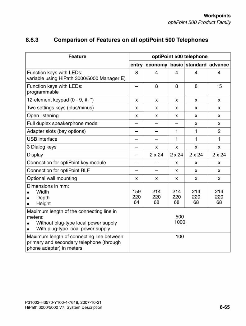
3000sb7.fm
For internal use only WorkpointsoptiPoint 500 Product Family
8.6.3 Comparison of Features on all optiPoint 500 Telephones
Feature optiPoint 500 telephone
entry economy basic standard advance
Function keys with LEDs:variable using HiPath 3000/5000 Manager E)
8 4 4 4 4
Function keys with LEDs: programmable
– 8 8 8 15
12-element keypad (0 - 9, #, *) x x x x x
Two settings keys (plus/minus) x x x x x
Open listening x x x x x
Full duplex speakerphone mode – – – x x
Adapter slots (bay options) – – 1 1 2
USB interface – – 1 1 1
3 Dialog keys – x x x x
Display – 2 x 24 2 x 24 2 x 24 2 x 24
Connection for optiPoint key module – – x x x
Connection for optiPoint BLF – – x x x
Optional wall mounting x x x x x
Dimensions in mm:● Width● Depth● Height
15922064
21422068
21422068
21422068
21422068
Maximum length of the connecting line in meters:● Without plug-type local power supply● With plug-type local power supply
5001000
Maximum length of connecting line between primary and secondary telephone (through phone adapter) in meters
100
P31003-H3570-Y100-4-7618, 2007-10-31HiPath 3000/5000 V7, System Description 8-65
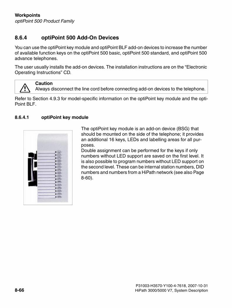
Workpoints For internal use only
3000sb7.fm
optiPoint 500 Product Family
8.6.4 optiPoint 500 Add-On Devices
You can use the optiPoint key module and optiPoint BLF add-on devices to increase the number of available function keys on the optiPoint 500 basic, optiPoint 500 standard, and optiPoint 500 advance telephones.
The user usually installs the add-on devices. The installation instructions are on the “Electronic Operating Instructions” CD.
Refer to Section 4.9.3 for model-specific information on the optiPoint key module and the opti-Point BLF.
8.6.4.1 optiPoint key module
7CautionAlways disconnect the line cord before connecting add-on devices to the telephone.
The optiPoint key module is an add-on device (BSG) that should be mounted on the side of the telephone; it provides an additional 16 keys, LEDs and labelling areas for all pur-poses.Double assignment can be performed for the keys if only numbers without LED support are saved on the first level. It is also possible to program numbers without LED support on the second level. These can be internal station numbers, DID numbers and numbers from a HiPath network (see also Page 8-60).
P31003-H3570-Y100-4-7618, 2007-10-318-66 HiPath 3000/5000 V7, System Description
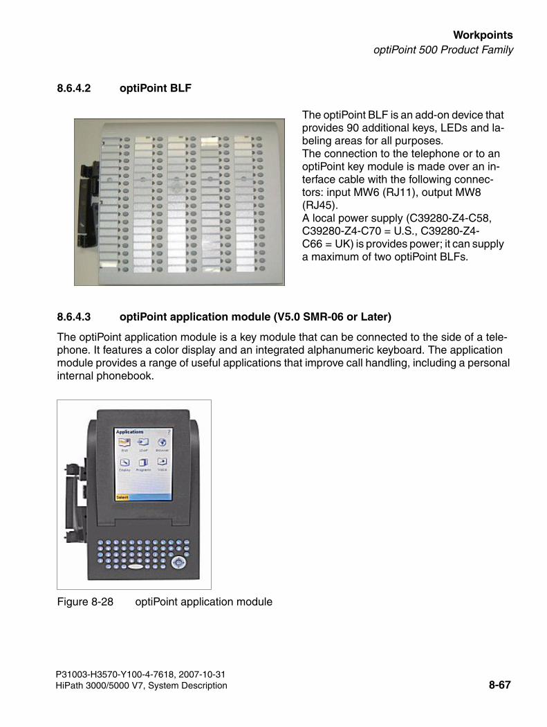
3000sb7.fm
For internal use only WorkpointsoptiPoint 500 Product Family
8.6.4.2 optiPoint BLF
8.6.4.3 optiPoint application module (V5.0 SMR-06 or Later)
The optiPoint application module is a key module that can be connected to the side of a tele-phone. It features a color display and an integrated alphanumeric keyboard. The application module provides a range of useful applications that improve call handling, including a personal internal phonebook.
The optiPoint BLF is an add-on device that provides 90 additional keys, LEDs and la-beling areas for all purposes. The connection to the telephone or to an optiPoint key module is made over an in-terface cable with the following connec-tors: input MW6 (RJ11), output MW8 (RJ45). A local power supply (C39280-Z4-C58, C39280-Z4-C70 = U.S., C39280-Z4-C66 = UK) is provides power; it can supply a maximum of two optiPoint BLFs.
Figure 8-28 optiPoint application module
P31003-H3570-Y100-4-7618, 2007-10-31HiPath 3000/5000 V7, System Description 8-67
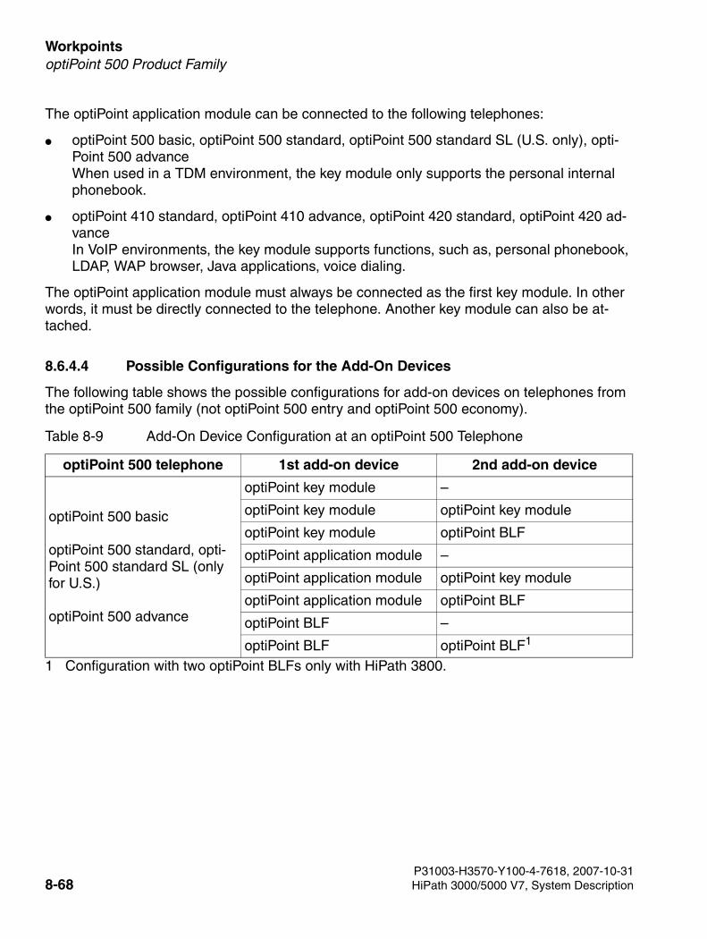
Workpoints For internal use only
3000sb7.fm
optiPoint 500 Product Family
The optiPoint application module can be connected to the following telephones:
● optiPoint 500 basic, optiPoint 500 standard, optiPoint 500 standard SL (U.S. only), opti-Point 500 advance When used in a TDM environment, the key module only supports the personal internal phonebook.
● optiPoint 410 standard, optiPoint 410 advance, optiPoint 420 standard, optiPoint 420 ad-vance In VoIP environments, the key module supports functions, such as, personal phonebook, LDAP, WAP browser, Java applications, voice dialing.
The optiPoint application module must always be connected as the first key module. In other words, it must be directly connected to the telephone. Another key module can also be at-tached.
8.6.4.4 Possible Configurations for the Add-On Devices
The following table shows the possible configurations for add-on devices on telephones from the optiPoint 500 family (not optiPoint 500 entry and optiPoint 500 economy).
Table 8-9 Add-On Device Configuration at an optiPoint 500 Telephone
optiPoint 500 telephone 1st add-on device 2nd add-on device
optiPoint 500 basic
optiPoint 500 standard, opti-Point 500 standard SL (only for U.S.)
optiPoint 500 advance
optiPoint key module –
optiPoint key module optiPoint key module
optiPoint key module optiPoint BLF
optiPoint application module –
optiPoint application module optiPoint key module
optiPoint application module optiPoint BLF
optiPoint BLF –
optiPoint BLF optiPoint BLF1
1 Configuration with two optiPoint BLFs only with HiPath 3800.
P31003-H3570-Y100-4-7618, 2007-10-318-68 HiPath 3000/5000 V7, System Description
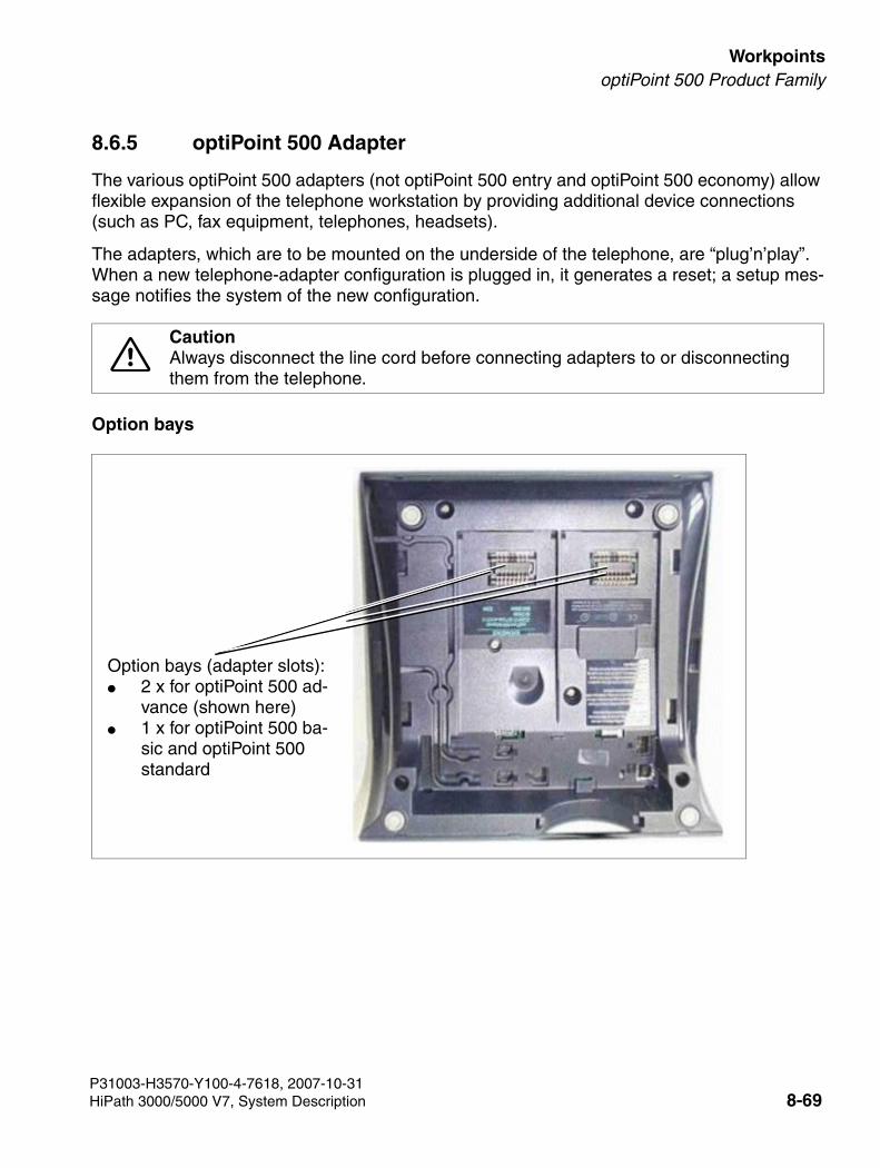
3000sb7.fm
For internal use only WorkpointsoptiPoint 500 Product Family
8.6.5 optiPoint 500 Adapter
The various optiPoint 500 adapters (not optiPoint 500 entry and optiPoint 500 economy) allow flexible expansion of the telephone workstation by providing additional device connections (such as PC, fax equipment, telephones, headsets).
The adapters, which are to be mounted on the underside of the telephone, are “plug’n’play”. When a new telephone-adapter configuration is plugged in, it generates a reset; a setup mes-sage notifies the system of the new configuration.
Option bays
7CautionAlways disconnect the line cord before connecting adapters to or disconnecting them from the telephone.
Option bays (adapter slots):● 2 x for optiPoint 500 ad-
vance (shown here)● 1 x for optiPoint 500 ba-
sic and optiPoint 500 standard
P31003-H3570-Y100-4-7618, 2007-10-31HiPath 3000/5000 V7, System Description 8-69
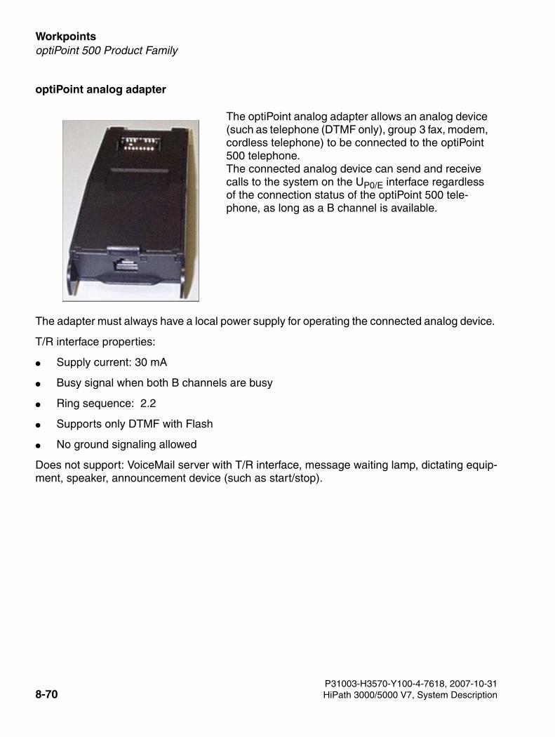
Workpoints For internal use only
3000sb7.fm
optiPoint 500 Product Family
optiPoint analog adapter
The adapter must always have a local power supply for operating the connected analog device.
T/R interface properties:
● Supply current: 30 mA
● Busy signal when both B channels are busy
● Ring sequence: 2.2
● Supports only DTMF with Flash
● No ground signaling allowed
Does not support: VoiceMail server with T/R interface, message waiting lamp, dictating equip-ment, speaker, announcement device (such as start/stop).
The optiPoint analog adapter allows an analog device (such as telephone (DTMF only), group 3 fax, modem, cordless telephone) to be connected to the optiPoint 500 telephone. The connected analog device can send and receive calls to the system on the UP0/E interface regardless of the connection status of the optiPoint 500 tele-phone, as long as a B channel is available.
P31003-H3570-Y100-4-7618, 2007-10-318-70 HiPath 3000/5000 V7, System Description
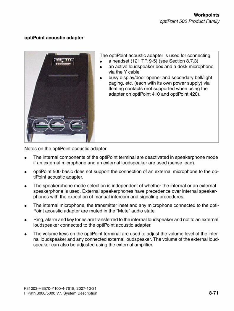
3000sb7.fm
For internal use only WorkpointsoptiPoint 500 Product Family
optiPoint acoustic adapter
Notes on the optiPoint acoustic adapter
● The internal components of the optiPoint terminal are deactivated in speakerphone mode if an external microphone and an external loudspeaker are used (sense lead).
● optiPoint 500 basic does not support the connection of an external microphone to the op-tiPoint acoustic adapter.
● The speakerphone mode selection is independent of whether the internal or an external speakerphone is used. External speakerphones have precedence over internal speaker-phones with the exception of manual intercom and signaling procedures.
● The internal microphone, the transmitter inset and any microphone connected to the opti-Point acoustic adapter are muted in the “Mute” audio state.
● Ring, alarm and key tones are transferred to the internal loudspeaker and not to an external loudspeaker connected to the optiPoint acoustic adapter.
● The volume keys on the optiPoint terminal are used to adjust the volume level of the inter-nal loudspeaker and any connected external loudspeaker. The volume of the external loud-speaker can also be adjusted using the external amplifier.
The optiPoint acoustic adapter is used for connecting● a headset (121 TR 9-5) (see Section 8.7.3) ● an active loudspeaker box and a desk microphone
via the Y cable ● busy display/door opener and secondary bell/light
paging, etc. (each with its own power supply) via floating contacts (not supported when using the adapter on optiPoint 410 and optiPoint 420).
P31003-H3570-Y100-4-7618, 2007-10-31HiPath 3000/5000 V7, System Description 8-71
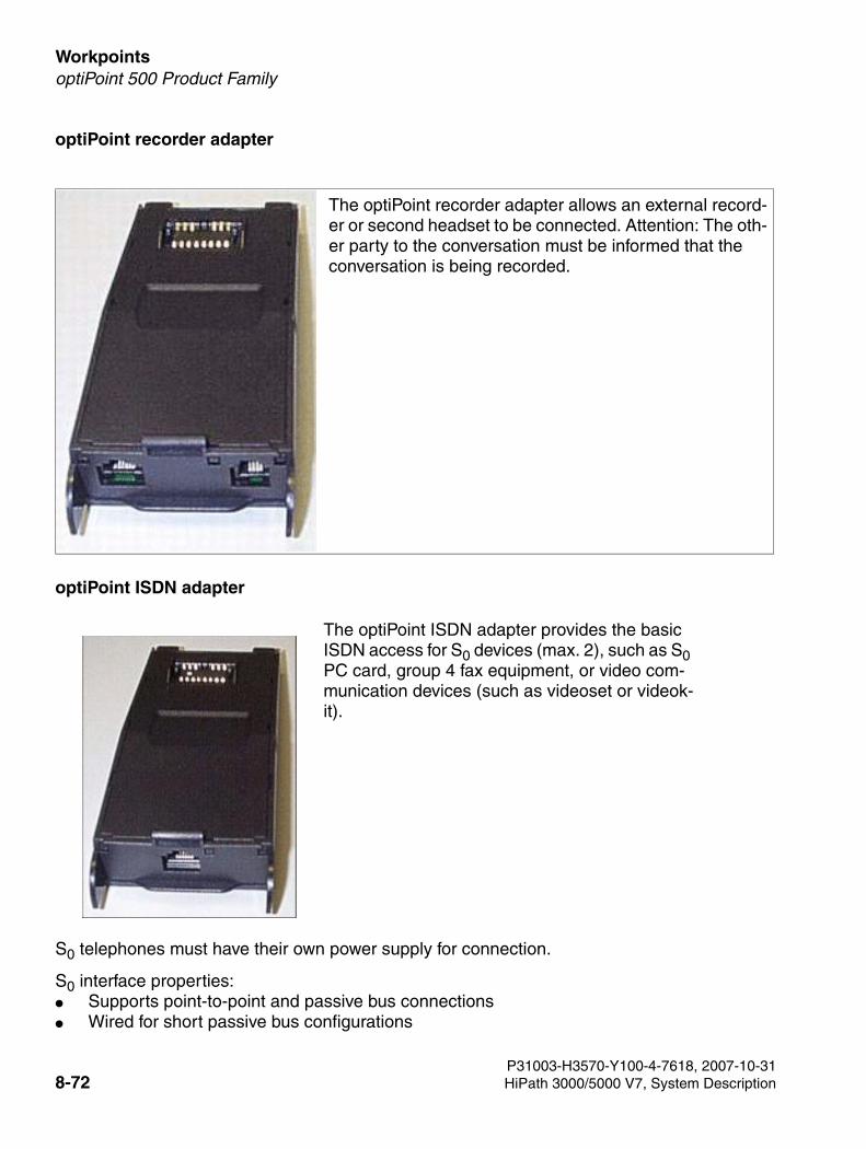
Workpoints For internal use only
3000sb7.fm
optiPoint 500 Product Family
optiPoint recorder adapter
optiPoint ISDN adapter
S0 telephones must have their own power supply for connection.
S0 interface properties: ● Supports point-to-point and passive bus connections ● Wired for short passive bus configurations
The optiPoint ISDN adapter provides the basic ISDN access for S0 devices (max. 2), such as S0 PC card, group 4 fax equipment, or video com-munication devices (such as videoset or videok-it).
The optiPoint recorder adapter allows an external record-er or second headset to be connected. Attention: The oth-er party to the conversation must be informed that the conversation is being recorded.
P31003-H3570-Y100-4-7618, 2007-10-318-72 HiPath 3000/5000 V7, System Description
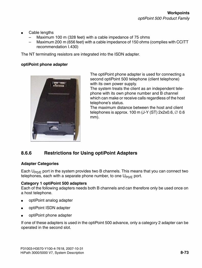
3000sb7.fm
For internal use only WorkpointsoptiPoint 500 Product Family
● Cable lengths– Maximum 100 m (328 feet) with a cable impedance of 75 ohms – Maximum 200 m (656 feet) with a cable impedance of 150 ohms (complies with CCITT
recommendation I.430)
The NT terminating resistors are integrated into the ISDN adapter.
optiPoint phone adapter
8.6.6 Restrictions for Using optiPoint Adapters
Adapter Categories
Each UP0/E port in the system provides two B channels. This means that you can connect two telephones, each with a separate phone number, to one UP0/E port.
Category 1 optiPoint 500 adaptersEach of the following adapters needs both B channels and can therefore only be used once on a host telephone.
● optiPoint analog adapter
● optiPoint ISDN adapter
● optiPoint phone adapter
If one of these adapters is used in the optiPoint 500 advance, only a category 2 adapter can be operated in the second slot.
The optiPoint phone adapter is used for connecting a second optiPoint 500 telephone (client telephone) with its own power supply. The system treats the client as an independent tele-phone with its own phone number and B channel which can make or receive calls regardless of the host telephone’s status. The maximum distance between the host and client telephones is approx. 100 m (J-Y (ST) 2x2x0.6, ∅ 0.6 mm).
P31003-H3570-Y100-4-7618, 2007-10-31HiPath 3000/5000 V7, System Description 8-73
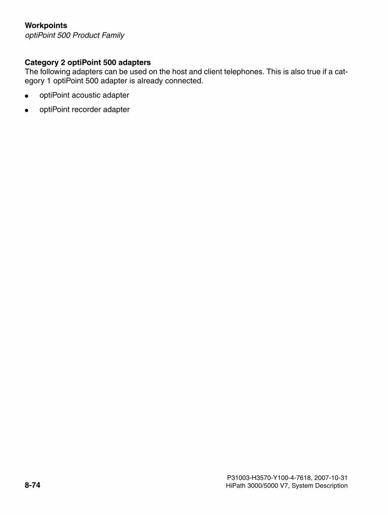
Workpoints For internal use only
3000sb7.fm
optiPoint 500 Product Family
Category 2 optiPoint 500 adaptersThe following adapters can be used on the host and client telephones. This is also true if a cat-egory 1 optiPoint 500 adapter is already connected.
● optiPoint acoustic adapter
● optiPoint recorder adapter
P31003-H3570-Y100-4-7618, 2007-10-318-74 HiPath 3000/5000 V7, System Description
3000sb7.fm
For internal use only WorkpointsAccessories for optiPoint Telephone Solutions
8.7 Accessories for optiPoint Telephone Solutions
8.7.1 Local Power Supply for optiset E, optiPoint 500 and optiPoint 600 office
You may need a local power supply if you are using large configurations or if you need to extend the range.
You can connect the local power supply to the line cords of a host or client telephone using two MW6 jacks and the included connecting cable (part number see Section 8.7.4).
Data for local power supply AUL:06D1284:
● Line voltage: 220 (230) VAC
● AC line frequency: 47 to 53 Hz
● Output voltage: Max. 50 V, min. 30 V
● Output current: Max. 250 mA
8.7.2 optiPoint 410 and optiPoint 420 local power supply
The local power supply has two MW6 jacks. Power is fed to the terminal over the left jack la-belled "Digital".
Technical specifications
Technical specifications Euro local power supply
C39280-Z4-C510
UK local power supply
C39280-Z4-C512
110 V U.S local power supply.
C39280-Z4-C511
Line voltage 230 VAC 230 VAC 120 VAC
AC line frequency 50 Hz 50 Hz 60 Hz
Output voltage max. 43 VDC,min. 30 VDC
max. 43 VDC,min. 30 VDC
max. 43 VDC,min. 30 VDC
Output current 480 mA 480 mA 480 mA
P31003-H3570-Y100-4-7618, 2007-10-31HiPath 3000/5000 V7, System Description 8-75
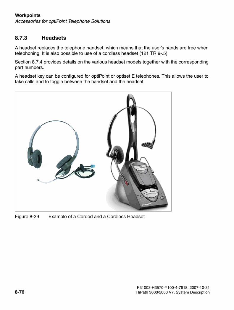
Workpoints For internal use only
3000sb7.fm
Accessories for optiPoint Telephone Solutions
8.7.3 Headsets
A headset replaces the telephone handset, which means that the user’s hands are free when telephoning. It is also possible to use of a cordless headset (121 TR 9-.5)
Section 8.7.4 provides details on the various headset models together with the corresponding part numbers.
A headset key can be configured for optiPoint or optiset E telephones. This allows the user to take calls and to toggle between the handset and the headset.
Figure 8-29 Example of a Corded and a Cordless Headset
P31003-H3570-Y100-4-7618, 2007-10-318-76 HiPath 3000/5000 V7, System Description
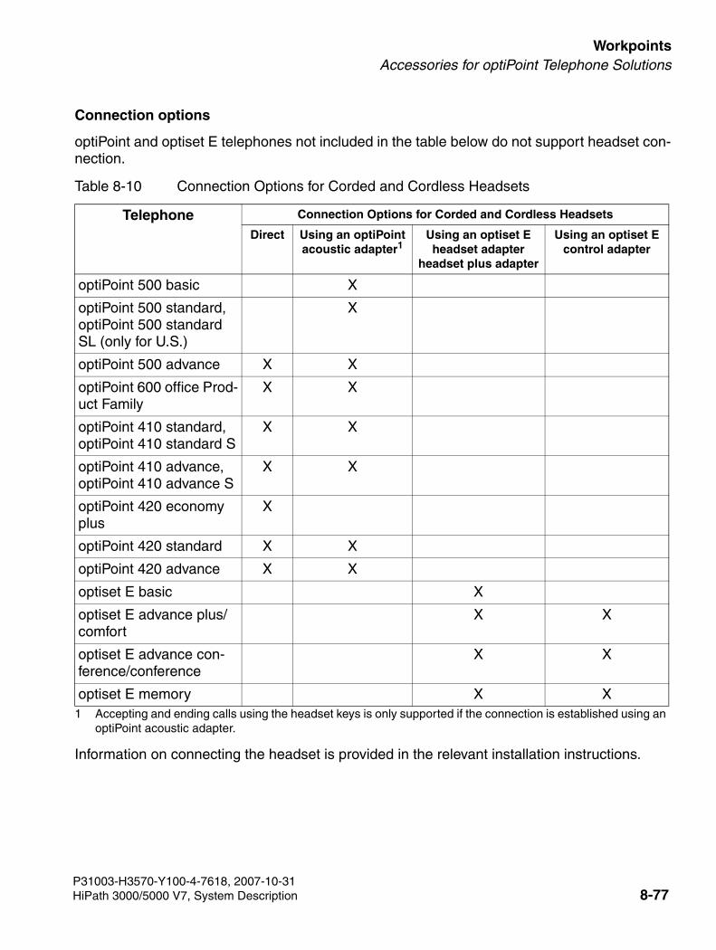
3000sb7.fm
For internal use only WorkpointsAccessories for optiPoint Telephone Solutions
Connection options
optiPoint and optiset E telephones not included in the table below do not support headset con-nection.
Information on connecting the headset is provided in the relevant installation instructions.
Table 8-10 Connection Options for Corded and Cordless Headsets
Telephone Connection Options for Corded and Cordless Headsets
Direct Using an optiPointacoustic adapter1
1 Accepting and ending calls using the headset keys is only supported if the connection is established using an optiPoint acoustic adapter.
Using an optiset Eheadset adapter
headset plus adapter
Using an optiset Econtrol adapter
optiPoint 500 basic X
optiPoint 500 standard, optiPoint 500 standard SL (only for U.S.)
X
optiPoint 500 advance X X
optiPoint 600 office Prod-uct Family
X X
optiPoint 410 standard, optiPoint 410 standard S
X X
optiPoint 410 advance, optiPoint 410 advance S
X X
optiPoint 420 economy plus
X
optiPoint 420 standard X X
optiPoint 420 advance X X
optiset E basic X
optiset E advance plus/comfort
X X
optiset E advance con-ference/conference
X X
optiset E memory X X
P31003-H3570-Y100-4-7618, 2007-10-31HiPath 3000/5000 V7, System Description 8-77
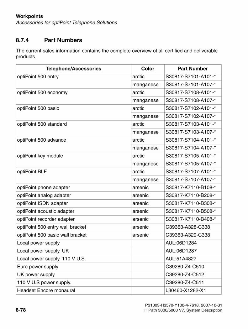
Workpoints For internal use only
3000sb7.fm
Accessories for optiPoint Telephone Solutions
8.7.4 Part Numbers
The current sales information contains the complete overview of all certified and deliverable products.
Telephone/Accessories Color Part Number
optiPoint 500 entry arctic S30817-S7101-A101-*
manganese S30817-S7101-A107-*
optiPoint 500 economy arctic S30817-S7108-A101-*
manganese S30817-S7108-A107-*
optiPoint 500 basic arctic S30817-S7102-A101-*
manganese S30817-S7102-A107-*
optiPoint 500 standard arctic S30817-S7103-A101-*
manganese S30817-S7103-A107-*
optiPoint 500 advance arctic S30817-S7104-A101-*
manganese S30817-S7104-A107-*
optiPoint key module arctic S30817-S7105-A101-*
manganese S30817-S7105-A107-*
optiPoint BLF arctic S30817-S7107-A101-*
manganese S30817-S7107-A107-*
optiPoint phone adapter arsenic S30817-K7110-B108-*
optiPoint analog adapter arsenic S30817-K7110-B208-*
optiPoint ISDN adapter arsenic S30817-K7110-B308-*
optiPoint acoustic adapter arsenic S30817-K7110-B508-*
optiPoint recorder adapter arsenic S30817-K7110-B408-*
optiPoint 500 entry wall bracket arsenic C39363-A328-C338
optiPoint 500 basic wall bracket arsenic C39363-A329-C338
Local power supply AUL:06D1284
Local power supply, UK AUL:06D1287
Local power supply, 110 V U.S. AUL:51A4827
Euro power supply C39280-Z4-C510
UK power supply C39280-Z4-C512
110 V U.S power supply. C39280-Z4-C511
Headset Encore monaural L30460-X1282-X1
P31003-H3570-Y100-4-7618, 2007-10-318-78 HiPath 3000/5000 V7, System Description
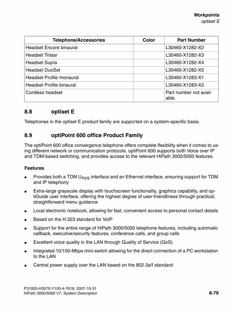
3000sb7.fm
For internal use only Workpointsoptiset E
8.8 optiset E
Telephones in the optiset E product family are supported on a system-specific basis.
8.9 optiPoint 600 office Product Family
The optiPoint 600 office convergence telephone offers complete flexibility when it comes to us-ing different network or communication protocols. optiPoint 600 supports both Voice over IP and TDM-based switching, and provides access to the relevant HiPath 3000/5000 features.
Features
● Provides both a TDM UP0/E interface and an Ethernet interface, ensuring support for TDM and IP telephony
● Extra-large grayscale display with touchscreen functionality, graphics capability, and op-tiGuide user interface, offering the highest degree of user-friendliness through practical, straightforward menu guidance
● Local electronic notebook, allowing for fast, convenient access to personal contact details
● Based on the H.323 standard for VoIP
● Support for the entire range of HiPath 3000/5000 telephone features, including automatic callback, executive/security features, conference calls, and group calls
● Excellent voice quality in the LAN through Quality of Service (QoS)
● Integrated 10/100-Mbps mini-switch allowing for the direct connection of a PC workstation to the LAN
● Central power supply over the LAN based on the 802.3a/f standard
Headset Encore binaural L30460-X1282-X2
Headset Tristar L30460-X1282-X3
Headset Supra L30460-X1282-X4
Headset DuoSet L30460-X1282-X5
Headset Profile monaural L30460-X1283-X1
Headset Profile binaural L30460-X1283-X2
Cordless headset Part number not avail-able.
Telephone/Accessories Color Part Number
P31003-H3570-Y100-4-7618, 2007-10-31HiPath 3000/5000 V7, System Description 8-79
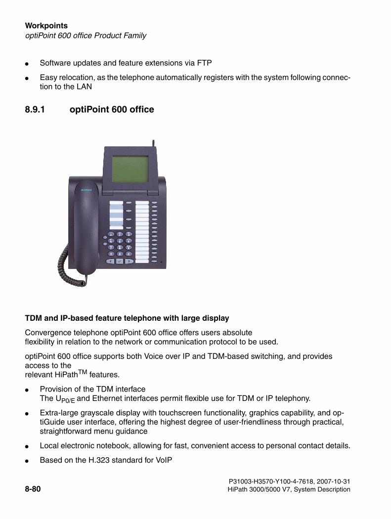
Workpoints For internal use only
3000sb7.fm
optiPoint 600 office Product Family
● Software updates and feature extensions via FTP
● Easy relocation, as the telephone automatically registers with the system following connec-tion to the LAN
8.9.1 optiPoint 600 office
TDM and IP-based feature telephone with large display
Convergence telephone optiPoint 600 office offers users absolute flexibility in relation to the network or communication protocol to be used.
optiPoint 600 office supports both Voice over IP and TDM-based switching, and providesaccess to therelevant HiPathTM features.
● Provision of the TDM interface The UP0/E and Ethernet interfaces permit flexible use for TDM or IP telephony.
● Extra-large grayscale display with touchscreen functionality, graphics capability, and op-tiGuide user interface, offering the highest degree of user-friendliness through practical, straightforward menu guidance
● Local electronic notebook, allowing for fast, convenient access to personal contact details.
● Based on the H.323 standard for VoIP
P31003-H3570-Y100-4-7618, 2007-10-318-80 HiPath 3000/5000 V7, System Description
3000sb7.fm
For internal use only WorkpointsoptiPoint 600 office Product Family
● Support for the entire range of HiPath 3000/HiPath 4000 telephone features, including au-tomatic callback, executive/security features, conference calls, and group calls
● High voice quality in the LAN with Quality of Service (QoS).
● Integrated 10/100-Mbps mini-switch allowing for the direct connection of a PC workstation to the LAN
● Central power supply over the LAN based on the pre802.3af standard
● Administrative measures are not necessary
● Software updates and feature extensions via FTP
● Easy relocation, as the telephone automatically registers with the system following connec-tion to the LAN
With UP0/E and Ethernet interfaces, optiPoint 600 office offers maximum flexibility in terms of which network should be used. optiPoint 600 office transforms the vision of converging net-works into a reality.
8.9.1.1 optiPoint 600 office as System Telephone
optiPoint 600 office completes the optiPoint 500 system telephone family. It provides all HiPath-TM features quickly and easily.
The integrated USB 1.1 interface can be used for PC connection. TAPI Service Provider Call Bridge lets you set up calls quickly and easily directly from the PC.
8.9.1.2 optiPoint 600 office as IP Telephone
Developed on the basis of H.323, the CorNet IP protocol supports all telephone features asso-ciated with the HiPath 3000 and HiPath 4000 IP communications platform. This means that all telephone features, such as executive/secretary features, group calls, and automatic callback are available as usual. For operation, this telephone uses the same menu system as the opti-Point 500 telephones directly connected to HiPath 3000/HiPath 4000.
Special Digital Signal Processors (DSP) and acoustic algorithms (echo cancellation) guarantee excellent voice quality. Speakerphone mode and open listening are therefore available at a very high acoustic level.
The use of Quality of Service (QoS) protocols both at Ethernet and IP level provides optimum voice quality in the LAN. optiPoint 600 office voice packets are assigned priority bits and are therefore transported through the LAN ahead of any other data packets.
The workstation PC connects to the optiPoint 600 office over the integrated 2-port Ethernet switch. Cost savings can thus be achieved in terms of inhouse cabling and the IP network.
P31003-H3570-Y100-4-7618, 2007-10-31HiPath 3000/5000 V7, System Description 8-81
Workpoints For internal use only
3000sb7.fm
optiPoint 600 office Product Family
8.9.1.3 Advantages at a Glance
Cost Reduction
● Cabling costs No additional wiring necessary for optiPoint 600 office necessary. The PC is connected via the integrated switch.
● Infrastructure costs for the data and voice network– one network,– one investment, and– one team for maintenance and service.
● Follow-on costsNo telephone and system reconfiguration following relocation in IP mode
Investment Protection
● A single device for TDM and VoIP providing for future migration to VoIP
● A single device for the HiPath 3000 and HiPath 4000 IP communications platforms
● The latest feature releases available as software downloads
Intuitive Operation
● Clear overview with largedisplay and direct selection via touchscreen functionality
● Interactive prompting withdialog keys and display using optiGuide
● Programmable direct access keys
● Direct dialing from the PC with CTI (TAPI)
Flexibility
● Upgrades available as software downloads
● Administration with Web browser and SNMP
● Quick configuration with DHCP (plug and call)
● Compatibility with different workstation environments using adapters and key modules
P31003-H3570-Y100-4-7618, 2007-10-318-82 HiPath 3000/5000 V7, System Description
3000sb7.fm
For internal use only WorkpointsoptiPoint 600 office Product Family
Comfort
● Optimum voice quality in the LAN through Quality of Service (QoS)
● Speakerphone for spontaneous inclusion of parties present in call with excellent voice quality
● Full access to all HiPath 3000 and HiPath 4000 telephony features
● Direct dialing from the PC
● Large display with touchscreen functionality
8.9.1.4 General Local Features
● Tilting grayscale graphics display with 320*240 pixels (8*24 characters), touchscreen func-tionality, background lighting and adjustable contrast
● Nineteen programmable function keys with LEDs
● Three dialog keys for interactive user guidance with optiGuide
● Two control key (plus and minus) for setting ringer pitch and volume
● Speakerphone mode and open listening
● Offhook dialing
● Calling party identification
● Key click
● Password protection for administrator-specific data
● DTMF/signaling, inband and outband
● Feature updating with software downloads (via FTP)
● Electronic notebook for 640 entries
● Headset interface (121 TR9-5 and Polaris)
● Hearing-aid compatibility
● CTI in TDM and IP Mode
● CAPI over USB and CallBridge for Data*
P31003-H3570-Y100-4-7618, 2007-10-31HiPath 3000/5000 V7, System Description 8-83
Workpoints For internal use only
3000sb7.fm
optiPoint 600 office Product Family
● JAVA Virtual Machine (VM) plus JAVA Development Kit (JDK) for generating user-specific JAVA applications
● Virtual key module (speed dialing application) with 40 speed dialing keys
● WAP bookmarks
● Input of WAP/URL addresses
● Resource sharing for optiPoint 600 entries over the PC keyboard
8.9.1.5 Accessories
Adapters
● optiPoint acoustic adapter
● optiPoint analog adapter*
● optiPoint ISDN adapter*
● optiPoint phone adapter*
● optiPoint recorder adapter
Add-On Devices
● optiPoint key module
● optiPoint signature module
● optiPoint BLF
P31003-H3570-Y100-4-7618, 2007-10-318-84 HiPath 3000/5000 V7, System Description
3000sb7.fm
For internal use only WorkpointsoptiPoint WL2 professional/optiPoint WL2 professional S
8.10 optiPoint WL2 professional/optiPoint WL2 professional S
optiPoint WL2 professional uses WLAN to simplify corporate access to data and resources.
WLANs are transparent in IP traffic and therefore create an ideal environment for IP multimedia applications. The incorporation of real-time IP communication (voice, for instance) is the next logical phase because it uses the investments in convergent LANs and extends the range of IP telephony and multimedia communication systems in a company.
The Siemens 802.11 WLAN phones, optiPoint WL2 professional, and optiPoint WL2 profes-sional S support all features needed by contemporary wireless telephones (polyphonic ring tone melodies, graphics display, and various telephone-specific applications, for instance). In addition, the CorNet-compatible telephone optiPoint WL2 professional grants wireless users access to the HiPath 4000 and HiPath 3000 systems’ wide range of telephone features and ap-plications. Thanks to its SIP-compliant properties, optiPoint WL2 professional S is the ideal so-lution for the growing SIP (Session Initiation Protocol) market. It supports SIP-compliant sys-tems from both Siemens and other providers.
Properties
Wireless LAN Voice-over-IP telephone with color graphics display.
optiPoint WL2 professional can be operated with HiPath 5000 V5.0 or later. optiPoint WL2 professional S is developed as a solution for SIP systems and can be operated with HiPath 5000 V6.0 and later.
● Interfaces: WLAN, USB
● Standards: WLAN, 802.11b (11 Mbps), 802.11g (full support for 54 Mbps), CorNet IP, SIP
Configuration
● Wireless connection with a WLAN access point as a link to a LAN switch
● IP connection to the HiPath 3000 gateway in the HiPath 3000 system; CorNet-IP registra-tion
● IP connection to a SIP proxy/registrar: SIP registration
● Basic configuration via DHCP
● Advanced configuration over the telephone’s Web page (single telephone) or using the Hi-Path Deployment Service.
P31003-H3570-Y100-4-7618, 2007-10-31HiPath 3000/5000 V7, System Description 8-85
Workpoints For internal use only
3000sb7.fm
optiPoint WL2 professional/optiPoint WL2 professional S
Features
Telephone
● Telephone with color graphics display (six lines, 128 x 128-pixel resolution, 4096 colors, 3.1 x 3.1 cm)
● Call animation and caller display (CLIP)/caller ID for incoming calls
● Illuminated keypad
● Two softkeys for dynamic feature access
● Intuitive user prompting
● Illuminated MWI key
● Speakerphone key
● Status display in standby or idle mode shows: date, time, battery status, RF signal strength, access point connected
● Status display during the call shows: battery status, RF signal strength, time per call, off-hook handset, CLIP/caller ID
● Missed calls display
● Speakerphone function
● Answered calls display
● Dialing by means of number entry, SIP-URI (professional S), and IP address (direct IP call)
● Multiline functionality
● Programmable speed dialing keys
● Dial preparation (phone number entry before line seizure) with correction option
● Redial function for the last ten different numbers dialed
● Key-activated keypad lock and ring tone deactivation with icon display
● Common user interface for Siemens desktop phones with optiGuide user interface (profes-sional S)
● Access to HiPath features (depending on the HiPath system connected) for call features, such as, callback, conference, consultation hold, etc.
● Local SIP features (professional S): hold, mute, transfer, three-party conference, MWI, DND, etc.
● SIP features with server support: Group Pickup, Priority Alerting, Distinctive Ringing, Key-set, Shared Call Appearance, Bridge Line Appearance, etc.
P31003-H3570-Y100-4-7618, 2007-10-318-86 HiPath 3000/5000 V7, System Description
3000sb7.fm
For internal use only WorkpointsoptiPoint WL2 professional/optiPoint WL2 professional S
Local phonebook
● Comprehensive local phonebook/address book
● CLIP replaced by the phonebook entry in the telephone or HiPath system
Audio
● Six polyphonic ring tones (adjustable volume)
● 16 ring tones, 12 of which are managed by the HiPath system and four by the user
● Ring tones can be downloaded
● Volume adjustment (eight settings)
● CLIP-/caller-ID-dependant ring tones
● VIP calls
Added-Value Applications and Features
● Caller voice announcement1) (CLIP/caller ID)
● Voice dialing
● Polyphonic ring tones (downloadable)
● Access to LDAP directories
● Headset connection via a Slim Lumberg connector
● Vibrating alarm
● Designed for broadband voice transmission (optional, G.722)
● CTI interface
● Upgrades and configurations can be performed OTA (Over The Air) using the HiPath De-ployment Service tool (advanced administration application)
● Support for HiPath applications
Codecs
● G.711 (a-law and µ-law)
● G.729ab (G.729a with VAD (Voice Activity Detection))
● G.723
● G.722 (optional)
● Advanced Echo Cancellation (AEC)
P31003-H3570-Y100-4-7618, 2007-10-31HiPath 3000/5000 V7, System Description 8-87
Workpoints For internal use only
3000sb7.fm
optiPoint WL2 professional/optiPoint WL2 professional S
QoS*
● ToS
● DiffServ
● 802.1q
● 802.11e (WME subset)
Accessories
● Desktop charger
● Desktop charger with second battery charging option
● USB data cable
● Broad range of headsets available
● Selection of carry sets available
● Power adapter (suitable for the relevant geographical region)
Additional Features
● Web-browser-based administration
● Multilingual user interface
● Date and time synchronization via the NTP server or HiPath system
● Range: indoors: up to 30 m (depending on the environment)Outdoors: up to 300 m (depending on the environment)
● Power supply unit (Li-Ion, 3.7 V, battery)
● Operating times: talk time up to 4 hours; standby time up to 80 hours
● Weight: approx. 100 g
● Dimensions: Telephone: 132 x 52 x 22 mm (LxWxH), Charger: 70 x 73 x 35 mm
● Color: Light Cashmere Silver
Wireless Features
● 802.11g (fallback to 802.11b)
● Frequency range: 2.4 – 2.497 GHz
● Number of dialable channels: 13 (ETSI) or 11 (North America)
P31003-H3570-Y100-4-7618, 2007-10-318-88 HiPath 3000/5000 V7, System Description
3000sb7.fm
For internal use only WorkpointsoptiPoint WL2 professional/optiPoint WL2 professional S
● Adjustable transmit power: approx. +20 dBm EIRP
● Site Survey Tool integrated in the telephone
● Transmission rates: 54, 48, 36, 24, 18, 12, 11, 9, 6, 5.5, 2, 1 Mbps
● SSID
Security Features
● WEP (64, 128 bits)
● WPA
● Cisco infrastructure support with CCX
● PIN-protection for telephone
● VPN client
● Authentication (login/password)
● 802.11i (optional, if the standard is selected)
Authentication
● EAP-TLS
● LEAP
Protocols/Network Features
● DHCP client
● FTP client
● VLAN support
● SNMP trap agent
● VoIP (SIP, RTP, RTCP, TLS)
● DNS
● HTTP and HTTPS servers
● PPTP for VPN support
● UPNP (control point and device)
● IP addressing: fixed, DHCP, PPPoE
P31003-H3570-Y100-4-7618, 2007-10-31HiPath 3000/5000 V7, System Description 8-89
Workpoints For internal use only
3000sb7.fm
optiPoint WL2 professional/optiPoint WL2 professional S
PC Software
● PC tool for swapping Microsoft Outlook phonebook data with data in the WLAN telephone’s local phonebook
● Ring tone downloading from the PC to the telephone
P31003-H3570-Y100-4-7618, 2007-10-318-90 HiPath 3000/5000 V7, System Description
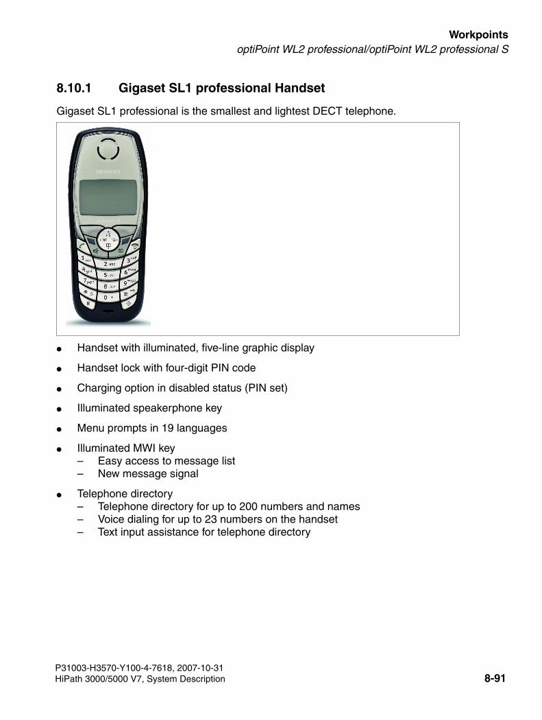
3000sb7.fm
For internal use only WorkpointsoptiPoint WL2 professional/optiPoint WL2 professional S
8.10.1 Gigaset SL1 professional Handset
Gigaset SL1 professional is the smallest and lightest DECT telephone.
● Handset with illuminated, five-line graphic display
● Handset lock with four-digit PIN code
● Charging option in disabled status (PIN set)
● Illuminated speakerphone key
● Menu prompts in 19 languages
● Illuminated MWI key– Easy access to message list– New message signal
● Telephone directory– Telephone directory for up to 200 numbers and names– Voice dialing for up to 23 numbers on the handset – Text input assistance for telephone directory
P31003-H3570-Y100-4-7618, 2007-10-31HiPath 3000/5000 V7, System Description 8-91
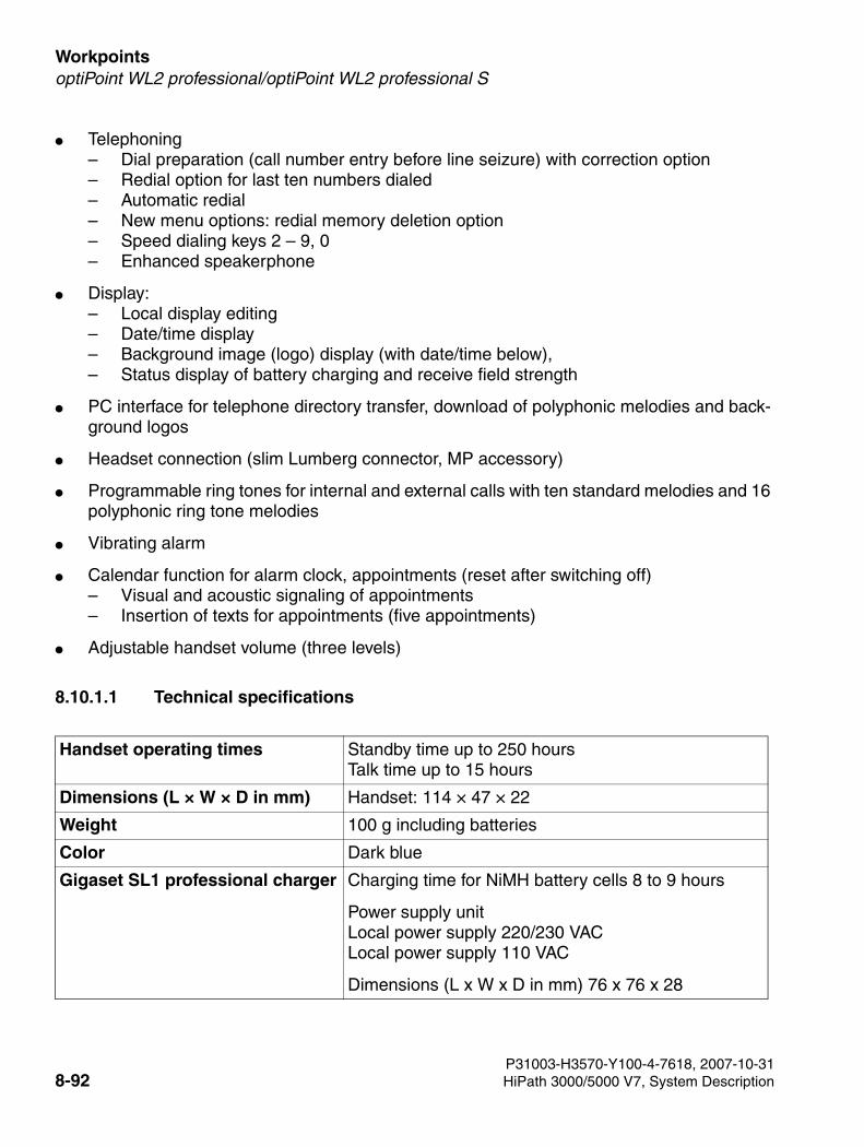
Workpoints For internal use only
3000sb7.fm
optiPoint WL2 professional/optiPoint WL2 professional S
● Telephoning– Dial preparation (call number entry before line seizure) with correction option– Redial option for last ten numbers dialed– Automatic redial– New menu options: redial memory deletion option– Speed dialing keys 2 – 9, 0– Enhanced speakerphone
● Display:– Local display editing– Date/time display – Background image (logo) display (with date/time below), – Status display of battery charging and receive field strength
● PC interface for telephone directory transfer, download of polyphonic melodies and back-ground logos
● Headset connection (slim Lumberg connector, MP accessory)
● Programmable ring tones for internal and external calls with ten standard melodies and 16 polyphonic ring tone melodies
● Vibrating alarm
● Calendar function for alarm clock, appointments (reset after switching off)– Visual and acoustic signaling of appointments– Insertion of texts for appointments (five appointments)
● Adjustable handset volume (three levels)
8.10.1.1 Technical specifications
Handset operating times Standby time up to 250 hoursTalk time up to 15 hours
Dimensions (L × W × D in mm) Handset: 114 × 47 × 22
Weight 100 g including batteries
Color Dark blue
Gigaset SL1 professional charger Charging time for NiMH battery cells 8 to 9 hours
Power supply unitLocal power supply 220/230 VAC Local power supply 110 VAC
Dimensions (L x W x D in mm) 76 x 76 x 28
P31003-H3570-Y100-4-7618, 2007-10-318-92 HiPath 3000/5000 V7, System Description
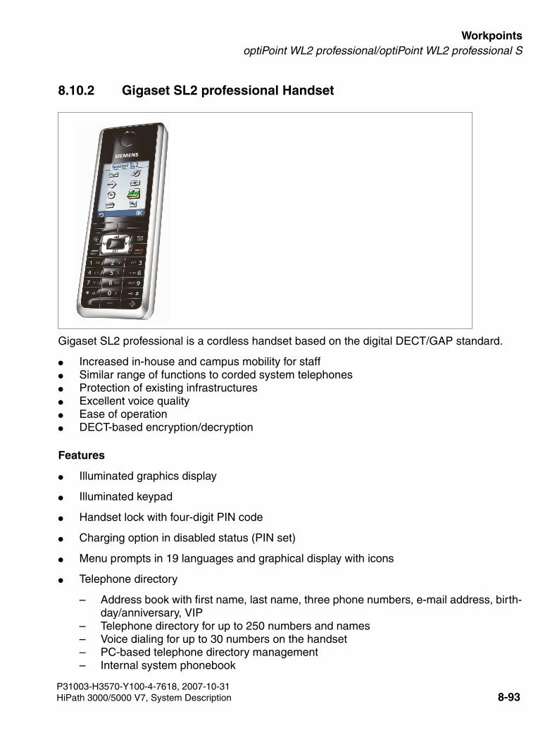
3000sb7.fm
For internal use only WorkpointsoptiPoint WL2 professional/optiPoint WL2 professional S
8.10.2 Gigaset SL2 professional Handset
Gigaset SL2 professional is a cordless handset based on the digital DECT/GAP standard.
● Increased in-house and campus mobility for staff● Similar range of functions to corded system telephones● Protection of existing infrastructures● Excellent voice quality● Ease of operation● DECT-based encryption/decryption
Features
● Illuminated graphics display
● Illuminated keypad
● Handset lock with four-digit PIN code
● Charging option in disabled status (PIN set)
● Menu prompts in 19 languages and graphical display with icons
● Telephone directory
– Address book with first name, last name, three phone numbers, e-mail address, birth-day/anniversary, VIP
– Telephone directory for up to 250 numbers and names– Voice dialing for up to 30 numbers on the handset – PC-based telephone directory management– Internal system phonebook
P31003-H3570-Y100-4-7618, 2007-10-31HiPath 3000/5000 V7, System Description 8-93
Workpoints For internal use only
3000sb7.fm
optiPoint WL2 professional/optiPoint WL2 professional S
● Telephoning
– Call-by-call list– Manual redial option for last ten numbers dialed– Automatic redial– Programmable emergency number (available even if the keypad is locked)– Fast access via programmable keys 0, 2 – 9, and the left display key– Full-duplex speakerphone mode– Voice dialing
● Displays in idle state
– Local display editing– Date/time display – Logo/screensaver display
● Status display for Bluetooth, battery charging, reception strength, ring tones, advisory tone, keylock
● Alarm clock
– Activation possible Monday-Friday or daily– Adjustable acoustic volume/melody setting
● Media pool
– Screensaver and CLIP pictures– Sounds– Memory display
● PC interface via Bluetooth
– Telephone directory synchronization– Access to telephone directory entries
● PC interface via data cable
– Telephone directory transfer– Loading polyphonic melodies and logos
● Adjustable ring tone settings for internal and external calls
– Three ring tones– 10 standard ring tones– 20 polyphonic ringer melodies
● Vibrating alarm
P31003-H3570-Y100-4-7618, 2007-10-318-94 HiPath 3000/5000 V7, System Description

3000sb7.fm
For internal use only WorkpointsoptiPoint WL2 professional/optiPoint WL2 professional S
● Calendar function
– Acoustic appointment signaling – Up to 30 appointments with text can be saved– Monthly overview
● Headset port (Bluetooth, Mini-Lumberg connector)
8.10.2.1 Technical specifications
Ranges Outdoors: up to 300 m Indoors: up to 50 m
Handset operating times > 200 hoursTalk time > 10 hours
Dimensions (L × W × D in mm) Handset: 130 × 47 × 22Charger: 68 x 68 x 22
Weight Handset including battery cell approx. 110 g
Color black
Power supply unit Handset: Lithium-Ion battery 750 mAhLocal power supply 220/230 VACLocal power supply 110 VAC
Gigaset SL1 professional charger Charging time for NiMH battery cells < 6 hours
P31003-H3570-Y100-4-7618, 2007-10-31HiPath 3000/5000 V7, System Description 8-95
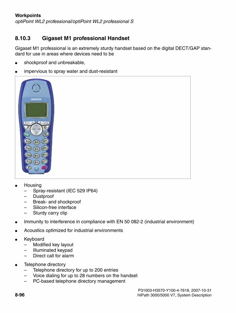
Workpoints For internal use only
3000sb7.fm
optiPoint WL2 professional/optiPoint WL2 professional S
8.10.3 Gigaset M1 professional Handset
Gigaset M1 professional is an extremely sturdy handset based on the digital DECT/GAP stan-dard for use in areas where devices need to be
● shockproof and unbreakable,
● impervious to spray water and dust-resistant
● Housing– Spray-resistant (IEC 529 IP64)– Dustproof– Break- and shockproof– Silicon-free interface– Sturdy carry clip
● Immunity to interference in compliance with EN 50 082-2 (industrial environment)
● Acoustics optimized for industrial environments
● Keyboard – Modified key layout– Illuminated keypad– Direct call for alarm
● Telephone directory– Telephone directory for up to 200 entries– Voice dialing for up to 28 numbers on the handset – PC-based telephone directory management
P31003-H3570-Y100-4-7618, 2007-10-318-96 HiPath 3000/5000 V7, System Description
3000sb7.fm
For internal use only WorkpointsoptiPoint WL2 professional/optiPoint WL2 professional S
● Display– Illuminated, five-line graphic display
In idle state:– Date/time display – Status display for battery charging and receive field strength
● Speakerphone– Illuminated speakerphone key– Full-duplex speakerphone mode
● Telephoning– Dial preparation (call number entry before line seizure) with correction option– Redial option for last ten numbers dialed– Automatic redial– Optical call and appointment signaling– External room monitoring
● PC interface via data cable (Lumberg)– Used for:
telephone directory entry management– PC software and data cable as accessories compatible with C35, C45; M35; ME45,
S25, S35; S45, SL45– SoftDataLink 5.0 software can be obtained from retail outlets/ICM or downloaded free
of charge fromwww.siemens-mobile.com/gigaset-sds
Personal Settings
● Ring tone combined with vibrating alarm (deactivation possible)
● Can be charged by external charging unit connected via Lumberg jack
● Key-based ringer cutoff
● Telephone volume (five settings)
● Ringer volume (seven settings)
● Ringer melody (ten settings)
● Handset volume (three settings)
Languages
● Menu prompts in 14 languages, including Polish
P31003-H3570-Y100-4-7618, 2007-10-31HiPath 3000/5000 V7, System Description 8-97
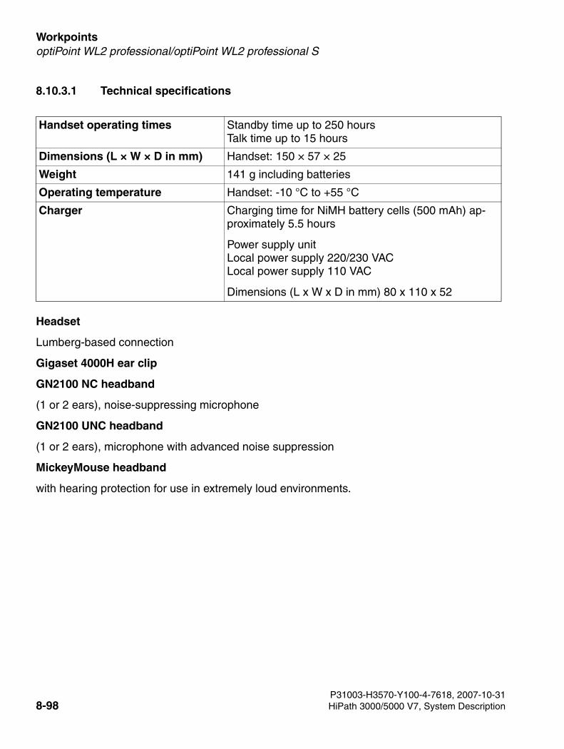
Workpoints For internal use only
3000sb7.fm
optiPoint WL2 professional/optiPoint WL2 professional S
8.10.3.1 Technical specifications
Headset
Lumberg-based connection
Gigaset 4000H ear clip
GN2100 NC headband
(1 or 2 ears), noise-suppressing microphone
GN2100 UNC headband
(1 or 2 ears), microphone with advanced noise suppression
MickeyMouse headband
with hearing protection for use in extremely loud environments.
Handset operating times Standby time up to 250 hoursTalk time up to 15 hours
Dimensions (L × W × D in mm) Handset: 150 × 57 × 25
Weight 141 g including batteries
Operating temperature Handset: -10 °C to +55 °C
Charger Charging time for NiMH battery cells (500 mAh) ap-proximately 5.5 hours
Power supply unitLocal power supply 220/230 VAC Local power supply 110 VAC
Dimensions (L x W x D in mm) 80 x 110 x 52
P31003-H3570-Y100-4-7618, 2007-10-318-98 HiPath 3000/5000 V7, System Description
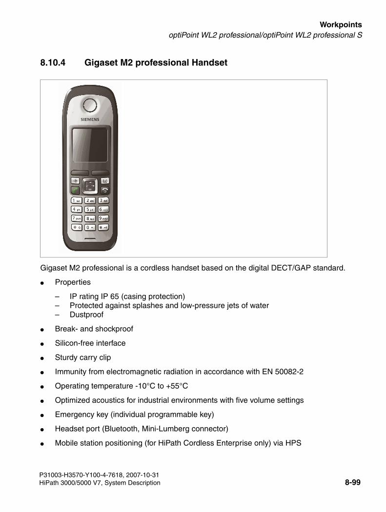
3000sb7.fm
For internal use only WorkpointsoptiPoint WL2 professional/optiPoint WL2 professional S
8.10.4 Gigaset M2 professional Handset
Gigaset M2 professional is a cordless handset based on the digital DECT/GAP standard.
● Properties
– IP rating IP 65 (casing protection)– Protected against splashes and low-pressure jets of water– Dustproof
● Break- and shockproof
● Silicon-free interface
● Sturdy carry clip
● Immunity from electromagnetic radiation in accordance with EN 50082-2
● Operating temperature -10°C to +55°C
● Optimized acoustics for industrial environments with five volume settings
● Emergency key (individual programmable key)
● Headset port (Bluetooth, Mini-Lumberg connector)
● Mobile station positioning (for HiPath Cordless Enterprise only) via HPS
P31003-H3570-Y100-4-7618, 2007-10-31HiPath 3000/5000 V7, System Description 8-99
Workpoints For internal use only
3000sb7.fm
optiPoint WL2 professional/optiPoint WL2 professional S
Features
● Increased in-house and campus mobility for staff● Similar range of functions to corded system telephones● Protection of existing infrastructures● Excellent voice quality● Ease of operation● DECT-based encryption/decryption● Illuminated graphics display
(128 x 160 pixels, 64k colors)● Illuminated keypad, programmable emergency key● New message signaling via illuminated message-waiting key● Handset lock with four-digit PIN code● Charging option in disabled status● Menu prompts in 19 languages and graphical display with icons● List of missed appointments● Memory card for device-specific and individual entries● VIP call signaling (V3.0 or later)● Playback of recorded voice patterns in incoming calls (V3.0 or later)● Advanced features with HiPath DAKS● Multicell capability● Telephone directory● Displays in idle state● Alarm clock● Media pool● PC interface via Bluetooth● PC interface via data cable● Adjustable ring tone settings for internal and external calls ● Tones and signals ● Calendar function
P31003-H3570-Y100-4-7618, 2007-10-318-100 HiPath 3000/5000 V7, System Description
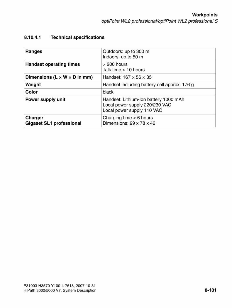
3000sb7.fm
For internal use only WorkpointsoptiPoint WL2 professional/optiPoint WL2 professional S
8.10.4.1 Technical specifications
Ranges Outdoors: up to 300 mIndoors: up to 50 m
Handset operating times > 200 hoursTalk time > 10 hours
Dimensions (L × W × D in mm) Handset: 167 × 56 × 35
Weight Handset including battery cell approx. 176 g
Color black
Power supply unit Handset: Lithium-Ion battery 1000 mAhLocal power supply 220/230 VACLocal power supply 110 VAC
ChargerGigaset SL1 professional
Charging time < 6 hoursDimensions: 99 x 78 x 46
P31003-H3570-Y100-4-7618, 2007-10-31HiPath 3000/5000 V7, System Description 8-101
Workpoints For internal use only
3000sb7.fm
optiPoint WL2 professional
8.11 optiPoint WL2 professional
optiPoint WL2 professional uses WLAN to simplify corporate access to data and resources.
WLANs are transparent in IP traffic and therefore create an ideal environment for IP multimedia applications. The incorporation of real-time IP communication (voice, for instance) is the next logical phase because it uses the investments in convergent LANs and extends the range of IP telephony and multimedia communication systems in a company.
HiPath 3000/5000 provides wireless LAN services when connected to a WLAN access point via a DMZ interface. The following WLAN workpoints are used:
● optiPoint WL2 professionalApart from Relocate, all HiPath 3000/5000 features in the display dialog, service menu, and on function keys are available.
● optiPoint WL2 professional S Supports SIP (Session Initiation Protocol). SIP is an ASCII-based signal protocol used to set up sessions in an IP network.
Properties
Wireless LAN Voice-over-IP telephone with color graphics display.
optiPoint WL2 professional can be operated with HiPath 3000/5000 V5.0 or later. optiPoint WL2 professional S is developed as a solution for SIP systems and can be operated with HiPath 3000/5000 V6.0 and later.
● Interfaces: WLAN, USB
● Standards: WLAN, 802.11b (11 Mbps), 802.11g (full support for 54 Mbps), CorNet IP, SIP
Configuration
● Wireless connection with a WLAN access point as a link to a LAN switch
● IP connection to the HG1500 gateway in the HiPath 3000 system; CorNet-IP registration
● Basic configuration via DHCP
● Advanced configuration over the telephone’s Web page (single telephone) or using the Hi-Path Deployment Service.
P31003-H3570-Y100-4-7618, 2007-10-318-102 HiPath 3000/5000 V7, System Description
3000sb7.fm
For internal use only WorkpointsoptiPoint WL2 professional
Features
Telephone
● Telephone with color graphics display (six lines, 128 x 128-pixel resolution, 4096 colors, 3.1 x 3.1 cm)
● Call animation and caller display (CLIP)/caller ID for incoming calls
● Illuminated keypad
● Two softkeys for dynamic feature access
● Intuitive user prompting
● Illuminated MWI key
● Speakerphone key
● Status display in standby or idle mode shows: date, time, battery status, RF signal strength, access point connected
● Status display during the call shows: battery status, RF signal strength, time per call, off-hook handset, CLIP/caller ID
● Missed calls display
● Speakerphone function
● Answered calls display
● Dialing by means of number entry, SIP-URI (professional S), and IP address (direct IP call)
● Multiline functionality
● Programmable speed dialing keys
● Dial preparation (phone number entry before line seizure) with correction option
● Redial function for the last ten different numbers dialed
● Key-activated keypad lock and ring tone deactivation with icon display
● Common user interface for Siemens desktop phones with optiGuide user interface (profes-sional S)
● Access to HiPath features (depending on the HiPath system connected) for call features, such as, callback, conference, consultation hold, etc.
● SIP features with server support: Group Pickup, Priority Alerting, Distinctive Ringing, Key-set, Shared Call Appearance, Bridge Line Appearance, etc.
P31003-H3570-Y100-4-7618, 2007-10-31HiPath 3000/5000 V7, System Description 8-103
Workpoints For internal use only
3000sb7.fm
optiPoint WL2 professional
P31003-H3570-Y100-4-7618, 2007-10-31
Local phonebook
● Comprehensive local phonebook/address book
● CLIP replaced by the phonebook entry in the telephone or HiPath system
Audio
● Six polyphonic ring tones (adjustable volume)
● 16 ring tones, 12 of which are managed by the HiPath system and four by the user
● Ring tones can be downloaded
● Volume adjustment (eight settings)
● CLIP-/caller-ID-dependant ring tones
● VIP calls
Added-Value Applications and Features
● Caller voice announcement1) (CLIP/caller ID)
● Voice dialing
● Polyphonic ring tones (downloadable)
● Access to LDAP directories
● Headset connection via a Slim Lumberg connector
● Vibrating alarm
● Designed for broadband voice transmission (optional, G.722)
● CTI interface
● Upgrades and configurations can be performed OTA (Over The Air) using the HiPath De-ployment Service tool (advanced administration application)
● Support for HiPath applications
Codecs
● G.711 (a-law and µ-law)
● G.729ab (G.729a with VAD (Voice Activity Detection))
● G.723
● G.722 (optional)
● Advanced Echo Cancellation (AEC)
8-104 HiPath 3000/5000 V7, System Description
3000sb7.fm
For internal use only WorkpointsoptiPoint WL2 professional
QoS*
● ToS
● DiffServ
● 802.1q
● 802.11e (WME subset)
Accessories
● Desktop charger
● Desktop charger with second battery charging option
● USB data cable
● Broad range of headsets available
● Selection of carry sets available
● Power adapter (suitable for the relevant geographical region)
Additional Features
● Web-browser-based administration
● Multilingual user interface
● Date and time synchronization via the NTP server or HiPath system
● Range: indoors: up to 30 m (depending on the environment)Outdoors: up to 300 m (depending on the environment)
● Power supply unit (Li-Ion, 3.7 V, battery)
● Operating times: talk time up to 4 hours; standby time up to 80 hours
● Weight: approx. 100 g
● Dimensions: Telephone: 132 x 52 x 22 mm (LxWxH), Charger: 70 x 73 x 35 mm
● Color: Light Cashmere Silver
P31003-H3570-Y100-4-7618, 2007-10-31HiPath 3000/5000 V7, System Description 8-105
Workpoints For internal use only
3000sb7.fm
optiPoint WL2 professional
Wireless Features
● 802.11g (fallback to 802.11b)
● Frequency range: 2.4 – 2.497 GHz
● Number of dialable channels: 13 (ETSI) or 11 (North America)
● Adjustable transmit power: approx. +20 dBm EIRP
● Site Survey Tool integrated in the telephone
● Transmission rates: 54, 48, 36, 24, 18, 12, 11, 9, 6, 5.5, 2, 1 Mbps
● SSID
Security Features
● WEP (64, 128 bits)
● WPA
● Cisco infrastructure support with CCX
● PIN-protection for telephone
● VPN client
● Authentication (login/password)
● 802.11i (optional, if the standard is selected)
Authentication
● EAP-TLS
● LEAP
P31003-H3570-Y100-4-7618, 2007-10-318-106 HiPath 3000/5000 V7, System Description
3000sb7.fm
For internal use only WorkpointsoptiPoint WL2 professional
Protocols/Network Features
● DHCP client
● FTP client
● VLAN support
● SNMP trap agent
● VoIP (SIP, RTP, RTCP, TLS)
● DNS
● HTTP and HTTPS servers
● PPTP for VPN support
● UPNP (control point and device)
● IP addressing: fixed, DHCP, PPPoE
PC Software
● PC tool for swapping Microsoft Outlook phonebook data with data in the WLAN telephone’s local phonebook
● Ring tone downloading from the PC to the telephone
P31003-H3570-Y100-4-7618, 2007-10-31HiPath 3000/5000 V7, System Description 8-107
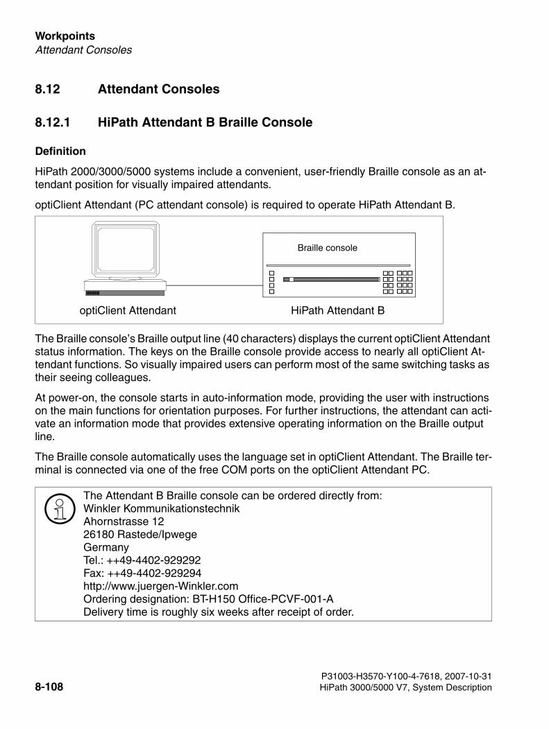
Workpoints For internal use only
3000sb7.fm
Attendant Consoles
8.12 Attendant Consoles
8.12.1 HiPath Attendant B Braille Console
Definition
HiPath 2000/3000/5000 systems include a convenient, user-friendly Braille console as an at-tendant position for visually impaired attendants.
optiClient Attendant (PC attendant console) is required to operate HiPath Attendant B.
The Braille console’s Braille output line (40 characters) displays the current optiClient Attendant status information. The keys on the Braille console provide access to nearly all optiClient At-tendant functions. So visually impaired users can perform most of the same switching tasks as their seeing colleagues.
At power-on, the console starts in auto-information mode, providing the user with instructions on the main functions for orientation purposes. For further instructions, the attendant can acti-vate an information mode that provides extensive operating information on the Braille output line.
The Braille console automatically uses the language set in optiClient Attendant. The Braille ter-minal is connected via one of the free COM ports on the optiClient Attendant PC.
>The Attendant B Braille console can be ordered directly from:Winkler KommunikationstechnikAhornstrasse 1226180 Rastede/IpwegeGermanyTel.: ++49-4402-929292Fax: ++49-4402-929294http://www.juergen-Winkler.comOrdering designation: BT-H150 Office-PCVF-001-ADelivery time is roughly six weeks after receipt of order.
optiClient Attendant
Braille console
HiPath Attendant B
P31003-H3570-Y100-4-7618, 2007-10-318-108 HiPath 3000/5000 V7, System Description
3000sb7.fm
For internal use only WorkpointsAttendant Consoles
8.12.2 optiClient Attendant (V8)
Definition
optiClient Attendant is a PC-based attendant console which can be connected to HiPath 2000/3000/5000 systems. Depending on the model, up to six optiClient Attendants can be installed per node.
optiClient Attendant can also be used as a central attendant console in a network of HiPath 2000/3000/5000 systems.
Technical changes compared to version 7.0:
● A device is required to operate optiClient Attendant V8, even when operating the IP con-nection variant. This device is sold separately (no connection via SoftOla).
● Any headsets used should therefore be connected to the telephone instead of the PC.
● If the optiClient Attendant PC experiences a malfunction or is switched off, reachability is guaranteed via the telephone.
Connection types
1. Connection via TCP/IP to optiPoint 410, optiPoint 420, OpenStage
2. Connection with optiPoint 500 or OpenStage USB interface
3. Connection to optiset E via control adapter
>optiClient Attendant V8 replaces the previous optiClient Attendant V7.0 for all con-nection types (USB, V24, and LAN). optiClient Attendant V7.0 will no longer be marketed.The order options are:1. optiClient Attendant V8 full version2nd upgrade version from optiClient Attendant V7.0 to V8
>optiClient Attendant V8 can function only on HiPath 3000/HiPath 5000 V7 and Hi-Path 2000 V2 - it is not downward compatible. optiClient Attendant V7.0 is not compatible with HiPath 3000/HiPath 5000 V7 and Hi-Path 2000 V2 (startup is not possible.
P31003-H3570-Y100-4-7618, 2007-10-31HiPath 3000/5000 V7, System Description 8-109
Workpoints For internal use only
3000sb7.fm
Attendant Consoles
optiClient Attendant V8 features
● Ongoing, waiting or parked calls are displayed with type, name, and phone number.
● Acoustic message signaling with volume control
● Display of the switching state of source and target
● Answering of pending calls
● VIP call flagging for preferred call acceptance
● Selection of telephone directories:
– Outlook contacts
– Lotus Notes
– Internal Attendant telephone directory, based on Microsoft Access
– Open LDAP
● Advanced integration with MS Outlook, featuring direct e-mail transmission using the phonebook entry
● Call statistics for incoming calls with sort function according to various criteria
● Convenient caller list with an almost unlimited number of entries, sorted according to date and time
● Additional functions such as hold keys, override, callback, conference, paging, speaker an-nouncements, alarm signaling, view call charges, redial (last 10 dialed destinations)
● No calls are lost: Options are provided for intercepting unanswered DID calls and DID calls to busy stations
● Online help under Windows
● Convenient configuration of individual features
● Service tools for diagnosis and protocols
● Simple installation routine
● User interface currently available in German, English, Dutch, Portuguese, Italian, French and Spanish
● Optional braille console connection
● optiClient Attendant may serve as the central attendant console in HiPath networks
● Import of CSV files to the integrated internal phonebook
● Busy lamp fields offer the following features:
P31003-H3570-Y100-4-7618, 2007-10-318-110 HiPath 3000/5000 V7, System Description
3000sb7.fm
For internal use only WorkpointsAttendant Consoles
– Up to 300 fields per BLF
– Up to two BLFs possible
– Configuration of busy lamp fields to suit individual user requirements
– BLF scalability with automatic font adjustment
– Speed dialing via busy lamp field
– Color display of station status: idle, calling, busy internal, busy external
– Call forwarding may be switched on or off for each station
– Do not disturb may be switched off for each station
– Displays "forwarded" and "do not disturb" using symbols
– Name definition for BLFs
– Definition of titles for groups of BLF stations
– Access to public calendar (Exchange)
– Copy/cut and paste on the BLF
P31003-H3570-Y100-4-7618, 2007-10-31HiPath 3000/5000 V7, System Description 8-111
Workpoints For internal use only
3000sb7.fm
Attendant Consoles
Compatibility of the optiClient Attendant with HiPath 2000, HiPath 3000, HiPath 5000
PC system requirements:
● Pentium IV
● Memory: 256 MB
● Operating systems: WIN2000, XP, 2003 Server (for Windows Vista Business, see notes in sales information)
● Microsoft-compatible mouse
● CD-ROM or DVD drive
● For operation with a TCP/IP connection:
– Functional system with network card configured
– optiPoint 410, optiPoint 420 telephones (for OpenStage telephones, see notes in the sales information)
● For operation with USB:
– optiPoint 500 telephone with USB interface (for OpenStage telephones, see notes in the sales information), USB cable (code number: S30267-Z360-A30-1), USB driver (included in CallBridge TU software) and a free USB port on the PC.
● For operation with optiset E control/data adapter:optiset E telephone with adapter slot and a free RS 232 interface on the PC (COM port 1 – 4).If the licensing components CLA and CLM are installed on the same PC, you also have to consider their system requirements.
HiPath 3000/5000 V7
HiPath 2000 V2
HiPath 3000/5000 V6.0
HiPath 2000 V1.0
HiPath 3000/5000 V5.0
optiClient Attendant V8 Yes No, cannot start up No, cannot start up
optiClient Attendant V7.0 No, cannot start up Yes Yes
P31003-H3570-Y100-4-7618, 2007-10-318-112 HiPath 3000/5000 V7, System Description
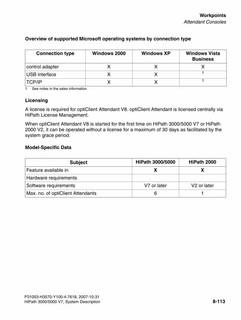
3000sb7.fm
For internal use only WorkpointsAttendant Consoles
Overview of supported Microsoft operating systems by connection type
Licensing
A license is required for optiClient Attendant V8. optiClient Attendant is licensed centrally via HiPath License Management.
When optiClient Attendant V8 is started for the first time on HiPath 3000/5000 V7 or HiPath 2000 V2, it can be operated without a license for a maximum of 30 days as facilitated by the system grace period.
Model-Specific Data
Connection type Windows 2000 Windows XP Windows Vista Business
control adapter X X X
USB interface X X 1
1 See notes in the sales information
TCP/IP X X 1
Subject HiPath 3000/5000 HiPath 2000
Feature available in X X
Hardware requirements
Software requirements V7 or later V2 or later
Max. no. of optiClient Attendants 6 1
P31003-H3570-Y100-4-7618, 2007-10-31HiPath 3000/5000 V7, System Description 8-113

Workpoints For internal use only
3000sb7.fm
Attendant Consoles
8.12.2.1 optiClient Attendant as a central attendant console
The optiClient Attendant can be used as a central attendant console throughout an IP network (max. 6 optiClient Attendants per network). The attendant consoles must be connected to one of the network’s HiPath 3000 nodes, or registered, to enable network-wide BLF functionality. This functionality is independent of the optiClient Attendant connection type. (IP, UP0/E or USB).
>optiClient Attendant’s control of network-wide busy signaling is independent of the network-wide busy signaling to workpoints by HiPath 5000’s Presence Manager.
IP-networked HiPath 3000
HiPath 3000central node
TDM terminals
TDM terminals
IP terminals + IP clients
optiClientAttendant
IP network
Public network
P31003-H3570-Y100-4-7618, 2007-10-318-114 HiPath 3000/5000 V7, System Description

3000sb7.fm
For internal use only WorkpointsAttendant Consoles
8.12.2.2 optiClient BLF V1
optiClient BLF is an independent application for displaying the BLF status (for example, free, busy or ringing). optiClient BLF windows are scalable and can display between 25 and 500 BLFs. The application is released for use with Windows XP, Windows 2000 and Windows Vista PCs. Up to 100 optiClient BLF applications can be operated per system or network.
optiClient BLF V1 software is included on the CD shipped with optiClient Attendant V8. One license per active optiClient BLF is required for operation. Licensing is via independent CLA. The license may be installed on the same PC as the optiClient BLF or centrally on the customer network.
The following functions are only available on the optiClient Attendant BLF: call setup from BLF, call forwarding activation/deactivation, subscriber-driven DND deactivation.
The optiClient BLF should always be operated with optiClient Attendant V8.
The optiClient BLF and optiClient Attendant BLF server components communicate via TCP/IP.
Each optiClient BLF may be configured individually according to user requirements.
Each optiClient BLF is licensed via HiPath License Management. The necessary license file is loaded onto a local CLA or one on the customer network. All software components required by optiClient Attendant V8 and optiClient BLF V1 are provided on the optiClient Attendant V8 CD and may be downloaded from the software server.
The main functions are:
● Monitoring function (BLF and calendar access)
● Information exchange via BLF server components or Exchange server. At least one opti-Client Attendant with integrated BLF server function is required for this.
The optiClient BLF can be operated in two variants. Either each HiPath system has its own op-tiClient Attendant or IP-networked systems have a central optiClient Attendant.
P31003-H3570-Y100-4-7618, 2007-10-31HiPath 3000/5000 V7, System Description 8-115
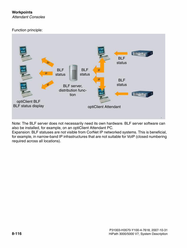
Workpoints For internal use only
3000sb7.fm
Attendant Consoles
Function principle:
Note: The BLF server does not necessarily need its own hardware. BLF server software can also be installed, for example, on an optiClient Attendant PC. Expansion: BLF statuses are not visible from CorNet IP networked systems. This is beneficial, for example, in narrow-band IP infrastructures that are not suitable for VoIP (closed numbering required across all locations).
optiClient BLFBLF status display
BLF status
BLF status
BLFstatus
optiClient Attendant
BLF server,distribution func-
tion
BLFstatus
P31003-H3570-Y100-4-7618, 2007-10-318-116 HiPath 3000/5000 V7, System Description
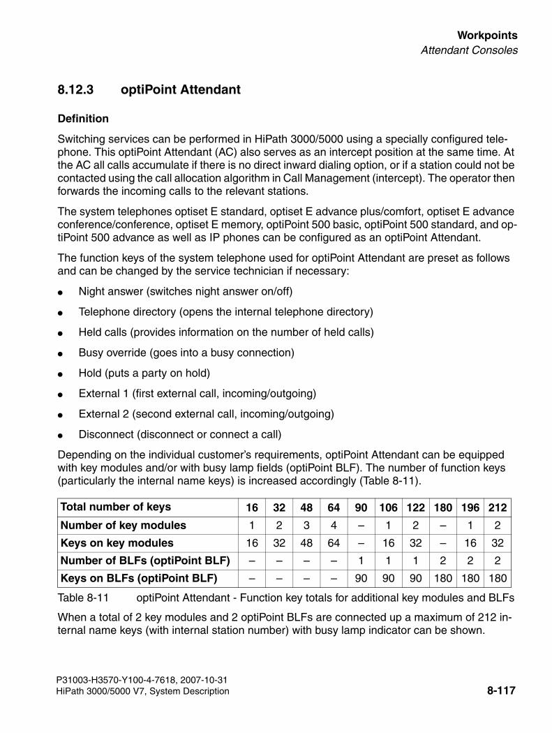
3000sb7.fm
For internal use only WorkpointsAttendant Consoles
8.12.3 optiPoint Attendant
Definition
Switching services can be performed in HiPath 3000/5000 using a specially configured tele-phone. This optiPoint Attendant (AC) also serves as an intercept position at the same time. At the AC all calls accumulate if there is no direct inward dialing option, or if a station could not be contacted using the call allocation algorithm in Call Management (intercept). The operator then forwards the incoming calls to the relevant stations.
The system telephones optiset E standard, optiset E advance plus/comfort, optiset E advance conference/conference, optiset E memory, optiPoint 500 basic, optiPoint 500 standard, and op-tiPoint 500 advance as well as IP phones can be configured as an optiPoint Attendant.
The function keys of the system telephone used for optiPoint Attendant are preset as follows and can be changed by the service technician if necessary:
● Night answer (switches night answer on/off)
● Telephone directory (opens the internal telephone directory)
● Held calls (provides information on the number of held calls)
● Busy override (goes into a busy connection)
● Hold (puts a party on hold)
● External 1 (first external call, incoming/outgoing)
● External 2 (second external call, incoming/outgoing)
● Disconnect (disconnect or connect a call)
Depending on the individual customer’s requirements, optiPoint Attendant can be equipped with key modules and/or with busy lamp fields (optiPoint BLF). The number of function keys (particularly the internal name keys) is increased accordingly (Table 8-11).
When a total of 2 key modules and 2 optiPoint BLFs are connected up a maximum of 212 in-ternal name keys (with internal station number) with busy lamp indicator can be shown.
Total number of keys 16 32 48 64 90 106 122 180 196 212
Number of key modules 1 2 3 4 – 1 2 – 1 2
Keys on key modules 16 32 48 64 – 16 32 – 16 32
Number of BLFs (optiPoint BLF) – – – – 1 1 1 2 2 2
Keys on BLFs (optiPoint BLF) – – – – 90 90 90 180 180 180
Table 8-11 optiPoint Attendant - Function key totals for additional key modules and BLFs
P31003-H3570-Y100-4-7618, 2007-10-31HiPath 3000/5000 V7, System Description 8-117

Workpoints For internal use only
3000sb7.fm
Attendant Consoles
P31003-H3570-Y100-4-7618, 2007-10-318-118 HiPath 3000/5000 V7, System Description
3000sb8.fm
For internal use only ApplicationsOverview
9 Applications
9.1 Overview
The scope of HiPath 3000/5000 systems can be extended by connecting additional applica-tions. These include products for automatic call distribution (ACD), hotel applications, voice messaging services, call charge computing, video conferences, and mobile communication.
HiPath 3000/5000 and applications running on host computers (plus products) can communi-cation over
● the V.24 application interface (CSTA protocol, 19200 bauds)
– plus products that support the CSTA protocol standardized by ECMA can be connect-ed directly (for example, Hicom Agentline Office V1.1 CSTA).
● an S0 interface (ISDN/USBS) configured as a station
● an ISDN adapter (TA S0) (ISDN/USBS)
● the LAN interface (Ethernet)for details, see Chapter 4.
● the PSTN interface for details, see Chapter 4.
HiPath 3000/5000 supports CSTA Phase II and CSTA Phase III. The application connected decides whether to use CSTA Phase II or Phase 3 III during con-nection setup.
P31003-H3570-Y100-4-7618, 2007-10-31HiPath 3000/5000 V7, System Description 9-1
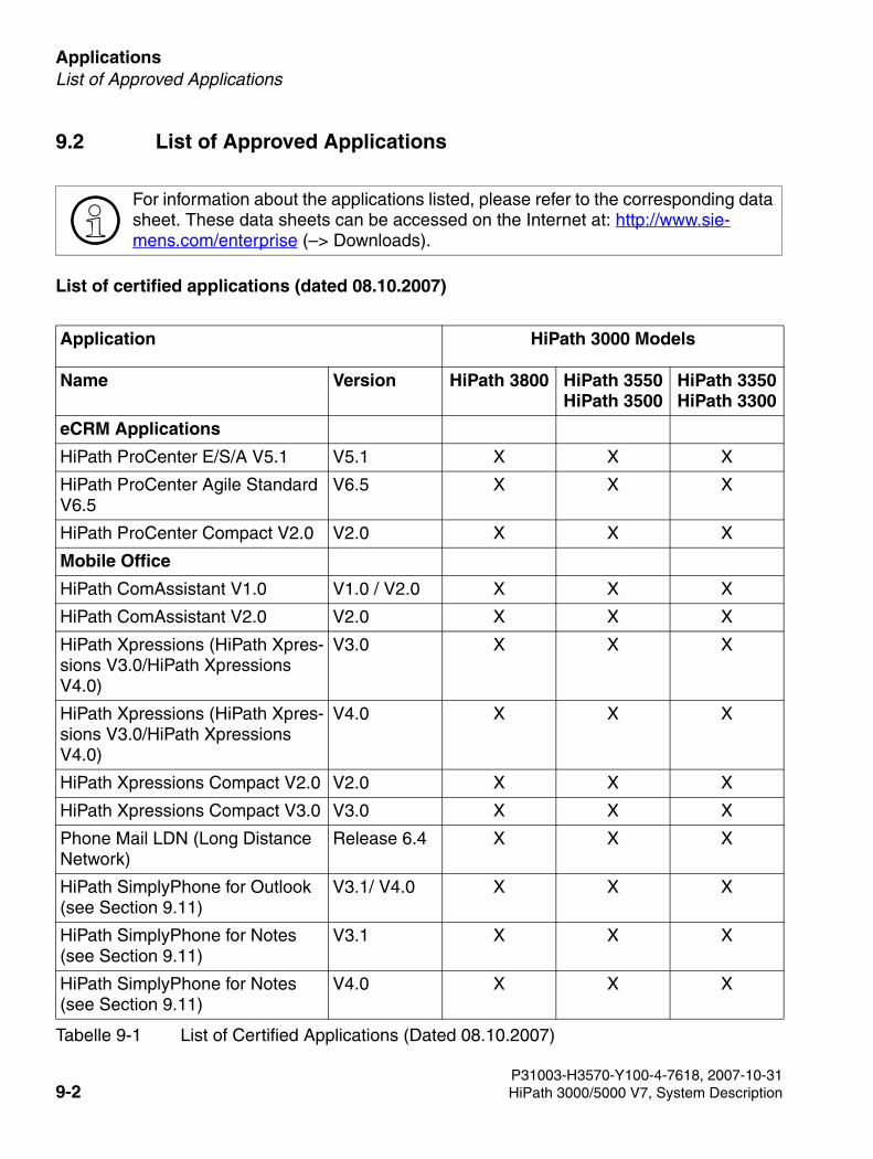
Applications For internal use only
3000sb8.fm
List of Approved Applications
9.2 List of Approved Applications
List of certified applications (dated 08.10.2007)
>For information about the applications listed, please refer to the corresponding data sheet. These data sheets can be accessed on the Internet at: http://www.sie-mens.com/enterprise (–> Downloads).
Application HiPath 3000 Models
Name Version HiPath 3800 HiPath 3550HiPath 3500
HiPath 3350HiPath 3300
eCRM Applications
HiPath ProCenter E/S/A V5.1 V5.1 X X X
HiPath ProCenter Agile Standard V6.5
V6.5 X X X
HiPath ProCenter Compact V2.0 V2.0 X X X
Mobile Office
HiPath ComAssistant V1.0 V1.0 / V2.0 X X X
HiPath ComAssistant V2.0 V2.0 X X X
HiPath Xpressions (HiPath Xpres-sions V3.0/HiPath Xpressions V4.0)
V3.0 X X X
HiPath Xpressions (HiPath Xpres-sions V3.0/HiPath Xpressions V4.0)
V4.0 X X X
HiPath Xpressions Compact V2.0 V2.0 X X X
HiPath Xpressions Compact V3.0 V3.0 X X X
Phone Mail LDN (Long Distance Network)
Release 6.4 X X X
HiPath SimplyPhone for Outlook (see Section 9.11)
V3.1/ V4.0 X X X
HiPath SimplyPhone for Notes(see Section 9.11)
V3.1 X X X
HiPath SimplyPhone for Notes(see Section 9.11)
V4.0 X X X
Tabelle 9-1 List of Certified Applications (Dated 08.10.2007)
P31003-H3570-Y100-4-7618, 2007-10-319-2 HiPath 3000/5000 V7, System Description
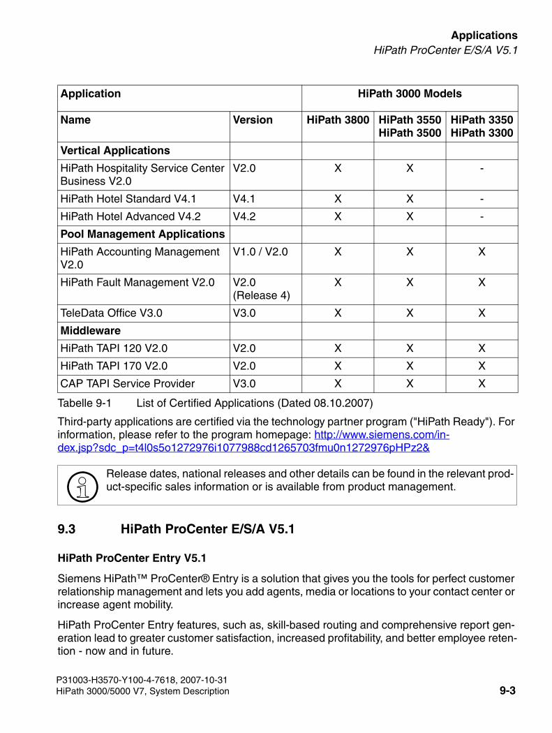
3000sb8.fm
For internal use only ApplicationsHiPath ProCenter E/S/A V5.1
Third-party applications are certified via the technology partner program ("HiPath Ready"). For information, please refer to the program homepage: http://www.siemens.com/in-dex.jsp?sdc_p=t4l0s5o1272976i1077988cd1265703fmu0n1272976pHPz2&
9.3 HiPath ProCenter E/S/A V5.1
HiPath ProCenter Entry V5.1
Siemens HiPath™ ProCenter® Entry is a solution that gives you the tools for perfect customer relationship management and lets you add agents, media or locations to your contact center or increase agent mobility.
HiPath ProCenter Entry features, such as, skill-based routing and comprehensive report gen-eration lead to greater customer satisfaction, increased profitability, and better employee reten-tion - now and in future.
Vertical Applications
HiPath Hospitality Service Center Business V2.0
V2.0 X X -
HiPath Hotel Standard V4.1 V4.1 X X -
HiPath Hotel Advanced V4.2 V4.2 X X -
Pool Management Applications
HiPath Accounting Management V2.0
V1.0 / V2.0 X X X
HiPath Fault Management V2.0 V2.0(Release 4)
X X X
TeleData Office V3.0 V3.0 X X X
Middleware
HiPath TAPI 120 V2.0 V2.0 X X X
HiPath TAPI 170 V2.0 V2.0 X X X
CAP TAPI Service Provider V3.0 X X X
>Release dates, national releases and other details can be found in the relevant prod-uct-specific sales information or is available from product management.
Application HiPath 3000 Models
Name Version HiPath 3800 HiPath 3550HiPath 3500
HiPath 3350HiPath 3300
Tabelle 9-1 List of Certified Applications (Dated 08.10.2007)
P31003-H3570-Y100-4-7618, 2007-10-31HiPath 3000/5000 V7, System Description 9-3
Applications For internal use only
3000sb8.fm
HiPath ProCenter E/S/A V5.1
● Intelligent customer forwarding to optimum agents
● Real-time overview of contact center processes and comprehensive reporting
● Optimum alignment of agent competence with customer requirements for more job satis-faction
The best agent for your customerSiemens HiPath ProCenter Entry offers intelligent, competence-based routing. A highly quali-fied staff group ideally suited to meeting the individual requirements of your customers is auto-matically created on the basis of defined contact profiles, a database of agent skills, and virtual group functions.
Contact profileSeveral requirements that increase routing efficiency are identified for every incoming customer call. These are obtained from several sources: information about the calling party (ANI), dialed numbers (DNIS), voice-based dialing, data input in an interactive voice response system, and information from the customer database.
Agent skills databaseAll agent skills are stored in the skills database. The skills are used as a guide when choosing the most suitable agent for the defined customer profile. Skills are used to describe agent know-how, training, characteristics or transaction-based experience. You can use this feature to add new training courses to the staff descriptions and therefore also ascertain when further training is needed. At the same time, you can ensure that the relevant agents are not required to pro-cess calls beyond their capability.
Virtual groupA virtual call-specific group is automatically created to set up contact with a suitable agent. The agents assigned to this group are fully qualified to handle the special requirements of the cus-tomer. The virtual group can also be dynamically redefined depending on the age of the call or the real-time performance requirements of the contact center so that service quality remains at optimum levels. The transaction type can also be used to link priority levels so that important customers get the highest level of attention and service.
HiPath ProCenter Standard and Advanced V5.1
No matter how your customers choose to contact you, they always expect the same levels of service and individual support on the telephone. They expect you to demonstrate real-time fa-miliarity with all previous contacts - irrespective of the media used.
How can these different communication channels be integrated in a unique infrastructure for a contact center? The solution is called HiPath™ ProCenter® Standard and Advanced.
● Forwarding customers to the best-qualified agent over random channels or media
● More effective use of resources in customer interaction in all channels
● Integration of contact center, CRM, and e-business applications
P31003-H3570-Y100-4-7618, 2007-10-319-4 HiPath 3000/5000 V7, System Description
3000sb8.fm
For internal use only ApplicationsHiPath ProCenter Agile V6.0
HiPath ProCenter helps you to integrate new media into your contact center’s workflow. Multi-media integration in turn lets your company perform real electronic Customer Relationship Management (eCRM). CRM helps to optimize development, control, and assessment of your customer relationships and at the same time increase profitability.
9.4 HiPath ProCenter Agile V6.0
HiPath ProCenter Agile was designed with the concrete objective of developing a comprehen-sive and immediately executable solution that was easy to operate, configure, and expand in response to changing requirements.
Agile delivers intelligent call routing, diagram reporting, and innovative productivity tools, both for agents and for managers – and all this with a whole new level of user-friendliness.
Small and medium-sized companies and ’informal’ call centers can now enjoy the benefits of a multi-functional solution at a fair price.
Siemens provides a cost-effective solution with the following features:
● complete packet with a wide-range of intuitive options
● rational implementation without expensive special services
● presence and cooperation tools for optimum utilization of corporate know-how so that all issues raised by a customer are dealt with in full during the very first call
● Intuitive, ‘idiot-proof’ management programs that guarantee effective strategy planning for call routing
Your customers benefit from more efficient and more effective customer service.
The agents are more satisfied and productive because they are working at an integrated desk-top that has everything they need for top-level customer service. Managers will be impressed by faster call processing speeds and higher agent productivity and will value the greater level of clarity in terms of work procedures provided by adaptable real-time and historical reporting.
These components are very easy to implement using a visual workflow designer because this tool automatically has full control over the call processing item you assembled with drag-and-drop operations and your routing concept.
The report center provides an engine that is powerful yet easy to adapt for defining and display-ing a practical, unlimited number of real-time and historical reports.
Real-time and cumulated views are constantly updated and contain key data, such as, agent workload, service levels, abandon rates, and average talktime. These reports and views can be output in a multitude of graphical and table formats.
An integrated analytical model uses real data trends to forecast call patterns and traffic in real time. This allows for more precise planning of personal requirements and call routing.
P31003-H3570-Y100-4-7618, 2007-10-31HiPath 3000/5000 V7, System Description 9-5
Applications For internal use only
3000sb8.fm
HiPath ProCenter Agile V6.0
Limits and notifications can be configured without difficulty to visually or acoustically inform the manager when set operating parameters are exceeded.
For historical reporting, views can be created quickly and easily by selecting data elements and report parameters with simple point-and-click operations.
Reports can be planned and, depending on requirements, displayed, printed or exported, for example, in Excel, HTML or PDF formats.
Detailed and comprehensible activity logs are even available to examine the step-by-step progress of a random customer call or to trace the details of the work of a particular agent over an entire day.
The Report Center offers an unbelievable amount of information about how your contact center works. The wide range of functions available in this flexible and adaptable tools makes it easier to monitor operations and reach decisions. In addition, the Report Center helps agents to pro-actively detect patterns so that they can respond to a situation before it becomes a problem.
For agents
The Agent Desktop offers tools and information for improved call processing and significantly boosts the quality of customer service. The features include:
● Intuitive, flexible interface that supports simple alignment to random formats and styles.
● Practical screen elements and toolbars based on the "Disconnect and park" principle.
● Real-time streaming for statistics and personal performance data.
● Visual indication of waiting contacts.
● Wide-ranging control elements and tools for call management, including speed dialing, di-rectory, and contact log.
● Automatic pop-up window with customer and call data that is synchronized when an ap-propriate call is received on the desktop.
● Interface to CRM systems (own and third-party vendors) to automate customer data re-trieval on the agent screen.
● Availability status and wrap-up reasons with report option.
● Compact mode that reduces the screen output to an icon on the taskbar.
● Agents can also access the "Teamlist" feature to ensure that all issues raised by a custom-er contacts are dealt with in full during the first call. This feature displays the presence and availability of co-workers, superiors or experts outside the contact center in real time - with a simple mouse click.
P31003-H3570-Y100-4-7618, 2007-10-319-6 HiPath 3000/5000 V7, System Description
3000sb8.fm
For internal use only ApplicationsHiPath ProCenter Agile Standard V6.5
For managers
HiPath ProCenter Agile features a standardized Manager Desktop, a flexible interface, and a familiar Outlook-based screen layout. Planning and configuration are easier to perform with an integrated tool for all administration tasks.
The Manager Desktop encompasses the following activity centers:
● The Administration Center is used to define users, groups, queues, and devices.With predefined, editable profiles and appropriate classes of service, the configuration of system users and resources is child’s play. Call-specific wrap-up and availability reasons are also configured here.
● In the Broadcast Center, views and real-time statistics are defined for filtering purposes, representation on wallboards or streaming transmission to the Agent Desktops. You can quickly define your own business rules, limits and display parameters for immediate imple-mentation with simple point-and-click operations.
● The Design Center is a powerful program with configurable and reusable components that can be used in intelligent routing concepts, schedules, call processing, and queues.
9.5 HiPath ProCenter Agile Standard V6.5
HiPathTM ProCenter© Agile offers small and medium-sized companies as well as "unofficial" call centers with up to 150 agents a cost-effective, high-performance solution with the following features:
● Intuitive Agent Desktops for the efficient processing of voice and e-mail interaction
● Unique presence and cooperation tool for increasing the initial contact resolution rate
● Advanced visual display tools for optimum contact center design, supervision, and report-ing
● Intelligent, group-based routing and call processing, including optional basic IVR
● Rational implementation for rapid, simple, and cost-effective application
Companies are nowadays under increasing pressure to meet growing customers’ demands for higher levels of service. Routing, customer contact processing and administration are of key importance to offering excellent customer service and increasing customer loyalty.
At the same time, you want to ensure that your agents have the necessary tools to efficiently process contacts at all customer interaction interfaces. Your managers should also be issued with user-friendly tools so that they can guarantee top-quality customer service and optimum staff productivity.
P31003-H3570-Y100-4-7618, 2007-10-31HiPath 3000/5000 V7, System Description 9-7
Applications For internal use only
3000sb8.fm
HiPath ProCenter Agile Standard V6.5
Presence and cooperation in the contact center
HiPath ProCenter Agile satisfies not only the daily requirements of your contact center manager and agents, it also delivers unique presence and cooperation tools. You can use these tools to increase the initial contact resolution rate. These tools also make it easier to expand the cus-tomer service team beyond the limits of the contact center and involve experts from other cor-porate divisions in the process of problem resolution.
The HiPath ProCenter Agile Agent Desktop supplies contact processors with real-time data on co-worker presence and availability, irrespective of their current location – even for external us-ers or those operating from home.
Experts, managers or specialists from the entire company can use the function-optimized As-sociate Desktop to advertise their skills to assist in resolving a customer problem.
Simplified contact center administration
HiPath ProCenter Agile features a standardized Manager Desktop with a flexible interface based on the familiar Outlook screen layout. Thanks to the Manager Desktop, all administrative functions can be designed and configured quickly and easily with a single integrated tool.
The Manager Desktop features the following work centers:
Users, groups, and resources can be defined in the Administration Center. User creation is simplified with predefined, editable profiles and appropriate classes of service. With profiles you can also control which contacts are processed by every user: voice, e-mail, callback or a combination of these media.
Agents can be assigned multiple groups (up to ten) for the simplified configuration of individual groups or for more complex contact editing strategies.
Views and real-time statistics for voice and e-mail can be defined in the Broadcast Center be-fore being filtered and shown on wallboards and plasma display panels linked to the client or transferred by means of streaming to Agent Desktops. Business rules, limits, and display pa-rameters can be quickly defined for immediate use with simple point-and-click operations.
The Design Center features configurable, reusable components for use in intelligent group-based routing concept and queue process sequences for voice and e-mail interaction. All in-coming voice and e-mail contacts are analyzed, categorized, and forwarded on the basis of these sequences.
The Design Editor - a visual, workflow-based tool - automatically examines and validates your strategies in the course of creation.
The Call Director, HiPath ProCenter Agile’s basic IVR unit, is fully integrated in the Design Center. Managers can use the Design Editor’s practical drag-and-drop interface to generate in-telligent "frond-end" call processing sequences.
P31003-H3570-Y100-4-7618, 2007-10-319-8 HiPath 3000/5000 V7, System Description
3000sb8.fm
For internal use only ApplicationsHiPath ProCenter Agile Standard V6.5
Interactive components, such as
● call menu prompt
● digit entry via caller input
● read/write access to external databases
● "numbers-to-speech" playback
deliver a basic self-service functionality and provide for the interactive front-end processing of incoming calls without complicated and expensive IVR integration.
A component for reading and writing data in external databases simplifies the use of existing customer data for data-driven routing and makes it easier to collect new customer data.
Managers can also easily configure conditional routing concepts based on real-time measure-ments, such as, the current service level, the average waiting time or schedules for routing after close of business.
The preinstalled Microsoft CRM integration uses contact center data, such as, the caller’s tele-phone number or dialed digits, for example, a customer number, for the automatic retrieval of customer files in the Microsoft CRM desktop. As this feature is fully integrated in the Design Center, no special services are required.
The Report Center features a high-performance reporting module for defining and displaying a practically unlimited number of real-time, summation, and historical reports for all media. You can edit and modify reports without difficulty over this flexible interface, without needing an ex-ternal Report Writer tool.
The Report Center provides detailed views of your contact center operations and makes it eas-ier to monitor operations and reach decisions. It also gives you the skills to proactively detect and respond to patterns – before they turn into problems.
Real-time and summation reports
Real-time and summation views are constantly updated and contain important data, such as, agent workload, service levels, abandon rates, and average processing time for voice and e-mail interaction.
An integrated analysis model uses current data trends to forecast patterns and contact traffic in real time and in this way makes it easier to reach decisions on human resources or contact forwarding.
Limits and alarms can easily be programmed to send a manager an acoustic or visual signal when set operating measurements are exceeded.
P31003-H3570-Y100-4-7618, 2007-10-31HiPath 3000/5000 V7, System Description 9-9
Applications For internal use only
3000sb8.fm
HiPath ProCenter Agile Standard V6.5
Activity logs
Using detailed, traceable activity logs, managers can examine the step-by-step sequence of a customer contact or check the detailed activities of an agent during the day for voice, e-mail, and callback contacts.
Historical reporting
Comprehensive historical reports can be configured quickly by selecting data elements and re-port parameters with simple point-and-click operations.
The Report Center generates historical reports with diagram and table views.
The report output can be planned, where necessary, printed or in exported in formats, such as, Excel, HTML, PDF or text.
Agent tools for top-level customer service
The media-integrated Agent Desktop provides tools and information to effectively process voice and e-mail interaction and at the same time improve the quality of customer service.
The Desktop features include
● an intuitive standardized interface for processing voice, e-mail, and callback interaction,
● unique presence and cooperation tool for increasing the initial contact resolution rate
● a user-friendly feature for "detaching and anchoring" screen elements and toolbars,
● real-time statistics and personal performance data via streaming,
● a visual indication of waiting contacts for incoming calls, e-mails, and callbacks,
● report-based availability status and wrap-up reasons
● an "icon mode" display option that uses taskbar icons to keep the screen free.
Voice and callback processing
A complete set of telephony control elements and tools optimizes the processing of inbound calls as well as agent- and Web-initiated callback interaction.
All inbound interaction is signaled to the agent by a pop-up window on the desktop containing customer data and contact details.
An interface to third-party or internal CRM systems can also be used for the automatic retrieval of customer files for presentation on the agent’s display.
P31003-H3570-Y100-4-7618, 2007-10-319-10 HiPath 3000/5000 V7, System Description
3000sb8.fm
For internal use only ApplicationsHiPath ProCenter Agile Standard V6.5
Presence and cooperation tools
Agents can use the Teamlist and Teambar functions to further improve the initial contact reso-lution rate and response time. They are used to display the real-time presence and availability statuses of co-workers, managers or even experts outside the contact center. Detailed pres-ence information is displayed for all media so that the agents can easily find the most suitable partner for cooperation in voice and e-mail contacts.
Available users can be included in the call processing operation with the forwarding, consulta-tion hold or conference function by simply clicking the relevant parties.
E-mail processing
The Agent Desktop offers tools to effectively process inbound and agent-initiated e-mail inter-action. Incoming e-mail contacts are displayed in a pop-up window. Functions are available for internal and external forwarding and consultation hold to improve the response time and speed up contact resolution.
Agents can proactively address customers by initiating new e-mails. Agent-initiated e-mails and the associated replies can be tracked and displayed in reports to assess the success of e-mail campaigns or the reactivation of customer relationships.
Information sent via e-mail to a caller is monitored and recorded in reports. This improves the quality of customer service and reduces the need for follow-up activities by the agents.
Various different search criteria can be used in the e-mail history program to trace the progress of interaction and to search existing e-mail threads. Agents and managers can then create a sequence of interactions that help to achieve an appropriate solution.
P31003-H3570-Y100-4-7618, 2007-10-31HiPath 3000/5000 V7, System Description 9-11
Applications For internal use only
3000sb8.fm
HiPath ProCenter Office V1.3
9.6 HiPath ProCenter Office V1.3
HiPath ProCenter Office V1.3 is a standardized solution for call centers in small and medium-sized companies. All communication processes can be individually customized and optimized for corporate workflows.
HiPath ProCenter Office comes with all the necessary interfaces for integration in the custom-er’s existing EDP environment. This means that callers can be identified, for example, on the basis of their call number and customer-specific data can be displayed on the call center work-station’s monitor.
Features
Call distribution
HiPath ProCenter Office offers both group-based and skill-based routing (optional). Both rout-ing mechanisms can also be combined with classical distribution list criteria (linear, cyclical, longest-idle, time-based).
CTI/outbound/campaigns
Specific interfaces are available for CTI functions:
● Tray bar displays information on the status of the other agent.
● Tray phone shows a history window with an overview of inbound and outbound calls.
Both interfaces can be used for dialing operations.
CTI platforms, such as, the DDE interface and TAPI First-Party driver, are available for integra-tion in the EDP environment as well as for corporate processes. These platforms support caller identification based on the call number and customer-specific data display on the call center workstation’s monitor (for example, screen pop-up with customer history).
Campaigns can still be planned and performed via the supervisors and the agents. Campaigns are allocated in accordance with predefined criteria and priorities.
Outbound/dialing functions are available for performing telephone campaigns. Dialing lists can be used to perform customer queries at scheduled times, for example, and to draw conclusions about lost calls.
Agent workstation
Agents have two tools at their disposal: The telephone and the PC. The telephone, preferably optiPoint 400/500 with display, is used for voice connections and shows the agent status, group assignments, waiting calls, and the call status. optiClient 130 V2.0 or later and analog devices are also supported.
P31003-H3570-Y100-4-7618, 2007-10-319-12 HiPath 3000/5000 V7, System Description
3000sb8.fm
For internal use only ApplicationsHiPath ProCenter Office V1.3
The remote agent logs onto the system by telephone and can specify his or her status by en-tering a code (DTMF tone dialing).
LAN access is required for using a client PC.
Supervisor/administrator
The supervisor or administrator logs onto the system and is automatically assigned his or her predefined rights. The user interface can be customized.
The information provided about agents, groups, reporting, queues, service level, and alarm messages allows the supervisor or administrator to play an active role in call center communi-cation processes.
Queues
Integrated queues are used for initial, interim, or final announcements. The supervisor/admin-istrator can modify queue sizes and announcements.
Wallboard
ACD information is displayed in real time on the wallboards. This gives the user a group-specific overview, for example, of queued calls, service level, and available agents.
Security
User identification prevents unauthorized persons from accessing corporate HiPath ProCenter Office data. Special measures are needed for additional security mechanisms, such as, a fire-wall within a customer LAN.
Unified Messaging
This functionality is implemented in combination with HiPath Xpressions V3.0 (Step 2).
HiPath ProCenter Office offers ACD users voicemail, faxmail, e-mail and SMS messaging functions.
Inbound messages are distributed to agents or agent groups on the basis of defined priorities and volumes. Unified Messaging is operated via a separate messaging client and, in the case of voicemail, a telephone operation function.
An option is available for embedding the messaging functions in MS Outlook® or Lotus Notes.
P31003-H3570-Y100-4-7618, 2007-10-31HiPath 3000/5000 V7, System Description 9-13
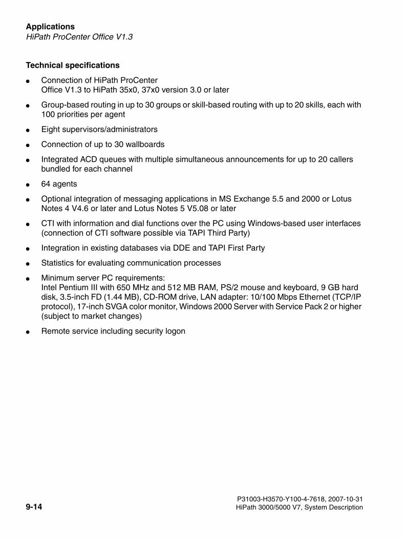
Applications For internal use only
3000sb8.fm
HiPath ProCenter Office V1.3
Technical specifications
● Connection of HiPath ProCenter Office V1.3 to HiPath 35x0, 37x0 version 3.0 or later
● Group-based routing in up to 30 groups or skill-based routing with up to 20 skills, each with 100 priorities per agent
● Eight supervisors/administrators
● Connection of up to 30 wallboards
● Integrated ACD queues with multiple simultaneous announcements for up to 20 callers bundled for each channel
● 64 agents
● Optional integration of messaging applications in MS Exchange 5.5 and 2000 or Lotus Notes 4 V4.6 or later and Lotus Notes 5 V5.08 or later
● CTI with information and dial functions over the PC using Windows-based user interfaces (connection of CTI software possible via TAPI Third Party)
● Integration in existing databases via DDE and TAPI First Party
● Statistics for evaluating communication processes
● Minimum server PC requirements: Intel Pentium III with 650 MHz and 512 MB RAM, PS/2 mouse and keyboard, 9 GB hard disk, 3.5-inch FD (1.44 MB), CD-ROM drive, LAN adapter: 10/100 Mbps Ethernet (TCP/IP protocol), 17-inch SVGA color monitor, Windows 2000 Server with Service Pack 2 or higher (subject to market changes)
● Remote service including security logon
P31003-H3570-Y100-4-7618, 2007-10-319-14 HiPath 3000/5000 V7, System Description
3000sb8.fm
For internal use only ApplicationsHiPath ProCenter Compact V2.0
9.7 HiPath ProCenter Compact V2.0
Medium-sized companies are increasingly calling for options in the simple ACD solutions seg-ment to visualize and evaluate customer call behavior.
For HiPath 3000/5000, HiPath ProCenter Compact represents a professional, cost-effective call-center application that extends the integrated uniform call distribution (UCD) service to in-clude
● supervisor station with real-time reporting
● statistics
● wallboards
for up to 64 active agents.
HiPath ProCenter Compact is operated on a standard PC under Microsoft Windows NT 4 Work-station, 2000 Professional or XP.
HiPath ProCenter Compact is a multi-user application that assigns each user individual rights to use the application and evaluate recorded data.
The integrated administration interface permits the user-friendly configuration of users, classes of service, reports, licenses, etc. A special database backup feature is used to protect custom-er-specific data on the PC against unauthorized evaluation.
Statutory provisions involving data capture and evaluations and subject to the co-determination act are satisfied by implementing a second password for the administration of this data.
9.8 HiPath ComAssistant V1.0
ComAssistant is a server-based CTI solution for the intranet. Software installation and config-uration are performed centrally on the server. User-specific journal data and settings are saved on this server. This totally eliminates the need for client installations. It ensures fast and simple distribution on the intranet.
As the function is offered via HTML pages and HTTP requests, all you need is a Web browser to use ComAssistant from any computer in the intranet.
Even if the user’s PC is deactivated, all journal information relevant to him or her is displayed on the server.
User data backup is performed centrally.
In addition to a key option for integrating the telephony function in own Web pages using HTTP requests, ComAssistant delivers a standard user interface with which all functions can be used.
ComAssistant Rules is the ComAssistant component that performs rule definition and interpre-tation.
P31003-H3570-Y100-4-7618, 2007-10-31HiPath 3000/5000 V7, System Description 9-15
Applications For internal use only
3000sb8.fm
HiPath Xpressions (HiPath Xpressions V3.0/HiPath Xpressions V4.0)
ComAssistant Rules extends the ComAssistant CTI, Exchange (Outlook) or Lotus Notes/Dom-ino functionality to include rules/rule sets for forwarding calls or e-mails and supports user-friendly voice connection.
ComAssistant Rules lets you schedule call forwarding - depending on the importance of the caller - either to the voice info system or the mobile telephone and execute it at a specified time.
ComAssistant consists of four components:
● ComAssistant CTIHiPath ComAssistant CTI is a server-driven application that delivers Web-based telephony functionality on the intranet. HiPath ComAssistant CTI is ideally suited for the integration of CTI in existing intranet solutions.
● ComAssistant RulesComAssistant extends the function of ComAssistant CTI, Exchange (Outlook) or Lotus Notes/Domino to include rules/rule sets for forwarding calls or e-mails and supports user-friendly voice connection.
● ComAssistant DBComAssistant DB is the database for ComAssistant. It is installed as a component of Co-mAssistant Rules and is the basis for all user-specific data.
● ComAssistant GroupComAssistant Group is the groupware component in ComAssistant.This add-on component provides connections for Lotus and Exchange. It must be installed on the groupware computer and run on the Lotus or Exchange Server.
9.9 HiPath Xpressions(HiPath Xpressions V3.0/HiPath Xpressions V4.0)
HiPath Xpressions provides user support for the daily exchange of voice, fax, and e-mail in-formation.
The current location of the user is of no importance here. Flexible telephone- or PC-based ac-cess means that you can operate HiPath Xpressions in the office, from home (for example, as a teleworker) or when travelling (on business trips, at the customer facility, etc.). Groups of per-sons who mainly communication with mobile telephones can use SMS texts (Short Message Service) to keep abreast of new messages, have SMS messages sent to their mobile telephone and access all voice, fax, and e-mail messages. HiPath Xpressions delivers a flexible solution for all user groups in the company.
P31003-H3570-Y100-4-7618, 2007-10-319-16 HiPath 3000/5000 V7, System Description
3000sb8.fm
For internal use only ApplicationsHiPath Xpressions (HiPath Xpressions V3.0/HiPath Xpressions V4.0)
HiPath Xpressions combines the services
● voicemail,
● faxmail,
● e-mail, and
● SMS
on a Windows2000/2003 platform to form a unified messaging system. Thanks to its modular, scalable client/server architecture, this solution can be dimensioned to suit the individual com-munication requirements of your customers. Investment protection for the future is already guaranteed by open standards, integration in existing EDP and telecommunication environ-ments, universal access to messages via PC and telephone, and secure access via ISDN, LAN, and intranet/Internet. You can select requirements-based services, user packages, EDP integrations, and software-only solutions. From small starter packages to networked communi-cation solutions, there is always a HiPath solution tailored to suit the customer’s needs.
HiPath Xpressions is mobile and makes users mobile. This solution lets you configure a sep-arate mailbox for each of your employees. An inbound message received can be signaled not only on the PC but also, if required, at any workstation-based telephone or mobile telephone. The message can be retrieved on the office PC, at home or in a hotel. For the home office to work smoothly, it is also vital that the teleworker has constant access to corporate resources. This is not a problem with HiPath Xpressions.
Your customers can use the Fax-on-Demand supplementary feature at any time, day or night, to retrieve information, such as, current prices, product data, market or weather forecasts. This service allows clever companies to save or even make money.
Unified Messaging
Unified Messaging refers to the integration of voice, fax, e-mail, and SMS services. All personal messages are available for retrieval in a user-specific mailbox. The Internet-oriented function lets you access all IMAP4 clients from your PC (for example, Netscape Communicator or Out-look 2000/XP/2003). No need, therefore, to abandon your familiar user interface. You can op-erate your mailbox very easily over the telephone when on the road.
Unified Messaging is especially attractive to companies that have not yet installed an e-mail system. It means they can avoid this separate investment without foregoing the benefits of a powerful and Internet-capable e-mail component.
The services are also easy to integrate in your existing communication environment. Optimized versions are available for MS Exchange, Lotus Notes, and SAP R/3 (see information on EDP integrations).
P31003-H3570-Y100-4-7618, 2007-10-31HiPath 3000/5000 V7, System Description 9-17
Applications For internal use only
3000sb8.fm
HiPath Xpressions (HiPath Xpressions V3.0/HiPath Xpressions V4.0)
Faxmail and fax applications
All subscribers have a personal, cross-service mailbox with their own DID number for sending and receiving fax messages. This mailbox is password-protected to prevent unauthorized ac-cess.
Fax receiptFax messages that are addressed to a subscriber’s fax number are saved in the subscribers mailbox where they can be retrieved or edited further.
Automatic fax tone recognitionIf call forwarding is active at the workstation telephone, HiPath Xpressions uses the typical function implemented by analog all-in-one telephone/fax machines to check if the call is in fact a fax and, where applicable, switches to fax message acceptance mode.
Deputy ruleAll inbound messages can be automatically forwarded to another station to guarantee that no messages go unprocessed (for example, during a vacation).
Fax viewer/editorIncoming fax messages can be displayed and edited on the PC using a default fax viewer/editor for TIFF or JPEG format or are integrated with HiPath Xpressions Extension for MS Outlook 2000/XP/2003.
Output on LAN printerYou are not obligated to output inbound fax messages on a fax machine. Instead, you can out-put them at any time on a LAN printer. The number of fax machines needed in a company can thus be significantly reduced.
Outputting e-mails as faxesInbound e-mails and convertible attachments can be output as faxes on a random fax device. This means you always have the latest information, even when on the road.
Archive
Incoming fax messages containing important corporate data, for example, are not only sent to the original recipient. A copy of these messages can also be sent to a separate mailbox (for example, for central archival by an external application).
Fax transmission
● Fax coversheet and logoYou can use a subscriber-specific fax coversheet and logo when sending a fax.
● Fragmented fax transmissionIf a fax transmission is interrupted, transmission is resumed from the page on which the interruption occurred. The resumption of an interrupted transmission can be indicated by a configurable marker.
P31003-H3570-Y100-4-7618, 2007-10-319-18 HiPath 3000/5000 V7, System Description
3000sb8.fm
For internal use only ApplicationsHiPath Xpressions (HiPath Xpressions V3.0/HiPath Xpressions V4.0)
● Transmission from an MS Office applicationFax messages can be generated and sent directly from an MS Office application (for ex-ample, MS Word for Windows, MS PowerPoint, etc.).
● Scheduled transmissionThe user can specify when a fax should be sent using the priority levels normal, medium, and high. The periods are assigned priorities centrally and equally for all users.
Fax on DemandFax documents stored in HiPath Xpressions are available for polling as required. Each of the documents provided is assigned a permanent station number. The document is transmitted when this station number is dialed from a fax machine. The caller bears for the connection costs in this type of transmission.
Voicemail
The voicemail application in HiPath Xpressions lets every user receive, save, forward, answer, and comment on voice messages. This interface is provided by the telephone or PC. Fax and e-mail messages can also be output via voicemail. Faxes can be forwarded to a printer or a random fax machine. E-mails can be read out (text to speech).
User promptingAcoustic user prompts guide you through all functions. You can use the Help function to access detailed additional information. When using a digital telephone with Hicom 300 E/300/300 H or HiPath 4000, visual on-screen displays are used to indicate the individual steps in addition to spoken user prompts. You can set the user prompt language at each station for the specified functions. The languages available are: German, British or American English, French, Canadi-an French, Italian, Portuguese, Brazilian Portuguese, Spanish, American Spanish, Turkish, Russian or Dutch. User prompting is available in these languages with a comparable Hicom PhoneMail or Hicom 300 VMS user interface. Every subscriber can use the administration con-sole to set his or her user interface (if this is available in the system).
For external and internal callersYou can redirect calls to your mailbox when you are absent (meeting, business trip, vacation, etc.). A caller hears your personal announcement and can leave a message for your after the signal tone. This also applies if the subscriber’s mailbox limits were reached. If the caller wants to speak directly to another party instead of leaving a message, he or she can set up a connec-tion to a deputy or attendant console, without having to call again.
For mailbox ownersAn announcement is added to the user prompts when you enter the access number in HiPath Xpressions. You must enter a personal station number and password to output existing mes-sages (voice, fax, e-mail) and to send messages, etc.
P31003-H3570-Y100-4-7618, 2007-10-31HiPath 3000/5000 V7, System Description 9-19
Applications For internal use only
3000sb8.fm
HiPath Xpressions (HiPath Xpressions V3.0/HiPath Xpressions V4.0)
PasswordAll saved messages are password-protected. The user can change this at any time. If you re-peatedly enter the wrong password, HiPath Xpressions clears down the connection and, in the case of external callers, sets up a connection to the attendant console.
Receiving messagesYou specify whether the caller should only hear an advisory (advisory function) when you are absent or whether the caller can to leave a message after an announcement (answering ma-chine function).
Visual and acoustic signalingNew inbound messages are visually signaled on digital telephones with display by the illumi-nated mailbox LED and by an announcement when you lift the handset. When you press the mailbox key on digital telephones connected to Hicom 300 E/300/HiPath 4000, a message sig-nals the existence of a message in HiPath Xpressions.
In analog and digital telephones without display, you only hear an acoustic signal. You can re-trieve messages by accessing your mailbox in the usual manner.
Notification serviceYou can arrange for new messages to be signaled by SMS. Every subscriber is free to configure this on a service-specific basis. Voicemail, faxmail, and e-mail are therefore signaled by a short message on your mobile telephone. These settings can be modified at any time at the tele-phone or via the user-friendly Web Administration client.
Listening to messagesYou can play back messages saved on your telephone at any time and anywhere by dialing your mailbox. You can perform fast-forward or rewind operations within a message or insert a pause.
HiPath Xpressions makes a distinction between the various services, such as
● voicemail
● faxmail
as well as the following message queues:
● incoming or undeliverable messages,
● new messages,
● messages that have already been played back,
● messages sent after the HiPath Xpressions connection is ended.
If there is more than one message, you can scroll back and forth until find a particular message.You can select your voice message in your HiPath Xpressions mailbox on your PC and output it via the built-in loudspeakers.
P31003-H3570-Y100-4-7618, 2007-10-319-20 HiPath 3000/5000 V7, System Description
3000sb8.fm
For internal use only ApplicationsHiPath Xpressions (HiPath Xpressions V3.0/HiPath Xpressions V4.0)
Answering/forwarding messages
You can delete, save or edit a message once you have played it back. You can therefore record your answer to an internal subscriber’s question on his or her mailbox without having to redial his or her station number or set up a direct connection to the internal or external sender. The message can also be forwarded to another mailbox owner with a comment. Messages with comments can also be forwarded with comments.
This function is available on the telephone and PC.
Sending messages
● to a recipientYou can forward a recorded message to another user’s mailbox. This is possible from every location and around the clock.
● to a distribution listYou can create personal distribution lists on your PC to send messages to a specific circle of recipients. Each distribution list can contain up to 99 station numbers. Central distribu-tion lists can also be configured for all mailbox owners.
Creating messagesA voice message can be recorded and sent not only from the telephone but also from the PC.
Personal announcements/central announcements
● Personal announcement (greeting)Every mailbox owner can record his or her personal name announcement; otherwise, the station number of the station dialed is output by default. In addition, you can choose between nine personal announcements. The user can assign these personal announcements to the following call situations depending on the time:
– alternative announcement (used for internal and external callers)
– announcement for internal callers
– announcement for external callers
– announcement on busy
If you did not activate the personal announcement, the system announcement is used by default and the caller can then leave his or her message.
● Central announcementIn addition to the personal greetings, you can create central announcements that are valid for all users.
P31003-H3570-Y100-4-7618, 2007-10-31HiPath 3000/5000 V7, System Description 9-21
Applications For internal use only
3000sb8.fm
HiPath Xpressions (HiPath Xpressions V3.0/HiPath Xpressions V4.0)
Auto Attendant
The Auto Attendant function is provided to improve customer availability. After listening to the greeting and list of options available, a caller can either select a more qualified contact, set up a direct telephone connection to the selected contact or choose automatic connection to the attendant console.
9.9.1 HiPath Xpressions Compact V2.0
HiPath Xpressions Compact is a system for operating voice mailboxes with different capabilities with the AutoAttendant function (menu-driven call processing). The system is designed as a plug-in card for operation in Hicom 150/HiPath 3000 communication systems. System admin-istration is performed with HiPath 3000 Manager C or HiPath 3000 Manager E.
HiPath Xpressions Compact V2.0 features the following individual functions:
● Depending on the HiPath Xpressions Compact V2.0 system type and product variant, up to 8 or 24 ports, that is, up to 8 or 24 parallel attendant console and answering machine operations.
● 100 hours voice recording capacity.
● Two telephone user interfaces; the standard interface corresponds to the interface in ver-sion 1.0. The second interface is the Xpressions interface which has the same key layout as the Xpressions V3.0 interface (same key for same function).
● The HiPath 3000 multi-customer function is supported (for example, in incubators with a common telephone system).
● 3/8/20 minutes maximum announcement length per voice mailbox, depending on the mail-box type.
● Scheduled notification call after receiving a new voice message,either as a telephone call, as a pager message* or as an SMS* (Short Message Service)(DTMF suffix-dialing only)
● Classification of messages, answers and comments as private, urgent, and normal.
● Date and time stamp for every message.
● Distribution of messages to all mailboxes (broadcast) or distribution lists.
● Option for calling back callers who left a message (CLIP service necessary).
● Automatic deletion of old voice messages after a preset interval.
● Alternative greetings depending on time of day, call type or calendar.
P31003-H3570-Y100-4-7618, 2007-10-319-22 HiPath 3000/5000 V7, System Description
3000sb8.fm
For internal use only ApplicationsPhone Mail LDN (Long Distance Network)
● AutoAttendant (automatic call pickup, greeting and switching, day/night service). This in-volves: name-based speed dialing possible for call forwarding.
● Automatic fax tone recognition and forwarding of faxes to a mailbox-specific fax destina-tion.
● Context-sensitive telephone-based mailbox administration by the user.
● Playback of professionally recorded greetings over HiPath 3000 Manager.
● Music on hold with endless loop.
● Playback of individual announcements (for example, for internal call distribution (UCD)).
● Group mailboxes with up to 20 stations.
● Information mailboxes with 20-minute announcement. Endless playback and navigation possible in the announcement text.
9.10 Phone Mail LDN (Long Distance Network)
HiPath Phone Mail is the user-friendly starter package for the voice messaging product seg-ment.
The key features of HiPath PhoneMail are
● receiving, saving, forwarding, answering, and commenting on voice messages, sending own voice messages to stations
● auto attendant with DTMF suffix-dialing and fax dial tone recognition
● automatic call acceptance/announcements before answering
● automatic info services
>HiPath Xpressions Compact supports a central voicemail functionality in a HiPath 3000/5000 network. All stations can use the central voicemail server. It cannot be used as a central announcement device in a network.
P31003-H3570-Y100-4-7618, 2007-10-31HiPath 3000/5000 V7, System Description 9-23
Applications For internal use only
3000sb8.fm
HiPath SimplyPhone for Outlook V3.1 and HiPath SimplyPhone for Notes V3.1 and V4.0
9.11 HiPath SimplyPhone for Outlook V3.1 and HiPath SimplyPhone for Notes V3.1 and V4.0
HiPath SimplyPhone is ideally suited for workstations that use Lotus Notes or Outlook 98 as a universal communication and organization tool.
Telephone calls can be saved in Lotus Notes documents. In the case of inbound calls, the call-ing party is recognized in Lotus Notes/Domino address books or global LDAP address books (MetaDirectory).
Direct calling via menu is possible with entries from Lotus Notes view, personal address books and Domino directories, journal and e-mail databases. It is also possible to search for a station in the personal address book, Domino directory and the global LDAP address books (MetaDi-rectory), and then choose from the stations found.
HiPath SimplyPhone for Lotus Notes 3.1 is a CTI client based on the Microsoft telephone inter-face TAPI and can be used with various TAPI Service Providers.
HiPath SimplyPhone for Lotus Notes 3.1 enhances the available Microsoft Outlook 2000 or 98 functions with convenient telephone functions, such as, consultation hold, conference, ring no answer, toggle, call forwarding and the following CTI features:
● Calling entries from Lotus Notes view, personal address books and Domino directories, journal and e-mail databases.
● Caller identification from Lotus Notes personal address books and Domino directories or global LDAP address books (MetaDirectory).
● Call logging in Lotus Notes documents.
● Call planning and callback list in Lotus Notes mail/journal database. E-mail notification in the case of forwarded or transferred calls.
P31003-H3570-Y100-4-7618, 2007-10-319-24 HiPath 3000/5000 V7, System Description
3000sb8.fm
For internal use only ApplicationsHiPath Hospitality Service Center Compact V2.0
9.12 HiPath Hospitality Service Center Compact V2.0
The HiPath Hospitality Service Center is an intelligent CRM solution that can perfectly simulate and implement service operations in hotels. HHSC was specially developed for the needs of the service-oriented hospitality industry. It is a conceptual breakthrough in the integration of communication services and service control for guests. This innovative solutions helps hotels to reflect their business strategy in consistent guest services and to increase profitability.
Features
● Work process optimization through the integration of telephone switches and software ap-plications
● Intuitive, customized interface for the hospitality industry
● Service tracking to trace customer wishes from request to satisfaction
● Reporting functions for effective personnel management (including a more flexible definition of key performance indicators)
● Provision of large volumes of information and statistics for Hotel Management
● Intelligent routing functions to automatically increase capacities during peak hours
● Facility Monitoring and the emergency module for effective facility management and active security
● Service center shared by multiple facilities to maximize savings
9.13 HiPath Hospitality Service Center Business V2.0
See Section 9.12, "HiPath Hospitality Service Center Compact V2.0"
9.14 HiPath Hotel Standard V4.1
Communication solution for hotels and residential homes for the elderly
HiPath Hotel Standard is a PC-based hotel solution for small and medium-sized hotels and res-idential homes for the elderly (serviced apartments with hotel-like character) with up to 250 rooms as standalone or multi-station system. The Windows interface is intuitive and easy to use. In connection with the communication platform, work routines are accelerated, duplicated activities are avoided, and perfect service is guaranteed.
The most important functions of HiPath Hotel Standard:
● Check-in with capture assistant, group check-in
● Check-out with billing assistant
P31003-H3570-Y100-4-7618, 2007-10-31HiPath 3000/5000 V7, System Description 9-25
Applications For internal use only
3000sb8.fm
HiPath Hotel Advanced V4.2
● Relocation function with capture assistant
● Billing assistant for flexible DTMF control of billing
● Printout of guest bill with conversion of the total in additional currencies (for example, euro)
● Generation of interim bills
● Name entry for caller identification
● Telephone charge recording and system evaluation
● Flexible telephone/telephone booth and Cordless assignment
● Automatic wake-up service with wake-up time recording at the telephone and in the front office
● Room status management
● Management of room category prices and day-specific supplement factors
● Management of measurement periods for graphic visualization
● Telephone-based recording of minibar use
● Service booking
● Message administration with automatic control of the message waiting lamp
● Advanced input masks for residential homes for the elderly
● Interface to health insurance billing systems
● Automatic/manual telephone charge billing at the end of the month
● Monthly bill output
● Prepayment
9.15 HiPath Hotel Advanced V4.2
Communication interface for hotel EDP systems
HiPath Hotel Advanced is an intelligent solution that broadens the range of communication plat-form features available for the hotel’s front-office area and therefore increases the interaction between both systems. This reduces staff workloads and increases guest comfort.
HiPath Hotel Advanced is available for all Siemens communication systems.
This solution is also advantageous for F/O-system manufacturers, as it offers a simple, uniform hotel interface. The protocol description is disclosed and made available to every F/O-solution supplier.
P31003-H3570-Y100-4-7618, 2007-10-319-26 HiPath 3000/5000 V7, System Description
3000sb8.fm
For internal use only ApplicationsHiPath Accounting Management V2.0
This standard hotel interface offers the following features:
● Check-in/check-out with COS activation/deactivation
● Name entry for caller identification
● Call charge calculation
● Wake-up service entry
● Room status entry
● Minibar status entry
● Message receipt (message waiting LED)
● Do not disturb
● Administration of virtual station numbers
Advanced options, such as
● wake-up module
● voicemail module
● fax module
● or special call charge management software
are also integrated.
HiPath Hotel Advanced is intended for hotels that already have a conventional front-office sys-tem and want to connect this to a communication system.
9.16 HiPath Accounting Management V2.0
Concept and functions
The need for standardized and simple administration increases as data and voice networks converge and at the same time grow in complexity.
HiPath Management is therefore a key component in the HiPath architecture. It supports Hi-Path component administration with User Management, calculates and bills communication costs based on use with Accounting Management, increases HiPath component availability and failure tolerance with Fault Management, and offers a wide range of supportive functions to secure the cost-effective operation of communication systems or networks. Transactions can be rapidly processed at any time and from any location thanks to this solution’s object-oriented and modular structure and its use of Web browsers and standard interfaces for access, for ex-ample, interfaces for Directory Access. This all leads to short response times and lower admin-istration costs. Tasks are executed quickly and without difficulty.
P31003-H3570-Y100-4-7618, 2007-10-31HiPath 3000/5000 V7, System Description 9-27
Applications For internal use only
3000sb8.fm
HiPath Accounting Management V2.0
The modular concept guarantees the correct combination of applications and functions for ev-ery HiPath network and provides long-terms investment protection for communication infra-structure.
HiPath AM system functions
Collecting AgentThe communication data (CDR Call Detail Records) provided by the individual communication systems in the network is collected by Collecting Agents (HiPath AM components), filtered, and submitted to Accounting Management for further processing.
Data storage/archivingThe communication data is organized in a database as monthly or daily files for better perfor-mance. An archive function can be used to export communication and organization data to disks or streamers for a selected period. You can restore one or more archives for evaluation or re-search.
User/rights managementEvery user can be assigned individual access rights depending his or her tasks. The user IDs are managed with their various classes of service and passwords by the system.
Master data administration in HiPath AM
Access over administrator workstationMaster data which includes organization charts divided into eight hierarchical levels, exten-sions, cost centers, PIN/account codes, tariffs, and a wide range of other data can be individ-ually configured, modified, and deleted. Similarly, import and synchronization is possible with the HDMS/CM-Win or HiPath 4000 Manager/Assistant data.
Web-based accessAuthorized users can use Web Access to configure and edit the organization chart without syn-chronization with HDMS/CM-Win or HiPath 4000 Manager/Assistant. Classes of service are in-dividually configured for each Web Access user. This allows you to make a clear distinction be-tween those organizations that can be seen and those that can be edited.
HiPath AM system backupAll important activities performed on the system are recorded in a logfile.A alarm message is signaled if no call data is transferred within a set interval.A Watchdog tool lets you monitor a wide range of different HiPath AM processes. If one of the monitored processes reports an alarm, you can forward it via e-mail or pager to another person.
Cost and price calculation
Cost/price differentiationParallel cost billing is possible for controlling service provider costs and calculating prices for further internal and external charging.
P31003-H3570-Y100-4-7618, 2007-10-319-28 HiPath 3000/5000 V7, System Description
3000sb8.fm
For internal use only ApplicationsHiPath Accounting Management V2.0
Transfer/individual calculationCosts/prices can be obtained from the communication system data record or calculated using individual tariff tables (optional). These can be entered with eight decimal places so that even per-second billing prices can be calculated with adequate accuracy.
Export/import of tariff tablesOnce defined, tariff tables can be exported and then imported into another installation.
RecalculationYou can recalculate existing connection data for a selectable period with new prices or modified organizational assignments.
Reports
Report layout/filterThe connection data saved can be evaluated using predefined system reports, as well as user-defined and generated own reports in tabular and graphical form.
Report layout can be freely defined or supplemented.Sophisticated filter functions (period, day/business hours, call types, extensions, and organiza-tion units, PIN/account codes and their groups, trunks, cost centers, limits, other CDR fields and attributes) permit the selection of required data.
Report outputOutputs are performed at the printer (local, network), file (local, network, e-mail) and on the screen (preview). Immediate creation and output, as well as scheduler functions can be initiated.
Web Access
Reporting over the Internet/intranetEvaluations and reports can be created on the Web with the Web Access application. Classes of service are individually configured for each Web Access user. You can use these classes of service to define which reports and which data each user is permitted to view. Interactive and graphical overview reports can be broken down/zoomed to provide a quick overview and spe-cific evaluations of the required organization units.
P31003-H3570-Y100-4-7618, 2007-10-31HiPath 3000/5000 V7, System Description 9-29
Applications For internal use only
3000sb8.fm
HiPath Fault Management V2.0
9.17 HiPath Fault Management V2.0
HiPath FM provides ideal support for the primary requirements of failsafe communication.
It does not matter:
● if communication is data- or voice-based,
● which type of infrastructure is used for communication, that is, line, LAN or wireless,
● if terminals, systems, servers or complex solutions, such as, call centers and other appli-cations should be monitored,
● if these are small networks or an international network topology with several hundred stan-dalone systems in different network domains.
HiPath FM signals the first signs of a fault in a clear graphic fault management component with fault priority and location information. It also display a wide range of additional information that can be used for immediate fault correction. And all this long before the network stations notice the effects of interference.
HiPath FM can be used to monitor communication resources even without comprehensive ex-pert know-how using a simple graphical user interface and wide-ranging support functions.
HiPath FM is programmed in Java meaning it runs on almost all conventional operating sys-tems and computer platforms. Internet access with Web browsers guarantee mobility for the user.
HiPath FM thus plays a very significant role in guaranteeing that the communication network operates securely and that your company maintains its competitive edge.
HiPath FM can be integrated via Materna GmbH gateways as well as in the umbrella manage-ment systems HP OpenView and IBM Tivoli NetView and in the process management system "Action Request".
System functions
Client/server architectureThe server manages all information and the logged-on clients. It monitors access to the man-aged objects. The client provides a graphic representation of the information managed in the server.
P31003-H3570-Y100-4-7618, 2007-10-319-30 HiPath 3000/5000 V7, System Description
3000sb8.fm
For internal use only ApplicationsHiPath Fault Management V2.0
Client accessAccess to the HiPath FM client is possible both with a Java standalone application and Web browsers. As a result, the application can be operated from almost every location.
Single Point of Access (SpoA)Provides access to the other applications of the individual element managers, for example, to perform configuration changes in the communication systems.
Platform independenceThe Java-based HiPath FM software permits operation on a large number of hardware and op-erating system platforms.
System administration
Managed objectsOnce the network elements have been automatically detected in a network domain, you can select which of the elements should be monitored with HiPath FM.The network elements monitored by HiPath FM are administered in the server as managed ob-jects using selected attributes. Administration covers not only the various network nodes, but also the connections between these.
User administrationUser access to the information saved in the server is protected by login and password. The graphic user administration unit simplifies user configuration, modification, and deletion.
Rights managementEvery user can be assigned individual access rights depending his or her tasks. Six user pro-files with permanently defined rights are predefined for added simplicity.
P31003-H3570-Y100-4-7618, 2007-10-31HiPath 3000/5000 V7, System Description 9-31
Applications For internal use only
3000sb8.fm
TeleData Office V3.0
9.18 TeleData Office V3.0
Cost management for your voice and data communication
Teledata Office version 3.0 can record communication data at the technical source (Hicom®/HG 1500) or read it in via electronic data exchange (mobile telephony) and calculate the asso-ciated costs. The resulting costs for fixed-network, Internet, and mobile communication are en-crypted on the basis of the user.
To make sure that this does not incur administration expenses, the user administration compo-nent in Teledata Office version 3.0 learns all communication addresses itself. The communica-tion addresses recorded in this way now only have to be assigned to a user.
The circle is thereby closed: professional Internet-age software guarantees provider-indepen-dent user data recording and transparency, even in the smallest cost center.
Corporate communications controlling
Controlling starts with examinations. Is the telephone bill correct? Where were the costs in-curred? The objectives of cost-effective management are therefore transparency and unique allocation of costs to cause. In addition to ongoing operating costs, the duration and purpose of communication operations are also important. After all, the time spent by the user on com-munication also costs money.
Communication infrastructure performance is another cost aspect. Every jump to higher band-width needed on account of exhausted network load always results in heavy investment in new hardware. A detailed inspection of utilization mitigates the migration pressure and saves costs.
P31003-H3570-Y100-4-7618, 2007-10-319-32 HiPath 3000/5000 V7, System Description
3000sb9.fm
For internal use only CapacitiesCapacities of HiPath Systems
10 Capacities
10.1 Capacities of HiPath Systems
Guide to the table:
The values listed are maximum values.
The "networked" column refers to systems with 2000 stations.
N/A: not applicable
"=": Not dependant on the size of the network. The capacity of Vulcan standalone systems ap-plies.
"+": The network requirement is the total capacity of the individual nodes or systems in the net-work.
The numbering format xx/yy/zz means valid for: Pro&ELS&SAPP/Com/Point (= HiPath 3800/37x0/35x0/33x0)
The HiPath 3000 capacities outlined in the table apply to HiPath 3800. Capacities for HiPath 35x0/33x0 may differ from these values.
There is no version 7 of the systems HiPath 3700 and 3750..
Parameter HiPath 3700 V3.01
HiPath 3700 V4.0 standalone1
HiPath 3000 V5.0/V6.0/V7 standalone
HiPath 5000 V5.0/V6.0/V7 (ComScendo Service)
HiPath 3000/5000 net-worked
Agents
Agent IDs in system
150 150 50 500 =
Agents active simultaneous-ly in system
32 32 32 64 =
Direct trunk access
Number of al-lowed lists
6 6 6 6 =
Number of de-nied lists
6 6 6 6 =
P31003-H3570-Y100-4-7618, 2007-10-31HiPath 3000/5000 V7, System Description 10-1
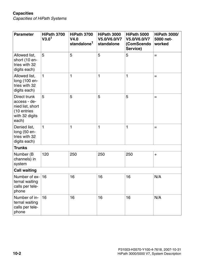
Capacities For internal use only
3000sb9.fm
Capacities of HiPath Systems
Allowed list, short (10 en-tries with 32 digits each)
5 5 5 5 =
Allowed list, long (100 en-tries with 32 digits each)
1 1 1 1 =
Direct trunk access - de-nied list, short (10 entries with 32 digits each)
5 5 5 5 =
Denied list, long (50 en-tries with 32 digits each)
1 1 1 1 =
Trunks
Number (B channels) in system
120 250 250 250 +
Call waiting
Number of ex-ternal waiting calls per tele-phone
16 16 16 16 N/A
Number of in-ternal waiting calls per tele-phone
16 16 16 16 N/A
Parameter HiPath 3700 V3.01
HiPath 3700 V4.0 standalone1
HiPath 3000 V5.0/V6.0/V7 standalone
HiPath 5000 V5.0/V6.0/V7 (ComScendo Service)
HiPath 3000/5000 net-worked
P31003-H3570-Y100-4-7618, 2007-10-3110-2 HiPath 3000/5000 V7, System Description
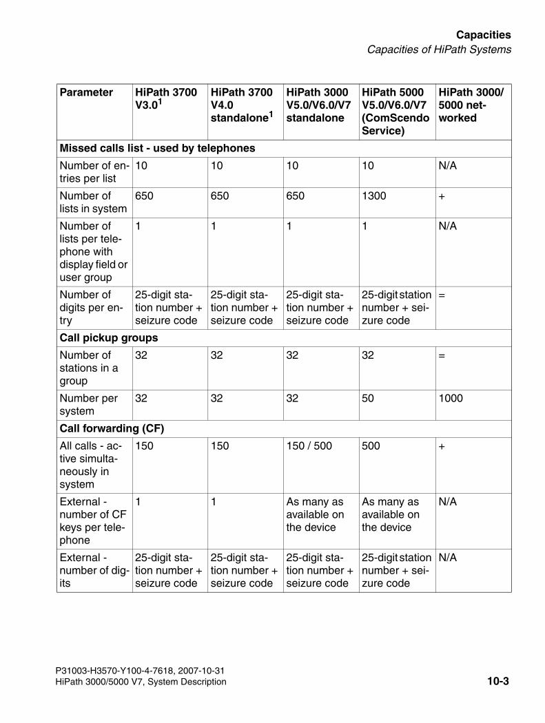
3000sb9.fm
For internal use only CapacitiesCapacities of HiPath Systems
Missed calls list - used by telephones
Number of en-tries per list
10 10 10 10 N/A
Number of lists in system
650 650 650 1300 +
Number of lists per tele-phone with display field or user group
1 1 1 1 N/A
Number of digits per en-try
25-digit sta-tion number + seizure code
25-digit sta-tion number + seizure code
25-digit sta-tion number + seizure code
25-digit station number + sei-zure code
=
Call pickup groups
Number of stations in a group
32 32 32 32 =
Number per system
32 32 32 50 1000
Call forwarding (CF)
All calls - ac-tive simulta-neously in system
150 150 150 / 500 500 +
External - number of CF keys per tele-phone
1 1 As many as available on the device
As many as available on the device
N/A
External - number of dig-its
25-digit sta-tion number + seizure code
25-digit sta-tion number + seizure code
25-digit sta-tion number + seizure code
25-digit station number + sei-zure code
N/A
Parameter HiPath 3700 V3.01
HiPath 3700 V4.0 standalone1
HiPath 3000 V5.0/V6.0/V7 standalone
HiPath 5000 V5.0/V6.0/V7 (ComScendo Service)
HiPath 3000/5000 net-worked
P31003-H3570-Y100-4-7618, 2007-10-31HiPath 3000/5000 V7, System Description 10-3
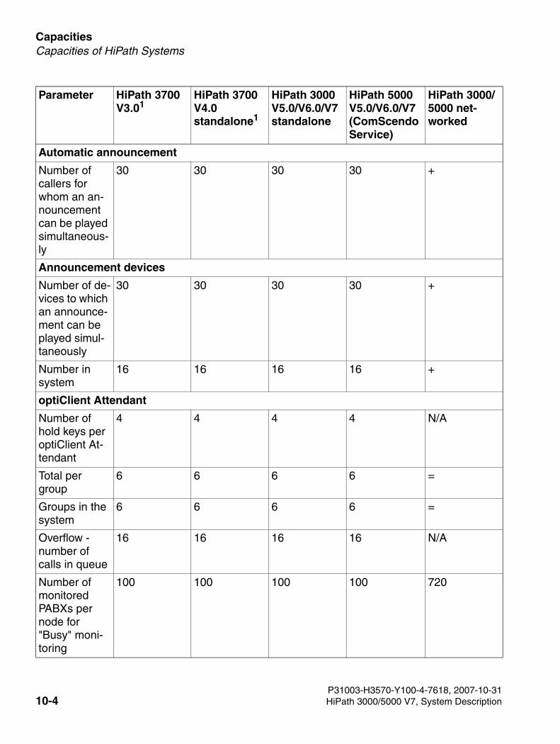
Capacities For internal use only
3000sb9.fm
Capacities of HiPath Systems
Automatic announcement
Number of callers for whom an an-nouncement can be played simultaneous-ly
30 30 30 30 +
Announcement devices
Number of de-vices to which an announce-ment can be played simul-taneously
30 30 30 30 +
Number in system
16 16 16 16 +
optiClient Attendant
Number of hold keys per optiClient At-tendant
4 4 4 4 N/A
Total per group
6 6 6 6 =
Groups in the system
6 6 6 6 =
Overflow - number of calls in queue
16 16 16 16 N/A
Number of monitored PABXs per node for "Busy" moni-toring
100 100 100 100 720
Parameter HiPath 3700 V3.01
HiPath 3700 V4.0 standalone1
HiPath 3000 V5.0/V6.0/V7 standalone
HiPath 5000 V5.0/V6.0/V7 (ComScendo Service)
HiPath 3000/5000 net-worked
P31003-H3570-Y100-4-7618, 2007-10-3110-4 HiPath 3000/5000 V7, System Description
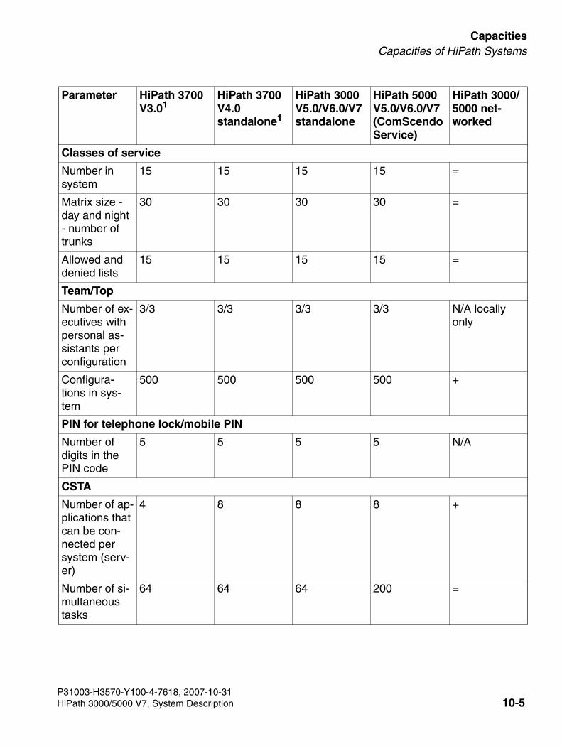
3000sb9.fm
For internal use only CapacitiesCapacities of HiPath Systems
Classes of service
Number in system
15 15 15 15 =
Matrix size - day and night - number of trunks
30 30 30 30 =
Allowed and denied lists
15 15 15 15 =
Team/Top
Number of ex-ecutives with personal as-sistants per configuration
3/3 3/3 3/3 3/3 N/A locally only
Configura-tions in sys-tem
500 500 500 500 +
PIN for telephone lock/mobile PIN
Number of digits in the PIN code
5 5 5 5 N/A
CSTA
Number of ap-plications that can be con-nected per system (serv-er)
4 8 8 8 +
Number of si-multaneous tasks
64 64 64 200 =
Parameter HiPath 3700 V3.01
HiPath 3700 V4.0 standalone1
HiPath 3000 V5.0/V6.0/V7 standalone
HiPath 5000 V5.0/V6.0/V7 (ComScendo Service)
HiPath 3000/5000 net-worked
P31003-H3570-Y100-4-7618, 2007-10-31HiPath 3000/5000 V7, System Description 10-5
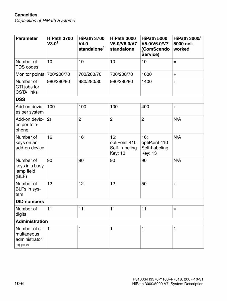
Capacities For internal use only
3000sb9.fm
Capacities of HiPath Systems
Number of TDS codes
10 10 10 10 =
Monitor points 700/200/70 700/200/70 700/200/70 1000 +
Number of CTI jobs for CSTA links
980/280/80 980/280/80 980/280/80 1400 +
DSS
Add-on devic-es per system
100 100 100 400 +
Add-on devic-es per tele-phone
2) 2 2 2 N/A
Number of keys on an add-on device
16 16 16; optiPoint 410 Self-Labeling Key: 13
16; optiPoint 410 Self-Labeling Key: 13
N/A
Number of keys in a busy lamp field (BLF)
90 90 90 90 N/A
Number of BLFs in sys-tem
12 12 12 50 +
DID numbers
Number of digits
11 11 11 11 =
Administration
Number of si-multaneous administrator logons
1 1 1 1 1
Parameter HiPath 3700 V3.01
HiPath 3700 V4.0 standalone1
HiPath 3000 V5.0/V6.0/V7 standalone
HiPath 5000 V5.0/V6.0/V7 (ComScendo Service)
HiPath 3000/5000 net-worked
P31003-H3570-Y100-4-7618, 2007-10-3110-6 HiPath 3000/5000 V7, System Description
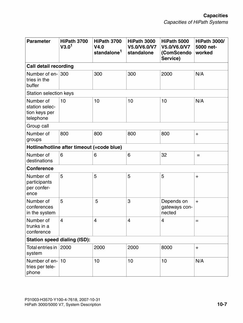
3000sb9.fm
For internal use only CapacitiesCapacities of HiPath Systems
Call detail recording
Number of en-tries in the buffer
300 300 300 2000 N/A
Station selection keys
Number of station selec-tion keys per telephone
10 10 10 10 N/A
Group call
Number of groups
800 800 800 800 +
Hotline/hotline after timeout (=code blue)
Number of destinations
6 6 6 32 =
Conference
Number of participants per confer-ence
5 5 5 5 +
Number of conferences in the system
5 5 3 Depends on gateways con-nected
+
Number of trunks in a conference
4 4 4 4 =
Station speed dialing (ISD):
Total entries in system
2000 2000 2000 8000 +
Number of en-tries per tele-phone
10 10 10 10 N/A
Parameter HiPath 3700 V3.01
HiPath 3700 V4.0 standalone1
HiPath 3000 V5.0/V6.0/V7 standalone
HiPath 5000 V5.0/V6.0/V7 (ComScendo Service)
HiPath 3000/5000 net-worked
P31003-H3570-Y100-4-7618, 2007-10-31HiPath 3000/5000 V7, System Description 10-7
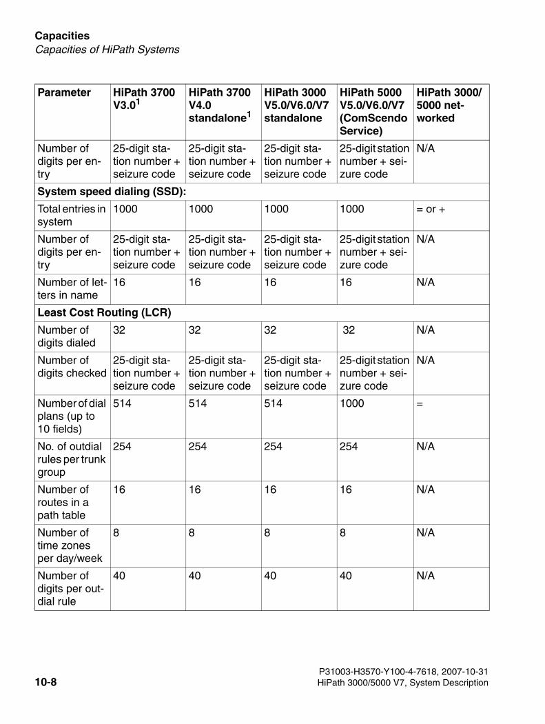
Capacities For internal use only
3000sb9.fm
Capacities of HiPath Systems
Number of digits per en-try
25-digit sta-tion number + seizure code
25-digit sta-tion number + seizure code
25-digit sta-tion number + seizure code
25-digit station number + sei-zure code
N/A
System speed dialing (SSD):
Total entries in system
1000 1000 1000 1000 = or +
Number of digits per en-try
25-digit sta-tion number + seizure code
25-digit sta-tion number + seizure code
25-digit sta-tion number + seizure code
25-digit station number + sei-zure code
N/A
Number of let-ters in name
16 16 16 16 N/A
Least Cost Routing (LCR)
Number of digits dialed
32 32 32 32 N/A
Number of digits checked
25-digit sta-tion number + seizure code
25-digit sta-tion number + seizure code
25-digit sta-tion number + seizure code
25-digit station number + sei-zure code
N/A
Number of dial plans (up to 10 fields)
514 514 514 1000 =
No. of outdial rules per trunk group
254 254 254 254 N/A
Number of routes in a path table
16 16 16 16 N/A
Number of time zones per day/week
8 8 8 8 N/A
Number of digits per out-dial rule
40 40 40 40 N/A
Parameter HiPath 3700 V3.01
HiPath 3700 V4.0 standalone1
HiPath 3000 V5.0/V6.0/V7 standalone
HiPath 5000 V5.0/V6.0/V7 (ComScendo Service)
HiPath 3000/5000 net-worked
P31003-H3570-Y100-4-7618, 2007-10-3110-8 HiPath 3000/5000 V7, System Description
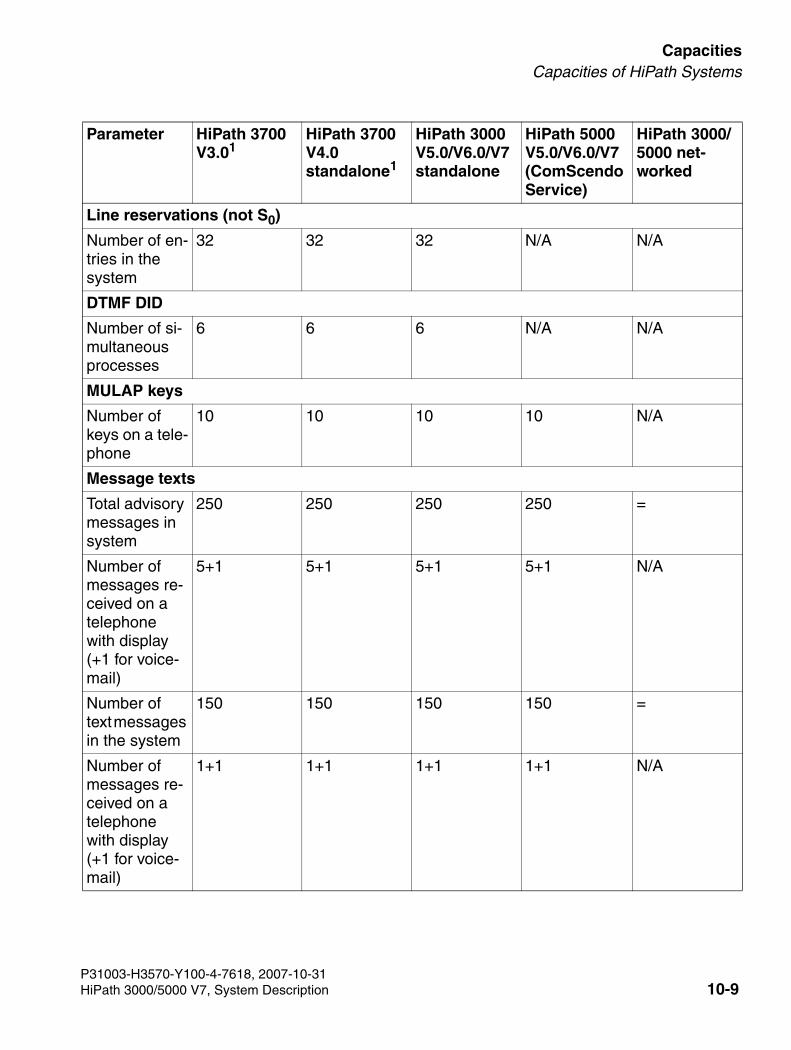
3000sb9.fm
For internal use only CapacitiesCapacities of HiPath Systems
Line reservations (not S0)
Number of en-tries in the system
32 32 32 N/A N/A
DTMF DID
Number of si-multaneous processes
6 6 6 N/A N/A
MULAP keys
Number of keys on a tele-phone
10 10 10 10 N/A
Message texts
Total advisory messages in system
250 250 250 250 =
Number of messages re-ceived on a telephone with display (+1 for voice-mail)
5+1 5+1 5+1 5+1 N/A
Number of text messages in the system
150 150 150 150 =
Number of messages re-ceived on a telephone with display (+1 for voice-mail)
1+1 1+1 1+1 1+1 N/A
Parameter HiPath 3700 V3.01
HiPath 3700 V4.0 standalone1
HiPath 3000 V5.0/V6.0/V7 standalone
HiPath 5000 V5.0/V6.0/V7 (ComScendo Service)
HiPath 3000/5000 net-worked
P31003-H3570-Y100-4-7618, 2007-10-31HiPath 3000/5000 V7, System Description 10-9
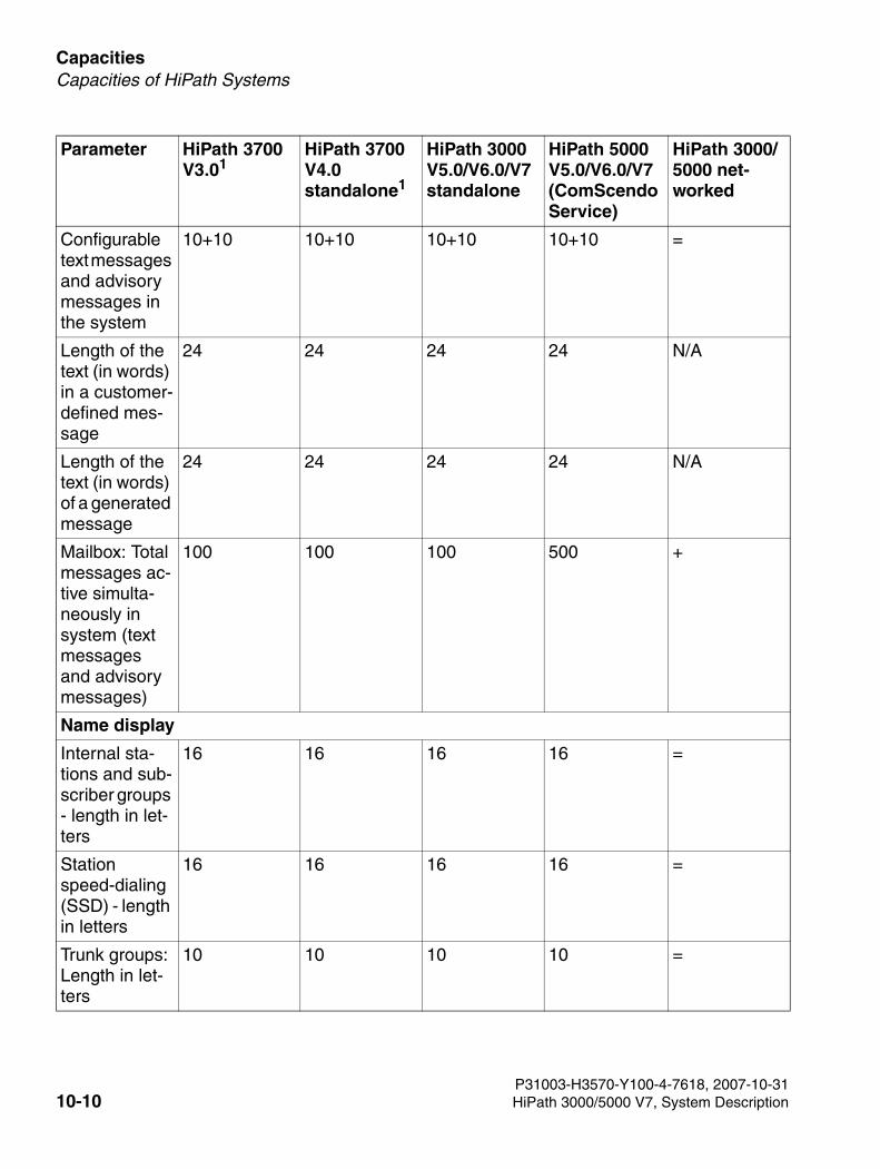
Capacities For internal use only
3000sb9.fm
Capacities of HiPath Systems
Configurable text messages and advisory messages in the system
10+10 10+10 10+10 10+10 =
Length of the text (in words) in a customer-defined mes-sage
24 24 24 24 N/A
Length of the text (in words) of a generated message
24 24 24 24 N/A
Mailbox: Total messages ac-tive simulta-neously in system (text messages and advisory messages)
100 100 100 500 +
Name display
Internal sta-tions and sub-scriber groups - length in let-ters
16 16 16 16 =
Station speed-dialing (SSD) - length in letters
16 16 16 16 =
Trunk groups: Length in let-ters
10 10 10 10 =
Parameter HiPath 3700 V3.01
HiPath 3700 V4.0 standalone1
HiPath 3000 V5.0/V6.0/V7 standalone
HiPath 5000 V5.0/V6.0/V7 (ComScendo Service)
HiPath 3000/5000 net-worked
P31003-H3570-Y100-4-7618, 2007-10-3110-10 HiPath 3000/5000 V7, System Description
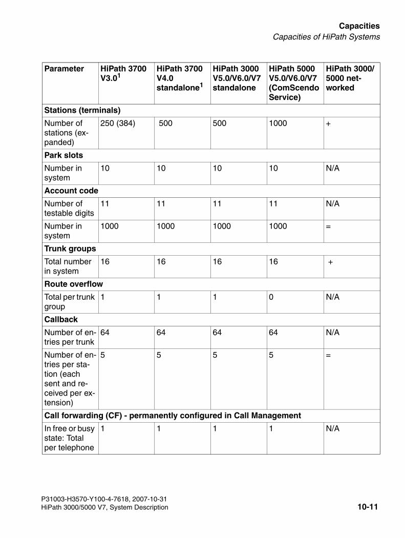
3000sb9.fm
For internal use only CapacitiesCapacities of HiPath Systems
Stations (terminals)
Number of stations (ex-panded)
250 (384) 500 500 1000 +
Park slots
Number in system
10 10 10 10 N/A
Account code
Number of testable digits
11 11 11 11 N/A
Number in system
1000 1000 1000 1000 =
Trunk groups
Total number in system
16 16 16 16 +
Route overflow
Total per trunk group
1 1 1 0 N/A
Callback
Number of en-tries per trunk
64 64 64 64 N/A
Number of en-tries per sta-tion (each sent and re-ceived per ex-tension)
5 5 5 5 =
Call forwarding (CF) - permanently configured in Call Management
In free or busy state: Total per telephone
1 1 1 1 N/A
Parameter HiPath 3700 V3.01
HiPath 3700 V4.0 standalone1
HiPath 3000 V5.0/V6.0/V7 standalone
HiPath 5000 V5.0/V6.0/V7 (ComScendo Service)
HiPath 3000/5000 net-worked
P31003-H3570-Y100-4-7618, 2007-10-31HiPath 3000/5000 V7, System Description 10-11
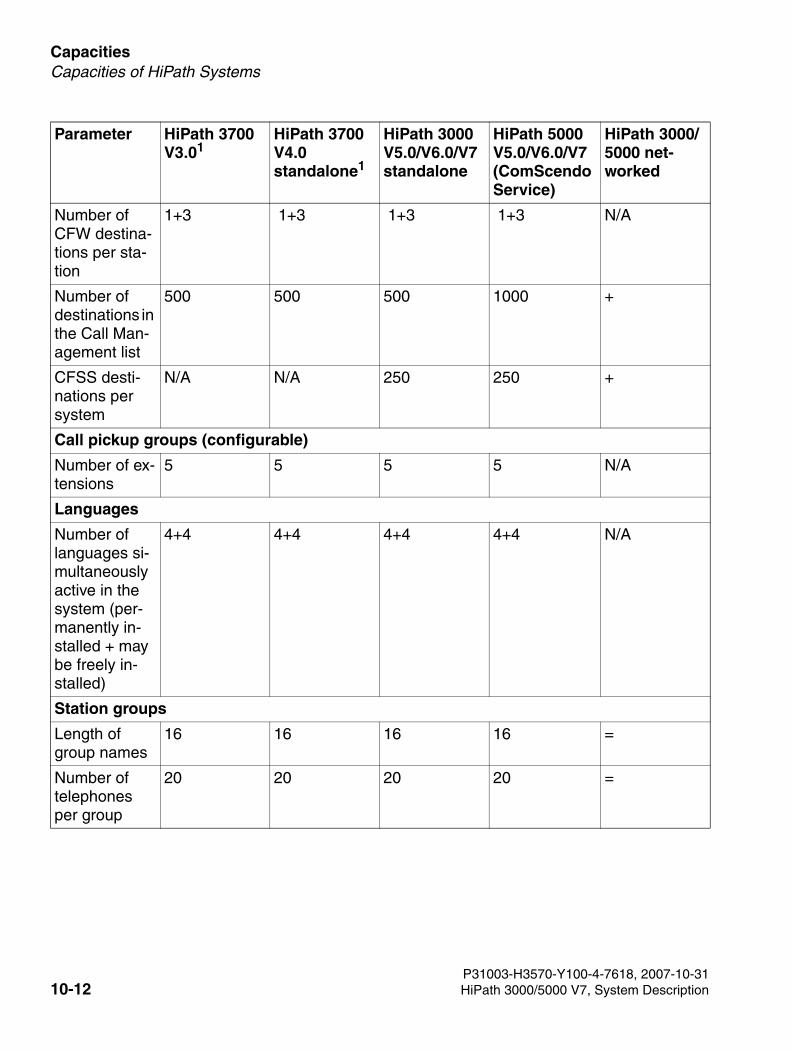
Capacities For internal use only
3000sb9.fm
Capacities of HiPath Systems
Number of CFW destina-tions per sta-tion
1+3 1+3 1+3 1+3 N/A
Number of destinations in the Call Man-agement list
500 500 500 1000 +
CFSS desti-nations per system
N/A N/A 250 250 +
Call pickup groups (configurable)
Number of ex-tensions
5 5 5 5 N/A
Languages
Number of languages si-multaneously active in the system (per-manently in-stalled + may be freely in-stalled)
4+4 4+4 4+4 4+4 N/A
Station groups
Length of group names
16 16 16 16 =
Number of telephones per group
20 20 20 20 =
Parameter HiPath 3700 V3.01
HiPath 3700 V4.0 standalone1
HiPath 3000 V5.0/V6.0/V7 standalone
HiPath 5000 V5.0/V6.0/V7 (ComScendo Service)
HiPath 3000/5000 net-worked
P31003-H3570-Y100-4-7618, 2007-10-3110-12 HiPath 3000/5000 V7, System Description
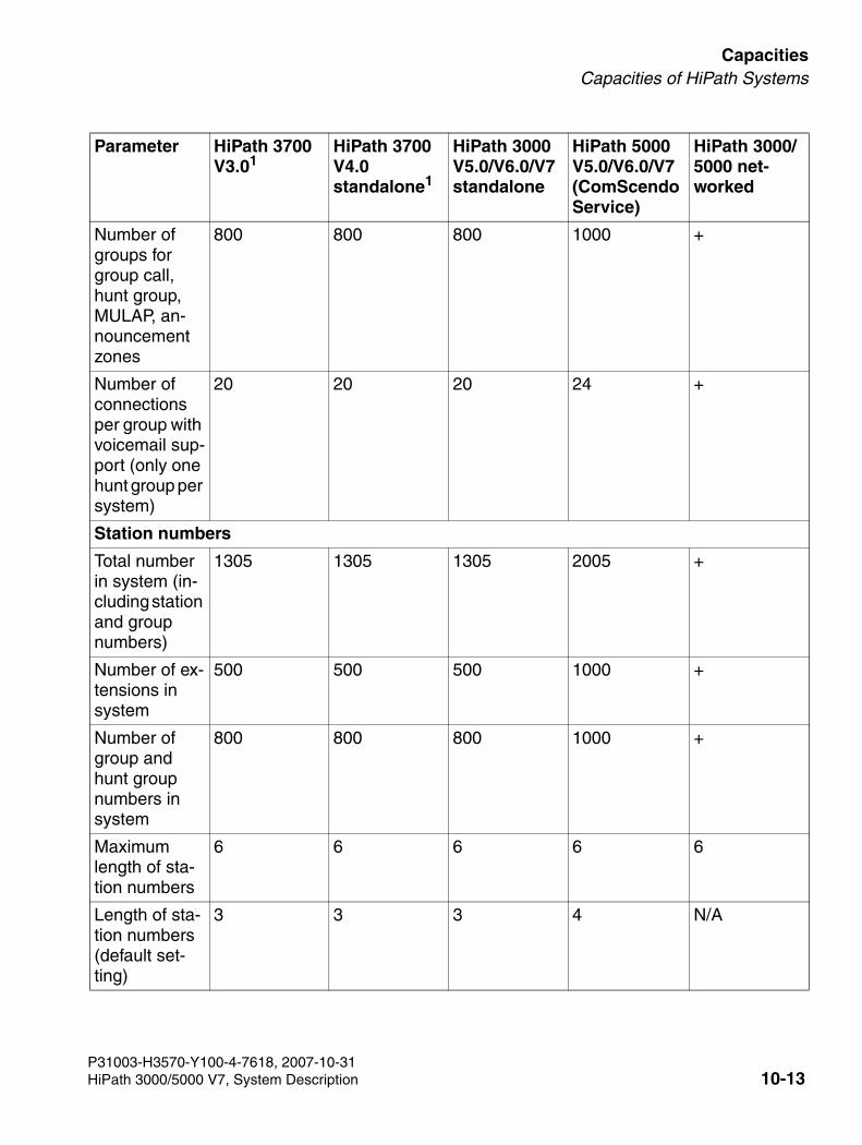
3000sb9.fm
For internal use only CapacitiesCapacities of HiPath Systems
Number of groups for group call, hunt group, MULAP, an-nouncement zones
800 800 800 1000 +
Number of connections per group with voicemail sup-port (only one hunt group per system)
20 20 20 24 +
Station numbers
Total number in system (in-cluding station and group numbers)
1305 1305 1305 2005 +
Number of ex-tensions in system
500 500 500 1000 +
Number of group and hunt group numbers in system
800 800 800 1000 +
Maximum length of sta-tion numbers
6 6 6 6 6
Length of sta-tion numbers (default set-ting)
3 3 3 4 N/A
Parameter HiPath 3700 V3.01
HiPath 3700 V4.0 standalone1
HiPath 3000 V5.0/V6.0/V7 standalone
HiPath 5000 V5.0/V6.0/V7 (ComScendo Service)
HiPath 3000/5000 net-worked
P31003-H3570-Y100-4-7618, 2007-10-31HiPath 3000/5000 V7, System Description 10-13
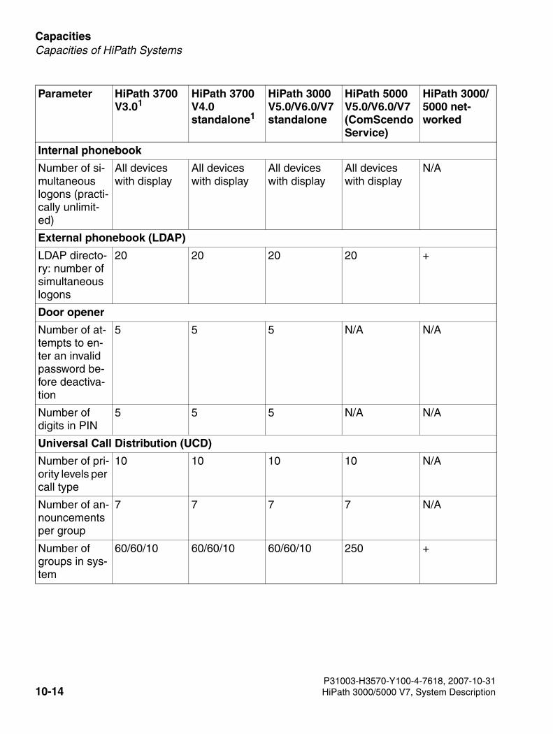
Capacities For internal use only
3000sb9.fm
Capacities of HiPath Systems
Internal phonebook
Number of si-multaneous logons (practi-cally unlimit-ed)
All devices with display
All devices with display
All devices with display
All devices with display
N/A
External phonebook (LDAP)
LDAP directo-ry: number of simultaneous logons
20 20 20 20 +
Door opener
Number of at-tempts to en-ter an invalid password be-fore deactiva-tion
5 5 5 N/A N/A
Number of digits in PIN
5 5 5 N/A N/A
Universal Call Distribution (UCD)
Number of pri-ority levels per call type
10 10 10 10 N/A
Number of an-nouncements per group
7 7 7 7 N/A
Number of groups in sys-tem
60/60/10 60/60/10 60/60/10 250 +
Parameter HiPath 3700 V3.01
HiPath 3700 V4.0 standalone1
HiPath 3000 V5.0/V6.0/V7 standalone
HiPath 5000 V5.0/V6.0/V7 (ComScendo Service)
HiPath 3000/5000 net-worked
P31003-H3570-Y100-4-7618, 2007-10-3110-14 HiPath 3000/5000 V7, System Description
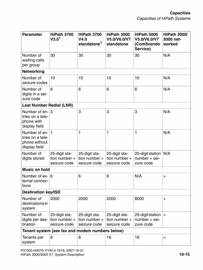
3000sb9.fm
For internal use only CapacitiesCapacities of HiPath Systems
Number of waiting calls per group
30 30 30 30 N/A
Networking
Number of seizure codes
10 10 10 10 N/A
Number of digits in a sei-zure code
6 6 6 6 N/A
Last Number Redial (LNR)
Number of en-tries on a tele-phone with display field
3 3 3 3 N/A
Number of en-tries on a tele-phone without display field
1 1 1 1 N/A
Number of digits stored
25-digit sta-tion number + seizure code
25-digit sta-tion number + seizure code
25-digit sta-tion number + seizure code
25-digit station number + sei-zure code
N/A
Music on hold
Number of ex-ternal connec-tions
6 6 6 N/A +
Destination key/ISD
Number of destinations in system
2000 2000 2000 8000 +
Number of digits per des-tination
25-digit sta-tion number + seizure code
25-digit sta-tion number + seizure code
25-digit sta-tion number + seizure code
25-digit station number + sei-zure code
=
Tenant system (see fax and modem numbers below)
Tenants per system
6 6 16 16 =
Parameter HiPath 3700 V3.01
HiPath 3700 V4.0 standalone1
HiPath 3000 V5.0/V6.0/V7 standalone
HiPath 5000 V5.0/V6.0/V7 (ComScendo Service)
HiPath 3000/5000 net-worked
P31003-H3570-Y100-4-7618, 2007-10-31HiPath 3000/5000 V7, System Description 10-15
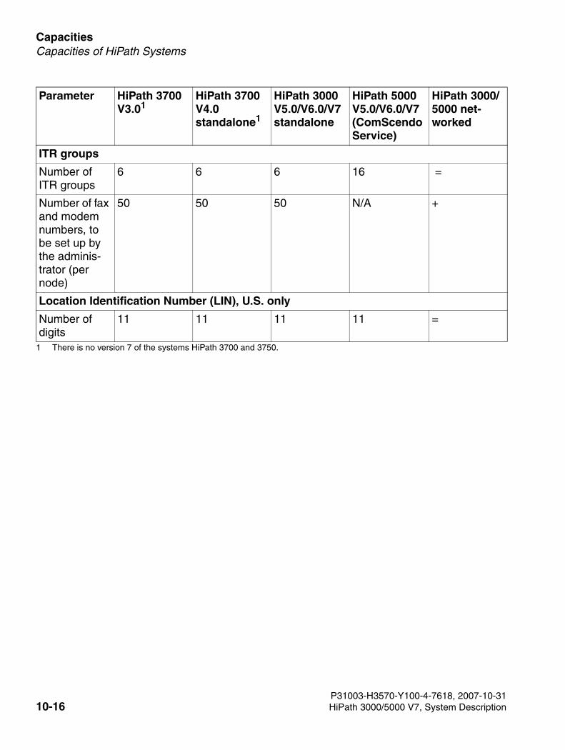
Capacities For internal use only
3000sb9.fm
Capacities of HiPath Systems
ITR groups
Number of ITR groups
6 6 6 16 =
Number of fax and modem numbers, to be set up by the adminis-trator (per node)
50 50 50 N/A +
Location Identification Number (LIN), U.S. only
Number of digits
11 11 11 11 =
1 There is no version 7 of the systems HiPath 3700 and 3750.
Parameter HiPath 3700 V3.01
HiPath 3700 V4.0 standalone1
HiPath 3000 V5.0/V6.0/V7 standalone
HiPath 5000 V5.0/V6.0/V7 (ComScendo Service)
HiPath 3000/5000 net-worked
P31003-H3570-Y100-4-7618, 2007-10-3110-16 HiPath 3000/5000 V7, System Description
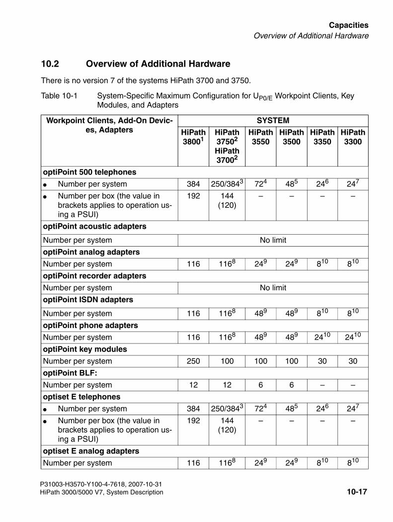
3000sb9.fm
For internal use only CapacitiesOverview of Additional Hardware
10.2 Overview of Additional Hardware
There is no version 7 of the systems HiPath 3700 and 3750.
Table 10-1 System-Specific Maximum Configuration for UP0/E Workpoint Clients, Key Modules, and Adapters
Workpoint Clients, Add-On Devic-es, Adapters
SYSTEM
HiPath 38001
HiPath 37502
HiPath 37002
HiPath 3550
HiPath 3500
HiPath 3350
HiPath 3300
optiPoint 500 telephones
● Number per system 384 250/3843 724 485 246 247
● Number per box (the value in brackets applies to operation us-ing a PSUI)
192 144 (120)
– – – –
optiPoint acoustic adapters
Number per system No limit
optiPoint analog adapters
Number per system 116 1168 249 249 810 810
optiPoint recorder adapters
Number per system No limit
optiPoint ISDN adapters
Number per system 116 1168 489 489 810 810
optiPoint phone adapters
Number per system 116 1168 489 489 2410 2410
optiPoint key modules
Number per system 250 100 100 100 30 30
optiPoint BLF:
Number per system 12 12 6 6 – –
optiset E telephones
● Number per system 384 250/3843 724 485 246 247
● Number per box (the value in brackets applies to operation us-ing a PSUI)
192 144 (120)
– – – –
optiset E analog adapters
Number per system 116 1168 249 249 810 810
P31003-H3570-Y100-4-7618, 2007-10-31HiPath 3000/5000 V7, System Description 10-17
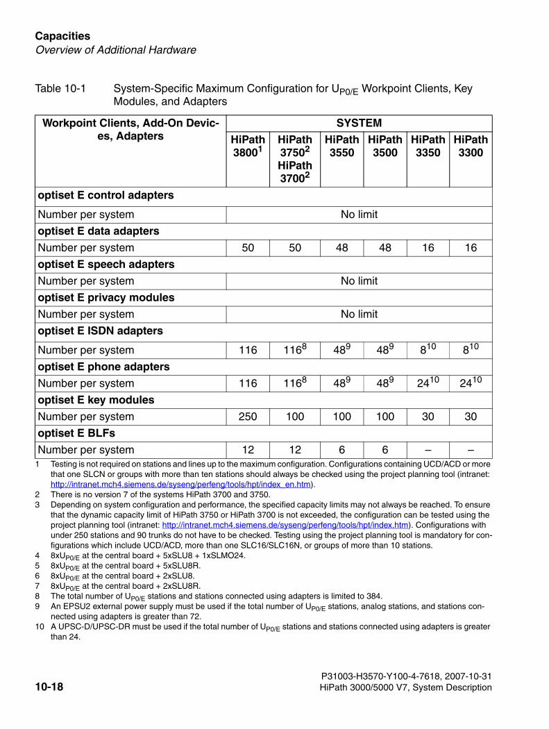
Capacities For internal use only
3000sb9.fm
Overview of Additional Hardware
optiset E control adapters
Number per system No limit
optiset E data adapters
Number per system 50 50 48 48 16 16
optiset E speech adapters
Number per system No limit
optiset E privacy modules
Number per system No limit
optiset E ISDN adapters
Number per system 116 1168 489 489 810 810
optiset E phone adapters
Number per system 116 1168 489 489 2410 2410
optiset E key modules
Number per system 250 100 100 100 30 30
optiset E BLFs
Number per system 12 12 6 6 – –1 Testing is not required on stations and lines up to the maximum configuration. Configurations containing UCD/ACD or more
that one SLCN or groups with more than ten stations should always be checked using the project planning tool (intranet: http://intranet.mch4.siemens.de/syseng/perfeng/tools/hpt/index_en.htm).
2 There is no version 7 of the systems HiPath 3700 and 3750.3 Depending on system configuration and performance, the specified capacity limits may not always be reached. To ensure
that the dynamic capacity limit of HiPath 3750 or HiPath 3700 is not exceeded, the configuration can be tested using the project planning tool (intranet: http://intranet.mch4.siemens.de/syseng/perfeng/tools/hpt/index.htm). Configurations with under 250 stations and 90 trunks do not have to be checked. Testing using the project planning tool is mandatory for con-figurations which include UCD/ACD, more than one SLC16/SLC16N, or groups of more than 10 stations.
4 8xUP0/E at the central board + 5xSLU8 + 1xSLMO24. 5 8xUP0/E at the central board + 5xSLU8R. 6 8xUP0/E at the central board + 2xSLU8. 7 8xUP0/E at the central board + 2xSLU8R. 8 The total number of UP0/E stations and stations connected using adapters is limited to 384. 9 An EPSU2 external power supply must be used if the total number of UP0/E stations, analog stations, and stations con-
nected using adapters is greater than 72. 10 A UPSC-D/UPSC-DR must be used if the total number of UP0/E stations and stations connected using adapters is greater
than 24.
Table 10-1 System-Specific Maximum Configuration for UP0/E Workpoint Clients, Key Modules, and Adapters
Workpoint Clients, Add-On Devic-es, Adapters
SYSTEM
HiPath 38001
HiPath 37502
HiPath 37002
HiPath 3550
HiPath 3500
HiPath 3350
HiPath 3300
P31003-H3570-Y100-4-7618, 2007-10-3110-18 HiPath 3000/5000 V7, System Description
3000sb10.fm
For internal use only Output Formats for Call Detail Recording
11 Output Formats for Call Detail Recording
While the HiPath 3000/5000 systems are in operation, CDRC call details for each completed section of a call or for each incoming call can be sent to a connected device on an ongoing ba-sis. This device is normally a PC, which evaluates the data received, or a printer.
Options for Exporting the Data to an External Output Device:
● Application programming interface (V.24)CDRC data is exported to call detail recording applications such as Teledata.
● PC attendant console portUsers can also forward the CDRC data to an optiClient Attendant (PC attendant console port). This transfers the call data to the Charge.dat file, which is created or updated when-ever a new record is entered. You can use software to evaluate this data.
● UP0/E port An optiset E control adapter, to which you can attach a printer or PC, must be connected to the UP0/E port. The system supports only one adapter per call data output.
● LAN interface (Ethernet)CDRC data can be exported to external applications via the LAN interface (Ethernet) (for more information, refer to Section 4.8, "Applications over IP").
Output Formats
The CDRC output can be in two different formats:
● Compressed format (via V.24/via LAN) for PC or call charge computerThe system outputs all data (including ACCT) without separating spaces, without headers, and without form feed. Call charge pulses, call charge amounts or arithmetic units are out-put.
● Long format for printerThe system outputs all data (except ACCT) separated by spaces, with header (in the lan-guage selected for the system) and form feed. The call charge amount is output.
P31003-H3570-Y100-4-7618, 2007-10-31HiPath 3000/5000 V7, System Description 11-1

Output Formats for Call Detail Recording For internal use only
3000sb10.fm
P31003-H3570-Y100-4-7618, 2007-10-3111-2 HiPath 3000/5000 V7, System Description
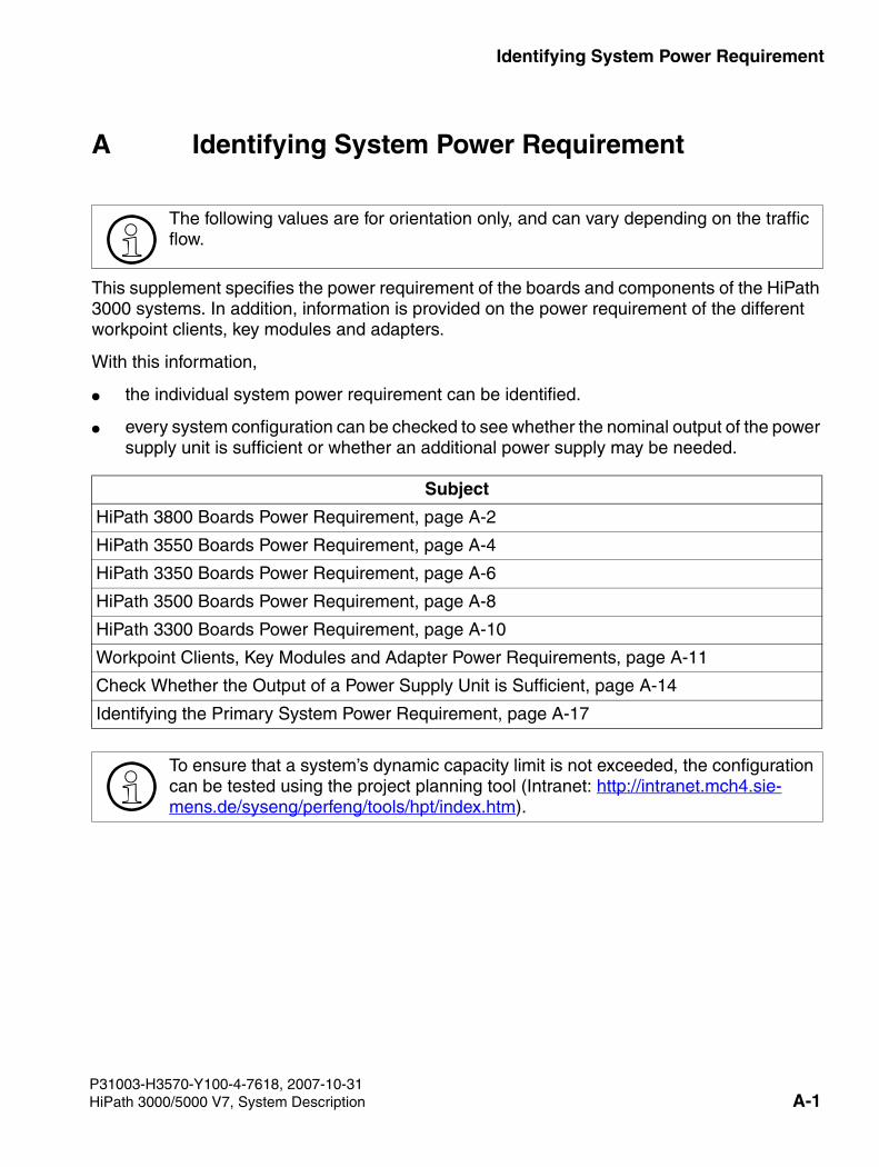
3000sb11.fm
For internal use only Identifying System Power Requirement
A Identifying System Power Requirement
This supplement specifies the power requirement of the boards and components of the HiPath 3000 systems. In addition, information is provided on the power requirement of the different workpoint clients, key modules and adapters.
With this information,
● the individual system power requirement can be identified.
● every system configuration can be checked to see whether the nominal output of the power supply unit is sufficient or whether an additional power supply may be needed.
>The following values are for orientation only, and can vary depending on the traffic flow.
Subject
HiPath 3800 Boards Power Requirement, page A-2
HiPath 3550 Boards Power Requirement, page A-4
HiPath 3350 Boards Power Requirement, page A-6
HiPath 3500 Boards Power Requirement, page A-8
HiPath 3300 Boards Power Requirement, page A-10
Workpoint Clients, Key Modules and Adapter Power Requirements, page A-11
Check Whether the Output of a Power Supply Unit is Sufficient, page A-14
Identifying the Primary System Power Requirement, page A-17
>To ensure that a system’s dynamic capacity limit is not exceeded, the configuration can be tested using the project planning tool (Intranet: http://intranet.mch4.sie-mens.de/syseng/perfeng/tools/hpt/index.htm).
P31003-H3570-Y100-4-7618, 2007-10-31HiPath 3000/5000 V7, System Description A-1
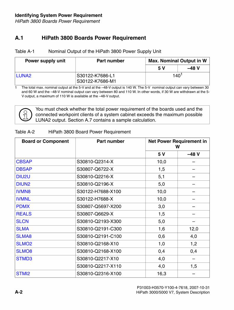
Identifying System Power Requirement For internal use only
3000sb11.fm
HiPath 3800 Boards Power Requirement
A.1 HiPath 3800 Boards Power Requirement
Table A-1 Nominal Output of the HiPath 3800 Power Supply Unit
Power supply unit Part number Max. Nominal Output in W
5 V –48 V
LUNA2 S30122-K7686-L1S30122-K7686-M1
1401
1 The total max. nominal output at the 5-V and at the –48-V output is 140 W. The 5-V nominal output can vary between 30 and 60 W and the –48-V nominal output can vary between 80 and 110 W. In other words, if 30 W are withdrawn at the 5-V output, a maximum of 110 W is available at the –48-V output.
>You must check whether the total power requirement of the boards used and the connected workpoint clients of a system cabinet exceeds the maximum possible LUNA2 output. Section A.7 contains a sample calculation.
Table A-2 HiPath 3800 Board Power Requirement
Board or Component Part number Net Power Requirement in W
5 V –48 V
CBSAP S30810-Q2314-X 10,0 –
DBSAP S30807-Q6722-X 1,5 –
DIU2U S30810-Q2216-X 5,1 –
DIUN2 S30810-Q2196-X 5,0 –
IVMN8 S30122-H7688-X100 10,0 –
IVMNL S30122-H7688-X 10,0 –
PDMX S30807-Q5697-X200 3,0 –
REALS S30807-Q6629-X 1,5 –
SLCN S30810-Q2193-X300 5,0 –
SLMA S30810-Q2191-C300 1,6 12,0
SLMA8 S30810-Q2191-C100 0,6 4,0
SLMO2 S30810-Q2168-X10 1,0 1,2
SLMO8 S30810-Q2168-X100 0,4 0,4
STMD3 S30810-Q2217-X10 4,0 –
S30810-Q2217-X110 4,0 1,5
STMI2 S30810-Q2316-X100 16,3 –
P31003-H3570-Y100-4-7618, 2007-10-31A-2 HiPath 3000/5000 V7, System Description
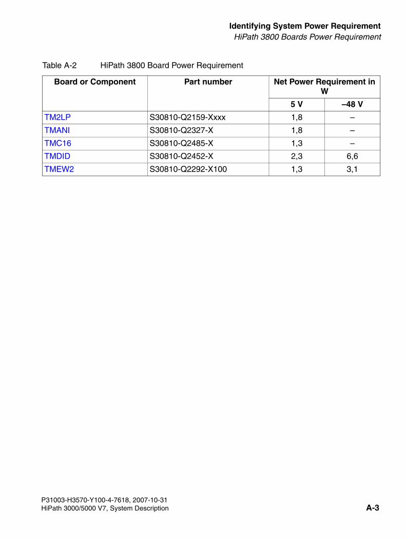
3000sb11.fm
For internal use only Identifying System Power RequirementHiPath 3800 Boards Power Requirement
TM2LP S30810-Q2159-Xxxx 1,8 –
TMANI S30810-Q2327-X 1,8 –
TMC16 S30810-Q2485-X 1,3 –
TMDID S30810-Q2452-X 2,3 6,6
TMEW2 S30810-Q2292-X100 1,3 3,1
Table A-2 HiPath 3800 Board Power Requirement
Board or Component Part number Net Power Requirement in W
5 V –48 V
P31003-H3570-Y100-4-7618, 2007-10-31HiPath 3000/5000 V7, System Description A-3
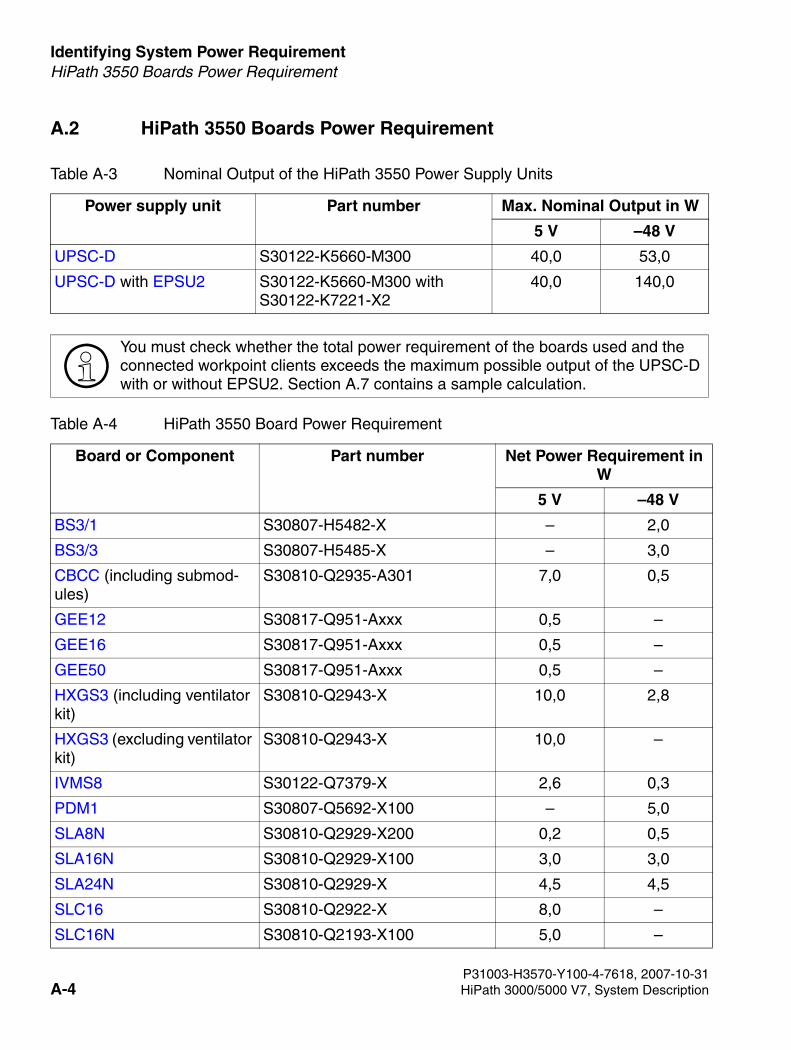
Identifying System Power Requirement For internal use only
3000sb11.fm
HiPath 3550 Boards Power Requirement
A.2 HiPath 3550 Boards Power Requirement
Table A-3 Nominal Output of the HiPath 3550 Power Supply Units
Power supply unit Part number Max. Nominal Output in W
5 V –48 V
UPSC-D S30122-K5660-M300 40,0 53,0
UPSC-D with EPSU2 S30122-K5660-M300 with S30122-K7221-X2
40,0 140,0
>You must check whether the total power requirement of the boards used and the connected workpoint clients exceeds the maximum possible output of the UPSC-D with or without EPSU2. Section A.7 contains a sample calculation.
Table A-4 HiPath 3550 Board Power Requirement
Board or Component Part number Net Power Requirement in W
5 V –48 V
BS3/1 S30807-H5482-X – 2,0
BS3/3 S30807-H5485-X – 3,0
CBCC (including submod-ules)
S30810-Q2935-A301 7,0 0,5
GEE12 S30817-Q951-Axxx 0,5 –
GEE16 S30817-Q951-Axxx 0,5 –
GEE50 S30817-Q951-Axxx 0,5 –
HXGS3 (including ventilator kit)
S30810-Q2943-X 10,0 2,8
HXGS3 (excluding ventilator kit)
S30810-Q2943-X 10,0 –
IVMS8 S30122-Q7379-X 2,6 0,3
PDM1 S30807-Q5692-X100 – 5,0
SLA8N S30810-Q2929-X200 0,2 0,5
SLA16N S30810-Q2929-X100 3,0 3,0
SLA24N S30810-Q2929-X 4,5 4,5
SLC16 S30810-Q2922-X 8,0 –
SLC16N S30810-Q2193-X100 5,0 –
P31003-H3570-Y100-4-7618, 2007-10-31A-4 HiPath 3000/5000 V7, System Description
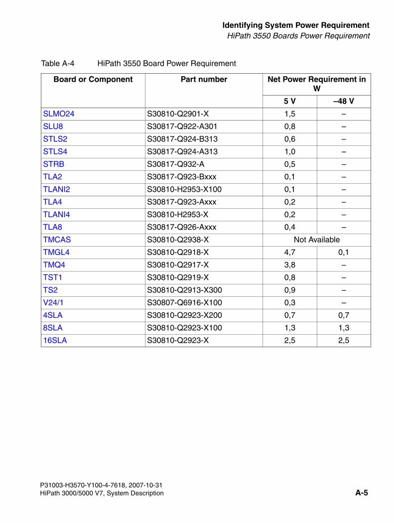
3000sb11.fm
For internal use only Identifying System Power RequirementHiPath 3550 Boards Power Requirement
SLMO24 S30810-Q2901-X 1,5 –
SLU8 S30817-Q922-A301 0,8 –
STLS2 S30817-Q924-B313 0,6 –
STLS4 S30817-Q924-A313 1,0 –
STRB S30817-Q932-A 0,5 –
TLA2 S30817-Q923-Bxxx 0,1 –
TLANI2 S30810-H2953-X100 0,1 –
TLA4 S30817-Q923-Axxx 0,2 –
TLANI4 S30810-H2953-X 0,2 –
TLA8 S30817-Q926-Axxx 0,4 –
TMCAS S30810-Q2938-X Not Available
TMGL4 S30810-Q2918-X 4,7 0,1
TMQ4 S30810-Q2917-X 3,8 –
TST1 S30810-Q2919-X 0,8 –
TS2 S30810-Q2913-X300 0,9 –
V24/1 S30807-Q6916-X100 0,3 –
4SLA S30810-Q2923-X200 0,7 0,7
8SLA S30810-Q2923-X100 1,3 1,3
16SLA S30810-Q2923-X 2,5 2,5
Table A-4 HiPath 3550 Board Power Requirement
Board or Component Part number Net Power Requirement in W
5 V –48 V
P31003-H3570-Y100-4-7618, 2007-10-31HiPath 3000/5000 V7, System Description A-5
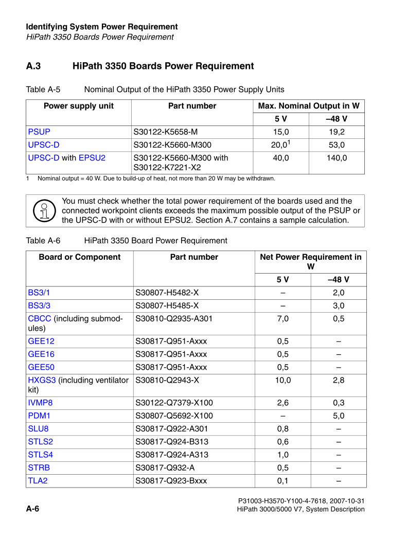
Identifying System Power Requirement For internal use only
3000sb11.fm
HiPath 3350 Boards Power Requirement
A.3 HiPath 3350 Boards Power Requirement
Table A-5 Nominal Output of the HiPath 3350 Power Supply Units
Power supply unit Part number Max. Nominal Output in W
5 V –48 V
PSUP S30122-K5658-M 15,0 19,2
UPSC-D S30122-K5660-M300 20,01
1 Nominal output = 40 W. Due to build-up of heat, not more than 20 W may be withdrawn.
53,0
UPSC-D with EPSU2 S30122-K5660-M300 with S30122-K7221-X2
40,0 140,0
>You must check whether the total power requirement of the boards used and the connected workpoint clients exceeds the maximum possible output of the PSUP or the UPSC-D with or without EPSU2. Section A.7 contains a sample calculation.
Table A-6 HiPath 3350 Board Power Requirement
Board or Component Part number Net Power Requirement in W
5 V –48 V
BS3/1 S30807-H5482-X – 2,0
BS3/3 S30807-H5485-X – 3,0
CBCC (including submod-ules)
S30810-Q2935-A301 7,0 0,5
GEE12 S30817-Q951-Axxx 0,5 –
GEE16 S30817-Q951-Axxx 0,5 –
GEE50 S30817-Q951-Axxx 0,5 –
HXGS3 (including ventilator kit)
S30810-Q2943-X 10,0 2,8
IVMP8 S30122-Q7379-X100 2,6 0,3
PDM1 S30807-Q5692-X100 – 5,0
SLU8 S30817-Q922-A301 0,8 –
STLS2 S30817-Q924-B313 0,6 –
STLS4 S30817-Q924-A313 1,0 –
STRB S30817-Q932-A 0,5 –
TLA2 S30817-Q923-Bxxx 0,1 –
P31003-H3570-Y100-4-7618, 2007-10-31A-6 HiPath 3000/5000 V7, System Description
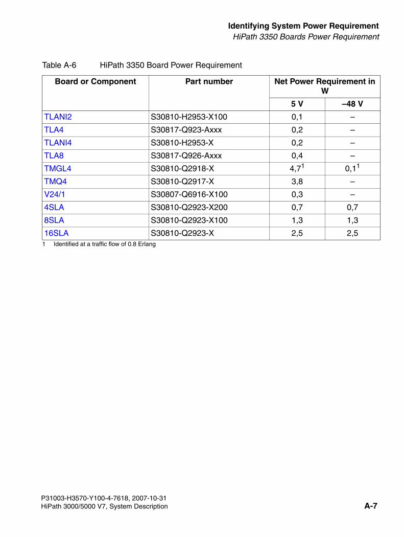
3000sb11.fm
For internal use only Identifying System Power RequirementHiPath 3350 Boards Power Requirement
TLANI2 S30810-H2953-X100 0,1 –
TLA4 S30817-Q923-Axxx 0,2 –
TLANI4 S30810-H2953-X 0,2 –
TLA8 S30817-Q926-Axxx 0,4 –
TMGL4 S30810-Q2918-X 4,71 0,11
TMQ4 S30810-Q2917-X 3,8 –
V24/1 S30807-Q6916-X100 0,3 –
4SLA S30810-Q2923-X200 0,7 0,7
8SLA S30810-Q2923-X100 1,3 1,3
16SLA S30810-Q2923-X 2,5 2,51 Identified at a traffic flow of 0.8 Erlang
Table A-6 HiPath 3350 Board Power Requirement
Board or Component Part number Net Power Requirement in W
5 V –48 V
P31003-H3570-Y100-4-7618, 2007-10-31HiPath 3000/5000 V7, System Description A-7
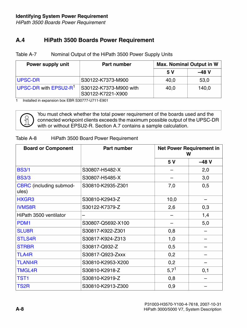
Identifying System Power Requirement For internal use only
3000sb11.fm
HiPath 3500 Boards Power Requirement
A.4 HiPath 3500 Boards Power Requirement
Table A-7 Nominal Output of the HiPath 3500 Power Supply Units
Power supply unit Part number Max. Nominal Output in W
5 V –48 V
UPSC-DR S30122-K7373-M900 40,0 53,0
UPSC-DR with EPSU2-R1
1 Installed in expansion box EBR S30777-U711-E901
S30122-K7373-M900 with S30122-K7221-X900
40,0 140,0
>You must check whether the total power requirement of the boards used and the connected workpoint clients exceeds the maximum possible output of the UPSC-DR with or without EPSU2-R. Section A.7 contains a sample calculation.
Table A-8 HiPath 3500 Board Power Requirement
Board or Component Part number Net Power Requirement in W
5 V –48 V
BS3/1 S30807-H5482-X – 2,0
BS3/3 S30807-H5485-X – 3,0
CBRC (including submod-ules)
S30810-K2935-Z301 7,0 0,5
HXGR3 S30810-K2943-Z 10,0 –
IVMS8R S30122-K7379-Z 2,6 0,3
HiPath 3500 ventilator – – 1,4
PDM1 S30807-Q5692-X100 – 5,0
SLU8R S30817-K922-Z301 0,8 –
STLS4R S30817-K924-Z313 1,0 –
STRBR S30817-Q932-Z 0,5 –
TLA4R S30817-Q923-Zxxx 0,2 –
TLANI4R S30810-K2953-X200 0,2 –
TMGL4R S30810-K2918-Z 5,71 0,1
TST1 S30810-K2919-Z 0,8 –
TS2R S30810-K2913-Z300 0,9 –
P31003-H3570-Y100-4-7618, 2007-10-31A-8 HiPath 3000/5000 V7, System Description

3000sb11.fm
For internal use only Identifying System Power RequirementHiPath 3500 Boards Power Requirement
8SLAR S30810-K2925-Z 1,3 1,31 Identified at a traffic flow of 0.8 Erlang
Table A-8 HiPath 3500 Board Power Requirement
Board or Component Part number Net Power Requirement in W
5 V –48 V
P31003-H3570-Y100-4-7618, 2007-10-31HiPath 3000/5000 V7, System Description A-9

Identifying System Power Requirement For internal use only
3000sb11.fm
HiPath 3300 Boards Power Requirement
P31003-H3570-Y100-4-7618, 2007-10-31
A.5 HiPath 3300 Boards Power Requirement
Table A-9 Nominal Output of the HiPath 3300 Power Supply Units
Power supply unit Part number Max. Nominal Output in W
5 V –48 V
UPSC-DR S30122-K7373-M900 20,01
1 Nominal output = 40 W. Due to build-up of heat, not more than 20 W may be withdrawn.
53,0
UPSC-DR with EPSU2-R2
2 Installed in expansion box EBR S30777-U711-E901
S30122-K7373-M900 with S30122-K7221-X900
40,0 140,0
>You must check whether the total power requirement of the boards used and the connected workpoint clients exceeds the maximum possible output of the UPSC-DR with or without EPSU2-R. A sample calculation is shown in Section A.7.
Table A-10 HiPath 3300 Board Power Requirement
Board or Component Part number Net Power Requirement in W
5 V –48 V
BS3/1 S30807-H5482-X – 2,0
BS3/3 S30807-H5485-X – 3,0
CBRC (including submod-ules)
S30810-K2935-Z301 7,0 0,5
HXGR3 S30810-K2943-Z 10,0 –
IVMP8R S30122-K7379-Z100 2,6 0,3
HiPath 3300 ventilator – – 1,4
PDM1 S30807-Q5692-X100 – 5,0
SLU8R S30817-K922-Z301 0,8 –
STLS4R S30817-K924-Z313 1,0 –
STRBR S30817-Q932-Z 0,5 –
TLA4R S30817-Q923-Zxxx 0,2 –
TLANI4R S30810-K2953-X200 0,2 –
TMGL4R S30810-K2918-Z 5,71
1 Identified at a traffic flow of 0.8 Erlang
0,1
8SLAR S30810-K2925-Z 1,3 1,3
A-10 HiPath 3000/5000 V7, System Description
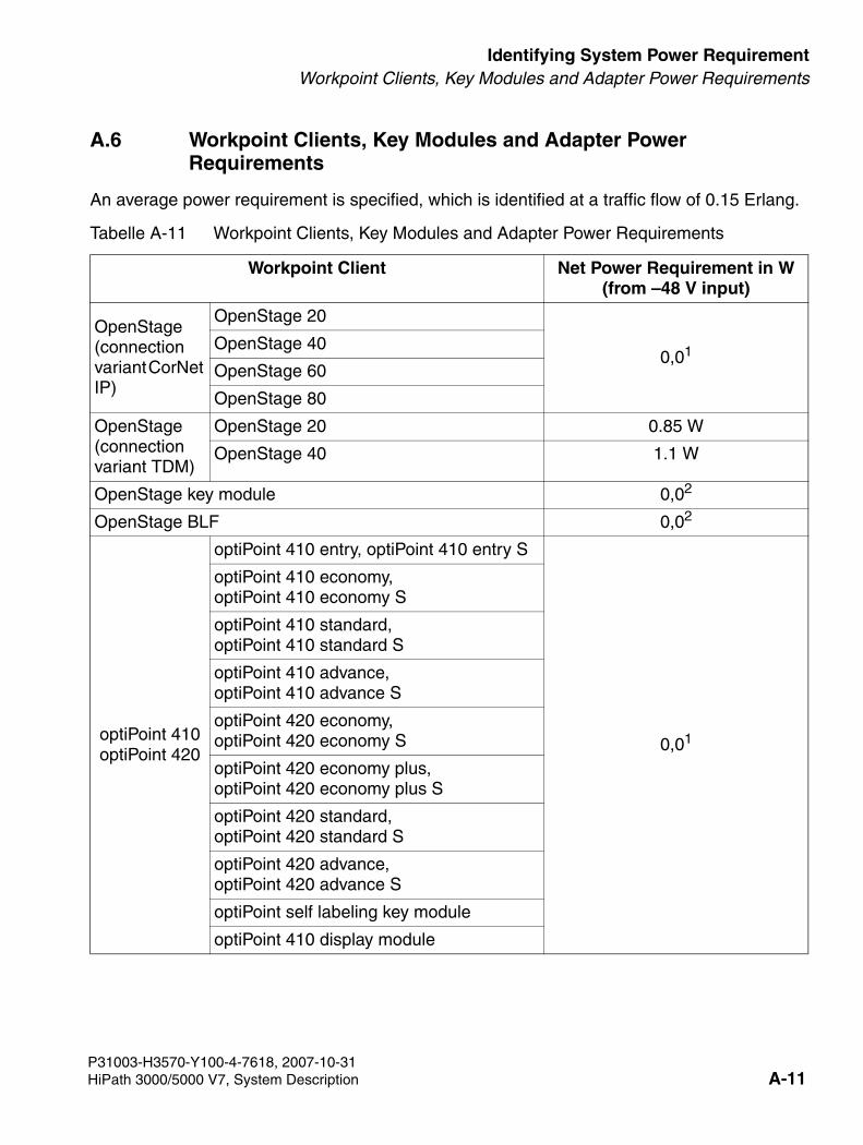
3000sb11.fm
For internal use only Identifying System Power RequirementWorkpoint Clients, Key Modules and Adapter Power Requirements
A.6 Workpoint Clients, Key Modules and Adapter Power Requirements
An average power requirement is specified, which is identified at a traffic flow of 0.15 Erlang.
Tabelle A-11 Workpoint Clients, Key Modules and Adapter Power Requirements
Workpoint Client Net Power Requirement in W(from –48 V input)
OpenStage (connection variant CorNet IP)
OpenStage 20
0,01OpenStage 40
OpenStage 60
OpenStage 80
OpenStage (connection variant TDM)
OpenStage 20 0.85 W
OpenStage 40 1.1 W
OpenStage key module 0,02
OpenStage BLF 0,02
optiPoint 410optiPoint 420
optiPoint 410 entry, optiPoint 410 entry S
0,01
optiPoint 410 economy, optiPoint 410 economy S
optiPoint 410 standard, optiPoint 410 standard S
optiPoint 410 advance, optiPoint 410 advance S
optiPoint 420 economy, optiPoint 420 economy S
optiPoint 420 economy plus, optiPoint 420 economy plus S
optiPoint 420 standard, optiPoint 420 standard S
optiPoint 420 advance, optiPoint 420 advance S
optiPoint self labeling key module
optiPoint 410 display module
P31003-H3570-Y100-4-7618, 2007-10-31HiPath 3000/5000 V7, System Description A-11
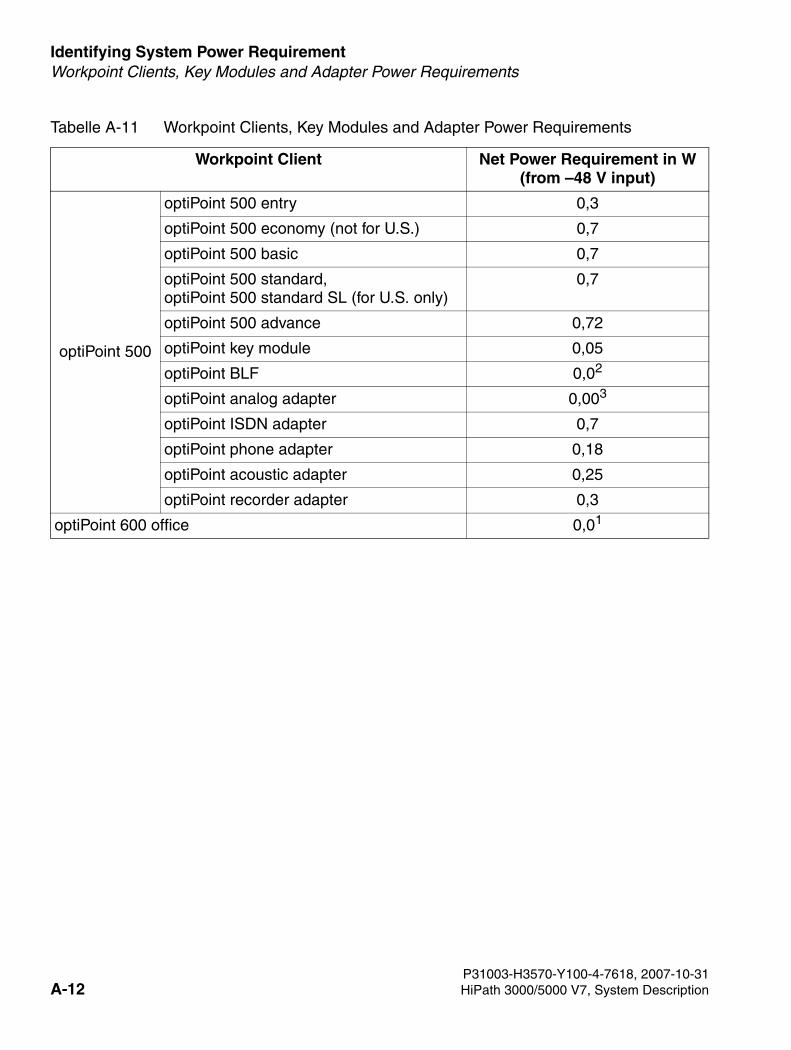
Identifying System Power Requirement For internal use only
3000sb11.fm
Workpoint Clients, Key Modules and Adapter Power Requirements
optiPoint 500
optiPoint 500 entry 0,3
optiPoint 500 economy (not for U.S.) 0,7
optiPoint 500 basic 0,7
optiPoint 500 standard, optiPoint 500 standard SL (for U.S. only)
0,7
optiPoint 500 advance 0,72
optiPoint key module 0,05
optiPoint BLF 0,02
optiPoint analog adapter 0,003
optiPoint ISDN adapter 0,7
optiPoint phone adapter 0,18
optiPoint acoustic adapter 0,25
optiPoint recorder adapter 0,3
optiPoint 600 office 0,01
Tabelle A-11 Workpoint Clients, Key Modules and Adapter Power Requirements
Workpoint Client Net Power Requirement in W(from –48 V input)
P31003-H3570-Y100-4-7618, 2007-10-31A-12 HiPath 3000/5000 V7, System Description
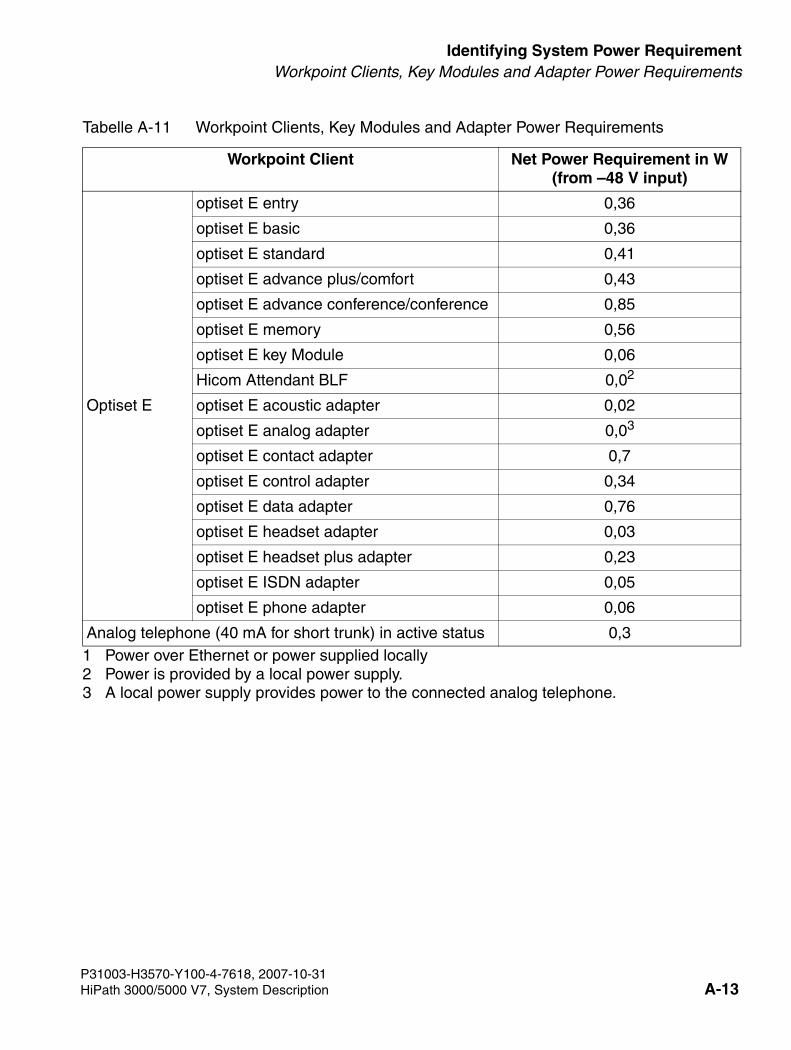
3000sb11.fm
For internal use only Identifying System Power RequirementWorkpoint Clients, Key Modules and Adapter Power Requirements
Optiset E
optiset E entry 0,36
optiset E basic 0,36
optiset E standard 0,41
optiset E advance plus/comfort 0,43
optiset E advance conference/conference 0,85
optiset E memory 0,56
optiset E key Module 0,06
Hicom Attendant BLF 0,02
optiset E acoustic adapter 0,02
optiset E analog adapter 0,03
optiset E contact adapter 0,7
optiset E control adapter 0,34
optiset E data adapter 0,76
optiset E headset adapter 0,03
optiset E headset plus adapter 0,23
optiset E ISDN adapter 0,05
optiset E phone adapter 0,06
Analog telephone (40 mA for short trunk) in active status 0,31 Power over Ethernet or power supplied locally 2 Power is provided by a local power supply. 3 A local power supply provides power to the connected analog telephone.
Tabelle A-11 Workpoint Clients, Key Modules and Adapter Power Requirements
Workpoint Client Net Power Requirement in W(from –48 V input)
P31003-H3570-Y100-4-7618, 2007-10-31HiPath 3000/5000 V7, System Description A-13
Identifying System Power Requirement For internal use only
3000sb11.fm
Check Whether the Output of a Power Supply Unit is Sufficient
A.7 Check Whether the Output of a Power Supply Unit is Sufficient
Apart from the secondary power requirements, the power output must also be checked to en-sure that the maximum possible output of the system’s power supply unit is sufficient. For this, the power requirement on the 5 V output format and on the –48 V output format must be exam-ined separately.
Procedure
Proceed as follows to identify the secondary power requirement of a system:
1. Determine secondary power requirement at the 5 V output
2. Determine secondary power requirement at the –48 V output
Using the specified values, check whether the total power requirement exceeds the maximum possible output of the power supply unit at the 5 V output or at the –48 V output. If this is the case, you have the following options:
● HiPath 3800 The number of LUNA2 power supply units can be increased.
● HiPath 3550 with USPSC-D The maximum nominal output at the –48 V output can be increased from 53 W to 140 W by using the EPSU2 external power supply unit.
● HiPath 3350 with USPSC-D Due to build-up of heat, the 5 V output format can only be loaded with a maximum of 20 W. A maximum nominal output of 40 W is possible by using the EPSU2 external power supply unit. In addition, the maximum nominal output of the –48 V output increases from 53 W to 140 W.
7Caution To guarantee smooth system operation, the nominal output of the power supply unit at the 5 V output and at the –48 V output must be greater than the respective sec-ondary power requirement.
5 V power requirement of the boards/components used
= secondary power requirement at the 5 V output
–48 V power requirement of the boards/components used
+ power requirement of connected workpoint clients (analog and digital telephones), key modules and adapters
= secondary power requirement at the –48 V output
P31003-H3570-Y100-4-7618, 2007-10-31A-14 HiPath 3000/5000 V7, System Description
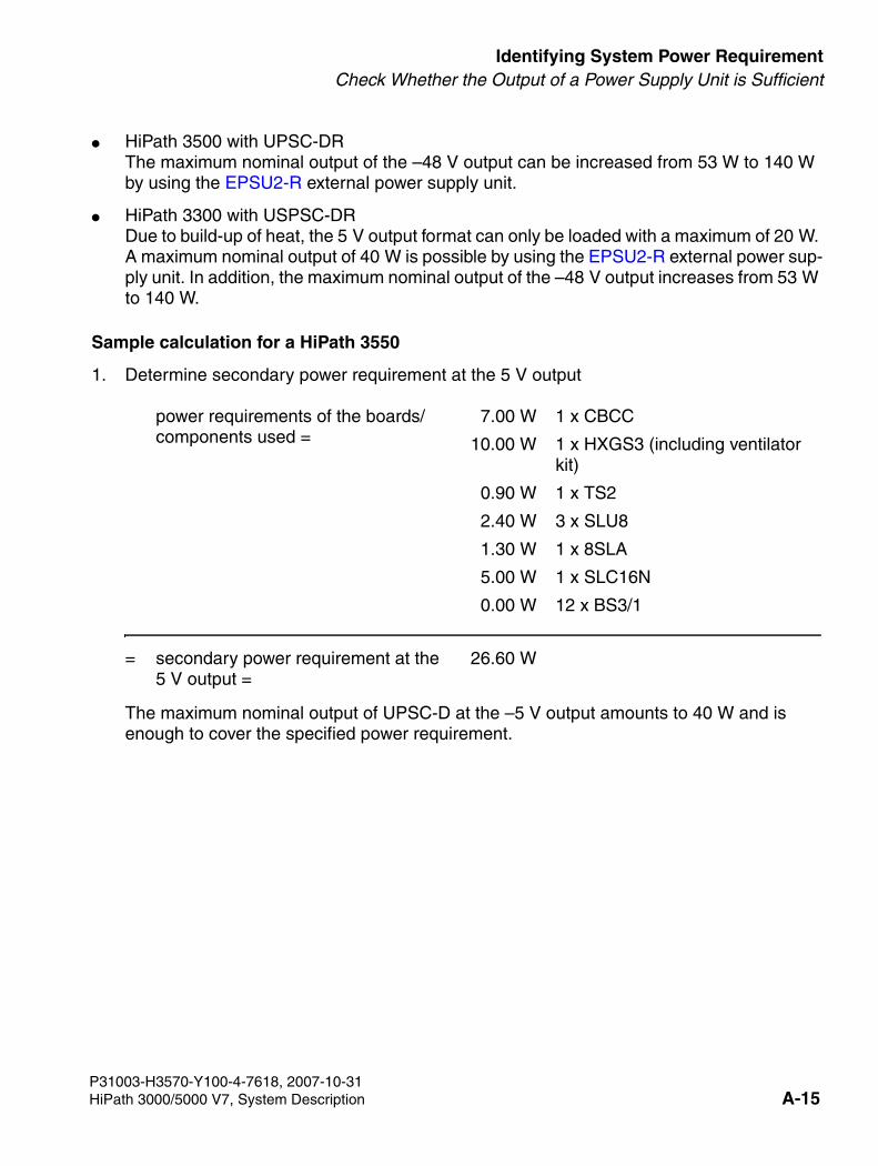
3000sb11.fm
For internal use only Identifying System Power RequirementCheck Whether the Output of a Power Supply Unit is Sufficient
● HiPath 3500 with UPSC-DR The maximum nominal output of the –48 V output can be increased from 53 W to 140 W by using the EPSU2-R external power supply unit.
● HiPath 3300 with USPSC-DR Due to build-up of heat, the 5 V output format can only be loaded with a maximum of 20 W. A maximum nominal output of 40 W is possible by using the EPSU2-R external power sup-ply unit. In addition, the maximum nominal output of the –48 V output increases from 53 W to 140 W.
Sample calculation for a HiPath 3550
1. Determine secondary power requirement at the 5 V output
The maximum nominal output of UPSC-D at the –5 V output amounts to 40 W and is enough to cover the specified power requirement.
power requirements of the boards/components used =
7.00 W 1 x CBCC
10.00 W 1 x HXGS3 (including ventilator kit)
0.90 W 1 x TS2
2.40 W 3 x SLU8
1.30 W 1 x 8SLA
5.00 W 1 x SLC16N
0.00 W 12 x BS3/1
= secondary power requirement at the 5 V output =
26.60 W
P31003-H3570-Y100-4-7618, 2007-10-31HiPath 3000/5000 V7, System Description A-15
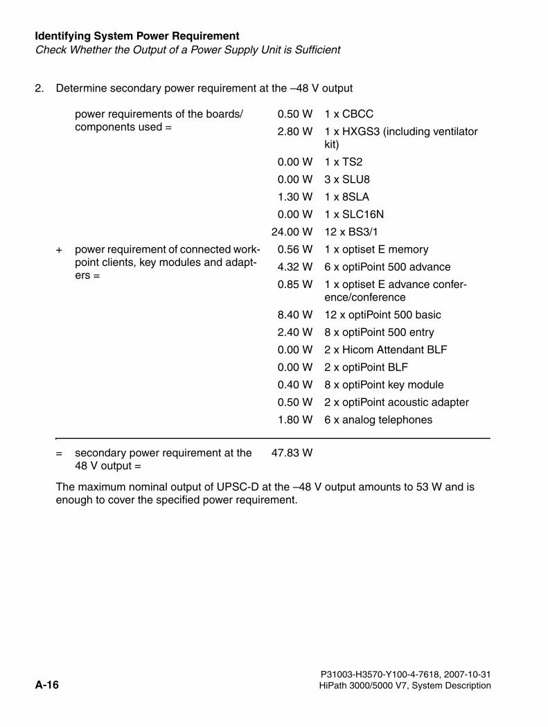
Identifying System Power Requirement For internal use only
3000sb11.fm
Check Whether the Output of a Power Supply Unit is Sufficient
2. Determine secondary power requirement at the –48 V output
The maximum nominal output of UPSC-D at the –48 V output amounts to 53 W and is enough to cover the specified power requirement.
power requirements of the boards/components used =
0.50 W 1 x CBCC
2.80 W 1 x HXGS3 (including ventilator kit)
0.00 W 1 x TS2
0.00 W 3 x SLU8
1.30 W 1 x 8SLA
0.00 W 1 x SLC16N
24.00 W 12 x BS3/1
+ power requirement of connected work-point clients, key modules and adapt-ers =
0.56 W 1 x optiset E memory
4.32 W 6 x optiPoint 500 advance
0.85 W 1 x optiset E advance confer-ence/conference
8.40 W 12 x optiPoint 500 basic
2.40 W 8 x optiPoint 500 entry
0.00 W 2 x Hicom Attendant BLF
0.00 W 2 x optiPoint BLF
0.40 W 8 x optiPoint key module
0.50 W 2 x optiPoint acoustic adapter
1.80 W 6 x analog telephones
= secondary power requirement at the 48 V output =
47.83 W
P31003-H3570-Y100-4-7618, 2007-10-31A-16 HiPath 3000/5000 V7, System Description
3000sb11.fm
For internal use only Identifying System Power RequirementIdentifying the Primary System Power Requirement
A.8 Identifying the Primary System Power Requirement
Procedure
Proceed as follows to identify the primary power requirement of a system:
1. Determine overall secondary power requirement
2. Identifying primary power requirement
power requirements of the boards/components used
+ power requirement of connected workpoint clients (analog and digital telephones), key modules and adapters
= overall secondary power requirement
overall secondary power requirement
+ requirements of power supply units (UPSM = 30 W, PSUP/UPSC-D/UPSC-DR = 12 W each)
+ requirements of EPSU2/EPSU2R (10 W each)
= the result should be multiplied by the factor 1.2 to allow for the degree of efficiency of the power supply.
P31003-H3570-Y100-4-7618, 2007-10-31HiPath 3000/5000 V7, System Description A-17
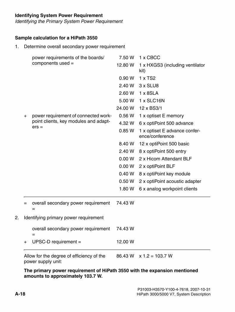
Identifying System Power Requirement For internal use only
3000sb11.fm
Identifying the Primary System Power Requirement
Sample calculation for a HiPath 3550
1. Determine overall secondary power requirement
2. Identifying primary power requirement
The primary power requirement of HiPath 3550 with the expansion mentioned amounts to approximately 103.7 W.
power requirements of the boards/components used =
7.50 W 1 x CBCC
12.80 W 1 x HXGS3 (including ventilator kit)
0.90 W 1 x TS2
2.40 W 3 x SLU8
2.60 W 1 x 8SLA
5.00 W 1 x SLC16N
24.00 W 12 x BS3/1
+ power requirement of connected work-point clients, key modules and adapt-ers =
0.56 W 1 x optiset E memory
4.32 W 6 x optiPoint 500 advance
0.85 W 1 x optiset E advance confer-ence/conference
8.40 W 12 x optiPoint 500 basic
2.40 W 8 x optiPoint 500 entry
0.00 W 2 x Hicom Attendant BLF
0.00 W 2 x optiPoint BLF
0.40 W 8 x optiPoint key module
0.50 W 2 x optiPoint acoustic adapter
1.80 W 6 x analog workpoint clients
= overall secondary power requirement =
74.43 W
overall secondary power requirement =
74.43 W
+ UPSC-D requirement = 12.00 W
Allow for the degree of efficiency of the power supply unit:
86.43 W x 1.2 = 103.7 W
P31003-H3570-Y100-4-7618, 2007-10-31A-18 HiPath 3000/5000 V7, System Description
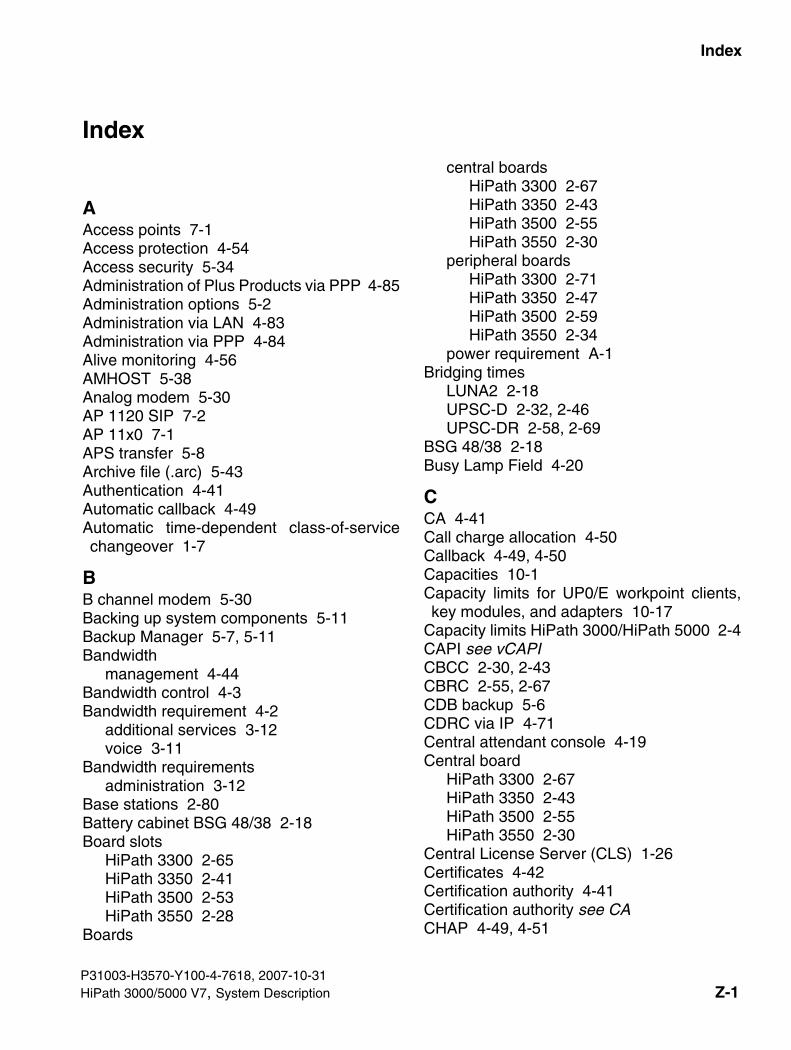
3000sbIX.fm
For internal use only Index
Index Z
AAccess points 7-1Access protection 4-54Access security 5-34Administration of Plus Products via PPP 4-85Administration options 5-2Administration via LAN 4-83Administration via PPP 4-84Alive monitoring 4-56AMHOST 5-38Analog modem 5-30AP 1120 SIP 7-2AP 11x0 7-1APS transfer 5-8Archive file (.arc) 5-43Authentication 4-41Automatic callback 4-49Automatic time-dependent class-of-servicechangeover 1-7
BB channel modem 5-30Backing up system components 5-11Backup Manager 5-7, 5-11Bandwidth
management 4-44Bandwidth control 4-3Bandwidth requirement 4-2
additional services 3-12voice 3-11
Bandwidth requirementsadministration 3-12
Base stations 2-80Battery cabinet BSG 48/38 2-18Board slots
HiPath 3300 2-65HiPath 3350 2-41HiPath 3500 2-53HiPath 3550 2-28
Boards
P31003-H3570-Y100-4-7618, 2007-10-31HiPath 3000/5000 V7, System Description
central boardsHiPath 3300 2-67HiPath 3350 2-43HiPath 3500 2-55HiPath 3550 2-30
peripheral boardsHiPath 3300 2-71HiPath 3350 2-47HiPath 3500 2-59HiPath 3550 2-34
power requirement A-1Bridging times
LUNA2 2-18UPSC-D 2-32, 2-46UPSC-DR 2-58, 2-69
BSG 48/38 2-18Busy Lamp Field 4-20
CCA 4-41Call charge allocation 4-50Callback 4-49, 4-50Capacities 10-1Capacity limits for UP0/E workpoint clients,key modules, and adapters 10-17
Capacity limits HiPath 3000/HiPath 5000 2-4CAPI see vCAPICBCC 2-30, 2-43CBRC 2-55, 2-67CDB backup 5-6CDRC via IP 4-71Central attendant console 4-19Central board
HiPath 3300 2-67HiPath 3350 2-43HiPath 3500 2-55HiPath 3550 2-30
Central License Server (CLS) 1-26Certificates 4-42Certification authority 4-41Certification authority see CACHAP 4-49, 4-51
Z-1
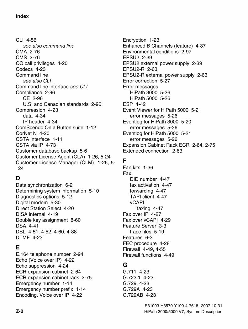
Index For internal use only
3000sbIX.fm
CLI 4-56see also command line
CMA 2-76CMS 2-76CO call privileges 4-20Codecs 4-23Command line
see also CLICommand line interface see CLICompliance 2-96
CE 2-96U.S. and Canadian standards 2-96
Compression 4-23data 4-34IP header 4-34
ComScendo On a Button suite 1-12CorNet N 4-20CSTA interface 1-11CSTA via IP 4-73Customer database backup 5-6Customer License Agent (CLA) 1-26, 5-24Customer License Manager (CLM) 1-26, 5-24
DData synchronization 6-2Determining system information 5-10Diagnostics options 5-12Digital modem 5-30Direct Station Select 4-20DISA internal 4-19Double key assignment 8-60DSA 4-41DSL 4-51, 4-52, 4-60, 4-88DTMF 4-23
EE.164 telephone number 2-94Echo (Voice over IP) 4-22Echo suppression 4-24ECR expansion cabinet 2-64ECR expansion cabinet rack 2-75Emergency number 1-14Emergency number prefix 1-14Encoding, Voice over IP 4-22
Encryption 1-23Enhanced B Channels (feature) 4-37Environmental conditions 2-97EPSU2 2-39EPSU2 external power supply 2-39EPSU2-R 2-63EPSU2-R external power supply 2-63Error correction 5-27Error messages
HiPath 3000 5-26HiPath 5000 5-26
ESP 4-42Event Viewer for HiPath 5000 5-21
error messages 5-26Eventlog for HiPath 3000 5-20
error messages 5-26Eventlog for HiPath 5000 5-21
error messages 5-26Expansion Cabinet Rack ECR 2-64, 2-75Extended connection 2-83
FFan kits 1-36Fax
DID number 4-47fax activation 4-47forwarding 4-47TAPI client 4-47vCAPI
faxing 4-47Fax over IP 4-27Fax over vCAPI 4-29Feature Server 3-3
trace files 5-19Features 6-3FEC procedure 4-28Firewall 4-49, 4-55Firewall functions 4-49
GG.711 4-23G.723.1 4-23G.729 4-23G.729A 4-23G.729AB 4-23
P31003-H3570-Y100-4-7618, 2007-10-31Z-2 HiPath 3000/5000 V7, System Description
3000sbIX.fm
For internal use only Index
HH.225.0 4-14H.225.0 Q.931 4-14H.245 4-14H.323 4-14H.323 client 4-43H.323 clients 4-43HG 1500
as Internet gateway 4-31management tools 4-56protocols 4-14
Hicom.pds 5-7HiPath 3000 Manager E 4-57HiPath 3150 2-52HiPath 3250 2-52HiPath 3300 2-65HiPath 3350 2-41HiPath 3500 2-53HiPath 3550 2-27HiPath 3800 2-6HiPath 5000
Feature Server 3-3HiPath Manager PCM Trace Monitor 5-19Presence Manager 3-5RAM requirements 3-6software structure 3-3state viewer 5-22
HiPath 5000 RSM 4-19HiPath Attendant B 8-108HiPath ComScendo Service 1-2, 3-1
state viewer 5-22HiPath Cordless Office 2-80
base stations 2-80extended connection 2-83single-cell BS 2-80, 2-82system configuration 2-82tech. base station data 2-87
HiPath Fault Management 5-23HiPath Feature Access 4-30HiPath Inventory Manager 5-10
analysis 5-25HiPath Manager PCM Trace Monitor 5-19HiPath Software Manager
analysis 5-25
APS transfer 5-9backing up customer data 5-7backing up system components 5-11determining system information 5-10
HTTP management applications 4-57
IIMODC 5-30Insecure mode 4-39Integrated modem 5-30Interface-to-interface ranges 2-92Internet 4-48Internet access 4-51Internet gateway 4-31Internet telephony 8-28, 8-53IP accounting 4-35IP address filter 4-33IP address mapping 4-53IP Control Protocol 4-34IP firewall see firewallIP header, compression 4-34IP mobility enhancement 1-14IP networking 4-18, 4-69IP trunking 4-62IP trunking see IP networkingIPCP 4-34ISDN Message Decoder 5-18
JJitter buffer 4-24
KKeep Alive 4-56Key assignment 8-60Key programming 8-60
LLAN connection 4-1, 4-9LAN connection via LIM 4-9LAN network 4-1LAN2 4-60, 4-88LAN-LAN and teleworking 4-49LAN-LAN connection 4-49Least cost routing 4-20License Management System 1-26
P31003-H3570-Y100-4-7618, 2007-10-31HiPath 3000/5000 V7, System Description Z-3
Index For internal use only
3000sbIX.fm
Licensing 1-26analysis 5-24License Management System 1-26
LIMS 2-20Local power supply 8-75LOG area 5-40, 5-43Loss of packets 3-14LUNA2
bridging times 2-18calculating the number required 2-19
MMAC address filter 4-34Management information bases (MIB) 4-76Management tools 4-56Manager E see HiPath 3000 Manager EMandatory message 4-28MIB 4-76, 4-78Migration 1-35MMC
replace 5-8Modem via IP 4-30Multi-gateway administration 4-58Multilink 4-34, 4-49, 4-51Music on Hold 4-20
NName resolution 4-68NAT 4-33Network Address Translation see NATNetworking see IP networkingNumbering plan 2-93Numbering scheme 4-47
OOn a Button suite 1-12OpenStage
accessories 8-21Gigabit variant 8-4OpenStage 20 8-5OpenStage 40 8-7OpenStage 60 8-10OpenStage 80 8-12OpenStage BLF 8-20OpenStage Key Module 8-19
Operating conditions 2-97optiClient Attendant 8-109optiPoint 150S 8-53optiPoint 410
Add-on device configurations 8-52optiPoint 410 advance 8-39optiPoint 410 display module 8-51optiPoint 410 economy 8-33optiPoint 410 economy plus 8-35optiPoint 410 entry 8-31optiPoint 410 standard 8-37optiPoint self labeling key module 8-50
optiPoint 410 SAdd-on device configurations 8-52optiPoint 410 advance S 8-39optiPoint 410 display module 8-51optiPoint 410 economy plus S 8-35optiPoint 410 economy S 8-33optiPoint 410 entry S 8-31optiPoint 410 standard S 8-37optiPoint self labeling key module 8-50
optiPoint 420Add-on device configurations 8-52optiPoint 410 display module 8-51optiPoint 420 advance 8-47optiPoint 420 economy 8-41optiPoint 420 economy plus 8-43optiPoint 420 standard 8-45optiPoint self labeling key module 8-50
optiPoint 420 SAdd-on device configurations 8-52optiPoint 410 display module 8-51optiPoint 420 advance S 8-47optiPoint 420 economy plus S 8-43optiPoint 420 economy S 8-41optiPoint 420 standard S 8-45optiPoint self labeling key module 8-50
optiPoint 500adapter
acoustic adapter 8-71analog adapter 8-70configurations 8-73ISDN adapter 8-72option bays (adapter slots) 8-69
P31003-H3570-Y100-4-7618, 2007-10-31Z-4 HiPath 3000/5000 V7, System Description
3000sbIX.fm
For internal use only Index
phone adapter 8-73recorder adapter 8-72
add-on device configuration 8-68BLF 8-67key module 8-66key programming 8-60optiPoint application module 8-67telephones
advance 8-64basic 8-63economy 8-63entry 8-61standard 8-64
optiPoint 600 office 8-56optiPoint accessories, part numbers 8-75optiPoint application module 8-67optiPoint Attendant 8-117optiPoint BLF 8-67optiPoint key module 8-66Order of installation 6-6Output formats for call detail recording 11-1
PPAP 4-49, 4-51Password 5-34Payload resources 4-11Payload switching 4-43PBX routing 4-69PDS file 5-7Permit firewall 4-55PKI servers 4-44Possible Configurations for the Add-On De-vices 8-20
Power requirement (boards, workpoint cli-ents, adapter) A-1
PPP 4-32multilink 4-49, 4-51PPP connections 4-49
PPPoE 4-32, 4-51, 4-53PPTP 4-32, 4-51Presence Manager 3-5
trace files 5-19Privacy and data security 1-42Privacy Release key 1-10
Programming the function keys 8-60Project planning tool 10-18PSTN partner 4-86PSUP 2-45
QQoS 4-23, 4-58Quality assurance procedures 3-14Quality of Service 4-23, 4-58
RRanges
CorNet N/CorNet-NQ 2-92trunk connection 2-92
RAS 4-14Redundancy messages 4-28Redundancy procedure 4-28Remote administration 5-31Remote control 4-54Remote service 5-29Ringer signaling, varying 1-8Router call number 4-84Routing 4-49, 4-68RSA 4-41RTCP 4-14RTP 4-14
SSAFETY International 2-96Second LAN 4-88Security 4-54, 5-34Security associations 4-41Security associations see security associa-tions
Security policy 4-40Service call via code 5-31Shift key 8-60Short-hold 4-34Signaling & Payload Encryption 1-23Signaling encryption 1-23Signaling resources 4-11Single-cell base station 2-80, 2-82Single-PC solution (HiPath 5000) 3-7SIP networking 4-2SIP protocol 4-2, 8-28, 8-53, 8-102
P31003-H3570-Y100-4-7618, 2007-10-31HiPath 3000/5000 V7, System Description Z-5
Index For internal use only
3000sbIX.fm
SIP terminals 1-20Smartset 4-45SNMP 4-56, 4-76, 4-78, 5-23
messages 4-77traps 4-77
SSL 4-39Static traffic capacity
HiPath 3300 2-66HiPath 3350 2-42HiPath 3500 2-54HiPath 3550 2-29HiPath 3800 2-14
Station diagnosis 5-16Station number verification 4-55Station status 5-16System administration, options 5-2System capacities 10-1System client 4-43System power requirement A-1System software upgrade 5-8System Speed Dialing 4-19
TTAPI 4-46TAPI 120 V2.0 6-1TAPI 170 V2.0 6-1TAPI clients 4-46TCP 4-15T-DSL 4-52Technical base station data 2-87Technical specifications 2-89, 2-96Telematics 4-45Telephones
interface to interface ranges 2-92Teleworking 4-49Terminal test 5-20Toll restriction 4-20Trace options
Customer License Agent (CLA) 5-24Customer License Manager (CLM) 5-24HiPath 3000 5-18HiPath Inventory Manager 5-25HiPath Manager PCM Trace Monitor 5-19HiPath Software Manager 5-25
Traffic capacity (in erlangs)HiPath 3300 2-66HiPath 3350 2-42HiPath 3500 2-54HiPath 3550 2-29HiPath 3800 2-14
Traffic statistics (Voice over IP) 4-22Traps 4-77Trunk diagnosis 5-15Trunk status 5-15Trunking see IP networkingTunnel 4-41
UUDP 4-15, 4-28Updating HG1500 5-9Updating system software 5-9Upgrade Manager 5-9Upgrading the system software 5-8UPSC-D 2-32, 2-45
bridging times 2-32, 2-46UPSC-DR 2-57, 2-69
bridging times 2-58, 2-69User groups and their access rights 5-36
VVAD 4-24vCAPI 4-36, 4-45
and Smartset 4-45and TAPI 4-46file transfer 4-48Internet access 4-48
vCAPI and fax 4-47vCAPI and file transfer 4-48Virtual ports 4-19Virtual Private Networks see VPNVoice Activity Detection 4-24Voice coding 4-23Voice over IP 4-21
bandwidth requirement 4-2encoding 4-22environment requirements 4-25H.323 clients 4-43
VPN 4-38VPN tunnel see tunnel
P31003-H3570-Y100-4-7618, 2007-10-31Z-6 HiPath 3000/5000 V7, System Description

3000sbIX.fm
For internal use only Index
WWBM 4-56Web-based management 4-56Web-based management (WBM) 3-3Web-based management see WBMWhisper 1-9Workpoint client power requirement A-1
XX.509 4-41
P31003-H3570-Y100-4-7618, 2007-10-31HiPath 3000/5000 V7, System Description Z-7

Index For internal use only
3000sbIX.fm
P31003-H3570-Y100-4-7618, 2007-10-31Z-8 HiPath 3000/5000 V7, System Description