HillstoneNetworks,Inc. HillstoneSecurityManagementUser Guide
321
Hillstone Networks, Inc. Hillstone Security Management User Guide Version 3.0R2
Transcript of HillstoneNetworks,Inc. HillstoneSecurityManagementUser Guide

HillstoneNetworks, Inc.
Hillstone Security Management UserGuideVersion 3.0R2

Copyright 2018 Hillstone Networks, Inc.. All rights reserved.
Information in this document is subject to change without notice. The software described in this document is furnishedunder a license agreement or nondisclosure agreement. The software may be used or copied only in accordance withthe terms of those agreements. No part of this publication may be reproduced, stored in a retrieval system, or trans-mitted in any form or any means electronic or mechanical, including photocopying and recording for any purposeother than the purchaser's personal use without the written permission of Hillstone Networks, Inc..
Hillstone Networks, Inc.
Contact Information:
US Headquarters:
Hillstone Networks
292 Gibraltar Drive, Suite 105
Sunnyvale, CA 94089
Phone: 1-408-508-6750
http://www.hillstonenet.com/about-us/contact/
About this Guide:
This guide gives you comprehensive configuration instructions of Hillstone Networks, Inc. HSM .
For more information, refer to the documentation site: http://docs.hillstonenet.com.
To provide feedback on the documentation, please write to us at:
Hillstone Networks, Inc.
TWNO: TW-HSM-UNI-3.0R2-EN-V1.0-2018/8/15

Contents
Contents 1
Preface 1
Conventions 1
Introduction to HSM 1
HSM Deployment Scenarios 1
Introduction to HSM Device 2
Hardware Specification 2
Deploying HSM Management Environment 3
Deploying HSM Management Environment 4
Configuring HSM IP Address 4
Configuring System Time 6
Adding Hillstone Devices to HSM System 6
Managing the Added Hillstone Devices 8
Main Page 9
Level-1 Navigation Pane 9
Level-2 Navigation Pane 10
Information Bar 11
Toolbar 11
Main Window 11
User Information 12
Alarms 13
Introduction to System Management 14
User Management 15
Creating a User 15
Editing a User 16
Deleting a User 16
Enabling/Disabling a User 16
Resetting Password 16
Creating a Role 17
Deleting a Role 17
AAA Server 17
Authentication Configuration 18
Distribute Management 19
Disk Management 21
Configuring HSM System Time 21
TOC - 1

HSM Network Management 22
Monitor Configuration 23
HSM System Status Monitor 24
Viewing Status 25
Setting Threshold 26
HSM System Configuration Management 26
Back up a System Configuration File 26
Export a System Configuration File 27
Restore a System Configuration File 27
Delete a System Configuration File 27
Configuring Trusted Host 28
Configuring WEB Port 28
HA Management 29
HSM System Upgrade 31
System Upgrade 31
Rollback 31
Restoring to Factory Defaults 31
Upgrading Signature Database for HSM 31
Configuring an Email Account 32
SMS Modem Configuration 33
SMS Modem Baud Rate 33
SMS Modem Signal Intensity 33
SMS Modem Status 33
Configuring SMS Parameters 34
Testing SMS 34
Diagnose Tools 34
Log Backup Management 35
FTP Server Configuration 35
Log Import 36
Log Backup 36
Manual Backup 36
Auto Backup 36
Log Clean 37
Device Management 38
Device Management 39
Creating a Device Group 39
Adding a Device to a Device Group 40
Deleting a Device from a Device Group 40
TOC - 2

Editing a Device Group 40
Deleting a Device Group 40
Favorite Device 41
Viewing Device Details 41
Session Query 43
Deleting a Device from HSM 43
Online Reboot 44
Immediate Reboot 44
Reboot on Schedule 44
Setting Restart Parameter 45
HA management for the managed devices 45
Introduction to Device Upgrade 46
Configuring a Device Upgrading Task 46
Importing/Deleting a Firmware 46
Specifying the Upgrade Management IP 47
Configuring a Device Upgrading Task 47
Checking the Task Status 48
Viewing Device Upgrading Logs 48
Level-1 Navigation Pane 49
Upgrading Navigation Pane 49
Filter 49
Main Window 49
Upgrading Signature Database 50
As a Update server 50
Configuring Upgrade Templates 50
Configuration File Management 52
Managing Configuration File 52
Retrieving Configuration File 52
Retrieving Configuration Files Automatically 52
Retrieving Configuration Files Manually 53
Retrieving Configuration Files on Schedule 53
Viewing Configuration File 54
View Change History 54
Restoring Configuration Files 54
Exporting Configuration Files 55
Importing Configuration Files 55
Comparing Configuration Files 55
Editing Configuration File 56
TOC - 3

Deleting Configuration File 56
Searching Configuration File 56
Managing Configuration Change History 57
Editing Change Record 57
Deleting Change Record 57
Searching Change History 57
Device Management Configuration Example 58
Deployment Scenario 58
Requirement 58
Configuration Steps 58
Introduction to Configuration Management 60
Device Configuration 62
Device Configuration 62
Policy Configuration 62
Creating a Policy Rule 62
Editing Rules 66
Creating a Rule Group 66
Moving Rules and Groups 67
Deleting a Rule Group 67
Creating a Partition Group 68
Deploying a Batch of Rules 68
Choose Partition Group 68
Choose Deploying Position 69
Configure Policy Rules 69
Opening Local Snapshot 69
Rule Match Analysis 69
Policy Rule Management 70
Converting a Policy from Private to Shared 71
Configuring the Policy-based Protection Function 71
iQoS 73
Implement Mechanism 73
Pipes and Traffic Control Levels 74
Pipes 74
Traffic Control Levels 75
Enabling/Disabling Traffic Control 76
Pipe Configuration 76
Basic Operations 76
Creating a Pipe 77
TOC - 4

NAT 82
Creating a SNAT Rule 82
Editing/Deleting a SNAT Rule 83
Creating an IP Mapping Rule 84
Creating a Port Mapping Rule 84
Creating an Advanced DNAT Rule 85
Route 86
Creating an Route Item 86
Synchronizing Configuration 87
Specifying Configuration 89
Snapshot Management 91
Locking Configuration 91
Device Object 92
Zone 93
Address Books 94
Service Books 94
Application Books 96
Schedules 97
Interface 98
SLB Server Pool 101
Intrusion Protection System 103
Configuring IPS Global Parameters 103
Configuring an IPS Rule 103
For NGFW of 5.5R2 or the previous versions 103
Creating an IPS Rule 103
Configuring Protocol Signature 104
Configuring a Protocol 105
Configuring Signature 112
WebServer Configuration 113
For IPS devices and NGFW of 5.5R3 or the later version 119
Creating an IPS rule 119
Enabling the Zone-based or Policy-based IPS Function 132
Avti-Virus 132
Configuring Anti-Virus Global Parameters 132
Creating Anti-Virus Rule 132
Enabling the Zone-based or Policy-based Anti-Vrius Function 134
Threat Protection 134
Editing the Device Threat Protection Configuration 134
TOC - 5

Device Threaten Configuration List 136
Searching the Specific Signature Entry Details 136
Creating a User-defined Signature 137
URL Filter 140
Configuring URL Filter 140
Predefined URL DB 142
User-defined URL DB 142
Configuring User-defined URL DB 142
Keyword Category 143
Configuring a Keyword Category 144
Warning Page 144
Configuring Block Warning 144
Configuring Audit Warning 145
Converting the Private Object to Shared Object 145
Viewing the Operation Records 146
Checking the Redundant Object 146
VPN 146
PKI 154
User 156
Role 162
AAA Server 165
Introduction to Global Configuration 175
Global Configuration 175
Policy Configuration 175
Creating a Shared Policy 175
Rule Configuration 176
Creating a Policy Rule 176
Creating a Rule Group 177
Moving Rules and Groups 177
Deleting a Rule Group 177
Viewing Operation Record 177
Opening Local Snapshot 177
Rule Match Analysis 177
Rule Conflict Check 177
Setting Head or Tail Policy 178
Viewing Policy Relationship 178
Viewing Topology Map 178
Configuring the Policy-based Protection Function 179
TOC - 6

iQoS 180
NAT 181
Creating a SNAT 181
Editing/Deleting a SNAT 182
Creating a SNAT Rule 182
Editing/Deleting a SNAT Rule 183
Creating a DNAT 184
Editing/Deleting a DNAT 184
Creating an IP Mapping Rule 184
Creating a Port Mapping Rule 185
Creating an Advanced DNAT Rule 185
Editing NAT 187
Setting Father NAT 187
Viewing Relationship 187
Viewing Topology Map 187
Editing Topology Map 188
Viewing Operation Record 188
Route 188
Creating a Destination Route 188
Editing/Deleting a Destination Route 189
Creating an Route Item 189
Editing/Deleting a Route Item 190
Configuration Bundle 190
Creating a Configuration Bundle 190
Method 1: 191
Method 2: 191
Joining Configuration Bundle 192
Copying a Configuration Bundle 193
Global Object 193
Zone 193
Address Books 194
Service Book 195
Application Books 196
Schedules 197
Virtual Router 197
Interface 198
SLB Server Pool 199
Intrusion Protection System 201
TOC - 7

Configuring IPS Global Parameters 201
Configuring an IPS Rule 201
For IPS devices and NGFW of 5.5R3 or the later version(New IPS) 201
For NGFW of 5.5R2 or the previous versions(Old IPS) 202
Configuring Protocol Signature 203
Configuring a Protocol 203
Configuring Signature 211
Searching the Specific Signature Entry Details 211
Configuring a Specific Attacking Signature 211
Configuring a WebServer 212
Enabling the Policy-based IPS Function 218
Anti-Virus 218
Configuring Anti-Virus Global Parameters 218
Creating a Shared Anti-Virus Rule 218
Enabling the Policy-based Anti-Virus Function 220
Threat Protection 220
Creating a Shared Threat Protection 220
Configuring a Shared Threat Protection 220
Global Threaten Configuration List 222
Searching the Specific Signature Entry Details 222
Creating a User-defined Signature Rule 223
URL Filter 226
Configuring URL Filter 226
Predefined URL DB 228
User-defined URL DB 228
Configuring User-defined URL DB 228
Keyword Category 229
Configuring a Keyword Category 230
Warning Page 230
Configuring Block Warning 230
Configuring Audit Warning 231
User 231
Role 232
AAA Server 232
Editing/Deleting an Object 232
Default Parameters 233
Task Management 234
Task Management Window 234
TOC - 8

Viewing Task Logs 235
Introduction to Monitor 236
Device Monitor 237
Main Page 237
Details Page 238
Drill-down Sub-page 239
Trend Page 239
User Monitor 240
Main Page 240
Details Page 241
Drill-down Sub-page 242
Trend Page 242
Application Monitor 244
Main Page 244
Details Page 245
Drill-down Sub-page 246
Trend Page 246
Network Threat Monitor 248
Main Page 248
Traditional 248
Intelligence 249
Statistics Period 249
Details Page 250
Drill-down Sub-page 251
Trend Page 251
Network Behavior Monitor 252
Main Page 252
Details Page 254
Drill-down Sub-page 254
Trend Page 255
VPN Monitor 256
Tunnel Statistics Page 256
Device VPN Traffic Statistics Page 257
MyMonitor 261
Adding to MyMonitor 261
Creating a New Monitor Group 261
Deleting a Monitor Group 261
Viewing Information in MyMonitor 262
TOC - 9

Introduction to the Alarm Function 263
Introduction to Alarm 264
Searching Alarm Information 264
Searching Alarm Information 264
Reading Alarm Information 264
Alarm Analysis 265
Device Analysis 265
Trend Analysis 266
Introduction to the Alarm Rule 268
Configuring the Alarm Rule 268
Viewing a Predefined Alarm Rule 268
Creating a User-defined Alarm Rule 269
Editing an Alarm Rule 269
Configuring an Alarm Recipient 269
Enabling/Disabling an Alarm Rule 270
Deleting an Alarm Rule 270
Emptying Recycle Bin 270
Introduction to Report 271
Introduction to Report File 272
Viewing a Report File 272
Managing a Report File 273
Downloading a Report File 274
Deleting a Report File 274
Restoring a Report File 274
Deleting a Report File Permanently 274
Introduction to Report Template 276
Configuring a Report Template 276
Creating a User-defined Template 276
Editing a User-defined Template 280
Deleting a User-defined Template 281
Restoring a User-defined Template 281
Deleting a User-defined Template Permanently 281
Managing a Report Schedule 282
Adding a Report Schedule 282
Viewing a Report Schedule/Report Schedule Running Log 282
Deleting a Report Schedule 282
Enabling/Disabling a Report Schedule 282
Report Server 283
TOC - 10

Configuring Servers 283
Introduction to Log 284
Introduction to Log 284
Log 284
Log Severity 284
Old Version Log 285
Introduction to Log Window 286
Level-1 Navigation Pane 286
Log Navigation Pane 286
Old Version Log 286
Log Filter 286
Log Chart 287
Toolbar 287
Log Window 287
Searching Log Messages 287
Online/Offline Log 288
Operation Log 288
Introduction to Log Window 290
Log Navigation Pane 290
Toolbar 290
Filter 290
Log Window 290
Searching Logs 291
Setting Filter Conditions 291
Managing Logs 294
Creating a New User-defined Search 294
Deleting a User-defined Search 294
Exporting Logs 294
Importing Logs 295
Backing Up Logs 295
Cleaning the Logs 296
HSM Configuration Example 298
Deployment Scenario 298
Requirement 298
Configuration Steps 298
Preparation 298
Configuration Steps(Requirement) 298
Configuration Steps(Requirement 2) 299
TOC - 11

Configuration Steps (Requirement 3) 301
Managing HSM via Console Port 304
Accessing HSM via Console Port 304
Command Introduction 304
TOC - 12

Preface
Thanks for choosing the network security products from Hillstone Networks, Inc. This document is an online help for Hill-stone HSM, mainly covering the following contents:
HSM hardware specifications;
HSM management introduction and configuration;
HSM deployment and configuration example.
Convent ionsThis manual uses the following conventions for your convenience to read and understand:
Tip: provides related reference, such as links to other chapters or sections.
Note: indicates important instructions for you better understanding, or cautions for possible system failure.
Bold font: indicates links, tags, buttons, checkboxes, textboxes, or options. For example, "Click Login to log into thehomepage of the device", or "To change MTU, select Manual, and type an appropriate value into the textbox."
CLI: brace ({ }) indicates a required element; square bracket ([ ]) indicates an optional element; vertical bar (|) sep-arates multiple mutually exclusive options; bold indicates an essential keyword in the command, and you must enterthis part correctly; italic indicates a user-specified parameter.
The command examples may vary from different platforms. In the command examples, the hostname in the promptis referred to as host-name.
Preface 1

Int roduct ion to HSM
Hillstone Security Management (HSM) is a centralized security management system independently researched anddeveloped by Hillstone. HSM can centralizes the control and management of multiple Hillstone devices in the network.After successful deployment, HSM allows users to perform the following operations via secure connection:
Viewing the operation status, resource utilization, logs, ect. of the managed devices;
Monitoring the managed devices and viewing monitor details, including traffic monitor, user monitor, NBC monitor,ect.;
Monitoring the operation status of managed devices by alarms. This function can help you to learn problems in net-work devices timely, speed up response to network problems, and lower risks of network failures;
Obtaining device statistics reports periodically. This function allows you to learn network status and analyze networkaccurately;
Centralizing policy management and batch deploying rules. This function improves availability and usability ofpolicy management;
Centralizing device upgrade. This function simplifies software management.
HSM Deployment Scenar iosTypically HSM can be deployed in two scenarios: Internet and Intranet.
Internet deployment: HSM and managed devices are connected via Internet. You can manage devices in different net-work segments by HSM if the routes between HSM and managed devices are reachable, as shown below:
Intranet deployment: HSM and managed devices belong to the same Intranet. You can manage devices in theIntranet via HSM, as shown below:
Introduction to HSM 1

Int roduct ion to HSM DeviceHillstone provides the following HSM product:
HSM-50: Capable of managing at least 5 (default) and up to 100 Hillstone devices. The amount of managed devicesis controlled by a license.
HSM-200: Capable of managing at least 5 (default) and up to 500 Hillstone devices. The amount of managed devicesis controlled by a license.
H ardw are Specif ica t ion
HSM-50 hardware adopts a rack-mountable server. The main hardware specifications are shown below:
Item Specification
CPU 4*Intel(R) Xeon(R) CPU E3-1220 v3 @ 3.10GHz
Memory 8GB (4*2GB)
Hard Drive 2TB (2*1TB)
NIC BCM 95720 dual-port gigabit Ethernet NIC
HSM-200 hardware adopts a rack-mountable server. The main hardware specifications are shown below:
Item Specification
CPU 2*Intel Xeon Processor E5606 2.13 GHZ
Memory 8GB (4*2GB)
Hard Drive 4TB (4*1TB)
NIC Broadcom 5716 dual-port gigabit Ethernet NIC
Introduction to HSM 2

Deploying HSM Management Environment
Configurations related to deploying HSM management environment include:
Deploying HSM Management Environment
Main page
Deploying HSMManagement Environment 3

Deploying HSM Management EnvironmentTo deploy HSM management environment, take the following steps:
1. Place HSM to an appropriate location in the network according to networking and management requirement.
2. Configure an IP address for HSM and make sure the route between HSM and the managed devices are reachable.
3. Configure system time for HSM.
4. Configure options related to HSM management on Hillstone devices, and make sure HSM can recognize the devices.
Completing the above configurations, you can centralize device management on HSM.
Conf igur ing HSM IP AddressThe default IP address configured on eth0 port of HSM is 192.168.1.1/24. When using HSM for the first time, you can visitHSM system management page via this interface and configure network-related options, so that HSM can adapt to thenetwork environment. HSM supports HTTP and HTTPS login methods. When using HTTPS to log in, HSM will encrypt datato ensure device's security.
To configure network management options on HSM, take the following steps:
1. Set the IP address of management PC to an IP address that belongs to the same subnet with 192.168.1.1/24; use anEthernet cable to connect the management PC and eth0 port of HSM.
2. In the Web browser (IE9 is recommended) of the management PC, type http://192.168.1.1 or https://192.168.1.1 ,and press Enter. If using HTTPS to log in, choose Continue to this website(not recommended) when the WebBrowser displays tips. The login page is shown below:
3. Type the default username (admin), password (hillstone) and captcha into the boxes respectively. If typing thewrong password for three times, HSM will lock your account for 30 minutes, and disable your account for 30 minuteswhen you type wrong password the fourth times.
Deploying HSMManagement Environment 4

4. Click Login to log into the main page of HSM, as shown below:
5. On the level-1 navigation pane, click System > Device Management > Network Management.
Deploying HSMManagement Environment 5

6. In the Internet Management dialog, configure IP addresses for HSM.
Eth0: Type the IP address and netmask for eth0 port into the IP Address and Netmask boxes respectively.
Eth1: Type the IP address and netmask for eth1 port into the IP Address and Netmask boxes respectively.
Gateway: Type the IP address for the gateway of HSM.
DNS Server: Specify DNS servers for HSM. Type IP addresses for the preferred and backup DNS servers into thePreferred and Backup boxes respectively.
Click OK to complete.
Conf igur ing System T imeSystem time of HSM affects many HSM modules, such as report, log, upgrade, etc. By default, the system time of HSM isset to Beijing time. You can modify the system time as needed, or synchronize the system time of managed devices andHSM via an NTP server. Since the system time is related to many modules, you are recommended to configure the systemtime properly during initial setup, and do not make any modification thereafter.
To configure system time for HSM, on the level-1 navigation pane, click System > Device Management > Date & Time. Inthe HSM System Date and Time dialog, configure options. For more details, see Configuring Date & Time.
Adding Hills tone Devices to HSM SystemYou can add the Hillstone devices to HSM by using one of the following methods:
Configure settings on Hillstone devices. Hillstone devices will automatically register themselves to HSM when the net-work is connected between HSM and Hillstone devices.
Configure settings on HSM to add Hillstone devices. You can add single device or multiple devices.
Note:
HSM will get all the VSYS devices of the physical device to manage them when registering.
After the registration is complete, the zero configuration IPS rules and the zero configuration
Deploying HSMManagement Environment 6

anti-virus rules of IPS devices will not appear in the HSM system until the implementation ofimporting configuration.
To configure setting on Hillstone devices, take the following steps:
1. Log into StoneOS. Select System > HSM from the menu bar.
2. In the HSM Agent Configuration dialog, configure the following options:
HSM Agent: Select the Enable checkbox to enable HSM agent, i.e., allowing HSM to manage the device.
Status: Shows the status of HSM management.
HSM Server IP: Specify the IP address of the HSM. This IP address cannot be 0.0.0.0, 255.255.255.255 or mul-ticast address.
HSM Server Port: Specify the port number of HSM. The value range is 1 to 65535, the default value is 9090. ForStoneOS 4.5R4 and higher versions, port number 9091 is recommended.
HSM Password: Specify the password for accessing HSM. HSM authenticates the device using this password.The value is 1 to 31 characters, the default value is 123456.
Confirm Password: Type the password again to make confirmation.
OK: Click this button to save the settings and make the settings take effect.
Cancel: Click this button to cancel the settings.
3. With the above options configured, the device can register to the accessible HSM in the network, and be managedby HSM.
To configure settings on HSM to add Hillstone devices, take the following steps. You can add single device or multipledevices.
Add single device
1. Click Device > Management from the level-1 navigation pane to enter the Device Management page.
2. Click the triangle icon ( ) next to the Add Device button and select Add Single Device from the drop-downmenu. The Add Multiple Devices dialog pops up.
3. Configure the following options in the dialog:
Device Name: Specify the device name to be displayed in HSM.
IP Address: Specify the device IP address.
Username: Specify the device login name.
Password: Specify the corresponding password.
Device Description: Specify the description for your reference.
Access Protocol: Specify the protocol for the connection between HSM and the device. Enter ssl to use theSSL protocol or enter telnet to use the Telnet protocol. If not specified, HSM will use SSL by default.
Favorite: Specify whether or not to add this device to your favorite device list.
Device Group: Specify a device group for this device.
Deploying HSMManagement Environment 7

4. Click OK to add and register this device to HSM.
Add multiple devices
1. Click Device > Management from the level-1 navigation pane to enter the Device Management page.
2. Click the triangle icon ( ) next to the Add Device button and select Add Multiple Devices from the drop-down menu. The Add Multiple Devices dialog pops up.
3. Click Download Device Info File Template. The Save As dialog appears.
4. Select the location and save the template deviceinfo.xls.
5. Open the template and configure the following options:
Device Name: Specify the device name to be displayed in HSM.
IP Address: Specify the device IP address.
Protocol: Specify the protocol for the connection between HSM and the device. Enter ssh to use the SSHprotocol or enter telnet to use the Telnet protocol. If not specified, HSM will use SSL by default.
Username: Specify the device login name.
Password: Specify the corresponding password.
Device Description: Specify the description for your reference.
6. Save the changes and close the template.
7. In the Add Multiple Devices dialog, click Browse. The Open dialog appears.
8. Locate the modified template and click OK. HSM starts to load the template.
9. After loading the template, click Upload. HSM starts to read the template and add the devices in it to HSM. Iffailed to register one device, all devices in the template will be failed to be registered. To view the error inform-
ation, hover over the exclamation mark ( ) in the Status column.
Managing the Added Hills tone DevicesYou can edit, delete and register the device which has been added to HSM.
Note: HSM supports for HA management of Active-Passive, Active-Active and Active-Peer modesfor the managed devices. When HSM manages the HA function of the managed devices, you canview, configure and share information of the master device in HA. For slave device, you can onlyview the configuration information on HSM.
When the properties of the IP address, username, password and so on change, you can edit device and modify propertyvalues. Take the following steps:
1. Click Device > Management from the Level-1 navigation pane to enter the device management page.
2. Select the device that needs to be edited.
3. Click Edit Device in the toolbar and the Edit Device dialog pops up.
Deploying HSMManagement Environment 8

4. You can modify the property values which need to change.
5. Click OK to save the configurations and close the dialog.
You can delete the related device when there's no need to manage the specified devices. Take the following steps.
1. Click Device > Management from the Level-1 navigation pane to enter the device management page.
2. Select one or more device(s) that need(s) to be deleted.
3. Click Delete Device in the toolbar, and the device will be deleted when you click OK in the pop-up dialog.
You can manually register the device when the device is in an offline state or error state. You can check the link statebetween the Hillstone device and HSM, as well as make sure that the device's IP address, login username and passwordare correct to make device register in HSM successfully. Take the following steps:
1. Click Device > Management from the Level-1 navigation pane to enter the device management page.
2. Select one or more device(s) that need(s) to be registered.
3. Click Register Device in the toolbar and the device will be registered on HSM. You can view the registration result ofthe device according to the displaying of status.
Main PageAfter deploying HSM management environment, to log into the system, take the following steps:
1. Type http://HSM management IP or https://HSM management IP in the web browser, and press Enter.
2. In the login page, type the username, password and verification code and log into the main page. The default user-name and password of HSM are admin and hillstone respectively.
The main page layout of HSM is shown below:
Level-1 Nav igat ion PaneLevel-1 navigation pane allows you to navigate to different modules of HSM.
Module Description
Device Management Device management page. You can view all the manageddevices, and manage the devices in this page, including delet-ing devices, adding to groups or favorite, viewing detailedmonitor information, etc.
Upgrade Device upgrade page. You can upgrade StoneOS running onthe managed devices in this page.
Configuration Configuration management manages all kinds of rules
Deploying HSMManagement Environment 9

Module Description
(policy rule, NAT rule, route rule) and related objects ondevices.
Task HSM uses tasks to track the system operations that need toknow the running status and the running results.
Monitor Monitor page. You can view monitor information of the man-aged devices, and learn and analyze network condition inthis page.
Alarm Alarm page. You can configure alarm rules, view alarm inform-ation, and learn emergent network accidents and anormaliestimely in this page.
Report Report page. You can create report templates and downloadnetwork information and anomalies reports in this page.
Log Log page. You can view logs for the managed devices andHSM itself.
System System User In the User Management dialog, you can configure systemadministrators.
Disk Man-agement
Refer to the configuration of cleanup threshold, you can man-age the storage space of system.
Date & Time In the HSM System Date and Time dialog, you can configuresystem time for HSM.
Parameters In the Email Configuration dialog, you can configure the mailserver that is used by HSM.
Network Man-agement
In the Internet Management dialog, you can configure IPaddresses for the interface, gateway and DNS server of HSM.
Upgrade In the Upgrade dialog, you can upgrade or rollback HSM sys-tem.
Monitor Con-figuration
In the Monitor Configuration dialog, you can enable or dis-able the monitor functions for certain devices.
Status Mon-itor
In the System Status Monitor dialog, you can view the CPUutilization, memory utilization, and disk utilization of HSM.
ConfigurationManagement
In the HSM System Configuration Management dialog, youcan manage the system configuration files.
Help Help HSM help page.
Register In the License dialog, you can apply for or install a license.
About In the About dialog, you can view HSM system information.
Restart Reboot Reboots HSM.
Shutdown Shuts down HSM.
Level-2 Nav igat ion PaneThe level-2 navigation panes of different modules vary. The level-2 navigation pane of the main page (device navigationpane) allows you to navigate to the managed devices. Select a node from the pane to display corresponding devicesinformation in the main window. For example, if you select a device group, all devices in the group will be displayed inthe main window; if you select a device, information about the device will be displayed in the main window.
Functions of device navigation pane are described as below:
Deploying HSMManagement Environment 10

Option Description
DeviceList
Shows all the managed devices. Type a keyword into the searching box to search fora device. Click the icon in the top-right corner of the device list to filter IPS
device, WAF device, NGFW device, BDS device or IDS device.
Favorite Shows all the devices that are added to the favorite. Type a keyword into the search-ing box to search for a device.
RecycleBin
Shows all the devices that are moved to the recycle bin.
I nf ormat ion BarFunctions of inoformation bar are described as below:
Option Description
All Devices Shows the statistics of the managed devices.
IncludeDevices inSub-groups
Select the checkbox to display all the devices in the selected group and all thedevices in the sub-groups of the selected group; clear the checkbox to only dis-play all the devices in the selected group.
Show/HideMonitorPanel
Click the link to show/hide monitor panels (CPU utilization, application traffic,user traffic) of the selected device.
T oolbarFunction buttons of the toolbar are described as below:
Option Description
DeleteDevice
Click the button to delete the device(s) selected in the main window.
Manualrefresh
Specify the refreshing mode. Select Manual refresh from the drop-down list, andclick Manual refresh to refresh the page immediately; select a refreshing period fromthe drop-down list to refresh the page at the specified interval.
Column Customizes columns displayed in the devices list.
Main WindowManaged devices and main information about the devices is displayed in the main window. Click a device or devicegroup in the device navigation pane to show corresponding information in the main window. You can customize thecolumns displayed in the list from the Column drop-down list. Columns of the list are described as below:
Option Description
Name Shows the name of managed device. Different icons before device names meandifferent device types: NGFW , IPS , WAF , BDS , IDS .
Status Shows the status of connection between the managed device and HSM::
Online ( ): The device has been registered successfully and is properlymanaged by HSM.
Registering ( ): The device is being registered to HSM.
Offline ( ): The device has been registered successfully but is not run-ning or connected. After the device is running or the connection works,
Deploying HSMManagement Environment 11

Option Description
the device will automatically register itself to HSM. You can also registerthe device manually.
Error ( ): The device fails to register in HSM. Hover over the icon to viewthe error message.
Host Name Shows the host name of the managed device.
New Sessions Shows the newly created sessions of the managed device.
ConcurrentSessions
Shows the concurrent sessions of the managed device.
ConfigurationModifiedTime
Shows the last modified time of the configurations of the managed device.
Address Shows the IP address of the managed device.
SN Shows the SN of the managed device.
StoneOS Shows the StoneOS version running on the managed device.
SystemUptime
Shows the system uptime of the managed device.
Unread Warn-ings
Shows the number of unread warnings related to the managed device.
CPU Shows the average CPU utilization in the latest 5 seconds of the manageddevice.
Memory Shows the current memory utilization of the managed device.
Traffic (bps) Shows the current traffic of the managed device.
Packet For-warding Rate
Shows the packet forwarding rate of the managed device.
Session Shows the session of the managed device. In the Session Query dialog, youcan filter the source address, source port, destination address, destination portand protocol to view the information.
License Shows the license of the managed device. In the License List dialog, you canview customer, type, valid time and other information of the license.
Platform Shows the platform of the managed device.
Description Shows the other information of the managed device.
Reboot log Shows the reboot log of the managed device. In the Log dialog, you can filterthe operation result and protocol and then view the information.
Operation Result:You can select All, Waiting, Success or Failure from theOperation Result drop-down list below.
Time:You can select All, Last 1 hour, Last 1 day, Last 1 week, Last 1 monthor Custom from the Time drop-down list below. Click Custom, the Time dia-log appears. You can specify the period and then select Period specifiedbelow, Before time specified below or Aafter time specified below.
User Inf ormat ionShows the username of the current system administrator.
Click Log Off to log off from HSM.
Deploying HSMManagement Environment 12

AlarmsShows the number of unread alarms. Click the alarm message to redirect to the alarm page. You can read detailed alarminformation and process alarms in the alarm page.
Deploying HSMManagement Environment 13

Int roduct ion to System Management
Configurations related to HSM system management include:
User
User: Configuring HSM system administrator.
Authentication Settings: Specifying the mode of authenticating users who logs in HSM.
Device Management
Disk Management : Managing the storage space of system.
Date & Time: Configuring HSM system date and time. HSM supports synchronization with NTP servers. HSM sys-tem time can be referenced by other modules, such as monitor, alarm, log, upgrade, etc.
Network Management: Configuring parameters for Internet management, including IP address, gateway andDNS servers.
Monitor Configuration: Enabling or disabling the Monitor function. The monitor function is disabled by defaultbecause it consumes more system performance. When the monitor function is disabled, monitor, alarm, report,and monitor charts shown in the single device page are not available.
Status Monitor: Viewing system status, including CPU utilization, memory utilization, and disk utilization.
Configuration Management: Back up configuration and running data for HSM system.
Trusted host: Configuring IP range of the host which is allowed to log in or manage HSM.
WEB Port: Specify the port number which users access to when logging in HSM by WebUI.
Upgrade: Upgrading or rolling back HSM system, or restoring to the factory defaults.
License: Viewing, applying for and installing a license.
Email: Configuring parameters for the Email server that is used to send alarm mails.
SMS Modem Configuration: Configuring parameters for sending SMS and viewing SMS Modem status information,etc.
Diagnose Tools: Testing the devices connection status with HSM, including DNS query, Ping, and Traceroute.
Log Backup Manager: Backing up logs to a FTP server, import logs from a FTP server to HSM, or clear logs in HSM.
Language: Changing the system language. Chinese and English are supported.
Shutdown
Reboot: Click this menu item to reboot the HSM device.
Shutdown: Click this menu item to shut the HSM device down.
Help
Help: Click this menu item to go to the help page of the product.
About: Check the software information.
Introduction to SystemManagement 14

User ManagementHSM supports user access control, and role-based access control mechanism. You can assign different privileges for usersin different roles, which helps different users do different operations.
User and its privilege management has the following characteristics:
1. System admin can specify privileges for every user, and the privilege can be accurate to every HSM function module(eg: Device, Configuration, Report).
2. A user can have one or more roles, and a role can be given to one or more users.
3. Allows to set a physical device or VSYS privileges for a user.
After login the HSM system administrator can use HSM to manage Hillstone devices. HSM users consist of super admin-istrator and administrator. Super administrator has all the privileges of a system administrator, which can cre-ate/delete/enable/disable administrator and specify role/device resources for administrator. The username and passwordfor the default super administrator of HSM are admin and hillstone respectively.
By default, HSM predefines three roles: system administrator, operator, log auditor. Predefined role cannot be modifiedand deleted. And user-defined role can be created according to your need. The followings are descriptions about pre-defined role:
Role Privilege Descriptions
System Administrator Privilege of all operations.
Operator Privilege of Device, Configurations, Monitor, Alarm.
Log Auditor Privilege of log management.
The administrator can do the following operations in HSM:
Creating a User
Editing a User
Deleting a User
Enabling/Disabling a User
Restting Password
Creating a Role
Deleting a Role
Creat ing a UserOnly the user who has the privilege of a system administrator can create a user. To create a user, take the following steps:
1. Click System > User > User from the Level-1 navigation pane.
2. In the User Management dialog, click New. In the User dialog, configure the following options:
Authentication:Specify the authentication for the user. The default authentication is local. When the authen-tication is local, the authorization can only be local. When the authentication is remote, the password item ishidden.
Authorization:Specify the anthorization for the user. The default anthorization is local. When the anthor-ization is remote, local do not support permission configuration.
User: Specify the username for the user.
Password: .Specify the password for the user. It should be 8-32 characters, including numbers, English char-acters(case sensitive), and special characters. The default password is hillstone, and you can change the pass-word as needed.
Introduction to SystemManagement 15
Password Strength: Shows the hints of password complexity.
Enable: Specify the status of the new user. By default the new user is enabled. Clear the checkbox to disable theuser, and the user will not be able to log into HSM.
Timeout (min): Specify the timeout for the user. If the user did not configure any option after timeout, the sys-tem will log off.
Department: Specify the department for the user.
Email: Specify the Email for the user.
Comment: Specify the comment for the user.
Cell: Specify the cell phone number for the user.
3. Click Privilege tab and configure the role for the current user. Specify the role in the Role text box, and then selectwhich device the user can manage in the Resource Device box.
4. Click OK to save the settings.
Also, you can create a new user by a faster way, i.e., copying. To create a user by copying, take the following steps:
1. In the User Management dialog, select a user by selecting the corresponding checkbox from the user list.
2. Click Copy in the toolbar. In the User dialog, all the configurations of the selected user is copied. You only need toconfigure the name for the new user, and modify other options as needed.
3. Click OK to save the settings.
Edit ing a UserTo edit a user, take the following steps:
1. In the User Management dialog, click the username you want to edit.
2. In the Details dialog, edit the user as needed.
3. Click Apply to save the changes. If needed, click Previous/Next to edit other users.
4. Click OK to save the settings.
Delet ing a UserTo delete a user, take the following steps:
1. In the User Management dialog, select a user by selecting the corresponding checkbox from the user list.
2. Click Delete in the toolbar.
3. In the OK dialog, Click OK.
Enabling/ Disabling a UserThe disabled users will not be able to log into HSM. To enable/disable a user, take the following steps:
1. In the User Management dialog, select a user by selecting the corresponding checkbox from the user list.
2. Click Enable/Disable in the toolbar.
Reset t ing Passw ordThis operation will reset the user password to the default password hillstone. Only the default administrator admin canreset password by one of the following methods:
Introduction to SystemManagement 16

In the User Management dialog, select a user by selecting the corresponding checkbox from the user list, and clickReset Password in the toolbar.
In the User Management dialog, click the username you want to edit. In the Details dialog, click Reset Password.
Creat ing a RoleTo create a role, take the following steps:
1. Click System > User > User from the Level-1 navigation pane.
2. In the Role tab, click New and the Add Role dialog pops up. Options are described as belows:
Role: Specify the name for the role.
Comment: Specify the comment information.
User: Click the text box and select which users the role belongs to.
Privilege: Specify the privileges for the role on each HSM modules.
3. Click OK to save the settings.
Also, you can create a new role by a faster way, i.e., copying. To create a role by copying, take the following steps:
1. In the Role tab of the User Management dialog, select a role by selecting the corresponding checkbox from the rolelist.
2. Click Copy in the toolbar. In the Add Role dialog, all the configurations of the selected role is copied. You only needto configure the name for the new role, and modify other options as needed.
3. Click OK to save the settings.
Delet ing a RolePredefined role cannot be deleted. The user who has the system administator privilege can delete user-defined roles.And once the role is deleted, the users who has specified to the role will lost all the privileges of the role.
To delete a role, take the following steps:
1. In the Role tab of the User Management dialog, select a role by selecting the corresponding checkbox from the rolelist.
2. Click Delete in the toolbar.
AAA ServerAAA is the abbreviation for Authentication, Authorization and Accounting. Details are as follows:
Authentication: Authenticates users’identities.
Authorization: Grants certain privileges according to the configuration.
Accounting: Records the fees users should pay for their network resource usage.
To configure the AAA server, take the following steps:
1. Click System > User > AAA Server from the Level-1 navigation pane. In the AAA Server dialog, local is the defaultlocal server and does not support editing and deletion.
Introduction to SystemManagement 17

2. Click the New .
3. In the AAA Server Configuration dialog, configure the following options:
Server Name: Specify the server name. You can specify at most 31 characters.
Server Name: Specify the server type is RADIUS。
Server Address: Specify the IP address or domain name for the Radius server. You can specify domains at most31 characters.
Port: Specify the port number for the Radius server. The value range is 1024 to 65535. The default value is 1812.
Password: Specify the password for communication between the server and HSM.
Link Test: Click link test. The system will verify that the configured Radius address is consistent with the Radiusserver configuration. If consistent, the system will prompt AAA server reach. If not, the system will prompt AAAserver can not reach.
4. Click OK to save the configuration.
Note: The system supports adding up to 9 AAA servers.
Authent icat ion Configurat ionThe authentication configuration is used to identify the user's legitimacy. Authenticated users can successfully log in andoperate HSM, and failed users will not be able to log in. HSM support two authentication methods:
Introduction to SystemManagement 18

Local authentication: Configures user information (including username, password and properties) on HSM devices.Local authentication is fast, and can reduce operation cost, but the amount of information that will be stored is lim-ited by the hardware of the device. By default, Hillstone devices use local authentication.
RADIUS authentication: User information is stored in an external RADIUS server, and HSM devices authenticate usersby the external server.
To configure the authentication on HSM, take the following steps:
1. Click System > User > Authentication Configuration from the Level-1 navigation pane.
When user not in local user list, to user remote authentication, choose Yes and select a default authenticationserver, user not in local user list can log in HSM.
When user not in local user list, to user remote authentication, choose No, user not in local user list can notlog in HSM.
2. Click OK to save the configuration.
Note:Under the method of radius authentication, the local authorization need set privilege and theremote authorization get privilege from radius server.
Dist r ibute ManagementFor users who need to manage a large number of devices, one HSM cannot meet their requirements. To resolve the prob-lem, you can use the distributed management function, which means when you configure multiple HSM devices, you canspecify one device as master device and others as slave devices. With this function, you can view information of the slavedevices and their firewalls on the master device. It can alleviate the pressure of single HSM. The distributed managementincludes standalone mode, master mode and slave mode.
Master Mode: When one HSM device manages multiple HSM devices and can view information of these HSM devicesand their firewalls, the current device is the master HSM, and the mode is master mode. The master HSM cannot man-age firewalls directly. One master HSM can register up to 16 slave HSM devices.
Introduction to SystemManagement 19

Slave Mode: When one HSM device is managed by one master HSM, the current device is slave HSM, and the modeis slave Mode. The slave HSM can manage firewalls directly. The slave HSM can only be registered with the user ofadmin on the master HSM.
Standalone Mode: The HSM device in the standalone mode or in the slave mode can manage the firewalls directly,while the standalone HSM cannot be registered on the master HSM. The default mode is standalone mode.
Note: When the master mode switches to the salve mode or standalone mode, the associationrelationship between all users and devices under the master mode will be cleared. When the salvemode or standalone mode switches to the master mode, the association relationship between allusers and devices under the slave mode or standalone mode will be cleared too.
To switch modes of the distributed management, take the following steps:
1. Click System > Distribute Management from the Level-1 navigation pane.
2. Select the mode check box that you needed in the Distribute Management dialog and click OK.
3. If you select the master mode. Click Device > Distribute List > Add Device from the Level-1 navigation pane to enterthe add device page and add slave HSM(s) for Master HSM.
4. Configure parameters in the Add Device dialog.
Option Description
Device Name Specifies the name of the slave HSM device.
Introduction to SystemManagement 20

Option Description
Address Specifies the IP address or domain name of the slave HSMdevice.
Password Specifies the password to log in the slave HSM device.
Device Description Specifies the descriptions of the slave HSM device.
5. Click OK to complete the switching of distributed management modes.
Disk ManagementHSM disk management refers to the configuration of cleanup threshold, you can manage the storage space of system.
To configure the cleanup threshold for HSM disk management, take the following steps:
1. Click System > Device Management > Disk Management from the Level-1 navigation pane.
2. In the Disk Management dialog, configure the following options:
Cleanup Threshold Settings: Specify the cleanup threshold. The default value is 90%, the minimum value is 60%.When the storage reaches the specified threshold , logs of the earliest week will be automatically cleared at00:15 a.m.
3. Click OK to save the settings.
Configur ing HSM System TimeHSM system time can be referenced by other modules, such as log, upgrade, etc. To assure the system time of HSM andthe managed devices are synchronized, you are recommended to configure the same NTP server for HSM and the man-aged devices. You can configure HSM system time manually or by synchronizing with an NTP server.
To configure HSM system time manually, take the following steps:
1. Select System > Device Management > Date & Time from the Level-1 navigation bar.
2. Select appropriate time zone from the HSM System Time Zone drop-down list. If the selected time zone uses DST, the"Automatically adjustment of daylight time clock" check box will be selected automatically.
Introduction to SystemManagement 21

3. The current date and time is shown in the HSM System Time box. If you still need to modify the date or time, typecorrect date and time into the box.
4. Click OK to save the settings.
5. The changed time will be applied to new data and time of existing data won't be updated. In the pop-up Warningdialog , click the yes button to confirm the update.If the time zone is adjusted from east to west, the time of new business data may be the same as the existing busi-ness data.
6. Restart the device and log in again.
To configure HSM system time by synchronizing with an NTP server, take the following steps:
1. Select System > Device Management > Date & Time from the Level-1 navigation bar.
2. Select the Sync with NTP Server check box.
3. Type the IP address for the NTP server into the Server 1 box; if needed, type the IP address for the NTP server intothe Server 2 box, and the system will try to synchronized with Server 2 if synchronization with Server 1 failed.
4. Click OK to save the settings.
Note: Configure the system time properly during the initial setup, and if possible, do not changethe system time thereafter. Otherwise, modules that rely on system time (such as report, log) willbe affected.
HSM Netw ork ManagementHSM network management refers to the configuration of IP address, gateway and DNS servers. These configurations canassure the connectivity between HSM and the managed devices. To facilitate network configuration, eth0 port of HSM isconfigured with a default IP address 192.168.1.1/255.255.255.0.
To configure parameters for HSM network management, take the following steps:
Introduction to SystemManagement 22

1. Click System > Device Management > Network Management from the Level-1 navigation pane.
2. In the Internet Management dialog, configure the following options:
IP Address: Specify the IP addresses for eth0 and eth1 according to network topology.
Netmask: Specify the netmasks for eth0 and eth1 according to network topology.
Gateway: Specify the IP address for the gateway of HSM.
Preferred: Specify the IP address for the preferred DNS server of HSM.
Backup: Specify the IP address for the backup DNS server of HSM.
3. Click OK to save the settings.
Monitor Configurat ionTo ensure the performance of HSM, HSM does not enable the monitor function for any device by default. If desired, youcan enable the monitor function according to your requirements. After enabling the monitor function, the HSM per-formance will be affected. To ensure the adequate performance, it is recommended that the number of monitoreddevices is less than 500.
To configure the monitor function on HSM, take the following steps:
1. Click System > Device Management > Monitor Configuration from the level-1 navigation pane. The Monitor Con-figuration dialog appears.
Introduction to SystemManagement 23

2. To enable or disable the monitor function on HSM for certain devices, choose devices from the device list, and thenclick Monitor Configure . The Monitor Configure dialog appears.
3. In the Email Configuration dialog, configure the following options:
VPN: Enable or disable the VPN monitor function.
Traffic: Enable or disable the traffic monitor function.
Other: Enable or disable the network threat and network behavior monitor function.
Priority: You can select Low, Middle, and High priority. When the monitor data exceed system capacity, systemwill disable the monitor function of low priority device, so as to ensure the monitor data of higher prioritydevice can be processed.
4. Click OK to save the settings. Monitor Configure dialog will be closed, then Update Configure progress bar dis-appears. Click OK to close the dialog.
5. On the Monitor Configuration dialog, click Close to save the settings and close the dialog.
Following functions will be affected after the monitor function is disabled.
Module Details
Monitor Statistics of CPU utilizations, memory utilizations, and total traffic keep updating.Other statistics will not update and can be viewed during a particular period.
Alarm Following alarm rules cannot take effect: VPN Tunnel Interrupt, VPN TunnelTraffic Beyond Threshold, AV Attack Count Beyond Threshold, APP Block CountBeyond Threshold, Email Receiving and Sending Times Beyond Threshold, URLCategory Hit Count Beyond Threshold, Port Traffic Beyond Threshold, and alluser-defined alarm rules that are based on above alarm rules.
Report Since statistics of CPU utilizations, memory utilizations, and total traffic keepupdating, you can generate the report. Other historical statistics will not updateand you can generate the report that contains historical statistics during a par-ticular period.
6. Click Close to close the dialog.
HSM System Status MonitorThe status monitor function monitors the CPU utilization, memory utilization, and disk utilization of HSM. Users can havea well understanding of system status. By configuring the threshold for each monitored object, HSM can generate thealarm when the status of an object keeps exceeding the threshold within the specified period (1 minute by default). Youcan take measures to deal with the alarms.
Introduction to SystemManagement 24

View ing StatusHSM provides the following statistics of the monitored objects: the trend within a specified time cycle, the current status,and other detailed information.
To view the status, click System > Device Management > Monitor Status from the level-1 navigation pane. The SystemStatus Monitor dialog appears.
The line chart shows the trend of the monitored objects. Based on the specified time cycle, HSM will take samplesaccordingly and display the trend in the chart. By default, HSM displays the trend within the latest 1 hour.
The right chart displays the current status of the monitored objects. HSM will refresh the data in every 5 minutes.
View detail: Click the View Detail link of each monitored object to view the detailed information. You can view thecolumn charts of the top 5 processes that occupy the CPU resources and the memory resources individually, and thepie charts of all objects that occupy the disk. The following chart displays the top 5 processes that occupy thememory resources.
HSM supports the predefined time cycle and the custom time cycle. Click Latest 1 Hour on the top right corner to set thetime cycle.
Predefined time cycle: Click Latest 1 Hour and then select a predefined one.
Latest 1 Hour: Displays the statistics of each monitored object within the latest 1 hour. HSM will take samplesevery minute.
Latest 1 Day: Displays the statistics of each monitored object within the latest 1 day. HSM will take samplesevery 10 minutes.
Introduction to SystemManagement 25

Latest 1 Week: Displays the statistics of each monitored object within the latest 1 week. HSM will take samplesevery hour.
Latest 1 Month: Displays the statistics of each monitored object within the latest 1 month. HSM will takesamples every 6 hours.
Custom time cycle: Click Latest 1 Hour and then select Custom. The Select Time dialog appears. You can select thestart time and the end time according to your requirements.
If the custom time cycle is within 6 hours, HSM takes samples every minute.
If the custom time cycle exceeds 6 hours and is less than 1 week, HSM takes samples every 10 minutes.
If the custom time cycle exceeds 1 week and is less than 6 months, HSM takes samples every 6 hours.
If the custom time cycle exceeds 6 months and is less than 1 year, HSM takes samples every 24 hours.
Set t ing T hresholdIf the utilization of the monitored objects keeps exceeding the threshold within the specified period (1 minute bydefault), HSM will generate the alarm.
To set the threshold for monitored objects, take the following steps:
1. Click System > Device Management > Status Monitor from the level-1 navigation pane. The System Status Monitordialog appears.
2. Click Set Threshold. The Set Threshold dialog appears.
3. Set the threshold for each object using one of the methods:
Drag the slider. The exact value will update in the text box.
Enter the value. The slider will move to the exact location.
4. Click OK to save the configuration settings and return to the System Status Monitor dialog. The red line representingthe threshold moves to the correct location.
For more information about configuring alarm rules, refer to Configuring the Alarm Rule.
HSM System Configurat ion ManagementAs a centralized security management system in network, HSM system must guarantee its own stability. For this purpose,HSM is developed to support the following management of its own system configuration file:
Backup: Back up the system configuration file.
Restore: Restore the system configuration file.
Export: Export the system configuration file to the local disk.
Deletion: Delete the backed-up system configuration file.
With these facilities, HSM can quickly resume after accidental breakdown.
Back up a System Conf igurat ion FileTo back up the system configuration file, take the following steps:
1. Click System > Device Management > Configuration Management. The HSM System Configuration Managementdialog appears.
2. Click Backup. The Backup dialog appears.
3. Specify the name of the backup file. By default, the file is named as backup_date_time, for example, backup_201311171035.
Introduction to SystemManagement 26

4. If desired, specify the description for this backup file.
5. Click OK. HSM starts to back up the system configuration file.
After backing up the file, HSM lists this file in the list of the HSM System Configuration Management dialog. You can viewthe detailed information, including the file name, the size, the backup time, the operated user, and the description.
Export a System Conf igurat ion FileTo export the system configuration file from HSM to the local disk, take the following steps:
1. Click System > Device Management > Configuration Management. The HSM System Configuration Managementdialog appears.
2. Select a file to be exported.
3. Click Export. The Save As dialog appears.
4. Select a location and click OK to save the file.
Restore a System Conf igurat ion FileAfter HSM resumes from a breakdown, or changes or upgrades to a new hardware platform, you can restore the systemconfiguration file. Considering the compatibility, it is strongly recommended to restore the configuration file to HSM thathas the same version.
To restore HSM system configurations to a file saved in HSM, take the following steps:
1. With the HSM System Configuration Management dialog active, select a backup file from the file list.
2. Click the triangle ( ) next to the Restore button. Then select Selected File. The Restoring window pops up. HSMstarts to analyze the file.
3. After analyzing the file, HSM starts to restore the file.
4. After restoring the file, HSM restarts.
To restore HSM system configurations to a local-saved file, take the following steps.
1. With the HSM System Configuration Management dialog active, click the triangle ( ) next to the Restore button.Then select Local File. The Restoring window pops up.
2. Click the magnifying glass ( ) to locate the local file and then open it.
When restoring a file backed up by the current HSM itself, the historical data of Monitor, Log, and Alarm in HSMwill remain the same.
When restoring a file that is not backed up by the current HSM, the historical data of Monitor, Log, and Alarm inHSM will be cleared.
3. Click Upload. HSM uploads the file to HSM.
4. After uploading the file, HSM analyzes the file and then starts to restore the file.
5. After restoring the file, HSM restarts.
Delete a System Conf igurat ion FileTo delete a system configuration file, take the following steps:
1. With the HSM System Configuration Management dialog active, select the files to be deleted.
2. Click Delete. The Delete dialog appears.
3. Click OK to delete the selected files.
Introduction to SystemManagement 27

Configur ing Trusted HostHSM device allows only trusted host to manage the system. Trusted hosts are recognized by their IP addresses. If the hostIP address is in the specified IP range, the host is a trusted host. Trusted host includes the following rules:
1. Only system admin can configure a trusted host.
2. By default, the trusted IP range is 0.0.0.0/0, which means all hosts are trusted.
3. Trusted host can be a IP address, IP range or multiple IP addresses.
To configure trusted host, take the following steps:
1. Click System > Device Management > Trusted Host from the Level-1 navigation pane.
2. Click New in the Trusted Host Configuration dialog, options are described as belows:
Host Name: Specify the name for the trusted host. It can be null.
IP Address: Specify the IP address or IP range for the trusted host, eg:10.188.1.10 - 10.188.1.15, or192.168.10.0/24
Remarks: Specify the remark information for the trusted host.
3. Click Save to save the settings.
4. Click OK.
To edit/delete trusted host, take the following steps:
1. Click System > Device Management > Trusted Host from the Level-1 navigation pane.
2. Select a trusted host by selecting the corresponding checkbox from the list, and then click Edit or Delete.
3. Click OK to save the settings.
Configur ing WEB PortYou can modify the port number which users can access to when logging in HSM by Web, in order to ensure the securityof the system.
To configure the webport for HSM, take the following steps:
1. Click System > Device Management > WEB Port from the Level-1 navigation pane.
2. In the WEB Port dialog, configure the following options:
HTTP WEB Port: Specify the port number accessing to HTTP service for HSM. The default value is 80.The valueranges from 1025 to 65535 besides 80,among them 2003~3003、3306、6514、8005、8080、8161、8443、9000、9090、9091、9092、61616、61617 are preoccupied by system.Preoccupied port number can not be configured.
HTTPS WEB Port: Specify the port number accessing to HTTPS service for HSM.The default value is 443.The valueranges from 1025 to 65535 besides 443,among them 2003~3003、3306、6514、8005、8080、8161、8443、
Introduction to SystemManagement 28

9000、9090、9091、9092、61616、61617 are preoccupied by system.Preoccupied port number can not be con-figured.
3. Click OK to save the settings.
Note: After webport is modified successfully, the previous port will be closed and the web servicewill be restarted.You need to access web service by the new port after the restart.
HA ManagementHA, the abbreviation for High Availability, provides a fail-over solution for communications line or device failure toensure the smooth communication and effectively improve the reliability of the network. To implement the HA functionof the two HSM devices, you need to use the identical hardware platform, firmware version, as well as install the samedevice license whose service is within the validity. When one HSM device is not available or cannot handle the requestfrom the client properly, the request will be promptly directed to the other device that works normally, thus ensuringuninterrupted network communication and greatly improving the reliability of communications.
To configure the HA management in the HSM system, take the following steps:
1. Click System > Device Management > HA Management from the Level-1 navigation pane to enter the device con-figuration page.
2. Configure the parameters in the HA Management dialog.
The parameters of HA management are explained as follows.Option Description
Current Role Displays current device's role. When the HA link is not built, the name ofrole is standalone. When the HA link has been built, the current name is thename of the specified management device's role.
Role Specifies the role of the management device. When the role is Master, theconfigurations can be issued. When the role is Slave, the configurationsonly can be viewed. When the role is Standalone, the page will display Dis-able HA and system will disable HA function.
HA Control linkinterface
Specifies a name of the HA control link interface. The control link can syn-chronize all data of the two devices.
Local IP Specifies the IP address and netmask of the HA control link interface.Peer IP Specifies the peer IP address of the HA control link interface.Virtual IP Specifies the virtual IP address of the HA management device.
Introduction to SystemManagement 29

Option DescriptionHello interval Specifies the Hello interval value. Hello interval refers to the interval for the
HA device to send heartbeats (Hello packets) to other devices in the HAgroup. The Hello interval in the same HA group must be identical.
Preempt Specifies whether the device enables the preemption mode. Only the masterdevice can be configured in the preemption mode currently. If the pree-mption mode is enabled, the master device will preempt to be master againwhen it recovered from breaking down. The preemption mode is disabledby default.
Track Object System uses the track object to monitor the working status of the device.Once the device cannot work normally, system will take corresponding meas-ures immediately.
ping: type a legal IP address or domain name. If the typed IP address ordomain can be connected, it indicates that the device is running normally. Ifnot, the master and backup device will switch.
Monitor/LogSynchronization
Select the Enable check box. System will synchronize monitoring and logdata.
Manual Syn-chronization
Click the Synchronize, the Manual Synchronization dialog will pop up.
Select Use data in peer device to cover data in local device. The Submitprompt box will pop up and display Data in local device will be reset,whether to continue? Click OK. When the synchronization completes,the local data will be covered.
Select Use data in local device to cover data in peer device. The Submitprompt box will pop up and display Data in peer device will be reset,whether to continue? Click OK. When the synchronization completes,the peer data will be covered.
HA Alarm Select the Enable check box. When the status of interface changes, thedevice will alarm.
Database Syn-chronize Status
Displays synchronization status of current database. The statuses includeNormal, Synchronizing and Failed to synchronize.
File SynchronizeStatus
Displays synchronization status of current file. The statuses include Normal,Synchronizing and Failed to synchronize.
HA HeartBeatStatus
Displays HeartBeat status of current HA. The statuses include Normal andFailed.
3. Click OK, and the HA Creating dialog will pop up. You can view the process of HA creating in the dialog.
The parameters are explained as follws.
Option Description
Interface modification You can view the result of modifying the HA connection inter-face in system.
Wait for configuration of You can view the result of the peer configuration and the con-
Introduction to SystemManagement 30

Option Description
the peer and connectingto the peer
nection between the local device and peer device in system.You need to configure the peer parameters before the HAbeing built or when the HA is built in process. You also need tomake sure HSM has connected with the peer device. Otherwise,it cannot be connected successfully.
HA Establish ConditionChecking
You can view the result of checking if the condition of estab-lishing HA is met in system.
HA Environment Build You can view the result of building the HA environment in sys-tem.
Master/Slave Device DataSynchronization
You can view the result of synchronizing data of the master andslave device in system. If the Monitor/Log Synchronization isenabled, the device will synronize all data. Otherwise the devicewill synchronize data except Monitor/Log data.
HA Build Successfully You can view the result that whether HA is built successfully.
4. Click Done to complete the HA building.
HSM System UpgradeHSM supports system upgrade, rollback and restoring to the factory defaults.
System UpgradeTo upgrade HSM system, take the following steps:
1. Click System > Upgrade from the Level-1 navigation pane.
2. In the Upgrade dialog, click to select an HSM system file.
3. Click Upload.
4. Complete the upgrade procedure as prompted.
RollbackTo roll back to the previous version, take the following steps:
1. Click System > Upgrade from the Level-1 navigation pane.
2. In the Upgrade dialog, click Rollback, and then click OK under the tag.
Restor ing to Factory Def ault sTo restore to the factory defaults, take the following steps:
1. Click System > Upgrade from the Level-1 navigation pane.
2. In the Upgrade dialog, click Factory Defaults, and then click OK under the tag.
Upgrading Signature Database for HSMTo upgrade IPS signature database, application signature database, Anti-Virus signature database or URL database forHSM:
Introduction to SystemManagement 31

Note: When HSM manages the HA function of the managed devices, it supports the upgrade ofsignature database of the managed devices. If the signature databases of the master device andslave device are upgraded to different visions, the signature database of the master device will besynchronized to that of the slave device.
1. Select System > Upgrade from the level-1 navigation panel, and then click the target signature upgrade tab.
2. In the pop-up Library Upgrade dialog box, configure as follows.Option DescriptionCurrent Version Show the current version number of signature database.SN Show the product series number of HSM.Magic Show the Magic code of HSM. Magic code is an encrypted string generated
according to the SN of HSM, which is required when you download thelatest signature file from a default update server.
Remote Upgrade Configure remote online upgrade for signature database.
Upgrade Now: Click Upgrade Online to upgrade the signature data-base right now.
Auto Upgrade: Select Enable Auto Update and specify the autoupgrade time. Click Save to save your changes. This function isenabled by default.
Configure Update Server: System updates the signature databaseeveryday automatically by default. HSM provides three default updateservers: update1.hillstonenet.com, update2.hillstonenet.com and HSMdevice. You can customize the servers according to your need. ClickUpdate Server Configuration, then in the pop-up Update Server dia-log, specify the server IP or domain name.
Local UpgradeClick and select the IPS signature file , Anti-Virus signature file orURL database file in your local PC, and then click Upload.
Note: To get the latest signature file, please enter update1.hill-stonenet.com or update2.hillstonenet.com in the browser's address bar,then click target signature upgrade link in the upper-left corner of thepage. Copy the SN number and Magic code displayed in HSM, then pastethem into the SN and Magic text fields respectively. Fill in the engine ver-sion, platform or current version in accordance with the instruction, thenclick Download to download the latest signature file(e.g. ips.sig).
Configur ing an Emai l AccountThe Email account configured in HSM is used to send alarm mails.
To configure the Email account in HSM, take the following steps:
Introduction to SystemManagement 32

1. Click System > Email from the Level-1 navigation pane.
2. In the Email Configuration dialog, configure the following options:
Mail Server: Specify the IP address of mail server.
Username: Specify the username of Email account.
Password: Specify the password of Email account.
Email Address: Specify the Email address of the Email account.
Testing Recipient: Specify the recipient that is used to test the Email account. Click Test to test if Email can besent by the Email account successfully.
3. Click OK to save the settings.
SMS Modem Configurat ionSMS alarm refers to the alarm information will be sent to the designated administrator by SMS modem.
An external GSM modem device is required for sending SMS messages. First, you need to prepare a mobile phone SIMcard and a GSM SMS Modem. Insert the SIM card into your modem and then, connect the modem and HSM using a USBcable.
The following two models of SMS modem are recommended:
Model Type Chip InterfaceHuatengtongyu GSMMODEM
GSM WAVECOM USB Interface
Jindi GSM MODEM GSM WAVECOM USB Interface
SMS Modem Baud RateYou can view the communication baud rate of SMS modem in Modem SMS Modem Configuration page.
SMS Modem Signal IntensityYou can view the communication signal intensity of SMS modem in Modem SMS Modem Configuration page. Only whenthe signal intensity between 16~31 can the alarm message be sent normally. If the signal intensity is under 15, the alarmmessage may fail to be sent.
SMS Modem StatusThe system will show the modem connection status: sms modem is online, sms modem is offline or no sim in smsmodem.
Introduction to SystemManagement 33

Conf igur ing SMS ParametersYou can define the maximum SMS message number in one hour or in one day. If the messages exceed the maximum num-ber, the system will not make the modem to send messages, but it will keep a log for this behavior.
Option DescriptionMaximum sendingnumber per hour
Defines the maximum message number the modem can send in one hour,the value ranges from 1 to 1000.
Maximum sendingnumber per day
Defines the maximum messages number the modem can send in one day,the value ranges from 1 to 1000.
T est ing SMSTo test if the message sending works, you can send a test text to a mobile.
To send a text message to a specified mobile number:
1. Select System > SMS Modem Configuration.
2. Enter a mobile phone number in the text box.
3. click Send.If the SMS modem is correctly configured and connected, the phone using that number will receive a text message.
Note: vHSM does not support SMS alarm.
Diagnose ToolsDuring HSM managing the devices, diagnose tools can help you test network availability and diagnose system errorsqulickly. You can choose the tools according to your requirements.
To use HSM diagnose tools, take the following steps:
1. Select System > Diagnose Tools > Test tools from the Level-1 navigation bar. The Test Tools dialog appears.
2. You can choose the tools according to your requirements, configure the following options:
DNS Query : Specify the DNS domain name. Check the legitimacy of domain name, and then the domain's IPaddress and fault messages will be displayed. If the DNS server is not configured, a dialog will pop up toprompt.
Introduction to SystemManagement 34

Ping: Specify the DNS domain name or IP address, click Test, and then the results of ping will be displayed.
Traceroute: Specify the DNS domain name or IP address, click Test, and then the results of traceroute will be dis-played.
3. Click Test, and then the results will be displayed in the below text box.
Log Backup ManagementHSM system supports the logs' backup and import. Before backing up or importing logs, you must configure the FTPserver settings.
FTP Server Configuration: Specify a FTP server for storing the backed-up logs or storing the logs that is for import.
Log Import: Import logs from the FTP server to HSM.
Log Backup: Back up logs and store them in the FTP server.
Log Clean: Clear the offline logs or the running logs within the specified period.
FT P Server Conf igurat ionConfiguring FTP server settings is the prerequisite to back up and import logs. To configure settings, take the followingsteps:
1. Click System > Log Backup Manager > FTP Config from the level-1 navigation pane. The FTP Configuration dialogappears.
2. In the toolbar in the dialog, click New. The New FTP Server Configuration dialog appears.
3. In the dialog, configure the following options:
Config Name: Specify the FTP server name. You can also enter other names to mark this entry. You can enter atmost 20 characters.
Address/Port: Specify the IP address and the corresponding port of the FTP server.
User name: Specify the user name that has access right to the FTP server.
Password: Specify the password for the user.
Path: Specify the path of the directory in the FTP server for storing logs. Use "/" as the separator.
4. After configuring the settings, click Detection to verify the connection between HSM and FTP server. After testingsuccessfully, click OK to save this entry and return to the FTP Configuration dialog. This entry is displayed in the FTPserver list.
You can also click OK directly instead of clicking Detection. HSM will not verify the connection and save this entry tothe FTP Configuration dialog. Click the Detection link in the Detect column to verify the connection.
If you want to edit the FTP server settings, select an entry from the FTP server list and then click Edit in the toolbar. Todelete the undesired FTP servers, select the entries from the list and then click Delete in the toolbar.
Introduction to SystemManagement 35

Log ImportHSM system supports the import and viewing logs. To import logs, take the following steps:
1. Click System > Log Backup Manager > Log Import from the level-1 navigation pane. The Log Import dialogappears.
2. In the dialog, configure the following options:
FTP Server: From the drop-down list, select the FTP server where you store the log files. Then the cor-responding FTP server settings are displayed. You can click Detection to verify the connection between HSMand the FTP server. If you want to modify the FTP server settings, click FTP Config.
Choose File: From the drop-down list, select log files. You can select folders and/or files. HSM supports the fol-lowing file types: ZIP, TXT, and CVS.
Log Type: From the drop-down list, select the type of logs you want to import. More than one log type can beselected.
Time Set: You can customize the time of logs.
3. Click Import to start the import task. The task progress will be displayed in task list. For more informatin, see task.
Log BackupHSM supports the backup of the logs. You can back up logs manually or automatically.
For the imported logs, HSM cannot back up them again.
For the backed-up logs, HSM can import them for viewing.
Manual B ack upTo back up logs manually, take the following steps :
1. Click System > Log Backup Manager > Log Backup from the level-1 navigation pane. The Log Backup dialogappears.
2. Click Manual Backup tab, In the dialog, configure the following options:
Log Type: From the drop-down list, select the log types to be backed up.
Start Time: Specify the start time of logs.
End Time: Specify the end time of logs.
FTP Server: From the drop-down list, select the FTP server where to store the log files. Then the correspondingFTP server settings are displayed. You can click Detection to verify the connection between HSM and the FTPserver. If you want to modify the FTP server settings, click FTP Config.
3. Click Backup to start the backup task. The task progress will be displayed in task list. For more informatin, see task.
A uto B ack upTo back up logs automatically, configure the following options:
1. Click System > Log Backup Manager > Log Backup from the level-1 navigation pane. The Log Backup dialogappears.
2. Click Auto Backup tab. In this dialog, configure the following options:
Enable Auto Backup: Select the check box to enable backing up logs automatically function.
Interval: Specify the periodical backup cycle, including Every Day, Every Week, Every Month.
Time: Specify the customized time for backing up logs automatically.
Introduction to SystemManagement 36

Backup Relative Time: From the drop-down list, select the number of days to be backed up. Logs of the specifiesdays will be exported, 90 days at most.
FTP Server: From the drop-down list, select the FTP server where to store the log files. Then the corresponding FTPserver settings are displayed. You can click Detection to verify the connection between HSM and the FTP server. Ifyou want to modify the FTP server settings, click FTP Config.
Delete date after backup: Select the check box to delete the specified date after backup.
3. Click OK to start the backup task. The task progress will be displayed in task list. For more informatin, see task.
Log CleanHSM supports the clearing of offline logs and running logs within the specified time. For more information of offlinelogs and running logs, refer to Searching Log Messages.
To clear logs, take the following steps:
1. Click System > Log Backup Manager > Log Clean from the level-1 navigation pane. The Log Backup dialog appears.
Select Offline Log to clear the offline logs.
Select Online Log to clear the online logs within the specified time.
2. Click OK. The Tip dialog appears.
3. Click Yes. HSM starts to clear the logs.
Introduction to SystemManagement 37

Device Management
This chapter describes the device management operations:
Device Management: Introduction to the operational processes for device management.
Device Upgrade: HSM supports device upgrade functionality.
Device Configuration File Manage: The configuration file management function in HSM facilitates the managementof configuration files located in different Hillstone devices and the management of configuration file's change his-tory.
Device Management Configuration Example: Describes a typical deployment scenario and some configurationexamples for your understanding of adding devices and retrieving configuration files.
Device Management 38

Device ManagementThis section describes the device management operations:
Creating a Device Group
Adding a Device to a Device Group
Deleting a Device from a Device Group
Editing a Device Group
Deleting a Device Group
Favorite Device
Viewing Device Details
Session Query
Deleting a Device from HSM
Online Reboot
HA management for the managed devices
Creat ing a Device GroupA device group is a logical managing unit for the devices. You can add related devices into one device group. One devicecan be added to different device groups.
To create a device group, take the following steps:
1. Move the cursor to the All Devices area of the device navigation pane, right-click and select Create Device Group.The Device Group Configuration dialog pops up.
2. Type the device group name in the Name text box. If necessary, give a description to the device group in the Descrip-tion text box.
3. Select a device group for the newly created device group in the selecting box under the Description text box. The cre-ated device group will belong to the selected device group.
4. Click OK to save the changes and close the dialog.
Device Management 39

The newly created device group will be displayed in the device navigation pane. You can adjust the position of the devicegroup by drag-and-dropping.
Adding a Device to a Dev ice GroupTwo methods are supported to add a device to a device group:
Drag and drop: In the device navigation pane, select the device to be added, drag and drop it to the device group(the the color of the target device group will become red and release the mouse after the color changed); or you canselect the device to be added from the device table and drag it to the device group in the device navigation pane.
Cut and paste: You can add multiple devices to a device group. The operating steps are listed below.
To add devices to a device group by cutting and pasting, take the following step:
1. Select the devices to be added from the device table (check the corresponding check boxes).
2. Right-click and select Cut Device.
3. Select the device group from the device navigation pane.
4. Move the mouse back to the device table area, right-click and select Paste Device.
Delet ing a Device f rom a Device GroupTwo methods are supported to delete a device from a device group:
Drag and drop: In the device navigation pane, select the device to be deleted, and then drag it out of the devicegroup.
Cut and paste: You can delete multiple devices from a device group. The operating steps are listed below.
To delete devices from a device group by cutting and pasting, take the following steps:
1. Select the device group from the device navigation pane, and the device table shows all the devices in the selecteddevice group.
2. Select the devices to be deleted from the device table (check the corresponding check boxes).
3. Right-click and select Cut Device.
4. Select another device group from the device navigation pane.
5. Move the mouse back to the device table area, right-click and select Paste Device.
Edit ing a Device GroupTo edit a device group, take the following steps:
1. Select the device group to be edited from the device navigation pane.
2. Right-click and select Edit Device Group.
3. Edit on the Device Group Configuration dialog.
4. Click OK to save the changes and close the dialog.
Delet ing a Device GroupTo delete a device group, take the following steps:
1. Select the device to be deleted from the device navigation pane.
2. Right-click and select Delete Device.
3. Click Yes on the Information dialog.
Device Management 40

Favor ite Dev iceYou can mark your important devices as favorite to make them easy to be find and managed.
To mark a device to be favorite, in the device table, click the flag in the Name column ( : Favorite; : Common). Thefavorite devices will be displayed under the Favorite label in the device navigation pane.
To remove from favorite, use either method below:
In the device table, click the flag in the Name column to make it grayed.
In the device navigation pane, under the Favorite label, select the device, right-click and select Remove From Favor-ite.
View ing Device DetailsThe device details are displayed in the device detail page, including basic information, interface information, alarminformation, resource information, traffic information and threat information. To get the detailed information, select the
device you want to read details from the device table first, then click Show Monitor Panel in theupper-right corner, and click Details in the monitor panel.
Here is the illustration of device detail page:
Options of the device detail page are described as below:
Device Management 41

Option Description
DeviceInformation
SN Shows the serial number of the managed device.
Name Shows the host name of the managed device.
Platform Shows the platform of the managed device.
System Time Shows the system time of the managed device.
StoneOS Shows the version of the firmware in the device. ClickUpgrade to upgrade the device. For more informationabout device upgrade, see Device Upgrade.
Running File Shows the name of the running firmware.
AV Signature Shows the version of the AV signature database in themanaged device.
IPS Signature Shows the version of the IPS signature database in themanaged device.
URL DB Shows the version of the URL database in the manageddevice.
APP Signature Shows the version of the APP signature database in themanaged device.
InterfaceInformation
The device front panel illustration is used to show the interface status andinformation. The interface statuses are:
: The interface is connected normally.
: The interface is not connected or the interface connection failed.
Move the mouse over the icon of a interface, the interface information will popup.
This function works on the version of StoneOS 4.5R4 and above.
Unread Warn-ings
Shows the unread warnings in the managed device.
CPU Util-ization
Shows the CPU utilization in the last 10 minutes.
Memory Util-ization
Shows the memory utilization in the last 10 minutes.
Traffic Trend Shows the traffic trend in the last 10 minutes.
Top 10ApplicationTraffic in 1Hour
Shows the top 10 application traffic in the last 1 hour.
Top 10 Aver-age UserTraffic in 1Hour
Shows the top 10 average user traffic in the last 1 hour.
Top 10 Intru-sions in 1Hour
Shows the top 10 IPS intrusions in the last 1 hour, which is only applicable forNGFW devices.
Latest 1 HourThreat Dis-tribution
Shows the percentage distribution of each threat in the last 1 hour, which isonly applicable for NIPS devices.
Device Management 42

Sess ion QueryYou can search current sessions of managed device according to the specified criteria by session query.
To query sessions, take the following steps:
1. Select the device which you want to query sessions from the device table, then click View in Session column to entersession query page.
2. Enter value in one or more text fields in the pop-up dialog box, then click the Search button.Source Addr: Specify the source IP address, you may enter IPv4 or IPv6 address.Src Port: Specify the source port of service.Destination Addr: Specify the destination IP address, you may enter IPv4 or IPv6 address.Dst Port: Specify the destination port of service.Protocol: Specify the transport layer protocol of service.The search result will be displayed in the session list. If you don't enter any value and click Search button directly, allcurrent sessions will be displayed in the list.
Delet ing a Device f rom HSMTo delete a device from HSM, take the following steps:
1. Select the device to be deleted from the device table, and click the Delete Device button above the device table; orselect the device to be deleted from the device navigation pane, right-click and then select Delete Device.
2. Click Yes on the Information dialog. The device is moved to the recycle bin.
3. Click the Recycle Bin label from the device navigation pane, and the device table shows all the devices in the recyclebin. Select the device to be deleted, and click the Delete Device button above the device table again.
4. Click Yes on the Warning dialog. Now the device is permanently deleted from HSM.
You can restore the device in the recycle bin.
To restore devices, take the following steps:
1. Click the Recycle Bin label from the device navigation pane, and the device table shows all the devices in the recyclebin.
2. Select the device to be restored, right-click and select Restore Device, or click the Restore Device button above thedevice table. The Device Restoration dialog pops up.
3. If necessary, edit the name of the device in the Name text box.
Device Management 43

4. Select a device group for the device to be restored in the box.
5. Click OK to save the changes and close the dialog.
Note: Do not support to delete VSYS device directly from HSM. When a physical device is deletedfrom HSM, its VSYS devices will be deleted at the same time.
Online RebootThe managed devices can be restarted immediately or restarted on schedule through HSM.
Im m ed iate RebootTo restart the managed devices immediately, take the following steps:
1. Click Device > Management from the level-1 navigation pane.
2. Select the devices to be restarted from the device list, and then click the Reboot Immediately button at the upperright corner of the toolbar, or click the small triangle to the right of the button and select Reboot Immediately.
3. Click OK in the pop-up dialog.
The devices will be restarted immediately, and the icon in the Status column will be changed from to . If the
reboot is successful, the icon will be changed from to .
Reboot on ScheduleYou can configure a scheduled reboot task so that one or more managed devices can be restarted according to the timeset in the task.
To configure a scheduled reboot task, take the following steps:
1. Click Device > Management from the level-1 navigation pane.
2. Click the small triangle to the right of the Reboot Immediately button at the upper right corner of the toolbar andselect Reboot Schedule Configuration in the menu.
3. Click New in the Timing Task dialog.
4. Configure the parameters in the pop-up dialog.Task Name: Specifies the name of the scheduled reboot task, which is 1 to 31 characters.Select Device: Select the devices that need to be restarted on schedule. You can click the filter icon at the upper rightcorner to filter the device type.Set Reboot Time: Specifies the detailed time that the device reboots, including both the absolute time and the peri-odic time. In the periodic time scenario, you can set the device to restart at a specific time on a day, certain day ofthe week, or the month. If you want to restart the device on the last day of each month, select the last day in EveryMonth.
5. Click OK, the newly created task will be displayed in the task list.The newly created task is enabled by default. Check the task, and then click Disable in the toolbar to disable the task.Click Edit or Delete in the toolbar to edit or delete the task separately. Click the Log link of the corresponding task inthe Log column to view the logs generated by the task. You can also view the device's reboot log by clicking the iconin the Reboot Log column on the Device Management page.
When the reboot task which is absolute time type has been executed, its status will become invalid. Invalid task also canbe disabled. The invalid status can be changed to enabled by editing the reboot time to an valid time.
Device Management 44

Setting Restart Param eterYou can set the restart parameters to determine whether the configuration of the managed device can be saved or notbefore restart. This feature is only applicable for NGFW devices of 5.5R4P1 and higher version.
To set restart parameter, take the following steps:
1. Click Device > Management from the level-1 navigation pane.
2. Click the small triangle to the right of the Reboot Immediately button at the upper right corner of the toolbar andselect Restart Param in the menu.
3. Select Save configuration before restart or Do not save configuration before restart radio button in the RestartParam dialog.By default, Save configuration before restart is selected. If you select the Do not save configuration before restartradio button, when you want to reboot device immediately, a prompt box will pop up to prompt you that the con-figuration will be lost after reboot. You can click the Modify Restart Parameter link to enter the Restart Param pageto modify restart parameters.
HA management f or the managed dev icesHSM supports for HA management of Active-Passive, Active-Active and Active-Peer modes for the managed devices.When HSM manages the HA function of the managed devices, you can view, configure and share information of the mas-ter device in HA. For slave device, you can only view the configuration information on HSM.
After configuring the Active-Peer mode, you need to create a virtual interface on the master device of the manageddevices. When the virtual interface is synchronized to slave device, HA cluster can be registered on HSM. For more inform-ation about HA function of the managed devices, refer to the StoneOS CLI User Guide.
Device Management 45

Int roduct ion to Device UpgradeHSM supports device upgrade functionality, which enables you to upgrade the firmware of the managed Hillstonedevices. To upgrade StoneOS through HSM, take the following steps:
1. Import the StoneOS firmware to the HSM system first. HSM will match the proper firmware to the managed devicesautomatically.
2. Create upgrading tasks according to your own requirements.
HSM also supports to upgrade signature database of the managed Hillstone devices, including two parts: one is that themanaged device can obtain the signature database file from HSM who is as a update server for online upgrade, and theother is to configure the signature database upgrade template in HSM to be delivered to the managed device. IPS sig-nature database, application signature database, Anti-Virus signature database and URL database can be upgraded.
You can check the upgrading task status in the Status page, and also you can get the upgrading logs in the Upgrade Logpage or Task Log page.
This section describes:
Configuring a Device Upgrading task
Viewing Device Upgrading Logs
Upgrading Signature Database
Conf igur ing a Device Upgrading T askNGFW, IPS , WAF , BDS and IDS devices of Hillstone Networks, Inc. can be upgraded through HSM by batch. To upgradethe managed devices through HSM, take the following steps:
1. Import StoneOS firmware to HSM.
2. Specify the upgrading management IP address.
3. Configure the device upgrading task.
After the task is successfully configured, you can check the upgrading status from the Current Upgrade Task dialog, andalso you can view the upgrading logs from the upgrading log page.
Im porting/Deleting a Fi rm w areThree importing methods are supported by HSM: importing from the local PC, importing via HTTP, and importing viaFTP.
To import from the local PC, take the following steps:
1. Click Device > Upgrade > Device Upgrade from the level-1 navigation pane.
2. Click the Import button from the toolbar.
3. On the Importing Firmware dialog, select Local, click the browse button and select the firmware to beuploaded on the pop-up dialog.
4. Click OK to upload.
To import via HTTP, take the following steps:
1. Click Device > Upgrade > Device Upgrade from the level-1 navigation pane.
2. Click the Import button from the toolbar.
Device Management 46
3. On the Importing Firmware dialog, select HTTP, and configure the following options:
HTTP URL: Specify the HTTP address of the firmware to be uploaded.
Username: Specify the username which is used to log into the HTTP server.
Password: Specify the password of the user.
4. Click OK to upload.
To import via FTP, take the following steps:
1. Click Device > Upgrade > Device Upgrade from the level-1 navigation pane.
2. Click the Import button from the toolbar.
3. On the Importing Firmware dialog, select FTP, and configure the following options:
FTP URL: Specify the FTP address of the firmware to be uploaded.
Username: Specify the username which is used to log into the FTP server.
Password: Specify the password of the user.
Anonymous: Specify to access the FTP server anonymously.
4. Click OK to upload.
To delete a firmware from HSM, select the firmware to be deleted from the firmware table, and then click the Delete but-ton from the toolbar.
Spec i fying the Upgrade Managem ent IPWhen upgrading devices through HSM, in order to successfully push the firmware to the managed devices, you must spe-cify a upgrade management IP before executing the upgrading task. The management IP must be a reachable IP for themanaged devices (usually, it is the management IP of the HSM device)
To specify the upgrade management IP, take the following steps:
1. Click Device > Upgrade > Device Upgrade from the level-1 navigation pane.
2. Click the Upgrade Configuration button from the toolbar.
3. On the Upgrade Management IP Configuration dialog, type the address into the IP text box.
4. Click Save to save the changes and close the dialog.
Conf iguring a Device Upgrad ing TaskWhen the firmware is uploaded into HSM, HSM will match the firmware with the managed devices automatically. Theupgrading task specifies the device to be upgraded, the upgrade time and so on.
To configure the device upgrading task, take the following steps:
1. Click Device > Upgrade > Device Upgrade from the level-1 navigation pane.
2. Select a firmware from the firmware table (check the corresponding check box), and then click the Task button fromthe toolbar. The Device Upgrade dialog pops up. This dialog shows all devices matching with the selected firmware.
3. Specify the upgrade type, including:
Immediately: Upgrade the devices to the specified firmware immediately.
On Schedule: Upgrade the devices to the specified firmware at a specified time.
4. Select the devices to be upgraded from the device table.
Device Management 47

5. Configure the upgrading options. The options are:
Backup Version: Select a version to be the backup firmware on the device (up to 2 versions can be saved on adevice). You can choose the backup version by selecting from the drop-down list. "Active" refers to the versioncurrently running on the device; "Backup" refers to the backup version on the device.
Backup Configuration: It this check box is selected, HSM will back up the configuration on the device whenupgrading.
Reboot: If this check box is selected, HSM will reboot the device after pushing the firmware to the device suc-cessfully to make the new firmware take effect.
To configure the upgrading options for all the devices to be upgraded, click the Upgrade Options button and con-figure on the pop-up dialog.
6. Click the Upgrade button to create the upgrading task.
Check ing the Task StatusYou can check the task status on the Current Upgrade Task (in the device upgrade page, click the Status button) dialog.There are 7 task statuses:
Waiting for upgrade: The device is waiting for loading the firmware from HSM.
Upgrading: HSM is pushing the firmware to the device.
Waiting for reboot: When multiple devices are configured in the task, the devices which have finished uploading thefirmware will be marked as this status.
Rebooting: The firmware is uploaded successfully and the device is rebooting.
Cancelling: The administrator cancelled the task and the device is cancelling the task.
Upgrade succeeded: The device has rebooted with the newly upgraded firmware.
Upgrade failed: You can get the failure reason from the upgrade logs.
To check the upgrading task status, take the following steps:
1. Configure the upgrading task.
2. On the upgrading page, click the Task button, and on the Current Upgrade Task dialog, check the upgrading statusfor each device.
If you want to cancel the upgrading task, click the Cancel Upgrade button in the bottom-right corner of the dialog. Theexecuting task cannot be cancelled.
View ing Device Upgrading LogsDevice upgrading logs record the upgrading status of devices.
To view the device upgrading logs, take the following steps:
1. Click Device > Upgrade > Device Upgrade from the level-1 navigation pane.
2. Click Upgrade Log from the upgrading navigation pane, and the upgrading logs will be displayed in the main win-dow.
You can filter the log messages by selecting the conditions above the log message table.
The following illustration shows the layout of the device upgrade page.
Device Management 48

Level-1 Navigation PaneLevel-1 navigation pane allows you to navigate to different modules of HSM.
Upgrad ing Navigation PaneSelect different options from the upgrading navigation pane to go to the corresponding upgrading pages. Functions ofthe upgrading navigation pane are described as below:
Option Description
DeviceUpgrade
Goes to the device upgrading page which includes the toolbar and the table of theStoneOS firmware. You can configure the upgrading tasks and view the upgradingstatus on this page.
UpgradeLog
Shows the upgrading logs. The search function is supported for you to see requiredlog messages.
Fi l terYou can filter the log messages by selecting the conditions provided here. The filter conditions are described as below:
Option Description
Status Filter the log messages with the task status.
DeviceName
Filter the log message with the device name.
Keyword Filter the log messages with keywords.
To filter with a keyword, take the following steps:
1. Select a type from the drop-down list before the keyword text box to restrainthe keyword scope.
2. Type the keyword in the text box and click the Enter key. The messages in thespecified scope include the specified keyword will be displayed in the log mes-sage table.
To cancel the keyword filter, you can take either of the following two methods:
Delete the keyword from the text box and then click the Enter key.
Select None from the drop-down list, move the cursor to the text box and thenclick the Enter key.
Time Filter the log messages with time.
Main W indowThe main window shows all the upgrading log messages. Columns of the log messages table are described as below:
Device Management 49

Option Description
Start Time Shows the start time of the task.
End Time Shows the end time of the task.
Device Name Shows the name of the upgraded device.
Platform Shows the platform of the upgraded device.
IP Shows the IP address of the upgraded device.
Name Shows the firmware name.
Version Shows the firmware version.
Status Shows the upgrading status.
Executor Shows the administrator name who executes the upgrading task.
Log Shows the content of the message.
Upgrading Signature Database
A s a Update serverAfter you have configured the signature database update server with IP address of HSM in the managed device, the man-aged device can obtain the signature database file from HSM and upgrade it online.
In addition, you can also upgrade the managed device's signature database immediately via HSM:
1. Click Device > Upgrade > Signature Update from the level-1 navigation pane.
2. Click the target signature upgrade tab, and then select signature version from the drop-down menu in the upper-right corner of the toolbar.
3. Click the Update Right Now button from the toolbar.
4. According to the current version of signature database, select devices to be upgraded from the device list.
5. Click the Upgrade button to start upgrading the signature database for the selected devices.You can view the Status column to see if the signature database has been upgraded successfully.
Conf iguring Upgrade Tem platesIf the configurations in an signature database upgrade template is delivered to managed device, the signature databaseof the managed device will be upgraded according to the template. At most 100 signature database upgrade templatescan be created respectively.
To create an signature database upgrade template, take the following steps:
1. Click Device > Upgrade > Signature Update from the level-1 navigation pane.
2. Select the target signature upgrade tab, and then click the New button from the toolbar, the corresponding UpdateServer Configuration dialog appears.
3. In the dialog, configure the signature database upgrade template information.
Option Description
Configuration Name Specifies the name of signature database upgrade template.You can use the system default name or customize it.
Device Select the device type to apply the upgrade template.
Configure Update Server: HSM provides three defaultupdate servers: update1.hillstonenet.com, update2.hill-stonenet.com and HSM's IP address. Click the text box, theabove three servers will be prompted. You can customize
Device Management 50

Option Description
the servers according to your need. Entering or selecting areboth supported. In the subsequent drop-down menu, spe-cify the virtual router(Only applicable for NGFW). You canalso create a new virtual router by clicking Add a vrouterfrom the drop-down menu.
Whether Automatic Select the check box and set the update time, the signaturedatabase of managed device will be automatically updatedaccording to the settings.
Primary Proxy When the device accesses the Internet through a HTTPproxy server, you need to specify the IP address and theport number of the HTTP proxy server. With the HTTP proxyserver specified, signature database can be updated nor-mally. It is optional.
Stand-by Proxy When the primary proxy server can not access the Internet,the backup proxy server will take effect. It is optional.
Relevant Device Select the device or device group to which the upgrade tem-plate will be delivered.
4. Click OK, the upgrade template will appear in the template list.In The Device To SendDown colunm, click the corresponding link to view all relevant devices and their status.
To deliver an upgrade template, take the following steps:
1. Click Device > Upgrade > Signature Update from the level-1 navigation pane.
2. Click the target signature upgrade tab, and then select the upgrade template which you want to deliver, and thenclick the SendDown button from the toolbar.
3. In the upper left corner of the dialog, select device type to view devices and their status.
The device to SendDown refers to device whose update server settings are different from the template.
All devices, i.e. the relevant devices, include the device to senddown, the offline device, and device whoseupdate server settings are the same as the template.
4. Click OK, the configuration in upgrade template starts being delivered, and a task has been generated.Click View Task Log to view the deliver log for the signature upgrade template. You can also go to the Task Man-agement page to view information such as the status of the task.
Device Management 51
Configurat ion Fi le ManagementA configuration file includes all configurations in a Hillstone device. The configuration file management function in HSMfacilitates the management of configuration files located in different Hillstone devices and the management of con-figuration file's change history. You can perform the management in the following two tabs:
Configuration File List tab: Displays configuration files of Hillstone devices and the corresponding information.
Configuration Change History tab: Displays change history of configuration files.
For detailed information about configuration file management, see the following topics:
Managing Configuration File
Managing Configuration Change History
Managing Conf igurat ion FileThe Configuration File List tab displays the retrieved configuration files and related information. You can manage the con-figuration files as follows:
Retrieving Configuration File
Viewing Configuration File
Viewing Change History
Restoring Configuration Files
Exporting Configuration Files
Importing Configuration Files
Comparing Configuration Files
Editing Configuration File
Deleting Configuration File
Searching Configuration File
Retrieving Conf iguration Fi leAfter you perform the retrieval action, HSM retrieved the running configuration file from the selected Hillstone device.HSM supports the automatic retrieving of configuration files, manual retrieving of configuration files and retrieving ofconfiguration files on schedule. The maximum number of configuration files can be stored by HSM is 10,000.
Ret r iev in g Con f igu rat ion F iles A u tom at ica lly
HSM will automatically retrieve the configuration files in following situations:
Before performing the Deploy Configuration action in Configuration > Device Configuration
After performing the Import Configuration action in Configuration > Device Configuration
The configuration file retrieved automatically is named as full_xml_config_date_time, for example, full_xml_config_20130929033151. During the process of retrieving the configuration files, HSM will check the number of files stored inHSM. If the total number of configuration files does not exceed the limitation, HSM can store the retrieved file suc-cessfully. If the total number of configuration files reaches the limitation, HSM will delete the oldest deletable files of thisdevice and then store the retrieved file in HSM. If HSM failed to retrieve the configuration files, you can manually retrievethem.
For the following situations, there is a green up arrow ( ) next to the device name which indicates that the con-figurations in the device have changed:
Device Management 52

HSM fails to retrieve the configuration files automatically
The configuration file in Hillstone devices changes
Note: If a device contains VSYS devices, green up arrow ( ) is not supported on the device node.
Ret r iev in g Con f igu rat ion F iles Man u a lly
To manually retrieve the configuration files, take the following steps:
1. With the Configuration File List tab active, select a device from the device navigation pane.
Click the icon in the top-right corner of the device list to filter device type, including NGFW, IPS and WAF.
2. Click Retrieve Configurations in the toolbar. The Retrieve Configurations dialog pops up.
3. In the dialog, modify the file name and enter the description (optional).
4. Click OK to start the retrieving.
After retrieving the configuration file successfully, you can view the retrieved file in the main window in the Con-figuration File List tab.
Ret r iev in g Con f igu rat ion F iles on Sch edu le
You can set a schedule to obtain configuration files for the specified device at a specified time. To retrieve the con-figuration files on schedule, take the following steps:
1. Enter the Configuration File List tab.
2. Click Retrieve Configurations Schedule in the top-right corner, the Retrieve Configurations Schedule dialog popsup.
3. Choose devices that will be retrieved configuration files in the left device list.
Click the icon in the top-right corner of the device list to filter device type, including NGFW, IPS and WAF.
4. Set retrieving time for configuration files in the right panel.
Every Day: Select the radio button to specify the specific time each day to get the configuration files.
Every Week: Select the radio button to specify the specific time every week to get the configuration files.
Device Management 53

Every Month: Select the radio button to specify the specific time every month to get the configuration files.
No plan: There is no retrieving schedule for configuration files. This option is selected by default.
5. Click OK , the system will retrieve configuration files at the specified time.You can enter the HSM System Log page to know whether the configuration file is retrieved successfully or not byviewing logs of the Get Configuration operation type.
View ing Conf iguration Fi leTo view the detailed configurations in a configuration file, take the following steps. The configurations will display in CLIformat.
1. With the Configuration File List tab active, select a device from the device navigation pane. The related configurationfiles are displayed in the main window.
2. Select a configuration file.
3. Click View Configurations in the toolbar. The View Configurations dialog pops up and displays the detailed con-figurations.
View Change H istoryThe change history of a configuration file records the detailed information about each change record.
To view the change history, take the following steps:
1. With the Configuration File List tab active, select a device from the device navigation pane. The related configurationfiles are displayed in the main window.
2. Select a configuration file.
3. Click the View link in the Change History column. The Configuration Change History dialog pops up and displaysthe change history of this selected configuration file.
Restoring Conf iguration Fi lesIn order to apply the backup configuration files to the device, you can restore the configuration files.
To restore a configuration file, take the following steps:
1. With the Configuration File List tab active, select a device from the device navigation pane. The related configurationfiles are displayed in the main window.
2. Select a configuration file. Only one configuration file can be restored to the corresponding device.
3. Click Restore from the toolbar. The Restore Configuration page appears. You may select save the configuration andreboot the device according to your need. You can take one of the following two methods:
Immediately: Selecting Immediately radio button to restore the specified configuration file immediately.
On Schedule: Selecting On Schedule radio button to specify a time to restore the configuration file. The timepoint must be after the current time of HSM system, otherwise, the configuration might not be restored.
4. Click OK to save your settings and close the dialog. A notice of the detailed task will pop up from the below. Clickthe information to enter the task schedule page.
Note: The device restoring the configuration file can not execute other tasks of restoring con-figuration file, otherwise the task will fail.
Device Management 54

Exporting Conf iguration Fi lesIn order to get the backup configuration files, you can export the configuration files from HSM to your local PC.
To export a configuration file, take the following steps:
1. With the Configuration File List tab active, select a device from the device navigation pane. The related configurationfiles are displayed in the main window.
2. Select a configuration file.
3. Click Export from the toolbar. The Save page appears.
4. Click OK, and then Save as page appears. You can select the save path and rename the configuration file accordingto your need.
5. Click OK to export the configuration file, and then the system will prompt configuration file had been exported suc-cessfully.
Note: Format of the configuration file which be export from HSM is ZIP.
Im porting Conf iguration Fi lesIn order to backup the local configuration files, you can import the local configuration files to HSM.
To import a configuration file, take the following steps:
1. With the Configuration File List tab active, select a device from the device navigation pane. The related configurationfiles are displayed in the main window.
2. Select a configuration file.
3. Click Import from the toolbar. The Import Configuration page and Open page appears. Select the local con-figuration file from the Open dialog. Click OK, and the open dialog closes. The name of configuration file to beimported and the loading progress bar will be displayed in the Import Configuration File dialog.
4. Click Upload, and then the upload progress bar will be displayed. You can see the configuration file which be impor-ted successfully in the main window.
Note: Only DAT and ZIP files can be imported.
Com paring Conf iguration Fi lesUse the Compare function to view the differences between two configuration files. The configuration files for comparisoncan be from one device or from two different devices.
To compare configuration files, take the following steps:
1. With the Configuration File List tab active, select a device or a device group from the device navigation pane. Therelated configuration files are displayed in the main window.
2. Select the two files for comparison by selecting their checkboxes.
3. Click Add to Compare. The File Comparison List dialog appears. The selected two files are added to this list with thedevice name and the file name displayed. To change files, you can delete them from the list by clicking Delete, andthen select new configuration files.
Device Management 55

4. In File Comparison List, click Compare. The Compare Configuration dialog pops up and displays the detailed con-figurations in each file. The differences are marked with red.
Ed i ting Conf iguration Fi leBy editing a configuration file, you can achieve the following aims:
Modify the file name
Add the file description
Set the file status
To edit the configuration file, take the following steps:
1. With the Configuration File List tab active, select a device from the device navigation pane. The related configurationfiles are displayed in the main window.
2. Select a configuration file.
3. Click Edit in the toolbar. The Edit dialog appears.
4. Configure the following options:
File Name: Modify the file name.
Status: Select status for this file: Deletable or Permanently Saved. Deletable is the default status and representsthat this file can be deleted. Permanently Saved represents that this file cannot be deleted. For each device, themaximum number of files with the Permanently Saved status is 10.
Description (optional): Add or modify the description.
5. Click OK to save the changes and close the dialog.
Deleting Conf iguration Fi leTo delete configuration files, take the following steps:
1. With the Configuration File List tab active, select a device from the device navigation pane. The related configurationfiles are displayed in the main window.
2. Select files to be deleted by selecting the checkboxes before the file name.
3. Click Delete in the toolbar to delete the selected files. If the selected files contain the Permanently Saved files, theDelete button becomes grey.
Searching Conf iguration Fi leUse the Filter function to quickly locate the desired configuration files that meets the filter conditions.
To use the Filter function, take the following steps:
1. With the Configuration File List tab active, select a device or a device group. The related configuration files of thisdevice or this device group are displayed in the main window.
Device Management 56

2. Specify the filter conditions.
FilterCondition
Description
Time Search the configuration files whose retrieved time is within the specifiedperiod.
Status Search the configuration files that matched the specified file status.
Keyword Search the configuration files whose columns contained the entered keywords.You can search the contents in the following columns: Device Name, File Name,SN, and Description.
3. Click Search. The configuration files that meet all filter conditions are displayed in the main window.
Managing Conf igurat ion Change HistoryThe Configuration Change History tab displays the change records and related information. You can manage the changerecords as follows:
Editing Change Record
Deleting Change Record
Searching Change Record
Ed i ting Change RecordTo edit a change record, take the following steps:
1. With the Configuration Change History tab active, select a device from the device navigation pane. The relatedchange records of this device are displayed in the main window.
2. Select a change record.
3. Click Edit in the toolbar. The Edit dialog appears.
4. Enter the description in the Description text box.
5. Click OK to save the changes and close the dialog.
Deleting Change RecordTo delete change records, take the following steps:
1. With the Configuration Change History tab active, select a device from the device navigation pane. The relatedchange records of this device are displayed in the main window.
2. Select change records.
3. Click Delete in the toolbar. The Delete dialog appears.
4. Click OK to delete the selected change records.
Searching Change H istoryUse the Filter function to quickly locate the desired configuration files that meets the filter conditions.
To use the Filter function, take the following steps:
1. With the Configuration Change History tab active, select a device or a device group. The related change records ofthis device or this device group are displayed in the main window.
Device Management 57

2. Specify the filter conditions.
FilterCondition
Description
Time Search the change records whose retrieved time was within the specifiedperiod.
Operation Search the change records that matched the specified operation.
Keyword Search the change records whose columns contained the entered keywords.You can search the contents in the following columns: User, Device Name, FileName, and Description.
3. Click Search. The change records that meet all filter conditions are displayed in the main window.
Device Management Configurat ion ExampleThis page describes a typical deployment scenario and some configuration examples for your understanding of addingdevices and retrieving configuration files. The requirements and configurations are shown below.
Deployment Scenar ioA company is headquartered in Beijing and has branches in Shanghai and Guangzhou. Each office is deployed with a Hill-stone security appliance to control Internet access. The requirement is to deploy an HSM in Beijing to manage the threedevices, as shown below:
RequirementRequirement 1: Add three security appliances
Requirement 2: Retrieve configuration files
Conf igurat ion Steps
Preparation
Configure a management IP address and the system time on HSM as described in Deploying HSM Management Envir-onment.
Configuration Steps (Requirement 1)
To add three security appliances to HSM, take the following steps:
Device Management 58

1. Click Device > Management from the level-1 navigation pane to enter the Device Management page.
2. Click the triangle icon ( ) next to the Add Device button and select Add Multiple Devices from the drop-downmenu. The Add Multiple Devices dialog pops up.
3. Click Download Device Info File Template. The Save As dialog appears.
4. Select the location and save the template deviceinfo.xls.
5. Open the template and configure the options as shown below:
6. Save the changes and close the template.
7. In the Add Multiple Devices dialog, click Browse. The Open dialog appears.
8. Locate the modified template and click OK. HSM starts to load the template.
9. After loading the template, click Upload. HSM starts to read the template and add the devices in it to HSM. If failedto register one device, all devices in the template will be failed to be registered.
Configuration Steps (Requirement 2)
When there is a green up arrow ( ) next to the device name, it indicates that the configurations in the device havechanged.
To retrieve the running configuration file to HSM, take the following steps:
1. Click Device > Management from the level-1 navigation pane and then click the Device Management tab.
2. In the device navigation pane, select the device from which you want to retrieve the configuration file.
3. With the Configuration File Management tab active, click Retrieve Configuration in the toolbar. The Retrieve Con-figurations dialog appears.
4. Change the file name to test by myself_201311191354 and add the description: this is a test.
5. Click OK. HSM starts to retrieve the configuration file.
Device Management 59
Int roduct ion to Configurat ion Management
Configuration management manages all kinds of rules (policy rule, NAT rule, route rule) and related objects on devices.By using HSM, you can get the rule configurations of each device, and also you can deploy rules from HSM to devices, inwhich way, the devices can be centrally managed. In order to reduce the configuration errors, HSM provides the followingfunctions to help administrators find and resolve problems: rule conflict check, redundant object check, object referencecheck, etc.
Here are the descriptions of configuration management related concepts:
Policy: HSM supports to configure policy rules for device. One policy can be deployed to multiple devices, but onedevice can only have one policy. HSM supports private policy and shared policy.
Private Policy: The policy that only belongs to one certain device, and cannot be used by other devices. Aprivate policy can be converted to a shared policy.
Shared Policy: One shared policy can be used by any device. A shared policy can be copied as a private policy.
There is a in front of the shared policy name.
NAT: HSM supports to configure SNAT and DNAT rules, and supports private NAT rule and shared NAT rule.
Private NAT : The NAT that only belongs to one certain device, and cannot be used by other devices. A privateNAT cannot be converted to a shared NAT.
Shared NAT : One shared NAT can be used by any device. A shared NAT cannot be copied as a private NAT .
There is a in front of the shared NAT rule name.
Route: HSM supports to configure destination route rules, and supports private destination route rule and shareddestination route rule.
Private Route: The route that only belongs to one certain device, and cannot be used by other devices. Aprivate route cannot be converted to a shared route .
Shared Route: One shared route can be used by any device. A route NAT cannot be copied as a private route .
There is a in front of the shared route rule name.
Object: The objects referenced by rules in policies/NAT/routes. HSM supports private object and shared object.
Private Object: The object that only belongs to one certain device. When a private policy is converted to ashared policy, the private objects of the private policy are converted to shared objects as well.
Shared Object: A shared object can be referenced by all rules, including the private rules. A shared object can-not be converted to a private object.
Device Configuration Sync: HSM checks the configuration of a device on both the local device and HSM, and list theconfiguration differences. Administrators can choose to upload the configuration from the local device to HSM ordeploy configuration from HSM to local device according to the differences.
Rule Redundance check: In order to make the rules in the policy are effective, HSM provides a method to check theconflicts among rules in a policy. With this method, administrators can get the rule shadow information.
Rule hit statistics: For the rules running on the devices, HSM gathers the hitting statistics and shows the result with apie chart, helping administrators learn the traffic matching status in their networks.
Redundant object check: Redundant objects refers to the objects those unreferenced by any policy or the objectshaving different names but with same contents.
HSM supports single device policy management (device configuration) and global policy management (shared con-figuration). HSM provides the task management method to track the policy related tasks, and also the log messages aregenerated for you to know the task status and results. For more information, see task.
For the detailed information about policy management, see the following sections:
Introduction to ConfigurationManagement 60

Device Configuration
Global Configuration
Introduction to ConfigurationManagement 61

Device Configurat ionDevice configuration manages the rules and objects on a certain device. On HSM, all the rules and objects in the deviceconfiguration on a device are listed, and you can specify a new rule/object or edit the existing rule/object on the deviceaccording to your own requirements.
For more information about device configuration, see the following sections:
Device Configuration
Device Object
Device Conf igurat ionClick Configuration > Device Configuration from the Level-1 navigation pane to enter the device configuration page.The related configurations are:
Policy
iQoS
NAT
Route
Synchronizing Configuration
Specifying Configuration
Snapshot Management
Locking Configuration
The rules created on the device configuration page are all private rules, and belong to a certain device. On HSM, you cancreate, edit, and delete the private rules. After configuring the private rules, you need to deploy the private rules to themanaged device if you want to take effect on the device. For more detailed information about deploying configuration,see Synchronizing Configuration.
Pol icy Conf igurationPolicy configuration includes creating/editing/deleting/moving a rule or rule group, enabling/disabling a rule and soon.
Creat in g a P o licy Ru le
Two ways can be used to create a new rule as below.
To create a rule by inserting, take the following steps:
1. Click Configuration > Device Configuration from the Level-1 navigation pane to enter the device configurationpage.
2. Select a device from the devices navigation pane.
3. Click Policies node in the object navigation pane at the bottom.
Option Description
ID Displays the policy ID.
Name Displays the policy name.
Status Edit the policy status as needed.
Src Zone Specifies a source zone of the policy rule. There are 8 predefinedsecurity zones in system, which are trust, untrust, dmz, L2-trust,L2-untrust, L2-dmz, vpnhub (VPN functional zone) and ha (HA
Introduction to ConfigurationManagement 62

Option Description
functional zone). You can also use the customized zones ofStoneOS.
Src Address Specifies the source addresses.
Dst Zone Specifies a destination zone of the policy rule. There are 8 pre-defined security zones in system, which are trust, untrust, dmz,L2-trust, L2-untrust, L2-dmz, vpnhub (VPN functional zone) andha (HA functional zone). You can also use the customized zonesof StoneOS.
Dst Address Specifies the destination addresses.
User Specifies a user or user group for the security policy rule.
Service Specifies a service or service group.
Application Specifies an application/application group/application filters.
Schedule Specifies a schedule when the security policy rule will take effect.Select a desired schedule from the Schedule drop-down list. Thisoption supports fuzzy search. After selecting the desired sched-ules, click the blank area in this dialog to complete the scheduleconfiguration.
To create a new schedule, click New Schedule.
Action Specifies an action for the traffic that is matched to the policyrule, including:
Permit - Select Permit to permit the traffic to pass through.
Deny - Select Deny to deny the traffic.
Secured connection:
From tunnel (VPN) - For the traffic from a peer to local,if this option is selected, the system will first determineif the traffic originates from a tunnel. Only such trafficwill be permitted. Select From tunnel (VPN) from thedrop-down list after selecting the Security Connectionoption, and then select a tunnel from the followingdrop-down list.
Tunnel (VPN) - For the traffic from local to a peer, selectthis option to allow the traffic to pass through the VPNtunnel. Select Tunnel (VPN) from the drop-down listafter selecting the Security Connection option, andthen select a tunnel from the following drop-down list.
Record Log You can log policy rule matching in system logs according toyour needs.
For the policy rules of Permit, logs will be generated in twoconditions: the traffic that is matched to policy rules startsand ends its session.
For the policy rules of Deny, logs will be generated when thetraffic that is matched to policy rules is denied.
Select one or more check boxes to enable the corresponding logtypes.
Deny - Generates logs when the traffic that is matched to
Introduction to ConfigurationManagement 63

Option Description
policy rules is denied.
Session start - Generates logs when the traffic that ismatched to policy rules starts its session.
Session end - Generates logs when the traffic that ismatched to policy rules ends its session.
Defense Status You can edit defense status.
Antivirus: Specifies an antivirus profile. The combination ofsecurity policy rule and antivirus profile enables the devicesto implement fine-grained application layer policy control.
IPS: Specifies an IPS profile. The combination of securitypolicy rule and IPS profile enables the devices to implementfine-grained application layer policy control.
URL Filter: Specifies a URL filter profile. The combination ofsecurity policy rule and URL filter profile enables the devicesto implement fine-grained application layer policy control.
Note: The Antivirus/IPS/URL filter func-tion is controlled by the license. Thepolicy can be correctly issued only afterthe device has been installed with a cor-responding license.
Data Security You can view the state of data security on HSM.
File Filter: Specifies a file filter profile. The combination ofsecurity policy rule and file filter profile enables the devicesto implement fine-grained application layer policy control.
Content Filter:
Web Content: Specifies a web content profile. The com-bination of security policy rule and Web Content profileenables the devices to implement fine-grained applic-ation layer policy control.
Web Posting: Specifies a web posting profile. The com-bination of security policy rule and web posting profileenables the devices to implement fine-grained applic-ation layer policy control.
Email Filter: Specifies an email filter profile. The com-bination of security policy rule and email filter profileenables the devices to implement fine-grained applic-ation layer policy control.
HTTP/FTP Control: Specifies a HTTP/FTP control profile.The combination of security policy rule and HTTP/FTPcontrol profile enables the devices to implement fine-grained application layer policy control.
Introduction to ConfigurationManagement 64

Option Description
Network Behavior Record: Specifies a NBR profile. The com-bination of security policy rule and NBR profile enables thedevices to implement fine-grained application layer policycontrol.
SSL Proxy Displays the SSL Proxy rule in the HSM device. The device can bedecrypted and HTTPS traffic can be controlled by the com-bination of policies and the SSL Proxy rule.
Description Type descriptions into the Description box.
QoS Tag Add QoS tag to the matched traffic by typing the value into thebox.
The smaller the value of the QoS tag is, the higher the priority ofthe device allowing the traffic to pass will be.
Operation Record Record the detailed information about your operation of somepolicy.
Hits Displays the number of user traffic which hits the security policy.
Shadow Select the Rule Conflict Check box. You can view the number ofrules and ID which are covered, and delete the rules as needed.
Last Hit Date The last date when user traffic hits the security policy.
4. In Security Policy page, three ways can be used to insert a new rule:
Click the New Rule arrow after, select the position ( Bottom, Top, Bottom in group, Top in group, After, Before)from the menu where the inserted rule locates;
Right-click on a rule in the entry list and select New Rule, then choose Bottom/Top/After/Before from the pop-up menu;
Right-click on a rule group in the entry list and select New Rule, then choose Bottom/Top/Bottom ingroup/Top in group/After/Before from the pop-up menu.
An all-deny rule will be created at the specified position. Click the New Rule button directly without specifying theposition, the system will create an all-deny rule at the bottom of the rule list.
5. Edit the rule according to your own requirements. For more information, please refer to "Editing Rules" on page 66.
To create a rule by the copy/paste way, take the following steps:
1. In Security Policy page, select a rule from the rule list, right-click on the rule and choose Copy from the pop-upmenu.You can copy one or more security policy rules :
Left-click or right-click to select one rule;
Select one rule first and hold the Ctrl key to choose discontinuous rules;
Select one rule first and hold the Shift key to choose continuous rules.
2. Paste rules. Three ways can be used to paste new rules:
Right-click on the blank cell and select Paste, then choose Bottom/Top from the pop-up menu;
Right-click on a rule in the entry list and select Paste, then choose Bottom/Top/After/Before from the pop-upmenu;
Right-click on a rule group in the entry list and select Paste, then choose Bottom/Top/Bottom in group/Top ingroup/After/Before from the pop-up menu.
The copied rules will be pasted at the specified position.
Introduction to ConfigurationManagement 65

3. Edit the rule according to your own requirements. For more information, please refer to "Editing Rules" on page 66.The security policy rules will be displayed in the following order: head policy rules, policy rules of the device, and tailpolicy rules.
Note: HSM does not support to copy private policy rules to another private policy.
Edit in g Ru les
To edit a rule, take one of the following methods:
In the rule list, double-click the cell of the object to be edited to edit.
To enter into Advanced Edit mode, in the policy rule list page, hold the Ctrl key, click a cell with the left mouse but-ton, and then the cell content will be copied to clipboard. Click the policy rule option which you want to modify withthe left mouse button, select Cover Paste to cover the clipboard contents to the policy option, or select Add Paste toadd the clipboard contents to the policy option.
Note: Only Address/Service/Application/Schedule option support to be edited in the AdvancedEdit mode.
Creat in g a Ru le Grou p
Security policy rule group is the management unit of rules . HSM will not deploy rule group to the managed devices. Youcan organize the rule which has already existed to the rule group, and create new rules in the rule group also. Rulegroups can be folded and expanded. Two ways can be used to create a new rule group as below.
To create a rule group by inserting, take the following steps:
Introduction to ConfigurationManagement 66

1. In Security Policy page, three ways can be used to insert a new rule group:
Click the New Rule Group arrow after, select the position ( With selected rules, Bottom, Top, After, Before) fromthe menu where the inserted rule locates;
Select one rule, right-click and select New Rule Group, then choose With selected rules/Bot-tom/Top/After/Before from the pop-up menu; or hold the Shift key to choose continuous ungrouped rules inthe entry list, right-click and select New Rule Group, then choose With selected rules/Bottom/Top from thepop-up menu;If With selected rules was selected, the specified rules would be added to the new group.
Right-click on a rule group in the entry list and select New Rule Group, then choose Bottom/Top/After/Beforefrom the pop-up menu.
2. In the New Rule Group dialog box, enter group name and click OK.A rule group will be created at the specified position. Click the New Rule Group button directly without specifyingthe position, the system will create a rule group with selected rules. You can click the group name to modify thename.
To create a rule group by the copy/paste way, take the following steps:
1. In Security Policy page, select a rule group from the rule list, right-click on the rule group and choose Copy from thepop-up menu.You can copy one or more security policy rule groups:
Left-click or right-click to select one rule group;
Select one rule group first and hold the Ctrl key to choose discontinuous rule groups;
Select one rule group first and hold the Shift key to choose continuous rule groups.
2. Paste rule groups. Three ways can be used to paste new rule groups:
Right-click on the blank cell and select Paste, then choose Bottom/Top from the pop-up menu;
Right-click on a rule in the entry list and select Paste, then choose Bottom/Top/After/Before from the pop-upmenu;
Right-click on a rule group in the entry list and select Paste, then choose Bottom/Top/After/Before from thepop-up menu.
The copied rule groups will be pasted at the specified position, in which all oringinal rules are included. Meanwhile,group name remains unchanged.
Note: HSM does not support to copy private rule groups to another private policy.
Mov in g Ru les an d Grou ps
To move a rule or group, select the rule or group to be moved, press and hold the left mouse button and move to the tar-get position, then release the left button. If a rule group is moved, the relative position of the rules in the rule group willremain unchanged. Rules can be arbitrarily moved in or out of rule group, but the rule group can not be moved intoanother rule group.
Delet in g a Ru le Grou p
To delete a rule group, take the following steps:
1. In Security Policy page, select a rule group from the rule list and click Delete from the toolbar.In the pop-up dialog box, if the Delete rules check box is checked, the system will delete the rule group and all the
Introduction to ConfigurationManagement 67

rules belonging to the group; if not, the system will only delete the rule group.
2. Click OK in the dialog box.
Note: When all the rules in the rule group are deleted, the rule group will be empty, rather thanbe deleted.
Creat in g a P ar t it ion Grou p
Partition group is the management unit of devices. You can add correlated devices into one partition group.
To create a partition group, take the following steps:
1. Click Configuration > Device Configuration from the Level-1 navigation pane to enter the device configurationpage.
2. In the device navigation pane, right-click All devices, and then select Deploy a batch of rules from the pop-upmenu. The Deploy a batch of rules guide dialog appears.
3. Click New in the dialog.
4. Type the partition group name into the Name text box.
5. Select the devices to be added from the Relevant Device drop-down list.
6. Click OK to save the configurations and close the dialog.
Deploy in g a Batch of Ru les
HSM provides a guide to help you deploy a batch of rules.
To deploy a batch of rules, take the following steps:
1. Click Configuration > Device Configuration from the Level-1 navigation pane to enter the device configurationpage.
2. In the device navigation pane, right-click All devices, and then select Deploy a batch of rules from the pop-upmenu. The Deploy a batch of rules guide dialog appears.
The following are three steps in the guide. Click Next once one step is completed.
Choos e Par t it ion G r oup
You can select partition groups or click New to create one.
Introduction to ConfigurationManagement 68

Choos e Deploying Pos it ion
You can select the position for the incoming security policy rules: top or bottom.
Conf igur e Policy R ule s
You can configure policy rules for the partition groups. Policy configuration includes creating/editing/deleting/movingrules. For more detailed information about deploying configuration, see Policy Configuration.
After the above configurations, click Deploy to add the policy rules to the devices in the partition group.
Open in g Loca l Sn apsh ot
This feature is used to display the security policy section in the local snapshot file, in order to facilitate users to copy thelocal modification to a shared or private policy. To copy rules or groups in snapshot, take the following steps:
1. In Security Policy page, click Open Local Snapshot from the toolbar to select local snapshot, then click Open.
2. Click Upload in the pop-up dialog box.The system will display details of the security policy configuration in the local snapshot.
3. Right-click rules or groups and select Copy.
4. Click the minimize or close button to locate the target security policy page, right-click and choose Paste to select theposition from the menu where the copied rule locates.
Ru le Match A n a ly s is
Rule match analysis can search security policy rules that meet your requirements. For example, if the source IP addressyou specified is included in the source address entries of a certain rule, then this rule will be displayed in result list.
Introduction to ConfigurationManagement 69

Please take the following steps:
1. In Security Policy page, click Rule Match Analysis from the toolbar.
2. Enter value in one or more text fields in the pop-up dialog box.Source Addr: Specify the source IP address.Src Port: Specify the source port of service.Destination Addr: Specify the destination IP address.Dst Port: Specify the destination port of service.Protocol: Specify the transport layer protocol of service.
3. Click Analysis to search.The analysis result will be displayed in the rule list. Click Reset to clear all the contents of text fields so that you canre-enter.
P olicy Ru le Man agem en t
Policy rule management includes:
Enable/disable rules: Control policy rule whether comes into effect.
Rule Conflict Check: Check whether the rules overshadow each other. The effectiveness of the rules will be improvedby using this function.
Rule Hit Statistics: Gather the rule hit statistics and show the statistics by pie chart.
In Security Policy page, select a rule to be operated from the rule list, then double click the icon in Status column tochange the status.
Two ways are supported to perform the rule conflict check function:
Select the Rule Conflict Check check box from the toolbar, system begins to check the conflicts among rules in thepolicy. When the checking process is finished, the useless rules will become hatched, and all the rule IDs that over-shadow the rule will be listed in the last column (shadow) of the rule list. You can select all of the redundant rules byclicking on the number in brackets after the check box, so that you can delete them in batches.
From the device navigation pane, right-click on the device you want to check the rule conflict, and then select RuleConflict Check from the pop-up menu. The system generates the task and begins to check. When the checking pro-
cess is finished, click the View Report button to read the detailed information. Click on the upper right corner tosave the PDF format report locally.
To view the rule hit statistics, take the following steps:
1. From the device navigation pane, right-click on the device you want to know the rule hit statistics, and then selectRule Hit Statistics from the pop-up menu.
Introduction to ConfigurationManagement 70

2. In the Rule Hit Statistics dialog, specify a time period of statistics (the default time period is the latest month), andclick View Report. The report appears. Click Save to save the PDF format report locally.
Con v er t in g a P o licy f rom P r iv ate to Sh ared
The private policy only belongs to one device, and you can convert a private policy to a shared one for other devices.
Note: Private policies can not be converted to shared ones when security policies are configuredwith Data Security and SSL Proxy or linked with From Tunnel(VPN) or Tunnel(VPN).
To convert a policy from private to shared, take the following steps:
1. Click Configuration > Device Configuration from the Level-1 navigation pane to enter the device configurationpage.
2. From the device navigation pane, select the device whose policy will be converted. From the object navigation pane,right-click on the policy and click Convert to Shared from the pop-up menu.
3. Specify the name for the converted policy in the Policy Name text box.
4. Click OK to save the changes and close the dialog.
Con f igu r in g th e P o licy -based P rotect ion F u n ct ion
The HSM system currently supports policy-based anti-Virus, IPS, URL filtering, or sandbox protection check.
To realize the policy-based protection function, take the following steps:
1. Click Configuration > Device Configuration from the Level-1 navigation pane to enter the device configurationpage.
2. From the device navigation pane, select the device whose policy will be edited. From the object navigation pane,and select Policies. The main window shows the policy rule list.
3. Click the policy entry list. The configuration dialog appears.
In the configuration dialog, configure the followings.
Introduction to ConfigurationManagement 71

Option Description
Anti Virus Select the On check box to enable Anti Virus function. Select theAnti Virus rule from the drop-down list.
Two ways can be used to configure an Anti Virus rule:
Predefined: By default, HSM has three default Anti Virusrules, including predef_low, predef_middle, and predef_high. Depending on the different rules, file types and pro-tocol types can be filtered also different. The higher the AntiVirus rule is, the higher security level is.
User-defined: The user-defined Anti Virus rules. Accordingto the actual needs of users, select an Anti Virus rule fromthe drop-down list, or you can click New from the drop-down list to create an Anti Virus rule. For more information,see Anti-Vrius.
: In the drop-down list, youcan specify the filtering conditions. The system will display allAnti Virus rules that matches the searching conditions.
Intrusion Protection
System
Select the On check box to enable IPS function. Select the IPSrule from the drop-down list.
Two ways can be used to configure an IPS rule:
Predefined: By default, HSM has two default IPS rules,including predef_default and predef_loose. predef_defaultrule which includes all the IPS signatures is strict with thedetecting attacks results, and default action for attacks isreset. predef_loose which only has the IPS signatures withcritical severity and above or high popularity has the highdetection efficiency, and default action for attacks is logonly.
User-defined: The user-defined IPS rules. According to theactual needs of users, select an IPS rule from the drop-downlist, or you can click New from the drop-down list to createan IPS rule. For more information, see Configuring IPS.
: In the drop-down list, youcan specify the searching conditions. The system will display allIPS rules that matches the searching conditions.
URL Filter Select the On check box to enable URL Filter function. Select theURL Filter rule from the drop-down list.According to the actual needs of users, select an URL Filter rulefrom the drop-down list, or you can click New from the drop-down list to create an URL Filter rule. For more information, seeURL Filter.
: In the drop-down list, youcan specify the filtering conditions. HSM will display all URL Filterrules that matches the searching conditions.
Sandbox You can view whether the sandbox protection is enabled on themanaged device. Sandbox protection configurations are cur-rently not supported on HSM.
Two ways can be used to configure a Sandbox rule:
Introduction to ConfigurationManagement 72

Option Description
Predefined: HSM has three default sandbox rules, includingpredef_low, predef_middle and predef_high. predef_low rulewhose file type is PE and protocol types areHTTP/FTP/POP3/SMTP/IMAP4, with white list and filterenabled. predef_middle rule whose file types arePE/APK/JAR/MS-Office/PDF and protocol types areHTTP/FTP/POP3/SMTP/IMAP4, with white list and filterenabled.predef_high rule whose file types arePE/APK/JAR/MS-Office/PDF/SWF/RAR/ZIP and protocoltypes are HTTP/FTP/POP3/SMTP/IMAP4, with white list andfilter enabled.
User-defined: The user-defined Sandbox rules.
4. After configuring settings, displays the Anti Virus function status which is enabled, displays the IPS function
status which is enabled, displays the URL Filter function status which is enabled, displays the Sandbox func-tion status which is enabled.
iQoSHSM can manage iQoS (intelligent quality of service) intensively which guarantees the customer's network performance,manages and optimizes the key bandwidth for critical business traffic, and helps the customer greatly in fully utilizingtheir bandwidth resources.
iQoS is used to provide different priorities to different traffic, in order to control the delay and flapping, and decrease thepacket loss rate. iQoS can assure the normal transmission of critical business traffic when the network is overloaded orcongested. iQoS is controlled by license. To configure iQoS for managed device, please apply and install the iQoS licenseon managed device.
Note: HSM only supports the centralized management of iQoS function whose NGFW version is5.5R1 or above.
Im plem en t Mech an ism
The packets are classified and marked after entering the system from the ingress interface. For the classified and markedtraffic, the system will smoothly forward the traffic through shaping mechanism, or drop the traffic through policingmechanism. If selecting shaping mechanism to forward the traffic, the congestion management and congestion avoid-ance mechanisms give different priorities to different types of packets so that the packets of higher priority can pass thegateway earlier to avoid network congestion.
In general, implementing QoS includes:
Classification and marking mechanism: Classification and marking is the process of identifying the priority of eachpacket. This is the first step of iQoS.
Policing and shaping mechanisms: Policing and shaping mechanisms are used to identify traffic violation and makeresponses. The policing mechanism checks traffic in real time, and takes immediate actions according to the settingswhen it discovers violation. The shaping mechanism works together with queuing mechanism. It makes sure that thetraffic will never exceed the defined flow rate so that the traffic can go through that interface smoothly.
Congestion management mechanism: Congestion management mechanism uses queuing theory to solve problemsin the congested interfaces. As the data rate can be different among different networks, congestion may happen toboth wide area network (WAN) and local area network (LAN). Only when an interface is congested will the queuingtheory begin to work.
Congestion avoidance mechanism: Congestion avoidance mechanism is a supplement to the queuing algorithm,
Introduction to ConfigurationManagement 73

and it also relies on the queuing algorithm. The congestion avoidance mechanism is designed to process TCP-basedtraffic.
P ipes an d Tra f f ic Con t ro l Lev els
The system supports two-level traffic control: level-1 control and level-2 control. In each level, the traffic control is imple-mented by pipes.
Pipes
By configuring pipes, the devices implement iQoS. Pipe, which is a virtual concept, represents the bandwidth of trans-mission path. The system classifies the traffic by using the pipe as the unit, and control the traffic crossing the pipesaccording to the actions defined for the pipes. For all traffic crossing the device, they will flow into virtual pipes accordingto the traffic matching conditions they match. If the traffic does not match any condition, they will flow into the defaultpipe predefined by the system.
Pipes, except the default pipe, include two parts of configurations: traffic matching conditions and traffic managementactions:
Traffic matching conditions: Defines the traffic matching conditions to classify the traffic crossing the device intomatched pipes. The system will limit the bandwidth to the traffic that matches the traffic matching conditions. Youcan define multiple traffic matching conditions to a pipe. The logical relation between each condition is OR. Whenthe traffic matches a traffic matching condition of a pipe, it will enter this pipe. If the same conditions are configuredin different root pipes, the traffic will first match the root pipe listed at the top of the Level-1 Control list in the Policy> iQoS page.
Traffic management actions: Defines the actions adopted to the traffic that has been classified to a pipe. The datastream control includes the forward control and the backward control. Forward control controls the traffic that flowsfrom the source to the destination; backward control controls the traffic flows from the destination to the source.
To provide flexible configurations, the system supports the multiple-level pipes. Configuring multiple-level pipes canlimit the bandwidth of different applications of different users. This can ensure the bandwidth for the key services andusers. Pipes can be nested to at most four levels. Sub pipes cannot be nested to the default pipe. The logical relationbetween pipes is shown as below:
You can create multiple root pipes that are independent individually. At most three levels of sub pipes can be nestedto the root pipe.
For the sub pipes at the same level, the total of their minimum bandwidth cannot exceed the minimum bandwidthof their upper-level parent pipe, and the total of their maximum bandwidth cannot exceed the maximum bandwidthof their upper-level parent pipe.
Introduction to ConfigurationManagement 74

If you have configured the forward or backward traffic management actions for the root pipe, all sub pipes thatbelongs to this root pipe will inherit the configurations of the traffic direction set on the root pipe.
The root pipe that is only configured the backward traffic management actions cannot work.
The following chart illustrates the application of multiple-level pipes in a company. The administrator can create the fol-lowing pipes to limit the traffic:
1. Create a root pipe to limit the traffic of the office located in Beijing.
2. Create a sub pipe to limit the traffic of its R&D department.
3. Create a sub pipe to limit the traffic of the specified applications so that each application has its own bandwidth.
4. Create a sub pipe to limit the traffic of the specified users so that each user owns the defined bandwidth when usingthe specified application.
Tr af f ic Cont r ol Leve ls
The system supports two-level traffic control: level-1 control and level-2 control. In each level, the traffic control is imple-mented by pipes. Traffic that is dealt with by level-1 control flows into the level-2 control, and then the system performsthe further management and control according to the pipe configurations of level-2 control. After the traffic flows intothe device, the process of iQoS is shown as below:
According to the chart above, the process of traffic control is described below:
1. The traffic first flows into the level-1 control, and then the system classifies the traffic into different pipes accordingto the traffic matching conditions of the pipe of level-1 control. The traffic that cannot match any pipe will be clas-sified into the default pipe. If the same conditions are configured in different root pipes, the traffic will first matchthe root pipe listed at the top of the Level-1 Control list in the Policy > iQoS page. After the traffic flows into theroot pipe, the system classifies the traffic into different sub pipes according to the traffic matching conditions ofeach sub pipe.
2. According to the traffic management actions configured for the pipes, the system manages and controls the trafficthat matches the traffic matching conditions.
3. The traffic dealt with by level-1 control flows into the level-2 control. The system manages and controls the traffic inlevel-2 control. The principle of traffic matching, management and control are the same as the one of the level-1 con-
Introduction to ConfigurationManagement 75

trol.
4. Complete the process of iQoS.
En ablin g/ Disab lin g Tra f f ic Con t ro l
The first level traffic control is enabled by default. To disable it, take the following steps:
1. Click Configuration > Device Configuration from the Level-1 navigation pane to enter the device configurationpage.
2. Select a device from the devices navigation pane.
3. Select Policies > iQoS to enter iQoS page.
4. In the Level-1 Control tab, click Disable First Level Control from the toolbar.First level traffic control will be disabled. If you need to enable it, please click Enable First Level Control from the tool-bar.
The second level traffic control is disabled by default. To enable it, take the following steps:
1. Click Configuration > Device Configuration from the Level-1 navigation pane to enter the device configurationpage.
2. Select a device from the devices navigation pane.
3. Select Policies > iQoS to enter iQoS page.
4. In the Level-2 Control tab, click Enable Second Level Control from the toolbar.Second level traffic control will be enabled. If you need to disable it, please click Disable Second Level Control fromthe toolbar.
P ipe Con f igu rat ion
By using pipes, devices implement iQoS. Pipes in different traffic control levels will take effect in different stages.
Configuring pipes includes the following sections:
1. Create the traffic matching conditions, which are used to capture the traffic that matches these conditions. If con-figuring multiple traffic matching conditions for a pipe, the logical relation between each condition is OR.
2. Create a white list according to your requirements. The system will not control the traffic in the white list. Only rootpipe and the default pipe support the white list.
3. Specify the traffic management actions, which are used to deal with the traffic that is classified into a pipe.
4. Specify the schedule. The pipe will take effect during the specified time period.
B as ic Ope r at ions
Select Policy > iQoS to open the iQoS page.
You can perform the following actions in this page:
Introduction to ConfigurationManagement 76

View pipe information: The pipe list displays the name, mode, action, schedule, and so on.
Click the icon to expand the root pipe and display its sub pipes.
Click the icon in Condition column to view the condition settings.
Click the icon of the root pipe in Whitelist column to view the white list settings.
If there is a red exclamation mark before pipe name, it means the pipe is not used. To view the unusable reason,please hover over the exclamation mark.
Create a root pipe: Select the Level-1 Control or Level-2 Control tab, then click New in the menu bar to create a newroot pipe.
Create a sub pipe: Click the icon of the root pipe or the sub pipe to create the corresponding sub pipe.
Click Enable in the menu bar to enable the selected pipe. By default, the newly-created pipe will be enabled.
Click Disable in the menu bar to disable the selected pipe. The disabled pipe will not take effect.
Click Delete to delete the selected pipe. The default pipe cannot be deleted.
Cr eat ing a Pipe
To create a pipe:
1. According to the methods above, create a root pipe or sub pipe. The Pipe Configuration page appears.
2. In the Basic tab, specify the basic pipe information.
Parent Pipe/Control Level: Displays the control level or the parent pipe of the newly created pipe.
Pipe Name: Specify a name for the new pipe.
Description: Specify the description of this pipe.
QoS Mode: Shape, Policy, or Monitor.
The Shape mode can limit the data transmission rate and smoothly forward the traffic. This mode supportsthe bandwidth borrowing and priority adjusting for the traffic within the root pipe.
The Policy mode will drop the traffic that exceeds the bandwidth limit. This mode does not support thebandwidth borrowing and priority adjusting, and cannot guarantee the minimum bandwidth.
The Monitor mode will monitor the matched traffic, generate the statistics, and will not control the traffic.
Introduction to ConfigurationManagement 77

3. In the Condition tab, click New.
In the Condition Configuration tab, configure the corresponding options.Source InformationZone Specify the source zone of the traffic. Select the zone name from the drop-
down menu.Interface Specify the source interface of the traffic. Select the interface name from
the drop-down menu.Address Specify the source address of the traffic.
1. Select an address type from the Address drop-down list.
2. Select or type the source addresses based on the selected type.
3. Click to add the addresses to the right pane.
4. After adding the desired addresses, click the blank area in this dialogto complete the address configuration.
You can also perform other operations:
When selecting the Address Book type, you can click Add to create anew address entry.
The default address configuration is any. To restore the configurationto this default one, select the any check box.
Destination InformationZone Specify the destination zone of the traffic. Select the zone name from the
drop-down menu.Interface Specify the destination interface of the traffic. Select the interface name
from the drop-down menu.Address Specify the destination address of the traffic.
1. Select an address type from the Address drop-down list.
2. Select or type the source addresses based on the selected type.
3. Click to add the addresses to the right pane.
4. After adding the desired addresses, click the blank area in this dialogto complete the address configuration.
You can also perform other operations:
When selecting the Address Book type, you can click Add to create anew address entry.
The default address configuration is any. To restore the configurationto this default one, select the any check box.
User Information Specify a user or user group that the traffic belongs to.
1. From the User drop-down menu, select the AAA server where theusers and user groups reside.
2. Based on different types of AAA server, you can execute one or moreactions: search a user/user group/role, expand the user/user grouplist, enter the name of the user/user group.
3. After selecting users/user groups/roles, click to add the them tothe right pane.
Introduction to ConfigurationManagement 78

4. After adding the desired objects, click the blank area in this dialog tocomplete the user information configuration.
Service Specify a service or service group that the traffic belongs to.
1. From the Service drop-down menu, select a type: Service, ServiceGroup.
2. You can search the desired service/service group, expand the ser-vice/service group list.
3. After selecting the desired services/service groups, click to addthem to the right pane.
4. After adding the desired objects, click the blank area in this dialog tocomplete the service configuration.
You can also perform other operations:
To add a new service or service group, click Add.
The default service configuration is any. To restore the configurationto this default one, select the any check box.
Application Specify an application or application group that the traffic belongs to.
The system supports at most 8-layer nested application group.
Expand Application Group from the left pane, select applications, applic-
ation groups, or software, and then click to add them to the rightpane. To remove a selected application or application group, select it from
the right pane, and then click .
To add a new application group, click New AppGroup.URL Category Specifies the URL category that the traffic belongs to.
After the user specifies the URL category, the system matches the trafficaccording to the specified category.
1. In the "URL category" drop-down menu, the user can select one ormore URL categories, up to 8 categories.
2. After selecting the desired filters, click the blank area in this dialog tocomplete the configuration.
To add a new URL category, click the "New" button, the page will pop up"URL category" dialog box. In this dialog box, the user can configure thecategory name and URL.
Select a URL category, click the "Edit" button, the page will pop up "URLcategory" dialog box. In this dialog box, the user can edit the URL in thecategory.
AdvancedVLAN Specify the VLAN information of the traffic.TOS Specify the TOS fields of the traffic; or click Configure to specify the TOS
fields of the IP header of the traffic in the appeared TOS Configuration dia-log.
Precedence: Specify the precedence.
Delay: Specify the minimum delay.
Throughput: Specify the maximum throughput.
Introduction to ConfigurationManagement 79

Reliability: Specify the highest reliability.
Cost: Specify the minimum monetary cost.
Reserved: Specify the normal service.
4. If you are configuring root pipes, you can specify the white list settings based on the description of configuring con-ditions.
5. In the Action tab, configuring the corresponding actions.Forward (From source to destination)The following configurations controls the traffic that flows from the source to the des-tination. For the traffic that matches the conditions, the system will perform the cor-responding actions.Pipe Bandwidth When configuring the root pipe, specify the pipe bandwidth.
When configuring the sub pipe, specify the maximum bandwidth and theminimum bandwidth of the pipe:
Min Bandwidth: Specify the minimum bandwidth. If you want thisminimum bandwidth to be reserved and cannot be used by otherpipes, select Enable Reserved Bandwidth.
Max Bandwidth: Specify the maximum bandwidth.Limit type Specify the maximum bandwidth and minimum bandwidth of the pipe for
each user/IP:
Type: Select the type of the bandwidth limitation: No Limit, Limit PerIP, or Limit Per User.
No Limit represents that the system will not limit the bandwidthfor each IP or each user.
Limit Per IP represents that the system will limit the bandwidthfor each IP. In the Limit by section, select Source IP to limit thebandwidth of the source IP in this pipe; or select Destination IPto limit the bandwidth of the destination IP in this pipe.
Limit Per User represents that the system will limit the band-width for each user. In the Limit by section, specify the min-imum/maximum bandwidth of the users.
When configuring the root pipe, you can select the Enable AverageBandwidth check box to make each source IP, destination IP, or userto share an average bandwidth.
Limit by When the Limit type is Limit Per IP or Limit Per User, you need to specifythe minimum bandwidth or the maximum bandwidth:
Min Bandwidth: Specify the minimum bandwidth.
Max Bandwidth: Specify the maximum bandwidth.AdvancedPriority Specify the priority for the pipes. Select a number, between 0 and 7, from
the drop-down menu. The smaller the value is, the higher the priority is.When a pipe has higher priority, the system will first deal with the trafficin it and borrow the extra bandwidth from other pipes for it. The priorityof the default pipe is 7.
TOS Specify the TOS fields of the traffic; or click Configure to specify the TOSfields of the IP header of the traffic in the appeared TOS Configurationpage.
Precedence: Specify the precedence.
Introduction to ConfigurationManagement 80

Delay: Specify the minimum delay.
Throughput: Specify the maximum throughput.
Reliability: Specify the highest reliability.
Cost: Specify the minimum monetary cost.
Reserved: Specify the normal service.Backward (From condition's destination to source)The following configurations controls the traffic that flows from the destination to thesource. For the traffic that matches the conditions, the system will perform the cor-responding actions.Pipe Bandwidth When configuring the root pipe, specify the pipe bandwidth.
When configuring the sub pipe, specify the maximum bandwidth and theminimum bandwidth of the pipe:
Min Bandwidth: Specify the minimum bandwidth. If you want thisminimum bandwidth to be reserved and cannot be used by otherpipes, select Enable Reserved Bandwidth.
Max Bandwidth: Specify the maximum bandwidth.Limit type Specify the maximum bandwidth and minimum bandwidth of the pipe for
each user/IP:
Type: Select the type of the bandwidth limitation: No Limit, Limit PerIP, or Limit Per User.
No Limit represents that the system will not limit the bandwidthfor each IP or each user.
Limit Per IP represents that the system will limit the bandwidthfor each IP. In the Limit by section, select Source IP to limit thebandwidth of the source IP in this pipe; or select Destination IPto limit the bandwidth of the destination IP in this pipe.
Limit Per User represents that the system will limit the band-width for each user. In the Limit by section, specify the min-imum/maximum bandwidth of the users.
When configuring the root pipe, you can select the Enable AverageBandwidth check box to make each source IP, destination IP, or userto share an average bandwidth.
Limit by When the Limit type is Limit Per IP or Limit Per User, you need to specifythe minimum bandwidth or the maximum bandwidth:
Min Bandwidth: Specify the minimum bandwidth.
Max Bandwidth: Specify the maximum bandwidth.AdvancedPriority Specify the priority for the pipes. Select a number, between 0 and 7, from
the drop-down menu. The smaller the value is, the higher the priority is.When a pipe has higher priority, the system will first deal with the trafficin it and borrow the extra bandwidth from other pipes for it. The priorityof the default pipe is 7.
TOS Specify the TOS fields of the traffic; or click Configure to specify the TOSfields of the IP header of the traffic in the appeared TOS Configurationpage.
Precedence: Specify the precedence.
Introduction to ConfigurationManagement 81

Delay: Specify the minimum delay.
Throughput: Specify the maximum throughput.
Reliability: Specify the highest reliability.
Cost: Specify the minimum monetary cost.
Reserved: Specify the normal service.
6. In the Schedule tab, configure the time period when the pipe will take effect. Select the schedule from the drop-down list, or create a new one.
7. Click OK to save the settings.
NA T
Creat in g a SNA T Ru le
To create a SNAT Rule, take the following steps:
1. Log into HSM, click Configuration > Device Configuration from the Level-1 navigation pane to enter the device con-figuration page.
2. From the device navigation pane, click the device you want to configure a SNAT rule.
3. From the object navigation pane, click SNAT. The main window shows the SNAT rule list.
4. From the toolbar of the SNAT rules list, click New. The SNAT Configuration page appears.
In the Basic tab in the SNAT Configuration dialog, configure the SNAT basic options.
Virtual Router: Specify a Virtual Router for the SNAT rule.
Source Addr: Specify the source IP address of the traffic, including:
Address Entry - Select an address entry from the drop-down list.
IP Address - Type an IP address into the IP address box.IP/netmask - Type an IP address and subnet mask intothe box.
Destination Addr: Specify the destination IP address of the traffic, including:
Address Entry - Select an address entry from the drop-down list.
IP Address - Type an IP address into the IP address box.IP/netmask - Type an IP address and subnet mask intothe box.
Ingress: Specify the ingress traffic of the source NAT rule. The default ingress is all traffic.
All Traffic: Specify the ingress traffic of the source NAT rule is all traffic. The traffic from any interface will matchthe source NAT rule.
Ingress Interface: Specify the ingress interface of traffic in the source NAT rule. Select an interface from thedrop-down list. Only the traffic flowing from the configured ingress interface will match the source NAT rule.
Egress: Specify the egress traffic, including:
All Traffic - Specify all traffic as the egress traffic.
Egress interface - Specify the egress interface of traffic. Select an interface from the drop-down list.Next Virtual Router - Specify the next Virtual Router of traffic. Select a Virtual Router from the drop-down list.
Service: Select the service you need from the Service drop-down list.
NAT Address: Specify the translated NAT IP address, including:
Introduction to ConfigurationManagement 82

Egress - Specify the NAT IP address to be an egress interface IP address. If Sticky is enabled, all sessions from anIP address will be mapped to the same fixed IP address. Click the Enable checkbox behind Sticky to enableSticky.
Specified IP - Specify the NAT IP address to be a specified IP address.Select Static radio button. Static modemeans one-to-one translation. This mode requires the translated address entry contains the same number of IPaddresses as that of the source address entry.Select Dynamic IP radio button. Dynamic IP mode means mul-tiple-to-one translation. This mode translates the source address to a specific IP address. Each source addresswill be mapped to a unique IP address, until all specified addresses are occupied.Select Dynamic Port radio but-ton. Namely PAT. Multiple source addresses will be translated to one specified IP address in an address entry. IfSticky is not enabled, the first address in the address entry will be used first; when port resources of the firstaddress are exhausted, the second address will be used. If Sticky is enabled, all sessions from an IP address willbe mapped to the same fixed IP address. Click the Enable checkbox behind Sticky to enable Sticky. You can alsotrack if the public address after NAT is available, i.e., use the translated address as the source address to track ifthe destination website or host is accessible. Select the Enable checkbox behind Track to enable the function,and select a track object from the drop-down list.No NAT - Do not implement NAT.
Specified IP - Specify the NAT IP address to be a specified IP address.Select Static radio button. Static modemeans one-to-one translation. This mode requires the translated address entry contains the same number of IPaddresses as that of the source address entry.Select Dynamic IP radio button. Dynamic IP mode means mul-tiple-to-one translation. This mode translates the source address to a specific IP address. Each source addresswill be mapped to a unique IP address, until all specified addresses are occupied.Select Dynamic Port radio but-ton. Namely PAT. Multiple source addresses will be translated to one specified IP address in an address entry. IfSticky is not enabled, the first address in the address entry will be used first; when port resources of the firstaddress are exhausted, the second address will be used. If Sticky is enabled, all sessions from an IP address willbe mapped to the same fixed IP address. Click the Enable checkbox behind Sticky to enable Sticky. You can alsotrack if the public address after NAT is available, i.e., use the translated address as the source address to track ifthe destination website or host is accessible. Select the Enable checkbox behind Track to enable the function,and select a track object from the drop-down list.No NAT - Do not implement NAT.
Description: Specify the description of the SNAT rule.
In the Advanced tab, configure the SNAT advanced options.
HA Group: Specify the HA group that the SNAT rule belongs to. The default setting is 0.
NAT Log: Select the Enable check box to enable the log function for this SNAT rule (generating log informationwhen there is traffic matching to this NAT rule).
Rule Position: Specify the position of the rule. Each SNAT rule has a unique ID. When traffic flowing into thedevice, the device will search SNAT rules by sequence, and then implement NAT on the source IP of the trafficaccording to the first matched rule. The sequence of the ID showed in the SNAT rule list is the order of the rulematching. Select one of the following items from the drop-down list:Bottom - The rule is located at the bottomof all the rules in the SNAT rule list. By default, the system will put the newly-created SNAT rule at the bottomof all SNAT rules.Top - The rule is located at the top of all the rules in the SNAT rule list.Before ID - Type the IDnumber into the text box. The rule will be located before the ID you specified.After ID - Type the ID number intothe text box. The rule will be located after the ID you specified.
ID: Specify the method you get the rule ID. It can be automatically assigned by system or manually assigned byyourself. If you click Manually assign ID, you should type an ID number into the box behind.
5. Click OK to save your settings. The new SNAT rule will be shown in the SNAT rule list.
Edit in g/ Delet in g a SNA T Ru le
To edit/delete a SNAT rule, take the following steps:
1. Log into HSM, click Configuration > Device Configuration from the Level-1 navigation pane to enter the device con-figuration page.
2. From the device navigation pane, click the device you want to edit or delete a SNAT rule.
3. From the object navigation pane, click SNAT. The main window shows the SNAT rule list.
Introduction to ConfigurationManagement 83

4. Select the SNAT rule you want to edit/delete from the SNAT rules list.
5. Click Edit/Delete from the toolbar.
Creat in g an IP Mappin g Ru le
To create an IP Mapping rule, take the following steps:
1. Log into HSM, click Configuration > Device Configuration from the Level-1 navigation pane to enter the device con-figuration page.
2. From the device navigation pane, click the device you want to configure an IP mapping rule.
3. From the object navigation pane, click DNAT. The main window shows the DNAT rule list.
4. From the toolbar of DNAT rules list, click New>IP Mapping, then IP Mapping Configuration page appears.
In the IP Mapping Configuration page, configure the DNAT options.
Virtual Router: Specify a Virtual Router for the DNAT rule.
HA Group: Specify the HA group that the DNAT rule belongs to. The default setting is 0.
Destination Addr: Specify the destination IP address of the traffic, including:Address Entry - Select an address entry from the drop-down list.IP Address - Type an IP address into the IP address box.IP/Netmask - Type an IP address and subnet mask into the box.
Translated to : Specify translated IP address, including:Address Entry - Select an address entry from the drop-down list.IP Address - Type an IP address into the IP address box.IP/Netmask - Type an IP address and subnet mask into the box.
Description: Specify the description of the DNAT rule.
5. Click OK to save your settings. The new DNAT rule will be shown in the DNAT rules list.
Creat in g a P or t Mappin g Ru le
To create a Port Mapping rule, take the following steps:
1. Log into HSM, click Configuration > Device Configuration from the Level-1 navigation pane to enter the device con-figuration page.
2. From the device navigation pane, click the device you want to configure a port mapping rule.
3. From the object navigation pane, click DNAT. The main window shows the DNAT rule list.
4. From the toolbar of DNAT rules list, click "New>Port Mapping", then Port Mapping Configuration page appears.
In the Port Mapping Configuration page, configure the DNAT options.
Virtual Router: Specify a Virtual Router for the DNAT rule.
HA Group: Specify the HA group that the DNAT rule belongs to. The default setting is 0.
Destination Addr: Specify the destination IP address of the traffic, including:Address EEntry - Select an address entry from the drop-down list.IP Address - Type an IP address into the IP address box.IP/Netmask - Type an IP address and subnet mask into the box.
Destination Addr: Specify the destination IP address of the traffic, including:Address EEntry - Select an address entry from the drop-down list.IP Address - Type an IP address into the IP address box.IP/Netmask - Type an IP address and subnet mask into the box.
Introduction to ConfigurationManagement 84

Service: Select the service you need from the Service drop-down list.
Translated to: Specify translated IP address, including:Address Entry - Select an address entry from the drop-down list.IP Address - Type an IP address into the IP address box.IP/Netmask - Type an IP address and subnet mask into the box.
Destination Port: Specify translated port, type the port number into the box.
Description: Specify the description of the DNAT rule.
5. Click OK to save your settings. The new DNAT rule will be shown in the DNAT rules list.
Creat in g an A dv an ced DNA T Ru le
To create an Advanced DNAT rule, take the following steps:
1. Log into HSM, click Configuration > Device Configuration from the Level-1 navigation pane to enter the device con-figuration page.
2. From the device navigation pane, click the device you want to configure an advanced DNAT rule.
3. From the object navigation pane, click DNAT. The main window shows the DNAT rule list.
4. From the toolbar of the DNAT rules list, click New > Advanced, then DNAT Configuration page appears.
In the Basic tab in the DNAT Configuration dialog, configure the DNAT basic options.
Virtual Router: Specify a Virtual Router for the DNAT rule.
Source Addr: Specify the source IP address of the traffic, including:
Address Entry - Select an address entry from the drop-down list.
IP Address - Type an IP address into the IP address box.IP/netmask - Type an IP address and subnet mask intothe box.
Destination Addr: Specify the destination IP address of the traffic, including:
Address Entry - Select an address entry from the drop-down list.
IP Address - Type an IP address into the IP address box.IP/netmask - Type an IP address and subnet mask intothe box.
Server: Select the service you need from the Service drop-down list.
Action: Specify the action for the traffic you specified, including:
NAT - Implements NAT for the eligible traffic.
Translated to: For the NAT option, you need to specify the translated IP address. Select an address entry or SLBserver pool from the Translated to drop-down list or type an IP address in the Translated to box or type an IPaddress and netmask in the Translated to box.NAT Port: Select the Enable check box and type the translatedport number into the Port box. The range is 1 to 65535.
Translated to: For the NAT option, you need to specify the translated IP address. Select an address entry or SLBserver pool from the Translated to drop-down list or type an IP address in the Translated to box or type an IPaddress and netmask in the Translated to box.NAT Port: Select the Enable check box and type the translatedport number into the Port box. The range is 1 to 65535.
Load Balancing: Select the Enable check box to enable the function. Then, traffic will be balanced to differentIntranet servers.No NAT - Do not implement NAT for the eligible traffic.
Description: Specify the description of the DNAT rule.
In the Advanced tab, configure the DNAT advanced options.
Ping Track: Select the Enable check box to enable Ping track, which means the system will send Ping packets to
Introduction to ConfigurationManagement 85

check whether the Intranet servers are reachable.
TCP Track: Select the Enable check box to enable TCP track, which means the system will send TCP packets tocheck whether the TCP ports of Intranet servers are reachable.
TCP Port: Specify the port number. The value range is 1 to 65535.
NAT Log: Select the Enable check box to enable the log function for this DNAT rule (generating log informationwhen there is traffic matching to this NAT rule).
HA Group: Specify the HA group that the DNAT rule belongs to. The default setting is 0.
Rule Position: Specify the position of the rule. Each DNAT rule has a unique ID. When traffic flowing into thedevice, the device will search DNAT rules by sequence, and then implement NAT on the destination IP of thetraffic according to the first matched rule. The sequence of the ID showed in the DNAT rule list is the order ofthe rule matching. Select one of the following items from the drop-down list:Bottom - The rule is located at thebottom of all the rules in the DNAT rule list. By default, the system will put the newly-created DNAT rule at thebottom of all DNAT rules.Top - The rule is located at the top of all the rules in the DNAT rule list.Before ID -Type the ID number into the box. The rule will be located before the ID you specified.After ID - Type the ID num-ber into the box. The rule will be located after the ID you specified.
ID: Specify the method you get the rule ID. It can be automatically assigned by system or manually assigned byyourself. If you click Manually assign ID, you should type an ID number into the box behind.
5. Click OK to save your settings. The new DNAT rule will be shown in the DNAT rules list.
Route
Creat in g an Rou te I tem
To create a Route Item on the HSM device configuration page, take the following steps:
1. Log into HSM, click Configuration > Device Configuration from the Level-1 navigation pane to enter the device con-figuration page.
2. From the device navigation pane, click the device you want to create a route entry.
3. From the object navigation pane, click Destination Route(Private). The Route items list will appear from the main win-dow below.
4. From the toolbar of the Route items list, click New. The Destination Route Configuration page appears.
In the Destination Route Configuration dialog, configure the destination route options.
Introduction to ConfigurationManagement 86
Destination: Specify the destination IP address of the route item.
Subnet Mask: Specify the corresponding subnet mask of destination IP address.
Next Hop : Click Gateway or Interface or Virtual Router radio button. If Gateway is selected, type the IP addressinto the Gateway box below; if Interface is selected, select a name from the Interface drop-down list below; ifVirtual Router is selected, select a name from the Virtual Router drop-down list below.
Schedule:Specifies a schedule when the rule will take effect. Select a desired schedule from the Schedule drop-down list. After selecting the desired schedules, click the blank area in this dialog to complete the schedule con-figuration.
Precedence: Specify the precedence of route. The smaller the parameter is, the higher the precedence is. If mul-tiple routes are available, the route with higher precedence will be prioritized. The value range is 1 to 255. Thedefault value is 1. When the value is set to 255, the route is invalid.
Weight: Specify the weight of route. This parameter is used to determine the weight of traffic forwarding in loadbalance. The value range is 1 to 255. The default value is 1.
Description: If necessary, type description information for the route item in this text box.
5. Click OK to save your settings. The new route item will be shown in the route items list.
Synchroniz ing Conf igurationHSM can get the policy configuration of a device, and also, you can configure the policy of the device on HSM. After thepolicy is modified on HSM or on the local device, the device configuration saved on HSM will be not the same as local. Inthis case, you can decide whether to synchronize the configuration according to the differences.
The icons shown in the device navigation pane indicate the differences:
: Configurations are not the same. The Configuration on HSM has been modified. The detailed changes will beshown when the mouse hovers over the icon.
: Configurations are not the same. The configuration on the local device has been modified. The detailedchanges will be shown when the mouse hovers over the icon.
On HSM, you can synchronize the configuration by two ways, they are:
Import Configuration: Import the local configuration to HSM.
Deploy Configuration: Deploy the HSM configuration to the device. The configuration on device will be replaced bythe deployed configuration.
HSM provides the function of viewing the latest configuration information of the managed devices. To read the latestconfiguration information of the device, take the following steps:
1. Click Configuration > Device Configuration from the Level-1 navigation pane to enter the device configurationpage.
2. In the device navigation pane, right-click on the device, and then select View Latest Configurations from the pop-up menu.
To import the local configuration to HSM, take the following steps:
1. Click Configuration > Device Configuration from the Level-1 navigation pane to enter the device configurationpage.
Introduction to ConfigurationManagement 87

2. In the device navigation pane, right-click on the device, and then select Import Configuration from the pop-upmenu.
3. Click OK on the confirmation dialog. HSM starts to uploading the local configuration to HSM.
Note: When you import the local configuration to HSM, if the association relationship or inher-itance relationship between the device and the shared configuration of the device on HSM is con-sistent, reserve and directly import the previous relationship. If not, the tooltip of The relationbetween shared configuration and device will be changed, continue? will prompt on the HSM .Click OK, and then the shared configuration of the device on HSM will be relieved. The importedconfiguration is private. Click Cancel, and then the configuration of the local device will be notimported to HSM.
To batch import the local configuration to HSM, take the following steps:
1. Click Configuration > Device Configuration from the Level-1 navigation pane to enter the device configurationpage.
2. In the device navigation pane, right-click and then select Batch Import Configuration from the pop-up menu. TheBatch Import Configuration dialog appears.
3. Select the devices or VSYS from the device entry list.
4. Specify the import mode. If Immediately is selected, HSM will generate a task and execute the taks immediately; ifGenerate Task is selected, HSM will generate a task, and you can execute the task at the Task Management page. Formore information about task, see Task.
5. Click OK.
Deploy HSM configuration to a device, take the following steps:
1. Click Configuration > Device Configuration from the Level-1 navigation pane to enter the device configurationpage.
Introduction to ConfigurationManagement 88

2. In the device navigation pane, right-click on the device, and then select Deploy Configuration from the pop-upmenu. The Deploy Configuration dialog appears.
3. Specify the deployment mode. If Immediately is selected, HSM will generate a task and execute the taks immediately;if Generate Task is selected, you can execute the tasks by scheduling or manually. If On Schedule is selected, HSMwill execute the task according the user-defined time. Otherwise, you need execute the task manually in the TaskManagement page. You can view the task status and related logs at the Task Management page. For more inform-ation about task, see Task.
4. Click OK.
To batch deploy HSM configuration to the devices, take the following steps:
1. Click Configuration > Device Configuration from the Level-1 navigation pane to enter the device configurationpage.
2. In the device navigation pane, right-click and then select Batch Deploy Configuration from the pop-up menu. TheBatch Deploy Configuration dialog appears.
3. Select the devices or VSYS from the device entry list.
4. Specify the deployment mode. If Immediately is selected, HSM will generate a task and execute the taks immediately;if Generate Task is selected, you can execute the tasks by scheduling or manually. If On Schedule is selected, HSMwill execute the task according the user-defined time. Otherwise, you need execute the task manually in the TaskManagement page. You can view the task status and related logs at the Task Management page. For more inform-ation about task, see Task.
5. Click OK.
Spec i fying Conf igurationOn HSM, the shared rule on the device configuration page can be specified to a certain device. After specifying con-figuration to the device, the binding relationship between the device and configuration is changed. However, you stillhave to deploy the specified configuration to the device if you want the configuration take effect on the device. For moredetailed information about deploying configuration, see Synchronizing Configuration.
To specify a policy, take the following steps:
1. Click Configuration > Device Configuration from the Level-1 navigation pane to enter the device configurationpage.
Introduction to ConfigurationManagement 89

2. In the device navigation pane, right-click on the decice you want to specify a policy on, and then select Specify Con-figuration>Specify Policy from the pop-up menu. The Specify Policy dialog appears.
3. Choose a shared policy from the Choose a Shared Policy selective box for the device. If you want to maintain thepolicy on the device as a private policy, select the Copy as a Private Policy check box.
4. Click OK.
To specify a SNAT, take the following steps:
1. Click Configuration > Device Configuration from the Level-1 navigation pane to enter the device configurationpage.
2. In the device navigation pane, right-click on the decice you want to specify a SNAT on, and then select Specify Con-figuration>Specify SNAT from the pop-up menu. The Specify SNAT dialog appears.
3. Choose a shared SNAT from the Choose a Shared Source NAT selective box for the device.
4. Click OK.
To specify a DNAT, take the following steps:
1. Click Configuration > Device Configuration from the Level-1 navigation pane to enter the device configurationpage.
2. In the device navigation pane, right-click on the decice you want to specify a DNAT on, and then select Specify Con-figuration>Specify DNAT from the pop-up menu. The Specify DNAT dialog appears.
3. Choose a shared DNAT from the Choose a Shared Destination NAT selective box for the device.
4. Click OK.
To specify a destination route, take the following steps:
1. Click Configuration > Device Configuration from the Level-1 navigation pane to enter the device configurationpage.
2. In the device navigation pane, right-click on the decice you want to specify a destination route on, and then selectSpecify Configuration>Specify DRouter from the pop-up menu. The Specify DRouter dialog appears.
3. Choose a shared destination route from the Choose a Shared Destination Route selective box for the device.
4. Click OK.
To specify a threat protection rule, take the following steps:
1. Click Configuration > Device Configuration from the Level-1 navigation pane to enter the device configurationpage.
Introduction to ConfigurationManagement 90

2. In the device navigation pane, right-click on the decice you want to specify a threat protection rule on, and thenselect Specify Configuration>Specify Threat Protection from the pop-up menu. The Specify Theat Protection dialogappears.
3. Choose a shared Threat Ptotection rule from the Choose a Shared Threat Protection selective box for the device.
4. Click OK.
Snapshot Managem entOn HSM, You can create a snapshot to back up the current configuration of the selected device. And you can also restorethe configurations of the snapshot to HSM according to your need.
To create a snapshot, take the following steps:
1. From the device navigation pane, right-click on the device you want to create a snapshot, and then select CreateSnapshot from the pop-up menu.
2. On the Creating Snapshot dialog, specify a snapshot name and its description, and click OK.
To restore a snapshot, take the following steps:
1. From the device navigation pane, right-click on the device you want to restore a snapshot, and then select RestoreSnapshot from the pop-up menu.
2. On the Restoring Snapshot dialog, specify a version you want to restore in the Choose a backup version drop-downlist, and then Click Restore.
To manage snapshots, take the following steps:
1. Click Configuration > Device Configuration from the Level-1 navigation pane to enter the device configurationpage.
2. From the device navigation pane, select All Devices and the main window will show all the devices list. Click Managefrom the Snapshot column, Snapshot Management dialog appears. Description of the options on the dialog:
Create Snapshot: Specify the snapshot name and its description, and click OK.View: Show the configurations of the snapshot.Export: Export snapshot to the local, and the format is zip for XML. Please click OK in the pop-up dialog box, thenchoose the location to save. You can edit the snapshot file in local.Delete: Delete the selected snapshot.Compare: Select Compared with Last Deployment, the current snapshot will be compared with last deployed snap-shot; select Compared with Configuration in Device, the current snapshot will be compared with the current con-figurations of device which HSM manages; select Compared with Configuration in HSM, the current snapshot will becompared with the current configurations of HSM.Restore: Restore the configurations of the snapshot.
3. Close the Snapshot Management dialog.
Lock ing Conf igurationConfiguration lock can lock all configurations of the managed device to prevent multiple administrators from modifyingthe device configuration simultaneously, in order to avoid confusion. Once device configurations are locked by oneadministrator, only this administrator can configure the device and unlock the device configuration as well, and otheradministrators can not deploy the configuration to device during locking period.
Introduction to ConfigurationManagement 91

Note:When HSM manages the HA function of the managed devices, as long as the master(slave)device is locked, the slave(master) device will be automatically locked.
When the managed device has been registered and locked on HSM, if it is added to HA clusterand specified as the slave device, when the HA cluster is synchronized to HSM, its locking statuswill be decided by that of the master device.
To lock or unlock device configuration, take the following steps:
1. Click Configuration > Device Configuration from the Level-1 navigation pane to enter the device configurationpage.
2. In the device navigation pane, click the lock icon after device which you want to lock or unlock.
When the lock icon is , you can click it to lock device configuration; when the lock icon is , you can click it tounlock device configuration.
After device configurations are locked by one administrator, please be noted that:
If other administrators move the mouse to the lock icon, the name of locked administrator will be displayed.
Not only can the private configuration but also the shared configuration be locked. If the shared configuration islocked by multiple administrators, no one can modify the shared configuration.
If the shared object is locked, system will prompt "locked by xxx, operation denied: locked devices(xxx)" when non-locked administrators modify it; if the shared rule is locked, "Configuration is locked by xxx" will be prompted on thelocation bar.
If you cancel the relevant relationship between device and shared configuration, the shared configuration will beunlocked, and private configuration will be locked.
All configurations that relevant to device directly or indirectly will be locked, others can not modify.
When modifying the private configuration, if new shared configuration is cited, the shared configuration will belocked. Conversely, the shared configuration will be unlocked.For example, if user A locked configuration of device 1, modify a rule in security policy 1 to cite shared address entryaddr1. After modification, user A has locked addr1.
Device ObjectOn the device configuration page, you can create a private or shared object. The private object that only belongs to onecertain device, and cannot be used by other devices. The shared object can be referenced by all devices.
On HSM, you can edit zone, and threat protection, and you can also create, edit, delete address entry, service group, ser-vice entry, application group, schedule, SLB server pool, intrusion protection system rule, Anti-Virus rule, threat pre-vention, URL filter, user, role and AAA server. After configuring the device object, you have to deploy the device objectto the security device if you want to take effect on the device. For more detailed information about deploying con-figuration, see Synchronizing Configuration.
Note:Only after licenses of the relevant functions had been installed, can corresponding functionsbe configured in HSM.
Object names of different device types can be the same.
Introduction to ConfigurationManagement 92

Zone
Configuring the Zone-based Anti-Virus and Intrusion Protection System Function
To realize the zone-based Anti-Virus and IPS function, take the following steps:
1. Log on to HSM, click Configuration > Device Configuration from the Level-1 navigation pane to enter the deviceconfiguration page.
2. From the device navigation pane, select the device whose zone will be configured. From the object navigation pane,and select Zones. The main window shows the zone entry list.
3. In the zone entry list, click the zone you want to enable the Anti-Virus and IPS function, and then click Edit from thetoolbar. The Zone dialog appears.
4. In the Zone dialog, specify the defense status configurations.
Option Description
Anti Virus Select the On check box to enable Anti Virus function. Select theAnti-Virus rule from the drop-down list.
Two ways can be used to configure an Anti Virus rule:
Predefined: By default, HSM has three default Anti-Virusrules, including predef_low, predef_middle, and predef_high. Depending on the different Anti-Virus rules, file typesand protocol types can be filtered also different. The higherthe Anti Virus rule is, the higher security level is.
User-defined: The user-defined Anti-Virus rules. Accordingto the actual needs of users, select an Anti-Virus rule fromthe drop-down list, or you can click New from the drop-down list to create an Anti Virus rule. For more information,see Anti-Virus.
: In the drop-down list, youcan specify the filtering conditions. The security device will dis-play all Anti-Virus rules that matches the searching conditions.
Intrusion Protection Select the On check box to enable IPS function. Select the IPSrule from the drop-down list.
Two ways can be used to configure an IPS rule:
Predefined: By default, HSM has three default IPS rules,including predef_default, predef_loose and no-ips. predef_default rule which includes all the IPS signatures is strictwith the detecting attacks results, and default action forattacks is reset. predef_loose which only has the IPS sig-natures with critical severity and above or high popularityhas the high detection efficiency, and default action forattacks is log only. No-ips rule does not includes any IPS sig-natures.
Introduction to ConfigurationManagement 93

Option Description
User-defined: The user-defined IPS rules. According to theactual needs of users, select an IPS rule from the drop-downlist, or you can click New from the drop-down list to createan IPS rule. For more information, see Configuring IPS.
Defense Protection: If IPS function is enabled, you need con-figure a direction(Bi-direct, Egress, Ingress) from Defense Dir-ection drop-down list. The IPS rule will be applied to the trafficthat is matched with the specified secuity zone and direction.
: In the drop-down list, youcan specify the searching conditions. HSM will display all IPSrules that matches the searching conditions.
5. Click OK.
A ddress B ook s
Creating an Address Entry
To create a new address entry on HSM, take the following steps:
1. Click Configuration > Device Configuration from the Level-1 navigation pane to enter the device configurationpage.
2. In the device navigation pane, select the device you want to create address entry, go to the object navigation paneand select Address Book. The main window shows the address entry list.
3. Click New from the toolbar. The Address dialog appears.
4. In the Address dialog, specify the address entry configurations.
Type : Specify the type of the object. It can be private or shared.
Name : Type the name of the address entry in the Name text box. If necessary, give a description to the addressentry in the Description text box.
Member : Select the member type from the drop-down list in the Member tab, and then type the IP address/net-mask, IP range or hostname in the text box or choose another address enrty. Click Add to add the member to themember entry list. Repeat this step to add multiple members. Click Delete to delete the selected address entry.
Exclude Member : Specify the exclude member. In the Exclude Member tab, select the exclude member type from thedrop-down list, and then tap the IP adress/netmask, IP range in the text box. Click Add to add the exclude memberto the exclude member entry list. Repeat this step to add multiple exclude member. Click Delete to delete the selec-ted address entry.
5. Click OK to save the changes and close the dialog.
Service B ook s
Creating a Service Group
To create a new service group on HSM, take the following steps:
1. Click Configuration > Device Configuration from the Level-1 navigation pane to enter the device configurationpage.
2. In the device navigation pane, select the device you want to create service group, go to the object navigation paneand select Service Book>User-defined Service Group. The main window shows the service group entry list.
3. Click New from the toolbar. The Service Group dialog appears.
Introduction to ConfigurationManagement 94

The options are described as below:
Type: The type of the object. It can be private or shared.
Name: The name of the service group.
Description: Give a description to the service group. It is optional.
Member: Select the service or service group from the left selective list, and click the righ-arrow button to add it. Todelete a selected service, select the service to be deleted from the right selective list, and then click the left-arrow but-ton.
4. Click OK to save the changes and close the dialog.
Creating a Service
To create a new service on HSM, take the following steps:
1. Click Configuration > Device Configuration from the Level-1 navigation pane to enter the device configurationpage.
2. In the device navigation pane, select the device you want to create service, go to the object navigation pane andselect Service Book > User-defined Service. The main window shows the user-defined service entry list.
3. Click New from the toolbar. The Service dialog appears.
The options are described as below:
Introduction to ConfigurationManagement 95

Type: The type of the object. It can be private or shared.
Name: The name of the service.
Description: Give a description to the service. It is optional.
Member: Specify the protocol type of the member, it can be TCP, UDP, ICMP or others. The parameters of each pro-tocl are described as below:
TCP/UDP
Dst Port: Specify the destination port range of the member. The value range is 1 to 65535.
Src Port: Specify the source port range of the member. The value range is 1 to 65535.
Application Type: Specify the application type of the member.
Timeout: Specify the timeout value of the member, in second or day. The defalt value is 1800 seconds.ICMP
Type: Specify the ICMP type value of the member. It can be one of the following: 3 (Destination-Unreachable), 4(Source Quench), 5 (Redirect), 8 (Echo), 11 (Time Exceeded), 12 (Parameter Problem), 13 (Timestamp), and 15 (Inform-ation).
Min Code: Specify the minimum ICMP code value of the member. The value range is 0 to 5.
Max Code: Specify the maximum ICMP code value of the member. The value range is 0 to 5.
Timeout: Specify the timeout value of the member, in second. The value range is 1 to 65535. The defalut value is 6seconds.Others
Protocol No.: Specify the protocol number of the member. The value range is 1 to 255.Timeout: Specify the timeout value of the member, in second or day. The default timeout value is 60 seconds.
After specifying the values of parameters, click Add to add it to the service. Repeat the above steps to add multiplemembers. Click Delete to delete the selected member.
4. Click OK to save the changes and close the dialog.
A pp l ication B ook s
Creating an Application Group
To create a new application group on HSM, take the following steps:
1. Click Configuration > Device Configuration from the Level-1 navigation pane to enter the device configurationpage.
2. In the device navigation pane, select the device you want to create application group, go to the object navigationpane and select Application Books > User-defined Application Group. The main window shows the user-definedapplication group information.
Introduction to ConfigurationManagement 96

3. Click New from the toolbar. The APP Group dialog appears.
Options are described as below:
Type: Specify the type of the application group. It can be private or shared.
Name: Specify the name of the application group.
Description: Give a description to the application group. It is optional.
Member: Specify members for the application group. Select the wanted applications from the selective list, and click
to add the selected objects to the application group.
4. Click OK to save the changes and close the dialog.
Schedules
Creating a Schedule
To create a schedule on HSM, take the following steps:
1. Click Configuration > Device Configuration from the Level-1 navigation pane to enter the device configurationpage.
2. In the device navigation pane, select the device you want to create application group, go to the object navigationpane and select Schedule. The main window shows schedule entry list.
3. Click New from the toolbar. The Schedule dialog appears.
4. Specify the type for the schedule. It can be private or shared.
5. Enter the name in the Name text box.
6. In the Absolute Schedule section, specify the start time and end time in which the periodic schedule will take effect.
7. Click New, and configure a periodic schedule in the dialog as below. The periodic schedule will take effect repeatedlyduring the time range specified by the absolute schedule.
Introduction to ConfigurationManagement 97

The options are described as below:
Daily: The periodic schedule will take effect everyday. Click the button and specify the start time and end time.
Days: The periodic schedule will take effect in the specified days of a week. Click the button, select the days in thePeriodic Schedule section, and specify the start time and end time.
Due: The periodic schedule will take effect during a continuous period of a week. Click the button and specify thestart date/time and end date/time.Click Preview to preview the periodic schedule; click Save to add the periodicschedule to the schedule.
8. Repeat Step 7 to add more periodic schedules.
9. Click OK to save the changes and close the dialog.
InterfaceHSM supports how to create, edit and delete a tunnel interface for the managed devices.
Creating a tunnel interface
To create a tunnel interface, take the following steps:
1. Click Configuration > Device Configuration from the Level-1 navigation pane.
2. Select the device in which you want to create an interface.
3. Select Interface in the Object navigation pane. The main window then shows the related information about the inter-face and toolbar.
4. Click New from the toolbar and the Tunnel Interface dialog box will pop up.
In the Basic tab, configure basic options for the interface.
Introduction to ConfigurationManagement 98

Option Description
Interface Name Specifies a name for the tunnel interface.
Description Enter descriptions for the tunnel interface.
Binding Zone If Layer 3 zone is selected, you should also select a security zonefrom the Zone drop-down list, and the interface will bind to aLayer 3 zone. If TAP is selected, the interface will bind to a tapzone. If No Binding is selected, the interface will not bind to anyzone.
Zone Select a security zone from the Zone drop-down list.
HA sync Select this check box to enable HA Sync function, which meansdisable Local property and use virtual MAC, and the primarydevice will synchronize its information with the backup device;don’t select this check box to disable HA Sync function, whichmeans enable Local property and use original MAC, and theprimary device will not synchronize its information with thebackup device.
IP Type Specifies an IP type for the interface, including static IP andDHCP.
IP address Specifies an IP address for the interface.
Netmask Specifies a netmask for the interface.
Set as Local IP In a HA environment, if specify this option, the interface IP willnot synchronize to the HA peer.
Enable DNS Proxy Select this check box to enable DNS proxy for the interface.
When the general DNS proxy is in use, the client in the net-work still gets DNS replies from the DNS server configuredon itself. If the DNS server address is configured as an inter-face address of Hillstone device, the device will work as aDNS server;
When the transparent DNS proxy is in use, all DNS requestsare replied by the Hillstone device. In such a case, there isno need to edit DNS configuration on each client. DNS ser-vice can be easily controlled by modifying the device's DNSconfiguration.
Enable DNS Bypass Select this check box to enable DNS bypass function for theinterface. The function means that if the DNS bypass is enabled,the DNS packet will be forwarded to the original IP directlywhen the DNS proxy is disabled.
Advanced Management IP: Specifies a management IP for the interface.Type the IP address into the box.
Secondary IP: Specifies secondary IPs for the interface. You canspecify up to 6 secondary IP addresses.
Management Select one or more management method check boxes to con-figure the interface management method.
Reverse Route Enable or Disable reverse route as needed:
Enable: Enforces to use a reverse route. If the reverse routeis not available, packets will be dropped. This option isenabled by default.
Close: Reverse route will not be used. When reaching the
Introduction to ConfigurationManagement 99

Option Description
interface the reverse data stream will be returned to its ori-ginal route without any reverse route check. That is, reversepackets will be sent from the ingress interface that ini-tializes the packets.
Auto: Reverse route will be prioritized. If available, thereverse route will be used to send packets; otherwise theingress interface that initializes the packets will be used asthe egress interface that sends reverse packets.
Tunnel Binding IPSec VPN: Specifies the name of IPsec VPN bound to the tun-nel interface, and then click Add from the Gateway options toadd a next-hop address for the tunnel, which can be either theIP address or the egress IP address of the peering tunnel inter-face. This parameter, which is 0.0.0.0 by default, is only validwhen multiple IPSec VPN tunnels should be bound to the tun-nel interface.
In the Properties tab, configure properties option for the tunnel interface.
Option Description
MTU Specifies a MTU for the interface. The value range is 1280 to1500/1800 bytes. The default value is 1500. The max MTU mayvary from different Hillstone platforms.
Keep-alive-IP Specifies an IP address that receives the interface's keep-alivepackets.
In the Advanced tab, configure advanced option for the tunnel interface.
Option Description
Shutdown System supports interface shutdown. You can not only enforceto shut down a specific interface, but also control the time ofshutdown by schedule, or control the shutdown according tothe link status of tracked objects. Configure the options asbelow:
1. Select the Shut down check box to enable interface shut-down.
2. To control the shutdown by schedule or tracked objects,select an appropriate check box, and then select an appro-priate schedule or tracked object from the drop-down list.
Monitor and Backup Configure the options as below:
1. Select an appropriate check box, and then select an appro-priate schedule or tracked object from the drop-down list.
2. Select an action:
Shut down the interface: During the time specified inthe schedule, or when the tracked object fails, the inter-face will be shut down and its related route will fail;
Migrate traffic to backup interface: During the time spe-cified in the schedule, or when the tracked object fails,traffic to the interface will be migrated to the backupinterface. In such a case you need to select a backup
Introduction to ConfigurationManagement 100

Option Description
interface from the Backup interface drop-down list andtype the time into the Migrating time box. (Migratingtime, 0 to 60 minutes, is the period during which trafficis migrated to the backup interface before the primaryinterface is switched to the backup interface. Duringthe migrating time, traffic is migrated from the primaryinterface to the backup interface smoothly. By defaultthe migrating time is set to 0, i.e., all the traffic will bemigrated to the backup interface immediately.)
In the RIP tab, configure RIP option for the tunnel interface.
Option Description
Authentication mode Specifies a packet authentication mode for the system, includ-ing plain text (the default) and MD5. The plain text authen-tication, during which unencrypted string is transmittedtogether with the RIP packet, cannot assure security, so it can-not be applied to the scenarios that require high security.
Authentication string Specifies a RIP authentication string for the interface.
Transmit version Specifies a RIP information version number transmitted by theinterface. By default V1&V2 RIP information will be transmitted.
Receive version Specifies a RIP information version number transmitted by theinterface. By default V1&V2 RIP information will be transmitted.
Split horizon Select the Enable checkbox to enable split horizon. With thisfunction enabled, routes learned from an interface will not besent from the same interface, in order to avoid routing loop andassure correct broadcasting to some extent.
SLB Server Pool
Creating a SLB Server Pool
To create a SLB server pool on HSM, take the following steps:
1. Click Configuration > Device Configuration from the Level-1 navigation pane to enter the device configurationpage.
2. In the device navigation pane, select the device you want to create SLB server pool, go to the object navigation paneand select SLB Server Pool. The main window shows the user-defined SLB server pool information.
3. Click New from the toolbar. The SLB Server Pool Configuration dialog appears.
Introduction to ConfigurationManagement 101
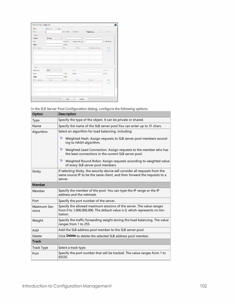
In the SLB Server Pool Configuration dialog, configure the following options.
Option Description
Type Specify the type of the object. It can be private or shared.
Name Specify the name of the SLB server pool.You can enter up to 31 chars.
Algorithm Select an algorithm for load balancing, including:
Weighted Hash: Assign requests to SLB server pool members accord-ing to HASH algorithm.
Weighted Least Connection: Assign requests to the member who hasthe least connections in the current SLB server pool.
Weighted Round Robin: Assign requests according to weighted valueof every SLB server pool members.
Sticky If selecting Sticky, the security device will consider all requests from thesame source IP to be the same client, and then forward the requests to aserver.
Member
Member Specify the member of the pool. You can type the IP range or the IPaddress and the netmask.
Port Specify the port number of the server.
Maximum Ses-sions
Specify the allowed maximum sessions of the server. The value rangesfrom 0 to 1,000,000,000. The default value is 0, which represents no lim-itation.
Weight Specify the traffic forwarding weight during the load balancing. The valueranges from 1 to 255.
Add Add the SLB address pool member to the SLB server pool.
Delete Click Delete to delete the selected SLB address pool member.
Track
Track Type Select a track type.
Port Specify the port number that will be tracked. The value ranges from 1 to65535.
Introduction to ConfigurationManagement 102

Option Description
Interval Specify the interval between each Ping/TCP/UDP packet. The unit issecond. The value ranges from 3 to 255.
Retries Specify a retry threshold. If no response packet is received after the spe-cified times of retries, the system will consider this track entry failed, i.e.,the track entry is unreachable. The value range is 1 to 255.
Weight Specify a weight for the overall failure of the whole track rule if this trackentry fails. The value range is 1 to 255.
Add Click Add to add the configured track rule to the list.
Delete Click Delete to delete the selected track rule.
Threshold Types the threshold for the track rule into the Threshold box. The valuerange is 1 to 255. If the sum of weights for failed entries in the track ruleexceeds the threshold, the security device will conclude that the track rulefails.
Description Types the description for this track rule. You can enter up to 95 chars.
4. Click OK to save the settings.
To view the details of the servers in the SLB pool:
1. Click Configuration > Device Configuration from the Level-1 navigation pane to enter the device configurationpage.
2. In the device navigation pane, select the device you want to create SLB server pool, go to the object navigation paneand select SLB Server Pool. The main window shows the user-defined SLB server pool information.
3. Select an SLB pool entry.
4. In the Server List tab at the bottom of this page, view the information of the servers that are in this SLB pool.
5. In the Server List tab, view the retries information of the SLB server pool. The retries information include IP/mask,port, weight, and maximum sessions.
6. In the Monitoring tab, view the information of the track rules. The track rules information include track type, prot,interval,and retries.
Intrusion Protection SystemIPS, the abbreviation for Intrusion Protection System, is designed to monitor various network attacks in real time andtake appropriate actions (like block) against the attacks according to your configuration.
To take the following steps to configure IPS function:
Configuring IPS Global Parameters
Configuring an IPS Rule
Enabling the Policy-based IPS Function
Con f igu r in g IP S Globa l P aram eters
You can enable or disable the IPS function, and configure the IPS global parameters. About configuring IPS global para-meters, see Threat Protection.
Con f igu r in g an IP S Ru le
For NG FW of 5 .5R 2 or t he pr evious ve r s ions
Creat in g an IP S Ru le
You can use the default IPS rules and the user-defined IPS rules. HSM has three default IPS rules: predef_default, predef_loose and no-ips. Predef_default rule which includes all the IPS signatures is strict with the detecting attacks results, and
Introduction to ConfigurationManagement 103

default action for attacks is reset. Predef_loose which only has the IPS signatures with critical severity and above or highpopularity has the high detection efficiency, and default action for attacks is log only. No-ips rule does not includes anyIPS signatures.
To create an IPS rule on HSM, take the following steps:
1. Log into HSM, click Configuration > Device Configuration from the Level-1 navigation pane to enter the device con-figuration page.
2. From the device navigation pane, select the device you want to create an IPS rule.
3. Go to the object navigation pane and select lntrusion Protection System. The main window shows the IPS rule list.
4. Click New from the toolbar. The Intrusion Protection System dialog appears.
In the Intrusion Protection System dialog, configure the values.
Type: Specify the type of the object. It can be private or shared.
Threat Protection: If the rule type is shared, you need select global threaten configuration from the Threat Pro-tection drop-down list. For more information, see Threat Protection.
Name: Type the name into the Name box.
Capture Packets: According to your requirements, select the Enable check box to enable capture packets function.The security device will capture packets of the selected protocol, and save the evidence messages. You can view anddownload the evidence message on the security device.
Protocol Types: In the Protocol types section, select the protocol check box as you need. You can click the Select Allbutton to select all protocol types quickly, and click the Unselect button to unselect all the protocol types. Aboutattacking signature configurations, see Configuring Protocol Signature.
Relevant Device: Specify the devices which you want to make a relationship with the shared IPS rule. If choosingVSYS devices of the device, the shared IPS rule will be relevant to the VSYS devices of the device, not the device itself.After configuring the shared IPS rule, you have to deploy the rule to the relevant device if you want to take effect onthe device. For more detailed information about deploying configuration, see Synchronizing Configuration.
5. Click OK to save the settings.
Con f igu r in g P rotoco l Sign atu re
Protocol signature consists protocol configuration and signature configuration. You can specify actions for attacks of dif-ferent levels (Log only, Reset, Block attacker) and actions for a specific attacking signature (the priority is higher than thatof the action configured in the signature set).
Introduction to ConfigurationManagement 104

For the HTTP protocol signature, you can configure the Web server to detect and protect Web-based attacks, see Web-server Configuration.
Conf igur ing a Pr ot ocol
To configure protocol signature on HSM, take the following steps:
1. Log into HSM, click Configuration > Device Configuration from the Level-1 navigation pane to enter the device con-figuration page.
2. From the device navigation pane, click the device you want to configure a protocol.
3. From the object navigation pane, click Intrusion Protection System. The main window shows the IPS rule list.
4. Click the specified protocol type in the IPS rule list. The protocol configuration dialog appears.
5. Click Protocol Configuration tab.
In Protocol Configuration tab,configure actions for attacks of different levels and other related options.
Option Description
Action for Crit-ical/Warning/Information levelattack
Capture Packets: Select the Enable check box to enablethe capture packet tools. The security device will cap-ture packets of the selected protocol, and save theevidence messages. You can view or download theevidence message on the security device.
Action: Specify an action for attacks of different levels.Select the radio button below:
Log only - Only generates logs if intrusions havebeen detected.
Reset - Resets connections (TCP) or sends des-tination unreachable packets (UDP) and also gen-erates logs if intrusions have been detected.
Block attacker: Select the Enable check box to blockthe specified attacker.
IP - Specify a block duration for the block IPaddress. The value range is 60 to 3600 seconds,and the default value is 60.
Service - Specify a block duration for the block ser-vice. The value range is 60 to 3600 seconds, andthe default value is 60.
Introduction to ConfigurationManagement 105

Option Description
Other Configuration Other related options that may vary from differenttypes of protocols. For detailed instructions, see thedescription of other configuration.
Other related options that may vary from different types of protoclos, the description of other configuration.
Option Description
DNS Protocol Anomaly Detection:Specify a check level for the pro-tocol validity check of the signature set.
Strict - When the Check level is set to Strict, if any protocolanomaly has been detected during the parsing, the secur-ity device will take the action that is specified in the cor-responding attack level against the attacking packetsaccording to the security level of the anomaly.
Loose - When the Check level is set to Loose, if any pro-tocol anomaly has been detected during the parsing, thesecurity device will only generate logs and invoke theengine to perform signature matching.
FTP Action for Brute-force:If the login attempts per minute failfor the times specified by the threshold, the security device willidentify the attempts as an intrusion and take an action accord-ing to the configuration. Select the Enable Brute-force checkbox to enable brute-force.
Login Threshold per Min - Specify a permitted authen-tication/login failure count per minute. The value range is1 to 100000.
Block - Select the block object whose login failure countexceeds the threshold.
Block Time - Specify the block duration. The value range is60 to 3600 seconds.
Protocol Anomaly Detection:Specify a check level for the pro-tocol validity check of the signature set.
Strict - When the Check level is set to Strict, if any protocolanomaly has been detected during the parsing, the secur-ity device will take the action that is specified in the cor-responding attack level against the attacking packetsaccording to the security level of the anomaly.
Loose - When the Check level is set to Loose, if any pro-tocol anomaly has been detected during the parsing, sys-tem will only generate logs and invoke the engine toperform signature matching.
Banner Detection:Select the Enable check box to enable pro-tection against FTP server banners.
Banner Information: Type the new information into thebox that will replace the original server banner inform-ation.
Max Command Line Length:Specify a max length (includingcarriage return) for the FTP command line. The value range is 5to 1024 bytes.
Introduction to ConfigurationManagement 106

Option Description
Security Level: Specify a security level for the events thatexceed the max command line length. The security devicewill take action according to this level.
Max Response Line Length:Specify a max length for the FTPresponse line. The value range is 5 to 1024 bytes.
Security Level: Specify a security level for the events thatexceed the max response line length. The security devicewill take action according to this level.
HTTP Protocol Anomaly Detection:Specify a check level for the pro-tocol validity check of the signature set.
Strict - When the Check level is set to Strict, if any protocolanomaly has been detected during the parsing, the secur-ity device will take the action that is specified in the cor-responding attack level against the attacking packetsaccording to the security level of the anomaly.
Loose - When the Check level is set to Loose, if any pro-tocol anomaly has been detected during the parsing, thesecurity device will only generate logs and invoke theengine to perform signature matching.
Banner Detection:Select the Enable check box to enable pro-tection against HTTP server banners.
Banner information - Type the new information into thebox that will replace the original server banner inform-ation.
Max URI Line Length:Specify a max URI length for the HTTPprotocol. The value range is 64 to 4096 bytes.
Security level:Specify a security level for the events thatexceed the max URI length. The security device will takeaction according to this level.
Allowed Methods :Specify allowed HTTP method(s).
POP3 Action for Brute-force:If the login attempts per minute failfor the times specified by the threshold, The security device willidentify the attempts as an intrusion and take an action accord-ing to the configuration. Select the Enable check box to enablebrute-force.
Login Threshold per Min - Specify a permitted authen-tication/login failure count per minute. The value range is1 to 100000.
Block - Select the block object whose login failure countexceeds the threshold.
Block Time - Specify the block duration. The value range is60 to 3600 seconds.
Protocol Anomaly Detection:Specify a check level for the pro-tocol validity check of the signature set.
Strict - When the Check level is set to Strict, if any protocolanomaly has been detected during the parsing, the secur-ity device will take the action that is specified in the cor-
Introduction to ConfigurationManagement 107

Option Description
responding attack level against the attacking packetsaccording to the security level of the anomaly.
Loose - When the Check level is set to Loose, if any pro-tocol anomaly has been detected during the parsing, thesecurity device will only generate logs and invoke theengine to perform signature matching.
Banner Detection:Select the Enable check box to enable pro-tection against POP3 server banners.
Banner information - Type the new information into thebox that will replace the original server banner inform-ation.
Max Command Line Length:Specify a max length (includingcarriage return) for the POP3 command line. The value range is64 to 1024 bytes.
Security Level - Specify a security level for the events thatexceed the max command line length. The security devicewill take action according to this level.
Max Parameter Length:Specify a max length for the POP3 cli-ent command parameter. The value range is 8 to 256 bytes.
Security Level - Specify a security level for the events thatexceed the max parameter length. The security device willtake action according to this level.
Max Failure Time:Specify a max failure time (within one singlePOP3 session) for the POP3 server. The value range is 0 to 512times.
Security Level - Specify a security level for the events thatexceed the max failure time. The security device will takeaction according to this level.
SMTP Action for Brute-force:If the login attempts per minute failfor the times specified by the threshold, the security device willidentify the attempts as an intrusion and take an action accord-ing to the configuration. Select the Enable check box to enablebrute-force.
Login Threshold per Min - Specify a permitted authen-tication/login failure count per minute. The value range is1 to 100000.
Block - Select the block object whose login failure countexceeds the threshold.
Block Time - Specify the block duration. The value range is60 to 3600 seconds.
Protocol Anomaly Detection:Specify a check level for the pro-tocol validity check of the signature set.
Strict - When the Check level is set to Strict, if any protocolanomaly has been detected during the parsing, the secur-ity device will take the action that is specified in the cor-responding attack level against the attacking packetsaccording to the security level of the anomaly.
Introduction to ConfigurationManagement 108

Option Description
Loose - When the Check level is set to Loose, if any pro-tocol anomaly has been detected during the parsing, thesecurity device will only generate logs and invoke theengine to perform signature matching.
Banner Detection:Select the Enable check box to enable pro-tection against POP3 server banners.
Banner information - Type the new information into thebox that will replace the original server banner inform-ation.
Max Command Line Length:Specify a max length (includingcarriage return) for the POP3 command line. The value range is5 to 1024 bytes.
Security Level - Specify a security level for the events thatexceed the max command line length. The security devicewill take action according to this level.
Max Path Line Length:Specify a max length for the reverse-path and forward-path field in the SMTP client command. Thevalue range is 16 to 512 bytes (including punctuation marks).
Security Level - Specify a security level for the events thatexceed the max path length. The system will take actionaccording to this level.
Max Reply Line Length:Specify a max reply line length for theSMTP server. The value range is 64 to 1024 bytes (including car-riage return).
Security Level - Specify a security level for the events thatexceed the max reply line length. The security device willtake action according to this level.
Max Text Line Length:Specify a max length for the E-mail textof the SMTP client. The value range is 64 to 2048 bytes (includ-ing carriage return).
Security Level - Specify a security level for the events thatexceed the max text line length. The security device willtake action according to this level.
Max Content Filename Length:Specify a max length for thefilename of E-mail attachment. The value range is 64 to 1024bytes.
Security Level - Specify a security level for the events thatexceed the max Content-Type length. The security devicewill take action according to this level.
Max Content Filename Length:Specify a max length for thefilename of E-mail attachment. The value range is 64 to 1024bytes.
Security Level - Specify a security level for the events thatexceed the max content filename length. The securitydevice will take action according to this level.
Max Failure Time:Specify a max failure time (within one singleSMTP session) for the SMTP server. The value range is 0 to 512times.
Introduction to ConfigurationManagement 109

Option Description
Security Level - Specify a security level for the events thatexceed the max failure time. The security device will takeaction according to this level.
Telnet Action for Brute-force:If the login attempts per minute failfor the times specified by the threshold, the security device willidentify the attempts as an intrusion and take an action accord-ing to the configuration. Select the Enable check box to enablebrute-force.
Login Threshold per Min - Specify a permitted authen-tication/login failure count per minute. The value range is1 to 100000.
Block - Select the block object whose login failure countexceeds the threshold.
Block Time - Specify the block duration. The value range is60 to 3600 seconds.
Protocol Anomaly Detection:Specify a check level for the pro-tocol validity check of the signature set.
Strict - When the Check level is set to Strict, if any protocolanomaly has been detected during the parsing, the secur-ity device will take the action that is specified in the cor-responding attack level against the attacking packetsaccording to the security level of the anomaly.
Loose - When the Check level is set to Loose, if any pro-tocol anomaly has been detected during the parsing, thesecurity device will only generate logs and invoke theengine to perform signature matching.
Username/Password Max Length:Specify a max length for theusername and password used in Telnet. The value range is 64 to1024 bytes.
Security Level - Specify a security level for the events thatexceed the max username/password length. the securitydevice will take action according to this level.
IMAP/Finger/NNTP/TFTP/SNMP/MYSQL/MSSQL/ORACLE/NETBIOS/DHCP/LDAP/VoIP /Other-TCP/Other-UDP
Max Scan Length:Specify a max scan length. The value rangeis 0 to 65535 bytes.
SUNRPC Action for Brute-force:If the login attempts per minute failfor the times specified by the threshold, the security device willidentify the attempts as an intrusion and take an action accord-ing to the configuration. Select the Enable check box to enablebrute-force.
Login Threshold per Min - Specify a permitted authen-tication/login failure count per minute. The value range is1 to 100000.
Block - Select the block object whose login failure countexceeds the threshold.
Introduction to ConfigurationManagement 110

Option Description
Block Time - Specify the block duration. The value range is60 to 3600 seconds.
Protocol Anomaly Detection:Specify a check level for the pro-tocol validity check of the signature set.
Strict - When the Check level is set to Strict, if any protocolanomaly has been detected during the parsing, the secur-ity device will take the action that is specified in the cor-responding attack level against the attacking packetsaccording to the security level of the anomaly.
Loose - When the Check level is set to Loose, if any pro-tocol anomaly has been detected during the parsing, thesecurity device will only generate logs and invoke theengine to perform signature matching.
MSRPC Action for Brute-force:If the login attempts per minute failfor the times specified by the threshold, the security device willidentify the attempts as an intrusion and take an action accord-ing to the configuration. Select the Enable check box to enablebrute-force.
Login Threshold per Min - Specify a permitted authen-tication/login failure count per minute. The value range is1 to 100000.
Block - Select the block object whose login failure countexceeds the threshold.
Block Time - Specify the block duration. The value range is60 to 3600 seconds.
Protocol Anomaly Detection:Specify a check level for the pro-tocol validity check of the signature set.
Strict - When the Check level is set to Strict, if any protocolanomaly has been detected during the parsing, the secur-ity device will take the action that is specified in the cor-responding attack level against the attacking packetsaccording to the security level of the anomaly.
Loose - When the Check level is set to Loose, if any pro-tocol anomaly has been detected during the parsing, thesecurity device will only generate logs and invoke theengine to perform signature matching.
Max Bind Length:Specify a max length for MSRPC's bindingpackets. The value range is 16 to 65535 bytes.
Security Level - Specify a security level for the events thatexceed the max bind length. The security device will takeaction according to this level.
Max Request Length:Specify a max length for MSRPC'srequest packets. The value range is 16 to 65535 bytes.
Security Level - Specify a security level for the events thatexceed the max request length. the security device will takeaction according to this level.
6. Select Signature List tab,to view or configure the signature, see Configuring Signature.
Introduction to ConfigurationManagement 111

7. Click OK.
Conf igur ing S ignat ur e
In the specific protocols Signature List tab, you can view , enable/disable or configure the signature.
Viewing the Specific Signature Entry Details
To view the specific signature entry details, take the following steps:
1. In the filter bar, click a filter name, and input a value for this filer. You may select more than one filters. Hover yourmouse over a parameter to view the drop-down list. The parameters include status, operating system, attack type,popularity, severity, service type, global status and type, etc.
2. Click , results that match your criteria will be shown in the signature list.
3. In the specific protocols Signature List, click ID. You can view the specific signature details in pop-up dialog.
Note:
Hover your mouse over the icon to view search tips.
Click the icon to reset the filter condition.
The icon can expand to show search history. If Auto Open is selected, the history can auto-matically be opened while you use the search box.
Configuring a Specific Attacking Signature
To configure a specific attacking signature of the user-defined IPS rules, take the following steps:
1. In the specific protocol Signature List tab, select the signature you want to edit from the signature list, and click Editfrom the toolbar. The Signature List Configuration dialog appears.
Introduction to ConfigurationManagement 112

In Signature List Configuration dialog, configuring a specific attacking signature.
Option Description
Capture Packets Select the Enable check box to enable the capture packet tools. The secur-ity device will capture packets of the selected protocol, and save the evid-ence messages. You can view or download the evidence message on thesecurity device.
Action Specify an action for attacks of different levels.
Follow General Configuration - If Follow General Configuration isselected, it means the action depends on the configuration of the sig-nature attack level.
Log Only - If attacks have been detected, the security device will onlygenerate protocol behavior logs.
Reset - If attacks have been detected, resets connections (TCP) orsends destination unreachable packets (UDP) and also generates logsif intrusions have been detected.
Block Attacker Block the specified attacker.
Follow General Configuration - If Follow General Configuration isselected, it means the action depends on the configuration of the sig-nature attack level.
Block - Specify a service for blocking the specified attacker.
Block IP - Specify a block duration for the block IP address. The valuerange is 60 to 3600 seconds, and the default value is 60.
Block Service - Specify a block duration for the block service. Thevalue range is 60 to 3600 seconds, and the default value is 60.
Never Block - If attacks have been detected, the security device willnot block the service from the attacker.
2. Click OK.
WebSer ve r Conf igur at ion
To create a WebServer, take the following steps:
1. Log into HSM, click Configuration > Device Configuration from the Level-1 navigation pane to enter the device con-figuration page.
2. From the device navigation pane, click the device you want to create a WebServer.
3. From the object navigation pane, click Intrusion Protection System. The main window shows IPS rule list.
4. Select the user-defined IPS rule from the IPS rule list, and then click HTTP.
5. Click Webserver Configuration tab.
Introduction to ConfigurationManagement 113

6. From the toolbar, click New. The Web Server Configuration dialog appears.
In Webserver Configuration dialog, configure the Web Server configuration.
For NGFW of 5.5R2 or the previous versions:
Option Description
Name Specify the name of the Web server.
ConfigureDomain
Specify domains for the Web server. Click this link, the Configure Domaindialog appears.
At most 5 domains can be configured for one Web server. The domainname of the Web server follows the longest match rule from the back tothe front. The traffic that does not match any rules will match the defaultWeb server. For example, you have configured two Web servers: web_server1 and web_server2. web_server1 contains the domain name abc.-com and web_server2 contains the domain name email.abc.com. Afterconfiguring the settings, the traffic that visits news.abc.com will matchthe web_server1, the traffic that visits www.email.abc.com will math web_server2, and the traffic that visits www.abc.com.cn will match the defaultWeb server.
SQL Injection Pro-tection
Select the Enable check box to enable SQL injection check for the HTTPprotocol.
Capture Packets: Select the Enable check box to enable the capturepacket tools. The security device will capture packets of the selectedprotocol, and save the evidence messages. You can view or down-load the evidence message on the security device.
Action:Specify an action for SQL injection check.
Block Attacker:Block the specified attacker.
Block IP - Specify a block duration for the block IP address. Thevalue range is 60 to 3600 seconds, and the default value is 60.
Block Service - Specify a block duration for the block service.The value range is 60 to 3600 seconds, and the default value is60.
Sensitivity:Specify the sensitivity for the SQL injection protectionfunction. The higher the sensitivity is, the lower the false negativerate is.
Introduction to ConfigurationManagement 114

Option Description
Check point:Specify the check point for the SQL injection check. Itcan be HTTP cookie, HTTP cookie2, HTTP post, HTTP referer or HTTPURI.
XSS Injection Pro-tection
Select the Enable check box to enable XSS injection check for the HTTPprotocol.
Capture Packets : Select the Enable check box to enable the capturepacket tools. The security device will capture packets of the selectedprotocol, and save the evidence messages. You can view or down-load the evidence message on the security device.
Action:Specify an action for XSS check.
Block Attacker:Block the specified attacker.
Block IP - Specify a block duration for the block IP address. Thevalue range is 60 to 3600 seconds, and the default value is 60.
Block Service - Specify a block duration for the block service.The value range is 60 to 3600 seconds, and the default value is60.
Sensitivity: Specify the sensitivity for the XSS injection protectionfunction. The higher the sensitivity is, the lower the false negativerate is.
Check point: Specify the check point for the XSS injection check. Itcan be HTTP cookie, HTTP cookie2, HTTP post, HTTP referer or HTTPURI.
External LinkCheck
Select the Enable check box to enable external link check for the Webserver. This function controls the access to the external resource.
Capture Packets : Select the Enable check box to enable the capturepacket tools. The security device will save the evidence messages,and support to view or download the messages.
External link exception:Click this link, the External Link ExceptionConfiguration dialog appears. All the URLs configured on this dialogcan be linked by the Web sever. At most 32 URLs can be specified forone Web server.
Action:Specify the action of the behavior of linking to the externalresource.
Log only: Only record the related logs when the external linkbehavior is detected.
Reset: Reset the TCP connection or send the UDP unreachablepacket and record the related logs when external link behavioris detected.
ACL Select the Enable check box to enable access control for the Web server.The access control function checks the upload paths of the websites toprevent the malicious code uploading from attackers.
ACL: Click this link, the ACL Configuration dialog appears. Specifywebsites and the properties on this dialog. "Static" means the URIcan be accessed statically only as the static resource (images andtext), otherwise, the access will handle as the action specified (log
Introduction to ConfigurationManagement 115

Option Description
only/reset); "Block" means the resource of the website is not allowedto access.
Action:Specify the action of the behavior of linking to the externalresource.
Log only: Only record the related logs when the external linkbehavior is detected.
Reset: Reset the TCP connection or send the UDP unreachablepacket and record the related logs when external link behavioris detected.
HTTP RequestFlood Protection
Select the Enable check box to enable the HTTP request flood protection.
Request threshold: Specify the request threshold. When the numberof HTTP connecting request reaches the threshold, the securitydevice will treat it as a HTTP request flood attack, and will enable theHTTP request flood protection.
Authentication: Specify the authentication method. The securitydevice judges the legality of the HTTP request on the source IPthrough the authentication. If a source IP fails on the authen-tication, the current request from the source IP will be blocked.Choose the proper authentication method from the drop-down list.The available authentication methods are:
Auto (JS Cookie): The Web browser will finish the authen-tication process automatically.
Auto (Redirect): The Web browser will finish the authenticationprocess automatically.
Manual (Access Confirm): The initiator of the HTTP requestmust confirm by clicking OK on the returned page to finish theauthentication process.
Manual (CAPTCHA): The initiator of the HTTP request must con-firm by entering the authentication code on the returned pageto finish the authentication process.
Crawler-friendly: If this check box is selected, the security device willnot authenticate to the crawler.
Request limit: Specify the request limit for the HTTP request floodprotection. After configuring the request limit, the security devicewill limit the request rate of each source IP. If the request rate ishigher than the limitation specified here and the HTTP request floodprotection is enabled, the security device will handle the exceededrequests according to the action specified (Block IP/Reset).
Proxy limit:Specify the proxy limit for the HTTP request flood pro-tection. After configuring the proxy limit, the security device willcheck whether each source belongs to the each source IP proxyserver. If belongs to, according to configuration to limit the requestrate. If the request rate is higher than the limitation specified hereand the HTTP request flood protection is enabled, the securitydevice will handle the exceeded requests according to the action spe-cified (Block IP/Reset).
Introduction to ConfigurationManagement 116

Option Description
White List:Specify the white list for the HTTP request flood pro-tection. The source IP added to the white list not check the HTTPrequest flood protection. Select the address entry from the drop-down list, the address entry can not be a domain name or IPv6address. If the source IP address traffic in whitelist exceeds thethreshold for the HTTP request flood protection, it will enable theHTTP request flood protection.
For NGFW of 5.5R3 or the later version and IPS devices:
Option Description
Name Specify the name of the Web server protection rule.
ConfigureDomain
Specify domains protected by this rule.
Click the link and the Configure Domain dialog appears. Enter the domainnames in the Domain text box. At most 5 domains can be configured. The trafficto these domains will be checked by the protection rule.
The domain name of the Web server follows the longest match rule from theback to the front. The traffic that does not match any rules will match thedefault Web server. For example, you have configured two protection rules:rule1 and rule2. The domain name in rule1 is abc.com. The domain name inrule2 is email.abc.com. The traffic that visits news.abc.com will match rule1, thetraffic that visits www.email.abc.com will math rule2, and the traffic that visitswww.abc.com.cn will match the default protection rule.
SQL Injec-tion Pro-tection
Select the Enable check box to enable SQL injection check.
Capture Packets: Capture the abnormal packets. You can view them in thethreat log.
Action: Log Only - Record a log. Rest - Reset connections (TCP) or sendsdestination unreachable packets (UDP) and also generates logs. Block IP -Block the IP address of the attacker and specify a block duration. Block Ser-vice - Block the service of the attacker and specify a block duration.
Sensitivity: Specifies the sensitivity for the SQL injection protection func-tion. The higher the sensitivity is, the lower the false negative rate is.
Check point: Specifies the check point for the SQL injection check. It can beCookie, Cookie2, Post, Referer or URI.
XSS Injec-tion Pro-tection
Select the Enable check box to enable XSS injection check for the HTTP protocol.
Capture Packets: Capture the abnormal packets. You can view them in thethreat log.
Action: Log Only - Record a log. Rest - Reset connections (TCP) or sendsdestination unreachable packets (UDP) and also generates logs. Block IP -Block the IP address of the attacker and specify a block duration. Block Ser-vice - Block the service of the attacker and specify a block duration.
Sensitivity: Specifies the sensitivity for the XSS injection protection func-tion. The higher the sensitivity is, the lower the false negative rate is.
Check point: Specifies the check point for the XSS injection check. It can beCookie, Cookie2, Post, Referer or URI.
ExternalLinkCheck
Select the Enable check box to enable external link check for the Web server.This function controls the resource reference from the external sites.
Introduction to ConfigurationManagement 117

Option Description
Capture Packets: Capture the abnormal packets. You can view them in thethreat log.
External link exception: Click this link, the External Link Exception Con-figuration dialog appears. All the URLs configured on this dialog can belinked by the Web sever. At most 32 URLs can be specified for one Webserver.
Action: Log Only - Record a log. Rest - Reset connections (TCP) or sendsdestination unreachable packets (UDP) and also generates logs.
ACL Action: Log Only - Record a log. Rest - Reset connections (TCP) or sendsdestination unreachable packets (UDP) and also generates logs.
HTTPRequestFlood Pro-tection
Select the Enable check box to enable the HTTP request flood protection.
Request threshold: Specifies the request threshold.
For the protected domain name, when the number of HTTP con-necting request per second reaches the threshold and this lasts 20seconds, the system will treat it as a HTTP request flood attack, and willenable the HTTP request flood protection.
For the protected full URL, when the number of HTTP connectingrequest per second towards this URL reaches the threshold and thislasts 20 seconds, the system will treat it as a HTTP request flood attacktowards this URL, and will enable the HTTP request flood protection. Itis only applicable to IPS devices.
Full URL: Enter the full URLs to protect particular URLs. Click this link to con-figure the URLs, for example, www.example.com/index.html. When pro-tecting a particular URL, you can select a statistic object. When the numberof HTTP connecting request per second by the object reaches the thresholdand this lasts 20 seconds, the system will treat it as a HTTP request floodattack by this object, and will enable the HTTP request flood protection. Itis only applicable to IPS devices.
x-forwarded-for: Select None, the system will not use the value in x-for-warded-for as the statistic object. Select First, the system will use thefirst value of the x-forwarded-for field as the statistic object. SelectLast, the system will use the last value of the x-forwarded-for field asthe statistic object. Select All, the system will use all values in x-for-warded-for as the statistic object.
x-real-ip: Select whether to use the value in the x-real-ip field as thestatistic field.
When the HTTP request flood attack is discovered, you can make the systemtake the following actions:
Authentication: Specifies the authentication method. The system judgesthe legality of the HTTP request on the source IP through the authen-tication. If a source IP fails on the authentication, the current request fromthe source IP will be blocked. The available authentication methods are:
Auto (JS Cookie): The Web browser will finish the authentication pro-cess automatically.
Auto (Redirect): The Web browser will finish the authentication pro-cess automatically.
Introduction to ConfigurationManagement 118

Option Description
Manual (Access Configuration): The initiator of the HTTP request mustconfirm by clicking OK on the returned page to finish the authen-tication process.
Manual (CAPTCHA): The initiator of the HTTP request must confirm byentering the authentication code on the returned page to finish theauthentication process.
Crawler-friendly: If this check box is selected, the system will not authen-ticate to the crawler.
Request limit: Specifies the request limit for the HTTP request flood pro-tection. After configuring the request limit, the system will limit the requestrate of each source IP. If the request rate is higher than the limitation spe-cified here and the HTTP request flood protection is enabled, the systemwill handle the exceeded requests according to the action specified (BlockIP/Reset). To record a log, select the Record log check box.
Proxy limit: Specifies the proxy limit for the HTTP request flood protection.After configuring the proxy limit, the system will check whether each sourcebelongs to the each source IP proxy server. If belongs to, according to con-figuration to limit the request rate. If the request rate is higher than the lim-itation specified here and the HTTP request flood protection is enabled, thesystem will handle the exceeded requests according to the action specified(Block IP/Reset). To record a log, select the Record log check box.
White List: Specifies the white list for the HTTP request flood protection.The source IP added to the white list not check the HTTP request flood pro-tection.
7. Click OK.
Note: After you create a HTTP signature, HSM will automatically create a default Web Server. Thedefault Web Server is enabled by default, and can not be disabled or deleted. At most 32 Webservers can be configured for one signature, not including the default server.
For I PS device s and NG FW of 5 .5R 3 or t he lat e r ve r s ion
Creat in g an IP S ru le
System has three default IPS rules: predef_default, predef_loose and no-ips. The predef_default rule includes all the IPSsignatures and its default action is reset. The predef_loose includes all the IPS signatures and its default action is logonly. No-ips rule does not includes any IPS signatures.
To create an IPS rule on HSM, take the following steps:
1. Log into HSM, click Configuration > Device Configuration from the Level-1 navigation pane to enter the device con-figuration page.
2. From the device navigation pane, select the device you want to create an IPS rule.
3. Go to the object navigation pane and select lntrusion Protection System. The main window shows the IPS rule list.
Introduction to ConfigurationManagement 119

4. Click New from the toolbar. The Intrusion Protection System Configuration dialog appears.
5. Specifies the type of IPS rule. It can be private or shared.
6. Type the name into the Name box.
7. According to your requirements, select the Enable check box of Global Packet Capture to capture packets. The secur-ity device will capture packets of the selected protocol in this rule, and save the evidence messages. You can viewand download the evidence message on the security device. This feature may not be available on all security devices,please refer to the actual page.
8. In the Select Signature area, you can also manage the signature sets, including New, Edit, and Delete. All existing sig-nature sets and their settings will be displays in the table.
Click New to create a new signature set rule.
Option Description
Creating a new signature set contains:
Select By: Select the method of how to choose the signature set. There are two meth-ods: Filter and Search Condition.
Introduction to ConfigurationManagement 120

Option Description
Capture package: Capture the abnormal packets that match the configured signatureset. You can view them in the threat log.
Action: Specify the action performed on the abnormal traffic that match the signatureset.
Select By
Filter The system categorizes the signatures according to the fol-lowing aspects (aka main categories): affected OS, attacktype, protocol, severity, released year, affected application,and bulletin board. A signature can be in several sub-categories of one main category. For example, the signatureof ID 105001 is in the Linux subcategory, the FreeBSD sub-category, and Other Linux subcategory at the same time.
With Filter selected, the system displays the main categoriesand subcategories above. You can select the subcategories tochoose the signatures in this subcategory. As shown below,after selecting the Web Attack subcategory in the AttackType main category, the system will choose the signaturesrelated to this subcategory. To view the detailed informationof these chosen signatures, you can click the ID in the table.
When selecting main category and subcategory, note the fol-lowing matters:
You can select multiple subcategories of one main cat-egory. The logic relation between them is OR.
The logic relation between each main category is AND.
For example, you have selected Windows and Linux inOS and select HIGH in Severity. The chosen signaturesare those whose severity is high and meanwhile whoseaffected operating system is either Windows or Linux.
Search Condition Enter the information of the signatures and press Enter tosearch the signatures. The system will perform the fuzzymatching in the following field: attack ID, attack name,description, and CVE-ID.
In the search results displayed in the table, select the check
box of the desired signatures. Then click toadd them to the right pane. The ID displayed in the rightpane are the ones that are included in this signature set.
To add all signatures in the left to the right, click
.
Use or to cancel the selectedsignatures or all signatures in the right.
Capture Packet
Capture Packet Capture the abnormal packets that match the configured sig-nature set. You can view them in the threat log.
Action
Log Only Record a log.
Introduction to ConfigurationManagement 121

Option Description
Reset Reset connections (TCP) or sends destination unreachablepackets (UDP) and also generates logs
Block IPBlock the IP address of the attacker. Specify a block duration.The value range is 60 to 3600 seconds, and the default valueis 60.
Block ServiceBlock the service of the attacker. Specify a block duration.The value range is 60 to 3600 seconds, and the default valueis 60.
Note: You create several signature sets and some of them contain a particular signature. Ifthe actions of these signature sets are different and the attack matches this particular sig-nature , the system will adopt the following rules:
Always perform the stricter action on the attack. The signature set with stricter actionwill be matched. The strict level is: Block IP > Block Service > Rest > Log Only. If one sig-nature set is Block IP with 15s and the other is Block Service with 30s, the final actionwill be Block IP with 30s.
If one signature set is configured with Capture Packet, the system will capture the pack-ets.
The action of the signature set created by Search Condition has high priority than theaction of the signature set created by Filter.
9. Click OK to complete signature set configurations. Repeat the above steps to create more signature sets.
10. In the Protocol Configuration area, click Edit to configure. The protocol configurations specify the requirements thatthe protocol part of the traffic must meet. If the protocol part contains abnormal contents, the system will processthe traffic according to the action configuration. The system supports the configurations of HTTP, DNS, FTP, MSRPC,POP3, SMTP, SUNRPC, and Telnet.
In the HTTP tab, select the Protocol tab, and configure the following settings:
Option Description
HTTP
Max Scan Length: Specify the maximum length of scanning whenscanning the HTTP packets.
Protocol Anomaly Detection: Select Enable to analyze the HTTP pack-ets. If abnormal contents exist, you can:
Capture Packets: Capture the abnormal packets. You can viewthem in the threat log.
Action: Log Only - Record a log. Rest - Reset connections (TCP)or sends destination unreachable packets (UDP) and also gen-erates logs. Block IP - Block the IP address of the attacker andspecify a block duration. Block Service - Block the service of theattacker and specify a block duration.
Banner Detection: Select the Enable check box to enable protectionagainst HTTP server banners.
Banner information - Type the new information into the boxthat will replace the original server banner information.
Max URI Length: Specify a max URI length for the HTTP protocol. Ifthe URI length exceeds the limitation, you can:
Capture Packets: Capture the abnormal packets. You can viewthem in the threat log.
Introduction to ConfigurationManagement 122

Option Description
Action: Log Only - Record a log. Rest - Reset connections (TCP)or sends destination unreachable packets (UDP) and also gen-erates logs. Block IP - Block the IP address of the attacker andspecify a block duration. Block Service - Block the service of theattacker and specify a block duration.
Allowed Methods: Specify the allowed HTTP methods.
To protect the Web server, select Web Server in the HTTP tab.
Protecting the Web server means the system can detect the following attacks: SQL injection, XSS injection, externallink check, ACL, and HTTP request flood and take actions when detecting them. A pre-defined Web server protectionrule named default is built in. By default, this protection rule is enabled and cannot be disabled or deleted.
Configure the following settings to protect the Web server:
Option Description
Name Specify the name of the Web server protection rule.
Configure Domain Specify domains protected by this rule.
Click the link and the Configure Domain dialog appears. Enter thedomain names in the Domain text box. At most 5 domains can beconfigured. The traffic to these domains will be checked by the pro-tection rule.
The domain name of the Web server follows the longest match rulefrom the back to the front. The traffic that does not match any ruleswill match the default Web server. For example, you have configuredtwo protection rules: rule1 and rule2. The domain name in rule1 isabc.com. The domain name in rule2 is email.abc.com. The traffic thatvisits news.abc.com will match rule1, the traffic that visits www.e-mail.abc.com will math rule2, and the traffic that visits www.-abc.com.cn will match the default protection rule.
SQL Injection Pro-tection
Select the Enable check box to enable SQL injection check.
Capture Packets: Capture the abnormal packets. You can viewthem in the threat log.
Action: Log Only - Record a log. Rest - Reset connections (TCP)or sends destination unreachable packets (UDP) and also gen-erates logs. Block IP - Block the IP address of the attacker andspecify a block duration. Block Service - Block the service of theattacker and specify a block duration.
Sensitivity: Specifies the sensitivity for the SQL injection pro-tection function. The higher the sensitivity is, the lower the falsenegative rate is.
Check point: Specifies the check point for the SQL injectioncheck. It can be Cookie, Cookie2, Post, Referer or URI.
XSS Injection Pro-tection
Select the Enable check box to enable XSS injection check for theHTTP protocol.
Capture Packets: Capture the abnormal packets. You can viewthem in the threat log.
Action: Log Only - Record a log. Rest - Reset connections (TCP)or sends destination unreachable packets (UDP) and also gen-
Introduction to ConfigurationManagement 123

Option Description
erates logs. Block IP - Block the IP address of the attacker andspecify a block duration. Block Service - Block the service of theattacker and specify a block duration.
Sensitivity: Specifies the sensitivity for the XSS injection pro-tection function. The higher the sensitivity is, the lower the falsenegative rate is.
Check point: Specifies the check point for the XSS injectioncheck. It can be Cookie, Cookie2, Post, Referer or URI.
External Link Check Select the Enable check box to enable external link check for the Webserver. This function controls the resource reference from theexternal sites.
Capture Packets: Capture the abnormal packets. You can viewthem in the threat log.
External link exception: Click this link, the External Link Excep-tion Configuration dialog appears. All the URLs configured onthis dialog can be linked by the Web sever. At most 32 URLs canbe specified for one Web server.
Action: Log Only - Record a log. Rest - Reset connections (TCP)or sends destination unreachable packets (UDP) and also gen-erates logs.
ACL Action: Log Only - Record a log. Rest - Reset connections (TCP)or sends destination unreachable packets (UDP) and also gen-erates logs.
HTTP Request FloodProtection
Select the Enable check box to enable the HTTP request flood pro-tection.
Request threshold: Specifies the request threshold. When thenumber of HTTP connecting request per second reaches thethreshold and this lasts 20 seconds, the system will treat it as aHTTP request flood attack, and will enable the HTTP requestflood protection.
When the HTTP request flood attack is discovered, you can make thesystem take the following actions:
Authentication: Specifies the authentication method. The sys-tem judges the legality of the HTTP request on the source IPthrough the authentication. If a source IP fails on the authen-tication, the current request from the source IP will be blocked.The available authentication methods are:
Auto (JS Cookie): The Web browser will finish the authen-tication process automatically.
Auto (Redirect): The Web browser will finish the authen-tication process automatically.
Manual (Access Configuration): The initiator of the HTTPrequest must confirm by clicking OK on the returned pageto finish the authentication process.
Manual (CAPTCHA): The initiator of the HTTP request must
Introduction to ConfigurationManagement 124

Option Description
confirm by entering the authentication code on thereturned page to finish the authentication process.
Crawler-friendly: If this check box is selected, the system will notauthenticate to the crawler.
Request limit: Specifies the request limit for the HTTP requestflood protection. After configuring the request limit, the systemwill limit the request rate of each source IP. If the request rate ishigher than the limitation specified here and the HTTP requestflood protection is enabled, the system will handle the exceededrequests according to the action specified (Block IP/Reset). Torecord a log, select the Record log check box.
Proxy limit: Specifies the proxy limit for the HTTP request floodprotection. After configuring the proxy limit, the system willcheck whether each source belongs to the each source IP proxyserver. If belongs to, according to configuration to limit therequest rate. If the request rate is higher than the limitation spe-cified here and the HTTP request flood protection is enabled,the system will handle the exceeded requests according to theaction specified (Block IP/Reset). To record a log, select theRecord log check box.
White List: Specifies the white list for the HTTP request flood pro-tection. The source IP added to the white list not check the HTTPrequest flood protection.
In the DNS tab, configure the following settings:
Option Description
DNS
Max Scan Length: Specify the maximum length of scanning whenscanning the DNS packets.
Protocol Anomaly Detection: Select Enable to analyze the DNS pack-ets. If abnormal contents exist, you can:
Capture Packets: Capture the abnormal packets. You can viewthem in the threat log.
Action: Log Only - Record a log. Rest - Reset connections (TCP)or sends destination unreachable packets (UDP) and also gen-erates logs. Block IP - Block the IP address of the attacker andspecify a block duration. Block Service - Block the service of theattacker and specify a block duration.
In the FTP tab, configure the following settings:
Option Description
FTP
Max Scan Length: Specify the maximum length of scanning whenscanning the FTP packets.
Protocol Anomaly Detection: Select Enable to analyze the FTP pack-ets. If abnormal contents exist, you can:
Capture Packets: Capture the abnormal packets. You can viewthem in the threat log.
Action: Log Only - Record a log. Rest - Reset connections (TCP)
Introduction to ConfigurationManagement 125

Option Description
or sends destination unreachable packets (UDP) and also gen-erates logs. Block IP - Block the IP address of the attacker andspecify a block duration. Block Service - Block the service of theattacker and specify a block duration.
Banner Detection: Select the Enable check box to enable protectionagainst FTP server banners.
Banner Information: Type the new information into the box thatwill replace the original server banner information.
Max Command Line Length: Specifies a max length (including car-riage return) for the FTP command line. If the length exceeds the lim-its, you can:
Capture Packets: Capture the abnormal packets. You can viewthem in the threat log.
Action: Log Only - Record a log. Rest - Reset connections (TCP)or sends destination unreachable packets (UDP) and also gen-erates logs. Block IP - Block the IP address of the attacker andspecify a block duration. Block Service - Block the service of theattacker and specify a block duration.
Max Response Line Length: Specifies a max length for the FTPresponse line.If the length exceeds the limits, you can:
Capture Packets: Capture the abnormal packets. You can viewthem in the threat log.
Action: Log Only - Record a log. Rest - Reset connections (TCP)or sends destination unreachable packets (UDP) and also gen-erates logs. Block IP - Block the IP address of the attacker andspecify a block duration. Block Service - Block the service of theattacker and specify a block duration.
Action for Brute-force: If the login attempts per minute fail for thetimes specified by the threshold, system will identify the attempts asan intrusion and take an action according to the configuration.Select the Enable check box to enable brute-force.
Login Threshold per Min - Specifies a permitted authen-tication/login failure count per minute.
Block IP - Block the IP address of the attacker and specify ablock duration.
Block Service - Block the service of the attacker and specify ablock duration.
Block Time - Specifies the block duration.
In the MSRPC tab, configure the following settings:
Option Description
MSRPC
Max Scan Length: Specify the maximum length of scanning whenscanning the MSRPC packets.
Protocol Anomaly Detection: Select Enable to analyze the MSRPCpackets. If abnormal contents exist, you can:
Introduction to ConfigurationManagement 126

Option Description
Capture Packets: Capture the abnormal packets. You can viewthem in the threat log.
Action: Log Only - Record a log. Rest - Reset connections (TCP)or sends destination unreachable packets (UDP) and also gen-erates logs. Block IP - Block the IP address of the attacker andspecify a block duration. Block Service - Block the service of theattacker and specify a block duration.
Max bind length: Specifies a max length for MSRPC's binding pack-ets. If the length exceeds the limits, you can:
Capture Packets: Capture the abnormal packets. You can viewthem in the threat log.
Action: Log Only - Record a log. Rest - Reset connections (TCP)or sends destination unreachable packets (UDP) and also gen-erates logs. Block IP - Block the IP address of the attacker andspecify a block duration. Block Service - Block the service of theattacker and specify a block duration.
Max request length: Specifies a max length for MSRPC's request pack-ets. If the length exceeds the limits, you can:
Capture Packets: Capture the abnormal packets. You can viewthem in the threat log.
Action: Log Only - Record a log. Rest - Reset connections (TCP)or sends destination unreachable packets (UDP) and also gen-erates logs. Block IP - Block the IP address of the attacker andspecify a block duration. Block Service - Block the service of theattacker and specify a block duration.
Action for Brute-force: If the login attempts per minute fail for thetimes specified by the threshold, system will identify the attempts asan intrusion and take an action according to the configuration.Select the Enable check box to enable brute-force.
Login Threshold per Min - Specifies a permitted authen-tication/login failure count per minute.
Block IP - Block the IP address of the attacker and specify ablock duration.
Block Service - Block the service of the attacker and specify ablock duration.
Block Time - Specifies the block duration.
In the POP3 tab, configure the following settings:
Option Description
POP3
Max Scan Length: Specify the maximum length of scanning whenscanning the POP3 packets.
Protocol Anomaly Detection: Select Enable to analyze the POP3 pack-ets. If abnormal contents exist, you can:
Capture Packets: Capture the abnormal packets. You can viewthem in the threat log.
Introduction to ConfigurationManagement 127

Option Description
Action: Log Only - Record a log. Rest - Reset connections (TCP)or sends destination unreachable packets (UDP) and also gen-erates logs. Block IP - Block the IP address of the attacker andspecify a block duration. Block Service - Block the service of theattacker and specify a block duration.
Banner Detection: Select the Enable check box to enable protectionagainst POP3 server banners.
Banner information - Type the new information into the box thatwill replace the original server banner information.
Max Command Line Length: Specifies a max length (including car-riage return) for the POP3 command line. If the length exceeds thelimits, you can:
Capture Packets: Capture the abnormal packets. You can viewthem in the threat log.
Action: Log Only - Record a log. Rest - Reset connections (TCP)or sends destination unreachable packets (UDP) and also gen-erates logs. Block IP - Block the IP address of the attacker andspecify a block duration. Block Service - Block the service of theattacker and specify a block duration.
Max Parameter Length: Specifies a max length for the POP3 clientcommand parameter. If the length exceeds the limits, you can:
Capture Packets: Capture the abnormal packets. You can viewthem in the threat log.
Action: Log Only - Record a log. Rest - Reset connections (TCP)or sends destination unreachable packets (UDP) and also gen-erates logs. Block IP - Block the IP address of the attacker andspecify a block duration. Block Service - Block the service of theattacker and specify a block duration.
Max failure time: Specifies a max failure time (within one single POP3session) for the POP3 server. If the failure time exceeds the limits, youcan:
Capture Packets: Capture the abnormal packets. You can viewthem in the threat log.
Action: Log Only - Record a log. Rest - Reset connections (TCP)or sends destination unreachable packets (UDP) and also gen-erates logs. Block IP - Block the IP address of the attacker andspecify a block duration. Block Service - Block the service of theattacker and specify a block duration.
Action for Brute-force: If the login attempts per minute fail for thetimes specified by the threshold, system will identify the attempts asan intrusion and take an action according to the configuration. Selectthe Enable check box to enable brute-force.
Login Threshold per Min - Specifies a permitted authen-tication/login failure count per minute.
Block IP - Block the IP address of the attacker and specify a blockduration.
Introduction to ConfigurationManagement 128

Option Description
Block Service - Block the service of the attacker and specify ablock duration.
Block Time - Specifies the block duration.
In the SMTP tab, configure the following settings:
Option Description
SMTP
Max Scan Length: Specify the maximum length of scanning whenscanning the SMTP packets.
Protocol Anomaly Detection: Select Enable to analyze the SMTP pack-ets. If abnormal contents exist, you can:
Capture Packets: Capture the abnormal packets. You can viewthem in the threat log.
Action: Log Only - Record a log. Rest - Reset connections (TCP)or sends destination unreachable packets (UDP) and also gen-erates logs. Block IP - Block the IP address of the attacker andspecify a block duration. Block Service - Block the service of theattacker and specify a block duration.
Banner Detection: Select the Enable check box to enable protectionagainst SMTP server banners.
Banner information - Type the new information into the box thatwill replace the original server banner information.
Max Command Line Length: Specifies a max length (including car-riage return) for the SMTP command line. If the length exceeds thelimits, you can:
Capture Packets: Capture the abnormal packets. You can viewthem in the threat log.
Action: Log Only - Record a log. Rest - Reset connections (TCP)or sends destination unreachable packets (UDP) and also gen-erates logs. Block IP - Block the IP address of the attacker andspecify a block duration. Block Service - Block the service of theattacker and specify a block duration.
Max Path Length: Specifies a max length for the reverse-path and for-ward-path field in the SMTP client command. If the length exceedsthe limits, you can:
Capture Packets: Capture the abnormal packets. You can viewthem in the threat log.
Action: Log Only - Record a log. Rest - Reset connections (TCP)or sends destination unreachable packets (UDP) and also gen-erates logs. Block IP - Block the IP address of the attacker andspecify a block duration. Block Service - Block the service of theattacker and specify a block duration.
Max Reply Line Length: Specifies a max length reply length for theSMTP server. If the length exceeds the limits, you can:
Capture Packets: Capture the abnormal packets. You can viewthem in the threat log.
Introduction to ConfigurationManagement 129

Option Description
Action: Log Only - Record a log. Rest - Reset connections (TCP)or sends destination unreachable packets (UDP) and also gen-erates logs. Block IP - Block the IP address of the attacker andspecify a block duration. Block Service - Block the service of theattacker and specify a block duration.
Max Text Line Length: Specifies a max length for the E-mail text ofthe SMTP client. If the length exceeds the limits, you can:
Capture Packets: Capture the abnormal packets. You can viewthem in the threat log.
Action: Log Only - Record a log. Rest - Reset connections (TCP)or sends destination unreachable packets (UDP) and also gen-erates logs. Block IP - Block the IP address of the attacker andspecify a block duration. Block Service - Block the service of theattacker and specify a block duration.
Max Content Type Length: Specifies a max length for the content-type of the SMTP protocol. If the length exceeds the limits, you can:
Capture Packets: Capture the abnormal packets. You can viewthem in the threat log.
Action: Log Only - Record a log. Rest - Reset connections (TCP)or sends destination unreachable packets (UDP) and also gen-erates logs. Block IP - Block the IP address of the attacker andspecify a block duration. Block Service - Block the service of theattacker and specify a block duration.
Max Content Filename Length: Specifies a max length for the file-name of E-mail attachment. If the length exceeds the limits, you can:
Capture Packets: Capture the abnormal packets. You can viewthem in the threat log.
Action: Log Only - Record a log. Rest - Reset connections (TCP)or sends destination unreachable packets (UDP) and also gen-erates logs. Block IP - Block the IP address of the attacker andspecify a block duration. Block Service - Block the service of theattacker and specify a block duration.
Max Failure Time: Specifies a max failure time (within one singleSMTP session) for the SMTP server. If the length exceeds the limits,you can:
Capture Packets: Capture the abnormal packets. You can viewthem in the threat log.
Action: Log Only - Record a log. Rest - Reset connections (TCP)or sends destination unreachable packets (UDP) and also gen-erates logs. Block IP - Block the IP address of the attacker andspecify a block duration. Block Service - Block the service of theattacker and specify a block duration.
Action for Brute-force: If the login attempts per minute fail for thetimes specified by the threshold, system will identify the attempts asan intrusion and take an action according to the configuration. Selectthe Enable check box to enable brute-force.
Introduction to ConfigurationManagement 130

Option Description
Login Threshold per Min - Specifies a permitted authen-tication/login failure count per minute.
Block IP - Block the IP address of the attacker and specify a blockduration.
Block Service - Block the service of the attacker and specify ablock duration.
Block Time - Specifies the block duration.
In the SUNRPC tab, configure the following settings:
Option Description
SUNRPC
Max Scan Length: Specify the maximum length of scanning when scan-ning the SUNRPC packets.
Protocol Anomaly Detection: Select Enable to analyze the SUNRPC pack-ets. If abnormal contents exist, you can:
Capture Packets: Capture the abnormal packets. You can view themin the threat log.
Action: Log Only - Record a log. Rest - Reset connections (TCP) orsends destination unreachable packets (UDP) and also generateslogs. Block IP - Block the IP address of the attacker and specify ablock duration. Block Service - Block the service of the attacker andspecify a block duration.
Action for Brute-force: If the login attempts per minute fail for the timesspecified by the threshold, system will identify the attempts as an intru-sion and take an action according to the configuration. Select the Enablecheck box to enable brute-force.
Login Threshold per Min - Specifies a permitted authentication/loginfailure count per minute.
Block IP - Block the IP address of the attacker and specify a blockduration.
Block Service - Block the service of the attacker and specify a blockduration.
Block Time - Specifies the block duration.
In the Telnet tab, configure the following settings:
Option Description
Telnet
Max Scan Length: Specify the maximum length of scanning whenscanning the Telnet packets.
Protocol Anomaly Detection: Select Enable to analyze the Telnet pack-ets. If abnormal contents exist, you can:
Capture Packets: Capture the abnormal packets. You can viewthem in the threat log.
Action: Log Only - Record a log. Rest - Reset connections (TCP) orsends destination unreachable packets (UDP) and also generateslogs. Block IP - Block the IP address of the attacker and specify a
Introduction to ConfigurationManagement 131

Option Description
block duration. Block Service - Block the service of the attackerand specify a block duration.
Username/Password Max Length: Specifies a max length for the user-name and password used in Telnet. If the length exceeds the limits,you can:
Capture Packets: Capture the abnormal packets. You can viewthem in the threat log.
Action: Log Only - Record a log. Rest - Reset connections (TCP) orsends destination unreachable packets (UDP) and also generateslogs. Block IP - Block the IP address of the attacker and specify ablock duration. Block Service - Block the service of the attackerand specify a block duration.
Action for Brute-force: If the login attempts per minute fail for thetimes specified by the threshold, system will identify the attempts asan intrusion and take an action according to the configuration. Selectthe Enable check box to enable brute-force.
Login Threshold per Min - Specifies a permitted authen-tication/login failure count per minute.
Block IP - Block the IP address of the attacker and specify a blockduration.
Block Service - Block the service of the attacker and specify ablock duration.
Block Time - Specifies the block duration.
11. Click OK to complete the protocol configurations, then click OK to complete the IPS rule configurations.
En ablin g th e Zon e-based or P o licy -based IP S F u n ct ion
To realize the zone-based or policy-based IPS, take the following steps:
To enable the zoned-based IPS on HSM, see zone.
To enable the policy-based IPS on HSM, see configuring the policy-based Protection function.
A vti -Vi rusTo take the following steps to configure Anti-Virus function:
Configuring Anti-Virus Global Parameters
Creating a Shared Anti-Virus Rule
Enabling the Policy-based Anti-Virus Function
Conf i gur i ng Ant i -V i rus Gl obal Parameters
You can enable/disable the Anti-Viurs functin, and configure the global parameters. About configuring Anti-Virus globalparameters, see Threat Protection.
Creat in g A n t i-Viru s Ru le
To create an Anti-Virus rule on HSM, take the following steps:
1. Click Configuration > Device Configuration from the Level-1 navigation pane to enter the device configurationpage.
Introduction to ConfigurationManagement 132

2. In the device navigation pane, select the device you want to create AV rule, go to the object navigation pane andselect Anti-Virus. The main window shows the Anti-Virus rule list.
3. Click New from the toolbar. The Anti-Virus dialog appears.
In the Anti-Virus dialog , enter the values.
Option Description
Type Specify the type of the object. It can be private or shared.
Name Specify the rule name.
FileTypes
Specify the file types you want to scan. It can be GZIP, JPEG, MAIL, RAR, HTML.,PE, BZIPE, RIFF, TAR, ELF, RAWDATA, MSOFFICE, PDF and OTHERS.
ProtocolTypes
Specify the protocol types (HTTP, SMTP, POP3, IMAP4, FTP) you want to scanand specifies the action the security device will take after virus is found.
Fill Magic - Processes the virus file by filling magic words, i.e., fills the filewith the magic words (Virus is found, cleaned) from the beginning to theending part of the infected section.
Log Only - Only generates log.
Warning - Pops up a warning page to prompt that a virus has been detec-ted. This option is only effective to the messages transferred over HTTP.
Reset Connection - If virus has been detected, the security device will resetconnections to the files.
Capture Select the Enable check box before Capture Packet to enable the capture func-tion. The security device will save the evidence messages, and support to view ordownload the messages.
MaliciousWebsiteAccessControl
Select the check box behind Malicious Website Access Control to enable the func-tion.
Action Specify the action the security device will take after the malicious website isfound.
Log Only - Only generates log.
Reset Connection - If malicious website has been detected, the securitydevice will reset connections to the files.
Warning - Pops up a warning page to prompt that a malicious website has
Introduction to ConfigurationManagement 133

Option Description
been detected.This option is only effective to the messages transferred overHTTP.
EnableLabel e-mail
If an email transferred over SMTP is scanned, you can enable label email to scanthe email and its attachment(s). The scanning results will be included in the mailbody, and sent with the email. If no virus has been detected, the message of "Novirus found" will be labeled; otherwise information related to the virus will be dis-played in the email, including the filename, result and action.
Type the end message content into the box. The range is 1 to 128.
4. Click OK.
Note: By default, according to virus filtering protection level, HSM comes with three default Anti-Virus rules: predef_low, predef_middle, predef_high. The default rule is not allowed to edit ordelete.
En ablin g th e Zon e-based or P o licy -based A n t i-Vr iu s F u n ct ion
To realize the zone-based or policy-based AV, take the following steps:
To enable the zoned-based AV on HSM, see zone.
To enable the policy-based AV on HSM, see configuring the policy-based Protection function.
Threat Protection
Configuring Threat Protection
Threat protection that only belongs to one certain device, but a shared threat protection can be referenced by all devices.For more details of the shared threat protection, see Threat Protection. One security device can only have one threat pro-tection configuration, and keep the lastest configuration.
Edit in g th e Dev ice Th reat P rotect ion Con f igu rat ion
To edit the device threat protection configuration, take the following steps:
1. Log into HSM, click Configuration > Device Configuration from the Level-1 navigation pane to enter the device con-figuration page.
2. From the device navigation pane, click the device you want to configure a threat protection configuration.
3. Expend Object from the object navigation pane, and then select Threat Protection. The Device Threaten Con-figuration tab appears.
In Device Threaten Configuration tab, specify the IPS configurations.
Option Description
APP ForceCheck
Select/clear the Enable check box to enable/disable force check , the secur-ity device will check application layer IPS, AV content filtering, IM and WebContent, application-layer behavior control. It should be noted that IPSdevice and the 5.5R3 and later versions of NGFW device do not supportthis feature.
If you disabled this feature , when the CPU usage exceeds 68%, the securitydevice will forwarding packets for new sessions, and not check the applic-ation layer randomly.
Introduction to ConfigurationManagement 134

Option Description
IPS Global Configuration
Intrusion Pro-tection System
Select/clear the Enable check box to enable/disable IPS. After enabling thisfunction, you have to reboot the security decice if you want to take effecton the security device.
Merge Log The security device can merge IPS logs which have the same protocol ID,the same VSYS ID, the same Signature ID, the same log ID, and the samemerging type. Thus it can help avoid to receive redundant logs, and themerging log is displayed to the standard output according to yourrequires. The function is disabled by default.
Select the merging types in the drop-down list:
---- - Do not merge any logs.
Source IP - Merge the logs with the same Source IP.
Destination IP - Merge the logs with the same Destination IP.
Source IP, Destination IP - Merge the logs with the same Source IP andthe same Destination IP.
Mode Specify a working mode for IPS:
Intrusion Protection System - If attacks have been detected, The fire-wall will generate protocol anormaly alarms and attacking behaviorlogs, and will also reset connections or block attackers. This is thedefault mode.
Log Only - If attacks have been detected, the firewall will only gen-erate protocol anormaly alarms and attacking behavior logs, but willnot reset connections or block attackers.
AV Global Configuration
Anti Virus Select/clear the Enable check box to enable/disable Anti-Virus. The newconfiguration will take effect after reset the relevant device.
Max Decom-pression Layer
By default the firewall can scan the files of up to 5 decompression layers.To specify a decompression layer, select a value from the drop-down list.The value range is 1 to 5.
Exceed Action Specify an action for the compressed files that exceed the max decom-pression layer. Select an action from the drop-down list:
Log Only - Only generates logs but will not scan the files. This actionis enabled by default.
Reset Connection - If virus has been detected, the firewall will resetconnections to the files.
Encrypted Com-pressed File
Specify an action for encrypted compressed files:
------ - Will not take any special anti-virus actions against the files,but might further scan the files according to the configuration.
Log Only - Only generates logs but will not scan the files.
Reset Connection - Resets connections to the files.
4. Select Device Threaten Configuration List tab, you can view the details info of all IPS signature list. For more inform-ation, see Device Threaten Configuration List.
5. Click OK.
Introduction to ConfigurationManagement 135

Dev ice Th reaten Con f igu rat ion Lis t
In the Device Threaten Configuration List tab, you can edit, delete, enable/disable a specific signature, or customize thesignature as needed.
Search i ng the Speci f i c Si gnature Entry Detai l s
To search the specific signature entry details, take the following steps:
1. Log into HSM, click Configuration > Device Configuration from the Level-1 navigation pane to enter the device con-figuration page.
2. From the device navigation pane, click the device you want to view.
3. Expend Object from the object navigation pane, and then select Threat Protection.
4. Click Device Threaten Configuration List tab.
5. You can click filtername, and then input the value for this filter in the search bar. You can also hover the mouse overthe parameter(include protocol, operating system, attack type, popularity, severity, service type, status and type.etc.) to view the drop-down list, and select the filter condition.
6. Click , results that match your criteria will be shown.
7. In the signature List, click ID. You can view the specific signature details in pop-up dialog.
Note:
Hover your mouse over the icon to view search tips.
Click the icon to reset the filter condition.
The icon can expand to show search history. If Auto Open is selected, the history can auto-matically be opened while you use the search box.
Introduction to ConfigurationManagement 136

Creat i ng a User-def i ned Si gnature
1. Log into HSM, click Configuration > Device Configuration from the Level-1 navigation pane to enter the device con-figuration page.
2. From the device navigation pane, click the device you want to cusmize a signature rule on.
3. Expend Object from the object navigation pane, and then select Threat Protection.
4. Select the Device Threaten Configuration List tab, and the main window shows the IPS signature list.
5. Click New from the toolbar. The User-defined Signature dialog appears.
6. In the User-defined Signature dialog, configure the signature settings.
For NGFW of 5.5R2 or the previous versions
Option Description
General tab
Name Specify the signature name.
Description Specify the signature descriptions.
Protocol Specify the protocol that signature supports.
Flow Specify the direction for the signature."To_Server" means the package ofattack is from server to the client. "To_Client" means the package of attackis from client to the server. "Both" means bidirection.
Source Port Specify the source port of the signature.
Any - Any source port.
Included - The source port you specified should be included. It canbe a port, several ports, or a range. Specify the port number in thetext box, and use "," to separate.
Excluded - The source port you specified should be excluded. It canbe a port, several ports, or a range. Specify the port number in thetext box, and use "," to separate.
DestinationPort
Specify the destination port of the signature.
Any - Any destination port.
Included - The destination port you specified should be included. Itcan be a port, several ports, or a range. Specify the port number inthe text box, and use "," to separate.
Excluded - The destination port you specified should be excluded. Itcan be a port, several ports, or a range. Specify the port number inthe text box, and use "," to separate.
Dsize Specify the payload message size. Select "----",">", "<" or "=" from thedrop-down list and specifies the value in the text box. "----" means notset the parameter.
Severity Specify the severity of the attack.
Attack Type Select the attack type from the drop-down list.
Service Type Select the service type from the drop-down list. "----" means all services.
Operating Sys-tem
Select the operating system from the drop-down list. "----" means all theoperating systems.
Detection Filter Specify the frequency of the signature rule.
Track - Select the track type from the drop-down list. It can be by
Introduction to ConfigurationManagement 137

Option Description
source IP and destination IP. After specifying, the system will matchthe attack according to the analysis of the source IP and destinationIP.
Count - Specify the maximum times the rule occurs in the specifiedtime. If the attacks exceed the Count value, the security device willtrigger rules and act as specified.
Seconds - Specify the interval value of the rule occurs.
Content tab: Create New and configure the signature contents. Click OK to save your set-tings.
Content Specify the signature content. Select the following check box if needed:
HEX - Means the content is hexadecimal.
Case Insensitive - Means the content is case sensitive.
URI - Means the content needs to match URI field of HTTP request.
Relative Specifies the signature content location.
If Beginning is selected, system will search from the header of theapplication layer packet.
Offset: System will start searching after the offset from theheader of the application layer packet. The unit is byte.
Depth: Specifies the scanning length after the offset. The unit isbyte.
If Last Content is selected, system will search from the content endposition.
Distance: System will start searching after the distance from theformer content end position. The unit is byte.
Within: Specifies the scanning length after the distance. The unitis byte.
For IPS devices and NGFW of 5.5R3 or the later version
Option Description
Name Specifies the signature name.
Description Specifies the signature descriptions.
Protocol Specifies the affected protocol.
Flow Specifies the direction.
To_Server means the package of attack is from server to the cli-ent.
To_Client means the package of attack is from client to theserver.
Any includes To_Server and To_Client.
Source Port Specifies the source port of the signature.
Any - Any source port.
Introduction to ConfigurationManagement 138

Option Description
Included - The source port you specified should be included. Itcan be a port, several ports, or a range. Specifies the port num-ber in the text box, and use "," to separate.
Excluded - The source port you specified should be excluded. Itcan be a port, several ports, or a range. Specifies the port num-ber in the text box, and use "," to separate.
Destination Port Specifies the destination port of the signature.
Any - Any destination port.
Included - The destination port you specified should beincluded. It can be a port, several ports, or a range. Specifies theport number in the text box, and use "," to separate.
Excluded - The destination port you specified should beexcluded. It can be a port, several ports, or a range. Specifies theport number in the text box, and use "," to separate.
Dsize Specifies the payload message size. Select "----",">", "<" or "=" fromthe drop-down list and specifies the value in the text box. "----"means not set the parameter.
Severity Specifies the severity of the attack.
Attack Type Select the attack type from the drop-down list.
Application Select the affected applications. "----" means all applications.
Operating System Select the affected operating system from the drop-down list. "----"means all the operating systems.
Bulletin Board Select a bulletin board of the attack.
Year Specifies the released year of attack.
Detection Filter Specifies the frequency of the signature rule.
Track - Select the track type from the drop-down list. It can beby_src or by_dst. System will use the statistic of source IP or des-tination IP to check whether the attack matches this rule.
Count - Specifies the maximum times the rule occurs in the spe-cified time. If the attacks exceed the Count value, system will trig-ger rules and act as specified.
Seconds - Specifies the interval value of the rule occurs.
In the Content tab, click New to specify the content of the signature:
Option Description
Content Specifies the signature content. Select the following check box ifneeded:
HEX - Means the content is hexadecimal.
Case Insensitive - Means the content is not case sensitive.
URI - Means the content needs to match URI field of HTTPrequest.
Relative Specifies the signature content location.
Introduction to ConfigurationManagement 139

Option Description
If Beginning is selected, system will search from the header ofthe application layer packet.
Offset: System will start searching after the offset from theheader of the application layer packet. The unit is byte.
Depth: Specifies the scanning length after the offset. Theunit is byte.
If Last Content is selected, system will search from the contentend position.
Distance: System will start searching after the distance fromthe former content end position. The unit is byte.
Within: Specifies the scanning length after the distance. Theunit is byte.
7. Click OK.
Note: Only the user-defined signature lists can be edited or deleted.
URL Fi l terURL filter controls the access to some certain websites and records log messages for the access actions. URL filter helpsyou control the network behaviors in the following aspects:
Access control to certain category of websites, such as gambling and pornographic websites.
Access control to certain category of websites during the specified period. For example, forbid to access IM websitesduring the office hours.
Access control to the website whose URL contains the specified keywords. For example, forbid to access the URL thatcontains keyword "game".
Note: HSM only supports the centralized management of URL filter function whose NGFW ver-sion is 5.5R1 or above.
Con f igu r in g URL F ilt er
Configuring URL filter contains two parts:
Create a URL filter rule
Bind a URL filter rule to a security policy rule
Part 1: Creating a URL filter rule
1. Select Configuration > Device Configuration, then click Object > URL Filter Bundle > URL Filter.
2. Click New.
Introduction to ConfigurationManagement 140

In the URL Filter dialog, configure the following options.Option Description
Type Specify the type of URL filter rule, including private and shared.Name Specify the name of the rule.Control Type Control types are URL Category, URL Keyword Category, and Web Surfing
Record. You can select one type for each URL filter rule.
URL Category controls the access to some certain category of website. Theoptions are:
New: Create a new URL category. For more information about URL cat-egory, see "User-defined URL DB" on page 142.
Edit: Select a URL category from the list, and click Edit to edit the selec-ted URL category.
URL category: Shows the name of pre-defined and user-defined URLcategories.
Block: Select the check box to block access to the corresponding URLcategory.
Log: Select the check box to log access to the corresponding URL cat-egory.
Other URLS: Specify the actions to the URLs that are not in the list,including Block Access and Record Log.
URL Keyword Category controls the access to the website who's URL con-tains the specific keywords. Click the URL Keyword Categoryoption to con-figure. The options are:
New: Create new keyword categories. For more information aboutkeyword category, see "Keyword Category" on page 143.
Edit: Select a URL keyword category from the list, and click Edit to editthe selected URL keyword category.
Keyword category: Shows the name of the configured keyword cat-egories.
Block: Select the check box to block the access to the website whoseURL contains the specified keywords.
Log: Select the check box to log the access to the website whose URLcontains the specified keywords.
Introduction to ConfigurationManagement 141

Option DescriptionOther URLS: Specify the actions to the URLs that do not contain thekeywords in the list, including Block Access and Record Log.
Web Surfing Record logs the GETand POST methods of HTTP.
Get: Records the logs when having GET methods.
Post: Records the logs when having POST methods.
Post Content: Records the posted content.Relevant Device Specify the devices which you want to make a relationship with the shared
URL filter rule. If choosing VSYS devices of the device, the rule will only berelevant to the root VSYS. After configuring the rule, you have to deploythe rule to the relevant device if you want to take effect on the device. Formore detailed information about deploying configuration, see Syn-chronizing Configuration.
3. Click OK to save the settings.
Part 2: Binding a URL filter rule to a security policy rule
After binding a URL filter rule to a security policy rule, the system will perform the URL filter function on the traffic thatmatches the security policy rule. For more information, please refer to Configuring the Policy-based Protection function.
P redef in ed URL DB
The system contains a predefined URL database.
The predefined URL database provides URL categories for the configurations of URL filter. It includes dozens of categoriesand tens of millions of URLs .
When identifying the URL category, the user-defined URL database has a higher priority than the predefined URL data-base.
Note: The predefined URL database is controlled by a license controlled. Only after a URL licenseis installed, the predefined URL database can be used.
User-def in ed URL DB
Besides categories in predefined URL database, you can also create user-defined URL categories, which provides URL cat-egories for the configurations of URL filter. When identifying the URL category, the user-defined URL database has ahigher priority than the predefined URL database.
System provides three user-defined URL categories by default: custom1, custom2, custom3.
Conf igur ing Us e r -de f ined UR L DB
To configure a user-defined URL category:
Introduction to ConfigurationManagement 142

1. Select Objects > URL Filter Bundle > User-defined URL DB.
2. Click New in the toolbar. The URL Category dialog appears.
3. Type the category name in the Name text box. URL category name cannot only be a hyphen (-). And you can createat most 1000 user-defined categories.
4. Type the category description in the Description text box. The value range is 0 to 255 characters.
5. Type a URL into the URL http:// box.
6. Click Add to add the URL and its category to the table.
7. Repeat the above steps to add more URLs.
8. To delete an existing one, select its check box and then click Delete.
9. Click OK to save the settings.
Key w ord Category
You can customize the keyword category and use it in the URL filter function.
After configuring a URL filter rule, the system will scan traffic according to the configured keywords and calculate thetrust value for the hit keywords. The calculating method is: adding up the results of times * trust value of each keywordthat belongs to the category. Then the system compares the sum with the threshold 100 and performs the followingactions according to the comparison result:
If the sum is larger than or equal to category threshold (100), the configured category action will be triggered;
If more than one category action can be triggered and there is block action configured, the final action will be Block;
If more than one category action can be triggered and all the configured actions are Permit, the final action will bePermit.
For example, a URL filter rule contains two keyword categories C1 with action block and C2 with action permit. Both of C1and C2 contain the same keywords K1 and K2. Trust values of K1 and K2 in C1 are 20 and 40. Trust values of K1 and K2 inC2 are 30 and 80.
If the system detects 1 occurrence of K1 and K2 each on a URL, then C1 trust value is 20*1+40*1=60<100, and C2 trustvalue is 30*1+80*1=110>100. As a result, the C2 action is triggered and the URL access is permitted.
If the system detects 3 occurrences of K1 and 1 occurrence of K2 on a URL, then C1 trust value is 20*3+40*1=100, and C2trust value C2 is 30*3+80*1=170>100. Conditions for both C1 and C2 are satisfied, but the block action for C1 is triggered,so the web page access is denied.
Introduction to ConfigurationManagement 143

Conf igur ing a K eyw or d Cat egor y
To configure a keyword category:
1. Select Object > URL Filter Bundle > Keyword Category. The Keyword Category dialog appears.
2. Click New. The Keyword Category dialog appears.
3. Type the category name.
4. Type the category description in the Description text box. The value range is 0 to 255 characters.
5. Specify the keyword, character matching method (simple/regular expression), and trust value.
6. Click Add to add the keyword to the list below.
7. Repeat the above steps to add more keywords.
8. To delete a keyword, select the keyword you want to delete from the list and click Delete.
9. Click OK to save your settings.
W arn in g P age
The warning page shows the user block information and user audit information.
Conf igur ing B lock War ning
If the Internet behavior is blocked by the URL filter function, the Internet access will be denied. The information of AccessDenied will be shown in your browser, and some web surfing rules will be shown to you on the warning page at the sametime. See the picture below:
After enabling the block warning function, block warning information will be shown in the browser when one of the fol-lowing actions is blocked:
Visiting a certain type of URL
Visiting the URL that contains a certain type of keyword category
The block warning function is disabled by default. To configure the block warning function:
Introduction to ConfigurationManagement 144

1. From the device navigation pane, select the device you want to configure the block warning function.
2. Click Object > URL Filter Bundle > Warning Page, the Warning Page dialog appears.
3. Select Enable check box in the Block Warning section.
4. Configure the display information in the blocking warning page.Option Description
Default Use the default blocking warning page as shown above.Redirect page Redirect to the specified URL. Type the URL in the URL http:// box. You can
click Detection to verify whether the URL is valid.Custom Customize the blocking warning page. Type the title in the Title box and
the description in the Description box. You can click Preview to previewthe blocking warning page.
5. Click OK to save the settings.
Conf igur ing Audit War ning
After enabling the audit warning function, when your network behavior matches the configured URL filter rule, yourHTTP request will be redirected to a warning page, on which the audit and privacy protection information is displayed.See the picture below:
The audit warning function is disabled by default. To configure the audit warning function:
1. From the device navigation pane, select the device you want to configure the audit warning function.
2. Select Object > URL Filter Bundle > Warning Page, the Warning Page dialog appears.
3. Select Enable check box in the Audit Warning section.
4. Click OK to save the settings.
Converting the Private Ob ject to Shared Ob jectTo convert the private object to shared object, enter the corresponding page, select the private object, and then click Con-vert to Shared from the toolbar.
HSM can check whether the object is referenced by rules or other objects. To view the reference information of an object,take the following steps:
1. From the device navigation pane, select the device you want to view the reference information.
2. From the object navigation pane, select the object type, the main window shows the detailed information of theobject.
3. From the object table, click View in the Referenced by column. The security device shows the Referenced by dialogof the corresponding object.
Introduction to ConfigurationManagement 145

View ing the Operation RecordsHSM records the operations you have made to the objects, for example, editing a service, adding a member, etc. To viewthe operation records, take the following steps:
1. From the device navigation pane, select the device you want to view the operation records.
2. From the object navigation pane, select the object type, the main window shows the detailed information of theobject.
3. From the object table, click in the Operation Record column. The system shows the Operation Record dialog ofthe corresponding object.
Check ing the Redundant Ob jectTo ensure the effectiveness of the objects in the system, HSM provides the Redundant Object Check function. By usingthis function, the objects have not been referenced and the objects having same elements except names will be listed.You can modify the object based on the checking result according to your own requirement.
When the system performs the redundant object check function, please note that:
The application type and timeout value of services are not checked.
The descriptions of all objects are not checked.
The IPv6 IP addresses are not checked.
The hostnames in address entries are case-sensitive.
To execute the object redundant check function, take the following steps:
1. From the device navigation pane, right-click on the device you want to check and then click Redundant ObjectCheck on the pop-up menu.
2. The system generates the related task and begins to check. After checking, a report will be generated. Click the ViewReport button to view the detailed information. You can view the report at the task management page as well.Here is the description of the report:Total Zone/Address Entry/Service Entry/Service Group/Schedule Number: Number of objects of a certain objecttype in the policy of the device.Unreferenced Zone/Address Entry/Service Entry/Service Group/Schedule: Number of unreferenced objects of a cer-tain type in the policy of the device.Same Zone/Address Entry/Service Entry/Service Group/Schedule: Number of objects having same elements exceptnames of a certain object type in the policy of the device.
3. Click Save button on the upper right corner to save the PDF format report locally.
VPNIPSec is a widely used protocol suite for establishing VPN tunnel. IPSec is not a single protocol, but a suite of protocolsfor securing IP communications. It includes Authentication Headers (AH), Encapsulating Security Payload (ESP), InternetKey Exchange (IKE) and some authentication methods and encryption algorithms. IPSec protocol defines how to choosethe security protocols and algorithms, as well as the method of exchanging security keys among communication peers,
Introduction to ConfigurationManagement 146

offering the upper layer protocols with network security services including access control, data source authentication,data encryption, etc.
Authentication Header (AH): AH is a member of the IPsec protocol suite. AH guarantees connectionless integrity anddata source verification of IP packets, and furthermore, it protects against replay attacks. AH can provide sufficientauthentications for IP headers and upper-layer protocols.
Encapsulating Security Payload (ESP): ESP is a member of the IPsec protocol suite. ESP provides encryption for con-fidential data and implements data integrity check of IPsec ESP data in order to guarantee confidentiality and integ-rity. Both ESP and AH can provide service of confidentiality (encryption), and the key difference between them is thecoverage.
Internet Key Exchange (IKE): IKE is used to negotiate the AH and ESP password algorithm and put the necessary keyof the algorithm to the right place.
IPsec provides encrypted communication between two peers which are known as IPsec ISAKMP gateways. There are twoways to set SA, one is manual and another is IKE ISAKMP. HSM support only IKE ISAKMP. HSM do not support share IPSeck VPN.
Creating IPSec VPN
IPSec VPN configuration page consists of four pages. They are IKE VPN List, VPN Peer List, P1 Proposal and P2 Proposal.Take the following steps:
1. Click Device Configuration from the Level-1 navigation pane and enter the configuration page.
2. Select the device you want to change.
3. Select VPN > IPSec VPN in the object navigation pane. The main window then displays the related informationabout IPSec VPN and toolbar.
4. Click New in the IKE VPN List and the IKE VPN Configuration dialog box will pop up.
In the IKE VPN Configuration tab, configure the corresponding options.
Option Description
Peer Name Specifies the name of the ISAKMP gateway. To edit an ISAKMPgateway, click Edit.
Information Shows the information of the selected peer.
Name Type a name for the tunnel.
Mode Specifies the mode, including tunnel mode and transport mode.
P2 Proposal Specifies the P2 proposal for tunnel.
Proxy ID Specifies ID of Phase 2 for the tunnel which can be Auto or
Introduction to ConfigurationManagement 147

Option Description
Manual.
Auto - The Phase 2 ID is automatically designated.
Manual - The Phase 2 ID is manually designated. Manualconfiguration of P2 ID includes the following options:
Local IP/Netmask - Specifies the local ID of Phase 2.
Remote IP/Netmask - Specifies the Phase 2 ID of thepeer device.
Service - Specifies the service.
DNS1/2 Specifies the IP address of the DNS server allocated to the clientby the PnPVPN server. You can define one primary DNS serverand a backup DNS server.
WINS1/2 Specifies the IP address of WINS server allocated to the client bythe PnPVPN server. You can define one primary WINS server anda backup WINS server.
Enable Idle Time Select the Enable check box to enable the idle time function. Bydefault, this function is disabled. This time length is the longesttime the tunnel can exist without traffic passing through. Whenthe time is over, SA will be cleared.
DF-Bit Select the check box to allow the forwarding device execute IPpacket fragmentation. The options are:
Copy - Copies the IP packet DF options from the sender dir-ectly. This is the default value.
Clear - Allows the device to execute packet fragmentation.
Set - Disallows the device to execute packet fragmentation.
Anti-Replay Anti-replay is used to prevent hackers from attacking the deviceby resending the sniffed packets, i.e., the receiver rejects theobsolete or repeated packets. By default, this function is dis-abled.
Disabled - Disables this function.
32 -Specifies the anti-replay window as 32.
64 - Specifies the anti-replay window as 64.
128 - Specifies the anti-replay window as 128.
256 - Specifies the anti-replay window as 256.
512 - Specifies the anti-replay window as 512.
Commit Bit Select the Enable check box to make the corresponding partyconfigure the commit bit function, which can avoid packet lossand time difference. However, commit bit may slow the respond-ing speed.
Accept-all-proxy-ID This function is disabled by default. With this function enabled,the device which is working as the initiator will use the peer's IDas its Phase 2 ID in the IKE negotiation, and return the ID to itspeer.
Introduction to ConfigurationManagement 148

Option Description
Auto Connect Select the Enable check box to enable the auto connection func-tion. By default, this function is disabled. The device has twomethods of establishing SA: auto and traffic intrigued. When itis auto, the device checks SA status every 60 seconds and ini-tiates negotiation request when SA is not established; when it istraffic intrigued, the tunnel sends negotiation request only whenthere is traffic passing through the tunnel. By default, trafficintrigued mode is used.
Note: Auto connection works only when the peer IP is static andthe local device is initiator.
Tunnel Route This item only can be modified after this IKE VPN is created. ClickChoose to add one or more tunnel routes in the appeared Tun-nel Route Configuration dialog. You can add up to 128 tunnelroutes.
Description Type the description for the tunnel.
VPN Track Select the Enable check box to enable the VPN track function.The device can monitor the connectivity status of the specifiedVPN tunnel, and also allows backup or load sharing between twoor more VPN tunnels. This function is applicable to both route-based and policy-based VPNs. The options are:
Track Interval - Specifies the interval of sending Ping pack-ets. The unit is second.
Threshold - Specifies the threshold for determining thetrack failure. If the system did not receive the specified num-ber of continuous response packets, it will identify a trackfailure, i.e., the target tunnel is disconnected.
Src Address - Specifies the source IP address that sends Pingpackets.
Dst Address - Specifies the IP address of the tracked object.
Notify Track Event - Select the Enable check box to enablethe VPN tunnel status notification function. With this func-tion enabled, for route-based VPN, the system will informthe routing module about the information of the dis-connected VPN tunnel and update the tunnel route oncedetecting any VPN tunnel disconnection; for policy-basedVPN, the system will inform the policy module about theinformation of the disconnected VPN tunnel and updatethe tunnel policy once detecting any VPN tunnel dis-connection.
Introduction to ConfigurationManagement 149

5. In the VPN Peer List tab, click New and the VPN Peer Configuration dialog box will pop up.
In the VPN Peer Configuration tab, configure the corresponding options.
Option Description
Name Specifies the name of the ISAKMP gateway.
Interface Specifies interface bound to the ISAKMP gateway.
Mode Specifies the mode of IKE negotiation. There are two IKE nego-tiation modes: Main and Aggressive. The main mode is thedefault mode. The aggressive mode cannot protect identity. Youhave no choice but use the aggressive mode in the situation thatthe IP address of the center device is static and the IP address ofclient device is dynamic.
Type Specifies the type of the peer IP. If the peer IP is static, type theIP address into the Peer IP box; if the peer IP type is user group,select the AAA server you need from the AAA Server drop-downlist.
Local ID Specifies the local ID. The system supports five types of ID:FQDN, U-FQDN, Asn1dn (only for license), KEY-ID and IP. Selectthe ID type you want, and then type the content for this ID intothe Local ID box or the Local IP box.
Peer ID Specifies the peer ID. The system supports five types of ID:FQDN, U-FQDN, Asn1dn (only for license), KEY-ID and IP. Selectthe ID type you want, and then type the content for this ID intothe Peer ID box or the Peer IP box.
Proposal1/2/3/4 Specifies a P1 proposal for ISAKMP gateway. Select the suitableP1 proposal from the Proposal1 drop-down list. You can defineup to four P1 proposals for an ISAKMP gateway
Pre-shared Key If you choose using pre-shared key to authenticate, type the keyinto the box.
Trust Domain If you choose to use RSA signature or DSA signature, select atrust domain.
User Key Click Generate. In the Generate the User Key dialog, type the IKEID into the IKE ID box, and then click Generate. The generateduser key will be displayed in the Generate Result box. PnPVPN cli-ent uses this key as the password to authenticate the login users.
Connection Type Specifies the connection type for ISAKMP gateway.
Introduction to ConfigurationManagement 150

Option Description
Bidirection - Specifies that the ISAKMP gateway serves asboth the initiator and responder. This is the default value.
Initiator - Specifies that the ISAKMP gateway serves only asthe initiator.
Responder - Specifies that the ISAKMP gateway serves onlyas the responder.
NAT Traversal This option must be enabled when there is a NAT device in theIPSec or IKE tunnel and the device implements NAT. By default,this function is disabled.
Any Peer ID Makes the ISAKMP gateway accept any peer ID and not check thepeer IDs.
Generate Route Select the Enable check box to enable the auto routing function.By default, this function is disabled. This function allows thedevice to automatically add routing entries which are from thecenter device to the branch, avoiding the problems caused bymanual configured routing.
DPD Select the Enable check box to enable the DPD (Delegated PathDiscovery) function. By default, this function is disabled. Whenthe responder does not receive the peer's packets for a longperiod, it can enable DPD and initiate a DPD request to the peerso that it can test if the ISAKMP gateway exists.
DPD Interval - The interval of sending DPD request to thepeer. The value range is 1 to 10 seconds. The default value is10 seconds.
DPS Retries - The times of sending DPD request to the peer.The device will keep sending discovery requests to the peeruntil it reaches the specified times of DPD reties. If thedevice does not receive response from the peer after theretry times, it will determine that the peer ISAKMP gatewayis down. The value range is 1 to 10 times. The default valueis 3.
Description Type the description for the ISAKMP gateway.
XAUTH Select Enable to enable the XAUTH server in the device. Thenselect an address pool from the drop-down list. After enablingthe XAUTH server, the device can verify the users that try toaccess the IPSec VPN network by integrating the configured AAAserver.
6. In the P1 Proposal List tab, click New and the Phase1 Proposal Configuration dialog box will pop up.
In the Phase1 Proposal Configuration tab, configure the corresponding options.
Introduction to ConfigurationManagement 151

Option Description
Proposal Name Specifies the name of the Phase1 proposal.
Authentication Specifies the IKE identity authentication method. IKE identityauthentication is used to verify the identities of both com-munication parties. There are three methods for authenticatingidentity: pre-shared key, RSA signature and DSA signature. Thedefault value is pre-shared key. For pre-shared key method, thekey is used to generate a secret key and the keys of both partiesmust be the same so that it can generate the same secret keys.
Hash Specifies the authentication algorithm for Phase1. Select thealgorithm you want to use.
MD5 – Uses MD5 as the authentication algorithm. Its hashvalue is 128-bit.
SHA – Uses SHA as the authentication algorithm. Its hashvalue is 160-bit. This is the default hash algorithm.
SHA-256 – Uses SHA-256 as the authentication algorithm.Its hash value is 256-bit.
SHA-384 – Uses SHA-384 as the authentication algorithm.Its hash value is 384-bit.
SHA-512 – Uses SHA-512 as the authentication algorithm.Its hash value is 512-bit.
Encryption Specifies the encryption algorithm for Phase1.
3DES - Uses 3DES as the encryption algorithm. The keylength is 192-bit. This is the default encryption algorithm.
DES – Uses DES as the encryption algorithm. The key lengthis 64-bit.
AES – Uses AES as the encryption algorithm. The key lengthis 128-bit.
AES-192 – Uses 192-bit AES as the encryption algorithm.The key length is 192-bit.
AES-256 – Uses 256-bit AES as the encryption algorithm.The key length is 256-bit.
DH Group Specifies the DH group for Phase1 proposal.
Group1 – Uses Group1 as the DH group. The key length is768-bit.
Group2 – Uses Group2 as the DH group. The key length is1024-bit. Group2 is the default value.
Group5 – Uses Group5 as the DH group. The key length is1536-bit.
Group14 – Uses Group14 as the DH group. The key length is2048-bit.
Group15 – Uses Group5 as the DH group. The key length is3072-bit.
Introduction to ConfigurationManagement 152

Option Description
Group16 – Uses Group5 as the DH group. The key length is4096-bit.
Lifetime Specifies the lifetime of SA Phase1. The value range is 300 to86400 seconds. The default value is 86400. Type the lifetimevalue into the Lifetime box. When the SA lifetime runs out, thedevice will send a SA P1 deleting message to its peer, notifyingthat the P1 SA has expired and it requires a new SA negotiation.
7. In the P2 Proposal List tab, click New and the Phase2 Proposal Configuration dialog box will pop up.
In the Phase2 Proposal Configuration tab, configure the corresponding options.
Option Description
Proposal Name Specifies the name of the Phase2 proposal.
Protocol Specifies the protocol type for Phase2. The options are ESP andAH. The default value is ESP.
Hash Specifies the authentication algorithm for Phase2. Select thealgorithm you want to use.
MD5 – Uses MD5 as the authentication algorithm. Its hashvalue is 128-bit.
SHA – Uses SHA as the authentication algorithm. Its hashvalue is 160-bit. This is the default hash algorithm.
SHA-256 – Uses SHA-256 as the authentication algorithm.Its hash value is 256-bit.
SHA-384 – Uses SHA-384 as the authentication algorithm.Its hash value is 384-bit.
SHA-512 – Uses SHA-512 as the authentication algorithm.Its hash value is 512-bit.
Null – No authentication.
Encryption Specifies the encryption algorithm for Phase2.
3DES - Uses 3DES as the encryption algorithm. The keylength is 192-bit. This is the default encryption algorithm.
DES – Uses DES as the encryption algorithm. The key lengthis 64-bit.
Introduction to ConfigurationManagement 153

Option Description
AES – Uses AES as the encryption algorithm. The key lengthis 128-bit.
AES-192 – Uses 192-bit AES as the encryption algorithm.The key length is 192-bit.
AES-256 – Uses 256-bit AES as the encryption algorithm.The key length is 256-bit.
Null – No authentication.
Compression Specifies the compression algorithm for Phase2. By default, nocompression algorithm is used.
PFS Group Specifies the PFS function for Phase2. PFS is used to protect DHalgorithm.
No PFS - Disables PFS. This is the default value.
Group1 – Uses Group1 as the DH group. The key length is768-bit.
Group2 – Uses Group2 as the DH group. The key length is1024-bit. Group2 is the default value.
Group5 – Uses Group5 as the DH group. The key length is1536-bit.
Group14 – Uses Group14 as the DH group. The key length is2048-bit.
Group15 – Uses Group5 as the DH group. The key length is3072-bit.
Group16 – Uses Group5 as the DH group. The key length is4096-bit.
Lifetime You can evaluate the lifetime by two standards which are thetime length and the traffic volume. Type the lifetime length ofP2 proposal into the box. The value range is 180 to 86400seconds. The default value is 28800.
Lifesize Select Enable to enable the P2 proposal traffic-based lifetime. Bydefault, this function is disabled. After selecting Enable, specifiesthe traffic volume of lifetime. The value range is 1800 to 4194303KBs. The default value is 1800. Type the traffic volume value intothe box.
PK IPKI (Public Key Infrastructure) is a system that provides public key encryption and digital signature service. PKI isdesigned to automate secret key and certificate management, and assure the confidentiality, integrity and non-repu-diation of data transmitted over Internet. The certificate of PKI is managed by a public key by binding the public key witha respective user identity by a trusted third-party, thus authenticating the user over Internet. A PKI system consists ofPublic Key Cryptography, CA (Certificate Authority), RA (Certificate Authority), Digital Certificate and related PKI storagelibrary.
PKI terminology:
Public Key Cryptography: A technology used to generate a key pair that consists of a public key and a private key.The public key is widely distributed, while the private key is known only to the recipient. The two keys in the key paircomplement each other, and the data encrypted by one key can only be decrypted by another key of the key pair.
CA: A trusted entity that issues digital certificates to individuals, computers or any other entities. CA accepts
Introduction to ConfigurationManagement 154

requests for certificates and verifies the information provided by the applicants based on certificate managementpolicy. If the information is legal, CA will sign the certificates with its private key and issue them to the applicants.
RA: The extension to CA. RA forwards requests for a certificate to CA, and also forwards the digital certificate and CRLissued by CA to directory servers in order to provide directory browsing and query services.
CRL: Each certificate is designed with expiration. However, CA might revoke a certificate before the date of expirationdue to key leakage, business termination or other reasons. Once a certificate is revoked, CA will issue a CRL toannounce the certificate is invalid, and list the series number of the invalid certificate.
Note: HSM only support the display of trust domain in PKI.
Viewing the Trust Domain
To view the trust domain in the device configuration page, take the follwing steps:
1. Click Configuration > Device Configuration from the Level-1 navigation pane to enter the device configurationpage.
2. Select the device in which you want to view the trust domain.
3. Click PKI > Trust Domain and then main window will display the related information about trust domain and tool-bar.
4. Select the trust domain you want to view, and click View.
In the Basic tab, view basic parameters of the trust domain.Option Description
BasicTrust Domain Enter the name of the new trust domain.EnrollmentType
Use one of the two following methods:
Select Manual Input, and click Browse to find the certificate and clickImport to import it into the system.
Select Self-signed Certificate, the certificate will be generated by thedevice itself.
Key Pair Select a key pair.Subject
Introduction to ConfigurationManagement 155

Option DescriptionBasic
Name Enter a name of the subject.Country(Region)
Enter the name of applicant's country or region. Only an abbreviation of twoletters are allowed, like CN.
Location Optional. The location of the applicant.State/Province Optional. State or province name.Organization Optional. Organization name.Organizationunit
Optional. Department name within applicant's organization.
In the CRL tab, view CRL parameters.Certification Revocation List
Check No Check - The system does not check CRL. This is the defaultoption.
Optional - The system accepts certificating from peer, no matterif CRL is available or not.
Force - The system only accepts certificating from pper whenCRL is available.
URL 1-3 The URL address for receiving CRL. At most 3 URLs are allowed, andtheir priority is from 1 to 3.
Select http:// if you want to get CRL via HTTP.
Select ldap:// if you want to get CRL via LDAP.
If you use LDAP to receive CRL, you need to enter the login-DNof LDAP server and password. If not login-DN or password isadded, transmission will be anonymous.
Auto Update Update frequency of CRL listManual Update Get the CRL immediately by clicking Obtaining CRL.
UserUser refers to the user who uses the functions and services provided by the Hillstone device, or who is authenticated ormanaged by the device. The authenticated users consist of local user and external user. The local users are created byadministrators. They belong to different local authentication servers, and are stored in system's configuration files. Theexternal users are stored in external servers, such as AD server or LDAP server. System supports User Group to facilitateuser management. Users belonging to one local authentication server can be allocated to different user groups, whileone single user can belong to different user groups simultaneously; similarly, user groups belonging to one local authen-tication server can be allocated to different user groups, while one single user group can belong to different user groupssimultaneously.
Creating a Local User
To create a new local user on HSM, take the following steps:
1. Click Configuration > Device Configuration from the Level-1 navigation pane to enter the device configurationpage.
2. In the device navigation pane, select the device you want to create local user, go to the Objects navigation pane andselect User>Local User. The main window shows the local user list.
3. Click New from the toolbar. The User Configuration dialog appears.
Introduction to ConfigurationManagement 156

Option Description
Name Specifies a name for the user.
Password Specifies a password for the user.
Confirm pass-word
Type the password again to make confirmation.
Mobile+countrycode
Specified the user's mobile number. When users log in the SCVPN client,system will send the verification code to the mobile number.
Description If needed, type the description for the user.
Group Add the user to a selected usergroup. Click Choose, and in the ChooseUser Group dialog, select the usergroup you want and click Add.
Expiration Select the Enable check box to enable expiration for the user, and thenspecify a date and time. After expiration, the user cannot be authen-ticated, therefore cannot be used in the system. By default expiration isnot enabled.
4. Click OK to save the changes and close the dialog.Click the View link in the user's Reference By column to view all policy rules, user groups, and iQoS pipes that ref-erence the user. Click the Remove link in Remove Relationship column of each tab to release the reference rela-tionship between this user and the corresponding policy rule, user group, or iQoS pipe. Before deleting a user thathas been referenced by a user group, remove the reference or delete the user group first.
Creating a User Group
To create a new local user group on HSM, take the following steps:
1. Click Configuration > Device Configuration from the Level-1 navigation pane to enter the device configurationpage.
2. In the device navigation pane, select the device you want to create local user group, go to the Objects navigationpane and select User>Local User. The main window shows the local user list.
3. Click New>User Group from the toolbar. The User Group Configuration dialog appears.
Introduction to ConfigurationManagement 157

4. Type the name for the user group into the Name box.
5. Specifies members for the user group. Expand User or User Group in the Available list, select a user or user groupand click Add to add it to the Selected list on the right. To delete a selected user or user group, select it in the Selec-ted list and then click Remove. One user group can contain multiple users or user groups, but system only supportsup to 5 layers of nested user groups, and does not support loopback nest, i.e., a user group should not nest theupper-layer user group it belongs to.
6. Click OK to save the changes and close the dialog.
Importing List
You can import a local user binding list or user password list to HSM, and the existing configurations will be updated bythe imported configurations. If the imported list contains a user that does not exist in the system, the user binding ruleor user password item will be automatically created. The list file format must be .txt. If the binding type is IP, the userbinding list content format is "AAA server name, user name, IP, virtual router, 0 or 1"; if the binding type is MAC, the userbinding list content format is "AAA server name , User name, MAC, virtual router, 0 ". The last bit indicates the whetherthe check login IP for Webauth user function is enabled. "0" means no, "1" means yes. User password list content formatis "local server name, user name, password".
To import list on HSM, take the following steps:
1. Click Configuration > Device Configuration from the Level-1 navigation pane to enter the device configurationpage.
2. In the device navigation pane, select the device you want to import list, go to the Objects navigation pane and selectUser>Local User. The main window shows the local user list.
3. Click the black triangle to the right of the Import button from the toolbar, and select Import User Binding List orImport User Password List.
4. Browse the local directory and select the file you want to import.
5. Click Open to import.
Exporting List
You can export a local user binding list or user password list to your local PC.
To export list on HSM, take the following steps:
1. Click Configuration > Device Configuration from the Level-1 navigation pane to enter the device configurationpage.
Introduction to ConfigurationManagement 158

2. In the device navigation pane, select the device you want to export list, go to the Objects navigation pane and selectUser>Local User. The main window shows the local user list.
3. Click the black triangle to the right of the Export button from the toolbar, and select Export User Binding List orExport User Password List.
4. Click OK in the prompt dialog and select the location you want to export.
5. Click Save to export.
Creating a LDAP User
You can synchronize users in a LDAP server to the Hillstone device. To synchronize users from a LDAP user, firstly, youneed to configure a LDAP server. To configure a LDAP server, see "AAA Server" on page 165.
To synchronize users on HSM, take the following steps:
1. Click Configuration > Device Configuration from the Level-1 navigation pane to enter the device configurationpage.
2. In the device navigation pane, select the device you want to synchronize users, go to the Objects navigation paneand select User>LDAP User. The main window shows the LDAP user list.
3. Select a server from the LDAP Server drop-down list, and click Sync User from the toolbar.
Importing Binding
You can import a LDAP user binding list to HSM. The list file format must be .txt.
To import list on HSM, take the following steps:
1. Click Configuration > Device Configuration from the Level-1 navigation pane to enter the device configurationpage.
2. In the device navigation pane, select the device you want to import list, go to the Objects navigation pane and selectUser>LDAP User. The main window shows the LDAP user list.
3. Click the Import Binding button from the toolbar.
4. Browse the local directory and select the file you want to import.
5. Click Open to import.
Exporting Binding
You can export a LDAP user binding list to your local PC.
To export list on HSM, take the following steps:
1. Click Configuration > Device Configuration from the Level-1 navigation pane to enter the device configurationpage.
2. In the device navigation pane, select the device you want to export list, go to the Objects navigation pane and selectUser>LDAP User. The main window shows the LDAP user list.
3. Click the Export Binding button from the toolbar.
4. Click OK in the prompt dialog and select the location you want to export.
5. Click Save to export.
Creating a Active Directory User
You can synchronize users in an Active Directory server to the Hillstone device. To synchronize users from an Active Dir-ectory user, firstly, you need to configure an Active Directory server. To configure an Active Directory server, see "AAAServer" on page 165.
To synchronize users on HSM, take the following steps:
Introduction to ConfigurationManagement 159

1. Click Configuration > Device Configuration from the Level-1 navigation pane to enter the device configurationpage.
2. In the device navigation pane, select the device you want to synchronize users, go to the Objects navigation paneand select User>Active Directory User. The main window shows the Active Directory user list.
3. Select a server from the Active Directory Server drop-down list, and click Sync User from the toolbar.
Importing Binding
You can import an Active Directory user binding list to HSM. The list file format must be .txt.
To import list on HSM, take the following steps:
1. Click Configuration > Device Configuration from the Level-1 navigation pane to enter the device configurationpage.
2. In the device navigation pane, select the device you want to import list, go to the Objects navigation pane and selectUser>Active Directory User. The main window shows the Active Directory user list.
3. Click the Import Binding button from the toolbar.
4. Browse the local directory and select the file you want to import.
5. Click Open to import.
Exporting Binding
You can export an Active Directory user binding list to your local PC.
To export list on HSM, take the following steps:
1. Click Configuration > Device Configuration from the Level-1 navigation pane to enter the device configurationpage.
2. In the device navigation pane, select the device you want to export list, go to the Objects navigation pane and selectUser>Active Directory User. The main window shows the Active Directory user list.
3. Click the Export Binding button from the toolbar.
4. Click OK in the prompt dialog and select the location you want to export.
5. Click Save to export.
Creating User Binding
To bind an IP or MAC address to a user, take the following steps:
1. Click Configuration > Device Configuration from the Level-1 navigation pane to enter the device configurationpage.
2. In the device navigation pane, select the device you want to add user binding, go to the Objects navigation paneand select User>User Binding.
3. Click Add User Binding from the toolbar. The IP MAC Binding dialog appears.
Introduction to ConfigurationManagement 160

User
AAA Server Select an AAA server from the drop-down list.
User Select a user for the binding from the drop-down list.
Binding Type
Binding Type By specifying the binding type, you can bind the user to a IP address orMAC address. In a virtual router, the same IP or MAC address can only bebound to one user. One user can bind multiple MAC addresses.
IP - If IP is selected, type the IP address into the IP text box. Andselect a VR from the Virtual Router drop-down list. Select the CheckWebAuth IP-User Mapping Relationship check box to apply the IP-User mapping only to the check for IP-user mapping during Webauthentication if needed. When the check box is checked, an AAAuser can only bind one IP address.
MAC - If MAC is selected, type the MAC address into the MAC textbox. And select a VR from the Virtual Router drop-down list.
4. Click OK to save the changes and close the dialog.
Importing List
You can import a user binding list to HSM.
To import list on HSM, take the following steps:
1. Click Configuration > Device Configuration from the Level-1 navigation pane to enter the device configurationpage.
2. In the device navigation pane, select the device you want to import list, go to the Objects navigation pane and selectUser>User Binding.
3. Click the Import Binding button from the toolbar.
4. Browse the local directory and select the file you want to import.
5. Click Open to import.
Exporting List
You can export a user binding list to your local PC.
To export list on HSM, take the following steps:
1. Click Configuration > Device Configuration from the Level-1 navigation pane to enter the device configurationpage.
2. In the device navigation pane, select the device you want to export list, go to the Objects navigation pane and selectUser>User Binding.
Introduction to ConfigurationManagement 161

3. Click the Export Binding button from the toolbar.
4. Click OK in the prompt dialog and select the location you want to export.
5. Click Save to export.
Searching for User Binding Items
You can select AAA server type, enter the IP address or MAC address to filter and search the user binding items in theupper right corner of the toolbar.
RoleRoles are designed with certain privileges. For example, a specific role can gain access to some specified networkresources, or make exclusive use of some bandwidth. In StoneOS, users and privileges are not directly associated. Instead,they are associated by roles.
The mappings between roles and users are defined by role mapping rules. In function configurations, different roles areassigned with different services. Therefore, the mapped users can gain the corresponding services as well.
System supports role combination, i.e., the AND, NOT or OR operation on roles. If a role is used by different modules,the user will be mapped to the result role generated by the specified operation.
Creating a Role
To create a role on HSM, take the following steps:
1. Click Configuration > Device Configuration from the Level-1 navigation pane to enter the device configurationpage.
2. In the device navigation pane, select the device you want to create role, go to the Objects navigation pane andselect Role>Role. The main window shows the role list.
3. Click New from the toolbar. The Role Configuration dialog appears.
Option Description
Type Specifies the type for new role, including private and shared.
Role Name Type the role name into the Role Name box.
Description Type the description for the role into the Description box.
4. Click OK to save the changes and close the dialog.The created role will be displayed in the role list. You can click the Edit or Delete button on the toolbar to edit ordelete roles. Click Convert to Shared to convert a private role into a shared role. In the search box at the upper rightcorner of the toolbar , enter a appropriate keyword about name to search for the role. Click the View link in therole's Reference By column to view all policy rules, role mapping rule, and role combination that reference the role.Click the Remove link in Remove Relationship column of each tab to release the reference relationship between thisrole and the corresponding policy rule or role mapping rule. Before deleting a role that has been referenced by arole mapping rule, remove the reference or delete the role mapping rule first.
Associating to Existing Mapping Rule
You can associate the role with the user, user group, certificate name, or organization unit of the existing mapping rule.
To associate the role on HSM, take the following steps:
1. Click Configuration > Device Configuration from the Level-1 navigation pane to enter the device configurationpage.
2. In the device navigation pane, select the device you want to associate the role, go to the Objects navigation paneand select Role>Role. The main window shows the role list.
3. Select a role, and click Mapping To from the toolbar. The Mapping To dialog appears.
Introduction to ConfigurationManagement 162

Select a role mapping rule from the first drop-down list, and then select a user, user group, certificate name (the CNfield of USB Key certificate) or organization unit (the OU field of USB Key certificate) from the second drop-down list.If User, User group, CN or OU is selected, also select or enter the corresponding user name, user group name, CN orOU into the box behind.
4. Click Add to add to the role mapping list.
5. If needed, repeat Step 3 and Step 4 to add more mappings. To delete a role mapping, select the role mapping youwant to delete from the mapping list, and click Delete.
6. Click OK to save the changes and close the dialog.
Creating a Role Mapping Rule
You can associate the role with the user, user group, certificate name, or organization unit. 64 role mapping rules can beconfigured, and 256 mapping items can be added in each role mapping rule.
To create a role mapping rule on HSM, take the following steps:
1. Click Configuration > Device Configuration from the Level-1 navigation pane to enter the device configurationpage.
2. In the device navigation pane, select the device you want, go to the Objects navigation pane and select Role>RoleMapping. The main window shows the role mapping rule list.
3. Click New from the toolbar. The Role Mapping Configuration dialog appears.
Type : Specifies the type for new role mapping rule, including private and shared.
Mapping Name : Type the name for the role mapping rule.In the Member section, select a role from the first drop-down list, and then select a user, user group, certificate name(the CN field of USB Key certificate) or organization unit (the OU field of USB Key certificate) from the second drop-down list. If User, User group, CN or OU is selected, also select or enter the corresponding user name, user groupname, CN or OU into the box behind.
4. Click Add to add to the role mapping list.
5. If needed, repeat Step 3 and Step 4 to add more mappings. To delete a role mapping, select the role mapping youwant to delete from the mapping list, and click Delete.
6. Click OK to save the changes and close the dialog.You can click the Edit or Delete button on the toolbar to edit or delete role mapping rules. In the search box at the
Introduction to ConfigurationManagement 163

upper right corner of the toolbar , enter a appropriate keyword about name to search for the role mapping rules.Click the View link in the role mapping rule's Reference By column to view all AAA servers that reference the rule.Click the Remove link in Remove Relationship column of each tab to release the reference relationship between thisrule and the corresponding AAA server. Before deleting a role mapping rule that has been referenced by a AAAserver, remove the reference or delete the AAA server first.
Creating a Role Combination
Different roles can be grouped together logically to form a new role.
To create a role combination on HSM, take the following steps:
1. Click Configuration > Device Configuration from the Level-1 navigation pane to enter the device configurationpage.
2. In the device navigation pane, select the device you want, go to the Objects navigation pane and select Role>RoleCombination. The main window shows the role combination list.
3. Click New from the toolbar. The Role Combination Configuration dialog appears.
Option Description
Type Specifies the type for new role combination, including private and shared.
First Prefix Specifies a prefix for the first role in the role regular expression.
First Role Select a role name from the First Role drop-down list to specify a name forthe first role in the role regular expression.
Operator Specifies an operator for the role regular expression.
Second Prefix Specifies a prefix for the second role in the role regular expression.
Second Role Select a role name from the Second Role drop-down list to specify a namefor the second role in the role regular expression.
Result Role Select a role name from the Result Role drop-down list to specify a namefor the result role in the role regular expression.
4. Click OK to save the changes and close the dialog.You can click the Delete button on the toolbar to delete role combinations. Click Convert to Shared to convert aprivate role combination into a shared one. In the search box at the upper right corner of the toolbar , enter a appro-priate keyword about name to search for the role combination.
Introduction to ConfigurationManagement 164

A A A ServerAn AAA server is a server program that handles user requests for access to computer resources and, for an enterprise,provides authentication, authorization, and accounting (AAA) services. The AAA server typically interacts with networkaccess and gateway servers and with databases and directories containing user information.
Here in system, authentication supports the following five types of AAA server:
Local server: a local server is the firewall itself. The firewall stores user identity information and handles requests. Alocal server authentication is fast and cheap, but its storage space is limited by the firewall hardware size.
External servers:
Radius server
LDAP server
Active-Directory server (AD server)
TACACS+ server
Creating a Local Server
To create a local server on HSM, take the following steps:
1. Click Configuration > Device Configuration from the Level-1 navigation pane to enter the device configurationpage.
2. In the device navigation pane, select the device you want, go to the Objects navigation pane and select AAA Server.
3. Click New from the toolbar. The Local Server Configuration dialog appears.
Option Description
Type Specifies the type for new local server, including private and shared.
Server Name Type the name for the new server into the text box.
Role MappingRule
Specifies a role mapping rule for the server. With this option selected, sys-tem will allocate a role for users who have been authenticated to theserver according to the specified role mapping rule.
Change Pass-word
If needed, select the Enable checkbox. With this function enabled, the sys-tem allows users to change their own passwords after the successfulWebAuth or SCVPN authentication.
BackupAuthenticationServer
To configure a backup authentication server, select a server from thedrop-down list. After configuring a backup authentication server for thelocal server, the backup authentication server will take over the authen-tication task when the primary server malfunctions or authentication failson the primary server. The backup authentication server can be any exist-ing local, Active-Directory, RADIUS or LDAP server defined in the system.
4. Click OK to save the changes and close the dialog.You can click the Delete button on the toolbar to delete servers. Click Convert to Shared to convert a private local
Introduction to ConfigurationManagement 165

server into a shared one. In the search box at the upper right corner of the toolbar , enter a appropriate keywordabout name to search for the local server, and Fuzzy and Accurate can be selected in the searching drop-downmenu.
Click the View link in the AAA server's Reference By column to view all objects that reference the AAA server. Click theRemove link in Remove Relationship column of each tab to release the reference relationship between this AAA serverand the corresponding object.
Creating a Radius Server
To create a Radius server on HSM, take the following steps:
1. Click Configuration > Device Configuration from the Level-1 navigation pane to enter the device configurationpage.
2. In the device navigation pane, select the device you want, go to the Objects navigation pane and select AAA Server.
3. Click the black triangle to the right of the New button from the toolbar, and select Radius Server. The Radius ServerConfiguration dialog appears.
Basic Configuration
Type Specifies the type for new Radius server, including private and shared.
Server Name Specifies a name for the Radius server.
Server Address Specifies an IP address or domain name for the Radius server.
Virtual Router Specifies a VR for the Radius server.
Port Specifies a port number for the Radius server. The value range is 1024 to65535. The default value is 1812.
Password Specifies a password for the Radius server. You can specify at most 31 char-acters.
Optional
Role MappingRule
Specifies a role mapping rule for the server. With this option selected, sys-tem will allocate a role for users who have been authenticated to theserver according to the specified role mapping rule.
Backup server1/Backup server
Specifies an IP address or domain name for backup server 1 or backupserver 2.
Introduction to ConfigurationManagement 166

Basic Configuration
2
Virtual Router-1/VirtualRouter2
Specifies a VR for the backup server.
Retries Specifies a retry time for the authentication packets sent to the AAAserver. The value range is 1 to 10. The default value is 3.
Timeout Specifies a timeout for the server response. The value range is 1 to 30seconds. The default value is 3.
Backup AuthServer
Specifies a backup authentication server. After configuring a backupauthentication server for the Radius server, the backup authenticationserver will take over the authentication task when the primary server mal-functions or authentication fails on the primary server. The backupauthentication server can be any existing local, Active-Directory, RADIUSor LDAP server defined in the system.
Enable Account Select the Enable Account checkbox to enable accounting for the Radiusserver, and then configure options in the sliding out area.
Server Address Specifies an IP address or domain name for theaccounting server.
Virtual Router Specifies a VR for the accounting server.
Port Specifies a port number for the accounting server. Thevalue range is 1024 to 65535. The default value is 1813.
Secret Specifies a password for the accounting server.
Backup server1/Backupserver 2
Specifies an IP address or domain name for backupserver 1 or backup server 2.
Virtual Router-1/VirtualRouter2
Specifies a VR for the backup server.
4. Click OK to save the changes and close the dialog.You can click the Delete button on the toolbar to delete servers. Click Convert to Shared to convert a private Radiusserver into a shared one. In the search box at the upper right corner of the toolbar , enter a appropriate keywordabout name to search for the Radius server, and Fuzzy and Accurate can be selected in the searching drop-downmenu.
Creating a Active Directory Server
To create an Active Directory server on HSM, take the following steps:
1. Click Configuration > Device Configuration from the Level-1 navigation pane to enter the device configurationpage.
2. In the device navigation pane, select the device you want, go to the Objects navigation pane and select AAA Server.
3. Click the black triangle to the right of the New button from the toolbar, and select Active Directory Server. The Act-
Introduction to ConfigurationManagement 167

ive Directory Server Configuration dialog appears.
Basic Configuration
Type Specifies the type for new Active Directory server, including private andshared.
Server Name Specifies a name for the Active Directory server.
Server Address Specifies an IP address or domain name for the Active Directory server.
Virtual Router Specifies a VR for the Active Directory server.
Port Specifies a port number for the Active Directory server. The value rangeis 1 to 65535. The default value is 389.
Base-dn Specifies a Base-dn for the AD server. Base-dn is the starting point atwhich your search will begin when the AD server receives an authen-tication request.
Take the example of abc.xyz.com described above, the format of Base-dn is "dc=abc,dc=xyz,dc=com".
Login-dn Specifies authentication characteristics for Login-dn (typically a useraccount with query privilege pre-defined by the AD server).
DN (Distinguished name) is a username of the AD server who has aread access to read user information. The format of DN is"cn=xxx,DC=xxx,...". For example, the server domain is abc.xyz.com, and the ADserver admin name is administrator who locates in Users directory. Thenthe login-dn should be "cn=a-administrator,cn=users,dc=abc,dc=xyz,dc=com".
sAMAccountName Specifies the sAMAccountName, which is a string of 1 to 63 charactersand is case sensitive.
AuthenticationMode
Specifies an authentication or synchronization method (either plain textor MD5). The default method is MD5.
If the sAMAccountName is not configured after you specify the MD5method, the plain method will be used in the process of synchronizinguser from the server, and the MD5 method will be used in the processof authenticating user.
Introduction to ConfigurationManagement 168

Basic Configuration
Password Specifies a password for the AD server. This should correspond to thepassword for Admin DN.
Optional
Role MappingRule
Specifies a role mapping rule for the server. With this option selected,system will allocate a role for users who have been authenticated to theserver according to the specified role mapping rule.
Backup server1/Backup server 2
Specifies an IP address or domain name for backup server 1 or backupserver 2.
Virtual Router-1/Virtual Router2
Specifies a VR for the backup server.
Synchronization Check the checkbox to enable the synchronization function; clear thecheckbox to disable the synchronization function, and the system willstop synchronizing and clear the existed user information. By default,the system will synchronize the user information on the configured Act-ive-Directory server to the local every 30 minutes.
Automatic Syn-chronization
Click the radio button to specify the automatic synchronization.
Interval Synchronization Specifies the time interval of auto-matic synchronization. The valuerange is 30 to 1440 minutes. Thedefault value is 30.
Daily Synchronization Specifies the time when the userinformation is synchronized every-day. The format is HH:MM, HH andMM indicates hour and minuterespectively.
Once Synchronization If this parameter is specified, the sys-tem will synchronize automaticallywhen the configuration of Active-Dir-ectory server is modified. Afterexecuting this command , the systemwill synchronize user informationimmediately.
Synchronous Oper-ation Mode
Specifies user synchronization mode, including Group Synchronizationand OU Synchronization. By default, user information will be syn-chronized to the local based on Group.
OU maximumdepth
Specifies the maximum depth of OU to be synchronized. The valuerange is 1 to 12, and the default value is 12.
OU structure that exceeds the maximum depth will not be syn-chronized, but users that exceed the maximum depth will be syn-chronized to the specified deepest OU where they belong to. If the totalcharacters of the OU name for each level(including the “OU=” stringand punctuation) is more than 128, OU information that exceeds thelength will not be synchronized to the local.
User Filter Specifies the user-filter conditions, the system can only synchronizeand authenticate users that are in accordance with the filtering con-dition on the authentication server. The length is 0 to 120 characters.For example, if the condition is configured to “mem-berOf=CN=Admin,DC=test,DC=com”,which manifests that the systemonly can synchronize or authenticate user whose DN is “mem-berOf=CN=Admin,DC=test,DC=com”. The commonly used operatorsare: =(equals a value)、&(and)、|(or)、!(not)、*(Wildcard.Matches
Introduction to ConfigurationManagement 169

Basic Configuration
zero or more charactors.)、~=( fuzzy query.)、>=(Be equal or greaterthan a specified value in lexicographical order.)、<=( Be equal or lessthan a specified value in lexicographical order.).
Security Agent Select the Enable check box to enable Security Agent. With this func-tion enabled, the system will be able to obtain the mappings betweenthe usernames of the domain users and IP addresses from the ADserver, so that the domain users can gain access to network resources.Besides, by making use of the obtained mappings, the system can alsoimplement other user-based functions, like security statistics, logging,behavior auditing, etc. To enable Security Agent on the AD server, youneed to install and run Security Agent first on the server. After thatwhen a domain user is logging in or logging off, Security Agent will logthe user's username, IP address, current time and other information,and add the mapping between the username and IP address to the sys-tem. In this way the system can obtain every online user's IP address.
AgentPort
Specifies an agent port. The value range is 1025 to 65535.The default port is 6666.
LoginInfoTimeout
Specifies a login info timeout. The value range is 0 to 1800seconds. The default value is 300. The value of 0 indicatesnever timeout.
Backup Authentic-ation Server
Specifies a backup authentication server. After configuring a backupauthentication server for the Radius server, the backup authenticationserver will take over the authentication task when the primary servermalfunctions or authentication fails on the primary server. The backupauthentication server can be any existing local, Active-Directory,RADIUS or LDAP server defined in the system.
4. Click OK to save the changes and close the dialog.You can click the Delete button on the toolbar to delete servers. Click Convert to Shared to convert a private Active-Directory server into a shared one. In the search box at the upper right corner of the toolbar , enter a appropriatekeyword about name to search for the Active-Directory server, and Fuzzy and Accurate can be selected in the search-ing drop-down menu.
Creating a LDAP Server
To create a LDAP server on HSM, take the following steps:
1. Click Configuration > Device Configuration from the Level-1 navigation pane to enter the device configurationpage.
2. In the device navigation pane, select the device you want, go to the Objects navigation pane and select AAA Server.
3. Click the black triangle to the right of the New button from the toolbar, and select LDAP Server. The LDAP Server
Introduction to ConfigurationManagement 170

Configuration dialog appears.
Basic Configuration
Type Specifies the type for new LDAP server, including private and shared.
Server Name Specifies a name for the LDAP server.
Server Address Specifies an IP address or domain name for the LDAP server.
Virtual Router Specifies a VR for the LDAP server.
Port Specifies a port number for the LDAP server. The value range is 1 to65535. The default value is 389.
Base-dn Specifies details for Base-dn. Base-dn is the starting point at which yoursearch will begin when the LDAP server receives an authenticationrequest.
Login-dn Specifies authentication characteristics for Login-dn (typically a useraccount with query privilege pre-defined by the LDAP server).
Authid Specifies the Authid, which is a string of 1 to 63 characters and is casesensitive.
AuthenticationMode
Specifies an authentication or synchronization method (either plain textor MD5). The default method is MD5.
If the Authid is not configured after you specify the MD5 method, theplain method will be used in the process of synchronizing user from theserver, and the MD5 method will be used in the process of authenticatinguser.
Password Specifies a password for the LDAP server. This should correspond to thepassword for Admin DN.
Optional
Role MappingRule
Specifies a role mapping rule for the server. With this option selected, sys-tem will allocate a role for users who have been authenticated to theserver according to the specified role mapping rule.
Backup server1/Backup server2
Specifies an IP address or domain name for backup server 1 or backupserver 2.
Introduction to ConfigurationManagement 171

Basic Configuration
Virtual Router-1/VirtualRouter2
Specifies a VR for the backup server.
Synchronization Check the checkbox to enable the synchronization function; clear thecheckbox to disable the synchronization function, and the system willstop synchronizing and clear the existed user information. By default, thesystem will synchronize the user information on the configured LDAPserver to the local every 30 minutes.
Automatic Syn-chronization
Click the radio button to specify the automatic synchronization.
Interval Synchronization Specifies the time interval of automaticsynchronization. The value range is 30to 1440 minutes. The default value is30.
Daily Synchronization Specifies the time when the userinformation is synchronized everyday.The format is HH:MM, HH and MMindicates hour and minute respectively.
Once Synchronization If this parameter is specified, the sys-tem will synchronize automaticallywhen the configuration of LDAP serveris modified. After executing this com-mand , the system will synchronizeuser information immediately.
SynchronousOperation Mode
Specifies user synchronization mode, including Group Synchronizationand OU Synchronization. By default, user information will be syn-chronized to the local based on Group.
OU maximumdepth
Specifies the maximum depth of OU to be synchronized. The value rangeis 1 to 12, and the default value is 12.
OU structure that exceeds the maximum depth will not be synchronized,but users that exceed the maximum depth will be synchronized to the spe-cified deepest OU where they belong to. If the total characters of the OUname for each level(including the “OU=” string and punctuation) ismore than 128, OU information that exceeds the length will not be syn-chronized to the local.
User Filter Specifies the user filters, the system can only synchronize and authen-ticate users that match the filters on the authentication server. The lengthis 0 to 120 characters. For example, if the condition is configured to “(|(objectclass=inetOrgperson)(objectclass=person))”,which manifests thatthe system only can synchronize or authenticate users which are definedas inetOrgperson or person. The commonly used operators are as follows:=(equals a value)、&(and)、|(or)、!(not)、*(Wildcard. Matches zero ormore characters.)、~=( fuzzy query.)、>=(Be equal or greater than a spe-cified value in lexicographical order.)、<=( Be equal or less than a spe-cified value in lexicographical order.).
Naming Attrib-ute
Specifies a naming attribute for the LDAP server. The default namingattribute is uid.
Member Attrib-ute
Specifies a member attribute for the LDAP server. The default memberattribute is uniqueMember.
Group Class Specifies a group class for the LDAP server. The default class is groupo-funiquenames.
Backup Specifies a backup authentication server. After configuring a backup
Introduction to ConfigurationManagement 172

Basic Configuration
AuthenticationServer
authentication server for the LDAP server, the backup authenticationserver will take over the authentication task when the primary server mal-functions or authentication fails on the primary server. The backupauthentication server can be any existing local, Active-Directory, RADIUSor LDAP server defined in the system.
4. Click OK to save the changes and close the dialog.You can click the Delete button on the toolbar to delete servers. Click Convert to Shared to convert a private LDAPserver into a shared one. In the search box at the upper right corner of the toolbar , enter a appropriate keywordabout name to search for the LDAP server, and Fuzzy and Accurate can be selected in the searching drop-downmenu.
Creating a TACACS+ Server
To create a TACACS+ server on HSM, take the following steps:
1. Click Configuration > Device Configuration from the Level-1 navigation pane to enter the device configurationpage.
2. In the device navigation pane, select the device you want, go to the Objects navigation pane and select AAA Server.
3. Click the black triangle to the right of the New button from the toolbar, and select TACACS+ Server. The TACACS+Server Configuration dialog appears.
Basic Configuration
Type Specifies the type for new TACACS+ server, including private and shared.
Server Name Enter a name for TACACS+ server.
Server Address Specify the IP address or host name of TACACS+ server.
Virtual Router Specify the VRouter of TACACS+ server.
Port Enter port number of TACACS+ server. Default value is 49. The valuerange is 1 to 65535.
Secret Enter the shared secret to connect TACACS+ server.
Confirm Secret Re-enter shared key.
Optional
Role mappingrule
Select a role mapping rule for the server. With this option selected, systemwill allocate a role for users who have been authenticated to the serveraccording to the specified role mapping rule.
Introduction to ConfigurationManagement 173

Basic Configuration
Backup Server 1(2)
Enter the domain name or IP address of backup TACACS+ server.
Virtual Router 1(2)
Select the VRouter of backup server.
4. Click OK to save the changes and close the dialog.You can click the Delete button on the toolbar to delete servers. Click Convert to Shared to convert a privateTACACS+ server into a shared one. In the search box at the upper right corner of the toolbar , enter a appropriatekeyword about name to search for the TACACS+ server, and Fuzzy and Accurate can be selected in the searchingdrop-down menu.
Introduction to ConfigurationManagement 174

Int roduct ion to Global Configurat ionGlobal configuration mainly provides a configuration method based on multiple devices sharing. You can design yournetwork configuration comprehensively, improving the managing efficiency. You can configure two kinds of rules inglobal configuration page: private and shared. The shared rules and objects can be used by all devices.The private rulescan help users to understand all the private rules from a global perspective. A shared security policy based on centralizedmanagement allow to be configured and deployed to multiple devices, realizing the unified management of devicetraffic and reducing the workload of configuration and error odds.
For more detailed configuration information, see the following topics:
Global Configuration
Global Object
Global Conf igurat ionClick Configuration > Global Configuration from the Level-1 navigation pane to enter the global configuration page. Inthis page, you can create, edit, delete the shared or private rules. The shared rules can be used by all devices.
Note: HSM supports for HA management of Active-Passive, Active-Active and Active-Peer modesfor the managed devices. When HSM manages the HA function of the managed devices, you canview, configure and share information of the master device in HA. For slave device, you can onlyview the configuration information on HSM.
After configuring the shared rules, you have to deploy the shard rules to the managed device if you want to take effecton the device. For more detailed information about deploying configuration, see Synchronizing Configuration.
The related configurations are:
Policy
iQoS
NAT
Route
Configuration Bundle
Pol icy Configurat ion
Creat in g a Sh ared P olicy
To create a shared policy on the HSM global configuration page, take the following steps:
1. Log into HSM, click Configuration > Global Configuration from the Level-1 navigation pane to enter the global con-figuration page.
Introduction to ConfigurationManagement 175

2. In the left navigation pane, select device types tab, then expand Configure and Security Policy nodes.
3. From the toolbar, click New. The Shared Policy Configuration dialog appears.
In the Shared Policy Configuration dialog, configure the followings.
Policy Name: Specify the name of shared policy.Description: If necessary, type description information for the policy in this text box.
4. Click OK. The new policy will be shown in the policy list.
5. Click on the policy name in the policy list or select the newly added policy from the configuration navigation pane toenter the rule editing page.
6. Configure rules for the policy. For the detailed information about how to configure, see " Rule Configuration" onpage 176.
After selecting a policy in the policy list, you can click the Edit button from the toolbar to edit the shared or privatepolicy, and click the Delete button to delete the shared policy.
Note: The newly created policy only exists on HSM before the deployment, even though youhave specified devices for the policy, it will not take effect on the specified devices.
Ru le Con f igu rat ion
Cr eat ing a Policy R ule
In the global configuration page, click Security Policy > Shared/Private from the configuration navigation pane, thenselect a shared or private policy to enter the policy configuration page. For the details about how to create, please referto "Creating a Policy Rule" on page 62 in Device Configuration.
Introduction to ConfigurationManagement 176

Note: HSM supports to copy shared policy rules to private or shared policy, but does not supportto copy private policy rules to shared policy or another private policy.
Cr eat ing a R ule G r oup
In the global configuration page, click Security Policy > Shared/Private from the configuration navigation pane, thenselect a shared or private policy to enter the policy configuration page. For the details about how to create, please referto "Creating a Rule Group" on page 66 in Device Configuration.
Note: HSM supports to copy shared policy rule groups to private or shared policy, but does notsupport to copy private policy rule groups to shared policy or another private policy.
M oving R ule s and G r oups
please refer to "Moving Rules and Groups" on page 67 in Device Configuration.
De le t ing a R ule G r oup
please refer to "Deleting a Rule Group" on page 67 in Device Configuration.
View ing Oper at ion R ecor d
To view operation record of policy rule and rule group, take the following steps:
1. Click Configuration > Global Configuration from the Level-1 navigation pane to enter the global configurationpage.
2. In the left navigation pane, select device types tab, then expand Configure and Security Policy nodes.
3. Click icon in Operation Record column. Operation record dialog for the security policy appears.You can view the detailed operation record of rules and rule groups, including add, edit, delete, paste and so on.
You can also view operation record in HSM System Log page, please refer to "Operation Log" on page 288.
Opening Local Snaps hot
please refer to "Opening Local Snapshot" on page 69 in Device Configuration.
R ule M at ch Analys is
please refer to "Rule Match Analysis" on page 69 in Device Configuration.
R ule Conf lic t Check
This feature is used to check whether there is useless rule. Select the Rule Conflict Check check box from the toolbar, sys-tem begins to check the conflicts among rules in the policy. When the checking process is finished, the useless rules willbecome hatched, and all the rule IDs that overshadow the rule will be listed in the last column (shadow) of the rule list.You can select all of the redundant rules by clicking on the number in brackets after the check box, so that you can deletethem in batches.
Introduction to ConfigurationManagement 177

Set t in g H ead or Ta il P o licy
You can specify a head policy or a tail policy for a private policy, and specify a head policy for a shared policy. Throughthe inheritance relations of policy, one and multiple rules can be applied on the device. The priority of head policy ruleswhich are applied on the device is higher than the existing rules on the device, and the priority of tail policy rules is lowerthan the existing rules on the device.
To set a head or tail policy for private policy or shared policy, take the following steps:
1. Log into HSM, click Configuration > Global Configuration from the Level-1 navigation pane to enter the global con-figuration page.
2. In the left navigation pane, select device types tab, then expand Configure and Security Policy nodes, and thenselect the policy you want to set head or tail policy from the policy list.
3. If you choose a shared policy, click Apply Policy from the toolbar. The Apply Policy Guide page appears. The con-figuration that can be performed is as follows:As head policy of devices: Click Next to select the device to use this shared policy as the head policy.As tail policy of devices: Click Next to select the device to use this shared policy as the tail policy.Override policies of devices: Click Next to select the device to be replaced own policy with this shared policy.As head policy of shared policy: Click Next to select shared policies to use this shared policy as the head policy.
4. If you choose a private policy, click Set Head Policy or Set Tail Policy from the toolbar. Select shared policies in thepop-up dialog box.
5. Click OK.The configuration you just made will be shown in the Head Policy and Tail Policy column.
Note:Only shared policy can be specified to be head or tail policy.
If a shared policy has been specified as a tail policy for a private policy, it is not allowed tobecome the head policy for other policies.
If a shared policy has been designated as the head policy for a policy, it is not allowed tobecome the tail policy for another policy.
A shared policy which has already been designated with a head policy is not allowed tobecome a tail policy for other policies.
View in g P olicy Rela t ion sh ip
In order to make users to understand the relationship of all policies more intuitively, HSM supports to view policy topo-logy map.
View ing Topology M ap
To view the topology map of the policy relationship, take the following steps:
1. Log into HSM, click Configuration > Global Configuration from the Level-1 navigation pane to enter the global con-figuration page.
2. In the left navigation pane, select device types tab, and then expand Configure and Security Policy node in turn.
3. Click Relationship View at the top right corner of the main window and view the topology map of policy rela-tionship.Topology map shows the relationship of private policies that the current administrator can access to and all theshared policies. Click Grid View to switch to the original view.
Introduction to ConfigurationManagement 178

You can enter a policy name in the search box at the top right of the view, and the corresponding policy will be high-lighted. Click Back to Center at the top right of the view, all the security policies will be displayed in the view. Click AutoArrange to switch to the topology view. Click Full Screen to switch to full screen mode. You can also right-click the policyicon to specify the head policy or tail policy, and mark the policy icon with color (the shared policy can not be designatedwith a tail policy).
Con f igu r in g th e P o licy -based P rotect ion F u n ct ion
The HSM system currently supports policy-based anti-Virus, IPS, URL filtering, or viewing sandbox protection.
To realize the policy-based protection function, take the following steps:
1. Click Configuration > Global Configuration from the Level-1 navigation pane to enter the global configurationpage.
2. In the left navigation pane, select device types tab, then expand Configure and Security Policy nodes, select thepolicy which will be edited. The main window shows the policy entry list.
3. Click the policy entry list. The configuration dialog appears.
ln the configuration dialog, configure the followings.
Option Description
Anti-Virus Select the On check box to enable Anti-Virus function. Select theAnti-Virus rule from the drop-down list.
Two ways can be used to configure an Anti Virus rule:
Predefined: By default, HSM has three default Anti-Virusrules, including predef_low, predef_middle, and predef_high. Depending on the different Anti-Virus rules, file typesand protocol types can be filtered also different. The higherthe Anti-Virus rule is, the higher security level is.
User-defined: The user-defined Anti-Virus rules. Accordingto the actual needs of users, select an Anti-Virus rule fromthe drop-down list, or you can click New from the drop-down list to create an Anti-Virus rule. For more information,see Anti-Virus.
: In the drop-down list, youcan specify the filtering conditions. HSM will display all Anti-Virus rules that matches the searching conditions.
Intrusion Protection Select the On check box to enable IPS function.
Select the IPS rule from the drop-down list. Two ways can beused to configure an IPS rule:
Predefined: By default, HSM has two default IPS rules,including predef_default and predef_loose. Predef_defaultwhich includes all the IPS signatures is strict with the detect-ing attacks results, and default action for attacks is reset. Pre-def_loose which only has the IPS signatures with critical
Introduction to ConfigurationManagement 179

Option Description
severity and above or high popularity has the high detec-tion efficiency, and default action for attacks is log only.
User-defined: The user-defined IPS rules. According to theactual needs of users, select an IPS rule from the drop-downlist, or you can click New from the drop-down list to createan IPS rule. For more information, see Intrusion PreventionSystem.
: In the drop-down list, youcan specify the searching conditions. HSM will display all IPSrules that matches the searching conditions.
URL Filter Select the On check box to enable URL Filter function. Select theURL Filter rule from the drop-down list.According to the actual needs of users, select an URL Filter rulefrom the drop-down list, or you can click New from the drop-down list to create an URL Filter rule. For more information, seeURL Filter.
: In the drop-down list, youcan specify the filtering conditions. HSM will display all URL Filterrules that matches the searching conditions.
Sandbox You can view whether the sandbox protection is enabled on themanaged device. Sandbox protection configuration on HSM iscurrently not supported.
Two ways can be used to configure a Sandbox rule:
Predefined: By default, HSM has three default Sandboxrules, including predef_low, predef_middle and predef_high.predef_low rule whose file type is PE and protocol types areHTTP/FTP/POP3/SMTP/IMAP4, with white list and filterenabled. predef_middle rule whose file types arePE/APK/JAR/MS-Office/PDF and protocol types areHTTP/FTP/POP3/SMTP/IMAP4, with white list and filterenabled.predef_high rule whose file types arePE/APK/JAR/MS-Office/PDF/SWF/RAR/ZIP and protocoltypes are HTTP/FTP/POP3/SMTP/IMAP4, with white list andfilter enabled.
User-defined: The user-defined Sandbox rules.
4. After configuring the Shared Policy-based AV and IPS function on HSM, displays the Anti Virus function status
which is enabled, displays the IPS function status which is enabled, displays the URL Filter function status
which is enabled, displays the Sandbox function status which is enabled.
iQoSTo create a shared iQoS on the HSM global configuration page, take the following steps:
1. Log into HSM, click Configuration > Global Configuration from the Level-1 navigation pane to enter the global con-figuration page.
2. In the left navigation pane, expand Configure and iQoS nodes in NGFW tab.
Introduction to ConfigurationManagement 180

3. From the toolbar, click New. The Add iQoS dialog appears.
Please enter iQoS name in the dialog, Relevant Device and Description are optional.
4. Click OK. The new iQoS will be shown in the iQoS list.
For more information about how to configure iQoS, please refer to iQoS in Device Configuration.
NA T
Creat in g a SNA T
SNAT is an assemblage of 0 and multiple SNAT rules.
To create a SNAT on the HSM global configuration page, take the following steps:
1. Log into HSM, click Configuration > Global Configuration from the Level-1 navigation pane to enter the global con-figuration page.
2. In the left navigation pane, select device types tab, then expand Configure and NAT nodes, select SNAT or Shared.
3. From the toolbar, click New. The Add Shared SNAT page appears.
In the Add Shared SNAT dialog, configure the followings.
SNAT Name : Specify the name of the SNAT.Relevant Device: Specify the devices which you want to make a relationship with SNAT. If choosing VSYS devices ofthe device, the SNAT will be relevant to the VSYS devices of the device, not the device itself. After configuring theSNAT, you have to deploy the rule to the relevant device if you want to take effect on the device. For more detailedinformation about deploying configuration, see Synchronizing Configuration.
Father NAT: Specify the father NAT for the SNAT. If specified, the SNAT will inherit configuration of the father NAT.
Description: If necessary, type description information for the SNAT in this text box.
4. Click OK. The new SNAT will be shown in the SNAT list.
Introduction to ConfigurationManagement 181

Edit in g/ Delet in g a SNA T
To edit/delete a SNAT, take the following steps:
1. Log into HSM, click Configuration > Global Configuration from the Level-1 navigation pane to enter the global con-figuration page.
2. In the left navigation pane, select device types tab, then expand Configure and NAT nodes, select SNAT or Shared.Select the SNAT you want to edit/delete from the NAT list.
3. Click Edit/Delete from the toolbar.
Creat in g a SNA T Ru le
To create a SNAT Rule, take the following steps:
1. Log into HSM, click Configuration > Global Configuration from the Level-1 navigation pane to enter the global con-figuration page.
2. In the left navigation pane, select device types tab, then expand Configure and NAT nodes, click Shared or Private.Double-click the SNAT name you want to create SNAT rules from the SNAT list. The main window shows the SNATrule list.
3. From the toolbar of the SNAT rules list, click New. The SNAT Configuration page appears.
In the Basic tab in the SNAT Configuration dialog, configure the followings.
Virtual Router: Specify a Virtual Router for the SNAT rule.
Source Addr: Specify the source IP address of the traffic, including:Address Entry - Select an address entry from the drop-down list.IP Address - Type an IP address into the IP address box.IP/Netmask - Type an IP address and subnet mask into the box.
Destination Addr: Specify the destination IP address of the traffic, including:Address Entry - Select an address entry from the drop-down list.IP Address - Type an IP address into the IP address box.IP/Netmask - Type an IP address and subnet mask into the box.
Ingress: Specify the ingress traffic of the source NAT rule. The default ingress is all traffic.
All Traffic: Specify the ingress traffic of the source NAT rule is all traffic. The traffic from any interface will matchthe source NAT rule.
Ingress Interface: Specify the ingress interface of traffic in the source NAT rule. Select an interface from thedrop-down list. Only the traffic flowing from the configured ingress interface will match the source NAT rule.
Egress: Specify the egress traffic, including:All Traffic - Specify all traffic as the egress traffic.Egress Interface - Specify the egress interface of traffic. Select an interface from the drop-down list.Next Virtual Router - Specify the next Virtual Router of traffic. Select a Virtual Router from the drop-down list.
Service: Select the service you need from the Service drop-down list.
NAT Address: Specify the translated NAT IP address, including:Egress - Specify the NAT IP address to be an egress interface IP address. If Sticky is enabled, all sessions from anIP address will be mapped to the same fixed IP address. Click the Enable checkbox behind Sticky to enableSticky.Specified IP - Specify the NAT IP address to be a specified IP address.Select Static radio button. Static mode means one-to-one translation. This mode requires the translated addressentry contains the same number of IP addresses as that of the source address entry.Select Dynamic IP radio button. Dynamic IP mode means multiple-to-one translation. This mode translates thesource address to a specific IP address. Each source address will be mapped to a unique IP address, until all spe-cified addresses are occupied.Select Dynamic Port radio button. Namely PAT. Multiple source addresses will be translated to one specified IP
Introduction to ConfigurationManagement 182

address in an address entry. If Sticky is not enabled, the first address in the address entry will be used first; whenport resources of the first address are exhausted, the second address will be used. If Sticky is enabled, all ses-sions from an IP address will be mapped to the same fixed IP address. Click the Enable checkbox behind Stickyto enable Sticky. You can also track if the public address after NAT is available, i.e., use the translated address asthe source address to track if the destination website or host is accessible. Select the Enable checkbox behindTrack to enable the function, and select a track object from the drop-down list.No NAT - Do not implement NAT.
NAT Address: Specify the translated NAT IP address, including:Egress - Specify the NAT IP address to be an egress interface IP address. If Sticky is enabled, all sessions from anIP address will be mapped to the same fixed IP address. Click the Enable checkbox behind Sticky to enableSticky.Specified IP - Specify the NAT IP address to be a specified IP address.Select Static radio button. Static mode means one-to-one translation. This mode requires the translated addressentry contains the same number of IP addresses as that of the source address entry.Select Dynamic IP radio button. Dynamic IP mode means multiple-to-one translation. This mode translates thesource address to a specific IP address. Each source address will be mapped to a unique IP address, until all spe-cified addresses are occupied.Select Dynamic Port radio button. Namely PAT. Multiple source addresses will be translated to one specified IPaddress in an address entry. If Sticky is not enabled, the first address in the address entry will be used first; whenport resources of the first address are exhausted, the second address will be used. If Sticky is enabled, all ses-sions from an IP address will be mapped to the same fixed IP address. Click the Enable checkbox behind Stickyto enable Sticky. You can also track if the public address after NAT is available, i.e., use the translated address asthe source address to track if the destination website or host is accessible. Select the Enable checkbox behindTrack to enable the function, and select a track object from the drop-down list.No NAT - Do not implement NAT.
Description: Specify the description of the SNAT rule.
In the Advanced tab, configure the followings.
HA Group: Specify the HA group that the SNAT rule belongs to. The default setting is 0.
NAT Log: Select the Enable check box to enable the log function for this SNAT rule (generating log informationwhen there is traffic matching to this NAT rule).
Rule Position: Specify the position of the rule. Each SNAT rule has a unique ID. When traffic flowing into thedevice, the device will search SNAT rules by sequence, and then implement NAT on the source IP of the trafficaccording to the first matched rule. The sequence of the ID showed in the SNAT rule list is the order of the rulematching. Select one of the following items from the drop-down list:Bottom - The rule is located at the bottom of all the rules in the SNAT rule list. By default, the system will putthe newly-created SNAT rule at the bottom of all SNAT rules.Top - The rule is located at the top of all the rules in the SNAT rule list.Before ID - Type the ID number into the text box. The rule will be located before the ID you specified.After ID - Type the ID number into the text box. The rule will be located after the ID you specified.
ID: Specify the method you get the rule ID. It can be automatically assigned by system or manually assigned byyourself. If you click Manually assign ID, you should type an ID number into the box behind.
4. Click OK to save your settings. The new SNAT rule will be shown in the SNAT rules list.
Edit in g/ Delet in g a SNA T Ru le
To edit/delete a SNAT rule, take the following steps:
1. Log into HSM, click Configuration > Global Configuration from the Level-1 navigation pane to enter the global con-figuration page.
2. In the left navigation pane, select device types tab, then expand Configure and NAT nodes, click Shared or Private.Double-click the SNAT name you want to edit/delete SNAT rules from the SNAT list. The main window shows theSNAT rule list.
Introduction to ConfigurationManagement 183

3. Select the SNAT rule you want to edit/delete from the SNAT rules list.
4. Click Edit/Delete from the toolbar.
Creat in g a DNA T
DNAT is an assemblage of 0 and multiple DNAT rules.
To create a DNAT on the HSM global configuration page, take the following steps:
1. Log into HSM, click Configuration > Global Configuration from the Level-1 navigation pane to enter the global con-figuration page.
2. In the left navigation pane, select device types tab, then expand Configure and NAT nodes, select DNAT or Shared.
3. From the toolbar, click New. The Add Shared DNAT dialog appears.
In the Add Shared DNAT dialog, configure the followings.
DNAT Name : Specify the name of the DNAT.Relevant Device: Specify the devices which you want to make a relationship with the DNAT. If choosing VSYS devicesof the device, the DNAT will be relevant to the VSYS devices of the device, not the device itself. After configuring theDNAT, you have to deploy the rule to the relevant device if you want to take effect on the device. For more detailedinformation about deploying configuration, see Synchronizing Configuration.
Father NAT: Specify the father NAT for the DNAT. If specified, the DNAT will inherit configuration of the father NAT.
Description: If necessary, type description information for the DNAT in this text box.
4. Click OK. The new DNAT will be shown in the DNAT list.
Edit in g/ Delet in g a DNA T
To edit/delete a DNAT, take the following steps:
1. Log into HSM, click Configuration > Global Configuration from the Level-1 navigation pane to enter the global con-figuration page.
2. In the left navigation pane, select device types tab, then expand Configure and NAT nodes, select DNAT or Shared.Select the DNAT you want to edit/delete from the DNAT list.
3. Click Edit/Delete from the toolbar.
Creat in g an IP Mappin g Ru le
To create an IP Mapping rule, take the following steps:
1. Log into HSM, click Configuration > Global Configuration from the Level-1 navigation pane to enter the global con-figuration page.
Introduction to ConfigurationManagement 184

2. Expand NAT from the configuration navigation pane, and then select DNAT or Shared. Double-click the DNATname you want to create DNAT rules from the DNAT list. The main window shows the DNAT rule list.
3. From the toolbar of the DNAT rules list, click New > IP Mapping, then IP Mapping Configuration page appears.
In the IP Mapping Configuration dialog, configure the followings.
Virtual Router: Specify a Virtual Router for the DNAT rule.
HA Group: Specify the HA group that the DNAT rule belongs to. The default setting is 0.
Destination Addr: Specify the destination IP address of the traffic, including:Address Entry - Select an address entry from the drop-down list.IP Address - Type an IP address into the IP address box.IP/Netmask - Type an IP address and subnet mask into the box.
Translated to : Specify translated IP address, including:Address Entry - Select an address entry from the drop-down list.IP Address - Type an IP address into the IP address box.IP/Netmask - Type an IP address and subnet mask into the box.
Description: Specify the description of the DNAT rule.
4. Click OK to save your settings. The new DNAT rule will be shown in the DNAT rules list.
Creat in g a P or t Mappin g Ru le
To create a Port Mapping rule, take the following steps:
1. Log into HSM, click Configuration > Global Configuration from the Level-1 navigation pane to enter the global con-figuration page.
2. Expand NAT from the configuration navigation pane, and then select DNAT or Shared. Double-click the DNATname you want to create DNAT rules from the DNAT list. The main window shows the DNAT rule list.
3. From the toolbar of the DNAT rules list, click New > Port Mapping, then Port Mapping Configuration page appears.
In the Port Mapping Configuration page, configure the DNAT options.
Virtual Router: Specify a Virtual Router for the DNAT rule.
HA Group: Specify the HA group that the SNAT rule belongs to. The default setting is 0.
Destination Addr: Specify the destination IP address of the traffic, including:Address Entry - Select an address entry from the drop-down list.IP Address - Type an IP address into the IP address box.IP/Netmask - Type an IP address and subnet mask into the box.
Service: Select the service you need from the Service drop-down list.
Translated to: Specify translated IP address, including:Address Entry - Select an address entry from the drop-down list.IP Address - Type an IP address into the IP address box.IP/Netmask - Type an IP address and subnet mask into the box.
Destination Port: Specify translated port, type the port number into the box.
Description: Specify the description of the DNAT rule.
4. Click OK to save your settings. The new DNAT rule will be shown in the DNAT rules list.
Creat in g an A dv an ced DNA T Ru le
To create an Advanced DNAT rule, take the following steps:
Introduction to ConfigurationManagement 185

1. Log into HSM, click Configuration > Global Configuration from the Level-1 navigation pane to enter the global con-figuration page.
2. Expand NAT from the configuration navigation pane, and then select DNAT or Shared. Double-click the DNATname you want to create DNAT rules from the DNAT list. The main window shows the DNAT rule list.
3. From the toolbar of the DNAT rules list, click New > Advanced, then DNAT Configuration page appears.
In the Basic tab in the DNAT Configuration dialog, configure the DNAT basic options.
Virtual Router: Specify a Virtual Router for the DNAT rule.
Source Addr: Specify the source IP address of the traffic, including:Address Entry - Select an address entry from the drop-down list.IP Address - Type an IP address into the IP address box.IP/Netmask - Type an IP address and subnet mask into the box.
Destination Addr: Specify the destination IP address of the traffic, including:Address Entry - Select an address entry from the drop-down list.IP Address - Type an IP address into the IP address box.IP/Netmask - Type an IP address and subnet mask into the box.
Server: Select the service you need from the Service drop-down list.
Action: Specify the action for the traffic you specified, including:NAT - Implements NAT for the eligible traffic.Translated to: For the NAT option, you need to specify the translated IP address. Select an address entry or SLBserver pool from the Translated to drop-down list or type an IP address in the Translated to box or type an IPaddress and netmask in the Translated to box.NAT Port: Select the Enable check box and type the translated port number into the Port box. The range is 1 to65535.Load Balancing: Select the Enable check box to enable the function. Then, traffic will be balanced to differentIntranet servers.No NAT - Do not implement NAT for the eligible traffic.
Description: Specify the description of the DNAT rule.
In the Advanced tab, configure the DNAT advanced options.
Ping Track: Select the Enable check box to enable Ping track, which means the system will send Ping packets tocheck whether the Intranet servers are reachable.
TCP Track: Select the Enable check box to enable TCP track, which means the system will send TCP packets tocheck whether the TCP ports of Intranet servers are reachable.
TCP Port: Specify the port number. The value range is 1 to 65535.
NAT Log: Select the Enable check box to enable the log function for this DNAT rule (generating log informationwhen there is traffic matching to this NAT rule).
HA Group: Specify the HA group that the DNAT rule belongs to. The default setting is 0.
Rule Position: Specify the position of the rule. Each DNAT rule has a unique ID. When traffic flowing into thedevice, the device will search DNAT rules by sequence, and then implement NAT on the destination IP of thetraffic according to the first matched rule. The sequence of the ID showed in the DNAT rule list is the order ofthe rule matching. Select one of the following items from the drop-down list:Bottom - The rule is located at the bottom of all the rules in the DNAT rule list. By default, the system will putthe newly-created DNAT rule at the bottom of all DNAT rules.Top - The rule is located at the top of all the rules in the DNAT rule list.Before ID - Type the ID number into the box. The rule will be located before the ID you specified.After ID - Type the ID number into the box. The rule will be located after the ID you specified.
ID: Specify the method you get the rule ID. It can be automatically assigned by system or manually assigned byyourself. If you click Manually Assign ID, you should type an ID number into the box behind.
Introduction to ConfigurationManagement 186

4. Click OK to save your settings. The new DNAT rule will be shown in the DNAT rules list.
Edit in g NA T
To edit a shared or private NAT, take the following steps:
1. Log into HSM, click Configuration > Global Configuration from the Level-1 navigation pane to enter the global con-figuration page.
2. Expand NAT from the configuration navigation pane, and then select Shared or Private. Select the NAT you want toedit from the NAT list.
3. Click Edit from the toolbar.NAT name does not support the modification, and the relevant device of the private NAT can not be modifiedeither.
Set t in g F ath er NA T
Private NAT or shared NAT inherit the configuration of the other shared NAT. The inherited NAT is father NAT which hashigher priority than the sub NAT. Through the inheritance relations of NAT, one and multiple rules can be applied on thedevice. The priority of rules which are applied on the device is higher than the existing rules on the device.
When there are multi-level inheritance relationship, the top-level father NAT rules are shown at the top of the NAT rulelist, and then the sub father NAT rules are displayed, and so on, the specified NAT rules are shown at last. The inheritedNAT rules are marked to orange by default, and they cannot be edited and moved. You can mark the color of NAT to dis-tinguish the inherited NAT rules, please refer to Viewing Relationship.
To set a father NAT for private NAT or shared NAT, take the following steps:
1. Log into HSM, click Configuration > Global Configuration from the Level-1 navigation pane to enter the global con-figuration page.
2. Select NAT from the configuration navigation pane, and then select Shared or Private. Select the NAT you want toset father NAT from the NAT list.When SNAT or DNAT is selected, the main window shows the private NAT of device that the current administratorcan access to and all shared NATs; when shared is selected, the main window shows all of the shared NAT; whenprivate is selected, the main window shows all the private NAT of device that the current administrator can access to.The Father NAT column displays the direct father NAT, and the Child NAT column displays all direct and indirectchild NAT.
3. Click Set Father NAT from the toolbar. The Set Father NAT page appears. You can select NAT which need to setfather NAT according to your requirements.
Note: Only shared NAT can be inherited.
View in g Rela t ion sh ip
In order to make users to understand the relationship of all NAT more intuitively, HSM supports to view and edit NATtopology map.
View ing Topology M ap
To view the topology map of the NAT inheritance relationship, take the following steps:
1. Log into HSM, click Configuration > Global Configuration from the Level-1 navigation pane to enter the global con-figuration page.
2. Select NAT from the configuration navigation pane, and then select SNAT or DNAT.
Introduction to ConfigurationManagement 187

3. Click Relationship View at the top right corner of the main window.Topology map shows the inheritance relationship of private NAT of device that the current administrator can accessto and all the shared NAT. Click Grid View to switch to the original view.
The icon of private NAT is , and the icon of shared NAT is . Private NAT is folded by default, while the shared NATis expanded, NAT which has no inherit relationship will be displayed in the first level. The hidden private NAT list will beshown when the mouse hovers over the private icon. If you need to expand the private NAT node, please click the inputbox on the top right of the view, all NAT will be displayed, then select the check box in front of the private NAT that youneed to expand and click the blank space.
Edit ing Topology M ap
You can change the inheritance relationship of NAT by editing the topology map. The operations include:
Right click on the blank space or shared NAT icon, select New in the pop-up menu to create a new shared NAT.
Right click on the private or shared NAT icon, select Edit in the pop-up menu to edit a NAT.
Right click on the shared NAT icon, select Delete in the pop-up menu to delete a NAT.
Right click on the private or shared NAT icon, select Cut in the pop-up menu, if select Paste on shared NAT icon, itmeans the pasted NAT will inherit this shared NAT; if select Paste on blank space, it means the pasted NAT willinherit no NAT.
Right click on the shared NAT icon, select Mark in the pop-up menu to mark color for NAT, then the NAT name willbecome the corresponding color.
View in g Operat ion Record
To view operation record of NAT rule, take the following steps:
1. Click Configuration > Global Configuration from the Level-1 navigation pane to enter the global configurationpage.
2. Select NAT from the configuration navigation pane, and then select Shared or Private.
3. Click icon in Operation Record column. Operation record dialog for the NAT appears.You can view the detailed operation record of rules , including add, edit, delete, setting father NAT, and so on.
Route
Creat in g a Dest in at ion Rou te
Destination Route is an assemblage of 0 and multiple route item.
To create a Destination Route on the HSM global configuration page, take the following steps:
1. Log into HSM, click Configuration > Global Configuration from the Level-1 navigation pane to enter the global con-figuration page.
2. In the left navigation pane, select device types tab, then expand Configure and Route nodes.
Introduction to ConfigurationManagement 188

3. From the toolbar, click New. The Add DRouter dialog appears.
In the Add DRouter dialog, configure the DRouter options.
DRouter Name : Specify the name of the destination route.Relevant Device: Specify the relevant devices or VSYS devices for destination route. When deploying, the destinationroutewill be deployed to the relevant devices or VSYS devices. For more detailed information about deploying con-figuration, see Synchronizing Configuration.Description: If necessary, type description information for the destination route in this text box.
4. Click OK. The new destination route will be shown in the destination route list.
Edit in g/ Delet in g a Dest in at ion Rou te
To edit/delete a Destination Route on the HSM global configuration page, take the following steps:
1. Log into HSM, click Configuration > Global Configuration from the Level-1 navigation pane to enter the global con-figuration page.
2. Expend Route from the configuration navigation pane. Select the destination route you want to edit/delete from thedestination route list.
3. Click Edit/Delete from the toolbar.
Creat in g an Rou te I tem
To create a Route Item on the HSM global configuration page, take the following steps:
1. Log into HSM, click Configuration > Global Configuration from the Level-1 navigation pane to enter the global con-figuration page.
2. Select Route from the configuration navigation pane. Double-click the destination route name you want to createroute item from the destination route items list. The main window shows the route item list.
3. From the toolbar of the Route items list, click New. The Destination Route Configuration page appears.
Introduction to ConfigurationManagement 189

In the Destination Route Configuration dialog, configure the destination route options.
Destination: Specify the destination IP address of the route item.Subnet Mask: Specify the corresponding subnet mask of destination IP address.Next Hop : Click Gateway or Interface or Virtual Router radio button. If Gateway is selected, type the IP address intothe Gateway box below. If Interface is selected, select a name from the Interface drop-down list below. If VirtualRouter in Current VSYS is selected, select a name from the Virtual Router drop-down list below.
Schedule:Specifies a schedule when the rule will take effect. Select a desired schedule from the Schedule drop-down list. After selecting the desired schedules, click the blank area in this dialog to complete the schedule con-figuration.Precedence: Specify the precedence of route. The smaller the parameter is, the higher the precedence is. If multipleroutes are available, the route with higher precedence will be prioritized. The value range is 1 to 255. The defaultvalue is 1. When the value is set to 255, the route is invalid.Weight: Specify the weight of route. This parameter is used to determine the weight of traffic forwarding in load bal-ance. The value range is 1 to 255. The default value is 1.Description: If necessary, type description information for the route item in this text box.
4. Click OK to save your settings. The new route item will be shown in the route items list.
Edit in g/ Delet in g a Rou te I tem
To edit/delete a Route Item on the HSM global configuration page, take the following steps:
1. Log into HSM, click Configuration > Global Configuration from the Level-1 navigation pane to enter the global con-figuration page.
2. Select Route from the configuration navigation pane. Double-click the destination route name you want to edit/de-lete route item from the destination route list. The main window shows the route item list.
3. Select the route item you want to edit/delete from the route items list.
4. Click Edit/Delete from the toolbar.
Conf iguration B und leSecurity policy, NAT, and route can be joined in a configuration bundle. When the configuration bundle is deployed tothe device, the security policy, NAT, and route in the configuration bundle can be deployed at the same time. A con-figuration bundle can be deployed to one and multiple devices.
Creat in g a Con f igu rat ion Bu n dle
To create a Configuration Bundle on the HSM global configuration page, take the following two methods:
Introduction to ConfigurationManagement 190

M et hod 1 :
1. Log into HSM, click Configuration > Global Configuration from the Level-1 navigation pane to enter the global con-figuration page.
2. In the left navigation pane, select device types tab, then expand Configuration Bundle nodes.
3. From the toolbar, click New. The Create Configuration Bundle dialog appears.
In the Create Configuration Bundle dialog, configure the configuration bundle options.
Name : Specify the name of configuration bundle.Relevant Device: Specify the relevant devices or VSYS devices for the configuration bundle. When deploying, the con-figuration bundle will be deployed to the relevant devices or VSYS devices. For more detailed information aboutdeploying configuration, see Synchronizing Configuration.Description: If necessary, type description information for the configuration bundle in this text box.
4. Click OK. The new configuration bundle will be shown in the configuration bundle table.
5. Click the name of configuration bundle, you can check the content in the configuration bundle.
M et hod 2 :
1. Log into HSM, click Configuration > Global Configuration from the Level-1 navigation pane to enter the global con-figuration page.
2. Select the configuration which need be added to the configuration bundle from the configuration navigation pane,including security policy, NAT, and route. Right click the mouse, and click Create Configuration Bundle.
Introduction to ConfigurationManagement 191

3. In the Create Configuration Bundle dialog appears. Configure the options as below.
In the Create Configuration Bundle, configure the configuration bundle options.
Name : Specify the name of configuration bundle.Relevant Device: Specify the relevant devices or VSYS devices for the configuration bundle. When deploying, the con-figuration bundle will be deployed to the relevant devices or VSYS devices. For more detailed information aboutdeploying configuration, see Synchronizing Configuration.Description: If necessary, type description information for the configuration bundle in this text box.
4. Click OK. The new configuration bundle will be shown in the configuration bundle table.
5. Click the name of configuration bundle, you can check the content in the configuration bundle.
J o in in g Con f igu rat ion Bu n dle
You can add the configurations to the configuration bundle according to your requirements. Take the following steps:
1. Log into HSM, click Configuration > Global Configuration from the Level-1 navigation pane to enter the global con-figuration page.
2. Select the configuration which need be added to the configuration bundle from the configuration navigation pane,including security policy, NAT, and route. Right click the mouse, and click Add to Configuration Bundle.
3. In the Add to Configuration Bundle dialog appears. Configure the options as below.
4. Select a configuration bundle from the drop-down list, then click OK. The configuration will be joined in the con-figuration bundle you selected.
Introduction to ConfigurationManagement 192

Copy in g a Con f igu rat ion Bu n dle
To copy a configuration bundle, take the following steps:
1. Log into HSM, click Configuration > Global Configuration from the Level-1 navigation pane to enter the global con-figuration page.
2. Select Configuration Bundle from the configuration navigation pane, and then select the configuration bundle youwant to copy from the configuration bundle table.
3. Click Copy from the toolbar. The configuration bundle which is copied will be shown in the configuration bundletable below. For example, the replicated configuration bundle called "test", system will automatically named it"CopyOftest".
Global ObjectThe global objects created on the global configuration page are all shared objects, and can be used by all devices. In theglobal configuration page, you can create, edit, delete zone, address entry, service group entry, service group, applic-ation group, schedule, virtual router, interface, SLB server pool, IPS rule, anti virus rule, threat protection, URL filter, user,role and AAA server global configuration. After configuring the global object, you have to deploy the global object tothe security device if you want to take effect on the device. For more detailed information about deploying con-figuration, see Synchronizing Configuration.
Note:If choosing VSYS devices of the device from the relevant device, the shared object will be rel-evant to the VSYS devices of the device, not the device itself.
Only after licenses of the relevant functions had been installed, can corresponding functionsbe configured in HSM.
Object names of different device types can be the same.
Zone
Creating a Shared Zone
You can create zones on HSM, but cannot deploy the created zones to devices successfully. When the deployed policycontains zones that do not exist in the devices, to avoid mistakes, you are required to create same zones on the devicesbefore deploying.
To create a shared zone, take the following steps:
1. Log into HSM, click Configuration > Global Configuration from the Level-1 navigation pane to enter the global con-figuration page.
2. In the left navigation pane, select device types tab, then expand Configure and Objects nodes, select Zone. Thezone entry list will appear from the main window below.
3. From the toolbar, click New. The Share Zone dialog appears.
Introduction to ConfigurationManagement 193

Name : Specify the name of the shared zone.
Matched Pattern : Specify the private zone which establishing the mapping relation with the shared zone.
Description : If necessary, type description information for the shared zone in this text box.
Zone Device Override : If the name of private zone is different the shared zone, you can map one private zone onthe security deice to the shared zone according to your requirements. Click New . The Zone Device Override dialogappears. Select the device from the Device drop-down list, and select the mapping private zone from the Zone drop-down list.
4. Click OK. The new shared zone will be shown in the zone entry list.
A ddress B ook s
Creating a Shared Address Entry
To create a shared address entry, take the following steps:
1. Log into HSM, click Configuration > Global Configuration from the Level-1 navigation pane to enter the global con-figuration page.
2. In the left navigation pane, select device types tab, then expand Configure and Objects nodes, select Addressbooks. The main window shows the address entry list.
3. From the toolbar, click New. The Share Address dialog appears.
4. In the Share Address dialog, configure the following options.
Name : Type the name of the address entry in the Name text box.
Description : If necessary, give a description to the address entry in the Description text box.
Member : Select the member type from the drop-down list in the Member tab, and then type the IP address/net-mask, IP range or hostname in the text box or choose another address entry. Click Add to add the member to themember entry list. Repeat this step to add multiple members. Click Delete to delete the selected address entry.
Exclude Member : Specify the exclude member. In the Exclude Member tab, select the exclude member type from thedrop-down list, and then tap the IP adress/netmask, IP range in the text box. Click Add to add the exclude memberto the exclude member entry list. Repeat this step to add multiple exclude member. Click Delete to delete the selec-ted address entry.
5. Click OK to save the changes and close the dialog.After you select an address book, click Object Copy in the toolbar, and then rename the address book to create anew shared address book. Shared address books of different device types can be copied each other except addressbook which includes the country address member when you copy from NGFW to IPS device .
Introduction to ConfigurationManagement 194

Service B ook
Creating a Shared Service Group
To create a shared service group on HSM, take the following steps:
1. Log into HSM, click Configuration > Global Configuration from the Level-1 navigation pane to enter the global con-figuration page.
2. In the left navigation pane, select device types tab, then expand Configure and Objects nodes, select ServiceBook>User-defined Service Group. The main window shows the user-defined service group list.
3. From the toolbar, click New. The Shared Service Group dialog appears.
4. In the Shared Service Group dialog, configure the following options.
Name: The name of the shared service group.Description: Give a description to the shared service group. It is optional.Member: Select the service or service group from the left selective list, and click the right-arrow button to add it. Todelete a selected service, select the service to be deleted from the right selective list, and then click the left-arrow but-ton.Relevant Device: Specify the devices which you want to make a relationship with the shared service group. If choos-ing VSYS devices of the device, the shared service group will be relevant to the VSYS devices of the device, not thedevice itself. After configuring the shared service group, you have to deploy the rule to the relevant device if youwant to take effect on the device. For more detailed information about deploying configuration, see SynchronizingConfiguration.
5. Click OK. The new shared service group entry will be shown in service group list.
6. from the right selective list, and then click the left-arrow button.
7. Click OK to save the changes and close the dialog.
Creating a Shared Service
To create a shared service on HSM, take the following steps:
1. Log into HSM, click Configuration > Global Configuration from the Level-1 navigation pane to enter the global con-figuration page.
2. In the left navigation pane, select device types tab, then expand Configure and Objects nodes, select ServiceBook>User-defined Service. The main window shows the user-defined service list.
3. Click New from the toolbar. The Shared Service dialog appears.
4. In the Shared Service dialog, configure the following options.
Name: The name of the shared service.Description: Give a description to the shared service. It is optional.Member: Specify the protocol type of the member, it can be TCP, UDP, ICMP or others. The parameters of each pro-tocl are described as below:
TCP/UDP
Dst Port: Specify the destination port range of the member. The value range is 1 to 65535.Src Port: Specify the source port range of the member. The value range is 1 to 65535.Application Type: Specify the application type of the member.Timeout: Specify the timeout value of the member, in second or day. The defalt value is 1800 seconds.ICMP
Introduction to ConfigurationManagement 195

Type: Specify the ICMP type value of the member. It can be one of the following: 3 (Destination-Unreachable), 4(Source Quench), 5 (Redirect), 8 (Echo), 11 (Time Exceeded), 12 (Parameter Problem), 13 (Timestamp), and 15 (Inform-ation).Min Code: Specify the minimum ICMP code value of the member. The value range is 0 to 5.Max Code: Specify the maximum ICMP code value of the member. The value range is 0 to 5.Timeout: Specify the timeout value of the member, in second. The value range is 1 to 65535. The defalut value is 6seconds.Others
Protocol No.: Specify the protocol number of the member. The value range is 1 to 255.Timeout: Specify the timeout value of the member, in second or day. The default timeout value is 60 seconds.
After specifying the values of parameters, click Add to add it to the service. Repeat the above steps to add multiplemembers. Click Delete to delete the selected member.
Relevant Device : Specify the devices which you want to make a relationship with the user-defined service. If choos-ing VSYS devices of the device, the user-defined service will be relevant to the VSYS devices of the device, not thedevice itself. After configuring the user-defined service, you have to deploy the rule to the relevant device if youwant to take effect on the device. For more detailed information about deploying configuration, see SynchronizingConfiguration.
5. Click OK to save the changes and close the dialog.After you select a service book, click Object Copy in the toolbar, and then rename the service book to create a newshared service book. Shared service books of different device types can be copied each other.
A pp l ication B ook s
Creating a Shared Application Group
To create a shared application group on HSM, take the following steps:
1. Log into HSM, click Configuration > Global Configuration from the Level-1 navigation pane to enter the global con-figuration page.
2. In the left navigation pane, select device types tab, then expand Configure and Objects nodes, select Applic-ation>User-defined Application Group. The main window shows user-defined applicaton group list.
3. Click New from the toolbar. The Shared APP Group dialog appears.
4. In the Shared APP Group dialog, configure the following options.Name: Specify the name of the shared application group.Description: Give a description to the shared application group. It is optional.Member: Specify members for the shared application group. Select the wanted applications from the selective list,and click the righ-arrow button to add the selected objects to the shared application group. To delete a selectedapplication group, select the application group to be deleted from the right selective list, and then click the left-arrow button.
Relevant Device: Specify the devices which you want to make a relationship with the shared application group. Ifchoosing VSYS devices of the device, the shared application group will be relevant to the VSYS devices of the device,not the device itself. After configuring the shared application group, you have to deploy the rule to the relevantdevice if you want to take effect on the device. For more detailed information about deploying configuration, seeSynchronizing Configuration.
Introduction to ConfigurationManagement 196

5. Click OK to save the changes and close the dialog.After you select an application book, click Object Copy in the toolbar, and then rename the application book to cre-ate a new shared application book. Shared application books of different device types can be copied each other.
Schedules
Creating a Shared Schedule
To create a shared schedule on HSM, take the following steps:
1. Log into HSM, click Configuration > Global Configuration from the Level-1 navigation pane to enter the global con-figuration page.
2. In the left navigation pane, select device types tab, then expand Configure and Objects nodes, select Schedules. Themain window shows the schedule list.
3. Click New from the toolbar. The Shared Schedule dialog appears.
4. Enter the name in the Name text box.
5. In the Absolute Schedule section, specify the start time and end time in which the periodic schedule will take effect.
6. Click New, and configure a periodic schedule in the dialog as below. The periodic schedule will take effect repeatedlyduring the time range specified by the absolute schedule.
The options are described as below:Daily: The periodic schedule will take effect everyday. Click the button and specify the start time and end time.Days: The periodic schedule will take effect in the specified days of a week. Click the button, select the days in thePeriodic Schedule section, and specify the start time and end time.Due: The periodic schedule will take effect during a continuous period of a week. Click the button and specify thestart date/time and end date/time.
Click Preview to preview the periodic schedule; click Save to add the periodic schedule to the schedule. To delete aselect schedule, select the schedule to be deleted from the schedule list, and then click Delete.
7. Repeat Step 6 to add more periodic schedules.
8. Click OK to save the changes and close the dialog.After you select a schedule, click Object Copy in the toolbar, and then rename the schedule to create a new sharedschedule. Shared schedules of different device types can be copied each other.
Virtual Router
Creating a Shared Virtual Router
The function of virtual routeris is same as the real router. Different virtual router has independently of the routing list.
Introduction to ConfigurationManagement 197

The system has a default VRouter called "trust-vr". By default, all three layers security domain will be bound to trust-vrautomatically. Both NAT and route need to be configured on the virtual router. In order to establish the mapping rela-tion between the shared virtual router and the virtual router on device, the name of virtual router need to be same.
To create a Shared Virtual Router on the HSM global configuration page, take the following steps:
1. Log into HSM, click Configuration > Global Configuration from the Level-1 navigation pane to enter the global con-figuration page.
2. In the left navigation pane, select device types tab, then expand Configure and Objects nodes, select Virtual Router.
3. From the toolbar, click New. The Share Virtual Router page appears.
Name : Specify the name of the shared virtual router.
Matched Pattern: Specify the private virtual router which establishing the mapping relation with the shared virtualrouter.
Description: If necessary, type description information for the shared virtual router in this text box.
Virtual Router Device Override: If the name of private virtual router is different with the shared virtual router, youcan map one private virtual router on the device to the shared virtual router according to your requirements.
Click New, Virtual Router Device Override page appears. Select the device from the Device drop-down list, and selectthe private virtual router from the Virtual Router drop-down list.
4. Click OK. The new shared virtual router will be shown in the virtual router list.
Note: Only shared virtual router can be created.
Interface
Creating a Shared Interface
After creating a shared interface, the shared interface can be mapped to interface on one and multiple devices. In orderto establish the mapping relation between the shared interface and the interface on device, the interface name need tobe the same.
To create a shared interface on the HSM global configuration page, take the following steps:
Introduction to ConfigurationManagement 198

1. Log into HSM, click Configuration > Global Configuration from the Level-1 navigation pane to enter the global con-figuration page.
2. In the left navigation pane, select device types tab, then expand Configure and Objects nodes, select Interface.
3. From the toolbar, click New. The Share Interface page appears.
Name : Specify the name of the shared interface.
Matched Pattern: Specify the interface which establishing the mapping relation with the shared interface.
Description: If necessary, type description information for the shared interface in this text box.
Interface Device Override: If the name of the interface on the device is different with the shared interface, you canmap one interface on the device to the shared interface according to your requirements.
Click New, Interface Device Override page appears. Select the device from the Device drop-down list, and select theinterface from the Interface drop-down list.
4. Click OK. The new shared interface will be shown in the interface list.
Note: Only shared interface can be created.
SLB Server Pool
Creating a shared SLB Server Pool
To create a shared SLB server pool on HSM, take the following steps:
1. Log into HSM, click Configuration > Global Configuration from the Level-1 navigation pane to enter the global con-figuration page.
2. In the left navigation pane, expand Configure and Objects nodes in NGFW tab, then select SLB Server Pool. Themain window shows the user-defined SLB server pool information.
3. Click New from the toolbar. The SLB Server Pool Configuration dialog appears.
4. In the SLB Server Pool Configuration dialog, configure the following options.
Introduction to ConfigurationManagement 199

Option Description
Name Specify the name of the SLB server pool.You can enter up to 31 chars.
Algorithm Select an algorithm for load balancing, including:
Weighted Hash: Assign requests to SLB server pool members accord-ing to HASH algorithm.
Weighted Least Connection: Assign requests to the member who hasthe least connections in the current SLB server pool.
Weighted Round Robin: Assign requests according to weightedvalue of every SLB server pool members.
Sticky If selecting Sticky, the security device will consider all requests from thesame source IP to be the same client, and then forward the requests to aserver.
Member
Member Specify the member of the pool. You can type the IP range or the IPaddress and the netmask.
Port Specify the port number of the server.
Maximum Ses-sions
Specify the allowed maximum sessions of the server. The value rangesfrom 0 to 1,000,000,000. The default value is 0, which represents no lim-itation.
Weight Specify the traffic forwarding weight during the load balancing. The valueranges from 1 to 255.
Add Add the SLB address pool member to the SLB server pool.
Delete Click Delete to delete the selected SLB address pool member.
Track
Track Type Select a track type.
Port Specify the port number that will be tracked. The value ranges from 1 to65535.
Interval Specify the interval between each Ping/TCP/UDP packet. The unit issecond. The value ranges from 3 to 255.
Retries Specify a retry threshold. If no response packet is received after the spe-cified times of retries, the system will consider this track entry failed , i.e.,the track entry is unreachable. The value range is 1 to 255.
Weight Specify a weight for the overall failure of the whole track rule if this trackentry fails. The value range is 1 to 255.
Add Click Add to add the configured track rule to the list.
Delete Click Delete to delete the selected track rule.
Threshold Type the threshold for the track rule into the Threshold box. The valuerange is 1 to 255. If the sum of weights for failed entries in the track ruleexceeds the threshold, the security device will conclude that the track rulefails.
Description Type the description for this track rule. You can enter up to 95 chars.
Relevant Device Specify the devices which you want to make a relationship with theshared SLB server pool. If choosing VSYS devices of the device, the sharedSLB server pool will be relevant to the VSYS devices of the device, not thedevice itself. After configuring the shared SLB server pool, you have todeploy the rule to the relevant device if you want to take effect on thedevice. For more detailed information about deploying configuration, see
Introduction to ConfigurationManagement 200

Option Description
Synchronizing Configuration.
5. Click OK to save the settings.
To view the details of the servers in the SLB pool:
1. Log into HSM, click Configuration > Global Configuration from the Level-1 navigation pane to enter the global con-figuration page.
2. In the left navigation pane, expand Configure and Objects nodes in NGFW tab, and then select SLB Server Pool. Themain window shows the user-defined SLB server pool information.
3. Select an SLB pool entry.
4. In the Server List tab at the bottom of this page, view the information of the servers that are in this SLB pool.
5. In the Server List tab, view the retries information of the SLB server pool. The retries informaton include IP/mask,port, weight, and maximum sessions.
6. In the Monitoring tab, view the information of the track rules. The track rules information include track type, prot,interval,and retries.
Note: IPS device does not support the configuration of SLB server pool.
Intrusion Protection SystemIPS, the abbreviation for Intrusion Prevention System, is designed to monitor various network attacks in real time andtake appropriate actions (like block) against the attacks according to your configuration.
To take the following steps to configure IPS function:
Configuring IPS Global Parameters
Configuring an IPS Rule
Enabling the Policy-based IPS Function
Con f igu r in g IP S Globa l P aram eters
You can enable or disable the IPS function, and configure the IPS global parameters. About configuring IPS global para-meters, see Threat Protection.
Con f igu r in g an IP S Ru le
For I PS device s and NG FW of 5 .5R 3 or t he lat e r ve r s ion(New I PS )
You can use the default IPS rules and the user-defined IPS rules. System has three default IPS rules: predef_default, pre-def_loose and no-ips. Predef_default rule which includes all the IPS signatures is strict with the detecting attacks results,and default action for attacks is reset. Predef_loose which only has the IPS signatures with critical severity and above orhigh popularity has the high detection efficiency, and default action for attacks is log only. No-ips rule does not includesany IPS signatures.
To create a shared IPS rule of new version on HSM, take the following steps:
1. Log into HSM, click Configuration > Global Configuration from the Level-1 navigation pane to enter the global con-figuration page.
2. In the left navigation pane, select device types tab, then expand Configure and Objects nodes, select Intrusion Pro-tection System, then click the New IPS tab.
Introduction to ConfigurationManagement 201

3. Click New from the toolbar. The Intrusion Protection System Configuration dialog appears.
For the detailed configuration, you can refer to "For IPS devices and NGFW of 5.5R3 or the later version" on page 119 inDevice Configuration.
For NG FW of 5 .5R 2 or t he pr evious ve r s ions (Old I PS )
You can use the default IPS rules and the user-defined IPS rules. System has three default IPS rules: predef_default, pre-def_loose and no-ips. Predef_default rule which includes all the IPS signatures is strict with the detecting attacks results,and default action for attacks is reset. Predef_loose which only has the IPS signatures with critical severity and above orhigh popularity has the high detection efficiency, and default action for attacks is log only. No-ips rule does not includesany IPS signatures.
To create a shared IPS rule of old version on HSM, take the following steps:
Introduction to ConfigurationManagement 202

1. Log into HSM, click Configuration > Global Configuration from the Level-1 navigation pane to enter the global con-figuration page.
2. In the left navigation pane, then expand Configure and Objects nodes in NGFW, select Intrusion Protection System,then click the Old IPS tab.
3. Click New from the toolbar. The Intrusion Protection System dialog appears.
In the Intrusion Protection System dialog, configure the following options.
Name: Type the name into the Name box.
Capture Packets: According to your requirements, select the Enable check box to enable capture packets of all theselected protocol. The security device will save the evidence messages, and support to view or download the evid-ence messages.
Protocol Types: In the Protocol types section, select the protocol check box as you need. You can click the Select Allbutton to select all protocol types quickly, and click the Unselect button to unselect all the protocol types. Aboutattacking signature configurations, see Configuring Protocol Signature.
Relevant Device: Specify the devices which you want to make a relationship with the shared IPS rule. If choosingVSYS devices of the device, the shared IPS rule will be relevant to the VSYS devices of the device, not the device itself.After configuring the shared IPS rule, you have to deploy the rule to the relevant device if you want to take effect onthe device. For more detailed information about deploying configuration, see Synchronizing Configuration.
4. Click OK to save the settings.
Conf igur ing Pr ot ocol S ignat ur e
Protocol signature consists protocol configuration and signature configuration.Specify actions for attacks of differentlevels (Log only, Reset, Block attacker) and actions for a specific attacking signature (the priority is higher than that of theaction configured in the signature set).
For the HTTP protocol signature, you can configure the Web server to detect and protect Web -based attacks, seeWebServer Configuration.
Con f igu r in g a P rotoco l
To configure protocol signature on HSM, take the following steps:
1. Log into HSM, click Configuration > Global Configuration from the Level-1 navigation pane to enter the global con-figuration page.
2. In the left navigation pane, expand Configure and Objects nodes in NGFW, select Intrusion Protection System, thenclick the Old IPS tab. The main window shows the IPS list of old IPS version.
3. Click the specified protocol type in the IPS rule list. The protocol configuration dialog appears.
4. Click Protocol Configuration tab.
Introduction to ConfigurationManagement 203

In Protocol Configuration tab,configure actions for attacks of different levels and other related options.
Option Description
Action for Crit-ical/Warning/Information levelattack
Capture Packets: Select the Enable check box to enablethe capture packet tools. The security device will cap-ture packets of the selected protocol, and save theevidence messages. You can view and download theevidence message on the security device.
Action: Specify an action for attacks of different levels.Select the radio button below:
Log only - Only generates logs if intrusions havebeen detected in the security device.
Reset - The security device resets connections(TCP) or sends destination unreachable packets(UDP) and also generates logs if intrusions havebeen detected.
Block attacker: Select the Enable check box to blockthe specified attacker.
IP - Specify a block duration for the block IPaddress. The value range is 60 to 3600 seconds,and the default value is 60.
Service - Specify a block duration for the block ser-vice. The value range is 60 to 3600 seconds, andthe default value is 60.
Other Configuration Other related options that may vary from differenttypes of protocols. For detailed instructions, see thedescription of other configuration.
Other related options that may vary from different types of protoclos.the description of other configuration.
Option Description
DNS Protocol Anomaly Detection:Specify a check level forthe protocol validity check of the signature set.
Strict - When the Check level is set to Strict, if anyprotocol anomaly has been detected during theparsing, the security device will take the actionthat is specified in the corresponding attack levelagainst the attacking packets according to thesecurity level of the anomaly.
Loose - When the Check level is set to Loose, if anyprotocol anomaly has been detected during theparsing, the security device will only generate logsand invoke the engine to perform signature match-ing.
FTP Action for Brute-force:If the login attempts perminute fail for the times specified by the threshold, sys-tem will identify the attempts as an intrusion and takean action according to the configuration. Select theEnable Brute-force check box to enable brute-force.
Login Threshold per Min - Specify a permittedauthentication/login failure count per minute. Thevalue range is 1 to 100000.
Introduction to ConfigurationManagement 204

Option Description
Block - Select the block object whose login failurecount exceeds the threshold.
Block Time - Specify the block duration. The valuerange is 60 to 3600 seconds.
Protocol Anomaly Detection:Specify a check level forthe protocol validity check of the signature set.
Strict - When the Check level is set to Strict, if anyprotocol anomaly has been detected during theparsing, the security device will take the actionthat is specified in the corresponding attack levelagainst the attacking packets according to thesecurity level of the anomaly.
Loose - When the Check level is set to Loose, ifany protocol anomaly has been detected duringthe parsing, the security device will only generatelogs and invoke the engine to perform signaturematching.
Banner Detection:Select the Enable check box toenable protection against FTP server banners.
Banner Information: Type the new informationinto the box that will replace the original serverbanner information.
Max Command Line Length:Specify a max length(including carriage return) for the FTP command line.The value range is 5 to 1024 bytes.
Security Level: Specify a security level for theevents that exceed the max command line length.The security device will take action according tothis level.
Max Response Line Length:Specify a max length forthe FTP response line. The value range is 5 to 1024bytes.
Security Level: Specify a security level for theevents that exceed the max response line length.The security device will take action according tothis level.
HTTP Protocol Anomaly Detection:Specify a check level forthe protocol validity check of the signature set.
Strict - When the Check level is set to Strict, if anyprotocol anomaly has been detected during theparsing, the security device will take the actionthat is specified in the corresponding attack levelagainst the attacking packets according to thesecurity level of the anomaly.
Loose - When the Check level is set to Loose, ifany protocol anomaly has been detected duringthe parsing, the security device will only generatelogs and invoke the engine to perform signaturematching.
Introduction to ConfigurationManagement 205

Option Description
Banner Detection:Select the Enable check box toenable protection against HTTP server banners.
Banner Information - Type the new informationinto the box that will replace the original serverbanner information.
Max URI Line Length:Specify a max URI length for theHTTP protocol. The value range is 64 to 4096 bytes.
Security level:Specify a security level for theevents that exceed the max URI length. The secur-ity device will take action according to this level.
Allowed Methods :Specify allowed HTTP method(s).
POP3 Action for Brute-force:If the login attempts perminute fail for the times specified by the threshold, thesecurity device will identify the attempts as an intrusionand take an action according to the configuration.Select the Enable check box to enable brute-force.
Login Threshold per Min - Specify a permittedauthentication/login failure count per minute. Thevalue range is 1 to 100000.
Block - Select the block object whose login failurecount exceeds the threshold.
Block Time - Specify the block duration. The valuerange is 60 to 3600 seconds.
Protocol Anomaly Detection:Specify a check level forthe protocol validity check of the signature set.
Strict - When the Check level is set to Strict, if anyprotocol anomaly has been detected during theparsing, the security device will take the actionthat is specified in the corresponding attack levelagainst the attacking packets according to thesecurity level of the anomaly.
Loose - When the Check level is set to Loose, if anyprotocol anomaly has been detected during theparsing, the security device will only generate logsand invoke the engine to perform signature match-ing.
Banner Detection:Select the Enable check box toenable protection against POP3 server banners.
Banner information - Type the new informationinto the box that will replace the original serverbanner information.
Max Command Line Length:Specify a max length(including carriage return) for the POP3 command line.The value range is 64 to 1024 bytes.
Security Level - Specify a security level for theevents that exceed the max command line length.The security device will take action according tothis level.
Introduction to ConfigurationManagement 206

Option Description
Max Parameter Length:Specify a max length for thePOP3 client command parameter. The value range is 8to 256 bytes.
Security Level - Specify a security level for theevents that exceed the max parameter length. Thesystem will take action according to this level.
Max Failure Time:Specify a max failure time (withinone single POP3 session) for the POP3 server. Thevalue range is 0 to 512 times.
Security Level - Specify a security level for theevents that exceed the max failure time. The man-aged security device will take action according tothis level.
SMTP Action for Brute-force:If the login attempts perminute fail for the times specified by the threshold, themanaged security device will identify the attempts asan intrusion and take an action according to the con-figuration. Select the Enable check box to enable brute-force.
Login Threshold per Min - Specify a permittedauthentication/login failure count per minute. Thevalue range is 1 to 100000.
Block - Select the block object whose login failurecount exceeds the threshold.
Block Time - Specify the block duration. The valuerange is 60 to 3600 seconds.
Protocol Anomaly Detection:Specify a check level forthe protocol validity check of the signature set.
Strict - When the Check level is set to Strict, if anyprotocol anomaly has been detected during theparsing, the managed security device will take theaction that is specified in the corresponding attacklevel against the attacking packets according tothe security level of the anomaly.
Loose - When the Check level is set to Loose, ifany protocol anomaly has been detected duringthe parsing, the managed security device will onlygenerate logs and invoke the engine to performsignature matching.
Banner Detection:Select the Enable check box toenable protection against POP3 server banners.
Banner information - Type the new informationinto the box that will replace the original serverbanner information.
Max Command Line Length:Specify a max length(including carriage return) for the POP3 command line.The value range is 64 to 1024 bytes.
Security Level - Specify a security level for the
Introduction to ConfigurationManagement 207

Option Description
events that exceed the max command line length.The managed security device will take actionaccording to this level.
Max Path Line Length:Specify a max length for thereverse-path and forward-path field in the SMTP clientcommand. The value range is 16 to 512 bytes (includ-ing punctuation marks).
Security Level - Specify a security level for theevents that exceed the max path length. The man-aged security device will take action according tothis level.
Max Reply Line Length:Specify a max reply linelength for the SMTP server. The value range is 64 to1024 bytes (including carriage return).
Security Level - Specify a security level for theevents that exceed the max reply line length. Themanaged security device will take action accordingto this level.
Max Text Line Length:Specify a max length for the E-mail text of the SMTP client. The value range is 64 to2048 bytes (including carriage return).
Security Level - Specify a security level for theevents that exceed the max text line length. Themanaged security device will take action accordingto this level.
Max Content Filename Length:Specify a max lengthfor the filename of E-mail attachment. The value rangeis 64 to 1024 bytes.
Security Level - Specify a security level for theevents that exceed the max Content-Type length.The managed security device will take actionaccording to this level.
Max Content Filename Length:Specify a max lengthfor the filename of E-mail attachment. The value rangeis 64 to 1024 bytes.
Security Level - Specify a security level for theevents that exceed the max content filenamelength. The managed security device will takeaction according to this level.
Max Failure Time:Specify a max failure time (withinone single SMTP session) for the SMTP server. Thevalue range is 0 to 512 times.
Security Level - Specify a security level for theevents that exceed the max failure time. The man-aged security device will take action according tothis level.
Telnet Action for Brute-force:If the login attempts perminute fail for the times specified by the threshold, themanaged security device will identify the attempts as
Introduction to ConfigurationManagement 208

Option Description
an intrusion and take an action according to the con-figuration. Select the Enable check box to enable brute-force.
Login Threshold per Min - Specify a permittedauthentication/login failure count per minute. Thevalue range is 1 to 100000.
Block - Select the block object whose login failurecount exceeds the threshold.
Block Time - Specify the block duration. The valuerange is 60 to 3600 seconds.
Protocol Anomaly Detection:Specify a check level forthe protocol validity check of the signature set.
Strict - When the Check level is set to Strict, if anyprotocol anomaly has been detected during theparsing, the managed security device will take theaction that is specified in the corresponding attacklevel against the attacking packets according tothe security level of the anomaly.
Loose - When the Check level is set to Loose, if anyprotocol anomaly has been detected during theparsing, the managed will only generate logs andinvoke the engine to perform signature matching.
Username/Password Max Length:Specify a maxlength for the username and password used in Telnet.The value range is 64 to 1024 bytes.
Security Level - Specify a security level for theevents that exceed the max username/passwordlength. The security device will take action accord-ing to this level.
IMAP/Finger/ NNTP/TFTP/SNMP/MYSQL/ MSSQL/ORACLE/NETBIOS/DHCP/ LDAP/VoIP/Other-TCP/ Other-UDP
Max Scan Length:Specify a max scan length. Thevalue range is 0 to 65535 bytes.
SUNRPC Action for Brute-force:If the login attempts perminute fail for the times specified by the threshold, themanaged security device will identify the attempts asan intrusion and take an action according to the con-figuration. Select the Enable check box to enable brute-force.
Login Threshold per Min - Specify a permittedauthentication/login failure count per minute. Thevalue range is 1 to 100000.
Block - Select the block object whose login failurecount exceeds the threshold.
Block Time - Specify the block duration. The valuerange is 60 to 3600 seconds.
Protocol Anomaly Detection:Specify a check level forthe protocol validity check of the signature set.
Introduction to ConfigurationManagement 209

Option Description
Strict - When the Check level is set to Strict, if anyprotocol anomaly has been detected during theparsing, the managed security device will take theaction that is specified in the corresponding attacklevel against the attacking packets according tothe security level of the anomaly.
Loose - When the Check level is set to Loose, if anyprotocol anomaly has been detected during theparsing, the managed security device will only gen-erate logs and invoke the engine to perform sig-nature matching.
MSRPC Action for Brute-force:If the login attempts perminute fail for the times specified by the threshold, willidentify the attempts as an intrusion and take an actionaccording to the configuration. Select the Enable checkbox to enable brute-force.
Login Threshold per Min - Specify a permittedauthentication/login failure count per minute. Thevalue range is 1 to 100000.
Block - Select the block object whose login failurecount exceeds the threshold.
Block Time - Specify the block duration. The valuerange is 60 to 3600 seconds.
Protocol Anomaly Detection:Specify a check level forthe protocol validity check of the signature set.
Strict - When the Check level is set to Strict, if anyprotocol anomaly has been detected during theparsing, the managed security device will take theaction that is specified in the corresponding attacklevel against the attacking packets according tothe security level of the anomaly.
Loose - When the Check level is set to Loose, if anyprotocol anomaly has been detected during theparsing, the managed security device will only gen-erate logs and invoke the engine to perform sig-nature matching.
Max Bind Length:Specify a max length for MSRPC'sbinding packets. The value range is 16 to 65535 bytes.
Security Level - Specify a security level for theevents that exceed the max bind length. The man-aged security device will take action according tothis level.
Max Request Length:Specify a max length forMSRPC's request packets. The value range is 16 to65535 bytes.
Security Level - Specify a security level for theevents that exceed the max request length. Themanaged security device will take action accordingto this level.
Introduction to ConfigurationManagement 210

5. Select Signature List tab,to view or configure the signature, see Configuring Signature.
6. Click OK.
Con f igu r in g Sign atu re
In the specific protocols Signature List tab, you can view , enable/disable or configure the signature.
Sear ching t he Spec if ic S ignat ur e Ent r y De t ails
To search the specific signature entry details, take the following steps:
1. In the specific protocol Signature List tab, you can click filtername, and then input the value for this filter in thesearch bar. You can also hover the mouse over the parameter(includestatus, operating system, attack type, pop-ularity, severity, service type, global status and type, etc.) to view the drop-down list, and select the filter condition.
2. Click , results that match your criteria will be shown in the signature list.
3. In the signature List, click ID. You can view the specific signature details in pop-up dialog.
Note:
Hover your mouse over the icon to view search tips.
Click the icon to reset the filter condition.
The icon can expand to show search history. If Auto Open is selected, the history can auto-matically be opened while you use the search box.
Conf igur ing a Spec if ic At t ack ing S ignat ur e
To configure a specific attacking signature of the user-defined IPS rules, take the following steps:
1. In the specific protocol Signature List tab, select the signature you want to edit from the signature list, and then clickEdit from the toolbar. The Signature List Configuration dialog appears.
Introduction to ConfigurationManagement 211

In Signature List Configuration dialog, configure a specific attacking signature.
Option Description
Capture Packets Select the Enable check box to enable the capture packet tools. The secur-ity device will capture packets and save the evidence messages, and sup-port to view or download the messages.
Action Specify an action for attacks of different levels.
Follow General Configuration - If Follow General Configuration isselected, it means the action depends on the configuration of the sig-nature attack level.
Log Only - If attacks have been detected, the system will only gen-erate protocol behavior logs.
Reset - If attacks have been detected, resets connections (TCP) orsends destination unreachable packets (UDP) and also generates logsif intrusions have been detected.
Block Attacker Block the specified attacker.
Follow General Configuration - If Follow General Configuration isselected, it means the action depends on the configuration of the sig-nature attack level.
Block - Specify a service for blocking the specified attacker.
Block IP - Specify a block duration for the block IP address. The valuerange is 60 to 3600 seconds, and the default value is 60.
Block Service - Specify a block duration for the block service. Thevalue range is 60 to 3600 seconds, and the default value is 60.
Never Block - If attacks have been detected, the system will not blockthe service from the attacker.
2. Click OK.
Con f igu r in g a W ebServ er
To create a WebServer, take the following steps:
1. Log into HSM, click Configuration > Global Configuration from the Level-1 navigation pane to enter the global con-figuration page.
2. Expand Object from the configuration navigation pane in NGFW tab, and then select Intrusion Protection System,then click the Old IPS tab. The main window shows the IPS rule list of old IPS version.
3. From the IPS rule list, select the user-defined IPS rule to be configured, and then click HTTP. The protocol con-figuration dialog appears.
4. Click Webserver Configuration tab.
5. From the toolbar, click New. The Web Server Configuration dialog appears.
Introduction to ConfigurationManagement 212

In Webserver Configuration dialog, configure the Web Server configuration.
For NGFW of 5.5R2 or the previous versions:
Option Description
Name Specify the name of the Web server.
ConfigureDomain
Specify domains for the Web server. Click this link, the Configure Domaindialog appears.
At most 5 domains can be configured for one Web server. The domainname of the Web server follows the longest match rule from the back tothe front. The traffic that does not match any rules will match the defaultWeb server. For example, you have configured two Web servers: web_server1 and web_server2. web_server1 contains the domain name abc.-com and web_server2 contains the domain name email.abc.com. Afterconfiguring the settings, the traffic that visits news.abc.com will matchthe web_server1, the traffic that visits www.email.abc.com will math web_server2, and the traffic that visits www.abc.com.cn will match the defaultWeb server.
SQL Injection Pro-tection
Select the Enable check box to enable SQL injection check for the HTTPprotocol.
Capture Packets: Select the Enable check box to enable the capturepacket tools.The security device will save the evidence messages,and support to view or download the messages.
Action:Specify an action for SQL injection check.
Block Attacker:Block the specified attacker.
Block IP - Specify a block duration for the block IP address. Thevalue range is 60 to 3600 seconds, and the default value is 60.
Block Service - Specify a block duration for the block service.The value range is 60 to 3600 seconds, and the default value is60.
Sensitivity:Specify the sensitivity for the SQL injection protectionfunction. The higher the sensitivity is, the lower the false negativerate is.
Check point:Specify the check point for the SQL injection check. Itcan be HTTP cookie, HTTP cookie2, HTTP post, HTTP referer or HTTP
Introduction to ConfigurationManagement 213

Option Description
URI.
XSS Injection Pro-tection
Select the Enable check box to enable XSS injection check for the HTTPprotocol.
Capture Packets : Select the Enable check box to enable the capturepacket tools. The security device will save the evidence messages,and support to view or download the messages.
Action:Specify an action for XSS check.
Block Attacker:Block the specified attacker.
Block IP - Specify a block duration for the block IP address. Thevalue range is 60 to 3600 seconds, and the default value is 60.
Block Service - Specify a block duration for the block service.The value range is 60 to 3600 seconds, and the default value is60.
Sensitivity: Specify the sensitivity for the XSS injection protectionfunction. The higher the sensitivity is, the lower the false negativerate is.
Check point: Specify the check point for the XSS injection check. Itcan be HTTP cookie, HTTP cookie2, HTTP post, HTTP referer or HTTPURI.
External LinkCheck
Select the Enable check box to enable external link check for the Webserver. This function controls the access to the external resource.
Capture Packets : Select the Enable check box to enable the capturepacket tools. The security device will save the evidence messages,and support to view or download the messages.
External link exception:Click this link, the External Link ExceptionConfiguration dialog appears. All the URLs configured on this dialogcan be linked by the Web sever. At most 32 URLs can be specified forone Web server.
Action:Specify the action of the behavior of linking to the externalresource.
Log only: Only record the related logs when the external linkbehavior is detected.
Reset: Reset the TCP connection or send the UDP unreachablepacket and record the related logs when external link behavioris detected.
ACL Select the Enable check box to enable access control for the Web server.The access control function checks the upload paths of the websites toprevent the malicious code uploading from attackers.
ACL: Click this link, the ACL Configuration dialog appears. Specifywebsites and the properties on this dialog. "Static" means the URIcan be accessed statically only as the static resource (images andtext), otherwise, the access will handle as the action specified (logonly/reset); "Block" means the resource of the website is not allowedto access.
Introduction to ConfigurationManagement 214

Option Description
Action:Specify the action of the behavior of linking to the externalresource.
Log only: Only record the related logs when the external linkbehavior is detected.
Reset: Reset the TCP connection or send the UDP unreachablepacket and record the related logs when external link behavioris detected.
HTTP RequestFlood Protection
Select the Enable check box to enable the HTTP request flood protection.
Request threshold: Specify the request threshold. When the numberof HTTP connecting request reaches the threshold, the securitydevice will treat it as a HTTP request flood attack, and will enable theHTTP request flood protection.
Authentication: Specify the authentication method. The securitydevice judges the legality of the HTTP request on the source IPthrough the authentication. If a source IP fails on the authen-tication, the current request from the source IP will be blocked.Choose the proper authentication method from the drop-down list.The available authentication methods are:
Auto (JS Cookie): The Web browser will finish the authen-tication process automatically.
Auto (Redirect): The Web browser will finish the authenticationprocess automatically.
Manual (Access Confirm): The initiator of the HTTP requestmust confirm by clicking OK on the returned page to finish theauthentication process.
Manual (CAPTCHA): The initiator of the HTTP request must con-firm by entering the authentication code on the returned pageto finish the authentication process.
Crawler-friendly: If this check box is selected, the security device willnot authenticate to the crawler.
Request limit: Specify the request limit for the HTTP request floodprotection. After configuring the request limit, the security devicewill limit the request rate of each source IP. If the request rate ishigher than the limitation specified here and the HTTP request floodprotection is enabled, the security device will handle the exceededrequests according to the action specified (Block IP/Reset).
Proxy limit:Specify the proxy limit for the HTTP request flood pro-tection. After configuring the proxy limit, the security device willcheck whether each source belongs to the each source IP proxyserver. If belongs to, according to configuration to limit the requestrate. If the request rate is higher than the limitation specified hereand the HTTP request flood protection is enabled, the securitydevice will handle the exceeded requests according to the action spe-cified (Block IP/Reset).
White List:Specify the white list for the HTTP request flood pro-tection. The source IP added to the white list not check the HTTP
Introduction to ConfigurationManagement 215

Option Description
request flood protection. Select the address entry from the drop-down list, the address entry can not be a domain name or IPv6address. If the source IP address traffic in whitelist exceeds thethreshold for the HTTP request flood protection, it will enable theHTTP request flood protection.
For NGFW of 5.5R3 or the later version and IPS devices:
Option Description
Name Specify the name of the Web server protection rule.
ConfigureDomain
Specify domains protected by this rule.
Click the link and the Configure Domain dialog appears. Enter the domainnames in the Domain text box. At most 5 domains can be configured. The trafficto these domains will be checked by the protection rule.
The domain name of the Web server follows the longest match rule from theback to the front. The traffic that does not match any rules will match thedefault Web server. For example, you have configured two protection rules:rule1 and rule2. The domain name in rule1 is abc.com. The domain name inrule2 is email.abc.com. The traffic that visits news.abc.com will match rule1, thetraffic that visits www.email.abc.com will math rule2, and the traffic that visitswww.abc.com.cn will match the default protection rule.
SQL Injec-tion Pro-tection
Select the Enable check box to enable SQL injection check.
Capture Packets: Capture the abnormal packets. You can view them in thethreat log.
Action: Log Only - Record a log. Rest - Reset connections (TCP) or sendsdestination unreachable packets (UDP) and also generates logs. Block IP -Block the IP address of the attacker and specify a block duration. Block Ser-vice - Block the service of the attacker and specify a block duration.
Sensitivity: Specifies the sensitivity for the SQL injection protection func-tion. The higher the sensitivity is, the lower the false negative rate is.
Check point: Specifies the check point for the SQL injection check. It can beCookie, Cookie2, Post, Referer or URI.
XSS Injec-tion Pro-tection
Select the Enable check box to enable XSS injection check for the HTTP protocol.
Capture Packets: Capture the abnormal packets. You can view them in thethreat log.
Action: Log Only - Record a log. Rest - Reset connections (TCP) or sendsdestination unreachable packets (UDP) and also generates logs. Block IP -Block the IP address of the attacker and specify a block duration. Block Ser-vice - Block the service of the attacker and specify a block duration.
Sensitivity: Specifies the sensitivity for the XSS injection protection func-tion. The higher the sensitivity is, the lower the false negative rate is.
Check point: Specifies the check point for the XSS injection check. It can beCookie, Cookie2, Post, Referer or URI.
ExternalLinkCheck
Select the Enable check box to enable external link check for the Web server.This function controls the resource reference from the external sites.
Capture Packets: Capture the abnormal packets. You can view them in thethreat log.
Introduction to ConfigurationManagement 216

Option Description
External link exception: Click this link, the External Link Exception Con-figuration dialog appears. All the URLs configured on this dialog can belinked by the Web sever. At most 32 URLs can be specified for one Webserver.
Action: Log Only - Record a log. Rest - Reset connections (TCP) or sendsdestination unreachable packets (UDP) and also generates logs.
ACL Action: Log Only - Record a log. Rest - Reset connections (TCP) or sendsdestination unreachable packets (UDP) and also generates logs.
HTTPRequestFlood Pro-tection
Select the Enable check box to enable the HTTP request flood protection.
Request threshold: Specifies the request threshold.
For the protected domain name, when the number of HTTP con-necting request per second reaches the threshold and this lasts 20seconds, the system will treat it as a HTTP request flood attack, and willenable the HTTP request flood protection.
For the protected full URL, when the number of HTTP connectingrequest per second towards this URL reaches the threshold and thislasts 20 seconds, the system will treat it as a HTTP request flood attacktowards this URL, and will enable the HTTP request flood protection. Itis only applicable to IPS devices.
Full URL: Enter the full URLs to protect particular URLs. Click this link to con-figure the URLs, for example, www.example.com/index.html. When pro-tecting a particular URL, you can select a statistic object. When the numberof HTTP connecting request per second by the object reaches the thresholdand this lasts 20 seconds, the system will treat it as a HTTP request floodattack by this object, and will enable the HTTP request flood protection. Itis only applicable to IPS devices.
x-forwarded-for: Select None, the system will not use the value in x-for-warded-for as the statistic object. Select First, the system will use thefirst value of the x-forwarded-for field as the statistic object. SelectLast, the system will use the last value of the x-forwarded-for field asthe statistic object. Select All, the system will use all values in x-for-warded-for as the statistic object.
x-real-ip: Select whether to use the value in the x-real-ip field as thestatistic field.
When the HTTP request flood attack is discovered, you can make the systemtake the following actions:
Authentication: Specifies the authentication method. The system judgesthe legality of the HTTP request on the source IP through the authen-tication. If a source IP fails on the authentication, the current request fromthe source IP will be blocked. The available authentication methods are:
Auto (JS Cookie): The Web browser will finish the authentication pro-cess automatically.
Auto (Redirect): The Web browser will finish the authentication pro-cess automatically.
Manual (Access Configuration): The initiator of the HTTP request mustconfirm by clicking OK on the returned page to finish the authen-tication process.
Introduction to ConfigurationManagement 217

Option Description
Manual (CAPTCHA): The initiator of the HTTP request must confirm byentering the authentication code on the returned page to finish theauthentication process.
Crawler-friendly: If this check box is selected, the system will not authen-ticate to the crawler.
Request limit: Specifies the request limit for the HTTP request flood pro-tection. After configuring the request limit, the system will limit the requestrate of each source IP. If the request rate is higher than the limitation spe-cified here and the HTTP request flood protection is enabled, the systemwill handle the exceeded requests according to the action specified (BlockIP/Reset). To record a log, select the Record log check box.
Proxy limit: Specifies the proxy limit for the HTTP request flood protection.After configuring the proxy limit, the system will check whether each sourcebelongs to the each source IP proxy server. If belongs to, according to con-figuration to limit the request rate. If the request rate is higher than the lim-itation specified here and the HTTP request flood protection is enabled, thesystem will handle the exceeded requests according to the action specified(Block IP/Reset). To record a log, select the Record log check box.
White List: Specifies the white list for the HTTP request flood protection.The source IP added to the white list not check the HTTP request flood pro-tection.
6. Click OK.
Note: After you create a HTTP signature, HSM will automatically create a default Web Server. Thedefault Web Server is enabled by default, and can not be disabled or deleted. At most 32 Webservers can be configured for one signature, not including the default server.
En ablin g th e P o licy -based IP S F u n ct ion
To enable the policy-based IPS on HSM, see configuring the policy-based protection function.
A nti -Vi rusTo take the following steps to configure Anti-Virus function:
Configuring Anti-Virus Global Parameters
Creating a Shared Anti-Virus Rule
Enabling the Policy-based Anti-Virus Function
Conf i gur i ng Ant i -V i rus Gl obal Parameters
You can enable or disable the Anti-Virus function, and configure the global parameters. About configuring Anti-Virusglobal parameters, see Threat Protection.
Creat in g a Sh ared A n t i-Viru s Ru le
To create a shared Anti-Virus rule on HSM, take the following steps:
1. Log into HSM, click Configuration > Global Configuration from the Level-1 navigation pane to enter the global con-figuration page.
Introduction to ConfigurationManagement 218

2. In the left navigation pane, select device types tab, then expand Configure and Objects nodes, select Anti-Virus.The main window shows the Anti-virus rule list.
3. Click New from the toolbar. The Anti-Virus dialog appears.
In the Anti-Virus dialog, configure the following options.
Option Description
Tpye Specify the type of the object. It can be private or shared.
Name Specify the rule name.
File Types Specify the file types you want to scan. It can be GZIP, JPEG, MAIL, RAR,HTML., PE, BZIPE, RIFF, and TAR, ELF, RAWDATA, MSOFFICE, PDF andOTHERS.
Protocol Types Specify the protocol types (HTTP, SMTP, POP3, IMAP4, FTP) you want toscan and specifies the action the security device will take after virus isfound.
Fill Magic - Processes the virus file by filling magic words, i.e., fills thefile with the magic words (Virus is found, cleaned) from the begin-ning to the ending part of the infected section.
Log Only - Only generates log.
Warning - Pops up a warning page to prompt that a virus has beendetected. This option is only effective to the messages transferredover HTTP.
Reset Connection - If virus has been detected, the security device willreset connections to the files.
Capture Select the Enable check box before Capture Packet to enable the capturefunction. The security device will save the evidence messages, and sup-port to view or download the messages.
Malicious Web-site Access Con-trol
Select the check box behind Malicious Website Access Control to enablethe function.
Action Specify the action the security device will take after the malicious websiteis found.
Log Only - Only generates log.
Reset Connection - If malicious website has been detected, the secur-ity device will reset connections to the files.
Warning - Pops up a warning page to prompt that a malicious web-site has been detected.This option is only effective to the messagestransferred over HTTP.
Enable Label e-mail
If an email transferred over SMTP is scanned, you can enable label emailto scan the email and its attachment(s). The scanning results will beincluded in the mail body, and sent with the email. If no virus has beendetected, the message of "No virus found" will be labeled; otherwiseinformation related to the virus will be displayed in the email, includingthe filename, result and action.
Type the end message content into the box. The range is 1 to 128.
4. Click OK.
Introduction to ConfigurationManagement 219

Note: By default, according to virus filtering protection level, HSM comes with three default virusfiltering rules: predef_low, predef_middle, predef_high. Depending on the different filtering rules,file types and protocol types can be filtered also different. The higher the Anti Virus filtering ruleis, the higher security level is. The default rule is not allowed to edit or delete.
En ablin g th e P o licy -based A n t i-Viru s F u n ct ion
To enable the policy-based Anti-Virs on HSM, see configuring the policy-based protection function.
Threat Protection
Configuring Threat Protection
Creat in g a Sh ared Th reat P rotect ion
To create a shared threat protection on the HSM global configuration page, take the following steps:
1. Log into HSM, click Configuration > Global Configuration from the Level-1 navigation pane to enter the global con-figuration page.
2. In the left navigation pane, select device types tab, then expand Configure and Objects nodes, select Threat Pro-tection, then click the New IPS or Old IPS tab. The main window shows the corresponding threat protection globalconfiguration rule list.
3. From the toolbar, click New. The Threat Protection page appears.
Name: Specify the name of the threat protection global configuration.
Description: If necessary, type description information for the shared threat protection global configuration in thistext box.
Relevant Device: Specify the devices which you want to make a relationship with the global threat protection con-figuration. If choosing VSYS devices of the device, the global threat protection configuration will be relevant to theVSYS devices of the device, not the device itself. After configuring the global threat protection configuration, youhave to deploy the configuration to the relevant device if you want to take effect on the device. For more detailedinformation about deploying configuration, see Synchronizing Configuration.
4. Click OK.
Con f igu r in g a Sh ared Th reat P rotect ion
1. Log into HSM, click Configuration > Global Configuration from the Level-1 navigation pane to enter the global con-figuration page.
2. In the left navigation pane, select device types tab, then expand Configure and Objects nodes, select Threat Pro-tection, then click the New IPS or Old IPS tab.
3. Double click the threat protection rule name you want to configure. The Global Threaten Configuration tab appears.
In Global Threaten Configuration tab, specify the IPS global configurations.
Introduction to ConfigurationManagement 220

Option Description
APP ForceCheck
Select/clear the Enable check box to enable/disable force check , the secur-ity device will check application layer IPS, AV content filtering, IM and WebContent, application-layer behavior control. It should be noted that the5.5R3 and later versions of NGFW device(new IPS function) do not supportthis feature.
If you disabled this feature , when the CPU usage exceeds 68%, the securitydevice will forwarding packets for new sessions, and not check the applic-ation layer randomly.
IPS Global Configuration
Intrusion Pro-tection System
Select/clear the Enable check box to enable/disable IPS. After enabling thisfunction, you have to reboot the security device if you want to take effecton the security device.
Merge Log The security device can merge IPS logs which have the same protocol ID,the same VSYS ID, the same Signature ID, the same log ID, and the samemerging type. Thus it can help avoid to receive redundant logs, and themerging log is displayed to the standard output according to yourrequires. The function is disabled by default.
Select the merging types in the drop-down list:
---- - Do not merge any logs.
Source IP - Merge the logs with the same Source IP.
Destination IP - Merge the logs with the same Destination IP.
Source IP, Destination IP - Merge the logs with the same Source IP andthe same Destination IP.
Mode Specify a working mode for IPS:
Intrusion Protection System - If attacks have been detected, The fire-wall will generate protocol anormaly alarms and attacking behaviorlogs, and will also reset connections or block attackers. This is thedefault mode.
Log Only - If attacks have been detected, the firewall will only gen-erate protocol anormaly alarms and attacking behavior logs, but willnot reset connections or block attackers.
AV Global Configuration
Anti Virus Select/clear the Enable check box to enable/disable Anti-Virus. The newconfiguration will take effect after reset the relevant device.
Max Decom-pression Layer
By default the firewall can scan the files of up to 5 decompression layers.To specify a decompression layer, select a value from the drop-down list.The value range is 1 to 5.
Exceed Action Specify an action for the compressed files that exceed the max decom-pression layer. Select an action from the drop-down list:
Log Only - Only generates logs but will not scan the files. This actionis enabled by default.
Reset Connection - If virus has been detected, the firewall will resetconnections to the files.
Encrypted Com-pressed File
Specify an action for encrypted compressed files:
------ - Will not take any special anti-virus actions against the files,
Introduction to ConfigurationManagement 221

Option Description
but might further scan the files according to the configuration.
Log Only - Only generates logs but will not scan the files.
Reset Connection - Resets connections to the files.
4. Select Global Threaten Configuration List tab, you can view the details info of all IPS signature list. For more inform-ation, see Global Threaten Configuration List.
5. Click OK.
Globa l Th reaten Con f igu rat ion Lis t
In the Global Threaten Configuration tab, you can view all details info of the IPS signature list. You can edit, delete,enable/disable a specific signature, or customize the signature as needed.
Search i ng the Speci f i c Si gnature Entry Detai l s
To search the specific signature entry details, take the following steps:
1. Log into HSM, click Configuration > Global Configuration from the Level-1 navigation pane to enter the global con-figuration page.
2. In the left navigation pane, select device types tab, then expand Configure and Objects nodes, select Threat Pro-tection, then click the New IPS or Old IPS tab.
3. Double click the threat protection rule name you want to configure.
4. Click Global Threaten Configuration List tab.
5. You can click filtername, and then input the value for this filter in the search bar. You can also hover the mouse overthe parameter(include protocol, operating system, attack type, popularity, severity, service type, status and type.etc.) to view the drop-down list, and select the filter condition.
6. Click , results that match your criteria will be shown.
7. In the signature List, click ID. You can view the specific signature details in pop-up dialog.
Introduction to ConfigurationManagement 222

Note:
Hover your mouse over the icon to view search tips.
Click the icon to reset the filter condition.
The icon can expand to show search history. If Auto Open is selected, the history can auto-matically be opened while you use the search box.
Creat i ng a User-def i ned Si gnature Ru l e
1. Log into HSM, click Configuration > Global Configuration from the Level-1 navigation pane to enter the global con-figuration page.
2. In the left navigation pane, select device types tab, then expand Configure and Objects nodes, select Threat Pro-tection, then click the New IPS or Old IPS tab.
3. Double click the threat protection rule name you want to create a user-defined signature rule.
4. Select the Global Threaten Configuration List tab, and the main window shows the IPS signature list.
5. Click New from the toolbar. The User-defined Signature dialog appears.
In the User-defined Signature dialog, configure the signature settings.
For NGFW of 5.5R2 or the previous versions
Option Description
General tab
Name Specify the signature name.
Description Specify the signature descriptions.
Protocol Specify the protocol that signature supports.
Flow Specify the direction for the signature."To_Server" means the package ofattack is from server to the client. "To_Client" means the package of attackis from client to the server. "Both" means bi-direction.
Source Port Specify the source port of the signature.
Any - Any source port.
Included - The source port you specified should be included. It canbe a port, several ports, or a range. Specify the port number in thetext box, and use "," to separate.
Excluded - The source port you specified should be excluded. It canbe a port, several ports, or a range. Specify the port number in thetext box, and use "," to separate.
DestinationPort
Specify the destination port of the signature.
Any - Any destination port.
Included - The destination port you specified should be included. Itcan be a port, several ports, or a range. Specify the port number inthe text box, and use "," to separate.
Excluded - The destination port you specified should be excluded. Itcan be a port, several ports, or a range. Specify the port number in
Introduction to ConfigurationManagement 223

Option Description
the text box, and use "," to separate.
Dsize Specify the payload message size. Select "----",">", "<" or "=" from thedrop-down list and specifies the value in the text box. "----" means notset the parameter.
Severity Specify the severity of the attack.
Attack Type Select the attack type from the drop-down list.
Service Type Select the service type from the drop-down list. "----" means all services.
Operating Sys-tem
Select the operating system from the drop-down list. "----" means all theoperating systems.
Detection Filter Specify the frequency of the signature rule.
Track - Select the track type from the drop-down list. It can be bysource IP and destination IP. After specifying, the system will matchthe attack according to the analysis of the source IP and destinationIP.
Count - Specify the maximum times the rule occurs in the specifiedtime. If the attacks exceed the Count value, the security device willtrigger rules and act as specified.
Seconds - Specify the interval value of the rule occurs.
Content tab: Create New and configure the signature contents. Click OK to save your set-tings.
Content Specify the signature content. Select the following check box if needed:
HEX - Means the content is hexadecimal.
Case Insensitive - Means the content is case sensitive.
URI - Means the content needs to match URI field of HTTP request.
Relative Specifies the signature content location.
If Beginning is selected, system will search from the header of theapplication layer packet.
Offset: System will start searching after the offset from theheader of the application layer packet. The unit is byte.
Depth: Specifies the scanning length after the offset. The unit isbyte.
If Last Content is selected, system will search from the content endposition.
Distance: System will start searching after the distance from theformer content end position. The unit is byte.
Within: Specifies the scanning length after the distance. The unitis byte.
For NGFW of 5.5R3 or the later version and IPS devices
Option Description
Name Specifies the signature name.
Introduction to ConfigurationManagement 224

Option Description
Description Specifies the signature descriptions.
Protocol Specifies the affected protocol.
Flow Specifies the direction.
To_Server means the package of attack is from server to the cli-ent.
To_Client means the package of attack is from client to theserver.
Any includes To_Server and To_Client.
Source Port Specifies the source port of the signature.
Any - Any source port.
Included - The source port you specified should be included. Itcan be a port, several ports, or a range. Specifies the port num-ber in the text box, and use "," to separate.
Excluded - The source port you specified should be excluded. Itcan be a port, several ports, or a range. Specifies the port num-ber in the text box, and use "," to separate.
Destination Port Specifies the destination port of the signature.
Any - Any destination port.
Included - The destination port you specified should beincluded. It can be a port, several ports, or a range. Specifiesthe port number in the text box, and use "," to separate.
Excluded - The destination port you specified should beexcluded. It can be a port, several ports, or a range. Specifiesthe port number in the text box, and use "," to separate.
Dsize Specifies the payload message size. Select "----",">", "<" or "="from the drop-down list and specifies the value in the text box. "----" means not set the parameter.
Severity Specifies the severity of the attack.
Attack Type Select the attack type from the drop-down list.
Application Select the affected applications. "----" means all applications.
Operating System Select the affected operating system from the drop-down list. "----"means all the operating systems.
Bulletin Board Select a bulletin board of the attack.
Year Specifies the released year of attack.
Detection Filter Specifies the frequency of the signature rule.
Track - Select the track type from the drop-down list. It can beby_src or by_dst. System will use the statistic of source IP or des-tination IP to check whether the attack matches this rule.
Count - Specifies the maximum times the rule occurs in the spe-cified time. If the attacks exceed the Count value, system willtrigger rules and act as specified.
Seconds - Specifies the interval value of the rule occurs.
Introduction to ConfigurationManagement 225

In the Content tab, click New to specify the content of the signature:
Option Description
Content Specifies the signature content. Select the following check box if needed:
HEX - Means the content is hexadecimal.
Case Insensitive - Means the content is not case sensitive.
URI - Means the content needs to match URI field of HTTP request.
Relative Specifies the signature content location.
If Beginning is selected, system will search from the header of the applicationlayer packet.
Offset: System will start searching after the offset from the header of theapplication layer packet. The unit is byte.
Depth: Specifies the scanning length after the offset. The unit is byte.
If Last Content is selected, system will search from the content end position.
Distance: System will start searching after the distance from the formercontent end position. The unit is byte.
Within: Specifies the scanning length after the distance. The unit is byte.
6. Click OK.
Note: Only the user-defined signature lists can be edited or deleted.
URL Fi l terURL filter controls the access to some certain websites and records log messages for the access actions. URL filter helpsyou control the network behaviors in the following aspects:
Access control to certain category of websites, such as gambling and pornographic websites.
Access control to certain category of websites during the specified period. For example, forbid to access IM websitesduring the office hours.
Access control to the website whose URL contains the specified keywords. For example, forbid to access the URL thatcontains the keyword of game.
Note: HSM only supports the centralized management of URL filter function whose NGFW ver-sion is 5.5R1 or above.
Con f igu r in g URL F ilt er
Configuring URL filter contains two parts:
Create a URL filter rule
Bind a URL filter rule to a security policy rule
Part 1: Creating a URL filter rule
Introduction to ConfigurationManagement 226

1. Select Configuration > Global Configuration, then click Object > URL Filter Bundle > URL Filter.
2. Click New.
In the URL Filter dialog, configure the following options.
Option Description
Name Specify the name of the rule.
Control Type Control types are URL Category, URL Keyword Category, and Web Surf-ing Record. You can select one type for each URL filter rule.
URL Category controls the access to some certain category of website.The options are:
New: Create a new URL category. For more information about URL cat-egory, see "User-defined URL DB" on page 228.
Edit: Select a URL category from the list, and click Edit to edit theselected URL category.
URL category: Shows the name of pre-defined and user-defined URLcategories.
Block: Select the check box to block access to the corresponding URLcategory.
Log: Select the check box to log access to the corresponding URL cat-egory.
Other URLS: Specify the actions to the URLs that are not in the list,including Block Access and Record Log.
URL Keyword Category controls the access to the website who's URL con-tains the specific keywords. Click the URL Keyword Categoryoption toconfigure. The options are:
New: Create new keyword categories. For more information aboutkeyword category, see "Keyword Category" on page 229.
Edit: Select a URL keyword category from the list, and click Edit toedit the selected URL keyword category.
Keyword category: Shows the name of the configured keyword cat-egories.
Block: Select the check box to block the access to the website whoseURL contains the specified keywords.
Introduction to ConfigurationManagement 227

Option Description
Log: Select the check box to log the access to the website whose URLcontains the specified keywords.
Other URLS: Specify the actions to the URLs that do not contain thekeywords in the list, including Block Access and Record Log.
Web Surfing Record logs the GETand POST methods of HTTP.
Get: Records the logs when having GET methods.
Post: Records the logs when having POST methods.
Post Content: Records the posted content.
Relevant Device Specify the devices which you want to make a relationship with the URL fil-ter rule. If choosing VSYS devices of the device, the rule will only be rel-evant to the root VSYS. After configuring the rule, you have to deploy therule to the relevant device if you want to take effect on the device. Formore detailed information about deploying configuration, see Syn-chronizing Configuration.
3. Click OK to save the settings.
Part 2: Binding a URL filter rule to a security policy rule
After binding a URL filter rule to a security policy rule, the system will perform the URL filter function on the traffic thatmatches the security policy rule. For more information, please refer to Configuring the Policy-based Anti-Virus, IPS andURL Filter Function.
P redef in ed URL DB
The system contains a predefined URL database.
The predefined URL database provides URL categories for the configurations of URL filter. It includes dozens of categoriesand tens of millions of URLs .
When identifying the URL category, the user-defined URL database has a higher priority than the predefined URL data-base.
Note: The predefined URL database is controlled by a license controlled. Only after a URL licenseis installed, the predefined URL database can be used.
User-def in ed URL DB
Besides categories in predefined URL database, you can also create user-defined URL categories, which provides URL cat-egories for the configurations of URL filter. When identifying the URL category, the user-defined URL database has ahigher priority than the predefined URL database.
System provides three user-defined URL categories by default: custom1, custom2, custom3.
Conf igur ing Us e r -de f ined UR L DB
To configure a user-defined URL category:
Introduction to ConfigurationManagement 228

1. Select Objects > URL Filter Bundle > User-defined URL DB.
2. Click New in the toolbar. The URL Category dialog appears.
3. Type the category name in the Name text box. URL category name cannot only be a hyphen (-). And you can createat most 1000 user-defined categories.
4. Type the category description in the Description text box. The value range is 0 to 255 characters.
5. Type a URL into the URL http:// box.
6. Click Add to add the URL and its category to the table.
7. Repeat the above steps to add more URLs.
8. To delete an existing one, select its check box and then click Delete.
9. Specify the deployment device for the URL category in the Relevant Device drop-down menu if necessary.
10. Click OK to save the settings.
Key w ord Category
Keyword can be grouped into different categories. URL filter that contains keyword category will control the access towebsites of certain categories.
When a URL filter rule includes keyword category, the system will scan traffic according to the configured keywords andcalculate the trust value for the hit keywords. The calculating method is: adding up the results of times * trust value ofeach keyword that belongs to the category. Then the system compares the sum with the threshold 100 and performs thefollowing actions according to the comparison result:
If the sum is larger than or equal to category threshold (100), the configured category action will be triggered;
If more than one category action can be triggered and there is block action configured, the final action will be Block;
If more than one category action can be triggered and all the configured actions are Permit, the final action will bePermit.
For example, a URL filter rule contains two keyword categories C1 with action block and C2 with action permit. Both of C1and C2 contain the same keywords K1 and K2. Trust values of K1 and K2 in C1 are 20 and 40. Trust values of K1 and K2 inC2 are 30 and 80.
If the system detects 1 occurrence of K1 and K2 each on a URL, then C1 trust value is 20*1+40*1=60<100, and C2 trustvalue is 30*1+80*1=110>100. As a result, the C2 action is triggered and the URL access is permitted.
If the system detects 3 occurrences of K1 and 1 occurrence of K2 on a URL, then C1 trust value is 20*3+40*1=100, and C2trust value C2 is 30*3+80*1=170>100. Conditions for both C1 and C2 are satisfied, but the block action for C1 is triggered,so the web page access is denied.
Introduction to ConfigurationManagement 229

Conf igur ing a K eyw or d Cat egor y
To configure a keyword category:
1. Select Object > URL Filter Bundle > Keyword Category. The Keyword Category dialog appears.
2. Click New. The Keyword Category dialog appears.
3. Type a category name.
4. Type the category description in the Description text box. The value range is 0 to 255 characters.
5. Specify the keyword, character matching method (simple/regular expression), and trust value.
6. Click Add to add the keyword to the list below.
7. Repeat the above steps to add more keywords.
8. To delete a keyword, select the keyword you want to delete from the list and click Delete.
9. Specify the deployment device for the keyword category in the Relevant Device drop-down menu if necessary.
10. Click OK to save your settings.
W arn in g P age
To create a new warning page, take the following steps:
1. Select Object > URL Filter Bundle > Warning Page.
2. Click New in the toolbar. The Warning Page dialog appears.Please enter Name, Description and Relevant Device are optional.
3. Click OK.You can also click Edit in the toolbar to edit the selected page, and click Delete to delete the page.
The warning page shows the user block information and user audit information.
Conf igur ing B lock War ning
If the Internet behavior is blocked by the URL filter function, the Internet access will be denied. The information of AccessDenied will be shown in your browser, and some web surfing rules will be shown to you on the warning page at the sametime. See the picture below:
Introduction to ConfigurationManagement 230

After enabling the block warning function, block warning information will be shown in the browser when one of the fol-lowing actions is blocked:
Visiting a certain type of URL
Visiting the URL that contains a certain type of keyword category
The block warning function is disabled by default. To configure the block warning function:
1. Click Object > URL Filter Bundle > Warning Page, choose the page you want to configure the block warning func-tion in left page list.
2. Select Enable check box in the Block Warning section.
3. Configure the display information in the blocking warning page.
Option Description
Default Use the default blocking warning page as shown above.
Redirect page Redirect to the specified URL. Type the URL in the URL http:// box. Youcan click Detection to verify whether the URL is valid.
Custom Customize the blocking warning page. Type the title in the Title box andthe description in the Description box. You can click Preview to previewthe blocking warning page.
4. Click OK to save the settings.
Conf igur ing Audit War ning
After enabling the audit warning function, when your network behavior matches the configured URL filter rule, yourHTTP request will be redirected to a warning page, on which the audit and privacy protection information is displayed.See the picture below:
The audit warning function is disabled by default. To configure the audit warning function:
1. Select Object > URL Filter Bundle > Warning Page, choose the page you want to configure the audit warning func-tion in left page list.
2. Select Enable check box in the Audit Warning section.
3. Click OK to save the settings.
UserTo configure shared users, click Configuration > Global Configuration from the Level-1 navigation pane to enter theglobal configuration page. In the left navigation pane, select NGFW tab, and then expand Configure, Objects and Usernodes in turn, select the target node for the next configuration.
For the detailed configuration, see "User" on page 156 in Device Object.
Introduction to ConfigurationManagement 231

RoleTo configure shared roles, click Configuration > Global Configuration from the Level-1 navigation pane to enter theglobal configuration page. In the left navigation pane, select NGFW tab, and then expand Configure, Objects and Rolenodes in turn, select the target node for the next configuration.
For the detailed configuration, see "Role" on page 162 in Device Object.
A A A ServerTo configure shared AAA servers, click Configuration > Global Configuration from the Level-1 navigation pane to enterthe global configuration page. In the left navigation pane, select NGFW tab, and then expand Configure, Objects andAAA Server nodes in turn.
For the detailed configuration, see "AAA Server" on page 165 in Device Object.
Ed i ting/Deleting an Ob jectTo edit or delete an object, enter the corresponding object page, select the object, and then click the Edit or Delete but-ton. For how to enter the object page and the description of the options of each object, see the creating object sections.
Note: Only shared virtual router and shared interface can be edited or deleted.
Introduction to ConfigurationManagement 232

Default ParametersTo configure the default action for a newly created security policy rule , take the following steps:
1. Log into HSM, click Configuration > Default Parameters from the Level-1 navigation pane, the Configure Para-meters dialog appears.
2. Select default action for new security policy rules, including Permit and Deny.
3. Click OK.
Introduction to ConfigurationManagement 233

Task Management
HSM uses tasks to track the system operations that need to know the running status and the running results. When youdo an operation on HSM, such as deploying a policy to devices, or checking the rule conflicts, the related task is gen-erated for you to track the operation. When the system executes the task, the related logs will be generated, and you canlearn the detailed task information and task failure reason from the logs.
This chapter describes the task management configurations, including:
Task Management Window
Viewing Task Logs
Task Management WindowClick Task from the Level-1 navigation pane to enter the task management page. The following is the layout of the page.
Level-1 Navigation Pane
Level-1 navigation pane allows you to navigate to different modules of HSM. For detailed information, see Homepage.Toolbar
Toolbar shows the available tools. Functions of toolbar are described as below:
Option Description
Start For the tasks in the status of initializing orpause, click this button to execute the task. Theexecuted tasks cannot be executed again.
Pause After starting a task, when it is in the status ofwaiting, click this button to make the systemstop executing the task.
Delete For the tasks in the status of initializing, pause,and terminate, click this button to deleted thetask.
Terminate For the tasks in the status of initializing, pause,or waiting, click this button to stop the task. Thestopped task cannot be executed again.
Task search. Enter the keyword in the text boxand then select type from the drop-down list.The searching result will be shown in the ruletable.
Column Customizes the columns displayed in the mainwindow.
TaskManagement 234

Main Window
The main window shows the task table. Columns in the task window are described as below:
Option Description
Task ID Shows the ID of the task.
TaskName
Shows the name of the task.
Operation Shows the operation type of the task.
Status Shows the status of the task. It can be one of the following:
Initializing: The task is generated without execution, and it is initializing. Youcan click Start to execute it.
Check: After clicking Start, the system check the executing situations of thetask.
Waiting: When there is more than one task is started, since the system doesnot support running multiple tasks simultaneously, the other started tasks willbe in this status. The task in this status can be paused or terminated.
Running: The task is running. The running task cannot be paused or ter-minated.
Pause: The task is paused.
Terminate: The task is terminated.
Result Shows the running result of the task.
View Report: Click to view the task report.
Failed: Failed to run the task. You can get the failure reason from the relatedlogs.
: Shows the policy deployment process.Green indicates successful deployment, orange indicates unsuccessful deploy-ment, and grey indicates have not deployed. Hover the mouse over the bar,the text tip appears.
CreateTime
Shows the time when the task is generated.
Run Time Shows the time when the task is executed.
Log Click the icon to view the related logs. Logs will be generated for each executedtask. You can also read the logs in the page of Log > HSM Log > Task Man-agement.
View ing Task Logs
In the task table, click the log icon in the Log column, the system will show the log window of the responding task.By reading the log messages, you can analyze the failure reason for the failed tasks. The system provides the log searchfunction for you get the desired information quickly.
TaskManagement 235

Int roduct ion to Monitor
The HSM monitor function gathers data of managed devices and display the statistics by bar chart, pie chart, line char,table and so on. You can learn the network situation and resolve network problems through the statistics. HSM providesmonitor data in multiple aspects, include
Device monitor: Shows the statistics in the aspect of the managed device (traffic, attack defense, anti-virus, IPS, CPU,memory). When problem happens in the network, you can figure out the problem device according to the result ofthe device rank, and under the help of the drill-down function, you can investigate further in different factors.
User monitor: Shows the statistics in the aspect of user/IP (traffic, attack defense, anti-virus, IPS). When problem hap-pens in the network, you can figure out the problem user/IP according to result of user/IP rank, and under the helpof the drill-down function, you can investigate further in different factors.
Application monitor: Shows the statistics in the aspect of application (application traffic). Application monitor helpsyou know the applications in the network and learn the network behavior of the managed people. Under the help ofthe drill-down function, you can get the application related statistics from different factors in details.
Network threat: Shows the statistics in the aspect of network threats (attack defense, anti-virus, IPS). When networkthreats occurs in the network, you can figure out the threat according to the result of the threat rank, and under thehelp of the drill-down function, you can investigate further.
Network behavior: Shows the statistics in the aspect of network behavior (URL hit and URL category hit). Networkbehavior monitor helps you know the network behavior of the managed people and hold the network access inform-ation.
VPN monitor: Shows the statistics in the aspect of VPN (tunnel information and VPN traffic). VPN monitor helps youget the VPN information of all managed devices.
HSM provides the My Monitor function. With this function,
you can continuously monitor a device in one aspect;
you can access the favorite monitor page conveniently to get interested information;
you can do customized monitor according to your own requirements.Bydefault, themonitor function is disabled. To enable/disable themonitor function, clickSystem>Device Management >MonitorConfiguration from the Level-1 navigation pane. For detailed information, refer to Monitor Configuration.
Introduction to Monitor 236

Device MonitorThe device monitor page shows kinds of statistics in the aspect of the managed device. The device monitor statistics isorganized in the main page (summary of device monitor), details page (detailed statistics of each module), drill-downsub-page (statistics in a specified factor), and trend page.
Main PageLog in to HSM, select Monitor from the level-1 navigation pane to enter the device monitor main page. The page showsthe following information with bar charts:
Top 10 devices by Average Rate: The device average rate rank in a specified time period. With the drill-down func-tion, namely click a bar of a device, and select a factor from the pop-up menu to see the related statistics. The sup-ported factors are zone, interface, user/IP, application, and traffic trend.
Top 10 Devices by Threat: The threat count rank of devices in a specified time period, including virus attack counts,intrusion counts and AD attack counts. With the drill-down function, namely click a bar of a device, and select afactor from the pop-up menu to see the related statistics. The supported factors are interface, attacker, victim, andtrend.
Top 10 Devices by CPU Utilization: The CPU utilization rank of devices in a specified time period. With the drill-downfunction, namely click a bar of a device, and select Trend to see the CPU utilization trend statistics of the device.
Top 10 Devices by Memory Utilization: The memory utilization rank of devices in a specified time period. With thedrill-down function, namely click a bar of a device, and select Trend to see the memory utilization trend statistics ofthe device.
The managed devices and time period can be specified.
To specify the devices whose statistics will be showed, take the following steps:
1. Click Select Device (Group) from the up-left corner of the main page. The Select Device(Group) dialog pops up.
2. Select the Device or Device Group radio option, and then select the device or device group from the box.
3. Click OK to save the changes and close the dialog. The monitor page only shows the statistics of the selecteddevices.
HSM support pre-defined time period and customized time period. You can specify the time period by configuring theoptions in the upper-right corner.
Introduction to Monitor 237

: The drop-down list of pre-defined time period. The menu items are described asbelow:
Latest 5 Minutes: Shows the statistics of the latest 5 minutes.
Latest 15 Minutes: Shows the statistics of the latest 15 minutes.
Latest 1 Hour: Shows the statistics of the latest 1 hour.
Latest 1 Day: Shows the statistics of the latest 1 day.
Latest 1 Month: Shows the statistics of the latest 1 month.
: Customize the time period. Select this option, the Select Time dialog appears. You can spe-cify the time period according to your own requirements. The minimum interval between the start time and the endtime is 15 minutes, and at most the latest 1 year statistics can be showed.
The devices and time period specified here will impact the details page, drill-down sub-page, and trend page.
Details PageIn the main page, click Details of each chart to go to the corresponding details page.
The details page shows the detailed statistics with bar charts and tables. The bar charts are used to show the device rankby different factors and you can switch factors by clicking the buttons in the up-left corner.
Also the drill-down function and the specification of time period are supported; the tables are used to display thedetailed data, and you can get the interested data quickly by using the search function.
What's more, the Add to MyMonitor function is provided in the details page. Click the Add to MyMonitor button, thecurrent chart and table information will be saved to MyMonitor. You can get your interested monitor quickly in theMyMonitor module.
Take the details page of device average rate as the example:
As shown in the screenshot above, the Top 10 drop-down list is used to determine the number of bar shown in the barchart; the Average Rate, Forwarding Rate, and New Sessions buttons are used to switch among different factors; the timeoptions in the upper-right corner are used to specify the time period of the statistics; use the drill-down function on thebars to get more detailed statistics in the specified factors.
Introduction to Monitor 238

As shown in the screenshot above, the detailed data of each device is displayed in the table. At most, the data of top 200devices can be displayed. By using the search function, you can get the information you want quickly.
Note: High, Middle, Low factors of the IPS details page refer to the severities of IPS signatureswhich are high, middle and low.
Dril l-dow n Sub-pageOn the main page or the details page, click a bar and select a menu option, the pop-up page is the drill-down sub-page.For example, in the device monitor main page, click the bar named M2105, and select Interface from the pop-up menu, anew page showing interface traffic rank of M2105 appears. The data in the drill-down sub-page is organized in the sameway as the details page (excluding the trend page).
T rend PageIn the bar chart, click a bar and select Traffic Trend/Trend, the trend page of the selected factor appears. HSM uses linecharts to show the developing trend in multiple factors.
Real-time Trend Monitor
To monitor a device in real-time, take the following steps:
1. In the main page or details page, click a bar and select Traffic Trend/Trend.
2. In the trend page, select Real-time from drop-down list in the upper-right corner.
Introduction to Monitor 239

Drill-down in Trend Page
In the current trend page, if the further information based on user/IP or application is available, you can get the inform-ation by the drill-down function. HSM uses pie chart to show the application distribution status, and uses bar chart toshow the user/IP rank.
To view the drill-down sub-page of the trend chart, take the following steps:
1. In the main page or details page, click a bar and select Traffic Trend/Trend.
2. In the trend chart, click a statistics value.
3. The dialog showing the application distribution or the user/IP rank appears.
4. Click the User/IP button to switch to the User/IP rank display.
User MonitorThe user monitor page shows kinds of statistics in the aspect of users on the managed device. The user monitor statisticsis organized in the main page (summary of user monitor), details page (detailed statistics of each module), drill-downsub-page (statistics in a specified factor), and trend page.
Main PageLog in to HSM, select Monitor from the level-1 navigation pane to enter the device monitor main page. Click User in themonitor navigation pane to enter the user monitor main page. The user monitor main page shows the following inform-ation with bar charts:
Top 10 User Traffic: The user traffic rank in a specified time period. With the drill-down function, namely click a barof a user, and select Traffic Trend from the pop-up menu to see the corresponding statistics.
Introduction to Monitor 240

Top 10 Users by Threat Count: The threat count rank of users (attacker) in a specified time period,including virusattack counts, intrusion counts and AD attack counts.. With the drill-down function, namely click a bar of a user, andselect Victim or Trend from the pop-up menu to see the corresponding statistics.
The managed devices and time period can be specified.
To specify the devices whose statistics will be shown, take the following steps:
1. Click Select Device (Group) from the up-left corner of the main page. The Select Device(Group) dialog pops up.
2. Select the Device or Device Group radio option, and then select the device or device group from the box.
3. Click OK to save the changes and close the dialog. The monitor page only shows the statistics of the selecteddevices.
HSM support pre-defined time period and customized time period. You can specify the time period by configuring theoptions in the upper-right corner.
: The drop-down list of pre-defined time period. The menu items are described asbelow:
Latest 5 Minutes: Shows the statistics of the latest 5 minutes.
Latest 15 Minutes: Shows the statistics of the latest 15 minutes.
Latest 1 Hour: Shows the statistics of the latest 1 hour.
Latest 1 Day: Shows the statistics of the latest 1 day.
Latest 1 Month: Shows the statistics of the latest 1 month.
: Customize the time period. Select this option, the Select Time dialog appears. You can spe-cify the time period according to your own requirements. The minimum interval between the start time and the endtime is 15 minutes, and at most the latest 1 year statistics can be showed.
The devices and time period specified here will impact the details page, drill-down sub-page, and trend page.
Details PageIn the main page, click Details of each chart to go to the corresponding details page.
Introduction to Monitor 241

The details page shows the detailed statistics with bar charts and tables. The bar charts are used to show the user rank bydifferent factors and you can switch factors by clicking the buttons in the up-left corner.
Also the drill-down function and the specification of time period are supported; the tables are used to display thedetailed data, and you can get the interested data quickly by using the search function.
What's more, the Add to MyMonitor function is provided in the details page. Click the Add to MyMonitor button, thecurrent chart and table information will be saved to MyMonitor. You can get your interested monitor quickly in theMyMonitor module.
Take the details page of user traffic as the example:
As shown in the screenshot above, the Top 10 drop-down list is used to determine the number of bar shown in the barchart; the Average Rate, Sent, Received, Forwarding Rate, and New Sessions buttons are used to switch among differentfactors; the time options in the upper-right corner are used to specify the time period of the statistics; use the drill-downfunction on the bars to get more detailed statistics in the specified factors.
As shown in the screenshot above, the detailed data of each user is displayed in the table. At most, the data of top 200users can be displayed. By using the search function, you can get the information you want quickly.
Dril l-dow n Sub-pageOn the main page or the details page, click a bar and select a menu option, the pop-up page is the drill-down sub-page.The drill-down page shows the detailed statistics in a specified factor of the user or the trending information of the user.For example, in the user monitor main page, click a bar from the user traffic rank chart, and select Application from thepop-up menu, a new page showing application traffic rank of the user appears. The data in the drill-down sub-page isorganized in the same way as the details page (excluding the trend page).
T rend PageIn the bar chart, click a bar and select Traffic Trend/Trend, the trend page of the selected factor appears. HSM uses linecharts to show the developing trend in multiple factors.
Real-time Trend Monitor
Introduction to Monitor 242

To monitor a user on a device in real-time, take the following steps:
1. In the user monitor main page, click , and select a device on the Select Device (Group) dialog.
2. In the main page or details page, click a bar and select Traffic Trend/Trend.
3. In the trend page, select Real-time from drop-down list in the upper-right corner.
Drill-down in Trend Page
In the current trend page, if the further information based on application is available, you can get the information by thedrill-down function. HSM uses pie chart to show the application distribution status.
To view the drill-down sub-page of the trend chart, take the following steps:
1. In the main page or details page, click a bar and select Traffic Trend/Trend.
2. In the trend chart, click a statistics value.
Introduction to Monitor 243

3. The dialog showing the application distribution appears.
Appl icat ion MonitorThe application monitor page shows kinds of statistics in the aspect of applications on the managed device. The usermonitor statistics is organized in the main page (summary of application monitor), details page (detailed statistics ofeach module), drill-down sub-page (statistics in a specified factor), and trend page.
Main PageLog in to HSM, select Monitor from the level-1 navigation pane to enter the device monitor main page. Click Applicationin the monitor navigation pane to enter the application monitor main page. The application monitor main page showsthe following information with bar charts:
Top 10 Application Traffic: The application traffic rank in the specified time period. With the drill-down function,namely click a bar of an application, and select a factor from the pop-up menu to see the related statistics. The sup-ported factors are device, user/IP, and Trend.
The managed devices and time period can be specified.
To specify the devices whose statistics will be showed, take the following steps:
1. Click Select Device (Group) from the up-left corner of the main page. The Select Device(Group) dialog pops up.
2. Select the Device or Device Group radio option, and then select the device or device group from the box.
3. Click OK to save the changes and close the dialog. The monitor page only shows the statistics of the selecteddevices.
HSM support pre-defined time period and customized time period. You can specify the time period by configuring theoptions in the upper-right corner.
Introduction to Monitor 244

: The drop-down list of pre-defined time period. The menu items are described asbelow:
Latest 5 Minutes: Shows the statistics of the latest 5 minutes.
Latest 15 Minutes: Shows the statistics of the latest 15 minutes.
Latest 1 Hour: Shows the statistics of the latest 1 hour.
Latest 1 Day: Shows the statistics of the latest 1 day.
Latest 1 Month: Shows the statistics of the latest 1 month.
: Customize the time period. Select this option, the Select Time dialog appears. You can spe-cify the time period according to your own requirements. The minimum interval between the start time and the endtime is 15 minutes, and at most the latest 1 year statistics can be showed.
The devices and time period specified here will impact the details page, drill-down sub-page, and trend page.
Details PageIn the main page, click Details of each chart to go to the corresponding details page.
The details page shows the detailed statistics with bar charts and tables. The bar charts are used to show the applicationrank by different factors and you can switch factors by clicking the buttons in the up-left corner.
Also the drill-down function and the specification of time period are supported; the tables are used to display thedetailed data, and you can get the interested data quickly by using the search function.
What's more, the Add to MyMonitor function is provided in the details page. Click the Add to MyMonitor button, thecurrent chart and table information will be saved to MyMonitor. You can get your interested monitor quickly in theMyMonitor module.
Take the details page of application traffic as the example:
As shown in the screenshot above, the Top 10 drop-down list is used to determine the number of bar shown in the barchart; the Average Rate, Forwarding Rate, and New Sessions buttons are used to switch among different factors; the timeoptions in the upper-right corner are used to specify the time period of the statistics; use the drill-down function on thebars to get more detailed statistics in the specified factors.
Introduction to Monitor 245

As shown in the screenshot above, the detailed data of each application is displayed in the table. At most, the data oftop 200 applications can be displayed. By using the search function, you can get the information you want quickly.
Dril l-dow n Sub-pageOn the main page or the details page, click a bar and select a menu option, the pop-up page is the drill-down sub-page.The drill-down page shows the detailed statistics in a specified factor of the application or the trending information ofthe application. For example, in the application monitor main page, click the HTTP bar from the application traffic rankchart, and select Device from the pop-up menu, a new page showing device rank of the HTTP application appears. Thedata in the drill-down sub-page is organized in the same way as the details page (excluding the trend page).
T rend PageIn the bar chart, click a bar and select Traffic Trend/Trend, the trend page of the selected factor appears. HSM uses linecharts to show the developing trend in multiple factors.
Real-time Trend Monitor (Method 1)
To monitor an application on a device in real-time, take the following steps:
1. In the user monitor main page, click and select a device on the Select Device (Group) dialog.
2. In the main page or details page, click a bar and select Traffic Trend/Trend.
Introduction to Monitor 246

3. In the trend page, select Real-time from drop-down list in the upper-right corner.
Real-time Trend Monitor (Method 2)
To monitor an application on a device in real-time, take the following steps:
1. In the main page or details page, click a bar and select Device.
2. In the device rank bar chart, click a bar and select Trend from the pop-up menu.
3. In the trend page, select Real-time from drop-down list in the upper-right corner.
Drill-down in Trend Page
In the current trend page, if the further information based on user/IP is available, you can get the information by thedrill-down function. HSM uses bar chart to show the user/IP rank of the application.
To view the drill-down sub-page of the trend chart, take the following steps:
1. In the main page or details page, click a bar and select Trend.
2. In the trend chart, click a statistics value.
Introduction to Monitor 247

3. The dialog showing the user/IP rank appears.
Netw ork Threat MonitorThe network threat monitor page shows kinds of statistics in the aspect of network threat on the managed device. Theuser monitor statistics is organized in the main page (summary of application monitor), details page (detailed statistics ofeach module), drill-down sub-page (statistics in a specified factor), and trend page.
Main Page
Trad i tionalLog in to HSM, select Monitor from the level-1 navigation pane to enter the device monitor main page. Click NetworkThreat > Traditional in the monitor navigation pane to enter the network traditional threat monitor main page. The net-work threat monitor main page shows the following information with bar charts:
Top 10 Attacks: The AD attack count rank in the specified time period. With the drill-down function, namely click abar of an attack, and select a factor from the pop-up menu to see the related statistics. The supported factors areattacker, victim, device, and trend.
Top 10 Virus: The virus attack count in a specified time period. With the drill-down function, namely click a bar of anvirus, and select a factor from the pop-up menu to see the related statistics. The supported factors are attack, victim,device, and trend.
Introduction to Monitor 248

Top 10 Intrusions: The intrusion count in a specified time period. With the drill-down function, namely click a bar ofan intrusion, and select a factor from the pop-up menu to see the related statistics. The supported factors areattacker, victim, device, and trend.
The ID shown in the X-axis is the IPS signature ID.
Intel l igenceLog in to HSM, select Monitor from the level-1 navigation pane to enter the device monitor main page. Click NetworkThreat > Intelligence in the monitor navigation pane to enter the network Intelligence threat monitor main page. OnlyNIPS and IDS devices support Intelligence threat monitor. The threat monitor main page shows the following inform-ation:
Week Threat Distribution: A pie chart shows the different threat types distributing in the specified time period.
Week Threat Deal Distribution: A doughnut chart shows threat deal distributing in the specified time period. Theinner ring displays proportion of blocking numbers and detecting numbers of all threats, while the outer ring dis-plays proportion of blocking numbers and detecting numbers of different types threats.
Week Top 10 Threat: The threat count in a specified time period, including virus attack counts, intrusion counts andAD attack counts.
Week Top 10 Distribution: The subtypes threat count in a specified time period.
Stat ist ics Per iodThe managed devices and time period can be specified.
To specify the devices whose statistics will be showed, take the following steps:
1. Click Select Device (Group) from the up-left corner of the main page. The Select Device(Group) dialog pops up.
2. Select the Device or Device Group radio option, and then select the device or device group from the box.
3. Click OK to save the changes and close the dialog. The monitor page only shows the statistics of the selecteddevices.
HSM support pre-defined time period and customized time period. You can specify the time period by configuring theoptions in the upper-right corner.
: The drop-down list of pre-defined time period. The menu items are described asbelow:
Latest 5 Minutes: Shows the statistics of the latest 5 minutes.
Latest 15 Minutes: Shows the statistics of the latest 15 minutes.
Latest 1 Hour: Shows the statistics of the latest 1 hour.
Latest 1 Day: Shows the statistics of the latest 1 day.
Latest 1 Month: Shows the statistics of the latest 1 month.
Introduction to Monitor 249

: Customize the time period. Select this option, the Select Time dialog appears. You can spe-cify the time period according to your own requirements. The minimum interval between the start time and the endtime is 15 minutes, and at most the latest 1 year statistics can be showed.
The devices and time period specified here will impact the details page, drill-down sub-page, and trend page.
Details PageIn the main page, click Details of each chart to go to the corresponding details page.
The details page shows the detailed statistics with bar charts and tables. The bar charts are used to show the attack rank.
Also the drill-down function and the specification of time period are supported; the tables are used to display thedetailed data, and you can get the interested data quickly by using the search function.
What's more, the Add to MyMonitor function is provided in the details page. Click the Add to MyMonitor button, thecurrent chart and table information will be saved to MyMonitor. You can get your interested monitor quickly in theMyMonitor module.
Take the details page of AD attack as the example:
As shown in the screenshot above, the Top 10 drop-down list is used to determine the number of bar shown in the barchart; the time options in the upper-right corner are used to specify the time period of the statistics; use the drill-downfunction on the bars to get more detailed statistics in the specified factors.
As shown in the screenshot above, the detailed data of each attack is displayed in the table. At most, the data of top 200attack can be displayed. By using the search function, you can get the information you want quickly.
Note: High, Middle, Low factors of the IPS details page refer to the severities of IPS signatureswhich are high, middle and low.
Introduction to Monitor 250

Dril l-dow n Sub-pageOn the main page or the details page, click a bar and select a menu option, the pop-up page is the drill-down sub-page.The drill-down page shows the detailed statistics in a specified factor of the attack or the trending information of theattack. For example, in the network threat monitor main page, click a bar of an attack from the AD attack rank chart, andselect Device from the pop-up menu, a new page showing device rank of the specified attack appears. The data in thedrill-down sub-page is organized in the same way as the details page (excluding the trend page).
T rend PageIn the bar chart, click a bar and select Trend, the trend page of the selected factor appears. HSM uses line charts to showthe developing trend in multiple factors.
Real-time Trend Monitor (Method 1)
To monitor an attack on a device in real-time, take the following steps:
1. In the network threat monitor main page, click and select a device on the Select Device(Group) dialog.
2. In the main page or details page, click a bar and select Trend.
3. In the trend page, select Real-time from drop-down list in the upper-right corner.
Real-time Trend Monitor (Method 2)
To monitor an attack on a device in real-time, take the following steps:
1. In the main page or details page, click a bar and select Device.
2. In the device rank bar chart, click a bar and select Trend from the pop-up menu.
3. In the trend page, select Real-time from drop-down list in the upper-right corner.
Drill-down in Trend Page
In the current trend page, if the further information based on user/IP or destination IP (victim) is available, you can getthe information by the drill-down function. HSM uses bar chart to show the user/IP rank of the application.
To view the drill-down sub-page of the trend chart, take the following steps:
Introduction to Monitor 251

1. In the main page or details page, click a bar and select Trend.
2. In the trend chart, click a statistics value.
3. The dialog showing the attacker rank and victim rank appears.
4. Click the Victim button to switch to the victim rank display.
Netw ork Behavior MonitorThe network behavior monitor page shows URL/URL category hit count statistics in the aspect network behavior . The net-work behavior monitor statistics is organized in the main page (summary of device monitor), details page (detailed stat-istics of each module), drill-down sub-page (statistics in a specified factor), and trend page.
Main PageLog in to HSM, select Monitor from the level-1 navigation pane to enter the device monitor main page. Click NBC in themonitor navigation pane to enter the network behavior monitor main page. The page shows the following informationwith bar charts:
Top 10 URL Category Hit Count: The URL category hit count rank in a specified time period. With the drill-down func-tion, namely click a bar of an URL category, and select a factor from the pop-up menu to see the related statistics.The supported factors are URL, user/IP, device, and Trend.
Introduction to Monitor 252

Top 10 URL Hit Count: The URL hit count rank in a specified time period. With the drill-down function, namely click abar of an URL, and select a factor from the pop-up menu to see the related statistics. The supported factors are user-/IP, device, and Trend.
The managed devices and time period can be specified.
To specify the devices whose statistics will be showed, take the following steps:
1. Click Select Device (Group) from the up-left corner of the main page. The Select Device(Group) dialog pops up.
2. Select the Device or Device Group radio option, and then select the device or device group from the box.
3. Click OK to save the changes and close the dialog. The monitor page only shows the statistics of the selecteddevices.
HSM support pre-defined time period and customized time period. You can specify the time period by configuring theoptions in the upper-right corner.
: The drop-down list of pre-defined time period. The menu items are described asbelow:
Latest 5 Minutes: Shows the statistics of the latest 5 minutes.
Latest 15 Minutes: Shows the statistics of the latest 15 minutes.
Latest 1 Hour: Shows the statistics of the latest 1 hour.
Latest 1 Day: Shows the statistics of the latest 1 day.
Latest 1 Month: Shows the statistics of the latest 1 month.
: Customize the time period. Select this option, the Select Time dialog appears. You can spe-cify the time period according to your own requirements. The minimum interval between the start time and the endtime is 15 minutes, and at most the latest 1 year statistics can be showed.
The devices and time period specified here will impact the details page, drill-down sub-page, and trend page.
Introduction to Monitor 253

Details PageIn the main page, click Details of each chart to go to the corresponding details page.
The details page shows the detailed statistics with bar charts and tables. The bar charts are used to show the URL cat-egory/URL hit count rank.
Also the drill-down function and the specification of time period are supported; the tables are used to display thedetailed data, and you can get the interested data quickly by using the search function.
What's more, the Add to MyMonitor function is provided in the details page. Click the Add to MyMonitor button, thecurrent chart and table information will be saved to MyMonitor. You can get your interested monitor quickly in theMyMonitor module.
Take the details page of URL category rank chart as the example:
As shown in the screenshot above, the Top 10 drop-down list is used to determine the number of bar shown in the barchart; the time options in the upper-right corner are used to specify the time period of the statistics; use the drill-downfunction on the bars to get more detailed statistics in the specified factors.
As shown in the screenshot above, the detailed data of each URL category/URL is displayed in the table. At most, thedata of top 200 attack can be displayed. By using the search function, you can get the information you want quickly.
Dril l-dow n Sub-pageOn the main page or the details page, click a bar and select a menu option, the pop-up page is the drill-down sub-page.The drill-down page shows the detailed statistics in a specified factor of the URL category/URL or the trending inform-ation of the URL category/URL. For example, in the network behavior monitor main page, click a bar of a URL categoryfrom the URL category hit count rank chart, and select URL from the pop-up menu, a new page showing URL hit countrank of the specified URL category appears. The data in the drill-down sub-page is organized in the same way as thedetails page (excluding the trend page).
Introduction to Monitor 254

T rend PageIn the bar chart, click a bar and select Trend, the trend page of the selected factor appears. HSM uses line charts to showthe developing trend in multiple factors.
Real-time Trend Monitor (Method 1)
To monitor an URL category/URL on a device in real-time, take the following steps:
1. In the network behavior monitor main page, click and select a device on the Select Device(Group) dialog.
2. In the main page or details page, click a bar and select Trend.
3. In the trend page, select Real-time from drop-down list in the upper-right corner.
Real-time Trend Monitor (Method 2)
To monitor an attack on a device in real-time, take the following steps:
1. In the main page or details page, click a bar and select Device.
2. In the device rank bar chart, click a bar and select Trend from the pop-up menu.
3. In the trend page, select Real-time from drop-down list in the upper-right corner.
Drill-down in Trend Page
In the current trend page, if the further information based on user/IP is available, you can get the information by thedrill-down function. HSM uses bar chart to show the user/IP rank of the URL category/URL hit count.
To view the drill-down sub-page of the trend chart, take the following steps:
Introduction to Monitor 255

1. In the main page or details page, click a bar and select Trend.
2. In the trend chart, click a statistics value.
3. The dialog showing the user/IP rank appears.
VPN MonitorThe VPN monitor page shows kinds of statistics in the aspect of VPN on the managed devices. The VPN monitor statisticsis organized in the tunnel statistics page and device VPN traffic statistics page (VPN traffic trend, and VPN traffic rank).
T unnel Stat ist ics PageLog in to HSM, select Monitor from the level-1 navigation pane to enter the device monitor main page. Click VPN in themonitor navigation pane to enter the tunnel statistics page. This page shows a table with detailed tunnel information.Options of the table are described as below:
Option Description
VPN Name Shows the tunnel name. Click the tunnel name, the system enters the traffictrend/traffic rank page of the tunnel.
Status Shows the current status of the tunnel:
: Connected.
: Disconnected.
Peer IP Shows the IP address of the peer.
ReceivedTraffic Rate
Shows the received traffic rate of the tunnel interface.
Introduction to Monitor 256

Option Description
(bps)
Sent TrafficRate (bps)
Shows the sent traffic rate of the tunnel interface.
CreatedTime
Shows the time when the tunnel is created.
Duration If the tunnel is connected, shows the duration of the tunnel since it is connected.If the tunnel is disconnected, shows the duration of the tunnel since it is dis-connected.
Re-con-nectingTimes
Shows the re-connecting times of the tunnel. Click the number in the cell, theReconnetion Time dialog appears. You can check the detailed re-connectinginformation of the tunnel in a specified time period.
VPN Type Shows the type of the tunnel. Only IPSec VPN is supported in the version.
DeviceName
Shows the device name the tunnel belongs to. Click the device name, the systementers the VPN traffic trend/VPN traffic rank page.
Algorithm Shows the algorithm used by the tunnel (protocol, encryption, authentication,compression).
Latency Shows the time consumed between sending the packet and receiving theresponse.
Packet LossRate
Shows the packet loss rate of the tunnel.
Description Shows the description of the tunnel.
The search function is supported for you to find the desired information. The search conditions are listed above the tun-nel table, and you can find information according to you own requirements.
Device VPN T raf f ic Stat ist ics PageOn the tunnel statistics page, click the View button from the upper-right corner to enter the device VPN traffic statisticspage. This page shows the VPN traffic statistics information of all managed devices, including total VPN traffic trend (linechart) and total traffic rank (bar chart).
Device Total VPN Traffic Trend Page
The system uses line chart to show the total VPN traffic trend of all managed devices.
You can select devices to be shown in the chart, specify the statistical time period, and view the tunnel traffic trend/rank.
To specify the devices whose statistics will be shown, take the following steps:
Introduction to Monitor 257

1. Click Add Legend Item under the line chart, a dialog box with all managed devices appears.
2. Select the devices you want from the dialog box. Use the search function to find the desired device from the upper-right corner if necessary.
3. Click anywhere outside the dialog box to close it. The selected devices will be shown on the line chart.
HSM support pre-defined time period. You can specify the time period by configuring the options in the upper-rightcorner.
: The drop-down list of pre-defined time period. The menu items are described as below:
Latest 5 Minutes: Shows the statistics of the latest 5 minutes.
Latest 15 Minutes: Shows the statistics of the latest 15 minutes.
Latest 1 Hour: Shows the statistics of the latest 1 hour.
Latest 1 Day: Shows the statistics of the latest 1 day.
Latest 1 Week: Shows the statistics of the latest 1 week.
Latest 1 Month: Shows the statistics of the latest 1 month.
To view the tunnel traffic trend/rank chart, select a value point on the line chart, click VPN Traffic Trend.
You can select tunnels to be shown in the chart, and specify the statistical time period.
To select tunnels, take the following steps:
1. Click Add Legend Item under the line chart, a dialog box with all tunnels appears.
2. Select the tunnels you want from the dialog box. Use the search function to find the desired tunnel from the upper-right corner if necessary
3. Click anywhere outside the dialog box to close it. The selected tunnels will be shown on the line chart.
HSM support pre-defined time period. You can specify the time period by configuring the options in the upper-rightcorner.
: The drop-down list of pre-defined time period. The menu items are described as below:
Latest 5 Minutes: Shows the statistics of the latest 5 minutes.
Latest 15 Minutes: Shows the statistics of the latest 15 minutes.
Latest 1 Hour: Shows the statistics of the latest 1 hour.
Introduction to Monitor 258

Latest 1 Day: Shows the statistics of the latest 1 day.
Latest 1 Week: Shows the statistics of the latest 1 week.
Latest 1 Month: Shows the statistics of the latest 1 month.
Device Rank by Total VPN Traffic Page
The system uses the bar chart to show the device rank by total VPN traffic. On the device total VPN traffic trend page,click the Device Rank by Total VPN Traffic button to switch to the device rank by total VPN traffic page.
You can select devices to be shown in the chart, specify the statistical time period, specify Top X shown in the chart, andview the tunnel traffic trend/rank of a single device.
To specify the devices whose statistics will be shown, take the following steps:
1. Click Add Legend Item under the line chart, a dialog box with all managed devices appears.
2. Select the devices you want from the dialog box. Use the search function to find the desired device from the upper-right corner if necessary.
3. Click anywhere outside the dialog box to close it. The selected devices will be shown on the line chart.
HSM support pre-defined time period. You can specify the time period by configuring the options in the upper-rightcorner.
: The drop-down list of pre-defined time period. The menu items are described as below:
Latest 5 Minutes: Shows the statistics of the latest 5 minutes.
Latest 15 Minutes: Shows the statistics of the latest 15 minutes.
Latest 1 Hour: Shows the statistics of the latest 1 hour.
Latest 1 Day: Shows the statistics of the latest 1 day.
Latest 1 Week: Shows the statistics of the latest 1 week.
Latest 1 Month: Shows the statistics of the latest 1 month.
To specify Top X shown in the chart, take the following steps:
: Top X filter drop-down list. Options are:
TOP10: Shows statistical information of top 10 devices.
TOP20: Shows statistical information of top 10 devices.
Introduction to Monitor 259

Custom: Show statistical information of a customized number of devices. You can specify the number by selectingdevices from the Add Legend Item dialog.
To view the tunnel traffic trend/rank page, select a bar and click VPN Traffic Rank.
You can select tunnels to be shown in the chart, specify the statistical time period, and specify Top X shown in the chart.
To select tunnels, take the following steps:
1. Click Add Legend Item under the line chart, a dialog box with all tunnels appears.
2. Select the tunnels you want from the dialog box. Use the search function to find the desired tunnel from the upper-right corner if necessary
3. Click anywhere outside the dialog box to close it. The selected tunnels will be shown on the line chart.
HSM support pre-defined time period. You can specify the time period by configuring the options in the upper-rightcorner.
: The drop-down list of pre-defined time period. The menu items are described as below:
Latest 5 Minutes: Shows the statistics of the latest 5 minutes.
Latest 15 Minutes: Shows the statistics of the latest 15 minutes.
Latest 1 Hour: Shows the statistics of the latest 1 hour.
Latest 1 Day: Shows the statistics of the latest 1 day.
Latest 1 Week: Shows the statistics of the latest 1 week.
Latest 1 Month: Shows the statistics of the latest 1 month.
To specify Top X shown in the chart, take the following steps:
: Top X filter drop-down list. Options are:
TOP10: Shows statistical information of top 10 devices.
TOP20: Shows statistical information of top 10 devices.
Custom: Show statistical information of a customized number of devices. You can specify the number by selectingdevices from the Add Legend Item dialog.
Introduction to Monitor 260

MyMonitorThe MyMonitor function enables you to view the important monitor statistics easily and conveniently. The charts addedto MyMonitor are organized by monitor groups (there is a default monitor group named Default Group), all the charts inone group are displayed in one page. One monitor group can contain 10 charts at most, and the maximum monitorgroup number is 10. The default group (Default Group) cannot be deleted.
Adding to MyMonitorTo add a monitor chart to MyMonitor, take the following steps:
1. Most of the monitor pages have the Add to MyMonitor button in the upper-right corner.Click this button, and the Add To MyMonitor dialog appears.
2. Select a monitor group from the MyMonitor Group drop-down list. The chart will be added to the group specifiedhere.
3. Type a name for the added chart in the MyMonitor Name text box.
4. Click OK to save the changes and close the dialog.
Creat ing a New Monitor GroupTo create a new monitor group, take the following steps:
1. Log in to HSM, select Monitor from the level-1 navigation pane to enter the device monitor main page. ClickMyMonitor from the monitor navigation pane to expand the monitor group, and click one of the monitor groups.
2. In the main window, click the New Group button. The New Monitor Group dialog appears.
3. Type a name for the new monitor group in the Name text box.
4. Click OK to save the changes and close the dialog.
Delet ing a Monitor GroupTo delete a monitor group, take the following steps:
Introduction to Monitor 261

1. Log in to HSM, select Monitor from the level-1 navigation pane to enter the device monitor main page. ClickMyMonitor from the monitor navigation pane to expand the monitor group. Select the monitor group to bedeleted.
2. Click the Delete button in the main window.
View ing Inf ormat ion in MyMonitorTo view the information in MyMonitor, take the following steps:
1. Log in to HSM, select Monitor from the level-1 navigation pane to enter the device monitor main page.
2. Click MyMonitor from the monitor navigation pane to expand the monitor group.
3. Select a monitor group and the charts added to the selected monitor group are displayed in the main window.
Introduction to Monitor 262

Int roduct ion to the Alarm Funct ion
HSM is capable of 24-hour monitoring network performance, and send an alarm notification to notice users there isabnormity. You can choose how to proceed according to alarm contents after receiving alarms.
For more information about the alarm function, see the followings:
Alarm
Alarm Rule
Introduction to the Alarm Function 263

Int roduct ion to AlarmWhen the alarm event occurs, HSM will generate an alarm message. HSM collects alarm messages which can help youknow the status of devices.
The alarm messages are all in Alarm page. The related topics of Alarm are shown as below:
Searching Alarm Information
Alarm Analysis
Searching Alarm Inf ormat ionWhen the alarm rules event occurs, HSM will generate an alarm message. HSM collects alarm messages which can helpyou know the status of devices.
The configurations of this page include:
Searching Alarm Information
Reading Alarm Information
Searching A larm Inform ationTo search alarm information, take the following steps:
1. Click Alarm from the level-1 navigation pane.
2. Select Alarm > Alarm Search from the alarm navigation pane, the alarm window will show all the alarm information.
3. Specify searching conditions.
SearchingCondition
Description
Device Search the alarm information including the specified device name.
Alarm Rule Search the alarm information that matched the specified alarm rules.
Severity Search the alarm information that matched the specified severity.
Alarming Time Search the alarm information that matched the specified alarming time. Itcan be user-defined.
Status Search the alarm information that matched the specified alarm status.
Read Time Search the alarm information that matched the specified read time ofalarm rules.
Read by Search the alarm information that matched the specified users who readthe rules.
Comment Search the alarm information that matched the specified comments.
Reason Search the alarm information that matched the specified alarm reason.
4. Click Search, the alarm window will show all the alarm information that matched the specified rules.
Read ing A larm Inform ationReading alarm information includes two actions: reading the message, and adding a comment.
You can operate one of the followings to read alarm information:
Read one or multiple alarm information, select the checkbox of the alarm message and select Read Selected, AddComment dialog appears. Type comment information and then click OK.
Read all the alarm information, select Read All and the Add Comment dialog appears. Type comment informationand then click OK.
Introduction to the Alarm Function 264

Alarm Analys isHSM provides the alarm analysis function, which can show you device statistics information or time trend analysis.
The configurations of this page include:
Device Analysis
Trend Analysis
Device A nalysi sTo view the device analysis, take the following steps:
1. Click Alarm from the level-1 navigation pane to enter the alarm page.
2. Select Alarm > Alarm Analysis > Device Analysis from the alarm navigation pane. This page shows the alarm timesof device with the view of bar chart.
3. Specify searching conditions to view the number of alarms that matched the specified conditions.
Searching Condi-tion
Description
Status Search the alarm information that matched the specified alarm status.
Ranking Search the alarm information on Top 5/10/15/50 devices ranked byalarming count.
Alarm Rule Search the alarm information that matched the specified alarm rules.
Analysis Period Search the alarm information that matched the specified alarming time.It can be user-defined.
Show Devices inRecycle Bin
Select the checkbox, HSM will count history alarm information that hasalready been deleted in Recycle Bin.
4. To view the statistic information of alarm severity for one device, click the bar chart of this device and select Level inthe popup menu.
Introduction to the Alarm Function 265

5. In the pie chart on the right side, click different colors of alarm severity, the table below will show you alarm inform-ation for this severity.
6. Use one of the following ways to read alarm status information:
Click the Status column in the table, and the Add Comment dialog appears. Type alarm reason and comment inthe text box and then click OK.
Batch process multiple alarm information, multi-check the check box before alarm information, and then clickRead Selected button on the top of the table, the Add Comment dialog appears. Type alarm reason and com-ment in the text box and then click OK.
Trend A nalysi sThe alarming time trend line chart shows the trend of alarm times for one period.
To view the alarm trend analysis, take the following steps:
1. Click Alarm from the level-1 navigation pane.
2. Select Alarm > Alarm Analysis > Trend Analysis from the alarm navigation pane, the alarm trend analysis pageappears.
3. Specify searching conditions to view the alarm trend analysis that matched the specified condition.
Searching Condi-tion
Description
Severity Search the alarm information that matched the specified severity.
Status Search the alarm information that matched the specified alarmstatus.
Introduction to the Alarm Function 266

Searching Condi-tion
Description
Device Search the alarm information including the specified device name.
Alarm Rule Search the alarm information that matched the specified alarm rules.
Analysis Period Search the alarm information that matched the specified alarmingtime.
4. Use one of the following ways to read alarm status information:
Click the Status column in the table, and the Add Comment dialog appears. Type alarm reason and comment inthe text box and then click OK.
Batch process multiple alarm information, multi-check the check box before alarm information, and then clickRead Selected button on the top of the table, the Add Comment dialog appears. Type alarm reason and com-ment in the text box and then click OK.
Introduction to the Alarm Function 267

Int roduct ion to the Alarm RuleThe alarm rule defines the generated condition of alarm. HSM will alarm according to the specified alarm rule, and theadmin will handle the event after the alarm.
For more information about the alarm rule, see the followings:
Configuring the Alarm Rule
Conf igur ing the Alarm RuleThe alarm rule defines the generated condition of alarm. HSM will alarm according to the specified alarm rule, and theadmin will handle the event after the alarm. HSM provides multiple alarm rules including resource, status, traditionalthreat, intelligent threat, VPN and other. You can use predefined and user-defined rules.
The configurations of this page include:
Viewing a Predefined Alarm Rule
Creating a User-defined Alarm Rule
Editing an Alarm Rule
Configuring an Alarm Email Recipient
Enabling/Disabling an Alarm Rule
Deleting an Alarm Rule
Emptying Recycle Bin
View ing a Predef ined A larm RuleHSM provides multiple predefined alarm rules. Every predefined rule can be modified and it will take effect after modi-fications.
To view the predefined alarm rule, take the following steps:
1. Click Alarm from the level-1 navigation pane to enter the alarm page.
2. Select Alarm Rule > All Rules > Predefined from the alarm navigation pane.
3. Select the type of the alarm rule, and the alarm window will show you the predefined alarm rule list.
4. Click the name of the predefined rule in the alarm window.
5. Configure the alarm rule as follows:
Rule Name: Show the alarm rule name. Predefined rule name cannot be modified.Description: Type the descriptions of the rule.Trigger: Specify the trigger condition that alarm occurs. When monitoring that there is such an event happened onthe selected device, HSM will generate an alarm message. Only some rules need the trigger condition.
Introduction to the Alarm Function 268

Device: Select the device which applied the alarm rule from the drop-down list. Rules of intelligent threat can onlybe applied to NIPS devices.Action: HSM can take the following actions when alarm occurs:
Only alarm.
Besides alarm, HSM can send an alarm email or message to the specified recipient. (Select the check box beforeSend via Email or Send via SMS, and click New, configure the recipient name, Email, Mobile Phone and Com-ment in the Send via Email dialog.)
6. Click OK to finish configurations.
Creating a User-def ined A larm RuleTo create a user-defined alarm rule, take the following steps:
1. Select Alarm Rule > All Rules > User-defined from the alarm navigation pane.
2. Click New in the alarm window.
3. Configure the alarm rule as follows:
Rule Name: Show the alarm rule name. Predefined rule name cannot be modified.Description: Type the descriptions of the rule.Trigger: Specify the trigger condition that alarm occurs. When monitoring that there is such an event happened onthe selected device, HSM will generate an alarm message. Only some rules need the trigger condition.
Device: Select the device which applied the alarm rule from the drop-down list. Rules of intelligent threat can onlybe applied to NIPS devices.Action: HSM can take the following actions when alarm occurs:
Only alarm.
Besides alarm, HSM can send an alarm email or message to the specified recipient. (Select the checkbox beforeSend via Email or Send via SMS, and click New, configure the recipient name, Email, Mobile phone and Com-ment in the Send via Email dialog.)
4. Click OK to finish configurations.
Ed i ting an A larm RuleTo edit an alarm rule that has already created, take the following steps:
1. In the alarm window of the Alarm Rule page, select the rule you want to modify.
2. Modify according to your need.
3. Click OK to save your changes.
Conf iguring an A larm Rec ip ientTo manage the mail or message recipients who receive the HSM alarm, take the following steps:
Introduction to the Alarm Function 269

1. In the alarm window of the Alarm Rule page, Click Send via Email.
2. In the Send via Email dialog, configure as one of the methods below:
Click New, and then specify the recipient name, Email, Mobile phone and comment in the text box.
Select the check box before the recipient who you want to delete, and then click Delete. (If a recipient has beenreferenced by an alarm rule, the recipient cannot be deleted.)
Enab l ing/Disab l ing an A larm RuleOnly the enabled alarm rule can be effective. The rule which is disabled cannot take effect.
To enable/disable an alarm rule, take the following steps:
1. In the alarm window of the Alarm Rule page, select the checkbox before the rule you want to enable/disable.
2. Click Enable or Disable in the toolbar.
3. In the Submit dialog, click OK.
Deleting an A larm RuleOnly the user-defined alarm rule can be deleted.
To delete an alarm rule, take the following steps:
1. Select Alarm Rule > All Rules > User-defined from the alarm navigation pane.
2. Select the checkbox before the rule you want to delete.
3. Click Delete in the toolbar.
4. In the Submit dialog, click OK.
Note:The alarm rule will be stored in the Recycle Bin after being deleted. You can click Restore inthe Recycle Bin page to restore the rule to its origin place or click Delete in the Recycle Binpage to permanently delete the rule.
If the alarm rules are permanently deleted, the alarm information that matched the rule areall deleted at the same time.
Em ptying Recyc le B inAll the deleted rules are stored in the recycle bin. To delete rules permanently, take the following steps:
1. Select Alarm Rule > Recycle Bin from the alarm navigation pane.
2. Click Empty from the toolbar.
3. Click OK.
Note:If the alarm rules are permanently deleted, the alarm information that matched the rule are alldeleted at the same time.
Introduction to the Alarm Function 270

Int roduct ion to Report
HSM provides rich and vivid reports that allow you to analyze device status, network access and user behaviors com-prehensively by all-around and multi-dimensional statistics and charts. HSM can generate periodical reports daily,weekly, monthly and quarterly, and the statistic granularity can be minute, hour and day. Reports can be rendered inHTML or PDF files, and mailed to specified recipients. At the time of writing HSM supports nearly 100 statistic items,including traffic, AV, IPS, network behavior, VPN, system, etc. These items can be categorized as below:
Traffic: Traffic information for the specified devices, zones, interfaces, applications, users or time range.
Network threat: Network threat information about AV, IPS and attack defense.
Network behavior: Network behavior information about Internet surfing and IM.
VPN: Tunnel information about IPSec VPN and SSL VPN.
System: CPU, memory and session information for the managed devices.
Note that the above items. may not be available on all devices. Please check your system's actual page to see if yourdevice delivers this items.
For more information about report, see the following chapters:
Report File
Report Template
Server
Introduction to Report 271
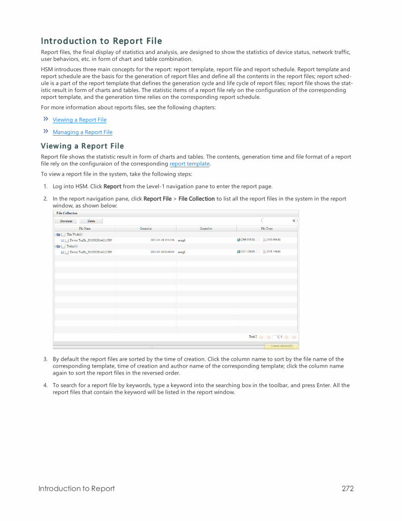
Int roduct ion to Report Fi leReport files, the final display of statistics and analysis, are designed to show the statistics of device status, network traffic,user behaviors, etc. in form of chart and table combination.
HSM introduces three main concepts for the report: report template, report file and report schedule. Report template andreport schedule are the basis for the generation of report files and define all the contents in the report files; report sched-ule is a part of the report template that defines the generation cycle and life cycle of report files; report file shows the stat-istic result in form of charts and tables. The statistic items of a report file rely on the configuration of the correspondingreport template, and the generation time relies on the corresponding report schedule.
For more information about reports files, see the following chapters:
Viewing a Report File
Managing a Report File
View ing a Report F ileReport file shows the statistic result in form of charts and tables. The contents, generation time and file format of a reportfile rely on the configuraion of the corresponding report template.
To view a report file in the system, take the following steps:
1. Log into HSM. Click Report from the Level-1 navigation pane to enter the report page.
2. In the report navigation pane, click Report File > File Collection to list all the report files in the system in the reportwindow, as shown below:
3. By default the report files are sorted by the time of creation. Click the column name to sort by the file name of thecorresponding template, time of creation and author name of the corresponding template; click the column nameagain to sort the report files in the reversed order.
4. To search for a report file by keywords, type a keyword into the searching box in the toolbar, and press Enter. All thereport files that contain the keyword will be listed in the report window.
Introduction to Report 272

5. Expand a report category and double-click the file name to view the report in a new browser window, as shownbelow:
6. The report files consist of left and right panes. Report items are listed in the left pane; contents are listed in the rightpane, including the basic information, template modification history and charts and tables. Click an item in the leftpane to jump to the corresponding details in the left pane.
To view a deleted report file, click Report File > Deleted Files in the report navigation pane, and repeat Step 3 to Step 6above.
Note: By default the report categories are not expanded. Each category may contain severalreport files. Only 100 report files can be listed in one page, so possibly there are more categoriesin other pages. To view the categories that are not listed in the current page, click the Next but-ton on the lower-right.
Managing a Report F ileReport file shows the statistic result in form of charts and tables. You can download, delete or restore a report file.
The configurations of report file management include:
Downloading a Report File
Deleting a Report File
Restoring a Report File
Deleting a Report File Permanenetly
Introduction to Report 273

Dow nload ing a Report Fi leHSM can generate report files in PDF or HTML format. The file format is specified in the Output of the file's template.
To download a report file in the system, take the following steps:
1. Log into HSM. Click Report from the Level-1 navigation pane to enter the report page.
2. In the report navigation pane, click Report File > File Collection to list all the report files in the system in the reportwindow. By default the report files are sorted by the time of creation.
3. Take one of the following operations:
To download a report file, click the icon under the File Type column ( indicates HTML format, and indic-ates PDF format), and download the file to your local disk as prompted.
To batch download multiple report files, select the checkboxes for the files, click Download in the toolbar, anddownload the compressed file package to your local disk as prompted. The file format in the package is spe-cified in the Output of the file's template.
Deleting a Report Fi leTo delete a report file in the system, take the following steps:
1. Log into HSM. Click Report from the Level-1 navigation pane to enter the report page.
2. In the report navigation pane, click Report File > File Collection to list all the report files in the system in the reportwindow. By default the report files are sorted by the time of creation.
3. Select the checkbox for the report file (or checkboxes for multiple report files) to be deleted, and click Delete in thebool bar.
4. In the OK dialog, click OK to delete.
Note: The deleted files are moved to Report File > Deleted Files.
Restoring a Report Fi leYou can restore a deleted report file if the file is not cleared. To restore a deleted report file, take the following steps:
1. Log into HSM. Click Report from the Level-1 navigation pane to enter the report page.
2. In the report navigation pane, click Report File > Deleted Files to list all the deleted report files in the report window.
3. Select the checkbox for the report file (or checkboxes for multiple report files) to be restored, and click Restore in thebool bar.
4. In the OK dialog, click OK to restore.
Deleting a Report Fi le Perm anentlyThe deleted files are moved to Report File > Deleted Files, and can be restored anytime. For more details, see Restoring aReport File.
To delete a deleted report file permanently, take the following steps:
1. Log into HSM. Click Report from the Level-1 navigation pane to enter the report page.
2. In the report navigation pane, click Report File > Deleted Files to list all the deleted report files in the report window.
3. Select the checkbox for the report file (or checkboxes for multiple report files) to be cleared, and click Delete in the
Introduction to Report 274

toolbar.
4. In the OK dialog, click OK to delete the file permanently.
You can also click Clear in the toolbar and then click OK in the OK dialog to delete all the deleted files permanently.
Note: Report files that are deleted permanently cannot be restored. Take this operation with cau-tion.
Introduction to Report 275

Int roduct ion to Report TemplateReport templates, the basis for the generation of report files, define all the contents in the report files, including statisticitems, chart format, schedule, output format, etc.
HSM report templates consist of predefined and user-defined templates. Predefined templates are built in HSM and cat-egorized by analysis contents. Nearly 100 report items in the predefined templates cover analysis data in traffic, network,network behaviors, VPN, system, etc. User-defined templates are created by users as needed.
Note that some items in predefined templates can be only displayed in the report of NIPS devices, such as Security RiskSummary, Risk Type Summary and Security Risk Detail.
For more information about the configuration of report template, see the following pages:
Configuring a Report Template
Managing a Report Schedule
Conf igur ing a Report T emplateReport templates, the basis for the generation of report files, define all the contents in the report files, including statisticitems, chart format, data time, schedule, output format, etc.
HSM report templates consist of predefined and user-defined templates. Predefined templates are built in HSM, but youcannot run the predefined template to generate a report file directly; user-defined templates are created by users asneeded, and you can run the user-defined template to generate a report file directly.
Note that some items in predefined templates can be only displayed in the report of NIPS and IDS devices, such as Secur-ity Risk Summary, Risk Type Summary and Security Risk Detail.
The configurations of report template include:
Creating a User-defined Template
Editing a User-defined Template
Deleting a User-defined Template
Restoring a User-defined Template
Deleting a User-defined Template Permanently
Creating a User-def ined Tem plateHSM provides a template wizard to help you create a user-defined template. You can create a report template step bystep as prompted by the template.
To start the template wizard, take the following steps:
1. Log into HSM. Click Report from the Level-1 navigation pane to enter the report page.
2. In the report navigation pane, click Report Template > User-defined to list all the user-defined templates in thereport window.
3. Click New in the toolbar to start the template wizard.
You can also edit a predefined template to create a user-defined template. In the report navigation pane, click the pre-defined template to be edited to start the template wizard.
To create a report template, you need to complete eight steps in different wizard tabs. Completing one step, click Next togo to the next step. Options and notices in each step are shown below:
Basic
This tab contains the basic information of the report template, and will be shown in the first page of the report file. Con-figure options as below:
Introduction to Report 276

Option description:
Name: Specify the name of the template. When creating a user-defined template on a predefined template, name of thenew template is the predefined template name plus the current system time by default.Company: Specify the company name in the report file.Description: Add description for the template.Show: Select a checkbox or checkboxes to show the operation history and/or description of the template in the reportfile.
Device
Select the analysis devices. Configure options as below:
Devices: Select one or more checkboxes for the devices to include the device(s) in the report file for statistics.Counting Type: Select Include Total Sum of Devices to count each device individually; select Not Include Total Sum ofDevices to count each devices and the total sum of all the selected devices.Only when you choose Include Total Sum ofDevices can the system show Security Risk Summary, Risk Type Summary or Security Risk Detail of the NIPS devices.
Data Time
Configure statistic time range and frequency as below:
Data Time: Specify the data time for the statistics. Click Latest and select a time range from the drop-down list which canbe 1 day, 1 week, 1 month or 3 months; click Period and specify the start time and end time of statistics.
Item
Report item, the key component of a report, defines the statistic contents. HSM contains nearly 100 built-in report items,covering analysis data in traffic, network, network behaviors, VPN, system, etc. A report template can contain multiplereport items.
To add a report item to the template, take the following steps:
1. Expand a report item category node in the left All box, select a category to list all the items in the category in theAvailable box.
2. Select an item and click Add, or click Add All. All the selected report item categories will be listed in the Selected box.To delete an item, select the item (or press Ctrl and left-click to select multiple items) and click Delete, or click DeleteAll to delete all the items.
Please note you need to select at least one report item, otherwise you can neither go to the next step nor save the tem-plate.
Item Options
Configure the following detailed options for each report item under the tab:
Basic: Shows the title and description of the report item (editable). Select the checkbox for Show the above chart to showthe description in the upper of the chart.
Introduction to Report 277

Filter: The filter options vary from report items. By default the report item counts all the objects of the selected devices.To edit a filter parameter, see filter parameter description below.
Parameter Description
Application By default the system counts all the application traffic of the selected devices (allthe checkboxes are not selected).To only count traffic of the specified application, select Application under Filter;under the Not Include tab, select the applications that will not be included in thetraffic statistics. If an application is selected under the Include and Not Includetabs simultaneously, the traffic of the application will not be included in trafficstatistics.
Direction By default the system counts both the sent and received traffic of the selecteddevices.To only count the sent traffic, select the checkbox for Sent Traffic, and clear thecheckbox for Received Traffic; to only count the received traffic, select the check-box for Received Traffic, and clear the checkbox for Sent Traffic.
Zone By default the system counts all the zone traffic of the selected devices (all thecheckboxes are not selected).To only count traffic of the specified zone, select Zone under Filter; under the NotInclude tab, select the zones that will not be included in the traffic statistics. If azone is selected under the Include and Not Include tabs simultaneously, thetraffic of the zone will not be included in traffic statistics.
Interface By default the system counts all the interface traffic of the selected devices.To only count traffic of the specified interface, select Interface under Filter; underthe Not Include tab, select the interfaces that will not be included in the trafficstatistics. If an interface is selected under the Include and Not Include tabs sim-ultaneously, the traffic of the interface will not be included in traffic statistics.
Src IP By default the system counts traffic from all users.To only count traffic from the specified user, select Src IP under Filter; under theInclude tab, specify the IP or IP range, and click Add. Under the Not Include tab,specify the IP or IP range that not be included in the traffic statistics, and clickAdd. If a user is selected under the Include and Not Include tabs simultaneously,the user will not be included in attack statistics.
Attacker By default the system counts attacks from all sources.To only count attacks from the specified source, select Attacker under Filter;under the Not Include tab, specify the IP or IP range that will not be included inthe attack statistics, and click Add. If a source is selected under the Include andNot Include tabs simultaneously, the source will not be included in attack stat-istics.
Dst IP By default the system counts attacks against all destination IPs.To only count traffic against the specified IP, select Dst IP under Filter; under theInclude tab, specify the IP or IP range, and click Add. Under the Not Include tab,specify the IP or IP range that not be included in the attack statistics, and clickAdd. If a destination IP is selected under the Include and Not Include tabs sim-ultaneously, the IP will not be included in attack statistics.
Attack By default the system will count all attacks.To only count the specified attack, under the Include tab, type the attack nameinto the text box and click Add; under the Not Include tab, type the attack namethat will not be included in the attack count into the text box and click Add.
Level Specify the severity of attacks which can be High and above, Middle and aboveand Low and above.
URL By default the system counts accesses to all URLs.To only count accesses to the specified website, select URL under Filter; under theInclude tab, type the URL into the text box, and click Add. Under the Not Include
Introduction to Report 278

Parameter Description
tab, repeat the above steps to specify the URL that will not be included in URLaccess statistics. If a URL is specified under the Include and Not Include tabs sim-ultaneously, the URL will not be included in URL access statistics.
IM By default the system counts all IM chats, including QQ, MSN, 9158 and Fetion.To only count the specified IM chat, select IM under Filter, and select IM softwarein the right box.
Username By default the system counts traffic of all VPN users.To only count traffic of the specified VPN user, select Username under Filter;under the Include tab, type the username into the text box, and click Add. Underthe Not Include tab, repeat the above steps to specify the VPN user that will notbe included in traffic statistics. If a username is specified under the Include andNot Include tabs simultaneously, the VPN user will not be included in the trafficstatistics.
Time Specify the time range of statistics. By default the time range is the same as theschedule defined in the report template.To modify the time range of the report item, clear the checkbox for Inherit fromTemplate, and select a time range within the time range specified by the reporttemplate.
Device Specify the object devices of statistics. By default the devices are the same as thedevices defined in the report template. To count other devices, clear the checkboxfor Inherit from Template, and select devices from the Counting Type box. In theDevices section, select Include Total Sum of Devices to count each device indi-vidually; select Not Include Total Sum of Devices to count each devices and thetotal sum of all the selected devices.
Chart: Specify the number of ranking items in the tables and charts of reports. The system can show maximum Top 10ranking items.
Schedule
Report schedule specifies the time range the corresponding report template will take effect. During the time range spe-cified by the report schedule, system will generate report files continuous. A report template can contain multiple reportschedules.
To add a report schedule to the report template, take the following steps:
1. Under the Schedule tab, click New. In the New dialog, configure the options as below:
Generation Cycle: Specify the generation cycle of report files which can be daily, weekly, monthly, quarterly or one-time.Effective: Specify the start time and end time of the schedule. Select No End to make the template take effect forever.Delete Schedule after End Date: Select the checkbox to delete the schedule after end date.Generated at: Specify the date and time the report file is generated.
2. Click OK to save the settings. The schedule is enabled by default.
Introduction to Report 279

You need to select at least one schedule, otherwise you will neither be able to go to the next step nor save the template.
Output
Output specifies the format of report files and the destination the report files will be sent to. Configure the options asbelow:
File Format: Select the format of the report file which can be PDF or HTML. You need to select at least one file format, oth-erwise you will neither be able to go to the next step nor save the template.
Send via Email: Select the checkbox to send the report files to an Email address.
To add a recipient, type an Email address to the Email box (separate multiple recipients by ";"), or take the followingsteps:
1. Click Manage. In the Email Configuration dialog, click New.
2. In the Add dialog, type the name, Email address and comments into the boxes, and click OK.
3. Close the Email Configuration dialog. Click Recipient.
4. In the Recipient dialog, select the checkbox for the recipient, and click OK. The recipient will be listed in the Emailbox.
Send via FTP: Select the checkbox to send the report files to an FTP server.
Server Name/IP:Type the server name or IP address.
Username: Type the username to log into the FTP server.
Password: Type the password to log into the FTP server.
Anonymous: Select the checkbox to log into the FTP server anonymously (only applicable to the FTP server that allowsanonymous login).
Path: Type the filepath for the report files.
Test: Click the button to test if the FTP server is available.
Sample
Sample is used to demonstrate the report file based on the template. To view a sample, take the following steps:
1. Click Generate Sample to generate.
2. When the system prompts "Generation succeeded", click View Sample to view the report file.
Ed i ting a User-def ined Tem plateTo edit a user-defined report template, take the following steps:
1. Log into HSM. Click Report from the Level-1 navigation pane to enter the report page.
2. In the report navigation pane, click Report Template > User-defined to list all the user-defined templates in thereport window.
Introduction to Report 280

3. Double-click the report template to be edited, and edit options under each tab.
4. Click Save to save the settings.
Note: To preview the report file based on the configured template, click Generate Now on theupper-left to generate a report file immediately. Click Report File > File Collection and double-click the report file with the name specified in the template to open the report file in a new win-dow of your web browser.
Deleting a User-def ined Tem plateTo delete a user-defined report template, take the following steps:
1. Log into HSM. Click Report from the Level-1 navigation pane to enter the report page.
2. In the report navigation pane, click Report Template > User-defined to list all the user-defined templates in thereport window.
3. Select the checkbox for the template to be deleted, and click Delete.
4. In the OK dialog, click OK to delete. If any report file has been generated based on this template, also select thecheckbox for Delete Report Files Generated by This Schedule.
Restoring a User-def ined Tem plateTo restore a deleted user-defined report template, take the following steps:
1. Log into HSM. Click Report from the Level-1 navigation pane to enter the report page.
2. In the report navigation pane, click Report Template > Deleted to list all the deleted templates in the report window.
3. Select the checkbox for the template to be restored, and click Restore.
4. In the OK dialog, click OK to restore.
Note: To also restore the report files deleted along with the template, see the steps described inRestoring a Report File.
Deleting a User-def ined Tem plate Perm anentlyThe deleted report templates are moved to Report Template > Deleted. To delete a user-defined report template per-manently, take the following steps:
1. Log into HSM. Click Report from the Level-1 navigation pane to enter the report page.
2. In the report navigation pane, click Report Template > Deleted to list all the deleted templates in the report window.
3. Select the checkbox for the template to be deleted permanently, and click Delete.
4. In the OK dialog, click OK.
You can also click Clear in the toolbar and then click OK in the OK dialog to delete all the deleted report templates per-manently.
Introduction to Report 281

Managing a Report ScheduleReport schedule defines the generation cycle and time of report files, and the time range the corresponding report tem-plate will take effect. The report schedule is configured under the Schedule tab of a report template, and cannot be cre-ated separately. A report template can contain multiple report schedules to facilitate report file management.
The configurations of report schedule include:
Adding a Report Schedule
Viewing a Report Schedule/Report Schedule Running Log
Deleting a Report Schedule
Enabling/Disabling a Report Schedule
A dd ing a Report ScheduleFor more details about how to add a report schedule when creating a report template, see Schedule in Creating a User-defined Template.
To add a report schedule to an existing report template, click Report Template > User-defined in the report navigationpane, and double-click the report template. Create a report schedule under the Schedule tab.
View ing a Report Schedule/Report Schedule Running LogYou can view the running log of a report schedule and report template, including the running log of the report scheduleand details, running log and modification history of the report template.
To view the running log of a report template and report schedule, take the following steps:
1. Log into HSM. Click Report from the Level-1 navigation pane to enter the report page.
2. In the report navigation pane, click Report Schedule to list all the report schedules by categories in the report win-dow.
3. To view the details of a report template, click the name of the template and click a tab below. Details, running logsand modification of the template will be shown under the corresponding tab. To view the running logs of a reportschedule, expand a template and click the report schedule. Running log of the report schedule will be shown underthe tab below.
Deleting a Report ScheduleReport schedule is configured under the Schedule tab of a report template. If a report schedule is deleted, the schedulein the corresponding report template will be deleted as well.
To delete a report schedule, take the following steps:
1. Log into HSM. Click Report from the Level-1 navigation pane to enter the report page.
2. In the report navigation pane, click Report Schedule to list all the report schedules by categories in the report win-dow.
3. Expand a report template and select the checkbox for the report schedule to be deleted. Click Delete.
4. In the OK dialog, click OK to delete.
When editing a report template, you can also click Delete under the Schedule tab to delete the report schedule.
Enab l ing/Disab l ing a Report ScheduleTo enable/disable a report schedule, take the following steps:
1. Log into HSM. Click Report from the Level-1 navigation pane to enter the report page.
2. In the report navigation pane, click Report Schedule to list all the report schedules by categories in the report win-dow.
Introduction to Report 282

3. Expand a report template and select the checkbox for the report schedule to be enabled/disabled. Click Enable/Dis-able.
4. In the OK dialog, click OK.
When editing a report template, you can also click Enable/Disable under the Schedule tab to enable/disable the reportschedule.
Report ServerNIPS devices support Report Server function. By specifying the name and the IP address of the intranet servers, thereport with the security risk summary and security risk detail selected will display the reports of these servers.
Conf igur ing ServersTo configure the servers, take the following steps:
1. Log into HSM. Click Report > Server from the Level-1 navigation pane to enter the Server page.
2. Click New. The Server Configuration dialog appears.
Configure the following settings
Option Description
Name Enter the name of servers.
Member Specify the IP addresses of the servers.
Add Click Add to add these servers.
3. Click OK.
In the generated reports, you can search the name of servers you specified to view the corresponding information.
Introduction to Report 283

Int roduct ion to Log
HSM collects log information in real-time, centralizes storage and maintenance, and provides multiple query com-binations in order to view various types of log information. By default, HSM can store up to the last 90 days of log inform-ation (when enough storage). Currently, HSM can manage logs of NGFW, IPS devices, and WAF devices of HillstoneNetworks, Inc..
Int roduct ion to LogThis chapter contains log and old version log. The upgrading descriptions of log and old version log are listed in thetable below.
HSM Version Description
Before version 2.5R2, and logshave been collected by HSM
After upgrading to version 2.5R2 or above, you can managethe collected logs in Old Version Log. For the new collectedlogs, you can search and export the logs in Log module, andbackup, import, and clean the logs in System>Log BackupManagement.
Before version 2.5R2, and logsare not collected by HSM
After upgrading to version 2.5R2 or above, you can search andexport the new collected logs in Log, and backup, import, andclean the logs in System>Log Backup Management.
Version 2.5R2 or above You can search and export the logs in Log, and backup,import, and clean the logs in System>Log Backup Man-agement.
LogHSM system optimizes the log management function, using a new searching, backup, importing, and cleaning method tomanage logs. The type of log can be categorized as online log, offline log and operation log.
Online/offline log types can be divided into the followings:
System log: Logs of the managed devices, including event logs, alarm logs, networks logs and configuration logs.
Treat log: Logs of invasion and attack behaviors, including IPS logs, security logs, threat logs, web security logs andanti defacement logs.
NBC log: Logs related to network behavior of managed devices, including URL logs, IM logs, webpost logs, emaillogs and FTP logs. URL logs, IM logs and webpost logs support binary and text format.
Traffic log: Logs of traffic, including NAT logs, NAT444 logs, session logs and PBR logs.
Data Security Log:Logs of data security, including post logs, webpage security logs, URL logs, IM logs, email logsand FTP logs.
Other log:The other Logs.
Operation log: Refers to HSM system logs, which record the local operation events of HSM system.
Log Sever ityEvent logs are categorized into eight severity levels, each level has its own color.
Severity Level Description Log ColorEmergencies 0 Identifies illegitimate system events.
Alerts 1 Identifies problems which need immediate atten-tion such as device is being attacked.
Critical 2 Identifies urgent problems, such as hardwarefailure.
Errors 3 Generates messages for system errors.
Introduction to Log 284

Severity Level Description Log ColorWarnings 4 Generates messages for warning.
Notifications 5 Generates messages for notice and special atten-tion.
Informational 6 Generates informational messages.
Debugging 7 Generates all debugging messages, includingdaily operatiol messages.
Old Vers ion LogThe types of old version logs can be divided into the followings:
Device system log: Record logs of managed devices, including event logs, alarm logs, networks logs, configurationlogs and others.
Traffic log: Record logs related to traffic, including session logs and NAT logs.
Security log: Record logs related to invasion and attack, including IPS logs.
APP control log: Record logs related to network behavior of managed devices, including FTP logs, IM logs, mail logs,URL logs, BBS logs.
HSM log: Record HSM system logs and task logs.
Related Topics:
For more information about Log function, see the followings:
Introduction to Log Window
Searching Logs
Introduction to Old Version Log
Introduction to Log 285

Int roduct ion to Log WindowLog main page is in the Level-1 Navigation Pane, as shown below.
Level-1 Nav igat ion PaneLevel-1 navigation pane displays the general function modules, including dashboard, log, device, task and report.
Log Navigat ion PaneLog navigation pane has three tabs: online log, offline log and operation log. Click on the tab, the right pane shows thecorresponding log messages.
Old Vers ion LogBefore version 2.5R2, the collected logs are managed in old version log. For more information, see Old Version Log.
Log FilterSearching is available for online and offline logs, not for operation logs. You may input values for filters and keywords toquery result that matches your criteria.
Option Description
Search Box Enter keywords or click filter name to insert into the search box. When you hoveryour mouse over , search tips will be shown; after query is done, click to
save it as a bookmark; click , you can view the history and books. If the Autoopen is selected, the history and bookmarks will be automatically open when youuse search box.
Time Range Select the time range of logs for you query.
Click this button to start searching.
Click the pause button to suspend an on-going query.
Click the stop button to abort the on-going query.
If your query takes a long time, switching to another page will discontinue the
query. Click to put the query into background, you can view the search res-ult in the task list.
When a query takes a long time, you may click the mail icon to put the queryinto background, when the query is complete, you will receive an email notice.
Note:To send an email from HSM, you need to set up mailbox first, refer to Con-figuring an Email Account.
Introduction to Log 286

For operation log, you can search logs according to the filters below.
Option Description
Log Type Use log type as a filter.
Operation type Search logs according to user's action
Operation res-ult
Use the result of a query as a filter, including success, unkown, failure.
Time Set the time range for logs.
Operator IP Search for logs of a specific IP address.
Search Click the button to start searching.
Log ChartLog number of different time is shown in bar chart. You may view the detailed diagram by clicking a bar.
T oolbarThe toolbar contains operation icons.
Option Description
Export In the Export dialog, you can save your search results in your local computer, inthe format of TXT file or CSV file.
Name: Enter a filename for the export file.
File Format: Select a format
Range: Select the pages to be exported. The format for specific pages is thepage number separated by comma, for example, 1, 3, 5-9.
Column Customize your column list.
Merge Log System can merge logs which have the same firewall or the same severity. Thusit can help reduce logs and avoid to receive redundant logs.
Select the merging types in the drop-down list:
Do not merge: Do not merge any logs.
FW: Merge the logs with the same firewall.
Severity: Merge the logs with the same severity.
Log WindowLog window shows detailed log list. The log window may vary slightly on different navigation pane.
Option Description
Received in The time when log is received.
Type Log type
Log Details of the log
Links:
Searching Log Messages
Searching Log MessagesYou may view the online, offline and operation logs in HSM.
Introduction to Log 287

Online log: logs that are received directly by HSM.
Offline log: logs that are imported into HSM from other server. For more information about how to import the logs,see Log Import.
Operation log: system logs of HSM itself.
HSM supports viewing logs by log types. You can set conditions to filter the log messages. For example, you may set avalue for firewall device, generation time to view logs that match you filters.
Note: You need to have the right to manage this device when searching logs.
Online/ Of f l ine LogThe type of searching can be divided into the followings:
Temporarily searching: Click the search button for direct local searching. The temporarily searching will be endedwhen you turn to other pages.
Backstage searching: After temporarily searching, click the backstage running button to create the backstagesearching task. In case of closing the searching page or running other searchings, the task of backstage searchingwill keep running.
To search log messages, take the following steps:
1. Log in HSM, and click Log from the level-1 navigation pane. The log window appears.
2. From the left Log Navigation Pane:
Click Online Log to view online log messages.
Click Offline Log to view offline log messages.
3. Select the log type you want to view.
4. In Log Filter, click a filter name, and input a value for this filer. You may select more than one filters.
5. You can quickly add filter conditions for the three types below:
Filter by devices: Click the device name from left navigation.
Filter by log types: Click a log type from the left navigation.
Filter by log contents: In the search box, enter the keyword you want to see in the log content.
6. Click , the matched results will be shown.
Operat ion LogTo view operation log, take the following steps:
1. Log in HSM, and click Log from the level-1 navigation pane. The log window appears.
2. From the left Log Navigation Pane, Click Operation Log to view HSM system operation logs.
3. Choose the log types you want in the log navigation bar, and set a filter condition in the filter bar, then click Search.The logs meeting requirements will be shown in the log window.
Introduction to Log 288

Log Type: Choose a log type from the drop-down list.
Operation Type: Choose an operation type from the drop-down list.
Operation Result: Choose an operation result from the drop-down list, including All, Waiting, Success, Failure.
Time: Choose the generated time of logs from the drop-down list. You can customize the time yourself.
Operator IP: Type the IP address of HSM in the text box.
Note:
Hover your mouse over the icon to view search tips.
To save your search filters, click to store them in the bookmark tab (in the on the leftof search box).
The icon can expand to show search history and stored collections. If Auto Open is selec-ted, the history and collection can automatically open while you use the search box.
Introduction to Log 289

Int roduct ion to Log WindowClick Log from the level-1 navigation pane , and then click Old Version Login the upper right corner of the log windowto enter the old version log page. Its layout is shown as below:
Log Navigat ion PaneLog navigation pane includes predefined query and user-defined query. Click different ones in log navigation pane, themain window will show its related information.
T oolbarFunction buttons of the toolbar are described as below:
Option Description
Predefined Query Export Export logs to local PC. The logs type can be TXT or CSVfile.
Save toMySearch
Create a new search for user-defined query.
User-definedQuery
Export Export logs to local PC. The logs type can be TXT or CSVfile.
Delete Delete the current log query.
FilterAccording to different types of logs, filter provides different filter conditions.
Option Description
Device Search logs of the selected device.
Time Search logs of the selected time.
Severity Search logs of the selected log severity.
Type Search logs of the selected log type.
Message Search logs including the selected text.
Search Click this button, search logs to meet the selected requirements.
Log WindowLog window shows logs which meet the selected requirements.
Introduction to Log 290

Option Description
Device Name Show the device name which generates the logs.
Time Show the generated time of logs.
Severity Show the severity of logs.
Type Show the types of logs.
Message Show the messages of togs
Related Topics:
Searching Logs
Managing Logs
Searching LogsHSM supports the running logs and offline logs. Running logs are generated by the current HSM itself. Offline logs arethe ones that are imported by using the log import function.
For these two types of logs, HSM provides logs classification view and filtering. You can view logs according to differenttypes of events, or set a filter condition such as device name, log time, log keyword to search logs.
To view log information, take the following steps:
1. Log into HSM.
To view running logs, click Log, and the click Old Version Log in the upper right corner. Click Running Log tab.
To view offline logs, click Log, and the click Old Version Log in the upper right corner. Click Offline Log tab.
2. Choose the log types from the log navigation pane, the log window will show you related log information.
In the running logs window, predefined query is the one which is pre-set by HSM, while user-defined query isthe one which is set by users according to requirements.
In the offline logs window, predefined logs are the ones which are pre-set by HSM, while other logs are the oneswhich are set by users according to requirements.
3. To further filter the log information, follow the instructions below to set the filter conditions.
Setting Fi l ter Cond i tionsChoose the log types you want in the log navigation bar, and set a filter condition in the filter bar, then click Search. Thelogs meeting requirements will be shown in the log window.
The filter condition of different log types is described as below:
Device System Log
Filter condition of device system log is described as below:
Device: Choose a device from the drop-down list.Time: Choose the generated time of logs from the drop-down list. You can customize the time yourself.Severity: Choose the log severity from the drop-down list, including Emergency, Alerts, Critical, Error, Warning, Notice,Informational and Debug.Message: Type the keyword in the text box.
Traffic Log - Session Log
Introduction to Log 291

Device: Choose a device from the drop-down list.Time: Choose the generated time of logs from the drop-down list. You can customize the time yourself.Service/Protocol: Type the service or protocol in the text box, such as TCP, UDP, QQ.Source Address: Type the source IP address of session in the text box.Source Port: Type the source port of session in the text box.Destination Address: Type the destination IP address of session in the text box.Destination Port: Type the destination port of session in the text box.
Traffic Log - NAT Log
Device: Choose a device from the drop-down list.Time: Choose the generated time of logs from the drop-down list. You can customize the time yourself.Service/Protocol: Type the service or protocol in the text box, such as TCP, UDP, QQ.Source Address: Type the source IP address of traffic in the text box.Source Port: Type the source port of traffic in the text box.Destination Address: Type the destination IP address of traffic in the text box.Destination Port: Type the destination port of traffic in the text box.Translated Address: Type the translated address after NAT in the text box.Translated port: Type the translated port after NAT in the text box.
Security Log - IPS Log
Device: Choose a device from the drop-down list.Time: Choose the generated time of logs from the drop-down list. You can customize the time yourself.Severity: Choose the log severity from the drop-down list, including Emergency, Alerts, Critical, Error, Warning, Notice,Informational and Debug.Message: Type the keyword in the text box.
APP Control Log - FTP
Device: Choose a device from the drop-down list.Time: Choose the generated time of logs from the drop-down list. You can customize the time yourself.Policy: Choose the policy action from the drop-down list, including Block and Permit. All means all the actions.User: Type the username or user IP address in the text box.Login ID: Type the username of logging in FTP server in the text box.FTP Server: Type the IP address of FTP in the text box.File Name: Type the name of the transferring file in the text box.
APP Control Log - IM
Device: Choose a device from the drop-down list.Time: Choose the generated time of logs from the drop-down list. You can customize the time yourself.Action: Choose the action for IM client in the drop-down list, including Log in, Log off, Block.
Introduction to Log 292

User: Type the username or user IP address in the text box.Sender: Type the sender name of IM in the text box.Content: Type the keyword of chatting in the text box.
APP Control Log - Email
Device: Choose a device from the drop-down list.Time: Choose the generated time of logs from the drop-down list. You can customize the time yourself.User: Type the username or user IP address in the text box.Subject: Type the keyword of a mail subject in the text box.Sender: Type the sender name of a mail in the text box.Recipient: Type the receiver name of a mail in the text box.
APP Control Log - URL
Device: Choose a device from the drop-down list.Time: Choose the generated time of logs from the drop-down list. You can customize the time yourself.URL Category: Choose the URL category from the drop-down list, including Malicious, Compromised, etc.Policy: Choose the policy action from the drop-down list, including Block and Permit. All means all the actions.User: Type the username or user IP address in the text box.URL: Type the keyword of the URL you want to search in the text box.
APP Control Log - BBS
Device: Choose a device from the drop-down list.Time: Choose the generated time of logs from the drop-down list. You can customize the time yourself.User: Type the username or user IP address in the text box.
HSM Log - Operation
Log Type: Choose a log type from the drop-down list.Operation Type: Choose an operation type from the drop-down list.Operation Result: Choose an operation result from the drop-down list, including Unknown, Success, Failure.Time: Choose the generated time of logs from the drop-down list. You can customize the time yourself.Operator IP: Type the IP address of HSM in the text box.
HSM Log - Task
Task ID: Enter the task ID in the text box.Device: Specify the devices whose logs to be searched.Operation Result: Choose an operation result from the drop-down list.Time: Choose the generated time of logs from the drop-down list. You can customize the time yourself.Operation Type: Choose the operation type from the drop-down list.Description: Enter the description keyword in the text box.
Introduction to Log 293

Managing LogsYou can not only save the current filter condition as a user-defined query, in order to ensure that you can view loginformation quickly and effectively,but also export the result of searching logs.
This page includes the following operations:
Creating a New User-defined Search
Deleting a New User-defined Search
Exporting Logs
Importing Logs
Backing up Logs
Cleaning Logs
Creating a New User-def ined SearchTo save the current filter condition as a user-defined query, take the following steps:
1. Set filter conditions as it is told inSearching Logs.
2. Click Save to MySearch button in the toolbar, and the Save dialog appears.
3. Type a name for the new search and click OK.
Note: The user-defined search only can include one log category.
Deleting a User-def ined SearchTo delete a new user-defined search, take the following steps:
1. Log in to HSM, click Log from the Level-1 navigation pane to enter the log management page.
2. Click Old Version Log in the upper right corner of the main window.
3. Click MySearch in the log navigation pane, and then click the user-defined search you want to delete.
4. From the toolbar, click Delete, and the click OK in the Delete dialog.
Exporting LogsTo save the current search as a TXT file or CSV file in local PC, take the following steps:
1. Log in to HSM, click Log from the Level-1 navigation pane to enter the log management page.
2. Click Old Version Log in the upper right corner of the main window.
3. Set filter conditions as it is told in Searching Logs.
4. Click Search and all the logs meeting the requirements will be shown in the log list.
Introduction to Log 294

5. Click Export in the toolbar, and the Export dialog is shown as below:
Name: Type a name for the export file.File Format: Choose the format of the export file.Range: Specify the page range of the export file. All Result means to export all the results for the current search;Page Range means you need to specify a page range (format as 3, 5-9) to export results of these pages.
6. Click OK to save changes.
Im porting LogsHSM system supports the import and viewing logs.
To import logs, take the following steps:
1. Log in to HSM, click Log from the Level-1 navigation pane to enter the log management page.
2. Click Old Version Log in the upper right corner of the main window.
3. Select Log Import from the Log Backup Manage drop-down list . The Log Import dialog appears.
4. In the Log Import dialog, configure the following options:
FTP Service: From the drop-down list, select the FTP server where you store the log files. Then the correspondingFTP server settings are displayed. You can click Detection to verify the connection between HSM and the FTP server.If you want to modify the FTP settings, please click FTP Config .
Choose File: From the drop-down list, select the log files. You can select folders and/or files. The system supportsthe following files types: ZIP, TXT, and CVS.
5. Click Import to start the import task. HSM displays the task progress in the current dialog. You can close this dialogto perform other actions. To stop the import task, click Stop Import.
You can view the imported logs in Offline Log tab.
B ack ing Up LogsHSM supports the backup of the logs. You can back up logs manually.
Introduction to Log 295

For the imported logs, HSM cannot backup them again.
For the backed-up logs, HSM can import them for viewing.
To back up the logs, take the following steps:
1. Log in to HSM, click Log from the Level-1 navigation pane to enter the log management page.
2. Click Old Version Log in the upper right corner of the main window.
3. Select Log Backup from the Log Backup Manage drop-down list . The Log Backup dialog appears.
4. In the Log Backup dialog, configure the following options:
Log Type: From the drop-down list, select the log types to be backed up.
Start Time: Specify the start time of logs.
End Time: Specify the end time of logs.
FTP Server: From the drop-down list, select the FTP server where to store the log files. Then the correspondingFTP server settings are displayed. You can click Detection to verify the connection between HSM and the FTPserver. If you want to modify the FTP server settings, click FTP Config.
5. Click Backup to start the backup task. HSM displays the task progress in the current dialog. You can close this dialogto perform other actions. To stop the task, click Stop Backup
Old version log can perform only one backup task at the same time. If a backup task is running when opening the LogBackup dialog, the task progress will be displayed. You can choose to stop the task or wait for its completion.
Cleaning the LogsHSM supports the clearing of offline logs and running logs within the specified time. You cannot restore the cleared logs.For more information of offline logs and running logs, refer to Searching Logs.
To clear logs, take the following steps:
1. Log in to HSM, click Log from the Level-1 navigation pane to enter the log management page.
2. Click Old Version Log in the upper right corner of the main window.
3. Select Log Clean from the Log Backup Manage drop-down list . The Log Clean dialog appears.
4. In the Log Clean dialog, configure the following options:
Offline Log: Select Offline Log to clear the offline logs.
Running Log: Select Running Log to clear the running log within the specified time.
Introduction to Log 296

5. Click OK. The Tip dialog appears.
6. Click Yes. HSM starts to clear the logs.
Introduction to Log 297

HSM Configurat ion Ex ample
This page describes a typical deployment scenario and some configuration examples for your understanding of HSM. Therequirements and configurations are shown below:
Deployment Scenar ioA company is headquartered in Beijing and has branches in Shanghai and Guangzhou. Each office is deployed with a Hill-stone security appliance to control Internet access, and in order to manage all the three security appliances centrally, aHSM is deployed in Beijing. The topology is shown as below:
RequirementRequirement 1: Configure a shared policy that permits Internet access from Intranet and deploy the policy to all the man-aged devices.
Requirement 2: Monitor the managed devices and view the memory utilization ranking, application traffic ranking andintrusion ranking within the latest one hour.
Requirement 3: Create an alarm rule that will trigger a major alarm and send an E-mail when the CPU utilization exceeds80% for continuous 10 minutes.
Configurat ion Steps
Preparat ionConfigure a management IP address on HSM as described in Deploying HSM Management Environment, and then addthe Hillstone devices deployed in Beijing, Shanghai and Guangzhou to HSM.
To check if the devices have been registered to HSM, log into HSM and click Device > Management to enter the devicepage, as shown below:
Conf igurat ion Steps(Requirement )Create a shared policy that permits Internet access from Intranet in HSM. Before configuring, make sure the trust zone ofthe three Hillstone devices is bound to the Intranet interfaces, and the untrust zone is bound to the Internet interface.
HSMConfiguration Example 298

Log into HSM and take the following steps:
1. Click Configuration > Shared Configuration from the Level-1 navigation pane to enter the shared policy page.
2. Select Security Policy from the configuration pane, and click New in the toolbar.
3. In the Shared Policy Configuration dialog, configure the options as below:
4. Click OK to save the policy configuration and close the dialog. The newly created policy is listed in the policy table.In the policy table, click the policy name sample_policy to enter the rule configuration page. From the toolbar, clickTop from the new drop-down list, the policy rule entry appears. Configure the options as below:
5. Click Configuration>Device Configuration from the Level-1 navigation pane to enter the device configuration page.
6. On the device navigation pane, right-click and select Batch Deplay Configuration from the pop-up dialog,
7. From the selective box, select the devices deployed in Beijing, Shanghai, and Guangzhou, and then click OK.
8. The system starts to deploy the configuration to the devices and generates the related task. Go to the task man-agement page to see the task status.
Conf igurat ion Steps(Requirement 2 )To view multiple monitor charts in one page, take the following steps in My Monitor:
Step1 : Create a Monitor Group
1. Log into HSM. Click Monitor from the Level-1 navigation pane to enter the monitor page.
2. In the left navigation pane, click MyMonitor, and click an arbitrary group.
HSMConfiguration Example 299

3. Click New Group. In the New Monitor Group dialog, type monitor_sample into the Name box and click OK.
Step 2: Add Monitor Charts
1. In the left navigation pane, click Device.
2. In the device monitor page, click .
3. In the Select Device (Group) dialog, click Device, and select Beijing, Shanghai and Guangzhou.
4. Select from the drop-down list in the device monitor page.
5. Find the Latest 1 Hour Top 10 Devices by Memory Utilization chart, and click Details on the upper-right.
6. Under the Device Rank by Memory Utilization tab, click Add to MyMonitor on the upper-right.
7. In the Add to MyMonitor dialog, select monitor_sample from the MyMonitor Group drop-down list.
8. Repeat Step 1 to Step 8 to add Latest 1 Hour Top 10 User Traffic and Latest 1 Hour Top 10 Intrusions to the monitor_sample group.
Step 3: Viewing Monitor Charts
In the left navigation pane, select MyMonitor > monitor_sample to view the selected monitor charts, as shown below:
HSMConfiguration Example 300

Conf igurat ion Steps (Requirement 3 )The configurations consist of two steps: configuring an alarm rule and reading/processing the alarms.
Step 1: Configuring an Alarm Rule
Configure an alarm rule that will trigger an alarm and send a notification Email when the CPU utilization of any manageddevice exceeds 80%.
This example adopts a predefined alarm rule. Take the following steps:
1. Click Alarm from the Level-1 navigation pane to enter the alarm page.
2. In the alarm navigation pane, click Alarm Rule > All Rules > Predefined > Resource > CPU Utilization.
3. In the Alarm Rule configuration page, configure options as below:
Rule Name: The name of predefined alarm rules cannot be modified.Description: Type over 80% into the text box.Device: Select the checkboxes for Beijing, Shanghai and Guangzhou.Trigger: Select CPU Utilization in consecutive 1 Hours Higher than 80%.Action: Select Major from the drop-down list. Select Send via Email, and click New. In the Send via Email dialog, typehsmadmin, [email protected] and admin into the text boxes, and click OK. In the Email list, select thecheckbox for hsmadmin.
4. Click OK to save the settings.
HSMConfiguration Example 301

Step 2: Reading and Processing Alarms
1. To view all the alarms, click Alarm from the Level-1 navigation pane. In the alarm navigation pane, click Alarm >Alarm Search to show all the alarms in the alarm window, as shown below:
2. To view all the alarms, click Alarm from the Level-1 navigation pane. In the alarm navigation pane, click Alarm >Alarm Search to show all the alarms in the alarm window, as shown below:
3. To view alarm analysis charts, in the alarm navigation pane, click Alarm > Alarm Analysis > Device Analysis to showall alarms in the alarm window, as shown below:
HSMConfiguration Example 302

4. To check if the device deployed in Guangzhou contains any alarm that matches the rule, click the bar chart and clickLevel.
5. In the pie chart, click Critical.
6. In the alarm list below, find the alarm with alarm rule named CPU Utilization, and click Unread under the Statuscolumn.
7. In the Add Comment dialog, type Alarm has been read and will find out the reason into the Comment box.
8. Click OK to save the comment.
HSMConfiguration Example 303

Managing HSM via Console Port
A command line interface (CLI) is a mechanism for you to interact with HSM by typing commands which instruct HSM toperform specific tasks. Following contents describe how to use HSM command line interface via Console port.
Accessing HSM via Console PortTo deploy the console management environment, take the following steps:
1. Take a standard RS-232 cable. Connect one end of the cable to a computer’s serial port, and the other end toHSM's console port, as shown below:
2. In PC, start the terminal emulation program (e.g. HyperTerminal) and use the following parameters:
Parameter Value
Baud 115200 bps
Data 8
Parity None
Stop 1
Flow Control None
3. Power on the HSM device and HSM system starts up. Type the default login name (hillstone) and password (hill-stone), then press Enter to log in.
4. After logging in successfully, the prompt [hillstone] appears for entering commands, as shown below:
Command Int roduct ionHSM provides a series of commands for management and configuration.
Enter the command after the prompt [hillstone] and press Enter to execute the tasks. The available commands aredescribed in the following table.
Function Command
Function Command
Displays thehelp inform-ation
help
Displays theversion, SN, lan-guage, etc. ofHSM
show version
Displays the IPaddress, net-mask, and
show interface
Managing HSMviaConsole Port 304

Function Command
status of inter-faces
Displays theHSM firmwarethat is saved inHSM
show systemBit
Displays theHSM firmwarethat is currentlyrunning
show currentBit
Displays theHSM HTTP portnumber that iscurrently open-ing
show httpPort
Displays theHSM HTTPSport numberthat is currentlyopening
show httpsPort
Modifies theHTTP port num-ber for HSM
webport httpport-number
port-number - Specify the port number accessing to HTTP service forHSM. The default value is 80.The value ranges from 1025 to 65535besides 80, among them 2003~3003、3306、6514、8005、8080、8161、8443、9000、9090、9091、9092、61616、61617 are pre-occupied by system.Preoccupied port number can not be configured.
Modifies theHTTPS portnumber forHSM
webport httpsport-number
port-number - Specify the port number accessing to HTTPS service forHSM.The default value is 443.The value ranges from 1025 to 65535besides 443, among them 2003~3003、3306、6514、8005、8080、8161、8443、9000、9090、9091、9092、61616、61617 are pre-occupied by system.Preoccupied port number can not be configured.
Shut downHSM
halt
Check whethera remote net-work is reach-able
ping [-LRUbdfnqrvVaA] [-ccount] [-iinterval] [-wdeadline] [-ppattern] [-spacketsize] [-tttl] [-Iinterface or address] [-Mmtu discovery hint] [-Ssnd-buf] [ -Ttimestamp option ] [ -Qtos ] [hop1 ...] destination
Displays theroute table
route print
Specify the IPaddress for thegateway ofHSM
route addip-address
ip-address - Specify the IP address for the gateway of HSM
Modifies thepassword ofthe WebUIuser: admin
passwd webadmin
Modifies thepassword of
passwd hillstone
Managing HSMviaConsole Port 305

Function Command
the CLI user:hillstone
Modifies the IPaddress andnetmask ofinterfaces
ipconfiginterfaceip-address netmask
interface - Specify the interface name to be modified.
ip-address - Specify the IP address for the interface.
netmask - Specify the netmask for the interface.
Modifies thestatus of inter-faces
ipconfiginterface {up|down}
interface - Specify the interface name to be modified.
up|down - Specify the interface status. up represents that this inter-face can be accessed; down represents that this interface cannot beaccessed.
View the statusof HSM services
services status
Manage systemservices
service {start|restart|stop}{all|image|config|monitor|adapter|report|alarm}
start|restart|stop - Specify the operation type. You can start, restart, orstop the specified services.
all|image|config|monitor|adapter|repor - Specify the service name. allrepresents all services.
Queries DNS toobtain domainname or IPaddress map-ping
nslookup
Tests andrecords gate-ways of packetsfrom sourcehost to the des-tination
traceroute [-46dFITUnrAV] [ -ffirst_ttl ] [ -ggate,... ] [ -idevice ] [ -mmax_ttl ] [ -Nsqueries ] [ -pport ] [ -ttos ] [ -lflow_label ] [ -wwaittime ] [ -qnquer-ies ] [ -ssrc_addr ] [ -zsendwait ] host [ packetlen ]
Reboots HSM reboot
Managing HSMviaConsole Port 306