INSTALLATION GUIDE - Mueller, Inc
68
MUELLER LOCK INSTALLATION GUIDE
Transcript of INSTALLATION GUIDE - Mueller, Inc

MUELLERLOCK INSTALLATION
GUIDE

TABLE OF CONTENTS
2
TABLE OF CONTENTS
2
IMPORTANT INFORMATION 3Customer Responsibility 3Roof Safety Considerations 5Walking & Working on Roof Panels 5
ENGINEER / ARCHITECT INFORMATION 6
GENERAL APPLICATION 7Sealants 7Snow Design 7Delivery and Storage 7
STANDARD PARTS 8-11
SAFETY AND STORAGE CONSIDERATIONS 12
CARE AND HANDLING OF MUELLER SHEET METAL 13
INSTALLATION DETAILS - PURLINInstalling Edge Plate 14Installing Eave Trim 15Insulation 16Starting Panel 17Floating Rake 18-19Installation Sequence 20Fastening Eave 21Panel Clips 22Endlap Placement 23Endlap Tape Sealant 24Installing Upper Panel 25Clamping Endlap 26Backup Channel 27Cinch Strap 28Endlap Screws 29Sealant Tabs 30-32Second Panel Back-Up Channel 33-34Clamping Side Laps 35Checking Coverage 36Metal Closures 37-40, 42-43Back-Up Channel at Ridge 41Floating Ridge 44Lapping and Sealing Rake Trim 45End Cap Installation 46Side Wall / Parapet Details 47End Wall / Parapet Details 48Gutter Installation 49-50Fixed Valley 51Floating Hip 52
INSTALLATION DETAILS - DECKING 53Floating Rake Details 54-55Fixed Eave 56Floating Eave 57Fixed Valley 58Floating Valley 59Fixed Ridge & Hip 60Floating Hip & Ridge 61Side Wall / Parapet Details 62End Wall / Parapet Details 63Fixed High Side Eave 64

3
Read this manual completely prior to beginning the installation of your Mueller Lock (MLK) roof system. Mueller Incorporated details must be followed as a minimum to ensure appropriate warranties are issued. Mueller Incorporated assumes no responsibility for any problems which might arise as a result improper installation or any personal injury or property damage that might occur with the products use.
Mueller is providing the following installation instructions and details as a guideline, to show a knowledgeable, trained erector, parts placement one to another. All local building codes in project specifications should be followed, however, in all cases, good roofing practices, and good workmanship should be employed when constructing a roofing system using Mueller products. These procedures and details are not intended to cover all instances, building requirements, designs, or codes. These details may require changes or revisions for each project, as conditions vary from project to project. The details provided are proven methods of construction.
Mueller Incorporated does not consider the installation of a standing seam roof to be a do-it-yourself project. Work should be performed by experienced craftsmen familiar with metal roofing products and current industry standards.
This installation guide is provided to Mueller customers and contractors as a basic recommended procedure for the correct assembly of the Mueller Lock Standing Seam Roof System. This guide is intended to be used in conjunction with the erection drawings to help plan and organize the installation of the Mueller Lock Standing Seam Roof System. The erection drawings govern specific part arrangement and identify the applicable roof conditions. The instructions will help identify parts, establish the installation sequence, demonstrate correct assembly, and point out areas or procedures requiring special emphasis or attention.
This installation guide applies to the Mueller Lock Standing Seam Roof System. Custom roof conditions, including custom details and instruction, will be covered by the erection drawings. In case of conflict between this installation guide and the erection drawings, the erection drawings will take precedence.
CUSTOMER’S RESPONSIBILITYSuitability of detailsIt is the responsibility of the customer (or designer) to ensure that the details meet particular building requirements to assure adequate water tightness. It is the customer’s responsibility to determine suitability of supplemental details for any claims arising from improper detail selection by others or faulty installation of any kind.
Suitability of substrate or structureIt is the responsibility of the customer (or designer) to determine suitability of structure, or substrate for the MLK panel system. It should be code-compliant and properly engineered and constructed for a structural standing seam roof system. It must be true and aligned to avoid panel distortion. MLK panels offer little or no diaphragm stability to the structure, and may not be relied upon for diaphragm support.
Suitability of roof accessoriesMueller may pass along vendor information to its customers for insulation, preformed roof curbs, hatches, vents, pipe flashings and other ancillary roof accessory items as well as tools and specialty fasteners. This is done as a convenience to the customer and is not to be construed as an approval of any particular roof accessory item for any given application. It is the responsibility of the customer to qualify other vendors and products with respect to quality and suitability for any particular application. Mueller assumes no responsibility for suitability or performance of materials and accessory items furnished by other vendors.
IMPORTANT INFORMATION

4
IMPORTANT INFORMATION
Subcontractor selectionThe customer must select a competent installer that is qualified and experienced in the installation of standing seam metal roof systems. The installer should take time to study and understand this guide and follow the guide’s instructions. Mueller, Inc. does not guarantee and is not liable for the qualifications of installer. Mueller, Inc. is not responsible for defects that may be attributed to improper installation or the negligence of other parties, suitability of structure, substrates or adjoining work or materials.
Compliance with codes, standards, and sound industry practicesThe customer (and/or) installer is responsible for proper installation of the roof in accordance with the erection drawings and this installation guide, and other good construction practices as well as code compliance. In the case of tested and rated panel systems, it is the responsibility of the customer to see that actual construction complies with the tested and rate assembly in every detail.
• Panels should be installed straight and accurately.
• Roof clips shall allow for thermal movement and must be installed in strict accordance with Mueller erection drawings with respect to type and quantity of fasteners as well as clip spacing along the panel seam.
• Thermal movement of panels must be considered when attaching to adjacent constructions and materials.
• All areas of roof must have positive drainage of 1/2:12 pitch minimum and not allow ponding in any area of the roof.
• Compatibility of adjacent materials (not furnished by Mueller) should be verified.
• No penetrations whatsoever shall be placed in the panel system by fasteners or other roof ancillaries except as shown on the erection drawings.
• Only Mueller furnished or approved sealants shall be used, and only as shown on drawings and within this manual.
• Some field cutting and fitting of panels and flashings is expected and considered part of normal installation.
• “Oil Canning” of the flat portion of metal panels is inherent to metal panels and a common industry phenomenon. It shall not be considered cause for rejection.
• All flashings, closures, and accessories shown on the erection drawings shall be provided by Mueller unless noted otherwise. Installation procedures shall be in accordance with Mueller printed instructions, details, approved shop drawings and the highest industry standards and practices.
Trade Knowledge and PracticesThe customer (and/or) installer of the roof system is responsible for the safe execution of the work. Metal roof installation is a skilled craft requiring considerable trade knowledge and experience. Such knowledge and experience includes general rooftop safety, as well as knowledge of the hazards associated with metal roofing, and the tools and equipment associated there-with. This manual is intended to describe the sequence and proper placement of parts. It is not the intent or purpose of this text or Mueller, Inc. to train individuals for the craft of Metal Roof Assembly, or to convey all necessary trade knowledge and practice of metal roof installation. Although some general safety comments is offered in the following text, it is not intended to prescribe comprehensive safety procedures.
If the installer cannot safely assemble the roof in accordance with these instructions, it is the responsibility of the installer to stop the work and determine alternate safety assembly procedures.

5
IMPORTANT INFORMATION
Roof Safety ConsiderationsOSHAThe Occupational Safety and Health Act (OSHA) has developed many regulations applicable to the installation of thisor any other roof system. These regulations, identified as Part 1926, Safety and Health Regulation for Construction, are available from any government book store. The objective of the OSHA standards is to protect the worker from injury or illness. These OSHA regulations should be recognized as job site requirements and fully complied with. Failure to do so may result in substantial fines in the event of an OSHA inspection. Safe installation practices may be further defined and made mandatory by state or local ordinances. Maintaining good housekeeping on the job site is recognized as being important to both OSHA compliance and to successful job completion.
Walking & Working on Roof PanelsPlacing Panels on the StructureDo not place bundles of panels on the roof structure without first verifying the structure will safely support the concentrated weight of the panels and the weight of the installation crew. Some roof structures may not be designed to support the weight of a full panel bundle without additional structural support.
Walking on Roof PanelsAn approved and safe walking platform should be used in high traffic areas to prevent the roof panels from being deformed, scratched, or scuffed.
Do not use a roof panel as a walking platform. An unscrewed panel could collapse under the weight of a person standing between purlins or at the end.
Do not walk on the last installed panel run, as the unsecured edge could collapse under a person’s weight. When installing clips or making end lap connections, etc., stand where the roof structure will support your weight.
Do not leave a roof panel edge unattached, always install the clips to the panel before terminating the installation for any period of time.
When using power tools, equipment, lanyards, retractable lines and other installation equipment, ensure that the metal parts are covered in such a manner that they do not scratch the panel surface if dragged along the panel.
Panel OverhangDo not stand on the end of unsupported (cantilevered) panels at the eave or ridge. Standing on the cantilever portions may result in panel collapse.
Construction LoadsWhen properly attached to supporting structures and seamed, MLK panels are designed to support uniform loads which are evenly distributed over the panel surfaces. Panels will also support a minimum 300 pound point load over any one square foot area of any part of the panel.

6
ENGINEER/ARCHITECT INFORMATION
Substrate:24 Gauge Galvalume - Standard Surface.
Panel Configurations:Flat
Panel Width:16”
Panel Length:50’ Standard Maximum Length. Longer lengths available upon request, 3 foot (3’) Mimimum Length.
Panel Height:2”
Minimum Slope:1/2:12 Pitch
Clip Spacing:See U.L. 90 Classifications - Roof Deck Construction for maximum clip spacing.
U.L. 90 Classifications - Roof Deck Construction:U.L. Class 90 - 24 Ga. minimum panel on 4’ - 0” maximum purlin spacing, per U.L. Construction #255U.L. Class 60 - 24 Ga. minimum panel on 5’ - 0” maximum purlin spacing, per U.L. Construction #255U.L. Class 90 - 24 Ga. minimum panel with clips spaced 36” on center over plywood decking, per U.L. Construction #343U.L. Class 90 - 24 Ga. minimum panel with clips spaced 48” on center over rigid insulation on metal deck, per U.L. Construction #468
Impact Resistance:UL 2218 - IMPACT: CLASS 4EXTERNAL FIRE: CLASS A
Air and Water Infiltration:Mueller Lock systems have been tested in accordance with ASTM E1680 and ASTM E1646 procedures.
Oil canning (pan wave) of metal panels is inherent in the product and is not cause for panel rejection.
.709˝
16˝
2˝

7
GENERAL APPLICATION INFORMATIONThe details shown on the following pages are suggestions or guidelines for installing the Mueller Lock System. The installation details shown here are proven methods of construction, but they are not intended to cover all building requirements, designs or codes. The details may require changes or revisions due to individual project conditions.
Installation procedures shall be in accordance with instructions, details or approved shop drawings. Installers should thoroughly familiarize themselves with all instructions prior to beginning the installation process.
The installer/designer is responsible for ensuring the following:• That the details here meet the particular building requirements.• Awareness of and allowance for expansion/contraction of roof panels. • That adequate water tightness is maintained.• That a proper uniform substructure is used to avoid panel distortion and that the substructure meets necessary
code requirements.• That all supporting members have been examined and are straight, level, and plumb.
Due to the complexities of a standing seam roof it is the responsibility of the customer (or designer/installer) to determine the suitability of the structure or substrate for a Mueller standing seam roof. It is the customer’s responsibility to insure that their building is code compliant, properly engineered and constructed to facilitate the installation of a standing seam roof. Standing seam panels offer little or no diaphragm stability to the structure and cannot be relied upon for diaphragm support. Purlin stability is not provided by a Mueller Lock panel. Accurate sheet lengths and trim components are critical to a successful install and should be confirmed by the designer/installer before any material is ordered.
Mueller can provide all flashings, trim and accessories shown in the installation drawings unless otherwise noted. Panels, flashing and trim shall be installed true and in proper alignment with any exposed fasteners equally spaced for best appearance. Sealant shall be field applied on clean dry surface.
Some field cutting and fitting of panels and flashings is to be expected and is a normal part of installation work. In some cases extra length has been added to panels to ensure adequate product on the jobsite. Workmanship shall be of the best industry standards with installation performed by experienced metal craftsmen.
SealantsSealants not exposed to direct sunlight should consist of either an elastic butyl rubber tape or non-shrinking, non- drying gum applied butyl. Single part urethane should be used when exposed to ultraviolet light. All sealant should be applied clean dry services to ensure weather tightness. Sealant shall be installed as shown without voids.
Snow DesignThe following details do not address snow load conditions. Special design consideration is required when installing a metal roof in heavy snow environments. Contact your Mueller sales representative for more details.
Delivery and StorageHandle panels in bundles with care. Do not use ropes or wires for lifting. Long panels (25 feet or more) may require two or more lift points to avoid bending and buckling of panels. Store panels in a dry, well ventilated area. Elevate one end of the panels to allow for drainage of any moisture. Block panels off the ground. Do not store panels in direct contact with the ground. Do not allow strippable film to remain exposed to direct sunlight for any extended period of time. Remove strippable film prior to, or immediately after installation of panels or trim. Do not walk directly on standing seams. Wear shoes with non-marking/scuffing soles. Inspect each and every panel, trim and all accessories before installation. Never install any product if it’s quality is in question. Notify your Mueller salesperson immediately if any product is believed to be out of tolerance, specification, or has been damaged during shipment. If there is a conflict between project erection drawings provided by Mueller and details in this manual, project erection drawings will take precedence.
Contents of this manual are subject to change without notice. To confirm this book is the most current copy, please visit the Mueller website at www.muellerinc.com.

8
1/8" diameter x 3/16" Grip Range Stainless Steel
12" x 24 x 1" Tek 2Grip Range Stainless Steel
• 5/16" Hex Head with 5/8" O.D. washer
STANDARD PARTS
Details are subject to change without prior notice.
14 x 1 1/4" Long Life Driller
• 3/8" Hex Head with sealing washer
14 x 1" Type AB Long Life
• 3/8" Hex Head with sealing washer (Long life exterior fastener)
14 x 7/8" Lap Tek
• 3/8" Hex Head with 3/8" O.D. washer
14 x 1 1/4" Shoulder Tek 2
• 5/16" Hex Head with no washer
14 x 1 1/4" Clip Screw
• 3 /8" Hex Head with no washer
10 x 1" #2 Phillips Pancake Head Self Driller
10 x 1" #2 Phillips Pancake Head
Stitch Screw 1/2"
• #2 Phillips Drive• Corrosion Resistant Coating• Painted or Mill Finished Head
1/2"
Deck Screw Driller
• 2"-6" x #14 • Length determined by rigid insulation thickness and metal deck depth.
#9 x 1 1/2" Woodgrip
• 1/4" Hex Washer Head• 1/2" O.D. EPDM Sealer Washer• Corrosion Resistant Coating• Painted or Mill Finished Head
1 1/2"
#14 x 7/8" Low Profile Lap Screw
• Low Profile Design• Large Diameter Head For Resistance• Corrosion Resistant Coating• Painted or Mill Finished Head
7/8"
6-Lobe
#9 x 2 1/2" Woodgrip
• 1/4" Hex Washer Head• 1/2" O.D. EPDM Sealer Washer• Corrosion Resistant Coating• Painted or Mill Finished Head
2 1/2"
1", 1 1/2", 2 1/2" Low Profile Head
• 1/2" Head Diameter Phillips Drive• Corrosion Resistant Coating• Painted or Mill Finished Head
1 1/2"
#9 x 1" Woodgrip
1"
• 1/4" Hex Washer Head• 1/2" O.D. EPDM Sealer Washer• Corrosion Resistant Coating• Painted or Mill Finished Head
8

9
STANDARD PARTS
Details are subject to change without prior notice.
Backup Angle
# 63654
4"
12'
2"
14-Gauge Slotted Rake Support
# 60879
2 1/4"
10'
1 3/4"
Back-Up Channel
# 56514
6'
Floating Clip
# 56504 or # 56506
Edge Plate
# 56512
1 1/2"
1 1/2"
1/2"
1 3/8" Offset
# 56513 3/8" Offset
1 1/2"
1 1/2" 10'
Ridge Trim, Floating & Fixed
# 0201
1/2" 1/2"
2 7/8" 2 7/8"
3"3"4"4"
This side painted
Gutter (Fixed Eave)
# 0504
1/2"1"
3 1/
8"3
5/8"
5"
This side painted
5"
1"
Tape Sealer
• For use at eave, ridge and endlaps
Tube Sealant
• Polyurethane• 11 oz. tube

10
STANDARD PARTS
Details are subject to change without prior notice.
Gutter Strap
# 1004
1/2"
1/2"
1/2"
1 3/
4"
This
sid
e pa
inte
d
Gutter End
# 1106
5"
1/2" lip all sides (shown here on two sides)
5 1/4"
4 7/8"
1/2"
This side painted
1/2"1/2
"
1 5/
16"
3 5/
8"
Peak Box
# 0912
This side painted
1 1/
2"3
1/16
"
1 1/
2"13
/16"
2 1/
8"
1"
1"
1"
3 5/
8"3
1/8"
3"3"
3/8"
3 9/
16"
9 7/8"
9 7/8"1"
1"1"
1"
2 13/16" 2 7/8"
1/2"
Eave Trim
# 0800
3"
4"
High Side Eave
# 0804
11 1/2"
1/2"
1/2"
3 1/
8"
3 5/8"
1 1/
2"
1"
Sidewall Trim
# 0723
6"
6"
This
sid
e pa
inte
d
1/2"
1"
Gutter – Hemmed Eave
# 0506
3 1/
8"3
5/8"
5"
This side painted
5"
5"1/2"
1"
Vent Trim
# 1504
1"
1"
3"
Vent Holes
3/4"
Valley Trim
# 0542
This side painted
2"
12"12"
2" 1/2"1/2"

11
Endwall
# 1803
3"
3"
4"
1/2"
2 7/8"
This sid
e pain
ted
Thermal Block
# 56509
3"
3/8"
16"
Thermal Block
# 56508
3"
5/8"
16"
STANDARD PARTS
Details are subject to change without prior notice.
Rake
# 1401
3/4"1/2"
8"
1"
1 1/
2"1/2
"
3 1/
8"3
5/8"
Rake Slide
# 1801
1/2"
1/2"
3/4"
Rake Closure - MLK
# 1802
2"
1 1/4"
1 1/4"
This
sid
e pa
inte
d
SS Rake Trim Support Angle
# 0715
1 1/4"
1 1/4"
This
sid
e pa
inte
d
MLK - Metal Closure
# 56515
2"
1 1/8"
1 1/8"
Bearing Plate
# 63655
4"
5"

12
SAFETY AND STORAGE CONSIDERATIONSAs with all major construction projects, safety should be a primary concern. The erector or contractor should be sure that all OSHA safety rules are followed and that job safety is strictly adhered to.
The following safety equipment is highly recommended when installing metal roofing:
1. Safety rope and harness
2. Hand protection
3. Eye protection
4. Hearing protection
5. Soft rubber soled shoes
Metal roofing presents several specific safety issues:1. Metal roofing is extremely slick and does not provide
firm footing. Extreme care should be taken when: A. Working on roofs with very steep pitches. B. Working on roofs when moisture is present. C. Working on roofs when high wind is a factor. D. Working with long panels.
2. Metal edges are very sharp and should be handled with care.
3. Care should be used when lifting panels due to their weight.
4. Always check for overhead electrical lines and exercise care not to have metal sheets come in contact with them.
5. All electrical tools should be inspected regularly for damaged cases or frayed electric cords. Extension cords should be inspected for damaged or frayed insulation. Tools which do not meet good safety standards should not be used.
Unsecured Panels May Slip If Stepped On!Never step on a single unsecured roof panel, or a stack of roof panels laying unattached on the roof. Secure each end of the panel with clamps or appropriate fasteners.
CAUTIONCare should be taken when cutting sheets.
Eye and hearing protection are important.
NOTEAlways wear rubber soled work boots. When on
the roof, use OSHA approved protection devices
such as safety lines, safety nets or catch
platforms.
Storage: It is recommended that sheets be kept covered and out of the elements if at all possible. If sheets are to be stored outside, the following precautions should be observed:
1. The storage area should be reasonably level, and located so as to minimize handling.
2. When stored on bare ground, place plastic ground cover under the bundles to minimize condensation on the sheets from ground moisture.
3. Store bundles at least 12 inches above ground level to allow air circulation beneath the bundle, and to prevent damage from rising water.
4. Elevate one end of each bundle slightly to permit runoff of moisture from the top of the bundle or from between sheets. A waterproof cover should be placed loosely over the bundles to allow for air circulation under the cover.
5. Inspect stored bundles daily and repair any tears or punctures in the waterproof cover.
6. Re-cover opened bundles at the end of each work day to prevent subsequent moisture damage.
Checking order at time of delivery:Check each order carefully, as it is unloaded. Report any obvious damage or shortages to the carrier immediately. If damage or shortages are noted after delivery (at time of unpacking) notify your Mueller representative immediately. Have invoice numbers and detailed descriptions of the damage or shortage available. These procedures are for your protection. A shortage or damage discovered later can be caused by theft, misplacement, mishandling or other causes and is not the responsibility of Mueller, Inc.Never Install Material if the Quality is in Question!

13
CARE AND HANDLING OF MUELLER SHEET METAL
Delivery: Mueller takes every precaution to ensure that material is delivered to the customer damage-free and fully protected from the elements during shipment. When the material is delivered to the customer it then becomes the customer’s responsibility to protect the material from the elements, possible theft, and other damage. The following guidelines are recommended:
HANDLING: Proper care is required in unloading and handling panel bundles in order to prevent damage.
1. Bundles should remain banded (if possible) during the unloading process. Bundles should never be lifted by the banding material.
2. Lift each bundle as close as possible to its center of gravity.
3. If the bundles are to be lifted with a crane, use a spreader bar of appropriate length and nylon band slings (do not use wire rope slings as they will damage the material).
4. Depending on the panel length, some bundles may be lifted by a forklift. When using a forklift, the forks should be spread to their maximum spacing, and the load centered on the forks.
Sheets over 25’ long require two forklifts.5. After panel bundles are opened, individual sheets must be handled carefully to prevent panel buckling or damage
to the panel coating. When removing a sheet from a bundle it should be rolled off the bundle to prevent scratching of the next sheet. Never drag or slide one sheet over another. Sheets should not be picked up by the ends. Instead, lift the sheet along its longitudinal edge and carry in a vertical position. For sheets over 10’ long, two or more people may be required to carry the sheet.
Wall and Roof PanelsMueller’s wall and roof panels, including color coated, galvalume and galvanized, provide excellent service under widely varied conditions. All unloading and erection personnel should fully understand that these panels are quality merchandise which merit cautious care in handling.
Under no circumstances should panels be handled roughly. Packages of sheets should be lifted off the truck with extreme care taken to ensure that no damage occurs to ends of the sheets or to side ribs. The packages should be stored off the ground sufficiently high to allow air circulation underneath the packages. This avoids ground moisture and deters people from walking on the packages. One end of the package should always be elevated to encourage drainage in case of rain.
All stacked metal panels are subject, to some degree, to localized discoloration or stain when water is trapped between their closely nested surfaces. Mueller, Inc. exercises extreme caution during fabrication and shipping operations to ensure that all panel stock is kept dry. However, due to climatic conditions, water formed by condensation of humid air can become trapped between stacked sheets. Water can also be trapped between the stacked sheets when exposed to rain causing discoloration, often called “wet storage stain.” The stain is usually superficial and has little effect on the appearance or service life of the panels as long as it is not permitted to remain on the panels. However, moisture in contact with the surface of the panels over an extended period can severely attack the finish and reduce the effective service life. Therefore, it is imperative that all panels be inspected for moisture upon receipt of the order. If moisture is present, dry the panels at once and store in a dry, warm place.

14
INSTALLING EDGE PLATE
Installation Steps:The edge plate is attached to the eave strut of the structure. It is used as the stationary attachment point of the panels. The edge plate has an offset in it to raise it to the level of the panel attachment clips. This plate isinstalled before the panel attachment process.
Before installing the edge plate, install tape sealant with the center of the sealant 1 ½” from the top outside edge of the eave strut. The eave strut surface should be straight and level before starting this procedure.
Starting flush with the outside of the rake angle and on the tape sealant, install the outside of the edge plate flush with the outside of the wall panel. Fasten the edge plate to the eave strut with self drill screws on 12”centers. Ends of edge plates should be tightly butted, not overlapped.
6"
6"
Tape SealantUnder Edge Plate
6" Typical Edge PlateButt Joint
Wall Panel
Roof Purlin
Eave Strut
Edge Plate
Rake Angle
12 x 1 1/4" Screws

15
INSTALLING EAVE TRIM
Installation Steps:Install the eave trim over the edge plate, starting the trim flush with the end of the edge plate and the rake angle. Fasten the eave trim at 5’ centers with pancake head screws to hold the trim in position until the panels are installed.
To insure water tightness, lap the trim approximately 2”, seal with tube caulk, and fasten together with rivets or stitch screws.
Apply a continuous strip of tape sealant along the top, outside edge of the eave trim, leaving the protective paper on the tape. The tape should be peeled back to the width to the panel being installed at the time of installation of the panel.
Panhead Screwsat 5'-0" O.C.
Eave Trim
Wall
Edge Plate
Eave Strut
Sealant TapeUnder Edge Plate
Eave Trim flush with Rake Angle
Extend tape sealant 1/2" beyond end
of Eave Trim
Tape Sealant
End View
WallEaveStrut
Tape Sealant

16
INSULATION
Insulation Installation:When insulation is installed, the outside edge of the insulation should be tight against the outside edge of the rake angle. A starter role of 4’ or 5’ is normally used so that approximately 12” of the leading edge will still be exposed when a new run of insulation is installed. This allows easy access to the vapor barrier lapping of the insulation. Four inches of the downhill end of the fiberglass blanket should be removed and the four inches of vapor barrier folded back over the remaining blanket. This starting end of the insulation should be placed on the inside, lower step of the edge plate and can be held in place with double-sided tape along the rake angle and the eave plate.
Floating Rake AngleStarter Piece
Roof Insulaltion(starter piece)
Insulaltion Vapor Barrier Facing
Purlin
Cut Fiberglass from facing and fold facing back over Fiberglass
Eave Strut
Edge Plate
End of Insulation(set behind rise
of edge plate)

17
STARTING PANEL
Installing First Panel:Installing the first panel – If insulation thermal blocks are required, place them over each purlin. Peel back the protective paper from the tape sealant. Install the female edge of the panel over the slotted rake angle with the downslope end of the panel extending over the eave trim 2”. After checking to verify proper alignment and overhang, temporarily attach female edge to the slotted rake angle using self drill screws on 5’ center.
2"
Eave Strut
Wall Panel
Female Edge
Male Edge
Roof Panel
Thermal Block ateach purlin,if required
Insulation
Eave Trim
Tape Sealant Protective Paper -Peel back only enough to install
next panel
Roof Panel
Eave Trim
Edge Plate

18
FLOATING RAKE DETAILS
Installation steps:1. To begin starting panel you must first attach the Slotted Rake Angle to the existing rake using #14x1¼” SD
Shoulder tek screws, 12” on center placing screw in the center of the slotted hole.
2. Place the female leg of the first panel over the upturned edge of the Slotted Rake Angle.
3. Install Rake Trim Support Angle as pictured using tape sealant and secure using #12x1¼” SD screws thru the Rake Trim Support Angle, tape sealant, panel leg and into the 14 ga. Slotted Rake Angle, 12” on center.
Tape Sealant
RakeTrim
Purlin
Rake Slide Trim
ScrewRafter
#14 x 1 1/4 " SDShoulder Screwon 12" Centers
Rake Angle
Mueller Lock Sheet
RPN Wall Sheets
#14 x 7/8" Lap Tek Screw - 6" centers
#14 x 7/8" Lap Tek
Rake TrimSupport Angle
#12 x 1 1/4" SD TekHex with Washer on 12" Centers14 ga Slotted
Rake Angle
Optional Closure

19
FLOATING RAKE DETAILS
Installation Steps continued:4. Apply tri bead to the top of the Rake Trim Support Angle and install Rake Trim as shown with #14x 7/8” lap
screws on 6” centers.
5. Attach Rake Slide Trim over bottom edge of the Rake Trim securing with #14x7/8” lap screws on 12” centers.
6. For last panel run, field cut the panel if necessary to form a 1 ¾” up turned leg that will position against the slotted rake angle when installed. Then complete the trim using the above steps.
Mueller Lock Panel
Rake Trim
14ga Slotted Rake Angle
RPN Wall Sheets
#12 x 1 1/4" SD TekHex with Washer
on 12" Centers
#14 x 7/8" Lap Tek Screw
Rake Slide Trim
#14 x 7/8" Lap Tek Screw on 6"Centers
Rake Angle
Rake Trim Support Angle
Sealant
6"
Optional Closure
#14 x 1 1/4" SD Shoulder Tek Screw on 12" Centers
Isometric View

20
INSTALLATION SEQUENCEThe installation of the panels should be from left to right. If endlaps are required, the endlap and upper panel should be completed before the second lower panel is installed.
Endlap
Rake AngleRoofInsulation
Roof Purlin
Rake Angle
Eave StrutEave Trim
Edge Plate
1
24
3
StartingRoof Panel
Roof Panel
Back-upChannel
21
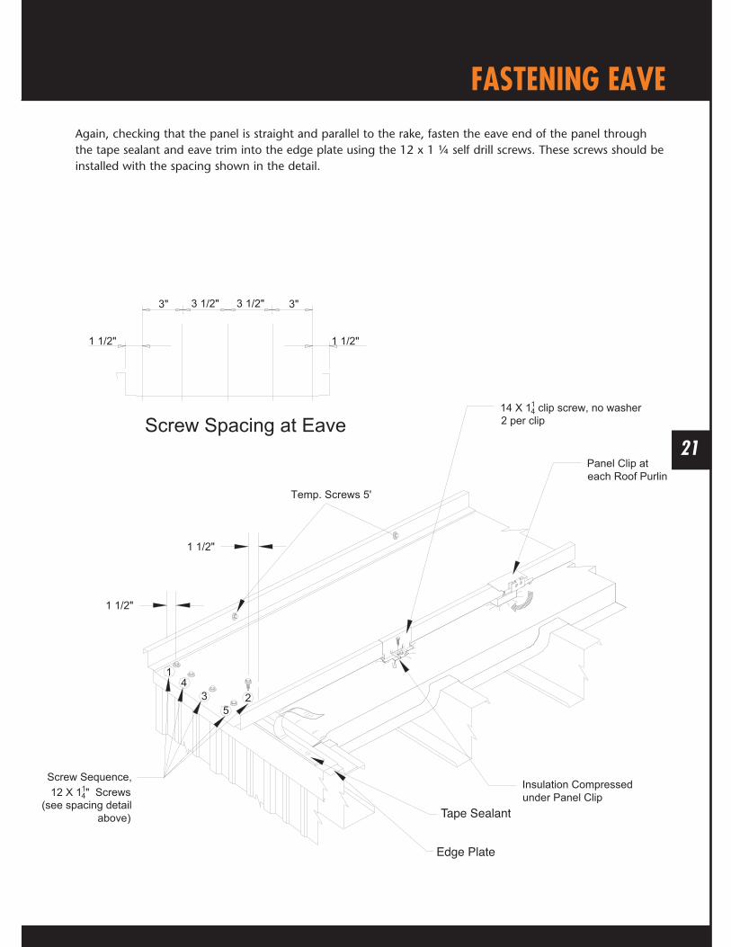
FASTENING EAVEAgain, checking that the panel is straight and parallel to the rake, fasten the eave end of the panel through the tape sealant and eave trim into the edge plate using the 12 x 1 ¼ self drill screws. These screws should be installed with the spacing shown in the detail.
3" 3 1/2" 3 1/2" 3"
1 1/2" 1 1/2"
Panel Clip ateach Roof Purlin
14 X 114 clip screw, no washer
2 per clip
Insulation Compressedunder Panel Clip
Screw Spacing at Eave
1 1/2"
1 1/2"
43
52
1
Screw Sequence,12 X 11
4" Screws(see spacing detail
above)
Temp. Screws 5'
Edge Plate
Tape Sealant

22
PANEL CLIPSPanel clips are in different heights and are floating or fixed types. The requirements of the specific installation will determine the type used. Refer to the project requirements for specific clip type.
Install the panel clips at each roof purlin. If there is insulation, the clip is normally installed compressing the insulation.
To install the clip, hook the clip over the male edge of the roof panel, then rotate the clip down to the installation position. Fasten the clip to the purlin using the self drill clip screws.
When installing, the clip tab must be seated snugly around the male edge of the panel and the base positioned firmly on the roof purlin. Always insure that the fasteners are properly attached to the structure.
Base CenteringStops
Clip Base
Panel Shelf
Clip Tab
Clip Screw, no washer(2 each 14 x 1 1/4" per clip)
Roof Panel
Clip Screw, no washer(2 each 14 x 1 1/4"per clip)
Roof Purlin
Panel Shelf(roof panel on top of stop)
Roof Panel
Clip To Panel Assembly
Purlin

23
ENDLAP PLACEMENTFor panel application where an endlap is necessary, the uphill end of the panel must extend past the upper flange of the endlap purlin at least 6” and can be as far as 12”
6" to 12"
Roof Panel
Roof Purlinat the endlap
ENDLAP PANEL OVERHANG
Panel Clip
Downslope RoofPanel
Endlap Tape Sealant1 5/8"
Upper Flange of Roof Purlin
End of Panel

24
ENDLAP TAPE SEALANTTape sealant should always be cut, not pulled apart.
Install the tape sealant as shown with 1/8” ends folded around the panel edges. Care must be used not to apply more than is shown in the details to avoid difficulties in the installation and seaming. Press the sealant to the panel surface to provide good adhesion. Do not over press and cause excess thinning of the tape sealant.
Endlap sealant placement is essential to a watertight roof installation. Always install the tape sealant to a clean and dry surface.
Place the downslope edge of the initial run of tape sealant 1 5/8” from the upslope end of the panel. The tape sealant should be installed by the method shown in these details.
Always check that the tape sealant is in contact with the panel at all corners and around all seams.
Roof Panel
Endlap Tape Sealant
FemaleEdge
Male Edge18" of tape sealant folded over edge
of panel
Endlap Tape Sealant
Endlap Tape Sealant
ENDLAP TAPE SEALANT AT MALE EDGE
ENDLAP TAPE SEALANT AT FEMALE EDGE
158"
158"
Roof Panel
18" of tape sealant foldedover edge of panel

25
INSTALLING UPPER PANELAfter removing the protective paper from the tape sealant, position the upslope panel so that there is a 2” overlap of the bottom panel. The end of the upper panel should butt against the notch on the lower panel. This should result in the correct lap over the tape sealant that is installed on the bottom panel.
While the upper panel is being lowered onto the bottom panel, bow the pan of the upper panel by pulling up on its center. This helps to fit the laps together without scraping the already applied tape sealant from the sides of the ribs.
Care should be taken not to scrape the tape sealant from its place while positioning the upper panel.
Roof Panel
Roof Purlinat the endlap
ENDLAP PANEL OVERHANG
Back-upChannel
Endlap Tape Sealant
Pull up centerof panel
Insulation
Slope
Upper Flangeof Roof Purlin 6" to 12"
End of Panel

26
CLAMPING ENDLAPUse seam clamps to position the seams together properly before attachment. Clamp carefully to allow tape sealant to properly expand between the lapped portions of the panels.
With the clamps in place, press down on the upper panel so that adhesion of the tape sealant isassured.
Back-up Channel
Endlap
Seam Clamp (centerover the seam notch)
Seam Clamp (center over the seam notch)
Insulation
Seam Clamp

27
BACK-UP CHANNELThe back-up channel which goes under the endlapped panels should be field cut on the end opposite the swaged end. The length should result in the swagged end of the channel positioned flush with the edge of the starter insulation.
The channel is installed under the panels, on top of the insulation and centered under the endlap. Clamp the channel to the roof panel with vice grips, leaving room for the cinch strap to be installed.
The back-up channel should not be in contact with the roof purlin.
Starting RoofPanel
Back-up Channel
Field cut end ofback-up channel
Starting Rake Detail
Rake Angle
SlottedRake Angle
Clamp
Back-up Channel
Swagged end of channel(flush with edge of insulation)
Insulation
Rake Angle
Endlap
Must have 134" Clearance
Field cut end of channel
Slotted Rake Angle

28
CINCH STRAPA cinch strap is required if the roof pitch is less than 3/12.
Position the cinch strap over the panel endlap. With the clamps still in place, install with the 12 x 1 ¼ self drill screws. Install the screws first at each end of the strap and then install in the remaining holes. The screws must penetrate through the tape sealant and engage the back-up channel. If no cinch strap is used, the screw placement and sequence should be the same as the eave.
The lap should then be hand seamed.
Manual Seamer
Manual Seamer
Roof Panel EndlapRoof Panel Endlap
STEP 1 STEP 2
Endlap Screws at eachhole in Cinch Strap
Cinch Strap(centered on endlaptape sealant)
Endlap

29
ENDLAP SCREWSThe endlap screws should penetrate the cinch strap (if used), the tape sealant, and secured through the back-up channel.
Endlap Tape Sealant
Back -upChannel
Roof Screws #12 x 1 1/4"

30
SEALANT TABSInstall the tape sealant tabs as illustrated. This must be completed before the next panel is installed.
See detailed drawings on the next page.
Back-up Channel
Endlap Sealant Tab
Ridge Sealant Tab
Eave Sealant Tab

31
SEALANT TAB DETAILSCut the tape sealant using a box knife or scissors. Position sealant tabs as illustrated. Do not use excess as this can cause difficulties during assembly. Remove any excess tape sealant. After placement, press tape sealant to the panel surface to assure adhesion.
Ridge endof Panel
Sealant Tabs
EaveTapeSealant
Eave End of Panel
Sealant Tabs
Tabs extendsto bottom edgeof Roof Panel
1/2" of sealantfolded under
edge of panel
Sealant Tabs
1/8" of Sealantfolded underedge of Panel
Work Sealant intocorner to eliminatevoids
1/4" of Sealantlapped on toEave Sealant
Eave Sealant
LAP SEALANT TAB AT RIDGE
EAVE SEALANT TAB DETAIL
Sealant Tabs
Notch2"

32
LAP SEALANT TAB DETAILSCut the tape sealant using a box knife or scissors. Position sealant tabs as illustrated. Do not use excess as this can cause difficulties during assembly. Remove any excess tape sealant. After placement, press tape sealant to the panel surface to assure adhesion.
End of Notch Sealant Tab
Endlap Sealant
End of Notch
3"
1/2"
1/2"
2"
Sealant Tab
1/4" extendeddown each sideof panel rib

33
SECOND PANEL BACK-UP CHANNELTo continue with the next panel installation, if there are endlaps, install the next run of back-up channel. Position the non-swagged end over the swagged end, parallel to the endlaps, and screw together with a panel clip fastener through the factory punched hole in the alignment dimple.
AlignmentSlot
Swagged End
Back-upChannel
Back-up ChannelLap Joint
Panel ClipScrew
Align Slot withScrew hole Back-up
Channel
Alignment SlotPreviously installed
Back-up Channel
LAP DETAIL

34
SECOND PANEL POSITIONINGRemove the protective paper from the next 16” of the eave tape sealant. Position the female edge of the panel over the male edge of the previous panel with the 2” overhang. If insulation thermal blocks are required, install them over each roof purlin. Tilt the panel as shown so that the female edge can be hooked over the male edge of the installed panel. See the details on the next page.
Male Edge ofpreviously installedRoof Panel
FemaleEdge
Panel Clip
Place the Roof Panel tooverlay the female edge ontothe male edge of the previouslyinstalled panel.
Thermo Blockat each purlin,if required
Tape Sealant

35
CLAMPING SIDE LAPSAfter the panel is in place and the edges are hooked properly, clamp the ribs together as needed and as shown. The coverage of the panel needs to be checked to assure that the installation does not accumulate excess coverage.
The panel is now ready for the eave screws to be installed. The panel clips should now be installed at each purlin.
Roof PanelSeam
Clamp Jaws
Rib Clamp
Roof Panel
Endlap
Rib Clamp

36
CHECKING COVERAGEIt is important that overall coverage be checked frequently so that any coverage errors are not allowed to accumulate. Coverage errors can cause panels to no longer be perpendicular to the eaves.
Coverage must be checked at the eave and at the ridge. If there are endlaps, the coverage must also be checked at each endlap.
If the panels do not have the correct coverage, seaming difficulties may occur.
Measuring Tape
Starter Panel
Measuring Tape at Ridge
Measuring Tape at Endlap
Measuring Tape at Eave
Endlap
1 3 5
2 4
CHECKING PANEL COVERAGE
PANEL COVERAGE MEASUREMENT

37
PREPARATION FOR METAL CLOSURESThe closures are installed as the roof panels are placed. Because coverage errors may cause installation issues, closures should be installed as the runs are completed to help determine if there are coverage issues.
The panel notches must be aligned within ¼”. If necessary, field cut the notches to the proper alignment.
Hand seam the end of panel, the length of seamer, to allow for enough space for the mechanical seamer to start. This should be done before the tape sealant is applied.
2"
2"
6"
Seaming Tool
Eave or RidgeEnd of Roof Panel
Seaming Tool
Eave or RidgeEnd of Roof Panel
Ridge end ofRoof Panel
Roof Panel
NOTCH FOR RIDGE CLOSURE
STEP 1
STEP 2
MARKING RIDGE CLOSURE LINE
Hand seam 16"
Ridge end ofRoof Panel
Panel
Roof Panel
Field cut maleand female paneledges to the chalk mark1/16"

38
SEALANT FOR METAL CLOSUREInstall a continuous strip of tape sealant across the panel with the downslope side of the tape sealantaligned with the Metal Closure.
See the next page for details.
Ridge end ofRoof Panel Remove protective
paperSealant Tab
Tape Sealant(align with downslope side of Metal Closure)
Slope
2"

39
SEALANT FOR METAL CLOSUREInstall the tape sealant as shown above before installing closures. The tape sealant must be correctly positioned and uniformly pressed against the panel surfaces.
Flashing Sealant
Sealant Wrappedover seam
RoofPanel
RoofPanel
2 1/2" Sealant TabCentered on panel leg
Ensure Tape Sealants make contact
End of Notch
TAPE SEALANT AT RIDGESEALANT TAB AT RIDGE
2"
Tape Sealant

40
INSTALLING METAL CLOSUREThe closure installs with the bottom flange turned upslope and the top flange downslope. Install the bottom flange over the tape sealant with the web of the closure in line with the panel notch 2” from the end of the panel.
TapeSealant
Top Flange (must beon downhill side)
Metal Closure

41
BACK-UP CHANNEL AT RIDGESlide the back-up channel under the panel, centered under the closure. Clamp the closures and the back-up channel together until the fasteners are installed.
Back-upChannel
Clamp
Back-upChannel

42
FASTENERS FOR METAL CLOSURESMetal closures must be installed to accommodate the associated trim.
Install the closures with 12 x 1 1/4" TEK through the closure and the tape sealant into the back-up channel. Install the fasteners in the placement sequence shown above.
Check that the top flange of the closure is aligned with the previously installed closure and then install a clip screw through the side of the end of the closure through the vertical leg of the panel and into the metal closure on the pervious panel.
12
4 3 5
Self Drill Screw ateach hole in
metal closure
Roof PanelTape Sealant
Back-up Channel#12 x 1 1/4" TEK
Self Drill Screw
Screw Sequence
Back-upChannel
Tape Sealant
Metal Closure
Roof Panel
METAL CLOSURE ATTACHMENT
ClampMetal Closure

43
DETAIL OF METAL CLOSUREThe closure should be installed as pictured. Check for unsealed voids between the closure and the panel.
Back-up Channel
Bottom Flangeof Metal Closure
Self Drill Screw
Top Flange of Metal Closure
Metal Closure
Metal Closure
Sealant Tab
Face of Metal Closure
Edge of Tape Sealant
Self Drill Screw

44
FLOATING RIDGE
Installation Steps: (use only with fixed eave and valley)1. Slide the backup channel underneath the end of the panel as shown.
2. To accommodate the width of the Ridge Trim, apply the tape sealant across the pan of the panel, aligned over the backup channel.
3. Install the metal closure using #12 screws on 4” centers through the panel and the backup channel as shown.
4. Use tube sealant to seal the ends of the closure.
5. Apply tape sealant to the top of the metal closure.
6. Fasten Ridge trim to closure using #14 x 7/8 Lap screws on 6” centers.
#12 x 1 1/4" Self Drill
Clip
Mueller Lock Panel
Tube Sealant on Vertical Edges
Ridge Trim
Back Up Channel
#14 x 1 1/4" Clip Screw(No Washer)
Metal Closure #14 x 7/8" Lap Tek Screw
Tek Screw with Washer PurlinPurlin
2" Minimum Clearance
Tape Sealant
Hip Screw Sequence
6" 6"2"

45
LAPPING AND SEALING RAKE TRIMSplice rake trim with tube sealant and lap screws. The lap must always be the uphill rake over the downhill rake.
At a ridge, field cut the rake trim 2” back from the center line of the ridge
At a high eave connection, field cut the rake trim as required to assure a weathertight connection to that connection.
2"
1 1/2" 1/2"
Tape Sealant
3/16" Dia.Sealant Tab
3/16" Dia. BeadTube Sealant
Downslope Rake Trim
Rake Trim
Secure Lap with 1/8"dia. Blind Rivets
Lap ScrewTop of Rake
Position Rake Trimso exposed edge isfactory cut
Metal ClosureTape Sealant
Finish end ofRake Trim
Rake Trim
Bend up or notch RakeTrim to clear Metal Closure
Slotted Rake Angle
RAKE TRIM SPLICE
RAKE TRIM AT RIDGE

46
END CAP INSTALLATIONEnd caps must be field cut and folded to fit. Install with tube sealer and pop rivets or stitch screws.
1/2"
Notch to clearRoof Panel
Starting or EndingRoof Panel
Eave Trim
Rake TrimEnd Cap
Rake Trim
Starting or EndingRoof Panel
Eave Trim
Rake TrimEnd Cap
Rake Trim
Secure with 1/8"dia. Blind Rivetsor Stitch Screws
Set End Cap flushwith end of Rake Trim
END CAP DETAIL
Field Cut and bendtab to fit

47
SIDE WALL / PARAPET DETAILS
Purlin
14ga SlottedRake Angle
Rake Angleby others
Rake TrimSupport Angle
Counter Flashing by Others
#14 x 7/8" Lap Tek Screw on 6" Center
Side Wall Trim
#12 x 1 1/4" SD Tek Hex with Washer
TapeSealant
#14 x 1 1/4 " SDShoulder Screw
Installation steps:1. To begin starting panel first attach the Slotted Rake Angle to the existing rake using #14 x 1¼” SD
Shoulder tek screws.2. Place the female leg of the first panel over the upturned edge of the Slotted Rake Angle.
3. Install Rake Trim Support Angle as pictured using tape sealant and secure using #12 x 1¼” SD screws thru the Rake Trim Support Angle, tri bead, panel leg and into the 14 ga. Slotted Rake Angle.
4. Apply tape sealant to the top of the Rake Trim Support Angle and install side wall trim as shown with #14 x 7/8” lap screws on 6” centers.
5. Attach the appropriate counter flashing as required by the application. This is supplied by others.
6. For last panel run, field cut the panel if necessary to form a 1 ¾” up turned leg that will position against the slotted rake angle when installed. Then complete the trim using the above steps.

48
END WALL / PARAPET DETAILS
2"7"
Back Up Channel
Metal Closure
Tape Sealant
#14 x 7/8" Lap
Tape Sealant
End Wall Trim
Tube Sealant
#12 x 1 1/4" Self Drill Tek Screw with Washer
Clip
#14 x 1 1/4"Clip Screw (no washer)
Counter Flashing by Others
Mueller Lock Panel
Purlin2" Minimum Clearance
Pitch
End of TransitionFlashing (flush withface of end cap)
Field Fabricated End Cap
LapScrew
EndwallFlashing
Rake Trim
Installation Steps: (use only with fixed eave)1. Slide the backup angle underneath the end of the panel as shown.
2. To accommodate the placement of the End Wall trim, apply the tape sealant across the pan of the panel, aligned over the backup channel.
3. Install the closure using #12 screws on 4” centers through the panel and the backup channel as shown.
4. Use tube sealant to seal the ends of the metal closure.
5. Apply tape sealant to the top of the closure.
6. Fasten End Wall trim to metal closure using #14 x 7/8 Lap screws on 6” centers.

49
GUTTER ASSEMBLYThe start and finish of the gutter is flush with the end walls, with enough extra gutter for the endwalls with rake trim to miter the gutter to rake connection.
Attach the gutter ends and make gutter splices with tube caulk fastened with pop rivets or stitch screws.
1/2"
2"
2"
1/2"
1/2" GutterEnd Cap
Secure with1/8" dia. Blind Rivets
Gutter
GutterEnd Cap
2 each, 3/16"dia. Beads TubeSealant
At finish end,field cut Gutter
to required length
Gutter
Field cut notch
2 each, 3/16"dia. Beads TubeSealant
Position Gutter soexposed edge is
factory cut
Gutter
1/8" dia. Blind Rivetsat front, bottom andback of Gutter
Eave Gutter Splice
Eave Gutter End Cap

50
GUTTER INSTALLATIONPosition the gutter with the correct end locations and the back flange of the gutter under the overhang of the roof panel. The back face of the gutter should be flush against the eave trim.
Field miter rake and gutter corners as required.
Clamp the gutter in position with clamps and fasten the back flange of the gutter to the roof panel with lap tek screws.
Apply strips of tape sealant 3” long to the inside of the gutter strap at the fastener locations on the uphill end of the gutter strap. With the outer edge of the gutter straight and level in the desired installation position, install the gutter straps with 2 lap fasteners and 1 roof fastener which is outside the building envelope. Fasten the strap to the outer edge of the gutter, using lap tek screws for all fastener location in the strap. Note, apply at gutter strap/support on each panel rib.
End Wall
End of GutterAssembly Complete
Lap Screw
Gutter for Lap Screw
Lap Screws or Rivets (2) per SupportKeep below "Wet Line"
Gutter Trim

51
FIXED VALLEY
Installation Steps (use only with fixed eave)1. If applicable, install insulation before proceeding (insulation omitted for clarity).
2. Install four runs of hat section up the valley as shown, securing to the purlins with # 10 x 1 self drill pan head screws (this step is applicable when insulation or thermal blocks are specified).
3. Install the two piece 14 ga. Valley Support Plates with #10 x 1 self drill pan head screws.
4. Install Valley trim over the Valley Support Plates. Secure with #10 x 1 self drill pan head screws (5’ centers).
5. Install tape sealant 4” to 5” from center of the valley trim.
6. Attach panel to Valley Support Plate using #12 x 1 ¼ self drill screws, on 4’ centers, through the tape sealant and the Valley Trim into the Valley Support Plate.
7. Seal the ends of the panel legs using tube sealant.
Mueller Lock Panel
# 10 x 1" Pan Head Self Drill Screw
Valley Trim
Valley Plates
#12 x 1 1/4" Self DrillTek Screw with Washer
TapeSealant
Fill Panel Ends With Tube Sealant
4" +/-
Mueller LockPanel
ValleyTrim
#12 x 1 1/4" Self Drill Tek Screw with Washer
#12 x 1 1/4" Self Drill Tek Screw
4" Typical
#10 x 1" Pan Head Self Drilling Screw
on 24" Center
2 - Piece, 14 ga.,Valley Plate
TapeSealant
PurlinPurlin
4" +/-
Isometric View

52
FLOATING HIP
Installation Steps: (use only with fixed eave or valley)1. Install 14 ga. Hip support plate using #10 x 1 self drill pan head screws to attach to purlin. The 1” leg should
be pointing to the top.
2. Install the panels with the ends bevel cut to the slope of the hip.
3. Slide the backup angle under the bottom of the panels at least 2” from the purlin clips as shown, 4” leg down.
4. To accommodate the width of the hip trim, apply the tape sealant to the panel over the backup angle as shown.
5. Field cut and attach Z closure to panel and backup angle using pop rivets on 4” centers.
6. Seal the ends of the Z closure using tube sealant.
7. Apply tape sealant to the top of the Z closure.
8. Attach hip trim to the Z closure using #14 x 7/8 lap screws on 6” centers.
Clip
Mueller Lock PanelTape
Sealant
Tube Sealant on Vertical Edges
Hip Trim"Z" Closure
2" x 4"Backup Angle
#14 x 7/8" LapTek Screw
Hip Screw Sequence
6" 6"2"
2 - Piece, 14ga.,Hip Plate
#14 x 1 1/4" Clip Screw(No Washer)
Pop Rivets

53
WOOD DECK APPLICATION

54
FLOATING RAKE DETAILS | WOOD DECK
Installation steps:1. To begin starting panel you must first attach the Slotted Rake Angle to the existing rake using #14x1¼” SD
Shoulder tek screws, 12” on center.
2. Place the female leg of the first panel over the upturned edge of the Slotted Rake Angle.
3. Install Rake Trim Support Angle as pictured using tape sealant and secure using #12x1¼” SD screws thru the Rake Trim Support Angle, tri bead, panel leg and into the 14 ga. Slotted Rake Angle, 12” on center.
Tape Sealant
RakeTrim
Rake Slide Trim
#14 x 1 1/4 " SDShoulder Screwon 12" Centers
Mueller Lock Sheet
Underlayment
Wood Deck
#14 x 7/8" Lap Tek Screw
#9 x 1 1/2"Woodgrip Screw
Rake TrimSupport Angle
#12 x 1 1/4" SD TekHex with Washer on 12" Centers14ga Slotted
Rake Angle
End View

55
Isometric View
FLOATING RAKE DETAILS | WOOD DECK
Installation steps continued:4. Apply tape sealant to the top of the Rake Trim Support Angle and install Rake Trim as shown with #14x 7/8” lap
screws on 6” centers.
5. Attach Rake Slide Trim over bottom edge of the Rake Trim securing with #9 woodgrip screws on 12” centers.
6. For last panel run, field cut the panel if necessary to form a 1 ¾” up turned leg that will position against the slotted rake angle when installed. Then complete the trim using the above steps.
Mueller Lock Panel
Rake Trim
14ga Slotted Rake Angle
#12 x 1 1/4" SD TekHex with Washer
on 12" Centers
#14 x 1 1/4" SD ShoulderTek Screws on 12" Centers #9 Woodgrip
Screw
Rake Slide Trim
#14 x 7/8" Lap Tek Screw on 6"Centers
Underlayment
Wood Deck
Tape Sealant
6"
Rake Trim Support Angle

56
FIXED EAVE | WOOD DECK
Installation Steps: (use only with floating ridge/hip)1. Install eave trim onto the eave using #10 x 1 pan head screws, 3 per 10’.
2. Apply tape sealant to top leg of the eave trim as shown.
3. Install panel and screw to the eave using 1 ½” screws. Panel should overhang the eave trim by 1 ¼” to accommodate optional gutter.
4. Seal the ends of the panel legs using tube sealant.
MuellerLock Sheet
Lap Tek Low Profile Wood Deck
Underlayment
WoodgripScrew
(for Eave Trim Only)
Eave Trim
TapeSealant
#10 X 1" Pan Head Woodgrip Screw
Clip1 1/2" Low Profile Woodgrip
23
4
1
OptionalGutter

57
FLOATING EAVE | WOOD DECK
Installation Steps: (use only with fixed ridge/hip)1. Install either eave trim or optional gutter onto the eave using #10 x 1 woodgrip pan head screws, 3 per 10’.
2. Apply tape sealant to top leg of the eave trim or gutter as shown.
3. Install edge plate over tape sealant using #10 x 1 woodgrip pan head screws, on 1’ centers.
4. Field notch, hem and fold the panel, then slide hemmed edge over edge plate as shown.
5. Attached clips as specified.
6. Seal the ends of the panel legs using tube sealant.
Wood Deck
Underlayment
Mueller Lock Sheet
Eave Trim
Clip
Edge Plate
#10 X 1" Pan Head Woodgrip Screw
Sealant
OptionalGutter

58
Mueller Lock Panel
# 10 x 1" Pan Head Screw
Valley Trim
Underlayment
Underlayment
1 1/2" Low Pro Woodgrip Screw
TapeSealant
Fill Panel Ends With Tube Sealant
4" +/-
Isometric View
FIXED VALLEY | WOOD DECK
Installation Steps (use only with fixed eave)1. Install Valley trim over the Underlayment and deck. Secure with #10 x 1” woodgrip pan head screws (5’ centers).
2. Install tape sealant 4” to 5” from center of the valley trim.
3. Field cut and attach panel to Valley using 1 ½” wood grip screws, on 4” centers, through the tape sealant and the Valley Trim into the deck.
4. Seal the ends of the panel legs using tube sealant.
MuellerLock Panel
ValleyTrim
1 1/2" Low ProWoodgrip Screw
4" +/-
4" Typical
TapeSealant
Wood Deck
Underlayment

59
FLOATING VALLEY | WOOD DECK
Installation Steps: (use only with fixed Ridge/Hips)1. Install Valley Trim over the Valley from the bottom up. Secure with #10 x 1 woodgrip pan head
screws (5’ centers).
2. Install tape sealant 4” to 5” from center of the valley trim.
3. Install edge plates over the tape sealant using #10 x 1 woodgrip pan head screws on 12” centers.
4. Field cut and hem panel ends. Install over edge plate as shown.
5. Seal the ends of the panel legs using tube sealant.
Wood Deck
Underlayment
MuellerLock Panel
ValleyTrim
4" Typical
TapeSealant Edge Plate
#10 x 1" Pan HeadWoodgrip Screw

60
FIXED RIDGE & HIP | WOOD DECK
Installation Steps: (use only with floating eave and valley)1. Install the tape sealant across the panel, aligned to accommodate ridge trim and metal closure.
2. Fasten metal closure through tape sealant and panel to deck using 1 ½” wood grip screws on 4” centers.
3. Use tube sealant to seal the ends of the metal closure.
4. Apply tape sealant to the top of the metal closure.
5. Fasten Ridge trim to metal closure using #14 x 7/8 lap screws on 6” centers.
Clip
Mueller Lock Panel
Tape Sealant Tape Sealant
Tube Sealant on Vertical Edges
Ridge TrimMetal Closure #14 x 7/8" Lap
Tek Screw
#10 x 1"Pan Head
Woodgrip Screw
Wood Deck
Underlayment
Hip Screw Sequence
6" 6"2"

61
FLOATING HIP & RIDGE | WOOD DECK
Installation Steps: (use only with fixed eave or valley)1. Install the panels with the ends bevel cut to the slope if applying to hip.
2. Slide the backup angle under the bottom of the panels at least 2” from the purlin clips with 2” leg turned up as shown.
3. To accommodate the width of the hip/ridge trim, apply the tape sealant to the panel over the backup angle as shown.
4. Field cut and attach Z closure on hips, use metal closures on ridges, attach the closure to the backup angle using pop rivets on 4” centers as shown.
5. Seal the ends of the closures using tube sealant.
6. Apply tape sealant to the top of the closure.
7. Attach ridge/hip trim to the closure using #14 x 7/8 lap screws on 6” centers.
Wood Deck
Clip
Mueller Lock PanelTape Sealant
Tube Sealant on Vertical Edges
Ridge/Hip TrimMetal Closure
2" x 4"Backup Angle
#14 x 7/8" LapTek Screw
Underlayment
#10 x 1" PanHead Screw
Pop Rivets
Hip Screw Sequence
6" 6"2"

62
SIDE WALL / PARAPET DETAILS | WOOD DECK
Installation steps:1. First attach the Slotted Rake Angle to the existing wood deck using #14 x 1¼” SD Shoulder tek screws as shown.2. Place the female leg of the first panel over the upturned edge of the Slotted Rake Angle.
3. Install Rake Trim Support Angle as pictured using tape sealant and secure using #12 x 1¼” SD screws thru the Rake Trim Support Angle, tape sealant, panel leg and into the 14 ga. Slotted Rake Angle.
4. Apply tape sealant to the top of the Rake Trim Support Angle and install side wall trim as shown with #14 x 7/8” lap screws on 6” centers.
5. Attach the appropriate counter flashing as required by the application. This is supplied by others.
6. For last panel run, field cut the panel if necessary to form a 2” up turned leg that will position against the slotted rake angle when installed. Then complete the trim using the above steps.
14ga SlottedRake Angle
Rake TrimSupport Angle
Counter Flashing by Others
#14 x 7/8" Lap Tek Screw
Side Wall Trim
#12 x 1 1/4" SD Tek Hex with Washer
Tape Sealant
#14 x 1 1/4 " SDShoulder Screw
Wood Deck
Underlayment

63
FIXED END WALL / PARAPET DETAILS | WOOD DECK
Installation Steps: (use only with floating eave)1. To accommodate the placement of the End Wall trim and metal closure, apply the tape sealant across the
pan of the panel.
2. Install the closure using woodgrip screws on 4” centers through the panel and closure as shown.
3. Use tube sealant to seal the ends of the metal closure.
4. Apply tape sealant to the top of the closure.
5. Fasten End Wall trim to closure using #14 x 7/8 Lap screws on 6” centers.
Wood Deck
Metal Closure
Tape Sealant
TapeSealant
End Wall Trim
Tube Sealant
1 1/2"Woodgrip Screw
Counter Flashing by Others
MuellerLock Panel
Underlayment

64
FIXED HIGH SIDE EAVE | WOOD DECK
Installation Steps: (use only with floating eave)1. Apply tape sealant to the panel, to accommodate the high side eave trim and metal closure.
2. Apply closure and attach using 1 ½” woodgrip screws on 4” centers.
3. Seal the closure sides with tube sealant.
4. Apply tape sealant to the top of the metal closure.
5. Attach High side eave trim to the closure using #14 x 7/8 lap screws on 6” centers as shown.
Mueller Lock Panel
Tape Sealant
Metal Closure
#12 1 1/2" Woodgrip Screw
Tube Sealant onVertical Edges
Tape Sealant
#14 x 7/8" Lap Tek Screw
High SideEave Trim
#12 1 1/2"Woodgrip
Screw
Wood Deck
Underlayment

65
NOTES

66
NOTES

67
NOTES

M-MLKMANUAL-REV.01/15
FIND OUT MORE ABOUT MUELLER, INC.
Call877-2-MUELLER (877-268-3553)This toll-free number connects you to one of our sales locationsacross the Southwest.
Clickwww.MuellerInc.comOur interactive website offers photos and all the details of ourmetal products.
Come byMore than 30 locations. Our branches are staffed with experts who arealways happy to answer any questions you may have.
Find usOn Facebook, check out our latest news and events.