Highway geometric design
31
Student name - Munshi Shehzadkhan (T - 12CL218 ) Presentation Title – Highway Geometric Design SAL INSTITUTE OF TECHNOLOGY AND ENGINEERING RESEARCH Civil Engineering Department
-
Upload
shehzadkhan-munshi -
Category
Education
-
view
409 -
download
14
Transcript of Highway geometric design

Student name - Munshi Shehzadkhan (T-12CL218)Presentation Title – Highway Geometric Design
SAL INSTITUTE OF TECHNOLOGY AND ENGINEERING RESEARCH
Civil Engineering Department

Definition of Geometric Design :
Geometric design of highways deals with the dimensions and layout of visible features of the highway.
Geometric design fulfills the requirements of the driver and the vehicle, such as comfort, efficiency and safety.
Proper geometric design will help in the reduction of accidents and their severity.

Goals of Geometric design :
Maximize the comfort, safety and economy of facilities.
Provide efficiency in traffic operation.
Provide maximum safety at reasonable cost.
Minimize the environmental impacts.

Factors affecting geometric design :
Design speed.
Topography.
Traffic.
Environmental factors.
Economical factors.
Vehicles properties (dimensions, weight, operating characteristics, etc.).
Humans (the physical, mental and psychological characteristics of the driver and pedestrians like the reaction time).

Road alignment :
Alignment : is an arrangement in a straight line or in correct relative positions.
The position or the layout of the central line of the highway on the ground is called the alignment.
Horizontal alignment includes straight and curved paths.
Vertical alignment includes level and gradients.

Alignment decision is important because a bad alignment will enhance the construction, maintenance and vehicle operating cost. Once an alignment is fixed and constructed, it is not easy to change it due to increase in cost of adjoining land and construction of costly structures by the roadside.

Types of alignment :
Horizontal Alignment : Horizontal alignment in road design consists of straight sections of road, known as tangents, connected by circular horizontal curves.
It is the design of the road in the horizontal plane.
Consists of a series of tangents (straight lines), circular curves and transition curves.
Should provide safe travel at a uniform design speed.


Vertical Alignment : Vertical alignment is the longitudinal section (shown on the y-axis of a road, it consists of straight grades joined by vertical curves.
Vertical alignment specifies the elevations of points along the roadway.

Cross-Section of road & its elements :

Carriage way :
The Width of pavement way on which vehicles travel is called carriage way .

Road Shoulders :
Shoulders are provided along the road edge to serve as an emergency lane for vehicles .
As per IRC, the min. width of shoulder should be 2.5m.
Uses :
Repair of broken down vehicles
Overtaking operations
To act as an emergency lane
For future widening of road
For temp. diversion of traffic during road repair etc

Formation width :
Formation width is the top width of the highway embankment or the bottom width of cutting excluding the side drain .
Formation width = Width of Carr. Way + Width of shoulder
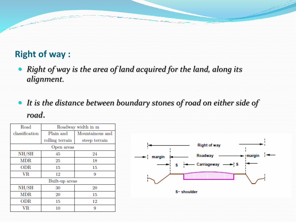
Right of way :
Right of way is the area of land acquired for the land, along its alignment.
It is the distance between boundary stones of road on either side of
road.

Side slope :
The slope of earthwork in Filling(embankment) or cutting is called sideslope.

Berm :
The distance between the road toe and inner edge of borrow pit is called berm.
It prevents the erosion of embankment soil.

Side drain :
For the drainage of rain water, drains are provided on either side of the road .
Normally, Side drain are required for road in cutting. For road in embankment side drain is not necessary.

Building line :
The distance from the centre line of road on either side, within which construction of building is not permitted is called building line.
Purposes :
For future widening of road
To reduce the chance of accidents
To relieve residents from noise pollution
To prevent disturbance to the traffic by nearby residents

Central line :
At the location like bank, hospital, factory, theatre etc. on the road where more people gather disturbance to the traffic will be more.
The distance from the centre line to such building is called control line.

Borrow pits :
The pits dug along the road alignment for using excavated earth in construction of embankment are known as borrow pits.
Borrow pit should be dug atleast 5m from toe of embankment.
The small portion left undug in a borrow pit to measure the depth of excavation is called deadman.
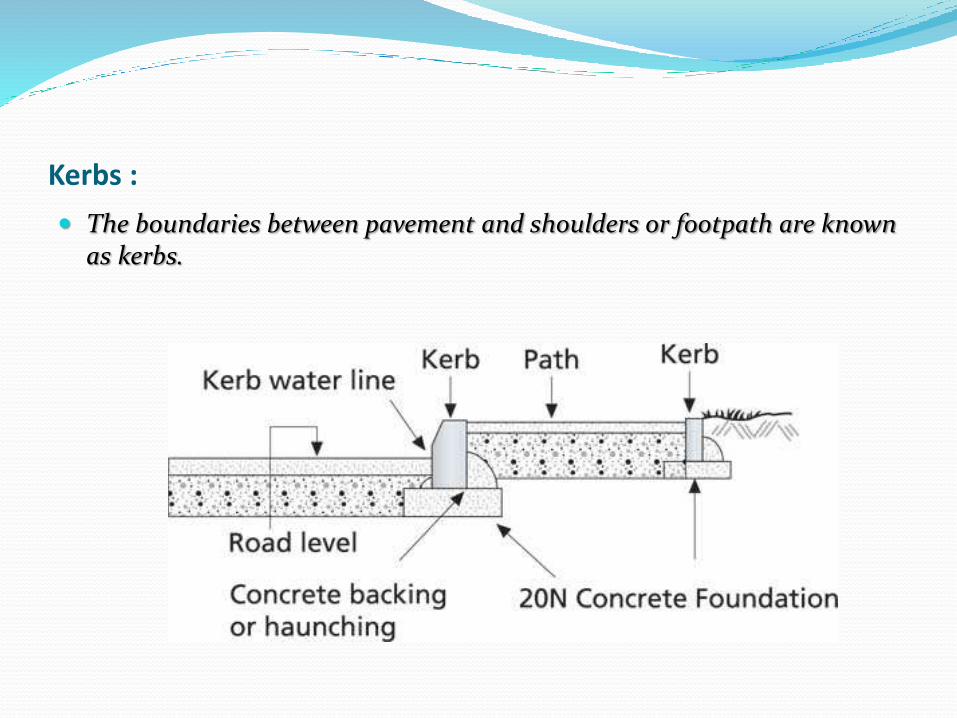
Kerbs :
The boundaries between pavement and shoulders or footpath are known as kerbs.
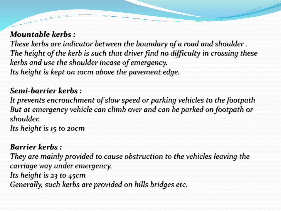
Mountable kerbs :These kerbs are indicator between the boundary of a road and shoulder .The height of the kerb is such that driver find no difficulty in crossing these kerbs and use the shoulder incase of emergency.Its height is kept on 10cm above the pavement edge.
Semi-barrier kerbs :It prevents encrouchment of slow speed or parking vehicles to the footpath But at emergency vehicle can climb over and can be parked on footpath or shoulder.Its height is 15 to 20cm
Barrier kerbs :They are mainly provided to cause obstruction to the vehicles leaving the carriage way under emergency.Its height is 23 to 45cmGenerally, such kerbs are provided on hills bridges etc.

Types of kerbs

Pavement design :
A highway pavement is a structure consisting of superimposed layers of processed materials above the natural soil sub-grade.
The pavement must provide an acceptable riding quality, adequate skid resistance, favourable light reflecting characteristics, and low noise pollution.

Cross section of different types of road as per IRC :

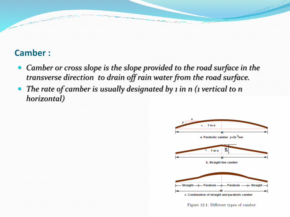
Camber :
Camber or cross slope is the slope provided to the road surface in the transverse direction to drain off rain water from the road surface.
The rate of camber is usually designated by 1 in n (1 vertical to n horizontal)

Purposes of camber :
To remove the rain water from the pavement surface as quickly as possible.
To prevent entry of water into bituminous pavement layers.
To prevert entry of surface water into subgrade soil through pavement.
To make pavement surface attractive.

Super elevation :
It is the slope across pavement surface and is fully developed in the circular curve.
(or)
Super-elevation (banking) is the transverse slope provided at horizontal curve to counteract the centrifugal force, by raising the outer edge of the pavement with respect to the inner edge, throughout the length of the horizontal curve.
So super elevation helps the vehicle to over come the centrifugal force on the curves on pavements
The need for super-elevation on road curves, to ensure safety against skidding and over turning with the advent of fast moving traffic.

In the past, roads were constructed without any regard to super-elevation on curves and had generally a cambered section for drainage purposes. It was little realised then that a vehicle moving on a curve had to overcome a centrifugal force to enable it to follow the curved path instead of a straight line, but, in justice to the early designers of roads, it must be said that there was no fast traffic in those days.

Thanks