Highly Efficient Solutions for .... 4 – India: Three large HVDCs at 500 kV of which Adani and...
24
Answers for energy. Presented at 21TH WORLD ENERGY CONGRESS, Montreal, Canada September 12–16, 2010 Updated Version, July 2011 Authors: W. Breuer, D. Retzmann, K. Uecker Siemens AG, Energy Sector, Power Transmission Division, Germany Highly Efficient Solutions for Smart and Bulk Power Transmission of “Green Energy” www.siemens.com/energy
-
Upload
truonglien -
Category
Documents
-
view
215 -
download
1
Transcript of Highly Efficient Solutions for .... 4 – India: Three large HVDCs at 500 kV of which Adani and...

Answers for energy.
Presented at 21TH WORLD ENERGY CONGRESS, Montreal, Canada September 12–16, 2010
Updated Version, July 2011
Authors: W. Breuer, D. Retzmann, K. Uecker Siemens AG, Energy Sector, Power Transmission Division, Germany
Highly Efficient Solutions for Smart and Bulk Power Transmission of “Green Energy”
www.siemens.com/energy

Table of Contents
Abstract 3
1. Introduction 4
2. Security and Sustainability due to Power Electronics 5
3. Benefits of Power Electronics for System Enhancement 8
4. Prospects of Power System Developments 10
5. Technologies for Smart and Super Grids 11 5.1 Smart Grid Solutions with VSC – Modular Multilevel Converters 11 5.2 Super Grid Solutions with FACTS and HVDC – “Classic” and Bulk 15 5.3 Super Grid Solutions with GIL – Gas Insulated Lines 20
6. Conclusions and Outlook 20
7. References 22
2 |

Copyright © Siemens AG 2011. All rights reserved. 2
Highly Efficient Solutions for Smart and Bulk Power Transmission of “Green Energy”
W. Breuer, D. Retzmann*, K. Uecker
Siemens AG, Energy Sector Erlangen, Germany
ABSTRACT The electric power supply is essential for the survival of a society, like the blood in the body. Lack of power brings about devastating consequences for daily life. However, deregulation and privatization are posing new challenges to the transmission systems. System elements are going to be loaded up to their thermal limits, and wide-area power trading with fast varying load patterns will contribute to an increasing congestion. In addition to this, the dramatic global climate developments call for changes in the way electricity is supplied. Environmental constraints, such as loss minimization and CO2 reduction, will play an increasingly important role. Consequently, we have to deal with an area of conflicts between reliability of supply, environmental sustainability as well as economic efficiency. The power grid of the future must be secure, cost-effective and environmentally compatible. The combination of these three tasks can be tackled with the help of ideas, intelligent solutions as well as innovative technologies.
Innovative solutions with HVDC (High-Voltage DC) and FACTS (Flexible AC Transmission Systems) have the potential to cope with the new challenges. By means of Power Electronics, they provide features which are necessary to avoid technical problems in the power systems, they increase the transmission capacity and system stability very efficiently and help prevent cascading disturbances.
KEY WORDS:
Smart and Super Grid Technologies; HVDC, FACTS; Sustainability and Security of Power Supply; Increase in Transmission Capacity; Solutions for Bulk Power Transmission; Reduction in Transmission Losses; Enhanced Grid Access for Regenerative Energy Sources (RES)

Copyright © Siemens AG 2011. All rights reserved. 3
1. INTRODUCTION The availability of electric power is the crucial prerequisite for the survivability of a modern society and power grids are virtually its lifelines. Without power supply there are devastating consequences for daily life. However, deregulation and privatization are posing new challenges to the transmission systems. System elements are going to be loaded up to their thermal limits, and wide-area power trading with fast varying load patterns will contribute to an increasing congestion.
In addition to this, the dramatic global climate developments call for changes in the way electricity is supplied. Environmental constraints, such as loss minimization and CO2 reduction, will play an increasingly important role.
Consequently, we have to deal with an area of conflicts between reliability of supply, environmental sustainability as well as economic efficiency. The power grid of the future must be secure, cost-effective and environmentally compatible. The combination of these three tasks can be tackled with the help of ideas, intelligent solutions as well as innovative technologies. The combination of these three tasks can be solved with the help of ideas, intelligent solutions as well as innovative technologies. Innovative solutions with HVDC and FACTS have the potential to cope with the new challenges. By means of Power Electronics, they provide features which are necessary to avoid technical problems in the power systems, they increase the transmission capacity and system stability very efficiently and help prevent cascading disturbances.
The vision and enhancement strategy for the future electricity networks are, for example, depicted in the program for “SmartGrids”, which was developed within the European Technology Platform. Features of a future Smart Grid such as this can be outlined as follows [1]:
Flexible: fulfilling customers’ needs whilst responding to the changes and challenges ahead
Accessible: granting connection access to all network users, particularly for RES and high efficiency local generation with zero or low carbon emissions
Reliable: assuring and improving security and quality of supply
Economic: providing best value through innovation, efficient energy management and “level playing field” competition and regulation
Smart Grids will help achieve a sustainable development. It is worthwhile mentioning that the Smart Grid vision is in the same way applicable to the system developments in other regions of the world. Smart Grids will help achieve a sustainable development.
An increasingly liberalized market will encourage trading opportunities to be identified and developed. Smart Grids is a necessary response to the environmental, social and political demands placed on energy supply.
Links will be strengthened across North and South America, East and West Europe, Africa and Asia, interconnecting countries where different but complementary renewable resources are to be found. For the interconnections, innovative solutions will be essential to avoid congestion and to improve stability. HVDC provides the necessary features to avoid technical problems in the power systems. It also increases the transmission capacity and system stability very efficiently and helps prevent cascading disturbances. HVDC can also be applied as a hybrid AC-DC solution in synchronous AC systems either as a Back-to-Back for grid power flow control (elimination of congestion and loop flows) or as a long-distance point-to-point transmission.
FACTS technology encompasses systems for both parallel and series compensation. It rests upon the principle of reactive power elements, controlled by means of power electronics, which can increase the transmission capacity of long AC lines or stabilize the voltage of selected grid nodes. Due to a high utilization degree of AC power grids, the application of FACTS technology will become an increasingly more interesting issue also in the case of meshed power systems, e.g. in Europe.
HVDC and FACTS applications will consequently play an important role in the future development of power systems. This will result in efficient, low-loss AC/DC hybrid grids which will ensure better
4 |

Copyright © Siemens AG 2011. All rights reserved. 4
controllability of the power flow and, in doing so, do their part in preventing “domino effects” in case of disturbances and blackouts.
In what follows, the global trends in power markets and the prospects of system developments are depicted, and the outlook for Smart Grid technologies for environmental sustainability and system security is given.
2. SECURITY AND SUSTAINABILITY DUE TO POWER ELECTRONICS
From the point of view of the design concept, the AC grids are not configured as wide-area bulk power transmission systems. By way of example, the Central European Power Grid (CE, former UCTE) at a transmission voltage of 400 kV was originally based on the concept of a system which provides power generation near the loads and has additional links to support the adjacent grids in the case of disturbances or planned outages of individual generation units.
In the course of deregulation and privatization of European power markets the idea of an All- European interconnected system came up, and in view of climate change, the issue of bulk power transmission of environmentally compatible energy completed the picture. However, prior to implementing this vision to the full extent, the grid concept must be adapted to these modified conditions. Now, the question is how renewable energies, wind power in particular, influence the grid in case of an outage.
The prime example here is the massive outage experienced in the European grid on November 4, 2006. The events started in the evening around 9:30 pm, and were triggered by the deliberate disconnection of two 400 kV lines over the Ems river in order to let a large vessel pass. Due to this, a number of lines were overloaded which resulted in a domino effect typical of massive outages of this kind and ended up in the splitting of the UCTE system (now CE, Central Europe) into three areas at different frequencies. It was the over-frequency area which, in addition to the congestion provoked by the failed lines, suffered from an excessive electric power infeed from wind farms, which was exactly what an over-frequency area required the least at that time. This scenario is depicted in Figs. 1-3.
It has highlighted the fact that Continental Europe is already behaving to some extent as a single power system, but with a network not designed accordingly. Europe's power system (including its network infrastructure) has to be planned, built and operated for the consumers it will serve.
Fig. 1 - European Power System Disturbance on November 4, 2006
At 21:38, both Circuitsof a 400 kV Line in the Northern German Gridwere switched-off in order to allow a large Ship to pass the Ems River
At 21:38, both Circuitsof a 400 kV Line in the Northern German Gridwere switched-off in order to allow a large Ship to pass the Ems River n-2 !
Source: UCTE – Final Report 2007-01-30
At around 22:10, the whole Europe was affected and UCTE split into 3 Islands
At around 22:10, the whole Europe was affected and UCTE split into 3 Islands
| 5

Copyright © Siemens AG 2011. All rights reserved. 5
Identifying, planning and building this infrastructure in liberalized markets is an ongoing process that requires regular monitoring and coordination between market actors.
Fig. 2 depicts separate parts of the CE grid in load-dependent colors; the red color marks a significant overload – resulting in high phase-angle differences, and the green one reflects a situation in which even more current can easily flow through.
Source: 5. – Information Session, 28 Nov. 2007 Stuttgart, Germany ELES Slovenia &
a)
b)
120000
600 1200
Source: 5. – Information Session, 28 Nov. 2007 Stuttgart, Germany ELES Slovenia &
a)a)
b)b)
120000
600 1200
Fig. 2 – Voltage Phase-Angle Difference
a) normal Condition & b) shortly before System Separation
Fig. 3 – The Solution: Transmission of Windmill Power by means of HVDC from Area 2 to Area 1 and Area 3
6 |

Copyright © Siemens AG 2011. All rights reserved. 6
Should even far higher input from offshore wind farms into the northern German grid come into play in the future, as Fig. 3 suggests, the HVDC technology could provide the best possibility to forward the power surplus from the low-load North directly to the Southern load centres of Germany or to the adjacent countries with higher power demand. This idea rests upon a well-known experience with hybrid grids in other countries, according to which the DC point-to-point connection carries out an easy power transfer over large distances and the adjacent AC grid is additionally supported by means of FACTS.
The most devoted users of this hybrid concept are India and China, see Figs. 4 and 5. Further examples of projects (from Siemens) with integrated AC/DC systems in a number of countries are depicted in Fig. 4, right part.
Fig. 4 – India: Three large HVDCs at 500 kV of which Adani and Ballia-Bhiwadi are fully integrated into the AC Grid
1,450 km
780 km 2,500 MW
2003 2,000 MW2,500 MW2007
960 km2011
Further Examples of integrated HVDC Systems
2,500 MW
Fully integrated
2010-2011
Adani HVDC – a private Investor goes aheadAdani HVDC – a private Investor goes ahead
• Cahora Bassa, Mozambique-South Africa, 1977-79, 1920 MW, 533 kV, 1414 km
• Gezhouba-Shanghai, China, 1989, 1200 MW, 500 kV, 1040 km
• Tianshengqiao-Guangzhou, China, 2000, 1800 MW, 500 kV, 960 km
• Guiguang I, China, 2004, 3000 MW, 500 kV, 940 km
• Guiguang II, China, 2007-2008, 3000 MW, 500 kV, 1225 km
• Neptune, New York, 2007, 660 MW, 500 kV, 105 km Cable
• Yunnan-Guangdong, China, 2009-2010, 5000 MW, 800 kV, 1418 km
• Trans Bay Cable, HVDC PLUS, San Francisco, 2010, 400 MW, 200 kV, 88 km Cable
• Xiangjiaba-Shanghai, China, 2010, 6400 MW, 800 kV, 2071 km
• INELFE, HVDC PLUS, France-Spain TEN Interconnection, 2013, 2 x 1000 MW, 320 kV, 65 km Cable
• Nuozhadu-Guangdong, China, 2012-2013, 5000 MW, 800 kV, 1451 km
• Ningdong-Shandong, China, 2010-2011, 4000 MW, 660 kV, 1418 km
Ballia-Bhiwadi – Power Grid Corporation of India Ltd Ballia-Bhiwadi – Power Grid Corporation of India Ltd
• Western Alberta Transmission Link, Canada, 2014, 1000 MW, 500 kV, 400 km
• East DC Link Project, Canada, 2014, 1000 MW, 500 kV, 500 km
• Jinping-Sunan, China, 2013, 7200 MW, 800 kV, 2095 km
• Hudson Transmission ProjectRidgefield (New Jersey), USA, B2B Station 660 MW, 2013
• Xiluodo-Guangdong, China, 2013, 2 x 3200 MW, 2 x 500 kV, 1268 km
East-South Interconnector –the DC Energy BridgeEast-South Interconnector –the DC Energy Bridge
Fig. 5 – Large HVDC Projects in Southern China enable low-loss West-to-East Transmission
| 7

Copyright © Siemens AG 2011. All rights reserved. 7
3. BENEFITS OF POWER ELECTRONICS FOR SYSTEM ENHANCEMENT
Power electronics is used in high-voltage systems for FACTS as well as for HVDC. HVDC helps prevent bottlenecks and overloads in power grids by means of systematic power-flow control. The function of the HVDC which is decisive for system security is that of an automatic firewall. This firewall function can prevent the spread of a disturbance, which occurs in the system, at all times; as soon as the disturbance has been cleared, power transmission can immediately be resumed. Moreover, the HVDC technology allows for grid access of generation facilities on the basis of availability- dependent regenerative energy sources, including large offshore wind farms, and, compared with the conventional AC transmission, it boasts a significantly lower level of transmission losses on the way to the loads [2 - 4]. FACTS technology was originally created to support weak AC grids and to stabilize AC transmission over very long distances. FACTS technology encompasses systems for both parallel and series compensation. It rests upon the principle of reactive power elements, controlled by means of power electronics, which can reduce the transmission angle (increase in transmission capacity) of long AC lines or stabilize the voltage of selected grid nodes to control load flow and to improve dynamic conditions. Moreover, FACTS can help solve technical problems in the interconnected power systems. Examples of FACTS controllers are:
SVC - Static VAR Compensator STATCOM - Static Synchronous Compensator FSC - Fixed Series Compensation TCSC/TPSC - Thyristor Controlled/Protected Series Compensation S³C - Solid-State Series Compensator UPFC - Unified Power Flow Controller CSC - Convertible Static Compensator
Rating of SVCs can go up to 800 MVAr; the world’s biggest FACTS project with series compensation (TCSC/FSC) is at Purnea and Gorakhpur in India at a total rating of 1.7 GVAr. In Fig. 6, the basic applications of HVDC and FACTS to solve system problems are explained. The figure depicts separate lines in load-dependent colors; the red color marks a significant overload, and the green one reflects a situation in which even more current can easily flow through. For the sake
Fig. 6 – Elimination of Bottlenecks in Transmission – The Power Electronics Application
Load Displacement by Series Compensation
Load Management by HVDC
Fault-Current Limitation for connecting new Power Plants
SVC & HVDC for Voltage Collapse Prevention
*
The FACTS & HVDC “Application Guide”
* PTDF = Power Transfer Distribution Factor* PTDF = Power Transfer Distribution Factor
Load Displacement by Series CompensationLoad Displacement by Series CompensationLoad Displacement by Series Compensation
Load Management by HVDCLoad Management by HVDCLoad Management by HVDC
Fault-Current Limitation for connecting new Power PlantsFault-Current Limitation for connecting new Power Plants
SVC & HVDC for Voltage Collapse PreventionSVC & HVDC for Voltage Collapse PreventionSVC & HVDC for Voltage Collapse Prevention
**
The FACTS & HVDC “Application Guide”The FACTS & HVDC “Application Guide”
* PTDF = Power Transfer Distribution Factor* PTDF = Power Transfer Distribution Factor
8 |
Copyright © Siemens AG 2011. All rights reserved. 8
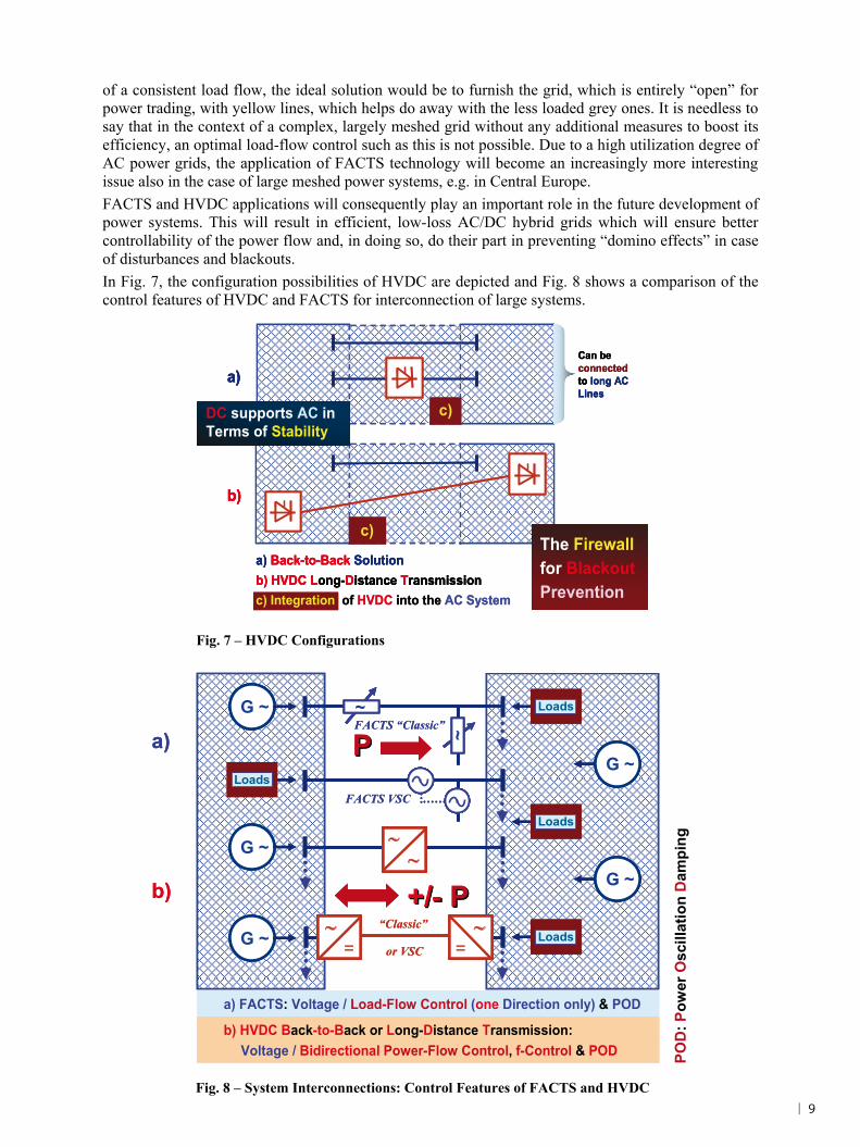
of a consistent load flow, the ideal solution would be to furnish the grid, which is entirely “open” for power trading, with yellow lines, which helps do away with the less loaded grey ones. It is needless to say that in the context of a complex, largely meshed grid without any additional measures to boost its efficiency, an optimal load-flow control such as this is not possible. Due to a high utilization degree of AC power grids, the application of FACTS technology will become an increasingly more interesting issue also in the case of large meshed power systems, e.g. in Central Europe. FACTS and HVDC applications will consequently play an important role in the future development of power systems. This will result in efficient, low-loss AC/DC hybrid grids which will ensure better controllability of the power flow and, in doing so, do their part in preventing “domino effects” in case of disturbances and blackouts. In Fig. 7, the configuration possibilities of HVDC are depicted and Fig. 8 shows a comparison of the control features of HVDC and FACTS for interconnection of large systems.
b) HVDC Long-Distance Transmission
a)
a) Back-to-Back Solution
Can be connected to long AC Lines
b)
c)
c)
The Firewall for BlackoutPrevention
DC supports AC in Terms of StabilityDC supports AC in Terms of Stability
c) Integration of HVDC into the AC Systemb) HVDC Long-Distance Transmission
a)
a) Back-to-Back Solution
Can be connected to long AC Lines
b)
c)
c)
The Firewall for BlackoutPrevention
DC supports AC in Terms of StabilityDC supports AC in Terms of Stability
b) HVDC Long-Distance Transmission
a)a)
a) Back-to-Back Solution
Can be connected to long AC Lines
b)b)
c)c)
c)c)
The Firewall for BlackoutPrevention
The Firewall for BlackoutPrevention
DC supports AC in Terms of StabilityDC supports AC in Terms of Stability
c) Integration of HVDC into the AC System
Fig. 7 – HVDC Configurations
Fig. 8 – System Interconnections: Control Features of FACTS and HVDC
a) FACTS: Voltage / Load-Flow Control (one Direction only) & POD
b) HVDC Back-to-Back or Long-Distance Transmission:Voltage / Bidirectional Power-Flow Control, f-Control & POD
a) FACTS: Voltage / Load-Flow Control (one Direction only) & POD
b) HVDC Back-to-Back or Long-Distance Transmission:Voltage / Bidirectional Power-Flow Control, f-Control & POD
a)
b)
~
~
+/+/-- PPG ~
Loads
G ~
Loads
Loads
Loads
G ~
G ~
G ~
PPFACTS “Classic”
FACTS VSC
=
=
“Classic”
or VSC
a)
b)
~
~
~~
~~
+/+/-- PPG ~G ~G ~
Loads Loads Loads
G ~G ~G ~
Loads Loads Loads
Loads Loads Loads
Loads Loads Loads
G ~G ~G ~
G ~G ~G ~
G ~G ~G ~
PPFACTS “Classic”
FACTS VSC
=
=
=
=
=
=“Classic”
or VSC
POD
: Pow
er O
scill
atio
n D
ampi
ng
| 9

Copyright © Siemens AG 2011. All rights reserved. 9
Fig. 10: Hybrid System Interconnections – “Supergrid” with HVDC and FACTS
Large System Interconnections, with HVDC…Large System Interconnections, with HVDC…
High-Voltage– via AC LinesHVDC B2B
AC Transmission & FACTS
SystemA
SystemA
SystemC
SystemC
SystemE
SystemE
SystemF
SystemF
SystemB
SystemB System
DSystem
D
SystemG
SystemG
Step 1Step 2Step 3
DC is a Stability Booster and“Firewall” against “Blackout”DC is a Stability Booster and
“Firewall” against “Blackout”
A “Super Grid” – “Smart” & StrongA “Super Grid” – “Smart” & Strong
HVDC – Long-Distance DC TransmissionHVDC – Long-Distance DC Transmission
Large System Interconnections and FACTSThe Result:
“Countermeasures”against large Blackouts
“Countermeasures”against large Blackouts
4. PROSPECTS OF POWER SYSTEM DEVELOPMENTS
Based on the previous evaluations, Figs. 9 and 10 show the stepwise interconnection of a number of grids by using AC lines, DC Back-to-Back systems, DC long distance transmissions and FACTS for strengthening the AC lines.
Fig. 9: Prospects of Grid Developments
1 Power Transmission Division06-2010
Generation
C
C
C
C
C C
C
C
C
C
C
CCA
CC
CC
CC
CC
CC CC
CC
CC
CC
CC
CC
CCCACA
CA =CA = Cell AgentCA =CA = Cell Agent
Virtual Power Plant
Cell
C
C
C
C
C C
C
C
C
C
C
CCA
CC
CC
CC
CC
CC CC
CC
CC
CC
CC
CC
CCCACA
GG
C
C
C
C
C C
C
C
C
C
C
CCA
CC
CC
CC
CC
CC CC
CC
CC
CC
CC
CC
CCCACA
C
C
C
C
C C
C
C
C
C
C
CCA
CC
CC
CC
CC
CC CC
CC
CC
CC
CC
CC
CCCACA
C
C
C
C
C C
C
C
C
C
C
CCA
CC
CC
CC
CC
CC CC
CC
CC
CC
CC
CC
CCCACA
GG
GG
CA
GGGG
Bulk Power AC/DCEnergy Highway
GGLL
LL
LL
LL
LL
LL
LL
LL
LL
LL
LL
LL
LL
LL
LL
LL
LL
LL
LL
DCDC
GG + =SS CCLL+Storage
SS
SSLLSmart, controlled Loads ACAC
“Micro Grid” “Smart Grid” “Super Grid”(autonomous)
10 |
Copyright © Siemens AG 2011. All rights reserved. 10
These integrated hybrid AC/DC systems provide significant advantages in terms of technology, economics as well as system security. They reduce transmission costs and help bypass heavily loaded AC systems. With these DC and AC Ultra High Power transmission technologies, the “Smart Grid”, consisting of a number of highly flexible “Micro Grids” will turn into a “Super Grid” with Bulk Power Energy Highways, fully suitable for a secure and sustainable access to huge renewable energy resources such as hydro, solar and wind, as indicated in Fig. 9. This approach is an important step in the direction of environmental sustainability of power supply: transmission technologies with HVDC and FACTS can effectively help reduce transmission losses and CO2 emissions.
The state-of-the-art AC and DC technologies and solutions for Smart and Super Grids are depicted in the following sections.
5. TECHNOLOGIES FOR SMART AND SUPER GRIDS
The core or the “workhorse” of line-commutated HVDC and FACTS installations are high-power thyristors, triggered optically by means of laser technology or electrically depending on application. Thyristors can only switch on the current. The switching-off is carried out by the next current zero crossing itself. This is the reason why a thyristor converter is referred to as a line-commutated system. Should no line voltage be available on one side of an HVDC system or in a FACTS application, the system would no longer be functioning. An advantage of thyristor converters is their high loading capacity both during nominal and overload operation as well as in the event of contingency. Consequently, bulk-power systems at high transmission capacities of 5 to over 7 GW can be implemented with thyristors only. A further benefit consists in comparatively low station losses. The TPSC technology mentioned before uses special-purpose thyristors capable of withstanding transient over-loading of up to approximately 110 kA.
The “strength”, i.e. short-circuit power of the grid, is an important design criterion for the application of line-commutated HVDC systems. If the grid is too weak, a thyristor-based HVDC system must reduce its power or, under certain conditions, shut down completely in order to avoid system collapse resulting from repetitive commutation failures. In the case of weak grids, remedy is provided by FACTS for grid support, i.e. a combination of the HVDC and FACTS as in the example of the SVC Siems for the HVDC project Baltic Cable [3].
Additionally, the problem can be tackled by means of “self-commutated” converters. Self-commutated converters make use of elements which can be switched off, mostly modular or press-pack high-power transistors, all of which, in their turn, consist of a number of separate elements, connected in parallel. In this way, a converter turns into an electronic generator. Self-commutated converters are normally furnished with a voltage-sourced DC circuit. With its help a separate capacitor or a number of them keep the voltage constant (VSC: Voltage-Sourced Converter), whereas a conventional thyristor-based HVDC system keeps the source current constant (CSC: Current-Sourced Converter) by means of reactors.
A detailed description of different VSC solutions is given in [2], for example. A general advantage of the VSC-based HVDC systems consists in the fact that one of the power grids subject to coupling can be completely voltage-free or passive, for, with the help of the intact grid, the other one can be started again similar to a power plant. This black-start capability is particularly interesting for connecting large offshore wind farms off the coast of Germany.
5.1 Smart Grid Solutions with VSC - Modular Multilevel Converters
An innovative development known as the MMC (Modular Multilevel Converter) technology is described in item [2], which is applied by Siemens as an “HVDC PLUS” for the HVDC projects and as an “SVC PLUS” for FACTS. This technology stands out due to its compact modular design and a new multilevel converter, which allows to generate an AC system of a virtually ideal sinus waveform from DC voltage in the voltage source by means of a great number of fine steps without any additional filters. The reactive power elements and filters of normally 50% of the active power, required in HVDC “Classic” applications, can be done completely away with in this case, which helps reduce the footprint of an HVDC station by approx. 40 %. VSC technology is the preferred solution for Smart
| 11

Copyright © Siemens AG 2011. All rights reserved. 11
Grid applications, whereas the “Classic” and Bulk Thyristor technology is the solution for Super Grids.
An overview of the first MMC HVDC project with a 200 kV XLPE DC sea cable transmission is given in Fig. 11. The goal of this project was to eliminate bottlenecks in the overloaded Californian grid: new power plants cannot be constructed in this densely populated area and there is no right-of-way for new lines or land cables. This is the reason why a DC cable is laid through the bay, and the power flows through it by means of the HVDC PLUS technology in an environmentally compatible way.
Fig. 11 – The “Trans Bay Cable“ Project in the U.S., World’s first VSC HVDC with MMC Technology and +/- 200 kV XLPE Cable
2010
~=
=~
==
~ == ~ ==
Elimination of Transmission BottlenecksElimination of Transmission Bottlenecks
Q = +/- 170-300 MVArP = 400 MW
Transmission Constraints before TBCTransmission Constraints before TBC
Dynamic Voltage SupportDynamic Voltage SupportNo Increase inShort-Circuit Power
Energy Exchangeby Sea Cable
No Increase inShort-Circuit Power
Energy Exchangeby Sea Cable
Transmission Constraints after TBCTransmission Constraints after TBC
Fig. 12 – HVDC PLUS and WIPOS: Three Projects, Germany – Offshore VSC HVDC with 866 MW
HelWin1HelWin1
2013
VDC = +/- 250 kVVDC = +/- 250 kV576 MW576 MW
~ == ~ ==
~ == ~ ==
BorWin2BorWin22013
VDC = +/- 300 kVVDC = +/- 300 kV800 MW800 MW
SylWin1SylWin1VDC = +/- 320 kVVDC = +/- 320 kV2014
864 MW864 MW
~ == ~ ==
HelWin1HelWin1
2013
VDC = +/- 250 kVVDC = +/- 250 kV576 MW576 MW
~ == ~ ==
~ == ~ ==
BorWin2BorWin22013
VDC = +/- 300 kVVDC = +/- 300 kV800 MW800 MW
SylWin1SylWin1VDC = +/- 320 kVVDC = +/- 320 kV2014
864 MW864 MW
~ == ~ ==
HelWin1HelWin1
2013
VDC = +/- 250 kVVDC = +/- 250 kV576 MW576 MW
~ == ~ ==
~ == ~ ==
BorWin2BorWin22013
VDC = +/- 300 kVVDC = +/- 300 kV800 MW800 MW
SylWin1SylWin1VDC = +/- 320 kVVDC = +/- 320 kV2014
864 MW864 MW
~ == ~ ==
864 MW
12 |

Copyright © Siemens AG 2011. All rights reserved. 12
Siemens’ second HVDC PLUS project is the world’s largest DC Offshore installation BorWin 2 with a power transfer of 800 MW for Grid Access of wind energy (Fig. 12).
The entire PLUS system has a modular structure and can be flexibly configured, what simplifies its standardization, see Fig. 13. The converter modules are connected on the secondary side of a high-voltage coupling transformer (for simplification not shown in the figure) to build the HVDC or the SVC. Due to the MMC configuration, there is almost no – or, in the worst case, very small - need for AC voltage filtering to achieve a clean voltage. The system configuration is very compact and normally occupies 50 % less space than a “classic” HVDC or SVC systems.
Examples of projects with SVC PLUS and the configuration possibilities are shown in Fig. 14.
Fig. 13 – VSC Technology with MMC: SVC PLUS and HVDC PLUS (ref. to Text) Configuration of Multilevel Voltage Sources for SVC (left Side) and HVDC (right Side)
Power Module with DC CapacitorPower Module with DC CapacitorPower Module with DC Capacitor
vvvv
Power Module with DC CapacitorPower Module with DC CapacitorPower Module with DC Capacitor
vvvv
PM 1
PM 2
PM n
PM 1
PM 2
PM n
PM 1
PM 2
PM n
PM 1
PM 2
PM n
PM 1
PM 2
PM n
PM 1
PM 2
PM n
ud
Phase Unit
Vd
Converter Arm
PM 1
PM 2
PM n
PM 1
PM 2
PM n
PM 1
PM 2
PM n
PM 1
PM 2
PM n
PM 1
PM 2
PM n
PM 1
PM 2
PM n
ud
Phase Unit
PM 1
PM 2
PM n
PM 1
PM 2
PM n
PM 1
PM 2
PM n
PM 1
PM 2
PM n
PM 1
PM 2
PM n
PM 1
PM 2
PM n
ud
Phase Unit
Vd
Converter Arm
Controlled Voltage Sources
Controlled Voltage Sources
| 13

Copyright © Siemens AG 2011. All rights reserved. 13
Fig. 14 – A wide Range of Application Possibilities: a) Grid Access of Green Energy with SVC PLUS - Greater Gabbard and London Array, UK b) Power Quality in AC Systems – Kikiwa Project, South Island, New Zealand c) From Containerized to Open Rack and Hybrid Solutions
SVC PLUS Hybrid (Option):MSR (Mechanically Switched Reactors)
MSC (Mechanically Switched Capacitors)
Up to 4 parallel L-Units: +/- 200 MVAr
Containerized Solutions:SVC PLUS S: +/- 25 MVArSVC PLUS M: +/- 35 MVArSVC PLUS L: +/- 50 MVAr
Open Rack Solution (Building):SVC PLUS C: +/-100 MVAr
SVC PLUS Hybrid (Option):MSR (Mechanically Switched Reactors)
MSC (Mechanically Switched Capacitors)
Up to 4 parallel L-Units: +/- 200 MVArUp to 4 parallel L-Units: +/- 200 MVAr
Containerized Solutions:SVC PLUS S: +/- 25 MVArSVC PLUS M: +/- 35 MVArSVC PLUS L: +/- 50 MVAr
Open Rack Solution (Building):SVC PLUS C: +/-100 MVAr
c)
b) SVC PLUS: 2 x PLUS M in parallel 220 kV / 11 kV Dynamic Voltage Support
during and after AC Line Faults(Voltage Dip Compensation)
2010SVC PLUS: 2 x PLUS M in parallel 220 kV / 11 kV Dynamic Voltage Support
during and after AC Line Faults(Voltage Dip Compensation)
2010
a)
SVC PLUS: 3 x PLUS L in parallel 132 kV / 13.9 kV
2010
… and London Array
2011SVC PLUS: 4 x PLUS L in parallel 150 kV / 13.9 kV
World’s largest Offshore Wind Farm
630 MW & Upgrade up to 1 GW
SVC PLUS: 3 x PLUS L in parallel 132 kV / 13.9 kV
2010
… and London Array… and London Array
2011SVC PLUS: 4 x PLUS L in parallel 150 kV / 13.9 kV
World’s largest Offshore Wind FarmWorld’s largest Offshore Wind Farm
630 MW & Upgrade up to 1 GW630 MW & Upgrade up to 1 GW
14 |

Copyright © Siemens AG 2011. All rights reserved. 14
The state-of-the-art highly flexible MMC technology for HVDC PLUS and SVC PLUS makes it possible to easily comply with all the known voltage quality requirements (Grid Codes) for grid access of wind farms as well as for transmission systems. In addition to this, the MMC PLUS technology is used for traction supply with Static Frequency Converters (SFC) and for industrial applications. The field of synergies and applications is therefore boundless.
5.2 Super Grid Solutions with FACTS and HVDC - “Classic” and Bulk
The progressive worldwide urbanization, as well as the trend towards megacities with more than 10 million inhabitants, poses new challenges on the power transmission systems. In every country of the world the economic pulses coming from cities provide more than half of the gross domestic product of the respective country, according to UN-statistics. One of the most important factors for the economic dynamics of megacities is an effective infrastructure. It goes without saying that the basis for this infrastructure is constituted by a reliable and efficient power supply.
An important development in the power supply of megacities is the outsourcing of power generation to close or more distant surrounding regions. That is, transmission networks and distribution systems are forced to interconnect increasingly longer distances. Furthermore, efficiency and reliability of supply play an important role in every planning, particularly in the face of increasing energy prices and almost incalculable safety risks during power blackouts.
Such an example is shown in Fig. 15. In India, for the increasing power demands of the area of the Megacity New Delhi, the world’s biggest FACTS project with series compensation (TCSC/FSC) was installed at Purnea and Gorakhpur with a total rating of 2 x 1.7 GVAr, ref. to the figure. This project provides clean and cheap hydro power from Bhutan over long distances. The systems at Purnea and Gorakhpur Substations use a combination of FSC and TCSC. TCSC is used if fast control of the line impedance is required, for load-flow control and for damping of power oscillations and FSC is an economic way to reduce the transmission angle over the line and to increase the transmission capacity.
The most devoted user of the Bulk Power DC transmission concept is China. The UHV HVDC systems at 800 kV require the most state-of-the-art converter technology. The separate components of this kind of installations boast impressive design and dimensions owing to the required insulation clearance distances. China requires this HVDC technology to construct a number of high-power DC energy highways, superimposed to the AC grid, in order to transmit electric power from huge hydro power plants in the center of the country to the load centers located as far as 2,000 to 3,000 km away with as little losses as possible. Fig. 16 depicts an example of the 3,000 MW HVDC project Gui-Guang I in Southern China.
Fig. 15 – Tala TCSC Project: Bulk Hydro Power from Bhutan to Delhi Area World’s largest FACTS for Series Compensation
| 15

Copyright © Siemens AG 2011. All rights reserved. 15
. The “next generation” HVDC project is the UHV DC Yunnan-Guangdong at a transfer capacity of 5 GW (see Figs.17 - 18). Siemens and the utility China Southern Power Grid succeeded to put pole 1 of this world’s first 800 kV HVDC into operation in December 2009 and pole 2 in June 2010.
The Yunnan-Guangdong project helps save around 33 m tons CO2 in comparison with local power generation, which, in view of the current energy mix in China, would be connected with a relatively high carbon amount, ref. to Fig. 17. Figs. 18-19 give views of the huge dimensions of the HVDC stations and the equipment.
Siemens – the Leader in Bulk Power UHV DC Transmission Technology
5,000 MW1,418 km
+/- 800 kV DC
Reduction in CO2 versus local Power Supply with Energy-Mix
32.9 m tons p.a. – by using Hydro Energy and HVDC for Transmission
Commercial Operation: 2009 – Pole 1 2010 – Pole 2
Yunnan-Guangdong
Siemens – the Leader in Bulk Power UHV DC Transmission TechnologySiemens – the Leader in Bulk Power UHV DC Transmission Technology
5,000 MW1,418 km
+/- 800 kV DC
Reduction in CO2 versus local Power Supply with Energy-Mix
32.9 m tons p.a. – by using Hydro Energy and HVDC for Transmission
Commercial Operation: 2009 – Pole 1 2010 – Pole 2
Commercial Operation: 2009 – Pole 1 2010 – Pole 2
Yunnan-GuangdongYunnan-Guangdong
Fig. 17 – Yunnan-Guangdong: World’s first 800 kV UHV DC in China Southern Power Grid
Fig. 16 – HVDC projects in Southern China enable low-Loss West-to-East Transmission of Hydro- power-based electrical Energy produced in the Country‘s Interior to coastal Load Centers (Example of Long-Distance Transmission Gui-Guang I)
2004
16 |
Copyright © Siemens AG 2011. All rights reserved. 16
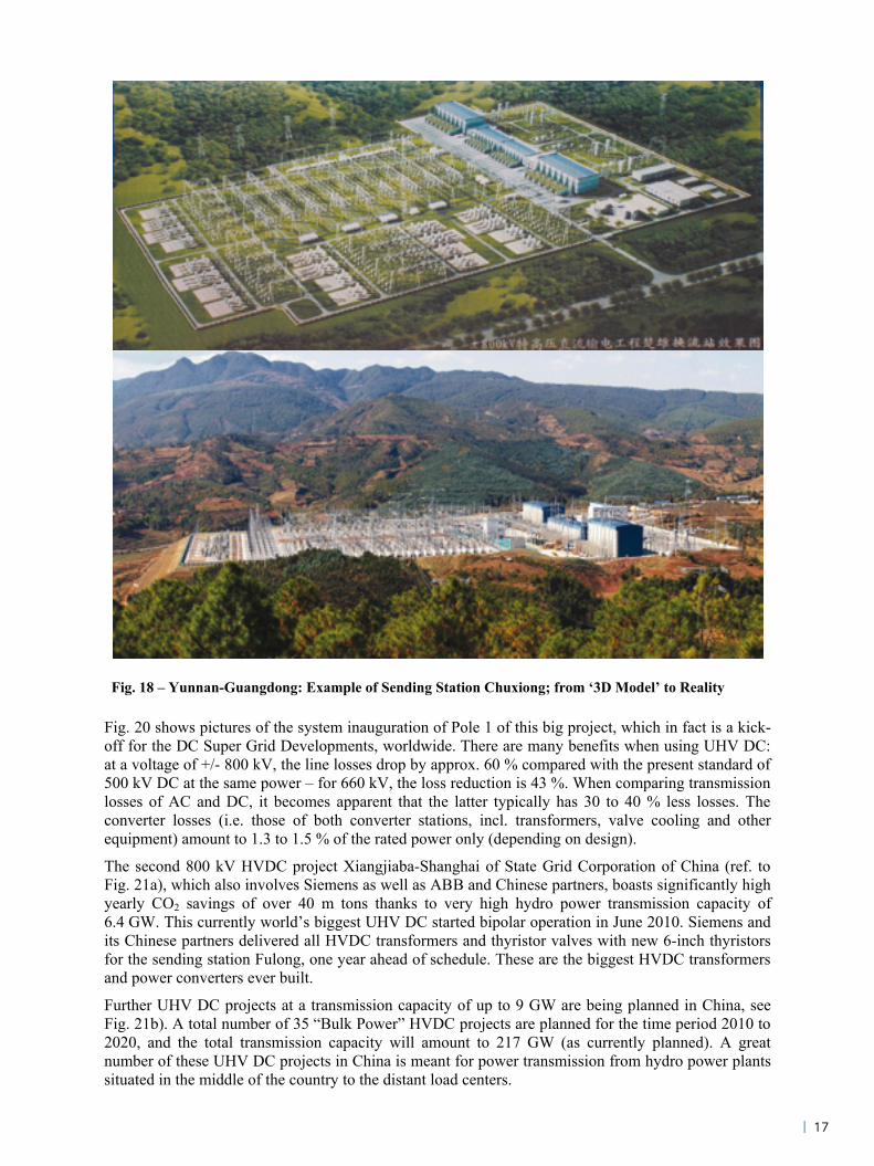
Fig. 20 shows pictures of the system inauguration of Pole 1 of this big project, which in fact is a kick-off for the DC Super Grid Developments, worldwide. There are many benefits when using UHV DC: at a voltage of +/- 800 kV, the line losses drop by approx. 60 % compared with the present standard of 500 kV DC at the same power – for 660 kV, the loss reduction is 43 %. When comparing transmission losses of AC and DC, it becomes apparent that the latter typically has 30 to 40 % less losses. The converter losses (i.e. those of both converter stations, incl. transformers, valve cooling and other equipment) amount to 1.3 to 1.5 % of the rated power only (depending on design).
The second 800 kV HVDC project Xiangjiaba-Shanghai of State Grid Corporation of China (ref. to Fig. 21a), which also involves Siemens as well as ABB and Chinese partners, boasts significantly high yearly CO2 savings of over 40 m tons thanks to very high hydro power transmission capacity of 6.4 GW. This currently world’s biggest UHV DC started bipolar operation in June 2010. Siemens and its Chinese partners delivered all HVDC transformers and thyristor valves with new 6-inch thyristors for the sending station Fulong, one year ahead of schedule. These are the biggest HVDC transformers and power converters ever built.
Further UHV DC projects at a transmission capacity of up to 9 GW are being planned in China, see Fig. 21b). A total number of 35 “Bulk Power” HVDC projects are planned for the time period 2010 to 2020, and the total transmission capacity will amount to 217 GW (as currently planned). A great number of these UHV DC projects in China is meant for power transmission from hydro power plants situated in the middle of the country to the distant load centers.
Fig. 18 – Yunnan-Guangdong: Example of Sending Station Chuxiong; from ‘3D Model’ to Reality
| 17

Copyright © Siemens AG 2011. All rights reserved. 17
Fig. 19 – 800 kV UHV DC Yunnan-Guangdong: View of the Bipolar Valve Halls – Two 400 kV Systems in series to build 800 kV (upper Part) Inside the 800 kV Valve Hall – the Converter System (Middle Part) Bipolar DC Line - uniting the single +/- Lines coming out of the Station (Lower Part)
800 kV DC800 kV DC
800 kV DC800 kV DC800 kV DC800 kV DC
2 x 400 kV DC2 x 400 kV DC
18 |

Copyright © Siemens AG 2011. All rights reserved. 18
a)
Fig. 21 – a) World’s biggest and longest 800 kV DC Transmission Project: Xiangjiaba-Shanghai b) Over 217 GW of additional HVDC Transmission Capacity are expected in China between 2010 and 2020
b)
Zheijang
Qinghai
Xizang
Inrfar Mongolia
Jilin
Liaoning
Yunnan
Hainan
Fujian
Taiwan
Bangkok
4
3
3
13
94
21
5
18
24
7
10
11
15
1620
14
19
17
22 25
2623
35
33
29
27
31
34
12
8
32
28
30
6
1. Yunnan – Guangdong 800 kV, 5000 MW, 2009/10
2. Xiangjiaba – Shanghai 800 kV, 6400 MW, 2010
3. Qinghai – Tibet 500 kV, 1200 MW, 2011
4. Mongolia – Tianjin 660 kV, 4000 MW, 2012
5. Russia – Liaoning 660 kV, 4000 MW, 2012
6. Nuozhadu – Guangdong 800 kV, 5000 MW, 2012
7. Jingping – Sunan800 kV, 7200 MW, 2012
8. Xiluodu – Guangdong 500 kV, 2 x 3200 MW, 2013
9. Humeng – Tangshan 660 kV, 4000 MW, 2013
10. Ningdong – Zhejiang 800 kV, 7200 MW, 2013
11. Xiluodu – Zhejiang 800 kV, 7200 MW, 2013
12. Sichuan – Hunan 660 kV, 4000 MW, 2014
13. Xiluodu – Hunan 660 kV, 4000 MW, 2014
14. Humeng – Shandong 800 kV, 7200 MW, 2014
15. Hami – Henan 800 kV, 7200 MW, 2014
21. Baoqing – Liaoning 660 kV, 4000 MW, 2017
22. Hami – Shandong 800 kV, 7200 MW, 2017
23. Tibet – Chongqing 800 kV, 7200 MW, 2017
24. Jinghong – Thailand 500 kV, 3000 MW, 2018
25. Ximeng – Wuxi 800 kV, 7200 MW, 2018
26. Baihetan – Hubei 800 kV, 7200 MW, 2018
27. Wudongde – Fujian 1000 kV, 9000 MW, 2018
28. Northwest – North B2B, 1500 MW, 2018
29. Mongolia – Jing-Jin-Tang 800 kV, 7200 MW, 2019
30. Russia – Liaoning 800 kV, 7200 MW, 2019
31. Zhundong – Jiangxi 1000 kV, 9000 MW, 2019
32. Tibet – Zhejiang 1000 kV, 9000 MW, 2019
33. Baihetan – Hunan 800 kV, 7200 MW, 2020
34. Yili – Sichuan 1000 kV, 9000 MW, 2020
35. Kazakhstan – Chengdu 1000 kV, 9000 MW, 2020
Ningxia Shanxi
Hebei
Beijing
JiangsuAnhuj
Guizhou
Sichuan &Chongqing
Gansu
Xinjiang
Heilongjiang
Shandong
Jiangxi
Hubai
Hunan
Shaanxi
Henan
2
1
Shanghai
Tianjin
Guangdong
1 x B2B3 x 500 kV7 x 660 kV
19 x 800 kV5 x 1000 kV
Zheijang
Qinghai
Xizang
Inrfar Mongolia
Jilin
Liaoning
Yunnan
Hainan
Fujian
Taiwan
Bangkok
4
3
3
13
94
21
5
18
24
7
10
11
15
1620
14
19
17
22 25
2623
35
33
29
27
31
34
12
8
32
28
30
6
1. Yunnan – Guangdong 800 kV, 5000 MW, 2009/10
2. Xiangjiaba – Shanghai 800 kV, 6400 MW, 2010
3. Qinghai – Tibet 500 kV, 1200 MW, 2011
4. Mongolia – Tianjin 660 kV, 4000 MW, 2012
5. Russia – Liaoning 660 kV, 4000 MW, 2012
6. Nuozhadu – Guangdong 800 kV, 5000 MW, 2012
7. Jingping – Sunan800 kV, 7200 MW, 2012
8. Xiluodu – Guangdong 500 kV, 2 x 3200 MW, 2013
9. Humeng – Tangshan 660 kV, 4000 MW, 2013
10. Ningdong – Zhejiang 800 kV, 7200 MW, 2013
11. Xiluodu – Zhejiang 800 kV, 7200 MW, 2013
12. Sichuan – Hunan 660 kV, 4000 MW, 2014
13. Xiluodu – Hunan 660 kV, 4000 MW, 2014
14. Humeng – Shandong 800 kV, 7200 MW, 2014
15. Hami – Henan 800 kV, 7200 MW, 2014
21. Baoqing – Liaoning 660 kV, 4000 MW, 2017
22. Hami – Shandong 800 kV, 7200 MW, 2017
23. Tibet – Chongqing 800 kV, 7200 MW, 2017
24. Jinghong – Thailand 500 kV, 3000 MW, 2018
25. Ximeng – Wuxi 800 kV, 7200 MW, 2018
26. Baihetan – Hubei 800 kV, 7200 MW, 2018
27. Wudongde – Fujian 1000 kV, 9000 MW, 2018
28. Northwest – North B2B, 1500 MW, 2018
29. Mongolia – Jing-Jin-Tang 800 kV, 7200 MW, 2019
30. Russia – Liaoning 800 kV, 7200 MW, 2019
31. Zhundong – Jiangxi 1000 kV, 9000 MW, 2019
32. Tibet – Zhejiang 1000 kV, 9000 MW, 2019
33. Baihetan – Hunan 800 kV, 7200 MW, 2020
34. Yili – Sichuan 1000 kV, 9000 MW, 2020
35. Kazakhstan – Chengdu 1000 kV, 9000 MW, 2020
Ningxia Shanxi
Hebei
Beijing
JiangsuAnhuj
Guizhou
Sichuan &ChongqingSichuan &Chongqing
Gansu
Xinjiang
Heilongjiang
Shandong
Jiangxi
Hubai
Hunan
Shaanxi
Henan
22
11
Shanghai
Tianjin
Guangdong
1 x B2B3 x 500 kV7 x 660 kV
19 x 800 kV5 x 1000 kV
Xiluodu-Zhexi 1728km
Zhexi
Xiluodu rightXiluodu right
Nanhui
XiangjiabaXiangjiaba
Sichuan Power Grid
Xiluodu-Zhuzhou 970kmZhuzhou
Xiluodu leftXiluoduleft
Wuhan
Guangdong
LeshanChongqing
Changsha
Shanghai
6,400 MW+/- 800 kV DC
2,071 km Commercial Operation: July 2010 – both Poles
Reduction in CO2 versus local Power Supply with Energy Mix
41 m tons p.a. – by using Hydro Power and HVDC for Transmission
Xiangjiaba-ShanghaiFulong – World’s biggest HVDC Converter Station in Operation: Transformers & Thyristor Valves with new 6-inch Thyristors from Siemens
Xiluodu-Zhexi 1728km
Zhexi
Xiluodu rightXiluodu right
Nanhui
XiangjiabaXiangjiaba
Sichuan Power Grid
Xiluodu-Zhuzhou 970kmZhuzhou
Xiluodu leftXiluoduleft
Wuhan
Guangdong
LeshanChongqing
Changsha
Shanghai
Xiluodu-Zhexi 1728kmXiluodu-Zhexi 1728km
ZhexiZhexi
Xiluodu rightXiluodu right Xiluodu rightXiluodu right
Nanhui
XiangjiabaXiangjiaba
Sichuan Power Grid
Xiluodu-Zhuzhou 970km
Xiluodu-Zhuzhou 970kmZhuzhouZhuzhou
Xiluodu leftXiluoduleft
Xiluodu leftXiluoduleft
Wuhan
Guangdong
LeshanChongqing
Changsha
Shanghai
6,400 MW+/- 800 kV DC
2,071 km Commercial Operation: July 2010 – both PolesCommercial Operation: July 2010 – both Poles
Reduction in CO2 versus local Power Supply with Energy Mix
41 m tons p.a. – by using Hydro Power and HVDC for Transmission
Xiangjiaba-ShanghaiXiangjiaba-ShanghaiFulong – World’s biggest HVDC Converter Station in Operation: Transformers & Thyristor Valves with new 6-inch Thyristors from Siemens
Fulong – World’s biggest HVDC Converter Station in Operation: Transformers & Thyristor Valves with new 6-inch Thyristors from Siemens
Fig. 20 – Yunnan-Guangdong UHV DC Inauguration on Dec. 28, 2009: Celebration of Pole 1 successful Commissioning and Start of full Bipolar Operation in June 2010
2,500 MW2,500 MW 2,500 MW2,500 MW
a)
| 19

Copyright © Siemens AG 2011. All rights reserved. 19
5.3 Super Grid Solutions with GIL – Gas Insulated Lines
GIL initially was developed in 1974 and 1975. At that time, the cost level compared to an overhead line was in the range of 30 times more expensive. Later, in 1998 and 1999, a second generation of GIL was developed where the power transmission capability was increased from 2,500 A to 4,000 A and at the same time the cost factor went significantly down in comparison with overhead lines and cables.
Fig. 22 gives examples of a new directly buried Bulk Power GIL installation in Germany, near the International Airport of the City of Frankfurt.
6. CONCLUSIONS AND OUTLOOK
The security of power supply in terms of reliability and blackout prevention has the utmost priority when planning and extending power grids. The availability of electric power is the crucial prerequisite for the survivability of a modern society and power grids are virtually its lifelines. The aspect of sustainability is gradually gaining in importance in view of such challenges as the global climate protection and economical use of power resources running short. It is, however, not a means to an end to do without electric power in order to reduce CO2 emissions. A more appropriate way is to integrate renewable energy resources to a greater extent in the future (energy mix) and, in addition to this, to increase the efficiency of conventional power generation as well as power transmission and distribution without loss of system security.
The future power grids will have to withstand increasingly more stresses caused by large-scale energy trading and a growing share of fluctuating regenerative energy sources, such as wind and solar power. In order to keep generation, transmission and consumption in balance, the grids must become more flexible, i.e. they must be controlled in a better way. State-of-the-art power electronics with HVDC and FACTS technologies provides a wide range of applications with different solutions, which can be adapted to the respective grid in the best possible manner. DC current transmission constitutes the best solution when it comes to loss reduction when transmitting power over long distances. The HVDC technology also helps control the load flow in an optimal way. This is the reason why, along with system interconnections, the HVDC systems become part of synchronous grids increasingly more often – either in form of a B2B for load-flow control and grid support, or as a DC energy highway to relieve heavily-loaded grids.
FACTS technology was originally developed to support systems with long AC transmission lines. FACTS installations are increasingly more often used in meshed grids to eliminate congestion and
Fig. 22 – Bulk Power Corridor with GIL: 400 kV Installation at Kelsterbach, Germany
Site View: Status June 2009 Site View: Status October 2009
2010
Laying Process: Pushing the
GIL Element by Element
and Phase by
PhaseGIL vs. Cable
Same Costs
4 Systems2 Systems
Customer: Amprion Location: Airport Frankfurt Award of Contract: July 2008 Installation: first directly buried GIL
Transmission Capacity: 2 x 1,800 MVA Length of GIL: appr. 1 km Gas for Insulation: 80% N2, 20% SF6
20 |

Copyright © Siemens AG 2011. All rights reserved. 20
bottlenecks. FACTS will play its role for strengthening long distance AC transmission and meshed grids as well.
In conclusion of the previous sections and based on studies and practical experience, the features of the different solutions can be summarized as follows (Fig. 23):
Fig. 23 includes an option for a 1,000 kV UHV DC application, which is currently under discussion in China. This option offers the lowest losses and highest transmission capacity, however, it is obvious that the extended insulation requirements for 1,000 kV will lead to an increase of the already huge mechanical dimensions of all equipment, including PTs, CTs, breakers, disconnectors, busbars, transformers and reactive power equipment.
HVDC – High-Voltage DC Transmission: It makes P flow
Three HVDC Options available: PLUS (VSC), “Classic” and Bulk
With DC, Overhead Line Losses are typically 30-40 % less than with AC
For Cable Transmission (over 80 km), HVDC is the only Solution
HVDC can be integrated into the AC Systems
HVDC supports AC in Terms of Stability
System Interconnection with HVDC:
DC is a “Firewall” against Cascading Disturbances
Bidirectional Control of Power Flow – quite easy
Frequency, Voltage and POD Control available
Staging of the Links – with DC quite easy
No Increase in Short-Circuit Power
DC is a Stability Booster
Fig. 24 – Summary: Features and Benefits of HVDC
Fig. 23 – Comparison of AC and DC Bulk Power Transmission Solutions
Solutions with Overhead Lines
Solutions with DC Cables *
High-Voltage DC Transmission: HVDC “Classic” with 500 kV (HV) / 660 kV (EHV) – 3 to 4 GW
HVDC “Bulk” with 800 kV (UHV) – 5 GW to 7.5 GW
AC Transmission: 400 kV (HV) / 500 kV AC (EHV) – 1.5 / 2 GVA 800 kV AC (EHV) – 3 GVA 1,000 kV AC (UHV) – 6 to 8 GVA
* Distances over 80 km: AC Cables too complex
Note: Power AC @ 1 System 3 , Power DC @ Bipole +/-
500 / 600 kV DC – per Cable, Mass Impregnated: 1 GW to 2 GW (actual - prospective)
HVDC PLUS (VSC) ≤ 1,100 MVAFor Comparison:
** Reference: Bowmanville, Canada, 1985 - Siemens*** Reference: Huanghe Laxiwa Hydropower Station,
China, 2009 - CGIT (USA)
400 kV AC (HV) – 1.8 GVA / 2.3 GVA (directly buried / Tunnel or Outdoor)
500 kV AC (EHV) – 2.3 GVA / 2.9 GVA (directly buried / Tunnel or Outdoor) 550 kV AC (EHV) – Substation: Standard 3.8 GVA / Special 7.6 GVA ** 800 kV AC (EHV) – Tunnel: 5.6 GVA ***
Solutions with GIL – Gas Insulated Lines
Option UHV DC 1,100 kV: 10 GW
The Winner is HVDC !
Solutions with Overhead LinesSolutions with Overhead Lines
Solutions with DC Cables *Solutions with DC Cables *
High-Voltage DC Transmission: HVDC “Classic” with 500 kV (HV) / 660 kV (EHV) – 3 to 4 GW
HVDC “Bulk” with 800 kV (UHV) – 5 GW to 7.5 GW
AC Transmission: 400 kV (HV) / 500 kV AC (EHV) – 1.5 / 2 GVA 800 kV AC (EHV) – 3 GVA 1,000 kV AC (UHV) – 6 to 8 GVA
* Distances over 80 km: AC Cables too complex
Note: Power AC @ 1 System 3 , Power DC @ Bipole +/-
500 / 600 kV DC – per Cable, Mass Impregnated: 1 GW to 2 GW (actual - prospective)
HVDC PLUS (VSC) ≤ 1,100 MVAFor Comparison:
** Reference: Bowmanville, Canada, 1985 - Siemens*** Reference: Huanghe Laxiwa Hydropower Station,
China, 2009 - CGIT (USA)
400 kV AC (HV) – 1.8 GVA / 2.3 GVA (directly buried / Tunnel or Outdoor)
500 kV AC (EHV) – 2.3 GVA / 2.9 GVA (directly buried / Tunnel or Outdoor) 550 kV AC (EHV) – Substation: Standard 3.8 GVA / Special 7.6 GVA ** 800 kV AC (EHV) – Tunnel: 5.6 GVA ***
Solutions with GIL – Gas Insulated LinesSolutions with GIL – Gas Insulated Lines
Option UHV DC 1,100 kV: 10 GW
The Winner is HVDC !The Winner is HVDC !
| 21

Copyright © Siemens AG 2011. All rights reserved. 21
Regarding long distance Bulk Power transmission, HVDC is the best solution, offering minimal losses. The features and benefits of HVDC are summarized in Fig. 24. It goes without saying that a combination of FACTS and classic line-commutated HVDC technology is feasible as well. In the case of state-of-the-art VSC-based HVDC technologies, the FACTS function of reactive power control is already integrated that is, additional FACTS controllers are superfluous. However, “Bulk Power” transmission up to the GW range remains reserved to classic, line-commutated thyristor-based HVDC systems.
For Bulk Power Transmission over short distances, GIL is a very attractive solution due to its high transmission capacity and small right-of-way requirements, in comparison with cables and overhead lines. This includes Bulk Power solutions for supply of both megacities and load centers. GIL can also be used in long tunnels and on bridges – there are no security and no EMI issues with this technology.
The vision of a European Super Grid is gaining impetus since the foundation of the DESERTEC Industrial Initiative in 2009. The basic idea is the combination of different kinds of renewable energies across Europe – a very promising scenario, which has to be developed step-by-step, ref. to Fig. 25.
7. REFERENCES
[1] European Technology Platform SmartGrids – Vision and Strategy for Europe’s Electricity Networks of the Future; 2006, Luxembourg, Belgium [2] D. Retzmann, “Modular Multilevel Converter – Technology & Principles” and “HVDC / FACTS using VSC – Applications & Prospects”, Cigré-Brazil B4 “Tutorial on VSC in Transmission Systems – HVDC & FACTS”, October 6-7, 2009, Rio de Janeiro, Brazil [3] W. Breuer, D. Povh, D. Retzmann, C. Urbanke, M. Weinhold, “Prospects of Smart Grid Technologies for a Sustainable and Secure Power Supply”; The 20TH World Energy Congress, November 11-15, 2007, Rome, Italy [4] M. Claus; D. Retzmann, D. Sörangr, K. Uecker, “Solutions for Smart and Super Grids with HVDC and FACTS”, 17th Conference on Electric Power Supply Industry CEPSI 2008, October 27-31, Macau, SAR of China
Fig. 25 – Super Grid in Europe: The DESERTEC Concept
Source: DESERTEC FoundationAn Initiative of the Club of Rome
Siemens has a commitment in the Desertec Industrial Initiative (DII). The objective of this initiative is to develop over the mid-term a technical and economic concept for solar power from Africa. Work will also focus on the clarification of legal and political issues.
Source: DESERTEC FoundationAn Initiative of the Club of Rome
Source: DESERTEC FoundationAn Initiative of the Club of Rome
Siemens has a commitment in the Desertec Industrial Initiative (DII). The objective of this initiative is to develop over the mid-term a technical and economic concept for solar power from Africa. Work will also focus on the clarification of legal and political issues.
Siemens has a commitment in the Desertec Industrial Initiative (DII). The objective of this initiative is to develop over the mid-term a technical and economic concept for solar power from Africa. Work will also focus on the clarification of legal and political issues.
22 |

Copyright © Siemens AG 2011. All rights reserved. 22
Permission for use The content of this paper is copyrighted by Siemens and is licensed to WEC for publication
and distribution only. Any inquiries regarding permission to use the content of this paper, in
whole or in part, for any purpose must be addressed to Siemens directly.
Disclaimer
These documents contain forward-looking statements and information – that is, statements
related to future, not past, events. These statements may be identified either orally or in
writing by words as “expects”, “anticipates”, “intends”, “plans”, “believes”, “seeks”,
“estimates”, “will” or words of similar meaning. Such statements are based on our current
expectations and certain assumptions, and are, therefore, subject to certain risks and
uncertainties. A variety of factors, many of which are beyond Siemens’ control, affect its
operations, performance, business strategy and results and could cause the actual results,
performance or achievements of Siemens worldwide to be materially different from any
future results, performance or achievements that may be expressed or implied by such
forward-looking statements. For us, particular uncertainties arise, among others, from changes
in general economic and business conditions, changes in currency exchange rates and interest
rates, introduction of competing products or technologies by other companies, lack of
acceptance of new products or services by customers targeted by Siemens worldwide, changes
in business strategy and various other factors. More detailed information about certain of
these factors is contained in Siemens’ filings with the SEC, which are available on the
Siemens website, www.siemens.com and on the SEC’s website, www.sec.gov. Should one or
more of these risks or uncertainties materialize, or should underlying assumptions prove
incorrect, actual results may vary materially from those described in the relevant forward-
looking statement as anticipated, believed, estimated, expected, intended, planned or
projected. Siemens does not intend or assume any obligation to update or revise these
forward-looking statements in light of developments which differ from those anticipated.
Trademarks mentioned in these documents are the property of Siemens AG, its affiliates or
their respective owners.
| 23
Published by and copyright © 2011: Siemens AG Energy Sector Freyeslebenstrasse 1 91058 Erlangen, Germany
Siemens AG Energy Sector Power Transmission Division Power Transmission Solutions Freyeslebenstrasse 1 91058 Erlangen, Germany www.siemens.com/energy/hvdc
For more information, please contact our Customer Support Center. Phone: +49 180/524 70 00 Fax: +49 180/524 24 71 (Charges depending on provider)
E-mail: [email protected]
Power Transmission Division Order No. E50001-G610-A127-X-4A00 | Printed in Germany | Dispo 30003 | c4bs No. 7805 | TH 150-110790 | SCH | 472543 | SD | 08112.0
Printed on elementary chlorine-free bleached paper.
All rights reserved. Trademarks mentioned in this document are the property of Siemens AG, its affiliates, or their respective owners.
Subject to change without prior notice. The information in this document contains general descriptions of the technical options available, which may not apply in all cases. The required technical options should therefore be specified in the contract.