highlights of quick, easy Slant/Fin installation of quick, easy Slant/Fin installation 1. ... Lift...
16
Transcript of highlights of quick, easy Slant/Fin installation of quick, easy Slant/Fin installation 1. ... Lift...


highlights of quick, easy Slant/Fin installation
1. Drill holes for risers and connecting piping.
2. Nail baseboard to wall. For faster installation, use “T-Shot” Nailing Tool, or, use powerscrew gun.
3. Join the elements to risers and each other and rest on brackets.
4. Drop piping under doorways.
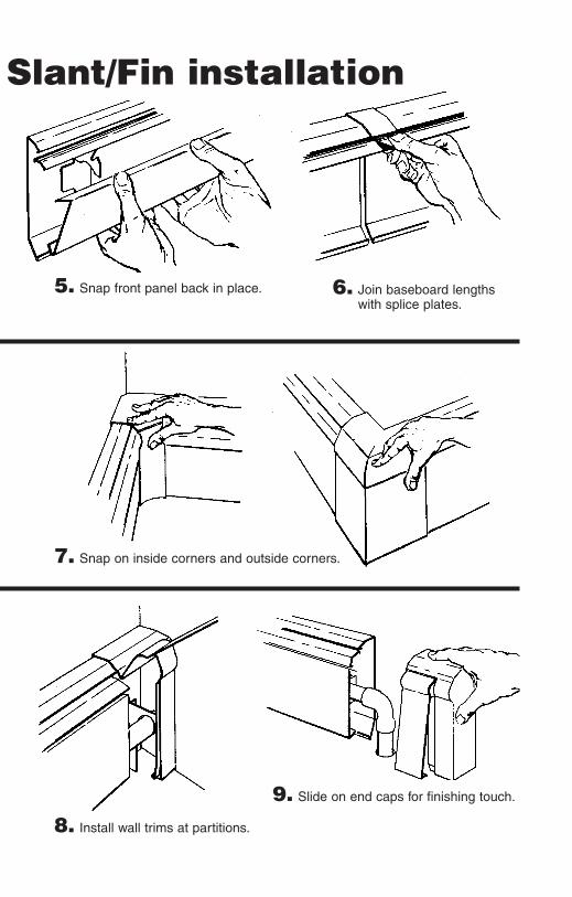
Slant/Fin installation
5. Snap front panel back in place. 6. Join baseboard lengthswith splice plates.
7. Snap on inside corners and outside corners.
8. Install wall trims at partitions.
9. Slide on end caps for finishing touch.

®
easiest kind of heatingto install(and the most beautiful)You’ll find that pre-assembled Slant/Fin baseboardis surprisingly easy to handle. With Slant/Fin pre-cut lengths and telescoping accessories you canleave your hacksaw at home. All parts snap togeth-er securely at the touch of your fingers, and theystay together. You end up with a neat, wall-to-wallinstallation of beautiful and efficient baseboardheating, without a shortened temper or bleedinghands. And you’re in and out in half the time you’dneed with most other baseboards.
what the parts are called...
Baseboard and all accessories serve both flush orrecessed installation.
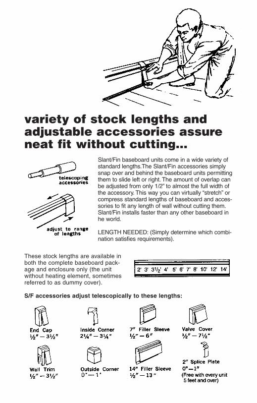
variety of stock lengths andadjustable accessories assureneat fit without cutting...
Slant/Fin baseboard units come in a wide variety ofstandard lengths.The Slant/Fin accessories simplysnap over and behind the baseboard units permittingthem to slide left or right. The amount of overlap canbe adjusted from only 1/2” to almost the full width ofthe accessory. This way you can virtually “stretch” orcompress standard lengths of baseboard and acces-sories to fit any length of wall without cutting them.Slant/Fin installs faster than any other baseboard inhe world.
LENGTH NEEDED: (Simply determine which combi-nation satisfies requirements).
These stock lengths are available inboth the complete baseboard pack-age and enclosure only (the unitwithout heating element, sometimesreferred to as dummy cover).
S/F accessories adjust telescopically to these lengths:

plan your piping...Here are examples of three basic piping systems, shown with and without optionsfor zoning.
1. SERIES LOOPSeries loop--single zone(The simplest, most economical system to install.) The Slant/Fin baseboard damper provides indi-vidual room control. A single cir-cuit runs from the boiler to the firstrun of baseboard, continues from there to the next room and so on.The last baseboard unit in the series is connected to the return at the boiler. It keeps pipe, fittings, controls and labor costs to a mini-mum. Use separate loop for each zone.
Series loop--multiple zonesEach zone is a “Series loop” with any number of Slant/Fin base-board units and controlled by its own room thermostat.
In the zone valve arrangement, each zone has an electrically operated zone valve and there is a single pump for the whole system.
In the zone pump arrangement, each zone is provided with a pump, a flow control valve and a relay.
Series loop--multi-zone withindividual pumps

2. SPLIT LOOP Provides more even heat distribution and the option of separate zone control. The house is “divided” into two (or more) sec-tions, each with its own circuit.Each circuit draws water of the same temperature from a central trunk line. Balancing valves should be installed in each circuit at return end just before entering circulator.
3. ONE PIPE WITH DIVERTER TEESPermits individual room shut-off or thermostatic control. Each base-board unit is connected to the main by a supply and return branch con-nection (usually with a shut-off valve at the diverter tee). This offers a sophisticated system of room temperature control, particularly in conjunction with Slant/Fin’s fully modulating damper.
air elimination...Provision must be made for venting air from system, to preventnoise or blockage of circulation by air pockets. Either install amanual air vent at every drop, or install an automatic air eliminatordevice at the boiler and a vent at highest point of the system forextra safety. A vent at every drop is an advantage in case the sys-tem is later drained and refilled without purging.
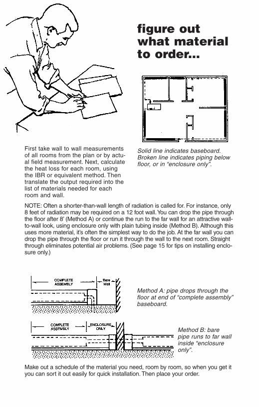
figure outwhat materialto order...
First take wall to wall measurementsof all rooms from the plan or by actu-al field measurement. Next, calculatethe heat loss for each room, usingthe IBR or equivalent method. Thentranslate the output required into thelist of materials needed for eachroom and wall.
NOTE: Often a shorter-than-wall length of radiation is called for. For instance, only8 feet of radiation may be required on a 12 foot wall.You can drop the pipe throughthe floor after 8’ (Method A) or continue the run to the far wall for an attractive wall-to-wall look, using enclosure only with plain tubing inside (Method B). Although thisuses more material, it’s often the simplest way to do the job. At the far wall you candrop the pipe through the floor or run it through the wall to the next room. Straightthrough eliminates potential air problems. (See page 15 for tips on installing enclo-sure only.)
Method A: pipe drops through thefloor at end of “complete assembly”baseboard.
Method B: bare pipe runs to far wallinside “enclosureonly”.
Make out a schedule of the material you need, room by room, so when you get ityou can sort it out easily for quick installation. Then place your order.
Solid line indicates baseboard.Broken line indicates piping belowfloor, or in “enclosure only”.

begin by drillingriser holes...The riser connects sub-floor supply tubing tothe baseboard. The diameter of the riser holeand the location of the hole with respect to the walls will vary depending on the type ofbaseboard you’re using. Here is a handy chart to follow:
Model
Diameter
Pipe Hole*
Back Wallto Center
(floor holes)
Floor to Center
(partition holes)
BL-50/751⁄2” or
3⁄4” 11⁄4” 13⁄8” 25⁄16”
15-501⁄2” 1” 121⁄64” 3”
15-753⁄4” 11⁄4” 121⁄64” 3”
30-753⁄4” 11⁄4” 13⁄8” 33⁄16”
81A3⁄4” 11⁄4” 13⁄4” 37⁄8”
83A23⁄4” 11⁄4” 19⁄16” 31⁄2”
84A3 1” 11⁄2” 19⁄16” 31⁄2”
85A/86AX 11⁄4” 13⁄4” 13⁄4” 37⁄8”
* Hole is 1/2” larger than pipe to allow for expansion. Install riser snug to inside edge of hole to allow maximum room for riser to move to outside edge of hole when pipe expands.
To make installation easy, lay out the cartonsof material and accessories along the wall inthe order in which they will be installed. Pre-planning should specify which combination ofbaseboard and accessories fits best.
distribute the cartons along the walls...
9

nail it up...The pre-assembled baseboard goes right from carton to wall with Slant/Fin’s“T-Shot” Nailing Tool (or power screw gun). You can load the Nailing Tool withany nail up to 5⁄16” round head. Just place the baseboard against the wall, andslip the Nailing Tool between the damper and front panel. Hit the drive rodwith the hammer and that’s it. Add another row of nails below the front panel.If you’re working without a “T-Shot” or screw gun, snap off the front panel bylifting it upward so the bottom bracket bends slightly upward, then pull towardyou with thumb.
1. for plaster walls...Locate the studs in the wall and mark location above baseboard, or on floor. It’s best to nail the baseboard at top and bottom to each stud.
2. for concrete or cinder block walls...Use masonry nails, or install a furring strip and nail into it.
3. for a particularly solid installation...Slide the bracket to the stud position and drive nail through the bracket holes and the back panel.
before you drive your nails...Make sure you leave enough room at the ends of the baseboard or other points where accessories will have to be installed later.
NOTE: To avoid scratching or cutting yourself, always handle baseboard with care.
solder the elements...
1. Clean and solder the adjoining element ends together using a non-corrosive flux, and connect elements to risers.
2. Immediately upon completion, flush system thoroughly. Left unflushed, flux can cause pitting in copper tubing of unfilled systems.
3. Fill system as soon as possible but prevent from freezing.4. Make sure cradles are centered over brackets to allow for smooth expansion
without scraping noises.

All piping expands when heated. In shorter runs, the movement of the risersin their holes will take care of expansion. But on longer runs, it’s wise toinstall an expansion compensator to prevent strains at the joints and bucklingof the elements. Install a Hydro/Tite at the center of a long run.
FLOW DIRECTION must be as shown, tokeep sludge from clogging the seals insidethe Hydro/Tite.
DON’T LOOSEN or tighten the knurled collar. Proper adjustment (set at factory) is hand-tight only.
PULL OPEN until red line just shows underthe knurled collar. Install in this extendedposition.
KEEP HEAT AWAY from the knurled collarand the coupling body, to avoid damage.Use soft solder only.
Provide forexpansion withHYDRO/TITEexpansion couplings on long straight runs.

replace front cover...BASELINE 2000, FINE/LINE 30 & MULTI/PAK 80Place lower edge underneath lower bracket.Lift slightly and press upper edge forward with thumb till panel snaps into place.
For a neat finish at partitions, use the walltrim (adjustable up to 31⁄2”). Air vents arerecommended at each drop; either walltrim or end caps (both hinged) provideeasy access to vent. These accessorieseliminate the wasteful need for cuttinglarge baseboard units to fit small gaps,and save you time and effort. Attractiveinside and outside corners assure a custom look.
snap on the accessories...WALL TRIMS, END CAPS, CORNERS
FINE/LINE 15Place top edge of front panel on bracketwith panel in “up” position, swing down.Important: to lock the panel to the brack-et, pull cover outward away from bracket,while swinging down. Push bottom ofpanel to engage lower bracket.
FILLER SLEEVE, SPLICE PLATES
The Filler Sleeve has 4 parts: back piece, damper sleever, top sleeve, front sleeve. The Splice Plate is exactly the same, but without a back piece.
12

FILLER SLEEVES (cont’d)1. When mounting the baseboard to the wall,
be sure the filler sleeve will overlap each baseboard unit by at least 1⁄2”.
2. Slip in the back piece so that the bent edge rests in the bottom channel of the baseboard. Nail the back piece to the wallto hold it in place.
3. Move both dampers to half-open position.Hold the damper sleeve with the crimped edge away from you. Hook it’s front edge over the front edges of the dampers. Snapthe back edge of the sleeve into place by pinching -- with thumb pressure on the baseboard top panel and finger pressure up under the back edge of the damper.
3A. (For Multi/Pak 80) Move both dampers tohalf open position.Hook the damper sleeve’s top edge over the top edge of the dampers. Press downon the sleeve and snap the bottom edgeinto place.
4. Hook the sharp angle of the top sleeve over the front edge of the baseboard’s toppanel. Press down on the back edge until the sleeve snaps into place.
5. Replace baseboard front covers. Hook thefront sleeve’s top edge over the front cov-ers and snap the bottom edge into place.
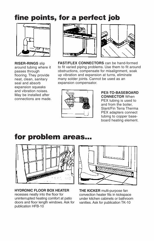
fine points, for a perfect job
RISER-RINGS sliparound tubing where itpasses through flooring. They provideneat, clean, sanitaryseal and absorb expansion squeaks and vibration noises.May be installed afterconnections are made.
FAST/FLEX CONNECTORS can be hand-formedto fit varied piping problems. Use them to fit aroundobstructions, compensate for misalignment, soakup vibration and expansion at turns, eliminate many solder joints. Cannot be used as an expansion compensator.
PEX-TO-BASEBOARDCONNECTOR WhenPEX tubing is used toand from the boiler,Slant/Fin Terra ThermaPEX adapters connecttubing to copper base-board heating element.
for problem areas...
HYDRONIC FLOOR BOX HEATERrecesses neatly into the floor for uninterrupted heating comfort at patiodoors and floor length windows. Ask forpublication HFB-10
THE KICKER multi-purpose fan convection heater fits in kickspaceunder kitchen cabinets or bathroomvanities. Ask for publication TK-10

fine points using enclosure only...Use Slant/Fin hanger to support the bare tubing at the same height as adjoin-ing heating elements. In-sert the short hook of thehanger as shown. Install from the left side, so thatthe large hook (which holds the tubing) faces therear panel.
when a normal loopcan’t be run...In some installations, it’s not possible to drop the return line below the floor. Inthis case, run the return tubing within the baseboard enclosure. Support withwire hanger which you can shorten to hold the tubing in the space between theheating element and bracket arm. For Base/Line 2000, a special cutout in thebracket arm accommodates return tubing. Use a Slant/Fin return bend to con-nect the heating element with the return line above it. This fitting has a conven-ient 1⁄8” IPS threaded opening to receive an air vent.
Note: If the baseboard isinstalled below the boilerlevel, as in many slabjobs, the return bend maybe installed with the ventopening pointed down-ward, and plugged. Thispermits easy drainage ifneeded.
replacing oldstanding radiators...A handy illustrated guide from Slant/Fin helpsyou figure how many feet of baseboard it takes toequal the heat output of most styles of standingcast-iron radiators. Ask for publication RC-40.
15

...wasn’t that easy?
®
America’s No. 1 brand ofbaseboard convection heating
SLANT/FIN CORPORATION, Greenvale, N.Y. 11548 • Phone: (516) 484-2600
©Slant/Fin Corp. 1994. Printed in USA 103. Publication No. BB-40
www.slantfin.com