
HIGH SPEED CNC MACHINING OF AISI 304 STAINLESS … · HIGH SPEED CNC MACHINING OF AISI 304...
13
9 HIGH SPEED CNC MACHINING OF AISI 304 STAINLESS STEEL; OPTIMIZATION OF PROCESS PARAMETERS V S Thangarasu 1 * and R Sivasubramanian 1 *Corresponding Author: V S Thangarasu, [email protected] This study highlights optimization of CNC high speed milling process parameters to provide better surface finish as well as high material removal rate. The surface finish and material removal rate have been identified as quality attributes and are assumed to be directly related to productivity. In order to build up a bridge between quality and productivity, and attempt made to optimize aforesaid quality attributes in small and medium size companies involved with heterogenic product demand. This invites a multi-objective optimization problem which has been solved by DOE based genetic algorithm optimization procedure. The response surface method of Box- Benkhen method has been adapted to get multi objective optimization problem. The methodology found to be useful in simultaneous optimization of more number of responses. Keywords: CNC milling, Optimization, Surface finish, DOE, ANOVA, Material removal rate, Box-benkhen method, Stainless steel INTRODUCTION High speed machining has become increasingly imminent for small and medium scale enterprises to stay in contention of the hectic competition and to get through the agile, lean and heavy demand patterns of today. The usage Alloy steels increasing day to day in fields of engineering especially the stainless steel materials for precision component industries, which demands high accuracy, high quality and frequently varying quantity ISSN 2278 – 0149 www.ijmerr.com Vol. 1, No. 3, October 2012 © 2012 IJMERR. All Rights Reserved Int. J. Mech. Eng. & Rob. Res. 2012 1 Department of Mechanical Engineering, Coimbatore Institute of Technology, Coimbatore 641014, India. requirements. In this paper Stainless steel AISI 304 material is taken for the study to determine the parameters and to optimize with Design Of Experiments (DOE) based Response Surface Method (RSM) to find the optimal parameter set as per the requirements of the user of the high speed CNC machine. Accordingly with the suggested technique the process planners can decide on the input parameters to attain the required quality of the product in time to meet the demand. The Research Paper
Transcript of HIGH SPEED CNC MACHINING OF AISI 304 STAINLESS … · HIGH SPEED CNC MACHINING OF AISI 304...

9
Int. J. Mech. Eng. & Rob. Res. 2012 V S Thangarasu and R Sivasubramanian, 2012
HIGH SPEED CNC MACHINING OF AISI 304STAINLESS STEEL; OPTIMIZATION OF PROCESS
PARAMETERS
V S Thangarasu1* and R Sivasubramanian1
*Corresponding Author: V S Thangarasu,[email protected]
This study highlights optimization of CNC high speed milling process parameters to providebetter surface finish as well as high material removal rate. The surface finish and materialremoval rate have been identified as quality attributes and are assumed to be directly related toproductivity. In order to build up a bridge between quality and productivity, and attempt made tooptimize aforesaid quality attributes in small and medium size companies involved withheterogenic product demand. This invites a multi-objective optimization problem which hasbeen solved by DOE based genetic algorithm optimization procedure. The response surfacemethod of Box- Benkhen method has been adapted to get multi objective optimization problem.The methodology found to be useful in simultaneous optimization of more number of responses.
Keywords: CNC milling, Optimization, Surface finish, DOE, ANOVA, Material removal rate,Box-benkhen method, Stainless steel
INTRODUCTIONHigh speed machining has becomeincreasingly imminent for small and mediumscale enterprises to stay in contention of thehectic competition and to get through the agile,lean and heavy demand patterns of today. Theusage Alloy steels increasing day to day infields of engineering especially the stainlesssteel materials for precision componentindustries, which demands high accuracy, highquality and frequently varying quantity
ISSN 2278 – 0149 www.ijmerr.comVol. 1, No. 3, October 2012
© 2012 IJMERR. All Rights Reserved
Int. J. Mech. Eng. & Rob. Res. 2012
1 Department of Mechanical Engineering, Coimbatore Institute of Technology, Coimbatore 641014, India.
requirements. In this paper Stainless steel AISI304 material is taken for the study to determinethe parameters and to optimize with DesignOf Experiments (DOE) based ResponseSurface Method (RSM) to find the optimalparameter set as per the requirements of theuser of the high speed CNC machine.Accordingly with the suggested technique theprocess planners can decide on the inputparameters to attain the required quality of theproduct in time to meet the demand. The
Research Paper

10
Int. J. Mech. Eng. & Rob. Res. 2012 V S Thangarasu and R Sivasubramanian, 2012
proposed method is found to be most usefulfor job order type production houses deals withprecision components. The study and theresults of the experimentation showsimprovements in machining input parameterslike Speed of the spindle, feed rate, Depth ofcut with 12 mm flat bull and ball end millingcutters. The components are with betteraccuracy and faster production rate withoptimal input parameters which minimizes themachining time, while improving the accuracy(Ra) and Material Removal Rate (MRR).
LITERATURE SURVEYMike et al. (1999), have developed a surfaceroughness prediction method using regressionanalysis for CNC end Milling is the first of itskind in development of the importance ofprecision machining and surface roughness(Mike et al., 1999). The real frame work wasdeveloped by the study conducted by Yih-Fongand Fu Chen (2005) on two phased parameteroptimization for better accuracy by Taguchi’srobust design method, which prompted the twophase analysis technique with Taguchi’s DOEand simultaneous optimization procedure togive away the various parameters on surfaceroughness requirements followed by a casestudy. The study conducted for turning processwith cutting force modeling with tool wear rateby dynamic signal reading procedure wasdeveloped, though it is a significantdevelopment but failed to recognize the otherimportant factors of real time process. Abeleand Frolich (2008) have compiled the casestudy of high speed milling of titanium alloyshave provided base for different metallurgicaland machining conditions to be taken intoaccount for the study. The case studyconducted for the titanium based alloys were
conducted for the high speed milling processfor sets of input parameters with moderatecutting speeds and feed rate to get bettermaterial removal of aircraft materials. The rapidintroduction of the computational intelligencein product data engineering was insisted forcomputerized solutions for optimality of theCNC environment. Expressions for entry andexit angles and limiting combinations of feedrate, spindle speed, and tool radius for chipformation are also studied to improve cuttingconditions in milling. Kaladhar et al. (2010)developed the optimized parameters of turningprocess of AISI 202 Austenitic stainless steelby Taguchi’s DOE model with constraints asthe material cutting conditions and parameterswere optimized with the study ended up atmiddle point strategy of operator, but providedwide knowledge of the stainless steel 202 andoperating conditions to be taken in toconsideration. Aman and Hari (2005) reviewedvarious linear and non linear optimizationtechniques were studied in detail and relativeadvantages are also discussed and inferredfor the non linear optimization methods are themost suited for the optimization of machiningprocesses. Study on optimization of CNCmilling process parameters using PCA basedTaguchi method by Sanjit et al. (2010) hadserved the purposes of optimization but notsimultaneously optimize the surface roughnessand the material removal rate. The studyinstead used cumulative method toapproximate the effect of the parameters toreduce it into single objective problem.Abdullah et al. (2006) had conducted theoptimization experiments in stainless steelmilling but addressed the improvement ofSurface roughness for the conventional CNCmachine. The paper by Palanisamy et al.
11
Int. J. Mech. Eng. & Rob. Res. 2012 V S Thangarasu and R Sivasubramanian, 2012
(2007) had established cutting parameters arethe most valuable in terms of providing highprecision and efficient machining and theoptimization of parameters for milling isimportant to minimize the machining time andcutting force, increase productivity and tool lifeand obtain better surface finish.
The work is to provide a comprehensivesolution to the optimal output of the lowestaverage surface roughness with optimally highrate of material removal for the finish operationof the stainless steel with the best of the highspeed machining operation (Zolfaghariy andLiang, 2002; Yih-Fong and Fu Chen, 2005; andSanjit et al., 2010). The literatures havegenerally discussed the factors andparameters with single objective and the samehave given us the base idea of the variousfactors involved and the parameters to bestudied with this case study. Theimprovements and strides of the earlierresearchers are taken as benchmark for thestart up of the work, and one of the relevantareas of improvement at simultaneousoptimization of the parameters is studied inthis paper. The need for optimized parameterset for best roughness measures withimproved metal removal rate by controlling therelevant parameters. This study excludes andfixes less influencing tool wear, coolingmethod, Cutting force, tool geometry and toolmetallurgy and many other factors as they werediscussed in detail by the researchers and gotoptimized earlier, hence the contributions bythe researchers are considered as best suitedand kept as constant and referred as leastinfluencing factors for the simultaneousoptimization. The contribution of researcherson the factors and parameters considered in
this study taken based on the bench markstudies. The chemical composition of themachined work piece material is shown
Chemical composition (wt. %) of AISI 304
Element C- Si- Mn- Cr-wt % 0.02- 0.32- 1.31- 16.38-
Mo- P- S- Ni
2.03- 0.30- 0.20- 12.17
PROBLEM DESCRIPTIONAfter the detailed study of the literature and aon the job study conducted at advancedmanufacturing Technology laboratory ofCoimbatore Institute of Technology,Coimbatore, and SME grade companies of 3PPM level of quality assurance to their clientsof Japan and Germany, when considering withsurface roughness deviations, are Sri GowrishCNC (P) Ltd., Sri Parthasarathi CNC (P)Limited, Genuine CNC consultants,Chinnavedampatti, Ganapathi, COINDIA toolroom at Coimbatore 641006, South India. TheCNC based job order companies involved inprecision components manufacturing toequipment manufacturers of Japan andGermany and to the local market inside India.The study reveals the surface roughness is themost important requirement along withgeometrical and dimensional qualities with itstolerance levels. The choice of High speedCNC manufacturing process is based on cost,productivity and quality requirements to attainbest possible surface quality within the givenconstraints for precision components. Theindicator of surface quality on machined partsis the value of surface roughness or thewaviness. The surface roughness is mainly aresult of various controllable or uncontrollable

12
Int. J. Mech. Eng. & Rob. Res. 2012 V S Thangarasu and R Sivasubramanian, 2012
process parameters (Figure 1) and it is harderto attain and track than physical dimensions.A considerable number of studies haveresearched the effects of the cutting speed,feed, depth of cut, nose radius and otherfactors on the surface roughness (Zolfaghariyand Liang, 2002). In recent studies, the effectsof some factors on surface roughness havebeen evaluated and models are developed butfailed to address the requirements of the endoperator, who decides on the input parametersand ground realities. The goal of this study isto obtain a mathematical model that relatesthe surface roughness to three cuttingparameters in face milling, precisely to thecutting speed, feed rate and depth of cut. Inthis work DOE based approach is used toget the mathematical model and Box Behnken
model analysis used for the optimizedparameter set. Case study method isadopted for parameter study and Design OfExperiment (DOE) with analysis andRegression Analysis (RA).
Surface Roughness
The surface parameter used to evaluatesurface roughness in this study is theroughness average (Ra). The roughnessaverage is the area between the roughnessprofile and its central line, or the integral of theabsolute value of the roughness profile heightover the evaluation length. There are a largenumber of factors influencing the surfaceroughness and Figure 2 shows all influentialfactors on machined surface roughness (Lin,2002). The roughness component of surface
Figure 1: Fish Bone Diagram for Surface Roughness Parameters

13
Int. J. Mech. Eng. & Rob. Res. 2012 V S Thangarasu and R Sivasubramanian, 2012
is generally quantified by the parameterroughness average (Ra), is an effectiveparameter representing the quality ofmachined surface. Ra is the area between theroughness profile and its mean line, or theintegral of the absolute profile height over theevaluation length as shown in Figure 2.
Therefore, the Ra is specified by thisequation:
L
dxxYL
Ra0
1...(1)
Material Removal Rate
From this equation, Ra is the arithmeticaverage deviation from the mean line, L isthe sampling length, and Y is the ordinate ofthe profile curve. Material Removal Rate(MRR) has been calculated from thedifference of weight of work piece before andafter the experiment (Yih-Fong and Fu Chen,2005).
MRR = Wi – W
f/r
st ...(2)
Wi – The initial weight of the work piece in
grams;
Wf – Final weight of the work piece in
grams;
rs – Density of the material in grams/mm3;
t – Time taken for machining (cutting).
The theoretical calculation of materialremoval done to verify the values obtainedfrom volumetric measurements.
CuttingtheforSecondsofNoTotal
onCutofLengthCutterofDiaFDMRR rc
.
...(3)
Tangential force component for the cuttingoperation is given by
Ft = Ks D
cfr sin + D
c Edge Force
Constant Flank Wear Width ...(4)
Axial force component for the cuttingoperation is given by
Figure 2: Surface Roughness Profile
Z
Cutoff Length
Roughness Center Line
H
L
Y
Y: Profile Curve
X: Profile Direction
Z: Average Roughness Height
L: Sampling Length
H: Profile Height
X
14
Int. J. Mech. Eng. & Rob. Res. 2012 V S Thangarasu and R Sivasubramanian, 2012
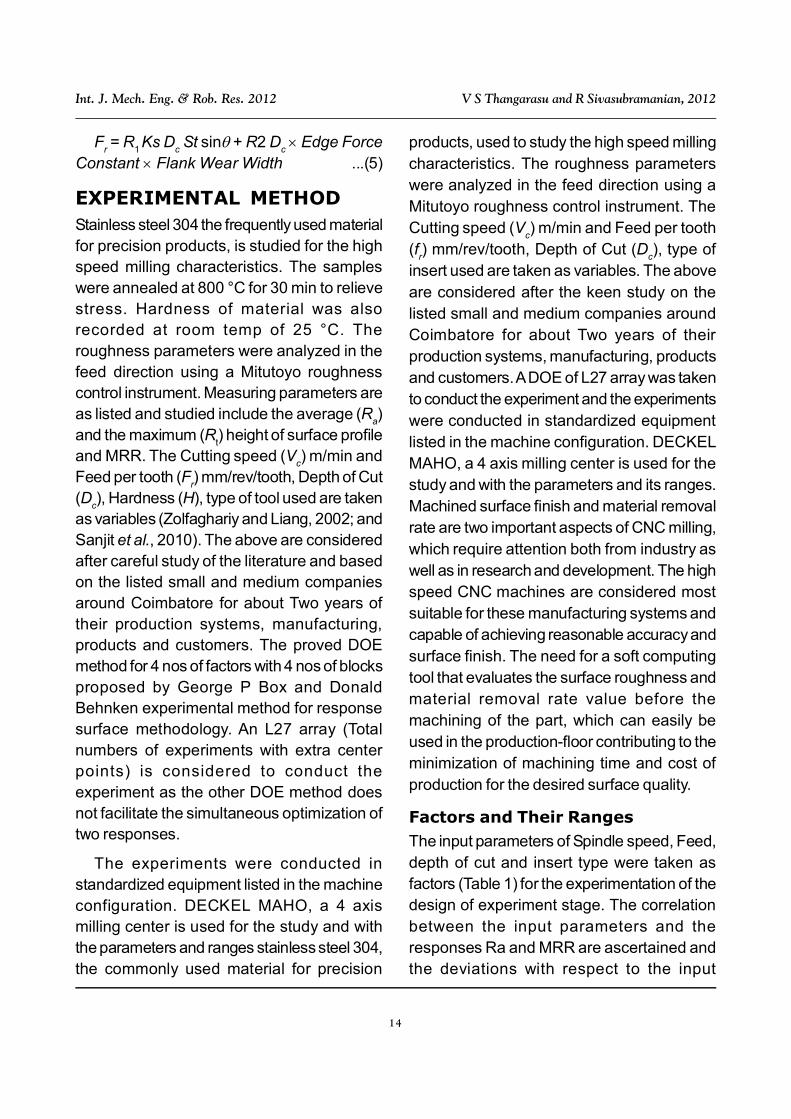
Fr = R
1 Ks D
cSt sin + R2 D
c Edge Force
Constant Flank Wear Width ...(5)
EXPERIMENTAL METHODStainless steel 304 the frequently used materialfor precision products, is studied for the highspeed milling characteristics. The sampleswere annealed at 800 °C for 30 min to relievestress. Hardness of material was alsorecorded at room temp of 25 °C. Theroughness parameters were analyzed in thefeed direction using a Mitutoyo roughnesscontrol instrument. Measuring parameters areas listed and studied include the average (R
a)
and the maximum (Rt) height of surface profile
and MRR. The Cutting speed (Vc) m/min and
Feed per tooth (Fr) mm/rev/tooth, Depth of Cut
(Dc), Hardness (H), type of tool used are taken
as variables (Zolfaghariy and Liang, 2002; andSanjit et al., 2010). The above are consideredafter careful study of the literature and basedon the listed small and medium companiesaround Coimbatore for about Two years oftheir production systems, manufacturing,products and customers. The proved DOEmethod for 4 nos of factors with 4 nos of blocksproposed by George P Box and DonaldBehnken experimental method for responsesurface methodology. An L27 array (Totalnumbers of experiments with extra centerpoints) is considered to conduct theexperiment as the other DOE method doesnot facilitate the simultaneous optimization oftwo responses.
The experiments were conducted instandardized equipment listed in the machineconfiguration. DECKEL MAHO, a 4 axismilling center is used for the study and withthe parameters and ranges stainless steel 304,the commonly used material for precision
products, used to study the high speed millingcharacteristics. The roughness parameterswere analyzed in the feed direction using aMitutoyo roughness control instrument. TheCutting speed (V
c) m/min and Feed per tooth
(fr) mm/rev/tooth, Depth of Cut (D
c), type of
insert used are taken as variables. The aboveare considered after the keen study on thelisted small and medium companies aroundCoimbatore for about Two years of theirproduction systems, manufacturing, productsand customers. A DOE of L27 array was takento conduct the experiment and the experimentswere conducted in standardized equipmentlisted in the machine configuration. DECKELMAHO, a 4 axis milling center is used for thestudy and with the parameters and its ranges.Machined surface finish and material removalrate are two important aspects of CNC milling,which require attention both from industry aswell as in research and development. The highspeed CNC machines are considered mostsuitable for these manufacturing systems andcapable of achieving reasonable accuracy andsurface finish. The need for a soft computingtool that evaluates the surface roughness andmaterial removal rate value before themachining of the part, which can easily beused in the production-floor contributing to theminimization of machining time and cost ofproduction for the desired surface quality.
Factors and Their RangesThe input parameters of Spindle speed, Feed,depth of cut and insert type were taken asfactors (Table 1) for the experimentation of thedesign of experiment stage. The correlationbetween the input parameters and theresponses Ra and MRR are ascertained andthe deviations with respect to the input
15
Int. J. Mech. Eng. & Rob. Res. 2012 V S Thangarasu and R Sivasubramanian, 2012
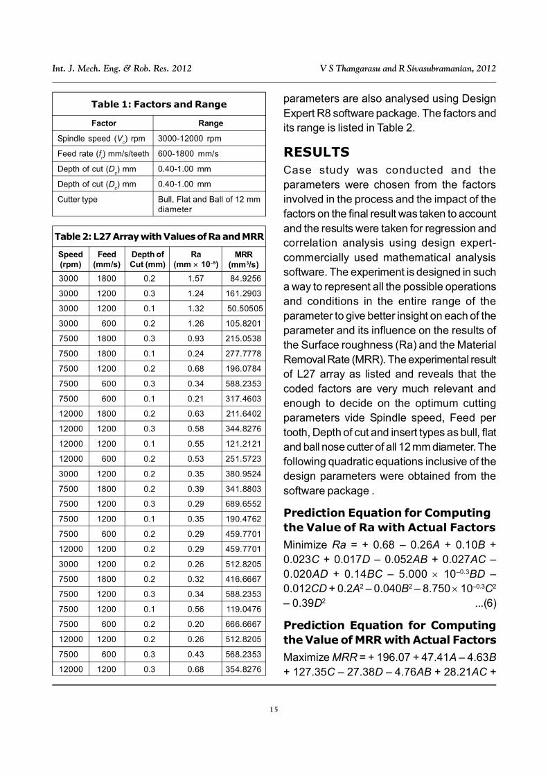
parameters are also analysed using DesignExpert R8 software package. The factors andits range is listed in Table 2.
RESULTSCase study was conducted and theparameters were chosen from the factorsinvolved in the process and the impact of thefactors on the final result was taken to accountand the results were taken for regression andcorrelation analysis using design expert-commercially used mathematical analysissoftware. The experiment is designed in sucha way to represent all the possible operationsand conditions in the entire range of theparameter to give better insight on each of theparameter and its influence on the results ofthe Surface roughness (Ra) and the MaterialRemoval Rate (MRR). The experimental resultof L27 array as listed and reveals that thecoded factors are very much relevant andenough to decide on the optimum cuttingparameters vide Spindle speed, Feed pertooth, Depth of cut and insert types as bull, flatand ball nose cutter of all 12 mm diameter. Thefollowing quadratic equations inclusive of thedesign parameters were obtained from thesoftware package .
Prediction Equation for Computingthe Value of Ra with Actual Factors
Minimize Ra = + 0.68 – 0.26A + 0.10B +0.023C + 0.017D – 0.052AB + 0.027AC –0.020AD + 0.14BC – 5.000 10–0.3BD –0.012CD + 0.2A2 – 0.040B2 – 8.750 10–0.3C2
– 0.39D2 ...(6)
Prediction Equation for Computingthe Value of MRR with Actual Factors
Maximize MRR = + 196.07 + 47.41A – 4.63B+ 127.35C – 27.38D – 4.76AB + 28.21AC +
Factor Range
Spindle speed (Vc) rpm 3000-12000 rpm
Feed rate (fr) mm/s/teeth 600-1800 mm/s
Depth of cut (Dc) mm 0.40-1.00 mm
Depth of cut (Dc) mm 0.40-1.00 mm
Cutter type Bull, Flat and Ball of 12 mmdiameter
Table 1: Factors and Range
3000 1800 0.2 1.57 84.9256
3000 1200 0.3 1.24 161.2903
3000 1200 0.1 1.32 50.50505
3000 600 0.2 1.26 105.8201
7500 1800 0.3 0.93 215.0538
7500 1800 0.1 0.24 277.7778
7500 1200 0.2 0.68 196.0784
7500 600 0.3 0.34 588.2353
7500 600 0.1 0.21 317.4603
12000 1800 0.2 0.63 211.6402
12000 1200 0.3 0.58 344.8276
12000 1200 0.1 0.55 121.2121
12000 600 0.2 0.53 251.5723
3000 1200 0.2 0.35 380.9524
7500 1800 0.2 0.39 341.8803
7500 1200 0.3 0.29 689.6552
7500 1200 0.1 0.35 190.4762
7500 600 0.2 0.29 459.7701
12000 1200 0.2 0.29 459.7701
3000 1200 0.2 0.26 512.8205
7500 1800 0.2 0.32 416.6667
7500 1200 0.3 0.34 588.2353
7500 1200 0.1 0.56 119.0476
7500 600 0.2 0.20 666.6667
12000 1200 0.2 0.26 512.8205
7500 600 0.3 0.43 568.2353
12000 1200 0.3 0.68 354.8276
Table 2: L27 Array with Values of Ra and MRR
Speed(rpm)
Feed(mm/s)
Depth ofCut (mm)
Ra(mm 10–5)
MRR(mm3/s)

16
Int. J. Mech. Eng. & Rob. Res. 2012 V S Thangarasu and R Sivasubramanian, 2012
28.86AD – 69.88BC + 33.03BD + 25.36CD– 36.80A2 + 66.94B2 + 23.80C2 + 221.84D2
...(7)
When the parameters obtained areoptimum and can be treated as the desiredset. The surface roughness and Materialremoval rate are completely controlled by theabove factors and by keeping the Spindlespeed as high, moderate feed rate and abovemoderate value of depth of cut for bull and flattype cutters of 12 mm diameter is suggestedfor the stainless steel material of AISI 304grade. This is because all surface roughnesscharacteristics follow Lower-the-Better criteriaat the same time the objective is to improvesurface finish. In this computation it has beenassumed that all quality features are equallyimportant (same priority weightage).
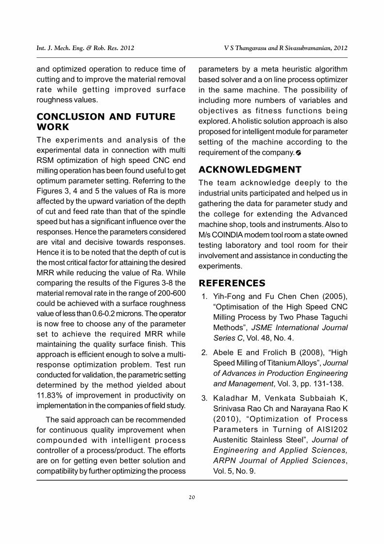
DISCUSSIONThe input values are also listed and the MRRvalues were computed to find the maximum
Figure 3: Ra vs. Depth of Cut, Feed Rate
1.0
0.8
0.6
0.2
0.4
0.30
600.00900.00
1500.001200.00
1800.00
0.25
0.20
0.150.10
Su
rfa
ce
Ro
ug
hn
es
samong the listed values. The list of inputs andthe responses were analyzed using the graphsshown below. The enlisted values gives us thesets of operating parameters for the optimumsurface finish for the precision machining ofthe AISI 304 stainless steel material. Thismethod is giving the best set of parametersby which the end user, i.e. The small andmedium scale companies involved with joborder type production of precision parts.
The Figures 3, 4 and 5 shows the valuesof Ra and MRR are mainly dependent of theinput parameters and relatively has thecomplexity of suggesting a particular factoris more dominating. The general idea that canbe derived is that the input parameters areequally vital and has a cumulative effect onthe responses. Thus it is to be noted thedomain space of the feasible solution is wideranged inside the confirmed domainsurrounded by the parameter ranges. Theplanner has to decide based on the above

17
Int. J. Mech. Eng. & Rob. Res. 2012 V S Thangarasu and R Sivasubramanian, 2012
Figure 4: Ra vs. Depth of Cut, Speed
1.4
1.2
1.0
0.4
0.8
0.30
3000.00
11100.00
8400.00
12000.00
0.25
0.20
0.15
0.10
Su
rfa
ce
Ro
ug
hn
es
s
10200.009300.00
7500.006600.00
5700.004800.00
3900.00
0.6
Figure 5: Ra vs. Feed, Speed
1.6
1.4
1.2
0.4
0.8
1800.00
3000.00
11100.00
8400.00
12000.00
1500.00
1200.00
900.00
600.00
Su
rfa
ce
Ro
ug
hn
es
s
10200.009300.00
7500.006600.00
5700.004800.00
3900.00
0.6
1.0

18
Int. J. Mech. Eng. & Rob. Res. 2012 V S Thangarasu and R Sivasubramanian, 2012
graph that the required level of Ra say 20-40
micron finish, it is recommended to choosehigher depth of cut(D
c) say 0.9 -0.95 Max
value of the cutting tool manufacturerspecified parameter range instead of the midvalue to get the best values of MRR, where
the Speed of the spindle and feed rate may
also be taken more than the mid value to get
the desired levels of Ra and MRR.
The Figures 6 and 7 shown in clearly
indicates the variation of Ra with respect to the
Figure 7: MRR vs. Depth of Cut, Speed
400
300
200
0
0.30
3000.00
11100.00
8400.00
12000.00
0.25
0.20
0.150.10
MR
R
10200.009300.00
7500.006600.00
5700.004800.00
3900.00
100
Figure 6: MRR vs. Depth of Cut, Feed
600
500
300
0
200
0.30
600.00900.00
1500.001200.00
1800.00
0.250.20
0.150.10
MR
R
400
100

19
Int. J. Mech. Eng. & Rob. Res. 2012 V S Thangarasu and R Sivasubramanian, 2012
Figure 8: MRR vs. Feed, Speed
400
300
200
0
1800.00
3000.00
11100.00
8400.00
12000.00
1500.00
1200.00
900.00
600.00
MR
R
10200.009300.00
7500.006600.00
5700.004800.00
3900.00
100
input parameters in the 3 dimentinal mode toaccommodate comparison of more than onefactor at a time and draws a conclusive nonmid point optimum for the different inputparameter. Thus it could be inferred such thatthe mid point strategy of these SME’s can bereplaced with our methods of deciding theoptimum parameter values to improve theirperformance without affecting the quality, i.e.,surface roughness requirements.
Similarly from the 3 dimentional graphicalillustrations the broadly used mid pointselection of the input parameters were provednon optimum but generally serves the purposeby increased spending of time and effort. Thusthe mid point strategy of choosing the inputparameters and thump rule based selectionprocedure can be restructed with scientificallyproved and easy method provided by this
study. The higher the depth of cut (0.28 mm)and feed rate (1360 mm/s) would yield bettermaterial removal rate with relatively goodsurface roughness values using a spindlespeed (12280 rpm) more than the mid value,which improves productivity.
The multi objective simultaneousoptimization methodology yielded the resultswith Min of Ra 0.0167 mm or 16.7 microns atmaterial removal rate of 272 mm3/s. Tovalidate the results the machining operationis carried out to confirm the results for theinput parametric values of Spindle speed12280 rpm, Feed rate of 1290 mm/s, with0.29 mm of depth of cut for the bull type cutterperformed and found with a variation of 3.16%from the predicted values according to thegiven input. The results were encouraging andfound useful in performance improvement
20
Int. J. Mech. Eng. & Rob. Res. 2012 V S Thangarasu and R Sivasubramanian, 2012
and optimized operation to reduce time ofcutting and to improve the material removalrate while getting improved surfaceroughness values.
CONCLUSION AND FUTUREWORKThe experiments and analysis of theexperimental data in connection with multiRSM optimization of high speed CNC endmilling operation has been found useful to getoptimum parameter setting. Referring to theFigures 3, 4 and 5 the values of Ra is moreaffected by the upward variation of the depthof cut and feed rate than that of the spindlespeed but has a significant influence over theresponses. Hence the parameters consideredare vital and decisive towards responses.Hence it is to be noted that the depth of cut isthe most critical factor for attaining the desiredMRR while reducing the value of Ra. Whilecomparing the results of the Figures 3-8 thematerial removal rate in the range of 200-600could be achieved with a surface roughnessvalue of less than 0.6-0.2 microns. The operatoris now free to choose any of the parameterset to achieve the required MRR whilemaintaining the quality surface finish. Thisapproach is efficient enough to solve a multi-response optimization problem. Test runconducted for validation, the parametric settingdetermined by the method yielded about11.83% of improvement in productivity onimplementation in the companies of field study.
The said approach can be recommendedfor continuous quality improvement whencompounded with intell igent processcontroller of a process/product. The effortsare on for getting even better solution andcompatibility by further optimizing the process
parameters by a meta heuristic algorithmbased solver and a on line process optimizerin the same machine. The possibility ofincluding more numbers of variables andobjectives as fitness functions beingexplored. A holistic solution approach is alsoproposed for intelligent module for parametersetting of the machine according to therequirement of the company.
ACKNOWLEDGMENTThe team acknowledge deeply to theindustrial units participated and helped us ingathering the data for parameter study andthe college for extending the Advancedmachine shop, tools and instruments. Also toM/s COINDIA modern tool room a state ownedtesting laboratory and tool room for theirinvolvement and assistance in conducting theexperiments.
REFERENCES1. Yih-Fong and Fu Chen Chen (2005),
“Optimisation of the High Speed CNCMilling Process by Two Phase TaguchiMethods”, JSME International JournalSeries C, Vol. 48, No. 4.
2. Abele E and Frolich B (2008), “HighSpeed Milling of Titanium Alloys”, Journalof Advances in Production Engineeringand Management, Vol. 3, pp. 131-138.
3. Kaladhar M, Venkata Subbaiah K,Srinivasa Rao Ch and Narayana Rao K(2010), “Optimization of ProcessParameters in Turning of AISI202Austenitic Stainless Steel”, Journal ofEngineering and Applied Sciences,ARPN Journal of Applied Sciences,Vol. 5, No. 9.

21
Int. J. Mech. Eng. & Rob. Res. 2012 V S Thangarasu and R Sivasubramanian, 2012
4. Aman Aggarwal and Hari Singh(December 2005), “Optimization ofMachining Techniques—A Retrospectiveand Literature Review Optimization onMachining Techniques”, Vol. 30, Part 6,pp. 699-711.
5. Sanjit Moshat, Saurav Data, AshishBandopaddhayay and Pradip Kumar Pal(2010), “Optimisation of CNC MillingProcess Parameters Using PCA BasedTaguchi Method”, International Journal ofEngineering, Science and Technology,Vol. 2, No. 1, pp. 92-102.
6. Sai K and Bouzid W (2005), “RoughnessModeling in Up-Face Milling”,International Journal of AdvancedManufacturing Technology, Vol. 26,No. 4, pp. 324-329.
7. Lin T-R (2002), “Optimisation Techniquefor Face Milling Stainless Steel withMultiple Performance Characteristics”,International Journal of AdvancedManufacturing Technology, Vol. 19,pp. 330-335, Springer-Verlag.
8. Abdullah Konak et al. (2006), “Multi-Objective Optimization Using GeneticAlgorithms: A Tutorial”, Reliability
Engineering and System Safety, Vol. 91,pp. 992-1007.
9. Mike S Lou, Joseph C and Chen CalebM (1999), “Surface Roughness PredictionTechnique for CNC End Milling”, Journalof Industrial Technology, Vol. 15.
10. Palanisamy P, Rajendran I andShanmugasundaram S (2007),“Optimization of Machining ParametersUsing Genetic Algorithm andExperimental Validation for End-MillingOperations”, International Journal ofAdvanced Manufacturing Technology,Vol. 32, pp. 644-655.
11. Zolfaghariy S and Liang M (2002)“Comparative Study of Simulated Annealing,Genetic Algorithms and Tabu Search forSolving Binary and ComprehensiveMachine-Grouping Problems”, InternationalJournal of Production Research, Vol. 40,No. 9, pp. 2141-2158.
12. Lin T-R (2002), “Optimisation Techniquefor Face Milling Stainless Steel withMultiple Performance Characteristics”,International Journal of AdvancedManufacturing Technology, Vol. 19,pp. 330-335, Springer-Verlag.


