Catalog 8080/USA High Speed Automation Linear Modules HLE ...

www.parkermotion.com Parker Hannifin CorporationElectromechanical Automation Division
Irwin, Pennsylvania
High Speed Automation
• palletizing • storage and retrieval
• machine loading • parts transfer
• material handling • automated assembly
Gantry Robot Systems and LinearModulesFor high speed automation, both gantry andarticulated arm robots are widely usedthroughout industry. Because of the manyinherent advantages of the gantry robot,it is rapidly becoming the preferred choice for:
Parker offers seven standard gantry configura-tions to solve these and other automation ap-plications. Utilization of these pre-engineeredsystems enables the user to redirect scarceengineering resources from motion system de-sign to machine or process functionality. HPLA and HLE Linear Drive Modules arethe primary building blocks for Parker’s sevenstandard gantry systems. With six differentcross sectional sizes (60, 80, 100, 120,150,and 180 mm) and three bearing systems(polyamide or steel rollers, and square railbearings), these modules can effectively, effi-ciently and economically satisfy the widestrange of application requirements.
Parker minimizes your engineering effort with• Pre-engineered multi-axis systems• Drawings, documentation, and sizing
Parker is your source for unlimitedsystem solutions
• Unrivaled breadth of product• Proven design and reliability• Optimized mechanics and electronic controls
Parker is your assurance of short,reliable lead times
Parker systems are supported by theglobal Parker network 1-800-C-PARKER
Gantry Robot CD available atwww.parkermotion.com
• Sizing• Software• CAD Files (Parametric Tools)• Product Manuals• Photos/Applications Library• Movie Gallery
Parker Gantry Robot Features
D1
zla04

High Precision
www.parkermotion.com Parker Hannifin CorporationElectromechanical Automation Division
Irwin, Pennsylvania

www.parkermotion.com Parker Hannifin CorporationElectromechanical Automation Division
Irwin, Pennsylvania
High Speed AutomationCatalog 8092/USAGantry Systems
Servo Motor SystemBrushless servo motorsystem allows closed loopreliability and high dynamicperformance.
Fully adjustable mechanicalor proximity sensors provideover-travel protection.
HPLA or HLE Linear DriveModule
Structural FrameSteel or aluminum supportstructures are utilized toprovide the strength andrigidity needed for high-speed applications.
Home Position SensorFully adjustable mechanicalor proximity sensors provideaccurate and repeatablehoming.
Cable ManagementSystem
Proven high-speed, beltdriven linear modules are thecore motion components ofthe gantry system.
Gear ReducersPrecision planetary gearheads(in-line and right-angle)accurately transfer motionfrom the motors and reducereflected inertia.
Vertical DriveModulesDesigned specifically tosatisfy thrust, side, andmoment load requirementswhile providing reliablevertical motion.
Gantry Robot Elements
Standardized cable carrierswith high flex cables ensuresystem reliability
Travel Limit Sensors
D3

www.parkermotion.com Parker Hannifin CorporationElectromechanical Automation Division
Irwin, Pennsylvania
High Speed Automation
Parker’s seven standard system configurations are designed to satisfy the vast majority ofgantry robot applications. By standardizing on these configurations, Parker has simplified sizingand selection, shortened lead times, and reduced costs for users of these systems. Thetravels and loads indicated are nominal, and should not be considered limiting factors. Longertravels and increased loads are attainable depending upon the combination of parameters.
System OneTwo Axis: XX’ - Y
System TwoTwo Axis: XX’ - YY’
System ThreeTwo Axis: XX’ - Z
System FourTwo Axis: XX’ - Z
System FiveTwo Axis: XX’ - Z
System SixThree Axis: XX’ - YY’ - Z
System SevenThree Axis: XX’ - YY’ - Z
Catalog 8092/USAGantry Systems
Gantry Robot Configurations
D4

www.parkermotion.com Parker Hannifin CorporationElectromechanical Automation Division
Irwin, Pennsylvania
High Speed Automation
System One provides two axes of horizontal motion. Theprimary axis (X) is comprised of two HPLA or HLE LinearModules linked by a common drive shaft, and the secondaryaxis (Y) is comprised of one HPLA or HLE Linear Module. Theselinear modules are capable of high speeds and accelerationsover long travels. This system is designed for rapid transport oflight to moderate loads in a singlehorizontal plane.
SeriesNo.
X-Axis Y-Axis Z-Axis (kg) X-Axis(meters)
Y-Axis(meters)
Z-Axis(meters)
X-Axis(m/sec.)
Y-Axis(m/sec.)
Z-Axis(m/sec.)
Axis Model Number Load Travel Velocity
1 HLE60RB HLE60RB — 15 2.9 1.3 — 2.0 2.0 —
2 HLE60SR HLE60SR — 25 2.8 1.3 — 2.0 2.0 —
3 HPLA080 HPLA080 — 30 5.4 2.0 — 2.0 3.0 —
4 HLE100RB HLE100RB — 35 6.0 2.0 — 2.0 3.0 —
5 HLE100SR HLE100SR — 75 6.0 2.0 — 2.0 3.0 —
6 HPLA120 HPLA120 — 85 9.3 3.0 — 2.0 3.0 —
7 HLE150RB HLE150RB — 100 7.9 3.0 — 2.0 3.0 —
1
2
3
45
6
7
8
10
1 Support Structure Available (steel or aluminum framing)
2 X-Axis Drive Rail Assembly
3 X-Axis Driven Rail Assembly
4 X-Axis Link Shaft Assembly
5 X-Axis Cable Carrier
6 X-Axis Drive Motor
7 Y-Axis Drive Rail Assembly
Note: Loads, travels, and velocities shown are interdependent. Increased values are attainable.
9
System One
Catalog 8092/USAHLE Gantry Systems
X
YZ
D5
8 Y-Axis Cable Carrier
9 Y-Axis Drive Motor
10 Pillow Block Bearing & Support (Based on Application)

www.parkermotion.com Parker Hannifin CorporationElectromechanical Automation Division
Irwin, Pennsylvania
High Speed Automation
BETWEEN BUMPERS =X-AXIS TRAVEL + "B" DIM.
1/2 TRAVEL
OVERALL =Y-AXIS TRAVEL + "H" DIM.
OVERALL =X-AXIS TRAVEL + "C" DIM.
BETWEEN CENTERSY-AXIS TRAVEL + "E" DIM.
BETWEEN BUMPERS =Y-AXIS TRAVEL + "G" DIM.
"F" DIM.
1/2 TRAVEL
"A" DIM.
1/2 TRAVEL 1/2 TRAVEL
System One (XX’-Y)Series
No. “A” Dim.mm (in)
“B” Dim.mm (in)
“C” Dim.mm (in)
“E” Dim.mm (in)
“F” Dim.mm (in)
“G” Dim.mm (in)
“H” Dim.mm (in)
1
2
3
4
5
6
System One Dimensions
Catalog 8092/USAHLE Gantry Systems
254.0 (10.00) 504.0 (19.84) 730.0 (28.74) 406.2 (15.99) 152.4 (6.00) 402.4 (15.84) 628.4 (24.74)
254.0 (10.00) 504.0 (19.84) 720.0 (28.35) 380.2 (14.97) 152.4 (6.00) 402.4 (15.84) 618.0 (24.33)
400.0 (15.75) 650.0 (25.59) 1012.0 (39.84) 530.0 (20.87) 250.0 (9.84) 500.0 (19.69) 862.0 (33.94)
450.0 (17.72) 700.0 (27.56) 1090.0 (42.91) 588.0 (23.15) 300.0 (11.81) 550.0 (21.65) 940.0 (37.01)
450.0 (17.72) 700.0 (27.56) 1141.0 (44.92) 605.0 (23.82) 300.0 (11.81) 550.0 (21.65) 991.0 (39.02)
500.0 (19.69) 750.0 (29.53) 1205.0 (47.44) 560.0 (22.05) 300.0 (11.81) 550.0 (21.65) 1005.0 (39.57)
7 500.0 (19.69) 750.0 (29.53) 1220.0 (48.03) 612.0 (24.09) 350.0 (13.78) 600.0 (23.62) 1070.0 (42.13)
D6

www.parkermotion.com Parker Hannifin CorporationElectromechanical Automation Division
Irwin, Pennsylvania
High Speed Automation
1 Support Structure Available (steel or aluminum framing)
2 X-Axis Drive Rail Assembly
3 X-Axis Driven Rail Assembly
4 X-Axis Link Shaft Assembly
5 X-Axis Cable Carrier
6 X-Axis Drive Motor
7 Clamping Profile
8 Y-Axis Drive Rail Assembly
9 Y-Axis Idler Rail Assembly
10 Y-Axis Cable Carrier
11 Y-Axis Drive Motor
12 Pillow Block Bearing & Support (Based on Application)
SeriesNo. X-Axis Y-Axis Z-Axis (kg)
X-Axis(meters)
Y-Axis(meters)
Z-Axis(meters)
X-Axis(m/sec.)
Y-Axis(m/sec.)
Z-Axis(m/sec.)
Axis Model Number Load Travel Velocity
1 HLE60RB HLE60RB — 30 2.9 1.3 — 1.0 2.0 —
2 HLE60SR HLE60SR — 50 2.8 1.3 — 1.0 2.0 —
3 HPLA080 HPLA080 — 60 5.4 2.0 — 2.0 3.0 —
4 HLE100RB HLE100RB — 70 6.0 2.0 — 1.5 4.0 —
5 HLE100SR HLE100SR — 150 6.0 2.0 — 1.5 4.0 —
6 HPLA120 HPLA120 — 170 9.3 3.0 — 2.0 4.0 —
7 HLE150RB HLE150RB — 200 7.9 3.0 — 2.0 4.0 —
1
2
3
45
6
7
8
9
10
1112
System Two utilizes two linear modules in both axes (X & Y).The second linear module of the Y-axis is an idler unit whichincreases load capacity (normal and moment) and permitslonger travel. The addition of this unit doubles the load capacityover System One. Traction force can be improved by linking thesecond axis (Y) module to the first with acommon drive shaft. The link shaft doublesthe potential acceleration of the system.This system is intended for moderateto heavy loads.
Note: Loads, travels, and velocities shown are interdependent. Increased values are attainable.
Catalog 8092/USAGantry Systems
System Two
X
YZ
D7

www.parkermotion.com Parker Hannifin CorporationElectromechanical Automation Division
Irwin, Pennsylvania
High Speed Automation
OVERALL =X-AXIS TRAVEL + "C" DIM.
OVERALL =Y-AXIS TRAVEL + "H" DIM.
BETWEEN BUMPERS =Y-AXIS TRAVEL + "G" DIM.
"F" DIM.
1/2 TRAVEL 1/2 TRAVEL
BETWEEN CENTERSY-AXIS TRAVEL + "E" DIM.
"D" DIM.BETWEENCENTERS
BETWEEN BUMPERS =X-AXIS TRAVEL + "B" DIM.
"A" DIM.
1/2 TRAVEL 1/2 TRAVEL
System Two (XX’-YY’)Series
No. “A” Dim.mm (in)
“B” Dim.mm (in)
“C” Dim.mm (in)
“D” Dim.mm (in)
“E” Dim.mm (in)
“F” Dim.mm (in)
“H” Dim.mm (in)
2
3
4
5
6
254.0 (10.00) 504.0 (19.84) 730.0 (28.74) 169.8 (6.69) 508.2 (20.01) 254.0 (10.00) 504.0 (19.84) 730.0 (28.74)
254.0 (10.00) 504.0 (19.84) 720.0 (28.35) 169.8 (6.69) 482.2 (18.98) 254.0 (10.00) 504.0 (19.84) 720.0 (28.35)
400.0 (15.75) 650.0 (25.59) 1012.0 (39.84) 280.0 (11.02) 680.0 (26.77) 400.0 (15.75) 650.0 (25.59) 1012.0 (39.84)
450.0 (17.72) 700.0 (27.56) 1090.0 (42.91) 310.0 (12.21) 738.0 (29.06) 450.0 (17.72) 700.0 (27.56) 1090.0 (42.91)
450.0 (17.72) 700.0 (27.56) 1141.0 (44.92) 310.0 (12.21) 755.0 (29.72) 450.0 (17.72) 700.0 (27.56) 1141.0 (44.92)
500.0 (19.69) 750.0 (29.53) 1205.0 (47.44) 330.0 (12.99) 760.0 (29.92) 500.0 (19.69) 750.0 (29.53) 1205.0 (47.44)
7 500.0 (19.69) 750.0 (29.53) 1220.0 (48.03) 300.0 (11.81) 762.0 (30.00) 500.0 (19.69) 750.0 (29.53) 1220.0 (48.03)
“G” Dim.mm (in)
1
Catalog 8092/USAGantry Systems
System Two Dimensions
D8

www.parkermotion.com Parker Hannifin CorporationElectromechanical Automation Division
Irwin, Pennsylvania
High Speed Automation
1 Support Structure Available (steel or aluminum framing)
2 X-Axis Drive Rail Assembly
3 X-Axis Idler Rail Assembly
4 X-Axis Cable Carrier
5 X-Axis Drive Motor
6 ET Cylinder Z-Axis with Flange Plate
SeriesNo.
X-Axis Y-Axis Z-Axis (kg)X-Axis
(meters)Y-Axis
(meters)Z-Axis
(meters)X-Axis
(m/sec.)Y-Axis
(m/sec.)Z-Axis
(m/sec.)
Axis Model Number Load Travel Velocity
1 HLE60RB — ETB32 10 2.9 — 0.3 1.5 — 0.5
2 HLE60RB — ETB50 20 2.9 — 0.5 1.5 — 0.8
3 HLE60SR — ETB32 10 2.8 — 0.3 1.5 — 0.5
4 HLE60SR — ETB50 20 2.8 — 0.5 1.5 — 0.8
5 HPLA080 — ETB50 35 5.4 — 0.5 2.0 — 0.8
6 HLE100RB — ETB50 40 6.0 — 0.5 2.0 — 0.8
7 HLE100RB — ETB80 50 6.0 — 1.0 2.0 — 0.5
8 HLE100SR — ETB50 40 6.0 — 0.5 2.0 — 0.5
9 HLE100SR — ETB80 50 6.0 — 1.0 2.0 — 0.5
10 HPLA120 — ETB80 75 9.3 — 1.0 2.5 — 0.5
11 HPLA120 — ETB100 100 9.3 — 1.0 2.5 — 1.0
12 HLE150RB — ETB80 75 7.9 — 1.0 2.5 — 0.5
13 HLE150RB — ETB100 100 7.9 — 1.0 2.5 — 1.0
7 Z-Axis Mounting Plate
8 Z-Axis Drive Motor
9 Z-Axis Cable Carrier
1
2
3
4
5
6
7
8
9System Three provides two axes of motion in avertical plane. A ballscrew driven ET Cylinder isutilized to provide high thrust in the verticaldirection. ET Rod Guides, in conjunctionwith the dual X-axis, minimize the effectsof moment and side loading, permittinghigher acceleration of the payload.
Note: Loads, travels, and velocities shown are interdependent. Increased values are attainable.
Catalog 8092/USAGantry Systems
System Three
X
YZ
D9

www.parkermotion.com Parker Hannifin CorporationElectromechanical Automation Division
Irwin, Pennsylvania
High Speed Automation
BETWEEN BUMPERSX-AXIS TRAVEL + "B" DIM.
X-AXIS TRAVEL + "C" DIM.
OVERALL =TRAVEL + "E" DIM.
Z-AXIS TRAVEL
RETRACTED HEIGHT ANDZ-AXIS POSITION
DETERMINED BY APPLICATION
1/2 TRAVEL
"D" DIM.BETWEEN CENTERS
1/2 TRAVEL
"A" DIM.
System Three XX’-Z (Electric Cylinder)Series
No. “A” Dim.mm (in)
“B” Dim.mm (in)
“C” Dim.mm (in)
“D” Dim.mm (in)
“E” Dim.mm (in)
1
2
3
4
5
6
7
8
9
10
11
12
13
254.0 (10.00) 504.0 (19.84) 730.0 (28.74) 200.0 (7.87) 238.0 (9.37)
254.0 (10.00) 504.0 (19.84) 730.0 (28.74) 200.0 (7.87) 304.1 (11.97)
254.0 (10.00) 504.0 (19.84) 720.0 (28.35) 200.0 (7.87) 238.0 (9.37)
254.0 (10.00) 504.0 (19.84) 720.0 (28.35) 200.0 (7.87) 304.1 (11.97)
400.0 (15.75) 650.0 (25.59) 1012.0 (39.84) 250.0 (9.84) 304.1 (11.97)
450.0 (17.72) 700.0 (27.56) 1090.0 (42.91) 300.0 (11.81) 304.1 (11.97)
450.0 (17.72) 700.0 (27.56) 1090.0 (42.91) 300.0 (11.81) 321.9 (12.67)
450.0 (17.72) 700.0 (27.56) 1141.0 (44.92) 300.0 (11.81) 304.1 (11.97)
450.0 (17.72) 700.0 (27.56) 1141.0 (44.92) 300.0 (11.81) 321.9 (12.67)
500.0 (19.69) 750.0 (29.53) 1205.0 (47.44) 350.0 (13.78) 321.9 (12.67)
500.0 (19.69) 750.0 (29.53) 1205.0 (47.44) 350.0 (13.78) 494.0 (19.45)
500.0 (19.69) 750.0 (29.53) 1220.0 (48.03) 350.0 (13.78) 321.9 (12.67)
500.0 (19.69) 750.0 (29.53) 1220.0 (48.03) 350.0 (13.78) 494.0 (19.45)
Catalog 8092/USAGantry Systems
System Three Dimensions
D10
www.parkermotion.com Parker Hannifin CorporationElectromechanical Automation Division
Irwin, Pennsylvania
High Speed Automation
1 Support Structure Available (steel or aluminum framing)
2 X-Axis Drive Rail Assembly
3 X-Axis Idler Rail Assembly
4 Z-Axis Mounting Plate
5 X-Axis Cable Carrier
6 X-Axis Drive Motor
SeriesNo.
X-Axis Y-Axis Z-Axis (kg) X-Axis(meters)
Y-Axis(meters)
Z-Axis(meters)
X-Axis(m/sec.)
Y-Axis(m/sec.)
Z-Axis(m/sec.)
Axis Model Number Load Travel Velocity
1 HLE60RB — ETB32 10 2.9 — 0.3 1.5 — 0.5
2 HLE60RB — ETB50 20 2.9 — 0.5 1.5 — 0.8
3 HLE60SR — ETB32 10 2.8 — 0.3 1.5 — 0.5
4 HLE60SR — ETB50 20 2.8 — 0.5 1.5 — 0.8
5 HPLA080 — ETB50 35 5.4 — 0.5 2.0 — 0.8
6 HLE100RB — ETB50 40 6.0 — 0.5 2.0 — 0.8
7 HLE100RB — ETB80 50 6.0 — 1.0 2.0 — 0.5
8 HLE100SR — ETB50 40 6.0 — 0.5 2.0 — 0.5
9 HLE100SR — ETB80 50 6.0 — 1.0 2.0 — 0.5
10 HPLA120 — ETB80 75 9.3 — 1.0 2.5 — 0.5
11 HPLA120 — ETB100 100 9.3 — 1.0 2.5 — 1.0
12 HLE150RB — ETB80 75 7.9 — 1.0 2.5 — 0.5
13 HLE150RB — ETB100 100 7.9 — 1.0 2.5 — 1.0
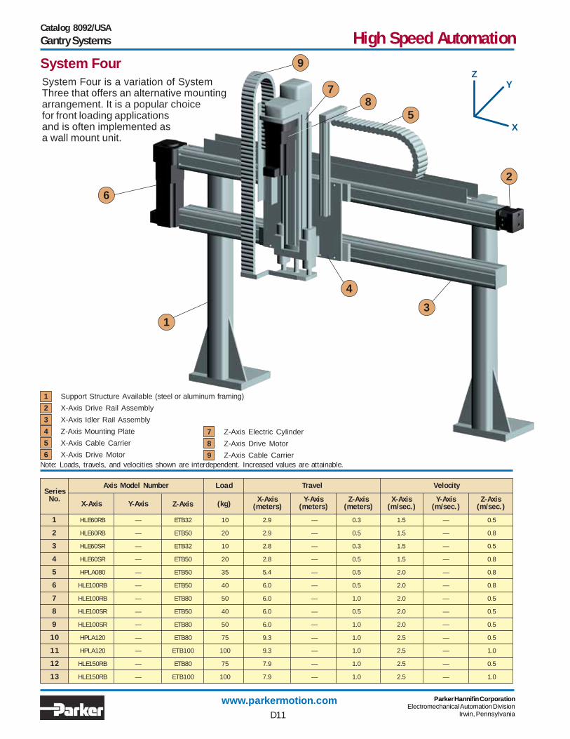
7 Z-Axis Electric Cylinder
8 Z-Axis Drive Motor
9 Z-Axis Cable Carrier
1
2
3
4
5
78
9
System Four is a variation of SystemThree that offers an alternative mountingarrangement. It is a popular choicefor front loading applicationsand is often implemented asa wall mount unit.
6
Note: Loads, travels, and velocities shown are interdependent. Increased values are attainable.
Catalog 8092/USAGantry Systems
System Four
X
YZ
D11

www.parkermotion.com Parker Hannifin CorporationElectromechanical Automation Division
Irwin, Pennsylvania
High Speed Automation
"A" DIM.
1/2 TRAVEL 1/2 TRAVEL
BETWEEN BUMPERS =X-AXIS TRAVEL + "B" DIM.
"D" DIM.BETWEEN CENTERS
OVERALL ="E" DIM. + TRAVEL
Z-AXISTRAVEL
RETRACTED HEIGHTAND Z-AXIS POSITION
DETERMINED BY APPLICATION
OVERALL =X-AXIS TRAVEL + "C" DIM.
System Four XX’-Z (Electric Cylinder)
SeriesNo.
“A” Dim.mm (in)
“B” Dim.mm (in)
“C” Dim.mm (in)
“D” Dim.mm (in)
“E” Dim.mm (in)
254.0 (10.00) 504.0 (19.84) 730.0 (28.74) 200.0 (7.87) 238.0 (9.37)
254.0 (10.00) 504.0 (19.84) 730.0 (28.74) 200.0 (7.87) 304.1 (11.97)
254.0 (10.00) 504.0 (19.84) 720.0 (28.35) 200.0 (7.87) 238.0 (9.37)
254.0 (10.00) 504.0 (19.84) 720.0 (28.35) 200.0 (7.87) 304.1 (11.97)
400.0 (15.75) 650.0 (25.59) 1012.0 (39.84) 250.0 (9.84) 304.1 (11.97)
450.0 (17.72) 700.0 (27.56) 1090.0 (42.91) 300.0 (11.81) 304.1 (11.97)
450.0 (17.72) 700.0 (27.56) 1090.0 (42.91) 300.0 (11.81) 321.9 (12.67)
450.0 (17.72) 700.0 (27.56) 1141.0 (44.92) 300.0 (11.81) 304.1 (11.97)
450.0 (17.72) 700.0 (27.56) 1141.0 (44.92) 300.0 (11.81) 321.9 (12.67)
500.0 (19.69) 750.0 (29.53) 1205.0 (47.44) 350.0 (13.78) 321.9 (12.67)
500.0 (19.69) 750.0 (29.53) 1205.0 (47.44) 350.0 (13.78) 494.0 (19.45)
500.0 (19.69) 750.0 (29.53) 1220.0 (48.03) 350.0 (13.78) 321.9 (12.67)
500.0 (19.69) 750.0 (29.53) 1220.0 (48.03) 350.0 (13.78) 494.0 (19.45)
Catalog 8092/USAGantry Systems
System Four Dimensions
1
2
3
4
5
6
7
8
9
10
11
12
13
D12

www.parkermotion.com Parker Hannifin CorporationElectromechanical Automation Division
Irwin, Pennsylvania
High Speed Automation
1
3
6 HZR Z-Axis with Flange Plate
7 Z-Axis Cable Carrier
8 Z-Axis Drive Motor
1 Support Structure Available (steel or aluminum framing)
2 X-Axis Drive Rail Assembly
3 X-Axis Idler Rail Assembly
4 X-Axis Cable Carrier
5 X-Axis Drive Motor
SeriesNo.
1 HLE100RB — HZR80 50 6.0 — 1.0 2.0 — 1.5
2 HLE100RB — HZR100 100 6.0 — 1.5 2.0 — 1.5
3 HLE100SR — HZR80 50 6.0 — 1.0 2.0 — 1.5
4 HLE100SR — HZR100 100 6.0 — 1.5 2.0 — 1.5
5 HPLA120 — HZR80 50 9.3 — 1.0 2.5 — 1.5
6 HPLA120 — HZR100 100 9.3 — 1.5 2.5 — 1.5
7 HLE150RB — HZR80 50 7.9 — 1.0 2.5 — 1.5
8 HLE150RB — HZR100 100 7.9 — 1.5 2.5 — 1.5
X-Axis Y-Axis Z-Axis (kg)X-Axis
(meters)Y-Axis
(meters)Z-Axis
(meters)X-Axis
(m/sec.)Y-Axis
(m/sec.)Z-Axis
(m/sec.)
Axis Model Number Load Travel Velocity
6
7
8
5
4
System Five is an X-Z system utilizing the HZR beltdriven unit for the vertical axis. The rigidity of theHZR permits higher vertical speed, greater X-axisacceleration, and larger moment loading thanSystem Three.
2
Note: Loads, travels, and velocities shown are interdependent. Increased values are attainable.
Catalog 8092/USAGantry Systems
System Five
X
YZ
D13

www.parkermotion.com Parker Hannifin CorporationElectromechanical Automation Division
Irwin, Pennsylvania
High Speed Automation
BETWEEN BUMPERS =X-AXIS TRAVEL + "B" DIM.
1/2 TRAVEL 1/2 TRAVEL
"A" DIM.
"D" DIM.BETWEEN CENTERS
OVERALL =X-AXIS TRAVEL + "C"
"E" DIM.
"F" DIM.
Z-AXISTRAVEL
RETRACTED HEIGHTDETERMINED BY
CUSTOMER
System Five XX’-Z (HZR)Series
No. “A” Dim.mm (in)
“B” Dim.mm (in)
“C” Dim.mm (in)
“D” Dim.mm (in)
“E” Dim.mm (in)
“F” Dim.mm (in)
450.0 (17.72) 700.0 (27.56) 1090.0 (42.91) 310.0 (12.21) 885.0 (34.84) 170.0 (6.69)
450.0 (17.72) 700.0 (27.56) 1090.0 (42.91) 360.0 (14.17) 1030.0 (40.55) 245.0 (9.65)
450.0 (17.72) 700.0 (27.56) 1141.0 (44.92) 310.0 (12.21) 885.0 (34.84) 170.0 (6.69)
450.0 (17.72) 700.0 (27.56) 1141.0 (44.92) 360.0 (14.17) 1030.0 (40.55) 245.0 (9.65)
500.0 (19.69) 750.0 (29.53) 1205.0 (47.44) 400.0 (15.75) 885.0 (34.84) 115.0 (4.53)
500.0 (19.69) 750.0 (29.53) 1205.0 (47.44) 400.0 (15.75) 1030.0 (40.55) 190.0 (7.48)
500.0 (19.69) 750.0 (29.53) 1220.0 (48.03) 400.0 (15.75) 885.0 (34.84) 115.0 (4.53)
500.0 (19.69) 750.0 (29.53) 1220.0 (48.03) 400.0 (15.75) 1030.0 (40.55) 190.0 (7.48)
Catalog 8092/USAHLE Gantry Systems
System Five Dimensions
1
2
3
4
5
6
7
8
D14

www.parkermotion.com Parker Hannifin CorporationElectromechanical Automation Division
Irwin, Pennsylvania
High Speed Automation
System Six is a three axis version of System Two.HPLA/HLE linear modules provide motion inthe X and Y directions while a vertically mountedET cylinder provides the third axis (Z) ofmotion. The ET cylinder provides highvertical thrust capacity at moderatespeeds. With the Z-axis retracted,this system can transport mod-erate to heavy loads at highrates of speed over longtravel distances.
2
1
SeriesNo.
X-Axis Y-Axis Z-Axis (kg) X-Axis(meters)
Y-Axis(meters)
Z-Axis(meters)
X-Axis(m/sec.)
Y-Axis(m/sec.)
Z-Axis(m/sec.)
Axis Model Number Load Travel Velocity
1 HLE60RB HLE60RB ETB32 10 2.9 1.0 0.3 1.0 1.5 0.5
2 HLE60RB HLE60RB ETB50 20 2.9 0.5 0.5 1.0 1.5 0.8
3 HLE60SR HLE60SR ETB32 10 2.8 1.0 0.3 1.0 1.5 0.5
4 HLE60SR HLE60SR ETB50 20 2.8 0.5 0.5 1.0 1.5 0.8
5 HPLA080 HPLA080 ETB50 45 5.4 1.5 0.5 2.0 2.0 0.8
6 HLE100RB HLE100RB ETB80 50 6.0 1.5 1.0 2.0 2.0 0.5
7 HLE100SR HLE100SR ETB80 50 6.0 1.4 1.0 2.0 2.0 0.5
8 HPLA120 HPLA120 ETB100 100 9.3 3.0 1.0 2.5 2.5 1.0
9 HLE150RB HLE150RB ETB100 100 7.9 3.0 1.0 2.5 2.5 1.0
10 Y-Axis Idler Rail Assembly
11 Y-Axis Cable Carrier
12 Y-Axis Drive Motor
13 Z-Axis ET Electric Cylinder
4
5
7
9
10 11
12
1314
15
16
38
17
14 Z-Axis Drive Motor
15 Electric Cylinder Mounting Plate
16 Electric Cylinder Mounting Bracket
17 Z-Axis Cable Carrier
Note: Loads, travels, and velocities shown are interdependent. Increased values are attainable.
Catalog 8092/USAGantry Systems
System Six
X
YZ
6
D15
1 Support Structure Available (steel or aluminum framing)
2 X-Axis Drive Rail Assembly
3 X-Axis Driven Rail Assembly
4 X-Axis Link Shaft Assembly
5 X-Axis Cable Carrier
6 X-Axis Drive Motor
7 Pillow Block Bearing Support (Based on Application)
8 Clamping Profile
9 Y-Axis Drive Rail Assembly

www.parkermotion.com Parker Hannifin CorporationElectromechanical Automation Division
Irwin, Pennsylvania
High Speed Automation
"A" DIM.
OVERALL =X-AXIS TRAVEL + "C" DIM.
BETWEEN BUMPERS =X-AXIS TRAVEL + "B" DIM.
1/2 TRAVEL 1/2 TRAVEL
BETWEEN CENTERS =Y-AXIS TRAVEL + "E" DIM.
OVERALL =Z-AXIS TRAVEL + "J" DIM.
"D" DIM.BETWEEN CENTERS
Z-AXISTRAVEL
Z-AXIS POSITION& RETRACTED HEIGHT
DETERMINED BYAPPLICATION
OVERALL =Y-AXIS TRAVEL + "H" DIM.
BETWEEN BUMPERS =Y-AXIS TRAVEL + "G" DIM.
1/2 TRAVEL 1/2 TRAVEL"F" DIM.
System Six XX’-YY’-Z (Electric Cylinder)Series
No. “A” Dim.mm (in)
“B” Dim.mm (in)
“C” Dim.mm (in)
“D” Dim.mm (in)
“E” Dim.mm (in)
“F” Dim.mm (in)
“G” Dim.mm (in)
“H” Dim.mm (in)
“J” Dim.mm (in)
254.0 (10.00) 504.0 (19.84) 730.0 (28.74) 169.8 (6.69) 508.2 (20.01) 254.0 (10.00) 504.0 (19.84) 730.0 (28.74) 238.0 (9.37)
254.0 (10.00) 504.0 (19.84) 730.0 (28.74) 169.8 (6.69) 508.2 (20.01) 254.0 (10.00) 504.0 (19.84) 730.0 (28.74) 304.1 (11.97)
254.0 (10.00) 504.0 (19.84) 720.0 (28.35) 169.8 (6.69) 482.2 (19.98) 254.0 (10.00) 504.0 (19.84) 720.0 (28.35) 238.0 (9.37)
254.0 (10.00) 504.0 (19.84) 720.0 (28.35) 169.8 (6.69) 482.2 (19.98) 254.0 (10.00) 504.0 (19.84) 720.0 (28.35) 304.1 (11.97)
400.0 (15.75) 650.0 (25.59) 1012.0 (39.84) 280.0 (0.02) 680.0 (26.77) 400.0 (15.75) 650.0 (25.59) 1012.0 (39.84) 304.1 (11.97)
450.0 (17.72) 700.0 (27.56) 1090.0 (42.91) 310.0 (12.21) 738.0 (29.06) 450.0 (17.72) 700.0 (27.56) 1090.0 (42.91) 321.9 (12.67)
450.0 (17.72) 700.0 (27.56) 1141.0 (44.92) 310.0 (12.21) 755.0 (29.72) 450.0 (17.72) 700.0 (27.56) 1141.0 (44.92) 321.9 (12.67)
500.0 (19.69) 750.0 (29.53) 1205.0 (47.44) 330.0 (12.99) 760.0 (29.92) 500.0 (19.69) 750.0 (29.53) 1205.0 (47.44) 494.0 (19.45)
500.0 (19.69) 750.0 (29.53) 1220.0 (48.03) 300.0 (11.81) 762.0 (30.00) 500.0 (19.69) 750.0 (29.53) 1220.0 (48.03) 494.0 (19.45)
Catalog 8092/USAGantry Systems
System Six Dimensions
1
2
3
4
5
6
7
8
9
D16

www.parkermotion.com Parker Hannifin CorporationElectromechanical Automation Division
Irwin, Pennsylvania
High Speed Automation
1 Support Structure Available (steel or aluminum framing)
2 X-Axis Drive Rail Assembly
3 X-Axis Driven Rail Assembly
4 X-Axis Link Shaft Assembly
5 X-Axis Cable Carrier
6 X-Axis Drive Motor
7 Clamping Profile
SeriesNo. X-Axis Y-Axis Z-Axis (kg) X-Axis
(meters)Y-Axis
(meters)Z-Axis
(meters)X-Axis
(m/sec.)Y-Axis
(m/sec.)Z-Axis
(m/sec.)
Axis Module Number Load Travel Velocity
1 HLE100RB HLE100RB HZR80 50 6.0 2.0 1.0 2.0 2.0 1.5
2 HLE100RB HLE100RB HZR100 100 6.0 1.3 1.5 2.0 2.0 1.5
3 HLE100SR HLE100SR HZR80 50 6.0 2.0 1.0 2.0 2.0 1.5
4 HLE100SR HLE100SR HZR100 100 6.0 1.3 1.5 2.0 2.0 1.5
5 HPLA120 HPLA120 HZR80 50 9.3 4.0 1.0 2.5 2.5 1.5
6 HPLA120 HPLA120 HZR100 100 9.3 3.3 1.5 2.5 2.5 1.5
7 HLE150RB HLE150RB HZR80 50 7.9 4.0 1.0 2.5 2.5 1.5
8 HLE150RB HLE150RB HZR100 100 7.9 3.3 1.5 2.5 2.5 1.5
8 Y-Axis Drive Rail Assembly
9 Y-Axis Idler Rail Assembly
10 Y-Axis Cable Carrier
11 Y-Axis Drive Motor
1
2
45
6
7
8
10
11
12
15
System Seven is a three axis system which utilizes the HZR unit forthe vertical axis. As a result, this system can provide longervertical travel, higher speed, and greater acceleration thanSystem Six. The inherent rigidity of the HZR also contributesto superior system stiffness, stability, and ease of tuning.If the Z-axis is retracted during horizontal motion,System Seven can easily handle moderate toheavy loads. With the Z-axis fully extendedit can handle light to moderate loads.
12 HZR Z-Axis with Flange Plate
13 Z-Axis Cable Carrier
14 Z-Axis Drive Motor
15 Pillow Block Bearing & Support (Based on Application)
Note: Loads, travels, and velocities shown are interdependent. Increased values are attainable.
13
Catalog 8092/USAGantry Systems
System Seven
X
YZ
3
14
9
D17

www.parkermotion.com Parker Hannifin CorporationElectromechanical Automation Division
Irwin, Pennsylvania
High Speed Automation
BETWEEN BUMPERS =X-AXIS TRAVEL + "B" DIM.
OVERALL =X-AXIS TRAVEL + "C" DIM.
1/2 TRAVEL 1/2 TRAVEL
"A" DIM.
BETWEEN CENTERSY-AXIS TRAVEL + "E" DIM.
"D" DIM.BETWEENCENTERS
"J" DIM.
"K" DIM. Z-AXISTRAVEL
RETRACTED HEIGHTDETERMINED BY
CUSTOMER
1/2 TRAVEL 1/2 TRAVEL
"F" DIM.
OVERALL =Y-AXIS TRAVEL + "H" DIM.
BETWEEN BUMPERS =Y-AXIS TRAVEL + "G" DIM.
* Indicates bottom of Z-Axis is above bottom of X-Axis
System Seven (XX’-YY’-HZR)Series
No. “A” Dim.mm (in)
450 (17.72) 700 (27.56) 1090 (42.91) 310 (12.21) 738 (29.06) 450 (17.72) 700 (27.56) 1090 (42.91) 885 (34.84) 50 (1.97)
450 (17.72) 700 (27.56) 1090 (42.91) 310 (12.21) 738 (29.06) 450 (17.72) 700 (27.56) 1090 (42.91) 1030 (40.55) 125 (4.92)
450 (17.72) 700 (27.56) 1141 (44.92) 310 (12.21) 755 (29.72) 450 (17.72) 700 (27.56) 1141 (44.92) 885 (34.84) 50 (1.97)
450 (17.72) 700 (27.56) 1141 (44.92) 310 (12.21) 755 (29.72) 450 (17.72) 700 (27.56) 1141 (44.92) 1030 (40.55) 125 (4.92)
500 (19.69) 750 (29.53) 1205 (47.44) 330 (12.99) 760 (29.92) 500 (19.69) 750 (29.53) 1205 (47.44) 885 (34.84) 60 (2.36)
500 (19.69) 750 (29.53) 1205 (47.44) 330 (12.99) 760 (29.92) 500 (19.69) 750 (29.53) 1205 (47.44) 1030 (40.55) 15 (0.59)
550 (21.65) 800 (31.50) 1270 (50.00) 350 (13.78) 762 (30.00) 500 (19.69) 750 (29.53) 1220 (48.03) 885 (34.84) 60 (2.36)
600 (23.62) 850 (33.47) 1320 (51.97) 400 (15.75) 762 (30.00) 500 (19.69) 750 (29.53) 1220 (48.03) 1030 (40.55) 15 (0.59)
“B” Dim.mm (in)
“C” Dim.mm (in)
“D” Dim.mm (in)
“E” Dim.mm (in)
“F” Dim.mm (in)
“G” Dim.mm (in)
“H” Dim.mm (in)
“J” Dim.mm (in)
“K” Dim.mm (in)
Catalog 8092/USAGantry Systems
System Seven Dimensions
1
2
3
4
5
6
7
8
D18