HIGH SPECIFIC POWER AMMONIA ARCJET...
10
IEPC-93-079 724 HIGH SPECIFIC POWER AMMONIA AND HYDROGEN ARCJET DEVELOPMENT G. Aston*, J. B. Kolts** and M. B. Aston ! Electric Propulsion Laboratory, Inc. Monument, CO 80132 Abstract A review of advanced ammonia and Typically, these cost benefits, as hydrogen arcjet development programs at identified by analyses 6-8 , are reduced EPL is presented. Rationale for specif- launch vehicle size and cost when an ic arcjet design features are discussed in electric orbit transfer vehicle (EOTV) is the context of fabricating engines which selected for satellite orbit insertion, as may be readily qualified for near term compared to larger, higher cost launch flight applications. A standardized vehicles coupled with a chemical rocket arcjet engine design is presented which transfer stage. weighs only 1.5 kg and which is sized for variable input power operation up to 15 These EOTV cost benefit trade studies kW. identify required arcjet performance levels which exceed those attained by conventional arcjet designs. 9- 1 In Introduction recognition of these performance limitations, the Air Force Phillips High performance arcjet engines are Laboratory, and McDonnell Douglas attractive for a wide range of Earth orbit Aerospace, initiated separate advanced missions. The relative simplicity, small arcjet development programs several years volume and mass of arcjets, coupled with ago at the Electric Propulsion Laboratory their benign plume characteristics, make (EPL). For the Phillips Laboratory, the these engines fairly straight forward to program goals are the development of a integrate to existing spacecraft designs. flight weight, fully welded arcjet, These important features are enhanced by performance optimized to achieve a minimum the large input power handling capability specific impulse of 950 sec., and a of an arcjet. This power handling minimum efficiency of 35% using ammonia capability allows for engines of a size propellant while operating over an input which can be comfortably hand held, and power range of 6 - 14 kW. For McDonnell yet which are potentially capable of orbit Douglas Aerospace, the program goals are raising satellites weighing thousands of the development of a flight weight, fully kilograms. welded arcjet, performance optimized to achieve a minimum specific impulse of Most arcjets presently under 1,300 sec., and a minimum efficiency of development can trace their design 40% using hydrogen propellant while heritage to extensive high power ammonia operating at a constant input power of 5 and hydrogen arcjet test programs kW. performed during the sixties. At present, no arcjet has yet flown in space. This paper describes the basic arcjet However, a first north/south station- design and test considerations, and the keeping communications satellite techniques used to investigate critical application of a 1.8 kW hydrazine arcjet arcjet geometry changes for performance system is expected soon. Beyond this optimization using both ammonia and initial low power application, a test hydrogen propellants. Data are presented flight is scheduled for verification of emphasizing the importance of arcjet the environment surrounding a battery designs which are capable of operating at powered 26 kW ammonia arcjet. very high specific power without damage. For arcjet orbit raising Specific Power as a Performance Criteria applications, significant economic benefits must be derived from the use of For an arcjet, specific power is arcjet propulsion to justify its selection defined as the ratio of the electrical over traditional chemical rocket systems. input power divided by the propellant mass flow rate and is usually expressed in the units MJ/kg. This important parameter is useful in comparing the relative performance advantages of different arcjet , M r AA designs and is usually plotted against the * Director, Member AIAA measured arcjet specific impulse and STest Engineer, Member AIAA efficiency. Generally, arcjet specific Senior Analyst, Member AIAA impulse increases with increases in Copyright 1993 by the Electric Propulsion specific power, with the rate of increase Laboratory, Inc. Published by the Ameri- thein engine ipushedingto itsecremaximum can Institute of Aeronautics and Astronau- specific power. This maximum specific tics with Permission. specific power. This maximum specific power limit is usually reached when, for a 1
-
Upload
phungquynh -
Category
Documents
-
view
214 -
download
0
Transcript of HIGH SPECIFIC POWER AMMONIA ARCJET...

IEPC-93-079 724
HIGH SPECIFIC POWER AMMONIA AND HYDROGEN ARCJET DEVELOPMENT
G. Aston*, J. B. Kolts** and M. B. Aston !
Electric Propulsion Laboratory, Inc.Monument, CO 80132
Abstract
A review of advanced ammonia and Typically, these cost benefits, as
hydrogen arcjet development programs at identified by analyses6 -8 , are reduced
EPL is presented. Rationale for specif- launch vehicle size and cost when an
ic arcjet design features are discussed in electric orbit transfer vehicle (EOTV) is
the context of fabricating engines which selected for satellite orbit insertion, as
may be readily qualified for near term compared to larger, higher cost launch
flight applications. A standardized vehicles coupled with a chemical rocket
arcjet engine design is presented which transfer stage.
weighs only 1.5 kg and which is sized forvariable input power operation up to 15 These EOTV cost benefit trade studies
kW. identify required arcjet performancelevels which exceed those attained byconventional arcjet designs.
9- 1 In
Introduction recognition of these performancelimitations, the Air Force Phillips
High performance arcjet engines are Laboratory, and McDonnell Douglas
attractive for a wide range of Earth orbit Aerospace, initiated separate advanced
missions. The relative simplicity, small arcjet development programs several years
volume and mass of arcjets, coupled with ago at the Electric Propulsion Laboratory
their benign plume characteristics, make (EPL). For the Phillips Laboratory, the
these engines fairly straight forward to program goals are the development of a
integrate to existing spacecraft designs. flight weight, fully welded arcjet,
These important features are enhanced by performance optimized to achieve a minimum
the large input power handling capability specific impulse of 950 sec., and a
of an arcjet. This power handling minimum efficiency of 35% using ammonia
capability allows for engines of a size propellant while operating over an input
which can be comfortably hand held, and power range of 6 - 14 kW. For McDonnell
yet which are potentially capable of orbit Douglas Aerospace, the program goals are
raising satellites weighing thousands of the development of a flight weight, fully
kilograms. welded arcjet, performance optimized toachieve a minimum specific impulse of
Most arcjets presently under 1,300 sec., and a minimum efficiency of
development can trace their design 40% using hydrogen propellant while
heritage to extensive high power ammonia operating at a constant input power of 5
and hydrogen arcjet test programs kW.performed during the sixties. Atpresent, no arcjet has yet flown in space. This paper describes the basic arcjet
However, a first north/south station- design and test considerations, and the
keeping communications satellite techniques used to investigate critical
application of a 1.8 kW hydrazine arcjet arcjet geometry changes for performance
system is expected soon. Beyond this optimization using both ammonia and
initial low power application, a test hydrogen propellants. Data are presented
flight is scheduled for verification of emphasizing the importance of arcjet
the environment surrounding a battery designs which are capable of operating at
powered 26 kW ammonia arcjet. very high specific power without damage.
For arcjet orbit raising Specific Power as a Performance Criteriaapplications, significant economicbenefits must be derived from the use of For an arcjet, specific power isarcjet propulsion to justify its selection defined as the ratio of the electricalover traditional chemical rocket systems. input power divided by the propellant mass
flow rate and is usually expressed in the
units MJ/kg. This important parameter is
useful in comparing the relative
performance advantages of different arcjet
, M r AA designs and is usually plotted against the
* Director, Member AIAA measured arcjet specific impulse andSTest Engineer, Member AIAA efficiency. Generally, arcjet specific
Senior Analyst, Member AIAA impulse increases with increases in
Copyright 1993 by the Electric Propulsion specific power, with the rate of increaseLaboratory, Inc. Published by the Ameri- thein engine ipushedingto itsecremaximumcan Institute of Aeronautics and Astronau- specific power. This maximum specifictics with Permission. specific power. This maximum specificpower limit is usually reached when, for a
1

725 IEPC-93-079
given fixed input power, the propellant Similarly, for EOTV applications,mass flow rate has been leaned to the arcjet operation at reduced input powerspoint where further leaning would cause during throttling need not be extended tounacceptably high constrictor erosion arbitrarily low power levels. Severelyrates due to excessively high operating throttling engines designed for operationtemperatures. An excellant presentation at input powers of 25 - 30 kW, to powerof the pursuit of higher arcjet specific levels of 3 - 5 kW results in relativelyimpulse, by incremental specific power poor engine performance and alsoincreases in a conventional ammonia arcjet potentially unstable arc column formationengine, is presented in Ref. 9. and operation. 16 These considerations,
the anticipated degradation of a nominalPower throttled operation of an 30 kW EOTV solar array, and redundancy
arcjet is required during a typical orbit requirements, suggest a 15 kW arcjetraising mission as a result of solar array design should be throttled to a minimumdegradation during passage through the power of about 5 - 6 kW.radiation belts. To achieve maximumperformance from the arcjet during The arcjets developed by EPL forthrottling, it is desirable that as the either ammonia or hydrogen operation areinput power is reduced, the propellant all sized, with minimal externalmass flow rate also be reduced to maintain differences, to this general requirementconstant engine specific power. This of maximum input power operation of 15 kWthrottling scenario results in continued and a throttling range of about 3:1.arcjet operation at approximately the samethrust-to-power ratio, while causing onlygradual linear reductions with power of Mechanical Integritythe arcjet specific impulse andefficiency. During orbit raising, an arcjet
propulsion system will be turned offThe design challenge of building during Earth shadowing of the solar arrays
arcjets with performance suitable for since it is impractical to oversize theorbit transfer applications is then two arrays and provide additional storagefold. First, the engine must be capable batteries for continuous operation duringof long term operation at specific powers eclipse. The thermal stress attendant tosignificantly in excess of conventional this cyclic operation, and the extremearcjet designs to achieve the required sensitivity of internal arcjet pressuregains in specific impulse and efficiency, changes on engine performance, put severeSecond, the engine must not be damaged, or requirements on the arcjet mechanicalexcessively eroded, during reduced input integrity.power operation while maintaining thishigh specific power. Initial EPL arcjet development
efforts investigated a variety of arcjetsealing techniques.17 As result of this
Arciet Design Considerations and later work, all EPL arcjets use acombination of electron beam welds, TIG
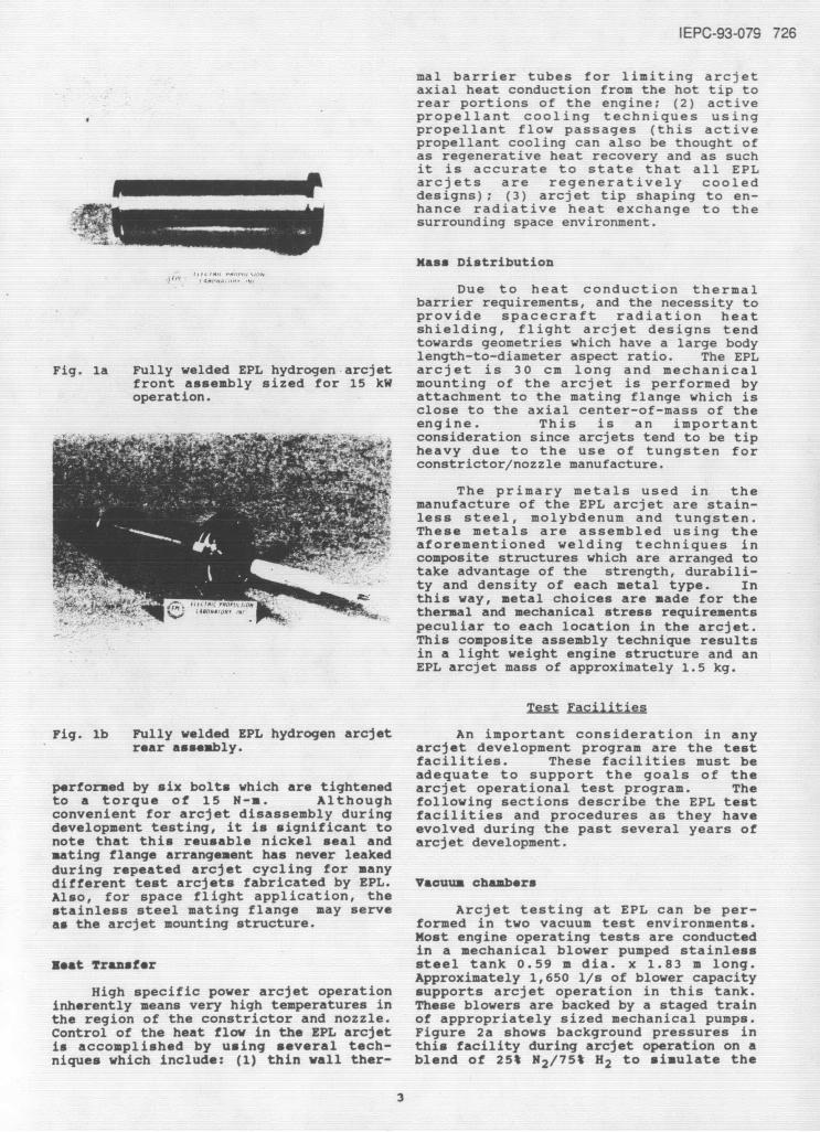
In evolving an advanced, high welds and high temperature brazing toperformance arcjet design, the approach ensure various engine components remaintaken to meet the requirement of long term leak tight during thermal cycling. Overhigh specific power operation has been the several years of EPL developmentguided by the additional objective of testing, no failure of any weld joint hasdeveloping a flight qualifiable engine for occurred.near term use. The following sectionssummarize the results of various design, The basic EPL arcjet design consistsfabrication and analysis programs which of two portions; a front assembly and acontributed to critical arcjet design rear assembly. Figures la and lb showfeatures. these major components for a hydrogen
arcjet prior to assembly and testing.Briefly, the arcjet rear assembly contains
Power Handling Capability the cathode, cathode holder, propellantdistributor, hermetically sealed cathode
For orbit raising missions with and anode insulator assembly, the anodelaunches planned in the next ten years, support barrel and half mating flange.available spacecraft solar array power Similarly, the arcjet front assemblylevels of a maximum of a few tens of kW's contains the expansion nozzle anode,can reasonably be assumed. While arcjet constrictor and critical support compo-input powers of 25 - 40 kW have been nents, propellant distribution paths,examined during recent test thermal barrier tubes, and half matingprograms9 ,1 1 ,15 , and a battery powered 26 flange.kW ammonia arcjet test flight is planned5 ,practical considerations of redundancy, Assembly of the arcjet sections shownlifetime, power throttling requirements, in Figs. la and lb, is accomplished by theand spacecraft integration, suggest use of a solid nickel seal into which themaximum arcjet input power levels of 15 kW knife edges machined into the respectivewould satisfy most foreseeable EOTV front and rear assembly half flanges aremissions. compressed. This compression is
2
IEPC-93-079 726
mal barrier tubes for limiting arcjetaxial heat conduction from the hot tip torear portions of the engine; (2) activepropellant cooling techniques usingpropellant flow passages (this activepropellant cooling can also be thought ofas regenerative heat recovery and as suchit is accurate to state that all EPLarcjets are regeneratively cooleddesigns); (3) arcjet tip shaping to en-hance radiative heat exchange to thesurrounding space environment.
Mass Distribution
Due to heat conduction thermalbarrier requirements, and the necessity toprovide spacecraft radiation heatshielding, flight arcjet designs tendtowards geometries which have a large bodylength-to-diameter aspect ratio. The EPL
Fig. la Fully welded EPL hydrogen arcjet arcjet is 30 cm long and mechanicalfront assembly sized for 15 kW mounting of the arcjet is performed byoperation. attachment to the mating flange which is
close to the axial center-of-mass of theengine. This is an important
Sconsideration since arcjets tend to be tipheavy due to the use of tungsten forconstrictor/nozzle manufacture.
The primary metals used in themanufacture of the EPL arcjet are stain-less steel, molybdenum and tungsten.These metals are assembled using theaforementioned welding techniques in
o composite structures which are arranged too atake advantage of the strength, durabili-
ty and density of each metal type. Inn a:: dr this way, metal choices are made for the
notem t . thermal and mechanical stress requirementspeculiar to each location in the arcjet.This composite assembly technique resultsin a light weight engine structure and anEPL arcjet mass of approximately 1.5 kg.
Test Facilities
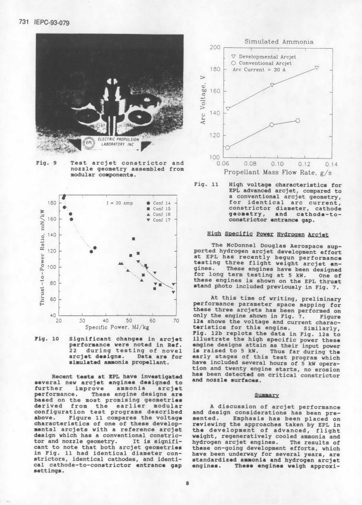
Fig. lb Fully welded EPL hydrogen arcjet An important consideration in anyrear assembly. arcjet development program are the test
facilities. These facilities must beadequate to support the goals of the
performed by six bolts which are tightened arcjet operational test program. Theto a torque of 15 N-m. Although following sections describe the EPL testconvenient for arcjet disassembly during facilities and procedures as they havedevelopment testing, it is significant to evolved during the past several years ofnote that this reusable nickel seal and arcjet development.mating flange arrangement has never leakedduring repeated arcjet cycling for manydifferent test arcjets fabricated by EPL. Vaouum chambersAlso, for space flight application, thestainless steel mating flange may serve Arcjet testing at EPL can be per-as the arcjet mounting structure. formed in two vacuum test environments.
Most engine operating tests are conductedin a mechanical blower pumped stainless
Neat Traasfer steel tank 0.59 a dia. x 1.83 m long.Approximately 1,650 1/s of blower capacity
High specific power arcjet operation supports arcjet operation in this tank.inherently means very high temperatures in These blowers are backed by a staged trainthe region of the constrictor and nozzle. of appropriately sized mechanical pumps.Control of the heat flow in the EPL arcjet Figure 2a shows background pressures inis accomplished by using several tech- this facility during arcjet operation on aniques which include: (1) thin wall ther- blend of 25% N2/75% H2 to simulate the
3

727 IEPC-93-079
mechanical blower pumped arcjet test_ ,facility is that the arcjet exhausts into
I a diffuser which is shown in Fig. 3.c imulated Ammonia This diffuser promotes significant arcjet
plume pressure recovery, in addition to1C providing the straight forward function of
Sliterally guiding the rapidly moving plumeSgases to the inlet throats of the blowers.
: Figure 4 shows operation of a test arcjetSwith simulated ammonia propellant and high
Slights the direct arcjet plume injectioninto the diffuser throat. The diffuseralso functions as a plume calorimeter for
1 / measurements requiring estimates of theH arcjet plume power and this function has
E been discussed in a previous paper.
> 10
1000.D3 0.08 0.10 C 1
Propellant Flow Rate, g/s
Fig. 2a Pumping capability of EPLmechanically pumped arcjet testfacility for arcjet operationusing simulated ammoniapropellant.
400
O Hydrogen
- 350
Fig. 3 Diffuser/calorimeter used by EPLSto augment pumping of arcjet
300 plume in the mechanically pumpedSarcjet test facility.
E 250
2000.020 0.025 0.030 0.035 0.040
Propellant Flow Rate, g/s
Fig. 2b Pumping capability of EPL
mechanically pumped arcjet testfacility for arcjet operationusing hydrogen propellant.
decomposed products of ammonia, and Fig.2b shows background pressures for arcjetoperation on pure hydrogen. This facili-ty is capable of maintaining backgroundpressures in the sub-Torr range duringarcjet operation at engine power levels upto 15 kW. Should additional blower Fig. 4 Arcjet plume being captured bycapacity be required, the pump room diffuser during arcjet operationsupporting this facility is provided with on simulated ammonia propellant.hook-ups to accept an additional blower of Diffuser entrance is to rightapproximately 1,500 1/s capacity. and arcjet is shown at left
The principle reason for the excel- enclosed by thermal radiation
lant pumping capability of the EPL arcjet shroud.
4

IEPC-93-079 728
The second vacuum test environment 0.15available for arcjet testing and perform-ance evaluation at EPL, is a diffusion imulated Ammoniapumped test facility with a total length S dof 8.3 m. This diffusion pumped facilitycomprises three separate EPL diffusionpumped vacuum chambers joined together //along their long axes. During normal a -operation these chambers are separatelypumped and are used to support various oexperimental test programs. For arcjet .testing, light weight adapter collars are Cfitted between the chambers, and thearcjet and thrust stand bulkhead are 0 05relocated to the largest chamber which hasa diameter of 1.3 m. These changes takeonly a couple of hours. The resultingcombined facility is capable of main-taining a background pressure environment < Cof 5 x 10" Torr during arcjet operation 0.C 0at input powers up to 5 kW. This high 0 5 10 15vacuum test capability is particularlyimportant for investigating nozzle flow Flow Meter Reading, slpmexpansion effects, and background gasconvective cooling effects such as de- Fig. 5a Typical flow controllerscribed by Sankovic et al. 19 calibration results for
simulated ammonia propellantusing direct gas bottle
Propellant Flow System weighing.
Accurate propellant mass flow ratereadings are critical to ensuring that 0 05arcjet performance figures are reliable.All propellant gases used at EPL for Hydrogenarcjet testing are ultra pure carrier Ograde with a 99.999% purity specification 0.04
and an oxygen content less than 1.0 ppm.Where premixed gases are required, such asfor hydrogen and nitrogen gas blends 003simulating the decomposed products of 0ammonia, each bottle is individuallycertified and the variance in blend ratiosis not more than 0.2% of the gas bottle 002volume.
Electronic mass flow controllers ofthe thermal sensing type are used to 0.01monitor arcjet propellant flow rates.Primary calibration of these flow control-lers is maintained by a direct gas bottle 000 ___ ,weighing technique. Figures 5a and 5b 0 5 10 15 20show typical flow controller calibration 5 10 15 20results for simulated ammonia and pure Flow Meter Reading, slpmhydrogen propellants. In addition todirect bottle weighing, the flow system Fig. 5b Typical flow controller
has a sample bottle in-line with the calibration results for hydrogen
arcjet which can be bled down in pressure, propellant using direct gas
while maintaining arcjet operation at bottle weighing.constant conditions. This in-situ bleeddown calibration technique estimates flow down and soft start arc initiation.rates which differ by less than 1% from These start techniques are pertinent tothe direct bottle weighing approach, present arcjet power conditioning unit
development activities and are describedin more detail in the following sections.
Arojet Start-upIn starting any arcjet there are
During past arcjet and related devel- three basic steps which must be performedopment programs, EPL developed an arcjet sequentially. The first requirement is
power supply system which has proven to be to break down the propellant gas so thatextremely capable of non-destructively free electrons and ions are present instarting any arcjet constrictor and nozzle great enough numbers to support an arc.test configuration. 2 0 - 2 2 Two key At EPL this break down is accomplished byfeatures of this laboratory power system applying a continuous ringing voltage toare the use of high frequency gas break the cathode-to-anode constrictor gap.
5

729 IEPC-93-0 79
The frequency of this applied voltage is Oof order 1 MHz, and the peak-to-peak opencircuit voltage is about 2 kV. Thisstarting voltage waveform is generated bya Tesla coil circuit whose air coupledsecondary winding is in series with a softstart arc initiation supply. The step-uptransformer to this Tesla coil circuit issupplied by 60 Hz laboratory power and hasa maximum rating of 50 VA. EPL hasapplied this starting circuit to severaldozen different arcjet test geometrieswith great success. Gas breakdown alwaysoccurs, and does so without regard forwhether the arcjet cathode has been re-cei.tly exposed to air, or the specifictest geometry under investigation. Theaverage power transferred to the cathodeduring this gas breakdown is so low thatthe starting circuit can be left on forlong time periods with no measurablecathode erosion.
Fig. 6 Cathode tip condition afterFollowing gas break down, the second more than one hundred arcjetarcjet starting requirement is to estab- starts, and repeated airlish a low current arc discharge. This exposures, during testing ofarc discharge current is regulated to not twenty five different arcjets.exceed 4 A and is left on for a few sec-onds during which time the high frequencygas breakdown circuit is switched off.The purpose of this soft start arc initia- Thrust Standtion procedure is to allow sufficientcathode tip heating to occur so as to The EPL arcjet thrust stand is flangethermally condition the cathode for high mounted and bolted to one end of thecurrent operation. arcjet vacuum test facility. To expedite
engine inspections, and the turn aroundWith the cathode thermally condi- time required for engine geometry changes,tioned, the third arcjet starting require- the thrust stand and arcjet are removed asment is to establish the desired test arc a unit from the test chamber. Thiscurrent. The high power run supplies are arrangement also allows for readyswitched across the arcjet with an initial relocation of the arcjet to the frontcurrent of typically 20 A, after which the bulkhead of the three coupled EPLsoft start arc initiation supply is turned diffusion pumped vacuum chambers when veryoff. At this point, arcjet start-up has low background pressure arcjet testing isbeen fully effected and the operator can desired.adjust the arc current to the test valuedesired while the engine is allowed to Figure 7 shows a hydrogen arcjetthermally equilibrate, mounted to the EPL thrust stand prior to
testing. The thrust stand design is ofThe above described starting system the swing arm type with the flexureis used at EPL with argon gas, with switch vertical so that the arcjet is free toover to simulated ammonia, or hydrogen, swing in the horizontal plane. Thisafter the high power run supplies have swing arm is fabricated from carbon-carbonbeen activated. The use of argon gas is composite material with the flexuresimply a laboratory technique which allows fabricated from full hard 301, 18/8relaxation of the insulation tape chrome-nickel alloy 0.381 mm thick. Therequirements around the engine electrical swing arm assembly, which contains theand gas feeds, and thus significantly arcjet mounting insulators, is securelyspeeds up the turn around time for testing bolted to a 3 cm thick graphite plate,different arcjet configurations. For which in turn is securely bolted to aspace flight applications, arcjet start-up stress braced aluminum support cradle,would be performed directly on ammonia or which in turn is bolted to the vacuum tankhydrogen propellants. mating flange.
Figure 6 shows a close-up photograph A load cell, mounted at the flexureof a cathode tip after this cathode was location, provides a signal proportionalused to thoroughly test twenty five to the arcjet thrust. Thrust standdifferent arcjet engine configurations on calibration is performed in-situ duringsimulated ammonia and pure hydrogen pro- arcjet operation by sequentially addingpellants. The number of starts on this three accurately known weights. Thrustcathode was well in excess of one hundred, measurements are taken after the testand this cathode was exposed to air at arcjet has reached thermal equilibrium.least fifty times. The round and bluntedcathode tip reflects initial shape prepa-ration prior to its use.
6

IEPC-93-079 730
-- .70" -25" --- 75
.25"
T .10"Nozzle 1
-.70" .251 - 75-
Fig. 7 Hydrogen arcjet shown mounted to .25
EPL swing arm thrust stand.
.25" 15'Early Arciet Tests.25" 5 15
The first arcjet tests performed at T .10"
EPL were with early regeneratively cooledengine designs using hydrogen propellant Nozzle 2during 1989/1990.' 3 Figure 8 showsnozzle and constrictor design details forthe three fully welded front arcjetassemblies used in this program. These .05" -initial engine designs investigated .75"__enhanced nozzle heat removal by the use of - .70" .25#- 75a radiation fin and also a bi-angle nozzlefor investigating nozzle energy expansionprocesses.I 7
Modular Geometry Optimization . 2 5 "
Based upon the results of initial T .075"arcjet desi , fabrication and testprograms, 2 0 ,', 2 3 arcjet optimization Nozzle 3studies were performed for both simulpteammonia and hydrogen propellants."'-These optimization studies were carriedout using a special test bed arcjet which Fig. 8 Constrictor and nozzle tipallowed for modular build-up of virtually design features for earlyany constrictor and nozzle geometry. (1989/1990) regenerativelyFigure 9 shows a test arcjet constrictor cooled hydrogen test arcjets.and nozzle geometry assembled usingmodular tungsten sections, extras of whichare shown in the rear of the photo. certain configurations showed promise of
achieving high specific power, andThis test bed arcjet was used to performance, at high voltage. The
investigate the relative performance of importance of achieving high voltageeighteen different arcjet geometries using arcjet operation cannot be understated for
simulated ammonia propellant.2 2 Figure practical application of high power10 reproduces a few results of this arcjets to EOTV applications. Simplyinvestigation and shows plots of the stated, a 15 kW arcjet operating at an arcvariation in thrust-to-power as a function voltage of 100 V requires a current feedof specific power for various arcjet test of 150 A, whereas an arcjet optimized forgeometries. Similar investigations were 200 V operation requires only 75 A of arcperformed using hydrogen propellant.2
4 current. For mission application, thiscurrent reduction can mean the differencebetween using a relatively simple flexible
Nigh Voltage Geometries current feed, or a more complicated rigidcurrent feed as has had to be designed
Of the many arcjet geometries into the ESSEX flight arcjet.5
investigated using the test bed arcjet,
7
731 IEPC-93-079
Simulated Ammonia200 ,
SDevelopmental ArcjetO Conventional Arcjet
180 Arc Current 30 A
o 160
120
E LECTRIC PROPUL SION 120
, E I LABORATORY INC
100Fig. 9 Test arcjet constrictor and 0.06 0.08 0.10 0.12 0.14
nozzle geometry assembled from Propellan Mass Flow Rae, g/smodular components. roeant ass o
Fig. 11 High voltage characteristics forEPL advanced arcjet, compared toa conventional arcjet geometry,
180 I = 20 Amp Cont 14 for identical arc current,S Cont 15 constrictor diameter, cathode
0 A Conf 16 geometry, and cathode-to-S160 v Conf 17 - constrictor entrance gap.
o 140 - High Soecific Power Hydrogen Arcat
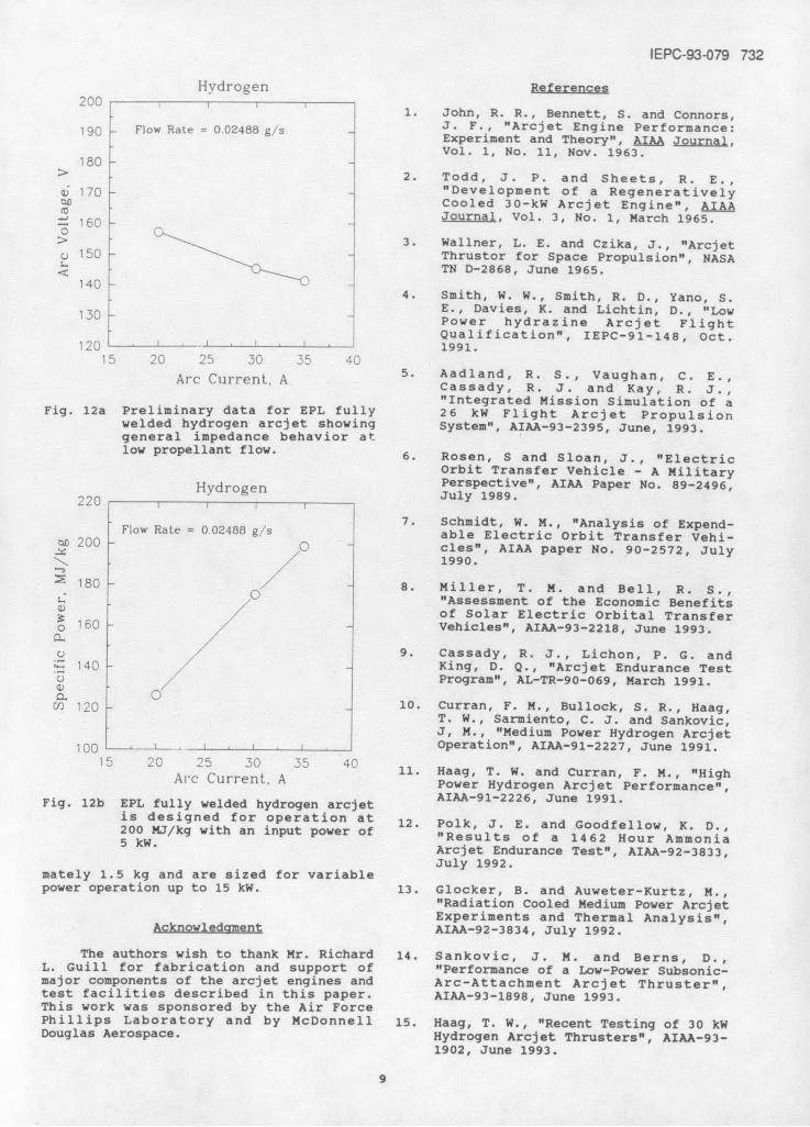
* The McDonnel Douglas Aerospace sup-120 - ported hydrogen arcjet development effortm at EPL has recently begun performance
AL testing three flight weight arcjet en-o 100 gines. These engines have been designedA V for long term testing at 5 kW. One of80 -A these engines is shown on the EPL thrust80 " stand photo included previously in Fig. 7.
=-60 At this time of writing, preliminaryEperformance parameter space mapping for
these three arcjets has been performed on40 only the engine shown in Fig. 7. Figure
20 30 40 50 60 70 12a shows the voltage and current charac-Specific Power. MJ/kg teristics for this engine. Similarly,
Fig. 12b replots the data in Fig. 12a toFig. 10 Significant changes in arcjet illustrate the high specific power these
performance were noted in Ref. engine designs attain as their input power22 during testing of novel is raised to 5 kW. Thus far during thearcjet designs. Data are for early stages of this test program whichsimulated ammonia propellant. have included several hours of 5 kW opera-
tion and twenty engine starts, no erosionRecent tests at EPL have investigated has been detected on critical constrictor
several new arcjet engines designed to and nozzle surfaces.further improve ammonia arcjetperformance. These engine designs are Sarybased on the most promising geometriesderived from the earlier modular A discussion of arcjet performanceconfiguration test programs described and design considerations has been pre-above. Figure 11 compares the voltage sented. Emphasis has been placed oncharacteristics of one of these develop- reviewing the approaches taken by EPL inmental arcjets with a reference arcjet the development of advanced, flightdesign which has a conventional constric- weight, regeneratively cooled ammonia andtor and nozzle geometry. It is signifi- hydrogen arcjet engines. The results ofcant to note that both arcjet geometries these on-going development efforts, whichin Fig. 11 had identical diameter con- have been underway for several years, arestrictors, identical cathodes, and identi- standardized ammonia and hydrogen arcjetcal cathode-to-constrictor entrance gap engines. These engines weigh approxi-settings.
8
IEPC-93-079 732
Hydrogen References200 200 1. John, R. R., Bennett, S. and Connors,
90 Flow Rate = 0.02488 g/s J. F., "Arcjet Engine Performance:Experiment and Theory", AIAA Journal,Vol. 1, No. 11, Nov. 1963.
180> 2. Todd, J. P. and Sheets, R. E.,
a 170 -"Development of a RegenerativelySI Cooled 30-kW Arcjet Engine", AIAA
S- Journal, Vol. 3, No. 1, March 1965.160> i 3. Wallner, L. E. and Czika, J., "Arcjet
o 150 - Thrustor for Space Propulsion", NASA< TN D-2868, June 1965.
1404. Smith, W. W., Smith, R. D., Yano, S.
130 J E., Davies, K. and Lichtin, D., "LowPower hydrazine Arcjet FlightQualification", IEPC-91-148, Oct.
120 - 1991.15 20 25 30 35 40
Arc Current,A 5. Aadland, R. S., Vaughan, C. E.,Cassady, R. J. and Kay, R. J.,"Integrated Mission Simulation of a
Fig. 12a Preliminary data for EPL fully 26 kW Flight Arcjet Propulsionwelded hydrogen arcjet showing System", AIAA-93-2395, June, 1993.general impedance behavior atlow propellant flow.low propellant flow. 6. Rosen, S and Sloan, J., "Electric
Orbit Transfer Vehicle - A MilitaryHydrogen Perspective", AIAA Paper No. 89-2496,
220 I IJuly 1989.
7. Schmidt, W. M., "Analysis of Expend-Flow Rate = 0.02488 g/s able Electric Orbit Transfer Vehi-o 200 /O cles", AIAA paper No. 90-2572, July
/ 1990.
S180 7 8. Miller, T. M. and Bell, R. S.,.0 "Assessment of the Economic Benefits
/ of Solar Electric Orbital Transfero 160 -/ Vehicles", AIAA-93-2218, June 1993.
o / 9. Cassady, R. J., Lichon, P. G. and140 - King, D. Q., "Arcjet Endurance Test
S / Program", AL-TR-90-069, March 1991.Q. 0
V) 120 - 10. Curran, F. M., Bullock, S. R., Haag,T. W., Sarmiento, C. J. and Sankovic,J, M., "Medium Power Hydrogen Arcjet
100 L ___ , I I Operation", AIAA-91-2227, June 1991.15 20 25 50 35 40Ac Current, A 4 11. Haag, T. W. and Curran, F. M., "HighA CurrenA Power Hydrogen Arcjet Performance",
Fig. 12b EPL fully welded hydrogen arcjet AIAA-91-2226, June 1991.is designed for operation at 12. Polk, J. E. and Goodfellow, K. D.,200 MJ/kg with an input power of "Results of a 1462 Hour Ammonia
5 W. Arcjet Endurance Test", AIAA-92-3833,July 1992.
mately 1.5 kg and are sized for variablepower operation up to 15 kW. 13. Glocker, B. and Auweter-Kurtz, M.,
"Radiation Cooled Medium Power ArcjetExperiments and Thermal Analysis",
Acknowledgment AIAA-92-3834, July 1992.
The authors wish to thank Mr. Richard 14. Sankovic, J. M. and Berns, D.,L. Guill for fabrication and support of "Performance of a Low-Power Subsonic-major components of the arcjet engines and Arc-Attachment Arcjet Thruster",test facilities described in this paper. AIAA-93-1898, June 1993.This work was sponsored by the Air ForcePhillips Laboratory and by McDonnell 15. Haag, T. W., "Recent Testing of 30 kWDouglas Aerospace. Hydrogen Arcjet Thrusters", AIAA-93-
1902, June 1993.
9

733 IEPC-93-079
16. Goodfellow, K. D. and Polk, J. E.,"Throttling Capability of a 30-kW
Class Ammonia Arcjet", AIAA-91-257 7 ,
June 1991.
17. Aston, G., Aston, M. B., Kolts, J. B.
and Acker, T. L., "Hydrogen ArcjetSealing Techniques and ThermalAnalysis", AIAA-90-2617, July 1990.
18. Aston, G., Aston, M. B. and Kolts, J.B., "Diagnostics for Arcjet Develop-ment", AIAA-92-3562, July 1992.
19. Sankovic, J. M. and Curran, F. M.,"Arcjet Thermal Characteristics",AIAA-91-2456, June 1991.
20. Aston, G., "Dual Mode Hydrogen Arc-
jet", AL-TR-90-052, August 1990
21. Aston, G. and Aston, M. B., "ArcjetPlume Self-Pumping", PL-TR-91-3075,Jan. 1992.
22. Aston, G., "High Performance, Varia-ble Power Ammonia Arcjet", PL-TR-91-3112, April 1992.
23. Aston, G., "Preliminary Developmentof a 7.5 kW Hydrogen Arcjet",Prepared for McDonnell Douglas SpaceSystems Company under SubContract89724072, Sep. 1990.
24. Aston, G., "Hydrogen ArcjetPerformance EnhancementOpportunities", Prepared forMcDonnell Douglas Space SystemsCompany under Service Contract91664127H, Sep. 1992.
10