Micro Cathode Arc Thruster PhoneSat Experiment for Small...
10
The 33st International Electric Propulsion Conference, The George Washington University, USA October 6 – 10, 2013 1 Micro Cathode Arc Thruster PhoneSat Experiment for Small Satellites IEPC-2013-409 Presented at the 33rd International Electric Propulsion Conference, The George Washington University • Washington, D.C. • USA October 6 – 10, 2013 Samudra E. Haque 1 , George Teel 2 and Michael Keidar 3 , The George Washington University, Washington, DC 20052, United States Elwood F. Agasid 4 , Oriol Tintore Gazulla 5 , Andres Dono Perez 6 , Greenfield T. Trinh 7 , and Eddie A. Uribe 8 NASA Ames Research Center, Moffett Field, California, 94035, United States Abstract: NASA Ames Research center and George Washington University have been working together to increase the TRL level of a micro arc cathode thruster developed by GWU by integrating the system into the ARC PhoneSat bus. The main objectives of the collaboration were (1) to build a test bench in which a phone, running the PhoneSat firmware and a custom designed Android App could fire several thrusters in vacuum at the same time and (2) to design a CAD model of a <3U model that could incorporate the PhoneSat bus, the thruster avionics and the thrusters themselves. This paper presents how the interfaces of these two systems were developed, as well as the results obtained during the testing phase. I. Introduction he Micro-propulsion and Nanotechnology Laboratory (MpNL) of the Dept. of Mechanical and Aerospace Engineering at The George Washington University, has been conducting fundamental and applied research, since 2007, in order to develop a scalable, and modular, “In-Space Propulsion” subsystem utilizing the novel plasma micro-propulsion technology called Micro-Cathode Arc Thruster 1-7 (µCAT). This system is meant for applications in small spacecraft of various sizes, ranging from Nano-satellites (1-10 Kg) onwards to Mini- satellites (100 Kg or higher). Concurrently, NASA Ames Research Center (ARC) has been working on the PhoneSat CubeSat bus since 2010, and has successfully flown the three cheapest satellites ever sent to space (2 PhoneSat 1 and 1 PhoneSat 2.0.beta). The project has now two scheduled launches for 2 PhoneSat 2 units for late 2013 and early 2014. In early 2013, after receiving a Center Innovation Fund, both GWU and NASA-ARC started to work on the integration of the GWU micro arc cathode thruster with the PhoneSat bus, within the framework of an experiment entitled “Micro-Cathode Arc Thruster PhoneSat Experiment” (MCATPE). The project deliverables included: Develop a test bench that would allow a vacuum test of several microthrusters, controlled by a PhoneSat smartphone, that would use the same firmware as a current PhoneSat bus. This would prove 1 Ph.D Student, Department of Mechanical and Aerospace Engineering, [email protected] 2 MS Student, Department of Mechanical and Aerospace Engineering, [email protected] 3 Professor of Engineering and Applied Science, Dept. of Mech. and Aerospace Engineering, [email protected] 4 Chief Technologist, Mission Design Center, NASA Ames Research Center, [email protected] 5 Aerospace Engineer, Stinger Ghaffarian Technologies Inc., [email protected] 6 Physicist, International Space University, [email protected] 7 Test Engineer Intern, University Space Research Association, [email protected] 8 Aerospace Engineer, Jacobs Technology, Inc., [email protected] T
Transcript of Micro Cathode Arc Thruster PhoneSat Experiment for Small...

The 33st International Electric Propulsion Conference, The George Washington University, USA
October 6 – 10, 2013
1
Micro Cathode Arc Thruster PhoneSat Experiment for Small Satellites
IEPC-2013-409
Presented at the 33rd International Electric Propulsion Conference, The George Washington University • Washington, D.C. • USA
October 6 – 10, 2013
Samudra E. Haque1, George Teel2 and Michael Keidar3, The George Washington University, Washington, DC 20052, United States
Elwood F. Agasid4, Oriol Tintore Gazulla5, Andres Dono Perez 6, Greenfield T. Trinh7, and Eddie A. Uribe8
NASA Ames Research Center, Moffett Field, California, 94035, United States
Abstract: NASA Ames Research center and George Washington University have been working together to increase the TRL level of a micro arc cathode thruster developed by GWU by integrating the system into the ARC PhoneSat bus. The main objectives of the collaboration were (1) to build a test bench in which a phone, running the PhoneSat firmware and a custom designed Android App could fire several thrusters in vacuum at the same time and (2) to design a CAD model of a <3U model that could incorporate the PhoneSat bus, the thruster avionics and the thrusters themselves. This paper presents how the interfaces of these two systems were developed, as well as the results obtained during the testing phase.
I. Introduction
he Micro-propulsion and Nanotechnology Laboratory (MpNL) of the Dept. of Mechanical and Aerospace Engineering at The George Washington University, has been conducting fundamental and applied research,
since 2007, in order to develop a scalable, and modular, “In-Space Propulsion” subsystem utilizing the novel plasma micro-propulsion technology called Micro-Cathode Arc Thruster1-7 (µCAT). This system is meant for applications in small spacecraft of various sizes, ranging from Nano-satellites (1-10 Kg) onwards to Mini-satellites (100 Kg or higher). Concurrently, NASA Ames Research Center (ARC) has been working on the PhoneSat CubeSat bus since 2010, and has successfully flown the three cheapest satellites ever sent to space (2 PhoneSat 1 and 1 PhoneSat 2.0.beta). The project has now two scheduled launches for 2 PhoneSat 2 units for late 2013 and early 2014.
In early 2013, after receiving a Center Innovation Fund, both GWU and NASA-ARC started to work on the integration of the GWU micro arc cathode thruster with the PhoneSat bus, within the framework of an experiment entitled “Micro-Cathode Arc Thruster PhoneSat Experiment” (MCATPE). The project deliverables included:
Develop a test bench that would allow a vacuum test of several microthrusters, controlled by a
PhoneSat smartphone, that would use the same firmware as a current PhoneSat bus. This would prove
1 Ph.D Student, Department of Mechanical and Aerospace Engineering, [email protected] 2 MS Student, Department of Mechanical and Aerospace Engineering, [email protected] 3 Professor of Engineering and Applied Science, Dept. of Mech. and Aerospace Engineering, [email protected] 4 Chief Technologist, Mission Design Center, NASA Ames Research Center, [email protected] 5 Aerospace Engineer, Stinger Ghaffarian Technologies Inc., [email protected] 6 Physicist, International Space University, [email protected] 7 Test Engineer Intern, University Space Research Association, [email protected] 8 Aerospace Engineer, Jacobs Technology, Inc., [email protected]
T

The 33st International Electric Propulsion Conference, The George Washington University, USA
October 6 – 10, 2013
2
Figure 1: PhoneSat 2 satellite bus. The current architecture allows easy integration of new payloads both from the hardware and software perspectives
that the thruster is ready to be integrated into a bus and that the PhoneSat architecture can easily add new subsystems to be tested in space.
Design a 3U PhoneSat model that would accommodate the bus, the Plasma Processing Unit (PPU) and several microthrusters for either orbit maintenance or for attitude control.
This paper presents details of both systems, how they have been integrated, and the functional tests performed so far. Then, a version of the CAD model developed that could potentially fly is analyzed and the conclusions and possible future work can be found at the end of the paper.
II. Potential Applications
It was envisaged, subject to a successful completion of the experiment, relevant components of the experimental work output (e.g. analysis, embedded hardware, embedded control code, plasma power units, applications software etc.) could be utilized to develop a follow-on innovative mission concept entitled, Microcathode Arc thruster PhoneSat Experiment for a Communication Relay Satellite (MAPERS) such as the hypothetical lunar communications relay system15, by Haque shown in Figure 2, published in 2013. During the course of the MCATPE new technology was designed in stages and tested to determine viability and reliability.
Any small spacecraft with thrusters, or a miniature active propulsion subsystem (aka micropropulsion subsystem), can be used for both solo and formation/constellation based mission architectures. For example, a constellation of small spacecraft could effectively provide time-diversified/space-diversified observations of Earth (remote sensing), wide-sky astrophysical observation, specific target tracking (e.g., Near Earth Objects), simply on-demand communications and/or data relay and other applications not possible with the traditional scenario of few satellites on-orbit. Keeping phase consistent of the members of such a network over a long time or providing long term propulsion capability with good storage characteristics for occasional use has proven to be a great challenge to mission designers and propulsion system engineers.
III. The PhoneSat bus
The NASA PhoneSat team, at ARC, has been working to develop a compact, low-cost, standardized spacecraft bus that could potentially accommodate any small payload that could fit into a notional CubeSat16 envelope. The NASA EDISON Demonstration of a SmallSat Network (EDSN) is a good example of the use of this standard platform, involving the planned launch of a loose formation of eight 1.5U CubeSats into orbit, with cross-link communications to enable scientific multi point measurements.
Under the philosophy of releasing early and releasing often, PhoneSat wants to offer its bus to test other subsystems and payloads in space reducing the cost and time to fly new experiments.
The current PhoneSat 2 design, and the EDSN extension as the use of PhoneSat as a bus,
allow a plug and play hardware system in which testing a different subsystem or payload requires minimal redesign and engineering time.
Figure 2 Lunar Relay Comm System (of Small Sats w/ uCAT)
The 33st International Electric Propulsion Conference, The George Washington University, USA
October 6 – 10, 2013
3
Moreover, the PhoneSat software bus also allows this possibility: by using the same Android firmware as PhoneSat and EDSN are using, other projects can benefit from almost the entire satellite software, thus reducing the time and money spent on software development. The PhoneSat goal in this sense is being able to adapt itself to any different mission by only changing the lowest software layer, the Android Application.
The current PhoneSat 2 bus consists of: Nexus S phone as the main on board computer
4 Li-Ion batteries and solar panels for all the faces (designs have been finished and manufactured for 1U and 1.5U CubeSats)
Microhard 2420 radio as the on board communication transceiver
UHF StenSat beacon as the backup downlink communication system
3 Axis Attitude Control System
o Reaction Wheels o Magnetorquers embedded on the solar panels
Arduino based watchdog
Arduino based Sensor Interface
Serial Router for intercommunication between the different subsystems
From the phone perspective, each different subsystem is a serial channel from which it can receive data and to which it can send commands. Keeping in mind this configuration, the project conceived the thruster as a new subsystem that needed its own serial channel. Therefore, the main software challenge of the project was to use the PhoneSat firmware to create a thruster serial channel and send commands to fire the different thrusters. Two important additions from the EDSN project that could benefit future MCATPE objectives is the addition of an onboard GPS unit and the experience of adding an external payload board (EPISEM). The experience gained adding these two new boards has brought the plug and play concept closer to reality, and the MCATPE project wants to show its feasibility with ongoing and future work.
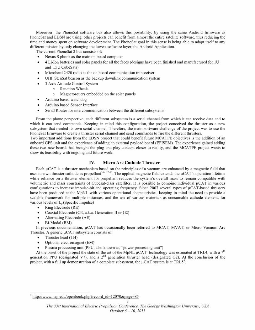
IV. Micro Arc Cathode Thruster
Each µCAT is a thruster mechanism based on the principles of a vacuum arc enhanced by a magnetic field that uses its own thruster cathode as propellant3-6, 17-19. The applied magnetic field extends the µCAT’s operation lifetime while reliance on a thruster element for propellant reduces the system’s overall mass to remain compatible with volumetric and mass constraints of Cubesat-class satellites. It is possible to combine individual µCAT in various configurations to increase impulse-bit and operating frequency. Since 2007 several types of µCAT-based thrusters have been produced at the MpNL with various operational characteristics, keeping in mind the need to provide a scalable framework for multiple instances, and the use of various materials as consumable cathode element, for various levels of Isp (Specific Impulse)
Ring Electrode (RE) Coaxial Electrode (CE, a.k.a. Generation II or G2) Alternating Electrode (AE) Bi-Modal (BM)
In previous documentation, µCAT has occasionally been referred to MCAT, MVAT, or Micro Vacuum Arc Thruster. A generic µCAT subsystem consists of:
Thruster head (TH) Optional electromagnet (EM) Plasma processing unit (PPU, also known as, “power processing unit”)
At the onset of the project the state of the art of the MpNL µCAT technology was estimated at TRL4, with a 7th generation PPU (designated V7), and a 2nd generation thruster head (designated G2). At the conclusion of the project, with a full up demonstration of a complete subsystem, the µCAT system is at TRL59.
9 http://www.nap.edu/openbook.php?record_id=12070&page=85

The 33st International Electric Propulsion Conference, The George Washington University, USA
October 6 – 10, 2013
4
Figure 3: uCAT Thruster Head (Generation II/CE)
Figure 4: Trigger Pulse Signal
A. Legacy System Description (pre-2013) A µCAT is essentially an Electric Propulsion device that utilizes
regular pulses of high electrical currents to create micro-plasma and then plasma between its anode and cathode terminals, from a Vacuum Arc, and erosion of the cathode terminal material from a mobile, unstable, Cathode Spot. A PPU is used to charge an inductive energy storage device (inductor) rapidly, followed by a discharge of all of the stored energy into the Thruster Head by a fast-acting high-discharge IGBT semiconductor switch, in a very small amount of time, to create the very high current levels, and low voltage arc discharge, required for production of quasi-neutral plasma jet. The mechanism is actuated by a trigger pulse (TP) interacting with a two-part circuit containing a clamped inductive load (e.g., an inductor for energy storage, IES) and Anode/Cathode discharge (ACD) section. The Transistor-Transistor Logic (TTL) level TP logic signal from a Control Unit (CU, which in this particular experiment is an embedded 32-bit ColdFire microprocessor) is used to generate a precise high-current trigger signal using a Metal Oxide Semiconductor/Insulated Gate Base Transistor (MOSFET/IGBT) pre-driver device or, IPD.
The output of the ACD is fed directly to the Cathode and Anode terminals, which are manufactured as two concentric made from any element that has good electrical properties, and reasonable atomic mass to impart momentum to the spacecraft. The momentum exchange phenomenon happens naturally due to the fact that the plasma is driven by a pressure gradient in the cathode arc spot, which is itself rotating on the inside edge of the cathode cylinder while the arc is present. Materials currently tested at the MpNL include Titanium, Nickel and Silicon. The term PPU therefore nominally refers to the amalgamation of all three parts, (IES, ACD, and IPD).
The steps of operation of the legacy µCAT systems were observed to be comprised of six operational states, in a total of two stages. These are:
Step 1: Charge Cycle
Step 1A Quiescent State
Step 1B Initial State
Step 1C Charging State
Step 2: Discharge Cycle
Step 2A Breakdown State
Step 2B Plasma Flow/Discharging State
Step 2C Discharged State
A CAD rendering of the Generation II (Coaxial Electrode, or CE) thruster head is shown in Figure 3. The thruster head mechanism consists of a holder (now shown), a spring, the anode, the cathode, an optional Magnetic Coil (not shown) and/or a Ferrite Plate (not shown).
-1 0 1 2 3 4 5 6 7 8
x 10-4
0
0.5
1
1.5
2
2.5
3
Trigger Pulse Signal (TP)
Seconds
Vo
lts

The 33st International Electric Propulsion Conference, The George Washington University, USA
October 6 – 10, 2013
5
Figure 5: Plasma Processing Unit
Figure 6: Thruster Heads
B. Precision Trigger Pulse An algorithm to generate a precise µCAT trigger pulse and end-of-cycle
delay for various pulse-width duty cycles, was formulated by Haque, for the purposes of generating synchronized µCAT pulses (Figure 4)and was calculated to match the register settings of a high speed logic toggle interrupt service routine (ISR) that utilized the hardware Direct Memory Access timer feature of a 32-bit Coldfire Microcontroller Unit (MCU). The timing for the trigger pulse was also matched experimentally derived taking into account the aggregate arc discharge time, a value dependent upon the components of the IPD and the ACD section. The resolution of the hardware timer was chosen to be 10µS, and it was decided to use the same trigger pulse for all µCAT channels being tested in the experiment. In a real in-space application, the synchronization of trigger pulses may be advantageous to ensure that multiple thruster units are firing in coordination, but alternative scenarios may also have to be considered where the triggers to different thruster channels are generated independently.
C. Improved Plasma Power Unit
Several legacy PPUs were adapted and radically upgraded with new features, and V7.2 was finally designated. While previously the PPUs’ timing parameters were difficult to change, the new design enables programmable impulse bit generation. The new feature set includes:
Switched 15 Volts DC input for IPD (P15L bus) Switched 15 Volts DC input for ACD (P15H bus) Input port for the trigger pulse from the Control Unit (TP) Protection system for reverse current discharge Miniature capacitor used as backup power supply Modularization of all power/trigger connectors
D. Improved Thruster Head Miniature thruster heads (Figure 6) were fabricated by Teel, with the
intent of fitting several thrusters in the geometric confines of a CubeSat body face (e.g., 100 mm x 100 mm). Utilizing Titanium as the Cathode cylinder terminal, Brass as the anode screw terminal and Aluminum as the protective outer shell, a total mechanical dimension of 0.4”x1” was. This configuration has been designated G2.2, and is likely to be a candidate design suitable for future mass production.
E. New Control Unit and Embedded C++ Control Program A 32-bit embedded Coldfire Microcontroller equipped board, operating at 3.3VDC, was utilized as a multi-
purpose command/telemetry processor and logic control. TTL Logic control signals were used as commands to actuate optoelectronic relays on a stand-alone interface board. An embedded C++ application was written to receive serial inputs, actuate the required logic sequences and issue appropriate status responses via serial output. The initial command vocabulary is presented in Table 1.
cmd Action cmd Z Enable Thruster Channel #1 0 Display System Status z Disable Thruster Channel #1 1 Set operating frequency of
thruster channel(s) at F=1 Hz Y Enable Thruster Channel #2 2 Set operating frequency of
thruster channel(s) at F=2 Hz y Disable Thruster Channel #2 6 Enable Trigger Pulse X Enable Thruster Channel #3 7 Disable Trigger Pulse x Disable Thruster Channel #3 9 Revert to Main Menu
Table 1: serial signals sent from the phone to the Coldfire

The 33st International Electric Propulsion Conference, The George Washington University, USA
October 6 – 10, 2013
6
F. New Power Management module A commercial off the shelf managed and intelligent DC/DC power module (PM) from Analog Devices, with
reference circuits and application software for power rail sequencing/customization was utilized to generate 3V, 5V, 15V from a 6-14VDC input. Due to restriction of 0.1A current on the 15V output of this board, an external 15V power supply was used to drive the P15H bus. The PM was provided with 12 VDC from an external power supply for all other operations, including the Control Unit interface board.
G. Scalable configurations Prior to the actual experiment and fabrication of a complete subsystem with multiple thrusters, potential scalable
arrangements of the key components were considered and evaluated. 1. Single Channel
A single PPU (e.g. PPU/1) is used to power a single TH (TH/A), triggered by a single control signal (TP/1). This is a stand-alone configuration and is likely the simplest implementation method.
Figure 7 Single Channel
2. µCAT Array A collection of PPUs (e.g. PPU/2-4), each with its own TH (single qty). Each chain can be triggered
individually, or as a group. This configuration was chosen for MCATPE, with all trigger pulses inputs being fed by the same signal.
Figure 8 Array
3. µCAT Cluster In a future configuration, certain in-space applications may call for expanded thruster capability, or potentially a
switching method where some of the thrusters are activated, while others are not, from the same PPU. Examples of the later case may be opposing thrusters that are placed in a parallel direction, creating a 1-axis control mechanism.
Figure 9 Cluster (w/optional Switch)
4. µCAT Cluster-Array Hybrid If a larger spacecraft bus is available, arrays of of µCAT devices (e.g., PPU/6) could potentially be combined
with Cluster ( e.g. PPU/7). This configuration is most suitable for varying power levels. Triggers could be all the same, but could also be manipulated to be independent from each other.

The 33st International Electric Propulsion Conference,
Figure 11: Hardware bench experiment.
A “breadboard” setup (Figure 11) was external power supplies, an interface for connection to a PhoneSat CPU (Nexus S Smartphone running the customized PhoneSat App) and connections to a µCAT Array of three G2.2 Thruster 13). All connections were tailor fit to the layout of the boardlocal computer with an Ethernet cable to enable quick reprogramming and live monitoringconnected to the interface board with mechanical switches for the P15L lines, which allowed manual activation of channels on a one-by-one basis.
A. Software Integration The software integration involved the interface between the two main cSmartphone which uses Android as its OS and a ColdFire MCF5270 V2, embedded in a Mod5270B module, manufactured by Netburner, that runs µC/OS, a Realrequired Java, and the Netburner environment, embedded C/C++. GNU C/C++ compiler was used via the supplied Eclipse Integrated Design Environment (IDE). The integration procedure involvfrom the Nexus S to the ColdFire V2 which current to the thruster head. The phone runs the PhoneSat firmware, which allocates one serial channel for each individual subsystem. It currently has channels for the two radios, the ADCSadded maintain the same architecture to allow an easy future integration with the entire bus, and this channel was dedicated to the thruster. This is the only modification that needs to be donecompatible with the thruster and its microcontroller.
International Electric Propulsion Conference, The George Washington University
October 6 – 10, 2013
7
TH
PPU TH
TH
A
7 A
B
TP7
PPU 6TP6
Figure 10 Hybrid Cluster/Array
: Hardware bench experiment. All the hardware electronic components of the MAPERS experiment
V. Systems integration
) was assembled to test a complete 3-channel µCAT subsystemexternal power supplies, an interface for connection to a PhoneSat CPU (Nexus S Smartphone running the
and connections to a µCAT Array of three G2.2 Thruster Heads in a steel frame (All connections were tailor fit to the layout of the board and secured with cable ties. The CU was connected to a
local computer with an Ethernet cable to enable quick reprogramming and live monitoring. Tconnected to the interface board with mechanical switches for the P15L lines, which allowed manual activation of
The software integration involved the interface between the two main computers in the system: a Nexus S as its OS and a ColdFire MCF5270 V2, embedded in a Mod5270B module,
manufactured by Netburner, that runs µC/OS, a Real-Time Operating System (RTOS). The Android environment red Java, and the Netburner environment, embedded C/C++. GNU C/C++ compiler was used via the supplied
Eclipse Integrated Design Environment (IDE). The integration procedure involved sending suitable serial signal from the Nexus S to the ColdFire V2 which would then command the various PPU channels to send a brief pulsed
The phone runs the PhoneSat firmware, which allocates one serial channel for each individual subsystem. It currently has channels for the two radios, the ADCS, the watchdog and the sensor interface. One extra channel was added maintain the same architecture to allow an easy future integration with the entire bus, and this channel was dedicated to the thruster. This is the only modification that needs to be done to the PhoneSat firmware to make it compatible with the thruster and its microcontroller.
Washington University, USA
All the hardware electronic components of the MAPERS experiment
channel µCAT subsystem with appropriate external power supplies, an interface for connection to a PhoneSat CPU (Nexus S Smartphone running the
Heads in a steel frame (Figure and secured with cable ties. The CU was connected to a
The PPU units were connected to the interface board with mechanical switches for the P15L lines, which allowed manual activation of
omputers in the system: a Nexus S as its OS and a ColdFire MCF5270 V2, embedded in a Mod5270B module,
Time Operating System (RTOS). The Android environment red Java, and the Netburner environment, embedded C/C++. GNU C/C++ compiler was used via the supplied
ed sending suitable serial signal would then command the various PPU channels to send a brief pulsed
The phone runs the PhoneSat firmware, which allocates one serial channel for each individual subsystem. It , the watchdog and the sensor interface. One extra channel was
added maintain the same architecture to allow an easy future integration with the entire bus, and this channel was to the PhoneSat firmware to make it

The 33st International Electric Propulsion Conference, The George Washington University, USA
October 6 – 10, 2013
8
Figure 12: 1-Channel µCAT Subsystem (2013, THG2.2/PPUV7x)
Figure 13: First Light Test. Three uCAT thrusters firing at the same time
An Android application (apk) was developed to send the right serial commands to the thruster, matching the command vocabulary in (TABLE XX). For ground testing purposes, a graphical user interface (GUI) layout was utilized for a user friendly application. Finally, the C++ code was an update of a previous version that was used to test the thruster with a PC, modified in parallel with the development the .apk to assure concurrent testing and functionality. This code receives the serial commands from the phone and eventually creates the pulses that will fire the thruster. At first, the testing was done limiting the frequency to 1 and 2 Hz due to the fact that to increment the frequency a parameter in the code needs to change the end of cycle count of the ColdFire V2 timer to account for the correct pulsing frequency desired. Too high frequency could cause overheating issues in some of the parts, so low frequencies were considered safer and more ideal for this initial testing phase. However, once the first set of tests was finished, higher frequencies (10, 25 and 50Hz) were also tested after the development of the second version of the Netburner code and the apk. As previously mentioned, overheating is the main issue when using high frequencies, and it has been tested at GWU that 50Hz is a good high frequency limit.
VI. Testing
A. Thruster Simulator Before having the thrusters and the PPUs, the first test performed
was the serial communication between the phone and the ColdFire microcontroller. The communication ICD between the phone and the microcontroller was developed and a simple apk was tested to turn on and off different LEDs of the microcontroller development board. Thus the main interface programming problem was solved. This test was initially done at GWU, and then replicated at ARC.Single Thruster Operation Testing
An experiment was designed to test the CU interaction with a single µCAT channel, and the experiment was streamed live to ARC PhoneSat team. Subsequently, GWU development focused on the multiple channel control while ARC tested a sample thruster (FIGURE XX) connected to the smartphone, with guidance from the MpNL team. Both tests were successful, and the only remaining part was the operation of multiple channels from the phone.
B. “First Light” – Milestone Event
The GWU and the ARC teams worked together, at Ames, to get the entire subsystem assembled, integrated and tested. The process was not significant without challenges and unexpected hardware/software performance, compatibility, and catastrophic component failure issues. A combined effort of approximately 6 man-weeks, resulted in the first ever generation of synchronized impulse-bits, from the complete “3-channel µCAT Subsystem”, at the NASA ARC SpaceShop on 21 August, 2013 which is an industry watershed event.
C. Vacuum Chamber Testing The vacuum chamber testing involved mounting 3 thrusters inside the a 2 x 2 x 3
ft vacuum chamber built by Abyess instruments and Systems Inc. running at 10-5 Torr, starting the thruster and running different commands:
Run at 1Hz Run at 2 Hz
The tests were successful as the thrusters fired in vacuum. However, it was discovered that the carbon paint on two of the thrusters had been consumed during air testing on two of them, which prevent them from working in vacuum. After adding some more carbon between the anode and the cathode, the thrusters fired well in vacuum again.

The 33st International Electric Propulsion Conference, The George Washington University, USA
October 6 – 10, 2013
9
Figure 14: Mechanical models. Left: 2U configuration MAPERS satellite. Right: 3U configuration MAPERS satellite
D. Extended Testing After the vacuum test was performed and the goal of the project was accomplished, some extended tests were
performed in order to check how well the thrusters would respond to higher frequencies. The App was modified to accommodate 10, 25 and 50Hz, together with the Netburner code. To prevent the IGBT
from burning, a heat sink was added for better heat dissipation, which allowed the successful test at higher frequencies, which was successful in early trials.
VII. Mechanical model
The Mechanical model of the satellite was focused on an orbit maintenance propulsion system added to the PhoneSat bus. It would also be possible to change it to an Attitude Control System if desired. The final development of the PPU and the possibility of adding more batteries to the system would drive the final mechanical design of the satellite, but two possibilities have been addressed:
a) If no extra batteries are added and the PPU can be significantly reduced in size, a 2U or even a 1.5U could fit well the PhoneSat bus together with the PPU and the thrusters b) If more space was needed, a 3U configuration would be used instead
VIII. Future work
After the successful integration of the uCAT with the PhoneSat bus, the next logical step for the MAPERS project would be to integrate a PPU into a CubeSat size PCB accommodating 2+ thrusters and working at the PhoneSat available voltage (7V). Future testing would include: longevity (endurance) testing, Thrust Measurements, Spin Test and Thermal cycling, Electromagnetic Compatibility investigation, Shake Testing, Electrical Testing
A uCAT PhoneSat based satellite could place 2 thrusters as part for the ADCS subsystem and could be easily tested in space. One the satellite has detumbled using its magnetorquers and the BDot algorithm, the satellite could try to spin itself using the thrusters and measuring the rotational speed with the phone gyroscope. Other possible applications include the use of the thruster under a new propulsion subsystem, which, placed at the back of the satellite, could try to change the satellite’s altitude, which could also be measured with the onboard GPS
In order to accomplish these possible flight tests, MAPERS wants to leverage PhoneSat and EDSN previous work to design a satellite with very low design budget and schedule. The PhoneSat standard bus and the EDSN implementation of the plug and play concept will allow MAPERS to quickly and easily develop its own satellite design. In parallel, the project also wants to analyze in detail the possible space flight operations of the integrated system by increasing the hardware testing (i.e. long duration system test, full thrust characterization …). If these goals can be accomplished, the project will be able to have a flight design, together with a concept of operation, ready for a CubeSat satellite propulsion test in space, towards space qualification.

The 33st International Electric Propulsion Conference, The George Washington University, USA
October 6 – 10, 2013
10
References
1. Zhuang, T., Shashurin, A., Brieda, L., and Keidar, M., "Development of Micro-Vacuum Arc Thruster with Extended Lifetime," 31st International Electric Propulsion Conference, Vol. 2009, 2009,
2. Suaris, T., "Dynamic Mission Modeling and Simulation: Application of Micro-Vacuum Arc Thrusters and Frozen Orbits," 2011,
3. Zhuang, T., Shashurin, A., Beilis, I., and Keidar, M., "Ion velocities in a micro-cathode arc thruster," Physics of Plasmas, Vol. 19, No. 6, 2012, pp. 063501-063501-5. doi: 10.1063/1.4725500
4. Keidar, M., Schein, J., Wilson, K., Gerhan, A., Au, M., Tang, B., Idzkowski, L., Krishnan, M., and Beilis, I. I., "Magnetically enhanced vacuum arc thruster," Plasma Sources Science and Technology, Vol. 14, 2005, pp. 661-669.
5. Vail, P., Pancotti, A., Zhuang, T., Shashurin, A., Keidar, M., and Denz, T., "Performance Characterization of Micro-Cathode Arc Thruster (uCAT)," 47th AIAA/ASME/SAE/ASEE Joint Propulsion Conference & Exhibit, 2011,
6. Denz, T. A., "Performance Evaluation of a Magnetically Enhanced Micro-Cathode Vacuum Arc Thruster," 2012,
7. Zhuang, T., Shashurin, A., Haque, S., and Keidar, M., "Performance characterization of the micro-Cathode Arc Thruster and propulsion system for space applications," 46th AIAA/ASME/SAE/ASEE Joint Propulsion Conference & Exhibit, Nashville, TN, 2010, pp. 8.
8. Anonymous "NASA and Ham Radio Operators Piece Together the PhoneSat Picture," Federal Information & News Dispatch, Inc, Lanham, 2013.
9. Linda Bell, "NASA Completes Successful PhoneSat Mission," NASA Tech Briefs, Vol. 37, No. 7, 2013, pp. 8. 10. Mark K. Matthews, "NASA's tiny 'PhoneSats' from smartphones show promise," McClatchy - Tribune
Business News, 2013, 11. Michael Cooney, "NASA smartphone satellites beam clear images of Earth: NASA's PhoneSats were an
experiment to develop super-cheap satellites," Network World (Online), 2013, 12. Anonymous "NASA'S PhoneSat Gets the Science Best of What's New Award," Entertainment Close - Up,
2012, 13. Anonymous "HTC and NASA to send Nexus One into space in 2013 as part of PhoneSat program,"
Engadget Mobile [Engadget Mobile - BLOG], 2012, 14. Mahoney, J., "Everyman's satellite: NASA PhoneSat.(BEST OF WHAT'S NEW: AEROSPACE)," Popular
Science, Vol. 281, No. 6, 2012, pp. 55. 15. Haque, S. E., Straub, J., and Whalen, D., "Small Satellites with Micro-Propulsion for Communications with
the Lunar South Pole Aitkens Basin," 2013 IEEE Aerospace Conference, Big Sky, MT, 2013, 16. Puig-Suari, J., Turner, C., and Ahlgren, W., "Development of the standard CubeSat deployer and a CubeSat
classPicoSatellite," Vol. 1, 2001, 17. Keidar, M., and Boyd, I., "Effect of a magnetic field on the plasma plume from Hall thrusters," Journal of
Applied Physics, Vol. 86, No. 9, 1999, pp. 4786-4791. doi: 10.1063/1.371444 18. Taisen Zhuang, Shashurin, A., and Keidar, M., "Microcathode Thruster (\mu\hbox) Plume Characterization,"
IEEE Transactions on Plasma Science, Vol. 39, No. 11, 2011, pp. 2936-2937. doi: 10.1109/TPS.2011.2160407 19. Zhuang, T., Shashurin, A., Denz, T., Chicka, D., and Keidar, M., "Micro-Vacuum Arc Thruster with
Extended Lifetime," 45th AIAA/ASME/SAE/ASEE Joint Propulsion Conference & Exhibit, Denver, CO, 2009,