High Purity Instruments MODEL 4100 - Analyze...
44
High Purity Instruments MODEL 4100 OXYGEN ANALYZER INSTALLATION MANUAL MEASUREMENT RANGE MODE RUN FAULT ALM 1 ALM 2 20.9 OXYGEN MODEL 4100 O 2 Analyzer NTRON PERCENT PPM PPB File Name: MN-A-0075 Manual Part Number: C5-06-4900-05-0 Revision Level: B Date: 5/13/08 ECO: 8451 Engineered Solutions for Gas Detection and Analysis
Transcript of High Purity Instruments MODEL 4100 - Analyze...

High Purity Instruments
MODEL 4100 OXYGEN ANALYZER
INSTALLATION MANUAL
MEASUREMENTRANGE MODE
RUN FAULT ALM 1 ALM 2
20.9OXYGEN
MODEL 4100 O2 AnalyzerNTRON
PERCENT
PPM
PPB
File Name: MN-A-0075 Manual Part Number: C5-06-4900-05-0 Revision Level: B Date: 5/13/08 ECO: 8451
Engineered Solutions for Gas Detection and Analysis

Page 3
Table of Contents
TABLE OF CONTENTS 3
FOR YOUR SAFETY 4
CHAPTER 1 - INTRODUCTION 6
CHAPTER 2 – INSTALLATION INSTRUCTIONS 8
STEP 1 – ANALYZER AND RSM INSTALLATION 8
STEP 2 – ELECTRICAL CONNECTIONS 11
CHAPTER 3 – OPERATING INSTRUCTIONS 16
A. FIRST TIME POWER UP 16
B. NORMAL POWER UP AND POWER DOWN 20
C. OXYGEN ALARM LEVEL SETTINGS 20
D. FEATURES 20
CHAPTER 4 – MAINTENANCE AND TROUBLESHOOTING 28
CHAPTER 5 – SPECIFICATIONS 30
WARRANTY STATEMENT AND STATEMENT OF INTENDED USE 32
APPENDIX A – AMBIENT AIR CALIBRATION 33
APPENDIX B – SYSTEM FAULTS 35
APPENDIX C – OXYGEN ALARM LEVEL SETTINGS 38
APPENDIX D – RS-232 PORT 39
APPENDIX E - SYSTEM SETUP 40
APPENDIX F – SPARE PARTS LIST 43
APPENDIX G – MATERIAL SAFETY DATA SHEET 44

Page 4
For Your Safety: PLEASE READ THIS MANUAL IN ITS ENTIRETY BEFORE ATTEMPTING INSTALLATION OR OPERATION! Attempting to operate the Model 4100 without fully understanding its features and functions may result in unsafe conditions.
• Never expose the Model 4100 analyzer chassis to water, high humidity or moisture. The analyzer chassis is not watertight.
• Never expose the Model 4100 to flame or high temperatures.
• Never expose the Model 4100 analyzer to flammable gases or vapors. The unit is not rated Explosion Proof or Intrinsically Safe.
• Ensure the analyzer unit is mounted in an area of free airflow to prevent the chassis from exceeding the operating temperature specifications. Do not mount the analyzer against hot surfaces. Do not block the ventilation louver on the analyzer chassis.
Page 5
Thank you for purchasing the Model 4100 Analyzer for your PPB/PPM/% range Oxygen measurement.
The Model 4100 Compact Analyzer is a user friendly, microprocessor controlled analyzer designed to be used with either the 4-LP-N1-SS or the 4-SPM-N1-SS remote sensor module for oxygen measurements in inert gas backgrounds. It has many features to offer the user, which will be described in this manual. We require that all personnel who use the instrument read this manual to become more familiar with its proper operation.
For further detail regarding the maintenance and in-field service of the Model 4100 analyzer, please contact the Neutronics Inc. Customer Service Department. If you have questions or comments, we would like to hear from you.
Neutronics Inc. Customer Service Department 456 Creamery Way Exton, PA 19341 Tel: (610) 524-8800 Toll Free: (800) 378-2287 (US only) Fax: (610) 524-8807
EMAIL: [email protected] Visit us at www.neutronicsinc.com
Equipment Serial Number: ________________ (For faster service, please have this number ready if for any reason you need to contact us about your instrument)
Copyright ©2008 Neutronics Inc.
This work is protected under Title 17 of the US Code and is the sole property of Neutronics Inc. No part of this document may be copied or otherwise reproduced, or stored in any electronic information retrieval system, except as specifically permitted under US copyright law, without the prior written consent of Neutronics Inc.
1 CHAPTER 1 – INTRODUCTION

Page 6
The Model 4100 is a microprocessor-based instrument that indicates the measured oxygen concentration in either parts-per-billion, parts-per-million, or percent by volume when used with a Neutronics remote sensor module.
The Model 4100 analyzer is designed to be flush mounted to a panel or console. Because of its small size, the analyzer can be integrated into a variety of equipment or control panels. Some of the analyzer features include:
• Large 4-Digit 7-Segment LED display for oxygen readout and system configuration.
• Front panel keypads for user setup access and calibration.
• Two oxygen alarms relays with configurable outputs for process control use.
• One System Fault relay output.
• 4-20 mA Analog Current Output, range configurable.
• 0-1/5/10 VDC Analog Voltage Output, range configurable.
• 0-10V Range Identification Voltage to be used with the Analog Outputs.
• RS-232 Serial Interface Port.

Page 7
Introduction (continued)
Front View
NEMA 4 Panel Mounting Gasket Mounting Studs
Removable Terminal Blocks
Interface Port for the SensorInterface Cable to the Remote
SensorModule
Rear View
Figure 1 – Model 4100 Analyzer Front And Rear View
MEASUREMENT
RANGE MODE
RUN FAULT ALM 1 ALM 2
20.9OXYGEN
MODEL 4100 O2 AnalyzerNTRON
PERCENT
PPM
PPB
Measurement Range Indicator
LED Bank
NEMA 4 Front Panel
Large, Menu-Driven Push-Button Operators For:IncrementDecrementMode Select
Color Coded Status Indicators:RUN = GreenFAULT = YellowALARM 1 = RedALARM 2 = Red
Oversized LED Displays

Page 8
2 CHAPTER 2 – INSTALLATION INSTRUCTIONS
STEP 1:ANALYZER/RSMINSTALLATION
STEP 2:ELECTRICAL CONNECTIONS
STEP 3:POWER UP
STEP 4:AIR VERIFICATION/CALIBRATION
Figure 2 – Power Up Sequence

Page 9
Step 1 Analyzer and RSM Installation
Install either the 4-LP-N1-SS or the 4-SPM-N1-SS remote sensor module as detailed by its installation manual.
WARNING: The internal components of the Model 4100 analyzer are fragile. Do not drop the analyzer during installation. Do not expose the unit to shock or vibration during installation. Failure to comply may damage the fragile components inside the analyzer and may result in loss of warranty.
CAUTION: The Model 4100 analyzer and its remote sensor module are shipped as a matched set. If installing more than one system, verify that the serial numbers on the analyzer and the remote sensor module match. Failure to comply may result in reduced measurement accuracy.
Observe the following guidelines when installing the Model 4100 Analyzer.
• Locate the analyzer so that the range and status LEDs, and 7-segment LED readout can be easily read.
• Locate the analyzer so that the interface buttons on the display panel can be easily accessed.
• Allow ample space at the rear of the analyzer for easy access to all electrical connections.
• Be sure that the analyzer will not be exposed to water, adverse temperature, or shock.
• Be sure that the analyzer has free air flow around the vent slots on the chassis to prevent overheating.
Cut/drill the mounting panel. Cut panel as shown in Figure 3. Drill four clearance holes for the #8-32 threaded mounting studs. Trim all burrs or sharp edges in the cutout or mounting-holes. Hex nuts and lock washers are included for securing the unit to a panel.

Page 10
Step 1 Analyzer and RSM Installation (continued)
Slide the analyzer unit into the cutout. Slide the rear-chassis first. Seat the control panel gasket on the mounting surface. The gasket on the analyzer control panel ensures a watertight seal around the control panel cutout. Secure the threaded mounting studs with the supplied hex-nuts, and internal-tooth lock-washers. The front of analyzer is suitable for NEMA Type 4, IP20 environments when properly installed. The rear electronics chassis is suitable for NEMA Type 1, IP 20 environments.
PANEL CUTOUT & DRILL PATTERN
4 PLACES
6.62" 16.81cm
6.20" 15.50cm
2.75"6.99cm
2.91"7.39cm
.189 DIA. HOLE (.429cm)
Figure 3 – Analyzer Panel Cutout Diagram

Page 11
Step 2 – Electrical Connections
CAUTION: Be sure all mains power supply is off before attempting the electrical connections to the analyzer and remote sensor module. DO NOT WORK WITH LIVE WIRES! Do not leave any exposed wire at the connectors or cables.
DANGER: Electrical connections on the rear of the analyzer may have hazardous voltages present once power has been applied to the unit. High voltages may remain present for a short time even after power has been disconnected. All standard electrical safety precautions must be undertaken when making electrical connections to the remote sensor module. DANGER: The Model 4100 analyzer is not rated intrinsically safe or explosion proof. Be certain that no flammable gases are present in the area.
CAUTION: The Model 4100 rear housing is not rated waterproof. Do not mount the analyzer or the sensor in an area where it may contact water or other liquid elements.
All electrical connections to the Model 4100 Analyzer is to be made to the three terminal blocks and the sensor interface socket located at the back of the analyzer chassis. A label depicting the terminal block arrangement is affixed to the top of the chassis as reference. The terminal blocks may be removed for wiring.
*
12
SERVICE PORT
RS-232
ALARM 1ALARM 2FAULTTEMP
TB31
*
321TB2
C NO C
ANALOG
4
12V DC
32 5 6
-BAT. BU+*
V-OUT+ -
7 8 9 10
I-OUT+ - TX RX
7654
NO C NC NO
111098
NONCC *
PROCESS ANALYZER DIVISIONTRONN
90-264 VAC, 47-63 Hz, 20 VA
TB11 2
GND *
3 4
AC-N *
5
AC-L
AC POWER INPUT
V-OUT
NO CONNECTION11
*
RTN
1413
+ -CONNECTIONS
SENSORSEE MANUAL FORRANGE
Figure 4 – Electrical Connections Label

Page 12
Step 2 – Electrical Connections (continued)
Figure 5 – Analyzer chassis electrical connections (continued).
1 2 3TB2
4 5 6 7 8 9 10 11 12 13 14
Failsafe Fault
C NO C NC NO
Oxygen Alarm 2
C NC NO + -
1 2 3TB3
4 5 6 7 8 9 10 11
Bat.BU
+ -
VOut
+ -
mAOut
+ -
RS-232
TX RX RTN
12 VDC
no conn
ectio
n
no conn
ectio
n
ServicePort
NO = Normally OpenNC = Normally ClosedC = Common
VAC POWER INPUT, 90-264 VAC, 47-63 Hz 1 3TB1 52 4
GND AC-N AC-L
C NO
Temp OK
Oxygen Alarm 1
Range ID Voltage

Page 13
Step 2 – Electrical Connections (continued)
The following is a list of all possible electrical connections to the Model 4100 analyzer
Oxygen Alarm-1 Relay Output
Relay Type: Form 1 C, SPDT, 5A @ 250 VAC, 5A @ 30VDC Connections: Common: Terminal Block TB2 Pin 8 Normally Closed Output: Terminal Block TB2 Pin 9 Normally Open Output: Terminal Block TB2 Pin 10
Oxygen Alarm-2 Relay Output
Relay Type: Form 1 C, SPDT, 5A @ 250 VAC, 5A @ 30VDC Connections: Common: Terminal Block TB2 Pin 5 Normally Closed Output: Terminal Block TB2 Pin 6 Normally Open Output: Terminal Block TB2 Pin 7
System Fault Relay Output
Relay Type: Form 1 B, SPST, 5A @ 250 VAC, 5A @ 30VDC Connections: Common: Terminal Block TB2 Pin 3 Normally Open Output: Terminal Block TB2 Pin 4
Temperature OK Relay Output
Relay Type: Form 1 B, SPST, 5A @ 250 VAC, 5A @ 30VDC Connections: Common: Terminal Block TB2 Pin 1 Normally Open Output: Terminal Block TB2 Pin 2
Range ID Output
Use the Range ID voltage with either the analog voltage or the analog current output to identify the full span oxygen concentration measurement. Use 20-AWG, 2-conductor, stranded-wire, twisted pairs for the connections.
Output Voltage: 0 - 10 Volts DC Connections: Voltage + Output: Terminal Block TB2 Pin 13
Voltage - Output: Terminal Block TB2 Pin 14
Analog Voltage Output
The analog voltage output is factory pre-set to be either 0-1, 0-5, or 0-10 volts. Use 20-AWG, 2-conductor, stranded-wire, twisted pairs for the connections.
Output Voltage: 0 – 1, 0 – 5, or 0 - 10 Volts DC Connections: Voltage + Output: Terminal Block TB3 Pin 5 Voltage - Output: Terminal Block TB3 Pin 6
Page 14
Step 2 – Electrical Connections (continued)
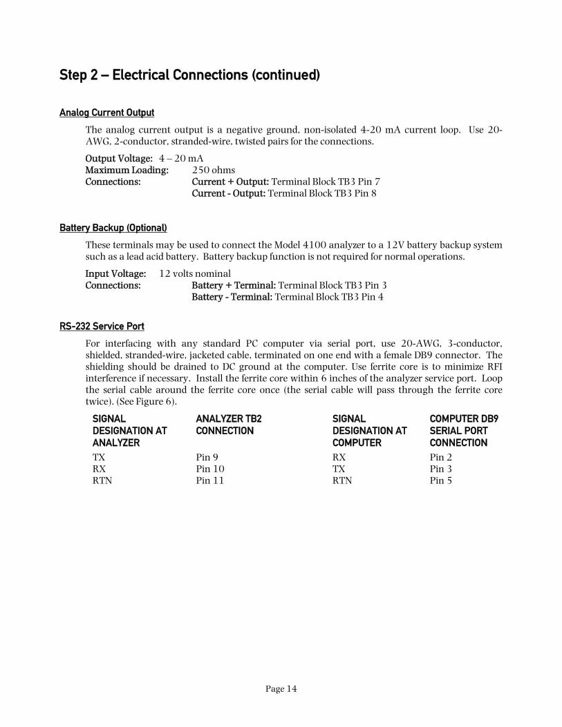
Analog Current Output
The analog current output is a negative ground, non-isolated 4-20 mA current loop. Use 20-AWG, 2-conductor, stranded-wire, twisted pairs for the connections.
Output Voltage: 4 – 20 mA Maximum Loading: 250 ohms Connections: Current + Output: Terminal Block TB3 Pin 7 Current - Output: Terminal Block TB3 Pin 8
Battery Backup (Optional)
These terminals may be used to connect the Model 4100 analyzer to a 12V battery backup system such as a lead acid battery. Battery backup function is not required for normal operations.
Input Voltage: 12 volts nominal Connections: Battery + Terminal: Terminal Block TB3 Pin 3 Battery - Terminal: Terminal Block TB3 Pin 4
RS-232 Service Port
For interfacing with any standard PC computer via serial port, use 20-AWG, 3-conductor, shielded, stranded-wire, jacketed cable, terminated on one end with a female DB9 connector. The shielding should be drained to DC ground at the computer. Use ferrite core is to minimize RFI interference if necessary. Install the ferrite core within 6 inches of the analyzer service port. Loop the serial cable around the ferrite core once (the serial cable will pass through the ferrite core twice). (See Figure 6).
SIGNAL DESIGNATION AT ANALYZER
ANALYZER TB2 CONNECTION
SIGNAL DESIGNATION AT COMPUTER
COMPUTER DB9 SERIAL PORT CONNECTION
TX Pin 9 RX Pin 2 RX Pin 10 TX Pin 3 RTN Pin 11 RTN Pin 5

Page 15
Step 2 – Electrical Connections (continued)
Mains Power
Use minimum 16-AWG, 3-conductor, stranded-wire for mains power connections.
Mains Power Voltage: 90-264 Volts AC, 47 – 63 Hz, Single Phase Connections: AC-Line: Terminal Block TB3 Pin 3 AC-Return: Terminal Block TB3 Pin 3 AC-Ground: Terminal Block TB3 Pin 3
WARNING: Do not apply mains power to the analyzer or the remote sensor module until all the electrical connections to the analyzer and the remote sensor module, and all the pneumatic connections to the remote sensor module have been properly installed.
Remote Sensor Module Interface Cable
Use the remote sensor module interface cable as supplied. Connect to the socket located to the rear of the Model 4100 analyzer. See figure 1 for the location of the socket
Serial Cable
Ferrite Core
Cable TieCable Tie
Figure 6 – RS-232 Ferrite Core
Page 16
3 CHAPTER 3 – OPERATING INSTRUCTIONS
A. First Time Power Up
The Model 4100 is shipped ready to use, right from the carton. Its default configuration has been set to your application. Review the default configuration settings, as shown in the analyzer software setup log sheet, shipped with your Model 4100 analyzer. Before commissioning your system, ensure that the default settings match your application. Contact the factory if your default settings do not match your application.
WARNING: Verify that the Model 4100 analyzer remote sensor module heater voltage has been properly configured to your mains power voltage: 115 or 230 VAC. Although the analyzer can operate at any voltage between 90 and 264 VAC, it requires that the heater voltage be correctly set to properly regulate the sensor heater temperature inside the
remote sensor module. If the heater voltage setting does not match the mains power voltage, the remote sensor module may be permanently damaged. Failure to comply may result in loss of warranty.
WARNING: Do not apply mains power to the analyzer or the remote sensor module until all the electrical connections to the analyzer and the remote sensor module, and all the pneumatic connections to the remote sensor module have been properly installed.

Page 17
First Time Power Up (continued)
FIRST TIME POWER UP CHECK LIST Have you:
Verified that all the electrical and pneumatic connections to the remote sensor module have been properly installed?
Verified that all the electrical connections to the analyzer have been properly installed?
Verified that the analyzer is properly connected to the remote sensor module via the sensor interface cable?
Ensured that none of the mains power wiring to both the analyzer and the remote sensor module are exposed?
Verified that the 4100 heater voltage setting matches the mains power voltage?
Mounted the analyzer in areas where there are no flammable vapors?
Mounted the analyzer away from exposure to rain, dripping water, or hose down?
Read this manual in its entirety?
Read the remote sensor module manual in its entirety?
First Time Power Up Instructions
1. Apply Ambient Air to the Remote Sensor Module: Apply clean, dry oil-free ambient air to the remote sensor module. See the remote sensor module installation manual for more detail.
2. Apply Mains Power: Apply mains power to both the analyzer and the remote sensor module. The Model 4100 analyzer will perform the following power up sequence:
a. Lamp Test (Verify): Verify that all the 7-Segment display and discrete LEDs light up and flash. If any of the display segments or LEDs do not light up, remove all mains power and return both the analyzer and remote sensor module to either the factory or a certified service center for servicing.
b. Software ID (No Action): After completing the lamp test, the 7-Segment display will show a 4-digit number signifying the software build number.

Page 18
First Time Power Up (continued)
First Time Power Up Instructions (continued)
c. Heater Voltage Setting (Verify): After indicating the software build number, the analyzer will display either “110” or “220”. If the display shows “110” the analyzer is set up to operate the sensor heater mains power voltage at 115 +/- 15 VAC. If the analyzer display shows “220” the analyzer is set-up to operate at mains power voltage of 230 +/- 30 VAC. Verify that the heater voltage setting matches your mains power supply voltage.
CAUTION: If the Model 4100 analyzer heater voltage setting does not match the mains power voltage, power down both the analyzer and the remote sensor module immediately. Contact the factory or an approved service center to correct the heater voltage setting. Failure to comply may damage the remote sensor module permanently and result in loss of warranty.
3. Wait 15 Minutes for Sensor to Warm Up to Operating Temperature: Upon completing the power up sequence, the Model 4100 will bring up the sensor heater temperature to the operating temperature. This process will take about 15 minutes. During this period the display will alternate between “nr” for not ready and the sensor temperature in degrees Centigrade.
NOTE: If the Model 4100 fails to increase sensor heater to operating temperature, the display will flash “HF” for heater failure. Power down both the analyzer and the remote sensor module. Check the sensor interface cable connection to ensure integrity. Repeat the power up procedure. If problem persists, return both the analyzer and the remote sensor module to the factory or a certified service center for servicing.
4. Temperature Stabilization: After completion of the warm-up sequence, the analyzer and the remote sensor module is ready for calibration and oxygen measurement. However, it is recommended that the user wait for an additional 1 hour for the system to reach temperature stabilization for the most accurate calibration and measurements.
5. Measure Air Sample (Verify): After temperature stabilization, if the Model 4100 analyzer displays between 20.7% and 21.1% at ambient air, calibration is not necessary. Otherwise, verify that clean, dry, oil-free ambient air is supplied to remote sensor module at the pressure and flow rate required by the remote sensor module manual. If the sample air supply requirements to the remote sensor module is met and the reading is not within the stated tolerance, perform air calibration per Appendix A.
First Time Power Up (continued)
6. Verify Outputs: If the Model 4100 analyzer displays between 20.7% and 21.1% after warm-up, and all the first time power-up verifications have been completed, Check the fault, temperature OK, and oxygen alarm relay contacts to ensure that they are wired properly and functioning normally. Also, check the analog current, analog voltage, and range ID voltage outputs to ensure that they are functioning normally.

Page 19
7. Apply The Gas To Be Analyzed: Apply the gas that is to be analyzed to the remote sensor module. Verify that the oxygen concentration display, the status LEDs, relay contact outputs, the analog outputs and the Range ID outputs are wired properly and functioning normally.

Page 20
B. Normal Power Up and Power Down Instructions
After the instructions for the first time power up has been completed, the Model 4100 analyzer and its remote sensor module can be run continuously. For periods when the analyzer and remote sensor module are not in use, power both units down. Wait at least 15 minutes after power down to ensure that the sensor is cool before reapplying power to both the analyzer and the remote sensor module again.
C. Oxygen Alarm Level Settings
If the user's process requires adjustments to either oxygen alarm level, follow adjustment procedure in Appendix C.
D. Features
The Model 4100 is intended to be used with the remote sensor module to measure oxygen concentrations in inert background. The Model 4100 Analyzer comes equipped with several operational features. Each feature will be discussed in detail separately:
• Three Pushbutton Control Panel Interface.
• 4-Digit 7-Segment Oxygen Concentration Display with Measurement Range LEDS.
• Four Status LEDs: RUN, FAULT, ALARM 1 and ALARM 2.
• Four relay outputs: TEMPERATURE OK, FAULT, ALARM 1 and ALARM 2.
• Three outputs: Analog Current, Analog Voltage & Range ID voltage.
• RS-232 output.
D. Features (continued)
Control Panel User Interface The Model 4100 Analyzer has three pushbuttons labeled as “UP” “DOWN” and “MODE” on the front panel. These pushbuttons are used for special functions like calibration and accessing the user setup mode. See the appendices for more details on the usage of the pushbuttons. When instructions specify pressing the "MODE" key more than once, press and release the "MODE" key approximately once every half-second.

Page 21
Figure 7 – Control Panel Pushbutton Interface
MEASUREMENTRANGE MODE
RUN FAULT ALM 1 ALM 2
20.9OXYGEN
MODEL 4100 O2 AnalyzerNTRON
PERCENT
PPM
PPB
“UP” PUSHBUTTON
“DOWN” PUSHBUTTON
“MODE” PUSHBUTTON

Page 22
D. Features (continued)
Oxygen Concentration Display The Model 4100 Analyzer uses the four 7-Segment LED banks and three measurement range LEDs to indicate the oxygen concentration. The display format is as below:
Measurement Range Percent LED PPM LED PPB LED 7-Segment Display Resolution
0.0 – 9.9 PPB OFF OFF ON X.X
10.0 – 99.9 PPB OFF OFF ON XX.X
100.0 – 999.9 PPB OFF OFF ON XXX.X
1.0 – 9.9 PPM OFF ON OFF X.X
10.0 – 99.9 PPM OFF ON OFF XX.X
100.0 – 999.9 PPM OFF ON OFF XXX.X
1000 – 9999 PPM OFF ON OFF XXXX.
1.00 – 9.99 PERCENT ON OFF OFF X.XX
10.0 – 99.9 PERCENT ON OFF OFF XX.X
100.0 PERCENT ON OFF OFF XXX.X
Status LEDs The Model 4100 Analyzer uses the four status LEDs to indicate the operational status of the Model 4100 Analyzer. The function of each of the status LEDs are described below
♦ Run LED (GREEN): The green Run LED is used to indicate the operational status of the Model 4100 analyzer. The operational status are:
o On Blinking: The Model 4100 Analyzer is operating normally. If the Fault LED is off, all analyzer outputs are valid.
o On Not Blinking: The Model 4100 Analyzer is powered but not operating normally. All analyzer outputs are not valid.
o Off: The Model 4100 Analyzer is not powered. All analyzer outputs are not valid.
Page 23
D. Features (continued)
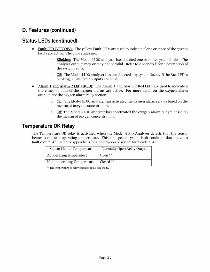
Status LEDs (continued) ♦ Fault LED (YELLOW): The yellow Fault LEDs are used to indicate if one or more of the system
faults are active. The valid states are:
o Blinking: The Model 4100 analyzer has detected one or more system faults. The analyzer outputs may or may not be valid. Refer to Appendix B for a description of the system faults.
o Off: The Model 4100 analyzer has not detected any system faults. If the Run LED is blinking, all analyzer outputs are valid.
♦ Alarm 1 and Alarm 2 LEDs (RED): The Alarm 1 and Alarm 2 Red LEDs are used to indicate if the either or both of the oxygen alarms are active. For more detail on the oxygen alarm outputs, see the oxygen alarm relay section:
o On: The Model 4100 analyzer has activated the oxygen alarm relay/s based on the measured oxygen concentration.
o Off: The Model 4100 analyzer has deactivated the oxygen alarm relay/s based on the measured oxygen concentration.
Temperature OK Relay The Temperature OK relay is activated when the Model 4100 Analyzer detects that the sensor heater is not at it operating temperature. This is a special system fault condition that activates fault code “14”. Refer to Appendix B for a description of system fault code “14”.
Sensor Heater Temperature Normally Open Relay Output
At operating temperature Open **
Not at operating Temperature Closed **
** The temperature ok relay operates in fail-safe mode.

Page 24
D. Features (continued)
Fault Relay The fault relay is activated when the Model 4100 Analyzer detects one or more system faults. Refer to Appendix B for a description of the system faults. Refer to the following table for the outputs of the fault relay:
System Fault Status Fault LED Normally Open Relay Output
Active On Blinking Open **
Not Active Off Closed **
** The fault relay operates in fail-safe mode.
Oxygen Alarm 1 & Alarm 2 Relays The Oxygen Alarm 1 and Alarm 2 relays activation depend on the following Model 4100 Analyzer settings. Refer to the software setup log shipped with the analyzer to determine your actual settings.
♦ Alarm Set point: Alarm Set point is the oxygen concentration at which the oxygen alarm relays and LEDs activate or de-activate. To adjust alarm set point, see Appendix C.
♦ Descending: The Descending setting determines if the oxygen alarm relays and LEDs are activated above or below the alarm set point. If the Descending setting is set to “yes”, the alarm relays and LEDs activate when the oxygen concentration is below the alarm set point concentration. If the Descending setting is set to “no”, the alarm relays activate when the oxygen concentration is above the alarm set point concentration. To adjust this setting, see Appendix E.
♦ Failsafe: The Failsafe setting determines the status of the alarm relays when the oxygen alarm is active. If the Failsafe setting is set to “yes”, the alarm relays are de-energized when the oxygen alarm is active. If the Failsafe setting is set to “no”, the alarm relays are energized when the oxygen alarm is active. To adjust this setting, see Appendix E.
D. Features (continued)
Oxygen Alarm 1 & 2 Relays (continued) The following table summarizes all the possible states of the oxygen alarm relay output:
O2 Concentration Above/Below Alarm Set point?
Descending? Failsafe? Alarm Relay/LED Status
Alarm Relay Normally Open Output
Alarm Relay Normally Closed Output
Above No No Active Closed Open

Page 25
Above No Yes Active Open Closed
Above Yes No Not-Active Open Closed
Above Yes Yes Not-Active Closed Open
Below No No Not-Active Open Closed
Below No Yes Not-Active Closed Open
Below Yes No Active Closed Open
Below Yes Yes Active Open Closed

Page 26
D. Features (continued)
Analog Voltage & Analog Current Output The analog voltage and analog current output produces either a voltage or a current output proportional to the measured oxygen concentration. For the analog voltage, the zero scale is always 0 volts. The full scale is programmed at the factory to be either 1, 5, or 10 volts. For the analog current output the zero scale output is 4 milliamperes and the full-scale output is 20 milliamperes.
The measurement scale is also preprogrammed at the factory to one of the following:
ANALOG FULL SCALE
10 PARTS-PER-BILLION 100 PARTS-PER BILLION 1000 PARTS-PER-BILLION 10 PARTS-PER-MILLION 100 PARTS-PER-MILLION 1000 PARTS-PER-MILLION 10000 PARTS-PER-MILLION 10 PERCENT 100 PERCENT AUTO-RANGING
When the measurement scale is auto-ranging, the analog output automatically scales to the smallest relevant measurement range. For example if the measurement is 99 PPB, the analog output will scale to 0–100 PPB. When the measurement increases to 101 PPB, the analog output will rescale to 0-1000 PPB. Use the Range ID voltage output to identify the active measurement scale.

Page 27
D. Features (continued)
Range ID Voltage The Range ID voltage is used to identify the oxygen concentration at which the analog voltage and analog current outputs are at their full scale. This information is useful if the analog outputs are set to auto-ranging.
The following is a list of all possible Range ID voltages. Actual measured voltage may be within +/- 0.2 volts of indicated voltage.
RANGE ID VOLTAGE ANALOG FULL SCALE
0.63 VOLTS 10 PARTS-PER-BILLION
1.25 VOLTS 100 PARTS-PER BILLION
1.88 VOLTS 1000 PARTS-PER-BILLION
3.13 VOLTS 10 PARTS-PER-MILLION
3.73 VOLTS 100 PARTS-PER-MILLION
4.38 VOLTS 1000 PARTS-PER-MILLION
5.00 VOLTS 10000 PARTS-PER-MILLION
6.25 VOLTS 10 PERCENT
8.13 VOLTS 100 PERCENT
RS-232 Port The Model 4100 Analyzer port will transmit information to a host computer via the RS-232 port. The information includes the oxygen concentration, fault status and oxygen alarm status. For more information on the RS-232 communications, see Appendix D.

Page 28
4 CHAPTER 4 - MAINTENANCE AND TROUBLESHOOTING
WARNING: The Model 4100 analyzer has no field-serviceable parts. Do not attempt to repair the unit. All repairs are to be performed either at the factory or at any of the certified service centers. Failure to comply will result in loss of warranty.
TASK RECOMMENDED FREQUENCY
AT COMMISSIONING EVERY YEAR AS REQUIRED
Calibrate Sensor √ √**
Verify Sensor √**** √ √
Clean the analyzer chassis and display panel with soft cloth. Make sure the ventilation ports are clear.
√ √
Service the Model 4100 Analyzer at an approved service centers
√*** Every 2 Years
** Air calibration is only required at commissioning or after the unit has been serviced for elevation compensation. Verify calibration is required at commissioning or after service.
*** The Model 4100 analyzer is matched to a particular remote sensor module. Both parts should be serviced simultaneously.
**** It is recommended that the unit be verified at ambient air concentration two weeks after commissioning to ensure that the sensor is not contaminated. Re-calibrate if the sensor output has drifted after two weeks and monitor for another six weeks if drift occurs. If the output in air continually drifts for the eight-week period, call an approved service center.
Troubleshooting
System faults should clear after the 15 minute warm up period, and two minutes after a calibration was performed. If fault persists, follow the fault identification procedure specified in Appendix B. Call an approved service center if assistance is still needed.
Unstable sensor: Exposure to cross-sensitive chemicals, such as hydrocarbons, has been known to cause erratic sensor output. To determine if a process substance is affecting the sensor, plumb pure nitrogen to the remote sensor module and purge. After 15 minutes, the displayed concentration should be more stable. Call an approved service center if assistance is still needed.
Maintenance and Troubleshooting (continued) Troubleshooting (continued)
Contaminated sensor: Avoid the use of silicone-based lubricants and sealants in the sample stream. Contamination should be monitored at commissioning, as detailed in the maintenance table in this section of the manual.

Page 29
Approved Service Centers for the Model 4100 Analyzer
Neutronics, Inc. reserves the right to change the list of service centers without notice.
Service Department Neutronics, Inc. 456 Creamery Way Exton, PA 19341 U.S.A. Email: [email protected] Toll Free: 1-800-378-2287 (U.S.A. Only) Phone: 610-524-8800 ext. 123 or 171 (Operator is ext. 100) Fax: 610-524-8807

Page 30
5 CHAPTER 5 – SPECIFICATIONS ****
Revision B Release Date: May 2008
SENSOR *** Model 4-LP-N1-SS or Model 4-SPM-N1-SS Remote Sensor Module
0.75” 7-segment LED digital display, 4 characters
3 Measurement Range LEDs to indicate measurements in Percent, PPM or PPB. Displays oxygen from 0.1 PPB to 100 percent.
Color -Coded LED’s for system status:
RUN: Green
FAULT: Yellow
ALARM-1: Red
DISPLAY
ALARM-2: Red
Serial Service Port: Bi-directional RS-232
Analog Voltage Output: 0–1, 0–5, or 0–10 VDC
Analog Current Output: Non-isolated 4 – 20 mA, 12 VDC, negative ground, powered by analyzer, maximum electrical load 250 Ohms
SIGNAL INTERFACE
Range ID Voltage: 0 – 10 Volts DC
Alarm-1: Field Adjustable Form C (SPDT) Voltage-free, 5A @ 250 VAC, 5A @ 30 VDC.
Alarm-2: Field Adjustable Form C (SPDT) Voltage-free, 5A @ 250 VAC, 5A @ 30 VDC.
Fault: Non-adjustable Form B (SPST) Voltage-free, 5A @ 250 VAC, 5A @ 30 VDC.
RELAY OUTPUTS
Temper-ature OK:
Non-adjustable Form B (SPST) Voltage-free, 5A @ 250 VAC, 5A @ 30 VDC.
*** See the remote sensor module installation manual for the sensor performance characteristics. **** Neutronics, Inc, whose policy is one of continuous improvements, reserves the right to change specifications and contents without notice.

Page 31
Specifications**** (continued)
Revision B Release Date: May 2008
RANGE See remote sensor module installation manual
ACCURACY See remote sensor module installation manual
RESPONSE TIME See remote sensor module installation manual
WARM UP TIME None
HUMIDITY 0-95% non-condensing
POWER 90-264 VAC, 47-63 Hz, Single Phase.
Power consumption: 3 Watts. Power Up Inrush: 5 Watts
OPERATING TEMPERATURE
32 to 122 degrees F (0 to 40 degrees C)
STORAGE TEMPERATURE
23 to 122 degrees F (-5 to 40 degrees C)
WEIGHT 2 lbs. (0.9 Kg)
Faceplate: Height 3.75” x Width 7.00” NEMA4 IP66
Panel Cut-out: Height 2.91” x Width 6.20” MECHANICAL
Electronic Compartment: Height 2.81” x Width 5.98” x Depth 3.60” NEMA 1 IP 20
WARRANTY 12 months from date of shipment
**** Neutronics, Inc, whose policy is one of continuous improvements, reserves the right to change specifications and contents without notice.

Page 32
Warranty Statement Neutronics warrants to the original purchaser, that the Model 4100 Oxygen analyzer is free from defects in material and workmanship for a period of one (1) year from the date of shipment from Neutronics or from one of Neutronics’ authorized dealers. Our liability will be limited to the repair or replacement, at our factory, of parts found to be defective within the warranty period, as determined by Neutronics. The parts will be repaired or replaced free of charge if shipped prepaid to the factory in the original shipping carton. This warranty is void if the product has been subject to misuse or abuse, including but not limited to: exposure to water, humidity, temperature, shock or pressure outside of the listed specifications, or has not been operated or installed in accordance with operating and maintenance instructions, for repairs which were not performed by Neutronics or by one of its authorized dealers, or if the identifying markings on the product label have been altered or removed.
The seller assumes no liability for consequential damages of any kind, and the buyer, by acceptance through purchase of this product, will assume all liability for the consequences of its use or misuse by the buyer, his employees, or others.
Neutronics reserves the right to use any materials in the manufacture, repair or service of the products and to modify the design as deemed suitable, in so far as these materials or modifications maintain the stated warranty.
It is the sole responsibility of the buyer / user to determine if this product is suitable for the intended application.
THESE WARRANTIES ARE EXCLUSIVE AND IN LIEU OF ALL OTHER WARRANTIES, EXPRESSED, OR IMPLIED INCLUDING WARRANTY OF MERCHANTABILITY, FITNESS FOR A PARTICULAR PURPOSE.
Intended Use For The Model 4100 The Model 4100 Oxygen analyzer was designed to provide the trained operator with useful information relating to the concentration of Oxygen. This information may be used in process control or to minimize possible hazardous conditions, which may be present in various processes. Before implementation, the user must fully understand the operation and limitations of this instrument as well as the application for its use. The responsibility for the proper application, operation, installation, and maintenance of the Model 4100 Oxygen analyzer is the sole obligation of the trained operator. The purchaser is required to ensure operators are properly trained in the use of this unit as well as in the possible hazards associated with its use or with the intended application. The purchaser must ensure that all of the proper warnings, labels, instruction manuals, lock outs, redundant components, hazard analysis, and system validation have been completed and provided to the trained operator before implementation of the Model 4100 instrument.

Page 33
Appendix A: Ambient Air Calibration
The Model 4100 Analyzer, along with its matching remote sensor module is shipped from the factory fully calibrated for its operational measurement range. It may be necessary, however, to perform air calibration at commissioning to account for differences in atmospheric pressures at the installation site.
CAUTION: Before attempting this air calibration procedure, verify that clean, dry, oil-free ambient air is being supplied to the remote sensor module as required by its installation manual. Using instrument grade air is recommended if remote sensor
module is located in a confined space.
The following are the steps to the calibration procedure:
Verify calibration is necessary:
• Start with the analyzer in run mode. Verify that the “RUN” indicator flashes slower than once per second.
• Flow ambient air though the remote sensor module.
• Allow two minutes for the sensor to stabilize.
• Observe the display for one minute. If the display drifts more than 0.2%, over the one minute period, check the ambient air source for contaminants such as a nearby nitrogen vent.
• Determine calibration is necessary: If the analyzer display reads 21.2% or greater, or the analyzer displays 20.6 or less, then calibration is necessary.
• If calibration is not necessary: Disconnect ambient air or calibration gas source from the remote sensor module. Apply process gas that is to be analyzed to the remote sensor module.
Calibration procedure:
• Press MODE Key Once: Press and release the “MODE” key once. The 7-segment alphanumeric display will show “CAL”, then an oxygen concentration value.
Note: In this mode, if no keys are pressed, then the analyzer will return to "RUN" mode, typically within two minutes.

Page 34
Appendix A: Ambient Air Calibration (continued) • Change the concentration setting: Verify that the PERCENT LED on the Measurement Range
panel is lit. Verify that the oxygen concentration so that the 7-segment display shows “20.9”.
If other concentration is displayed, use the “UP” and “DOWN” key, to adjust the oxygen concentration so that the 7-segment display shows “20.9”, and verify the PERCENT LED is lit.
If 20.9 is displayed and the percent LED is on, press the “UP” key once, then press the “DOWN” key once. The analyzer will not calibrate unless one of these keys is pressed. Verify the 7-segment display shows “20.9”.
• Press the MODE Key Four Times:
If the “UP” or “DOWN” key was pressed in the previous step, pressing the MODE key four times reads and stores the new air calibration setting. The 7-segment display will show the text, “RUN”, for one second. The air calibration has been completed and the analyzer is returning to normal operating mode.
If neither the “UP” or “DOWN” key was not pressed in the previous step, the analyzer will exit without storing calibration settings. The 7-segment display will show the text, “RUN”, for one second. The analyzer is returning to normal operating mode.
• Disconnect calibration gas: The analyzer will wait two minutes to take a sample. Disconnect ambient air or calibration gas source from the remote sensor module. Apply the gas that is to be analyzed to the remote sensor module.

Page 35
Appendix B: System Faults
If the Model 4100 Analyzer detects one or more system faults, it will illuminate the yellow FAULT LED on the front panel and will de-energize the System Fault relay.
The following are the steps to access the system faults viewing mode:
• Start with the analyzer in run mode. Verify that the “RUN” indicator flashes slower than once per second.
• Press MODE Key Four Times: Press and release the “MODE” key four times. The 7-segment alphanumeric display will show “FL”, one or two digits for the system fault code. See below for the description of the system fault codes. If there are no faults, the 7-segment alphanumeric display will show “FL ” only.
Note: In this mode, if no keys are pressed, then the analyzer will return to "RUN" mode, typically within two minutes.
• Scroll Through Active Faults: If there are more than one active system fault condition, use either the “UP” and “DOWN” keys to scroll through all the active system faults.
• Press MODE Key Once: Press the MODE key once to return to "RUN" mode. The 7-segment display will show the text, “RUN”, for one second.
The following is a description of all the system fault code digits and its troubleshooting guide:

Page 36
Appendix B – System Faults (continued) • “1” – Sensor is warming up: This system fault is active when the Model 4100 analyzer is
increasing the sensor heater temperature to its operating temperature. All system outputs are not valid. No troubleshooting required. This system fault will clear itself when the sensor heater reaches operating temperature. This fault will clear typically after 15 minutes.
• “2” – Relay Outputs are in Standby Mode: This system fault is active when the Model 4100 analyzer has just been air calibrated. This fault stays active for about 2 minutes. The oxygen concentration reading and analog outputs are valid. The oxygen alarm relay outputs are not valid. No troubleshooting required. This system fault condition clears itself typically after two minutes.
• “3” – Setup Mode Active: The Model 4100 Analyzer is in Setup Mode. All outputs are not valid. See Appendix E for a description of the Setup Mode. No troubleshooting required. This system fault condition clears itself after exiting setup mode.
• “5” – Analog Output Overflow: The measured oxygen concentration is higher than the span concentration of the analog voltage and current outputs. The analog output will be at full scale. Only the analog outputs are not valid. All other outputs are valid. For most instances, no troubleshooting is required. The fault will clear itself when your process gas is introduced to the remote sensor module. However, if this fault is experienced under process gas conditions, check the software setup log sheet to ensure that your analog output span setting is high enough to include all your process gas concentrations conditions. Your process gas concentration may also be larger than normal.
• “6” – Analog Output Underflow: The measured oxygen concentration is lower than the zero concentration of the analog voltage and current outputs. The analog output will be at zero scale. Only the analog outputs are not valid. All other outputs are valid. Note: This system fault condition can happen only on special custom units. This system fault cannot be remedied in the field. Contact the factory or an approved service center if this system fault code persists.
• “8” – Reading Not Available: The analyzer electronics has not produced a valid oxygen measurements. This may happen during power up, or during partial electronics failure. All analyzer outputs are not valid. If this system fault condition does not clear itself within minutes after power up, both the analyzer and the remote sensor module must be returned to the factory or an approved service center for servicing.
Page 37
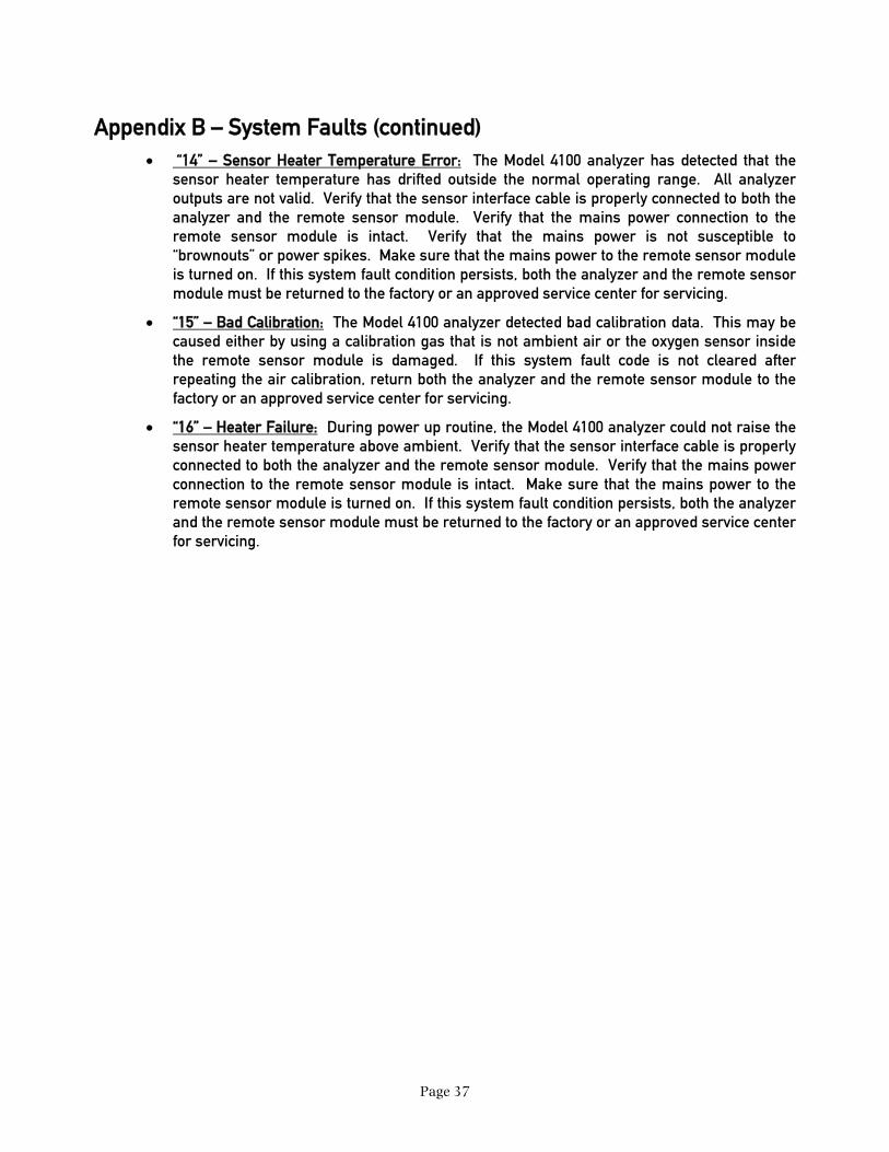
Appendix B – System Faults (continued) • “14” – Sensor Heater Temperature Error: The Model 4100 analyzer has detected that the
sensor heater temperature has drifted outside the normal operating range. All analyzer outputs are not valid. Verify that the sensor interface cable is properly connected to both the analyzer and the remote sensor module. Verify that the mains power connection to the remote sensor module is intact. Verify that the mains power is not susceptible to “brownouts” or power spikes. Make sure that the mains power to the remote sensor module is turned on. If this system fault condition persists, both the analyzer and the remote sensor module must be returned to the factory or an approved service center for servicing.
• “15” – Bad Calibration: The Model 4100 analyzer detected bad calibration data. This may be caused either by using a calibration gas that is not ambient air or the oxygen sensor inside the remote sensor module is damaged. If this system fault code is not cleared after repeating the air calibration, return both the analyzer and the remote sensor module to the factory or an approved service center for servicing.
• “16” – Heater Failure: During power up routine, the Model 4100 analyzer could not raise the sensor heater temperature above ambient. Verify that the sensor interface cable is properly connected to both the analyzer and the remote sensor module. Verify that the mains power connection to the remote sensor module is intact. Make sure that the mains power to the remote sensor module is turned on. If this system fault condition persists, both the analyzer and the remote sensor module must be returned to the factory or an approved service center for servicing.

Page 38
Appendix C: Oxygen Alarm Level Settings
The Model 4100 Analyzer, along with its matching remote sensor module is shipped from the factory with the oxygen alarm level set to your desired process. However, the oxygen alarm level settings may be changed using the procedures below.
WARNING: Altering the Oxygen Alarm Level setting may affect the Model 4100 analyzer’s performance in your process.
WARNING: Altering the Oxygen Alarm Level setting does not alter the factory default settings. If a Factory Restore function is performed (see Appendix E), the Oxygen Alarm Level setting will revert back to the one programmed at factory. It is best to have your desired Oxygen Alarm Level settings be programmed at the factory.
The following are the steps to change Alarm 1 level setting:
• Start with the analyzer in run mode. Verify that the “RUN” indicator flashes slower than once per second.
• Press MODE Key Twice: Press and release the “MODE” key twice. The 7-segment alphanumeric display will show “AL 1”, then an oxygen concentration value.
• Enter Oxygen Concentration: Using the “UP” and “DOWN” key, adjust the oxygen concentration so that the 7-segment display shows the desired oxygen level. Verify that the correct Measurement Range LED, Percent, PPM, or PPB, is lit.
• Press MODE Key Three Times: Press the MODE key once to return to "RUN" mode. The 7-segment display will show the text, “RUN”, for one second.
The following are the steps to change Alarm 2 level setting:
• Start with the analyzer in run mode. Verify that the “RUN” indicator flashes slower than once per second.
• Press MODE Key Three Times: Press and release the “MODE” key three times. The 7-segment alphanumeric display will show “AL 2”, then an oxygen concentration value.
• Enter Oxygen Concentration: Using the “UP” and “DOWN” key, adjust the oxygen concentration so that the 7-segment display shows the desired oxygen level. Verify that the correct Measurement Range LED, Percent, PPM, or PPB, is lit.
• Press MODE Key Twice: Press the MODE key once to return to "RUN" mode. The 7-segment display will show the text, “RUN”, for one second.
Appendix D: RS-232 Port
The RS-232 port may be used to send data to a host computer. There are four available formats that the Model 4100 may send data to the host computer. The speed of the data transmission can vary from 300BPS to 38.4KBPS. Unless otherwise specified, the following is the default transmission format:
Page 39
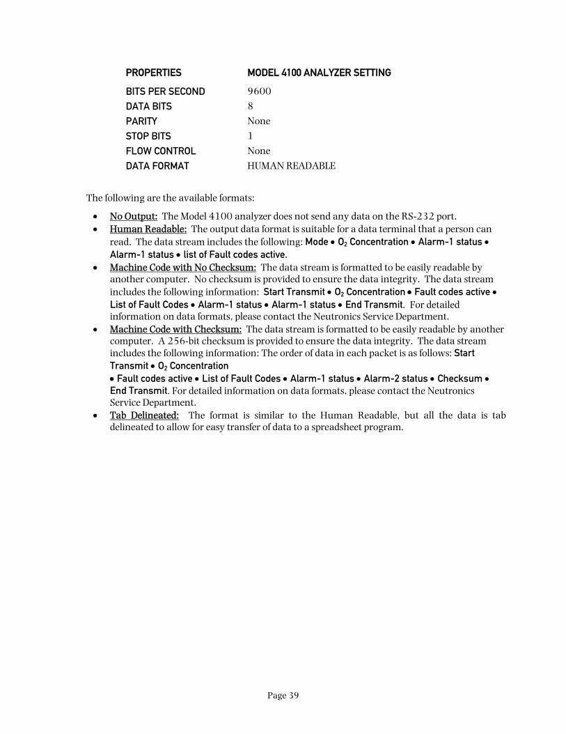
PROPERTIES MODEL 4100 ANALYZER SETTING
BITS PER SECOND 9600
DATA BITS 8
PARITY None
STOP BITS 1
FLOW CONTROL None
DATA FORMAT HUMAN READABLE
The following are the available formats:
• No Output: The Model 4100 analyzer does not send any data on the RS-232 port. • Human Readable: The output data format is suitable for a data terminal that a person can
read. The data stream includes the following: Mode • O2 Concentration • Alarm-1 status • Alarm-1 status • list of Fault codes active.
• Machine Code with No Checksum: The data stream is formatted to be easily readable by another computer. No checksum is provided to ensure the data integrity. The data stream includes the following information: Start Transmit • O2 Concentration • Fault codes active • List of Fault Codes • Alarm-1 status • Alarm-1 status • End Transmit. For detailed information on data formats, please contact the Neutronics Service Department.
• Machine Code with Checksum: The data stream is formatted to be easily readable by another computer. A 256-bit checksum is provided to ensure the data integrity. The data stream includes the following information: The order of data in each packet is as follows: Start Transmit • O2 Concentration • Fault codes active • List of Fault Codes • Alarm-1 status • Alarm-2 status • Checksum • End Transmit. For detailed information on data formats, please contact the Neutronics Service Department.
• Tab Delineated: The format is similar to the Human Readable, but all the data is tab delineated to allow for easy transfer of data to a spreadsheet program.

Page 40
Appendix E: System Setup
The Model 4100 is shipped ready to install and operate. It has been factory configured to meet the requirements of your application. The user, however, may change the settings from the setup menu accessed from the analyzer front panel.
WARNING: Altering the system setup settings will alter the performance of the oxygen analyzer, and may affect its performance in your process. Neutronics is not responsible for any effects from this change in performance.
WARNING: Altering the system setup settings do not alter the factory default settings. If a Factory Restore function is performed, all settings will revert back to the ones programmed at factory. It is best to have all your required settings be programmed at the factory.
NOTE: To return all settings to factory default settings, use the Factory Restore function as listed below.
IMPORTANT: Before changing any of the Model 4100 settings, refer to the software setup log that is supplied from the factory for reference. If the user has any questions before proceeding with changing analyzer settings, please contact the Neutronics Service Department for assistance.
Accessing the System Setup Menu
The control panel user setup menu may be accessed from the Model 4100 control panel by pressing and holding the “MODE” key for at least 10-seconds until the 7-segment alphanumeric display shows“---“ to indicate that the analyzer has accessed setup mode. Release the “MODE” key to activate setup mode. Once in setup mode, the user can access adjustable parameters sequentially by continuing to press and release the “MODE” key to scroll through the setup menu.
When you reach the mode that you wish to change, use the “UP” and “DOWN” keys to adjust the displayed setting. The modes are numerically identified by the number on the left side of the display. The current mode setting is identified by the number on the right side of the display. The new settings are automatically saved when the user advances to the next mode by pressing and releasing the “MODE” key. To exit press “MODE” key until the display shows “run”.
Appendix E: System Setup (continued)
WARNING: For each of the System Setup Settings listed below, do not use any setting that is not specifically listed. Failure to comply may cause the analyzer to operate outside its operating specifications and behave unpredictably.

Page 41
MODE
RUN FAULT ALM 1 ALM 2
2 lOXYGEN
MODEL 4100 O2 AnalyzerNTRON
User Setup A: Display Range Select
This setting specifies the operations of the Analog Voltage Output, Analog Current Output and the Display Range of the analyzer. The valid settings are:
1 (fixed range 0-10 PPB) • 2 (fixed range 0-100 PPB) • 3 (fixed range 0-1000 PPB) • 5 (fixed
range 0-10 PPM) • 6 (fixed range 0-100 PPM) • 7 (fixed range 0-1000 PPM) • 8 (fixed range 0–
10000 PPM) • 9 (fixed range 0–10 %) • 10 (fixed range 0–10000 PPM) • 12 (Auto Ranging)
User Setup 1: Alarm-1 Relays Ascending/Descending Action
This setting sets the Oxygen Alarm 1 relay to ascending (activates when the oxygen level is above set point) or to descending (activates when the oxygen level is below the set point). The valid settings are:
1 (Descending) • 0 (Ascending)
User Setup 2: Alarm-2 Relays Ascending/Descending Action
This setting sets the Oxygen Alarm 2 relay to ascending (activates when the oxygen level is above set point) or to descending (activates when the oxygen level is below the set point). The valid settings are:
1 (Descending) • 0 (Ascending)
Appendix E: System Setup (continued)
User Setup 3: Analog Voltage Output Setting
This setting sets the Analog Output Voltage full scale to 1, 5, or 10 volts. WARNING!!! Do not change this setting without consulting the factory!!!
User Setup 4: Serial Output Format
This parameter allows the user to set the RS-232 communications output format.
Valid Settings: 0 (Output on Request) • 1 (Human Readable) • 2 (Machine Code) • 3 (Machine Code with Checksum) • 4 (Tab Delimited)
User Setup 7: Low-End Calibration Range Code
WARNING!!! DO NOT CHANGE THIS SETTING!!!
USER SETUP MODE
USER SETUP SETTING

Page 42
User Setup F: Alarm 1/2 Relays Failsafe/Non Failsafe
This setting sets the Alarm-1 and Alarm-2 relays to either failsafe (not energized when alarm is active) or non-failsafe (energized when alarm is active). Valid settings are:
0 (Non-Failsafe) • 1 (Failsafe)
User Setup b: RS-232 Baud Rate
This parameter allows the user to set the RS-232 communications baud rate. The valid settings are:
Valid Settings: 1 (300BPS) • 2 (1200BPS) • 3 (2400BPS) • 4(4800BPS) • 5 (9600BPS) 6 (19200BPS) • 7 (38400BPS)
User Setup 8: System Restore.
This parameter allows the user to return the Model 4100 to its initial factory-commissioned settings. Always perform a gas calibration after restoring factory settings. Use this option to restore the system to the original factory specifications (Refer to the Software Setup Log that is supplied from the factory). A setting of “88” will activate the Factory Setup restore. Any other setting will be ignored
User Setup C: Heater Temperature Code
WARNING!!! DO NOT CHANGE THIS SETTING!!!
User Setup E: Heater Voltage Setup Code
WARNING!!! DO NOT CHANGE THIS SETTING!!!

Page 43
Appendix F – Spare Parts List
PART NUMBER DESCRIPTION
5-06-4900-00-0 Operations Manual
C1-17-0052-00-0 Replacement terminal block – TB1
C1-17-0142-00-0 Replacement terminal block – TB2
C1-17-0112-00-0 Replacement terminal block – TB3

Page 44
Appendix G – MSDS Material Safety Data Sheet 1. Product Identification
Model 4100 Analyzer, furnished by Neutronics Inc. • 456 Creamery Way • Exton, PA USA, 19341 • Telephone: 610-524-8800.
2. Hazardous Ingredients of Solution
None
3. Health Hazard
None
4. Physical and Chemical Data
N/A.
5. Unusual Fire and Explosion Hazards
None, when operated as specified by the Installation Manual
6. Health Hazard Data None.
7. Emergency and First-Aid Procedures
N/A.
8. Handling
Protective measures during cell replacement: N/A.
Note: The above data is based on MSDS provided by the manufacturers of components and by tests conducted by Neutronics. Neutronics believes that this information to be accurate and reliable. This information is supplied as reference only. Neutronics disclaims any liability for damage or injury which results from the use of the data and nothing contained therein shall constitute a guarantee, warranty, or merchantability or representation by Neutronics with respect to the data, the product described, or their use for any specific purpose, even if that purpose is known to Neutronics.