High-Performance Turning Centerengineering.jhu.edu/.../2014/04/DOOSAN-PUMA-2600Y.pdf · New Series...
24
High-Performance Turning Center
Transcript of High-Performance Turning Centerengineering.jhu.edu/.../2014/04/DOOSAN-PUMA-2600Y.pdf · New Series...

High-Performance Turning Center

New Series Horizontal Turning CenterPuma 2100/2600/3100 Series has been developed to create a full line up of high level 8" to 12" size covering all model variations from 2 axis to Y axis and sub spindle.
5000eaSales 8000ea
Sales 13239eaSales
1980 ~ 1995 ~ 2000 ~ 2005 ~
1st Generation 2nd Generation 3th Generation 4th Generation
18823eaSales
02 High Performance Turning Center

New Horizontal Turning Center
HighPerformance
WideVariation
EasyOperation
2010 ~
PUMA 3100ULY
PUMA 2600SYPUMA 2100LMS
NEW PUMA series
03
A B
Previous
04 High Performance Turning Center
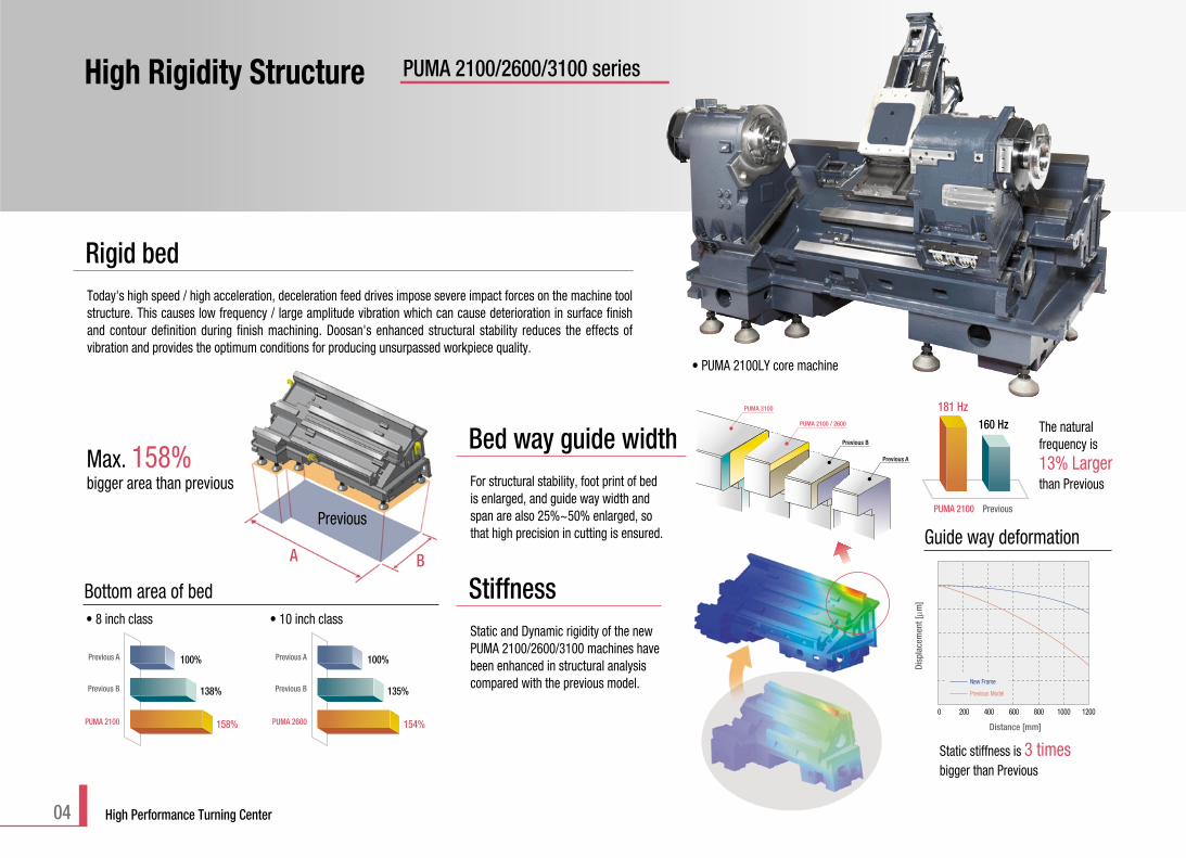
High Rigidity Structure PUMA 2100/2600/3100 series
Rigid bedToday's high speed / high acceleration, deceleration feed drives impose severe impact forces on the machine toolstructure. This causes low frequency / large amplitude vibration which can cause deterioration in surface finishand contour definition during finish machining. Doosan's enhanced structural stability reduces the effects ofvibration and provides the optimum conditions for producing unsurpassed workpiece quality.
StiffnessStatic and Dynamic rigidity of the newPUMA 2100/2600/3100 machines havebeen enhanced in structural analysiscompared with the previous model.
The natural frequency is 13% Largerthan Previous
• 8 inch class • 10 inch class
Static stiffness is 3 timesbigger than Previous
Bed way guide widthFor structural stability, foot print of bedis enlarged, and guide way width andspan are also 25%~50% enlarged, sothat high precision in cutting is ensured.
Max. 158%bigger area than previous
• PUMA 2100LY core machine
181 Hz160 Hz
PUMA 2100 Previous
Guide way deformation
Previous Model
New Frame
Disp
lace
men
t [µm
]
Distance [mm]
0 200 400 600 800 1000 1200
Bottom area of bed
100%Previous A
138%
158%
Previous B
PUMA 2100
100%Previous A
135%
154%
Previous B
PUMA 2600
PUMA 3100
PUMA 2100 / 2600
Previous B
Previous A

05
Main Spindle- Heavy duty cutting- Optimum surface finish- High cutting speeds- Highly accurate roundness
The spindle headstock has increased rigiditydue to the wide surface contact between theheadstock and bed way.
Max. 190% bigger area than previous (in the same class)
Increased attachment area of headstock base to the bed
Mounting base area is
50~94% bigger than previous
The sub-spindle rigidity has beenmassively increased by applying a morestable structure and increasing the spindlebearing diameter. These features providethe capability of heavy duty machining andoptimum surface finishes can be achieved.
Sub spindle Previous Model PUMA 2600 / 3100
Chuck size 135 / 170 mm 175 mm(5.3 / 6.7 inch) (6.88 inch)
The turret accomodates BMT55 or BMT65
The turret accommodates BMT55P and BMT65P tooling inwhich the toolholders are mounted directly to the turret'speriphery with 4 large bolts. This type of mounting systemgenerates exceptionally high rigidity. BMT55P is the standardtooling on the mill-turn turret of PUMA 2100. And also BMT65Pis provided as one of selectable options on PUMA 2100. InMills, BMT65P is the standard on all New Frame machines.
Rate of increase PUMA 2600/3100 Previous Model
Coupling 15 % 230 mm 200 mm(9.06 in.) (7.87 in)
Clamping force 17 % 53 kN 45 kN
Tool size - BMT65P BMT55P
Rotary tool motor - FANUC a2 FANUC a1.5
Max. rotary tool spindle speed
5000 r/minMax. rotary tool spindle power
5.5 kW (7.4 Hp) -15 min. {7.5 kW (10.1 Hp) -5 min. }Max. rotary tool spindle torque
47 N.m (34.7 Hp) {95.5 N.m (70.5 Hp) }
Enhanced turret rigidity
opt.
opt.
Saddle guide width and span areincreased in a range from
30% to 46%compared with previous
The broad width and long contact span of thesaddle slideway ensures stability of the supportstructure. This coupled with the optimised spindleand bed design provides heavy duty and accuratemachining capability.
Saddle

06 High Performance Turning Center
High Performance PUMA 2100/2600/3100 series
unit BMT55P BMT65P
Chip removal rate cm3/min (inch3/min) 90 (35.43) 105 (41.34)
Tool Dia. mm (inch) 18 (0.71) 20 (0.79)
Cutting Depth mm (inch) 20 (0.79) 21 (0.83)
Cutting speed m/min (ipm) 60 (2362.2) 60 (2362.2)
Feedrate mm/min (ipm) 250 (9.8) 250 (9.8)
unit BMT55P BMT65P
Rotary tool spindle speed r/min 240 240
Tap Size M20 x P2.5 M24 x P2.5
Cutting Speed m/min (ipm) 15 (590.6) 25 (984.3)
unit BMT55P BMT65P
Chip removal rate cm3/min (inch3/min) 35.9 (14.13) 53.9 (21.22)
Tool dia mm (inch) 63 (2.48) 63 (2.48)
Cutting Depth mm (inch) 3 (0.12) 4.5 (0.18)
Cutting speed m/min (ipm) 120 (4724.4) 120 (4724.4)
Feedrate mm/min (ipm) 190 (7.5) 190 (7.5)
unit PUMA 2100LMS PUMA 2600LY
Chip removal rate cm3/min (inch3/min) 528 (207.87) 616 (242.52)
Cutting Depth mm (inch) 4.3 (0.17) 5.0 (0.2)
Cutting speed m/min (ipm) 210 (8267.7) 210 (8267.7)
Feedrate mm/rev (ipr) 0.55 (0.022) 0.55 (0.022)
unit PUMA 2100LMS PUMA 2600LY
Chip removal rate cm3/min (inch3/min) 472 (185.83) 630 (248.03)
Cutting speed m/min (ipm) 200 (7874.0) 200 (7874.0)
Feedrate mm/rev (ipr) 0.15 (0.006) 0.2 (0.008)
unit PUMA 2100LMS PUMA 2600LY
Chip removal rate cm3/min (inch3/min) 169 (66.54) 241 (94.9)
Cutting Width mm (inch) 8 (0.31) 8 (0.31)
Cutting speed m/min (ipm) 150 (5905.5) 150 (5905.5)
Feedrate mm/rev (ipr) 0.14 (0.006) 0.2 (0.008)
End mill (SM45C)
Tapping (SM45C)
Face mill (SM45C)
O.D Turning
U-Drill dia. 63 mm (2.5 inch)
Grooving
These Doosan machines offer a high level of machining capability to provide optimum productivity for the customer.

07
Work material AL2024
Cutting speed m/min (ipm) 250 (9842.5)
Feedrate mm/rev (ipr) 0.08 (0.003)
Cutting depth mm (inch) 0.2 (0.01)
Tool Diamond [nose R0.8]
Roundness comparison
0.7
PUMA 2600SY Current PUMA(Equivalent 10" class)
3.2Users enjoy stable performance in all types of operationsfrom heavy-duty cutting to high speed machining.
Roundness
0.5µm (0.02 µinch) [Test machine : PUMA2600SY]
Cutting Condition
Machine PUMA 2600SY [Belt-driven]
Tool TNMG16404R-W [Nose radius 0.4mm]
Workpiece ø60 x L50 (ø2.4 x L2.0 inch) [SM45C]
Spindle Speed 3500 r/min
Cutting Depth 0.025 mm (0.001 inch)
Feedrate 0.025 mm/rev (0.001 ipr)
Roughness
Ra 0.11µm (Ra 0.004 µinch)
Rz 0.83µm (Rz 0.033 µinch)
Rmax 0.92µm (Rmax 0.036 µinch)
Material SM45C
Work Size ø60 x L50 mm (ø2.4 x L2.0 inch)
Spindle speed 3500 r/min
Feed 0.025 mm/rev (0.001 ipr)
Depth 0.025 mm (0.001 inch)
Holder PTGNR2020 M16
Insert TNMG160404 R-W (R0.4)
Doosan offers its customersunsurpassed levels of accuracy byapplying the latest design techniquesand rigorous testing processes.
Oil cooling
Thermal displacement and dimensional accuracy are greatly influencedby oil temperature in a machine. Coolant Temperature Control unitprevents the coolant from heating. Especially, when using oil-basedcoolant, the oil temperature can become extremely high.
Heat isolation structure
Thermal displacement compensation
One very important designconcept is to reduce the effectsof heat sources in the machine.Heat shields and fan motors areused to prevent the transmissionof heat to the machine structure.
Hydraulic cylinderElectrical
cabinet
Rotary tool motor
Hydraulic power unit
opt.

Wide Variation PUMA 2100/2600/3100 series
PUMA 240B B / MB / MSB
PUMA 2000 Y / SY
PUMA 300A A / MA / SA / MSA
PUMA 2000L Y / SY
PUMA 300LA A / LMA
PUMA 300C C / SC / MC / MSC
PUMA 300LC LC / LMC
PUMA 400 A / MA
PUMA 400L LA / LMA
PUMA 400XLA
PUMA 240C C / MC / MSC
PUMA 240L LC
PUMA 300B B / MB / SB / MSB
PUMA 300LB B / LMB
PUMA 2500 Y / SY
PUMA 2500L Y / SY
PUMA 2500XL XLY
PUMA 2100 2A / M / S / MS / Y / SY
PUMA 2100L 2A / M / S / MS / Y / SY
PUMA 3100 2A / M / Y
PUMA 3100L 2A / M / Y
PUMA 3100XL 2A / M / Y
PUMA 3100UL 2A / M / Y
PUMA 2600 2A / M / S / MS / Y / SY
PUMA 2600L 2A / M / S / MS / Y / SY
Chuck 500(19.7)
750(29.5)
1250(49.2)
2000(78.7)
3000(118.1)
500(19.7)
750(29.5)
1250(49.2)
2000(78.7)
3000(118.1)
ø 210
ø 255
ø 305
(ø 8.3)
(ø 10.0)
(ø 12.0)
08 High Performance Turning Center

09
std / L S / LS
M / LM
Y / LY
MS / LMS
SY / LSY
Turning work length mm (inch) 500 / 750 [L](19.7 / 29.5)
Chuck [Main / Sub] inch 8 / 6
Max. turn dia. mm (inch) 480, 4061) {3762)}(18.9,16.01) {14.8}2))
Revolving holder type BMT55P3) {BMT65P3)}
Travel [X / Z-axis] mm (inch) 260 / 590 (10.2 / 23.2)260 / 830 (10.2 / 32.7) [L]
Travel [Y-axis] mm (inch) 102 (4.0) [±51 (2.0)]
Turning work length mm (inch) 750 / 1250 (29.5 / 49.2) [L]2000 [XL] / 3000 [UL]
(78.7 / 118.1)
Chuck [Main / Sub] inch 12
Max. turn dia. mm (inch) 525, 4204) (20.7, 16.54))
Revolving holder type BMT65P3)
Travel [X / Z-axis] mm (inch) 293 / 830 (10.2 / 32.7)293 / 1350 (10.2 / 53.1) [L]293 / 2190 (10.2 / 86.2) [XL]293 / 3190 (10.2 / 125.6) [UL]
Travel [Y-axis] mm (inch) 130 (5.1) [±65 (2.6)]{ } : Option
Turning work length mm (inch) 750 / 1250 [L](29.5 / 49.2)
Chuck [Main / Sub] inch 10 / 6
Max. turn dia. mm (inch) 480, 3762) (18.9, 14.82))
Revolving holder type BMT65P3)
Travel [X / Z-axis] mm (inch) 260 / 830 (10.2 / 32.7)260 / 1350 (10.2 / 53.1) [L]
Travel [Y-axis] mm (inch) 102 (4.0) [±51 (2.0)]
Mill-turning
Turning
PUMA 3100
std / L XL / UL
M / LM
Y / LY
XLM / ULM
XLY / ULY
Mill-turning
Turning
PUMA 2100
std / L S / LS
M / LM
Y / LY
MS / LMS
SY / LSY
Mill-turning
Turning
PUMA 2600
1) : on the PUMA 2100M [LM] / MS [LMS] / Y [LY] / SY [LSY]2) : on the PUMA 2100, 2600M [LM] / MS [LMS] / Y [LY] / SY [LSY]3) : on the machine with Mill-turn Turret4) : on the PUMA 3100 M / LM / XLM / ULM / Y / LY / XLY / ULY

A
B
C
Bed SizeWe have added a high-rigidity bed and special functions and equipment for machining long workpieces. It is the definitive bar workmachine, eliminating all compromise.
10 High Performance Turning Center
Machine A B X Z CMax. work length Max. turning diameter X-axis travel distance Zx-axis travel distance Door open space
PUMA 2100L / 2600L 760 / 1280 (29.9 / 50.4) 480 (18.9) 260 [20 +240] (10.2 [0.8 +9.4]) 830 / 1350 (32.7 / 53.1) 815 / 1375 (32.1 / 54.1)
PUMA 2100LS / 2600LS 760 / 1280 (29.9 / 50.4) 480 (18.9) 260 [72 +188] (10.2 [2.8 +7.4]) 830 / 1350 (32.7 / 53.1) 815 / 1375 (32.1 / 54.1)
PUMA 2100LM / 2600LM 760 / 1280 (29.9 / 50.4) 406 / 376 (16.0 / 14.8) 260 [72 +188] (10.2 [2.8 +7.4]) 830 / 1350 (32.7 / 53.1) 815 / 1375 (32.1 / 54.1)
PUMA 2100LMS / 2600LMS 760 / 1280 (29.9 / 50.4) 406 / 376 (16.0 / 14.8) 260 [72 +188] (10.2 [2.8 +7.4]) 830 / 1350 (32.7 / 53.1) 815 / 1375 (32.1 / 54.1)
PUMA 2100LY / 2600LY 760 / 1280 (29.9 / 50.4) 406 / 376 (16.0 / 14.8) 260 [72 +188] (10.2 [2.8 +7.4]) 830 / 1350 (32.7 / 53.1) 815 / 1375 (32.1 / 54.1)
PUMA 2100LSY / 2600LSY 760 / 1280 (29.9 / 50.4) 406 / 376 (16.0 / 14.8) 260 [72 +188] (10.2 [2.8 +7.4]) 830 / 1350 (32.7 / 53.1) 815 / 1375 (32.1 / 54.1)
PUMA 3100L / XL / UL 1280 / 2125 / 3125 525 293 [30.5 +262.5] 1350 / 2190 / 3190 1440 / 2260 / 3260(50.4 / 83.7 / 123.0) (20.7) (11.5 [1.2 +10.3]) (53.1 / 86.2 / 125.6) (56.7 / 89.0 / 128.3)
PUMA 3100LM / XLM / ULM 1280 / 2125 / 3125 420 293 [83 +210] 1350 / 2190 / 3190 1440 / 2260 / 3260(50.4 / 83.7 / 123.0) (16.5) (11.5 [3.3 +8.2]) (53.1 / 86.2 / 125.6) (56.7 / 89.0 / 128.3)
PUMA 3100LY / XLY / ULY 1280 / 2125 / 3125 420 293 [83 +210] 1350 / 2190 / 3190 1440 / 2260 / 3260(50.4 / 83.7 / 123.0) (16.5) (11.5 [3.3 +8.2]) (53.1 / 86.2 / 125.6) (56.7 / 89.0 / 128.3)
Unit : mm (inch)
• PUMA 3100ULY

Main SpindleTo achieve a high level of stability duringmachining, improvements in rigidity havebeen the main focus in the design process.The mounting areas of main and Sub-spindles have been significantly widenedand the spindle length shortened tominimise vibration. Spindle bearingdiameter has been increased to improverigidity. This also allows a larger throughbore size for the sub-spindle. Spindles areavailable as belt type or built-in motor type.
Belt Driven Spindle Type( Y / SY models)
std. Built-in Motor Spindle Typeopt.
Model Speed Power Max. Torquer/min kW (Hp) N.m (ft-lbs)
PUMA 2100 4500 15 (20.1) 183 (135.1)
5000 22 (29.5) 358 (264.2)[Built-in]
PUMA 2600 3500 22 (29.5) 240 (177.1)
4000 22 (29.5) 599 (442.1)[Built-in]
PUMA 3100 2800 22 (29.5) 1123 (828.8)
3000 30 (40.2) 1203 (887.8)[Built-in]
std.
std.
std.
opt.
opt.
opt.
PUMA 2100 ø65 mm (ø2.6 inch)
PUMA 2600 ø76 mm (ø3.0 inch)
PUMA 3100 ø102 mm (ø4.0 inch)
Bar work capacity
PUMA 2100 ø76 mm (ø3.0 inch)
PUMA 2600 ø86 mm (ø3.4 inch)
PUMA 3100 ø115 mm (ø4.5 inch)
Spindle through hole
11
Spindle bearing
Changed combination of bearings to minimize thermal displacement.
PUMA 2100 (8") ø110 (4.3) ø120 (4.7)PUMA 2600 (10") ø130 (4.1) ø140 (5.5)

12 High Performance Turning Center
500 (19.7) 750 (29.5) 1250 (49.2) 2000 (78.7) 3000 (118.1)
Standard Manual type
Programmable type(Tow along type)
Programmable type(Tow along type)
Servo driven type
Not avaliable
Option 1
Option 2
Bed length mm (inch)Machine PUMA 2100 / L PUMA 2600/L PUMA 3100/XL/XLM/XLY
PUMA 3100/L/LM/Y/LY UL/ULM/ULY
Bed length : mm (inch) 500 / 750 (19.7 / 29.5) 750 / 1250 (29.5 / 49.2) 2000 / 3000 (78.7 / 118.1)
Live center MT4 StandardNot avaliable
Manual Built-in center MT3 Optiontail stock Live center MT5
Not avaliableStandard
Built-in center MT4 Option Not avaliableLive center MT4
Option Not avaliableBuilt-in center MT3
Programmable Live center MT5Option
tail stock Built-in center MT4 Not avaliableBuilt-in center MT5 Not avaliable StandardLive center MT4
Option Not avaliableServo driven Built-in center MT3 Not avaliabletail stock Live center MT5
Not avaliable OptionBuilt-in center MT4
Max. C-axis contour torque* 85 N.m (62.7 ft-lbs)
Max. C-axis breaking torque* 770 N.m (568.3 ft-lbs)
Max. C-axis rapid* 200 r/min (360 deg in 0.001 deg. Increment)
Sub-spindleTo make rotary tooling more effective, precise circular positioning of thespindle is necessary. The sub-spindle has 0.001° full C-axis contourfunction which is same with the function of main spindle. Moreover, powerand torque are increased for more cutting capability.
* : On turn-milling machine.
PUMA 2600 / 3100 Previous Model
Chuck size175 mm 135 / 170 mm
(6.88 inch) (5.3 / 6.7 inch)
Spindle bearing diameter90 mm 75 / 90 mm
(3.5 inch) (3.0 / 3.5 inch)
Spindle through hole62 mm 43 / 53 mm
(2.4 inch) (1.7 / 2.1 inch)
Enhanced sub-spindle
Tailstock configuration3 types of tail stocks such as manual, programmable and servo driven can be offered to customers as alternative choices.
Tail stock in various sizes are available for efficient precision machining, even with long workpieces.

13
Turret
The turret has been designedbased on a modular concept.It provides improved toolclearance and optimumrigidity. The milling turretversion includes 24 positionindexing to increase theavailable tool capacity.
The highly rigid rotary tool spindle improvesthe productivity of the Turning Center. Both main and sub-spindles include full Caxis control as standard.
Increased machining capacity
1.84 times
Cutting condition Previous head New head
End mill ø16 (Hss)2 FlutesV : 50 m/minS : 1000 r/minF : 0.2 mm/rev
Max. cutting depth(without chatter)
Chip removal rate
6 mm 11 mm
19.2 cm3/min 35.2 cm3/min
• Material : Carbon steel SM45C
Collet application
Rotary tool head
Turning Mill-turning
No. of tool stations 12/12/10 st 12 st
Tooling system DI base BMT55P/65P/65P
Tool size OD 25 x 25 mm (1.0 x 1.0 inch)
ID ø50 mm ø40/50/50 mm(ø2.0 inch) (ø1.6/1.6/2.0 inch)
Curvic coupling ø230 mm (9.1 inch)
Turret index time 0.15 sec

14 High Performance Turning Center
New frame PUMAPUMA 2100/2600 Y-axis
Bed slant angle 30° 30°
X slant angle 30° 30°
X-Y slant angle 30° 30°
Y axis stroke ±51 mm (±2.0 inch) ±51 mm (±2.0 inch)
X stroke 260 mm (10.2 inch) 254 mm (10.0 inch)
Ys stroke 204 mm (8.0 inch) 204 mm (8.0 inch)
Y-axis
On-center face groove
Y-axis
Poly-side machine
Y-axis
Off-center side groove
YX
Y&X-axis circular interpolation
Y-axis travel
PUMA 2100 / 2600 102 mm [±51mm] (4.0 inch [±2.0 inch])PUMA 3100 130 mm [±65mm] (5.1 inch [±2.6 inch])
Y-axis rapid 10 m/min (7.4 ipm)
Virtual Y-axis FunctionIn the Y-axis plane, tools can move in a plus or minus direction perpendicular to theZ-axis and spindle center line. Viewed from the operator's perspective, this Y-axismotion is toward or away from the door of the machine while X-axis moves from floorto ceiling. Y-axis enables various shape of cutting. Y-axis is realized virtually by thelinear interpolation ans synchronous movement of X1 and X2-axis that make itpossible to lower machine height for stability.
Simultaneous XYZ motion provides the capability millingcomplex shapes. In addition, the rigidly clamped C axisdisc brake enables heavy duty and precision machining.
All Enough in Single Setup
Configuration of Y-axis
Y-axis
Ys-a
xis
X-axis
Z-axis
Y-axis-axis
Ys-a
xis
X-ax
is
Z-axis
Y-axis
Ys-a
xis
X-ax
is

15
Coolant flow improvement
Improved Maintainability Maintainability is one of the crucial criteria that Doosan placed at the forefront of machine development. Large openings in the machine paneling facilitate access to the underlying maintenance units like lubricant oil tank and pneumatic fittings.
PUMA 2100/2600/3100 series
2
3 12
4
Movable console door.
Fully covered Guide Way
• Changed Chip Pan and Chip Conveyor installation in pursuit of No Coolant Leakage.• Chip skirt should be assembled when a machine is installed at the customer's site.
Easy to access for maintenance
To minimize the thermal effect on the machine,heat of chips should be prevented from beingtransmitted to bed and guide ways. Guide waysare fully covered so that heat can be isolated.Also, telescopic covers have strengthened linkagesystem that ensures durability.
The coolant tank can be pulled out at the frontand does not require the chip conveyor to beremoved.
• Chip cleaning of coolant tank even in a small space.
• Easy disassembly and assembly of coolant tank.
• No more time wasting.
Easy maintenance of coolant tank
1
Right and Left cover disassembly.2
Front cover disassembly in front of Head Stock.
3
Storage Shelf for convenience.4
No Coolant Leakagein New Turning Center
16 High Performance Turning Center
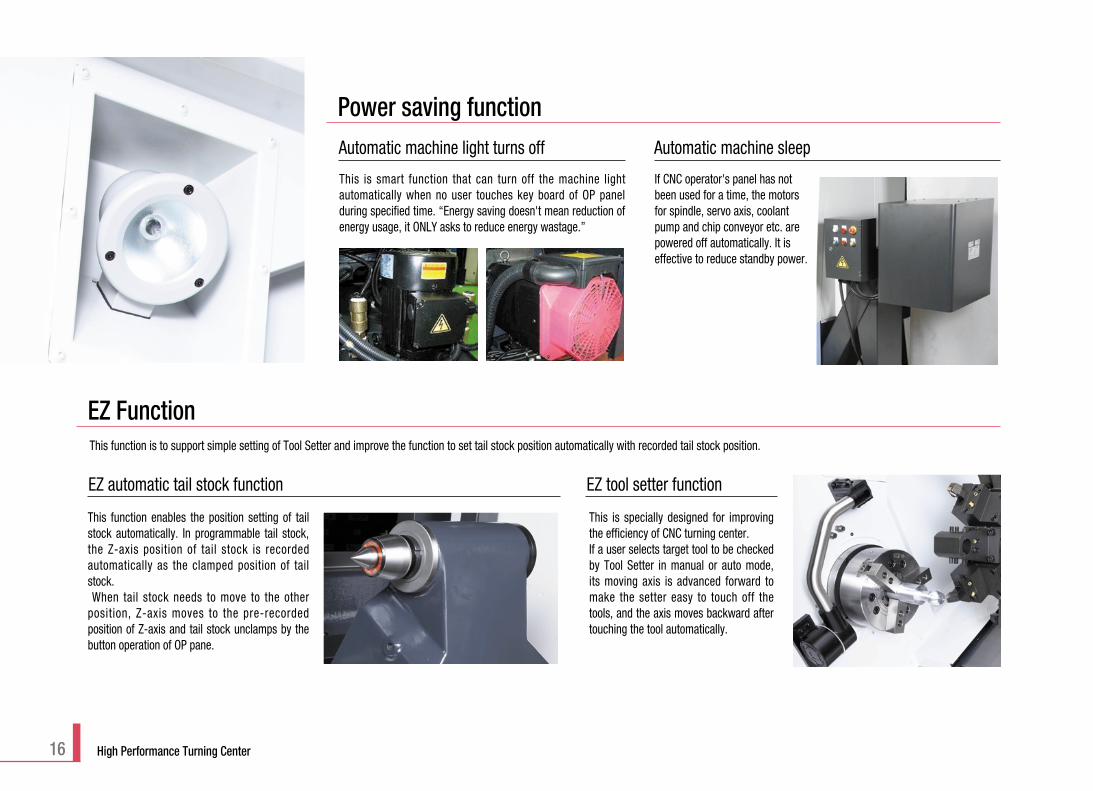
EZ automatic tail stock function
EZ Function
This function enables the position setting of tailstock automatically. In programmable tail stock,the Z-axis position of tail stock is recordedautomatically as the clamped position of tailstock.When tail stock needs to move to the other
position, Z-axis moves to the pre-recordedposition of Z-axis and tail stock unclamps by thebutton operation of OP pane.
This is specially designed for improvingthe efficiency of CNC turning center.If a user selects target tool to be checkedby Tool Setter in manual or auto mode,its moving axis is advanced forward tomake the setter easy to touch off thetools, and the axis moves backward aftertouching the tool automatically.
EZ tool setter function
Power saving function
This is smart function that can turn off the machine lightautomatically when no user touches key board of OP panelduring specified time. “Energy saving doesn't mean reduction ofenergy usage, it ONLY asks to reduce energy wastage.”
Automatic machine light turns off
If CNC operator's panel has notbeen used for a time, the motorsfor spindle, servo axis, coolantpump and chip conveyor etc. arepowered off automatically. It iseffective to reduce standby power.
Automatic machine sleep
This function is to support simple setting of Tool Setter and improve the function to set tail stock position automatically with recorded tail stock position.

Easy Operation PackageThese DOOSAN software packages have beencustomized to provide user-friendly functions.
Operator can check the meaning of each G-code.
G Code List
Operator can check the meaning of each M-code.
M Code List
Operator can calcute numerical formula in relation to arc andhole easily.
Calculator
Thrust force control is simple to set up using the speciallydesigned servo-driven tail stock thrust setting software.- Input value directly- Select one of the initially set values
Servo Tailstock Thrust Setting
PUMA 2100/2600/3100 series
Programming
The main function of this software is to detect overload when atool is wrong, and change it to an other tool. Stop machine toprotect a tool holder and next tools by detecting overload causedby tool breakage or its wear. Use editable tool life managementfor spare tools. Monitor load meter for all spindles and axes. If thetool load reaches abnormal band recorded in “Set data”, thesoftware issues an feed hold alarm or skips the tool.
Tool Load Monitor
The software is to help users recover turret step by step fromtrouble situation where it does not work. It can quickly recoveryour valuable machine.
Turret Recovery Help
This can be used to record tool load information detected in“Tool load monitor” for all tools used during cutting. Byreloading recorded data in tool table, Tool Load Monitorsoftware can compare the actual tool load with a recordedload pattern.
Back Up Custom Data
A major determinant of efficiency is the cost associated withsetting up the equipment to make a particular product. Thissoftware can be used to manage machine operation rate of 3operators. Total machine operation and real machining timefor a month can be recorded and measured. It helps toevaluate and monitor each operational efficiency. To keep itsecure, Password setting is essential.
Operation Rate - User Log In
Operation / Maintenance
17
• Doosan Fanuc i series• 10.4" color TFT LCD• Part programming storage 1280m
Std.
18 High Performance Turning Center
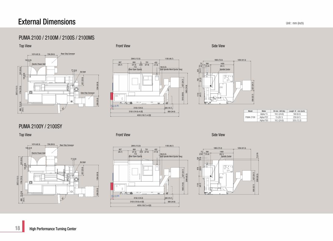
External Dimensions Unit : mm (inch)
Model Motor 30 min : kW (Hp) Length 'A' : mm (inch)
Alpha 15 18.5 (24.8) 160 (6.3)PUMA 2100 Alpha P22 15 (20.1) 230 (9.1)
Alpha P30 18.5 (24.8) 335 (13.2)
A 3150 (124.0)
880 (34.6)3150 (124.0)+A [B]
4030 (158.7)+A [B]
1010
(39.
8)62
7 (2
4.7)
1903
(74.
9)
907(35.7)
800(31.5)
5(2.0)
701(27.6)
432(17.0)
1185 (46.7)2845 (112.0)
25 (1.0) [B]500 (19.7)
486
(19.
1)73
(2.9
)17
90 (7
0.5)
523
(20.
6)
2872
(113
.1)
1074 (42.3) 736 (29.0)
1294
(50.
9)63
6 (2
5.0)
87˚
125
(4.9
)
150 (5.9)
657
(25.
9)
77 (3.0)
1400(55.1)
1863 (73.3)
830
(32.
7)
1054 (41.5)
1110
(43.
7)
627
(24.
7)
390(15.4)
73(2.9)
793
(31.
2)32
3(1
2.7)
Electric Power Inlet
Air Inlet
Rear Chip Conveyor
710[Door Open Space]
140 (5.5)[Sub Spindle Work Ejector Only] Spindle Center
A 3150 (124.0)
3150 (124.0)+A [B] 880 (34.6)
4030 (158.7)+A [B]
1903
(74.
9)62
7 (2
4.7)
2090
(82.
3)
907(35.7)
800(31.5)
5(2.0)
701(27.6)
432(17.0)
2845 (112.0) 1185 (46.7)
25 (1.0) [B]500 (19.7)
486
(19.
1)73
(2.9
)17
90 (7
0.5)
523
(20.
6)
125
(4.9
)
2872
(113
.1)
1074 (42.3) 736 (29.0)
87˚
636
(25.
0)12
94 (5
0.9)
150 (5.9)
77 (3.0)
657
(25.
9)
1110
(43.
7)97
8(3
8.5)
138
(5.4
)
73(2.9)
390(15.4)
1400(55.1)
1863 (73.3) 1054 (41.5)
830
(32.
7)62
7 (2
4.7)
2090
(82.
3)73
(2.9
)Electric Power Inlet
Air Inlet
Rear Chip Conveyor
710[Door Open Space]
140 (5.5)[Sub Spindle Work Ejector Only] Spindle Center
Side Chip Conveyor
Top View Front View Side View
Top View Front View Side View
PUMA 2100 / 2100M / 2100S / 2100MS
PUMA 2100Y / 2100SY
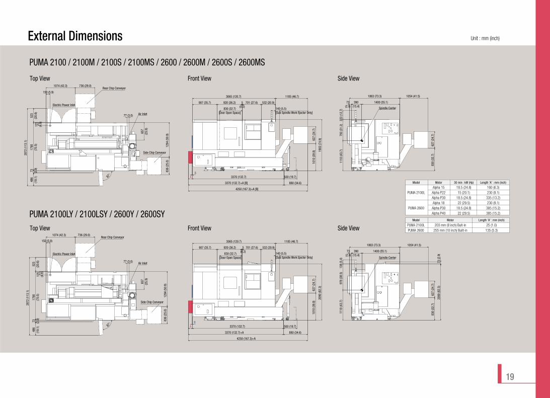
Unit : mm (inch)External Dimensions
Model Motor 30 min : kW (Hp) Length 'A' : mm (inch)
Alpha 15 18.5 (24.8) 160 (6.3)PUMA 2100L Alpha P22 15 (20.1) 230 (9.1)
Alpha P30 18.5 (24.8) 335 (13.2)Alpha 18 22 (29.5) 230 (9.1)
PUMA 2600 Alpha P30 18.5 (24.8) 385 (15.2)Alpha P40 22 (29.5) 385 (15.2)
3370 (132.7)A
3065 (120.7)
880 (34.6)
1185 (46.7)
1010
(39.
8)
3370 (132.7)+A [B]
4250 (167.3)+A [B]
830 (32.7)[Door Open Space]
627
(24.
7)
907 (35.7) 920 (36.2) 5(0.2)
701 (27.6) 532 (20.9)
1903
(74.
9)
140 (5.5)[Sub Spindle Work Ejector Only]
B500 (19.7)
523
(20.
6)
87°
486
(19.
1)
2872
(113
.1)
636
(25.
0)12
94 (5
0.9)
1074 (42.3) 736 (29.0)
1790
(70.
5)73 (2.9
)
657
(25.
9)
77 (3.0)
125
(4.9
)
150 (5.9)
1400 (55.1)
1863 (73.3)
830
(32.
7)
1054 (41.5)
1110
(43.
7)
627
(24.
7)
390(15.4)
73(2.9)
793
(31.
2)32
3 (1
2.7)
Electric Power Inlet
Air Inlet
Spindle Center
Model Motor Length 'A' : mm (inch)
PUMA 2100L 203 mm (8 inch) Bult-in 25 (1.0)PUMA 2600 255 mm (10 inch) Built-in 135 (5.3)
A 3370 (132.7)
3370 (132.7)+A 880 (34.6)
4250 (167.3)+A
1185 (46.7)3065 (120.7)
907 (35.7) 920 (36.2) 5(0.2)
701 (27.6) 532 (20.9)
830 (32.7)[Door Open Space]
2090
(82.
3)
1010
(39.
8)62
7 (2
4.7)
140 (5.5)[Sub Spindle Work Ejector Only]
B500 (19.7)
523
(20.
6)17
90(7
0.5)
73 (2.9
)48
6(1
9.1)
2872
(113
.1)
1074 (42.3) 736 (29.0)
636
(25.
0)12
94 (5
0.9)
87°
77 (3.0)
657
(25.
9)
125
(4.9
)
150 (5.9)
1110
(43.
7)97
8 (3
8.5)
138
(5.4
)
73(2.9)
390(15.4)
1400 (55.1)
1863 (73.3) 1054 (41.5)
830
(32.
7)62
7 (2
4.7)
2090
(82.
3)73
(2.9
)
Air Inlet
Electric Power InletSpindle Center
Side Chip Conveyor
Side Chip Conveyor
Rear Chip Conveyor
Rear Chip Conveyor
Top View Front View Side View
Top View Front View Side View
19
PUMA 2100 / 2100M / 2100S / 2100MS / 2600 / 2600M / 2600S / 2600MS
PUMA 2100LY / 2100LSY / 2600Y / 2600SY
20 High Performance Turning Center
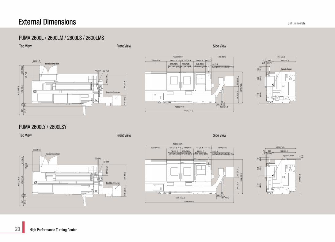
External Dimensions Unit : mm (inch)
4335 (170.7)
5389 (212.2)
1010
(39.
8)62
7 (2
4.7)
1307 (51.5) 850 (33.5) 5 (0.2) 785 (30.9) 735 (28.9) 348 (13.7)
1359 (53.5)
760 (29.9)[Door Open Space]
630 (24.8)[Door Open Space]
640 (25.2)[Console Moving Space]
4030 (158.7)
1054 (41.5)
1903
(74.
9)
140 (5.5)[Sub Spindle Work Ejector Only]
500 (19.7)175
(6.9
)17
90 (7
0.5)
523
(20.
6)54
7(2
1.5)
3035
(119
.5)
636
(25.
0)12
94 (5
0.9)
125
(4.9
)
550 (21.7)
657
(25.
9)
77 (3.0)
Electric Power Inlet
Air Inlet
1400 (55.1)
1863 (73.3)
1110
(43.
7)
390(15.4)
73(2.9)
793
(31.
2)32
3(1
2.7)
Spindle Center
4335 (170.7) 1054 (41.5)
5389 (212.2)
1010
(39.
8)62
7 (2
4.7)
2090
(82.
3)
1307 (51.5) 850 (33.5) 5 (0.2) 785 (30.9) 735 (28.9) 348 (13.7) 1359 (53.5)
760 (29.9)[Door Open Space]
630 (24.8)[Door Open Space]
4030 (158.7)
500 (19.7)636
(25.
0)12
94 (5
0.9)
547
(21.
5)17
5(6
.9)
1790
(70.
5)52
3 (2
0.6)
3035
(119
.5)
125
(4.9
)
550 (21.7)
77 (3.0)
657
(25.
9)
Electric Power Inlet
Air Inlet
1110
(43.
7)97
8(3
8.5)
138
(5.4
)
73(2.9)
390(15.4)
1400 (55.1)
1863 (73.3)
73 (2.9
)20
90 (8
2.3)
640 (25.2)[Console Moving Space]
140 (5.5)[Sub Spindle Work Ejector Only]
Spindle Center
Side Chip Conveyor
Side Chip Conveyor
Top View Front View Side View
Top View Front View Side View
PUMA 2600L / 2600LM / 2600LS / 2600LMS
PUMA 2600LY / 2600LSY

Unit : mm (inch)External Dimensions
21
Side Chip Conveyor
Air Inlet
127 (5.0)
595
(23.
4)
ø61 Hole (Electric Power Inlet)
2530 (99.6) Operation Panel Stroke2375 (93.5)
281
(11.
1)
3266
(128
.6)
756
(29.
8)
90˚
268 (10.6)Space to pull out Chip Conveyor
1104 (43.5)
1439
(56.
7)63
6 (2
5.0)
6565 (258.5)
2000
(78.
7)
2000
(78.
7)51
0 (2
0.1)
300 (11.8)Space to pull out C/tank
Spindle Center
1104 (43.5)6565 (258.5)
268 (10.6)Space to pull out Chip Conveyor
7669 (301.9)
1010
(39.
8)62
7 (2
4.7)
2175 (85.6)R-Door Open Space
1080 (42.5)L-Door Open Space
1650 (65.0)1167 (45.9)1170 (46.1)5 (0.2)2573 (101.3)20 (0.8)6565 (258.5)
2208
(86.
9)
Spindle Center
2281 (89.8)281 (11.1)
585
(23.
0)72
2 (2
8.4)
428
(16.
8)
2315
(91.
1)
1181
(46.
5)
525 (20.7)
2204
(86.
8)26
0 (1
0.2)
2208
(86.
9)10
7 (4
.2)2000 (78.7)
Side Chip Conveyor
Air Inlet
66 (2.6)
595
(23.
4)
1530 (60.2) Operation Panel Stroke2375 (93.5)
ø61 Hole (Electric Power Inlet)
3266
(128
.6)
756
(29.
8)
90˚
510
(20.
1)20
00 (7
8.7)
245 (9.6) Space to pull out Chip Conveyor
636
(25.
0)14
39 (5
6.7)
1128 (44.4)5315 (209.3)
281
(11.
1)20
00 (7
8.7)
Spindle Center
2315
(91.
1)10
7 (4
.2)
585
(23.
0)72
2 (2
8.4)
428
(16.
8)11
81 (4
6.5)
525 (20.7)
310.
5 (1
2.2)
2208
(86.
9)
2204
(86.
8)
2281 (89.8)2000 (78.7)281 (11.1)
Spindle Center
300 (11.8)Space to pull out C/tank
300 (11.8)
848 (33.4)5595 (220.3)
5 (0.2)
1175 (46.260) R-Door Open Space
1080 (42.5)L-Door Open Space
2737 (107.8)2573 (101.3)
245 (9.6) Space to pull out Chip Conveyor
6443 (253.7)
2208
(86.
9)627
(24.
7)10
10
(39.
8)
5315 (209.3)
Top View Front View Side View
Top View Front View Side View
PUMA 3100UL / 3100ULM / 3100ULY
PUMA 3100XL / 3100XLM / 3100XLY

22 High Performance Turning Center
Description Unit PUMA 2100/L PUMA 2100M/LM PUMA 2100MS/LMS PUMA 2100S/LS PUMA 2100Y/LY P 2100SY/LSY
Capacity
Travel
Main Spindle
Sub-spindle
Turret
Feedrates
Tail stock
Motor
Swing over bed mm (inch) 780 (30.7)Swing over saddle mm (inch) 630 (24.8)Recom. Turning diameter mm (inch) 210 (8.3)Max. turning diameter mm (inch) 480 (18.9) 406 (16.0) 480 (18.9) 406 (16.0)Max. work length mm (inch) 520 / 760 (20.5 / 29.9)Bar working diameter mm (inch) 65 (2.6)Travel X-axis mm (inch) 260 [20+240] 260 [72+188] 260 [20+240] 260 [72+188]
(10.2 [0.8+9.4]) (10.2 [2.8+7.4]) (10.2 [0.8+9.4]) (10.2 [2.8+7.4])Z-axis mm (inch) 590 / 830 (23.2 / 32.7)Y-axis mm (inch) - 102 [±51] (4.0 [±2.0])B-axis mm (inch) - 590 / 830 (23.2 / 32.7) - 590 / 830 (23.2 / 32.7)
Spindle speed (Belt Type) r/min 4500Spindle speed (Built-in Type) r/min 5000Spindle nose ASA A2#6Spindle bearing diameter (Front) mm (inch) 120 (4.7)Spindle through hole diameter mm (inch) 76 (3.0)Min. spindle indexing angle (C-axis) deg 0.001degSpindle speed (Belt [Built-in]) r/min - 4500 [6000] - 4500 [6000]Spindle nose - ASA A2-5 - ASA A2-5Spindle bearing diameter (Front) mm (inch) - 90 (3.5) - 90 (3.5)Spindle through hole diameter mm (inch) - 62 (2.4) - 62 (2.4)Min. spindle indexing angle (C-axis) deg - 0.001 - 0.001No. of tool stations 12 12 [24] 12 12 [24]OD tool size mm (inch) 25 (1.0) 25 [20] (1.0 [0.8]) 25 (1.0) 25 [20] (1.0 [0.8])Boring bar diameter mm (inch) 50 (2.0) 40 [32] (1.6 [1.3]) 50 (2.0) 40 [32] (1.6 [1.3])Indexing time (1st swivel time) s 0.15Rotary tool spindle speed r/min - 5000 - 5000 Rapid traverse X-axis m/min (ipm) 30 (1181.1)
Z-axis m/min (ipm) 30 (1181.1)Y-axis m/min (ipm) - 25 [20] (984.3 [787.4])B-axis m/min (ipm) - 30 (1181.1) - 30 (1181.1)
Quill diameter mm (inch) 80 (3.1) - 80 (3.1) -Quill bore taper (Live) MT#4 - MT#4 -Quill travel mm (inch) 80 (3.1) - 80 (3.1) -Main spindle motor kW (Hp) 18.5 / 15 (24.8 / 20.1)Sub spindle motor kW (Hp) - 7.5 / 5.5 (10.1 / 7.4) - 7.5 / 5.5 (10.1 / 7.4)Rotary tool spindle motor kW (Hp) - 5.5 (7.4) - 5.5 (7.4)Feed motor (X, Z, Y, B-axis) kW (Hp) 1.6 / 4.0 3.0 / 4.0 3.0 / 4.0 / - / 1.6 1.6 / 4.0 / - / 3.0 3.0 / 4.0 / 3.0 / - 3.0 / 4.0 / 3.0 / 1.6
(2.1 / 5.4) (4.0 / 5.4) (4.0 / 5.4 / - / 2.1) (2.1 / 5.4 / - / 4.0) (4.0 / 5.4 / 4.0 / -) (4.0 / 5.4 / 4.0 / 2.1)Coolant pump motor kW (Hp) 0.4 (0.5)Electric power supply (Rated capacity) kVA 35.63 38.41 45.63 42.85 41.32 48.54Machine height mm (inch) 1900 (74.8) 2163 (85.2)Machine dimension length mm (inch) 3415 / 3530 (134.4 / 139.0)
width mm (inch) 1863 (73.3)Machine mass kg (lb) 4850 / 5350 5000 / 5500 5450 / 5950 5300 / 5800 5450 / 5950 5900 / 6400
(10692.3 / 11794.6) (11023.0 / 12125.2) (12015.0 / 13117.3) (11684.3 / 12786.6) (12015.0 / 13117.3) (13007.1 / 14109.4)mm (inch) 210 (8.3)
Power source
Machine size
Chuck size
Machine SpecificationsStandard Feature
Optional Feature
• Hydraulic power unit• Lubrication equipment• Coolant supply equipment• Front guard door interlock• Hydraulic chuck & actuating cylinder• Soft jaws• Foot switch• Standard tool kit (tool holder & boring sleeve)• Work light• Signal tower (yellow, red, green)• Levelling jack screw & plates• Hand tool kit
(including small tool for operations)• Safety precaution name plates• Manuals
• Additional tool holder & sleeves• Air blast for chuck jaw cleaning• Air gun• Automatic door with safety device• Bar feeder interface• Dual chucking pressure• Hardened & ground jaws• Pressure switch for chucking pressure check• High pressure coolant• Oil skimmer• Chip conveyor• Chip bucket• Programmable tail stock• Servo driven tail stock• Tail stock quill for dead center• Tool monitoring system• Tool pre-setter (Automatic type)• Tool pre-setter (Manual type)• Work ejector• Parts catcher• Parts conveyor
• Design and specifications are subject to change without notice.• Doosan is not responsible for difference between the information in the catalogue and the actual machine.
{ } : Option

23
Description Unit PUMA 2600/L PUMA 2600M/LM PUMA 2600MS/LMS PUMA 2600S/LS PUMA 2600Y/LY PUMA 2600SY/LSY PUMA 3100/L/XL/UL PUMA 3100M/LM/XLM/ULM PUMA 3100Y/LY/XLY/ULY
Capacity
Travel
Main Spindle
Sub-spindle
Turret
Feedrates
Tail stock
Motor
Swing over bed mm (inch)Swing over saddle mm (inch)Recom. Turning diameter mm (inch)Max. turning diameter mm (inch)Max. work length mm (inch)Bar working diameter mm (inch)Travel X-axis mm (inch)
Z-axis mm (inch)Y-axis mm (inch)B-axis mm (inch)
Spindle speed (Belt Type) r/minSpindle speed (Built-in Type) r/minSpindle noseSpindle bearing diameter (Front) mm (inch)Spindle through hole diameter mm (inch)Min. spindle indexing angle (C-axis) degSpindle speed (Belt [Built-in]) r/minSpindle noseSpindle bearing diameter (Front) mm (inch)Spindle through hole diameter mm (inch)Min. spindle indexing angle (C-axis) degNo. of tool stationsOD tool size mm (inch)Boring bar diameter mm (inch)Indexing time (1st swivel time) sRotary tool spindle speed r/minRapid traverse X-axis m/min (ipm)
Z-axis m/min (ipm)Y-axis m/min (ipm)B-axis m/min (ipm)
Quill diameter mm (inch)Quill bore taper (Live)Quill travel mm (inch)Main spindle motor kW (Hp)Sub spindle motor kW (Hp)Rotary tool spindle motor kW (Hp)Feed motor (X, Z, Y, B-axis) kW (Hp)
Coolant pump motor kW (Hp)Electric power supply (Rated capacity) kVAMachine height mm (inch)Machine dimension length mm (inch)
width mm (inch)Machine mass kg (lb)
mm (inch)
780 (30.7) 850 (33.5)630 (24.8) 670 (26.4)255 (10.0) 305 (12.0)
480 (18.9) 376 (14.8) 480 (18.9) 376 (14.8) 525 (20.7) 420 (16.5)760 / 1280 (29.9 / 50.4) 760 / 1280 / 2125 / 3125 (29.9 / 50.4 / 83.7 / 123.0)
76 (3.0) 102 (4.0)260 [20+240] 260 [72+188] 260 [20+240] 260 [72+188] 293 [30.5+262.5] 293 [83+210]
(10.2 [0.8+9.4]) (10.2 [2.8+7.4]) (10.2 [0.8+9.4]) (10.2 [2.8+7.4]) (11.5 [1.2+10.3]) (11.5 [3.3+8.3])830 / 1350 (32.7 / 53.1) 830 / 1350 / 2190 / 3190 (32.7 / 53.1 / 86.2 / 125.6)
- 102 [±51] (4.0 [±2.0]) - 130 [±65] (5.1 [±2.6])- 830 / 1350 (32.7 / 53.1) - 830/1350 (32.7/53.1) -
3500 28004000 3000
ASA A2#8 ASA A2#11140 (5.5) 160 (6.3)86 (3.4) 115 (4.5)
0.001deg 0.001deg- 4500 [6000] - 4500 [6000] -- ASA A2-5 - ASA A2-5 -- 90 (3.5) - 90 (3.5) -- 62 (2.4) - 62 (2.4) -- 0.001 - 0.001 -
12 12 [24] 12 12 [24] 10 1225 (1.0) 25 [20] (1.0 [0.8]) 25 (1.0) 25 [20] (1.0 [0.8]) 25 (1.0)50 (2.0) 50 [40] (2.0 [1.6]) 50 (2.0) 50 [40] (2.0 [1.6]) 50 (2.0)
0.15 0.15- 5000 - 5000 - 5000
30 (1181.1) 30 (1181.1)30 (1181.1) 30 / 30 / 30 / 26 (1181.1 / 1181.1 / 1181.1 / 1023.6)
- 10 (393.7) - 10 (393.7)- 30 (1181.1) - 30 (1181.1) -
100 (3.9) - 100 (3.9) - 100 / 100 / 120 / 120 (3.9 / 3.9 / 4.7 / 4.7)MT#5 - MT#5 - MT#5
100 (3.9) - 100 (3.9) - 100 / 100 / 120 / 120 (3.9 / 3.9 / 4.7 / 4.7)22 / 18.5 (29.5 / 24.8) 22 / 18.5 (29.5 / 24.8)
- 7.5 / 5.5 (10.1 / 7.4) - 7.5 / 5.5 (10.1 / 7.4) -- 5.5 [7.5] (7.4 [10.1]) - 5.5 [7.5] (7.4 [10.1]) 5.5[7.5] (7.4 [10.1])
1.6 / 4.0 3.0 / 4.0 3.0 / 4.0 / - / 3.0 1.6 / 4.0 / - / 3.0 3.0 / 4.0 / 3.0 / - 3.0 / 4.0 / 3.0 / 3.0 3.0 / 4.0 [4.0 / 7.0 / 7.0] / 3.0 / -(2.1 / 5.4) (4.0 / 5.4) (4.0 / 5.4 / - / 4.0) (2.1 / 5.4 / - / 4.0) (4.0 / 5.4 / 4.0 / -) (4.0 / 5.4 / 4.0 / 4.0) (4.0 / 5.4 [5.4 / 9.4 / 9.4] / 4.0 / -)
0.4 (0.5) 0.4 (0.5)40.72 43.5 51.65 48.86 46.4 54.55 41.64/41.64/42.83/42.83 44.42/44.42/45.61/45.61 46.40/46.40/47.59/47.59
1900 (74.8) 2163 (85.2) 2010 / 2010 / 2315 / 2315 (79.1 / 79.1 / 91.1 / 91.1) 2315 (91.1)3600 / 4335 (141.7 / 170.7) 3765 / 4285 / 5595 / 6565 (148.2 / 168.7 / 220.3 / 246.7)
1863 / 1952 (73.3 / 76.9) 1978 / 2067 / 2280 / 2280 (77.9 / 81.4 / 89.8 / 89.8)5400 / 6700 5550 / 6850 6000 / 7300 5850 / 7150 6000 / 7300 6450 / 7750 5850/7350/10150/11650 6000/7500/10300/11800 6500/8000/10800/12300
(11904.8 / 14770.8) (12235.5 / 15101.4) (13227.5 / 16093.5) (12896.9 / 15762.8) (13227.5 / 16093.5) (14219.6 / 17085.6) (12896.9 / 16203.7 (13227.5 / 16534.4 (14329.8 / 17636.7/ 22376.6 / 23683.5) / 22707.3 / 26014.4) / 23809.6 / 27116.5)
255 (10.0) 305 (12.0)
Power source
Machine size
Chuck size• Design and specifications are subject to change without notice.• Doosan is not responsible for difference between the information in the catalogue and the actual machine.
{ } : Option

EX 1006SPi-serDesign and specifications are subject to change without prior notice.
Head Office : Doosan Tower 23rd FL., 18-12, Euljiro-6Ga, Jung-Gu, Seoul, Korea 100-730 Tel : ++82-2-3398-8671 / 8652 / 8680 / 8660 Fax : ++82-2-3398-8699 E-mail : [email protected]
Doosan Infracore America Corp.: 8 York Avenue, West Caldwell, NJ 07006, U.S.A. Tel : ++1-973-618-2500 Fax : ++1-973-618-2501
Doosan Infracore Germany GmbH : Hans-Böckler-Strasse 29, D-40764 Langenfeld-Fuhrkamp, Germany. Tel : ++49-2173-8509-0 Fax : ++49-2173-8509-60
Doosan Infracore Yantai Co., LTD : 13 Building, 140 Tianlin Road, Xuhui District, Shanghai, China (200233) Tel : ++86-21-6440-3384 (808, 805) Fax : ++86-21-6440-3389
http://domss.doosaninfracore.com
AXES CONTROL- Controlled path 1 path [2 path]- Controlled axes X, Z, C, Y [C2, B]- Simultaneous controlled axes 4 axes- Axis control by PMC- Backlash compensation 0 ~ ±9999 pulses- Backlash compensation for each rapid traverse
and cutting feed- Chamfering on / off- Cs contouring control- HRV2 control- Least input command 0.001 / 0.0001 mm/inch- Machine lock All axis / each axis- Mirror image- Overtravel- Stored pitch error compensation- Stored stroke check 1- Chuck and tail stock barrier- Stored stroke 2 and 3- Stroke limit check before move- Torque control
OPERATION- Automatic operation (memory)- MDI operation- DNC Operation with Memory card- Dry run- Handle incremental feed X1, X10, X100- Program restart- Wrong operation prevention- JOG feed- Manual handle feed 1unit- Manual intervention and return- Manual reference position return- Program number search- Refernce position setting without dog- Sequence number search- Single block- DNC operation (Reader / puncher interface is required)
- Manual handle feed 2 units- Manual handle interruption - Reference position shift
INTERPOLATION FUNCTIONS- Nano interpolation- Positioning G00- 1st. Reference position return Manual, G28- 2nd. reference position return G30- Circular interpolation G02- Continuous threading- Cylindrical interpolation- Dwell (per sec) G04- Helical interpolation- Linear interpolation G01- Multiple threading- Polar coordinate interpolation- Reference position return check G27- Skip G31- Thread cutting / Synchronous cutting- Thread cutting retract- Torque limit skip- 3rd / 4th reference point reurn- Polygon machining with two spindle- Variable lead threading
FEED FUNCTION- Automatic acceleration / deceleration- Cutting feedrate clamp- Feedrate override (10% unit) 0 - 200 %- Jog feed override (10% unit) 0 - 2000 mm/min- Override cancel- Rapid traverse override F0, 25, 100 %
AUXILIARY / SPINDLE SPEED FUNCTION- Spindle orientation- Actual spindle speed output- Auxiliary function lock- Constant surface speed control
- M-code function M3 digits- Multi spindle control- Rigid tapping- S-code function S4 / S5 digits- Spindle serial output S4 / S5 digits- Spindle speed override 0 - 150 %- [Spindle sychronous control]
PROGRAM INPUT- Absolute / incremental programming- Addition of custom macro common variables
#100~#199,#500~#999- Automatic coordinate system setting- Canned cycle for drilling / Turning- Circular interpolation by R programming- Coordinate system setting G50- Custom macro - Pocket calculator type decimal point programming- Diameter/radius programming (X axis)- Direct drawing dimension programming- Direct input of coordinate system shift- G code system A / B / C- Label skip- Macro executor- Manual absolute on and off- Maximum program dimension ±9 digit- Multiple repetitive canned cycle G70 - G76- Multiple repetitive canned cycle II- Optional block skip 9 piece- Parity check- Plane selection G17, G18, G19- Program file name 32 characters- Program stop / end (M00, M01 / M02, M30)- Programmable data input G10- Sequence number N8 digit- SUB program call 10 folds nested- Work coordinate system G52-G59- Interruption type custom macro - Optional block skip 9 piece
- Pattern data input
TOOL FUNCTION / TOOL COMPENSATION- Automatic tool offset- T-code function T2+2 digits- Tool geometry / wear compensation- Tool life management- Tool nose radius compensation- Tool offset G43, G44, G49- Tool offset pairs ±6 digits : 64 pairs- Tool offset value counter input- Y-axis offset
EDITING OPERATION- Number of registered programs 400 ea- Part program editing- Part program storage size 1280m (512kB)- Play back
SETTING AND DISPLAY- Alarm history display- Multi-language display- Program comment display 31 characters- Run hours / part count display- Self-diagnosis function- Operating monitor screen
DATA INPUT / OUTPUT- External work number search 15 points- Memory card input/output- RS232C interface- Automatic data backup- Screen hard copy
OTHERS- Cycle start and lamp- Display unit 10.4" Color LCD- Feed hold and lamp- MDI unit
- NC and servo ready- PMC system
INTERFACE FUNCTION- Ethernet function Embedded ethernet
OPERATION GUIDANCE FUNCTION - EZ Guidei (Conversational Programming Solution)
OPTIONAL SPECIFICATIONS
INTERPOLATION FUNCTIONS- Multi step skip
FEED FUNCTION- Advanced preview control
TOOL FUNCTION / TOOL COMPENSATION- Tool Load Monitoring system- Tool offset pairs 99 / 200 pairs
DATA INPUT / OUTPUT- Fast ethernet / Data server Only for 1 path
ROBOT INTERFACE- Robot interface with PMC I/O module
(Hardware between PMC I/O mudules)- Robot interface with PROFIBUS-DP
NC Unit Specifications DOOSAN Fanuc i series
[ ] : PUMA 2100/2600 SY/LSY only


![PUMA TL2000/2500 - Syracuse Supply · PUMA TL2000 / 2500 series Description Unit PUMA TL2000/2000M [L/LM] PUMA TL2000/2000M [L/LM] Max. turning dia. mm (inch) Ø370 / Ø350 (Ø14.6](https://static.fdocuments.in/doc/165x107/5fd6ca0c9990104f6c0fe665/puma-tl20002500-syracuse-supply-puma-tl2000-2500-series-description-unit-puma.jpg)