HIGH PERFORMANCE PRXB EXHAUST BRAKE · PRXB EXHAUST BRAKE HIGH PERFORMANCE ... 1994 - 2002 DODGE...
15
C44059, C44061, C44063, C44065 PRXB EXHAUST BRAKE HIGH PERFORMANCE APPLICATION 1994 - 2002 DODGE RAM AUTOMATIC TRUCKS EQUIPPED WITH 47RE TRANSMISSIONS WITH 5.9L, 24 VALVE CUMMINS DIESEL ENGINES
Transcript of HIGH PERFORMANCE PRXB EXHAUST BRAKE · PRXB EXHAUST BRAKE HIGH PERFORMANCE ... 1994 - 2002 DODGE...

C44059, C44061, C44063, C44065
PRXB EXHAUST BRAKEHIGH PERFORMANCE
APPLICATION1994 - 2002 DODGE RAM AUTOMATIC TRUCKS EQUIPPED WITH
47RE TRANSMISSIONS WITH 5.9L, 24 VALVE CUMMINS DIESEL ENGINES
INSTALLATION MANUAL - INSERT TITLE HERE, L1234
PG 1
INSTALLATION MANUAL - C44059 / C44061 / C44063 / C44065, L5855
PG 1
C44063/C44065
I N S TA L L AT I O N M A N U A L - L 5 8 5 5 P G . �
Getting Started
Thank you and congratulations on your purchase of a Pacbrake exhaust retarder.
Before starting the installation, please read the entire installation manual carefully and be sure you have a full understanding of the installation. Check that your Pacbrake kit is correct for the application and contains all the necessary parts.
Kit - C44063
Kit - C44065
Pacbrake kit C44063 is a High Performance PRXB Exhaust Brake designed to provide maximum retarding throughout the RPM range of your 1998½ Dodge 24 valve Cummins with 47RE automatic transmission.
ADDITIONAL MOUNTING GROUP REQUIRED: Vehicles with aftermarket exhaust systems require a different mounting group Vehicles with 3” factory downpipe and HX 35 turbo, use Pacbrake Part #C11430 Vehicles with 4” aftermarket exhaust and 5 bolt HX 35 turbo outlet, use Pacbrake Part #C11431 Vehicles with 4” aftermarket exhaust and HX 40 or equivalent turbo with half marmon flange, use Pacbrake Part #C11432
Pacbrake kit C44065 is a High Performance PRXB Exhaust Brake designed to provide maximum retarding throughout the RPM range of your 1999-2002 Dodge 24 valve Cummins with 47RE automatic transmission.
GETTING STARTEDThank you and congratulations on your purchase of a Pacbrake exhaust retarder.
Before starting the installation, please read the entire installation manual carefully and be sure you have a full understand-ing of the installation. Check that your Pacbrake kit is correct for the application and contains all the necessary parts.
ADDITIONAL MOUNTING GROUP REQUIREDVehicles with aftermarket exhaust systems require a different mounting group.- Vehicles with a 3" factory downpipe and an HX 35 turbo, use Pacbrake Part # C11430- Vehicles with a 4" aftermarket exhaust and a 5 bolt HX 35 turbo outlet, use Pacbrake Part # C11431- Vehicles with a 4" aftermarket exhaust and an HX 40 or equivalent turbo with a half marmon flange, use Part # C11432
Pacbrake C44059 Kit is a high performance PRXB exhaust brake designed to provide maximum retarding throughout the RPM range of your 1994-1995 Dodge 12 valve Cummins with an automatic 47RH transmission. Heavy duty exhaust valve springs ARE MANDATORY for all 12 valve engines. Pacbrake C14010 Spring Kit is included in the C44059 Kit. Failure to install the heavy duty springs WILL result in engine damage!
Pacbrake C44061 Kit is a high performance PRXB exhaust brake designed to provide maximum retarding throughout the RPM range of your 1996-1998 Dodge 12 valve Cummins with an automatic 47RE transmission. Heavy duty exhaust valve springs ARE MANDATORY for all 12 valve engines. Pacbrake C14010 Spring Kit is included in the C44061 Kit. Failure to install the heavy duty springs WILL result in engine damage!
Pacbrake C44063 Kit is a high performance PRXB exhaust brake designed to provide maximum retarding throughout the RPM range of your 1998½ Dodge 24 valve Cummins with an automatic 47RE transmission. Installation of heavy duty exhaust valve springs is NOT REquIRED on 24 valve engines.
Pacbrake C44065 Kit is a high performance PRXB exhaust brake designed to provide maximum retarding throughout the RPM range of your 1999-2002 Dodge 24 valve Cummins with an automatic 47RE transmission. Installation of heavy duty exhaust valve springs is NOT REquIRED on 24 valve engines.
INSTALLATION MANUAL - INSERT TITLE HERE, L1234
PG 2
INSTALLATION MANUAL - C44059 / C44061 / C44063 / C44065, L5855
PG 2
C44063/C44065
I N S TA L L AT I O N M A N U A L - L 5 8 5 5 P G . �
Electrical Installation
1 ON/OFF Switch Installation:Provided on the last pages of this manual are two templates for dash switch locations. The two switch locations are suggestions only and for specific years. Consult with the customer for their preference before drilling a 1/2" hole to accommodate the switch.
Do not install the dash switch at this point, just drill the hole for the switch location. The switch itself will be installed in step 5.
2 Remove the lower dash panel and locate an ignition power supply at the base of the steering column.
1998-2002 models use a black with orange tracer 18 gage wire
Check the wire with a voltmeter to ensure it is 12 volts and an ignition source. Attach the supplied “T” tap to this wire and insert the red 16 gauge 3 AMP fused wire to this “T” tap.
3 Locate the plastic plate in the driver side of the firewall. Drill a hole large enough to feed the Pacbrake harness through, then feed the harness into the engine compartment from the cab side.
4 Mount the Pacbrake control unit to the provided bracket on the inside of the firewall (under the dash - as shown in the photo) using the factory stud and nut for the steering column. Once the Pacbrake control unit is fastened to the stud, secure the harness with the tie straps provided. Connect the grey and black con-nectors of the harness to the Pacbrake Control Unit.
5 Installing the dash switch: Route the purple and red wires to the dash switch and connect the wires as shown in the schematic on page 8.
Apply silicon sealant around the loom, through the firewall, to provide a seal.
Install the lower dash panel.
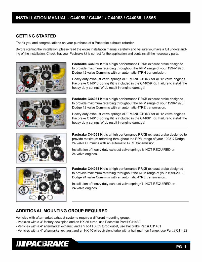
1 Remove the lower dash panel and locate an ignition power supply at the base of the steering column.
1994-1997 models use a medium blue 14 gage wire and blue “T” tap
1998-2002 models use a black with orange tracer 18 gage wire and a red “T” tap.
Check the wire with a voltmeter to ensure it is 12 volts and an ignition power source. Attach the supplied “T” tap to this wire and insert the red 16 gage 3 amp fused wire to this “T” tap.
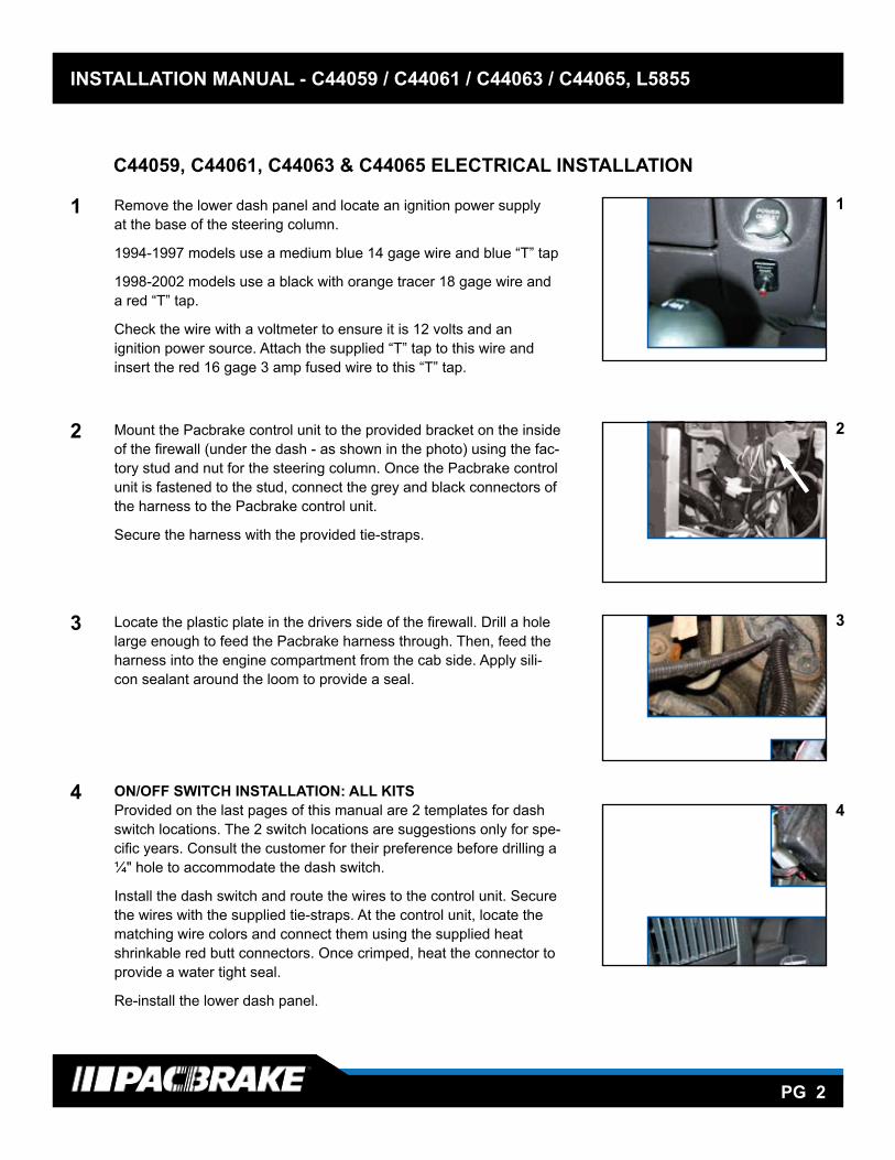
2 Mount the Pacbrake control unit to the provided bracket on the inside of the firewall (under the dash - as shown in the photo) using the fac- tory stud and nut for the steering column. Once the Pacbrake control unit is fastened to the stud, connect the grey and black connectors of the harness to the Pacbrake control unit.
Secure the harness with the provided tie-straps.
3 Locate the plastic plate in the drivers side of the firewall. Drill a hole large enough to feed the Pacbrake harness through. Then, feed the harness into the engine compartment from the cab side. Apply sili- con sealant around the loom to provide a seal.
4 ON/OFF SWITCH INSTALLATION: ALL KITS Provided on the last pages of this manual are 2 templates for dash switch locations. The 2 switch locations are suggestions only for spe- cific years. Consult the customer for their preference before drilling a ¼" hole to accommodate the dash switch.
Install the dash switch and route the wires to the control unit. Secure the wires with the supplied tie-straps. At the control unit, locate the matching wire colors and connect them using the supplied heat shrinkable red butt connectors. Once crimped, heat the connector to provide a water tight seal.
Re-install the lower dash panel.
1
C44059, C44061, C44063 & C44065 ELECTRICAL INSTALLATION
2
3
4
INSTALLATION MANUAL - INSERT TITLE HERE, L1234
PG 3
INSTALLATION MANUAL - C44059 / C44061 / C44063 / C44065, L5855
PG 3
C44063/C44065
I N S TA L L AT I O N M A N U A L - L 5 8 5 5 P G . �
6 Under the hood, beside the fuel filter, locate the factory 3 pin Weather-Pac connector on the driver side of the engine (shown by the arrow). Remove the protective cap and install the mating connector in the Pacbrake harness. Install the protective cap removed on the unused connector on the Pacbrake harness - unless you have a performance module connected to it.NOTE: Some 1999 model year trucks and all 1998.5 will require the use of the 3 pin triangular jumper harness to connect to the data link connector.
7 Route the leg of the Pacbrake harness with the brown and orange wires down the driver side frame rail to the transmission connector shown in the photo. Locate pin 7, the wire color should be orange with a black tracer. Cut this wire in a convenient location to install the connectors provided. Connect the orange wire in the Pacbrake harness to the transmission side wire and the brown to the harness side wire to the PCM side. Once crimped, heat the con-nector to provide a water tight seal. Secure the connectors and harness using the tie straps supplied.
NOTE: If the wire color in pin 7 doesn’t appear to be orange with a black tracer, make sure you connect to pin 7. It is not uncommon for the VOEM to change wire colors in mid production
8 Route the red fused wire with the eye terminal to the positive battery terminal (leaving the positive lead disconnected).
*The battery leads are connected in step 18.
9 Connect the black wire with the eye terminal to the negative battery terminal or a good chassis ground. Secure with the tie straps provided.
22 32
1 11
Powertrain ControlModule C2 (Diesel)
Transmission Solenoid Connector (5.9L)
1
27
836
45
OrangeBlack Tracer
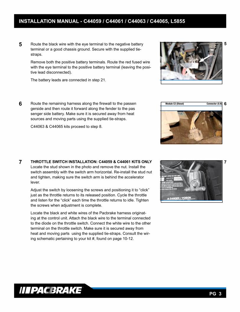
5 Route the black wire with the eye terminal to the negative battery terminal or a good chassis ground. Secure with the supplied tie- straps.
Remove both the positive battery terminals. Route the red fused wire with the eye terminal to the positive battery terminal (leaving the posi- tive lead disconnected).
The battery leads are connected in step 21.
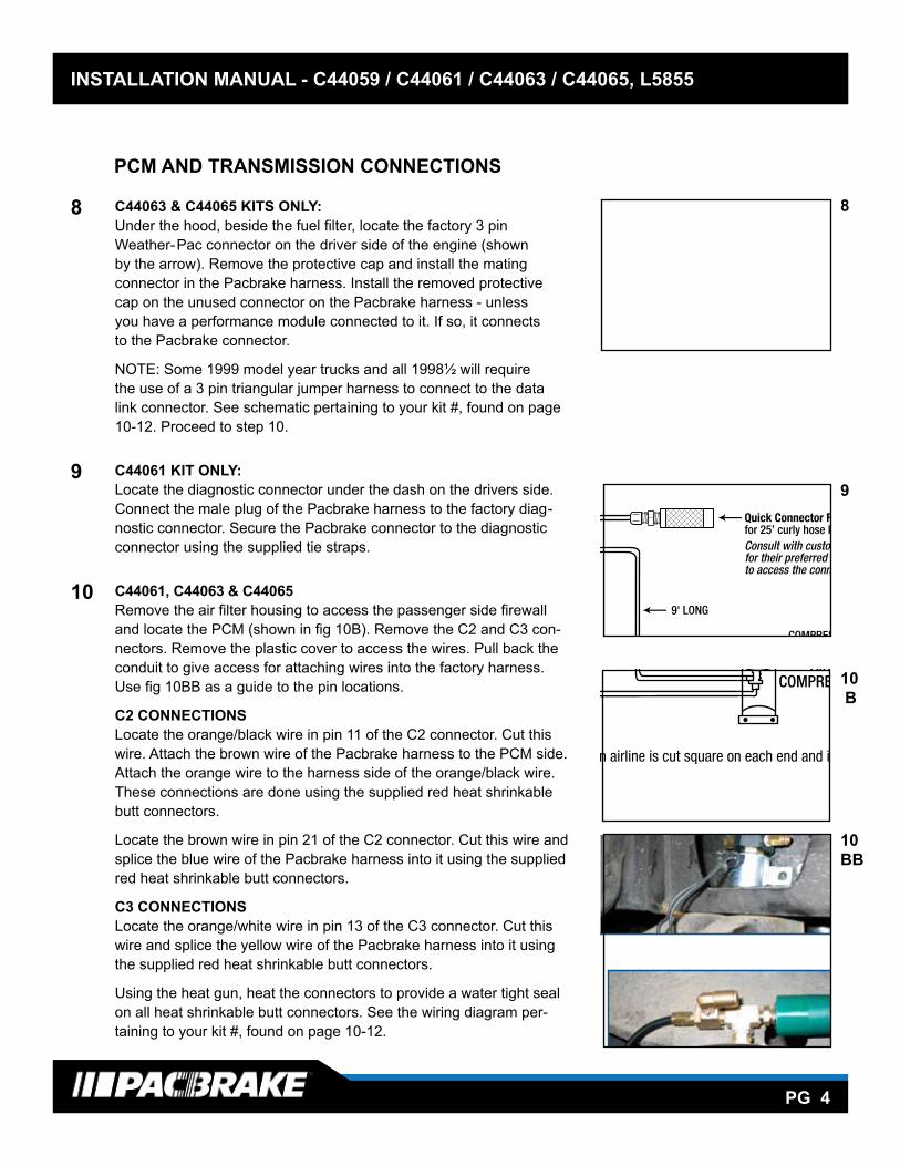
6 Route the remaining harness along the firewall to the passen gerside and then route it forward along the fender to the pas senger side battery. Make sure it is secured away from heat sources and moving parts using the supplied tie-straps.
C44063 & C44065 kits proceed to step 8.
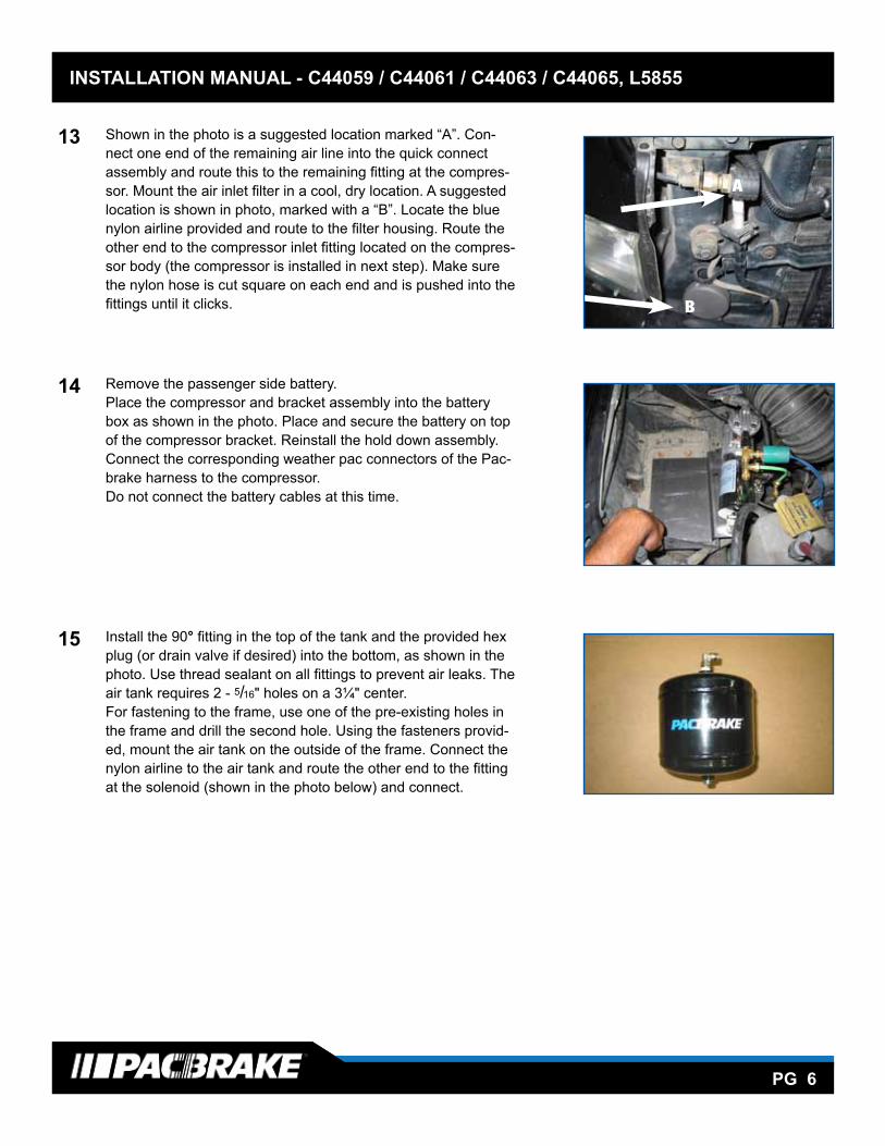
7 THROTTLE SWITCH INSTALLATION: C44059 & C44061 KITS ONLY Locate the stud shown in the photo and remove the nut. Install the switch assembly with the switch arm horizontal. Re-install the stud nut and tighten, making sure the switch arm is behind the accelerator lever.
Adjust the switch by loosening the screws and positioning it to “click” just as the throttle returns to its released position. Cycle the throttle and listen for the “click” each time the throttle returns to idle. Tighten the screws when adjustment is complete.
Locate the black and white wires of the Pacbrake harness originat- ing at the control unit. Attach the black wire to the terminal connected to the diode on the throttle switch. Connect the white wire to the other terminal on the throttle switch. Make sure it is secured away from heat and moving parts using the supplied tie-straps. Consult the wir- ing schematic pertaining to your kit #, found on page 10-12.
5
6
7
C44063/C44065
I N S TA L L AT I O N M A N U A L - L 5 8 5 5 P G . �
6 Under the hood, beside the fuel filter, locate the factory 3 pin Weather-Pac connector on the driver side of the engine (shown by the arrow). Remove the protective cap and install the mating connector in the Pacbrake harness. Install the protective cap removed on the unused connector on the Pacbrake harness - unless you have a performance module connected to it.NOTE: Some 1999 model year trucks and all 1998.5 will require the use of the 3 pin triangular jumper harness to connect to the data link connector.
7 Route the leg of the Pacbrake harness with the brown and orange wires down the driver side frame rail to the transmission connector shown in the photo. Locate pin 7, the wire color should be orange with a black tracer. Cut this wire in a convenient location to install the connectors provided. Connect the orange wire in the Pacbrake harness to the transmission side wire and the brown to the harness side wire to the PCM side. Once crimped, heat the con-nector to provide a water tight seal. Secure the connectors and harness using the tie straps supplied.
NOTE: If the wire color in pin 7 doesn’t appear to be orange with a black tracer, make sure you connect to pin 7. It is not uncommon for the VOEM to change wire colors in mid production
8 Route the red fused wire with the eye terminal to the positive battery terminal (leaving the positive lead disconnected).
*The battery leads are connected in step 18.
9 Connect the black wire with the eye terminal to the negative battery terminal or a good chassis ground. Secure with the tie straps provided.
22 32
1 11
Powertrain ControlModule C2 (Diesel)
Transmission Solenoid Connector (5.9L)
1
27
836
45
OrangeBlack Tracer
INSTALLATION MANUAL - INSERT TITLE HERE, L1234
PG 4
INSTALLATION MANUAL - C44059 / C44061 / C44063 / C44065, L5855
PG 4
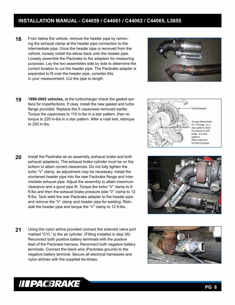
8 C44063 & C44065 KITS ONLY: under the hood, beside the fuel filter, locate the factory 3 pin Weather- Pac connector on the driver side of the engine (shown by the arrow). Remove the protective cap and install the mating connector in the Pacbrake harness. Install the removed protective cap on the unused connector on the Pacbrake harness - unless you have a performance module connected to it. If so, it connects to the Pacbrake connector.
NOTE: Some 1999 model year trucks and all 1998½ will require the use of a 3 pin triangular jumper harness to connect to the data link connector. See schematic pertaining to your kit #, found on page 10-12. Proceed to step 10.
9 C44061 KIT ONLY: Locate the diagnostic connector under the dash on the drivers side. Connect the male plug of the Pacbrake harness to the factory diag - nostic connector. Secure the Pacbrake connector to the diagnostic connector using the supplied tie straps.
10 C44061, C44063 & C44065 Remove the air filter housing to access the passenger side firewall and locate the PCM (shown in fig 10B). Remove the C2 and C3 con- nectors. Remove the plastic cover to access the wires. Pull back the conduit to give access for attaching wires into the factory harness. use fig 10BB as a guide to the pin locations.
C2 CONNECTIONSLocate the orange/black wire in pin 11 of the C2 connector. Cut this wire. Attach the brown wire of the Pacbrake harness to the PCM side. Attach the orange wire to the harness side of the orange/black wire. These connections are done using the supplied red heat shrinkable butt connectors.
Locate the brown wire in pin 21 of the C2 connector. Cut this wire and splice the blue wire of the Pacbrake harness into it using the supplied red heat shrinkable butt connectors.
C3 CONNECTIONSLocate the orange/white wire in pin 13 of the C3 connector. Cut this wire and splice the yellow wire of the Pacbrake harness into it using the supplied red heat shrinkable butt connectors.
using the heat gun, heat the connectors to provide a water tight seal on all heat shrinkable butt connectors. See the wiring diagram per-taining to your kit #, found on page 10-12.
8
9
10 B
PCM AND TRANSMISSION CONNECTIONS
10BB
C44063/C44065
I N S TA L L AT I O N M A N U A L - L 5 8 5 5 P G . 5
10 Route the remaining harness along the fire wall to the passenger side and then route it down to and along the passenger side frame rail. Make sure it is secured with the supplied tie straps and is not compromised by heat or moving parts.
Consult with customer for their preferred location to mount the quick connector for the air line. Using the two self tapping screws mount the L-bracket. Insert the bulkhead airline fitting into the L-bracket and tighten the jam nut to secure it. Follow the airline installation procedures in the next step.
Air System Installation:
Cut the nylon airline provided to the lengths shown in this diagram. Make sure the nylon airline is cut square on each end and is pushed into the fittings until it clicks
11 On the passenger side frame rail, locate the section of the inner frame with a cut out. The air solenoid, with the exhaust port pointing down, mounts inside this cut out and is secured to the frame with one of the air tank fasteners (see step 12). Route the Pacbrake harness to this location and connect the Weather-Pac connectors.
12 Install the fittings and pressure switch in the top of the tank as shown in the photo. Use thread sealant on all fittings to prevent air leaks. The air tank requires 2 -5/16" holes on a 3 1/4" center. Use one of the pre-existing holes in the frame and drill the second hole. Using the fasteners provided, mount the air tank on the outside of the frame and the solenoid on the inside using the same fastener. Install the nylon airlines to the solenoid valve and air tank as shown in step 10. Connect the Weather-Pac connector of the Pacbrake harness to the pressure switch connector.
EXHAUST BRAKESOLENOID
VALVEAIR
COMPRESSOR
CYL IN
#2 6' LONG
PRESSURE SWITCHQuick Connector Fittingfor 25’ curly hose kit.Consult with customer for their preferred locationto access the connector
COMPRESSORAIR INTAKE
9' LONG#1
AIRTANK
Pacbrake
8' LONG

INSTALLATION MANUAL - INSERT TITLE HERE, L1234
PG 5
INSTALLATION MANUAL - C44059 / C44061 / C44063 / C44065, L5855
PG 5
11a C44059 KITS ONLY:Route the brown, orange, blue, yellow and the OBD1 connector of the Pacbrake harness along the firewall to the passenger side firewall. Locate the factory OBD1 connector and apply electrical tape to se-cure them together. Remove the air filter housing to gain access to the PCM.
11b C44059 KITS ONLY:On the passenger side firewall, locate the PCM (shown in fig 11B). Remove the connector by loosening the bolt in the center. Remove the plastic cover to access the wires. Pull back the conduit to give access for attaching wires into the factory harness. use fig 11BB as a guide to the pin locations.
Locate the orange/black wire in pin 54 of the PCM connector. Cut this wire. Attach the brown wire of the Pacbrake harness to the PCM side. Attach the orange wire to the harness side of the orange/black wire. These connections are done using the supplied red heat shrinkable butt connectors.
Locate the brown wire in pin 55. Cut this wire and splice the blue wire of the Pacbrake harness into it using the supplied red heat shrinkable butt connectors.
Locate the orange/white wire in pin 10. Cut this wire and splice the yellow wire of the Pacbrake harness into it using the supplied red heat shrinkable butt connectors.
See wiring diagram pertaining to your kit #, found on page 10-12.
12 Consult with the customer for their preferred location to mount thequick disconnect for the airline. The mounting location should be in a clean, dry area with easy access to the operator.
using the two self tapping screws mount the “L” bracket. Insert the bulkhead airline fitting into the “L” bracket and tighten the jam nut to secure it. Apply thread sealant to prevent air leaks. Follow the airline installation procedures in the next step.
11 A
11 B
12
11BB
Connector view shown is of the PCM side, connector removed.
C44063/C44065
I N S TA L L AT I O N M A N U A L - L 5 8 5 5 P G . �
13 Locate the cross member just behind the cab that supports the rear of the fuel tank. This cross member is a U channel design with two pre-existing holes in the center. Enlarge the two pre-existing holes to 5/16". Then, using the air compressor as a template, mark and drill the two remaining mounting holes. Connect the nylon line marked air intake to the compressor intake port (barbed fitting below compressor head). Install the two nylon airlines to the compressor as shown in step 10. Install the compressor on top of the cross member inside the U channel using the flat washers, lock washers and nuts provided. Route the nylon air intake line to a clean, dry location for the intake filter. Connect the Weather-Pac connector of the Pacbrake harness to the connector on the compressor.
14 Exhaust Brake Installation:All vehicles, remove the two capscrews that attaches the cast elbow to the header pipe.
1998 vehicles, remove the V clamp between the elbow and the turbocharger. Remove the cast elbow. Removal of the 5 bolt flange is not required.
1999-2002 vehicles, remove the 5 capscrews securing the elbow to the turbocharger. Remove the cast elbow.
15 From below the vehicle, remove the header pipe by removing the exhaust clamp at the header pipe connection to the intermediate pipe. Once the header pipe is removed from the vehicle, loosely install the elbow back onto the header pipe. Loosely assemble the Pacbrake to the adapters for measuring purposes. Lay the two assemblies side by side to determine the correct location to cut the header pipe. The Pacbrake adapter is expanded to fit over the header pipe, consider this in your measurement. Cut the pipe to length.
16 1999-2002 vehicles, at the turbocharger check the gasket surface for imperfections. If okay, install the new gasket and turbo flange provided. Replace the 5 capscrews removed earlier. Torque the capscrews to 110 in-lbs in a star pattern, then retorque to 220 in-lbs in a star pattern. After a road test, retorque to 220 in-lbs.
in-lbs
in-lbs
INSTALLATION MANUAL - INSERT TITLE HERE, L1234
PG 6
INSTALLATION MANUAL - C44059 / C44061 / C44063 / C44065, L5855
PG 6
13 Shown in the photo is a suggested location marked “A”. Con-nect one end of the remaining air line into the quick connect assembly and route this to the remaining fitting at the compres-sor. Mount the air inlet filter in a cool, dry location. A suggested location is shown in photo, marked with a “B”. Locate the blue nylon airline provided and route to the filter housing. Route the other end to the compressor inlet fitting located on the compres-sor body (the compressor is installed in next step). Make sure the nylon hose is cut square on each end and is pushed into the fittings until it clicks.
14 Remove the passenger side battery.Place the compressor and bracket assembly into the battery box as shown in the photo. Place and secure the battery on top of the compressor bracket. Reinstall the hold down assembly. Connect the corresponding weather pac connectors of the Pac-brake harness to the compressor.Do not connect the battery cables at this time.
15 Install the 90° fitting in the top of the tank and the provided hex plug (or drain valve if desired) into the bottom, as shown in the photo. use thread sealant on all fittings to prevent air leaks. The air tank requires 2 - 5/16" holes on a 3¼" center. For fastening to the frame, use one of the pre-existing holes in the frame and drill the second hole. using the fasteners provid-ed, mount the air tank on the outside of the frame. Connect the nylon airline to the air tank and route the other end to the fitting at the solenoid (shown in the photo below) and connect.
A
B

INSTALLATION MANUAL - INSERT TITLE HERE, L1234
PG 7
INSTALLATION MANUAL - C44059 / C44061 / C44063 / C44065, L5855
PG 7
Connect to quick connect
Connect to air intake filter
Connect to exhaust brake
Connect to air tank
16 Compressor and Airline Routing
17 Exhaust Brake Installation
All vehicles, remove the two capscrews that attaches the cast elbow to the header pipe.
1994-1998 vehicles, remove the V clamp between the elbow and the turbo charger. Remove the cast elbow. Removal of the 5 bolt flange is not required. 1999-2002 vehicles, remove the 5 capscrews securing the elbow to the turbocharger. Remove the cast elbow.
NOTE: 12 valve engines REquIRE H.D. exhaust valve springs to be installed. Contact Pacbrake Customer Service @ 800.663.0096 for installation procedure, if required.
INSTALLATION MANUAL - INSERT TITLE HERE, L1234
PG 8
INSTALLATION MANUAL - C44059 / C44061 / C44063 / C44065, L5855
PG 8
18 From below the vehicle, remove the header pipe by remov-ing the exhaust clamp at the header pipe connection to the intermediate pipe. Once the header pipe is removed from the vehicle, loosely install the elbow back onto the header pipe. Loosely assemble the Pacbrake to the adapters for measuring purposes. Lay the two assemblies side by side to determine the correct location to cut the header pipe. The Pacbrake adapter is expanded to fit over the header pipe, consider this in your measurement. Cut the pipe to length.
19 1999-2002 vehicles, at the turbocharger check the gasket sur-face for imperfections. If okay, install the new gasket and turbo flange provided. Replace the 5 capscrews removed earlier. Torque the capscrews to 110 in-lbs in a star pattern, then re-torque to 220 in-lbs in a star pattern. After a road test, retorque to 220 in-lbs.
20 Install the Pacbrake as an assembly (exhaust brake and both exhaust adapters). The exhaust brake cylinder must be on the bottom to attain correct clearances. Do not fully tighten the turbo “V” clamp, as adjustment may be necessary. Install the shortened header pipe into the rear Pacbrake flange and inter-mediate exhaust pipe. Adjust the assembly to attain maximum clearance and a good pipe fit. Torque the turbo “V” clamp to 6 ft-lbs and then the exhaust brake pressure side “V” clamp to 12 ft-lbs. Tack weld the rear Pacbrake adapter to the header pipe and remove the “V” clamp and header pipe for welding. Rein-stall the header pipe and torque the “V” clamp to 12 ft-lbs.
21 using the nylon airline provided connect the solenoid valve port marked “CYL” to the air cylinder. (Fitting installed in step 26)Reconnect both positive battery terminals with the positive lead of the Pacbrake harness. Reconnect both negative battery terminals. Connect the black wire (Pacbrake ground) to the negative battery terminal. Secure all electrical harnesses and nylon airlines with the supplied tie-straps.
in-lbs
in-lbs

INSTALLATION MANUAL - INSERT TITLE HERE, L1234
PG 9
INSTALLATION MANUAL - C44059 / C44061 / C44063 / C44065, L5855
PG 9
TESTING THE SYSTEM - C44059, C44061, C44063 & C44065With the Pacbrake switch in the OFF position, start the engine and allow to idle. The Pacbrake compressor should pump air for approximately 2 minutes (this will fill the air tank from empty). Once the Pacbrake control unit confirms the air tank has reached maximum air pressure, the control unit will perform a Self Test Cycle which will activate and release the exhaust brake two times with the vehicle stationary.
Vehicles with 47RH/RE transmissions which have aftermarket valve bodies and aftermarket lock-up torque convert-ers which are able to hold lock-up during exhaust braking in 1st and 2nd gears can use the later 48RE programming. To change the existing program within the Pacbrake control unit, simply locate the orange wire with a spade con-nection approximately 6 inches from the control unit. Disconnect this connection. Turn the ignition ON. The exhaust brake should cycle 3 times confirming the 48RE program has been loaded. This difference between the two pro-grams is that the 48RE transmission will allow exhaust braking in 2nd and 1st gears, where the factory 47RH/RE transmission will not.
Test drive the vehicle. If lock-up will not hold during exhaust braking in 2nd or 1st gear, re-connect the orange wire.
LED SWITCH OPERATIONRED - Brake enabled and ready for activationGREEN - Parameters are achieved, and the Pacbrake controller is now commanding torque converter lock-upORANGE - Brake currently activeNo Illumination - Brake disabled/OFF
FEATURES - C44059, C44061 & C44065The Pacbrake control unit has a built in warm-up feature. This feature will activate the exhaust brake at idle with the vehicle stationary when the Pacbrake switch is turned ON. When the coolant temperature reaches 170°F or 75°C, the control unit will disable the warm-up feature at idle. When performing a road test, the O.D. (overdrive) switch must be in the OFF position and the Pacbrake switch in the ON position. Attain road speed above 40 MPH or 65km/h and release the accelerator pedal. The exhaust brake should apply, slowing the vehicle. Once the exhaust brake has brought the vehicle’s engine speed below 900 RPM, the exhaust brake will disengage. When using the auxiliary coil hose for inflation, the Pacbrake switch must be turned ON with the engine running.
INSTALLATION MANUAL - INSERT TITLE HERE, L1234
PG 10
INSTALLATION MANUAL - C44059 / C44061 / C44063 / C44065, L5855
PG 10
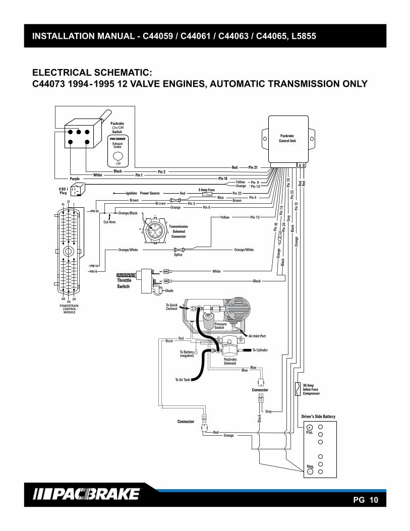
ELECTRICAL SCHEMATIC:C44073 1994-1995 12 VALVE ENGINES, AUTOMATIC TRANSMISSION ONLY
TransmissionSoleniod
Connector
Driver’s Side Battery
+Pos.
Neg.-
Cut Here
30 AmpInline FuseCompressor
Connector
Connector
A B
Oran
gePi
n 13
Blac
kGr
ey
Red
Red
Pin
23Pi
n18
PacbrakeControl Unit
Br o wnBrown
OrangePin
BlueBrown
Pin 4
5Pin 6
Pin
Pin 1 5
Pin
16Pi
n1 9
Black
White
Blac
kPi
n24
22
1
27
8
36
45
Orange/Black
Orange/White Orange/White
Yellow
Red
Grey
kcalB
Red3 Amp Fuse
YellowOrange
Pin 9Pin 1 0
Orange
Ignition Power Source
PIN 54
PIN 55
PIN 1 0
Oran
ge
O BD IPlug
4121
1
6040
20
POWERTRAINCONTROLMODULE
ThrottleSwitch
Pacbrake
Switch
Pin 1Black Pin 2
WhitePurple
Exhaustbrake
Pin 21
Pin 14
Red
Splice
Pressure Switch
Pacbrake Solenoid
Air Inlet Port
To Air Tank
To CylinderTo Battery(negative)
RedBlack
To QuickConnect
BlueBlue
Diode

INSTALLATION MANUAL - INSERT TITLE HERE, L1234
PG 11
INSTALLATION MANUAL - C44059 / C44061 / C44063 / C44065, L5855
PG 11
ELECTRICAL SCHEMATIC:C44076 1996-1998 12 VALVE ENGINES, AUTOMATIC TRANSMISSION ONLY
Pacbrake
Switch
Pin 1Black Pin 2
WhitePurple
Exhaustbrake
Pin 21
Pin 14
Red
Splice
Splice
Brow
n
TransmissionSoleniod
Connector
Driver’s Side Battery
+Pos.
Neg.-
Cut Here
22121
22121
322111
322111
30 AmpInline FuseCompressor
A B
Ora
nge
Pin
13Bl
ack
Gre
y
Red
Red
Pin
23Pi
n18
PacbrakeControl Unit
BrownBlue
Brown
OrangePin
Pin 4
5Pin6
Powertrain Control
OBD II Plug
Module C2 (Diesel)
Pin
Pin15
Pin1
6Pi
n19
Black
White Blac
kniP
24
22
1
27
836
45
Orange/Black
Orange withWhite Wire
Pin 15Pin 7
Red
Grey
kcalB
Red
Powertrain ControlModule C3 (Diesel)
3 Amp Fuse
GreenYellow
Pin 8Pin 7
Orange
Ignition Power Source
PIN13
Ora
nge
Orange with White Wire
Yellow
Pressure Switch
BlueBlue
RedOrange
To QuickConnect
ThrottleSwitch
Air Inlet Port
PacbrakeSolenoid
To Cylinder
Connector
To Battery(negative)
To Air Tank
Connector
Diode
INSTALLATION MANUAL - INSERT TITLE HERE, L1234
PG 12
INSTALLATION MANUAL - C44059 / C44061 / C44063 / C44065, L5855
PG 12
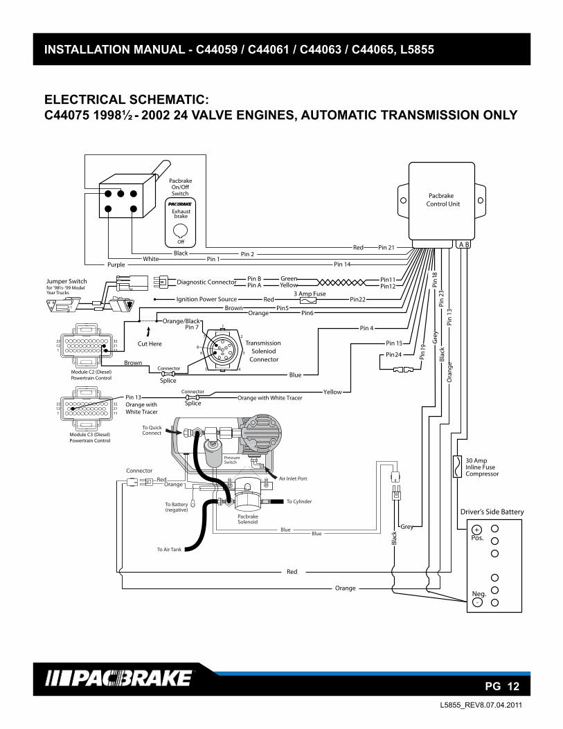
ELECTRICAL SCHEMATIC:C44075 1998½ - 2002 24 VALVE ENGINES, AUTOMATIC TRANSMISSION ONLY
Pin
19
Pin 24
Jumper Switch
TransmissionSoleniod
Connector
Driver’s Side Battery
+Pos.
Neg.-
Cut Here
30 AmpInline FuseCompressor
A B
Ora
nge
Pin
13Bl
ack
Gre
yPi
n 23
Pin
1 8
PacbrakeControl Unit
BrownOrange
Pin5Pin6
Pin22
1
27
836
45
Orange/Black
Brown
for ’98½-’99 ModelYear Trucks
Red
Grey
kcalB
Red3 Amp Fuse
Pin BPin A
GreenYellow
Pin11Pin12
Orange
Diagnostic Connector
Ignition Power Source
Pin 7
Powertrain ControlModule C2 (Diesel)
Powertrain ControlModule C3 (Diesel)
22121
322111
22121
322111
Connector
Connector
Pin 13Orange with White Tracer
Orange with White Tracer
Pin 4
Blue
Yellow
Pin 15
Pacbrake
Switch
Pin 1Black Pin 2
WhitePurple
Exhaustbrake
Pin 21
Pin 14
Red
Splice
Splice
Pressure Switch
To QuickConnect
Air Inlet Port
PacbrakeSolenoid
To CylinderTo Battery(negative)
To Air Tank
RedOrange
Connector
BlueBlue
L5855_REV8.07.04.2011
1/2" Drill
Hood release handle cut-out
Flush with edge of panel
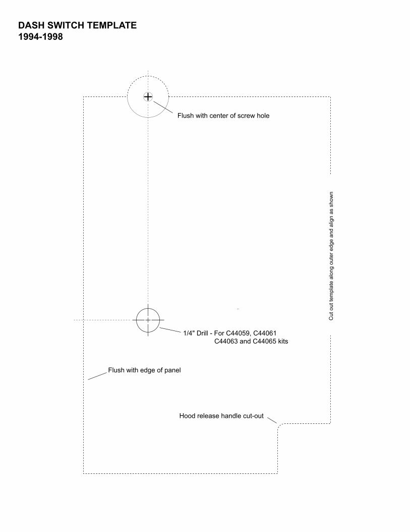
Flush with center of screw hole
Cut o
ut te
mplat
e al
ong
oute
r edg
e and
alig
n as
sho
wn.
DODGE RAMDASH S WITCH TEMPLATEMODEL YEARS 1994-1998
For C44072 and C44074 kitsNOT using a shifter switch
1/4" Drill For C44073, C44075 and C44076 kits
Flush with center of screw hole
1/4" Drill - For C44059, C44061 C44063 and C44065 kits
Flush with edge of panel
Hood release handle cut-out
Cut
out
tem
plat
e al
ong
oute
r edg
e an
d al
ign
as s
how
n
DASH SWITCH TEMPLATE 1994-1998
1/2" Drill
1/2" Drill
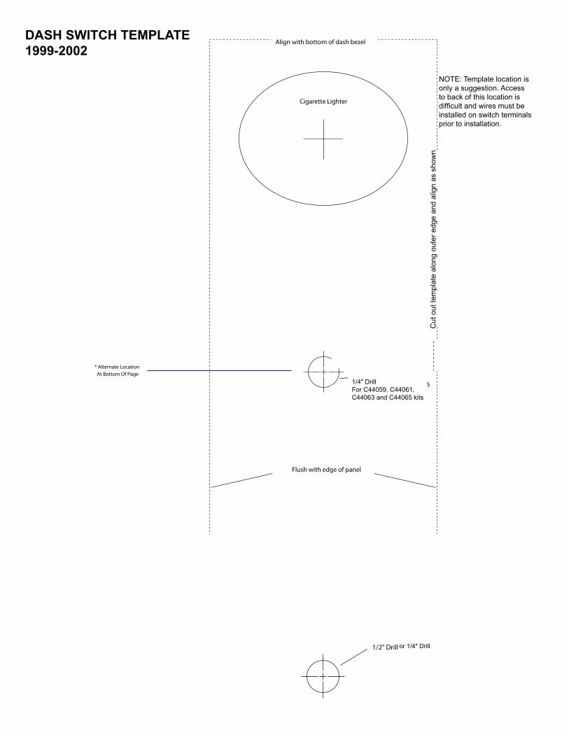
Flush with edge of panel
NOTE: Template location isonly a suggestion. Accessto back of this location isdi�cult and wires must beinstalled on switch terminalsprior to installation.
Cut o
ut te
mplat
e al
ong
oute
r edg
e an
d al
ign
as s
how
n.
Align with bottom of dash bezel
Cigarette Lighter
* Alternate Location At Bottom Of Page 1/4" Drill
For C44073, C44075 and C44076 kits
For C44072 and C44074 kitsNOT using a shifter switch
or 1/4" Drill
Cut
out
tem
plat
e al
ong
oute
r edg
e an
d al
ign
as s
how
n
NOTE: Template location isonly a suggestion. Access to back of this location isdifficult and wires must be installed on switch terminalsprior to installation.
DASH SWITCH TEMPLATE 1999-2002
1/4" DrillFor C44059, C44061,C44063 and C44065 kits