Performance of a Multi-Paradigm Messaging Runtime on Multicore Systems
High Performance Messaging onWorkstations:
Illinois Fast Messages (FM) for Myrinet�
Scott Pakiny Mario Lauriaz Andrew Chieny
Abstract
In most computer systems, software overhead dominatesthe cost of messaging, reducing delivered performance, espe-cially for short messages. Efficient software messaging layersare needed to deliver the hardware performance to the appli-cation level and to support tightly-coupled workstation clusters.
Illinois Fast Messages (FM) 1.0 is a high speed messag-ing layer that delivers low latency and high bandwidth for shortmessages. For 128-byte packets, FM achieves bandwidths of16.2 MB/s and one-way latencies 32�s on Myrinet-connectedSPARCstations (user-level to user-level). For shorter packets,we have measured one-way latencies of 25 �s, and for largerpackets, bandwidth as high as to 19.6 MB/s — delivered band-width greater than OC-3. FM is also superior to the Myrinet APImessaging layer, not just in terms of latency and usable band-width, but also in terms of the message half-power point (n 1
2),
which is two orders of magnitude smaller (54 vs. 4,409 bytes).We describe the FM messaging primitives and the critical
design issues in building a low-latency messaging layers forworkstation clusters. Several issues are critical: the division oflabor between host and network coprocessor, management ofthe input/output (I/O) bus, and buffer management. To achievehigh performance, messaging layers should assign as muchfunctionality as possible to the host. If the network interface hasDMA capability, the I/O bus should be used asymmetrically, with
�The research described in this paper was supported in part by NSF grantsCCR-9209336 and MIP-92-23732, ONR grants N00014-92-J-1961 and N00014-93-1-1086 and NASA grant NAG 1-613. Andrew Chien is supported in part by NSFYoung Investigator Award CCR-94-57809.
yDepartment of Computer Science, University of Illinois at Urbana-Champaign,1304 W. Springfield Ave., Urbana, IL 61801, USA
zDipartimento di Informatica e Sistemistica, Universita di Napoli “Federico II”,via Claudio 21, 80125 Napoli, Italy
1
the host processor moving data to the network and exploitingDMA to move data to the host. Finally, buffer managementshould be extremely simple in the network coprocessor andmatch queue structures between the network coprocessor andhost memory. Detailed measurements show how each of thesefeatures contribute to high performance.
1 IntroductionAs the performance of workstations reaches hundreds of megaflops(even gigaflops), networks of workstations provide an increasinglyattractive vehicle for high performance computation [3]. In fact, work-station clusters have a number of advantages over their major com-petitors (massively-parallel processors based on workstation proces-sors). These advantages can include lower cost, a larger softwarebase, and greater accessibility. Further, the advent of high perfor-mance network interconnects such as ATM [7], Fibre Channel [4],FDDI [13], and Myrinet [6] present the possibility that workstationclusters can deliver good performance on a broader range of parallelcomputations.
Achieving efficient communication is the major challenge in syn-thesizing effective parallel machines from networks of workstations.Unfortunately, to date the most common messaging layers used forclusters (TCP/IP [9], PVM [27]) generally have not delivered a largefraction of the underlying communication hardware performance tothe applications. Reasons for this include protocol overhead, buffermanagement, link management, and operating system overhead.Even in recent high speed network experiments, high bandwidths aregenerally only achieved for large messages (hundreds of kilobytes oreven megabytes) and then only with overheads of 1 millisecond ormore. Reasons for this include system call overhead, buffer copying,network admission control, poor network management, and softwareoverhead . As a result, parallel computing on workstation clustershas largely been limited to coarse-grained applications.
Attempts to improve performance based on specialized hardwarecan achieve dramatically higher performance, but generally requirespecialized components and interfacing deep into a computer systemdesign [16, 18, 19]. This increases cost, and decreases the potentialmarket (and hence sale volume) of the network hardware.
The goal of the Illinois Fast Messages (FM) project is to delivera large fraction of the network’s physical performance (latency andbandwidth) to the user at small packet sizes.1 Building efficient soft-
1More information and software releases of FM are available from:http://www-csag.cs.uiuc.edu/projects/communication/sw-messaging.html .
2

ware messaging layers is not a unique goal [12, 25, 30, 31], but FMis distinguished by its hardware context (Myrinet) and high perfor-mance.
The Fast Messages project focuses on optimizing the softwaremessaging layer that resides between lower-level communicationservices and the hardware. It is available on both the Cray T3D[22, 23] and Myricom’s Myrinet [6]. Using the Myrinet, FM providesMPP-like communication performance on workstation clusters. FMon the Myrinet achieves low-latency, high-bandwidth messaging forshort messages delivering 32�s latency and 16 MBytes/s bandwidthfor 128 byte packets (user-level to user-level). For shorter packets,latency drops to 25�s, and for larger packets, bandwidth rises to19.6 MB/s. This delivered bandwidth is greater than OC-3 ATM’sphysical link bandwidth of 19.4 MB/s. FM’s performance exceeds themessaging performance of commercial messaging layers on numer-ous massively-parallelmachines [21, 29, 11]. A good characterizationof a messaging layer’s usable bandwidth (bandwidth for short mes-sages) is n 1
2, the packet size to achieve half of the peak bandwidth
( r12 ). FM achieves an n 12
of 54 bytes. In comparison, Myricom’scommercial API requires messages of over 3,873 bytes to achievethe same bandwidth. FM has improved the network’s ability to deliverperformance to short messages dramatically, reducing n 1
2by nearly
two orders of magnitude.In the design of FM, we addressed three critical design issues
faced by all designers of input/output bus interfaced high speed net-works: division of labor between host and network coprocessor, man-agement of the input/output bus, and buffer management. To achievehigh performance, messaging layers should assign as much function-ality as possible to the host. This leaves the network coprocessor freeto service the high speed network channels. If the network interfacehas DMA capability, the input/output bus should be used asymmetri-cally, with the host processor moving data to the network and exploit-ing DMA to move data to the host. Using the processor to move datato the network reduces latency, particularly for small messages. DMAtransfer for incoming messages, initiated by the network coprocessor,maximizes receive bandwidth with little cost in latency. Finally, buffermanagement should be extremely simple in the network coprocessorand match queue structures between the network coprocessor andhost memory. Simple buffer management minimizes software over-head in the network coprocessor, again freeing the coprocessor toservice the fast network. Matching queue structures between the hostand network coprocessor allows short messages to be aggregatedin DMA operations, reducing the data movement overhead. Detailedmeasurements evaluate several design alternatives and show how
3

each of these achieves high performance.The rest of the paper is organized as follows. Section 2 describes
issues common to all messaging layers. Section 3 explains our FMdesign in light of the hardware constraints of a workstation cluster. InSection 4, we present the design and performance of FM elementsin detail, justifying each design decision with empirical studies. Wediscuss our findings in Section 5 and provide a brief summary of thepaper and conclusions in Section 6.
2 BackgroundFor some time, researchers and even production sites have been us-ing workstation clusters for parallel computation. Many libraries areavailable to support such distributed parallel computing (PVM [27]atop UDP or TCP [28] is perhaps the most popular). The communi-cation primitives in these libraries have typically exploited operatingsystem communication services, running atop 10 Mb/s Ethernet, ormore recently some higher speed physical media such as FDDI [13],ATM [7] or Fibre Channel [4]. While such facilities are useful forcoarse-grain decoupled parallelism, they suffer from high softwarecommunication overhead (operating system calls) and low achievedbandwidth (media limits or software overhead), and thus cannot sup-port more tightly coupled or finer-grained parallelism.
Higher performance messaging systems for workstation clustersoften bypass the operating system, mapping the network device in-terface directly into the user address space and accessing it directlyvia load/store operations. Protection can still be achieved at virtualaddress translation but sharing of communication resources is morecomplicated. Our FM layer uses this approach, mapping the Myrinetnetwork interface directly into the user address space. Note thateven with a memory-mapped interface accesses can still be expen-sive; in our Myrinet system, reading a network interface status fieldrequires �15 processor cycles. Some ATM systems provide memorymapped input/output bus interfaces, but achieving performance is stilla challenging proposition. For example, delivered bandwidths of 1–3 MB/s are typical [24]. Achieving high performance requires carefulmanagement of the hardware resources by the software messaginglayer.
How deeply network interfaces will be integrated into a typicalsystem is a debate currently raging in the workstation cluster com-munity. Less integrated solutions are favored by third party networkproviders, giving leverage for their designs over many systems. Moretightly integrated designs clearly make it easier to achieve low latencyand high bandwidth. The Myrinet hardware used for this work rep-
4

resents the former approach, interfacing the network to the Sun’sinput/output bus (SBus). Consequently, many parts of the worksta-tion architecture affect performance; in the following paragraphs wedescribe the performance of these salient network and workstationfeatures.
Myrinet Network Features
Myrinet is a high speed LAN interconnect which uses byte-wideparallel copper links to achieve physical link bandwidth of 76.3 MB/s [6].Myrinet uses a network coprocessor (LANai) which controls the phys-ical link and contains three DMA engines (incoming channel, outgoingchannel, and host) to move data efficiently. Host-LANai coordinationis achieved by mapping the LANai’s memory into the host addressspace. Though the LANai integrates much of the critical functionality(low-overhead DMA), the current version (2.3) is a rather slow pro-cessor, a CISC architecture operating at the SBus clock frequency(20–25 Mhz) and executing one instruction every 3–4 cycles. The lowspeed of the LANai processor (�5 MIPS) compared to the networkmakes LANai program design critical in achieving high performance.For example, spooling a packet of 128 bytes over the channel takes1.6�s, the equivalent of only about eight to ten LANai instructions!
Host memory Host memory
MBus-SBusinterface
SBus
MB
us
MB
usSB
us
MBus-SBusinterface
Myrinet
physical
connection
Myrinet interface
LANai Memory
Myrinet interface
LANai Memory
Write buffer
Cache
Write buffer
CacheSPARC SPARC
Figure 1: Host-to-host data path
Workstation Features
Critical issues in the workstation include the processor speed,memory performance (memory bus) and input/output performance
5

(input/output bus). While latency is important, for longer messagesthe critical issue is bandwidth. To reach the network, data must firsttraverse the processor memory hierarchy (write buffer, memory bus),then the input/output bus (see Figure 1). Because the memory bus(MBus) has typically much better performance, the input/output bus(SBus) is generally the bottleneck. SBus performance favors DMA,supporting it with special burst-mode transfers which provide 40–54 MB/s for large transfers. With the Myrinet network interface, DMAcan only initiated by the LANai and transfers must be to or from kernelmemory. For processor mediated transfers, using double-word writesachieves a maximum of 23.9 MB/s.
We use two workstations for our measurements: a SPARCsta-tion 20 with two 50 MHz SuperSPARC processors (without the op-tional L2 cache) and a SPARCstation 10 with four 55 MHz RT100HyperSPARCs. The multiplicity of processors is not a significant is-sue. The memory bandwidths of the processors are 60 MB/s writes,80 MB/s reads and 52 MB/s writes, 37 MB/s reads respectively.These memory bandwidths are greater than the processor-mediatedSBus bandwidth, and hence are not a critical performance factors.
3 The Fast Messages Approach3.1 Illinois Fast Messages (FM) 1.0
Illinois Fast Messages (FM) is a high performance messaging layerwhich is available on several parallel platforms (Cray T3D and work-station clusters) [22, 23]. The design goal of FM is to deliver networkhardware performance to the application level with a simple interface.FM is appropriate for implementors of compilers, language runtimes,communications libraries, and in some cases application program-mers.
Function OperationFM send 4(dest,handler,i0,i1,i2,i3) Send a four word messageFM send(dest,handler,buf,size) Send a long messageFM extract() Process received messages
Table 1: FM 1.0 layer calls
Table 1 lists all three of FM’s messaging functions. There are twocalls to send messages, FM send 4() andFM send(), for extremelyshort, and somewhat longer (32 words or fewer) messages. Eachmessage carries a pointer to a sender-specified function (called a
6
“handler”) that consumes the data at the destination. The handler-carrying message concept is similar to Active Messages [31], butin FM there is no notion of request-reply coupling. There are norestrictions on the actions that can be performed by an handler,and it is left to the programmer of preventing deadlock situations.When a process wishes to check for and process a message, itcalls FM extract(), which dequeues and processes one or moremessages. Because host processor involvement is not required toremove data from the network, polling is not required to prevent net-work blockage. Similar to Active Messages, message buffers do notpersist beyond the return of the handler.
3.2 Critical Messaging Layer Issues
The primary purpose of a messaging layer is the efficient transport ofdata from one processor to another. Messaging layers hide the un-derlying hardware and software components, providing services suchas reliable delivery, synchronization, in-order delivery, and collectivecommunication in addition to basic data movement. We are con-cerned with minimal messaging layers, so FM includes only featureswhose omission would cause major performance losses if handled inhigher software layers.
The basic feature provided by FM is reliable delivery which isdeemed necessary due to the costs of source buffering, timeout, andretry in higher software layers. Reliable delivery alone requires themessaging implementation to resolve issues of flow control, buffermanagement, and the division of labor between the host processorand the network coprocessor. Messaging layers generally provideflow control to avoid data loss and therefore, data retransmission.Flow control is required because all real computers and networkshave only a finite amount of buffering—flow control prevents bufferoverflow. Optimal flow control matches send rates to receive rateswith minimal overhead.
Buffer management enables the reuse of the finite host and net-work coprocessor memories to handle incoming and outgoing mes-sages. Buffering is employed to match rates between the host pro-cessor, network interface, and network channels. Buffers supportdifferent processing rates and service intervals, decoupling network,LANai, and host. An ideal buffering scheme would allow buffer allo-cation and release in any order at minimal overhead.
The division of labor between the host processor and the net-work coprocessor is a key performance issue in any system with aprogrammable network coprocessor. While most services can beprogrammed on either the host or the network interface, balanceddecompositions allow overlapping of the two levels and supporting
7
a higher message rate. Of course, configurations of host and net-work coprocessor in which the host processor is much faster and hassignificantly more memory [6, 20, 26] (e.g. our configuration) favorassigning more work to the host.
4 Fast Messages 1.0 Implementation DesignThe FM 1.0 implementation consists of two basic parts: the hostprogram and the LANai control program (LCP). These programs co-ordinate through the LANai memory which is mapped into the hostprocessor’s address space, but rather expensive to access becauseit resides on the SBus. Thus, a message transmission consists of thefollowing steps: getting the data to the LANai (traversing the sender’smemory bus and input/output bus), putting the data onto the commu-nication channel, removing it from the communication channel at thereceiver, and transporting the data to the receiver host’s memory.Each of these steps contributes to communication latency, and theslowest of them determines the maximum sustainable bandwidth.Thus, all parts of the system—both hardware and software—can becritical. Exploiting the Myrinet’s high speed links effectively requirescareful design of both the host and LCP both to be efficient and tomanage the bandwidth of the SBus and physical channel effectively.
Critical issues in the design of the FM messaging layer includethe structure of the LCP, buffer management and coordination of thetwo programs across the SBus, and the design of the host program.Careful design of all parts contributes to producing a high perfor-mance messaging layer. To elucidate the contribution of each factorto performance, we examine each in turn, building up from a mini-mal network coprocessor program that merely sends data across thechannel (never getting it to the hosts) to a complete messaging layer.
4.1 Performance Metrics and Measurements
To characterize communication performance, we use several stan-dard parameters (see Table 2). r
1bounds the maximum possi-
ble throughput, and t0 captures the leanness of the implementation.Since our goal is to support short messages more effectively, weuse n 1
2to show how successful we are in delivering good network
performance for short messages. These performance metrics arecalculated from measurements of latency and throughput.
Network latency is measured by ping-ponging a message backand forth 50 times, and dividing to compute the one-way packet la-tency. Bandwidth is determined by measuring the time to send 65,535packets and dividing the volume of data transmitted by the elapsed
8

Metric Definitionr1 Peak bandwidth for infinitely large packets (asymptotic)n 1
2Packet size to achieve bandwidth of r1
2
t0 Startup overhead` Packet latency (one way)
Table 2: Definitions of performance metrics
time. All measurements were taken on an 8-port Myrinet switch anda pair of workstations (see Section 2). In all of our measurements,message length refers to the payload (so that the reported data areinclusive of the header overhead), and 1 MB � 220 bytes.
4.2 Network Coprocessor Program
The network coprocessor program is a critical contributor to perfor-mance, incurring latency and bounding the peak bandwidth achiev-able. Because the network coprocessor (LANai) is of modest speed,and the LANai control program (LCP) is a sequential program deal-ing with concurrent activities, the organization of the LCP is critical toachieving high performance. We consider two basic implementationsof the LANai control program’s main loop. The first, baseline, is thestraightforward logical structure shown in Figure 2(a). The secondversion of the LCP loop, streamed, optimizes performance by con-solidating checks for queue management and by streaming sendsand receives to improve peak performance (see Figure 2(b)). Ascomputer traffic is often quite bursty, streaming is likely to improveaverage performance as well.
To calibrate our results and show how the LANai’s speed can im-pact network performance, we compare performance for the baselineand streamed performance against the LANai’s theoretical peak per-formance. Theoretical peak performance is indicated as theoreticalpeak and is calculated for an LCP which does DMAs of the appropri-ate size, omitting any pointer updates, checks for completion, queueboundary checks, looping overhead, etc. (see Appendix A).
The main loop organization in the LCP is a critical contributorto both latency and bandwidth for short messages. As shown inFigure 3, baseline incurs a latency far greater than the theoreticalminimum, indicating that even mundane pointer and looping over-heads reduce performance significantly. The Baseline loop achievesa t0 = 4:2�s, and n 1
2= 315 bytes. Streamed improves the basic
LCP loop, achieving higher bandwidth and lower latency, especially
9

send channel is availableif hostsent != lanaisentand then
a packet is available on the receive channelif then
send packet from a fixed buffer location
receive packet into a fixed buffer location
lanaisent++
repeat forever
end if
end ifend repeat
PACKET sendbuffer
PACKET receivebufferinteger hostsentinteger lanaisent /* Total # of msgs. LCP has sent */
/* Total # of msgs. host wants to send */
(a) Baseline
send channel is availablehostsent != lanaisentand then
a packet is available on the receive channelthen
send packet from a fixed buffer location
receive packet into a fixed buffer location
lanaisent++
repeat forever
end repeat
PACKET sendbuffer
PACKET receivebufferinteger hostsentinteger lanaisent /* Total # of msgs. LCP has sent */
/* Total # of msgs. host wants to send */
while
while
end while
end while
(b) Streamed
Figure 2: Pseudocode for the LCP main loop
0 100 200 300 400 500 600Packet size (bytes)
0
5
10
15
20
One
-way
late
ncy
(mic
rose
cond
s)
BaselineStreamedTheoretical peak
(a) Latency
0.0 100.0 200.0 300.0 400.0 500.0 600.0Packet size (bytes)
0.0
10.0
20.0
30.0
40.0
50.0
60.0
70.0
80.0
Ban
dwid
th (
MB
/s)
BaselineStreamedTheoretical peak
(b) Bandwidth
Figure 3: LANai to LANai Performance
10
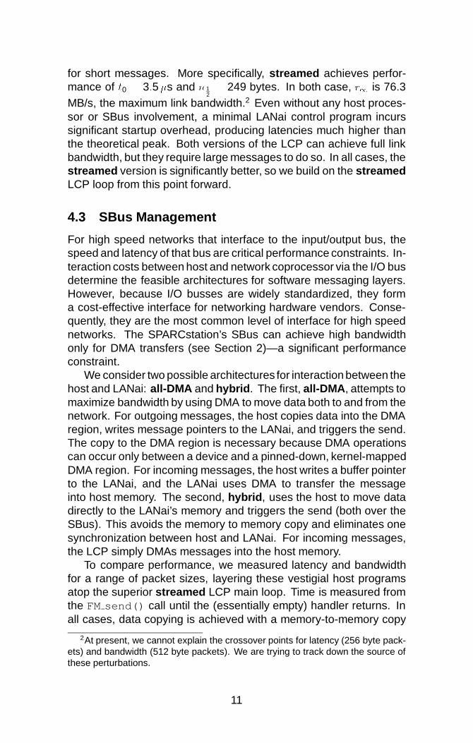
for short messages. More specifically, streamed achieves perfor-mance of t0 = 3:5�s and n 1
2= 249 bytes. In both case, r1 is 76.3
MB/s, the maximum link bandwidth.2 Even without any host proces-sor or SBus involvement, a minimal LANai control program incurssignificant startup overhead, producing latencies much higher thanthe theoretical peak. Both versions of the LCP can achieve full linkbandwidth, but they require large messages to do so. In all cases, thestreamed version is significantly better, so we build on the streamedLCP loop from this point forward.
4.3 SBus Management
For high speed networks that interface to the input/output bus, thespeed and latency of that bus are critical performance constraints. In-teraction costs between host and network coprocessor via the I/O busdetermine the feasible architectures for software messaging layers.However, because I/O busses are widely standardized, they forma cost-effective interface for networking hardware vendors. Conse-quently, they are the most common level of interface for high speednetworks. The SPARCstation’s SBus can achieve high bandwidthonly for DMA transfers (see Section 2)—a significant performanceconstraint.
We consider two possible architectures for interaction between thehost and LANai: all-DMA and hybrid. The first, all-DMA, attempts tomaximize bandwidth by using DMA to move data both to and from thenetwork. For outgoing messages, the host copies data into the DMAregion, writes message pointers to the LANai, and triggers the send.The copy to the DMA region is necessary because DMA operationscan occur only between a device and a pinned-down, kernel-mappedDMA region. For incoming messages, the host writes a buffer pointerto the LANai, and the LANai uses DMA to transfer the messageinto host memory. The second, hybrid, uses the host to move datadirectly to the LANai’s memory and triggers the send (both over theSBus). This avoids the memory to memory copy and eliminates onesynchronization between host and LANai. For incoming messages,the LCP simply DMAs messages into the host memory.
To compare performance, we measured latency and bandwidthfor a range of packet sizes, layering these vestigial host programsatop the superior streamed LCP main loop. Time is measured fromthe FM send() call until the (essentially empty) handler returns. Inall cases, data copying is achieved with a memory-to-memory copy
2At present, we cannot explain the crossover points for latency (256 byte pack-ets) and bandwidth (512 byte packets). We are trying to track down the source ofthese perturbations.
11

function optimized (opencoded) for the packet size.
0 100 200 300 400 500 600Packet size (bytes)
0
10
20
30
40
50
60
70
One
-way
late
ncy
(mic
rose
cond
s)
Streamed + hybridStreamed + all DMAStreamed
(a) Latency
0.0 100.0 200.0 300.0 400.0 500.0 600.0Packet size (bytes)
0.0
10.0
20.0
30.0
40.0
50.0
60.0
70.0
80.0
Ban
dwid
th (
MB
/s)
Streamed + hybridStreamed + all DMAStreamed
(b) Bandwidth
Figure 4: Minimal host to host performance
Because the cost of interaction and data movement across theSBus is high, extending the messaging layer out to the hosts pro-duces dramatically lower performance. Both protocols for managingthe SBus produce much higher latencies for all message sizes, andsaturate at lower bandwidths than the underlying streamed LCP (seeFigure 4). all-DMA incurs a large additional latency because of amemory to memory copy, and two synchronizations for SBus opera-tions. However, using DMA transfers delivers high SBus bandwidth,so all-DMA achieves t0 = 7:5�s, r1 = 33:0 MB/s and n 1
2= 162
bytes. In contrast, hybrid incurs less additional latency initially, byavoiding the memory to memory copy, and requiring only one syn-chronization. However, because processor-mediated data move-ment achieves lower SBus bandwidth, the SBus becomes the per-formance limitation. The 21.2 MB/s peak bandwidth approaches themaximum write bandwidth on the SBus. Overall, hybrid achievest0 = 3:5�s, r1 = 21:2 MB/s, and n 1
2= 44 bytes.
The poor performance of processor mediated data movementforces a performance tradeoff between short and long message per-formance. Incurring latency degrades short message performance,but delivers high bandwidth, improving long message performance.To optimize short message performance in FM, we choose to usethe hybrid scheme. This choice can increase the host overhead formessaging. Improved I/O bus bridges and higher performance I/Obusses could eliminate this tradeoff, enabling both high bandwidthand low latency communication. Even the latency-optimized code
12

Characteristic Reg. Mem. DMA region LANaiCapacity Virtual memory Physical memory 128 KBHost access Loads/store Loads/store Load/storeLANai access none DMA only Load/store
Figure 5: Memory characteristics
Packet
SBus
Myrinet
Packet
Send queue
Receive queue
Kernelmemory
Receive queueHost
Rejectqueue
Figure 6: Host and LANai queues
produces rather high absolute bandwidth, but we still must add buffermanagement and flow control to make the messaging layer useful.
4.4 Buffer Management
Buffer management is a critical issue for messaging layers, as it oftenaccounts for remarkably large fractions of the messaging overhead.Our minimally-functional messaging layer thus far assumes infinitebuffering; any useful messaging layer must recycle its storage. Inaddition, since the host and LANai must share message queues,efficient synchronization is critical. Data can be buffered in threelocations: LANai memory, host DMA region, or regular host mem-ory. Each type of memory has different capacity and accessibilitycharacteristics (see Table 5).
Because buffer management can be expensive, FM is designedto use only four queues: LANai send, LANai receive, host receive,and host reject queue (see Figure 6). More complex structures wereeschewed because even minimal multiplexing amongst queues inthe LANai reduces performance dramatically, and the cost of sharingqueues between the host and LANai is significant.
Outgoing packets are copied by the host directly into the LANaisend queue, and the packet’s presence is triggered by updating thehostsent counter in the LANai memory. The LCP then DMAs thepacket out to the network channel. To avoid write races on memorylocations, the LANai uses a separate counter to keep track of the
13

LANai send queue (the lanaisent counter) which always trails thehostsent counter by the number of packets in the queue. Allowingeach to own (and keep in a register) its respective counter reducesthe amount of synchronization between host and LANai.
For incoming packets, the LCP first DMAs the packet from thenetwork into the LANai receive queue. When the SBus becomesavailable, the LCP DMAs all undelivered packets to the host memory.The LANai does no interpretation of packets, blindly moving themto the DMA region. Using the LANai to move packets to the hostfrees the host to perform other computations but also enables higherSBus bandwidths through the use of DMA. The bandwidth issue iscritical, as delivering incoming packets to the host is often the criticalbottleneck in high-performance networks,
We chose to do no packet interpretation in the LANai for severalreasons. First, the cost of interpretation in the LANai is significant(see Figure 7). Second, having no packet interpretation and a sim-ple LANai receive queue structure allows packets to be aggregatedand transferred with a single DMA operation, further increasing thetransfer bandwidth and reducing overhead. This simple LCP leavespacket interpretation and sorting to the host (separating incomingpackets from rejected packets).
0 100 200 300 400 500 600Packet size (bytes)
0
10
20
30
40
50
60
70
One
-way
late
ncy
(mic
rose
cond
s)
Streamed + hybridStreamed + hybrid + buff. mgmt.Streamed + hybrid + buff. mgmt. + switch()
(a) Latency
0.0 100.0 200.0 300.0 400.0 500.0 600.0Packet size (bytes)
0.0
5.0
10.0
15.0
20.0
25.0
Ban
dwid
th (
MB
/s)
Streamed + hybridStreamed + hybrid + buff. mgmt.Streamed + hybrid + buff. mgmt. + switch()
(b) Bandwidth
Figure 7: Host to Host performance with buffer management
Adding FM’s streamlined buffer management incurs some la-tency, but preserves nearly all of the bandwidth of the messaginglayer. Figure 7 shows the performance of the hybrid layer, thehybrid layer augmented with buffer management, and the hybridlayer augmented by both buffer management and a switch() state-
14

ment to simulate packet interpretation. Compared to the hybridlayer’s performance, t0 = 3:5�s, r1 = 21:2 MB/s, and n 1
2= 44
bytes, the hybrid + buffer management layer achieves t0 = 3:8�s,r1 = 21:9 MB/s, and n 1
2= 53 bytes, representing only modest in-
creases in the startup latency and half-bandwidth packet size.The switch() statement was added in the streaming receive
loop to simulate the impact of even minimal packet interpretation.This change has little impact on overall latency, but because theoverhead is added in the innermost loop, it is fully exposed for eachpacket and therefore has a much larger impact on bandwidth thanother types of overhead. Note that the larger increase in latency fromadding buffer management produces less reduction in bandwidth forshort messages. Performance of the hybrid + buffer management+ switch() is only t0 = 6:8�s, r1 = 21:8 MB/s, and n 1
2= 127 bytes.
While the peak bandwidth is nearly the same, there is a markedincrease in n 1
2by 74 bytes. Clearly, adding packet interpretation to
the LCP would dramatically reduce short message performance.
4.5 Flow Control
The final piece of a complete messaging layer is flow control. Be-cause all networks have finite buffering, flow control is necessaryto achieve reliable delivery, ensuring a receiver has enough bufferspace to store incoming messages. Traditional flow control schemesinclude windows [28] which combine flow control and retransmis-sion for fault tolerance. However window protocols generally requirebuffer space proportional to the number of senders, incurring largememory overheads in large clusters.
To avoid this overhead, FM implements a return-to-sender pro-tocol which allocates buffers to prevent deadlock at the source (thereject queue), avoiding nonscalable buffering requirements. In return-to-sender, the sender optimistically sends packets into the networkwhile reserving space locally for each outstanding packet. If the re-ceiver does not have space, it rejects packets, retransmitting them tothe sender. Successfully received packets are acknowledged, allow-ing source buffers to be released. Rejected packets are retransmittedeventually to ensure progress. Because each sender’s buffering re-quirements are proportional to the number of outstanding packets,there is no large collection of buffers that must be statically allocated.Further, the buffer requirements for a particular node do not increasewith the number of hosts in the system. The idea behind return-to-sender has been used in MPP’s such as the Cray T3D, and is similarto deflection and chaos routing as used in the TERA-1 machine [2].The well-known drawback of all of these retransmission schemes is
15

that delivery order is not preserved.Because the reject queue holds packets rejected by any node,
it can be though of as “network window” and provides an efficientuse of pinned memory. Since the rejection mechanism does notprovide fault-tolerance, the network is assumed to be reliable, or fault-tolerance must be provided by a higher level protocol. In the caseof Myrinet, bit errors are exceedingly rare; other sources of systemfailure are much more likely. Multiple packets can be acknowledgedwith a single acknowledgement packet, and FM 1.0 optimizes furtherby piggybacking acknowledgements on ordinary data packets.
0 100 200 300 400 500 600Packet size (bytes)
0
10
20
30
40
50
60
70
One
-way
late
ncy
(mic
rose
cond
s)
Streamed + hybrid + buff. mgmt. + flow ctrl.Streamed + hybrid + buff. mgmt.
(a) Latency
0.0 100.0 200.0 300.0 400.0 500.0 600.0Packet size (bytes)
0.0
5.0
10.0
15.0
20.0
25.0
Ban
dwid
th (
MB
/s)
Streamed + hybrid + buff. mgmt. + flow ctrl.Streamed + hybrid + buff. mgmt.
(b) Bandwidth
Figure 8: Fast Messages messaging layer performance
Comparing the messaging layers with and without flow control in-dicates that return-to-sender incurs little additional latency and onlymoderate loss in bandwidth (see Figure 8). The entire FM layerachieves t0 = 4:1�s, r1 = 21:4 MB/s, and n 1
2= 54 bytes, a negligi-
ble difference from the performance of streamed + hybrid + buffermanagement.
4.6 Comparative Performance
There are few messaging layers available on the Myrinet today; theonly major point of reference is the Myricom-supplied “Myrinet API.”This software is part of the standard Myrinet software distribution (ver-sion 2.0, available in March 1995) and used to support their TCP/IPimplementations. Table 3 highlights some of the differences betweenthe two messaging layers.
16

Feature Fast Messages 1.0 Myrinet API 2.0Data Movement Direct from user
spaceFrom user space,DMA region, andsupports scatter-gather operations
Delivery Guaranteed Not guaranteedDelivery Order No guarantee PreservedReconfiguration Manual Automatic,
continuousBuffering Large number of
small buffersSmall number oflarge buffers
Fault Detection Assumes reliablenetwork
Messagechecksums
Table 3: Selected differences between Fast Messages and MyrinetAPI
From the preceding discussion, it should be clear that addingeven the smallest feature to the LCP can exact a large penalty inperformance. The Myricom API includes many additional features,each taking its toll on performance. For example, automatic net-work remapping—machines can be added or removed from the net-work without modifying any configuration files—may be convenientfor users but can hurt the messaging layer’s performance. Also, syn-chronization between the host and the LANai is expensive, yet mustbe done frequently in the Myrinet API, to pass buffer pointers backand forth.
The Myricom API’s greater functionality and host-LANai synchro-nization structure translates to significantly poorer performance thanFM’s (see Figure 9). The Myricom API presents two interfaces,myri cmd send imm() which uses the processor to move data tothe LANai, and myri cmd send() which uses DMA. FM achievessuperior performance to both interfaces. The design of FM achievesits goal of high performance for short messages reflected in lowvalues for t0 and n 1
2. Myricom’s API has much greater basic la-
tency and half power message size, but achieves comparable band-width at the peak. Specifically, for the Myricom API, t0 =105.0�s,r1 =23.9 MB/s3, and n 1
2� 4;409 bytes. For the modest sacrifice in
peak bandwidth, we have achieved a reduction of n 12
of two orders ofmagnitude.
3The Myricom API does not support message sizes large enough to accuratelymeasure r1, so we used the SBus write bandwidth.
17

0 100 200 300 400 500 600Packet size (bytes)
0
50
100
150
200
250
300
350
400
One
-way
late
ncy
(mic
rose
cond
s)
Fast MessagesMyrinet API (myri_cmd_send_imm())Myrinet API (myri_cmd_send())
(a) Latency
0.0 100.0 200.0 300.0 400.0 500.0 600.0Packet size (bytes)
0.0
5.0
10.0
15.0
20.0
25.0
Ban
dwid
th (
MB
/s)
Fast MessagesMyrinet API (myri_cmd_send_imm())Myrinet API (myri_cmd_send())
(b) Bandwidth
Figure 9: Fast Messages vs. Myricom’s API
5 DiscussionOur design goal for FM was low latency and high bandwidth forshort messages; as illustrated in Table 4, FM 1.0 achieves an n 1
2
of 54 bytes, delivering 10.7MB/s at this small packet size. Largerpacket deliver higher bandwidth at some penalty in latency – 512byte packets deliver 19.6 MB/s, greater than OC-3 ATM, and com-petitive with commercial massively-parallel machines. For example,while FM’s latencies are larger than Active Messages on the CM-5,the bandwidth is much higher. FM also compares favorably to recentMPPs [20, 21] in both bandwidth and latency.
While there may appear to be many design tradeoffs involvingperformance for short or long messages (latency versus bandwidth),the design of FM is a counterexample. Despite consistently favoringlow latency, the delivered peak bandwidth is within a few MB/s ofthe Myricom API. In fact, it may be most advantageous to pick framesizes which deliver 80-90% of the achievable bandwidth; there is littlebandwidth benefit in going beyond this size, and FM shows that lowlatencies are possible. Based on these considerations, we chose a128-byte frame size for FM 1.0. Larger messages will require seg-mentation and reassembly into frames of this size. Our approachdiffers from the Generic Active Messages model [1] which providesextremely short (4 word) messages and longer network DMA trans-fers. Serendipitously, the FM frame size is close to the best sizefor supporting TCP/IP and UDP/IP traffic, where the vast majority ofpackets would fit into a single frame [5]. This presents the possibil-
18
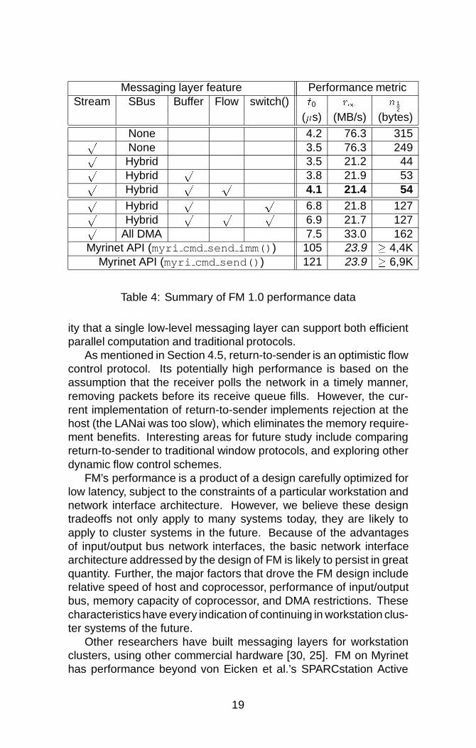
Messaging layer feature Performance metricStream SBus Buffer Flow switch() t0 r1 n 1
2
(�s) (MB/s) (bytes)None 4.2 76.3 315pNone 3.5 76.3 249pHybrid 3.5 21.2 44pHybrid
p3.8 21.9 53p
Hybridp p
4.1 21.4 54p
Hybridp p
6.8 21.8 127pHybrid
p p p6.9 21.7 127p
All DMA 7.5 33.0 162Myrinet API (myri cmd send imm()) 105 23.9 � 4,4K
Myrinet API (myri cmd send()) 121 23.9 � 6,9K
Table 4: Summary of FM 1.0 performance data
ity that a single low-level messaging layer can support both efficientparallel computation and traditional protocols.
As mentioned in Section 4.5, return-to-sender is an optimistic flowcontrol protocol. Its potentially high performance is based on theassumption that the receiver polls the network in a timely manner,removing packets before its receive queue fills. However, the cur-rent implementation of return-to-sender implements rejection at thehost (the LANai was too slow), which eliminates the memory require-ment benefits. Interesting areas for future study include comparingreturn-to-sender to traditional window protocols, and exploring otherdynamic flow control schemes.
FM’s performance is a product of a design carefully optimized forlow latency, subject to the constraints of a particular workstation andnetwork interface architecture. However, we believe these designtradeoffs not only apply to many systems today, they are likely toapply to cluster systems in the future. Because of the advantagesof input/output bus network interfaces, the basic network interfacearchitecture addressed by the design of FM is likely to persist in greatquantity. Further, the major factors that drove the FM design includerelative speed of host and coprocessor, performance of input/outputbus, memory capacity of coprocessor, and DMA restrictions. Thesecharacteristics have every indication of continuing in workstation clus-ter systems of the future.
Other researchers have built messaging layers for workstationclusters, using other commercial hardware [30, 25]. FM on Myrinethas performance beyond von Eicken et al.’s SPARCstation Active
19

Messages (SSAM), which employs ATM interface cards on the SBus.SSAM achieves 26�s latency on 4-word messages, assuming a10�s switch latency. Our measurements through an 8-port Myricomswitch achieve latencies of 25�s for 4-word messages and 32�s for32-word messages. SSAM peaks at 7.5 MB/s, while FM achieves16.2 MB/s for 32-word messages. Martin’s HP Active Messages(HPAM) uses HP workstations with Medusa FDDI interface cardson a high speed graphics bus. This makes HPAM’s network interfacemuch closer to the processor and therefore, connected with muchhigher bandwidth. Consequently, HPAM achieves a lower latency,15�s for 4-word messages and peak bandwidth of 12 MB/s. Despitebeing hindered by an I/O bus network interface, FM delivers higherbandwidth. HPAM’s hardware has the further advantage of signifi-cant memory (one megabyte versus 128 kilobytes for Myrinet) on theinterface card. This is a key difference which affects the bufferingprotocols feasible in the two systems.
A number of other researchers have explored the development ofspecial hardware to achieve low latency/high bandwidth communica-tion (MINI [16], FUNet [18], VUNet [19], etc.). However, these hard-ware approaches have the drawback that they depend on specificmemory bus interfaces, and require significant hardware investment.FM demonstrates that decent performance can be achieved withoutmoving the interfaces closer to the host processor.
We believe that only modest architectural improvements are re-quired to reduce the penalty of I/O bus interfaces further. The mostuseful improvement would be to improve workstation performanceon SBus operations. Simply supporting burst-mode operations inthe write buffer across the MBus-SBus interface would provide DMA-like bandwidth into the network enabling FM to achieve performanceclose to that of streamed shown in Figure 3. In addition, acceleratingthe LANai processor would reduce the serial overhead, a significantcontributor to messaging latency. Building custom hardware that im-plements the functionality of FM’s LCP is another means to reducethat serial overhead. Such custom hardware would provide truly con-current service for sends and receives for both the host and networkchannel.
6 ConclusionIllinois Fast Messages 1.0 is a high performance messaging layer thatachieves communication performance comparable to that of an MPPon a workstation cluster connected with a Myrinet network. Becauseworkstations are not designed to deliver low latency communication,we devised efficient solutions to a series of critical issues: division
20

of labor between host and network coprocessor, efficient utilizationof the I/O bus, and implementation of scalable and efficient schemesfor flow control and buffer management. FM 1.0 demonstrates that itis possible to find solutions in the context of current-day workstationand network interface architectures which deliver high performance.Despite our progress, we point out two minor changes that would havea significant impact on achievable network performance – improvedI/O bus performance for non-DMA operations and a moderately fasternetwork interface processor.
7 Future workFM 1.0 provides the starting point for a wealth of research in makingworkstation clusters useful for parallel computation. There are signif-icant outstanding questions about how to do flow control and reliabletransmission efficiently. We are exploring the software and hardwareissues in extending FM to provide higher performance, multitasking(protection), and preemptive messaging. In addition, delivering ef-fective low-latency communication requires coordinated scheduling,so we are exploring integrating messaging with the node scheduler.
FM is designed to support efficient implementation of a variety ofcommunication libraries and run-time systems. To explore interface,buffering, and scheduling issues, we are building implementations ofMPI [14], TCP/IP [10], and the Illinois Concert system’s runtime [8].MPI is of growing popularity among application builders, presentsinteresting collective communication operations, and there are effi-cient implementations to compare against [15]. TCP/IP is a legacyprotocol in widespread use. And the Illinois Concert system is a fine-grained programming system which depends critically on low-costhigh performance communication.
References[1] The Generic Active Message Interface Specification. Available from
http://now.cs.berkeley.edu/Papers/Papers/gam spec.ps, 1994.
[2] R. Alverson, D. Callahan, D. Cummings, B. Koblenz, A. Porterfield,and B. Smith. The Tera computer system. 1990 International Conf.on Supercomputing, June 11-15 1990. Published as Computer Ar-chitecture News 18:3.
[3] T. Anderson, D. Culler, and D. Patterson. A case for NOW (networksof workstations). IEEE Micro, 15(1):54–64, 1995.
21
[4] T. M. Anderson and R. S. Cornelius. High-performance switching withFibre Channel. In Digest of Papers Compcon 1992, pages 261–268.IEEE Computer Society Press, 1992. Los Alamitos, Calif.
[5] G. Armitage and K. Adams. How inefficient is IP over ATM anyway?IEEE Network, Jan/Feb 1995.
[6] Nanette J. Boden, Danny Cohen, Robert E. Felderman, Alan E. Ku-lawik, Charles L. Seitz, Jakov N. Seizovic, and Wen-King Su. Myrinet—a gigabit-per-second local-area network. IEEE Micro, 15(1):29–36,February 1995. Available from http://www.myri.com/myricom/Hot.ps .
[7] CCITT, SG XVIII, Report R34. Draft Recommendation I.150: B-ISDNATM functional characteristics, June 1990.
[8] Andrew A. Chien, Vijay Karamcheti, John Plevyak, and Xingbin Zhang.Concurrent aggregates language report 2.0. Available via anonymousftp from cs.uiuc.edu in /pub/csag or from http://www-csag.cs.uiuc.edu/,September 1993.
[9] D. Clark, V. Jacobson, J Romkey, and H. Salwen. An analysis of TCPprocessing overhead. IEEE Communication Magazine, 27(6):23–29,June 1989.
[10] Douglas E. Comer. Internetworking with TCP/IP Vol I: Principles Pro-tocols, and Architecture, 2nd edition. Prentice Hall, Englewood Cliffs,NJ, 1991.
[11] Cray Research, Inc. Cray T3D System Architecture Overview, March1993.
[12] Peter Druschel and Larry L. Peterson. Fbufs: A high-bandwidth cross-domain transfer facility. In Proceedings of Fourteenth ACM Sym-posium on Operating Systems Principles, pages 189–202. ACMSIGOPS, ACM Press, December 1993.
[13] Fiber-distributed data interface (FDDI)—Token ring media access con-trol (MAC). American National Standard for Information Systems ANSIX3.139-1987, July 1987. American National Standards Institute.
[14] Message Passing Interface Forum. The MPI message passing inter-face standard. Technical report, University of Tennessee, Knoxville,April 1994. Can be found at http://www.mcs.anl.gov/mpi/mpi-report.ps.
[15] H. Franke, C. E. Wu, M Riviere, P Pattnik, and M Snir. MPI pro-gramming environment for IBM SP1/SP2. In Proceedings of theInternational Symposium on Computer Architecture, 1995.
[16] F. Hady, R. Minnich, and D. Burns. The Memory Integrated NetworkInterface. In Proceedings of the IEEE Symposium on Hot Intercon-nects, 1994.
22

[17] Mark Henderson, Bill Nickless, and Rick Stevens. A scalable high-performance I/O system. In Proceedings of the Scalable High-Performance Computing Conference, pages 79–86, 1994.
[18] James Hoe and A. Boughton. Network substrate for parallel processingon a workstation cluster. In Proceedings of the IEEE Symposiumon Hot Interconnects, 1994.
[19] H. Houh, J. Adam, M. Ismert, C. Lindblad, and D. Tennenhouse. TheVuNet desk area network: Architecture, implementation and experi-ence. IEEE Journal of Selected Areas in Communications, 1995.
[20] IBM 9076 Scalable POWERparallel 1: General information.IBM brochure GH26-7219-00, February 1993. Available fromhttp://ibm.tc.cornell.edu/ibm/pps/sp2/index.html .
[21] Intel Corporation. Paragon XP/S Product Overview, 1991.
[22] Vijay Karamcheti and Andrew A. Chien. A comparison of architecturalsupport for messaging on the TMC CM-5 and the Cray T3D. In Pro-ceedings of the International Symposium on Computer Architec-ture, 1995. Available from http://www-csag.cs.uiuc.edu/papers/cm5-t3d-messaging.ps .
[23] Vijay Karamcheti and Andrew A. Chien. FM—fast messaging on theCray T3D. Available from http://www-csag.cs.uiuc.edu/papers/t3d-fm-manual.ps, February 1995.
[24] M. Liu, J. Hsieh, D. Hu, J. Thomas, and J. MacDonald. Distributednetwork computing over Local ATM Networks. In Supercomputing’94, 1995.
[25] R. Martin. HPAM: An Active Message layer for a net-work of HP workstation. In Proceedings of the IEEESymposium on Hot Interconnects, 1994. Available fromftp://ftp.cs.berkeley.edu/ucb/CASTLE/Active Messages/hotipaper.ps.
[26] Meiko World Incorporated. Meiko Computing Surface Communica-tions Processor Overview, 1993.
[27] V. S. Sunderam. PVM: A framework for parallel distributed computing.Concurrency, Practice and Experience, 2(4):315–340, [12] 1990.
[28] A. S. Tanenbaum. Computer networks. Prentice-Hall 2nd ed. 1989,1981.
[29] Thinking Machines Corporation, 245 First Street, Cambridge, MA02154-1264. The Connection Machine CM-5 Technical Summary, Oc-tober 1991.
[30] T. von Eicken, A. Basu, and V. Buch. Low-latency communication overATM networks using Active Messages. IEEE Micro, 15(1):46–53,1995.
23

[31] T. von Eicken, D. Culler, S. Goldstein, and K. Schauser. Ac-tive Messages: a mechanism for integrated communicationand computation. In Proceedings of the International Sym-posium on Computer Architecture, 1992. Available fromhttp://www.cs.cornell.edu/Info/People/tve/ucb papers/isca92.ps .
A Theoretical Peak Performance of LANaiTheoretical peak performance in Figures Figure 3 (a) and (b) is basedon the following measured performance characteristics of the LANai.
DMA setup (tDMA) = 8 cycles� 40ns
cycle= 320 ns
Message overhead (t0) = tDMA +N bytes� 12:5ns
byte=
= (320+ 12:5N)ns
Message latency (`) = t0 + tswitch = (320+ 12:5N) +
+550 = (870+ 12:5N)ns
Communication bandwidth (rN) =bytest0
=N bytes
(320+ 12:5N)ns
24
Scott Pakin
Scott Pakin is currently a Ph.D. student in the Department of Com-puter Science at the University of Illinois at Urbana-Champaign. Hehas been working in the Concurrent Systems Architecture Group un-der Professor Andrew A. Chien since January, 1993. The primarygoals of Scott’s research involve architecting scalable, parallel sys-tems, leveraging off commodity hardware, but developing novel soft-ware technology. Scott received his B.S. in mathematics/computerscience from Carnegie Mellon University in 1992 and his M.S. in com-puter science from the University of Illinois at Urbana-Champaign in1995.
Contact Information
E-mail: [email protected]: (217) 244-7116Fax: (217) 244-6500Mailing address: Scott Pakin
Department of Computer Science1304 W. Springfield Ave.Urbana, Illinois 61801USA
www: http://www-csag.cs.uiuc.edu/individual/pakin
Mario Lauria
Mario Lauria graduated in electronic engineering at the Universityof Naples, Italy, in 1992. He spent nine months at Ansaldo Trasporti,where he worked as a computer systems analyst. In 1994 he joined
25

the Department of Computer Science and Systems of the Universityof Naples, where he is working toward a Ph.D. in computer science.He is spending a Fulbright scholarship he was granted in 1994 atthe University of Illinois at Urbana-Champaign, where he has joinedthe Concurrent Systems Architecture Group. His research interestsinclude high performance computer communications and distributedsimulation, with the realization of a high speed communication systemfor network of workstations as his present goal.
Contact Information
E-mail: [email protected] [email protected]: (217) 244-7118 +39 81 768-2897Mail: Department of Dipartimento di
Computer Science Informatica e Sistemistica1304 W. Springfield Ave. via Claudio 21Urbana, Illinois 61801 80125 NapoliUSA Italy
www: http://www-csag.cs.uiuc.edu/individual/lauria
Andrew A. Chien
Andrew A. Chien is currently an Associate Professor in the De-partment of Computer Science at the University of Illinois at Urbana-Champaign, where he holds a joint appointment as an Associate Pro-fessor in the Department of Electrical and Computer Engineering aswell as a Research Scientist with the National Center for Supercom-puting Applications (NCSA). The primary goals of Professor Chien’sresearch involve the interaction of programming languages, compil-ers, system software, and machine architecture in high-performanceparallel systems. He has participated in the design of a numberof parallel systems (hardware and software), including the IllinoisConcert System (efficient parallel object-oriented programming), andIllinois Fast Messages (high performance communication for MPP’sand workstation clusters), and the MIT J-Machine (a 4096-processorfine-grained parallel computer). His research is supported by ARPA,NASA, ONR, and NSF as well as several corporate donors. Professor
26

Andrew Chien also co-directs an ARPA-funded I/O characterizationproject and is a participant in the Scalable I/O Initiative (SIO), workingon the characterization of application input/output patterns for scal-able, parallel scientific programs. Andrew Chien is the leader of theConcurrent Systems Architecture Group at the University of IllinoisDr. Chien received his B.S. in electrical engineering from the Mas-sachusetts Institute of Technology in 1984 and his M.S. and Ph.D., incomputer science, from the Massachusetts Institute of Technology in1987 and 1990, respectively. He was a recipient of the 1994 NationalScience Foundation Young Investigator Award, and in 1995 receivedthe C. W. Gear Outstanding Junior Faculty Award.
Contact Information
E-mail: [email protected]: (217) 333-6844Fax: (217) 244-6500Mailing address: Andrew A. Chien
Department of Computer Science1304 W. Springfield Ave.Urbana, Illinois 61801USA
www: http://www-csag.cs.uiuc.edu/individual/achien
27

Copyright © 1995 by the Association for Computing Machinery, Inc. (ACM).
Permission to make digital or hard copies of part or all of this work for personal orclassroom use is granted without fee provided that copies are not made or distributed forprofit or commercial advantage and that new copies bear this notice and the full citation onthe first page. Copyrights for components of this work owned by others than ACM must behonored. Abstracting with credit is permitted.
To copy otherwise, to republish, to post on servers or to redistribute to lists, requires priorspecific permission and/or a fee. Request permissions from Publications Dept, ACM Inc.,via fax at +1 (212) 869-0481, or via email at [email protected].