High-Intensity Approach Lighting System
6
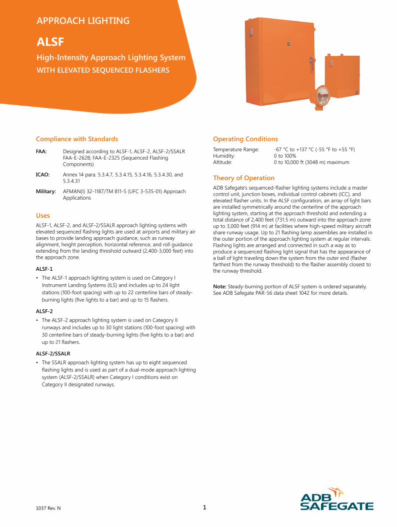
Compliance with Standards FAA: Designed according to ALSF-1, ALSF-2, ALSF-2/SSALR FAA-E-2628; FAA-E-2325 (Sequenced Flashing Components) ICAO: Annex 14 para. 5.3.4.7, 5.3.4.15, 5.3.4.16, 5.3.4.30, and 5.3.4.31 Military: AFMAN(I) 32-1187/TM 811-5 (UFC 3-535-01) Approach Applications Uses ALSF-1, ALSF-2, and ALSF-2/SSALR approach lighting systems with elevated sequenced flashing lights are used at airports and military air bases to provide landing approach guidance, such as runway alignment, height perception, horizontal reference, and roll guidance extending from the landing threshold outward (2,400-3,000 feet) into the approach zone. ALSF-1 • The ALSF-1 approach lighting system is used on Category I Instrument Landing Systems (ILS) and includes up to 24 light stations (100-foot spacing) with up to 22 centerline bars of steady- burning lights (five lights to a bar) and up to 15 flashers. ALSF-2 • The ALSF-2 approach lighting system is used on Category II runways and includes up to 30 light stations (100-foot spacing) with 30 centerline bars of steady-burning lights (five lights to a bar) and up to 21 flashers. ALSF-2/SSALR • The SSALR approach lighting system has up to eight sequenced flashing lights and is used as part of a dual-mode approach lighting system (ALSF-2/SSALR) when Category I conditions exist on Category II designated runways. Operating Conditions Temperature Range: -67 °C to +137 °C (-55 °F to +55 °F) Humidity: 0 to 100% Altitude: 0 to 10,000 ft (3048 m) maximum Theory of Operation ADB Safegate's sequenced-flasher lighting systems include a master control unit, junction boxes, individual control cabinets (ICC), and elevated flasher units. In the ALSF configuration, an array of light bars are installed symmetrically around the centerline of the approach lighting system, starting at the approach threshold and extending a total distance of 2,400 feet (731.5 m) outward into the approach zone up to 3,000 feet (914 m) at facilities where high-speed military aircraft share runway usage. Up to 21 flashing lamp assemblies are installed in the outer portion of the approach lighting system at regular intervals. Flashing lights are arranged and connected in such a way as to produce a sequenced flashing light signal that has the appearance of a ball of light traveling down the system from the outer end (flasher farthest from the runway threshold) to the flasher assembly closest to the runway threshold. Note: Steady-burning portion of ALSF system is ordered separately. See ADB Safegate PAR-56 data sheet 1042 for more details. APPROACH LIGHTING ALSF High-Intensity Approach Lighting System WITH ELEVATED SEQUENCED FLASHERS 1037 Rev. N 1
Transcript of High-Intensity Approach Lighting System
Compliance with Standards
FAA: Designed according to ALSF-1, ALSF-2, ALSF-2/SSALRFAA-E-2628; FAA-E-2325 (Sequenced FlashingComponents)
ICAO: Annex 14 para. 5.3.4.7, 5.3.4.15, 5.3.4.16, 5.3.4.30, and5.3.4.31
Military: AFMAN(I) 32-1187/TM 811-5 (UFC 3-535-01) ApproachApplications
UsesALSF-1, ALSF-2, and ALSF-2/SSALR approach lighting systems withelevated sequenced flashing lights are used at airports and military airbases to provide landing approach guidance, such as runwayalignment, height perception, horizontal reference, and roll guidanceextending from the landing threshold outward (2,400-3,000 feet) intothe approach zone.
ALSF-1
• The ALSF-1 approach lighting system is used on Category IInstrument Landing Systems (ILS) and includes up to 24 lightstations (100-foot spacing) with up to 22 centerline bars of steady-burning lights (five lights to a bar) and up to 15 flashers.
ALSF-2
• The ALSF-2 approach lighting system is used on Category IIrunways and includes up to 30 light stations (100-foot spacing) with30 centerline bars of steady-burning lights (five lights to a bar) andup to 21 flashers.
ALSF-2/SSALR
• The SSALR approach lighting system has up to eight sequencedflashing lights and is used as part of a dual-mode approach lightingsystem (ALSF-2/SSALR) when Category I conditions exist onCategory II designated runways.
Operating ConditionsTemperature Range: -67 °C to +137 °C (-55 °F to +55 °F)Humidity: 0 to 100%Altitude: 0 to 10,000 ft (3048 m) maximum
Theory of OperationADB Safegate's sequenced-flasher lighting systems include a mastercontrol unit, junction boxes, individual control cabinets (ICC), andelevated flasher units. In the ALSF configuration, an array of light barsare installed symmetrically around the centerline of the approachlighting system, starting at the approach threshold and extending atotal distance of 2,400 feet (731.5 m) outward into the approach zoneup to 3,000 feet (914 m) at facilities where high-speed military aircraftshare runway usage. Up to 21 flashing lamp assemblies are installed inthe outer portion of the approach lighting system at regular intervals.Flashing lights are arranged and connected in such a way as toproduce a sequenced flashing light signal that has the appearance ofa ball of light traveling down the system from the outer end (flasherfarthest from the runway threshold) to the flasher assembly closest tothe runway threshold.
Note: Steady-burning portion of ALSF system is ordered separately.See ADB Safegate PAR-56 data sheet 1042 for more details.
APPROACH LIGHTING
ALSFHigh-Intensity Approach Lighting SystemWITH ELEVATED SEQUENCED FLASHERS
1037 Rev. N 1
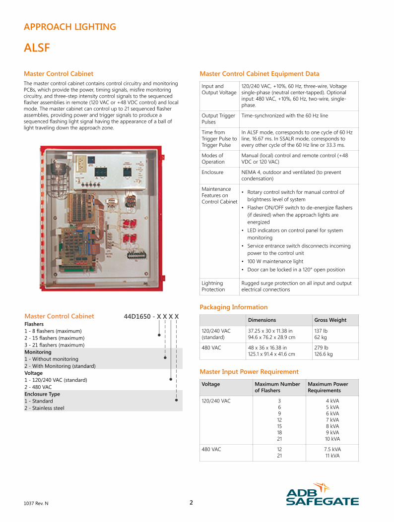
Master Control CabinetThe master control cabinet contains control circuitry and monitoringPCBs, which provide the power, timing signals, misfire monitoringcircuitry, and three-step intensity control signals to the sequencedflasher assemblies in remote (120 VAC or +48 VDC control) and localmode. The master cabinet can control up to 21 sequenced flasherassemblies, providing power and trigger signals to produce asequenced flashing light signal having the appearance of a ball oflight traveling down the approach zone.
Master Control Cabinet Flashers 1 - 8 flashers (maximum) 2 - 15 flashers (maximum) 3 - 21 flashers (maximum) Monitoring 1 - Without monitoring 2 - With Monitoring (standard) Voltage 1 - 120/240 VAC (standard) 2 - 480 VAC Enclosure Type 1 - Standard 2 - Stainless steel
44D1650 - X X X X
Master Control Cabinet Equipment Data
Input andOutput Voltage
120/240 VAC, +10%, 60 Hz, three-wire, Voltagesingle-phase (neutral center-tapped). Optionalinput: 480 VAC, +10%, 60 Hz, two-wire, single-phase.
Output TriggerPulses
Time-synchronized with the 60 Hz line
Time fromTrigger Pulse toTrigger Pulse
In ALSF mode, corresponds to one cycle of 60 Hzline, 16.67 ms. In SSALR mode, corresponds toevery other cycle of the 60 Hz line or 33.3 ms.
Modes ofOperation
Manual (local) control and remote control (+48VDC or 120 VAC)
Enclosure NEMA 4, outdoor and ventilated (to preventcondensation)
MaintenanceFeatures onControl Cabinet
• Rotary control switch for manual control ofbrightness level of system
• Flasher ON/OFF switch to de-energize flashers(if desired) when the approach lights areenergized
• LED indicators on control panel for systemmonitoring
• Service entrance switch disconnects incomingpower to the control unit
• 100 W maintenance light• Door can be locked in a 120° open position
LightningProtection
Rugged surge protection on all input and outputelectrical connections
Packaging Information
Dimensions Gross Weight
120/240 VAC(standard)
37.25 x 30 x 11.38 in94.6 x 76.2 x 28.9 cm
137 lb62 kg
480 VAC 48 x 36 x 16.38 in125.1 x 91.4 x 41.6 cm
279 lb126.6 kg
Master Input Power Requirement
Voltage Maximum Numberof Flashers
Maximum PowerRequirements
120/240 VAC 36912151821
4 kVA5 kVA6 kVA7 kVA8 kVA9 kVA10 kVA
480 VAC 1221
7.5 kVA11 kVA
APPROACH LIGHTING
ALSF
1037 Rev. N 2
High-Voltage WireUsed to interconnect elevated flash head and individual controlcabinet. Wire is supplied in 500-foot spools only. Please specify totallength (in feet) of wire required when ordering.
High-Voltage Wire Ordering Code 12 AWG, 3 kV 89A0110-1
Flasher
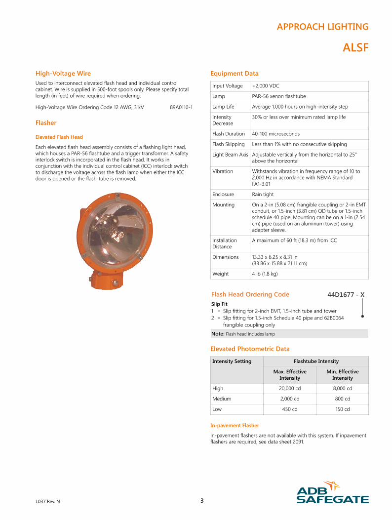
Elevated Flash Head
Each elevated flash head assembly consists of a flashing light head,which houses a PAR-56 flashtube and a trigger transformer. A safetyinterlock switch is incorporated in the flash head. It works inconjunction with the individual control cabinet (ICC) interlock switchto discharge the voltage across the flash lamp when either the ICCdoor is opened or the flash-tube is removed.
Equipment Data
Input Voltage +2,000 VDC
Lamp PAR-56 xenon flashtube
Lamp Life Average 1,000 hours on high-intensity step
IntensityDecrease
30% or less over minimum rated lamp life
Flash Duration 40-100 microseconds
Flash Skipping Less than 1% with no consecutive skipping
Light Beam Axis Adjustable vertically from the horizontal to 25°above the horizontal
Vibration Withstands vibration in frequency range of 10 to2,000 Hz in accordance with NEMA StandardFA1-3.01
Enclosure Rain tight
Mounting On a 2-in (5.08 cm) frangible coupling or 2-in EMTconduit, or 1.5-inch (3.81 cm) OD tube or 1.5-inchschedule 40 pipe. Mounting can be on a 1-in (2.54cm) pipe (used on an aluminum tower) usingadapter sleeve.
InstallationDistance
A maximum of 60 ft (18.3 m) from ICC
Dimensions 13.33 x 6.25 x 8.31 in(33.86 x 15.88 x 21.11 cm)
Weight 4 lb (1.8 kg)
Flash Head Ordering Code Slip Fit 1 = Slip fitting for 2-inch EMT, 1.5-inch tube and tower 2 = Slip fitting for 1.5-inch Schedule 40 pipe and 62B0064 frangible coupling only
Note: Flash head includes lamp
44D1677 - X
Elevated Photometric Data
Intensity Setting Flashtube Intensity
Max. EffectiveIntensity
Min. EffectiveIntensity
High 20,000 cd 8,000 cd
Medium 2,000 cd 800 cd
Low 450 cd 150 cd
In-pavement Flasher
In-pavement flashers are not available with this system. If inpavementflashers are required, see data sheet 2091.
APPROACH LIGHTING
ALSF
1037 Rev. N 3
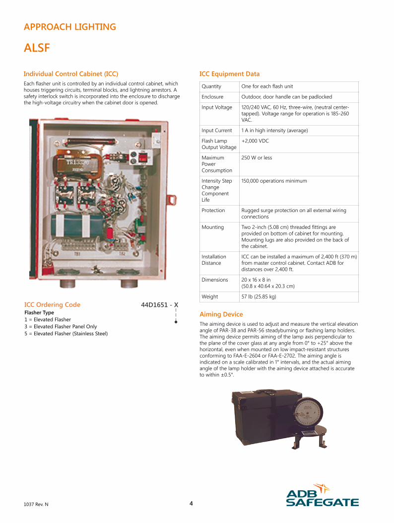
Individual Control Cabinet (ICC)Each flasher unit is controlled by an individual control cabinet, whichhouses triggering circuits, terminal blocks, and lightning arrestors. Asafety interlock switch is incorporated into the enclosure to dischargethe high-voltage circuitry when the cabinet door is opened.
ICC Ordering Code Flasher Type 1 = Elevated Flasher 3 = Elevated Flasher Panel Only 5 = Elevated Flasher (Stainless Steel)
44D1651 - X
ICC Equipment Data
Quantity One for each flash unit
Enclosure Outdoor, door handle can be padlocked
Input Voltage 120/240 VAC, 60 Hz, three-wire, (neutral center-tapped). Voltage range for operation is 185-260VAC.
Input Current 1 A in high intensity (average)
Flash LampOutput Voltage
+2,000 VDC
MaximumPowerConsumption
250 W or less
Intensity StepChangeComponentLife
150,000 operations minimum
Protection Rugged surge protection on all external wiringconnections
Mounting Two 2-inch (5.08 cm) threaded fittings areprovided on bottom of cabinet for mounting.Mounting lugs are also provided on the back ofthe cabinet.
InstallationDistance
ICC can be installed a maximum of 2,400 ft (370 m)from master control cabinet. Contact ADB fordistances over 2,400 ft.
Dimensions 20 x 16 x 8 in(50.8 x 40.64 x 20.3 cm)
Weight 57 lb (25.85 kg)
Aiming DeviceThe aiming device is used to adjust and measure the vertical elevationangle of PAR-38 and PAR-56 steadyburning or flashing lamp holders.The aiming device permits aiming of the lamp axis perpendicular tothe plane of the cover glass at any angle from 0° to +25° above thehorizontal, even when mounted on low impact-resistant structuresconforming to FAA-E-2604 or FAA-E-2702. The aiming angle isindicated on a scale calibrated in 1° intervals, and the actual aimingangle of the lamp holder with the aiming device attached is accurateto within ±0.5°.
APPROACH LIGHTING
ALSF
1037 Rev. N 4
Aiming Device Equipment Data
Quantity One
Aiming Flash lamp axis can be aimed from 0° to 25° abovethe horizontal
Scale Calibrated in 1° increments
Accuracy ±0.5°
Dimensions 7 dia. x 10 H in(17.78 dia. x 25.4 H cm)
Aiming Device Ordering Code Lamp Application 1 = For PAR-56 Lamp Only 2 = For PAR-56 and PAR-38 Lamps
44D1654 - X
Flasher TesterThe portable flasher tester is equipped with a test cable and plug,which connect to a socket in the ICC to monitor the operation of theflasher light unit. The flasher tester is capable of testing the powercircuits and control signals from the master control unit to the ICC,and from the ICC to the flash head.
Flasher Tester Equipment Data
Contains Voltmeter, pulse detector, test-signal switch, andintensity- and trigger-control switches
Test Cable Plugs into socket in the ICC
Dimensions 9 x 17 x 10 in (22.9 x 43.2 x 25.4 cm)
Weight 3.5 lb (1.59 kg)
Flasher Tester Ordering Code
44D1686 - 1
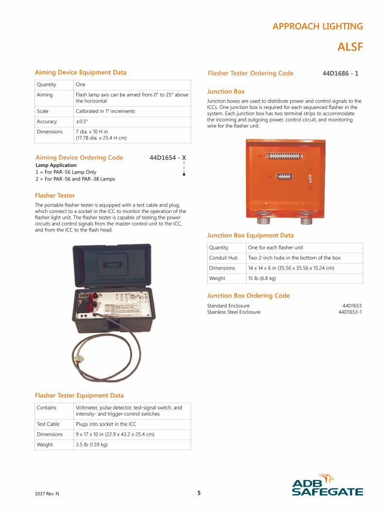
Junction BoxJunction boxes are used to distribute power and control signals to theICCs. One junction box is required for each sequenced flasher in thesystem. Each junction box has two terminal strips to accommodatethe incoming and outgoing power, control circuit, and monitoringwire for the flasher unit.
Junction Box Equipment Data
Quantity One for each flasher unit
Conduit Hub Two 2-inch hubs in the bottom of the box
Dimensions 14 x 14 x 6 in (35.56 x 35.56 x 15.24 cm)
Weight 15 lb (6.8 kg)
Junction Box Ordering CodeStandard Enclosure 44D1653Stainless Steel Enclosure 44D1653-1
APPROACH LIGHTING
ALSF
1037 Rev. N 5
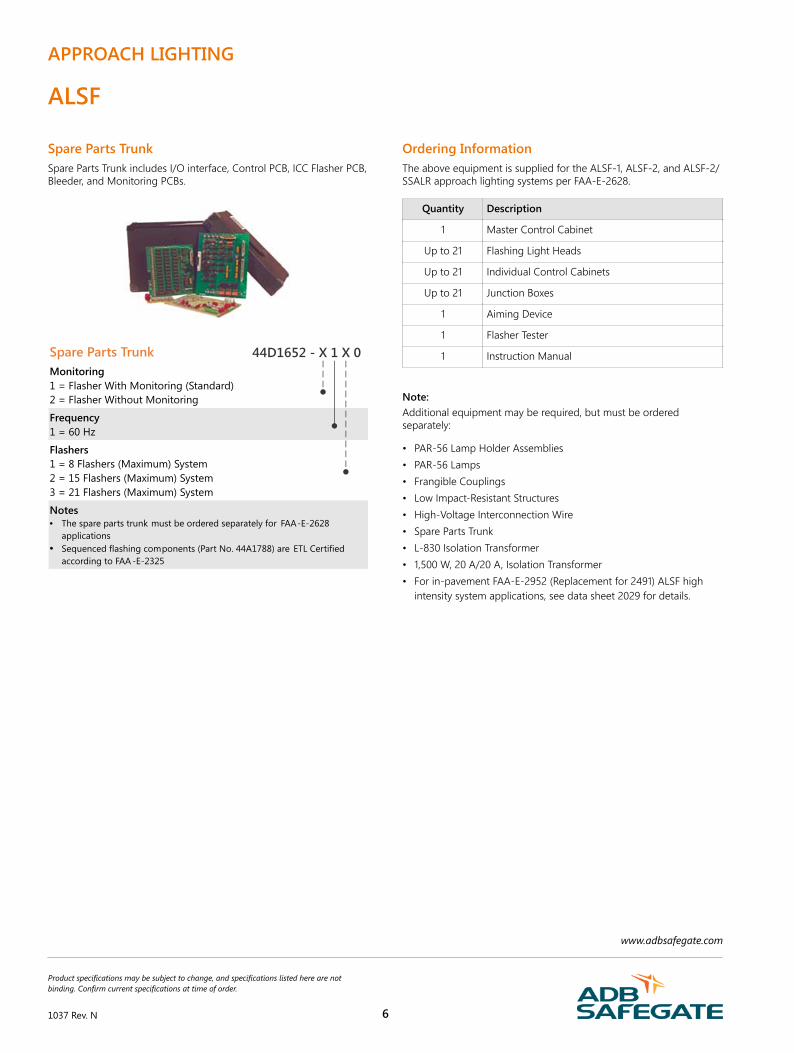
Spare Parts TrunkSpare Parts Trunk includes I/O interface, Control PCB, ICC Flasher PCB,Bleeder, and Monitoring PCBs.
Spare Parts Trunk Monitoring 1 = Flasher With Monitoring (Standard) 2 = Flasher Without Monitoring
Frequency 1 = 60 Hz
Flashers 1 = 8 Flashers (Maximum) System 2 = 15 Flashers (Maximum) System 3 = 21 Flashers (Maximum) System
Notes • The spare parts trunk must be ordered separately for FAA-E-2628
applications • Sequenced flashing components (Part No. 44A1788) are ETL Certified
according to FAA -E-2325
44D1652 - X 1 X 0
Ordering InformationThe above equipment is supplied for the ALSF-1, ALSF-2, and ALSF-2/SSALR approach lighting systems per FAA-E-2628.
Quantity Description
1 Master Control Cabinet
Up to 21 Flashing Light Heads
Up to 21 Individual Control Cabinets
Up to 21 Junction Boxes
1 Aiming Device
1 Flasher Tester
1 Instruction Manual
Note:Additional equipment may be required, but must be orderedseparately:
• PAR-56 Lamp Holder Assemblies• PAR-56 Lamps• Frangible Couplings• Low Impact-Resistant Structures• High-Voltage Interconnection Wire• Spare Parts Trunk• L-830 Isolation Transformer• 1,500 W, 20 A/20 A, Isolation Transformer• For in-pavement FAA-E-2952 (Replacement for 2491) ALSF high
intensity system applications, see data sheet 2029 for details.
APPROACH LIGHTING
ALSF
www.adbsafegate.com
Product specifications may be subject to change, and specifications listed here are notbinding. Confirm current specifications at time of order.
1037 Rev. N 6