HIGH ENERGY RATE FORMING PROCESSES VI/ME... · In electromagnetic forming, the initial gap between...
55
HIGH ENERGY RATE FORMING PROCESSES
Transcript of HIGH ENERGY RATE FORMING PROCESSES VI/ME... · In electromagnetic forming, the initial gap between...

HIGH ENERGY RATE FORMING PROCESSES
In these forming processes large amount of energy is
applied for a very short interval of time.
Many metals tend to deform more readily under extra – fast
application of load which make these processes useful to
form large size parts out of most metals including those which
are otherwise difficult – to – form.

Parts are formed at a rapid rate, and thus these processes are also
called high – velocity forming processes.
There are several advantages of using these forming processes,
like die costs are low,
easy maintenance of tolerances,
possibility of forming most metals,
and material does not show spring-back effect.
Production cost of components by such processes is low.
Limitation of these processes is the need for skilled personnel.
There are three main high energy rate forming
processes:
1. Explosive forming
2. Magnetic forming
3. Electro hydraulic forming

Explosive Forming Explosive forming, is distinguished from conventional
forming in that the punch or diaphragm is replaced by an
explosive charge.
Explosives used are generally high – explosive chemicals,
gaseous mixtures, or propellants.
There are two techniques of high – explosive forming:
Stand – off technique
Contact technique

Standoff Technique
Sheet metal work piece blank is clamped over a die and the assembly
is lowered into a tank filled with water.
Air in the die is pumped out.
Explosive charge is placed at some predetermined distance from the
work piece.
On detonation of the explosive, a pressure pulse of very high intensity
is produced.
Gas bubble is also produced which expands spherically and then
collapses.
When the pressure pulse impinges against the work piece, the metal is
deformed into the die with as high velocity as 120 m/s.
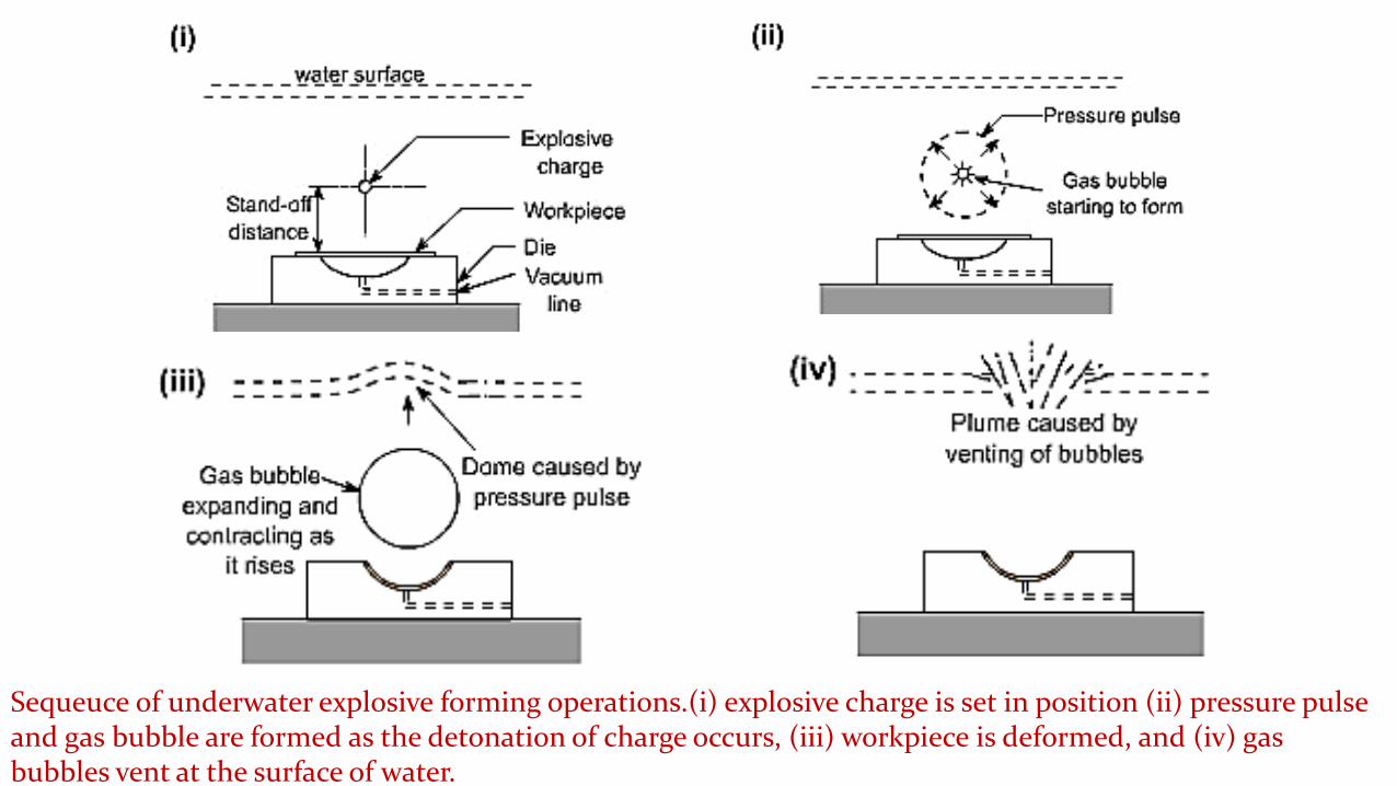
Sequeuce of underwater explosive forming operations.(i) explosive charge is set in position (ii) pressure pulse and gas bubble are formed as the detonation of charge occurs, (iii) workpiece is deformed, and (iv) gas bubbles vent at the surface of water.

Use of water as the energy transfer medium ensures a uniform
transmission of energy and muffles the sound of the explosive blast.
Process is versatile – a large variety of shapes can be formed, there is
virtually no limit to the size of the work piece, and it is suitable for low –
quantity production as well.
Process has been successfully used to form steel plates 25 mm thick
x 4 m diameter and to bulge steel tubes as thick as 25 mm.

Contact Technique
Explosive charge in the form of cartridge is held in direct contact with
the work piece while the detonation is initiated.
Detonation builds up extremely high pressures (upto 30,000MPa) on
the surface of the work piece resulting in metal deformation, and
possible fracture.
Process is used often for bulging tubes

Schematic illustration of contact technique of
explosive forming.
Process is generally used for bulging of tubes
Applications
Explosive forming is mainly used in the aerospace industries
but has also found successful applications in the production
of automotive related components.
Process has the greatest potential in limited – production
prototype forming and for forming large size components for
which conventional tooling costs are prohibitively high.

Explosives used can be:
• High energy chemicals like TNT, RDX, and Dynamite.
• Gaseous mixtures
• Propellants.

Factors to be considered while selecting an HERF process:
• Size of work piece
• Geometry of deformation
• Behavior of work material under high strain rates
• Energy requirements/ source
• Cost of tooling / die
• Cycle time
• Overall capital investment
• Safety considerations.

Role of water:
Acts as energy transfer medium
Ensures uniform transmission of energy
Muffles the sound of explosion
Cushioning/ smooth application of energy on the work without
direct contact.
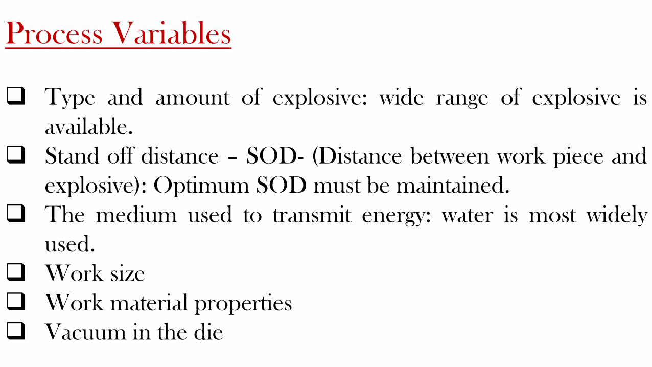
Process Variables
Type and amount of explosive: wide range of explosive is
available.
Stand off distance – SOD- (Distance between work piece and
explosive): Optimum SOD must be maintained.
The medium used to transmit energy: water is most widely
used.
Work size
Work material properties
Vacuum in the die
Electro Magnetic Forming
Process is also called magnetic pulse forming and is mainly used for
swaging type operations, such as fastening fittings on the ends of tubes
and crimping terminal ends of cables.
Other applications are blanking, forming, embossing, and drawing.
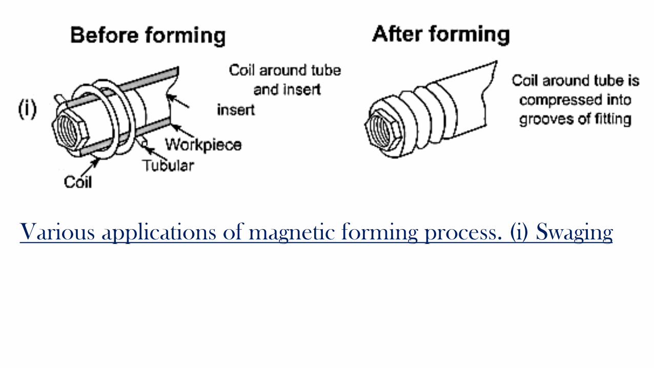
Various applications of magnetic forming process. (i) Swaging

Process details/ Steps:
The electrical energy is stored in the capacitor bank
The tubular work piece is mounted on a mandrel having the die cavity
to produce shape on the tube.
A primary coil is placed around the tube and mandrel assembly.
When the switch is closed, the energy is discharged through the coil
The coil produces a varying magnetic field around it.
In the tube a secondary current is induced, which creates its own
magnetic field in the opposite direction.
The directions of these two magnetic fields oppose one another and
hence the rigidly held coil repels the work into the die cavity.
The work tube collapses into the die, assuming its shape.
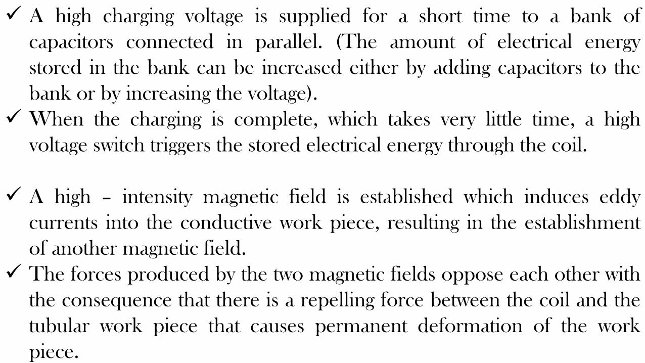
A high charging voltage is supplied for a short time to a bank of
capacitors connected in parallel. (The amount of electrical energy
stored in the bank can be increased either by adding capacitors to the
bank or by increasing the voltage).
When the charging is complete, which takes very little time, a high
voltage switch triggers the stored electrical energy through the coil.
A high – intensity magnetic field is established which induces eddy
currents into the conductive work piece, resulting in the establishment
of another magnetic field.
The forces produced by the two magnetic fields oppose each other with
the consequence that there is a repelling force between the coil and the
tubular work piece that causes permanent deformation of the work
piece.
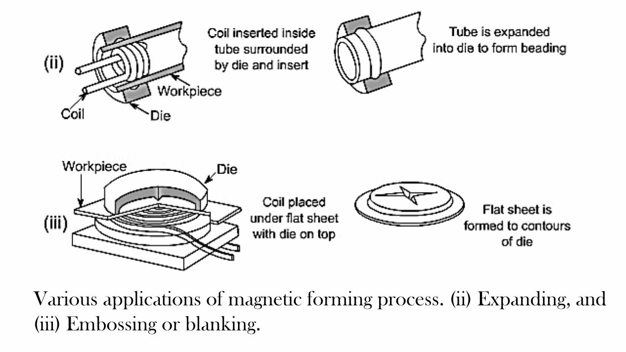
Various applications of magnetic forming process. (ii) Expanding, and
(iii) Embossing or blanking.

Magnetic forming can be accomplished in any of the following three ways,
depending upon the requirements.
Coil surrounding work piece:- When a tube – like part x is to fit over
another part y, coil is designed to surround x so that when energized,
would force the material of x tightly around y to obtain necessary fit.
Coil inside work piece:- Consider fixing of a collar on a tube – like part.
The magnetic coil is placed inside the tube – like part, so that when
energized would expand the material of the part into the collar.
Coil on flat surface:- Flat coil having spiral shaped winding can also be
designed to be placed either above or below a flat work piece.These
coils are used in conjunction with a die to form, emboss, blank, or
dimple the work piece.

Either permanent or expandable coils may be used.
Since the repelling force acts on the coil as well the
work, the coil itself and the insulation on it must be
capable of withstanding the force, or else they will be
destroyed.
Expandable coils are less costly and are also preferred
when high energy level is needed.

In electromagnetic forming, the initial gap between the work piece and
the die surface, called the fly distance , must be sufficient to permit the
material to deform plastically.
• From energy considerations, the ideal pressure pulse should be of just
enough magnitude that accelerates the part material to some maximum
velocity and then let the part come to zero velocity by the time it covers
the full fly distance.

Process parameters:
Work piece size
Electrical conductivity of the work material.
Size of the capacitor bank
The strength of the current, which decides the strength of the
magnetic field and the force applied.
Insulation on the coil.
Rigidity of the coil.

Advantages:
i) Suitable for small tubes
ii) Operations like collapsing, bending and crimping can be
easily done.
iii) Electrical energy applied can be precisely controlled and
hence the process is accurately controlled.
iv) The process is safer compared to explosive forming.
v) Wide range of applications.

Limitations:
i) Applicable only for electrically conducting materials.
ii) Not suitable for large work pieces.
iii) Rigid clamping of primary coil is critical.
iv) Shorter life of the coil due to large forces acting on it.

Applications
It has found extensive applications in the fabrication of hollow, non –
circular, or asymmetrical shapes from tubular stock.
Compression applications involve swaging to produce compression,
tensile, and torque joints or sealed pressure joints, and swaging to apply
compression bands or shrink rings for fastening components together.
Flat coils have been used on flat sheets to produce stretch (internal) and
shrink (external) flanges on ring and disc – shaped work pieces.
Electromagnetic forming has also been used to perform shearing,
piercing, and rivettting.

Electro Hydraulic Forming
Electro hydraulic forming (EHF), also known as electro spark forming,
is a process in which electrical energy is converted into mechanical
energy for the forming of metallic parts.
A bank of capacitors is first charged to a high voltage and then
discharged across a gap between two electrodes, causing explosions
inside the hollow work piece, which is filled with some suitable
medium, generally water.

These explosions produce shock waves that travel
radially in all directions at high velocity until they meet
some obstruction.
If the discharge energy is sufficiently high, the hollow
work piece is deformed.
The deformation can be controlled by applying external
restraints in the form of die or by varying the amount of
energy released.

ELECTRO HYDRAULIC FORMING

Unrestrained and
restrained electro-
hydraulic forming
process.

Principle
A sudden electrical discharge in the form of sparks is produced
between electrodes and this discharge produces a shock wave in
the water medium.
This shock wave deforms the work plate and collapses it into the
die.
Characteristics of this process are similar to those of explosive
forming.
Major difference, however, is that a chemical explosive is replaced
by a capacitor bank, which stores the electrical energy.

Capacitor is charged through a charging circuit.
When the switch is closed, a spark is produced between
electrodes and a shock wave or pressure pulse is created.
Energy released is much lesser than that released in
explosive forming.

Process Characteristics:
Stand off distance: It must be optimum.
Capacitor used: The energy of the pressure pulse depends on
the size of capacitor.
Transfer medium: Usually water is used.
Vacuum: the die cavity must be evacuated to prevent adiabatic
heating of the work due to a sudden compression of air.
Material properties with regard to the application of high rates
of strain.

Advantages
EHF can form hollow shapes with much ease and at less cost
compared to other forming techniques.
EHF is more adaptable to automatic production compared to
other high energy rate forming techniques.
EHF can produce small – to intermediate sized parts that
don't have excessive energy requirements.
Better control of the pressure pulse as source of energy is
electrical- which can be easily controlled.
Safer in handling than the explosive materials.
More suitable if the work size is small to medium.
Thin plates can be formed with smaller amounts of energy.
The process does not depend on the electrical properties of
the work material.

Limitations:
Suitable only for smaller works
Need for vacuum makes the equipment more complicated.
Proper SOD is necessary for effective process.
Applications:
• They include smaller radar dish, cone and other shapes in
thinner and small works.

Accuracy of parts produced
Accuracy of electro hydraulically formed parts depends on the
control of both the magnitude and location of energy discharges and
on the dimensional accuracy of the dies used.
External dimensions on tubular parts are possible to achieve within
± 0.05 mm with the current state of technology.
Materials formed
Materials having low ductility or having critical impact
velocity less than 30 m/s are generally not considered to be
good candidate for EHF.
All materials that can be formed by conventional forming
processes can be formed by EHF also.
These materials are aluminum alloys, nickel alloys, stainless
steels, titanium, and Inconel 718.

ADVANTAGES OF HERF
Production rates are higher, as parts are made at a rapid rate.
Die costs are relatively lower.
Tolerances can be easily maintained.
Versatility of the process – it is possible to form most metals including
difficult to form metals.
No or minimum spring back effect on the material after the process.

Production cost is low as power hammer (or press) is eliminated in the
process. Hence it is economically justifiable.
Complex shapes / profiles can be made much easily, as compared to
conventional forming.
The required final shape/ dimensions are obtained in one stroke (or
step), thus eliminating intermediate forming steps and pre forming
dies.
Suitable for a range of production volume such as small numbers,
batches or mass production

The forming processes are affected by the rates of strain used.
Effects of strain rates during forming:
1. The flow stress increases with strain rates
2. The temperature of work is increases due to adiabatic heating.
3. Improved lubrication if lubricating film is maintained.
4. Many difficult to form materials like Titanium and Tungsten alloys, can
be deformed under high strain rates.

Principle / important features of HERF processes:
• The energy of deformation is delivered at a much higher rate than in
conventional practice.
• Larger energy is applied for a very short interval of time.
• High particle velocities are produced in contrast with conventional
forming process.
• The velocity of deformation is also very large and hence these are also
called High Velocity Forming (HVF) processes.
• Many metals tend to deform more readily under extra fast application of
force.
• Large parts can be easily formed by this technique.

• For many metals, the elongation to fracture increases with strain rate
beyond the usual metal working range, until a critical strain rate is
achieved, where the ductility drops sharply.
• The strain rate dependence of strength increases with increasing
temperature.
• The yield stress and flow stress at lower plastic strains are more
dependent on strain rate than the tensile strength.
• High rates of strain cause the yield point to appear in tests on low
carbon steel that do not show a yield point under ordinary rates of strain.

LIMITATIONS OF HERF
Highly skilled personnel are required from design to execution.
Transient stresses of high magnitude are applied on the work.
Not suitable to highly brittle materials
Source of energy (chemical explosive or electrical) must be handled
carefully.
Governmental regulations/ procedures / safety norms must be
followed.

Dies need to be much bigger to withstand high energy rates and
shocks and to prevent cracking.
Controlling the application of energy is critical as it may crack the die
or work.
It is very essential to know the behaviour or established performance
of the work metal initially

Applications:
In ship building – to form large plates / parts (up to 25 mm
thick).
Bending thick tubes/ pipes (up to 25 mm thick).
Crimping of metal strips.
Radar dishes
Elliptical domes used in space applications.
Cladding of two large plates of dissimilar metals.

EFFECT OF HIGH SPEED ON STRESS – STRAIN
RELATIONSHIP
Yield strength and resistance to deformation increase with strain
rate
At ambient temperature, general level of the stress strain curve is
higher when the load is applied rapidly than when it is applied
slowly
Yield stress of several types of mild steel gets increased under
rapid loading

STRESS STRAIN CURVE OF Mild Steel

COMPARISON OF CONVENTIONAL AND HIGH VELOCITY
FORMING
Comparison in deformation velocity
o Velocities of conventional machines are usually lower by the order of 103 as
compared to high velocity forming system.
o In HVF, velocity ranges from 3 to 300 m/sec and in conventional machine
velocity ranges from 0.03 to 9 m/sec

Comparison in strain distribution
o Strain distribution is much more uniform in a single operation of HVF.
o It is easy to produce complex shapes without inducing unnecessary
strains in the material
o In HVF, strains required to failure are much higher as compared to
conventional process.
o Ductility obtained is more.
STRESS WAVES
Any material, when it is subjected to a load, stress induced in it is transmitted
as waves which travel at a finite velocity and is equal to speed of speed within the
material
Two types of waves in metal forming are
• Elastic waves
• Plastic waves
Further divided into two types
Longitudinal waves
Transverse waves or shear waves

In plastic waves propagation,
C = Velocity of wave propagation
=
𝑑σ
𝑑ε
ρ
ρ – mass density of the metal𝑑σ
𝑑ε- slope of engineering stress strain diagram

For many metals, the stress strain curve is less in the plastic range than in the elastic
range. Thus the velocity of plastic wave propagation is less than that for elastic
waves.
Velocity of propagation of longitudinal and transverse waves depend son the
following factors
Elastic constant
Density of material to be deformed.
Velocity of longitudinal wave,
VL =2𝐾 (1−ν)
ρ(1+ν)
K - Bulk modulus of material
ρ - Density of material
ν - Poisson’s ratio

Velocity of shear wave,
Vt = 𝐺
𝜌
G – Shear modulus