HFM Series - hydac-na. · PDF file2 FIL1606-1791 6.16 FILTER MAINTENANCE Paper Industry Steel...
6
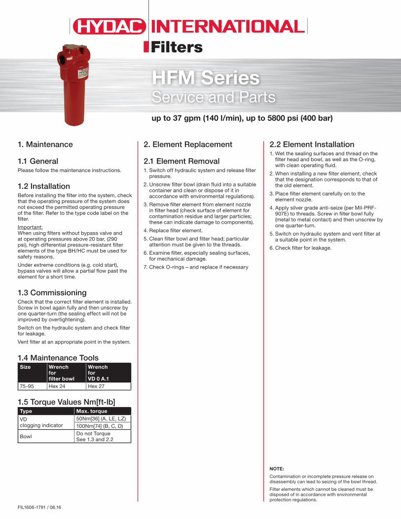
Filters FIL1606-1791 / 06.16 NOTE: Contamination or incomplete pressure release on disassembly can lead to seizing of the bowl thread. Filter elements which cannot be cleaned must be disposed of in accordance with environmental protection regulations. 1. Maintenance 1.1 General Please follow the maintenance instructions. 1.2 Installation Before installing the filter into the system, check that the operating pressure of the system does not exceed the permitted operating pressure of the filter. Refer to the type code label on the filter. Important: When using filters without bypass valve and at operating pressures above 20 bar, (290 psi), high differential pressure-resistant filter elements of the type BH/HC must be used for safety reasons. Under extreme conditions (e.g. cold start), bypass valves will allow a partial flow past the element for a short time. 1.3 Commissioning Check that the correct filter element is installed. Screw in bowl again fully and then unscrew by one quarter-turn (the sealing effect will not be improved by overtightening). Switch on the hydraulic system and check filter for leakage. Vent filter at an appropriate point in the system. 1.4 Maintenance Tools Size Wrench for filter bowl Wrench for VD 0 A.1 75-95 Hex 24 Hex 27 1.5 Torque Values Nm[ft-lb] Type Max. torque VD clogging indicator 50Nm[36] (A, LE, LZ) 100Nm[74] (B, C, D) Bowl Do not Torque See 1.3 and 2.2 2.2 Element Installation 1. Wet the sealing surfaces and thread on the filter head and bowl, as well as the O-ring, with clean operating fluid. 2. When installing a new filter element, check that the designation corresponds to that of the old element. 3. Place filter element carefully on to the element nozzle. 4. Apply silver grade anti-seize (per Mil-PRF- 907E) to threads. Screw in filter bowl fully (metal to metal contact) and then unscrew by one quarter-turn. 5. Switch on hydraulic system and vent filter at a suitable point in the system. 6. Check filter for leakage. 2. Element Replacement 2.1 Element Removal 1. Switch off hydraulic system and release filter pressure. 2. Unscrew filter bowl (drain fluid into a suitable container and clean or dispose of it in accordance with environmental regulations). 3. Remove filter element from element nozzle in filter head (check surface of element for contamination residue and larger particles; these can indicate damage to components). 4. Replace filter element. 5. Clean filter bowl and filter head; particular attention must be given to the threads. 6. Examine filter, especially sealing surfaces, for mechanical damage. 7. Check O-rings – and replace if necessary up to 37 gpm (140 l/min), up to 5800 psi (400 bar) HFM Series Service and Parts
-
Upload
vuongkhanh -
Category
Documents
-
view
215 -
download
2
Transcript of HFM Series - hydac-na. · PDF file2 FIL1606-1791 6.16 FILTER MAINTENANCE Paper Industry Steel...
Filters
FIL1606-1791 / 06.16
NOTE:
Contamination or incomplete pressure release on disassembly can lead to seizing of the bowl thread.
Filter elements which cannot be cleaned must be disposed of in accordance with environmental protection regulations.
1. Maintenance
1.1 General Please follow the maintenance instructions.
1.2 InstallationBefore installing the filter into the system, check that the operating pressure of the system does not exceed the permitted operating pressure of the filter. Refer to the type code label on the filter.
Important: When using filters without bypass valve and at operating pressures above 20 bar, (290 psi), high differential pressure-resistant filter elements of the type BH/HC must be used for safety reasons.
Under extreme conditions (e.g. cold start), bypass valves will allow a partial flow past the element for a short time.
1.3 CommissioningCheck that the correct filter element is installed. Screw in bowl again fully and then unscrew by one quarter-turn (the sealing effect will not be improved by overtightening).
Switch on the hydraulic system and check filter for leakage.
Vent filter at an appropriate point in the system.
1.4 Maintenance ToolsSize Wrench
for filter bowl
Wrench for VD 0 A.1
75-95 Hex 24 Hex 27
1.5 Torque Values Nm[ft-lb]Type Max. torque
VD clogging indicator
50Nm[36] (A, LE, LZ)100Nm[74] (B, C, D)
Bowl Do not Torque See 1.3 and 2.2
2.2 Element Installation1. Wet the sealing surfaces and thread on the
filter head and bowl, as well as the O-ring, with clean operating fluid.
2. When installing a new filter element, check that the designation corresponds to that of the old element.
3. Place filter element carefully on to the element nozzle.
4. Apply silver grade anti-seize (per Mil-PRF-907E) to threads. Screw in filter bowl fully (metal to metal contact) and then unscrew by one quarter-turn.
5. Switch on hydraulic system and vent filter at a suitable point in the system.
6. Check filter for leakage.
2. Element Replacement
2.1 Element Removal1. Switch off hydraulic system and release filter
pressure.
2. Unscrew filter bowl (drain fluid into a suitable container and clean or dispose of it in accordance with environmental regulations).
3. Remove filter element from element nozzle in filter head (check surface of element for contamination residue and larger particles; these can indicate damage to components).
4. Replace filter element.
5. Clean filter bowl and filter head; particular attention must be given to the threads.
6. Examine filter, especially sealing surfaces, for mechanical damage.
7. Check O-rings – and replace if necessary
up to 37 gpm (140 l/min), up to 5800 psi (400 bar)
HFM SeriesService and Parts

2 FIL1606-1791 / 06.16
FILTER MAINTENANCE
Paper Industry
Steel Industry Plastics Industry
Power Industry
3. Spare Parts 3.1 Spare Parts Drawing HFM 75 – 95
2.1
2.2/3.4
2.3/3.5
3.2
3.3
1.2 / 3.1
1.1
Item Consists Designation 75 951. Filter element See Point 4. Replacement elements
Filter element 0075 D... 0095 D...O-ring 25 x 3.53 25 x 3.53
2. Clogging indicator or indicator plug See Point 5. Replacement clogging indicator
Indicator plug VD 0 A.1 VD 0 A.1 /-V
00305932 00305931
Profile seal ring VM...O-ring 18 x 2.5
3. Repair kit HFM Repair kit HFM /-V
01280437 01282899
3.1 O-ring (element) 25 x 3.533.2 O-ring (bowl) 67.95 x 2.62 (AS568A-147)3.3 Back-up ring (bowl) 67.2 x 71.6 x 1.43.4 Profile seal ring (indicator) VM...3.5 O-ring (indicator) 18 x 2.5
Other spare parts on request -O-Ring durometer can range from 70-80Sh. EPR Seal Kits available on request. -Bowl assembly kits on request - kits include complete bowl with seals.
3FIL1606-1791 / 06.16
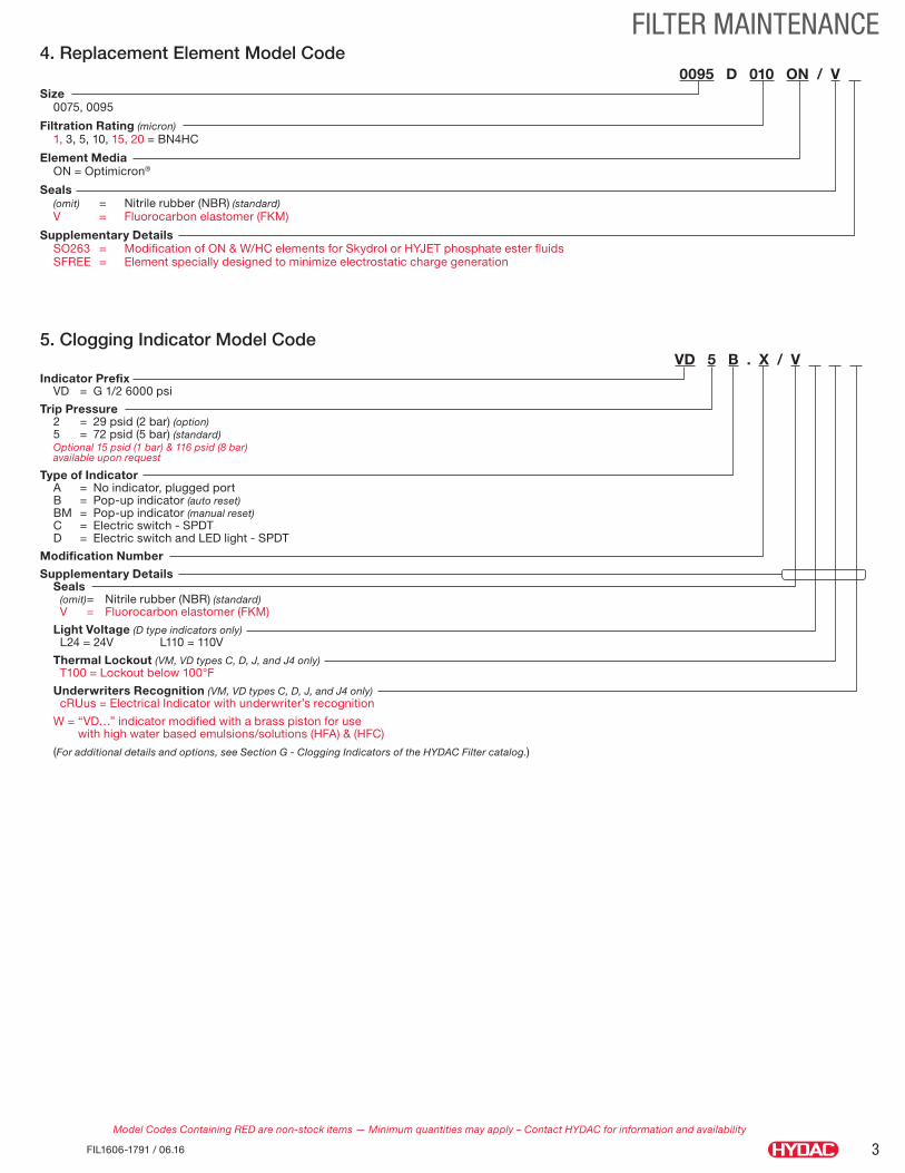
FILTER MAINTENANCE4. Replacement Element Model Code 0095 D 010 ON / V Size 0075, 0095
Filtration Rating (micron) 1, 3, 5, 10, 15, 20 = BN4HC
Element Media ON = Optimicron®
Seals (omit) = Nitrile rubber (NBR) (standard) V = Fluorocarbon elastomer (FKM)
Supplementary Details SO263 = Modification of ON & W/HC elements for Skydrol or HYJET phosphate ester fluids SFREE = Element specially designed to minimize electrostatic charge generation
Model Codes Containing RED are non-stock items — Minimum quantities may apply – Contact HYDAC for information and availability
5. Clogging Indicator Model CodeVD 5 B . X / V .
Indicator Prefix VD = G 1/2 6000 psi
Trip Pressure 2 = 29 psid (2 bar) (option) 5 = 72 psid (5 bar) (standard) Optional 15 psid (1 bar) & 116 psid (8 bar) available upon request
Type of Indicator A = No indicator, plugged port B = Pop-up indicator (auto reset) BM = Pop-up indicator (manual reset) C = Electric switch - SPDT D = Electric switch and LED light - SPDT
Modification Number
Supplementary Details Seals (omit) = Nitrile rubber (NBR) (standard) V = Fluorocarbon elastomer (FKM)
Light Voltage (D type indicators only) L24 = 24V L110 = 110V
Thermal Lockout (VM, VD types C, D, J, and J4 only) T100 = Lockout below 100°F
Underwriters Recognition (VM, VD types C, D, J, and J4 only) cRUus = Electrical Indicator with underwriter’s recognition
W = “VD…” indicator modified with a brass piston for use with high water based emulsions/solutions (HFA) & (HFC)
(For additional details and options, see Section G - Clogging Indicators of the HYDAC Filter catalog.)

4 FIL1606-1791 / 06.16
FILTER MAINTENANCE6. Maintenance Instructions
6.1 User Instructions for Filters
This symbol is followed by user tips and particularly useful information.
• This pressure equipment must only be put into operation in conjunction with a machine or system.
• The pressure equipment must only be used as stipulated in the operating instructions of the machine or system.
• This pressure equipment must only be operated using hydraulic or lubricating fluid.
• It is the responsibility of the operator to comply with the water regulations of the country concerned.
This symbol denotes safety precautions, the non-observance of which can endanger
persons and the environment.
CAUTION• The user must take appropriate action (e.g. venting) to prevent the
formation of air pockets.• Repairs, maintenance work and commissioning must only be carried
out by trained personnel. • Allow the pressure equipment to cool before handling. • The stipulations of the operating instructions of the machine or the
system must be followed.• Statutory accident prevention regulations, safety regulations and
safety data sheets for fluids must be observed.• Filter housing must be grounded.• When working on, or in the vicinity of, hydraulic systems, open flames,
sparks and smoking are forbidden.• Hydraulic oils and water-polluting fluids must not be allowed to
enter the soil or watercourses or sewer systems. Please ensure safe and environmentally friendly disposal of hydraulic oils. The relevant regulations in the country concerned with regard to ground water pollution, used oil and waste must be complied with.
• Whenever work is carried out on the filter, be prepared for hot oil to escape which can cause injury or scalding as a result of its high pressure or temperature.
DANGER!• Caution: pressure equipment! Before any work is carried out on the
pressure equipment, ensure the pressure chamber concerned (filter housing) is depressurized.
• On no account must any modifications (welding, drilling, opening by force...) be carried out on the pressure equipment.
• When using electrical clogging indicators, the electrical power supply to the system must be switched off before removing the clogging indicator connector.
6.2 Maintenance, GeneralThis section describes maintenance work which must be carried out periodically. The operational safety and life expectancy of the filter, and whether it is ready for use, depend to a large extent on regular and careful maintenance.
6.3 Maintenance Measures• Spare parts must fulfil the technical requirements specified by the
manufacturer. This is always ensured when using original HYDAC spare parts.
• Keep tools, working area and equipment clean.• After disassembling the filter, clean all parts, check for damage or
wear and replace parts if necessary.• When changing a filter element, a high level of cleanliness must be
observed.
6.4 Interval Between Element ChangesIn principle we recommend that the filter element is changed every 6 months or upon indication, whichever occurs first.
We recommend installing the filter with a clogging indicator (visual and/or electrical or electronic) to monitor the filter element.
If the clogging indicator responds, it is necessary to change or clean the filter element without delay (only W and V elements can be cleaned).
When no clogging indicator has been installed, we recommend changing the elements at specific intervals. (The frequency of changing the filter elements depends on the filter design and the conditions under which the filter is operated). When filter elements are subject to high dynamic loading it may prove necessary to change them more frequently. The same applies when the hydraulic system is commissioned, repaired or when the oil is changed
The standard clogging indicators only respond when fluid is flowing through the filter. With electrical indicators the signal can also be converted into a continuous display on the control panel. In this case the continuous display must be switched off during a cold start or after changing the element.
If the clogging indicator responds during a cold start only, it is possible that the element does not yet need to be changed.
Customer Information in respect of Machinery Directive 2006/42/EC
Hydraulic filters are defined as fluid power parts / components and are therefore excluded from the scope of the Machinery Directive, sections 1.4.1 - 1.4.3. They do not bear the CE mark.
Before using these components, ensure compliance with the specifications provided by HYDAC Technology Corporation. The specifications also contain information on the relevant essential health and safety requirements (based on Machinery Directive 2006/42/EC).
We hereby declare that the filters are intended to be incorporated into machinery within the terms of the Directive 2006/42/EC. It is prohibited to put the filters into service until the machinery as a whole is in conformity with the provisions of the Machinery Directive.
Service address
HYDAC Technology Corporation Filter Division
2260 City Line Road Bethlehem, PA 18017 +1.610.266.0100
NOTE The information in this brochure relates to the operating conditions and applications described. For applications or operating conditions not described, please contact the relevant technical department. Subject to technical modifications.

5FIL1606-1791 / 06.16
FILTER MAINTENANCENotes

Global HeadquartersHYDAC INTERNATIONAL
GMBH
IndustriegebietD – 66280 Sulzbach/Saar
Germany
Tel.: +49 6897 509-01
Fax: +49 6897 509-577
Internet: www.hydac.comEmail: [email protected]
North America Locations USA www.HYDAC-NA.com
HYDAC TECHNOLOGY CORPORATION Filter Division2260 City Line Road Bethlehem, PA 18017+1.610.266.0100
HYDAC TECHNOLOGY CORPORATION Cooling System Division1051 Airlie Parkway Denver, NC 28037+1.610.266.0100
HYDAC TECHNOLOGY CORPORATION Accessory Division2204 Avenue C Bethlehem, PA 18017+1.610.266.0100
HYDAC TECHNOLOGY CORPORATION Cooling System Division445 Windy Point Drive Glendale Heights, IL 60139+1.630.545.0800
HYDAC TECHNOLOGY CORPORATION Electronic Division Process Filter DivisionHYDAC CORPORATION Accumulator Division90 Southland Drive Bethlehem, PA 18017+1.610.266.0100
HYDAC TECHNOLOGY CORPORATION HYDAC CORPORATION Sales Office & Operations1718 Fry Road, Suite 100 Houston, TX 77084+1.281.579.8100
HYDAC TECHNOLOGY CORPORATION Filter System Division Process Filter Division580 West Park Road Leetsdale, PA 15056+1.724.318.1100
HYDAC TECHNOLOGY CORPORATION HYDAC CORPORATION NE Sales Office1660 Enterprise Parkway • Suite E Wooster, OH 44691+1.610.266.0100
HYDAC TECHNOLOGY CORPORATION Hydraulic Division450 Windy Point Drive Glendale Heights, IL 60139+1.630.545.0800
HYDAC TECHNOLOGY CORPORATION HYDAC CORPORATION SE Sales Office1051 Airlie Parkway Denver, NC 28037+1.610.266.0100
HYDAC TECHNOLOGY CORPORATION Mobile Hydraulic Division1660 Enterprise Parkway • Suite E Wooster, OH 44691+1.610.266.0100
HYDAC TECHNOLOGY CORPORATION HYDAC CORPORATION NW Sales Office1201 NE 144th St. Bldg. B, Suite 111 Vancouver, WA 98685+1.610.266.0100
HYDAC CYLINDERS LLC540 Carson Road North Birmingham, AL 35217+1.205.520.1220
HYDAC TECHNOLOGY CORPORATION Hydraulic Division – Tech Center430 Windy Point Drive Glendale Heights, IL 60139+1.630.545.0800
Canada www.HYDAC-NA.comHYDAC CORPORATION14 Federal Road Welland, Ontario, Canada L3B 3P2 +1.905.714.9322
HYDAC CORPORATION Sales Office5160 75 Street NW Edmonton, Alberta, Canada T6E 6W2+1.780.484.4228
HYDAC CORPORATION Sales OfficeMontreal, Québec, Canada J2M 1K9+1.877.539.3388
Mexico www.HYDACmex.comHYDAC INTERNATIONAL SA de CVCalle Alfredo A Nobel No 35 Col Puente de Vigas Tlalnepantla, Edo Mexico CP 54090 Mexico+011.52.55.4777.1262
FIL1606-1791 / 06.16© Copyright 2016 HYDAC TECHNOLOGY CORPORATION • Brochure - Service HFM