HES HACILAR ELEKTRİK SANAYİ VE TİCARET A.Ş. · HES Hacılar Elektrik Sanayi ve Ticaret A.Ş....
280
HES Hacılar Elektrik Sanayi ve Ticaret A.Ş. (HES KABLO) established in 1974 is a leading cable manufacturer in Turkey and the Globe. Having more than 40 years of experience, HES KABLO has become an international leading company in wire and cable industry producing Power Cable, High Voltage Power Cables, Fiber Optic Cable, Copper Telecommunication Cable, Overhead Line Conductor, Enamelled Wire. The production is performed at fully integrated plant with the total floor space of 120,000 m2 and site area of 250,000 m2 with the latest technologies and using the most updated machinery and methods under the supervision of skilled and experienced staff assuring the most updated & quality products. All the production and QC procedures are achieved by the procedures and regulations of obtained ISO 9001, ISO 10002, ISO 14001, OHSAS 18001, ISO 27001, ISO 50001 and relevant international standards. Being a leading international cable manufacturer, HES KABLO products are supplied to all over the world for 40 years, in conformity with the international standards such as VDE, GOST, IEC, BS, CENELEC and also special customer requirements. Quality control of the products is fastidiously performed by the most updated equipments and methods. All these advanced technology and experience ensure high quality of products and make HES KABLO as a reputable brand name worldwide in cable industry. HES KABLO is ranked at 69 th place among the top 500 industrial companies in Turkey by İstanbul Chamber of Industry, Turkey in 2015. HES KABLO is proud to be a leading international company that supplies “reliable technology” products more than 130 countries worldwide. HES HACILAR ELEKTRİK SANAYİ VE TİCARET A.Ş.
Transcript of HES HACILAR ELEKTRİK SANAYİ VE TİCARET A.Ş. · HES Hacılar Elektrik Sanayi ve Ticaret A.Ş....

HES Hacılar Elektrik Sanayi ve Ticaret A.Ş. (HES KABLO) established in 1974 is a leading cable manufacturer in Turkey and the Globe.
Having more than 40 years of experience, HES KABLO has become an international leading company in wire and cable industry producing Power Cable, High Voltage Power Cables, Fiber Optic Cable, Copper Telecommunication Cable, Overhead Line Conductor, Enamelled Wire. The production is performed at fully integrated plant with the total floor space of 120,000 m2 and site area of 250,000 m2 with the latest technologies and using the most updated machinery and methods under the supervision of skilled and experienced staff assuring the most updated & quality products. All the production and QC procedures are achieved by the procedures and regulations of obtained ISO 9001, ISO 10002, ISO 14001, OHSAS 18001, ISO 27001, ISO 50001 and relevant international standards. Being a leading international cable manufacturer, HES KABLO products are supplied to all over the world for 40 years, in conformity with the international standards such as VDE, GOST, IEC, BS, CENELEC and also special customer requirements. Quality control of the products is fastidiously performed by the most updated equipments and methods. All these advanced technology and experience ensure high quality of products and make HES KABLO as a reputable brand name worldwide in cable industry. HES KABLO is ranked at 69 th place among the top 500 industrial companies in Turkey by İstanbul Chamber of Industry, Turkey in 2015. HES KABLO is proud to be a leading international company that supplies “reliable technology” products more than 130 countries worldwide.
HES HACILAR ELEKTRİK SANAYİ VE TİCARET A.Ş.


CONTENTS
Installation Cables
PVC Insulated Low Voltage Cables
XLPE Insulated Low Voltage Cables
HFRR Installation Cables
XLPE Insulated HFFR Low Voltage Cables
Solar Cables
Medium Voltage Cables
High Voltage Cables
Aluminium Conductors
AER and ABC Cables
Composite Fiber Optic Overhead Ground Wire (OPGW)
Copper Rod
Aluminium Wire-rod
Technical Information
1-6
7-55
56-94
95-99
100-130
131-132
133-227
228-231
232-241
242-245
246-250
251-254
255
256-286


Inst
alla
tio
n C
able
s
1
PVC Insulated, single core cables with copper conductor
Construction
1 2Solid or stranded copper conductor PVC insulation
Code: U, H07V-U, H07V-R (NYA), CU/PVCH05V-
U: Solid ConductorR: Stranded Conductor Rigid
Standards: EN 50525-2-31, HD 21.3 S3
VDE 0281, IEC 60227, BS 6004,
Technical DataMax. operating temperature : 70 °CMax. short circuit temperature : 160 °C (max. 5 sec.) Rated voltage : 300/500 V
450/750 V
ApplicationIn dry rooms, switch and distribution boards, for laying in conduit on and under plaster and on insulating supports above plaster.
* : 300/500 V (H05V - U)
RE : Single conductor wireRM : Stranded Conductor
12
DIMENSION AND WEIGHTS ELECTRICAL PROPERTIES
Nominal Cross Section
Overall Diameter (approx)
Net Weight (approx)
Delivery Length
DC Conductor Resistance at
20 ºC Max
Current Carrying Capacity (A)
mm² mm kg/km m ohm/km In ground at20 ºC
In air at 30 ºC
0.5 * RE
0.75 * RE
1.0 * RE
1.5RE
2.5RE
4RE
6RE
10RE
10RM
16RM
25RM
35RM
50RM
70RM
95RM
120RM
150RM
185RM
240RM
2.1
2.3
2.5
2.8
3.3
3.8
4.3
5.6
6.0
7.0
8.5
9.5
11.0
13.0
15.0
16.5
18.0
20.0
23.0
8
11
14
20
31
46
65
108
111
170
260
355
490
694
938
1172
1465
1808
2343
100
100
100
100
100
100
100
100
100
1000
1000
1000
1000
1000
1000
1000
1000
1000
1000
36.0
24.5
18.1
12.1
7.41
4.61
3.08
1.83
1.83
1.15
0.727
0.524
0.387
0.268
0.193
0.153
0.124
0.0991
0.0754
-
-
11
15
20
25
33
45
45
61
83
103
132
165
197
235
-
-
-
9
15
19
24
32
42
54
73
73
98
129
158
198
245
292
344
391
448
528

Inst
alla
tio
n C
able
s
2
PVC Insulated, single core cableswith flexible copper conductor
Construction
1 Flexible copper conductors
Code: K, H07V-K, (NYAF), CU/PVCH05V-
K: Flexible Conductor Standards: EN 50525-2-31, HD 21.3 S3
VDE 0281, IEC 60227, BS 6004,
Technical DataMax. operating temperature : 70 °CMax. short circuit temperature : 160 °C (max. 5 sec.) Rated voltage : 300/500 V
450/750 V
ApplicationFor protected installation and light fitting. Also for in conduit, on and under plaster.
2 PVC insulation
* : 300/500 V (H05V - K)
12
DIMENSION AND WEIGHTS ELECTRICAL PROPERTIES
Nominal Cross Section
Overall Diameter (approx)
Net Weight (approx)
Delivery Length
DC Conductor Resistance at
20 ºC Max
Current Carrying Capacity (A)
mm² mm kg/km m ohm/km In ground at20 ºC
In air at 30 ºC
11
16
20
24
32
42
54
73
98
129
158
198
245
292
344
391
448
528
0.5 *
0.75 *
1.0 *
1.5
2.5
4
6
10
16
25
35
50
70
95
120
150
185
240
2.1
2.3
2.5
3.0
3.6
4.2
4.8
6.5
8.0
10.0
11.0
13.5
15.0
17.5
19.5
22.0
24.0
27.5
9
11
14
20
32
46
65
115
175
270
350
525
700
900
1200
1500
1860
2400
100
100
100
100
100
100
100
100
100
1000
1000
1000
1000
1000
1000
1000
1000
1000
39.0
26.0
19.5
13.3
7.98
4.95
3.30
1.91
1.21
0.780
0.554
0.386
0.272
0.206
0.161
0.129
0.106
0.0801
-
-
11
15
20
25
33
45
61
83
103
132
165
197
235
-
-
-

Inst
alla
tio
n C
able
s
3
PVC insulated, stranded copper conductors, installation cables
Construction
1 3Solid or stranded copper conductor Filler
Code: NYM, CU/PVC/PVC, NVV
Standards: TS 9759, VDE 0250, IEC 60227, BS 6004, HD 21.4 S2
Technical DataMax. operating temperature : 70 °CMax. short circuit temperature : 160 °C (max. 5 sec.) Rated voltage : 300/500 V
ApplicationFor household appliances (refrigerators, spin dryers, etc.) under medium mechanical stresses, also in damp and wet spaces.
2 4PVC insulation PVC outer jacket
RE : Single conductor wireRM : Stranded Conductor
1234
DIMENSION AND WEIGHTS ELECTRICAL PROPERTIES
Nominal Cross Section
Overall Diameter (approx)
Net Weight (approx)
Delivery Length
DC Conductor Resistance at
20 ºC Max
Current Carrying Capacity
mm² mm kg/km m ohm/km A
2 x 1.5 RE2 x 2.5 RE
2 x 4 RE2 x 6 RE
2 x 10 RM2 x 16 RM2 x 25 RM2 x 35 RM3 x 1.5 RE3 x 2.5 RE
3 x 4 RE3 x 6 RE
3 x 10 RM3 x 16 RM3 x 25 RM3 x 35 RM4 x 1.5 RE4 x 2.5 RE
4 x 4 RE4 x 6 RE
4 x 10 RM4 x 16 RM4 x 25 RM4 x 35 RM5 x 1.5 RE5 x 2.5 RE
5 x 4 RE5 x 6 RE
5 x 10 RM5 x 16 RM5 x 25 RM5 x 35 RM
8.810.011.012.015.017.521.524.59.2
10.511.513.016.518.523.526.510.011.513.014.517.520.026.029.011.012.514.516.020.022.528.532.0
125165200250470650930
1240130180250330520750
11801550160220320430650950
15002000190270400520800
118018502450
100100100100
1000100010001000100100100100
1000100010001000100100100100
1000100010001000100100100100
1000100010001000
12.17.414.613.081.831.15
0.7270.52412.17.414.613.081.831.15
0.7270.52412.17.414.613.081.831.15
0.7270.52412.17.414.613.081.831.15
0.7270.524
182634446182
108135182634446182
108135182634446182
10813514202633466281
101

Inst
alla
tio
n C
able
s
4
PVC insulated, stranded copper conductors, installation cables
Construction
1 3Fine stranded copper conductors PVC outer jacket
Code: H03VV-F, H05VV-F, NYMH-rd, CU/PVC/PVC
F: Fine Stranded Conductor Standards: EN 50525-2-11, VDE 0281, IEC 60227, BS 6500, HD 21.5 S3,
Technical DataMax. operating temperature : 70 °CMax. short circuit temperature : 160 °C (max. 5 sec.) Rated voltage : 300/300 V
300/500 V
ApplicationFor household appliances (refrigerators, spin dryers, etc.) under medium mechanical stresses, also in damp and wet spaces.
2 PVC insulation
* : 300/300 V (H03VV - F)
123
DIMENSION AND WEIGHTS ELECTRICAL PROPERTIES
Nominal Cross Section
Overall Diameter (approx)
Net Weight (approx)
Delivery Length
DC Conductor Resistance at
20 ºC Max
Current Carrying Capacity
mm² mm kg/km m ohm/km A
2x0.50*
2x0.75
2x1.0
2x1.5
2x2.5
2x4.0
3x0.50*
3x0.75
3x1.0
3x1.5
3x2.5
3x4.0
4x0.50*
4x0.75
4x1.0
4x1.5
4x2.5
4x4.0
5x0.75
5x1.0
5x1.5
5x2.5
5x4.0
5.5
6.2
6.6
7.6
9.8
11.0
5.4
6.5
7.2
8.5
10.0
11.4
6.4
7.1
7.8
9.5
11.0
12.5
8.0
8.5
10.5
12.5
14.5
48
55
80
105
160
210
55
65
80
110
165
230
65
75
95
140
200
290
100
115
170
260
370
100
100
100
100
100
100
100
100
100
100
100
100
100
100
100
100
100
100
100
100
100
100
100
39.0
26.0
19.5
13.3
7.98
4.95
39.0
26.0
19.5
13.3
7.98
4.95
39.0
26.0
19.5
13.3
7.98
4.95
26.0
19.5
13.3
7.98
4.95
8
13
16
20
27
34
8
13
16
20
27
34
8
13
16
20
27
34
13
16
20
27
34

Inst
alla
tio
n C
able
s
5
PVC insulated flat cables with flexible copper conductor
Construction
1 3Fine stranded copper conductors PVC outer jacket
Code: H07VVH6-F
F: Fine Stranded Conductors Standards: EN 50214, IEC 60227-6
Technical DataMax. operating temperature : 70 °C Max. short circuit temperature : 160 °C (max. 5 sec.) Rated voltage : 450/750 V
ApplicationFor use in passenger and goods lifts and special applications like hoists and travelling cranes.
2 PVC insulation
123
DIMENSION AND WEIGHTS ELECTRICAL PROPERTIES
Nominal Cross Section
Outer Dimensions
(approx)
Net Weight (approx)
Delivery Length
DC Conductor Resistance at
20 ºC Max
Current Carrying Capacity
mm² mm(H x W)
kg/km m ohm/km A
3x1.5
3x2.5
3x4
3x6
3x10
3x16
3x25
4x1.5
4x2.5
4x4
4x6
4x10
4x16
4x25
5x1.5
5x2.5
5x4
5x6
5x10
5x16
5x25
4.9x11.7
5.6x14.4
6.6x16.2
7.1x17.7
9.1x22.5
10.3x25.9
12.3x31.3
4.9x14.6
5.6x18.0
6.6x20.4
7.1x22.4
9.1x28.8
10.3x33.2
12.3x40.4
4.9x17.5
5.60x18.0
6.6x24.6
7.50x29.1
9.10x35.1
10.30x40.5
12.3x49.5
120
170
240
300
500
720
1070
150
220
300
390
640
940
1400
155
230
375
520
790
1155
1720
1000
1000
1000
1000
1000
1000
1000
1000
1000
1000
1000
1000
1000
1000
1000
1000
1000
1000
1000
1000
1000
13.3
7.98
4.95
3.30
1.91
1.21
0.78
13.3
7.98
4.95
3.30
1.91
1.21
0.78
13.3
7.98
4.95
3.30
1.91
1.21
0.78
20
27
34
44
61
82
108
20
27
34
44
61
82
108
14
20
26
33
46
62
81

Inst
alla
tio
n C
able
s
6
PVC insulated flat cables with flexible copper conductor
Construction
1 3Fine stranded copper conductors PVC outer jacket
Code: H03VVH2-F, H05VVH2-F
F: Fine Stranded Conductors Standards: TS 9760 HD 21.5 S3, EN 50525-2-11
Technical DataMax. operating temperature : 70 °CMax. short circuit temperature : 160 °C (max. 5 sec.) Rated voltage : 300/300 V
300/500 V
ApplicationFor use in passenger and goods lifts and special applications like hoists and travelling cranes.
2 PVC insulation
* : 300/300 V (H03VVH2-F)
123
DIMENSION AND WEIGHTS ELECTRICAL PROPERTIES
Nominal Cross Section
Outer Dimension
(approx)
Net Weight (approx)
Delivery Length
DC Conductor Resistance at
20 ºC Max
Current Carrying Capacity
mm² mm(H x W)
kg/km m ohm/km A
2x0.5*
2x0.75*
2x0.75
2x1.0
3.4x5.4
3.4x5.8
4.1x6.6
4.3x6.9
33
39
49
55
100
100
100
100
39.00
26.00
26.00
19.50
3
6
6
10

DIMENSION AND WEIGHTS ELECTRICAL PROPERTIES
Nominal Cross
Section
Overall Diameter (approx)
Net Weight (approx)
Delivery Length
DC Conductor Resistance at
20 ºC MaxCurrent Carrying Capacity (A)
mm² mm kg/km m ohm/kmIn ground at 20 ºC In air at 30 ºC
*** ** * *** ** *
PV
C In
sula
ted
Lo
w V
olt
age
Cab
les
7
0.6/1 kV PVC insulated, single core cableswith copper conductor
Construction
1 3Solid or stranded copper conductor PVC outer jacket
Code: YVV-U, YVV-R, CU/PVC/PVC, NYY
U: Solid ConductorR: Stranded Conductor Rigid
Standards: IEC 60502 - 1, VDE 0276 - 603
Technical Data ApplicationIndoors and outdoors, in cable ducts, underground, in power or switching stations, local energy distributions, industrial plants, where there is no risk of mechanical damage.
2 PVC insulation
Max. operating temperature : 70 °CMax. short circuit temperature : (max. 5 sec.)
Rated voltage : 0.6/1 kVMin. bending radius : 12 x DD : Cable outer diameter
Cross section < 300 2_ mmCross section > 2300 mm : 140 °C
: 160 °C
13 2
1x1,5
1x2,5
1x4
1x6
1x10
1x16
1x25
1x35
1x50
1x70
1x95
1x120
1x150
1x185
1x240
1x300
1x400
1x500
1x630
5.8
6.2
7.0
7.5
9.0
10.0
11.5
12.5
14.0
15.5
18.0
19.5
21.0
23.5
27.0
30.5
34.0
37.0
42.0
50
60
85
105
160
215
320
420
570
780
1050
1300
1600
1950
2550
3150
4200
5200
6450
1000
1000
1000
1000
1000
1000
1000
1000
1000
1000
1000
1000
1000
1000
1000
1000
1000
1000
500
12.1
7.41
4.61
3.08
1.83
1.15
0.727
0.524
0.387
0.268
0.193
0.153
0.124
0.0991
0.0754
0.0601
0.0470
0.0366
0.0283
-
-
-
-
-
127
163
195
230
282
336
382
428
483
561
632
730
823
866
30
39
50
62
83
107
137
165
195
239
287
326
366
414
481
542
624
698
775
25
34
45
57
78
103
137
169
206
261
321
374
428
494
590
678
817
940
1042
20
27
37
48
66
89
118
145
176
224
271
314
361
412
484
549
657
749
858
Note : Current carrying capacities are valid under the following conditions;In ground : 20 ºC, 70 cm depth of lay, soil-thermal resistivity 1 K.m/W, load factor 0.7In air : 30 ºC, load factor 1.0*** : Flat formation, clearance between cables; in air = 1 x Cable outer diameter, in ground = 7 cm : Trefoil formationNumber of system : 1
** *

PV
C In
sula
ted
Lo
w V
olt
age
Cab
les
8
0.6/1 kV PVC insulated, multi-core cableswith copper conductor
Construction
1 3Solid or stranded copper conductor Filler
Code: YVV-U, YVV-R, CU/PVC/PVC, NYY
U: Solid ConductorR: Stranded Conductor Rigid
Standards: IEC 60502 - 1, VDE 0276 - 603
Technical DataMax. operating temperature : 70 °C Max. short circuit temperature : 160 °C (max. 5 sec.)
Rated voltage : 0.6/1 kV
ApplicationIndoors and outdoors, in cable ducts, underground, in power or switching stations, local energy distributions, industrial plants, where there is no risk of mechanical damage.
2 PVC insulation
Min. bending radius : 12 x DD : Cable outer diameter
4 PVC outer jacket
134 2
DIMENSION AND WEIGHTS ELECTRICAL PROPERTIES
Nominal Cross Section
Overall Diameter (approx)
Net Weight (approx)
Delivery Length
DC Conductor Resistance at
20 ºC MaxCurrent Carrying Capacity (A)
mm² mm kg/km m ohm/km In ground at20 ºC
In air at 30 ºC
2x1.5
2x2.5
2x4
2x6
2x10
2x16
2x25
2x35
2x50
2x70
2x95
2x120
2x150
2x185
2x240
2x300
10.5
11.2
13.0
14.0
15.5
18.5
22.5
24.5
27.5
31.0
35.5
39.0
43.0
48.0
54.0
61.5
165
215
300
350
500
675
1000
1250
1650
2200
2950
3650
4450
5550
7150
9000
1000
1000
1000
1000
1000
1000
1000
1000
1000
1000
1000
1000
1000
500
500
500
12.1
7.41
4.61
3.08
1.83
1.15
0.727
0.524
0.387
0.268
0.193
0.153
0.124
0.0991
0.0754
0.0601
32
42
54
68
90
116
150
181
215
264
317
360
406
458
537
604
20
27
37
48
66
89
118
145
176
224
271
314
361
412
484
556
Note : Current carrying capacities are valid under the following conditions;In ground : 20 ºC, 70 cm depth of lay, soil-thermal resistivity 1 K.m/W, load factor 0.7In air : 30 ºC, load factor 1.0Number of system : 1
PV
C In
sula
ted
Lo
w V
olt
age
Cab
les
9
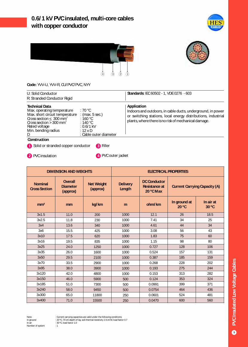
0.6/1 kV PVC insulated, multi-core cableswith copper conductor
Construction
Code: YVV-U, YVV-R, CU/PVC/PVC, NYY
U: Solid ConductorR: Stranded Conductor Rigid
Standards: IEC 60502 - 1, VDE 0276 - 603
Technical Data ApplicationIndoors and outdoors, in cable ducts, underground, in power or switching stations, local energy distributions, industrial plants, where there is no risk of mechanical damage.
Max. operating temperature : 70 °CMax. short circuit temperature : (max. 5 sec.)
Rated voltage : 0.6/1 kVMin. bending radius : 12 x DD : Cable outer diameter
2_Cross section < 300 mmCross section > 2300 mm : 140 °C
: 160 °C
1 3Solid or stranded copper conductor Filler
2 PVC insulation 4 PVC outer jacket
14 3 2
DIMENSION AND WEIGHTS ELECTRICAL PROPERTIES
Nominal Cross Section
Overall Diameter (approx)
Net Weight (approx)
Delivery Length
DC Conductor Resistance at
20 ºC MaxCurrent Carrying Capacity (A)
mm² mm kg/km m ohm/kmIn ground at
20 ºCIn air at
30 ºC
3x1.5
3x2.5
3x4
3x6
3x10
3x16
3x25
3x35
3x50
3x70
3x95
3x120
3x150
3x185
3x240
3x300
3x400
11.0
11.8
13.6
15.5
17.5
19.5
24.0
26.0
29.5
33.5
38.0
42.0
46.0
51.0
58.0
65.0
71.0
200
230
340
425
620
835
1250
1600
2100
2900
3900
4800
5900
7300
9450
11800
15500
1000
1000
1000
1000
1000
1000
1000
1000
1000
1000
1000
1000
500
500
500
250
250
12.1
7.41
4.61
3.08
1.83
1.15
0.727
0.524
0.387
0.268
0.193
0.153
0.124
0.0991
0.0754
0.0601
0.0470
26
34
44
56
75
98
128
157
185
228
275
313
353
399
464
524
600
18.5
25
34
43
60
80
106
131
159
202
244
282
324
371
436
481
560
Note : Current carrying capacities are valid under the following conditions;In ground : 20 ºC, 70 cm depth of lay, soil-thermal resistivity 1 K.m/W, load factor 0.7In air : 30 ºC, load factor 1.0Number of system : 1
PV
C In
sula
ted
Lo
w V
olt
age
Cab
les
10
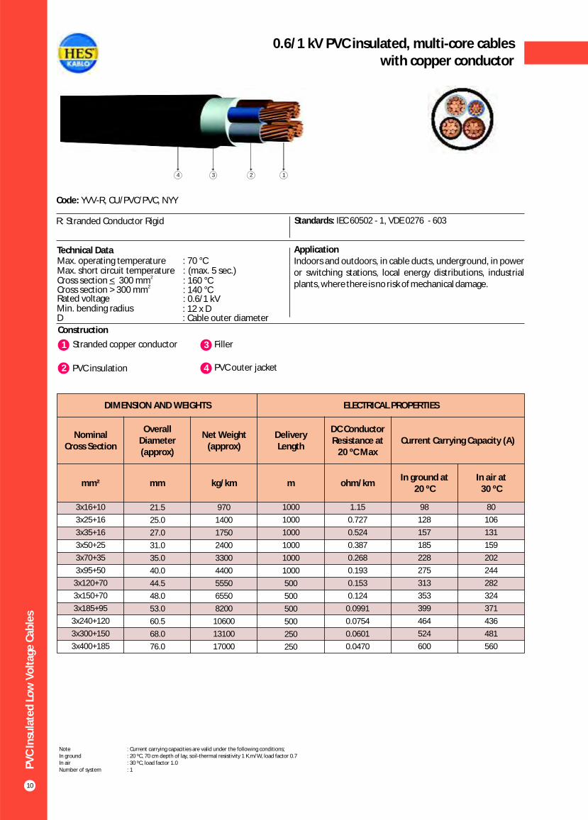
0.6/1 kV PVC insulated, multi-core cableswith copper conductor
Construction
1 3Stranded copper conductor Filler
Code: YVV-R, CU/PVC/PVC, NYY
R: Stranded Conductor Rigid Standards: IEC 60502 - 1, VDE 0276 - 603
Technical Data ApplicationIndoors and outdoors, in cable ducts, underground, in power or switching stations, local energy distributions, industrial plants, where there is no risk of mechanical damage.
2 PVC insulation 4 PVC outer jacket
Max. operating temperature : 70 °CMax. short circuit temperature : (max. 5 sec.)
Rated voltage : 0.6/1 kVMin. bending radius : 12 x DD : Cable outer diameter
2_Cross section < 300 mmCross section > 2300 mm : 140 °C
: 160 °C
134 2
DIMENSION AND WEIGHTS ELECTRICAL PROPERTIES
Nominal Cross Section
Overall Diameter (approx)
Net Weight (approx)
Delivery Length
DC Conductor Resistance at
20 ºC MaxCurrent Carrying Capacity (A)
mm² mm kg/km m ohm/kmIn ground at
20 ºCIn air at
30 ºC
3x16+10
3x25+16
3x35+16
3x50+25
3x70+35
3x95+50
3x120+70
3x150+70
3x185+95
3x240+120
3x300+150
3x400+185
21.5
25.0
27.0
31.0
35.0
40.0
44.5
48.0
53.0
60.5
68.0
76.0
970
1400
1750
2400
3300
4400
5550
6550
8200
10600
13100
17000
1000
1000
1000
1000
1000
1000
500
500
500
500
250
250
1.15
0.727
0.524
0.387
0.268
0.193
0.153
0.124
0.0991
0.0754
0.0601
0.0470
98
128
157
185
228
275
313
353
399
464
524
600
80
106
131
159
202
244
282
324
371
436
481
560
Note : Current carrying capacities are valid under the following conditions;In ground : 20 ºC, 70 cm depth of lay, soil-thermal resistivity 1 K.m/W, load factor 0.7In air : 30 ºC, load factor 1.0Number of system : 1

PV
C In
sula
ted
Lo
w V
olt
age
Cab
les
11
0.6/1 kV PVC insulated, multi-core cableswith copper conductor
Construction
Code: YVV-U, YVV-R, CU/PVC/PVC, NYY
U: Solid ConductorR: Stranded Conductor Rigid
Standards: IEC 60502 - 1, VDE 0276 - 603
Technical Data ApplicationIndoors and outdoors, in cable ducts, underground, in power or switching stations, local energy distributions, industrial plants, where there is no risk of mechanical damage.
Max. operating temperature : 70 °C Max. short circuit temperature : (max. 5 sec.)
Rated voltage : 0.6/1 kVMin. bending radius : 12 x DD : Cable outer diameter
2_Cross section < 300 mmCross section > 2300 mm : 140/1 kV
: 160/1 kV
1 3Solid or stranded copper conductor Filler
2 PVC insulation 4 PVC outer jacket
134 2
DIMENSION AND WEIGHTS ELECTRICAL PROPERTIES
Nominal Cross Section
Overall Diameter (approx)
Net Weight (approx)
Delivery Length
DC Conductor Resistance at
20 ºC MaxCurrent Carrying Capacity (A)
mm² mm kg/km m ohm/kmIn ground at
20 ºCIn air at
30 ºC
4x1.5
4x2.5
4x4
4x6
4x10
4x16
4x25
4x35
4x50
4x70
4x95
4x120
4x150
4x185
4x240
4x300
4x400
11.6
12.6
14.8
16.0
18.0
21.5
26.0
28.5
33.0
37.5
42.5
46.5
51.5
57.0
65.0
73.0
79.0
235
270
400
520
690
1050
1550
2000
2750
3750
5000
6200
7600
9450
12200
15200
19500
1000
1000
1000
1000
1000
1000
1000
1000
1000
1000
1000
500
500
500
500
250
250
12.1
7.41
4.61
3.08
1.83
1.15
0.727
0.524
0.387
0.268
0.193
0.153
0.124
0.0991
0.0754
0.0601
0.0470
26
34
44
56
75
98
128
157
185
228
275
313
353
399
464
524
600
18.5
25
34
43
60
80
106
131
159
202
244
282
324
371
436
481
560
Note : Current carrying capacities are valid under the following conditions;In ground : 20 ºC, 70 cm depth of lay, soil-thermal resistivity 1 K.m/W, load factor 0.7In air : 30 ºC, load factor 1.0Number of system : 1

PV
C In
sula
ted
Lo
w V
olt
age
Cab
les
12
0.6/1 kV PVC Insulated, multi-core cables,control cables with copper conductor
Construction
1 3Solid or stranded copper conductor Filler
Code: YVV-U, YVV-R, CU/PVC/PVC, NYY
U: Solid ConductorR: Stranded Conductor Rigid
Standards: IEC 60502 - 1, VDE 0271
ApplicationIndoors and outdoors, in cable ducts, underground, in power or switching stations, local energy distributions, industrial plants, where there is no risk of mechanical damage.
2 PVC insulation 4 PVC outer jacket
Technical DataMax. operating temperature : 70 °CMax. short circuit temperature : 160 °C (max. 5 sec.)
Rated voltage : 0.6/1 kV
Min. bending radius : 12 x DD : Cable outer diameter
14 3 2
DIMENSION AND WEIGHTS ELECTRICAL PROPERTIES
Nominal Cross Section
Overall Diameter (approx)
Net Weight (approx)
Delivery Length
DC Conductor Resistance at
20 ºC MaxCurrent Carrying Capacity (A)
mm² mm kg/km m ohm/kmIn ground at
20 ºCIn air at
30 ºC
5x1.5
6x1.5
7x1.5
8x1.5
10x1.5
12x1.5
14x1.5
16x1.5
19x1.5
21x1.5
24x1.5
27x1.5
30x1.5
37x1.5
40x1.5
48x1.5
52x1.5
61x1.5
13.5
13.5
13.5
16.0
16.5
17.0
18.0
18.5
19.5
20.5
22.5
23.0
24.5
26.5
27.5
30.0
31.0
33.0
270
290
325
385
475
515
565
630
700
775
920
975
1050
1230
1330
1600
1730
1975
1000
1000
1000
1000
1000
1000
1000
1000
1000
1000
1000
1000
1000
1000
1000
1000
1000
1000
12.1
12.1
12.1
12.1
12.1
12.1
12.1
12.1
12.1
12.1
12.1
12.1
12.1
12.1
12.1
12.1
12.1
12.1
18.2
16.9
15.6
14.3
13.0
12.3
11.7
11.1
10.4
9.9
9.1
8.8
8.6
8.1
7.8
7.3
6.7
6.5
14.0
13.0
12.0
11.1
10.2
9.7
9.3
8.8
8.3
8.0
7.4
7.2
7.0
6.7
6.5
6.1
5.8
5.6
Note : Current carrying capacities are valid under the following conditions;In ground : 20 ºC, 70 cm depth of lay, soil-thermal resistivity 1 K.m/W, load factor 0.7In air : 30 ºC, load factor 1.0Number of system : 1

PV
C In
sula
ted
Lo
w V
olt
age
Cab
les
13
0.6/1 kV PVC Insulated, multi-core cables,control cables with copper conductor
Construction
Code: YVV-U, YVV-R, CU/PVC/PVC, NYY
U: Solid ConductorR: Stranded Conductor Rigid
Standards: IEC 60502 - 1, VDE 0271
ApplicationIndoors and outdoors, in cable ducts, underground, in power or switching stations, local energy distributions, industrial plants, where there is no risk of mechanical damage.
1 3Solid or stranded copper conductor Filler
2 PVC insulation 4 PVC outer jacket
Technical DataMax. operating temperature : 70 °CMax. short circuit temperature : 160 °C (max. 5 sec.)
Rated voltage : 0.6/1 kV
Min. bending radius : 12 x DD : Cable outer diameter
14 3 2
DIMENSION AND WEIGHTS ELECTRICAL PROPERTIES
Nominal Cross Section
Overall Diameter (approx)
Net Weight (approx)
Delivery Length
DC Conductor Resistance at
20 ºC MaxCurrent Carrying Capacity (A)
mm² mm kg/km m ohm/kmIn ground at
20 ºCIn air at
30 ºC
5x2.5
6x2.5
7x2.5
8x2.5
10x2.5
12x2.5
14x2.5
16x2.5
19x2.5
21x2.5
24x2.5
27x2.5
30x2.5
37x2.5
40x2.5
48x2.5
52x2.5
61x2.5
13.5
14.5
14.5
17.0
18.0
18.5
19.5
20.5
21.5
22.5
24.8
25.3
27.0
29.5
30.5
32.5
34.5
37.0
320
375
415
500
595
650
730
825
920
1010
1190
1280
1380
1660
1800
2135
2320
2630
1000
1000
1000
1000
1000
1000
1000
1000
1000
1000
1000
1000
1000
1000
1000
1000
1000
1000
7.41
7.41
7.41
7.41
7.41
7.41
7.41
7.41
7.41
7.41
7.41
7.41
7.41
7.41
7.41
7.41
7.41
7.41
23.8
22.1
20.4
18.7
17.0
16.2
15.3
14.5
13.6
12.9
11.9
11.6
11.2
10.6
10.2
9.5
8.9
8.5
18.8
17.5
16.3
15.0
13.8
13.1
12.5
11.9
11.3
10.8
10.0
9.7
9.4
9.1
8.8
8.3
7.8
7.5
Note : Current carrying capacities are valid under the following conditions;In ground : 20 ºC, 70 cm depth of lay, soil-thermal resistivity 1 K.m/W, load factor 0.7In air : 30 ºC, load factor 1.0Number of system : 1

DIMENSION AND WEIGHTS ELECTRICAL PROPERTIES
Nominal Cross
Section
Overall Diameter (approx)
Net Weight (approx)
Delivery Length
DC Conductor Resistance at
20 ºC MaxCurrent Carrying Capacity (A)
mm² mm kg/km m ohm/kmIn ground at 20 ºC In air at 30 ºC
*** ** * *** ** *
PV
C In
sula
ted
Lo
w V
olt
age
Cab
les
14
0.6/1 kV PVC Insulated, concentric conductor screen,single core cables with copper conductor
Construction
Code: YVCV-U, YVCV-R, CU/PVC/SC/PVC, NYCY
U: Solid ConductorR: Stranded Conductor Rigid
Standards: IEC 60502 - 1, VDE 0276 - 603
Technical Data ApplicationIndoor installations, in cable ducts, outdoor and underground for power stations, industrial plants and switching stations as well as local supply systems if increased protection is necessary. In case of mechanical damage the screen prevents any damage due to power leak to the surrounding area.
1 3Solid or stranded copper conductor PVC inner sheath
2 PVC insulation 4 Concentric copper wire
5 Copper tape as binder
6 Polyester tape
Max. operating temperature : 70 °CMax. short circuit temperature : 160 °C (max. 5 sec.)
Rated voltage : 0.6/1 kV
Min. bending radius : 15 x DD : Cable outer diameter
7 PVC outer jacket
14 3 2567
1x1.5/1.5
1x2.5/2.5
1x4/4
1x6/6
1x10/10
1x16/16
1x25/16
1x35/16
1x50/25
1x70/35
1x95/50
1x120/70
1x150/70
1x185/95
1x240/120
10.5
11.0
12.0
12.5
13.5
15.0
16.5
17.5
19.0
21.0
23.5
25.5
27.0
30.0
33.5
145
150
200
250
350
450
600
700
950
1250
1650
2100
2400
3000
3850
1000
1000
1000
1000
1000
1000
1000
1000
1000
1000
1000
1000
1000
1000
1000
12.1
7.41
4.61
3.08
1.83
1.15
0.727
0.524
0.387
0.268
0.193
0.153
0.124
0.0991
0.0754
-
-
-
-
-
127
163
195
230
282
336
382
428
483
561
30
39
50
62
83
107
137
165
195
239
287
326
366
414
481
25
34
45
57
78
103
137
169
206
261
321
374
428
494
590
20
27
37
48
66
89
118
145
176
224
271
314
361
412
484
Note : Current carrying capacities are valid under the following conditions;In ground : 20 ºC, 70 cm depth of lay, soil-thermal resistivity 1 K.m/W, load factor 0.7In air : 30 ºC, load factor 1.0*** : Flat formation, clearance between cables; in air = 1 x Cable outer diameter, in ground = 7 cm : Trefoil formationNumber of system : 1
** *

PV
C In
sula
ted
Lo
w V
olt
age
Cab
les
15
0.6/1 kV PVC Insulated, concentric conductor screen,multi-core cables with copper conductor
Construction
Code: YVCV-U, YVCV-R, CU/PVC/SC/PVC, NYCY
U: Solid ConductorR: Stranded Conductor Rigid
Standards: IEC 60502 - 1, VDE 0276 - 603
Technical Data ApplicationIndoor installations, in cable ducts, outdoor and underground for power stations, industrial plants and switching stations as well as local supply systems if increased protection is necessary. In case of mechanical damage the screen prevents any damage due to power leak to the surrounding area.
1 3Solid or stranded copper conductor Filler
2 PVC insulation 4 Concentric copper wire
5 Copper tape as binder
6 Polyester tape
7 PVC outer jacket
Max. operating temperature : 70 °CMax. short circuit temperature : 160 °C (max. 5 sec.)
Rated voltage : 0.6/1 kV
Min. bending radius : 15 x DD : Cable outer diameter
134 2567
DIMENSION AND WEIGHTS ELECTRICAL PROPERTIES
Nominal Cross Section
Overall Diameter (approx)
Net Weight (approx)
Delivery Length
DC Conductor Resistance at
20 ºC MaxCurrent Carrying Capacity (A)
mm² mm kg/km m ohm/kmIn ground at
20 ºC In air at
30 ºC
2x1.5/1.5
2x2.5/2.5
2x4/4
2x6/6
2x10/10
2x16/16
2x25/16
2x35/16
2x50/25
2x70/35
2x95/50
2x120/70
2x150/70
2x185/95
2x240/120
13.0
13.5
15.5
16.5
19.0
21.0
24.0
26.0
29.0
32.5
37.5
41.5
45.0
50.5
57.0
240
250
280
420
600
850
1150
1400
1900
2550
3450
4300
5100
6450
8300
1000
1000
1000
1000
1000
1000
1000
1000
1000
1000
1000
1000
500
500
500
12.1
7.41
4.61
3.08
1.83
1.15
0.727
0.524
0.3870
0.268
0.193
0.153
0.124
0.0991
0.0754
32
42
54
68
90
116
150
181
215
264
317
360
406
458
537
20
27
37
48
66
89
118
145
176
224
271
314
361
412
484
Note : Current carrying capacities are valid under the following conditions;In ground : 20 ºC, 70 cm depth of lay, soil-thermal resistivity 1 K.m/W, load factor 0.7In air : 30 ºC, load factor 1.0Number of system : 1

PV
C In
sula
ted
Lo
w V
olt
age
Cab
les
16
0.6/1 kV PVC Insulated, concentric conductor screen,multi-core cables with copper conductor
Construction
Code: YVCV-U, YVCV-R, CU/PVC/SC/PVC, NYCY
U: Solid ConductorR: Stranded Conductor Rigid
Standards: IEC 60502 - 1, VDE 0276 - 603
Technical Data ApplicationIndoor installations, in cable ducts, outdoor and underground for power stations, industrial plants and switching stations as well as local supply systems if increased protection is necessary. In case of mechanical damage the screen prevents any damage due to power leak to the surrounding area.
1 3Solid or stranded copper conductor Filler
2 PVC insulation 4 Concentric copper wire
5 Copper tape as binder
6 Polyester tape
Max. operating temperature : 70 °CMax. short circuit temperature : 160 °C (max. 5 sec.)
Rated voltage : 0.6/1 kV
Min. bending radius : 15 x DD : Cable outer diameter
7 PVC outer jacket
167 2345
DIMENSION AND WEIGHTS ELECTRICAL PROPERTIES
Nominal Cross Section
Overall Diameter (approx)
Net Weight (approx)
Delivery Length
DC Conductor Resistance at
20 ºC MaxCurrent Carrying Capacity (A)
mm² mm kg/km m ohm/kmIn ground at
20 ºC In air at
30 ºC
3x1.5/1.5
3x2.5/2.5
3x4/4
3x6/6
3x10/10
3x16/16
3x25/16
3x35/16
3x50/25
3x70/35
3x95/50
3x120/70
3x150/70
3x185/95
3x240/120
3x300/150
3x400/185
14.0
15.0
17.0
17.5
20.0
22.0
25.5
27.5
31.0
35.0
39.5
43.5
47.5
52.0
59.5
66.5
78.0
240
300
420
530
730
1000
1400
1750
2350
3200
4300
5350
6450
8000
10350
12850
17300
1000
1000
1000
1000
1000
1000
1000
1000
1000
1000
1000
500
500
500
250
250
250
12.1
7.410
4.610
3.080
1.830
1.150
0.727
0.524
0.387
0.268
0.193
0.153
0.124
0.0991
0.0754
0.0601
0.0470
26
34
44
56
75
98
128
157
185
228
275
313
353
399
464
524
600
18.5
25
34
43
60
80
106
131
159
202
244
282
324
371
436
481
560
Note : Current carrying capacities are valid under the following conditions;In ground : 20 ºC, 70 cm depth of lay, soil-thermal resistivity 1 K.m/W, load factor 0.7In air : 30 ºC, load factor 1.0Number of system : 1

PV
C In
sula
ted
Lo
w V
olt
age
Cab
les
17
0.6/1 kV PVC Insulated, concentric conductor screen,multi-core cables with copper conductor
Construction
Code: YVCV-U, YVCV-R, CU/PVC/SC/PVC, NYCY
U: Solid ConductorR: Stranded Conductor Rigid
Standards: IEC 60502 - 1, VDE 0276 - 603
Technical Data ApplicationIndoor installations, in cable ducts, outdoor and underground for power stations, industrial plants and switching stations as well as local supply systems if increased protection is necessary. In case of mechanical damage the screen prevents any damage due to power leak to the surrounding area.
1 3Solid or stranded copper conductor Filler
2 PVC insulation 4 Concentric copper wire
5 Copper tape as binder
6 Polyester tape
Max. operating temperature : 70 °CMax. short circuit temperature : 160 °C (max. 5 sec.)
Rated voltage : 0.6/1 kV
Min. bending radius : 15 x DD : Cable outer diameter
7 PVC outer jacket
167 2345
DIMENSION AND WEIGHTS ELECTRICAL PROPERTIES
Nominal Cross Section
Overall Diameter (approx)
Net Weight (approx)
Delivery Length
DC Conductor Resistance at
20 ºC MaxCurrent Carrying Capacity (A)
mm² mm kg/km m ohm/kmIn ground at
20 ºC In air at
30 ºC
4x1.5/1.5
4x2.5/2.5
4x4/4
4x6/6
4x10/10
4x16/10
4x25/16
4x35/16
4x50/25
4x70/35
4x95/50
4x120/70
4x150/70
4x185/95
4x240/120
4x300/150
4x400/185
14.5
15.5
17.5
18.5
22.0
24.0
28.0
30.0
34.0
39.0
46.0
50.0
54.0
61.0
69.0
74.0
83.0
290
350
490
600
890
1200
1750
2200
3000
4050
5500
6900
8300
10400
13300
16300
20500
1000
1000
1000
1000
1000
1000
1000
1000
1000
1000
500
500
500
250
250
250
250
12.1
7.41
4.61
3.08
1.83
1.15
0.727
0.524
0.387
0.268
0.193
0.153
0.124
0.0991
0.0754
0.0601
0.0470
26
34
44
56
75
98
128
157
185
228
275
313
353
399
464
524
600
18.5
25
34
43
60
80
106
131
159
202
244
282
324
371
436
481
560
Note : Current carrying capacities are valid under the following conditions;In ground : 20 ºC, 70 cm depth of lay, soil-thermal resistivity 1 K.m/W, load factor 0.7In air : 30 ºC, load factor 1.0Number of system : 1

PV
C In
sula
ted
Lo
w V
olt
age
Cab
les
18
0.6/1 kV PVC Insulated, concentric conductor screen,control cables with copper conductor
Construction
Code: YVCV-U, YVCV-R, CU/PVC/SC/PVC, NYCY
U: Solid ConductorR: Stranded Conductor Rigid
Standards: IEC 60502 - 1, VDE 0271
Technical Data Application Used as control cables, indoor installations, in cable ducts, outdoor and underground for power stations, industrial plants and switching stations as well as local supply systems if increased protection is necessary. In case of mechanical damage the screen prevents any damage due to power leak to the surrounding area.
1 3Solid or stranded copper conductor Filler
2 PVC insulation 4 Concentric copper wire
5 Copper tape as binder
6 Polyester tape
7 PVC outer jacket
Max. operating temperature : 70 °CMax. short circuit temperature : 160 °C (max. 5 sec.)
Rated voltage : 0.6/1 kV
Min. bending radius : 15 x DD : Cable outer diameter
147 5 236
DIMENSION AND WEIGHTS ELECTRICAL PROPERTIES
Nominal Cross Section
Overall Diameter (approx)
Net Weight (approx)
Delivery Length
DC Conductor Resistance at
20 ºC MaxCurrent Carrying Capacity (A)
mm² mm kg/km m ohm/kmIn ground at
20 ºCIn air at
30 ºC
7x1.5/2.5 8x1.5/2.5
10x1.5/2.5 12x1.5/2.514x1.5/2.5 19x1.5/4 24x1.5/6 27x1.5/6 30x1.5/6
37x1.5/10 7x2.5/2.5 8x2.5/2.5 10x2.5/4 12x2.5/4
14x2.5/2.5 19x2.5/6
24x2.5/10 27x2.5/10 30x2.5/10 37x2.5/10
7x4/4 8x4/6
10x4/6 12x4/6 14x4/6
19x4/10
16.0 18.2 19.0 19.5 20.0 22.0 25.0 26.0 26.5 28.0 17.5 20.5 21.0 22.0 22.3 24.3 28.5 28.0 29.0 31.0 20.0 23.0 24.5 25.0 25.528.0
350400500 550600750
1000100011001350450550650700800
10001350147015501800650800950
10501200 1500
10001000100010001000100010001000100010001000100010001000100010001000100010001000100010001000100010001000
12.1 12.1 12.1 12.1 12.1 12.1 12.1 12.1 12.1 12.1 7.41 7.41 7.41 7.41 7.417.41 7.41 7.41 7.41 7.41 4.61 4.61 4.61 4.61 4.61 4.61
15.6 14.313.0 12.3 11.7 10.4 9.18.8 8.68.1
20.4 18.7 17.0 16.215.313.6 11.9 11.511.2 10.626.4 24.222.0 20.9 19.817.6
12.011.110.29.79.38.37.47.27.06.7
16.315.013.813.112.511.310.09.89.49.1
22.120.418.717.917.015.3
Note : Current carrying capacities are valid under the following conditions;In ground : 20 ºC, 70 cm depth of lay, soil-thermal resistivity 1 K.m/W, load factor 0.7In air : 30 ºC, load factor 1.0Number of system : 1

PV
C In
sula
ted
Lo
w V
olt
age
Cab
les
19
0.6/1 kV PVC Insulated, concentric conductor screen,multi-core cables with copper conductor
Construction
Code: YVCV-U, YVCV-R, CU/PVC/SC/PVC, NYCY
U: Solid ConductorR: Stranded Conductor Rigid
Standards: IEC 60502 - 1, VDE 0276 - 603
Technical Data ApplicationIndoor installations, in cable ducts, outdoor and underground for power stations, industrial plants and switching stations as well as local supply systems if increased protection is necessary. In case of mechanical damage the screen prevents any damage due to power leak to the surrounding area.
1 3Solid or stranded copper conductor Filler
2 PVC insulation 4 Concentric copper wire
5 Copper tape as binder. (100% coverage with overlap)
6 Polyester tape
Max. operating temperature : 70 °CMax. short circuit temperature : 160 °C (max. 5 sec.)
Rated voltage : 0.6/1 kV
Min. bending radius : 15 x DD : Cable outer diameter
7 PVC outer jacket
167 2345
DIMENSION AND WEIGHTS ELECTRICAL PROPERTIES
Nominal Cross Section
Overall Diameter (approx)
Net Weight (approx)
Delivery Length
DC Conductor Resistance at
20 ºC MaxCurrent Carrying Capacity (A)
mm² mm kg/km m ohm/kmIn ground at
20 ºC In air at
30 ºC
2x1.5/9
2x2.5/9
2x4/9
2x6/9
2x10/9
3x1.5/9
3x2.5/9
3x4/9
3x6/9
3x10/9
4x1.5/9
4x2.5/9
4x4/9
4x6/9
4x10/9
5x1.5/9
5x2.5/9
5x4/9
13.0
13.5
15.5
16.5
19.0
14.0
15.0
17.0
18.5
20.0
14.5
15.5
17.5
18.5
22.0
15.0
16.0
18.0
270
320
420
490
670
300
360
480
590
720
350
410
550
660
880
360
440
600
1000
1000
1000
1000
1000
1000
1000
1000
1000
1000
1000
1000
1000
1000
1000
1000
1000
1000
12.1
7.41
4.61
3.08
1.83
12.1
7.41
4.61
3.08
1.83
12.1
7.41
4.61
3.08
1.83
12.1
7.41
4.61
32
42
54
68
90
26
34
44
56
75
26
34
44
56
75
26
34
44
20
27
37
48
66
18.5
25
34
43
60
18.5
25
34
43
60
18.5
25
34
Note : Current carrying capacities are valid under the following conditions;In ground : 20 ºC, 70 cm depth of lay, soil-thermal resistivity 1 K.m/W, load factor 0.7In air : 30 ºC, load factor 1.0Number of system : 1
PV
C In
sula
ted
Lo
w V
olt
age
Cab
les
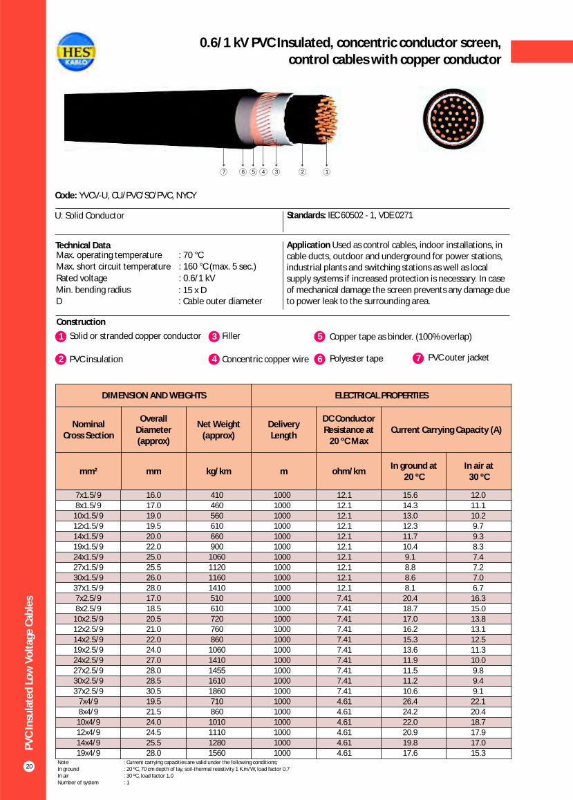
20
0.6/1 kV PVC Insulated, concentric conductor screen,control cables with copper conductor
Construction
Code: YVCV-U, CU/PVC/SC/PVC, NYCY
U: Solid Conductor Standards: IEC 60502 - 1, VDE 0271
Technical Data Application Used as control cables, indoor installations, in cable ducts, outdoor and underground for power stations, industrial plants and switching stations as well as local supply systems if increased protection is necessary. In case of mechanical damage the screen prevents any damage due to power leak to the surrounding area.
1 3Solid or stranded copper conductor Filler
2 PVC insulation 4 Concentric copper wire
5 Copper tape as binder. (100% overlap)
6 Polyester tape 7 PVC outer jacket
Max. operating temperature : 70 °CMax. short circuit temperature : 160 °C (max. 5 sec.)
Rated voltage : 0.6/1 kV
Min. bending radius : 15 x DD : Cable outer diameter
147 5 236
DIMENSION AND WEIGHTS ELECTRICAL PROPERTIES
Nominal Cross Section
Overall Diameter (approx)
Net Weight (approx)
Delivery Length
DC Conductor Resistance at
20 ºC MaxCurrent Carrying Capacity (A)
mm² mm kg/km m ohm/kmIn ground at
20 ºCIn air at
30 ºC
7x1.5/98x1.5/9
10x1.5/912x1.5/914x1.5/9 19x1.5/9 24x1.5/927x1.5/930x1.5/937x1.5/9 7x2.5/9 8x2.5/9
10x2.5/912x2.5/9 14x2.5/9 19x2.5/924x2.5/927x2.5/930x2.5/9 37x2.5/9
7x4/9 8x4/9
10x4/9 12x4/914x4/9 19x4/9
16.0 17.0 19.0 19.5 20.0 22.0 25.0 25.526.0 28.0 17.0 18.5 20.5 21.0 22.0 24.0 27.0 28.0 28.5 30.5 19.5 21.5 24.0 24.5 25.5 28.0
410460560610660900
1060112011601410510610720760860
10601410145516101860710860
1010111012801560
10001000100010001000100010001000100010001000100010001000100010001000100010001000100010001000100010001000
12.1 12.1 12.1 12.1 12.1 12.1 12.1 12.1 12.1 12.1 7.41 7.41 7.41 7.41 7.417.41 7.41 7.41 7.41 7.41 4.61 4.61 4.61 4.61 4.61 4.61
15.6 14.313.0 12.3 11.7 10.4 9.18.88.68.1
20.4 18.7 17.0 16.215.313.6 11.9 11.511.2 10.626.4 24.222.0 20.9 19.817.6
12.011.110.29.79.38.37.47.27.06.7
16.315.013.813.112.511.310.09.89.49.1
22.120.418.717.917.015.3
Note : Current carrying capacities are valid under the following conditions;In ground : 20 ºC, 70 cm depth of lay, soil-thermal resistivity 1 K.m/W, load factor 0.7In air : 30 ºC, load factor 1.0Number of system : 1

DIMENSION AND WEIGHTS ELECTRICAL PROPERTIES
Nominal Cross
Section
Overall Diameter (approx)
Net Weight (approx)
Delivery Length
DC Conductor Resistance at
20 ºC MaxCurrent Carrying Capacity (A)
mm² mm kg/km m ohm/kmIn ground at 20 ºC In air at 30 ºC
*** ** * *** ** *
PV
C In
sula
ted
Lo
w V
olt
age
Cab
les
21
0.6 / 1 kV PVC insulated, round aluminium wire armoured,single core cables with copper conductor
Construction
Code: YVY2V-R, CU/PVC/AWA/PVC, NYR(A)Y
R: Stranded Conductor Rigid Standards: IEC 60502 - 1, VDE 0276 - 603, BS 6346
Technical Data ApplicationIndoors and outdoors, in cable ducts, underground, in power or switching stations, local energy distributions, industrial plants, where there is risk of mechanical damage.
1 3Stranded copper conductors Inner sheath
2 PVC insulation 4 Round aluminium wire
5 Polyester tape
6 PVC outer jacket
Max. operating temperature : 70 °CMax. short circuit temperature : (max. 5 sec.)
Rated voltage : 0.6/1 kVMin. bending radius : 15 x DD : Cable outer diameter
2_Cross section < 300 mm2Cross section > 300 mm : 140 °C
: 160 °C
123456
1x25
1x35
1x50
1x70
1x95
1x120
1x150
1x185
1x240
1x300
1x400
1x500
1x630
17.5
18.5
20.0
21.5
24.5
26.0
27.5
30.0
33.0
37.5
41.5
46.0
50.0
550
650
800
1050
1400
1650
2000
2400
3050
3750
4750
5850
7450
1000
1000
1000
1000
1000
1000
1000
1000
1000
1000
500
500
500
0.727
0.524
0.387
0.268
0.193
0.153
0.124
0.0991
0.0754
0.0601
0.0470
0.0366
0.0283
163
195
230
282
336
382
428
483
561
632
730
823
866
137
165
195
239
287
326
366
414
481
542
624
698
775
137
169
206
261
321
374
428
494
590
678
817
940
1108
118
145
176
224
271
314
361
412
484
549
657
749
920
Note : Current carrying capacities are valid under the following conditions;In ground : 20 ºC, 70 cm depth of lay, soil-thermal resistivity 1 K.m/W, load factor 0.7In air : 30 ºC, load factor 1.0*** : Flat formation, clearance between cables; in air = 1 x Cable outer diameter, in ground = 7 cm : Trefoil formationNumber of system : 1
** *
PV
C In
sula
ted
Lo
w V
olt
age
Cab
les
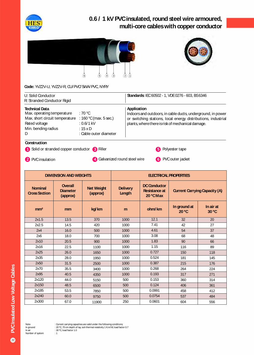
22
0.6 / 1 kV PVC insulated, round steel wire armoured,multi-core cables with copper conductor
Construction
Code: YVZ2V-U, YVZ2V-R, CU/PVC/SWA/PVC, NYRY
U: Solid ConductorR: Stranded Conductor Rigid
Standards: IEC 60502 - 1, VDE 0276 - 603, BS 6346
Technical Data ApplicationIndoors and outdoors, in cable ducts, underground, in power or switching stations, local energy distributions, industrial plants, where there is risk of mechanical damage.
Max. operating temperature : 70 °CMax. short circuit temperature : 160 °C (max. 5 sec.)
Rated voltage : 0.6/1 kV
Min. bending radius : 15 x DD : Cable outer diameter
1 3Solid or stranded copper conductor Filler
2 PVC insulation 4 Galvanized round steel wire
5 Polyester tape
6 PVC outer jacket
156 234
DIMENSION AND WEIGHTS ELECTRICAL PROPERTIES
Nominal Cross Section
Overall Diameter (approx)
Net Weight (approx)
Delivery Length
DC Conductor Resistance at
20 ºC MaxCurrent Carrying Capacity (A)
mm² mm kg/km m ohm/kmIn ground at
20 ºCIn air at
30 ºC
20
27
37
48
66
89
118
145
176
224
271
314
361
412
484
556
2x1.5
2x2.5
2x4
2x6
2x10
2x16
2x25
2x35
2x50
2x70
2x95
2x120
2x150
2x185
2x240
2x300
13.5
14.5
16.0
18.0
20.5
22.5
26.0
28.0
31.5
35.5
40.5
44.0
48.5
53.5
60.0
67.0
370
420
500
700
900
1100
1650
1950
2500
3400
4350
5150
6500
7850
9750
11900
1000
1000
1000
1000
1000
1000
1000
1000
1000
1000
1000
500
500
500
500
250
12.1
7.41
4.61
3.08
1.83
1.15
0.727
0.524
0.387
0.268
0.193
0.153
0.124
0.0991
0.0754
0.0601
32
42
54
68
90
116
150
181
215
264
317
360
406
458
537
604
Note : Current carrying capacities are valid under the following conditions;In ground : 20 ºC, 70 cm depth of lay, soil-thermal resistivity 1 K.m/W, load factor 0.7In air : 30 ºC, load factor 1.0Number of system : 1

PV
C In
sula
ted
Lo
w V
olt
age
Cab
les
23
0.6 / 1 kV PVC insulated, round steel wire armoured,multi-core cables with copper conductor
Construction
Code: YYVZ2V-U, YVZ2V-R, CU/PVC/SWA/PVC, NYRY
U: Solid ConductorR: Stranded Conductor Rigid
Standards: IEC 60502 - 1, VDE 0276 - 603, BS 6346
Technical Data ApplicationIndoors and outdoors, in cable ducts, underground, in power or switching stations, local energy distributions, industrial plants, where there is risk of mechanical damage.
1 3Solid or stranded copper conductor Filler
2 PVC insulation 4 Galvanized round steel wire
5 Polyester tape
6 PVC outer jacket
Max. operating temperature : 70 °CMax. short circuit temperature : (max. 5 sec.)
Rated voltage : 0.6/1 kVMin. bending radius : 15 x DD : Cable outer diameter
2_Cross section < 300 mm2Cross section > 300 mm : 140 °C
: 160 °C
123456
DIMENSION AND WEIGHTS ELECTRICAL PROPERTIES
Nominal Cross Section
Overall Diameter (approx)
Net Weight (approx)
Delivery Length
DC Conductor Resistance at
20 ºC MaxCurrent Carrying Capacity (A)
mm² mm kg/km m ohm/kmIn ground at
20 ºCIn air at
30 ºC
18.5
25
34
43
60
80
106
131
159
202
244
282
324
371
436
481
560
3x1.5
3x2.5
3x4
3x6
3x10
3x16
3x25
3x35
3x50
3x70
3x95
3x120
3x150
3x185
3x240
3x300
3x400
14.0
15.0
17.5
18.5
21.5
23.5
27.5
29.5
33.5
38.0
43.0
46.5
52.0
57.0
64.0
72.0
82.0
400
420
670
780
1050
1300
1950
2350
3050
4200
5350
6400
8150
9750
12250
15000
20000
1000
1000
1000
1000
1000
1000
1000
1000
1000
1000
500
500
500
500
250
250
250
12.1
7.41
4.61
3.08
1.83
1.15
0.727
0.524
0.387
0.268
0.193
0.153
0.124
0.0991
0.0754
0.0601
0.0470
26
34
44
56
75
98
128
157
185
228
275
313
353
399
464
524
600
Note : Current carrying capacities are valid under the following conditions;In ground : 20 ºC, 70 cm depth of lay, soil-thermal resistivity 1 K.m/W, load factor 0.7In air : 30 ºC, load factor 1.0Number of system : 1

PV
C In
sula
ted
Lo
w V
olt
age
Cab
les
24
0.6 / 1 kV PVC insulated, round steel wire armoured,multi-core cables with copper conductor
Construction
Code: YVZ2V-R, CU/PVC/SWA/PVC, NYRY
R: Stranded Conductor Rigid Standards: IEC 60502 - 1, VDE 0276 - 603, BS 6346
Technical Data ApplicationIndoors and outdoors, in cable ducts, underground, in power or switching stations, local energy distributions, industrial plants, where there is risk of mechanical damage.
1 3Solid or stranded copper conductor Filler
2 PVC insulation 4 Galvanized round steel wire
5 Polyester tape
6 PVC outer jacket
Max. operating temperature : 70 °CMax. short circuit temperature : (max. 5 sec.)
Rated voltage : 0.6/1 kVMin. bending radius : 15 x DD : Cable outer diameter
2_Cross section < 300 mm2Cross section > 300 mm : 140 °C
: 160 °C
146 235
DIMENSION AND WEIGHTS ELECTRICAL PROPERTIES
Nominal Cross Section
Overall Diameter (approx)
Net Weight (approx)
Delivery Length
DC Conductor Resistance at
20 ºC MaxCurrent Carrying Capacity (A)
mm² mm kg/km m ohm/kmIn ground at
20 ºCIn air at
30 ºC
80
106
131
159
202
244
282
324
371
436
481
560
3x16+10
3x25+16
3x35+16
3x50+25
3x70+35
3x95+50
3x120+70
3x150+70
3x185+95
3x240+120
3x300+150
3x400+185
25.5
28.5
30.5
35.5
39.5
44.5
50.5
53.5
59.0
66.5
73.5
84.0
1600
2150
2550
3600
4650
5950
7700
8900
10800
13500
16500
21800
1000
1000
1000
1000
500
500
250
250
250
250
250
250
1.15
0.727
0.524
0.387
0.268
0.193
0.153
0.124
0.0991
0.0754
0.0601
0.0470
98
128
157
185
228
275
313
353
399
464
524
600
Note : Current carrying capacities are valid under the following conditions;In ground : 20 ºC, 70 cm depth of lay, soil-thermal resistivity 1 K.m/W, load factor 0.7In air : 30 ºC, load factor 1.0Number of system : 1
PV
C In
sula
ted
Lo
w V
olt
age
Cab
les
25
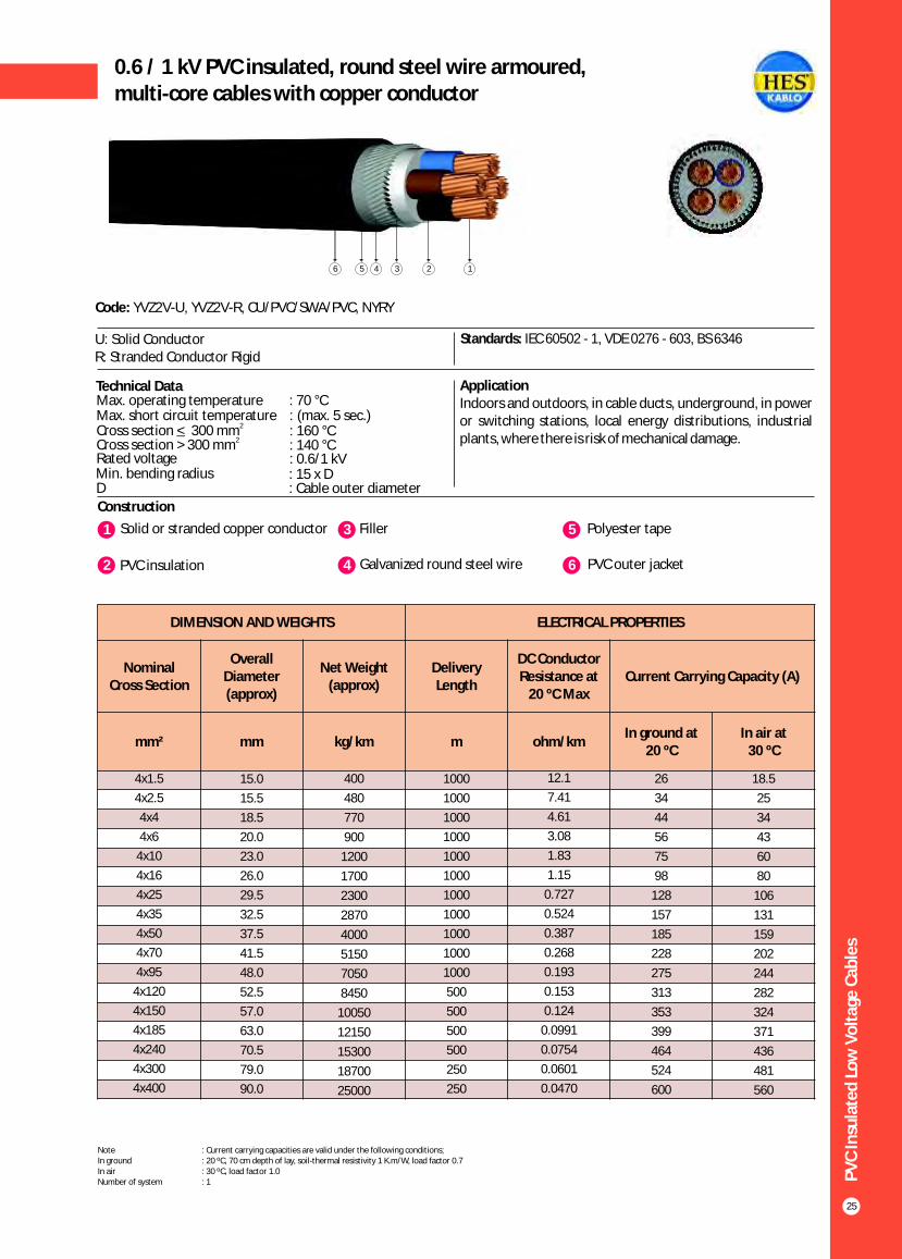
0.6 / 1 kV PVC insulated, round steel wire armoured,multi-core cables with copper conductor
Construction
Code: YVZ2V-U, YVZ2V-R, CU/PVC/SWA/PVC, NYRY
U: Solid ConductorR: Stranded Conductor Rigid
Standards: IEC 60502 - 1, VDE 0276 - 603, BS 6346
Technical Data ApplicationIndoors and outdoors, in cable ducts, underground, in power or switching stations, local energy distributions, industrial plants, where there is risk of mechanical damage.
Max. operating temperature : 70 °CMax. short circuit temperature : (max. 5 sec.)
Rated voltage : 0.6/1 kVMin. bending radius : 15 x DD : Cable outer diameter
2_Cross section < 300 mm2Cross section > 300 mm : 140 °C
: 160 °C
1 3Solid or stranded copper conductor Filler
2 PVC insulation 4 Galvanized round steel wire
5 Polyester tape
6 PVC outer jacket
15 2346
DIMENSION AND WEIGHTS ELECTRICAL PROPERTIES
Nominal Cross Section
Overall Diameter (approx)
Net Weight (approx)
Delivery Length
DC Conductor Resistance at
20 ºC MaxCurrent Carrying Capacity (A)
mm² mm kg/km m ohm/kmIn ground at
20 ºCIn air at
30 ºC
18.5
25
34
43
60
80
106
131
159
202
244
282
324
371
436
481
560
4x1.5
4x2.5
4x4
4x6
4x10
4x16
4x25
4x35
4x50
4x70
4x95
4x120
4x150
4x185
4x240
4x300
4x400
15.0
15.5
18.5
20.0
23.0
26.0
29.5
32.5
37.5
41.5
48.0
52.5
57.0
63.0
70.5
79.0
90.0
400
480
770
900
1200
1700
2300
2870
4000
5150
7050
8450
10050
12150
15300
18700
25000
1000
1000
1000
1000
1000
1000
1000
1000
1000
1000
1000
500
500
500
500
250
250
12.1
7.41
4.61
3.08
1.83
1.15
0.727
0.524
0.387
0.268
0.193
0.153
0.124
0.0991
0.0754
0.0601
0.0470
26
34
44
56
75
98
128
157
185
228
275
313
353
399
464
524
600
Note : Current carrying capacities are valid under the following conditions;In ground : 20 ºC, 70 cm depth of lay, soil-thermal resistivity 1 K.m/W, load factor 0.7In air : 30 ºC, load factor 1.0Number of system : 1

PV
C In
sula
ted
Lo
w V
olt
age
Cab
les
26
0.6/1 kV PVC Insulated, round steel wire armoured,control cables with copper conductor
Construction
Code: YVZ2V-U, YVZ2V-R, CU/PVC/SWA/PVC, NYRY
U: Solid ConductorR: Stranded Conductor Rigid
Standards: IEC 60502 - 1, VDE 0271, BS 6346
Technical Data ApplicationIndoors and outdoors, in cable ducts, underground, in power or switching stations, local energy distributions, industrial plants, where there is risk of mechanical damage.
1 3Solid or stranded copper conductor Filler
2 PVC insulation 4 Galvanized round steel wire
5 Polyester tape
6 PVC outer jacket
Max. operating temperature : 70 °CMax. short circuit temperature : 160 °C (max. 5 sec.)
Rated voltage : 0.6/1 kV
Min. bending radius : 15 x DD : Cable outer diameter
146 235
DIMENSION AND WEIGHTS ELECTRICAL PROPERTIES
Nominal Cross Section
Overall Diameter (approx)
Net Weight (approx)
Delivery Length
DC Conductor Resistance at
20 ºC MaxCurrent Carrying Capacity (A)
mm² mm kg/km m ohm/kmIn ground at
20 ºCIn air at
30 ºC
14.0
13.0
12.0
11.1
10.2
9.7
9.3
8.8
8.3
8.0
7.4
7.2
7.0
6.7
6.5
6.1
5.8
5.6
5x1.5
6x1.5
7x1.5
8x1.5
10x1.5
12x1.5
14x1.5
16x1.5
19x1.5
21x1.5
24x1.5
27x1.5
30x1.5
37x1.5
40x1.5
48x1.5
52x1.5
61x1.5
15.5
16.5
16.5
18.5
20.5
21.0
21.5
22.5
24.0
25.0
27.0
27.5
28.0
30.0
31.0
34.5
36.0
37.5
460
520
530
820
870
920
1000
1100
1300
1400
1600
1700
1800
2050
2150
2750
2950
3250
1000
1000
1000
1000
1000
1000
1000
1000
1000
1000
1000
1000
1000
1000
1000
1000
1000
1000
12.1
12.1
12.1
12.1
12.1
12.1
12.1
12.1
12.1
12.1
12.1
12.1
12.1
12.1
12.1
12.1
12.1
12.1
18.2
16.9
15.6
14.3
13.0
12.3
11.7
11.1
10.4
9.9
9.1
8.8
8.6
8.1
7.8
7.3
6.7
6.5
Note : Current carrying capacities are valid under the following conditions;In ground : 20 ºC, 70 cm depth of lay, soil-thermal resistivity 1 K.m/W, load factor 0.7In air : 30 ºC, load factor 1.0Number of system : 1

PV
C In
sula
ted
Lo
w V
olt
age
Cab
les
27
0.6/1 kV PVC Insulated, round steel wire armoured,control cables with copper conductor
Construction
Code: YVZ2V-U, YVZ2V-R, CU/PVC/SWA/PVC, NYRY
U: Solid ConductorR: Stranded Conductor Rigid
Standards: IEC 60502 - 1, VDE 0271, BS 6346
Technical Data ApplicationIndoors and outdoors, in cable ducts, underground, in power or switching stations, local energy distributions, industrial plants, where there is risk of mechanical damage.
1 3Solid or stranded copper conductor Filler
2 PVC insulation 4 Galvanized round steel wire
5 Polyester tape
6 PVC outer jacket
Max. operating temperature : 70 °CMax. short circuit temperature : 160 °C (max. 5 sec.)
Rated voltage : 0.6/1 kV
Min. bending radius : 15 x DD : Cable outer diameter
146 235
DIMENSION AND WEIGHTS ELECTRICAL PROPERTIES
Nominal Cross Section
Overall Diameter (approx)
Net Weight (approx)
Delivery Length
DC Conductor Resistance at
20 ºC MaxCurrent Carrying Capacity (A)
mm² mm kg/km m ohm/kmIn ground at
20 ºCIn air at
30 ºC
18.8
17.5
16.3
15.0
13.8
13.1
12.5
11.9
11.3
10.8
10.0
9.7
9.4
9.1
8.8
8.3
7.8
7.5
5x2.5
6x2.5
7x2.5
8x2.5
10x2.5
12x2.5
14x2.5
16x2.5
19x2.5
21x2.5
24x2.5
27x2.5
30x2.5
37x2.5
40x2.5
48x2.5
52x2.5
61x2.5
16.5
18.5
18.0
20.0
22.0
22.5
24.0
25.0
26.0
27.0
29.5
30.0
31.0
33.0
35.0
38.5
39.5
41.5
550
750
760
880
1050
1100
1350
1500
1600
1750
2000
2100
2250
2600
3800
3550
3700
4150
1000
1000
1000
1000
1000
1000
1000
1000
1000
1000
1000
1000
1000
1000
1000
1000
1000
1000
7.41
7.41
7.41
7.41
7.41
7.41
7.41
7.41
7.41
7.41
7.41
7.41
7.41
7.41
7.41
7.41
7.41
7.41
23.8
22.1
20.4
18.7
17.0
16.2
15.3
14.5
13.6
12.9
11.9
11.6
11.2
10.6
10.2
9.5
8.9
8.5
Note : Current carrying capacities are valid under the following conditions;In ground : 20 ºC, 70 cm depth of lay, soil-thermal resistivity 1 K.m/W, load factor 0.7In air : 30 ºC, load factor 1.0Number of system : 1

PV
C In
sula
ted
Lo
w V
olt
age
Cab
les
28
0.6/1 kV PVC Insulated, flat steel wire armoured,multi-core cables with copper conductor
Construction
Code: YVZ3V-R, NYFGY
R: Stranded Conductor Rigid Standards: IEC 60502 - 1, VDE 0276 - 603
Technical Data ApplicationIndoors and outdoors, in cable ducts, underground, in power or switching stations, local energy distributions, industrial plants, where there is risk of mechanical damage.
1 3Stranded copper conductors Filler
2 PVC insulation 4 Galvanized flat steel wire
5 Galvanized steel binding strap
6 PVC outer jacket
Max. operating temperature : 70 °CMax. short circuit temperature : 160 °C (max. 5 sec.)
Rated voltage : 0.6/1 kV
Min. bending radius : 15 x DD : Cable outer diameter
146 235
DIMENSION AND WEIGHTS ELECTRICAL PROPERTIES
Nominal Cross Section
Overall Diameter (approx)
Net Weight (approx)
Delivery Length
DC Conductor Resistance at
20 ºC MaxCurrent Carrying Capacity (A)
mm² mm kg/km m ohm/kmIn ground at
20 ºCIn air at
30 ºC
89
118
145
176
224
271
314
361
412
484
556
2x16
2x25
2x35
2x50
2x70
2x95
2x120
2x150
2x185
2x240
2x300
21.5
24.5
26.5
30.0
34.0
38.0
41.5
45.0
50.0
56.5
64.0
1180
1450
1750
2200
2850
3700
4450
5350
6500
8200
10300
1000
1000
1000
1000
1000
1000
1000
1000
500
500
500
1.15
0.727
0.524
0.387
0.268
0.193
0.153
0.124
0.0991
0.0754
0.0601
116
150
181
215
264
317
360
406
458
537
604
Note : Current carrying capacities are valid under the following conditions;In ground : 20 ºC, 70 cm depth of lay, soil-thermal resistivity 1 K.m/W, load factor 0.7In air : 30 ºC, load factor 1.0Number of system : 1
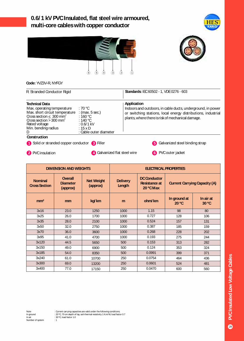
PV
C In
sula
ted
Lo
w V
olt
age
Cab
les
29
0.6/1 kV PVC Insulated, flat steel wire armoured,multi-core cables with copper conductor
Construction
Code: YVZ3V-R, NYFGY
R: Stranded Conductor Rigid Standards: IEC 60502 - 1, VDE 0276 - 603
Technical Data ApplicationIndoors and outdoors, in cable ducts, underground, in power or switching stations, local energy distributions, industrial plants, where there is risk of mechanical damage.
1 3Solid or stranded copper conductor Filler
2 PVC insulation 4 Galvanized flat steel wire
5 Galvanized steel binding strap
6 PVC outer jacket
Max. operating temperature : 70 °CMax. short circuit temperature : (max. 5 sec.)
Rated voltage : 0.6/1 kVMin. bending radius : 15 x DD : Cable outer diameter
2_Cross section < 300 mm2Cross section > 300 mm : 140 °C
: 160 °C
146 235
DIMENSION AND WEIGHTS ELECTRICAL PROPERTIES
Nominal Cross Section
Overall Diameter (approx)
Net Weight (approx)
Delivery Length
DC Conductor Resistance at
20 ºC MaxCurrent Carrying Capacity (A)
mm² mm kg/km m ohm/kmIn ground at
20 ºCIn air at
30 ºC
80
106
131
159
202
244
282
324
371
436
481
560
3x16
3x25
3x35
3x50
3x70
3x95
3x120
3x150
3x185
3x240
3x300
3x400
23.0
26.0
28.0
32.0
36.0
41.0
44.5
49.0
54.0
61.0
69.0
77.0
1250
1700
2100
2750
3600
4700
5650
6900
8350
10700
13200
17150
1000
1000
1000
1000
1000
1000
500
500
500
250
250
250
1.15
0.727
0.524
0.387
0.268
0.193
0.153
0.124
0.0991
0.0754
0.0601
0.0470
98
128
157
185
228
275
313
353
399
464
524
600
Note : Current carrying capacities are valid under the following conditions;In ground : 20 ºC, 70 cm depth of lay, soil-thermal resistivity 1 K.m/W, load factor 0.7In air : 30 ºC, load factor 1.0Number of system : 1

PV
C In
sula
ted
Lo
w V
olt
age
Cab
les
30
0.6/1 kV PVC Insulated, flat steel wire armoured,multi-core cables with copper conductor
Construction
Code: YVZ3V-R, NYFGY
R: Stranded Conductor Rigid Standards: IEC 60502 - 1, VDE 0276 - 603
Technical Data ApplicationIndoors and outdoors, in cable ducts, underground, in power or switching stations, local energy distributions, industrial plants, where there is risk of mechanical damage.
1 3Stranded copper conductors Filler
2 PVC insulation 4 Galvanized flat steel wire
5 Galvanized steel binding strap
6 PVC outer jacket
Max. operating temperature : 70 °C Max. short circuit temperature : (max. 5 sec.)
Rated voltage : 0.6/1 kVMin. bending radius : 15 x DD : Cable outer diameter
2_Cross section < 300 mm2Cross section > 300 mm : 140 °C
: 160 °C
146 235
DIMENSION AND WEIGHTS ELECTRICAL PROPERTIES
Nominal Cross Section
Overall Diameter (approx)
Net Weight (approx)
Delivery Length
DC Conductor Resistance at
20 ºC MaxCurrent Carrying Capacity (A)
mm² mm kg/km m ohm/kmIn ground at
20 ºCIn air at
30 ºC
80
106
131
159
202
244
282
324
371
436
481
560
3x16+10
3x25+16
3x35+16
3x50+25
3x70+35
3x95+50
3x120+70
3x150+70
3x185+95
3x240+120
3x300+150
3x400+185
24.0
27.5
29.5
33.5
37.5
43.0
47.5
50.5
56.0
63.0
70.0
79.0
1450
2000
2300
3050
4000
5250
6500
7600
9400
11900
14600
18900
1000
1000
1000
1000
1000
1000
500
500
500
250
250
250
1.15
0.727
0.524
0.387
0.268
0.193
0.153
0.124
0.0991
0.0754
0.0601
0.0470
98
128
157
185
228
275
313
353
399
464
524
600
Note : Current carrying capacities are valid under the following conditions;In ground : 20 ºC, 70 cm depth of lay, soil-thermal resistivity 1 K.m/W, load factor 0.7In air : 30 ºC, load factor 1.0Number of system : 1
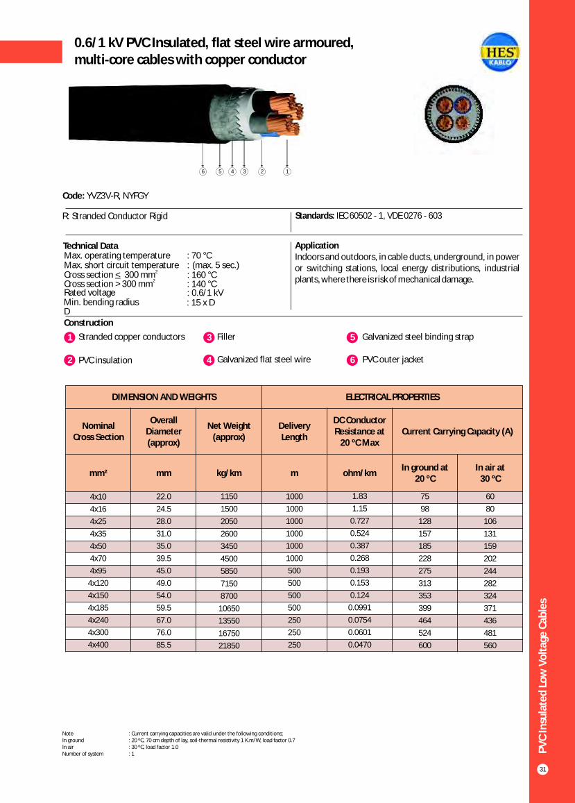
Construction
Code: YVZ3V-R, NYFGY
R: Stranded Conductor Rigid Standards: IEC 60502 - 1, VDE 0276 - 603
Technical Data ApplicationIndoors and outdoors, in cable ducts, underground, in power or switching stations, local energy distributions, industrial plants, where there is risk of mechanical damage.
1 3Stranded copper conductors Filler
2 PVC insulation 4 Galvanized flat steel wire
5 Galvanized steel binding strap
6 PVC outer jacket
Max. operating temperature : 70 °CMax. short circuit temperature : (max. 5 sec.)
Rated voltage : 0.6/1 kVMin. bending radius : 15 x DD
2_Cross section < 300 mm2Cross section > 300 mm : 140 °C
: 160 °C
146 235
PV
C In
sula
ted
Lo
w V
olt
age
Cab
les
31
0.6/1 kV PVC Insulated, flat steel wire armoured,multi-core cables with copper conductor
DIMENSION AND WEIGHTS ELECTRICAL PROPERTIES
Nominal Cross Section
Overall Diameter (approx)
Net Weight (approx)
Delivery Length
DC Conductor Resistance at
20 ºC MaxCurrent Carrying Capacity (A)
mm² mm kg/km m ohm/kmIn ground at
20 ºCIn air at
30 ºC
60
80
106
131
159
202
244
282
324
371
436
481
560
4x10
4x16
4x25
4x35
4x50
4x70
4x95
4x120
4x150
4x185
4x240
4x300
4x400
22.0
24.5
28.0
31.0
35.0
39.5
45.0
49.0
54.0
59.5
67.0
76.0
85.5
1150
1500
2050
2600
3450
4500
5850
7150
8700
10650
13550
16750
21850
1000
1000
1000
1000
1000
1000
500
500
500
500
250
250
250
1.83
1.15
0.727
0.524
0.387
0.268
0.193
0.153
0.124
0.0991
0.0754
0.0601
0.0470
75
98
128
157
185
228
275
313
353
399
464
524
600
Note : Current carrying capacities are valid under the following conditions;In ground : 20 ºC, 70 cm depth of lay, soil-thermal resistivity 1 K.m/W, load factor 0.7In air : 30 ºC, load factor 1.0Number of system : 1
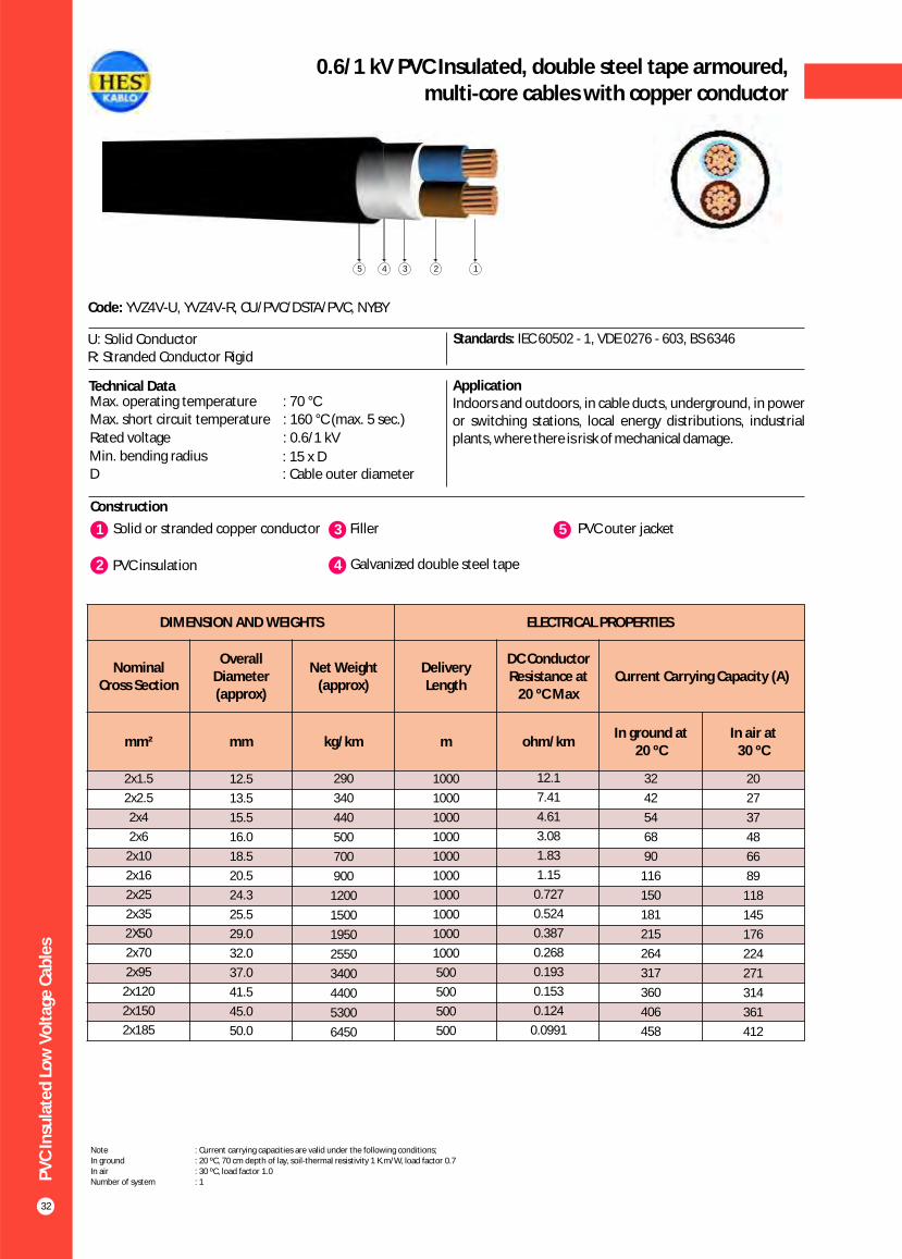
PV
C In
sula
ted
Lo
w V
olt
age
Cab
les
32
0.6/1 kV PVC Insulated, double steel tape armoured,multi-core cables with copper conductor
Construction
Code: YVZ4V-U, YVZ4V-R, CU/PVC/DSTA/PVC, NYBY
U: Solid Conductor R: Stranded Conductor Rigid
Standards: IEC 60502 - 1, VDE 0276 - 603, BS 6346
Technical Data ApplicationIndoors and outdoors, in cable ducts, underground, in power or switching stations, local energy distributions, industrial plants, where there is risk of mechanical damage.
1 3Solid or stranded copper conductor Filler
2 PVC insulation 4 Galvanized double steel tape
5 PVC outer jacket
Max. operating temperature : 70 °C Max. short circuit temperature : 160 °C (max. 5 sec.)
Rated voltage : 0.6/1 kV
Min. bending radius : 15 x DD : Cable outer diameter
14 235
DIMENSION AND WEIGHTS ELECTRICAL PROPERTIES
Nominal Cross Section
Overall Diameter (approx)
Net Weight (approx)
Delivery Length
DC Conductor Resistance at
20 ºC MaxCurrent Carrying Capacity (A)
mm² mm kg/km m ohm/kmIn ground at
20 ºCIn air at
30 ºC
20
27
37
48
66
89
118
145
176
224
271
314
361
412
2x1.5
2x2.5
2x4
2x6
2x10
2x16
2x25
2x35
2X50
2x70
2x95
2x120
2x150
2x185
12.5
13.5
15.5
16.0
18.5
20.5
24.3
25.5
29.0
32.0
37.0
41.5
45.0
50.0
290
340
440
500
700
900
1200
1500
1950
2550
3400
4400
5300
6450
1000
1000
1000
1000
1000
1000
1000
1000
1000
1000
500
500
500
500
12.1
7.41
4.61
3.08
1.83
1.15
0.727
0.524
0.387
0.268
0.193
0.153
0.124
0.0991
32
42
54
68
90
116
150
181
215
264
317
360
406
458
Note : Current carrying capacities are valid under the following conditions;In ground : 20 ºC, 70 cm depth of lay, soil-thermal resistivity 1 K.m/W, load factor 0.7In air : 30 ºC, load factor 1.0Number of system : 1

PV
C In
sula
ted
Lo
w V
olt
age
Cab
les
33
0.6/1 kV PVC Insulated, double steel tape armoured,multi-core cables with copper conductor
Construction
Code: YVZ4V-R, YVZ4V-U, CU/PVC/DSTA/PVC, NYBY
U: Solid Conductor R: Stranded Conductor Rigid
Standards: IEC 60502 - 1, VDE 0276 - 603, BS 6346
ApplicationIndoors and outdoors, in cable ducts, underground, in power or switching stations, local energy distributions, industrial plants, where there is risk of mechanical damage.
1 3Solid or stranded copper conductor Filler
2 PVC insulation 4 Galvanized double steel tape
5 PVC outer jacket
Technical DataMax. operating temperature : 70 °CMax. short circuit temperature : (max. 5 sec.)
Rated voltage : 0.6/1 kVMin. bending radius : 15 x DD : Cable outer diameter
2_Cross section < 300 mm2Cross section > 300 mm : 140 °C
: 160 °C
145 23
DIMENSION AND WEIGHTS ELECTRICAL PROPERTIES
Nominal Cross Section
Overall Diameter (approx)
Net Weight (approx)
Delivery Length
DC Conductor Resistance at
20 ºC MaxCurrent Carrying Capacity (A)
mm² mm kg/km m ohm/kmIn ground at
20 ºCIn air at
30 ºC
18.5
25
34
43
60
80
106
131
159
202
244
282
324
371
436
481
560
3x1.5
3x2.5
3x4
3x6
3x10
3x16
3x25
3x35
3x50
3x70
3x95
3x120
3x150
3x185
3x240
3x300
3x400
13.0
14.0
16.0
17.0
19.5
21.5
25.0
27.0
31.0
35.0
40.5
44.0
48.5
53.5
60.5
68.0
77.0
320
380
500
600
800
1050
1500
1850
2450
3300
4650
5600
6800
8300
10600
13000
17000
1000
1000
1000
1000
1000
1000
1000
1000
1000
1000
1000
500
500
500
250
250
250
12.1
7.41
4.61
3.08
1.83
1.15
0.727
0.524
0.387
0.268
0.193
0.153
0.124
0.0991
0.0754
0.0601
0.0470
26
34
44
56
75
98
128
157
185
228
275
313
353
399
464
524
600
Note : Current carrying capacities are valid under the following conditions;In ground : 20 ºC, 70 cm depth of lay, soil-thermal resistivity 1 K.m/W, load factor 0.7In air : 30 ºC, load factor 1.0Number of system : 1
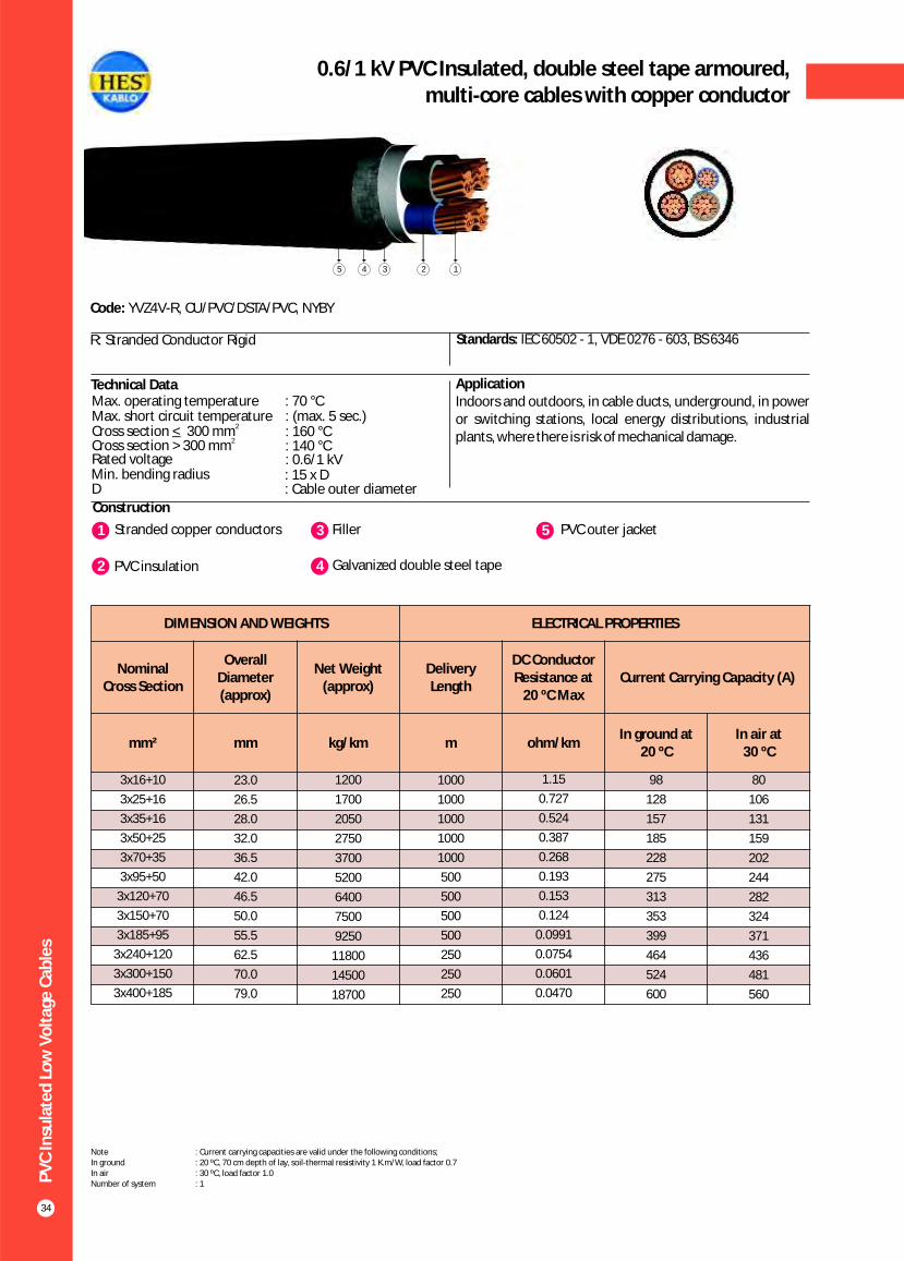
Construction
Code: YVZ4V-R, CU/PVC/DSTA/PVC, NYBY
R: Stranded Conductor Rigid Standards: IEC 60502 - 1, VDE 0276 - 603, BS 6346
Technical Data ApplicationIndoors and outdoors, in cable ducts, underground, in power or switching stations, local energy distributions, industrial plants, where there is risk of mechanical damage.
1 3Stranded copper conductors Filler
2 PVC insulation 4 Galvanized double steel tape
5 PVC outer jacket
Max. operating temperature : 70 °CMax. short circuit temperature : (max. 5 sec.)
Rated voltage : 0.6/1 kVMin. bending radius : 15 x DD : Cable outer diameter
2_Cross section < 300 mm2Cross section > 300 mm : 140 °C
: 160 °C
14 235
PV
C In
sula
ted
Lo
w V
olt
age
Cab
les
34
0.6/1 kV PVC Insulated, double steel tape armoured,multi-core cables with copper conductor
DIMENSION AND WEIGHTS ELECTRICAL PROPERTIES
Nominal Cross Section
Overall Diameter (approx)
Net Weight (approx)
Delivery Length
DC Conductor Resistance at
20 ºC MaxCurrent Carrying Capacity (A)
mm² mm kg/km m ohm/kmIn ground at
20 ºCIn air at
30 ºC
80
106
131
159
202
244
282
324
371
436
481
560
3x16+10
3x25+16
3x35+16
3x50+25
3x70+35
3x95+50
3x120+70
3x150+70
3x185+95
3x240+120
3x300+150
3x400+185
23.0
26.5
28.0
32.0
36.5
42.0
46.5
50.0
55.5
62.5
70.0
79.0
1200
1700
2050
2750
3700
5200
6400
7500
9250
11800
14500
18700
1000
1000
1000
1000
1000
500
500
500
500
250
250
250
1.15
0.727
0.524
0.387
0.268
0.193
0.153
0.124
0.0991
0.0754
0.0601
0.0470
98
128
157
185
228
275
313
353
399
464
524
600
Note : Current carrying capacities are valid under the following conditions;In ground : 20 ºC, 70 cm depth of lay, soil-thermal resistivity 1 K.m/W, load factor 0.7In air : 30 ºC, load factor 1.0Number of system : 1

PV
C In
sula
ted
Lo
w V
olt
age
Cab
les
35
0.6/1 kV PVC Insulated, double steel tape armoured,multi-core cables with copper conductor
Construction
Code: YVZ4V-U, YVZ4V-R, CU/PVC/DSTA/PVC, NYBY
U: Solid Conductor R: Stranded Conductor Rigid
Standards: IEC 60502 - 1, VDE 0276 - 603, BS 6346
Technical Data ApplicationIndoors and outdoors, in cable ducts, underground, in power or switching stations, local energy distributions, industrial plants, where there is risk of mechanical damage.
1 3Solid or stranded copper conductor Filler
2 PVC insulation 4 Galvanized double steel tape
5 PVC outer jacket
Max. operating temperature : 70 °CMax. short circuit temperature : (max. 5 sec.)
Rated voltage : 0.6/1 kVMin. bending radius : 15 x DD : Cable outer diameter
2_Cross section < 300 mm2Cross section > 300 mm : 140 °C
: 160 °C
14 235
DIMENSION AND WEIGHTS ELECTRICAL PROPERTIES
Nominal Cross Section
Overall Diameter (approx)
Net Weight (approx)
Delivery Length
DC Conductor Resistance at
20 ºC MaxCurrent Carrying Capacity (A)
mm² mm kg/km m ohm/kmIn ground at
20 ºCIn air at
30 ºC
18.5
25
34
43
60
80
106
131
159
202
244
282
324
371
436
481
560
4x1.5
4x2.5
4x4
4x6
4x10
4x16
4x25
4x35
4x50
4x70
4x95
4x120
4x150
4x185
4x240
4x300
4x400
14.0
15.0
17.0
18.0
21.0
23.5
27.0
29.5
34.0
39.0
44.5
49.0
53.5
59.0
67.0
75.5
85.5
360
440
580
700
980
1300
1850
2350
3100
4450
5800
7100
8600
10500
13400
16600
21650
1000
1000
1000
1000
1000
1000
1000
1000
1000
1000
500
500
500
250
250
250
250
12.1
7.41
4.61
3.08
1.83
1.15
0.727
0.524
0.387
0.268
0.193
0.153
0.124
0.0991
0.0754
0.0601
0.0470
26
34
44
56
75
98
128
157
185
228
275
313
353
399
464
524
600
Note : Current carrying capacities are valid under the following conditions;In ground : 20 ºC, 70 cm depth of lay, soil-thermal resistivity 1 K.m/W, load factor 0.7In air : 30 ºC, load factor 1.0Number of system : 1

DIMENSION AND WEIGHTS ELECTRICAL PROPERTIES
Nominal Cross
Section
Overall Diameter (approx)
Net Weight (approx)
Delivery Length
DC Conductor Resistance at
20 ºC MaxCurrent Carrying Capacity (A)
mm² mm kg/km m ohm/kmIn ground at 20 ºC In air at 30 ºC
*** ** * *** ** *
PV
C In
sula
ted
Lo
w V
olt
age
Cab
les
36
0.6 / 1 kV PVC insulated single core, aluminium conductor cables
Construction
Code: YAVV-R, AL/PVC/PVC, NAYY
R: Stranded Conductor Rigid Standards: IEC 60502 - 1, VDE 0276 -603
Technical Data ApplicationIndoors and outdoors, in cable ducts, underground, in power or switching stations, local energy distributions, industrial plants, where there is no risk of mechanical damage.
1 3Stranded aluminium conductor PVC outer jacket
2 PVC insulation
Max. operating temperature : 70 °CMax. short circuit temperature : (max. 5 sec.)
Rated voltage : 0.6/1 kVMin. bending radius : 12 x DD : Cable outer diameter
2_Cross section < 300 mm2Cross section > 300 mm : 140 °C
: 160 °C
123
1x16
1x25
1x35
1x50
1x70
1x95
1x120
1x150
1x185
1x240
1x300
1x400
1x500
10.0
11.5
12.5
14.0
16.0
18.0
20.0
22.0
24.0
27.0
30.0
34.0
37,5
130
160
200
280
350
450
550
700
800
1050
1300
1700
2050
1000
1000
1000
1000
1000
1000
1000
1000
1000
1000
1000
1000
1000
1.91
1.20
0.868
0.641
0.443
0.320
0.253
0.206
0.164
0.125
0.100
0.0778
0.0605
75
125
151
179
218
261
297
332
376
437
494
572
649
84
105
127
151
186
223
254
285
323
378
427
496
562
80
87
131
160
202
249
291
333
384
460
530
642
744
66
75
113
138
174
210
244
281
320
378
433
523
603
Note : Current carrying capacities are valid under the following conditions;In ground : 20 ºC, 70 cm depth of lay, soil-thermal resistivity 1 K.m/W, load factor 0.7In air : 30 ºC, load factor 1.0*** : Flat formation, clearance between cables; in air = 1 x Cable outer diameter, in ground = 7 cm : Trefoil formationNumber of system : 1
** *
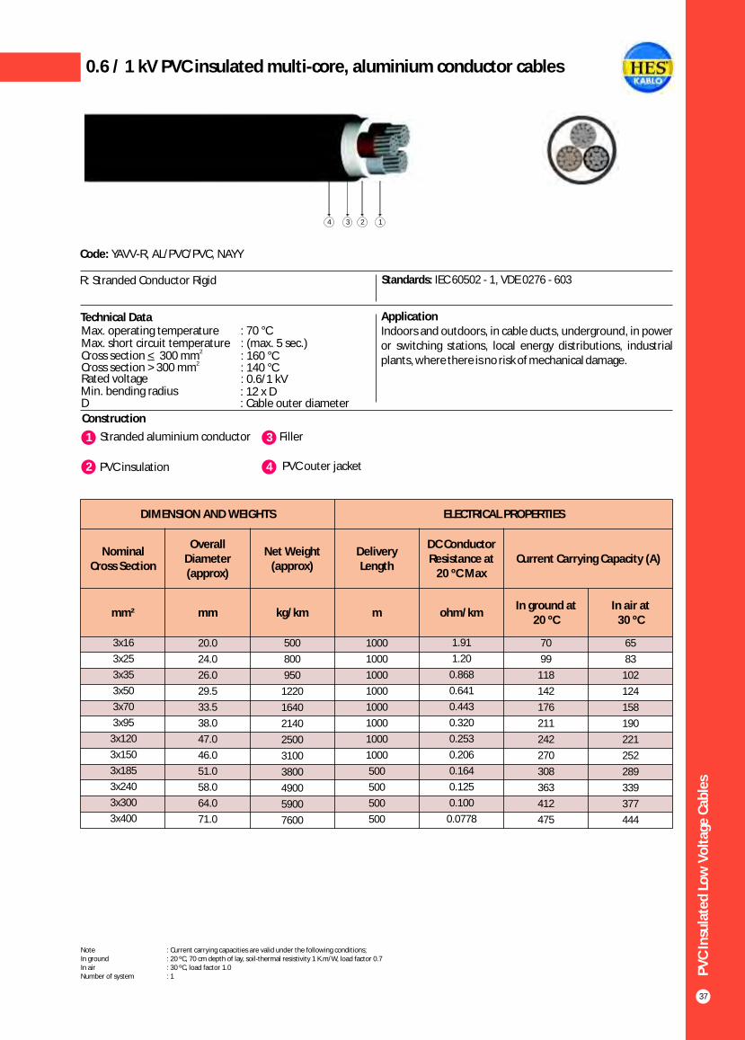
PV
C In
sula
ted
Lo
w V
olt
age
Cab
les
37
0.6 / 1 kV PVC insulated multi-core, aluminium conductor cables
Construction
Code: YAVV-R, AL/PVC/PVC, NAYY
R: Stranded Conductor Rigid Standards: IEC 60502 - 1, VDE 0276 - 603
Technical Data ApplicationIndoors and outdoors, in cable ducts, underground, in power or switching stations, local energy distributions, industrial plants, where there is no risk of mechanical damage.
1 3Stranded aluminium conductor Filler
2 PVC insulation 4 PVC outer jacket
Max. operating temperature : 70 °CMax. short circuit temperature : (max. 5 sec.)
Rated voltage : 0.6/1 kVMin. bending radius : 12 x DD : Cable outer diameter
2_Cross section < 300 mm2Cross section > 300 mm : 140 °C
: 160 °C
14 23
DIMENSION AND WEIGHTS ELECTRICAL PROPERTIES
Nominal Cross Section
Overall Diameter (approx)
Net Weight (approx)
Delivery Length
DC Conductor Resistance at
20 ºC MaxCurrent Carrying Capacity (A)
mm² mm kg/km m ohm/kmIn ground at
20 ºCIn air at
30 ºC
65
83
102
124
158
190
221
252
289
339
377
444
3x16
3x25
3x35
3x50
3x70
3x95
3x120
3x150
3x185
3x240
3x300
3x400
20.0
24.0
26.0
29.5
33.5
38.0
47.0
46.0
51.0
58.0
64.0
71.0
500
800
950
1220
1640
2140
2500
3100
3800
4900
5900
7600
1000
1000
1000
1000
1000
1000
1000
1000
500
500
500
500
1.91
1.20
0.868
0.641
0.443
0.320
0.253
0.206
0.164
0.125
0.100
0.0778
70
99
118
142
176
211
242
270
308
363
412
475
Note : Current carrying capacities are valid under the following conditions;In ground : 20 ºC, 70 cm depth of lay, soil-thermal resistivity 1 K.m/W, load factor 0.7In air : 30 ºC, load factor 1.0Number of system : 1

PV
C In
sula
ted
Lo
w V
olt
age
Cab
les
38
0.6/1 kV PVC insulated multi-core, aluminium conductor cables
Construction
Code: YAVV-R, AL/PVC/PVC, NAYY
R: Stranded Conductor Rigid Standards: IEC 60502 - 1, VDE 0276 - 603
Technical Data ApplicationIndoors and outdoors, in cable ducts, underground, in power or switching stations, local energy distributions, industrial plants, where there is no risk of mechanical damage.
1 3Stranded aluminium conductor Filler
2 PVC insulation 4 PVC outer jacket
Max. operating temperature : 70 °C Max. short circuit temperature : (max. 5 sec.)
Rated voltage : 0.6/1 kVMin. bending radius : 12 x DD : Cable outer diameter
2_Cross section < 300 mm2Cross section > 300 mm : 140 °C
: 160 °C
1234
DIMENSION AND WEIGHTS ELECTRICAL PROPERTIES
Nominal Cross Section
Overall Diameter (approx)
Net Weight (approx)
Delivery Length
DC Conductor Resistance at
20 ºC MaxCurrent Carrying Capacity (A)
mm² mm kg/km m ohm/kmIn ground at
20 ºCIn air at
30 ºC
65
83
102
124
158
190
221
252
289
339
377
444
3x16+10
3x25+16
3x35+16
3x50+25
3x70+35
3x95+50
3x120+70
3x150+70
3x185+95
3x240+120
3x300+150
3x400+185
21.0
25.0
27.0
32.0
36.0
41.0
45.5
49.5
55.0
61.5
68.0
76.5
550
900
1000
1400
1800
2400
2900
3450
4250
5500
6550
8500
1000
1000
1000
1000
1000
1000
1000
1000
500
500
500
500
1.91
1.20
0.868
0.641
0.443
0.320
0.253
0.206
0.164
0.125
0.100
0.0778
70
99
118
142
176
211
242
270
308
363
412
475
Note : Current carrying capacities are valid under the following conditions;In ground : 20 ºC, 70 cm depth of lay, soil-thermal resistivity 1 K.m/W, load factor 0.7In air : 30 ºC, load factor 1.0Number of system : 1

PV
C In
sula
ted
Lo
w V
olt
age
Cab
les
39
0.6/1 kV PVC insulated multi-core, aluminium conductor cables
Construction
Code: YAVV-R, AL/PVC/PVC, NAYY
R: Stranded Conductor Rigid Standards: IEC 60502 - 1, VDE 0276 - 603
Technical Data ApplicationIndoors and outdoors, in cable ducts, underground, in power or switching stations, local energy distributions, industrial plants, where there is no risk of mechanical damage.
1 3Stranded aluminium conductor Filler
2 PVC insulation 4 PVC outer jacket
Max. operating temperature : 70 °CMax. short circuit temperature : (max. 5 sec.)
Rated voltage : 0.6/1 kVMin. bending radius : 12 x DD : Cable outer diameter
2_Cross section < 300 mm2Cross section > 300 mm : 140 °C
: 160 °C
1234
DIMENSION AND WEIGHTS ELECTRICAL PROPERTIES
Nominal Cross Section
Overall Diameter (approx)
Net Weight (approx)
Delivery Length
DC Conductor Resistance at
20 ºC MaxCurrent Carrying Capacity (A)
mm² mm kg/km m ohm/kmIn ground at
20 ºCIn air at
30 ºC
65
83
102
124
158
190
221
252
289
339
377
444
4x16
4x25
4x35
4x50
4x70
4x95
4x120
4x150
4x185
4x240
4x300
4x400
22.0
26.0
29.0
34.0
38.5
43.5
48.0
53.0
59.0
66.0
72.5
82.5
600
950
1150
1600
2050
2650
3200
3950
4900
6150
7500
9750
1000
1000
1000
1000
1000
1000
1000
1000
500
500
500
500
1.91
1.20
0.868
0.641
0.443
0.320
0.253
0.206
0.164
0.125
0.100
0.0778
70
99
118
142
176
211
242
270
308
363
412
475
Note : Current carrying capacities are valid under the following conditions;In ground : 20 ºC, 70 cm depth of lay, soil-thermal resistivity 1 K.m/W, load factor 0.7In air : 30 ºC, load factor 1.0Number of system : 1

PV
C In
sula
ted
Lo
w V
olt
age
Cab
les
40
0.6/1 kV PVC insulated multi-core, aluminium conductor cables
Construction
Code: YAVV-R, AL/PVC/PVC, NAYY
R: Stranded Conductor Rigid Standards: IEC 60502 - 1, VDE 0276 - 603
Technical Data ApplicationIndoors and outdoors, in cable ducts, underground, in power or switching stations, local energy distributions, industrial plants, where there is no risk of mechanical damage.
1 3Stranded aluminium conductor Filler
2 PVC insulation 4 PVC outer jacket
Max. operating temperature : 70 °CMax. short circuit temperature : (max. 5 sec.)
Rated voltage : 0.6/1 kVMin. bending radius : 12 x DD : Cable outer diameter
2_Cross section < 300 mm2Cross section > 300 mm : 140 °C
: 160 °C
1234
DIMENSION AND WEIGHTS ELECTRICAL PROPERTIES
Nominal Cross Section
Overall Diameter (approx)
Net Weight (approx)
Delivery Length
DC Conductor Resistance at
20 ºC MaxCurrent Carrying Capacity (A)
mm² mm kg/km m ohm/kmIn ground at
20 ºCIn air at
30 ºC
-
-
65
83
102
124
158
190
221
252
289
339
377
444
5x6
5x10
5x16
5x25
5x35
5x50
5x70
5x95
5x120
5x150
5x185
5x240
5x300
5x400
18.0
21.0
24.0
29.0
31.0
36.0
41.0
48.0
52.0
57.0
63.0
71.0
78.0
89.0
400
550
700
1100
1350
1800
2400
3250
3850
4750
5850
7400
9100
11550
1000
1000
1000
1000
1000
1000
1000
1000
1000
1000
500
500
500
500
4.87
3.08
1.91
1.20
0.868
0.641
0.443
0.320
0.253
0.206
0.164
0.125
0.100
0.0778
-
-
70
99
118
142
176
211
242
270
308
363
412
475
Note : Current carrying capacities are valid under the following conditions;In ground : 20 ºC, 70 cm depth of lay, soil-thermal resistivity 1 K.m/W, load factor 0.7In air : 30 ºC, load factor 1.0Number of system : 1
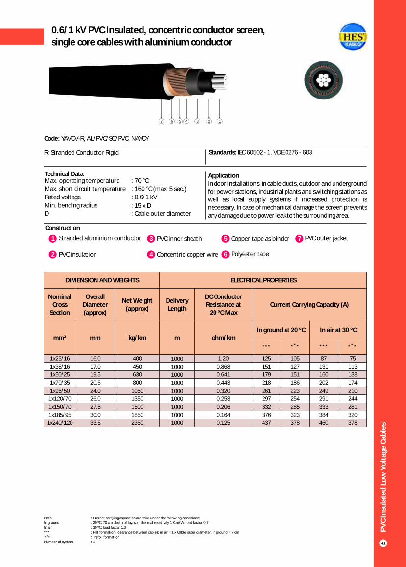
DIMENSION AND WEIGHTS ELECTRICAL PROPERTIES
Nominal Cross
Section
Overall Diameter (approx)
Net Weight (approx)
Delivery Length
DC Conductor Resistance at
20 ºC MaxCurrent Carrying Capacity (A)
mm² mm kg/km m ohm/kmIn ground at 20 ºC In air at 30 ºC
*** ** * *** ** *
PV
C In
sula
ted
Lo
w V
olt
age
Cab
les
41
0.6/1 kV PVC Insulated, concentric conductor screen,single core cables with aluminium conductor
Construction
Code: YAVCV-R, AL/PVC/SC/PVC, NAYCY
R: Stranded Conductor Rigid Standards: IEC 60502 - 1, VDE 0276 - 603
Technical Data
1 3Stranded aluminium conductor PVC inner sheath
2 PVC insulation 4 Concentric copper wire
5 Copper tape as binder
6 Polyester tape
7 PVC outer jacket
Max. operating temperature : 70 °CMax. short circuit temperature : 160 °C (max. 5 sec.)
Rated voltage : 0.6/1 kV
Min. bending radius : 15 x DD : Cable outer diameter
1234567
ApplicationIn door installations, in cable ducts, outdoor and underground for power stations, industrial plants and switching stations as well as local supply systems if increased protection is necessary. In case of mechanical damage the screen prevents any damage due to power leak to the surrounding area.
Note : Current carrying capacities are valid under the following conditions;In ground : 20 ºC, 70 cm depth of lay, soil-thermal resistivity 1 K.m/W, load factor 0.7In air : 30 ºC, load factor 1.0*** : Flat formation, clearance between cables; in air = 1 x Cable outer diameter, in ground = 7 cm : Trefoil formationNumber of system : 1
** *
1x25/16
1x35/16
1x50/25
1x70/35
1x95/50
1x120/70
1x150/70
1x185/95
1x240/120
400
450
630
800
1050
1350
1500
1850
2350
1000
1000
1000
1000
1000
1000
1000
1000
1000
1.20
0.868
0.641
0.443
0.320
0.253
0.206
0.164
0.125
125
151
179
218
261
297
332
376
437
105
127
151
186
223
254
285
323
378
87
131
160
202
249
291
333
384
460
75
113
138
174
210
244
281
320
378
16.0
17.0
19.5
20.5
24.0
26.0
27.5
30.0
33.5
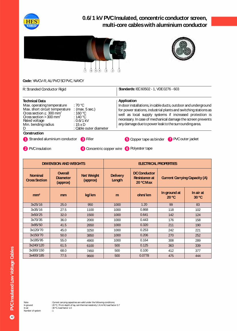
PV
C In
sula
ted
Lo
w V
olt
age
Cab
les
42
0.6/1 kV PVC Insulated, concentric conductor screen,multi-core cables with aluminium conductor
Construction
Code: YAVCV-R, AL/PVC/SC/PVC, NAYCY
R: Stranded Conductor Rigid Standards: IEC 60502 - 1, VDE 0276 - 603
Technical Data ApplicationIn door installations, in cable ducts, outdoor and underground for power stations, industrial plants and switching stations as well as local supply systems if increased protection is necessary. In case of mechanical damage the screen prevents any damage due to power leak to the surrounding area.
Max. operating temperature : 70 °CMax. short circuit temperature : (max. 5 sec.)
Rated voltage : 0.6/1 kVMin. bending radius : 15 x DD : Cable outer diameter
2_Cross section < 300 mm2Cross section > 300 mm : 140 °C
: 160 °C
1 3Stranded aluminium conductor Filler
2 PVC insulation 4 Concentric copper wire
5 Copper tape as binder
6 Polyester tape
7 PVC outer jacket
1234567
DIMENSION AND WEIGHTS ELECTRICAL PROPERTIES
Nominal Cross Section
Overall Diameter (approx)
Net Weight (approx)
Delivery Length
DC Conductor Resistance at
20 ºC MaxCurrent Carrying Capacity (A)
mm² mm kg/km m ohm/kmIn ground at
20 ºC In air at
30 ºC
83
102
124
158
190
221
252
289
339
377
444
3x25/16
3x35/16
3x50/25
3x70/35
3x95/50
3x120/70
3x150/70
3x185/95
3x240/120
3x300/150
3x400/185
25.0
27.5
32.0
36.0
41.5
45.0
50.0
55.0
61.5
68.0
77.5
950
1100
1500
2000
2650
3250
3850
4900
6100
7450
9600
1000
1000
1000
1000
1000
1000
1000
1000
500
500
500
1.20
0.868
0.641
0.443
0.320
0.253
0.206
0.164
0.125
0.100
0.0778
99
118
142
176
211
242
270
308
363
412
475
Note : Current carrying capacities are valid under the following conditions;In ground : 20 ºC, 70 cm depth of lay, soil-thermal resistivity 1 K.m/W, load factor 0.7In air : 30 ºC, load factor 1.0Number of system : 1

DIMENSION AND WEIGHTS ELECTRICAL PROPERTIES
Nominal Cross
Section
Overall Diameter (approx)
Net Weight (approx)
Delivery Length
DC Conductor Resistance at
20 ºC MaxCurrent Carrying Capacity (A)
mm² mm kg/km m ohm/km
In ground at 20 ºC In air at 30 ºC
*** ** * *** ** *
PV
C In
sula
ted
Lo
w V
olt
age
Cab
les
43
0.6/1 kV PVC Insulated, round aluminium wire armoured,single-core cables with aluminium conductor
Construction
Code: YAVY2V-R, AL/PVC/AWA/PVC, NAYR(A)Y
R: Stranded Conductor Rigid Standards: IEC 60502 - 1, VDE 0276 - 603, BS 6346
Technical Data ApplicationIndoors and outdoors, in cable ducts, underground, in power or switching stations, local energy distributions, industrial plants, where there is risk of mechanical damage.
Max. operating temperature : 70 °CMax. short circuit temperature : (max. 5 sec.)
Rated voltage : 0.6/1 kVMin. bending radius : 15 x DD : Cable outer diameter
2_Cross section < 300 mm2Cross section > 300 mm : 140 °C
: 160 °C
1 3Stranded aluminium conductor PVC inner sheath
2 PVC insulation 4 Round aluminium wire
5 Polyester tape
6 PVC outer jacket
123456
1x25
1x35
1x50
1x70
1x95
1x120
1x150
1x185
1x240
1x300
1x400
1x500
17.0
18.0
20.0
21.5
24.5
26.0
28.0
30.0
33.0
36.5
40.5
44.0
400
450
500
650
850
950
1100
1300
1550
1950
2350
2850
1000
1000
1000
1000
1000
1000
1000
1000
1000
1000
1000
1000
1.20
0.868
0.641
0.443
0.320
0.253
0.206
0.164
0.125
0.100
0.0778
0.0605
125
151
179
218
261
297
332
376
437
494
572
649
105
127
151
186
223
254
285
323
378
427
496
562
87
131
160
202
249
291
333
384
460
530
642
744
75
113
138
174
210
244
281
320
378
433
523
603
Note : Current carrying capacities are valid under the following conditions;In ground : 20 ºC, 70 cm depth of lay, soil-thermal resistivity 1 K.m/W, load factor 0.7In air : 30 ºC, load factor 1.0*** : Flat formation, clearance between cables; in air = 1 x Cable outer diameter, in ground = 7 cm : Trefoil formationNumber of system : 1
** *

PV
C In
sula
ted
Lo
w V
olt
age
Cab
les
44
0.6 / 1 kV PVC insulated, round steel wire armoured,multi-core cables with aluminium conductor
Construction
Code: YAVZ2V-R, AL/PVC/SWA/PVC, NAYRY
R: Stranded Conductor Rigid Standards: IEC 60502 - 1, VDE 0276 - 603, BS 6346
Technical Data ApplicationIndoors and outdoors, in cable ducts, underground, in power or switching stations, local energy distributions, industrial plants, where there is risk of mechanical damage.
1 3Stranded aluminium conductor Filler
2 PVC insulation 4 Galvanized round steel wire
5 Polyester tape
6 PVC outer jacket
Max. operating temperature : 70 °CMax. short circuit temperature : 160 °C (max. 5 sec.)
Rated voltage : 0.6/1 kV
Min. bending radius : 15 x DD : Cable outer diameter
123456
DIMENSION AND WEIGHTS ELECTRICAL PROPERTIES
Nominal Cross Section
Overall Diameter (approx)
Net Weight (approx)
Delivery LengthDC Conductor Resistance at
20 ºC Max
Current Carrying Capacity (A)
mm² mm kg/km m ohm/kmIn air at
30 ºC
2x25
2x35
2x50
2x70
2x95
2x120
2x150
2x185
2x240
25.5
28.0
32.0
36.0
41.0
44.5
49.5
54.5
60.5
1350
1550
1950
2600
3250
3700
4800
5650
6800
1000
1000
1000
1000
1000
1000
1000
500
500
1.20
0.868
0.641
0.443
0.320
0.253
0.206
0.164
0.125
91
113
138
174
210
244
281
320
378
Note : Current carrying capacities are valid under the following conditions;In air : 30 ºC, load factor 1.0Number of system : 1
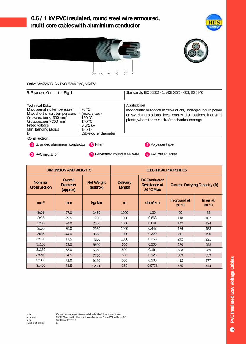
PV
C In
sula
ted
Lo
w V
olt
age
Cab
les
45
0.6 / 1 kV PVC insulated, round steel wire armoured,multi-core cables with aluminium conductor
Construction
Code: YAVZ2V-R, AL/PVC/SWA/PVC, NAYRY
R: Stranded Conductor Rigid Standards: IEC 60502 - 1, VDE 0276 - 603, BS 6346
Technical Data ApplicationIndoors and outdoors, in cable ducts, underground, in power or switching stations, local energy distributions, industrial plants, where there is risk of mechanical damage.
Max. operating temperature : 70 °C Max. short circuit temperature : (max. 5 sec.)
Rated voltage : 0.6/1 kVMin. bending radius : 15 x DD : Cable outer diameter
2_Cross section < 300 mm2Cross section > 300 mm : 140 °C
: 160 °C
1 3Stranded aluminium conductor Filler
2 PVC insulation 4 Galvanized round steel wire
5 Polyester tape
6 PVC outer jacket
123456
DIMENSION AND WEIGHTS ELECTRICAL PROPERTIES
Nominal Cross Section
Overall Diameter (approx)
Net Weight (approx)
Delivery Length
DC Conductor Resistance at
20 ºC MaxCurrent Carrying Capacity (A)
mm² mm kg/km m ohm/kmIn ground at
20 ºCIn air at
30 ºC
83
102
124
158
190
221
252
289
339
377
444
3x25
3x35
3x50
3x70
3x95
3x120
3x150
3x185
3x240
3x300
3x400
27.0
29.5
34.0
39.0
44.0
47.5
53.0
58.0
64.5
71.0
81.5
1450
1700
2200
2950
3650
4200
5500
6350
7750
9150
12300
1000
1000
1000
1000
1000
1000
500
500
500
500
250
1.20
0.868
0.641
0.443
0.320
0.253
0.206
0.164
0.125
0.100
0.0778
99
118
142
176
211
242
270
308
363
412
475
Note : Current carrying capacities are valid under the following conditions;In ground : 20 ºC, 70 cm depth of lay, soil-thermal resistivity 1 K.m/W, load factor 0.7In air : 30 ºC, load factor 1.0Number of system : 1

0.6 / 1 kV PVC insulated, round steel wire armoured,multi-core cables with aluminium conductor
Construction
Code: YAVZ2V-R, AL/PVC/SWA/PVC, NAYRY
R: Stranded Conductor Rigid Standards: IEC 60502 - 1, VDE 0276 - 603, BS 6346
Technical Data ApplicationIndoors and outdoors, in cable ducts, underground, in power or switching stations, local energy distributions, industrial plants, where there is risk of mechanical damage.
1 3Stranded aluminium conductor Filler
2 PVC insulation 4 Galvanized round steel wire
5 Polyester tape
6 PVC outer jacket
Max. operating temperature : 70 °CMax. short circuit temperature : (max. 5 sec.)
Rated voltage : 0.6/1 kVMin. bending radius : 15 x DD : Cable outer diameter
2_Cross section < 300 mm2Cross section > 300 mm : 140 °C
: 160 °C
123456
PV
C In
sula
ted
Lo
w V
olt
age
Cab
les
46
DIMENSION AND WEIGHTS ELECTRICAL PROPERTIES
Nominal Cross Section
Overall Diameter (approx)
Net Weight (approx)
Delivery Length
DC Conductor Resistance at
20 ºC MaxCurrent Carrying Capacity (A)
mm² mm kg/km m ohm/kmIn ground at
20 ºCIn air at
30 ºC
83
102
124
158
190
221
252
289
339
377
444
3x25+16
3x35+16
3x50+25
3x70+35
3x95+50
3x120+70
3x150+70
3x185+95
3x240+120
3x300+150
3x400+185
28.5
31.0
36.5
40.5
46.0
51.5
55.0
60.5
67.0
73.5
84.0
1600
1800
2600
3150
3950
5100
5800
6850
8250
9750
13050
1000
1000
1000
1000
1000
1000
500
500
500
500
250
1.20
0.868
0.641
0.443
0.320
0.253
0.206
0.164
0.125
0.100
0.0778
99
118
142
176
211
242
270
308
363
412
475
Note : Current carrying capacities are valid under the following conditions;In ground : 20 ºC, 70 cm depth of lay, soil-thermal resistivity 1 K.m/W, load factor 0.7In air : 30 ºC, load factor 1.0Number of system : 1

PV
C In
sula
ted
Lo
w V
olt
age
Cab
les
47
0.6 / 1 kV PVC insulated, round steel wire armoured,multi-core cables with aluminium conductor
Construction
Code: YAVZ2V-R, AL/PVC/SWA/PVC, NAYRY
R: Stranded Conductor Rigid Standards: IEC 60502 - 1, VDE 0276 - 603, BS 6346
Technical Data ApplicationIndoors and outdoors, in cable ducts, underground, in power or switching stations, local energy distributions, industrial plants, where there is risk of mechanical damage.
Max. operating temperature : 70 °CMax. short circuit temperature : (max. 5 sec.)
Rated voltage : 0.6/1 kVMin. bending radius : 15 x DD : Cable outer diameter
2_Cross section < 300 mm2Cross section > 300 mm : 140 °C
: 160 °C
1 3Stranded aluminium conductor Filler
2 PVC insulation 4 Galvanized round steel wire
5 Polyester tape
6 PVC outer jacket
123456
DIMENSION AND WEIGHTS ELECTRICAL PROPERTIES
Nominal Cross Section
Overall Diameter (approx)
Net Weight (approx)
Delivery Length
DC Conductor Resistance at
20 ºC MaxCurrent Carrying Capacity (A)
mm² mm kg/km m ohm/kmIn ground at
20 ºCIn air at
30 ºC
83
102
124
158
190
221
252
289
339
377
444
4x25
4x35
4x50
4x70
4x95
4x120
4x150
4x185
4x240
4x300
4x400
29.5
32.0
38.5
42.5
49.0
53.0
58.5
64.0
71.0
78.0
89.5
1650
2000
2900
3450
4700
5500
6500
7650
9250
10950
14700
1000
1000
1000
1000
1000
1000
500
500
500
250
250
1.20
0.868
0.641
0.443
0.320
0.253
0.206
0.164
0.125
0.100
0.0778
99
118
142
176
211
242
270
308
363
412
475
Note : Current carrying capacities are valid under the following conditions;In ground : 20 ºC, 70 cm depth of lay, soil-thermal resistivity 1 K.m/W, load factor 0.7In air : 30 ºC, load factor 1.0Number of system : 1
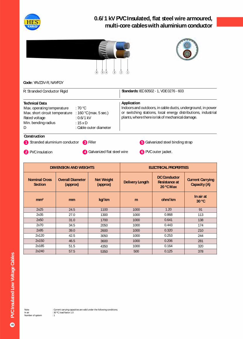
PV
C In
sula
ted
Lo
w V
olt
age
Cab
les
48
0.6/1 kV PVC Insulated, flat steel wire armoured,multi-core cables with aluminium conductor
Construction
Code: YAVZ3V-R, NAYFGY
R: Stranded Conductor Rigid Standards: IEC 60502 - 1, VDE 0276 - 603
Technical Data ApplicationIndoors and outdoors, in cable ducts, underground, in power or switching stations, local energy distributions, industrial plants, where there is risk of mechanical damage.
1 3Stranded aluminium conductor Filler
2 PVC insulation 4 Galvanized flat steel wire
5 Galvanized steel binding strap
6 PVC outer jacket.
Max. operating temperature : 70 °CMax. short circuit temperature : 160 °C (max. 5 sec.)
Rated voltage : 0.6/1 kV
Min. bending radius : 15 x DD : Cable outer diameter
123456
DIMENSION AND WEIGHTS ELECTRICAL PROPERTIES
Nominal Cross Section
Overall Diameter (approx)
Net Weight (approx)
Delivery LengthDC Conductor Resistance at
20 ºC Max
Current Carrying Capacity (A)
mm² mm kg/km m ohm/kmIn air at
30 ºC
2x25
2x35
2x50
2x70
2x95
2x120
2x150
2x185
2x240
24.5
27.0
31.0
34.5
39.0
42.5
46.5
51.5
57.5
1100
1300
1700
2050
2600
3050
3600
4350
5350
1000
1000
1000
1000
1000
1000
1000
1000
500
1.20
0.868
0.641
0.443
0.320
0.253
0.206
0.164
0.125
91
113
138
174
210
244
281
320
378
Note : Current carrying capacities are valid under the following conditions;In air : 30 ºC, load factor 1.0Number of system : 1

PV
C In
sula
ted
Lo
w V
olt
age
Cab
les
49
0.6/1 kV PVC Insulated, flat steel wire armoured,multi-core cables with aluminium conductor
Construction
Code: YAVZ3V-R, NAYFGY
R: Stranded Conductor Rigid Standards: IEC 60502 - 1, VDE 0276 - 603
ApplicationIndoors and outdoors, in cable ducts, underground, in power or switching stations, local energy distributions, industrial plants, where there is risk of mechanical damage.
1 3Stranded aluminium conductor Filler
2 PVC insulation 4 Galvanized flat steel wire
5 Galvanized steel binding strap
6 PVC outer jacket
Technical DataMax. operating temperature : 70 °CMax. short circuit temperature : (max. 5 sec.)
Rated voltage : 0.6/1 kVMin. bending radius : 15 x DD : Cable outer diameter
2_Cross section < 300 mm2Cross section > 300 mm : 140 °C
: 160 °C
123456
DIMENSION AND WEIGHTS ELECTRICAL PROPERTIES
Nominal Cross Section
Overall Diameter (approx)
Net Weight (approx)
Delivery Length
DC Conductor Resistance at
20 ºC MaxCurrent Carrying Capacity (A)
mm² mm kg/km m ohm/kmIn ground at
20 ºCIn air at
30 ºC
83
102
124
158
190
221
252
289
339
377
444
3x25
3x35
3x50
3x70
3x95
3x120
3x150
3x185
3x240
3x300
3x400
26.0
28.5
33.0
37.0
42.0
45.5
50.0
55.0
61.5
68.0
76.5
1250
1500
1900
2350
2950
3500
4200
5000
6200
7450
9500
1000
1000
1000
1000
1000
1000
1000
500
500
500
500
1.20
0.868
0.641
0.443
0.320
0.253
0.206
0.164
0.125
0.100
0.0778
99
118
142
176
211
242
270
308
363
412
475
Note : Current carrying capacities are valid under the following conditions;In ground : 20 ºC, 70 cm depth of lay, soil-thermal resistivity 1 K.m/W, load factor 0.7In air : 30 ºC, load factor 1.0Number of system : 1

PV
C In
sula
ted
Lo
w V
olt
age
Cab
les
50
0.6/1 kV PVC Insulated, flat steel wire armoured,multi-core cables with aluminium conductor
Construction
Code: YAVZ3V-R, NAYFGY
R: Stranded Conductor Rigid Standards: IEC 60502 - 1, VDE 0276 - 603
ApplicationIndoors and outdoors, in cable ducts, underground, in power or switching stations, local energy distributions, industrial plants, where there is risk of mechanical damage.
1 3Stranded aluminium conductor Filler
2 PVC insulation 4 Galvanized flat steel wire
5 Galvanized steel binding strap
6 PVC outer jacket
Technical DataMax. operating temperature : 70 °CMax. short circuit temperature : (max. 5 sec.)
Rated voltage : 0.6/1 kVMin. bending radius : 15 x DD : Cable outer diameter
2_Cross section < 300 mm2Cross section > 300 mm : 140 °C
: 160 °C
123456
DIMENSION AND WEIGHTS ELECTRICAL PROPERTIES
Nominal Cross Section
Overall Diameter (approx)
Net Weight (approx)
Delivery Length
DC Conductor Resistance at
20 ºC MaxCurrent Carrying Capacity (A)
mm² mm kg/km m ohm/kmIn ground at
20 ºCIn air at
30 ºC
83
102
124
158
190
221
252
289
339
377
444
3x25+16
3x35+16
3x50+25
3x70+35
3x95+50
3x120+70
3x150+70
3x185+95
3x240+120
3x300+150
3x400+185
27.5
29.5
34.0
38.5
43.5
48.0
52.0
57.0
63.5
70.0
79.0
1500
1550
2050
2550
3250
3900
4500
5400
6650
8000
10100
1000
1000
1000
1000
1000
1000
1000
500
500
500
250
1.20
0.868
0.641
0.443
0.320
0.253
0.206
0.164
0.125
0.100
0.0778
99
118
142
176
211
242
270
308
363
412
475
Note : Current carrying capacities are valid under the following conditions;In ground : 20 ºC, 70 cm depth of lay, soil-thermal resistivity 1 K.m/W, load factor 0.7In air : 30 ºC, load factor 1.0Number of system : 1
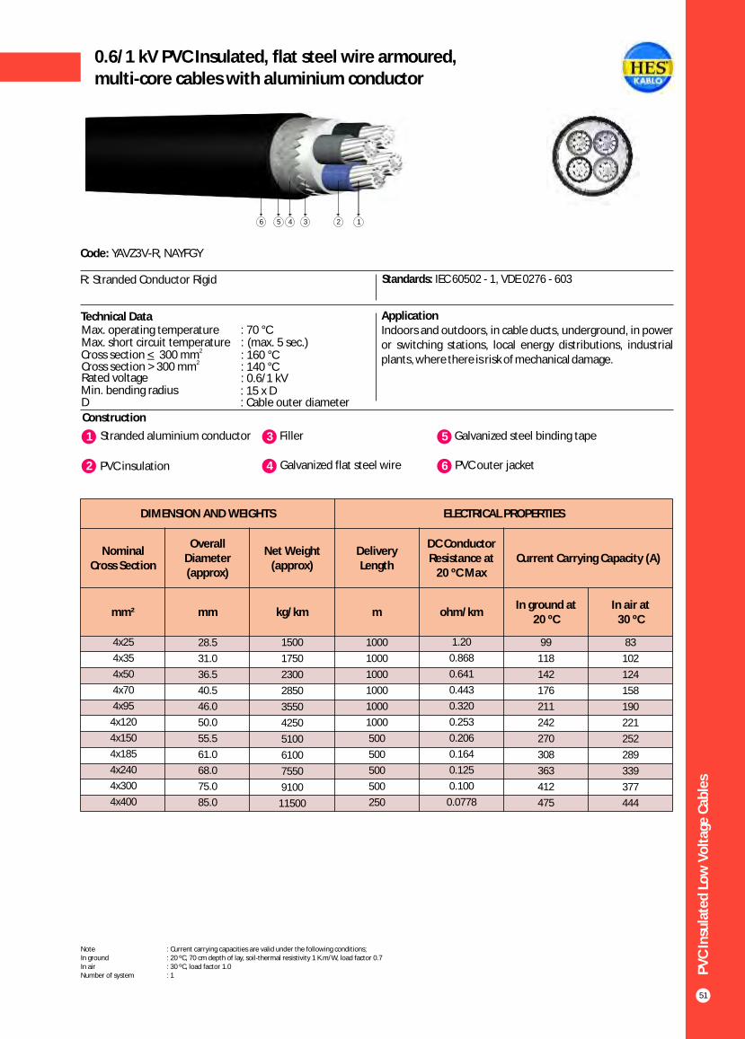
PV
C In
sula
ted
Lo
w V
olt
age
Cab
les
51
0.6/1 kV PVC Insulated, flat steel wire armoured,multi-core cables with aluminium conductor
Construction
Code: YAVZ3V-R, NAYFGY
R: Stranded Conductor Rigid Standards: IEC 60502 - 1, VDE 0276 - 603
ApplicationIndoors and outdoors, in cable ducts, underground, in power or switching stations, local energy distributions, industrial plants, where there is risk of mechanical damage.
1 3Stranded aluminium conductor Filler
2 PVC insulation 4 Galvanized flat steel wire
5 Galvanized steel binding tape
6 PVC outer jacket
Technical DataMax. operating temperature : 70 °CMax. short circuit temperature : (max. 5 sec.)
Rated voltage : 0.6/1 kVMin. bending radius : 15 x DD : Cable outer diameter
2_Cross section < 300 mm2Cross section > 300 mm : 140 °C
: 160 °C
123456
DIMENSION AND WEIGHTS ELECTRICAL PROPERTIES
Nominal Cross Section
Overall Diameter (approx)
Net Weight (approx)
Delivery Length
DC Conductor Resistance at
20 ºC MaxCurrent Carrying Capacity (A)
mm² mm kg/km m ohm/kmIn ground at
20 ºCIn air at
30 ºC
83
102
124
158
190
221
252
289
339
377
444
4x25
4x35
4x50
4x70
4x95
4x120
4x150
4x185
4x240
4x300
4x400
28.5
31.0
36.5
40.5
46.0
50.0
55.5
61.0
68.0
75.0
85.0
1500
1750
2300
2850
3550
4250
5100
6100
7550
9100
11500
1000
1000
1000
1000
1000
1000
500
500
500
500
250
1.20
0.868
0.641
0.443
0.320
0.253
0.206
0.164
0.125
0.100
0.0778
99
118
142
176
211
242
270
308
363
412
475
Note : Current carrying capacities are valid under the following conditions;In ground : 20 ºC, 70 cm depth of lay, soil-thermal resistivity 1 K.m/W, load factor 0.7In air : 30 ºC, load factor 1.0Number of system : 1
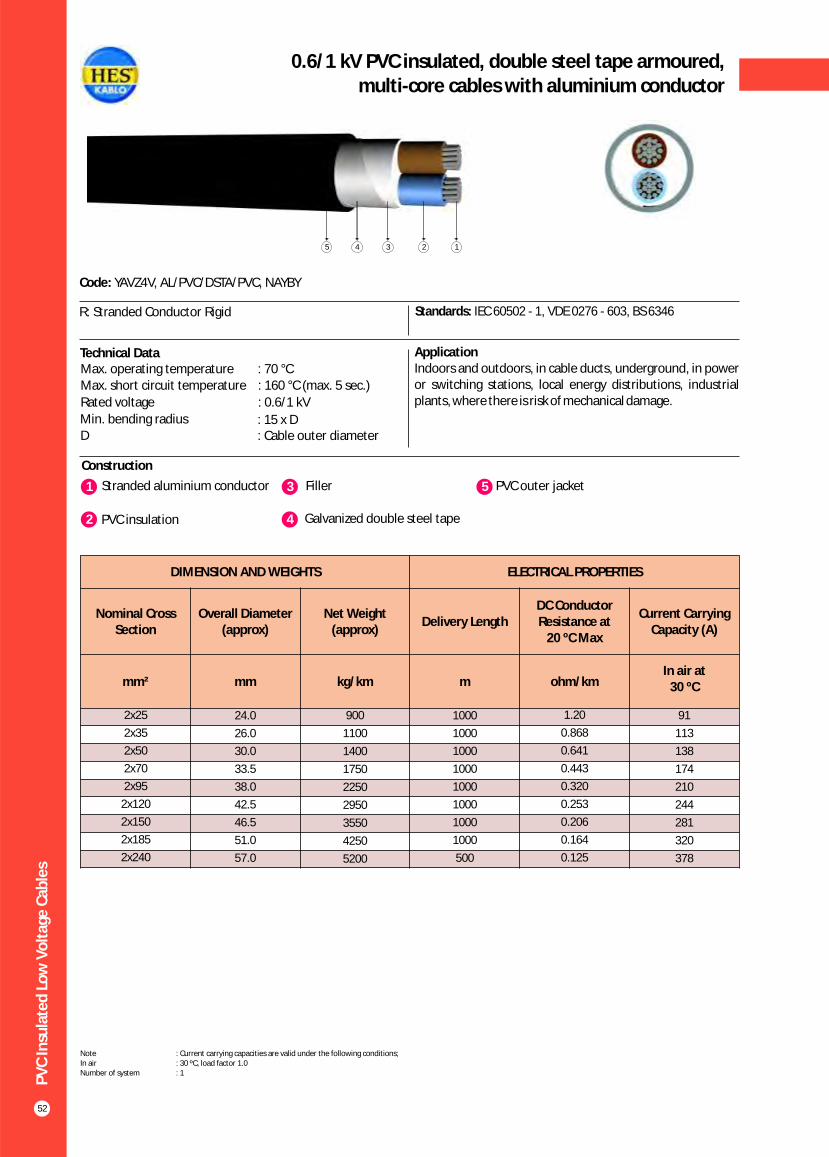
PV
C In
sula
ted
Lo
w V
olt
age
Cab
les
52
0.6/1 kV PVC insulated, double steel tape armoured,multi-core cables with aluminium conductor
Construction
Code: YAVZ4V, AL/PVC/DSTA/PVC, NAYBY
R: Stranded Conductor Rigid Standards: IEC 60502 - 1, VDE 0276 - 603, BS 6346
Technical Data ApplicationIndoors and outdoors, in cable ducts, underground, in power or switching stations, local energy distributions, industrial plants, where there is risk of mechanical damage.
1 3Stranded aluminium conductor Filler
2 PVC insulation 4 Galvanized double steel tape
5 PVC outer jacket
Max. operating temperature : 70 °CMax. short circuit temperature : 160 °C (max. 5 sec.)
Rated voltage : 0.6/1 kV
Min. bending radius : 15 x DD : Cable outer diameter
12345
DIMENSION AND WEIGHTS ELECTRICAL PROPERTIES
Nominal Cross Section
Overall Diameter (approx)
Net Weight (approx)
Delivery LengthDC Conductor Resistance at
20 ºC Max
Current Carrying Capacity (A)
mm² mm kg/km m ohm/kmIn air at
30 ºC
2x25
2x35
2x50
2x70
2x95
2x120
2x150
2x185
2x240
24.0
26.0
30.0
33.5
38.0
42.5
46.5
51.0
57.0
900
1100
1400
1750
2250
2950
3550
4250
5200
1000
1000
1000
1000
1000
1000
1000
1000
500
1.20
0.868
0.641
0.443
0.320
0.253
0.206
0.164
0.125
91
113
138
174
210
244
281
320
378
Note : Current carrying capacities are valid under the following conditions;In air : 30 ºC, load factor 1.0Number of system : 1

PV
C In
sula
ted
Lo
w V
olt
age
Cab
les
53
0.6/1 kV PVC insulated, double steel tape armoured,multi-core cables with aluminium conductor
Construction
Code: YAVZ4V-R, AL/PVC/DSTA/PVC, NAYBY
R: Stranded Conductor Rigid Standards: IEC 60502 - 1, VDE 0276 - 603, BS 6346
ApplicationIndoors and outdoors, in cable ducts, underground, in power or switching stations, local energy distributions, industrial plants, where there is risk of mechanical damage.
1 3Stranded aluminium conductor Filler
2 PVC insulation 4 Galvanized double steel tape
5 PVC outer jacket
Technical DataMax. operating temperature : 70 °CMax. short circuit temperature : (max. 5 sec.)
Rated voltage : 0.6/1 kVMin. bending radius : 15 x DD : Cable outer diameter
2_Cross section < 300 mm2Cross section > 300 mm : 140 °C
: 160 °C
12345
DIMENSION AND WEIGHTS ELECTRICAL PROPERTIES
Nominal Cross Section
Overall Diameter (approx)
Net Weight (approx)
Delivery Length
DC Conductor Resistance at
20 ºC MaxCurrent Carrying Capacity (A)
mm² mm kg/km m ohm/kmIn ground at
20 ºCIn air at
30 ºC
83
102
124
158
190
221
252
289
339
377
444
3x25
3x35
3x50
3x70
3x95
3x120
3x150
3x185
3x240
3x300
3x400
25.0
27.5
32.0
36.0
42.0
45.0
50.0
55.0
61.5
67.5
76.5
1050
1250
1600
2050
2900
3400
4150
4900
6100
7300
9300
1000
1000
1000
1000
1000
1000
1000
500
500
500
500
1.20
0.868
0.641
0.443
0.320
0.253
0.206
0.164
0.125
0.100
0.0778
99
118
142
176
211
242
270
308
363
412
475
Note : Current carrying capacities are valid under the following conditions;In ground : 20 ºC, 70 cm depth of lay, soil-thermal resistivity 1 K.m/W, load factor 0.7In air : 30 ºC, load factor 1.0Number of system : 1
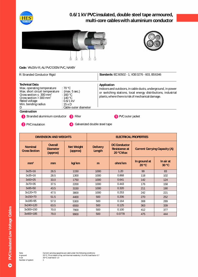
PV
C In
sula
ted
Lo
w V
olt
age
Cab
les
54
0.6/1 kV PVC insulated, double steel tape armoured,multi-core cables with aluminium conductor
Construction
Code: YAVZ4V-R, AL/PVC/DSTA/PVC, NAYBY
R: Stranded Conductor Rigid Standards: IEC 60502 - 1, VDE 0276 - 603, BS 6346
ApplicationIndoors and outdoors, in cable ducts, underground, in power or switching stations, local energy distributions, industrial plants, where there is risk of mechanical damage.
1 3Stranded aluminium conductor Filler
2 PVC insulation 4 Galvanized double steel tape
5 PVC outer jacket
Technical DataMax. operating temperature : 70 °CMax. short circuit temperature : (max. 5 sec.)
Rated voltage : 0.6/1 kVMin. bending radius : 15 x DD : Cable outer diameter
2_Cross section < 300 mm2Cross section > 300 mm : 140 °C
: 160 °C
12345
DIMENSION AND WEIGHTS ELECTRICAL PROPERTIES
Nominal Cross Section
Overall Diameter (approx)
Net Weight (approx)
Delivery Length
DC Conductor Resistance at
20 ºC MaxCurrent Carrying Capacity (A)
mm² mm kg/km m ohm/kmIn ground at
20 ºCIn air at
30 ºC
83
102
124
158
190
221
252
289
339
377
444
3x25+16
3x35+16
3x50+25
3x70+35
3x95+50
3x120+70
3x150+70
3x185+95
3x240+120
3x300+150
3x400+185
26.5
28.5
33.0
37.5
43.5
47.5
51.5
57.0
63.5
70.0
79.0
1150
1300
1750
2200
3150
3800
4400
5300
6550
7900
9900
1000
1000
1000
1000
1000
1000
500
500
500
500
500
1.20
0.868
0.641
0.443
0.320
0.253
0.206
0.164
0.125
0.100
0.0778
99
118
142
176
211
242
270
308
363
412
475
Note : Current carrying capacities are valid under the following conditions;In ground : 20 ºC, 70 cm depth of lay, soil-thermal resistivity 1 K.m/W, load factor 0.7In air : 30 ºC, load factor 1.0Number of system : 1
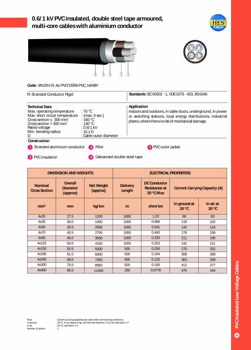
PV
C In
sula
ted
Lo
w V
olt
age
Cab
les
55
0.6/1 kV PVC insulated, double steel tape armoured,multi-core cables with aluminium conductor
Construction
Code: YAVZ4V-R, AL/PVC/DSTA/PVC, NAYBY
R: Stranded Conductor Rigid Standards: IEC 60502 - 1, VDE 0276 - 603, BS 6346
ApplicationIndoors and outdoors, in cable ducts, underground, in power or switching stations, local energy distributions, industrial plants, where there is risk of mechanical damage.
1 3Stranded aluminium conductor Filler
2 PVC insulation 4 Galvanized double steel tape
5 PVC outer jacket
Technical DataMax. operating temperature : 70 °CMax. short circuit temperature : (max. 5 sec.)
Rated voltage : 0.6/1 kVMin. bending radius : 15 x DD : Cable outer diameter
2_Cross section < 300 mm2Cross section > 300 mm : 140 °C
: 160 °C
12345
DIMENSION AND WEIGHTS ELECTRICAL PROPERTIES
Nominal Cross Section
Overall Diameter (approx)
Net Weight (approx)
Delivery Length
DC Conductor Resistance at
20 ºC MaxCurrent Carrying Capacity (A)
mm² mm kg/km m ohm/kmIn ground at
20 ºCIn air at
30 ºC
83
102
124
158
190
221
252
289
339
377
444
4x25
4x35
4x50
4x70
4x95
4x120
4x150
4x185
4x240
4x300
4x400
27.5
30.0
35.5
40.5
46.0
50.0
55.5
61.0
68.0
75.0
85.0
1200
1450
2000
2750
3500
4150
5000
6000
7450
8950
11400
1000
1000
1000
1000
1000
1000
500
500
500
500
250
1.20
0.868
0.641
0.443
0.320
0.253
0.206
0.164
0.125
0.100
0.0778
99
118
142
176
211
242
270
308
363
412
475
Note : Current carrying capacities are valid under the following conditions;In ground : 20 ºC, 70 cm depth of lay, soil-thermal resistivity 1 K.m/W, load factor 0.7In air : 30 ºC, load factor 1.0Number of system : 1

DIMENSION AND WEIGHTS ELECTRICAL PROPERTIES
Nominal Cross
Section
Overall Diameter (approx)
Net Weight (approx)
Delivery Length
DC Conductor Resistance at
20 ºC MaxCurrent Carrying Capacity (A)
mm² mm kg/km m ohm/kmIn ground at 20 ºC In air at 30 ºC
*** ** * *** ** *
XLP
E In
sula
ted
Lo
w V
olt
age
Cab
les
56
0.6/1 kV XLPE Insulated,single-core cables with copper conductor
Construction
Code: YXV-U, YXV-R, CU/XLPE/PVC, N2XY
U: Solid Conductor R: Stranded Conductor Rigid
Standards: IEC 60502 - 1, VDE 0276 - 603, BS 7889
Technical Data ApplicationThese cables have a low dielectric loss, used in indoors and outdoors, in cable ducts, underground, in power or switchingstations, local energy distributions, industrial plants, where there is no risk of mechanical damage.
1 3 Solid or stranded copper conductor PVC outer jacket
2 XLPE insulation
Max. operating temperature : 90 °C
Max. short circuit temperature : 250 °C (max. 5 sec.)
Rated voltage : 0.6/1 kV
Min. bending radius : 15 x DD : Cable outer diameter
123
1x1.5
1x2.5
1x4
1x6
1x10
1x16
1x25
1x35
1x50
1x70
1x95
1x120
1x150
1x185
1x240
1x300
1x400
1x500
1x630
5.5
6.0
6.5
7.0
8.0
9.0
10.5
11.5
13.0
15.0
17.0
18.5
20.5
22.5
25.5
29.0
32.0
35.5
39.0
45
55
75
90
140
200
300
400
530
750
1000
1250
1550
1900
2450
3000
4000
5000
6100
1000
1000
1000
1000
1000
1000
1000
1000
1000
1000
1000
1000
1000
1000
1000
1000
1000
1000
1000
12.1
7.41
4.61
3.08
1.83
1.15
0.727
0.524
0.387
0.268
0.193
0.153
0.124
0.0991
0.0754
0.0601
0.0470
0.0366
0.0283
39
51
66
82
109
139
179
213
251
307
366
416
465
526
610
689
788
889
980
32
43
55
68
90
115
149
178
211
259
310
352
396
449
521
587
669
748
843
32
42
56
71
96
128
173
212
258
328
404
471
541
626
749
864
1018
1173
1315
25
34
44
57
77
102
139
170
208
265
326
381
438
507
606
697
816
933
1083Note : Current carrying capacities are valid under the following conditions;In ground : 20 ºC, 70 cm depth of lay, soil-thermal resistivity 1 K.m/W, load factor 0.7In air : 30 ºC, load factor 1.0*** : Flat formation, clearance between cables; in air = 1 x Cable outer diameter, in ground = 7 cm : Trefoil formationNumber of system : 1
** *

XLP
E In
sula
ted
Lo
w V
olt
age
Cab
les
57
0.6 / 1 kV XLPE insulatedmulti-core cables with copper conductor
Construction
Code: YXV-U, YXV-R, CU/XLPE/PVC, N2XY
U: Solid Conductor R: Stranded Conductor Rigid
Standards: IEC 60502 - 1, VDE 0276 - 603, BS 7889
Technical Data ApplicationThese cables have a low dielectric loss, used in indoors and outdoors, in cable ducts, underground, in power or switchingstations, local energy distributions, industrial plants, where there is no risk of mechanical damage.
Max. operating temperature : 90 °CMax. short circuit temperature : 250 °C (max. 5 sec.)
Rated voltage : 0.6/1 kV
Min. bending radius : 12 x DD : Cable outer diameter
1 3 Solid or stranded copper conductor Filler
2 XLPE insulation 4 PVC outer jacket
1234
DIMENSION AND WEIGHTS ELECTRICAL PROPERTIES
Nominal Cross Section
Overall Diameter (approx)
Net Weight (approx)
Delivery Length
DC Conductor Resistance at
20 ºC MaxCurrent Carrying Capacity (A)
mm² mm kg/km m ohm/kmIn ground at
20 ºCIn air at
30 ºC
32
42
56
71
96
125
155
195
235
300
370
430
490
570
680
785
860
2x1.5
2x2.5
2x4
2x6
2x10
2x16
2x25
2x35
2x50
2x70
2x95
2x120
2x150
2x185
2x240
2x300
2x400
10.5
11.3
12.3
13.5
15.2
17.3
21.5
23.3
25.8
29.7
33.9
37.4
41.1
45.9
51.5
56.6
64.0
155
200
260
320
460
630
920
1150
1490
2050
2760
3400
4150
5200
6700
8200
10600
1000
1000
1000
1000
1000
1000
1000
1000
1000
1000
1000
1000
1000
1000
500
500
500
12.1
7.41
4.61
3.08
1.83
1.15
0.727
0.524
0.387
0.268
0.193
0.153
0.124
0.0991
0.0754
0.0601
0.0470
39
51
66
82
109
115
145
175
210
255
310
355
400
455
530
605
690
Note : Current carrying capacities are valid under the following conditions;In ground : 20 ºC, 70 cm depth of lay, soil-thermal resistivity 1 K.m/W, load factor 0.7In air : 30 ºC, load factor 1.0Number of system : 1

XLP
E In
sula
ted
Lo
w V
olt
age
Cab
les
58
0.6 / 1 kV XLPE insulatedmulti-core cables with copper conductor
Construction
Code: YXV-U, YXV-R, CU/XLPE/PVC, N2XY
U: Solid Conductor R: Stranded Conductor Rigid
Standards: IEC 60502 - 1, VDE 0276 - 603, BS 7889
Technical Data ApplicationThese cables have a low dielectric loss, used in indoors and outdoors, in cable ducts, underground, in power or switchingstations, local energy distributions, industrial plants, where there is no risk of mechanical damage.
Max. operating temperature : 90 °C
Max. short circuit temperature : 250 °C (max. 5 sec.)
Rated voltage : 0.6/1 kV
Min. bending radius : 12 x DD : Cable outer diameter
1 3 Solid or stranded copper conductor Filler
2 XLPE insulation 4 PVC outer jacket
1234
DIMENSION AND WEIGHTS ELECTRICAL PROPERTIES
Nominal Cross Section
Overall Diameter (approx)
Net Weight (approx)
Delivery Length
DC Conductor Resistance at
20 ºC MaxCurrent Carrying Capacity (A)
mm² mm kg/km m ohm/kmIn ground at
20 ºCIn air at
30 ºC
24
32
42
53
73
96
130
160
195
247
305
355
407
469
551
638
746
3x1.5
3x2.5
3x4
3x6
3x10
3x16
3x25
3x35
3x50
3x70
3x95
3x120
3x150
3x185
3x240
3x300
3x400
11.0
12.0
13.0
14.5
16.0
19.0
22.5
24.5
27.5
32.0
36.0
40.0
44.5
49.0
56.0
63.0
72.0
180
230
300
370
550
700
1150
1500
1950
2750
3600
4500
5600
6950
9000
11200
14750
1000
1000
1000
1000
1000
1000
1000
1000
1000
1000
1000
1000
500
500
500
250
250
12.1
7.41
4.61
3.08
1.83
1.15
0.727
0.524
0.387
0.268
0.193
0.153
0.124
0.0991
0.0754
0.0601
0.0470
30
40
52
64
86
111
143
173
205
252
303
346
390
441
511
580
663
Note : Current carrying capacities are valid under the following conditions;In ground : 20 ºC, 70 cm depth of lay, soil-thermal resistivity 1 K.m/W, load factor 0.7In air : 30 ºC, load factor 1.0Number of system : 1

XLP
E In
sula
ted
Lo
w V
olt
age
Cab
les
59
0.6 / 1 kV XLPE insulatedmulti-core cables with copper conductor
Construction
Code: YXV-R, CU/XLPE/PVC, N2XY
R: Stranded Conductor Rigid Standards: IEC 60502 - 1, VDE 0276 - 603, BS 7889
Technical Data ApplicationThese cables have a low dielectric loss, used in indoors and outdoors, in cable ducts, underground, in power or switchingstations, local energy distributions, industrial plants, where there is no risk of mechanical damage.
Max. operating temperature : 90 °CMax. short circuit temperature : 250 °C (max. 5 sec.)
Rated voltage : 0.6/1 kV
Min. bending radius : 12 x DD : Cable outer diameter
1 3 Stranded copper conductors Filler
2 XLPE insulation 4 PVC outer jacket
1234
DIMENSION AND WEIGHTS ELECTRICAL PROPERTIES
Nominal Cross Section
Overall Diameter (approx)
Net Weight (approx)
Delivery Length
DC Conductor Resistance at
20 ºC MaxCurrent Carrying Capacity (A)
mm² mm kg/km m ohm/kmIn ground at
20 ºCIn air at
30 ºC
96
130
160
195
247
305
355
407
469
551
638
746
3x16+10
3x25+16
3x35+16
3x50+25
3x70+35
3x95+50
3x120+70
3x150+70
3x185+95
3x240+120
3x300+150
3x400+185
20.0
23.5
25.5
29.0
33.5
37.5
42.0
45.5
51.0
58.0
65.0
73.5
850
1300
1650
2200
3100
4100
5200
6250
7800
10100
12500
16300
1000
1000
1000
1000
1000
1000
500
500
500
500
250
250
1.15
0.727
0.524
0.387
0.268
0.193
0.153
0.124
0.0991
0.0754
0.0601
0.0470
111
143
173
205
252
303
346
390
441
511
580
663
Note : Current carrying capacities are valid under the following conditions;In ground : 20 ºC, 70 cm depth of lay, soil-thermal resistivity 1 K.m/W, load factor 0.7In air : 30 ºC, load factor 1.0Number of system : 1

XLP
E In
sula
ted
Lo
w V
olt
age
Cab
les
60
0.6 / 1 kV XLPE insulatedmulti-core cables with copper conductor
Construction
Code: YXV-U, YXV-R, CU/XLPE/PVC, N2XY
U: Solid Conductor R: Stranded Conductor Rigid
Standards: IEC 60502 - 1, VDE 0276 - 603, BS 7889
Technical Data ApplicationThese cables have a low dielectric loss, used in indoors and outdoors, in cable ducts, underground, in power or switchingstations, local energy distributions, industrial plants, where there is no risk of mechanical damage.
Max. operating temperature : 90 °C
Max. short circuit temperature : 250 °C (max. 5 sec.)
Rated voltage : 0.6/1 kV
Min. bending radius : 12 x DD : Cable outer diameter
1 3 Solid or stranded copper conductor Filler
2 XLPE insulation 4 PVC outer jacket
1234
DIMENSION AND WEIGHTS ELECTRICAL PROPERTIES
Nominal Cross Section
Overall Diameter (approx)
Net Weight (approx)
Delivery Length
DC Conductor Resistance at
20 ºC MaxCurrent Carrying Capacity (A)
mm² mm kg/km m ohm/kmIn ground at
20 ºCIn air at
30 ºC
24
32
42
53
73
96
130
160
195
247
305
355
407
469
551
638
746
4x1.5
4x2.5
4x4
4x6
4x10
4x16
4x25
4x35
4x50
4x70
4x95
4x120
4x150
4x185
4x240
4x300
4x400
12.0
13.0
14.0
15.5
17.5
20.5
24.5
27.0
30.5
35.5
39.5
44.5
49.0
54.5
62.0
70.0
80.0
200
250
350
450
630
905
1400
1850
2500
3500
4650
5900
7200
8950
11600
14400
19000
1000
1000
1000
1000
1000
1000
1000
1000
1000
1000
1000
500
500
500
250
250
250
12.1
7.41
4.61
3.08
1.83
1.15
0.727
0.524
0.387
0.268
0.193
0.153
0.124
0.0991
0.0754
0.0601
0.0470
30
40
52
64
86
111
143
173
205
252
303
346
390
441
511
580
663
Note : Current carrying capacities are valid under the following conditions;In ground : 20 ºC, 70 cm depth of lay, soil-thermal resistivity 1 K.m/W, load factor 0.7In air : 30 ºC, load factor 1.0Number of system : 1

XLP
E In
sula
ted
Lo
w V
olt
age
Cab
les
61
0.6/1 kV XLPE Insulated,control cables with copper conductor
Construction
Code: YXV-U, CU/XLPE/PVC, N2XY
U: Solid Conductor Standards: IEC 60502 - 1, VDE 0271
Technical Data ApplicationThese cables have a low dielectric loss, used as control cables, used in indoors and outdoors, in cable ducts, underground, inpower or switching stations, local energy distributions, industrial plants, where there is no risk of mechanical damage.
Max. operating temperature : 90 °CMax. short circuit temperature : 250 °C (max. 5 sec.)
Rated voltage : 0.6/1 kV
Min. bending radius : 12 x DD : Cable outer diameter
1 3 Solid copper conductor Filler
2 XLPE insulation 4 PVC outer jacket
1234
DIMENSION AND WEIGHTS ELECTRICAL PROPERTIES
Nominal Cross Section
Overall Diameter (approx)
Net Weight (approx)
Delivery Length
DC Conductor Resistance at
20 ºC MaxCurrent Carrying Capacity (A)
mm² mm kg/km m ohm/kmIn ground at
20 ºCIn air at
30 ºC
18.0
16.8
15.6
14.4
13.2
12.6
12.0
11.4
10.8
10.2
9.6
9.4
9.1
8.6
8.4
7.9
7.4
7.2
5x1.5
6x1.5
7x1.5
8x1.5
10x1.5
12x1.5
14x1.5
16x1.5
19x1.5
21x1.5
24x1.5
27x1.5
30x1.5
37x1.5
40x1.5
48x1.5
52x1.5
61x1.5
12.0
13.0
13.0
15.0
15.7
15.7
17.0
17.5
18.5
20.5
22.0
22.5
22.5
25.0
26.0
28.0
29.0
31.0
240
250
270
340
420
450
500
550
620
680
800
850
900
1050
1150
1400
1450
1700
1000
1000
1000
1000
1000
1000
1000
1000
1000
1000
1000
1000
1000
1000
1000
1000
1000
1000
12.1
12.1
12.1
12.1
12.1
12.1
12.1
12.1
12.1
12.1
12.1
12.1
12.1
12.1
12.1
12.1
12.1
12.1
21.0
19.5
18.0
16.5
15.0
14.3
13.5
12.8
12.0
11.3
10.5
10.2
9.9
9.3
9.0
8.4
7.8
7.5
Note : Current carrying capacities are valid under the following conditions;In ground : 20 ºC, 70 cm depth of lay, soil-thermal resistivity 1 K.m/W, load factor 0.7In air : 30 ºC, load factor 1.0Number of system : 1

XLP
E In
sula
ted
Lo
w V
olt
age
Cab
les
62
0.6/1 kV XLPE Insulated,control cables with copper conductor
Construction
Code: YXV-U, YXV-R, CU/XLPE/PVC, N2XY
U: Solid ConductorR: Stranded Conductor Rigid
Standards: IEC 60502 - 1, VDE 0271
ApplicationThese cables have a low dielectric loss, used as control cables, used in indoors and outdoors, in cable ducts, underground, inpower or switching stations, local energy distributions, industrial plants, where there is no risk of mechanical damage.
1 3Solid or stranded copper conductor Filler
2 XLPE insulation 4 PVC outer jacket
Technical DataMax. operating temperature : 90 °CMax. short circuit temperature : 250 °C (max. 5 sec.)
Rated voltage : 0.6/1 kV
Min. bending radius : 12 x DD : Cable outer diameter
14 3 2
DIMENSION AND WEIGHTS ELECTRICAL PROPERTIES
Nominal Cross Section
Overall Diameter (approx)
Net Weight (approx)
Delivery Length
DC Conductor Resistance at
20 ºC MaxCurrent Carrying Capacity (A)
mm² mm kg/km m ohm/kmIn ground at
20 ºCIn air at
30 ºC
24.0
22.0
21.0
19.0
17.5
16.5
16.0
15.0
14.5
13.5
13.0
12.5
12.0
11.5
11.0
10.5
10.0
9.5
5x2.5
6x2.5
7x2.5
8x2.5
10x2.5
12x2.5
14x2.5
16x2.5
19x2.5
21x2.5
24x2.5
27x2.5
30x2.5
37x2.5
40x2.5
48x2.5
52x2.5
61x2.5
13.0
14.0
14.0
15.0
17.0
17.5
18.0
19.0
20.0
20.5
23.0
24.0
25.0
27.0
28.0
30.0
32.0
34.0
280
330
350
450
510
570
640
720
800
870
1040
1100
1200
1450
1550
1900
2050
2300
1000
1000
1000
1000
1000
1000
1000
1000
1000
1000
1000
1000
1000
1000
1000
1000
1000
1000
7.41
7.41
7.41
7.41
7.41
7.41
7.41
7.41
7.41
7.41
7.41
7.41
7.41
7.41
7.41
7.41
7.41
7.41
28
26
24
22
20
19
18
16.5
16
15
14
13.5
13.0
12.5
12.0
11.0
10.5
10.0
Note : Current carrying capacities are valid under the following conditions;In ground : 20 ºC, 70 cm depth of lay, soil-thermal resistivity 1 K.m/W, load factor 0.7In air : 30 ºC, load factor 1.0Number of system : 1

XLP
E In
sula
ted
Lo
w V
olt
age
Cab
les
63
Construction
Code: YXCV-U, YXCV-R, CU/XLPE/SC/PVC, N2XCY
U: Solid Conductor R: Stranded Conductor Rigid
Standards: IEC 60502 - 1, VDE 0276 - 603, BS 7889
Technical Data Application These cables have a low dielectric loss, Indoor installations, in cable ducts, outdoor and underground for power stations, industrial plants and switching stations as well as local supply systems if increased protection is necessary. In case of mechanical damage the screen prevents any damage due to power leak to the surrounding area.
Max. operating temperature : 90 °C
Max. short circuit temperature : 250 °C (max. 5 sec.)
Rated voltage : 0.6/1 kV
Min. bending radius : 15 x DD : Cable outer diameter
1 3 Solid or stranded copper conductor Inner sheath
2 XLPE insulation 4 Concentric copper wire
5 Copper tape as binder
6 Polyester tape
7 PVC outer jacket
1234567
1x1.5/1.5
1x2.5/2.5
1x4/4
1x6/6
1x10/10
1x16/16
1x25/16
1x35/16
1x50/25
1x70/35
1x95/50
1x120/70
1x150/70
1x185/95
1x240/120
10.5
11.0
11.3
11.5
12.5
14.0
15.5
16.5
18.0
20.0
22.5
25.0
26.5
29.0
32.0
140
160
200
220
390
430
550
650
850
1200
1600
2000
2300
2900
3700
1000
1000
1000
1000
1000
1000
1000
1000
1000
1000
1000
1000
1000
1000
1000
12.1
7.41
4.61
3.08
1.83
1.15
0.727
0.524
0.387
0.268
0.193
0.153
0.124
0.0991
0.0754
39
51
66
82
109
139
179
213
251
307
366
416
465
526
610
32
43
55
68
90
115
149
178
211
259
310
352
396
449
521
32
42
56
71
96
128
173
212
258
328
404
471
541
626
749
25
34
44
57
77
102
139
170
208
265
326
381
438
507
606
DIMENSION AND WEIGHTS ELECTRICAL PROPERTIES
Nominal Cross
Section
Overall Diameter (approx)
Net Weight (approx)
Delivery Length
DC Conductor Resistance at
20 ºC MaxCurrent Carrying Capacity (A)
mm² mm kg/km m ohm/km
In ground at 20 ºC In air at 30 ºC
*** ** * *** ** *
0.6 / 1 kV XLPE insulated concentricconductor screen,single core cables with copper conductor
Note : Current carrying capacities are valid under the following conditions;In ground : 20 ºC, 70 cm depth of lay, soil-thermal resistivity 1 K.m/W, load factor 0.7In air : 30 ºC, load factor 1.0*** : Flat formation, clearance between cables; in air = 1 x Cable outer diameter, in ground = 7 cm : Trefoil formationNumber of system : 1
** *

XLP
E In
sula
ted
Lo
w V
olt
age
Cab
les
64
0.6 / 1 kV XLPE insulated concentricconductor screen, multi-core cables with copper conductor
Construction
Code: YXCV-R, CU/XLPE/SC/PVC, N2XCY
R: Stranded Conductor Rigid Standards: IEC 60502 - 1, VDE 0276 - 603
Application These cables have a low dielectric loss, Indoor installations, in cable ducts, outdoor and underground for power stations, industrial plants and switching stations as well as local supply systems if increased protection is necessary. In case of mechanical damage the screen prevents any damage due to power leak to the surrounding area.
1 3Stranded copper conductors Filler
2 XLPE insulation 4 Concentric copper wire
5 Copper tape as binder
6 Polyester tape
7 PVC outer jacket
Technical DataMax. operating temperature : 90 °CMax. short circuit temperature : 250 °C (max. 5 sec.)
Rated voltage : 0.6/1 kV
Min. bending radius : 15 x DD : Cable outer diameter
1234567
DIMENSION AND WEIGHTS ELECTRICAL PROPERTIES
Nominal Cross Section
Overall Diameter (approx)
Net Weight (approx)
Delivery Length
DC Conductor Resistance at
20 ºC MaxCurrent Carrying Capacity (A)
mm² mm kg/km m ohm/kmIn ground at
20 ºC In air at
30 ºC
130
160
195
247
305
355
407
469
551
638
746
3x25/16
3x35/16
3x50/25
3x70/35
3x95/50
3x120/70
3x150/70
3x185/95
3x240/120
3x300/150
3x400/185
24.5
26.5
29.0
34.0
39.0
43.0
47.5
53.0
59.5
65.0
73.0
1300
1600
2100
3000
4100
5100
6200
7700
10000
12300
15800
1000
1000
1000
1000
1000
500
500
500
250
250
250
0.727
0.524
0.387
0.268
0.193
0.153
0.124
0.0991
0.0754
0.0601
0.0470
143
173
205
252
303
346
390
441
511
580
663
Note : Current carrying capacities are valid under the following conditions;In ground : 20 ºC, 70 cm depth of lay, soil-thermal resistivity 1 K.m/W, load factor 0.7In air : 30 ºC, load factor 1.0Number of system : 1

XLP
E In
sula
ted
Lo
w V
olt
age
Cab
les
65
0.6 / 1 kV XLPE Insulated, concentricconductor screen, control cables with copper conductor
Construction
Code: YXCV-U, CU/XLPE/SC/PVC, N2XCY
U: Solid Conductor Standards: IEC 60502 - 1, VDE 0271
Technical Data Application These cables have a low dielectric loss, used as control cables, indoor installations, in cable ducts, outdoor and underground for power stations, industrial plantsand switching stations as well as local supply systems if increased protection is necessary.In case of mechanical damage the screen prevents any damage due to power leak to the surrounding area.
Max. operating temperature : 90 °C
Max. short circuit temperature : 250 °C (max. 5 sec.)
Rated voltage : 0.6/1 kV
Min. bending radius : 15 x DD : Cable outer diameter
1 3Solid copper conductor Filler
2 XLPE insulation 4 Concentric copper wire
5 Copper tape as binder
6 Polyester tape
7 PVC outer jacket
1234567
DIMENSION AND WEIGHTS ELECTRICAL PROPERTIES
Nominal Cross Section
Overall Diameter (approx)
Net Weight (approx)
Delivery Length
DC Conductor Resistance at
20 ºC MaxCurrent Carrying Capacity (A)
mm² mm kg/km m ohm/kmIn ground at
20 ºCIn air at
30 ºC
7x1.5/2.58x1.5/2.5
10x1.5/2.512x1.5/2.514x1.5/2.519x1.5/424x1.5/630x1.5/6
37x1.5/107x2.5/2.58x2.5/2.510x2.5/412x2.5/414x2.5/619x2.5/6
24x2.5/1030x2.5/1037x2.5/10
7x4/48x4/6
10x4/612x4/614x4/6
19x4/10
16.218.019.018.520.321.025.026.226.516.519.720.821.321.024.227.528.830.818.021.523.023.524.527.0
360430500510550740950
10001200460500600730820900
120014001600550760800900
10001300
100010001000100010001000100010001000100010001000100010001000100010001000100010001000100010001000
12.112.112.112.112.112.112.112.112.17.417.417.417.417.417.417.417.417.414.614.614.614.614.614.61
18.016.515.014.313.512.010.59.99.3
24.022.020.019.018.016.014.013.212.431.228.626.024.723.420.8
15.614.413.212.612.010.89.69.18.6
20.819.217.616.816.014.412.812.211.527.325.223.122.121.018.9
Note : Current carrying capacities are valid under the following conditions;In ground : 20 ºC, 70 cm depth of lay, soil-thermal resistivity 1 K.m/W, load factor 0.7In air : 30 ºC, load factor 1.0Number of system : 1

XLP
E In
sula
ted
Lo
w V
olt
age
Cab
les
66
Construction
Code: YXZ2V-U, YXZ2V-R, CU/XLPE/SWA/PVC, N2XRY
U: Solid Conductor R: Stranded Conductor Rigid
Standards: IEC 60502 - 1, BS 5467
Technical Data ApplicationThese cables have a low dielectric loss, used in indoors and outdoors, in cable ducts, underground, in power or switchingstations, local energy distributions, industrial plants, where there is risk of mechanical damage.
Max. operating temperature : 90 °C
Max. short circuit temperature : 250 °C (max. 5 sec.)
Rated voltage : 0.6/1 kV
Min. bending radius : 15 x DD : Cable outer diameter
1 3Solid or stranded copper conductor Filler
2 XLPE insulation 4 Galvanized round steel wire
5 Polyester tape
6 PVC outer jacket
123456
DIMENSION AND WEIGHTS ELECTRICAL PROPERTIES
Nominal Cross Section
Overall Diameter (approx)
Net Weight (approx)
Delivery Length
DC Conductor Resistance at
20 ºC MaxCurrent Carrying Capacity (A)
mm² mm kg/km m ohm/kmIn ground at
20 ºCIn air at
30 ºC
24
32
42
53
73
96
130
160
195
247
305
355
407
469
551
638
746
3x1.5
3x2.5
3x4
3x6
3x10
3x16
3x25
3x35
3x50
3x70
3x95
3x120
3x150
3x185
3x240
3x300
3x400
14.5
15.5
16.5
17.8
20.0
22.0
26.0
28.0
31.0
36.5
40.5
44.5
50.0
55.0
61.5
69.0
77.0
395
460
540
640
950
1200
1800
2200
2800
4000
5000
6050
7750
9300
11650
14000
18000
1000
1000
1000
1000
1000
1000
1000
1000
1000
1000
500
500
500
500
250
250
250
12.1
7.41
4.61
3.08
1.83
1.15
0.727
0.524
0.387
0.268
0.193
0.153
0.124
0.0991
0.0754
0.0601
0.0470
30
40
52
64
86
111
143
173
205
252
303
346
390
441
511
580
663
0.6/1 kV XLPE Insulated, round steel wire armoured,multi-core cables with copper conductor
Note : Current carrying capacities are valid under the following conditions;In ground : 20 ºC, 70 cm depth of lay, soil-thermal resistivity 1 K.m/W, load factor 0.7In air : 30 ºC, load factor 1.0Number of system : 1
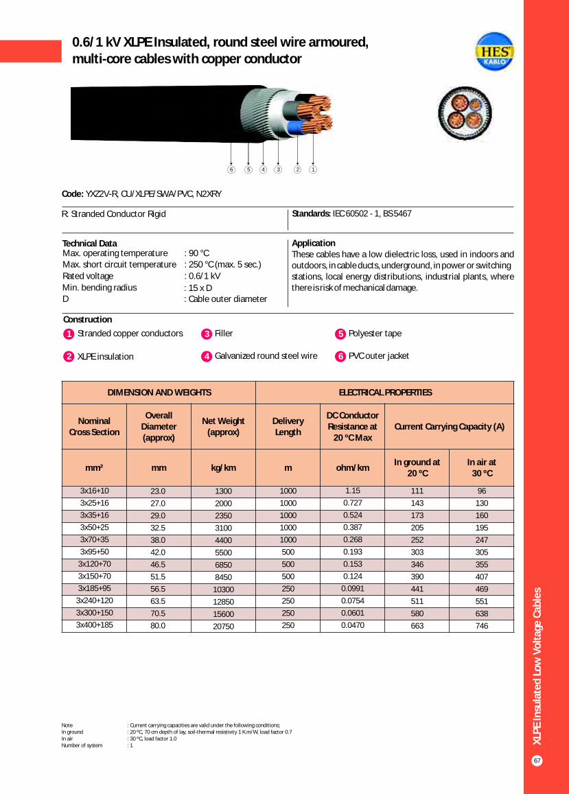
XLP
E In
sula
ted
Lo
w V
olt
age
Cab
les
67
Construction
Code: YXZ2V-R, CU/XLPE/SWA/PVC, N2XRY
R: Stranded Conductor Rigid Standards: IEC 60502 - 1, BS 5467
Technical Data ApplicationThese cables have a low dielectric loss, used in indoors and outdoors, in cable ducts, underground, in power or switchingstations, local energy distributions, industrial plants, where there is risk of mechanical damage.
Max. operating temperature : 90 °CMax. short circuit temperature : 250 °C (max. 5 sec.)
Rated voltage : 0.6/1 kV
Min. bending radius : 15 x DD : Cable outer diameter
1 3Stranded copper conductors Filler
2 XLPE insulation 4 Galvanized round steel wire
5 Polyester tape
6 PVC outer jacket
123456
DIMENSION AND WEIGHTS ELECTRICAL PROPERTIES
Nominal Cross Section
Overall Diameter (approx)
Net Weight (approx)
Delivery Length
DC Conductor Resistance at
20 ºC MaxCurrent Carrying Capacity (A)
mm² mm kg/km m ohm/kmIn ground at
20 ºCIn air at
30 ºC
96
130
160
195
247
305
355
407
469
551
638
746
3x16+10
3x25+16
3x35+16
3x50+25
3x70+35
3x95+50
3x120+70
3x150+70
3x185+95
3x240+120
3x300+150
3x400+185
23.0
27.0
29.0
32.5
38.0
42.0
46.5
51.5
56.5
63.5
70.5
80.0
1300
2000
2350
3100
4400
5500
6850
8450
10300
12850
15600
20750
1000
1000
1000
1000
1000
500
500
500
250
250
250
250
1.15
0.727
0.524
0.387
0.268
0.193
0.153
0.124
0.0991
0.0754
0.0601
0.0470
111
143
173
205
252
303
346
390
441
511
580
663
0.6/1 kV XLPE Insulated, round steel wire armoured,multi-core cables with copper conductor
Note : Current carrying capacities are valid under the following conditions;In ground : 20 ºC, 70 cm depth of lay, soil-thermal resistivity 1 K.m/W, load factor 0.7In air : 30 ºC, load factor 1.0Number of system : 1

XLP
E In
sula
ted
Lo
w V
olt
age
Cab
les
68
Construction
Code: YXZ2V-U, YXZ2V-R, CU/XLPE/SWA/PVC, N2XRY
U: Solid Conductor R: Stranded Conductor Rigid
Standards: IEC 60502 - 1, BS 5467
Technical Data ApplicationThese cables have a low dielectric loss, used in indoors and outdoors, in cable ducts, underground, in power or switchingstations, local energy distributions, industrial plants, where there is risk of mechanical damage.
Max. operating temperature : 90 °CMax. short circuit temperature : 250 °C (max. 5 sec.)
Rated voltage : 0.6/1 kV
Min. bending radius : 15 x DD : Cable outer diameter
1 3Solid or stranded copper conductor Filler
2 XLPE insulation 4 Galvanized round steel wire
5 Polyester tape
6 PVC outer jacket
123456
DIMENSION AND WEIGHTS ELECTRICAL PROPERTIES
Nominal Cross Section
Overall Diameter (approx)
Net Weight (approx)
Delivery Length
DC Conductor Resistance at
20 ºC MaxCurrent Carrying Capacity (A)
mm² mm kg/km m ohm/kmIn ground at
20 ºCIn air at
30 ºC
24
32
42
53
73
96
130
160
195
247
305
355
407
469
551
638
746
4x1.5
4x2.5
4x4
4x6
4x10
4x16
4x25
4x35
4x50
4x70
4x95
4x120
4x150
4x185
4x240
4x300
4x400
15.3
16.4
17.6
20.0
21.0
24.0
28.0
30.5
34.0
40.0
44.0
50.5
55.0
60.5
68.0
76.0
87.0
430
510
615
800
1100
1550
2150
2700
3400
4850
6150
8000
9600
11570
14550
17750
23800
1000
1000
1000
1000
1000
1000
1000
1000
1000
1000
1000
500
500
250
250
250
250
12.1
7.41
4.61
3.08
1.83
1.15
0.727
0.524
0.387
0.268
0.193
0.153
0.124
0.0991
0.0754
0.0601
0.0470
30
40
52
64
86
111
143
173
205
252
303
346
390
441
511
580
663
0.6/1 kV XLPE Insulated, round steel wire armoured,multi-core cables with copper conductor
Note : Current carrying capacities are valid under the following conditions;In ground : 20 ºC, 70 cm depth of lay, soil-thermal resistivity 1 K.m/W, load factor 0.7In air : 30 ºC, load factor 1.0Number of system : 1

XLP
E In
sula
ted
Lo
w V
olt
age
Cab
les
69
Construction
Code: YXZ2V-U, YXZ2V-R, CU/XLPE/SWA/PVC, N2XRY
U: Solid Conductor R: Stranded Conductor Rigid
Standards: IEC 60502 - 1, BS 5467
Technical Data ApplicationThese cables have a low dielectric loss, used in indoors and outdoors, in cable ducts, underground, in power or switchingstations, local energy distributions, industrial plants, where there is risk of mechanical damage.
Max. operating temperature : 90 °CMax. short circuit temperature : 250 °C (max. 5 sec.)
Rated voltage : 0.6/1 kV
Min. bending radius : 15 x DD : Cable outer diameter
1 3Solid or stranded copper conductor Filler
2 XLPE insulation 4 Galvanized round steel wire
5 Polyester tape
6 PVC outer jacket
123456
DIMENSION AND WEIGHTS ELECTRICAL PROPERTIES
Nominal Cross Section
Overall Diameter (approx)
Net Weight (approx)
Delivery Length
DC Conductor Resistance at
20 ºC MaxCurrent Carrying Capacity (A)
mm² mm kg/km m ohm/kmIn ground at
20 ºCIn air at
30 ºC
18.0
16.8
15.6
14.4
13.2
12.6
12.0
11.4
10.8
10.2
9.6
9.4
9.1
8.6
8.4
7.9
7.4
7.2
5x1.5
6x1.5
7x1.5
8x1.5
10x1.5
12x1.5
14x1.5
16x1.5
19x1.5
21x1.5
24x1.5
27x1.5
30x1.5
37x1.5
40x1.5
48x1.5
52x1.5
61x1.5
15.0
16.5
16.5
18.0
19.5
20.0
20.5
21.5
22.0
24.0
25.5
26.0
27.0
28.5
29.5
32.0
32.5
35.5
420
470
480
670
800
850
900
950
1050
1300
1450
1500
1600
1800
1950
2250
2350
2900
1000
1000
1000
1000
1000
1000
1000
1000
1000
1000
1000
1000
1000
1000
1000
1000
1000
1000
12.1
12.1
12.1
12.1
12.1
12.1
12.1
12.1
12.1
12.1
12.1
12.1
12.1
12.1
12.1
12.1
12.1
12.1
21.0
19.5
18.0
16.5
15.0
14.3
13.5
12.8
12.0
11.3
10.5
10.2
9.9
9.3
9.0
8.4
7.8
7.5
0.6/1 kV XLPE Insulated, round steel wire armoured,control cables with copper conductor
Note : Current carrying capacities are valid under the following conditions;In ground : 20 ºC, 70 cm depth of lay, soil-thermal resistivity 1 K.m/W, load factor 0.7In air : 30 ºC, load factor 1.0Number of system : 1

XLP
E In
sula
ted
Lo
w V
olt
age
Cab
les
70
Construction
Code: YXZ2V-U, YXZ2V-R, CU/XLPE/SWA/PVC, N2XRY
U: Solid Conductor R: Stranded Conductor Rigid
Standards: IEC 60502 - 1, BS 5467
Technical Data ApplicationThese cables have a low dielectric loss, used in indoors and outdoors, in cable ducts, underground, in power or switchingstations, local energy distributions, industrial plants, where there is risk of mechanical damage.
Max. operating temperature : 90 °C
Max. short circuit temperature : 250 °C (max. 5 sec.)
Rated voltage : 0.6/1 kV
Min. bending radius : 15 x DD : Cable outer diameter
1 3Solid or stranded copper conductor Filler
2 XLPE insulation 4 Galvanized round steel wire
5 Polyester tape
6 PVC outer jacket
123456
DIMENSION AND WEIGHTS ELECTRICAL PROPERTIES
Nominal Cross Section
Overall Diameter (approx)
Net Weight (approx)
Delivery Length
DC Conductor Resistance at
20 ºC MaxCurrent Carrying Capacity (A)
mm² mm kg/km m ohm/kmIn ground at
20 ºCIn air at
30 ºC
24.0
22.4
20.8
19.2
17.6
16.8
16.0
15.2
14.4
13.6
12.8
12.5
12.2
11.5
11.2
10.6
9.9
9.6
5x2.5
6x2.5
7x2.5
8x2.5
10x2.5
12x2.5
14x2.5
16x2.5
19x2.5
21x2.5
24x2.5
27x2.5
30x2.5
37x2.5
40x2.5
48x2.5
52x2.5
61x2.5
16.0
17.5
18.0
19.0
21.0
21.5
22.0
24.0
25.0
26.0
28.0
28.5
29.5
31.5
32.5
36.5
37.5
39.5
500
700
700
800
950
1050
1100
1350
1450
1600
1850
1900
2050
2300
2500
3200
3400
3750
1000
1000
1000
1000
1000
1000
1000
1000
1000
1000
1000
1000
1000
1000
1000
1000
1000
1000
7.41
7.41
7.41
7.41
7.41
7.41
7.41
7.41
7.41
7.41
7.41
7.41
7.41
7.41
7.41
7.41
7.41
7.41
28.0
26.0
24.0
22.0
20.0
19.0
18.0
16.5
16.0
15.0
14.0
13.6
13.2
12.5
12.0
11.0
10.5
10.0
0.6/1 kV XLPE Insulated, round steel wire armoured,control cables with copper conductor
Note : Current carrying capacities are valid under the following conditions;In ground : 20 ºC, 70 cm depth of lay, soil-thermal resistivity 1 K.m/W, load factor 0.7In air : 30 ºC, load factor 1.0Number of system : 1

XLP
E In
sula
ted
Lo
w V
olt
age
Cab
les
71
Construction
Code: YXZ3V-R, N2XFGY
R: Stranded Conductor Rigid Standards: IEC 60502 - 1, VDE 0276 - 603
Technical Data ApplicationThese cables have a low dielectric loss, used in indoors and outdoors, in cable ducts, underground, in power or switchingstations, local energy distributions, industrial plants, where there is risk of mechanical damage.
Max. operating temperature : 90 °C
Max. short circuit temperature : 250 °C (max. 5 sec.)
Rated voltage : 0.6/1 kV
Min. bending radius : 15 x DD : Cable outer diameter
1 3Stranded copper conductors Filler
2 XLPE insulation 4 Galvanized flat steel wire
5 Galvanized steel binding tape
6 PVC outer jacket
123456
DIMENSION AND WEIGHTS ELECTRICAL PROPERTIES
Nominal Cross Section
Overall Diameter (approx)
Net Weight (approx)
Delivery Length
DC Conductor Resistance at
20 ºC MaxCurrent Carrying Capacity (A)
mm² mm kg/km m ohm/kmIn ground at
20 ºC In air at
30 ºC
155
195
235
300
370
430
490
570
680
785
860
2x25
2x35
2x50
2x70
2x95
2x120
2x150
2x185
2x240
2x300
2x400
24.5
26.3
28.8
32.9
36.9
40.4
44.3
49.1
54.7
59.6
67.2
1410
1700
2100
2750
3500
4300
5150
6300
7950
9550
12150
1000
1000
1000
1000
1000
500
500
500
250
250
250
0.727
0.524
0.387
0.268
0.193
0.153
0124
0.0991
0.0754
0.0601
0.0470
145
175
210
255
310
355
400
455
530
605
690
0.6/1 kV XLPE Insulated, flat steel wire armoured,multi-core cables with copper conductor
Note : Current carrying capacities are valid under the following conditions;In ground : 20 ºC, 70 cm depth of lay, soil-thermal resistivity 1 K.m/W, load factor 0.7In air : 30 ºC, load factor 1.0Number of system : 1

XLP
E In
sula
ted
Lo
w V
olt
age
Cab
les
72
Construction
Code: YXZ3V-R, N2XFGY
R: Stranded Conductor Rigid Standards: IEC 60502 - 1, VDE 0276 - 603
Technical Data ApplicationThese cables have a low dielectric loss, used in indoors and outdoors, in cable ducts, underground, in power or switchingstations, local energy distributions, industrial plants, where there is risk of mechanical damage.
Max. operating temperature : 90 °CMax. short circuit temperature : 250 °C (max. 5 sec.)
Rated voltage : 0.6/1 kV
Min. bending radius : 15 x DD : Cable outer diameter
1 3Stranded copper conductors Filler
2 XLPE insulation 4 Galvanized flat steel wire
5 Galvanized steel binding tape
6 PVC outer jacket
123456
DIMENSION AND WEIGHTS ELECTRICAL PROPERTIES
Nominal Cross Section
Overall Diameter (approx)
Net Weight (approx)
Delivery Length
DC Conductor Resistance at
20 ºC MaxCurrent Carrying Capacity (A)
mm² mm kg/km m ohm/kmIn ground at
20 ºC In air at
30 ºC
130
160
195
247
305
355
407
469
551
638
746
3x25
3x35
3x50
3x70
3x95
3x120
3x150
3x185
3x240
3x300
3x400
25.0
27.0
30.0
34.5
38.5
42.5
47.0
51.5
58.5
65.5
74.0
1600
1950
2550
3450
4400
5400
6600
8000
10200
12500
16300
1000
1000
1000
1000
1000
500
500
500
250
250
250
0.727
0.524
0.387
0.268
0.193
0.153
0124
0.0991
0.0754
0.0601
0.0470
143
173
205
252
303
346
390
441
511
580
663
0.6/1 kV XLPE Insulated, flat steel wire armoured,multi-core cables with copper conductor
Note : Current carrying capacities are valid under the following conditions;In ground : 20 ºC, 70 cm depth of lay, soil-thermal resistivity 1 K.m/W, load factor 0.7In air : 30 ºC, load factor 1.0Number of system : 1

XLP
E In
sula
ted
Lo
w V
olt
age
Cab
les
73
Construction
Code: YXZ3V-R, N2XFGY
R: Stranded Conductor Rigid Standards: IEC 60502 - 1, VDE 0276 - 603
Technical Data ApplicationThese cables have a low dielectric loss, used in indoors and outdoors, in cable ducts, underground, in power or switchingstations, local energy distributions, industrial plants, where there is risk of mechanical damage.
Max. operating temperature : 90 °C
Max. short circuit temperature : 250 °C (max. 5 sec.)
Rated voltage : 0.6/1 kV
Min. bending radius : 15 x DD : Cable outer diameter
1 3Stranded copper conductors Filler
2 XLPE insulation 4 Galvanized flat steel wire
5 Galvanized steel binding tape
6 PVC outer jacket
123456
DIMENSION AND WEIGHTS ELECTRICAL PROPERTIES
Nominal Cross Section
Overall Diameter (approx)
Net Weight (approx)
Delivery Length
DC Conductor Resistance at
20 ºC MaxCurrent Carrying Capacity (A)
mm² mm kg/km m ohm/kmIn ground at
20 ºC In air at
30 ºC
130
160
195
247
305
355
407
469
551
638
746
3x25+16
3x35+16
3x50+25
3x70+35
3x95+50
3x120+70
3x150+70
3x185+95
3x240+120
3x300+150
3x400+185
26.0
27.5
31.5
35.5
40.0
44.5
48.5
53.5
60.5
67.5
75.5
1800
2150
2800
3800
4900
6100
7250
8900
11350
13900
18000
1000
1000
1000
1000
500
500
500
500
250
250
250
0.727
0.524
0.387
0.268
0.193
0.153
0124
0.0991
0.0754
0.0601
0.0470
143
173
205
252
303
346
390
441
511
580
663
0.6/1 kV XLPE Insulated, flat steel wire armoured,multi-core cables with copper conductor
Note : Current carrying capacities are valid under the following conditions;In ground : 20 ºC, 70 cm depth of lay, soil-thermal resistivity 1 K.m/W, load factor 0.7In air : 30 ºC, load factor 1.0Number of system : 1

XLP
E In
sula
ted
Lo
w V
olt
age
Cab
les
74
Construction
Code: YXZ3V-R, N2XFGY
R: Stranded Conductor Rigid Standards: IEC 60502 - 1, VDE 0276 - 603
Technical Data ApplicationThese cables have a low dielectric loss, used in indoors and outdoors, in cable ducts, underground, in power or switchingstations, local energy distributions, industrial plants, where there is risk of mechanical damage.
Max. operating temperature : 90 °CMax. short circuit temperature : 250 °C (max. 5 sec.)
Rated voltage : 0.6/1 kV
Min. bending radius : 15 x DD : Cable outer diameter
1 3Stranded copper conductors Filler
2 XLPE insulation 4 Galvanized flat steel wire
5 Galvanized steel binding tape
6 PVC outer jacket
123456
DIMENSION AND WEIGHTS ELECTRICAL PROPERTIES
Nominal Cross Section
Overall Diameter (approx)
Net Weight (approx)
Delivery Length
DC Conductor Resistance at
20 ºC MaxCurrent Carrying Capacity (A)
mm² mm kg/km m ohm/kmIn ground at
20 ºC In air at
30 ºC
96
130
160
195
247
305
355
407
469
551
638
746
4x16
4x25
4x35
4x50
4x70
4x95
4x120
4x150
4x185
4x240
4x300
4x400
23.0
27.0
29.0
33.0
38.0
42.0
47.0
51.5
57.0
64.5
72.5
82.5
1350
1900
2400
3150
4300
5500
6850
8250
10100
12900
15900
20800
1000
1000
1000
1000
1000
500
500
500
250
250
250
250
1.15
0.727
0.524
0.387
0.268
0.193
0.153
0.124
0.0991
0.0754
0.0601
0.0470
111
143
173
205
252
303
346
390
441
511
580
663
0.6/1 kV XLPE Insulated, flat steel wire armoured,multi-core cables with copper conductor
Note : Current carrying capacities are valid under the following conditions;In ground : 20 ºC, 70 cm depth of lay, soil-thermal resistivity 1 K.m/W, load factor 0.7In air : 30 ºC, load factor 1.0Number of system : 1
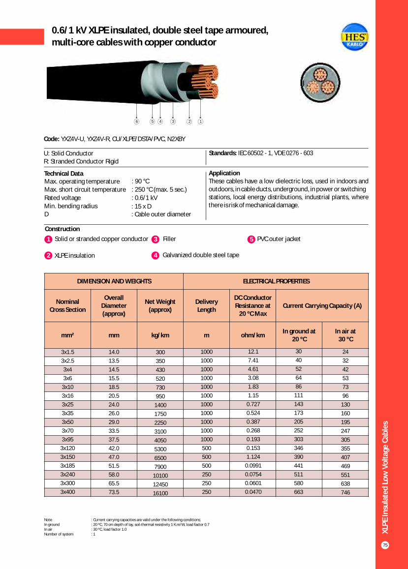
XLP
E In
sula
ted
Lo
w V
olt
age
Cab
les
75
0.6/1 kV XLPE insulated, double steel tape armoured,multi-core cables with copper conductor
Construction
Code: YXZ4V-U, YXZ4V-R, CU/XLPE/DSTA/PVC, N2XBY
U: Solid Conductor R: Stranded Conductor Rigid
Standards: IEC 60502 - 1, VDE 0276 - 603
Technical Data ApplicationThese cables have a low dielectric loss, used in indoors and outdoors, in cable ducts, underground, in power or switchingstations, local energy distributions, industrial plants, where there is risk of mechanical damage.
Max. operating temperature : 90 °C
Max. short circuit temperature : 250 °C (max. 5 sec.)
Rated voltage : 0.6/1 kV
Min. bending radius : 15 x DD : Cable outer diameter
1 3Solid or stranded copper conductor Filler
2 XLPE insulation 4 Galvanized double steel tape
5 PVC outer jacket
123456
DIMENSION AND WEIGHTS ELECTRICAL PROPERTIES
Nominal Cross Section
Overall Diameter (approx)
Net Weight (approx)
Delivery Length
DC Conductor Resistance at
20 ºC MaxCurrent Carrying Capacity (A)
mm² mm kg/km m ohm/kmIn ground at
20 ºC In air at
30 ºC
24
32
42
53
73
96
130
160
195
247
305
355
407
469
551
638
746
3x1.5
3x2.5
3x4
3x6
3x10
3x16
3x25
3x35
3x50
3x70
3x95
3x120
3x150
3x185
3x240
3x300
3x400
14.0
13.5
14.5
15.5
18.5
20.5
24.0
26.0
29.0
33.5
37.5
42.0
47.0
51.5
58.0
65.5
73.5
300
350
430
520
730
950
1400
1750
2250
3100
4050
5300
6500
7900
10100
12450
16100
1000
1000
1000
1000
1000
1000
1000
1000
1000
1000
1000
500
500
500
250
250
250
12.1
7.41
4.61
3.08
1.83
1.15
0.727
0.524
0.387
0.268
0.193
0.153
1.124
0.0991
0.0754
0.0601
0.0470
30
40
52
64
86
111
143
173
205
252
303
346
390
441
511
580
663
Note : Current carrying capacities are valid under the following conditions;In ground : 20 ºC, 70 cm depth of lay, soil-thermal resistivity 1 K.m/W, load factor 0.7In air : 30 ºC, load factor 1.0Number of system : 1

XLP
E In
sula
ted
Lo
w V
olt
age
Cab
les
76
0.6/1 kV XLPE insulated, double steel tape armoured,multi-core cables with copper conductor
Construction
Code: YXZ4V-R, CU/XLPE/DSTA/PVC, N2XBY
R: Stranded Conductor Rigid Standards: IEC 60502 - 1, VDE 0276 - 603
Technical Data ApplicationThese cables have a low dielectric loss, used in indoors and outdoors, in cable ducts, underground, in power or switchingstations, local energy distributions, industrial plants, where there is risk of mechanical damage.
Max. operating temperature : 90 °CMax. short circuit temperature : 250 °C (max. 5 sec.)
Rated voltage : 0.6/1 kV
Min. bending radius : 15 x DD : Cable outer diameter
1 3Stranded copper conductors Filler
2 XLPE insulation 4 Galvanized double steel tape
5 PVC outer jacket
12345
DIMENSION AND WEIGHTS ELECTRICAL PROPERTIES
Nominal Cross Section
Overall Diameter (approx)
Net Weight (approx)
Delivery Length
DC Conductor Resistance at
20 ºC MaxCurrent Carrying Capacity (A)
mm² mm kg/km m ohm/kmIn ground at
20 ºC In air at
30 ºC
96
130
160
195
247
305
355
407
469
551
638
746
3x16+10
3x25+16
3x35+16
3x50+25
3x70+35
3x95+50
3x120+70
3x150+70
3x185+95
3x240+120
3x300+150
3x400+185
21.5
25.0
26.5
30.5
34.5
39.5
44.5
48.0
53.5
60.0
67.0
75.0
1100
1550
1900
2550
3500
4800
6050
7150
8850
11250
13800
17700
1000
1000
1000
1000
1000
1000
500
500
500
250
250
250
1.15
0.727
0.524
0.387
0.268
0.193
0.153
0.124
0.0991
0.0754
0.0601
0.0470
111
143
173
205
252
303
346
390
441
511
580
663
Note : Current carrying capacities are valid under the following conditions;In ground : 20 ºC, 70 cm depth of lay, soil-thermal resistivity 1 K.m/W, load factor 0.7In air : 30 ºC, load factor 1.0Number of system : 1

XLP
E In
sula
ted
Lo
w V
olt
age
Cab
les
77
0.6/1 kV XLPE insulated, double steel tape armoured,multi-core cables with copper conductor
Construction
Code: YXZ4V-U, YXZ4V-R, CU/XLPE/DSTA/PVC, N2XBY
U: Solid Conductor R: Stranded Conductor Rigid
Standards: IEC 60502 - 1, VDE 0276 - 603
Technical Data ApplicationThese cables have a low dielectric loss, used in indoors and outdoors, in cable ducts, underground, in power or switchingstations, local energy distributions, industrial plants, where there is risk of mechanical damage.
Max. operating temperature : 90 °C
Max. short circuit temperature : 250 °C (max. 5 sec.)
Rated voltage : 0.6/1 kV
Min. bending radius : 15 x DD : Cable outer diameter
1 3Solid or stranded copper conductor Filler
2 XLPE insulation 4 Galvanized double steel tape
5 PVC outer jacket
12345
DIMENSION AND WEIGHTS ELECTRICAL PROPERTIES
Nominal Cross Section
Overall Diameter (approx)
Net Weight (approx)
Delivery Length
DC Conductor Resistance at
20 ºC MaxCurrent Carrying Capacity (A)
mm² mm kg/km m ohm/kmIn ground at
20 ºC In air at
30 ºC
24
32
42
53
73
96
130
160
195
247
305
355
407
469
551
638
746
4x1.5
4x2.5
4x4
4x6
4x10
4x16
4x25
4x35
4x50
4x70
4x95
4x120
4x150
4x185
4x240
4x300
4x400
13.5
14.5
15.5
17.0
19.5
22.0
26.0
28.0
31.5
37.0
42.0
47.0
51.5
57.0
64.5
72.5
82.0
330
400
500
600
900
1150
1700
2150
2850
3950
5400
6750
8200
10000
12800
15800
20600
1000
1000
1000
1000
1000
1000
1000
1000
1000
1000
500
500
500
250
250
250
250
12.1
7.41
4.61
3.08
1.83
1.15
0.727
0.524
0.387
0.268
0.193
0.153
1.124
0.0991
0.0754
0.0601
0.0470
30
40
52
64
86
111
143
173
205
252
303
346
390
441
511
580
663
Note : Current carrying capacities are valid under the following conditions;In ground : 20 ºC, 70 cm depth of lay, soil-thermal resistivity 1 K.m/W, load factor 0.7In air : 30 ºC, load factor 1.0Number of system : 1

DIMENSION AND WEIGHTS ELECTRICAL PROPERTIES
Nominal Cross
Section
Overall Diameter (approx)
Net Weight (approx)
Delivery Length
DC Conductor Resistance at
20 ºC MaxCurrent Carrying Capacity (A)
mm² mm kg/km m ohm/km
In ground at 20 ºC In air at 30 ºC
*** ** * *** ** *
XLP
E In
sula
ted
Lo
w V
olt
age
Cab
les
78
0.6 / 1 kV XLPE insulated single core cableswith aluminium conductor
Construction
Code: YAXV-R, AL/XLPE/PVC, NA2XY
R: Stranded Conductor Rigid Standards: IEC 60502 - 1, VDE 0276 - 603, BS 7889
Technical Data ApplicationThese cables have a low dielectric loss, used in indoors and outdoors, in cable ducts, underground, in power or switchingstations, local energy distributions, industrial plants, where there is no risk of mechanical damage.
Max. operating temperature : 90 °CMax. short circuit temperature : 250 °C (max. 5 sec.)
Rated voltage : 0.6/1 kV
Min. bending radius : 15 x DD : Cable outer diameter
1 3Stranded aluminium conductor PVC outer jacket
2 XLPE insulation
123
1x25
1x35
1x50
1x70
1x95
1x120
1x150
1x185
1x240
1x300
1x400
1x500
10.5
12.0
13.5
15.5
17.0
19.0
21.0
23.0
26.0
27.0
31.0
35.0
150
180
250
300
400
500
600
750
950
1150
1450
1800
1000
1000
1000
1000
1000
1000
1000
1000
1000
1000
1000
1000
1.200
0.868
0.641
0.443
0.320
0.253
0.206
0.164
0.125
0.100
0.0778
0.0605
-
164
195
238
284
323
361
408
476
537
616
699
114
137
163
201
240
274
308
348
408
462
531
601
-
163
200
254
313
366
420
486
585
675
798
926
106
131
161
205
253
296
341
395
475
548
647
749
Note : Current carrying capacities are valid under the following conditions;In ground : 20 ºC, 70 cm depth of lay, soil-thermal resistivity 1 K.m/W, load factor 0.7In air : 30 ºC, load factor 1.0*** : Flat formation, clearance between cables; in air = 1 x Cable outer diameter, in ground = 7 cm : Trefoil formationNumber of system : 1
** *

XLP
E In
sula
ted
Lo
w V
olt
age
Cab
les
79
0.6 / 1 kV XLPE insulated multi-core cableswith aluminium conductor
Construction
Code: YAXV-R, AL/XLPE/PVCV, NA2XY
R: Stranded Conductor Rigid Standards: IEC 60502 - 1, VDE 0276 - 603, BS 7889
Technical Data ApplicationThese cables have a low dielectric loss, used in indoors and outdoors, in cable ducts, underground, in power or switchingstations, local energy distributions, industrial plants, where there is no risk of mechanical damage.
Max. operating temperature : 90 °C
Max. short circuit temperature : 250 °C (max. 5 sec.)
Rated voltage : 0.6/1 kV
Min. bending radius : 12 x DD : Cable outer diameter
1 3Stranded aluminium conductor Filler
2 XLPE insulation 4 PVC outer jacket
1234
DIMENSION AND WEIGHTS ELECTRICAL PROPERTIES
Nominal Cross Section
Overall Diameter (approx)
Net Weight (approx)
Delivery Length
DC Conductor Resistance at
20 ºC MaxCurrent Carrying Capacity (A)
mm² mm kg/km m ohm/kmIn ground at
20 ºC In air at
30 ºC
115
140
175
220
270
2x25
2x35
2x50
2x70
2x95
21.5
23.3
25.8
29.7
33.9
600
700
900
1200
1550
1000
1000
1000
1000
1000
1.20
0.868
0.641
0.443
0.320
110
130
155
195
235
Note : Current carrying capacities are valid under the following conditions;In ground : 20 ºC, 70 cm depth of lay, soil-thermal resistivity 1 K.m/W, load factor 0.7In air : 30 ºC, load factor 1.0Number of system : 1

XLP
E In
sula
ted
Lo
w V
olt
age
Cab
les
80
0.6 / 1 kV XLPE insulated multi-core cableswith aluminium conductor
Construction
Code: YAXV-R, AL/XLPE/PVC, NA2XY
R: Stranded Conductor Rigid Standards: IEC 60502 - 1, VDE 0276 - 603, BS 7889
Technical Data ApplicationThese cables have a low dielectric loss, used in indoors and outdoors, in cable ducts, underground, in power or switchingstations, local energy distributions, industrial plants, where there is no risk of mechanical damage.
Max. operating temperature : 90 °CMax. short circuit temperature : 250 °C (max. 5 sec.)
Rated voltage : 0.6/1 kV
Min. bending radius : 12 x DD : Cable outer diameter
1 3Stranded aluminium conductor Filler
2 XLPE insulation 4 PVC outer jacket
1234
DIMENSION AND WEIGHTS ELECTRICAL PROPERTIES
Nominal Cross Section
Overall Diameter (approx)
Net Weight (approx)
Delivery Length
DC Conductor Resistance at
20 ºC MaxCurrent Carrying Capacity (A)
mm² mm kg/km m ohm/kmIn ground at
20 ºC In air at
30 ºC
100
122
147
189
232
270
308
357
435
501
592
3x25
3x35
3x50
3x70
3x95
3x120
3x150
3x185
3x240
3x300
3x400
22.5
25.0
28.5
33.0
37.0
41.0
46.0
50.5
57.0
62.5
71.0
650
800
1100
1500
1850
2300
2900
3500
4450
5450
7100
1000
1000
1000
1000
1000
1000
1000
1000
1000
500
500
1.20
0.868
0.641
0.443
0.320
0.253
0.206
0.164
0.125
0.100
0.0778
111
132
157
195
233
266
299
340
401
455
526
Note : Current carrying capacities are valid under the following conditions;In ground : 20 ºC, 70 cm depth of lay, soil-thermal resistivity 1 K.m/W, load factor 0.7In air : 30 ºC, load factor 1.0Number of system : 1

XLP
E In
sula
ted
Lo
w V
olt
age
Cab
les
81
0.6 / 1 kV XLPE insulated multi-core cableswith aluminium conductor
Construction
Code: YAXV-R, AL/XLPE/PVC, NA2XY
R: Stranded Conductor Rigid Standards: IEC 60502 - 1, VDE 0276 - 603, BS 7889
Technical Data ApplicationThese cables have a low dielectric loss, used in indoors and outdoors, in cable ducts, underground, in power or switchingstations, local energy distributions, industrial plants, where there is no risk of mechanical damage.
Max. operating temperature : 90 °C
Max. short circuit temperature : 250 °C (max. 5 sec.)
Rated voltage : 0.6/1 kV
Min. bending radius : 12 x DD : Cable outer diameter
1 3Stranded aluminium conductor Filler
2 XLPE insulation 4 PVC outer jacket
1234
DIMENSION AND WEIGHTS ELECTRICAL PROPERTIES
Nominal Cross Section
Overall Diameter (approx)
Net Weight (approx)
Delivery Length
DC Conductor Resistance at
20 ºC MaxCurrent Carrying Capacity (A)
mm² mm kg/km m ohm/kmIn ground at
20 ºC In air at
30 ºC
100
122
147
189
232
270
308
357
435
501
592
3x25+16
3x35+16
3x50+25
3x70+35
3x95+50
3x120+70
3x150+70
3x185+95
3x240+120
3x300+150
3x400+185
23.5
25.5
30.0
34.5
39.0
43.0
47.5
52.5
59.0
65.0
73.5
750
850
1200
1600
2050
2550
3100
3800
4800
5900
7550
1000
1000
1000
1000
1000
1000
1000
1000
500
500
500
1.20
0.868
0.641
0.443
0.320
0.253
0.206
0.164
0.125
0.100
0.0778
111
132
157
195
233
266
299
340
401
455
526
Note : Current carrying capacities are valid under the following conditions;In ground : 20 ºC, 70 cm depth of lay, soil-thermal resistivity 1 K.m/W, load factor 0.7In air : 30 ºC, load factor 1.0Number of system : 1

XLP
E In
sula
ted
Lo
w V
olt
age
Cab
les
82
0.6 / 1 kV XLPE insulated multi-core cableswith aluminium conductor
Construction
Code: YAXV-R, AL/XLPE/PVC, NA2XY
R: Stranded Conductor Rigid Standards: IEC 60502 - 1, VDE 0276 - 603, BS 7889
Technical Data ApplicationThese cables have a low dielectric loss, used in indoors and outdoors, in cable ducts, underground, in power or switchingstations, local energy distributions, industrial plants, where there is no risk of mechanical damage.
Max. operating temperature : 90 °CMax. short circuit temperature : 250 °C (max. 5 sec.)
Rated voltage : 0.6/1 kV
Min. bending radius : 12 x DD : Cable outer diameter
1 3Stranded aluminium conductor Filler
2 XLPE insulation 4 PVC outer jacket
1234
DIMENSION AND WEIGHTS ELECTRICAL PROPERTIES
Nominal Cross Section
Overall Diameter (approx)
Net Weight (approx)
Delivery Length
DC Conductor Resistance at
20 ºC MaxCurrent Carrying Capacity (A)
mm² mm kg/km m ohm/kmIn ground at
20 ºC In air at
30 ºC
100
122
147
189
232
270
308
357
435
501
592
4x25
4x35
4x50
4x70
4x95
4x120
4x150
4x185
4x240
4x300
4x400
24.5
27.5
31.5
36.5
41.0
46.0
51.0
56.5
63.0
69.5
79.5
800
1000
1350
1800
2300
2900
3550
4350
5550
6750
8900
1000
1000
1000
1000
1000
1000
1000
1000
500
500
500
1.20
0.868
0.641
0.443
0.320
0.253
0.206
0.164
0.125
0.100
0.0778
111
132
157
195
233
266
299
340
401
455
526
Note : Current carrying capacities are valid under the following conditions;In ground : 20 ºC, 70 cm depth of lay, soil-thermal resistivity 1 K.m/W, load factor 0.7In air : 30 ºC, load factor 1.0Number of system : 1
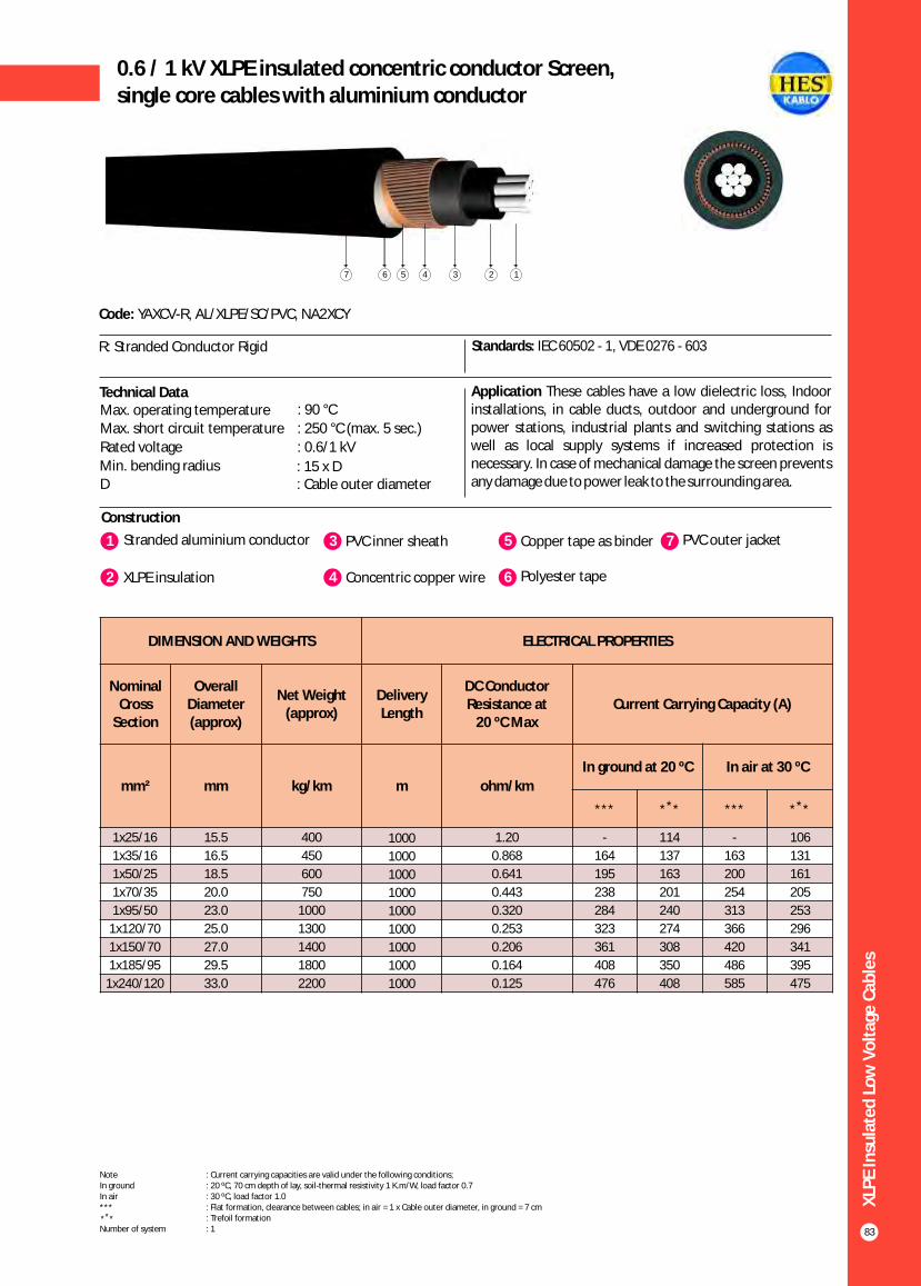
XLP
E In
sula
ted
Lo
w V
olt
age
Cab
les
83
0.6 / 1 kV XLPE insulated concentric conductor Screen,single core cables with aluminium conductor
Construction
Code: YAXCV-R, AL/XLPE/SC/PVC, NA2XCY
R: Stranded Conductor Rigid Standards: IEC 60502 - 1, VDE 0276 - 603
Technical Data Application These cables have a low dielectric loss, Indoor installations, in cable ducts, outdoor and underground for power stations, industrial plants and switching stations as well as local supply systems if increased protection is necessary. In case of mechanical damage the screen prevents any damage due to power leak to the surrounding area.
Max. operating temperature : 90 °C
Max. short circuit temperature : 250 °C (max. 5 sec.)
Rated voltage : 0.6/1 kV
Min. bending radius : 15 x DD : Cable outer diameter
1 3Stranded aluminium conductor PVC inner sheath
2 XLPE insulation 4 Concentric copper wire
5 Copper tape as binder
6 Polyester tape
7 PVC outer jacket
1234567
1x25/16
1x35/16
1x50/25
1x70/35
1x95/50
1x120/70
1x150/70
1x185/95
1x240/120
15.5
16.5
18.5
20.0
23.0
25.0
27.0
29.5
33.0
400
450
600
750
1000
1300
1400
1800
2200
1000
1000
1000
1000
1000
1000
1000
1000
1000
1.20
0.868
0.641
0.443
0.320
0.253
0.206
0.164
0.125
-
164
195
238
284
323
361
408
476
114
137
163
201
240
274
308
350
408
-
163
200
254
313
366
420
486
585
106
131
161
205
253
296
341
395
475
DIMENSION AND WEIGHTS ELECTRICAL PROPERTIES
Nominal Cross
Section
Overall Diameter (approx)
Net Weight (approx)
Delivery Length
DC Conductor Resistance at
20 ºC MaxCurrent Carrying Capacity (A)
mm² mm kg/km m ohm/km
In ground at 20 ºC In air at 30 ºC
*** ** * *** ** *
Note : Current carrying capacities are valid under the following conditions;In ground : 20 ºC, 70 cm depth of lay, soil-thermal resistivity 1 K.m/W, load factor 0.7In air : 30 ºC, load factor 1.0*** : Flat formation, clearance between cables; in air = 1 x Cable outer diameter, in ground = 7 cm : Trefoil formationNumber of system : 1
** *
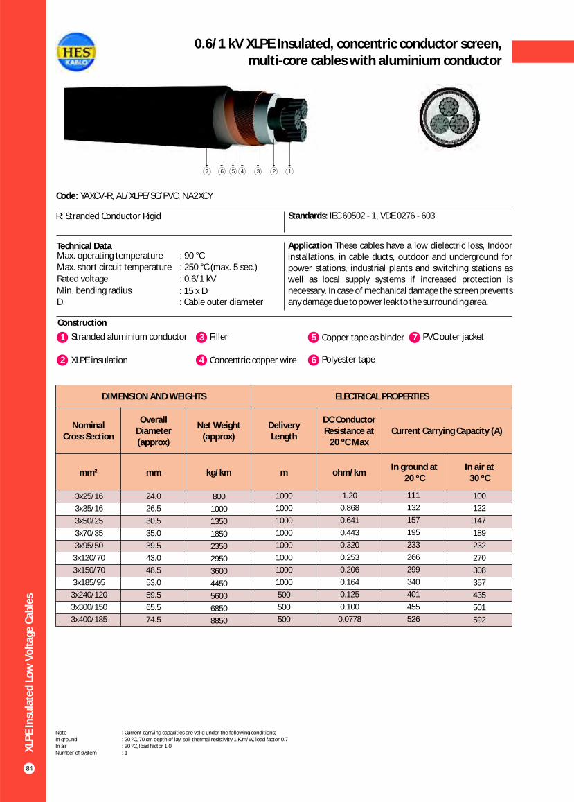
XLP
E In
sula
ted
Lo
w V
olt
age
Cab
les
84
0.6/1 kV XLPE Insulated, concentric conductor screen,multi-core cables with aluminium conductor
Construction
Code: YAXCV-R, AL/XLPE/SC/PVC, NA2XCY
R: Stranded Conductor Rigid Standards: IEC 60502 - 1, VDE 0276 - 603
Technical Data Application These cables have a low dielectric loss, Indoor installations, in cable ducts, outdoor and underground for power stations, industrial plants and switching stations as well as local supply systems if increased protection is necessary. In case of mechanical damage the screen prevents any damage due to power leak to the surrounding area.
Max. operating temperature : 90 °CMax. short circuit temperature : 250 °C (max. 5 sec.)
Rated voltage : 0.6/1 kV
Min. bending radius : 15 x DD : Cable outer diameter
1 3Stranded aluminium conductor Filler
2 XLPE insulation 4 Concentric copper wire
5 Copper tape as binder
6 Polyester tape
7 PVC outer jacket
1234567
DIMENSION AND WEIGHTS ELECTRICAL PROPERTIES
Nominal Cross Section
Overall Diameter (approx)
Net Weight (approx)
Delivery Length
DC Conductor Resistance at
20 ºC MaxCurrent Carrying Capacity (A)
mm² mm kg/km m ohm/kmIn ground at
20 ºC In air at
30 ºC
100
122
147
189
232
270
308
357
435
501
592
3x25/16
3x35/16
3x50/25
3x70/35
3x95/50
3x120/70
3x150/70
3x185/95
3x240/120
3x300/150
3x400/185
24.0
26.5
30.5
35.0
39.5
43.0
48.5
53.0
59.5
65.5
74.5
800
1000
1350
1850
2350
2950
3600
4450
5600
6850
8850
1000
1000
1000
1000
1000
1000
1000
1000
500
500
500
1.20
0.868
0.641
0.443
0.320
0.253
0.206
0.164
0.125
0.100
0.0778
111
132
157
195
233
266
299
340
401
455
526
Note : Current carrying capacities are valid under the following conditions;In ground : 20 ºC, 70 cm depth of lay, soil-thermal resistivity 1 K.m/W, load factor 0.7In air : 30 ºC, load factor 1.0Number of system : 1

XLP
E In
sula
ted
Lo
w V
olt
age
Cab
les
85
0.6/1 kV XLPE Insulated, round aluminium wire armoured,single-core cables with aluminium conductor
Construction
Code: YAXY2V-R, AL/XLPE/AWA/PVC, NA2XR(A)Y
R: Stranded Conductor Rigid Standards: IEC 60502 - 1, BS 5467
Technical Data ApplicationThese cables have a low dielectric loss, used in indoors and outdoors, in cable ducts, underground, in power or switchingstations, local energy distributions, industrial plants, where there is risk of mechanical damage.
Max. operating temperature : 90 °C
Max. short circuit temperature : 250 °C (max. 5 sec.)
Rated voltage : 0.6/1 kV
Min. bending radius : 15 x DD : Cable outer diameter
1 3Stranded aluminium conductor PVC inner sheath
2 XLPE insulation 4 Round aluminium wire
5 Polyester tape
6 PVC outer jacket
123456
1x25
1x35
1x50
1x70
1x95
1x120
1x150
1x185
1x240
1x300
1x400
1x500
15.5
17.5
19.5
21.0
23.5
25.0
27.0
29.5
32.0
35.5
39.5
43.0
300
400
450
600
750
850
1000
1150
1400
1750
2150
2600
1000
1000
1000
1000
1000
1000
1000
1000
1000
1000
1000
1000
1.20
0.868
0.641
0.443
0.320
0.253
0.206
0.164
0.125
0.100
0.0778
0.0605
-
164
195
238
284
323
361
408
476
537
616
699
114
137
163
201
240
274
308
350
408
462
531
601
-
163
200
254
313
366
420
486
585
675
798
926
106
131
161
205
253
296
341
395
475
548
647
749
DIMENSION AND WEIGHTS ELECTRICAL PROPERTIES
Nominal Cross
Section
Overall Diameter (approx)
Net Weight (approx)
Delivery Length
DC Conductor Resistance at
20 ºC MaxCurrent Carrying Capacity (A)
mm² mm kg/km m ohm/km
In ground at 20 ºC In air at 30 ºC
*** ** * *** ** *
Note : Current carrying capacities are valid under the following conditions;In ground : 20 ºC, 70 cm depth of lay, soil-thermal resistivity 1 K.m/W, load factor 0.7In air : 30 ºC, load factor 1.0*** : Flat formation, clearance between cables; in air = 1 x Cable outer diameter, in ground = 7 cm : Trefoil formationNumber of system : 1
** *

XLP
E In
sula
ted
Lo
w V
olt
age
Cab
les
86
0.6/1 kV XLPE Insulated, round steel wire armoured,multi-core cables with aluminium conductor
Construction
Code: YAXZ2V-R, AL/XLPE/SWA/PVC, NA2XRY
R: Stranded Conductor Rigid Standards: IEC 60502 - 1, BS 5467
Technical Data ApplicationThese cables have a low dielectric loss, used in indoors and outdoors, in cable ducts, underground, in power or switchingstations, local energy distributions, industrial plants, where there is risk of mechanical damage.
Max. operating temperature : 90 °CMax. short circuit temperature : 250 °C (max. 5 sec.)
Rated voltage : 0.6/1 kV
Min. bending radius : 15 x DD : Cable outer diameter
1 3Stranded aluminium conductor Filler
2 XLPE insulation 4 Galvanized round steel wire
5 Polyester tape
6 PVC outer jacket
123456
DIMENSION AND WEIGHTS ELECTRICAL PROPERTIES
Nominal Cross Section
Overall Diameter (approx)
Net Weight (approx)
Delivery Length
DC Conductor Resistance at
20 ºC MaxCurrent Carrying Capacity (A)
mm² mm kg/km m ohm/kmIn ground at
20 ºC In air at
30 ºC
100
122
147
189
232
270
308
357
435
501
592
3x25
3x35
3x50
3x70
3x95
3x120
3x150
3x185
3x240
3x300
3x400
26.0
28.5
31.0
36.0
40.0
44.0
50.0
55.0
61.0
66.0
75.0
1300
1550
1800
2600
3300
3850
4900
5750
7150
8000
10000
1000
1000
1000
1000
1000
1000
500
500
500
500
250
1.20
0.868
0.641
0.443
0.320
0.253
0.206
0.164
0.125
0.100
0.0778
111
132
157
195
233
266
299
340
401
455
526
Note : Current carrying capacities are valid under the following conditions;In ground : 20 ºC, 70 cm depth of lay, soil-thermal resistivity 1 K.m/W, load factor 0.7In air : 30 ºC, load factor 1.0Number of system : 1

XLP
E In
sula
ted
Lo
w V
olt
age
Cab
les
87
0.6/1 kV XLPE Insulated, round steel wire armoured,multi-core cables with aluminium conductor
Construction
Code: YAXZ2V-R, AL/XLPE/SWA/PVC, NA2XRY
R: Stranded Conductor Rigid Standards: IEC 60502 - 1, BS 5467
Technical Data ApplicationThese cables have a low dielectric loss, used in indoors and outdoors, in cable ducts, underground, in power or switchingstations, local energy distributions, industrial plants, where there is risk of mechanical damage.
Max. operating temperature : 90 °C
Max. short circuit temperature : 250 °C (max. 5 sec.)
Rated voltage : 0.6/1 kV
Min. bending radius : 15 x DD : Cable outer diameter
1 3Stranded aluminium conductor Filler
2 XLPE insulation 4 Galvanized round steel wire
5 Polyester tape
6 PVC outer jacket
123456
DIMENSION AND WEIGHTS ELECTRICAL PROPERTIES
Nominal Cross Section
Overall Diameter (approx)
Net Weight (approx)
Delivery Length
DC Conductor Resistance at
20 ºC MaxCurrent Carrying Capacity (A)
mm² mm kg/km m ohm/kmIn ground at
20 ºC In air at
30 ºC
100
122
147
189
232
270
308
357
435
501
592
3x25+16
3x35+16
3x50+25
3x70+35
3x95+50
3x120+70
3x150+70
3x185+95
3x240+120
3x300+150
3x400+185
27.0
29.0
32.0
37.5
41.5
45.5
51.5
57.0
64.0
68.0
76.5
1400
1600
1950
2900
3500
4200
5300
6200
7600
8450
10400
1000
1000
1000
1000
1000
1000
500
500
500
500
250
1.20
0.868
0.641
0.443
0.320
0.253
0.206
0.164
0.125
0.100
0.0778
111
132
157
195
233
266
299
340
401
455
526
Note : Current carrying capacities are valid under the following conditions;In ground : 20 ºC, 70 cm depth of lay, soil-thermal resistivity 1 K.m/W, load factor 0.7In air : 30 ºC, load factor 1.0Number of system : 1

XLP
E In
sula
ted
Lo
w V
olt
age
Cab
les
88
0.6/1 kV XLPE Insulated, round steel wire armoured,multi-core cables with aluminium conductor
Construction
Code: YAXZ2V-R, AL/XLPE/SWA/PVC, NA2XRY
R: Stranded Conductor Rigid Standards: IEC 60502 - 1, BS 5467
Technical Data ApplicationThese cables have a low dielectric loss, used in indoors and outdoors, in cable ducts, underground, in power or switchingstations, local energy distributions, industrial plants, where there is risk of mechanical damage.
Max. operating temperature : 90 °CMax. short circuit temperature : 250 °C (max. 5 sec.)
Rated voltage : 0.6/1 kV
Min. bending radius : 15 x DD : Cable outer diameter
1 3Stranded aluminium conductor Filler
2 XLPE insulation 4 Galvanized round steel wire
5 Polyester tape
6 PVC outer jacket
123456
DIMENSION AND WEIGHTS ELECTRICAL PROPERTIES
Nominal Cross Section
Overall Diameter (approx)
Net Weight (approx)
Delivery Length
DC Conductor Resistance at
20 ºC MaxCurrent Carrying Capacity (A)
mm² mm kg/km m ohm/kmIn ground at
20 ºC In air at
30 ºC
100
122
147
189
232
270
308
357
435
501
592
4x25
4x35
4x50
4x70
4x95
4x120
4x150
4x185
4x240
4x300
4x400
28.0
31.0
35.0
41.0
45.5
51.5
56.5
62.0
68.5
75.0
86.5
1500
1800
2300
3200
3850
5100
6000
7000
8500
10000
13650
1000
1000
1000
1000
1000
500
500
500
500
500
250
1.20
0.868
0.641
0.443
0.320
0.253
0.206
0.164
0.125
0.100
0.0778
111
132
157
195
233
266
299
340
401
455
526
Note : Current carrying capacities are valid under the following conditions;In ground : 20 ºC, 70 cm depth of lay, soil-thermal resistivity 1 K.m/W, load factor 0.7In air : 30 ºC, load factor 1.0Number of system : 1
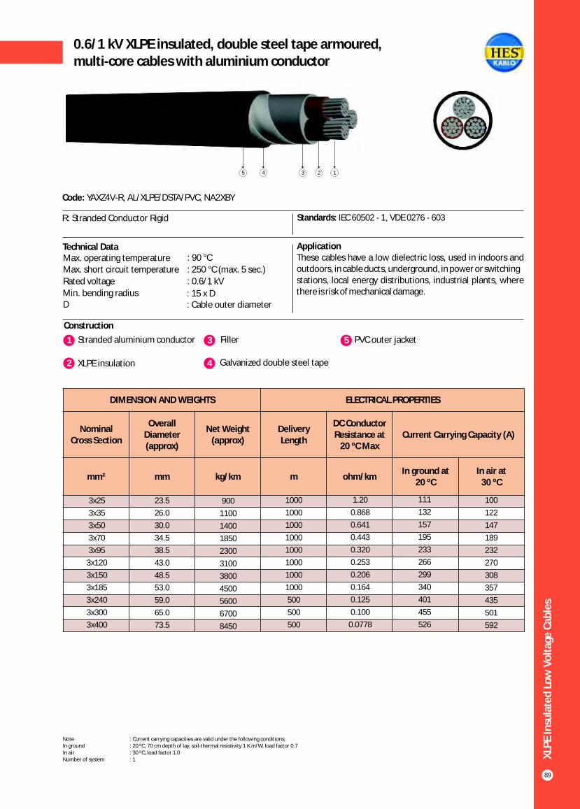
XLP
E In
sula
ted
Lo
w V
olt
age
Cab
les
89
0.6/1 kV XLPE insulated, double steel tape armoured,multi-core cables with aluminium conductor
Construction
Code: YAXZ4V-R, AL/XLPE/DSTA/PVC, NA2XBY
R: Stranded Conductor Rigid Standards: IEC 60502 - 1, VDE 0276 - 603
Technical Data ApplicationThese cables have a low dielectric loss, used in indoors and outdoors, in cable ducts, underground, in power or switchingstations, local energy distributions, industrial plants, where there is risk of mechanical damage.
Max. operating temperature : 90 °C
Max. short circuit temperature : 250 °C (max. 5 sec.)
Rated voltage : 0.6/1 kV
Min. bending radius : 15 x DD : Cable outer diameter
1 3Stranded aluminium conductor Filler
2 XLPE insulation 4 Galvanized double steel tape
5 PVC outer jacket
12345
DIMENSION AND WEIGHTS ELECTRICAL PROPERTIES
Nominal Cross Section
Overall Diameter (approx)
Net Weight (approx)
Delivery Length
DC Conductor Resistance at
20 ºC MaxCurrent Carrying Capacity (A)
mm² mm kg/km m ohm/kmIn ground at
20 ºC In air at
30 ºC
100
122
147
189
232
270
308
357
435
501
592
3x25
3x35
3x50
3x70
3x95
3x120
3x150
3x185
3x240
3x300
3x400
23.5
26.0
30.0
34.5
38.5
43.0
48.5
53.0
59.0
65.0
73.5
900
1100
1400
1850
2300
3100
3800
4500
5600
6700
8450
1000
1000
1000
1000
1000
1000
1000
1000
500
500
500
1.20
0.868
0.641
0.443
0.320
0.253
0.206
0.164
0.125
0.100
0.0778
111
132
157
195
233
266
299
340
401
455
526
Note : Current carrying capacities are valid under the following conditions;In ground : 20 ºC, 70 cm depth of lay, soil-thermal resistivity 1 K.m/W, load factor 0.7In air : 30 ºC, load factor 1.0Number of system : 1
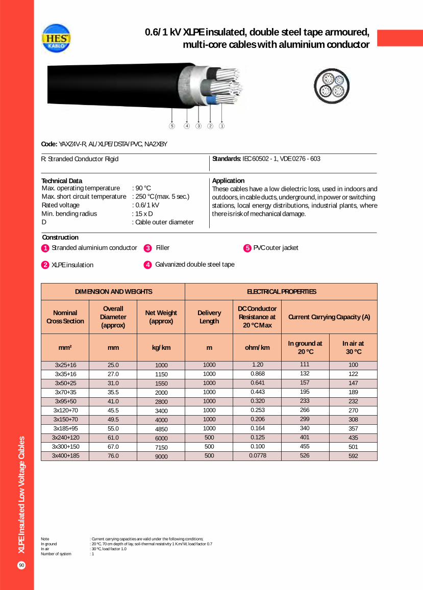
XLP
E In
sula
ted
Lo
w V
olt
age
Cab
les
90
0.6/1 kV XLPE insulated, double steel tape armoured,multi-core cables with aluminium conductor
Construction
Code: YAXZ4V-R, AL/XLPE/DSTA/PVC, NA2XBY
R: Stranded Conductor Rigid Standards: IEC 60502 - 1, VDE 0276 - 603
Technical Data ApplicationThese cables have a low dielectric loss, used in indoors and outdoors, in cable ducts, underground, in power or switchingstations, local energy distributions, industrial plants, where there is risk of mechanical damage.
Max. operating temperature : 90 °CMax. short circuit temperature : 250 °C (max. 5 sec.)
Rated voltage : 0.6/1 kV
Min. bending radius : 15 x DD : Cable outer diameter
1 3Stranded aluminium conductor Filler
2 XLPE insulation 4 Galvanized double steel tape
5 PVC outer jacket
12345
DIMENSION AND WEIGHTS ELECTRICAL PROPERTIES
Nominal Cross Section
Overall Diameter (approx)
Net Weight (approx)
Delivery Length
DC Conductor Resistance at
20 ºC MaxCurrent Carrying Capacity (A)
mm² mm kg/km m ohm/kmIn ground at
20 ºC In air at
30 ºC
100
122
147
189
232
270
308
357
435
501
592
3x25+16
3x35+16
3x50+25
3x70+35
3x95+50
3x120+70
3x150+70
3x185+95
3x240+120
3x300+150
3x400+185
25.0
27.0
31.0
35.5
41.0
45.5
49.5
55.0
61.0
67.0
76.0
1000
1150
1550
2000
2800
3400
4000
4850
6000
7150
9000
1000
1000
1000
1000
1000
1000
1000
1000
500
500
500
1.20
0.868
0.641
0.443
0.320
0.253
0.206
0.164
0.125
0.100
0.0778
111
132
157
195
233
266
299
340
401
455
526
Note : Current carrying capacities are valid under the following conditions;In ground : 20 ºC, 70 cm depth of lay, soil-thermal resistivity 1 K.m/W, load factor 0.7In air : 30 ºC, load factor 1.0Number of system : 1

XLP
E In
sula
ted
Lo
w V
olt
age
Cab
les
91
Construction
Code: YAXZ4V-R, AL/XLPE/DSTA/PVC, NA2XBY
R: Stranded Conductor Rigid Standards: IEC 60502 - 1, VDE 0276 - 603
Technical Data ApplicationThese cables have a low dielectric loss, used in indoors and outdoors, in cable ducts, underground, in power or switchingstations, local energy distributions, industrial plants, where there is risk of mechanical damage.
Max. operating temperature : 90 °C
Max. short circuit temperature : 250 °C (max. 5 sec.)
Rated voltage : 0.6/1 kV
Min. bending radius : 15 x DD : Cable outer diameter
1 3Stranded aluminium conductor Filler
2 XLPE insulation 4 Galvanized double steel tape
5 PVC outer jacket
12345
DIMENSION AND WEIGHTS ELECTRICAL PROPERTIES
Nominal Cross Section
Overall Diameter (approx)
Net Weight (approx)
Delivery Length
DC Conductor Resistance at
20 ºC MaxCurrent Carrying Capacity (A)
mm² mm kg/km m ohm/kmIn ground at
20 ºC In air at
30 ºC
100
122
147
189
232
270
308
357
435
501
592
4x25
4x35
4x50
4x70
4x95
4x120
4x150
4x185
4x240
4x300
4x400
26.0
28.5
33.0
38.0
43.0
48.0
53.0
58.5
65.5
72.0
82.0
1050
1300
1550
2250
3100
3800
4550
5450
6800
8100
10450
1000
1000
1000
1000
1000
1000
1000
500
500
500
250
1.20
0.868
0.641
0.443
0.320
0.253
0.206
0.164
0.125
0.100
0.0778
111
132
157
195
233
266
299
340
401
455
526
0.6/1 kV XLPE insulated, double steel tape armoured,multi-core cables with aluminium conductor
Note : Current carrying capacities are valid under the following conditions;In ground : 20 ºC, 70 cm depth of lay, soil-thermal resistivity 1 K.m/W, load factor 0.7In air : 30 ºC, load factor 1.0Number of system : 1

XLP
E In
sula
ted
Lo
w V
olt
age
Cab
les
92
0.6/1 kV XLPE Insulated, flat steel wire armoured,multi-core cables with aluminium conductor
Construction
Code: YAXZ3V-R, NA2XFGY
R: Stranded Conductor Rigid Standards: IEC 60502 - 1, VDE 0276 - 603
Technical Data ApplicationThese cables have a low dielectric loss, used in indoors and outdoors, in cable ducts, underground, in power or switchingstations, local energy distributions, industrial plants, where there is risk of mechanical damage.
Max. operating temperature : 90 °CMax. short circuit temperature : 250 °C (max. 5 sec.)
Rated voltage : 0.6/1 kV
Min. bending radius : 15 x DD : Cable outer diameter
1 3Stranded aluminium conductor Filler
2 XLPE insulation 4 Galvanized flat steel wire
5 Galvanized steel binding tape
6 PVC outer jacket
123456
DIMENSION AND WEIGHTS ELECTRICAL PROPERTIES
Nominal Cross Section
Overall Diameter (approx)
Net Weight (approx)
Delivery Length
DC Conductor Resistance at
20 ºC MaxCurrent Carrying Capacity (A)
mm² mm kg/km m ohm/kmIn ground at
20 ºC In air at
30 ºC
100
122
147
189
232
270
308
357
435
501
592
3x25
3x35
3x50
3x70
3x95
3x120
3x150
3x185
3x240
3x300
3x400
25.0
27.0
31.0
35.5
39.5
43.5
48.5
53.0
59.5
65.0
73.5
1150
1350
1700
2200
2700
3200
3900
4650
5700
6850
8650
1000
1000
1000
1000
1000
1000
1000
1000
500
500
500
1.20
0.868
0.641
0.443
0.320
0.253
0.206
0.164
0.125
0.100
0.0778
111
132
157
195
233
266
299
340
401
455
526
Note : Current carrying capacities are valid under the following conditions;In ground : 20 ºC, 70 cm depth of lay, soil-thermal resistivity 1 K.m/W, load factor 0.7In air : 30 ºC, load factor 1.0Number of system : 1

XLP
E In
sula
ted
Lo
w V
olt
age
Cab
les
93
0.6/1 kV XLPE Insulated, flat steel wire armoured,multi-core cables with aluminium conductor
Construction
Code: YAXZ3V-R, NA2XFGY
R: Stranded Conductor Rigid Standards: IEC 60502 - 1, VDE 0276 - 603
Technical Data ApplicationThese cables have a low dielectric loss, used in indoors and outdoors, in cable ducts, underground, in power or switchingstations, local energy distributions, industrial plants, where there is risk of mechanical damage.
Max. operating temperature : 90 °C
Max. short circuit temperature : 250 °C (max. 5 sec.)
Rated voltage : 0.6/1 kV
Min. bending radius : 15 x DD : Cable outer diameter
1 3Stranded aluminium conductor Filler
2 XLPE insulation 4 Galvanized flat steel wire
5 Galvanized steel binding tape
6 PVC outer jacket
123456
DIMENSION AND WEIGHTS ELECTRICAL PROPERTIES
Nominal Cross Section
Overall Diameter (approx)
Net Weight (approx)
Delivery Length
DC Conductor Resistance at
20 ºC MaxCurrent Carrying Capacity (A)
mm² mm kg/km m ohm/kmIn ground at
20 ºC In air at
30 ºC
100
122
147
189
232
270
308
357
435
501
592
3x25+16
3x35+16
3x50+25
3x70+35
3x95+50
3x120+70
3x150+70
3x185+95
3x240+120
3x300+150
3x400+185
26.0
28.0
32.0
36.5
41.0
45.5
50.0
55.0
61.5
67.5
76.0
1250
1400
1850
2350
2900
3500
4150
4950
6100
7300
9200
1000
1000
1000
1000
1000
1000
1000
1000
500
500
500
1.20
0.868
0.641
0.443
0.320
0.253
0.206
0.164
0.125
0.100
0.0778
111
132
157
195
233
266
299
340
401
455
526
Note : Current carrying capacities are valid under the following conditions;In ground : 20 ºC, 70 cm depth of lay, soil-thermal resistivity 1 K.m/W, load factor 0.7In air : 30 ºC, load factor 1.0Number of system : 1

XLP
E In
sula
ted
Lo
w V
olt
age
Cab
les
94
0.6/1 kV XLPE Insulated, flat steel wire armoured,multi-core cables with aluminium conductor
Construction
Code: YAXZ3V-R, NA2XFGY
R: Stranded Conductor Rigid Standards: IEC 60502 - 1, VDE 0276 - 603
Technical Data ApplicationThese cables have a low dielectric loss, used in indoors and outdoors, in cable ducts, underground, in power or switchingstations, local energy distributions, industrial plants, where there is risk of mechanical damage.
Max. operating temperature : 90 °CMax. short circuit temperature : 250 °C (max. 5 sec.)
Rated voltage : 0.6/1 kV
Min. bending radius : 15 x DD : Cable outer diameter
1 3Stranded aluminium conductor Filler
2 XLPE insulation 4 Galvanized flat steel wire
5 Galvanized steel binding tape
6 PVC outer jacket
123456
DIMENSION AND WEIGHTS ELECTRICAL PROPERTIES
Nominal Cross Section
Overall Diameter (approx)
Net Weight (approx)
Delivery Length
DC Conductor Resistance at
20 ºC MaxCurrent Carrying Capacity (A)
mm² mm kg/km m ohm/kmIn ground at
20 ºC In air at
30 ºC
100
122
147
189
232
270
308
357
435
501
592
4x25
4x35
4x50
4x70
4x95
4x120
4x150
4x185
4x240
4x300
4x400
27.0
29.5
34.0
39.0
43.5
48.5
53.5
58.5
65.5
72.0
82.0
1300
1550
2000
2650
3200
3900
4700
5600
6900
8300
10650
1000
1000
1000
1000
1000
1000
1000
500
500
500
250
1.20
0.868
0.641
0.443
0.320
0.253
0.206
0.164
0.125
0.100
0.0778
111
132
157
195
233
266
299
340
401
455
526
Note : Current carrying capacities are valid under the following conditions;In ground : 20 ºC, 70 cm depth of lay, soil-thermal resistivity 1 K.m/W, load factor 0.7In air : 30 ºC, load factor 1.0Number of system : 1


HFR
R In
stal
lati
on
Cab
les
96
300/500V and 450/750V halogen free, flame retardant,single core cables with copper conductor
Construction
Code: H05Z1-U, H07Z1-U, H07Z1-R
Standards: HD 21 15 S1, EN 50525 - 3 - 31
Application Used in energy networks in refineries, mines, hotels, schools, tunnels, high constructions, hospitals, power plant, data processing centers, business centers where there is a risk of fire.RE : Solid conductor ( H07Z1-U)RM : Stranded conductor (H07Z1-R)
Technical DataMax. operating temperature : 70 °CMax. short circuit temperature : 160 °C (max. 5 sec.) Rated voltage : 300/500 V
450/750 V
1 2Solid or stranded copper conductor HFFR insulation
U: Solid conductorR: Stranded Conductor Rigid
12
DIMENSION AND WEIGHTS ELECTRICAL PROPERTIES
Nominal Cross Section
Overall Diameter (approx)
Net Weight (approx)
Delivery Length
DC Conductor Resistance at
20 ºC MaxCurrent Carrying Capacity (A)
mm² mm kg/km m ohm/kmIn ground at
20 ºCIn air at
30 ºC
2.0
2.2
2.4
2.6
3.2
3.9
4.4
5.6
6.1
6.8
8.8
9.8
11.0
13.2
15.0
17.0
18.0
21.0
23.0
25.5
29.0
* 0.5 RE
* 0.75 RE
* 1.0 RE
1.5 RE
2.5 RE
4.0 RE
6.0 RE
10 RE
10 RM
16 RM
25 RM
35 RM
50 RM
70 RM
95 RM
120 RM
150 RM
185 RM
240 RM
300 RM
400 RM
8
11
14
20
32
46
65
108
115
170
260
355
500
680
930
1170
1450
1850
2350
2950
3900
36.0
24.5
18.1
12.1
7.41
4.61
3.08
1.83
1.83
1.15
0.727
0.524
0.387
0.268
0.193
0.153
0.124
0.0991
0.0754
0.0601
0.0470
-
-
11
16
20
27
35
48
48
65
88
110
140
175
210
250
-
-
-
-
-
-
15
19
24
32
42
54
73
73
98
129
158
198
245
292
344
391
448
528
608
726
100
100
100
100
100
100
100
100
100
1000
1000
1000
1000
1000
1000
1000
1000
1000
1000
1000
1000
* : 300/500 V (H05Z1 - U)

HFR
R In
stal
lati
on
Cab
les
97
300/500V and 450/750V halogen free, flame retardant, single corecables with flexible copper conductor.
Construction
Code: H05Z1-K, H07Z1-K
Standards: HD 21 15 S1, EN 50525 - 3 - 31
ApplicationUsed in energy networks in refineries, mines, hotels, schools, tunnels, high constructions, hospitals, power plant, data processing centers, business centers where there is a risk offire.
Technical Data
K: Flexible conductor
Max. operating temperature : 70 °CMax. short circuit temperature : 160 °C (max. 5 sec.) Rated voltage : 300/500 V
450/750 V
1 2Flexible copper conductor HFFR insulation
12
DIMENSION AND WEIGHTS ELECTRICAL PROPERTIES
Nominal Cross Section
Overall Diameter (approx)
Net Weight (approx)
Delivery Length
DC Conductor Resistance at
20 ºC MaxCurrent Carrying Capacity (A)
mm² mm kg/km m ohm/kmIn ground at
20 ºCIn air at
30 ºC
2.2
2.4
2.6
3.0
3.6
4.2
4.8
6.7
8.0
9.7
11.0
13.5
15.0
17.5
19.5
22.0
24.5
27.5
* 0.5
* 0.75
* 1.0
1.5
2.5
4.0
6.0
10
16
25
35
50
70
95
120
150
185
240
9
12
15
22
34
50
70
120
179
277
376
535
730
900
1230
1500
1900
2450
39.0
26.0
19.5
13.3
7.98
4.95
3.30
1.91
1.21
0.78
0.554
0.386
0.272
0.206
0.161
0.129
0.106
0.0801
-
-
12
15
20
25
33
45
61
83
103
132
165
197
235
-
-
-
-
16
20
24
32
42
54
73
98
129
158
198
245
292
344
391
448
528
100
100
100
100
100
100
100
100
100
1000
1000
1000
1000
1000
1000
1000
1000
1000
* : 300/500 V (H05Z1 - K)
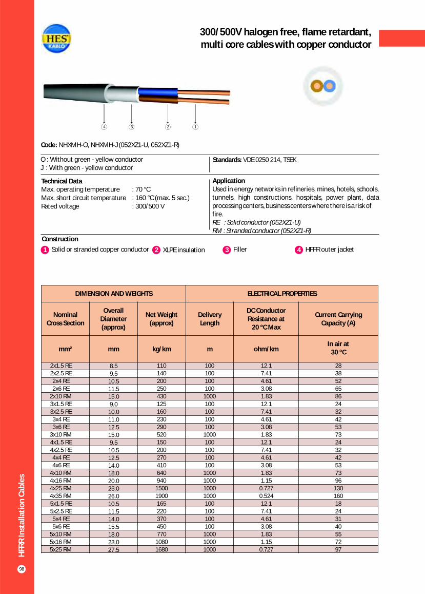
HFR
R In
stal
lati
on
Cab
les
98
300/500V halogen free, flame retardant,multi core cables with copper conductor
Construction
Code: NHXMH-O, NHXMH-J (052XZ1-U, 052XZ1-R)
Standards: VDE 0250 214, TSEK
ApplicationUsed in energy networks in refineries, mines, hotels, schools, tunnels, high constructions, hospitals, power plant, data processing centers, business centers where there is a risk offire.RE : Solid conductor (RM : Stranded conductor (
052XZ1-U)052XZ1-R)
Technical Data
O : Without green - yellow conductorJ : With green - yellow conductor
Max. operating temperature : 70 °CMax. short circuit temperature : 160 °C (max. 5 sec.) Rated voltage : 300/500 V
1 2Solid or stranded copper conductor XLPE insulation 3 4Filler HFFR outer jacket
1234
DIMENSION AND WEIGHTS ELECTRICAL PROPERTIES
Nominal Cross Section
Overall Diameter (approx)
Net Weight (approx)
Delivery Length
DC Conductor Resistance at
20 ºC Max
Current Carrying Capacity (A)
mm² mm kg/km m ohm/kmIn air at
30 ºC
2x1.5 RE2x2.5 RE2x4 RE2x6 RE
2x10 RM3x1.5 RE3x2.5 RE3x4 RE3x6 RE
3x10 RM4x1.5 RE4x2.5 RE4x4 RE4x6 RE
4x10 RM4x16 RM4x25 RM4x35 RM5x1.5 RE5x2.5 RE5x4 RE5x6 RE
5x10 RM5x16 RM5x25 RM
8.59.5
10.511.515.09.0
10.011.012.515.09.5
10.512.514.018.020.025.026.010.511.514.015.518.023.027.5
110140200250430125160230290520150200270410640940
15001900165220370450770
10801680
100100100100
1000100100100100
1000100100100100
1000100010001000100100100100
100010001000
12.17.414.613.081.8312.17.414.613.081.8312.17.414.613.081.831.15
0.7270.52412.17.414.613.081.831.15
0.727
28385265862432425373243242537396
13016018243140557297
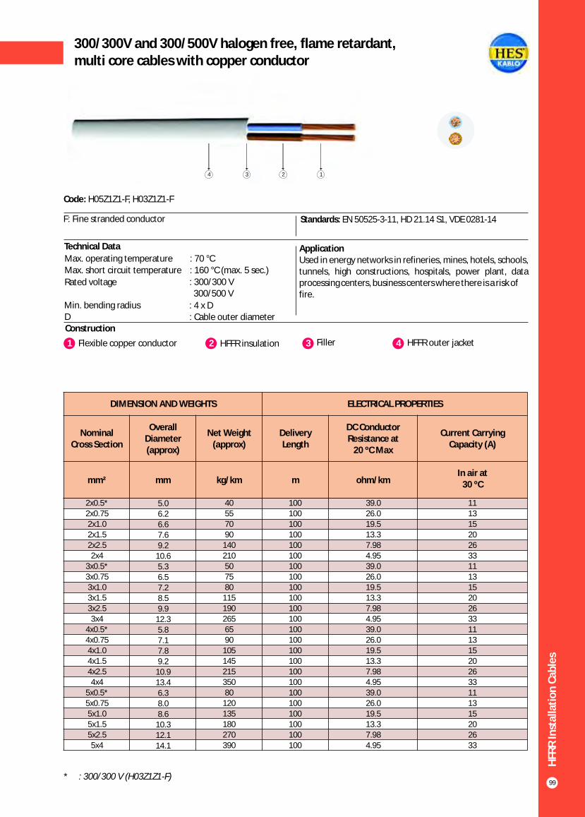
HFR
R In
stal
lati
on
Cab
les
99
300/300V and 300/500V halogen free, flame retardant,multi core cables with copper conductor
Construction
Code: H05Z1Z1-F, H03Z1Z1-F
Standards: EN 50525-3-11, HD 21.14 S1, VDE 0281-14
1 2Flexible copper conductor HFFR insulation
F: Fine stranded conductor
3 Filler
Technical Data
Max. operating temperature : 70 °CMax. short circuit temperature : 160 °C (max. 5 sec.)
Rated voltage : 300/300 V 300/500 V
Min. bending radius : 4 x DD : Cable outer diameter
4 HFFR outer jacket
DIMENSION AND WEIGHTS ELECTRICAL PROPERTIES
Nominal Cross Section
Overall Diameter (approx)
Net Weight (approx)
Delivery Length
DC Conductor Resistance at
20 ºC Max
Current Carrying Capacity (A)
mm² mm kg/km m ohm/kmIn air at
30 ºC
2x0.5*2x0.752x1.02x1.52x2.52x4
3x0.5*3x0.753x1.03x1.53x2.53x4
4x0.5*4x0.754x1.04x1.54x2.54x4
5x0.5*5x0.755x1.05x1.55x2.55x4
5.06.26.67.69.2
10.65.36.57.28.59.9
12.35.87.17.89.2
10.913.46.38.08.6
10.312.114.1
40557090
140210507580
1151902656590
10514521535080
120135180270390
100100100100100100100100100100100100100100100100100100100100100100100100
39.026.019.513.37.984.9539.026.019.513.37.984.9539.026.019.513.37.984.9539.026.019.513.37.984.95
111315202633111315202633111315202633111315202633
1234
ApplicationUsed in energy networks in refineries, mines, hotels, schools, tunnels, high constructions, hospitals, power plant, data processing centers, business centers where there is a risk offire.
* : 300/300 V (H03Z1Z1-F)

XLP
E In
sula
ted
HFF
R L
ow
Vo
ltag
e C
able
s
100
0.6/1 kV halogen free, flame retardant, XLPE insulatedsingle core cables with copper conductor
Construction
Code: N2XH
Standards: HD 604 S1, IEC 60502-1, VDE 0276 - 604
ApplicationUsed in energy networks in refineries, mines, hotels, schools, tunnels, high constructions, hospitals, power plant, data processing centers, business centers where there is a risk offire.
Technical Data
O : Without green - yellow conductorJ : With green - yellow conductor
1 2Solid or stranded copper conductor XLPE insulation 3 HFFR outer jacket
Max. operating temperature : 90 °C
Max. short circuit temperature : 250 °C (max. 5 sec.)
Rated voltage : 0.6/1 kV
Min. bending radius : 12 x DD : Cable outer diameter
123
1x4
1x6
1x10
1x16
1x25
1x35
1x50
1x70
1x95
1x120
1x150
1x185
1x240
1x300
1x400
1x500
6.5
7.0
8.5
9.5
11.0
12.0
13.5
15.5
17.5
19.5
20.5
23.5
26.5
28.5
32.5
35.0
70
95
130
200
300
400
500
750
950
1200
1500
1850
2350
3000
3900
4900
1000
1000
1000
1000
1000
1000
1000
1000
1000
1000
1000
1000
1000
1000
1000
1000
4.61
3.08
1.83
1.15
0.727
0.524
0.387
0.268
0.193
0.153
0.124
0.0991
0.0754
0.0601
0.0470
0.0366
66
82
109
139
179
213
251
307
366
416
465
526
610
689
788
889
55
68
90
115
149
178
211
259
310
352
396
449
521
587
669
748
56
71
96
128
173
212
258
328
404
471
541
626
749
864
1018
1173
44
57
77
102
139
170
208
265
326
381
438
507
606
697
816
933
DIMENSION AND WEIGHTS ELECTRICAL PROPERTIES
Nominal Cross
Section
Overall Diameter (approx)
Net Weight (approx)
Delivery Length
DC Conductor Resistance at
20 ºC MaxCurrent Carrying Capacity (A)
mm² mm kg/km m ohm/km
In ground at 20 ºC In air at 30 ºC
*** ** * *** ** *
Note : Current carrying capacities are valid under the following conditions;In ground : 20 ºC, 70 cm depth of lay, soil-thermal resistivity 1 K.m/W, load factor 0.7In air : 30 ºC, load factor 1.0*** : Flat formation, clearance between cables; in air = 1 x Cable outer diameter, in ground = 7 cm : Trefoil formationNumber of system : 1
** *
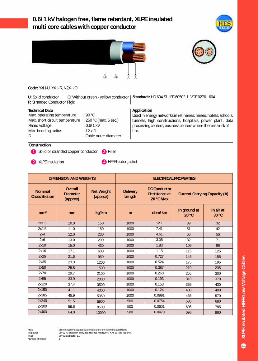
XLP
E In
sula
ted
HFF
R L
ow
Vo
ltag
e C
able
s
101
0.6/1 kV halogen free, flame retardant, XLPE insulatedmulti core cables with copper conductor
Construction
Code: YXH-U, YXH-R, N2XH-O
O: Without green - yellow conductor Standards: HD 604 S1, IEC 60502-1, VDE 0276 - 604
Technical Data ApplicationUsed in energy networks in refineries, mines, hotels, schools, tunnels, high constructions, hospitals, power plant, data processing centers, business centers where there is a risk offire.
Max. operating temperature : 90 °CMax. short circuit temperature : 250 °C (max. 5 sec.)
Rated voltage : 0.6/1 kV
Min. bending radius : 12 x DD : Cable outer diameter
1 3 Solid or stranded copper conductor Filler
2 XLPE insulation 4 HFFR outer jacket
1234
U: Solid conductorR: Stranded Conductor Rigid
DIMENSION AND WEIGHTS ELECTRICAL PROPERTIES
Nominal Cross Section
Overall Diameter (approx)
Net Weight (approx)
Delivery Length
DC Conductor Resistance at
20 ºC MaxCurrent Carrying Capacity (A)
mm² mm kg/km m ohm/kmIn ground at
20 ºCIn air at
30 ºC
32
42
56
71
96
125
155
195
235
300
370
430
490
570
680
785
860
2x1.5
2x2.5
2x4
2x6
2x10
2x16
2x25
2x35
2x50
2x70
2x95
2x120
2x150
2x185
2x240
2x300
2x400
10.0
11.0
12.0
13.0
15.0
17.1
21.5
23.3
25.8
29.7
33.9
37.4
41.1
45.9
51.5
56.6
64.0
150
180
230
290
430
600
950
1200
1500
2100
2800
3500
4300
5350
6900
8500
10900
1000
1000
1000
1000
1000
1000
1000
1000
1000
1000
1000
1000
1000
1000
500
500
500
12.1
7.41
4.61
3.08
1.83
1.15
0.727
0.524
0.387
0.268
0.193
0.153
0.124
0.0991
0.0754
0.0601
0.0470
39
51
66
82
109
115
145
175
210
255
310
355
400
455
530
605
690
Note : Current carrying capacities are valid under the following conditions;In ground : 20 ºC, 70 cm depth of lay, soil-thermal resistivity 1 K.m/W, load factor 0.7In air : 30 ºC, load factor 1.0Number of system : 1

XLP
E In
sula
ted
HFF
R L
ow
Vo
ltag
e C
able
s
102
0.6/1 kV halogen free, flame retardant, XLPE insulatedmulti core cables with copper conductor
Construction
Code: YXH-U, YXH-R, N2XH-O
Standards: HD 604 S1, IEC 60502-1, VDE 0276 - 604
ApplicationUsed in energy networks in refineries, mines, hotels, schools, tunnels, high constructions, hospitals, power plant, data processing centers, business centers where there is a risk offire.
1 2Solid or stranded copper conductor XLPE insulation 3 Filler
Technical Data
Max. operating temperature : 90 °C
Max. short circuit temperature : 250 °C (max. 5 sec.)
Rated voltage : 0.6/1 kV
Min. bending radius : 12 x DD : Cable outer diameter
4 HFFR outer jacket
O : Without green - yellow conductorJ : With green - yellow conductor
1234
DIMENSION AND WEIGHTS ELECTRICAL PROPERTIES
Nominal Cross Section
Overall Diameter (approx)
Net Weight (approx)
Delivery Length
DC Conductor Resistance at
20 ºC MaxCurrent Carrying Capacity (A)
mm² mm kg/km m ohm/kmIn ground at
20 ºCIn air at
30 ºC
24
32
42
53
73
96
130
160
195
247
305
355
407
469
551
638
746
3x1.5
3x2.5
3x4
3x6
3x10
3x16
3x25
3x35
3x50
3x70
3x95
3x120
3x150
3x185
3x240
3x300
3x400
11.0
12.0
13.0
14.0
15.5
18.0
22.0
25.0
27.0
31.5
35.5
39.5
43.5
48.5
54.5
60.5
67.0
150
200
250
340
500
700
1150
1500
1950
2700
3600
4500
5500
6800
8900
11000
14100
1000
1000
1000
1000
1000
1000
1000
1000
1000
1000
1000
1000
500
500
500
250
250
12.1
7.41
4.61
3.08
1.83
1.15
0.727
0.524
0.387
0.268
0.193
0.153
0.124
0.0991
0.0754
0.0601
0.0470
30
40
52
64
86
111
143
173
205
252
303
346
390
441
511
580
663
Note : Current carrying capacities are valid under the following conditions;In ground : 20 ºC, 70 cm depth of lay, soil-thermal resistivity 1 K.m/W, load factor 0.7In air : 30 ºC, load factor 1.0Number of system : 1
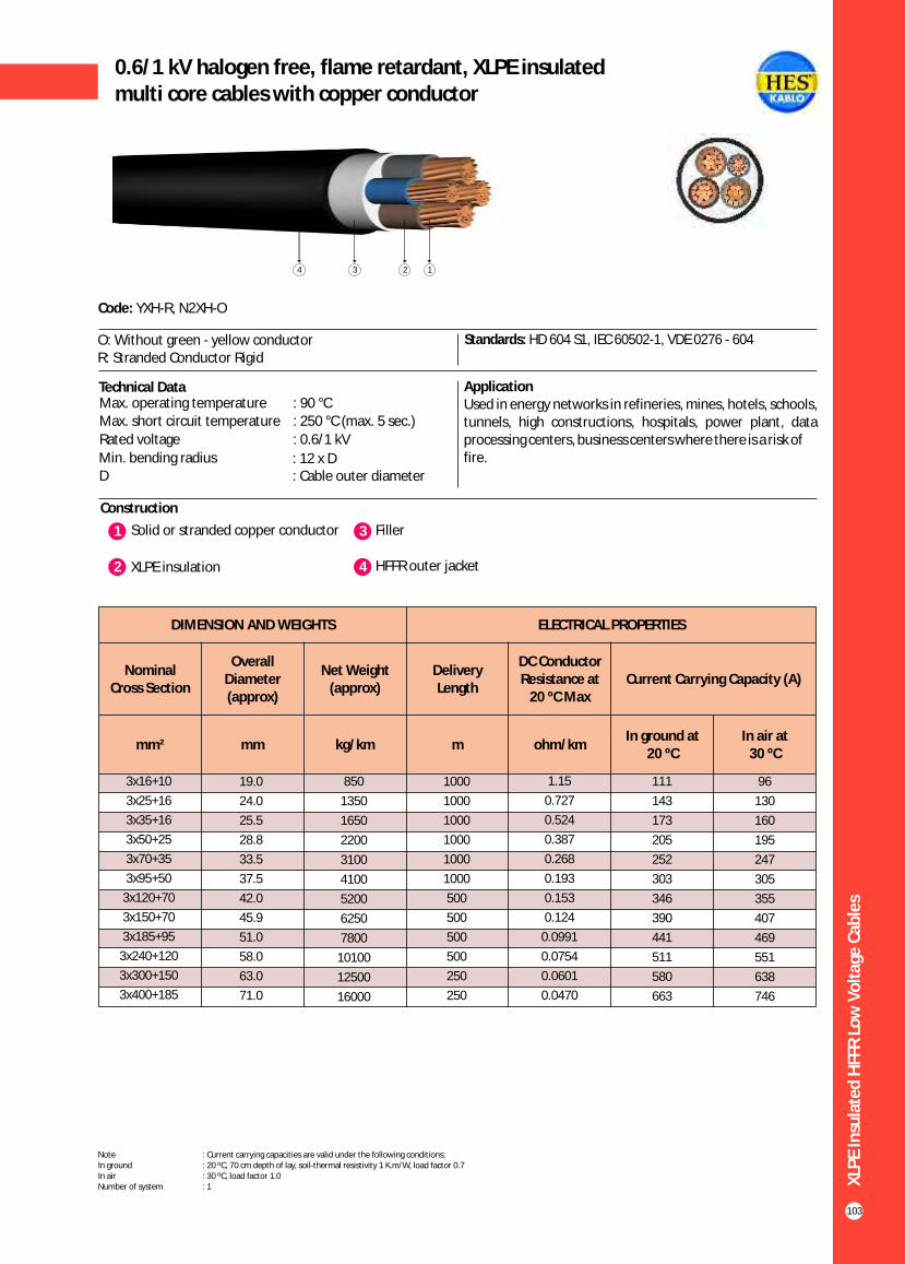
XLP
E In
sula
ted
HFF
R L
ow
Vo
ltag
e C
able
s
103
0.6/1 kV halogen free, flame retardant, XLPE insulatedmulti core cables with copper conductor
Construction
Code: YXH-R, N2XH-O
O: Without green - yellow conductorR: Stranded Conductor Rigid
Standards: HD 604 S1, IEC 60502-1, VDE 0276 - 604
Technical Data ApplicationUsed in energy networks in refineries, mines, hotels, schools, tunnels, high constructions, hospitals, power plant, data processing centers, business centers where there is a risk offire.
Max. operating temperature : 90 °CMax. short circuit temperature : 250 °C (max. 5 sec.)
Rated voltage : 0.6/1 kV
Min. bending radius : 12 x DD : Cable outer diameter
1 3Solid or stranded copper conductor Filler
2 XLPE insulation 4 HFFR outer jacket
1234
DIMENSION AND WEIGHTS ELECTRICAL PROPERTIES
Nominal Cross Section
Overall Diameter (approx)
Net Weight (approx)
Delivery Length
DC Conductor Resistance at
20 ºC MaxCurrent Carrying Capacity (A)
mm² mm kg/km m ohm/kmIn ground at
20 ºCIn air at
30 ºC
96
130
160
195
247
305
355
407
469
551
638
746
3x16+10
3x25+16
3x35+16
3x50+25
3x70+35
3x95+50
3x120+70
3x150+70
3x185+95
3x240+120
3x300+150
3x400+185
19.0
24.0
25.5
28.8
33.5
37.5
42.0
45.9
51.0
58.0
63.0
71.0
850
1350
1650
2200
3100
4100
5200
6250
7800
10100
12500
16000
1000
1000
1000
1000
1000
1000
500
500
500
500
250
250
1.15
0.727
0.524
0.387
0.268
0.193
0.153
0.124
0.0991
0.0754
0.0601
0.0470
111
143
173
205
252
303
346
390
441
511
580
663
Note : Current carrying capacities are valid under the following conditions;In ground : 20 ºC, 70 cm depth of lay, soil-thermal resistivity 1 K.m/W, load factor 0.7In air : 30 ºC, load factor 1.0Number of system : 1

XLP
E In
sula
ted
HFF
R L
ow
Vo
ltag
e C
able
s
104
0.6/1 kV halogen free, flame retardant, XLPE insulatedmulti core cables with copper conductor
Construction
Code: YXH-U, YXH-R, N2XH-O
Standards: HD 604 S1, IEC 60502-1, VDE 0276 - 604
ApplicationUsed in energy networks in refineries, mines, hotels, schools, tunnels, high constructions, hospitals, power plant, data processing centers, business centers where there is a risk offire.
Technical Data
1 2Solid or stranded copper conductor XLPE insulation 3 Filler
Max. operating temperature : 90 °C
Max. short circuit temperature : 250 °C (max. 5 sec.)
Rated voltage : 0.6/1 kV
Min. bending radius : 12 x DD : Cable outer diameter
3 HFFR outer jacket4
O : Without green - yellow conductorJ : With green - yellow conductor
1234
DIMENSION AND WEIGHTS ELECTRICAL PROPERTIES
Nominal Cross Section
Overall Diameter (approx)
Net Weight (approx)
Delivery Length
DC Conductor Resistance at
20 ºC MaxCurrent Carrying Capacity (A)
mm² mm kg/km m ohm/kmIn ground at
20 ºCIn air at
30 ºC
24
32
42
53
73
96
130
160
195
247
305
355
407
469
551
638
746
4x1.5
4x2.5
4x4
4x6
4x10
4x16
4x25
4x35
4x50
4x70
4x95
4x120
4x150
4x185
4x240
4x300
4x400
12.0
13.0
14.0
15.5
17.5
20.0
24.5
26.0
30.0
34.0
38.0
43.0
48.0
53.0
61.0
67.0
76.0
200
250
300
400
580
850
1300
1700
2300
3200
4250
5400
7000
8800
11400
14000
18200
1000
1000
1000
1000
1000
1000
1000
1000
1000
1000
1000
500
500
500
250
250
250
12.1
7.41
4.61
3.08
1.83
1.15
0.727
0.524
0.387
0.268
0.193
0.153
0.124
0.0991
0.0754
0.0601
0.0470
30
40
52
64
86
111
143
173
205
252
303
346
390
441
511
580
663
Note : Current carrying capacities are valid under the following conditions;In ground : 20 ºC, 70 cm depth of lay, soil-thermal resistivity 1 K.m/W, load factor 0.7In air : 30 ºC, load factor 1.0Number of system : 1

XLP
E In
sula
ted
HFF
R L
ow
Vo
ltag
e C
able
s
105
0.6/1 kV halogen free, flame retardant, XLPE insulatedcontrol cable with copper conductor
Construction
Code: YXH-U, N2XH-O
O: Without green - yellow conductorU: Solid conductor
Standards: HD 604 S1, IEC 60502-1, VDE 0271
Technical Data ApplicationThese cables have a low dielectric loss, used in indoors and outdoors, in cable ducts, underground, in power or switching stations, local energy distributions, industrial plants, where there is risk of mechanical damage and fire.
Max. operating temperature : 90 °CMax. short circuit temperature : 250 °C (max. 5 sec.)
Rated voltage : 0.6/1 kV
Min. bending radius : 12 x DD : Cable outer diameter
1234
1 2Solid or stranded copper conductor XLPE insulation 3 Filler 3 HFFR outer jacket4
DIMENSION AND WEIGHTS ELECTRICAL PROPERTIES
Nominal Cross Section
Overall Diameter (approx)
Net Weight (approx)
Delivery Length
DC Conductor Resistance at
20 ºC MaxCurrent Carrying Capacity (A)
mm² mm kg/km m ohm/kmIn ground at
20 ºCIn air at
30 ºC
18.0
16.8
15.6
14.4
13.2
12.6
12.0
11.4
10.8
10.2
9.6
9.4
9.1
8.6
8.4
7.9
7.4
7.2
5x1.5
6x1.5
7x1.5
8x1.5
10x1.5
12x1.5
14x1.5
16x1.5
19x1.5
21x1.5
24x1.5
27x1.5
30x1.5
37x1.5
40x1.5
48x1.5
52x1.5
61x1.5
12.0
13.0
13.2
15.0
15.5
16.0
17.0
17.4
18.0
19.0
21.0
21.4
22.0
24.0
25.0
27.0
28.0
30.0
220
270
290
370
390
430
480
520
590
650
770
800
900
1050
1150
1350
1450
1650
1000
1000
1000
1000
1000
1000
1000
1000
1000
1000
1000
1000
1000
1000
1000
1000
1000
1000
12.1
12.1
12.1
12.1
12.1
12.1
12.1
12.1
12.1
12.1
12.1
12.1
12.1
12.1
12.1
12.1
12.1
12.1
21.0
19.5
18.0
16.5
15.0
14.3
13.5
12.8
12.0
11.3
10.5
10.2
9.9
9.3
9.0
8.4
7.8
7.5
Note : Current carrying capacities are valid under the following conditions;In ground : 20 ºC, 70 cm depth of lay, soil-thermal resistivity 1 K.m/W, load factor 0.7In air : 30 ºC, load factor 1.0Number of system : 1
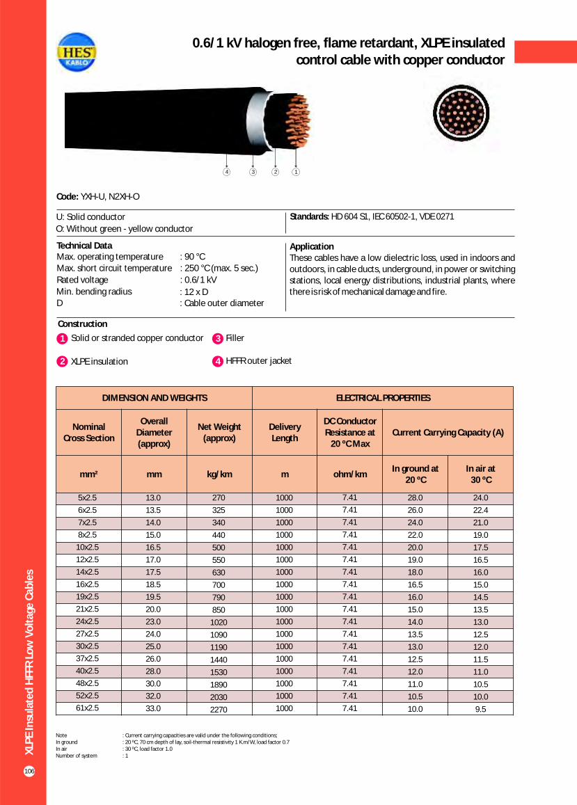
XLP
E In
sula
ted
HFF
R L
ow
Vo
ltag
e C
able
s
106
0.6/1 kV halogen free, flame retardant, XLPE insulatedcontrol cable with copper conductor
Construction
Code: YXH-U, N2XH-O
U: Solid conductor Standards: HD 604 S1, IEC 60502-1, VDE 0271
ApplicationThese cables have a low dielectric loss, used in indoors and outdoors, in cable ducts, underground, in power or switching stations, local energy distributions, industrial plants, where there is risk of mechanical damage and fire.
1 3Solid or stranded copper conductor Filler
2 XLPE insulation 4 HFFR outer jacket
Technical DataMax. operating temperature : 90 °CMax. short circuit temperature : 250 °C (max. 5 sec.)
Rated voltage : 0.6/1 kV
Min. bending radius : 12 x DD : Cable outer diameter
14 3 2
DIMENSION AND WEIGHTS ELECTRICAL PROPERTIES
Nominal Cross Section
Overall Diameter (approx)
Net Weight (approx)
Delivery Length
DC Conductor Resistance at
20 ºC MaxCurrent Carrying Capacity (A)
mm² mm kg/km m ohm/kmIn ground at
20 ºCIn air at
30 ºC
24.0
22.4
21.0
19.0
17.5
16.5
16.0
15.0
14.5
13.5
13.0
12.5
12.0
11.5
11.0
10.5
10.0
9.5
5x2.5
6x2.5
7x2.5
8x2.5
10x2.5
12x2.5
14x2.5
16x2.5
19x2.5
21x2.5
24x2.5
27x2.5
30x2.5
37x2.5
40x2.5
48x2.5
52x2.5
61x2.5
13.0
13.5
14.0
15.0
16.5
17.0
17.5
18.5
19.5
20.0
23.0
24.0
25.0
26.0
28.0
30.0
32.0
33.0
270
325
340
440
500
550
630
700
790
850
1020
1090
1190
1440
1530
1890
2030
2270
1000
1000
1000
1000
1000
1000
1000
1000
1000
1000
1000
1000
1000
1000
1000
1000
1000
1000
7.41
7.41
7.41
7.41
7.41
7.41
7.41
7.41
7.41
7.41
7.41
7.41
7.41
7.41
7.41
7.41
7.41
7.41
28.0
26.0
24.0
22.0
20.0
19.0
18.0
16.5
16.0
15.0
14.0
13.5
13.0
12.5
12.0
11.0
10.5
10.0
Note : Current carrying capacities are valid under the following conditions;In ground : 20 ºC, 70 cm depth of lay, soil-thermal resistivity 1 K.m/W, load factor 0.7In air : 30 ºC, load factor 1.0Number of system : 1
O: Without green - yellow conductor

XLP
E In
sula
ted
HFF
R L
ow
Vo
ltag
e C
able
s
107
0.6/1 kV halogen free, flame retardant, XLPE insulated,flat steel wire armoured multi core cables with copper conductor
Construction
Code: N2XFGH
Standards: HD 604 S1, IEC 60502-1, VDE 0276
Technical Data ApplicationThese cables have a low dielectric loss, used in indoors and outdoors, in cable ducts, underground, in power or switching stations, local energy distributions, industrial plants, where there is risk of mechanical damage and fire.
1 3Solid or stranded copper conductor Filler
2 XLPE insulation 4 Galvanized flat steel wire
5 Galvanized steel binding tape
6 HFFR outer jacket
Max. operating temperature : 90 °CMax. short circuit temperature : 250 °C (max. 5 sec.)
Rated voltage : 0.6/1 kV
Min. bending radius : 15 x DD : Cable outer diameter
146 235
DIMENSION AND WEIGHTS ELECTRICAL PROPERTIES
Nominal Cross Section
Overall Diameter (approx)
Net Weight (approx)
Delivery Length
DC Conductor Resistance at
20 ºC MaxCurrent Carrying Capacity (A)
mm² mm kg/km m ohm/kmIn ground at
20 ºC In air at
30 ºC
155
195
235
300
370
430
490
570
680
785
860
2x25
2x35
2x50
2x70
2x95
2x120
2x150
2x185
2x240
2x300
2x400
24.5
26.3
28.8
32.9
36.9
40.4
44.3
49.1
54.7
59.6
67.2
1410
1700
2100
2750
3500
4300
5150
6300
7950
9550
12150
1000
1000
1000
1000
1000
500
500
500
250
250
250
0.727
0.524
0.387
0.268
0.193
0.153
0124
0.0991
0.0754
0.0601
0.0470
145
175
210
255
310
355
400
455
530
605
690
Note : Current carrying capacities are valid under the following conditions;In ground : 20 ºC, 70 cm depth of lay, soil-thermal resistivity 1 K.m/W, load factor 0.7In air : 30 ºC, load factor 1.0Number of system : 1

XLP
E In
sula
ted
HFF
R L
ow
Vo
ltag
e C
able
s
108
0.6/1 kV halogen free, flame retardant, XLPE insulated,flat steel wire armoured multi core cables with copper conductor
146 235
Construction
Code: N2XFGH
Standards: HD 604 S1, IEC 60502-1, VDE 0276
Technical Data ApplicationThese cables have a low dielectric loss, used in indoors and outdoors, in cable ducts, underground, in power or switching stations, local energy distributions, industrial plants, where there is risk of mechanical damage and fire.
1 3Stranded copper conductors Filler
2 XLPE insulation 4 Galvanized flat steel wire
5 Galvanized steel binding tape
6 HFFR outer jacket
Max. operating temperature : 90 °CMax. short circuit temperature : 250 °C (max. 5 sec.)
Rated voltage : 0.6/1 kV
Min. bending radius : 15 x DD : Cable outer diameter
DIMENSION AND WEIGHTS ELECTRICAL PROPERTIES
Nominal Cross Section
Overall Diameter (approx)
Net Weight (approx)
Delivery Length
DC Conductor Resistance at
20 ºC MaxCurrent Carrying Capacity (A)
mm² mm kg/km m ohm/kmIn ground at
20 ºC In air at
30 ºC
130
160
195
247
305
355
407
469
551
638
746
3x25
3x35
3x50
3x70
3x95
3x120
3x150
3x185
3x240
3x300
3x400
25.0
27.0
30.0
34.5
38.5
42.5
47.0
51.5
58.5
65.5
74.0
1600
1950
2550
3450
4400
5400
6600
8000
10200
12500
16300
1000
1000
1000
1000
1000
500
500
500
250
250
250
0.727
0.524
0.387
0.268
0.193
0.153
0.124
0.0991
0.0754
0.0601
0.0470
143
173
205
252
303
346
390
441
511
580
663
Note : Current carrying capacities are valid under the following conditions;In ground : 20 ºC, 70 cm depth of lay, soil-thermal resistivity 1 K.m/W, load factor 0.7In air : 30 ºC, load factor 1.0Number of system : 1
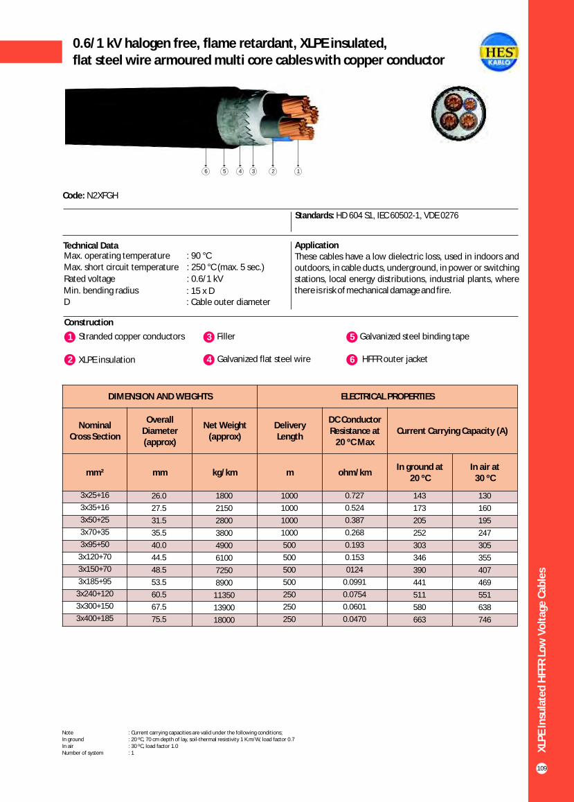
XLP
E In
sula
ted
HFF
R L
ow
Vo
ltag
e C
able
s
109
146 235
Construction
Code: N2XFGH
Standards: HD 604 S1, IEC 60502-1, VDE 0276
Technical Data ApplicationThese cables have a low dielectric loss, used in indoors and outdoors, in cable ducts, underground, in power or switching stations, local energy distributions, industrial plants, where there is risk of mechanical damage and fire.
1 3Stranded copper conductors Filler
2 XLPE insulation 4 Galvanized flat steel wire
5 Galvanized steel binding tape
6 HFFR outer jacket
Max. operating temperature : 90 °CMax. short circuit temperature : 250 °C (max. 5 sec.)
Rated voltage : 0.6/1 kV
Min. bending radius : 15 x DD : Cable outer diameter
0.6/1 kV halogen free, flame retardant, XLPE insulated,flat steel wire armoured multi core cables with copper conductor
DIMENSION AND WEIGHTS ELECTRICAL PROPERTIES
Nominal Cross Section
Overall Diameter (approx)
Net Weight (approx)
Delivery Length
DC Conductor Resistance at
20 ºC MaxCurrent Carrying Capacity (A)
mm² mm kg/km m ohm/kmIn ground at
20 ºC In air at
30 ºC
130
160
195
247
305
355
407
469
551
638
746
3x25+16
3x35+16
3x50+25
3x70+35
3x95+50
3x120+70
3x150+70
3x185+95
3x240+120
3x300+150
3x400+185
26.0
27.5
31.5
35.5
40.0
44.5
48.5
53.5
60.5
67.5
75.5
1800
2150
2800
3800
4900
6100
7250
8900
11350
13900
18000
1000
1000
1000
1000
500
500
500
500
250
250
250
0.727
0.524
0.387
0.268
0.193
0.153
0124
0.0991
0.0754
0.0601
0.0470
143
173
205
252
303
346
390
441
511
580
663
Note : Current carrying capacities are valid under the following conditions;In ground : 20 ºC, 70 cm depth of lay, soil-thermal resistivity 1 K.m/W, load factor 0.7In air : 30 ºC, load factor 1.0Number of system : 1

XLP
E In
sula
ted
HFF
R L
ow
Vo
ltag
e C
able
s
110
146 235
0.6/1 kV halogen free, flame retardant, XLPE insulated,flat steel wire armoured multi core cables with copper conductor
Construction
Code: N2XFGH
Standards: HD 604 S1, IEC 60502-1, VDE 0276
Technical Data ApplicationThese cables have a low dielectric loss, used in indoors and outdoors, in cable ducts, underground, in power or switching stations, local energy distributions, industrial plants, where there is risk of mechanical damage and fire.
1 3Stranded copper conductors Filler
2 XLPE insulation 4 Galvanized flat steel wire
5 Galvanized steel binding tape
6 HFFR outer jacket
Max. operating temperature : 90 °CMax. short circuit temperature : 250 °C (max. 5 sec.)
Rated voltage : 0.6/1 kV
Min. bending radius : 15 x DD : Cable outer diameter
DIMENSION AND WEIGHTS ELECTRICAL PROPERTIES
Nominal Cross Section
Overall Diameter (approx)
Net Weight (approx)
Delivery Length
DC Conductor Resistance at
20 ºC MaxCurrent Carrying Capacity (A)
mm² mm kg/km m ohm/kmIn ground at
20 ºC In air at
30 ºC
96
130
160
195
247
305
355
407
469
551
638
746
4x16
4x25
4x35
4x50
4x70
4x95
4x120
4x150
4x185
4x240
4x300
4x400
23.0
27.0
29.0
33.0
38.0
42.0
47.0
51.5
57.0
64.5
72.5
82.5
1350
1900
2400
3150
4300
5500
6850
8250
10100
12900
15900
20800
1000
1000
1000
1000
1000
500
500
500
250
250
250
250
1.15
0.727
0.524
0.387
0.268
0.193
0.153
0124
0.0991
0.0754
0.0601
0.0470
111
143
173
205
252
303
346
390
441
511
580
663
Note : Current carrying capacities are valid under the following conditions;In ground : 20 ºC, 70 cm depth of lay, soil-thermal resistivity 1 K.m/W, load factor 0.7In air : 30 ºC, load factor 1.0Number of system : 1

XLP
E In
sula
ted
HFF
R L
ow
Vo
ltag
e C
able
s
111
0.6/1 kV halogen free,flame retardant, XLPE insulated,round aluminium wire armoured, single core cables with copper conductor
Construction
Code: N2XR(A)H, CU/XLPE/AWA/LSF
Standards: HD 604 S1, IEC 60502 - 1, VDE 0276 - 604,BS 6724
Technical Data
Max. operating temperature : 90 °C
Max. short circuit temperature : 250 °C (max. 5 sec.)
Rated voltage : 0.6/1 kV
Min. bending radius : 15 x DD : Cable outer diameter
1 3Stranded copper conductors HFFR inner sheath
2 XLPE insulation 4 Round aluminium wire
5 Polyester tape
6 HFFR outer jacket
123456
1x25
1x35
1x50
1x70
1x95
1x120
1x150
1x185
1x240
1x300
1x400
1x500
1x630
15.5
17.5
19.0
20.5
23.0
25.0
26.5
28.5
31.5
36.0
40.5
45.5
50.0
500
700
900
1150
1600
1900
2200
2600
3200
4100
5100
6350
8800
1000
1000
1000
1000
1000
1000
1000
1000
1000
1000
500
500
500
0.727
0.524
0.387
0.268
0.193
0.153
0.124
0.0991
0.0754
0.0601
0.0470
0.0366
0.0283
179
213
251
307
366
416
465
526
610
689
788
889
980
149
178
211
259
310
352
396
449
521
587
669
748
843
173
212
258
328
404
471
541
626
749
864
1018
1173
1315
139
170
208
265
326
381
438
507
606
697
816
933
1083
ApplicationThese cables have a low dielectric loss, used in indoors and outdoors, in cable ducts, underground, in power or switching stations, local energy distributions, industrial plants, where there is risk of mechanical damage and fire.
DIMENSION AND WEIGHTS ELECTRICAL PROPERTIES
Nominal Cross Section
Overall Diameter (approx)
Net Weight (approx)
Delivery Length
DC Conductor Resistance at
20 ºC MaxCurrent Carrying Capacity (A)
mm² mm kg/km m ohm/km
In ground at 20 ºC In air at 30 ºC
*** ** * *** ** *
Note : Current carrying capacities are valid under the following conditions;In ground : 20 ºC, 70 cm depth of lay, soil-thermal resistivity 1 K.m/W, load factor 0.7In air : 30 ºC, load factor 1.0*** : Flat formation, clearance between cables; in air = 1 x Cable outer diameter, in ground = 7 cm : Trefoil formationNumber of system : 1
** *

0.6/1 kV halogen free,flame retardant, XLPE insulated,round steel wire armoured, multi core cables with copper conductor
Construction
Code: N2XRH, CU/XLPE/SWA/LSF
Standards: HD 604 S1, IEC 60502 - 1, VDE 0276-604,BS 6724
Technical Data ApplicationThese cables have a low dielectric loss, used in indoors and outdoors, in cable ducts, underground, in power or switching stations, local energy distributions, industrial plants, where there is risk of mechanical damage and fire.
Max. operating temperature : 90 °CMax. short circuit temperature : 250 °C (max. 5 sec.)
Rated voltage : 0.6/1 kV
Min. bending radius : 15 x DD : Cable outer diameter
1 3Solid or stranded copper conductor Filler
2 XLPE insulation 4 Galvanized round steel wire
5 Polyester tape
6 HFFR outer jacket
156 234
DIMENSION AND WEIGHTS ELECTRICAL PROPERTIES
Nominal Cross Section
Overall Diameter (approx)
Net Weight (approx)
Delivery Length
DC Conductor Resistance at
20 ºC MaxCurrent Carrying Capacity (A)
mm² mm kg/km m ohm/kmIn ground at
20 ºC In air at
30 ºC
32
42
56
71
96
125
155
195
235
300
370
430
490
570
680
785
2x1.5
2x2.5
2x4
2x6
2x10
2x16
2x25
2x35
2x50
2x70
2x95
2x120
2x150
2x185
2x240
2x300
14.0
15.0
16.0
17.0
20.0
22.0
26.0
28.0
30.0
34.0
39.0
43.0
46.0
53.0
58.0
63.0
350
390
450
540
850
1070
1600
1900
2300
3000
4000
4750
5800
7500
9000
11000
1000
1000
1000
1000
1000
1000
1000
1000
1000
1000
1000
500
500
500
500
250
12.1
7.41
4.61
3.08
1.83
1.15
0.727
0.524
0.387
0.268
0.193
0.153
0.124
0.0991
0.0754
0.0601
39
51
66
82
109
115
145
175
210
255
310
355
400
455
530
605
XLP
E In
sula
ted
HFF
R L
ow
Vo
ltag
e C
able
s
112
Note : Current carrying capacities are valid under the following conditions;In ground : 20 ºC, 70 cm depth of lay, soil-thermal resistivity 1 K.m/W, load factor 0.7In air : 30 ºC, load factor 1.0Number of system : 1

XLP
E In
sula
ted
HFF
R L
ow
Vo
ltag
e C
able
s
113
0.6/1 kV halogen free,flame retardant, XLPE insulated,round steel wire armoured, multi core cables with copper conductor
Construction
Code: N2XRH, CU/XLPE/SWA/LSF
Standards: HD 604 S1, IEC 60502-1, VDE 0276 - 604,BS 6724
Technical DataMax. operating temperature : 90 °C
Max. short circuit temperature : 250 °C (max. 5 sec.)
Rated voltage : 0.6/1 kV
Min. bending radius : 15 x DD : Cable outer diameter
1 3Solid or stranded copper conductor Filler
2 XLPE insulation 4 Galvanized round steel wire
5 Polyester tape
6 HFFR outer jacket
123456
DIMENSION AND WEIGHTS ELECTRICAL PROPERTIES
Nominal Cross Section
Overall Diameter (approx)
Net Weight (approx)
Delivery Length
DC Conductor Resistance at
20 ºC MaxCurrent Carrying Capacity (A)
mm² mm kg/km m ohm/kmIn ground at
20 ºC In air at
30 ºC
24
32
42
53
73
96
130
160
195
247
305
355
407
469
551
3x1.5
3x2.5
3x4
3x6
3x10
3x16
3x25
3x35
3x50
3x70
3x95
3x120
3x150
3x185
3x240
13.5
14.0
15.5
16.5
20.0
22.0
26.0
28.0
31.0
36.5
40.5
44.5
50.0
55.0
61.5
370
430
510
600
980
1260
1700
2100
2700
3800
4700
5700
7300
8800
11000
1000
1000
1000
1000
1000
1000
1000
1000
1000
1000
1000
500
500
500
250
12.1
7.41
4.61
3.08
1.83
1.15
0.727
0.524
0.387
0.268
0.193
0.153
0.124
0.0991
0.0754
30
40
52
64
86
111
143
173
205
252
303
346
390
441
511
ApplicationThese cables have a low dielectric loss, used in indoors and outdoors, in cable ducts, underground, in power or switching stations, local energy distributions, industrial plants, where there is risk of mechanical damage and fire.
Note : Current carrying capacities are valid under the following conditions;In ground : 20 ºC, 70 cm depth of lay, soil-thermal resistivity 1 K.m/W, load factor 0.7In air : 30 ºC, load factor 1.0Number of system : 1

XLP
E In
sula
ted
HFF
R L
ow
Vo
ltag
e C
able
s
114
0.6/1 kV halogen free,flame retardant, XLPE insulated,round steel wire armoured, multi core cables with copper conductor
Construction
Code: N2XRH, CU/XLPE/SWA/LSF
Standards: HD 604 S1, VDE 0276 - 604, BS 6724, IEC 60502 - 1
Technical Data
Max. operating temperature : 90 °C
Max. short circuit temperature : 250 °C (max. 5 sec.)
Rated voltage : 0.6/1 kV
Min. bending radius : 15 x DD : Cable outer diameter
1 3Stranded copper conductors HFFR inner sheath
2 XLPE insulation 4 Galvanized round steel wire
5 Polyester tape
6 HFFR outer jacket
123456
DIMENSION AND WEIGHTS ELECTRICAL PROPERTIES
Nominal Cross Section
Overall Diameter (approx)
Net Weight (approx)
Delivery Length
DC Conductor Resistance at
20 ºC MaxCurrent Carrying Capacity (A)
mm² mm kg/km m ohm/kmIn ground at
20 ºC In air at
30 ºC
96
130
160
195
247
305
355
407
469
551
638
746
3x16+10
3x25+16
3x35+16
3x50+25
3x70+35
3x95+50
3x120+70
3x150+70
3x185+95
3x240+120
3x300+150
3x400+185
23.0
27.0
29.0
32.5
38.0
42.0
46.5
51.5
56.5
63.5
70.5
80.0
1400
2100
2400
3100
4400
5600
6900
8500
10300
13000
15500
19500
1000
1000
1000
1000
1000
500
500
500
500
250
250
250
1.15
0.727
0.524
0.387
0.268
0.193
0.153
0.124
0.0991
0.0754
0.0601
0.0470
111
143
173
205
252
303
346
390
441
511
580
663
ApplicationThese cables have a low dielectric loss, used in indoors and outdoors, in cable ducts, underground, in power or switching stations, local energy distributions, industrial plants, where there is risk of mechanical damage and fire.
Note : Current carrying capacities are valid under the following conditions;In ground : 20 ºC, 70 cm depth of lay, soil-thermal resistivity 1 K.m/W, load factor 0.7In air : 30 ºC, load factor 1.0Number of system : 1

XLP
E In
sula
ted
HFF
R L
ow
Vo
ltag
e C
able
s
115
0.6/1 kV halogen free,flame retardant, XLPE insulated,round steel wire armoured, multi core cables with copper conductor
Construction
Code: N2XRH, CU/XLPE/SWA/LSF
U: Solid conductor R: Stranded Conductor Rigid
Standards: IEC 60502 - 1, VDE 0276-604, HD 604 S1BS 6724
Technical Data ApplicationThese cables have a low dielectric loss, used in indoors and outdoors, in cable ducts, underground, in power or switching stations, local energy distributions, industrial plants, where there is risk of mechanical damage and fire.
Max. operating temperature : 90 °CMax. short circuit temperature : 250 °C (max. 5 sec.)
Rated voltage : 0.6/1 kV
Min. bending radius : 15 x DD : Cable outer diameter
1 3Solid or stranded copper conductor Filler
2 XLPE insulation 4 Galvanized round steel wire
5 Polyester tape
6 HFFR outer jacket
123456
DIMENSION AND WEIGHTS ELECTRICAL PROPERTIES
Nominal Cross Section
Overall Diameter (approx)
Net Weight (approx)
Delivery Length
DC Conductor Resistance at
20 ºC MaxCurrent Carrying Capacity (A)
mm² mm kg/km m ohm/kmIn ground at
20 ºC In air at
30 ºC
24
32
42
53
73
96
130
160
195
247
305
355
407
469
551
638
746
4x1.5
4x2.5
4x4
4x6
4x10
4x16
4x25
4x35
4x50
4x70
4x95
4x120
4x150
4x185
4x240
4x300
4x400
14.0
15.0
16.0
18.5
21.0
24.0
28.0
30.5
34.0
40.0
44.0
50.5
55.0
60.5
68.0
76.0
87.0
400
470
580
830
1100
1600
2200
2700
3350
4800
6100
7800
9300
11000
14000
17000
23000
1000
1000
1000
1000
1000
1000
1000
1000
1000
1000
1000
500
500
250
250
250
250
12.1
7.41
4.61
3.08
1.83
1.15
0.727
0.524
0.387
0.268
0.193
0.153
0.124
0.0991
0.0754
0.0601
0.0470
30
40
52
64
86
111
143
173
205
252
303
346
390
441
511
580
663
Note : Current carrying capacities are valid under the following conditions;In ground : 20 ºC, 70 cm depth of lay, soil-thermal resistivity 1 K.m/W, load factor 0.7In air : 30 ºC, load factor 1.0Number of system : 1

XLP
E In
sula
ted
HFF
R L
ow
Vo
ltag
e C
able
s
116
0.6/1 kV halogen free, flame retardant,XLPE insulatedconcentric conductor screened, multi core cables
with copper conductor
Construction
Code: N2XCH
Standards: HD 604 S1, VDE 0276 - 604, IEC 60502-1
ApplicationThese cables have a low dielectric loss, Indoor installations, in cable ducts, outdoor and underground for power stations, industrial plants and switching stations as well as local supply systems if increased protection is necessary. In case of mechanical damage the screen prevents any damage due to power leak to the surrounding area.
Technical DataMax. operating temperature : 90 °C
Max. short circuit temperature : 250 °C (max. 5 sec.)
Rated voltage : 0.6/1 kV
Min. bending radius : 15 x DD : Cable outer diameter
1 3Solid or stranded copper conductor Filler
2 XLPE insulation 4 Concentric copper wire
5 Copper tape as binder
6 Polyester tape
7 HFFR outer jacket
1234567
DIMENSION AND WEIGHTS ELECTRICAL PROPERTIES
Nominal Cross Section
Overall Diameter (approx)
Net Weight (approx)
Delivery Length
DC Conductor Resistance at
20 ºC MaxCurrent Carrying Capacity (A)
mm² mm kg/km m ohm/kmIn ground at
20 ºC In air at
30 ºC
32
42
56
71
96
125
24
32
42
53
73
96
130
160
195
2x1.5/1.5
2x2.5/2.5
2x4/4
2x6/6
2x10/10
2x16/16
3x1.5/1.5
3x2.5/2.5
3x4/4
3x6/6
3x10/10
3x16/16
3x25/16
3x35/16
3x50/25
12.5
13.0
14.5
15.5
17.0
19.0
13.0
13.5
15.0
16.0
18.5
20.5
24.0
26.0
29.0
240
270
300
400
500
750
200
300
390
500
750
1000
1350
1670
2200
1000
1000
1000
1000
1000
1000
1000
1000
1000
1000
1000
1000
1000
1000
1000
12.1
7.41
4.61
3.08
1.83
1.15
12.1
7.41
4.61
3.08
1.83
1.15
0.727
0.524
0.387
39
51
66
82
109
115
30
40
52
64
86
111
143
173
205
Note : Current carrying capacities are valid under the following conditions;In ground : 20 ºC, 70 cm depth of lay, soil-thermal resistivity 1 K.m/W, load factor 0.7In air : 30 ºC, load factor 1.0Number of system : 1

XLP
E In
sula
ted
HFF
R L
ow
Vo
ltag
e C
able
s
117
0.6/1 kV halogen free, flame retardant,XLPE insulatedconcentric conductor screened, multi core cableswith copper conductor
Construction
Code: YXCH-U, YXCH-R, N2XCH
Standards: HD 604 S1, VDE 0276 - 604, IEC 60502-1
ApplicationThese cables have a low dielectric loss, Indoor installations, in cable ducts, outdoor and underground for power stations, industrial plants and switching stations as well as local supply systems if increased protection is necessary. In case of mechanical damage the screen prevents any damage due to power leak to the surrounding area.
Technical DataMax. operating temperature : 90 °C
Max. short circuit temperature : 250 °C (max. 5 sec.)
Rated voltage : 0.6/1 kV
Min. bending radius : 15 x DD : Cable outer diameter
1 3Solid or stranded copper conductor Filler
2 XLPE insulation 4 Concentric copper wire
5 Copper tape as binder ( 100% coverage with overlap)
6 Polyester tape 7 HFFR outer jacket
1234567
U: Solid conductorR: Stranded Conductor Rigid
DIMENSION AND WEIGHTS ELECTRICAL PROPERTIES
Nominal Cross Section
Overall Diameter (approx)
Net Weight (approx)
Delivery Length
DC Conductor Resistance at
20 ºC MaxCurrent Carrying Capacity (A)
mm² mm kg/km m ohm/kmIn ground at
20 ºC In air at
30 ºC
32
42
56
71
96
24
32
42
53
73
24
32
42
53
73
24
32
42
2x1.5/9
2x2.5/9
2x4/9
2x6/9
2x10/9
3x1.5/9
3x2.5/9
3x4/9
3x6/9
3x10/9
4x1.5/9
4x2.5/9
4x4/9
4x6/9
4x10/9
5x1.5/9
5x2.5/9
5x4/9
13.0
13.5
14.0
15.0
17.0
13.5
14.0
15.0
16.0
18.5
14.0
15.0
16.0
18.0
20.0
15.0
16.0
17.0
280
310
370
450
580
300
340
410
510
670
330
380
470
590
790
360
410
520
1000
1000
1000
1000
1000
1000
1000
1000
1000
1000
1000
1000
1000
1000
1000
1000
1000
1000
12.1
7.41
4.61
3.08
1.83
12.1
7.41
4.61
3.08
1.83
12.1
7.41
4.61
3.08
1.83
12.1
7.41
4.61
39
51
66
82
109
30
40
52
64
86
30
40
52
64
86
30
40
52
Note : Current carrying capacities are valid under the following conditions;In ground : 20 ºC, 70 cm depth of lay, soil-thermal resistivity 1 K.m/W, load factor 0.7In air : 30 ºC, load factor 1.0Number of system : 1

XLP
E In
sula
ted
HFF
R L
ow
Vo
ltag
e C
able
s
118
0.6/1 kV halogen free, flame retardant, XLPE insulated,concentric conductor screened, control cables
with copper conductor
Construction
Code: N2XCH
Standards: HD 604 S1, IEC 60502 - 1, VDE 0276 - 604
ApplicationThese cables have a low dielectric loss, Indoor installations, in cable ducts, outdoor and underground for power stations, industrial plants and switching stations as well as local supply systems if increased protection is necessary. In case of mechanical damage the screen prevents any damage due to power leak to the surrounding area.
Technical Data
Max. operating temperature : 90 °C
Max. short circuit temperature : 250 °C (max. 5 sec.)
Rated voltage : 0.6/1 kV
Min. bending radius : 15 x DD : Cable outer diameter
1 3Solid or stranded copper conductor Filler
2 XLPE insulation 4 Concentric conductor
5 Copper tape as binder
6 Polyester tape
7 HFFR outer jacket
1234567
DIMENSION AND WEIGHTS ELECTRICAL PROPERTIES
Nominal Cross Section
Overall Diameter (approx)
Net Weight (approx)
Delivery Length
DC Conductor Resistance at
20 ºC MaxCurrent Carrying Capacity (A)
mm² mm kg/km m ohm/kmIn ground at
20 ºC In air at
30 ºC
15.5
13.0
12.5
11.4
10.2
9.5
9.0
9.0
21.0
17.5
17.0
15.0
13.5
13.0
12.5
12.0
7x1.5/2.5
10x1.5/2.5
12x1.5/2.5
16x1.5/4
21x1.5/6
24x1.5/6
27x1.5/6
30x1.5/6
7x2.5/2.5
10x2.5/2.5
12x2.5/2.5
16x2.5/4
21x2.5/6
24x2.5/6
27x2.5/6
30x2.5/6
15.0
17.0
19.0
21.0
22.0
24.0
24.5
25.0
17.0
19.0
21.0
23.0
25.0
26.0
27.0
28.0
350
470
520
670
750
850
950
1000
450
600
700
850
1080
1170
1250
1380
1000
1000
1000
1000
1000
1000
1000
1000
1000
1000
1000
1000
1000
1000
1000
1000
12.1
12.1
12.1
12.1
12.1
12.1
12.1
12.1
7.41
7.41
7.41
7.41
7.41
7.41
7.41
7.41
18.0
15.0
14.0
12.8
11.3
10.5
10.0
10.0
24.0
20.0
19.0
16.5
15.0
14.0
13.5
13.0
Note : Current carrying capacities are valid under the following conditions;In ground : 20 ºC, 70 cm depth of lay, soil-thermal resistivity 1 K.m/W, load factor 0.7In air : 30 ºC, load factor 1.0Number of system : 1

XLP
E In
sula
ted
HFF
R L
ow
Vo
ltag
e C
able
s
119
0.6/1 kV halogen free, flame retardant, XLPE insulated,concentric conductor screened, control cableswith copper conductor
Construction
Code: YXCH-U, YXCH-R, N2XCH
Standards: HD 604 S1, IEC 60502 - 1, VDE 0276 - 604
ApplicationThese cables have a low dielectric loss, Indoor installations, in cable ducts, outdoor and underground for power stations, industrial plants and switching stations as well as local supply systems if increased protection is necessary. In case of mechanical damage the screen prevents any damage due to power leak to the surrounding area.
Technical Data
Max. operating temperature : 90 °C
Max. short circuit temperature : 250 °C (max. 5 sec.)
Rated voltage : 0.6/1 kV
Min. bending radius : 15 x DD : Cable outer diameter
1 3Solid or stranded copper conductor Filler
2 XLPE insulation 4 Concentric conductor
5 Copper tape as binder (100% coverage with overlap)
6 Polyester tape 7 HFFR outer jacket
1234567
U: Solid conductorR: Stranded Conductor Rigid
DIMENSION AND WEIGHTS ELECTRICAL PROPERTIES
Nominal Cross Section
Overall Diameter (approx)
Net Weight (approx)
Delivery Length
DC Conductor Resistance at
20 ºC MaxCurrent Carrying Capacity (A)
mm² mm kg/km m ohm/kmIn ground at
20 ºC In air at
30 ºC
15.5
13.0
12.5
11.4
10.2
9.5
9.0
9.0
21.0
17.5
17.0
15.0
13.5
13.0
12.5
12.0
7x1.5/9
10x1.5/9
12x1.5/9
16x1.5/9
21x1.5/9
24x1.5/9
27x1.5/9
30x1.5/9
7x2.5/9
10x2.5/9
12x2.5/9
16x2.5/9
21x2.5/9
24x2.5/9
27x2.5/9
30x2.5/9
15.0
17.0
19.0
21.0
22.0
24.0
24.5
25.0
17.0
19.0
21.0
23.0
25.0
26.0
27.0
28.0
410
530
580
715
775
875
980
1025
510
660
760
895
1105
1195
1280
1400
1000
1000
1000
1000
1000
1000
1000
1000
1000
1000
1000
1000
1000
1000
1000
1000
12.1
12.1
12.1
12.1
12.1
12.1
12.1
12.1
7.41
7.41
7.41
7.41
7.41
7.41
7.41
7.41
18.0
15.0
14.0
12.8
11.3
10.5
10.0
10.0
24.0
20.0
19.0
16.5
15.0
14.0
13.5
13.0
Note : Current carrying capacities are valid under the following conditions;In ground : 20 ºC, 70 cm depth of lay, soil-thermal resistivity 1 K.m/W, load factor 0.7In air : 30 ºC, load factor 1.0Number of system : 1

XLP
E In
sula
ted
HFF
R L
ow
Vo
ltag
e C
able
s
120
0.6/1 kV halogen free, flame retardant, XLPE insulatedsingle core cables with aluminium conductor
Construction
Code: YAXH-R, NA2XH-O
O: Without green - yellow conductorR: Stranded Conductor Rigid
Standards: HD 604 S1, IEC 60502 - 1, VDE 0276
Technical Data ApplicationUsed in energy networks in refineries, mines, hotels, schools, tunnels, high constructions, hospitals, power plant, data processing centers, business centers where there is a risk offire.
Max. operating temperature : 90 °CMax. short circuit temperature : 250 °C (max. 5 sec.)
Rated voltage : 0.6/1 kV
Min. bending radius : 12 x DD : Cable outer diameter
1 3Stranded aluminum conductor HFFR outer jacket
2 XLPE insulation
123
1x25
1x35
1x50
1x70
1x95
1x120
1x150
1x185
1x240
1x300
1x400
1x500
10.5
12.0
13.5
15.5
17.0
19.0
21.0
23.0
26.0
28.0
31.0
35.0
150
180
225
305
405
510
605
765
925
1155
1480
1850
1000
1000
1000
1000
1000
1000
1000
1000
1000
1000
1000
1000
1.20
0.868
0.641
0.443
0.320
0.253
0.206
0.164
0.125
0.100
0.0778
0.0605
-
164
195
238
284
323
361
408
476
537
616
699
114
137
163
201
240
274
308
348
408
462
531
601
-
163
200
254
313
366
420
486
585
675
798
926
106
131
161
205
253
296
341
395
475
548
647
749
DIMENSION AND WEIGHTS ELECTRICAL PROPERTIES
Nominal Cross
Section
Overall Diameter (approx)
Net Weight (approx)
Delivery Length
DC Conductor Resistance at
20 ºC MaxCurrent Carrying Capacity (A)
mm² mm kg/km m ohm/km
In ground at 20 ºC In air at 30 ºC
*** ** * *** ** *
Note : Current carrying capacities are valid under the following conditions;In ground : 20 ºC, 70 cm depth of lay, soil-thermal resistivity 1 K.m/W, load factor 0.7In air : 30 ºC, load factor 1.0*** : Flat formation, clearance between cables; in air = 1 x Cable outer diameter, in ground = 7 cm : Trefoil formationNumber of system : 1
** *

XLP
E In
sula
ted
HFF
R L
ow
Vo
ltag
e C
able
s
121
0.6/1 kV halogen free, flame retardant, XLPE insulatedmulti core cables with aluminium conductor
Construction
Code: YAXH-R, NA2XH-O
O: Without green - yellow conductorR: Stranded Conductor Rigid
Standards: HD 604 S1, IEC 60502 - 1, VDE 0276
Technical Data ApplicationUsed in energy networks in refineries, mines, hotels, schools, tunnels, high constructions, hospitals, power plant, data processing centers, business centers where there is a risk offire.
Max. operating temperature : 90 °C
Max. short circuit temperature : 250 °C (max. 5 sec.)
Rated voltage : 0.6/1 kV
Min. bending radius : 12 x DD : Cable outer diameter
1 3Stranded aluminium conductor Filler
2 XLPE insulation 4 HFFR outer jacket
1234
DIMENSION AND WEIGHTS ELECTRICAL PROPERTIES
Nominal Cross Section
Overall Diameter (approx)
Net Weight (approx)
Delivery Length
DC Conductor Resistance at
20 ºC MaxCurrent Carrying Capacity (A)
mm² mm kg/km m ohm/kmIn ground at
20 ºC In air at
30 ºC
115
140
175
220
270
2x25
2x35
2x50
2x70
2x95
21.5
23.3
25.8
29.7
33.9
600
750
950
1250
1650
1000
1000
1000
1000
1000
1.20
0.868
0.641
0.443
0.320
110
130
155
195
235
Note : Current carrying capacities are valid under the following conditions;In ground : 20 ºC, 70 cm depth of lay, soil-thermal resistivity 1 K.m/W, load factor 0.7In air : 30 ºC, load factor 1.0Number of system : 1
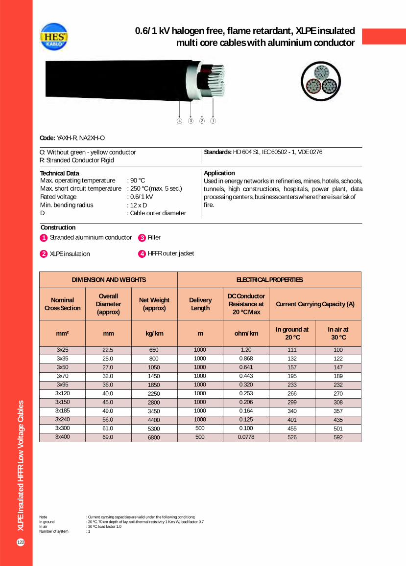
XLP
E In
sula
ted
HFF
R L
ow
Vo
ltag
e C
able
s
122
0.6/1 kV halogen free, flame retardant, XLPE insulatedmulti core cables with aluminium conductor
Construction
Code: YAXH-R, NA2XH-O
O: Without green - yellow conductorR: Stranded Conductor Rigid
Standards: HD 604 S1, IEC 60502 - 1, VDE 0276
Technical Data ApplicationUsed in energy networks in refineries, mines, hotels, schools, tunnels, high constructions, hospitals, power plant, data processing centers, business centers where there is a risk offire.
Max. operating temperature : 90 °CMax. short circuit temperature : 250 °C (max. 5 sec.)
Rated voltage : 0.6/1 kV
Min. bending radius : 12 x DD : Cable outer diameter
1 3Stranded aluminium conductor Filler
2 XLPE insulation 4 HFFR outer jacket
1234
DIMENSION AND WEIGHTS ELECTRICAL PROPERTIES
Nominal Cross Section
Overall Diameter (approx)
Net Weight (approx)
Delivery Length
DC Conductor Resistance at
20 ºC MaxCurrent Carrying Capacity (A)
mm² mm kg/km m ohm/kmIn ground at
20 ºC In air at
30 ºC
100
122
147
189
232
270
308
357
435
501
592
3x25
3x35
3x50
3x70
3x95
3x120
3x150
3x185
3x240
3x300
3x400
22.5
25.0
27.0
32.0
36.0
40.0
45.0
49.0
56.0
61.0
69.0
650
800
1050
1450
1850
2250
2800
3450
4400
5300
6800
1000
1000
1000
1000
1000
1000
1000
1000
1000
500
500
1.20
0.868
0.641
0.443
0.320
0.253
0.206
0.164
0.125
0.100
0.0778
111
132
157
195
233
266
299
340
401
455
526
Note : Current carrying capacities are valid under the following conditions;In ground : 20 ºC, 70 cm depth of lay, soil-thermal resistivity 1 K.m/W, load factor 0.7In air : 30 ºC, load factor 1.0Number of system : 1

XLP
E In
sula
ted
HFF
R L
ow
Vo
ltag
e C
able
s
123
0.6/1 kV halogen free, flame retardant, XLPE insulatedmulti core cables with aluminium conductor
Construction
Code: YAXH-R, NA2XH-O
O: Without green - yellow conductorR: Stranded Conductor Rigid
Standards: HD 604 S1, IEC 60502 - 1, VDE 0276
Technical Data ApplicationUsed in energy networks in refineries, mines, hotels, schools, tunnels, high constructions, hospitals, power plant, data processing centers, business centers where there is a risk offire.
Max. operating temperature : 90 °C
Max. short circuit temperature : 250 °C (max. 5 sec.)
Rated voltage : 0.6/1 kV
Min. bending radius : 12 x DD : Cable outer diameter
1 3Stranded aluminium conductor Filler
2 XLPE insulation 4 HFFR outer jacket
1234
DIMENSION AND WEIGHTS ELECTRICAL PROPERTIES
Nominal Cross Section
Overall Diameter (approx)
Net Weight (approx)
Delivery Length
DC Conductor Resistance at
20 ºC MaxCurrent Carrying Capacity (A)
mm² mm kg/km m ohm/kmIn ground at
20 ºC In air at
30 ºC
100
122
147
189
232
270
308
357
435
501
592
3x25+16
3x35+16
3x50+25
3x70+35
3x95+50
3x120+70
3x150+70
3x185+95
3x240+120
3x300+150
3x400+185
24.0
26.0
29.0
33.0
38.0
42.0
46.0
51.0
58.0
63.0
71.0
750
900
1200
1600
2100
2600
3100
3850
4900
5950
7500
1000
1000
1000
1000
1000
1000
1000
1000
500
500
500
1.20
0.868
0.641
0.443
0.320
0.253
0.206
0.164
0.125
0.100
0.0778
111
132
157
195
233
266
299
340
401
455
526
Note : Current carrying capacities are valid under the following conditions;In ground : 20 ºC, 70 cm depth of lay, soil-thermal resistivity 1 K.m/W, load factor 0.7In air : 30 ºC, load factor 1.0Number of system : 1
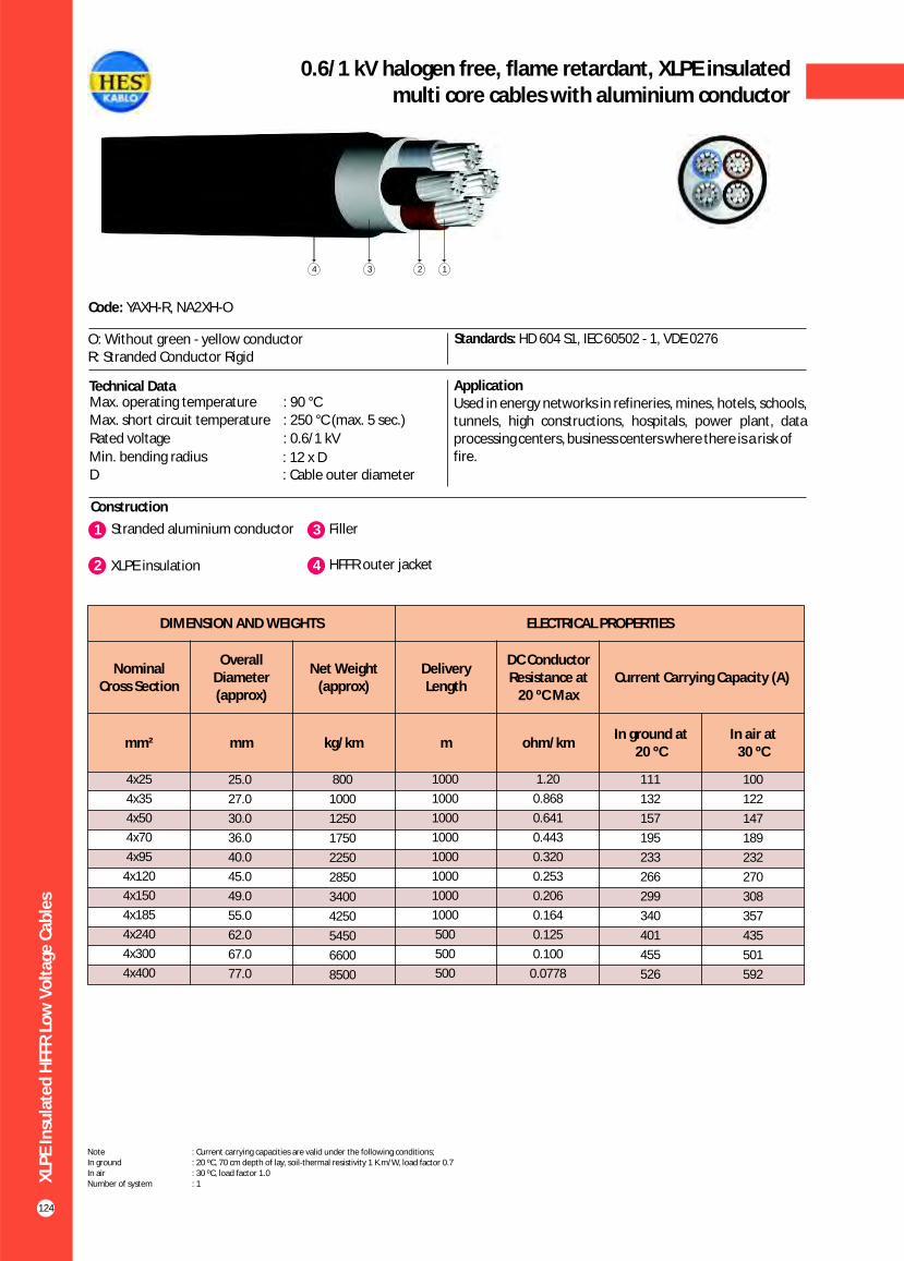
XLP
E In
sula
ted
HFF
R L
ow
Vo
ltag
e C
able
s
124
0.6/1 kV halogen free, flame retardant, XLPE insulatedmulti core cables with aluminium conductor
Construction
Code: YAXH-R, NA2XH-O
O: Without green - yellow conductorR: Stranded Conductor Rigid
Standards: HD 604 S1, IEC 60502 - 1, VDE 0276
Technical Data ApplicationUsed in energy networks in refineries, mines, hotels, schools, tunnels, high constructions, hospitals, power plant, data processing centers, business centers where there is a risk offire.
Max. operating temperature : 90 °CMax. short circuit temperature : 250 °C (max. 5 sec.)
Rated voltage : 0.6/1 kV
Min. bending radius : 12 x DD : Cable outer diameter
1 3Stranded aluminium conductor Filler
2 XLPE insulation 4 HFFR outer jacket
1234
DIMENSION AND WEIGHTS ELECTRICAL PROPERTIES
Nominal Cross Section
Overall Diameter (approx)
Net Weight (approx)
Delivery Length
DC Conductor Resistance at
20 ºC MaxCurrent Carrying Capacity (A)
mm² mm kg/km m ohm/kmIn ground at
20 ºC In air at
30 ºC
100
122
147
189
232
270
308
357
435
501
592
4x25
4x35
4x50
4x70
4x95
4x120
4x150
4x185
4x240
4x300
4x400
25.0
27.0
30.0
36.0
40.0
45.0
49.0
55.0
62.0
67.0
77.0
800
1000
1250
1750
2250
2850
3400
4250
5450
6600
8500
1000
1000
1000
1000
1000
1000
1000
1000
500
500
500
1.20
0.868
0.641
0.443
0.320
0.253
0.206
0.164
0.125
0.100
0.0778
111
132
157
195
233
266
299
340
401
455
526
Note : Current carrying capacities are valid under the following conditions;In ground : 20 ºC, 70 cm depth of lay, soil-thermal resistivity 1 K.m/W, load factor 0.7In air : 30 ºC, load factor 1.0Number of system : 1
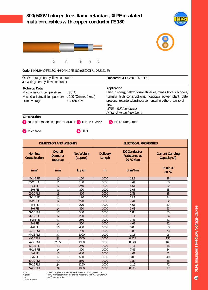
XLP
E In
sula
ted
HFF
R L
ow
Vo
ltag
e C
able
s
125
300/500V halogen free, flame retardant, XLPE insulatedmulti core cables with copper conductor FE 180
Construction
Code: NHXMH-O FE 180, NHXMH-J FE 180 (052XZ1-U, 052XZ1-R)
Standards: VDE 0250 214, TSEK
ApplicationUsed in energy networks in refineries, mines, hotels, schools, tunnels, high constructions, hospitals, power plant, data processing centers, business centers where there is a risk offire.U/RE : Solid conductorR/RM : Stranded conductor
Technical Data
O : Without green - yellow conductorJ : With green - yellow conductor
Max. operating temperature : 70 °CMax. short circuit temperature : 160 °C (max. 5 sec.) Rated voltage : 300/500 V
1 3Solid or stranded copper conductor XLPE insulation
4
5
Filler
HFFR outer jacket
1345
2 Mica tape
2
DIMENSION AND WEIGHTS ELECTRICAL PROPERTIES
Nominal Cross Section
Overall Diameter (approx)
Net Weight (approx)
Delivery Length
DC Conductor Resistance at
20 ºC Max
Current Carrying Capacity (A)
mm² mm kg/km m ohm/kmIn air at
30 ºC
2x1.5 RE2x2.5 RE2x4 RE2x6 RE
2x10 RM3x1.5 RE3x2.5 RE3x4 RE3x6 RE
3x10 RM4x1.5 RE4x2.5 RE4x4 RE4x6 RE
4x10 RM4x16 RM4x25 RM4x35 RM5x1.5 RE5x2.5 RE5x4 RE5x6 RE
5x10 RM5x16 RM5x25 RM
1011121316111213141712131416192126
28.513141517202429
150180240300470170220270360550200250350460700
100015001900240300440550850
12501800
1000100010001000100010001000100010001000100010001000100010001000100010001000100010001000100010001000
12.17.414.613.081.8312.17.414.613.081.8312.17.414.613.081.831.15
0.7270.52412.17.414.613.081.831.15
0.727
28385265862432425373243242537396
13016018243140557297
Note : Current carrying capacities are valid under the following conditions;In ground : 20 ºC, 70 cm depth of lay, soil-thermal resistivity 1 K.m/W, load factor 0.7In air : 30 ºC, load factor 1.0Number of system : 1

XLP
E In
sula
ted
HFF
R L
ow
Vo
ltag
e C
able
s
126
0.6/1 kV halogen free, flame retardant, XLPE insulatedsingle core cables with copper conductor FE 180
Construction
Code: YXH-U, YXH-R, N2XH-O FE 180
Standards: HD 604 S1, IEC 60502 - 1, VDE 0276
Technical Data ApplicationUsed in energy networks in refineries, mines, hotels, schools, tunnels, high constructions, hospitals, power plant, data processing centers, business centers where there is a risk offire.
1 3 Solid or stranded copper conductor XLPE insulation
2 Mica tape.
Max. operating temperature : 90 °C
Max. short circuit temperature : 250 °C (max. 5 sec.)
Rated voltage : 0.6/1 kV
Min. bending radius : 12 x DD : Cable outer diameter
123
4 HFFR outer jacket
U: Solid conductorR: Stranded Conductor Rigid
4
1x1.5
1x2.5
1x4
1x6
1x10
1x16
1x25
1x35
1x50
1x70
1x95
1x120
1x150
1x185
1x240
1x300
1x400
1x500
6.0
6.5
6.9
7.4
8.6
9.7
11.0
12.0
13.0
15.0
17.0
18.5
20.5
22.5
25.5
29.0
33.0
37.5
50
65
80
100
150
200
300
400
530
750
1000
1250
1500
1900
2450
3000
3900
4900
1000
1000
1000
1000
1000
1000
1000
1000
1000
1000
1000
1000
1000
1000
1000
1000
1000
1000
12.1
7.41
4.61
3.08
1.83
1.15
0.727
0.524
0.387
0.268
0.193
0.153
0.124
0.0991
0.0754
0.0601
0.0470
0.0366
39
51
66
82
109
139
179
213
251
307
366
416
465
526
610
689
788
889
32
43
55
68
90
115
149
178
211
259
310
352
396
449
521
587
669
748
32
42
56
71
96
128
173
212
258
328
404
471
541
626
749
864
1018
1173
25
34
44
57
77
102
139
170
208
265
326
381
438
507
606
697
816
933
DIMENSION AND WEIGHTS ELECTRICAL PROPERTIES
Nominal Cross Section
Overall Diameter (approx)
Net Weight (approx)
Delivery Length
DC Conductor Resistance at
20 ºC MaxCurrent Carrying Capacity (A)
mm² mm kg/km m ohm/km
In ground at 20 ºC In air at 30 ºC
*** ** * *** ** *
Note : Current carrying capacities are valid under the following conditions;In ground : 20 ºC, 70 cm depth of lay, soil-thermal resistivity 1 K.m/W, load factor 0.7In air : 30 ºC, load factor 1.0*** : Flat formation, clearance between cables; in air = 1 x Cable outer diameter, in ground = 7 cm : Trefoil formationNumber of system : 1
** *
O: Without green - yellow conductor

XLP
E In
sula
ted
HFF
R L
ow
Vo
ltag
e C
able
s
127
0.6/1 kV halogen free, flame retardant, XLPE insulatedmulti core cables with copper conductor FE 180
Construction
Standards: HD 604 S1, IEC 60502 - 1, VDE 0276
Technical Data ApplicationUsed in energy networks in refineries, mines, hotels, schools, tunnels, high constructions, hospitals, power plant, data processing centers, business centers where there is a risk offire.
Max. operating temperature : 90 °CMax. short circuit temperature : 250 °C (max. 5 sec.)
Rated voltage : 0.6/1 kV
Min. bending radius : 12 x DD : Cable outer diameter
1 3 Solid or stranded copper conductor XLPE insulation
2 Mica tape 4 Filler
1234
5 HFFR outer jacket
Code: YXH-U, YXH-R, N2XH-O FE 180
U: Solid conductorR: Stranded Conductor Rigid
5
DIMENSION AND WEIGHTS ELECTRICAL PROPERTIES
Nominal Cross Section
Overall Diameter (approx)
Net Weight (approx)
Delivery Length
DC Conductor Resistance at
20 ºC MaxCurrent Carrying Capacity (A)
mm² mm kg/km m ohm/kmIn ground at
20 ºC In air at
30 ºC
32
42
56
71
96
125
155
195
235
300
370
430
490
570
680
785
860
2x1.5
2x2.5
2x4
2x6
2x10
2x16
2x25
2x35
2x50
2x70
2x95
2x120
2x150
2x185
2x240
2x300
2x400
11.0
12.0
13.0
14.0
16.2
18.3
23.0
24.0
27.0
31.0
35.0
39.0
42.0
47.0
53.0
58.0
65.0
170
200
260
320
460
630
1000
1250
1600
2200
2900
3600
4400
5500
7050
8650
11100
1000
1000
1000
1000
1000
1000
1000
1000
1000
1000
1000
1000
1000
1000
500
500
500
12.1
7.41
4.61
3.08
1.83
1.15
0.727
0.524
0.387
0.268
0.193
0.153
0.124
0.0991
0.0754
0.0601
0.0470
39
51
66
82
109
115
145
175
210
255
310
355
400
455
530
605
690
Note : Current carrying capacities are valid under the following conditions;In ground : 20 ºC, 70 cm depth of lay, soil-thermal resistivity 1 K.m/W, load factor 0.7In air : 30 ºC, load factor 1.0Number of system : 1
O: Without green - yellow conductor

XLP
E In
sula
ted
HFF
R L
ow
Vo
ltag
e C
able
s
128
0.6/1 kV halogen free, flame retardant, XLPE insulatedmulti core cables with copper conductor FE 180
Construction
Standards: HD 604 S1, IEC 60502 - 1, VDE 0276
Technical Data ApplicationUsed in energy networks in refineries, mines, hotels, schools, tunnels, high constructions, hospitals, power plant, data processing centers, business centers where there is a risk offire.
Max. operating temperature : 90 °C
Max. short circuit temperature : 250 °C (max. 5 sec.)
Rated voltage : 0.6/1 kV
Min. bending radius : 12 x DD : Cable outer diameter
1234
1 3 Solid or stranded copper conductor XLPE insulation
2 Mica tape 4 Filler
5 HFFR outer jacket
Code: YXH-U, YXH-R, N2XH-O FE 180
U: Solid conductorR: Stranded Conductor Rigid
5
DIMENSION AND WEIGHTS ELECTRICAL PROPERTIES
Nominal Cross Section
Overall Diameter (approx)
Net Weight (approx)
Delivery Length
DC Conductor Resistance at
20 ºC MaxCurrent Carrying Capacity (A)
mm² mm kg/km m ohm/kmIn ground at
20 ºC In air at
30 ºC
24
32
42
53
73
96
130
160
195
247
305
355
407
469
551
638
746
3x1.5
3x2.5
3x4
3x6
3x10
3x16
3x25
3x35
3x50
3x70
3x95
3x120
3x150
3x185
3x240
3x300
3x400
11.5
12.5
13.5
14.5
17.0
19.0
24.0
26.0
29.0
33.0
37.0
41.0
46.0
50.0
57.0
62.0
70.0
190
230
300
370
550
750
1200
1550
2000
2800
3700
4600
5650
7000
9100
11100
14300
1000
1000
1000
1000
1000
1000
1000
1000
1000
1000
1000
1000
500
500
500
250
250
12.1
7.41
4.61
3.08
1.83
1.15
0.727
0.524
0.387
0.268
0.193
0.153
0.124
0.0991
0.0754
0.0601
0.0470
30
40
52
64
86
111
143
173
205
252
303
346
390
441
511
580
663
Note : Current carrying capacities are valid under the following conditions;In ground : 20 ºC, 70 cm depth of lay, soil-thermal resistivity 1 K.m/W, load factor 0.7In air : 30 ºC, load factor 1.0Number of system : 1
O: Without green - yellow conductor
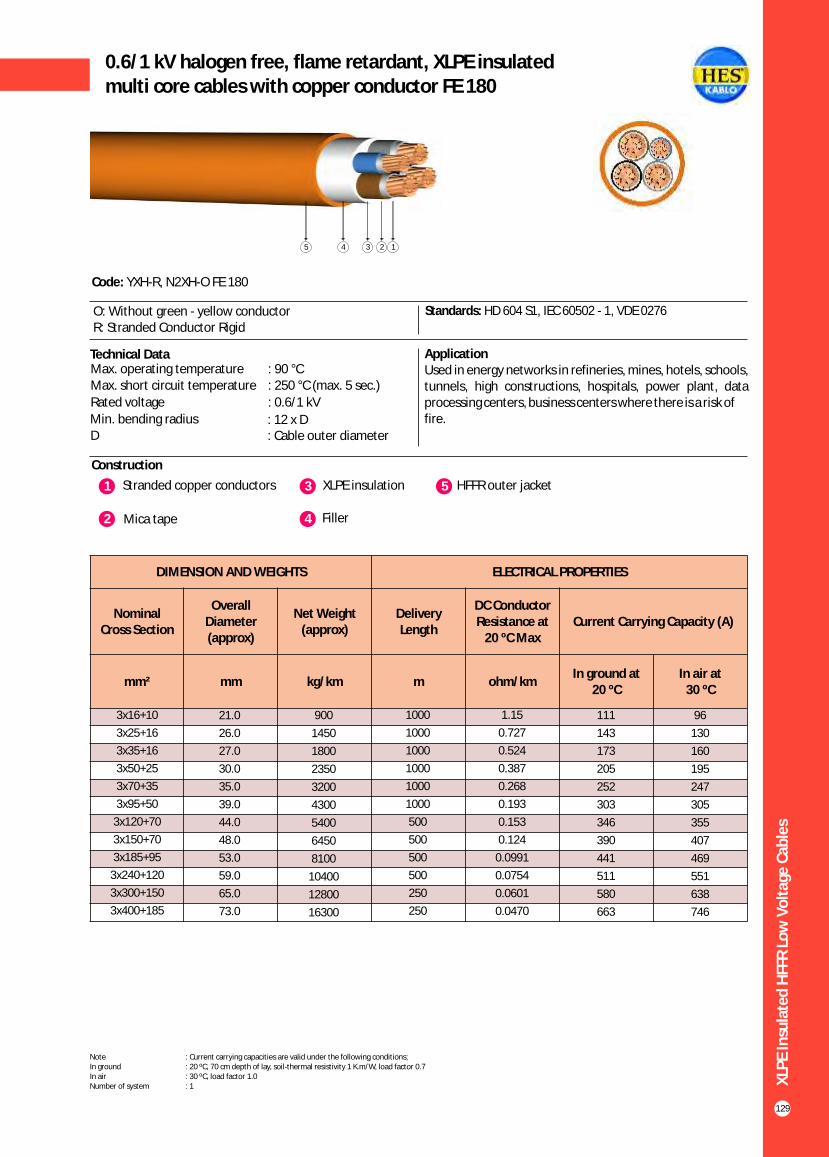
XLP
E In
sula
ted
HFF
R L
ow
Vo
ltag
e C
able
s
129
0.6/1 kV halogen free, flame retardant, XLPE insulatedmulti core cables with copper conductor FE 180
Construction
Standards: HD 604 S1, IEC 60502 - 1, VDE 0276
Technical Data ApplicationUsed in energy networks in refineries, mines, hotels, schools, tunnels, high constructions, hospitals, power plant, data processing centers, business centers where there is a risk offire.
Max. operating temperature : 90 °CMax. short circuit temperature : 250 °C (max. 5 sec.)
Rated voltage : 0.6/1 kV
Min. bending radius : 12 x DD : Cable outer diameter
1235
1 3 Stranded copper conductors XLPE insulation
2 Mica tape 4 Filler
5 HFFR outer jacket
Code: YXH-R, N2XH-O FE 180
O: Without green - yellow conductorR: Stranded Conductor Rigid
4
DIMENSION AND WEIGHTS ELECTRICAL PROPERTIES
Nominal Cross Section
Overall Diameter (approx)
Net Weight (approx)
Delivery Length
DC Conductor Resistance at
20 ºC MaxCurrent Carrying Capacity (A)
mm² mm kg/km m ohm/kmIn ground at
20 ºC In air at
30 ºC
96
130
160
195
247
305
355
407
469
551
638
746
3x16+10
3x25+16
3x35+16
3x50+25
3x70+35
3x95+50
3x120+70
3x150+70
3x185+95
3x240+120
3x300+150
3x400+185
21.0
26.0
27.0
30.0
35.0
39.0
44.0
48.0
53.0
59.0
65.0
73.0
900
1450
1800
2350
3200
4300
5400
6450
8100
10400
12800
16300
1000
1000
1000
1000
1000
1000
500
500
500
500
250
250
1.15
0.727
0.524
0.387
0.268
0.193
0.153
0.124
0.0991
0.0754
0.0601
0.0470
111
143
173
205
252
303
346
390
441
511
580
663
Note : Current carrying capacities are valid under the following conditions;In ground : 20 ºC, 70 cm depth of lay, soil-thermal resistivity 1 K.m/W, load factor 0.7In air : 30 ºC, load factor 1.0Number of system : 1

XLP
E In
sula
ted
HFF
R L
ow
Vo
ltag
e C
able
s
130
0.6/1 kV halogen free, flame retardant, XLPE insulatedmulti core cables with copper conductor FE 180
Construction
Standards: HD 604 S1, IEC 60502 - 1, VDE 0276
Technical Data ApplicationUsed in energy networks in refineries, mines, hotels, schools, tunnels, high constructions, hospitals, power plant, data processing centers, business centers where there is a risk offire.
Max. operating temperature : 90 °C
Max. short circuit temperature : 250 °C (max. 5 sec.)
Rated voltage : 0.6/1 kV
Min. bending radius : 12 x DD : Cable outer diameter
1235
1 3 Solid or stranded copper conductor XLPE insulation
2 Mica tape 4 Filler
5 HFFR outer jacket
Code: YXH-U, YXH-R, N2XH-O FE 180
U: Solid conductorR: Stranded Conductor Rigid
4
DIMENSION AND WEIGHTS ELECTRICAL PROPERTIES
Nominal Cross Section
Overall Diameter (approx)
Net Weight (approx)
Delivery Length
DC Conductor Resistance at
20 ºC MaxCurrent Carrying Capacity (A)
mm² mm kg/km m ohm/kmIn ground at
20 ºC In air at
30 ºC
24
32
42
53
73
96
130
160
195
247
305
355
407
469
551
638
746
4x1.5
4x2.5
4x4
4x6
4x10
4x16
4x25
4x35
4x50
4x70
4x95
4x120
4x150
4x185
4x240
4x300
4x400
12.0
13.0
14.5
15.5
18.5
20.5
26.0
28.0
32.0
37.0
41.0
46.0
51.0
56.0
63.0
69.0
78.0
220
250
350
450
700
950
1500
1900
2500
3500
4700
5900
7200
8950
11600
14200
18400
1000
1000
1000
1000
1000
1000
1000
1000
1000
1000
1000
500
500
500
250
250
250
12.1
7.41
4.61
3.08
1.83
1.15
0.727
0.524
0.387
0.268
0.193
0.153
0.124
0.0991
0.0754
0.0601
0.0470
30
40
52
64
86
111
143
173
205
252
303
346
390
441
511
580
663
Note : Current carrying capacities are valid under the following conditions;In ground : 20 ºC, 70 cm depth of lay, soil-thermal resistivity 1 K.m/W, load factor 0.7In air : 30 ºC, load factor 1.0Number of system : 1
O: Without green - yellow conductor


Sola
r ca
ble
s
132
0.6/1 kV LSFOH Insulated, single core, solar cables
Construction
Code: PV1 - F
Standards: TÜV 2 PfG 1169 / 08.2007
ApplicationIntended for the interconnection of the various elements of photovoltaic systems such as solar panel arrays and inverters. Suitable for fixed installations, internal and external, within unprotected pipes, or in similar closed systems.
Technical Data
Temperature rating : Between-40°C and +120°C
Short-circuit temp : 250 °C (max. 5 sec.)
Rated operating voltage (A.C.) : 0.6/1 kVRated operating voltage (D.C) : 1.8 kVTest Voltage : 6 kV ( 5 min.)
123
1 3Tinned filexible conductors LSFOH outer jacket
2 LSFOH insulation
MECHANICAL AND ELECTRICAL PROPERTIES
Cross Section
Conductor Diameter (Approx)
Cable Diameter (Approx)
Cable Weight
Current Capacity
60 ºC
Min. Bending Radius
Max. Tensile Load
Short-circuit
Withstand
mm² mm mm kg/km Amper mm N kA
23
38
60
90
150
240
375
525
750
1050
1425
1800
2250
2775
3600
4500
1.5
2.5
4
6
10
16
25
35
50
70
95
120
150
185
240
300
1.6
1.9
2.4
2.9
4.5
5.6
6.1
7.3
8.7
10.5
12.2
14.8
15.7
17.8
20.4
23.6
4.6
4.9
5.4
6.8
7.5
9.5
11.0
12.3
14.0
16.4
18.5
21.0
22.0
24.5
27.2
32.0
35
47
65
90
135
200
285
385
530
730
840
1190
1470
1750
2290
2900
30
41
55
70
98
132
176
218
276
347
416
488
566
644
775
896
14
15
16
18
23
35
38
43
48
61
69
84
85
95
107
120
0.19
0.32
0.50
0.76
1.26
2.02
3.15
4.41
6.30
8.82
11.97
15.12
18.90
23.31
30.24
37.80
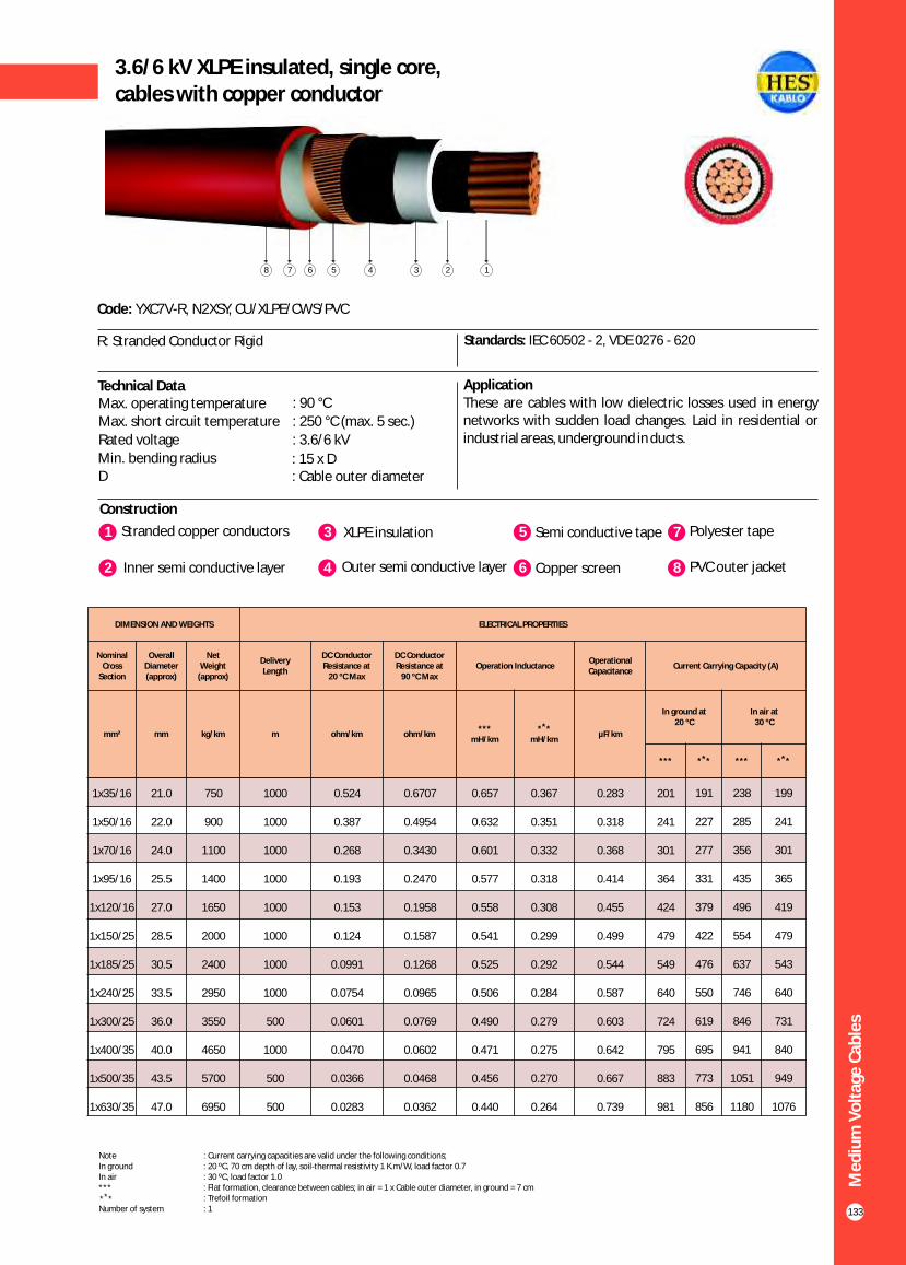
Me
diu
m V
olt
age
Cab
les
133
3.6/6 kV XLPE insulated, single core,cables with copper conductor
Construction
Code: YXC7V-R, N2XSY, CU/XLPE/CWS/PVC
R: Stranded Conductor Rigid Standards: IEC 60502 - 2, VDE 0276 - 620
Technical Data ApplicationThese are cables with low dielectric losses used in energy networks with sudden load changes. Laid in residential or industrial areas, underground in ducts.
Max. operating temperature : 90 °C
Max. short circuit temperature : 250 °C (max. 5 sec.)
Rated voltage : 3.6/6 kV
Min. bending radius : 15 x DD : Cable outer diameter
1 3Stranded copper conductors XLPE insulation
2 Inner semi conductive layer 4 Outer semi conductive layer
5 Semi conductive tape
6 Copper screen
7 Polyester tape
8 PVC outer jacket
12345678
1x35/16
1x50/16
1x70/16
1x95/16
1x120/16
1x150/25
1x185/25
1x240/25
1x300/25
1x400/35
1x500/35
1x630/35
21.0
22.0
24.0
25.5
27.0
28.5
30.5
33.5
36.0
40.0
43.5
47.0
750
900
1100
1400
1650
2000
2400
2950
3550
4650
5700
6950
1000
1000
1000
1000
1000
1000
1000
1000
500
1000
500
500
0.524
0.387
0.268
0.193
0.153
0.124
0.0991
0.0754
0.0601
0.0470
0.0366
0.0283
0.6707
0.4954
0.3430
0.2470
0.1958
0.1587
0.1268
0.0965
0.0769
0.0602
0.0468
0.0362
0.657
0.632
0.601
0.577
0.558
0.541
0.525
0.506
0.490
0.471
0.456
0.440
0.367
0.351
0.332
0.318
0.308
0.299
0.292
0.284
0.279
0.275
0.270
0.264
0.283
0.318
0.368
0.414
0.455
0.499
0.544
0.587
0.603
0.642
0.667
0.739
201
241
301
364
424
479
549
640
724
795
883
981
191
227
277
331
379
422
476
550
619
695
773
856
238
285
356
435
496
554
637
746
846
941
1051
1180
199
241
301
365
419
479
543
640
731
840
949
1076
DIMENSION AND WEIGHTS ELECTRICAL PROPERTIES
Nominal Cross
Section
Overall Diameter (approx)
Net Weight
(approx)
Delivery Length
DC Conductor Resistance at
20 ºC Max
DC Conductor Resistance at
90 ºC MaxOperation Inductance
Operational Capacitance
Current Carrying Capacity (A)
mm² mm kg/km m ohm/km ohm/km***
mH/km
** *mH/km
µF/km
In ground at20 ºC
In air at30 ºC
*** ** * *** ** *
Note : Current carrying capacities are valid under the following conditions;In ground : 20 ºC, 70 cm depth of lay, soil-thermal resistivity 1 K.m/W, load factor 0.7In air : 30 ºC, load factor 1.0*** : Flat formation, clearance between cables; in air = 1 x Cable outer diameter, in ground = 7 cm : Trefoil formationNumber of system : 1
** *

Me
diu
m V
olt
age
Cab
les
134
5.8/10 kV (6/10 kV) or 6.35/11 kV XLPE insulated, single core,cables with copper conductor
Construction
Code: YXC7V-R, N2XSY, CU/XLPE/CWS/PVC
R: Stranded Conductor Rigid Standards: IEC 60502 - 2, VDE 0276 - 620
Technical Data ApplicationThese are cables with low dielectric losses used in energy networks with sudden load changes. Laid in residential or industrial areas, underground in ducts.
Max. operating temperature : 90 °CMax. short circuit temperature : 250 °C (max. 5 sec.)
Rated voltage : 5.8/10 kV (6/10 kV) 6.35/11 kV
Min. bending radius : 15 x DD : Cable outer diameter
1 3Stranded copper conductors XLPE insulation
2 Inner semi conductive layer 4 Outer semi conductive layer
5 Semi conductive tape
6 Copper screen
7 Polyester tape
8 PVC outer jacket
12345678
DIMENSION AND WEIGHTS ELECTRICAL PROPERTIES
Nominal Cross
Section
Overall Diameter (approx)
Net Weight
(approx)
Delivery Length
DC Conductor Resistance at
20 ºC Max
DC Conductor Resistance at
90 ºC MaxOperation Inductance
Operational Capacitance
Current Carrying Capacity (A)
mm² mm kg/km m ohm/km ohm/km***
mH/km
** *mH/km
µF/km
In ground at20 ºC
In air at30 ºC
*** ** * *** ** *
1x35/16
1x50/16
1x70/16
1x95/16
1x120/16
1x150/25
1x185/25
1x240/25
1x300/25
1x400/35
1x500/35
1x630/35
22.5
24.0
26.0
27.5
29.5
30.5
32.5
35.0
37.5
41.0
44.0
47.5
800
950
1200
1450
1700
2100
2450
3050
3650
4700
5700
7000
1000
1000
1000
1000
1000
1000
1000
1000
1000
1000
500
500
0.524
0.387
0.268
0.193
0.153
0.124
0.0991
0.0754
0.0601
0.0470
0.0366
0.0283
0.6707
0.4954
0.3430
0.2470
0.1958
0.1587
0.1268
0.0965
0.0769
0.0602
0.0468
0.0362
0.661
0.636
0.606
0.582
0.563
0.546
0.529
0.509
0.493
0.473
0.457
0.440
0.383
0.366
0.349
0.334
0.323
0.313
0.304
0.294
0.288
0.278
0.271
0.264
0.223
0.248
0.285
0.320
0.350
0.382
0.415
0.462
0.507
0.573
0.631
0.699
212
249
303
358
404
441
493
563
626
676
743
820
187
220
269
321
364
405
457
528
593
665
739
818
231
277
345
418
481
537
612
716
811
901
1006
1130
195
234
292
354
407
460
527
621
709
815
921
1045
Note : Current carrying capacities are valid under the following conditions;In ground : 20 ºC, 70 cm depth of lay, soil-thermal resistivity 1 K.m/W, load factor 0.7In air : 30 ºC, load factor 1.0*** : Flat formation, clearance between cables; in air = 1 x Cable outer diameter, in ground = 7 cm : Trefoil formationNumber of system : 1
** *

Me
diu
m V
olt
age
Cab
les
135
8.7/15 kV XLPE insulated, single core,cables with copper conductor
Construction
Code: YXC7V-R, N2XSY, CU/XLPE/CWS/PVC
R: Stranded Conductor Rigid Standards: IEC 60502 - 2, VDE 0276 - 620
Technical Data ApplicationThese are cables with low dielectric losses used in energy networks with sudden load changes. Laid in residential or industrial areas, underground in ducts.
Max. operating temperature : 90 °C
Max. short circuit temperature : 250 °C (max. 5 sec.)
Rated voltage : 8.7/15 kV
Min. bending radius : 15 x DD : Cable outer diameter
1 3Stranded copper conductors XLPE insulation
2 Inner semi conductive layer 4 Outer semi conductive layer
5 Semi conductive tape
6 Copper screen
7 Polyester tape
8 PVC outer jacket
12345678
DIMENSION AND WEIGHTS ELECTRICAL PROPERTIES
Nominal Cross
Section
Overall Diameter (approx)
Net Weight
(approx)
Delivery Length
DC Conductor Resistance at
20 ºC Max
DC Conductor Resistance at
90 ºC MaxOperation Inductance
Operational Capacitance
Current Carrying Capacity (A)
mm² mm kg/km m ohm/km ohm/km***
mH/km
** *mH/km
µF/km
In ground at20 ºC
In air at30 ºC
*** ** * *** ** *
1x35/16
1x50/16
1x70/16
1x95/16
1x120/16
1x150/25
1x185/25
1x240/25
1x300/25
1x400/35
1x500/35
1x630/35
25.0
26.5
28.0
29.5
31.5
33.0
35.0
37.5
40.0
43.5
46.5
50.0
900
1050
1300
1550
1850
2200
2600
3150
3750
4900
5900
7150
1000
1000
1000
1000
1000
1000
1000
1000
1000
1000
500
500
0.524
0.387
0.268
0.193
0.153
0.124
0.0991
0.0754
0.0601
0.0470
0.0366
0.0283
0.6707
0.4954
0.3430
0.2470
0.1958
0.1587
0.1268
0.0965
0.0769
0.0602
0.0468
0.0362
0.666
0.640
0.609
0.585
0.567
0.549
0.534
0.514
0.497
0.477
0.461
0.445
0.
0.383
0.362
0.346
0.336
0.325
0.317
0.307
0.298
0.289
0.282
0.275
401 0.181
0.201
0.229
0.255
0.278
0.302
0.328
0.363
0.398
0.447
0.491
0.543
212
249
303
358
404
441
493
563
626
676
743
820
187
220
269
321
364
405
457
528
593
665
739
818
231
277
345
418
481
537
612
716
811
901
1006
1130
195
234
292
354
407
460
527
621
709
815
921
1045
Note : Current carrying capacities are valid under the following conditions;In ground : 20 ºC, 70 cm depth of lay, soil-thermal resistivity 1 K.m/W, load factor 0.7In air : 30 ºC, load factor 1.0*** : Flat formation, clearance between cables; in air = 1 x Cable outer diameter, in ground = 7 cm : Trefoil formationNumber of system : 1
** *

Me
diu
m V
olt
age
Cab
les
136
12/20 kV or 12.7/22 kV XLPE insulated, single core, cables with copper conductor
Construction
Code: YXC7V-R, N2XSY, CU/XLPE/CWS/PVC
R: Stranded Conductor Rigid Standards: IEC 60502 - 2, VDE 0276 - 620
ApplicationThese are cables with low dielectric losses used in energy networks with sudden load changes. Laid in residential or industrial areas, underground in ducts.
1 3Stranded copper conductors XLPE insulation
2 Inner semi conductive layer 4 Outer semi conductive layer
5 Semi conductive tape
6 Copper screen
7 Polyester tape
8 PVC outer jacket
Technical DataMax. operating temperature : 90 °C
Max. short circuit temperature : 250 °C (max. 5 sec.)
Rated voltage : 12/20 kV 12.7/22 kV
Min. bending radius : 15 x DD : Cable outer diameter
12345678
DIMENSION AND WEIGHTS ELECTRICAL PROPERTIES
Nominal Cross
Section
Overall Diameter (approx)
Net Weight
(approx)
Delivery Length
DC Conductor Resistance at
20 ºC Max
DC Conductor Resistance at
90 ºC MaxOperation Inductance
Operational Capacitance
Current Carrying Capacity (A)
mm² mm kg/km m ohm/km ohm/km***
mH/km
** *mH/km
µF/km
In ground at20 ºC
In air at30 ºC
*** ** * *** ** *
1x35/16
1x50/16
1x70/16
1x95/16
1x120/16
1x150/25
1x185/25
1x240/25
1x300/25
1x400/35
1x500/35
1x630/35
27.0
28.5
30.0
32.0
34.0
35.0
37.0
39.5
42.0
45.5
48.5
52.5
950
1150
1400
1650
1950
2350
2700
3300
3900
5000
6000
7300
1000
1000
1000
1000
1000
1000
1000
1000
1000
1000
500
500
0.524
0.387
0.268
0.193
0.153
0.124
0.0991
0.0754
0.0601
0.0470
0.0366
0.0283
0.6707
0.4954
0.3430
0.2470
0.1958
0.1587
0.1268
0.0965
0.0769
0.0602
0.0468
0.0362
0.670
0.644
0.614
0.590
0.571
0.554
0.538
0.518
0.501
0.480
0.464
0.448
0.416
0.397
0.377
0.360
0.349
0.338
0.329
0.317
0.308
0.298
0.290
0.282
0.157
0.174
0.197
0.218
0.238
0.258
0.278
0.308
0.336
0.377
0.413
0.455
213
250
304
361
407
445
498
569
633
686
756
842
189
223
273
325
368
410
463
534
601
674
750
836
233
279
347
420
483
540
614
718
813
904
1011
1128
199
238
296
358
412
466
534
627
715
819
927
1041
Note : Current carrying capacities are valid under the following conditions;In ground : 20 ºC, 70 cm depth of lay, soil-thermal resistivity 1 K.m/W, load factor 0.7In air : 30 ºC, load factor 1.0*** : Flat formation, clearance between cables; in air = 1 x Cable outer diameter, in ground = 7 cm : Trefoil formationNumber of system : 1
** *

Me
diu
m V
olt
age
Cab
les
137
18/30 kV or 19/33 kV XLPE insulated, single core,cables with copper conductor
Construction
Code: YXC7V-R, N2XSY, CU/XLPE/CWS/PVC
R: Stranded Conductor Rigid Standards: IEC 60502 - 2, VDE 0276 - 620
Technical Data ApplicationThese are cables with low dielectric losses used in energy networks with sudden load changes. Laid in residential or industrial areas, underground in ducts.
1 3Stranded copper conductors XLPE insulation
2 Inner semi conductive layer 4 Outer semi conductive layer
5 Semi conductive tape
6 Copper screen
7 Polyester tape
8 PVC outer jacket
12345678
DIMENSION AND WEIGHTS ELECTRICAL PROPERTIES
Nominal Cross
Section
Overall Diameter (approx)
Net Weight
(approx)
Delivery Length
DC Conductor Resistance at
20 ºC Max
DC Conductor Resistance at
90 ºC MaxOperation Inductance
Operational Capacitance
Current Carrying Capacity (A)
mm² mm kg/km m ohm/km ohm/km***
mH/km
** *mH/km
µF/km
In ground at20 ºC
In air at30 ºC
*** ** * *** ** *
1x35/16
1x50/16
1x70/16
1x95/16
1x120/16
1x150/25
1x185/25
1x240/25
1x300/25
1x400/35
1x500/35
1x630/35
32.0
33.5
35.0
37.0
39.0
40.5
42.5
45.0
47.5
50.5
54.0
57.5
1200
1400
1650
1950
2250
2700
3050
3650
4300
5450
6500
7850
1000
1000
1000
1000
1000
1000
1000
1000
1000
500
500
500
0.524
0.387
0.268
0.193
0.153
0.124
0.0991
0.0754
0.0601
0.0470
0.0366
0.0283
0.6707
0.4954
0.3430
0.2470
0.1958
0.1587
0.1268
0.0965
0.0769
0.0602
0.0468
0.0362
0.680
0.655
0.624
0.600
0.581
0.564
0.547
0.527
0.510
0.489
0.473
0.457
0.451
0.432
0.408
0.391
0.377
0.366
0.355
0.342
0.332
0.320
0.310
0.301
0.123
0.135
0.151
0.166
0.180
0.194
0.208
0.229
0.248
0.276
0.301
0.330
214
251
306
363
410
449
503
576
641
697
768
858
192
226
276
329
373
415
468
541
608
684
762
847
233
279
348
421
483
540
615
718
812
904
1011
1128
202
241
299
362
416
469
536
630
717
823
929
1043
Note : Current carrying capacities are valid under the following conditions;In ground : 20 ºC, 70 cm depth of lay, soil-thermal resistivity 1 K.m/W, load factor 0.7In air : 30 ºC, load factor 1.0*** : Flat formation, clearance between cables; in air = 1 x Cable outer diameter, in ground = 7 cm : Trefoil formationNumber of system : 1
** *
Max. operating temperature : 90 °C
Max. short circuit temperature : 250 °C (max. 5 sec.)
Rated voltage : 18/30 kV 19/33 kV
Min. bending radius : 15 x DD : Cable outer diameter

Me
diu
m V
olt
age
Cab
les
138
20.3/35 kV or 20.8/36 kV XLPE insulated, single core, cables with copper conductor
Construction
Code: YXC7V-R, N2XSY, CU/XLPE/CWS/PVC
R: Stranded Conductor Rigid Standards: HD 620 S2, TSEK
ApplicationThese are cables with low dielectric losses used in energy networks with sudden load changes. Laid in residential or industrial areas, underground in ducts.
1 3Stranded copper conductors XLPE insulation
2 Inner semi conductive layer 4 Outer semi conductive layer
5 Semi conductive tape
6 Copper screen
7 Polyester tape
8 PVC outer jacket
Technical DataMax. operating temperature : 90 °C
Max. short circuit temperature : 250 °C (max. 5 sec.)
Rated voltage : 20.3/35 kV 20.8/36 kV
Min. bending radius : 15 x DD : Cable outer diameter
12345678
DIMENSION AND WEIGHTS ELECTRICAL PROPERTIES
Nominal Cross
Section
Overall Diameter (approx)
Net Weight
(approx)
Delivery Length
DC Conductor Resistance at
20 ºC Max
DC Conductor Resistance at
90 ºC MaxOperation Inductance
Operational Capacitance
Current Carrying Capacity (A)
mm² mm kg/km m ohm/km ohm/km***
mH/km
** *mH/km
µF/km
In ground at20 ºC
In air at30 ºC
*** ** * *** ** *
1x35/16
1x50/16
1x70/16
1x95/16
1x120/16
1x150/25
1x185/25
1x240/25
1x300/25
1x400/35
1x500/35
1x630/35
34.5
36.0
37.5
39.5
41.5
43.0
44.5
47.5
49.5
53.0
56.0
60.0
1300
1550
1800
2100
2400
2850
3200
3800
4500
5650
6700
8000
1000
1000
1000
1000
1000
1000
1000
1000
1000
500
500
500
0.524
0.387
0.268
0.193
0.153
0.124
0.0991
0.0754
0.0601
0.0470
0.0366
0.0283
0.6707
0.4954
0.3430
0.2470
0.1958
0.1587
0.1268
0.0965
0.0769
0.0602
0.0468
0.0362
0.685
0.659
0.628
0.604
0.585
0.567
0.551
0.531
0.514
0.493
0.477
0.460
0.464
0.444
0.420
0.402
0.388
0.376
0.365
0.351
0.341
0.328
0.318
0.308
0.115
0.125
0.140
0.153
0.165
0.178
0.191
0.209
0.226
0.252
0.274
0.300
214
251
306
363
410
449
503
576
641
697
768
858
192
226
276
329
373
415
468
541
608
684
762
847
233
279
348
421
483
540
615
718
812
904
1011
1128
202
241
299
362
416
469
536
630
717
823
929
1043
Note : Current carrying capacities are valid under the following conditions;In ground : 20 ºC, 70 cm depth of lay, soil-thermal resistivity 1 K.m/W, load factor 0.7In air : 30 ºC, load factor 1.0*** : Flat formation, clearance between cables; in air = 1 x Cable outer diameter, in ground = 7 cm : Trefoil formationNumber of system : 1
** *

Me
diu
m V
olt
age
Cab
les
139
3.6/6 kV XLPE insulated, longitudinally sealed,single core cables with copper conductor
Construction
Code: N2XS(F)2Y, CU/XLPE/SCWBT/CWS/WBT/PE
Standards: IEC 60502 - 2, VDE 276 - 620
Application These are cables with low dielectric losses used in energy networks with sudden load changes. Laid in residential or industrial areas, underground in ducts. If the cable gets water inside due to the mechanical damages, swellable tapes prevent the penetration of the water inside the cable.
1 3Stranded copper conductors XLPE insulation
2 Inner semi conductive layer 4 Outer semi conductive layer
5 Semi conductive swelling tape
6 Copper screen
7 Swellable tape
8 PE outer jacket
Technical Data
Max. operating temperature : 90 °CMax. short circuit temperature : 250 °C (max. 5 sec.)
Rated voltage : 3.6/6 kV 3.8/6.6 kV
Min. bending radius : 15 x DD : Cable outer diameter
12345678
DIMENSION AND WEIGHTS ELECTRICAL PROPERTIES
Nominal Cross
Section
Overall Diameter (approx)
Net Weight
(approx)
Delivery Length
DC Conductor Resistance at
20 ºC Max
DC Conductor Resistance at
90 ºC MaxOperation Inductance
Operational Capacitance
Current Carrying Capacity (A)
mm² mm kg/km m ohm/km ohm/km***
mH/km
** *mH/km
µF/km
In ground at20 ºC
In air at30 ºC
*** ** * *** ** *
1x35/16
1x50/16
1x70/16
1x95/16
1x120/16
1x150/25
1x185/25
1x240/25
1x300/25
1x400/35
1x500/35
1x630/35
24.0
25.0
26.5
28.5
30.0
31.5
33.5
36.5
39.0
43.0
46.5
50.0
700
900
1100
1350
1600
1950
2350
2850
3500
4600
5550
6800
1000
1000
1000
1000
1000
1000
1000
1000
500
1000
500
500
0.524
0.387
0.268
0.193
0.153
0.124
0.0991
0.0754
0.0601
0.0470
0.0366
0.0283
0.6707
0.4954
0.3430
0.2470
0.1958
0.1587
0.1268
0.0965
0.0769
0.0602
0.0468
0.0362
0.663
0.638
0.607
0.583
0.564
0.547
0.531
0.511
0.496
0.476
0.461
0.445
0.
0.374
0.353
0.338
0.327
0.317
0.309
0.299
0.294
0.287
0.282
0.275
391 0.283
0.318
0.368
0.414
0.455
0.499
0.544
0.587
0.603
0.642
0.667
0.739
201
241
301
364
424
479
549
640
724
795
883
981
191
227
277
331
379
422
476
550
619
695
773
856
238
285
356
435
496
554
637
746
846
941
1051
1180
199
241
301
365
419
479
543
640
731
840
949
1076
Note : Current carrying capacities are valid under the following conditions;In ground : 20 ºC, 70 cm depth of lay, soil-thermal resistivity 1 K.m/W, load factor 0.7In air : 30 ºC, load factor 1.0*** : Flat formation, clearance between cables; in air = 1 x Cable outer diameter, in ground = 7 cm : Trefoil formationNumber of system : 1
** *

Me
diu
m V
olt
age
Cab
les
140
5.8/10 kV (6/10 kV) or 6.35/11 kV XLPE insulated,longitudinally sealed, single core cables with copper conductor
Construction
Code: N2XS(F)2Y, CU/XLPE/SCWBT/CWS/WBT/PE
Standards: IEC 60502 - 2, VDE 276 - 620, BS 7870 - 4.10
Application These are cables with low dielectric losses used in energy networks with sudden load changes. Laid in residential or industrial areas, underground in ducts. If the cable gets water inside due to the mechanical damages, swellable tapes prevent the penetration of the water inside the cable.
1 3Stranded copper conductors XLPE insulation
2 Inner semi conductive layer 4 Outer semi conductive layer
5 Semi conductive swelling tape
6 Copper screen
7 Swellable tape
8 PE outer jacket
Technical Data
Max. operating temperature : 90 °CMax. short circuit temperature : 250 °C (max. 5 sec.)
Rated voltage : 5.8/10 kV (6/10 kV) 6.35/11 kV
Min. bending radius : 15 x DD : Cable outer diameter
12345678
DIMENSION AND WEIGHTS ELECTRICAL PROPERTIES
Nominal Cross
Section
Overall Diameter (approx)
Net Weight
(approx)
Delivery Length
DC Conductor Resistance at
20 ºC Max
DC Conductor Resistance at
90 ºC MaxOperation Inductance
Operational Capacitance
Current Carrying Capacity (A)
mm² mm kg/km m ohm/km ohm/km***
mH/km
** *mH/km
µF/km
In ground at20 ºC
In air at30 ºC
*** ** * *** ** *
1x35/16
1x50/16
1x70/16
1x95/16
1x120/16
1x150/25
1x185/25
1x240/25
1x300/25
1x400/35
1x500/35
1x630/35
25.5
27.0
28.5
30.0
32.0
33.5
35.5
38.0
40.5
43.5
47.0
50.5
750
950
1150
1400
1650
2050
2400
2950
3550
4650
5600
6850
1000
1000
1000
1000
1000
1000
1000
1000
1000
1000
500
500
0.524
0.387
0.268
0.193
0.153
0.124
0.0991
0.0754
0.0601
0.0470
0.0366
0.0283
0.6707
0.4954
0.3430
0.2470
0.1958
0.1587
0.1268
0.0965
0.0769
0.0602
0.0468
0.0362
0.667
0.642
0.611
0.586
0.568
0.551
0.534
0.515
0.498
0.478
0.462
0.446
0.406
0.387
0.366
0.350
0.338
0.329
0.319
0.309
0.301
0.291
0.284
0.276
0.223
0.248
0.285
0.320
0.350
0.382
0.415
0.462
0.507
0.573
0.631
0.699
212
249
303
358
404
441
493
563
626
676
743
820
187
220
269
321
364
405
457
528
593
665
739
818
231
277
345
418
481
537
612
716
811
901
1006
1130
195
234
292
354
407
460
527
621
709
815
921
1045
Note : Current carrying capacities are valid under the following conditions;In ground : 20 ºC, 70 cm depth of lay, soil-thermal resistivity 1 K.m/W, load factor 0.7In air : 30 ºC, load factor 1.0*** : Flat formation, clearance between cables; in air = 1 x Cable outer diameter, in ground = 7 cm : Trefoil formationNumber of system : 1
** *

Me
diu
m V
olt
age
Cab
les
141
8.7/15 kV XLPE insulated, longitudinally sealed,single core cables with copper conductor
Construction
Code: N2XS(F)2Y, CU/XLPE/SCWBT/CWS/WBT/PE
Standards: IEC 60502 - 2, VDE 0276 - 620
Application These are cables with low dielectric losses used in energy networks with sudden load changes. Laid in residential or industrial areas, underground in ducts. If the cable gets water inside due to the mechanical damages, swellable tapes prevent the penetration of the water inside the cable.
1 3Stranded copper conductors XLPE insulation
2 Inner semi conductive layer 4 Outer semi conductive layer
5 Semi conductive swelling tape
6 Copper screen
7 Swellable tape
8 PE outer jacket
Technical DataMax. operating temperature : 90 °C
Max. short circuit temperature : 250 °C (max. 5 sec.)
Rated voltage : 8.7/15 kV
Min. bending radius : 15 x DD : Cable outer diameter
12345678
DIMENSION AND WEIGHTS ELECTRICAL PROPERTIES
Nominal Cross
Section
Overall Diameter (approx)
Net Weight
(approx)
Delivery Length
DC Conductor Resistance at
20 °C Max
DC Conductor Resistance at
90 °C MaxOperation Inductance
Operation Capacitance
Current Carrying Capacity (A)
mm² mm kg/km m ohm/km ohm/km***
mH/km
** *mH/km
µF/km
In ground at 20 °C
In air at30 °C
*** ** * *** ** *
1x35/16
1x50/16
1x70/16
1x95/16
1x120/16
1x150/25
1x185/25
1x240/25
1x300/25
1x400/35
1x500/35
1x630/35
28.0
29.0
30.5
32.5
34.5
35.5
37.5
40.5
42.5
46.0
49.5
53.0
850
1000
1250
1500
1750
2150
2500
3100
3700
4800
5750
7000
1000
1000
1000
1000
1000
1000
1000
1000
1000
1000
500
500
0.524
0.387
0.268
0.193
0.153
0.124
0.0991
0.0754
0.0601
0.0470
0.0366
0.0283
0.6707
0.4954
0.3430
0.2470
0.1958
0.1587
0.1268
0.0965
0.0769
0.0602
0.0468
0.0362
0.672
0.646
0.615
0.591
0.572
0.555
0.539
0.519
0.502
0.482
0.466
0.450
0.422
0.403
0.381
0.364
0.353
0.341
0.332
0.321
0.311
0.301
0.293
0.285
0.181
0.201
0.229
0.255
0.278
0.302
0.328
0.363
0.398
0.447
0.491
0.543
212
249
303
358
404
441
493
563
626
676
743
820
187
220
269
321
364
405
457
528
593
665
739
818
231
277
345
418
481
537
612
716
811
901
1006
1130
195
234
292
354
407
460
527
621
709
815
921
1045
Note : Current carrying capacities are valid under the following conditions;In ground : 20 ºC, 70 cm depth of lay, soil-thermal resistivity 1 K.m/W, load factor 0.7In air : 30 ºC, load factor 1.0*** : Flat formation, clearance between cables; in air = 1 x Cable outer diameter, in ground = 7 cm : Trefoil formationNumber of system : 1
** *
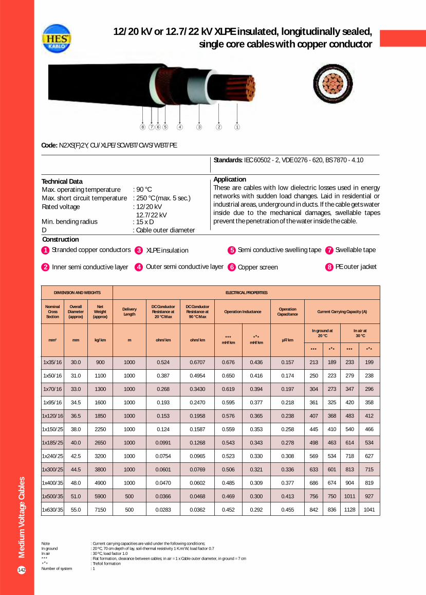
Me
diu
m V
olt
age
Cab
les
142
12/20 kV or 12.7/22 kV XLPE insulated, longitudinally sealed,single core cables with copper conductor
Construction
Code: N2XS(F)2Y, CU/XLPE/SCWBT/CWS/WBT/PE
Standards: IEC 60502 - 2, VDE 0276 - 620, BS 7870 - 4.10
Application These are cables with low dielectric losses used in energy networks with sudden load changes. Laid in residential or industrial areas, underground in ducts. If the cable gets water inside due to the mechanical damages, swellable tapes prevent the penetration of the water inside the cable.
1 3Stranded copper conductors XLPE insulation
2 Inner semi conductive layer 4 Outer semi conductive layer
5 Semi conductive swelling tape
6 Copper screen
7 Swellable tape
8 PE outer jacket
Technical DataMax. operating temperature : 90 °C
Max. short circuit temperature : 250 °C (max. 5 sec.)
Rated voltage : 12.7/22 kV
12/20 kV
Min. bending radius : 15 x DD : Cable outer diameter
12345678
DIMENSION AND WEIGHTS ELECTRICAL PROPERTIES
Nominal Cross
Section
Overall Diameter (approx)
Net Weight
(approx)
Delivery Length
DC Conductor Resistance at
20 °C Max
DC Conductor Resistance at
90 °C MaxOperation Inductance
Operation Capacitance
Current Carrying Capacity (A)
mm² mm kg/km m ohm/km ohm/km***
mH/km
** *mH/km
µF/km
In ground at 20 °C
In air at30 °C
*** ** * *** ** *
1x35/16
1x50/16
1x70/16
1x95/16
1x120/16
1x150/25
1x185/25
1x240/25
1x300/25
1x400/35
1x500/35
1x630/35
30.0
31.0
33.0
34.5
36.5
38.0
40.0
42.5
44.5
48.0
51.0
55.0
900
1100
1300
1600
1850
2250
2650
3200
3800
4900
5900
7150
1000
1000
1000
1000
1000
1000
1000
1000
1000
1000
500
500
0.524
0.387
0.268
0.193
0.153
0.124
0.0991
0.0754
0.0601
0.0470
0.0366
0.0283
0.6707
0.4954
0.3430
0.2470
0.1958
0.1587
0.1268
0.0965
0.0769
0.0602
0.0468
0.0362
0.676
0.650
0.619
0.595
0.576
0.559
0.543
0.523
0.506
0.485
0.469
0.452
0.436
0.416
0.394
0.377
0.365
0.353
0.343
0.330
0.321
0.309
0.300
0.292
0.157
0.174
0.197
0.218
0.238
0.258
0.278
0.308
0.336
0.377
0.413
0.455
213
250
304
361
407
445
498
569
633
686
756
842
189
223
273
325
368
410
463
534
601
674
750
836
233
279
347
420
483
540
614
718
813
904
1011
1128
199
238
296
358
412
466
534
627
715
819
927
1041
Note : Current carrying capacities are valid under the following conditions;In ground : 20 ºC, 70 cm depth of lay, soil-thermal resistivity 1 K.m/W, load factor 0.7In air : 30 ºC, load factor 1.0*** : Flat formation, clearance between cables; in air = 1 x Cable outer diameter, in ground = 7 cm : Trefoil formationNumber of system : 1
** *
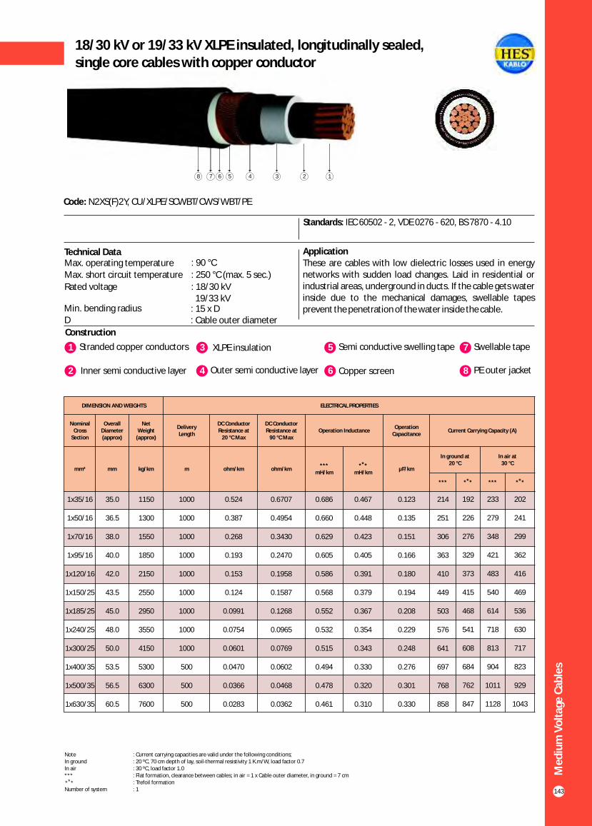
Me
diu
m V
olt
age
Cab
les
143
18/30 kV or 19/33 kV XLPE insulated, longitudinally sealed,single core cables with copper conductor
Construction
Code: N2XS(F)2Y, CU/XLPE/SCWBT/CWS/WBT/PE
Standards: IEC 60502 - 2, VDE 0276 - 620, BS 7870 - 4.10
Application These are cables with low dielectric losses used in energy networks with sudden load changes. Laid in residential or industrial areas, underground in ducts. If the cable gets water inside due to the mechanical damages, swellable tapes prevent the penetration of the water inside the cable.
1 3Stranded copper conductors XLPE insulation
2 Inner semi conductive layer 4 Outer semi conductive layer
5 Semi conductive swelling tape
6 Copper screen
7 Swellable tape
8 PE outer jacket
Technical Data
12345678
DIMENSION AND WEIGHTS ELECTRICAL PROPERTIES
Nominal Cross
Section
Overall Diameter (approx)
Net Weight
(approx)
Delivery Length
DC Conductor Resistance at
20 °C Max
DC Conductor Resistance at
90 °C MaxOperation Inductance
Operation Capacitance
Current Carrying Capacity (A)
mm² mm kg/km m ohm/km ohm/km***
mH/km
** *mH/km
µF/km
In ground at 20 °C
In air at30 °C
*** ** * *** ** *
1x35/16
1x50/16
1x70/16
1x95/16
1x120/16
1x150/25
1x185/25
1x240/25
1x300/25
1x400/35
1x500/35
1x630/35
35.0
36.5
38.0
40.0
42.0
43.5
45.0
48.0
50.0
53.5
56.5
60.5
1150
1300
1550
1850
2150
2550
2950
3550
4150
5300
6300
7600
1000
1000
1000
1000
1000
1000
1000
1000
1000
500
500
500
0.524
0.387
0.268
0.193
0.153
0.124
0.0991
0.0754
0.0601
0.0470
0.0366
0.0283
0.6707
0.4954
0.3430
0.2470
0.1958
0.1587
0.1268
0.0965
0.0769
0.0602
0.0468
0.0362
0.686
0.660
0.629
0.605
0.586
0.568
0.552
0.532
0.515
0.494
0.478
0.461
0.467
0.448
0.423
0.405
0.391
0.379
0.367
0.354
0.343
0.330
0.320
0.310
0.123
0.135
0.151
0.166
0.180
0.194
0.208
0.229
0.248
0.276
0.301
0.330
214
251
306
363
410
449
503
576
641
697
768
858
192
226
276
329
373
415
468
541
608
684
762
847
233
279
348
421
483
540
614
718
813
904
1011
1128
202
241
299
362
416
469
536
630
717
823
929
1043
Note : Current carrying capacities are valid under the following conditions;In ground : 20 ºC, 70 cm depth of lay, soil-thermal resistivity 1 K.m/W, load factor 0.7In air : 30 ºC, load factor 1.0*** : Flat formation, clearance between cables; in air = 1 x Cable outer diameter, in ground = 7 cm : Trefoil formationNumber of system : 1
** *
Max. operating temperature : 90 °C
Max. short circuit temperature : 250 °C (max. 5 sec.)
Rated voltage : 18/30 kV 19/33 kV
Min. bending radius : 15 x DD : Cable outer diameter

Me
diu
m V
olt
age
Cab
les
144
20.3/35 kV or 20.8/36 kV XLPE insulated, longitudinally sealed,single core cables with copper conductor
Construction
Code: N2XS(F)2Y, CU/XLPE/SCWBT/CWS/WBT/PE
Standards: HD 620 S2, TSEK
Application These are cables with low dielectric losses used in energy networks with sudden load changes. Laid in residential or industrial areas, underground in ducts. If the cable gets water inside due to the mechanical damages, swellable tapes prevent the penetration of the water inside the cable.
1 3Stranded copper conductors XLPE insulation
2 Inner semi conductive layer 4 Outer semi conductive layer
5 Semi conductive swelling tape
6 Copper screen
7 Swellable tape
8 PE outer jacket
Technical DataMax. operating temperature : 90 °C
Max. short circuit temperature : 250 °C (max. 5 sec.)
Rated voltage : 20.3/35 kV 20.8/36 kV
Min. bending radius : 15 x DD : Cable outer diameter
12345678
DIMENSION AND WEIGHTS ELECTRICAL PROPERTIES
Nominal Cross
Section
Overall Diameter (approx)
Net Weight
(approx)
Delivery Length
DC Conductor Resistance at
20 °C Max
DC Conductor Resistance at
90 °C MaxOperation Inductance
Operation Capacitance
Current Carrying Capacity (A)
mm² mm kg/km m ohm/km ohm/km***
mH/km
** *mH/km
µF/km
In ground at 20 °C
In air at30 °C
*** ** * *** ** *
1x35/16
1x50/16
1x70/16
1x95/16
1x120/16
1x150/25
1x185/25
1x240/25
1x300/25
1x400/35
1x500/35
1x630/35
37.5
38.5
40.5
42.0
44.0
45.5
47.5
50.0
52.5
55.5
59.0
62.5
1250
1450
1700
2000
2250
2700
3050
3650
4300
5450
6500
7800
1000
1000
1000
1000
1000
1000
1000
1000
1000
500
500
500
0.524
0.387
0.268
0.193
0.153
0.124
0.0991
0.0754
0.0601
0.0470
0.0366
0.0283
0.6707
0.4954
0.3430
0.2470
0.1958
0.1587
0.1268
0.0965
0.0769
0.0602
0.0468
0.0362
0.690
0.664
0.633
0.609
0.590
0.572
0.556
0.535
0.519
0.497
0.481
0.464
0.480
0.459
0.434
0.416
0.401
0.389
0.376
0.363
0.351
0.338
0.328
0.317
0.115
0.125
0.140
0.153
0.165
0.178
0.191
0.209
0.226
0.252
0.274
0.300
214
251
306
363
410
449
503
576
641
697
768
858
192
226
276
329
373
415
468
541
608
684
762
847
233
279
348
421
483
540
615
718
812
904
1011
1128
202
241
299
362
416
469
536
630
717
823
929
1043
Note : Current carrying capacities are valid under the following conditions;In ground : 20 ºC, 70 cm depth of lay, soil-thermal resistivity 1 K.m/W, load factor 0.7In air : 30 ºC, load factor 1.0*** : Flat formation, clearance between cables; in air = 1 x Cable outer diameter, in ground = 7 cm : Trefoil formationNumber of system : 1
** *
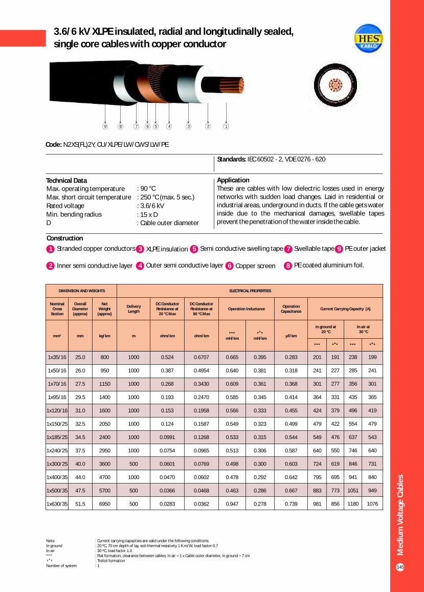
Me
diu
m V
olt
age
Cab
les
145
3.6/6 kV XLPE insulated, radial and longitudinally sealed,single core cables with copper conductor
Construction
Code: N2XS(FL)2Y, CU/XLPE/LW/CWS/LW/PE
Standards: IEC 60502 - 2, VDE 0276 - 620
Application These are cables with low dielectric losses used in energy networks with sudden load changes. Laid in residential or industrial areas, underground in ducts. If the cable gets water inside due to the mechanical damages, swellable tapes prevent the penetration of the water inside the cable.
1 3Stranded copper conductors XLPE insulation
2 Inner semi conductive layer 4 Outer semi conductive layer
5 Semi conductive swelling tape
6 Copper screen
7 Swellable tape
8 PE coated aluminium foil.
Technical DataMax. operating temperature : 90 °C
Max. short circuit temperature : 250 °C (max. 5 sec.)
Rated voltage : 3.6/6 kV
Min. bending radius : 15 x DD : Cable outer diameter
9 PE outer jacket
123456789
DIMENSION AND WEIGHTS ELECTRICAL PROPERTIES
Nominal Cross
Section
Overall Diameter (approx)
Net Weight
(approx)
Delivery Length
DC Conductor Resistance at
20 °C Max
DC Conductor Resistance at
90 °C MaxOperation Inductance
Operation Capacitance
Current Carrying Capacity (A)
mm² mm kg/km m ohm/km ohm/km***
mH/km
** *mH/km
µF/km
In ground at 20 °C
In air at30 °C
*** ** * *** ** *
1x35/16
1x50/16
1x70/16
1x95/16
1x120/16
1x150/25
1x185/25
1x240/25
1x300/25
1x400/35
1x500/35
1x630/35
25.0
26.0
27.5
29.5
31.0
32.5
34.5
37.5
40.0
44.0
47.5
51.5
800
950
1150
1400
1600
2050
2400
2950
3600
4700
5700
6950
1000
1000
1000
1000
1000
1000
1000
1000
500
1000
500
500
0.524
0.387
0.268
0.193
0.153
0.124
0.0991
0.0754
0.0601
0.0470
0.0366
0.0283
0.6707
0.4954
0.3430
0.2470
0.1958
0.1587
0.1268
0.0965
0.0769
0.0602
0.0468
0.0362
0.665
0.640
0.609
0.585
0.566
0.549
0.533
0.513
0.498
0.478
0.463
0.947
0.395
0.381
0.361
0.345
0.333
0.323
0.315
0.306
0.300
0.292
0.286
0.278
0.283
0.318
0.368
0.414
0.455
0.499
0.544
0.587
0.603
0.642
0.667
0.739
201
241
301
364
424
479
549
640
724
795
883
981
191
227
277
331
379
422
476
550
619
695
773
856
238
285
356
435
496
554
637
746
846
941
1051
1180
199
241
301
365
419
479
543
640
731
840
949
1076
Note : Current carrying capacities are valid under the following conditions;In ground : 20 ºC, 70 cm depth of lay, soil-thermal resistivity 1 K.m/W, load factor 0.7In air : 30 ºC, load factor 1.0*** : Flat formation, clearance between cables; in air = 1 x Cable outer diameter, in ground = 7 cm : Trefoil formationNumber of system : 1
** *

Me
diu
m V
olt
age
Cab
les
146
5.8/10 kV (6/10 kV) or 6.35/11 kV XLPE insulated, radial andlongitudinally sealed, single core cables with copper conductor
Construction
Code: N2XS(FL)2Y, CU/XLPE/LW/CWS/LW/PE
Standards: IEC 60502 - 2, VDE 0276 - 620, BS 7870 - 4.10
Application These are cables with low dielectric losses used in energy networks with sudden load changes. Laid in residential or industrial areas, underground in ducts. If the cable gets water inside due to the mechanical damages, swellable tapes prevent the penetration of the water inside the cable.
Technical Data
Max. operating temperature : 90 °CMax. short circuit temperature : 250 °C (max. 5 sec.)
Rated voltage : 5.8/10 kV (6/10 kV) 6.35/11 kV
Min. bending radius : 15 x DD : Cable outer diameter
1 3Stranded copper conductors XLPE insulation
2 Inner semi conductive layer 4 Outer semi conductive layer
5 Semi conductive swelling tape
6 Copper screen
7 Swellable tape
8 PE coated aluminium foil.
9 PE outer jacket
123456789
DIMENSION AND WEIGHTS ELECTRICAL PROPERTIES
Nominal Cross
Section
Overall Diameter (approx)
Net Weight
(approx)
Delivery Length
DC Conductor Resistance at
20 ºC Max
DC Conductor Resistance at
90 ºC MaxOperation Inductance
Operation Capacitance
Current Carrying Capacity (A)
mm² mm kg/km m ohm/km ohm/km***
mH/km
** *mH/km
µF/km
In ground at 20 ºC
In air at30 ºC
*** ** * *** ** *
1x35/16
1x50/16
1x70/16
1x95/16
1x120/16
1x150/25
1x185/25
1x240/25
1x300/25
1x400/35
1x500/35
1x630/35
25.0
26.0
28.0
30.0
31.0
33.0
34.0
37.0
40.0
43.0
46.0
50.0
850
1000
1200
1500
1750
2150
2500
3050
3650
4750
5700
7000
1000
1000
1000
1000
1000
1000
1000
1000
1000
1000
500
500
0.524
0.387
0.268
0.193
0.153
0.124
0.0991
0.0754
0.0601
0.0470
0.0366
0.0283
0.6707
0.4954
0.3430
0.2470
0.1958
0.1587
0.1268
0.0965
0.0769
0.0602
0.0468
0.0362
0.669
0.644
0.613
0.588
0.570
0.552
0.537
0.516
0.500
0.479
0.463
0.447
0.413
0.395
0.373
0.357
0.346
0.335
0.326
0.314
0.305
0.295
0.288
0.280
0.223
0.248
0.285
0.320
0.350
0.382
0.415
0.462
0.507
0.573
0.631
0.699
212
249
303
358
404
441
493
563
626
676
743
820
187
220
269
321
364
405
457
528
593
665
739
818
231
277
345
418
481
537
612
716
811
901
1006
1130
195
234
292
354
407
460
527
621
709
815
921
1045
Note : Current carrying capacities are valid under the following conditions;In ground : 20 ºC, 70 cm depth of lay, soil-thermal resistivity 1 K.m/W, load factor 0.7In air : 30 ºC, load factor 1.0*** : Flat formation, clearance between cables; in air = 1 x Cable outer diameter, in ground = 7 cm : Trefoil formationNumber of system : 1
** *

Me
diu
m V
olt
age
Cab
les
147
8.7/15 kV XLPE insulated, radial and longitudinally sealed,single core cables with copper conductor
Construction
Code: N2XS(FL)2Y, CU/XLPE/LW/CWS/LW/PE
Standards: IEC 60502 - 2, VDE 0276 - 620
Application These are cables with low dielectric losses used in energy networks with sudden load changes. Laid in residential or industrial areas, underground in ducts. If the cable gets water inside due to the mechanical damages, swellable tapes prevent the penetration of the water inside the cable.
1 3Stranded copper conductors XLPE insulation
2 Inner semi conductive layer 4 Outer semi conductive layer
5 Semi conductive swelling tape
6 Copper screen
7 Swellable tape
8 PE coated aluminium foil
Technical DataMax. operating temperature : 90 °C
Max. short circuit temperature : 250 °C (max. 5 sec.)
Rated voltage : 8.7/15 kV
Min. bending radius : 15 x DD : Cable outer diameter
9 PE outer jacket
123456789
DIMENSION AND WEIGHTS ELECTRICAL PROPERTIES
Nominal Cross
Section
Overall Diameter (approx)
Net Weight
(approx)
Delivery Length
DC Conductor Resistance at
20 ºC Max
DC Conductor Resistance at
90 ºC MaxOperation Inductance
Operation Capacitance
Current Carrying Capacity (A)
mm² mm kg/km m ohm/km ohm/km***
mH/km
** *mH/km
µF/km
In ground at 20 ºC
In air at30 ºC
*** ** * *** ** *
1x35/16
1x50/16
1x70/16
1x95/16
1x120/16
1x150/25
1x185/25
1x240/25
1x300/25
1x400/35
1x500/35
1x630/35
28.0
29.0
30.0
32.0
34.0
36.0
37.0
40.0
42.0
46.0
48.0
54.0
900
1100
1300
1600
1850
2250
2600
3200
3800
4900
5900
7150
1000
1000
1000
1000
1000
1000
1000
1000
1000
1000
500
500
0.524
0.387
0.268
0.193
0.153
0.124
0.0991
0.0754
0.0601
0.0470
0.0366
0.0283
0.6707
0.4954
0.3430
0.2470
0.1958
0.1587
0.1268
0.0965
0.0769
0.0602
0.0468
0.0362
0.674
0.648
0.617
0.593
0.574
0.557
0.541
0.521
0.504
0.483
0.467
0.451
0.
0.410
0.387
0.371
0.358
0.348
0.337
0.326
0.316
0.305
0.297
0.289
429 0.181
0.201
0.229
0.255
0.278
0.302
0.328
0.363
0.398
0.447
0.491
0.543
212
249
303
358
404
441
493
563
626
676
743
820
187
220
269
321
364
405
457
528
593
665
739
818
231
277
345
418
481
537
612
716
811
901
1006
1130
195
234
292
354
407
460
527
621
709
815
921
1045
Note : Current carrying capacities are valid under the following conditions;In ground : 20 ºC, 70 cm depth of lay, soil-thermal resistivity 1 K.m/W, load factor 0.7In air : 30 ºC, load factor 1.0*** : Flat formation, clearance between cables; in air = 1 x Cable outer diameter, in ground = 7 cm : Trefoil formationNumber of system : 1
** *

Me
diu
m V
olt
age
Cab
les
148
12/20 kV or 12.7/22 kV XLPE insulated, radial and longitudinallysealed, single core cables with copper conductor
Construction
Code: N2XS(FL)2Y, CU/XLPE/LW/CWS/LW/PE
Standards: IEC 60502 - 2, VDE 0276 - 620, BS 7870 - 4.10
Application These are cables with low dielectric losses used in energy networks with sudden load changes. Laid in residential or industrial areas, underground in ducts. If the cable gets water inside due to the mechanical damages, swellable tapes prevent the penetration of the water inside the cable.
1 3Stranded copper conductors XLPE insulation
2 Inner semi conductive layer 4 Outer semi conductive layer
5 Semi conductive swelling tape
6 Copper screen
7 Swellable tape
8 PE coated aluminium foil
9 PE outer jacket
Technical DataMax. operating temperature : 90 °C
Max. short circuit temperature : 250 °C (max. 5 sec.)
Rated voltage : 12.7/22 kV
12/20 kV
Min. bending radius : 15 x DD : Cable outer diameter
123456789
DIMENSION AND WEIGHTS ELECTRICAL PROPERTIES
Nominal Cross
Section
Overall Diameter (approx)
Net Weight
(approx)
Delivery Length
DC Conductor Resistance at
20 ºC Max
DC Conductor Resistance at
90 ºC MaxOperation Inductance
Operation Capacitance
Current Carrying Capacity (A)
mm² mm kg/km m ohm/km ohm/km***
mH/km
** *mH/km
µF/km
In ground at 20 ºC
In air at30 ºC
*** ** * *** ** *
1x35/16
1x50/16
1x70/16
1x95/16
1x120/16
1x150/25
1x185/25
1x240/25
1x300/25
1x400/35
1x500/35
1x630/35
31.0
32.0
34.0
35.5
37.5
34.0
41.0
43.5
45.5
49.0
52.5
56.0
950
1000
1400
1700
1950
2350
2750
3300
3900
5000
6000
7300
1000
1000
1000
1000
1000
1000
1000
1000
1000
1000
500
500
0.524
0.387
0.268
0.193
0.153
0.124
0.0991
0.0754
0.0601
0.0470
0.0366
0.0283
0.6707
0.4954
0.3430
0.2470
0.1958
0.1587
0.1268
0.0965
0.0769
0.0602
0.0468
0.0362
0.678
0.652
0.621
0.597
0.578
0.561
0.545
0.524
0.508
0.486
0.470
0.454
0.442
0.422
0.400
0.382
0.370
0.358
0.348
0.335
0.325
0.313
0.304
0.295
0.157
0.174
0.197
0.218
0.238
0.258
0.278
0.308
0.336
0.377
0.413
0.455
213
250
304
361
407
445
498
569
633
686
756
842
189
223
273
325
368
410
463
534
601
674
750
836
233
279
348
421
483
540
615
718
812
904
1011
1128
199
238
296
358
412
466
534
627
715
819
927
1041
Note : Current carrying capacities are valid under the following conditions;In ground : 20 ºC, 70 cm depth of lay, soil-thermal resistivity 1 K.m/W, load factor 0.7In air : 30 ºC, load factor 1.0*** : Flat formation, clearance between cables; in air = 1 x Cable outer diameter, in ground = 7 cm : Trefoil formationNumber of system : 1
** *
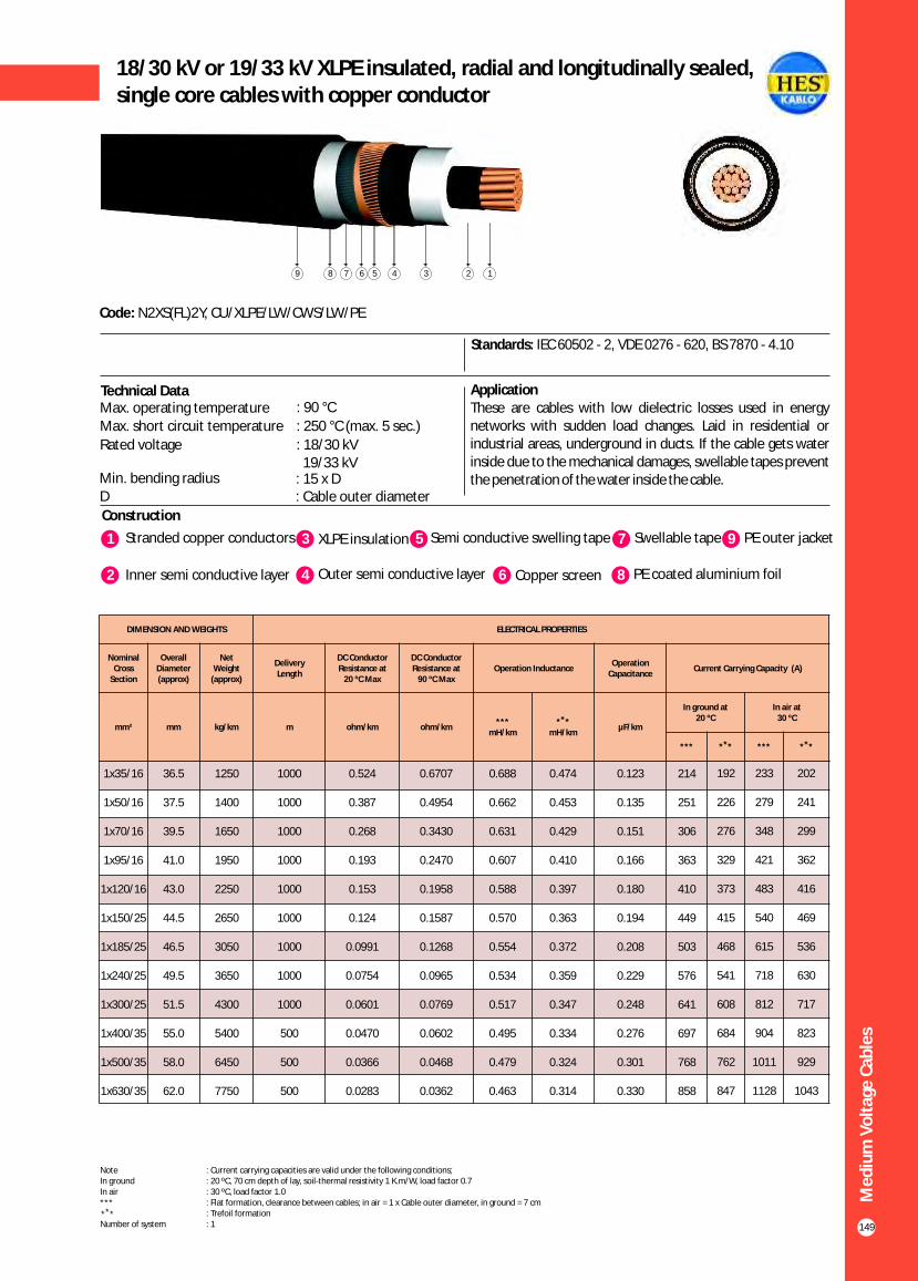
Me
diu
m V
olt
age
Cab
les
149
18/30 kV or 19/33 kV XLPE insulated, radial and longitudinally sealed,single core cables with copper conductor
Construction
Code: N2XS(FL)2Y, CU/XLPE/LW/CWS/LW/PE
Standards: IEC 60502 - 2, VDE 0276 - 620, BS 7870 - 4.10
Application These are cables with low dielectric losses used in energy networks with sudden load changes. Laid in residential or industrial areas, underground in ducts. If the cable gets water inside due to the mechanical damages, swellable tapes prevent the penetration of the water inside the cable.
1 3Stranded copper conductors XLPE insulation
2 Inner semi conductive layer 4 Outer semi conductive layer
5 Semi conductive swelling tape
6 Copper screen
7 Swellable tape
8 PE coated aluminium foil
Technical Data
9 PE outer jacket
123456789
DIMENSION AND WEIGHTS ELECTRICAL PROPERTIES
Nominal Cross
Section
Overall Diameter (approx)
Net Weight
(approx)
Delivery Length
DC Conductor Resistance at
20 ºC Max
DC Conductor Resistance at
90 ºC MaxOperation Inductance
Operation Capacitance
Current Carrying Capacity (A)
mm² mm kg/km m ohm/km ohm/km***
mH/km
** *mH/km
µF/km
In ground at 20 ºC
In air at30 ºC
*** ** * *** ** *
1x35/16
1x50/16
1x70/16
1x95/16
1x120/16
1x150/25
1x185/25
1x240/25
1x300/25
1x400/35
1x500/35
1x630/35
36.5
37.5
39.5
41.0
43.0
44.5
46.5
49.5
51.5
55.0
58.0
62.0
1250
1400
1650
1950
2250
2650
3050
3650
4300
5400
6450
7750
1000
1000
1000
1000
1000
1000
1000
1000
1000
500
500
500
0.524
0.387
0.268
0.193
0.153
0.124
0.0991
0.0754
0.0601
0.0470
0.0366
0.0283
0.6707
0.4954
0.3430
0.2470
0.1958
0.1587
0.1268
0.0965
0.0769
0.0602
0.0468
0.0362
0.688
0.662
0.631
0.607
0.588
0.570
0.554
0.534
0.517
0.495
0.479
0.463
0.474
0.453
0.429
0.410
0.397
0.363
0.372
0.359
0.347
0.334
0.324
0.314
0.123
0.135
0.151
0.166
0.180
0.194
0.208
0.229
0.248
0.276
0.301
0.330
214
251
306
363
410
449
503
576
641
697
768
858
192
226
276
329
373
415
468
541
608
684
762
847
233
279
348
421
483
540
615
718
812
904
1011
1128
202
241
299
362
416
469
536
630
717
823
929
1043
Note : Current carrying capacities are valid under the following conditions;In ground : 20 ºC, 70 cm depth of lay, soil-thermal resistivity 1 K.m/W, load factor 0.7In air : 30 ºC, load factor 1.0*** : Flat formation, clearance between cables; in air = 1 x Cable outer diameter, in ground = 7 cm : Trefoil formationNumber of system : 1
** *
Max. operating temperature : 90 °C
Max. short circuit temperature : 250 °C (max. 5 sec.)
Rated voltage : 18/30 kV 19/33 kV
Min. bending radius : 15 x DD : Cable outer diameter

Me
diu
m V
olt
age
Cab
les
150
20.3/35 kV or 20.8/36 kV XLPE insulated, radial and longitudinally sealed, single core cables with copper conductor
Construction
Code: N2XS(FL)2Y, CU/XLPE/LW/CWS/LW/PE
Standards: HD 620 S2, TSEK
Application These are cables with low dielectric losses used in energy networks with sudden load changes. Laid in residential or industrial areas, underground in ducts. If the cable gets water inside due to the mechanical damages, swellable tapes prevent the penetration of the water inside the cable.
1 3Stranded copper conductors XLPE insulation
2 Inner semi conductive layer 4 Outer semi conductive layer
5 Semi conductive swelling tape
6 Copper screen
7 Swellable tape
8 PE coated aluminium foil
9 PE outer jacket
Technical DataMax. operating temperature : 90 °C
Max. short circuit temperature : 250 °C (max. 5 sec.)
Rated voltage : 20.3/35 kV 20.8/36 kV
Min. bending radius : 15 x DD : Cable outer diameter
123456789
DIMENSION AND WEIGHTS ELECTRICAL PROPERTIES
Nominal Cross
Section
Overall Diameter (approx)
Net Weight
(approx)
Delivery Length
DC Conductor Resistance at
20 ºC Max
DC Conductor Resistance at
90 ºC MaxOperation Inductance
Operation Capacitance
Current Carrying Capacity (A)
mm² mm kg/km m ohm/km ohm/km***
mH/km
** *mH/km
µF/km
In ground at 20 ºC
In air at30 ºC
*** ** * *** ** *
1x35/16
1x50/16
1x70/16
1x95/16
1x120/16
1x150/25
1x185/25
1x240/25
1x300/25
1x400/35
1x500/35
1x630/35
38.5
39.5
41.5
43.0
45.0
46.5
48.5
51.0
53.0
56.5
60.0
63.5
1350
1550
1800
2100
2400
2800
3200
3800
4450
5550
6600
7950
1000
1000
1000
1000
1000
1000
1000
1000
1000
500
500
500
0.524
0.387
0.268
0.193
0.153
0.124
0.0991
0.0754
0.0601
0.0470
0.0366
0.0283
0.6707
0.4954
0.3430
0.2470
0.1958
0.1587
0.1268
0.0965
0.0769
0.0602
0.0468
0.0362
0.692
0.666
0.635
0.610
0.591
0.574
0.557
0.537
0.520
0.499
0.482
0.466
0.485
0.464
0.439
0.419
0.405
0.342
0.381
0.366
0.354
0.341
0.330
0.320
0.115
0.125
0.140
0.153
0.165
0.178
0.191
0.209
0.248
0.226
0.274
0.300
214
251
306
363
410
449
503
576
641
697
768
858
192
226
276
329
373
415
468
541
608
684
762
847
233
279
348
421
483
540
615
718
812
904
1011
1128
202
241
299
362
416
469
536
630
717
823
929
1043
Note : Current carrying capacities are valid under the following conditions;In ground : 20 ºC, 70 cm depth of lay, soil-thermal resistivity 1 K.m/W, load factor 0.7In air : 30 ºC, load factor 1.0*** : Flat formation, clearance between cables; in air = 1 x Cable outer diameter, in ground = 7 cm : Trefoil formationNumber of system : 1
** *

Me
diu
m V
olt
age
Cab
les
151
3.6/6 kV XLPE insulated round aluminium wire armouredsingle core cables with copper conductor
Construction
Code: N2XSYR(A)Y, CU/XLPE/CWS/PVC/AWA/PVC
Standards: IEC 60502 - 2, VDE 0276 - 620, BS 6622
ApplicationThese are cables with low dielectric losses used in energy networks with sudden load changes. Laid in residential or industrial areas, underground in ducts.
1 4Stranded copper conductors Outer semi conductive layer
2 Inner semi conductive layer 5 Semi conductive tape
7 Polyester tape
8 Inner sheath
10 Polyester tape
11 PVC outer jacket
Technical DataMax. operating temperature : 90 °C
Max. short circuit temperature : 250 °C (max. 5 sec.)
Rated voltage : 3.6/6 kV
Min. bending radius : 15 x DD : Cable outer diameter
3 XLPE insulation 6 Copper screen 9 Round aluminium wire
1234567891011
DIMENSION AND WEIGHTS ELECTRICAL PROPERTIES
Nominal Cross
Section
Overall Diameter (approx)
Net Weight
(approx)
Delivery Length
DC Conductor Resistance at
20 ºC Max
DC Conductor Resistance at
90 ºC MaxOperation Inductance
Operation Capacitance
Current Carrying Capacity (A)
mm² mm kg/km m ohm/km ohm/km***
mH/km
** *mH/km
µF/km
In ground at 20 ºC
In air at30 ºC
*** ** * *** ** *
1x35/16
1x50/16
1x70/16
1x95/16
1x120/16
1x150/25
1x185/25
1x240/25
1x300/25
1x400/35
1x500/35
1x630/35
26.2
27.3
29.0
31.0
32.3
34.7
36.6
39.4
41.8
46.9
50.6
54.5
1135
1280
1530
1840
2110
2600
3000
3640
4270
5535
6670
8130
1000
1000
1000
1000
1000
1000
1000
1000
1000
500
500
500
0.524
0.387
0.268
0.193
0.153
0.124
0.0991
0.0754
0.0601
0.0470
0.0366
0.0283
0.6707
0.4954
0.3430
0.2470
0.1958
0.1587
0.1268
0.0965
0.0769
0.0602
0.0468
0.0362
0.657
0.632
0.601
0.577
0.558
0.541
0.525
0.506
0.490
0.471
0.456
0.440
0.
0.351
0.332
0.318
0.308
0.299
0.292
0.284
0.279
0.275
0.270
0.264
367 0.283
0.318
0.368
0.414
0.455
0.499
0.544
0.587
0.603
0.642
0.667
0.739
201
241
301
364
424
479
549
640
724
795
883
981
191
227
277
331
379
422
476
550
619
695
773
856
238
285
356
435
496
554
637
746
846
941
1051
1180
199
241
301
365
419
479
543
640
731
840
949
1076
Note : Current carrying capacities are valid under the following conditions;In ground : 20 ºC, 70 cm depth of lay, soil-thermal resistivity 1 K.m/W, load factor 0.7In air : 30 ºC, load factor 1.0*** : Flat formation, clearance between cables; in air = 1 x Cable outer diameter, in ground = 7 cm : Trefoil formationNumber of system : 1
** *

Me
diu
m V
olt
age
Cab
les
152
5.8/10 kV (6/10 kV) XLPE insulated round aluminium wire armoured single core cables with copper conductor
Construction
Code: N2XSYR(A)Y, CU/XLPE/CWS/PVC/AWA/PVC
Standards: IEC 60502 - 2, VDE 0276 - 620, BS 6622
ApplicationThese are cables with low dielectric losses used in energy networks with sudden load changes. Laid in residential or industrial areas, underground in ducts.
Technical DataMax. operating temperature : 90 °C
Max. short circuit temperature : 250 °C (max. 5 sec.)
Rated voltage : 5.8/10 kV (6/10 kV)
Min. bending radius : 15 x DD : Cable outer diameter
1 4Stranded copper conductors Outer semi conductive layer
2 Inner semi conductive layer 5 Semi conductive tape
7 Polyester tape
8 Inner sheath
10 Polyester tape
11 PVC outer jacket
3 XLPE insulation 6 Copper screen 9 Round aluminium wire
1234567891011
1x35/16
1x50/16
1x70/16
1x95/16
1x120/16
1x150/25
1x185/25
1x240/25
1x300/25
1x400/35
1x500/35
1x630/35
28.0
29.3
31.0
32.9
35.1
36.7
38.4
41.0
43.2
47.7
51.0
55.0
1220
1390
1640
1962
2320
2725
3125
3750
4380
5600
6620
8190
1000
1000
1000
1000
1000
1000
1000
1000
1000
500
500
500
0.524
0.387
0.268
0.193
0.153
0.124
0.0991
0.0754
0.0601
0.0470
0.0366
0.0283
0.6707
0.4954
0.3430
0.2470
0.1958
0.1587
0.1268
0.0965
0.0769
0.0602
0.0468
0.0362
0.657
0.632
0.601
0.577
0.558
0.541
0.525
0.506
0.490
0.471
0.456
0.440
0.367
0.351
0.332
0.318
0.308
0.299
0.292
0.284
0.279
0.275
0.270
0.264
0.223
0.248
0.285
0.320
0.350
0.382
0.415
0.462
0.507
0.573
0.631
0.699
212
249
303
358
404
441
493
563
626
676
743
820
187
220
269
321
364
405
457
528
593
665
739
818
231
277
345
418
481
537
612
716
811
901
1006
1130
195
234
292
354
407
460
527
621
709
815
921
1045
DIMENSION AND WEIGHTS ELECTRICAL PROPERTIES
Nominal Cross
Section
Overall Diameter (approx)
Net Weight
(approx)
Delivery Length
DC Conductor Resistance at
20 ºC Max
DC Conductor Resistance at
90 ºC MaxOperation Inductance
Operation Capacitance
Current Carrying Capacity (A)
mm² mm kg/km m ohm/km ohm/km***
mH/km
** *mH/km
µF/km
In ground at 20 ºC
In air at30 ºC
*** ** * *** ** *
Note : Current carrying capacities are valid under the following conditions;In ground : 20 ºC, 70 cm depth of lay, soil-thermal resistivity 1 K.m/W, load factor 0.7In air : 30 ºC, load factor 1.0*** : Flat formation, clearance between cables; in air = 1 x Cable outer diameter, in ground = 7 cm : Trefoil formationNumber of system : 1
** *
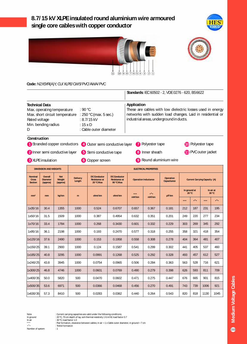
Me
diu
m V
olt
age
Cab
les
153
8.7/15 kV XLPE insulated round aluminium wire armouredsingle core cables with copper conductor
Construction
Code: N2XSYR(A)Y, CU/XLPE/CWS/PVC/AWA/PVC
Standards: IEC 60502 - 2, VDE 0276 - 620, BS 6622
ApplicationThese are cables with low dielectric losses used in energy networks with sudden load changes. Laid in residential or industrial areas, underground in ducts.
1 4Stranded copper conductors Outer semi conductive layer
2 Inner semi conductive layer 5 Semi conductive tape
7 Polyester tape
8 Inner sheath
10 Polyester tape
11 PVC outer jacket
Technical DataMax. operating temperature : 90 °C
Max. short circuit temperature : 250 °C (max. 5 sec.)
Rated voltage : 8.7/15 kV
Min. bending radius : 15 x DD : Cable outer diameter
3 XLPE insulation 6 Copper screen 9 Round aluminium wire
1234567891011
DIMENSION AND WEIGHTS ELECTRICAL PROPERTIES
Nominal Cross
Section
Overall Diameter (approx)
Net Weight
(approx)
Delivery Length
DC Conductor Resistance at
20 ºC Max
DC Conductor Resistance at
90 ºC MaxOperation Inductance
Operation Capacitance
Current Carrying Capacity (A)
mm² mm kg/km m ohm/km ohm/km***
mH/km
** *mH/km
µF/km
In ground at 20 ºC
In air at30 ºC
*** ** * *** ** *
1x35/16
1x50/16
1x70/16
1x95/16
1x120/16
1x150/25
1x185/25
1x240/25
1x300/25
1x400/35
1x500/35
1x630/35
30.4
31.5
33.4
36.1
37.6
39.1
40.8
43.8
46.8
50.0
53.6
57.3
1355
1509
1784
2198
2490
2900
3295
3945
4746
5820
6971
8410
1000
1000
1000
1000
1000
1000
1000
1000
1000
500
500
500
0.524
0.387
0.268
0.193
0.153
0.124
0.0991
0.0754
0.0601
0.0470
0.0366
0.0283
0.6707
0.4954
0.3430
0.2470
0.1958
0.1587
0.1268
0.0965
0.0769
0.0602
0.0468
0.0362
0.657
0.632
0.601
0.577
0.558
0.541
0.525
0.506
0.490
0.471
0.456
0.440
0.
0.351
0.332
0.318
0.308
0.299
0.292
0.284
0.279
0.275
0.270
0.264
367 0.181
0.201
0.229
0.255
0.278
0.302
0.328
0.363
0.398
0.447
0.491
0.543
212
249
303
358
404
441
493
563
626
676
743
820
187
220
269
321
364
405
457
528
593
665
739
818
231
277
345
418
481
537
612
716
811
901
1006
1130
195
234
292
354
407
460
527
621
709
815
921
1045
Note : Current carrying capacities are valid under the following conditions;In ground : 20 ºC, 70 cm depth of lay, soil-thermal resistivity 1 K.m/W, load factor 0.7In air : 30 ºC, load factor 1.0*** : Flat formation, clearance between cables; in air = 1 x Cable outer diameter, in ground = 7 cm : Trefoil formationNumber of system : 1
** *

154
12/20 kV or 12.7/22 kV XLPE insulated round aluminium wire armoured single core cables with copper conductor
Construction
Code: N2XSYR(A)Y, CU/XLPE/CWS/PVC/AWA/PVC
Standards: IEC 60502 - 2, VDE 0276 - 620, BS 6622
ApplicationThese are cables with low dielectric losses used in energy networks with sudden load changes. Laid in residential or industrial areas, underground in ducts.
Technical Data
Max. operating temperature : 90 °C
Max. short circuit temperature : 250 °C (max. 5 sec.)
Rated voltage : 12.7/22 kV
12/20 kV
Min. bending radius : 15 x DD : Cable outer diameter
1 4Stranded copper conductors Outer semi conductive layer
2 Inner semi conductive layer 5 Semi conductive tape
7 Polyester tape
8 Inner sheath
10 Polyester tape
11 PVC outer jacket
3 XLPE insulation 6 Copper screen 9 Round aluminium wire
12345678910111
Me
diu
m V
olt
age
Cab
les
DIMENSION AND WEIGHTS ELECTRICAL PROPERTIES
Nominal Cross
Section
Overall Diameter (approx)
Net Weight
(approx)
Delivery Length
DC Conductor Resistance at
20 ºC Max
DC Conductor Resistance at
90 ºC MaxOperation Inductance
Operation Capacitance
Current Carrying Capacity (A)
mm² mm kg/km m ohm/km ohm/km***
mH/km
** *mH/km
µF/km
In ground at 20 ºC
In air at30 ºC
*** ** * *** ** *
1x35/16
1x50/16
1x70/16
1x95/16
1x120/16
1x150/25
1x185/25
1x240/25
1x300/25
1x400/35
1x500/35
1x630/35
32.6
34.5
36.4
38.1
39.8
41.1
43.0
46.8
48.9
52.4
55.8
56.0
1482
1730
2020
2330
2640
3040
3465
4290
4935
6045
7185
8660
1000
1000
1000
1000
1000
1000
1000
1000
500
500
500
500
0.524
0.387
0.268
0.193
0.153
0.124
0.0991
0.0754
0.0601
0.0470
0.0366
0.0283
0.6707
0.4954
0.3430
0.2470
0.1958
0.1587
0.1268
0.0965
0.0769
0.0602
0.0468
0.0362
0.657
0.632
0.601
0.577
0.558
0.541
0.525
0.506
0.490
0.471
0.456
0.440
0.367
0.351
0.332
0.318
0.308
0.299
0.292
0.284
0.279
0.275
0.270
0.264
0.123
0.135
0.151
0.166
0.180
0.194
0.208
0.229
0.248
0.276
0.301
0.330
213
250
304
361
407
445
498
569
633
686
756
842
189
223
273
325
368
410
463
534
601
674
750
836
233
279
348
421
483
540
615
718
812
904
1011
1128
199
238
296
358
412
466
534
627
715
819
927
1041
Note : Current carrying capacities are valid under the following conditions;In ground : 20 ºC, 70 cm depth of lay, soil-thermal resistivity 1 K.m/W, load factor 0.7In air : 30 ºC, load factor 1.0*** : Flat formation, clearance between cables; in air = 1 x Cable outer diameter, in ground = 7 cm : Trefoil formationNumber of system : 1
** *

Me
diu
m V
olt
age
Cab
les
155
18/30 kV or 19/33 XLPE insulated round aluminium wire armouredsingle core cables with copper conductor
Construction
Code: N2XSYR(A)Y, CU/XLPE/CWS/PVC/AWA/PVC
Standards: IEC 60502 - 2, VDE 0276 - 620, BS 6622
ApplicationThese are cables with low dielectric losses used in energy networks with sudden load changes. Laid in residential or industrial areas, underground in ducts.
1 4Stranded copper conductors Outer semi conductive layer
2 Inner semi conductive layer 5 Semi conductive tape
7 Polyester tape
8 Inner sheath
10 Polyester tape
11 PVC outer jacket
Technical Data
3 XLPE insulation 6 Copper screen 9 Round aluminium wire
1234567891011
DIMENSION AND WEIGHTS ELECTRICAL PROPERTIES
Nominal Cross
Section
Overall Diameter (approx)
Net Weight
(approx)
Delivery Length
DC Conductor Resistance at
20 ºC Max
DC Conductor Resistance at
90 ºC MaxOperation Inductance
Operation Capacitance
Current Carrying Capacity (A)
mm² mm kg/km m ohm/km ohm/km***
mH/km
** *mH/km
µF/km
In ground at 20 ºC
In air at30 ºC
*** ** * *** ** *
1x35/16
1x50/16
1x70/16
1x95/16
1x120/16
1x150/25
1x185/25
1x240/25
1x300/25
1x400/35
1x500/35
1x630/35
39.0
40.0
41.8
43.5
46.4
48.0
49.6
52.4
54.6
58.0
61.2
66.0
1927
2100
2400
2735
3220
3660
4090
4800
5465
6610
7686
9308
1000
1000
1000
1000
1000
1000
1000
1000
500
500
500
500
0.524
0.387
0.268
0.193
0.153
0.124
0.0991
0.0754
0.0601
0.0470
0.0366
0.0283
0.6707
0.4954
0.3430
0.2470
0.1958
0.1587
0.1268
0.0965
0.0769
0.0602
0.0468
0.0362
0.657
0.632
0.601
0.577
0.558
0.541
0.525
0.506
0.490
0.471
0.456
0.440
0.367
0.351
0.332
0.318
0.308
0.299
0.292
0.284
0.279
0.275
0.270
0.264
0.123
0.135
0.151
0.166
0.180
0.194
0.208
0.229
0.248
0.276
0.301
0.330
214
251
306
363
410
449
503
576
641
697
768
858
192
226
276
329
373
415
468
541
608
684
762
847
233
279
348
421
483
540
615
718
812
904
1011
1128
202
241
299
362
416
469
536
630
717
823
929
1043
Note : Current carrying capacities are valid under the following conditions;In ground : 20 ºC, 70 cm depth of lay, soil-thermal resistivity 1 K.m/W, load factor 0.7In air : 30 ºC, load factor 1.0*** : Flat formation, clearance between cables; in air = 1 x Cable outer diameter, in ground = 7 cm : Trefoil formationNumber of system : 1
** *
Max. operating temperature : 90 °C
Max. short circuit temperature : 250 °C (max. 5 sec.)
Rated voltage : 18/30 kV 19/33 kV
Min. bending radius : 15 x DD : Cable outer diameter
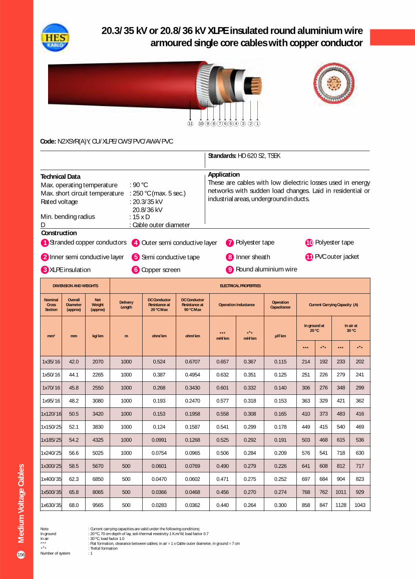
156
20.3/35 kV or 20.8/36 kV XLPE insulated round aluminium wire armoured single core cables with copper conductor
Construction
Code: N2XSYR(A)Y, CU/XLPE/CWS/PVC/AWA/PVC
Standards: HD 620 S2, TSEK
ApplicationThese are cables with low dielectric losses used in energy networks with sudden load changes. Laid in residential or industrial areas, underground in ducts.
Technical Data
Max. operating temperature : 90 °C
Max. short circuit temperature : 250 °C (max. 5 sec.)
Rated voltage : 20.3/35 kV 20.8/36 kV
Min. bending radius : 15 x DD : Cable outer diameter
1 4Stranded copper conductors Outer semi conductive layer
2 Inner semi conductive layer 5 Semi conductive tape
7 Polyester tape
8 Inner sheath
10 Polyester tape
11 PVC outer jacket
3 XLPE insulation 6 Copper screen 9 Round aluminium wire
12345678910111
Me
diu
m V
olt
age
Cab
les
DIMENSION AND WEIGHTS ELECTRICAL PROPERTIES
Nominal Cross
Section
Overall Diameter (approx)
Net Weight
(approx)
Delivery Length
DC Conductor Resistance at
20 ºC Max
DC Conductor Resistance at
90 ºC MaxOperation Inductance
Operation Capacitance
Current Carrying Capacity (A)
mm² mm kg/km m ohm/km ohm/km***
mH/km
** *mH/km
µF/km
In ground at 20 ºC
In air at30 ºC
*** ** * *** ** *
1x35/16
1x50/16
1x70/16
1x95/16
1x120/16
1x150/25
1x185/25
1x240/25
1x300/25
1x400/35
1x500/35
1x630/35
42.0
44.1
45.8
48.2
50.5
52.1
54.2
56.6
58.5
62.3
65.8
68.0
2070
2265
2550
3080
3420
3830
4325
5025
5670
6850
8065
9565
1000
1000
1000
1000
1000
1000
1000
1000
500
500
500
500
0.524
0.387
0.268
0.193
0.153
0.124
0.0991
0.0754
0.0601
0.0470
0.0366
0.0283
0.6707
0.4954
0.3430
0.2470
0.1958
0.1587
0.1268
0.0965
0.0769
0.0602
0.0468
0.0362
0.657
0.632
0.601
0.577
0.558
0.541
0.525
0.506
0.490
0.471
0.456
0.440
0.367
0.351
0.332
0.318
0.308
0.299
0.292
0.284
0.279
0.275
0.270
0.264
0.115
0.125
0.140
0.153
0.165
0.178
0.191
0.209
0.226
0.252
0.274
0.300
214
251
306
363
410
449
503
576
641
697
768
858
192
226
276
329
373
415
468
541
608
684
762
847
233
279
348
421
483
540
615
718
812
904
1011
1128
202
241
299
362
416
469
536
630
717
823
929
1043
Note : Current carrying capacities are valid under the following conditions;In ground : 20 ºC, 70 cm depth of lay, soil-thermal resistivity 1 K.m/W, load factor 0.7In air : 30 ºC, load factor 1.0*** : Flat formation, clearance between cables; in air = 1 x Cable outer diameter, in ground = 7 cm : Trefoil formationNumber of system : 1
** *
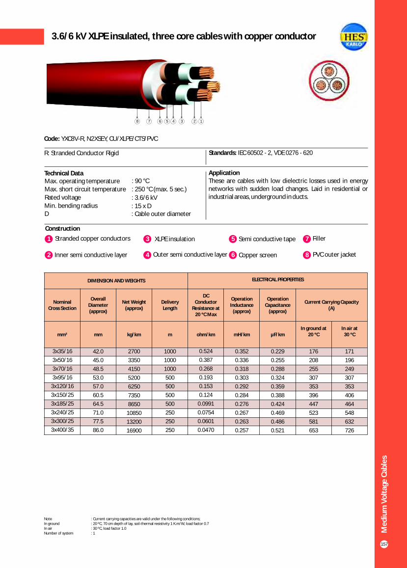
157
3.6/6 kV XLPE insulated, three core cables with copper conductor
Construction
Code: YXC8V-R, N2XSEY, CU/XLPE/CTS/PVC
Standards: IEC 60502 - 2, VDE 0276 - 620
ApplicationThese are cables with low dielectric losses used in energy networks with sudden load changes. Laid in residential or industrial areas, underground in ducts.
Technical DataMax. operating temperature : 90 °C
Max. short circuit temperature : 250 °C (max. 5 sec.)
Rated voltage : 3.6/6 kVMin. bending radius : 15 x DD : Cable outer diameter
1 3Stranded copper conductors XLPE insulation
2 Inner semi conductive layer 4 Outer semi conductive layer
5 Semi conductive tape
6 Copper screen
7 Filler
8 PVC outer jacket
R: Stranded Conductor Rigid
1235678 4
Me
diu
m V
olt
age
Cab
les
DIMENSION AND WEIGHTS ELECTRICAL PROPERTIES
Nominal Cross Section
Overall Diameter (approx)
Net Weight (approx)
Delivery Length
DC Conductor
Resistance at20 ºC Max
Operation Inductance
(approx)
Operation Capacitance
(approx)
Current Carrying Capacity (A)
mm² mm kg/km m ohm/km mH/km µF/kmIn ground at
20 ºCIn air at
30 ºC
0.229
0.255
0.288
0.324
0.359
0.388
0.424
0.469
0.486
0.521
3x35/16
3x50/16
3x70/16
3x95/16
3x120/16
3x150/25
3x185/25
3x240/25
3x300/25
3x400/35
42.0
45.0
48.5
53.0
57.0
60.5
64.5
71.0
77.5
86.0
2700
3350
4150
5200
6250
7350
8650
10850
13200
16900
1000
1000
1000
500
500
500
500
250
250
250
0.524
0.387
0.268
0.193
0.153
0.124
0.0991
0.0754
0.0601
0.0470
0.352
0.336
0.318
0.303
0.292
0.284
0.276
0.267
0.263
0.257
176
208
255
307
353
396
447
523
581
653
171
196
249
307
353
406
464
548
632
726
Note : Current carrying capacities are valid under the following conditions;In ground : 20 ºC, 70 cm depth of lay, soil-thermal resistivity 1 K.m/W, load factor 0.7In air : 30 ºC, load factor 1.0Number of system : 1

158
5.8/10 kV or 6.35/11 kV XLPE insulated,three core cables with copper conductor
Construction
Code: YXC8V-R, N2XSEY, CU/XLPE/CTS/PVC
Standards: IEC 60502 - 2, VDE 0276 - 620
ApplicationThese are cables with low dielectric losses used in energy networks with sudden load changes. Laid in residential or industrial areas, underground in ducts.
1 3Stranded copper conductors XLPE insulation
2 Inner semi conductive layer 4 Outer semi conductive layer
5 Semi conductive tape
6 Copper screen
7 Filler
8 PVC outer jacket
R: Stranded Conductor Rigid
Technical Data
Max. operating temperature : 90 °C Max. short circuit temperature : 250 °C (max. 5 sec.)
Rated voltage : 5.8/10 kV (6/10 kV) 6.35/11 kV
Min. bending radius : 15 x DD : Cable outer diameter
1235678 4
Me
diu
m V
olt
age
Cab
les
DIMENSION AND WEIGHTS ELECTRICAL PROPERTIES
Nominal Cross Section
Overall Diameter (approx)
Net Weight (approx)
Delivery Length
DC Conductor
Resistance at20 ºC Max
Operation Inductance
(approx)
Operation Capacitance
(approx)
Current Carrying Capacity (A)
mm² mm kg/km m ohm/km mH/km µF/kmIn ground at
20 ºCIn air at
30 ºC
0.189
0.209
0.236
0.263
0.291
0.314
0.341
0.387
0.422
0.475
3x35/16
3x50/16
3x70/16
3x95/16
3x120/16
3x150/25
3x185/25
3x240/25
3x300/25
3x400/35
46.5
49.5
53.0
57.5
61.5
64.5
68.5
75.0
80.5
88.0
3100
3750
4600
5700
6700
7850
9200
11450
13650
17250
1000
1000
1000
500
500
500
500
250
250
250
0.524
0.387
0.268
0.193
0.153
0.124
0.0991
0.0754
0.0601
0.0470
0.374
0.355
0.336
0.320
0.308
0.299
0.290
0.278
0.270
0.261
178
210
256
307
349
392
443
513
576
650
173
206
257
313
360
410
469
553
635
731
Note : Current carrying capacities are valid under the following conditions;In ground : 20 ºC, 70 cm depth of lay, soil-thermal resistivity 1 K.m/W, load factor 0.7In air : 30 ºC, load factor 1.0Number of system : 1

159
8.7/15 kV XLPE insulated, three core cables with copper conductor
Construction
Code: YXC8V-R, N2XSEY, CU/XLPE/CTS/PVC
Standards: IEC 60502 - 2, VDE 0276 - 620
ApplicationThese are cables with low dielectric losses used in energy networks with sudden load changes. Laid in residential or industrial areas, underground in ducts.
Technical DataMax. operating temperature : 90 °C
Max. short circuit temperature : 250 °C (max. 5 sec.)
Rated voltage : 8.7/15 kVMin. bending radius : 15 x DD : Cable outer diameter
1 3Stranded copper conductors XLPE insulation
2 Inner semi conductive layer 4 Outer semi conductive layer
5 Semi conductive tape
6 Copper screen
7 Filler
8 PVC outer jacket
R: Stranded Conductor Rigid
1235678 4
Me
diu
m V
olt
age
Cab
les
DIMENSION AND WEIGHTS ELECTRICAL PROPERTIES
Nominal Cross Section
Overall Diameter (approx)
Net Weight (approx)
Delivery Length
DC Conductor
Resistance at20 ºC Max
Operation Inductance
(approx)
Operation Capacitance
(approx)
Current Carrying Capacity (A)
mm² mm kg/km m ohm/km mH/km µF/kmIn ground at
20 ºCIn air at
30 ºC
0.160
0.175
0.196
0.218
0.240
0.258
0.280
0.315
0.343
0.385
3x35/16
3x50/16
3x70/16
3x95/16
3x120/16
3x150/25
3x185/25
3x240/25
3x300/25
3x400/35
51.5
54.5
58.5
62.5
66.5
69.5
74.0
80.5
85.5
93.0
3600
4300
5200
6300
7350
8550
10000
12200
14450
18150
1000
1000
500
500
500
500
500
250
250
250
0.524
0.387
0.268
0.193
0.153
0.124
0.0991
0.0754
0.0601
0.0470
0.397
0.377
0.356
0.339
0.325
0.315
0.305
0.292
0.284
0.273
178
210
256
307
349
392
443
513
576
650
173
206
257
313
360
410
469
553
635
731
Note : Current carrying capacities are valid under the following conditions;In ground : 20 ºC, 70 cm depth of lay, soil-thermal resistivity 1 K.m/W, load factor 0.7In air : 30 ºC, load factor 1.0Number of system : 1

160
12/20 kV or 12.7/22 kV XLPE insulated,three core cables with copper conductor
Construction
Code: YXC8V-R, N2XSEY, CU/XLPE/CTS/PVC
Standards: IEC 60502 - 2, VDE 0276 - 620
ApplicationThese are cables with low dielectric losses used in energy networks with sudden load changes. Laid in residential or industrial areas, underground in ducts.
1 3Stranded copper conductors XLPE insulation
2 Inner semi conductive layer 4 Outer semi conductive layer
5 Semi conductive tape
6 Copper screen
7 Filler
8 PVC outer jacket
R: Stranded Conductor Rigid
Technical Data
Max. operating temperature : 90 °C
Max. short circuit temperature : 250 °C (max. 5 sec.)
Rated voltage : 12.7/22 kV
12/20 kV
Min. bending radius : 15 x DD : Cable outer diameter
1235678 4
Me
diu
m V
olt
age
Cab
les
DIMENSION AND WEIGHTS ELECTRICAL PROPERTIES
Nominal Cross Section
Overall Diameter (approx)
Net Weight (approx)
Delivery Length
DC Conductor
Resistance at20 ºC Max
Operation Inductance
(approx)
Operation Capacitance
(approx)
Current Carrying Capacity (A)
mm² mm kg/km m ohm/km mH/km µF/kmIn ground at
20 ºCIn air at
30 ºC
0.141
0.155
0.172
0.191
0.209
0.225
0.243
0.273
0.296
0.331
3x35/16
3x50/16
3x70/16
3x95/16
3x120/16
3x150/25
3x185/25
3x240/25
3x300/25
3x400/35
56.5
59.5
63.0
67.0
71.0
74.5
78.5
85.0
90.0
98.0
4150
4850
5800
6900
8000
9250
10650
13000
15250
19100
1000
1000
500
500
500
500
250
250
250
250
0.5240
0.3870
0.2680
0.1930
0.1530
0.1240
0.0991
0.0754
0.0601
0.0470
0.416
0.395
0.373
0.355
0.340
0.329
0.319
0.304
0.295
0.284
183
216
264
316
360
404
457
532
599
685
182
217
269
326
377
426
488
576
654
750
Note : Current carrying capacities are valid under the following conditions;In ground : 20 ºC, 70 cm depth of lay, soil-thermal resistivity 1 K.m/W, load factor 0.7In air : 30 ºC, load factor 1.0Number of system : 1

161
18/30 kV or 19/33 kV XLPE insulated, three core cables with copper conductor
Construction
Code: YXC8V-R, N2XSEY, CU/XLPE/CTS/PVC
Standards: IEC 60502 - 2, VDE 0276 - 620
ApplicationThese are cables with low dielectric losses used in energy networks with sudden load changes. Laid in residential or industrial areas, underground in ducts.
Technical Data
1 3Stranded copper conductors XLPE insulation
2 Inner semi conductive layer 4 Outer semi conductive layer
5 Semi conductive tape
6 Copper screen
7 Filler
8 PVC outer jacket
R: Stranded Conductor Rigid
1235678 4
Me
diu
m V
olt
age
Cab
les
DIMENSION AND WEIGHTS ELECTRICAL PROPERTIES
Nominal Cross Section
Overall Diameter (approx)
Net Weight (approx)
Delivery Length
DC Conductor
Resistance at20 ºC Max
Operation Inductance
(approx)
Operation Capacitance
(approx)
Current Carrying Capacity (A)
mm² mm kg/km m ohm/km mH/km µF/kmIn ground at
20 ºCIn air at
30 ºC
0.114
0.124
0.137
0.150
0.163
0.174
0.188
0.209
0.226
0.251
3x35/16
3x50/16
3x70/16
3x95/16
3x120/16
3x150/25
3x185/25
3x240/25
3x300/25
3x400/35
68.0
71.5
75.0
79.0
83.0
86.0
90.0
97.0
102.0
110.0
5650
6500
7500
8700
9900
11150
12650
15200
17650
21550
500
500
500
500
500
250
250
250
250
200
0.5240
0.3870
0.2680
0.1930
0.1530
0.1240
0.0991
0.0754
0.0601
0.0470
0.457
0.434
0.410
0.389
0.372
0.360
0.348
0.331
0.321
0.307
-
214
261
313
356
400
441
510
604
-
-
217
269
326
377
426
488
576
651
-
Note : Current carrying capacities are valid under the following conditions;In ground : 20 ºC, 70 cm depth of lay, soil-thermal resistivity 1 K.m/W, load factor 0.7In air : 30 ºC, load factor 1.0Number of system : 1
Max. operating temperature : 90 °C
Max. short circuit temperature : 250 °C (max. 5 sec.)
Rated voltage : 18/30 kV 19/33 kV
Min. bending radius : 15 x DD : Cable outer diameter

162
20.3/35 kV or 20.8/36 kV XLPE insulated,three core cables with copper conductor
Construction
Code: YXC8V-R, N2XSEY, CU/XLPE/CTS/PVC
Standards: HD 620 S2, TSEK
ApplicationThese are cables with low dielectric losses used in energy networks with sudden load changes. Laid in residential or industrial areas, underground in ducts.
1 3Stranded copper conductors XLPE insulation
2 Inner semi conductive layer 4 Outer semi conductive layer
5 Semi conductive tape
6 Copper screen
7 Filler
8 PVC outer jacket
R: Stranded Conductor Rigid
Technical Data
Max. operating temperature : 90 °C
Max. short circuit temperature : 250 °C (max. 5 sec.)
Rated voltage : 20.3/35 kV 20.8/36 kV
Min. bending radius : 15 x DD : Cable outer diameter
1235678 4
Me
diu
m V
olt
age
Cab
les
DIMENSION AND WEIGHTS ELECTRICAL PROPERTIES
Nominal Cross Section
Overall Diameter (approx)
Net Weight (approx)
Delivery Length
DC Conductor
Resistance at20 ºC Max
Operation Inductance
(approx)
Operation Capacitance
(approx)
Current Carrying Capacity (A)
mm² mm kg/km m ohm/km mH/km µF/kmIn ground at
20 ºCIn air at
30 ºC
0.107
0.116
0.127
0.140
0.152
0.161
0.173
0.193
0.208
0.231
3x35/16
3x50/16
3x70/16
3x95/16
3x120/16
3x150/25
3x185/25
3x240/25
3x300/25
3x400/35
73.0
76.5
79.5
83.5
87.5
91.0
95.0
101.5
106.5
114.0
6400
7150
8200
9400
10700
12000
13600
16100
18550
22550
500
500
500
500
250
250
250
250
250
200
0.524
0.387
0.268
0.193
0.153
0.124
0.0991
0.0754
0.0601
0.0470
0.471
0.448
0.423
0.401
0.384
0.372
0.359
0.341
0.330
0.316
-
214
261
313
356
400
441
510
-
-
-
210
262
319
364
418
478
562
-
-
Note : Current carrying capacities are valid under the following conditions;In ground : 20 ºC, 70 cm depth of lay, soil-thermal resistivity 1 K.m/W, load factor 0.7In air : 30 ºC, load factor 1.0Number of system : 1

163
3.6/6 kV XLPE insulated flat steel wire armoured,three core cables with copper conductor
Construction
Code: YXC8VZ3V-R, N2XSEYFGY
Standards: IEC 60502 - 2, VDE 0276 - 620
ApplicationThese are cables with low dielectric losses used in energy networks with sudden load changes. Laid in residential or industrial areas, underground in ducts.
1 4Stranded copper conductors Outer semi conductive layer
2 Inner semi conductive layer 5 Semi conductive tape
7 Filler
8 Inner sheath
10 Galvanized steel tape
11 PVC outer jacket
Technical DataMax. operating temperature : 90 °C
Max. short circuit temperature : 250 °C (max. 5 sec.)
Rated voltage : 3.6/6 kVMin. bending radius : 15 x DD : Cable outer diameter
3 XLPE insulation 6 Copper screen 9 Galvanized flat steel wire
R: Stranded Conductor Rigid
1234567891011
Me
diu
m V
olt
age
Cab
les
DIMENSION AND WEIGHTS ELECTRICAL PROPERTIES
Nominal Cross Section
Overall Diameter (approx)
Net Weight (approx)
Delivery Length
DC Conductor
Resistance at20 ºC Max
Operation Inductance
(approx)
Operation Capacitance
(approx)
Current Carrying Capacity (A)
mm² mm kg/km m ohm/km mH/km µF/kmIn ground at
20 ºCIn air at
30 ºC
0.229
0.255
0.288
0.324
0.359
0.388
0.424
0.469
0.486
0.521
3x35/16
3x50/16
3x70/16
3x95/16
3x120/16
3x150/25
3x185/25
3x240/25
3x300/25
3x400/35
47.0
50.5
54.5
58.5
63.0
66.0
70.0
77.5
84.0
93.0
3950
4700
5650
6750
8000
9200
10650
13100
15700
19750
1000
1000
500
500
500
500
250
250
250
250
0.524
0.387
0.268
0.193
0.153
0.124
0.0991
0.0754
0.0601
0.0470
0.352
0.336
0.318
0.303
0.292
0.284
0.276
0.267
0.263
0.257
176
208
255
307
353
396
447
523
581
653
171
196
249
307
353
406
464
548
632
726
Note : Current carrying capacities are valid under the following conditions;In ground : 20 ºC, 70 cm depth of lay, soil-thermal resistivity 1 K.m/W, load factor 0.7In air : 30 ºC, load factor 1.0Number of system : 1

164
5.8/10 kV (6/10 kV) XLPE insulated flat steel wire armoured,three core cables with copper conductor
Construction
Code: YXC8VZ3V-R, N2XSEYFGY
Standards: IEC 60502 - 2, VDE 0276 - 620
ApplicationThese are cables with low dielectric losses used in energy networks with sudden load changes. Laid in residential or industrial areas, underground in ducts.
Technical DataMax. operating temperature : 90 °C
Max. short circuit temperature : 250 °C (max. 5 sec.)
Rated voltage : 5.8/10 kV (6/10 kV)
Min. bending radius : 15 x DD : Cable outer diameter
1 4Stranded copper conductors Outer semi conductive layer
2 Inner semi conductive layer 5 Semi conductive tape
7 Filler
8 Inner sheath
10 Galvanized steel tape
11 PVC outer jacket
3 XLPE insulation 6 Copper screen 9 Galvanized flat steel wire
R: Stranded Conductor Rigid
1234567891011
Me
diu
m V
olt
age
Cab
les
DIMENSION AND WEIGHTS ELECTRICAL PROPERTIES
Nominal Cross Section
Overall Diameter (approx)
Net Weight (approx)
Delivery Length
DC Conductor
Resistance at20 ºC Max
Operation Inductance
(approx)
Operation Capacitance
(approx)
Current Carrying Capacity (A)
mm² mm kg/km m ohm/km mH/km µF/kmIn ground at
20 ºCIn air at
30 ºC
0.189
0.209
0.236
0.263
0.291
0.314
0.341
0.387
0.422
0.475
3x35/16
3x50/16
3x70/16
3x95/16
3x120/16
3x150/25
3x185/25
3x240/25
3x300/25
3x400/35
52.0
54.5
58.5
63.0
67.0
70.5
74.5
81.5
87.0
94.5
4450
5200
6200
7400
8600
9850
11350
13850
16250
20150
1000
500
500
500
500
500
250
250
250
250
0.524
0.387
0.268
0.193
0.153
0.124
0.0991
0.0754
0.0601
0.0470
0.374
0.355
0.336
0.320
0.308
0.299
0.290
0.278
0.270
0.261
178
210
256
307
349
392
443
513
576
650
217
269
326
377
426
488
576
-
-
-
Note : Current carrying capacities are valid under the following conditions;In ground : 20 ºC, 70 cm depth of lay, soil-thermal resistivity 1 K.m/W, load factor 0.7In air : 30 ºC, load factor 1.0Number of system : 1

165
8.7/15 kV XLPE insulated flat steel wire armoured,three core cables with copper conductor
Construction
Code: YXC8VZ3V-R, N2XSEYFGY
Standards: IEC 60502 - 2, VDE 0276 - 620
ApplicationThese are cables with low dielectric losses used in energy networks with sudden load changes. Laid in residential or industrial areas, underground in ducts.
1 4Stranded copper conductors Outer semi conductive layer
2 Inner semi conductive layer 5 Semi conductive tape
7 Filler
8 Inner sheath
10 Galvanized steel tape
11 PVC outer jacket
Technical DataMax. operating temperature : 90 °C
Max. short circuit temperature : 250 °C (max. 5 sec.)
Rated voltage : 8.7/15 kVMin. bending radius : 15 x DD : Cable outer diameter
3 XLPE insulation 6 Copper screen 9 Galvanized flat steel wire
R: Stranded Conductor Rigid
1234567891011
Me
diu
m V
olt
age
Cab
les
DIMENSION AND WEIGHTS ELECTRICAL PROPERTIES
Nominal Cross Section
Overall Diameter (approx)
Net Weight (approx)
Delivery Length
DC Conductor
Resistance at20 ºC Max
Operation Inductance
(approx)
Operation Capacitance
(approx)
Current Carrying Capacity (A)
mm² mm kg/km m ohm/km mH/km µF/kmIn ground at
20 ºCIn air at
30 ºC
0.160
0.175
0.196
0.218
0.240
0.258
0.280
0.315
0.343
0.385
3x35/16
3x50/16
3x70/16
3x95/16
3x120/16
3x150/25
3x185/25
3x240/25
3x300/25
3x400/35
57.0
60.5
64.5
68.5
72.5
76.0
80.0
87.0
92.0
100.0
5150
6000
7000
8250
9450
10750
12350
14800
17250
21300
500
500
500
500
500
250
250
250
250
250
0.524
0.387
0.268
0.193
0.153
0.124
0.0991
0.0754
0.0601
0.0470
0.397
0.377
0.356
0.339
0.325
0.315
0.305
0.292
0.284
0.273
178
210
256
307
349
392
443
513
576
650
173
206
257
313
360
410
469
553
635
731
Note : Current carrying capacities are valid under the following conditions;In ground : 20 ºC, 70 cm depth of lay, soil-thermal resistivity 1 K.m/W, load factor 0.7In air : 30 ºC, load factor 1.0Number of system : 1
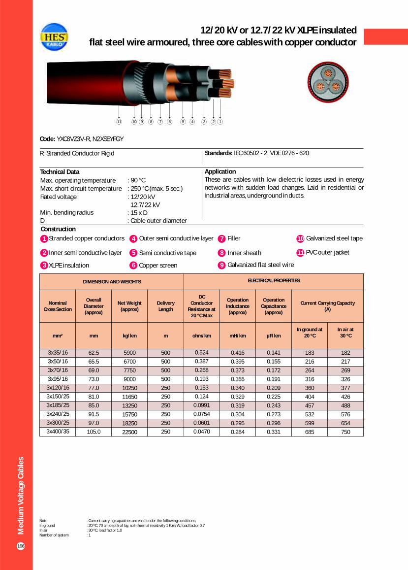
166
12/20 kV or 12.7/22 kV XLPE insulatedflat steel wire armoured, three core cables with copper conductor
Construction
Code: YXC8VZ3V-R, N2XSEYFGY
Standards: IEC 60502 - 2, VDE 0276 - 620
ApplicationThese are cables with low dielectric losses used in energy networks with sudden load changes. Laid in residential or industrial areas, underground in ducts.
1 4Stranded copper conductors Outer semi conductive layer
2 Inner semi conductive layer 5 Semi conductive tape
7 Filler
8 Inner sheath
10 Galvanized steel tape
11 PVC outer jacket
3 XLPE insulation 6 Copper screen 9 Galvanized flat steel wire
Technical Data
R: Stranded Conductor Rigid
Max. operating temperature : 90 °C
Max. short circuit temperature : 250 °C (max. 5 sec.)
Rated voltage : 12.7/22 kV
12/20 kV
Min. bending radius : 15 x DD : Cable outer diameter
1234567891011
Me
diu
m V
olt
age
Cab
les
DIMENSION AND WEIGHTS ELECTRICAL PROPERTIES
Nominal Cross Section
Overall Diameter (approx)
Net Weight (approx)
Delivery Length
DC Conductor
Resistance at20 ºC Max
Operation Inductance
(approx)
Operation Capacitance
(approx)
Current Carrying Capacity (A)
mm² mm kg/km m ohm/km mH/km µF/kmIn ground at
20 ºCIn air at
30 ºC
0.141
0.155
0.172
0.191
0.209
0.225
0.243
0.273
0.296
0.331
3x35/16
3x50/16
3x70/16
3x95/16
3x120/16
3x150/25
3x185/25
3x240/25
3x300/25
3x400/35
62.5
65.5
69.0
73.0
77.0
81.0
85.0
91.5
97.0
105.0
5900
6700
7750
9000
10250
11650
13250
15750
18250
22500
500
500
500
500
250
250
250
250
250
250
0.524
0.387
0.268
0.193
0.153
0.124
0.0991
0.0754
0.0601
0.0470
0.416
0.395
0.373
0.355
0.340
0.329
0.319
0.304
0.295
0.284
183
216
264
316
360
404
457
532
599
685
182
217
269
326
377
426
488
576
654
750
Note : Current carrying capacities are valid under the following conditions;In ground : 20 ºC, 70 cm depth of lay, soil-thermal resistivity 1 K.m/W, load factor 0.7In air : 30 ºC, load factor 1.0Number of system : 1
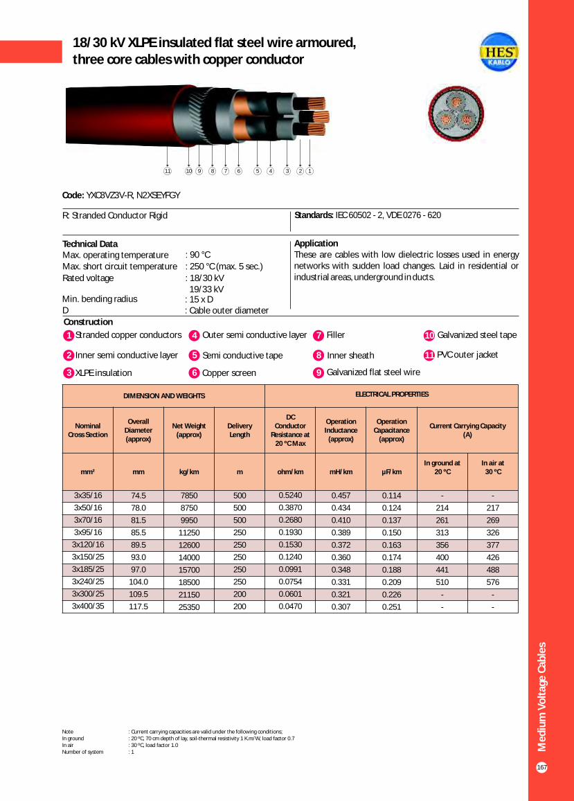
167
18/30 kV XLPE insulated flat steel wire armoured,three core cables with copper conductor
Construction
Code: YXC8VZ3V-R, N2XSEYFGY
Standards: IEC 60502 - 2, VDE 0276 - 620
ApplicationThese are cables with low dielectric losses used in energy networks with sudden load changes. Laid in residential or industrial areas, underground in ducts.
1 4Stranded copper conductors Outer semi conductive layer
2 Inner semi conductive layer 5 Semi conductive tape
7 Filler
8 Inner sheath
10 Galvanized steel tape
11 PVC outer jacket
Technical Data
3 XLPE insulation 6 Copper screen 9 Galvanized flat steel wire
R: Stranded Conductor Rigid
1234567891011
Me
diu
m V
olt
age
Cab
les
DIMENSION AND WEIGHTS ELECTRICAL PROPERTIES
Nominal Cross Section
Overall Diameter (approx)
Net Weight (approx)
Delivery Length
DC Conductor
Resistance at20 ºC Max
Operation Inductance
(approx)
Operation Capacitance
(approx)
Current Carrying Capacity (A)
mm² mm kg/km m ohm/km mH/km µF/kmIn ground at
20 ºCIn air at
30 ºC
0.114
0.124
0.137
0.150
0.163
0.174
0.188
0.209
0.226
0.251
3x35/16
3x50/16
3x70/16
3x95/16
3x120/16
3x150/25
3x185/25
3x240/25
3x300/25
3x400/35
74.5
78.0
81.5
85.5
89.5
93.0
97.0
104.0
109.5
117.5
7850
8750
9950
11250
12600
14000
15700
18500
21150
25350
500
500
500
250
250
250
250
250
200
200
0.5240
0.3870
0.2680
0.1930
0.1530
0.1240
0.0991
0.0754
0.0601
0.0470
0.457
0.434
0.410
0.389
0.372
0.360
0.348
0.331
0.321
0.307
-
214
261
313
356
400
441
510
-
-
-
217
269
326
377
426
488
576
-
-
Note : Current carrying capacities are valid under the following conditions;In ground : 20 ºC, 70 cm depth of lay, soil-thermal resistivity 1 K.m/W, load factor 0.7In air : 30 ºC, load factor 1.0Number of system : 1
Max. operating temperature : 90 °C
Max. short circuit temperature : 250 °C (max. 5 sec.)
Rated voltage : 18/30 kV 19/33 kV
Min. bending radius : 15 x DD : Cable outer diameter

168
20.3/35 kV or 20.8/36 kV XLPE insulatedflat steel wire armoured, three core cables with copper conductor
Construction
Code: YXC8VZ3V-R, N2XSEYFGY
Standards: HD 620 S2, TSEK
ApplicationThese are cables with low dielectric losses used in energy networks with sudden load changes. Laid in residential or industrial areas, underground in ducts.
1 4Stranded copper conductors Outer semi conductive layer
2 Inner semi conductive layer 5 Semi conductive tape
7 Filler
8 Inner sheath
10 Galvanized steel tape
11 PVC outer jacket
3 XLPE insulation 6 Copper screen 9 Galvanized flat steel wire
Technical Data
R: Stranded Conductor Rigid
Max. operating temperature : 90 °C
Max. short circuit temperature : 250 °C (max. 5 sec.)
Rated voltage : 20.3/35 kV 20.8/36 kV
Min. bending radius : 15 x DD : Cable outer diameter
1234567891011
Me
diu
m V
olt
age
Cab
les
DIMENSION AND WEIGHTS ELECTRICAL PROPERTIES
Nominal Cross Section
Overall Diameter (approx)
Net Weight (approx)
Delivery Length
DC Conductor
Resistance at20 ºC Max
Operation Inductance
(approx)
Operation Capacitance
(approx)
Current Carrying Capacity (A)
mm² mm kg/km m ohm/km mH/km µF/kmIn ground at
20 ºCIn air at
30 ºC
0.107
0.116
0.127
0.140
0.152
0.161
0.173
0.193
0.208
0.231
3x35/16
3x50/16
3x70/16
3x95/16
3x120/16
3x150/25
3x185/25
3x240/25
3x300/25
3x400/35
80.0
82.5
86.5
90.5
94.5
98.0
102.5
109.5
114.5
122.0
8750
9600
10800
12200
13600
15000
16800
19600
22250
26600
500
500
250
250
250
250
250
250
200
200
0.524
0.387
0.268
0.193
0.153
0.124
0.0991
0.0754
0.0601
0.0470
0.471
0.448
0.423
0.401
0.384
0.372
0.359
0.341
0.330
0.316
-
214
261
313
356
400
441
510
-
-
-
210
262
319
366
418
478
562
-
-
Note : Current carrying capacities are valid under the following conditions;In ground : 20 ºC, 70 cm depth of lay, soil-thermal resistivity 1 K.m/W, load factor 0.7In air : 30 ºC, load factor 1.0Number of system : 1

169
3.6/6 kV XLPE insulated round steel wire armoured,three core cables with copper conductor
Construction
Code: YXC8VZ2V-R, N2XSEYRY, CU/XLPE/CTS/PVC/SWA/PVC
Standards: IEC 60502 - 2, VDE 0276 - 620, BS 6622
ApplicationThese are cables with low dielectric losses used in energy networks with sudden load changes. Laid in residential or industrial areas, underground in ducts.
1 4Stranded copper conductors Outer semi conductive layer
2 Inner semi conductive layer 5 Semi conductive tape
7 Filler
8 Inner sheath
10 Polyester tape
11 PVC outer jacket
Technical DataMax. operating temperature : 90 °C
Max. short circuit temperature : 250 °C (max. 5 sec.)
Rated voltage : 3.6/6 kVMin. bending radius : 15 x DD : Cable outer diameter
3 XLPE insulation 6 Copper screen 9 Galvanized round steel wire
R: Stranded Conductor Rigid
1234567891011
Me
diu
m V
olt
age
Cab
les
DIMENSION AND WEIGHTS ELECTRICAL PROPERTIES
Nominal Cross Section
Overall Diameter (approx)
Net Weight (approx)
Delivery Length
DC Conductor
Resistance at20 ºC Max
Operation Inductance
(approx)
Operation Capacitance
(approx)
Current Carrying Capacity (A)
mm² mm kg/km m ohm/km mH/km µF/kmIn ground at
20 ºCIn air at
30 ºC
0.229
0.255
0.288
0.324
0.359
0.388
0.424
0.469
0.486
0.521
3x35/16
3x50/16
3x70/16
3x95/16
3x120/16
3x150/25
3x185/25
3x240/25
3x300/25
3x400/35
50.5
54.0
58.0
62.0
66.5
70.0
74.0
82.0
89.0
98.0
4400
5900
7000
8300
9600
9900
11400
15100
17950
22200
1000
500
500
500
500
500
250
250
250
250
0.524
0.387
0.268
0.193
0.153
0.124
0.0991
0.0754
0.0601
0.0470
0.352
0.336
0.318
0.303
0.292
0.284
0.276
0.267
0.263
0.257
176
208
255
307
353
396
447
523
581
653
171
196
249
307
353
406
464
548
632
726
Note : Current carrying capacities are valid under the following conditions;In ground : 20 ºC, 70 cm depth of lay, soil-thermal resistivity 1 K.m/W, load factor 0.7In air : 30 ºC, load factor 1.0Number of system : 1
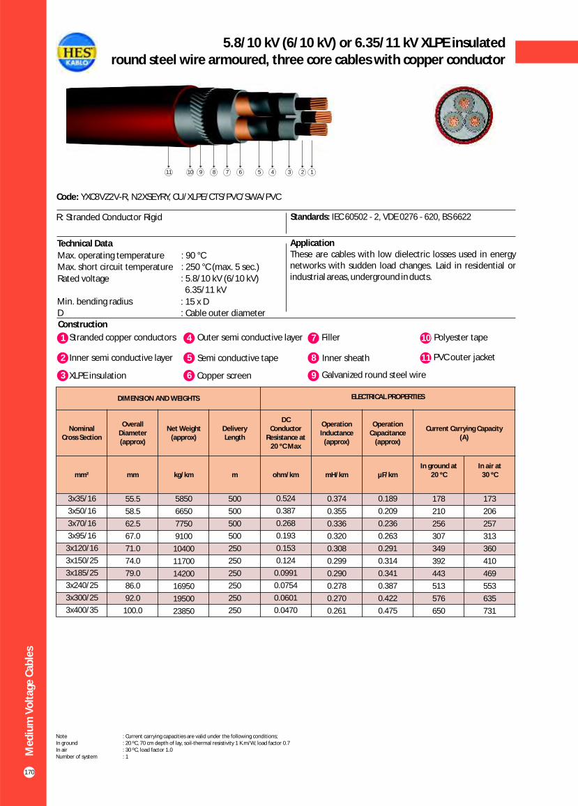
170
5.8/10 kV (6/10 kV) or 6.35/11 kV XLPE insulatedround steel wire armoured, three core cables with copper conductor
Construction
Code: YXC8VZ2V-R, N2XSEYRY, CU/XLPE/CTS/PVC/SWA/PVC
Standards: IEC 60502 - 2, VDE 0276 - 620, BS 6622
ApplicationThese are cables with low dielectric losses used in energy networks with sudden load changes. Laid in residential or industrial areas, underground in ducts.
Technical Data
Max. operating temperature : 90 °CMax. short circuit temperature : 250 °C (max. 5 sec.)
Rated voltage : 5.8/10 kV (6/10 kV) 6.35/11 kV
Min. bending radius : 15 x DD : Cable outer diameter
R: Stranded Conductor Rigid
1 4Stranded copper conductors Outer semi conductive layer
2 Inner semi conductive layer 5 Semi conductive tape
7 Filler
8 Inner sheath
10 Polyester tape
11 PVC outer jacket
3 XLPE insulation 6 Copper screen 9 Galvanized round steel wire
1234567891011
Me
diu
m V
olt
age
Cab
les
DIMENSION AND WEIGHTS ELECTRICAL PROPERTIES
Nominal Cross Section
Overall Diameter (approx)
Net Weight (approx)
Delivery Length
DC Conductor
Resistance at20 ºC Max
Operation Inductance
(approx)
Operation Capacitance
(approx)
Current Carrying Capacity (A)
mm² mm kg/km m ohm/km mH/km µF/kmIn ground at
20 ºCIn air at
30 ºC
0.189
0.209
0.236
0.263
0.291
0.314
0.341
0.387
0.422
0.475
3x35/16
3x50/16
3x70/16
3x95/16
3x120/16
3x150/25
3x185/25
3x240/25
3x300/25
3x400/35
55.5
58.5
62.5
67.0
71.0
74.0
79.0
86.0
92.0
100.0
5850
6650
7750
9100
10400
11700
14200
16950
19500
23850
500
500
500
500
250
250
250
250
250
250
0.524
0.387
0.268
0.193
0.153
0.124
0.0991
0.0754
0.0601
0.0470
0.374
0.355
0.336
0.320
0.308
0.299
0.290
0.278
0.270
0.261
178
210
256
307
349
392
443
513
576
650
173
206
257
313
360
410
469
553
635
731
Note : Current carrying capacities are valid under the following conditions;In ground : 20 ºC, 70 cm depth of lay, soil-thermal resistivity 1 K.m/W, load factor 0.7In air : 30 ºC, load factor 1.0Number of system : 1
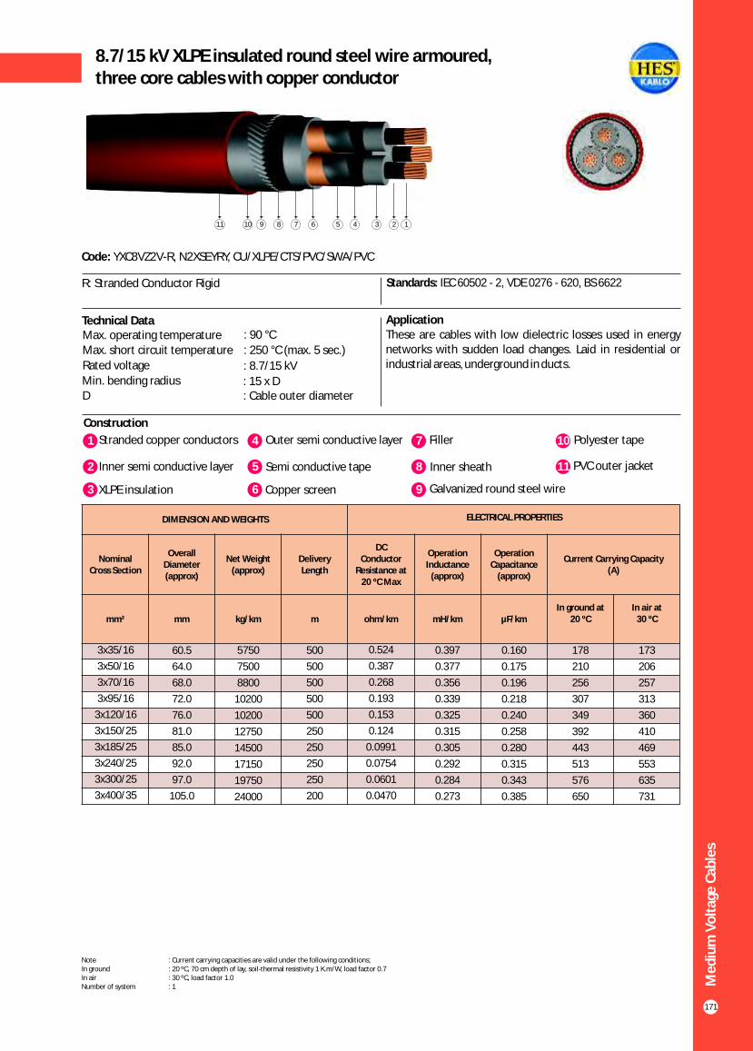
171
8.7/15 kV XLPE insulated round steel wire armoured,three core cables with copper conductor
Construction
Code: YXC8VZ2V-R, N2XSEYRY, CU/XLPE/CTS/PVC/SWA/PVC
Standards: IEC 60502 - 2, VDE 0276 - 620, BS 6622
ApplicationThese are cables with low dielectric losses used in energy networks with sudden load changes. Laid in residential or industrial areas, underground in ducts.
1 4Stranded copper conductors Outer semi conductive layer
2 Inner semi conductive layer 5 Semi conductive tape
7 Filler
8 Inner sheath
10 Polyester tape
11 PVC outer jacket
Technical DataMax. operating temperature : 90 °C
Max. short circuit temperature : 250 °C (max. 5 sec.)
Rated voltage : 8.7/15 kVMin. bending radius : 15 x DD : Cable outer diameter
3 XLPE insulation 6 Copper screen 9 Galvanized round steel wire
R: Stranded Conductor Rigid
1234567891011
Me
diu
m V
olt
age
Cab
les
DIMENSION AND WEIGHTS ELECTRICAL PROPERTIES
Nominal Cross Section
Overall Diameter (approx)
Net Weight (approx)
Delivery Length
DC Conductor
Resistance at20 ºC Max
Operation Inductance
(approx)
Operation Capacitance
(approx)
Current Carrying Capacity (A)
mm² mm kg/km m ohm/km mH/km µF/kmIn ground at
20 ºCIn air at
30 ºC
0.160
0.175
0.196
0.218
0.240
0.258
0.280
0.315
0.343
0.385
3x35/16
3x50/16
3x70/16
3x95/16
3x120/16
3x150/25
3x185/25
3x240/25
3x300/25
3x400/35
60.5
64.0
68.0
72.0
76.0
81.0
85.0
92.0
97.0
105.0
5750
7500
8800
10200
10200
12750
14500
17150
19750
24000
500
500
500
500
500
250
250
250
250
200
0.524
0.387
0.268
0.193
0.153
0.124
0.0991
0.0754
0.0601
0.0470
0.397
0.377
0.356
0.339
0.325
0.315
0.305
0.292
0.284
0.273
178
210
256
307
349
392
443
513
576
650
173
206
257
313
360
410
469
553
635
731
Note : Current carrying capacities are valid under the following conditions;In ground : 20 ºC, 70 cm depth of lay, soil-thermal resistivity 1 K.m/W, load factor 0.7In air : 30 ºC, load factor 1.0Number of system : 1

172
12/20 kV or 12.7/22 kV XLPE insulated round steel wire armoured, three core cables with copper conductor
Construction
Code: YXC8VZ2V-R, N2XSEYRY, CU/XLPE/CTS/PVC/SWA/PVC
Standards: IEC 60502 - 2, VDE 0276 - 620, BS 6622
ApplicationThese are cables with low dielectric losses used in energy networks with sudden load changes. Laid in residential or industrial areas, underground in ducts.
Technical Data
Max. operating temperature : 90 °CMax. short circuit temperature : 250 °C (max. 5 sec.)
Rated voltage : 12.7/22 kV 12/20 kV
Min. bending radius : 15 x DD : Cable outer diameter
R: Stranded Conductor Rigid
1 4Stranded copper conductors Outer semi conductive layer
2 Inner semi conductive layer 5 Semi conductive tape
7 Filler
8 Inner sheath
10 Polyester tape
11 PVC outer jacket
3 XLPE insulation 6 Copper screen 9 Galvanized round steel wire
1234567891011
Me
diu
m V
olt
age
Cab
les
DIMENSION AND WEIGHTS ELECTRICAL PROPERTIES
Nominal Cross Section
Overall Diameter (approx)
Net Weight (approx)
Delivery Length
DC Conductor
Resistance at20 ºC Max
Operation Inductance
(approx)
Operation Capacitance
(approx)
Current Carrying Capacity (A)
mm² mm kg/km m ohm/km mH/km µF/kmIn ground at
20 ºCIn air at
30 ºC
0.141
0.155
0.172
0.191
0.209
0.225
0.243
0.273
0.296
0.331
3x35/16
3x50/16
3x70/16
3x95/16
3x120/16
3x150/25
3x185/25
3x240/25
3x300/25
3x400/35
66.0
69.0
72.0
78.0
82.0
86.0
90.0
96.0
102.0
110.0
6550
7400
8500
10950
12300
13850
15500
18250
20850
25300
500
500
500
250
250
250
250
250
200
200
0.524
0.387
0.268
0.193
0.153
0.124
0.0991
0.0754
0.0601
0.0470
0.416
0.395
0.373
0.355
0.340
0.329
0.319
0.304
0.295
0.284
183
216
264
316
360
404
457
532
599
685
182
217
269
326
377
426
488
576
654
750
Note : Current carrying capacities are valid under the following conditions;In ground : 20 ºC, 70 cm depth of lay, soil-thermal resistivity 1 K.m/W, load factor 0.7In air : 30 ºC, load factor 1.0Number of system : 1

173
18/30 kV or 19/33 kV XLPE insulated round steel wire armoured,three core cables with copper conductor
Construction
Code: YXC8VZ2V-R, N2XSEYRY, CU/XLPE/CTS/PVC/SWA/PVC
Standards: IEC 60502 - 2, VDE 0276 - 620, BS 6622
ApplicationThese are cables with low dielectric losses used in energy networks with sudden load changes. Laid in residential or industrial areas, underground in ducts.
1 4Stranded copper conductors Outer semi conductive layer
2 Inner semi conductive layer 5 Semi conductive tape
7 Filler
8 Inner sheath
10 Polyester tape
11 PVC outer jacket
Technical Data
3 XLPE insulation 6 Copper screen 9 Galvanized round steel wire
R: Stranded Conductor Rigid
1234567891011
Me
diu
m V
olt
age
Cab
les
DIMENSION AND WEIGHTS ELECTRICAL PROPERTIES
Nominal Cross Section
Overall Diameter (approx)
Net Weight (approx)
Delivery Length
DC Conductor
Resistance at20 ºC Max
Operation Inductance
(approx)
Operation Capacitance
(approx)
Current Carrying Capacity (A)
mm² mm kg/km m ohm/km mH/km µF/kmIn ground at
20 ºCIn air at
30 ºC
0.114
0.124
0.137
0.150
0.163
0.174
0.188
0.209
3x35/16
3x50/16
3x70/16
3x95/16
3x120/16
3x150/25
3x185/25
3x240/25
79.0
82.5
86.5
90.5
95.0
98.0
102.0
109.5
9750
10750
12000
13500
14950
16400
18200
21250
500
250
250
250
250
250
250
200
0.5240
0.3870
0.2680
0.1930
0.1530
0.1240
0.0991
0.0754
0.457
0.434
0.410
0.389
0.372
0.360
0.348
0.331
183
216
264
316
360
404
457
532
182
217
269
326
377
426
488
576
Note : Current carrying capacities are valid under the following conditions;In ground : 20 ºC, 70 cm depth of lay, soil-thermal resistivity 1 K.m/W, load factor 0.7In air : 30 ºC, load factor 1.0Number of system : 1
Max. operating temperature : 90 °C
Max. short circuit temperature : 250 °C (max. 5 sec.)
Rated voltage : 18/30 kV 19/33 kV
Min. bending radius : 15 x DD : Cable outer diameter

174
20.3/35 kV or 20.8/36 kV XLPE insulated round steel wire armoured, three core cables with copper conductor
Construction
Code: YXC8VZ2V-R, N2XSEYRY, CU/XLPE/CTS/PVC/SWA/PVC
Standards: HD 620 S2, TSEK
ApplicationThese are cables with low dielectric losses used in energy networks with sudden load changes. Laid in residential or industrial areas, underground in ducts.
Technical Data
Max. operating temperature : 90 °CMax. short circuit temperature : 250 °C (max. 5 sec.)
Rated voltage : 20.3/35 kV 20.8/36 kV
Min. bending radius : 15 x DD : Cable outer diameter
R: Stranded Conductor Rigid
1 4Stranded copper conductors Outer semi conductive layer
2 Inner semi conductive layer 5 Semi conductive tape
7 Filler
8 Inner sheath
10 Polyester tape
11 PVC outer jacket
3 XLPE insulation 6 Copper screen 9 Galvanized round steel wire
1234567891011
Me
diu
m V
olt
age
Cab
les
DIMENSION AND WEIGHTS ELECTRICAL PROPERTIES
Nominal Cross Section
Overall Diameter (approx)
Net Weight (approx)
Delivery Length
DC Conductor
Resistance at20 ºC Max
Operation Inductance
(approx)
Operation Capacitance
(approx)
Current Carrying Capacity (A)
mm² mm kg/km m ohm/km mH/km µF/kmIn ground at
20 ºCIn air at
30 ºC
0.114
0.124
0.137
0.150
0.163
0.174
0.188
0.209
3x35/16
3x50/16
3x70/16
3x95/16
3x120/16
3x150/25
3x185/25
3x240/25
83.5
86.0
90.0
94.0
97.5
101.0
105.0
111.0
13000
12900
14000
16000
17800
19400
21400
24400
500
250
250
250
250
250
250
200
0.524
0.387
0.268
0.193
0.153
0.124
0.0991
0.0754
0.457
0.434
0.410
0.389
0.372
0.360
0.348
0.331
183
216
264
316
360
404
457
532
176
210
262
319
364
418
478
562
Note : Current carrying capacities are valid under the following conditions;In ground : 20 ºC, 70 cm depth of lay, soil-thermal resistivity 1 K.m/W, load factor 0.7In air : 30 ºC, load factor 1.0Number of system : 1

3.6/6 kV XLPE insulated double steel tape armoured,three core cables with copper conductor
Construction
Code: YXC8VZ4V-R, N2XSEYBY, CU/XLPE/CTS/PVC/STA/PVC
Standards: IEC 60502 - 2, VDE 0276 - 620
ApplicationThese are cables with low dielectric losses used in energy networks with sudden load changes. Laid in residential or industrial areas, underground in ducts.
R: Stranded Conductor Rigid
1 4Stranded copper conductors Outer semi conductive layer
2 Inner semi conductive layer 5 Semi conductive tape
7 Filler
8 Inner sheath
10 PVC outer jacket
3 XLPE insulation 6 Copper screen 9 Galvanized double steel tape
Technical DataMax. operating temperature : 90 °C
Max. short circuit temperature : 250 °C (max. 5 sec.)
Rated voltage : 3.6/6 kVMin. bending radius : 15 x DD : Cable outer diameter
12345678910
175
Me
diu
m V
olt
age
Cab
les
DIMENSION AND WEIGHTS ELECTRICAL PROPERTIES
Nominal Cross Section
Overall Diameter (approx)
Net Weight (approx)
Delivery Length
DC Conductor
Resistance at20 ºC Max
Operation Inductance
(approx)
Operation Capacitance
(approx)
Current Carrying Capacity (A)
mm² mm kg/km m ohm/km mH/km µF/kmIn ground at
20 ºCIn air at
30 ºC
0.229
0.255
0.288
0.324
0.359
0.388
0.424
0.469
0.486
0.521
3x35/16
3x50/16
3x70/16
3x95/16
3x120/16
3x150/25
3x185/25
3x240/25
3x300/25
3x400/35
47.0
50.0
54.0
58.0
62.5
66.0
70.0
77.0
83.5
94.0
3900
4600
5600
6500
7500
8600
10000
12350
14900
19550
1000
1000
500
500
500
500
250
250
250
250
0.524
0.387
0.268
0.193
0.153
0.124
0.0991
0.0754
0.0601
0.0470
0.352
0.336
0.318
0.303
0.292
0.284
0.276
0.267
0.263
0.257
176
208
255
307
353
396
447
523
581
653
171
196
249
307
353
406
464
548
632
726
Note : Current carrying capacities are valid under the following conditions;In ground : 20 ºC, 70 cm depth of lay, soil-thermal resistivity 1 K.m/W, load factor 0.7In air : 30 ºC, load factor 1.0Number of system : 1
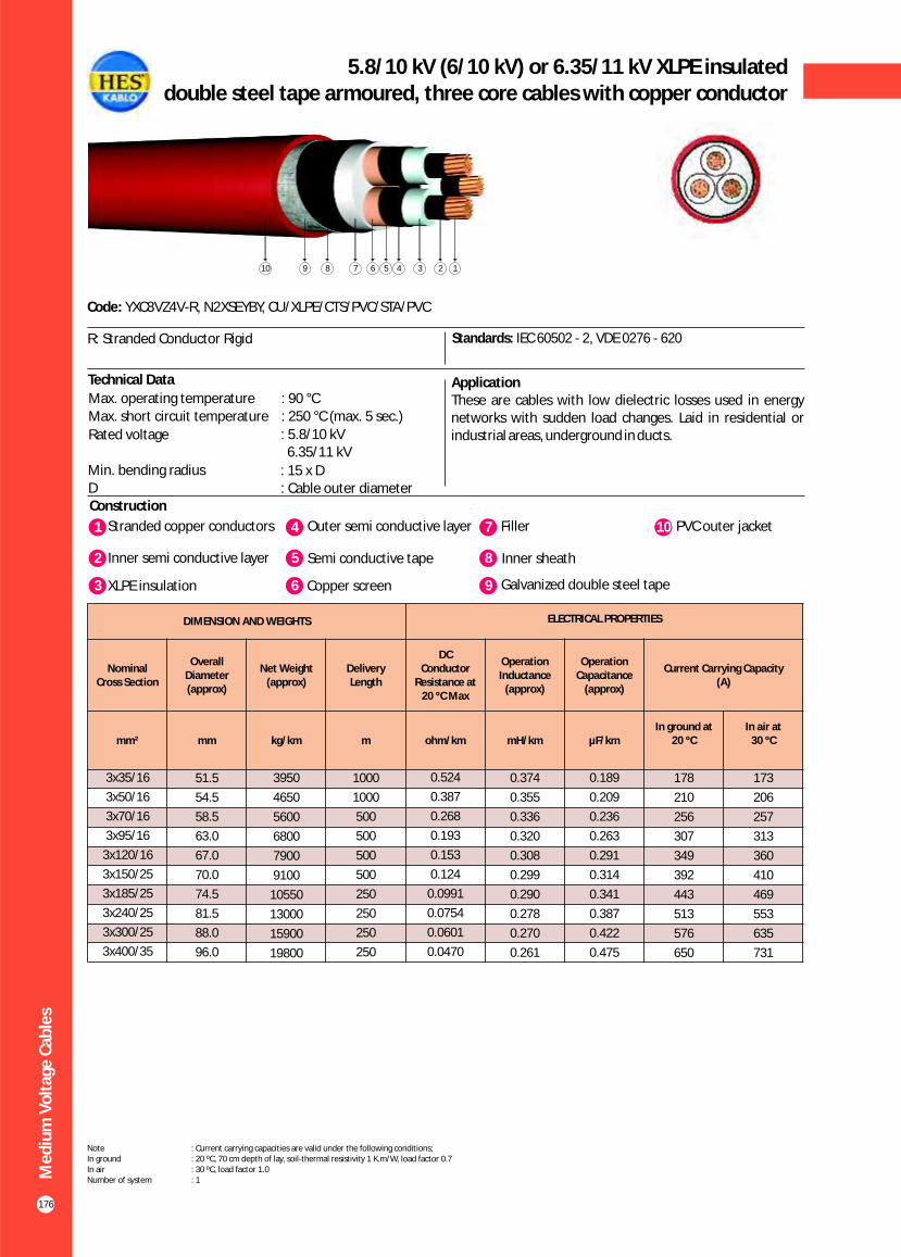
5.8/10 kV (6/10 kV) or 6.35/11 kV XLPE insulated double steel tape armoured, three core cables with copper conductor
Construction
Code: YXC8VZ4V-R, N2XSEYBY, CU/XLPE/CTS/PVC/STA/PVC
Standards: IEC 60502 - 2, VDE 0276 - 620
ApplicationThese are cables with low dielectric losses used in energy networks with sudden load changes. Laid in residential or industrial areas, underground in ducts.
1 4Stranded copper conductors Outer semi conductive layer
2 Inner semi conductive layer 5 Semi conductive tape
7 Filler
8 Inner sheath
10 PVC outer jacket
3 XLPE insulation 6 Copper screen 9 Galvanized double steel tape
R: Stranded Conductor Rigid
Technical Data
Max. operating temperature : 90 °CMax. short circuit temperature : 250 °C (max. 5 sec.)
Rated voltage : 5.8/10 kV 6.35/11 kV
Min. bending radius : 15 x DD : Cable outer diameter
12345678910
176
Me
diu
m V
olt
age
Cab
les
DIMENSION AND WEIGHTS ELECTRICAL PROPERTIES
Nominal Cross Section
Overall Diameter (approx)
Net Weight (approx)
Delivery Length
DC Conductor
Resistance at20 ºC Max
Operation Inductance
(approx)
Operation Capacitance
(approx)
Current Carrying Capacity (A)
mm² mm kg/km m ohm/km mH/km µF/kmIn ground at
20 ºCIn air at
30 ºC
0.189
0.209
0.236
0.263
0.291
0.314
0.341
0.387
0.422
0.475
3x35/16
3x50/16
3x70/16
3x95/16
3x120/16
3x150/25
3x185/25
3x240/25
3x300/25
3x400/35
51.5
54.5
58.5
63.0
67.0
70.0
74.5
81.5
88.0
96.0
3950
4650
5600
6800
7900
9100
10550
13000
15900
19800
1000
1000
500
500
500
500
250
250
250
250
0.524
0.387
0.268
0.193
0.153
0.124
0.0991
0.0754
0.0601
0.0470
0.374
0.355
0.336
0.320
0.308
0.299
0.290
0.278
0.270
0.261
178
210
256
307
349
392
443
513
576
650
173
206
257
313
360
410
469
553
635
731
Note : Current carrying capacities are valid under the following conditions;In ground : 20 ºC, 70 cm depth of lay, soil-thermal resistivity 1 K.m/W, load factor 0.7In air : 30 ºC, load factor 1.0Number of system : 1

8.7/15 kV XLPE insulated double steel tape armoured,three core cables with copper conductor
Construction
Code: YXC8VZ4V-R, N2XSEYBY, CU/XLPE/CTS/PVC/STA/PVC
Standards: IEC 60502 - 2, VDE 0276 - 620
ApplicationThese are cables with low dielectric losses used in energy networks with sudden load changes. Laid in residential or industrial areas, underground in ducts.
R: Stranded Conductor Rigid
1 4Stranded copper conductors Outer semi conductive layer
2 Inner semi conductive layer 5 Semi conductive tape
7 Filler
8 Inner sheath
10 PVC outer jacket
3 XLPE insulation 6 Copper screen 9 Galvanized double steel tape
Technical DataMax. operating temperature : 90 °C
Max. short circuit temperature : 250 °C (max. 5 sec.)
Rated voltage : 8.7/15 kVMin. bending radius : 15 x DD : Cable outer diameter
12345678910
177
Me
diu
m V
olt
age
Cab
les
DIMENSION AND WEIGHTS ELECTRICAL PROPERTIES
Nominal Cross Section
Overall Diameter (approx)
Net Weight (approx)
Delivery Length
DC Conductor
Resistance at20 ºC Max
Operation Inductance
(approx)
Operation Capacitance
(approx)
Current Carrying Capacity (A)
mm² mm kg/km m ohm/km mH/km µF/kmIn ground at
20 ºCIn air at
30 ºC
0.160
0.175
0.196
0.218
0.240
0.258
0.280
0.315
0.343
0.385
3x35/16
3x50/16
3x70/16
3x95/16
3x120/16
3x150/25
3x185/25
3x240/25
3x300/25
3x400/35
57.0
60.5
64.0
68.5
72.5
75.5
80.0
88.0
93.0
101.0
5200
5500
6400
7600
8750
10000
11600
14600
17050
21000
1000
500
500
500
500
250
250
250
250
200
0.524
0.387
0.268
0.193
0.153
0.124
0.0991
0.0754
0.0601
0.0470
0.397
0.377
0.356
0.339
0.325
0.315
0.305
0.292
0.284
0.273
178
210
256
307
349
392
443
513
576
650
173
206
257
313
360
410
469
553
635
731
Note : Current carrying capacities are valid under the following conditions;In ground : 20 ºC, 70 cm depth of lay, soil-thermal resistivity 1 K.m/W, load factor 0.7In air : 30 ºC, load factor 1.0Number of system : 1

12/20 kV or 12.7/22 kV XLPE insulated double steel tape armoured, three core cables with copper conductor
Construction
Code: YXC8VZ4V-R, N2XSEYBY, CU/XLPE/CTS/PVC/STA/PVC
Standards: IEC 60502 - 2, VDE 0276 - 620
ApplicationThese are cables with low dielectric losses used in energy networks with sudden load changes. Laid in residential or industrial areas, underground in ducts.
1 4Stranded copper conductors Outer semi conductive layer
2 Inner semi conductive layer 5 Semi conductive tape
7 Filler
8 Inner sheath
10 PVC outer jacket
3 XLPE insulation 6 Copper screen 9 Galvanized double steel tape
R: Stranded Conductor Rigid
Technical Data
Max. operating temperature : 90 °CMax. short circuit temperature : 250 °C (max. 5 sec.)
Rated voltage : 12.7/22 kV 12/20 kV
Min. bending radius : 15 x DD : Cable outer diameter
12345678910
178
Me
diu
m V
olt
age
Cab
les
DIMENSION AND WEIGHTS ELECTRICAL PROPERTIES
Nominal Cross Section
Overall Diameter (approx)
Net Weight (approx)
Delivery Length
DC Conductor
Resistance at20 ºC Max
Operation Inductance
(approx)
Operation Capacitance
(approx)
Current Carrying Capacity (A)
mm² mm kg/km m ohm/km mH/km µF/kmIn ground at
20 ºCIn air at
30 ºC
0.141
0.155
0.172
0.191
0.209
0.225
0.243
0.273
0.296
0.331
3x35/16
3x50/16
3x70/16
3x95/16
3x120/16
3x150/25
3x185/25
3x240/25
3x300/25
3x400/35
62.0
62.0
69.0
73.0
77.0
81.0
86.0
92.5
98.0
106.5
5350
6100
7100
8300
9500
10900
13000
15550
18000
22200
500
500
500
500
500
250
250
250
250
200
0.524
0.387
0.268
0.193
0.153
0.124
0.0991
0.0754
0.0601
0.0470
0.416
0.395
0.373
0.355
0.340
0.329
0.319
0.304
0.295
0.284
183
216
264
316
360
404
457
532
599
685
182
217
269
326
377
426
488
576
654
750
Note : Current carrying capacities are valid under the following conditions;In ground : 20 ºC, 70 cm depth of lay, soil-thermal resistivity 1 K.m/W, load factor 0.7In air : 30 ºC, load factor 1.0Number of system : 1
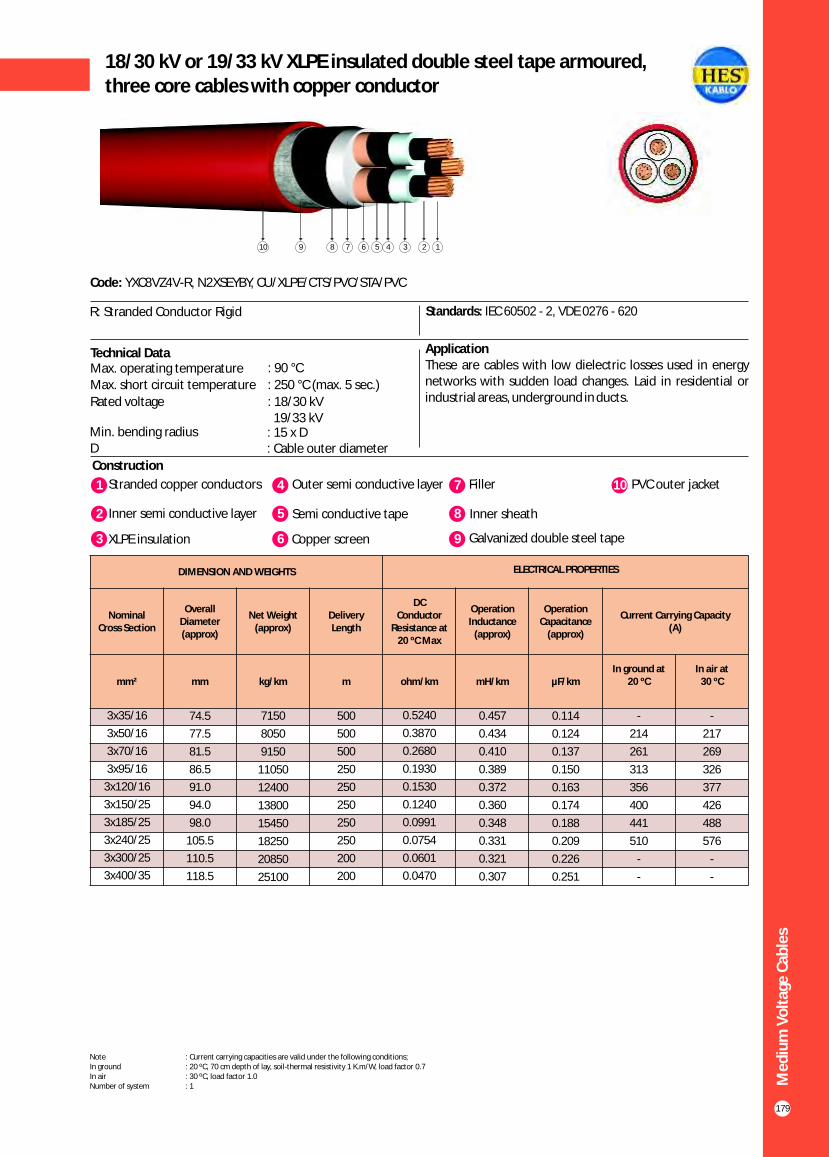
18/30 kV or 19/33 kV XLPE insulated double steel tape armoured,three core cables with copper conductor
Construction
Code: YXC8VZ4V-R, N2XSEYBY, CU/XLPE/CTS/PVC/STA/PVC
Standards: IEC 60502 - 2, VDE 0276 - 620
ApplicationThese are cables with low dielectric losses used in energy networks with sudden load changes. Laid in residential or industrial areas, underground in ducts.
R: Stranded Conductor Rigid
1 4Stranded copper conductors Outer semi conductive layer
2 Inner semi conductive layer 5 Semi conductive tape
7 Filler
8 Inner sheath
10 PVC outer jacket
3 XLPE insulation 6 Copper screen 9 Galvanized double steel tape
Technical Data
12345678910
179
Me
diu
m V
olt
age
Cab
les
DIMENSION AND WEIGHTS ELECTRICAL PROPERTIES
Nominal Cross Section
Overall Diameter (approx)
Net Weight (approx)
Delivery Length
DC Conductor
Resistance at20 ºC Max
Operation Inductance
(approx)
Operation Capacitance
(approx)
Current Carrying Capacity (A)
mm² mm kg/km m ohm/km mH/km µF/kmIn ground at
20 ºCIn air at
30 ºC
0.114
0.124
0.137
0.150
0.163
0.174
0.188
0.209
0.226
0.251
3x35/16
3x50/16
3x70/16
3x95/16
3x120/16
3x150/25
3x185/25
3x240/25
3x300/25
3x400/35
74.5
77.5
81.5
86.5
91.0
94.0
98.0
105.5
110.5
118.5
7150
8050
9150
11050
12400
13800
15450
18250
20850
25100
500
500
500
250
250
250
250
250
200
200
0.5240
0.3870
0.2680
0.1930
0.1530
0.1240
0.0991
0.0754
0.0601
0.0470
0.457
0.434
0.410
0.389
0.372
0.360
0.348
0.331
0.321
0.307
-
214
261
313
356
400
441
510
-
-
-
217
269
326
377
426
488
576
-
-
Note : Current carrying capacities are valid under the following conditions;In ground : 20 ºC, 70 cm depth of lay, soil-thermal resistivity 1 K.m/W, load factor 0.7In air : 30 ºC, load factor 1.0Number of system : 1
Max. operating temperature : 90 °C
Max. short circuit temperature : 250 °C (max. 5 sec.)
Rated voltage : 18/30 kV 19/33 kV
Min. bending radius : 15 x DD : Cable outer diameter

20.3/35 kV or 20.8/36 kV XLPE insulated double steel tape armoured, three core cables with copper conductor
Construction
Code: YXC8VZ4V-R, N2XSEYBY, CU/XLPE/CTS/PVC/STA/PVC
Standards: HD 620 S2, TSEK
ApplicationThese are cables with low dielectric losses used in energy networks with sudden load changes. Laid in residential or industrial areas, underground in ducts.
1 4Stranded copper conductors Outer semi conductive layer
2 Inner semi conductive layer 5 Semi conductive tape
7 Filler
8 Inner sheath
10 PVC outer jacket
3 XLPE insulation 6 Copper screen 9 Galvanized double steel tape
R: Stranded Conductor Rigid
Technical Data
Max. operating temperature : 90 °CMax. short circuit temperature : 250 °C (max. 5 sec.)
Rated voltage : 20.8/36 kV
20.3/35 kV
Min. bending radius : 15 x DD : Cable outer diameter
12345678910
180
Me
diu
m V
olt
age
Cab
les
DIMENSION AND WEIGHTS ELECTRICAL PROPERTIES
Nominal Cross Section
Overall Diameter (approx)
Net Weight (approx)
Delivery Length
DC Conductor
Resistance at20 ºC Max
Operation Inductance
(approx)
Operation Capacitance
(approx)
Current Carrying Capacity (A)
mm² mm kg/km m ohm/km mH/km µF/kmIn ground at
20 ºCIn air at
30 ºC
0.114
0.124
0.137
0.150
0.163
0.174
0.188
0.209
0.226
0.251
3x35/16
3x50/16
3x70/16
3x95/16
3x120/16
3x150/25
3x185/25
3x240/25
3x300/25
3x400/35
78.0
82.0
87.0
90.0
93.0
97.0
101.0
105.5
110.5
118.5
8900
10500
12000
13500
15000
16500
18500
21000
24000
28000
500
500
500
250
250
250
250
250
200
200
0.524
0.387
0.268
0.193
0.153
0.124
0.0991
0.0754
0.0601
0.0470
0.457
0.434
0.410
0.389
0.372
0.360
0.348
0.331
0.321
0.307
-
214
261
313
356
400
441
510
-
-
-
210
262
319
364
418
478
562
-
-
Note : Current carrying capacities are valid under the following conditions;In ground : 20 ºC, 70 cm depth of lay, soil-thermal resistivity 1 K.m/W, load factor 0.7In air : 30 ºC, load factor 1.0Number of system : 1

181
3.6/6 kV XLPE insulated single core cables with aluminium conductor
Construction
Code: YAXC7V-R, NA2XSY, AL/XLPE/CWS/PVC
Standards: IEC 60502 - 2, VDE 0276 - 620
ApplicationThese cables have a low dielectric loss, used in indoors and outdoors, in cable ducts, underground, in power or switching stations, local energy distributions, industrial plants, where there is no risk of mechanical damage.
R: Stranded Conductor Rigid
Technical DataMax. operating temperature : 90 °C
Max. short circuit temperature : 250 °C (max. 5 sec.)
Rated voltage : 3.6/6 kVMin. bending radius : 15 x DD : Cable outer diameter
1 3Stranded aluminium conductor XLPE insulation
2 Inner semi conductive layer 4 Outer semi conductive layer
5 Semi conductive tape
6 Copper screen
7 Polyester tape
8 PVC outer jacket
12345678
Me
diu
m V
olt
age
Cab
les
DIMENSION AND WEIGHTS ELECTRICAL PROPERTIES
Nominal Cross
Section
Overall Diameter (approx)
Net Weight
(approx)
Delivery Length
DC Conductor Resistance at
20 ºC Max
DC Conductor Resistance at
90 ºC MaxOperation Inductance
Operation Capacitance
Current Carrying Capacity (A)
mm² mm kg/km m ohm/km ohm/km***
mH/km
** *mH/km
µF/km
In ground at 20 ºC
In air at30 ºC
*** ** * *** ** *
1x35/16
1x50/16
1x70/16
1x95/16
1x120/16
1x150/25
1x185/25
1x240/25
1x300/25
1x400/35
1x500/35
1x630/35
21.0
22.0
24.0
25.5
27.0
28.5
30.5
33.5
36.0
40.0
43.5
47.0
550
600
700
800
900
1100
1250
1450
1700
2200
2600
3050
1000
1000
1000
1000
1000
1000
1000
1000
1000
1000
1000
1000
0.868
0.641
0.443
0.320
0.253
0.206
0.164
0.125
0.100
0.0778
0.0605
0.0469
1.1110
0.8205
0.5670
0.4096
0.3238
0.2637
0.2099
0.1600
0.1280
0.1009
0.0774
0.0600
0.657
0.632
0.601
0.577
0.558
0.541
0.525
0.506
0.490
0.471
0.456
0.440
0.367
0.351
0.332
0.318
0.308
0.299
0.292
0.284
0.279
0.275
0.270
0.264
0.283
0.318
0.368
0.414
0.455
0.499
0.544
0.587
0.603
0.642
0.667
0.739
-
186
234
287
338
388
449
530
605
678
762
858
-
178
217
259
298
333
377
438
495
562
633
712
-
233
280
344
392
441
510
587
682
781
883
1007
-
188
235
286
329
376
428
508
586
676
772
882
Note : Current carrying capacities are valid under the following conditions;In ground : 20 ºC, 70 cm depth of lay, soil-thermal resistivity 1 K.m/W, load factor 0.7In air : 30 ºC, load factor 1.0*** : Flat formation, clearance between cables; in air = 1 x Cable outer diameter, in ground = 7 cm : Trefoil formationNumber of system : 1
** *

182
5.8/10 kV (6/10 kV) or 6.35/11 kV XLPE insulatedsingle core cables with aluminium conductor
Construction
Code: YAXC7V-R, NA2XSY, AL/XLPE/CWS/PVC
Standards: IEC 60502 - 2, VDE 0276 - 620
ApplicationThese cables have a low dielectric loss, used in indoors and outdoors, in cable ducts, underground, in power or switching stations, local energy distributions, industrial plants, where there is no risk of mechanical damage.
R: Stranded Conductor Rigid
Technical Data
Max. operating temperature : 90 °CMax. short circuit temperature : 250 °C (max. 5 sec.)
Rated voltage : 5.8/10 kV (6/10 kV) 6.35/11 kV
Min. bending radius : 15 x DD : Cable outer diameter
1 3Stranded aluminium conductor XLPE insulation
2 Inner semi conductive layer 4 Outer semi conductive layer
5 Semi conductive tape
6 Copper screen
7 Polyester tape
8 PVC outer jacket
12345678
Me
diu
m V
olt
age
Cab
les
DIMENSION AND WEIGHTS ELECTRICAL PROPERTIES
Nominal Cross
Section
Overall Diameter (approx)
Net Weight
(approx)
Delivery Length
DC Conductor Resistance at
20 ºC Max
DC Conductor Resistance at
90 ºC MaxOperation Inductance
Operation Capacitance
Current Carrying Capacity (A)
mm² mm kg/km m ohm/km ohm/km***
mH/km
** *mH/km
µF/km
In ground at 20 ºC
In air at30 ºC
*** ** * *** ** *
1x35/16
1x50/16
1x70/16
1x95/16
1x120/16
1x150/25
1x185/25
1x240/25
1x300/25
1x400/35
1x500/35
1x630/35
22.5
24.0
26.0
27.5
29.5
30.5
32.5
35.0
37.5
41.0
44.0
47.5
600
650
750
870
970
1200
1300
1550
1800
2250
2600
3050
1000
1000
1000
1000
1000
1000
1000
1000
1000
1000
1000
1000
0.868
0.641
0.443
0.320
0.253
0.206
0.164
0.125
0.100
0.0778
0.0605
0.0469
1.1110
0.8205
0.5670
0.4096
0.3238
0.2637
0.2099
0.1600
0.1280
0.1009
0.0774
0.0600
0.657
0.632
0.601
0.577
0.558
0.541
0.525
0.506
0.490
0.471
0.456
0.440
0.367
0.351
0.332
0.318
0.308
0.299
0.292
0.284
0.279
0.275
0.270
0.264
0.223
0.248
0.285
0.320
0.350
0.382
0.415
0.462
0.507
0.573
0.631
0.699
-
194
236
281
318
350
393
453
507
559
622
697
-
171
209
249
283
316
358
416
469
532
599
679
-
215
269
327
377
424
485
573
652
741
838
957
-
181
226
275
317
359
412
489
559
651
744
851
Note : Current carrying capacities are valid under the following conditions;In ground : 20 ºC, 70 cm depth of lay, soil-thermal resistivity 1 K.m/W, load factor 0.7In air : 30 ºC, load factor 1.0*** : Flat formation, clearance between cables; in air = 1 x Cable outer diameter, in ground = 7 cm : Trefoil formationNumber of system : 1
** *
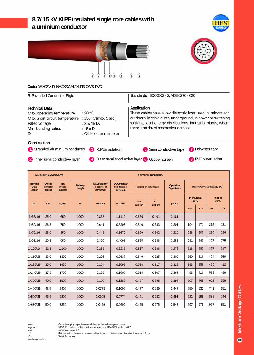
183
8.7/15 kV XLPE insulated single core cables with aluminium conductor
Construction
Code: YAXC7V-R, NA2XSY, AL/XLPE/CWS/PVC
Standards: IEC 60502 - 2, VDE 0276 - 620
ApplicationThese cables have a low dielectric loss, used in indoors and outdoors, in cable ducts, underground, in power or switching stations, local energy distributions, industrial plants, where there is no risk of mechanical damage.
R: Stranded Conductor Rigid
Technical DataMax. operating temperature : 90 °C
Max. short circuit temperature : 250 °C (max. 5 sec.)
Rated voltage : 8.7/15 kVMin. bending radius : 15 x DD : Cable outer diameter
1 3Stranded aluminium conductor XLPE insulation
2 Inner semi conductive layer 4 Outer semi conductive layer
5 Semi conductive tape
6 Copper screen
7 Polyester tape
8 PVC outer jacket
12345678
Me
diu
m V
olt
age
Cab
les
DIMENSION AND WEIGHTS ELECTRICAL PROPERTIES
Nominal Cross
Section
Overall Diameter (approx)
Net Weight
(approx)
Delivery Length
DC Conductor Resistance at
20 ºC Max
DC Conductor Resistance at
90 ºC MaxOperation Inductance
Operation Capacitance
Current Carrying Capacity (A)
mm² mm kg/km m ohm/km ohm/km***
mH/km
** *mH/km
µF/km
In ground at 20 ºC
In air at30 ºC
*** ** * *** ** *
1x35/16
1x50/16
1x70/16
1x95/16
1x120/16
1x150/25
1x185/25
1x240/25
1x300/25
1x400/35
1x500/35
1x630/35
25.0
26.5
28.0
29.5
31.5
33.0
35.0
37.5
40.0
43,5
46,5
50.0
650
750
850
950
1.100
1300
1450
1700
1900
2400
2800
3250
1000
1000
1000
1000
1000
1000
1000
1000
1000
1000
1000
1000
0.868
0.641
0.443
0.320
0.253
0.206
0.164
0.125
0.100
0.0778
0.0605
0.0469
1.1110
0.8205
0.5670
0.4096
0.3238
0.2637
0.2099
0.1600
0.1280
0.1009
0.0774
0.0600
0.666
0.640
0.609
0.585
0.567
0.549
0.534
0.514
0.497
0.477
0.461
0.455
0.401
0.383
0.362
0.346
0.336
0.325
0.317
0.307
0.298
0.289
0.282
0.275
0.181
0.201
0.229
0.255
0.278
0.302
0.328
0.363
0.398
0.447
0.491
0.543
-
194
236
281
318
350
393
453
507
559
622
697
-
171
209
249
283
316
358
416
469
532
599
679
-
215
269
327
377
424
485
573
652
741
838
957
-
181
226
275
317
359
412
489
559
651
744
851
Note : Current carrying capacities are valid under the following conditions;In ground : 20 ºC, 70 cm depth of lay, soil-thermal resistivity 1 K.m/W, load factor 0.7In air : 30 ºC, load factor 1.0*** : Flat formation, clearance between cables; in air = 1 x Cable outer diameter, in ground = 7 cm : Trefoil formationNumber of system : 1
** *

184
12/20 kV or 12.7/22 kV XLPE insulatedsingle core cables with aluminium conductor
Construction
Code: YAXC7V-R, NA2XSY, AL/XLPE/CWS/PVC
Standards: IEC 60502 - 2, VDE 0276 - 620
ApplicationThese cables have a low dielectric loss, used in indoors and outdoors, in cable ducts, underground, in power or switching stations, local energy distributions, industrial plants, where there is no risk of mechanical damage.
R: Stranded Conductor Rigid
1 3Stranded aluminium conductor XLPE insulation
2 Inner semi conductive layer 4 Outer semi conductive layer
5 Semi conductive tape
6 Copper screen
7 Polyester tape
8 PVC outer jacket
Technical DataMax. operating temperature : 90 °C
Max. short circuit temperature : 250 °C (max. 5 sec.)
Rated voltage : 12.7/22 kV
12/20 kV
Min. bending radius : 15 x DD : Cable outer diameter
12345678
Me
diu
m V
olt
age
Cab
les
DIMENSION AND WEIGHTS ELECTRICAL PROPERTIES
Nominal Cross
Section
Overall Diameter (approx)
Net Weight
(approx)
Delivery Length
DC Conductor Resistance at
20 ºC Max
DC Conductor Resistance at
90 ºC MaxOperation Inductance
Operation Capacitance
Current Carrying Capacity (A)
mm² mm kg/km m ohm/km ohm/km***
mH/km
** *mH/km
µF/km
In ground at 20 ºC
In air at30 ºC
*** ** * *** ** *
1x35/16
1x50/16
1x70/16
1x95/16
1x120/16
1x150/25
1x185/25
1x240/25
1x300/25
1x400/35
1x500/35
1x630/35
27.0
28.5
30.0
32.0
34.0
35.0
37.0
39.5
42.0
45.5
48.5
52.5
750
800
950
1050
1200
1400
1550
1800
2050
2550
2900
3400
1000
1000
1000
1000
1000
1000
1000
1000
1000
1000
1000
1000
0.868
0.641
0.443
0.320
0.253
0.206
0.164
0.125
0.100
0.0778
0.0605
0.0469
1.1110
0.8205
0.5670
0.4096
0.3238
0.2637
0.2099
0.1600
0.1280
0.1009
0.0774
0.0600
0.670
0.644
0.614
0.590
0.571
0.554
0.538
0.518
0.501
0.480
0.464
0.448
0.416
0.397
0.377
0.360
0.349
0.338
0.329
0.317
0.308
0.298
0.290
0.282
0.157
0.174
0.197
0.218
0.238
0.258
0.278
0.308
0.336
0.377
0.413
0.455
-
195
237
282
320
353
396
457
511
566
630
719
-
173
211
252
287
320
362
421
474
538
606
686
-
217
270
328
378
425
485
573
652
740
838
953
-
184
229
278
320
363
415
493
563
652
746
850
Note : Current carrying capacities are valid under the following conditions;In ground : 20 ºC, 70 cm depth of lay, soil-thermal resistivity 1 K.m/W, load factor 0.7In air : 30 ºC, load factor 1.0*** : Flat formation, clearance between cables; in air = 1 x Cable outer diameter, in ground = 7 cm : Trefoil formationNumber of system : 1
** *

185
18/30 kV or 19/33 kV XLPE insulated single core cables with aluminium conductor
Construction
Code: YAXC7V-R, NA2XSY, AL/XLPE/CWS/PVC
Standards: IEC 60502 - 2, VDE 0276 - 620
ApplicationThese cables have a low dielectric loss, used in indoors and outdoors, in cable ducts, underground, in power or switching stations, local energy distributions, industrial plants, where there is no risk of mechanical damage.
R: Stranded Conductor Rigid
Technical Data
1 3Stranded aluminium conductor XLPE insulation
2 Inner semi conductive layer 4 Outer semi conductive layer
5 Semi conductive tape
6 Copper screen
7 Polyester tape
8 PVC outer jacket
12345678
Me
diu
m V
olt
age
Cab
les
DIMENSION AND WEIGHTS ELECTRICAL PROPERTIES
Nominal Cross
Section
Overall Diameter (approx)
Net Weight
(approx)
Delivery Length
DC Conductor Resistance at
20 ºC Max
DC Conductor Resistance at
90 ºC MaxOperation Inductance
Operation Capacitance
Current Carrying Capacity (A)
mm² mm kg/km m ohm/km ohm/km***
mH/km
** *mH/km
µF/km
In ground at 20 ºC
In air at30 ºC
*** ** * *** ** *
1x35/16
1x50/16
1x70/16
1x95/16
1x120/16
1x150/25
1x185/25
1x240/25
1x300/25
1x400/35
1x500/35
1x630/35
32.0
33.5
35.0
37.0
39.0
40.5
42.5
45.0
47.5
50.5
54.0
57.5
1000
1100
1200
1400
1500
1750
1900
2200
2450
3000
3400
3900
1000
1000
1000
1000
1000
1000
1000
1000
1000
1000
1000
1000
0.868
0.641
0.443
0.320
0.253
0.206
0.164
0.125
0.100
0.0778
0.0605
0.0469
1.1110
0.8205
0.5670
0.4096
0.3238
0.2637
0.2099
0.1600
0.1280
0.1009
0.0774
0.0600
0.680
0.655
0.624
0.600
0.581
0.564
0.547
0.527
0.510
0.489
0.473
0.457
0.451
0.432
0.408
0.391
0.377
0.366
0.355
0.342
0.332
0.320
0.310
0.301
0.123
0.135
0.151
0.166
0.180
0.194
0.208
0.229
0.248
0.276
0.301
0.330
-
196
238
284
322
355
400
461
516
572
638
728
-
175
214
256
290
324
366
426
479
545
614
690
-
217
270
328
378
425
485
572
649
737
835
950
-
187
232
281
323
365
418
494
564
654
747
851
Note : Current carrying capacities are valid under the following conditions;In ground : 20 ºC, 70 cm depth of lay, soil-thermal resistivity 1 K.m/W, load factor 0.7In air : 30 ºC, load factor 1.0*** : Flat formation, clearance between cables; in air = 1 x Cable outer diameter, in ground = 7 cm : Trefoil formationNumber of system : 1
** *
Max. operating temperature : 90 °C
Max. short circuit temperature : 250 °C (max. 5 sec.)
Rated voltage : 18/30 kV 19/33 kV
Min. bending radius : 15 x DD : Cable outer diameter

186
20.3/35 kV or 20.8/36 kV XLPE insulatedsingle core cables with aluminium conductor
Construction
Code: YAXC7V-R, NA2XSY, AL/XLPE/CWS/PVC
Standards: HD 620 S2, TSEK
ApplicationThese cables have a low dielectric loss, used in indoors and outdoors, in cable ducts, underground, in power or switching stations, local energy distributions, industrial plants, where there is no risk of mechanical damage.
R: Stranded Conductor Rigid
1 3Stranded aluminium conductor XLPE insulation
2 Inner semi conductive layer 4 Outer semi conductive layer
5 Semi conductive tape
6 Copper screen
7 Polyester tape
8 PVC outer jacket
Technical DataMax. operating temperature : 90 °C
Max. short circuit temperature : 250 °C (max. 5 sec.)
Rated voltage : 20.3/35 kV 20.8/36 kV
Min. bending radius : 15 x DD : Cable outer diameter
12345678
Me
diu
m V
olt
age
Cab
les
DIMENSION AND WEIGHTS ELECTRICAL PROPERTIES
Nominal Cross
Section
Overall Diameter (approx)
Net Weight
(approx)
Delivery Length
DC Conductor Resistance at
20 ºC Max
DC Conductor Resistance at
90 ºC MaxOperation Inductance
Operation Capacitance
Current Carrying Capacity (A)
mm² mm kg/km m ohm/km ohm/km***
mH/km
** *mH/km
µF/km
In ground at 20 ºC
In air at30 ºC
*** ** * *** ** *
1x35/16
1x50/16
1x70/16
1x95/16
1x120/16
1x150/25
1x185/25
1x240/25
1x300/25
1x400/35
1x500/35
1x630/35
34.5
36.0
37.5
39.5
41.5
43.0
44.5
47.5
49.5
53.0
56.0
60.0
1100
1200
1350
1500
1650
1900
2050
2350
2600
3150
3600
4150
1000
1000
1000
1000
1000
1000
1000
1000
1000
1000
1000
1000
0.868
0.641
0.443
0.320
0.253
0.206
0.164
0.125
0.100
0.0778
0.0605
0.0469
1.1110
0.8205
0.5670
0.4096
0.3238
0.2637
0.2099
0.1600
0.1280
0.1009
0.0774
0.0600
0.657
0.632
0.601
0.577
0.558
0.541
0.525
0.506
0.490
0.471
0.456
0.440
0.464
0.444
0.420
0.402
0.388
0.376
0.365
0.351
0.341
0.328
0.318
0.308
0.115
0.125
0.140
0.153
0.165
0.178
0.191
0.209
0.226
0.252
0.274
0.300
-
196
238
284
322
355
400
461
516
572
638
728
-
175
214
256
290
324
366
426
479
545
614
690
-
217
270
328
378
425
485
572
649
737
835
950
-
187
232
281
323
365
418
494
564
654
747
851
Note : Current carrying capacities are valid under the following conditions;In ground : 20 ºC, 70 cm depth of lay, soil-thermal resistivity 1 K.m/W, load factor 0.7In air : 30 ºC, load factor 1.0*** : Flat formation, clearance between cables; in air = 1 x Cable outer diameter, in ground = 7 cm : Trefoil formationNumber of system : 1
** *
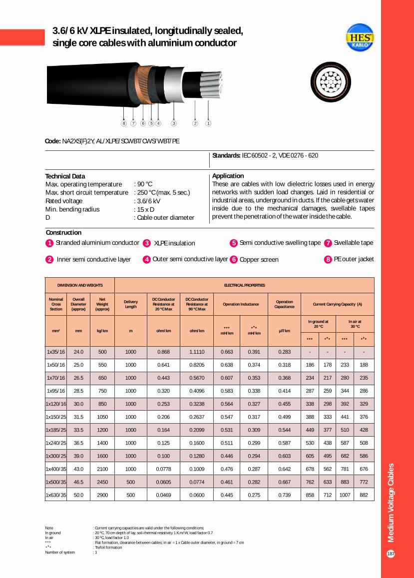
187
3.6/6 kV XLPE insulated, longitudinally sealed,single core cables with aluminium conductor
Construction
Code: NA2XS(F)2Y, AL/XLPE/SCWBT/CWS/WBT/PE
Standards: IEC 60502 - 2, VDE 0276 - 620
ApplicationThese are cables with low dielectric losses used in energy networks with sudden load changes. Laid in residential or industrial areas, underground in ducts. If the cable gets water inside due to the mechanical damages, swellable tapes prevent the penetration of the water inside the cable.
Technical DataMax. operating temperature : 90 °C
Max. short circuit temperature : 250 °C (max. 5 sec.)
Rated voltage : 3.6/6 kVMin. bending radius : 15 x DD : Cable outer diameter
1 3Stranded aluminium conductor XLPE insulation
2 Inner semi conductive layer 4 Outer semi conductive layer
5 Semi conductive swelling tape
6 Copper screen
7 Swellable tape
8 PE outer jacket
12345678
Me
diu
m V
olt
age
Cab
les
DIMENSION AND WEIGHTS ELECTRICAL PROPERTIES
Nominal Cross
Section
Overall Diameter (approx)
Net Weight
(approx)
Delivery Length
DC Conductor Resistance at
20 ºC Max
DC Conductor Resistance at
90 ºC MaxOperation Inductance
Operation Capacitance
Current Carrying Capacity (A)
mm² mm kg/km m ohm/km ohm/km***
mH/km
** *mH/km
µF/km
In ground at 20 ºC
In air at30 ºC
*** ** * *** ** *
1x35/16
1x50/16
1x70/16
1x95/16
1x120/16
1x150/25
1x185/25
1x240/25
1x300/25
1x400/35
1x500/35
1x630/35
24.0
25.0
26.5
28.5
30.0
31.5
33.5
36.5
39.0
43.0
46.5
50.0
500
550
650
750
850
1050
1200
1400
1600
2100
2450
2900
1000
1000
1000
1000
1000
1000
1000
1000
1000
1000
500
500
0.868
0.641
0.443
0.320
0.253
0.206
0.164
0.125
0.100
0.0778
0.0605
0.0469
1.1110
0.8205
0.5670
0.4096
0.3238
0.2637
0.2099
0.1600
0.1280
0.1009
0.0774
0.0600
0.663
0.638
0.607
0.583
0.564
0.547
0.531
0.511
0.446
0.476
0.461
0.445
0.391
0.374
0.353
0.338
0.327
0.317
0.309
0.299
0.294
0.287
0.282
0.275
0.283
0.318
0.368
0.414
0.455
0.499
0.544
0.587
0.603
0.642
0.667
0.739
-
186
234
287
338
388
449
530
605
678
762
858
-
178
217
259
298
333
377
438
495
562
633
712
-
233
280
344
392
441
510
587
682
781
883
1007
-
188
235
286
329
376
428
508
586
676
772
882
Note : Current carrying capacities are valid under the following conditions;In ground : 20 ºC, 70 cm depth of lay, soil-thermal resistivity 1 K.m/W, load factor 0.7In air : 30 ºC, load factor 1.0*** : Flat formation, clearance between cables; in air = 1 x Cable outer diameter, in ground = 7 cm : Trefoil formationNumber of system : 1
** *
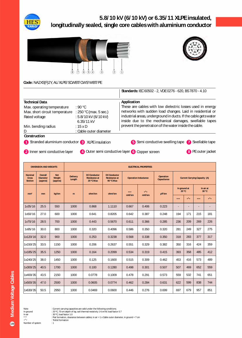
188
5.8/10 kV (6/10 kV) or 6.35/11 XLPE insulated,longitudinally sealed, single core cables with aluminium conductor
Construction
Code: NA2XS(F)2Y, AL/XLPE/SCWBT/CWS/WBT/PE
Standards: IEC 60502 - 2, VDE 0276 - 620, BS 7870 - 4.10
ApplicationThese are cables with low dielectric losses used in energy networks with sudden load changes. Laid in residential or industrial areas, underground in ducts. If the cable gets water inside due to the mechanical damages, swellable tapes prevent the penetration of the water inside the cable.
1 3Stranded aluminium conductor XLPE insulation
2 Inner semi conductive layer 4 Outer semi conductive layer
5 Semi conductive swelling tape
6 Copper screen
7 Swellable tape
8 PE outer jacket
Technical Data
Max. operating temperature : 90 °CMax. short circuit temperature : 250 °C (max. 5 sec.)
Rated voltage : 5.8/10 kV (6/10 kV) 6.35/11 kV
Min. bending radius : 15 x DD : Cable outer diameter
12345678
Me
diu
m V
olt
age
Cab
les
DIMENSION AND WEIGHTS ELECTRICAL PROPERTIES
Nominal Cross
Section
Overall Diameter (approx)
Net Weight
(approx)
Delivery Length
DC Conductor Resistance at
20 ºC Max
DC Conductor Resistance at
90 ºC MaxOperation Inductance
Operation Capacitance
Current Carrying Capacity (A)
mm² mm kg/km m ohm/km ohm/km***
mH/km
** *mH/km
µF/km
In ground at 20 ºC
In air at30 ºC
*** ** * *** ** *
1x35/16
1x50/16
1x70/16
1x95/16
1x120/16
1x150/25
1x185/25
1x240/25
1x300/25
1x400/35
1x500/35
1x630/35
25.5
27.0
28.5
30.0
32.0
33.5
35.5
38.0
40.5
43.5
47.0
50.5
550
600
700
800
900
1150
1250
1450
1700
2150
2500
2950
1000
1000
1000
1000
1000
1000
1000
1000
1000
1000
1000
1000
0.868
0.641
0.443
0.320
0.253
0.206
0.164
0.125
0.100
0.0778
0.0605
0.0469
1.1110
0.8205
0.5670
0.4096
0.3238
0.2637
0.2099
0.1600
0.1280
0.1009
0.0774
0.0600
0.667
0.642
0.611
0.586
0.568
0.551
0.534
0.515
0.498
0.478
0.462
0.446
0.406
0.387
0.366
0.350
0.338
0.329
0.319
0.309
0.301
0.291
0.284
0.276
0.223
0.248
0.285
0.320
0.350
0.382
0.415
0.462
0.507
0.573
0.631
0.699
-
194
236
281
318
350
393
453
507
559
622
697
-
171
209
249
283
316
358
416
469
532
599
679
-
215
269
327
377
424
485
573
652
741
838
957
-
181
226
275
317
359
412
489
559
651
744
851
Note : Current carrying capacities are valid under the following conditions;In ground : 20 ºC, 70 cm depth of lay, soil-thermal resistivity 1 K.m/W, load factor 0.7In air : 30 ºC, load factor 1.0*** : Flat formation, clearance between cables; in air = 1 x Cable outer diameter, in ground = 7 cm : Trefoil formationNumber of system : 1
** *

189
8.7/15 kV XLPE insulated, longitudinally sealed,single core cables with aluminium conductor
Construction
Code: NA2XS(F)2Y, AL/XLPE/SCWBT/CWS/WBT/PE
Standards: IEC 60502 - 2, VDE 0276 - 620
ApplicationThese are cables with low dielectric losses used in energy networks with sudden load changes. Laid in residential or industrial areas, underground in ducts. If the cable gets water inside due to the mechanical damages, swellable tapes prevent the penetration of the water inside the cable.
Technical DataMax. operating temperature : 90 °C
Max. short circuit temperature : 250 °C (max. 5 sec.)
Rated voltage : 8.7/15 kVMin. bending radius : 15 x DD : Cable outer diameter
1 3Stranded aluminium conductor XLPE insulation
2 Inner semi conductive layer 4 Outer semi conductive layer
5 Semi conductive swelling tape
6 Copper screen
7 Swellable tape
8 PE outer jacket
12345678
Me
diu
m V
olt
age
Cab
les
DIMENSION AND WEIGHTS ELECTRICAL PROPERTIES
Nominal Cross
Section
Overall Diameter (approx)
Net Weight
(approx)
Delivery Length
DC Conductor Resistance at
20 ºC Max
DC Conductor Resistance at
90 ºC MaxOperation Inductance
Operation Capacitance
Current Carrying Capacity (A)
mm² mm kg/km m ohm/km ohm/km***
mH/km
** *mH/km
µF/km
In ground at 20 ºC
In air at30 ºC
*** ** * *** ** *
1x35/16
1x50/16
1x70/16
1x95/16
1x120/16
1x150/25
1x185/25
1x240/25
1x300/25
1x400/35
1x500/35
1x630/35
28.0
29.0
30.5
32.5
34.5
35.5
37.5
40.5
42.5
46.0
49.5
53.0
650
700
800
900
1050
1250
1400
1600
1800
2300
2650
3100
1000
1000
1000
1000
1000
1000
1000
1000
1000
1000
1000
1000
0.868
0.641
0.443
0.320
0.253
0.206
0.164
0.125
0.100
0.0778
0.0605
0.0469
1.1110
0.8205
0.5670
0.4096
0.3238
0.2637
0.2099
0.1600
0.1280
0.1009
0.0774
0.0600
0.672
0.646
0.615
0.591
0.572
0.555
0.539
0.519
0.502
0.482
0.466
0.450
0.422
0.403
0.381
0.364
0.353
0.341
0.332
0.321
0.311
0.301
0.293
0.285
0.181
0.201
0.229
0.255
0.278
0.302
0.328
0.363
0.398
0.447
0.491
0.543
-
194
236
281
318
350
393
453
507
559
622
697
-
171
209
249
283
316
358
416
469
532
599
679
-
215
269
327
377
424
485
573
652
741
838
957
-
181
226
275
317
359
412
489
559
651
744
851
Note : Current carrying capacities are valid under the following conditions;In ground : 20 ºC, 70 cm depth of lay, soil-thermal resistivity 1 K.m/W, load factor 0.7In air : 30 ºC, load factor 1.0*** : Flat formation, clearance between cables; in air = 1 x Cable outer diameter, in ground = 7 cm : Trefoil formationNumber of system : 1
** *

190
12/20 kV or 12.7/22 kV XLPE insulated,longitudinally sealed, single core cables with aluminium conductor
Construction
Code: NA2XS(F)2Y, AL/XLPE/SCWBT/CWS/WBT/PE
Standards: IEC 60502 - 2, VDE 0276 - 620, BS 7870 - 4.10
ApplicationThese are cables with low dielectric losses used in energy networks with sudden load changes. Laid in residential or industrial areas, underground in ducts. If the cable gets water inside due to the mechanical damages, swellable tapes prevent the penetration of the water inside the cable.
1 3Stranded aluminium conductor XLPE insulation
2 Inner semi conductive layer 4 Outer semi conductive layer
5 Semi conductive swelling tape
6 Copper screen
7 Swellable tape
8 PE outer jacket
Technical DataMax. operating temperature : 90 °C
Max. short circuit temperature : 250 °C (max. 5 sec.)
Rated voltage : 12.7/22 kV
12/20 kV Min. bending radius
: 15 x DD : Cable outer diameter
12345678
Me
diu
m V
olt
age
Cab
les
DIMENSION AND WEIGHTS ELECTRICAL PROPERTIES
Nominal Cross
Section
Overall Diameter (approx)
Net Weight
(approx)
Delivery Length
DC Conductor Resistance at
20 ºC Max
DC Conductor Resistance at
90 ºC MaxOperation Inductance
Operation Capacitance
Current Carrying Capacity (A)
mm² mm kg/km m ohm/km ohm/km***
mH/km
** *mH/km
µF/km
In ground at 20 ºC
In air at30 ºC
*** ** * *** ** *
1x35/16
1x50/16
1x70/16
1x95/16
1x120/16
1x150/25
1x185/25
1x240/25
1x300/25
1x400/35
1x500/35
1x630/35
30.0
31.0
33.0
34.5
36.5
38.0
40.0
42.5
44.5
48.0
51.0
55.0
700
800
900
1000
1150
1350
1500
1700
1950
2400
2800
3250
1000
1000
1000
1000
1000
1000
1000
1000
1000
1000
1000
1000
0.868
0.641
0.443
0.320
0.253
0.206
0.164
0.125
0.100
0.0778
0.0605
0.0469
1.1110
0.8205
0.5670
0.4096
0.3238
0.2637
0.2099
0.1600
0.1280
0.1009
0.0774
0.0600
0.676
0.650
0.619
0.595
0.576
0.559
0.543
0.523
0.506
0.485
0.469
0.452
0.436
0.416
0.394
0.377
0.365
0.353
0.343
0.330
0.321
0.309
0.300
0.292
0.157
0.174
0.197
0.218
0.238
0.258
0.278
0.308
0.336
0.377
0.413
0.455
-
195
237
282
320
353
396
457
511
566
630
719
-
173
211
252
287
320
362
421
474
538
606
686
-
217
270
328
378
425
485
573
652
740
838
953
-
184
229
278
320
363
415
493
563
652
746
850
Note : Current carrying capacities are valid under the following conditions;In ground : 20 ºC, 70 cm depth of lay, soil-thermal resistivity 1 K.m/W, load factor 0.7In air : 30 ºC, load factor 1.0*** : Flat formation, clearance between cables; in air = 1 x Cable outer diameter, in ground = 7 cm : Trefoil formationNumber of system : 1
** *

191
18/30 kV or 19/33 kV XLPE insulated, longitudinally sealed,single core cables with aluminium conductor
Construction
Code: NA2XS(F)2Y, AL/XLPE/SCWBT/CWS/WBT/PE
Standards: IEC 60502 - 2, VDE 0276 - 620, BS 7870 - 4.10
ApplicationThese are cables with low dielectric losses used in energy networks with sudden load changes. Laid in residential or industrial areas, underground in ducts. If the cable gets water inside due to the mechanical damages, swellable tapes prevent the penetration of the water inside the cable.
Technical Data
1 3Stranded aluminium conductor XLPE insulation
2 Inner semi conductive layer 4 Outer semi conductive layer
5 Semi conductive swelling tape
6 Copper screen
7 Swellable tape
8 PE outer jacket
12345678
Me
diu
m V
olt
age
Cab
les
DIMENSION AND WEIGHTS ELECTRICAL PROPERTIES
Nominal Cross
Section
Overall Diameter (approx)
Net Weight
(approx)
Delivery Length
DC Conductor Resistance at
20 ºC Max
DC Conductor Resistance at
90 ºC MaxOperation Inductance
Operation Capacitance
Current Carrying Capacity (A)
mm² mm kg/km m ohm/km ohm/km***
mH/km
** *mH/km
µF/km
In ground at 20 ºC
In air at30 ºC
*** ** * *** ** *
1x35/16
1x50/16
1x70/16
1x95/16
1x120/16
1x150/25
1x185/25
1x240/25
1x300/25
1x400/35
1x500/35
1x630/35
35.0
36.5
38.0
40.0
42.0
43.5
45.0
48.0
50.0
53.5
56.5
60.5
900
1000
1150
1250
1400
1650
1800
2050
2300
2800
3200
3700
1000
1000
1000
1000
1000
1000
1000
1000
1000
1000
1000
1000
0.868
0.641
0.443
0.320
0.253
0.206
0.164
0.125
0.100
0.0778
0.0605
0.0469
1.1110
0.8205
0.5670
0.4096
0.3238
0.2637
0.2099
0.1600
0.1280
0.1009
0.0774
0.0600
0.686
0.660
0.629
0.605
0.586
0.568
0.552
0.532
0.515
0.494
0.478
0.461
0.467
0.448
0.423
0.405
0.391
0.379
0.367
0.354
0.343
0.330
0.320
0.310
0.123
0.135
0.151
0.166
0.180
0.194
0.208
0.229
0.248
0.276
0.301
0.330
-
146
238
284
322
355
400
461
516
572
638
728
-
175
214
256
290
324
366
426
479
545
614
690
-
217
270
328
378
425
485
572
649
737
835
950
-
187
232
281
323
365
418
494
564
654
747
851
Note : Current carrying capacities are valid under the following conditions;In ground : 20 ºC, 70 cm depth of lay, soil-thermal resistivity 1 K.m/W, load factor 0.7In air : 30 ºC, load factor 1.0*** : Flat formation, clearance between cables; in air = 1 x Cable outer diameter, in ground = 7 cm : Trefoil formationNumber of system : 1
** *
Max. operating temperature : 90 °C
Max. short circuit temperature : 250 °C (max. 5 sec.)
Rated voltage : 18/30 kV 19/33 kV
Min. bending radius : 15 x DD : Cable outer diameter

192
20.3/35 kV or 20.8/36 kV XLPE insulated,longitudinally sealed, single core cables with aluminium conductor
Construction
Code: NA2XS(F)2Y, AL/XLPE/SCWBT/CWS/WBT/PE
Standards: HD 620 S2, TSEK
ApplicationThese are cables with low dielectric losses used in energy networks with sudden load changes. Laid in residential or industrial areas, underground in ducts. If the cable gets water inside due to the mechanical damages, swellable tapes prevent the penetration of the water inside the cable.
1 3Stranded aluminium conductor XLPE insulation
2 Inner semi conductive layer 4 Outer semi conductive layer
5 Semi conductive swelling tape
6 Copper screen
7 Swellable tape
8 PE outer jacket
Technical DataMax. operating temperature : 90 °C
Max. short circuit temperature : 250 °C (max. 5 sec.)
Rated voltage : 20.3/35 kV 20.8/36 kV
Min. bending radius : 15 x DD : Cable outer diameter
12345678
Me
diu
m V
olt
age
Cab
les
DIMENSION AND WEIGHTS ELECTRICAL PROPERTIES
Nominal Cross
Section
Overall Diameter (approx)
Net Weight
(approx)
Delivery Length
DC Conductor Resistance at
20 ºC Max
DC Conductor Resistance at
90 ºC MaxOperation Inductance
Operation Capacitance
Current Carrying Capacity (A)
mm² mm kg/km m ohm/km ohm/km***
mH/km
** *mH/km
µF/km
In ground at 20 ºC
In air at30 ºC
*** ** * *** ** *
1x35/16
1x50/16
1x70/16
1x95/16
1x120/16
1x150/25
1x185/25
1x240/25
1x300/25
1x400/35
1x500/35
1x630/35
37.5
38.5
40.5
42.0
44.0
45.5
47.5
50.0
52.5
55.5
59.0
62.5
1000
1100
1250
1400
1500
1750
1950
2200
2450
2950
3400
3900
1000
1000
1000
1000
1000
1000
1000
1000
1000
1000
1000
1000
0.868
0.641
0.443
0.320
0.253
0.206
0.164
0.125
0.100
0.0778
0.0605
0.0469
1.1110
0.8205
0.5670
0.4096
0.3238
0.2637
0.2099
0.1600
0.1280
0.1009
0.0774
0.0600
0.690
0.664
0.633
0.609
0.590
0.572
0.556
0.535
0.519
0.497
0.481
0.464
0.480
0.459
0.434
0.416
0.401
0.389
0.376
0.363
0.351
0.338
0.328
0.317
0.115
0.125
0.140
0.153
0.165
0.178
0.191
0.209
0.226
0.252
0.274
0.300
-
196
238
284
322
355
400
461
516
572
638
728
-
175
214
256
290
324
366
426
479
545
614
690
-
217
270
328
378
425
485
572
649
737
835
950
-
187
232
281
323
365
418
494
564
654
747
851
Note : Current carrying capacities are valid under the following conditions;In ground : 20 ºC, 70 cm depth of lay, soil-thermal resistivity 1 K.m/W, load factor 0.7In air : 30 ºC, load factor 1.0*** : Flat formation, clearance between cables; in air = 1 x Cable outer diameter, in ground = 7 cm : Trefoil formationNumber of system : 1
** *

193
3.6/6 kV XLPE insulated, radial and longitudinally sealed, single core cables with aluminium conductor
Construction
Code: NA2XS(FL)2Y, AL/XLPE/CWS/LW/PE
Standards: IEC 60502 - 2, VDE 0276 - 620
Application These are cables with low dielectric losses used in energy networks with sudden load changes. Laid in residential or industrial areas, underground in ducts. If the cable gets water inside due to the mechanical damages, swellable tapes prevent the penetration of the water inside the cable.
Technical DataMax. operating temperature : 90 °C
Max. short circuit temperature : 250 °C (max. 5 sec.)
Rated voltage : 3.6/6 kVMin. bending radius : 15 x DD : Cable outer diameter
1 3Stranded aluminium conductor XLPE insulation
2 Inner semi conductive layer 4 Outer semi conductive layer
5 Semi conductive swelling tape
6 Copper screen
7 Swellable tape
8 PE coated aluminium foil
9 PE outer jacket
Me
diu
m V
olt
age
Cab
les
DIMENSION AND WEIGHTS ELECTRICAL PROPERTIES
Nominal Cross
Section
Overall Diameter (approx)
Net Weight
(approx)
Delivery Length
DC Conductor Resistance at
20 ºC Max
DC Conductor Resistance at
90 ºC MaxOperation Inductance
Operation Capacitance
Current Carrying Capacity (A)
mm² mm kg/km m ohm/km ohm/km***
mH/km
** *mH/km
µF/km
In ground at 20 ºC
In air at30 ºC
*** ** * *** ** *
1x35/16
1x50/16
1x70/16
1x95/16
1x120/16
1x150/25
1x185/25
1x240/25
1x300/25
1x400/35
1x500/35
1x630/35
25.0
26.0
27.5
29.5
31.0
32.5
34.5
37.5
40.0
44.0
47.5
51.5
550
650
700
850
950
1100
1250
1500
1750
2200
2600
3050
1000
1000
1000
1000
1000
1000
1000
1000
1000
1000
1000
1000
0.868
0.641
0.443
0.320
0.253
0.206
0.164
0.125
0.100
0.0778
0.0605
0.0469
1.1110
0.8205
0.5670
0.4096
0.3238
0.2637
0.2099
0.1600
0.1280
0.1009
0.0774
0.0600
0.665
0.640
0.609
0.585
0.566
0.549
0.533
0.513
0.498
0.478
0.463
0.447
0.399
0.381
0.361
0.345
0.333
0.323
0.315
0.306
0.300
0.292
0.286
0.278
0.283
0.318
0.368
0.414
0.455
0.499
0.544
0.587
0.603
0.642
0.667
0.739
-
186
234
287
338
388
449
530
605
678
762
858
-
178
217
259
298
333
377
438
495
562
633
712
-
233
280
344
392
441
510
587
682
781
883
1007
-
188
235
286
329
376
428
508
586
676
772
882
Note : Current carrying capacities are valid under the following conditions;In ground : 20 ºC, 70 cm depth of lay, soil-thermal resistivity 1 K.m/W, load factor 0.7In air : 30 ºC, load factor 1.0*** : Flat formation, clearance between cables; in air = 1 x Cable outer diameter, in ground = 7 cm : Trefoil formationNumber of system : 1
** *
12345678
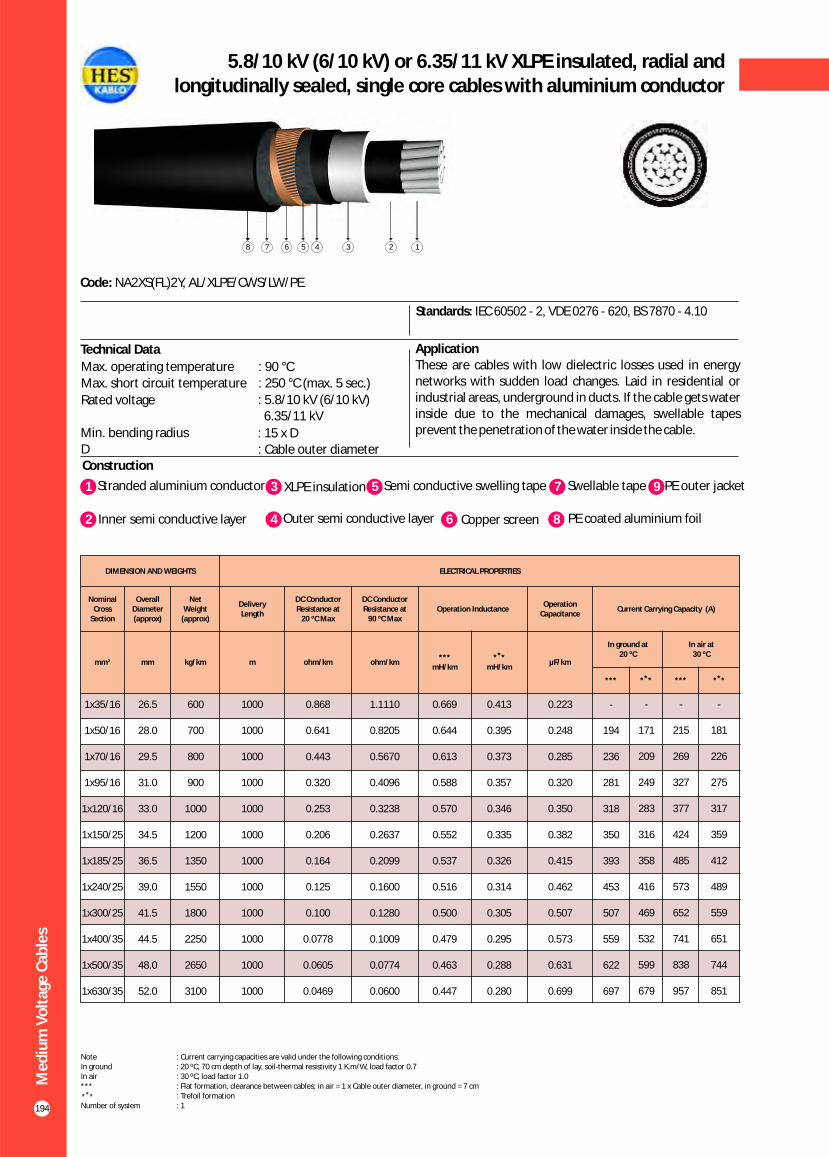
194
5.8/10 kV (6/10 kV) or 6.35/11 kV XLPE insulated, radial and longitudinally sealed, single core cables with aluminium conductor
Construction
Code: NA2XS(FL)2Y, AL/XLPE/CWS/LW/PE
Standards: IEC 60502 - 2, VDE 0276 - 620, BS 7870 - 4.10
Application These are cables with low dielectric losses used in energy networks with sudden load changes. Laid in residential or industrial areas, underground in ducts. If the cable gets water inside due to the mechanical damages, swellable tapes prevent the penetration of the water inside the cable.
Technical Data
Max. operating temperature : 90 °CMax. short circuit temperature : 250 °C (max. 5 sec.)
Rated voltage : 5.8/10 kV (6/10 kV) 6.35/11 kV
Min. bending radius : 15 x DD : Cable outer diameter
Me
diu
m V
olt
age
Cab
les
DIMENSION AND WEIGHTS ELECTRICAL PROPERTIES
Nominal Cross
Section
Overall Diameter (approx)
Net Weight
(approx)
Delivery Length
DC Conductor Resistance at
20 ºC Max
DC Conductor Resistance at
90 ºC MaxOperation Inductance
Operation Capacitance
Current Carrying Capacity (A)
mm² mm kg/km m ohm/km ohm/km***
mH/km
** *mH/km
µF/km
In ground at 20 ºC
In air at30 ºC
*** ** * *** ** *
1x35/16
1x50/16
1x70/16
1x95/16
1x120/16
1x150/25
1x185/25
1x240/25
1x300/25
1x400/35
1x500/35
1x630/35
26.5
28.0
29.5
31.0
33.0
34.5
36.5
39.0
41.5
44.5
48.0
52.0
600
700
800
900
1000
1200
1350
1550
1800
2250
2650
3100
1000
1000
1000
1000
1000
1000
1000
1000
1000
1000
1000
1000
0.868
0.641
0.443
0.320
0.253
0.206
0.164
0.125
0.100
0.0778
0.0605
0.0469
1.1110
0.8205
0.5670
0.4096
0.3238
0.2637
0.2099
0.1600
0.1280
0.1009
0.0774
0.0600
0.669
0.644
0.613
0.588
0.570
0.552
0.537
0.516
0.500
0.479
0.463
0.447
0.413
0.395
0.373
0.357
0.346
0.335
0.326
0.314
0.305
0.295
0.288
0.280
0.223
0.248
0.285
0.320
0.350
0.382
0.415
0.462
0.507
0.573
0.631
0.699
-
194
236
281
318
350
393
453
507
559
622
697
-
171
209
249
283
316
358
416
469
532
599
679
-
215
269
327
377
424
485
573
652
741
838
957
-
181
226
275
317
359
412
489
559
651
744
851
1 3Stranded aluminium conductor XLPE insulation
2 Inner semi conductive layer 4 Outer semi conductive layer
5 Semi conductive swelling tape
6 Copper screen
7 Swellable tape
8 PE coated aluminium foil
9 PE outer jacket
Note : Current carrying capacities are valid under the following conditions;In ground : 20 ºC, 70 cm depth of lay, soil-thermal resistivity 1 K.m/W, load factor 0.7In air : 30 ºC, load factor 1.0*** : Flat formation, clearance between cables; in air = 1 x Cable outer diameter, in ground = 7 cm : Trefoil formationNumber of system : 1
** *
12345678
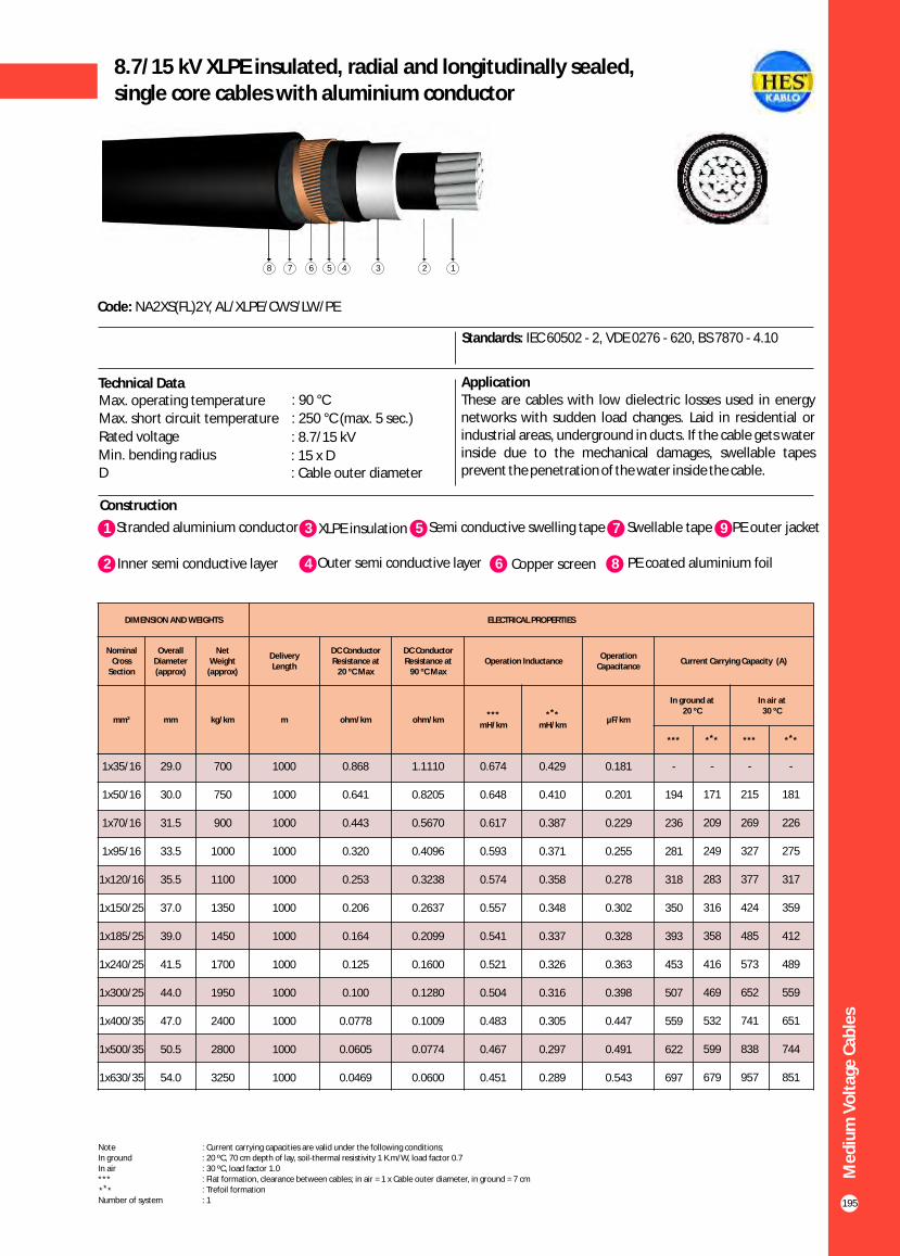
195
8.7/15 kV XLPE insulated, radial and longitudinally sealed, single core cables with aluminium conductor
Construction
Code: NA2XS(FL)2Y, AL/XLPE/CWS/LW/PE
Standards: IEC 60502 - 2, VDE 0276 - 620, BS 7870 - 4.10
Application These are cables with low dielectric losses used in energy networks with sudden load changes. Laid in residential or industrial areas, underground in ducts. If the cable gets water inside due to the mechanical damages, swellable tapes prevent the penetration of the water inside the cable.
Technical DataMax. operating temperature : 90 °C
Max. short circuit temperature : 250 °C (max. 5 sec.)
Rated voltage : 8.7/15 kVMin. bending radius : 15 x DD : Cable outer diameter
Me
diu
m V
olt
age
Cab
les
DIMENSION AND WEIGHTS ELECTRICAL PROPERTIES
Nominal Cross
Section
Overall Diameter (approx)
Net Weight
(approx)
Delivery Length
DC Conductor Resistance at
20 ºC Max
DC Conductor Resistance at
90 ºC MaxOperation Inductance
Operation Capacitance
Current Carrying Capacity (A)
mm² mm kg/km m ohm/km ohm/km***
mH/km
** *mH/km
µF/km
In ground at 20 ºC
In air at30 ºC
*** ** * *** ** *
1x35/16
1x50/16
1x70/16
1x95/16
1x120/16
1x150/25
1x185/25
1x240/25
1x300/25
1x400/35
1x500/35
1x630/35
29.0
30.0
31.5
33.5
35.5
37.0
39.0
41.5
44.0
47.0
50.5
54.0
700
750
900
1000
1100
1350
1450
1700
1950
2400
2800
3250
1000
1000
1000
1000
1000
1000
1000
1000
1000
1000
1000
1000
0.868
0.641
0.443
0.320
0.253
0.206
0.164
0.125
0.100
0.0778
0.0605
0.0469
1.1110
0.8205
0.5670
0.4096
0.3238
0.2637
0.2099
0.1600
0.1280
0.1009
0.0774
0.0600
0.674
0.648
0.617
0.593
0.574
0.557
0.541
0.521
0.504
0.483
0.467
0.451
0.429
0.410
0.387
0.371
0.358
0.348
0.337
0.326
0.316
0.305
0.297
0.289
0.181
0.201
0.229
0.255
0.278
0.302
0.328
0.363
0.398
0.447
0.491
0.543
-
194
236
281
318
350
393
453
507
559
622
697
-
171
209
249
283
316
358
416
469
532
599
679
-
215
269
327
377
424
485
573
652
741
838
957
-
181
226
275
317
359
412
489
559
651
744
851
1 3Stranded aluminium conductor XLPE insulation
2 Inner semi conductive layer 4 Outer semi conductive layer
5 Semi conductive swelling tape
6 Copper screen
7 Swellable tape
8 PE coated aluminium foil
9 PE outer jacket
Note : Current carrying capacities are valid under the following conditions;In ground : 20 ºC, 70 cm depth of lay, soil-thermal resistivity 1 K.m/W, load factor 0.7In air : 30 ºC, load factor 1.0*** : Flat formation, clearance between cables; in air = 1 x Cable outer diameter, in ground = 7 cm : Trefoil formationNumber of system : 1
** *
12345678
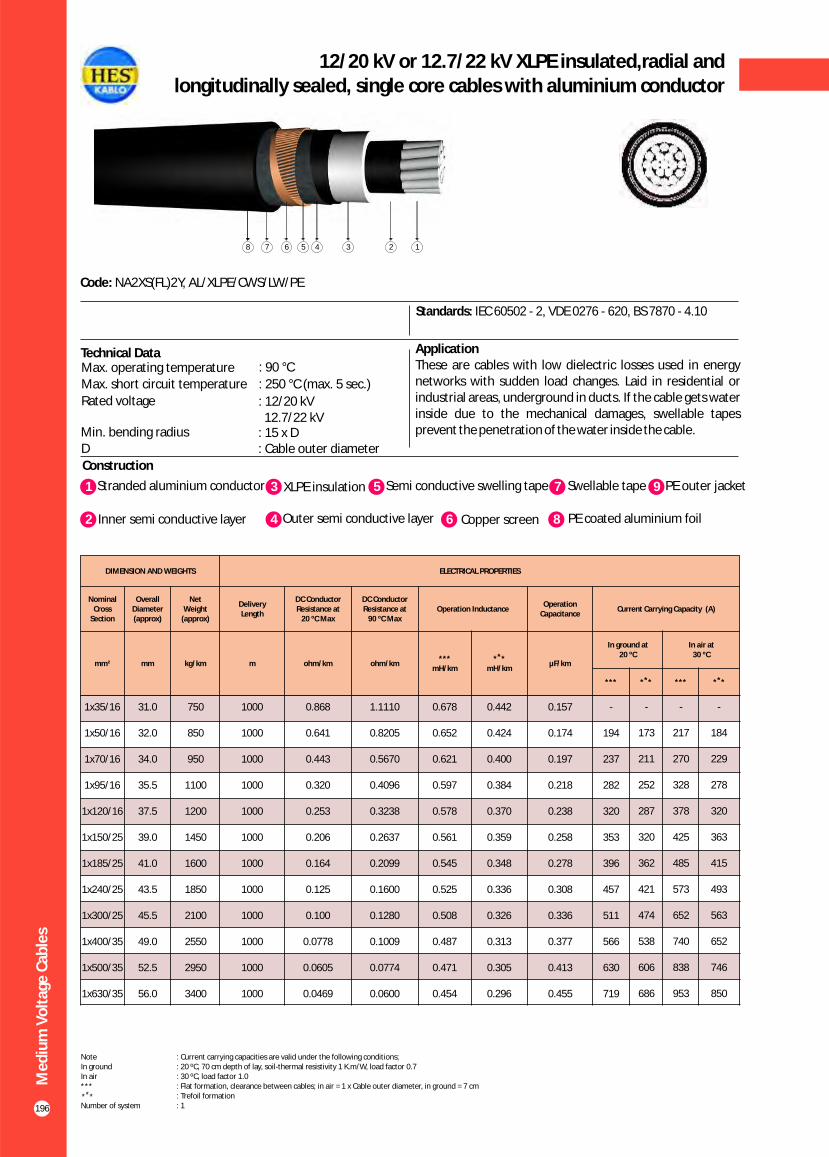
196
12/20 kV or 12.7/22 kV XLPE insulated,radial andlongitudinally sealed, single core cables with aluminium conductor
Construction
Code: NA2XS(FL)2Y, AL/XLPE/CWS/LW/PE
Standards: IEC 60502 - 2, VDE 0276 - 620, BS 7870 - 4.10
Application These are cables with low dielectric losses used in energy networks with sudden load changes. Laid in residential or industrial areas, underground in ducts. If the cable gets water inside due to the mechanical damages, swellable tapes prevent the penetration of the water inside the cable.
Technical DataMax. operating temperature : 90 °C
Max. short circuit temperature : 250 °C (max. 5 sec.)
Rated voltage : 12.7/22 kV 12/20 kV
Min. bending radius : 15 x DD : Cable outer diameter
Me
diu
m V
olt
age
Cab
les
DIMENSION AND WEIGHTS ELECTRICAL PROPERTIES
Nominal Cross
Section
Overall Diameter (approx)
Net Weight
(approx)
Delivery Length
DC Conductor Resistance at
20 ºC Max
DC Conductor Resistance at
90 ºC MaxOperation Inductance
Operation Capacitance
Current Carrying Capacity (A)
mm² mm kg/km m ohm/km ohm/km***
mH/km
** *mH/km
µF/km
In ground at 20 ºC
In air at30 ºC
*** ** * *** ** *
1x35/16
1x50/16
1x70/16
1x95/16
1x120/16
1x150/25
1x185/25
1x240/25
1x300/25
1x400/35
1x500/35
1x630/35
31.0
32.0
34.0
35.5
37.5
39.0
41.0
43.5
45.5
49.0
52.5
56.0
750
850
950
1100
1200
1450
1600
1850
2100
2550
2950
3400
1000
1000
1000
1000
1000
1000
1000
1000
1000
1000
1000
1000
0.868
0.641
0.443
0.320
0.253
0.206
0.164
0.125
0.100
0.0778
0.0605
0.0469
1.1110
0.8205
0.5670
0.4096
0.3238
0.2637
0.2099
0.1600
0.1280
0.1009
0.0774
0.0600
0.678
0.652
0.621
0.597
0.578
0.561
0.545
0.525
0.508
0.487
0.471
0.454
0.442
0.424
0.400
0.384
0.370
0.359
0.348
0.336
0.326
0.313
0.305
0.296
0.157
0.174
0.197
0.218
0.238
0.258
0.278
0.308
0.336
0.377
0.413
0.455
-
194
237
282
320
353
396
457
511
566
630
719
-
173
211
252
287
320
362
421
474
538
606
686
-
217
270
328
378
425
485
573
652
740
838
953
-
184
229
278
320
363
415
493
563
652
746
850
1 3Stranded aluminium conductor XLPE insulation
2 Inner semi conductive layer 4 Outer semi conductive layer
5 Semi conductive swelling tape
6 Copper screen
7 Swellable tape
8 PE coated aluminium foil
9 PE outer jacket
Note : Current carrying capacities are valid under the following conditions;In ground : 20 ºC, 70 cm depth of lay, soil-thermal resistivity 1 K.m/W, load factor 0.7In air : 30 ºC, load factor 1.0*** : Flat formation, clearance between cables; in air = 1 x Cable outer diameter, in ground = 7 cm : Trefoil formationNumber of system : 1
** *
12345678

197
18/30 kV or 19/33 kV XLPE insulated, radial and longitudinally sealed, single core cables with aluminium conductor
Construction
Code: NA2XS(FL)2Y, AL/XLPE/CWS/LW/PE
Standards: IEC 60502 - 2, VDE 0276 - 620, BS 7870 - 4.10
Application These are cables with low dielectric losses used in energy networks with sudden load changes. Laid in residential or industrial areas, underground in ducts. If the cable gets water inside due to the mechanical damages, swellable tapes prevent the penetration of the water inside the cable.
Technical Data
Me
diu
m V
olt
age
Cab
les
DIMENSION AND WEIGHTS ELECTRICAL PROPERTIES
Nominal Cross
Section
Overall Diameter (approx)
Net Weight
(approx)
Delivery Length
DC Conductor Resistance at
20 ºC Max
DC Conductor Resistance at
90 ºC MaxOperation Inductance
Operation Capacitance
Current Carrying Capacity (A)
mm² mm kg/km m ohm/km ohm/km***
mH/km
** *mH/km
µF/km
In ground at 20 ºC
In air at30 ºC
*** ** * *** ** *
1x35/16
1x50/16
1x70/16
1x95/16
1x120/16
1x150/25
1x185/25
1x240/25
1x300/25
1x400/35
1x500/35
1x630/35
36.5
37.5
39.5
41.0
43.0
44.5
46.5
49.5
51.5
55.0
58.0
62.0
950
1100
1250
1350
1500
1750
1900
2150
2450
2950
3350
3850
1000
1000
1000
1000
1000
1000
1000
1000
1000
1000
1000
1000
0.868
0.641
0.443
0.320
0.253
0.206
0.164
0.125
0.100
0.0778
0.0605
0.0469
1.1110
0.8205
0.5670
0.4096
0.3238
0.2637
0.2099
0.1600
0.1280
0.1009
0.0774
0.0600
0.688
0.662
0.631
0.607
0.588
0.570
0.554
0.534
0.517
0.495
0.479
0.463
0.474
0.453
0.429
0.410
0.397
0.383
0.372
0.359
0.347
0.334
0.324
0.314
0.123
0.135
0.151
0.166
0.180
0.194
0.208
0.229
0.248
0.276
0.301
0.330
-
196
238
284
322
355
400
461
516
592
638
728
-
175
214
256
290
324
366
426
478
545
614
690
-
217
270
328
378
425
485
572
649
737
835
950
-
187
232
281
323
365
418
494
564
654
747
851
1 3Stranded aluminium conductor XLPE insulation
2 Inner semi conductive layer 4 Outer semi conductive layer
5 Semi conductive swelling tape
6 Copper screen
7 Swellable tape
8 PE coated aluminium foil
9 PE outer jacket
Note : Current carrying capacities are valid under the following conditions;In ground : 20 ºC, 70 cm depth of lay, soil-thermal resistivity 1 K.m/W, load factor 0.7In air : 30 ºC, load factor 1.0*** : Flat formation, clearance between cables; in air = 1 x Cable outer diameter, in ground = 7 cm : Trefoil formationNumber of system : 1
** *
Max. operating temperature : 90 °C
Max. short circuit temperature : 250 °C (max. 5 sec.)
Rated voltage : 18/30 kV 19/33 kV
Min. bending radius : 15 x DD : Cable outer diameter
12345678

198
20.3/35 kV or 20.8/36 kV XLPE insulated, radial and longitudinally sealed, single core cables with aluminium conductor
Construction
Code: NA2XS(FL)2Y, AL/XLPE/CWS/LW/PE
Standards: HD 620 S2, TSEK
Application These are cables with low dielectric losses used in energy networks with sudden load changes. Laid in residential or industrial areas, underground in ducts. If the cable gets water inside due to the mechanical damages, swellable tapes prevent the penetration of the water inside the cable.
Technical DataMax. operating temperature : 90 °C
Max. short circuit temperature : 250 °C (max. 5 sec.)
Rated voltage : 20.3/35 kV 20.8/36 kV
Min. bending radius : 15 x DD : Cable outer diameter
Me
diu
m V
olt
age
Cab
les
DIMENSION AND WEIGHTS ELECTRICAL PROPERTIES
Nominal Cross
Section
Overall Diameter (approx)
Net Weight
(approx)
Delivery Length
DC Conductor Resistance at
20 ºC Max
DC Conductor Resistance at
90 ºC MaxOperation Inductance
Operation Capacitance
Current Carrying Capacity (A)
mm² mm kg/km m ohm/km ohm/km***
mH/km
** *mH/km
µF/km
In ground at 20 ºC
In air at30 ºC
*** ** * *** ** *
1x35/16
1x50/16
1x70/16
1x95/16
1x120/16
1x150/25
1x185/25
1x240/25
1x300/25
1x400/35
1x500/35
1x630/35
38.5
39.5
41.5
43.0
45.0
46.5
48.5
51.0
53.0
56.5
60.0
63.5
1100
1200
1350
1500
1650
1900
2050
2300
2600
3100
3550
4050
1000
1000
1000
1000
1000
1000
1000
1000
1000
1000
1000
1000
0.868
0.641
0.443
0.320
0.253
0.206
0.164
0.125
0.100
0.0778
0.0605
0.0469
1.1110
0.8205
0.5670
0.4096
0.3238
0.2637
0.2099
0.1600
0.1280
0.1009
0.0774
0.0600
0.692
0.666
0.635
0.611
0.591
0.574
0.558
0.537
0.520
0.499
0.483
0.466
0.486
0.464
0.439
0.420
0.405
0.393
0.381
0.366
0.355
0.341
0.331
0.320
0.115
0.125
0.140
0.153
0.165
0.178
0.191
0.209
0.226
0.252
0.274
0.300
-
196
238
284
322
355
400
461
516
572
638
728
-
175
214
256
290
324
366
426
479
545
614
690
-
217
270
328
378
425
485
572
649
737
835
950
-
187
232
281
323
365
418
494
564
654
747
851
1 3Stranded aluminium conductor XLPE insulation
2 Inner semi conductive layer 4 Outer semi conductive layer
5 Semi conductive swelling tape
6 Copper screen
7 Swellable tape
8 PE coated aluminium foil
9 PE outer jacket
Note : Current carrying capacities are valid under the following conditions;In ground : 20 ºC, 70 cm depth of lay, soil-thermal resistivity 1 K.m/W, load factor 0.7In air : 30 ºC, load factor 1.0*** : Flat formation, clearance between cables; in air = 1 x Cable outer diameter, in ground = 7 cm : Trefoil formationNumber of system : 1
** *
12345678

199
3.6/6 kV XLPE insulated round aluminium wire armouredsingle core cables with aluminium conductor
Construction
Code: NA2XSYR(A)Y, AL/XLPE/CWS/PVC/AWA/PVC
Standards: IEC 60502 - 2, VDE 0276 - 620, BS 6622
ApplicationThese are cables with low dielectric losses used in energy networks with sudden load changes. Laid in residential or industrial areas, underground in ducts.
1 4Stranded aluminium conductor Outer semi conductive layer
2 Inner semi conductive layer 5 Semi conductive tape
7 Polyester tape
8 Inner sheath
10 Polyester tape
11 PVC outer jacket
Technical DataMax. operating temperature : 90 °C
Max. short circuit temperature : 250 °C (max. 5 sec.)
Rated voltage : 3.6/6 kV
Min. bending radius : 15 x DD : Cable outer diameter
3 XLPE insulation 6 Copper screen 9 Round aluminium wire
1234567891011
Me
diu
m V
olt
age
Cab
les
DIMENSION AND WEIGHTS ELECTRICAL PROPERTIES
Nominal Cross
Section
Overall Diameter (approx)
Net Weight
(approx)
Delivery Length
DC Conductor Resistance at
20 ºC Max
DC Conductor Resistance at
90 ºC MaxOperation Inductance
Operation Capacitance
Current Carrying Capacity (A)
mm² mm kg/km m ohm/km ohm/km***
mH/km
** *mH/km
µF/km
In ground at 20 ºC
In air at30 ºC
*** ** * *** ** *
1x35/16
1x50/16
1x70/16
1x95/16
1x120/16
1x150/25
1x185/25
1x240/25
1x300/25
1x400/35
1x500/35
1x630/35
26.2
27.3
29.0
31.0
32.3
34.7
36.6
39.4
41.8
46.9
50.6
54.5
926
1000
1123
1270
1390
1705
1890
2177
2443
3159
3645
4291
1000
1000
1000
1000
1000
1000
1000
1000
1000
500
500
500
0.868
0.641
0.443
0.320
0.253
0.206
0.164
0.125
0.100
0.0778
0.0605
0.0469
1.1110
0.8205
0.5670
0.4096
0.3238
0.2637
0.2099
0.1600
0.1280
0.1009
0.0774
0.0600
0.657
0.632
0.601
0.577
0.558
0.541
0.525
0.506
0.490
0.471
0.456
0.440
0.367
0.351
0.332
0.318
0.308
0.299
0.292
0.284
0.279
0.275
0.270
0.264
0.283
0.318
0.368
0.414
0.455
0.499
0.544
0.587
0.603
0.642
0.667
0.739
-
186
234
287
338
388
449
530
605
678
762
858
-
178
217
259
298
333
377
438
495
562
633
712
-
233
280
344
392
441
510
587
682
781
883
1007
-
188
235
286
329
376
428
508
586
676
772
882
Note : Current carrying capacities are valid under the following conditions;In ground : 20 ºC, 70 cm depth of lay, soil-thermal resistivity 1 K.m/W, load factor 0.7In air : 30 ºC, load factor 1.0*** : Flat formation, clearance between cables; in air = 1 x Cable outer diameter, in ground = 7 cm : Trefoil formationNumber of system : 1
** *

200
5.8/10 kV (6/10 kV) XLPE insulated round aluminium wire armouredsingle core cables with aluminium conductor
Construction
Code: NA2XSYR(A)Y, AL/XLPE/CWS/PVC/AWA/PVC
Standards: IEC 60502 - 2, VDE 0276 - 620, BS 6622
ApplicationThese are cables with low dielectric losses used in energy networks with sudden load changes. Laid in residential or industrial areas, underground in ducts.
Technical DataMax. operating temperature : 90 °C
Max. short circuit temperature : 250 °C (max. 5 sec.)
Rated voltage : 5.8/10 kV (6/10 kV)
Min. bending radius : 15 x DD : Cable outer diameter
1234567891011
Me
diu
m V
olt
age
Cab
les
DIMENSION AND WEIGHTS ELECTRICAL PROPERTIES
Nominal Cross
Section
Overall Diameter (approx)
Net Weight
(approx)
Delivery Length
DC Conductor Resistance at
20 ºC Max
DC Conductor Resistance at
90 ºC MaxOperation Inductance
Operation Capacitance
Current Carrying Capacity (A)
mm² mm kg/km m ohm/km ohm/km***
mH/km
** *mH/km
µF/km
In ground at 20 ºC
In air at30 ºC
*** ** * *** ** *
1x35/16
1x50/16
1x70/16
1x95/16
1x120/16
1x150/25
1x185/25
1x240/25
1x300/25
1x400/35
1x500/35
1x630/35
28.0
29.3
31.0
32.9
35.1
36.7
38.4
41.0
43.2
47.7
51.0
55.0
1015
1106
1230
1392
1600
1835
2013
2286
2556
3227
3674
4365
1000
1000
1000
1000
1000
1000
1000
1000
1000
500
500
500
0.868
0.641
0.443
0.320
0.253
0.206
0.164
0.125
0.100
0.0778
0.0605
0.0469
1.1110
0.8205
0.5670
0.4096
0.3238
0.2637
0.2099
0.1600
0.1280
0.1009
0.0774
0.0600
0.657
0.632
0.601
0.577
0.558
0.541
0.525
0.506
0.490
0.471
0.456
0.440
0.367
0.351
0.332
0.318
0.308
0.299
0.292
0.284
0.279
0.275
0.270
0.264
0.223
0.248
0.285
0.320
0.350
0.382
0.415
0.462
0.507
0.573
0.631
0.699
-
194
236
281
318
350
393
453
507
559
622
697
-
171
209
249
283
316
358
416
469
532
599
679
-
215
269
327
377
424
485
573
652
741
838
957
-
181
226
275
317
359
412
489
559
651
744
851
1 4Stranded aluminium conductor Outer semi conductive layer
2 Inner semi conductive layer 5 Semi conductive tape
7 Polyester tape
8 Inner sheath
10 Polyester tape
11 PVC outer jacket
3 XLPE insulation 6 Copper screen 9 Round aluminium wire
Note : Current carrying capacities are valid under the following conditions;In ground : 20 ºC, 70 cm depth of lay, soil-thermal resistivity 1 K.m/W, load factor 0.7In air : 30 ºC, load factor 1.0*** : Flat formation, clearance between cables; in air = 1 x Cable outer diameter, in ground = 7 cm : Trefoil formationNumber of system : 1
** *

201
8.7/15 kV XLPE insulated round aluminium wire armouredsingle core cables with aluminium conductor
Construction
Code: NA2XSYR(A)Y, AL/XLPE/CWS/PVC/AWA/PVC
Standards: IEC 60502 - 2, VDE 0276 - 620, BS 6622
ApplicationThese are cables with low dielectric losses used in energy networks with sudden load changes. Laid in residential or industrial areas, underground in ducts.
Technical DataMax. operating temperature : 90 °C
Max. short circuit temperature : 250 °C (max. 5 sec.)
Rated voltage : 8.7/15 kV
Min. bending radius : 15 x DD : Cable outer diameter
1234567891011
Me
diu
m V
olt
age
Cab
les
DIMENSION AND WEIGHTS ELECTRICAL PROPERTIES
Nominal Cross
Section
Overall Diameter (approx)
Net Weight
(approx)
Delivery Length
DC Conductor Resistance at
20 ºC Max
DC Conductor Resistance at
90 ºC MaxOperation Inductance
Operation Capacitance
Current Carrying Capacity (A)
mm² mm kg/km m ohm/km ohm/km***
mH/km
** *mH/km
µF/km
In ground at 20 ºC
In air at30 ºC
*** ** * *** ** *
1x35/16
1x50/16
1x70/16
1x95/16
1x120/16
1x150/25
1x185/25
1x240/25
1x300/25
1x400/35
1x500/35
1x630/35
30.4
31.5
33.4
36.1
37.6
39.1
40.8
43.8
46.8
50.0
53.6
57.3
1145
1224
1374
1628
1766
2008
2183
2477
2922
3446
3931
4588
1000
1000
1000
1000
1000
1000
1000
1000
1000
500
500
500
0.868
0.641
0.443
0.320
0.253
0.206
0.164
0.125
0.100
0.0778
0.0605
0.0469
1.1110
0.8205
0.5670
0.4096
0.3238
0.2637
0.2099
0.1600
0.1280
0.1009
0.0774
0.0600
0.657
0.632
0.601
0.577
0.558
0.541
0.525
0.506
0.490
0.471
0.456
0.440
0.367
0.351
0.332
0.318
0.308
0.299
0.292
0.284
0.279
0.275
0.270
0.264
0.181
0.201
0.229
0.255
0.278
0.302
0.328
0.363
0.398
0.447
0.491
0.543
-
194
236
281
318
350
393
453
507
559
622
697
-
171
209
249
283
316
358
416
469
532
599
679
-
215
269
327
377
424
485
573
652
741
838
957
-
181
226
275
317
359
412
489
559
651
744
851
1 4Stranded aluminium conductor Outer semi conductive layer
2 Inner semi conductive layer 5 Semi conductive tape
7 Polyester tape
8 Inner sheath
10 Polyester tape
11 PVC outer jacket
3 XLPE insulation 6 Copper screen 9 Round aluminium wire
Note : Current carrying capacities are valid under the following conditions;In ground : 20 ºC, 70 cm depth of lay, soil-thermal resistivity 1 K.m/W, load factor 0.7In air : 30 ºC, load factor 1.0*** : Flat formation, clearance between cables; in air = 1 x Cable outer diameter, in ground = 7 cm : Trefoil formationNumber of system : 1
** *

202
12/20 kV or 12.7/22 kV XLPE insulated round aluminium wire armoured single core cables with aluminium conductor
Construction
Code: NA2XSYR(A)Y, AL/XLPE/CWS/PVC/AWA/PVC
Standards: IEC 60502 - 2, VDE 0276 - 620, BS 6622
ApplicationThese are cables with low dielectric losses used in energy networks with sudden load changes. Laid in residential or industrial areas, underground in ducts.
Technical DataMax. operating temperature : 90 °C
Max. short circuit temperature : 250 °C (max. 5 sec.)
Rated voltage : 12.7/22 kV 12/20 kV
Min. bending radius : 15 x DD : Cable outer diameter
1234567891011
Me
diu
m V
olt
age
Cab
les
DIMENSION AND WEIGHTS ELECTRICAL PROPERTIES
Nominal Cross
Section
Overall Diameter (approx)
Net Weight
(approx)
Delivery Length
DC Conductor Resistance at
20 ºC Max
DC Conductor Resistance at
90 ºC MaxOperation Inductance
Operation Capacitance
Current Carrying Capacity (A)
mm² mm kg/km m ohm/km ohm/km***
mH/km
** *mH/km
µF/km
In ground at 20 ºC
In air at30 ºC
*** ** * *** ** *
1x35/16
1x50/16
1x70/16
1x95/16
1x120/16
1x150/25
1x185/25
1x240/25
1x300/25
1x400/35
1x500/35
1x630/35
32.6
34.5
36.4
38.1
39.8
41.1
43.0
46.8
48.9
52.4
55.8
56.0
1275
1440
1610
1760
1915
2150
2355
2820
3110
3670
4155
4845
1000
1000
1000
1000
1000
1000
1000
1000
1000
500
500
500
0.868
0.641
0.443
0.320
0.253
0.206
0.164
0.125
0.100
0.0778
0.0605
0.0469
1.111
0.8205
0.5670
0.4096
0.3238
0.2637
0.2099
0.1600
0.1280
0.1009
0.0774
0.0600
0.657
0.632
0.601
0.577
0.558
0.541
0.525
0.506
0.490
0.471
0.456
0.440
0.367
0.351
0.332
0.318
0.308
0.299
0.292
0.284
0.279
0.275
0.270
0.264
0.123
0.135
0.151
0.166
0.180
0.194
0.208
0.229
0.248
0.276
0.301
0.330
-
195
237
282
320
353
396
457
511
566
630
719
-
173
211
252
287
320
362
421
474
538
606
686
-
217
270
328
378
425
485
573
652
740
838
953
-
184
229
278
320
363
415
493
563
652
746
850
1 4Stranded aluminium conductor Outer semi conductive layer
2 Inner semi conductive layer 5 Semi conductive tape
7 Polyester tape
8 Inner sheath
10 Polyester tape
11 PVC outer jacket
3 XLPE insulation 6 Copper screen 9 Round aluminium wire
Note : Current carrying capacities are valid under the following conditions;In ground : 20 ºC, 70 cm depth of lay, soil-thermal resistivity 1 K.m/W, load factor 0.7In air : 30 ºC, load factor 1.0*** : Flat formation, clearance between cables; in air = 1 x Cable outer diameter, in ground = 7 cm : Trefoil formationNumber of system : 1
** *

203
18/30 kV or 19/33 kV XLPE insulated round aluminium wire armouredsingle core cables with aluminium conductor
Construction
Code: NA2XSYR(A)Y, AL/XLPE/CWS/PVC/AWA/PVC
Standards: IEC 60502 - 2, VDE 0276 - 620, BS 6622
ApplicationThese are cables with low dielectric losses used in energy networks with sudden load changes. Laid in residential or industrial areas, underground in ducts.
Technical Data
1234567891011
Me
diu
m V
olt
age
Cab
les
DIMENSION AND WEIGHTS ELECTRICAL PROPERTIES
Nominal Cross
Section
Overall Diameter (approx)
Net Weight
(approx)
Delivery Length
DC Conductor Resistance at
20 ºC Max
DC Conductor Resistance at
90 ºC MaxOperation Inductance
Operation Capacitance
Current Carrying Capacity (A)
mm² mm kg/km m ohm/km ohm/km***
mH/km
** *mH/km
µF/km
In ground at 20 ºC
In air at30 ºC
*** ** * *** ** *
1x50/16
1x70/16
1x95/16
1x120/16
1x150/25
1x185/25
1x240/25
1x300/25
1x400/35
1x500/35
1x630/35
39.9
41.8
43.5
46.4
48.0
49.6
52.4
54.6
58.0
61.2
66.0
1815
1990
2165
2499
2769
2977
3332
3640
4235
4748
5480
1000
1000
1000
1000
1000
1000
1000
500
500
500
500
0.6410
0.4430
0.3200
0.2530
0.2060
0.1640
0.1250
0.1000
0.0778
0.0605
0.0469
0.8205
0.5670
0.4096
0.3238
0.2637
0.2099
0.1600
0.1280
0.1009
0.0774
0.0600
0.632
0.601
0.577
0.558
0.541
0.525
0.506
0.490
0.471
0.456
0.440
0.351
0.332
0.318
0.308
0.299
0.292
0.284
0.279
0.275
0.270
0.264
0.135
0.151
0.166
0.180
0.194
0.208
0.229
0.248
0.276
0.301
0.330
196
238
284
322
355
400
461
516
572
638
728
175
214
256
290
324
366
426
479
545
614
690
217
270
328
378
425
485
572
649
737
835
950
187
202
281
323
365
418
494
564
454
747
851
1 4Stranded aluminium conductor Outer semi conductive layer
2 Inner semi conductive layer 5 Semi conductive tape
7 Polyester tape
8 Inner sheath
10 Polyester tape
11 PVC outer jacket
3 XLPE insulation 6 Copper screen 9 Round aluminium wire
Note : Current carrying capacities are valid under the following conditions;In ground : 20 ºC, 70 cm depth of lay, soil-thermal resistivity 1 K.m/W, load factor 0.7In air : 30 ºC, load factor 1.0*** : Flat formation, clearance between cables; in air = 1 x Cable outer diameter, in ground = 7 cm : Trefoil formationNumber of system : 1
** *
Max. operating temperature : 90 °C
Max. short circuit temperature : 250 °C (max. 5 sec.)
Rated voltage : 18/30 kV 19/33 kV
Min. bending radius : 15 x DD : Cable outer diameter

204
20.3/35 kV or 20.8/36 kV XLPE insulated round aluminium wire armoured single core cables with aluminium conductor
Construction
Code: NA2XSYR(A)Y, AL/XLPE/CWS/PVC/AWA/PVC
Standards: HD 620 S2, TSEK
ApplicationThese are cables with low dielectric losses used in energy networks with sudden load changes. Laid in residential or industrial areas, underground in ducts.
Technical DataMax. operating temperature : 90 °C
Max. short circuit temperature : 250 °C (max. 5 sec.)
Rated voltage : 20.3/35 kV 20.8/36 kV
Min. bending radius : 15 x DD : Cable outer diameter
1234567891011
Me
diu
m V
olt
age
Cab
les
DIMENSION AND WEIGHTS ELECTRICAL PROPERTIES
Nominal Cross
Section
Overall Diameter (approx)
Net Weight
(approx)
Delivery Length
DC Conductor Resistance at
20 ºC Max
DC Conductor Resistance at
90 ºC MaxOperation Inductance
Operation Capacitance
Current Carrying Capacity (A)
mm² mm kg/km m ohm/km ohm/km***
mH/km
** *mH/km
µF/km
In ground at 20 ºC
In air at30 ºC
*** ** * *** ** *
1x35/16
1x50/16
1x70/16
1x95/16
1x120/16
1x150/25
1x185/25
1x240/25
1x300/25
1x400/35
1x500/35
1x630/35
42.0
44.1
45.8
48.2
50.5
52.1
54.2
56.6
58.5
62.3
65.8
68.0
1860
1980
2140
2510
2698
2940
3210
3555
3845
4475
5035
5755
1000
1000
1000
1000
1000
1000
1000
1000
500
500
500
500
0.868
0.641
0.443
0.320
0.253
0.206
0.164
0.125
0.100
0.0778
0.0605
0.0469
1.111
0.8205
0.5670
0.4096
0.3238
0.2637
0.2099
0.1600
0.1280
0.1009
0.0774
0.0600
0.657
0.632
0.601
0.577
0.558
0.541
0.525
0.506
0.490
0.471
0.456
0.440
0.367
0.351
0.332
0.318
0.308
0.299
0.292
0.284
0.279
0.275
0.270
0.264
0.115
0.125
0.140
0.153
0.165
0.178
0.191
0.209
0.226
0.252
0.274
0.300
-
196
238
284
322
355
400
461
516
572
638
728
-
175
214
256
290
324
366
426
479
545
614
690
-
217
270
328
378
425
485
572
649
737
835
950
-
187
202
281
323
365
418
494
564
654
747
851
1 4Stranded aluminium conductor Outer semi conductive layer
2 Inner semi conductive layer 5 Semi conductive tape
7 Polyester tape
8 Inner sheath
10 Polyester tape
11 PVC outer jacket
3 XLPE insulation 6 Copper screen 9 Round aluminium wire
Note : Current carrying capacities are valid under the following conditions;In ground : 20 ºC, 70 cm depth of lay, soil-thermal resistivity 1 K.m/W, load factor 0.7In air : 30 ºC, load factor 1.0*** : Flat formation, clearance between cables; in air = 1 x Cable outer diameter, in ground = 7 cm : Trefoil formationNumber of system : 1
** *

205
3.6/6 kV XLPE insulatedthree core cables with aluminium conductor
Construction
Code: YAXC8V-R, NA2XSEY, AL/XLPE/CTS/PVC
Standards: IEC 60502 - 2, VDE 0276 - 620, BS 6622
ApplicationThese are cables with low dielectric losses used in energy networks with sudden load changes. Laid in residential or industrial areas, underground in ducts.
Technical DataMax. operating temperature : 90 °C
Max. short circuit temperature : 250 °C (max. 5 sec.)
Rated voltage : 3.6/6 kVMin. bending radius : 15 x DD : Cable outer diameter
1 3Stranded aluminium conductor XLPE insulation
2 Inner semi conductive layer 4 Outer semi conductive layer
5 Semi conductive tape
6 Copper screen
7 Filler
8 PVC outer jacket
R: Stranded Conductor Rigid
12345678
Me
diu
m V
olt
age
Cab
les
DIMENSION AND WEIGHTS ELECTRICAL PROPERTIES
Nominal Cross Section
Overall Diameter (approx)
Net Weight (approx)
Delivery Length
DC Conductor
Resistance at20 ºC Max
Operation Inductance
(approx)
Operation Capacitance
(approx)
Current Carrying Capacity (A)
mm² mm kg/km m ohm/km mH/km µF/kmIn ground at
20 ºCIn air at
30 ºC
0.229
0.255
0.288
0.324
0.359
0.388
0.424
0.469
0.486
0.521
3x35/16
3x50/16
3x70/16
3x95/16
3x120/16
3x150/25
3x185/25
3x240/25
3x300/25
3x400/35
42.0
45.0
48.5
53.0
57.0
60.5
64.5
71.0
77.5
86.0
2050
2400
2850
3400
4000
4500
5150
6300
7600
9400
1000
1000
1000
1000
1000
1000
500
500
500
500
0.868
0.641
0.443
0.320
0.253
0.206
0.164
0.125
0.100
0.0778
0.352
0.336
0.318
0.303
0.292
0.284
0.276
0.267
0.263
0.257
-
160
199
238
275
307
349
410
460
520
-
150
191
236
273
313
360
426
528
564
Note : Current carrying capacities are valid under the following conditions;In ground : 20 ºC, 70 cm depth of lay, soil-thermal resistivity 1 K.m/W, load factor 0.7In air : 30 ºC, load factor 1.0Number of system : 1

206
5.8/10 kV (6/10 kV) or 6.35/11 kV XLPE insulatedthree core cables with aluminium conductor
Construction
Code: YAXC8V-R, NA2XSEY, AL/XLPE/CTS/PVC
Standards: IEC 60502 - 2, VDE 0276 - 620, BS 6622
ApplicationThese are cables with low dielectric losses used in energy networks with sudden load changes. Laid in residential or industrial areas, underground in ducts.
R: Stranded Conductor Rigid
Technical Data
Max. operating temperature : 90 °CMax. short circuit temperature : 250 °C (max. 5 sec.)
Rated voltage : 5.8/10 kV (6/10 kV) 6.35/11 kV
Min. bending radius : 15 x DD : Cable outer diameter
Me
diu
m V
olt
age
Cab
les
DIMENSION AND WEIGHTS ELECTRICAL PROPERTIES
Nominal Cross Section
Overall Diameter (approx)
Net Weight (approx)
Delivery Length
DC Conductor
Resistance at20 ºC Max
Operation Inductance
(approx)
Operation Capacitance
(approx)
Current Carrying Capacity (A)
mm² mm kg/km m ohm/km mH/km µF/kmIn ground at
20 ºCIn air at
30 ºC
0.189
0.209
0.236
0.263
0.291
0.314
0.341
0.387
0.422
0.475
3x35/16
3x50/16
3x70/16
3x95/16
3x120/16
3x150/25
3x185/25
3x240/25
3x300/25
3x400/35
46.5
49.5
53.0
57.5
61.5
64.5
68.5
75.0
80.0
88.0
2450
2800
3300
3900
4450
5050
5700
6900
8000
9750
1000
1000
1000
1000
1000
500
500
500
500
500
0.868
0.641
0.443
0.320
0.253
0.206
0.164
0.125
0.100
0.0778
0.374
0.355
0.336
0.320
0.308
0.299
0.290
0.278
0.270
0.261
-
162
199
238
271
304
345
401
453
517
-
160
199
242
280
318
365
431
494
569
1 3Stranded aluminium conductor XLPE insulation
2 Inner semi conductive layer 4 Outer semi conductive layer
5 Semi conductive tape
6 Copper screen
7 Filler
8 PVC outer jacket
Note : Current carrying capacities are valid under the following conditions;In ground : 20 ºC, 70 cm depth of lay, soil-thermal resistivity 1 K.m/W, load factor 0.7In air : 30 ºC, load factor 1.0Number of system : 1
12345678

207
8.7/15 kV XLPE insulatedthree core cables with aluminium conductor
Construction
Code: YAXC8V-R, NA2XSEY, AL/XLPE/CTS/PVC
Standards: IEC 60502 - 2, VDE 0276 - 620, BS 6622
ApplicationThese are cables with low dielectric losses used in energy networks with sudden load changes. Laid in residential or industrial areas, underground in ducts.
Technical DataMax. operating temperature : 90 °C
Max. short circuit temperature : 250 °C (max. 5 sec.)
Rated voltage : 8.7/15 kVMin. bending radius : 15 x DD : Cable outer diameter
R: Stranded Conductor Rigid
Me
diu
m V
olt
age
Cab
les
DIMENSION AND WEIGHTS ELECTRICAL PROPERTIES
Nominal Cross Section
Overall Diameter (approx)
Net Weight (approx)
Delivery Length
DC Conductor
Resistance at20 ºC Max
Operation Inductance
(approx)
Operation Capacitance
(approx)
Current Carrying Capacity (A)
mm² mm kg/km m ohm/km mH/km µF/kmIn ground at
20 ºCIn air at
30 ºC
0.160
0.175
0.196
0.218
0.240
0.258
0.280
0.315
0.343
0.385
3x35/16
3x50/16
3x70/16
3x95/16
3x120/16
3x150/25
3x185/25
3x240/25
3x300/25
3x400/35
51.5
54.5
58.5
62.5
66.5
69.5
74.0
80.0
85.0
93.0
2950
3400
3900
4500
5100
5700
6500
7700
8800
10650
1000
1000
1000
1000
500
500
500
500
500
250
0.868
0.641
0.443
0.320
0.253
0.206
0.164
0.125
0.100
0.0778
0.397
0.377
0.356
0.339
0.325
0.315
0.305
0.292
0.284
0.273
-
162
199
238
271
304
345
401
453
517
-
160
199
242
280
318
365
431
494
569
1 3Stranded aluminium conductor XLPE insulation
2 Inner semi conductive layer 4 Outer semi conductive layer
5 Semi conductive tape
6 Copper screen
7 Filler
8 PVC outer jacket
Note : Current carrying capacities are valid under the following conditions;In ground : 20 ºC, 70 cm depth of lay, soil-thermal resistivity 1 K.m/W, load factor 0.7In air : 30 ºC, load factor 1.0Number of system : 1
12345678

208
12/20 kV or 12.7/22 kV XLPE insulatedthree core cables with aluminium conductor
Construction
Code: YAXC8V-R, NA2XSEY, AL/XLPE/CTS/PVC
Standards: IEC 60502 - 2, VDE 0276 - 620, BS 6622
ApplicationThese are cables with low dielectric losses used in energy networks with sudden load changes. Laid in residential or industrial areas, underground in ducts.
R: Stranded Conductor Rigid
Technical Data
Max. operating temperature : 90 °C
Max. short circuit temperature : 250 °C (max. 5 sec.)
Rated voltage : 12.7/22 kV
12/20 kV
Min. bending radius : 15 x DD : Cable outer diameter
Me
diu
m V
olt
age
Cab
les
DIMENSION AND WEIGHTS ELECTRICAL PROPERTIES
Nominal Cross Section
Overall Diameter (approx)
Net Weight (approx)
Delivery Length
DC Conductor
Resistance at20 ºC Max
Operation Inductance
(approx)
Operation Capacitance
(approx)
Current Carrying Capacity (A)
mm² mm kg/km m ohm/km mH/km µF/kmIn ground at
20 ºCIn air at
30 ºC
0.141
0.155
0.172
0.191
0.209
0.225
0.243
0.273
0.296
0.331
3x35/16
3x50/16
3x70/16
3x95/16
3x120/16
3x150/25
3x185/25
3x240/25
3x300/25
3x400/35
56.5
59.5
63.0
67.0
71.0
74.0
78.0
85.0
90.0
98.0
3500
3900
4450
5100
5750
6450
7200
8450
9650
11600
1000
1000
1000
500
500
500
500
500
500
250
0.868
0.641
0.443
0.320
0.253
0.206
0.164
0.125
0.100
0.0778
0.416
0.395
0.373
0.355
0.340
0.329
0.319
0.304
0.295
0.284
-
168
207
247
282
316
359
420
476
552
-
171
211
255
297
334
384
454
513
593
1 3Stranded aluminium conductor XLPE insulation
2 Inner semi conductive layer 4 Outer semi conductive layer
5 Semi conductive tape
6 Copper screen
7 Filler
8 PVC outer jacket
Note : Current carrying capacities are valid under the following conditions;In ground : 20 ºC, 70 cm depth of lay, soil-thermal resistivity 1 K.m/W, load factor 0.7In air : 30 ºC, load factor 1.0Number of system : 1
12345678

209
18/30 kV or 19/33 kV XLPE insulatedthree core cables with aluminium conductor
Construction
Code: YAXC8V-R, NA2XSEY, AL/XLPE/CTS/PVC
Standards: IEC 60502 - 2, VDE 0276 - 620, BS 6622
ApplicationThese are cables with low dielectric losses used in energy networks with sudden load changes. Laid in residential or industrial areas, underground in ducts.
Technical Data
R: Stranded Conductor Rigid
Me
diu
m V
olt
age
Cab
les
DIMENSION AND WEIGHTS ELECTRICAL PROPERTIES
Nominal Cross Section
Overall Diameter (approx)
Net Weight (approx)
Delivery Length
DC Conductor
Resistance at20 ºC Max
Operation Inductance
(approx)
Operation Capacitance
(approx)
Current Carrying Capacity (A)
mm² mm kg/km m ohm/km mH/km µF/kmIn ground at
20 ºCIn air at
30 ºC
0.114
0.124
0.137
0.150
0.163
0.174
0.188
0.209
0.226
0.251
3x35/16
3x50/16
3x70/16
3x95/16
3x120/16
3x150/25
3x185/25
3x240/25
3x300/25
3x400/35
68.0
71.5
75.0
79.0
83.0
86.0
90.0
97.0
102.0
110.0
5000
5550
6200
6900
7650
8350
9200
10700
12000
14060
1000
500
500
500
500
500
500
250
250
250
0.868
0.641
0.443
0.320
0.253
0.206
0.164
0.125
0.100
0.0778
0.457
0.434
0.410
0.389
0.372
0.360
0.348
0.331
0.321
0.307
-
166
204
244
278
312
343
398
-
-
-
171
211
255
297
334
384
454
-
-
1 3Stranded aluminium conductor XLPE insulation
2 Inner semi conductive layer 4 Outer semi conductive layer
5 Semi conductive tape
6 Copper screen
7 Filler
8 PVC outer jacket
Note : Current carrying capacities are valid under the following conditions;In ground : 20 ºC, 70 cm depth of lay, soil-thermal resistivity 1 K.m/W, load factor 0.7In air : 30 ºC, load factor 1.0Number of system : 1
Max. operating temperature : 90 °C
Max. short circuit temperature : 250 °C (max. 5 sec.)
Rated voltage : 18/30 kV 19/33 kV
Min. bending radius : 15 x DD : Cable outer diameter
12345678
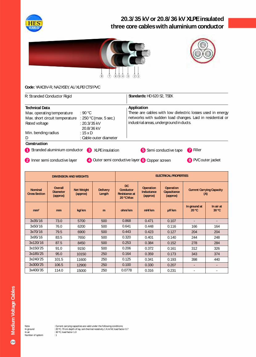
210
20.3/35 kV or 20.8/36 kV XLPE insulatedthree core cables with aluminium conductor
Construction
Code: YAXC8V-R, NA2XSEY, AL/XLPE/CTS/PVC
Standards: HD 620 S2, TSEK
ApplicationThese are cables with low dielectric losses used in energy networks with sudden load changes. Laid in residential or industrial areas, underground in ducts.
R: Stranded Conductor Rigid
Technical Data
Max. operating temperature : 90 °C
Max. short circuit temperature : 250 °C (max. 5 sec.)
Rated voltage : 20.3/35 kV 20.8/36 kV
Min. bending radius : 15 x DD : Cable outer diameter
Me
diu
m V
olt
age
Cab
les
DIMENSION AND WEIGHTS ELECTRICAL PROPERTIES
Nominal Cross Section
Overall Diameter (approx)
Net Weight (approx)
Delivery Length
DC Conductor
Resistance at20 ºC Max
Operation Inductance
(approx)
Operation Capacitance
(approx)
Current Carrying Capacity (A)
mm² mm kg/km m ohm/km mH/km µF/kmIn ground at
20 ºCIn air at
30 ºC
0.107
0.116
0.127
0.140
0.152
0.161
0.173
0.193
0.207
0.231
3x35/16
3x50/16
3x70/16
3x95/16
3x120/16
3x150/25
3x185/25
3x240/25
3x300/25
3x400/35
73.0
76.0
79.5
83.5
87.5
91.0
95.0
101.5
106.5
114.0
5700
6200
6900
7650
8450
9150
10150
11600
12900
15000
500
500
500
500
500
500
250
250
250
250
0.868
0.641
0.443
0.320
0.253
0.206
0.164
0.125
0.100
0.0778
0.471
0.448
0.423
0.401
0.384
0.372
0.359
0.341
0.330
0.316
-
166
204
244
278
312
343
398
-
-
-
164
204
248
284
326
374
440
-
-
1 3Stranded aluminium conductor XLPE insulation
2 Inner semi conductive layer 4 Outer semi conductive layer
5 Semi conductive tape
6 Copper screen
7 Filler
8 PVC outer jacket
Note : Current carrying capacities are valid under the following conditions;In ground : 20 ºC, 70 cm depth of lay, soil-thermal resistivity 1 K.m/W, load factor 0.7In air : 30 ºC, load factor 1.0Number of system : 1
12345678
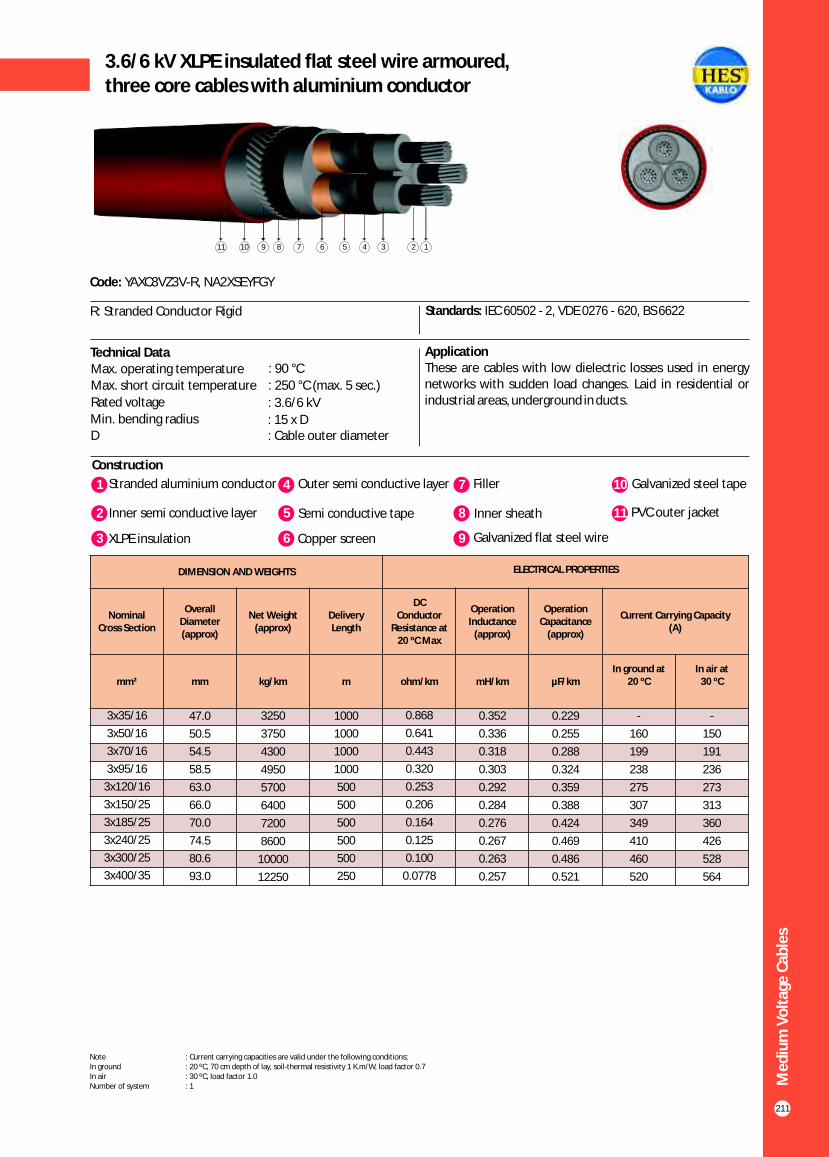
211
3.6/6 kV XLPE insulated flat steel wire armoured,three core cables with aluminium conductor
Construction
Code: YAXC8VZ3V-R, NA2XSEYFGY
Standards: IEC 60502 - 2, VDE 0276 - 620, BS 6622
ApplicationThese are cables with low dielectric losses used in energy networks with sudden load changes. Laid in residential or industrial areas, underground in ducts.
1 4Stranded aluminium conductor Outer semi conductive layer
2 Inner semi conductive layer 5 Semi conductive tape
7 Filler
8 Inner sheath
10 Galvanized steel tape
11 PVC outer jacket
Technical DataMax. operating temperature : 90 °C
Max. short circuit temperature : 250 °C (max. 5 sec.)
Rated voltage : 3.6/6 kVMin. bending radius : 15 x DD : Cable outer diameter
3 XLPE insulation 6 Copper screen 9 Galvanized flat steel wire
R: Stranded Conductor Rigid
12345678191011
Me
diu
m V
olt
age
Cab
les
DIMENSION AND WEIGHTS ELECTRICAL PROPERTIES
Nominal Cross Section
Overall Diameter (approx)
Net Weight (approx)
Delivery Length
DC Conductor
Resistance at20 ºC Max
Operation Inductance
(approx)
Operation Capacitance
(approx)
Current Carrying Capacity (A)
mm² mm kg/km m ohm/km mH/km µF/kmIn ground at
20 ºCIn air at
30 ºC
0.229
0.255
0.288
0.324
0.359
0.388
0.424
0.469
0.486
0.521
3x35/16
3x50/16
3x70/16
3x95/16
3x120/16
3x150/25
3x185/25
3x240/25
3x300/25
3x400/35
47.0
50.5
54.5
58.5
63.0
66.0
70.0
74.5
80.6
93.0
3250
3750
4300
4950
5700
6400
7200
8600
10000
12250
1000
1000
1000
1000
500
500
500
500
500
250
0.868
0.641
0.443
0.320
0.253
0.206
0.164
0.125
0.100
0.0778
0.352
0.336
0.318
0.303
0.292
0.284
0.276
0.267
0.263
0.257
-
160
199
238
275
307
349
410
460
520
-
150
191
236
273
313
360
426
528
564
Note : Current carrying capacities are valid under the following conditions;In ground : 20 ºC, 70 cm depth of lay, soil-thermal resistivity 1 K.m/W, load factor 0.7In air : 30 ºC, load factor 1.0Number of system : 1

212
5.8/10 kV (6/10 kV) XLPE insulated flat steel wire armoured,three core cables with aluminium conductor
Construction
Code: YAXC8VZ3V-R, NA2XSEYFGY
Standards: IEC 60502 - 2, VDE 0276 - 620, BS 6622
ApplicationThese are cables with low dielectric losses used in energy networks with sudden load changes. Laid in residential or industrial areas, underground in ducts.
Technical DataMax. operating temperature : 90 °C
Max. short circuit temperature : 250 °C (max. 5 sec.)
Rated voltage : 5.8/10 kV (6/10 kV)
Min. bending radius : 15 x DD : Cable outer diameter
R: Stranded Conductor Rigid
12345678191011
Me
diu
m V
olt
age
Cab
les
DIMENSION AND WEIGHTS ELECTRICAL PROPERTIES
Nominal Cross Section
Overall Diameter (approx)
Net Weight (approx)
Delivery Length
DC Conductor
Resistance at20 ºC Max
Operation Inductance
(approx)
Operation Capacitance
(approx)
Current Carrying Capacity (A)
mm² mm kg/km m ohm/km mH/km µF/kmIn ground at
20 ºCIn air at
30 ºC
0.173
0.189
0.209
0.236
0.263
0.291
0.314
0.341
0.387
0.422
0.475
3x25/16
3x35/16
3x50/16
3x70/16
3x95/16
3x120/16
3x150/25
3x185/25
3x240/25
3x300/25
3x400/35
49.5
52.0
54.5
58.5
63.0
67.0
70.0
74.0
81.0
81.4
90.08
3450
3800
4250
4900
5916
6552
7238
8134
9350
10600
12650
1000
1000
1000
1000
500
500
500
500
500
250
250
1.20
0.868
0.641
0.443
0.320
0.253
0.206
0.164
0.125
0.100
0.0778
0.392
0.374
0.355
0.336
0.320
0.308
0.299
0.290
0.278
0.270
0.261
-
-
162
199
238
271
304
345
401
453
517
-
-
160
199
242
280
318
365
431
494
569
1 4Stranded aluminium conductor Outer semi conductive layer
2 Inner semi conductive layer 5 Semi conductive tape
7 Filler
8 Inner sheath
10 Galvanized steel tape
11 PVC outer jacket
3 XLPE insulation 6 Copper screen 9 Galvanized flat steel wire
Note : Current carrying capacities are valid under the following conditions;In ground : 20 ºC, 70 cm depth of lay, soil-thermal resistivity 1 K.m/W, load factor 0.7In air : 30 ºC, load factor 1.0Number of system : 1

213
8.7/15 kV XLPE insulated flat steel wire armoured,three core cables with aluminium conductor
Construction
Code: YAXC8VZ3V-R, NA2XSEYFGY
Standards: IEC 60502 - 2, VDE 0276 - 620, BS 6622
ApplicationThese are cables with low dielectric losses used in energy networks with sudden load changes. Laid in residential or industrial areas, underground in ducts.
Technical DataMax. operating temperature : 90 °C
Max. short circuit temperature : 250 °C (max. 5 sec.)
Rated voltage : 8.7/15 kVMin. bending radius : 15 x DD : Cable outer diameter
R: Stranded Conductor Rigid
12345678191011
Me
diu
m V
olt
age
Cab
les
DIMENSION AND WEIGHTS ELECTRICAL PROPERTIES
Nominal Cross Section
Overall Diameter (approx)
Net Weight (approx)
Delivery Length
DC Conductor
Resistance at20 ºC Max
Operation Inductance
(approx)
Operation Capacitance
(approx)
Current Carrying Capacity (A)
mm² mm kg/km m ohm/km mH/km µF/kmIn ground at
20 ºCIn air at
30 ºC
0.160
0.175
0.196
0.218
0.240
0.258
0.280
0.315
0.343
0.385
3x35/16
3x50/16
3x70/16
3x95/16
3x120/16
3x150/25
3x185/25
3x240/25
3x300/25
3x400/35
56.0
59.0
63.0
67.0
71.0
74.0
78.0
84.0
89.0
96.0
4700
5200
5900
6750
7400
8150
9150
10500
11500
13900
500
500
500
500
500
500
250
250
250
250
0.868
0.641
0.443
0.320
0.253
0.206
0.164
0.125
0.100
0.0778
0.397
0.377
0.356
0.339
0.325
0.315
0.305
0.292
0.284
0.273
-
162
199
238
271
304
345
401
453
517
-
160
199
242
280
318
365
431
494
569
1 4Stranded aluminium conductor Outer semi conductive layer
2 Inner semi conductive layer 5 Semi conductive tape
7 Filler
8 Inner sheath
10 Galvanized steel tape
11 PVC outer jacket
3 XLPE insulation 6 Copper screen 9 Galvanized flat steel wire
Note : Current carrying capacities are valid under the following conditions;In ground : 20 ºC, 70 cm depth of lay, soil-thermal resistivity 1 K.m/W, load factor 0.7In air : 30 ºC, load factor 1.0Number of system : 1

214
12/20 kV or 12.7/22 kV XLPE insulatedflat steel wire armoured, three core cables with aluminium conductor
Construction
Code: YAXC8VZ3V-R, NA2XSEYFGY
Standards: IEC 60502 - 2, VDE 0276 - 620, BS 6622
ApplicationThese are cables with low dielectric losses used in energy networks with sudden load changes. Laid in residential or industrial areas, underground in ducts.
Technical DataMax. operating temperature : 90 °C
Max. short circuit temperature : 250 °C (max. 5 sec.)
Rated voltage : 12.7/22 kV 12/20 kV
Min. bending radius : 15 x DD : Cable outer diameter
R: Stranded Conductor Rigid
12345678191011
Me
diu
m V
olt
age
Cab
les
DIMENSION AND WEIGHTS ELECTRICAL PROPERTIES
Nominal Cross Section
Overall Diameter (approx)
Net Weight (approx)
Delivery Length
DC Conductor
Resistance at20 ºC Max
Operation Inductance
(approx)
Operation Capacitance
(approx)
Current Carrying Capacity (A)
mm² mm kg/km m ohm/km mH/km µF/kmIn ground at
20 ºCIn air at
30 ºC
0.107
0.116
0.127
0.140
0.152
0.161
0.173
0.193
0.207
3x35/16
3x50/16
3x70/16
3x95/16
3x120/16
3x150/25
3x185/25
3x240/25
3x300/25
61.0
64.0
68.0
72.0
75.0
79.0
81.0
89.0
93.0
5500
6000
6750
7600
8300
9200
10200
11500
13000
1000
500
500
500
500
500
500
250
250
0.868
0.641
0.443
0.320
0.253
0.206
0.164
0.125
0.100
0.471
0.448
0.423
0.401
0.384
0.372
0.359
0.341
0.330
-
168
207
247
282
316
359
420
476
-
171
211
255
297
334
384
454
513
1 4Stranded aluminium conductor Outer semi conductive layer
2 Inner semi conductive layer 5 Semi conductive tape
7 Filler
8 Inner sheath
10 Galvanized steel tape
11 PVC outer jacket
3 XLPE insulation 6 Copper screen 9 Galvanized flat steel wire
Note : Current carrying capacities are valid under the following conditions;In ground : 20 ºC, 70 cm depth of lay, soil-thermal resistivity 1 K.m/W, load factor 0.7In air : 30 ºC, load factor 1.0Number of system : 1

215
18/30 kV or 19/33 kV XLPE insulated flat steel wire armoured,three core cables with aluminium conductor
Construction
Code: YAXC8VZ3V-R, NA2XSEYFGY
Standards: IEC 60502 - 2, VDE 0276 - 620, BS 6622
ApplicationThese are cables with low dielectric losses used in energy networks with sudden load changes. Laid in residential or industrial areas, underground in ducts.
Technical Data
R: Stranded Conductor Rigid
12345678191011
Me
diu
m V
olt
age
Cab
les
DIMENSION AND WEIGHTS ELECTRICAL PROPERTIES
Nominal Cross Section
Overall Diameter (approx)
Net Weight (approx)
Delivery Length
DC Conductor
Resistance at20 ºC Max
Operation Inductance
(approx)
Operation Capacitance
(approx)
Current Carrying Capacity (A)
mm² mm kg/km m ohm/km mH/km µF/kmIn ground at
20 ºCIn air at
30 ºC
0.160
0.175
0.196
0.218
0.240
0.258
0.280
0.315
0.343
0.385
3x35/16
3x50/16
3x70/16
3x95/16
3x120/16
3x150/25
3x185/25
3x240/25
3x300/25
3x400/35
73.0
76.0
80.0
84.0
88.0
91.0
95.0
101.0
106.0
113.0
7500
8200
9000
10000
10800
11600
12800
14500
15900
18200
500
500
500
500
500
500
250
250
250
250
0.868
0.641
0.443
0.320
0.253
0.206
0.164
0.125
0.100
0.0778
0.397
0.377
0.356
0.339
0.325
0.315
0.305
0.292
0.284
0.273
-
166
204
244
278
312
343
398
476
542
-
164
204
248
284
326
374
440
513
583
1 4Stranded aluminium conductor Outer semi conductive layer
2 Inner semi conductive layer 5 Semi conductive tape
7 Filler
8 Inner sheath
10 Galvanized steel tape
11 PVC outer jacket
3 XLPE insulation 6 Copper screen 9 Galvanized flat steel wire
Note : Current carrying capacities are valid under the following conditions;In ground : 20 ºC, 70 cm depth of lay, soil-thermal resistivity 1 K.m/W, load factor 0.7In air : 30 ºC, load factor 1.0Number of system : 1
Max. operating temperature : 90 °C
Max. short circuit temperature : 250 °C (max. 5 sec.)
Rated voltage : 18/30 kV 19/33 kV
Min. bending radius : 15 x DD : Cable outer diameter

216
20.3/35 kV or 20.8/36 kV XLPE insulatedflat steel wire armoured, three core cables with aluminium conductor
Construction
Code: YAXC8VZ3V-R, NA2XSEYFGY
Standards: HD 620 S2, TSEK
ApplicationThese are cables with low dielectric losses used in energy networks with sudden load changes. Laid in residential or industrial areas, underground in ducts.
Technical DataMax. operating temperature : 90 °C
Max. short circuit temperature : 250 °C (max. 5 sec.)
Rated voltage : 20.3/35 kV 20.8/36 kV
Min. bending radius : 15 x DD : Cable outer diameter
R: Stranded Conductor Rigid
12345678191011
Me
diu
m V
olt
age
Cab
les
DIMENSION AND WEIGHTS ELECTRICAL PROPERTIES
Nominal Cross Section
Overall Diameter (approx)
Net Weight (approx)
Delivery Length
DC Conductor
Resistance at20 ºC Max
Operation Inductance
(approx)
Operation Capacitance
(approx)
Current Carrying Capacity (A)
mm² mm kg/km m ohm/km mH/km µF/kmIn ground at
20 ºCIn air at
30 ºC
0.107
0.116
0.127
0.140
0.152
0.161
0.173
0.193
0.207
3x35/16
3x50/16
3x70/16
3x95/16
3x120/16
3x150/25
3x185/25
3x240/25
3x300/25
78.0
81.0
85.0
89.0
93.0
96.0
100.0
106.0
111.0
8450
9000
9900
10900
11800
12600
13800
15500
17000
1000
500
500
500
500
500
500
250
250
0.868
0.641
0.443
0.320
0.253
0.206
0.164
0.125
0.100
0.471
0.448
0.423
0.401
0.384
0.372
0.359
0.341
0.330
-
166
204
244
278
312
343
398
476
-
164
204
248
284
326
374
440
513
1 4Stranded aluminium conductor Outer semi conductive layer
2 Inner semi conductive layer 5 Semi conductive tape
7 Filler
8 Inner sheath
10 Galvanized steel tape
11 PVC outer jacket
3 XLPE insulation 6 Copper screen 9 Galvanized flat steel wire
Note : Current carrying capacities are valid under the following conditions;In ground : 20 ºC, 70 cm depth of lay, soil-thermal resistivity 1 K.m/W, load factor 0.7In air : 30 ºC, load factor 1.0Number of system : 1
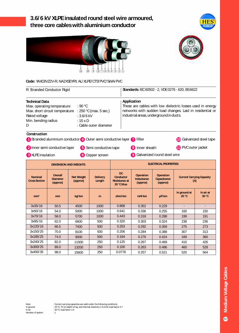
217
3.6/6 kV XLPE insulated round steel wire armoured,three core cables with aluminium conductor
Construction
Code: YAXC8VZ2V-R, NA2XSEYRY, AL/XLPE/CTS/PVC/SWA/PVC
Standards: IEC 60502 - 2, VDE 0276 - 620, BS 6622
ApplicationThese are cables with low dielectric losses used in energy networks with sudden load changes. Laid in residential or industrial areas, underground in ducts.
Technical DataMax. operating temperature : 90 °C
Max. short circuit temperature : 250 °C (max. 5 sec.)
Rated voltage : 3.6/6 kVMin. bending radius : 15 x DD : Cable outer diameter
R: Stranded Conductor Rigid
123672891011 245
Me
diu
m V
olt
age
Cab
les
DIMENSION AND WEIGHTS ELECTRICAL PROPERTIES
Nominal Cross Section
Overall Diameter (approx)
Net Weight (approx)
Delivery Length
DC Conductor
Resistance at20 °C Max
Operation Inductance
(approx)
Operation Capacitance
(approx)
Current Carrying Capacity (A)
mm² mm kg/km m ohm/km mH/km µF/kmIn ground at
20 °CIn air at
30 °C
0.229
0.255
0.288
0.324
0.359
0.388
0.424
0.469
0.486
0.521
3x35/16
3x50/16
3x70/16
3x95/16
3x120/16
3x150/25
3x185/25
3x240/25
3x300/25
3x400/35
50.5
54.0
58.0
62.0
66.5
70.0
74.0
82.0
89.0
98.0
4500
5000
5700
6600
7400
8100
9000
11500
13200
15600
1000
1000
1000
500
500
500
500
250
250
250
0.868
0.641
0.443
0.320
0.253
0.206
0.164
0.125
0.100
0.0778
0.352
0.336
0.318
0.303
0.292
0.284
0.276
0.267
0.263
0.257
-
160
199
238
275
307
349
410
460
520
-
150
191
236
273
313
360
426
528
564
1 4Stranded aluminium conductor Outer semi conductive layer
2 Inner semi conductive layer 5 Semi conductive tape
7 Filler
8 Inner sheath
10 Galvanized steel tape
11 PVC outer jacket
3 XLPE insulation 6 Copper screen 9 Galvanized round steel wire
Note : Current carrying capacities are valid under the following conditions;In ground : 20 ºC, 70 cm depth of lay, soil-thermal resistivity 1 K.m/W, load factor 0.7In air : 30 ºC, load factor 1.0Number of system : 1
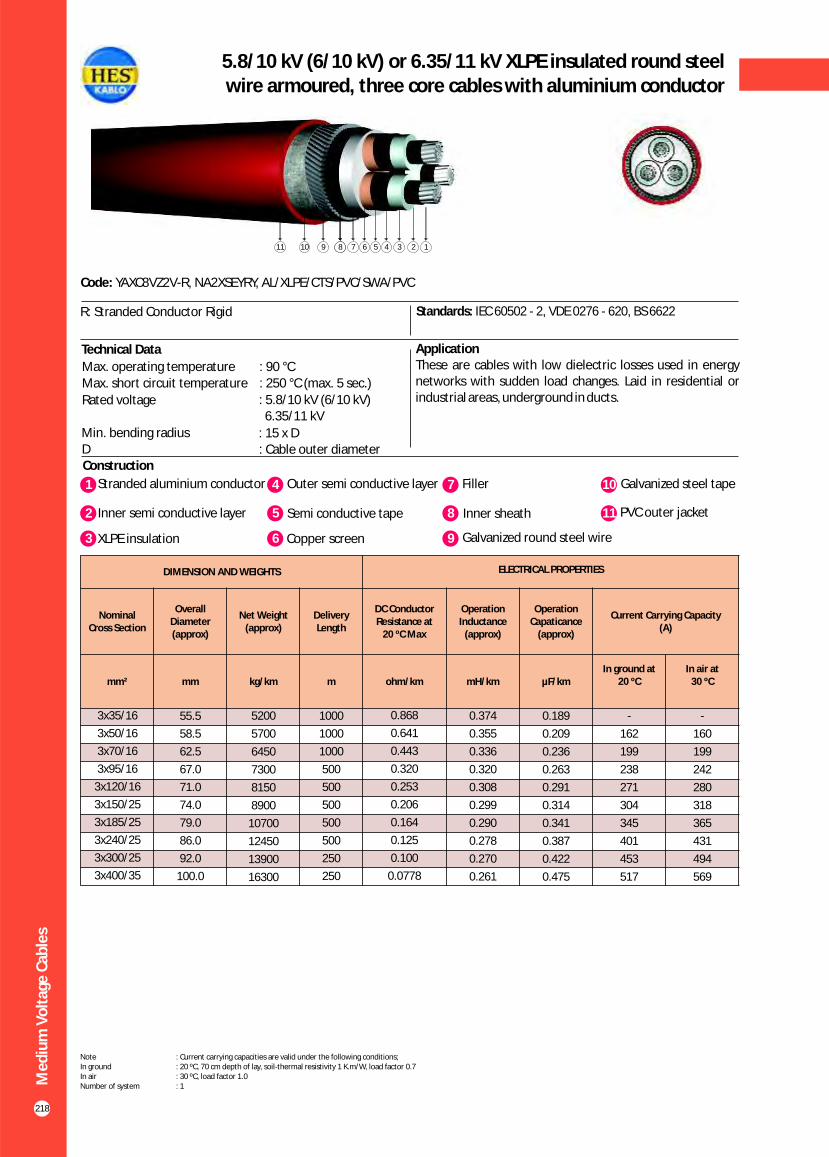
218
5.8/10 kV (6/10 kV) or 6.35/11 kV XLPE insulated round steel wire armoured, three core cables with aluminium conductor
Construction
Code: YAXC8VZ2V-R, NA2XSEYRY, AL/XLPE/CTS/PVC/SWA/PVC
Standards: IEC 60502 - 2, VDE 0276 - 620, BS 6622
ApplicationThese are cables with low dielectric losses used in energy networks with sudden load changes. Laid in residential or industrial areas, underground in ducts.
Technical Data
Max. operating temperature : 90 °CMax. short circuit temperature : 250 °C (max. 5 sec.)
Rated voltage : 5.8/10 kV (6/10 kV) 6.35/11 kV
Min. bending radius : 15 x DD : Cable outer diameter
R: Stranded Conductor Rigid
123672891011 245
Me
diu
m V
olt
age
Cab
les
DIMENSION AND WEIGHTS ELECTRICAL PROPERTIES
Nominal Cross Section
Overall Diameter (approx)
Net Weight (approx)
Delivery Length
DC Conductor Resistance at
20 ºC Max
Operation Inductance
(approx)
Operation Capaticance
(approx)
Current Carrying Capacity (A)
mm² mm kg/km m ohm/km mH/km µF/kmIn ground at
20 ºCIn air at
30 ºC
0.189
0.209
0.236
0.263
0.291
0.314
0.341
0.387
0.422
0.475
3x35/16
3x50/16
3x70/16
3x95/16
3x120/16
3x150/25
3x185/25
3x240/25
3x300/25
3x400/35
55.5
58.5
62.5
67.0
71.0
74.0
79.0
86.0
92.0
100.0
5200
5700
6450
7300
8150
8900
10700
12450
13900
16300
1000
1000
1000
500
500
500
500
500
250
250
0.868
0.641
0.443
0.320
0.253
0.206
0.164
0.125
0.100
0.0778
0.374
0.355
0.336
0.320
0.308
0.299
0.290
0.278
0.270
0.261
-
162
199
238
271
304
345
401
453
517
-
160
199
242
280
318
365
431
494
569
1 4Stranded aluminium conductor Outer semi conductive layer
2 Inner semi conductive layer 5 Semi conductive tape
7 Filler
8 Inner sheath
10 Galvanized steel tape
11 PVC outer jacket
3 XLPE insulation 6 Copper screen 9 Galvanized round steel wire
Note : Current carrying capacities are valid under the following conditions;In ground : 20 ºC, 70 cm depth of lay, soil-thermal resistivity 1 K.m/W, load factor 0.7In air : 30 ºC, load factor 1.0Number of system : 1

Me
diu
m V
olt
age
Cab
les
219
8.7/15 kV XLPE insulated round steel wire armoured, three core cables with aluminium conductor
Construction
Code: YAXC8VZ2V-R, NA2XSEYRY, AL/XLPE/CTS/PVC/SWA/PVC
Standards: IEC 60502 - 2, VDE 0276, BS 6622
ApplicationThese are cables with low dielectric losses used in energy networks with sudden load changes. Laid in residential or industrial areas, underground in ducts.
Technical DataMax. operating temperature : 90 °C
Max. short circuit temperature : 250 °C (max. 5 sec.)
Rated voltage : 8.7/15 kVMin. bending radius : 15 x DD : Cable outer diameter
R: Stranded Conductor Rigid
123672891011 245
DIMENSION AND WEIGHTS ELECTRICAL PROPERTIES
Nominal Cross Section
Overall Diameter (approx)
Net Weight (approx)
Delivery Length
DC Conductor Resistance at
20 C Max°
Operation Inductance
(approx)
Operation Capaticance
(approx)
Current Carrying Capacity (A)
mm² mm kg/km m ohm/km mH/km µF/kmIn ground at
20 C°In air at
30 C°
0.160
0.175
0.196
0.218
0.240
0.258
0.280
0.315
0.343
0.385
3x35/16
3x50/16
3x70/16
3x95/16
3x120/16
3x150/25
3x185/25
3x240/25
3x300/25
3x400/35
60.5
64.0
68.0
72.0
76.0
81.0
85.0
92.0
97.0
105.0
6100
6600
7500
8400
9100
10900
12100
13700
15100
17500
500
500
500
500
500
500
250
250
250
250
0.868
0.641
0.443
0.320
0.253
0.206
0.164
0.125
0.100
0.0778
0.397
0.377
0.356
0.339
0.325
0.315
0.305
0.292
0.284
0.273
-
162
199
238
271
304
345
401
453
517
-
160
199
242
280
318
365
431
494
569
1 4Stranded aluminium conductor Outer semi conductive layer
2 Inner semi conductive layer 5 Semi conductive tape
7 Filler
8 Inner sheath
10 Galvanized steel tape
11 PVC outer jacket
3 XLPE insulation 6 Copper screen 9 Galvanized round steel wire
Note : Current carrying capacities are valid under the following conditions;In ground : 20 ºC, 70 cm depth of lay, soil-thermal resistivity 1 K.m/W, load factor 0.7In air : 30 ºC, load factor 1.0Number of system : 1
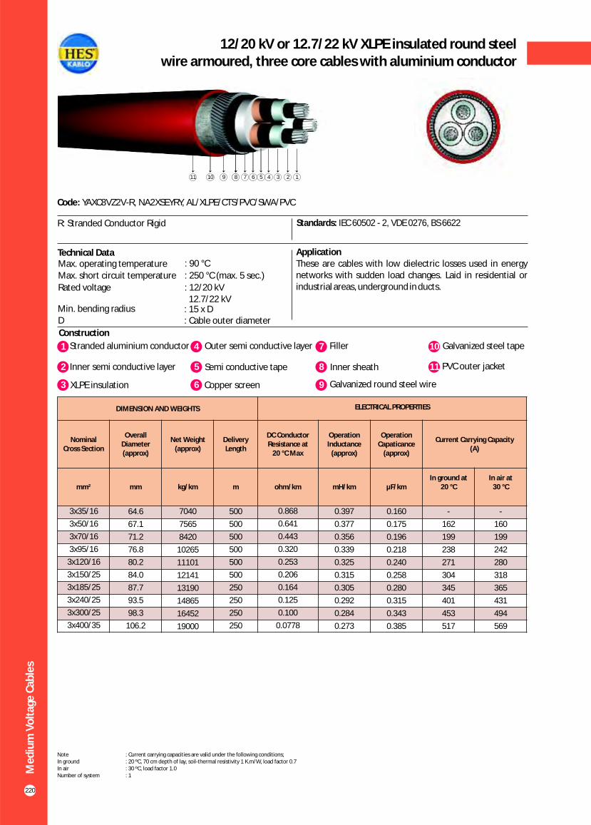
Me
diu
m V
olt
age
Cab
les
220
12/20 kV or 12.7/22 kV XLPE insulated round steel wire armoured, three core cables with aluminium conductor
Construction
Code: YAXC8VZ2V-R, NA2XSEYRY, AL/XLPE/CTS/PVC/SWA/PVC
Standards: IEC 60502 - 2, VDE 0276, BS 6622
ApplicationThese are cables with low dielectric losses used in energy networks with sudden load changes. Laid in residential or industrial areas, underground in ducts.
Technical Data
R: Stranded Conductor Rigid
123672891011 245
DIMENSION AND WEIGHTS ELECTRICAL PROPERTIES
Nominal Cross Section
Overall Diameter (approx)
Net Weight (approx)
Delivery Length
DC Conductor Resistance at
20 C Max°
Operation Inductance
(approx)
Operation Capaticance
(approx)
Current Carrying Capacity (A)
mm² mm kg/km m ohm/km mH/km µF/kmIn ground at
20 C°In air at
30 C°
0.160
0.175
0.196
0.218
0.240
0.258
0.280
0.315
0.343
0.385
3x35/16
3x50/16
3x70/16
3x95/16
3x120/16
3x150/25
3x185/25
3x240/25
3x300/25
3x400/35
64.6
67.1
71.2
76.8
80.2
84.0
87.7
93.5
98.3
106.2
7040
7565
8420
10265
11101
12141
13190
14865
16452
19000
500
500
500
500
500
500
250
250
250
250
0.868
0.641
0.443
0.320
0.253
0.206
0.164
0.125
0.100
0.0778
0.397
0.377
0.356
0.339
0.325
0.315
0.305
0.292
0.284
0.273
-
162
199
238
271
304
345
401
453
517
-
160
199
242
280
318
365
431
494
569
1 4Stranded aluminium conductor Outer semi conductive layer
2 Inner semi conductive layer 5 Semi conductive tape
7 Filler
8 Inner sheath
10 Galvanized steel tape
11 PVC outer jacket
3 XLPE insulation 6 Copper screen 9 Galvanized round steel wire
Note : Current carrying capacities are valid under the following conditions;In ground : 20 ºC, 70 cm depth of lay, soil-thermal resistivity 1 K.m/W, load factor 0.7In air : 30 ºC, load factor 1.0Number of system : 1
Max. operating temperature : 90 °C
Max. short circuit temperature : 250 °C (max. 5 sec.)
Rated voltage : 12.7/22 kV
12/20 kV
Min. bending radius : 15 x DD : Cable outer diameter

Me
diu
m V
olt
age
Cab
les
221
18/30 kV or 19/33 kV XLPE insulated round steel wire armoured, three core cables with aluminium conductor
Construction
Code: YAXC8VZ2V-R, NA2XSEYRY, AL/XLPE/CTS/PVC/SWA/PVC
Standards: IEC 60502 - 2, VDE 0276, BS 6622
ApplicationThese are cables with low dielectric losses used in energy networks with sudden load changes. Laid in residential or industrial areas, underground in ducts.
Technical Data
R: Stranded Conductor Rigid
123672891011 245
DIMENSION AND WEIGHTS ELECTRICAL PROPERTIES
Nominal Cross Section
Overall Diameter (approx)
Net Weight (approx)
Delivery Length
DC Conductor Resistance at
20 C Max°
Operation Inductance
(approx)
Operation Capaticance
(approx)
Current Carrying Capacity (A)
mm² mm kg/km m ohm/km mH/km µF/kmIn ground at
20 C°In air at
30 C°
0.160
0.175
0.196
0.218
0.240
0.258
0.280
0.315
3x35/16
3x50/16
3x70/16
3x95/16
3x120/16
3x150/25
3x185/25
3x240/25
77.9
80.8
84.9
89.2
92.5
95.9
100.0
106.0
6100
6600
7500
8400
9100
10900
12100
13700
500
500
500
500
500
500
250
250
0.868
0.641
0.443
0.320
0.253
0.206
0.164
0.125
0.397
0.377
0.356
0.339
0.325
0.315
0.305
0.292
-
162
199
238
271
304
345
401
-
160
199
242
280
318
365
431
1 4Stranded aluminium conductor Outer semi conductive layer
2 Inner semi conductive layer 5 Semi conductive tape
7 Filler
8 Inner sheath
10 Galvanized steel tape
11 PVC outer jacket
3 XLPE insulation 6 Copper screen 9 Galvanized round steel wire
Note : Current carrying capacities are valid under the following conditions;In ground : 20 ºC, 70 cm depth of lay, soil-thermal resistivity 1 K.m/W, load factor 0.7In air : 30 ºC, load factor 1.0Number of system : 1
Max. operating temperature : 90 °C
Max. short circuit temperature : 250 °C (max. 5 sec.)
Rated voltage : 18/30 kV 19/33 kV
Min. bending radius : 15 x DD : Cable outer diameter

Me
diu
m V
olt
age
Cab
les
222
3.6/6 kV XLPE insulated double steel tape armoured,three core cables with aluminium conductor
Construction
Code: YAXC8VZ4V-R, NA2XSEYBY, AL/XLPE/CTS/PVC/STA/PVC
Standards: IEC 60502 - 2, VDE 0276, BS 6622
ApplicationThese are cables with low dielectric losses used in energy networks with sudden load changes. Laid in residential or industrial areas, underground in ducts.
R: Stranded Conductor Rigid
Technical DataMax. operating temperature : 90 °C
Max. short circuit temperature : 250 °C (max. 5 sec.)
Rated voltage : 3.6/6 kVMin. bending radius : 15 x DD : Cable outer diameter
DIMENSION AND WEIGHTS ELECTRICAL PROPERTIES
Nominal Cross Section
Overall Diameter (approx)
Net Weight (approx)
Delivery Length
DC Conductor
Resistance at20 °C Max
Operation Inductance
(approx)
Operation Capaticance
(approx)
Current Carrying Capacity (A)
mm² mm kg/km m ohm/km mH/km µF/kmIn ground at
20 °CIn air at
30 °C
0.229
0.255
0.288
0.324
0.359
0.388
0.424
0.469
0.486
0.521
3x35/16
3x50/16
3x70/16
3x95/16
3x120/16
3x150/25
3x185/25
3x240/25
3x300/25
3x400/35
47.0
50.0
54.0
58.0
62.5
66.0
70.0
77.0
83.5
94.0
3200
3700
4300
5000
5700
6300
7200
8500
10000
13000
1000
1000
1000
1000
500
500
500
500
500
250
0.868
0.641
0.443
0.320
0.253
0.206
0.164
0.125
0.100
0.0778
0.352
0.336
0.318
0.303
0.292
0.284
0.276
0.267
0.263
0.257
-
160
199
238
275
307
349
410
460
520
-
150
191
236
273
313
360
426
528
564
1 4Stranded aluminium conductor Outer semi conductive layer
2 Inner semi conductive layer 5 Semi conductive tape
7 Filler
8 Inner sheath
10 PVC outer jacket
3 XLPE insulation 6 Copper screen 9 Galvanized steel tape
Note : Current carrying capacities are valid under the following conditions;In ground : 20 ºC, 70 cm depth of lay, soil-thermal resistivity 1 K.m/W, load factor 0.7In air : 30 ºC, load factor 1.0Number of system : 1
1236728910 245

Me
diu
m V
olt
age
Cab
les
223
5.8/10 kV (6/10 kV) or 6.35/11 kV XLPE insulated double steel tape armoured, three core cables with aluminium conductor
Construction
Code: YAXC8VZ4V-R, NA2XSEYBY, AL/XLPE/CTS/PVC/STA/PVC
Standards: IEC 60502 - 2, VDE 0276, BS 6622
ApplicationThese are cables with low dielectric losses used in energy networks with sudden load changes. Laid in residential or industrial areas, underground in ducts.
R: Stranded Conductor Rigid
Technical Data
Max. operating temperature : 90 °C Max. short circuit temperature : 250 °C (max. 5 sec.)
Rated voltage : 5.8/10 kV (6/10 kV) 6.35/11 kV
Min. bending radius : 15 x DD : Cable outer diameter
DIMENSION AND WEIGHTS ELECTRICAL PROPERTIES
Nominal Cross Section
Overall Diameter (approx)
Net Weight (approx)
Delivery Length
DC Conductor
Resistance at20 °C Max
Operation Inductanse
(approx)
Operation Capaticance
(approx)
Current Carrying Capacity (A)
mm² mm kg/km m ohm/km mH/km µF/kmIn ground at
20 °CIn air at
30 °C
0.189
0.209
0.236
0.263
0.291
0.314
0.341
0.387
0.422
0.475
3x35/16
3x50/16
3x70/16
3x95/16
3x120/16
3x150/25
3x185/25
3x240/25
3x300/25
3x400/35
51.5
54.5
58.5
63.0
67.0
70.0
74.0
81.0
88.0
96.0
3800
4200
4900
5700
6400
7000
7900
9300
11500
13500
1000
1000
1000
1000
500
500
500
500
250
250
0.868
0.641
0.443
0.320
0.253
0.206
0.164
0.125
0.100
0.0778
0.374
0.355
0.336
0.320
0.308
0.299
0.290
0.278
0.270
0.261
-
162
199
238
271
304
345
401
453
517
-
160
199
242
280
318
365
431
494
569
1 4Stranded aluminium conductor Outer semi conductive layer
2 Inner semi conductive layer 5 Semi conductive tape
7 Filler
8 Inner sheath
10 PVC outer jacket
3 XLPE insulation 6 Copper screen 9 Galvanized steel tape
Note : Current carrying capacities are valid under the following conditions;In ground : 20 ºC, 70 cm depth of lay, soil-thermal resistivity 1 K.m/W, load factor 0.7In air : 30 ºC, load factor 1.0Number of system : 1
1236728910 245

Me
diu
m V
olt
age
Cab
les
224
8.7/15 kV XLPE insulated double steel tape armoured,three core cables with aluminium conductor
Construction
Code: YAXC8VZ4V-R, NA2XSEYBY, AL/XLPE/CTS/PVC/STA/PVC
Standards: IEC 60502 - 2, VDE 0276, BS 6622
ApplicationThese are cables with low dielectric losses used in energy networks with sudden load changes. Laid in residential or industrial areas, underground in ducts.
R: Stranded Conductor Rigid
Technical DataMax. operating temperature : 90 °C
Max. short circuit temperature : 250 °C (max. 5 sec.)
Rated voltage : 8.7/15 kVMin. bending radius : 15 x DD : Cable outer diameter
DIMENSION AND WEIGHTS ELECTRICAL PROPERTIES
Nominal Cross Section
Overall Diameter (approx)
Net Weight (approx)
Delivery Length
DC Conductor
Resistance at20 °C Max
Operation Inductance
(approx)
Operation Capaticance
(approx)
Current Carrying Capacity (A)
mm² mm kg/km m ohm/km mH/km µF/kmIn ground at
20 °CIn air at
30 °C
0.160
0.175
0.196
0.218
0.240
0.258
0.280
0.315
0.343
0.385
3x35/16
3x50/16
3x70/16
3x95/16
3x120/16
3x150/25
3x185/25
3x240/25
3x300/25
3x400/35
57.0
60.5
64.0
68.5
72.5
75.5
80.0
88.0
93.0
101.0
4500
5000
5700
6600
7200
8000
9000
11300
12700
14800
1000
1000
500
500
500
500
500
500
250
250
0.868
0.641
0.443
0.320
0.253
0.206
0.164
0.125
0.100
0.0778
0.397
0.377
0.356
0.339
0.325
0.315
0.305
0.292
0.284
0.273
-
162
199
238
271
304
345
401
453
517
-
160
199
242
280
318
365
431
494
569
1 4Stranded aluminium conductor Outer semi conductive layer
2 Inner semi conductive layer 5 Semi conductive tape
7 Filler
8 Inner sheath
10 PVC outer jacket
3 XLPE insulation 6 Copper screen 9 Galvanized steel tape
Note : Current carrying capacities are valid under the following conditions;In ground : 20 ºC, 70 cm depth of lay, soil-thermal resistivity 1 K.m/W, load factor 0.7In air : 30 ºC, load factor 1.0Number of system : 1
1236728910 245

Me
diu
m V
olt
age
Cab
les
225
12/20 kV or 12.7/22 kV XLPE insulated double steel tape armoured, three core cables with aluminium conductor
Construction
Code: YAXC8VZ4V-R, NA2XSEYBY, AL/XLPE/CTS/PVC/STA/PVC
Standards: IEC 60502 - 2, VDE 0276, BS 6622
ApplicationThese are cables with low dielectric losses used in energy networks with sudden load changes. Laid in residential or industrial areas, underground in ducts.
R: Stranded Conductor Rigid
Technical Data
DIMENSION AND WEIGHTS ELECTRICAL PROPERTIES
Nominal Cross Section
Overall Diameter (approx)
Net Weight (approx)
Delivery Length
DC Conductor
Resistance at20 °C Max
Operation Inductance
(approx)
Operation Capaticance
(approx)
Current Carrying Capacity (A)
mm² mm kg/km m ohm/km mH/km µF/kmIn ground at
20 °CIn air at
30 °C
0.141
0.155
0.172
0.191
0.209
0.225
0.243
0.273
0.296
0.331
3x35/16
3x50/16
3x70/16
3x95/16
3x120/16
3x150/25
3x185/25
3x240/25
3x300/25
3x400/35
61.0
63.5
67.6
71.7
75.0
78.8
84.0
89.8
94.4
102.5
5366
5816
6585
7409
8115
8966
10882
12409
13771
16162
1000
500
500
500
500
500
500
250
250
250
0.868
0.641
0.443
0.320
0.253
0.206
0.164
0.125
0.100
0.0778
0.416
0.395
0.373
0.355
0.340
0.329
0.319
0.304
0.295
0.284
-
168
207
247
282
316
359
420
476
552
-
171
211
255
297
334
384
454
513
593
1 4Stranded aluminium conductor Outer semi conductive layer
2 Inner semi conductive layer 5 Semi conductive tape
7 Filler
8 Inner sheath
10 PVC outer jacket
3 XLPE insulation 6 Copper screen 9 Galvanized steel tape
Note : Current carrying capacities are valid under the following conditions;In ground : 20 ºC, 70 cm depth of lay, soil-thermal resistivity 1 K.m/W, load factor 0.7In air : 30 ºC, load factor 1.0Number of system : 1
Max. operating temperature : 90 °C
Max. short circuit temperature : 250 °C (max. 5 sec.)
Rated voltage : 12.7/22 kV
12/20 kV
Min. bending radius : 15 x DD : Cable outer diameter
1236728910 245
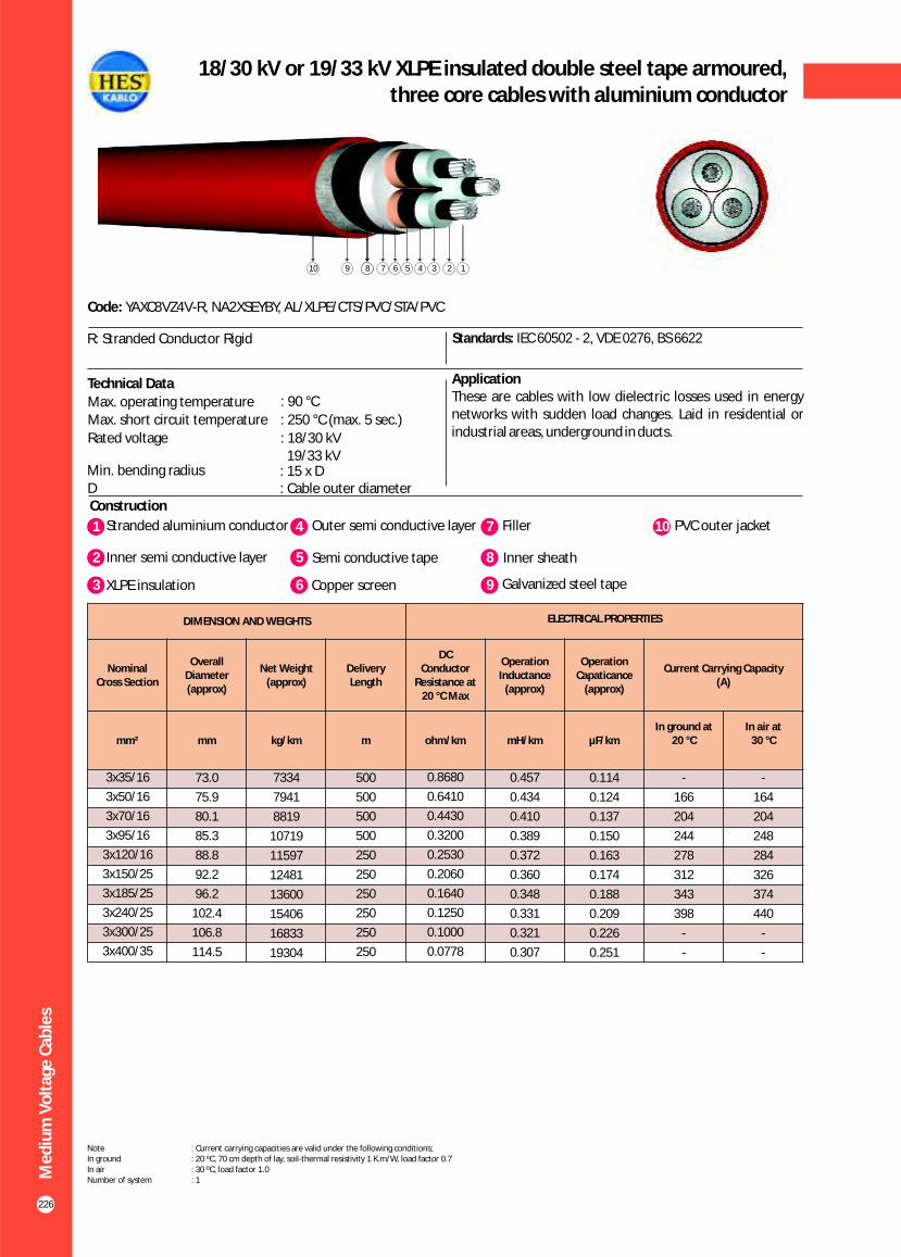
Me
diu
m V
olt
age
Cab
les
226
18/30 kV or 19/33 kV XLPE insulated double steel tape armoured,three core cables with aluminium conductor
Construction
Code: YAXC8VZ4V-R, NA2XSEYBY, AL/XLPE/CTS/PVC/STA/PVC
Standards: IEC 60502 - 2, VDE 0276, BS 6622
ApplicationThese are cables with low dielectric losses used in energy networks with sudden load changes. Laid in residential or industrial areas, underground in ducts.
R: Stranded Conductor Rigid
Technical Data
DIMENSION AND WEIGHTS ELECTRICAL PROPERTIES
Nominal Cross Section
Overall Diameter (approx)
Net Weight (approx)
Delivery Length
DC Conductor
Resistance at20 °C Max
Operation Inductance
(approx)
Operation Capaticance
(approx)
Current Carrying Capacity (A)
mm² mm kg/km m ohm/km mH/km µF/kmIn ground at
20 °CIn air at
30 °C
0.114
0.124
0.137
0.150
0.163
0.174
0.188
0.209
0.226
0.251
3x35/16
3x50/16
3x70/16
3x95/16
3x120/16
3x150/25
3x185/25
3x240/25
3x300/25
3x400/35
73.0
75.9
80.1
85.3
88.8
92.2
96.2
102.4
106.8
114.5
7334
7941
8819
10719
11597
12481
13600
15406
16833
19304
500
500
500
500
250
250
250
250
250
250
0.8680
0.6410
0.4430
0.3200
0.2530
0.2060
0.1640
0.1250
0.1000
0.0778
0.457
0.434
0.410
0.389
0.372
0.360
0.348
0.331
0.321
0.307
-
166
204
244
278
312
343
398
-
-
-
164
204
248
284
326
374
440
-
-
1 4Stranded aluminium conductor Outer semi conductive layer
2 Inner semi conductive layer 5 Semi conductive tape
7 Filler
8 Inner sheath
10 PVC outer jacket
3 XLPE insulation 6 Copper screen 9 Galvanized steel tape
Note : Current carrying capacities are valid under the following conditions;In ground : 20 ºC, 70 cm depth of lay, soil-thermal resistivity 1 K.m/W, load factor 0.7In air : 30 ºC, load factor 1.0Number of system : 1
Max. operating temperature : 90 °C
Max. short circuit temperature : 250 °C (max. 5 sec.)
Rated voltage : 19/33 kV
18/30 kV
Min. bending radius : 15 x DD : Cable outer diameter
1236728910 245

Me
diu
m V
olt
age
Cab
les
227
20.3/35 kV veya 20.8/36 kV XLPE insulated double steel tape armoured, three core cables with aluminium conductor
Construction
Code: YAXC8VZ4V-R, NA2XSEYBY, AL/XLPE/CTS/PVC/STA/PVC
Standards: HD 620 S2, TSEK
ApplicationThese are cables with low dielectric losses used in energy networks with sudden load changes. Laid in residential or industrial areas, underground in ducts.
R: Stranded Conductor Rigid
Technical DataMax. operating temperature : 90 °C
Max. short circuit temperature : 250 °C (max. 5 sec.)
Rated voltage : 20.3/35 kV 20.8/36 kV
Min. bending radius : 15 x DD : Cable outer diameter
DIMENSION AND WEIGHTS ELECTRICAL PROPERTIES
Nominal Cross Section
Overall Diameter (approx)
Net Weight (approx)
Delivery Length
DC Conductor
Resistance at20 °C Max
Operation Inductance
(approx)
Operation Capaticance
(approx)
Current Carrying Capacity (A)
mm² mm kg/km m ohm/km mH/km µF/kmIn ground at
20 °CIn air at
30 °C
0.107
0.116
0.127
0.140
0.152
0.161
0.173
0.193
0.207
0.231
3x35/16
3x50/16
3x70/16
3x95/16
3x120/16
3x150/25
3x185/25
3x240/25
3x300/25
3x400/35
78.0
82.0
86.0
90.0
93.0
97.0
101.0
107.0
112.0
119.0
4650
5150
5800
6500
7250
8000
9500
11000
12350
20620
1000
500
500
500
500
500
500
250
250
250
0.868
0.641
0.443
0.320
0.253
0.206
0.164
0.125
0.100
0.0778
0.471
0.448
0.423
0.401
0.384
0.372
0.359
0.341
0.330
0.316
-
166
204
244
278
312
343
398
476
552
-
164
204
248
284
326
374
440
513
593
1 4Stranded aluminium conductor Outer semi conductive layer
2 Inner semi conductive layer 5 Semi conductive tape
7 Filler
8 Inner sheath
10 PVC outer jacket
3 XLPE insulation 6 Copper screen 9 Galvanized steel tape
Note : Current carrying capacities are valid under the following conditions;In ground : 20 ºC, 70 cm depth of lay, soil-thermal resistivity 1 K.m/W, load factor 0.7In air : 30 ºC, load factor 1.0Number of system : 1
1236728910 245
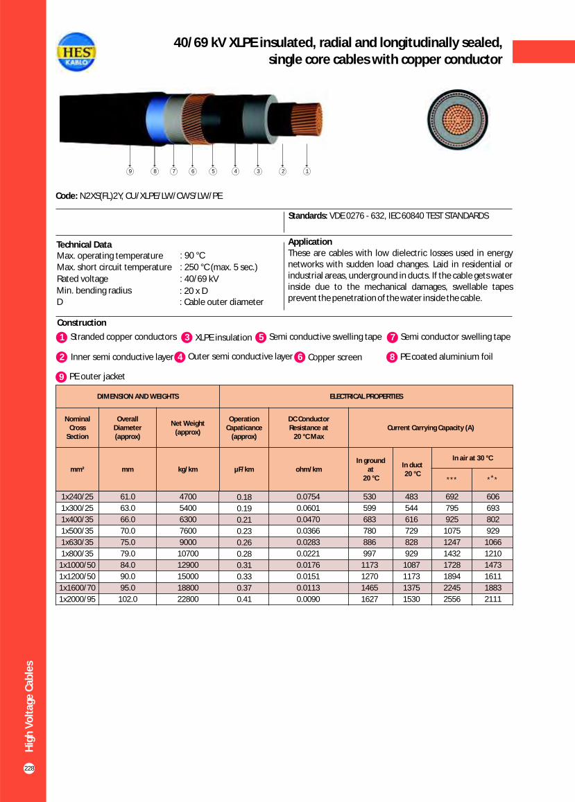
Hig
h V
olt
age
Cab
les
228
40/69 kV XLPE insulated, radial and longitudinally sealed,single core cables with copper conductor
Construction
Code: N2XS(FL)2Y, CU/XLPE/LW/CWS/LW/PE
Standards: VDE 0276 - 632, IEC 60840 TEST STANDARDS
ApplicationThese are cables with low dielectric losses used in energy networks with sudden load changes. Laid in residential or industrial areas, underground in ducts. If the cable gets water inside due to the mechanical damages, swellable tapes prevent the penetration of the water inside the cable.
1 3Stranded copper conductors XLPE insulation
2 Inner semi conductive layer 4 Outer semi conductive layer
5 Semi conductive swelling tape
6 Copper screen
7 Semi conductor swelling tape
8 PE coated aluminium foil
9 PE outer jacket
Technical DataMax. operating temperature : 90 °C
Max. short circuit temperature : 250 °C (max. 5 sec.)
Rated voltage : 40/69 kV
Min. bending radius : 20 x DD : Cable outer diameter
123456789
61.0
63.0
66.0
70.0
75.0
79.0
84.0
90.0
95.0
102.0
4700
5400
6300
7600
9000
10700
12900
15000
18800
22800
0.18
0.19
0.21
0.23
0.26
0.28
0.31
0.33
0.37
0.41
0.0754
0.0601
0.0470
0.0366
0.0283
0.0221
0.0176
0.0151
0.0113
0.0090
530
599
683
780
886
997
1173
1270
1465
1627
483
544
616
729
828
929
1087
1173
1375
1530
692
795
925
1075
1247
1432
1728
1894
2245
2556
606
693
802
929
1066
1210
1473
1611
1883
2111
DIMENSION AND WEIGHTS ELECTRICAL PROPERTIES
Nominal Cross
Section
Overall Diameter (approx)
Net Weight (approx)
Operation Capaticance
(approx)
DC Conductor Resistance at
20 °C MaxCurrent Carrying Capacity (A)
mm² mm kg/km µF/km ohm/kmIn ground
at 20 °C
In duct20 °C
In air at 30 °C
*** ** *
1x240/25
1x300/25
1x400/35
1x500/35
1x630/35
1x800/35
1x1000/50
1x1200/50
1x1600/70
1x2000/95

Hig
h V
olt
age
Cab
les
229
89/154 kV XLPE insulated, radial and longitudinally sealed,single core cables with copper conductor
Construction
Code: N2XS(FL)2Y, CU/XLPE/LW/CWS/LW/PE
Standards: VDE 0276 - 632, IEC 60840 TEST STANDARDS
ApplicationThese are cables with low dielectric losses used in energy networks with sudden load changes. Laid in residential or industrial areas, underground in ducts. If the cable gets water inside due to the mechanical damages, swellable tapes prevent the penetration of the water inside the cable.
Technical DataMax. operating temperature : 90 °C
Max. short circuit temperature : 250 °C (max. 5 sec.)
Rated voltage : 89/154 kV
Min. bending radius : 20x DD : Cable outer diameter
123456789
1x300/25
1x400/35
1x500/35
1x630/35
1x800/35
1x1000/50
1x1200/50
1x1600/70
1x2000/95
85.0
89.0
93.0
96.0
102.0
106.0
110.0
120.0
126.0
7100
8200
9700
11400
13600
16000
18500
22500
26500
0.15
0.16
0.18
0.19
0.20
0.21
0.22
0.23
0.27
0.0601
0.0470
0.0366
0.0283
0.0221
0.0176
0.0151
0.0113
0.0090
591
673
766
871
977
1143
1232
1404
1554
553
629
713
829
928
1081
1208
1382
1523
765
887
1027
1193
1367
1639
1790
2100
2384
684
789
907
1043
1181
1415
1535
1765
1973
DIMENSION AND WEIGHTS ELECTRICAL PROPERTIES
Nominal Cross
Section
Overall Diameter (approx)
Net Weight (approx)
Operation Capaticance
(approx)
DC Conductor Resistance at
20 °C MaxCurrent Carrying Capacity (A)
mm² mm kg/km µF/km ohm/kmIn ground
at 20 °C
In duct20 °C
In air at 30 °C
*** ** *
1 3Stranded copper conductors XLPE insulation
2 Inner semi conductive layer 4 Outer semi conductive layer
5 Semi conductive swelling tape
6 Copper screen
7 Semi conductive swelling tape
8 PE coated aluminium foil
9 PE outer jacket

Hig
h V
olt
age
Cab
les
230
40/69 kV XLPE insulated, radial and longitudinally sealed,single core cables with aluminium conductor
Construction
Code: NA2XS(FL)2Y, AL/XLPE/LW/CWS/LW/PE
Standards: VDE 0276 - 632, IEC 60840 TEST STANDARDS
ApplicationThese are cables with low dielectric losses used in energy networks with sudden load changes. Laid in residential or industrial areas, underground in ducts. If the cable gets water inside due to the mechanical damages, swellable tapes prevent the penetration of the water inside the cable.
Technical DataMax. operating temperature : 90 °C
Max. short circuit temperature : 250 °C (max. 5 sec.)
Rated voltage : 40/69 kV
Min. bending radius : 20 x DD : Cable outer diameter
1 4Stranded aluminium conductor Outer semi conductive layer
2 Inner semi conductive layer 5 Semi conductive swelling tape
7 Semi conductive swelling tape
8 PE coated aluminium foil
3 XLPE insulation 6 Copper screen 9 PE outer jacket
123456789
1x300/25
1x400/35
1x500/35
1x630/35
1x800/35
1x1000/50
1x1200/50
1x1600/70
61.0
65.0
67.0
73.0
77.0
80.0
84.0
90,0
2900
3300
4000
4500
5200
6200
6900
8500
0.19
0.21
0.23
0.26
0.28
0.31
0.33
0.37
0.100
0.0778
0.0605
0.0469
0.0367
0.0291
0.0247
0.0212
480
550
630
720
820
930
1040
1210
450
525
605
700
800
910
1025
1179
640
752
875
1020
1180
1360
1555
1834
510
614
669
805
930
1056
1169
1432
DIMENSION AND WEIGHTS ELECTRICAL PROPERTIES
Nominal Cross
Section
Overall Diameter (approx)
Net Weight (approx)
Operation Capaticance
(approx)
DC Conductor Resistance at
20 °C MaxCurrent Carrying Capacity (A)
mm² mm kg/km µF/km ohm/kmIn ground
at 20 °C
In duct20 °C
In air at 30 °C
*** ** *

Hig
h V
olt
age
Cab
les
231
89/154 kV XLPE insulated, radial and longitudinally sealed,single core cables with aluminium conductor
Construction
Code: NA2XS(FL)2Y, AL/XLPE/LW/CWS/LW/PE
Standards: VDE 0276 - 632, IEC 60840 TEST STANDARDS
ApplicationThese are cables with low dielectric losses used in energy networks with sudden load changes. Laid in residential or industrial areas, underground in ducts. If the cable gets water inside due to the mechanical damages, swellable tapes prevent the penetration of the water inside the cable.
Technical DataMax. operating temperature : 90 °C
Max. short circuit temperature : 250 °C (max. 5 sec.)
Rated voltage : 89/154 kV
Min. bending radius : 20 x DD : Cable outer diameter
1 4Stranded aluminium conductor Outer semi conductive layer
2 Inner semi conductive layer 5 Semi conductive swelling tape
7 Semi conductive swelling tape
8 PE coated aluminium foil
3 XLPE insulation 6 Copper screen 9 PE outer jacket
123456789
DIMENSION AND WEIGHTS ELECTRICAL PROPERTIES
Nominal Cross
Section
Overall Diameter (approx)
Net Weight (approx)
Operation Capaticance
(approx)
DC Conductor Resistance at
20 °C MaxCurrent Carrying Capacity (A)
mm² mm kg/km µF/km ohm/kmIn ground
at 20 °C
In duct20 °C
In air at 30 °C
*** ** *
1x300/25
1x400/35
1x500/35
1x630/35
1x800/35
1x1000/50
1x1200/50
1x1600/70
87.0
90.0
93.0
98.0
101.0
105.0
108.0
120.0
4800
5400
6000
6700
7500
8600
9300
11200
0.15
0.16
0.18
0.19
0.20
0.21
0.22
0.23
0.100
0.0778
0.0605
0.0469
0.0367
0.0291
0.0247
0.0212
475
545
625
715
813
920
1030
1195
450
525
610
701
803
910
1020
1179
620
741
860
1009
1169
1340
1530
1803
510
615
680
815
935
1060
1086
1421


Aluminium wire-rod
Properties
Aluminium conductors can be divided into two groups : “Stranded Aluminium Conductors” and “Steel Reinforced Aluminium Conductors”. Aluminium wires, used to produce aluminium conductors, are obtained by cold-drawing (hard or annealed) method from high quality rods.
Stranded Aluminium Conductors - AAC
EN 50182, ASTM B - 230, ASTM B-231, IEC 61089, CSAC 48 DIN 48201
Steel Reinforced Aluminium Conductors - ACSR
EN 50182, ASTM B -230, ASTM B-232, IEC 61089
ASTM B-498, DIN 48204, BS 215
Aluminium Alloy Stranded Conductors - AAAC
EN 50182, ASTM BB 231, BS 215, DIN 48201
-299, IEC 61089, CSA C49.1
Aluminium Alloy Conductors Steel Reinforced - AACSR
EN 50182, ASTM B-711, IEC 61089
manufactured in accordance with customer specifications or standards.
Alu
min
ium
wir
e-r
od
233
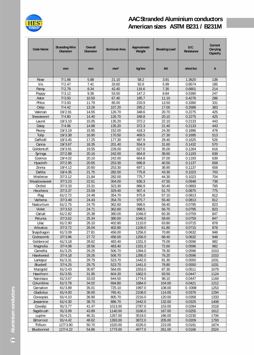
AAC Stranded Aluminium conductors American sizes ASTM B231 / B231M
Alu
min
ium
co
nd
uct
ors
234
Code Name Stranding Wire
Diameter Overall
Diameter Sectional Area
Approximate Weight
Breaking Load D.C.
Resistance
Current Carrying Capacity
mm mm mm² kg/km kN ohm/km A
Rose
Iris
Pansy
Poppy
Aster
Phlox
Oxlip
Valerian
Sneezewort
Laurel
Daisy
Peony
Tulip
Daffodil
Canna
Goldentuft
Syringa
Cosmos
Hyacinth
Zinnia
Dahlia
Mistletoe
Meadowsweet
Orchid
Heuchera
Flag
Varbena
Nasturtium
Violet
Cattail
Petunia
Lilac
Arbustus
Snapdragon
Cockscomb
Goldenrod
Magnolia
Camellia
Hawkweed
Larkspur
Bluebell
Marigold
Hawthorn
Narcissus
Columbine
Carnation
Gladiolus
Coreopsis
Jessamine
Cowslip
Sagebrush
Lupine
Bitterroot
Trillium
Bluebonnet
7/1.96
7/2.47
7/2.78
7/3.12
7/3.50
7/3.93
7/4.42
19/2.91
7/4.80
19/3.10
7/4.96
19/3.19
19/3.38
19/3.45
19/3.67
19/3.91
37/2.88
19/4.02
37/2.95
19/4.12
19/4.35
37/3.12
37/3.23
37/3.33
37/3.37
61/2.72
37/3.49
61/2.75
37/3.53
61/2.82
37/3.62
61/2.90
37/3.72
61/3.09
37/3.96
61/3.18
37/4.08
61/3.25
37/4.18
61/3.31
37/4.25
61/3.43
61/3.55
61/3.67
61/3.78
61/3.89
61/4.00
61/4.10
61/4.30
91/3.77
91/3.99
91/4.21
91/4.42
127/3.90
127/4.22
5.88
7.41
8.34
9.36
10.50
11.79
13.26
14.55
14.40
15.05
14.88
15.95
16.90
17.25
18.35
19.55
20.16
20.10
20.65
20.60
21.75
21.84
22.61
23.31
23.59
24.48
24.43
24.75
24.71
25.38
25.34
26.10
26.04
27.81
27.72
28.62
28.56
29.25
29.26
29.79
29.75
30.87
31.95
33.03
34.02
35.01
36.00
36.90
38.70
41.47
43.89
46.31
48.62
50.70
54.86
58.2
92.6
116.6
147.2
185.7
233.9
295.2
348.6
348.8
372.2
372.3
418.3
469.5
487.9
554.9
627.6
664.8
664.8
696.8
697.1
775.8
775.7
836.3
886.9
907.4
975.8
975.7
998.5
998.5
1046.0
1046.0
1110.0
1109.0
1256.0
1256.0
1331.0
1331.0
1394.0
1395.0
1442.0
1441.0
1553.0
1662.0
1774.0
1884.0
1997.0
2108.0
2216.0
2442.0
2787.0
3166.0
3519.0
3872.0
4226.0
4977.0
21.10
33.60
42.40
53.50
67.40
85.00
107.20
126.70
126.70
135.20
135.20
152.00
170.50
177.30
201.40
228.00
242.00
242.00
253.30
253.30
282.00
282.00
304.00
323.30
329.40
354.70
354.70
362.60
362.60
380.00
380.00
402.80
402.80
456.00
456.00
483.40
483.40
506.70
506.70
523.70
523.70
564.00
604.20
644.50
694.80
725.10
765.41
805.70
886.70
1013.00
1140.00
1267.00
1393.00
1520.00
1773.00
3.91
5.99
7.30
8.84
11.10
13.50
17.00
20.70
20.10
22.10
21.40
24.30
27.30
28.40
31.60
35.00
38.60
37.00
40.50
38.90
43.30
44.30
47.50
50.40
51.70
57.10
55.40
58.40
56.70
60.30
58.60
63.80
61.80
70.80
68.40
75.00
72.60
78.30
76.20
81.30
78.80
87.30
93.50
98.10
104.00
108.00
114.00
120.00
132.00
153.00
167.00
186.00
205.00
223.00
261.00
1.3620
0.8574
0.6801
0.5390
0.4276
0.3390
0.2688
0.2275
0.2275
0.2133
0.2133
0.1896
0.1695
0.1625
0.1432
0.1264
0.1193
0.1193
0.1137
0.1137
0.1023
0.1023
0.0948
0.0893
0.0875
0.0813
0.0813
0.0795
0.0795
0.0759
0.0759
0.0715
0.0715
0.0632
0.0632
0.0596
0.0596
0.0596
0.0596
0.0550
0.0550
0.0511
0.0447
0.0447
0.0421
0. 0398
0.0376
0.0358
0.0325
0.0284
0.0255
0.0230
0.0209
0.0191
0.0166
138
185
214
247
286
331
383
425
425
443
443
478
513
526
570
616
639
639
658
658
703
704
738
765
775
812
812
823
823
847
847
878
878
948
948
982
982
1010
1010
1031
1031
1079
1124
1169
1212
1253
1294
1333
1408
1518
1612
1706
1793
1874
2024
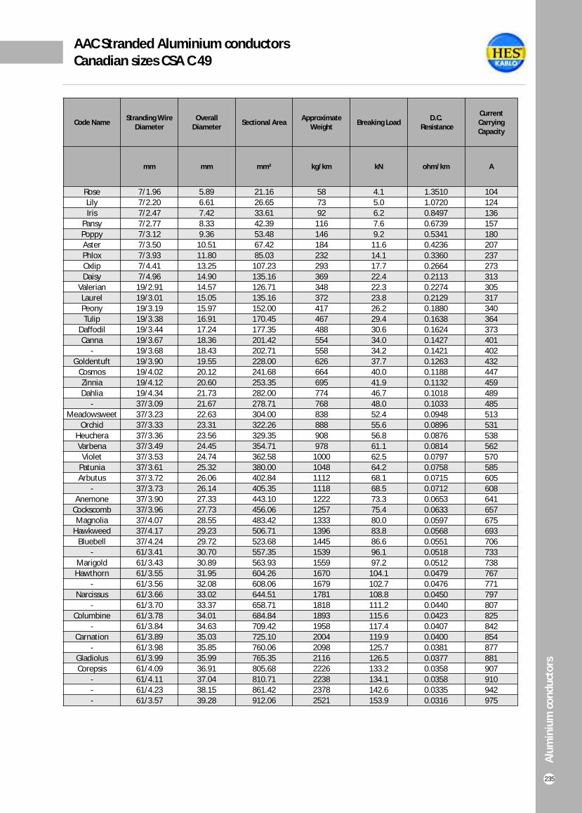
AAC Stranded Aluminium conductors Canadian sizes CSA C 49
Alu
min
ium
co
nd
uct
ors
235
Code Name Stranding Wire
Diameter Overall
Diameter Sectional Area
Approximate Weight
Breaking Load D.C.
Resistance
Current Carrying Capacity
mm mm mm² kg/km kN ohm/km A
Rose
Lily
Iris
Pansy
Poppy
Aster
Phlox
Oxlip
Daisy
Valerian
Laurel
Peony
Tulip
Daffodil
Canna
-
Goldentuft
Cosmos
Zinnia
Dahlia
-
Meadowsweet
Orchid
Heuchera
Varbena
Violet
Patunia
Arbutus
-
Anemone
Cockscomb
Magnolia
Hawkweed
Bluebell
-
Marigold
Hawthorn
-
Narcissus
-
Columbine
-
Carnation
-
Gladiolus
Corepsis
-
-
-
7/1.96
7/2.20
7/2.47
7/2.77
7/3.12
7/3.50
7/3.93
7/4.41
7/4.96
19/2.91
19/3.01
19/3.19
19/3.38
19/3.44
19/3.67
19/3.68
19/3.90
19/4.02
19/4.12
19/4.34
37/3.09
37/3.23
37/3.33
37/3.36
37/3.49
37/3.53
37/3.61
37/3.72
37/3.73
37/3.90
37/3.96
37/4.07
37/4.17
37/4.24
61/3.41
61/3.43
61/3.55
61/3.56
61/3.66
61/3.70
61/3.78
61/3.84
61/3.89
61/3.98
61/3.99
61/4.09
61/4.11
61/4.23
61/3.57
5.89
6.61
7.42
8.33
9.36
10.51
11.80
13.25
14.90
14.57
15.05
15.97
16.91
17.24
18.36
18.43
19.55
20.12
20.60
21.73
21.67
22.63
23.31
23.56
24.45
24.74
25.32
26.06
26.14
27.33
27.73
28.55
29.23
29.72
30.70
30.89
31.95
32.08
33.02
33.37
34.01
34.63
35.03
35.85
35.99
36.91
37.04
38.15
39.28
58
73
92
116
146
184
232
293
369
348
372
417
467
488
554
558
626
664
695
774
768
838
888
908
978
1000
1048
1112
1118
1222
1257
1333
1396
1445
1539
1559
1670
1679
1781
1818
1893
1958
2004
2098
2116
2226
2238
2378
2521
21.16
26.65
33.61
42.39
53.48
67.42
85.03
107.23
135.16
126.71
135.16
152.00
170.45
177.35
201.42
202.71
228.00
241.68
253.35
282.00
278.71
304.00
322.26
329.35
354.71
362.58
380.00
402.84
405.35
443.10
456.06
483.42
506.71
523.68
557.35
563.93
604.26
608.06
644.51
658.71
684.84
709.42
725.10
760.06
765.35
805.68
810.71
861.42
912.06
4.1
5.0
6.2
7.6
9.2
11.6
14.1
17.7
22.4
22.3
23.8
26.2
29.4
30.6
34.0
34.2
37.7
40.0
41.9
46.7
48.0
52.4
55.6
56.8
61.1
62.5
64.2
68.1
68.5
73.3
75.4
80.0
83.8
86.6
96.1
97.2
104.1
102.7
108.8
111.2
115.6
117.4
119.9
125.7
126.5
133.2
134.1
142.6
153.9
1.3510
1.0720
0.8497
0.6739
0.5341
0.4236
0.3360
0.2664
0.2113
0.2274
0.2129
0.1880
0.1638
0.1624
0.1427
0.1421
0.1263
0.1188
0.1132
0.1018
0.1033
0.0948
0.0896
0.0876
0.0814
0.0797
0.0758
0.0715
0.0712
0.0653
0.0633
0.0597
0.0568
0.0551
0.0518
0.0512
0.0479
0.0476
0.0450
0.0440
0.0423
0.0407
0.0400
0.0381
0.0377
0.0358
0.0358
0.0335
0.0316
104
124
136
157
180
207
237
273
313
305
317
340
364
373
401
402
432
447
459
489
485
513
531
538
562
570
585
605
608
641
657
675
693
706
733
738
767
771
797
807
825
842
854
877
881
907
910
942
975
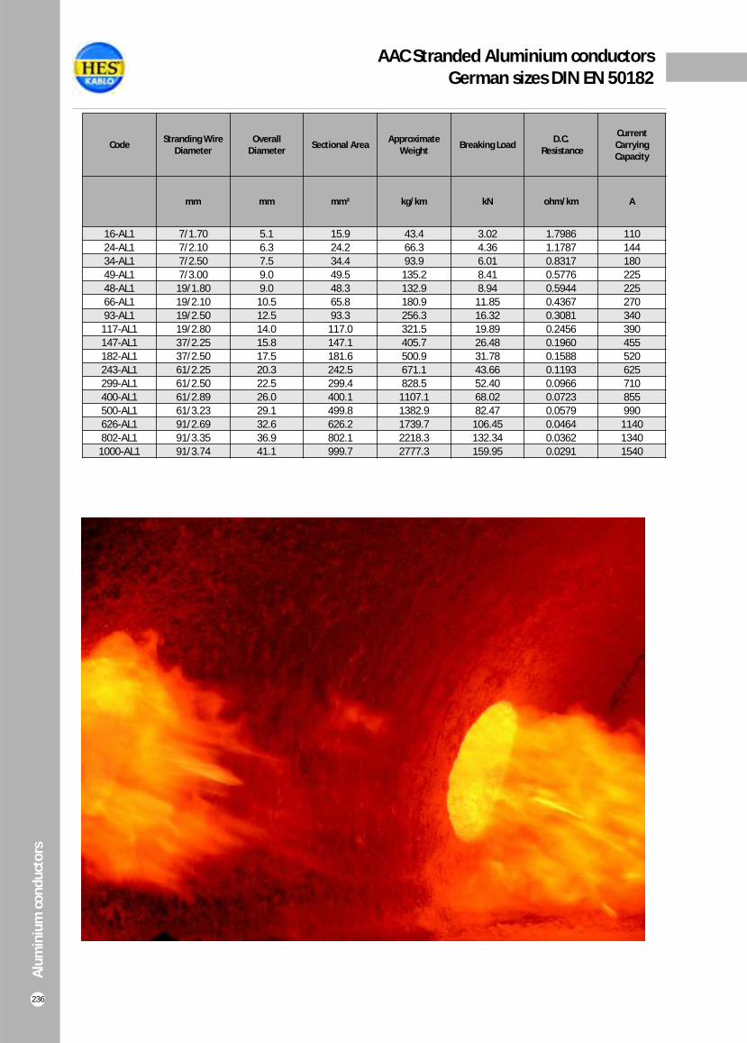
AAC Stranded Aluminium conductors German sizes DIN EN 50182
Alu
min
ium
co
nd
uct
ors
236
Code Stranding Wire
Diameter Overall
Diameter Sectional Area
Approximate Weight
Breaking Load D.C.
Resistance
Current Carrying Capacity
mm mm mm² kg/km kN ohm/km A
16-AL1
24-AL1
34-AL1
49-AL1
48-AL1
66-AL1
93-AL1
117-AL1
147-AL1
182-AL1
243-AL1
299-AL1
400-AL1
500-AL1
626-AL1
802-AL1
1000-AL1
7/1.70
7/2.10
7/2.50
7/3.00
19/1.80
19/2.10
19/2.50
19/2.80
37/2.25
37/2.50
61/2.25
61/2.50
61/2.89
61/3.23
91/2.69
91/3.35
91/3.74
5.1
6.3
7.5
9.0
9.0
10.5
12.5
14.0
15.8
17.5
20.3
22.5
26.0
29.1
32.6
36.9
41.1
43.4
66.3
93.9
135.2
132.9
180.9
256.3
321.5
405.7
500.9
671.1
828.5
1107.1
1382.9
1739.7
2218.3
2777.3
15.9
24.2
34.4
49.5
48.3
65.8
93.3
117.0
147.1
181.6
242.5
299.4
400.1
499.8
626.2
802.1
999.7
3.02
4.36
6.01
8.41
8.94
11.85
16.32
19.89
26.48
31.78
43.66
52.40
68.02
82.47
106.45
132.34
159.95
1.7986
1.1787
0.8317
0.5776
0.5944
0.4367
0.3081
0.2456
0.1960
0.1588
0.1193
0.0966
0.0723
0.0579
0.0464
0.0362
0.0291
110
144
180
225
225
270
340
390
455
520
625
710
855
990
1140
1340
1540

ACSR Steel reinforced Aluminium conductorsAmerican sizes ASTM B 232/B 232M
Alu
min
ium
co
nd
uct
ors
237
Code Name
Stranding Wire Diameter Overall
Diameter
Sectional Area Approximate
Weight
Breaking Load
D.C. Resistance
Current Carrying CapacityAluminium Steel Aluminium Steel Total
mm mm mm mm² mm² mm² kg/km kN ohm/km A
Turkey
Swan
Swanate
Sparrow
Sparate
Robin
Raven
Quail
Pigeon
Penguin
Waxwing
Partridge
Ostrich
Merlin
Linnet
Oriole
Chickadee
Brant
Ibis
Lark
Pelican
Flicker
Hawk
Hen
Osprey
Parakeet
Dove
Eagle
Peacock
Squab
WoodDuck
Teal
Kingbird
Swift
Rook
Grosbeak
Scoter
Egret
Flamingo
Gannet
Stilt
Starling
Redwing
6/1.68
6/2.12
7/1.96
6/2.67
7/2.47
6/3
6/3.37
6/3.78
6/4.25
6/4.77
18/3.09
26/2.57
26/2.73
18/3.47
26/2.89
30/2.69
18/3.77
24/3.27
26/3.14
30/2.92
18/4.14
24/3.58
26/3.44
30/3.2
18/4.47
24/3.87
26/3.72
30/3.46
24/4.03
26/3.87
30/3.61
30/3.61
18/4.78
36/3.38
24/4.14
26/3.97
30/3.7
30/3.7
24/4.23
26/4.07
24/4.39
26/4.21
30/3.92
1/1.68
1/2.12
1/2.62
1/2.67
1/3.3
1/3
1/3.37
1/3.78
1/4.25
1/4.77
1/3.09
7/2
7/2.12
1/3.47
7/2.25
7/2.69
1/3.77
7/2.18
7/2.44
7/2.92
1/4.14
7/2.39
7/2.67
7/3.2
1/4.47
7/2.58
7/2.89
7/3.46
7/2.69
7/3.01
7/3.61
19/2.16
1/4.78
1/3.38
7/2.76
7/3.09
7/3.7
19/2.22
7/2.82
7/3.16
7/2.92
7/3.28
19/2.35
5.03
6.35
6.53
8.03
8.26
8.99
10.11
11.35
12.75
14.30
15.47
16.31
17.27
17.37
18.29
18.82
18.87
19.61
19.89
20.47
20.68
21.49
21.79
22.43
22.33
23.22
23.55
24.21
24.21
24.54
25.25
25.25
23.88
23.62
24.82
25.17
25.88
25.88
25.40
25.76
26.31
26.70
27.46
13.29
21.17
21.11
33.57
33.53
42.40
53.50
67.30
85.07
107.20
135.00
135.00
152.00
170.14
170.46
170.41
200.83
201.45
201.23
200.80
242.20
241.50
241.50
241.15
282.30
282.16
282.44
282.00
306.00
305.70
307.00
307.00
323.00
323.00
323.00
321.70
322.40
322.40
337.10
338.10
363.10
361.75
362.00
2.21
3.53
5.38
5.60
8.55
7.06
8.91
11.22
14.18
17.86
7.50
21.98
24.70
9.45
27.82
39.76
11.16
26.11
32.71
47.00
13.45
31.40
39.17
56.27
15.70
36.60
45.90
65.80
40.00
50.00
71.61
69.60
18.00
9.00
42.00
52.50
75.23
73.51
43.70
55.00
46.85
59.12
82.37
15.52
24.70
26.49
39.20
42.08
49.46
62.41
78.52
99.25
125.06
142.50
156.98
176.70
179.59
198.30
210.20
212.00
227.60
234.00
247.80
255.65
273.00
280.70
297.50
298.00
318.80
328.34
348.00
346.00
355.70
378.60
376.60
341.00
332.00
365.00
374.20
397.60
396.00
381.00
393.10
410.00
421.00
444.40
53,7
85,3
99,6
136
159
171
216
272
343
433
430
546
613
543
687
783
641
761
812
925
770
913
975
1111
898
1066
1139
1296
1159
1237
1408
1397
1027
956
1217
1301
1481
1469
1277
1363
1370
1464
1651
5.29
8.28
10.50
12.68
15.39
15.79
19.49
23.62
29.45
37.15
30.61
50.27
56.50
38.62
62.73
76.97
44.22
64.96
72.52
90.31
52.50
76.52
86.76
105.9
60.95
88.01
100.5
123.6
96.01
108.0
128.5
133.4
69.79
60.85
97.79
112.0
135.1
140.0
105.3
117.3
113.3
126.2
153.8
2.1030
1.3222
1.3090
0.8333
0.8235
0.6594
0.5216
0.4134
0.3281
0.2608
0.2110
0.2090
0.1860
0.1673
0.1657
0.1647
0.1417
0.1411
0.1404
0.1394
0.1181
0.1175
0.1168
0.1161
0.1010
0.1007
0.1004
0.0994
0.0925
0.0922
0.0915
0.0915
0.0886
0.0889
0.0879
0.0876
0.0840
0.0873
0.0840
0.0837
0.0784
0.0781
0.0774
105
140
140
184
184
212
242
276
315
357
449
475
492
519
529
535
576
584
587
594
646
655
659
666
711
721
726
734
760
765
774
773
773
769
784
789
798
798
807
812
844
849
859
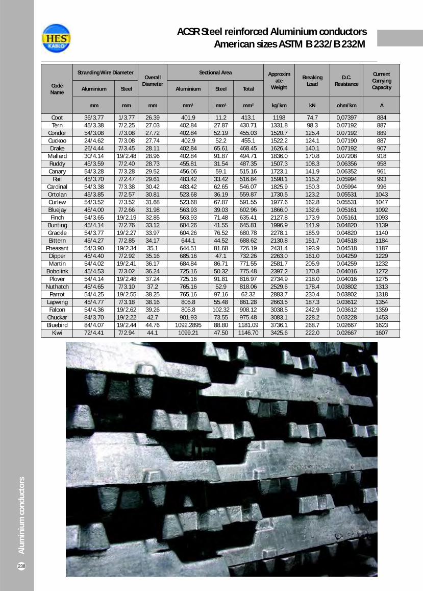
ACSR Steel reinforced Aluminium conductorsAmerican sizes ASTM B 232/B 232M
Alü
min
yum
İlet
ken
Alu
min
ium
co
nd
uct
ors
238
Code Name
Stranding Wire Diameter Overall
Diameter
Sectional Area Approximate
Weight
Breaking Load
D.C. Resistance
Current Carrying CapacityAluminium Steel Aluminium Steel Total
mm mm mm mm² mm² mm² kg/km kN ohm/km A
Coot
Tern
Condor
Cuckoo
Drake
Mallard
Ruddy
Canary
Rail
Cardinal
Ortolan
Curlew
Bluejay
Finch
Bunting
Grackle
Bittern
Pheasant
Dipper
Martin
Bobolink
Plover
Nuthatch
Parrot
Lapwing
Falcon
Chuckar
Bluebird
Kiwi
36/3.77
45/3.38
54/3.08
24/4.62
26/4.44
30/4.14
45/3.59
54/3.28
45/3.70
54/3.38
45/3.85
54/3.52
45/4.00
54/3.65
45/4.14
54/3.77
45/4.27
54/3.90
45/4.40
54/4.02
45/4.53
54/4.14
45/4.65
54/4.25
45/4.77
54/4.36
84/3.70
84/4.07
72/4.41
1/3.77
7/2.25
7/3.08
7/3.08
7/3.45
19/2.48
7/2.40
7/3.28
7/2.47
7/3.38
7/2.57
7/3.52
7/2.66
19/2.19
7/2.76
19/2.27
7/2.85
19/2.34
7/2.92
19/2.41
7/3.02
19/2.48
7/3.10
19/2.55
7/3.18
19/2.62
19/2.22
19/2.44
7/2.94
26.39
27.03
27.72
27.74
28.11
28.96
28.73
29.52
29.61
30.42
30.81
31.68
31.98
32.85
33.12
33.97
34.17
35.1
35.16
36.17
36.24
37.24
37.2
38.25
38.16
39.26
42.7
44.76
44.1
401.9
402.84
402.84
402.9
402.84
402.84
455.81
456.06
483.42
483.42
523.68
523.68
563.93
563.93
604.26
604.26
644.1
644.51
685.16
684.84
725.16
725.16
765.16
765.16
805.8
805.8
901.93
1092.2895
1099.21
11.2
27.87
52.19
52.2
65.61
91.87
31.54
59.1
33.42
62.65
36.19
67.87
39.03
71.48
41.55
76.52
44.52
81.68
47.1
86.71
50.32
91.81
52.9
97.16
55.48
102.32
73.55
88.80
47.50
413.1
430.71
455.03
455.1
468.45
494.71
487.35
515.16
516.84
546.07
559.87
591.55
602.96
635.41
645.81
680.78
688.62
726.19
732.26
771.55
775.48
816.97
818.06
62.32
861.28
908.12
975.48
1181.09
1146.70
1198
1331.8
1520.7
1522.2
1626.4
1836.0
1507.3
1723.1
1598.1
1825.9
1730.5
1977.6
1866.0
2127.8
1996.9
2278.1
2130.8
2431.4
2263.0
2581.7
2397.2
2734.9
2529.6
2883.7
2663.5
3038.5
3083.1
3736.1
3425.6
74.7
98.3
125.4
124.1
140.1
170.8
108.3
141.9
115.2
150.3
123.2
162.8
132.6
173.9
141.9
185.9
151.7
193.9
161.0
205.9
170.8
218.0
178.4
230.4
187.3
242.9
228.2
268.7
222.0
0,07397
0.07192
0.07192
0.07190
0.07192
0.07208
0.06356
0.06352
0.05994
0.05994
0.05531
0.05531
0.05161
0.05161
0.04820
0.04820
0.04518
0.04518
0.04259
0.04259
0.04016
0.04016
0.03802
0.03802
0.03612
0.03612
0.03228
0.02667
0.02667
884
887
889
887
907
918
958
961
993
996
1043
1047
1092
1093
1139
1140
1184
1187
1229
1232
1272
1275
1313
1318
1354
1359
1453
1623
1607

ACSR Steel reinforced Aluminium conductorsCanadian sizes CSA C 49
Alu
min
ium
co
nd
uct
ors
239
Code Name
Stranding Wire Diameter Overall
Diameter
Sectional Area Approximate
Weight
Breaking Load
D.C. Resistance
Current Carrying CapacityAluminium Steel Aluminium Steel Total
mm mm mm mm² mm² mm² kg/km kN ohm/km A
Wren
Warbler
Turkey
Thrush
Swan
Swallow
Sparrow
Robin
Raven
Quail
Pigeon
Penguin
Owl
Waxwing
Partridge
Phoebe
Ostrich
Piper
Merlin
Linnet
Oriole
Chickadee
Ibis
Lark
Pelican
-
Hawk
Hen
Heron
-
Dove
Eagle
-
Duck
-
Grosbeak
Egret
Goose
-
Gull
Starling
Redwing
-
Crow
Drake
Mallard
-
Condore
-
Crane
-
6/1.33
6/1.50
6/1.68
6/1.89
6/2.12
6/2.38
6/2.67
6/3.00
6/3.37
6/3.78
6/4.25
6/4.77
6/5.36
18/3.09
26/2.57
18/3.28
26/2.73
30/2.54
18/3.47
26/2.89
30/2.69
18/3.77
26/3.14
30/2.92
18/4.14
22/3.74
26/3.44
30/3.20
30/3.28
22/4.04
26/3.72
30/3.46
22/4.21
54/2.69
22/4.32
26/3.97
30/3.70
54/2.76
42/3.20
54/2.82
26/4.21
30/3.92
42/3.31
54/2.92
26/4.44
30/4.14
42/3.50
54/3.08
42/3.67
54/3.23
42/3.72
1/1.33
1/1.50
1/1.68
1/1.89
1/2.12
1/2.38
1/2.67
1/3.00
1/3.37
1/3.78
1/4.25
1/4.77
7/1.74
1/3.09
7/2.00
1/3.28
7/2.12
7/2.54
1/3.47
7/2.25
7/2.69
1/3.77
7/2.44
7/2.92
1/4.14
7/2.08
7/2.67
7/3.20
7/3.28
7/2.24
7/2.89
7/3.46
7/2.34
7/2.69
7/2.40
7/3.09
19/2.22
7/2.76
7/1.78
7/2.82
7/3.28
19/2.35
7/1.84
7/2.92
7/3.45
19/2.48
7/1.94
7/3.08
7/2.04
7/3.23
7/2.07
3.99
4.5
5.04
5.67
6.36
7.14
8.01
9
10.11
11.34
12.75
14.31
16.09
15.15
16.28
16.4
17.28
17.78
17.35
18.31
18.83
18.85
19.88
20.44
20.7
21.2
21.77
22.4
22.96
22.88
23.55
24.22
23.86
24.21
24.48
25.15
25.9
24.84
24.54
25.38
26.68
27.43
25.38
26.28
28.11
28.96
26.82
27.72
28.14
29.07
28.53
8.39
10.59
13.29
16.77
21.16
26.65
33.61
42.39
53.48
67.42
85.03
107.23
135.16
135.16
135.16
152
152
152
170.45
170.45
170.45
201.42
201.42
201.42
241.68
241.68
241.68
241.68
253.35
282
282
282
306.58
306.58
322.26
322.26
322.26
322.26
337.74
337.74
362.58
362.58
362.58
362.58
402.84
402.8
402.8
402.8
443.1
443.1
456.1
1.42
1.34
2.19
2.77
3.55
4.45
5.61
7.1
8.9
11.23
14.19
17.87
17.55
7.48
22
8.45
24.71
35.48
9.48
27.81
39.81
11.16
32.77
46.97
13.42
23.74
39.42
56.39
59.1
27.68
45.94
65.81
30.07
39.81
31.61
52.45
73.55
41.74
17.35
43.81
59.03
82.58
18.65
46.97
65.61
91.84
20.71
52.19
22.84
57.48
23.42
9.81
11.93
15.48
19.54
24.71
31.09
39.22
49.49
62.38
78.65
99.22
125.1
152.7
142.6
157.2
160.5
176.7
187.5
179.9
198.3
210.3
212.6
234.2
248.4
255.1
265.4
281.1
298.1
312.5
309.7
327.9
347.8
336.7
346.4
353.9
374.7
395.8
364
355.1
381.6
421.6
445.2
381.2
409.6
468.5
494.7
423.6
455
465.9
500.7
479.5
34
43
54
68
85
108
136
171
215
273
343
433
508
430
545
483
613
697
543
687
783
641
813
923
769
853
975
1108
1162
993
1137
1293
1080
1159
1135
1299
1467
1217
1068
1277
1462
1648
1148
1369
1624
1832
1274
1521
1402
1674
1442
3.3
4.2
5.2
6.5
8.2
10.0
12.4
15.5
19.0
10.8
29.7
37.5
42.5
31.5
50.01
35.5
56.2
68.6
39.8
62.5
75.8
46.3
72.0
88.8
54.8
68.6
86.5
103.9
108.8
79.1
99.9
121.2
84.9
100.1
84.8
111.2
140.6
105.2
78.6
109.2
125.0
153.9
84.3
117.2
139
171.0
93.6
127.0
102
133
105
3.4226
2.7139
2.1535
1.7077
1.3537
1.0738
0.8504
0.6752
0.5351
0.4245
0.3366
0.2671
0.2119
0.2126
0.2136
0.1893
0.19
0.1903
0.1686
0.1696
0.1696
0.143
0.1434
0.1437
0.1191
0.1194
0.1194
0.1198
0.1142
0.1024
0.1024
0.1027
0.0942
0.0945
0.0896
0.0896
0.0896
0.0899
0.0856
0.0856
0.0797
0.0797
0.0797
0.0797
0.0715
0.0719
0.0719
0.0719
0.0653
0.0653
0.0633
63
67
86
93
109
126
140
162
186
211
241
276
322
319
321
341
343
348
364
368
370
402
404
410
449
452
450
453
469
496
495
497
519
520
532
530
542
534
546
553
575
581
573
577
611
618
610
615
645
649
655

ACSR Steel reinforced Aluminium conductorsCanadian sizes CSA C 49
Alü
min
yum
İlet
ken
Alu
min
ium
co
nd
uct
ors
240
Code Name
Stranding Wire Diameter Overall
Diameter
Sectional Area Approximate
Weight
Breaking Load
D.C. Resistance
Current Carrying CapacityAluminium Steel Aluminium Steel Total
mm mm mm mm² mm² mm² kg/km kN ohm/km A
Canary
-
Cardinal
-
Curlew
-
Finch
-
Grackle
-
Pheasant
-
Martin
-
Plover
-
Parrot
-
Falcon
-
Bantam
Magpie
Shrike
Snipe
Loon
Grouse
Petrel
Minorca
Leghorn
Guinea
Dotterell
Dorking
Brahma
Auk
Cochin
54/3.28
42/3.38
54/3.38
42/3.99
54/3.51
42/4.41
54/3.65
42/4.28
54/3.77
42/4.42
54/3.90
42/4.56
54/4.02
42/4.69
54/4.14
42/4.82
54/4.25
48/4.36
54/4.36
72/3.77
3/1.68
3/2.12
3/2.67
3/3.37
3/3.78
8/2.54
12/2.34
12/2.44
12/2.69
12/2.92
12/3.08
12/3.20
16/2.86
8/4.05
12/3.37
7/3.28
7/2.13
7/3.38
7/2.21
7/3.51
7/2.30
19/2.19
7/2.38
19/2.27
7/2.46
19/2.34
7/2.53
19/2.41
7/2.61
19/2.48
7/2.67
19/2.55
7/3.60
19/2.62
7/2.52
4/1.68
4/2.12
4/2.67
4/3.37
4/3.78
1/4.24
7/2.34
7/2.44
7/2.69
7/2.92
7/3.08
7/3.20
19/2.48
7/2.25
7/3.37
29.52
29.87
30.42
30.57
31.59
31.74
32.85
32.82
33.97
33.9
35.1
34.95
36.17
35.97
37.24
36.93
38.25
38.58
39.26
37.72
5.04
6.36
8.01
10.11
11.34
9.32
11.7
12.2
13.45
14.6
15.4
16
18.12
14.83
16.85
456.1
483.4
483.4
523.7
523.7
563.9
563.9
604.3
604.26
644.51
644.51
684.84
684.84
725.1
725.1
765.35
765.4
805.7
805.7
805.7
6.65
10.58
16.84
26.17
33.68
40.52
51.61
56.13
68.19
80.68
89.48
96.71
102.97
102.84
107.1
59.1
24.84
62.65
26.97
67.87
28.97
71.55
31.1
76.58
33.16
81.68
35.23
86.71
37.35
91.87
39.35
96.84
71.1
102.1
34.84
8.84
14.13
22.45
35.68
44.97
14.13
30.01
32.77
39.81
46.97
52.19
56.39
91.87
92.32
62.45
515,20
508,24
546,05
550,67
591,57
592,87
635,45
635,40
680,84
677,67
726,19
720,07
771,55
762,45
816,97
804,70
862,24
876,80
907,80
840,54
15,49
24,71
39,29
61,85
78,65
54,65
81,62
88,90
108,00
127,65
141,67
153,10
194,84
195,16
169,55
1724
1528
1826
1657
1978
1783
2121
1911
2271
2039
2421
2166
2573
2294
2725
2420
2877
2779
3028
2498
87.80
139.70
222.60
354.10
445.80
221.20
376.90
311.30
498.50
587.80
654.80
706.90
1004.9
500.00
782.8
144
109.0
152
118
165
126
179
135
192
144
199
153
212
162
224
171
237
212
250
176
11.7
18.6
28.6
43.9
55.3
23.1
43.8
47.7
57.5
67.6
73.0
78.9
122.5
49.6
87.4
0.0633
0.0597
0.0597
0.0551
0.0551
0.0512
0.0512
0.0479
0.0479
0.0449
0.0449
0.0423
0.0423
0.0397
0.04
0.0377
0.0377
0.0358
0.0358
0.0358
4.3218
2.7077
1.7054
1.0718
0.8514
0.7077
0.5591
0.5134
0.4226
0.3579
0.3215
0.2982
0.2815
0.2789
0.2694
660
678
682
710
715
741
746
772
776
800
805
829
835
858
862
885
890
929
917
910
61
77
99
132
149
157
193
198
221
244
260
271
287
276
288

ACSR Steel reinforced Aluminium conductorsGerman sizes DIN EN 50182
Alu
min
ium
co
nd
uct
ors
241
Code
Stranding Wire Diameter Overall
Diameter
Sectional Area Approximate
Weight Breaking
Load D.C.
Resistance
Current Carrying Capacity
Al Steel Aluminium Steel Total
mm mm mm mm² mm² mm² kg/km kN ohm/km A
16/2.5
25/4
35/6
44/32
50/8
50/30
70/12
95/15
95/55
105/75
120/20
120/70
125/30
150/25
170/40
185/30
210/35
210/50
230/30
240/40
265/35
300/50
305/40
340/30
380/50
385/35
435/55
450/40
490/65
495/35
510/45
550/70
560/50
570/40
650/45
680/85
1045/45
6/1.80
6/2.25
6/2.70
14/2.00
6/3.20
12/2.33
26/1.85
26/2.15
12/3.20
14/3.10
26/2.44
12/3.60
30/2.33
26/2.70
30/2.70
26/3.00
26/3.20
30/3.00
24/3.50
26/3.45
24/3.74
26/3.86
54/2.68
48/3.00
54/3.00
48/3.20
54/3.20
48/3.45
54/3.40
45/3.74
48/3.68
54/3.60
48/3.86
45/4.02
45/4.30
54/4.00
72/4.30
1/1.80
1/2.25
1/2.70
7/2.40
1/3.20
7/2.33
7/1.44
7/1.67
7/3.20
19/2.25
7/1.90
7/3.60
7/2.33
7/2.10
7/2.70
7/2.33
7/2.49
7/3.00
7/2.33
7/2.68
7/2.49
7/3.00
7/2.68
7/2.33
7/3.00
7/2.49
7/3.20
7/2.68
7/3.40
7/2.49
7/2.87
7/3.60
7/3.00
7/2.68
7/2.87
19/2.40
7/2.87
5.4
6.8
8.1
11.2
9.6
11.7
11.7
13.6
16
17.5
15.5
18
16.1
17.1
18.9
19
20.3
21.3
21
21.9
22.4
24.5
24.1
25
27
26.7
28.8
28.7
30.6
29.9
30.7
32.4
32.2
32.2
34.4
36
43
15.3
23.8
34.3
44
48.3
51.2
69.9
94.4
96.5
105.7
121.6
122
127.9
148.9
171.8
183.8
209.1
212.1
230.9
243
263.7
304.3
304.6
339.3
382
386
434.3
448.7
490.3
494.4
510.15
550
561.7
571.2
653.5
678.8
1045.6
2.5
4
5.7
31.7
8
29.8
11.4
15.3
56.3
75.5
19.8
71.3
29.8
24.2
40.1
29.8
34.1
49.5
29.8
39.5
34.1
49.5
39.5
29.8
49.5
34.1
56.3
39.5
63.6
34.1
45.3
71.3
49.5
39.5
45.3
86
45.3
17.9
27.8
40
75.7
56.3
81
81.3
110
153
182
141
193
158
173
212
214
243
262
261
283
298
354
344
369
432
420
491
488
554
528.4
555.8
621
611
610.6
698.8
765
1010
62
96
139
369
195
375
282
381
707
885
491
895
587
601
788
741
844
973
871
980
994
1227
1151
1171
1443
1334
1641
1549
1853
1632
1765
2077
1940
1887
2160
2550
3248
5.81
9.02
12.70
45.46
17.18
44.28
26.31
35.17
80.20
106.69
44.94
98.16
57.86
54.37
77.01
66.28
74.94
92.25
73.09
86.46
82.94
105.09
99.30
92.56
120.91
104.31
136.27
120.19
152.85
117.96
133.31
166.32
146.28
136.4
156.18
206.56
218.92
1.8793
1.2028
0.8353
0.6573
0.5946
0.5644
0.4130
0.3058
0.2992
0.2736
0.2374
0.2364
0.2259
0.1939
0.1682
0.1571
0.1380
0.1363
0.1249
0.1188
0.1094
0.0949
0.0949
0.0851
0.0757
0.0748
0.0666
0.0644
0.0590
0.0584
0.0566
0.0526
0.0514
0.0506
0.0442
0.0426
0.0277
105
140
170
-
210
-
290
350
-
-
410
-
425
470
520
535
590
610
630
645
680
740
740
790
840
850
900
920
960
985
995
1020
1040
1050
1120
1150
1580

AER
Cab
les
242
0.6/1kV PE insulated aerial power cables with aluminium conductor
Construction
Code: AER
Standards: TS 11654, SFS 2200, HD 626 S1
ApplicationIt is prefered to use of AER cables instead of uninsulated conductors at low voltage networks. AER cables are especiallyused at areas where the cost of underground networks is expensive and also for electrification of rural areas like villages.
Technical DataMax. operating temperature : 90 °C
Max. short circuit temperature : 250 °C (max. 5 sec.)
Rated voltage : 0.6/1 kV
1 3Solid or stranded aluminium conductor Messenger wire2 PE or XLPE insulation
123
Number Of Conductor
Cross Section
INSULATED WIRES MESSENGER WIRE FINISHED CABLE
mm² mm² Adet mm ohm/km A mm² A mm kN ohm/km mm kg/km
1x16+1x16+25
3x16+1x16+25
3x25+1x16+35
3x35+1x16+50
3x50+1x16+70
3x70+1x16+95
4x16+1x16+25
4x25+1x16+35
4x35+1x16+50
4x50+1x16+70
4x70+1x16+95
1x16
3x16
3x25
3x35
3x50
3x70
4x16
4x25
4x35
4x50
4x70
1
1
7
7
7
7
1
7
7
7
7
4.4
4.4
5.9
6.9
8.1
9.6
4.4
5.9
6.9
8.1
9.3
70
60
80
95
120
150
60
80
95
120
150
1x16
1x16
1x16
1x16
1x16
1x16
1x16
1x16
1x16
1x16
1x16
60
60
60
60
60
60
60
60
60
60
60
5.9
5.9
6.9
8x1
9.6
11.4
5.9
6.9
8.1
9.63
11.4
7.4
7.1
10.3
14.2
20.6
27.9
7.4
10.3
14.2
20.6
27.9
1.38
1.38
0.986
0.72
0.493
0.363
1.38
0.986
0.72
0.493
0.363
15
22
26
30
35
41
25
30
34
40
47
225
350
475
625
800
1100
410
610
810
1060
1420
1.91
1.91
1.2
0.868
0.641
0.443
1.91
1.2
0.868
0.641
0.443
Conductor size
Number of
wires
Resistance of
20 °C
Diameter of
conductors
Resistance of
20 °C
Current Carrying Capacity
Current Carrying Capacity
Diameter of
Messenger Wire
Minimum Tensile
Strenght
Maximum Resistance of
20 °C
App.Max. Bundle
Diameter
App. Net Weight
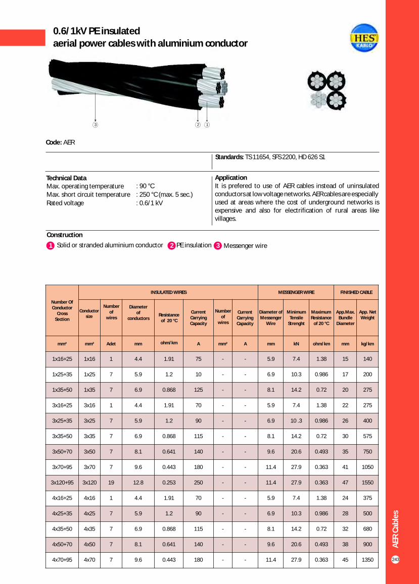
243
0.6/1kV PE insulated aerial power cables with aluminium conductor
Construction
Code: AER
Standards: TS 11654, SFS 2200, HD 626 S1
ApplicationIt is prefered to use of AER cables instead of uninsulated conductors at low voltage networks. AER cables are especiallyused at areas where the cost of underground networks is expensive and also for electrification of rural areas like villages.
Technical DataMax. operating temperature : 90 °C
Max. short circuit temperature : 250 °C (max. 5 sec.)
Rated voltage : 0.6/1 kV
1 3Solid or stranded aluminium conductor Messenger wire2 PE insulation
12
Number Of Conductor
Cross Section
INSULATED WIRES MESSENGER WIRE FINISHED CABLE
Resistance of 20 °C
Current Carrying Capacity
mm² mm² Adet mm ohm/km A mm² A mm kN ohm/km mm kg/km
1x16+25
1x25+35
1x35+50
3x16+25
3x25+35
3x35+50
3x50+70
3x70+95
3x120+95
4x16+25
4x25+35
4x35+50
4x50+70
4x70+95
AER
Cab
les
1x16
1x25
1x35
3x16
3x25
3x35
3x50
3x70
3x120
4x16
4x25
4x35
4x50
4x70
1
7
7
1
7
7
7
7
19
1
7
7
7
7
4.4
5.9
6.9
4.4
5.9
6.9
8.1
9.6
12.8
4.4
5.9
6.9
8.1
9.6
1.91
1.2
0.868
1.91
1.2
0.868
0.641
0.443
0.253
1.91
1.2
0.868
0.641
0.443
75
10
125
70
90
115
140
180
250
70
90
115
140
180
-
-
-
-
-
-
-
-
-
-
-
-
-
-
-
-
-
-
-
-
-
-
-
-
-
-
-
-
5.9
6.9
8.1
5.9
6.9
8.1
9.6
11.4
11.4
5.9
6.9
8.1
9.6
11.4
7.4
10.3
14.2
7.4
10 .3
14.2
20.6
27.9
27.9
7.4
10.3
14.2
20.6
27.9
1.38
0.986
0.72
1.38
0.986
0.72
0.493
0.363
0.363
1.38
0.986
0.72
0.493
0.363
15
17
20
22
26
30
35
41
47
24
28
32
38
45
140
200
275
275
400
575
750
1050
1550
375
500
680
900
1350
Conductor size
Number of
wires
Diameter of
conductors
App. Net Weight
3
App.Max. Bundle
Diameter
Maximum Resistance
of 20 °C
MinimumTensile
Strenght
Diameter of Messenger
Wire
Current Carrying Capacity
Number of
wires
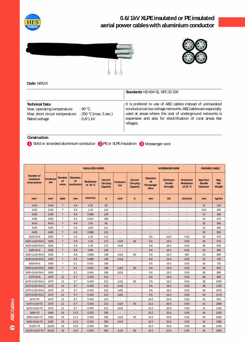
AB
C C
able
s
244
0.6/1kV XLPE insulated or PE insulated aerial power cables with aluminium conductor
Construction
Code: NFA2X
Standards: HD 604 S1, NFC 33 209
It is prefered to use of ABC cables instead of uninsulated conductors at low voltage networks. ABC cables are especiallyused at areas where the cost of underground networks is expensive and also for electrification of rural areas like villages.
Technical DataMax. operating temperature : 90 °C
Max. short circuit temperature : 250 °C (max. 5 sec.)
Rated voltage : 0.6/1 kV
1 3Solid or stranded aluminium conductor Messenger wire2 PE or XLPE insulation
123
Number of conductor
cross section
INSULATED WIRES MESSENGER WIRE FINISHED CABLE
Resistance of 20 °C
Current Carrying Capacity
Current Carrying Capacity
Diameter of
Messenger Wire
Minimum Tensile
Strenght
Maximum Resistance
of 20 °C
App.Max. Bundle
Diameter
App. Net
Weight
mm² mm² Adet mm ohm/km A mm² A mm kN ohm/km mm kg/km
2x16
2x25
2x35
2x50
4x16
4x25
4x35
3x25+54.6
3x25+1x16+54.6
3x25+2x16+54.6
3x35+54.6
3x35+1x16+54.6
3x35+2x16+54.6
3x50+54.6
3x50+1x16+54.6
3x50+2x16+54.6
3x70+54.6
3x70+1x16+54.6
3x70+2x16+54.6
3x70+1x25+54.6
3x70+2x25+54.6
3x70+70
3x70+1x16+70
3x70+2x16+70
3x95+70
3x95+1x16+70
3x95+2x16+70
3x120+70
3x120+1x16+70
2x16
2x25
2x35
2x50
4x16
4x25
4x35
3x25
3x25
3x25
3x35
3x35
3x35
3x50
3x50
3x50
3x70
3x70
3x70
3x70
3x70
3x70
3x70
3x70
3x95
3x95
3x95
3x120
3x120
7
7
7
7
7
7
7
7
7
7
7
7
7
7
7
7
12
12
12
12
12
12
12
12
19
19
19
19
19
4.6
5.9
6.9
8.1
4.6
5.9
6.9
5.9
5.9
5.9
6.9
6.9
6.9
8.1
8.1
8.1
9.7
9.7
9.7
9.7
9.7
9.7
9.7
9.7
11.5
11.5
11.5
12.8
12.8
1.91
1.20
0.868
0.641
1.91
1x20
0.868
1.20
1.20
1.20
0.86
0.868
0.868
0.641
0.641
0.641
0.443
0.443
0.443
0.443
0.443
0.443
0.443
0.443
0.320
0.320
0.320
0.253
0.253
93
122
129
158
83
111
131
112
112
112
138
138
138
168
168
168
213
213
213
213
213
213
213
213
258
258
258
300
300
-
-
-
-
-
-
-
-
1x16
2x16
-
1x16
2x16
-
1x16
2x16
-
1x16
2x16
1x25
2x25
-
1x16
2x16
-
1x16
2x16
-
1x16
-
-
-
-
-
-
-
-
60
-
-
60
-
-
60
-
-
60
-
-
-
-
60
-
-
60
-
-
60
-
-
-
-
-
-
-
9.6
9.6
9.6
9.6
9.6
9.6
9.6
9.6
9.6
9.6
9.6
9.6
9.6
9.6
10.2
10.2
10.2
10.2
10.2
10.2
10.2
10.2
-
-
-
-
-
-
-
16.0
16.0
16.0
16.0
16.0
16.0
16.0
16.0
16.0
16.0
16.0
16.0
16.0
16.0
20.6
20.6
20.6
20.6
20.6
20.6
20.6
20.6
-
-
-
-
-
-
-
0.63
0.63
0.63
0.63
063
0.63
0.63
0.63
0.63
0.63
0.63
0.63
0.63
0.63
0.50
0.50
0.50
0.50
0.50
0.50
0.50
0.50
15
18,5
22
24
18
22
26
30
30
30
33
33
33
36
36
36
38
38
38
40
40
41
41
41
44
44
44
46
46
132
200
280
370
265
400
550
470
570
640
580
690
750
720
820
890
930
1030
1100
1070
1170
970
1080
1150
1200
1300
1380
1430
1540
Conductor size
Number of
wiresConductor
size
Diameter of
conductors

245
0.6/1kV XLPE insulated or PE insulated aerial power cables with aluminium conductor
AB
C C
able
s
Number of conductor
cross section
INSULATED WIRES MESSENGER WIRE FINISHED CABLE
Resistance of 20 °C
Current Carrying Capacity
Current Carrying Capacity
Diameter of
Messenger Wire
Minimum Tensile
Strenght
Maximum Resistance
of 20 °C
App.Max. Bundle
Diameter
App. Net
Weight
mm² mm² Adet mm ohm/km A mm² A mm kN ohm/km mm kg/km
3x120+2x16+70
3x150+70
3x150+1x16+70
3x150+2x16+70
3x120+95
3x120+1x16+95
3x120+2x16+95
3x150+95
3x150+1x16+95
3x150+2x16+95
Construction
Code: NFA2X
Standards: HD 604 S1, NFC 33 209
It is prefered to use of ABC cables instead of uninsulated conductors at low voltage networks. ABC cables are especiallyused at areas where the cost of underground networks is expensive and also for electrification of rural areas like villages.
Technical DataMax. operating temperature : 90 °C
Max. short circuit temperature : 250 °C (max. 5 sec.)
Rated voltage : 0.6/1 kV
1 3Solid or stranded aluminium conductor Messenger wire2 PE or XLPE insulation
123
3x120
3x150
3x150
3x150
3x120
3x120
3x120
3x150
3x150
3x150
19
19
19
19
19
19
19
19
19
19
12.8
14.5
14.5
14.5
12.8
12.8
12.8
14.5
14.5
14.5
0.253
0.206
0.206
0.206
0.253
0.253
0.253
0.206
0.206
0.206
300
344
344
344
300
300
300
344
344
344
2x16
-
1x16
2x16
-
1x16
2x16
-
1x16
2x16
-
-
60
-
-
60
-
-
60
-
10.2
10.2
10.2
10.2
12.9
12.9
12.9
12.9
12.9
12.9
20.6
20.6
20.6
20.6
27.9
27.9
27.9
27.9
27.9
27.9
0.50
0.50
0.50
0.50
0.343
0.343
0.343
0.343
0.343
0.343
46
48
48
48
47
47
47
49
49
49
1600
1680
1780
1850
1500
1620
1680
1740
1880
1940
Conductor size
Number of
wires
Conductor size
Diameter of
conductors

Composite fiber optic overhead ground wire (OPGW-95)
Co
mp
osi
te F
ibe
r O
pti
c O
verh
ead
Gro
un
d W
ire
(O
PG
W)
246
Definition of OPGWOPGW (optical ground wire) is a type of conductor that is used in the construction of electric power transmission lines. Here the conductor combines both the functions of grounding and communications. OPGW contains a tubuler structure with one or more optical fibers in it, surrounded by layers of galvanized steel and aluminium alloy wire. In the OPGW system, the conductor serves as a normal ground wire, protecting the phase conductors against the lightning strikes. The opticalfibers are integrated in a stainless steel tube filled with a thixotropic jelly and hermetically sealed to provide best protection of enclosed fibers at any stage of the installation or operation.
Optical FibersThe optical fiber of the OPGW is manufactured and designed to provide optimum transmission services. These fibers are used primarily in telecomunications networks characterised by long distance links and high capacity.
Aluminium Clad Steel Wire (AS) (10 x 2.60mm)
Optical Unit (1 x 2.60mm)
Fibers (24 Core)
Aluminium Alloy Wire (AA) (8 x 2.60mm)
TECHNICAL SPECIFICATIONS
Aluminium Alloy Wire Diameter
Aluminium Clad Steel Wire Diameter
O/F Stainless Steel Tube Diameter
OPGW Conductor Diameter
Number of Aluminium Clad Steel Wire
Number of Aluminium Clad Steel Wire
Number of Stainless Steel Tube
Number of Aluminium Alloy (AAA) Wire
Number of Aluminium Clad Steel Wire
Lay Direction
Lay Direction
Total OPGW Cross-Section
Aluminium Alloy Unit Weight
Aluminium Clad Steel Wire Unit Weight
O/F Tube and Jelly Unit Weight
Total OPGW Unit Weight
OPGW Rated Tensile Strength (RTS)
Final Modulus Elasticity of OPGW
Thermal Expansion Coefficient of OPGW
Permissible Max. Working Stress
Medium High Tension
Endurance Tensile Strength (ETS)
Short Time Overcurrent (0.5 second) (40-180°C)
Temperature After Short Time Overcurrent
Working Temperature (Max.)
Resistance at 20 °C (Max.)
O/F Stainless Steel Tube Diameter (Inner/Outer)
Fiber Count
Working Temperature
mm
mm
mm
mm
center
1 st Layer
1 st Layer
2 nd Layer
2 nd Layer
1 st Layer
2 nd Layer
mm²
kg/km
kg/km
kg/km
kg/km
daN
daN/mm²
10-6/°C
daN
daN
daN
A
°C
°C
ohm/km
mm
-
°C
2.60 ± 0.03
2.60 ± 0.05
2.60 ± 0.05
13.00 ± 0.5
1
5
1
8
4
Left-Hand (S-twist)
Right-Hand (Z-twist)
95.6
115
350
16
485
8200
11844
15.1
3280
1312 - 2050
5740
14000
180
80
0.540
2.2/2.6
12-24
-40 to 80
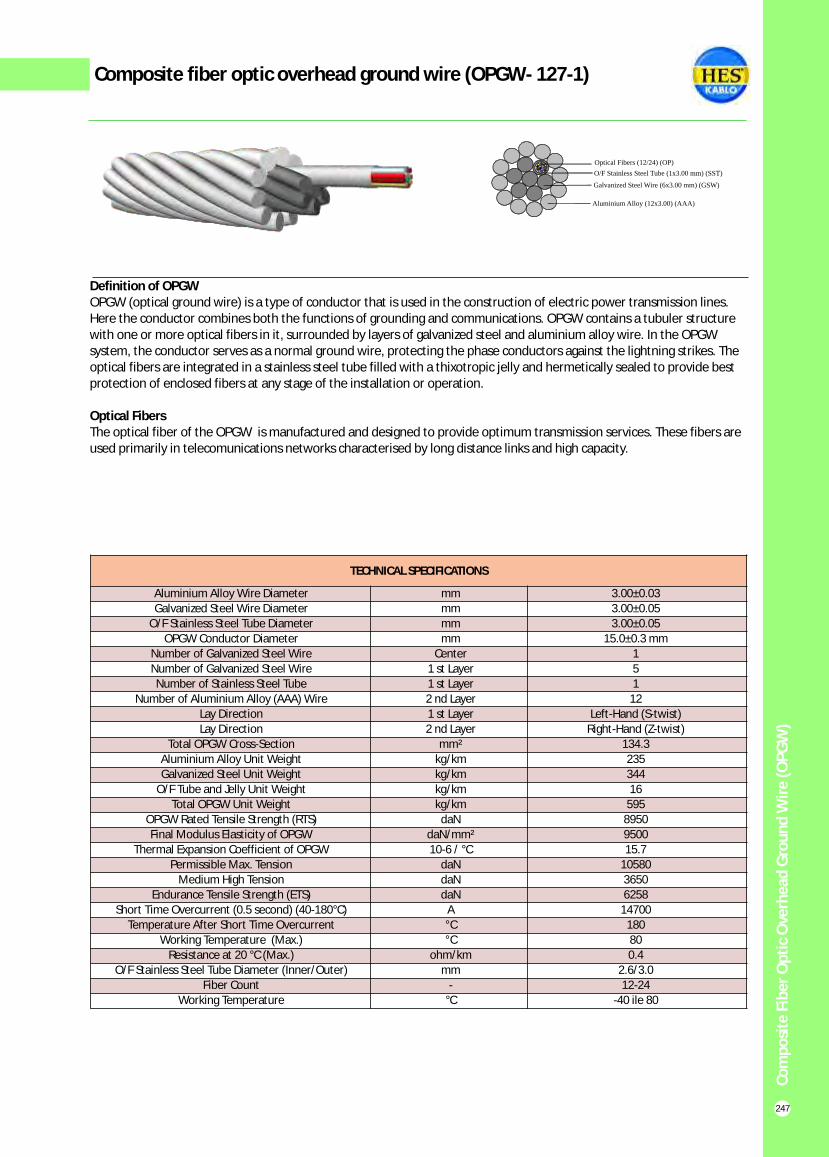
Composite fiber optic overhead ground wire (OPGW- 127-1)
Co
mp
osi
te F
ibe
r O
pti
c O
verh
ead
Gro
un
d W
ire
(O
PG
W)
247
Definition of OPGWOPGW (optical ground wire) is a type of conductor that is used in the construction of electric power transmission lines. Here the conductor combines both the functions of grounding and communications. OPGW contains a tubuler structure with one or more optical fibers in it, surrounded by layers of galvanized steel and aluminium alloy wire. In the OPGW system, the conductor serves as a normal ground wire, protecting the phase conductors against the lightning strikes. The optical fibers are integrated in a stainless steel tube filled with a thixotropic jelly and hermetically sealed to provide best protection of enclosed fibers at any stage of the installation or operation.
Optical FibersThe optical fiber of the OPGW is manufactured and designed to provide optimum transmission services. These fibers are used primarily in telecomunications networks characterised by long distance links and high capacity.
O/F Stainless Steel Tube (1x3.00 mm) (SST)
Optical Fibers (12/24) (OP)
Aluminium Alloy (12x3.00) (AAA)
Galvanized Steel Wire (6x3.00 mm) (GSW)
TECHNICAL SPECIFICATIONS
Aluminium Alloy Wire Diameter
Galvanized Steel Wire Diameter
O/F Stainless Steel Tube Diameter
OPGW Conductor Diameter
Number of Galvanized Steel Wire
Number of Galvanized Steel Wire
Number of Stainless Steel Tube
Number of Aluminium Alloy (AAA) Wire
Lay Direction
Lay Direction
Total OPGW Cross-Section
Aluminium Alloy Unit Weight
Galvanized Steel Unit Weight
O/F Tube and Jelly Unit Weight
Total OPGW Unit Weight
OPGW Rated Tensile Strength (RTS)
Final Modulus Elasticity of OPGW
Thermal Expansion Coefficient of OPGW
Permissible Max. Tension
Medium High Tension
Endurance Tensile Strength (ETS)
Short Time Overcurrent (0.5 second) (40-180°C)
Temperature After Short Time Overcurrent
Working Temperature (Max.)
Resistance at 20 °C (Max.)
O/F Stainless Steel Tube Diameter (Inner/Outer)
Fiber Count
Working Temperature
mm
mm
mm
mm
Center
1 st Layer
1 st Layer
2 nd Layer
1 st Layer
2 nd Layer
mm²
kg/km
kg/km
kg/km
kg/km
daN
daN/mm²
10-6 / °C
daN
daN
daN
A
°C
°C
ohm/km
mm
-
°C
3.00±0.03
3.00±0.05
3.00±0.05
15.0±0.3 mm
1
5
1
12
Left-Hand (S-twist)
Right-Hand (Z-twist)
134.3
235
344
16
595
8950
9500
15.7
10580
3650
6258
14700
180
80
0.4
2.6/3.0
12-24
-40 ile 80

Composite fiber optic overhead ground wire (OPGW-127-2)
248
Definition of OPGWOPGW (optical ground wire) is a type of conductor that is used in the construction of electric power transmission lines. Here the conductor combines both the functions of grounding and communications. OPGW contains a tubuler structure with one or more optical fibers in it, surrounded by layers of galvanized steel and aluminium alloy wire. In the OPGW system, the conductor serves as a normal ground wire, protecting the phase conductors against the lightning strikes. The optical fibers are integrated in a stainless steel tube filled with a thixotropic jelly and hermetically sealedto provide best protection of enclosed fibers at any stage of the installation or operation.
Optical FibersThe optical fiber of the OPGW is manufactured and designed to provide optimum transmission services. These fibers are used primarily in telecomunications networks characterised by long distance links and high capacity.
O/F Stainless Steel Tube (1x3.00 mm) (SST)
Optical Fibers (12/24) (OP)
Aluminium Alloy (8x3.00) (AAA)
Aluminium Clad Steel Wire (10x3.00 mm) (ACSW)
TECHNICAL SPECIFICATIONS
Aluminium Alloy Wire Diameter
Aluminium Clad Steel Wire Diameter
O/F Stainless Steel Tube Diameter
OPGW Conductor Diameter
Number of Aluminium Clad Steel Wire
Number of Aluminium Clad Steel Wire
Number of Stainless Steel Tube
Number of Aluminium Alloy (AAA) Wire
Number of Aluminium Clad Steel Wire
Lay Direction
Lay Direction
Total OPGW Cross-Section
Aluminium Alloy Unit Weight
Aluminium Clad Steel Wire Unit Weight
O/F Tube and Jelly Unit Weight
Total OPGW Unit Weight
OPGW Rated Tensile Strength (RTS)
Final Modulus Elasticity of OPGW
Thermal Expansion Coefficient of OPGW
Permissible Max. Working Stress
Medium High Tension
Endurance Tensile Strength (ETS)
Short Time Overcurrent (0.5 second) (40-180 °C )
Temperature After Short Time Overcurrent
Working Temperature (Max.)
Resistance at 20 °C (Max.)
O/F Stainless Steel Tube Diameter (Inner/Outer)
Fiber Count
Working Temperature
mm
mm
mm
mm
center
1 st Layer
1 st Layer
2 nd Layer
2 nd Layer
1 st Layer
2 nd Layer
mm²
kg/km
kg/km
kg/km
kg/km
daN
daN/mm²
10-6/°C
daN
daN
daN
A
°C
°C
ohm/km
mm
-
°C
3.00 ± 0.03
3.00 ± 0.05
3.00 ± 0.05
15.00 ± 0.5
1
5
1
8
4
Left-Hand (S-twist)
Right-Hand (Z-twist)
134.3
152.8
465.6
16.0
634.4
10700
11200
15.1
4280
1712 - 2675
7490
14600
180
80
0.4
2.6/3.0
12-24
-40 ile 80
Co
mp
osi
te F
ibe
r O
pti
c O
verh
ead
Gro
un
d W
ire
(O
PG
W)

Composite fiber optic overhead ground wire (OPGW)
Co
mp
osi
te F
ibe
r O
pti
c O
verh
ead
Gro
un
d W
ire
(O
PG
W)
249
General application of single mode fibers
Both G.652 and G.655 are called as single mode fibers which are optimized for OPGW network. The most important advantageous are,
- They have lowest PMD (polarization mode dispersion) value- Better joining performance- They are characterized with high wavelength rates (up to 1625 nm)
NZDS(non-zero dispersion shifted)Fiber designed for DWDM applications. It is characterised by very low dispersion from 1530 to 1625 nm and a high effective area, which prevents the non-linear effects of high speed in this type of transmission, offering improved service in comparison to the previous fibers.
12 FIBER TUBE COLORS FIBER NO 24 FIBER TUBE COLORS
RED 1
YELLOW 2
GREEN 3
BLUE 4
VIOLET 5
BROWN
6
BLACK or GRAY
7
ORANGE
8
PINK
9
GRAY or AQUA
10
LIGHT GREEN or WHITE
11
NATURAL
12
13 RED with BLACK RINGS
14 YELLOW with BLACK RINGS
15 GREEN with BLACK RINGS
16 BLUE with BLACK RINGS
17 VIOLET with BLACK RINGS
18 BROWN with BLACK RINGS
19 WHITE with BLACK RINGS
20 ORANGE with BLACK RINGS
21 PINK with BLACK RINGS
22 GRAY with BLACK RINGS
23 LIGHT GREEN with BLACK RINGS
24 NATURAL with BLACK RINGS
50-60 mm 2.0 mm
Fiber
Black Rings
RED
YELLOW
GREEN
BLUE
VIOLET
BROWN
BLACK or GRAY
ORANGE
PINK
GRAY or AQUA
LIGHT GREEN or WHITE
NATURAL

Composite fiber optic overhead ground wire (OPGW)
Co
mp
osi
te F
ibe
r O
pti
c O
verh
ead
Gro
un
d W
ire
(O
PG
W)
250

Copper rod
Co
pp
er
Ro
d
251
Copper Rod as the main material in cable production is produced in three sequantial stages; anode casting, electrolysing and rod drawing.
Quality of copper is continiously controlled in order to produce high quality of copper for high quality of cable thereafter.
The copper is supplied as electrolytic cathode or as copper rod in requested diameters as well.
StandardsEN 1977

Copper rod
Co
pp
er
Ro
d
ANODE CASTING UNIT
ELECTROLYSIS UNIT
252
Anode is produced from blister copper or scrap copper which is melted in 2 rotary furnaces each having the capacity of 30 tons/day. The production capacity of anode casting unit is about 30.000 tons/year. Weight of each anode copper produced is about 300-350 kg. The impurities are checked during the melting process so that the quality of anode copper is obtained as required. The samples taken from the anodes are tested and the production is arranged in accordance.
Copper anodes are refined and the impurities are eliminated in electrolysing process and cathode copper with 99.99 % purity is produced. Average weight of each cathode is between 100 – 125 kg and the production capacity is 24.000 tons/year.
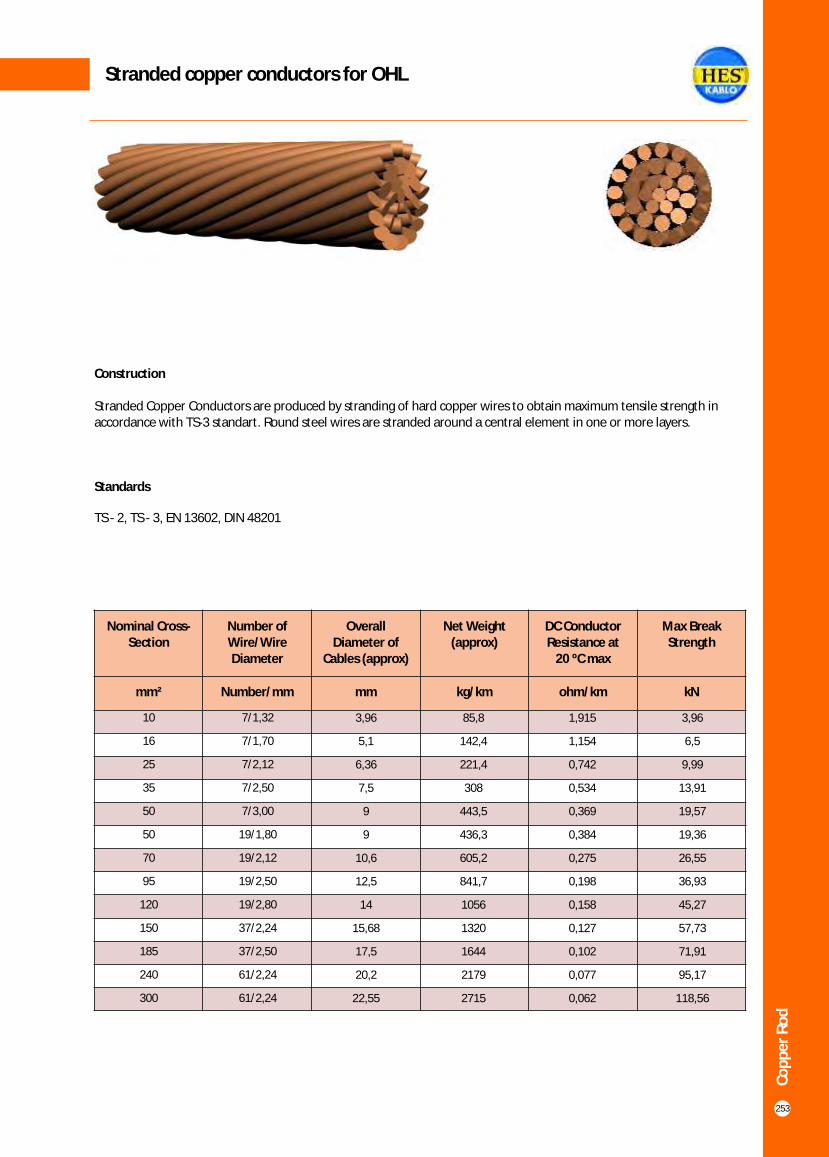
Stranded copper conductors for OHL
Co
pp
er
Ro
d
Construction
Stranded Copper Conductors are produced by stranding of hard copper wires to obtain maximum tensile strength in accordance with TS-3 standart. Round steel wires are stranded around a central element in one or more layers.
Standards
TS - 2, TS - 3, EN 13602, DIN 48201
253
Nominal Cross-Section
Number of Wire/Wire Diameter
Overall Diameter of
Cables (approx)
Net Weight (approx)
DC Conductor Resistance at
20 ºC max
Max Break Strength
mm² Number/mm mm kg/km ohm/km kN
10
16
25
35
50
50
70
95
120
150
185
240
300
7/1,32
7/1,70
7/2,12
7/2,50
7/3,00
19/1,80
19/2,12
19/2,50
19/2,80
37/2,24
37/2,50
61/2,24
61/2,24
3,96
5,1
6,36
7,5
9
9
10,6
12,5
14
15,68
17,5
20,2
22,55
85,8
142,4
221,4
308
443,5
436,3
605,2
841,7
1056
1320
1644
2179
2715
1,915
1,154
0,742
0,534
0,369
0,384
0,275
0,198
0,158
0,127
0,102
0,077
0,062
3,96
6,5
9,99
13,91
19,57
19,36
26,55
36,93
45,27
57,73
71,91
95,17
118,56

Annealed electrolytic copper conductor
Co
pp
er
Ro
d
Construction
Soft annealed copper conductors are manufactured according to EN 13602 and ASTM B3-1990
Standards
EN 13602, EN 60228
254
Nominal Cross Section
Number of Wire Overall Diameter of
Cables (Approx)
Net Weight (Approx)
DC Conductor Resistance at
20 ºC max
mm² Number mm kg/km ohm/km
10
16
25
35
50
70
95
120
150
185
240
300
7
7
7
7
10
14
19
24
30
37
49
60
3,9
4,90
6,10
7,0
8,05
9,75
11,45
12,9
14,25
15,90
18,13
20,45
85,2
135,4
214,4
296,8
406,2
586,9
810,6
1030,6
1255
1575,6
2086
2620
1,83
1,15
0,727
0,524
0,387
0,268
0,193
0,153
0,124
0,0991
0,0754
0,0601
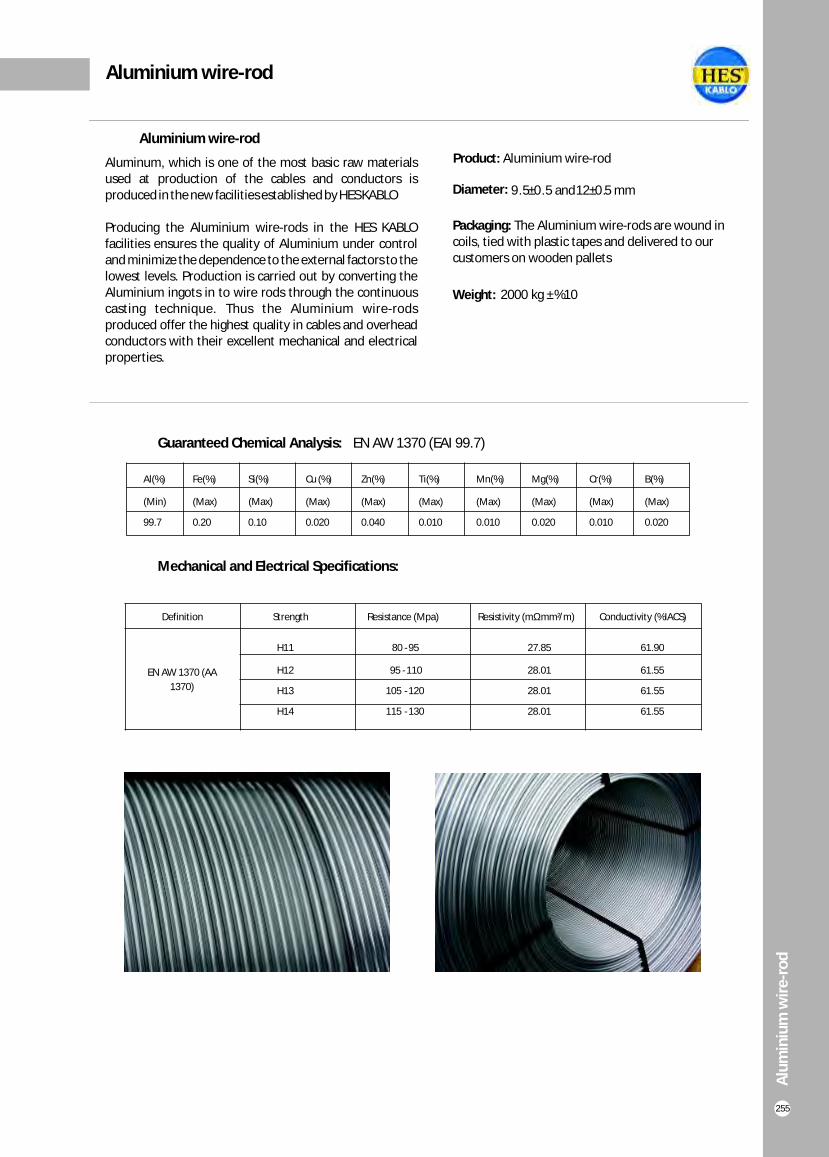
Aluminium wire-rod
Definition Strength Resistance (Mpa) Resistivity (mΩmm²/m) Conductivity (%IACS)
EN AW 1370 (AA
1370)
H11 80 -95 27.85 61.90
H12 95 -110 28.01 61.55
H13 105 -120 28.01 61.55
H14 115 -130 28.01 61.55
Guaranteed Chemical Analysis: EN AW 1370 (EAI 99.7)
Al(%) Fe(%) Si(%) Cu (%) Zn(%) Ti(%) Mn(%) Mg(%) Cr(%) B(%)
(Min) (Max) (Max) (Max) (Max) (Max) (Max) (Max) (Max) (Max)
99.7 0.20 0.10 0.020 0.040 0.010 0.010 0.020 0.010 0.020
Mechanical and Electrical Specifications:
Aluminium wire-rod
Alü
min
yum
İlet
ken
Alü
min
yum
İlet
ken
Alu
min
ium
wir
e-r
od
255
Aluminum, which is one of the most basic raw materials used at production of the cables and conductors is produced in the new facilities established by HES KABLO
Producing the Aluminium wire-rods in the HES KABLO facilities ensures the quality of Aluminium under control and minimize the dependence to the external factors to the lowest levels. Production is carried out by converting the Aluminium ingots in to wire rods through the continuous casting technique. Thus the Aluminium wire-rods produced offer the highest quality in cables and overhead conductors with their excellent mechanical and electrical properties.
Product: Aluminium wire-rod
Diameter:
Packaging:
customers on wooden pallets
The Aluminium wire-rods are wound in coils, tied with plastic tapes and delivered to our
Weight:
9.5±0.5 and12±0.5 mm
2000 kg ±%10

Insulation colors used in installation and low voltage cables are as follows. The cables available in our stocks are shown in color
Energy cables insulation colours
256
Blue-Brown
Blue-Brown-Yellow/Green
Brown-Black-Gray-Yellow/Green
Cable Type No. of coresO Type
(no Yellow-Green wire)J Type
(withYellow-Green wire)
2
3
4
5
>5
2
5
>5
0.6/1 kV LOW VOLTAGE CABLES
INSTALLATION CABLES
Blue-Brown
Gray-Brown-Black Blue-Brown-Yellow/Green
Blue-Brown-Black-Yellow/Green
Yellow/Green and all remaining black numbered All black numbered with white colours
NVV (NYM)H03VV-F H05VV-F
NHXMH 052XZ1-F
H07VVH6-F
Blue-Brown-Black-Gray
Blue-Brown-Black-Gray-Black Blue-Brown-Black-Gray-Yellow/Green
Blue-Brown-Black-Gray
Blue-Brown-Black-Gray-Black
All black numbered with white colours
Blue-Brown-Black-Gray-Yellow/Green
Yellow/Green and all remaining black numbered
Gray-Brown-Black
3
4
YVV (NYY)YVCV (NYCY)YVZ2V (NYRY)YVZ3V (NYFGY)YXV (2XY)N2XH N2XH FE 180YAVV (NAYY)
Tech
nic
al in
form
atio
n

Technical information
Tech
nic
al in
form
atio
n
257
Cable to the current loading conditions:
Heat arising from a cable under load should be spread to the envirmoment by every point on the surface of cable. Current load of the cable should be restricted according to this condition.Current carrying capacities of cables given on the tables are prepared to meet the following installation conditions:
A) In air (It is assumed that the cables are protected from sun light): Environmental Temperature :30 °C Loading factor :1.0
It is also assumed that the heat arising from cable is not prevented to spread, environmental temperature is not heating source. If the cables are installed minimum 2 m distance from the nearest flor,ceiling or wall, these conditions are met. Distance between the cables installed side by side should be at least 2 times the diameter of the cable. Distance between the cables installed one on the top of the other should be at least 2 times the diameter of the cable. This distance is about 20 cm for cable installing systems. Because of the heat spreading effect, suitable distances should be arranged between the cables and also ducts are properly ventilated.
B) In duct Environmental Temperature :30 °C Loading factor :1.0
C) In Ground Environmental Temperature :20 °C Loading factor :0.7 Thermal resistivity of soil :0.7 K.m/W(very moist soil)
:1.0 K.m/W(moist soil):1.5 K.m/W(dry soil):2.5 K.m/W(very dry soil)
Installation depth :70 cm No. of cable system :1
For the given current values it is assument that cables are directly installed to the underground which is lay downed by sand and bonded by bricks. In this case cable canal consists of limited numbers of cable ducts each of them not longer than 6 m. Also it assume that the cable joints are protected from direct sun light.Current loading capacities of the cables can also vary according to spesific heat resistance of the insulation material. This value
For PVC insulated cables :6.0 K.m/W For XLPE insulated cables :3.5 K.m/W
If cable installation conditions are different then above conditions,current carrying capacities can be calculated by multiplying the currents given on the related tables.Current carring capacities of the cables for Standard installation conditions are given on Tables 1-4, and for other operating conditions on Table 5-14

Technical information
Tech
nic
al in
form
atio
n
258
TABLE 1Load capacity for 0.6/1 kV PVC and XLPE insulated cables with copper conductor
A) In gorund : 20°C, 70 cm depth of lay, soil-thermal resistivity 1 K.m/W, load factor 0.7B) In air : 30°C, load factor 1.0
Method of laying : Side by side, clearance between cables; in air= 1 x Cable outer diameter, in ground=7cm) : Bunched laying 1 (Number of system)
TABLE 2Load capacity for 0.6/1kV PVC and XLPE insulated cables with aluminium conductor
A) In gorund : 20°C, 70 cm depth of lay, soil-thermal resistivity 1 K.m/W, load factor 0.7B) In air : 30°C, load factor 1.0
Method of laying : Side by side, clearance between cables; in air= 1 x Cable outer diameter, in ground=7cm: Bunched laying1 (Number of system)
lnsulation materialPermissible conductor temp.
PVC 70°C
XLPE 90°C
Number of cores 1 2 3-4 1 3-4
Nominal cross-section area
mm A B A B A B A B A B A B A B
1.5
2.5
4
6
10
16
25
35
50
70
95
120
150
185
240
300
400
500
-
-
-
-
-
127
163
195
230
282
336
382
428
483
561
632
730
823
25
34
45
57
78
103
137
169
206
261
321
374
428
494
590
678
817
940
-
-
-
-
-
107
137
165
195
239
287
326
366
414
481
542
624
698
20
27
37
48
66
89
118
145
176
224
271
314
361
412
484
549
657
749
32
42
54
68
90
116
150
181
215
264
317
360
406
458
537
-
-
-
20
27
37
48
66
89
118
145
176
224
271
314
361
412
484
-
-
-
26
34
44
56
75
98
128
157
185
228
275
313
353
399
464
524
600
-
18.5
25
34
43
60
80
106
131
159
202
244
282
324
371
436
481
560
-
39
51
66
82
109
139
179
213
251
307
366
416
465
526
610
689
788
889
32
42
56
71
96
128
173
212
258
328
404
471
541
626
749
864
1018
1173
32
43
55
68
90
115
149
178
211
259
310
352
396
449
521
587
669
748
25
34
44
57
77
102
139
170
208
265
326
381
438
507
606
697
816
933
30
40
52
64
86
111
143
173
205
252
303
346
390
441
511
580
663
-
24
32
42
53
73
96
130
160
195
247
305
355
407
469
551
638
746
-
lnsulation materialPermissible conductor temp.
PVC 70°C
XLPE 90°C
Number of cores 1 2 3-4 1 3-4
Nominal cross-section area
mm A B A B A B A B A B A B A B
25
35
50
70
95
120
150
185
240
300
400
500
-
151
179
218
261
297
332
376
437
494
572
649
-
131
160
202
249
291
333
384
460
530
642
744
-
127
151
186
223
254
285
323
378
427
496
562
-
113
138
174
210
244
281
320
378
433
523
603
-
-
-
-
-
-
-
-
-
-
-
91
113
138
174
210
244
281
320
378
-
-
-
99
118
142
176
211
242
270
308
363
412
475
-
83
102
124
158
190
221
252
289
339
377
444
-
-
164
195
238
284
323
361
408
476
537
616
699
-
163
200
254
313
366
420
486
585
675
798
926
-
137
163
201
240
274
308
350
408
462
531
601
-
131
161
205
253
296
341
395
475
548
647
749
111
132
157
195
233
266
299
340
401
455
526
-
100
122
147
189
232
270
308
357
435
501
592
-

lnsulation material
Permissible conductor temp.
XLPE 90°C
Rated voltage 3.5/6 kV 5.8/10 kV-8.7/15 kV 12/20 kV 18/30 kV -20.8/36 kV
Number of cores1 3 1 3 1 3 1 3
Nominal cross-section area
mmrA B A B A B A B A B A B A B A B A B A B A B A B
Tech
nic
al in
form
atio
n
259
Technical information
TABLE 3Load capacity for medium voltage, XLPE insulated cables with copper conductor
A) In gorund : 20°C, 70 cm depth of lay, soil-thermal resistivity 1 K.m/W, load factor 0.7B) In air : 30°C, load factor 1.0
Method of laying : Side by side, clearance between cables; in air= 1 x Cable outer diameter, in ground=7cm) : Bunched laying 1 (Number of system)
TABLE 4Load capacity for medium voltage XLPE insulated cables with aluminium conductor
A) In gorund : 20°C, 70 cm depth of lay, soil-thermal resistivity 1 K.m/W, load factor 0.7B) In air : 30°C, load factor 1.0
Method of laying : Side by side, clearance between cables; in air= 1 x Cable outer diameter, in ground=7cm: Bunched laying 1 (Number of system)
25
35
50
70
95
120
150
185
240
300
400
500
185
201
241
301
364
424
479
549
640
724
795
883
180
238
285
356
435
496
554
637
746
846
941
1051
154
191
227
277
331
379
422
476
550
619
695
773
167
199
241
301
365
419
479
543
640
731
840
949
149
176
208
255
307
353
396
447
523
581
653
-
141
171
196
249
307
353
406
464
548
632
726
-
179
212
249
303
358
404
441
493
563
626
676
743
191
231
277
345
418
481
537
612
716
811
901
1006
157
187
220
269
321
364
405
457
528
593
665
739
162
195
234
292
354
407
460
527
621
709
815
921
148
178
210
256
307
349
392
443
513
576
650
-
143
173
206
257
313
360
410
469
553
635
731
-
-
213
250
304
361
407
445
498
569
633
686
756
-
233
279
347
420
483
540
614
718
813
904
1011
-
189
223
273
325
368
410
463
534
601
674
750
-
199
238
296
358
412
466
532
627
715
819
927
-
183
216
264
316
360
404
457
532
599
685
-
-
182
217
269
326
377
426
488
576
654
750
-
-
214
251
306
363
410
449
503
576
641
697
768
-
233
279
348
421
483
540
615
718
812
904
1011
-
192
226
276
329
373
415
468
541
608
684
762
-
202
241
299
362
416
469
536
630
717
823
929
-
181
214
261
313
356
400
441
510
-
-
-
-
176
210
262
319
364
418
478
562
-
-
-
lnsulation material
Permissible conductor temp.
XLPE 90°C
Rated voltage 3.5/6 kV 5.8/10 kV-8.7/15 kV 12/20 kV 18/30 kV -20.8/36 kV
Number of cores1 3 1 3 1 3 1 3
Nominal cross-section area
mmrA B A B A B A B A B A B A B A B A B A B A B A B
35
50
70
95
120
150
185
240
300
400
500
-
186
234
287
338
388
449
530
605
678
762
-
233
280
344
392
441
510
587
682
781
883
-
178
217
259
298
333
377
438
495
562
633
-
188
235
286
329
376
428
508
586
676
772
-
160
199
238
275
307
349
410
460
520
-
-
150
191
236
273
313
360
426
528
564
-
164
194
236
281
318
350
393
453
507
559
622
178
215
269
327
377
424
485
573
652
741
838
144
171
209
249
283
316
358
416
469
532
599
151
181
226
275
317
359
412
489
559
651
744
-
162
199
238
271
304
345
401
453
517
-
-
160
199
242
280
318
365
431
494
569
-
-
195
237
282
320
353
396
457
511
566
630
-
217
270
328
378
425
485
573
652
740
838
-
173
211
252
287
320
362
421
474
538
606
-
184
229
278
320
363
415
493
563
652
746
-
168
207
247
282
316
359
420
476
552
-
-
171
211
255
297
334
384
454
513
593
-
-
196
238
284
322
355
400
461
516
572
638
-
217
270
328
378
425
485
572
649
737
835
-
175
214
256
290
324
366
426
479
545
614
-
187
232
281
323
365
418
494
564
654
747
-
166
204
244
278
312
343
398
476
542
-
-
164
204
248
284
326
374
440
513
583
-

Tech
nic
al in
form
atio
n
260
TS HD 603 S1 - TS HD 604 S1 PREPARED BY STANDARDS
Technical information
Permissible Operation Temperature
Temperature Of Earth
Thermal Resistivity of Earth K.m/W
0.7 1.0 1.5 2.5
Loading Loading Loading Loading
°C °C 0.5 0.6 0.7 0.85 1.00 0.5 0.6 0.7 0.85 1.00 0.5 0.6 0.7 0.85 1.00 05-1.00
XLPE Cables 90 °C
XLPE Cables 90 °C
5
10
15
20
25
30
35
40
5
10
15
20
25
30
35
40
1.24
1.23
1.21
1.19
-
-
-
-
1.29
1.27
1.25
1.23
-
-
-
-
1.21
1.19
1.17
1.15
-
-
-
-
1.26
1.23
1.21
1.18
-
-
-
-
1.18
1.16
1.14
1.12
-
-
-
-
1.22
1.19
1.17
1.14
-
-
-
-
1.13
1.11
1.08
1.06
-
-
-
-
1.15
1.13
1.10
1.08
-
-
-
-
1.07
1.05
1.03
1.00
-
-
-
-
1.09
1.06
1.03
1.01
-
-
-
-
1.11
1.09
1.07
1.05
1.02
-
-
-
1.13
1.11
1.08
1.06
1.03
-
-
-
1.09
1.07
1.05
1.02
1.00
-
-
-
1.11
1.08
1.06
1.03
1.00
-
-
-
1.07
1.05
1.02
1.00
0.98
0.95
-
-
1.08
1.06
1.03
1.00
0.97
0.94
-
-
1.03
1.01
0.99
0.96
0.94
0.91
-
-
1.04
1.01
0.99
0.96
0.93
0.89
-
-
1.00
0.98
0.95
0.93
0.90
0.88
-
-
1.00
0.97
0.94
0.91
0.88
0.85
-
-
0.99
0.97
0.95
0.92
0.90
0.87
-
-
0.99
0.96
0.93
0.90
0.87
0.84
-
-
0.98
0.96
0.93
0.91
0.88
0.86
-
-
0.98
0.95
0.92
0.89
0.85
0.82
-
-
0.97
0.95
0.92
0.90
0.87
0.84
0.82
-
0.97
0.94
0.91
0.87
0.84
0.80
0.77
-
0.96
0.93
0.91
0.88
0.85
0.83
0.80
-
0.95
0.92
0.88
0.85
0.82
0.78
0.74
-
0.94
0.91
0.89
0.86
0.84
0.81
0.78
-
0.93
0.89
0.86
0.83
0.79
0.76
0.72
-
0.89
0.86
0.84
0.81
0.78
0.75
0.72
0.68
0.86
0.83
0.79
0.76
0.72
0.68
0.63
0.59
TABLE 5Rating factor for all cables (not applicable to PVC cables with Uo/U=6/10kVfor installation in ground and differing air temperature
TABLE 6Rating factor for installation in ground. Single-core cables in three-phase system, bunched
Type of Construct
ion
Soil-termal
resistivity
Method of laying 7 cm
0.7 1.0 1.5 2.5
°C °C 0.5 0.6 0.7 0.85 1.00 0.5 0.6 0.7 0.85 1.00 0.5 0.6 0.7 0.85 1.00 0.5 0.6 0.7 0.85 1.00
XLPEInsulated
Cables
0.6/1kV-36 kV
PVCInsulated
Cables
0.6/1kV - 6/10 kV
1
2
3
4
5
6
8
10
1
2
3
4
5
6
8
10
1.09
0.97
0.88
0.83
0.79
0.76
0.72
0.69
1.01
0.94
0.86
0.82
0.78
0.75
0.71
0.68
1.04
0.90
0.80
0.75
0.71
0.68
0.64
0.61
1.02
0.89
0.79
0.75
0.71
0.68
0.64
0.61
0.99
0.84
0.74
0.69
0.65
0.62
0.58
0.56
0.99
0.84
0.74
0.69
0.65
0.62
0.58
0.55
0.93
0.77
0.67
0.62
0.58
0.55
0.51
0.49
0.93
0.77
0.67
0.62
0.58
0.55
0.51
0.49
0.87
0.71
0.61
0.56
0.52
0.50
0.46
0.44
0.87
0.71
0.61
0.56
0.52
0.50
0.46
0.44
1.11
0.98
0.89
0.84
0.80
0.77
0.72
0.69
1.04
0.97
0.89
0.84
0.80
0.77
0.72
0.69
1.05
0.91
0.82
0.76
0.72
0.69
0.65
0.62
1.05
0.91
0.81
0.76
0.72
0.69
0.65
0.62
1.00
0.85
0.75
0.70
0.66
0.63
0.59
0.56
1.00
0.85
0.75
0.70
0.66
0.63
0.59
0.56
0.93
0.77
0.67
0.62
0.58
0.55
0.52
0.49
0.93
0.77
0.67
0.62
0.58
0.55
0.52
0.49
0.87
0.71
0.61
0.56
0.52
0.50
0.46
0.44
0.87
0.71
0.61
0.56
0.52
0.50
0.46
0.44
1.13
1.00
0.90
0.85
0.80
0.77
0.73
0.70
1.07
0.99
0.90
0.85
0.80
0.77
0.73
0.69
1.07
0.92
0.82
0.77
0.73
0.70
0.65
0.62
1.06
0.92
0.83
0.77
0.73
0.70
0.65
0.62
1.01
0.86
0.76
0.70
0.66
0.63
0.59
0.56
1.01
0.86
0.76
0.71
0.66
0.64
0.59
0.56
0.94
0.77
0.68
0.62
0.58
0.56
0.52
0.49
0.94
0.77
0.68
0.62
0.58
0.56
0.52
0.49
0.87
0.71
0.61
0.56
0.52
0.50
0.46
0.44
0.87
0.71
0.61
0.56
0.52
0.50
0.46
0.44
1.17
1.02
0.92
0.82
0.81
0.78
0.74
0.70
1.11
1.01
0.91
0.86
0.81
0.78
0.73
0.70
1.09
0.94
0.83
0.78
0.73
0.70
0.66
0.63
1.08
0.93
0.83
0.78
0.73
0.70
0.66
0.63
1.03
0.87
0.76
0.71
0.67
0.64
0.59
0.57
1.01
0.87
0.77
0.71
0.67
0.64
0.60
0.57
0.94
0.78
0.68
0.63
0.59
0.56
0.52
0.49
0.94
0.78
0.68
0.63
0.59
0.56
0.52
0.49
0.87
0.71
0.61
0.56
0.52
0.50
0.46
0.44
0.87
0.71
0.61
0.56
0.52
0.50
0.46
0.44

Tech
nic
al in
form
atio
n
261
TS HD 603 S1 - TS HD 604 S1 PREPARED BY STANDARDS
Technical information
TABLE 8Rating factor for installation in ground. Single-core cables in three-phase system, bunched
Type of Construct
ion
Soil-termal
resistivity
Method of laying 25 cm
0.7 1.0 1.5 2.5
°C km/W 0.5 0.6 0.7 0.85 1.00 0.5 0.6 0.7 0.85 1.00 0.5 0.6 0.7 0.85 1.00 0.5 0.6 0.7 0.85 1.00
XLPEInsulated
Cables
0.6/1kV-36 kV
PVCInsulated
Cables
0.6/1kV - 6/10 kV
1
2
3
4
5
6
8
10
1
2
3
4
5
6
8
10
1.09
1.01
0.94
0.91
0.88
0.86
0.83
0.81
1.01
0.97
0.94
0.91
0.88
0.86
0.83
0.82
1.04
0.94
0.87
0.84
0.80
0.79
0.76
0.74
1.02
0.95
0.88
0.84
0.81
0.79
0.76
0.75
0.99
0.89
0.81
0.78
0.74
0.72
0.70
0.68
0.99
0.89
0.82
0.78
0.75
0.73
0.70
0.69
0.93
0.82
0.74
0.70
0.67
0.65
0.62
0.60
0.93
0.82
0.74
0.70
0.67
0.65
0.62
0.60
0.87
0.75
0.67
0.64
0.60
0.59
0.56
0.54
0.87
0.75
0.67
0.64
0.60
0.59
0.56
0.54
1.11
1.02
0.95
0.92
0.89
0.87
0.84
0.82
1.04
1.00
0.97
0.92
0.89
0.87
0.84
0.82
1.05
0.95
0.88
0.84
0.81
0.79
0.76
0.74
1.05
0.96
0.88
0.85
0.82
0.80
0.77
0.75
1.00
0.89
0.82
0.78
0.75
0.73
0.70
0.68
1.00
0.90
0.82
0.79
0.76
0.74
0.71
0.69
0.93
0.82
0.74
0.70
0.67
0.65
0.62
0.60
0.93
0.82
0.74
0.70
0.67
0.65
0.62
0.60
0.87
0.75
0.67
0.64
0.60
0.59
0.56
0.54
0.87
0.75
0.67
0.64
0.60
0.59
0.56
0.54
1.13
1.04
0.97
0.93
0.90
0.88
0.85
0.83
1.07
1.03
0.97
0.93
0.90
0.88
0.85
0.83
1.07
0.97
0.89
0.85
0.82
0.80
0.77
0.75
1.06
0.97
0.89
0.86
0.82
0.81
0.78
0.76
1.01
0.90
0.82
0.79
0.75
0.73
0.70
0.68
1.01
0.91
0.83
0.79
0.76
0.74
0.71
0.69
0.94
0.82
0.74
0.70
0.67
0.65
0.62
0.61
0.94
0.82
0.74
0.70
0.67
0.65
0.62
0.61
0.87
0.75
0.67
0.64
0.60
0.59
0.56
0.54
0.87
0.75
0.67
0.64
0.60
0.59
0.56
0.54
1.17
1.06
0.99
0.95
0.91
0.89
0.86
0.84
1.11
1.06
0.98
0.95
0.91
0.89
0.86
0.84
1.09
0.98
0.90
0.86
0.83
0.81
0.78
0.76
1.08
0.98
0.90
0.87
0.83
0.81
0.78
0.76
1.03
0.91
0.83
0.79
0.76
0.74
0.71
0.69
1.01
0.92
0.84
0.80
0.77
0.75
0.72
0.70
0.94
0.83
0.74
0.71
0.67
0.65
0.62
0.61
0.94
0.83
0.74
0.71
0.67
0.65
0.62
0.61
0.87
0.75
0.67
0.64
0.60
0.59
0.56
0.54
0.87
0.75
0.67
0.64
0.60
0.59
0.56
0.54
TABLE 9Rating factor for installation in ground. Single-core cables in three-phase system, side by side
Type of Construct
ion
Soil-termal
resistivity
Method of laying 7 cm
0.7 1.0 1.5 2.5
°C km/W 0.5 0.6 0.7 0.85 1.00 0.5 0.6 0.7 0.85 1.00 0.5 0.6 0.7 0.85 1.00 0.5 0.6 0.7 0.85 1.00
XLPEInsulated
Cables
0.6/1kV-36 kV
PVCInsulated
Cables
0.6/1kV - 6/10 kV
1
2
3
4
5
6
8
10
1
2
3
4
5
6
8
10
1.08
1.01
0.92
0.88
0.84
0.82
0.79
0.77
0.96
0.92
0.88
0.86
0.84
0.82
0.79
0.77
1.05
0.93
0.84
0.80
0.76
0.74
0.71
0.69
0.97
0.89
0.84
0.80
0.76
0.74
0.71
0.69
0.99
0.86
0.77
0.73
0.69
0.67
0.64
0.62
0.98
0.86
0.77
0.73
0.70
0.68
0.65
0.63
0.91
0.77
0.69
0.65
0.61
0.59
0.57
0.55
0.91
0.77
0.69
0.65
0.61
0.59
0.57
0.55
0.85
0.71
0.62
0.58
0.55
0.53
0.51
0.49
0.85
0.71
0.62
0.58
0.55
0.53
0.51
0.49
1.13
1.03
0.93
0.89
0.85
0.83
0.80
0.78
1.01
0.96
0.91
0.89
0.85
0.83
0.80
0.78
1.07
0.94
0.85
0.80
0.77
0.75
0.71
0.69
1.01
0.94
0.85
0.81
0.77
0.75
0.72
0.70
1.00
0.87
0.77
0.73
0.70
0.68
0.65
0.63
1.00
0.87
0.78
0.74
0.70
0.68
0.65
0.63
0.92
0.78
0.69
0.65
0.61
0.60
0.57
0.55
0.92
0.78
0.69
0.65
0.61
0.60
0.57
0.55
0.85
0.71
0.62
0.58
0.55
0.53
0.51
0.49
0.85
0.71
0.62
0.58
0.55
0.53
0.51
0.49
1.18
1.05
0.95
0.90
0.87
0.84
0.81
0.78
1.07
1.00
0.95
0.90
0.87
0.84
0.81
0.79
1.09
0.95
0.86
0.81
0.78
0.75
0.72
0.70
1.05
0.95
0.86
0.82
0.78
0.76
0.72
0.70
1.01
0.88
0.78
0.74
0.70
0.68
0.65
0.63
1.01
0.88
0.79
0.74
0.71
0.69
0.65
0.63
0.92
0.78
0.69
0.65
0.62
0.60
0.57
0.55
0.92
0.78
0.69
0.65
0.62
0.60
0.57
0.55
0.85
0.71
0.62
0.58
0.55
0.53
0.51
0.49
0.85
0.71
0.62
0.58
0.55
0.53
0.51
0.49
1.19
1.06
0.96
0.91
0.87
0.85
0.81
0.79
1.16
1.05
0.96
0.91
0.87
0.85
0.81
0.79
1.11
0.96
0.86
0.82
0.78
0.76
0.72
0.70
1.10
0.97
0.87
0.82
0.79
0.76
0.73
0.71
1.03
0.88
0.79
0.74
0.71
0.69
0.65
0.63
1.02
0.89
0.79
0.75
0.71
0.69
0.66
0.64
0.93
0.79
0.69
0.65
0.62
0.60
0.57
0.55
0.93
0.79
0.69
0.65
0.62
0.60
0.57
0.55
0,85
0,71
0.62
0.58
0.55
0.53
0.51
0.49
0.85
0.71
0.62
0.58
0.55
0.53
0.51
0.49
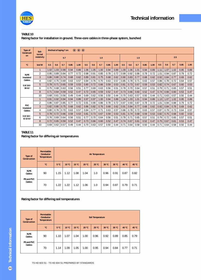
Tech
nic
al in
form
atio
n
262
TS HD 603 S1 - TS HD 604 S1 PREPARED BY STANDARDS
Technical information
TABLE 10Rating factor for installation in ground. Three-core cables in three-phase system, bunched
Type of Constructi
on
Soil-termal
resistivity
Method of laying 7 cm
0.7 1.0 1.5 2.5
°C km/W 0.5 0.6 0.7 0.85 1.00 0.5 0.6 0.7 0.85 1.00 0.5 0.6 0.7 0.85 1.00 0.5 0.6 0.7 0.85 1.00
XLPEInsulated
Cables
0.6/1kV-36 kV
PVCInsulated
Cables
0.6/1kV - 6/10 kV
1
2
3
4
5
6
8
10
1
2
3
4
5
6
8
10
1.02
0.95
0.86
0.82
0.78
0.75
0.71
0.68
0.91
0.86
0.82
0.80
0.78
0.76
0.72
0.69
1.03
0.89
0.80
0.75
0.71
0.68
0.64
0.61
0.92
0.87
0.80
0.76
0.72
0.69
0.65
0.62
0.99
0.84
0.74
0.69
0.65
0.63
0.59
0.56
0.94
0.85
0.75
0.70
0.66
0.64
0.59
0.57
0.94
0.77
0.68
0.63
0.59
0.56
0.52
0.49
0.94
0.77
0.68
0.63
0.59
0.56
0.52
0.49
0.89
0.72
0.62
0.57
0.53
0.51
0.47
0.44
0.89
0.72
0.62
0.57
0.53
0.51
0.47
0.44
1.06
0.98
0.89
0.84
0.80
0.77
0.72
0.69
0.97
0.91
0.86
0.84
0.81
0.77
0.73
0.70
1.05
0.91
0.81
0.76
0.72
0.69
0.65
0.62
0.97
0.90
0.82
0.77
0.73
0.70
0.66
0.63
1.00
0.85
0.75
0.70
0.66
0.63
0.59
0.56
1.00
0.86
0.76
0.71
0.67
0.64
0.60
0.57
0.94
0.78
0.68
0.63
0.59
0.56
0.52
0.50
0.94
0.78
0.68
0.63
0.59
0.56
0.52
0.50
0.89
0.72
0.62
0.57
0.53
0.51
0.47
0.44
0.89
0.72
0.62
0.57
0.53
0.51
0.47
0.44
1.09
0.99
0.90
0.85
0.81
0.78
0.73
0.70
1.04
0.97
0.91
0.86
0.81
0.78
0.74
0.71
1.06
0.92
0.83
0.78
0.73
0.70
0.66
0.63
1.03
0.93
0.84
0.78
0.74
0.71
0.67
0.64
1.01
0.86
0.77
0.71
0.67
0.64
0.60
0.57
1.01
0.87
0.77
0.72
0.68
0.65
0.61
0.58
0.94
0.78
0.68
0.63
0.59
0.57
0.52
0.50
0.94
0.78
0.68
0.63
0.59
0.57
0.52
0.50
0.89
0.72
0.62
0.57
0.53
0.51
0.47
0.44
0.89
0.72
0.62
0.57
0.53
0.51
0.47
0.44
1.11
1.01
0.92
0.86
0.82
0.79
0.74
0.71
1.13
1.01
0.92
0.87
0.82
0.79
0.75
0.71
1.07
0.94
0.84
0.78
0.74
0.71
0.66
0.63
1.07
0.94
0.84
0.79
0.75
0.72
0.67
0.64
1.02
0.87
0.77
0.72
0.67
0.65
0.60
0.57
1.02
0.88
0.78
0.73
0.68
0.65
0.61
0.58
0.95
0.79
0.69
0.64
0.60
0.57
0.53
0.50
0.95
0.79
0.69
0.64
0.60
0.57
0.53
0.50
0.89
0.72
0.62
0.57
0.53
0.51
0.47
0.44
0.89
0.72
0.62
0.57
0.53
0.51
0.47
0.44
TABLE 11Rating factor for differing air temperatures
Type of Construction
Permissible Conductor
Temperature Air Temperature
°C 5 °C 10 °C 15 °C 20 °C 25 °C 30 °C 35 °C 40 °C 45 °C
XLPECables
PE and PVC Cables
90
70
1.15
1.22
1.12
1.22
1.08
1.12
1.04
1.06
1.0
1.0
0.96
0.94
0.91
0.87
0.87
0.79
0.82
0.71
Rating factor for differing soil temperatures
Type of Construction
Permissible Conductor
Temperature Soil Temperature
°C 5 °C 10 °C 15 °C 20 °C 25 °C 30 °C 35 °C 40 °C 45 °C
XLPECables
PE and PVC Cables
90
70
1.10
1.14
1.07
1.09
1.04
1.05
1.00
1.00
0.96
0.95
0.92
0.94
0.89
0.84
0.85
0.77
0.79
0.71
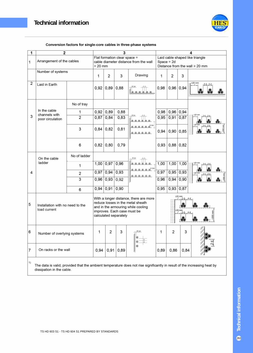
Tech
nic
al in
form
atio
n
263
TS HD 603 S1 - TS HD 604 S1 PREPARED BY STANDARDS
Technical information

Tech
nic
al in
form
atio
n
264
TS HD 603 S1 - TS HD 604 S1 PREPARED BY STANDARDS
Technical information

Tech
nic
al in
form
atio
n
265
TS HD 603 S1 - TS HD 604 S1 PREPARED BY STANDARDS
Technical information

Tech
nic
al in
form
atio
n
266
Technical information
TS HD 603 S1 - TS HD 604 S1 PREPARED BY STANDARDS
Nominal cross sections of conductor
mm2
Resistance
Cu Al
1.5
2.5
4
6
10
16
25
35
50
70
95
120
150
185
240
300
400
?
/ km
?
/ km
12.10
7.41
1.61
3.08
1.83
1.15
0.727
0.524
0.387
0.268
0.193
0.153
0.124
0.0991
0.0754
0.0601
0.0470
-
-
-
-
-
1.91
1.20
0.868
0.641
0.443
0.320
0.253
0.206
0.164
0.125
0.100
0.0778
TABLE 24Effective resistance

TS HD 603 S1 - TS HD 604 S1 PREPARED BY STANDARDS Tech
nic
al in
form
atio
n
267
Technical information

TS HD 620 S2 PREPARED BY STANDARDS
Medium Voltage cables correction factors
Tech
nic
al in
form
atio
n
268
Technical information

TS HD 620 S2 PREPARED BY STANDARDS Tech
nic
al in
form
atio
n
269
Technical information

TABLE 15Permissible operating temperature short-circuit temperature and short circuit currents for cables with copper and aluminium conductor
Tech
nic
al in
form
atio
n
270
Technical information
Number of Cores under load In ground In the air
5
7
10
14
19
24
40
61
0.70
0.60
0.50
0.45
0.40
0.35
0.30
0.25
0.75
0.65
0.55
0.50
0.45
0.40
0.35
0.30
TABLE 14Correction factors for multicore cables laid in ground or in air with cross section from 1.5 to 10 mm² mm²
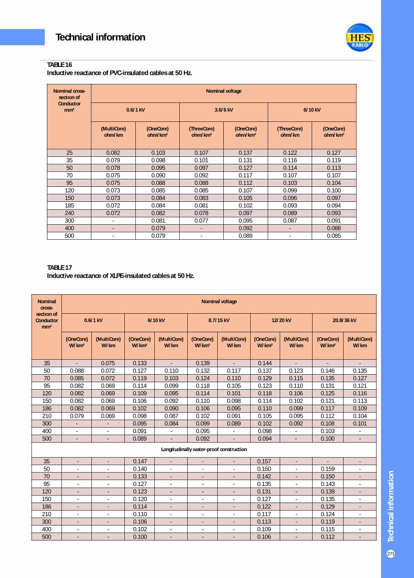
Nominal cross-
sectıon of Conductor
mm²
Nominal voltage
0.6/1 kV 6/10 kV 8.7/15 kV 12/20 kV 20.8/36 kV
(OneCore)W/km²
(MultiCore)W/km
(OneCore)W/km²
(MultiCore)W/km
(OneCore)W/km²
(MultiCore)W/km
(OneCore)W/km²
(MultiCore)W/km
(OneCore)W/km²
(MultiCore)W/km
Longitudinally water-proof construction
Tech
nic
al in
form
atio
n
271
Technical information
Nominal cross-sectıon of Conductor
mm²
Nominal voltage
0.6/1 kV 3.6/6 kV 6/10 kV
(MultiCore)ohm/km
(OneCore)ohm/km²
(ThreeCore)ohm/km²
(OneCore)ohm/km²
(ThreeCore)ohm/km
(OneCore)ohm/km²
0.082
0.079
0.078
0.075
0.075
0.073
0.073
0.072
0.072
-
-
-
0.103
0.098
0.095
0.090
0.088
0.085
0.084
0.084
0.082
0.081
0.079
0.079
0.107
0.101
0.097
0.092
0.088
0.085
0.083
0.081
0.078
0.077
-
-
0.137
0.131
0.127
0.117
0.112
0.107
0.105
0.102
0.097
0.095
0.092
0.089
0.122
0.116
0.114
0.107
0.103
0.099
0.096
0.093
0.089
0.087
-
-
0.127
0.119
0.113
0.107
0.104
0.100
0.097
0.094
0.093
0.091
0.088
0.085
TABLE 16Inductive reactance of PVC-insulated cables at 50 Hz.
TABLE 17Inductive reactance of XLPE-insulated cables at 50 Hz.
35
50
70
95
120
150
186
210
300
400
500
-
0.088
0.085
0.082
0.082
0.082
0.082
0.079
-
-
-
0.075
0.072
0.072
0.069
0.069
0.069
0.069
0.069
-
-
-
0.133
0.127
0.119
0.114
0.109
0.106
0.102
0.098
0.095
0.091
0.089
-
0.117
0.110
0.105
0.101
0.098
0.095
0.091
0.089
-
-
0.144
0.137
0.129
0.123
0.118
0.114
0.110
0.105
0.102
0.098
0.094
-
0.123
0.115
0.110
0.106
0.102
0.099
0.095
0.092
-
-
-
0.110
0.103
0.099
0.095
0.092
0.090
0.087
0.084
-
-
0.139
0.132
0.124
0.118
0.114
0.110
0.106
0.102
0.099
0.095
0.092
-
0.146
0.135
0.131
0.125
0.121
0.117
0.112
0.108
0.103
0.100
-
0.135
0.127
0.121
0.116
0.113
0.109
0.104
0.101
-
-
-
-
-
-
-
-
-
-
-
-
-
35
50
70
95
120
150
186
210
300
400
500
-
-
-
-
-
-
-
-
-
-
-
-
-
-
-
-
-
-
-
-
-
-
0.147
0.140
0.133
0.127
0.123
0.120
0.114
0.110
0.106
0.102
0.100
-
-
-
-
-
-
-
-
-
-
-
-
-
-
-
-
-
-
-
-
-
-
-
-
-
-
-
-
-
-
-
-
-
0.157
0.150
0.142
0.135
0.131
0.127
0.122
0.117
0.113
0.109
0.106
-
-
-
-
-
-
-
-
-
-
-
-
0.159
0.150
0.143
0.139
0.135
0.129
0.124
0.119
0.115
0.112
25
35
50
70
95
120
150
185
240
300
400
500
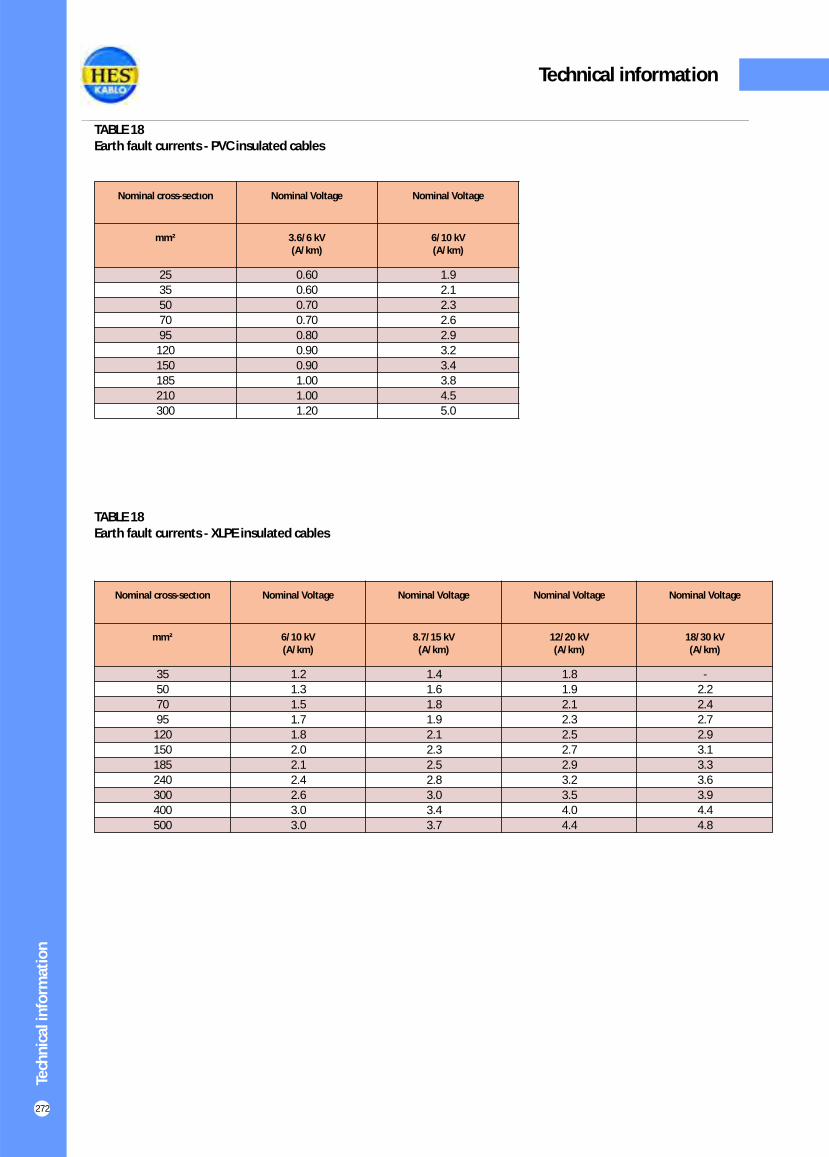
Tech
nic
al in
form
atio
n
272
Technical information
Nominal cross-sectıon Nominal Voltage Nominal Voltage
mm² 3.6/6 kV(A/km)
6/10 kV(A/km)
25
35
50
70
95
120
150
185
210
300
0.60
0.60
0.70
0.70
0.80
0.90
0.90
1.00
1.00
1.20
1.9
2.1
2.3
2.6
2.9
3.2
3.4
3.8
4.5
5.0
TABLE 18Earth fault currents - PVC insulated cables
TABLE 18Earth fault currents - XLPE insulated cables
Nominal cross-sectıon Nominal Voltage Nominal Voltage Nominal Voltage Nominal Voltage
mm² 6/10 kV(A/km)
8.7/15 kV(A/km)
12/20 kV(A/km)
18/30 kV(A/km)
35
50
70
95
120
150
185
240
300
400
500
1.2
1.3
1.5
1.7
1.8
2.0
2.1
2.4
2.6
3.0
3.0
1.4
1.6
1.8
1.9
2.1
2.3
2.5
2.8
3.0
3.4
3.7
1.8
1.9
2.1
2.3
2.5
2.7
2.9
3.2
3.5
4.0
4.4
-
2.2
2.4
2.7
2.9
3.1
3.3
3.6
3.9
4.4
4.8

Tech
nic
al in
form
atio
n
273
Technical information

Tech
nic
al in
form
atio
n
274
(K.d initial temperature 90 °C. final temperature 250 °C).
Technical information
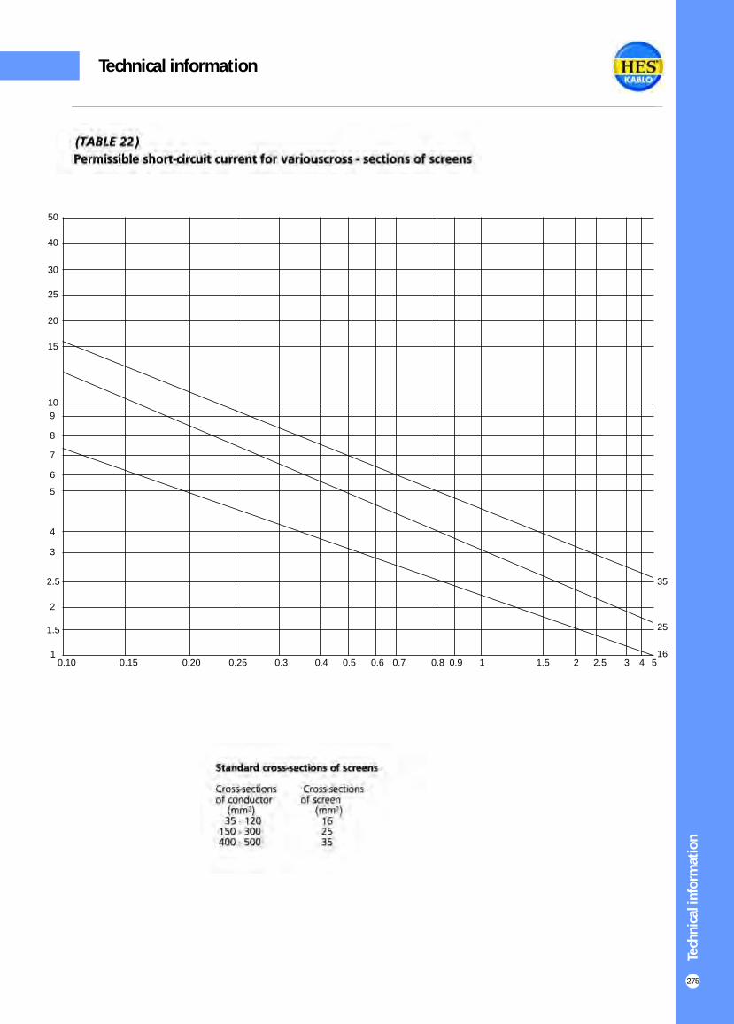
Tech
nic
al in
form
atio
n
275
1
1.5
2
2.5
3
4
5
6
7
8
9
10
15
20
25
30
40
50
0.10 0.15 0.20 0.25 0.3 0.4 0.5 0.6 0.7 0.8 0.9 1 1.5 2 2.5 3 4 516
25
35
Technical information

Tech
nic
al in
form
atio
n
276
Technical information


