
ENHANCEMENT OF HEAT TRANSFER USING TURBULENCE PROMOTERS
207
ENHANCEMENT OF HEAT TRANSFER USING TURBULENCE PROMOTERS A Thesis Submitted to the College of Engineering of Nahrain University in Partial Fulfillment of the Requirements for the Degree of Master of Science in Chemical Engineering by ABBAS NAWAR ZNAD (B.Sc., 1995) Rabee I 1432 February 2011
Transcript of ENHANCEMENT OF HEAT TRANSFER USING TURBULENCE PROMOTERS

ENHANCEMENT OF HEAT TRANSFER USING TURBULENCE PROMOTERS
A Thesis
Submitted to the College of Engineering
of Nahrain University in Partial Fulfillment of the
Requirements for the Degree of Master of Science
in
Chemical Engineering
by
ABBAS NAWAR ZNAD (B.Sc., 1995)
Rabee I 1432
February 2011
Certification
I certiE/ that this thesis entitled .,Enhancement of Heat TransferUsing Turbulence Prornoters" was prepared by Abbas Nawar Znad undermy supewision at Nahrain University/College of Engineering in partial
:.rlfillment of the requirements for the degree of Master of Science inClemical Engineering..
Sigaature:
\ame: Prof,
(Head of Department)
Date: \3 / "-
/ ".,-F
\
/,
7'/(SuprSupervisor)
I2-I24, 1\

Certificate
We certi$', as an examining committee, that we have read the thesis::::iried "Enhancement of Heat Transfer Using Turbulence promotersr',
:ramined the student Abbas Nawar Znad in its content a-nd found it meets---,: standard of thesis for the degree of Master of Science in Chemical::jleering..
i. Qasim J. M. Slaiman Name: Asst. Prof.br. Basim O. Hasan(Supervisor)
/ 2-t zo\l Date:tt(Mernber)
\ j / z / -z- - t \
Signature:
t lt\.1'* )t'-"
(Member)
i - ] / 2/Lorr
:-:r:rc-. al ofthe College ofEngineenng
Name: Asst. Prof. Dr. Balasim A. Abiel
Date:
(Chairman)
13 tz lzol l
Signature: l'1 . 5. -J-il {. IName: Prof. Dr. Muhsin J. Jweeg
@ean)T)are . a l / Z i 7 - -s l \
l l

I
ABSTRACT
Three cases of heat transfer enhancement by turbulence promoters were
adopted in order to increase the thermal performance of a double pipe heat
exchanger of 1245 mm effective length, 28 mm outer diameter and
changeable inner diameter (11 or 14 mm). Wire coils of 1 mm diameter and
10, 20, 30 and 40 mm coiling pitches were used as turbulence promoters to
augment heart transfer inside the inner tube of heat exchanger at a Reynolds
number range of 5000 to 40000 based on smooth tube diameter. Two new
types of turbulence promoters are used to enhance heat transfer in the annulus
of the same double pipe heat exchanger for a Reynolds number range of 3000
to 10000 based on smooth annulus equivalent diameter. The first was by wire
coils of 1 and 2.2 mm diameters and 10, 20, 30 and 40 mm coiling pitches set
up on the outer surface of the inner tube. The second was by circular ribs of
2.2 mm diameter and the same pitches and position. Water was used as the
working fluid in the two sides. Variation in the experimental conditions was
attained by changing the mass flowrates of unenhanced side and changing the
inlet temperature of hot fluid. These conditions were followed in order to
increase the data points in addition to observe the effect of these conditions.
Heat transfer is increased inside the inner tube by 2.43 folds compared
to smooth tube at the same Reynolds number accompanied by friction factor
increase of 4.75 folds. For the annulus-side enhancement, heat transfer is
increased by 3.25 folds, compared to smooth annulus with an increase of
friction factor of 2.63 folds. New correlations of Nusselt number and friction
factor for the tube and annulus sides were proposed as functions of Reynolds
number, Prandtl number and geometrical characteristics of inserts and sizes of
tubes and annuli. In addition, performance evaluation criteria (PEC) were
applied to the results, in order to determine the most beneficial method.

II
List of Contents Contents Page Abstract I
List of Contents II Notations VI List of Tables IX List of Figures XIV
CHAPTER ONE: Introduction 1 1.1 Introduction 1 1.2 Classification of Heat Transfer Enhancement
Techniques 1
1.3 Scope of the present work 3
CHAPTER TWO: Literature Review 4 2.1 The Problem of Turbulence 4 2.2 Enhancement of Heat Transfer 5 2.2.1 Enhancement of Heat Transfer by Turbulence
Promoters 5
2.2.1.1 Wire coil inserts 5 2.2.1.2 Twisted tapes, helical inserts and twisted angles 8 2.2.1.3 Rod-pin inserts and louvered strips 11
2.2.1.4 Disk and mesh inserts 12 2.2.1.5 Conical nozzles 13 2.2.1.6 Twisted and corrugated tubes 13 2.2.1.7 Ribbed surfaces and channels 15 2.2.2 Enhancement of heat transfer in the annulus of a
double-pipe heat exchanger 16
CHAPTER THREE: Theoretical Background 18 3.1 Introduction 18 3.2 Turbulent Fluid Flow and Heat Transfer 18
3.2.1 Fluid Flow and Heat Transfer in Circular Tubes 18

III
3.2.2 Fluid Flow and Heat Transfer in the Annulus of Concentric Tubes
21
3.2.3 Empirical Correlations of Turbulent Fluid Flow and Heat Transfer in Tubes Inserted with Wire Coils
24
3.3 Mechanisms of Heat Transfer Augmentation by Turbulence Promoters
26
3.4 Performance Evaluation Criteria (PEC) 29 3.4.1 Objective Functions and Constraints 30 3.4.2 Algebraic Formulation of the PEC 31 3.5 Thermal Design of the Double Pipe Heat Exchangers 33
CHAPTER FOUR: Experimental Work 34 4.1 Experimental Rig Design and Assembly 34 4.1.1 Components of the Experimental Rig 37 4.1.1.1 Hot Fluid Unit 37 4.1.1.2 Cold Fluid Unit 37 4.1.1.3 Flow Measurement Instrumentation 38 4.1.1.4 Pressure Measurement Instrumentation 39 4.1.1.5 Temperature Measurement Instrumentation 40 4.1.1.6 Pipes, Pumps, and Valves 40 4.1.1.7 Test Section (Double-Pipe Heat Exchanger) 40 4.1.2 Turbulence Promoter Selection and Fabrication 43 4.2 Operation of the System 44 4.2.1 Isothermal Pressure Drop Experiments 44 4.2.2 Heat Exchange Experiments 46
4.3 Calculation procedure 48 4.3.1 Prediction of Physical Properties 48 4.3.2 Isothermal Pressure Drop Calculations 49 4.3.3 Heat Transfer Calculations 49 4.4 Error Sources and Uncertainty 51

IV
CHAPTER FIVE: Experimental Results 52 5.1 Introduction 52 5.2 Test of Authenticity of Using the Present Heat
Exchanger 52
5.3 The Effect of Turbulence Promoters on Heat Transfer Rate and Pressure Drop
55
5.4 Effect of Turbulence Promoters on Friction Factor 60 5.4.1 Friction Factor in Heat Exchange Process 60 5.4.2 Friction Factor in Isothermal Process 62 5.5 Effect of Turbulence Promoters on Heat Transfer 65 5.6 Proposed Correlations of Friction Factor and Nusselt
Number 70
5.6.1 Concise Description of Inserts 70 5.6.2 Proposed Correlations of Friction Factor 70 5.6.3 Proposed Correlations of Nusselt Number 74
CHAPTER SIX: Discussion 77 6.1 Introduction 77 6.2 The Influence of the Experimental Conditions 77 6.3 Friction Factor in Enhanced Tubes and Annuli 80 6.3.1 The Effect of the Wire or Rib Diameter and Coiling or
Ribbing Pitch on Friction Factor 80
6.3.2 The Effect of the Annulus Diameter Ratio (Di/Do) 82 6.3.3 The Effect of Disruption Shape of Insert on Friction
Factor 83
6.3.4 The Dependency of Friction Factor on Reynolds Number
83
6.3.5 Friction Factor Augmentation 84 6.3.5.1 Friction Factor Augmentation for Tube-Side Heat
Transfer Enhancement 84
6.3.5.2 Friction Factor Augmentation for Annulus-Side Heat Transfer Enhancement by Wire Coil
87

V
6.3.5.3 Friction Factor Augmentation for Annulus-Side Heat Transfer Enhancement by Circular Ribs
89
6.4 Heat Transfer in Enhanced Tubes and Annuli 90
6.4.1 The Effect of the Wire or Rib Diameter and Coiling or Ribbing Pitch on Nusselt Number
91
6.4.2 The Effect of the Annulus Diameter Ratio (Di/Do) 93 6.4.3 The Dependency of Nusselt Number on Reynolds
Number 94
6.4.4 The Effect of Prandtl Number on Heat Transfer 95 6.4.5 Nusselt Number Augmentation 95 6.4.5.1 Nusselt Number Augmentation for Tube-Side Heat
Transfer Enhancement 95
6.4.5.2 Nusselt Number Augmentation for Annulus-Side Heat Transfer Enhancement by Wire Coil
99
6.4.5.3 Nusselt Number Augmentation for Annulus-Side Heat Transfer Enhancement by Circular Ribs
101
6.5 Performance Evaluation Criteria (PEC) 103
6.5.1 PEC Application for Tube-Side Heat Transfer Enhancement
104
6.5.2 PEC Application for Annulus-Side Heat Transfer Enhancement
112
CHAPTER SEVEN: Conclusions and Recommendations 120 7.1 Conclusions 120 7.2 Recommendations 121
References 122
Appendix A Physical Properties of Liquid Water A-1 Appendix B Calibration of Measurement Instrumentations B-1 Appendix C Experimental and Predicted Results C-1

VI
Notations
Symbols Description A Heat exchange surface area [m2] Ac Cross-sectional area [m2] Cf Fanning friction factor [—] Cp Heat capacity [J/kg.°C] d Tube diameter [m]
D´e Equivalent diameter of annulus based on fluid flow [m]
De Equivalent of annulus [m] Di Inner diameter of annulus[m] Do Outer diameter of annulus [m] e Wire or rib diameter [m] Eh Enhancement ratio [—] f Darcy friction factor [—] G Mass flux [kg/m2s] h Convective heat transfer coefficient [W/m2.°C] j Colburn factor (Nu/Re Pr1/3) [—] k Thermal conductivity [W/m.°C] L Length [m]
m Mass flowrate [kg/s] N Number of tubes of shell and tube heat exchanger
Nu Nusselt number (hd/k) [—] p Coiling or ribbing pitch [m] P Pumping Power [W] Pr Prandtl number (Cpµ/k) [—] q Heat transfer rate [W] r Radius [m]
Re Reynolds number (ρ d ν/µ) [—]

VII
Reo Reynolds number in smooth tube for PEC calculations [—]
St Stanton number (Nu/Re Pr) [—] T Temperature [°C] U Overall heat transfer coefficient y Twist ratio (twisted tape insert) [—]
ΔH Enthalpy difference [kJ/kg] Δp Pressure drop [N/m2] ΔTi Approach temperature difference [°C] Q Volumetric flowrate [m3/s]
Greek Symbols µ Dynamic viscosity [Pa.s] β Coiling angle (Bergles equation) δ Tape thickness (twisted tape) [m] θ Disruption shape corner (Bergles equation) ν Fluid Velocity [m/s] ρ Density [kg/m3]
Subscripts 1,2,3,4 The four temperatures of the heat exchanger
a Augmented b Bulk, both c Cold, cross-sectional, corrected e Equivalent h Hot, hydraulic i Inner, inlet
m Mean o Outer, outlet, smooth in PEC calculations p Pass

VIII
s Smooth w Wall
Superscript n exponent of Prandtl number
Abbreviations
ID Inner diameter of tube OD Outer diameter of tube PEC Performance Evaluation criteria
LMTD Logarithmic Mean Temperature Difference

IX
List of Tables
Table No. Title of Table Page 3-1 Performance Evaluation Criteria for Single-Phase Forced
Convection in Enhanced Tubes 30
5-1 Deviations of Experimental Nusselt and Friction Factor from Theoretical Values for Smooth Inner Tubes and Annuli
55
A-1 Physical Properties of Liquid Water A-1 B-1 Calibration of Thermocouples B-1 B-2 Calibration of the Rotameter at 20, 40, 60 and 70 °C B-2 B-3 Calibration of the Orifice Plate at 60 and 70 °C B-4 C-1 Experimental Results of Tube-Side Heat Transfer
Enhancement for Two Sizes of Inner Tube (Smooth Tube)
C-2
C-2 Experimental Results of Tube-Side Heat Transfer Enhancement for Two Sizes of Inner Tube (Wire coil, e=1 mm, p = 10 mm)
C-3
C-3 Experimental Results of Tube-Side Heat Transfer Enhancement for Two Sizes of Inner Tube (Wire coil, e=1 mm, p = 20 mm)
C-4
C-4 Experimental Results of Tube-Side Heat Transfer Enhancement for Two Sizes of Inner Tube (Wire coil, e=1 mm, p = 30 mm)
C-5
C-5 Experimental Results of Tube-Side Heat Transfer Enhancement for Two Sizes of Inner Tube (Wire coil, e=1 mm, p = 40 mm)
C-6
C-6 Experimental Results of Annulus-Side Heat Transfer Enhancement for Two Annulus Sizes (Smooth Annulus)
C-7
C-7 Experimental Results of Annulus-Side Heat Transfer Enhancement for Two Annulus Sizes (Wire Coil, e =1 mm, p = 10 mm)
C-8

X
C-8 Experimental Results of Annulus-Side Heat Transfer Enhancement for Two Annulus Sizes (Wire Coil, e =1 mm, p = 20 mm)
C-9
C-9 Experimental Results of Annulus-Side Heat Transfer Enhancement for Two Annulus Sizes (Wire Coil, e =1 mm, p = 30 mm)
C-10
C-10 Experimental Results of Annulus-Side Heat Transfer Enhancement for Two Annulus Sizes (Wire Coil, e =1 mm, p = 40 mm)
C-11
C-11 Experimental Results of Annulus-Side Heat Transfer Enhancement for Two Annulus Sizes (Wire Coil, e =2.2 mm, p = 10 mm)
C-12
C-12 Experimental Results of Annulus-Side Heat Transfer Enhancement for Two Annulus Sizes (Wire Coil, e =2.2 mm, p = 20 mm)
C-13
C-13 Experimental Results of Annulus-Side Heat Transfer Enhancement for Two Annulus Sizes (Wire Coil, e =2.2 mm, p = 30 mm)
C-14
C-14 Experimental Results of Annulus-Side Heat Transfer Enhancement for Two Annulus Sizes (Wire Coil, e =2.2 mm, p = 40 mm)
C-15
C-15 Experimental Results of Annulus-Side Heat Transfer Enhancement for Two Annulus Sizes (Circular Ribs, e=2.2 mm, p = 10 mm)
C-16
C-16 Experimental Results of Annulus-Side Heat Transfer Enhancement for Two Annulus Sizes (Circular Ribs, e =2.2 mm, p = 20 mm)
C-17
C-17 Experimental Results of Annulus-Side Heat Transfer Enhancement for Two Annulus Sizes (Ribs, e =2.2 mm, p = 30 mm)
C-18
C-18 Experimental Results of Annulus-Side Heat Transfer Enhancement for Two Annulus Sizes (Circular Ribs, e =2.2 mm, p = 40 mm)
C-19

XI
C-19 Predicted Results (Res,c, Pr, f, h, Nu and empirical values of fs,i, and Nus,i) for Tube-Side Heat Transfer Enhancement for Two Sizes of Inner Tube (Tube)
C-20
C-20 Predicted Results (Res,c, Pr, f, h, Nu, fa/fs and Nua/Nus) for Tube-Side Heat Transfer Enhancement for Two Sizes of Inner Tube (Wire Coil, e =1 mm, p = 10 mm)
C-21
C-21 Predicted Results (Res,c, Pr, f, h, Nu, fa/fs and Nua/Nus) for Tube-Side Heat Transfer Enhancement for Two Sizes of Inner Tube (Wire Coil, e =1 mm, p = 20 mm)
C-22
C-22 Predicted Results (Res,c, Pr, f, h, Nu, fa/fs and Nua/Nus) for Tube-Side Heat Transfer Enhancement for Two Sizes of Inner Tube (Wire Coil, e =1 mm, p = 30 mm)
C-23
C-23 Predicted Results (Res,c, Pr, f, h, Nu, fa/fs and Nua/Nus) for Tube-Side Heat Transfer Enhancement for Two Sizes of Inner Tube (Wire Coil, e =1 mm, p = 40 mm)
C-24
C-24 Predicted Results (Res,h, Pr, f, h, Nu and empirical values of fs,o, and Nus,o) for Annulus-Side Heat Transfer Enhancement for Two Annulus Sizes (Smooth Annulus)
C-25
C-25 Predicted Results (Res,h, Pr, f, h, Nu, fa/fs and Nua/Nus) for Annulus-Side Heat Transfer Enhancement for Two Annulus Sizes (Wire Coil, e =1 mm, p = 10 mm)
C-26
C-26 Predicted Results (Res,h, Pr, f, h, Nu, fa/fs and Nua/Nus) for Annulus-Side Heat Transfer Enhancement for Two Annulus Sizes (Wire Coil, e =1 mm, p = 20 mm)
C-27
C-27 Predicted Results (Res,h, Pr, f, h, Nu, fa/fs and Nua/Nus) for Annulus-Side Heat Transfer Enhancement for Two Annulus Sizes (Wire Coil, e =1 mm, p = 30 mm)
C-28
C-28 Predicted Results (Res,h, Pr, f, h, Nu, fa/fs and Nua/Nus) for Annulus-Side Heat Transfer Enhancement for Two Annulus Sizes (Wire Coil, e =1 mm, p = 40 mm)
C-29
C-29 Predicted Results (Res,h, Pr, f, h, Nu, fa/fs and Nua/Nus) for Annulus-Side Heat Transfer Enhancement for Two Annulus Sizes (Wire Coil, e =2.2 mm, p = 10 mm)
C-30

XII
C-30 Predicted Results (Res,h, Pr, f, h, Nu, fa/fs and Nua/Nus) for Annulus-Side Heat Transfer Enhancement for Two Annulus Sizes (Wire Coil, e =2.2 mm, p = 20 mm)
C-31
C-31 Predicted Results (Res,h, Pr, f, h, Nu, fa/fs and Nua/Nus) for Annulus-Side Heat Transfer Enhancement for Two Annulus Sizes (Wire Coil, e = 2.2 mm, p = 30 mm)
C-32
C-32 Predicted Results (Res,h, Pr, f, h, Nu, fa/fs and Nua/Nus) for Annulus-Side Heat Transfer Enhancement for Two Annulus Sizes (Wire Coil, e = 2.2 mm, p = 40 mm)
C-33
C-33 Predicted Results (Res,h, Pr, f, h, Nu, fa/fs and Nua/Nus) for Annulus-Side Heat Transfer Enhancement for Two Annulus Sizes (Circular Ribs, e = 2.2 mm, p = 10 mm)
C-34
C-34 Predicted Results (Res,h, Pr, f, h, Nu, fa/fs and Nua/Nus) for Annulus-Side Heat Transfer Enhancement for Two Annulus Sizes (Circular Ribs, e = 2.2 mm, p = 20 mm)
C-35
C-35 Predicted Results (Res,h, Pr, f, h, Nu, fa/fs and Nua/Nus) for Annulus-Side Heat Transfer Enhancement for Two Annulus Sizes (Circular Ribs, e = 2.2 mm, p = 30 mm)
C-36
C-36 Predicted Results (Res,h, Pr, f, h, Nu, fa/fs and Nua/Nus) for Annulus-Side Heat Transfer Enhancement for Two Annulus Sizes (Circular Ribs, e = 2.2 mm, p = 40 mm)
C-37
C-37 Isothermal Pressure Drop and Friction Factor for Smooth and Augmented Tubes (Using a Wire Coil of e = 1 mm and p = 10, 20, 30, and 40 mm) for Water Flowing at 20, 40, 60, and 70 °C
C-38
C-38 Isothermal Pressure Drop and Friction Factor for Smooth and Augmented Annuli (Using a Wire Coil of e = 1 mm and p = 10, 20, 30, and 40 mm) for Water Flowing at 20, 40, 60, and 70 °C
C-39
C-39 Isothermal Pressure Drop and Friction Factor for Smooth and Augmented Annuli (Using a Wire Coil of e = 2.2 mm and p = 10, 20, 30, and 40 mm) for Water Flowing at 20, 40, 60, and 70 °C
C-40

XIII
C-40 Isothermal Pressure Drop and Friction Factor for Smooth and Augmented Annuli (Using Circular Ribs of e = 2.2 mm and p = 10, 20, 30, and 40 mm) for Water Flowing at 20, 40, 60, and 70 °C
C-41
C-41 Description of Turbulence Promoters (Inserts) in Terms of the Dimensionless Parameters (e/di) and (p/di) or (e/De) and (p/De)
C-42
C-42 Application of FG-2a Criterion to the Tube-Side Heat Transfer Enhancement for all Geometrical Characteristics and Conditions
C-43
C-43 Application of FG-3 Criterion to the Tube-Side Heat Transfer Enhancement for all Geometrical Characteristics and Conditions
C-44
C-44 Application of FN-1 Criterion to the Tube-Side Heat Transfer Enhancement for all Geometrical Characteristics and Conditions
C-45
C-45 Application of FG-2a Criterion to the Annulus-Side Heat Transfer Enhancement for all Geometrical Characteristics and Conditions
C-46
C-46 Application of FG-3 Criterion to the Annulus-Side Heat Transfer Enhancement for all Geometrical Characteristics and Conditions
C-47
C-47 Application of FN-1 Criterion to the Annulus-Side Heat Transfer Enhancement for all Geometrical Characteristics and Conditions
C-48

XIV
List of Figures
Figure No. Title of Figure Page 1-1 Enhanced tubes for augmentation of single-phase heat
transfer 2
2-1 compound wire coil/ twisted tape insert tested by Eiamsa-ard et al
8
2-2 Devices used by Promvonge, et al. 9 2-3 Test tube used by Eiamsa-ard and Promvonge 10 2-4 A twisted angle 11 2-5 Rod-pin inserts used by Nazrul Islam et al. 12 2-6 Louvered strips with forward and backward
arrangements 12
2-7 Mesh inserts 13 2-8 Completed twisted tube bundle 14 2-9 The V corrugated plates used by Naphon 15
2-10 Enhanced annulus adopted by Agrawal et al. 16 2-11 Schematic representation of angled spiraling tape heat
exchanger 17
3-1 Internal enhancement geometries and profile shapes considered by Ravigururajan and Bergles
25
3-2 An enhanced tube with the separation and reattachment mechanism
27
3-3 Recirculation flow patterns over transverse ribs as a function of rib spacing
28
4-1 A photograph of the experimental rig 35 4-2 A schematic flow diagram of the experimental rig 36 4-3 Sketch of the double-pipe heat exchanger used in the
present work 41
4-4 Pressure taps 42 4-5 Turbulence promoters used in the present work 43

XV
4-6 An algorithm for calculations of tube-side heat transfer enhancement
50
5-1 Comparison of empirical and experimental friction factor of smooth tubes used in tube-side heat transfer enhancement experiments for two tube sizes
53
5-2 Comparison of empirical and experimental Nusselt number inside the smooth tubes used in tube-side heat transfer enhancement experiments
53
5-3 Comparison of empirical and experimental friction factor of smooth annuli used in annulus-side heat transfer enhancement experiments
54
5-4 Comparison of empirical and experimental Nusselt number of smooth annuli used in annulus-side heat transfer enhancement experiments
54
5-5 Heat transfer rate (W) and pressure drop (N/m2) vs. Reynolds number for tube-side heat transfer enhancement using a wire coil of e = 1 mm
56
5-6 Heat transfer rate (W) and pressure drop (N/m2) vs. Reynolds number for annulus-side heat transfer enhancement by wire coils of e = 1 mm
57
5-7 Heat transfer rate (W) and pressure drop (N/m2) vs. Reynolds number for annulus-side heat transfer enhancement by wire coils of e = 2.2 mm
58
5-8 Heat transfer rate (W) and pressure drop (N/m2) vs. Reynolds number for annulus-side heat transfer enhancement by circular ribs of e = 2.2 mm
59
5-9 Friction factor vs. Reynolds number for heat exchange process inside the inner tube inserted with a wire coil of e = 1 mm
60
5-10 Friction factor vs. Reynolds number for annulus-side heat transfer enhancement by wire coils of e = 1 mm (heat exchange process)
61
5-11 Friction factor vs. Reynolds number for annulus-side 61

XVI
heat transfer enhancement by wire coils of e = 2.2 mm (heat exchange process)
5-12 Friction factor vs. Reynolds number for annulus-side heat transfer enhancement by circular ribs of e = 2.2 mm (heat exchange process)
62
5-13 Friction factor vs. Reynolds number for smooth tube and roughened by a wire coil of e = 1 mm in isothermal conditions
63
5-14 Friction factor vs. Reynolds number for smooth annulus and with a wire coil of e = 1 mm in isothermal conditions
63
5-15 Friction factor vs. Reynolds number for smooth annulus and with a wire coil of e = 2.2 mm in isothermal conditions
64
5-16 Friction factor vs. Reynolds number for smooth annulus and with circular ribs of e = 2.2 mm in isothermal conditions
64
5-17 Nusselt number vs. Reynolds number for tube-side heat transfer enhancement using a wire coil of e = 1 mm
66
5-18 Nusselt number vs. Reynolds number for annulus-side heat transfer enhancement using a wire coil of e= 1 mm
67
5-19 Nusselt number vs. Reynolds number for annulus-side heat transfer enhancement using a wire coil of e = 2.2 mm
68
5-20 Nusselt number vs. Reynolds number for annulus-side heat transfer enhancement using circular ribs of e = 2.2 mm
69
6-1 Friction factor augmentation vs. Reynolds number for tube-side heat transfer enhancement using a wire coil of e=1 mm
85
6-2 Comparison of present work friction factor with that of previous works for tube-side heat transfer enhancement by wire coil of e/di=0.1 and p/di=1.2
87

XVII
6-3 Friction factor augmentation vs. Reynolds number for annulus-side heat transfer enhancement using two wire coils of 1 and e=2.2 mm
88
6-4 Friction factor augmentation vs. Reynolds number for annulus-side heat transfer enhancement using circular ribs of e = 2.2 mm for two annulus sizes
90
6-5 Nusselt number augmentation vs. Reynolds number for inner tube-side heat transfer enhancement using a wire coil of e=1 mm
97
6-6 Comparison of Nusselt number resulted in the present work with that of previous works for tube-side heat transfer enhancement with wire coil of e/di=0.1 and p/di= 1.2 and Pr = 3.0
98
6-7 Nusselt number augmentation vs. Reynolds number for annulus-side heat transfer enhancement using two wire coils of e = 1 and 2.2 mm for two annulus sizes
100
6-8 Nusselt number augmentation vs. Reynolds number for annulus-side heat transfer enhancement using circular ribs of e= 2.2 mm
102
6-9 Application of the performance evaluation criterion (FG-2a) to the tube-side heat transfer enhancement by wire coils
106
6-10 Application of the performance evaluation criterion (FG-3) to the tube-side heat transfer enhancement by wire coils
108
6-11 Application of the performance evaluation criterion (FN-1) to the tube-side heat transfer enhancement by wire coils
111
6-12 Application of the performance evaluation criterion (FG-2a) to the annulus-side heat transfer enhancement by wire coils and circular ribs
115
6-13 Application of the performance evaluation criterion (FG-3) to the annulus-side heat transfer enhancement
117

XVIII
by wire coils and circular ribs 6-14 Application of the performance evaluation criterion
(FN-1) to the annulus-side heat transfer enhancement by wire coils and circular ribs
119
A-1 Physical properties of liquid water A-2 B-1 Calibration of the rotameter at 20, 40, 60 and 70 °C B-2 B-2 An orifice plate design B-3 B-3 Calibration of the orifice at 60 and 70 °C B-4

1
CHAPTER ONE
Introduction
1.1 Introduction
The conversion, utilization, and recovery of energy in every industrial,
commercial, and domestic application involve a heat exchange process. Some
common examples are steam generation in power plants; sensible heating and
cooling of viscous media in thermal processing of chemical, pharmaceutical,
and agricultural products; refrigerant evaporation and condensation in air
conditioning and refrigeration; gas flow heating in manufacturing and waste-
heat recovery; air and liquid cooling of engine and turbomachinery systems;
and cooling of electrical machines and electronic devices. Improved heat
exchange, can significantly improve the thermal efficiency in such
applications as well as the economics of their design and operation.
Enhancement techniques essentially reduce the thermal resistance in a
conventional heat exchanger by promoting higher convective heat transfer
coefficient with or without surface area increases. As a result, the size of a
heat exchanger can be reduced, or the heat duty of an existing exchanger can
be increased, or the pumping power requirements can be reduced, or the
exchanger’s operating approach temperature difference can be decreased [1].
1.2 Classification of Heat Transfer Enhancement Techniques
Generally, enhancement techniques can be classified either as passive or
active methods. In the first class, no direct application of external power is
required, but, to the surface configuration, the enhancement of heat transfer
belongs. Treated or roughened surfaces are used for boiling and condensation

2
by coating the surface with fine-scale roughness which also might be
beneficial, when its height is larger to enhance heat transfer in single-phase.
The latter might be produced in many configurations ranging from random
sand-grain type roughness to discrete protuberances, all to disturb the laminar
sublayer rather than increasing the heat transfer surface area.
Displaced enhancement devices, such as in fig. 1-1are inserted into the
flow channel, in forced flow operation, so as indirectly to improve energy
transport at the heated surface. A category of those is Swirl-flow devices
which include a number of geometric arrangements or tube inserts that create
rotating and secondary flow, for example coiled tubes, inlet vortex generators,
twisted-tape inserts, wire coils.
Figure 1-1: Enhanced tubes for augmentation of single-phase heat transfer.
The second class of enhancement techniques requires external power. It
might include Mechanical aids which involve stirring the fluid by mechanical
means or by rotating the surface especially in batch processing of viscous
liquids in the chemical process industry; vibration of surface at either low or
high frequency or vibration of fluid itself with a range from pulsations of
about 1 Hz to ultrasound. Single-phase fluids are of primary concern; AC or

3
DC electrostatic fields; injection of particular gas to the stagnant or flowing
liquids; and suction or removal of vapors in nucleate boiling [1, 2].
In many cases heat transfer enhancement in tubes can be supplemented
by heat transfer enhancement on the outside wall of tubes, as for double pipe
heat exchangers. An application is in vapor compression hot-water heat
pumps. The condensing refrigerant may typically flow in the inner tube and
the water to be heated in a counter flow direction in the annulus. In this case,
heat transfer enhancement on the outer wall is also important. Like these heat
exchangers are suitable when one or both of the fluids is at very high pressure
because containment in the small-diameter pipe or tubing is less costly than
containment in a large-diameter shell. Furthermore, double pipe exchangers
are generally used for small-capacity applications where the total heat transfer
surface area required is 50 m2 or less [3, 4].
1.3 Scope of the present work
The present work aims to study the application of wire coil inserts and
circular ribs as turbulence promoters to enhance heat transfer, with different
conditions and assembling positions of a double pipe heat exchanger. It is
comprised of three parts; the first is using the coiled wire insert as a
turbulence promoter inside the inner tube of heat exchanger using a wire with
one diameter; the second part is using a coiled wire with two diameters on the
outer surface of the inner tube; and finally using circular rib turbulence
promoters on the outer surface of the inner tube.
All experiments would be implemented using the same double pipe heat
exchanger but with two inner tubes. Different experimental conditions and
dimensions are employed to obtain large quantity of data to be used to obtain
empirical correlations for heat transfer and pressure drop.

4
CHAPTER TWO
Literature Review
2.1 The Problem of Turbulence
Turbulent fluid flow is a complex, nonlinear multiscale phenomenon,
which poses some of the most difficult and fundamental problems in classical
physics. It is also of tremendous practical importance in making predictions,
for example, about heat transfer in nuclear reactors, drag in oil pipelines, the
weather, and the circulation of the atmosphere and the oceans. Many
generations of scientists have struggled valiantly to understand both the
physical essence and the mathematical structure of turbulent fluid motion.
Leonardo da Vinci in (1507) named the phenomenon observed in swirling
flow “la turbolenza” [5].
The scientific study of turbulence had generally begun with the work of
Osborne Reynolds in (1883). The problem that Reynolds had studied was
the classic one of flow through long straight pipes of constant diameter and
circular cross-section. Using his “method of color bands”, he was the first
person to show that, for a given fluid and pipe, the flow would be orderly
(laminar) for velocities below a certain critical speed. At the critical speed,
the flow abruptly became turbulent at some distances from the pipe entrance.
Reynolds found that the criterion for the transition from laminar to
turbulent flow could be expressed in universal form in the terms of the value
taken by dimensionless group
dv
Re … (2.1)
where Re is what is now called the Reynolds number [6].

5
Reynolds noted that the main motion of the flow took place in the
direction of the axis of the pipe. Because of the flow fluctuations, a great
amount of mixing occurred in the turbulent flow, leading to a transverse
motion perpendicular to the main motion. Reynolds discovered that the
transition from laminar to turbulent flow always took place at almost exactly
the same Reynolds number (Recrit=2300). For Re < Recrit, the flow is laminar,
and turbulent for Re > Recrit. He already suspected that the critical Reynolds
number will be larger if the disturbances in the incoming flow are smaller [7].
2.2 Enhancement of Heat Transfer.
Here, a brief survey for the most recent works performed in the field of
heat transfer enhancement in single-phase flow is included concentrating on
those that depends on turbulence caused by devices or inserts installed in the
flow passage which may be referred to as “turbulence promoters”. Some
studies, stated here, ascribe the enhancement of heat transfer to vortices or
swirls generated by these devices; the present survey will include, for the
reason that such phenomena may occur together with turbulence.
2.2.1 Enhancement of Heat Transfer by Turbulence Promoters
To make it easy to understand and compare the different types of turbulence
promoters, a simple classification, built on the basis of similarity in
configuration and the manner of work for each group, is introduced in the
following sections.
2.2.1.1 Wire coil inserts.
Wire coils inserts are currently used in applications as oil cooling devices,
preheaters or fire boilers. They showed several advantages with respect to
other enhancement techniques:

6
1. Low cost.
2. Easy installation and removal.
3. Preservation of original plain tube mechanical strength.
4. Possibility of installation in an existing smooth tube heat exchanger [8].
Many correlations had been set for predicting the heat transfer and
pressure drop. Ravigururajan and Bergles in (1985) [1, 2] proposed what
might be the most famous method for predicting heat transfer and pressure
drop inside internally ribbed tubes and plain tubes with coiled wire inserts.
Kumar et al., in (1970) [9] examined the influence of wire coils
inserted in a tube on the heat transfer and the pressure drop. Water was used
as the test fluid. The pitch (p/di=1.05-5.5) and the wire size (e/di=0.1-0.15)
were employed. They had maximum increase of heat transfer of 280% with a
large increase of pressure drop. They developed the following relation:
286.03
3/1 Re0554.0Pr
fNua … (2.2)
This equation was found to be independent of the tube diameter di, the
wire diameter e, the pitch p and the test fluid [9].
Zhang et al., in (1991) [10] investigated heat transfer and friction factor
of hot air, regarding the influence of pitches and wire diameter of the helical
coils in tubes. They used air as the flowing fluid, heated to 200±5°C, and
obtained the following correlation
171.0372.0716.0Re253.0
iia d
pdeNu ... (2.3)
which was considered to be valid for: 6000 ≤ Re ≤ 100000, 0.037 ≤ e/di ≤
0.10 and 0.35≤ p/di ≤ 2.50.

7
Viedma, et al. in (2005) [8], had experimentally studied wire coils
inserted in a round tube in order to obtain their thermodynamic behavior in
laminar, transition and turbulent flows. They used water and propylene glycol
mixtures at different concentrations, for a range of Reynolds number of 100 to
90,000 and Prandtl number from 2.8 to 200. They tested six wire coil inserts
with different geometric range of helical pitch and wire diameter. Their
results showed that the wire coil increased pressure drop up to 9 times and
heat transfer up to 4 times compared to the empty smooth tube. Their
proposed correlation for Nusselt number was:
37.072.0372.0 PrRe132.0 ia dpNu … (2.4)
They concluded that the wire coil diameter had a slight influence on heat
transfer. The corresponding correlation of friction factor for Reynolds
numbers from 2000 to 30000 was:
217.021.195.0 Re76.5 iiafdpdeC … (2.5)
They recommended that equation (2.5) might overpredict up to 15 % the
experimental values.
Eiamsa-ard et al., in (2010) [11] studied experimentally heat transfer,
friction factor and thermal performance behaviors in a tube equipped with the
combined devices between the twisted tape and constant and periodically
varying wire coil pitch ratio. The experiments were conducted in a turbulent
flow regime with Reynolds numbers ranging from 4600 to 20000 using air as
the test fluid. They found that heat transfer rate was further augmented by the
compound devices by 3.65 times compared to plane tube, 1.39 times
compared to wire coil insert and 2.34 times compared to tube inserted with
twisted tape. Correspondingly, the friction factor augmentation was about
28.8, 2.24 and 8.37 respectively.

8
Figure 2-1: Compound wire coil/ twisted tape insert tested by Eiamsa-ard et al [11].
2.2.1.2 Twisted tapes, helical inserts and twisted angles.
Twisted tape inserts cause the flow to spiral along the tube. Their potential
performance is diminished because the thermal contact of the tape and the
tube wall is not ideal, so they do not perform as “wall-attached roughness”.
They enhance the heat transfer due to the increased tangential velocity
component and reduced flow cross section [51].
Manglik and Bergles in 1992 [12] proposed the following friction
factor correlation for tubes with twisted tape inserts in turbulent flow regime:
29.1
25.175.1
25.0
752.214
224Re
0791.0yd
dd
Ci
i
ifa
... (2.6)
where:
idpy
2 … (2.7)
Their corresponding heat transfer correlation for turbulent flows was:
yNu
Nu
y
a 769.01
... (2.8)
and Nuy=∞ for straight tape:
n
w
b
i
i
iy d
dtd
Nu
2.08.04.08.0
/4/22
/4PrRe023.0
… (2.9)
where the exponent n is equal to 0.18 for heating and 0.30 for cooling.

9
Promvonge, et al., in 2004 [13] studied experimentally the influence of
helical tapes inserted in a tube on heat transfer enhancement, fig. 2-2. Their
swirling flow devices were a full-length helical tape with or without a
centered-rod, and a regularly-spaced helical tape, inserted in the inner tube of
a concentric tube heat exchanger. Hot air was passed through the inner tube,
whereas cold water flowed in the annulus. They concluded that full-length
helical tape with rod provides the highest heat transfer rate about 10% better
than that without rod but with increased pressure drop. They found that
regularly spaced helical tape inserts at spacing ratio=0.5 yielded the highest
Nusselt number which was about 50% above the plain tube.
Ahmed et al., in 2005 [14] performed an experimental investigation on
heat transfer and pressure drop characteristics in a circular tube fitted with
twisted tape inserts, at three different twist ratios (y=23, 11.5 and 8). They
concluded that the average heat transfer coefficient was about 1.3 to 3 times
higher than that of the smooth tube.
Promvonge et al., in 2006 [15] studied experimentally the influence of
the twisted tape insertion on heat transfer and flow friction in double pipe heat
exchanger. In the experiments, the swirling flow was introduced by using
twisted tape placed inside the inner test tube of the heat exchanger with
Figure 2-2: Devices used by Promvonge, et al., [13].

10
different twist ratios, y=5 and 7. Over the range investigated, they found that
the maximum increase in Nusselt number was for using the enhancement
devices with y=5 became 188% higher than that for plain tube.
Eiamsa-ard and Promvonge in 2006 [16] investigated the heat transfer
and pressure drop characteristics in a circular wavy-surfaced tube with a
helical-tape insert, fig. 2-3. In the experiment, the turbulence flow near the
tube wall was produced by using wavy surfaced wall while the swirling flow
was generated by inserting the helical-tape along the core region. The Nusselt
numbers for the tube with wavy-surfaced wall was found 1.9 to 2.0 times that
for the plain tube, while for the tube combined with wavy-surfaced wall and a
helical-tape insert, were 2.48 to 2.67 times, and pressure drops were seen to
be 9.3 to 22.3 times the plain tube.
Figure 2-3: Test tube used by Eiamsa-ard and Promvonge [16].
Kumar et al., in 2008 [17], studied the development and testing of
modified solar water heater having twisted tape inserted inside the tubes along
with plain one for the range of flow Reynolds number as 4000 < Re < 20000,
and twist pitch ratio of between 3 and 12. Experimental results showed that
in the range of parameters investigated, thermal enhancement factor varied
between 1.18 to 2.7 and the maximum value of collector efficiency increased
by about 30% compared to that of plain ones at same operational conditions.

11
Gouda and Bikram in 2008 [18] studied the determination of friction
factor and heat transfer coefficient for various twisted angles, fig. 2-4, having
different twist ratios. They observed that the heat transfer coefficient could
vary from 1.16 to 2.87 times the smooth tube value but the corresponding
friction factor increased by 4 to 9.6 times the smooth tube values.
Figure 2-4: A twisted angle [18].
Yadav in 2009 [19] investigated experimentally influences of the half
length twisted tape inserted inside the inner tube of a U-bend double pipe heat
exchanger. The heat transfer coefficient was found to increase by 40% with
half-length twisted tape inserts when compared with plain heat exchanger. It
was found that on the basis of equal mass flow rate, the heat transfer
performance of half-length twisted tape was better than plain heat exchanger.
Thianpong et al. in 2009 [20] investigated experimentally the friction
factor heat transfer behaviors in a dimpled tube fitted with a twisted tape swirl
generator using air as working fluid in the range of Reynolds number of
12000 to 44000. They found that both heat transfer coefficient and friction
factor in the dimpled tube fitted with the twisted tape, were higher than those
in the dimple tube acting alone and plain tube.
2.2.1.3 Rod-pin inserts and louvered strips.
Nazrul Islam et al., in 2007 [21] investigated experimentally the pressure
drop and heat transfer in a tube with rod-pin, fig. 2-5 with air as the working
fluid. They indicated that heat transfer increased by three folds.

12
Figure 2-5: Rod-pin inserts used by Nazrul Islam et al., [21].
Promvonge et al., in 2007 [22] investigated experimentally, heat
transfer and friction characteristics, employing louvered strips inserted in a
concentric tube heat exchanger, fig. 2-6 with water used as working fluid.
They obtained increases in average Nusselt number and friction loss for the
inclined forward louvered strip about 284% and 413% while those for the
backward louvered strip were 263% and 233% over the plain tube,
respectively.
Figure 2-6: Louvered strips with forward and backward arrangements [22].
2.2.1.4 Disk and mesh inserts
Alemrajabi et al., in 2006 [23] studied experimentally the effects of insertion
of disks with different geometries on heat transfer in the flow of air in a tube.
The disks were elliptic in shape with an elliptical or rectangular hole in the
center and were either perpendicular to the flow or at angle relative to the
flow. They found that disks were more effective at higher Reynolds numbers.
Raju et al., in 2009 [24] investigated experimentally the augmentation
of turbulent flow heat transfer in a horizontal tube by means of mesh inserts,
fig. 2-7, with air as the working fluid with different types of mesh inserts with

13
different screen diameters and distances between the screens in the porosity
range of 99.73 to 99.98 were considered for experimentation. It was observed
that the enhancement of heat transfer by using mesh inserts when compared to
plain tube at the same mass flow rate was more by a factor of 2 times, where
as the pressure drop was only about a factor of 1.45 times.
Figure 2-7: Mesh inserts [24].
2.2.1.5 Conical nozzles.
Promvonge et al., in 2009 [25] investigated experimentally the
enhancements of heat transfer characteristics in a uniform heat flux circular
tube fitted with conical nozzles and swirl generator. The conical nozzles,
assumed as a turbulator/reverse flow generator, were placed in a model pipe
line through which air was flowing as working fluid. In addition, the snail was
also employed to provide swirling flow at the inlet of the test tube. They
found that application of the conical nozzle and the snail could help to
increase heat transfer rate over that of the plain tube by about 278% and
206%, respectively. The use of the conical nozzle with the snail led to a
maximum heat transfer rate that was up by 316%.
2.2.1.6 Twisted and corrugated tubes
A new innovation or developed technology, known as twisted tube
technology, fig. 2-8, which has been able to overcome the limitations of the
conventional technology, and in addition, provide superior overall heat

14
transfer coefficients through tube side enhancement. The twisted tube
exchanger consists of a bundle of uniquely formed tubes assembled in a
bundle without the use of baffles. That type is giving 40% increase in heat
transfer coefficient compared to a conventional shell and tube heat exchanger
with the same pressure drop [26].
Figure 2-8: Completed twisted tube bundle [26].
Rainieri, et al., [27] investigated experimentally the effect of the
internal helical ridging tubes on the heat transfer coefficient and friction
factor for laminar flow forced convection to. They found that in the spirally
enhanced geometries the transition to the turbulent flow might occur at
Reynolds number values much lower than 2000. This early transition is
accompanied by a significant heat transfer enhancement values between 1.1
and 6 in the Reynolds number range 300-1800.
Zimparov et al., [28], studied performance evaluation criteria, used to
assess the benefit of replacing the smooth tubes with deeper corrugated tubes
in shell and-tube heat exchangers in the case of condensers with steam
condensing on the outside of the vertically or horizontally mounted tubes and
water in forced convection (non-boiling) flow being pumped through the
tubes. It was concluded that in all the cases considered, corrugated tubes with
large pitches and small helix angle have low thermal efficiency.

15
2.2.1.7 Ribbed surfaces and channels
Kotcioglu et al., in 1998 [29] studied experimentally heat transfer using
winglet-type vortex generators in the range of Reynolds number between
3,000 and 30,000. The installation of wings was organized, in such a way that
periodically interrupted enlarged and contracted channel flow domains could
be established. Wings were aligned at various angles of 7-20° positively and
negatively with the direction of main air flow direction. They concluded an
increase of heat transfer coefficient was observed with accompanying large
pressure drops, increasing with the inclination angle.
Layek, et al., in 2006 [30] studied the effect of compound turbulator on
heat transfer coefficient and friction factor in rectangular ducts with repeated
transverse integral chamfered rib groove roughness on one broad uniformly
heated. They found that heat transfer performance of chamfered rib-groove
roughened ducts was much better than the ribbed ducts only, and compared to
smooth duct the chamfered rib-groove roughened walls enhanced the Nusselt
number and friction factor 3.03 and 3.6 folds respectively.
Naphon in 2006 [31] tested the heat transfer characteristics and
pressure drop in a channel with V corrugated upper and lower plates under
constant heat flux, fig. 2-9. They concluded that the corrugated surface had
higher heat transfer as well as pressure drop, and that was because of the
presence of recirculation zones.
Figure 2-9: The V corrugated plates used by Naphon [31].

16
Fletcher et al., in 2008 [32] conducted an investigation to determine
whether dimpled surfaces (spherical and elliptical or trenched dimples) could
improve the heat transfer in a heat sink under laminar airflows. They found
that heat transfer enhancement was up to a 6% relative to a flat plate were
consistently observed for Reynolds number (based on channel height) in the
range of 500 to 1650 on both circular and oval dimples. The pressure drop
over the dimpled plates was either equivalent to or less than that of the flat
plate with no dimples.
2.2.2 Enhancement of heat transfer in the annulus of a double-pipe heat
exchanger.
Agrawal et al., in 1992 [33] investigated numerically the laminar forced
convection in a double pipe heat exchanger which with an isothermal tube
with periodic enhancements (promoters) placed concentrically inside an
insulated circular tube; fig. 2-10. Comparing to an unenhanced tube annulus
of identical length and heat transfer surface area and mass flow rate and
Reynolds number kept the same, they found that the effects of promoter
length and spacing on the pressure drop and heat transfer were small and the
pressure drop was influenced significantly by the promoter height and the
annular gap, while the promoter height was the only significant geometric
parameter affecting the heat transfer.
Figure 2-10: Enhanced annulus adopted by Agrawal et al. [33]

17
Coetzee in 2001 [34] studied the heat transfer and pressure drop
characteristics of an angled spiraling tape used in the annulus of a double pipe
heat exchanger, fig. 2-11 to induce swirl and then increase heat transfer.
Three heat exchangers were tested with angled spiraling tape in the annulus
with different pitches. It was determined that the heat exchanger with the
smallest pitch of the angled spiraling tape and with flow against the curvature
of the tape resulted in the highest increase in the Nusselt number of 206%. As
penalty this heat exchanger also had the highest increase of the pressure drop
of 203%.
Figure 2-11: Schematic representation of angled spiraling tape heat exchanger [34].
The second and third parts of the present work fall into this type of
enhancement inserts, where a wire coil and circular ribs with different
diameters, different coiling pitches and different experimental conditions have
been used to enhance heat transfer in the annulus of a double pipe heat
exchanger. The first part is a conventional method which is the coiled wire
insert in the inside of the inner tube of the double pipe heat exchanger but
with new conditions and with exploiting the most recent correlations in
calculating heat transfer and pressure drop in smooth tubes which had
undergone numerous developments in the last decades.

18
CHAPTER THREE
Theoretical Background
3.1 Introduction
The subject of enhanced heat transfer has developed to the stage that it is
of serious interest for heat exchanger application. The refrigeration and
automotive industries routinely use enhanced surfaces in their heat
exchangers. The process industry is aggressively working to incorporate
enhanced heat transfer surfaces in its heat exchangers. Virtually, every heat
exchanger is a potential candidate for enhanced heat transfer. However, each
potential application must be tested to see if enhanced heat transfer “makes
sense”. Heat exchangers were initially developed to use plain (or smooth) heat
transfer surfaces. An “enhanced heat transfer surface” has a special surface
geometry that provides a higher (hA) value, per unit base surface area than a
plain surface. The term “enhancement ratio” (Eh), is the ratio of the (hA) of an
enhanced surface to that of a plain surface [35]. Thus:
sh hA
hAE … (3.1)
3.2 Turbulent Fluid Flow and Heat Transfer
3.2.1 Fluid Flow and Heat Transfer in Circular Tubes
Turbulent flow is commonly utilized in practice because of the higher heat
transfer coefficients that is associated with. Most correlations for the friction
and heat transfer coefficients in turbulent flow are based on experimental
studies because of the difficulty in dealing with turbulent flow theoretically.

19
For smooth tubes, the friction factor in turbulent flow can be determined from
the first Petukhov equation [36]
264.1Reln79.0 f … (3.3)
or from the well-known Moody diagram. The friction factor considered in
equation (3.3) is the Darcy friction factor that is used to calculate the pressure
drop using the equation
2
2vdLfp
i
… (3.4)
which is well-known as Darcy-Weisbach equation [37, 38].
The Nusselt number in turbulent flow is related to the friction factor
through the Chilton–Colburn analogy [39] expressed as:
31PrRe125.0 fNu … (3.5)
With the friction factor is available, equation (3.5) can be used
conveniently to evaluate the Nusselt number for both smooth and rough tubes.
For fully developed turbulent flow in smooth tubes, a simple relation for the
Nusselt number can be obtained by substituting the simple power law relation
2Re184.0 f … (3.6)
for the friction factor into equation (3.5), it gives
318.0 PrRe023.0Nu (0.7 ≤ Pr ≤ 160, Re > 10,000) … (3.7)
which is known as the Colburn equation. The accuracy of this equation can be
improved by modifying it as:
nNu PrRe023.0 8.0 … (3.8)
where n = 0.4 for heating and 0.3 for cooling of the fluid flowing through the
tube. This equation is known as the Dittus–Boelter equation [40], with
properties of the fluid concerned evaluated at the bulk mean fluid temperature
2/oib TTT . When the temperature difference between the fluid and the

20
wall is very large, a correction factor is used to account for the different
viscosities near the wall and at the tube center. Sieder and Tate [41]
suggested a correction factor to be used with all the equations above
14.0
w
bc NuNu
… (3.9)
where µb is evaluated at bulk mean temperature while µw at the temperature of
the wall. The Nusselt number relations above are fairly simple, but they may
give errors as large as 25% [42].
Comparing a great number of experimental data on heat transfer in tubes
with the correlations included in the literature, Gnielinski [43] found that a
semiempirical type of equation similar to that proposed by Prandtl correlates
the data best. The equation of Prandtl for fully developed turbulent flow is of
the form
)1(Pr87.81
PrRe8/5.0
f
fNu … (3.10)
A number of modifications of equation (3.10) are to be found in the
literature and may be summarized by the equation
)1(Pr8
PrRe8/5.0
21
nfkkfNu … (3.11)
For it, Petukhov and Popov [44] had suggested that k1 = 1, k2 = 12.7
and 32n , where data were correlated best in the region of fully developed
turbulent flow by this expression. Since equation (3.11) is based on a model
for fully developed turbulent flow ( Re > 10000), it does not account for
entrance effects and it is not applicable in the transition range between
laminar and fully developed turbulent flow where the Reynolds numbers are
between 2300 and 104. To overcome these disadvantages of Eq. (3.11),

21
Gnielinski modified it by replacing Re by (Re −1000) and by multiplying
with the entrance correction factor derived by Hausen [45]. The equation
becomes
32
325.0 1)1(Pr87.121
Pr1000Re8/Ld
ffNu i … (3.12)
For estimation purposes, Gnielinski suggested the following simplified
forms for equation (3.12);
324.08.0 1Pr100Re0214.0
LdNu i … (3.13)
for 0.5 < Pr < 1.5; and 104 < Re < 5 × 10⁶ and
324.087.0 1Pr280Re012.0
LdNu i ... (3.14)
for 1.5 < Pr < 500; and 3000 < Re < 5 × 10⁶
Nowadays equation (3.12) is known as Gnielinski equation where f is
Darcy friction factor for turbulent flow in smooth tubes obtained using
equation (3.3). The viscosity correction, equation (3.9) also can be used to
correct for the difference between the temperature of the wall of tube and the
bulk temperature of the fluid.
Equation (3.3) in connection with equation (3.12) has been shown to
represent the majority of the experimental data within 20%. This equation is
valid for developing or fully developed turbulent flow 2300 < Re < 5 x 10⁶,
0.5 < Pr < 2000 and di /L < 1[43].
3.2.2 Fluid Flow and Heat Transfer in the Annulus of Concentric Tubes.
When a fluid flows in a conduit having a non-circular cross section, such as
an annulus, it is convenient to express heat transfer coefficients and friction

22
factors by the same types of equations and curves used for pipes and tubes. To
permit this type of representation for annulus heat transfer, it has been found
advantageous to employ an equivalent diameter De. The equivalent diameter
is four times the hydraulic radius, and the hydraulic radius is, in turn, the
radius of a pipe equivalent to the annulus cross section.
The hydraulic radius is obtained as the ratio of the flow area to the wetted
perimeter. For a fluid flowing in an annulus the flow area is 224 io DD but
the wetted perimeters for heat transfer and pressure drop are different. For
heat transfer the wetted perimeter is the outer circumstance of the inner tube
i
io
i
iohe D
DDD
DDrD2222
44
perimeter) dsfer wette(heat tranarea) (flow44
… (3.15)
In pressure drop calculations the friction not only results from the
resistance of the outer tube but it is also affected by the outer surface of the
inner tube. The total wetted perimeter is io DD and the equivalent
diameter for pressure drop calculations in the annulus is:
io
io
iohe DD
DDDDrD
44
perimeter) wettedl(frictionaarea) (flow44
22
… (3.16)
This leads to the anomalous result that the Reynolds numbers for the
same flow conditions are different for heat transfer and pressure drop. Since
Reynolds number evaluated using eD might be above 2100 while that using
eD is below 2100. Actually, both Reynolds numbers should be considered only
approximations, since the sharp distinction between streamline and turbulent
flow at the Reynolds number of 2100 is not completely valid in annuli [46].

23
The details above are very decisive, if equations like that of Dittus and
Boelter, equation (3.8), are used in calculating the Nusselt number, where two
values for Reynolds number must be estimated, one for friction factor
calculations and another for heat transfer calculations [4, 46, 47, 48, 49]. As
an effort in the field, Davis [50] has proposed the equation;
15.014.0
33.08.0
Pr031.0
i
o
w
ii
DDGD
khD
… (3.17)
to be used to estimate the Nusselt number in the annulus of Di and Do as the
inner and outer diameter of the annulus respectively, using the outer diameter
of the inner tube as the characteristic dimension, which is the surface through
which heat transfer occurs.
Heat transfer in turbulent flow of gases and liquids in concentric annuli
may be obtained using a modified form of equation (3.12) in tubes using the
hydraulic or equivalent diameter ioe DDD to evaluate Nu, Re and D/L in
equation (3.12). According to Petukhov and Roizen [51], the Nusselt
number in case of heat transfer at the inner wall, and the outer wall insulated,
might be calculated using
16.0
86.0
o
i
tube
i
DD
NuNu
… (3.18)
for cases, the heat transfer at the outer wall, and the inner wall insulated
6.0
14.01
o
i
tube
o
DD
NuNu
… (3.19)
The third case is when heat transfer on both walls of the passage, and
equal temperatures on both walls, Nusselt number is calculated using

24
o
i
o
i
o
i
tube
b
DD
DD
DD
NuNu
1
14.0186.06.084.0
… (3.20)
Nowadays numerous studies [42, 52, 53, 54, and 55] do ignore the
physical fact of what surface in the annulus is concerned with heat transfer
and use the Reynolds number value, based on the equivalent diameter
ioe DDD in both heat transfer and pressure drop calculations regardless
of what correlation is used.
Since all calculations of the present work are based on equation (3.12),
then no need for obtaining two values for Reynolds number, i.e. friction factor
as well as Nusselt number calculations in the annulus will include the same
Reynolds number with the hydraulic diameter defined by ioe DDD . By
equation (3.18), the use of equation (3.12) for the annulus is acceptably
accurate. Furthermore, for the two sides, equation (3.12) includes the entrance
effect term as well as working in larger range of Reynolds number.
3.2.3 Empirical Correlations of Turbulent Fluid Flow and Heat Transfer
in Tubes Inserted with Wire Coils
Many correlations had been set for predicting the heat transfer and pressure
drop. Ravigururajan and Bergles in (1985) [56] proposed what might be
considered to be the most general and accurate method for predicting heat
transfer and pressure drop inside internally ribbed tubes (and plain tubes with
coiled wire inserts). Figure 3-1 depicts the rib geometries and profiles (and
wire geometry) that were included in their study. The ncorners here is the
number of sharp corners of the rib facing the flow (two for triangular or
rectangular cross-section ribs and infinity for smoother profiles). The profile

25
contact angle for a circular sector and circular profiles is taken as 90°. Their
method is applicable to the following range of parameters: 0.01 < e/di < 0.02,
0.1 < p/di < 7.0, 0.3 < β/90 < 1.0, 5000 < Re < 250000 and 0.66 < Pr < 37.6.
Their ribbed tube heat transfer correlation is:
717
024.029.021.0212.0
036.0 Pr90
Re64.21
iis
a
dp
de
NuNu
… (3.21)
The friction factor is correlated as a ratio to the value for a smooth tube
of the same internal diameter as:
15161615432
1 sin94.2190
Re1.291
corners
aa
i
a
i
a
s
a
ndp
de
ff
… (3.22a)
9049.006.067.01
idpa
idpa 157.037.12
9033.0Re1066.13 6 a
idpa 15.0Re1011.459.44 6
... (3.22b)
Figure 3-1: Internal enhancement geometries and profile shapes considered by
Ravigururajan and Bergles (1985) [57].

26
In equations (3.21) and (3.22), equations (3.3) and (3.11) are used to
determine the friction factor and Nusselt number of the reference tube
(smooth, plain surface tube) [1, 2, 57, 35, and 58]. But because the friction
factor correlation above reported to predict 96% of the data within ±50%, and
the heat transfer correlation to predict the 99% of the data within ±50%, these
correlations are not recommended for general use [35].
3.3 Mechanisms of Heat Transfer Augmentation by Turbulence
Promoters
One of the most important mechanisms of augmenting heat transfer is
the displacement of the turbulent boundary layer. Figure 3-2 depicts a
diagram that Arman and Rabas [59, 60] used to illustrate this process,
showing the separation of the flow as it passes over a transverse rib (creating
a small recirculation zone in front of the rib), the formation of a recirculation
zone behind the rib, flow reattachment on the base wall, and then flow up and
over the next rib. Recirculation eddies are formed above these flow regions.
They commented as follows on a rib’s effect on the heat transfer process:
1. There are six distinct heat transfer regions, although some are more
important than others (the upstream recirculation zone, the rib’s
upstream, top and downstream faces, the downstream recirculation
zone, and finally the boundary layer reattachment zone);
2. Two peaks in local heat transfer occur, one at the top of the rib and the
other in the downstream recirculation zone just before the reattachment
point;
3. Heat transfer enhancement increases substantially with increasing
Prandtl number, so that for large Prandtl number, fluids heat transfer is
dominated by flow around the rib surfaces;

27
4. The surface-averaged heat transfer performance is directly proportional
to the maximum enhancement at the rib;
5. The point of the local maximum in the heat transfer coefficient on the
base wall between ribs moves upstream towards the back of the rib
with increasing Reynolds and Prandtl numbers, and is located on the
base wall between the reattachment point and the point of maximum
wall shear stress;
6. The Prandtl number has the same influence on thermal performance in
the downstream recirculation region as at the rib;
7. The high heat transfer augmentation in the downstream recirculation
region is due to the high turbulence levels near the surface;
8. Two more local maximums in heat transfer occur at large Reynolds
numbers in the front recirculation zone before the rib and on the rear
face of the rib [59, 60].
Webb, Eckert and Goldstein in 1971 [61] have presented an
interesting composite diagram of the recirculation and reattachment zones as a
function of rib spacing for ribs oriented normal to the flow. Figure 3-3 shows
this diagram where the flows are characterized by the axial rib pitch to rib
height (p/e) ratio. For closely spaced ribs (at bottom of diagram), one large
recirculation eddy is trapped between two successive ribs with two small
Figure 3-2: An enhanced tube with the separation and reattachment mechanism [59].

28
eddies in the corners. As the (p/e) ratio increases, the large recirculation eddy
elongates until it is broken and a reattachment zone is formed, such that two
dominant eddies exist at larger ratios. The separation occurs at the ribs,
which leads to the formation of a shear layer and finally reattaches at about 6-
8 times the rib height, downstream of the rib. The reverse flow boundary was
found to originate from the reattachment point and had grown in thickness.
The wall shear stress is zero at the reattachment point and was found to
increase in the reverse flow region. Webb had shown that reattachment does
not take place below a particular (p/e) ratio [61].
Similarly, but using an advanced technique, Acharya et al., [62, 63]
adopted a laser-Doppler measurement system to investigate the effect of the
rib on local heat transfer. They reported a peak in stream-wise turbulence
intensity that occurred directly above the rib. Cross-stream turbulence
intensity profiles were found to reach a maximum downstream of the rib as
well as a peak in heat transfer upstream of the point of flow reattachment.
Figure 3-3: Recirculation flow patterns over transverse ribs as a function of rib spacing [61].

29
3.4 Performance Evaluation Criteria (PEC)
It is impossible to establish an absolute applicable selection criterion for
the use of enhancement techniques, because numerous factors influence the
designer’s decision. In addition to the relative thermal-hydraulic performance
improvements brought about by the enhancement devices, there are many
factors that must be considered. They include economic (capital, installation,
maintenance, etc.), manufacturability (machining, forming, etc.), reliability
(material compatibility, and long-time performance), and finally safety.
Common thermal-hydraulic goals include reducing the size of a heat
exchanger required for a specified heat duty, increasing the heat duty of an
existing heat exchanger, reducing the approach temperature difference for the
process streams, or reducing the pumping power. The presence of system and
design constraints leads to a number of performance evaluation criteria
(PECs). The geometric variables for tube-side flow in a shell-and-tube heat
exchanger are tube diameter, tube length, and number of tubes per pass. The
heat exchanger performance is represented by two dependent variables: heat
transfer rate (q) and pressure drop (Δp) or pumping power (P), as
mTUAq … (3.23)
2
2GdLfp
i
… (3.24)
cGApP … (3.25)
The primary independent operating variables are the approach
temperature difference and the mass flow rate ( m ), and in the case of the
tubular geometry, the design variables (heat transfer surface area (A) or
exchanger size) are the diameter (di) and length (L) of tubes and number of
30
tubes (N) per pass. PECs are established for the process stream of interest by
selecting one of the operational variables for the performance objective and
applying the design constraints on the remaining variables [1, 2, 35, 58].
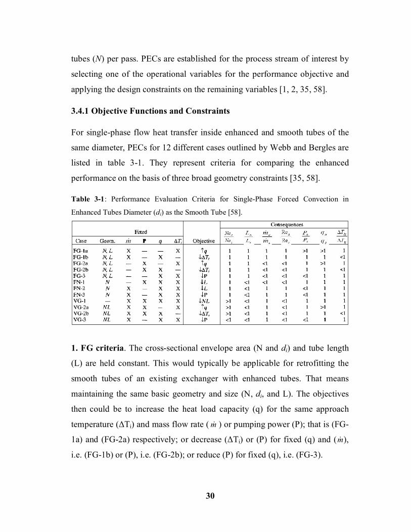
3.4.1 Objective Functions and Constraints
For single-phase flow heat transfer inside enhanced and smooth tubes of the
same diameter, PECs for 12 different cases outlined by Webb and Bergles are
listed in table 3-1. They represent criteria for comparing the enhanced
performance on the basis of three broad geometry constraints [35, 58].
Table 3-1: Performance Evaluation Criteria for Single-Phase Forced Convection in
Enhanced Tubes Diameter (di) as the Smooth Tube [58].
1. FG criteria. The cross-sectional envelope area (N and di) and tube length
(L) are held constant. This would typically be applicable for retrofitting the
smooth tubes of an existing exchanger with enhanced tubes. That means
maintaining the same basic geometry and size (N, di, and L). The objectives
then could be to increase the heat load capacity (q) for the same approach
temperature (ΔTi) and mass flow rate ( m ) or pumping power (P); that is (FG-
1a) and (FG-2a) respectively; or decrease (ΔTi) or (P) for fixed (q) and (m ),
i.e. (FG-1b) or (P), i.e. (FG-2b); or reduce (P) for fixed (q), i.e. (FG-3).
¯

31
2. FN criteria. These criteria maintain fixed cross-sectional area (N and di)
and allowing the heat exchanger length to vary. Here the objectives are to
seek a reduction in either the heat transfer surface area (A → L), i.e. (FN-1)
and (FN-2); or the pumping power (P), i.e. (FN-3) for a fixed heat load.
3. VG criteria. In many cases, a heat exchanger is sized for a required
thermal duty with specified flow rate. In these situations the FG and FN
criteria are not applicable. Because the tube-side velocity must be reduced to
accommodate the higher friction characteristics of the enhanced surface, it is
necessary to increase the flow area to maintain constant flow rate. This is
accomplished by using a greater number of parallel flow circuits. Maintaining
a constant exchanger flow rate eliminates the penalty of operating at higher
thermal effectiveness encountered in the previous FG and FN cases [58].
3.4.2 Algebraic Formulation of the PEC
Calculation of the performance evaluation criteria for any of the 12 cases in
Table 3-1 requires algebraic relations that quantify the objective function and
constraints. It is convenient to develop the algebraic relations relative to a
smooth surface operating at the same fluid temperature. This allows
cancellation of the fluid properties from the equations.
The different cases listed in table 3-1 are derived for flow inside
enhanced and smooth tubes of the same inside diameter. Considering a shell
and tube heat exchanger of length L, having N tubes in each pass, and Np
passes. The total tube-side surface area in the heat exchanger is
pi LNNdA ... (3.26)
The basic heat transfer and friction performance characteristics of the
enhanced and smooth tubes are normally presented as Colburn factor (j)

32
defined as 3132 PrRePr NuStj and f vs. Gd iRe . Because the
tube inside diameter is held constant, one may write
32PrjGC
h p … (3.27)
The value of (hA) of the enhanced surface, as in equation (3.1), relative to
that of the smooth surface is the aim of interest. Writing equation (3.27) as the
ratio, relative to a smooth surface gives
sssss G
GAA
jj
AhhA
… (3.28)
Substituting equation (3.24) in (3.25) and replacing Ac by [ 24 id ] gives
equation (3.29) for pumping power
2
3
8fAGP ... (3.29)
Writing equation (3.29) as the ratio, relative to the smooth surface, gives
3
ssss GG
AA
ff
PP
… (3.30)
Elimination of the term G/Gs from equations (3.28) and (3.30) gives
313231s
s
ss
ss
ffjj
AAPPAhhA
… (3.31)
To apply one of the PECs, one of the variables on the left side of
equation (3.31) is set as the objective function, and the remaining two are set
as operating constraints (equal to unity). It is necessary to determine the G/Gs
ratio that satisfies Equation (3.31). The equations of the js and fs as a function
of Res and the j and f as a function of Re must be known [35]. Accordingly, in
the present work, these equations would be created from the experimental
data to accommodate the requirements of these PECs either for the tube-side
or annulus-side heat transfer enhancement.

33
3.5 Thermal Design of the Double Pipe Heat Exchangers
Only two important relationships constitute the entire thermal design
procedure of a heat exchanger. These are:
1. Heat transfer rate for a non-adiabatic single-phase flow:
io TTCpmHmq … (3.32)
2. Heat transfer rate equation:
mTUAq … (3.33)
Equation (3.33) reflects a convection–conduction heat transfer
phenomenon in a two-fluid heat exchanger. Heat transfer rate is proportional
to the heat transfer area (A) and mean temperature difference (Tm) between the
fluids. This mean temperature difference is a log-mean temperature difference
(LMTD), for counterflow and parallelflow exchangers, it is
1122
1122
ln chch
chchm TTTT
TTTTLMTDT
... (3.34)
If a wall of a hollow cylinder (like a double pipe heat exchanger) is
considered, the overall heat transfer coefficient (U) in equation (3.33) may be
based on either the inside or outside area of the tube. Accordingly,
oo
iioi
i
i
hAA
kLrrA
h
U1
2ln1
1
… (3.35)
o
ioo
ii
oo
hkLrrA
hAAU
12ln11
… (3.36)
Equations (3.35) and (3.36) include three thermal resistances, heat is
transferred through. Two are concerned with convection heat transfer in the
two sides of the exchanger and the other is caused by the wall itself [4, 64].

34
CHAPTER FOUR
Experimental Work
4.1 Experimental Rig Design and Assembly.
An experimental rig was designed and assembled to carry out the
experiments that require particular fluid temperatures, particular fluid flow
rates, and for each run, temperatures of four points and pressure drop in
specific sections, which represent the heart of the present work, must be
measured in acceptable accuracy.
Simply, the concerned rig is an assembly of several parts when operated,
the result is two streams of fluids having particular temperatures that the study
needs, flowing separately and sometimes mixed for specific tasks. In addition,
two specialized streams were used in the isothermal pressure drop
experiments, which might stop the working as a heat exchange system and
mixing the two streams to work under constant temperature conditions. No
automatic temperature control devices are available, so manual control is
widely adopted to regulate temperatures of fluid streams. Figure 4-1 shows a
photograph of the rig whose parts are detailed in the schematic flow diagram
depicted in fig. 4-2.
Water was used as the working hot fluid and cold fluid streams for its
availability; high heat capacity, which enables easy control of temperature;
and conventionality of using it as the cold fluid in many actual heat exchange
processes.

35
Figu
re 4
-1: A
pho
togr
aph
of th
e ex
perim
enta
l rig
.

36
Figu
re 4
-2: A
sche
mat
ic fl
ow d
iagr
am o
f the
exp
erim
enta
l rig
.

37
4.1.1 Components of the Experimental Rig.
4.1.1.1 Hot Fluid Unit.
As depicted in fig. 4-2 the hot fluid unit consists mainly of the following:
( i ) Insulated Tank: A tank of (50×50×100 cm) dimensions well-insulated
using 5 cm thick of mineral wool insulation to forbid loss of heating energy.
( ii ) Electric heaters: 4 electric heaters with 3 kW power for each in
addition to a 3.5 kW power supplied by 1500, 1000, and 500 W heaters and
500 W heater controlled by a variac are used to supply thermal energy needed
for heat transfer. The partitioned 3.5 kW power is exploited to control
temperature of the hot stream to the required value, where the heat transferred
from the hot to cold stream through the heat exchanger at any time, is guessed
by calculations as shown later.
Hot fluid unit is supplied with water (as the working fluid) after passing
through a filter assembled at the inlet of the system. Hot water is circulated
throughout the system and returned to the hot fluid tank. Water is replaced
periodically so as to keep it free from salts which may be concentrated as a
result of continuous heating.
4.1.1.2 Cold Fluid Unit
The cold fluid unit consists of the following:
( i ) Main Stream of Tap Water: The cold fluid used throughout the system
is filtered tap water used for one pass without circulating, but since it may
come in different temperatures during the different seasons of the year, its
temperature must be maintained to the required temperature which is 20 °C.
( ii ) Heating Tank: To maintain tap water at 20 °C which may arrive in
temperature less than this degree (during winter), a heating tank provided with

38
a 6 kW electric heater is used for the task. In most cases, tap water is divided
into two streams before entering the unit; one is passed through the heating
tank. The two streams are mixed in a joint point before entering the system.
The flowrates of the two streams are maintained manually till the temperature
of the “mixture” is being settled at the required value.
( iii ) Water Cooler: In summer, the task may be different where the tap
water is arriving in temperature more than 20 °C, so it is necessary to lower to
this temperature. The task is carried out in a manner similar to that used in the
preceding case but instead of passing one of the two streams, the water have
been divided into the heating tank, it is now passed through a water cooler.
The concerned stream is passed through a shell-and-tube heat exchanger
immersed inside the pool of the water cooler and exchanging heat with cold
water (its temperature is below 5 °C, pumped by a centrifugal pump) without
mixing. This exit stream is mixed with the other stream and again controlled
manually to produce water at the required temperature. Depending on the
techniques discussed above and enough experience, temperature of cold water
was controlled to 20 ± 0.5.
4.1.1.3 Flow Measurement Instrumentation
Two flow measurement devices have been used, one for each stream:
( i ) Rotameter:
A rotameter type (FLOWTECH, LZS-25) with flowrate range between 0.16
and 1.5m3/hr, were used to measure the flowrate of cold water (20 °C). But in
case of isothermal pressure drop experiments, which would be explained later,
the rotameter was used to measure the flowrate of hotter water, reaches 70 °C,
so an accurate calibration was required in order to ensure obtaining results as

39
acceptable as possible. Calibration of rotameter was performed to produce
calibration curves for flowrate of water, at four temperatures (20, 40, 60, and
70 °C). Details of calibration of the rotameter and calibration curves,
produced are fixed in appendix B.
( ii ) Orifice plate.
An orifice plate was designed and manually fabricated to be used in
measuring hot water flowrate. This device is supplied with two manometers,
an inverted manometer filled with mercury to be used in measuring relatively
high flowrates (between 0.3 and 0.9 m3/hr), and the other is an ordinary water
manometer to be used in measuring low flowrates (0.3 m3/hr and lower).
Design and calibration of the orifice plate for the two temperatures (60 and 70
°C) is detailed in appendix B. The mercury manometer graduation is directly
fixed on the orifice manometer panel, while the water manometer must be
treated differently. That is by using a computer program written for the
purpose because the water manometer readings cannot be adjusted directly.
4.1.1.4 Pressure Measurement Instrumentation
One of the most important data to be obtained in the present work is the
pressure drop inside the test section (double-pipe heat exchanger), so four
pressure taps were fixed in the inlet and exit of the hot and cold fluid streams
to measure pressure drop inside the inner tube and the annulus. Three
manometers were used. Two of the manometers-that use water-are employed
to measure low pressure drops and the third that uses mercury is employed to
measure high pressure drops. The latter is connected to each of the others if
needed. When working together, the water manometer must be closed, when
measuring high flowrates, or else it might overflow.

40
4.1.1.5 Temperature Measurement Instrumentation
Four thermocouples type (J) fixed at the inlet and outlet of the hot and cold
fluid streams to measure temperature of the intended fluids at specific points.
The ends of thermocouples are screwed to be tightly fixed in the external
tubes near the inlet and outlet points. The thermocouples are connected to a
temperature reader device type (DORIC) with five buttons.
Since these temperature values play a decisive role in calculating the
Nusselt number, and to ensure that the temperatures obtained are as accurate
as possible, an accurate calibration for the four thermocouples and the
temperature reader device were carried out using a mercury thermometer. The
latter was calibrated using boiling distilled water and a mixture of distilled
water and ice [65]. The result of the calibration process was converted to four
calibration curves to be used to predict the actual values of temperature.
Details of calibration are fixed in appendix B.
4.1.1.6 Pipes, Pumps, and Valves
All pipes used in the construction of the rig are made of galvanized iron pipes
of ID=16mm, well-insulated to save energy. Three centrifugal pumps, with
maximum volumetric flowrate of 4 m3/hr, are included, one for the cold fluid
unit and the others are employed to pump the hot and cold fluids in concerned
streams. 26 ball valves are used in the rig. This type of valve had been used
because it could be easily and rapidly opened and sealed and easily used in
controlling the volumetric flowrates of the two streams.
4.1.1.7 Test Section (Double-Pipe Heat Exchanger)
The most important part of the experimental rig is the test section which is a
double pipe heat exchanger. Figure 4-3 illustrates its main parts:

41
Figure 4-3: Sketch of the double-pipe heat exchanger used in the present work.
( i ) The outer tube: It is made of stainless steel to avoid corrosion during
operation. It is 1.2 m length, ID=2.8 cm and OD=3.0 cm.
( ii ) The inner tube: It is made of pure copper (South African Origin) for its
low thermal resistance with two sizes used. The first is 1.4 m length, ID=1.1
cm and OD=1.25 cm. The second has the same length but with ID=1.4 cm
and OD=1.55 cm.
( iii ) Pipe fittings: Two 1-½ inch reducing tee lateral fits are connected to the
two ends of the stainless steel tube with making their branches in opposite
directions. In addition, four hexagon bushings with their hollows filled with
rubber plugs, were used. These were perforated in a way can hold the inner
tube without leakage. Two were used to conjoin the inner with the outer tube
in a manner enables the operator to disassemble the two tubes in order to
change the inner tube easily after each experiment. The other two were used
to connect the two ends of the inner tube to the external pipes of the rig [66].
( iv ) Pressure taps: Four pressure taps are installed in four points around the
double-pipe heat exchanger, and connected to the manometer panel detailed
above. Two pressure taps concerning the pressure drop in the inner tube are
fixed directly in that tube by perforating it carefully near the two ends keeping

42
a distance of 134.5 cm between the two perforations. This distance was larger
than the effective heat transfer length (124.5 cm) which equals to the distance
between the inlet and outlet of cold water or the two centers of the tee fittings,
so all pressure drop values registered for the tube side would be multiplied by
the ration of (124.5/134.5) to obtain the real value of pressure drop. To avoid
leakage in these points, an adhesive material was used, taking into
consideration that no protrusion was left inside the tube which may cause an
error in reading the actual pressure drop. The annulus side pressure taps were
fixed in the centre of the tee lateral body. That was in order to calculate the
actual pressure drop in the annulus without that caused by the entrance. The
registered value in that case was adopted directly without correction. These
taps not like those of the inner tube, they were not removable because the
outer tube connected to the reducing tee laterals were left without
disassembling all the experimental work. Fig. 4-4 shows the pressure taps.
Figure 4-4: Pressure taps.
The temperature thermocouples installation was easier because they
were fixed in the external tubes belonging to the rig itself and left without
removing all the experimental work.
The whole body of the heat exchanger was insulated with a layer of
mineral wool insulation to avoid heat loss.

43
4.1.2 Turbulence Promoter Selection and Fabrication
Three types of inserts with different pitch length and wire diameter, (defined
in fig. 4-5a), was used in the present work:
Figure 4-5: Turbulence promoters used in the present work, (a) Definition of pitch length
p and wire diameter e, (b) Inner coiled wire inserts, (c) Coiled wire on the outer surface of
the inner tube e =1 mm, (d) Coiled wire on the outer surface of the inner tube e =2.2 mm,
(e) Circular rib on the outer surface of the inner tube e =2.2 mm.
d i
= 1
4.0
mm
d
i = 1
1.0
mm

44
( i ) Wire coil insert inside the inner tube: 1 mm diameter copper wire was
coiled around a steel bar of about 8.5 and 12 mm diameter to produce wire
coils with outside coiling diameters of 11 and 14 mm. Four coiling pitches
had been studied (10, 20, 30, and 40 mm), as in fig.4-5b.
( ii ) Wire coil insert on the outer surface of the inner tube: Two copper
wire sizes were used (1 and 2.2 mm diameter). That was by coiling the
interested wires around the copper tubes directly with keeping four coiling
pitches to be used (10, 20, 30, and 40 mm), fig. 4-5c, and d.
( iii ) Circular ribs on the outer surface of the inner tube: A copper wire
with diameter of 2.2 mm was used in fabricating circular ribs to be used as
turbulence promoters on the outer surface of the inner tube with four pitch
lengths (10, 20, 30, and 40 mm).
4.2 Operation of the System
In the present work, experiments were divided into two kinds,
isothermal pressure drop experiments and heat exchange experiments:
4.2.1 Isothermal Pressure Drop Experiments
The aim of the isothermal pressure drop experiments is to obtain the friction
factor or pressure drop, in mm H2O, for the range of Reynolds numbers of
working fluid flowing through the tube or annulus side of the heat exchanger
at constant temperature (no heat exchange). In the present work experiments
were performed at four temperatures 20, 40, 60, and 70 °C, which give a
satisfactory variety of physical properties, with 8 values for Reynolds number,
from 5000 through 40000 for the tube-side enhancement experiments and
from 3000 through 10000 based on the equivalent diameter for annulus-side
enhancement experiments. The operation of isothermal pressure drop, in case,

45
if the tube side is intended to study the pressure drop inside, can be
summarized in the following steps (referring to fig. 4-2):
The first step was filling the hot water tank with water at one of the
temperatures above. Then temperature is changed to the next.
The isothermal pressure drop operation was a closed-loop process. That
was by sealing valves V-17, V-23, and V-25.
The interested loop of water was being determined according to its
temperature. For 20 and 40 °C water circulated the loop was started
from the hot water tank passing through V-2, pumped by the hot water
centrifugal pump through V-4, V-6, passing through the rotameter and
then V-7 entering the inner tube of the heat exchanger and returning to
the tank. V-5 and V-18 was tightly sealed. That loop was decided
because the orifice plate was designed and calibrated to work at 60 and
70 °C, while that was accessible in the rotameter. For 60 and 70 °C, the
loop was different, starting from the hot water tank, through V-2, V-5
pumped through the orifice plate to the inner tube of the heat exchanger
and finally returned to the tank. V-6 and V-7 was tightly sealed.
Flowrate measured by the rotameter was the wanted one in case of 20
and 40 °C temperatures while that measured by the orifice plate for 60
and 70 °C. For each case, the pressure drop was registered. Then the
flowrate was raised for the next using valve V-4.
Valves V-18, V-20, V-21, V-24, and V-26 were left open, while V-19
and V-22 there was no problem if were being forgotten open.
If the annulus side was intended to study the pressure drop inside, with
the aid of fig. 4.2, the main steps are summarized by the following points:
Filling the hot water tank with water at a specific temperature.
Sealing valves V-17, V-23, and V-25.

46
Valve V-7 should be tightly sealed.
Valves V-19 and V-22 were left sealed.
In the present case the path of water was: the hot water tank, V-2, the
hot water pump, V-7, the rotameter, V-18, V-20, V-21, V-24, V-26,
and returning to the tank. The flowrate measured by the rotameter was
the intended flowrate. Then, pressure drop was registered.
V-5 was left slightly open and V-8 and V-9 were being left open to
permit some of water to pass through the inner tube to ensure that no
heat exchange was happening.
4.2.2 Heat Exchange Experiments
The second part of the present work was the heat transfer experiments. Cold
water was flowing in open cycle, through the annulus of the double pipe heat
exchanger, counter-currently with hot water stream which was flowing in
closed cycle through the inner tube. The implementation of a heat transfer
experiment can be summarized in the following steps:
Valves V-23 and V-26 were kept sealed during all the work.
Valves V-6 and V-7 should be tightly sealed to keep the two streams
separated.
V-11 was the inlet of the water, so it should be opened.
The cold fluid unit work was depending on whether the water was
coming with temperature less or greater than 20 °C (working
temperature of cold water for all heat transfer experiments). If less than
20 °C, V-13 and V-14 were both sealed, i.e., the water cooler and its
accessories were shut down, while the heating tank was being used (V-
15 opened). If the water temperature was greater than 20 °C, then the

47
water cooler and its accessories were being operated (V-13 and V-14
open), while the heating tank was shut down (V-15 sealed).
In the mixing point, two streams were mixed, the fresh stream of water
and either that coming from the cooling or the heating tank, manually
controlled to obtain a water stream at 20 ± 0.5 °C to be used as the cold
fluid.
V-19 and V-22 were always left sealed.
The cold water path was: the mixing point, pumped by the cold water
pump through V-17, the rotameter, V-18, V-20, counter-currently
through the annulus of the heat exchanger, V-21, V-24, and through V-
25 water was drained outside the system.
The volumetric flowrate assigned by the rotameter is the flowrate of
cold water under study.
Valves V-1, V-3, and V-10 were left sealed.
In the present work, all experiments were performed with two
temperatures for the hot water stream, 60 and 70 °C. These
temperatures were controlled manually. Heat transferred in the
exchanger was always known due to the computer program employed,
so, by using the variety of heaters, provided to the hot water tank
especially those controlled by the variac, temperature of the produced
water would be controlled to 60 or 70 ± 0.5 °C. The large volume of the
hot water tank was widely helping in forbidding the fluctuations in
these temperatures.
The path of hot water was: the hot water tank, V-2, pumped by the hot
water pump through V-4 and V-5, and then through the orifice plate
and V-8 entering into the inner tube of the double pipe heat exchanger,
and finally through V-9 returning to the hot water tank.

48
Two divisions of heat exchange experiments were performed, the first
was carried out for the case of enhancement of heat transfer inside the
inner tube. In that kind, the cold water mass flowrate was kept constant
at two values (0.1 and 0.15 kg/s) and hot water was changed for 8
values of Reynolds number in the inner tube starting from 5000 through
40000. The second kind was performed when the annulus as the
enhanced side, where constant mass flowrates for the hot water stream
(0.1125 and 0.2 kg/s), while the cold water was changed for 8 values of
Reynolds number starting from 3000 through 10000.
Valves V-4 and V-17 were used as control valves of the hot and cold
flowrates respectively.
All steps stated above were in need to wait for few minutes until the
steady state conditions were reached for each change in the hot or cold
flowrate. When the approval value of volumetric flowrate (determined
by using the computer program) was reached, four temperatures of the
inlet and outlet points, as well as the pressure drop in the two sides,
read on the manometers panel, were being registered.
4.3 Calculation Procedure 4.3.1 Prediction of Physical Properties
The use of a computer program (fig. 4-6) to perform calculation of the system
which includes widely the properties of water like density, dynamic viscosity,
conductivity, and heat capacity, needs to deduce equations for these properties
to be used in the computer program. Appendix A includes tabulated properties
of water which have been converted by curve fitting to polynomial equations.
Equations (A.1), (A.2) and (A.3) would be used in the computer program to
predict the physical properties of water instead of direct use of table A-1.

49
4.3.2 Isothermal Pressure Drop Calculations
This class of calculations includes the calculation of Darcy-Weisbach friction
factor for all cases studied using the values of isothermal pressure drop
obtained during the experiments of isothermal pressure drop, discussed
previously, using the equation (3.4). Thus, a large number of points would be
available to be used in predicting an isothermal friction factor correlation.
4.3.3 Heat Transfer Calculations
The more complicated calculations are that of heat transfer which includes:
( i ) Calculation of Reynolds number: It is an implicit problem where
Reynolds number was intended to be calculated with unknown physical
properties and mass flowrate in order to appear in the form of an integer
(5000, 10000, 15000, etc.) in addition to the great physical meaning might be
included if all readings had been taken for particular Reynolds numbers
instead of volumetric or mass flowrates. In other words, a specified Reynolds
number at particular temperature (particular physical properties) might mean
a mass flowrate, different from that at another temperature. A trial and error
procedure is adopted for the purpose which may be explained as: an initial
volumetric flowrate Q is assumed as the required value for the Reynolds
number under study, using the temperatures of the inlet and outlet streams of
the double pipe heat exchanger resulted to predict physical properties which
would lead to a new value for Q for the interested stream, repeating the
process until convergence would be reached as illustrated in fig. 4-6 which
represents an algorithm for a computer program. Figure 4-6 was written for
tube-side enhancement, similar one for annulus enhancement, easily could be
imitated by excluding the part of the orifice plate operation which was
unnecessary in that case, with some changes in the equations used for
calculations to be suitable for the annulus instead of the inner tube.

50
( ii ) Friction factor calculations: For both enhanced or unenhanced sides of
the heat exchanger, friction factor was calculated directly by using equation
(3.4) adopting the pressure drop measured by the manometer,
( iii ) Nusselt number calculations: The procedure of calculating Nusselt
number might be summarized as:
1. Heat Transfer rate is calculated by equation (3.32) for the two sides and
the average value is considered.
2. The overall heat transfer coeff. Uo was calculated by eq. (3.33).
Figure 4-6: An algorithm for calculations of tube-side heat transfer enhancement.

51
3. Friction factor for the unenhanced side is predicted by equation (3.4).
4. Nusselt number (and then the heat transfer coefficient) for the
unenhanced side is calculated by equation (3.12), alone, if it is the tube
side or with equation (3.18), if it is the annulus side.
5. By equation (3.36), the heat transfer coefficient is obtained for the
enhanced side, and then Nusselt number for that side.
4.4 Error Sources and Uncertainty In the present work, some of the error sources which may be fixed as
the sources of uncertainty in predicting volumetric flowrates, temperatures
and pressure drops which might lead to errors in the predicted values:
1- Electric power instability.
2- Uncertainty in temperature reading resulted from manufacturing defects
in the thermocouples and temperature reader device.
3- Errors in flow measurements.
4- Temperature control difficulties.
The first three might lead to that the heat transfer calculated by
TCpmq be not equal, so the average value was used in all calculations
with an acceptable deviation ratio defined as:
100ratioDeviation .
avg
ch
qqq
≤ 5%. ... (4.1)
The fourth source was constrained to ± 0.5 °C for the inlet temperatures
with keeping the inlet temperature approach as close to 40 or 50 °C as
possible.

52
CHAPTER FIVE
Experimental Results
5.1 Introduction
Experiments on thirty six cases of smooth and augmented tubes and
annuli were carried out in order to study the effect of different types of inserts
on heat transfer and pressure drop in a double pipe heat exchanger. The
primary experimental data taken are temperatures of the four inlets and
outlets, pressure drop in the two sides and heat transfer rate at different
experimental conditions. Tables C-1 through C-18 includes the experimental
results for the smooth, as well as augmented tubes and annuli. In addition,
experiments on isothermal pressure drop for all cases have been performed.
Their results are displayed in tables C-37 through C-40.
5.2 Test of Authenticity of Using the Present Heat Exchanger.
First of all calculations and comparisons among the heat transfer and
pressure drop or friction factor for augmented and smooth tubes annuli, these
smooth tubes and annuli must be tested for authenticity to be used in the
experimental work. For heat transfer authenticity test, a comparison between
Nusselt number calculated empirically by Gnielinski equation (equation 3.12)
and that calculated by using the experimental data obtained, has been
performed. For the pressure drop authenticity test a comparison between the
friction factor calculated theoretically by Petukhov equation (equation 3.3)
and that obtained by experimental work (equation (3.4)). Theoretical and
experimental Nusselt number and friction factor (for heat exchange and
isothermal conditions) are presented in tables C-19, C-24, C-37 and C-38 and
plotted in figs. 5-1 through 5-4.

53
Figure 5-1: Comparison of empirical (eq. (3.3)) and experimental friction factor of
smooth tubes used in tube-side heat transfer enhancement experiments for two tube sizes.
10000 20000 30000 40000 10000 20000 30000 400000.010
0.020
0.030
0.050
Fric
tion
Fact
or (f
)
Re
Theoretical (Petukhov eq.)Experimental (Th1=60 C, mc=0.1 kg/s)Experimental (Th1=60 C, mc=0.15 kg/s)Experimental (Th1=70 C, mc=0.1 kg/s)Experimental (Th1=70 C, mc=0.15 kg/s)Experimental (Isothermal, average value)
Inner Tube, di=11.0 mm
Inner Tube, di=14.0 mm
Theoretical (Petukhov eq. (3.3)) Experimental (Th1=60 °C, mc=0.1 kg/s) Experimental (Th1=60 °C, mc=0.15 kg/s) Experimental (Th1=70 °C, mc=0.1 kg/s) Experimental (Th1=70 °C, mc=0.15 kg/s) Experimental (Isothermal, average value)
Figure 5-2: Comparison of empirical (eq. (3.12)) and experimental Nusselt number
inside the smooth tubes used in tube-side heat transfer enhancement experiments.
10000 20000 30000 40000
2
3
5
10
100
10000 20000 30000 40000
Theoretical (Gnielinski eq.)Experimental (Th1=60 C, mc=0.1 kg/s)Experimental (Th1=60 C, mc=0.15 kg/s)Experimental (Th1=70 C, mc=0.1 kg/s)Experimental (Th1=70 C, mc=0.15 kg/s)
Nu
Re
Inner Tube, di=11.0 mm
Inner Tube, di=14.0 mm
Theoretical (Gnielinski eq. (3.12)) Experimental (Th1=60 °C, mc=0.1 kg/s) Experimental (Th1=60 °C, mc=0.15 kg/s) Experimental (Th1=70 °C, mc=0.1 kg/s) Experimental (Th1=70 °C, mc=0.15 kg/s)

54
Figure 5-3: Comparison of theoretical and experimental friction factor of smooth
annuli used in annulus-side heat transfer enhancement experiments.
4000 6000 8000 10000 4000 6000 8000 10000
Theoretical (Petukhov eq.)Experimental (Th1=60 C, mh=0.1125 kg/s)Experimental (Th1=60 C, mh=0.2 kg/s)Experimental (Th1=70 C, mh=0.1125 kg/s)Experimental (Th1=70 C, mh=0.2 kg/s)Experimental (Isothermal, average value)
0.010
0.020
0.030
0.050
Fric
tion
Fact
or (f
)
Re
0.100
Annulus, Di=12.5 mm Do=28.0 mm
Annulus, Di=15.5 mm Do=28.0 mm
Theoretical (Petukhov eq. (3.4)) Experimental (Th1=60 °C, mh=0.1125 kg/s) Experimental (Th1=60 °C, mh=0.2 kg/s) Experimental (Th1=70 °C, mh=0.1125 kg/s) Experimental (Th1=70 °C, mh=0.2 kg/s) Experimental (Isothermal, average value)
Figure 5-4: Comparison of theoretical and experimental Nusselt number of smooth
annuli used in annulus-side heat transfer enhancement experiments.
4000 6000 8000 10000
2
4
6
8
10
100
4000 6000 8000 10000
Nu
Re
Theoretical (Gnielinski eq.)Experimental (Th1=60 C, mh=0.1125 kg/s)Experimental (Th1=60 C, mh=0.2 kg/s)Experimental (Th1=70 C, mh=0.1125 kg/s)Experimental (Th1=70 C, mh=0.2 kg/s)
Annulus, Di=12.5 mm Do=28.0 mm
Annulus, Di=15.5 mm Do=28.0 mm
Theoretical (Gnielinski eq. (3.12)) Experimental (Th1=60 °C, mh=0.1125 kg/s) Experimental (Th1=60 °C, mh=0.2 kg/s) Experimental (Th1=70 °C, mh=0.1125 kg/s) Experimental (Th1=70 °C, mh=0.2 kg/s)

55
Deviations from theoretical values are fixed in table 5-1. These values
were obtained by dividing the absolute difference of the experimental and
theoretical value by the theoretical value for all values of the friction factor
and Nusselt number and then the average value is considered.
5.3 The Effect of Turbulence Promoters on Heat Transfer Rate
and Pressure Drop.
To have a general view of the effect of turbulence promoters, used in
the present work, on heat transfer rate and pressure drop in the inner tube and
annulus, values of heat transfer rate and pressure drop (tables C-1 through C-
18) are plotted versus Reynolds number in figs. 5-5 through 5-8 for all cases.
Figures 5-5 through 5-8 reveals an expected increase of pressure drop
with decreasing the coiling or ribbing pitches either in tube-side or annulus-
side heat transfer enhancement. On the other hand, the heat transfer rate does
not behave in a similar manner except in case of tube-side heat transfer
enhancement (fig. 5-5) where the above description becomes valid only for
the wire coil of e =1 mm used on the outer surface of the inner tube (fig. 5-6)
for the two annulus sizes, while this fact becomes invalid for the e =2.2 mm
wire coil or circular rib where decreasing the coiling or ribbing pitch for that
wire or rib diameter means decreasing heat transfer rate (fig. 5-7 and 5-8).
Type of experiment
Inner tube Annulus
di = 11 di = 14 Di = 12.5 Do = 28.0
Di = 15.5 Do = 28.0
% dev. in Nu
% dev. in f
% dev. in Nu
% dev. in f
% dev. in Nu
% dev. in f
% dev. in Nu
% dev. in f
Dev. in heat exch. exp. + 8.66 + 8.36 + 8.55 + 9.18 8.88+ + 10.79 + 7.77 11.35+
Dev. in isothermal pressure drop exp. ― + 8.12 ― + 6.96 ― + 9.79 ― 7.46+
Average deviation + 8.66 + 8.24 + 8.55 + 8.07 8.88+ + 10.29 + 7.77 + 9.41
Table 5-1: Deviations of Experimental Nusselt and Friction Factor from Values obtained from empirical equations for Smooth Inner Tubes and Annuli.

56
0
1000
2000
3000
4000
0
1000
2000
3000
4000
0
1000
2000
3000
4000
10000 20000 30000 400000
1000
2000
3000
4000
0
7500
15000
22500
30000
0
7500
15000
22500
30000
0
7500
15000
22500
30000
10000 20000 30000 40000 0
7500
15000
22500
30000
Smooth tubeWire coil, p=10Wire coil, p=20Wire coil, p=30Wire coil, p=40
Figure 5-5: Heat transfer rate (W) and pressure drop (N/m2) vs. Reynolds number for
tube-side heat transfer enhancement using a wire coil of e = 1 mm for two inner tube
sizes and four experimental conditions (Notation above belongs to all cases).
Inner tube, di=11.0 mm
Inner tube, di=14.0 mm

57
0
2500
5000
7500
10000
0
2500
5000
7500
10000
0
2500
5000
7500
10000
4000 6000 8000 100000
2500
5000
7500
10000
0
2000
4000
6000
8000
0
2000
4000
6000
8000
0
2000
4000
6000
8000
4000 6000 8000 10000 0
2000
4000
6000
8000
Smooth annulusWire coil, p=10Wire coil, p=20Wire coil, p=30Wire coil, p=40
Figure 5-6: Heat transfer rate (W) and pressure drop (N/m2) vs. Reynolds number for
annulus-side heat transfer enhancement by wire coils of e = 1 mm for two annulus sizes
and four experimental conditions (Notation above belongs to all cases).
Annulus, Di=15.5 mm Do=28.0 mm
Annulus, Di=12.5 mm Do=28.0 mm

58
0
2500
5000
7500
10000
0
2500
5000
7500
10000
0
2500
5000
7500
10000
4000 6000 8000 100000
2500
5000
7500
10000
0
2000
4000
6000
8000
0
2000
4000
6000
8000
0
2000
4000
6000
8000
4000 6000 8000 10000 0
2000
4000
6000
8000
Smooth annulusWire coil, p=10Wire coil, p=20Wire coil, p=30Wire coil, p=40
Figure 5-7: Heat transfer rate (W) and pressure drop (N/m2) vs. Reynolds number for
annulus-side heat transfer enhancement by wire coils of e = 2.2 mm for two annulus
sizes and four experimental conditions (Notation above belongs to all cases).
Annulus, Di=15.5 mm Do=28.0 mm
Annulus, Di=12.5 mm Do=28.0 mm

59
0
2500
5000
7500
10000
0
3000
6000
9000
12000
0
2500
5000
7500
10000
0
2500
5000
7500
10000
4000 6000 8000 100000
2500
5000
7500
10000
0
3000
6000
9000
12000
0
3000
6000
9000
12000
4000 6000 8000 10000 0
3000
6000
9000
12000
Hea
t Tra
nsfe
r Rat
e (q
), W
Pres
sure
Dro
p (Δ
P), N
/m2
Smooth annulusCircular rib, p=10Circular rib, p=20Circular rib, p=30Circular rib, p=40
Figure 5-8: Heat transfer rate (W) and pressure drop (N/m2) vs. Reynolds number for
annulus-side heat transfer enhancement by circular ribs of e = 2.2 mm for two annulus
sizes and four experimental conditions (Notation above belongs to all cases).
Annulus, Di=15.5 mm Do=28.0 mm
Annulus, Di=12.5 mm Do=28.0 mm

60
5.4 Effect of Turbulence Promoters on Friction Factor
Two collections of friction factor were obtained for each promoter used
to augment heat transfer. The first is that for real heat exchange process.
These values of friction factor, graphically or in correlation form, would be
used for comparisons and PECs to study the effect and usefulness of each
insert. The second is that for isothermal operation conditions. The latter might
be converted to correlations to be used in design of heat exchangers.
5.4.1 Friction Factor in Heat Exchange Process
Friction factor inside the inner tube and annulus either smooth or with wire
coil inserts (for all wire diameters adopted), have been calculated using the
experimental values of pressure drop using equation (3.4), as tabulated in
tables C-19 through C-36 and plotted in fig. 5-9 through 5-12 versus
Reynolds number.
0.100
0.020
0.030
0.050
0.080
0.200
Fric
tion
Fact
or (f
)
Re
0.300
10000 20000 30000 40000 10000 20000 30000 40000
Smooth tubeWire coil, p=10Wire coil, p=20Wire coil, p=30Wire coil, p=40
Figure 5-9: Friction factor vs. Reynolds number for heat exchange process inside the
inner tube inserted with a wire coil of e = 1 mm for two inner tube sizes.
Inner Tube, di=11.0 mm
Inner Tube, di=14.0 mm

61
Figure 5-11: Friction factor vs. Reynolds number for annulus-side heat transfer
enhancement by wire coils of e = 2.2 mm (heat exchange process) for two annulus sizes.
4000 6000 8000 10000 4000 6000 8000 10000
0.100
0.020
0.050
0.200
Fric
tion
Fact
or (f
) 0.500
1.000
Re
Smooth annulusWire coil, p=10Wire coil, p=20Wire coil, p=30Wire coil, p=40
Annulus, Di=12.5 mm Do=28.0 mm
Annulus, Di=15.5 mm Do=28.0 mm
4000 6000 8000 10000 4000 6000 8000 10000
0.100
0.020
0.050
0.200
Fric
tion
Fact
or (f
)
Re
0.500
1.000
Smooth annulusWire coil, p=10Wire coil, p=20Wire coil, p=30Wire coil, p=40
Figure 5-10: Friction factor vs. Reynolds number for annulus-side heat transfer
enhancement by wire coils of e = 1 mm (heat exchange process) for two annulus sizes.
Annulus, Di=12.5 mm Do=28.0 mm
Annulus, Di=15.5 mm Do=28.0 mm

62
In figs. 5-9 through 5-12, no sign for the operational conditions have
been included and the curve fit represented the average value of friction factor
for the four operation conditions for each case considered, because only the
geometrical parameters, in addition to Reynolds number, would be included
in the proposed correlations produced in the present work. That would be in a
similar manner to those appearing in Petukhov equation for smooth tubes or
the previous works [1, 2, 8, 9, 10, 11, 35, 51, and 52] for augmented tubes.
5.4.2 Friction Factor in Isothermal Process.
That was performed by using similar calculations to that adopted in heat
exchange process but with using the isothermal pressure drop values.
Isothermal pressure drop and friction factor obtained are tabulated in tables C-
37 through C-40) and plotted in figs. 5-13 through 5-16 versus Reynolds
number.
4000 6000 8000 10000 4000 6000 8000 10000
0.100
0.020
0.050
0.200
Fric
tion
Fact
or (f
) 0.500
1.000
Re
Circular rib, p=10Smooth annulus
Circular rib, p=20Circular rib, p=30Circular rib, p=40
Figure 5-12: Friction factor vs. Reynolds number for annulus-side heat transfer
enhancement by circular ribs of e = 2.2 mm (heat exchange process) for two annulus
sizes.
Annulus, Di=12.5 mm Do=28.0 mm
Annulus, Di=15.5 mm Do=28.0 mm

63
10000 20000 30000 40000 10000 20000 30000 40000
Smooth tubeWire coil, p=10Wire coil, p=20Wire coil, p=30Wire coil, p=40
Figure 5-13: Friction factor vs. Reynolds number for smooth tube and roughened by a
wire coil of e = 1 mm in isothermal conditions for two inner tube sizes.
Inner Tube, di=11.0 mm
Inner Tube, di=14.0 mm
0.100
0.020
0.050
0.200
Fric
tion
Fact
or (f
) 0.500
1.000
Re4000 6000 8000 100004000 6000 8000 10000
Smooth annulusWire coil, p=10Wire coil, p=20Wire coil, p=30Wire coil, p=40
Figure 5-14: Friction factor vs. Reynolds number for smooth annulus and with a wire coil
of e = 1 mm in isothermal conditions for two annulus sizes.
Annulus, Di=12.5 mm Do=28.0 mm
Annulus, Di=15.5 mm Do=28.0 mm

64
4000 6000 8000 10000 4000 6000 8000 10000
0.100
0.020
0.050
0.200
Fric
tion
Fact
or (f
) 0.500
1.000
Re
Smooth annulusWire coil, p=10Wire coil, p=20Wire coil, p=30Wire coil, p=40
Annulus, Di=12.5 mm Do=28.0 mm
Annulus, Di=15.5 mm Do=28.0 mm
Figure 5-15: Friction factor vs. Reynolds number for smooth annulus and with a wire coil
of e = 2.2 mm in isothermal conditions for two annulus sizes.
4000 6000 8000 10000 4000 6000 8000 10000
0.100
0.020
0.050
0.200
Fric
tion
Fact
or (f
) 0.500
1.000
Re
Circular rib, p=10Smooth annulus
Circular rib, p=20Circular rib, p=30Circular rib, p=40
Figure 5-16: Friction factor vs. Reynolds number for smooth annulus and with circular
ribs of e = 2.2 mm in isothermal conditions for two annulus sizes.
Annulus, Di=12.5 mm Do=28.0 mm
Annulus, Di=15.5 mm Do=28.0 mm

65
5.5 Effect of Turbulence Promoters on Heat Transfer
In addition to friction factor, heat transfer represented by Nusselt
number is the most important factor might be studied in a heat transfer
enhancement study, because it might be considered as the real indication to
the variations in heat transfer in smooth tubes or those obtained by using
turbulence promoters, rather than heat transfer rate plotted in figs. 5-5 through
5-8. Nusselt number values for different types of inserts, different positions,
different tube or annulus sizes, and operational conditions are tabulated in
tables C-19 through C-36 and plotted in figs. 5-17 through 5-20.
In these plots, the adopted operation conditions are strictly considered
because they are the only way to indicate to the Prandtl number which is
importantly included in all Nusselt number relationships either for smooth or
roughened tubes and annuli.
Similar to relationships of heat transfer rate, the Nusselt number versus
Reynolds number curve fits behave, where Nusselt number, for different
conditions, increases with Reynolds number and coiling pitch in case of tube-
side heat transfer enhancement while that does not occur in the other two
cases and the same statement can be said for the variation in wire diameter.

66
2
3
5
2
3
10
100
2
3
5
2
3
10
100
2
3
5
2
3
10
100
10000 20000 30000 40000
2
3
5
2
3
10
100
10000 20000 30000 40000
Smooth tubeWire coil, p=10Wire coil, p=20Wire coil, p=30Wire coil, p=40
Figure 5-17: Nusselt number vs. Reynolds number for tube-side heat transfer
enhancement using a wire coil of e = 1 mm for two inner tube sizes and four
experimental conditions (Notation above belongs to all cases).
Inner tube, di=14.0 mm
Inner tube, di=11.0 mm
Nus
selt
num
ber (
Nu)

67
2
3
5
2
100
2
3
5
2
100
2
3
5
2
100
4000 6000 8000 100002
3
5
2
100
4000 6000 8000 10000
Smooth annulusWire coil, p=10Wire coil, p=20Wire coil, p=30Wire coil, p=40
Figure 5-18: Nusselt number vs. Reynolds number for annulus-side heat transfer
enhancement using a wire coil of e = 1 mm for two annulus sizes and four experimental
conditions (Notation above belongs to all cases).
Annulus, Di=15.5 mm Do=28.0 mm
Annulus, Di=12.5 mm Do=28.0 mm
Nus
selt
num
ber (
Nu)

68
2
3
5
2
100
2
3
5
2
100
2
3
5
2
100
4000 6000 8000 100002
3
5
2
100
4000 6000 8000 10000
Smooth annulusWire coil, p=10Wire coil, p=20Wire coil, p=30Wire coil, p=40
Figure 5-19: Nusselt number vs. Reynolds number for annulus-side heat transfer
enhancement using a wire coil of e = 2.2 mm for two annulus sizes and four
experimental conditions.
Annulus, Di=15.5 mm Do=28.0 mm
Annulus, Di=12.5 mm Do=28.0 mm
Nus
selt
num
ber (
Nu)

69
2
3
5
2
100
2
3
5
2
100
2
3
5
2
100
4000 6000 8000 100002
3
5
2
100
4000 6000 8000 10000
Circular rib, p=10Smooth annulus
Circular rib, p=20Circular rib, p=30Circular rib, p=40
Figure 5-20: Nusselt number vs. Reynolds number for annulus-side heat transfer
enhancement using circular ribs of e = 2.2 mm for two annulus sizes and four
experimental conditions.
Annulus, Di=15.5 mm Do=28.0 mm
Annulus, Di=12.5 mm Do=28.0 mm
Nus
selt
num
ber (
Nu)

70
5.6 Proposed Correlations of Friction Factor and Nusselt
Number.
Comprehensive correlations of friction factor and Nusselt number can be
proposed for the three heat transfer enhancement methods. Like these
correlations must include all geometrical parameters and operation conditions
which are thought to influence the friction factor and Nusselt number. The
first step is describing the studied inserts concisely in terms of the most
effective geometrical parameters.
5.6.1 Concise Description of Inserts.
A concise description of inserts used in the present work has been
accommodated in terms of the most effective geometrical parameters which
can be summarized as:
ide or
eDe :
idp or
eDp :
The values of these parameters are set in table C-41.
5.6.2 Proposed Correlations of Friction Factor
Curve fits in figures 5-9 through 5-16 each apart represents a correlation for
friction factor versus Reynolds number for the intended inner tube or annulus
with particular insert type, position of installation, size of tube or annulus or
operation conditions. To have more useful correlations of friction factor to be
This parameter represents the effect of the wire or circular rib
diameter related to the inner diameter of the tube or the
equivalent diameter of the annulus.
This parameter represents the effect of the coiling or ribbing
pitch related to the inner diameter of the tube or the equivalent
diameter of the annulus.

71
used in comparing the efficiency of different turbulence promoters in
augmenting heat transfer or to be used in heat transfer equipment design, 256
points of friction factor versus Reynolds number for four heat exchange
conditions inside the inner tube of the double pipe heat exchanger which have
been used in plotting the mentioned figures ware admitted together into the
STATISTICA software package (a computer software concerned with
statistical calculations) to produce a comprehensive empirical correlation of
friction factor as a function of Reynolds number, and the two parameters
(e/di) and (p/di) whose values are calculated for tube-side in table C-41. The
correlation proposed is:
7856.08912.00964.0Re6346.3
iia d
pdef
... (5.1)
Equation (5.1) has a coefficient of determination of 0.9915. The latter
may be defined as the criterion often used to judge the adequacy of a
regression model [67].
Using the 256 friction factor points obtained for isothermal pressure
drop experiments (plotted in fig. 5-13 except those for smooth tube), a similar
correlation with a coefficient of determination equal to 0.9912 was obtained
for isothermal operation conditions. That is:
7963.09576.00945.0Re1497.4
iia d
pdef
… (5.2)
The validity of equations (5.1) and (5.2) is in the range of Reynolds
number of 5000 to 40000, e/di = 0.0714 to 0.0909 and p/di = 0.7143 to 3.6364.
Of course, equation (5.2) is more authenticable than equation (5.1), because
the latter has been created using points fixed in isothermal conditions which

72
mean real physical properties to be used in calculating the Reynolds number,
while Reynolds number calculated using physical properties at arithmetic
mean temperature.
For the case of annulus-side heat transfer enhancement using a wire coil
set up on the outer surface of the inner tube, 512 friction factor versus
Reynolds number points (used in fig. 5-10 and 5-11 except those for smooth
tube) are available to be used in correlating an empirical equation for the
friction factor as a function of Reynolds number and (e/De) and (p/De). That is
4652.00872.12491.0Re0619.16
eea D
pDef
… (5.3)
Equation (5.3) has a coefficient of determination of 0.9709. An attempt
to improve the value of that criterion (or enhancing the accuracy of equation
(5.3)), may be by enforcing a new parameter which may be thought to be an
influence in the friction factor in the annulus. That is the ratio of the inner to
outer diameter of the annulus or (Di/Do), which has the value of 0.4464 and
0.5536 for the annulus of Di= 12.5 mm and Do=28.0 mm and Di= 15.5 mm
and Do=28.0 mm respectively. The resulting correlation is
6875.04870.00126.12467.0Re8417.21
o
i
eea D
DDp
Def
… (5.4)
with a coefficient of determination something larger than that of equation
(5.3) to be equal to 0.9820. For the isothermal operation conditions, also the
512 points (used in fig. 5-14 and 5-15 except those for smooth tube) are
available to be used to obtain an equation similar to equation (5.3). That is:

73
4479.01142.12088.0Re5288.11
eea D
pDef
… (5.5)
which has a coefficient of determination of 0.9636, but inserting the
parameter (Di/Do) enables having an equation with larger coefficient of
determination of 0.9829 with producing the following equation
9179.04774.00108.12069.0Re4238.17
o
i
eea D
DDp
Def
… (5.6)
Equations (5.4) and (5.6) are valid for the range of Reynolds number of
3000 to 10000, Di/Do=0.4464 to 0.5536, e/De= 0.0645 to 0.176 and p/De =
0.6452 to 3.2.
The third part of the present work was using circular ribs set up on the
outer surface of the inner tube. Using the 256 points of friction factor versus
Reynolds number plotted in fig. 5-12 except those of smooth tube gives the
equation:
0001.04821.01579.22666.0Re7049.204
o
i
eea D
DDp
Def
… (5.7)
with a coefficient of determination of 0.9833 while the empirical correlation
for friction factor under isothermal conditions is obtained by adopting the 256
points plotted in fig. 5-16 (except those for smooth annulus) to obtain
equation (5.8) with a coefficient of determination of 0.9803
0001.04967.00482.22657.0Re1513.169
o
i
eea D
DDp
Def
… (5.8)
Equations (5.7) and (5.8) look not greatly dependent on the parameter
(Di/Do) as its power seems. They are valid for the range of Reynolds number

74
of 3000 to 10000, Di/Do= 0.4464 to 0.5536, e/De = 0.1419 to 0.1760 and
p/De= 0.6452 to 3.2.
In the subsequent calculations, correlations of friction factor for smooth
tube and annulus under heat exchange conditions are needed. For the smooth
tube, friction factor as a function of Reynolds number could be obtained using
data depicted in table C-1. The best fit is
2708.0Re4185.0 sf ... (5.9)
having a coefficient of determination of 0.9847 and validity for water with the
range of Reynolds number of 5000 to 40000. For smooth annulus, the friction
factor correlation using the data in table C-5 is
0672.03395.0Re8168.0
o
is D
Df ... (5.10)
with a coefficient of determination of 0.9123. Equation (5.10) is valid for
water flowing in an annulus of (Di/Do) of 0.4464 to 0.5536 for the range of
Reynolds number of 3000 to 10000.
5.6.3 Proposed Correlations of Nusselt Number
Making use of the STATISTICA software, empirical equations for the
Nusselt number as a function of Reynolds number, geometrical characteristics
of inserts (table C-41) and the inner tube and annuli, and Prandtl number
which plays a vital role in heat transfer can be obtained for the three cases
studied in the present work. In case of the tube-side heat transfer
enhancement, it is expected that the affecting factors in the final correlation of
Nusselt number are the Reynolds number, Prandtl number, and the
geometrical parameters (e/di) and (p/di). Using the 256 points of Nusselt

75
number plotted in fig. 5-17 give equation (5.11) which has a coefficient of
determination of 0.9796.
3532.02049.02741.07938.0 PrRe0668.0
iia d
pdeuN … (5.11)
Equation (5.11) is valid for the range of Reynolds number of 5000 to
40000, e/di = 0.0714 to 0.0909 and p/di = 0.7143 to 3.6364. In addition, this
equation is valid for water only in the range of temperatures employed in the
hot fluid stream of the present work which is about 50 to 70 °C.
For the case of annulus-side heat transfer enhancement using wire coil
set up on the outer surface of the inner tube, the form of the correlation of
Nusselt number is expected to be more complicated than that of tube-side heat
transfer enhancement. The best curve fit of the 512 points of Nusselt number
plotted in figs. 5-18 and 5-19 that might be suggested is the equation
3.01462.1
PrRe002.0
1475.02464.0
ee Dp
De
auN
3823.0
515.1
5503.0
5892.2
8156.0
8717.301.0
o
i
e
e
e
e
DD
Dp
Dp
De
De
… (5.12)
which has a coefficient of determination of 0.9563. This correlation is
considered to be valid for the range of Reynolds number of 3000 to 10000,
Di/Do=0.4464 to 0.5536, e/De= 0.0645 to 0.176 and p/De = 0.6452 to 3.2.
For the case of annulus-side heat transfer enhancement using circular
ribs set up on the outer surface of the inner tube the best curve fit of the 256
points plotted in fig. 5-20 is the following equation:

76
29.03298.0
PrRe1006.0
0645.04696.0
ee Dp
De
auN
12.0
001.0
51.0
3452.2
0527.0
983.05044.0
o
i
e
e
e
e
DD
Dp
Dp
De
De
... (5.13)
which has a coefficient of determination of 0.9503 and valid for the range of
Reynolds number of 3000 to 10000, Di/Do=0.4464 to 0.5536, e/De= 0.1419 to
0.1760 and p/De = 0.6452 to 3.2. Equations (5.12) and (5.13) are valid to be
used for water in the range of temperature of about 20 to 35 °C.
For smooth tube, the empirical correlations of Nusselt number
corresponding to equation (3.12) is
265.0833.0 PrRe013.0suN ... (5.14)
with a coefficient of determination of 0.9952, and for the smooth annulus, it is
2392.045.0843.0 PrRe0124.0
o
is D
DuN ... (5.15)
having a coefficient of determination of 0.9947 and valid for Di/Do=0.4464 to
0.5536. The last two correlations are valid for water with the ranges of Prandtl
and Reynolds number adopted in the present work.
It is important to mention that equations (5.9) and (5.10) and equations
(5.14) and (5.15) are assumed to be more accurate than Petukhov and
Gnielinski equation respectively, for the double pipe heat exchanger used in
the present work including the deviation values depicted in table 5-1.

77
CHAPTER SIX
Discussion
6.1 Introduction
The study of heat transfer enhancement in heat exchangers by
mechanical methods, like those adopted in the present work, consists of two
principal results; the first is the gain of the enhancement process represented
by augmentation of heat transfer (Nusselt number), and the second is the
penalty paid for this gain; it is the growth of friction factor which is
axiomatically followed by increasing pumping power. In general,
implementation of the aim for which, one suggests to enhance or design an
enhanced heat exchanger, is based on the judgment whether the followed
method is beneficial or not.
6.2 The Influence of the Experimental Conditions
In the present work, the variation of the operational conditions,
represented by the mass flow rate of the unenhanced side and the inlet
temperature of the hot fluid stream (60 or 70 °C) have given the chance to
have a large quantity of experimental data to correlate as accurate
relationships as possible, either for friction factor or Nusselt number. These
variations are the only way available to have a variety in the physical
properties especially in the calculations of Nusselt number. These properties
are briefly expressed by Prandtl number which has a vital role in heat transfer
since it relates the convective and conductive heat transfer in the fluid as
being a function of temperature [64]. Prandtl number in the present work has
been varied from 2.6 to 3.4 in hot fluid stream in tube-side heat transfer
enhancement experiments and from 5.5 to 6.5 in cold fluid stream in annulus-

78
side heat transfer enhancement experiments. So these ranges do not represent
wide scopes to consider that the experimental results, obtained assess the
proper influence of Prandtl number. Hence, using different liquids as the
working fluid or by adding different quantities of a particular substance like
propylene glycol to water may produce an enough variation of Prandtl
number [8].
The change of the experimental conditions represented by changing the
mass flow rate of cold fluid stream in case of tube-side enhancement or by
changing the mass flow rate of hot fluid stream in case of annulus-side
enhancement, both at a given inlet temperature of hot fluid stream, have given
an observable change in heat transfer rate as shown in figs. 5-5 through 5-8.
That is axiomatic since that any change in the mass flow rate of the
unenhanced side would affect the heat transfer coefficient in that side and
then affect the heat transfer coefficient leading to influence heat transfer rate
in the enhanced side through equation (3.35) or (3.36). Accidentally that
change is leading to a slight change in Prandtl number which could not be
considered as an effective influence on heat transfer.
On the other hand, changing the hot fluid temperature, for both
enhancement cases, affects directly Prandtl number which leads to affect the
heat transfer not only in the hot fluid stream but also in the other side. In
another word, raising the hot fluid inlet temperature (in case of tube-side
enhancement) leads to lower Prandtl number which leads to lower heat
transfer, represented by Nusselt number and not the heat transfer rate which
axiomatically increases due to the increase in temperature difference. This is
obvious in fig. 5-17, where for the two tube sizes, values of Nusselt number in
case of hot fluid temperature is70 °C, are lower than those when it is 60 °C.

79
The same behavior happens, but with lesser magnitude, when the case is
the annulus-side enhancement, where raising the hot fluid inlet temperature
means making the other side working at higher temperature which leads to
lower the Prandtl number and then lowering the Nusselt number as shown in
figs. 5-18 through 5-20, i.e., relatively lowering heat transfer. The whole
situation is agreeing with the information concerning heat transfer in smooth
tubes or annuli as in equations (3.8) and (3.12) or with that of Arman and
Rabas [59, 60] for ribbed surfaces to enhance heat transfer as discussed in
chapter three but to a lesser degree that cannot be considered as picturing the
relationship between the heat transfer and Prandtl number.
What happens for the pressure drop or friction factor, either in heat
exchange or isothermal conditions, starting with the tube-side enhancement
(fig. 5-5), is that raising the mass flowrate of the unenhanced side (in heat
exchange conditions) means raising heat transfer and then lowering the mean
temperature of the other side. That means that the enhanced side fluid density
will be increased, but with larger manner the viscosity will do (that is obvious
in the density or viscosity versus temperature relationships as shown in
appendix A). That means that the Reynolds number at which the reading is
taken needs larger mass flowrate which means larger velocity, and then larger
pressure drop according to equation (3.4).
The reverse occurs for the annulus-side enhancement case (figs. 5-6
through 5-8), where increasing the hot stream mass flowrate leads to increase
the mean temperature of the annulus side fluid which means lowering the
mass flowrate required for a particular Reynolds number and lowering the
pressure drop in that stream. On the other hand, raising the inlet temperature
of hot fluid, in both enhancement cases, means lowering the mass flowrate
required for a particular Reynolds number leading to lower the pressure drop.
80
The friction factor, in both heat exchange and isothermal processes, has
been intended to be calculated as a function of geometrical parameters in
addition to Reynolds number without granting an importance to the physical
properties outside the Reynolds number. As a result, the curves in figs. 5-9
through 5-16 represent the average value for each case. To reduce complexity
in the coming calculations, the experimental conditions would be reduced to
only two conditions that concern the working at a particular hot stream inlet
temperature (60 or 70 °C), considering the average values for the two groups
working at a specified mass flowrate of unenhanced side.
6.3 Friction Factor in Enhanced Tubes and Annuli
It is important to point out that the heat transfer enhancement by
turbulence promoters is simply an action to disturb the laminar sublayer
which prevents or decreases heat transfer. Such enhancement always is
accompanied by pressure drop or drag due to the obstruction created by
adding these turbulence promoters. So, looking for a suitable promoter, one
must take into consideration reducing the pressure drop might be reached by
investigating an affluent passage through which the fluid could pass with
keeping the promoter to work as efficient heat transfer enhancer as possible.
6.3.1 The Effect of the Wire or Rib Diameter and Coiling or Ribbing
Pitch on Friction Factor.
In the tube-side heat transfer enhancement, fast propagation of pressure drop
or friction factor with increasing the intensity of coils or decreasing the
coiling pitches of the wire coil is observed. A glance at figs. 5-9 and 5-13
shows that the friction factor in the inner tube inserted with a wire coil is
developing non-linearly; for example, increasing the wire coiling from p=20
to p=10 leads to increase the friction factor about three times that when

81
increasing the wire coiling from p=40 to p=30 with slightly greater
propagation at large Reynolds numbers than that at lower ones. This fact
emphasizes an attention to avoid the exaggeration in increasing the intensity
of coils inside the tube even when that leads to increase heat transfer.
The friction factor recorded in case of the annulus-side enhancement
using wire coil set up on the outer surface of the inner tube (figs. 5-10, 5-11,
5-14, and 5-15) is affected by the wire diameter or (e/De) as well as coiling
pitches or (p/De) giving friction factor values in case of wire coil of e= 2.2
mm twice that of e=1 mm with the same coiling pitch and at the same
Reynolds number. That is for the annulus of Di=12.5 mm and with greater
magnitude in case of the Di=15.5 mm annulus which has a narrower annular
gap. Here, the wire coil works as roughness installed on the outer surface of
the inner tube helping the friction factor to increase, especially in case of e=1
mm. This action might be one of two causes of increasing the friction factor
in case of using the e=2.2 mm wire, which might be considered as swirl
generator around the inner tube lengthening the path of fluid flow in a similar
manner to the method of enhancing heat transfer in the annulus by using a
spiraling tape to induce swirl leading to more friction [34]. Also, the wire of
this size might work as a series of obstacles standing in that path increasing
the friction factor, especially in case of the 10 mm coiling pitch, where fluid
crosses over “ribs” that the close coils might formulate [68].
The obstruction encountered in the case of using the e=2.2 mm wire coil
becomes larger in case of using circular ribs with the same diameter giving a
huge friction factor values especially in case of the annulus of Di=15.5 mm
where the passage of flowing becomes relatively very narrow with
consecutive obstacles (circular ribs) blocking the way of fluid flow without
permitting to the fluid to flow spirally around the inner tube producing, as a

82
result, greater friction factor, reaching to one fold as compared to that of the
wire coil of 2.2 mm at the same Reynolds number, as shown in figs. 5-11 and
5-12. The last observation gives an urgent fact that the spiral coil permits the
fluid to flow more easily than the ribs which work as obstacles, granting no
chance to the fluid to flow in ease fluency [68].
In fact, each of the two sides of figs. 5-9 or 5-13 represents an (e/di)
ratio, so comparing the act of the coiling pitch in case of the tube-side heat
transfer enhancement, is simply by seeing the curve fits of the same colors in
the two sides of each of these figures, while comparing the effect of the coil
pitch ratio (p/di) at a particular (e/di) is accessible by comparing the curve fits
in the same figure side. The same description might be said for the annulus-
side heat transfer enhancement methods.
6.3.2 The Effect of the Annulus Diameter Ratio (Di/Do)
In addition to the geometrical parameters of inserts, another parameter,
(Di/Do), had appeared in the friction factor correlations in the annulus-side
heat transfer enhancement, to distinguish between the two annuli used giving
an importance to the extent of the annular gap. This parameter might be
simply considered as a correction factor concerned with the double pipe heat
exchanger, used in the present work. But, since it had appeared in values
greater than the deviation values fixed in table 5-1 for the two annuli used in
the present work (that can be proved easily by predicting the values of (Di/Do)
with the exponents appearing in the concerned correlations). In addition, that
factor had appeared in both friction factor and Nusselt number correlation, so
it is apt to consider it in fluid flow and heat transfer in annulus.
In order to use this factor safely the whole boundary conditions
concerning the present heat exchanger must be mentioned to give a perfect

83
image about the authenticity of using this parameter. The boundary condition
that might be absent in describing the annuli in chapter five is the effective
length of the present heat exchanger which is 1.245 m, so a boundary
condition including this length might be (L/De) having a value of between
80.32 and 99.60. Indeed, the parameter (Di/Do) had appeared in all
correlations of friction factor belonging to the annulus either smooth or
enhanced but with dissimilar exponents, so ignoring that parameter in case of
the friction factor correlation for the annulus-side enhancement by circular
ribs, where its exponent is close to zero, might be considered as a good
approximation. Also, appearing in slight power in equation (5.10) for smooth
annulus might lead to consider it as a correction factor for the present annuli.
6.3.3 The Effect of Disruption Shape of Insert on Friction Factor
In the three methods of heat transfer enhancement, adopted in the present
work, a circular section of the enhancement devices (circular wires and ribs),
have been used. This shape produces smaller friction factor than that given by
a rectangular one or a shape with sharp corners but, unfortunately, produces
smaller Nusselt number. This is due to the disruption effect of the owned
corners [69].
6.3.4 The Dependency of Friction Factor on Reynolds Number
In general, dependency of friction factor on Reynolds number in the tube-side
heat transfer enhancement using wire coil, as revealed in the present work, is
low as compared to the dependency on the geometrical characteristics of the
wire coil itself as shown in figs. 5-9 and 5-13 which are typified in equations
(5.1) and (5.2). The relationship between friction factor and Reynolds number
is slightly different in case of the two types of the annulus-side enhancement
where the friction factor is more dependent on Reynolds number as obviously

84
seen in figs 5-10 through 5-12 and 5-14 through 5-16 and presented in
equations (5.3) through (5.8). Such observations might be considered as an
agreement with the well-known Moody diagram, where the wire coil or the
circular ribs might be considered as roughness on the inner or outer surface of
the tube. It is to be admitted that the Reynolds number range adopted in the
tube-side enhancement is larger than that adopted in the annulus-side
enhancement where the dependency on Reynolds number decreases with
increasing the relative roughness [38].
6.3.5 Friction Factor Augmentation
The friction factor augmentation is one of the most important purposes of
heat transfer enhancement study, because it represents the magnitude of
penalty, one might pay if he followed a specified enhancement method. It is
defined by the ratio between the friction factors of enhanced (augmented)
tube or annulus and that of smooth ones at the same Reynolds numbers [8,35].
6.3.5.1 Friction Factor Augmentation for Tube-Side Heat Transfer
Enhancement
For the tube-side heat transfer enhancement, the equation of friction factor
augmentation is obtained by dividing equation (5.1) by equation (5.9). The
latter represents the actual friction factor relationship of smooth tube in the
present work. The produced equation is:
7856.08912.01744.0Re6848.8
iis
a
dp
de
ff
... (6.1)
Inserting values of the dimensionless parameters into equation (6.1)
gives values of friction factor augmentation as listed in tables C-20 through
C-23 and plotted in fig. 6-1 which shows the friction factor augmentation of
tube-side heat transfer enhancement by wire coil in the adopted ranges.

85
The maximum value recorded for friction factor augmentation is 7 times
that for smooth tube. That value is for friction factor in the tube of di=11 mm
inserted with a wire coil of e=1 mm and p=10 mm at Reynolds number of
40000, as compared to that of smooth tube, i.e., e/di=0.0909 and p/di=0.9091,
and something less for the same values of e and p for the other tube size. It is
obvious that the friction factor augmentation, like the friction factor itself,
greatly affected by the coiling pitch or (p/di) depending largely upon
Reynolds number at high (p/di) values and slightly at lower ones.
The values of friction factor augmentation calculated using equation
(6.1) is agreeing with the experimental values of friction factor plotted in fig.
5-9. To have an idea about the agreement of the values obtained for the
friction factor of the tube inserted with a wire coil, studied in the present
10000 20000 30000 4000010000 20000 30000 40000
1.00
2.00
3.00
4.00
5.00
6.00
7.00
8.00
9.00 Smooth tubeWire coil, e=1, p=10Wire coil, e=1, p=20Wire coil, e=1, p=30Wire coil, e=1, p=40
f Augmentation
Re
Fric
tion
fact
or a
ugm
enta
tion
(f a/f s
)
Figure 6-1: Friction factor augmentation vs. Reynolds number for tube-side heat transfer
enhancement using a wire coil of e = 1 mm for two inner tube sizes.
Inner Tube, di= 11.0 mm
Inner Tube, di= 14.0 mm

86
work, a comparison with previous works at least for specified values of
dimensionless parameters and physical properties can be performed.
As a one of the most well-known studies in the field of heat transfer
enhancement by wire coils was that of Ravigururajan and Bergles in (1985)
[56] which led to equation (3.22), for friction factor, and (3.21), for Nusselt
number, in (1996). The friction correlation predicted 96% of the data within
±50%, and the heat transfer correlation predicted 99% of the data within
±50%. Because of the high deviation, recently, these correlations are not
recommended for general use [35]. Moreover, these equations cover ranges
outside those adopted in the present work.
Viedma et al., in (2005) [8] showed a comparison between their results
and correlations proposed by Sethumadhavan and Rao (1982), Zhang et al.,
(1991), and Inaba et al., (1994) for a wire coil of e/di= 0.1 and p/di= 1.2 for
turbulent flow regime. The ranges adopted by that comparison fall in the
ranges adopted in the present work for (p/di), (p/di = 0.7143 to 3.6364) and
slightly larger for (e/di), (e/di = 0.0714 to 0.0909), but for comparison, these
considered values can be inserted in the proposed equation (5.1), to give fig.
6-2. It reveals good agreement of the present work results with that of
Sethumadhavan and Rao and good agreement in being not largely dependent
on Reynolds number with that of Zhang et al. Also the present results disagree
with the results of Viedma et al. Generally, the results of Zhang et al. and
Viedma et al. overpredict the results of the present work while those of
Sethumadhavan and Rao, and Inaba et al. underpredict [8].
The large contradiction in the friction factor results obtained by the
mentioned works and other works might be, as an interpretation suggested by
Rabas [8], resulting from the vibrations of the coil and the tube and the
clearance that sometimes exists between the coil and the tube wall, enforcing

87
many authors not to correlate their experimental friction factor results [8]. In
the present work, considerable care has been given to the registration of the
pressure drop especially at high Reynolds numbers which increase these
vibrations and always the average of many readings is considered.
6.3.5.2 Friction Factor Augmentation for Annulus-Side Heat Transfer
Enhancement by Wire Coil
In case of the annulus-side heat transfer enhancement using wire coil set
up on the outer surface of the inner tube, the experimental results collected in
the present work are more numerous than those of the first case giving a more
comprehensive relationship. Here the friction factor augmentation relationship
can be obtained by dividing equation (5.4) by (5.10)
6203.04870.00126.1
0928.0Re7406.26
o
i
ees
a
DD
Dp
De
ff
... (6.2)
Figure 6-2: Comparison of present work friction factor (equation (5.1)) with that of
previous works for tube-side heat transfer enhancement by wire coil of e/di = 0.1 and
p/di = 1.2.
10000 20000 30000 40000
0.100
0.200
0.300
0.400
0.050 Sethumadhavan & Rao (1982)Zhang et al. (1991)Inaba et al. (1994)Viedma et al. (2005)Present work
Fric
tion
fact
or (f
a)
Re
, equation (5.1)

88
Using equation (6.2) directly with substituting values of the geometrical
parameters to obtain the values of friction factor augmentation as listed in
tables C-25 through C-32 which are plotted versus Reynolds number in fig. 6-
3 which indicates a huge jump in friction factor augmentation registered for
the wire of e=2.2 mm and of greater value in case of the annulus of the
smallest gap (annulus of Di=15.5 mm), reaching the greatest magnitude of 8.5
as compared to smooth annulus, registered for the wire coil of e=2.2 wound
around the inner tube of 15.5 mm outer diameter with p=10 mm (e/De=0.176
and p/De=0.8) at Reynolds number of 10000.
That magnitude, when compared to the friction factor augmentation
registered for the case of using 1 mm diameter wire with the same coiling
pitch (e/De=0.08 and p/De=0.80) at the same Reynolds number, reveals a great
dependency of friction factor augmentation on wire diameter, as clearly
observed by equation (6.2). The wire coil here progressively formulates
Re
Fric
tion
fact
or a
ugm
enta
tion
(f a/f s
)
4000 6000 8000 100000.00
2.00
4.00
6.00
8.00
10.00
4000 6000 8000 10000
Smooth tubeWire coil, e=1, p=10Wire coil, e=1, p=20Wire coil, e=1, p=30Wire coil, e=1, p=40
f Augmentation
Wire coil, e=2.2, p=10Wire coil, e=2.2, p=20Wire coil, e=2.2, p=30Wire coil, e=2.2, p=40
Annulus, Di= 12.5 mm Do=28.0 mm
Annulus, Di= 15.5 mm Do=28.0 mm
Figure 6-3: Friction factor augmentation vs. Reynolds number for annulus-side heat
transfer enhancement using two wire coils of 1 and e=2.2 mm for two annulus sizes.
Annulus

89
obstacle not only increases friction factor but also decreases heat transfer as
will be seen later giving an imagination that increasing the wire diameter as
well as decreasing the coiling pitch might lead to unwanted result at least in
the dimensions adopted in the present work. Here, the least friction factor
augmentation registered is 1.275 at Reynolds number of 3000 in case of
largest annulus with e=1 mm wire and p=40 mm.
6.3.5.3 Friction Factor Augmentation for Annulus-Side Heat Transfer
Enhancement by Circular Ribs
There is no doubt that the results of the friction factor augmentation of
annulus-side enhancement by wire coil foretells the magnification of that by
circular ribs in similar manner to that in discussing the effect of the type of
augmentation device on friction factor, but just to show the effect of changing
to circular ribs instead of wire coil, the study continues. Friction factor
augmentation of annulus-side heat transfer enhancement by circular ribs is
obtained by dividing equation (5.7) by (5.10) as:
0671.04821.01579.20729.0Re6181.250
o
i
ees
a
DD
Dp
De
ff
... (6-3)
Equation (6.3), after inserting the required parameters gives the values
of friction factor augmentation as listed in tables C-33 through C-36 which
are plotted in fig. 6-4. Figure 6-4 reveals a friction factor augmentation of
more than one and a half times that for the same dimensions in case of the
annulus-side enhancement by wire coil. This supports the previous
interpretation of the effect of the swirl in reducing the friction factor. Friction
factor augmentation ratio in equation (6-3) is Reynolds number-independent
with greatest friction factor augmentation is in case of the least ribbing pitch
with the least annular gap.

90
It is important to state that the methods of heat transfer enhancement in
the annulus of double pipe heat exchanger (by wire coils, as well as circular
ribs), adopted in the present work are completely new, with no similar works
to be compared with, for friction factor or Nusselt number, like those for tube-
side heat transfer enhancement by wire coils.
6.4 Heat Transfer in Enhanced Tubes and Annuli
The enhancement of heat transfer by turbulence promoters has more
difficult mechanisms than the manner by which the friction factor increases as
a result of adding these turbulators, differing according to their types, their
geometrical characteristics and, the position where they are attached to or in
the vicinity of installment. In addition, Prandtl number plays an important
role in the mechanism of heat transfer when using roughened tubes.
4000 6000 8000 100000.00
2.00
4.00
6.00
8.00
10.00
12.00
14.00
16.00
4000 6000 8000 10000Re
Fric
tion
fact
or a
ugm
enta
tion
(f a/f s
)Smooth tube
f Augmentation
Cir. rib, e=2.2, p=10Cir. rib, e=2.2, p=20Cir. rib, e=2.2, p=30Cir. rib, e=2.2, p=40
Annulus, Di= 12.5 mm Do=28.0 mm
Annulus, Di= 15.5 mm Do=28.0 mm
Figure 6-4: Friction factor augmentation vs. Reynolds number for annulus-side heat
transfer enhancement using circular ribs of e = 2.2 mm for two annulus sizes.
Annulus

91
6.4.1 The Effect of the Wire or Rib Diameter and Coiling or Ribbing
Pitch on Nusselt Number.
The geometrical characteristics of inserts either wire coils or circular ribs
affect heat transfer differently as compared to magnifying the friction factor,
where the latter increases with increasing the intensity of roughness either by
decreasing the coiling or ribbing pitches or by increasing the diameter of wire
coils or ribs, while that doesn’t occur always in case of heat transfer. In case
of tube-side heat transfer enhancement by wire coils, Nusselt number
increases with decreasing the coiling pitches or (p/di) for the same tube size,
as shown in fig. 5-17. In addition, the ratio (e/di) influences Nusselt number,
in spite of using one wire size here, but with varying the tube diameter that is
possible. The behavior discussed here cannot be generalized for geometrical
dimensions outside the range adopted in the present work.
Enhancement of heat transfer by wire coils, inserted inside the inner
tube, might be considered to act in two ways, one might overcome the other.
The first is as a swirl flow generator, generating a helical flow at the
periphery of the flow. This rotating flow is superimposed upon the axially
directed central core flow and promotes centrifugal forces that aid convection.
The second is as a turbulence promoter increasing the flow turbulence level
by a separation and reattachment mechanism. Moreover, when wire coils are
in contact with the tube wall, they act as roughness elements disturbing the
existing laminar sublayer. Wire coils increase heat transfer rate through one or
two of the mechanisms mentioned above, depending on flow conditions and
wire geometry. However, it is expected that wire coils will act as random
roughness at high Reynolds numbers [8].

92
When the coiling pitches approach one another reaching a limit which
prevents the formation of these reattachment points, as obviously seen in fig.
3-3 where heat transfer will decrease [61]. This does not occur in case of
tube-side heat transfer enhancement because the coiling pitch range, adopted
in the present work, does not reach this limit. But in case of the annulus-side
heat transfer, this is obvious, especially in case of 2.2 mm wire coil. In the
annulus-side heat transfer like in tube-side, heat transfer is imposed upon the
mechanism of separation and reattachment mechanism, as well as the
enhancement of heat transfer by swirl generation. In case of using the wire
coil of e=1 mm, for the two annulus sizes, Nusselt number was kept
increasing with decreasing the coiling pitch as clearly presented in fig. 5-18.
Very close values of Nusselt number are observed in case p=20 and 10,
giving an idea that the coiling pitch plays no more role in enhancing heat
transfer.
The last observation might be considered as a critical value to start a
reverse relationship as in case of the e= 2.2 mm wire as clear in fig. 5-19,
where heat transfer keeps increasing with decreasing coiling pitch to a
specified value and then the relationship goes reversely when the coils
become close to each other preventing the formation of the reattachment
regions which increase the local heat transfer coefficient. In fig. 5-19, the
maximum Nusselt number values are obtained for p=20 mm using the annulus
of Di= 12.5 mm, while for the annulus having the smallest annular gap, it is
when p=30 mm. The last observation confirms the great role of the
mechanism of separation and reattachment which needs enough space to form
as in fig. 3-2 [59].
Considering the case of 2.2 mm wire coil, the role of swirl appears
clearly as a heat transfer inducer in a manner similar to that of Coetzee [34],

93
who used a spiraling tape around the inner tube of the double pipe heat
exchanger. The enhanced heat transfer is by swirls tending to increase the
effective flow path of the fluid through the tube or annulus. This would
increase heat transfer, as well as pressure drop, but this effect decreases or
disappears altogether at higher helix angles since fluid flow simply passes
axially over coils [57, 68].
What happens in case of annulus-side heat transfer enhancement by
circular ribs supports the opinion of giving the swirl flow an importance in
heat transfer. In this case, the effect of the swirl flow completely disappears,
keeping the only means for enhancing heat transfer being the mechanism of
separation and reattachment leading to lower Nusselt number values in
addition to increase the friction factor as seen previously. In the last case the
majority of experiments have given close values of Nusselt number especially
in case of close ribs (the least values of (p/De)).
The complex situation encountered in case of annulus-side heat transfer
enhancement has led to the complex correlations of Nusselt number (equation
(5.12) and (5.13)). These correlations have been desired to express all points
or curves included in figs. 5-18 through 5-20, but revealing an accurate
description as these correlations do not express all these points or curves
giving as reasonably accurate relationships as possible to express the majority
of them and to surpass the irregular points or curves, as will be seen in the
Nusselt number augmentation curves, depicted later.
6.4.2 The Effect of the Annulus Diameter Ratio (Di/Do)
The (Di/Do) parameter has appeared in Nusselt number correlations for the
annulus-side heat transfer enhancement, giving significance to the annular gap
size in enhanced annuli as well as smooth ones as in equations (5.12) and

94
(5.13) and (5.15) respectively. Since the exponent of that parameter in
equation (5.15) makes it giving values close to those fixed as deviation values
of Nusselt number in smooth annuli used in the present work (table 5-1), it
might be valuable to consider it as a correction factor concerned with the
smooth annuli used presently.
On the other hand, such parameter seems more effective in equations
(5.12) and (5.13) to suppose reasonably that this factor is more than a
correction factor in case of the annulus-side heat transfer either by wire coils
or circular ribs. No clear explanation is available for such case in the
literature, where most valuable description of fluid flow and heat transfer
around ribs is cited for a flat plate or circular tube, as in fig. 3-2. The present
situation might be different where the local circulation eddies are formed over
the ribs and the separation and reattachment zones, undergoing an impedance
caused by the outer wall of the annulus, meaning that the impedance is greatly
affected by the annular gap size which is represented by the ratio (Di/Do) [59].
6.4.3 The Dependency of Nusselt Number on Reynolds Number
It seems clearly that the dependency of Nusselt number on Reynolds number
in case of tube-side enhancement by wire coils as obviously seen in fig. 5-17
and equation (5.11), is very close to that for smooth tubes. On the other hand,
the relation for the case of the annulus-side enhancement is different where
the dependency is related to the geometrical characteristics of inserts
themselves as obvious in equations (5.12) and (5.13). Indeed, the complex
exponents of Reynolds number in these equations have come as a result of the
complex physics of fluid flow and heat transfer in the annulus. Clearer picture
would be formed later in the study of Nusselt number augmentation.

95
6.4.4 The Effect of Prandtl Number on Heat Transfer
Many studies refer to the great role, Prandtl number plays in the enhancement
of heat transfer by wire coils or by other disruption shapes. Mathematically,
the effect of Prandtl number appears significantly in the exponent of Prandtl
number in Nusselt number correlations (e.g., equations (5.11), (5.12) and
(5.13)). As a conclusion Webb et al., [61] attained that Prandtl number
exponent doesn’t differ greatly from the value of about 0.33 depending on
Prandtl number itself. The value of this exponent decreases with Prandtl
number.
In the present work, Prandtl number exponents are 0.27 for tube-side
heat transfer enhancement and 0.3 and 0.29 for annulus-side enhancement by
wire coils and circular ribs respectively. No doubt that the narrow range of
Prandtl number adopted in the present work (using water as the only working
fluid), doesn’t anyway permit to have more accurate idea about the
dependency of heat transfer in enhanced tubes and annuli.
6.4.5 Nusselt Number Augmentation
It is defined by the ratio between the Nusselt numbers of enhanced
(augmented) tube or annulus and that of smooth ones at the same Prandtl and
Reynolds numbers [8, 35].
6.4.5.1 Nusselt Number Augmentation for Tube-Side Heat Transfer
Enhancement
The equation of Nusselt number augmentation for the tube-side heat transfer
enhancement is obtained by dividing equation (5.11) by equation (5.14),
which represents the actual Nusselt number correlation of smooth tube in the
present work, to give the equation

96
3532.02049.0
0091.00392.0 PrRe1385.5
iis
a
dp
de
uNuN
... (6.4)
Inserting the required values of dimensionless parameters from table C-
41 into equation (6.4) gives the values of Nusselt number augmentation for
tube-side heat transfer enhancement by wire coils for the two tube sizes and
all values of the adopted geometrical characteristics as listed in tables C-20
through 23 and plotted in fig. 6-5. The latter reveals good agreement with fig.
5-17 that shows the Nusselt number-Reynolds number relationship for
different conditions. The four experimental conditions have been summarized
into two cases only (concerned with the change of the hot fluid inlet
temperature), because Prandtl number has insignificant variation for the other
two conditions. Also the variation of the inlet temperature of hot fluid with
fixing that of cold one leads to variation of the approach temperature
difference which would be adopted in the PEC calculations discussed later.
For all values of the characteristic variables in fig. 6-5, the Nusselt
number augmentation decreases with Reynolds number leading to suggest
that the heat transfer enhancement inside the inner tube by wire coils at low
Reynolds numbers is more efficient than that at high Reynolds number
especially when knowing that these low values of Reynolds number have
given the lowest friction factor augmentation values as stated previously. But
in general, Nusselt number augmentation is weakly dependent on Reynolds
number especially at high values.
The maximum value of Nusselt number augmentation obtained is 2.43
for the 14 mm diameter tube and 2.34 for the other size, both at Reynolds
number of 5000, e = 10 and p =10, corresponding to maxima in friction
factor augmentation of 4.75 and 4.88. For the same geometries, for high

97
Reynolds number (40000), the maxima registered, are 2.24 and 2.16 with
corresponding friction factor augmentation values of 6.83 and 7.01
respectively. That means that the maximum heat transfer augmentation is 2.43
for the wire geometries of (e/di= 0.0714 and p/di= 0.7143). Close values for
the two experimental conditions have been registered.
10000 20000 30000 40000
1.00
1.50
2.00
2.50
3.00
1.00
1.50
2.00
2.50
3.00
10000 20000 30000 40000
Re
Smooth tubeWire coil, e=1, p=10Wire coil, e=1, p=20Wire coil, e=1, p=30Wire coil, e=1, p=40
Nu Augmentation
Nus
selt
num
ber a
ugm
enta
tion
(Nu a
/Nu s
)
Th1= 60 °C Th1= 60 °C
Th1= 70 °C Th1= 70 °C
Inner Tube, di= 11.0 mm
Inner Tube, di= 14.0 mm
Figure 6-5: Nusselt number augmentation vs. Reynolds number for inner tube-side heat
transfer enhancement using a wire coil of e = 1 mm for two inner tube sizes.

98
Similar to the comparison performed for friction factor correlation
(equation (5.1)), another comparison must be performed for Nusselt number
(equation (5.11)), with results or correlations proposed by other works which
were carried out in similar ranges of Reynolds and Prandtl number as well as
geometrical characteristics. The work of Sethumadhavan and Rao and
Viedma [8], Kumar and Judd [9] and Klaczak [70], are chosen for the
comparison. The comparison is for a specified Prandtl number equaling to 3,
e/di=0.1 and p/di=1.2, as depicted in fig. 6-6. It reveals that the results of the
present work are very close to those of Kumar and Judd and in good
agreement with the results of Klaczak, and in general, lower than the results
of Sethumadhavan and Rao and Viedma. Indeed, the latter has also high
friction factor compared to the present work (fig. 6-2). At the same time the
work of Klaczak is very appropriate to be compared with, because water was
used as the only flowing fluid with similar geometrical characteristics [70].
10000 20000 30000 40000
2
3
5
2
3
10
100
Sethumadhavan & Rao (1982)
Viedma et al. (2005)Present work
Kumar & Judd (1970)Klaczak (1973)
Nus
selt
num
ber (
Nu a
)
ReFigure 6-6: Comparison of Nusselt number resulted in the present work (equation
(5.11)) with that of previous works for tube-side heat transfer enhancement with
wire coil of e/di=0.1 and p/di=1.2 and Pr=3.0.
, equation (5.11)

99
6.4.5.2 Nusselt Number Augmentation for Annulus-Side Heat Transfer
Enhancement by Wire Coil
The Nusselt number augmentation relationship of annulus-side heat transfer
enhancement by wire coil is obtained by dividing equation (5.12) by (5.15)
15.0
1462.1843.0
PrRe1613.0
1475.02464.0
ee Dp
De
s
a
uNuN
1431.0
515.1
5503.0
5892.2
8156.0
8717.301.0
o
i
e
e
e
e
DD
Dp
Dp
De
De
... (6.5)
Substituting the required values of geometrical parameters from table C-
41 for the two wire sizes produces the values of Nusselt number augmentation
as listed in tables C-25 through C-32 and plotted in fig. 6-7 which shows a
complex situation for Nusselt number augmentation specified in the range of
the geometrical characteristics adopted in the present work. A great role is
observed for the ratios (e/De) and (p/De) to determine the relationship of the
augmentation ratio with Reynolds number. Unlike the tube-side heat transfer
enhancement a great dependency of Nusselt number augmentation upon
Reynolds number is observed specially for low values of (e/De). The case of
the group of greater (e/De) ratio (e=2.2 mm) reveals low Reynolds number
dependency giving close augmentation ratio for the four (p/De) ratios with
reflection in the relationship at the values of p= 20 and 30 mm (e=2.2 mm)
have given values of Nusselt number augmentation larger than p= 10 and 40
mm. The maximum value of Nusselt number augmentation for annulus-side
enhancement by wire coils is registered at Reynolds number of 3000 for e=1
mm and p=10 mm for the annulus of Di=12.5 mm (e/De=0.0645 and
p/De=0.6452) having a value of 3.25. For the other annulus, it is 3.15. These

100
values are corresponding to friction factor augmentation of 2.63 and 3.37
respectively. The largest value for high Reynolds number (10000) is for e=2.2
mm and p=20 mm having a value of 2.49 and 2.3 with friction factor
augmentation of 4.66 and 6.03 for the two annuli respectively. Then, the
maximum for 10000 Reynolds number is 2.49 for (e/De=0.176 and p/De=1.6).
Figure 6-7: Nusselt number augmentation vs. Reynolds number for annulus-side heat
transfer enhancement using two wire coils of e=1 and 2.2 mm for two annulus sizes.
Re
Nus
selt
num
ber a
ugm
enta
tion
(Nu a
/Nu s
)
1.00
1.50
2.00
2.50
3.00
3.50
4.00
4000 6000 8000 10000
1.00
1.50
2.00
2.50
3.00
3.50
4.00
4000 6000 8000 10000
Smooth annulusWire coil, e=1, p=10Wire coil, e=1, p=20Wire coil, e=1, p=30Wire coil, e=1, p=40
Nu Augmentation
Wire coil, e=2.2, p=10Wire coil, e=2.2, p=20Wire coil, e=2.2, p=30Wire coil, e=2.2, p=40
Th1= 60 °C Th1= 60 °C
Th1= 70 °C Th1= 70 °C
Annulus, Di= 15.5 mm Do=28.0 mm
Annulus, Di= 12.5 mm Do=28.0 mm

101
6.4.5.3 Nusselt Number Augmentation for Annulus-Side Heat Transfer
Enhancement by Circular Ribs
Nusselt number augmentation relationship of the annulus-side heat transfer
enhancement by circular ribs can be obtained by dividing equation (5.13) by
(5.15) to be
16.0
3298.0843.0
PrRe1129.8
0645.04696.0
ee Dp
De
s
a
uNuN
1192.0
001.0
51.0
3452.2
0527.0
983.05044.0
o
i
e
e
e
e
DD
Dp
Dp
De
De
... (6.6)
Substituting values of the geometrical parameters from table C-41 gives
fig. 6-8 (values are listed in tables C-33 through C-36) which shows close
Nusselt number augmentation regardless of the values of the geometrical
parameters of inserts with simple superiority for the coils with the largest
coiling pitches especially in case of the annulus of Di=15.5 mm which has the
least annular gap. In general all Nusselt number augmentation ratios in case of
using circular ribs are less than the corresponding values in case of using wire
coils. The high friction factor augmentation ratios registered for this case, as
explained previously, gives an impression that the use of circular ribs has less
efficiency than the wire coil regardless of the geometrical dimensions.
A comparison between the proposed methods of annulus-side heat
transfer enhancement with the method of Coetzee [34] shows that the
proposed method has higher efficiency than Coetzee’s which had a maximum
value of Nusselt number augmentation of 2.06 with friction factor
augmentation of 2.03. These are less than the values obtained in the present

102
work that equal to 3.25 with friction factor augmentation of 2.63 in case of
wire coil insert as discussed previously.
Figure 6-8: Nusselt number augmentation vs. Reynolds number for annulus-side heat
transfer enhancement using circular ribs of e = 2.2 mm for two annulus sizes (the axis
scales, in spite of unclarity, have been taken the same as in fig. 6-7 to enable
comparison between the two methods of annulus-side heat transfer enhancement).
Re
Nus
selt
num
ber a
ugm
enta
tion
(Nu a
/Nu s
)
1.00
1.50
2.00
2.50
3.00
3.50
4.00
4000 6000 8000 10000
1.00
1.50
2.00
2.50
3.00
3.50
4.00
4000 6000 8000 10000
Smooth annulusNu Augmentation
Cir. rib, e=2.2, p=10Cir. rib, e=2.2, p=20Cir. rib, e=2.2, p=30Cir. rib, e=2.2, p=40
Th1= 60 °C Th1= 60 °C
Th1= 70 °C Th1= 70 °C
Annulus, Di= 15.5 mm Do=28.0 mm
Annulus, Di= 12.5 mm Do=28.0 mm

103
6.5 Performance Evaluation Criteria (PEC)
One possibility to quantify the performance improvement is to calculate
Nusselt number and friction factor augmentation ratios as detailed previously.
That has led to the fact that the friction factor of an enhanced surface in
single-phase flow is higher than that of the smooth surface, when operated at
the same velocity (or Reynolds number). However, this method is not
sufficient to describe the most effective enhancement method because it does
not define the actual performance improvement, subject to specific operating
constraints. If one simply calculated the Nusselt number augmentation ratio,
at equal velocities, an unfair comparison may result. This is because the
enhanced surface would be allowed to operate at a higher pressure drop. The
plain surface would give a higher h value if it were allowed to operate at a
higher velocity, giving the same pressure drop as the enhanced surface. Thus,
the pressure drop constraint is a very important consideration for calculating
the performance benefits of an enhanced surface in single-phase flow [35].
Twelve performance evaluation criteria (PECs) had been set to accommodate
different cases that might be encountered in the industrial application as listed
in table 3-1.
To apply these criteria to the results of the present work, starting from
equation (3.31) derived previously. One of the groupings on the left side
becomes the objective function, with the other two set as 1.0 for the
corresponding operating constraints, which also provide the mass flux ratio
(Ga/Gs) that satisfies equation (3.31). This ratio, equaling to the corresponding
Reynolds number ratio (Rea/Res), is usually for most cases larger than unity.
To avoid confusion in defining the “smooth tube” term in equation (3.31)
with that used in the previous calculations, a new notation is used “o” to

104
distinguish the smooth tube case at the same Reynolds number from that
required to satisfy equation (3.31), leading to write it in the form
313231
oa
oa
oaoa
ooaa
ffjj
AAPPAhAh
... (6.7)
The application of PECs requires to have fixed tube diameter, so each of
the two tubes, used in the present work, would be considered separately. In
addition, constant physical properties must be assumed, to qualify the
requirements set by Webb and Bergles [35, 58]. Three cases of performance
evaluation criteria will be applied to the results of the present work.
6.5.1 PEC Application for Tube-Side Heat Transfer Enhancement
In the tube-side heat transfer enhancement case, the four experimental
conditions would be briefed into two only, concerning the inlet approach
temperature difference (ΔTi). The two approach temperature differences are
40 and 50 °C. Indeed, this classification is applied due to a difference in the
average Prandtl number for each (ΔTi). Prandtl number values would be
fixed to the values of 3.14 and 2.72 and 3.14 and 2.71 for tubes of 11 and 14
mm inner diameter, respectively, as presented in figs. 6-9, 6-10 and 6-11.
( i ) FG-2a criterion: the area of flow cross section (N and di) and tube length
L are kept constant. This would typically be applicable for retrofitting the
smooth tube of an existing exchanger with enhanced tubes, thereby
maintaining the same basic geometry and size (N, di, and L). The objective
then could be to increase the heat load capacity (q) for the same approach
temperature (ΔTi) and pumping power (P) [1, 35, 58].

105
To apply this criterion, the ratios (Pa/Po) and (Aa/Ao) in equation (6.7) are
set to unity. Then equation (6.7) becomes
31oa
oaooaa ff
jjAhAh ... (6.8)
Returning to the definition of Colburn factor, at fixed physical properties,
equation (6.8) becomes
oaoa
oaooaa ff
NuNuAhAhReRe31 ... (6.9)
where Nuo is the Nusselt number for smooth tube calculated at constant
pumping power and heat exchange surface area. To satisfy the constrain of
constant pumping power, Nuo is evaluated at Reo which is obtained by using
the (Pa/Po) that has been set to unity. Using equation (3.30) with changing the
notation of smooth tube and replacing the mass flux by the Reynolds number
(physical properties are constant), then
33 ReRe aaoo ff ... (6.10)
For the tube-side heat transfer enhancement, equations (6.10) and (5.9)
for the value of Reo which would be used to calculate Nuo. In addition,
equation (6.10) can be substituted in equation (6.9) to simplify it to be
o
a
oo
aa
NuNu
AhAh
... (6.11)
Then the (FG-2a) criterion can be expressed as:
PTdLo
a
o
a
iiNuNu
,,,
... (6.12)

106
Equation (5.11) is used to calculate the values of Nua, for the range of
Reynolds number (5000 to 40000), and with equation (6.12), to obtain the
heat transfer ratios (FG-2a) for the tube-side heat transfer enhancement as
listed in table C-42, and plotted in fig. 6-10.
Re
q a/q
o
1.00
1.10
1.20
1.30
1.40
1.50
10000 20000 30000 400001.00
1.10
1.20
1.30
1.40
1.50
10000 20000 30000 40000
Wire coil, e=1, p=10Wire coil, e=1, p=20Wire coil, e=1, p=30Wire coil, e=1, p=40
PEC (FG-2a)
Figure 6-9: Application of the performance evaluation criterion (FG-2a) to the tube-
side heat transfer enhancement by wire coils for two tube sizes and two experimental
conditions.
Inner Tube, di= 14.0 mm
q a/q
o
Inner Tube, di= 11.0 mm
ΔTi = 50 °C Pr = 2.72
ΔTi = 50 °C Pr = 2.71
ΔTi = 40 °C Pr = 3.14
ΔTi = 40 °C Pr = 3.14

107
Indeed the (FG-2a) criterion represents the actual enhancement ratio
(Eh) defined by equation (3.1) which refers to the most effective method of
heat transfer enhancement [35].
In fig. 6-9, the wire coil of 10 mm coiling pitch has the best performance
in case of the two tube sizes, having a value of 1.45 for the 11 mm diameter
tube and 1.52 for the other size, both at Reynolds number of 5000. The best
performance at 40000 Reynolds number is registered for the same geometrical
dimensions having the values of 1.2 and 1.25 respectively. That means that
the best enhancement ratio is 1.52 for the geometries of e/di= 0.0714 and
p/di= 0.7143. It is obvious that the arrangement of the four geometries in the
heat transfer augmentation depicted in fig. 6-5 has been left unchanged here.
( ii ) FG-3 criterion: in this criterion the basic geometry and size (N, di, L)
are also kept constant like the (FG-2a), i.e. constant heat exchange surface
area. The objective then could be decreasing the pumping power with keeping
the inlet temperature approach and the heat duty constant [1, 35, 58]. So, to
apply this criterion the ratios (Aa/Ao) and (ha Aa/hoAo) in equation (6.7) are set
to unity. Then equation (6.7), with substituting the definition of (j), becomes
3
ReRe
o
a
a
o
o
a
o
a
NuNu
ff
PP
... (6.13)
To satisfy the constrain of constant heat duty, fo and Nuo are evaluated at
Reo which is obtained by using the ratio haAa/hoAo=1 to give
ao NuNu ... (6.14)
which enables omitting the Nusselt number ratio from equation (6.13) giving
qTdLo
a
o
a
o
a
ii
ff
PP
,,,
3
ReRe
... (6.15)

108
By calculating the values of Nua (by using equation (5.11)) for equation
(6.14), this equation and equation (5.14) are solved directly for Reo. The
values of the pumping power ratio (Pa/Po) are fixed in table C-43 and plotted
in fig. 6-10.
0.00
0.20
0.40
0.60
0.80
1.00
10000 20000 30000 400000.00
0.20
0.40
0.60
0.80
10000 20000 30000 40000
Re
P a/P
o
Wire coil, e=1, p=10Wire coil, e=1, p=20Wire coil, e=1, p=30Wire coil, e=1, p=40
PEC (FG-3)
Figure 6-10: Application of the performance evaluation criterion (FG-3) to the tube-side
heat transfer enhancement by wire coils for two tube sizes and two experimental
conditions.
Inner Tube, di= 14.0 mm
Inner Tube, di= 11.0 mm
ΔTi = 50 °C Pr = 2.72
ΔTi = 50 °C Pr = 2.71
ΔTi = 40 °C Pr = 3.14
ΔTi = 40 °C Pr = 3.14
P a/P
o

109
Figure 6-10 reveals that the pumping power, needed with adopting the
wire coil of 10 mm coiling pitch is about 30% and 55% that for smooth tube
for Re = 5000 and 40000, respectively for the 11 mm diameter tube and for
the other tube size the values are 25% and 45% for Re = 5000 and 40000,
respectively. The other three geometries have lesser pumping power with the
conventional arrangement.
( iii ) FN-1 criterion: the flow cross section (N and di ) is kept constant, and
the heat exchanger length is allowed to vary. Here, the objective is to seek a
reduction in heat transfer surface area (A → L) for a fixed heat load and
pumping power [1, 35, 58]. To apply this criterion, the ratios (ha Aa/hoAo) and
(Pa/Po) in equation (6.7) are set to unity. Then, equation (6.7), with
substituting the definition of (j), becomes
232321
ReRe
o
a
a
o
o
a
o
a
NuNu
ff
AA
... (6.16)
To satisfy the constrain of constant heat duty and pumping power, fo and
Nuo are evaluated at Reo. The latter is obtained by setting both (haAa/hoAo)
and (Pa/Po) to unity as follows:
1oo
aa
AhAh
... (6.17)
1
o
a
o
a
AA
NuNu
... (6.18)
and
1o
a
PP
... (6.19)

110
Substituting equation (3.30) in equation (6.19) with replacing the mass
flux ratio by the Reynolds number ratio
1ReRe
3
o
a
o
a
o
a
AA
ff
... (6.20)
Dividing equation (6.20) by equation (6.18) leads to the relationship
aaaooo NufNuf 33 ReRe
... (6.21)
Equations (6.21), (5.9) and (5.14) could be solved iteratively for Reo
until convergence occurs to find the values of Reo corresponding to those of
Rea. Furthermore, equation (6.21) can be substituted in equation (6.16) to give
the final form of the heat exchange surface area reduction relationship as:
PqTda
o
a
o
o
a
ii
ff
AA
,,,
3
ReRe
... (6.22)
Values of heat exchange surface area reduction ratio (Aa/Ao) are fixed in
table C-44 and plotted in fig. 6-11. It reveals that the best heat exchange
surface area reduction is obtained by using the wire coil with the coiling pitch
of 10 mm, where the enhanced surface area is about 0.58 and 0.77 of that for
smooth tube for Re = 5000 and 40000 respectively using the tube of di= 11
mm. For the other tube, the ratios are 0.55 and 0.73 for the two Reynolds
numbers respectively. Indeed these values, for a constant diameter, represent
the reduction of tube lengths. Also, the conventional arrangement of the four
geometries for the two tube sizes is kept the same.

111
In figs. 6-9 through 6-11, plots have been set to show the ratios (qa/qo),
(Pa/Po) and (Aa/Ao) for two concise experimental conditions represented by
working with two approach temperature differences. A very slight effect is
Figure 6-11: Application of the performance evaluation criterion (FN-1) to the tube-
side heat transfer enhancement by wire coils for two tube sizes and two experimental
conditions.
0.00
0.20
0.40
0.60
0.80
1.00
10000 20000 30000 400000.00
0.20
0.40
0.60
0.80
10000 20000 30000 40000Re
A a/A
o
Wire coil, e=1, p=10Wire coil, e=1, p=20Wire coil, e=1, p=30Wire coil, e=1, p=40
PEC (FN-1)
Inner Tube, di= 14.0 mm
Inner Tube, di= 11.0 mm
ΔTi = 50 °C Pr = 2.72
ΔTi = 50 °C Pr = 2.71
ΔTi = 40 °C Pr = 3.14
ΔTi = 40 °C Pr = 3.14
Aa/A
o

112
noticed in the three ratios to the extent that it cannot be read directly in the
plots, but by observing the concerned tables (tables C-42 through C-44).
Generally, the three ratios are slightly larger in case of working with the 40
°C approach temperature difference. This confirms the exergetic fact that
working at lower approach temperature differences is the most efficient.
Indeed, the only representation which can be fixed for the approach
temperature difference in the mathematics of heat transfer is the changes in
physical properties.
6.5.2 PEC Application for Annulus-Side Heat Transfer Enhancement
The performance evaluation criteria of Webb and Bergles [35, 58] had been
set to accommodate the heat transfer enhancement inside tubes or ducts. To
make these criteria suitable for annulus-side heat transfer enhancement, the
general equation (6.7) must be checked to suit that use. First, (3.24) is
substituted in equation (3.25) with changing the notations for annulus
2
3
2c
e
AGDLfP
... (6.23)
Substituting the cross sectional area and the equivalent diameter of
annulus in equation (6.23) leads to:
io DDGfLP
2
3
8 ... (6.24)
Writing equation (6.24) as the ratio, relative to a smooth surface with
omitting the property parameters gives:
oio
aio
o
a
o
a
o
a
o
a
DDDD
GG
LL
ff
PP
)(
3
... (6.25)

113
Since the evaluation performance criteria had been set for equal diameter
tubes, then equation (6.25) can be simplified for annuli having the same inner
and outer diameters. The parenthesis of diameters in equation (6.25) can be
omitted safely to give the equation:
3
o
a
o
a
o
a
o
a
GG
LL
ff
PP
... (6.26)
But the length ratio is equal to the ratio of the outer surface of the inner tube
of the annulus, leading to:
3
o
a
o
a
o
a
o
a
GG
AA
ff
PP
... (6.27)
Equation (6.27) is the same as equation (3.30) having the area
abbreviation referring to the area of the outer surface of the inner tube of the
annulus. On the other hand, equation (3.28) can be used without any change
because the area ratio stated there is the heat transfer surface area (outer
surface of the inner tube in case of the annulus). Then, equations (3.28) and
(6.27) can be used to produce the general equation of the performance
evaluation criteria for annulus which is the same as equation (6.7) provided
that both the inner and outer diameters of the annulus must be constant, i.e.
oi DDoa
oa
oaoa
ooaa
ffjj
AAPPAhAh
,313231
... (6.28)
This means that equations of the three ratios, derived for the tube-side
enhancement, can be used for the annulus-side enhancement but with
considering the specificity of the annulus, as shown later.

114
It is important to state that the area ratios in both equations (6.7) and
(6.28) are the same as the effective length ratio for the double pipe heat
exchanger because the only way to change the surface area, with keeping the
diameters constant, is by changing the effective length of the exchanger.
In the present work, the PECs are applied for the annulus-side heat
transfer enhancement by wire coils and circular ribs together, with using the
concerned equations for each type, to make a direct comparison for the two
cases. Moreover, the four experimental conditions have been briefed in one
only because the differences caused by changing these conditions are very
slight and cannot be recognized for comparison. The average values for
physical properties of the four conditions have been considered. The
application of the three criteria is as follows:
( i ) FG-2a criterion: using the modified conditions, the area of flow cross
section is constant with keeping the Di and Do constant, as well as the tube
length L is kept constant. This would typically be applicable for retrofitting
the smooth annulus of an existing exchanger with an enhanced one. The
objective then could be to increase the heat load capacity (q) for the same
approach temperature (ΔTi) and pumping power (P). The corresponding
equation for the annulus-side heat enhancement is:
PTDDLo
a
o
a
ioiNuNu
,,,,
... (6.29)
Likely, equation (6.10) also can be used safely to predict the
corresponding Reynolds number Reo by direct solution with equation (5.10)

115
for smooth annulus. Nua is obtained by using equation (5.12) for annulus-side
heat transfer enhancement by wire coil and by using equation (5.13) for the
enhancement by circular ribs. Results obtained for the (qa/qo) are fixed in
table C-45. The plot of these results is in fig. 6-12.
4000 6000 8000 100000.80
1.00
1.20
1.40
1.60
1.80
2.00
2.20
2.40
4000 6000 8000 10000
Wire coil, e=1, p=10Wire coil, e=1, p=20Wire coil, e=1, p=30Wire coil, e=1, p=40
PEC (FG-2a)
Wire coil, e=2.2, p=10Wire coil, e=2.2, p=20Wire coil, e=2.2, p=30Wire coil, e=2.2, p=40Circ., rib, e=2.2, p=10Circ., rib, e=2.2, p=20Circ., rib, e=2.2, p=30Circ., rib, e=2.2, p=40
Figure 6-12 gives a very important conclusion for the annulus-side heat
transfer enhancement study performed in the present work, where the most
effective annulus-side insert geometries have become known which is the
wire coil insert of geometries e=1 mm and p= 20 mm (i.e. e/De= 0.0645 and
Figure 6-12: Application of the performance evaluation criterion (FG-2a) to the
annulus-side heat transfer enhancement by wire coils and circular ribs for two annulus
sizes and one experimental condition.

116
p/De= 1.2903) for the whole Reynolds number range adopted in the present
work. The value of the enhancement ratio is 2.367 for Re = 3000 and 1.717
for Re = 10000. These results are for the annulus of Di=12.5 mm, for the
Di=15.5 mm annulus the result is something different, where the superiority is
registered for the insert of e=1 mm and p= 20 mm (i.e. e/De= 0.08 and p/De=
1.6) for Reynolds number range larger than 4000, but for lower Reynolds
numbers, the best is the insert of e= 1 mm and p= 10 mm (e/De= 0.08 and
p/De= 0.8).
A general view of fig. 6-12 gives an imagination that the wire of 1 mm
diameter has given the best thermal performance for all coiling pitches
adopted, to the extent that even that of p = 40 has a thermal performance
better than that of the insert of e = 2.2 mm for all coiling pitches. Moreover
the circular ribs give the least performance to the extent that the circular ribs
of 10 mm coiling pitches, in case of the annulus of Di=15.5 mm, have a
performance lower than smooth annulus.
( ii ) FG-3 criterion: to apply this criterion the basic geometry and size (Di,
Do and L) kept constant, i.e. constant heat exchange surface area. The
objective then could be decreasing the pumping power with keeping the inlet
temperature approach and the heat duty constant. Corresponding to equation
(6.15), the equation of pumping power ratio for the annulus-side heat transfer
enhancement is:
qTDDLo
a
o
a
o
a
ioi
ff
PP
,,,,
3
ReRe
... (6.30)
Equation (6.14) can be used for the annulus-side enhancement to
evaluate the Reo required for calculating fo by equation (5.10) in a manner

117
similar to that used for the tube-side heat transfer enhancement but with using
the concerned equations of friction factor and heat transfer for the annulus-
side heat transfer by wire coil and circular ribs which are equations (5.4) and
(5.6) and (5.12) and (5.13) respectively. The predicted results of the (Pa/Po)
are listed in table C-46. Figure 6-13 shows these results.
4000 6000 8000 100000.00
0.20
0.40
0.60
0.80
1.00
1.20
1.40
4000 6000 8000 10000
Wire coil, e=1, p=10Wire coil, e=1, p=20Wire coil, e=1, p=30Wire coil, e=1, p=40
PEC (FG-3)
Wire coil, e=2.2, p=10Wire coil, e=2.2, p=20Wire coil, e=2.2, p=30Wire coil, e=2.2, p=40Circ., rib, e=2.2, p=10Circ., rib, e=2.2, p=20Circ., rib, e=2.2, p=30Circ., rib, e=2.2, p=40
In fig. 6-13 the best pumping power ratio, performed, is by the wire coil
insert of geometries e=1 mm and p= 20 mm (e/De= 0.0645 and p/De= 1.2903)
for the annulus of Di=12.5 mm having the value of 0.066 at Re = 3000 and
Figure 6-13: Application of the performance evaluation criterion (FG-3) to the
annulus-side heat transfer enhancement by wire coils and circular ribs for two annulus
sizes and one experimental condition.

118
0.094 performed by the wire coil of e=1 mm and p= 10 mm for the annulus of
Di=15.5 mm. And the best values for Re = 10000 is 0.182 and 0.223 for the
two annuli respectively, both for the wire coil having e=1 mm and p= 20 mm.
Close results for the inserts of e= 1 mm are observed. Furthermore, the
circular ribs have the worst pumping power ratio in an arrangement similar to
that observed in case of (qa/qo) ratio.
( iii ) FN-1 criterion: in this criterion the flow cross section is kept constant
(Di and Do must be constant), and the heat exchanger length is allowed to
vary. Here the objective is to seek a reduction in heat transfer surface area for
a fixed heat load and pumping power. The equation corresponding to equation
(6.22) for the heat exchange area or length reduction of annulus-side heat
transfer enhancement is:
PqTDDa
o
a
o
o
a
ioi
ff
AA
,,,,
3
ReRe
... (6.31)
The iterative solution of equation (6.21), (5.15) and (5.12) or (5.13) (the
latter is for wire coil and circular ribs respectively) is followed to predict the
requirements of equation (6.31) as explained previously. The predicted results
are fixed in table C-47. These results are plotted in fig. 6-14 which shows that
the best value of heat exchange surface area or length reduction in the double
pipe heat exchanger is that performed by the wire coil of e=1 mm and p= 20
mm equaling 0.283 for the annulus of Di=12.5 mm at Re = 3000. For the
other annulus size the best value is 0.335 for the wire coil of e=1 mm and
p=10 at Re = 3000, and the best values for Re = 10000 are 0.453 and 0.498
for the two annuli respectively, both performed by the wire coil of e=1 mm

119
and p = 20 mm. The circular ribs also give the worst surface area reduction
and the wire coil of 2.2 mm is in between.
4000 6000 8000 100004000 6000 8000 100000.00
0.20
0.40
0.60
0.80
1.00
1.20
1.40
Wire coil, e=1, p=10Wire coil, e=1, p=20Wire coil, e=1, p=30Wire coil, e=1, p=40
PEC (FN-1)
Wire coil, e=2.2, p=10Wire coil, e=2.2, p=20Wire coil, e=2.2, p=30Wire coil, e=2.2, p=40Circ., rib, e=2.2, p=10Circ., rib, e=2.2, p=20Circ., rib, e=2.2, p=30Circ., rib, e=2.2, p=40
In general, the wire coil of geometries e = 1 mm and p = 20 can be
considered as the best heat transfer enhancer in the annulus for the three PECs
studied in the present work for the ranges of geometries and sizes and
Reynolds number adopted.
Figure 6-14: Application of the performance evaluation criterion (FN-1) to the
annulus-side heat transfer enhancement by wire coils and circular ribs for two annulus
sizes and one experimental condition.

120
CHAPTER SEVEN
Conclusions and Recommendations
7.1 Conclusions In the present work, the following can be concluded:
1- According to high performance results, the proposed method of
annulus-side heat transfer enhancement by wire coils can be considered
as a promising method of promoting heat transfer in the annulus of the
double pipe heat exchanger.
2- For both tube and annulus side heat transfer enhancement, Nusselt
number and friction factor are more dependent on Reynolds number at
low values than high ones.
3- In the annulus-side enhancement, swirl flow is greatly important for
enhancing heat transfer especially when the mechanism of separation
and reattachment becomes weak when coils become relatively close
with relatively low pressure drop as compared to inserts that forbid the
generation of swirls (like circular ribs).
4- Friction factor and heat transfer in enhanced annuli are affected by the
annular gap size.
5- In annulus-side enhancement, the performance of wire coils is better
than circular ribs in all calculations and PECs.
6- Heat transfer, as well as friction factor increases with decreasing the
coiling pitch in the tube-side heat transfer enhancement by wire coils
giving a maximum heat transfer augmentation ratio of 2.43 compared
to smooth tube at Re = 5000 with 4.75 augmentation of friction factor.
That is obtained with wire coil of e/di= 0.0714 and p/di= 0.7143. The

121
maximum values at Re = 40000 is given by the same wire coil. They
are 2.24 and 6.83 respectively.
7- Heat transfer as well as friction factor increases with decreasing the
coiling pitch in the annulus-side heat transfer enhancement by wire coil
to a specified limit, then the relationship reflects giving a maximum
heat transfer augmentation ratio of 3.25 compared to smooth annulus at
Re = 3000 with 2.63 friction factor augmentation. That is obtained with
wire coil of (e/De=0.0645 and p/De=0.6452). The maximum value at Re
= 10000 is given by the wire coil of (e/De=0.176 and p/De=1.6). It is
2.49 with 4.66 friction factor augmentation.
8- The PEC calculations have determined that the best wire coil insert
used in the tube-side enhancement in the ranges adopted is that having
e/di= 0.0909 and p/di= 0.9091. In the annulus-side enhancement, the
best insert is the wire coil of e/De= 0.0645 and p/De= 1.2903.
7.2 Recommendations
1- Using chemical additives with water or using other fluids, in addition to
water, enables attaining a wider range of Prandtl number, either in tube-
side or annulus-side heat transfer enhancement.
2- Using additional tube sizes for the tube-side heat transfer enhancement
in order to increase the number of points to make correlations obtained
more comprehensive.
3- In case of the annulus-side heat transfer enhancement by wire coil,
using a wire coil of diameter in between 1 and 2.2 mm might lead to a
better maximum of heat transfer enhancement.
4- Using circular ribs of diameter less than 2.2 to check if the circular ribs
carry out a better performance.

122
References [1]. Manglik, R. M., “Heat Transfer Enhancement”, in “Heat Transfer
Handbook”, Chap. 14, A. Bejan, and A. D. Kraus (editors), John Wiley
& Sons Inc., New Jersey, (2003). [2]. Bergles, A. E., “Heat Transfer Enhancement”, in “The CRC Handbook
of Thermal Engineering”, F. Kreith (editor), CRC Press, NY (2000).
[3]. Zimparov, V. D, Penchev, P. J., and Meyer, J., “Performance Evaluation
of Tube-in-Tube Heat Exchangers with Heat Transfer Enhancement in
the Annulus”, Thermal Science, Vol. 10, (2006), pp. 45-56.
[4]. Shah, R. K., and Sekulic, D. P., “Fundamentals of Heat Exchanger
Design”, John Wiley & Sons, Inc., New Jersey, (2003).
[5]. Ecke, R., “The Turbulence Problem, An Experimentalist’s Perspective”,
Los Alamos Science, Number 29 2005, pp. 124-125.
[6]. McComb, W. D, “The Physics of Fluid Turbulence”, Clarendon Press,
Oxford, (1992), pp. 4-5.
[7]. Oertel, H., “Prandtl’s Essentials of Fluid Mechanics”, 2nd edition,
Springer-Verlag New York, Inc., (2004) pp. 126-127.
[8]. Viedma, A., Garcia, A and Vicente, P. G., “Experimental Investigation
on Heat Transfer and Frictional Characteristics of Wire Coils Inserts in
Transition Flows at Different Prandtl Numbers”, International Journal of
Heat and Mass Transfer, Volume 48, Issues 21-22, October 2005, pp
4640-4651.
[9]. Kumar, P., and Judd, R. L., “Heat Transfer with Coiled Wire Turbulence
Promoters”, The Canadian Journal of Chemical Engineering, Vol. 48,
pp. 378-383, (1970).
[10]. Zhang, Y. F., Yue Li, F., and Liang, Z. M., “Heat transfer in spiral coil
inserted tubes and its application”, Advances in Heat Transfer
Augmentation and Mixed Convection, ASME, pp. 31-36, (1991).

123
[11]. Eiamsa-ard, S., Nivesrangsan, P., Chokphoemphun, P., and Promvonge,
P., “Influence of Combined Non-Uniform Wire Coil and Twisted Tape
Inserts on Thermal Performance Characteristics”, International
Communications in Heat and Mass Transfer 37 (2010) pp. 850–856.
[12]. Manglik, R. M., and Bergles, A. E., “Heat Transfer and Pressure Drop
Correlations for Twisted-Tape Inserts in Isothermal Tubes: Part II –
Transition and Turbulent Flows”, Enhanced Heat Transfer, HTD Vol.
202, ASME, (1992), pp. 99-106, cited in “Engineering Data book III”,
Chap. 5, J. R. Thome, Wolverine Tube Inc., (2009).
[13]. Promvonge, P., Eiamsa-ard, S., “Enhancement of heat transfer in a tube
with regularly-spaced helical tape swirl generators”, Elsevier Ltd.,
(2004).
[14]. Ahmed, S. M., Deju, L., Sarkar M. A., and Nazrul Islam, S. M., “Heat
Transfer in Turbulent Flow through a Circular Tube with Twisted Tape
Inserts”, The International Conference on Mechanical Engineering,
December 2005, Dhaka, Bangladesh.
[15]. Promvonge, P., Eiamsa-ard, S., and Noothong1, W., “Effect of Twisted-
tape Inserts on Heat Transfer in a Tube”, International Conference on
Sustainable Energy and Environment, Bangkok, Thailand, (2006).
[16]. Eiamsa-ard, S., and Promvonge, P., “Enhancement of heat transfer in a
circular wavy-surfaced tube with a helical-tape insert”, International
Conference on Sustainable Energy and Environment, Bangkok,
Thailand, (2006).
[17]. Kumar, A., and Prasad, B. N., “Enhancement in Solar Water Heater
Performance using Twisted Tape Inserts”, IE (I) Journal, Volume 90
(2009).
[18]. Gouta, R., and Das, A. B., “Some Experimental Studies on Heat Transfer
Augmentation for Flow of Liquid through Circular Tubes Using Twisted

124
Angles and Tapes”, B.Tech. thesis, National Institute of Technology,
Rourkela, India, (2008)
[19]. Yadav, A. S., “Effect of Half Length Twisted-Tape Turbulators on Heat
Transfer and Pressure Drop Characteristics inside a Double Pipe U-Bend
Heat Exchanger”, Jordan Journal of Mechanical and Industrial
Engineering, Volume 3, (2009), pp. 17-22.
[20]. Thianpong, C., Eiamsa-ard P, Wongcharee, K., “Compound heat transfer
enhancement of a dimpled tube with a twisted tape swirl generator”,
International Communications in Heat and Mass Transfer 36 (2009) pp.
698–704.
[21]. Nazrul Islam, S. M., Chowdhuri, M. A., Hossain, R. A, and Sarkar, M.
A., “Heat Transfer in Turbulent Flow through Tube with Rod-pin
Inserts”, The International Conference on Mechanical Engineering,
December 2007, Dhaka, Bangladesh.
[22]. Promvonge, P., Eiamsa-ard, S., Pethkool, S., and Thianpong, C.,
“Turbulent Flow Heat Transfer and Pressure Loss in a Double Pipe Heat
Exchanger with Louvered Strip Inserts”, Elsevier Ltd., (2007).
[23]. Alemrajabi, A. A., and Karamipour, H., “Effect of Disks’ Geometry on
Heat Transfer in a Tube”, International Conference on Energy and
Environment, Iran (2006).
[24]. Raju, a. V., Sarda, N., and Radha, K. K., “Experimental Investigations in
a Circular Tube to Enhance Turbulent Heat Transfer Using Mesh
Inserts”, ARPN Journal of Engineering and Applied Sciences, Vol.4,
(2009), pp. 53-60.
[25]. Promvonge, P., Eiamsa-ard, S., “Heat Transfer Enhancement in a Tube
with Combined Conical-Nozzle Inserts and Swirl Generator”,
www.thaiscience.info, (2009).

125
[26]. Morgan, R. D., “Twisted Tube Heat Exchanger Technology”, Brown
Finetube Company, Texas, USA.
[27]. Rainieri, S., Farina, A., and Pagliarini, G., “Experimental Investigation
of Heat Transfer and Pressure Drop Augmentation for Laminar Flow in
Spirally Enhanced Tubes”, Università di Parma, Parma, Spain.
[28]. Zimparov, V., and Penchev, P., “Performance Evaluation of Deep
Spirally Corrugated Tubes for Shell-and-Tube Heat Exchangers”, 3rd
International Symposium on Heat Transfer Enhancement and Energy
Conservation, Guangzhou, China.
[29]. Kotcioglu, I., Ayhan, T., Olgun, H., and Ayhan, B., “Heat Transfer and
Flow Structure in a Rectangular Channel with Wing-Type Vortex
Generator”, Tr. J. of Engineering and Environmental Science, 22,
(1998), pp. 185-195.
[30]. Layek, A., Saini, J. S., and Solanki, S. C., “Heat Transfer and Friction
Characteristics of Solar Air Heater Having Compound Turbulator on
Absorber Plate”, Advances in Energy Research (2006).
[31]. Naphon, P., “Heat Transfer Characteristics and Pressure Drop in
Channel with V-Corrugated Upper and Lower Plates”, Elsevier Ltd.,
(2006).
[32]. Park, D., Silva, C., Marotta, E., and Fletcher, L., “Study of Laminar
Forced Convection Heat Transfer for Dimpled Heat Sinks”, Journal of
Thermophysics and Heat Transfer, Vol. 22, No. 2, (2008).
[33]. Agrawal, A. K., and Sengupta, S., “Laminar Fluid Flow and Heat
Transfer in an Annulus with an Externally Enhanced Inner Tube”, Int. J.
Heat and Fluid Flow, Vol. 14, No. 1, (1993), pp. 54-63.
[34]. Coetzee, H., “Heat Transfer and Pressure Drop Characteristics of Angled
Spiraling Tape Inserts in a Heat Exchanger Annulus”, M. Sc. thesis,
Rand Afrikaans University, Johannesburg, South Africa, (2001).

126
[35]. Webb, R. L., and Kim, N., “Principles of Enhanced Heat Transfer”, 2nd
edition, Taylor & Francis Routledge, New York, (2005).
[36]. Petukhov, B. S., “Heat Transfer and Friction in Turbulent Pipe Flow
with Variable Physical Properties”, in “Advances in Heat Transfer”,
Vol.6, J. B. Hartnett, and T. F. Irvine, (editors) Academic Press Inc.,
(1970), pp. 503-564.
[37]. Streeter, V. L., “Fluid Mechanics”, 9th edition McGraw-Hill Inc., New
York, (1998).
[38]. Munson, B. R., and Young, D. F., “Fundamentals of Fluid Mechanics”,
4th Edition, John Wiley & Sons, Inc., (2002).
[39]. Colburn, A. P., Transactions of the AICHE 26 (1933). pp 174, cited in
“Heat Transfer, a Practical Approach”, McGraw-Hill, New York, (2002).
[40]. Dittus, F. W., and Boelter, L. M., University of California Publications
on Engineering 2 (1930), p. 433, cited in “Heat Transfer, a Practical
Approach”, McGraw-Hill, New York, (2002).
[41]. Sieder, E. N., and Tate, G. E., “Heat Transfer and Pressure Drop of
Liquids in Tubes”, Ind. Eng. Chem., vol. 8, pp. 1429-1435, 1936, cited
in “Heat Exchanger Design Handbook”, D. B. Spalding (editor),
Hemisphere Publishing Corporation, New York, (1983).
[42]. Çengel, Y. A., “Heat Transfer, a Practical Approach”, McGraw-Hill,
New York, (2002).
[43]. Gnielinski, V., “Forced Convection in Ducts”, in “Heat Exchanger
Design Handbook”, D. B. Spalding (editor), Hemisphere Publishing
Corporation, New York, (1983).
[44]. Petukhov, B. S., and Popov, V. N., “Theoretical Calculation of Heat
Exchange and Frictional Resistance in Turbulent Flow in Tubes of an
Incompressible Fluid with Variable Physical Properties”, High Temp.
(USSR), vol. 1, pp. 69-83, 1963, cited in “Heat Exchanger Design

127
Handbook”, D. B. Spalding (editor), Hemisphere Publishing
Corporation, New York, (1983).
[45]. Hausen H., “Darstellung des Warmeiiberganges in Rohren durch
verallgemeinerte Potenzbeziehungen”, Z. Ver. Dtsch. Ing., Beiheft
Verfahrenstech., no. 4, pp. 91-134, 1943, cited in “Heat Exchanger
Design Handbook”, D. B. Spalding (editor), Hemisphere Publishing
Corporation, New York, (1983).
[46]. Kern, D. Q., “Process Heat Transfer”, McGraw-Hill, New York, (1965).
[47]. Kakaç, S., and Liu, N, “Heat Exchangers, Selection, Rating, and
Thermal Design”, 2nd edition, CRC Press, Florida, (2002).
[48]. McKetta, J. J., “Heat Transfer Design Methods”, Marcel Dekker Inc.,
New York, (1992)
[49]. Coa, E., “Heat Transfer in Process Engineering”, McGraw-Hill, New
York, (2010).
[50]. Davis, E. S., “Heat transfer and pressure drop in annuli”, Trans. Am.
Soc. Mech. Eng. 65 (1943), cited in “Chemical Engineering, Vol. 1, 6th
edition, J. M. Coulson, and J. F. Richardson, Butterworth-Heinemann,
Oxford, (1999).
[51]. Petukhov, B. S., and Roizen L. I., “Generalized Relationship for Heat
Transfer in a Turbulent Flow of Gas in Tubes of Annular Section, High
Temp. (USSR), vol. 2, pp. 65-68, (1964), cited in: “Heat Exchanger
Design Handbook”, D. B. Spalding (editor), Hemisphere Publishing
Corporation, New York, (1983).
[52]. Kaviany, M., “Principles of Heat Transfer”, John Wiley & Sons Inc.,
New York, (2002).
[53]. Incropera, F. P., and DeWitt, D. P., “Fundamentals of Heat and mass
Transfer”, 6th edition, John Wiley & Sons Inc., New York, (2006).

128
[54]. Jiji, L. M., “Heat Convection”, 2nd edition, Springer-Verlag Berlin
Heidelberg, (2009).
[55]. Sinnott, R. K., “Chemical Engineering Design”, 4th edition, Elsevier
Butterworth-Heinemann, Oxford, (2005).
[56]. Ravigururajan, T.S. and Bergles, A.E., “General Correlations for
Pressure Drop and Heat Transfer for Single-Phase Turbulent Flow in
Internally Ribbed Tubes”, Augmentation of Heat Transfer in Energy
Systems, ASME Symp. Vol. HTD, 52, 9–20 (1985), cited in
“Engineering Data Book III”, Thome, J. R., Wolverine Tube Inc.,
Switzerland, (2009).
[57]. Thome, J. R., “Engineering Data Book III”, Wolverine Tube Inc.,
Switzerland, (2009).
[58]. Bergles, A. E., “Techniques to Enhance Heat Transfer”, in “Handbook of
Heat Transfer”, chap. 11, 3rd edition, W. M. Rohsenow, J. R. Hartnett,
and Y. I. Cho, (editors), McGraw-Hill, New York, (1998).
[59]. Arman, B. and Rabas, T. J., “Disruption Shape Effects on the
Performance of Enhanced Tubes with the Separation and Reattachment
Mechanism”, Enhanced Heat Transfer, HTD Vol. 202, ASME, (1992),
pp. 67-76.
[60]. Arman, B. and Rabas, T. J., “The Influence of the Prandtl Number on the
Thermal Performance of Tubes with the Separation and Reattachment
Mechanism”, Energy Systems Division, Argonne National Laboratory,
(1992).
[61]. Webb, R.L., Eckert, E.R.G. and Goldstein, R.J., “Heat Transfer and
Friction in Tubes with Repeated-Rib Roughness”, Int. J. Heat Mass
Transfer, Vol. 14, (1971), pp. 601-617.

129
[62]. Acharya, S., Myrum, T., and Baker, R., “Turbulent Flow and Heat
Transfer Past a Surface Mounted Two Dimensional Rib”, ASME HTD
Vol. 239, (1993), pp. 27-34.
[63]. Acharya, S., Dutta, S., Myrum, T., and Baker, R., “Turbulent flow past a
surface mounted rib”, Journal of fluid Engineering, Vol. 116, No.2,
(1994), pp. 238-246.
[64]. Holman, J. P., “Heat Transfer”, 9th edition, McGraw-Hill, New York,
(2007).
[65]. Eckert, E. R., and Goldstein, R. J., “Measurement Techniques in Heat
Transfer”, Technivision Services, Slough, England, (1970)
[66]. Sherwood, D. R., and Wistance, D. J., “The Piping Handbook”, (1973).
[67]. Montgomery, D. C., and Runger, G. C., “Applied Statistics and
Probability for Engineers”, 3rd edition, John Wiley & Sons, Inc., (2003).
[68]. Henry, F. S., and Collins, M. W., “Prediction of Flow over Helically
Ribbed Surfaces”, International Journal for Numerical Methods in
Fluids, Volume 13, Issue 3, pp. 321–340, 20 July 1991.
[69]. Nunner, W., “Heat Transfer and Pressure Drop in Rough Tubes”, United
Kingdom Atomic Energy Authority, Harwell, (1956).
[70]. Klaczak, A., “Heat transfer in tubes with spiral and helical turbulators”,
Journal of Heat Transfer, (1973), pp. 557-559.
[71]. Perry, R. H., “Perry’s Chemical Engineers’ Handbook”, 7th edit.,
McGraw-Hill Inc., New York, (1997).
[72]. Wagner, W., “International Steam Tables”, 2nd Springer-Verlag Berlin
Heidelberg, (2008).

1A-
Appendix A: Physical Properties of Liquid Water
Physical properties of water needed in the calculations of the present
work are listed in table A-1 and plotted versus temperature in fig. A-1.
T °C ρ (kg/m3)
µ (10-3) (Pa.s)
k (W/m.°C)
12 999.5 1.2341 0.5856 14 999.2 1.1684 0.5892 16 998.9 1.1081 0.5927 18 998.6 1.0527 0.5961 20 998.2 1.0016 0.5995 22 997.8 0.9544 0.6027 24 997.3 0.9107 0.6059 26 996.8 0.8701 0.6090 28 996.2 0.8324 0.6120 30 995.6 0.7972 0.6150 32 995.0 0.7644 0.6178 34 994.4 0.7337 0.6206 36 993.7 0.7050 0.6233 38 993.0 0.6780 0.6260 40 992.2 0.6527 0.6286 42 991.4 0.6289 0.6311 44 990.6 0.6065 0.6335 46 989.8 0.5853 0.6359 48 988.9 0.5654 0.6382 50 988.0 0.5465 0.6405 52 987.1 0.5286 0.6426 54 986.2 0.5117 0.6448 56 985.2 0.4957 0.6468 58 984.2 0.4805 0.6488 60 983.2 0.4660 0.6508 62 982.2 0.4523 0.6526 64 981.1 0.4392 0.6545 66 980.0 0.4267 0.6562 68 978.9 0.4149 0.6579 70 977.8 0.4035 0.6596 72 976.6 0.3927 0.6612 74 975.4 0.3824 0.6627
Table A-1: Physical Properties of Liquid Water [71, 72].

2A-
0 10 20 30 40 50 60 70 80 900.200
0.400
0.600
0.800
1.000
1.200
1.400
0 10 20 30 40 50 60 70 80 900.200
0.400
0.600
0.800
1.000
1.200
1.400
0 10 20 30 40 50 60 70 80 90 970
975
980
985
990
995
1000
k
µ
ρ
T °C
These properties are correlated in three polynomials (as functions of
temperature) to make them easy to be used in computer programs as below:
32 00002.000627.002215.01.1000 TTT ... (A-1)
6432 1000019.002068.03358.1616.582.1777 TTTT ... (A-2)
3825 109724.11011452.100211.056837.0 TTTk ... (A-3)
where T in degree centigrade. In addition, the heat capacity, Cp is fixed at a
value of 4.184 kJ/kg.K and 4.182 kJ/kg.K for hot and cold water, respectively,
because the change in the heat capacity values is very slight through the range
of temperatures, adopted.
Figure A-1: Physical properties of liquid water.

1B-
Appendix B: Calibration of Measurement Instrumentations
B.1 Calibration of Thermocouples and Temperature Reader
The four thermocouples together with the temperature reader device are
calibrated by using a mercury thermometer. Calibration results are fixed in
table B-1
Values of the four thermocouples are so close that they cannot be
distinguished if plotted. Correlating the values above gives calibration curves
(straight lines)
2018.19744.0 ,11 realhh TT ... (B.1)
0910.19740.0 ,22 realhh TT ... (B.2)
9035.09779.0 ,11 realcc TT ... (B.3)
7511.09924.0 ,22 realcc TT ... (B-4)
Treal °C
Th1 °C
Th2 °C
Tc1 °C
Tc2 °C
17.5 16.77 16.85 16.70 16.63 19.0 18.23 18.39 18.52 18.44 21.0 20.36 20.65 20.57 20.45 22.5 21.80 21.99 22.08 21.56 24.0 23.45 23.53 23.64 23.47 25.0 24.40 24.25 24.66 24.48 27.0 26.49 26.61 26.50 26.79 29.5 29.04 29.17 29.47 29.01 31.0 30.50 30.91 30.97 30.52 33.0 32.69 32.77 32.85 32.53 34.5 34.10 34.31 34.38 34.15 35.5 35.23 35.04 35.01 35.05 37.0 36.70 36.88 36.94 36.56 39.0 38.82 38.93 38.99 38.58 41.0 40.80 40.78 41.33 40.59 43.0 42.91 43.04 43.08 42.44 45.0 44.80 45.49 45.20 44.62 47.5 47.59 47.66 47.68 47.14 49.0 49.23 49.21 49.22 48.65 51.0 51.09 51.05 51.06 50.21 53.0 53.14 53.30 53.31 52.67 55.0 55.19 55.36 55.36 54.69 57.5 57.71 58.00 57.41 57.21 59.0 59.51 59.46 59.45 58.70 60.5 60.90 61.01 60.98 60.23 63.0 63.46 63.30 63.52 62.75 65.0 65.31 65.63 65.59 65.00 66.5 66.99 67.17 67.32 66.27 68.0 68.53 69.11 68.89 67.78 70.0 70.70 70.76 70.70 69.49 72.0 72.60 72.52 72.35 71.81 75.0 75.71 75.89 75.60 74.83
Table B-1: Calibration of Thermocouples.

2B-
B.2 Calibration of Rotameter
The rotameter is calibrated manually by using a graduated container of
100 liter volume and a stop watch at four temperatures (20, 40, 60 and 70 °C).
The results of the calibration process are fixed in table B-2 and plotted in fig.
B-1.
The calibration curves of the rotameter at the four temperatures which
are plotted above are
Qmeas. (m3/hr)
Qobs. (m3/hr)
20 °C 40 °C 60 °C 70 °C 0.20 0.169 0.196 0.209 0.211 0.30 0.264 0.291 0.307 0.308 0.40 0.359 0.394 0.413 0.411 0.50 0.451 0.489 0.513 0.511 0.60 0.551 0.593 0.608 0.617 0.70 0.642 0.691 0.725 0.724 0.80 0.762 0.802 0.837 0.842 0.90 0.846 0.884 0.932 0.936 1.00 0.944 0.991 1.039 1.041 1.10 1.046 1.095 1.146 1.146 1.20 1.139 1.185 1.240 1.255 1.30 1.231 1.291 1.347 1.350
Table B-2: Calibration of the Rotameter at 20, 40, 60 and 70 °C.
0.000 0.200 0.400 0.600 0.800 1.000 1.200 1.4000.000
0.200
0.400
0.600
0.800
1.000
1.200
1.400
Q obs.
at 20 C
at 40 C
at 60 C
at 70 C
Qob
s. (m
3 /hr)
Qmeas. (m3/hr)
Figure B-1: Calibration of the rotameter at 20, 40, 60 and 70 °C.

3B-
0301.09739.0 .20., measCobs QQ ... (B.5)
0053.09960.0 .40., measCobs QQ ... (B.6)
0045.00411.1 .60., measCobs QQ ... (B.7)
0057.00468.1 .70., measCobs QQ ... (B.8)
where Q is in m3/hr. Equations above are used to correct the values of the
volumetric flowrates taken from the rotameter.
B.3 Design and Calibration of the Orifice Plate
An orifice plate is designed as in fig. B-2. The inner diameter of the
connecting pipe (D1) is 16 mm and the plate perforation (D0) is 6 mm
diameter. To avoid manufacture
defaults, actual values of volumetric
flowrates are intended to be considered
in graduating the mercury manometer
and finding an equation for the water
manometer to be used in the computer
program, so values of an actual
calibration are used to produce these
equations (volumetric flowrate as a
function of pressure drop in mmHg and
mmH2O respectively). The calibration values at 60 and 70 °C are listed in
table B-3 and plotted in fig. B-3. The equations produced via curve fitting are
4801.060., 2
0233.0 OHCobs pQ ... (B.9)
4996.060., 0764.0 HgCobs pQ ... (B.10)
5062.070., 2
0206.0 OHCobs pQ ... (B.11)
Figure B-2: An orifice plate design [37].

4B-
5093.070., 0720.0 HgCobs pQ ... (B.12)
Equations (B.10) and (B.12) are used to graduate the mercury
manometer, while equations (B.9) and (B.11) are used to determine the
flowrate by using the computer program.
60 °C 70 °C Qobs.
(m3/hr) Δp
(mmH2O) Δp
(mmHg) Qobs.
(m3/hr) Δp
(mmH2O) Δp
(mmHg) 0.11 26 1.9 0.0833 16 1.25 0.14 37 3 0.1134 29 2.50
0.165 63 5 0.1325 39 3.25 0.186 83 6.3 0.1600 57 5.00 0.226 120 10 0.2037 92 8.25 0.272 163 13.5 0.3084 210 17.5 0.308 203 16.5 0.4130 375 31.0 0.412 --- 28.5 0.5177 --- 46.5 0.516 --- 44 0.6224 --- 67.5 0.62 --- 62 0.7270 --- 93.0
0.724 --- 87.5 0.8318 --- 123.5 0.828 --- 119 --- --- ---
Table B-3: Calibration of the Orifice Plate at 60 and 70 °C.
0 50 100 150 200 250 300 350 4000.000
0.200
0.400
0.600
0.800
1.000
Q
for mmH2O at 60 C
for mmHg at 60 C
for mmH2O at 70 C
for mmHg at 70 C
Qobs.
Qob
s. (m
3 /hr)
? p (mmH2O or mmHg)Δp
Figure B-3: Calibration of the orifice at 60 and 70 °C.

Appendix C: Experimental and Predicted Results.
This part includes the experimental and predicted results, either plotted
or used to complete calculations. To recognize the plotted values, they are
written in Italic.
For place saving, only some of the tables (C-1, C-2, C-19, C-20, C-37,
C-41and C-42) are presented in printed matter. The others are included in a
CD-ROM on the back cover of the thesis.
C-1

Re Inner tube
Qh 10-4
(m3/s)
Temperatures and Temperature Difference ( °C ) Pressure Drop Heat Transfer Rate
( W )
Th1 Th2 Tc1 Tc2 LMTD Inner tube Annulus qh qc qavg.
Dev. % mmH2O N/m2 mmH2O N/m2
Inner Tube Dimensions: L=1.245 m di= 0.011 m Experimental Conditions: Hot Water Inlet Temperature: 60 ± 0.5 °C Cold Water Mass Flowrate: 0.1 kg/s
5000 0.2192 60.23 50.76 22.17 20.12 34.22 12.5 122.2 8 78.34 855.732 857.31 856.521 0.18 10000 0.4286 60.18 53.76 22.70 20.04 35.57 41.7 407.9 8 78.34 1133.75 1112.41 1123.08 1.90 15000 0.6356 60.24 55.23 22.95 19.90 36.30 78.7 770.5 7.5 73.44 1311.47 1275.51 1293.49 2.78 20000 0.8383 60.36 56.57 23.47 20.40 36.53 126 1233 7 68.55 1308.02 1283.87 1295.95 1.86 25000 1.0476 60.07 56.90 23.27 19.95 36.87 176 1722 7 68.55 1367.13 1388.42 1377.78 1.55 30000 1.2477 60.48 57.50 23.79 20.30 36.94 254 2484 7.5 73.44 1530.33 1459.52 1494.92 4.74 35000 1.4536 60.31 57.86 23.66 20.14 37.18 322 3154 7 68.55 1465.72 1472.06 1468.89 0.43 40000 1.6594 60.32 58.00 23.81 20.18 37.16 410 4015 7.5 73.44 1584.41 1518.07 1551.24 4.28
Experimental Conditions: Hot Water Inlet Temperature: 60 ± 0.5 °C Cold Water Mass Flowrate: 0.15 kg/s 5000 0.2252 60.32 47.14 22.05 20.17 32.29 13 126.9 17.5 171.40 1224.92 1179.32 1202.12 3.79
10000 0.4355 60.23 51.60 22.55 20.10 34.5 40.7 398.8 17 166.50 1549.37 1536.89 1543.13 0.81 15000 0.6437 60.35 53.43 23.30 20.44 34.98 80.5 788.6 17 166.50 1835.35 1794.08 1814.72 2.27 20000 0.8526 60.25 54.41 23.49 20.37 35.38 131 1278 17 166.50 2051.14 1957.18 2004.16 4.69 25000 1.0585 60.25 55.32 23.40 20.00 36.08 193 1894 17 166.50 2149.22 2132.82 2141.02 0.77 30000 1.2610 60.43 56.12 24.00 20.50 36.02 256 2511 17 166.50 2237.75 2195.55 2216.65 1.90 35000 1.4663 60.42 56.58 24.13 20.40 36.23 330 3227 17 166.50 2317.98 2339.83 2328.91 0.94 40000 1.6710 60.40 56.98 24.35 20.48 36.27 413 4043 17 166.50 2352.5 2427.65 2390.08 3.14
Experimental Conditions: Hot Water Inlet Temperature: 70 ± 0.5 °C Cold Water Mass Flowrate: 0.1 kg/s 5000 0.1971 69.80 55.52 22.77 20.14 40.93 9.72 95.18 8 78.34 1156.07 1099.87 1127.97 4.98
10000 0.3793 69.85 60.76 23.85 20.3 43.17 31.5 308.2 8 78.34 1414.22 1484.61 1449.42 4.86 15000 0.5603 69.78 62.92 24.03 20.1 44.27 63.9 625.4 8 78.34 1575.67 1643.53 1609.6 4.22 20000 0.7392 69.96 64.17 24.47 20.32 44.66 98.1 960.8 8 78.34 1753.86 1735.53 1744.7 1.05 25000 0.9125 70.20 65.60 24.21 20.00 45.79 141 1378 7 68.55 1719.39 1760.62 1740 2.37 30000 1.0910 70.12 66.17 24.41 20.00 45.94 193 1885 7 68.55 1764.96 1844.26 1804.61 4.39 35000 1.2645 70.32 66.84 24.88 20.38 45.95 247 2420 7 68.55 1801.78 1881.9 1841.84 4.35 40000 1.4454 70.16 66.98 24.71 20.30 46.06 313 3064 7 68.55 1881.96 1844.26 1863.11 2.02
Experimental Conditions: Hot Water Inlet Temperature: 70 ± 0.5 °C Cold Water Mass Flowrate: 0.15 kg/s 5000 0.2027 69.77 51.70 22.19 19.90 39.16 10.2 99.71 18 176.3 1506.05 1436.52 1471.28 4.73
10000 0.3881 69.77 57.68 22.95 20.02 42.07 33.3 326.3 17 166.5 1926.39 1837.99 1882.19 4.70 15000 0.5701 70.00 60.32 23.50 20.00 43.34 62 607.3 17 166.5 2263.99 2195.55 2229.77 3.07 20000 0.7480 70.30 62.22 23.91 20.12 44.21 101 988 17 166.5 2477.92 2377.47 2427.69 4.14 25000 0.9299 70.14 63.12 24.45 20.33 44.22 145 1423 17 166.5 2675.87 2584.48 2630.17 3.47 30000 1.1057 70.30 64.20 24.42 20.00 45.03 196 1922 17 166.5 2763.76 2772.67 2768.21 0.32 35000 1.2858 70.14 64.80 24.86 20.19 44.94 255 2493 17 166.5 2813.08 2929.49 2871.29 4.05 40000 1.4621 70.34 65.27 24.85 20.15 45.30 323 3163 17 166.5 3036.59 2948.31 2992.45 2.95
Inner Tube Dimensions: L=1.245 m di= 0.014 m Experimental Conditions: Hot Water Inlet Temperature: 60 ± 0.5 °C Cold Water Mass Flowrate: 0.1 kg/s
5000 0.2788 59.87 51.20 22.55 20.12 34.10 6.2 60.870 16 156.68 996.479 1016.23 1006.35 1.96 10000 0.5470 59.97 53.62 23.66 20.07 34.91 18.5 181.29 16 156.68 1431.11 1501.34 1466.23 4.79 15000 0.8098 60.10 55.23 24.22 20.17 35.47 38.9 380.70 16 156.68 1624.26 1693.71 1658.98 4.19 20000 1.0723 60.22 56.03 24.81 20.37 35.53 62.9 616.37 15 146.89 1850.10 1856.81 1853.45 0.36 25000 1.3295 60.50 56.85 25.00 20.41 35.97 91.6 897.37 15 146.89 1997.62 1919.54 1958.58 3.99 30000 1.5968 60.13 57.10 25.04 20.45 35.86 126 1232.7 14 137.09 1991.79 1919.54 1955.66 3.69 35000 1.8507 60.42 57.70 25.22 20.32 36.28 158 1550.0 14 137.09 2071.83 2049.18 2060.51 1.10 40000 2.1142 60.30 57.88 25.32 20.38 36.23 205 2003.2 14 137.09 2105.69 2065.91 2085.80 1.91
Experimental Conditions: Hot Water Inlet Temperature: 60 ± 0.5 °C Cold Water Mass Flowrate: 0.15 kg/s 5000 0.2816 59.86 49.91 21.64 19.78 34.01 6.48 63.450 29 283.98 1155.42 1166.78 1161.10 0.98
10000 0.5534 59.84 52.20 22.82 19.97 34.57 18.5 181.29 29 283.98 1742.84 1787.81 1765.32 2.55 15000 0.8177 60.37 53.66 23.65 20.22 35.05 40.7 398.83 29 283.98 2260.62 2151.64 2206.13 4.94 20000 1.0806 60.42 54.80 24.12 20.30 35.39 63.9 625.44 29 283.98 2501.33 2396.29 2448.81 4.29 25000 1.3461 60.26 55.42 24.10 20.02 35.78 87.9 861.11 29 283.98 2683.16 2559.38 2621.27 4.72 30000 1.6125 60.06 55.86 24.40 20.16 35.68 129 1259.9 28 274.19 2788.86 2659.75 2724.31 4.74 35000 1.8653 60.40 56.66 24.88 20.27 35.95 160 1568.1 28 274.19 2872.01 2891.85 2881.93 0.69 40000 2.1300 60.30 56.87 24.95 20.37 35.92 206 2021.3 27 264.39 3007.69 2873.03 2940.36 4.58
Experimental Conditions: Hot Water Inlet Temperature: 70 ± 0.5 °C Cold Water Mass Flowrate: 0.1 kg/s 5000 0.2469 69.95 57.53 22.93 19.97 42.11 5.09 49.854 16 156.68 1259.06 1237.87 1248.47 1.70
10000 0.4801 70.14 61.22 24.32 20.00 43.48 13.9 135.96 15 146.89 1756.23 1806.62 1781.43 2.83 15000 0.7107 70.21 62.95 25.00 20.11 44.01 28.7 280.99 15 146.89 2114.87 2045.00 2079.94 3.36 20000 0.9369 70.34 64.34 25.67 20.22 44.39 50.9 498.54 15 146.89 2303.37 2279.19 2291.28 1.06 25000 1.1673 70.14 64.98 26.00 20.33 44.39 68.5 670.76 15 146.89 2467.71 2371.19 2419.45 3.99 30000 1.3875 70.43 65.96 26.53 20.26 44.79 93.5 915.5 15 146.89 2540.05 2622.11 2581.08 3.18 35000 1.6149 70.35 66.36 26.14 20.11 45.22 119 1169.3 14 137.09 2638.55 2521.75 2580.15 4.53 40000 1.8403 70.35 66.74 26.48 20.17 45.21 147 1441.2 14 137.09 2720.17 2638.84 2679.51 3.04
Experimental Conditions: Hot Water Inlet Temperature: 70 ± 0.5 °C Cold Water Mass Flowrate: 0.15 kg/s 5000 0.2498 69.85 56.04 22.51 20.14 41.36 5.09 49.854 28 274.19 1416.84 1486.7 1451.77 4.81
10000 0.4889 69.77 59.10 23.37 20.12 42.58 15.7 154.09 28 274.19 2140.76 2038.73 2089.74 4.88 15000 0.7239 69.88 60.76 24.21 20.00 43.17 30.5 299.12 28 274.19 2708.17 2640.93 2674.55 2.51 20000 0.9528 70.00 62.41 24.97 20.23 43.59 49.1 480.41 28 274.19 2964.95 2973.4 2969.18 0.28 25000 1.1802 70.23 63.41 25.28 20.22 44.06 65.7 643.57 27 264.39 3299.00 3174.14 3236.57 3.86 30000 1.4085 70.13 64.25 25.58 20.38 44.21 91.6 897.37 27 264.39 3393.79 3261.96 3327.88 3.96 35000 1.6328 70.24 65.00 26.00 20.27 44.48 123 1205.6 27 264.39 3505.09 3594.43 3549.76 2.52 40000 1.8562 70.32 65.63 26.11 20.15 44.84 156 1522.8 26 254.6 3565.64 3738.71 3652.17 4.74
Table C-1: Experimental Results of Tube-Side Heat Transfer Enhancement for Two Sizes of Inner Tube (Enhancement Status: Smooth Tube).
C-2

Re Inner tube
Qh 10-4
(m3/s)
Temperatures and Temperature Difference ( °C ) Pressure Drop Heat Transfer Rate
( W )
Th1 Th2 Tc1 Tc2 LMTD Inner tube Annulus qh qc qavg.
Dev. % mmH2O N/m2 mmH2O N/m2
Inner Tube Dimensions: L=1.245 m di= 0.011 m Experimental Conditions: Hot Water Inlet Temperature: 60 ± 0.5 °C Cold Water Mass Flowrate: 0.1 kg/s
5000 0.2265 59.87 46.87 23.20 20.34 31.33 65.11 637.58 9.5 93.03 1215.22 1196.05 1205.64 1.59 10000 0.4336 60.50 51.92 23.90 20.34 34.03 226.4 2216.9 9 88.13 1533.28 1488.79 1511.04 2.94 15000 0.6432 60.05 53.84 23.99 20.34 34.76 483.1 4730.5 9 88.13 1645.63 1526.43 1586.03 7.52 20000 0.8503 60.13 54.90 24.37 20.18 35.24 826 8088.5 9.5 93.03 1831.64 1752.26 1791.95 4.43 25000 1.0512 60.32 56.18 24.29 20.19 36.01 1241 12156 9 88.13 1791.93 1714.62 1753.27 4.41 30000 1.2526 60.50 56.95 24.33 20.16 36.48 1738 17023 9 88.13 1830.46 1743.89 1787.18 4.84 35000 1.4580 60.43 57.33 24.65 20.35 36.38 2315 22670 9 88.13 1860.41 1798.26 1829.34 3.4 40000 1.6619 60.46 57.66 24.54 20.14 36.71 3004 29414 9 88.13 1915.14 1840.08 1877.61 4.00
Experimental Conditions: Hot Water Inlet Temperature: 60 ± 0.5 °C Cold Water Mass Flowrate: 0.15 kg/s 5000 0.2310 60.23 44.00 22.60 20.11 30.24 66.65 652.63 18 176.3 1548.41 1561.98 1555.19 0.87
10000 0.4437 60.27 49.12 23.30 20.19 32.79 245.3 2402 18 176.3 2040.79 1950.90 1995.84 4.50 15000 0.6526 60.25 51.72 23.80 20.15 33.95 493.4 4831.3 18 176.3 2294.61 2289.65 2292.13 0.22 20000 0.8599 60.18 53.35 24.15 20.21 34.56 840.5 8230.4 18 176.3 2420.02 2471.56 2445.79 2.11 25000 1.0655 60.25 54.45 24.20 20.29 35.10 1267 12409 17.5 171.4 2545.58 2452.74 2499.16 3.71 30000 1.2705 60.24 55.31 24.40 20.19 35.48 1786 17485 17.5 171.4 2577.45 2640.93 2609.19 2.43 35000 1.4736 60.33 56.00 24.70 20.50 35.56 2374 23250 17 166.5 2627.27 2634.66 2630.96 0.28 40000 1.6820 60.25 56.25 24.60 20.23 35.83 3063 29994 17.5 171.4 2769.75 2741.30 2755.52 1.03
Experimental Conditions: Hot Water Inlet Temperature: 70 ± 0.5 °C Cold Water Mass Flowrate: 0.1 kg/s 5000 0.2022 70.00 51.79 23.80 20.32 38.36 52.76 516.67 9 88.13 1514.04 1455.34 1484.69 3.95
10000 0.3845 70.13 58.61 24.97 20.50 41.54 183.3 1794.7 9 88.13 1817.80 1869.35 1843.58 2.80 15000 0.5637 70.42 61.45 25.00 20.41 43.19 367.5 3598.5 9 88.13 2073.39 1919.54 1996.46 7.71 20000 0.7401 70.44 63.53 25.26 20.38 44.16 626.7 6136.5 8.5 83.24 2095.70 2040.82 2068.26 2.65 25000 0.9190 70.50 64.35 25.50 20.23 44.56 948.8 9290.9 9 88.13 2315.75 2203.91 2259.83 4.95 30000 1.0989 70.18 65.15 25.69 20.37 44.64 1340 13125 9 88.13 2264.39 2225.66 2245.02 1.73 35000 1.2744 70.23 65.90 25.65 20.40 45.04 1782 17449 8.5 83.24 2260.04 2195.55 2227.79 2.89 40000 1.4488 70.33 66.50 25.75 20.37 45.35 2283 22353 8.5 83.24 2272.16 2248.84 2260.50 1.03
Experimental Conditions: Hot Water Inlet Temperature: 70 ± 0.5 °C Cold Water Mass Flowrate: 0.15 kg/s 5000 0.2079 70.23 47.81 22.88 19.95 36.75 56.46 552.92 17 166.5 1918.02 1837.99 1878.01 4.26
10000 0.3943 70.33 54.95 24.05 20.23 40.22 187.9 1840.1 18 176.3 2491.00 2396.29 2443.64 3.88 15000 0.5775 70.30 58.25 24.55 20.00 41.89 381.4 3734.5 18 176.3 2856.24 2854.22 2855.23 0.07 20000 0.7597 70.16 60.25 24.75 19.97 42.79 659.1 6453.8 18 176.3 3088.27 2998.49 3043.38 2.95 25000 0.9384 70.41 61.62 25.48 20.24 43.13 982.1 9617.2 17.5 171.4 3382.18 3287.05 3334.62 2.85 30000 1.1163 70.10 63.11 25.14 19.90 44.08 1375 13461 17.5 171.4 3198.55 3287.05 3242.80 2.73 35000 1.2919 70.30 64.00 25.45 20.22 44.31 1834 17956 17 166.5 3335.24 3280.78 3308.01 1.65 40000 1.4693 70.24 64.72 25.65 20.31 44.50 2337 22887 17 166.5 3322.81 3349.78 3336.30 0.81
Inner Tube Dimensions: L=1.245 m di= 0.014 m Experimental Conditions: Hot Water Inlet Temperature: 60 ± 0.5 °C Cold Water Mass Flowrate: 0.1 kg/s
5000 0.2881 59.70 47.11 23.34 19.90 31.56 29.6 289.9 14 137.1 1497.02 1438.61 1467.81 3.98 10000 0.5519 60.14 52.26 23.96 19.73 34.32 97.2 951.8 14 137.1 1792.52 1768.99 1780.75 1.32 15000 0.8170 60.00 54.14 24.45 19.73 34.98 215 2103 14 137.1 1972.56 1973.9 1973.23 0.07 20000 1.0765 60.25 55.48 24.94 20.00 35.39 367 3589 14 137.1 2114.66 2065.91 2090.29 2.33 25000 1.3382 60.21 56.26 24.92 19.82 35.86 562 5502 13.5 132.2 2176.47 2132.82 2154.65 2.03 30000 1.6005 60.17 56.75 25.61 20.32 35.49 782 7659 14 137.1 2253.51 2212.28 2232.9 1.85 35000 1.8509 60.5 57.61 25.61 20.3 36.09 1038 10161 13 127.3 2201.49 2220.64 2211.07 0.87 40000 2.1171 60.27 57.72 25.63 20.24 36.04 1342 13143 13 127.3 2222.03 2254.1 2238.06 1.43
Experimental Conditions: Hot Water Inlet Temperature: 60 ± 0.5 °C Cold Water Mass Flowrate: 0.15 kg/s 5000 0.2923 59.85 45.10 22.77 19.95 30.73 29.6 290.1 27 264.4 1780.50 1768.99 1774.74 0.65
10000 0.5608 60.21 50.10 23.80 19.90 33.21 103 1006 27 264.4 2337.97 2446.47 2392.22 4.54 15000 0.8282 60.12 52.22 24.32 19.95 34.00 222 2175 27 264.4 2696.88 2741.3 2719.09 1.63 20000 1.0901 60.25 53.81 24.67 19.95 34.71 373 3653 26.5 259.5 2892.19 2960.86 2926.53 2.35 25000 1.3528 60.25 54.77 25.10 20.00 34.96 569 5575 26 254.6 3053.50 3199.23 3126.36 4.66 30000 1.6091 60.45 55.75 25.42 20.37 35.20 787 7705 25 244.8 3114.14 3167.87 3141.00 1.71 35000 1.8717 60.31 56.29 25.64 20.45 35.25 1060 10379 25 244.8 3097.96 3255.69 3176.82 4.96 40000 2.1345 60.34 56.55 25.41 20.24 35.62 1375 13461 25 244.8 3330.52 3243.14 3286.83 2.66
Experimental Conditions: Hot Water Inlet Temperature: 70 ± 0.5 °C Cold Water Mass Flowrate: 0.1 kg/s 5000 0.2555 69.85 52.95 23.96 19.90 39.12 23.1 226.6 14 137.1 1774.74 1697.89 1736.31 4.43
10000 0.4903 69.75 58.73 24.95 19.87 41.76 78.7 770.5 14 137.1 2217.50 2124.46 2170.98 4.29 15000 0.7192 69.98 61.55 25.80 19.87 42.92 167 1632 14 137.1 2486.42 2479.93 2483.17 0.26 20000 0.9429 70.32 63.51 26.43 20.12 43.64 282 2765 14 137.1 2631.49 2638.84 2635.17 0.28 25000 1.1673 70.50 64.62 26.45 19.96 44.35 424 4151 14 137.1 2812.04 2714.12 2763.08 3.54 30000 1.3962 70.21 65.35 26.27 19.90 44.69 592 5801 13 127.3 2779.58 2663.93 2721.76 4.25 35000 1.6219 70.13 66.00 26.84 20.13 44.57 794 7777 13 127.3 2743.55 2806.12 2774.84 2.26 40000 1.8474 70.13 66.45 27.15 20.19 44.60 1019 9980 13 127.3 2784.04 2910.67 2847.36 4.45
Experimental Conditions: Hot Water Inlet Temperature: 70 ± 0.5 °C Cold Water Mass Flowrate: 0.15 kg/s 5000 0.2608 69.95 50.03 23.68 20.10 37.51 24.1 235.7 27 264.4 2137.06 2245.73 2191.40 4.96
10000 0.4992 70.12 55.87 24.83 20.32 40.22 83.3 815.8 27 264.4 2921.77 2829.12 2875.44 3.22 15000 0.7319 70.25 58.88 25.21 19.87 41.95 172 1686 26 254.6 3415.09 3349.78 3382.44 1.93 20000 0.9613 70.22 60.98 25.90 20.00 42.63 292 2855 26 254.6 3642.89 3701.07 3671.98 1.58 25000 1.1878 70.34 62.43 26.31 20.21 43.12 438 4287 27 264.4 3851.84 3826.53 3839.19 0.66 30000 1.4141 70.34 63.51 26.33 20.32 43.6 611 5982 25 244.8 3958.22 3770.07 3864.15 4.87 35000 1.6400 70.45 64.20 26.63 20.22 43.9 812 7949 25 244.8 4199.82 4020.99 4110.40 4.35 40000 1.8655 70.35 64.93 27.00 20.48 43.9 1038 10161 25 244.8 4142.14 4090.00 4116.07 1.27
Table C-2: Experimental Results of Tube-Side Heat Transfer Enhancement for Two Sizes of Inner Tube (Enhancement Status: Wire coil, e= 1 mm, p= 10 mm).
C-3

Re Inner tube
Qh 10-4
(m3/s)
Temperatures and Temperature Difference ( °C ) Pressure Drop Heat Transfer Rate
( W )
Th1 Th2 Tc1 Tc2 LMTD Inner tube Annulus qh qc qavg.
Err. % mmH2O N/m2 mmH2O N/m2
Inner Tube Dimensions: L=1.245 m di= 0.011 m Experimental Conditions: Hot Water Inlet Temperature: 60 ± 0.5 °C Cold Water Mass Flowrate: 0.1 kg/s
5000 0.2258 60.00 47.11 22.74 19.97 31.93 39.09 382.78 9 88.13 1201.35 1158.41 1179.88 3.64 10000 0.4349 60.06 51.97 23.70 20.32 33.95 129.6 1269 9 88.13 1450.15 1413.52 1431.83 2.56 15000 0.6394 60.11 54.56 23.69 20.33 35.31 278.6 2728.4 8.5 83.24 1461.85 1405.15 1433.50 3.96 20000 0.8480 60.07 55.31 24.05 20.22 35.55 473.9 4640.9 9 88.13 1662.53 1601.71 1632.12 3.73 25000 1.0500 60.28 56.38 24.12 19.90 36.32 710.9 6961.4 9 88.13 1685.97 1764.80 1725.39 4.57 30000 1.2577 60.16 56.74 24.29 20.05 36.28 985.8 9653.5 9 88.13 1770.89 1773.17 1772.03 0.13 35000 1.4576 60.39 57.41 24.44 20.31 36.52 1321 12935 8.5 83.24 1787.85 1727.17 1757.51 3.45 40000 1.6689 60.08 57.47 24.21 20.11 36.61 1707 16715 8.5 83.24 1792.99 1714.62 1753.81 4.47
Experimental Conditions: Hot Water Inlet Temperature: 60 ± 0.5 °C Cold Water Mass Flowrate: 0.15 kg/s 5000 0.2296 60.50 44.51 22.54 20.00 30.75 41.65 407.89 18 176.3 1515.83 1593.34 1554.59 4.99
10000 0.4420 60.34 49.55 23.22 20.05 33.16 138.8 1359.6 17.5 171.4 1967.07 1988.54 1977.80 1.09 15000 0.6476 60.24 52.75 23.47 20.14 34.65 291.6 2855.3 17 166.5 1998.81 2088.91 2043.86 4.41 20000 0.8553 60.42 53.82 23.85 19.96 35.20 488.7 4786 18 176.3 2325.64 2440.20 2382.92 4.81 25000 1.0610 60.43 54.83 24.10 20.03 35.56 732.2 7169.9 17.5 171.4 2447.16 2553.11 2500.14 4.24 30000 1.2698 60.20 55.42 23.87 19.85 35.95 1009 9880.1 17.5 171.4 2499.63 2521.75 2510.69 0.88 35000 1.4708 60.47 56.11 24.20 20.00 36.19 1351 13234 17.5 171.4 2640.39 2634.66 2637.52 0.22 40000 1.6735 60.50 56.68 24.29 19.90 36.49 1732 16959 17.5 171.4 2631.68 2753.85 2692.77 4.54
Experimental Conditions: Hot Water Inlet Temperature: 70 ± 0.5 °C Cold Water Mass Flowrate: 0.1 kg/s 5000 0.2006 70.22 52.64 23.72 20.41 38.93 29.62 290.06 8.5 83.24 1449.89 1384.24 1417.06 4.63
10000 0.3838 70.07 58.92 24.31 20.20 42.14 103.7 1015.2 9 88.13 1756.10 1718.80 1737.45 2.15 15000 0.5620 70.30 61.98 24.51 20.05 43.83 218.5 2139.2 8.5 83.24 1917.15 1865.17 1891.16 2.75 20000 0.7398 70.40 63.62 25.04 19.95 44.51 359.2 3517 9 88.13 2055.49 2128.64 2092.06 3.50 25000 0.9173 70.38 64.72 25.33 20.23 44.77 539.7 5284.5 9 88.13 2127.12 2132.82 2129.97 0.27 30000 1.0959 70.19 65.51 25.42 20.31 44.98 749.8 7342.1 8.5 83.24 2100.78 2137.00 2118.89 1.71 35000 1.2737 70.20 66.00 25.51 20.33 45.18 1004 9834.8 8.5 83.24 2190.99 2166.28 2178.63 1.13 40000 1.4472 70.31 66.66 25.63 20.10 45.61 1279 12527 8.5 83.24 2163.00 2312.65 2237.82 6.69
Experimental Conditions: Hot Water Inlet Temperature: 70 ± 0.5 °C Cold Water Mass Flowrate: 0.15 kg/s 5000 0.2069 70.23 48.46 22.81 20.00 37.14 33.32 326.32 17 166.5 1853.19 1762.71 1807.95 5.00
10000 0.3932 70.22 55.44 23.89 20.13 40.57 111.1 1087.7 18 176.3 2386.98 2358.65 2372.82 1.19 15000 0.5755 70.23 58.81 24.21 20.05 42.29 226.8 2220.8 17.5 171.4 2696.92 2609.57 2653.24 3.29 20000 0.7587 70.10 60.49 24.61 20.07 42.91 376.7 3689.2 18 176.3 2990.70 2847.94 2919.32 4.89 25000 0.9333 70.23 62.54 25.02 20.11 43.81 557.2 5456.7 17 166.5 2942.27 3080.04 3011.16 4.58 30000 1.1141 70.15 63.33 24.95 20.04 44.24 785 7686.5 17 166.5 3114.31 3080.04 3097.18 1.11 35000 1.2900 70.20 64.30 25.32 20.11 44.53 1032 10107 17 166.5 3118.67 3268.23 3193.45 4.68 40000 1.4621 70.50 65.11 25.50 20.19 44.96 1324 12962 17 166.5 3228.24 3330.96 3279.60 3.13
Inner Tube Dimensions: L=1.245 m di= 0.014 m Experimental Conditions: Hot Water Inlet Temperature: 60 ± 0.5 °C Cold Water Mass Flowrate: 0.1 kg/s
5000 0.2859 59.87 47.93 23.10 19.83 32.24 19.55 191.45 14 137.1 1408.47 1367.51 1387.99 2.95 10000 0.5529 59.87 52.30 23.90 19.75 34.23 65.72 643.57 14 137.1 1725.11 1735.53 1730.32 0.60 15000 0.8151 60.13 54.32 24.50 20.05 34.95 141.6 1386.8 14.5 142 1951.03 1860.99 1906.01 4.72 20000 1.0760 60.21 55.58 24.81 20.14 35.42 238.8 2338.6 14 137.1 2051.65 1952.99 2002.32 4.93 25000 1.3359 60.31 56.39 25.22 20.22 35.63 360.1 3526 14 137.1 2156.12 2091.00 2123.56 3.07 30000 1.5981 60.14 56.98 25.31 20.22 35.79 505.4 4949.1 13 127.3 2079.00 2128.64 2103.82 2.36 35000 1.8537 60.35 57.55 25.55 20.43 35.95 669.2 6553.5 13 127.3 2136.36 2141.18 2138.77 0.23 40000 2.1136 60.36 57.86 25.56 20.38 36.12 865.5 8475.1 13 127.3 2174.63 2166.28 2170.45 0.38
Experimental Conditions: Hot Water Inlet Temperature: 60 ± 0.5 °C Cold Water Mass Flowrate: 0.15 kg/s 5000 0.2922 59.75 45.25 22.60 19.67 31.01 20.36 199.42 28 274.2 1749.61 1837.99 1793.80 4.93
10000 0.5581 60.50 50.44 23.91 20.12 33.36 68.5 670.76 28 274.2 2314.85 2377.47 2346.16 2.67 15000 0.8265 60.24 52.38 24.21 19.97 34.19 148.1 1450.3 28 274.2 2677.34 2659.75 2668.55 0.66 20000 1.0921 60.15 53.66 24.60 20.03 34.58 245.3 2402 27 264.4 2920.32 2866.76 2893.54 1.85 25000 1.3515 60.20 54.95 24.86 20.38 34.95 367.5 3598.5 26 254.6 2922.40 2810.30 2866.35 3.91 30000 1.6090 60.34 55.87 25.12 20.20 35.44 506.3 4958.2 26 254.6 2961.52 3086.32 3023.92 4.13 35000 1.8720 60.27 56.31 25.51 20.41 35.33 682.2 6680.4 26 254.6 3052.19 3199.23 3125.71 4.70 40000 2.1334 60.29 56.67 25.22 20.13 35.80 873.8 8556.7 25 244.8 3179.42 3192.96 3186.19 0.42
Experimental Conditions: Hot Water Inlet Temperature: 70 ± 0.5 °C Cold Water Mass Flowrate: 0.1 kg/s 5000 0.2538 69.71 53.98 23.97 20.13 39.50 13.88 135.96 14 137.1 1640.81 1605.89 1623.35 2.15
10000 0.4889 69.85 59.00 25.18 20.22 41.66 50.91 498.54 14 137.1 2177.20 2074.27 2125.74 4.84 15000 0.7181 70.00 61.74 25.53 19.95 43.12 105.5 1033.3 14 137.1 2432.39 2333.56 2382.97 4.15 20000 0.9422 70.24 63.69 26.10 20.34 43.74 179.6 1758.5 13 127.3 2529.08 2408.83 2468.96 4.87 25000 1.1682 70.31 64.71 26.41 20.26 44.17 272.1 2664.9 13.5 132.2 2680.21 2571.93 2626.07 4.12 30000 1.3935 70.20 65.62 26.65 20.31 44.42 381.4 3734.5 13 127.3 2614.15 2651.39 2632.77 1.41 35000 1.6155 70.34 66.32 26.71 20.17 44.88 504.5 4940.1 13 127.3 2659.43 2735.03 2697.23 2.80 40000 1.8400 70.43 66.68 26.85 20.26 44.99 648 6345 13 127.3 2825.22 2755.94 2790.58 2.48
Experimental Conditions: Hot Water Inlet Temperature: 70 ± 0.5 °C Cold Water Mass Flowrate: 0.15 kg/s 5000 0.2602 69.75 50.55 22.98 19.75 38.23 15.74 154.09 27 264.4 2054.81 2026.18 2040.50 1.40
10000 0.4985 70.23 55.95 24.31 19.85 40.81 53.69 525.73 27 264.4 2923.73 2797.76 2860.74 4.40 15000 0.7317 69.88 59.30 25.04 19.85 42.09 112 1096.8 27 264.4 3176.61 3255.69 3216.15 2.46 20000 0.9573 70.34 61.43 25.47 20.11 43.07 187 1831 26 254.6 3497.61 3362.33 3429.97 3.94 25000 1.1846 70.40 62.74 26.02 20.34 43.38 278.6 2728.4 26 254.6 3719.56 3563.06 3641.31 4.30 30000 1.4159 70.14 63.54 26.29 20.16 43.61 393.4 3852.3 26 254.6 3829.92 3845.35 3837.64 0.40 35000 1.6385 70.36 64.41 26.52 20.15 44.05 519.3 5085.1 26 254.6 3994.52 3995.90 3995.21 0.03 40000 1.8649 70.27 65.05 26.87 20.31 44.07 665.5 6517.2 25 244.8 3988.06 4115.09 4051.57 3.14
Table C-3: Experimental Results of Tube-Side Heat Transfer Enhancement for Two Sizes of Inner Tube (Enhancement Status: Wire Coil, e= 1 mm, p= 20 mm).
C-4

Re Inner tube
Qh 10-4
(m3/s)
Temperatures and Temperature Difference ( °C ) Pressure Drop Heat Transfer Rate
( W )
Th1 Th2 Tc1 Tc2 LMTD Inner tube Annulus qh qc qavg.
Dev. % mmH2O N/m2 mmH2O N/m2
Inner Tube Dimensions: L=1.245 m di= 0.011 m Experimental Conditions: Hot Water Inlet Temperature: 60 ± 0.5 °C Cold Water Mass Flowrate: 0.1 kg/s
5000 0.2229 60.10 48.70 22.31 19.82 33.14 26.8 262.4 8 78.34 1048.19 1041.32 1044.75 0.66 10000 0.4313 60.11 53.00 23.11 19.95 34.99 86.09 842.98 8 78.34 1263.75 1321.51 1292.63 4.47 15000 0.6416 60.00 54.22 23.58 19.75 35.44 186.1 1821.9 8.5 83.24 1527.76 1601.71 1564.73 4.73 20000 0.8446 60.12 55.80 23.50 19.90 36.26 309.2 3027.5 8 78.34 1502.57 1505.52 1504.04 0.20 25000 1.0499 60.17 56.50 23.80 20.15 36.36 461.9 4523.1 8 78.34 1586.42 1526.43 1556.43 3.85 30000 1.2572 60.05 56.91 24.05 20.12 36.39 637.8 6245.3 8.5 83.24 1625.16 1643.53 1634.34 1.12 35000 1.4582 60.21 57.53 24.21 20.21 36.66 845.1 8275.7 8 78.34 1608.60 1672.80 1640.70 3.91 40000 1.6724 59.84 57.43 24.02 20.04 36.60 1089 10660 8 78.34 1659.16 1664.44 1661.80 0.32
Experimental Conditions: Hot Water Inlet Temperature: 60 ± 0.5 °C Cold Water Mass Flowrate: 0.15 kg/s 5000 0.2281 60.41 45.40 22.49 20.32 31.06 29.62 290.06 18 176.3 1413.71 1361.24 1387.47 3.78
10000 0.4396 60.32 50.30 23.01 20.25 33.55 94.42 924.56 18 176.3 1816.16 1731.35 1773.75 4.78 15000 0.6473 60.31 52.74 23.45 20.17 34.67 190.7 1867.3 18 176.3 2019.21 2057.54 2038.38 1.88 20000 0.8567 60.31 53.71 23.76 20.22 35.00 319.3 3127.2 17 166.5 2329.62 2220.64 2275.13 4.79 25000 1.0600 60.43 54.96 24.00 20.21 35.58 476.7 4668.1 17.5 171.4 2387.95 2377.47 2382.71 0.44 30000 1.2708 59.90 55.61 23.86 20.10 35.77 659.1 6453.8 17 166.5 2245.30 2358.65 2301.97 4.92 35000 1.4699 60.34 56.33 24.42 20.36 35.94 860.9 8429.8 17 166.5 2426.75 2546.84 2486.79 4.83 40000 1.6761 60.30 56.67 24.39 20.23 36.17 1096 10732 17 166.5 2504.83 2609.57 2557.20 4.10
Experimental Conditions: Hot Water Inlet Temperature: 70 ± 0.5 °C Cold Water Mass Flowrate: 0.1 kg/s 5000 0.1997 70.10 53.42 23.13 19.77 39.94 20.36 199.42 9 88.13 1368.82 1405.15 1386.99 2.62
10000 0.3809 70.34 59.68 24.06 20.27 42.75 68.5 670.76 8 78.34 1665.91 1584.98 1625.44 4.98 15000 0.5605 70.38 62.26 24.38 20.13 44.04 140.7 1377.8 8.5 83.24 1865.93 1777.35 1821.64 4.86 20000 0.7390 70.24 63.93 24.95 20.19 44.51 235.1 2302.3 8.5 83.24 1910.79 1990.63 1950.71 4.09 25000 0.9157 70.34 65.00 24.76 19.95 45.31 349.9 3426.3 8 78.34 2003.13 2011.54 2007.34 0.42 30000 1.0907 70.50 65.83 25.21 20.38 45.37 482.3 4722.5 8 78.34 2086.02 2019.91 2052.97 3.22 35000 1.2694 70.34 66.31 25.43 20.19 45.51 638.7 6254.4 8.5 83.24 2094.92 2191.37 2143.14 4.50 40000 1.4489 70.22 66.60 25.12 20.13 45.78 823.8 8067.2 8 78.34 2147.75 2086.82 2117.28 2.88
Experimental Conditions: Hot Water Inlet Temperature: 70 ± 0.5 °C Cold Water Mass Flowrate: 0.15 kg/s 5000 0.2058 69.95 49.44 22.52 19.66 37.92 22.22 217.54 18 176.3 1736.63 1794.08 1765.36 3.25
10000 0.3925 69.90 56.00 23.47 20.04 40.97 74.98 734.21 17 166.5 2240.81 2151.64 2196.22 4.06 15000 0.5744 69.98 59.31 23.86 20.04 42.60 148.1 1450.3 17 166.5 2515.05 2396.29 2455.67 4.84 20000 0.7552 70.23 60.98 24.48 19.92 43.36 249.9 2447.4 18 176.3 2865.15 2860.49 2862.82 0.16 25000 0.9321 70.22 62.73 24.96 20.25 43.86 361.9 3544.2 17 166.5 2861.81 2954.58 2908.20 3.19 30000 1.1116 70.12 63.66 24.73 19.88 44.58 505.4 4949.1 17 166.5 2943.13 3042.41 2992.77 3.32 35000 1.2904 70.12 64.34 25.10 20.19 44.58 659.1 6453.8 17 166.5 3056.18 3080.04 3068.11 0.78 40000 1.4631 70.42 65.10 25.54 20.34 44.82 846 8284.8 17 166.5 3188.55 3261.96 3225.25 2.28
Inner Tube Dimensions: L=1.245 m di= 0.014 m Experimental Conditions: Hot Water Inlet Temperature: 60 ± 0.5 °C Cold Water Mass Flowrate: 0.1 kg/s
5000 0.2855 59.78 48.19 23.00 19.86 32.37 14.02 137.3 15 146.9 1365.32 1313.15 1339.24 3.90 10000 0.5519 59.95 52.44 23.82 19.93 34.29 47.21 462.3 14.5 142 1708.49 1626.8 1667.64 4.90 15000 0.8158 59.93 54.41 24.40 19.95 34.99 101.8 997.1 14.5 142 1855.23 1860.99 1858.11 0.31 20000 1.0785 59.87 55.61 24.83 20.1 35.27 164.8 1613 14 137.1 1892.22 1978.09 1935.15 4.44 25000 1.3363 60.22 56.44 25.00 20.14 35.76 242.5 2375 14 137.1 2079.76 2032.45 2056.11 2.30 30000 1.6000 60.10 56.86 24.40 19.18 36.68 344.3 3372 14 137.1 2134.25 2183.00 2158.63 2.26 35000 1.8588 60.11 57.42 25.42 20.31 35.89 454.5 4451 13 127.3 2058.26 2137.00 2097.63 3.75 40000 2.1200 60.11 57.70 25.42 20.15 36.10 580.4 5683 13 127.3 2102.93 2203.91 2153.42 4.69
Experimental Conditions: Hot Water Inlet Temperature: 60 ± 0.5 °C Cold Water Mass Flowrate: 0.15 kg/s 5000 0.2903 59.96 45.88 22.53 19.80 31.41 14.81 145 29.5 288.9 1687.37 1712.53 1699.95 1.48
10000 0.5571 60.31 50.85 23.34 19.82 33.91 49.99 489.5 29 284 2173.01 2208.10 2190.55 1.60 15000 0.8230 60.38 52.80 24.00 19.92 34.60 99.97 978.9 28 274.2 2570.69 2559.38 2565.04 0.44 20000 1.0860 60.36 54.20 24.31 19.83 35.20 167.5 1641 28 274.2 2755.73 2810.30 2783.01 1.96 25000 1.3508 60.24 54.98 24.78 20.22 35.11 250.9 2456 27 264.4 2926.38 2860.49 2893.43 2.28 30000 1.6089 60.32 55.90 25.00 20.10 35.56 344.3 3372 27 264.4 2928.16 3073.77 3000.97 4.85 35000 1.8686 60.45 56.37 25.42 20.33 35.53 458.2 4487 27 264.4 3138.88 3192.96 3165.92 1.71 40000 2.1283 60.50 56.78 25.38 20.42 35.74 586.9 5747 26 254.6 3259.23 3111.41 3185.32 4.64
Experimental Conditions: Hot Water Inlet Temperature: 70 ± 0.5 °C Cold Water Mass Flowrate: 0.1 kg/s 5000 0.2536 69.80 54.03 23.81 19.74 39.85 12.03 117.8 15 146.9 1643.24 1702.07 1672.66 3.52
10000 0.4874 69.82 59.46 24.73 19.96 42.23 37.03 362.6 15 146.9 2072.14 1994.81 2033.48 3.80 15000 0.7147 70.12 62.26 25.32 19.96 43.54 75.9 743.3 14 137.1 2303.34 2241.55 2272.45 2.72 20000 0.9400 70.31 63.93 26.12 20.23 43.94 125.9 1233 14 137.1 2457.57 2463.20 2460.38 0.23 25000 1.1665 70.36 64.86 26.45 20.11 44.33 187.9 1840 14 137.1 2628.27 2651.39 2639.83 0.88 30000 1.3933 70.26 65.58 26.73 20.11 44.49 261 2556 14 137.1 2670.81 2768.48 2719.65 3.59 35000 1.6184 70.30 66.12 26.93 20.19 44.64 341.6 3345 14 137.1 2770.48 2818.67 2794.58 1.72 40000 1.8394 70.47 66.68 27.18 20.36 44.79 438.8 4296 14 137.1 2854.46 2852.12 2853.29 0.08
Experimental Conditions: Hot Water Inlet Temperature: 70 ± 0.5 °C Cold Water Mass Flowrate: 0.15 kg/s 5000 0.2600 69.95 50.46 23.15 19.66 38.24 12.03 117.8 28 274.2 2084.11 2189.28 2136.69 4.92
10000 0.4930 70.34 57.38 24.32 20.00 41.55 35.17 344.4 28 274.2 2622.86 2709.94 2666.40 3.27 15000 0.7244 70.39 60.15 24.94 19.85 42.82 78.68 770.5 28 274.2 3043.06 3192.96 3118.01 4.81 20000 0.9551 70.47 61.61 25.81 20.12 43.06 128.7 1260 27 264.4 3469.78 3569.34 3519.56 2.83 25000 1.1849 70.24 62.86 25.92 20.07 43.55 195.3 1913 28 274.2 3584.69 3669.71 3627.20 2.34 30000 1.4092 70.45 63.87 26.11 20.32 43.94 271.2 2656 27 264.4 3799.57 3632.07 3715.82 4.51 35000 1.6352 70.42 64.62 26.55 20.16 44.16 354.5 3472 27 264.4 3885.70 4008.45 3947.07 3.11 40000 1.8595 70.46 65.25 26.54 20.06 44.55 448.9 4396 26 254.6 3968.38 4064.90 4016.64 2.40
Table C-4: Experimental Results of Tube-Side Heat Transfer Enhancement for Two Sizes of Inner Tube (Enhancement Status: Wire Coil, e= 1 mm, p= 30 mm).
C-5

Re Inner tube
Qh 10-4
(m3/s)
Temperatures and Temperature Difference ( °C ) Pressure Drop Heat Transfer Rate
( W )
Th1 Th2 Tc1 Tc2 LMTD Inner tube Annulus qh qc qavg.
Dev. % mmH2O N/m2 mmH2O N/m2
Inner Tube Dimensions: L=1.245 m di= 0.011 m Experimental Conditions: Hot Water Inlet Temperature: 60 ± 0.5 °C Cold Water Mass Flowrate: 0.1 kg/s
5000 0.2234 59.72 48.76 22.58 20.12 32.71 21.48 210.31 8 78.34 1010.31 1028.77 1019.54 1.81 10000 0.4307 60.50 52.80 22.93 19.65 35.31 69.42 679.82 8 78.34 1366.59 1371.70 1369.14 0.37 15000 0.6355 60.42 55.08 23.41 20.14 35.97 139.8 1368.7 8 78.34 1397.53 1367.51 1382.52 2.17 20000 0.8409 60.47 56.04 23.62 20.10 36.39 222.2 2175.4 8.5 83.24 1533.84 1472.06 1502.95 4.11 25000 1.0503 60.10 56.52 23.70 19.85 36.53 342.5 3353.8 8 78.34 1548.11 1610.07 1579.09 3.92 30000 1.2491 60.50 57.33 24.32 20.24 36.63 467.5 4577.5 8.5 83.24 1629.77 1706.26 1668.01 4.59 35000 1.4524 60.43 57.85 24.00 20.14 37.07 611.9 5991.5 7.5 73.44 1542.19 1614.25 1578.22 4.57 40000 1.6643 60.10 57.82 24.02 20.13 36.88 775.7 7595.9 7.5 73.44 1561.86 1626.80 1594.33 4.07
Experimental Conditions: Hot Water Inlet Temperature: 60 ± 0.5 °C Cold Water Mass Flowrate: 0.15 kg/s 5000 0.2272 60.43 45.91 22.33 20.08 31.57 21.29 208.48 17.5 171.4 1361.70 1411.43 1386.56 3.59
10000 0.4389 60.50 50.32 23.11 20.04 33.71 71.28 697.95 18 176.3 1842.25 1925.81 1884.03 4.44 15000 0.6454 60.50 52.94 23.43 20.17 34.88 142.6 1395.9 18 176.3 2010.42 2045.00 2027.71 1.71 20000 0.8529 60.35 54.26 23.56 20.28 35.37 240.7 2356.7 17 166.5 2139.78 2057.54 2098.66 3.92 25000 1.0591 60.50 55.00 23.95 20.17 35.68 348 3408.2 18 176.3 2399.01 2371.19 2385.10 1.17 30000 1.2694 60.13 55.53 24.00 20.34 35.66 481.3 4713.4 17 166.5 2404.76 2295.92 2350.34 4.63 35000 1.4693 60.42 56.30 24.06 20.18 36.24 626.7 6136.5 17 166.5 2492.36 2433.92 2463.14 2.37 40000 1.6800 60.14 56.52 24.10 20.10 36.23 794.2 7777.2 17 166.5 2503.88 2509.2 2506.54 0.21
Experimental Conditions: Hot Water Inlet Temperature: 70 ± 0.5 °C Cold Water Mass Flowrate: 0.1 kg/s 5000 0.1984 69.86 54.54 22.90 20.00 40.43 17.59 172.22 8 78.34 1248.90 1212.78 1230.84 2.93
10000 0.3808 70.12 59.94 24.00 20.37 42.76 54.61 534.8 8 78.34 1590.41 1518.07 1554.24 4.65 15000 0.5580 70.41 62.85 24.21 20.00 44.50 108.3 1060.5 8 78.34 1729.03 1760.62 1744.82 1.81 20000 0.7369 70.39 64.15 24.45 20.04 45.02 177.7 1740.4 8 78.34 1884.21 1844.26 1864.24 2.14 25000 0.9177 70.14 64.90 24.98 20.45 44.80 262 2565.2 8 78.34 1970.19 1894.45 1932.32 3.92 30000 1.0911 70.33 65.95 25.20 20.36 45.36 359.2 3517 8 78.34 1957.25 2024.09 1990.67 3.36 35000 1.2659 70.50 66.52 25.42 20.25 45.67 461.9 4523.1 8 78.34 2062.93 2162.09 2112.51 4.69 40000 1.4565 69.82 66.30 25.00 20.21 45.45 597 5846.5 8 78.34 2099.89 2003.18 2051.53 4.71
Experimental Conditions: Hot Water Inlet Temperature: 70 ± 0.5 °C Cold Water Mass Flowrate: 0.15 kg/s 5000 0.2034 69.80 51.22 22.52 19.93 38.74 16.66 163.16 17 166.5 1553.85 1624.71 1589.28 4.46
10000 0.3903 69.85 56.82 23.56 20.11 41.32 57.39 561.99 17 166.5 2088.41 2164.19 2126.30 3.56 15000 0.5730 70.33 59.30 24.15 20.15 42.57 112 1096.8 17 166.5 2593.23 2509.20 2551.22 3.29 20000 0.7496 70.44 61.80 24.72 20.31 43.57 184.2 1803.8 18 176.3 2655.32 2766.39 2710.86 4.10 25000 0.9295 70.41 62.92 24.94 19.87 44.25 266.6 2610.5 18 176.3 2853.50 3180.41 3016.95 10.8 30000 1.1063 70.48 63.95 24.91 20.12 44.69 368.4 3607.6 17 166.5 2960.18 3004.77 2982.47 1.49 35000 1.2820 70.48 64.85 25.34 20.39 44.80 474.9 4650 17 166.5 2956.91 3105.14 3031.02 4.89 40000 1.4645 70.34 65.05 25.59 20.45 44.67 616.5 6036.8 17 166.5 3173.77 3224.32 3199.05 1.58
Inner Tube Dimensions: L=1.245 m di= 0.014 m Experimental Conditions: Hot Water Inlet Temperature: 60 ± 0.5 °C Cold Water Mass Flowrate: 0.1 kg/s
5000 0.2808 60.14 50.00 23.14 20.23 33.25 11.18 109.46 15 146.9 1174.03 1216.96 1195.50 3.59 10000 0.5507 60.06 52.62 24.31 20.33 33.99 39.8 389.77 16 156.7 1688.73 1664.44 1676.58 1.45 15000 0.8130 60.16 54.64 24.43 20.12 35.12 75.9 743.27 15 146.9 1848.62 1802.44 1825.53 2.53 20000 1.0763 60.12 55.64 25.03 20.31 35.21 125 1223.7 15 146.9 1985.64 1973.9 1979.77 0.59 25000 1.3317 60.41 56.72 25.14 20.22 35.88 188.8 1849.1 14 137.1 2022.92 2057.54 2040.23 1.70 30000 1.5987 60.11 56.96 25.43 20.43 35.60 262.9 2574.3 14 137.1 2073.22 2091.00 2082.11 0.85 35000 1.8576 60.21 57.41 25.63 20.36 35.80 346.2 3390.1 14 137.1 2140.95 2203.91 2172.43 2.90 40000 2.1139 60.32 57.88 25.52 20.45 36.10 437.8 4287.4 13 127.3 2122.76 2120.27 2121.52 0.12
Experimental Conditions: Hot Water Inlet Temperature: 60 ± 0.5 °C Cold Water Mass Flowrate: 0.15 kg/s 5000 0.2850 60.22 47.96 22.42 20.11 32.57 11.11 108.77 29 284 1441.82 1449.06 1445.44 0.50
10000 0.5565 60.10 51.20 23.52 20.21 33.71 41.65 407.89 29 284 2042.12 2076.36 2059.24 1.66 15000 0.8229 60.17 53.02 23.85 20.05 34.62 78.68 770.47 29 284 2424.67 2383.74 2404.20 1.70 20000 1.0881 60.20 54.10 24.52 20.32 34.72 128.7 1259.9 29 284 2734.40 2634.66 2684.53 3.72 25000 1.3508 60.20 55.02 24.71 19.92 35.29 194.4 1903.5 28 274.2 2881.87 3004.77 2943.32 4.18 30000 1.6162 60.06 55.55 24.93 20.12 35.28 270.3 2646.8 28 274.2 3001.88 3017.31 3009.60 0.51 35000 1.8679 60.41 56.46 25.13 20.22 35.76 352.7 3453.5 27 264.4 3037.70 3080.04 3058.87 1.38 40000 2.1286 60.41 56.85 25.28 20.12 35.92 447.1 4378.1 27 264.4 3119.53 3236.87 3178.20 3.69
Experimental Conditions: Hot Water Inlet Temperature: 70 ± 0.5 °C Cold Water Mass Flowrate: 0.1 kg/s 5000 0.2512 69.75 55.34 23.42 19.81 40.69 8.331 81.579 15 146.9 1487.34 1509.7 1498.52 1.49
10000 0.4837 70.34 59.98 24.9 20.22 42.54 30.55 299.12 15 146.9 2055.90 1957.18 2006.54 4.92 15000 0.7153 70.14 62.14 25.57 20.22 43.23 59.24 580.12 15 146.9 2346.16 2237.37 2291.76 4.75 20000 0.9393 70.46 63.88 26.12 20.27 43.97 99.04 969.88 15 146.9 2532.66 2446.47 2489.56 3.46 25000 1.1668 70.25 64.93 26.23 20.23 44.36 143.5 1405 14 137.1 2543.04 2509.2 2526.12 1.34 30000 1.3940 70.17 65.60 26.53 20.07 44.58 202.7 1985.1 14 137.1 2609.46 2701.57 2655.51 3.47 35000 1.6213 70.11 66.07 26.3 19.85 45.00 263.8 2583.3 14 137.1 2682.72 2697.39 2690.05 0.55 40000 1.8456 70.20 66.51 26.8 20.12 44.88 337.9 3308.5 14 137.1 2788.76 2793.58 2791.17 0.17
Experimental Conditions: Hot Water Inlet Temperature: 70 ± 0.5 °C Cold Water Mass Flowrate: 0.15 kg/s 5000 0.2537 70.50 53.24 23.11 20.24 39.76 9.257 90.643 28 274.2 1799.72 1800.35 1800.04 0.03
10000 0.4948 70.22 57.00 24.33 20.05 41.26 29.62 290.06 28 274.2 2685.58 2684.84 2685.21 0.03 15000 0.7285 70.13 59.65 25.13 20.35 42.09 62.94 616.37 28 274.2 3132.35 2998.49 3065.42 4.37 20000 0.9550 70.44 61.65 25.54 20.13 43.19 100.9 988.01 28 274.2 3442.10 3393.69 3417.90 1.42 25000 1.1863 70.00 62.95 25.73 20.07 43.57 149 1459.4 28 274.2 3428.34 3550.52 3489.43 3.50 30000 1.4086 70.40 63.97 26.08 20.13 44.08 206.4 2021.3 27 264.4 3711.53 3732.44 3721.98 0.56 35000 1.6328 70.41 64.83 26.3 20.12 44.41 267.5 2619.6 27 264.4 3732.52 3876.71 3804.62 3.79 40000 1.8589 70.50 65.25 26.54 20.21 44.50 342.5 3353.8 26 254.6 3997.60 3970.81 3984.21 0.67
Table C-5: Experimental Results of Tube-Side Heat Transfer Enhancement for Two Sizes of Inner Tube (Enhancement Status: Wire Coil, e= 1 mm, p= 40 mm).
C-6

Re Annul
-us
Qc 10-4
(m3/s)
Temperatures and Temperature Difference ( °C ) Pressure Drop Heat Transfer Rate
( W )
Th1 Th2 Tc1 Tc2 LMTD Inner tube Annulus qh qc qavg.
Dev. % mmH2O N/m2 mmH2O N/m2
Annulus Dimensions: L=1.245 m Do= 0.028 m Di= 0.0125 m Experimental Conditions: Hot Water Inlet Temperature: 60 ± 0.5 °C Hot Water Mass Flowrate: 0.1125 kg/s
3000 0.8948 60.50 56.70 25.30 20.43 35.73 203.6 1994.2 7 68.547 1788.66 1817.86 1803.26 1.62 4000 1.1996 60.18 55.63 24.80 20.46 35.27 203.6 1994.2 11 107.72 2141.69 2172.01 2156.85 1.41 5000 1.5045 60.46 55.03 24.50 20.47 35.26 203.6 1994.2 16 156.68 2555.90 2529.72 2542.81 1.03 6000 1.8289 59.93 54.04 23.80 20.07 35.04 204.6 2003.2 22 215.43 2772.42 2846.59 2809.51 2.64 7000 2.1305 59.91 53.32 23.72 20.28 34.59 205.5 2012.3 30 293.77 3101.91 3058.08 3080.00 1.42 8000 2.4282 60.00 52.87 23.72 20.51 34.28 206.4 2021.3 38 372.11 3356.09 3252.37 3304.23 3.14 9000 2.757 60.13 52.66 23.30 20.15 34.63 206.4 2021.3 49 479.83 3516.13 3624.04 3570.09 3.02
10000 3.0504 60.11 52.35 23.41 20.40 34.27 207.3 2030.4 61 597.34 3652.63 3831.26 3741.94 4.77 Experimental Conditions: Hot Water Inlet Temperature: 60 ± 0.5 °C Hot Water Mass Flowrate: 0.2 kg/s
3000 0.9024 60.06 57.83 25.00 20.00 36.43 571.1 5592.7 6.5 63.65 1866.06 1882.50 1874.28 0.88 4000 1.1977 60.31 57.62 25.02 20.37 36.26 571.1 5592.7 10.5 102.82 2250.99 2323.59 2287.29 3.17 5000 1.5042 60.30 57.00 24.62 20.37 36.15 572.1 5601.8 15 146.89 2761.44 2667.19 2714.32 3.47 6000 1.8052 60.46 56.60 24.51 20.47 36.04 572.1 5601.8 23 225.22 3230.05 3042.84 3136.44 5.97 7000 2.1101 60.31 56.20 24.36 20.46 35.84 572.1 5601.8 29.5 288.88 3439.25 3433.45 3436.35 0.17 8000 2.4137 60.24 55.74 24.26 20.48 35.62 572.1 5601.8 41 401.49 3765.60 3806.81 3786.20 1.09 9000 2.7151 60.00 55.10 24.25 20.50 35.17 573 5610.8 47 460.24 4100.32 4248.17 4174.24 3.54
10000 3.0343 60.26 55.02 23.88 20.38 35.50 573 5610.8 59 577.75 4386.51 4433.05 4409.78 1.06 Experimental Conditions: Hot Water Inlet Temperature: 70 ± 0.5 °C Hot Water Mass Flowrate: 0.1125 kg/s
3000 0.8877 70.06 65.00 26.30 20.11 44.32 201.8 1976 7 68.547 2381.74 2292.25 2336.99 3.83 4000 1.1861 70.31 64.50 25.90 20.33 44.29 201.8 1976 10 97.924 2734.77 2756.00 2745.38 0.77 5000 1.4987 69.99 63.35 25.19 20.11 44.02 202.7 1985.1 15 146.89 3125.45 3176.44 3150.94 1.62 6000 1.8178 69.78 62.29 24.50 19.89 43.82 201.8 1976 21 205.64 3525.54 3496.49 3511.02 0.83 7000 2.0973 70.10 62.00 24.90 20.44 43.35 202.7 1985.1 27 264.39 3812.67 3902.43 3857.55 2.33 8000 2.3994 70.40 61.74 24.75 20.50 43.41 202.7 1985.1 38 372.11 4076.26 4254.44 4165.35 4.28 9000 2.7327 70.20 60.57 24.00 20.20 43.22 202.7 1985.1 46 450.45 4532.84 4332.97 4432.91 4.51
10000 3.0355 70.12 60.30 24.00 20.23 43.03 202.7 1985.1 56 548.37 4622.27 4780.37 4701.32 3.36 Experimental Conditions: Hot Water Inlet Temperature: 70 ± 0.5 °C Hot Water Mass Flowrate: 0.2 kg/s
3000 0.8807 70.10 67.00 26.98 20.12 44.97 569.3 5574.6 7 68.547 2594.08 2520.00 2557.04 2.90 4000 1.1836 70.10 66.41 26.30 20.11 45.04 569.3 5574.6 10 97.924 3087.79 3056.33 3072.06 1.02 5000 1.4775 70.30 66.00 26.20 20.33 44.88 569.3 5574.6 14.5 141.99 3598.24 3617.84 3608.04 0.54 6000 1.7796 70.00 65.27 25.80 20.41 44.53 570.2 5583.6 20 195.85 3958.06 4001.34 3979.70 1.09 7000 2.0875 70.22 65.00 25.40 20.34 44.74 570.2 5583.6 27 264.39 4368.10 4406.64 4387.37 0.88 8000 2.3863 70.20 64.44 25.26 20.46 44.46 571.1 5592.7 36 352.53 4819.97 4778.51 4799.24 0.86 9000 2.6883 70.28 64.20 25.08 20.52 44.44 571.1 5592.7 45 440.66 5087.74 5114.24 5100.99 0.52
10000 3.0071 70.17 63.60 24.70 20.33 44.36 572.1 5601.8 55 538.58 5498.97 5486.18 5492.58 0.23 Annulus Dimensions: L=1.245 m Do= 0.028 m Di= 0.0155 m
Experimental Conditions: Hot Water Inlet Temperature: 60 ± 0.5 °C Hot Water Mass Flowrate: 0.1125 kg/s 3000 0.9533 60.39 55.68 25.97 20.46 34.82 67.57 661.7 13 127.3 2217.00 2191.06 2204.03 1.18 4000 1.2781 60.30 54.85 25.46 20.49 34.60 67.57 661.7 22 215.43 2565.32 2649.96 2607.64 3.25 5000 1.6013 60.41 54.11 25.25 20.50 34.38 67.57 661.7 32 313.36 2965.41 3173.26 3069.34 6.77 6000 1.9328 60.38 53.35 24.80 20.45 34.22 67.57 661.7 43 421.07 3309.02 3507.82 3408.42 5.83 7000 2.2677 60.50 52.84 24.35 20.42 34.25 68.04 666.23 55 538.58 3605.56 3718.35 3661.95 3.08 8000 2.5971 60.50 52.28 24.18 20.41 34.05 68.5 670.76 66 646.3 3869.15 4085.22 3977.19 5.43 9000 2.9310 60.50 51.38 23.94 20.38 33.70 69.42 679.82 81.5 798.08 4292.78 4353.79 4323.29 1.41
10000 3.2642 60.43 51.04 23.68 20.44 33.58 69.89 684.36 97 949.86 4417.86 4407.12 4412.49 0.24 Experimental Conditions: Hot Water Inlet Temperature: 60 ± 0.5 °C Hot Water Mass Flowrate: 0.2 kg/s
3000 0.9437 60.49 57.37 26.95 20.35 35.25 181 1772.1 13 127.3 2610.82 2598.04 2604.43 0.49 4000 1.2710 60.50 56.84 25.97 20.46 35.45 180.5 1767.5 22 215.43 3062.69 2921.42 2992.05 4.72 5000 1.5897 60.30 56.02 25.89 20.49 34.97 180.5 1767.5 31 303.56 3581.50 3580.96 3581.23 0.02 6000 1.9121 60.41 55.70 25.68 20.50 34.96 181.4 1776.6 43.5 425.97 3941.33 4131.74 4036.54 4.72 7000 2.2419 60.33 55.09 25.27 20.48 34.83 182.4 1785.7 54 528.79 4384.83 4479.98 4432.40 2.15 8000 2.6005 60.50 54.62 24.52 19.96 35.32 182.8 1790.2 64 626.71 4920.38 4947.72 4934.05 0.55 9000 2.8952 60.35 54.00 24.87 20.50 34.48 183.3 1794.7 78 763.81 5313.68 5278.46 5296.07 0.67
10000 3.2376 60.41 53.90 24.43 20.39 34.73 183.3 1794.7 93 910.69 5448.76 5455.35 5452.06 0.12 Experimental Conditions: Hot Water Inlet Temperature: 70 ± 0.5 °C Hot Water Mass Flowrate: 0.1125 kg/s
3000 0.9337 70.50 64.41 27.80 20.43 43.34 65.72 643.57 13 127.3 2866.56 2870.09 2868.33 0.12 4000 1.2588 70.50 63.57 26.83 20.44 43.40 66.18 648.1 23 225.22 3261.95 3355.00 3308.48 2.81 5000 1.5813 70.35 62.36 26.34 20.50 42.93 65.72 643.57 32 313.36 3760.89 3852.01 3806.45 2.39 6000 1.9083 70.10 61.33 25.88 20.47 42.52 67.11 657.16 40.5 396.59 4128.04 4306.62 4217.33 4.23 7000 2.2367 70.37 60.81 25.46 20.49 42.57 66.65 652.63 53 519 4499.89 4637.43 4568.66 3.01 8000 2.5687 70.38 59.88 25.10 20.43 42.30 67.57 661.7 63 616.92 4942.35 5004.63 4973.49 1.25 9000 2.8915 70.44 59.20 25.01 20.47 41.99 67.57 661.7 77 754.01 5290.67 5476.70 5383.69 3.46
10000 3.2210 70.38 58.76 24.80 20.46 41.83 67.57 661.7 90 881.31 5468.19 5830.23 5649.21 6.41 Experimental Conditions: Hot Water Inlet Temperature: 70 ± 0.5 °C Hot Water Mass Flowrate: 0.2 kg/s
3000 0.9236 70.50 66.63 28.77 20.42 43.93 179.6 1758.5 12 117.51 3238.42 3216.04 3227.23 0.69 4000 1.2439 70.23 65.73 27.84 20.47 43.81 179.6 1758.5 21 205.64 3765.60 3823.25 3794.43 1.52 5000 1.5550 70.24 64.39 27.80 20.50 43.16 180.5 1767.5 31 303.56 4895.28 4734.22 4814.75 3.35 6000 1.8868 70.13 64.27 26.83 20.50 43.53 181 1772.1 45 440.66 4903.65 4981.78 4942.71 1.58 7000 2.2051 70.12 63.52 26.68 20.50 43.23 181 1772.1 51 499.41 5522.88 5684.24 5603.56 2.88 8000 2.5315 70.41 63.13 26.33 20.46 43.37 181.4 1776.6 64 626.71 6091.90 6198.49 6145.2 1.73 9000 2.8552 70.00 62.16 26.10 20.47 42.79 182.4 1785.7 76 744.22 6560.51 6705.37 6632.94 2.18
10000 3.1895 70.23 62.00 25.63 20.47 43.05 182.4 1785.7 88 861.73 6889.25 6860.03 6874.64 0.43
Table C-6: Experimental Results of Annulus-Side Heat Transfer Enhancement for Two Annulus Sizes (Enhancement Status: Smooth Annulus).
C-7

Re Annul
-us
Qc 10-4
(m3/s)
Temperatures and Temperature Difference ( °C ) Pressure Drop Heat Transfer Rate
( W )
Th1 Th2 Tc1 Tc2 LMTD Inner tube Annulus qh qc qavg.
Dev. % mmH2O N/m2 mmH2O N/m2
Annulus Dimensions: L=1.245 m Do= 0.028 m Di= 0.0125 m Experimental Conditions: Hot Water Inlet Temperature: 60 ± 0.5 °C Hot Water Mass Flowrate: 0.1125 kg/s
3000 0.8577 60.21 53.22 29.53 19.89 31.99 211 2066.7 19 186.06 3290.19 3447.74 3368.97 4.68 4000 1.1467 60.36 52.31 28.68 20.50 31.74 211 2066.7 30 293.77 3789.14 3911.50 3850.32 3.18 5000 1.4531 60.47 51.57 27.61 20.37 32.02 212.9 2084.8 44 430.86 4189.23 4387.67 4288.45 4.63 6000 1.7597 59.85 50.40 26.75 20.43 31.51 212.9 2084.8 57.5 563.06 4448.12 4638.96 4543.54 4.20 7000 2.0728 60.50 50.27 26.07 20.28 32.16 214.8 2102.9 74 724.64 4815.26 5006.46 4910.86 3.89 8000 2.3772 60.00 49.30 25.6 20.45 31.54 214.8 2102.9 91 891.11 5036.49 5107.13 5071.81 1.39 9000 2.7174 60.50 48.97 24.81 19.87 32.28 215.7 2112 117 1145.7 5427.17 5600.89 5514.03 3.15
10000 3.0096 60.27 48.41 24.70 20.26 31.72 215.7 2112 143 1400.3 5582.50 5580.50 5581.50 0.04 Experimental Conditions: Hot Water Inlet Temperature: 60 ± 0.5 °C Hot Water Mass Flowrate: 0.2 kg/s
3000 0.8473 59.98 55.44 30.63 19.87 32.36 581.3 5692.4 18 176.26 3799.07 3801.25 3800.16 0.06 4000 1.1402 60.05 54.72 29.73 19.95 32.49 581.3 5692.4 29 283.98 4460.14 4649.92 4555.03 4.17 5000 1.4347 60.28 54.29 28.92 20.18 32.72 583.2 5710.5 43 421.07 5012.43 5228.89 5120.66 4.23 6000 1.7421 60.28 53.74 27.88 20.18 32.98 583.2 5710.5 59 577.75 5472.67 5594.56 5533.62 2.20 7000 2.0376 60.28 53.30 27.42 20.42 32.87 585 5728.7 78 763.81 5840.86 5948.73 5894.80 1.83 8000 2.3393 60.28 52.98 26.96 20.48 32.91 585 5728.7 94 920.48 6108.64 6322.75 6215.69 3.44 9000 2.6595 60.50 52.65 26.27 20.26 33.30 585 5728.7 114 1116.3 6568.88 6667.42 6618.15 1.49
10000 2.9574 60.49 52.44 26.07 20.39 33.22 585.9 5737.7 144 1410.1 6736.24 7007.19 6871.72 3.94 Experimental Conditions: Hot Water Inlet Temperature: 70 ± 0.5 °C Hot Water Mass Flowrate: 0.1125 kg/s
3000 0.8333 70.26 61.46 32.07 19.92 39.84 210.1 2057.6 18 176.26 4142.16 4220.71 4181.44 1.88 4000 1.1143 70.42 60.19 31.23 20.50 39.44 211.5 2071.2 27 264.39 4815.26 4984.45 4899.86 3.45 5000 1.4160 69.82 58.70 29.78 20.48 39.12 212 2075.7 40 391.7 5234.18 5490.73 5362.46 4.78 6000 1.7292 70.46 58.10 28.56 20.15 39.89 212.9 2084.8 53 519 5817.85 6064.84 5941.34 4.16 7000 2.0357 70.46 57.40 27.76 20.16 39.91 212.9 2084.8 76 744.22 6147.34 6452.65 6300.00 4.85 8000 2.3447 70.47 56.54 27.13 20.11 39.79 212.9 2084.8 87 851.94 6556.85 6865.57 6711.21 4.60 9000 2.6768 70.50 55.94 26.21 19.76 40.10 214.8 2102.9 110 1077.2 6853.39 7202.59 7027.99 4.97
10000 2.9672 70.34 54.91 26.02 20.15 39.34 214.8 2102.9 138 1351.3 7263.57 7260.53 7262.05 0.04 Experimental Conditions: Hot Water Inlet Temperature: 70 ± 0.5 °C Hot Water Mass Flowrate: 0.2 kg/s
3000 0.8146 70.27 64.62 34.32 19.73 40.25 576.7 5647.1 17 166.47 4727.92 4953.26 4840.59 4.66 4000 1.0941 69.94 63.25 32.91 20.48 39.83 578.5 5665.2 29 283.98 5598.19 5667.94 5633.07 1.24 5000 1.3921 70.46 62.68 31.70 20.08 40.65 578.5 5665.2 40 391.7 6510.30 6743.56 6626.93 3.52 6000 1.6878 70.46 62.00 30.66 20.20 40.79 579.9 5678.8 57 558.17 7079.33 7360.45 7219.89 3.89 7000 1.9790 70.18 61.25 29.92 20.49 40.51 581.3 5692.4 68 665.88 7472.62 7781.20 7626.91 4.05 8000 2.2820 69.77 60.36 29.12 20.50 40.25 581.3 5692.4 85 832.35 7874.29 8202.40 8038.35 4.08 9000 2.5809 70.30 60.32 28.65 20.50 40.73 581.8 5696.9 103 1008.6 8351.26 8771.60 8561.43 4.91
10000 2.9097 70.20 59.59 27.59 20.28 40.93 583.2 5710.5 135 1322 8876.06 8867.70 8871.88 0.09 Annulus Dimensions: L=1.245 m Do= 0.028 m Di= 0.0155 m
Experimental Conditions: Hot Water Inlet Temperature: 60 ± 0.5 °C Hot Water Mass Flowrate: 0.1125 kg/s 3000 0.9036 60.35 51.95 30.89 20.25 30.57 69 675.29 36 352.53 3953.88 4008.14 3981.01 1.36 4000 1.2218 60.50 51.21 29.43 20.46 30.91 69 675.29 59 577.75 4372.80 4569.75 4471.28 4.40 5000 1.5534 60.47 50.36 27.99 20.40 31.20 69.4 679.82 90 881.31 4758.78 4917.19 4837.98 3.27 6000 1.8799 60.45 49.57 27.18 20.47 31.14 69.4 679.82 123 1204.5 5121.22 5261.28 5191.25 2.70 7000 2.2099 60.50 49.00 26.57 20.42 31.18 69.4 679.82 170 1664.7 5413.05 5669.16 5541.11 4.62 8000 2.5468 60.45 48.25 25.83 20.44 31.09 70.3 688.89 227 2222.9 5744.42 5729.12 5736.77 0.27 9000 2.8798 60.45 47.81 25.39 20.44 31.06 71.3 697.95 283 2771.2 5951.53 5949.96 5950.75 0.03
10000 3.2136 60.45 47.41 25.02 20.44 31.01 71.3 697.95 345 3378.4 6139.81 6143.82 6141.81 0.07 Experimental Conditions: Hot Water Inlet Temperature: 60 ± 0.5 °C Hot Water Mass Flowrate: 0.2 kg/s
3000 0.8766 60.42 54.86 33.63 20.25 30.53 181 1776.6 35 342.73 4652.61 4888.14 4770.37 4.94 4000 1.1888 60.45 53.85 31.86 20.48 30.92 181 1776.6 57 558.17 5522.88 5639.23 5581.06 2.08 5000 1.5088 60.40 53.16 30.53 20.44 31.27 181 1776.6 88 861.73 6058.43 6347.11 6202.77 4.65 6000 1.8376 60.46 52.42 29.33 20.32 31.61 181 1776.6 120 1175.1 6727.87 6904.07 6815.97 2.59 7000 2.1590 60.47 51.87 28.53 20.50 31.65 181 1776.6 160 1566.8 7196.48 7229.76 7213.12 0.46 8000 2.4935 60.44 51.33 27.71 20.40 31.82 182 1785.7 217 2124.9 7623.25 7604.03 7613.64 0.25 9000 2.8225 60.44 50.95 27.17 20.40 31.89 182 1785.7 272 2663.5 7941.23 7972.42 7956.82 0.39
10000 3.1535 60.44 50.58 26.69 20.40 31.93 183 1794.7 333 3260.9 8250.85 8276.36 8263.60 0.31 Experimental Conditions: Hot Water Inlet Temperature: 70 ± 0.5 °C Hot Water Mass Flowrate: 0.1125 kg/s
3000 0.8677 70.30 60.17 34.32 20.50 37.79 68.5 670.76 32 313.36 4768.19 4996.73 4882.46 4.68 4000 1.1900 70.12 58.37 31.80 20.45 38.12 69.4 679.82 55 538.58 5530.73 5630.04 5580.38 1.78 5000 1.5141 70.44 57.60 30.39 20.27 38.67 69.4 679.82 88 861.73 6043.79 6388.37 6216.08 5.54 6000 1.8458 70.44 56.67 29.04 20.22 38.87 69.4 679.82 119 1165.3 6481.54 6788.69 6635.11 4.63 7000 2.1666 70.46 55.90 28.27 20.45 38.72 70.3 688.89 160 1566.8 6853.39 7065.79 6959.59 3.05 8000 2.4997 70.45 55.12 27.52 20.37 38.70 70.3 688.89 202 1978.1 7215.83 7454.31 7335.07 3.25 9000 2.8254 70.50 54.82 27.00 20.48 38.74 70.3 688.89 261 2555.8 7380.58 7683.58 7532.08 4.02
10000 3.1665 70.39 53.73 26.34 20.39 38.44 71.3 697.95 335 3280.4 7840.52 7857.18 7848.85 0.21 Experimental Conditions: Hot Water Inlet Temperature: 70 ± 0.5 °C Hot Water Mass Flowrate: 0.2 kg/s
3000 0.8409 70.30 63.49 37.23 20.50 37.81 181 1776.6 31 303.56 5698.61 5859.97 5779.29 2.79 4000 1.1554 70.34 62.16 34.72 20.22 38.69 181 1767.5 56 548.37 6845.02 6980.89 6912.96 1.97 5000 1.4639 70.20 61.26 33.21 20.49 38.85 181 1776.6 80 783.39 7480.99 7760.51 7620.75 3.67 6000 1.7856 70.10 60.18 31.72 20.50 39.03 181 1776.6 115 1126.1 8301.06 8351.15 8326.10 0.60 7000 2.1168 70.20 59.69 30.58 20.20 39.55 182 1785.7 155 1517.8 8794.77 9161.03 8977.90 4.08 8000 2.4353 70.37 59.27 29.76 20.43 39.72 182 1785.7 195 1909.5 9288.48 9473.90 9381.19 1.98 9000 2.7593 70.40 58.65 29.14 20.42 39.73 182 1785.7 250 2448.1 9832.40 10033.1 9932.75 2.02
10000 3.0959 70.45 58.32 28.43 20.27 40.00 183 1794.7 315 3084.6 10150.4 10535.3 10342.8 3.72
Table C-7: Experimental Results of Annulus-Side Heat Transfer Enhancement for Two Annulus Sizes (Enhancement Status: Wire Coil, e=1 mm, p= 10 mm).
C-8

Re Annul
-us
Qc 10-4
(m3/s)
Temperatures and Temperature Difference ( °C ) Pressure Drop Heat Transfer Rate
( W )
Th1 Th2 Tc1 Tc2 LMTD Inner tube Annulus qh qc qavg.
Dev. % mmH2O N/m2 mmH2O N/m2
Annulus Dimensions: L=1.245 m Do= 0.028 m Di= 0.0125 m Experimental Conditions: Hot Water Inlet Temperature: 60 ± 0.5 °C Hot Water Mass Flowrate: 0.1125 kg/s
3000 0.859 59.91 53.25 29.2 20.08 31.92 212 2075.7 16 156.68 3134.86 3266.99 3200.93 4.13 4000 1.1601 59.98 52.24 28.03 20.13 32.03 211 2066.7 26 254.6 3643.22 3822.17 3732.69 4.79 5000 1.4646 60.12 51.33 27.06 20.23 32.07 212 2075.7 38 372.11 4137.45 4172.42 4154.93 0.84 6000 1.7779 60.23 50.83 26.16 20.13 32.36 212.9 2084.8 53 519 4424.58 4472.27 4448.42 1.07 7000 2.0774 60.15 50.08 25.91 20.25 31.98 215.7 2112 70 685.47 4739.95 4904.95 4822.45 3.42 8000 2.3891 60.23 49.51 25.27 20.35 31.97 212.9 2084.8 85 832.35 5045.9 4903.73 4974.82 2.86 9000 2.7088 60.34 48.96 24.8 20.15 32.06 215.7 2112 106 1038 5356.57 5255.28 5305.92 1.91
10000 3.0105 60.44 48.58 24.58 20.35 31.89 215.7 2112 131 1282.8 5582.5 5313.05 5447.77 4.95 Experimental Conditions: Hot Water Inlet Temperature: 60 ± 0.5 °C Hot Water Mass Flowrate: 0.2 kg/s
3000 0.8453 60.12 55.62 30.55 20.16 32.43 583.2 5710.5 15 146.89 3765.6 3661.81 3713.71 2.79 4000 1.1392 60.23 54.94 29.53 20.23 32.66 583.2 5710.5 25 244.81 4426.67 4417.67 4422.17 0.2 5000 1.4343 60.33 54.29 28.78 20.34 32.74 581.3 5692.4 37 362.32 5054.27 5048.25 5051.26 0.12 6000 1.7616 60.12 53.73 27.21 19.88 33.38 583.2 5710.5 52 509.2 5347.15 5385.94 5366.55 0.72 7000 2.0512 60.45 53.62 27.13 20.13 33.4 585 5728.7 68 665.88 5715.34 5988.86 5852.1 4.67 8000 2.3528 60.15 53.12 26.6 20.34 33.16 585 5728.7 83 812.77 5882.7 6143.68 6013.19 4.34 9000 2.6659 60.23 52.62 26.15 20.17 33.26 585.9 5737.7 104 1018.4 6368.05 6650.44 6509.24 4.34
10000 2.9763 60.08 52.3 25.71 20.2 33.22 585.9 5737.7 129 1263.2 6510.3 6841.38 6675.84 4.96 Experimental Conditions: Hot Water Inlet Temperature: 70 ± 0.5 °C Hot Water Mass Flowrate: 0.1125 kg/s
3000 0.8313 70.45 61.41 32 20.21 39.81 208.3 2039.5 14 137.09 4255.13 4085.56 4170.34 4.07 4000 1.1191 70.34 60.28 31.01 20.34 39.63 208.3 2039.5 24 235.02 4735.24 4977.84 4856.54 5 5000 1.4277 70.41 59.07 29.35 20.18 39.97 209.2 2048.5 36 352.53 5337.74 5459.21 5398.47 2.25 6000 1.7269 70.5 58.17 28.65 20.18 39.89 209.2 2048.5 50 489.62 5803.73 6099.69 5951.71 4.97 7000 2.0413 70.49 57.38 27.64 20.04 40.03 209.2 2048.5 66 646.3 6170.88 6470.6 6320.74 4.74 8000 2.3209 70.28 56.3 27.63 20.5 39.13 210.1 2057.6 80 783.39 6580.39 6901.65 6741.02 4.77 9000 2.6302 70.5 55.85 26.99 20.5 39.29 210.1 2057.6 100 979.24 6895.76 7119.94 7007.85 3.2
10000 2.9656 70.5 54.95 26.06 20.16 39.42 211 2066.7 126 1233.8 7319.39 7299.06 7309.22 0.28 Experimental Conditions: Hot Water Inlet Temperature: 70 ± 0.5 °C Hot Water Mass Flowrate: 0.2 kg/s
3000 0.8029 70.2 64.26 35.3 20.08 39.36 576.7 5647.1 13 127.3 4970.59 5091.97 5031.28 2.41 4000 1.088 69.8 62.96 33.41 20.49 39.35 576.7 5647.1 22 215.43 5723.71 5858.12 5790.92 2.32 5000 1.38 70 62.42 32.11 20.46 39.89 578.5 5665.2 34 332.94 6342.94 6701.34 6522.14 5.5 6000 1.6901 69.6 61.42 30.44 20.3 40.13 578.5 5665.2 46 450.45 6845.02 7144.97 6995 4.29 7000 1.9844 70.07 61.2 29.76 20.41 40.55 580.4 5683.3 62 607.13 7422.42 7736.26 7579.34 4.14 8000 2.2859 69.99 60.44 28.97 20.5 40.48 581.3 5692.4 78 763.81 7991.44 8073.5 8032.47 1.02 9000 2.5915 69.99 60.06 28.29 20.5 40.62 581.3 5692.4 95 930.28 8309.42 8418.85 8364.13 1.31
10000 2.8962 70.13 59.68 27.78 20.5 40.74 581.3 5692.4 117 1145.7 8744.56 8793.32 8768.94 0.56 Annulus Dimensions: L=1.245 m Do= 0.028 m Di= 0.0155 m
Experimental Conditions: Hot Water Inlet Temperature: 60 ± 0.5 °C Hot Water Mass Flowrate: 0.1125 kg/s 3000 0.8989 60.5 52.31 31.13 20.48 30.58 68.5 670.76 29 283.98 3855.03 3990.7 3922.87 3.46 4000 1.2236 60.5 51.14 29.38 20.38 30.94 68.96 675.29 52 509.2 4405.75 4591.84 4498.8 4.14 5000 1.5529 60.5 50.4 28.06 20.36 31.22 69.42 679.82 83 812.77 4754.07 4986.73 4870.4 4.78 6000 1.8829 60.49 49.77 27.01 20.5 31.33 69.42 679.82 119 1165.3 5045.9 5112.75 5079.33 1.32 7000 2.2186 60.4 48.8 26.35 20.3 31.19 70.35 688.89 166 1625.5 5460.12 5599.12 5529.62 2.51 8000 2.5462 60.5 48.9 25.85 20.44 31.45 70.35 688.89 210 2056.4 5460.12 5746.2 5603.16 5.11 9000 2.8771 60.49 48.59 25.41 20.5 31.46 70.35 688.89 264 2585.2 5601.33 5893.19 5747.26 5.08
10000 3.2187 60.48 47.77 24.9 20.42 31.28 71.28 697.95 326 3192.3 5983.94 6012.09 5998.02 0.47 Experimental Conditions: Hot Water Inlet Temperature: 60 ± 0.5 °C Hot Water Mass Flowrate: 0.2 kg/s
3000 0.8775 60.5 54.84 33.42 20.37 30.63 180.5 1767.5 28 274.19 4736.29 4772.34 4754.31 0.76 4000 1.1913 60.4 53.9 31.67 20.48 31.02 180.5 1767.5 50 489.62 5439.2 5556.9 5498.05 2.14 5000 1.5136 60.49 53.14 30.27 20.42 31.45 181.4 1776.6 80 783.39 6150.48 6215.81 6183.15 1.06 6000 1.8364 60.5 52.72 29.25 20.46 31.75 180.5 1767.5 113 1106.5 6510.3 6730.88 6620.59 3.33 7000 2.1666 60.17 51.98 28.26 20.46 31.71 181.4 1776.6 155 1517.8 6853.39 7047.72 6950.56 2.8 8000 2.4931 60.28 51.66 27.66 20.46 31.9 182.4 1785.7 201 1968.3 7213.22 7486.52 7349.87 3.72 9000 2.8247 60.38 51.34 27.05 20.45 32.09 182.4 1785.7 251 2457.9 7564.67 7776.05 7670.36 2.76
10000 3.1585 60.17 50.81 26.5 20.45 31.99 182.4 1785.7 314 3074.8 7832.45 7970.83 7901.64 1.75 Experimental Conditions: Hot Water Inlet Temperature: 70 ± 0.5 °C Hot Water Mass Flowrate: 0.1125 kg/s
3000 0.8642 70.13 59.83 34.69 20.5 37.35 68.5 670.76 27 264.39 4848.21 5109.67 4978.94 5.25 4000 1.1888 70.14 58.47 31.95 20.39 38.13 68.5 670.76 50 489.62 5493.07 5728.43 5610.75 4.19 5000 1.5103 70.13 57.61 30.4 20.48 38.42 69.42 679.82 77 754.01 5893.16 6246.53 6069.85 5.82 6000 1.8397 70.13 56.87 29.07 20.48 38.68 69.42 679.82 114 1116.3 6241.48 6589.76 6415.62 5.43 7000 2.1686 70.43 56.34 28.18 20.46 38.98 70.35 688.89 155 1517.8 6632.16 6981.86 6807.01 5.14 8000 2.5048 70.43 55.7 27.25 20.46 39.08 70.35 688.89 203 1987.9 6933.41 7093.75 7013.58 2.29 9000 2.8361 70.5 55.35 26.72 20.43 39.18 70.35 688.89 260 2546 7131.11 7440.99 7286.05 4.25
10000 3.1695 70.43 55.26 26.19 20.46 39.33 70.81 693.42 316 3094.4 7140.52 7575.67 7358.1 5.91 Experimental Conditions: Hot Water Inlet Temperature: 70 ± 0.5 °C Hot Water Mass Flowrate: 0.2 kg/s
3000 0.8358 70.14 63.22 37.9 20.41 37.28 180.5 1767.5 25 244.81 5790.66 6088 5939.33 5.01 4000 1.1442 70.46 62.27 35.34 20.5 38.35 180.5 1767.5 47 460.24 6853.39 7074.4 6963.9 3.17 5000 1.4593 70.34 61.3 33.51 20.48 38.79 181.4 1776.6 73 714.84 7564.67 7924.13 7744.4 4.64 6000 1.7779 70.5 60.65 32.14 20.47 39.26 181.4 1776.6 106 1038 8242.48 8648.24 8445.36 4.8 7000 2.1029 70.48 60.1 30.87 20.5 39.6 182.4 1785.7 146 1429.7 8685.98 9091.38 8888.68 4.56 8000 2.4546 69.89 59.15 29.33 20.16 39.77 182.4 1785.7 195 1909.5 8987.23 9386.04 9186.64 4.34 9000 2.7844 70.3 58.98 28.57 20.19 40.24 182.4 1785.7 243 2379.5 9472.58 9730.68 9601.63 2.69
10000 3.1278 70.1 58.41 27.8 20 40.32 182.4 1785.7 308 3016.1 9782.19 10175.6 9978.88 3.94
Table C-8: Experimental Results of Annulus-Side Heat Transfer Enhancement for Two Annulus Sizes (Enhancement Status: Wire Coil, e=1 mm, p= 20 mm).
C-9

Re Annul
-us
Qc 10-4
(m3/s)
Temperatures and Temperature Difference ( °C ) Pressure Drop Heat Transfer Rate
( W )
Th1 Th2 Tc1 Tc2 LMTD Inner tube Annulus qh qc qavg.
Dev. % mmH2O N/m2 mmH2O N/m2
Annulus Dimensions: L=1.245 m Do= 0.028 m Di= 0.0125 m Experimental Conditions: Hot Water Inlet Temperature: 60 ± 0.5 °C Hot Water Mass Flowrate: 0.1125 kg/s
3000 0.8657 60.28 53.61 28.68 19.92 32.63 210.1 2057.6 11.5 112.61 3139.57 3162.62 3151.09 0.73 4000 1.1789 59.72 52.18 27.07 19.69 32.57 210.1 2057.6 19.5 190.95 3549.08 3629.04 3589.06 2.23 5000 1.4811 60.05 51.52 26.4 19.92 32.61 211 2066.7 30 293.77 4015.07 4003.61 4009.34 0.29 6000 1.7759 60.39 51.3 26.13 20.26 32.62 211 2066.7 40 391.7 4278.66 4348.51 4313.59 1.62 7000 2.0716 60.51 50.9 25.9 20.5 32.46 210.1 2057.6 53 519 4523.43 4666.51 4594.97 3.11 8000 2.391 60.5 50.45 25.23 20.32 32.63 211 2066.7 66.5 651.19 4730.54 4897.79 4814.16 3.47 9000 2.7241 60.5 49.82 24.55 19.92 32.83 212 2075.7 83 812.77 5027.08 5262.49 5144.78 4.58
10000 3.0119 60.5 49.48 24.61 20.28 32.43 212.9 2084.8 102 998.82 5187.11 5441.22 5314.17 4.78 Experimental Conditions: Hot Water Inlet Temperature: 60 ± 0.5 °C Hot Water Mass Flowrate: 0.2 kg/s
3000 0.8576 59.89 55.52 29.75 19.68 32.91 580.8 5687.9 11 107.72 3656.82 3601.12 3628.97 1.53 4000 1.1611 59.78 54.66 28.38 19.7 33.15 581.3 5692.4 19 186.06 4284.42 4203.43 4243.92 1.91 5000 1.4631 59.83 54.04 27.47 19.91 33.24 581.3 5692.4 29 283.98 4845.07 4613.55 4729.31 4.9 6000 1.7541 59.94 53.61 27.2 20.26 33.04 581.3 5692.4 39 381.9 5296.94 5077.51 5187.23 4.23 7000 2.0575 60.5 53.56 26.73 20.26 33.53 582.2 5701.5 52 509.2 5807.39 5552.83 5680.11 4.48 8000 2.3517 60.4 53.26 26.48 20.5 33.34 582.2 5701.5 65 636.5 5974.75 5866.15 5920.45 1.83 9000 2.6678 60.47 52.81 25.97 20.29 33.5 583.2 5710.5 81 793.18 6409.89 6321.24 6365.56 1.39
10000 2.9635 60.5 52.58 25.78 20.5 33.38 583.2 5710.5 100 979.24 6627.46 6527.45 6577.45 1.52 Experimental Conditions: Hot Water Inlet Temperature: 70 ± 0.5 °C Hot Water Mass Flowrate: 0.1125 kg/s
3000 0.8461 70.11 61.55 30.83 19.8 40.5 206.4 2021.3 10.5 102.82 4029.19 3890.9 3960.04 3.49 4000 1.1324 70.46 60.73 29.79 20.5 40.45 208.3 2039.5 18 176.26 4579.91 4386.36 4483.14 4.32 5000 1.4374 70.07 59.44 28.48 20.45 40.28 208.3 2039.5 27 264.39 5003.54 4813.49 4908.51 3.87 6000 1.7387 70.21 58.75 27.75 20.48 40.33 208.3 2039.5 38 372.11 5394.22 5271.79 5333 2.3 7000 2.045 70.33 58.33 27.02 20.5 40.51 208.3 2039.5 49 479.83 5648.4 5561.39 5604.9 1.55 8000 2.3654 70.5 57.66 26.26 20.22 40.75 209.2 2048.5 63.5 621.82 6043.79 5959.66 6001.72 1.4 9000 2.6573 70.32 57.07 26.1 20.5 40.27 209.2 2048.5 78 763.81 6236.78 6207.49 6222.13 0.47
10000 2.9615 70.32 56.69 25.84 20.5 40.19 209.2 2048.5 95 930.28 6415.64 6597 6506.32 2.79 Experimental Conditions: Hot Water Inlet Temperature: 70 ± 0.5 °C Hot Water Mass Flowrate: 0.2 kg/s
3000 0.8205 69.89 64.23 33.37 20.03 40.24 573 5610.8 10 97.924 4736.29 4561.66 4648.97 3.76 4000 1.1133 70.11 63.58 31.78 20.03 40.88 573 5610.8 17.5 171.37 5464.3 5453.37 5458.84 0.2 5000 1.4225 70.06 62.59 30.05 19.8 41.38 573.9 5619.9 27 264.39 6250.9 6079.92 6165.41 2.77 6000 1.7202 70.11 62.04 29.25 19.92 41.49 575.8 5638 38 372.11 6752.98 6692.87 6722.92 0.89 7000 2.0135 70.5 61.87 28.68 20.2 41.74 577.6 5656.1 48 470.03 7221.58 7120.62 7171.1 1.41 8000 2.3056 70.5 61.33 28.28 20.43 41.56 578.5 5665.2 61 597.34 7673.46 7547.99 7610.72 1.65 9000 2.6101 70.48 60.84 27.75 20.41 41.57 578.5 5665.2 77.5 758.91 8066.75 7990.27 8028.51 0.95
10000 2.9101 70.5 60.52 27.43 20.43 41.56 579.5 5674.3 93 910.69 8351.26 8496.23 8423.75 1.72 Annulus Dimensions: L=1.245 m Do= 0.028 m Di= 0.0155 m
Experimental Conditions: Hot Water Inlet Temperature: 60 ± 0.5 °C Hot Water Mass Flowrate: 0.1125 kg/s 3000 0.9102 60.29 52.94 30.02 20.47 31.36 68.5 670.76 23 225.22 3459.65 3624.11 3541.88 4.64 4000 1.2371 60.09 51.79 28.3 20.49 31.54 68.5 670.76 39.5 386.8 3906.81 4029.19 3968 3.08 5000 1.5662 60.19 51.15 27.19 20.48 31.82 68.5 670.76 56 548.37 4255.13 4383.39 4319.26 2.97 6000 1.8964 60.5 50.83 26.42 20.47 32.18 69.42 679.82 79 773.6 4551.67 4706.74 4629.2 3.35 7000 2.245 60.3 50 25.47 20.16 32.27 69.42 679.82 103 1008.6 4848.21 4973.33 4910.77 2.55 8000 2.5642 60.38 49.76 25.22 20.46 32.14 69.42 679.82 136 1331.8 4998.83 5092.09 5045.46 1.85 9000 2.9159 60.25 49.36 24.6 20.16 32.32 69.42 679.82 163 1596.2 5125.92 5401.77 5263.85 5.24
10000 3.239 60.29 48.75 24.4 20.38 31.98 69.42 679.82 195 1909.5 5429.86 5426.86 5428.36 0.06 Experimental Conditions: Hot Water Inlet Temperature: 60 ± 0.5 °C Hot Water Mass Flowrate: 0.2 kg/s
3000 0.8944 60.09 55.17 31.57 20.49 31.5 180.5 1767.5 21 205.64 4117.06 4130.88 4123.97 0.34 4000 1.2225 60.19 54.53 29.36 20.48 32.41 181 1772.1 35 342.73 4736.29 4526.48 4631.39 4.53 5000 1.5308 60.27 53.87 29.23 20.45 32.22 181.4 1776.6 54 528.79 5355.52 5604.61 5480.06 4.55 6000 1.858 60.37 53.4 28.3 20.38 32.54 181.4 1776.6 74 724.64 5832.5 6136.66 5984.58 5.08 7000 2.1892 60.45 52.9 27.49 20.32 32.77 181.4 1776.6 96 940.07 6317.84 6546.82 6432.33 3.56 8000 2.5227 60.18 52.41 26.63 20.46 32.74 182.4 1785.7 121 1184.9 6501.94 6492.56 6497.25 0.14 9000 2.843 60.43 52.23 26.44 20.5 32.85 182.4 1785.7 159 1557 6861.76 7044.13 6952.95 2.62
10000 3.1808 60.28 51.64 25.9 20.44 32.77 182.4 1785.7 190 1860.6 7232.34 7244.89 7238.62 0.17 Experimental Conditions: Hot Water Inlet Temperature: 70 ± 0.5 °C Hot Water Mass Flowrate: 0.1125 kg/s
3000 0.8846 70.34 61.3 32.56 20.49 39.28 68.04 666.23 20 195.85 4255.13 4450.42 4352.77 4.49 4000 1.2067 70.5 59.99 30.67 20.33 39.74 68.5 670.76 33.5 328.04 4947.06 5201.73 5074.4 5.02 5000 1.5291 70.5 59.07 29.36 20.42 39.88 68.5 670.76 52 509.2 5380.1 5700.23 5540.17 5.78 6000 1.866 70.43 58.06 28.05 20.25 40.05 68.5 670.76 73 714.84 5822.56 6070.18 5946.37 4.16 7000 2.1862 70.38 57.63 27.43 20.5 39.97 68.5 670.76 93.5 915.59 6001.43 6318.91 6160.17 5.15 8000 2.5248 70.4 57.05 26.62 20.4 40.11 68.5 670.76 116 1135.9 6283.85 6550.5 6417.17 4.16 9000 2.8588 70.43 56.18 26.06 20.4 39.92 68.5 670.76 146 1429.7 6705.12 6751.89 6728.51 0.7
10000 3.1924 70.43 55.69 25.63 20.4 39.85 68.5 670.76 180 1762.6 6935.76 6967.29 6951.53 0.45 Experimental Conditions: Hot Water Inlet Temperature: 70 ± 0.5 °C Hot Water Mass Flowrate: 0.2 kg/s
3000 0.8613 70.2 64.14 35.04 20.46 39.27 180 1763 20 195.85 5071.01 5232.28 5151.65 3.13 4000 1.1695 70.26 63.12 33.33 20.5 39.71 180.5 1767.5 32 313.36 5974.75 6253.07 6113.91 4.55 5000 1.4923 70.31 62.22 31.63 20.33 40.26 180.5 1767.5 50 489.62 6769.71 7029.39 6899.55 3.76 6000 1.8189 70.09 61.27 30.33 20.23 40.4 180.5 1767.5 67 656.09 7380.58 7659.57 7520.07 3.71 7000 2.149 70.07 60.69 29.28 20.16 40.66 181.4 1776.6 90 881.31 7849.18 8172.68 8010.93 4.04 8000 2.4706 70.19 60.06 28.58 20.34 40.66 181.4 1776.6 112 1096.7 8473.44 8493.89 8483.66 0.24 9000 2.7995 70.19 59.58 27.95 20.34 40.72 181.4 1776.6 140 1370.9 8875.1 8889.58 8882.34 0.16
10000 3.1294 70.19 59.15 27.42 20.34 40.76 181.4 1776.6 172 1684.3 9234.92 9246.2 9240.56 0.12
Table C-9: Experimental Results of Annulus-Side Heat Transfer Enhancement for Two Annulus Sizes (Enhancement Status: Wire Coil e=1 mm, p= 30 mm).
C-10

Re Annul
-us
Qc 10-4
(m3/s)
Temperatures and Temperature Difference ( °C ) Pressure Drop Heat Transfer Rate
( W )
Th1 Th2 Tc1 Tc2 LMTD Inner tube Annulus qh qc qavg.
Dev. % mmH2O N/m2 mmH2O N/m2
Annulus Dimensions: L=1.245 m Do= 0.028 m Di= 0.0125 m Experimental Conditions: Hot Water Inlet Temperature: 60 ± 0.5 °C Hot Water Mass Flowrate: 0.1125 kg/s
3000 0.8747 60.05 53.96 27.78 19.91 33.15 208.3 2039.5 11 107.72 2866.56 2871.3 2868.93 0.17 4000 1.1806 59.99 53.03 26.76 19.87 33.19 208.3 2039.5 17 166.47 3276.07 3393.23 3334.65 3.51 5000 1.4982 59.94 52.21 25.65 19.68 33.4 210.1 2057.6 25 244.81 3638.51 3731.62 3685.07 2.53 6000 1.7785 60.27 52.1 25.79 20.47 33.03 211.1 2066.7 35 342.73 3845.62 3947.07 3896.34 2.6 7000 2.1064 60.5 51.76 24.9 20.07 33.61 212 2075.7 45 440.66 4113.92 4244.66 4179.29 3.13 8000 2.3949 60.33 51.19 24.95 20.46 33 211 2066.7 56 548.37 4302.2 4486.22 4394.21 4.19 9000 2.7025 60.25 50.68 24.65 20.5 32.82 212 2075.7 66 646.3 4504.6 4679.14 4591.87 3.8
10000 3.0674 60.48 50.14 23.59 19.75 33.54 212.9 2084.8 82 802.98 4867.04 4915.21 4891.13 0.98 Experimental Conditions: Hot Water Inlet Temperature: 60 ± 0.5 °C Hot Water Mass Flowrate: 0.2 kg/s
3000 0.8653 59.94 56.03 28.85 19.79 33.6 573.9 5619.9 10 97.924 3271.89 3269.42 3270.65 0.08 4000 1.166 59.83 55.27 27.92 19.79 33.66 576.7 5647.1 16 156.68 3815.81 3953.96 3884.88 3.56 5000 1.469 60.05 54.94 27.12 19.91 33.97 583.2 5710.5 24 235.02 4276.05 4417.89 4346.97 3.26 6000 1.7591 59.94 54.39 26.85 20.36 33.56 583.2 5710.5 33 323.15 4644.24 4762.08 4703.16 2.51 7000 2.0592 59.94 53.96 26.45 20.47 32 583.2 5710.5 44 430.86 5004.06 5136.47 5070.27 2.61 8000 2.3744 60.5 53.94 25.87 20.28 34.14 585 5728.7 54 528.79 5489.41 5536.97 5513.19 0.86 9000 2.6687 60.37 53.63 25.73 20.5 33.88 585 5728.7 65 636.5 5640.03 5822.48 5731.26 3.18
10000 2.9957 60.5 53.11 25.15 20.2 34.12 585 5728.7 81 793.18 6183.95 6186.66 6185.31 0.04 Experimental Conditions: Hot Water Inlet Temperature: 70 ± 0.5 °C Hot Water Mass Flowrate: 0.1125 kg/s
3000 0.8575 70.17 62.82 29.53 19.91 41.76 203.6 1994.2 10 97.924 3459.65 3439.8 3449.72 0.58 4000 1.1466 70.28 61.65 29.05 20.14 41.37 205.5 2012.3 15 146.89 4062.14 4260.08 4161.11 4.76 5000 1.4736 69.9 60.35 26.91 19.85 41.73 208.3 2039.5 23 225.22 4495.19 4339.6 4417.39 3.52 6000 1.7746 69.8 59.64 26.36 20.09 41.46 208.3 2039.5 32 313.36 4782.31 4641.58 4711.94 2.99 7000 2.0663 70.34 59.34 26.22 20.4 41.48 208.3 2039.5 42 411.28 5177.7 5016.55 5097.13 3.16 8000 2.3703 69.96 58.46 25.8 20.5 40.98 211 2066.7 53 519 5413.05 5240.52 5326.78 3.24 9000 2.6815 70.13 58.2 25.39 20.43 41.16 210.1 2057.6 64 626.71 5615.45 5548.5 5581.97 1.2
10000 2.9839 70.4 58.59 25.19 20.5 41.55 212.9 2084.8 78 763.81 5558.97 5838.31 5698.64 4.9 Experimental Conditions: Hot Water Inlet Temperature: 70 ± 0.5 °C Hot Water Mass Flowrate: 0.2 kg/s
3000 0.843 69.97 65.1 31.3 19.65 41.97 568.3 5565.5 9 88.131 4075.22 4094.74 4084.98 0.48 4000 1.1353 69.53 63.78 30.15 19.91 41.58 570.2 5583.6 15 146.89 4811.6 4847.58 4829.59 0.75 5000 1.4312 69.74 63.35 29.17 20.14 41.88 570.2 5583.6 22 215.43 5347.15 5389.4 5368.28 0.79 6000 1.7247 70.49 63.44 28.77 20.17 42.49 572.1 5601.8 31 303.56 5899.44 6185.49 6042.47 4.73 7000 2.0509 70.29 62.71 27.21 20.06 42.86 573.9 5619.9 41 401.49 6342.94 6116.49 6229.71 3.64 8000 2.3217 69.92 61.94 27.6 20.5 41.88 573.9 5619.9 52 509.2 6677.66 6874.99 6776.33 2.91 9000 2.6287 69.9 61.56 27.08 20.46 41.95 573.9 5619.9 63 616.92 6978.91 7258.35 7118.63 3.93
10000 2.9642 70.5 61.38 26.36 19.9 42.8 573.9 5619.9 77 754.01 7631.62 7988.11 7809.86 4.56 Annulus Dimensions: L=1.245 m Do= 0.028 m Di= 0.0155 m
Experimental Conditions: Hot Water Inlet Temperature: 60 ± 0.5 °C Hot Water Mass Flowrate: 0.1125 kg/s 3000 0.9145 60.2 52.88 29.74 20.33 31.49 69.42 679.82 19 186.06 3445.52 3588.07 3516.8 4.05 4000 1.2389 60.38 52.24 28.16 20.5 31.98 69.42 679.82 30 293.77 3831.5 3957.71 3894.61 3.24 5000 1.5686 60.49 51.66 27.09 20.45 32.29 69.42 679.82 44 430.86 4156.28 4344.2 4250.24 4.42 6000 1.9017 60.5 51.09 26.19 20.46 32.44 69.42 679.82 60 587.54 4429.29 4545.4 4487.35 2.59 7000 2.2338 60.37 50.59 25.62 20.44 32.4 70.35 688.89 77 754.01 4603.45 4827.15 4715.3 4.74 8000 2.5693 60.27 50.17 25.07 20.44 32.39 70.81 693.42 96 940.07 4754.07 4962.93 4858.5 4.3 9000 2.9016 60.32 49.8 24.74 20.44 32.37 71.28 697.95 117 1145.7 4951.76 5205.55 5078.66 5
10000 3.2395 60.49 49.54 24.32 20.45 32.5 71.28 697.95 139 1361.1 5154.17 5230.82 5192.49 1.48 Experimental Conditions: Hot Water Inlet Temperature: 60 ± 0.5 °C Hot Water Mass Flowrate: 0.2 kg/s
3000 0.8908 60.32 55.41 31.92 20.5 31.54 180.5 1767.5 18 176.26 4108.69 4240.49 4174.59 3.16 4000 1.211 60.28 54.63 30.18 20.5 32.07 180.5 1767.5 29 283.98 4727.92 4887.38 4807.65 3.32 5000 1.5457 60.37 54.09 28.58 20.25 32.8 181.4 1776.6 43 421.07 5255.1 5369.36 5312.23 2.15 6000 1.8624 60.25 53.54 27.97 20.5 32.66 181.4 1776.6 57 558.17 5614.93 5801.99 5708.46 3.28 7000 2.198 60.49 53.35 27.11 20.35 33.19 182.4 1785.7 75 734.43 5974.75 6197.54 6086.14 3.66 8000 2.5196 60.4 52.95 26.7 20.5 33.07 182.4 1785.7 93 910.69 6234.16 6515.79 6374.97 4.42 9000 2.8575 60.27 52.49 26.06 20.44 33.12 182.4 1785.7 113 1106.5 6510.3 6698.94 6604.62 2.86
10000 3.1912 60.48 52.28 25.62 20.44 33.33 183.3 1794.7 135 1322 6861.76 6895.93 6878.84 0.5 Experimental Conditions: Hot Water Inlet Temperature: 70 ± 0.5 °C Hot Water Mass Flowrate: 0.1125 kg/s
3000 0.8846 70.45 61.43 32.55 20.5 39.4 66.65 652.63 18 176.26 4245.71 4443.05 4344.38 4.54 4000 1.2049 70.5 60.05 30.7 20.43 39.71 66.65 652.63 29 283.98 4918.82 5158.93 5038.87 4.77 5000 1.5434 70.3 58.93 28.8 20.16 40.12 66.65 652.63 42 411.28 5351.86 5560.87 5456.37 3.83 6000 1.8812 70.2 58.15 27.54 20.05 40.34 67.57 661.7 58 567.96 5671.94 5876.96 5774.45 3.55 7000 2.2199 70.42 57.67 26.71 19.89 40.67 67.57 661.7 76 744.22 6001.43 6315.42 6158.42 5.1 8000 2.5233 70.19 57.14 26.57 20.5 40.03 68.5 670.76 93 910.69 6142.64 6388.82 6265.73 3.93 9000 2.8601 70.46 56.98 26.02 20.4 40.38 68.5 670.76 112 1096.7 6345.04 6705.2 6525.12 5.52
10000 3.1875 70.45 56.54 25.67 20.49 40.26 68.96 675.29 134 1312.2 6547.44 6887.85 6717.64 5.07 Experimental Conditions: Hot Water Inlet Temperature: 70 ± 0.5 °C Hot Water Mass Flowrate: 0.2 kg/s
3000 0.8623 69.68 63.76 34.89 20.5 38.87 177.7 1740.4 17 166.47 4953.86 5170.33 5062.09 4.28 4000 1.1743 70.11 63 32.95 20.5 39.77 177.7 1740.4 27 264.39 5949.65 6093.52 6021.58 2.39 5000 1.4949 70.18 62.33 31.3 20.5 40.34 177.7 1740.4 40 391.7 6568.88 6730.44 6649.66 2.43 6000 1.815 70.09 61.58 30.26 20.49 40.46 178.2 1744.9 54 528.79 7121.17 7393.37 7257.27 3.75 7000 2.1408 70.05 61.11 29.28 20.5 40.69 178.7 1749.4 71 695.26 7480.99 7837.5 7659.25 4.65 8000 2.47 69.97 60.57 28.44 20.5 40.8 178.7 1749.4 89 871.52 7865.92 8178.42 8022.17 3.9 9000 2.8542 69.89 60 26.93 19.67 41.63 179.6 1758.5 113 1106.5 8275.95 8643.69 8459.82 4.35
10000 3.1875 70.31 59.89 26.38 19.78 41.99 179.6 1758.5 134 1312.2 8719.46 8776.03 8747.74 0.65
Table C-10: Experimental Results of Annulus-Side Heat Transfer Enhancement for Two Annulus Sizes (Enhancement Status: Wire Coil, e=1 mm, p= 40 mm).
C-11

Re Annul
-us
Qc 10-4
(m3/s)
Temperatures and Temperature Difference ( °C ) Pressure Drop Heat Transfer Rate
( W )
Th1 Th2 Tc1 Tc2 LMTD Inner tube Annulus qh qc qavg.
Dev. % mmH2O N/m2 mmH2O N/m2
Annulus Dimensions: L=1.245 m Do= 0.028 m Di= 0.0125 m Experimental Conditions: Hot Water Inlet Temperature: 60 ± 0.5 °C Hot Water Mass Flowrate: 0.1125 kg/s
3000 0.8564 60.16 52.94 29.52 20.03 31.76 203.6 1994.2 38 372.11 3398.45 3389.06 3393.75 0.28 4000 1.1673 60.16 51.86 27.82 19.8 32.2 205.5 2012.3 62 607.13 3906.81 3904.53 3905.67 0.06 5000 1.4687 60.16 51.09 27.02 20.03 32.09 204.6 2003.2 96 940.07 4269.25 4282.09 4275.67 0.3 6000 1.7858 60.27 50.55 26.11 19.8 32.43 203.6 1994.2 130 1273 4575.2 4700.81 4638.01 2.71 7000 2.0776 60.04 50.01 25.89 20.26 31.9 205.5 2012.3 178 1743 4721.12 4879.52 4800.32 3.3 8000 2.3774 60.14 49.47 25.61 20.43 31.71 205.5 2012.3 208 2036.8 5022.37 5137.48 5079.92 2.27 9000 2.6849 60.5 49.34 25.32 20.39 31.96 207.3 2030.4 272 2663.5 5253.01 5522.06 5387.54 4.99
10000 2.9916 60.49 48.92 24.98 20.49 31.84 207.8 2034.9 310 3035.6 5446 5603.82 5524.91 2.86 Experimental Conditions: Hot Water Inlet Temperature: 60 ± 0.5 °C Hot Water Mass Flowrate: 0.2 kg/s
3000 0.8434 60.11 55.39 31 19.91 32.19 574.8 5628.9 35 342.73 3949.7 3899.67 3924.69 1.27 4000 1.1299 60.5 54.9 30.1 20.39 32.41 575.3 5633.5 58 567.96 4686.08 4574.27 4630.17 2.41 5000 1.4304 60.44 54.03 29.02 20.34 32.54 575.8 5638 87 851.94 5363.89 5177.55 5270.72 3.54 6000 1.7288 60.02 53.15 28.25 20.48 32.22 576.7 5647.1 128 1253.4 5748.82 5602.01 5675.42 2.59 7000 2.0299 60.24 52.83 27.69 20.48 32.45 577.1 5651.6 163 1596.2 6200.69 6103.88 6152.28 1.57 8000 2.3321 60.13 52.27 27.23 20.48 32.34 578.5 5665.2 207 2027 6577.25 6565.62 6571.43 0.18 9000 2.6414 59.67 51.63 26.65 20.47 32.08 578.5 5665.2 261 2555.8 6727.87 6809.04 6768.46 1.2
10000 2.9791 60.49 51.73 25.89 19.94 33.18 579.5 5674.3 307 3006.3 7330.37 7394.64 7362.5 0.87 Experimental Conditions: Hot Water Inlet Temperature: 70 ± 0.5 °C Hot Water Mass Flowrate: 0.1125 kg/s
3000 0.8317 69.88 61.33 32.14 20.03 39.49 201.8 1976 35 342.73 4024.49 4198.33 4111.41 4.23 4000 1.1258 70.26 60.35 30.56 20.25 39.9 202.3 1980.6 57 558.17 4664.64 4839.34 4751.99 3.68 5000 1.4163 70.21 59.48 29.75 20.49 39.72 202.7 1985.1 88 861.73 5050.61 5468.36 5259.48 7.94 6000 1.7239 69.8 57.9 28.55 20.43 39.33 203.6 1994.2 125 1224 5601.33 5837.58 5719.45 4.13 7000 2.0366 70.45 57.74 27.49 20.39 40.09 205.5 2012.3 170 1664.7 5982.6 6030.93 6006.76 0.8 8000 2.3369 70.5 57.15 27.12 20.41 39.97 206.4 2021.3 206 2017.2 6283.85 6540.34 6412.09 4 9000 2.6469 70.5 56.55 26.51 20.43 39.93 206.9 2025.9 258 2526.4 6566.27 6712.91 6639.59 2.21
10000 2.9584 70.4 55.75 26 20.43 39.69 208.3 2039.5 302 2957.3 6895.76 6873.9 6884.83 0.32 Experimental Conditions: Hot Water Inlet Temperature: 70 ± 0.5 °C Hot Water Mass Flowrate: 0.2 kg/s
3000 0.8122 70.49 64.92 34.3 20.03 40.38 572.1 5601.8 33 323.15 4660.98 4829.64 4745.31 3.55 4000 1.1019 70.33 63.5 32.59 20.15 40.48 572.7 5608.1 56 548.37 5715.34 5713.74 5714.54 0.03 5000 1.3861 70.49 62.96 31.68 20.49 40.61 574 5620.8 84 822.56 6301.1 6465.64 6383.37 2.58 6000 1.6752 70.08 61.47 31.03 20.5 40 573.9 5619.9 117 1145.7 7204.85 7353.86 7279.35 2.05 7000 1.9918 70.44 60.89 29.89 19.95 40.74 574.8 5628.9 157 1537.4 7991.44 8255.4 8123.42 3.25 8000 2.2859 70.36 60.26 29.18 20.29 40.57 575.8 5638 199 1948.7 8451.68 8473.83 8462.76 0.26 9000 2.5771 70.25 59.55 28.78 20.5 40.25 577.1 5651.6 234 2291.4 8953.76 8898.26 8926.01 0.62
10000 2.883 70.46 59.49 28.3 20.38 40.62 577.6 5656.1 298 2918.1 9179.7 9522.41 9351.05 3.66 Annulus Dimensions: L=1.245 m Do= 0.028 m Di= 0.0155 m
Experimental Conditions: Hot Water Inlet Temperature: 60 ± 0.5 °C Hot Water Mass Flowrate: 0.1125 kg/s 3000 0.9115 60.28 51.88 30.29 20.07 30.89 72.2 707.02 81.5 798.08 3953.88 3884.1 3918.99 1.78 4000 1.2403 60.28 51.3 28.49 20.07 31.51 72.2 707.02 145 1419.9 4224.99 4355.39 4290.19 3.04 5000 1.5637 60.29 50.78 27.39 20.42 31.61 72.2 707.02 225 2203.3 4475.38 4545.86 4510.62 1.56 6000 1.8936 60.36 50.42 26.52 20.5 31.84 73.1 716.08 320 3133.6 4679.95 4754.91 4717.43 1.59 7000 2.2388 60.46 50.15 25.62 20.25 32.31 73.6 720.61 440 4308.6 4852.92 5015.37 4934.14 3.29 8000 2.5801 60.47 49.84 25 20.15 32.5 73.1 716.08 581 5684.5 5002.75 5220.85 5111.8 4.27 9000 2.8993 60.12 49.21 24.75 20.5 31.92 73.1 716.08 715 7001.6 5134.91 5140.78 5137.85 0.11
10000 3.2533 60.32 48.88 24.13 20.28 32.25 73.1 716.08 880 8617.3 5386.15 5226.03 5306.09 3.02 Experimental Conditions: Hot Water Inlet Temperature: 60 ± 0.5 °C Hot Water Mass Flowrate: 0.2 kg/s
3000 0.8836 59.5 53.67 33.11 20.05 29.86 184 1803.8 78.5 768.7 4878.54 4809.55 4844.05 1.42 4000 1.2049 60.03 53.48 30.95 20.18 31.14 182 1785.7 140 1370.9 5477.92 5410.1 5444.01 1.25 5000 1.5276 59.9 52.91 29.45 20.42 31.46 182 1785.7 219 2144.5 5848.6 5751.71 5800.15 1.67 6000 1.8733 59.93 52.58 28.01 19.95 32.27 182 1785.7 312 3055.2 6151.46 6297.19 6224.32 2.34 7000 2.1963 59.65 51.99 27.23 20.3 32.06 184 1803.8 425 4161.8 6407.53 6348.24 6377.88 0.93 8000 2.53 59.8 51.88 26.54 20.3 32.41 183 1794.7 570 5581.7 6629.35 6585.35 6607.35 0.67 9000 2.8519 60.25 52.09 26.22 20.45 32.82 182 1785.7 701 6864.5 6825.01 6864.1 6844.55 0.57
10000 3.2126 59.87 51.5 25.25 20.24 32.91 183 1794.7 863 8450.8 7000.03 6720.49 6860.26 4.07 Experimental Conditions: Hot Water Inlet Temperature: 70 ± 0.5 °C Hot Water Mass Flowrate: 0.1125 kg/s
3000 0.8793 70.22 59.86 33.42 20.18 38.22 71.3 697.95 75 734.43 4876.45 4852.04 4864.25 0.5 4000 1.2073 70.1 58.8 31.01 19.94 38.97 72.2 707.02 134 1312.2 5318.91 5572.12 5445.52 4.65 5000 1.5229 70.45 58.15 29.72 20.42 39.21 71.3 697.95 214 2095.6 5789.58 5905.5 5847.54 1.98 6000 1.8905 70.5 57.56 27.64 19.52 40.4 71.3 697.95 324 3172.7 6090.79 6403.16 6246.98 5 7000 2.197 70.48 57 27.33 20.17 39.91 72.2 707.02 418 4093.2 6345.47 6561.21 6453.34 3.34 8000 2.5146 70.5 56.55 26.95 20.42 39.72 73.1 716.08 550 5385.8 6566.08 6849.06 6707.57 4.22 9000 2.8571 70.5 56.14 26.25 20.26 39.92 73.1 716.08 695 6805.7 6760.67 7139.14 6949.9 5.45
10000 3.2038 70.06 55.15 25.59 20.13 39.56 73.6 720.61 865 8470.4 7018.14 7297.73 7157.93 3.91 Experimental Conditions: Hot Water Inlet Temperature: 70 ± 0.5 °C Hot Water Mass Flowrate: 0.2 kg/s
3000 0.8618 70.1 63.25 35.73 19.72 38.77 182 1781.1 72 705.05 5732.08 5748.61 5740.35 0.29 4000 1.1679 70.25 61.94 34.11 19.84 39.04 181 1776.6 130 1273 6953.81 6945.66 6949.73 0.12 5000 1.4804 69.93 60.84 32.5 20.18 39.02 182 1785.7 201 1968.3 7606.51 7602.33 7604.42 0.06 6000 1.8181 70.11 59.97 30.88 19.72 39.74 182 1785.7 305 2986.7 8485.15 8459.61 8472.38 0.3 7000 2.1228 70.47 60.21 30.33 20.2 40.07 181 1776.6 408 3995.3 8585.57 8965.76 8775.66 4.33 8000 2.434 70.44 59.72 29.74 20.5 39.96 182 1785.7 535 5238.9 8970.5 9377.18 9173.84 4.43 9000 2.7664 70.25 59.05 28.93 20.4 39.97 182 1785.7 680 6658.8 9372.16 9840.32 9606.24 4.87
10000 3.1257 70.22 58.24 27.78 20.08 40.26 182 1785.7 845 8274.6 10026.1 10038.1 10032.1 0.12
Table C-11: Experimental Results of Annulus-Side Heat Transfer Enhancement for Two Annulus Sizes (Enhancement Status: Wire Coil, e= 2.2 mm, p= 10 mm).
C-12

Re Annul
-us
Qc 10-4
(m3/s)
Temperatures and Temperature Difference ( °C ) Pressure Drop Heat Transfer Rate
( W )
Th1 Th2 Tc1 Tc2 LMTD Inner tube Annulus qh qc qavg.
Dev. % mmH2O N/m2 mmH2O N/m2
Annulus Dimensions: L=1.245 m Do= 0.028 m Di= 0.0125 m Experimental Conditions: Hot Water Inlet Temperature: 60 ± 0.5 °C Hot Water Mass Flowrate: 0.1125 kg/s
3000 0.8523 60.26 52.62 30.09 19.89 31.43 206.4 2021.3 28 274.19 3596.15 3624.78 3610.47 0.79 4000 1.1627 60.09 51.42 28.19 19.77 31.77 207.3 2030.4 47 460.24 4080.97 4083.18 4082.07 0.05 5000 1.4473 60.04 50.77 27.87 20.46 31.23 207.3 2030.4 71 695.26 4363.39 4472.6 4417.99 2.47 6000 1.7499 60.31 50.3 27.21 20.46 31.44 208.3 2039.5 97 949.86 4711.71 4926.5 4819.1 4.46 7000 2.0585 60 49.55 26.45 20.5 31.25 208.3 2039.5 134 1312.2 4918.82 5108.92 5013.87 3.79 8000 2.367 60.34 48.97 25.97 20.45 31.35 209.7 2053.1 167 1635.3 5351.86 5450.39 5401.13 1.82 9000 2.6904 60.17 48.34 25.28 20.26 31.37 210.1 2057.6 215 2105.4 5569.95 5640.07 5605.01 1.25
10000 3.002 60.17 47.83 24.81 20.36 31.25 210.1 2057.6 275 2692.9 5810.01 5573.56 5691.78 4.15 Experimental Conditions: Hot Water Inlet Temperature: 60 ± 0.5 °C Hot Water Mass Flowrate: 0.2 kg/s
3000 0.8376 60.14 55.13 31.76 19.77 31.74 576.7 5647.1 27 264.39 4192.37 4186.74 4189.55 0.13 4000 1.1336 59.92 54.25 30.31 19.89 31.93 577.6 5656.1 45 440.66 4744.66 4924.94 4834.8 3.73 5000 1.4181 60.03 53.7 29.63 20.5 31.78 577.6 5656.1 67 656.09 5296.94 5398.34 5347.64 1.9 6000 1.7179 59.86 52.96 28.79 20.5 31.76 579.5 5674.3 95 930.28 5773.92 5938.66 5856.29 2.81 7000 2.0227 60.41 52.85 28 20.48 32.39 580.4 5683.3 131 1282.8 6326.21 6343.61 6334.91 0.27 8000 2.3286 60.2 52.19 27.34 20.5 32.27 580.4 5683.3 163 1596.2 6702.77 6643.16 6672.96 0.89 9000 2.6477 60.09 51.61 26.64 20.27 32.38 581.8 5696.9 210 2056.4 7098.85 7031.6 7065.22 0.95
10000 2.9559 60.09 51.29 26.23 20.27 32.42 583.2 5710.5 269 2634.2 7366.63 7344.79 7355.71 0.3 Experimental Conditions: Hot Water Inlet Temperature: 70 ± 0.5 °C Hot Water Mass Flowrate: 0.1125 kg/s
3000 0.8299 69.61 60.03 32.7 19.66 38.61 203.6 1994.2 26 254.6 4509.31 4511.13 4510.22 0.04 4000 1.1217 69.84 59.05 31.09 20.05 38.87 205.5 2012.3 43 421.07 5078.85 5162.68 5120.77 1.64 5000 1.4295 69.72 57.96 29.53 19.89 39.12 206.4 2021.3 65 636.5 5535.43 5746.24 5640.83 3.74 6000 1.7298 70.5 57.54 28.72 19.96 39.64 206.4 2021.3 93 910.69 6100.27 6319.42 6209.84 3.53 7000 2.0195 70.46 56.86 28.24 20.38 39.28 206.4 2021.3 130 1273 6401.52 6619.75 6510.64 3.35 8000 2.3509 70.06 55.56 26.99 20.02 39.18 206.4 2021.3 160 1566.8 6825.15 6834.92 6830.03 0.14 9000 2.6637 70.03 54.95 26.4 19.99 39.13 206.4 2021.3 205 2007.4 7098.94 7118.83 7108.89 0.28
10000 2.9787 70 54.36 25.88 19.96 39.06 206.4 2021.3 262 2565.6 7361.75 7356.49 7359.12 0.07 Experimental Conditions: Hot Water Inlet Temperature: 70 ± 0.5 °C Hot Water Mass Flowrate: 0.2 kg/s
3000 0.8025 70.18 63.74 35.66 19.77 39.05 575.8 5638 24 235.02 5388.99 5313.2 5351.1 1.42 4000 1.0962 70.07 62.65 33.32 19.89 39.68 576.2 5642.5 43 421.07 6209.06 6136.21 6172.63 1.18 5000 1.3783 69.85 61.68 32.22 20.46 39.4 576.7 5647.1 64 626.71 6836.66 6756.3 6796.48 1.18 6000 1.6721 70.51 61.7 31.28 20.42 40.25 577.6 5656.1 92 900.9 7372.21 7569.82 7471.01 2.64 7000 1.9667 70.47 61.06 30.47 20.5 40.28 578.5 5665.2 126 1233.8 7874.29 8174.74 8024.51 3.74 8000 2.2697 70.29 60.3 29.65 20.45 40.24 578.5 5665.2 157 1537.4 8359.63 8706.53 8533.08 4.07 9000 2.5957 70.23 59.68 28.4 20.25 40.62 579.9 5678.8 202 1978.1 8826.85 8824.06 8825.45 0.03
10000 2.9035 70.23 59.26 27.81 20.25 40.69 580.4 5683.3 258 2526.4 9178.3 9156.93 9167.62 0.23 Annulus Dimensions: L=1.245 m Do= 0.028 m Di= 0.0155 m
Experimental Conditions: Hot Water Inlet Temperature: 60 ± 0.5 °C Hot Water Mass Flowrate: 0.1125 kg/s 3000 0.9161 59.85 51.69 29.96 19.95 30.81 71.7 702.49 71 695.26 3840.91 3823.81 3832.36 0.45 4000 1.2357 59.96 50.98 28.42 20.47 31.02 72.2 707.02 119 1165.3 4226.89 4096.71 4161.8 3.13 5000 1.5625 59.78 50.36 27.38 20.5 31.11 72.2 707.02 179 1752.8 4433.99 4483.53 4458.76 1.11 6000 1.8938 60.29 50.15 26.51 20.5 31.67 74.1 725.15 251 2457.9 4772.9 4747.56 4760.23 0.53 7000 2.2427 59.7 49.41 25.54 20.18 31.63 71.3 697.95 332 3251.1 4843.5 5014.85 4929.18 3.48 8000 2.5717 60.3 49.51 25.25 20.18 32.11 73.1 716.08 393 3848.4 5078.85 5439.69 5259.27 6.86 9000 2.8925 59.87 49.05 24.94 20.51 31.63 71.3 697.95 485 4749.3 5092.97 5345.89 5219.43 4.85
10000 3.2397 59.96 48.71 24.44 20.33 31.82 72.2 707.02 593 5806.9 5297.39 5559.27 5428.33 4.82 Experimental Conditions: Hot Water Inlet Temperature: 60 ± 0.5 °C Hot Water Mass Flowrate: 0.2 kg/s
3000 0.8814 60.23 54.7 32.96 20.42 30.64 181 1776.6 68 665.88 4627.5 4606.76 4617.13 0.45 4000 1.2137 60.12 53.71 30.53 19.95 31.63 181 1776.6 116 1135.9 5363.89 5353.92 5358.9 0.19 5000 1.5395 60 53.04 29 20.18 31.92 181 1776.6 179 1752.8 5824.13 5662.42 5743.28 2.82 6000 1.8592 60.2 52.73 28.2 20.42 32.15 182 1785.7 246 2408.9 6250.9 6032.35 6141.62 3.56 7000 2.1845 59.75 52.11 27.5 20.5 31.93 182 1785.7 321 3143.4 6393.15 6377.57 6385.36 0.24 8000 2.502 59.5 51.66 27.06 20.75 31.67 184 1803.8 380 3721.1 6560.51 6584.65 6572.58 0.37 9000 2.8492 59.97 51.69 26.38 20.37 32.44 183 1794.7 470 4602.4 6925.91 7142.94 7034.43 3.09
10000 3.1823 59.97 51.44 25.93 20.37 32.53 183 1794.7 572 5601.2 7135.11 7381.03 7258.07 3.39 Experimental Conditions: Hot Water Inlet Temperature: 70 ± 0.5 °C Hot Water Mass Flowrate: 0.1125 kg/s
3000 0.8793 70.02 59.57 33.65 19.95 37.97 69.4 679.82 68 665.88 4918.82 5020.61 4969.71 2.05 4000 1.2042 70.22 58.64 31.23 19.95 38.84 69.4 679.82 115 1126.1 5450.71 5663.09 5556.9 3.82 5000 1.5269 70.22 57.6 29.73 20.18 38.93 69.4 679.82 173 1694.1 5940.23 6080.16 6010.2 2.33 6000 1.866 70.12 56.88 28.23 20.07 39.3 70.3 688.89 241 2360 6232.07 6350.34 6291.21 1.88 7000 2.2003 70.22 56.36 27.3 20.07 39.51 70.3 688.89 315 3084.6 6523.9 6635.35 6579.63 1.69 8000 2.5382 70.32 55.94 26.49 20.07 39.72 70.3 688.89 378 3701.5 6768.67 6797.48 6783.07 0.42 9000 2.8473 69.82 55.23 26.33 20.48 38.96 69.4 679.82 468 4582.8 6867.51 6947.92 6907.72 1.16
10000 3.209 70.13 54.88 25.47 20.11 39.51 70.8 693.42 560 5483.7 7180.19 7175.87 7178.03 0.06 Experimental Conditions: Hot Water Inlet Temperature: 70 ± 0.5 °C Hot Water Mass Flowrate: 0.2 kg/s
3000 0.8563 69.52 62.35 36.2 19.84 37.73 181 1767.5 67 656.09 5999.63 5836.49 5918.06 2.76 4000 1.16 70 61.63 34.5 20.07 38.45 181 1767.5 112 1096.7 7002.99 6975.56 6989.28 0.39 5000 1.4791 70.17 60.87 32.53 20.23 39.12 181 1767.5 170 1664.7 7781.26 7583.21 7682.23 2.58 6000 1.7969 70.25 60.19 31.4 20.25 39.39 181 1776.6 234 2291.4 8417.15 8352.35 8384.75 0.77 7000 2.1261 70.24 59.54 30.21 20.18 39.69 181 1776.6 307 3006.3 8954.78 8891.37 8923.08 0.71 8000 2.4444 70.34 59.08 29.45 20.41 39.77 182 1781.1 370 3623.2 9420.51 9213.98 9317.24 2.22 9000 2.7803 70.46 58.71 28.51 20.38 40.11 182 1785.7 457 4475.1 9831.3 9426.3 9628.8 4.21
10000 3.1129 70.25 58.06 27.97 20.25 40 182 1785.7 545 5336.8 10198.8 10022.4 10110.6 1.74
Table C-12: Experimental Results of Annulus-Side Heat Transfer Enhancement for Two Annulus Sizes (Enhancement Status: Wire Coil, e= 2.2 mm, p= 20 mm).
C-13

Re Annul
-us
Qc 10-4
(m3/s)
Temperatures and Temperature Difference ( °C ) Pressure Drop Heat Transfer Rate
( W )
Th1 Th2 Tc1 Tc2 LMTD Inner tube Annulus qh qc qavg.
Dev. % mmH2O N/m2 mmH2O N/m2
Annulus Dimensions: L=1.245 m Do= 0.028 m Di= 0.0125 m Experimental Conditions: Hot Water Inlet Temperature: 60 ± 0.5 °C Hot Water Mass Flowrate: 0.1125 kg/s
3000 0.8503 60.37 52.83 29.97 20.22 31.49 205.5 2012.3 23 225.22 3549.08 3456.6 3502.84 2.64 4000 1.1536 60.5 52.18 28.31 20.34 32.01 205.5 2012.3 36 352.53 3916.22 3834.33 3875.28 2.11 5000 1.4606 60.41 51.44 27.23 20.3 32.15 207.3 2030.4 50 489.62 4222.18 4221.73 4221.96 0.01 6000 1.7622 60.43 50.97 26.56 20.5 32.14 207.3 2030.4 68 665.88 4452.82 4454.32 4453.57 0.03 7000 2.075 60.37 50.05 25.83 20.43 32.02 208.3 2039.5 97 949.86 4857.62 4674.16 4765.89 3.85 8000 2.3769 60.33 49.77 25.56 20.5 31.94 208.3 2039.5 115 1126.1 4970.59 5017.29 4993.94 0.94 9000 2.7311 60.44 49.25 24.43 19.82 32.61 209.2 2048.5 145 1419.9 5267.13 5253.46 5260.29 0.26
10000 3.0125 60.41 49.06 24.57 20.3 32.17 210.1 2057.6 175 1713.7 5341.1 5365.21 5353.15 0.45 Experimental Conditions: Hot Water Inlet Temperature: 60 ± 0.5 °C Hot Water Mass Flowrate: 0.2 kg/s
3000 0.8314 60.04 55.01 32.12 20.08 31.29 576.7 5647.1 22 215.43 4209.1 4172.66 4190.88 0.87 4000 1.1263 59.77 53.97 30.46 20.31 31.43 577.6 5656.1 34 332.94 4853.44 4766.39 4809.92 1.81 5000 1.4358 60.38 53.99 28.97 20.06 32.65 578.3 5663.4 50 489.62 5347.15 5334.87 5341.01 0.23 6000 1.7473 60.38 53.5 27.8 20 33.04 578.5 5665.2 68 665.88 5757.18 5684.28 5720.73 1.27 7000 2.0308 60.43 53.24 27.63 20.5 32.77 578.5 5665.2 90 881.31 6016.59 6038.94 6027.77 0.37 8000 2.3564 60.25 52.72 26.61 20.2 33.08 579.9 5678.8 110 1077.2 6301.1 6300.43 6300.77 0.01 9000 2.67 60.5 52.57 25.96 20.23 33.43 580.4 5683.3 139 1361.1 6635.82 6382.11 6508.97 3.9
10000 2.9785 60.25 52.15 25.65 20.2 33.26 580.4 5683.3 165 1615.7 6778.08 6775.43 6776.75 0.04 Experimental Conditions: Hot Water Inlet Temperature: 70 ± 0.5 °C Hot Water Mass Flowrate: 0.1125 kg/s
3000 0.8258 70.49 61.21 32.9 19.91 39.42 203.6 1994.2 20 195.85 4368.1 4471.27 4419.69 2.33 4000 1.1119 69.94 59.62 31.43 20.5 38.81 203.6 1994.2 31 303.56 4857.62 5065.95 4961.79 4.2 5000 1.4179 70.45 58.85 29.75 20.39 39.57 206 2016.8 46 450.45 5460.12 5533.7 5496.91 1.34 6000 1.728 70.5 58.26 28.59 20.18 39.96 206.9 2025.9 64 626.71 5761.37 6060.66 5911.01 5.06 7000 2.0453 70.33 57.2 27.51 20 39.94 207.8 2034.9 89 871.52 6180.29 6406.58 6293.44 3.6 8000 2.3418 70.41 56.7 27.03 20.32 39.78 208.3 2039.5 106 1038 6453.3 6554.01 6503.65 1.55 9000 2.657 70.37 55.98 26.37 20.24 39.73 208.3 2039.5 130 1273 6773.37 6794.2 6783.78 0.31
10000 2.9711 70.33 55.43 25.86 20.2 39.67 208.7 2044 158 1547.2 7013.43 7015.28 7014.35 0.03 Experimental Conditions: Hot Water Inlet Temperature: 70 ± 0.5 °C Hot Water Mass Flowrate: 0.2 kg/s
3000 0.8049 70.04 64.02 35.26 19.89 39.27 572.7 5608.1 18 176.26 5037.54 5155.15 5096.34 2.31 4000 1.0857 70.39 63.39 33.59 20.5 39.77 573.4 5615.3 29 283.98 5857.6 5922.72 5890.16 1.11 5000 1.3824 69.46 61.79 31.91 20.5 39.39 574.8 5628.9 43 421.07 6418.26 6575.05 6496.65 2.41 6000 1.6722 70.23 61.61 31.19 20.5 40.07 574.8 5628.9 60 587.54 7213.22 7452.16 7332.69 3.26 7000 1.9698 70.34 61.12 30.33 20.5 40.31 575.8 5638 82 802.98 7715.3 8072.73 7894.01 4.53 8000 2.2717 70.4 60.59 29.56 20.46 40.48 575.8 5638 99 969.45 8209.01 8619.74 8414.38 4.88 9000 2.5891 70.14 59.74 28.48 20.39 40.49 576.7 5647.1 122 1194.7 8705.51 8733.07 8719.29 0.32
10000 2.8958 70.14 59.1 27.9 20.39 40.45 577.6 5656.1 150 1468.9 9241.06 9067.9 9154.48 1.89 Annulus Dimensions: L=1.245 m Do= 0.028 m Di= 0.0155 m
Experimental Conditions: Hot Water Inlet Temperature: 60 ± 0.5 °C Hot Water Mass Flowrate: 0.1125 kg/s 3000 0.908 60.2 51.92 30.65 20.05 30.7 71.3 697.95 52 509.2 3897.4 4013 3955.2 2.92 4000 1.2234 60.19 51.05 29.27 20.5 30.73 72.2 707.02 90 881.31 4302.2 4473.98 4388.09 3.91 5000 1.5541 59.6 49.97 27.85 20.5 30.6 73.1 716.08 138 1351.3 4532.84 4763.9 4648.37 4.97 6000 1.8829 60.44 49.93 27.13 20.38 31.39 72.2 707.02 198 1938.9 4947.06 5301.24 5124.15 6.91 7000 2.2153 60.24 49.22 26.32 20.46 31.27 73.1 716.08 262 2565.6 5187.11 5415.07 5301.09 4.3 8000 2.5577 60.46 48.81 25.65 20.25 31.58 73.1 716.08 335 3280.4 5483.66 5761.84 5622.75 4.95 9000 2.8943 60.19 48.15 25.04 20.36 31.33 73.1 716.08 419 4103 5666.44 5655.15 5660.8 0.2
10000 3.2298 60.19 47.79 24.67 20.36 31.3 73.1 716.08 510 4994.1 5835.9 5812.39 5824.14 0.4 Experimental Conditions: Hot Water Inlet Temperature: 60 ± 0.5 °C Hot Water Mass Flowrate: 0.2 kg/s
3000 0.8814 60.43 54.86 33.31 20.07 30.8 181 1776.6 50 489.62 4660.98 4863.92 4762.45 4.26 4000 1.1904 60.03 53.62 31.72 20.5 30.65 182 1785.7 85 832.35 5363.89 5567.43 5465.66 3.72 5000 1.5243 60.46 53.23 30.03 20.03 31.79 181 1776.6 136 1331.8 6050.06 6355.79 6202.93 4.93 6000 1.8426 60.27 52.32 29.04 20.37 31.59 181 1776.6 195 1909.5 6652.56 6661.79 6657.17 0.14 7000 2.1622 60.25 52.06 28.4 20.5 31.7 182 1785.7 260 2546 6853.39 7123.33 6988.36 3.86 8000 2.4903 60.24 51.64 27.72 20.5 31.83 182 1785.7 330 3231.5 7196.48 7498.66 7347.57 4.11 9000 2.8163 60.12 51.31 27.26 20.5 31.82 181 1767.5 400 3917 7372.21 7940.61 7656.41 7.42
10000 3.1635 60.26 50.65 26.46 20.35 32.02 182 1785.7 502 4915.8 8039.26 8058.98 8049.12 0.25 Experimental Conditions: Hot Water Inlet Temperature: 70 ± 0.5 °C Hot Water Mass Flowrate: 0.1125 kg/s
3000 0.8705 70.39 60.01 34.34 20.18 37.91 71.3 697.95 48 470.03 4885.87 5136.62 5011.24 5 4000 1.193 70.49 58.65 31.84 20.18 38.56 71.3 697.95 83 812.77 5573.09 5798.76 5685.92 3.97 5000 1.5253 70.26 57.5 30 20 38.86 72.2 707.02 133 1302.4 6006.13 6360.13 6183.13 5.73 6000 1.8516 70.15 56.57 28.75 20.23 38.82 73.1 716.08 192 1880.1 6392.11 6578.86 6485.48 2.88 7000 2.1773 70.29 56.12 27.94 20.35 38.97 72.2 707.02 255 2497.1 6669.82 6892.01 6780.91 3.28 8000 2.5043 70.3 55.6 27.31 20.42 38.95 73.1 716.08 331 3241.3 6919.29 7196.56 7057.92 3.93 9000 2.8325 70.45 55.3 26.79 20.47 39.08 74.1 725.15 420 4112.8 7131.11 7466.93 7299.02 4.6
10000 3.186 70.33 54.38 25.94 20.26 39.03 74.1 725.15 498 4876.6 7509.01 7547.14 7528.08 0.51 Experimental Conditions: Hot Water Inlet Temperature: 70 ± 0.5 °C Hot Water Mass Flowrate: 0.2 kg/s
3000 0.8416 70.39 63.37 37.58 20.07 37.81 181 1767.5 45 440.66 5874.34 6138.48 6006.41 4.4 4000 1.1437 70.31 62.06 35.38 20.5 38.15 181 1767.5 77 754.01 6903.6 7090.37 6996.99 2.67 5000 1.4593 70.22 61.13 33.49 20.5 38.65 181 1767.5 125 1224 7606.51 7899.8 7753.16 3.78 6000 1.7955 69.57 59.79 31.44 20.28 38.82 181 1767.5 180 1762.6 8183.9 8353.26 8268.58 2.05 7000 2.1266 70.39 59.69 30.19 20.18 39.85 181 1776.6 253 2477.5 8953.76 8875.66 8914.71 0.88 8000 2.4624 70.49 59.27 29.26 19.95 40.27 181 1776.6 323 3162.9 9388.9 9559.92 9474.41 1.81 9000 2.754 70 58.54 29.24 20.49 39.39 182 1785.7 395 3868 9589.73 10048.1 9818.91 4.67
10000 3.1061 70.2 58.03 28.13 20.28 39.87 182 1781.1 490 4798.3 10180.3 10166.9 10173.6 0.13
Table C-13: Experimental Results of Annulus-Side Heat Transfer Enhancement for Two Annulus Sizes (Enhancement Status: Wire Coil, e= 2.2 mm, p= 30 mm).
C-14

Re Annul
-us
Qc 10-4
(m3/s)
Temperatures and Temperature Difference ( °C ) Pressure Drop Heat Transfer Rate
( W )
Th1 Th2 Tc1 Tc2 LMTD Inner tube Annulus qh qc qavg.
Dev. % mmH2O N/m2 mmH2O N/m2
Annulus Dimensions: L=1.245 m Do= 0.028 m Di= 0.0125 m Experimental Conditions: Hot Water Inlet Temperature: 60 ± 0.5 °C Hot Water Mass Flowrate: 0.1125 kg/s
3000 0.848 59.95 53.05 30 20.43 31.27 202.7 1985.1 18 176.26 3247.83 3383.54 3315.69 4.09 4000 1.1482 60.22 52.26 28.56 20.5 31.71 203.6 1994.2 30 293.77 3746.77 3859.42 3803.1 2.96 5000 1.468 60.48 51.68 27.1 19.99 32.53 203.6 1994.2 46 450.45 4142.16 4353.57 4247.87 4.98 6000 1.7652 60.39 50.9 26.45 20.46 32.16 204.6 2003.2 65 636.5 4466.94 4410.57 4438.75 1.27 7000 2.0723 60.5 50.5 26.03 20.34 32.27 205.5 2012.3 85 832.35 4707 4918.84 4812.92 4.4 8000 2.3852 60.49 50.05 25.37 20.39 32.31 205.5 2012.3 108 1057.6 4914.11 4955.37 4934.74 0.84 9000 2.6905 60.25 49.35 25.09 20.44 31.93 207.3 2030.4 131 1282.8 5130.63 5219.47 5175.05 1.72
10000 3.0073 60.35 49.19 24.71 20.31 32.14 207.3 2030.4 160 1566.8 5253.01 5520.7 5386.86 4.97 Experimental Conditions: Hot Water Inlet Temperature: 60 ± 0.5 °C Hot Water Mass Flowrate: 0.2 kg/s
3000 0.8393 60.49 55.79 31.3 20.05 32.35 573.9 5619.9 16.5 161.57 3932.96 3936.32 3934.64 0.09 4000 1.1411 59.9 54.75 29.49 20.12 32.47 573.9 5619.9 28 274.19 4309.52 4458.54 4384.03 3.4 5000 1.4321 60.42 54.57 28.86 20.4 32.85 574.8 5628.9 42 411.28 4895.28 5052.1 4973.69 3.15 6000 1.7365 60.4 53.96 27.84 20.5 33.01 576.7 5647.1 60 587.54 5388.99 5315.8 5352.4 1.37 7000 2.0453 60.35 53.4 27.17 20.34 33.12 576.7 5647.1 76 744.22 5815.76 5826.49 5821.12 0.18 8000 2.3428 60.5 52.98 26.81 20.5 33.08 576.7 5647.1 103 1008.6 6292.74 6166.17 6229.45 2.03 9000 2.6475 60.38 52.59 26.44 20.48 33.02 577.6 5656.1 126 1233.8 6518.67 6581.95 6550.31 0.97
10000 2.9646 60.44 52.06 25.94 20.31 33.11 577.6 5656.1 150 1468.9 7012.38 6962.59 6987.49 0.71 Experimental Conditions: Hot Water Inlet Temperature: 70 ± 0.5 °C Hot Water Mass Flowrate: 0.1125 kg/s
3000 0.8331 69.92 61.26 32.03 19.99 39.56 201.8 1976 15.5 151.78 4076.26 4181.09 4128.68 2.54 4000 1.1333 70.35 60.4 30.11 20.11 40.26 202.3 1980.6 26.5 259.5 4683.47 4725.36 4704.41 0.89 5000 1.4347 70.29 59.4 28.85 20.25 40.28 202.7 1985.1 39.5 386.8 5125.92 5145.13 5135.53 0.37 6000 1.7344 70.35 59.01 28 20.45 40.43 203.6 1994.2 56.5 553.27 5337.74 5460.96 5399.35 2.28 7000 2.035 70.2 58.27 27.45 20.5 40.21 203.6 1994.2 73 714.84 5615.45 5898.74 5757.09 4.92 8000 2.3453 70.34 57.23 26.72 20.5 40.08 205.5 2012.3 92 900.9 6170.88 6084.58 6127.73 1.41 9000 2.6959 70.39 57 25.55 19.81 40.9 206.4 2021.3 117 1145.7 6302.67 6455.87 6379.27 2.4
10000 2.9715 70.5 56.68 25.68 20.37 40.42 206.4 2021.3 141 1380.7 6505.07 6582.24 6543.66 1.18 Experimental Conditions: Hot Water Inlet Temperature: 70 ± 0.5 °C Hot Water Mass Flowrate: 0.2 kg/s
3000 0.8162 69.6 64.04 34 19.87 39.73 567.4 5556.4 15 146.89 4652.61 4806.66 4729.63 3.26 4000 1.1105 69.77 63.45 31.99 20.05 40.53 567.4 5556.4 25 244.81 5288.58 5527.25 5407.91 4.41 5000 1.3979 70.33 63.22 30.94 20.47 41.05 567.4 5556.4 37 362.32 5949.65 6101.54 6025.59 2.52 6000 1.6971 70.48 62.76 29.87 20.5 41.43 569.3 5574.6 53 519 6460.1 6630.18 6545.14 2.6 7000 1.9997 70.32 61.82 29.19 20.3 41.32 569.3 5574.6 72 705.05 7112.8 7412.91 7262.86 4.13 8000 2.3043 70.49 61.36 28.5 20.26 41.54 569.7 5579.1 90 881.31 7639.98 7918.44 7779.21 3.58 9000 2.6212 70.17 60.64 27.55 20.24 41.5 571.1 5592.7 115 1126.1 7970.52 7989.73 7980.13 0.24
10000 2.9275 70.17 60.15 27.1 20.24 41.47 571.1 5592.7 137 1341.6 8380.55 8374.43 8377.49 0.07 Annulus Dimensions: L=1.245 m Do= 0.028 m Di= 0.0155 m
Experimental Conditions: Hot Water Inlet Temperature: 60 ± 0.5 °C Hot Water Mass Flowrate: 0.1125 kg/s 3000 0.9221 60.05 51.56 29.61 19.72 31.13 69.4 679.82 43 421.07 3996.24 3803.08 3899.66 4.95 4000 1.2343 60.06 50.85 28.57 20.42 30.96 69.4 679.82 74 724.64 4335.15 4194.95 4265.05 3.29 5000 1.5625 59.58 49.85 27.38 20.5 30.75 69.4 679.82 110 1077.2 4579.91 4483.53 4531.72 2.13 6000 1.8962 59.8 49.62 26.43 20.47 31.21 70.3 688.89 156 1527.6 4791.73 4714.1 4752.91 1.63 7000 2.2256 59.99 49.2 25.88 20.5 31.33 70.3 688.89 202 1978.1 5078.85 4994.78 5036.82 1.67 8000 2.5538 60.47 49.08 25.53 20.5 31.65 71.3 697.95 260 2546 5361.27 5358.87 5360.07 0.04 9000 2.8986 60.04 48.19 24.77 20.5 31.33 71.3 697.95 320 3133.6 5577.8 5163.75 5370.77 7.71
10000 3.2297 60 48.09 24.53 20.5 31.36 71.7 702.49 395 3868 5605.36 5430.37 5517.87 3.17 Experimental Conditions: Hot Water Inlet Temperature: 60 ± 0.5 °C Hot Water Mass Flowrate: 0.2 kg/s
3000 0.8951 59.93 54.41 32.15 19.84 31.05 181 1767.5 41 401.49 4619.14 4593.06 4606.1 0.57 4000 1.2136 59.93 53.85 30.42 20.07 31.6 181 1767.5 70 685.47 5087.74 5236.93 5162.34 2.89 5000 1.5401 59.8 52.94 29 20.15 31.78 181 1776.6 105 1028.2 5740.45 5683.64 5712.04 0.99 6000 1.8748 59.5 52.21 27.91 19.98 31.91 182 1785.7 154 1508 6100.27 6200.63 6150.45 1.63 7000 2.2031 59.81 51.88 27.19 20.07 32.21 182 1785.7 205 2007.4 6635.82 6542.75 6589.29 1.41 8000 2.5417 59.95 51.56 26.49 19.95 32.53 182 1785.7 254 2487.3 7020.75 6934.25 6977.5 1.24 9000 2.8293 59.4 51.05 26.76 20.6 31.53 183 1794.7 316 3094.4 6987.28 7269.45 7128.36 3.96
10000 3.1925 59.97 50.93 25.93 20.09 32.41 183 1794.7 389 3809.2 7564.67 7772.1 7668.39 2.71 Experimental Conditions: Hot Water Inlet Temperature: 70 ± 0.5 °C Hot Water Mass Flowrate: 0.1125 kg/s
3000 0.8838 70.1 59.64 33.19 19.95 38.28 69 675.29 40 391.7 4923.52 4876.93 4900.22 0.95 4000 1.1963 69.91 58.48 31.29 20.48 38.31 68.5 670.76 69 675.67 5380.1 5391.16 5385.63 0.21 5000 1.5222 69.55 57.37 29.68 20.5 38.35 69 675.29 105 1028.2 5733.13 5826.65 5779.89 1.62 6000 1.8483 69.55 56.58 28.64 20.5 38.44 69.4 679.82 150 1468.9 6104.98 6273.91 6189.45 2.73 7000 2.179 69.49 55.94 27.72 20.5 38.52 69.4 679.82 200 1958.5 6377.99 6561.33 6469.66 2.83 8000 2.51 69.6 55.49 27.03 20.5 38.66 69.9 684.36 255 2497.1 6641.58 6836.36 6738.97 2.89 9000 2.8527 69.7 54.96 26.24 20.41 38.84 71.3 697.95 310 3035.6 6938.12 6943.45 6940.78 0.08
10000 3.1877 69.7 54.46 25.75 20.41 38.79 71.3 697.95 385 3770.1 7173.47 7107.67 7140.57 0.92 Experimental Conditions: Hot Water Inlet Temperature: 70 ± 0.5 °C Hot Water Mass Flowrate: 0.2 kg/s
3000 0.8565 69.5 62.66 35.9 20.12 37.89 180 1758.5 38 372.11 5723.71 5630.8 5677.26 1.64 4000 1.1613 69.47 61.58 33.97 20.5 38.22 179 1749.4 62 607.13 6602.35 6518.68 6560.52 1.28 5000 1.483 70.08 61.25 32.24 20.28 39.38 179 1749.4 98 959.65 7388.94 7393.4 7391.17 0.06 6000 1.8055 70.08 60.49 30.94 20.28 39.67 180 1758.5 145 1419.9 8024.91 8024.1 8024.51 0.01 7000 2.1218 70.5 60.53 30.11 20.46 40.23 180 1758.5 188 1841 8342.9 8537.05 8439.97 2.3 8000 2.4521 70.46 59.8 29.27 20.31 40.33 181 1767.5 241 2360 8920.29 9161.67 9040.98 2.67 9000 2.7997 70.44 59.35 28.33 19.95 40.74 181 1767.5 301 2947.5 9280.11 9784.59 9532.35 5.29
10000 3.1178 70.08 58.35 27.81 20.27 40.14 181 1767.5 379 3711.3 9812.08 9802.57 9807.32 0.1
Table C-14: Experimental Results of Annulus-Side Heat Transfer Enhancement for Two Annulus Sizes (Enhancement Status: Wire Coil, e= 2.2 mm, p= 40 mm).
C-15

Re Annul
-us
Qc 10-4
(m3/s)
Temperatures and Temperature Difference ( °C ) Pressure Drop Heat Transfer Rate
( W )
Th1 Th2 Tc1 Tc2 LMTD Inner tube Annulus qh qc qavg.
Dev. % mmH2O N/m2 mmH2O N/m2
Annulus Dimensions: L=1.245 m Do= 0.028 m Di= 0.0125 m Experimental Conditions: Hot Water Inlet Temperature: 60 ± 0.5 °C Hot Water Mass Flowrate: 0.1125 kg/s
3000 0.8659 59.8 52.9 28.81 19.77 32.05 200.9 1967 53.8 527.3 3249.13 3264.46 3256.79 0.47 4000 1.1618 60.07 52.13 27.92 20.11 32.09 201.8 1976 90 881.31 3736.86 3784.3 3760.58 1.26 5000 1.4639 60.3 51.56 27.02 20.31 32.25 201.8 1976 134 1312.2 4115.17 4097.21 4106.19 0.44 6000 1.7713 60.37 50.97 26.35 20.26 32.34 202.7 1985.1 188 1841 4424.27 4499.91 4462.09 1.7 7000 2.089 60.28 50.33 25.55 20.13 32.41 203.2 1989.6 251 2457.9 4685.62 4723.48 4704.55 0.8 8000 2.3907 60.32 49.88 25.24 20.32 32.24 203.6 1994.2 317 3104.2 4912 4907.19 4909.6 0.1 9000 2.6996 60.24 49.38 24.91 20.33 32.09 204.6 2003.2 391 3828.8 5111.69 5158.49 5135.09 0.91
10000 3.0126 60.47 49.23 24.58 20.29 32.29 206 2016.8 475 4651.4 5290.32 5392.23 5341.27 1.91 Experimental Conditions: Hot Water Inlet Temperature: 60 ± 0.5 °C Hot Water Mass Flowrate: 0.2 kg/s
3000 0.8414 60 55.58 31.06 20.06 32.12 570.8 5590 51 499.41 3700.16 3858.85 3779.51 4.2 4000 1.1397 59.95 54.62 29.6 20.12 32.38 571.6 5597.2 86 842.14 4462.58 4505.22 4483.9 0.95 5000 1.4285 60.43 54.39 29.02 20.46 32.65 573 5610.8 128 1253.4 5053.95 5098.97 5076.46 0.89 6000 1.731 60.26 53.64 28.23 20.39 32.64 573.9 5619.9 179 1752.8 5537.14 5659.64 5598.39 2.19 7000 2.0324 60.32 53.21 27.69 20.37 32.74 573.9 5619.9 237 2320.8 5945.67 6204.88 6075.27 4.27 8000 2.334 60.36 52.83 27.21 20.43 32.77 573.9 5619.9 302 2957.3 6299.55 6600.15 6449.85 4.66 9000 2.6454 60.27 52.37 26.61 20.38 32.82 574.6 5626.2 375 3672.1 6611.7 6874.52 6743.11 3.9
10000 2.9694 60.1 51.87 25.89 20.22 32.91 574.6 5626.2 460 4504.5 6890.93 7023.56 6957.24 1.91 Experimental Conditions: Hot Water Inlet Temperature: 70 ± 0.5 °C Hot Water Mass Flowrate: 0.1125 kg/s
3000 0.8337 69.91 61.47 31.85 20.1 39.69 198.6 1944.3 50 489.62 3971.58 4083.6 4027.59 2.78 4000 1.136 70.04 60.23 30.03 19.98 40.13 199 1948.8 86 842.14 4618.29 4760.35 4689.32 3.03 5000 1.4256 70.31 59.43 29.34 20.32 40.03 199 1948.8 127 1243.6 5119.92 5361.94 5240.93 4.62 6000 1.7314 70.32 58.57 28.15 20.45 40.11 199 1948.8 178 1743 5529.78 5559.85 5544.81 0.54 7000 2.0369 70.24 57.76 27.49 20.38 40 199.9 1957.9 238 2330.6 5876.31 6040.12 5958.21 2.75 8000 2.3458 70.26 57.14 26.81 20.39 40.01 199.9 1957.9 305 2986.7 6176.48 6281.68 6229.08 1.69 9000 2.6454 70.43 56.75 26.51 20.48 39.97 200.9 1967 376 3681.9 6441.26 6653.83 6547.54 3.25
10000 2.957 70.37 56.18 26 20.47 39.88 200.9 1967 455 4455.5 6678.11 6821.35 6749.73 2.12 Experimental Conditions: Hot Water Inlet Temperature: 70 ± 0.5 °C Hot Water Mass Flowrate: 0.2 kg/s
3000 0.8216 69.98 64.57 33.3 19.97 40.51 567.9 5561 48 470.03 4524.01 4564.84 4544.43 0.9 4000 1.1011 70.43 63.7 32.58 20.23 40.6 568.1 5562.8 81 793.18 5629.97 5667.97 5648.97 0.67 5000 1.3889 70.45 62.7 31.67 20.32 40.55 568.3 5565.5 121 1184.9 6487.81 6571.35 6529.58 1.28 6000 1.6829 70.35 61.76 30.9 20.22 40.49 568.3 5565.5 170 1664.7 7188.72 7493.19 7340.96 4.15 7000 1.9882 70.23 60.93 29.77 20.23 40.58 569.8 5580 227 2222.9 7781.33 7908.76 7845.05 1.62 8000 2.2807 70.41 60.5 29.19 20.48 40.62 570.2 5583.6 289 2830 8294.68 8283.31 8289 0.14 9000 2.5789 70.44 59.99 28.76 20.46 40.59 571.1 5592.7 358 3505.7 8747.48 8925.88 8836.68 2.02
10000 2.8876 70.48 59.54 28.11 20.43 40.72 571.1 5592.7 433 4240.1 9152.52 9248.73 9200.63 1.05 Annulus Dimensions: L=1.245 m Do= 0.028 m Di= 0.0155 m
Experimental Conditions: Hot Water Inlet Temperature: 60 ± 0.5 °C Hot Water Mass Flowrate: 0.1125 kg/s 3000 0.9115 60.24 52.21 30.19 20.17 31.03 71.3 697.95 144 1410.1 3780.95 3808.09 3794.52 0.72 4000 1.2468 60.23 51.53 28.05 20.05 31.83 71.7 702.49 250 2448.1 4096.26 4160.14 4128.2 1.55 5000 1.572 60.25 51.03 26.96 20.39 31.95 72.2 707.02 377 3691.7 4340.84 4307.88 4324.36 0.76 6000 1.9008 60.36 50.71 26.23 20.46 32.15 73.1 716.08 523 5121.4 4540.68 4575 4557.84 0.75 7000 2.2484 60.49 50.48 25.21 20.29 32.67 73.1 716.08 702 6874.3 4709.63 4615.11 4662.37 2.03 8000 2.5868 60.47 50.15 24.72 20.21 32.76 73.1 716.08 892 8734.8 4855.99 4867.48 4861.73 0.24 9000 2.9047 60.21 49.62 24.61 20.48 32.26 73.1 716.08 1098 10752 4985.09 5005.06 4995.07 0.4
10000 3.257 60.32 49.49 24.02 20.29 32.62 73.6 720.61 1343 13151 5100.57 5065.1 5082.83 0.7 Experimental Conditions: Hot Water Inlet Temperature: 60 ± 0.5 °C Hot Water Mass Flowrate: 0.2 kg/s
3000 0.8871 59.87 54.22 32.85 19.95 30.5 182 1785.7 135 1322 4726.29 4769.74 4748.02 0.92 4000 1.2125 60.13 53.92 30.45 20.12 31.69 182 1785.7 234 2291.4 5198.67 5222.07 5210.37 0.45 5000 1.5371 60.01 53.36 29.03 20.29 32.01 182 1785.7 360 3525.3 5565.08 5602.08 5583.58 0.66 6000 1.881 59.94 52.93 27.61 19.99 32.63 183 1790.2 515 5043.1 5864.46 5978.27 5921.36 1.92 7000 2.2084 59.74 52.43 26.84 20.21 32.56 182 1785.7 674 6600.1 6117.57 6107.37 6112.47 0.17 8000 2.5506 59.89 52.32 26.03 20.11 33.03 183 1794.7 860 8421.4 6336.84 6298.94 6317.89 0.6 9000 2.8654 60.14 52.34 25.87 20.39 33.09 183 1794.7 1062 10400 6530.24 6550.41 6540.33 0.31
10000 3.2172 60.03 52.02 25.21 20.15 33.32 183 1794.7 1305 12779 6703.24 6789.77 6746.51 1.28 Experimental Conditions: Hot Water Inlet Temperature: 70 ± 0.5 °C Hot Water Mass Flowrate: 0.1125 kg/s
3000 0.8813 70.23 60.16 33.2 20.19 38.48 69.4 679.82 133 1302.4 4740.95 4778.89 4759.92 0.8 4000 1.2192 70.11 58.92 30.25 19.83 39.48 69.4 679.82 243 2379.5 5265.68 5296.98 5281.33 0.59 5000 1.5288 70.35 58.3 29.41 20.39 39.4 70.3 688.89 358 3505.7 5672.69 5749.93 5711.31 1.35 6000 1.8927 70.44 57.68 27.44 19.62 40.48 70.3 688.89 518 5072.5 6005.24 6173.77 6089.5 2.77 7000 2.2038 70.38 57.02 26.96 20.27 39.99 71.3 697.95 670 6560.9 6286.41 6149.76 6218.08 2.2 8000 2.5277 70.48 56.61 26.54 20.38 39.96 71.3 697.95 850 8323.5 6529.97 6494.87 6512.42 0.54 9000 2.8694 70.5 56.17 25.89 20.25 40.11 72.2 707.02 1075 10527 6744.8 6751.14 6747.97 0.09
10000 3.2104 70.36 55.62 25.41 20.13 40.03 72.2 707.02 1312 12848 6936.98 7068.03 7002.5 1.87 Experimental Conditions: Hot Water Inlet Temperature: 70 ± 0.5 °C Hot Water Mass Flowrate: 0.2 kg/s
3000 0.8597 70.13 63.27 35.74 19.93 38.69 181 1767.5 128 1253.4 5742.99 5663.13 5703.06 1.4 4000 1.1688 70.22 62.19 34.01 19.87 39.19 181 1767.5 216 2115.2 6719.44 6887.72 6803.58 2.47 5000 1.4845 69.97 61.03 32.31 20.12 39.26 182 1785.7 332 3251.1 7476.84 7543.17 7510.01 0.88 6000 1.8261 70.07 60.4 30.52 19.69 40.12 181 1767.5 490 4798.3 8095.68 8245.9 8170.79 1.84 7000 2.1278 70.43 60.13 30 20.32 40.12 181 1776.6 627 6139.8 8618.9 8587.93 8603.41 0.36 8000 2.4438 70.5 59.66 29.41 20.47 40.13 182 1781.1 820 8029.8 9072.13 9109.98 9091.06 0.42 9000 2.7756 70.23 58.91 28.63 20.41 40.03 182 1785.7 990 9694.5 9471.91 9514.26 9493.09 0.45
10000 3.1269 70.22 58.47 27.71 20.12 40.4 182 1785.7 1202 11770 9829.53 9904.25 9866.89 0.76
Table C-15: Experimental Results of Annulus-Side Heat Transfer Enhancement for Two Annulus Sizes (Enhancement Status: Circular Rib, e= 2.2 mm, p= 10 mm).
C-16

Re Annul
-us
Qc 10-4
(m3/s)
Temperatures and Temperature Difference ( °C ) Pressure Drop Heat Transfer Rate
( W )
Th1 Th2 Tc1 Tc2 LMTD Inner tube Annulus qh qc qavg.
Dev. % mmH2O N/m2 mmH2O N/m2
Annulus Dimensions: L=1.245 m Do= 0.028 m Di= 0.0125 m Experimental Conditions: Hot Water Inlet Temperature: 60 ± 0.5 °C Hot Water Mass Flowrate: 0.1125 kg/s
3000 0.8512 59.92 52.36 30.09 20 31.08 206.4 2021.3 43 421.07 3556.99 3581.21 3569.1 0.68 4000 1.1503 60.07 51.4 28.69 20.21 31.28 207.3 2030.4 71 695.26 4081.7 4067.99 4074.84 0.34 5000 1.4511 60.3 50.76 27.77 20.33 31.47 208.3 2039.5 110 1077.2 4488.69 4502.63 4495.66 0.31 6000 1.7652 60.3 50.06 26.75 20.16 31.69 208.3 2039.5 155 1517.8 4821.23 4852.36 4836.8 0.64 7000 2.0625 60.21 49.37 26.35 20.43 31.34 209.2 2048.5 202 1978.1 5102.39 5093.24 5097.81 0.18 8000 2.3791 60.32 48.96 25.67 20.31 31.56 209.7 2053.1 260 2546 5345.94 5319.74 5332.84 0.49 9000 2.6868 60.14 48.33 25.28 20.37 31.28 211 2066.7 321 3143.4 5560.76 5503.54 5532.15 1.03
10000 3.0049 60.17 47.95 24.81 20.28 31.36 212 2075.7 391 3828.8 5752.93 5679.12 5716.03 1.29 Experimental Conditions: Hot Water Inlet Temperature: 60 ± 0.5 °C Hot Water Mass Flowrate: 0.2 kg/s
3000 0.8339 59.97 55.09 31.89 20.04 31.43 576.7 5647.1 41 401.49 4086.11 4119.27 4102.69 0.81 4000 1.1314 59.83 54.03 30.31 20.06 31.69 578.5 5665.2 71 695.26 4852 4835.24 4843.62 0.35 5000 1.4181 60.4 53.89 29.63 20.5 32.06 579.1 5670.6 105 1028.2 5446.07 5398.34 5422.2 0.88 6000 1.7259 60.2 53.11 28.59 20.29 32.21 579.5 5674.3 148 1449.3 5931.46 5973.83 5952.64 0.71 7000 2.0283 60.22 52.64 27.87 20.37 32.31 581.3 5692.4 196 1919.3 6341.85 6344.27 6343.06 0.04 8000 2.345 60 52 27 20.23 32.38 580.4 5683.3 253 2477.5 6697.34 6621.83 6659.59 1.13 9000 2.6475 60 51.62 26.64 20.28 32.34 581.3 5692.4 312 3055.2 7010.91 7023.69 7017.3 0.18
10000 2.9557 60.11 51.4 26.24 20.27 32.48 583.2 5710.5 378 3701.5 7291.41 7360.66 7326.03 0.95 Experimental Conditions: Hot Water Inlet Temperature: 70 ± 0.5 °C Hot Water Mass Flowrate: 0.1125 kg/s
3000 0.8284 69.85 60.35 32.82 19.71 38.8 206 2016.8 40 391.7 4473.81 4526.72 4500.27 1.18 4000 1.1239 69.96 58.99 31.09 19.87 38.99 206.9 2025.9 70 685.47 5164.59 5257.54 5211.07 1.78 5000 1.4272 70.1 57.99 29.53 20.03 39.25 207.3 2030.4 106 1038 5700.4 5653.73 5677.07 0.82 6000 1.728 69.92 56.88 28.72 20.05 38.97 207.3 2030.4 148 1449.3 6138.19 6248.02 6193.11 1.77 7000 2.0322 70.21 56.38 27.91 20.16 39.18 207.3 2030.4 197 1929.1 6508.33 6568.62 6538.47 0.92 8000 2.3409 70.25 55.74 27.21 20.17 39.19 207.3 2030.4 252 2467.7 6828.97 6873.94 6851.45 0.66 9000 2.6561 70.23 55.12 26.52 20.12 39.19 207.8 2034.9 314 3074.8 7111.79 7090.97 7101.38 0.29
10000 2.9721 70.17 54.52 26.03 20 39.14 207.8 2034.9 380 3721.1 7364.78 7476.5 7420.64 1.51 Experimental Conditions: Hot Water Inlet Temperature: 70 ± 0.5 °C Hot Water Mass Flowrate: 0.2 kg/s
3000 0.8004 69.91 63.62 35.79 19.88 38.73 577.8 5658 38 372.11 5264.4 5305.92 5285.16 0.79 4000 1.0887 70.23 62.82 33.61 20.23 39.53 578.1 5660.7 65 636.5 6197 6070.72 6133.86 2.06 5000 1.3792 70.39 62.12 32.32 20.3 39.92 578.5 5665.2 99 969.45 6920.38 6910.31 6915.34 0.15 6000 1.6835 69.95 60.97 30.91 20.18 39.91 578.5 5665.2 141 1380.7 7511.43 7530.82 7521.13 0.26 7000 1.9826 70.16 60.59 30.01 20.24 40.25 578.5 5665.2 187 1831.2 8011.15 8076.42 8043.79 0.81 8000 2.2722 70.31 60.22 29.51 20.49 40.26 579.5 5674.3 236 2311 8444.03 8545.91 8494.97 1.2 9000 2.5941 70.35 59.8 28.4 20.3 40.71 579.9 5678.8 301 2947.5 8825.85 8762.93 8794.39 0.72
10000 2.8876 70.5 59.54 28.11 20.43 40.73 580.4 5683.3 361 3535 9167.41 9248.73 9208.07 0.88 Annulus Dimensions: L=1.245 m Do= 0.028 m Di= 0.0155 m
Experimental Conditions: Hot Water Inlet Temperature: 60 ± 0.5 °C Hot Water Mass Flowrate: 0.1125 kg/s 3000 0.9153 59.94 51.86 29.97 20.02 30.89 71.3 697.95 113 1102.9 3804.1 3797.43 3800.76 0.18 4000 1.2369 60.03 51.12 28.41 20.39 31.17 72.2 707.02 191 1870.3 4193.82 4137.05 4165.44 1.36 5000 1.565 59.98 50.43 27.29 20.45 31.31 72.7 711.55 288 2820.2 4496.12 4464.69 4480.41 0.7 6000 1.8945 60.21 50.13 26.51 20.47 31.64 72.2 707.02 402 3936.5 4743.12 4772.93 4758.02 0.63 7000 2.2424 60.01 49.49 25.5 20.23 31.81 73.1 716.08 530 5190 4951.95 4930.07 4941.01 0.44 8000 2.5835 60.15 49.25 24.91 20.13 32.08 74.1 725.15 693 6786.1 5132.85 5152.18 5142.51 0.38 9000 2.9129 59.81 48.57 24.64 20.21 31.64 74.1 725.15 854 8362.7 5292.41 5383.87 5338.14 1.71
10000 3.2501 60.02 48.47 24.22 20.27 31.85 73.1 716.08 1045 10233 5435.14 5354.66 5394.9 1.49 Experimental Conditions: Hot Water Inlet Temperature: 60 ± 0.5 °C Hot Water Mass Flowrate: 0.2 kg/s
3000 0.8835 60.21 54.64 32.95 20.22 30.7 181 1767.5 108 1057.6 4662.26 4687.5 4674.88 0.54 4000 1.2137 60.15 53.86 30.51 19.97 31.72 181 1767.5 188 1841 5266.73 5333.68 5300.2 1.26 5000 1.5401 60.12 53.27 29.02 20.13 32.11 181 1772.1 283 2771.2 5735.59 5709.33 5722.46 0.46 6000 1.8563 60.06 52.75 28.34 20.42 32.02 181 1776.6 390 3819 6118.67 6131.02 6124.85 0.2 7000 2.1842 59.86 52.16 27.53 20.48 32 181 1776.6 510 4994.1 6442.57 6422.39 6432.48 0.31 8000 2.5138 59.6 51.57 26.94 20.46 31.88 181 1776.6 660 6463 6723.14 6794.25 6758.69 1.05 9000 2.8568 60 51.67 26.24 20.28 32.56 182 1785.7 825 8078.7 6970.62 7102.55 7036.59 1.87
10000 3.1879 60.11 51.52 25.82 20.33 32.71 182 1785.7 1001 9802.2 7192 7300.91 7246.46 1.5 Experimental Conditions: Hot Water Inlet Temperature: 70 ± 0.5 °C Hot Water Mass Flowrate: 0.1125 kg/s
3000 0.8789 70.11 59.42 33.66 19.98 37.92 69.4 679.82 103 1008.6 5032.39 5011.06 5021.73 0.42 4000 1.204 70.17 58.39 31.21 19.99 38.68 70.1 686.17 177 1733.3 5544.95 5631.69 5588.32 1.55 5000 1.5283 70.28 57.66 29.69 20.14 39.03 69.4 679.82 260 2546 5942.51 6085.7 6014.11 2.38 6000 1.8643 70.11 56.8 28.22 20.16 39.2 70.3 688.89 385 3770.1 6267.35 6266.74 6267.04 0.01 7000 2.2041 70.24 56.34 27.19 20.03 39.59 71.3 697.95 527 5160.6 6541.99 6582.57 6562.28 0.62 8000 2.5344 70.29 55.89 26.52 20.17 39.61 71.3 697.95 663 6492.3 6779.9 6713.17 6746.53 0.99 9000 2.8509 69.87 55.02 26.32 20.38 38.93 70.3 688.89 802 7853.5 6989.75 7063.86 7026.81 1.05
10000 3.2097 70.15 54.9 25.44 20.12 39.54 70.3 688.89 985 9645.5 7177.47 7121.96 7149.71 0.78 Experimental Conditions: Hot Water Inlet Temperature: 70 ± 0.5 °C Hot Water Mass Flowrate: 0.2 kg/s
3000 0.8533 69.77 62.57 36.41 19.96 37.8 181 1772.1 94 920.48 6021.47 5847.51 5934.49 2.93 4000 1.16 69.93 61.54 34.57 20 38.37 181 1767.5 162 1586.4 7016.77 7043.24 7030.01 0.38 5000 1.4781 70.12 60.81 32.6 20.22 39.04 181 1776.6 252 2467.7 7788.79 7627.41 7708.1 2.09 6000 1.7961 70.29 60.23 31.42 20.27 39.41 182 1785.7 365 3574.2 8419.58 8348.6 8384.09 0.85 7000 2.1242 70.32 59.62 30.31 20.16 39.73 182 1785.7 502 4915.8 8952.9 8989.58 8971.24 0.41 8000 2.4394 70.31 59.06 29.66 20.38 39.66 182 1781.1 632 6188.8 9414.88 9439.22 9427.05 0.26 9000 2.774 70.36 58.62 28.77 20.32 39.92 182 1785.7 769 7530.3 9822.38 9774.87 9798.62 0.48
10000 3.1097 70.23 58.06 28.09 20.22 39.95 182 1785.7 939 9195 10186.9 10206.6 10196.7 0.19
Table C-16: Experimental Results of Annulus-Side Heat Transfer Enhancement for Two Annulus Sizes (Enhancement Status: Circular Rib, e= 2.2 mm, p= 20 mm).
C-17

Re Annul
-us
Qc 10-4
(m3/s)
Temperatures and Temperature Difference ( °C ) Pressure Drop Heat Transfer Rate
( W )
Th1 Th2 Tc1 Tc2 LMTD Inner tube Annulus qh qc qavg.
Dev. % mmH2O N/m2 mmH2O N/m2
Annulus Dimensions: L=1.245 m Do= 0.028 m Di= 0.0125 m Experimental Conditions: Hot Water Inlet Temperature: 60 ± 0.5 °C Hot Water Mass Flowrate: 0.1125 kg/s
3000 0.8462 60.33 52.95 30.26 20.36 31.31 203.6 1994.2 31.6 309.48 3472.92 3492.68 3482.8 0.57 4000 1.1541 60.43 52.07 28.4 20.21 31.95 204.6 2003.2 55 538.58 3933.84 3941.99 3937.91 0.21 5000 1.4592 60.43 51.31 27.31 20.3 32.05 203.6 1994.2 81 793.18 4291.36 4266.51 4278.94 0.58 6000 1.7742 60.41 50.67 26.31 20.16 32.27 207.3 2030.4 115 1126.1 4583.48 4551.68 4567.58 0.7 7000 2.0726 60.45 50.19 25.95 20.41 32.08 207.3 2030.4 149 1459.1 4830.46 4789.73 4810.1 0.85 8000 2.3863 60.32 49.6 25.39 20.33 32.02 207.3 2030.4 194 1899.7 5044.4 5037.34 5040.87 0.14 9000 2.6949 60.48 49.36 25 20.39 32.12 208.3 2039.5 240 2350.2 5233.12 5183.11 5208.11 0.96
10000 3.0133 60.33 48.85 24.57 20.28 32.03 209.2 2048.5 290 2839.8 5401.93 5393.51 5397.72 0.16 Experimental Conditions: Hot Water Inlet Temperature: 60 ± 0.5 °C Hot Water Mass Flowrate: 0.2 kg/s
3000 0.8244 60.34 55.2 32.75 20.21 31.15 576.7 5647.1 30 293.77 4298.41 4309.16 4303.79 0.25 4000 1.1268 60.3 54.42 30.67 20.06 31.94 575.8 5638 52 509.2 4922.8 4984.67 4953.73 1.25 5000 1.4229 60.4 53.94 29.5 20.33 32.24 576.7 5647.1 78 763.81 5407.12 5440.55 5423.83 0.62 6000 1.7288 60.42 53.49 28.45 20.28 32.58 577.6 5656.1 109 1067.4 5802.83 5890.41 5846.62 1.5 7000 2.0425 60.22 52.89 27.43 20.2 32.74 577.6 5656.1 147 1439.5 6137.4 6159.15 6148.27 0.35 8000 2.352 60.33 52.65 26.76 20.21 33 578.5 5665.2 188 1841 6427.22 6426.05 6426.64 0.02 9000 2.6604 60.33 52.34 26.22 20.28 33.08 579.5 5674.3 232 2271.8 6682.86 6592.07 6637.46 1.37
10000 2.9797 60.21 51.95 25.68 20.13 33.16 580.4 5683.3 283 2771.2 6911.54 6899.14 6905.34 0.18 Experimental Conditions: Hot Water Inlet Temperature: 70 ± 0.5 °C Hot Water Mass Flowrate: 0.1125 kg/s
3000 0.8161 70.37 60.86 33.62 20.27 38.64 205.5 2012.3 28 274.19 4476.37 4540.32 4508.35 1.42 4000 1.1177 70.33 59.46 31.24 20.22 39.16 205.5 2012.3 50 489.62 5117.03 5134.75 5125.89 0.35 5000 1.4238 70.21 58.28 29.64 20.13 39.35 205.5 2012.3 77 754.01 5613.97 5646.13 5630.05 0.57 6000 1.7421 69.92 57.13 28.11 19.95 39.45 205.5 2012.3 111 1087 6019.99 5928.78 5974.39 1.53 7000 2.0343 70.47 56.95 27.72 20.26 39.64 205.5 2012.3 145 1419.9 6363.28 6329.4 6346.34 0.53 8000 2.3401 70.45 56.3 27.13 20.28 39.56 207.3 2030.4 186 1821.4 6660.65 6686.1 6673.37 0.38 9000 2.6485 70.43 55.72 26.57 20.32 39.48 208.3 2039.5 229 2242.5 6922.95 6904.62 6913.78 0.27
10000 2.9601 70.42 55.21 26.09 20.29 39.44 209.2 2048.5 279 2732.1 7157.58 7161.93 7159.75 0.06 Experimental Conditions: Hot Water Inlet Temperature: 70 ± 0.5 °C Hot Water Mass Flowrate: 0.2 kg/s
3000 0.798 69.91 63.79 35.81 20.14 38.68 571.1 5592.7 29 283.98 5121.54 5209.9 5165.72 1.71 4000 1.0863 70.03 62.68 33.81 20.23 39.25 570.1 5582.7 48 470.03 6149.5 6147.83 6148.66 0.03 5000 1.3735 70.33 62.03 32.5 20.5 39.65 571.1 5592.7 74 724.64 6946.85 6869.6 6908.22 1.12 6000 1.6776 69.95 60.87 31.22 20.18 39.7 571.1 5592.7 105 1028.2 7598.33 7721.33 7659.83 1.61 7000 1.9786 70.06 60.32 30.19 20.24 39.98 572.1 5601.8 140 1370.9 8149.15 8208.42 8178.78 0.72 8000 2.2697 70.31 60 29.61 20.49 40.1 573.9 5619.9 176 1723.5 8626.29 8630.82 8628.56 0.05 9000 2.5701 70.35 59.54 29.02 20.5 40.17 574.8 5628.9 217 2124.9 9047.16 9131.08 9089.12 0.92
10000 2.882 70.25 58.99 28.28 20.43 40.24 576.7 5647.1 226 2213.1 9423.64 9434.99 9429.31 0.12 Annulus Dimensions: L=1.245 m Do= 0.028 m Di= 0.0155 m
Experimental Conditions: Hot Water Inlet Temperature: 60 ± 0.5 °C Hot Water Mass Flowrate: 0.1125 kg/s 3000 0.9065 60.17 51.64 30.72 20.13 30.47 72.2 707.02 87.6 858.02 4013.38 4002.41 4007.9 0.27 4000 1.2254 60.13 50.6 29.18 20.45 30.55 72.2 707.02 148 1449.3 4485.57 4460.7 4473.13 0.56 5000 1.5539 59.81 49.5 27.91 20.45 30.45 73.1 716.08 225 2203.3 4851.83 4834.64 4843.24 0.35 6000 1.8834 60.43 49.49 27.08 20.41 31.16 73.1 716.08 314 3074.8 5151.09 5239.63 5195.36 1.7 7000 2.2163 60.27 48.79 26.31 20.43 31.08 73.1 716.08 418 4093.2 5404.1 5436.08 5420.09 0.59 8000 2.555 60.41 48.46 25.63 20.36 31.32 73.1 716.08 545 5336.8 5623.28 5617.2 5620.24 0.11 9000 2.8993 60.28 47.92 25.03 20.22 31.32 73.1 716.08 669 6551.1 5816.6 5818.15 5817.38 0.03
10000 3.243 60.21 47.49 24.54 20.14 31.33 74.1 725.15 802 7853.5 5989.54 5953.53 5971.53 0.6 Experimental Conditions: Hot Water Inlet Temperature: 60 ± 0.5 °C Hot Water Mass Flowrate: 0.2 kg/s
3000 0.8822 60.33 54.51 33.3 20 30.62 182 1785.7 85 832.35 4873.32 4890.31 4881.81 0.35 4000 1.1909 60.07 53.3 31.74 20.44 30.54 182 1785.7 142 1390.5 5664.96 5609.64 5637.3 0.98 5000 1.5234 60.49 52.99 30.04 20.07 31.67 182 1785.7 221 2164.1 6279 6333.12 6306.06 0.86 6000 1.8433 60.22 52.12 29.06 20.32 31.48 183 1790.2 303 2967.1 6780.71 6717.88 6749.29 0.93 7000 2.1617 60.14 51.53 28.46 20.46 31.37 183 1794.7 400 3917 7204.9 7211.85 7208.37 0.1 8000 2.492 60.32 51.27 27.7 20.46 31.71 183 1794.7 505 4945.2 7572.35 7524.64 7548.49 0.63 9000 2.8231 60.23 50.79 27.13 20.42 31.72 183 1794.7 645 6316.1 7896.46 7901.07 7898.77 0.06
10000 3.1607 60.26 50.47 26.58 20.31 31.89 183 1794.7 775 7589.1 8186.39 8266.45 8226.42 0.97 Experimental Conditions: Hot Water Inlet Temperature: 70 ± 0.5 °C Hot Water Mass Flowrate: 0.1125 kg/s
3000 0.8701 70.28 59.19 34.43 20.13 37.43 71.3 697.95 78 763.81 5218.95 5185.11 5202.03 0.65 4000 1.1908 70.5 58.13 31.92 20.27 38.22 71.3 697.95 137 1341.6 5824.8 5782.74 5803.77 0.72 5000 1.5241 70.29 56.92 30.04 20.03 38.54 71.3 697.95 201 1968.3 6294.74 6361.42 6328.08 1.05 6000 1.8464 70.11 55.92 28.94 20.29 38.33 71.3 697.95 295 2888.8 6678.7 6660.13 6669.41 0.28 7000 2.1795 70.32 55.44 27.92 20.28 38.67 72.2 707.02 401 3926.7 7003.34 6944.61 6973.98 0.84 8000 2.5051 70.25 54.77 27.33 20.37 38.51 73.1 716.08 510 4994.1 7284.55 7272.2 7278.38 0.17 9000 2.8345 70.42 54.42 26.81 20.39 38.62 73.1 716.08 645 6316.1 7532.6 7590.37 7561.48 0.76
10000 3.1797 70.34 53.87 26.12 20.25 38.68 73.1 716.08 761 7452 7754.49 7784.17 7769.33 0.38 Experimental Conditions: Hot Water Inlet Temperature: 70 ± 0.5 °C Hot Water Mass Flowrate: 0.2 kg/s
3000 0.8417 70.32 62.89 37.61 20.03 37.56 180 1758.5 76 744.22 6215.92 6163.68 6189.8 0.84 4000 1.1438 70.29 61.62 35.42 20.45 37.93 180 1758.5 135 1322 7258.48 7134.04 7196.26 1.73 5000 1.4593 70.18 60.54 33.53 20.46 38.34 181 1767.5 195 1909.5 8067.16 7948.45 8007.8 1.48 6000 1.7699 69.83 59.4 32.54 20.48 38.1 181 1767.5 280 2741.9 8727.89 8896.44 8812.17 1.91 7000 2.1046 70.41 59.31 31.07 20.23 39.21 181 1767.5 380 3721.1 9286.53 9510.94 9398.73 2.39 8000 2.4677 70.23 58.55 29.25 19.77 39.87 181 1776.6 480 4700.3 9770.45 9755.7 9763.08 0.15 9000 2.7574 69.91 57.72 29.26 20.36 38.98 181 1776.6 623 6100.7 10197.3 10233.2 10215.2 0.35
10000 3.1024 70.17 57.52 28.26 20.25 39.54 181 1776.6 710 6952.6 10579.1 10358.2 10468.7 2.11
Table C-17: Experimental Results of Annulus-Side Heat Transfer Enhancement for Two Annulus Sizes (Enhancement Status: Circular Rib, e= 2.2 mm, p= 30 mm).
C-18

Re Annul
-us
Qc 10-4
(m3/s)
Temperatures and Temperature Difference ( °C ) Pressure Drop Heat Transfer Rate
( W )
Th1 Th2 Tc1 Tc2 LMTD Inner tube Annulus qh qc qavg.
Dev. % mmH2O N/m2 mmH2O N/m2
Annulus Dimensions: L=1.245 m Do= 0.028 m Di= 0.0125 m Experimental Conditions: Hot Water Inlet Temperature: 60 ± 0.5 °C Hot Water Mass Flowrate: 0.1125 kg/s
3000 0.8477 60.33 53.06 30.10 20.36 31.45 203.2 1989.6 27 264.39 3423.56 3442.47 3433.02 0.55 4000 1.1541 60.23 51.89 28.40 20.21 31.76 203.6 1994.2 43 421.07 3925.51 3941.99 3933.75 0.42 5000 1.4514 60.43 51.26 27.60 20.48 31.80 203.6 1994.2 62 607.13 4314.84 4309.97 4312.41 0.11 6000 1.7699 60.20 50.36 26.52 20.16 31.91 207.3 2030.4 85 832.35 4632.96 4695.57 4664.27 1.34 7000 2.0661 60.45 50.04 26.13 20.50 31.87 206.4 2021.3 111 1087 4901.92 4852.22 4877.07 1.02 8000 2.3805 60.12 49.21 25.60 20.33 31.62 207.3 2030.4 139 1361.1 5134.90 5233.49 5184.19 1.90 9000 2.6915 60.48 49.13 25.11 20.39 31.94 208.3 2039.5 176 1723.5 5340.41 5299.91 5320.16 0.76
10000 3.0045 60.33 48.59 24.74 20.36 31.77 208.3 2039.5 220 2154.3 5524.24 5490.42 5507.33 0.61 Experimental Conditions: Hot Water Inlet Temperature: 60 ± 0.5 °C Hot Water Mass Flowrate: 0.2 kg/s
3000 0.8301 60.34 55.65 32.00 20.34 31.70 575.2 5632.6 26 254.6 3928.22 4034.63 3981.42 2.67 4000 1.1286 60.30 54.69 30.23 20.36 32.15 575.8 5638 42 411.28 4696.68 4644.37 4670.53 1.12 5000 1.4221 60.40 54.08 29.49 20.39 32.28 576.7 5647.1 60 587.54 5292.75 5395.94 5344.34 1.93 6000 1.7296 60.42 53.51 28.41 20.28 32.62 577.6 5656.1 83 812.77 5779.77 5864.26 5822.01 1.45 7000 2.0394 60.22 52.82 27.45 20.31 32.64 577.6 5656.1 109 1067.4 6191.54 6073.33 6132.43 1.93 8000 2.3361 60.43 52.60 27.11 20.45 32.73 577.6 5656.1 137 1341.6 6548.23 6489.34 6518.79 0.90 9000 2.6439 60.33 52.13 26.65 20.39 32.70 578.5 5665.2 173 1694.1 6862.85 6903.60 6883.23 0.59
10000 2.9618 60.21 51.67 26.10 20.23 32.76 578.5 5665.2 218 2134.7 7144.29 7252.60 7198.45 1.50 Experimental Conditions: Hot Water Inlet Temperature: 70 ± 0.5 °C Hot Water Mass Flowrate: 0.1125 kg/s
3000 0.8243 70.29 61.23 32.73 20.25 39.25 203.6 1994.2 26 254.6 4263.32 4287.59 4275.46 0.57 4000 1.1256 70.33 59.99 30.61 20.22 39.74 203.6 1994.2 41 401.49 4868.95 4875.78 4872.37 0.14 5000 1.4319 70.21 58.87 29.12 20.15 39.89 205.5 2012.3 59 577.75 5338.71 5356.05 5347.38 0.32 6000 1.7423 69.86 57.70 28.00 20.05 39.72 206 2016.8 81 793.18 5722.53 5776.87 5749.70 0.95 7000 2.0441 70.27 57.42 27.30 20.26 40.00 206 2016.8 110 1077.2 6047.05 6002.16 6024.6 0.75 8000 2.3509 70.33 56.89 26.72 20.29 40.00 205.5 2012.3 138 1351.3 6328.15 6305.38 6316.77 0.36 9000 2.6579 70.42 56.45 26.26 20.32 40.01 206.4 2021.3 172 1684.3 6576.11 6585.92 6581.01 0.15
10000 2.9635 70.45 56.01 25.86 20.42 39.92 206.4 2021.3 212 2076 6797.91 6725.25 6761.58 1.07 Experimental Conditions: Hot Water Inlet Temperature: 70 ± 0.5 °C Hot Water Mass Flowrate: 0.2 kg/s
3000 0.8060 69.83 64.05 34.89 20.14 39.25 568.7 5569.1 24 235.02 4840.03 4953.73 4896.88 2.32 4000 1.1008 70.03 63.11 32.73 20.10 40.09 569.6 5577.3 39 381.9 5793.51 5795.19 5794.35 0.03 5000 1.3906 70.43 62.62 31.60 20.28 40.56 571.1 5592.7 58 567.96 6533.07 6562.08 6547.58 0.44 6000 1.6977 69.95 61.42 30.34 20.00 40.51 571.1 5592.7 81 793.18 7137.35 7319.04 7228.19 2.51 7000 2.0001 70.06 60.92 29.33 20.14 40.76 572.1 5601.8 107 1047.8 7648.25 7664.82 7656.53 0.22 8000 2.2871 70.37 60.70 28.93 20.49 40.82 573.9 5619.9 134 1312.2 8090.82 8049.50 8070.16 0.51 9000 2.5959 70.35 60.21 28.22 20.42 40.95 573.9 5619.9 168 1645.1 8481.19 8444.20 8462.69 0.44
10000 2.9025 70.27 59.72 27.76 20.33 40.93 573.9 5619.9 208 2036.8 8830.39 8994.20 8912.29 1.84 Annulus Dimensions: L=1.245 m Do= 0.028 m Di= 0.0155 m
Experimental Conditions: Hot Water Inlet Temperature: 60 ± 0.5 °C Hot Water Mass Flowrate: 0.1125 kg/s 3000 0.9148 60.18 51.72 30.12 19.92 30.92 70.8 693.42 68.9 675.07 3979.94 3890.63 3935.28 2.27 4000 1.2277 60.19 50.86 28.97 20.49 30.79 70.3 688.89 114 1116.3 4392.21 4341.38 4366.79 1.16 5000 1.5575 59.74 49.73 27.66 20.50 30.63 71.3 697.95 175 1713.7 4711.98 4650.93 4681.46 1.30 6000 1.8881 59.93 49.36 26.77 20.50 30.96 71.3 697.95 245 2399.1 4973.26 4938 4955.63 0.71 7000 2.2250 60.11 49.08 25.95 20.45 31.31 71.3 697.95 335 3280.4 5194.17 5105 5149.58 1.73 8000 2.5648 60.34 48.90 25.31 20.35 31.68 70.3 688.89 419 4103 5385.53 5307.29 5346.41 1.46 9000 2.8905 60.17 48.37 25.07 20.44 31.38 70.3 688.89 506 4954.9 5554.32 5583.3 5568.81 0.52
10000 3.2237 60.09 47.97 24.77 20.42 31.28 70.3 688.89 625 6120.2 5705.30 5850.51 5777.91 2.51 Experimental Conditions: Hot Water Inlet Temperature: 60 ± 0.5 °C Hot Water Mass Flowrate: 0.2 kg/s
3000 0.8900 60.13 54.55 32.43 20.07 30.96 181 1776.6 65 636.5 4673.31 4585.43 4629.37 1.90 4000 1.2001 60.16 53.68 31.19 20.30 31.12 181 1776.6 110 1077.2 5420.75 5448.2 5434.48 0.51 5000 1.5233 60.07 52.90 29.74 20.38 31.41 181 1776.6 165 1615.7 6000.51 5944.96 5972.73 0.93 6000 1.8632 59.73 51.99 28.23 20.20 31.65 185 1812.9 230 2252.2 6474.21 6239.82 6357.01 3.69 7000 2.1773 60.02 51.80 27.98 20.31 31.77 183 1794.7 320 3133.6 6874.72 6964.65 6919.68 1.30 8000 2.5216 60.18 51.55 26.96 20.17 32.29 183 1794.7 403 3946.3 7221.65 7141.65 7181.65 1.11 9000 2.8358 59.63 50.63 26.75 20.41 31.53 185 1812.9 501 4906.0 7527.67 7499.27 7513.47 0.38
10000 3.1760 60.21 50.89 26.21 20.26 32.28 184 1803.8 605 5924.4 7801.41 7879.04 7840.22 0.99 Experimental Conditions: Hot Water Inlet Temperature: 70 ± 0.5 °C Hot Water Mass Flowrate: 0.1125 kg/s
3000 0.874 70.33 59.58 33.97 20.18 37.86 68.5 670.76 63 616.92 5059.26 5022.89 5041.07 0.72 4000 1.1900 70.14 58.19 31.75 20.50 38.04 68.5 670.76 99 969.45 5624.80 5580.44 5602.62 0.79 5000 1.5141 69.78 56.90 30.17 20.49 37.99 69.4 679.82 163 1596.2 6063.46 6110.61 6087.04 0.77 6000 1.8449 69.72 56.08 28.82 20.48 38.19 70.3 688.89 233 2281.6 6421.88 6416.29 6419.09 0.09 7000 2.1795 69.72 55.43 27.71 20.49 38.37 70.3 688.89 310 3035.6 6724.91 6562.84 6643.88 2.44 8000 2.5026 69.83 54.99 27.32 20.47 38.37 70.3 688.89 402 3936.5 6987.42 7149.81 7068.61 2.30 9000 2.8358 70.00 54.66 26.66 20.50 38.57 69.4 679.82 505 4945.2 7218.96 7286.36 7252.66 0.93
10000 3.1783 69.93 54.15 25.96 20.45 38.61 70.3 688.89 609 5963.6 7426.08 7305.26 7365.67 1.64 Experimental Conditions: Hot Water Inlet Temperature: 70 ± 0.5 °C Hot Water Mass Flowrate: 0.2 kg/s
3000 0.8478 69.73 62.62 36.64 20.33 37.50 178 1740.4 58 567.96 5948.00 5760.04 5854.02 3.21 4000 1.1530 69.77 61.39 34.65 20.48 37.94 179 1749.4 103 1008.6 7010.17 6807.78 6908.98 2.93 5000 1.4811 70.01 60.65 32.52 20.12 38.99 179 1749.4 150 1468.9 7834.05 7655.11 7744.58 2.31 6000 1.8110 69.66 59.49 31.04 19.91 39.10 180 1758.5 218 2134.7 8507.22 8403.49 8455.35 1.23 7000 2.1126 70.41 59.56 30.55 20.41 39.51 180 1758.5 300 2937.7 9076.37 8931 9003.68 1.61 8000 2.4441 70.22 58.78 29.77 20.10 39.56 181 1767.5 382 3740.7 9569.39 9854.98 9712.19 2.94 9000 2.7920 70.33 58.37 28.64 19.88 40.07 181 1767.5 479 4690.6 10004.3 10200 10102.2 1.94
10000 3.1077 70.02 57.60 28.19 20.18 39.58 181 1767.5 565 5532.7 10393.3 10387 10390.2 0.06
Table C-18: Experimental Results of Annulus-Side Heat Transfer Enhancement for Two Annulus Sizes (Enhancement Status: Circular Rib, e= 2.2 mm, p= 40 mm).
C-19

Re Inner tube
Uo W/m2.C
Annulus (smooth)† Inner Tube (smooth)
Res,c Prc fs,o Nus hs,o
W/m2.C Prh fs,i hs,i
W/m2.C Nus,i Empirical
fs,i Nus,i Inner Tube Dimensions: L=1.245 m di= 0.011 m
Experimental Conditions: Hot Water Inlet Temperature: 60 ± 0.5 °C Cold Water Mass Flowrate: 0.1 kg/s 5000 511.81 3226.3 6.7748 0.0474 26.14 1014 3.2351 0.0412 1176.7 20.03 0.0386 16.4
10000 645.6 3243.8 6.7342 0.0474 26.29 1020.5 3.154 0.036 2004 34.03 0.0315 32.4 15000 728.52 3248.1 6.7243 0.0444 25.26 980.48 3.1132 0.0309 3240 54.95 0.0282 46.9 20000 725.35 3287.9 6.6337 0.0414 24.46 950.95 3.0749 0.0285 3496 59.23 0.0262 60.5 25000 763.91 3262.5 6.6912 0.0414 24.26 942.45 3.0739 0.0255 4619.8 78.26 0.0247 73.7 30000 827.31 3296.5 6.6144 0.0444 25.65 997.53 3.0479 0.0259 5563.6 94.18 0.0236 86.4 35000 807.7 3285.2 6.6398 0.0414 24.44 950.03 3.043 0.0242 6193.4 104.8 0.0228 98.8 40000 853.46 3292.6 6.6231 0.0444 25.62 996.15 3.0392 0.0237 6852.9 116 0.0221 111
Experimental Conditions: Hot Water Inlet Temperature: 60 ± 0.5 °C Cold Water Mass Flowrate: 0.15 kg/s 5000 761.14 4835.3 6.7812 0.046 44.24 1716 3.3368 0.0405 1558.7 26.6 0.0386 16.5
10000 914.55 4860.4 6.7423 0.0447 43.62 1692.9 3.2117 0.0341 2269.5 38.6 0.0315 32.5 15000 1060.7 4924.2 6.6451 0.0447 44.12 1714.7 3.1583 0.0309 3177.8 53.96 0.0282 47 20000 1158.1 4931.3 6.6345 0.0447 44.17 1717.1 3.1347 0.0285 4071.5 69.1 0.0262 60.7 25000 1213.3 4904.3 6.6752 0.0447 43.96 1707.9 3.1105 0.0274 4801.2 81.42 0.0247 73.8 30000 1258.1 4968.9 6.5787 0.0447 44.46 1729.9 3.0848 0.0256 5290.9 89.66 0.0236 86.5 35000 1314.1 4970.7 6.5761 0.0447 44.48 1730.5 3.0731 0.0244 6274.5 106.3 0.0228 99 40000 1347.1 4988.4 6.5501 0.0447 44.61 1736.5 3.0633 0.0235 6910.6 117 0.0221 111
Experimental Conditions: Hot Water Inlet Temperature: 70 ± 0.5 °C Cold Water Mass Flowrate: 0.1 kg/s 5000 563.46 3250.4 6.7189 0.0474 26.35 1023 2.8678 0.0399 1429 24.06 0.0386 16.3
10000 686.43 3298.9 6.6091 0.0473 26.77 1040.9 2.7457 0.0349 2300.1 38.59 0.0315 32 15000 743.39 3298.1 6.6109 0.0473 26.76 1040.6 2.6987 0.0325 2973.5 49.82 0.0282 46.3 20000 798.64 3324 6.5536 0.0473 26.98 1050.1 2.6668 0.0287 3815.7 63.87 0.0262 59.6 25000 776.84 3301.2 6.6039 0.0414 24.57 955.39 2.6297 0.027 4763.5 79.65 0.0247 72.4 30000 803.14 3309.1 6.5865 0.0414 24.63 958 2.6189 0.0258 5703.1 95.34 0.0236 84.9 35000 819.56 3342.5 6.5132 0.0414 24.88 969.1 2.5997 0.0247 6100.8 101.9 0.0228 96.9 40000 826.97 3332.7 6.5346 0.0414 24.81 965.83 2.6001 0.0239 6612.7 110.5 0.0221 109
Experimental Conditions: Hot Water Inlet Temperature: 70 ± 0.5 °C Cold Water Mass Flowrate: 0.15 kg/s 5000 768.13 4827.7 6.793 0.0474 44.99 1744.6 2.9604 0.0394 1563.8 26.4 0.0386 16.3
10000 914.63 4879.1 6.7135 0.0447 43.76 1699.3 2.818 0.0353 2259.9 38 0.0315 32.1 15000 1052 4910.1 6.6663 0.0447 44.01 1709.9 2.7523 0.0304 3124 52.43 0.0282 46.3 20000 1122.7 4941.3 6.6196 0.0447 44.25 1720.5 2.7027 0.0288 3696 61.93 0.0262 59.7 25000 1216 4985.4 6.5544 0.0447 44.59 1735.5 2.6862 0.0268 4653.9 77.95 0.0247 72.6 30000 1256.7 4964.2 6.5856 0.0447 44.43 1728.3 2.6586 0.0256 5283.3 88.42 0.0236 85 35000 1306.2 5001.4 6.5312 0.0447 44.71 1740.9 2.6488 0.0246 6007.2 100.5 0.0228 97.1 40000 1350.5 4998.4 6.5355 0.0447 44.69 1739.9 2.634 0.0241 6940.3 116.1 0.0221 109
Inner Tube Dimensions: L=1.245 m di= 0.014 m Experimental Conditions: Hot Water Inlet Temperature: 60 ± 0.5 °C Cold Water Mass Flowrate: 0.1 kg/s
5000 486.53 3017.5 6.7405 0.0573 25.63 1233.4 3.2329 0.0424 890.99 19.3 0.0386 16.6 10000 692.47 3056.1 6.646 0.0573 26 1252.9 3.1635 0.0328 1719.2 37.16 0.0315 32.7 15000 771.21 3080.1 6.5882 0.0573 26.23 1265.1 3.1169 0.0315 2195.7 47.4 0.0282 47.2 20000 860.01 3109.1 6.5201 0.0537 25.43 1228.1 3.0927 0.0291 3194.7 68.92 0.0262 61 25000 897.84 3117.5 6.5004 0.0537 25.51 1232.2 3.0641 0.0275 3687.5 79.48 0.0247 74.2 30000 899.09 3120.4 6.4936 0.0501 24.43 1180.2 3.0672 0.0262 4210.6 90.77 0.0236 87.1 35000 936.47 3122.3 6.4894 0.0501 24.45 1181.1 3.0443 0.0245 5051.8 108.8 0.0228 99.5 40000 949.37 3128.1 6.4758 0.0501 24.5 1183.7 3.0428 0.0243 5359.7 115.5 0.0221 112
Experimental Conditions: Hot Water Inlet Temperature: 60 ± 0.5 °C Cold Water Mass Flowrate: 0.15 kg/s 5000 562.83 4458.5 6.8546 0.0462 38.49 1849.2 3.2697 0.0433 897.2 19.45 0.0386 16.6
10000 841.98 4532.8 6.7297 0.0462 39.07 1880.5 3.2059 0.032 1693.1 36.64 0.0315 32.7 15000 1037.7 4591.7 6.6337 0.0462 39.52 1905.2 3.1516 0.0323 2534.5 54.77 0.0282 47.3 20000 1140.8 4621.8 6.5856 0.0462 39.75 1917.7 3.1198 0.029 3135.3 67.69 0.0262 61.1 25000 1208 4605.4 6.6118 0.0462 39.63 1910.9 3.1076 0.0258 3659.7 78.98 0.0247 74.3 30000 1258.9 4629.5 6.5735 0.0446 38.92 1877.8 3.1013 0.0263 4261.6 91.96 0.0236 87.2 35000 1321.7 4661.9 6.5226 0.0446 39.16 1890.9 3.0716 0.0244 4903.2 105.7 0.0228 99.7 40000 1349.6 4671.3 6.5081 0.043 38.31 1850.5 3.0687 0.0242 5576.2 120.2 0.0221 112
Experimental Conditions: Hot Water Inlet Temperature: 70 ± 0.5 °C Cold Water Mass Flowrate: 0.1 kg/s 5000 488.8 3025.9 6.7198 0.0573 25.71 1237.6 2.8173 0.0444 895.88 19.17 0.0386 16.4
10000 675.55 3077.6 6.5943 0.0537 25.15 1213 2.7288 0.0321 1693.2 36.14 0.0315 32.3 15000 779.17 3106.5 6.5261 0.0537 25.41 1226.9 2.6884 0.0303 2373.9 50.61 0.0282 46.6 20000 850.99 3135.1 6.4598 0.0537 25.67 1240.7 2.6546 0.0309 3015.9 64.23 0.0262 60 25000 898.59 3151.3 6.4228 0.0537 25.81 1248.4 2.6448 0.0268 3573 76.08 0.0247 73 30000 950.07 3168.3 6.3846 0.0537 25.97 1256.5 2.6167 0.0259 4346.3 92.47 0.0236 85.5 35000 940.73 3148.4 6.4295 0.0501 24.67 1193 2.6096 0.0244 4970 105.7 0.0228 97.7 40000 977.3 3163.1 6.3962 0.0501 24.8 1199.7 2.6012 0.0232 5899.1 125.4 0.0221 110
Experimental Conditions: Hot Water Inlet Temperature: 70 ± 0.5 °C Cold Water Mass Flowrate: 0.15 kg/s 5000 578.8 4525.2 6.7423 0.0446 38.14 1835.3 2.8544 0.0434 937.56 20.09 0.0386 16.4
10000 809.17 4571 6.6672 0.0446 38.48 1854 2.7853 0.0351 1594.2 34.08 0.0315 32.3 15000 1021.5 4610.3 6.6039 0.0446 38.78 1870 2.745 0.0311 2503.9 53.47 0.0282 46.7 20000 1123.1 4664.7 6.5184 0.0446 39.18 1892 2.7052 0.0288 3076.6 65.62 0.0262 60.1 25000 1211.1 4681.2 6.4928 0.043 38.39 1854.3 2.6777 0.0252 3892.3 82.95 0.0247 73.1 30000 1241.2 4706.6 6.4539 0.043 38.57 1864.3 2.6612 0.0246 4141.8 88.23 0.0236 85.6 35000 1315.7 4723.7 6.4279 0.043 38.69 1871 2.6421 0.0246 4951.9 105.4 0.0228 97.8 40000 1342.9 4723.1 6.4287 0.0414 37.75 1825.2 2.6264 0.0241 5683.5 120.9 0.0221 110
Table C-19: Predicted Results (Res,c, Pr, f, h, Nu and empirical values of fs,i, and Nus,i) for Tube-Side Heat Transfer Enhancement for Two Sizes of Inner Tube (Enhancement Status: Smooth Tube).
†Predicted values of smooth annulus are used to complete calculations only. C-20

Re Inner tube
Uo W/m2.C
Annulus (smooth)† Inner Tube (augmented)
Res,c Prc fs,o Nus hs,o
W/m2.C Prh fa ha,i
W/m2.C Nua Augmentation††
fa/fs Nua/Nus Inner Tube Dimensions: L=1.245 m di= 0.011 m
Experimental Conditions: Hot Water Inlet Temperature: 60 ± 0.5 °C Cold Water Mass Flowrate: 0.1 kg/s 5000 786.85 3275 6.6628 0.0562 29.64 1151.9 3.3582 0.2012 2835.7 48.42 4.8781 2.3445
10000 907.89 3302.4 6.6013 0.0533 28.9 1123.9 3.1954 0.1912 5418.4 92.11 5.5049 2.2799 15000 932.77 3305.9 6.5934 0.0533 28.93 1125.4 3.1553 0.1855 6262.5 106.3 5.9082 2.2431 20000 1039.7 3314.6 6.5743 0.0562 30.03 1168.4 3.1248 0.1815 10936 185.5 6.2122 2.2174 25000 995.46 3311.8 6.5804 0.0533 28.99 1127.7 3.0861 0.1785 9813.1 166.3 6.4587 2.1976 30000 1001.7 3312.2 6.5795 0.0533 28.99 1127.9 3.0615 0.1761 10358 175.4 6.6674 2.1816 35000 1028.2 3332.3 6.5355 0.0533 29.18 1135.9 3.0535 0.1731 12596 213.3 6.8491 2.1682 40000 1045.6 3319.7 6.5631 0.0533 29.06 1130.9 3.0443 0.1729 16214 274.4 7.0105 2.1567
Experimental Conditions: Hot Water Inlet Temperature: 60 ± 0.5 °C Cold Water Mass Flowrate: 0.15 kg/s 5000 1051.4 4863.9 6.7369 0.0474 45.28 1757.6 3.4344 0.1979 2989.5 51.16
10000 1244.6 4909.6 6.6672 0.0474 45.65 1773.9 3.2806 0.1976 4780.5 81.46 15000 1380.3 4936.6 6.6266 0.0473 45.87 1783.5 3.2078 0.1839 7024.7 119.5 20000 1446.7 4960.7 6.5908 0.0473 46.07 1792.1 3.1651 0.1805 8661.7 147.1 25000 1455.9 4968.3 6.5795 0.046 45.3 1762.4 3.1336 0.1773 9674.6 164.2 30000 1503.7 4974.2 6.5709 0.046 45.35 1764.5 3.1112 0.1758 11803 200.2 35000 1512.5 5010.2 6.5184 0.0447 44.78 1743.9 3.0906 0.1738 13256 224.7 40000 1572.2 4988.4 6.5501 0.046 45.46 1769.4 3.0861 0.1721 16497 279.6
Experimental Conditions: Hot Water Inlet Temperature: 70 ± 0.5 °C Cold Water Mass Flowrate: 0.1 kg/s 5000 791.22 3297.7 6.6118 0.0533 28.85 1122.1 2.9526 0.2054 3066 51.76 2.3418
10000 907.49 3350.8 6.4953 0.0533 29.35 1143.3 2.7883 0.1977 5044.9 84.75 2.2771 15000 945.03 3348.4 6.5004 0.0533 29.33 1142.3 2.7173 0.1846 6286.7 105.4 2.2402 20000 957.63 3357.5 6.4809 0.0503 28.35 1104.7 2.6703 0.1827 8295.4 138.9 2.2144 25000 1036.9 3361 6.4733 0.0533 29.44 1147.4 2.6508 0.1794 12511 209.3 2.1947 30000 1028.3 3374 6.4456 0.0533 29.56 1152.5 2.6402 0.1773 11057 185 2.1787 35000 1011.3 3373.7 6.4463 0.0503 28.49 1110.9 2.6224 0.1753 13123 219.4 2.1652 40000 1019.1 3376.6 6.4402 0.0503 28.52 1112 2.607 0.1738 14223 237.7 2.1537
Experimental Conditions: Hot Water Inlet Temperature: 70 ± 0.5 °C Cold Water Mass Flowrate: 0.15 kg/s 5000 1044.9 4870.9 6.7261 0.0447 43.7 1696.5 3.0464 0.2078 3108.4 52.62
10000 1242.1 4956 6.5978 0.0473 46.03 1790.4 2.8687 0.1926 4646.9 78.25 15000 1393.6 4971.9 6.5743 0.0473 46.16 1796 2.7926 0.1823 7157.9 120.3 20000 1454 4981.9 6.5596 0.0473 46.24 1799.6 2.7502 0.1822 8738 146.6 25000 1580.7 5041 6.4741 0.046 45.87 1787.6 2.7137 0.178 15960 267.5 30000 1504.1 5000.8 6.5321 0.046 45.56 1773.7 2.6873 0.1761 11475 192.2 35000 1526.3 5038 6.4784 0.0447 44.99 1753.3 2.663 0.1754 13720 229.6 40000 1532.9 5055.2 6.4539 0.0447 45.13 1759.1 2.6484 0.1729 13876 232.2
Inner Tube Dimensions: L=1.245 m di= 0.014 m Experimental Conditions: Hot Water Inlet Temperature: 60 ± 0.5 °C Cold Water Mass Flowrate: 0.1 kg/s
5000 766.74 3038.2 6.6894 0.0501 23.72 1142.5 3.3561 0.1888 2593.3 56.36 4.7541 2.4296 10000 855.46 3054.6 6.6495 0.0501 23.86 1150 3.1959 0.1692 3722.4 80.54 5.365 2.3626 15000 930.19 3072.5 6.6065 0.0501 24.02 1158.2 3.1486 0.1706 5280.1 114.1 5.7581 2.3246 20000 973.73 3100.3 6.5407 0.0501 24.26 1171 3.1063 0.1678 6474.1 139.7 6.0543 2.2979 25000 990.64 3092.9 6.5579 0.0483 23.64 1140.6 3.0869 0.1665 8467 182.6 6.2946 2.2775 30000 1037.5 3136.6 6.4564 0.0501 24.57 1187.6 3.0752 0.1621 9237.1 199.2 6.498 2.2609 35000 1010.3 3135.9 6.4581 0.0465 23.42 1131.8 3.0446 0.1608 10614 228.6 6.675 2.247 40000 1023.9 3134.4 6.4615 0.0465 23.4 1131.2 3.0476 0.159 12213 263.1 6.8323 2.2351
Experimental Conditions: Hot Water Inlet Temperature: 60 ± 0.5 °C Cold Water Mass Flowrate: 0.15 kg/s 5000 952.24 4529 6.736 0.043 37.28 1794.2 3.4123 0.1834 2255.7 49.1
10000 1187.8 4582.4 6.6486 0.043 37.67 1815.4 3.2543 0.1731 3829.7 83 15000 1318.4 4613.6 6.5987 0.043 37.9 1827.7 3.1976 0.1717 5288.2 114.4 20000 1390.1 4632.8 6.5683 0.0422 37.58 1813.1 3.1508 0.1665 6674.7 144.2 25000 1474.5 4659.2 6.5269 0.0414 37.3 1800.9 3.1251 0.165 9156.3 197.7 30000 1471.1 4697.2 6.4682 0.0398 36.61 1769.4 3.094 0.1613 9832.7 212.1 35000 1485.9 4713.7 6.443 0.0398 36.72 1775.5 3.0835 0.1606 10272 221.5 40000 1521.6 4689.5 6.4801 0.0398 36.56 1766.5 3.076 0.1601 12425 267.9
Experimental Conditions: Hot Water Inlet Temperature: 70 ± 0.5 °C Cold Water Mass Flowrate: 0.1 kg/s 5000 731.83 3060.8 6.6345 0.0501 23.92 1152.9 2.928 0.1885 2227.4 47.82 2.4267
10000 857.18 3095.9 6.551 0.0501 24.22 1169 2.7943 0.1743 3580.9 76.58 2.3598 15000 953.99 3127 6.4784 0.0501 24.49 1183.2 2.7249 0.1716 5505.4 117.5 2.3216 20000 995.64 3159.4 6.4045 0.0501 24.76 1198 2.6735 0.1693 6603.3 140.7 2.2948 25000 1027.1 3154.3 6.4162 0.0501 24.72 1195.6 2.6448 0.166 8187.7 174.3 2.2743 30000 1004.2 3145.4 6.4362 0.0465 23.49 1135.9 2.6351 0.1621 9752.2 207.6 2.2578 35000 1026.6 3175 6.3697 0.0465 23.73 1148.6 2.6224 0.1611 10905 232 2.2439 40000 1052.6 3188.6 6.3393 0.0465 23.84 1154.5 2.6125 0.1594 13529 287.8 2.2319
Experimental Conditions: Hot Water Inlet Temperature: 70 ± 0.5 °C Cold Water Mass Flowrate: 0.15 kg/s 5000 963.3 4586.8 6.6416 0.043 37.7 1817.1 2.9973 0.188 2279.1 49.03
10000 1178.7 4661.9 6.5226 0.043 38.25 1846.8 2.852 0.1779 3630.8 77.78 15000 1329.4 4658.1 6.5286 0.0414 37.29 1800.4 2.7794 0.1711 5682.5 121.5 20000 1420.3 4703.2 6.4589 0.0414 37.61 1817.7 2.7324 0.1681 7286.8 155.5 25000 1468.1 4737.5 6.407 0.043 38.79 1876.4 2.6971 0.1654 7570.5 161.4 30000 1461.3 4744.7 6.3962 0.0398 36.93 1786.9 2.673 0.1629 9024.8 192.3 35000 1543.8 4755.8 6.3796 0.0398 37.01 1791 2.6552 0.161 12668 269.8 40000 1546 4790.7 6.3279 0.0398 37.24 1803.8 2.6413 0.1591 12240 260.6
Table C-20: Predicted Results (Res,c, Pr, f, h, Nu, fa/fs and Nua/Nus) for Tube-Side Heat Transfer Enhancement for Two Sizes of Inner Tube (Enhancement Status: : Wire Coil, e=1 mm, p= 10 mm).
†Predicted values of smooth annulus are used to complete calculations only. ††Augmentation values are predicted by using the proposed correlations and not experimental results.
C-21

Re Inner tube
Uo W/m2.C
Annulus (smooth)† Inner Tube (augmented)
Res,c Prc fs,o Nus hs,o
W/m2.C Prh fa ha,i
W/m2.C Nua Augmentation††
fa/fs Nua/Nus Inner Tube Dimensions: L=1.245 m di= 0.011 m
Experimental Conditions: Hot Water Inlet Temperature: 60 ± 0.5 °C Cold Water Mass Flowrate: 0.1 kg/s 5000 755.43 3242.6 6.7369 0.0533 28.34 1099.9 3.3471 0.1215 2754.4 47.02 2.8298 1.8353
10000 862.27 3293.8 6.6205 0.0533 28.82 1120.5 3.2062 0.1088 4284.1 72.85 3.1934 1.7848 15000 829.95 3293.8 6.6205 0.0503 27.78 1080.3 3.1344 0.1083 4099.8 69.57 3.4274 1.7559 20000 938.58 3303.6 6.5987 0.0533 28.91 1124.4 3.1155 0.1047 6528 110.7 3.6038 1.7358 25000 971.27 3293.8 6.6205 0.0533 28.82 1120.5 3.082 0.1025 8411.5 142.5 3.7468 1.7203 30000 998.66 3306.3 6.5926 0.0533 28.93 1125.5 3.0757 0.0991 10252 173.7 3.8678 1.7079 35000 983.87 3322.4 6.557 0.0503 28.04 1091.3 3.0525 0.0988 11594 196.3 3.9732 1.6974 40000 979.44 3305.5 6.5943 0.0503 27.89 1084.8 3.0589 0.0974 11699 198.1 4.0668 1.6884
Experimental Conditions: Hot Water Inlet Temperature: 60 ± 0.5 °C Cold Water Mass Flowrate: 0.15 kg/s 5000 1033.8 4854 6.7522 0.0474 45.2 1754 3.4104 0.1252 2875.3 49.17
10000 1219.3 4896.7 6.6867 0.046 44.73 1737.5 3.2663 0.1128 4684.5 79.79 15000 1206 4916.6 6.6566 0.0447 44.06 1712.1 3.1798 0.1104 4675.4 79.44 20000 1384.2 4928.3 6.6389 0.0473 45.81 1780.6 3.1459 0.1061 7155.2 121.5 25000 1437.5 4947.1 6.6109 0.046 45.13 1755.1 3.1187 0.1033 9174.1 155.6 30000 1427.9 4923.1 6.6469 0.046 44.94 1746.7 3.1092 0.0994 9034.1 153.2 35000 1490.1 4951.3 6.6048 0.046 45.16 1756.5 3.084 0.0993 11388 193 40000 1508.6 4950.7 6.6056 0.046 45.16 1756.3 3.0685 0.0983 12422 210.4
Experimental Conditions: Hot Water Inlet Temperature: 70 ± 0.5 °C Cold Water Mass Flowrate: 0.1 kg/s 5000 744.22 3298.1 6.6109 0.0503 27.82 1081.9 2.9266 0.1171 2722.5 45.92 1.8332
10000 842.93 3313 6.5778 0.0533 29 1128.2 2.7826 0.1122 3814 64.06 1.7825 15000 882.14 3315 6.5735 0.0503 27.97 1088.4 2.7081 0.1104 5339.6 89.49 1.7536 20000 960.98 3331.9 6.5364 0.0533 29.17 1135.7 2.6692 0.1048 7187.8 120.3 1.7335 25000 972.72 3354.3 6.4877 0.0533 29.38 1144.7 2.6452 0.1024 7454.9 124.7 1.718 30000 963.03 3361 6.4733 0.0503 28.38 1106 2.632 0.0997 8592.9 143.7 1.7055 35000 985.94 3365.4 6.464 0.0503 28.42 1107.7 2.6209 0.0989 10381 173.5 1.695 40000 1003.1 3361 6.4733 0.0503 28.38 1106 2.6039 0.0976 12515 209.1 1.6859
Experimental Conditions: Hot Water Inlet Temperature: 70 ± 0.5 °C Cold Water Mass Flowrate: 0.15 kg/s 5000 995.35 4869.7 6.7279 0.0447 43.69 1696.1 3.0298 0.1238 2751.1 46.55
10000 1195.8 4940.7 6.6205 0.0473 45.91 1784.9 2.8598 0.1145 4146.8 69.81 15000 1282.8 4954.8 6.5995 0.046 45.19 1757.7 2.7814 0.1092 5447.9 91.5 20000 1391.1 4979.5 6.5631 0.0473 46.22 1798.7 2.7461 0.1044 7063.3 118.5 25000 1405.4 5006.1 6.5244 0.0447 44.75 1742.5 2.6971 0.1021 8378.1 140.4 30000 1431.4 4997.8 6.5364 0.0447 44.69 1739.7 2.6813 0.101 9331 156.3 35000 1466.1 5023.8 6.4987 0.0447 44.89 1748.5 2.6586 0.099 10507 175.8 40000 1491.4 5039.2 6.4767 0.0447 45 1753.7 2.634 0.0989 11562 193.4
Inner Tube Dimensions: L=1.245 m di= 0.014 m Experimental Conditions: Hot Water Inlet Temperature: 60 ± 0.5 °C Cold Water Mass Flowrate: 0.1 kg/s
5000 709.83 3027 6.7171 0.0501 23.62 1137.3 3.3268 0.1267 2098.9 45.58 2.7579 1.9019 10000 833.44 3053.1 6.653 0.0501 23.85 1149.3 3.2023 0.114 3377.5 73.09 3.1123 1.8495 15000 899.3 3086 6.5743 0.0519 24.68 1190.9 3.1403 0.1131 4095.9 88.48 3.3403 1.8197 20000 932.09 3100.6 6.5398 0.0501 24.26 1171.2 3.1047 0.1095 5101.8 110.1 3.5122 1.7989 25000 982.78 3118.6 6.4979 0.0501 24.42 1179.4 3.0809 0.1071 6604.8 142.4 3.6516 1.7829 30000 969.32 3121.9 6.4902 0.0465 23.3 1125.8 3.07 0.105 7830.9 168.8 3.7695 1.7699 35000 981 3138.4 6.4522 0.0465 23.44 1132.9 3.05 0.1034 8219.5 177.1 3.8722 1.759 40000 990.69 3137 6.4556 0.0465 23.42 1132.3 3.0418 0.1029 8911.4 192 3.9635 1.7497
Experimental Conditions: Hot Water Inlet Temperature: 60 ± 0.5 °C Cold Water Mass Flowrate: 0.15 kg/s 5000 953.9 4504.5 6.7766 0.0446 37.98 1826.9 3.4107 0.1262 2218.9 48.29
10000 1159.7 4600.5 6.6196 0.0446 38.7 1866 3.2366 0.1166 3412.8 73.93 15000 1287 4608.7 6.6065 0.0446 38.76 1869.4 3.1899 0.115 4611.6 99.76 20000 1379.6 4633.4 6.5674 0.043 38.04 1835.5 3.1575 0.1091 6218.6 134.4 25000 1352.1 4666.9 6.5149 0.0414 37.35 1803.8 3.1216 0.1067 6042.9 130.5 30000 1406.7 4671.3 6.5081 0.0414 37.38 1805.5 3.0937 0.1038 7141.1 154.1 35000 1458.9 4704.4 6.4573 0.0414 37.61 1818.1 3.084 0.1033 8296.5 178.9 40000 1467.4 4672.9 6.5056 0.0398 36.45 1760.4 3.0742 0.1019 9937.8 214.3
Experimental Conditions: Hot Water Inlet Temperature: 70 ± 0.5 °C Cold Water Mass Flowrate: 0.1 kg/s 5000 677.67 3069.5 6.6135 0.0501 23.99 1156.9 2.9066 0.1146 1817.2 38.99 1.8996
10000 841.41 3117.1 6.5013 0.0501 24.4 1178.7 2.7858 0.1134 3274.6 70.01 1.8473 15000 911.28 3120.1 6.4945 0.0501 24.43 1180 2.7202 0.109 4465.3 95.28 1.8174 20000 930.62 3155.4 6.4137 0.0465 23.57 1140.2 2.6712 0.1079 5661.9 120.6 1.7964 25000 980.19 3163.9 6.3945 0.0483 24.23 1172.2 2.647 0.1064 6705.7 142.8 1.7804 30000 977.16 3174.6 6.3705 0.0465 23.73 1148.5 2.6293 0.1048 7348.4 156.4 1.7675 35000 990.96 3171.6 6.3771 0.0465 23.7 1147.2 2.6107 0.1032 8173.7 173.9 1.7566 40000 1022.8 3180.1 6.3582 0.0465 23.77 1150.9 2.6008 0.1021 10368 220.5 1.7472
Experimental Conditions: Hot Water Inlet Temperature: 70 ± 0.5 °C Cold Water Mass Flowrate: 0.15 kg/s 5000 880.03 4529.5 6.7351 0.043 37.28 1794.4 2.9894 0.1235 1918.6 41.27
10000 1155.7 4607.6 6.6083 0.043 37.85 1825.4 2.8476 0.1149 3509.8 75.18 15000 1260 4647.6 6.545 0.043 38.14 1841.2 2.7782 0.1114 4454.4 95.21 20000 1313.1 4685.6 6.486 0.0414 37.48 1810.9 2.7195 0.1087 5338.2 113.9 25000 1383.9 4728.7 6.4203 0.0414 37.78 1827.3 2.6888 0.1058 6387 136.2 30000 1450.8 4733.6 6.4128 0.0414 37.82 1829.2 2.6768 0.1046 7873.8 167.8 35000 1495.4 4745.8 6.3945 0.0414 37.9 1833.9 2.6526 0.1032 9119.2 194.2 40000 1516 4774.1 6.3524 0.0398 37.13 1797.7 2.6404 0.1021 10920 232.5
Table C-21: Predicted Results (Res,c, Pr, f, h, Nu, fa/fs and Nua/Nus) for Tube-Side Heat Transfer Enhancement for Two Sizes of Inner Tube (Enhancement Status: : Wire Coil, e=1 mm, p= 20 mm).
C-22

Re Inner tube
Uo W/m2.C
Annulus (smooth)† Inner Tube (augmented)
Res,c Prc fs,o Nus hs,o
W/m2.C Prh fa ha,i
W/m2.C Nua Augmentation††
fa/fs Nua/Nus Inner Tube Dimensions: L=1.245 m di= 0.011 m
Experimental Conditions: Hot Water Inlet Temperature: 60 ± 0.5 °C Cold Water Mass Flowrate: 0.1 kg/s 5000 644.64 3220 6.7894 0.0474 26.09 1011.7 3.2976 0.0856 2026.2 34.54 2.0579 1.5902
10000 755.36 3256.2 6.7055 0.0474 26.4 1025.1 3.1765 0.0735 3280.7 55.74 2.3223 1.5465 15000 902.8 3266.8 6.6814 0.0503 27.54 1069.9 3.1465 0.0718 6647.4 112.8 2.4925 1.5216 20000 848.09 3269.5 6.6752 0.0474 26.51 1030 3.1013 0.0689 5509.1 93.4 2.6207 1.5042 25000 875.19 3291 6.6266 0.0473 26.7 1038 3.0817 0.0666 6413.5 108.7 2.7247 1.4908 30000 918.15 3299.7 6.6074 0.0503 27.84 1082.5 3.0742 0.0641 6956.1 117.8 2.8127 1.48 35000 915.12 3309.5 6.5856 0.0473 26.86 1044.7 3.0541 0.0632 8507.8 144 2.8894 1.4709 40000 928.33 3295.4 6.617 0.0473 26.73 1039.6 3.0662 0.0619 10034 169.9 2.9575 1.4631
Experimental Conditions: Hot Water Inlet Temperature: 60 ± 0.5 °C Cold Water Mass Flowrate: 0.15 kg/s 5000 913.34 4869.7 6.7279 0.0474 45.33 1759.7 3.3861 0.0902 2166.3 37.02
10000 1081 4896.1 6.6876 0.0474 45.54 1769.1 3.2456 0.0775 3175.8 54.06 15000 1202 4917.2 6.6557 0.0474 45.72 1776.6 3.1781 0.0723 4255.5 72.31 20000 1329.1 4938.3 6.624 0.0447 44.23 1719.5 3.1518 0.0691 6732.2 114.3 25000 1369.1 4951.8 6.6039 0.046 45.17 1756.7 3.1153 0.0674 7139.3 121.1 30000 1315.6 4937.1 6.6258 0.0447 44.22 1719.1 3.1121 0.0648 6442.4 109.3 35000 1414.5 4985.4 6.5544 0.0447 44.59 1735.5 3.0817 0.0633 8825.8 149.5 40000 1445.3 4976 6.5683 0.0447 44.52 1732.3 3.0739 0.062 10091 170.9
Experimental Conditions: Hot Water Inlet Temperature: 70 ± 0.5 °C Cold Water Mass Flowrate: 0.1 kg/s 5000 709.99 3250 6.7198 0.0533 28.41 1102.9 2.9107 0.0813 2273.9 38.34 1.5885
10000 777.32 3305.9 6.5934 0.0473 26.83 1043.5 2.7591 0.0753 3484.7 58.49 1.5446 15000 845.75 3313 6.5778 0.0503 27.95 1087.6 2.7 0.0715 4354.8 72.97 1.5196 20000 896.04 3337.8 6.5235 0.0503 28.18 1097.1 2.6659 0.0688 5610.3 93.91 1.5022 25000 905.69 3320.9 6.5605 0.0473 26.95 1048.9 2.6399 0.0667 7638.6 127.8 1.4888 30000 925.14 3355.5 6.4852 0.0473 27.25 1061.6 2.618 0.0648 8298.3 138.7 1.4779 35000 962.76 3356.7 6.4826 0.0503 28.34 1104.4 2.611 0.0633 8662.7 144.8 1.4688 40000 945.55 3342.1 6.5141 0.0473 27.13 1056.7 2.6072 0.0627 10402 173.8 1.461
Experimental Conditions: Hot Water Inlet Temperature: 70 ± 0.5 °C Cold Water Mass Flowrate: 0.15 kg/s 5000 951.76 4833 6.7848 0.0474 45.03 1746.5 3.0121 0.0834 2386.8 40.36
10000 1095.9 4910.7 6.6654 0.0447 44.01 1710.1 2.8541 0.0775 3489.2 58.73 15000 1178.5 4933.6 6.631 0.0447 44.19 1717.9 2.7757 0.0716 4297.5 72.17 20000 1349.8 4963 6.5873 0.0473 46.09 1792.9 2.7321 0.0699 6275.7 105.3 25000 1355.8 5010.8 6.5175 0.0447 44.79 1744.1 2.6931 0.0665 7006.2 117.4 30000 1372.5 4975.4 6.5691 0.0447 44.51 1732.1 2.6746 0.0653 7615.3 127.5 35000 1407 5015.5 6.5107 0.0447 44.82 1745.7 2.6595 0.0632 8362.6 140 40000 1471.3 5050.5 6.4606 0.0447 45.09 1757.5 2.6359 0.0631 10455 174.9
Inner Tube Dimensions: L=1.245 m di= 0.014 m Experimental Conditions: Hot Water Inlet Temperature: 60 ± 0.5 °C Cold Water Mass Flowrate: 0.1 kg/s
5000 682.13 3024.4 6.7234 0.0537 24.66 1187.2 3.3218 0.0911 1780.8 38.67 2.0057 1.6481 10000 801.92 3056.8 6.6442 0.0519 24.42 1177.2 3.1962 0.0822 2799.2 60.57 2.2634 1.6028 15000 875.53 3078.7 6.5917 0.0519 24.62 1187.5 3.1432 0.0812 3714.5 80.25 2.4292 1.5769 20000 904.54 3099.9 6.5415 0.0501 24.25 1170.8 3.1129 0.0752 4438.5 95.8 2.5542 1.5589 25000 948.1 3107.6 6.5235 0.0501 24.32 1174.3 3.082 0.0721 5502.4 118.7 2.6556 1.545 30000 970.31 3050.6 6.6592 0.0501 23.83 1148.2 3.0742 0.0714 7022.3 151.4 2.7414 1.5338 35000 963.77 3129.2 6.4733 0.0465 23.36 1128.9 3.0595 0.0698 7389.9 159.3 2.8161 1.5244 40000 983.52 3123.4 6.4868 0.0465 23.31 1126.4 3.0523 0.0686 8718.8 187.9 2.8824 1.5163
Experimental Conditions: Hot Water Inlet Temperature: 60 ± 0.5 °C Cold Water Mass Flowrate: 0.15 kg/s 5000 892.25 4507.8 6.7712 0.047 39.3 1890.7 3.3852 0.093 1876.9 40.82
10000 1065 4553 6.6965 0.0462 39.22 1889 3.2304 0.0854 2716.4 58.83 15000 1222.3 4594.5 6.6293 0.0446 38.66 1863.6 3.1746 0.0783 3960.8 85.64 20000 1303.5 4606.5 6.61 0.0446 38.75 1868.5 3.1373 0.0754 4813.9 104 25000 1358.8 4653.7 6.5355 0.043 38.19 1843.5 3.1198 0.0729 5781.6 124.8 30000 1391.5 4659.2 6.5269 0.043 38.23 1845.7 3.0934 0.0706 6331.4 136.6 35000 1469.1 4695 6.4716 0.043 38.48 1859.8 3.0778 0.0697 7851.9 169.3 40000 1469.7 4697.7 6.4674 0.0414 37.57 1815.6 3.0659 0.0688 8673.1 187
Experimental Conditions: Hot Water Inlet Temperature: 70 ± 0.5 °C Cold Water Mass Flowrate: 0.1 kg/s 5000 692 3049.5 6.6619 0.0537 24.89 1199.4 2.9032 0.0995 1817 38.98 1.6462
10000 793.88 3091.1 6.5622 0.0537 25.27 1219.5 2.7759 0.083 2529.8 54.07 1.6007 15000 860.6 3112.7 6.5115 0.0501 24.36 1176.7 2.7058 0.0792 3569.6 76.14 1.5748 20000 923.15 3152.1 6.4212 0.0501 24.7 1194.6 2.6643 0.076 4533.9 96.59 1.5567 25000 981.9 3159.8 6.4037 0.0501 24.77 1198.2 2.6426 0.0737 6088.5 129.6 1.5429 30000 1007.8 3170.1 6.3805 0.0501 24.86 1202.9 2.6289 0.0717 6968.7 148.3 1.5317 35000 1032.3 3180.5 6.3574 0.0501 24.94 1207.6 2.616 0.0696 7985.3 169.9 1.5222 40000 1050.4 3196 6.323 0.0501 25.08 1214.6 2.5999 0.0692 8737.8 185.8 1.5141
Experimental Conditions: Hot Water Inlet Temperature: 70 ± 0.5 °C Cold Water Mass Flowrate: 0.15 kg/s 5000 921.2 4533.9 6.7279 0.0446 38.2 1838.9 2.9866 0.0946 2051.2 44.11
10000 1058.1 4616.4 6.5943 0.0446 38.82 1872.5 2.8118 0.077 2706.6 57.91 15000 1200.5 4642.1 6.5536 0.0446 39.01 1882.9 2.7473 0.0799 3691.8 78.84 20000 1347.8 4704.9 6.4564 0.043 38.56 1863.6 2.7126 0.0752 5444.1 116.1 25000 1373.3 4708.2 6.4514 0.0446 39.5 1909.6 2.6897 0.0742 5466.3 116.5 30000 1394.2 4732.5 6.4145 0.043 38.75 1874.5 2.6626 0.0728 6090.8 129.7 35000 1473.6 4748 6.3912 0.043 38.87 1880.5 2.6466 0.0707 7643 162.7 40000 1486.5 4741.9 6.4004 0.0414 37.88 1832.4 2.6317 0.0693 8858.1 188.5
Table C-22: Predicted Results (Res,c, Pr, f, h, Nu, fa/fs and Nua/Nus) for Tube-Side Heat Transfer Enhancement for Two Sizes of Inner Tube (Enhancement Status: : Wire Coil, e=1 mm, p= 30 mm).
C-23

Re Inner tube
Uo W/m2.C
Annulus (smooth)† Inner Tube (augmented)
Res,c Prc fs,o Nus hs,o
W/m2.C Prh fa ha,i
W/m2.C Nua Augmentation††
fa/fs Nua/Nus Inner Tube Dimensions: L=1.245 m di= 0.011 m
Experimental Conditions: Hot Water Inlet Temperature: 60 ± 0.5 °C Cold Water Mass Flowrate: 0.1 kg/s 5000 637.34 3242.2 6.7378 0.0474 26.28 1019.9 3.3069 0.0682 1937.3 33.04 1.6416 1.4427
10000 792.68 3237.5 6.7486 0.0474 26.24 1018.2 3.1713 0.0594 4096.2 69.59 1.8525 1.4035 15000 785.94 3275.4 6.6619 0.0474 26.56 1032.2 3.1124 0.055 3768.4 63.91 1.9883 1.3811 20000 844.35 3282 6.6469 0.0503 27.68 1075.7 3.0859 0.0499 4496.3 76.2 2.0906 1.3655 25000 883.68 3275.4 6.6619 0.0474 26.56 1032.2 3.083 0.0493 7066.3 119.7 2.1735 1.3536 30000 930.94 3315 6.5735 0.0503 27.97 1088.4 3.0517 0.0476 7408.4 125.4 2.2438 1.3439 35000 870.53 3298.5 6.61 0.0444 25.67 998.21 3.0402 0.0461 7841.3 132.7 2.3049 1.3357 40000 883.88 3298.9 6.6091 0.0444 25.67 998.35 3.0494 0.0445 8897.9 150.6 2.3592 1.3288
Experimental Conditions: Hot Water Inlet Temperature: 60 ± 0.5 °C Cold Water Mass Flowrate: 0.15 kg/s 5000 898.01 4846.4 6.7639 0.046 44.33 1719.9 3.3701 0.0654 2143.6 36.62
10000 1142.7 4889.6 6.6974 0.0474 45.49 1766.8 3.2399 0.0587 3700.1 62.98 15000 1188.7 4916 6.6575 0.0474 45.71 1776.2 3.1675 0.0544 4113.9 69.88 20000 1213.2 4930.1 6.6363 0.0447 44.16 1716.7 3.136 0.0526 4740.7 80.45 25000 1366.6 4946.6 6.6118 0.0473 45.95 1787 3.1124 0.0493 6678.7 113.3 30000 1347.6 4959.5 6.5926 0.0447 44.39 1726.7 3.1081 0.0475 7063.1 119.8 35000 1389.6 4953.6 6.6013 0.0447 44.34 1724.7 3.0804 0.0461 8247.3 139.7 40000 1414.5 4951.3 6.6048 0.0447 44.33 1723.9 3.082 0.0447 9101.2 154.2
Experimental Conditions: Hot Water Inlet Temperature: 70 ± 0.5 °C Cold Water Mass Flowrate: 0.1 kg/s 5000 622.39 3250 6.7198 0.0474 26.35 1022.8 2.8896 0.0712 1812.4 30.54 1.441
10000 743.12 3307.5 6.59 0.0473 26.84 1044 2.7582 0.0601 2945.3 49.43 1.4018 15000 801.58 3301.2 6.6039 0.0473 26.79 1041.7 2.6862 0.0555 3979.3 66.65 1.3794 20000 846.65 3312.2 6.5795 0.0473 26.88 1045.8 2.6577 0.0523 5098.8 85.33 1.3637 25000 881.77 3349.2 6.4987 0.0473 27.19 1059.3 2.6466 0.0497 6042.8 101.1 1.3517 30000 897.28 3354.3 6.4877 0.0473 27.24 1061.2 2.6191 0.0482 6679.5 111.7 1.342 35000 945.67 3358.7 6.4784 0.0473 27.27 1062.8 2.6028 0.0461 9924.9 165.8 1.3338 40000 922.83 3340.5 6.5175 0.0473 27.12 1056.1 2.6227 0.045 8432.1 141 1.3269
Experimental Conditions: Hot Water Inlet Temperature: 70 ± 0.5 °C Cold Water Mass Flowrate: 0.15 kg/s 5000 838.83 4848.7 6.7603 0.0447 43.53 1688.8 2.9715 0.0641 1900.3 32.1
10000 1052.2 4920.1 6.6513 0.0447 44.08 1713.3 2.8361 0.06 3116.2 52.42 15000 1225.3 4957.1 6.596 0.0447 44.37 1725.9 2.7679 0.0544 4842.3 81.3 20000 1272.1 5000.2 6.5329 0.0473 46.39 1806.1 2.709 0.0523 4931.6 82.66 25000 1394 4987.2 6.5519 0.0473 46.28 1801.5 2.6846 0.0493 7091.4 118.8 30000 1364.3 5000.2 6.5329 0.0447 44.7 1740.5 2.6601 0.0481 7265.8 121.6 35000 1383.3 5041.6 6.4733 0.0447 45.02 1754.5 2.6402 0.0461 7528.7 125.9 40000 1464 5059.9 6.4472 0.0447 45.16 1760.7 2.6388 0.0459 10049 168.1
Inner Tube Dimensions: L=1.245 m di= 0.014 m Experimental Conditions: Hot Water Inlet Temperature: 60 ± 0.5 °C Cold Water Mass Flowrate: 0.1 kg/s
5000 592.76 3042.9 6.6778 0.0537 24.83 1196.2 3.2592 0.0751 1303.9 28.26 1.5999 1.4886 10000 813.28 3089.3 6.5665 0.0573 26.31 1269.8 3.1883 0.0696 2515.9 54.42 1.8055 1.4479 15000 857.02 3086 6.5743 0.0537 25.22 1217 3.1309 0.0609 3226.2 69.67 1.9378 1.4245 20000 927.1 3114.9 6.5064 0.0537 25.49 1231 3.1055 0.0572 4189.3 90.41 2.0375 1.4082 25000 937.53 3115.7 6.5047 0.0501 24.39 1178 3.0698 0.0565 5130.9 110.6 2.1184 1.3957 30000 964.42 3134 6.4623 0.0501 24.55 1186.4 3.0713 0.0546 5765.2 124.3 2.1868 1.3856 35000 1000.5 3138.8 6.4514 0.0501 24.59 1188.6 3.0571 0.0533 7089.6 152.8 2.2464 1.3771 40000 969 3138.1 6.453 0.0465 23.43 1132.8 3.0423 0.052 7521.6 162 2.2993 1.3697
Experimental Conditions: Hot Water Inlet Temperature: 60 ± 0.5 °C Cold Water Mass Flowrate: 0.15 kg/s 5000 731.69 4518.7 6.7531 0.0462 38.96 1874.6 3.3156 0.0724 1331.9 28.91
10000 1007.3 4584.1 6.646 0.0462 39.46 1902 3.2265 0.0713 2380.9 51.56 15000 1145.1 4593.4 6.631 0.0462 39.54 1905.9 3.1743 0.0616 3194.3 69.07 20000 1274.8 4644.9 6.5493 0.0462 39.93 1927.3 3.1443 0.0576 4200.2 90.74 25000 1375 4633.4 6.5674 0.0446 38.95 1879.4 3.1198 0.0565 5730.8 123.7 30000 1406.6 4656.4 6.5312 0.0446 39.12 1888.7 3.1095 0.0549 6167.6 133.1 35000 1410.5 4672.9 6.5056 0.043 38.33 1851.1 3.0765 0.0537 6638.4 143.1 40000 1458.7 4675.7 6.5013 0.043 38.35 1852.2 3.0664 0.0524 7707.5 166.1
Experimental Conditions: Hot Water Inlet Temperature: 70 ± 0.5 °C Cold Water Mass Flowrate: 0.1 kg/s 5000 607.2 3037.9 6.6903 0.0537 24.79 1193.7 2.8732 0.0702 1371.6 29.4 1.4869
10000 777.78 3106.9 6.5252 0.0537 25.41 1227.1 2.7523 0.0695 2361.7 50.44 1.446 15000 874.07 3131.5 6.4682 0.0537 25.64 1238.9 2.7081 0.0617 3305.6 70.51 1.4227 20000 933.47 3153.5 6.4178 0.0537 25.83 1249.5 2.6621 0.0599 4116.5 87.69 1.4063 25000 938.96 3156.1 6.412 0.0501 24.74 1196.5 2.6435 0.0562 4872 103.7 1.3938 30000 982.2 3161.3 6.4004 0.0501 24.78 1198.8 2.6304 0.0557 6083.4 129.5 1.3837 35000 985.56 3144.7 6.4379 0.0501 24.64 1191.3 2.6213 0.0535 6390.8 136 1.3752 40000 1025.5 3173.1 6.3738 0.0501 24.88 1204.2 2.6096 0.0529 7755.7 165 1.3678
Experimental Conditions: Hot Water Inlet Temperature: 70 ± 0.5 °C Cold Water Mass Flowrate: 0.15 kg/s 5000 746.43 4563.3 6.6796 0.0446 38.42 1850.9 2.9054 0.0765 1388.4 29.79
10000 1073.1 4619.7 6.5891 0.0446 38.85 1873.8 2.8233 0.0644 2794.2 59.8 15000 1201 4680.1 6.4945 0.0446 39.3 1898.3 2.7645 0.0632 3643.3 77.84 20000 1304.9 4690.6 6.4784 0.0446 39.37 1902.5 2.7123 0.059 4637.4 98.93 25000 1320.5 4697.7 6.4674 0.0446 39.43 1905.4 2.6931 0.0565 4803.4 102.4 30000 1392.2 4720.4 6.4329 0.043 38.67 1869.7 2.6614 0.0555 6102 130 35000 1412.6 4732 6.4153 0.043 38.75 1874.2 2.6421 0.0535 6422.2 136.7 40000 1476.3 4750.2 6.3879 0.0414 37.93 1835.5 2.6309 0.0529 8478.9 180.5
Table C-23: Predicted Results (Res,c, Pr, f, h, Nu, fa/fs and Nua/Nus) for Tube-Side Heat Transfer Enhancement for Two Sizes of Inner Tube (Enhancement Status: : Wire Coil, e=1 mm, p= 40 mm).
C-24

Re Annul
us
Uo W/m2.C
Inner Tube (smooth)† Annulus (smooth)
Res,h Prh fs,i Nus hs,i
W/m2.C Prc fs,o ha,i
W/m2.C Nus,o Empirical
fs,o Nus,o Annulus Dimensions: L=1.245 m Do= 0.028 m Di= 0.0125 m
Experimental Conditions: Hot Water Inlet Temperature: 60 ± 0.5 °C Hot Water Mass Flowrate: 0.1125 kg/s 3000 1031.8 27334 3.068 0.0248 146.1 8623 6.4733 0.052 1197 30.72 0.0456 22.55 4000 1250.1 27043 3.1042 0.0248 145.2 8565.6 6.5132 0.0455 1503.2 38.6 0.0414 31.88 5000 1474.6 26976 3.1126 0.0248 145 8552.4 6.5381 0.042 1840.8 47.28 0.0386 40.64 6000 1639.4 26660 3.1532 0.0249 144.7 8519.4 6.6337 0.0391 2107.1 54.2 0.0365 49.23 7000 1820.5 26507 3.1732 0.025 144.7 8518.2 6.6223 0.0393 2416.1 62.14 0.0349 57.27 8000 1970.6 26433 3.1831 0.0251 145 8532.8 6.6021 0.0383 2686.2 69.07 0.0335 65.04 9000 2108.1 26416 3.1852 0.0251 145 8529.4 6.6707 0.0383 2948.7 75.9 0.0324 72.97
10000 2232.4 26348 3.1943 0.0252 145.3 8545 6.6389 0.039 3195.5 82.21 0.0315 80.34 Experimental Conditions: Hot Water Inlet Temperature: 60 ± 0.5 °C Hot Water Mass Flowrate: 0.2 kg/s
3000 1052 48851 3.0502 0.022 241 14235 6.5355 0.0475 1151.1 29.57 0.0456 22.63 4000 1289.7 48866 3.0492 0.022 241 14238 6.5022 0.0435 1441.8 37.01 0.0414 31.86 5000 1535 48631 3.0654 0.022 240.8 14216 6.5364 0.0394 1755.9 45.1 0.0386 40.64 6000 1779.3 48541 3.0716 0.022 240.5 14200 6.5372 0.042 2083.4 53.51 0.0365 48.97 7000 1960 48336 3.0859 0.022 240.1 14165 6.551 0.0394 2336.7 60.03 0.0349 57.04 8000 2173.3 48140 3.0997 0.022 239.6 14131 6.5579 0.0418 2647.6 68.03 0.0335 64.88 9000 2426.5 47813 3.123 0.0221 239.1 14093 6.557 0.0379 3035.2 77.99 0.0324 72.5
10000 2539.4 47881 3.1181 0.0221 239.2 14105 6.5997 0.0381 3213.2 82.61 0.0315 80.16 Experimental Conditions: Hot Water Inlet Temperature: 70 ± 0.5 °C Hot Water Mass Flowrate: 0.1125 kg/s
3000 1078 31302 2.6461 0.0244 155.5 9297.4 6.4162 0.0528 1244.7 31.91 0.0456 22.49 4000 1267.3 31242 2.6517 0.0244 155.4 9286.7 6.4312 0.0423 1504.5 38.58 0.0414 31.73 5000 1463.6 30890 2.6844 0.0245 155.1 9258.3 6.5098 0.0397 1790.6 45.97 0.0386 40.58 6000 1638 30592 2.7128 0.0244 153.7 9171 6.5882 0.0378 2063.6 53.05 0.0365 49.1 7000 1819.2 30599 2.7121 0.0246 154.3 9205.9 6.5064 0.0365 2357.1 60.52 0.0349 56.9 8000 1961.9 30608 2.7112 0.0245 154.3 9207.6 6.5141 0.0392 2602.3 66.82 0.0335 64.72 9000 2097 30291 2.7421 0.0246 153.5 9150.2 6.6048 0.0366 2851.8 73.33 0.0324 72.7
10000 2234 30211 2.75 0.0246 153.3 9135.6 6.6025 0.0361 3113.1 80.04 0.0315 80.17 Experimental Conditions: Hot Water Inlet Temperature: 70 ± 0.5 °C Hot Water Mass Flowrate: 0.2 kg/s
3000 1162.4 56541 2.601 0.0218 257.9 15433 6.359 0.0537 1274.5 32.65 0.0456 22.42 4000 1394.6 56280 2.614 0.0218 257.3 15393 6.4162 0.0424 1559.5 39.98 0.0414 31.71 5000 1643.7 56187 2.6187 0.0218 257.1 15379 6.4062 0.0395 1877.9 48.14 0.0386 40.34 6000 1827.3 55739 2.6415 0.0218 256.4 15331 6.4329 0.0376 2122.6 54.43 0.0365 48.68 7000 2005 55717 2.6426 0.0218 256.4 15327 6.4724 0.0368 2366.2 60.72 0.0349 56.79 8000 2207.1 55468 2.6555 0.0219 256.2 15309 6.4741 0.0376 2653.6 68.09 0.0335 64.57 9000 2347 55399 2.659 0.0219 256 15299 6.4843 0.037 2859 73.38 0.0324 72.19
10000 2531.3 55098 2.6748 0.0219 255.7 15272 6.5332 0.0362 3138.5 80.61 0.0315 79.85 Annulus Dimensions: L=1.245 m Do= 0.028 m Di= 0.0155 m
Experimental Conditions: Hot Water Inlet Temperature: 60 ± 0.5 °C Hot Water Mass Flowrate: 0.1125 kg/s 3000 1043.7 21291 3.0974 0.0274 123.3 5713.8 6.4145 0.0515 1311.7 27.12 0.0456 21.57 4000 1242.7 21140 3.1216 0.0275 122.8 5687.3 6.4547 0.0485 1644.5 34.02 0.0414 30.49 5000 1472.1 21037 3.1384 0.0275 122.5 5669.2 6.4716 0.0449 2074.5 42.93 0.0386 38.85 6000 1642.2 20908 3.1597 0.0275 122 5646.4 6.5141 0.0414 2433.8 50.4 0.0365 46.93 7000 1762.8 20845 3.1702 0.0277 122.5 5664.7 6.5553 0.0385 2703.9 56.03 0.0349 54.75 8000 1926.1 20754 3.1855 0.0278 122.8 5677.9 6.5709 0.0352 3103.6 64.32 0.0335 62.3 9000 2115 20608 3.2103 0.0282 123.6 5709.8 6.5943 0.0341 3611.1 74.87 0.0324 69.72
10000 2166.8 20541 3.2218 0.0284 124 5726.5 6.6114 0.0327 3756.8 77.91 0.0315 76.97 Experimental Conditions: Hot Water Inlet Temperature: 60 ± 0.5 °C Hot Water Mass Flowrate: 0.2 kg/s
3000 1218.2 38374 3.051 0.0232 198.2 9199.1 6.3426 0.0525 1431.5 29.56 0.0456 21.49 4000 1391.8 38222 3.0643 0.0232 197.4 9158.7 6.4145 0.049 1678.9 34.71 0.0414 30.42 5000 1688.7 37923 3.0908 0.0232 196.6 9115.7 6.4187 0.0441 2133.4 44.11 0.0386 38.74 6000 1903.5 37862 3.0963 0.0233 197.3 9143.3 6.4354 0.0428 2485.9 51.41 0.0365 46.72 7000 2098 37661 3.1145 0.0234 197.5 9150.3 6.4716 0.0387 2827.5 58.51 0.0349 54.49 8000 2303.6 37573 3.1224 0.0235 197.7 9155.5 6.5804 0.034 3213.5 66.61 0.0335 62.34 9000 2532.5 37350 3.143 0.0236 197.5 9140.5 6.5039 0.0335 3679.9 76.19 0.0324 69.36
10000 2588.4 37339 3.144 0.0236 197.4 9138.8 6.5509 0.0319 3799.3 78.72 0.0315 76.7 Experimental Conditions: Hot Water Inlet Temperature: 70 ± 0.5 °C Hot Water Mass Flowrate: 0.1125 kg/s
3000 1091.3 24566 2.6495 0.0266 130.4 6123.7 6.2671 0.0537 1363.2 28.12 0.0456 21.4 4000 1257 24407 2.6681 0.0268 130.7 6133.4 6.345 0.0522 1631.1 33.69 0.0414 30.31 5000 1462.1 24154 2.6985 0.0266 129.2 6059.7 6.3805 0.0461 2003 41.39 0.0386 38.66 6000 1635.5 23920 2.7272 0.0271 130.7 6123.8 6.4212 0.04 2332.8 48.24 0.0365 46.68 7000 1769.4 23874 2.7328 0.027 129.8 6083 6.4547 0.0381 2623.5 54.27 0.0349 54.44 8000 1938.7 23709 2.7536 0.0273 130.8 6122.9 6.4902 0.0344 3003 62.16 0.0335 62.02 9000 2114 23598 2.7677 0.0273 130.4 6104.8 6.4945 0.0331 3451.8 71.46 0.0324 69.32
10000 2226.6 23508 2.7792 0.0274 130.2 6090.1 6.5131 0.0312 3768.9 78.04 0.0315 76.53 Experimental Conditions: Hot Water Inlet Temperature: 70 ± 0.5 °C Hot Water Mass Flowrate: 0.2 kg/s
3000 1211.2 44435 2.6003 0.0229 211.8 9962.4 6.1907 0.0506 1403.5 28.91 0.0456 21.31 4000 1428.1 44030 2.6262 0.023 210.9 9910.4 6.2607 0.0488 1704.9 35.16 0.0414 30.17 5000 1839.3 43579 2.6557 0.0231 210.7 9893 6.2615 0.0461 2326.8 47.99 0.0386 38.4 6000 1872 43501 2.6608 0.0231 211 9903.4 6.3401 0.0455 2378.6 49.12 0.0365 46.47 7000 2137.3 43248 2.6777 0.0231 210.3 9870.1 6.3524 0.0377 2827 58.39 0.0349 54.12 8000 2336.2 43215 2.6799 0.0232 210.7 9886 6.3846 0.0359 3184 65.8 0.0335 61.64 9000 2556.1 42761 2.7108 0.0233 210.5 9866.1 6.4028 0.0335 3610 74.62 0.0324 68.95
10000 2633.3 42785 2.7091 0.0233 210.5 9869.3 6.4418 0.0311 3765.2 77.88 0.0315 76.21
Table C-24: Predicted Results (Res,h, Pr, f, h, Nu and empirical values of fs,o, and Nus,o) for Annulus-Side Heat Transfer Enhancement for Two Annulus Sizes (Enhancement Status: Smooth Annulus).
†Predicted values of smooth inner tube are used to complete calculations only. C-25

Re Annul
us
Uo W/m2.C
Inner Tube (smooth)† Annulus (augmented)
Res,h Prh fs,i Nus,i hs,i
W/m2.C Prc fa ha,o
W/m2.C Nua Augmentation††
fa/fs Nua/Nus Annulus Dimensions: L=1.245 m Do= 0.028 m Di= 0.0125 m
Experimental Conditions: Hot Water Inlet Temperature: 60 ± 0.5 °C Hot Water Mass Flowrate: 0.1125 kg/s 3000 2153.4 26548 3.1678 0.0257 147.9 8704.4 6.1726 0.1537 3013.7 76.96 2.6291 3.2276 4000 2479.8 26391 3.1885 0.0257 147.4 8671.6 6.1914 0.1357 3701 94.54 2.7003 2.961 5000 2738 26261 3.2059 0.0259 148 8702.8 6.2873 0.1239 4298.5 110 2.7568 2.7669 6000 2948.2 25893 3.256 0.0259 146.9 8624.6 6.3524 0.1104 4868.1 124.7 2.8038 2.6168 7000 3122.1 26000 3.2413 0.0262 148.2 8705.1 6.4212 0.1024 5326.5 136.6 2.8442 2.4975 8000 3287.4 25699 3.2832 0.0262 147.2 8640.1 6.4463 0.0958 5859.6 150.3 2.8797 2.399 9000 3492.1 25733 3.2783 0.0263 147.8 8676.2 6.5631 0.0942 6520.2 167.5 2.9113 2.3116
10000 3597.9 25572 3.3011 0.0263 147.3 8641.1 6.5393 0.0939 6924.1 177.9 2.9399 2.2411 Experimental Conditions: Hot Water Inlet Temperature: 60 ± 0.5 °C Hot Water Mass Flowrate: 0.2 kg/s
3000 2401 47932 3.1145 0.0224 242.1 14274 6.0887 0.1492 2986.2 76.15 4000 2866 47691 3.1317 0.0224 241.5 14232 6.1522 0.1327 3744.6 95.6 5000 3200.1 47617 3.1371 0.0224 241.9 14254 6.1978 0.1243 4333.6 110.7 6000 3430.8 47414 3.1518 0.0225 241.4 14218 6.2808 0.1156 4772.4 122.1 7000 3666.6 47252 3.1637 0.0225 241.6 14224 6.2986 0.1117 5240.3 134.1 8000 3861.7 47135 3.1724 0.0225 241.3 14203 6.3311 0.1022 5651.9 144.7 9000 4063.2 47094 3.1754 0.0225 241.2 14196 6.4062 0.0958 6095.7 156.3
10000 4229.1 47013 3.1814 0.0226 241.3 14199 6.412 0.0979 6476.2 166 Experimental Conditions: Hot Water Inlet Temperature: 70 ± 0.5 °C Hot Water Mass Flowrate: 0.1125 kg/s
3000 2145.8 30511 2.7207 0.0254 158.6 9457.1 5.9758 0.1542 2908.2 74.03 3.2461 4000 2540.1 30255 2.7457 0.0256 158.7 9458.3 5.9953 0.1294 3682.8 93.77 2.9785 5000 2802.4 29780 2.7933 0.0257 157.7 9383.6 6.1071 0.1187 4278.5 109.1 2.7800 6000 3045 29789 2.7924 0.0258 158.2 9417.8 6.2287 0.1054 4860.7 124.2 2.6277 7000 3227.6 29632 2.8085 0.0258 157.8 9387.3 6.2921 0.1091 5354.4 137 2.5074 8000 3448.9 29443 2.8282 0.0258 157.3 9350.4 6.3475 0.0941 6009.4 153.9 2.4068 9000 3583.4 29317 2.8415 0.026 158 9389.6 6.453 0.0913 6409.2 164.4 2.3204
10000 3773.7 29056 2.8694 0.0261 157.2 9337.6 6.4359 0.0932 7078 181.5 2.2468 Experimental Conditions: Hot Water Inlet Temperature: 70 ± 0.5 °C Hot Water Mass Flowrate: 0.2 kg/s
3000 2458.5 55575 2.6499 0.0221 258.4 15446 5.8251 0.1525 3019.7 76.67 4000 2891.5 54853 2.6877 0.0222 257.5 15373 5.8727 0.1442 3704.9 94.14 5000 3333.1 54832 2.6888 0.0222 257.4 15370 5.9915 0.1228 4462.9 113.6 6000 3618.7 54548 2.7041 0.0222 257.3 15354 6.0611 0.1191 4992 127.3 7000 3849.4 54122 2.7272 0.0223 256.8 15316 6.0956 0.1033 5447.4 138.9 8000 4082.8 53591 2.7566 0.0223 255.6 15230 6.1569 0.0971 5941.6 151.7 9000 4297.8 53790 2.7455 0.0223 256.2 15272 6.1938 0.092 6399.8 163.5
10000 4431.2 53452 2.7644 0.0224 255.9 15246 6.2959 0.0948 6705.7 171.6 Annulus Dimensions: L=1.245 m Do= 0.028 m Di= 0.0155 m
Experimental Conditions: Hot Water Inlet Temperature: 60 ± 0.5 °C Hot Water Mass Flowrate: 0.1125 kg/s 3000 2147.5 20676 3.1987 0.028 123.2 5693.1 6.0398 0.1587 3714.6 76.33 3.3652 3.125 4000 2385.1 20580 3.215 0.028 122.9 5675.6 6.1358 0.1423 4500.3 92.63 3.4563 2.9024 5000 2556.5 20438 3.2396 0.0282 123 5678.5 6.2543 0.1342 5149.2 106.2 3.5286 2.7388 6000 2748.8 20308 3.2626 0.0282 122.6 5654.3 6.314 0.1252 6024.2 124.4 3.5888 2.6127 7000 2930.3 20224 3.2774 0.0282 122.3 5638.7 6.3681 0.1253 6996.7 144.5 3.6405 2.5117 8000 3042 20096 3.3004 0.0286 123.1 5671.7 6.4281 0.1259 7602.6 157.2 3.6859 2.4261 9000 3159 20026 3.3132 0.029 124.1 5714.7 6.4651 0.1228 8275.8 171.2 3.7264 2.3541
10000 3265.5 19962 3.3249 0.029 123.8 5702.4 6.4964 0.1202 9083.7 188 3.763 2.2916 Experimental Conditions: Hot Water Inlet Temperature: 60 ± 0.5 °C Hot Water Mass Flowrate: 0.2 kg/s
3000 2576 37620 3.1182 0.0233 196.6 9108 5.8373 0.164 3778.6 77.38 4000 2976.3 37335 3.1443 0.0233 195.9 9066.2 5.9498 0.1452 4719.5 96.84 5000 3270.3 37121 3.1643 0.0233 195.3 9034.7 6.0527 0.1392 5517.2 113.4 6000 3555 36925 3.1828 0.0233 194.8 9005.6 6.1545 0.1279 6395.3 131.7 7000 3757.2 36769 3.1976 0.0233 194.4 8982.5 6.2033 0.1235 7096.7 146.2 8000 3944.9 36605 3.2134 0.0235 194.7 8993.5 6.2769 0.1256 7788 160.7 9000 4113.7 36495 3.224 0.0235 194.4 8977.1 6.3207 0.1229 8491 175.3
10000 4266.8 36389 3.2343 0.0236 194.9 8996.4 6.36 0.1205 9148.1 189 Experimental Conditions: Hot Water Inlet Temperature: 70 ± 0.5 °C Hot Water Mass Flowrate: 0.1125 kg/s
3000 2130 23746 2.7489 0.0277 132.3 6195.4 5.7703 0.1531 3462.7 70.83 3.1467 4000 2413.7 23394 2.794 0.0281 132.6 6202 5.9565 0.1399 4277.3 87.77 2.9159 5000 2650.2 23314 2.8044 0.0281 132.4 6188.5 6.0764 0.1382 5090.4 104.7 2.7517 6000 2814.4 23151 2.8259 0.0281 131.9 6160.8 6.1851 0.1257 5759.5 118.6 2.6231 7000 2963.4 23021 2.8434 0.0285 132.8 6202.5 6.2279 0.1227 6371.1 131.3 2.5201 8000 3125.4 22884 2.8619 0.0285 132.4 6178.8 6.2945 0.1163 7205.6 148.7 2.4348 9000 3205.8 22841 2.8678 0.0285 132.3 6171.2 6.3279 0.1177 7660.1 158.2 2.3624
10000 3366.2 22635 2.8964 0.0289 132.9 6198 6.3894 0.1202 8587.3 177.5 2.298 Experimental Conditions: Hot Water Inlet Temperature: 70 ± 0.5 °C Hot Water Mass Flowrate: 0.2 kg/s
3000 2520 43298 2.6744 0.0232 210.9 9897 5.5703 0.158 3534 72.03 4000 2945.7 42872 2.7032 0.0231 209 9800.2 5.7618 0.1511 4454.1 91.1 5000 3234.4 42534 2.7265 0.0232 209.1 9795.5 5.8503 0.1344 5150.2 105.5 6000 3517.7 42155 2.7532 0.0232 208.1 9744.7 5.9587 0.1299 5928.6 121.7 7000 3742.4 42031 2.762 0.0233 208.7 9767.6 6.0672 0.1245 6584.4 135.4 8000 3894.4 41951 2.7677 0.0234 208.5 9756.8 6.1126 0.1184 7076.2 145.6 9000 4122.6 41765 2.7812 0.0234 208 9731.4 6.1616 0.1182 7885.9 162.4
10000 4263.1 41676 2.7876 0.0235 208.6 9758.8 6.2295 0.1183 8394.2 173
Table C-25: Predicted Results (Res,h, Pr, f, h, Nu, fa/fs and Nua/Nus) for Annulus-Side Heat Transfer Enhancement for Two Annulus Sizes (Enhancement Status: : Wire Coil, e=1 mm, p= 10 mm).
†Predicted values of smooth inner tube are used to complete calculations only. ††Augmentation values are predicted by using the proposed correlations and not experimental results.
C-26

Re Annul
us
Uo W/m2.C
Inner Tube (smooth)† Annulus (augmented)
Res,h Prh fs,i Nus,i hs,i
W/m2.C Prc fa ha,o
W/m2.C Nua Augmentation††
fa/fs Nua/Nus Annulus Dimensions: L=1.245 m Do= 0.028 m Di= 0.0125 m
Experimental Conditions: Hot Water Inlet Temperature: 60 ± 0.5 °C Hot Water Mass Flowrate: 0.1125 kg/s 3000 2050 26492 3.1751 0.0258 148.2 8722.2 6.1836 0.129 2812.9 71.85 1.876 2.8991 4000 2382.7 26298 3.2009 0.0257 147.1 8652.2 6.2727 0.1149 3492.3 89.33 1.9267 2.7025 5000 2648.9 26140 3.2223 0.0258 147.1 8648 6.3434 0.1054 4096.6 104.9 1.967 2.5594 6000 2810.9 26060 3.2332 0.0259 147.4 8660 6.4262 0.0997 4494 115.2 2.0006 2.4439 7000 3082.7 25889 3.2566 0.0263 148.3 8709.9 6.4371 0.0965 5210.7 133.6 2.0294 2.3562 8000 3181.3 25789 3.2706 0.0259 146.5 8602.3 6.4826 0.0886 5548.5 142.4 2.0547 2.2808 9000 3384 25699 3.2832 0.0263 147.7 8668.6 6.5398 0.0859 6157.4 158.2 2.0773 2.2151
10000 3492.4 25641 3.2912 0.0263 147.5 8656.2 6.5415 0.0859 6533.9 167.8 2.0977 2.1595 Experimental Conditions: Hot Water Inlet Temperature: 60 ± 0.5 °C Hot Water Mass Flowrate: 0.2 kg/s
3000 2341.6 48050 3.106 0.0224 243 14331 6.0725 0.1249 2892.3 73.74 4000 2768 47839 3.1211 0.0224 242.5 14293 6.1459 0.1146 3574.5 91.24 5000 3154.9 47636 3.1357 0.0224 241.4 14222 6.1962 0.107 4254.3 108.7 6000 3287.3 47352 3.1564 0.0225 241.2 14207 6.3598 0.0997 4500.3 115.3 7000 3581.8 47433 3.1505 0.0225 242 14257 6.3459 0.0961 5064 129.7 8000 3707.2 47138 3.1721 0.0225 241.3 14204 6.3722 0.0892 5326.8 136.5 9000 4001.5 46984 3.1836 0.0226 241.2 14194 6.4237 0.087 5958.4 152.8
10000 4108.4 46811 3.1965 0.0226 240.8 14162 6.4581 0.0866 6205.3 159.2 Experimental Conditions: Hot Water Inlet Temperature: 70 ± 0.5 °C Hot Water Mass Flowrate: 0.1125 kg/s
3000 2141.8 30543 2.7175 0.0252 157.5 9396.7 5.9594 0.1206 2907.4 73.99 2.9198 4000 2505.3 30257 2.7455 0.0252 156.8 9343.2 6.0239 0.1140 3629.5 92.46 2.7212 5000 2761.8 29997 2.7714 0.0254 156.6 9327.1 6.1639 0.1051 4197.4 107.2 2.5732 6000 3050.6 29814 2.7899 0.0254 156.1 9292.4 6.2191 0.0997 4914 125.6 2.4584 7000 3228.2 29635 2.8083 0.0254 155.6 9258.2 6.3116 0.0942 5404.9 138.3 2.3662 8000 3522.6 29348 2.8382 0.0255 155.4 9235.4 6.2752 0.0883 6296.3 161.1 2.2919 9000 3646.8 29297 2.8436 0.0255 155.2 9225.6 6.3271 0.0860 6710.3 171.8 2.2259
10000 3791.1 29099 2.8647 0.0256 155.2 9219 6.4321 0.0852 7220.3 185.2 2.1672 Experimental Conditions: Hot Water Inlet Temperature: 70 ± 0.5 °C Hot Water Mass Flowrate: 0.2 kg/s
3000 2613.6 55391 2.6595 0.0221 258 15418 5.7309 0.1200 3258.5 82.59 4000 3008.7 54673 2.6973 0.0221 256.4 15305 5.8359 0.1106 3904.6 99.15 5000 3342.9 54531 2.7049 0.0222 256.8 15322 5.9328 0.1063 4485 114.1 6000 3563.6 53953 2.7364 0.0222 255.5 15230 6.0703 0.0958 4902.3 125 7000 3821.6 54056 2.7308 0.0222 256.4 15285 6.1141 0.0937 5396.2 137.7 8000 4057.2 53713 2.7498 0.0223 255.9 15250 6.1686 0.0888 5884.3 150.3 9000 4209.9 53558 2.7584 0.0223 255.5 15225 6.2223 0.0841 6215.7 158.9
10000 4400.2 53461 2.7638 0.0223 255.3 15209 6.2631 0.0830 6643.2 169.9 Annulus Dimensions: L=1.245 m Do= 0.028 m Di= 0.0155 m
Experimental Conditions: Hot Water Inlet Temperature: 60 ± 0.5 °C Hot Water Mass Flowrate: 0.1125 kg/s 3000 2114.9 20759 3.1847 0.0278 122.8 5678.8 6.0043 0.1292 3624.7 74.44 2.4011 2.7663 4000 2397.5 20569 3.217 0.028 122.8 5673.5 6.1459 0.125 4546 93.58 2.4661 2.6153 5000 2571.8 20449 3.2377 0.0282 123.1 5680.6 6.2519 0.1239 5209.9 107.4 2.5177 2.5036 6000 2673.3 20346 3.2558 0.0282 122.7 5661.4 6.3254 0.1208 5665 117 2.5607 2.4168 7000 2922.9 20176 3.286 0.0286 123.4 5686.8 6.3962 0.1213 6875.3 142.1 2.5975 2.3451 8000 2937.2 20208 3.2803 0.0286 123.5 5692.8 6.4262 0.1166 6945 143.6 2.6299 2.2862 9000 3012.6 20156 3.2895 0.0286 123.3 5683.1 6.4581 0.1148 7399.6 153.1 2.6588 2.2351
10000 3161.2 20024 3.3135 0.029 124 5714.4 6.5079 0.1132 8291.8 171.7 2.685 2.1898 Experimental Conditions: Hot Water Inlet Temperature: 60 ± 0.5 °C Hot Water Mass Flowrate: 0.2 kg/s
3000 2559.6 37637 3.1166 0.0232 195.9 9074.2 5.8438 0.131 3749.6 76.8 4000 2922.8 37335 3.1443 0.0232 195.1 9030.1 5.9639 0.1269 4596.7 94.34 5000 3241.3 37141 3.1624 0.0233 195.4 9037.7 6.0741 0.1257 5433.9 111.7 6000 3437.9 37023 3.1735 0.0232 194.3 8984.3 6.1498 0.1206 6036.6 124.3 7000 3613.6 36714 3.2028 0.0233 194.2 8974.3 6.2279 0.1188 6605.9 136.2 8000 3798.4 36654 3.2087 0.0235 194.8 9000.8 6.276 0.1164 7231.8 149.2 9000 3940.6 36590 3.2148 0.0235 194.6 8991.3 6.3262 0.1132 7773.1 160.5
10000 4073.1 36378 3.2354 0.0235 194.1 8959.4 6.3714 0.1133 8336.6 172.2 Experimental Conditions: Hot Water Inlet Temperature: 70 ± 0.5 °C Hot Water Mass Flowrate: 0.1125 kg/s
3000 2197.9 23655 2.7604 0.0277 132 6180.2 5.7443 0.1302 3651.6 74.66 2.7869 4000 2425.9 23415 2.7913 0.0277 131.3 6140.3 5.9498 0.1274 4349.3 89.24 2.6306 5000 2605.2 23262 2.8113 0.0281 132.2 6179.6 6.0596 0.1215 4933.6 101.4 2.5172 6000 2734.9 23132 2.8284 0.0281 131.8 6157.5 6.1624 0.1212 5439.3 112 2.4281 7000 2879.4 23092 2.8338 0.0285 133.1 6214.9 6.2343 0.1186 5982.3 123.3 2.3555 8000 2959.4 22981 2.8488 0.0285 132.7 6195.6 6.3091 0.1164 6360.6 131.3 2.2924 9000 3066 22933 2.8553 0.0285 132.6 6187.2 6.3549 0.1163 6885.5 142.2 2.2405
10000 3084.6 22905 2.8591 0.0287 133.1 6214.2 6.3962 0.1132 6942.6 143.5 2.1945 Experimental Conditions: Hot Water Inlet Temperature: 70 ± 0.5 °C Hot Water Mass Flowrate: 0.2 kg/s
3000 2627.2 43155 2.6839 0.0231 209.7 9837.5 5.5317 0.129 3757.9 76.54 4000 2994.1 42947 2.698 0.0231 209.2 9810.2 5.6989 0.1293 4563.3 93.23 5000 3291.8 42592 2.7225 0.0232 209.2 9803.3 5.8294 0.1235 5294.9 108.4 6000 3546.6 42434 2.7335 0.0232 208.8 9782.1 5.9298 0.1208 5995.4 123 7000 3700.5 42251 2.7464 0.0233 209.2 9797.4 6.0224 0.1189 6441.5 132.3 8000 3808.7 41761 2.7814 0.0234 208 9731 6.1671 0.1165 6812.2 140.3 9000 3934 41837 2.7759 0.0234 208.2 9741.3 6.2247 0.1128 7217.6 148.8
10000 4080.3 41595 2.7936 0.0234 207.6 9708.2 6.3018 0.1133 7749 159.9
Table C-26: Predicted Results (Res,h, Pr, f, h, Nu, fa/fs and Nua/Nus) for Annulus-Side Heat Transfer Enhancement for Two Annulus Sizes (Enhancement Status: Wire Coil, e=1 mm, p= 20 mm).
C-27

Re Annul
us
Uo W/m2.C
Inner Tube (smooth)† Annulus (augmented)
Res,h Prh fs,i Nus,i hs,i
W/m2.C Prc fa ha,o
W/m2.C Nua Augmentation††
fa/fs Nua/Nus Annulus Dimensions: L=1.245 m Do= 0.028 m Di= 0.0125 m
Experimental Conditions: Hot Water Inlet Temperature: 60 ± 0.5 °C Hot Water Mass Flowrate: 0.1125 kg/s 3000 1974.2 26644 3.1553 0.0256 147.6 8694.6 6.2375 0.0913 2675 68.39 1.5398 2.5303 4000 2253 26232 3.2098 0.0256 146.4 8609.1 6.3871 0.0834 3227.4 82.71 1.5815 2.3815 5000 2513.4 26164 3.2189 0.0257 146.7 8624.1 6.4237 0.0813 3786.6 97.09 1.6145 2.2751 6000 2703.4 26189 3.2156 0.0257 146.8 8629.3 6.4178 0.0754 4233.5 108.5 1.6421 2.194 7000 2894.3 26131 3.2234 0.0256 146.1 8588 6.417 0.0734 4735.3 121.4 1.6658 2.1264 8000 3016.2 26037 3.2363 0.0257 146.3 8597.3 6.4885 0.0692 5067.2 130.1 1.6865 2.0687 9000 3203.8 25908 3.254 0.0258 146.4 8598.8 6.5813 0.0665 5619.1 144.4 1.7051 2.0169
10000 3350.3 25838 3.2637 0.0259 146.7 8612.8 6.545 0.0669 6078 156.1 1.7218 1.9758 Experimental Conditions: Hot Water Inlet Temperature: 60 ± 0.5 °C Hot Water Mass Flowrate: 0.2 kg/s
3000 2254.7 47928 3.1147 0.0224 241.9 14265 6.1718 0.089 2763.6 70.57 4000 2617.6 47569 3.1406 0.0224 241.2 14210 6.2792 0.0838 3332.8 85.26 5000 2909.2 47359 3.1559 0.0224 240.7 14173 6.336 0.0806 3823.4 97.9 6000 3209.5 47241 3.1645 0.0224 240.4 14152 6.3295 0.0754 4361.8 111.7 7000 3463.1 47429 3.1508 0.0224 241.1 14203 6.3681 0.073 4837 123.9 8000 3631 47282 3.1616 0.0224 240.8 14177 6.3689 0.0699 5175.1 132.6 9000 3884.9 47142 3.1719 0.0225 240.7 14169 6.4287 0.0677 5708 146.4
10000 4028.4 47068 3.1773 0.0225 240.5 14156 6.427 0.0677 6025.9 154.5 Experimental Conditions: Hot Water Inlet Temperature: 70 ± 0.5 °C Hot Water Mass Flowrate: 0.1125 kg/s
3000 1999 30497 2.722 0.025 156.3 9321.3 6.0787 0.0873 2657.3 67.76 2.5447 4000 2266 30388 2.7326 0.0252 157.1 9367.7 6.1048 0.0835 3144.8 80.22 2.3981 5000 2491.7 30004 2.7707 0.0252 156.1 9295.6 6.2112 0.0777 3609.2 92.23 2.2863 6000 2703.7 29879 2.7832 0.0252 155.7 9272.1 6.2671 0.0748 4076.7 104.3 2.2015 7000 2828.9 29812 2.7901 0.0252 155.6 9259.3 6.3246 0.0697 4371.5 111.9 2.1326 8000 3011.6 29700 2.8016 0.0254 155.8 9270.6 6.4103 0.0675 4820.1 123.6 2.074 9000 3158.7 29528 2.8194 0.0254 155.3 9237.7 6.4004 0.0657 5220.4 133.8 2.0249
10000 3309.7 29443 2.8282 0.0254 155.1 9221.5 6.422 0.0644 5652.8 144.9 1.9816 Experimental Conditions: Hot Water Inlet Temperature: 70 ± 0.5 °C Hot Water Mass Flowrate: 0.2 kg/s
3000 2362.2 55246 2.667 0.0219 256.4 15315 5.872 0.0884 2880.8 73.2 4000 2729.8 55064 2.6766 0.0219 256 15286 5.9893 0.084 3448.6 87.8 5000 3045.9 54627 2.6998 0.022 255.3 15238 6.1389 0.0794 3972.7 101.4 6000 3313.2 54419 2.711 0.0221 255.5 15245 6.1922 0.0764 4439.1 113.4 7000 3512.2 54510 2.7061 0.0221 256.4 15299 6.2152 0.0704 4797.7 122.6 8000 3744.4 54287 2.7182 0.0222 256.2 15283 6.2287 0.0683 5243.9 134 9000 3948.7 54076 2.7297 0.0222 255.7 15249 6.2727 0.0677 5658.9 144.7
10000 4143.8 53953 2.7364 0.0222 255.8 15249 6.297 0.0653 6068.3 155.3 Annulus Dimensions: L=1.245 m Do= 0.028 m Di= 0.0155 m
Experimental Conditions: Hot Water Inlet Temperature: 60 ± 0.5 °C Hot Water Mass Flowrate: 0.1125 kg/s 3000 1862.4 20827 3.1732 0.0278 123.1 5691.1 6.0894 0.0999 2937.6 60.42 1.9709 2.3641 4000 2074.1 20608 3.2103 0.0279 122.3 5651.4 6.2223 0.0929 3518 72.51 2.0242 2.2604 5000 2238.1 20521 3.2253 0.0279 122 5635.6 6.3124 0.0822 4026.2 83.11 2.0666 2.1867 6000 2371.6 20519 3.2256 0.0282 123.3 5693.4 6.3763 0.079 4440.3 91.75 2.1018 2.1267 7000 2509.1 20353 3.2546 0.0282 122.7 5662.6 6.4818 0.0735 4973.9 102.9 2.1321 2.076 8000 2588.3 20327 3.2592 0.0282 122.6 5657.9 6.4775 0.0744 5299.9 109.7 2.1587 2.0355 9000 2685.6 20242 3.2743 0.0282 122.3 5642 6.5562 0.069 5742.5 119 2.1824 1.9993
10000 2798.9 20149 3.2908 0.0282 122 5624.8 6.5541 0.0669 6310.5 130.8 2.2038 1.9683 Experimental Conditions: Hot Water Inlet Temperature: 60 ± 0.5 °C Hot Water Mass Flowrate: 0.2 kg/s
3000 2158.7 37614 3.1187 0.0232 195.8 9070.8 5.9706 0.0945 2948 60.51 4000 2355.9 37457 3.1331 0.0233 195.8 9066.1 6.1397 0.0843 3329.4 68.53 5000 2804.8 37289 3.1486 0.0233 195.7 9059.4 6.1522 0.0829 4304 88.61 6000 3032.2 37182 3.1586 0.0233 195.5 9043.6 6.2311 0.0772 4868.9 100.4 7000 3236.5 37060 3.17 0.0233 195.1 9025.7 6.301 0.0721 5425.2 112 8000 3271.7 36841 3.1907 0.0235 195.3 9028.8 6.3598 0.0684 5523.7 114.1 9000 3490.2 36861 3.1888 0.0235 195.4 9031.8 6.3722 0.0708 6174.8 127.6
10000 3642.6 36649 3.2091 0.0235 194.8 9000.1 6.422 0.0676 6687.7 138.3 Experimental Conditions: Hot Water Inlet Temperature: 70 ± 0.5 °C Hot Water Mass Flowrate: 0.1125 kg/s
3000 1827.3 23958 2.7225 0.0275 132.2 6196.9 5.8975 0.092 2727.8 55.92 2.3773 4000 2105.1 23750 2.7484 0.0277 132.3 6196 6.0504 0.0828 3397.2 69.82 2.2736 5000 2290.4 23585 2.7693 0.0277 131.8 6168.7 6.1444 0.0801 3919.6 80.69 2.1958 6000 2448 23394 2.794 0.0277 131.2 6136.7 6.2615 0.0755 4422.8 91.22 2.1334 7000 2541.2 23309 2.8051 0.0277 131 6122.6 6.2913 0.0704 4746.1 97.93 2.084 8000 2638 23211 2.818 0.0277 130.7 6106.1 6.3656 0.0655 5107.9 105.5 2.0417 9000 2779.1 23064 2.8376 0.0277 130.2 6081.3 6.4121 0.0643 5688.8 117.6 2.0053
10000 2875.9 22979 2.8491 0.0277 130 6067 6.4481 0.0635 6125.9 126.7 1.9735 Experimental Conditions: Hot Water Inlet Temperature: 70 ± 0.5 °C Hot Water Mass Flowrate: 0.2 kg/s
3000 2163.2 43481 2.6621 0.023 210 9859.8 5.7226 0.0971 2873.6 58.73 4000 2538.8 43162 2.6835 0.0231 209.7 9838.4 5.8409 0.0843 3579.5 73.31 5000 2825.4 42882 2.7025 0.0231 209 9801.5 5.978 0.0808 4184.3 85.9 6000 3069.4 42502 2.7288 0.0231 208.1 9751.1 6.084 0.0729 4755.8 97.8 7000 3248.6 42308 2.7423 0.0232 208.5 9765.3 6.171 0.0701 5195.7 107 8000 3440.4 42144 2.7539 0.0232 208.1 9743.2 6.2123 0.066 5713 117.7 9000 3596.5 41991 2.7649 0.0232 207.7 9722.6 6.2626 0.0643 6165.6 127.2
10000 3738.2 41855 2.7747 0.0232 207.4 9704.2 6.3054 0.0632 6603.6 136.3
Table C-27: Predicted Results (Res,h, Pr, f, h, Nu, fa/fs and Nua/Nus) for Annulus-Side Heat Transfer Enhancement for Two Annulus Sizes (Enhancement Status: Wire Coil, e=1 mm, p= 30 mm).
C-28

Re Annul
us
Uo W/m2.C
Inner Tube (smooth)† Annulus (augmented)
Res,h Prh fs,i Nus,i hs,i
W/m2.C Prc fa ha,o
W/m2.C Nua Augmentation††
fa/fs Nua/Nus Annulus Dimensions: L=1.245 m Do= 0.028 m Di= 0.0125 m
Experimental Conditions: Hot Water Inlet Temperature: 60 ± 0.5 °C Hot Water Mass Flowrate: 0.1125 kg/s 3000 1769.3 26669 3.1521 0.0253 146.7 8640.3 6.3108 0.0855 2316.7 59.29 1.2752 2.1997 4000 2053.9 26464 3.179 0.0254 146.1 8598.2 6.3979 0.0725 2835.2 72.67 1.3097 2.0894 5000 2255.6 26284 3.2028 0.0256 146.6 8619.8 6.5073 0.0662 3231.1 82.96 1.3371 2.0068 6000 2411.5 26329 3.1968 0.0257 147.2 8658.7 6.4287 0.0658 3553.3 91.12 1.3599 1.947 7000 2542.5 26307 3.1998 0.0258 147.6 8683.2 6.5381 0.0603 3839.9 98.63 1.3795 1.8931 8000 2722.4 26154 3.2203 0.0257 146.7 8621.9 6.5004 0.0581 4282.5 109.9 1.3967 1.8495 9000 2860.9 26033 3.2368 0.0258 146.8 8625.4 6.5226 0.0537 4634.4 119 1.4121 1.8121
10000 2982 25969 3.2456 0.0259 147.1 8640.8 6.6805 0.0518 4954.8 127.5 1.4259 1.7748 Experimental Conditions: Hot Water Inlet Temperature: 60 ± 0.5 °C Hot Water Mass Flowrate: 0.2 kg/s
3000 1990.2 48136 3.1 0.0221 240.2 14167 6.2343 0.0794 2379.6 60.83 4000 2359.5 47813 3.123 0.0222 240.3 14164 6.3091 0.0700 2927.6 74.93 5000 2616.4 47773 3.1259 0.0224 242.3 14282 6.3648 0.0661 3326.4 85.21 6000 2865.4 47529 3.1435 0.0225 241.7 14238 6.35 0.0634 3743 95.86 7000 3239.5 47370 3.1551 0.0225 241.3 14210 6.3738 0.0617 4410.9 113 8000 3301.4 47569 3.1406 0.0225 242.4 14281 6.4379 0.057 4518.5 115.9 9000 3458.7 47407 3.1524 0.0225 242 14252 6.4312 0.0543 4822 123.7
10000 3706.9 47263 3.1629 0.0225 241.6 14226 6.5056 0.0537 5322.6 136.6 Experimental Conditions: Hot Water Inlet Temperature: 70 ± 0.5 °C Hot Water Mass Flowrate: 0.1125 kg/s
3000 1688.8 30808 2.6922 0.0247 155.4 9277.3 6.171 0.0809 2138.4 54.61 2.2083 4000 2056.5 30559 2.7159 0.0249 155.9 9299.4 6.1907 0.0679 2762 70.55 2.0993 5000 2164.1 30172 2.7539 0.0252 156.5 9327.3 6.3871 0.063 2956.6 75.76 2.014 6000 2323.4 29988 2.7723 0.0252 156 9292.6 6.4128 0.0604 3266.8 83.75 1.9506 7000 2512.6 30042 2.7668 0.0252 156.2 9302.9 6.3987 0.0585 3651.9 93.6 1.8968 8000 2657.5 29758 2.7956 0.0256 157.1 9346.8 6.4254 0.0561 3957.2 101.5 1.8546 9000 2773 29738 2.7977 0.0255 156.5 9310.4 6.4657 0.0529 4227.3 108.5 1.8155
10000 2804.2 29886 2.7826 0.0258 158.5 9436.6 6.4767 0.0521 4270.4 109.6 1.7805 Experimental Conditions: Hot Water Inlet Temperature: 70 ± 0.5 °C Hot Water Mass Flowrate: 0.2 kg/s
3000 1990 55653 2.6459 0.0218 255.6 15277 6.0542 0.0753 2346.8 59.82 4000 2374.5 54903 2.685 0.0218 254.6 15202 6.1226 0.0692 2903.8 74.1 5000 2621 54811 2.69 0.0218 254.4 15187 6.1812 0.0639 3281.9 83.82 6000 2907.5 55165 2.6712 0.0219 255.9 15282 6.2104 0.062 3737.4 95.5 7000 2971.4 54773 2.692 0.022 255.7 15261 6.345 0.058 3845.2 98.47 8000 3308.3 54299 2.7175 0.022 254.6 15186 6.2776 0.0574 4435.9 113.5 9000 3469.1 54134 2.7265 0.022 254.2 15160 6.323 0.0542 4732.9 121.2
10000 3731.1 54307 2.7171 0.022 254.6 15188 6.4287 0.0521 5230.6 134.1 Annulus Dimensions: L=1.245 m Do= 0.028 m Di= 0.0155 m
Experimental Conditions: Hot Water Inlet Temperature: 60 ± 0.5 °C Hot Water Mass Flowrate: 0.1125 kg/s 3000 1841.2 20803 3.1773 0.0282 124.2 5745.5 6.1218 0.0818 2869.9 59.06 1.7132 2.0267 4000 2008 20728 3.1899 0.0282 124 5731.8 6.2327 0.0703 3301.9 68.07 1.7596 1.9562 5000 2170.1 20652 3.2028 0.0282 123.7 5717.8 6.323 0.0644 3770.9 77.85 1.7964 1.9022 6000 2281.1 20561 3.2184 0.0282 123.4 5701.2 6.3962 0.0597 4128.8 85.34 1.827 1.8612 7000 2399.9 20459 3.236 0.0286 124.3 5740.1 6.4455 0.0555 4508.3 93.25 1.8534 1.8264 8000 2473.4 20375 3.2507 0.0288 124.7 5753 6.4919 0.0523 4764.8 98.63 1.8765 1.7977 9000 2586.9 20324 3.2597 0.029 125.1 5771.8 6.5201 0.0500 5187.8 107.4 1.8971 1.7722
10000 2634.2 20309 3.2623 0.029 125.1 5769.1 6.5553 0.0476 5384.3 111.6 1.9157 1.7498 Experimental Conditions: Hot Water Inlet Temperature: 60 ± 0.5 °C Hot Water Mass Flowrate: 0.2 kg/s
3000 2182.1 37751 3.1063 0.0232 196.2 9090.7 5.9439 0.0817 2989.6 61.34 4000 2471.6 37512 3.128 0.0232 195.6 9056 6.0748 0.0712 3566.8 73.34 5000 2670.1 37382 3.14 0.0233 196 9073.1 6.2191 0.0648 3991.8 82.27 6000 2882 37188 3.158 0.0233 195.5 9044.5 6.2479 0.0591 4492.7 92.64 7000 3023.5 37202 3.1567 0.0234 196.3 9082.6 6.3295 0.0559 4834.3 99.81 8000 3178.4 37060 3.17 0.0235 195.9 9061.5 6.3508 0.0527 5250.5 108.4 9000 3288.2 36890 3.1861 0.0235 195.5 9036.2 6.4087 0.0498 5567.6 115.1
10000 3403.2 36890 3.1861 0.0236 196.2 9071.8 6.4455 0.0477 5889 121.8 Experimental Conditions: Hot Water Inlet Temperature: 70 ± 0.5 °C Hot Water Mass Flowrate: 0.1125 kg/s
3000 1818.3 24002 2.7171 0.027 130.2 6103.3 5.8975 0.0828 2727.8 55.92 2.038 4000 2092.2 23761 2.7471 0.027 129.5 6064.8 6.0405 0.0719 3408.1 70.04 1.9659 5000 2242.4 23525 2.7771 0.027 128.8 6026.7 6.2088 0.0635 3842.5 79.18 1.9101 6000 2360.4 23369 2.7972 0.0274 129.8 6067.2 6.3189 0.059 4180.7 86.3 1.867 7000 2496.5 23323 2.8032 0.0274 129.6 6059.6 6.4004 0.0555 4632.6 95.76 1.8314 8000 2580.9 23190 2.8208 0.0277 130.6 6102.6 6.3615 0.0526 4900.8 101.2 1.8034 9000 2664.2 23209 2.8182 0.0277 130.7 6105.8 6.4153 0.0493 5207.4 107.7 1.7745
10000 2751.4 23130 2.8287 0.0279 131.1 6125 6.4371 0.0475 5533.7 114.4 1.7524 Experimental Conditions: Hot Water Inlet Temperature: 70 ± 0.5 °C Hot Water Mass Flowrate: 0.2 kg/s
3000 2147.2 43181 2.6821 0.0227 207.2 9718.7 5.7302 0.0824 2858.7 58.43 4000 2496.5 43072 2.6895 0.0227 206.9 9704.6 5.8684 0.0705 3515 72.02 5000 2718.1 42875 2.7029 0.0227 206.4 9679.1 5.99 0.0644 3975.7 81.63 6000 2957.7 42602 2.7218 0.0228 206.2 9663.7 6.0695 0.059 4513.8 92.8 7000 3103.7 42437 2.7333 0.0229 206.3 9662.2 6.1444 0.0558 4863.1 100.1 8000 3242.3 42238 2.7473 0.0229 205.8 9635.9 6.2104 0.0525 5220.9 107.6 9000 3350.6 42031 2.762 0.023 206.1 9648.3 6.4004 0.0499 5503 113.7
10000 3434.9 42129 2.755 0.023 206.4 9661.5 6.4371 0.0475 5729.1 118.5
Table C-28: Predicted Results (Res,h, Pr, f, h, Nu, fa/fs and Nua/Nus) for Annulus-Side Heat Transfer Enhancement for Two Annulus Sizes (Enhancement Status: Wire Coil, e=1 mm, p= 40 mm).
C-29

Re Annul
us
Uo W/m2.C
Inner Tube (smooth)† Annulus (augmented)
Res,h Prh fs,i Nus,i hs,i
W/m2.C Prc fa ha,o
W/m2.C Nua Augmentation††
fa/fs Nua/Nus Annulus Dimensions: L=1.245 m Do= 0.028 m Di= 0.0125 m
Experimental Conditions: Hot Water Inlet Temperature: 60 ± 0.5 °C Hot Water Mass Flowrate: 0.1125 kg/s 3000 2184.6 26480 3.1768 0.0248 143.6 8453.3 6.1624 0.3082 3112.3 79.47 5.8418 2.8705 4000 2479.9 26257 3.2064 0.025 144 8467.5 6.3165 0.2706 3745 95.86 5.9999 2.7203 5000 2724.3 26099 3.2279 0.0249 143 8405.7 6.3631 0.2647 4350.3 111.4 6.1254 2.6096 6000 2924.5 26010 3.2399 0.0248 142.3 8358.4 6.4581 0.2424 4902.5 125.8 6.2299 2.5215 7000 3076.7 25852 3.2617 0.025 142.8 8384.5 6.4379 0.2452 5333.9 136.8 6.3197 2.4522 8000 3275.8 25762 3.2743 0.025 142.5 8365.9 6.4472 0.2188 5972.8 153.2 6.3985 2.3931 9000 3446.1 25809 3.2677 0.0253 143.7 8433.6 6.475 0.2244 6517.7 167.3 6.4688 2.3411
10000 3547.8 25721 3.28 0.0253 143.6 8429.7 6.4953 0.206 6894.4 177 6.5324 2.2939 Experimental Conditions: Hot Water Inlet Temperature: 60 ± 0.5 °C Hot Water Mass Flowrate: 0.2 kg/s
3000 2492.8 47961 3.1124 0.0221 240 14154 6.0573 0.2927 3136.1 79.94 4000 2920.7 47924 3.115 0.0221 240.1 14157 6.0894 0.2703 3844.7 98.05 5000 3311.5 47580 3.1398 0.0222 239.4 14106 6.1773 0.2529 4557.8 116.4 6000 3601.6 47101 3.1749 0.0222 238.5 14039 6.2271 0.2547 5136.2 131.3 7000 3876.3 47065 3.1776 0.0222 238.6 14041 6.2719 0.2353 5713.2 146.1 8000 4154.2 46819 3.1959 0.0223 238.4 14024 6.3091 0.2264 6342.2 162.3 9000 4313.6 46416 3.2265 0.0223 237.4 13952 6.3574 0.2225 6740.1 172.6
10000 4537.4 46753 3.2009 0.0223 238.5 14030 6.4648 0.2057 7279.1 186.8 Experimental Conditions: Hot Water Inlet Temperature: 70 ± 0.5 °C Hot Water Mass Flowrate: 0.1125 kg/s
3000 2128.5 30393 2.7321 0.0244 153.2 9135.1 5.9624 0.3011 2911.9 74.1 2.8868 4000 2435 30255 2.7457 0.0245 153.1 9126.9 6.0649 0.2676 3519.2 89.71 2.7344 5000 2707.2 30045 2.7666 0.0246 152.9 9105.2 6.1087 0.261 4122.6 105.2 2.6246 6000 2973.2 29597 2.8122 0.0247 152.2 9055.6 6.2073 0.2502 4788.5 122.4 2.5358 7000 3063.4 29706 2.8009 0.0249 153.6 9141.4 6.2953 0.2438 4997.2 127.9 2.4603 8000 3280.1 29586 2.8134 0.025 153.9 9151.3 6.3238 0.2243 5596.4 143.3 2.4006 9000 3400 29452 2.8273 0.0251 153.8 9142.3 6.3722 0.219 5959.3 152.7 2.3487
10000 3546.8 29253 2.8483 0.0253 154 9152.8 6.4145 0.2052 6419.6 164.6 2.3024 Experimental Conditions: Hot Water Inlet Temperature: 70 ± 0.5 °C Hot Water Mass Flowrate: 0.2 kg/s
3000 2402.4 55799 2.6384 0.0219 257.3 15380 5.8051 0.2978 2938.2 74.57 4000 2886.3 55123 2.6735 0.0219 256 15290 5.9202 0.2745 3701.9 94.14 5000 3213.6 54962 2.6819 0.022 256.1 15293 5.9624 0.2602 4257.8 108.4 6000 3720.5 54171 2.7245 0.022 254.3 15166 6.0103 0.2481 5212.7 132.8 7000 4076.3 54081 2.7294 0.022 254.4 15171 6.1397 0.2354 5938 151.6 8000 4264.6 53790 2.7455 0.0221 254.1 15145 6.1686 0.2266 6351.6 162.2 9000 4534.3 53457 2.7641 0.0221 253.8 15121 6.1836 0.2096 6974.7 178.1
10000 4707.2 53518 2.7607 0.0221 254.1 15140 6.2311 0.2133 7387 188.8 Annulus Dimensions: L=1.245 m Do= 0.028 m Di= 0.0155 m
Experimental Conditions: Hot Water Inlet Temperature: 60 ± 0.5 °C Hot Water Mass Flowrate: 0.1125 kg/s 3000 2091.8 20653 3.2026 0.0294 127.5 5892.1 6.0994 0.3531 3470.1 71.38 7.5635 2.4688 4000 2245.5 20559 3.2187 0.0294 127.2 5874.1 6.2407 0.3392 3923.5 80.89 7.7681 2.3763 5000 2352.8 20477 3.2329 0.0294 126.9 5858.3 6.301 0.3311 4272.7 88.18 7.9307 2.3091 6000 2442.6 20430 3.2411 0.0297 128 5906.2 6.3656 0.3211 4546.4 93.92 8.066 2.2532 7000 2518.2 20403 3.2458 0.0299 128.5 5929.2 6.4615 0.3159 4798.5 99.28 8.1822 2.2085 8000 2594 20354 3.2543 0.0297 127.7 5891.4 6.5226 0.3137 5112.7 105.9 8.2842 2.1703 9000 2653.7 20197 3.2823 0.0298 127.1 5860.5 6.5141 0.306 5378.4 111.4 8.3753 2.1397
10000 2713 20176 3.286 0.0298 127 5856.5 6.5865 0.2991 5631.9 116.8 8.4576 2.1086 Experimental Conditions: Hot Water Inlet Temperature: 60 ± 0.5 °C Hot Water Mass Flowrate: 0.2 kg/s
3000 2674.9 37008 3.1749 0.0237 197.3 9125.2 5.8895 0.3621 3991.5 81.82 4000 2883.1 37107 3.1656 0.0234 196 9068.4 6.0405 0.3472 4489 92.25 5000 3040.1 36904 3.1847 0.0235 195.5 9038.3 6.1374 0.3378 4891.2 100.7 6000 3179.7 36818 3.1929 0.0235 195.3 9025.4 6.2889 0.32 5267.6 108.7 7000 3281.4 36567 3.217 0.0237 196.1 9058.6 6.3238 0.3171 5538.8 114.3 8000 3360.7 36579 3.2159 0.0236 195.4 9025 6.3805 0.3204 5783.7 119.5 9000 3439.4 36769 3.1976 0.0235 195.1 9018.1 6.3945 0.3101 6024.3 124.5
10000 3437 36488 3.2246 0.0236 195.1 9011.4 6.494 0.3008 6020.3 124.6 Experimental Conditions: Hot Water Inlet Temperature: 70 ± 0.5 °C Hot Water Mass Flowrate: 0.1125 kg/s
3000 2098.3 23676 2.7577 0.0288 136.3 6380.8 5.8575 0.3493 3321.5 68.05 2.4816 4000 2303.7 23466 2.7846 0.0292 137 6409 6.0542 0.331 3855.9 79.26 2.388 5000 2458.9 23413 2.7915 0.0289 135.5 6335.1 6.1164 0.3321 4349.1 89.49 2.3204 6000 2549.4 23318 2.8039 0.0289 135.2 6318.5 6.3541 0.3262 4650.4 96.06 2.2591 7000 2666.2 23216 2.8173 0.0292 136.2 6364.7 6.3262 0.3116 5022 103.7 2.2183 8000 2784.1 23141 2.8273 0.0296 137.3 6415 6.3369 0.313 5416.9 111.9 2.1821 9000 2870.3 23070 2.8368 0.0296 137.1 6402.1 6.4078 0.3063 5764.7 119.2 2.1478
10000 2983.6 22822 2.8704 0.0298 136.9 6388.6 6.4741 0.3032 6254.7 129.4 2.1162 Experimental Conditions: Hot Water Inlet Temperature: 70 ± 0.5 °C Hot Water Mass Flowrate: 0.2 kg/s
3000 2441.3 43152 2.6842 0.0233 211 9898 5.7261 0.3493 3380.9 69.1 4000 2934.8 42771 2.7101 0.0232 209.6 9827.1 5.8323 0.3432 4423.1 90.57 5000 3213.1 42312 2.7421 0.0233 209.4 9805.7 5.9247 0.3303 5093.4 104.5 6000 3515.4 42091 2.7577 0.0233 208.8 9775.8 6.081 0.3322 5909.4 121.5 7000 3610.6 42283 2.7441 0.0232 208.4 9761.9 6.0864 0.3259 6189.7 127.3 8000 3785.7 42117 2.7559 0.0233 208.9 9779.3 6.1087 0.3251 6713.7 138.1 9000 3962.7 41844 2.7755 0.0234 208.2 9742.2 6.1796 0.3198 7314.2 150.7
10000 4108.3 41580 2.7947 0.0234 207.6 9706.1 6.297 0.3113 7852 162
Table C-29: Predicted Results (Res,h, Pr, f, h, Nu, fa/fs and Nua/Nus) for Annulus-Side Heat Transfer Enhancement for Two Annulus Sizes (Enhancement Status: Wire Coil, e=2.2 mm, p= 10 mm).
C-30

Re Annul
us
Uo W/m2.C
Inner Tube (smooth)† Annulus (augmented)
Res,h Prh fs,i Nus,i hs,i
W/m2.C Prc fa ha,o
W/m2.C Nua Augmentation††
fa/fs Nua/Nus Annulus Dimensions: L=1.245 m Do= 0.028 m Di= 0.0125 m
Experimental Conditions: Hot Water Inlet Temperature: 60 ± 0.5 °C Hot Water Mass Flowrate: 0.1125 kg/s 3000 2348.4 26435 3.1828 0.0251 145 8533.2 6.1288 0.2293 3440.8 87.81 4.1683 2.8552 4000 2626.6 26152 3.2206 0.0252 144.7 8504.7 6.2889 0.2068 4080.1 104.4 4.2811 2.7595 5000 2892.3 26008 3.2402 0.0253 144.3 8474.9 6.2591 0.2016 4769.8 122 4.3707 2.6949 6000 3133.7 25967 3.2458 0.0254 144.6 8495.5 6.3124 0.1884 5454.3 139.6 4.4453 2.6389 7000 3280.8 25750 3.276 0.0254 144 8450.1 6.3714 0.1881 5941.2 152.2 4.5093 2.5917 8000 3522 25701 3.2829 0.0255 144.6 8483 6.4153 0.1773 6758.5 173.3 4.5655 2.5519 9000 3653.5 25538 3.3059 0.0256 144.3 8462.9 6.4898 0.1766 7277 186.8 4.6157 2.5154
10000 3723.8 25434 3.3208 0.0256 144 8440.8 6.5209 0.1814 7581.3 194.7 4.6611 2.4852 Experimental Conditions: Hot Water Inlet Temperature: 60 ± 0.5 °C Hot Water Mass Flowrate: 0.2 kg/s
3000 2698.5 47876 3.1185 0.0222 240.4 14175 6.0103 0.229 3467.5 88.31 4000 3096.2 47470 3.1478 0.0222 239.7 14122 6.1118 0.2084 4158.1 106.1 5000 3440.4 47308 3.1597 0.0222 239.3 14093 6.1172 0.1982 4807.3 122.7 6000 3770 46973 3.1844 0.0223 239.1 14069 6.1828 0.1915 5480.4 140 7000 3998.8 47135 3.1724 0.0224 239.8 14115 6.2471 0.1905 5968.1 152.6 8000 4227.6 46815 3.1962 0.0224 239 14058 6.2986 0.1788 6506.4 166.5 9000 4460.7 46563 3.2152 0.0224 238.8 14039 6.3744 0.1781 7080.7 181.4
10000 4638.9 46446 3.2241 0.0225 238.9 14044 6.4084 0.1831 7539.1 193.3 Experimental Conditions: Hot Water Inlet Temperature: 70 ± 0.5 °C Hot Water Mass Flowrate: 0.1125 kg/s
3000 2388.1 30033 2.7677 0.0247 153.4 9136.3 5.9483 0.2246 3420.5 87.03 2.8719 4000 2693.2 29864 2.7848 0.0249 154 9170.8 6.0398 0.2034 4075.2 103.8 2.7757 5000 2948.1 29592 2.8127 0.025 153.9 9152.6 6.1726 0.1892 4694 119.9 2.7042 6000 3202.7 29673 2.8044 0.025 154.1 9167.7 6.2311 0.1849 5368.4 137.2 2.6474 7000 3388.8 29512 2.821 0.025 153.7 9137.5 6.2359 0.1896 5927.2 151.5 2.602 8000 3563.7 29137 2.8607 0.025 152.6 9066.2 6.3664 0.1722 6525.3 167.2 2.5589 9000 3714 28997 2.8758 0.025 152.2 9039.5 6.4176 0.1718 7065.8 181.2 2.5217
10000 3852.2 28861 2.8906 0.0251 151.9 9013.5 6.464 0.1756 7604.1 195.1 2.4906 Experimental Conditions: Hot Water Inlet Temperature: 70 ± 0.5 °C Hot Water Mass Flowrate: 0.2 kg/s
3000 2801.3 55161 2.6715 0.0221 257.2 15362 5.7275 0.2219 3558.9 90.2 4000 3180.6 54656 2.6982 0.0221 256.2 15292 5.8858 0.213 4200.1 106.7 5000 3527 54163 2.7249 0.0221 255.3 15224 5.9247 0.2005 4834 122.9 6000 3795.3 54444 2.7097 0.0221 256.2 15288 5.9975 0.1958 5343.6 136.1 7000 4073.2 54163 2.7249 0.0222 255.9 15263 6.0527 0.1938 5915.6 150.8 8000 4335.1 53778 2.7461 0.0222 255.1 15201 6.1195 0.1813 6497.5 165.8 9000 4442.3 53501 2.7616 0.0222 254.9 15186 6.2336 0.1783 6744.7 172.4
10000 4606.3 53331 2.7712 0.0223 254.7 15168 6.2809 0.182 7134.5 182.5 Annulus Dimensions: L=1.245 m Do= 0.028 m Di= 0.0155 m
Experimental Conditions: Hot Water Inlet Temperature: 60 ± 0.5 °C Hot Water Mass Flowrate: 0.1125 kg/s 3000 2051.2 20553 3.2198 0.0292 126.5 5844.1 6.1343 0.3045 3377.4 69.51 5.3966 2.4381 4000 2212 20456 3.2366 0.0294 126.8 5854.2 6.2144 0.2805 3831.8 78.97 5.5426 2.3998 5000 2362.9 20327 3.2592 0.0294 126.3 5829.4 6.2953 0.2639 4323.6 89.22 5.6586 2.372 6000 2478.3 20375 3.2507 0.0301 129 5952.1 6.3664 0.2518 4640.2 95.86 5.7552 2.3505 7000 2569.4 20161 3.2886 0.029 124.5 5740.8 6.4741 0.2375 5145.4 106.5 5.8381 2.3309 8000 2701 20274 3.2686 0.0297 127.4 5875.6 6.4987 0.2138 5561.2 115.1 5.9109 2.3167 9000 2721 20131 3.2941 0.029 124.4 5734.9 6.497 0.2086 5798.2 120 5.9758 2.3029
10000 2812.8 20091 3.3012 0.0294 125.5 5783.7 6.5555 0.2033 6168.8 127.8 6.0345 2.2901 Experimental Conditions: Hot Water Inlet Temperature: 60 ± 0.5 °C Hot Water Mass Flowrate: 0.2 kg/s
3000 2484.5 37518 3.1275 0.0233 196.4 9093.1 5.8735 0.3152 3587.4 73.51 4000 2793.6 37199 3.157 0.0233 195.5 9046.2 6.0902 0.2835 4281 88.05 5000 2966.6 36971 3.1784 0.0233 194.9 9012.4 6.1914 0.2718 4711.3 97.06 6000 3149.3 36939 3.1814 0.0235 195.6 9043.5 6.2359 0.2561 5178.1 106.8 7000 3297.4 36631 3.2109 0.0235 194.8 8997.4 6.2856 0.2421 5610.8 115.8 8000 3422 36429 3.2304 0.0237 195.7 9037.7 6.301 0.2185 5961.7 123 9000 3575.4 36572 3.2165 0.0236 195.4 9024 6.3879 0.2083 6451 133.3
10000 3678.8 36500 3.2235 0.0236 195.2 9013.2 6.4254 0.2032 6802.4 140.7 Experimental Conditions: Hot Water Inlet Temperature: 70 ± 0.5 °C Hot Water Mass Flowrate: 0.1125 kg/s
3000 2158 23589 2.7689 0.0281 133.2 6235 5.8575 0.3167 3523.1 72.17 2.4526 4000 2359 23459 2.7855 0.0281 132.8 6213.1 6.0367 0.2855 4103 84.31 2.4142 5000 2545.2 23276 2.8095 0.0281 132.3 6182 6.1343 0.2671 4721.1 97.17 2.3846 6000 2639.8 23132 2.8284 0.0285 133.2 6221.9 6.2615 0.2491 5028 103.7 2.3602 7000 2745.6 23059 2.8382 0.0285 133 6209.2 6.3369 0.2341 5437.2 112.3 2.34 8000 2815.9 23004 2.8457 0.0285 132.8 6199.5 6.4037 0.2111 5729 118.4 2.3238 9000 2923.7 22795 2.8742 0.0281 130.7 6099.6 6.3829 0.2077 6307.6 130.3 2.3107
10000 2995.5 22789 2.875 0.0287 132.8 6193.7 6.486 0.1956 6531.7 135.2 2.2961 Experimental Conditions: Hot Water Inlet Temperature: 70 ± 0.5 °C Hot Water Mass Flowrate: 0.2 kg/s
3000 2586.4 42667 2.7173 0.0231 208.5 9773 5.6851 0.3292 3685 75.27 4000 2997.3 42589 2.7227 0.0231 208.3 9762.7 5.788 0.2998 4582.2 93.76 5000 3238 42398 2.736 0.0231 207.9 9737.3 5.9188 0.2798 5177.6 106.2 6000 3509.8 42206 2.7495 0.0232 208.3 9751.5 6.0013 0.2609 5903.3 121.2 7000 3706.3 41996 2.7645 0.0232 207.7 9723.2 6.0971 0.2445 6495.3 133.6 8000 3863.3 41882 2.7727 0.0233 207.9 9727.6 6.1382 0.2229 6990.7 143.9 9000 3958.1 41802 2.7784 0.0234 208.1 9736.6 6.2144 0.2128 7302 150.5
10000 4167.7 41532 2.7982 0.0234 207.4 9699.6 6.2679 0.2024 8076.8 166.6
Table C-30: Predicted Results (Res,h, Pr, f, h, Nu, fa/fs and Nua/Nus) for Annulus-Side Heat Transfer Enhancement for Two Annulus Sizes (Enhancement Status: Wire Coil, e=2.2 mm, p= 20 mm).
C-31

Re Annul
us
Uo W/m2.C
Inner Tube (smooth)† Annulus (augmented)
Res,h Prh fs,i Nus,i hs,i
W/m2.C Prc fa ha,o
W/m2.C Nua Augmentation††
fa/fs Nua/Nus Annulus Dimensions: L=1.245 m Do= 0.028 m Di= 0.0125 m
Experimental Conditions: Hot Water Inlet Temperature: 60 ± 0.5 °C Hot Water Mass Flowrate: 0.1125 kg/s 3000 2274.1 26501 3.174 0.025 144.7 8517 6.1126 0.1893 3286.3 83.84 3.4214 2.6641 4000 2474.9 26393 3.1883 0.025 144.4 8495.2 6.2335 0.1609 3727.4 95.28 3.5139 2.6096 5000 2685 26222 3.2111 0.0252 144.9 8519.1 6.3238 0.1394 4218.7 108 3.5875 2.5667 6000 2833.1 26129 3.2237 0.0252 144.6 8500 6.3623 0.1302 4602.6 117.9 3.6487 2.5337 7000 3043.4 25928 3.2512 0.0254 144.5 8487.4 6.4287 0.134 5190 133.1 3.7013 2.5083 8000 3196.6 25862 3.2603 0.0254 144.3 8473.7 6.4455 0.121 5658.9 145.1 3.7474 2.484 9000 3298.1 25778 3.272 0.0255 144.6 8485 6.6004 0.1156 5978.5 153.7 3.7886 2.46
10000 3402.4 25733 3.2784 0.0256 144.9 8504.2 6.5466 0.1146 6318 162.3 3.8258 2.4447 Experimental Conditions: Hot Water Inlet Temperature: 60 ± 0.5 °C Hot Water Mass Flowrate: 0.2 kg/s
3000 2738 47795 3.1243 0.0222 240.2 14161 5.9602 0.1894 3534 89.93 4000 3128.4 47311 3.1594 0.0222 239.3 14094 6.068 0.1595 4219.2 107.6 5000 3344.2 47544 3.1424 0.0223 240.2 14149 6.2033 0.1443 4614.6 117.9 6000 3540.3 47363 3.1556 0.0223 239.8 14121 6.3018 0.1325 5000.6 128 7000 3760.8 47285 3.1613 0.0223 239.6 14107 6.2752 0.1298 5454.5 139.5 8000 3894.6 47028 3.1803 0.0223 239.4 14088 6.3829 0.1178 5744.3 147.2 9000 3981.1 47065 3.1776 0.0224 239.6 14103 6.4346 0.1159 5931.2 152.1
10000 4165.9 46819 3.1959 0.0224 239 14059 6.4634 0.1106 6361.2 163.2 Experimental Conditions: Hot Water Inlet Temperature: 70 ± 0.5 °C Hot Water Mass Flowrate: 0.1125 kg/s
3000 2292.5 30506 2.7211 0.0247 154.6 9222.7 5.9151 0.1745 3215.7 81.77 2.678 4000 2613.6 30015 2.7695 0.0247 153.3 9132.9 5.9803 0.1492 3903.6 99.37 2.6258 5000 2840.2 29956 2.7755 0.025 154.6 9204.5 6.1164 0.1361 4412.8 112.6 2.5813 6000 3024 29834 2.7878 0.0251 154.8 9214.5 6.2239 0.1275 4869.7 124.5 2.5472 7000 3221.3 29559 2.8162 0.0252 154.6 9195 6.3254 0.1265 5410.2 138.5 2.5178 8000 3342.9 29465 2.8259 0.0253 154.6 9193.4 6.3385 0.115 5762.8 147.6 2.4948 9000 3491.3 29297 2.8436 0.0253 154.2 9161.2 6.3995 0.1095 6235.3 159.8 2.4721
10000 3615 29167 2.8574 0.0253 154.1 9152.3 6.4455 0.1064 6646.8 170.5 2.4533 Experimental Conditions: Hot Water Inlet Temperature: 70 ± 0.5 °C Hot Water Mass Flowrate: 0.2 kg/s
3000 2653.4 55220 2.6683 0.0219 256.2 15305 5.7471 0.1654 3326.5 84.34 4000 3028.3 55102 2.6746 0.022 256.2 15302 5.8222 0.1464 3937.8 99.97 5000 3372.1 54048 2.7312 0.022 254.4 15166 5.9446 0.1339 4553.4 115.8 6000 3741.8 54291 2.718 0.022 254.9 15205 5.9983 0.1277 5249.4 133.7 7000 4003.5 54134 2.7265 0.0221 254.9 15200 6.0634 0.1257 5780.1 147.3 8000 4249.5 53941 2.7371 0.0221 254.4 15169 6.1257 0.1141 6313.3 161.1 9000 4402.3 53491 2.7622 0.0221 253.7 15116 6.2158 0.1083 6668.1 170.4
10000 4627.1 53233 2.7768 0.0222 253.5 15094 6.2622 0.1064 7203.6 184.2 Annulus Dimensions: L=1.245 m Do= 0.028 m Di= 0.0155 m
Experimental Conditions: Hot Water Inlet Temperature: 60 ± 0.5 °C Hot Water Mass Flowrate: 0.1125 kg/s 3000 2124.6 20647 3.2037 0.029 126.2 5833.1 6.0733 0.227 3585.6 73.72 4.4296 2.2419 4000 2354.1 20504 3.2281 0.0294 127 5863.6 6.1452 0.2164 4273.7 87.98 4.5495 2.242 5000 2505 20235 3.2754 0.0297 127.2 5868.1 6.2575 0.2056 4795.3 98.89 4.6446 2.2379 6000 2691.4 20364 3.2526 0.0294 126.5 5836.5 6.3254 0.201 5559.2 114.8 4.7239 2.2376 7000 2795.3 20218 3.2786 0.0298 127.2 5864.6 6.3854 0.1921 5988.9 123.8 4.792 2.2374 8000 2935.5 20187 3.284 0.0298 127.1 5858.6 6.4589 0.1842 6680.4 138.2 4.8517 2.2361 9000 2979.4 20037 3.311 0.0298 126.5 5829.2 6.5016 0.1799 6958.1 144.1 4.905 2.2358
10000 3067.9 19980 3.3215 0.0298 126.3 5817.8 6.5332 0.1759 7481.1 155 4.9532 2.2346 Experimental Conditions: Hot Water Inlet Temperature: 60 ± 0.5 °C Hot Water Mass Flowrate: 0.2 kg/s
3000 2549.8 37623 3.1179 0.0233 196.6 9108.4 5.8735 0.2318 3722.4 76.28 4000 2940.1 37147 3.1618 0.0234 196.1 9074.4 5.9587 0.216 4626.7 94.95 5000 3216.7 37159 3.1607 0.0233 195.4 9040.2 6.1226 0.2107 5364.2 110.4 6000 3474.8 36841 3.1907 0.0233 194.5 8993.2 6.1733 0.2067 6146.8 126.6 7000 3634.3 36760 3.1984 0.0235 195.1 9016.8 6.2136 0.2002 6649.9 137 8000 3806.7 36636 3.2103 0.0235 194.8 8998.2 6.2679 0.1915 7263.9 149.8 9000 3966.8 36507 3.2228 0.0232 192.9 8908 6.3051 0.1815 7948.1 164
10000 4145.4 36357 3.2375 0.0235 194 8956.3 6.3827 0.1805 8648.4 178.7 Experimental Conditions: Hot Water Inlet Temperature: 70 ± 0.5 °C Hot Water Mass Flowrate: 0.1125 kg/s
3000 2179.6 23734 2.7505 0.0288 136.5 6390.7 5.7916 0.2282 3526.5 72.16 2.2587 4000 2431.3 23509 2.7791 0.0288 135.8 6351.7 5.9736 0.21 4255.2 87.34 2.2543 5000 2623.2 23265 2.8108 0.0292 136.4 6373.4 6.1273 0.2058 4866 100.1 2.2497 6000 2755 23083 2.835 0.0296 137.1 6404.6 6.2073 0.2016 5315.6 109.5 2.2457 7000 2869.2 23030 2.8422 0.0292 135.6 6331.5 6.2623 0.1936 5824.8 120.1 2.2438 8000 2987.4 22941 2.8541 0.0296 136.7 6378.9 6.3075 0.1899 6281.9 129.7 2.2422 9000 3079.6 22915 2.8577 0.03 137.9 6437 6.3459 0.1884 6634.3 137 2.2441
10000 3180.2 22737 2.8822 0.03 137.3 6404.1 6.4336 0.1765 7164.4 148.2 2.2407 Experimental Conditions: Hot Water Inlet Temperature: 70 ± 0.5 °C Hot Water Mass Flowrate: 0.2 kg/s
3000 2619.1 43288 2.675 0.0231 210 9854.9 5.5756 0.2289 3738.6 76.21 4000 3024.1 42830 2.7061 0.0231 208.9 9794.6 5.6962 0.2121 4637.2 94.73 5000 3307.8 42498 2.729 0.0231 208.1 9750.6 5.8294 0.2114 5353.7 109.6 6000 3512.3 41863 2.7741 0.0231 206.6 9665.5 5.996 0.201 5946.1 122.1 7000 3688.2 42091 2.7577 0.0232 208 9736.1 6.0987 0.2014 6433.6 132.3 8000 3879.5 41989 2.765 0.0232 207.7 9722.3 6.1891 0.1917 7047 145.2 9000 4110.1 41604 2.7929 0.0234 207.6 9709.5 6.1483 0.1875 7856.3 161.7
10000 4207.5 41506 2.8001 0.0233 207 9676.4 6.2525 0.1828 8246.2 170.1
Table C-31: Predicted Results (Res,h, Pr, f, h, Nu, fa/fs and Nua/Nus) for Annulus-Side Heat Transfer Enhancement for Two Annulus Sizes (Enhancement Status: Wire Coil, e=2.2 mm, p= 30 mm).
C-32

Re Annul
us
Uo W/m2.C
Inner Tube (smooth)† Annulus (augmented)
Res,h Prh fs,i Nus,i hs,i
W/m2.C Prc fa ha,o
W/m2.C Nua Augmentation††
fa/fs Nua/Nus Annulus Dimensions: L=1.245 m Do= 0.028 m Di= 0.0125 m
Experimental Conditions: Hot Water Inlet Temperature: 60 ± 0.5 °C Hot Water Mass Flowrate: 0.1125 kg/s 3000 2168.2 26459 3.1795 0.0247 143.1 8419.4 6.094 0.1489 3084.2 78.66 2.8334 2.4321 4000 2452.1 26352 3.1937 0.0248 143.3 8427.6 6.2009 0.1354 3690.5 94.29 2.9101 2.4053 5000 2670 26286 3.2026 0.0248 143.1 8414.3 6.3598 0.1269 4211.2 107.9 2.971 2.3849 6000 2822 26107 3.2267 0.0249 143 8407.4 6.3747 0.1241 4604.5 118 3.0217 2.3702 7000 3049.6 26047 3.2349 0.025 143.4 8424.5 6.4195 0.1177 5235.3 134.2 3.0652 2.3567 8000 3122.3 25953 3.2478 0.025 143.1 8405.2 6.4708 0.1129 5462.7 140.2 3.1035 2.346 9000 3313.4 25760 3.2746 0.0253 143.5 8423.4 6.4902 0.1076 6064.7 155.7 3.1376 2.3368
10000 3426.6 25748 3.2763 0.0253 143.5 8420.8 6.5338 0.1052 6456.8 165.8 3.1684 2.3272 Experimental Conditions: Hot Water Inlet Temperature: 60 ± 0.5 °C Hot Water Mass Flowrate: 0.2 kg/s
3000 2486.4 48251 3.0919 0.0221 240.5 14187 6.0239 0.1394 3124.2 79.59 4000 2760.1 47647 3.1349 0.0221 239 14082 6.1577 0.1279 3576.7 91.32 5000 3095.8 47773 3.1259 0.0221 239.6 14121 6.1851 0.1218 4157.4 106.2 6000 3315.3 47540 3.1427 0.0222 239.6 14116 6.2583 0.1183 4563.8 116.7 7000 3593.5 47315 3.1591 0.0222 239.1 14077 6.3254 0.1081 5113.9 130.9 8000 3850 47215 3.1664 0.0222 238.8 14059 6.3418 0.1116 5653 144.8 9000 4056.3 47028 3.1803 0.0222 238.6 14044 6.3738 0.1069 6112.4 156.6
10000 4315.3 46855 3.1932 0.0222 238.2 14013 6.4295 0.1015 6728.2 172.5 Experimental Conditions: Hot Water Inlet Temperature: 70 ± 0.5 °C Hot Water Mass Flowrate: 0.1125 kg/s
3000 2134 30386 2.7328 0.0244 153.2 9133.9 5.9736 0.1329 2922.5 74.39 2.4415 4000 2388.8 30287 2.7425 0.0245 153.2 9132.7 6.1102 0.1228 3422.5 87.31 2.4135 5000 2606.4 30045 2.7666 0.0246 152.9 9105.2 6.1978 0.1142 3893.3 99.47 2.3944 6000 2730.8 29970 2.7741 0.0247 153.2 9124.6 6.2495 0.1117 4172.8 106.7 2.3783 7000 2927.4 29769 2.7945 0.0247 152.7 9087.5 6.2897 0.1048 4661.1 119.3 2.3648 8000 3126.1 29568 2.8152 0.0249 153.3 9115.4 6.3492 0.0995 5175.8 132.6 2.3526 9000 3189.2 29528 2.8194 0.025 153.7 9140.4 6.5047 0.0957 5341.4 137.1 2.3384
10000 3310.3 29481 2.8243 0.025 153.6 9131.6 6.4463 0.095 5693.7 146 2.332 Experimental Conditions: Hot Water Inlet Temperature: 70 ± 0.5 °C Hot Water Mass Flowrate: 0.2 kg/s
3000 2433.8 55043 2.6777 0.0217 253.9 15163 5.838 0.134 2994.8 76.05 4000 2728.4 54866 2.6871 0.0217 253.5 15136 5.9721 0.1206 3455.1 87.94 5000 3001.3 55005 2.6797 0.0217 253.8 15157 6.0193 0.1127 3903.2 99.43 6000 3230 54874 2.6866 0.0218 254.2 15177 6.0987 0.1095 4297.2 109.6 7000 3593.3 54415 2.7112 0.0218 253.2 15105 6.1671 0.1071 4973.8 127 8000 3828.5 54295 2.7177 0.0218 253.1 15097 6.2247 0.1008 5437.4 139 9000 3931.8 53865 2.7413 0.0219 252.6 15059 6.3025 0.0996 5654.2 144.7
10000 4130.6 53666 2.7524 0.0219 252.2 15027 6.3392 0.0951 6080.4 155.7 Annulus Dimensions: L=1.245 m Do= 0.028 m Di= 0.0155 m
Experimental Conditions: Hot Water Inlet Temperature: 60 ± 0.5 °C Hot Water Mass Flowrate: 0.1125 kg/s 3000 2065.2 20564 3.2178 0.0282 123.4 5701.8 6.1796 0.182 3471.5 71.5 3.8505 2.0195 4000 2271.6 20451 3.2374 0.0282 123.1 5680.9 6.2065 0.1748 4109.6 84.68 3.9547 2.0417 5000 2429.7 20213 3.2794 0.0282 122.2 5636.6 6.2953 0.1621 4691.1 96.81 4.0375 2.0569 6000 2510.8 20211 3.2797 0.0286 123.5 5693.4 6.3755 0.1561 4954.5 102.4 4.1063 2.069 7000 2651 20174 3.2863 0.0286 123.3 5686.4 6.4187 0.1467 5539.2 114.5 4.1655 2.0807 8000 2792 20232 3.276 0.029 124.8 5754.3 6.448 0.1434 6106.1 126.3 4.2174 2.0906 9000 2826.8 20020 3.3142 0.029 124 5713.7 6.5124 0.137 6328.9 131.1 4.2638 2.1017
10000 2900.7 19997 3.3183 0.0292 124.6 5737.4 6.5329 0.1362 6676.3 138.3 4.3057 2.1082 Experimental Conditions: Hot Water Inlet Temperature: 60 ± 0.5 °C Hot Water Mass Flowrate: 0.2 kg/s
3000 2445.8 37347 3.1432 0.0232 195.1 9031.8 5.9758 0.1843 3517.5 72.21 4000 2693.9 37185 3.1583 0.0232 194.7 9008.1 6.0894 0.1711 4059.7 83.5 5000 2963.1 36884 3.1866 0.0233 194.7 8999.6 6.1938 0.1593 4706.5 96.96 6000 3178.1 36587 3.215 0.0235 194.6 8990.9 6.2945 0.1577 5276.4 108.9 7000 3372.7 36582 3.2156 0.0235 194.6 8990.1 6.3459 0.152 5835.7 120.5 8000 3537 36530 3.2206 0.0235 194.5 8982.3 6.4137 0.1415 6350.2 131.3 9000 3727.4 36226 3.2504 0.0236 194.4 8971.6 6.3377 0.1421 6998.4 144.5
10000 3901 36355 3.2377 0.0236 194.8 8991.2 6.4485 0.1373 7620.9 157.6 Experimental Conditions: Hot Water Inlet Temperature: 70 ± 0.5 °C Hot Water Mass Flowrate: 0.1125 kg/s
3000 2110.5 23615 2.7654 0.0279 132.6 6206.6 5.8909 0.1844 3407.7 69.85 2.0343 4000 2318 23376 2.7963 0.0277 131.2 6133.8 5.9923 0.1736 4017.3 82.49 2.0546 5000 2485 23118 2.8303 0.0279 131.1 6122.9 6.1133 0.1631 4553.5 93.69 2.068 6000 2654.6 22981 2.8488 0.0281 131.3 6131.6 6.1946 0.158 5150.4 106.1 2.0800 7000 2769.4 22860 2.8652 0.0281 131 6110.9 6.2679 0.1516 5620.4 115.9 2.091 8000 2874.4 22802 2.8732 0.0283 131.4 6132.6 6.3238 0.1457 6046.8 124.8 2.0999 9000 2946.7 22728 2.8834 0.0289 133.2 6214.5 6.3966 0.1371 6280.4 129.8 2.1064
10000 3035 22643 2.8953 0.0289 133 6199.3 6.4375 0.1363 6715.5 138.9 2.1147 Experimental Conditions: Hot Water Inlet Temperature: 70 ± 0.5 °C Hot Water Mass Flowrate: 0.2 kg/s
3000 2470.2 42761 2.7108 0.023 207.9 9745.1 5.6865 0.1866 3457.5 70.62 4000 2830.1 42402 2.7358 0.0229 206.2 9657.5 5.7951 0.1656 4224.4 86.45 5000 3094.3 42492 2.7294 0.0229 206.4 9669.4 5.9365 0.1604 4838.3 99.25 6000 3335 42248 2.7466 0.023 206.7 9677.2 6.0337 0.1601 5451 112 7000 3459.1 42395 2.7362 0.023 207 9696.8 6.0833 0.1503 5782.8 118.9 8000 3695.9 42148 2.7536 0.0231 207.3 9703.9 6.16 0.1443 6472.8 133.3 9000 3857.9 41999 2.7643 0.0231 206.9 9683.9 6.2631 0.1382 6998.3 144.3
10000 4029 41568 2.7955 0.0231 205.9 9625.8 6.2791 0.1403 7622.1 157.2
Table C-32: Predicted Results (Res,h, Pr, f, h, Nu, fa/fs and Nua/Nus) for Annulus-Side Heat Transfer Enhancement for Two Annulus Sizes (Enhancement Status: Wire Coil, e=2.2 mm, p= 40 mm).
C-33

Re Annul
us
Uo W/m2.C
Inner Tube (smooth)† Annulus (augmented)
Res,h Prh fs,i Nus,i hs,i
W/m2.C Prc fa ha,o
W/m2.C Nua Augmentation††
fa/fs Nua/Nus Annulus Dimensions: L=1.245 m Do= 0.028 m Di= 0.0125 m
Experimental Conditions: Hot Water Inlet Temperature: 60 ± 0.5 °C Hot Water Mass Flowrate: 0.1125 kg/s 3000 2077.3 26397 3.1877 0.024 141.9 8347.5 6.2391 0.4272 2913.3 74.48 8.6658 2.5661 4000 2396.5 26294 3.2015 0.025 142.1 8356.7 6.2832 0.3966 3580.7 91.61 8.8494 2.5652 5000 2602.4 26224 3.2109 0.025 141.9 8342.7 6.3401 0.3719 4064.5 104.1 8.9946 2.566 6000 2821.3 26117 3.2253 0.025 142.1 8350.7 6.3995 0.3563 4622.1 118.5 9.1149 2.5645 7000 2966.9 25967 3.2458 0.025 141.9 8335 6.4775 0.342 5032.7 129.2 9.2179 2.5628 8000 3114 25883 3.2575 0.025 141.9 8332.5 6.4877 0.3298 5472.3 140.5 9.3081 2.5633 9000 3272 25764 3.274 0.025 142 8337.3 6.5149 0.319 5976.8 153.5 9.3884 2.5625
10000 3382.1 25781 3.2717 0.025 142.8 8384.2 6.5467 0.3112 6324 162.5 9.4607 2.5607 Experimental Conditions: Hot Water Inlet Temperature: 60 ± 0.5 °C Hot Water Mass Flowrate: 0.2 kg/s
3000 2405.5 47991 3.1103 0.022 238.8 14082 6.0413 0.4286 3002.9 76.52 4000 2830.4 47617 3.1371 0.022 238.1 14032 6.1491 0.3939 3699.5 94.44 5000 3178.6 47710 3.1304 0.022 238.8 14075 6.1678 0.3732 4313.1 110.1 6000 3508 47370 3.1551 0.022 238.3 14033 6.2359 0.3553 4948.6 126.5 7000 3795.7 47234 3.1651 0.022 238 14009 6.2808 0.3413 5545.4 141.9 8000 4024.1 47109 3.1743 0.022 237.6 13987 6.3148 0.3297 6051.6 154.9 9000 4200.6 46907 3.1894 0.022 237.3 13964 6.3681 0.3187 6465.4 165.6
10000 4320.5 46661 3.2078 0.022 236.7 13921 6.4413 0.3102 6765.4 173.5 Experimental Conditions: Hot Water Inlet Temperature: 70 ± 0.5 °C Hot Water Mass Flowrate: 0.1125 kg/s
3000 2074.9 30432 2.7283 0.024 151.3 9024.6 5.9788 0.4281 2824.7 71.9 2.5804 4000 2388.9 30177 2.7534 0.024 151 8996 6.1265 0.3965 3445.1 87.91 2.5784 5000 2677 30056 2.7654 0.024 150.7 8974.4 6.1538 0.3718 4082.9 104.2 2.5786 6000 2826.6 29864 2.7848 0.024 150.2 8939.8 6.2375 0.3532 4451.1 113.8 2.5763 7000 3044.6 29664 2.8053 0.024 150.2 8936.7 6.2962 0.3412 5018 128.4 2.5737 8000 3183.2 29530 2.8192 0.024 149.9 8912.3 6.3508 0.3296 5416.1 138.7 2.573 9000 3348.4 29481 2.8243 0.024 150.3 8936.1 6.3681 0.3195 5900.7 151.2 2.573
10000 3460.4 29341 2.8389 0.024 149.9 8910.4 6.4112 0.3094 6272 160.8 2.5714 Experimental Conditions: Hot Water Inlet Temperature: 70 ± 0.5 °C Hot Water Mass Flowrate: 0.2 kg/s
3000 2294.3 55429 2.6575 0.022 254.9 15233 5.8815 0.4232 2783.6 70.74 4000 2845.5 55250 2.6668 0.022 254.6 15209 5.9151 0.3976 3640.3 92.56 5000 3291.3 54836 2.6886 0.022 253.8 15151 5.9758 0.3733 4408.8 112.2 6000 3707 54402 2.7119 0.022 252.8 15084 6.0413 0.3572 5197.3 132.4 7000 3952.8 54011 2.7333 0.022 252.5 15054 6.1273 0.3416 5698.5 145.4 8000 4171.9 53908 2.7389 0.022 252.4 15046 6.153 0.3305 6166.9 157.4 9000 4449.7 53713 2.7498 0.022 252.3 15034 6.1883 0.3202 6796.5 173.6
10000 4620.3 53546 2.7591 0.022 251.9 15008 6.2423 0.3089 7209.6 184.3 Annulus Dimensions: L=1.245 m Do= 0.028 m Di= 0.0155 m
Experimental Conditions: Hot Water Inlet Temperature: 60 ± 0.5 °C Hot Water Mass Flowrate: 0.1125 kg/s 3000 2015.7 20700 3.1946 0.029 126.4 5843.2 6.0994 0.6239 3282.4 67.52 12.2557 2.2648 4000 2138.2 20588 3.2136 0.0292 126.7 5850.9 6.2776 0.5787 3617.1 74.62 12.5154 2.1991 5000 2231.6 20511 3.227 0.0294 127 5864.8 6.3385 0.549 3885.9 80.24 12.7207 2.1527 6000 2337.8 20477 3.2329 0.0297 128.1 5915.3 6.3929 0.5209 4191.2 86.62 12.8909 2.1139 7000 2353.7 20461 3.2357 0.0297 128.1 5912.2 6.4928 0.4996 4244.1 87.85 13.0366 2.0821 8000 2447.4 20404 3.2456 0.0297 127.9 5901.2 6.5415 0.4796 4566.3 94.6 13.1641 2.055 9000 2552.7 20277 3.268 0.0297 127.4 5876.3 6.5278 0.4682 4966.7 102.9 13.2776 2.0348
10000 2568.6 20274 3.2685 0.0299 128 5903.9 6.5949 0.4554 5004.9 103.8 13.38 2.0128 Experimental Conditions: Hot Water Inlet Temperature: 60 ± 0.5 °C Hot Water Mass Flowrate: 0.2 kg/s
3000 2015.7 20700 3.1946 0.029 126.4 5843.2 6.0994 0.6239 3762.1 77.15 4000 2138.2 20588 3.2136 0.0292 126.7 5850.9 6.2776 0.5787 4077.5 83.85 5000 2231.6 20511 3.227 0.0294 127 5864.8 6.3385 0.549 4472.5 92.12 6000 2337.8 20477 3.2329 0.0297 128.1 5915.3 6.3929 0.5209 4761.8 98.3 7000 2353.7 20461 3.2357 0.0297 128.1 5912.2 6.4928 0.4996 5045 104.2 8000 2447.4 20404 3.2456 0.0297 127.9 5901.2 6.5415 0.4796 5187.7 107.3 9000 2552.7 20277 3.268 0.0297 127.4 5876.3 6.5278 0.4682 5470.8 113.1
10000 2568.6 20274 3.2685 0.0299 128 5903.9 6.5949 0.4554 5710.2 118.2 Experimental Conditions: Hot Water Inlet Temperature: 70 ± 0.5 °C Hot Water Mass Flowrate: 0.1125 kg/s
3000 2039.3 23732 2.7507 0.0281 133.7 6259.1 5.8727 0.6166 3210.3 65.79 2.2781 4000 2206.3 23489 2.7816 0.0281 132.9 6218.2 6.1211 0.5885 3660.2 75.32 2.2108 5000 2389.6 23422 2.7903 0.0285 134.1 6271.8 6.1428 0.5514 4167.2 85.78 2.1649 6000 2480.6 23328 2.8025 0.0285 133.8 6255.7 6.3623 0.5203 4461 92.15 2.1203 7000 2564.1 23202 2.8192 0.0289 134.8 6298.2 6.3483 0.4964 4711.8 97.32 2.0928 8000 2686.8 23148 2.8264 0.0289 134.6 6288.7 6.3738 0.4787 5150.6 106.4 2.0672 9000 2774.1 23075 2.8361 0.0292 135.7 6339.6 6.4388 0.4698 5439.3 112.5 2.0428
10000 2884.4 22955 2.8523 0.0292 135.3 6318.2 6.4892 0.458 5900.5 122.1 2.0205 Experimental Conditions: Hot Water Inlet Temperature: 70 ± 0.5 °C Hot Water Mass Flowrate: 0.2 kg/s
3000 2429.7 43168 2.683 0.0231 209.7 9839.3 5.7107 0.6239 3366.3 68.79 4000 2862.8 42843 2.7052 0.0231 208.9 9796.3 5.8373 0.5694 4267.9 87.4 5000 3154.7 42386 2.7369 0.0233 209.6 9815.6 5.9431 0.5425 4945.4 101.5 6000 3356.6 42216 2.7489 0.0231 207.4 9712.9 6.111 0.529 5496.1 113.1 7000 3535.9 42244 2.7468 0.0232 208.4 9756.7 6.1025 0.4985 5975.4 122.9 8000 3734.8 42117 2.7559 0.0233 208.5 9759.4 6.1366 0.4942 6565 135.1 9000 3910.3 41793 2.7791 0.0234 208.1 9735.3 6.2025 0.4625 7141.7 147.2
10000 4028 41652 2.7894 0.0234 207.7 9716 6.2997 0.4424 7557.3 156
Table C-33: Predicted Results (Res,h, Pr, f, h, Nu, fa/fs and Nua/Nus) for Annulus-Side Heat Transfer Enhancement for Two Annulus Sizes (Enhancement Status: Circular Ribs, e=2.2 mm, p= 10 mm).
C-34

Re Annul
us
Uo W/m2.C
Inner Tube (smooth)† Annulus (augmented)
Res,h Prh fs,i Nus,i hs,i
W/m2.C Prc fa ha,o
W/m2.C Nua Augmentation††
fa/fs Nua/Nus Annulus Dimensions: L=1.245 m Do= 0.028 m Di= 0.0125 m
Experimental Conditions: Hot Water Inlet Temperature: 60 ± 0.5 °C Hot Water Mass Flowrate: 0.1125 kg/s 3000 2348.5 26311 3.1993 0.0251 144.6 8507.9 6.1203 0.3531 3445.7 87.92 6.2044 2.612 4000 2662.8 26144 3.2217 0.0252 144.7 8503 6.2136 0.3192 4168.5 106.5 6.3359 2.5814 5000 2921.5 26060 3.2332 0.0254 144.9 8514.7 6.2776 0.3107 4835.1 123.7 6.4398 2.5606 6000 3120.1 25916 3.2529 0.0254 144.5 8484.8 6.3747 0.2958 5418.4 138.8 6.5259 2.5396 7000 3326.1 25756 3.2751 0.0255 144.5 8480.3 6.3854 0.2824 6074.1 155.6 6.5997 2.5254 8000 3455.7 25695 3.2837 0.0255 144.5 8481.7 6.4522 0.2732 6519.5 167.2 6.6642 2.5101 9000 3615 25529 3.3072 0.0257 144.8 8489.5 6.4801 0.2644 7104.4 182.3 6.7217 2.4992
10000 3726.5 25458 3.3174 0.0258 145 8502.7 6.5278 0.2575 7536.6 193.6 6.7735 2.4884 Experimental Conditions: Hot Water Inlet Temperature: 60 ± 0.5 °C Hot Water Mass Flowrate: 0.2 kg/s
3000 2667.5 47799 3.124 0.0222 240.3 14162 5.9803 0.3509 3417.3 86.99 4000 3125.1 47355 3.1562 0.0223 239.8 14119 6.0987 0.33 4210.7 107.4 5000 3458.1 47514 3.1446 0.0223 240.3 14158 6.1172 0.3107 4833.3 123.3 6000 3778.8 47153 3.1711 0.0223 239.5 14101 6.2152 0.2956 5493.4 140.4 7000 4014.2 46987 3.1833 0.0224 239.7 14107 6.2663 0.2834 6004.2 153.6 8000 4203.9 46672 3.207 0.0224 238.6 14033 6.3483 0.2736 6456.6 165.4 9000 4436.9 46533 3.2175 0.0224 238.6 14025 6.3738 0.2647 7025.1 180
10000 4610.6 46493 3.2206 0.0225 239.1 14053 6.4078 0.2573 7461.8 191.3 Experimental Conditions: Hot Water Inlet Temperature: 70 ± 0.5 °C Hot Water Mass Flowrate: 0.1125 kg/s
3000 2370.4 30161 2.755 0.025 155.1 9242.5 5.9357 0.3469 3368 85.67 2.6281 4000 2732 29877 2.7835 0.0251 154.9 9222.5 6.0535 0.3297 4152.7 105.8 2.5957 5000 2957.1 29684 2.8032 0.0251 154.7 9202.5 6.1616 0.3096 4702.1 120.1 2.5708 6000 3248.8 29397 2.8331 0.0251 153.9 9148 6.2239 0.2948 5507.3 140.8 2.5502 7000 3412.2 29350 2.838 0.0251 153.8 9139.1 6.28 0.2837 5998.5 153.5 2.5339 8000 3575 29218 2.852 0.0252 153.4 9113.8 6.336 0.2735 6534.9 167.3 2.5209 9000 3704.6 29077 2.8671 0.0252 153.3 9102.9 6.397 0.2647 6988.6 179.1 2.5063
10000 3877.4 28933 2.8827 0.0252 152.9 9075.1 6.448 0.2558 7652.6 196.3 2.4961 Experimental Conditions: Hot Water Inlet Temperature: 70 ± 0.5 °C Hot Water Mass Flowrate: 0.2 kg/s
3000 2789.7 54996 2.6801 0.0221 257.6 15380 5.7107 0.3531 3539 89.67 4000 3173.5 54794 2.6909 0.0221 257.2 15354 5.8402 0.3264 4182.6 106.2 5000 3542.1 54569 2.7029 0.0222 256.9 15328 5.9291 0.3097 4850.5 123.4 6000 3853.9 53912 2.7387 0.0222 255.4 15223 6.0436 0.296 5469.9 139.4 7000 4085.2 53843 2.7425 0.0222 255.2 15212 6.1079 0.283 5949.8 151.8 8000 4313.6 53753 2.7475 0.0222 255.3 15217 6.1273 0.2719 6445.9 164.5 9000 4417 53599 2.7561 0.0222 255.1 15202 6.2295 0.2661 6683.1 170.8
10000 4623.4 53554 2.7586 0.0223 255.2 15204 6.2423 0.2575 7166.5 183.2 Annulus Dimensions: L=1.245 m Do= 0.028 m Di= 0.0155 m
Experimental Conditions: Hot Water Inlet Temperature: 60 ± 0.5 °C Hot Water Mass Flowrate: 0.1125 kg/s 3000 2028.4 20595 3.2126 0.029 126.1 5823.3 6.128 0.4839 3323.6 68.4 8.7743 2.3766 4000 2203.2 20490 3.2307 0.0294 126.9 5860.8 6.2215 0.4493 3802.5 78.37 8.9602 2.2873 5000 2359.1 20370 3.2516 0.0296 127.1 5866.1 6.3067 0.4232 4288.8 88.52 9.1072 2.2217 6000 2479.6 20360 3.2534 0.0294 126.5 5835.7 6.3689 0.4031 4726.3 97.64 9.229 2.1712 7000 2560.9 20224 3.2774 0.0297 127.2 5865.9 6.4733 0.3792 5006 103.6 9.3333 2.1271 8000 2643.1 20207 3.2804 0.0301 128.4 5918.7 6.5321 0.3735 5282.6 109.4 9.4246 2.0906 9000 2781.7 20044 3.3099 0.0301 127.8 5886.1 6.5484 0.3621 5902.9 122.3 9.5059 2.0591
10000 2793 20062 3.3066 0.0298 126.6 5834 6.5794 0.3559 6014.1 124.7 9.5792 2.0317 Experimental Conditions: Hot Water Inlet Temperature: 60 ± 0.5 °C Hot Water Mass Flowrate: 0.2 kg/s
3000 2510.7 37495 3.1296 0.0232 195.5 9053.4 5.8887 0.4983 3649.5 74.8 4000 2755.4 37250 3.1522 0.0232 194.9 9017.7 6.0902 0.4594 4198.9 86.36 5000 2938.7 37071 3.169 0.0233 194.8 9009.3 6.1938 0.4295 4642.3 95.64 6000 3153.6 36904 3.1847 0.0233 194.7 9002.5 6.2247 0.4074 5204.8 107.3 7000 3313.9 36677 3.2064 0.0233 194.1 8968.8 6.2848 0.3847 5671.3 117 8000 3496 36431 3.2302 0.0233 193.4 8932.1 6.3344 0.3759 6245.9 129 9000 3563.2 36576 3.2162 0.0235 194.6 8989.2 6.407 0.3637 6431.2 132.9
10000 3652.4 36563 3.2174 0.0235 194.6 8987.3 6.4379 0.3544 6728.8 139.2 Experimental Conditions: Hot Water Inlet Temperature: 70 ± 0.5 °C Hot Water Mass Flowrate: 0.1125 kg/s
3000 2183.3 23578 2.7703 0.0281 133.2 6233.1 5.8546 0.4802 3591.7 73.58 2.3928 4000 2382.2 23406 2.7924 0.0284 133.6 6249.6 6.0352 0.4396 4155.6 85.39 2.3022 5000 2540.5 23296 2.8068 0.0281 132.3 6185.4 6.1405 0.4007 4702.7 96.8 2.2346 6000 2635.8 23116 2.8307 0.0285 133.1 6219 6.2551 0.3987 5015.5 103.4 2.1807 7000 2733.4 23059 2.8382 0.0289 134.3 6273.1 6.3492 0.3904 5336.9 110.2 2.1357 8000 2808.6 22989 2.8477 0.0289 134.1 6260.8 6.3929 0.3714 5642.5 116.6 2.0998 9000 2976.5 22768 2.878 0.0285 132 6158.3 6.392 0.3551 6485 134 2.0685
10000 2981.4 22796 2.874 0.0285 132.1 6163.3 6.4876 0.344 6502.4 134.6 2.0385 Experimental Conditions: Hot Water Inlet Temperature: 70 ± 0.5 °C Hot Water Mass Flowrate: 0.2 kg/s
3000 2588.7 42821 2.7066 0.0232 209.3 9813.7 5.6624 0.4652 3683.4 75.2 4000 3021 42539 2.7262 0.0231 208.2 9756 5.788 0.4336 4639.3 94.93 5000 3255.8 42364 2.7384 0.0232 208.6 9772.7 5.9144 0.4153 5211.9 106.9 6000 3507.6 42231 2.7478 0.0233 209.2 9794.8 5.9983 0.4074 5879.7 120.7 7000 3722.7 42047 2.7609 0.0233 208.7 9769.8 6.091 0.4005 6522.6 134.2 8000 3919.6 41865 2.7739 0.0233 207.9 9725.4 6.1242 0.3823 7178.6 147.7 9000 4046.8 41743 2.7827 0.0234 208 9728.5 6.1985 0.3597 7615.1 156.9
10000 4208.5 41525 2.7987 0.0234 207.4 9698.6 6.2607 0.3495 8232.2 169.8
Table C-34: Predicted Results (Res,h, Pr, f, h, Nu, fa/fs and Nua/Nus) for Annulus-Side Heat Transfer Enhancement for Two Annulus Sizes (Enhancement Status: Circular Ribs, e=2.2 mm, p= 20 mm).
C-35

Re Annul
us
Uo W/m2.C
Inner Tube (smooth)† Annulus (augmented)
Res,h Prh fs,i Nus,i hs,i
W/m2.C Prc fa ha,o
W/m2.C Nua Augmentation††
fa/fs Nua/Nus Annulus Dimensions: L=1.245 m Do= 0.028 m Di= 0.0125 m
Experimental Conditions: Hot Water Inlet Temperature: 60 ± 0.5 °C Hot Water Mass Flowrate: 0.1125 kg/s 3000 2274 26518 3.1718 0.0248 143.7 8460.9 6.0794 0.2626 3295.6 84.03 5.1027 2.6578 4000 2520.2 26357 3.1931 0.0249 143.8 8458.1 6.2367 0.2456 3839.9 98.16 5.2108 2.6069 5000 2729.2 26200 3.2141 0.0248 142.8 8396.9 6.3173 0.2262 4365.6 111.7 5.2963 2.5717 6000 2893.6 26064 3.2326 0.0252 144.4 8486.5 6.4112 0.2173 4769.4 122.3 5.3671 2.5414 7000 3065.5 25973 3.2451 0.0253 144.1 8467.6 6.4203 0.2063 5263.3 134.9 5.4278 2.5178 8000 3218.9 25826 3.2653 0.0253 143.7 8437.2 6.4741 0.2026 5748.1 147.5 5.4809 2.4969 9000 3315.5 25810 3.2676 0.0254 144.2 8462.6 6.5022 0.1965 6048.9 155.3 5.5282 2.4795
10000 3445.2 25675 3.2865 0.0255 144.2 8463.2 6.5484 0.1899 6494.6 166.8 5.5708 2.4627 Experimental Conditions: Hot Water Inlet Temperature: 60 ± 0.5 °C Hot Water Mass Flowrate: 0.2 kg/s
3000 2825.2 47978 3.1112 0.0222 240.7 14193 5.9041 0.2627 3678.2 93.51 4000 3171.5 47672 3.1332 0.0222 239.6 14122 6.071 0.2437 4295 109.5 5000 3440.1 47532 3.1433 0.0222 239.6 14115 6.1405 0.2292 4803.8 122.6 6000 3668.6 47372 3.1549 0.0222 239.5 14104 6.2271 0.2169 5263 134.5 7000 3839.7 47078 3.1766 0.0222 238.8 14052 6.3156 0.2096 5632 144.2 8000 3981.5 47031 3.1801 0.0223 238.9 14062 6.3697 0.2021 5940.5 152.2 9000 4102.8 46919 3.1884 0.0223 239 14059 6.4087 0.1949 6215.2 159.3
10000 4258 46731 3.2026 0.0224 238.8 14043 6.4665 0.1895 6582.4 168.9 Experimental Conditions: Hot Water Inlet Temperature: 70 ± 0.5 °C Hot Water Mass Flowrate: 0.1125 kg/s
3000 2385.6 30397 2.7317 0.0249 155.5 9269.6 5.8366 0.2503 3394.7 86.2 2.6744 4000 2675.9 30067 2.7643 0.0249 154.6 9208.6 6.0156 0.2382 4027.6 102.6 2.6231 5000 2925.3 29774 2.7939 0.0249 153.8 9154.1 6.1452 0.226 4636.2 118.3 2.5855 6000 3096.3 29452 2.8273 0.0249 152.9 9093.7 6.2808 0.2175 5102.2 130.5 2.5524 7000 3273 29535 2.8187 0.0249 153.2 9109.2 6.2873 0.2084 5593.9 143.1 2.5292 8000 3449.2 29386 2.8343 0.0251 153.9 9145.8 6.3336 0.202 6110.1 156.4 2.5093 9000 3580.4 29254 2.8482 0.0253 154 9152.9 6.3763 0.1942 6530.3 167.3 2.4911
10000 3711.6 29140 2.8604 0.0254 154.3 9163 6.4187 0.1893 6973.6 178.8 2.474 Experimental Conditions: Hot Water Inlet Temperature: 70 ± 0.5 °C Hot Water Mass Flowrate: 0.2 kg/s
3000 2730.6 55068 2.6764 0.0219 255.3 15247 5.6913 0.2711 3452.1 87.44 4000 3202.6 54653 2.6984 0.0218 254 15160 5.8258 0.2421 4250.3 107.9 5000 3562.2 54506 2.7063 0.0219 254.1 15159 5.9012 0.2335 4907.9 124.8 6000 3944.6 53872 2.741 0.0219 252.6 15059 6.0201 0.222 5680.6 144.7 7000 4183 53693 2.7509 0.0219 252.6 15051 6.094 0.2128 6190.1 157.9 8000 4399.1 53664 2.7525 0.022 253.2 15085 6.1195 0.2033 6667.6 170.1 9000 4625.7 53493 2.7621 0.022 253.1 15078 6.1647 0.1954 7204.5 184
10000 4790.9 53231 2.7769 0.0221 253.2 15074 6.2287 0.1618 7614.3 194.6 Annulus Dimensions: L=1.245 m Do= 0.028 m Di= 0.0155 m
Experimental Conditions: Hot Water Inlet Temperature: 60 ± 0.5 °C Hot Water Mass Flowrate: 0.1125 kg/s 3000 2168.8 20597 3.2122 0.0294 127.3 5881.4 6.0618 0.3839 3692 75.9 7.2164 2.462 4000 2414.3 20422 3.2425 0.0294 126.7 5847.7 6.1561 0.3548 4486.8 92.38 7.3693 2.3605 5000 2622.2 20194 3.2828 0.0298 127.1 5859.9 6.2567 0.3353 5251.1 108.3 7.4902 2.2811 6000 2748.7 20291 3.2655 0.0297 127.4 5879 6.3271 0.3186 5763.8 119 7.5904 2.2206 7000 2875.8 20153 3.2901 0.0298 126.9 5851.9 6.3887 0.3062 6387.9 132 7.6762 2.1711 8000 2958.4 20123 3.2955 0.0298 126.8 5846.1 6.4514 0.3004 6819.1 141.1 7.7512 2.1281 9000 3062 20016 3.315 0.0298 126.4 5824.9 6.5141 0.2863 7433.8 153.9 7.8181 2.0908
10000 3142.9 19936 3.3296 0.0301 127.4 5864.6 6.5631 0.2743 7849 162.7 7.8784 2.0579 Experimental Conditions: Hot Water Inlet Temperature: 60 ± 0.5 °C Hot Water Mass Flowrate: 0.2 kg/s
3000 2629.1 37491 3.13 0.0234 197.1 9125.3 5.8793 0.3933 3890.4 79.73 4000 3043.6 37066 3.1694 0.0235 195.9 9062.4 5.9617 0.3605 4892.3 100.4 5000 3283.4 37097 3.1665 0.0234 196 9067 6.1187 0.3428 5541.1 114 6000 3535.4 36768 3.1977 0.0235 195.5 9035.7 6.1757 0.321 6315.6 130.1 7000 3788.3 36576 3.2162 0.0236 195.4 9024.6 6.212 0.3081 7178.5 147.9 8000 3925.4 36553 3.2184 0.0236 195.3 9021.1 6.2727 0.2927 7690.1 158.6 9000 4106.2 36390 3.2342 0.0236 194.9 8996.5 6.3222 0.2912 8439.9 174.2
10000 4253.6 36306 3.2424 0.0236 194.6 8983.8 6.3763 0.2791 9101.4 188.1 Experimental Conditions: Hot Water Inlet Temperature: 70 ± 0.5 °C Hot Water Mass Flowrate: 0.1125 kg/s
3000 2291.3 23568 2.7715 0.0288 136 6362 5.7887 0.3711 3840.1 78.57 2.4816 4000 2504 23417 2.7909 0.0289 135.5 6335.8 5.9609 0.3479 4491.7 92.18 2.3751 5000 2707 23168 2.8236 0.0289 134.7 6292.3 6.1218 0.3115 5222.7 107.5 2.2938 6000 2868.7 22964 2.8511 0.0289 134 6256.3 6.1875 0.3115 5894.7 121.4 2.2327 7000 2973.8 22917 2.8574 0.0293 135.2 6311.4 6.2695 0.3038 6294.5 129.8 2.1796 8000 3116.7 22790 2.8748 0.0296 136.1 6351.4 6.31 0.2925 6917.8 142.8 2.1337 9000 3228.2 22758 2.8792 0.0296 136 6345.6 6.3508 0.2889 7501.6 154.9 2.0995
10000 3312.3 22650 2.8942 0.0296 135.7 6325.8 6.4194 0.2708 8006.4 165.5 2.065 Experimental Conditions: Hot Water Inlet Temperature: 70 ± 0.5 °C Hot Water Mass Flowrate: 0.2 kg/s
3000 2717.4 43106 2.6872 0.023 208.7 9790.4 5.5763 0.3865 3953.7 80.6 4000 3128.2 42678 2.7165 0.023 207.7 9734.2 5.6969 0.3717 4903.1 100.2 5000 3443.9 42295 2.7432 0.0231 207.6 9723.6 5.8294 0.3298 5729.9 117.3 6000 3813.7 41821 2.7771 0.0231 206.5 9660 5.8997 0.3219 6867.3 140.8 7000 3952.2 41977 2.7658 0.0231 206.9 9681 6.0277 0.3089 7316.6 150.3 8000 4037.3 41681 2.7873 0.0232 207 9680.5 6.2041 0.2837 7614.2 156.9 9000 4320.5 41321 2.8138 0.0232 206.1 9631.5 6.1569 0.2949 8732.5 179.8
10000 4365.1 41339 2.8124 0.0232 206.1 9634 6.2443 0.2655 8913.9 183.8
Table C-35: Predicted Results (Res,h, Pr, f, h, Nu, fa/fs and Nua/Nus) for Annulus-Side Heat Transfer Enhancement for Two Annulus Sizes (Enhancement Status: Circular Ribs, e=2.2 mm, p= 30 mm).
C-37

Re Annul
us
Uo W/m2.C
Inner Tube (smooth)† Annulus (augmented)
Res,h Prh fs,i Nus,i hs,i
W/m2.C Prc fa ha,o
W/m2.C Nua Augmentation††
fa/fs Nua/Nus Annulus Dimensions: L=1.245 m Do= 0.028 m Di= 0.0125 m
Experimental Conditions: Hot Water Inlet Temperature: 60 ± 0.5 °C Hot Water Mass Flowrate: 0.1125 kg/s 3000 2232 26539 3.169 0.0247 143.5 8450.3 6.0917 0.2236 3209.8 81.86 4.2339 2.6937 4000 2532.7 26278 3.2037 0.0248 143 8412.6 6.2367 0.192 3879.9 99.19 4.3236 2.6327 5000 2773 26190 3.2155 0.0248 142.8 8394.8 6.2792 0.1751 4479.4 114.6 4.3945 2.5905 6000 2988.8 25956 3.2473 0.0253 144.1 8464.2 6.3937 0.1614 5042.5 129.2 4.4533 2.5523 7000 3128.9 25942 3.2494 0.0251 143.6 8432 6.3979 0.1546 5470 140.2 4.5036 2.5236 8000 3352.4 25705 3.2823 0.0253 143.3 8411.9 6.4564 0.1459 6204 159.2 4.5477 2.4988 9000 3405.2 25763 3.2741 0.0254 144 8452.9 6.4928 0.1445 6360.7 163.3 4.5869 2.4767
10000 3544.2 25622 3.294 0.0254 143.6 8423.3 6.5269 0.1449 6885.6 176.8 4.6223 2.4565 Experimental Conditions: Hot Water Inlet Temperature: 60 ± 0.5 °C Hot Water Mass Flowrate: 0.2 kg/s
3000 2568.3 48142 3.0996 0.0221 240.6 14193 5.9498 0.2245 3254.3 82.8 4000 2970 47772 3.126 0.0222 239.9 14139 6.0817 0.1962 3932.1 100.3 5000 3385.2 47582 3.1396 0.0222 239.7 14124 6.1366 0.1765 4696.4 119.9 6000 3649.4 47382 3.1542 0.0222 239.5 14106 6.2303 0.165 5223.3 133.5 7000 3841.3 47054 3.1784 0.0222 238.7 14048 6.3051 0.1559 5636.1 144.2 8000 4071.6 47052 3.1786 0.0222 238.7 14048 6.3213 0.1493 6146.3 157.3 9000 4303.7 46840 3.1943 0.0223 238.5 14028 6.3639 0.1472 6696.3 171.5
10000 4492.8 46629 3.2103 0.0223 237.9 13990 6.4228 0.1478 7176.7 184 Experimental Conditions: Hot Water Inlet Temperature: 70 ± 0.5 °C Hot Water Mass Flowrate: 0.1125 kg/s
3000 2227.3 30465 2.7251 0.0247 154.5 9215.2 5.9026 0.2278 3089.8 78.55 2.7076 4000 2506.5 30187 2.7524 0.0247 153.8 9164.5 6.0634 0.1926 3663.7 93.39 2.6446 5000 2740.6 29906 2.7805 0.0249 154.2 9178.7 6.1843 0.1712 4183 106.8 2.5988 6000 2959.7 29566 2.8154 0.025 153.5 9131.4 6.2816 0.1587 4730 121 2.5602 7000 3079.7 29595 2.8124 0.025 153.6 9136.9 6.3213 0.1566 5042.2 129.1 2.5304 8000 3228.7 29489 2.8234 0.0249 153 9100.6 6.3664 0.1485 5469.1 140.1 2.5063 9000 3362.9 29412 2.8315 0.025 153.4 9118.5 6.402 0.1448 5857.3 150.1 2.4836
10000 3463 29321 2.8411 0.025 153.1 9101.3 6.427 0.1435 6176.9 158.4 2.464 Experimental Conditions: Hot Water Inlet Temperature: 70 ± 0.5 °C Hot Water Mass Flowrate: 0.2 kg/s
3000 2550.6 55142 2.6724 0.0218 254.6 15207 5.7555 0.2199 3171.4 80.42 4000 2955.4 54831 2.6889 0.0218 254.2 15176 5.9136 0.1915 3824.4 97.25 5000 3300.4 54795 2.6908 0.0219 254.7 15205 5.984 0.1785 4420 112.5 6000 3648.2 54097 2.7285 0.0219 253.1 15095 6.101 0.1672 5080.9 129.6 7000 3841 53937 2.7373 0.0219 253.1 15090 6.1686 0.1591 5463.7 139.5 8000 4041.8 53974 2.7353 0.022 253.9 15135 6.1726 0.1524 5871.4 149.9 9000 4225.1 53767 2.7467 0.022 253.4 15102 6.2343 0.1483 6272.7 160.4
10000 4452 53533 2.7598 0.022 252.9 15064 6.2784 0.1469 6794.8 173.8 Annulus Dimensions: L=1.245 m Do= 0.028 m Di= 0.0155 m
Experimental Conditions: Hot Water Inlet Temperature: 60 ± 0.5 °C Hot Water Mass Flowrate: 0.1125 kg/s 3000 2098.2 20612 3.2096 0.0288 125.5 5797.6 6.1242 0.2965 3525.6 72.55 6.2818 2.5253 4000 2338.3 20474 3.2335 0.0286 124.4 5742.8 6.1694 0.2722 4293.8 88.43 6.4149 2.414 5000 2519.8 20219 3.2783 0.029 124.7 5751.8 6.2727 0.2596 4941.2 101.9 6.5202 2.3276 6000 2639 20191 3.2833 0.029 124.6 5746.4 6.345 0.2473 5426.5 112.1 6.6074 2.2583 7000 2711.7 20173 3.2865 0.029 124.6 5743.1 6.417 0.2435 5747.1 118.8 6.6821 2.204 8000 2782.7 20182 3.2849 0.0286 123.4 5687.9 6.4792 0.2292 6145.3 127.2 6.7474 2.1557 9000 2926.2 20070 3.3051 0.0286 123 5666.7 6.4919 0.2179 6926.4 143.4 6.8056 2.1174
10000 3045.8 19994 3.3189 0.0286 122.7 5652.3 6.5192 0.2164 7665.3 158.7 6.8581 2.0817 Experimental Conditions: Hot Water Inlet Temperature: 60 ± 0.5 °C Hot Water Mass Flowrate: 0.2 kg/s
3000 2465.1 37444 3.1343 0.0233 196.2 9082.2 5.9379 0.2955 3549 72.81 4000 2879 37203 3.1566 0.0233 195.5 9046.7 6.0133 0.275 4484.8 92.12 5000 3135.1 36950 3.1803 0.0233 194.8 9009.4 6.118 0.256 5152.2 106 6000 3312.1 36591 3.2147 0.0238 196.9 9097.5 6.2511 0.2384 5610.5 115.7 7000 3591.6 36620 3.2119 0.0236 195.5 9031.3 6.2623 0.2429 6499.9 134.1 8000 3667 36593 3.2145 0.0236 195.4 9027.2 6.3565 0.2281 6753.7 139.5 9000 3928.6 36172 3.2556 0.0238 195.8 9033.5 6.3541 0.2242 7692.7 158.9
10000 4004.4 36411 3.2321 0.0237 195.7 9034.9 6.4109 0.2158 7987.2 165.1 Experimental Conditions: Hot Water Inlet Temperature: 70 ± 0.5 °C Hot Water Mass Flowrate: 0.1125 kg/s
3000 2195.4 23646 2.7615 0.0277 132 6178.8 5.8179 0.297 3645.3 74.63 2.5468 4000 2428.5 23365 2.7977 0.0277 131.1 6132 5.9565 0.2517 4362.2 89.52 2.4295 5000 2642.1 23076 2.8359 0.0281 131.6 6147.9 6.0764 0.256 5091.3 104.7 2.3394 6000 2771.6 22924 2.8566 0.0285 132.5 6185.6 6.182 0.2464 5560.9 114.5 2.2688 7000 2855.1 22813 2.8717 0.0285 132.2 6166.2 6.2695 0.2349 5927.3 122.3 2.2141 8000 3037.2 22755 2.8797 0.0285 132 6156.1 6.3026 0.231 6783.4 140 2.1665 9000 3100.4 22729 2.8833 0.0281 130.5 6088.1 6.3541 0.226 7210 148.9 2.124
10000 3145.4 22630 2.8971 0.0285 131.6 6134.2 6.4162 0.2169 7382.8 152.6 2.0885 Experimental Conditions: Hot Water Inlet Temperature: 70 ± 0.5 °C Hot Water Mass Flowrate: 0.2 kg/s
3000 2573.7 42824 2.7065 0.0227 206.3 9672.4 5.6215 0.2908 3675.3 74.98 4000 3002.3 42438 2.7332 0.0229 206.3 9662.3 5.7485 0.2791 4618.9 94.44 5000 3275.1 42276 2.7446 0.0229 205.9 9640.9 5.9276 0.2462 5304.8 108.8 6000 3565.6 41797 2.7788 0.023 205.6 9617.1 6.0542 0.2393 6121.9 125.8 7000 3757.8 42057 2.7601 0.023 206.2 9651.9 6.0535 0.242 6692.7 137.6 8000 4047.9 41750 2.7822 0.0231 206.3 9650.4 6.1374 0.2302 7672.8 157.9 9000 4156.8 41656 2.7891 0.0231 206.1 9637.7 6.2439 0.2212 8083.6 166.7
10000 4327.8 41316 2.8141 0.0231 205.2 9591.5 6.2562 0.2106 8799.2 181.5
Table C-36: Predicted Results (Res,h, Pr, f, h, Nu, fa/fs and Nua/Nus) for Annulus-Side Heat Transfer Enhancement for Two Annulus Sizes (Enhancement Status: Circular Ribs, e=2.2 mm, p= 40 mm).
C-37

Re Inner tube
Q × 10-4
(m3/s)
Smooth Tube Augmented Tube, Wire coil, e = 1 mm p = 10 mm p = 20 mm p = 30 mm p = 40 mm
Δp (mm H2O)
fs Δp (mm H2O)
fa Δp
(mm H2O) fa
Δp (mm H2O)
fa Δp
(mm H2O) fa Exp. Theo.
Inner Tube Dimensions: L=1.245 m di= 0.011 m Experimental Conditions: Isothermal T = 20 °C
5000 0.4336 51 0.0425 0.0386 241 0.2009 143 0.1189 99 0.0824 79 0.0658 10000 0.8671 162 0.0338 0.0315 899 0.1873 524 0.1092 352 0.0733 272 0.0567 15000 1.3007 326 0.0302 0.0282 1961 0.1816 1131 0.1047 746 0.0691 566 0.0524 20000 1.7343 537 0.028 0.0262 3419 0.1781 1957 0.1019 1269 0.0661 950 0.0495 0.0475 1424 0.0639 1918 0.0997 2989 0.1756 ٭ 5267 0.0247 0.0264 793 2.1679 25000 0.0457 1972 0.0621 2684 0.0977 4222 0.1738 ٭ 7506 0.0236 0.0253 1093 2.6014 30000 0.0442 2598 0.0606 3561 0.0962 ٭ 5653 0.1723 ٭ 10131 0.0228 0.0244 1433 3.035 35000 0.0429 3297 0.0591 4538 0.0946 ٭ 7263 0.171 ٭ 13128 0.0221 0.0236 1813 3.4686 40000
Experimental Conditions: Isothermal T = 40 °C 5000 0.2843 21 0.0412 0.0386 105 0.2027 62 0.1206 42 0.0829 34 0.066
10000 0.5685 70 0.0341 0.0315 390 0.1891 227 0.1107 151 0.0736 115 0.0561 15000 0.8528 140 0.0303 0.0282 850 0.1831 491 0.1064 320 0.0694 240 0.052 20000 1.1371 230 0.028 0.0262 1483 0.1797 849 0.1035 545 0.0664 405 0.0494 25000 1.4213 339 0.0265 0.0247 2284 0.1771 1296 0.1011 825 0.0644 607 0.0474 30000 1.7056 466 0.0252 0.0236 3255 0.1753 1831 0.0992 1154 0.0625 842 0.0456 35000 1.9899 611 0.0243 0.0228 4393 0.1738 2452 0.0976 1531 0.0609 1110 0.0442 0.0429 1409 0.0595 1951 0.096 3149 0.1725 ٭ 5693 0.0221 0.0236 773 2.2741 40000
Experimental Conditions: Isothermal T = 60 °C 5000 0.2049 11 0.0423 0.0386 55 0.2067 32 0.1223 22.5 0.0847 18 0.0675
10000 0.4097 35 0.0332 0.0315 203 0.1924 119 0.1128 80 0.0758 63 0.0597 15000 0.6146 72 0.0303 0.0282 444 0.187 256 0.1078 169 0.0712 130 0.0547 20000 0.8195 120 0.0284 0.0262 773 0.1831 443 0.1049 287 0.068 218 0.0516 25000 1.0243 178 0.027 0.0247 1192 0.1807 676 0.1025 434 0.0658 326 0.0494 30000 1.2292 242 0.0255 0.0236 1698 0.1788 955 0.1005 607 0.0639 451 0.0475 35000 1.434 318 0.0246 0.0228 2292 0.1773 1279 0.0989 806 0.0623 595 0.046 40000 1.6389 405 0.024 0.0221 2970 0.1759 1643 0.0973 1027 0.0608 753 0.0446
Experimental Conditions: Isothermal T = 70 °C 5000 0.1767 8 0.0418 0.0386 39.5 0.2033 23.5 0.1203 16.5 0.0841 13 0.067
10000 0.3535 28 0.0358 0.0315 148 0.1895 86 0.1101 58 0.0743 47 0.0602 15000 0.5302 55 0.0313 0.0282 323 0.1838 186 0.1058 124 0.0706 92 0.0523 20000 0.7069 89 0.0285 0.0262 563 0.1802 322 0.1031 211 0.0675 160 0.0512 25000 0.8837 132 0.027 0.0247 867 0.1776 492 0.1008 319 0.0653 235 0.0481 30000 1.0604 181 0.0257 0.0236 1236 0.1758 695 0.0989 446 0.0634 330 0.0469 35000 1.2371 235 0.0246 0.0228 1668 0.1743 931 0.0973 592 0.0619 430 0.0449 40000 1.4139 297 0.0238 0.0221 2162 0.173 1196 0.0957 754 0.0603 550 0.044
Inner Tube Dimensions: L=1.245 m di= 0.014 m Experimental Conditions: Isothermal T = 20 °C
5000 0.5518 23 0.0395 0.0386 106 0.1821 71 0.122 52 0.0894 42 0.0722 10000 1.1036 79 0.0339 0.0315 394 0.1693 261 0.1121 188 0.0808 148 0.0636 15000 1.6555 159 0.0304 0.0282 855 0.1632 563 0.1075 401 0.0766 311 0.0594 20000 2.2073 263 0.0282 0.0262 1488 0.1598 974 0.1046 688 0.0739 527 0.0566 25000 2.7591 387 0.0266 0.0247 2292 0.1575 1491 0.1025 1044 0.0718 792 0.0544 30000 3.3109 535 0.0255 0.0236 3265 0.1558 2109 0.1007 1468 0.0701 1106 0.0528 35000 3.8627 702 0.0246 0.0228 4405 0.1545 2829 0.0992 1957 0.0686 1463 0.0513 0.0501 1865 0.0672 2504 0.0979 3645 0.1535 ٭ 5716 0.0221 0.0238 888 4.4146 40000
Experimental Conditions: Isothermal T = 40 °C 5000 0.3618 10 0.0402 0.0386 46 0.1839 29 0.1166 22 0.0885 17 0.0684
10000 0.7236 33 0.0332 0.0315 172 0.1719 113 0.1136 81 0.0814 63 0.0633 15000 1.0854 69 0.0308 0.0282 373 0.1657 246 0.1099 172 0.0769 133 0.0594 20000 1.4472 113 0.0284 0.0262 650 0.1624 426 0.1071 296 0.0744 226 0.0568 25000 1.809 169 0.0272 0.0247 1002 0.1602 652 0.1049 449 0.0722 340 0.0547 30000 2.1708 232 0.0259 0.0236 1428 0.1586 922 0.103 631 0.0705 475 0.0531 35000 2.5325 304 0.0249 0.0228 1927 0.1572 1237 0.1015 841 0.069 628 0.0515 40000 2.8943 381 0.0239 0.0221 2500 0.1561 1594 0.1002 1076 0.0676 798 0.0501
Experimental Conditions: Isothermal T = 60 °C 5000 0.2607 5 0.0391 0.0386 24 0.1875 15 0.1172 11 0.086 9 0.0703
10000 0.5215 16 0.0313 0.0315 89 0.1739 58 0.1133 42 0.082 33 0.0645 15000 0.7822 35 0.0304 0.0282 194 0.1684 126 0.1094 90 0.0781 70 0.0608 20000 1.0429 58 0.0283 0.0262 338 0.1651 220 0.1074 155 0.0757 119 0.0581 25000 1.3037 85 0.0266 0.0247 520 0.1625 337 0.1053 236 0.0738 179 0.0559 30000 1.5644 117 0.0254 0.0236 741 0.1608 477 0.1035 332 0.0721 250 0.0543 35000 1.8252 155 0.0247 0.0228 997 0.159 640 0.1021 442 0.0705 331 0.0528 40000 2.0859 196 0.0239 0.0221 1298 0.1585 825 0.1007 566 0.0691 421 0.0514
Experimental Conditions: Isothermal T = 70 °C 5000 0.2249 4 0.0422 0.0386 17 0.1795 11 0.1161 9 0.095 7 0.0739
10000 0.4499 12 0.0317 0.0315 65 0.1716 42 0.1108 31 0.0818 24 0.0633 15000 0.6748 27 0.0317 0.0282 143 0.1677 91 0.1067 68 0.0798 51 0.0598 20000 0.8997 42 0.0277 0.0262 249 0.1643 159 0.1049 117 0.0772 87 0.0574 25000 1.1247 65 0.0274 0.0247 384 0.1622 243 0.1026 178 0.0752 131 0.0553 30000 1.3496 85 0.0249 0.0236 548 0.1607 344 0.1009 250 0.0733 183 0.0537 35000 1.5745 116 0.025 0.0228 741 0.1596 461 0.0993 330 0.0711 243 0.0524 40000 1.7995 143 0.0236 0.0221 960 0.1584 594 0.098 423 0.0698 309 0.051
Table C-37: Isothermal Pressure Drop and Friction Factor for Smooth and Augmented Tubes (Using a Wire Coil of e = 1 mm and p = 10, 20, 30, and 40 mm) for Water Flowing at 20, 40, 60, and 70 °C.
.Values of pressure drop larger than 5000 mm H2O are obtained via extrapolation and not by experimental work ٭C-38

Re Annul
us
Q × 10-4
(m3/s)
Smooth Annulus Augmented Annulus, Wire coil, e = 1 mm p = 10 mm p = 20 mm p = 30 mm p = 40 mm
Δp (mm H2O)
fs Δp (mm H2O)
fa Δp
(mm H2O) fa
Δp (mm H2O)
fa Δp
(mm H2O) fa Exp. Theo.
Annulus Dimensions: L=1.245 m Do= 0.028 m Di= 0.0125 m Experimental Conditions: Isothermal T = 20 °C
3000 0.9578 7 0.0453 0.0456 21 0.136 18 0.1166 15 0.0972 10 0.0648 4000 1.2771 11 0.0401 0.0414 32 0.1166 27 0.0984 23 0.0838 18 0.0656 5000 1.5963 17 0.0396 0.0386 42 0.0979 41 0.0956 37 0.0863 27 0.063 6000 1.9156 24 0.0389 0.0365 61 0.0988 59 0.0955 49 0.0794 39 0.0632 7000 2.2349 32 0.0381 0.0349 80 0.0952 70 0.0833 64 0.0761 51 0.0607 8000 2.5541 42 0.0383 0.0335 99 0.0902 90 0.082 81 0.0738 63 0.0574 9000 2.8734 52 0.0374 0.0324 123 0.0885 118 0.0849 102 0.0734 80 0.0576
10000 3.1927 65 0.0379 0.0315 150 0.0874 150 0.0874 135 0.0787 102 0.0595 Experimental Conditions: Isothermal T = 40 °C
3000 0.628 3 0.0455 0.0456 9 0.1356 7.5 0.1137 6 0.091 5 0.0758 4000 0.8373 5 0.0426 0.0414 13 0.1102 12 0.1023 9 0.0767 7 0.0597 5000 1.0466 7.5 0.0409 0.0386 20 0.1085 15 0.0819 13 0.0709 11 0.0600 6000 1.2559 10 0.0379 0.0365 25 0.0942 20 0.0758 18 0.0682 17 0.0644 7000 1.4653 14 0.039 0.0349 35 0.0969 29 0.0807 24 0.0668 21 0.0585 8000 1.6746 18 0.0384 0.0335 42 0.089 35 0.0746 30 0.064 29 0.0618 9000 1.8839 22 0.0371 0.0324 53 0.0887 46 0.0775 39 0.0657 34 0.0573
10000 2.0932 28 0.0382 0.0315 62 0.0841 56 0.0764 49 0.0669 41 0.0559 Experimental Conditions: Isothermal T = 60 °C
3000 0.4526 1.5 0.0442 0.0456 5 0.1473 4 0.1178 3 0.0884 2.5 0.0736 4000 0.6034 2.5 0.0414 0.0414 7 0.116 5 0.0828 4 0.0663 4 0.0663 5000 0.7543 3.5 0.0371 0.0386 10 0.106 8 0.0848 7 0.0742 5 0.053 6000 0.9051 5.5 0.0405 0.0365 14 0.1031 12 0.0884 9 0.0663 7 0.0515 7000 1.056 7.5 0.0406 0.0349 18 0.0974 15 0.0812 12 0.0649 11 0.0595 8000 1.2068 9.5 0.0394 0.0335 22 0.0911 19 0.0787 15 0.0621 13 0.0539 9000 1.3577 12 0.0393 0.0324 26 0.0851 23 0.0753 19 0.0622 16 0.0524
10000 1.5085 14 0.0371 0.0315 33 0.0875 30 0.0795 25 0.0663 20 0.053 Experimental Conditions: Isothermal T = 70 °C
3000 0.3904 1.5 0.0597 0.0456 3 0.1194 3 0.1194 2.5 0.0995 2 0.0796 4000 0.5206 2 0.0448 0.0414 5 0.1119 4 0.0895 4 0.0895 3 0.0672 5000 0.6507 3 0.043 0.0386 8 0.1146 6 0.086 6 0.086 4 0.0573 6000 0.7808 4 0.0398 0.0365 11 0.1094 8 0.0796 7 0.0696 6 0.0597 7000 0.911 5 0.0365 0.0349 14 0.1023 11 0.0804 9 0.0658 8 0.0585 8000 1.0411 7 0.0392 0.0335 17 0.0951 13 0.0728 11 0.0616 10 0.056 9000 1.1713 9 0.0398 0.0324 21 0.0929 17 0.0752 15 0.0663 12 0.0531
10000 1.3014 10 0.0358 0.0315 24 0.086 21 0.0752 17 0.0609 15 0.0537 Annulus Dimensions: L=1.245 m Do= 0.028 m Di= 0.0155 m
Experimental Conditions: Isothermal T = 20 °C 3000 1.0288 15 0.051 0.0456 45 0.1529 41 0.1393 28 0.0951 24 0.0815 4000 1.3717 24 0.0459 0.0414 75 0.1433 69 0.1319 43 0.0822 37 0.0707 5000 1.7146 36 0.044 0.0386 110 0.1345 100 0.1223 63 0.0771 52 0.0636 6000 2.0575 46 0.0391 0.0365 150 0.1274 141 0.1198 82 0.0696 72 0.0612 7000 2.4004 61 0.0381 0.0349 198 0.1236 181 0.1129 107 0.0668 85 0.053 8000 2.7433 78 0.0373 0.0335 240 0.1147 230 0.1099 136 0.065 107 0.0511 9000 3.0863 94 0.0355 0.0324 305 0.1151 287 0.1083 171 0.0646 133 0.0502
10000 3.4292 113 0.0346 0.0315 372 0.1137 343 0.1049 203 0.0621 161 0.0492 Experimental Conditions: Isothermal T = 40 °C
3000 0.6745 6 0.0477 0.0456 20 0.1581 17 0.1352 12 0.0954 11 0.0875 4000 0.8993 10 0.0447 0.0414 33 0.1467 29 0.1297 18 0.0805 17 0.076 5000 1.1241 15 0.0429 0.0386 47 0.1337 43 0.1231 25 0.0716 25 0.0716 6000 1.349 20 0.0398 0.0365 64 0.1265 59 0.1173 34 0.0676 33 0.0656 7000 1.5738 25 0.0365 0.0349 88 0.1277 80 0.1168 45 0.0657 43 0.0628 8000 1.7986 31 0.0347 0.0335 114 0.1267 103 0.1152 59 0.066 55 0.0615 9000 2.0234 39 0.0345 0.0324 141 0.1238 132 0.1166 70 0.0618 67 0.0592
10000 2.2483 48 0.0343 0.0315 175 0.1245 163 0.1166 87 0.0623 78 0.0558 Experimental Conditions: Isothermal T = 60 °C
3000 0.4861 3 0.0463 0.0456 11 0.1699 9 0.139 6 0.0927 6 0.0927 4000 0.6481 5 0.0435 0.0414 18 0.1564 15 0.1304 10 0.0869 9 0.0782 5000 0.8101 7 0.0389 0.0386 24 0.1335 22 0.1224 15 0.0834 13 0.0723 6000 0.9722 10 0.0386 0.0365 34 0.1313 31 0.1197 20 0.0772 17 0.0657 7000 1.1342 13 0.0369 0.0349 45 0.1277 41 0.1163 26 0.0738 20 0.0568 8000 1.2962 17 0.0369 0.0335 59 0.1282 52 0.113 32 0.0695 24 0.0521 9000 1.4583 21 0.036 0.0324 71 0.1219 65 0.1116 38 0.0652 33 0.0566
10000 1.6203 25 0.0348 0.0315 87 0.121 76 0.1057 45 0.0626 37 0.0514 Experimental Conditions: Isothermal T = 70 °C
3000 0.4193 2 0.0417 0.0456 8 0.167 6.5 0.1357 5 0.1044 4 0.0835 4000 0.5591 3.5 0.0411 0.0414 14 0.1644 11 0.1292 8 0.0939 7 0.0822 5000 0.6989 5.5 0.0413 0.0386 20 0.1503 15 0.1127 11 0.0827 10 0.0751 6000 0.8387 8 0.0417 0.0365 27 0.1409 21 0.1096 14 0.0731 13 0.0678 7000 0.9785 10.5 0.0403 0.0349 35 0.1342 28 0.1073 19 0.0728 17 0.0652 8000 1.1182 13 0.0382 0.0335 43 0.1262 35 0.1027 23 0.0675 21 0.0616 9000 1.258 16 0.0371 0.0324 53 0.1229 44 0.102 27 0.0626 25 0.058
10000 1.3978 17 0.0319 0.0315 70 0.1315 55 0.1033 34 0.0639 30 0.0564
Table C-38: Isothermal Pressure Drop and Friction Factor for Smooth and Augmented Annuli (Using a Wire Coil of e = 1 mm and p = 10, 20, 30, and 40 mm) for Water Flowing at 20, 40, 60, and 70 °C.
C-39

Re Annul
us
Q × 10-4
(m3/s)
Smooth Annulus Augmented Annulus, Wire coil, e = 2.2 mm p = 10 mm p = 20 mm p = 30 mm p = 40 mm
Δp (mm H2O)
fs Δp (mm H2O)
fa Δp
(mm H2O) fa
Δp (mm H2O)
fa Δp
(mm H2O) fa Exp. Theo.
Annulus Dimensions: L=1.245 m Do= 0.028 m Di= 0.0125 m Experimental Conditions: Isothermal T = 20 °C
3000 0.9578 7 0.0453 0.0456 47 0.2639 34 0.1909 29 0.1628 22 0.1235 4000 1.2771 11 0.0401 0.0414 76 0.24 56 0.1769 43 0.1358 37 0.1169 5000 1.5963 17 0.0396 0.0386 110 0.2224 85 0.1718 62 0.1253 55 0.1112 6000 1.9156 24 0.0389 0.0365 142 0.1993 117 0.1642 85 0.1193 75 0.1053 7000 2.2349 32 0.0381 0.0349 188 0.1939 154 0.1588 115 0.1186 100 0.1031 8000 2.5541 42 0.0383 0.0335 241 0.1903 199 0.1571 139 0.1098 125 0.0987 9000 2.8734 52 0.0374 0.0324 302 0.1884 244 0.1522 165 0.1029 157 0.0979
10000 3.1927 65 0.0379 0.0315 360 0.1819 300 0.1516 200 0.1011 183 0.0925 Experimental Conditions: Isothermal T = 40 °C
3000 0.628 3 0.0455 0.0456 19 0.2863 13 0.1971 12 0.1819 9 0.1364 4000 0.8373 5 0.0426 0.0414 29 0.2458 23 0.1961 17 0.145 13 0.1109 5000 1.0466 7.5 0.0409 0.0386 44 0.2387 35 0.191 24 0.131 22 0.1201 6000 1.2559 10 0.0379 0.0365 60 0.226 48 0.1819 35 0.1326 31 0.1175 7000 1.4653 14 0.039 0.0349 80 0.2214 63 0.1754 45 0.1253 41 0.1142 8000 1.6746 18 0.0384 0.0335 102 0.2161 81 0.1727 56 0.1194 54 0.1151 9000 1.8839 22 0.0371 0.0324 129 0.216 101 0.1701 70 0.1179 67 0.1129
10000 2.0932 28 0.0382 0.0315 158 0.2143 124 0.1692 84 0.1146 83 0.1132 Experimental Conditions: Isothermal T = 60 °C
3000 0.4526 1.5 0.0442 0.0456 9 0.2651 7 0.2062 6 0.1767 4.5 0.1326 4000 0.6034 2.5 0.0414 0.0414 16 0.2651 12 0.1988 9 0.1491 7 0.116 5000 0.7543 3.5 0.0371 0.0386 25 0.2651 17 0.1803 12 0.1273 10 0.106 6000 0.9051 5.5 0.0405 0.0365 32 0.2357 25 0.1841 17 0.1252 15 0.1105 7000 1.056 7.5 0.0406 0.0349 40 0.2164 32 0.1731 24 0.1298 20 0.1082 8000 1.2068 9.5 0.0394 0.0335 51 0.2113 40 0.1657 29 0.1201 23 0.0953 9000 1.3577 12 0.0393 0.0324 64 0.2095 52 0.1702 35 0.1146 29 0.0949
10000 1.5085 14 0.0371 0.0315 77 0.2041 62 0.1644 42 0.1113 38 0.1007 Experimental Conditions: Isothermal T = 70 °C
3000 0.3904 1.5 0.0597 0.0456 7 0.2786 5 0.199 4.5 0.1791 3.5 0.1393 4000 0.5206 2 0.0448 0.0414 12 0.2686 9 0.2015 7 0.1567 5 0.1119 5000 0.6507 3 0.043 0.0386 18 0.2579 13 0.1863 10 0.1433 8 0.1146 6000 0.7808 4 0.0398 0.0365 25 0.2487 20 0.199 13 0.1293 11 0.1094 7000 0.911 5 0.0365 0.0349 34 0.2485 25 0.1827 18 0.1316 15 0.1096 8000 1.0411 7 0.0392 0.0335 42 0.2351 32 0.1791 23 0.1287 19 0.1063 9000 1.1713 9 0.0398 0.0324 53 0.2344 40 0.1769 27 0.1194 25 0.1105
10000 1.3014 10 0.0358 0.0315 61 0.2185 48 0.1719 33 0.1182 30 0.1075 Annulus Dimensions: L=1.245 m Do= 0.028 m Di= 0.0155 m
Experimental Conditions: Isothermal T = 20 °C 3000 1.0288 15 0.051 0.0456 105 0.3567 88 0.299 65 0.2208 54 0.1835 4000 1.3717 24 0.0459 0.0414 179 0.3421 145 0.2771 110 0.2102 90 0.172 5000 1.7146 36 0.044 0.0386 261 0.3192 215 0.263 171 0.2091 132 0.1614 6000 2.0575 46 0.0391 0.0365 375 0.3185 301 0.2557 230 0.1954 185 0.1571 7000 2.4004 61 0.0381 0.0349 509 0.3176 387 0.2415 312 0.1947 239 0.1491 8000 2.7433 78 0.0373 0.0335 661 0.3158 504 0.2408 402 0.1921 305 0.1457 9000 3.0863 94 0.0355 0.0324 836 0.3156 634 0.2393 508 0.1918 390 0.1472
10000 3.4292 113 0.0346 0.0315 1023 0.3128 767 0.2345 622 0.1902 475 0.1452 Experimental Conditions: Isothermal T = 40 °C
3000 0.6745 6 0.0477 0.0456 42 0.332 34 0.2703 27 0.2147 22 0.1749 4000 0.8993 10 0.0447 0.0414 72 0.3201 60 0.2683 46 0.2057 37 0.1655 5000 1.1241 15 0.0429 0.0386 110 0.313 88 0.2519 68 0.1946 56 0.1603 6000 1.349 20 0.0398 0.0365 151 0.2984 121 0.2405 93 0.1849 75 0.1491 7000 1.5738 25 0.0365 0.0349 212 0.3078 162 0.2366 130 0.1899 100 0.146 8000 1.7986 31 0.0347 0.0335 270 0.3001 211 0.2359 167 0.1867 131 0.1465 9000 2.0234 39 0.0345 0.0324 339 0.2977 263 0.2323 211 0.1864 166 0.1467
10000 2.2483 48 0.0343 0.0315 430 0.3059 322 0.2304 258 0.1846 196 0.1403 Experimental Conditions: Isothermal T = 60 °C
3000 0.4861 3 0.0463 0.0456 23 0.3553 18 0.2781 15 0.2317 12 0.1854 4000 0.6481 5 0.0435 0.0414 40 0.3476 31 0.2694 22 0.1912 18 0.1564 5000 0.8101 7 0.0389 0.0386 56 0.3115 46 0.2558 33 0.1835 28 0.1557 6000 0.9722 10 0.0386 0.0365 79 0.3051 64 0.2472 46 0.1777 40 0.1545 7000 1.1342 13 0.0369 0.0349 103 0.2923 81 0.2299 62 0.1759 52 0.1476 8000 1.2962 17 0.0369 0.0335 139 0.302 105 0.2281 81 0.176 63 0.1369 9000 1.4583 21 0.036 0.0324 174 0.2987 130 0.2232 103 0.1768 78 0.1339
10000 1.6203 25 0.0348 0.0315 215 0.2989 158 0.2197 123 0.171 95 0.1321 Experimental Conditions: Isothermal T = 70 °C
3000 0.4193 2 0.0417 0.0456 17 0.3548 14 0.2922 11 0.2296 9 0.1879 4000 0.5591 3.5 0.0411 0.0414 30 0.3522 25 0.2935 16 0.1879 15 0.1761 5000 0.6989 5.5 0.0413 0.0386 45 0.3381 37 0.278 26 0.1954 22 0.1653 6000 0.8387 8 0.0417 0.0365 60 0.3131 51 0.2661 36 0.1879 29 0.1513 7000 0.9785 10.5 0.0403 0.0349 83 0.3182 67 0.2569 47 0.1802 39 0.1495 8000 1.1182 13 0.0382 0.0335 105 0.3082 82 0.2407 59 0.1732 48 0.1409 9000 1.258 16 0.0371 0.0324 134 0.3108 102 0.2366 74 0.1716 62 0.1438
10000 1.3978 17 0.0319 0.0315 160 0.3006 122 0.2292 90 0.1691 75 0.1409
Table C-39: Isothermal Pressure Drop and Friction Factor for Smooth and Augmented Annuli (Using a Wire Coil of e = 2.2 mm and p = 10, 20, 30, and 40 mm) for Water Flowing at 20, 40, 60, and 70 °C.
C-40

Re Annul
us
Q × 10-4
(m3/s)
Smooth Annulus Augmented Annulus, Circular ribs, e = 2.2 mm p = 10 mm p = 20 mm p = 30 mm p = 40 mm
Δp (mm H2O)
fs Δp (mm H2O)
fa Δp
(mm H2O) fa
Δp (mm H2O)
fa Δp
(mm H2O) fa Exp. Theo.
Annulus Dimensions: L=1.245 m Do= 0.028 m Di= 0.0125 m Experimental Conditions: Isothermal T = 20 °C
3000 0.9578 7 0.0453 0.0456 79 0.4436 64 0.3594 43 0.2414 41 0.2302 4000 1.2771 11 0.0401 0.0414 127 0.4011 103 0.3253 69 0.2179 65 0.2053 5000 1.5963 17 0.0396 0.0386 177 0.3578 143 0.2891 96 0.1941 91 0.1839 6000 1.9156 24 0.0389 0.0365 244 0.3425 197 0.2765 132 0.1853 125 0.1755 7000 2.2349 32 0.0381 0.0349 314 0.3238 254 0.262 170 0.1753 161 0.166 8000 2.5541 42 0.0383 0.0335 396 0.3127 320 0.2527 214 0.169 203 0.1603 9000 2.8734 52 0.0374 0.0324 485 0.3026 392 0.2446 262 0.1635 249 0.1553
10000 3.1927 65 0.0379 0.0315 582 0.2941 471 0.238 315 0.1592 299 0.1511 Experimental Conditions: Isothermal T = 40 °C
3000 0.628 3 0.0455 0.0456 30 0.4521 24 0.3638 16.5 0.2501 15 0.2274 4000 0.8373 5 0.0426 0.0414 50 0.4238 40 0.3411 27 0.2302 26 0.2217 5000 1.0466 7.5 0.0409 0.0386 74 0.4014 59 0.322 40 0.2183 37 0.2019 6000 1.2559 10 0.0379 0.0365 102 0.3843 81 0.307 55 0.2084 52 0.1971 7000 1.4653 14 0.039 0.0349 134 0.3709 106 0.2951 72 0.2005 68 0.1893 8000 1.6746 18 0.0384 0.0335 168 0.356 133 0.2835 91 0.194 85 0.1812 9000 1.8839 22 0.0371 0.0324 207 0.3466 164 0.2762 112 0.1887 105 0.1769
10000 2.0932 28 0.0382 0.0315 249 0.3377 197 0.2688 134 0.1828 125 0.1705 Experimental Conditions: Isothermal T = 60 °C
3000 0.4526 1.5 0.0442 0.0456 14.5 0.4271 12 0.3535 8.5 0.2504 7 0.2062 4000 0.6034 2.5 0.0414 0.0414 24 0.3977 20 0.3314 14 0.232 12 0.1988 5000 0.7543 3.5 0.0371 0.0386 35 0.3712 29 0.3075 20 0.2121 17 0.1803 6000 0.9051 5.5 0.0405 0.0365 48 0.3535 40 0.2946 28 0.2062 24 0.1767 7000 1.056 7.5 0.0406 0.0349 63 0.3409 52 0.2813 37 0.2002 31 0.1677 8000 1.2068 9.5 0.0394 0.0335 80 0.3314 66 0.2734 46 0.1905 39 0.1616 9000 1.3577 12 0.0393 0.0324 98 0.3207 81 0.2651 57 0.1866 48 0.1571
10000 1.5085 14 0.0371 0.0315 117 0.3102 97 0.2572 68 0.1803 58 0.1538 Experimental Conditions: Isothermal T = 70 °C
3000 0.3904 1.5 0.0597 0.0456 12 0.4776 9 0.3582 6.5 0.2587 5.5 0.2189 4000 0.5206 2 0.0448 0.0414 21 0.4701 16 0.3582 11 0.2462 9 0.2015 5000 0.6507 3 0.043 0.0386 30 0.4298 23 0.3295 16 0.2292 14 0.2006 6000 0.7808 4 0.0398 0.0365 42 0.4179 32 0.3184 22 0.2189 19 0.189 7000 0.911 5 0.0365 0.0349 56 0.4093 42 0.307 29 0.212 25 0.1827 8000 1.0411 7 0.0392 0.0335 69 0.3862 52 0.291 36 0.2015 31 0.1735 9000 1.1713 9 0.0398 0.0324 85 0.3759 64 0.283 44 0.1946 38 0.168
10000 1.3014 10 0.0358 0.0315 102 0.3653 77 0.2758 53 0.1898 46 0.1648 Annulus Dimensions: L=1.245 m Do= 0.028 m Di= 0.0155 m
Experimental Conditions: Isothermal T = 20 °C 3000 1.0288 15 0.051 0.0456 184 0.6251 142 0.4824 113 0.3839 87 0.2956 4000 1.3717 24 0.0459 0.0414 304 0.581 234 0.4472 186 0.3555 144 0.2752 5000 1.7146 36 0.044 0.0386 448 0.5479 345 0.422 275 0.3363 212 0.2593 6000 2.0575 46 0.0391 0.0365 615 0.5224 474 0.4026 377 0.3202 291 0.2472 7000 2.4004 61 0.0381 0.0349 805 0.5023 620 0.3869 494 0.3083 381 0.2377 8000 2.7433 78 0.0373 0.0335 1014 0.4844 781 0.3731 622 0.2972 480 0.2293 9000 3.0863 94 0.0355 0.0324 1241 0.4685 956 0.3609 761 0.2873 587 0.2216
10000 3.4292 113 0.0346 0.0315 1494 0.4568 1151 0.3519 916 0.2801 707 0.2162 Experimental Conditions: Isothermal T = 40 °C
3000 0.6745 6 0.0477 0.0456 77 0.6086 60 0.4771 48 0.3816 37 0.2942 4000 0.8993 10 0.0447 0.0414 133 0.5913 103 0.4607 81 0.3623 63 0.2818 5000 1.1241 15 0.0429 0.0386 195 0.5548 152 0.4336 119 0.3406 93 0.2662 6000 1.349 20 0.0398 0.0365 252 0.4979 196 0.3886 155 0.3081 121 0.2405 7000 1.5738 25 0.0365 0.0349 333 0.4834 259 0.3782 205 0.2994 160 0.2337 8000 1.7986 31 0.0347 0.0335 425 0.4724 331 0.3695 262 0.2929 205 0.2292 9000 2.0234 39 0.0345 0.0324 533 0.4681 415 0.3662 327 0.2889 257 0.227
10000 2.2483 48 0.0343 0.0315 643 0.4574 500 0.3578 396 0.2834 310 0.2218 Experimental Conditions: Isothermal T = 60 °C
3000 0.4861 3 0.0463 0.0456 41 0.6334 32 0.4944 25 0.3862 20 0.309 4000 0.6481 5 0.0435 0.0414 68 0.5909 52 0.4519 40 0.3476 32 0.2781 5000 0.8101 7 0.0389 0.0386 101 0.5617 77 0.4283 59 0.3281 47 0.2614 6000 0.9722 10 0.0386 0.0365 139 0.5369 106 0.4094 81 0.3129 65 0.2511 7000 1.1342 13 0.0369 0.0349 180 0.5108 138 0.3916 106 0.3008 84 0.2384 8000 1.2962 17 0.0369 0.0335 227 0.4932 174 0.378 133 0.289 106 0.2303 9000 1.4583 21 0.036 0.0324 280 0.4807 214 0.3674 164 0.2815 130 0.2232
10000 1.6203 25 0.0348 0.0315 336 0.4672 257 0.3573 197 0.2739 157 0.2183 Experimental Conditions: Isothermal T = 70 °C
3000 0.4193 2 0.0417 0.0456 30 0.6262 23 0.4801 17 0.3548 14 0.2922 4000 0.5591 3.5 0.0411 0.0414 49 0.5753 39 0.4579 28 0.3288 23 0.27 5000 0.6989 5.5 0.0413 0.0386 72 0.541 57 0.4283 41 0.3081 34 0.2555 6000 0.8387 8 0.0417 0.0365 100 0.5218 79 0.4122 57 0.2974 47 0.2453 7000 0.9785 10.5 0.0403 0.0349 131 0.5022 103 0.3949 74 0.2837 62 0.2377 8000 1.1182 13 0.0382 0.0335 165 0.4843 130 0.3816 93 0.273 78 0.229 9000 1.258 16 0.0371 0.0324 201 0.4662 159 0.3688 114 0.2644 95 0.2203
10000 1.3978 17 0.0319 0.0315 242 0.4546 191 0.3588 137 0.2574 114 0.2142
Table C-40: Isothermal Pressure Drop and Friction Factor for Smooth and Augmented Annuli (Using Circular Ribs of e = 2.2 mm and p = 10, 20, 30, and 40 mm) for Water Flowing at 20, 40, 60, and 70 °C.
C-41

Type of Insert
Wire coil inside the inner tube
Wire coil on the outer surface of the inner tube
Circular rib on the outer surface of the inner tube
Param-eter
di = 11.0 di = 14.0 Param-eter
Di = 12.5 Do = 28.0
Di = 15.5 Do = 28.0
Di = 12.5 Do = 28.0
Di = 15.5 Do = 28.0
Para. value
Para. value
Para. value
Para. value
Para. value
Para. value
Wire
or c
ircul
ar ri
b di
amet
er
e
= 1
mm
Coi
ling
or ri
bbin
g pi
tch,
p
(mm
)
10 e/di 0.0909 0.0714 e/De 0.0645 0.0800 ― ― p/di 0.9091 0.7143 p/De 0.6452 0.8000 ― ―
20 e/di 0.0909 0.0714 e/De 0.0645 0.0800 ― ―
p/di 1.8182 1.4286 p/De 1.2903 1.6000 ― ―
30 e/di 0.0909 0.0714 e/De 0.0645 0.0800 ― ― p/di 2.7273 2.1429 p/De 1.9355 2.4000 ― ―
40 e/di 0.0909 0.0714 e/De 0.0645 0.0800 ― ― p/di 3.6364 2.8571 p/De 2.5806 3.2000 ― ―
e =
2.2
mm
10 e/di ― ― e/De 0.1419 0.1760 0.1419 0.1760 p/di ― ― p/De 0.6452 0.8000 0.6452 0.8000
20 e/di ― ― e/De 0.1419 0.1760 0.1419 0.1760 p/di ― ― p/De 1.2903 1.6000 1.2903 1.6000
30 e/di ― ― e/De 0.1419 0.1760 0.1419 0.1760 p/di ― ― p/De 1.9355 2.4000 1.9355 2.4000
40 e/di ― ― e/De 0.1419 0.1760 0.1419 0.1760 p/di ― ― p/De 2.5806 3.2000 2.5806 3.2000
Table C-41: Description of Turbulence Promoters (Inserts) in Terms of the Dimensionless Parameters (e/di) and (p/di) or (e/De) and (p/De)
C-42

Re Inner tube
FG-2a Criterion, Wire Coil, e = 1 mm
p = 10 mm p = 20 mm p = 30 mm p = 40 mm Reo qa/qo Reo qa/qo Reo qa/qo Reo qa/qo
Inner Tube Dimensions: L=1.245 m di= 0.011 m ΔTi= 40 °C, Pr= 3.14
5000 8936.1 1.4505 7319.8 1.3408 6513.4 1.2806 5995.8 1.2395 10000 18682 1.3605 15303 1.2576 13617 1.2011 12535 1.1625 15000 28758 1.3104 23556 1.2114 20961 1.1569 19296 1.1198 20000 39055 1.2761 31991 1.1796 28467 1.1266 26205 1.0904 25000 49520 1.25 40563 1.1555 36095 1.1036 33226 1.0681 30000 60121 1.2291 49246 1.1362 43821 1.0851 40339 1.0503 35000 70835 1.2117 58023 1.1201 51631 1.0698 47528 1.0354 40000 81649 1.1969 66880 1.1064 59513 1.0566 54783 1.0227
ΔTi= 50 °C, Pr= 2.72 5000 8936.1 1.4486 7319.8 1.3391 6513.4 1.2789 5995.8 1.2378
10000 18682 1.3587 15303 1.256 13617 1.1995 12535 1.161 15000 28758 1.3087 23556 1.2098 20961 1.1554 19296 1.1183 20000 39055 1.2744 31991 1.178 28467 1.1251 26205 1.089 25000 49520 1.2484 40563 1.154 36095 1.1021 33226 1.0667 30000 60121 1.2275 49246 1.1347 43821 1.0837 40339 1.0489 35000 70835 1.2101 58023 1.1187 51631 1.0684 47528 1.0341 40000 81649 1.1953 66880 1.1049 59513 1.0553 54783 1.0214
Inner Tube Dimensions: L=1.245 m di= 0.014 m ΔTi= 40 °C, Pr= 3.14
5000 8852.2 1.5151 7251.1 1.4005 6452.3 1.3376 5939.5 1.2947 10000 18506 1.4211 15159 1.3136 13489 1.2546 12417 1.2143 15000 28488 1.3688 23335 1.2653 20765 1.2084 19114 1.1696 20000 38689 1.3329 31691 1.2321 28200 1.1767 25959 1.139 25000 49056 1.3057 40183 1.2069 35756 1.1527 32914 1.1157 30000 59557 1.2838 48784 1.1868 43410 1.1334 39960 1.0971 35000 70170 1.2657 57478 1.17 51146 1.1174 47082 1.0815 40000 80882 1.2501 66252 1.1556 58954 1.1037 54269 1.0683
ΔTi= 50 °C, Pr= 2.71 5000 8852.2 1.5131 7251.1 1.3987 6452.3 1.3358 5939.5 1.293
10000 18506 1.4192 15159 1.3119 13489 1.2529 12417 1.2127 15000 28488 1.367 23335 1.2636 20765 1.2068 19114 1.1681 20000 38689 1.3311 31691 1.2305 28200 1.1752 25959 1.1375 25000 49056 1.304 40183 1.2054 35756 1.1512 32914 1.1142 30000 59557 1.2822 48784 1.1852 43410 1.1319 39960 1.0956 35000 70170 1.264 57478 1.1685 51146 1.1159 47082 1.0801 40000 80882 1.2485 66252 1.1541 58954 1.1022 54269 1.0669
Table C-42: Application of FG-2a Criterion to the Tube-Side Heat Transfer Enhancement for all Geometrical Characteristics and Conditions.
C-43

Re Inner tube
FG-3 Criterion, Wire Coil, e = 1 mm
p = 10 mm p = 20 mm p = 30 mm p = 40 mm Reo Pa/Po Reo Pa/Po Reo Pa/Po Reo Pa/Po
Inner Tube Dimensions: L=1.245 m di= 0.011 m ΔTi= 40 °C, Pr= 3.14
5000 13965.3 0.2957 10409 0.3825 8764.86 0.4447 7758.35 0.4949 10000 27034.1 0.3647 20149.9 0.4719 16967.1 0.5486 15018.7 0.6105 15000 39784.8 0.4124 29653.6 0.5335 24969.7 0.6203 22102.3 0.6903 20000 52333.1 0.4499 39006.5 0.5821 32845.3 0.6768 29073.5 0.7531 25000 64733.1 0.4814 48248.8 0.6228 40627.7 0.7241 35962.3 0.8058 30000 77016 0.5087 57403.9 0.6581 48336.7 0.7652 42786 0.8515 35000 89202.6 0.533 66487.2 0.6896 55985.2 0.8017 49556.2 0.8922 40000 101307 0.555 75509.4 0.7181 63582.3 0.8348 56280.9 0.929
ΔTi= 50 °C, Pr= 2.72 5000 13943.4 0.2969 10392.7 0.3842 8751.12 0.4467 7746.19 0.497
10000 26991.8 0.3663 20118.3 0.4739 16940.5 0.551 14995.2 0.6131 15000 39722.5 0.4141 29607.1 0.5358 24930.6 0.623 22067.7 0.6932 20000 52251.1 0.4518 38945.4 0.5846 32793.8 0.6797 29027.9 0.7563 25000 64631.6 0.4834 48173.2 0.6255 40564 0.7272 35905.9 0.8092 30000 76895.3 0.5109 57313.9 0.661 48261 0.7685 42719 0.8552 35000 89062.8 0.5353 66383 0.6926 55897.5 0.8052 49478.6 0.896 40000 101148 0.5574 75391 0.7211 63482.7 0.8384 56192.7 0.933
Inner Tube Dimensions: L=1.245 m di= 0.014 m ΔTi= 40 °C, Pr= 3.14
5000 14576.8 0.2564 10864.8 0.3317 9148.65 0.3856 8098.2 0.4291 10000 28217.9 0.3162 21032.2 0.4091 17710.1 0.4757 15676.6 0.5293 15000 41526.9 0.3575 30952.1 0.4626 26063.1 0.5378 23070.5 0.5985 20000 54624.7 0.3901 40714.5 0.5047 34283.5 0.5868 30347 0.6529 25000 67567.6 0.4174 50361.5 0.54 42406.7 0.6278 37537.5 0.6986 30000 80388.4 0.441 59917.5 0.5706 50453.3 0.6634 44660.2 0.7382 35000 93108.6 0.4621 69398.5 0.5979 58436.7 0.6951 51727 0.7735 40000 105743 0.4812 78815.8 0.6226 66366.5 0.7238 58746.2 0.8054
ΔTi= 50 °C, Pr= 2.71 5000 14553.9 0.2575 10847.8 0.3331 9134.31 0.3873 8085.5 0.4309
10000 28173.7 0.3176 20999.3 0.4109 17682.3 0.4777 15652 0.5316 15000 41461.8 0.3591 30903.6 0.4646 26022.2 0.5401 23034.3 0.601 20000 54539.1 0.3918 40650.7 0.5069 34229.7 0.5893 30299.5 0.6557 25000 67461.7 0.4191 50282.6 0.5423 42340.2 0.6305 37478.7 0.7016 30000 80262.4 0.4429 59823.6 0.5731 50374.2 0.6663 44590.2 0.7414 35000 92962.7 0.4641 69289.7 0.6005 58345.1 0.6981 51645.9 0.7768 40000 105578 0.4833 78692.2 0.6252 66262.4 0.7269 58654.1 0.8089
Table C-43: Application of FG-3 Criterion to the Tube-Side Heat Transfer Enhancement for all Geometrical Characteristics and Conditions.
C-44

Re Inner tube
FN-1 Criterion, Wire Coil, e = 1 mm
p = 10 mm p = 20 mm p = 30 mm p = 40 mm Reo Aa/Ao Reo Aa/Ao Reo Aa/Ao Reo Aa/Ao
Inner Tube Dimensions: L=1.245 m di= 0.011 m ΔTi= 40 °C, Pr= 3.14
5000 7344.63 0.5855 6270.82 0.6556 5717.02 0.7005 5354.01 0.7342 10000 15882.2 0.6421 13560.1 0.719 12362.6 0.7682 11577.6 0.8051 15000 24936.6 0.6776 21290.8 0.7588 19410.5 0.8108 18178 0.8497 20000 34343.9 0.7041 29322.7 0.7884 26733.1 0.8424 25035.6 0.8829 25000 44022.6 0.7253 37586.4 0.8122 34267 0.8678 32091.2 0.9095 30000 53923.3 0.7431 46039.6 0.8321 41973.6 0.8891 39308.5 0.9318 35000 64012.5 0.7585 54653.7 0.8494 49827 0.9075 46663.2 0.9511 40000 74265.9 0.7721 63408 0.8646 57808.2 0.9238 54137.6 0.9682
ΔTi= 50 °C, Pr= 2.72 5000 7349.69 0.5866 6275.14 0.6569 5720.96 0.7018 5357.7 0.7356
10000 15893.1 0.6433 13569.5 0.7203 12371.1 0.7696 11585.6 0.8066 15000 24953.8 0.6789 21305.5 0.7603 19423.9 0.8123 18190.5 0.8513 20000 34367.6 0.7054 29342.9 0.7899 26751.5 0.844 25052.9 0.8846 25000 44053 0.7267 37612.3 0.8137 34290.6 0.8694 32113.3 0.9112 30000 53960.5 0.7445 46071.3 0.8337 42002.6 0.8907 39335.6 0.9336 35000 64056.6 0.7599 54691.4 0.851 49861.3 0.9092 46695.3 0.9529 40000 74317.1 0.7735 63451.7 0.8662 57848 0.9255 54174.9 0.97
Inner Tube Dimensions: L=1.245 m di= 0.014 m ΔTi= 40 °C, Pr= 3.14
5000 7110.46 0.5499 6070.89 0.6158 5534.74 0.6579 5183.27 0.6896 10000 15375.8 0.603 13127.8 0.6753 11968.4 0.7215 11208.4 0.7562 15000 24141.5 0.6365 20612 0.7127 18791.6 0.7615 17598.3 0.7981 20000 33248.9 0.6613 28387.8 0.7405 25880.8 0.7912 24237.3 0.8292 25000 42619.1 0.6812 36388 0.7628 33174.4 0.815 31067.8 0.8542 30000 52204.1 0.6979 44571.7 0.7816 40635.4 0.835 38054.9 0.8752 35000 61971.6 0.7124 52911.2 0.7978 48238.3 0.8523 45175.1 0.8933 40000 71898.1 0.7252 61386.4 0.8121 55965.1 0.8676 52411.2 0.9093
ΔTi= 50 °C, Pr= 2.71 5000 7115.36 0.551 6075.07 0.617 5538.56 0.6592 5186.85 0.6909
10000 15386.4 0.6042 13136.9 0.6766 11976.7 0.7229 11216.1 0.7576 15000 24158.2 0.6377 20626.2 0.7141 18804.6 0.7629 17610.5 0.7996 20000 33271.8 0.6625 28407.4 0.7419 25898.6 0.7927 24254 0.8308 25000 42648.4 0.6825 36413.1 0.7643 33197.3 0.8166 31089.2 0.8558 30000 52240.1 0.6993 44602.4 0.783 40663.4 0.8366 38081.2 0.8768 35000 62014.3 0.7137 52947.6 0.7993 48271.6 0.854 45206.3 0.895 40000 71947.6 0.7265 61428.7 0.8136 56003.6 0.8693 52447.3 0.911
Table C-44: Application of FN-1 Criterion to the Tube-Side Heat Transfer Enhancement for all Geometrical Characteristics and Conditions.
C-45

Re Annulu
s
FG-2a Criterion, Wire Coil, e = 1 mm
p = 10 mm p = 20 mm p = 30 mm p = 40 mm Reo qa/qo Reo qa/qo Reo qa/qo Reo qa/qo
Annulus Dimensions: L=1.245 m Do= 0.028 m Di= 0.0125 m 3000 4314.35 2.3679 3800.3 2.3669 3528.44 2.2033 3347.46 2.0056 4000 5810.48 2.1562 5118.17 2.1921 4752.04 2.0626 4508.29 1.8927 5000 7319.85 2.0051 6447.71 2.0654 5986.46 1.9597 5679.4 1.8094 6000 8839.86 1.8896 7786.61 1.9674 7229.58 1.8794 6858.76 1.7442 7000 10368.8 1.7971 9133.35 1.8882 8479.98 1.8141 8045.02 1.6908 8000 11905.3 1.7206 10486.8 1.8221 9736.65 1.7594 9237.24 1.6459 9000 13448.6 1.6559 11846.3 1.7657 10998.8 1.7125 10434.7 1.6073
10000 14998 1.6001 13211 1.7168 12265.9 1.6716 11636.8 1.5736 Annulus Dimensions: L=1.245 m Do= 0.028 m Di= 0.0155 m
3000 4733.81 2.1126 4169.72 2.0804 3871.45 1.8978 3672.86 1.7009 4000 6375.39 1.9507 5615.7 1.9567 5214 1.806 4946.53 1.6328 5000 8031.51 1.8337 7074.48 1.8659 6568.42 1.7378 6231.48 1.5818 6000 9699.3 1.7433 8543.53 1.7948 7932.39 1.684 7525.48 1.5414 7000 11376.9 1.6704 10021.2 1.7368 9304.35 1.6398 8827.07 1.5079 8000 13062.8 1.6097 11506.3 1.688 10683.2 1.6025 10135.2 1.4796 9000 14756.2 1.558 12997.8 1.6462 12068.1 1.5703 11449 1.455
10000 16456.1 1.5132 14495.2 1.6097 13458.3 1.542 12768 1.4334
Re Annulu
s
FG-2a Criterion, Wire Coil, e = 2.2 mm
p = 10 mm p = 20 mm p = 30 mm p = 40 mm Reo qa/qo Reo qa/qo Reo qa/qo Reo qa/qo
Annulus Dimensions: L=1.245 m Do= 0.028 m Di= 0.0125 m 3000 5824.29 1.6344 5130.34 1.8074 4763.33 1.7938 4519.01 1.7129 4000 7844.04 1.5393 6909.44 1.7376 6415.16 1.7472 6086.11 1.6848 5000 9881.66 1.4694 8704.28 1.6854 8081.61 1.7119 7667.08 1.6632 6000 11933.6 1.4147 10511.8 1.6439 9759.8 1.6836 9259.19 1.6459 7000 13997.6 1.37 12329.9 1.6096 11447.8 1.6601 10860.6 1.6313 8000 16072 1.3324 14157.1 1.5804 13144.3 1.6399 12470.1 1.6188 9000 18155.4 1.3001 15992.3 1.5552 14848.2 1.6223 14086.6 1.6078
10000 20247 1.2719 17834.6 1.5329 16558.8 1.6068 15709.4 1.5981 Annulus Dimensions: L=1.245 m Do= 0.028 m Di= 0.0155 m
3000 6390.55 1.2978 5629.05 1.4266 5226.39 1.3955 4958.29 1.3175 4000 8606.67 1.2431 7581.09 1.3975 7038.8 1.3865 6677.73 1.323 5000 10842.4 1.2023 9550.41 1.3753 8867.25 1.3796 8412.39 1.3273 6000 13093.9 1.17 11533.6 1.3575 10708.6 1.374 10159.3 1.3308 7000 15358.6 1.1433 13528.4 1.3425 12560.7 1.3693 11916.4 1.3338 8000 17634.6 1.1207 15533.2 1.3297 14422.1 1.3652 13682.3 1.3364 9000 19920.6 1.1012 17546.8 1.3186 16291.7 1.3616 15456 1.3387
10000 22215.5 1.084 19568.3 1.3086 18168.5 1.3584 17236.5 1.3407
Re Annulu
s
FG-2a Criterion, Circular Ribs, e = 2.2 mm
p = 10 mm p = 20 mm p = 30 mm p = 40 mm Reo qa/qo Reo qa/qo Reo qa/qo Reo qa/qo
Annulus Dimensions: L=1.245 m Do= 0.028 m Di= 0.0125 m 3000 6754.83 1.277 5957.6 1.4423 5535.55 1.5593 5254.4 1.6529 4000 9077.71 1.2701 8006.34 1.4193 7439.14 1.5253 7061.31 1.6101 5000 11416.7 1.2649 10069.3 1.4018 9355.96 1.4994 8880.77 1.5777 6000 13768.7 1.2606 12143.7 1.3876 11283.4 1.4786 10710.3 1.5517 7000 16131.5 1.2569 14227.6 1.3758 13219.7 1.4613 12548.2 1.53 8000 18503.5 1.2538 16319.7 1.3656 15163.6 1.4464 14393.4 1.5115 9000 20883.8 1.251 18419 1.3566 17114.2 1.4334 16244.9 1.4954
10000 23271.3 1.2486 20524.7 1.3487 19070.7 1.4218 18102.1 1.4811 Annulus Dimensions: L=1.245 m Do= 0.028 m Di= 0.0155 m
3000 7694.74 1.035 6786.49 1.2078 6305.75 1.3302 5985.45 1.4282 4000 10340.9 1.0025 9120.27 1.1589 8474.2 1.2695 8043.76 1.3579 5000 13005.3 0.978 11470.3 1.1223 10657.7 1.2243 10116.4 1.3058 6000 15684.6 0.9585 13833.2 1.0933 12853.3 1.1885 12200.4 1.2647 7000 18376.1 0.9423 16207.1 1.0693 15059 1.1592 14294.1 1.231 8000 21078.3 0.9284 18590.3 1.049 17273.4 1.1343 16396 1.2025 9000 23789.7 0.9164 20981.7 1.0314 19495.4 1.1128 18505.1 1.1779
10000 26509.4 0.9058 23380.4 1.0159 21724.1 1.0939 20620.7 1.1564
Table C-45: Application of FG-2a Criterion to the Annulus-Side Heat Transfer Enhancement for all Geometrical Characteristics and Conditions.
C-46

Re Annulu
s
FG-3 Criterion, Wire Coil, e = 1 mm
p = 10 mm p = 20 mm p = 30 mm p = 40 mm Reo Pa/Po Reo Pa/Po Reo Pa/Po Reo Pa/Po
Annulus Dimensions: L=1.245 m Do= 0.028 m Di= 0.0125 m 3000 11995 0.0658 10560.4 0.0659 9006.28 0.0827 7642.77 0.1112 4000 14455.9 0.0885 12985.3 0.084 11216.3 0.1018 9609.15 0.1335 5000 16707.5 0.1113 15243.4 0.1014 13297.5 0.1196 11476.6 0.1539 6000 18805.1 0.1342 17377 0.1182 15281.7 0.1365 13268.7 0.1728 7000 20782.7 0.1573 19412.3 0.1345 17188.5 0.1526 15000.6 0.1906 8000 22663.2 0.1804 21367.1 0.1505 19031.5 0.1681 16682.6 0.2075 9000 24462.7 0.2036 23254.1 0.1662 20820.6 0.1831 18322 0.2236
10000 26193.1 0.2269 25082.8 0.1816 22563 0.1976 19924.6 0.2391 Annulus Dimensions: L=1.245 m Do= 0.028 m Di= 0.0155 m
3000 11495.2 0.0944 9942.94 0.0991 8278.59 0.1324 6896.85 0.1871 4000 14084.3 0.1214 12451.7 0.1202 10512.2 0.1548 8848.8 0.2128 5000 16487.7 0.1476 14826 0.1397 12652 0.1748 10735.9 0.2352 6000 18753 0.1731 17098.2 0.1579 14719.8 0.193 12572.8 0.2553 7000 20909.4 0.1981 19289 0.1751 16729.7 0.2099 14369 0.2735 8000 22976.7 0.2226 21412.4 0.1916 18691.3 0.2258 16131.1 0.2904 9000 24969.3 0.2467 23478.5 0.2074 20611.5 0.2407 17863.9 0.3062
10000 26897.7 0.2706 25495.2 0.2226 22495.9 0.2549 19571.1 0.321
Re Annulu
s
FG-3 Criterion, Wire Coil, e = 2.2 mm
p = 10 mm p = 20 mm p = 30 mm p = 40 mm Reo Pa/Po Reo Pa/Po Reo Pa/Po Reo Pa/Po
Annulus Dimensions: L=1.245 m Do= 0.028 m Di= 0.0125 m 3000 10431.2 0.2122 10353.2 0.1544 9527.06 0.1581 8556.88 0.1829 4000 13084.6 0.2563 13307.4 0.1749 12436.5 0.1718 11299.8 0.1928 5000 15599.3 0.2968 16168 0.1925 15292.3 0.1833 14019.6 0.2008 6000 18008.7 0.3346 18956.1 0.2083 18106 0.1932 16721.2 0.2075 7000 20334 0.3703 21685.3 0.2227 20885.3 0.202 19407.6 0.2134 8000 22589.6 0.4043 24365.1 0.2359 23635.4 0.2099 22081.2 0.2187 9000 24786 0.4368 27002.5 0.2482 26360.2 0.2172 24743.5 0.2234
10000 26931 0.4681 29602.7 0.2597 29062.7 0.2239 27396 0.2277 Annulus Dimensions: L=1.245 m Do= 0.028 m Di= 0.0155 m
3000 8706.04 0.4393 8580.1 0.3258 7760.2 0.3494 6877.05 0.4188 4000 11141.8 0.5032 11276.1 0.3477 10371.8 0.3565 9307.73 0.4133 5000 13491.3 0.559 13938.2 0.3658 12988.9 0.3622 11770.6 0.4092 6000 15774.4 0.6093 16573.4 0.3812 15610.4 0.3669 14259.4 0.4058 7000 18003.6 0.6552 19186.6 0.3947 18235.6 0.3709 16770 0.4029 8000 20187.7 0.6979 21781.1 0.4068 20863.9 0.3744 19299.4 0.4005 9000 22333.2 0.7377 24359.3 0.4178 23495 0.3775 21845.3 0.3983
10000 24444.9 0.7754 26923.1 0.4279 26128.5 0.3804 24406 0.3964
Re Annulu
s
FG-3 Criterion, Circular Ribs, e = 2.2 mm
p = 10 mm p = 20 mm p = 30 mm p = 40 mm Reo Pa/Po Reo Pa/Po Reo Pa/Po Reo Pa/Po
Annulus Dimensions: L=1.245 m Do= 0.028 m Di= 0.0125 m 3000 9027.7 0.4622 9199.1 0.3148 9376.2 0.2461 9537.1 0.2047 4000 12055 0.4702 12130 0.3311 12275 0.2638 12424 0.2224 5000 15086 0.4764 15032 0.3444 15128 0.2785 15253 0.2372 6000 18121 0.4815 17911 0.3556 17945 0.291 18036 0.2499 7000 21158 0.4859 20772 0.3654 20731 0.3021 20782 0.2613 8000 24198 0.4898 23617 0.3741 23493 0.312 23496 0.2715 9000 27239 0.4932 26448 0.3819 26232 0.321 26183 0.2809
10000 30283 0.4963 29267 0.389 28953 0.3293 28845 0.2895 Annulus Dimensions: L=1.245 m Do= 0.028 m Di= 0.0155 m
3000 8014.8 0.8972 8490.4 0.551 8845.5 0.4064 9135.1 0.3247 4000 10371 0.9922 10864 0.6279 11246 0.471 11563 0.3807 5000 12667 1.0726 13153 0.6948 13549 0.528 13883 0.4308 6000 14915 1.1432 15377 0.7547 15776 0.5798 16120 0.4765 7000 17124 1.2065 17548 0.8094 17943 0.6274 18291 0.519 8000 19301 1.2641 19675 0.8599 20058 0.6719 20406 0.5588 9000 21449 1.3173 21764 0.9071 22131 0.7137 22473 0.5964
10000 23573 1.3667 23821 0.9516 24165 0.7533 24499 0.6322
Table C-46: Application of FG-3 Criterion to the Annulus-Side Heat Transfer Enhancement for all Geometrical Characteristics and Conditions.
C-47

Re Annulu
s
FN-1 Criterion, Wire Coil, e = 1 mm
p = 10 mm p = 20 mm p = 30 mm p = 40 mm Reo Aa/Ao Reo Aa/Ao Reo Aa/Ao Reo Aa/Ao
Annulus Dimensions: L=1.245 m Do= 0.028 m Di= 0.0125 m 3000 2684.96 0.2831 2365.62 0.2833 2284.67 0.3146 2282.54 0.361 4000 3807.28 0.3247 3323.34 0.317 3190.71 0.3465 3173.7 0.393 5000 4991.87 0.3612 4325.99 0.3458 4134.36 0.3735 4098.26 0.4198 6000 6228.59 0.394 5365.96 0.3714 5109.09 0.3971 5050.35 0.443 7000 7510.41 0.424 6438.03 0.3944 6110.46 0.4182 6025.94 0.4636 8000 8832.14 0.4519 7538.37 0.4155 7135.22 0.4373 7022.13 0.4822 9000 10189.8 0.4779 8664.03 0.4351 8180.87 0.455 8036.68 0.4992
10000 11580.2 0.5026 9812.68 0.4533 9245.44 0.4714 9067.82 0.515 Annulus Dimensions: L=1.245 m Do= 0.028 m Di= 0.0155 m
3000 3136.87 0.3346 2786.49 0.3422 2721.29 0.3915 2742.08 0.4595 4000 4414.14 0.376 3881.52 0.3743 3766.4 0.4209 3777 0.4879 5000 5753.28 0.4117 5019.43 0.4013 4846.32 0.4453 4841.89 0.5111 6000 7143.87 0.4433 6192.72 0.4248 5954.82 0.4663 5931.3 0.5308 7000 8578.77 0.4719 7396.27 0.4457 7087.67 0.4848 7041.53 0.5481 8000 10052.7 0.4981 8626.34 0.4647 8241.77 0.5014 8169.89 0.5636 9000 11561.7 0.5225 9880.09 0.4821 9414.8 0.5166 9314.36 0.5775
10000 13102.5 0.5454 11155.2 0.4982 10604.9 0.5305 10473.3 0.5903
Re Annulu
s
FN-1 Criterion, Wire Coil, e = 2.2 mm
p = 10 mm p = 20 mm p = 30 mm p = 40 mm Reo Aa/Ao Reo Aa/Ao Reo Aa/Ao Reo Aa/Ao
Annulus Dimensions: L=1.245 m Do= 0.028 m Di= 0.0125 m 3000 4444.81 0.4872 3704.36 0.4205 3453.64 0.4251 3360.76 0.4548 4000 6186.83 0.5318 5098.17 0.4454 4719.13 0.4418 4567.68 0.466 5000 7995.86 0.5693 6531.3 0.4657 6012.16 0.4552 5795.07 0.4749 6000 9860.13 0.6018 7996.56 0.4831 7327.55 0.4665 7039.03 0.4822 7000 11771.6 0.6308 9489.09 0.4982 8661.84 0.4762 8296.93 0.4885 8000 13724.6 0.657 11005.4 0.5117 10012.5 0.4848 9566.89 0.4941 9000 15714.4 0.681 12542.7 0.5239 11377.7 0.4925 10847.5 0.499
10000 17737.6 0.7033 14099.1 0.5351 12755.9 0.4995 12137.6 0.5034 Annulus Dimensions: L=1.245 m Do= 0.028 m Di= 0.0155 m
3000 5536.74 0.6828 4629.44 0.5944 4350.88 0.614 4260.26 0.6679 4000 7635.37 0.7272 6306.02 0.6127 5880.46 0.6198 5724.51 0.6638 5000 9797.01 0.7636 8014.37 0.6272 7428.38 0.6243 7198.74 0.6607 6000 12010.2 0.7947 9748.49 0.6393 8991.08 0.6281 8680.99 0.6581 7000 14267.3 0.8219 11504.3 0.6497 10566.2 0.6313 10169.9 0.656 8000 16562.6 0.8463 13279 0.6589 12152 0.634 11664.6 0.6541 9000 18891.8 0.8684 15070.2 0.6671 13747.2 0.6365 13164.4 0.6525
10000 21251.6 0.8887 16876.3 0.6745 15350.8 0.6387 14668.6 0.651
Re Annulu
s
FN-1 Criterion, Circular Ribs, e = 2.2 mm
p = 10 mm p = 20 mm p = 30 mm p = 40 mm Reo Aa/Ao Reo Aa/Ao Reo Aa/Ao Reo Aa/Ao
Annulus Dimensions: L=1.245 m Do= 0.028 m Di= 0.0125 m 3000 5904.58 0.6991 4870.34 0.585 4335.18 0.5219 3985.13 0.4792 4000 7958.58 0.7047 6603.18 0.5989 5897.11 0.539 5433.39 0.498 5000 10032.2 0.709 8361.61 0.6099 7486.72 0.5527 6910.31 0.513 6000 12121.7 0.7125 10140.7 0.6191 9098.75 0.5641 8410.47 0.5257 7000 14224.3 0.7155 11937.2 0.6269 10729.7 0.5739 9930.23 0.5366 8000 16338.4 0.7181 13748.7 0.6338 12376.9 0.5826 11467 0.5462 9000 18462.4 0.7205 15573.5 0.6399 14038.6 0.5904 13018.7 0.5549
10000 20595.4 0.7225 17410 0.6454 15713.2 0.5974 14584 0.5627 Annulus Dimensions: L=1.245 m Do= 0.028 m Di= 0.0155 m
3000 7550.65 0.951 6116.79 0.7585 5389.65 0.6586 4919.6 0.5935 4000 10326.6 0.9964 8409.48 0.8058 7431.69 0.7052 6797.46 0.639 5000 13165.3 1.0331 10764.7 0.8446 9534.84 0.7436 8734.98 0.6766 6000 16054.8 1.064 13170.9 0.8776 11688 0.7766 10721.4 0.7091 7000 18987.4 1.091 15620.4 0.9066 13883.7 0.8056 12749.5 0.7377 8000 21957.4 1.1148 18107.6 0.9324 16116.4 0.8316 14813.9 0.7634 9000 24960.4 1.1363 20628.2 0.9558 18382 0.8552 16910.6 0.7868
10000 27993.1 1.1559 23178.8 0.9772 20677.3 0.8769 19036.4 0.8084
Table C-47: Application of FN-1 Criterion to the Annulus-Side Heat Transfer Enhancement for all Geometrical Characteristics and Conditions.
C-48

الخلاصةتم استخدام ثلاث طرق لتعزیز انتقال الحرارة باستخدام مسببات شدة الاضطراب وذلك من
ملم وبقطر 1245مركزة بطول اجل زیادة الكفائة الحراریة لمبادل حراري من نوع الانابیب المت
ملم 1محلزنات سلكیة بقطر . ملم 14و 11داخلي قابل للتغییر بقطرین وانبوبملم 28خارجي
كمسببات شدة الاضطراب داخل الانبوب استخدمتملم 40و 30، 20، 10وفواصل لف بمقدار
كما تم استخدام نوعین جدیدین . 40000و 5000الداخلي للمبادل الحراري في مدى رقم رینولدز بین
في الجانب الخارجي لنفس المبادل الحراري في من مسببات شدة الاضطراب لزیادة انتقال الحرارة
ملم 2.2و 1بقطر ةسلكی اتتم باستخدام محلزن النوع الاول. 10000و 3000ز بین مدى رقم رینولد
اما . ملم تم تركیبھا على السطح الخارجي للانبوب الداخلي 40و 30، 20، 10وفواصل لف بمقدار
. ملم ركبت بنفس الفواصل والموقع 2.2دائریة المقطع بقطر نتؤاتالطریقة الثانیة فكانت باستخدام
ري كما تم تنویع الظروف التجریبیة وذلك بتغییر معدل الجریان ستخدام الماء في جانبي المبادل الحراأ
من الھدف. الكتلي للجانب الغیر المراد رفع كفائتھ وكذلك بتغییر درجة حرارة الدخول للمائع الساخن
من النقاط التجریبیة للحصول على معادلات قدر تغییر الظروف التجریبیة ھو الحصول على اكبر
.معرفة مدى تأثیر تغییر تلك الظروفالى بالاضافةتجریبیة بأدق مایمكن
ضعف ماھو علیھ في حالة 2.43تم زیادة انتقال الحرارة في داخل الانبوب الداخلي بمقدار
4.75استخدام انبوب املس بنفس رقم رینولدز وكان ذلك مصحوبا بازدیاد معامل الاحتكاك بمقدار
اضعاف مقارنة 3.25لمبادل فقد تم زیادة انتقال الحرارة بمقدار اما في الجانب الخارجي ل. اضعاف
.اضعاف 2.63بالجانب الخارجي الاملس وكان ذلك مصحوباً بزیادة معامل الاحتكاك بمقدار
تم الحصول على معادلات تجریبیة جدیدة لرقم نسلت ومعامل الاحتكال لجانبي المبادل
كما . الحراري وذلك كدوال لرقمي رینولدز وبرانتل بالاضافة للخواص الھندسیة للمضافات والانابیب
یقة الاكثر الموضوعة من قبل وب وبیرجلز وذلك لتحدید الطر (PEC)الانجاز تقییمتم تطبیق معاییر
.فائدة

شكر وتقدیر
الفاضل بالشكر الجزیل الى استاذيبعد شكر الباري عز وجل والثناء علیھ، اود ان اتقدم
والمشرف على ھذه الرسالة الاستاذ الدكتور قاسم جبار السلیمان والذي لولا توجیھاتھ لما خرج ھذا
بوافر الشكر والامتنان للسید عمید كلیة الھندسة لما ابداه من دعم أتقدم ، كما الصورة البھیةھذه العمل ب
كر السید رئیس قسم الھندسة الكیمیاویة والسادة التدریسیین معنوي لي اثناء العمل التجریبي، وأش
.والكادر العامل في قسم الھندسة الكیمیاویة
ولا انسى ان أشكر جمیع زملائي وزمیلاتي في جامعة النھرین لما كان لھم من دور كبیر في
.التخفیف من معاناة التعب والانتظار
عباس نوار

تعزیز إنتقال الحرارة الإضطراب شدة بإستخدام مسبباب
رسالة
مقدمة إلى كلیة الھندسة في جامعة النھرین
وھي جزء من متطلبات نیل درجة ماجستیر علوم
في الھندسة الكیمیاویة
من قبل
عباس نوار زناد)1995 ، الھندسة الكیمیاویةعلوم في بكالوریوس(
ھـ1432 ربیع الأول
م 2011 شباط