Heat transfer augmentation of a quasi-two-dimensional...
24
Full Terms & Conditions of access and use can be found at http://www.tandfonline.com/action/journalInformation?journalCode=unht20 Download by: [Monash University Library] Date: 06 October 2016, At: 15:28 Numerical Heat Transfer, Part A: Applications An International Journal of Computation and Methodology ISSN: 1040-7782 (Print) 1521-0634 (Online) Journal homepage: http://www.tandfonline.com/loi/unht20 Heat transfer augmentation of a quasi-two- dimensional MHD duct flow via electrically driven vortices Ahmad H. A. Hamid, Wisam K. Hussam & Gregory J. Sheard To cite this article: Ahmad H. A. Hamid, Wisam K. Hussam & Gregory J. Sheard (2016) Heat transfer augmentation of a quasi-two-dimensional MHD duct flow via electrically driven vortices, Numerical Heat Transfer, Part A: Applications, 70:8, 847-869, DOI: 10.1080/10407782.2016.1214518 To link to this article: http://dx.doi.org/10.1080/10407782.2016.1214518 Published online: 20 Sep 2016. Submit your article to this journal Article views: 8 View related articles View Crossmark data
Transcript of Heat transfer augmentation of a quasi-two-dimensional...

Full Terms & Conditions of access and use can be found athttp://www.tandfonline.com/action/journalInformation?journalCode=unht20
Download by: [Monash University Library] Date: 06 October 2016, At: 15:28
Numerical Heat Transfer, Part A: ApplicationsAn International Journal of Computation and Methodology
ISSN: 1040-7782 (Print) 1521-0634 (Online) Journal homepage: http://www.tandfonline.com/loi/unht20
Heat transfer augmentation of a quasi-two-dimensional MHD duct flow via electrically drivenvortices
Ahmad H. A. Hamid, Wisam K. Hussam & Gregory J. Sheard
To cite this article: Ahmad H. A. Hamid, Wisam K. Hussam & Gregory J. Sheard (2016)Heat transfer augmentation of a quasi-two-dimensional MHD duct flow via electricallydriven vortices, Numerical Heat Transfer, Part A: Applications, 70:8, 847-869, DOI:10.1080/10407782.2016.1214518
To link to this article: http://dx.doi.org/10.1080/10407782.2016.1214518
Published online: 20 Sep 2016.
Submit your article to this journal
Article views: 8
View related articles
View Crossmark data

NUMERICAL HEAT TRANSFER, PART A 2016, VOL. 70, NO. 8, 847–869 http://dx.doi.org/10.1080/10407782.2016.1214518
Heat transfer augmentation of a quasi-two-dimensional MHD duct flow via electrically driven vortices Ahmad H. A. Hamida,b, Wisam K. Hussama,c, and Gregory J. Shearda
aDepartment of Mechanical and Aerospace Engineering, Monash University, Victoria, Australia; bFaculty of Mechanical Engineering, Universiti Teknologi MARA, Selangor, Malaysia; cSchool of Engineering, Australian College of Kuwait, Safat, Kuwait
ABSTRACT The fluid dynamics and heat transfer characteristics of magnetohydrody-namic duct flow often degrade the laminarization caused by the magnetic field. The present work evaluates the performance of a system featuring alternating current injection from a point electrode as a vortex promoter for enhancement of the thermal-hydraulic characteristics. It is found that the vortices generated by the current injection alone generally induce a greater thermal-hydraulic performance with a significantly smaller additional pressure loss than configurations featuring a physical obstacle. A maximum overall efficiency index of 1.83 was recorded within the parameter space investigated.
ARTICLE HISTORY Received 28 April 2016 Accepted 23 June 2016
1. Introduction
Magnetohydrodynamics (MHD) covers phenomena in electrically conducting fluids that interact with magnetic fields. The interaction between induced electric currents and the applied magnetic field results in an electromagnetic Lorentz force, which in turn gives a damping effect on the flow [1]. Such flows are described by two sets of equations, namely, the fluid equations and electromagnetic equations. Broadly speaking, the fluid-magnetic fields interaction occurs either naturally or in a controlled environment. In the former case, interaction occurs in the interstellar medium, where the presence of magnetic fields influences many astrophysical phenomena. In the latter case, which is dealt with in the present work, magnetic field is used to confine high-temperature plasma in the fusion reactors. The plasma, due to its very high temperature (which can reach values of the order of 108 K [2]), is confined within a vacuum chamber by a series of magnetic fields.
Some of the energy from the fusion reaction is transferred to the coolant, which is typically lithium or lithium lead, through high-energy neutrons that bombard the plasma facing wall and heat them. The heat is then used to produce superheated steam via a heat exchanger, which is used to drive a steam turbine and produce electricity. However, the fundamental physics of MHD results in laminarization of the coolant flow, which results in a substantial reduction in the thermal-hydraulic performance of the blankets. A degradation of approximately 25% in the Nusselt number of MHD duct flows has been reported when the magnetic field (B) was changed from 0 to 10 tesla [3].
Previous studies [4, 5] have proposed empirical correlations for a fully developed turbulent MHD channel flow (interaction parameter N < 0.04), flowing in a channel with nonconducting walls, heated from one Hartmann wall and cooled from the opposite wall. The correlation related the nor-malized Nusselt number to the interaction parameter, i.e. Nu/Nu0 ¼ 1 � pN, where Nu is the Nusselt number, Nu0 is the Nusselt number under the same flow conditions in the absence of a magnetic field,
CONTACT Gregory J. Sheard [email protected] Department of Mechanical and Aerospace Engineering, Monash University, Victoria 3800, Australia. Color versions of one or more of the figures in the article can be found online at www.tandfonline.com/unht. © 2016 Taylor & Francis
and p is a Prandtl-number-dependent constant. Their correlation suggests that heat transfer decreases monotonically with increasing magnetic field strength.
It has been shown previously that the convective transfer of heat can be enhanced by means of turbulence promoter that generates intensive vortices [6], which also leads to a significantly lower heated wall temperature [7]. These vortices are responsible for the thinning of the thermal boundary layer and thus improving the Nusselt number. Methods to generate such vortical fields include the insertion of bluff bodies in a duct, a nonuniform wall electrical conductivity, a wall protrusion, and fringing magnetic fields. Heat transfer enhancement using grid bars placed upstream to generate turbulence in an MHD duct flow was investigated experimentally by Branover et al. [8] and a maximum almost twofold increase in the Nusselt number relative to the unperturbed flow was observed when the bars were oriented parallel to the imposed magnetic field. A more recent investigation by Hussam and Sheard [9] revealed a maximum threefold Nusselt number increment when a rather large circular cylinder (with β ¼ 0.4) was placed at the duct centerline, producing large wake vortices. It should be noted that their study was based on a constant Hartmann number, while the thermal-hydraulic performance of MHD duct flows with a turbulence promoter deteriorates with increasing magnetic field strength [10, 11]. This is due to the fact that at high Hartmann number, the vortex shedding behind the cylinder tends to be suppressed by Hartmann damping force [12].
Although the magnetic field intensity is insufficient to inhibit the time-dependent wake flow, the enhancement in convective heat transfer is obtained at the expense of pressure loss [13]. For example, the aforementioned thermal performance augmentation reported by Hussam and Sheard [9] was accompanied by 30% increase in pressure drop, even at a moderate interaction parameter (i.e., N ≈ 40). Furthermore, a maximum twofold increase in pressure gradient of MHD flows in a square insulated duct was reported as a result of the insertion of two rather small circular cylinders (with
Nomenclature
a duct height (out-of-plane) B uniform out-of-plane magnetic field strength Cp constant pressure specific heat capacity CD cylinder drag coefficient Ec Eckert number f vortex shedding frequency ff current injection frequency f0 natural vortex shedding frequency h vortex street lateral spacing H friction parameter Ha Hartmann number HR* overall heat transfer enhancement ratio I current injection amplitude l vortex street longitudinal spacing ly transverse electrode position L half duct width Ld length of downstream flow region Lw length of heated wall ℒ2 integral of velocity magnitude throughout the
domain n number of Hartmann layers N interaction parameter Nu time averaged Nusselt number Nu�0 Nu for the same duct in the absence of a current
injection and a cylinder Nux local instantaneous Nusselt number p pressure Δp time-averaged pressure drop Dp�0 time-averaged pressure drop for a base case with
no cylinder
DP�net overall net power enhancement Pheat heat power Pflow pumping power PR* overall pressure penalty ratio Pe Peclet number Pr Prandtl number ReL Reynolds number based on half duct width St Srouhal number t time u x-direction velocity component u⊥ velocity projected onto (x,y) plane u0 force vector field U0 peak fluid velocity at duct inlet Uξ wake advection velocity x streamwise coordinate y transverse coordinate z spanwise coordinate α duct aspect ratio β blockage ratio δS Shercliff boundary layer thickness η* overall efficiency index κT thermal diffusivity ν fluid kinematic viscosity ρ density σ electrical conductivity θ temperature τ current injection pulse width ξp peak vorticity ωf current forcing frequency
848 A. H. A. HAMID ET AL.

blockage ratio of 0.15) in tandem arrangement [14]. Previous study [11] has shown a monotonic increase in additional pressure loss for increasing cylinder diameter, and the effect is more pronounced at higher Hartmann numbers.
An alternative means to generate vortical flow field in an MHD duct flow without having to insert a physical body is by injecting an electrical current through the duct wall [15]. When a uniform magnetic field is imposed on a conducting fluid in a duct, the direction of injected current determines whether it serves as a force mechanism that drives the flow (as in Stelzer et al. [16]) or as a vortex generator (as in Sommeria [17]). In the latter case, as the injected current moved radially toward the sidewalls, the radial electric current lines induce azimuthal force on the fluid. It is expected that the resulting fluid flow is sensitive to the injected current profile due to the fact that the highly conducting fluid is subjected to a strong magnetic field.
The study of electrically driven vortices has received a considerable attention for their stability [18], dimensionality [19], decay behavior [17], and turbulence in an MHD flow [20, 21]. However, a similar attention for heat transfer augmentation is rather scarce, despite its potential capability [15]. The effects of current injection on the amplification of cylinder wake vortices and its consequent effects on the convective heat transfer transversely from hot to cold walls have been investigated by the same authors [22]. The present study is an extension to this work, where we seek to investigate the performance of current injection from a point electrode as a sole source of vorticity (apart from the friction due to the presence of the lateral walls) to enhance the aforementioned heat transfer. The implementation of electrode to induce azimuthal velocity fields provides the option of controlling the source location, intensity, rate of shedding, and size of the vortices, and thus the convective heat transfer. This is achieved by varying the electrode location, and electric current amplitude, frequency and pulse width.
This paper is organized as follows: the problem geometry and governing equations are presented in Section 2.1. A grid independence study is presented in Section 2.2. In Section 3, the results related to heat transfer enhancement, mechanical loss, and overall system efficiency are presented, followed by conclusions in Section 4.
2. Methodology
2.1. Problem setup
The flow geometry consists of a two-dimensional duct of width 2L, in which an electrode is mounted flush to one of the out-of-plane wall, as shown in Figure 1a. The walls are electrically insulated and zero Dirichlet boundary conditions are applied for velocity components. Both sidewalls are assumed isothermal, with the bottom wall temperature θw greater than the top wall θ0. A liquid metal alloy GaInSn (with Prandtl number Pr ¼ 0.022), which is commonly utilized in MHD laboratory experiments, are employed in the present investigation.
Due to the nature of a strong imposed magnetic field in the fusion-relevant application, any velocity-induced magnetic field is neglected and thus the quasi-static approximation is adopted. Furthermore, under the limit of high electromagnetic force and negligible inertial effect, the flow is quasi-two-dimensional (quasi-2-d), where any velocity variation along the magnetic field direction is suppressed almost instantaneously [23], and the velocity decays exponentially to zero due to the no-slip Hartmann wall. A quasi-2-d model for MHD duct flow model (SM82 model [1]) is thus employed. A fully developed quasi-2-d MHD velocity profile and a uniform temperature distribution has been imposed on the entire channel as initial conditions.
Under this model, the respective MHD equations of continuity, momentum, and energy are expressed in dimensionless form using the scalings
p ¼ 1qU0
2 p; x ¼ 1L x; h ¼ h� h0
hw� h0;
u ¼ 1U0
u; t ¼ U0L t
)
ð1Þ
NUMERICAL HEAT TRANSFER, PART A 849

as
r � u? ¼ 0 ð2Þqu?qt¼ � ðu? � rÞu? � rp? þ
1ReLr2u? þ
HReL
u0
n� u?
� �ð3Þ
and
qh?
qtþ ðu? � rÞh? ¼
1Per2h? ð4Þ
In Eqs. (1)–(4), U0 is the peak inlet velocity; u⊥, p⊥, and θ⊥ are the respective velocity, pressure, and temperature fields, projected onto a plane orthogonal to the magnetic field; t is time; ∇ the gradient operator, H ¼ n(L/a)2Ha is the friction parameter; n ¼ 2 is the number of Hartmann layers; a is duct height in the magnetic field (out-of-plane) direction; Ha ¼ aB
ffiffiffiffiffiffiffiffiffiffiffiffiffiffiffir=ðqnÞ
pis the Hartmann number; B
is the imposed magnetic field; and σ, ρ, and ν are electrical conductivity, density, and kinematic viscosity of the liquid metal, respectively, ReL ¼ U0L/ν is the Reynolds number, Pe is the Peclet number, and u0 is the forcing velocity field due to current injection. Although the details of the mathematical derivations of the forcing term u0 are explained in Hamid et al. [24], a brief description is made for the sake of completeness.
When current jw is injected at one or both of the Hartmann walls from an electrode, it drives an azimuthal flow, represented by the velocity vector u0 ¼ j � ez. Here, j is the electric current density and ez is the unit vector in the z-direction. A scalar ψ0 is defined as a stream function for u0 such that u0 ¼ ∇ψ0 � ez. It follows then that j ¼ ∇ψ0, in which, with the z-averaged current conservation ∇ · j ¼ � jw, satisfies a Poisson equation ∇2ψ0 ¼ � jw [25]. The Poisson equation is solved [26] for a source term at the current injection point that is a Dirac function on a domain extending infinitely in streamwise direction and bounded by insulated duct sidewalls (∂ψ0/∂y ¼ 0 at y ¼�1). For electrode positioned at (0,0), the respective horizontal and vertical components of u0 ultimately yield
u0 ¼I8
sin½pðyþ 2Þ=2�cos½pðy þ 2Þ=2� � cosh½pðxÞ=2�
þsin½pðyÞ=2�
cos½pðyÞ=2� � cosh½pðxÞ=2�
� �
ð5Þ
Figure 1. (a) Domain representations of the flow problem. The circle indicates a point electrode mounted in one of the Hartmann walls. Dashed lines represent the Shercliff boundary layer. (b) Close-up of the spectrally discretized domain using an eighth-order polynomial shape function. The mesh in the vicinity of the electrode is shown (≈ 20% of the full-size domain) for ly ¼ 1. The full mesh extends 3.2L upstream and 8L downstream.
850 A. H. A. HAMID ET AL.

and
v0 ¼I8�
sinh½pðxÞ=2�cos½pðyþ 2Þ=2� � cosh½pðxÞ=2�
�sinh½pðxÞ=2�
cos½pðyÞ=2� � cosh½pðxÞ=2�
� �
ð6Þ
where I is the nondimensional current amplitude, scaled by aU0ffiffiffiffiffiffiffiffiffiqnrp .
The electric current is injected in alternating sign pulses that follow modified square waveforms, which include frequencies much higher than the frequency associated to two-dimensionalization at the smallest scale in the flow. As such, the unsteady phenomena carried by the higher frequencies might not be well described by the SM82 model. However, these components of high frequency have magnitudes much lower than the fundamental mode (the amplitude decreases with a scale of 1/n, where n is the number of harmonics in the Fourier series representing the modified square wave-forms). Previous analysis [24] has shown that the errors associated with the exclusion of the high- frequency modes are negligibly small, i.e. less than 0.003%. It is important to note that these errors were observed while excluding modes that are theoretically resolvable by the SM82 model, which implies that the unresolvable higher frequency components have negligible effects on the resulting flow.
The restrictions on the quasi-two-dimensionalization time scale also lead to a restrictive condition on the length scale, where the smallest quasi-2D structure that is resolvable by the model is l? � a=
ffiffiffiffiffiffiHap
. A typical duct length scale of a ¼ O(10� 1 m) yields a threshold length scale of order millimeters for magnetic field strength imposed in the present investigation. This implies that the size of the electrode (here, the radius of the electrode is taken as the characteristic length scale [27]) should be at least of the same order (mm) for the model to satisfactorily resolve structures in the flow, which is typically the case for MHD experiments [17, 27].
An in-house solver employing a spectral element method for spatial discretization and a third-order scheme based on backwards differentiation for time integration is used to evaluate the governing equations. The implementation of the SM82 model within the solver has previously been validated in [11, 22, 28], and those papers should be consulted for further details.
2.2. Grid independence
The optimum fineness of the mesh required for the current problems was evaluated by conducting a grid independence study whereby the element polynomial degree was varied from 4 to 10, while keeping the macro element distribution unchanged. The grid consists of four regions: two regions near the transverse walls, a region centered at the electrode location, and a core region. Smaller cells were distributed near the walls to resolve the aforementioned expected high gradients in MHD flows [29] and in the vicinity of the electrode, extending toward domain boundary in the transverse and stream-wise directions, while the grid in the core sparsely but uniformly distributed (as shown in Figure 1b).
Convergence is assessed using the time-averaged Strouhal number (St), total drag coefficient (CD), the integral of velocity magnitude throughout the domain (ℒ2 norm), and Nusselt number (Nu), as they are known to be sensitive to the domain size and resolution. The error of these quantities is defined as eP ¼ |1 � PNi/PN¼10| � 100%, where P is the monitored parameter.
Results, presented in Table 1, reveal that a mesh with Np ¼ 8 has a numerical convergence that is better than 0.1%, and thus was chosen for the present analysis.
Table 1. Grid independence study at H ¼ 500, ReL ¼ 1500, ly ¼ 0.6, I ¼ 24, ωf ¼ 5 and τ/T ¼ 0.25. A polynomial degree of Np ¼ 8 was chosen for the simulations in the present study.
Np eSt eCD eL2 eNu
4 0.3813 6.6498 0.4100 0.4072 5 0.1259 0.4469 0.0562 0.1220 6 0.0495 0.1388 0.0232 0.1185 7 0.0193 0.4423 0.0338 0.2748 8 0.0193 0.0971 0.0200 0.0337 9 0.0443 0.2343 0.0192 0.0698
NUMERICAL HEAT TRANSFER, PART A 851

3. Results
The effect of various flow and current injection variables on the thermal-hydraulic performance of an MHD duct flow was investigated parametrically. The performance is quantified by the time-averaged Nusselt number and the pressure drop across the duct, i.e.,
Nu ¼1
Ld
Z Ld
0NuxðxÞ dx ð7Þ
and
Dp ¼ pin � pout ð8Þ
respectively, where Nu is the Nusselt number, Ld is the length of the heated wall, Nux is the time- averaged local Nusselt number, Δp is the pressure drop across the duct, and pin and pout are the pressure at the inlet and the outlet of the duct, respectively. The time-averaged local Nusselt number is defined as
NuxðxÞ ¼1Dt
Z t2
t1
Nuwðx; tÞ dt ð9Þ
where subscripts 1 and 2 represent arbitrary initial and final computational times and Nuw(x, t) is the typical instantaneous local Nusselt number, i.e.,
Nuwðx; tÞ ¼2L
hf � hw
qh
qyjwall
ð10Þ
where θf is the bulk fluid temperature, which is calculated using the velocity and temperature distribution as follows:
hf ðx; tÞ ¼Z L
� Luh dy=
Z L
� Lu dy ð11Þ
Both Nusselt number and pressure drop are normalized by reference quantities, i.e., HR� ¼ Nu=Nu�0 and PR� ¼ Dp=Dp�0, respectively, where Nu�0 and Dp�0 are the time-averaged Nusselt number and pressure drop of an empty duct in the absence of current injection.
In the present investigation, the effects of the secondary 3D recirculations which correspond to Ekman pumping are neglected. Although the emergence of these recirculations can potentially modify heat transfer characteristics, such effects are minimal given the fact that under a strong magnetic field, the recirculation is weakened [30].
3.1. Base cases
The core velocity of an MHD duct flow drops sharply toward the wall in order to satisfy the kinematic no-slip boundary condition. A stronger magnetic field leads to a steeper velocity gradient within the boundary layers, which in turn generates a thinner thermal boundary layer, and thus a higher Nusselt number is produced (as shown in Figure 2). Furthermore, as the friction parameter increases, the Nusselt number increases until a near saturation is reached for the heat transfer, for which the magnetic field has a minimum effect on the local distribution of Nusselt number. This observation is consistent with the experimental findings of Sukoriansky et al. [31], for a nonconducting duct and a constant Reynolds number, and is likely due to the nature of the velocity profile near the boundary. In the limit of infinite friction parameter, the velocity asymptotically approaches a uniform profile. Thus, the growth of thermal boundary layer is almost uninfluenced by the variation in friction parameter.
Furthermore, the Hartmann damping results in an appreciable increase in pressure drop, as depicted in Figure 2. The pressure drop agreed well with the quasi-two-dimensional solution for
852 A. H. A. HAMID ET AL.
an empty duct pressure drop, which is given by Dp�0=Lw ¼ H=ReL [10], where Lw is the length of heated wall.
3.2. Comparisons with the obstructed duct flow cases
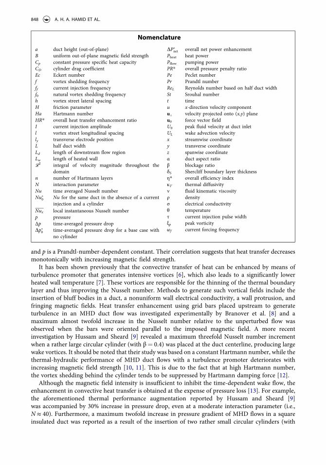
3.2.1. Thermal performance In this section, the thermal performance of current injection vortex promotion with and without a cylinder in a duct is compared. The results of heat transfer enhancement ratio HR* for cases when a cylinder is present are reproduced from Hamid et al. [24]. To facilitate a direct comparison, these results are renormalized with respect to the base flows in the absence of both current injection and cylinder vortex promoters (given the symbol Nu�0), hence the label asterisk. In general, the overall trend of heat transfer is independent of whether the cylinder is present or not, as can be seen in Figures 3, 5, and 7. Hence, the present paper will discuss only briefly the dependencies of current injection parameters on the enhancement of heat transfer presented in these figures. The reader is referred to Hamid et al. [24] for further discussion.
The dependencies of the current injection frequency and amplitude on the heat transfer enhance-ment are presented in Figure 3. The heat transfer enhancement ratio HR* exhibits a nonmonotonic relation with forcing frequency. This trend is attributed to the competition between the size and the separation distance of the shed vortices. When the forcing frequency is low, the vorticity supply to each shed vortex is large. The vorticity rolls up to form a large vortex structure in the wake, which
Figure 3. Time-averaged heat transfer enhancement plotted against forcing frequency ωf at nondimensional current amplitudes I as indicated for H ¼ 500, ReL ¼ 1,500 and τ/T ¼ 0.25. Lines with (without) symbols represent cases without (with) a cylinder in the duct.
Figure 2. (Primary vertical axis) Local Nusselt number and (secondary vertical axis) pressure drop of base flows plotted against friction parameter H for Reynolds number ReL ¼ 1,500 and 3,000. Lines with (without) symbols represent local Nusselt number (pressure drop).
NUMERICAL HEAT TRANSFER, PART A 853

then interacts efficiently with the heated wall thermal boundary layer. Thermal plumes rise due to the entrainment of heat within the boundary layer by the counterrotating vortices, reaching the cold wall and rolling up in both sides of the streamwise direction to generate mushroom-like plumes (as can be seen in Figure 4b). The formation of these structures leads to a thermal boundary layer thinning, and thus to an effective transverse heat transfer. Recall that the diffuse nature of the thermal structures relative to the vorticity structures is due to the small Prandtl number, Pr ¼ 0.022.
However, when the forcing frequency is either too low (ωf < 1.5) or too high (ωf ≳ 6), the duct thermal performance is poor. In the former condition, the wake loses its coherence as a result of interactions with the Shercliff layers, as depicted in Figure 4a. There is no entrainment of hot fluid
Figure 4. Plot of vorticity (left) and temperature (right) contours for H ¼ 500, ReL ¼ 1,500, τ/T ¼ 0.25, and (a) I ¼ 30 and ωf ¼ 0.5, (b) I ¼ 30 and ωf ¼ 2, (c) I ¼ 30 and ωf ¼ 6, (d, e) I ¼ 12 and ωf ¼ 4, and (f, g) I ¼ 30 and ωf ¼ 4. In (e) and (g), a circular cylinder with a diameter of 20% of the duct width is placed at the duct centerline. Vorticity fields: contour levels ranges between � 2 and 2, with light and dark contours represent positive and negative vorticity, respectively. Temperature fields: contour levels ranges between θ0 and θw, with dark and light contours represent cold and hot fluid, respectively.
Figure 5. Time-averaged heat transfer enhancement plotted against current injection pulse width τ/T at frequencies ωf as indicated for H ¼ 500, ReL ¼ 1,500, and I ¼ 30. Lines with symbols are the no-cylinder cases; lines with no symbols are the cases with the cylinder present.
854 A. H. A. HAMID ET AL.

into the bulk flow due to the large separation distance between successive counterrotating vortices, and thus leads to a poor transport of heat. The latter condition results in a wake exhibiting a row of small counterrotating vortices align to the duct centerline, (refer Figure 4c). The thermal plumes no longer reach the top wall due to the weak entrainment generated by the small and weak vortices, which also results to a low convective heat transfer.
It is also noted that in the higher current amplitude regime (I ≳ 30), the empty duct with current injection alone generally achieves greater thermal performance relative to the duct with a cylinder, while the opposite is true in the lower current amplitude regime. The discussion to follow explains the latter observation. Inspection of vorticity contours for both cases (as shown in Figure 4d–4g) revealed an apparent difference in the trajectory of the wake vortices. The electrically augmented wake (with a cylinder) tends to be wider than the electrically generated wake (without a cylinder). The wider wake generally leads to a stronger vortex-boundary layer interaction, which results in a thinner thermal boundary layer and thus superior heat transfer.
However, for a high forcing amplitude, although the wake-boundary layer interaction appears to be stronger in the obstructed duct due to the aforementioned wider wake, the enhancement in heat transfer in the unobstructed duct is greater. This is attributed to the fact that the vortices that are generated solely by a current injection are more intense than the vortices generated by both a current injection and a cylinder, which is likely due to the counteractions between the electrically driven
Figure 6. Instantaneous vorticity contour plots for H ¼ 500, ReL ¼ 1,500, I ¼ 30, ωf ¼ 3.5, and (a, b) τ/T ¼ 0.1 and (c, d) τ/T ¼ 0.4. In (b) and (d), a circular cylinder with a diameter of 20% of the duct width is placed at the duct centerline. Contour levels are as per Figure 4.
Figure 7. Time-averaged heat transfer enhancement plotted against friction parameter H at Reynolds numbers ReL as indicated for I ¼ 30, ωf ¼ 1.75, and τ/T ¼ 0.25. Lines with symbols are the no-cylinder cases; lines with no symbols are the cases with the cylinder present.
NUMERICAL HEAT TRANSFER, PART A 855
vortices and the vortices generated by the cylinder during their formation. The more intense pair of counterrotating vortices entrains larger amount of hot fluid in the vicinity of the heated wall into the bulk flow, resulting in taller plume structures in the thermal field (as visualized in Figure 4f relative to Figure 4g and thus an improved heat transfer. Further discussion concerning the wake vortices dynamics and their decay is presented in Section 3.2.2.
Figure 5 presents the variation of HR* with current injection pulse width, which are varied between 0.05 and 0.5 for ωf ¼ 1.75 and ωf ¼ 3.5, while other parameters are kept constant. In general, the enhancement in heat transfer progressively increases for increasing current injection pulse width. The reason for this is that for a given forcing frequency, longer injection pulse width means that the vortex rolls up with greater number of rotations as they advect downstream, as can be seen in Figure 6. This leads to a larger vortical structure in the wake and thus leading to an improved heat transport enhancement.
Figure 5 also reveals that when the pulse width is short, the duct with a cylinder outperforms the empty duct. In the absence of the cylinder, shorter current pulses generate relatively smaller vortices (the sizes are evidenced by comparing Figures 6a and 6c. When the cylinder is present, the wake is wider and the generated vortices are larger due to the reinforcement by shear layers separating from the cylinder, as can be seen in Figure 6b. However, the vortices are weaker (e.g. the vortex is approximately 50% weaker than the corresponding case without a cylinder at x/d ≈ 3). Hence, in the regime of shorter pulse width, the strength of wake-boundary layer interaction plays a greater role in the enhancement of heat transfer than the vortex intensity, due to the fact that the entrainment mechanism is rather weak for small vortices. The presence of the cylinder, however, becomes less beneficial when the current pulses are longer due to the aforementioned detrimental interaction between the cylinder and the electrically driven vortices. In this case, the wake vortices are smaller than the empty duct case, as shown in Figure 6d in comparison with Figure 6c.
The effect of friction parameter and Reynolds number on the heat transfer enhancement ratio is demonstrated in Figure 7. Here, the friction parameter is restricted to H � 5,000 so that the quasi-2-dimensionality assumption holds. For H > 5,000 (which corresponds to Ha > 104 for n ¼ 2 and duct aspect ratio α ¼ 2L/a ¼ 1) and magnetic Prandtl numbers range between Prm ¼ 10� 6 and 10� 5 [which is typical for liquid metals; 32], the magnetic field advection timescale is smaller than its diffusion counterpart (the ratio of these two time scales are quantified by the Lundquist number S ¼ HaPr1=2
m ). In such a case, the injection of current pulses is likely to generate unsteady phenomena such as Alfvén waves. These waves travel along the imposed magnetic field, which will then violate the quasi-static assumption, and thus the more restrictive quasi-2-dimensionality assumption. The figure shows a nonmonotonic relation between the enhancement of heat transfer and the friction parameter due to the competing effect between inertia and Hartmann damping [24]. In the low-H regime, the increasing intensity of the imposed magnetic field results in stronger electrically driven vortices. Furthermore, the Hartmann damping is relatively low, permitting these coherent vortices to advect to a greater downstream distance while interacting with the thermal boundary layer (as shown in Figure 8a), thus leading to an increased heat transfer enhancement.
It is interesting to note that in this regime, the presence of a cylinder improves the heat transfer characteristic of the duct, particularly for the higher Reynolds number case. This is due to mutual interaction of the current driving force and the inertia that leads to a substantial loss of wake coher-ence, visible in both vorticity and temperature field plots in Figure 8b. The bulk vortices interact with the Shercliff layers, causing its destabilization and formation of secondary vortices that results in a consistent enhancement in the local Nusselt number along the downstream of the duct (as evidenced in Figure 9).
In the high-H regime, however, the action of Hartmann damping is more prominent than the driving Lorentz force, leading to a strong vortex only in the vicinity of the injection point due to the magnetic field-imposed current interaction, and decays abruptly after its formation. As a result, a substantial enhancement in heat transfer which is localized only in this region was observed, as
856 A. H. A. HAMID ET AL.
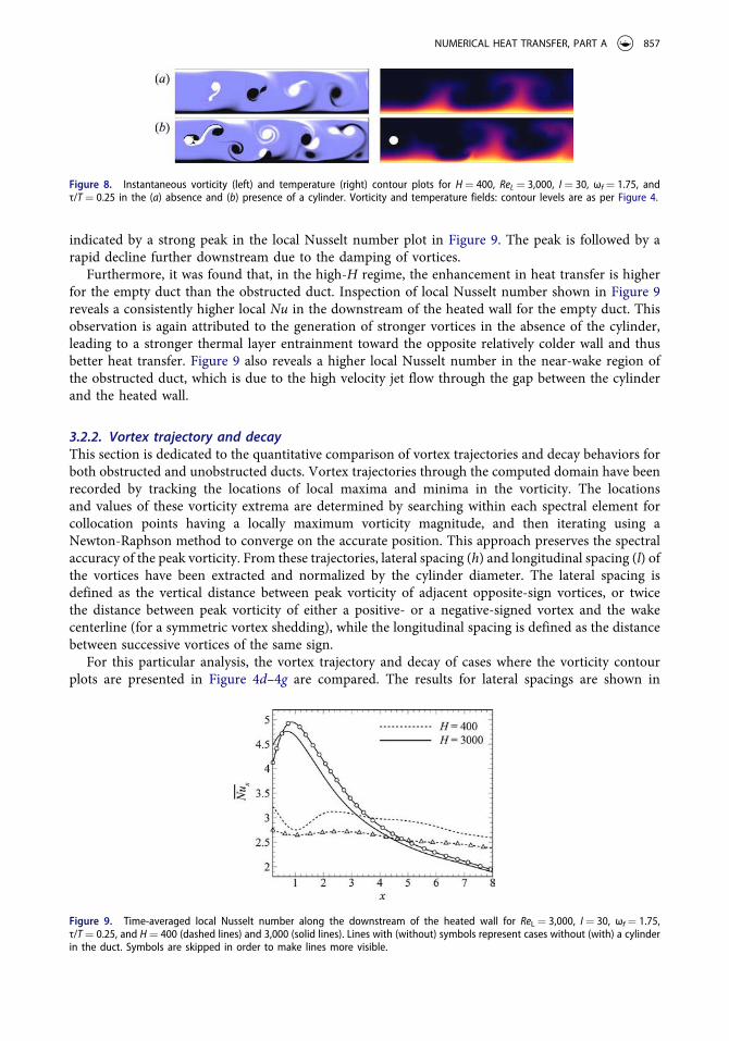
indicated by a strong peak in the local Nusselt number plot in Figure 9. The peak is followed by a rapid decline further downstream due to the damping of vortices.
Furthermore, it was found that, in the high-H regime, the enhancement in heat transfer is higher for the empty duct than the obstructed duct. Inspection of local Nusselt number shown in Figure 9 reveals a consistently higher local Nu in the downstream of the heated wall for the empty duct. This observation is again attributed to the generation of stronger vortices in the absence of the cylinder, leading to a stronger thermal layer entrainment toward the opposite relatively colder wall and thus better heat transfer. Figure 9 also reveals a higher local Nusselt number in the near-wake region of the obstructed duct, which is due to the high velocity jet flow through the gap between the cylinder and the heated wall.
3.2.2. Vortex trajectory and decay This section is dedicated to the quantitative comparison of vortex trajectories and decay behaviors for both obstructed and unobstructed ducts. Vortex trajectories through the computed domain have been recorded by tracking the locations of local maxima and minima in the vorticity. The locations and values of these vorticity extrema are determined by searching within each spectral element for collocation points having a locally maximum vorticity magnitude, and then iterating using a Newton-Raphson method to converge on the accurate position. This approach preserves the spectral accuracy of the peak vorticity. From these trajectories, lateral spacing (h) and longitudinal spacing (l) of the vortices have been extracted and normalized by the cylinder diameter. The lateral spacing is defined as the vertical distance between peak vorticity of adjacent opposite-sign vortices, or twice the distance between peak vorticity of either a positive- or a negative-signed vortex and the wake centerline (for a symmetric vortex shedding), while the longitudinal spacing is defined as the distance between successive vortices of the same sign.
For this particular analysis, the vortex trajectory and decay of cases where the vorticity contour plots are presented in Figure 4d–4g are compared. The results for lateral spacings are shown in
Figure 9. Time-averaged local Nusselt number along the downstream of the heated wall for ReL ¼ 3,000, I ¼ 30, ωf ¼ 1.75, τ/T ¼ 0.25, and H ¼ 400 (dashed lines) and 3,000 (solid lines). Lines with (without) symbols represent cases without (with) a cylinder in the duct. Symbols are skipped in order to make lines more visible.
Figure 8. Instantaneous vorticity (left) and temperature (right) contour plots for H ¼ 400, ReL ¼ 3,000, I ¼ 30, ωf ¼ 1.75, and τ/T ¼ 0.25 in the (a) absence and (b) presence of a cylinder. Vorticity and temperature fields: contour levels are as per Figure 4.
NUMERICAL HEAT TRANSFER, PART A 857

Figure 10a. The wakes of these cases exhibit a symmetric pattern, and thus the trajectories of both positive and negative vorticity show a symmetric profile with respect to the wake centerline. It is observed from Figure 10a that current injection significantly widens the cylinder wake (by more than 100% through the downstream of the computed domain). However, in the absence of the cylinder, vortices of both signs that are generated by the current injection organize into a nearly single row which coincides with the duct centerline, with lateral spacings of less than half of the cylinder diameter. It is interesting to note that the negative (positive) vortices are formed in the upper (lower) half of the wake, but their trajectories intersect at a certain distance along the wake and their position with respect to the duct centerline is inverted, which explains the spacing of zero at approximately x/d ¼ 5.8 downstream of the electrode. Beyond the intersection region, vortices of both sign are deflected away equally from the wake axis. Furthermore, it is also observed from Figure 10a that higher current amplitude results in the vortices being cast further away from the wake centerline, and that the rate of widening is higher for the unobstructed cases. The reason for the latter obser-vation is that the tandem arrangement of the opposite sign vortices induces a significant transverse velocity component between the vortices, which then feeds energy into the vortices and consequently causes them to expand. Larger current amplitude induces stronger entrainment in the transverse direction, thus explaining the observed wider wake.
The current injection also significantly alters the longitudinal spacing of the vortex street, as shown in Figure 10b. Here, the longitudinal spacing is measured in the stable wake region in which the longi-tudinal spacing is ideally constant [33], i.e. 10 ≲ x/d ≲ 16. Upstream of this region is the formation region, where there is no clear trend in the longitudinal spacings.
In the presence of the current injection, the longitudinal spacing is approximately 17% higher than those with a cylinder only. This is attributed to the fact that the longitudinal spacing is proportional to the wake advection velocity and inversely proportional to the shedding frequency, i.e., l/d ¼ Uξ/(fd) [34]. The analysis of vortex spatiotemporal evolution revealed that the wake advection velocity is almost identical across the investigated cases, which ranges between 0.98 and 1 relative to peak inlet velocity. This suggests that the longitudinal spacing is strongly influenced by the shedding frequency. It has been reported previously [24] that the shedding frequency of an electrically augmented cylinder wake vortices is governed by the electrical forcing frequency. It follows then that for a given forcing frequency, the longitudinal length is constant, which is in agreement with the results shown in Figure 10b. Spectral analysis of the cylinder lift coefficient reveals a natural cylinder vortex shedding frequency (in the absence of current forcing) for H ¼ 500 and ReL ¼ 1,500 of f0 ≈ 0.742. This frequency is 16.6% higher than the forcing shedding frequency (i.e., ff ¼ ωf/2π ¼ 0.637), which
Figure 10. Spatial variation of (a) vortex lateral spacing and (b) vortex longitudinal spacing, for H ¼ 500, ReL ¼ 1,500, ωf ¼ 4, τ/T ¼ 0.25, and current amplitudes as indicated. Open and solid symbols represents duct cases with and without a cylinder, respectively. Line without symbols represents duct cases with a cylinder in the absence of current injection.
858 A. H. A. HAMID ET AL.

expectedly matches the aforementioned percentage increase in the longitudinal spacing due to the forcing current.
A further analysis on the strength and decay of the shed vortices are performed through the mea-sured local peak vorticity and the results are shown in Figure 11. It is observed that the current injec-tion significantly enhances the strength of the cylinder wake vortices, where the peak vorticity increases averagely (calculated along the downstream of the cylinder or electrode) by 90% and 160% relative to the base case, respectively, for I ¼ 12 and I ¼ 30. It is also observed that for a higher current amplitude (I ¼ 30), the presence of a cylinder tends to inhibit the growth of the shed vortices likely due to the aforementioned counteractions of the vorticity generation mechanisms. The peak vorticity in the vortices generated solely by the current injection is on average approximately 30% stronger than in the corresponding obstructed wake flow. However, for I ¼ 12, the average strength of shed vortices in the presence of a cylinder is approximately 20% higher relative to the unobstructed case.
It is found that the vortices exhibit very close to an exponential decay, and the rate of decay is similar for all cases (as shown by the almost linear and consistent gradient in the semilog plot of Figure 11). This behavior is attributed to the strong Hartmann damping in the flow. For β ¼ 0.2 and ReL ¼ 1,500, the estimated critical friction parameter (a friction parameter at which the decay is dominated by the Hartmann damping only) is Hcr ¼ Re0:974
L =ð0:90ðbL þ 2bð0:075bþ 0:01ÞReLð1 � bÞ � ð4:3b � 0:15ÞÞÞ � 120 [22]. The friction parameter imposed to the flow (H ¼ 500) is considerably higher than the critical value, which implies that the decay of vortices is governed by the Hartmann friction term [22] and that the magnitude of the decay rate is constant for a given friction parameter and Reynolds number.
In the following sections, the analysis of various parameters on the enhancement of heat transfer are restricted to the case where the cylinder is absent, unless otherwise mentioned.
3.3. Reynolds number dependence
In this section, additional consideration is given to the dependence of Reynolds number on the heat transfer. The Reynolds number is varied between ReL ¼ 200 and 4,000 for friction parameters of H ¼ 500 and H ¼ 1,000. The resulting Nusselt number variation is plotted against the ratio of friction parameter to Reynolds number H/ReL, following Figure 4 of Sukoriansky et al. [31], and is presented here in Figure 12a.
The Nusselt number for cases with friction parameter being fixed exhibit a distinct trend compared to the cases of constant Reynolds number. In the former case, the Nusselt number increases mono-tonically with increasing Reynolds number due to the convectively dominated heat transport. The Nusselt number variation for the latter case is also plotted in Figure 12a for the sake of comparison
Figure 11. Spatial evolution of peak vorticity for H ¼ 500, ReL ¼ 1,500, ωf ¼ 4, τ/T ¼ 0.25 and current amplitudes as indicated. Dashed line represents peak vorticity predicted using a vortex decay model proposed by Hamid et al. [22]. Symbols and other lines are as per Figure 10.
NUMERICAL HEAT TRANSFER, PART A 859

(the HR* data have already been presented in Figure 7). The Nusselt number for this case exhibits a similar trend to that of the heat transfer enhancement ratio, which is expected since the Nusselt number for the base case is almost uninfluenced by the friction parameter (as depicted in Figure 2). Interestingly, the heat transfer enhancement ratio for the cases with a constant friction parameter also exhibits a nonmonotonic trend, as shown in Figure 12b.
This observed trend may be explained as follows: although the Nusselt numbers for these cases are progressively increasing with an increased Reynolds number, the Nusselt numbers for the respective base cases are also following a similar trend (as indicated by the consistently increasing local downstream Nusselt number with increasing Reynolds number shown in Figure 13a).
This results in the normalized local Nusselt number variations as shown in Figure 13b. Figure 12b shows that in the low-H/ReL regime (a regime where H/ReL < (H/ReL)cr, where (H/ReL)cr is the critical value corresponding to the peak of HR* for the respective constant Reynolds number or friction para-meter lines), an increase in H/ReL leads to an increase in the heat transfer enhancement ratio. This is due to the enhancement in the local Nusselt number in the region closer to the electrode (as indicated by region S2 in Figure 13b) being greater than its diminution further downstream (as represented by
Figure 13. (a) Local Nusselt number for (primary vertical axis, solid lines) cases with H ¼ 1,000, I ¼ 30, ωf ¼ 1.75, and τ/T ¼ 0.25 and (secondary vertical axis, dashed lines) the respective base cases. The Reynolds numbers are progressively increasing for lines from bottom to top as indicated, for both solid and dashed lines. (b) Normalized time-averaged local Nusselt number along the downstream of the heated wall for cases in (a). The dark (lighter) region corresponds to a deficit (surplus) in heat transfer enhancement of a higher Reynolds number case relative to the lower one. I1 and I2 are intersection points of local Nusselt number lines at different Reynolds numbers.
Figure 12. Variation of (a) Nusselt number and (b) time-averaged heat transfer enhancement ratio with respect to H/ReL at Reynolds numbers and friction parameters as indicated for I ¼ 30, ωf ¼ 1.75, and τ/T ¼ 0.25. Open and solid symbols represent cases with a fixed Reynolds number and friction parameter, respectively.
860 A. H. A. HAMID ET AL.

region D2), which results in a net increase in HR*. However, the opposite is true in the high-H/ReL regime. This is due to the shifting of the intersection point toward the upstream with increasing H/ReL (e.g., from points I2 to I1 as shown in Figure 13b), resulting in a simultaneous shrinking and growing of the “surplus” S1 and “deficit” D1 regions, respectively, and leading to a net decrease in HR*.
Unlike the cases with a fixed friction parameter, the base local Nusselt number for cases with a constant Reynolds number are almost independent of the friction parameter. Furthermore, the local Nusselt number for these cases follows a similar trend to that of the normalized local Nusselt number for a fixed friction parameter cases as presented in Figure 13b, which also explains the nonmonotonic behavior of its heat transfer enhancement.
It is also interesting to note from Figure 12b that the HR* nearly collapses in the low-H/ReL regime, but not in the higher range of H/ReL. This is despite the fact that, in the limit of high magnetic field strength and for a given H/ReL, the resultant vortex pattern and strength are similar regardless of both the Reynolds number and the friction parameter (which is expected since the birth of the vortices and their subsequent decay are governed by the ratio of H/ReL, as indicated by the respective forcing terms in Eq. (3)). In the high-H/ReL regime, the magnetic damping effect on the bulk flow is relatively significant (i.e., the heat transport is conductively dominated), thus an increase in Reynolds number yields an appreciable thinning in the thermal boundary layer (as evidenced in Figure 14a–14c) and as a result an increase in the heat transfer enhancement ratio. In the low-H/ReL regime; however, the flow is already convectively dominated and thus is less sensitive to Reynolds number variations (as shown by the almost constant thermal boundary layer thicknesses in Figure 14d-e).
3.4. Effects of the current injection profile and frequency on heat transfer
In this section, the effect of asymmetric current injection profile on the heat transfer enhancement ratio is investigated. The injection duty cycle is fixed (at D ¼ 2τ/T ¼ 0.5), so that the total current power input is maintained regardless of the imposed current profile. A duty cycle of D ¼ 0.5 means that the current injection is active for half of the period. The profile of the asymmetric current pulses are represented by the difference between the positive and negative signal pulse width, i.e., Δτ/T, as depicted in Figure 15a. A positive Δτ/T produces positive vorticity that has a longer pulse width rela-tive to the negative vorticity and vice versa. In the limit of Δτ/T ¼�0.5, the current injection profile
Figure 14. Instantaneous vorticity contour plots for I ¼ 30, ωf ¼ 1.75, τ/T ¼ 0.25, and (a) H/ReL ¼ 1.667 and ReL ¼ 300, (b) H/ReL ¼ 1.667 and ReL ¼ 600, (c) H/ReL ¼ 1.667 and ReL ¼ 1,500, (d) H/ReL ¼ 0.25 and ReL ¼ 2,000 and (e) H/ReL ¼ 0.25 and ReL ¼ 4,000. Contour levels are as per Figure 4.
NUMERICAL HEAT TRANSFER, PART A 861

takes a square waveform, where only either positive or negative vorticity is produced. Furthermore, Δτ/T ¼ 0 represents a symmetric alternating current pulse waveform.
The heat transfer enhancement results are presented in Figure 15b. In general, it was observed that, for a given injection frequency and duty cycle, the efficiency of the current injection vortex promoter can be further increased by injecting the current pulses asymmetrically; thus confirming the authors’ previous conjecture [24]. The results imply that the action of the counterclockwise (positive) vortex tail in thinning the thermal boundary layer is more pronounced than the corresponding action of the clockwise vortex, and that the thermal efficiency can be further improved by injecting an asymmetric current pulse.
The strong positive vortex-boundary layer interaction can readily be seen in Figure 16a for a posi-tive Δτ/T at a relatively high forcing frequency (e.g., ωf ¼ 3.5), which results in a higher heat transfer enhancement ratio relative to the symmetric and negative Δτ/T current pulses. It is noted that the vortex pattern resulting from a negative Δτ/T is a flipped to that from the positive Δτ/T. As such, the vorticity field of a negative/positive Δτ/T may be inferred from the respective opposite sign field.
The flipped vortex pattern yields an almost opposite trend in the local Nusselt number for both current injection polarities, as shown in Figure 17. Furthermore, the symmetric injection pulses pro-duce alternating counterrotating vortices that interact with the boundary layer in an almost consistent manner (the vorticity field is similar to the one presented in Figure 4f), which results in a nearly uniform enhancement in the local Nusselt number throughout the domain, which is also shown in Figure 17. However, at a low forcing frequency (e.g., ωf ¼ 0.5), the enhancement in heat transfer is almost uninfluenced by the current injection profile, as indicated in Figure 15b. This observation is attributed to the fact that at a low forcing frequency, the size of the resulting vortices are relatively large (as depicted in Figures 16b and 4a for asymmetric and symmetric current injection, respect-ively); thus, the integral strength of their interaction with the thermal boundary layer is almost constant regardless of the injection profile.
It is also interesting to note that within the range of optimum frequencies (i.e., 1 ≲ ωf ≲ 2, as indicated in Figure 3), HR* reaches its maximum value when the forcing current is symmetric. This is due to the aforementioned entrainment of a significant portion of the hot fluid from the heated wall by the pairs of counterrotating vortices (as shown by the temperature plot in Figure 4b). This action of vortex pairs is, however, less visible in the asymmetric cases due to the size of the opposite sign vortices becoming smaller with increasing magnitude of Δτ/T, as can be seen in Figures 16c. Despite the different vortex pattern compared to other frequency cases, the trend of local Nusselt number is similar for all Δτ/T, as depicted in Figure 17. However, the local Nusselt number for a case within the
Figure 15. (a) Electric current injection profiles, represented by an asymmetric modified square waveform with pulse width τ/T ¼ 0.5. The amplitude of the current is normalized by its peak amplitude, Ip, and the time is normalized by signal period, T. (b) Time-averaged heat transfer enhancement ratio plotted against pulse width difference at frequencies as indicated for H ¼ 500, ReL ¼ 1,500, I ¼ 30, τ/T ¼ 0.5, and ly ¼ 1.
862 A. H. A. HAMID ET AL.
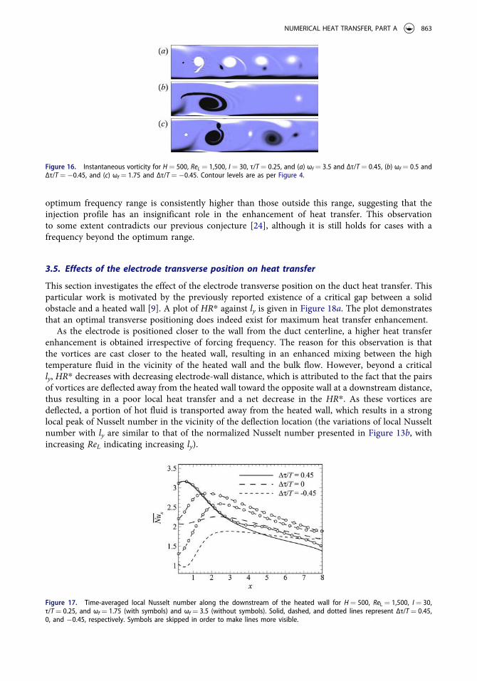
optimum frequency range is consistently higher than those outside this range, suggesting that the injection profile has an insignificant role in the enhancement of heat transfer. This observation to some extent contradicts our previous conjecture [24], although it is still holds for cases with a frequency beyond the optimum range.
3.5. Effects of the electrode transverse position on heat transfer
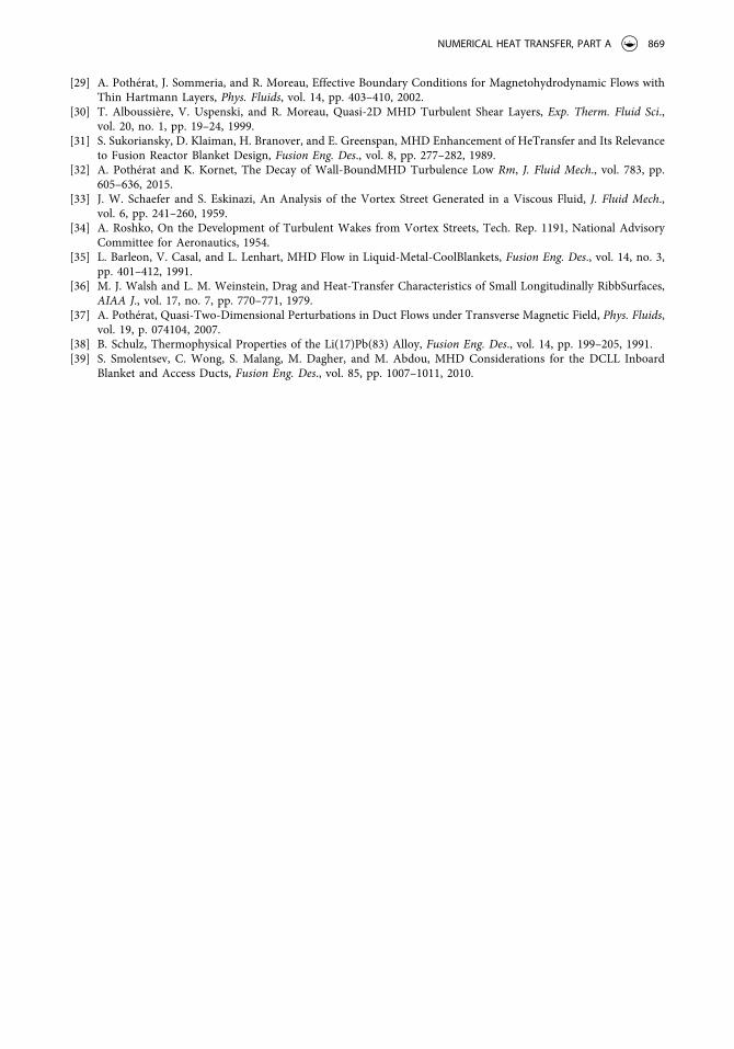
This section investigates the effect of the electrode transverse position on the duct heat transfer. This particular work is motivated by the previously reported existence of a critical gap between a solid obstacle and a heated wall [9]. A plot of HR* against ly is given in Figure 18a. The plot demonstrates that an optimal transverse positioning does indeed exist for maximum heat transfer enhancement.
As the electrode is positioned closer to the wall from the duct centerline, a higher heat transfer enhancement is obtained irrespective of forcing frequency. The reason for this observation is that the vortices are cast closer to the heated wall, resulting in an enhanced mixing between the high temperature fluid in the vicinity of the heated wall and the bulk flow. However, beyond a critical ly, HR* decreases with decreasing electrode-wall distance, which is attributed to the fact that the pairs of vortices are deflected away from the heated wall toward the opposite wall at a downstream distance, thus resulting in a poor local heat transfer and a net decrease in the HR*. As these vortices are deflected, a portion of hot fluid is transported away from the heated wall, which results in a strong local peak of Nusselt number in the vicinity of the deflection location (the variations of local Nusselt number with ly are similar to that of the normalized Nusselt number presented in Figure 13b, with increasing ReL indicating increasing ly).
Figure 17. Time-averaged local Nusselt number along the downstream of the heated wall for H ¼ 500, ReL ¼ 1,500, I ¼ 30, τ/T ¼ 0.25, and ωf ¼ 1.75 (with symbols) and ωf ¼ 3.5 (without symbols). Solid, dashed, and dotted lines represent Δτ/T ¼ 0.45, 0, and � 0.45, respectively. Symbols are skipped in order to make lines more visible.
Figure 16. Instantaneous vorticity for H ¼ 500, ReL ¼ 1,500, I ¼ 30, τ/T ¼ 0.25, and (a) ωf ¼ 3.5 and Δτ/T ¼ 0.45, (b) ωf ¼ 0.5 and Δτ/T ¼ � 0.45, and (c) ωf ¼ 1.75 and Δτ/T ¼ � 0.45. Contour levels are as per Figure 4.
NUMERICAL HEAT TRANSFER, PART A 863
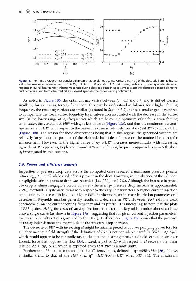
As noted in Figure 18b, the optimum gap varies between ly ¼ 0.5 and 0.7, and is shifted toward smaller ly for increasing forcing frequency. This may be understood as follows: for a higher forcing frequency, the resulting vortices are smaller (as noted in Section 3.2), hence a smaller gap is required to compensate the weak vortex-boundary layer interaction associated with the decrease in the vortex size. In the lower range of ωf (frequencies which are below the optimum value for a given forcing amplitude), the variation of HR* with ly is less obvious (Figure 18a), and that the maximum percent-age increase in HR* with respect to the centerline cases is relatively low at 6 <%HR* < 9 for ωf � 1.5 (Figure 18b). The reason for these observations being that in this regime, the generated vortices are relatively large thus; the position of the electrode has little influence on the attained heat transfer enhancement. However, in the higher range of ωf, %HR* increases monotonically with increasing ωf, with %HR* appearing to plateau toward 20% as the forcing frequency approaches ωf ¼ 5 (highest ωf investigated in this section).
3.6. Power and efficiency analysis
Inspection of pressure drop data across the computed cases revealed a maximum pressure penalty ratio PR�max � 28:7% while a cylinder is present in the duct. However, in the absence of the cylinder, a negligible gain in pressure drop was recorded (i.e., PR�max � 1:2%). Although the increase in press-ure drop is almost negligible across all cases (the average pressure drop increase is approximately 2.2%), it exhibits a systematic trend with respect to the varying parameters. A higher current injection amplitude and pulse width lead to a higher PR*. Furthermore, an increase in friction parameter or a decrease in Reynolds number generally results in a decrease in PR*. However, PR* exhibits weak dependencies on the current forcing frequency and its profile. It is interesting to note that the plots of PR* against H/ReL for cases of varying friction parameter and Reynolds number almost collapse onto a single curve (as shown in Figure 19a), suggesting that for given current injection parameters, the pressure penalty ratio is governed by the H/ReL. Furthermore, Figure 19b shows that the presence of the cylinder dictates the magnitude of the pressure drop increase.
The decrease of PR* with increasing H might be misinterpreted as a lower pumping power loss for a higher magnetic field strength if the definition of PR* is not considered carefully (PR* ¼ Δp/Δp0), which would appear to be contradictory to the fact that a stronger magnetic field leads to a stronger Lorentz force that opposes the flow [35]. Indeed, a plot of Δp with respect to H recovers the linear relation Dp � Dp�0 / H, which is expected given that PR* is almost unity.
Furthermore, PR* ≈ 1 also means that the efficiency index, defined as η* ¼HR*/PR* [36], follows a similar trend to that of the HR* (i.e., η* ¼HR*/PR* ≈ HR* when PR* ≈ 1). The maximum
Figure 18. (a) Time-averaged heat transfer enhancement ratio plotted against vertical distance ly of the electrode from the heated wall at frequencies as indicated for H ¼ 500, ReL ¼ 1,500, I ¼ 30, and τ/T ¼ 0.25. (b) (Primary vertical axis, open symbols) Maximum response in overall heat transfer enhancement ratio due to electrode positioning relative to when the electrode is placed along the duct centerline, and (secondary vertical axis, closed symbols) the corresponding optimum ly.
864 A. H. A. HAMID ET AL.

efficiency index across all cases was found to be η* ¼ 1.83, which is for the case with H ¼ 500, Re ¼ 1,500, I ¼ 60, ωf ¼ 1.25, and τ/T ¼ 0.25. This value is higher than the corresponding maximum value reported in Hamid et al. [24], i.e., η ¼ 1.91 or η* ¼ 1.80. It is important to note that the efficiency index in the latter case was obtained using a higher current injection amplitude (I ¼ 90). It is shown in Figure 13 of Hamid et al. [24] that larger current amplitude generally leads to an improved heat transfer thus; it is anticipated that the efficiency index in the former case can be further increased by injecting a larger current amplitude.
In order to further evaluate the thermal-hydraulic efficiency of the current injection vortex promoter, the net power enhancement is evaluated as follows:
DP�net ¼ DP�heat � DP�flow
¼ ðPheat � P�0;heatÞ � ðPflow � P�0;flowÞð12Þ
where ΔPheat and ΔPflow are, respectively, the net increase in heat power and pumping power due to incorporation of the vortex promoter, while Pheat and Pflow are the heat power transferred through the heated wall and the pumping power, respectively. Here the subscript 0 again denotes the correspond-ing flow without current injection, with an asterisk denoting the absence of the cylinder. Normalizing power by qL2U3
0 and applying the scalings outlined in Eq. (1), the dimensionless heat and pumping power may be expressed, respectively, as
Pheat ¼ajTCpdh
L2U30
Z Ld
0
qh
qydx ¼
2a
jTCpdh
LU30
Z Ld
0
qh
qydx ð13Þ
Figure 19. (a, b) Overall pressure penalty ratio plotted against H/ReL for (a) no-cylinder cases and (b) cases with and without a cylinder. In (b), lines with symbols are the no-cylinder cases; lines with no symbols are the cases with the cylinder present. Solid, dashed and dash-dotted lines represent ReL ¼ 1,500, ReL ¼ 3,000 and PR* ¼ 1, respectively. (c) (Primary vertical axis) Overall efficiency index and (secondary vertical axis) normalized net power enhancement plotted against H/ReL for friction parameters as indicated. Solid and dashed lines represent H ¼ 500 and 1,000, respectively. Lines with and without symbols represent, respectively, efficiency index and net power enhancement. In all cases, I ¼ 30, ωf ¼ 1.75, and τ/T ¼ 0.25.
NUMERICAL HEAT TRANSFER, PART A 865

and
Pflow ¼ 2aL
UavgDp ¼4a
UavgDp ð14Þ
where κT is the thermal diffusivity, Cp is the constant pressure specific heat capacity, and Uavg is the area-averaged velocity through the duct, which is estimated using the exact solution of a fully developed quasi-2-D MHD duct flow [37], i.e.
Uavg ¼1
2L
Z � L
Lu?ðyÞ dy;
¼1
2Lcoth2
ffiffiffiffiHp
2
� �
�2ffiffiffiffiHp coth
ffiffiffiffiHp
2
� �
þ 1� � ð15Þ
The net power balance is thus
DP�net ¼2a
jTCpdh
LU30
Z Ld
0
qh
qy�qh�0qy
dx � 2UavgðDp � Dp�0Þ� �
ð16Þ
The prefactor to the heat flux term is rewritten in terms of dimensionless parameters via
jTCpdh
LU30¼
1Pr
n
LU0
Cpdh
U20¼
1Pr ReL Ec
ð17Þ
where Ec is the Eckert number Ec ¼ U20=ðCpdhÞ. The form of the prefactor indicates that a net benefit
in heat transfer enhancement will be more significant for smaller Prandtl numbers (liquid metals present small Prandtl numbers), smaller Reynolds numbers (the Reynolds numbers are relatively modest in magnetic confinement fusion blankets), and smaller Eckert numbers.
Normalizing the net power enhancement by the pumping power, and taking Pr ¼ 0.022, Cp ¼ 188 J kg� 1 K� 1, δθ ¼ 250 K, and U0 ¼ 0.015 ms� 1 (these values are relevant to the fusion blanket application [38, 39]), the final form of the normalized net power balance may be rewritten as
DP�netPflow
¼4:75� 109
UavgDp ReL
Z Ld
0
qh
qy�qh�0qy
dx � 1 �1
PR�
� �
ð18Þ
As noted earlier, PR* is of order of unity, hence the second term on the left-hand side of Eq. (18) is approximately zero. In the limit of strong magnetic field, Uavg approaches unity (e.g., for 200 �H �5,000, 0.929 �Uavg � 0.989). Furthermore, inspection of temperature flux data revealed that it generally exhibits a similar trend with the Nusselt number. It follows then that for a given Reynolds number, DP�net follows a similar trend to that of the η* (and thus the HR*). The case with maximum and minimum DP�net=Pflow corresponds to the case with, respectively, maximum and minimum η*, which confirms the previous argument. However, for a varying Reynolds number cases, the DP�net=Pflow exhibits a trend distinct from the η* due to the ReL dependencies noted in Eq. (18). A plot of DP�net=Pflow and η* against H/ReL is shown in Figure 19c.
It can be seen from the figure that the peak of η* is higher for H ¼ 1,000 than for H ¼ 500. However, the opposite is true for DP�net=Pflow. For a stronger imposed magnetic field, the opposing damping Lorentz force is greater, which generally results in a lower heat transfer characteristic and a higher pressure loss. Thus it appears that the net power is indeed a more relevant measure for comparing cases of varying Reynolds number, although the general nonmonotonic trend in the efficiency index is still being preserved.
In general, DP�net=Pflow ranges between 2.04 � 103 and 4.69 � 105 for a fusion-relevant conditions across all the cases computed in the present study, which indicates a significant gain in heat transfer relative to the additional pressure loss.
866 A. H. A. HAMID ET AL.

4. Conclusion
The potential of electrically driven vortices as a means of enhancing convective heat transfer from a heated wall has been explored. Computations are made over a wider range of flow and current injection parameters than those reported in Hamid et al. [24] in order to elucidate further the relationship between the gain in the heat transfer and the dependent variables.
The first part of the analysis compared the gain in the thermal performance between the obstructed and the unobstructed ducts. It was found that the general trend of heat transfer enhancement for both duct configurations is similar, which might suggest that the presence of the cylinder does not change the global wake response in the duct. Surprisingly, however, the inspection of vorticity contours revealed a distinct wake pattern between the two cases. The presence of the cylinder tends to widen the wake vortices, whereas the vortices are almost aligned directly downstream of the electrode in the absence of the cylinder. In the former case, although the interaction between the wake and the thermal boundary layer appears to be stronger, the HR* data revealed that the system without a cylinder can achieve a better thermal gain depending on the intensity of the generated vorticity. Furthermore, when the inertia is relatively significant to the Hartmann damping, the cylinder wake loses its coherence and exhibits a chaotic behavior, which generally improves the wake-boundary layer interaction and thus is beneficial for the heat transfer augmentation.
The analysis of Reynolds number variations revealed that in the conductive regime (high-H/ReL), the gain in heat transfer is dependent on the Reynolds number. However, despite the distinct Nusselt number trend, the data of the normalized Nusselt number HR* almost collapse in the low-H/ReL regime when plotted against H/ReL for both constant friction parameter and constant Reynolds number cases. The results also show that heat transfer can be further improved by injecting an asymmetric alternating current. However, in the range of optimum injection frequency of 1 ≲ ωf ≲ 2, the symmetric profile outperforms its asymmetric counterpart. Furthermore, the analysis of the effect of transverse electrode position on the heat transfer enhancement suggested the existence of an optimal gap for maximum HR*, corroborating previous findings for a cylindrical obstacle in a duct. However, the electrode position is less influential on the HR* for low forcing frequency, while the optimum gap decreases with increasing forcing frequency.
The results also indicate a maximum increase in pressure drop induced by the current injection in an unobstructed duct is typically an order of magnitude less than the obstructed duct counterparts. Furthermore, the amplitude and pulse width of the current injection, together with the Reynolds number and friction parameter, were found to govern the PR*, while the current injection frequency and its profile were not. For given current parameters, the PR* was found to be governed by the ratio H/ReL.
A further power analysis also revealed a net power enhancement per unit pumping power of at least the order of 103 for a fusion-relevant conditions, while a maximum net power enhancement reaching a value of two orders of magnitude higher than the corresponding minimum value. Given the fact that the electrically generated vortices, unlike its physical obstacle counterparts, can be precisely controlled via current injection parameters such as amplitude, frequency, pulse width, and profile, a greater heat transfer gain than those reported here is anticipated through further optimization. Therefore, electrically generated vortices stand as a promising technology superior to physical vortex generators, notwithstanding the significant technical challenges in their deployment.
Funding
This research was supported by the Australian Research Council through Discovery Grants DP120100153 and DP150102920, a high-performance computing time allocations from the National Computational Infrastructure (NCI), which is supported by the Australian Government, and the Monash SunGRID. A. H. A. H. is supported by the Malaysia Ministry of Education and the Universiti Teknologi MARA, Malaysia.
NUMERICAL HEAT TRANSFER, PART A 867

References
[1] J. Sommeria and R. Moreau, Why How, and M. H. D. When, Turbulence Becomes Two-Dimensional, J. Fluid Mech., vol. 118, pp. 507–518, 1982.
[2] F. Dobran, Fusion Energy Conversion in Magnetically ConfinPlasma Reactors, Prog. Nucl. Energ., vol. 60, pp. 89–116, 2012.
[3] S. Smolentsev, R. Miraghaie, and M. Abdou, MHD Effects on HeTransfer in a Molten Salt Blanket, Fusion Sci. Technol., vol. 47, pp. 559–563, 2005.
[4] E. Y. A. Blum, Effect of a Magnetic Field on HeTransfer in the Turbulent Flow of a Conducting Fluid, High Temp., vol. 5, pp. 68–74, 1967.
[5] Y. Yamamoto and T. Kunugi, Discussion on HeTransfer Correlation in Turbulent Channel Flow ImposWall- Normal Magnetic Field, Fusion Eng. Des., vol. 86, pp. 2886–2890, 2011.
[6] D. Chatterjee and S. K. Gupta, MHD Flow and HeTransfer Behind a Square Cylinder in a Duct under Strong Axial Magnetic Field, Int. J. Heat Mass Tran., vol. 88, pp. 1–13, 2015.
[7] Y. B. Kolesnikov and O. V. Andreev, Heat-Transfer Intensification Promoted by Vortical Structures in ClosChannel under Magnetic Field, Exp. Therm. Fluid Sci., vol. 15, pp. 82–90, 1997.
[8] H. Branover, A. Eidelman, and M. Nagorny, Use of Turbulence Modification for HeTransfer Enhancement in Liquid Metal Blankets, Fusion Eng. Des., vol. 27, pp. 719–724, 1995.
[9] W. K. Hussam and G. J. Sheard, HeTransfer in a High Hartmann Number MHD Duct Flow with a Circular Cylinder PlacNear the HeatSide-Wall, Int. J. Heat Mass Tran., vol. 67, pp. 944–954, 2013.
[10] O. G. W. Cassells, W. K. Hussam, and G. J. Sheard, HeTransfer Enhancement Using Rectangular Vortex Promoters in ConfinQuasi-Two-Dimensional Magnetohydrodynamic Flows, Int. J. Heat Mass Tran., vol. 93, pp. 186–199, 2016.
[11] W. K. Hussam, M. C. Thompson, and G. J. Sheard, Dynamics and HeTransfer in a Quasi-Two-Dimensional MHD Flow Past a Circular Cylinder in a Duct High Hartmann Number, Int. J. Heat Mass Tran., vol. 54, pp. 1091–1100, 2011.
[12] G. Mutschke, G. Gerbeth, V. Shatrov, and A. Tomboulides, Two-and Three-Dimensional Instabilities of the Cylinder Wake in an AlignMagnetic Field, Phys. Fluids, vol. 9, no. 11, pp. 3114–3116, 1997.
[13] H. Huang and B. Li, HeTransfer Enhancement of Free Surface MHD-Flow by a Protrusion Wall, Fusion Eng. Des., vol. 85, pp. 1496–1502, 2010.
[14] S. Malang and M. S. Tillack, Development of Self-CoolLiquid Metal Breeder Blankets, Tech. Rep. FZKA 5581, Forschungszentrum Karlsruhe GmbH, Karlsruhe, 1995.
[15] L. Bühler, Instabilities in Quasi-Two-Dimensional Magnetohydrodynamic Flows, J. Fluid Mech., vol. 326, pp. 125–150, 1996.
[16] Z. Stelzer, D. Cébron, S. Miralles, S. Vantieghem, J. Noir, P. Scarfe, and A. Jackson, Experimental and Numerical Study of Electrically Driven Magnetohydrodynamic Flow in a ModifiCylindrical Annulus. I. Base Flow. Phys. Fluids, vol. 27, p. 077101, 2015.
[17] J. Sommeria, Electrically Driven Vortices in a Strong Magnetic Field, J. Fluid Mech., vol. 189, pp. 553–569, 1988. [18] J. Young, S. Smolentsev, and M. Abdou, Study of Instabilities in a Quasi-2D MHD Duct Flow with an Inflectional
Velocity Profile, Fusion Eng. Des., vol. 89, pp. 1163–1167, 2014. [19] N. T. Baker, A. Pothérat, and L. Davoust, Dimensionality, Secondary Flows and Helicity in Low-Rm MHD
Vortices, J. Fluid Mech., vol. 779, pp. 325–350, 2015. [20] K. Messadek and R. Moreau, An Experimental Investigation of MHD Quasi-Two-Dimensional Turbulent Shear
Flows, J. Fluid Mech., vol. 456, pp. 137–159, 2002. [21] A. Pothérat and R. Klein, Why, How and When MHD Turbulence Low Rm Becomes Three-Dimensional, J. Fluid
Mech., vol. 761, pp. 168–205, 2014. [22] A. H. A. Hamid, W. K. Hussam, A. Pothérat, and G. J. Sheard, Spatial Evolution of a Quasi-Two-Dimensional
Kármán Vortex Street Subjected to a Strong Uniform Magnetic Field, Phys. Fluids, vol. 27, p. 053602, 2015. [23] A. Pothérat, J. Sommeria, and R. Moreau, An Effective Two-Dimensional Model for MHD Flows with Transverse
Magnetic Field, J. Fluid Mech., vol. 424, pp. 75–100, 2000. [24] A. H. A. Hamid, W. K. Hussam, and G. J. Sheard, Combining an Obstacle and Electrically Driven Vortices to
Enhance HeTransfer in a Quasi-Two-Dimensional MHD Duct Flow, J. Fluid Mech., vol. 792, pp. 364–396, 2016. [25] A. Pothérat, J. Sommeria, and R. Moreau, Numerical Simulations of an Effective Two-Dimensional Model for
Flows with a Transverse Magnetic Field, J. Fluid Mech., vol. 534, pp. 115–143, 2005. [26] A. D. Polyanin, Handbook of Linear Partial Differential Equations for Engineers and Scientists, Chapman and Hall/
CRC, Boca Raton, 2001. [27] J. C. R. Hunt and D. G. Malcolm, Some Electrically Driven Flows in Magnetohydrodynamics Part 2. Theory and
Experiment, J. Fluid Mech., vol. 33, no. 4, pp. 775–801, 1968. [28] W. K. Hussam, M. C. Thompson, and G. J. Sheard, Enhancing HeTransfer in a High Hartmann Number
Magnetohydrodynamic Channel Flow via Torsional Oscillation of a Cylindrical Obstacle, Phys. Fluids, vol. 24, p. 113601, 2012.
868 A. H. A. HAMID ET AL.
[29] A. Pothérat, J. Sommeria, and R. Moreau, Effective Boundary Conditions for Magnetohydrodynamic Flows with Thin Hartmann Layers, Phys. Fluids, vol. 14, pp. 403–410, 2002.
[30] T. Alboussière, V. Uspenski, and R. Moreau, Quasi-2D MHD Turbulent Shear Layers, Exp. Therm. Fluid Sci., vol. 20, no. 1, pp. 19–24, 1999.
[31] S. Sukoriansky, D. Klaiman, H. Branover, and E. Greenspan, MHD Enhancement of HeTransfer and Its Relevance to Fusion Reactor Blanket Design, Fusion Eng. Des., vol. 8, pp. 277–282, 1989.
[32] A. Pothérat and K. Kornet, The Decay of Wall-BoundMHD Turbulence Low Rm, J. Fluid Mech., vol. 783, pp. 605–636, 2015.
[33] J. W. Schaefer and S. Eskinazi, An Analysis of the Vortex Street Generated in a Viscous Fluid, J. Fluid Mech., vol. 6, pp. 241–260, 1959.
[34] A. Roshko, On the Development of Turbulent Wakes from Vortex Streets, Tech. Rep. 1191, National Advisory Committee for Aeronautics, 1954.
[35] L. Barleon, V. Casal, and L. Lenhart, MHD Flow in Liquid-Metal-CoolBlankets, Fusion Eng. Des., vol. 14, no. 3, pp. 401–412, 1991.
[36] M. J. Walsh and L. M. Weinstein, Drag and Heat-Transfer Characteristics of Small Longitudinally RibbSurfaces, AIAA J., vol. 17, no. 7, pp. 770–771, 1979.
[37] A. Pothérat, Quasi-Two-Dimensional Perturbations in Duct Flows under Transverse Magnetic Field, Phys. Fluids, vol. 19, p. 074104, 2007.
[38] B. Schulz, Thermophysical Properties of the Li(17)Pb(83) Alloy, Fusion Eng. Des., vol. 14, pp. 199–205, 1991. [39] S. Smolentsev, C. Wong, S. Malang, M. Dagher, and M. Abdou, MHD Considerations for the DCLL Inboard
Blanket and Access Ducts, Fusion Eng. Des., vol. 85, pp. 1007–1011, 2010.
NUMERICAL HEAT TRANSFER, PART A 869