HD uDTA INSTALL - hellotds.com · HD uDTA INSTALL Resource Book © 2013 Evolution Digital, LLC |...
131
HD uDTA INSTALL Resource Book © 2013 Evolution Digital, LLC | This document contains confidential and privileged material for the sole use of the intended recipient.
Transcript of HD uDTA INSTALL - hellotds.com · HD uDTA INSTALL Resource Book © 2013 Evolution Digital, LLC |...

HD uDTA INSTALLResource Book
© 2013 Evolution Digital, LLC | This document contains confidential and privileged material for the sole use of the intended recipient.

ContentsHD uDTA Customer Facing User GuideLiberty HD uDTA Wall-Plate Device InstallationHD uDTA Traning PresentationHD uDTA Technical User Guide
© 2013 Evolution Digital, LLC | This document contains confidential and privileged material for the sole use of the intended recipient.

HD uDTACustomer Facing User Guide
© 2013 Evolution Digital, LLC | This document contains confidential and privileged material for the sole use of the intended recipient.

© 2013 Evolution Digital, LLC. All Rights Reserved.Manufactured under license from Dolby Laboratories. Dolby and the double-D symbol are trademarks of Dolby Laboratories.
HDMI, the HDMI logo and High-Definition Multimedia Interface are trademarks or registered trademarks of HDMI licensing LLC.
WARNING
TO REDUCE THE RISK OF FIRE OR ELECTRIC SHOCK, DO NOT EXPOSE THIS PRODUCT TO RAIN OR MOISTURE. DO NOT INSERT ANY METALLIC OBJECT THROUGH THE VENTILATION GRILLS OR OTHER OPENINGS ON THE EQUIPMENT. APPARATUS SHALL NOT BE EXPOSED TO DRIPPING OR SPLASHING AND NO OBJECTS FILLED WITH LIQUIDS, SUCH AS VASES, SHALL BE PLACED ON THE APPARATUS.
EXPLANATION OF GRAPHICAL SYMBOLS
The lightning flash with arrowhead symbol, within an equilateral triangle, is intended to alert the user to the presence of “dangerous voltage” within the product’s enclosure that may be of sufficient magnitude to constitute a risk of electric shock to persons.
The exclamation point within an equilateral triangle is intended to alert the user to the presence of important operating and maintenance (servicing) instructions in the literature accompanying the product.
1. Read these instructions.
2. Keep these instructions.
3. Heed all warnings.
4. Follow all instructions.
5. Do not use this apparatus near water.
6. Clean only with a dry cloth.
7. Do not block any of the ventilation openings. Install in accordance with the manufacturer’s instructions.
8. Do not install near any heat sources such as radiators, heat registers, stoves, or other apparatus (including amplifiers) that produce heat.
9. Do not defeat the safety purpose of the polarized or grounding type plug. A polarized plug has two blades with one wider than the other. A grounding type plug has two blades and a third grounding prong. The wide blade or the third prong is provided for your safety. When the provided plug does not fit into your outlet, consult an electrician for replacement of the obsolete outlet.
10. Protect the power cord from being walked on or pinched particularly at plugs, convenience receptacles, and the point where they exit from the apparatus. Ensure that the power cord receptacle is accessible such that power can be easily disconnected if required.
11. Only use the attachments/accessories specified by the manufacturer.
12. Use only with a cart, stand, tripod, bracket, or table specified by the manufacturer, or sold with the apparatus. When a cart is used, use caution when moving the cart/ apparatus combination to avoid injury from tip-over.
13. Unplug this apparatus during lightning storms or when unused for long periods of time.
14. Refer all servicing to qualified service personnel. Servicing is required when the apparatus has been damaged in any way, such as power supply cord or plug is damaged, liquid has been spilled or objects have fallen into the apparatus, the apparatus has been exposed to rain or moisture, does not operate normally, or has been dropped.
CAUTION: TO REDUCE THE RISK OF ELECTRIC SHOCK.DO NOT REMOVE COVER (OR BACK).
NO USER-SERVICEABLE PARTS INSIDE.REFERS SERVICING TO QUALIFIED SERVICE PERSONNEL.
CAUTIONRISK OF ELECTRIC SHOCK
NO NOT OPEN
Evolution Digital HD Set-Top BoxImportant Safety Instructions

FCC InformationThis equipment has been tested and found to comply with the limits for a Class B digital device, pursuant to Part 15 of the FCC Rules. These limits are designed to provide reasonable protection against harmful interference in a residential installation.
This equipment generates, uses and can radiate radio frequency energy and, if not installed and used in accordance with the instruc-tions, may cause harmful interference to radio communications. However, there is no guarantee that interference will not occur in a particular installation.
If this equipment does cause harmful interference to radio or television reception which can be determined by turning the equipment off and on, the user is encouraged to try to correct the interference by one or more of the following measures: • Increase the separation between the equipment and receiver. • Connecttheequipmentintoanoutletonacircuitdifferent from that to which the receiver is connected. • Consult the dealer or an experienced radio/TV technician for help. • Onlyshieldedinterfacecableshouldbeused.
Finally, any changes or modifications to the equipment by the user not expressly approved by the grantee or manufacturer could void the user’s authority to operate such equipment.
Disconnection DeviceDisconnect the main plug from the apparatus, if it’s defective. And please call a repair man in your location.When used outside of the U.S., it may be used HAR code with fittings of an approved agency is employed.
CAUTIONThese servicing instructions are for use by qualified service personnel only. To reduce the risk of electric shock do not perform any servicing other than that contained in the operating instructions unless you are qualified to do so.
Manufactured under license from Dolby Laboratories. Dolby and the double-D symbol are trademarks of Dolby Laboratories.
6 7
Getting Set Up
HDThank You for choosing the Evolution Digital High-Definition Set-Top Box (HD STB). You can now enjoy viewing Standard-Definition (SD) or High-Definition (HD) programming on an analog or digital television set. When connecting the Set-Top Box with an HDMI cable to your HDTV, you will be able to view HD programming with easy-to-use on-screen menus and navigation.
In the user guide êCable Connections 8
Activation 9
Remote Control 10 Pair your remote control 11 Remove remote control pairing 11
Menu 12
FAQs 14
In the box êHD Set-Top Box
Power Cord
AdhesiveVelcro
Remote withBatteries
HDMI Cable
Setup your HD STB by following the connection diagrams on page 8.
Activate your HD STB by calling your cable provider or going online (if available).
Pair your remote with your HD STB and TV by following the directions on page 11.
1 setup 2 activate 3 pair remote
Let’s get started! è
TV
M enu
Exit
Last
PgPg
Info
VOL CH
8 9
21Cable Connections
HDMI Set-up
To TV
HDMI (IN)
To TV
To Electrical Outlet
To Coaxial Wall Outlet
CABLE IN
To TV
To Electrical Outlet
To Coaxial Wall Outlet
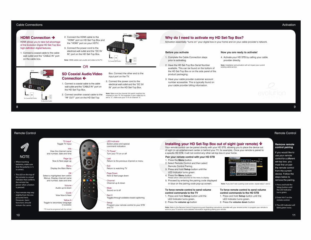
HDMI Connection èHDMI allows you to take full advantage of the Evolution Digital HD Set-Top Box high-definition digital features.
1. Connect a coaxial cable to the cable wall outlet and the “CABLE IN” port on the cable box.
2. Connect the HDMI cable to the “HDMI” port on HD Set-Top Box and the “HDMI” port on your HDTV.
3. Connect the power cord to the electrical wall outlet and the “DC 5V IN” port on the HD Set-Top Box.
Note: HDMI cables carry audio and video to the TV.
Before you activate
1. Complete the Cable Connection steps prior to activating.
2. Have the HD Set-Top Box Serial Number available. This can be found on the bottom of the HD Set-Top Box or on the side panel of the product packaging.
3. Have your cable provider customer account number accessible. This is typically found on your cable provider billing information.
Now you are ready to activate!
4. Activate your HD STB by calling your cable provider directly.
Note: Installation and activation will not impact your current existing cable service.
SD Coaxial Audio/Video Connection ç1. Connect a coaxial cable to the cable wall outlet and the “CABLE IN” port on the HD Set-Top Box.
2. Connect another coaxial cable to the “RF OUT” port on the HD Set-Top
Box. Connect the other end to the input port on the TV.
3. Connect the power cord to the electrical wall outlet and the “DC 5V IN” port on the HD Set-Top Box.
Note: Make sure the channel 3/4 switch matches the channel on your TV. For example, if your cable box is set to “3”, make sure your TV is on channel “3”.
Activation
OR
Why do I need to activate my HD Set-Top Box?Activation essentially “turns on” your digital box in your home and on your cable provider’s network.
10 11
3Remote ControlRemote Control
TV Input*
Toggle TV Input
InfoView the channel name
and number, date and time
Page UpNow & Next page up
MenuDisplay the Main Menu
OKSelect a highlighted item within Menus. Display channel name
and number, date and time
VolumeAudio up & down
GuideView Now & Next
Yellow AToggle to secondary language
(if available)
*TV must be programed with the remote
LED IndicatorButton press and special command indication
TV Power*
Turn your TV on or off
LastReturn to the previous channel or menu
ExitReturn to watching TV
Page DownNow & Next page down
ChannelChannel up & down
MuteSound on & off
Red CToggles through available closed captioning
SetupProgram your remote control to your STB and TV
NOTE• Wheninserting batteries,makesure thatthepolarity(+/-) iscorrect.
• TheLEDonthetopof theremoteisavisual indicatorthatconfirms theremotehas powerwhenabutton ispressed.
• Yourremotemayvary slightlyfromtheone picturedhere. However,basic functionsshould remainthesame.
Remove remote control pairing
If you would like to use your remote control for a different set-top box, you must first un-pair the remote control from the current device. Follow the steps below to remove the pairing.
1Pressandholdthe Setupbuttonuntil theLEDIndicator turnsgreen.
2Enter9-8-7onthe remotecontrol.
3TheLEDIndicatorwill blinkgreentwice.
Pair your remote control with your HD STB1. Press the Menu button.2. Select Remote Control and then select Remote Control Pairing.3. Press and hold Setup button until the LED Indicator turns green.4. Press the Menu button. Please allow a few seconds for the menu to display
5. Proceed by entering the pairing code displayed in blue on the pairing code pop-up screen. Note: If you don’t see a pairing code screen, repeat steps 1 and 2.
To force remote control to send volume control commands to the TV1. Press and hold Setup button until the LED Indicator turns green.2. Press the volume up button
To force remote control to send volume control commands to the HD STB1. Press and hold Setup button until the LED Indicator turns green.2. Press the volume down button
Installing your HD Set-Top Box out of sight (pair remote) êYour remote control can be paired directly with your HD STB, allowing you to place the device out of sight (in an entertainment center or behind your TV, for example). Once your remote is paired to a specific HD STB, it will not control any other set-top box in your home.
Note: Refer to the Remote Control Programming and Operating instructions, provided with your remote control, to program your remote to work on your TV and for more detailed information regarding pairing your remote.
12 13
Using the RF output?
SD Setup
Use SD Setup to scale video to your TV.
Select SD Setup and press OK. The following op-tions are available; Aspect Ratio, Just Scale, Box, and Pan and Scan.
Menu Menu
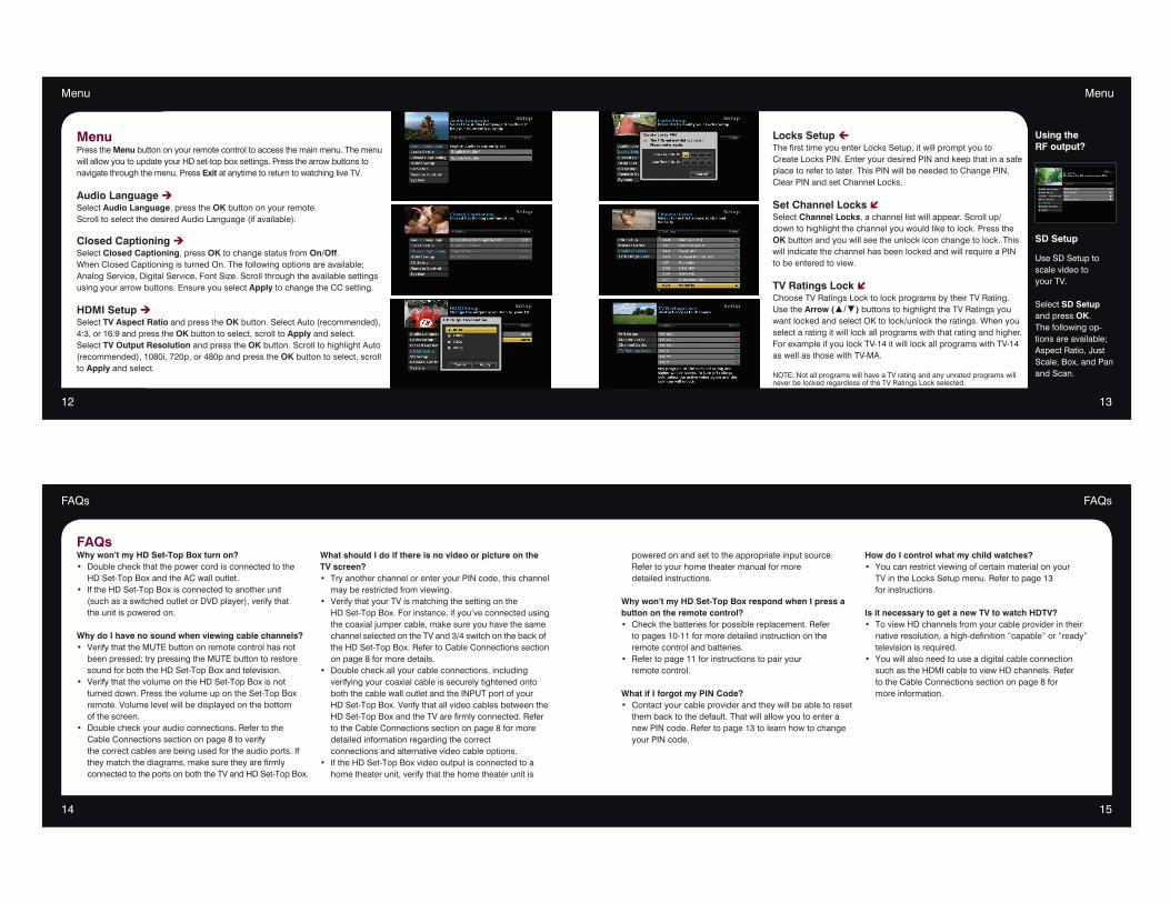
MenuPress the Menu button on your remote control to access the main menu. The menu will allow you to update your HD set-top box settings. Press the arrow buttons to navigate through the menu. Press Exit at anytime to return to watching live TV.
Audio Language èSelect Audio Language, press the OK button on your remote.Scroll to select the desired Audio Language (if available).
Closed Captioning èSelect Closed Captioning, press OK to change status from On/Off. When Closed Captioning is turned On. The following options are available; Analog Service, Digital Service, Font Size. Scroll through the available settings using your arrow buttons. Ensure you select Apply to change the CC setting.
HDMI Setup èSelect TV Aspect Ratio and press the OK button. Select Auto (recommended), 4:3, or 16:9 and press the OK button to select, scroll to Apply and select.Select TV Output Resolution and press the OK button. Scroll to highlight Auto (recommended), 1080i, 720p, or 480p and press the OK button to select, scroll to Apply and select.
Locks Setup çThe first time you enter Locks Setup, it will prompt you to Create Locks PIN. Enter your desired PIN and keep that in a safe place to refer to later. This PIN will be needed to Change PIN, Clear PIN and set Channel Locks.
Set Channel Locks íSelect Channel Locks, a channel list will appear. Scroll up/down to highlight the channel you would like to lock. Press the OK button and you will see the unlock icon change to lock. This will indicate the channel has been locked and will require a PIN to be entered to view.
TV Ratings Lock íChoose TV Ratings Lock to lock programs by their TV Rating. Use the Arrow (▲/▼) buttons to highlight the TV Ratings you want locked and select OK to lock/unlock the ratings. When you select a rating it will lock all programs with that rating and higher. For example if you lock TV-14 it will lock all programs with TV-14 as well as those with TV-MA.
NOTE: Not all programs will have a TV rating and any unrated programs will never be locked regardless of the TV Ratings Lock selected.
14 15
FAQsFAQs
powered on and set to the appropriate input source. Refer to your home theater manual for more detailed instructions.
Why won’t my HD Set-Top Box respond when I press a button on the remote control?• Checkthebatteriesforpossiblereplacement.Refer to pages 10-11 for more detailed instruction on the remotecontrolandbatteries.• Refertopage11forinstructionstopairyour remote control.
What if I forgot my PIN Code?• Contactyourcableproviderandtheywillbeabletoreset thembacktothedefault.Thatwillallowyoutoentera new PIN code. Refer to page 13 to learn how to change your PIN code.
How do I control what my child watches?• Youcanrestrictviewingofcertainmaterialonyour TVintheLocksSetupmenu.Refertopage13 for instructions.
Is it necessary to get a new TV to watch HDTV?• ToviewHDchannelsfromyourcableproviderintheir nativeresolution,ahigh-definition“capable”or“ready” televisionisrequired.• Youwillalsoneedtouseadigitalcableconnection suchastheHDMIcabletoviewHDchannels.Refer totheCableConnectionssectiononpage8for more information.
FAQs Why won’t my HD Set-Top Box turn on?• Doublecheckthatthepowercordisconnectedtothe HDSet-TopBoxandtheACwalloutlet.• IftheHDSet-TopBoxisconnectedtoanotherunit (suchasaswitchedoutletorDVDplayer),verifythat the unit is powered on.
Why do I have no sound when viewing cable channels?• VerifythattheMUTEbuttononremotecontrolhasnot beenpressed;trypressingtheMUTEbuttontorestore soundforboththeHDSet-TopBoxandtelevision.• VerifythatthevolumeontheHDSet-TopBoxisnot turneddown.PressthevolumeupontheSet-TopBox remote.Volumelevelwillbedisplayedonthebottom of the screen.• Doublecheckyouraudioconnections.Refertothe CableConnectionssectiononpage8toverify thecorrectcablesarebeingusedfortheaudioports.If theymatchthediagrams,makesuretheyarefirmly connectedtotheportsonboththeTVandHDSet-TopBox.
What should I do if there is no video or picture on the TV screen?• TryanotherchannelorenteryourPINcode,thischannel mayberestrictedfromviewing.• VerifythatyourTVismatchingthesettingonthe HDSet-TopBox.Forinstance,ifyou’veconnectedusing thecoaxialjumpercable,makesureyouhavethesame channelselectedontheTVand3/4switchonthebackof theHDSet-TopBox.RefertoCableConnectionssection onpage8formoredetails.• Doublecheckallyourcableconnections,including verifyingyourcoaxialcableissecurelytightenedonto boththecablewalloutletandtheINPUTportofyour HDSet-TopBox.Verifythatallvideocablesbetweenthe HDSet-TopBoxandtheTVarefirmlyconnected.Refer totheCableConnectionssectiononpage8formore detailed information regarding the correct connectionsandalternativevideocableoptions.• IftheHDSet-TopBoxvideooutputisconnectedtoa hometheaterunit,verifythatthehometheaterunitis

Liberty HD uDTAWall-Plate Device Installation
© 2013 Evolution Digital, LLC | This document contains confidential and privileged material for the sole use of the intended recipient.
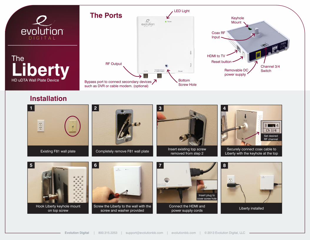
Coax RF Input
KeyholeMount
Channel 3/4 SwitchRemovable DC
power supply
Reset button
HDMI to TV
1 3
75
2 4
86
Installation
The Ports
The
LibertyHD uDTA Wall Plate Device
Existing F81 wall plateInsert existing top screw
removed from step 2Completely remove F81 wall plate
Securely connect coax cable to Liberty with the keyhole at the top
Connect the HDMI and power supply cords
Hook Liberty keyhole mount on top screw
Liberty installedScrew the Liberty to the wall with the screw and washer provided
Bypass port to connect secondary devices such as DVR or cable modem. (optional)
RF Output
LED Light
BottomScrew Hole
Set desiredRF channel
Insert plug to cover screw hole
Evolution Digital | 800.315.2253 | [email protected] | evolutionbb.com | © 2013 Evolution Digital, LLC

HD uDTATraining Presentation
© 2013 Evolution Digital, LLC | This document contains confidential and privileged material for the sole use of the intended recipient.
8/13/12 © 2013 Evolution Digital, LLC. All Rights Reserved. Confidential information.!
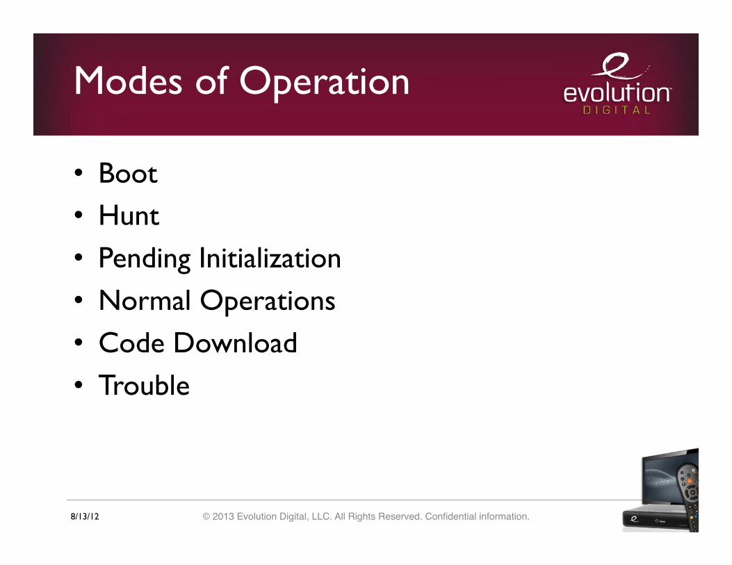
Modes of Operation
• Boot • Hunt • Pending Initialization • Normal Operations • Code Download • Trouble
8/13/12 © 2013 Evolution Digital, LLC. All Rights Reserved. Confidential information.!
Boot Mode
• Occurs when power is applied or when DTA has been reset (either manually or via headend messaging)
• Function: Validate/launch code image • LED Status: None • Valid Mode Transitions: Hunt Mode (if code
image is successfully validated), Trouble Mode (if code image fails validation)
8/13/12 © 2013 Evolution Digital, LLC. All Rights Reserved. Confidential information.!
Hunt Mode
• Occurs when the DTA has completed Boot Mode and successfully validated and loaded the active code image
• Function: Search for QAM with CAT PID and valid CA system ID
• LED Status: Continuous blink • Valid Mode Transition: Pending Initialization
(upon receipt of CAT PID)
8/13/12 © 2013 Evolution Digital, LLC. All Rights Reserved. Confidential information.!
Hunt Mode
• When the DTA first enters Hunt Mode it will scan a list of well known DTA frequencies (567, 573, 579, 585, 591, 651, 657, 489, 495, 807, 565.750, and 571.750 MHz)
• If the DTA does not lock on to any of those frequencies it will start hunting at 57 MHz and increment by 6 MHz until it finds a valid QAM

8/13/12 © 2013 Evolution Digital, LLC. All Rights Reserved. Confidential information.!
Hunt Mode On-Screen Message
8/13/12 © 2013 Evolution Digital, LLC. All Rights Reserved. Confidential information.!
Pending Initialization Mode
• Occurs when the DTA has transitioned from Hunt mode by finding a CAT PID with a valid CA system ID
• Function: Verifying CA parameters found in hunt mode, monitoring network PID for SI, monitoring EMM PID for headend messaging
• LED Status: Two blinks, repeated continuously • Valid Mode Transitions: Code Download,
Boot, Normal Operations
8/13/12 © 2013 Evolution Digital, LLC. All Rights Reserved. Confidential information.!
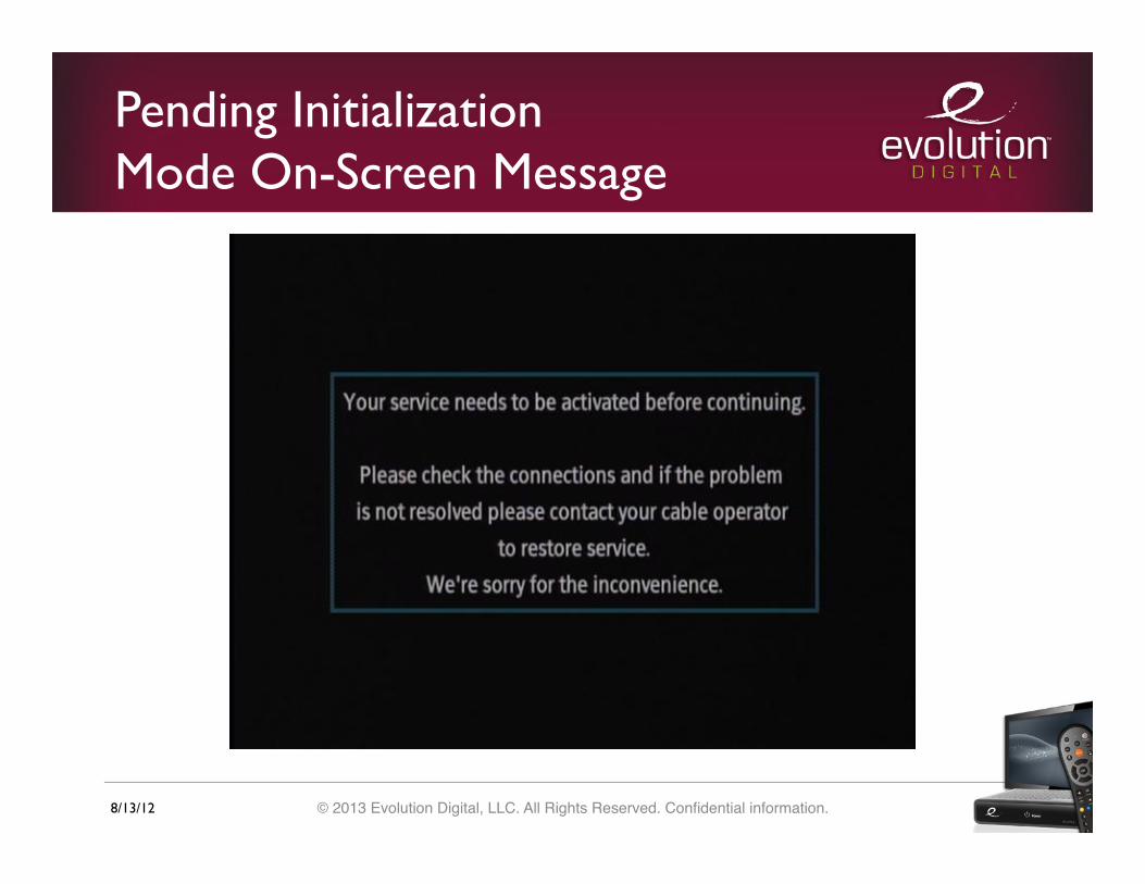
Pending Initialization Mode On-Screen Message
8/13/12 © 2013 Evolution Digital, LLC. All Rights Reserved. Confidential information.!
Normal Operations Mode
• Occurs when the DTA has transitioned from Pending Initialization mode by receiving the proper configuration and activation messages and has loaded a channel map
• Function: Decoding A/V, Monitoring SI data and EMM messages and remote control commands
• LED Status: Solid green, no blinking • Valid Mode Transitions: Pending Initialization,
Code Download, Boot
8/13/12 © 2013 Evolution Digital, LLC. All Rights Reserved. Confidential information.!
Code Download Mode
• Occurs when the DTA has detected a valid CVT indicating that a newer version of code is available for download
• Function: Download new code image • LED Status: Three blinks followed by a long
pause • Valid Mode Transitions: Boot (upon successful
download), previous mode (upon failed download)

8/13/12 © 2013 Evolution Digital, LLC. All Rights Reserved. Confidential information.!
Code Download On-Screen Message

8/13/12 © 2013 Evolution Digital, LLC. All Rights Reserved. Confidential information.!
Trouble Mode
• Occurs when the bootloader fails to validate the DTA code image
• The DTA will only enter trouble mode from boot mode
• LED Status: Continuous short blink • Valid Mode Transitions: None, the DTA must
be reset in order to re-attempt a proper boot
8/13/12 © 2013 Evolution Digital, LLC. All Rights Reserved. Confidential information.!
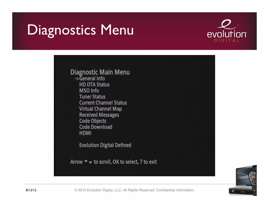
Diagnostics Menu
• To access the diagnostics menu hold down the 7 button on the remote control (note that the diagnostics menu can be accessed in any mode except Boot and Trouble)
• Although there are a large number of options, this presentation will only cover those that will be most useful in troubleshooting the DTA.
8/13/12 © 2013 Evolution Digital, LLC. All Rights Reserved. Confidential information.!
Diagnostics Menu
8/13/12 © 2013 Evolution Digital, LLC. All Rights Reserved. Confidential information.!
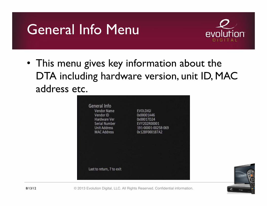
General Info Menu
• This menu gives key information about the DTA including hardware version, unit ID, MAC address etc.

8/13/12 © 2013 Evolution Digital, LLC. All Rights Reserved. Confidential information.!
HD DTA Status Menu 1
• This menu gives information on the status of the DTA including the activated status as well as the current operating mode

8/13/12 © 2013 Evolution Digital, LLC. All Rights Reserved. Confidential information.!
HD DTA Status Menu 2
• The second page of the HD DTA Status menu gives information about the time configuration of the DTA
8/13/12 © 2013 Evolution Digital, LLC. All Rights Reserved. Confidential information.!
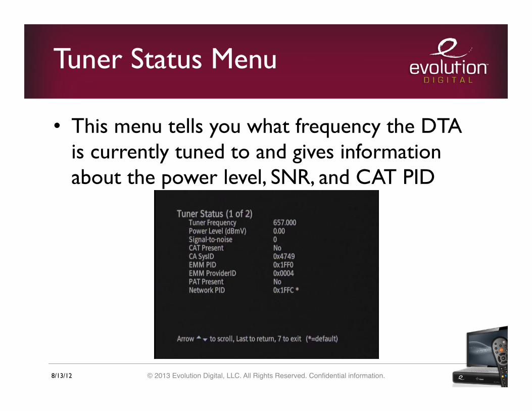
Tuner Status Menu
• This menu tells you what frequency the DTA is currently tuned to and gives information about the power level, SNR, and CAT PID
8/13/12 © 2013 Evolution Digital, LLC. All Rights Reserved. Confidential information.!
Current Channel Status
• This screen gives details about the currently tuned channel including its frequency modulation, and program number, as well as which audio and video PIDs are present
• The channel can be changed real time while viewing this menu by either direct channel entry or by using the CH up/down buttons on the remote

8/13/12 © 2013 Evolution Digital, LLC. All Rights Reserved. Confidential information.!
Current Channel Status

8/13/12 © 2013 Evolution Digital, LLC. All Rights Reserved. Confidential information.!
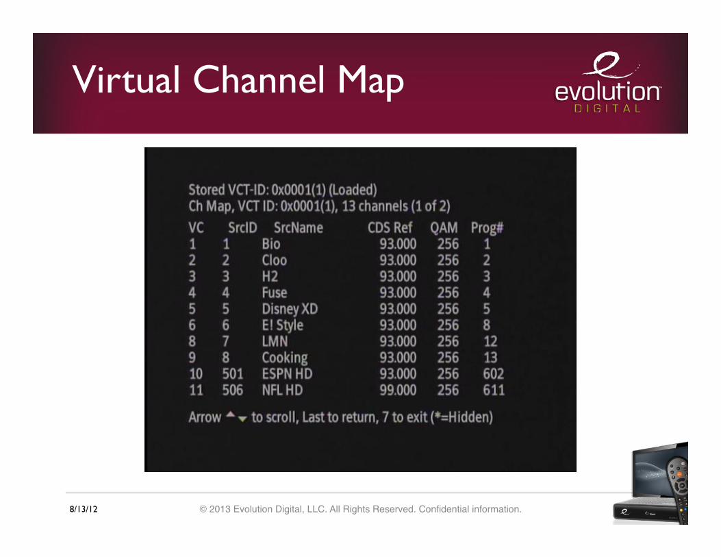
Virtual Channel Map
• The virtual channel map menu gives a listing of the entire channel map loaded on the DTA
• Each service is listed by its display (virtual) channel number and includes its display name, frequency, and program number
• The virtual channel map will likely be several pages long and can be navigated using the up and down arrows on the remote control
8/13/12 © 2013 Evolution Digital, LLC. All Rights Reserved. Confidential information.!
Virtual Channel Map
8/13/12 © 2013 Evolution Digital, LLC. All Rights Reserved. Confidential information.!
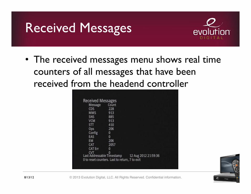
Received Messages
• The received messages menu shows real time counters of all messages that have been received from the headend controller

8/13/12 © 2013 Evolution Digital, LLC. All Rights Reserved. Confidential information.!
Code Objects
• This screen displays the name of the currently loaded code object (SW version)
• There are two code banks, Bank A and Bank B • If both banks display a code name then the
bank with the asterisk next to it is the SW that the DTA is currently running and the other bank is the previously loaded SW

8/13/12 © 2013 Evolution Digital, LLC. All Rights Reserved. Confidential information.!
Code Objects
8/13/12 © 2013 Evolution Digital, LLC. All Rights Reserved. Confidential information.!
Troubleshooting
• If a problem is reported in the field then pictures of the following diagnostic menus should be provided to Evolution:
• HD DTA Status • Tuner Status (while the DTA is tuned to the
problematic channel or channels) • Current Channel Status (of the problematic channel
or channels) • Code Objects • Received Messages
8/13/12 © 2013 Evolution Digital, LLC. All Rights Reserved. Confidential information.!
Troubleshooting
• Additionally, a full QAM capture (capture of the RF input to the DTA) may be required

8/13/12 © 2013 Evolution Digital, LLC. All Rights Reserved. Confidential information.!
Troubleshooting
• Additionally, a full QAM capture (capture of the RF input to the DTA) may be required
• When all of this information has been gathered please contact Evolution support at [email protected] for further instructions
• Note that the two steps listed above should be completed by headend personnel
8/13/12 © 2013 Evolution Digital, LLC. All Rights Reserved. Confidential information.!
Factory Reset
• The DTA can be manually reset to its factory default settings by taking the following steps (note that the currently loaded SW will remain the same but all other values including the channel map and activation status of the DTA will be reset):
• Enter the diagnostics menu by holding 7 on the remote control
8/13/12 © 2013 Evolution Digital, LLC. All Rights Reserved. Confidential information.!
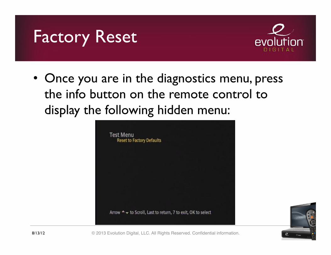
Factory Reset
• Once you are in the diagnostics menu, press the info button on the remote control to display the following hidden menu:

8/13/12 © 2013 Evolution Digital, LLC. All Rights Reserved. Confidential information.!
Factory Reset
• The Reset to Factory Defaults option will be highlighted by default so just press the OK button on the remote control to complete the process
• After a successful reset the DTA will reboot and enter hunt mode

8/13/12 © 2013 Evolution Digital, LLC. All Rights Reserved. Confidential information.!
Remote
8/13/12 © 2013 Evolution Digital, LLC. All Rights Reserved. Confidential information.!
RF Remote Pairing
• The remote delivered with the DTA is capable of RF pairing so that a customer may hide the device and still be able to control it
• To pair the remote take the following steps (note that line of sight is required between the remote and the DTA during the pairing process):
8/13/12 © 2013 Evolution Digital, LLC. All Rights Reserved. Confidential information.!
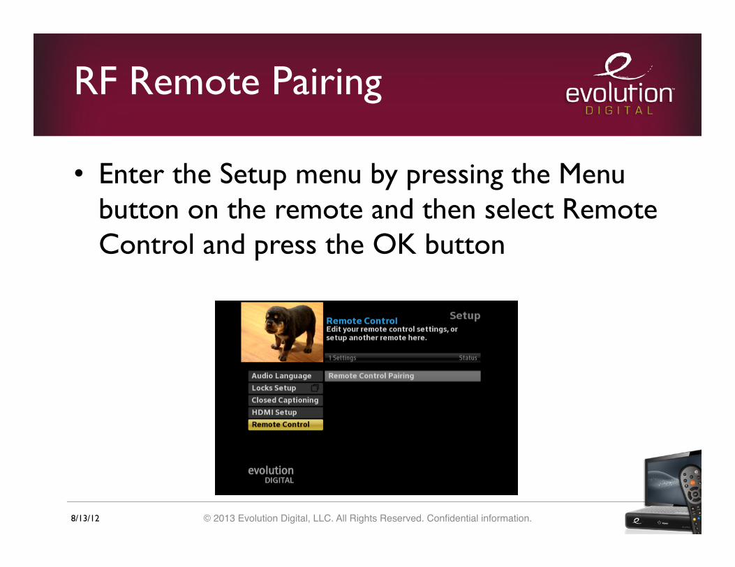
RF Remote Pairing
• Enter the Setup menu by pressing the Menu button on the remote and then select Remote Control and press the OK button

8/13/12 © 2013 Evolution Digital, LLC. All Rights Reserved. Confidential information.!
RF Remote Pairing
• After you select Remote Control Pairing you will see a popup screen with instructions on how to complete the process
8/13/12 © 2013 Evolution Digital, LLC. All Rights Reserved. Confidential information.!
RF Remote Pairing
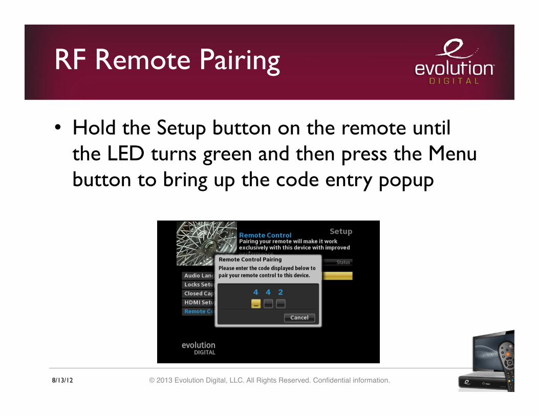
• Hold the Setup button on the remote until the LED turns green and then press the Menu button to bring up the code entry popup
8/13/12 © 2013 Evolution Digital, LLC. All Rights Reserved. Confidential information.!
RF Remote Pairing
• Once you enter the pairing code you will be presented with the pairing success message and the remote will operate in RF mode (note that IR will no longer be transmitted)
• Also note that the DTA will always be able to receive IR commands as a failsafe regardless of whether or not a remote is paired with it

8/13/12 © 2013 Evolution Digital, LLC. All Rights Reserved. Confidential information.!
RF Remote Pairing

8/13/12 © 2013 Evolution Digital, LLC. All Rights Reserved. Confidential information.!
Special Remote Codes
• There are several special remote codes that can be used to change the mode of operation of the remote control
• To unpair the remote hold setup until the LED turns green and press 9, 8, 7
• If the code is entered successfully the LED will blink green two times and the remote will be unpaired and operate in IR mode
8/13/12 © 2013 Evolution Digital, LLC. All Rights Reserved. Confidential information.!
Special Remote Codes
• To reset the TV IR code hold setup until the LED turns green and then enter 9, 8, 6
• If the code is entered successfully the LED will blink green two times and the remote will no longer be able to control the television
8/13/12 © 2013 Evolution Digital, LLC. All Rights Reserved. Confidential information.!
Special Remote Codes
• To factory reset the remote, hold setup until the LED turns green and then enter 9, 8, 1
• If the code is entered successfully the LED will blink green two times and the remote will be reset to factory defaults (all RF pairing information and TV control will be reset and the remote will operate in IR mode)

HD uDTATechnical User Guide
© 2013 Evolution Digital, LLC | This document contains confidential and privileged material for the sole use of the intended recipient.

DMS-2002HD-U User Guide
Evolution Digital, LLC
7347 S. Revere Parkway, Building A | Centennial, CO 80112
www.evolutionbb.com | 800-315-2253
Evolution Digital
EVO-SUP-DMS2002HD-U-001-v1r0 Page 2
Table of Contents 1.0 Introduction ......................................................................................................................................................10
1.1 Terms and Abbreviations ..............................................................................................................................10
1.2 References .....................................................................................................................................................11
1.3 Document Overview .....................................................................................................................................11
1.4 Out of Scope Material ...................................................................................................................................12
2.0 DTA Modes .....................................................................................................................................................12
2.1 High Level Overview ....................................................................................................................................12
2.2 Boot Mode ....................................................................................................................................................13
2.2.1 Reset Processing .....................................................................................................................................14
2.2.2 Mode Transitions ....................................................................................................................................14
2.3 Hunt Mode ....................................................................................................................................................14
2.3.1 QAM Search ...........................................................................................................................................16
2.3.1.1 CA System ID ...................................................................................................................................17
2.3.1.2 Network PID .....................................................................................................................................17
2.3.2 Hunt Mode On-Screen Messages ............................................................................................................17
2.3.3 Mode Transitions ....................................................................................................................................19
2.4 Pending Initialization Mode ..........................................................................................................................19
2.4.1 CA Values check .....................................................................................................................................21
2.4.2 DTA Activation and Configuration ........................................................................................................21
2.4.2.1 Transition to Normal Operations ......................................................................................................22
2.4.3 Network PID Monitoring ........................................................................................................................23
2.4.3.1 VCT ID Assignment .........................................................................................................................23
2.4.4 Pending Initialization Mode On-Screen Messages .................................................................................23
2.4.5 Mode Transitions ....................................................................................................................................26
2.5 Normal Operations Mode .............................................................................................................................26
2.5.1 Turn On QAM Update ............................................................................................................................29
2.5.2 Channel Map Updates .............................................................................................................................29

Evolution Digital
EVO-SUP-DMS2002HD-U-001-v1r0 Page 3
2.5.3 Interruption to Service ............................................................................................................................29
2.5.4 Mode Transitions ....................................................................................................................................30
2.6 Code Download Mode ..................................................................................................................................30
2.6.1 CVT.........................................................................................................................................................32
2.6.2 CVT Configuration Count ......................................................................................................................32
2.6.2.1 Location Value 0 ...............................................................................................................................33
2.6.2.2 Location Value 1 ...............................................................................................................................33
2.6.2.3 Location Value 2 ...............................................................................................................................34
2.6.3 Code Object Delivery .............................................................................................................................34
2.6.4 Code Download Retry .............................................................................................................................34
2.6.4.1 Failed Code Downloads ....................................................................................................................34
2.6.5 Code Download Mode On-Screen Message ...........................................................................................36
2.6.6 Interruption to Code Download ..............................................................................................................36
2.6.7 Mode Transitions ....................................................................................................................................36
2.7 Trouble Mode ................................................................................................................................................37
2.7.1 Mode Transitions ....................................................................................................................................37
3.0 Channel Maps ..................................................................................................................................................37
3.1 Channel Types Supported .............................................................................................................................37
3.1.1 Channel Numbers ....................................................................................................................................38
3.1.2 Channel Name .........................................................................................................................................38
3.2 Channel Map Updates ...................................................................................................................................39
3.2.1 Addition of Channels ..............................................................................................................................39
3.2.2 Removal of Channels ..............................................................................................................................40
3.2.2.1 Changes Made to Currently Tuned to Service ..................................................................................40
3.2.3 Change of VCT ID ..................................................................................................................................40
4.0 DTA Reset .......................................................................................................................................................41
4.1 Reset Recovery .............................................................................................................................................43
4.1.1 Recovery from Initialization ...................................................................................................................43

Evolution Digital
EVO-SUP-DMS2002HD-U-001-v1r0 Page 4
4.1.2 Recovery from Cold Reset ......................................................................................................................43
4.1.3 Recovery from Warm Reset ....................................................................................................................43
4.2 Manual Clear, Full ........................................................................................................................................44
5.0 EAS ..................................................................................................................................................................44
5.1 Alert Priorities ...............................................................................................................................................44
5.2 Exceptions List ..............................................................................................................................................44
5.3 Force Tune Behavior .....................................................................................................................................44
5.3.1 Duration of Force Tune ...........................................................................................................................44
5.3.2 DTA Behavior .........................................................................................................................................44
6.0 Diagnostic Menu ..............................................................................................................................................45
6.1 Navigating the Diagnostic Menu ..................................................................................................................45
6.2 Main Diagnostic Screen ................................................................................................................................45
6.3 General Info ..................................................................................................................................................46
6.4 HD DTA Status .............................................................................................................................................47
6.5 MSO Info ......................................................................................................................................................51
6.5.1 MSO Info Customization ........................................................................................................................52
6.6 Tuner Status ..................................................................................................................................................54
6.7 Current Channel Status .................................................................................................................................56
6.8 Virtual Channel Map .....................................................................................................................................58
6.9 Received Messages .......................................................................................................................................60
6.10 Code Objects .................................................................................................................................................62
6.11 Code Download ............................................................................................................................................63
6.12 HDMI ............................................................................................................................................................65
7.0 Evolution Digital Defined ................................................................................................................................67
7.1 SI Descriptors ................................................................................................................................................68
7.2 Decoder Status ..............................................................................................................................................69
7.3 RF Remote Control .......................................................................................................................................69
7.4 EAS Location ................................................................................................................................................73
8.0 Troubleshooting ...............................................................................................................................................73
Evolution Digital
EVO-SUP-DMS2002HD-U-001-v1r0 Page 5
8.1 Hunt Mode ....................................................................................................................................................73
8.2 Manual Clear .................................................................................................................................................73
Appendix A Frequency Hunt List ................................................................................................................................75
Appendix B Default NVRAM Values .........................................................................................................................76
Appendix C Additional DTA Screenshots ...................................................................................................................77
Appendix D DTA Headend Messages .........................................................................................................................79
D.1 DTA Configuration Message ............................................................................................................................79
D.2 DTA Operations Messages ...............................................................................................................................79

Evolution Digital
EVO-SUP-DMS2002HD-U-001-v1r0 Page 6
List of Tables
Table 1 List of Terms and Abbreviations ....................................................................................................................10
Table 2 Boot Mode Properties .....................................................................................................................................13
Table 3 Hunt Mode Properties ......................................................................................................................................14
Table 4 Hunt Mode Progress Bar Percentages .............................................................................................................18
Table 5 Pending Initialization Mode Properties ...........................................................................................................20
Table 6 DTA Transition to Normal Operations ............................................................................................................22
Table 7 Normal Operations Mode Properties ...............................................................................................................26
Table 8 Code Download Mode Properties ....................................................................................................................30
Table 9 Trouble Mode Properties .................................................................................................................................37
Table 10 Reset Types and their Effect on the DTA .....................................................................................................41
Table 11 Effects on Parameters Across DTA Reset Types .........................................................................................42
Table 12 Useable Remote Buttons While In Diagnostic Menu ...................................................................................45
Table 13 General Info Screen Parameters ...................................................................................................................46
Table 14 HD DTA Status Screen Parameters ..............................................................................................................48
Table 15 MSO Info Screen Parameters .......................................................................................................................51
Table 16 Tuner Status Screen Parameters ...................................................................................................................54
Table 17 Current Channel Status Screen Parameters ..................................................................................................56
Table 18 Virtual Channel Map Screen Parameters ......................................................................................................58
Table 19 Received Messages Screen Parameters ........................................................................................................60
Table 20 Code Objects Screen Parameters ..................................................................................................................62
Table 21 Code Download Screen Parameters ..............................................................................................................63
Table 22 HDMI Screen Parameters .............................................................................................................................66
Table 23 RF Remote Control Screen Parameters ........................................................................................................69

Evolution Digital
EVO-SUP-DMS2002HD-U-001-v1r0 Page 7
Table 24 NVRAM Default Values ..............................................................................................................................76
List of Figures
Figure 1 DTA Boot Sequence to Normal Operations ..................................................................................................13
Figure 2 DTA Status, Hunt Mode ................................................................................................................................15
Figure 3 Tuner Status, Hunt Mode ..............................................................................................................................16
Figure 4 Tuner Status, Pending Initialization Mode ....................................................................................................17
Figure 5 Hunt Mode On-Screen Message – Initial Scan .............................................................................................18
Figure 6 Hunt Mode On-Screen Message – Extended Scan ........................................................................................19
Figure 7 DTA Status Screen during Pending Initialization .........................................................................................21
Figure 8 DTA Status Screen – Normal Operations .....................................................................................................22
Figure 9 Activation Support Message – Initial Entry to Pending Init ..........................................................................24
Figure 10 Activation Support Message – Cable Operator Defined Custom Message ..................................................25
Figure 11 Activation Support Message – Default Message ..........................................................................................26
Figure 12 DTA Status, Normal Operations Mode; Screen 1 of 2 ................................................................................28
Figure 13 DTA Status, Normal Operations Mode; Screen 2 of 2 ................................................................................28
Figure 14 Interruption During Normal Operations ......................................................................................................29
Figure 15 DTA Status Diagnostic Screen During Code Download ............................................................................31
Figure 16 Code Download Diagnostic Screen .............................................................................................................32
Figure 17 Code Objects Diagnostic Screen .................................................................................................................33
Figure 18 Code Download Failure – Code Verification Failure ..................................................................................35
Figure 19 Code Download Failure – File Download Failure ......................................................................................35
Figure 20 Code Download On-screen Message ...........................................................................................................36
Figure 21 Channel Name and Number Displayed .......................................................................................................38
Figure 22 Virtual Channel Map Diagnostic Screen, Channel map loaded ..................................................................39
Evolution Digital
EVO-SUP-DMS2002HD-U-001-v1r0 Page 8
Figure 23 Delayed Service Interruption Message ........................................................................................................40
Figure 24 Virtual Channel Map Diagnostic Screen, Change in VCT-ID ....................................................................41
Figure 25 Diagnostic Menu – Main Menu ...................................................................................................................46
Figure 26 Diagnostic Menu – General Info .................................................................................................................47
Figure 27 Diagnostic Menu – DTA Status, Screen 1 ...................................................................................................50
Figure 28 Diagnostic Menu – DTA Status, Screen 2 ...................................................................................................50
Figure 29 Diagnostic Menu – MSO Info, Screen 1 .....................................................................................................51
Figure 30 Diagnostic Menu – MSO Info, Screen 2 .....................................................................................................52
Figure 31 Service Interruption Message with Default MSO Phone Number ..............................................................53
Figure 32 Diagnostic Menu – MSO Info, Screen 1 with modified MSO Phone Number ...........................................53
Figure 33 Service Interruption Message with Customized MSO Phone Number .......................................................54
Figure 34 Diagnostic Menu – Tuner Status .................................................................................................................56
Figure 35 Diagnostic Menu – Current Channel Status ................................................................................................58
Figure 36 Diagnostic Menu – Virtual Channel Map ...................................................................................................60
Figure 37 Diagnostic Menu – Received Messages ......................................................................................................62
Figure 38 Diagnostic Menu – Code Objects ................................................................................................................63
Figure 39 Diagnostic Menu – Code Download ...........................................................................................................65
Figure 40 Diagnostic Menu – HDMI ...........................................................................................................................67
Figure 41 Evolution Digital Defined Menu .................................................................................................................68
Figure 42 SI Descriptors Screen ..................................................................................................................................69
Figure 43 Diagnostic Menu – RF Remote Control, Screen 1 ......................................................................................72
Figure 44 Diagnostic Menu – RF Remote Control, Screen 2 ......................................................................................72
Figure 45 EAS Location Screen ..................................................................................................................................73
Figure 46 Test Menu ....................................................................................................................................................74
Evolution Digital
EVO-SUP-DMS2002HD-U-001-v1r0 Page 9
Figure 47 DTA On-Screen Information – Channel Info ..............................................................................................77
Figure 48 DTA On-Screen Information – Volume Bar ...............................................................................................77
Figure 49 DTA On-Screen Information – Muted Volume Bar ....................................................................................78
Version Control
Version Date Notes Author
1.0 06/15/2012 Initial Release A.Schneider
Evolution Digital
EVO-SUP-DMS2002HD-U-001-v1r0 Page 10
1.0 Introduction
This document provides detailed support and user information about Evolution Digital DTA, model number DMS-
2002U. This intended audience for this document is cable operator technicians and customer support personnel.
1.1 Terms and Abbreviations
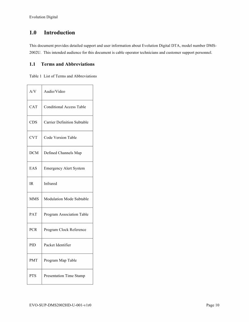
Table 1 List of Terms and Abbreviations
A/V Audio/Video
CAT Conditional Access Table
CDS Carrier Definition Subtable
CVT Code Version Table
DCM Defined Channels Map
EAS Emergency Alert System
IR Infrared
MMS Modulation Mode Subtable
PAT Program Association Table
PCR Program Clock Reference
PID Packet Identifier
PMT Program Map Table
PTS Presentation Time Stamp
Evolution Digital
EVO-SUP-DMS2002HD-U-001-v1r0 Page 11
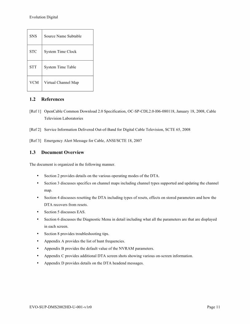
SNS Source Name Subtable
STC System Time Clock
STT System Time Table
VCM Virtual Channel Map
1.2 References
[Ref 1] OpenCable Common Download 2.0 Specification, OC-SP-CDL2.0-I06-080118, January 18, 2008, Cable
Television Laboratories
[Ref 2] Service Information Delivered Out-of-Band for Digital Cable Television, SCTE 65, 2008
[Ref 3] Emergency Alert Message for Cable, ANSI/SCTE 18, 2007
1.3 Document Overview
The document is organized in the following manner.
• Section 2 provides details on the various operating modes of the DTA.
• Section 3 discusses specifics on channel maps including channel types supported and updating the channel
map.
• Section 4 discusses resetting the DTA including types of resets, effects on stored parameters and how the
DTA recovers from resets.
• Section 5 discusses EAS.
• Section 6 discusses the Diagnostic Menu in detail including what all the parameters are that are displayed
in each screen.
• Section 8 provides troubleshooting tips.
• Appendix A provides the list of hunt frequencies.
• Appendix B provides the default value of the NVRAM parameters.
• Appendix C provides additional DTA screen shots showing various on-screen information.
• Appendix D provides details on the DTA headend messages.
Evolution Digital
EVO-SUP-DMS2002HD-U-001-v1r0 Page 12
1.4 Out of Scope Material
Headend configuration and management is not covered in this document. Evolution Digital does not manufacture
the headend equipment necessary to activate and configure the DTA. The operator must consult the manufacture
and vendor of the headend equipment for questions regarding the operation and configuration of such equipment.
2.0 DTA Modes
The DTA can be in one of six (6) modes. These modes are Boot, Hunt, Pending Initialization, Normal Operations,
Code Download, and Trouble mode. The LED will also indicate the mode the DTA is in. The remainder of this
section discusses each mode in a little more detail including how the DTA goes in and out of each mode.
2.1 High Level Overview
To achieve Normal Operations, the DTA will make its way through Boot, Hunt and Pending Initialization modes as
shown in Figure 1. Will progressing through each mode, certain conditions need to be met to proceed to the next
mode. It is important to note that the DTA will always follow the same path after a reboot message from the
headend or power cycle. The DTA does not store its current mode of operation for previous use. So, for example, if
the DTA is in Normal Operations and power is cycled, the DTA will progress from Boot Mode to Hunt Mode to
Pending Initialization to Normal Operations, only if all the conditions are met to do so. If the RF cable is pulled on
the input to the DTA prior to the reboot, the DTA will stay in Hunt Mode. This is just an example and is used to
illustrate the fact that the DTA does not deviate from the specified sequence of boot-up.
Evolution Digital
EVO-SUP-DMS2002HD-U-001-v1r0 Page 13
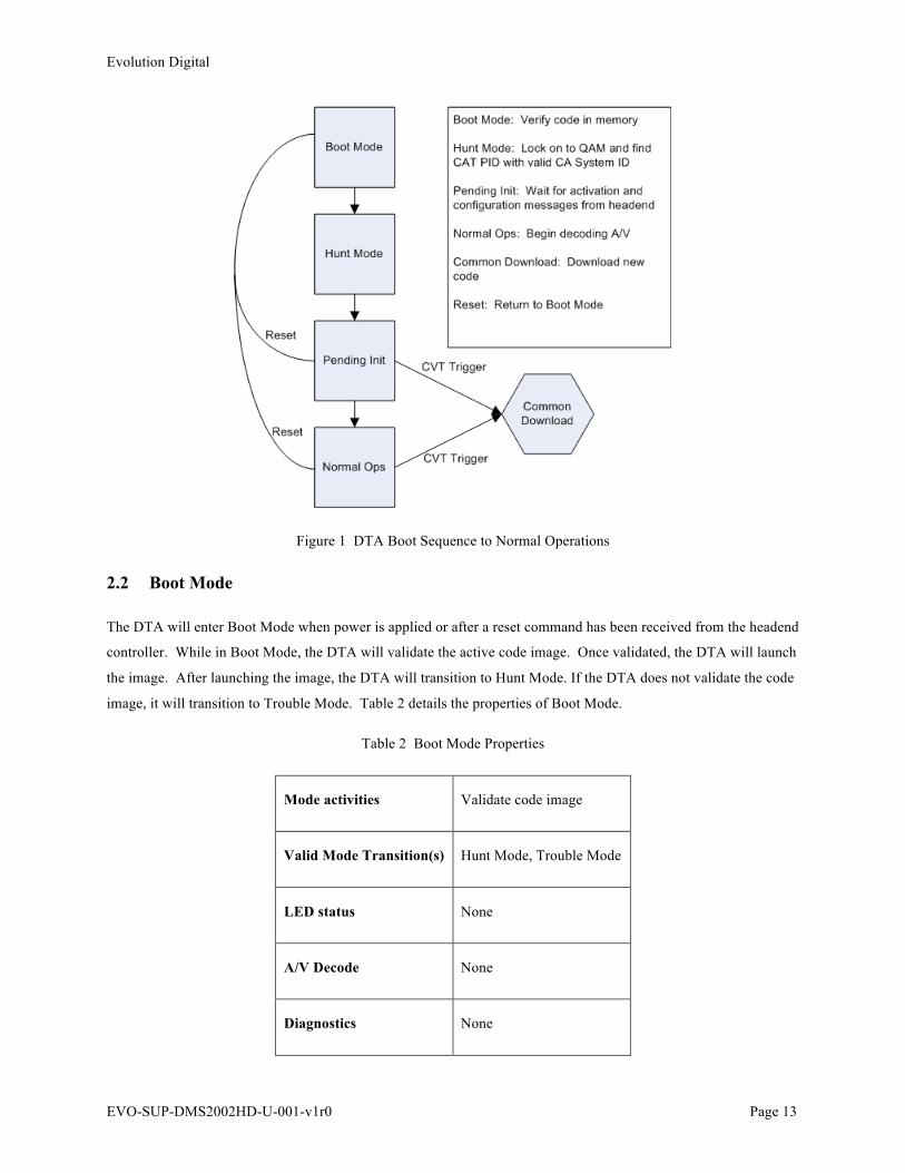
Figure 1 DTA Boot Sequence to Normal Operations
2.2 Boot Mode
The DTA will enter Boot Mode when power is applied or after a reset command has been received from the headend
controller. While in Boot Mode, the DTA will validate the active code image. Once validated, the DTA will launch
the image. After launching the image, the DTA will transition to Hunt Mode. If the DTA does not validate the code
image, it will transition to Trouble Mode. Table 2 details the properties of Boot Mode.
Table 2 Boot Mode Properties
Mode activities Validate code image
Valid Mode Transition(s) Hunt Mode, Trouble Mode
LED status None
A/V Decode None
Diagnostics None
Evolution Digital
EVO-SUP-DMS2002HD-U-001-v1r0 Page 14
IR Input Disabled
In-band Message
Processing
None
Please note the DTA should not be sent an activation and or configuration message while in Boot Mode. These
messages should only be sent when the DTA is in Pending Initialization Mode.
2.2.1 Reset Processing
As mentioned in the previous section, the DTA will enter Boot Mode when a reset is received. The DTA will
process a reset from the headend controller when in Hunt, Pending Initialization, Normal Operations or Common
Download mode. The DTA will not process resets sent from the headend controller when in Trouble Mode. Resets
are discussed more in Section 4.0.
2.2.2 Mode Transitions
The DTA will transition from Boot Mode to Hunt Mode after successfully validating a stored image.
The DTA will transition from Boot Mode to Trouble Mode if it fails to validate a stored image.
2.3 Hunt Mode
The DTA will enter Hunt Mode from Boot or Pending Initialization Modes; please see these respective sections for
more details about how the DTA enters Hunt Mode. In Hunt Mode, the DTA is looking for a QAM frequency
containing a CAT PID with a valid CA system ID. Once all conditions are met, the DTA will enter Pending
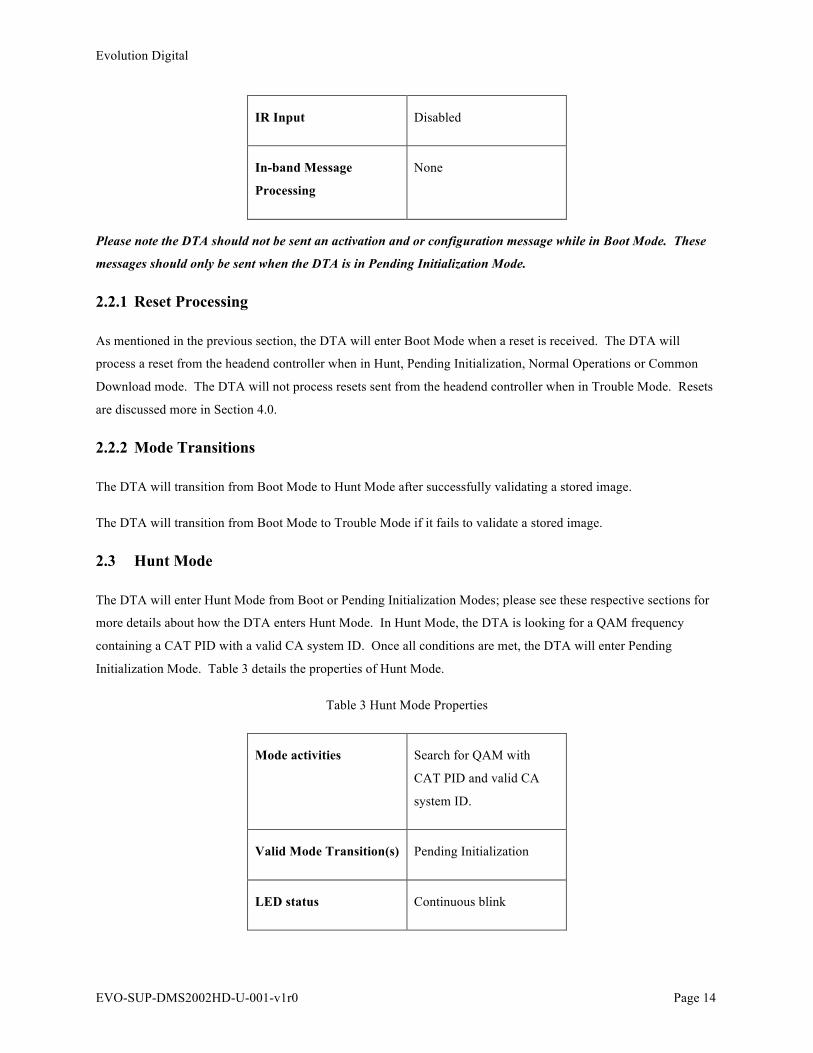
Initialization Mode. Table 3 details the properties of Hunt Mode.
Table 3 Hunt Mode Properties
Mode activities Search for QAM with
CAT PID and valid CA
system ID.
Valid Mode Transition(s) Pending Initialization
LED status Continuous blink
Evolution Digital
EVO-SUP-DMS2002HD-U-001-v1r0 Page 15
A/V Decode None
Diagnostics Available
IR Input Available
In-band Message
Processing
Only processing CAT PID.
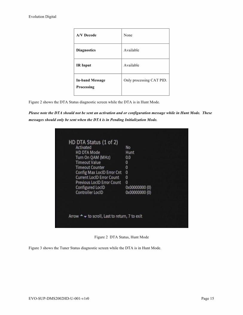
Figure 2 shows the DTA Status diagnostic screen while the DTA is in Hunt Mode.
Please note the DTA should not be sent an activation and or configuration message while in Hunt Mode. These
messages should only be sent when the DTA is in Pending Initialization Mode.
Figure 2 DTA Status, Hunt Mode
Figure 3 shows the Tuner Status diagnostic screen while the DTA is in Hunt Mode.

Evolution Digital
EVO-SUP-DMS2002HD-U-001-v1r0 Page 16
Figure 3 Tuner Status, Hunt Mode
2.3.1 QAM Search
Upon entering Hunt Mode, the DTA will check if the Turn On QAM is set in NVRAM. If the Turn On QAM is set,
the DTA will attempt to tune to this QAM. If the DTA does not lock within 1 second, it will continue searching for
QAMs. If there is no stored Turn On QAM in NVRAM, the DTA will start its QAM search using a predefined hunt
list. Please see Appendix A for the predefined hunt list. A predefined hunt list has been created to help speed up the
initial installation of the DTA on a cable network. Upon locking to a QAM, the DTA will wait 3 seconds for a CAT
PID containing a valid CA system ID. It is expected the CAT PID will be 0x01 (decimal 1). If the CAT PID is
found and it contains a valid CA system ID, the QAM will be stored as the Turn On QAM and the DTA will
transition to Pending Initialization Mode.
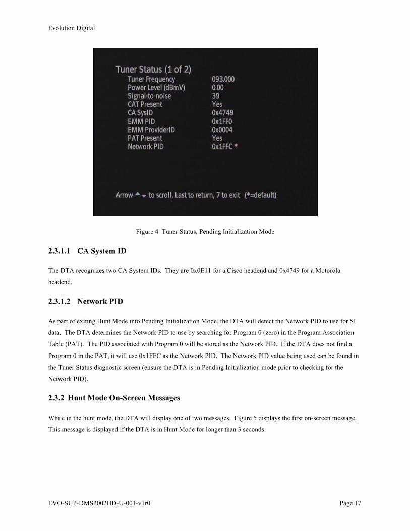
Once the DTA enters Pending Initialization Mode, you will also notice that the DTA will populate the CA and
Network parameters into the DTA Tuner Status diagnostic screen. Figure 4 below shows an example of the updated
Tuner Status diagnostic menu once the DTA has entered Pending Initialization Mode.
Evolution Digital
EVO-SUP-DMS2002HD-U-001-v1r0 Page 17
Figure 4 Tuner Status, Pending Initialization Mode
2.3.1.1 CA System ID
The DTA recognizes two CA System IDs. They are 0x0E11 for a Cisco headend and 0x4749 for a Motorola
headend.
2.3.1.2 Network PID
As part of exiting Hunt Mode into Pending Initialization Mode, the DTA will detect the Network PID to use for SI
data. The DTA determines the Network PID to use by searching for Program 0 (zero) in the Program Association
Table (PAT). The PID associated with Program 0 will be stored as the Network PID. If the DTA does not find a
Program 0 in the PAT, it will use 0x1FFC as the Network PID. The Network PID value being used can be found in
the Tuner Status diagnostic screen (ensure the DTA is in Pending Initialization mode prior to checking for the
Network PID).
2.3.2 Hunt Mode On-Screen Messages
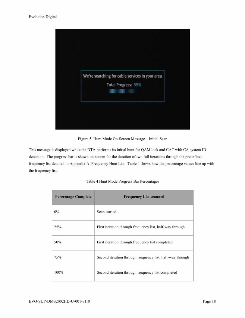
While in the hunt mode, the DTA will display one of two messages. Figure 5 displays the first on-screen message.
This message is displayed if the DTA is in Hunt Mode for longer than 3 seconds.
Evolution Digital
EVO-SUP-DMS2002HD-U-001-v1r0 Page 18
Figure 5 Hunt Mode On-Screen Message – Initial Scan
This message is displayed while the DTA performs its initial hunt for QAM lock and CAT with CA system ID
detection. The progress bar is shown on-screen for the duration of two full iterations through the predefined
frequency list detailed in Appendix A Frequency Hunt List. Table 4 shows how the percentage values line up with
the frequency list.
Table 4 Hunt Mode Progress Bar Percentages
Percentage Complete Frequency List scanned
0% Scan started
25% First iteration through frequency list, half-way through
50% First iteration through frequency list completed
75% Second iteration through frequency list, half-way through
100% Second iteration through frequency list completed

Evolution Digital
EVO-SUP-DMS2002HD-U-001-v1r0 Page 19
After completing two iterations through the progress bar (reaching 100% two times) and failing to lock onto a QAM
and detect a CAT PID with a valid CA system ID, the DTA will display the on-screen message shown in Figure 6.
Figure 6 Hunt Mode On-Screen Message – Extended Scan
While this message is displayed, the DTA will continue to cycle through the frequency list. In the event the
extended hunt mode exceeds five (5) minutes, the DTA will remove the OSD and display a screen saver to prevent
plasma screen burn-in.
2.3.3 Mode Transitions
The DTA will transition from Hunt Mode to Pending Initialization Mode as described in this section.
2.4 Pending Initialization Mode
The DTA enters Pending Initialization Mode (also known as Pending Init) from Hunt, Normal Operations or
Common Download Modes; please see these respective sections for more details about how the DTA enters Pending
Init Mode. In Pending Init Mode, the DTA is checking CA system parameters, monitoring the In-band messaging,
and waiting for proper activation. Once all conditions are met, the DTA will enter Normal Operations Mode. Table
5 details the properties of Pending Initialization Mode.
Evolution Digital
EVO-SUP-DMS2002HD-U-001-v1r0 Page 20
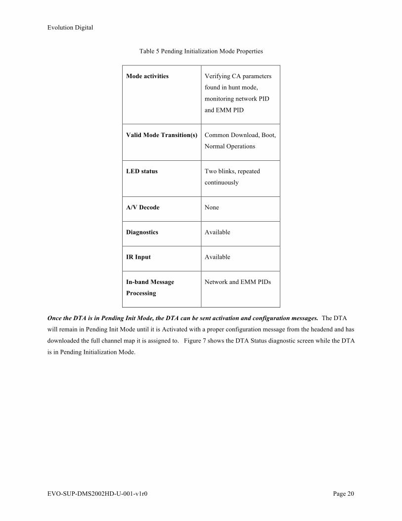
Table 5 Pending Initialization Mode Properties
Mode activities Verifying CA parameters
found in hunt mode,
monitoring network PID
and EMM PID
Valid Mode Transition(s) Common Download, Boot,
Normal Operations
LED status Two blinks, repeated
continuously
A/V Decode None
Diagnostics Available
IR Input Available
In-band Message
Processing
Network and EMM PIDs
Once the DTA is in Pending Init Mode, the DTA can be sent activation and configuration messages. The DTA
will remain in Pending Init Mode until it is Activated with a proper configuration message from the headend and has
downloaded the full channel map it is assigned to. Figure 7 shows the DTA Status diagnostic screen while the DTA
is in Pending Initialization Mode.

Evolution Digital
EVO-SUP-DMS2002HD-U-001-v1r0 Page 21
Figure 7 DTA Status Screen during Pending Initialization
Figure 4 in Section 2.3.1 shows the Tuner Status screen when the DTA enters Pending Initialization Mode from
Hunt Mode.
2.4.1 CA Values check
Upon receiving the CAT PID with valid CA System ID, the DTA will store the CA System ID and EMM Provider
ID as temporary values. Next, the DTA will compare these temporary values to its stored values. If either one of
these values does not match the respective stored values, the DTA will set its Activation Flag to “No”. After the
comparison, the DTA will set the stored values to the temporary values. Please note the EMM Provider ID is not
required for normal operations. The EMM PID value is set according to what is defined in the CAT.
2.4.2 DTA Activation and Configuration
The DTA controller in the cable headend will provide the messaging necessary to activate the DTA and configure
for operation on the plant. The configuration messages will set the following parameters in the DTA (found in the
DTA Status diagnostic menu).
• Activation Flag
• Timeout Value Parameter
• Configured Max Location ID Error Count

Evolution Digital
EVO-SUP-DMS2002HD-U-001-v1r0 Page 22
• Site Code
In addition to setting the parameters listed above, the headend will assign the DTA to a VCT ID. The DTA will
transition to Normal Operations mode once it has received the headend messaging to configure and activate the
DTA and the DTA has fully downloaded and loaded the virtual channel map. Section 2.4.2.1 discusses how the
DTA transitions to Normal Operations. Figure 8 below shows an example of the DTA Status screen when the DTA
is in Normal Operations mode.
Figure 8 DTA Status Screen – Normal Operations
2.4.2.1 Transition to Normal Operations
Table 6 below details the condition that must be met in order for the DTA to transition to Normal Operations Mode
and the combination of states and conditions that keep the DTA in Pending Initialization Mode.
Table 6 DTA Transition to Normal Operations
DTA State Timeout Value
Parameter
Timeout Counter Activated Flag Site Error Count
Normal Operations Any nonzero value Nonzero Yes Max LocID >
Current LocID

Evolution Digital
EVO-SUP-DMS2002HD-U-001-v1r0 Page 23
Pending Init Don’t care Zero Yes Max LocID >
Current LocID
Pending Init Don’t care Zero Yes Current LocID >=
Max LocID
Pending Init Any nonzero value Nonzero No Don’t care
Pending Init Don’t care Zero No Don’t care
In summary, if the Activation Flag is set to 0, the DTA will not enter Normal Operations Mode. If the Timeout
Counter has reached 0, the DTA will revert to Pending Initialization mode.
2.4.3 Network PID Monitoring
In Pending Init Mode, the DTA is filtering for Network PIDs carrying the SI data (SCTE-65 tables). Determination
of the Network PID value is discussed in Section 2.3.1.2. The DTA supports all mandatory SCTE-65 tables
associated with Profile 2. The DTA does not support nor require optional tables associated with SCTE-65 Profile 2.
It is highly suggested that all QAMs carrying DTA services carry the Network PID and SI tables. In this way, it
will be assured the DTA will receive channel map updated and code download triggers.
2.4.3.1 VCT ID Assignment
By default, the DTA is looking for SI associated with VCT-ID 0, until a message from the headend indicates
otherwise. The DTA will filter the Network PID and tables associated with its assigned VCT ID. It will load the
channel map once it has been completely downloaded.
Note, in order for the DTA to enter Normal Operations Mode from Pending Init Mode, the DTA must load a channel
map.
2.4.4 Pending Initialization Mode On-Screen Messages
If the DTA is in Pending Init Mode for more than three (3) seconds, the DTA will display one of two messages: the
Activation Support Message or the Service Interruption Message.
The DTA will display the Activation Support Message if any of the following conditions are met.
1. Activation Flag is not set
Evolution Digital
EVO-SUP-DMS2002HD-U-001-v1r0 Page 24
2. Timeout Value Parameter is 0
3. Timeout Value Parameter is greater than 0, but the Timeout Counter is 0
4. Current Error Count is greater than Configured Error Count
5. No channel map available for the assigned VCT ID
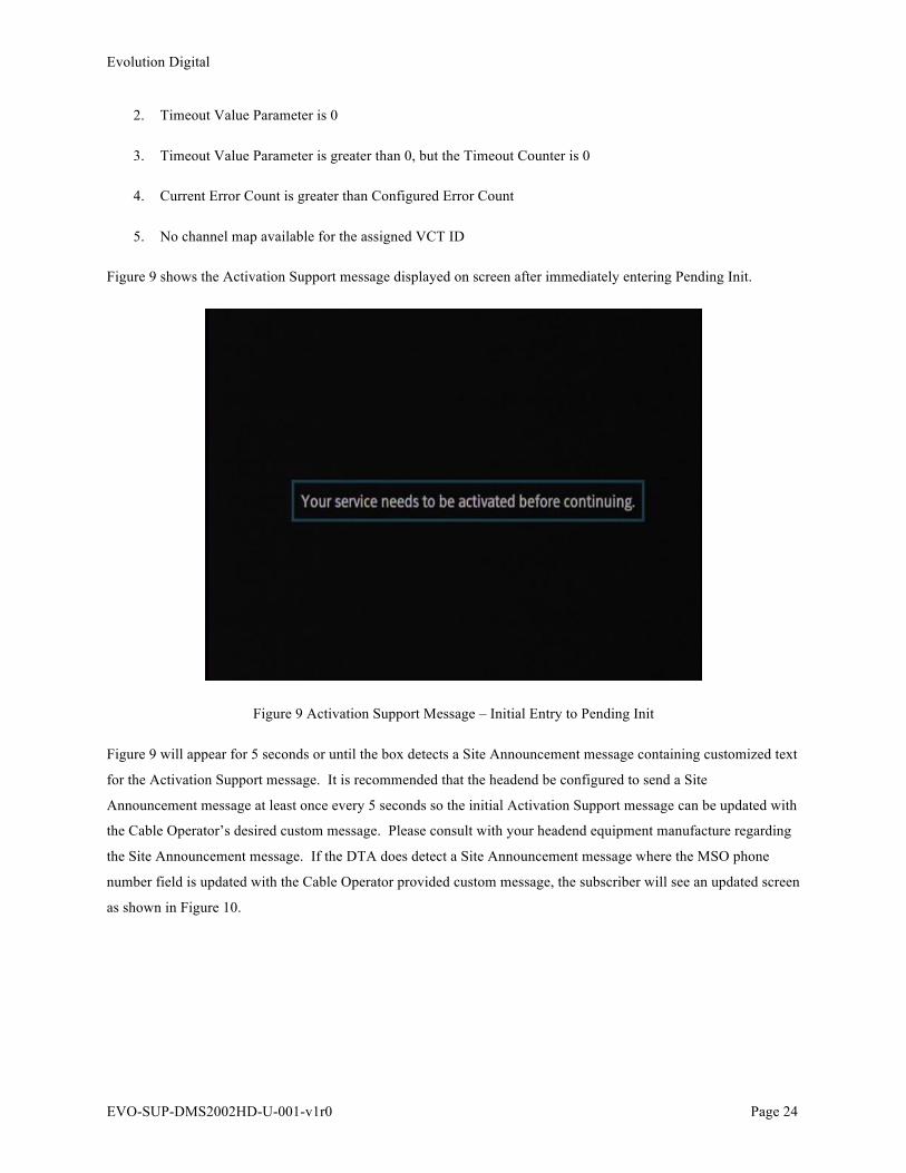
Figure 9 shows the Activation Support message displayed on screen after immediately entering Pending Init.
Figure 9 Activation Support Message – Initial Entry to Pending Init
Figure 9 will appear for 5 seconds or until the box detects a Site Announcement message containing customized text
for the Activation Support message. It is recommended that the headend be configured to send a Site
Announcement message at least once every 5 seconds so the initial Activation Support message can be updated with
the Cable Operator’s desired custom message. Please consult with your headend equipment manufacture regarding
the Site Announcement message. If the DTA does detect a Site Announcement message where the MSO phone
number field is updated with the Cable Operator provided custom message, the subscriber will see an updated screen
as shown in Figure 10.
Evolution Digital
EVO-SUP-DMS2002HD-U-001-v1r0 Page 25
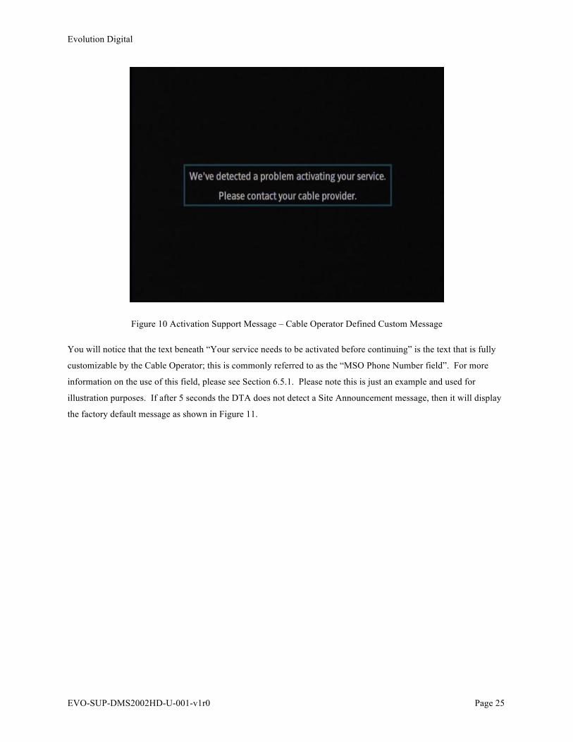
Figure 10 Activation Support Message – Cable Operator Defined Custom Message
You will notice that the text beneath “Your service needs to be activated before continuing” is the text that is fully
customizable by the Cable Operator; this is commonly referred to as the “MSO Phone Number field”. For more
information on the use of this field, please see Section 6.5.1. Please note this is just an example and used for
illustration purposes. If after 5 seconds the DTA does not detect a Site Announcement message, then it will display
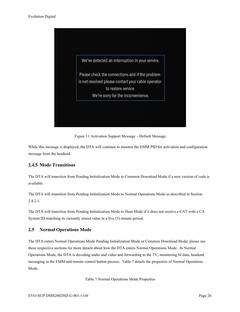
the factory default message as shown in Figure 11.
Evolution Digital
EVO-SUP-DMS2002HD-U-001-v1r0 Page 26
Figure 11 Activation Support Message – Default Message
While this message is displayed, the DTA will continue to monitor the EMM PID for activation and configuration
message from the headend.
2.4.5 Mode Transitions
The DTA will transition from Pending Initialization Mode to Common Download Mode if a new version of code is
available.
The DTA will transition from Pending Initialization Mode to Normal Operations Mode as described in Section
2.4.2.1.
The DTA will transition from Pending Initialization Mode to Hunt Mode if it does not receive a CAT with a CA
System ID matching its currently stored value in a five (5) minute period.
2.5 Normal Operations Mode
The DTA enters Normal Operations Mode Pending Initialization Mode or Common Download Mode; please see
these respective sections for more details about how the DTA enters Normal Operations Mode. In Normal
Operations Mode, the DTA is decoding audio and video and forwarding to the TV, monitoring SI data, headend
messaging in the EMM and remote control button presses. Table 7 details the properties of Normal Operations
Mode.
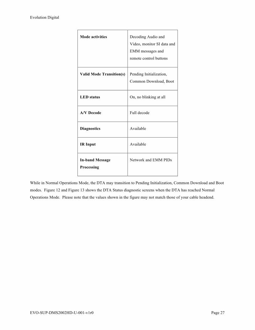
Table 7 Normal Operations Mode Properties
Evolution Digital
EVO-SUP-DMS2002HD-U-001-v1r0 Page 27
Mode activities Decoding Audio and
Video, monitor SI data and
EMM messages and
remote control buttons
Valid Mode Transition(s) Pending Initialization,
Common Download, Boot
LED status On, no blinking at all
A/V Decode Full decode
Diagnostics Available
IR Input Available
In-band Message
Processing
Network and EMM PIDs
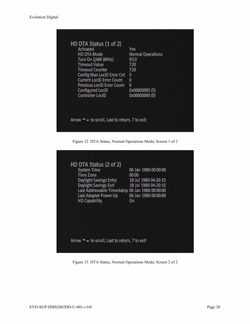
While in Normal Operations Mode, the DTA may transition to Pending Initialization, Common Download and Boot
modes. Figure 12 and Figure 13 shows the DTA Status diagnostic screens when the DTA has reached Normal
Operations Mode. Please note that the values shown in the figure may not match those of your cable headend.
Evolution Digital
EVO-SUP-DMS2002HD-U-001-v1r0 Page 28
Figure 12 DTA Status, Normal Operations Mode; Screen 1 of 2
Figure 13 DTA Status, Normal Operations Mode; Screen 2 of 2

Evolution Digital
EVO-SUP-DMS2002HD-U-001-v1r0 Page 29
2.5.1 Turn On QAM Update
After a channel change, if the DTA is tuned to a new QAM and the QAM contains a CAT PID with the same CA
system ID as previously stored, the DTA will store the new QAM as its Turn On QAM. After power cycle of the
box, the DTA will immediately tune to the stored Turn On QAM.
2.5.2 Channel Map Updates
While in Normal Operations Mode, the DTA will update its channel map when it detects a new version of channel
map is available or assigned to a new VCT ID. This topic is discussed in more detail in Section 3.0.
2.5.3 Interruption to Service
In the event service is interrupted, the DTA will display an on-screen message as shown in Figure 14. Please note
that the message shown in Figure 14 is for illustrative purposes only and can be modified by the headend.
Figure 14 Interruption During Normal Operations
An interruption in service could be any of the following events, but is not limited to this list.
1. RF Cable Pulled
2. Loss of video on a channel
3. Unsupported scrambling

Evolution Digital
EVO-SUP-DMS2002HD-U-001-v1r0 Page 30
2.5.4 Mode Transitions
While in Normal Operations Mode, the DTA will transition to pending initialization mode per Table 6.
While in Normal Operations Mode, the DTA will transition to Code Download Mode with the proper trigger for
code download.
While in Normal Operations Mode, the DTA will transition to Boot Mode if the proper headend message is
received.
2.6 Code Download Mode
Code Download Mode is entered when the DTA detects a new version of code is available for download. The DTA
enters Code Download Mode from Pending Initialization or Normal Operations Mode. In Code Download Mode,
the DTA will perform the code download function and block all video and audio decoding. It will however allow
the user to enter the diagnostic menu. Table 8 details the properties of Normal Operations Mode.
Table 8 Code Download Mode Properties
Mode activities Downloading new code
Valid Mode Transition(s) Boot Mode (for successful
download), Previous Mode
(after reset or failed
download)
LED status Three blinks, then long
pause
A/V Decode None
Diagnostics Available
IR Input Available
In-band Message
Processing
None
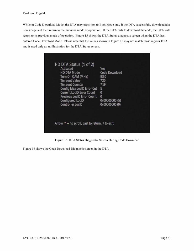
Evolution Digital
EVO-SUP-DMS2002HD-U-001-v1r0 Page 31
While in Code Download Mode, the DTA may transition to Boot Mode only if the DTA successfully downloaded a
new image and then return to the previous mode of operation. If the DTA fails to download the code, the DTA will
return to its previous mode of operation. Figure 15 shows the DTA Status diagnostic screen when the DTA has
entered Code Download Mode. Please note that the values shown in Figure 15 may not match those in your DTA
and is used only as an illustration for the DTA Status screen.
Figure 15 DTA Status Diagnostic Screen During Code Download
Figure 16 shows the Code Download Diagnostic screen in the DTA.
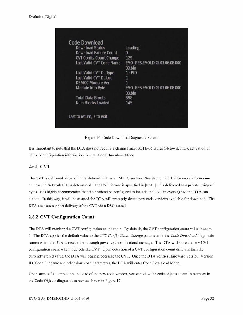
Evolution Digital
EVO-SUP-DMS2002HD-U-001-v1r0 Page 32
Figure 16 Code Download Diagnostic Screen
It is important to note that the DTA does not require a channel map, SCTE-65 tables (Netowrk PID), activation or
network configuration information to enter Code Download Mode.
2.6.1 CVT
The CVT is delivered in-band in the Network PID as an MPEG section. See Section 2.3.1.2 for more information
on how the Network PID is determined. The CVT format is specified in [Ref 1]; it is delivered as a private string of
bytes. It is highly recommended that the headend be configured to include the CVT in every QAM the DTA can
tune to. In this way, it will be assured the DTA will promptly detect new code versions available for download. The
DTA does not support delivery of the CVT via a DSG tunnel.
2.6.2 CVT Configuration Count
The DTA will monitor the CVT configuration count value. By default, the CVT configuration count value is set to
0. The DTA applies the default value to the CVT Config Count Change parameter in the Code Download diagnostic
screen when the DTA is reset either through power cycle or headend message. The DTA will store the new CVT
configuration count when it detects the CVT. Upon detection of a CVT configuration count different than the
currently stored value, the DTA will begin processing the CVT. Once the DTA verifies Hardware Version, Version
ID, Code Filename and other download parameters, the DTA will enter Code Download Mode.
Upon successful completion and load of the new code version, you can view the code objects stored in memory in
the Code Objects diagnostic screen as shown in Figure 17.
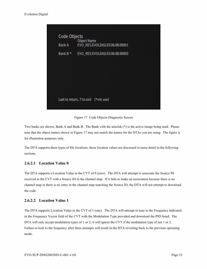
Evolution Digital
EVO-SUP-DMS2002HD-U-001-v1r0 Page 33
Figure 17 Code Objects Diagnostic Screen
Two banks are shown, Bank A and Bank B. The Bank with the asterisk (*) is the active image being used. Please
note that the object names shown in Figure 17 may not match the names for the DTAs you are using. The figure is
for illustration purposes only.
The DTA supports three types of file locations; these location values are discussed in more detail in the following
sections.
2.6.2.1 Location Value 0
The DTA supports a Location Value in the CVT of 0 (zero). The DTA will attempt to associate the Source ID
received in the CVT with a Source ID in the channel map. If it fails to make an association because there is no
channel map or there is no entry in the channel map matching the Source ID, the DTA will not attempt to download
the code.
2.6.2.2 Location Value 1
The DTA supports Location Value in the CVT of 1 (one). The DTA will attempt to tune to the Frequency indicated
in the Frequency Vector field of the CVT with the Modulation Type provided and download the PID listed. The
DTA will only accept modulation types of 1 or 2; it will ignore the CVT if the modulation type of not 1 or 2.
Failure to lock to the frequency after three attempts will result in the DTA reverting back to the previous operating
mode.
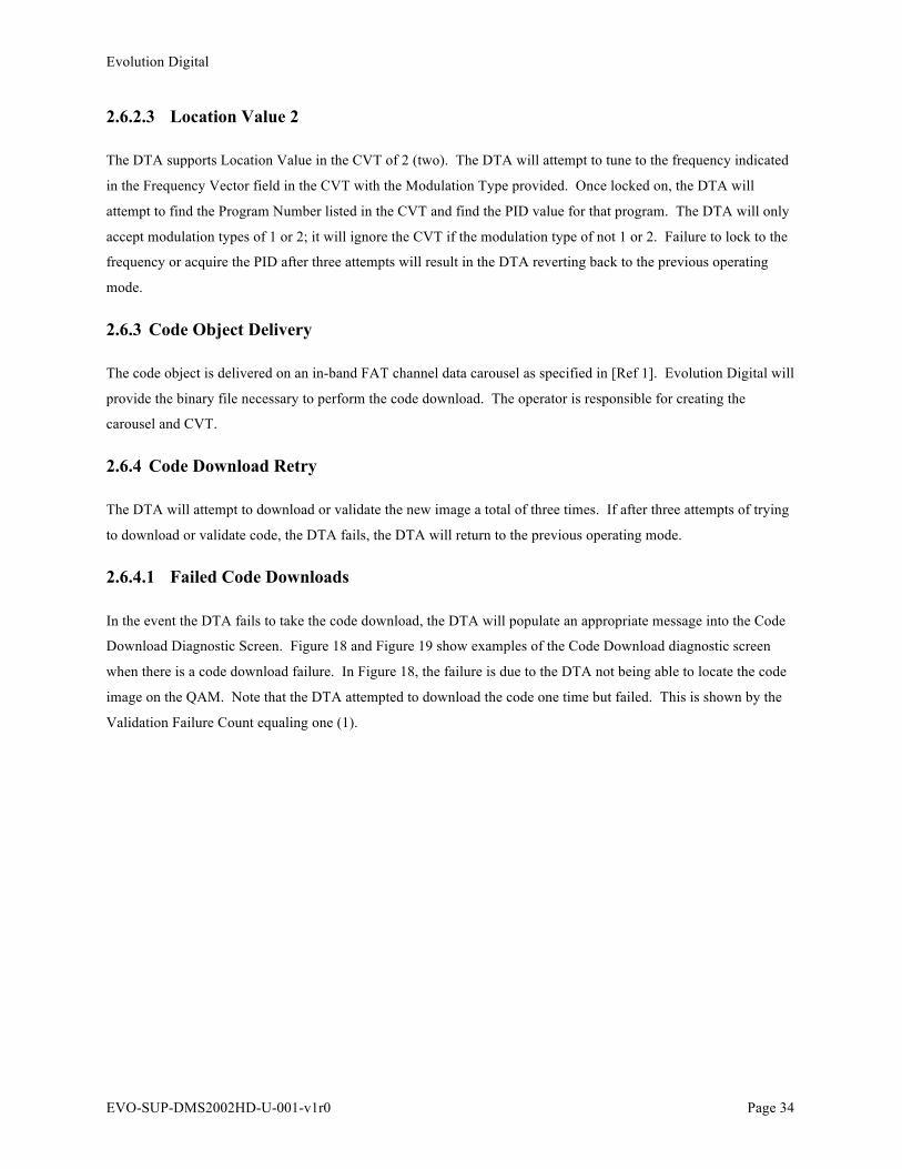
Evolution Digital
EVO-SUP-DMS2002HD-U-001-v1r0 Page 34
2.6.2.3 Location Value 2
The DTA supports Location Value in the CVT of 2 (two). The DTA will attempt to tune to the frequency indicated
in the Frequency Vector field in the CVT with the Modulation Type provided. Once locked on, the DTA will
attempt to find the Program Number listed in the CVT and find the PID value for that program. The DTA will only
accept modulation types of 1 or 2; it will ignore the CVT if the modulation type of not 1 or 2. Failure to lock to the
frequency or acquire the PID after three attempts will result in the DTA reverting back to the previous operating
mode.
2.6.3 Code Object Delivery
The code object is delivered on an in-band FAT channel data carousel as specified in [Ref 1]. Evolution Digital will
provide the binary file necessary to perform the code download. The operator is responsible for creating the
carousel and CVT.
2.6.4 Code Download Retry
The DTA will attempt to download or validate the new image a total of three times. If after three attempts of trying
to download or validate code, the DTA fails, the DTA will return to the previous operating mode.
2.6.4.1 Failed Code Downloads
In the event the DTA fails to take the code download, the DTA will populate an appropriate message into the Code
Download Diagnostic Screen. Figure 18 and Figure 19 show examples of the Code Download diagnostic screen
when there is a code download failure. In Figure 18, the failure is due to the DTA not being able to locate the code
image on the QAM. Note that the DTA attempted to download the code one time but failed. This is shown by the
Validation Failure Count equaling one (1).
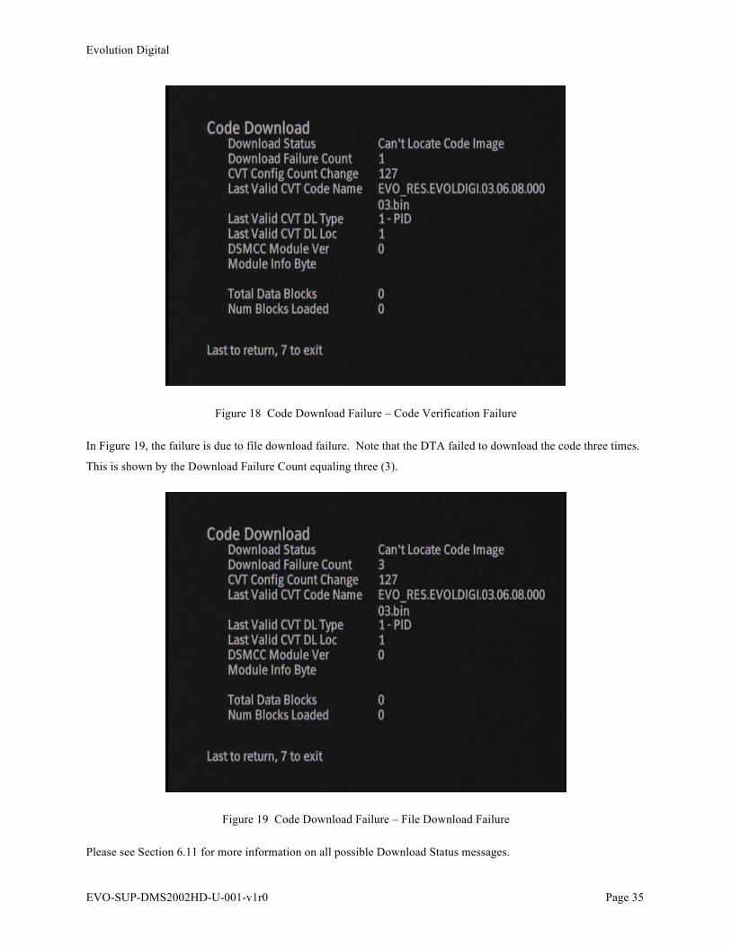
Evolution Digital
EVO-SUP-DMS2002HD-U-001-v1r0 Page 35
Figure 18 Code Download Failure – Code Verification Failure
In Figure 19, the failure is due to file download failure. Note that the DTA failed to download the code three times.
This is shown by the Download Failure Count equaling three (3).
Figure 19 Code Download Failure – File Download Failure
Please see Section 6.11 for more information on all possible Download Status messages.
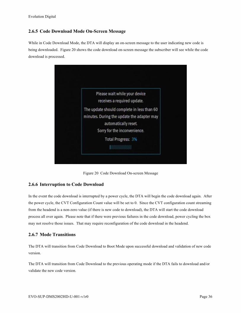
Evolution Digital
EVO-SUP-DMS2002HD-U-001-v1r0 Page 36
2.6.5 Code Download Mode On-Screen Message
While in Code Download Mode, the DTA will display an on-screen message to the user indicating new code is
being downloaded. Figure 20 shows the code download on-screen message the subscriber will see while the code
download is processed.
Figure 20 Code Download On-screen Message
2.6.6 Interruption to Code Download
In the event the code download is interrupted by a power cycle, the DTA will begin the code download again. After
the power cycle, the CVT Configuration Count value will be set to 0. Since the CVT configuration count streaming
from the headend is a non-zero value (if there is new code to download), the DTA will start the code download
process all over again. Please note that if there were previous failures in the code download, power cycling the box
may not resolve those issues. That may require reconfiguration of the code download in the headend.
2.6.7 Mode Transitions
The DTA will transition from Code Download to Boot Mode upon successful download and validation of new code
version.
The DTA will transition from Code Download to the previous operating mode if the DTA fails to download and/or
validate the new code version.
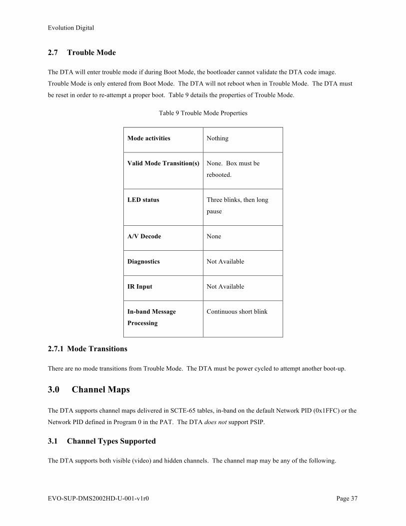
Evolution Digital
EVO-SUP-DMS2002HD-U-001-v1r0 Page 37
2.7 Trouble Mode
The DTA will enter trouble mode if during Boot Mode, the bootloader cannot validate the DTA code image.
Trouble Mode is only entered from Boot Mode. The DTA will not reboot when in Trouble Mode. The DTA must
be reset in order to re-attempt a proper boot. Table 9 details the properties of Trouble Mode.
Table 9 Trouble Mode Properties
Mode activities Nothing
Valid Mode Transition(s) None. Box must be
rebooted.
LED status Three blinks, then long
pause
A/V Decode None
Diagnostics Not Available
IR Input Not Available
In-band Message
Processing
Continuous short blink
2.7.1 Mode Transitions
There are no mode transitions from Trouble Mode. The DTA must be power cycled to attempt another boot-up.
3.0 Channel Maps
The DTA supports channel maps delivered in SCTE-65 tables, in-band on the default Network PID (0x1FFC) or the
Network PID defined in Program 0 in the PAT. The DTA does not support PSIP.
3.1 Channel Types Supported
The DTA supports both visible (video) and hidden channels. The channel map may be any of the following.

Evolution Digital
EVO-SUP-DMS2002HD-U-001-v1r0 Page 38
• A single channel – hidden or video
• All hidden channels
• All video channels
• Any combination of hidden and video channels
The DAT supports a minimum of 400 channels in the channel map; there is no real restriction for the number of
channels supported in the DTA (ie. it can support a lot).
3.1.1 Channel Numbers
The DTA supports 4 digit channel numbers, with a maximum channel number of 4095. In the Virtual Channel Map
(VCM) table of the SI data, the virtual channel field is 12 bits long, resulting in a maximum value of 4095.
3.1.2 Channel Name
The DTA displays a channel name. The channel name length is capped at 14 characters. The character map
includes all valid alphanumeric and symbolic characters. Figure 21 shows an example of the channel name and
number displayed on-screen when the info button is pressed or the channel is changed.
Figure 21 Channel Name and Number Displayed

Evolution Digital
EVO-SUP-DMS2002HD-U-001-v1r0 Page 39
3.2 Channel Map Updates
Channel map updates are supported by mechanisms detailed in [Ref 2]. When a new channel map is available, the
DTA will begin downloading the channel map in the background, with little to no interruption experienced by the
viewer. In addition, the DTA will continue using its currently loaded channel map until the new channel map is
fully loaded. As previously mentioned, the DTA will default its VCT ID to zero (0) until provisioned for a different
VCT ID.
When a channel map is fully loaded and currently in use, the Virtual Channel Map diagnostic screen will look
similar to that shown in Figure 22. Notice that the Stored VCT-ID is ”Loaded”. The second line represents the
VCT-ID of the channel map that is currently loaded and active; note the VCT-IDs match. Please note that the VCT-
ID values used in your system may be different than the values shown in the figure. The figure is for illustration
purposes only.
Figure 22 Virtual Channel Map Diagnostic Screen, Channel map loaded
Stored channel maps are persistent between power cycles. The DTA will ignore all channel maps with VCT IDs
different than the currently configured value. The remainder of this section details typical scenarios and how the
DTA behaves.
3.2.1 Addition of Channels
When channels are added to an existing channel map, the channels will be added with in a seamless transition.
Please view the Virtual Channel Map diagnostic screen to view additions.

Evolution Digital
EVO-SUP-DMS2002HD-U-001-v1r0 Page 40
3.2.2 Removal of Channels
When channels are removed to an existing channel map, the channels will be added with in a seamless transition.
Please view the Virtual Channel Map diagnostic screen to view additions.
3.2.2.1 Changes Made to Currently Tuned to Service
If changes are made to the currently tuned to service, the DTA will apply (load) the new channel map once the user
has changed channels to a new service. If for some reason the channel map changes cause interruption of service to
the viewer, the DTA will provide the following delayed service interruption message to the viewer.
Figure 23 Delayed Service Interruption Message
3.2.3 Change of VCT ID
When the DTA is assigned to a new VCT-ID through a headend message, the DTA Virtual Channel Map diagnostic
screen will look similar to that shown in Figure 24. The Stored VCT-ID in this case represents the new VCT-ID the
DTA is assigned to and the DTA is “Searching” for the channel map. The channel map VCT-ID that is loaded is
represented in the second line of this diagnostic screen. Notice the VCT-IDs are different. Please note that the
VCT-ID values used in your system may be different than the values shown in the figure. The figure is for
illustration purposes only.
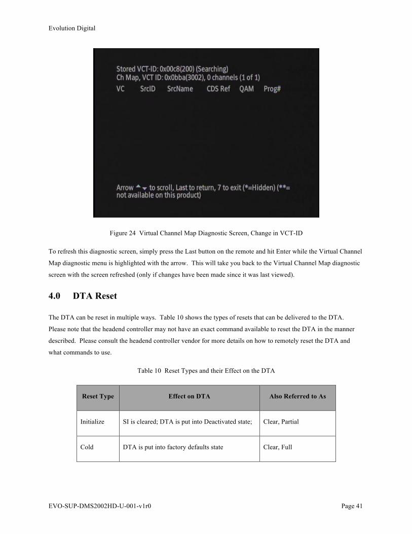
Evolution Digital
EVO-SUP-DMS2002HD-U-001-v1r0 Page 41
Figure 24 Virtual Channel Map Diagnostic Screen, Change in VCT-ID
To refresh this diagnostic screen, simply press the Last button on the remote and hit Enter while the Virtual Channel
Map diagnostic menu is highlighted with the arrow. This will take you back to the Virtual Channel Map diagnostic
screen with the screen refreshed (only if changes have been made since it was last viewed).
4.0 DTA Reset
The DTA can be reset in multiple ways. Table 10 shows the types of resets that can be delivered to the DTA.
Please note that the headend controller may not have an exact command available to reset the DTA in the manner
described. Please consult the headend controller vendor for more details on how to remotely reset the DTA and
what commands to use.
Table 10 Reset Types and their Effect on the DTA
Reset Type Effect on DTA Also Referred to As
Initialize SI is cleared; DTA is put into Deactivated state; Clear, Partial
Cold DTA is put into factory defaults state Clear, Full

Evolution Digital
EVO-SUP-DMS2002HD-U-001-v1r0 Page 42
Warm Box is rebooted only Reboot and power cycle
Table 11 shows what is cleared in the DTA for the three types of reset described in the table above.
Table 11 Effects on Parameters Across DTA Reset Types
Parameter Initialize Cold Warm
VCT ID Save Clear Save
SI Tables Clear Clear Save
Turn On QAM Save Clear Save
Configured Location ID Save Clear Save
Configured Timezone Save Clear Save
Configured Daylight Savings Entry Save Clear Save
Configured Daylight Savings Exit Save Clear Save
Configured MSO Phone Number Save Clear Save
Configured Timeout Value Parameter Save Clear Save
Timeout Counter Parameter Save Clear Save
Network PID Clear Clear Clear
EMM PID Clear Clear Clear
Stored CA System ID Save Clear Save

Evolution Digital
EVO-SUP-DMS2002HD-U-001-v1r0 Page 43
Stored EMM Provider ID Save Clear Save
Code Download Status Save Save Save
Configured Max Site Error Count Save Clear Save
Current Site Error Count Save Clear Save
Previous Site Error Count Save Clear Save
Language Save Clear Save
CVT Configuration Count Change Clear Clear Clear
4.1 Reset Recovery
Depending on the type of reset command sent to the DTA, the DTA may need configuration or activation messages
to return to normal operations.
4.1.1 Recovery from Initialization
Upon boot-up, the DTA will not have a channel map. First it will determine the network PID from the Turn On
QAM it is tuned to. The DTA will then automatically acquire the channel map for its stored VCT ID.
4.1.2 Recovery from Cold Reset
A cold reset is essentially a return to factory reset. Upon boot-up, the DTA will enter Hunt Mode and proceed
through the Pending Init and finally Normal Operations, provided the proper headend messages are delivered after
reset.
4.1.3 Recovery from Warm Reset
A warm reset is equivalent to a power cycle. The DTA does not need to re-acquire the channel map nor does it need
messages from the headend to return to normal operations.

Evolution Digital
EVO-SUP-DMS2002HD-U-001-v1r0 Page 44
4.2 Manual Clear, Full
Section 8.2 discusses the method for a manual clear, full. With the proper remote button presses, the DTA can be
manually put into a cold reset state. In this case however, the headend is not aware that the DTA has been reset
since the command was manually initiated. The DTA will need the configuration and activation commands sent
from the headend controller to bring it back to a Normal Operations Mode state.
5.0 EAS
The DTA supports in-band EAS messages delivered via SCTE-18 messages on PID 0x1FFB. More details on the
EAS messaging structure can be found in [Ref 3]. The DTA only supports force tune.
5.1 Alert Priorities
The DTA will only process EAS messages when in Normal Operations Mode. The DTA will process all EAS
messages with a priority alert of one (1) or higher. If an EAS message with priority zero (0) is received, the DTA
will store the sequence number associated with that EAS message and will not tune to the alert channel.
5.2 Exceptions List
The DTA supports an exception list. Meaning, if the DTA is tuned to a channel that is included in the exception list
delivered with the EAS message (configured in the headend) the DTA will not tune to the alert channel. It will
ignore the EAS message.
5.3 Force Tune Behavior
Upon reception of an EAS message containing a priority of 1 or greater, the DTA will force tune to the alert channel
as described in the details_major_channel_number and details_minor_channel_number fields. The major channel
number field will represent the CDS reference (EIA channel) and the minor channel will represent the MPEG
service number. Please note, the DTA will only force tune to a channel that is included in its currently loaded
channel map.
5.3.1 Duration of Force Tune
The DTA will stay tuned to the alert channel for the period of time indicated in the alert_message_time_remaining
included in the EAS message (maximum value of 120 seconds).
5.3.2 DTA Behavior
During the force tune, the DTA will not allow any channel changes (either direct or up/down changes). The DTA
will ignore all remote control button presses except volume up/down, mute and language. The DTA will ignore any

Evolution Digital
EVO-SUP-DMS2002HD-U-001-v1r0 Page 45
CVT messages that contain a change in Configuration Count. At the end of the force tune, the DTA will return to
the previously tuned to channel.
6.0 Diagnostic Menu
The DTA provides a diagnostic menu that is accessible by holding the 7 button on the remote for a minimum of 4
seconds. The remainder of this section details the DTA diagnostic menu.
6.1 Navigating the Diagnostic Menu
Table 12 shows the list of useable remote button while in the Diagnostic Menu. Buttons not shown in Table 12 are
not useable in anyway while in the Diagnostic Menu.
Table 12 Useable Remote Buttons While In Diagnostic Menu
Button Use
Channel Up/Down Move selection arrow up or down
Enter Select item
Info Exit Diagnostic menu
Last Return to previous screen
Please note that throughout the remainder of this section, screen shots will be used as illustrations of the various
diagnostic screens. These are just examples and are used as illustrations of what is presented by the DTA on
screen. These figures do not represent exactly what you will see when viewing your DTA.
6.2 Main Diagnostic Screen
From the Diagnostic Main Menu, the user can select from any one of the following menu items.
• General Info
• DTA Status
• MSO Info
• Tuner Status
• Current Channel Status
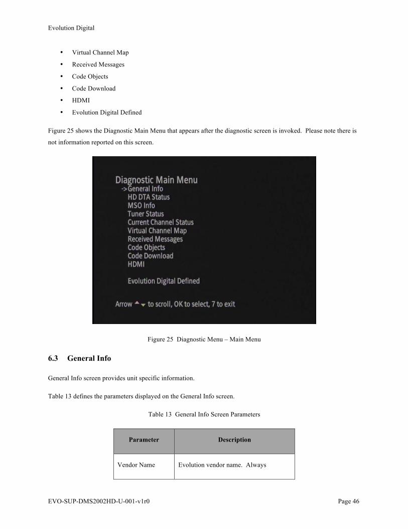
Evolution Digital
EVO-SUP-DMS2002HD-U-001-v1r0 Page 46
• Virtual Channel Map
• Received Messages
• Code Objects
• Code Download
• HDMI
• Evolution Digital Defined
Figure 25 shows the Diagnostic Main Menu that appears after the diagnostic screen is invoked. Please note there is
not information reported on this screen.
Figure 25 Diagnostic Menu – Main Menu
6.3 General Info
General Info screen provides unit specific information.
Table 13 defines the parameters displayed on the General Info screen.
Table 13 General Info Screen Parameters
Parameter Description
Vendor Name Evolution vendor name. Always
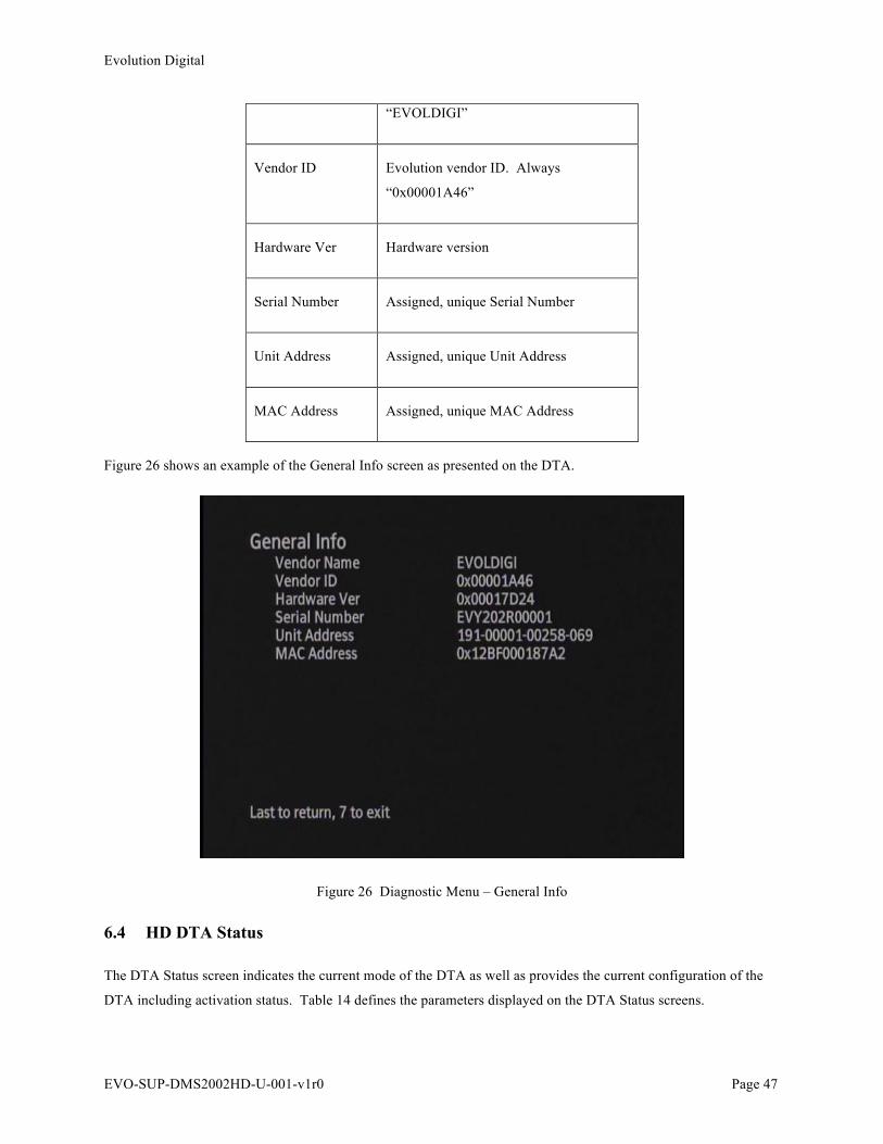
Evolution Digital
EVO-SUP-DMS2002HD-U-001-v1r0 Page 47
“EVOLDIGI”
Vendor ID Evolution vendor ID. Always
“0x00001A46”
Hardware Ver Hardware version
Serial Number Assigned, unique Serial Number
Unit Address Assigned, unique Unit Address
MAC Address Assigned, unique MAC Address
Figure 26 shows an example of the General Info screen as presented on the DTA.
Figure 26 Diagnostic Menu – General Info
6.4 HD DTA Status
The DTA Status screen indicates the current mode of the DTA as well as provides the current configuration of the
DTA including activation status. Table 14 defines the parameters displayed on the DTA Status screens.
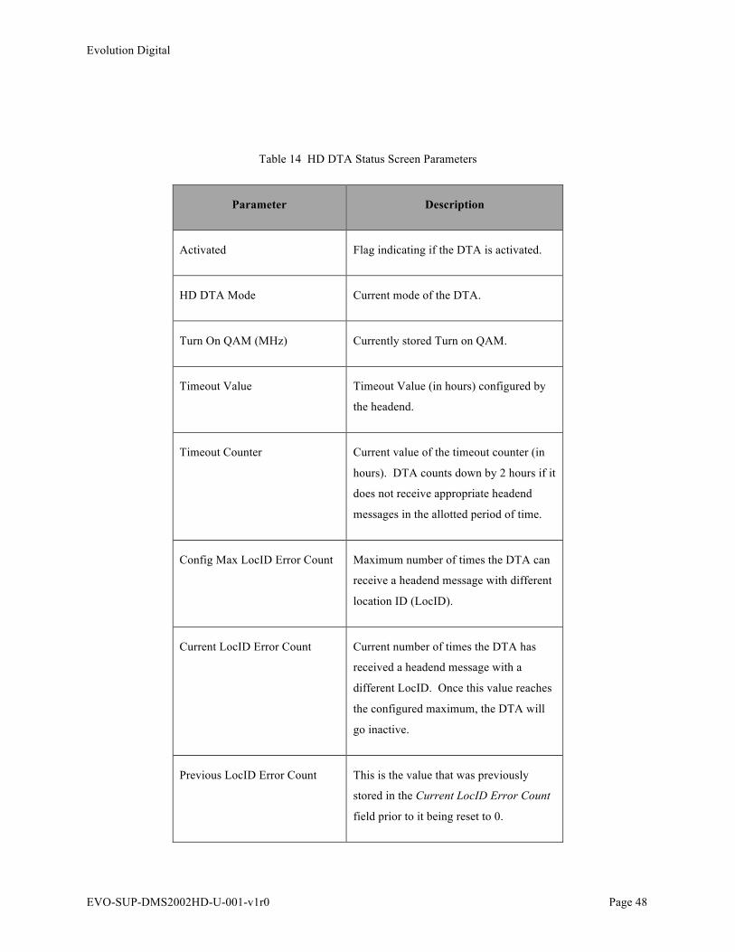
Evolution Digital
EVO-SUP-DMS2002HD-U-001-v1r0 Page 48
Table 14 HD DTA Status Screen Parameters
Parameter Description
Activated Flag indicating if the DTA is activated.
HD DTA Mode Current mode of the DTA.
Turn On QAM (MHz) Currently stored Turn on QAM.
Timeout Value Timeout Value (in hours) configured by
the headend.
Timeout Counter Current value of the timeout counter (in
hours). DTA counts down by 2 hours if it
does not receive appropriate headend
messages in the allotted period of time.
Config Max LocID Error Count Maximum number of times the DTA can
receive a headend message with different
location ID (LocID).
Current LocID Error Count Current number of times the DTA has
received a headend message with a
different LocID. Once this value reaches
the configured maximum, the DTA will
go inactive.
Previous LocID Error Count This is the value that was previously
stored in the Current LocID Error Count
field prior to it being reset to 0.
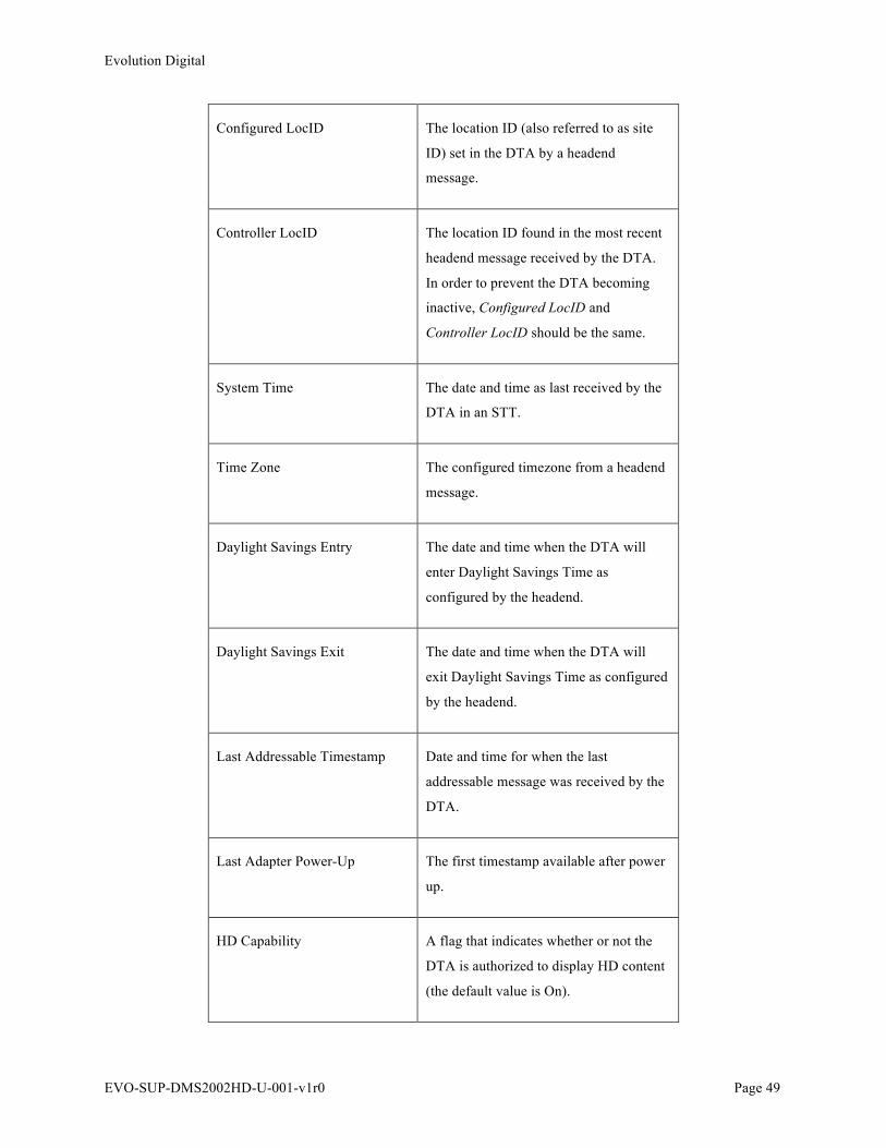
Evolution Digital
EVO-SUP-DMS2002HD-U-001-v1r0 Page 49
Configured LocID The location ID (also referred to as site
ID) set in the DTA by a headend
message.
Controller LocID The location ID found in the most recent
headend message received by the DTA.
In order to prevent the DTA becoming
inactive, Configured LocID and
Controller LocID should be the same.
System Time The date and time as last received by the
DTA in an STT.
Time Zone The configured timezone from a headend
message.
Daylight Savings Entry The date and time when the DTA will
enter Daylight Savings Time as
configured by the headend.
Daylight Savings Exit The date and time when the DTA will
exit Daylight Savings Time as configured
by the headend.
Last Addressable Timestamp Date and time for when the last
addressable message was received by the
DTA.
Last Adapter Power-Up The first timestamp available after power
up.
HD Capability A flag that indicates whether or not the
DTA is authorized to display HD content
(the default value is On).
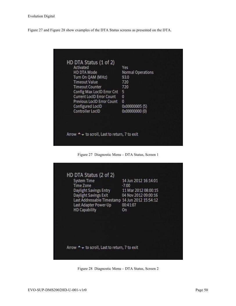
Evolution Digital
EVO-SUP-DMS2002HD-U-001-v1r0 Page 50
Figure 27 and Figure 28 show examples of the DTA Status screens as presented on the DTA.
Figure 27 Diagnostic Menu – DTA Status, Screen 1
Figure 28 Diagnostic Menu – DTA Status, Screen 2
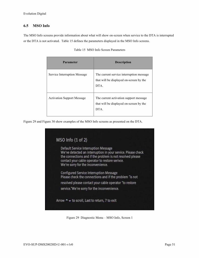
Evolution Digital
EVO-SUP-DMS2002HD-U-001-v1r0 Page 51
6.5 MSO Info
The MSO Info screens provide information about what will show on-screen when service to the DTA is interrupted
or the DTA is not activated. Table 15 defines the parameters displayed in the MSO Info screens.
Table 15 MSO Info Screen Parameters
Parameter Description
Service Interruption Message The current service interruption message
that will be displayed on-screen by the
DTA.
Activation Support Message The current activation support message
that will be displayed on-screen by the
DTA.
Figure 29 and Figure 30 show examples of the MSO Info screens as presented on the DTA.
Figure 29 Diagnostic Menu – MSO Info, Screen 1

Evolution Digital
EVO-SUP-DMS2002HD-U-001-v1r0 Page 52
Figure 30 Diagnostic Menu – MSO Info, Screen 2
6.5.1 MSO Info Customization
The MSO info screens can be customized to a certain extent, with information from the headend controller.
Specifically, there is an MSO Phone Number field that can be set by the operator. Please consult with your headend
controller manufacture for modification of the MSO phone number field to understand its effect on the DTA on-
screen messaging for service interruptions and activation support.
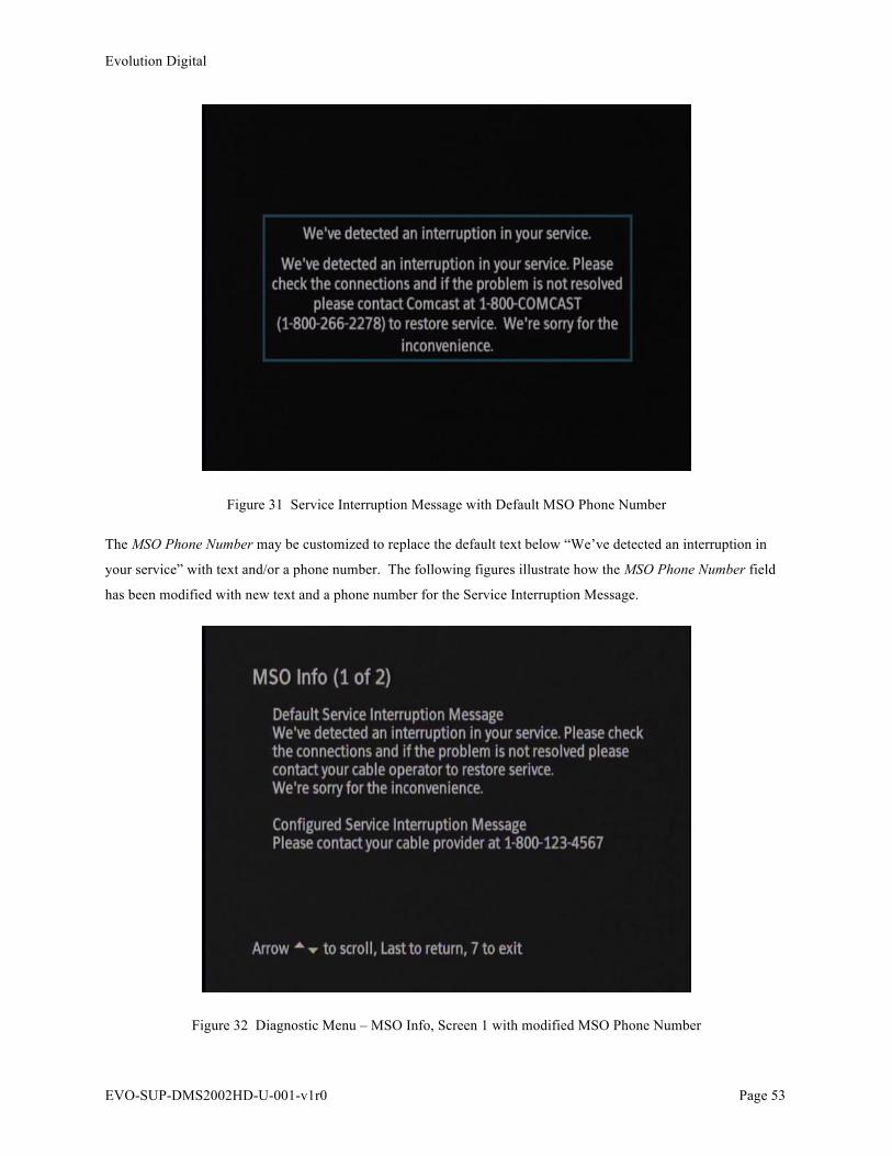
Evolution Digital
EVO-SUP-DMS2002HD-U-001-v1r0 Page 53
Figure 31 Service Interruption Message with Default MSO Phone Number
The MSO Phone Number may be customized to replace the default text below “We’ve detected an interruption in
your service” with text and/or a phone number. The following figures illustrate how the MSO Phone Number field
has been modified with new text and a phone number for the Service Interruption Message.
Figure 32 Diagnostic Menu – MSO Info, Screen 1 with modified MSO Phone Number
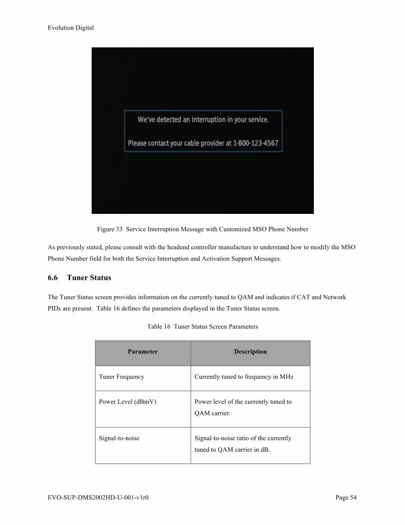
Evolution Digital
EVO-SUP-DMS2002HD-U-001-v1r0 Page 54
Figure 33 Service Interruption Message with Customized MSO Phone Number
As previously stated, please consult with the headend controller manufacture to understand how to modify the MSO
Phone Number field for both the Service Interruption and Activation Support Messages.
6.6 Tuner Status
The Tuner Status screen provides information on the currently tuned to QAM and indicates if CAT and Network
PIDs are present. Table 16 defines the parameters displayed in the Tuner Status screen.
Table 16 Tuner Status Screen Parameters
Parameter Description
Tuner Frequency Currently tuned to frequency in MHz
Power Level (dBmV) Power level of the currently tuned to
QAM carrier.
Signal-to-noise Signal-to-noise ratio of the currently
tuned to QAM carrier in dB.

Evolution Digital
EVO-SUP-DMS2002HD-U-001-v1r0 Page 55
CAT Present Indicated if a CAT PID is present on the
currently tuned to QAM.
CA SysID Once CAT PID is found with a valid CA
System ID (CA SysID) the DTA will
display the CA SysID in use in the
system.
EMM PID Once CAT PID is found with a valid CA
System ID (CA SysID) the DTA will
display the EMM PID in use on the
QAM.
EMM ProviderID Once CAT PID is found with a valid CA
System ID (CA SysID) the DTA will
display the EMM Provider ID.
PAT Present Indicates if PAT is present on the tuned
to QAM.
Network PID Indicates the Network PID being used on
the currently tuned to QAM. May change
for each QAM if the operator configures
some QAMs to use different network PID
then others. If the DTA does not find
Program 0 in the PAT referencing a
network PID, it will default to 0x1FFC as
the network PID and an asterisk will
show next to the network PID.
Figure 34 shows an example of the Tuner Status screen as presented on the DTA.
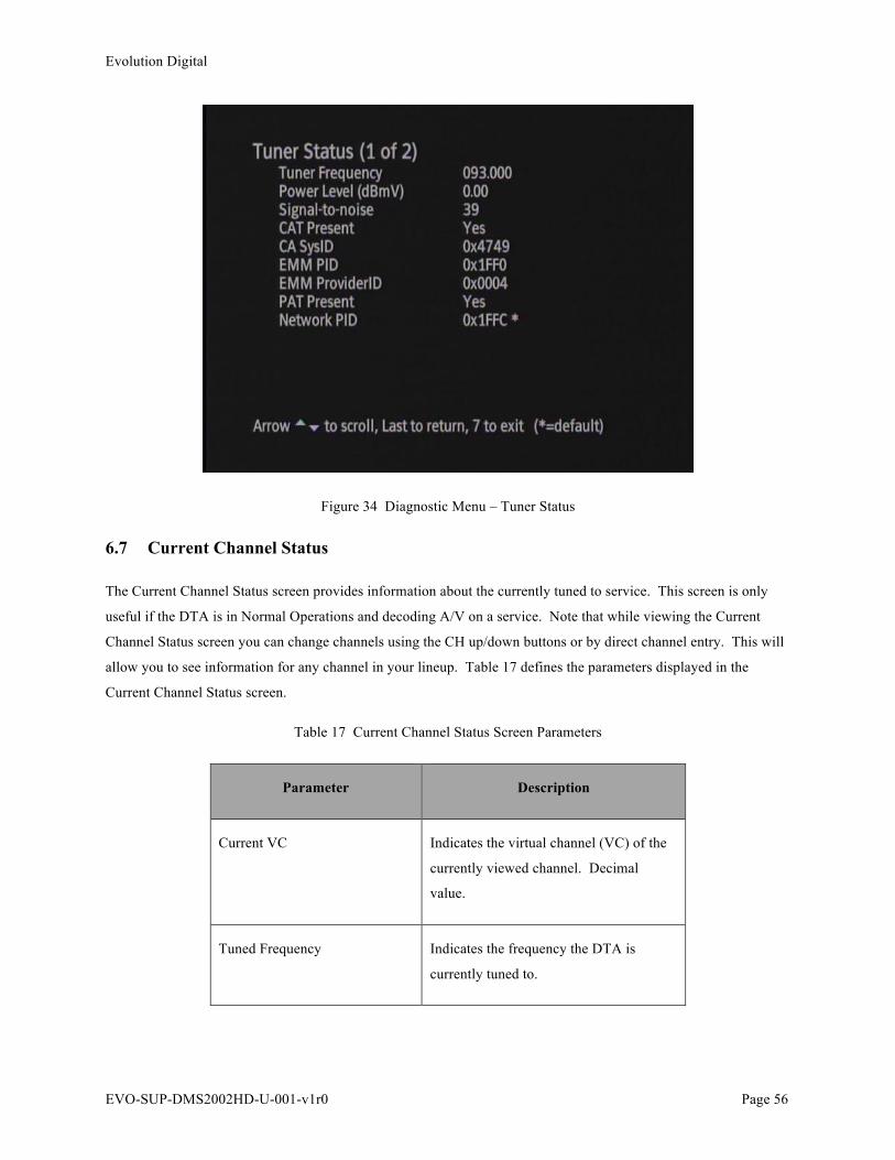
Evolution Digital
EVO-SUP-DMS2002HD-U-001-v1r0 Page 56
Figure 34 Diagnostic Menu – Tuner Status
6.7 Current Channel Status
The Current Channel Status screen provides information about the currently tuned to service. This screen is only
useful if the DTA is in Normal Operations and decoding A/V on a service. Note that while viewing the Current
Channel Status screen you can change channels using the CH up/down buttons or by direct channel entry. This will
allow you to see information for any channel in your lineup. Table 17 defines the parameters displayed in the
Current Channel Status screen.
Table 17 Current Channel Status Screen Parameters
Parameter Description
Current VC Indicates the virtual channel (VC) of the
currently viewed channel. Decimal
value.
Tuned Frequency Indicates the frequency the DTA is
currently tuned to.

Evolution Digital
EVO-SUP-DMS2002HD-U-001-v1r0 Page 57
Modulation Indicates the modulation of the QAM
carrying the service. Either QAM 256 or
QAM 64.
Program Number Indicated the program number of the
service. Decimal value.
Video PID Indicated the PID present for the service
that is carrying video. Only one per
service. Hex value.
Audio PID(s) Indicates the PIDs present for the service
that are carrying audio and what language
they are (language based on ISO-639).
Hex value. An asterisk is placed next to
the audio PID that has been selected by
the user.
Audio User Muted Indicated if the user has muted audio on
the DTA.
Decryption Error If the DTA is tuned to an encrypted
channel but cannot decrypt it for some
reason the value will be Yes. Note that
this is not related to the channel being
authorized or not, only whether or not
there is an error in decrypting it.
Figure 35 shows an example of the Current Channel Status screen as presented on the DTA.

Evolution Digital
EVO-SUP-DMS2002HD-U-001-v1r0 Page 58
Figure 35 Diagnostic Menu – Current Channel Status
6.8 Virtual Channel Map
The Virtual Channel Map screen displays the currently loaded virtual channel map and indicates if a new channel
map for a different VCT ID is being downloaded. Table 18 defines the parameters displayed in the Virtual Channel
Map screen.
Table 18 Virtual Channel Map Screen Parameters
Parameter Description
Stored VCT ID Indicates the VCT ID of the channel map
assigned to the DTA. In both Hex and
decimal values. If the channel map for
this VCT ID is fully loaded, the word
“Loaded” will appear after it. If the
channel map for this VCT ID is currently
being downloaded, the word “Searching”
will appear after it.

Evolution Digital
EVO-SUP-DMS2002HD-U-001-v1r0 Page 59
Ch Map VCT ID Indicates the VCT ID of the channel map
that is currently loaded.
VC Virtual Channel number. Unique to each
channel. If the channel is defined as a
hidden channel (eg. common download
carousel), the VC will have an asterisk
next to it.
SrdID Source ID, unique to each service.
SrcName Source Name as defined in the SCTE-65
SI server.
CDSRef CDS Reference; QAM frequency
carrying this service.
QAM Modulation mode; either 64 or 256.
Prog# MPEG Program number for the service.
Figure 36 shows an example of the Virtual Channel Map screen as presented on the DTA.
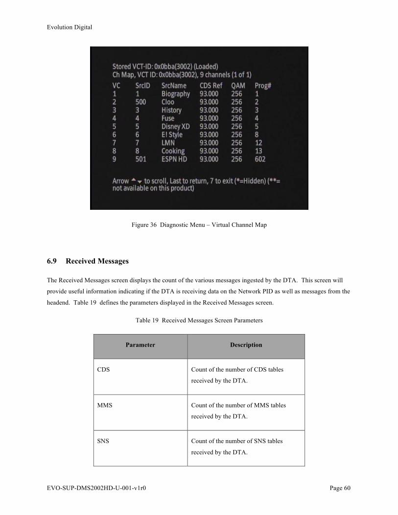
Evolution Digital
EVO-SUP-DMS2002HD-U-001-v1r0 Page 60
Figure 36 Diagnostic Menu – Virtual Channel Map
6.9 Received Messages
The Received Messages screen displays the count of the various messages ingested by the DTA. This screen will
provide useful information indicating if the DTA is receiving data on the Network PID as well as messages from the
headend. Table 19 defines the parameters displayed in the Received Messages screen.
Table 19 Received Messages Screen Parameters
Parameter Description
CDS Count of the number of CDS tables
received by the DTA.
MMS Count of the number of MMS tables
received by the DTA.
SNS Count of the number of SNS tables
received by the DTA.

Evolution Digital
EVO-SUP-DMS2002HD-U-001-v1r0 Page 61
VCM Count of the number of VCM tables
received by the DTA.
STT Count of the number of STT tables
received by the DTA.
Ops Count of the number of Operation
messages received by the DTA.
Config Count of the number of Configuration
messages received by the DTA.
EAS Count of the number of EAS messages
received by the DTA.
EM Count of the number of EMMs received
by the DTA.
CAT Count of the number of CAT PIDs
received by the DTA.
CAT Err Count of the number of errored CAT
PIDs received.
CVT Count of the number of CVT tables
received by the DTA.
Last Addressable Timestamp Date and time for when the last
addressable message was received by the
DTA.
In this screen, if you press the number “0”, all counters will be reset to “0”. Anytime the DTA is reset, all counters return to 0. Figure 37 shows an example of the Received Messages screen as presented on the DTA.

Evolution Digital
EVO-SUP-DMS2002HD-U-001-v1r0 Page 62
Figure 37 Diagnostic Menu – Received Messages
6.10 Code Objects
The Code Objects screen displays the currently stored objects in non-volatile memory. Table 20 defines the
parameters displayed in the Code Objects screen.
Table 20 Code Objects Screen Parameters
Parameter Description
Bank A Name of object stored in Bank A.
Bank B Name of object stored in Bank B.
The Bank with the object that is currently loaded will have an asterisk (*) next to it. The user cannot select which
object to load after the next reset. It is possible to have only one object loaded in memory. When a new version of
code is available, the DTA will download the code into an empty bank or the bank with the oldest code. The values
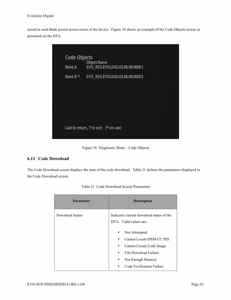
Evolution Digital
EVO-SUP-DMS2002HD-U-001-v1r0 Page 63
stored in each Bank persist across resets of the device. Figure 38 shows an example of the Code Objects screen as
presented on the DTA.
Figure 38 Diagnostic Menu – Code Objects
6.11 Code Download
The Code Download screen displays the state of the code download. Table 21 defines the parameters displayed in
the Code Download screen.
Table 21 Code Download Screen Parameters
Parameter Description
Download Status Indicates current download status of the
DTA. Valid values are:
• Not Attempted
• Cannot Locate DSM-CC PID
• Cannot Locate Code Image
• File Download Failure
• Not Enough Memory
• Code Verification Failure

Evolution Digital
EVO-SUP-DMS2002HD-U-001-v1r0 Page 64
• Loading
• Successful
Download Failure Count Indicates the number of times that the
DTA has failed to successfully download
a code image in consecutive attempts.
The maximum value is 3 and then the
DTA will stop attempting to download
the code.
Validation Failure Count Indicates the number of times that the
DTA has failed to successfully validate a
fully downloaded code image in
consecutive attempts. The maximum
value is 3 and then the DTA will stop
attempting to download the code. After a
successful code validation, this value will
be set to 0.
CVT Config Count Change Indicates the value of the configuration
count change in the last successfully
processed CVT. After each reset of the
DTA, this parameter will be set to 0.
Last Valid CVT Code Nam The code file name in the last
successfully processed CVT.
Last Valid CVT DL Type Indicates the code download type listed in
the last successfully processed CVT.
Last Valid CVT DL Loc Indicates the location of the code image
to be downloaded in the last successfully
processed CVT.
DSMCC Module Ver Indicates the module version in the DII
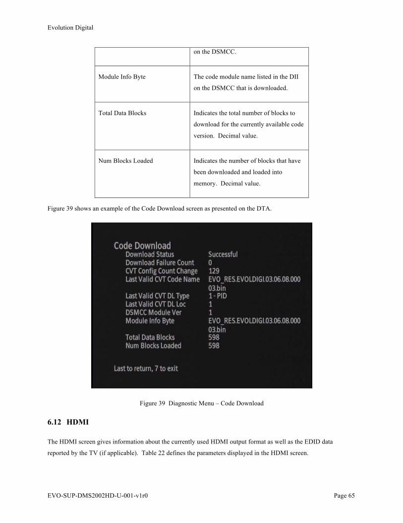
Evolution Digital
EVO-SUP-DMS2002HD-U-001-v1r0 Page 65
on the DSMCC.
Module Info Byte The code module name listed in the DII
on the DSMCC that is downloaded.
Total Data Blocks Indicates the total number of blocks to
download for the currently available code
version. Decimal value.
Num Blocks Loaded Indicates the number of blocks that have
been downloaded and loaded into
memory. Decimal value.
Figure 39 shows an example of the Code Download screen as presented on the DTA.
Figure 39 Diagnostic Menu – Code Download
6.12 HDMI
The HDMI screen gives information about the currently used HDMI output format as well as the EDID data
reported by the TV (if applicable). Table 22 defines the parameters displayed in the HDMI screen.
Evolution Digital
EVO-SUP-DMS2002HD-U-001-v1r0 Page 66
Table 22 HDMI Screen Parameters
Parameter Description
Device Connected Set to Yes if the HDMI cable is currently
connected to a TV and is in use.
HDCP Enabled Set to yes if HDCP copy protection is
enabled.
Output Format The current output format (resolution).
Aspect Ratio The current output aspect ratio (16:9 or
4:3)
EDID Data Under the EDID Data entry there is a list
of the four combinations of supported
output formats. To the right of each entry
will be either a Yes or a No depending on
whether or not the connected TV supports
each output.
Figure 39 shows an example of the HDMI screen as presented on the DTA.

Evolution Digital
EVO-SUP-DMS2002HD-U-001-v1r0 Page 67
Figure 40 Diagnostic Menu – HDMI
7.0 Evolution Digital Defined
The Evolution Digital Defined option will take you to the Evolution Digital Defined sub-menu which contains the
following options:
• SI Descriptors
• Decoder Status
• RF Remote Control
• EAS Location
Figure 41 shows an example of the Evolution Digital Defined sub-menu as presented by the DTA.
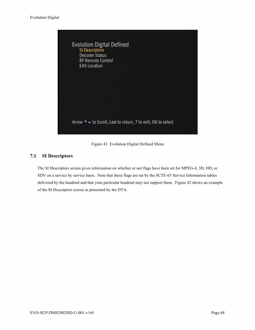
Evolution Digital
EVO-SUP-DMS2002HD-U-001-v1r0 Page 68
Figure 41 Evolution Digital Defined Menu
7.1 SI Descriptors
The SI Descriptors screen gives information on whether or not flags have been set for MPEG-4, 3D, HD, or
SDV on a service by service basis. Note that these flags are set by the SCTE-65 Service Information tables
delivered by the headend and that your particular headend may not support them. Figure 42 shows an example
of the SI Descriptors screen as presented by the DTA.

Evolution Digital
EVO-SUP-DMS2002HD-U-001-v1r0 Page 69
Figure 42 SI Descriptors Screen
7.2 Decoder Status
The Decoder Status screen is present for Broadcom support personnel and is not intended for use by cable operators.
7.3 RF Remote Control
The RF Remote Control screen displays different parameters related to the RF remote control. Note that if no
remotes are paired then the menu will only display the first page.
Table 23 RF Remote Control Screen Parameters
Parameter Description
RF4CE MAC Address The MAC address in the DTA that is sent
to the remote control for RF
communications.
RF4CE Short Address The short MAC address in the DTA that
is sent to the remote control for RF

Evolution Digital
EVO-SUP-DMS2002HD-U-001-v1r0 Page 70
communications.
PAN ID Personal Area Network ID for RF4CE.
Active Channel The current channel that the DTA is using
and the % of impairment or pollution on
that channel.
Backup Channel 1 The first backup channel that the DTA
may use and the % of impairment or
pollution on that channel.
Backup Channel 2 The second backup channel that the DTA
may use and the % of impairment or
pollution on that channel.
Number of Paired Remotes The number of RF remote controls paired
with the DTA. A maximum of 5 remote
controls may be paired at any time.
Controller Type The remote control type which typically
relates to hardware model.
MAC Address The MAC address of the remote control
that is currently being used with the
DTA.
Short Address The short MAC address of the remote
control that is currently being used with
the DTA.
Number of Commands The number of commands received by the
DTA for the remote control MAC address
currently in use.
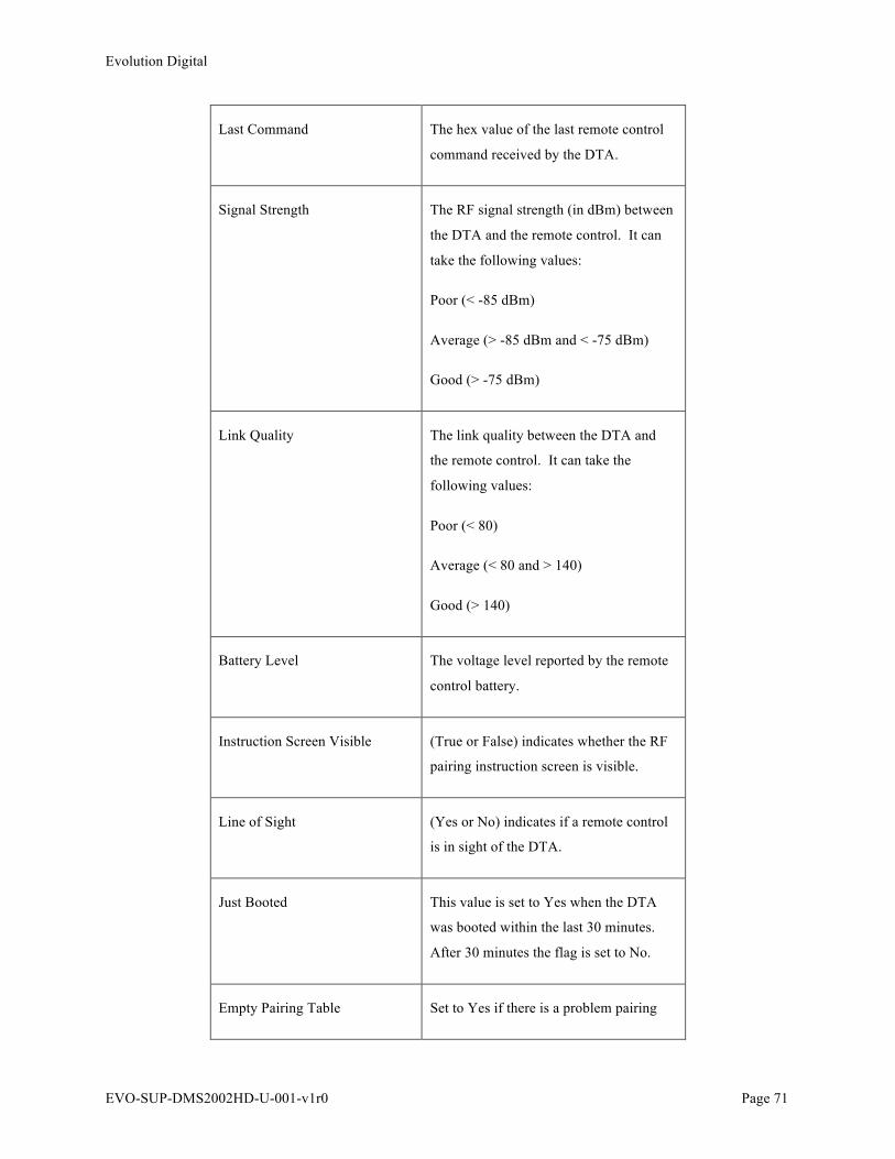
Evolution Digital
EVO-SUP-DMS2002HD-U-001-v1r0 Page 71
Last Command The hex value of the last remote control
command received by the DTA.
Signal Strength The RF signal strength (in dBm) between
the DTA and the remote control. It can
take the following values:
Poor (< -85 dBm)
Average (> -85 dBm and < -75 dBm)
Good (> -75 dBm)
Link Quality The link quality between the DTA and
the remote control. It can take the
following values:
Poor (< 80)
Average (< 80 and > 140)
Good (> 140)
Battery Level The voltage level reported by the remote
control battery.
Instruction Screen Visible (True or False) indicates whether the RF
pairing instruction screen is visible.
Line of Sight (Yes or No) indicates if a remote control
is in sight of the DTA.
Just Booted This value is set to Yes when the DTA
was booted within the last 30 minutes.
After 30 minutes the flag is set to No.
Empty Pairing Table Set to Yes if there is a problem pairing

Evolution Digital
EVO-SUP-DMS2002HD-U-001-v1r0 Page 72
the RF remote control to the DTA.
Figure 43 and Figure 44 show examples of the RF Remote Control screens as presented on the DTA.
Figure 43 Diagnostic Menu – RF Remote Control, Screen 1
Figure 44 Diagnostic Menu – RF Remote Control, Screen 2
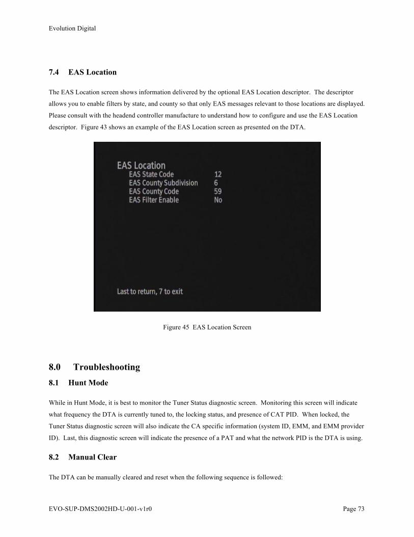
Evolution Digital
EVO-SUP-DMS2002HD-U-001-v1r0 Page 73
7.4 EAS Location
The EAS Location screen shows information delivered by the optional EAS Location descriptor. The descriptor
allows you to enable filters by state, and county so that only EAS messages relevant to those locations are displayed.
Please consult with the headend controller manufacture to understand how to configure and use the EAS Location
descriptor. Figure 43 shows an example of the EAS Location screen as presented on the DTA.
Figure 45 EAS Location Screen
8.0 Troubleshooting 8.1 Hunt Mode
While in Hunt Mode, it is best to monitor the Tuner Status diagnostic screen. Monitoring this screen will indicate
what frequency the DTA is currently tuned to, the locking status, and presence of CAT PID. When locked, the
Tuner Status diagnostic screen will also indicate the CA specific information (system ID, EMM, and EMM provider
ID). Last, this diagnostic screen will indicate the presence of a PAT and what the network PID is the DTA is using.
8.2 Manual Clear
The DTA can be manually cleared and reset when the following sequence is followed:
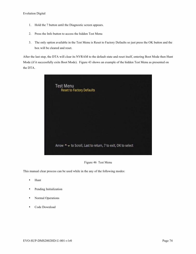
Evolution Digital
EVO-SUP-DMS2002HD-U-001-v1r0 Page 74
1. Hold the 7 button until the Diagnostic screen appears.
2. Press the Info button to access the hidden Test Menu
3. The only option available in the Test Menu is Reset to Factory Defaults so just press the OK button and the
box will be cleared and reset.
After the last step, the DTA will clear its NVRAM to the default state and reset itself, entering Boot Mode then Hunt
Mode (if it successfully exits Boot Mode). Figure 43 shows an example of the hidden Test Menu as presented on
the DTA.
Figure 46 Test Menu
This manual clear process can be used while in the any of the following modes:
• Hunt
• Pending Initialization
• Normal Operations
• Code Download

Evolution Digital
EVO-SUP-DMS2002HD-U-001-v1r0 Page 75
Appendix A Frequency Hunt List
When in Hunt Mode, the DTA will scan frequencies in a prescribed manner. The DTA will start with a list of well
used EIA centered frequencies, and then move to a complete list of EIA centered frequencies. If the DTA fails to
lock on any of the EIA centered frequencies it will move to HRC centered frequencies. The remainder of this
section details the list of frequencies in the order they are scanned.
/* Well Known List of EIA Centered Frequencies (kHz) */
567000, 573000, 579000, 585000, 591000, 651000, 657000, 489000, 495000, 807000, 565750, 571750
/* Complete list of EIA Centered Frequencies (kHz)*/
57000, 63000, 69000, 85000, 177000, 183000, 189000, 195000, 201000, 207000, 213000, 123000, 129000, 135000,
141000, 147000, 153000, 159000, 165000, 171000, 219000, 225000, 231000, 237000, 243000, 249000, 255000,
261000, 267000, 273000, 279000, 285000, 291000, 297000, 303000, 309000, 315000, 321000, 327000, 333000,
339000, 345000, 351000, 357000, 363000, 375000, 381000, 387000, 393000, 399000, 405000, 411000, 417000,
423000, 429000, 435000, 441000, 447000, 453000, 459000, 465000, 471000, 477000, 483000, 489000, 495000,
501000, 507000, 513000, 519000, 525000, 531000, 537000, 543000, 549000, 555000, 561000, 567000, 573000,
579000, 585000, 591000, 597000, 603000, 609000, 615000, 621000, 627000, 633000, 639000, 645000, 93000,
99000, 105000, 111000, 117000, 651000, 657000, 663000, 669000, 675000, 681000, 687000, 693000, 699000,
705000, 711000, 717000, 723000, 729000, 735000, 741000, 747000, 753000, 759000, 765000, 771000, 777000,
783000, 789000, 795000, 801000, 807000, 813000, 837000, 843000, 849000, 855000, 861000
/* HRC Centered Frequencies (kHz)*/
58750, 64750, 70750, 86750, 178750, 184750, 190750, 196750, 202750, 208750, 214750, 124750, 130750,
36750, 142750, 148750, 154750, 160750, 166750, 172750, 220750, 226750, 232750, 238750, 244750, 250750,
256750, 262750, 268750, 274750, 280750, 286750, 292750, 298750, 304750, 310750, 316750, 322750, 328750,
334750, 340750, 346750, 352750, 358750, 364750, 370750, 376750, 382750, 388750, 394750, 400750, 406750,
412750, 418750, 424750, 430750, 436750, 442750, 448750, 454750, 460750, 466750, 472750, 478750, 484750,
490750, 496750, 502750, 508750, 514750, 520750, 526750, 532750, 538750, 544750, 550750, 556750, 562750,
568750, 574750, 580750, 586750, 592750, 598750, 604750, 610750, 616750, 622750, 628750, 634750, 640750,
646750, 94750, 100750, 106750, 112750, 118750, 652750, 658750, 664750, 670750, 676750, 682750, 688750,
694750, 700750, 706750, 712750, 718750, 724750, 730750, 736750, 742750, 748750, 754750, 760750, 766750,
772750, 778750, 784750, 790750, 796750, 802750, 808750, 814750, 820750, 826750, 832750, 838750, 844750,
850750, 856750, 862750
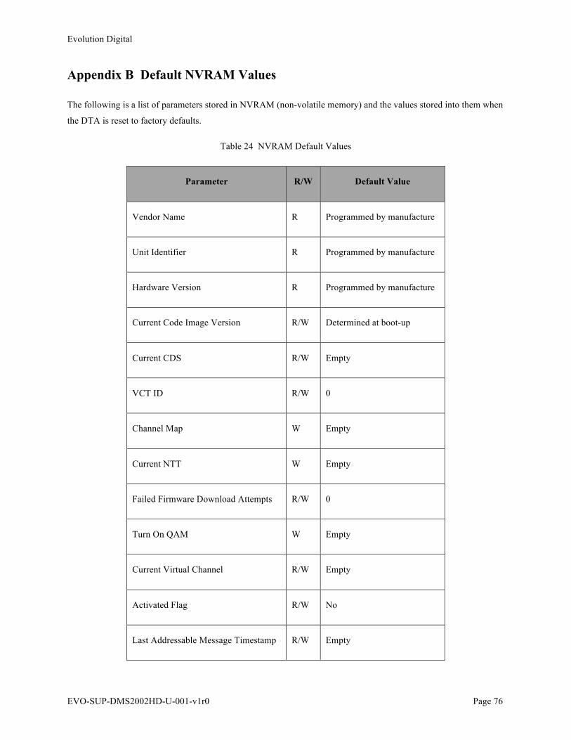
Evolution Digital
EVO-SUP-DMS2002HD-U-001-v1r0 Page 76
Appendix B Default NVRAM Values
The following is a list of parameters stored in NVRAM (non-volatile memory) and the values stored into them when
the DTA is reset to factory defaults.
Table 24 NVRAM Default Values
Parameter R/W Default Value
Vendor Name R Programmed by manufacture
Unit Identifier R Programmed by manufacture
Hardware Version R Programmed by manufacture
Current Code Image Version R/W Determined at boot-up
Current CDS R/W Empty
VCT ID R/W 0
Channel Map W Empty
Current NTT W Empty
Failed Firmware Download Attempts R/W 0
Turn On QAM W Empty
Current Virtual Channel R/W Empty
Activated Flag R/W No
Last Addressable Message Timestamp R/W Empty

Evolution Digital
EVO-SUP-DMS2002HD-U-001-v1r0 Page 77
Appendix C Additional DTA Screenshots
The following are additional screenshots showing various on-screen information while viewing TV services.
Figure 47 DTA On-Screen Information – Channel Info
Figure 48 DTA On-Screen Information – Volume Bar

Evolution Digital
EVO-SUP-DMS2002HD-U-001-v1r0 Page 78
Figure 49 DTA On-Screen Information – Muted Volume Bar
Evolution Digital
EVO-SUP-DMS2002HD-U-001-v1r0 Page 79
Appendix D DTA Headend Messages
Throughout this document, the term “headend message” has been used to generically refer to messages from the
headend used to activate or configure a DTA. This Appendix provides some insight into the specific messages that
originate from the headend when received by the DTA cause it to be activated, deactivated and be configured with
site specific settings.
D.1 DTA Configuration Message
DTA Configuration Message is a Network Config Message. With a Network Config message the following values
are defined and assigned.
• Site code (also referred to as Location ID or LocID)
• Timeout value
• Site timeout policy
• Max Site Errors
• VCT ID
• Timezone information including current offset, daylight savings entry and exit
The timeout policy will dictate what messages the DTA looks for when determining if the timeout counter is
decremented. Specifically, the DTA can either look for a connect or site announcement message. Connect and site
announcement messages are part of the DTA Operations Messaging. Please consult with your headend controller
manufacture to understand the frequency of the playout of Network Config messages.
D.2 DTA Operations Messages
DTA Operations Messages, or just DTA Ops messages, are messages used to instruct the DTA to perform a specific
operation. DTA Operations Messages are comprised of the following sub commands.
• Initialize
• Reset – warm or cold
• Connect – activation command
• Disconnect – deactivation command
• Site Announcement – announces controller site code, MSO Phone Number

Evolution Digital
EVO-SUP-DMS2002HD-U-001-v1r0 Page 80
The site announcement message is typically a periodic message sent by the headend controller. Depending on how
the site timeout policy was set in the Network Config message, the DTA will either look for periodic connect or site
announcement messages. Please consult with your headend controller manufacture to understand the frequency of
the DTA Ops Messages.
You have reached the end of this document.