HAWAII GEOTHERMAL PROJECT · The Hawaii Geothermal Project was organised ... Perforating, Testing...
48
Transcript of HAWAII GEOTHERMAL PROJECT · The Hawaii Geothermal Project was organised ... Perforating, Testing...


HAWAII GEOTHERMAL PROJECTWELL COMPLETION REPORTHGP-A
r----NOTlCE-------.
nu. .-port was prepared u an account of workIponlOred by the United States Government. Neither theUnited State, nor the United Statea Department ofEnergy. nor any of their employee., nor Iny of theirCOIltracton. subcontrlcton. or their employees, mawany warranty, exprelS or implied, or ..urnes any Jegalliability or respontibWty for the accuracy. completenessor Ulefulness of any information. apparatul, product orpraceD dilcloted. or repreleDts that itl ute would notInfrtnse privately owned riJlhfJo
Report Prepared forUNIVERSITY OF HAWAII RESEARCH CORPORATION, andU.S. ENERGY RESEARCH & DEVELOPMENT ADMINISTRATION
By°KINGSTON REYNOLDS THOM & ALLARDICE LIMITEDgeothermal consultants44 Wakefield Street, Auckland, New ZealandTelex NZ21385 Cables KingsdiceSeptember 1976

HAWAII GEOTHERMAL PROJECT
COMPLETION REPORT
Table of Contents Page
U 1. Introduction 12. Drilling summary 23. Surface equipment 43.1 Wellheads 43.2 Drilling recorder 43.3 Electrical logging equipment 43.4 High temperature logging equipment 43.5 Cooling tower 44. Casing and liner 54.1 Conductorcasing 54.2 Surface casing 54.3 Anchorcasing 54.4 Production casing 54.5 Liner 55. Drilling bit and hole openersummary 66. Coring 67. Deviation 78. Drilling fluid summary 79. Samples 7
10. Cementing 810.1 Equipment 810.2 Surface casing 810.3 Anchorcasing 810.4 Production casing 911. Dailydrilling reports 1012. Perforating, testing and cementing 1913. Completion testing (including logging) 2014. Geological summary 2215. Acknowledgements 25
Appendices
A. Surface Casing 26B. Anchor Casing 27 'C. Production Casing 28D. Slotted/Plain Liner 29E. Bit Record 31F. Deviation Recordings 32G. Perforating and Testing 33
Drawings
Fig. 1. Map of Hawaii2. Site location3. Aerial photograph of site4. Drilling and operations summary5. Wellheads6. Wellheads7. Wellheads8. Plan and elevation of the final wellhead9. Present subsurface well status
10. Mud temperatures
V 11. Completion tests

NORTH
KalapanaBlack sandbeach
Scale - 9 2p miles
Contour interval - 2000 ft
Figure 1 - Map of Hawaii

u
(o
)
NORTH
WEllSITE--
o
Contours shown in ~ t. lee
Figure 2 - Site location


HAWAII GEOTHERMAL PROJECTCOMPLETION REPORT
1. INTRODUCTION
The Hawaii Geothermal Project was organised to focus the resources of the University, theState, the County of Hawaii and the Federal Government through the offices of theUnited States Energy Research & DevelopmentAdministration (ERDA) on the identification,generation and utilisation of geothermal energy on the Big Island of Hawaii. This island isthe largest and youngest of the islands in the Hawaiian chain, and is still growing from recentactivity of the Mauna Loa and Kilauea volcanoes; therefore it is the island with thegreatestamount of heatat or near the earth's surface. Consequently, the Big Islandwas selected as the site for initial geothermal exploration.
Phase I of the project was organised into geophysical, engineering, environmental,socio-economic and research drilling programmes. Research work started early in thesummer of 1973, with the majoremphasis on the geophysical aspects. In early 1974 it wasapparent that an exploratory drilling programme was essential to investigate the subsurfaceconditions predicted by the surveys. Consequently aSite Selection Committee wasestablished in April 1974, chaired by DrA. T. Abbot, to develop recommendationsfor the drilling programme and site selection.
The committee considered all the geophysical, geological, thermal and geochemicalevidence, and concluded that the most favourable site was on the Pahoa self-potentialanomaly (ref. fig. 8 HGP- Phase II, Revision to Proposal AER7500285-000 ).However, as itwas not possible to get permission to drill there, the site was shifted northeastto aslightly less favourable position, where permission to drill was obtained from theKapoho Land and Development Company. The site is just under 600 feet altitude,approximately 200 feet north of the Pohoiki Bay Road, 0.6 miles southwest of theprehistoric cone of Puu Honuaula, and 0.23 miles south of the first vents of the 1955eruption (ref. figs. 1and 2). DrAbbot placed astake in the ground atthe site early inMay 1975. Shortlyafter the site was selected DrAbbot was forced by ill health, resultingin his death on 31 July, to withdraw from active participation in the project andProject Director, Dean John W. Shupe requested Dr G. A. Macdonald to take overDrAbbott's duties.
Specifications forthe drilling had been drawn up by DrAbbott and invitations to bidon the job were sent out to twenty-eightdrilling companies, in addition to generaladvertising, in early June. Only one bid was received, from Water Resources International Inc.of Honolulu, and after assessment this bid was accepted.
As no one in the Universityof Hawaii had experience in deep hole geothermal drilling,Kingston Reynolds Thorn & Allardice Ltd ofAuckland, NewZealand was appointed tohandle the technical contract management and advise on testing procedures andequipment. WarwickJ. Tracey was the company's representative on the site during thedrilling and completion testing of the well.
The drillingsite was dedicated on 22 November, and mobilisation had proceeded farenough to enable the contractor to start drilling on 10 December 1975, using aSpencer Harrismodel 7000 drilling rig. This report describes the procedures followed and equipmentused in the completion of the well. .
1

2. DRILLING SUMMARY
A site for the drilling rig and supporting equipment including consumable materials, withapproximate dimensions of 300 feet by 150 feet, was prepared in late Sepember 1975,and mobilisation of drilling equipment started in early October. By early December a reservoircontaining approximately 200,000 US gallons had been formed adjacent to the rig (ref.fig. 3), and after lining with Butyl rubber it was filled with water trucked from the nearestsupply, approximately one mile away.
The well was spudded in on 10 December and 2 feet of 9~ inch hole was made in nineand a half hours. Drilling was slow due to the lack of weight on the bit, and to the hardnessof the fresh basalt lava flow. After resolving a few minor problems drilling continued on atwenty-four hour basis from 11 December.
Maintenance of circulation in the upper 200-300 feet of the well was initially a problem,and loss materials (cottonseed hulls, mica and cellophane flakes) were used to sealholes in the cinder beds that were being penetrated. The rate of drilling improved when thehard surface layers of basalt were penetrated, and more weight could be applied to the bit.A depth of 399 feet had been reached by 18 December, and as it was not possible todrill deeper with the 9~ inch bit at that stage due to the lack of an appropriate crossoversub to fit the drillpipe to the collars, the drillstring was removed from the hole and the15i inch hole opener was run in. Circulation was again a problem, and most of the hole openingwas done without mud returns. Hole opening stopped on 23 December at a depth of 300 feet,and the rig was closed down for the Christmas period.
Work started again on 5 January, when a 9il inch bit was run in and the hole was deepenedfrom 399 feet to 458 feet, where the first core was taken using a diamond bit - 27 inchesof basalt were recovered. 151 inch hole opening was then resumed and by 9 January adepth of 401 feet had been reached. The hole was then opened to 20 inches and after afour day break, hole opening to 26 inches started. This work was completed by 28 January,and after reaming the hole, the 20 inch casing was run in. An obstruction stopped thecasing from going below 103 feet, even with the centralisers removed, so a specialreaming shoe was fabricated and used to straighten the hole. The casing was eventuallyrun in and the annulus was cemented using 78 tons of cement in 107 pounds/cubic footgrout (refer to section 10, Cementing, ofthis report for full details).
After a break on 1 and 2 February, the cementing operation was completed, the blowout preventorswere installed, and the9il inch hole was drilled to 1,057 feet by7 February.An attempt was made to obtain a core, but as the hole appeared to be blocked at 937 feet,itwas decided to delay the coring and proceed instead with the hole opening to 151 inchesand then to 20 inches, which was completed after many trips to change cutters, by25 February. The hole was reamed and the 131 inch casing was run and cemented by28 February, using 79 tons of 104 pounds/cubic foot grout.
After another break, drilling started again with a 121 inch bit on 5 March and a depthof 1,437 feet had been reached by 9 March, when a failure was experienced in the BOP's.Reaming of the hole and centrepunching was done between 18 and 21 March, whendrilling was able to continue using 81 inch bits. A depth of 2,230 feet was reached on25 March and the hole was then opened to 121 inches to a depth of 2,244 feet by31 March. The hole was reamed, the 91 inch casing was run and cemented, with difficulty,(which resulted in subsequent perforating and squeezing of cement into the 91-131 inchannulus when the Cement Bond log was obtained - ref. section 12 on perforating andcementing in this report), and drilling with the 81 inch bits started again on 5 April.
2

APRILMARCHFEBRUARY
A -J represedf cores f&ken
DECEMBER 1915 JANUARY 1916
~~:&IlHO. 15~'41\:20".H.C1i7' I U1!l5l!..br gk t
97,sbit ., I _-,399' 9"'18" \J4561 401'
A
2500
INOTES: Ref: Loc,sJftbns CVI 6raph above.
1 Reaminq, r<!..Jnninq 20 11casingcerner7Ting c5JncT insfalling wellhead
2 Tried 10 oblp;in core oul hole lNasblocked sf. ~37 -Ff Removed wellheadand fiffed '1ew c::onducfor ppe.
30003 Very h~rd (frrmafion encounfered.
t----------+- so dec/elect· nol 10 drill to in/endeddepfh or 10(/6 fi:
4 Riq broke down 9hrs. fl.0 worn oufaMd re/?Is:tet, Followed by re~rning( /E-hr.sJ
5 Reaming, . nning /3349# c&sinq,cerne.nflnq ,: Insl&l/in,g we//he-aCi andrunning mS3nef
40001----------+- 6 B.OR f"si/urd, wailing on ..spares.
7 Reaming c9rd ceni-re punchitItJ·
8 Rearninq, runn;nq ~5/BIIcssinq,cemenf,ng, ' insf5l//ing we//hecSfds.
2000t----------+---------+-----+----------~+_--------_\_+_--'I_t_----------...--...,
3500
500
1500
o
1000 1----------+----------\---+---H--=-=-=-:--~~:L__~-+_~r__---------t___----------_112~.( bit with stabilisers
enc:c 4500III:::J.0
.2:-CiioX
~ 5000,geCII
.s:.-~ 55002CII.0
to-UJ
[ ~ 6000z:::J:t-Il.UJ
6500c
Figure 4 - Drilling & Operations Summary

From then on drilling proceeded at an average rate of 248 feet/day including cores whichwere taken at approximately700 feet intervals, until adepth of 6,039 feet was reachedon 23April. Nosignificantmud losses were noted over this section of the hole, but the mudreturn temperature increased to such an extent that acooling tower had to be constructedand installed in the mud tank. This was operational by 17April, when adepth of4,956 feethad been reached. The maximum mud temperature did not exceed 70°C (ref. fig. 10).
The well was logged between 23 and 27 April,· (ref. section 13, Completion Testing, ofthis report) and as thewell was obviously hot, and permeabilityappeared to be improvingalthough mud circulation had been maintained by the use of loss materials, it was decided todrill on for another two days, or 500 feet, or until the bit wore out, (whichever came first).This plan was followed, and the bit wore out at 6,446 feet. The mud was then conditioned,acore was obtained, and the logging was completed withinthe temperature limitationsof the equipment.
The rig was on 'watchman only' status from 29 April to 24 May. During this period theslotted linerand wellhead valves were obtained from the mainland. The Cement BondLog had indicated the possibility of voids in the 91-131 inch annulus, and thereforeequipment was obtained at the same time to perforate, pressure testthe annulus, and, ifnecessary, control cement injection through the perforations and into voids in the annulus.This operation of perforating, testing and cementing took from 24 May to 1 June (ref.section 12, Perforating, Testing and Cementing, ofthis report). Temperatureruns whichhad been made with the Kuster Geothermograph prior to 24 May indicated that the mud hadstiffened up, and was quite hot at depth. Care was therefore taken in circulating out andconditioning the mud prior to running the 7 inch slotted/plain liner: The mud was thenwashed out of the well using 21 inch tubing, and after heating up overnight, completiontests on the well were started on 6 June (ref. section 13, Completion Testing, in thisreport). Work with the rig and pumps was completed on 8 June, and the well wasallowed to heat up.
Cold water on the top of the well was airlifted out in an attempt to get the well to discharge,between 22 and 24 June. This operation was terminated prematurely when one of the twoair hoses fell down the well. The well was subsequently flashed for four minutes on 2 July,and after cleaning outthe cellar, recementing the top 8 feet ofthe 131-20 inchannulus, providing adrain for the cellar, and 1 inch steelwire rope bracing for thewellhead, the well was flashed for one houron 19July, and then for four hours on 22 July.Quotations are being obtained at the time of writing for further testing equipment and acomprehensive testing programme is being prepared.
Note: Airdepths in this report are distances below the rotary kelly bushing, unless notedotherwise.
3
3. SURFACE EQUIPMENT
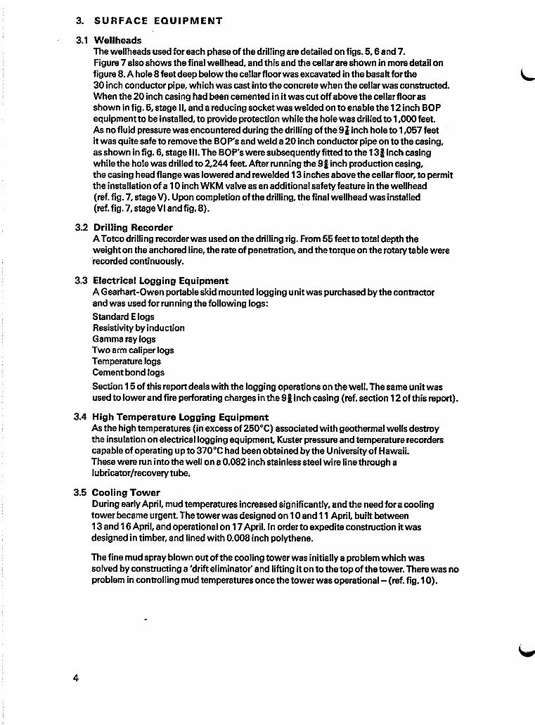
3.1 WellheadsThe wellheads used for each phase of the drilling are detailed on figs. 5, 6 and 7.Figure 7 also shows the final wellhead, and this and the cellar are shown in moredetail onfigure 8. A hole 8 feet deep below the cellar floor was excavated in the basalt for the30 inch conductor pipe, which was cast into the concrete when the cellar was constructed.When the 20 inch casing had been cemented in itwas cut off above the cellar floorasshown in fig. 5, stage II, and areducing socket was welded on to enable the 12inch BOPequipment to be installed, to provide protection while the holewas drilled to 1,000feet.As no fluid pressure was encountered during the drilling of the 91 inch hole to 1,057 feetit was quite safe to remove the BOP's and weld a20 inch conductor pipe on to the casing,as shown in fig. 6, stage III. The BOP's were subsequently fitted to the 131inch casingwhile the hole was drilled to 2,244 feet. After running the 91 inch production casing,the casing head flange was lowered and rewelded 13 inches above the cellar floor, to permitthe installation of a10 inch WKM valve as an additional safety feature in the wellhead(ref. fig. 7, stage V). Upon completion ofthe drilling, the final wellhead was installed(ref. fig. 7, stage VI and fig. 8).
3.2 Drilling RecorderA Totco drilling recorder was used on the drilling rig. From 55 feet to total depth theweight on the anchored line, the rate of penetration, and the torque on the rotary table wererecorded continuously.
3.3 Electrical Logging EquipmentA Gearhart-Owen portable skid mounted logging unit was purchased by the contractorand was used for running the following logs:Standard ElogsResistivity by inductionGamma ray logsTwo arm caliper logsTemperature logsCementbond logs
Section 15 of this report deals with the logging operations on the well. The same unit wasused to lowerand fire perforating charges in the 91 inch casing (ref. section 12 of this report).
3.4 High Temperature Logging EquipmentAs the high temperatures (in excess of250°C) associated with geothermal wells destroythe insulation on electrical logging equipment, Kuster pressure and temperature recorderscapable of operating up to 370°C had been obtained by the Universityof Hawaii.These were run into the well on a0.082 inch stainless steel wire line through alubricator/recovery tube.
3.5 Cooling TowerDuring earlyApril, mud temperatures increased significantly, and the need for acoolingtower became urgent. The tower was designed on 10and 11 April, built between13 and 16April, and operational on 17April. In order to expedite construction it wasdesigned in timber, and lined with 0.008 inch polythene.
The fine mud spray blown out ofthe cooling tower was initially aproblem which wassolved by constructing a 'drift eliminator' and lifting it on to the top of the tower. There was noproblem in controlling mud temperatures once the tower was operational- (ref. fig. 10).
4

( (
~__t\\'--~Rotary table
reference level
>-1------8"_ mud return line o
~----30"~ conductor pipe
Shaffer LWS B.Q.I? 121-3000
~-12· 900 flanges
Mffl~iL---:30"Conductor pipe
~--~~-IReducing socket
I"---+l~-1weld
~----:20' Casing
Hydril OK B.O.I? 12--3000......----studded for 12"-900
flange on top
J;;;;;;;;;~"--~--112·-900 flanges
1~0"
~-:rCDQCoen
"ce·I::iiic.nI
STAGE IDrilling 0 to 401'and hole opening (9~"15~20"26"), , ,
STAGE nDrilling 401' to 1051' (9\1')

~-s=CDDCoen
(
o
-t-----20..conductor pipe
r------weld
STAGE mHole opening 407' to 996' (15'1~20")
c
o
t------Hydril OK anp. 12"-30000,-----.'
~~~--~--'12~900flanges
--5'haffer LWS anp. 12"-3000
~""f;=r.:;=---r----12'!..900 flanges
~~-----.30"conductor pipe
:~~----20" surface casing.M:i%"-----13~;anchor casing
STAGE DrDrilling and hole opening 996' to 2240'12~·bits, plus 8~ and 12~·

( (
61-0"
~---..,--WKMpower seal 10"·600
10"" pipe
to-------olflipipe
.~M--------,30"conductorpipe
,.....,'ffI-----20"surface casingi:::~~i:t-----13%·anchor casing::~f:&-------~lY8" production casing
'---------------urainage pit
-1"
2'-1~"
31-434!,,1I
J------Hydril OK B.QP. 1211- 3000
~~---30"cQsing
~e----20"casing
~~i1-------'13~casing
.~~~----9~" casing
~~,__---;;>,-----:12n 900 flanges
~~ ...------'-Shaffer LWS B.OP.12"-3000
"T1_.CQ
~.
'-3
STAGE :2:Drilling 8'i1l from 2244 to 6000
STAGE E - FINAL WELLHEAD

( c
8'-0"
21-0.
_...----------'2'-0" #f drain
....---------------.:2'-0.. x 1'-0" reinforcedconcrete buttress approx2'-0" below ground level
rainage pit approx121-0" long x 6'-0" deepx 3'-0" wide.
____---WKM power seal 10"-900
~------4WKM power seal 10··600
t--~-----.-..:Vertical discharge pipe
[:::1---------:10" Tee
11.":r 6'o :::J- QO
~m---CD':T<CD' 0o -a.. o'
:::J
PLAN OF CELLAR(Diagonal bracing to wellheadomitted for clarity J

Depfh orcellar ,3'-5/1
,........,-- 2W' or3~'disrn.sir hose
1114';~---~~"dlam J( 43·5 lfD/fi N80seal77/ess range 3 buflressthreaded casing
1f',4o-----7~B"dial77 slo/led liner2G lcolFf seamless raree3lIydril FJ.P
sZ.~~smmEErT,rmmm.~~/30"diarn Conducfor Casing
2G"diam 84' 20"diam x 104·1.3 lro/lf APIhole qrade 5'- bevelleo fOr
welding.
:1I'*'I;44----/3~6'diarn >< 54·5 lre/ft K55seamless rdnge 3 buHress
. fhresded casing.
IE'!t;."diarn hole-"""'"
IbYe'diam hole
2000-
3000-
4000-
5000-
1000-
::t:
tUJc 6500-
...UJUJ
~ 6000-
Nofe : All depfhs sre below fhe casing head flange
Figure 9 - Present Subsurface Well Status

o 54/cYhours)
mud
'P
80
rom67'
706050MUD TEMPERATURE (CO)
30 40
~"~~~~ Cor-ing e 288(0' (Took /G hours)
'"~'"~\
\\\\~ ...""-., .
~_ Corin$ ~3(;,tO(2)'i')b-.. (nra lei> hours).,. I' Ij \ New mud tank hooked u~ "\)~ ~ '" \.
-~O'l~ ~ \ .
.~ .t i:: Temperature of mud 't-Temperature of~
ij.Qpumped into well '\ , from! well~ -Q~
~ ~_ Cored fi....!- -- 4447'10 44JiI' :-...:
/-- ("
~\
.... ~\
~ ~ IJ~ /)~ ("""
.~ ~ ~ ~//.f ~-~4J
<~ ~Q.. "~ ,,"
&QJ • 09.. ~ I'"a 0 ..... l_
a~ -- ~ Cored Trom 5400'f,f....
.... ~ --- ----__ (lOoK cc, .....~ <:::: ---------.~ ~~ ~
,---1\....-::: ~0 ~Qj -~a~~~ "'-,
"I....!- - ""-.. GO(2)O'
I
2500
3500
2000
3000
4500
4000
5000
_5500t-.WWLL
:I:t:g: 6000
u
Figure 10 - Mud Temperatures

4. CASING AND LINER
4.1 Conductor CasingWhen the excavation was made for the cellar, ahole 8 feet belowthe cellar floor was machinedug in the basalt and 30 inch diameter by i inch thick conductor pipe was positioned andcast in when the concrete cellarwas constructed. An extension 19 feet long was subsequentlywelded on to facilitate mud returns to the tanks while drilling down to 458 feet. This wascut off flush with the cellar floor after cementing the 20 inch casing.
4.2 Surface Casing (ref. Appendix A)Eightjoints of 20 inch, 81.1 0 pounds/foot copper bearing structural steel casing, withends bevelled for welding, totaling 422.93 feet were landed 384 feet below the final131inch casing head flange level. A stab-in cement float shoe was welded to the bottomof the casing, and centralisers were omitted afterdifficultywas experienced in runningthe casing.
4.3 Anchor Casing (ref. Appendix B)Twenty-seven joints of 131inch diameterJ55, 54.50 pounds/foot butrress threaded casing,totaling 997.07 feet were landed 979 feet below the final casing head flange. A B&Wfloat shoe was used and centralisers were positioned every90 feet.
4~4 Production Casing (ref. Appendix C)Fifty-six jointsof91 inch diameter N80, 43.5 pounds/foot were landed 2,216 feet belowthecasing head flange. A B&Wguide shoe and float collarwere used, and centraliserswerepositioned every90 feet.
4~5 Slotted/Plain Liner (ref. Appendix D)One hundred and nine joints of7 inch diameter K55, 23 pounds/foot, 8R thread were runinto the well and sat on the bottom at 6,435 feet belowthe casing head flange.Thirty-nine joints of this casing had been supplied with thirty-two 2 inch by i inch parallelsided slots per foot, and these were positioned as shown in fig. 15. Thp bottom joint wasfitted with acone, to guide the linerdown the hole and ease penetration through the mud,and aspade to prevent rotation while the left hand thread on the top linersubwasdisengaged. The top linersub (Joy Manufacturing Co. No. 8035-0001,12753) had7 inch 8 round thread on the bottom (screwed into the liner) and 7 inch Acme left handthread on top, which was engaged by nine turns of the lifting tool which is fitted to thebottom of the drill pipe.
6

5. DRILLING BIT AND HOLE OPENER SUMMARY
The initial drilling and hole opening Was done using milled steel bits and cutters on thehole openers. However, itwas soon found that the performance of the tungsten carbideinsert bits was significantly better, and consequently as supplies permitted, this type wasused. (Ref. the abbreviated bit record in Appendix E). The increased performance of thetungsten carbide bits and cutters was particularly marked when opening the 81 inch holeto 121 inch between 1,450feet and 2,244 feet - the milled steel cutters on the holeopener made approximately 69 feet/day, and all other conditions being apparentlyequal,the tungsten carbide cutters made 350 feet/day. All drilling was done with mud weighingbetween 8.8 and 9.4 pounds/gallon (US), and pump pressures of from 100psi to 750 psidepending upon the depth and jet size.
A problem was experienced in fitting the 20 inch hole opener through the 20 inchsurface casing for drilling from 407 feetto 987 feet. Consequently the hard facing on the shirttails was gas cut off to provide clearance between the hole opener and casing. Thismeant that the hole openersoon lostgauge and in one case the shirt tails wore rightthrough and the ball bearings came out. Extensive reaming was required to bring the holebackto gauge.
6. CORING
Cores were taken with two Hycalog 61 inch by 31 inch diamond core bits, at the followingintervals:
1. 456 to 458 feet Core recovered 2 feet2. 1,057 " 1,068 " ,,1 foot3. 1,412" 1,423 " " 2 feet4. 2,230" 2,240 " "" 10 feet5. 2,876 ,,2,886 " 1O:feet6. 3,666 ,,3,676 " 10 feet7. 4,447" 4,457 " " 1ofeet8. 5,396 ,,5,406 " "" 10ifeet9. 6,029" 6,039 " ,,1Weet
10. 6,446" 6,456 " " 10feet
These cores are being analysed by the Universityof Hawaii, and will be included in aseparate report. (Ref. also section 14, Geological Summary, in this report).
6

u
7. DEVIATION
A Totco double recorder mechanical drift indicator was used to establish the deviationas drilling progressed. There was considerable concern when the rate of change ofdeviation increased to 0.83°/foot between 1,725 and_1,767 feet. This was rectified byreaming this section of the hole, and drilling on with reduced weight for a limited period untilit was apparent that the remedial measures had been effective, as noted bysubsequentdeviation recordings. There was no difficulty in keeping the deviation below 4 0 for the .remainderof the hole. (Ref.Appendix F, Deviation recordings).
8. DRILLING FLUID SUMMARY
A fresh water based gel mud was used for all of the drilling and coring operations. Mudweight was maintained between 8.8 and 9.4 pounds/gallon, and viscosity ofapproximately 51 secs/1,000 cc. Sand content was generally held within 1 and 2 percentof total volume.
Cottonseed hulls, cellophane and mica flakes were used as loss materials, particularly inthe upper 1,000 feet of the hole where losses to the formation were more significant.The mud was treated with diesel before running the anchor casing and production casing.Tannex was used initially for thinning the mud, and Spersene was used in the deeper,hottersections of the hole.
Total mud materials consumed during the drilling were:
Bentonite 4,939 bags at 100 poundsSpersene 31"" 50 poundsBarite 410 " ,,100poundsCC16 41 " " 50poundsTannex 36 " " 50 poundsSoda bicarb 11"" 100 poundsQ Broxin 60"" 50 poundsCottonseed 160" " 50 poundsMicatex 66"" 50 poundsCaustic soda 75" " 50 poundsJelflake 238"" 25 poundsCellex 128 " " 25 pounds
9. SAMPLES
Cuttings were sampled Intermittently from the surface to 680 feet due primarily to the lackof continuoLls mud circulation. Samples were taken from then on at 10feet Intervals,laterdecreasing to 5 feet Intervals.
A preliminary Inspection ofthe cuttings was made by Mr D. Palmiter, the Universitygeologist on the site, and they were subsequently shipped to Honolulu for more detailedexamination at the University. The results of this work will be included in a separate report.
7

10. CEMENTING
10.1 Equipment and CementCement was shipped in containers by barge from Honolulu to Hilo, then trucked to the sitewhere itwas transferred to a150ton silo by compressed air. During grouting operationsthe cement was aerated and transferred by compressed airto agravity hoppersupported overaHalliburton jet mixer, to which water was supplied from the reservoir by one ofthe slushpumps. The grout was delivered to asmall tank of approximately 60 gallons capacitywherean air entraining agentwas added, and itwas then pumped out of this tank and downthe well by the second slush pump.
The cementwas type 1, conforming to ASTM Specification C-150-71, FederalSpecification SS-C-192g. and AASHTO specification M-85-74.
Chemical composition ofthe cement was:C3S 54 percent byweight
CzS 19 " "" "C3A 7.4" "" "C4AF 10 " "" "Fineness: 3,650S03:2.25Initial setting time: 2 hours 40 minutesFinal setting time: 5 hours 15minutesCompressive strength at 3 days: 2,650 psiCompressive strength at 7 days: 3,560 psi
As noted above, acommercial airentraining agent (MB-VR Master Builders NeutralisedVinsol Resin Solution) was used to entrain an estimated 2 to 3 per cent of air.2 per cent by weight of Bentonite was added manually to the groutat the jetmixer.The temperatures encountered during drilling to 2,200 feet did not justify the use ofHR4 retarder.
10.2 Cementing of the Surface CasingThe 422.93 feet of 20 inch casing were cemented on 31 Januaryand 3 February, using78 tons of cement. The casing had been run into the hole and filled with mud as it went in.The stinger on the end of the drill pipe was located in the stab-in float shoe and 1,200gallons of water were pumped down to flush out the mud, followed by 1,200gallons(4,325 pounds of cement) of lightweight (78 pounds/cubic foot) grout. This was followedby apredetermined quantity of 138,120pounds of cement mixed with water to givegroutwith amean densityof 1,061 pounds/cubic foot and standard deviation of 2.8 pounds/cubic foot. No return of heavyweightgrout, lightweightgrout, oreven waterwas obtainedduring this operation. Water was pumped down the annulus to flush any weak cement intothe formation loss zones, and itwas decided to finish the operation aftera break.
On 3 February atube welded to asinkerbar was lowered down the annulus on a line,and acore of rotten cement was recovered from adepth of 54 feet 6 inches. This was flushedoutwith high pressure water from a1i inch diametertremie pipe, and afurther tenminutes of pumping saw afull return of heavyweightgroutwhich did notrequiretopping up.
10.3 Cementing of the Anchor CasingThe 997 feet of 131 inch casing were cemented on 28 February, using 79 tons ofcement.The same basic procedure was used as for the surface casing - 8,01 0 pounds of cementwere used for lightweight (86 pounds/cubic foot) grout followed by 145,560pounds of cementfor heavyweight (104 pounds/cubic foot and standard deviation of 2.2 pounds/cubic foot).Cementing started at 12.04 pm, and good returns of heavyweightcement had been obtainedbythe time it was stopped at 1.34 pm. Circulation was lost briefly, from 12.38 to 12.40 pm,when the heavyweight cement would have reached the shoe of the 20 inch casing.
8

u
Circulation was again lost while the cement in the drillpipe was carefully displaced withwater, and the cementsettled to between 40 and 50 feet down the annulus. At thisstage acalculated weight of73 tons of cement had been used. Graut was mixed again at3.30 pm, and aftersome initial difficulty in getting the requisite density, the annulus wasbackfilled (3.3 tons were pumped to waste and 2.5 tons went into the annulus).Considerable difficulty was experienced in getting the equipment to operate satisfactorilyand produce consistent groutquality.
The grout in the annulus.subsequentlysettled afurther 8 feet, and this was filled with114pounds/cubic foot groutafter the rig had been removed and the cellar cleaned out,on 9 July, using 13 bags of cement, including waste.
10.4 Cementing of the Production CasingThe 2,244 feet of91 inch casing were cemented on 1 and 2 April, using 136 tons ofcement. A Halliburton cementing head was screwed onto the top of the casing to facilitateinstallation of the top and bottomtravelling plugs, and connection of the grouting pipework.1,200gallons ofwater were pumped away, followed by the bottom travelling plug and1,200gallons of lightweightgrout (4,280 pounds ofcement were used for grout with amean densityof78.3 pounds/cubic footand standard deviation of 10.3 pounds/cubic foot).The predetermined quantity of 3,000 cubic feet of heavyweight grout (153,238 pounds ofcement mixed with water to give grout with amean densityof 100.2 pounds/cubic footand astandard deviation of 2.7 pounds/cubic foot) where then pumped away between12.00and 1.30am, followed by the top plug which was pumped down with mud.
Atthis stage there had been noreturn of lightweight grout, letalone heavyweight, sothe annulus was flushed out with 760 cubic feet ofwater, followed immediately by thesame volume of heavyweight cement using 70,655 pounds of cement to give grout with amean densityof 104 pounds/cubic foot and standard deviation of 5.2 pounds/cubic foot.There was still no return and itwas not possible to pressurise the cement in the annulus,so the equipment was cleaned up and when samples taken earliershowed that the initialset had taken place, grout was batch mixed and pumped down the annulus. Difficulty wasexperienced with the equipment and atotal of43,610 pounds of cement was consumedduring the batch mixing, which gave grout with amean densityof 90.6 pounds/cubic footand standard deviation of 13 pounds/cubic foot, most ofwhich was pumped to waste.Itwas suspected that airlocks were forming in the small size annulus.
In view ofthese problems it was decided to lift the wellhead and pourready-mixedgroutdown the annulus. However, the annulus was found to be full on lifting thewellhead, so the equipment was cleaned up and work proceeded on fitting the newwellhead.
9

11. DAILY DRILLING REPORTS
4 December
5 December
6,7and8December
Rig being assembled and reservoir being lined with Butyl rubber.
Lining of reservoir completed. Rig electrical work underway. Weldersworking on pipework.
Work continued on assembling rig, particularly pipework associated withthe new mud tanks and pumps. Mud materials arrived on site.
9 December Filling of reservoir started. First batch ofmud mixed. Kelly rotated for firsttime in late afternoon but no drilling as fabrication ofequipment stillcontinuing.
10 December Drilling started at 7.30 am, finished at 5.35 pm. 3 feet of hole drilled - 91 inchbit used with 20 feet collar. Note: the conductor pipe set 29 feet belowrotary table (BRT).
11 December Drilling continued in very hard formation. Twenty-four hourshiftsstarted. 34 feet BRT at 5.00 pm.
12 December Broke through the hard formation at 5.00 am and lost circulation. Drillingcontinued, pumping 5 to 7 gallons per minute of mud to clearcuttings and to cool and lubricate the bit, which is a technique that thecontractor has used on this type of formation in the past. Reservoir wasabout halffull; welders and electricians still working on site. 52 feet BRT.
13 December Drilling progressing steadily in hard formation. Totco four pen recordernow operating. 150 tons cement silo delivered to site. 61 feet BRT.
14 December Drilling in generallysofter formation with hard, but thin, layers between.146 feet BRT at midnight.
15 December Drilling 91 inch pilot hole and pumping loss materials with mud. Depthat mid-day (DAMD) 190feetBRT.
16 December Cement deliverystarted to silo. Still no circulation. New batch ofmudmixed and pumped down hole. Removed bit from hole as it was worn out.Regained circulation by filling hole with mud and loss circulationmaterial. Fitted tungsten carbide insert bit and ran it into hole. Lostcirculation immediately but carried on drilling and pumping cement.DAMD 209 feet BRT.
17 December Circulation returned overnight and disposal of loss materials plus cuttingsbecame a problem. There was a slight loss of mud to the formation all thetime. DAMD 305 feet BRT.
18 December Circulation lost and regained overnight. Could not drill beyond 390 feet dueto lack of crossover subs so pulled out of hole and started opening the holeto 151 inches at 6.00 pm. DAMD 390 ~eetBRT.
19 December Lost circulation at 38 feet. Continued drilling blind to conserve lossmaterials. DAMD41 feetBRT.
20 December Opening hole blind through hard formation. Crew constructing mudstorage shed. DAMD 60 feet BRT.
21 December DAMD 196feet BRT.
10
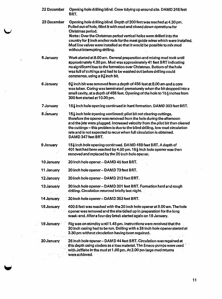
22 December Opening hole drilling blind. Crew tidying up around site. DAMD 248 feetBRT.
23 December Opening hole drilling blind. Depth of 300 feet was reached at 4.30 pm.Pulled out of hole, filled itwith mud and closed down operations forChristmas period.Note: Over the Christmas period vertical holes were drilled into thecountry for! inch anchor rods for the mast guide wires which were installed.Mud line valves were installed so that it would be possible to mix mud .without interrupting drilling.
6 January Workstarted at 8.00 am. General preparation and mixing mud took untilapproximately 4.30 pm. Mud was approximately 41 feet BRT indicatingno significant loss to the formation over Christmas. Bottom of the holewas full of cuttings and had to be washed out before drilling couldcommence, using a 91 inch bit.
6 January 91 inch bitwas removed from a depth of 456 feet tlt8.00 am and a corewas taken. Coring was terminated prematurely when the bit dropped into asmall cavity, at adepth of 468 feet. Opening of the hole to 151 inches from300 feet started at 10.00 pm.
7 January 161 inch hole opening continued in hard formation. DAMD 303 feet BRT.
8 January 161 inch hole opening continued; pilot bit not clearing cuttings,therefore the opener was removed from the hole during the afternoonand the jets were plugged. Increased velocity from the pilot bit then clearedthe cuttings - this problem is due to the blind drilling, low mud circulationrate and is not expected to recur when full circulation is obtained.DAMD347feetBRT.
9 January 161 inch hole opening continued. DAMD 459 feet BRT. A depth of _401 feet had been reached by 4.00 pm. 161 inch hole opener was thenremoved and replaced by the 20 inch hole opener.
10January 20 Inch hole opener - DAMD 45 feet BRT.
11 January 20 inch hole opener- DAMD 73 feet BRT.
12January 20 inch hole opener- DAMD 213 feet BRT.
13January 20 Inch hole opener- DAMD 301 feet BRT. Formation hard and roughdrilling. Circulation returned briefly last night.
14January ·20inchholeopener-DAMD353feetBRT.
16January 400.6 feet was reached with the 20 inch hole opener at 9.00 am. The holeopener was removed and the site tidied up in preparation for the longweek-end. Aftera four day break started again on 19January.
_ '19 January Rig was on st~mdbyuntil 1.45 pm. Instructions were received thatthe20 inch casing had to be run. Drilling with a 26 inch hole opener started at3.30 pm without circulation having been regained.
20January 26 Inchhole opener - DAMD 44 feet BRT. Circulation was regained atthis depth using cinders as a loss material. The Emsco pumps were used with Jelflake in the mud at 1.00 pm. At 2.00 pm large mud returns
, were achieved.
11

12
21 January
22 January
23 January
24 January
25 January
26 January
27 January
28 January
29 January
30 January
31 January
1 and2February
3 February
4 February
5 February
6 February
7 February
26 inch hole opener- DAMD 63 feet BRT. Circulation continued untilthe hard surface layer was penetrated at 68 feet BRT at4.30 pm. Lost15,000gallons of mud overnight.
26 inch hole opener- DAMD 193 feet BRT. Good progress made; blinddrilling all the way. 20 inch casing being welded into doubles andcement disposal equipment being assembled.
26 inch hole opener- DAMD226 feet BRT.
26 inch holeopener- DAMD 294 feet BRT. Cinders plus Jelflake used toregain circulation without difficulty.
26 inch hole opener- DAMD 307 feet BRT. Drilling with circulationproceeding slowly.
26 in.ch hole opener - DAMD350 feet BRT. Drilling with circulationall day.
26 inch hole opener- DAMD 362 feet BRT. Circulation maintained withloss of 600-700 gallons of mud per hour.
26 inch hole opener- DAMD407 feet BRT- this was the maximum depthreached with the 26 inch hole opener. Itwas then removed and the26 inch reamer was run in at 1.00pm.
Reaming completed at 9.00 am and casing was run in. The second lengthwould not go past adepth of 103 feet, even with the centralisersremoved. Itwas therefore removed from the hole and the rig was onstandby from 1.00 pm while aspecial reaming shoe and fittings werefabricated.
The special reamer was run into the hole at 9.00 am, and the hole wasreamed all day. Casing was then run into the hole that evening.
Preparations were made for cementing, which started at 1.00 pm. (Ref.item 10.2- cementing ofsurface casing.
Rig closed down for break.
Top of cement found at 54 feet 6 inches BRT using asinker bar and coringtube. Flushed out annulus to remove rotten cement with high pressure water.Pumped heavyweight cement down annulus and had full return. Cut30 inches conductor pipe flush with cellar floor and fitted reducing coneand BOP's to the 20 inch casing.
Mixed mud and began drilling at mid-day with 91 inch tungsten carbidebit which drilled much faster than the milled steel bits.
91 inch bit - DAMD 620 feet BRT. Mud being lostat 600-700 gallons perhourbut circulation being maintained.
870 feet. Drilling was proceeding at the fastest rate so far. Mud lossescontinuing.
Reached 1,050feet at 1.00am. Mud was conditioned and the holecleaned with the intention of taking acore but the hole was found to bebridged at 937 feet. Pulled out core barrel and ran in 151 inch hole opener.Drilling started about 11.00 pm.

8 February 151 inch hole opener - DAMD 467 feet BRT. Hole opening proceedingslowly all day with good mud returns.
9 February 550 feet. Drilling slowly all day with fairly large mud losses.
U10 February 638 feet at 9.30 am. Pulled out and started drilling with the 20 inch hole
opener at 1.30 pm with circulation.
11 February 499 feet. Hole opening proceeding with small losses until at 4.30 pmcirculation was lost. Opening then continue,d; drilling blind while moremud was mixed. Slight increase in mud return temperature was notedmid-day. Mud in at77°F-outat85°F.
12 February 542 feet. Drilling continued slowly with circulation. Tripped out at1.15 pm and ran back in with the 151 inch hole opener.
13 February 151 inch opener.- DAMD725 feet BRT. Large losses of mud between5.00 and 7.00 am, but circulation was regained.
14 February Hole opening with 151 inch hole openerstopped at 6.00 am with adepth of784 feet. Contractor closed down for the week-end.
15 February Rig closed down. General maintenance carried out.
16 February 151 inch hole opener - DAMD 806 feet BRT. Drilling started at 10.00am.Circulation was maintained all day. 20 inch hole opener being rebuilt.
17 February 995 feet. Drilling rate slowed down until at 3.45 pm and at depth of998 feetthe 151 inch hole opener was removed and replaced by the 20 inchhole opener which had been rebuilt and had the hard facing cut off.Reaming of the hole from 400-543 feet started at 9.30 pm.
18 February 20 inch hole opener- DAMD 541 feet BRT. Hole opening continuedwith circulation all day.
19 February 637 feet. Slow progress - drilling with circulation.
20 February 678 feet. Mud circulation OK but abOut 8,000 gallons lostovernight.Second 20 inch hole opener arrived from Honolulu.
21 February 697 feet. Six bolts on the rig jack shaft sheared off and rig was out of actionfrom 1.00am to 10.00 am. All of the hard facing was gas cut off thesecond 20 inch hole opener. At 3.00 am the first 20 inch hole openerwasremoved - it was worn out on the teeth and gauge and had lost ball bearings.
22 February 728 feet. The rebuilt holeopener was run in and the hole was reameduntil 8.00 am, when hole opening re-started.
23 February 833 feet. John Englebretsen (drilling supervisor, NZ MWD) arrived fromNewZealand to expedite progress.
24 February 941 feet. Drilling proceeding slowly. Site being tidied up.
25 February 986 feet. Very slow progress being made with the 20 inch hole opener andas it had been in the hole for three days it was decided at mid-day toremove it and sound the hole with two lengths of 13i inch casingtotalling 40 feet.
26 February The hole was reamed all day and the mud was conditioned in anticipationofrunning the 131 inch casing.
~
13

27 February Reaming was completed and the casing was run in under adverse weatherconditions (very hard rain) which delayed welding of the cementinghead to the top of the casing. The drilling string was then run into thecasing and located in the float shoe between 7.00 and 10.00 pm.
28 February Pressure tested cement system. Filled mud tank and pumps with water.Burst water pump delivery hose so all water was flushed out of the well bythe cementing pump, which was subsequently used for pumping grout.Cementing started at 12.04 pm (ref. section 10.3 of this report), and aftercompleting the job the equipment was cleaned up and the rig closeddown for a programmed four day break.
29 February, Rig closed down. One GM pump engine and the Caterpillar generator1 and 2 March engine were overhauled by respective manufacturers. Work started on
preparation of 131 inch casing and casing head flange for welding.
3 March
4 March
5 March
6 March
7 March
8 March
Work proceeding on the welding of the casing head flange after rectifyinginitial misalignment. Wellhead and conductor pipe were then installed.
The float shoe and cement below were drilled out with a 121 inch bit.The shoe had been set at 990 feet BRT. After radiographing the casing headflange a magnet was run into the hole and the mud was conditionedprior to obtaining the core (four pieces of metal were recovered).The core barrel was run in and was on the bottom at 1,056 feet at 11.00 pm.
121 inch bit - DAMD 992 feet BRT. A core was cut to 1,066 feet and at6.00 am the barrel was removed from the hole. A12 inch core ofbroken dense basalt was obtained. Drilling with 121 inch bit andstabilisers 30 feet and 60 feet up started at 10.00 am. Tuboscopeinspection gear and operator arrived on site.
121inch bit- DAMD 1,151 feet BRT. Drilling proceeded quickly all day.
1,372 feet. Drilling proceeded at a good rate until at 6.1 0 pm, the chaindrive linking the two draw works engines broke. Drilling started again at9.50 pm after repairing and checking the rig.
1,413 feet. Drilling had proceeded slowly all night and on removal ofthe 121 inch bit it was found to have a failed roller bearing in one cone.A core was taken by 6.00 pm. Clarence Mason (drilling supervisor, ReynoldsElectrical Co, Las Vegas) arrived from Nevada. The rig was on standbyuntil 3.30 am on 9 March waiting for the second 121 inch bit from Honolulu.
9 March 1,437 feet. Reaming started at 6.30 am and drilling at 7.35 am. Nostabilisers were used and no torquing-up problems were experienced.On tripping out at 11.00 am the pipe rams closed in on a drill collar due to afault in the BOP's. The rig was then on repair until 12.00 mid-day.
10to 15 March Tuboscoping started under poor weather conditions. Rig on repair timeand rig equipment being improved. John Englebretsen left on 12 March.
14
16 March
17 March
18 March
A tool string to centrepunch the bottom of the 121 inch hole with an 81 inchwas assembled and run into the hole. The tools were then pulled up insidethe 131 inch casing pending BOP spares arrival.
Tuboscoping completed. Rig maintenance continuing.
Decided to ream the 121 inch hole from 990 feet to 1,413 feet withthe 121 inch bit and near bit reamer followed by stabilisers. Centrepunchset up was therefore removed and reaming started at 11.00 pm.

u
19 March
20 March
21 March
22 March
23 March
24 March
25 March
26 March
27 March
28 March
29 March
30 March
31 March
1 April
Reaming until 11.30 pm. BOP spares arrived at 3.00 pm.
Ran in 500 feet of 91 inch casing to sound the hole and ran to bottom, without difficultyat12.30 pin. Casing was then removed, the hole was
centrepunched at 10.30 pm and the 81 inch drill string was assembled.
8i-inch bit- DAMD 1,475 feet BRT. Weight was kept off the bitto.prevent excessive deviation until afull set of stabilisers was within the8i-inch hole.
1,691 feet. Drilling rate varied between 40 feet and 5 feet per hour.
1,802 feet. The bit was replaced after drilling to 1,776 feet. Deviationwas increasing so weight on the bit was reduced.
1,992 feet. Drilling continued with reduced weight and anumber ofdeviation recordings were taken to check progress.
2,230 feet was reached at 7.30 am and 10feet of core was taken.Gearhart-Owen's logging operator arrived and adecision was made totake logs before casing this section ofthe hole.
121 inch bit - DAMD 1,495 feet BRT. After various difficulties it wasdecided to forego logging and hole opening started again at 8.00 am.
1,649 feet. Poor progress made during the nightso the hole opener wasreplaced in the early morning and again at 9.00 pm. Formation was veryrough and hard.
1,666 feet. Hole opening in hard, rough formation at 0.5 to 1 foot per hour.Tripped out from 1,666 feet at 10.00 am and fitted 121 inch tungsten carbidebit and nearbit reamer, and two stabilisers to cut through the hardformation. Started drilling again at 4.30 pm with care as there was nb pilotbit to prevent deviation from the 81 inch hole.
121inch hole opener- DAMD 1,744feet BRT. Tripped out of the hole atmidnight from adepth of 1,71 ofeet and refitted the 121 inch holeopener. Drilling again at 5.30 am. pulled out at 3.30 pm from 1,751 feet andrefitted the 121 inch tungsten carbide insert bit and two 121 inchstabilisers. Drilling with care again at 9.00 pm. The rate was twice asfast as with the hole opener.
121 inch hole opener- DAMD 1,811 feet BRT. At 6.35 am, at adepth «;»f1,811 feet the 121 inch bit was removed and replaced by a 121 inchhole opener with medium formation cutters. There were no more hardformation cutters available on site. 1,865 feet at 5.00 pm. The 121 inchtungsten carbide insert hole opener arrived and was fitted. Drilling againat 10.40 pm.
121 inch hole opener - DAMD 2,055 feet BRT. Reached 2,244 feet at .6.00 pm. Pulled up to 970 feet then reamed to bottom and tripped out.
Removed Hydril and replaced the 131 inch pipe as the cement return wasexpected to rise up the wellhead due to the hydrostatic head necessaryto discharge it through the long reject pipe. Started running the 91 inch .casing at mid-day and completed it at 6.00 pm. Prepared cementing equipmentand pumped 1,200gallons of water, bottom travelling plug and 1,200gallons of lightweight cement.
15

16
2 April
3 April
4 April
5 April
6 April
7 April
8 April
9 April
1oApril
11 April
12April
13April
14April
15April
16April
17 April
18April
19April
Cemented the 91 inch casing (ref. section 10.4, Cementing of ProductionCasing). As noted, considerable difficulty was experienced withgetting afull return to the surface and backfilling down the annulus wasnecessary. The equipment was cleaned up during the mid-afternoon and thecasing head flange was cut off.
The casing head flange was machined for welding and a length ofapproximately 18 inches of 131 inch casing was cut off and preparedfor welding. 6 inches of cement from the previous cementing job wasbroken out of the cellarand general work continued around the site inpreparation for the nextdrilling operation.
The casing head flange was re-welded and radiographed. 10 inch valveand blow-out preventers fitted.
Wellhead completed and checked. Started running in the drill stringat 5.00 pm. Drilled out cement from 2,175 feet at 8.00 pm with 81 inchbit- depth at midnight (DAMN) 2,234 feet BRT.
DAMN 2,506 feet. Drilling well all day. Deviation holding between 3° and 4°.
2,825 feet. Drilling well all day. Setting up of new mud tank started.
2,886 feet. Obtained acore from 2,876 feet between 1.00and 3.00 pm,with 100 per cent recovery. Reamed the hole from 2,876 feet to 2,886 feet,starting at 10.00 pm.
3,106 feet. Drilling well all day.
3,445 feet. Drilled arecord for this project of 339 feet in the lasttwenty-four hours.
3,666 feet. Mud temperatures increased to 56°C in, 57°C out. Tripped outof hole at 9.00 pm to take acore.
3,788 feet. 100per cent recovery obtained of core from 3,666 feet to3,676 feet. Drilling again by 12.45 pm.
3,996 feet. Hard drilling in the morning but at9.00 am rate ofpenetrationincreased from 5 feet per hour to 15 feet per hour. New mud tankbeing used so that mud temperatures reduced slightly. Construction ofcooling towerstarted.
4,227 feet. Drilling well all day. Cooling tower ready for erection byevening.
4,447 feet. Cooling tower lifted into mud tank and lined with polythene.Mud temperatures 65°C in, 69°C out. Started trip-outfrom 4,447 feet at1.00 pm to take acore.
4,596 feet. Core recovered at 10.00 am. Plumbing and fans fitted to thecooling tower.
4,956 feet. Cooling tower nowoperating effectively.
5,244 feet. Drilling well all day. 100 per cent circulation; no problems.Mud temperatures 48°C in, 58°C out. Very little torque on bit - easy drilling.
5,400 feet. Conditioned mud between 11.00and 12.00am, then trippedout for acore which was obtained by 10.34 pm with 100 per cent recovery.

20 April
21 April
22 April
23 April
24 April
25 April
26April
27 April
28 April
29 April
30April
1 to 23 May
24 May
25 May
5,622 feet. Drilling started again at about 9.00 am. Drift eliminator andladder were fitted to the cooling tower. Mud temperatures variedbetween 41 °C-53°C in and 60°C-65°C out.
5~968 feet. Drilling well all day. Started losing circulation at about10.00 pm. 85 per cent returns. Added loss materials and reduced loss to5 per cent by midnight. Mud temperatures 35°C-40°C in and 51°C-53°Cout.
6,029 feet. Conditioned mud from 5.30-6.30 am. Tripped out for acorewhich was obtained by 4.45 pm with 100 per cent recovery. Mud losseshad continued at about 15 per cent whilst coring.
6,060 feet. Drill string was run back into the hole and after conditioningmud the hole was reamed and deepened to 6,060 feet from 5.30-7.30 am.Mud was conditioned while waiting for the logging unit operator to arrive.At 5.30 pm the logging winch drum collector unitwas found to have ashort and had to be replaced. The drillpipe was therefore lifted up insidethe production casing and the pipe rams were closed while waitingon the replacement parts.
Drill string was removed from the hole and logging started at 11.00 am.Collector ring spares arrived by 8.40 pm~
Logging continued all morning with the Gearhart-Owen equipment.(Ref. section 13, Completion Testing). The 81 inch bit was then runinto the hole circulating every twenty joints to condition the mudand reduce the temperature. Drilling started at adepth of 6,060 feet at10.00 pm, with approximately 95 per cent mud returns. Temperatures were46°C in and 63°C out. Depth at midnight was 6,091 feet.
6,330 feet. Drilling 81 inch with 85 inch mud returns. Temperatureswere 43°C-58°C in and 58°C-67°C out.
6,446 feet. Failure of the bit was suspected due to rhythmic torquing up onthe rotary table at 8.45 pm. The mud was then conditioned and atrip out was made from 1.00-4.30 pm, followed immediately by logging.A temperature of 140°C was reached at4,100 feet and it was still rising.Started to trip in for acore at 10.00 pm.
6,456 feet (bottom of core). Acore with 100 per cent recovery wasobtained at 11.30am. The actual coring had been completed at 7.30 amand this is the time from which heating up ofthe well has been subsequentlymeasured. Started laying down drillpipe into the racks.
Completed Kustergeothermal graph run at1.00am after fifteen hourSheating. Laid downdrillpipe and collars on the racks by 9.30 am.Cleaned up around the site.
General cleaning up around the site.
Rig on 'watchman only' status. Temperature runs by Universityof Hawaiistaff.
Mud was cleared from the well down to 1,191 feet with water and a100 foot cement plug was placed.
Checked the level of the top of the cement plug and pressured-up on it to1,150 psi. Pulled out of the hole by 10.00 am and waited for the perforatorto arrive plus explosive charges.
17

26 May Waiting for perforator and explosive charges.
27 to 31 May Perforating, testing and cementing of 91-131 inch.annulus (ref. section 12).
1 June Completed perforating. Drilled out the cement plug below 1,091 feet.Circulated out and conditioned mud in big stages initially (1,191 feet2,663 feet - 3,360 feet - 3,509 feet) and reducing to every pipe lengthbelow 3,500 feet.
18
2 June Circulating out, conditioning and cooling hot mud. Mud temperaturesincreased from 25°C-40°C in and from 40°C-52°C out between 4,000and 5,500 feet.
3 June Continued cooling and conditioning mud to bottom of hole. Reamedoutto 6,455 feet. Tripped out of hole and laid down collars and excessdrillpipe on the racks. Started running 7 inch casing at 4.00 pm.
4 June Completed running the liner and sat it on the bottom then disconnectedand removed the drillpipe and went back into the hole with 21 inchdiametertubing pumping down water every 60 feet to flush outthe mud,making four passes overevery section of liner.
5 June Completed washing out the well then removed the drillpipe and tubingand laid it down on the racks.
6 June Started completion testing (ref. section 13).
7 June Completed first stage of the completion testing with the rig in position.Dismantled the drilling wellhead and started the final expansion spooland 10inch/900WKM mastervalve.
8 to 21 June Work with the rig and pumps was completed by 10.30 am on 8 Juneand the well was allowed to heat up. Temperature and pressure runs weremade under the guidance of W. Chen. The contractor tidied up aroundthe site and started to remove some of his equipment. Surplus mudmaterials were taken to HT & T's yard in Hilo.
22 June Rig being removed from the site. Ran f inch diameterair hose 350 feet downthe well and airlifted water outwith a 170 CFM 100-110 psi compressor.The compressor appeared to be inadequate for the job as a continuousdischarge was not obtained.
23 June Obtained a second identical compressor and by mid-day a continuousdischarge of air and water at a rate of 10-15 gpm was obtained. Stoppedwhile rig substructure was removed and fitted temperature andpressure gauges to the wellhead as well as i inch diameter bleed line.Started again at3.00 pm and kept compressors going all night.
24 June The water discharge started to heat up at about 3.00 am and increasedvery slowly through the morning and early afternoon, until at approximately2.00 pm when the water temperature was 76°C, 250 feet of air hose felldown the well. Water continued to discharge naturally from the well atarate of 5-1 0 gallons per minute until the mastervalve was closed thatevening.
The well was subsequently flashed using the same technique as describedabove for a short period on 2 July, followed by the installation of bracingto the wellhead and the provision of drainage to the cellar between 8 and18July. During this period the cold wateron top of the well was bled offeach day, and on 19July the well was flashed for one hour, followeciby a four hour public display and test on 22 July. \..;'

u
12. PERFORATING, TESTING AND CEMENTING
A Cement Bond log (CBl) was run by Gearhart-Owen (GO) as part ofthe logging of thewell on 25 April, to 2,230 feet. This log indicated a lack of bond (and by implication,absence of cement) from 40 feet to 220 feet and from 320 feet to 868 feet. Arrangementswere therefore made for Halliburton to send a RTTS (Retrievable-Test-Treat~Squeeze)tool plus operator over from the mainland, and for GO to send a perforating tool,explosive charges and operator.
This operation started on 24 May with a temperature run to check downhole temperaturesto 1,200 feet, followed by the placing of a cement plug in the 91 inch casing from 1,091 feetto 1,191 feet. A pressure test of 1,150 psi was applied to the plug the next day, and on 27 Maywhen the GO operator and equipment arrived, another CBlwas run to verify the earlierCBl. Perforating and testing for circulation then began, the actual sequence that wasfollowed being shown In Appendix G. The perforating gun could fire any number ofcharges at one time, but only In a straight vertical line. When it became apparent thatcirculation was notgoing to be obtained easily, the decision was made to perforate one holeat each point to conserve the charges for the complete examination of the suspect area,within practical and economic limitations. The charges were exploded electrically, inintimate contact with the inside ofthe 91 inch casing, and produced a 1 inch diameter hole(verified by a surface test) which, the manufacturer was confident, would not penetratethe 131 inch casing.
Circulation in the annulus was eventually obtained between 54 feet and 172 feet, afterperforating the entire suspect area at Intervals of approximately 25 feet and attemptingto obtain circulation in the annulus between perforations by setting the RTTS toolbetween them and pressurising to approximately 1,200 psi across them.
On 29 May, cement was squeezed into the annulus in two stages - from 172 feet to 153 feetand from 153 feetto 54 feet, and after waiting for nineteen hours the cement in the91 inch casing was drilled out and the RTTS was run in to pressure test the two stages to1,200 psi. Both were found to be leaking, so were flushed out with high pressure water,and cement was again squeezed into the annulus, using 1per cent calcium chloride (whichwas all that could be obtained) as an accelerator. The cement in the 91 inch casing wasagain drilled out, and the cement in the annulus withstood the 1,200 psi pressure testwhen the RTTS was run in twenty-four hours later.
A significant improvement was noted when the CBlwas re-run, but as there was stilldoubt about three small areas, these were perforated to vent any trapped liquid. (It should benoted thatthe CBl is not reliable ifthe cement is less than three days old).
The 100 feet cement plug below 1,091 feet was drilled out on 1 June, and then work proceededwith conditioning the mud and running the 7 inch diameterslottedjplain liner.
19

13. COM PLETION TESTING'
The slotted/plain 7 inch diameter liner was installed on 4 June, and the mud was washedout of the hole on 4 arid 5 June. Pumping water through the 21 inch diameter washpipeto the bottom of the well stopped at 8.30 pm on 5 June, from which time the wellstarted to heat up.
A casing caliper was not available, so this test was omitted -1 00 gpm of cold water isnormally pumped away during this test and this goes down the well and out into thecountry in the permeable region, helping to define the permeable zones in the well.
Completion tests therefore started on 6 June, with a temperature run to establish theoriginal downhole condition prior to the 'water loss' run (ref. curve A in fig. 11).The waterloss run started at 1.25 pm with 340 gallons of water per minute being pumped down the well.This pumping rate was reduced to 108gpm from 2.30 pm to 4.00 pm, as advice receivedindicated that the large amount of cold water could 'swamp' any small permeable zones.The temperature run obtained is shown in fig. 11, curve B. The wellhead pressure wasapproximately 600 psi when pumping at 340 gpm, and approximately 400 psi whenpumping at 108 gpm. When the pumps were stopped on completion of the test andthe valves to the wellhead opened, water flowed out of the well for over an hour.
Permeability of the formation was then investigated by lowering the pressure gauge tothree levels (4,000 feet; 5,200 feet and 6,455 feet) down the well, and recording thepressure when pumping at 0,108,200 and 300 gals/minute at each ofthese levels (ref.fig. 11, curves C. The pressure difference between 0 and 300 gpm was approximately700 psi at4,000 feet and 5,200 feet, and was beyond the instrument range at 6,455 feet.As these results indicated that the well was relatively impermeable, water was pumpeddown the well at the maximum possible rate in an endeavour to clear the formation of mud,cuttings and loss materials, as follows:
From 10.30 to 10.40 pm - 530 gpm and wellhead pressure 650 psi" .0.40" 10.47 ,,-630gpm " " " 700 psi
10.47 ,,10.55 ,,-300gpm " " 600 psi10.55 ,,11.00 ,,-200 gpm " 525 psi11.00 ,,11.06 ,,-100gpm " 450 psi
The above pressures were read on the rig pressure gauge, which was probably readingabout 100 psi low. It was feltthatthere had been a slight improvement as a result ofthe abovepumping, but the well was still relatively impermeable.
The 100 gpm 'water loss' run was then repeated on 7 June between 8.00 am and 11.00 am,after pumping away 300 gpm for three minutes. (Ref. fig. 11,curve D). The well was thenallowed to heat up, and another temperature run was made on 8 June, after 271 hours ofheating - (ref. fig. 11, curve E).
20

( ~/ I
1 ,..----~40 I-H"-.--
---~ l/ I20 , .... ~
,,~ " ~~-- -~.. i /-~~
.- ......- ,J i 6800 7200 7600 8000 8400 880000
~, '.. ,/ '~ \.
80 ./ifJ J
/ V./ / / 2800 "./?-~ .... V / ~,
60 A -" /./-~Pressure gauge---~' ~'l'"
~ III' at 5200'..... /' .-'-
I ,/ " I / .. \'y- --/ .. ~...J ~~/ 7-J~~;..,
/'/ ~@ 29·176 7 day.5 after / //~, ..... /-O!', l I- I2600
// 4 nour lIasmr'g 'I I / / f20 ~~~'76II / :' 1(8)6'E I aterl lSS runlsi ·76 Pu mpina
A I I i ~~~ngf~TOr ,~ "II'S I I00 nnrn f
Iii TemPi ratUf"E 8~·76 ro/ ! I / !I2400
/ (®~ 2·176 Immedi ~tely ftJ n~ UI'S ottr~ I I / . / ! /.,
80 ~.
/ after 4 hour fie~hing I ! I / ! .,.,.< ./ I V J i ,/ I L I--Pressure gauge
/ ,I I .I / I i at 4000'
2200 ;
/ I I I /'II I40
I I ..' " /' iI II //i / I' !0
: ~. V ./(5: 7·6·']6 ~ emperc tur.e 2000I
/ / // V I~fter c~mpteti~g~ I00/' ... 4 / /- I
0 .I V / I !// / .. k/ ./ - I,..-.....
vi 1800-/' ~' 6,6·76 ® '/ ",/
loo-'" 0: I0 - . ...: -. '... -, /r V14 hours .,.... f Ii
~~.~ :J
0enen
....;;:;:' CIJ- 0: 16000 400 800 1200 1600 2000 2400 2800 3200 3600 4000 '4400 4800 5200 5600 6000 6400 0 100 200 300 400 5Depth below RKB. Water loss runs (G.P. MJ
----- --
12
2
2
3
3
3
I 2(")
~ 1¥-O· 160::7
n;t!!l. 1en
:n WlQCca 2

u
On 22 July atemperature run was made after flashing the well for four hours- (ref.fig. 11, curve F) - and the temperature profile now appears to have stabilised at curveG- (ref. fig. 11) which was recorded on 29 July.
The well was logged on 25 and 27 April using Gearhart-Owen equipment. The depthtowhich it could be logged was limited by the temperature, to 3,450 feet. A summary ofthelog Is as follows:
No. Description Run on Run on/
25 April 27 April
A 1 Std. Resistivity 16 inch normal } ie the Taken to Notre-run due to2 " " 64" " Std. E-Iog 3,450 feet thermal gradient3 Self potential
B 4 Self potential Not run due Run to 3,450 feet6 Res. by induction 161nch to faults6 " " " 40 " ('6FF40' type)
C 7 Natural gamma ray Taken to Notre-run dueto8 Casing collar locator 3,450 feet thermal gradient9 Slow neutron
D 10 Two arm caliper Delayed to Taken to 3,800 feet27 April
E 11 Temperature Runto3,500 feet-finally to
- 4,1 00 feet
F12 Cement Bond Log Run to2,230 feet
21
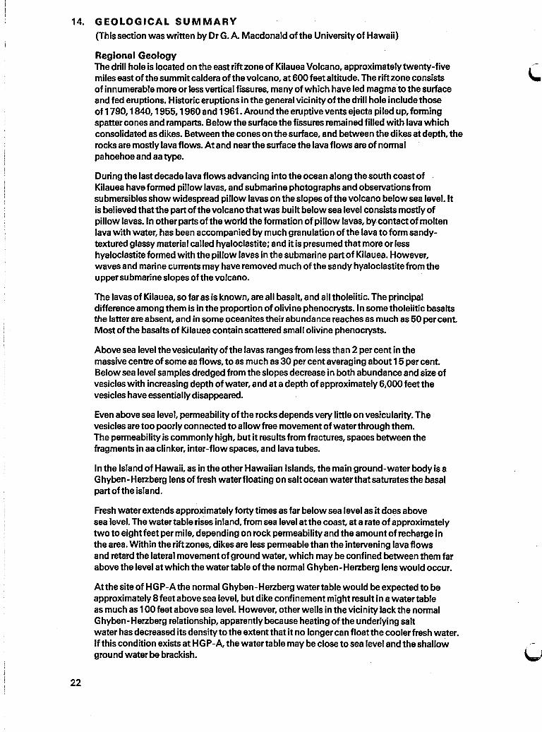
14. GEOLOGICAL SUMMARY
(This section was written by Dr G. A. Macdonald ofthe University of Hawaii)
Regional GeologyThe drill hole is located on the east rift zone of Kilauea Volcano, approximately twenty-fivemiles east of the summit caldera of the volcano, at 600 feet altitude. The rift zone consistsof innumerable more or less vertical fissures, many of which have led magma to the surfaceand fed eruptions. Historic eruptions in the general vicinity of the drill hole include thoseof 1790, 1840, 1955, 1960and 1961. Around the eruptive vents ejecta piled up, formingspatter cones and ramparts. Below the surface the fissures remained filled with lava whichconsolidated as dikes. Between the cones on the surface, and between the dikes at depth, therocks are mostly lava flows. At and near the surface the lava flows are of normalpahoehoe and aa type.
During the last decade lava flows advancing into the ocean along the south coast ofKilauea have formed pillow lavas, and submarine photographs and observations fromsubmersibles show widespread pillow lavas on the slopes of the volcano belowsea level. Itis believed that the part of the volcano that was built below sea level consists mostly ofpillow lavas. In other parts of the world the formation of pillow lavas, bycontact of moltenlava with water, has been accompanied by much granulation of the lava to form sandytextured glassy material called hyaloclastite; and it is presumed that more or lesshyaloclastite formed with the pillow lavas in the submarine part of Kilauea. However,waves and marine currents may have removed much of the sandy hyaloclastite from theuppersubmarine slopes of the volcano.
The lavas of Kilauea, so far as is known, are all basalt, and all tholeiitic. The principaldifference among them is in the proportion of olivine phenocrysts. In some tholeiitic basaltsthe latter are absent, and in some oceanites their abundance reaches as much as 50 per cent.Most ofthe basalts of Kilauea contain scattered small olivine phenocrysts.
Above sea level the vesicularity ofthe lavas ranges from less than 2 per cent in themassive centre of some aa flows, to as much as 30 per cent averaging about 15 per cent.Below sea level samples dredged from the slopes decrease in both abundance and size ofvesicles with increasing depth of water, and at a depth of approximately 6,000 feet thevesicles have essentiallydisappeared.
Even above sea level, permeability of the rocks depends very little on vesicularity. Thevesicles are too poorly connected to allow free movement of water through them.The permeability is commonly high, but it results from fractures, spaces between thefragments in aa clinker, inter-flow spaces, and lava tubes.
In the Island of Hawaii, as in the other Hawaiian Islands, the main ground-water body is aGhyben-Herzberg lens offresh water floating on salt ocean water that saturates the basalpart ofthe island.
Fresh water extends approximately forty times as far below sea level as it does abovesea level. The water table rises inland, from sea level at the coast, at a rate of approximatelytwo to eight feet per mile, depending on rock permeability and the amount ofrecharge inthe area. Within the rift zones, dikes are less permeable than the intervening lava flowsand retard the lateral movement of ground water, which may be confined between them farabove the level at which the water table ofthe normal Ghyben-Herzberg lens would occur.
Atthe site of HGP-A the normal Ghyben-Herzberg water table would be expected to beapproximately 8 feet above sea level, but dike confinement might result in a water tableas much as 100 feet above sea level. However, other wells in the vicinity lack the normalGhyben-Herzberg relationship, apparently because heating ofthe underlying saltwater has decreased its density to the extentthat it no longer can floatthe cooler fresh water.Ifthis condition exists at HGP-A, the water table may be close to sea level and the shallowground water be brackish.
22

Geology of the Drill Hole .The study of toe rock samples from the HGP-A drill holehas begun. Microscopic thinsections are being made, and the physical properties of the rocks, including thermal andelectrical conductivity,density, and porosity; are. being determined. Later, samples will beselected for chemical analysis. The following descriptions are based wholly onexaminations made in the field, with a hand magnifier.
Cores were taken through the following intervals:
A. 456 - 458 feet below rotary tableB. 1,057-1 ,068"" "C. 1,412-1,423"" "D. 2,230-2,240"" "E. 2,876 - 2,886" " " "F. 3,666-3,676" " " "G. 4,447 -4,457" " " "H. 5,396-5,406" " " "I. 6,029-6,039 " ""J. 6,446 - 6,456 " "In addition, cutting samples were taken every ten feet through the part of the hole below1,000 feet, and every five feetthrough part of the interval. In the upper part ofthe holecutting samples were taken whenever return mud circulation was attained.
The rocks penetrated by HGP-A at and near the surface are normal olivine-bearing tholeiiticbasalt of Kilauea, of both aa and pahoehoe types, with vesicularity ranging from about5 to 25 percent. The surficial lavas are highly jointed, with most of the joints dippingmore than 700
• Ordinary appearing lavas, presumably ofsubaerial origin, continuedwell below sea level, as would be expected because of the sinking of the island since thelavas were formed. (The island is at present sinking at a rate of approximately 2 feetper century). Core B, between 1,057 and 1,068 feet below rotary table (eg 450 feetbelow sea level) consists of dark grey dense basalt with a few pahoehoe-type vesicles.The lava was probably formed subaerially. On the other hand, the lower part of Core C,from 1,412 to 1,423 feet below rotary table, is partly glassy and appears probably to besubaqueous pillow lava. .
Core E, from 2,876 to 2,886 feet, consists at the top of 3 feet of fine grained olivine-bearing grey basalt with about 3 per cent of pahoehoe-type vesicles less than 0.5 mmacross. It is probably tholeiitic. This grades downward through a thickness of about 4 inchesinto dense black tachylite (basalt obsidian), which constitutes the remaining 7 feetof the core. The tachylite is intensely fractured, and the fracture surfaces commonly arealtered to a thin coating of serpentine, showing that the fracturing is old, and not theresult ofdrilling. Some of the fracture surfaces areslickensided, and many of thembear many tiny cubes of pyrite. This very abnormal thickness of basaltic glass must be theresult of very rapid chilling of the molten lava by water.
Between about 3,682 feet and 3,760 feet (BRT) the cuttings consist of sandy material withangular grains averaging about 1.5 mm in diameter. It appears to have been essentially looseatdepth. The material appears to be hyaloclastite.
All the cores below 3,000 feet depth(BRT) show some degree of alteration, with agreenish colouring owing to the formation of secondary chlorite. Tiny cubes of pyrite alsoare present in all, and become more abundant with increasing depth. Below 1,200 feet (BRT)secondary zeolite and calcite appear in the cores, and remain moderately abundant to about4,000 feet, but below that depth they decrease. The final core, taken from 6,446 to 6,456 feet,has at the top four inches ofdense dark grey basalt bounded by a contact which runs acrossthe corenearly at 900
• The contact is moderately lobate but shows very little effect ofchilling. The rest ofthe core, below the contact is dense but greenish grey, with manyspotsof chlorite and much pyrite, it is intensely fractured, many of the fractures somewhatslickensided, and some covered with a white coating as much as 1 mm thick. The whitematerial is partly calcite, but mostly zeolite ( 1).
23

24
The highlyfractured character of mostofthe cores is noteworthy. Even cores thatappearquitesolid as theyemerge from the core barrel mayfall aparton handling.Thischaracteristic was worrisome during drilling, because ofthe possibility that the fracturedmaterial mightcave into the hole, and the caving possibility remains, particularly afterthe mudis removed from the hole. The hyaloclastitealso hascaving possibilities.

u
15. ACKNOWLEDGEMENTS
Financial support for the Project was provided by:
Energy Research & DevelopmentAdministration
National Science Foundation
Stateof Hawaii
Countyof Hawaii
Hawaiian Electric Company
Water Resources International Inc.
The following people were engaged on the project, or contributed to it.
John W. Shupe Project DirectorDean, College of EngineeringUniversity of Hawaii
Gordon A. Macdonald Senior Professor, GeologyHawaii Institute of Geophysics
Paul C. Yuen Associate Dean of EngineeringUniversity of Hawaii
Patrick K. Takahashi Associate Professor, College of EngineeringUniversity of Hawaii
Bill H. Chen Associate ProfessorUniversity of Hawaii (Hilo campus)
Bennie G. DiBona Director, Industrial Applications DivisionEnergy Research & Development AdministrationNevada Operations Office
E. & W. Craddick Water Resources International Inc.Honolulu
Clarence Mason Drilling SupervisorReynolds Electrical & Engineering Co LtdLas Vegas
Warwick J. Tracey Consultant Geothermal EngineerKingston Reynolds Thorn & Allardice LtdAuckland, New Zealand
W. Basil Stilwell Geothermal Projects EngineerMinistry of Works Et DevelopmentWairakei, New Zealand
John V. Englebretsen Drilling SupervisorMinistry of Works & DevelopmentWairakei, New Zealand
Geoffrey W. Hitchcock Measurements ScientistMinistry of Works & DevelopmentWairakei, New Zealand
Frank E. Studt Geothermal Co-ordinatorDepartment of Scientific Et Industrial ResearchWellington, New Zealand
W. A. J. Mahon Officer-in-ChargeDepartment of Scientific &Industrial ResearchWairakei, New Zealand
W. J. P. Macdonald Geophysics DivisionDepartment of Scientific & Industrial ResearchWellington, New Zealand
25

26
Appendix A Surface Casing
KRTA Casing Record - HGP~A
Hole Size 26 inchStarted 30 January : Completed 30 January 1976
Joint 1 thru Joint 8 81.10lbs/foot
Joint Measured CumulativeNo. Length (feet) Length (feet)
1 67.33 67.332 60.08 127.413 65.20 ·192.614 60.00 252.615 65.20 317.816 65.20 383.017 30.00 413.018 9.92 . 422.93
Note:Welded joints, copper bearing structural steel.21 feet 7 inches was cut off originally leaving the top ofthe 20 inch casing 2 feet 6 inches below the rotary·table.Subsequently a further 18feet 6 inches was cut off toleave the 20 inch casing flush with the cellar floor.

u
Appendix B Anchor Casin~
KRTA Casing Record - HGP-AHole Size 20, inch
. Star:ted 27.February : Completed 27 February 1976Joint 1 thru Joint 27 : Size 131 inch OD 54.50 Ibs/foot
Grade J55 Thread Buttress
JointNo.
~}3456789
101112131415161718192021222324252627
MeasuredLength (feet)
74.58
31.7543.9243.0046.3346.0846.5829.2528.0033.0029.9231.3332.7530.5029.5032.0032.5830.4236.4240.0046.5843.9246.1646.0043.5023.00
, CumulativeLength (feet)
74.58
106.33150.25193.25239.58285.66332.24361.49389.49422.49452.41483.74516.49546.99576.49608.49641.07671.49707.91747.91794.49838.41884.57930.57974.07997.07
Remarks
997.07- 29.00 top of casing to cellar floor
968.071.08 cellarfloor to CHF
969.15 = depth ofcasing belowCHF
27

Appendix C ProductionCasing
KRTA Production Casing Record - HGP-AHole Size 121 inch
Started 1 April : Completed 1 April 1976Joint 1 thru Joint 56 I Size 91 inch 00 43.5 Ibs/foot
Grade N.80 Thread BTC Total Depth 2,244 feet
28
JointNo.
123456789
1011121314151617181920212223242526272829303132333435363738394041424344454647484950515253545556
MeasuredLength (feet)
45.6840.5539.8537.5538.5939.9338.2940.8036.4339.5540.9746.3041.6242.5945.6844.7246.4746.6842.4340.3447.4344.2639.8937.6837.2239.1337.5137.5139.3836.5138.3439.0138.8536.8039.5440.3440.3037.7239.0940.6337.5936.6839.9738.9333.9343.2639.5538.3839.0939.2640.3839.5140.7237.2636.5940.38
CumulativeLength (feet)
45.6886.23
126.08163.63202.22242.15280.44321.24357.67397.22438.19484.49526.11568.70614.38659.10705.57752.25794.68835.02882.45926.71966.60
1,004.281,041.501,080.631,118.141,155.651,195.031,231.541,269.881,308.891,347.741,384.541,424.081,464.421,504.721,542.441,581.531,622.161,659.751,696.431,736.401,775.331,809.261,852.521,892.071,930.451,969.542,008.802,049.182,088.692,129.412,166.672,203.262,243.64
Remarks

Appendix 0 Slotted/Plain Liner
KRTA Casing Record - HGP-AHole Size ~i inch
Started 3 June : Completed 4 June 1976Joint 1 thru Joint 109 : Size 7 inch 00 23 Ibs/foot
Grade K.55 Thread 8R Type L.C.T
JointNo.
123456789
101112131415161718192021222324252627282930313233343536373839404142434445464748496051
·6253645556
MeasuredLength (feet)
41.0638.9339.3939.6639.6039.6439.6439.2639.6538.2839.6439.6039.6539.6639.3739.6039.6339.6239.6339.6339.6239.6139.6239.6339.6339.5839.6339.6339.6839.6339.6539.5639.6039.6639.6839.0439.6439.6239.0139.6239.6339.6439.6339.6239.2539.6539.6039.6239.6039.6839.7239.7039.6039.6039.6339.61
CumulativeLength (feet)
41.0679.99
119.38159.04198.64238.28277.92317.18356.83395.11434.75474.35514.00553.66593.03632.63672.26711.88751.51791.14830.76870.37909.99949.62989.25
1,028.831,068.461,108.091,147.771,187.401,227.051,266.611,306.211,345.871,385.55
·1,424.591,464.231,503.851,542.861,582.481,622.111,661.751,701.381,741.001,780.251,819.901,859.501,899.121,928.721,978.302,018.022,057.722,097.322,136.922,176.552,216.16
Remarks
Slotted liner
Slotted liner
Slotted liner
Slotted liner
Slotted liner
Slotted liner
Slotted liner
Slotted liner
Slotted liner
Slotted liner
Slotted liner
Slotted liner
Slotted liner
Slotted liner
Slotted liner
Slotted liner
Slotted liner
Slotted liner
Slotted liner
Slotted liner
Slotted liner
Slotted liner
Slotted liner
Slotted liner
Slotted liner
SlottedJiner
29

30
KRTA Casing Record - HGP-AHole Size 81 inch
Started 3 June : Completed 4 June 1976Joint 1 thru Joint 109 . Size 7 inch 00 23 Ibs/foot.
Grade K.55 Thread 8R Type LC.T "-Joint Measured CumulativeNo. Length (feet) Length (feet) Remarks
57 . 39.62 2,255.7858 39.62 2,295.40 Slotted liner59 39.25 2,334.6560 39.62 2,374.27 Slotted liner61 39.63 2,413.9062 39.56 2,453.46 Slotted liner63 39.64 2,493.1064 39.25 2,532.3465 39.62 2,571.97 Slotted liner66 39.62 2,611.5967 39.63 2,651.2268 39.61 2,690.8269 39.62 2,730.45 Slotted liner70 39.62 2,770.0771 39.62 2,809.6972 39.63 2,849.3273 39.63 2,888.95 Slotted liner74 39.60 2,928.5575 39.58 2,968.1376 39.60 3,007.7377 39.68 3,047.41 Slotted liner78 39.05 3,086.4679 39.58 3,126.0480 39.60 3,165.6481 39.61 3,205.25 Slotted liner82 39.60 3,244.8583 39.05 3,283.9084 39.00 3,322.9085 39.62 3,362.5286 39.75 3,402.27 Slotted liner87 39.60 3,441.8788 39.61 3,481.4889 38.95 3,520.4390 39.61 3,560.0491 39.61 3,599.65 Slotted liner92 39.61 3,639.2693 39.60 3,678.8694 39.61 3,718.4795 39.61 3,758.0896 39.60 3,797.68 Slotted liner97 39.64 3,837.3298 39.63 3,876.9599 39.61 3,916.56
100 39.60 3,956.16101 39.63 3,995.79 Slotted liner102 39.61 4,035.40103 39.64 4,075.04104 39.65 4,114.69105 39.61 4,154.30106 39.60 4,193.90 Slotted liner107 39.01 4,232.91108 39.60 4,272.51109 39.62 4,312.13

(
Appendix E Bit Record
c
Hole . Depth Depth DriUedBit Opener Make Size Type . Serial In Out Feet Hours Remark$
1 Smith 91" L4 14H,694A 27 209 182 1031 n,B4,01"2 Smith 151" M 27 638 611 2001 T4, B4,01"3 Smith 151" M 10460 638 998 360 64 T2, B2, I4 Smith 20' M 27 543 516 167 T2, B2,1
5 Smith ·91" F.3 669H 209 1,057 848 891 . T1 BT. B2,16 Smith 20' 543 697 154 72 T4, B8,01"7 Smith 20' 697 987 290 74 T2, B2, I8 Smith 26~ 27 407 380 201 T2, B2, I
9 Smith 121" F.57 821CC 998 1,437 439 581 T1, B8,01'10 Smith 121" F.57 393CJ 1,437 1,450 13 211 Security 81" S.86F 572093 1,450 1,776 326 351 T2, B2,01'12 Security 8i" . S.86F 573070 1,776 2,230 454 48 -
13 Grant 121" 19932 1,450 1,649· 199 221 T8, B8.14 Grant 121" 19932 1,649 1,659 10 71 -15 Grant 121" 19932 1,659 1,666 7 71 8.4.1
16 Smith 121' F.57 393CJ(RR) 1,666 1,712 46 - -17 Grant 121" 19932 1,712 1,751 39 9 -
18 Smith 121" F.57 393CJ(RR) 1,751 1,812 61 101 2.2.0K19 Smith 121" TCinsert 1,812 1,865 53 41 . 3.2.0K20 Security 121" TCinsert- 1,865 2,240 375 . 191 -
21 Security 81" S86F 630264 2,244 2,876 632 46 -22 Security 81' S86F 578184 2,876 3,666 790 63 4.2.123 Security 8i' S86F 630100 3,666 4,447 781 68 -24 Security 81" S86F 588791 4,447 5,400 953 571 2.8.1- Loose cone25 Security 81" S86F 630069 5,400 6,060 660 46 -26 Security 8i" S86F 580940 6,060 6,445 385 321 6.8.1- All cones loose

Appendix F Deviation Recordings
Depth of Distance Deviation Diff. in dev. Rate ofDate station apart (degrees) between change of
(feet) (feet) stations dev.\..(degrees) (degrees/foot)
12 February 500 0°-20'480 10' 0.02
16 March 980 0°-30'100 1°-20' 0.80
9 II 1,080 1°_50'280 40' 0.14
16 II 1,360 2°-30'115 50' 0.'113
22 II 1,475 3°-20'165 20' 0.12
22 II 1,640 3°-40',
85 15' 0.1822 II 1,725 3°-55'
42 35' 0.8323 II 1,767 4°-30'
28 40' 0.0223 1,795 3°-50'
39 6' 0.0023 II 1,825 3°-56'
100 6' 0.0024 II 1,925 3°-50'
95 10' 0.1124 " 2,020 4~- 0'
95 0' 0.0025 2,115 4°_ 0'
210 30' 0.146 April 2,325 3°-30'
120 15' 0.136 II 2,445 3°-15'
105 15' 0.147 II 2,550 3°_ 0'
220 50' 0.237 II 2,770 3°-50'
156 20' 0.139 II 2,926 3°-30'
274 30' 0.1110 II 3,200 3°-00'
120 0' 0.0010 ,. 3,320 3°-00'
153 2' 0.0111 II 3,473 2°-58'
967 13' 0.0116 II 4,440 2°-45'
32

Appendix G Record of Perforating and Testing for·Circulation
Perforated RTTSDate at: set at: Remarks
(feet) . (feet) " - ~_... -.". --- ._ .. _. _.- . _.- . "-
27 May 842,844 BH test -1 ,200 psi. No circulation370,372
423 No eire. between 370 and 842829,830
835 " " "830 and 842
825 " " " 829 and 37228 May 600,601 " " "
(Midnight 28 May)423 " or " 600 and 372610 " " " 601 and829
814807 " " " 814 and 601
800792 " " "
800 and 601784
773 " " " 784 and 601763
749 " " "763 and 601
696749 " " "
696 and 763734
701 " " "734 and 696
749 " " " 734 and 763835 " "
"tChecks that RTTS
825 " " " was operating807 " " "
satisfactorily.792 " " "
Checking RTTS.773 " " "646624 " " "
646 and 601650 " " " 646 and 696
623614 " " " 623 and 601634 " " " 623 and 646
670675 No eire. between 670 and 696650 " " " 670 and 646
682675 " " " 682 and 670688 " " " 682 and 696
Tripped out and checked RTTS
29 Maywhile waiting onperforator.
~6 Started at 8.00 am approximately.518 No eire. between 486 and 600
S43455 " " " 486 and 372
579 " " " 543 and 600518 " ,. " 486 and 543
429455 " " " 429 and 486392 " " " 429 and 372
453465 " " " 453 and 486400 " " " 453 and 429
400410
" " " 400 and 429392 " " " 400 and 372
514618 " " " 614 and 543610 " " "
514 and 486671
579 " " " 571 and 600659 " " " 571 and 543
33

DatePerforated
at:(feet)
RTTSset at:(feet) I Remarks
34
29 May 244153
24
202
174
172
Checking of the top suspected void from 50ft-250ft
235 No eire. between 153 and 244142 Cire. " 153 and 54
180 No eire. between 202 and 153
" " " 202 and 244
162 " " " 174 and 153182 " " " 174 and 202
162 Cire. " 172 and 153