Harmonic Mitigating Transformers (HMTs) Frequently Asked …€¦ · Harmonic Mitigating...
27
Harmonic Mitigating Transformers (HMTs) Frequently Asked Questions (FAQ) This document has been written to provide answers to the more frequently asked questions we have received regarding harmonics and the Harmonic Mitigating Transformer technology used to address them. This information will be of interest to both those experienced in harmonic mitigation techniques and those new to the problem of harmonics. 1. What are non-linear loads and why are they a concern today? 2. Do different types of non-linear loads generate different harmonics? 3. Why do non-linear loads have low power factors and why is it important to have a high power factor? 4. What is an SMPS and how does it generate harmonics? 5. Can’t equipment manufacturers design their products to be free of harmonics? 6. What problems do non-linear loads and harmonics create? 7. Why do 3 rd harmonic currents overload neutral conductors? 8. How do non-linear loads create current and voltage harmonics? 9. What ill effects do the harmonics created by computer power supplies have on themselves? 10. How do harmonics increase power losses and overheat transformers? 11. What are zero sequence harmonic filters and how do they reduce 3 rd harmonic and prevent neutral conductor overheating? 12. What is a Harmonic Mitigating Transformer and how is it different than a K-rated Transformer? 13. How do Harmonic Mitigating Transformers reduce voltage distortion? 14. How do Harmonic Mitigating Transformers save energy? 15. What constitutes an EPA EnergyStar Transformer and is it important when supplying non-linear loads? 16. How reliable are transformer energy efficiency measurements under non-linear loading? 17. Am I not safe from harmonics if I use K-Rated transformers and oversized neutrals? 18. Are there standards that can help in addressing harmonics? 19. Can neutral currents, such as the 3 rd harmonic, be reduced by the use of 3 rd Harmonic Blocking Filters?
Transcript of Harmonic Mitigating Transformers (HMTs) Frequently Asked …€¦ · Harmonic Mitigating...

Harmonic Mitigating Transformers (HMTs)
Frequently Asked Questions (FAQ) This document has been written to provide answers to the more frequently asked questions we have received regarding harmonics and the Harmonic Mitigating Transformer technology used to address them. This information will be of interest to both those experienced in harmonic mitigation techniques and those new to the problem of harmonics. 1. What are non-linear loads and why are they a concern today? 2. Do different types of non-linear loads generate different harmonics? 3. Why do non-linear loads have low power factors and why is it important to have a high power factor? 4. What is an SMPS and how does it generate harmonics? 5. Can’t equipment manufacturers design their products to be free of harmonics? 6. What problems do non-linear loads and harmonics create? 7. Why do 3rd harmonic currents overload neutral conductors? 8. How do non-linear loads create current and voltage harmonics? 9. What ill effects do the harmonics created by computer power supplies have on themselves? 10. How do harmonics increase power losses and overheat transformers? 11. What are zero sequence harmonic filters and how do they reduce 3rd harmonic and prevent neutral
conductor overheating? 12. What is a Harmonic Mitigating Transformer and how is it different than a K-rated Transformer? 13. How do Harmonic Mitigating Transformers reduce voltage distortion? 14. How do Harmonic Mitigating Transformers save energy? 15. What constitutes an EPA EnergyStar Transformer and is it important when supplying non-linear loads? 16. How reliable are transformer energy efficiency measurements under non-linear loading? 17. Am I not safe from harmonics if I use K-Rated transformers and oversized neutrals? 18. Are there standards that can help in addressing harmonics? 19. Can neutral currents, such as the 3rd harmonic, be reduced by the use of 3rd Harmonic Blocking Filters?

______________________________________________________________________________________________________________________________
_________________________________________________________________________________________________________________ Hammond Power Solutions Inc. Literature Code: HPS-TA5
Harmonic Mitigating Transformers - FAQ
Page 2 of 27
FIXED SPEED INDUCTION MOTOR (LINEAR LOAD)
PERSONAL COMPUTER (NON-LINEAR)
VFD with 6-pulse Rectifier (Non-linear)
VFD with 12-pulse Rectifier (Non-linear)
Figure 1-1: Typical linear and non-linear current waveforms
1. What are non-linear loads and why are they a concern today?
A load is considered non-linear if its impedance changes with the applied voltage. The changing impedance means that the current drawn by the non-linear load will not be sinusoidal even when it is connected to a sinusoidal voltage. These non-sinusoidal currents contain harmonic currents that interact with the impedance of the power distribution system to create voltage distortion that can affect both the distribution system equipment and the loads connected to it. In the past, non-linear loads were primarily found in heavy industrial applications such as arc furnaces, large variable speed drives, heavy rectifiers for electrolytic refining, etc. The harmonics they generated were typically localized and often addressed by knowledgeable experts. Times have changed. Harmonic problems are now common in not only industrial applications but in commercial buildings as well. This is due primarily to new power conversion technologies, such as the Switch-Mode Power Supply (SMPS), which can be found in virtually every power electronic device (computers, servers, monitors, printers, photocopiers, telecom systems, broadcasting equipment, banking machines, etc.). The SMPS is an excellent power supply, but it is also a highly non-linear load. Their proliferation has made them a substantial portion of the total load in most commercial buildings. Examples of the current drawn by various types of equipment are shown in Figure 1-1. The most common form of distorted current is a pulse waveform with a high crest factor. The SMPS is one such load since it consists of a 2-pulse rectifier bridge (to convert AC to DC) and a large filter capacitor on its DC bus. The SMPS draws current in short, high-amplitude pulses that occur right at the positive and negative peaks of the voltage. Typically these high current pulses will cause clipping or flat-topping of the 120VAC supply voltage. The “double-hump” current waveform of the 6-pulse rectifier in a UPS or a VFD also will cause clipping or flat-topping of the 480V or 600V distribution system. Further discussions on voltage flat-topping and its effect on connected equipment can be found in answers to Questions 8 and 9.

______________________________________________________________________________________________________________________________
_________________________________________________________________________________________________________________ Hammond Power Solutions Inc. Literature Code: HPS-TA5
Harmonic Mitigating Transformers - FAQ
Page 3 of 27
Treat: 3, 5, 7 & 9 Treat: 5 & 7
Phase-Phase & 3-Phase Loads
P H A S E
N E U T R A L
0 20 40 60 80
100
1 3 5 7 9 11 13 15
0 20 40 60 80
100
1 3 5 7 9 11 13 15
Figure 2-1: Typical non-linear load harmonic spectrums and waveforms
2. Do different types of non-linear loads generate different harmonics? By far the majority of today’s non-linear loads are rectifiers with DC smoothing capacitors. These rectifiers typically come in 3 types – (i) single phase, line-to-neutral, (ii) single phase, phase-to-phase and (iii) three-phase. Single-phase line-to-neutral rectifier loads, such as switch-mode power supplies in computer equipment, generate current harmonics 3rd, 5th, 7th, 9th and higher. The 3rd will be the most predominant and typically the most troublesome. 3rd, 9th and other odd multiples of the 3rd harmonic are often referred to as triplen harmonics and because they add arithmetically in the neutral are also considered zero sequence currents. Line-to-neutral non-linear loads can be found in computer data centers, telecom rooms, broadcasting studios, schools, financial institutions, etc. 208V single-phase rectifier loads can also produce 3rd, 5th, 7th, 9th and higher harmonic currents but if they are reasonably balanced across the 3 phases, the amplitude of 3rd and 9th will be small. Because they are connected line-line, these loads cannot contribute to the neutral current. The largest current and voltage harmonics will generally be the 5th followed by the 7th. Typical single phase, 208V rectifier loads include the switch-mode power supplies in computer equipment and peripherals. Three-phase rectifier loads are inherently balanced and therefore generally produce very little 3rd and 9th harmonic currents unless their voltage supply is unbalanced. Their principle harmonics are the 5th and 7th with 11th and 13th also present. They cannot produce neutral current because they are not connected to the neutral conductor. The rectifiers of variable speed drives and Uninterruptible Power Supplies (UPS) are typical examples of three-phase rectifier loads.

______________________________________________________________________________________________________________________________
_________________________________________________________________________________________________________________ Hammond Power Solutions Inc. Literature Code: HPS-TA5
Harmonic Mitigating Transformers - FAQ
Page 4 of 27
Q = kVAR(nonwork
producing)
P = kW (work producing)
S = kVA
φ
With Linear Loadsφcos===
kVAkW
SPpf
S P Q= +2 2
kVA kW kVAR= +2 2
True Power Factor = (Displacement Power Factor) x (Distortion Power Factor)
With Non-linear Loads
S P Q H= + +2 2 2
kVA kW kVAR kVARH= + +2 2 2
pf PS
kWkVA
= = ≠ cosφ
Q = kVAR(nonwork
producing)
P = kW (work producing)
H = kVAH(nonwork
producing)
S = kVA
φ
Q = kVAR(nonwork
producing)
P = kW (work producing)
S = kVA
φ
With Linear Loadsφcos===
kVAkW
SPpf
S P Q= +2 2
kVA kW kVAR= +2 2
Q = kVAR(nonwork
producing)
P = kW (work producing)
S = kVA
φ
Q = kVAR(nonwork
producing)
P = kW (work producing)
S = kVA
φ
With Linear Loadsφcos===
kVAkW
SPpf φcos===
kVAkW
SPpf
S P Q= +2 2S P Q= +2 2
kVA kW kVAR= +2 2kVA kW kVAR= +2 2
True Power Factor = (Displacement Power Factor) x (Distortion Power Factor)
With Non-linear Loads
S P Q H= + +2 2 2
kVA kW kVAR kVARH= + +2 2 2
pf PS
kWkVA
= = ≠ cosφ
Q = kVAR(nonwork
producing)
P = kW (work producing)
H = kVAH(nonwork
producing)
S = kVA
φ
With Non-linear Loads
S P Q H= + +2 2 2S P Q H= + +2 2 2
kVA kW kVAR kVARH= + +2 2 2kVA kW kVAR kVARH= + +2 2 2
pf PS
kWkVA
= = ≠ cosφpf PS
kWkVA
= = ≠ cosφ
Q = kVAR(nonwork
producing)
P = kW (work producing)
H = kVAH(nonwork
producing)
S = kVA
φ
Q = kVAR(nonwork
producing)
P = kW (work producing)
H = kVAH(nonwork
producing)
S = kVA
φφ
Figure 3- 1: Power factor relationship for Linear and Non-linear loads
3. Why do non-linear loads have low power factors and why is it important to have a high power
factor? Power factor is a measure of how effectively a specific load consumes electricity to produce work. The higher the power factor, the more work produced for a given voltage and current. Figure 3-1 shows the power vector relationships for both linear and non-linear loads. Power factor is always measured as the ratio between real power in kilowatts (kW) and apparent power in kilovoltamperes (kVA). For linear loads, the apparent power in kVA (S = V•I) is the vector sum of the reactive power in kVAR (Q) and the real power in kW (P). The power factor is P/S = CosΦ, where Φ is the angle between S and P. This angle is the same as the displacement angle between the voltage and the current for linear loads. For a given amount of current, increasing the displacement angle will increase Q, decrease P, and lower the PF. Inductive loads such as induction motors cause their current to lag the voltage, capacitors cause their current to lead the voltage, and purely resistive loads draw their current in-phase with the voltage. For circuits with strictly linear loads (a rare situation) simple capacitor banks may be added to the system to improve a lagging power factor due to induction motors or other lagging loads. For non-linear loads, the harmonic currents they draw produce no useful work and therefore are reactive in nature. The power vector relationship becomes 3 dimensional with distortion reactive power, H, combining with both Q and P to produce the apparent power which the power system must deliver. Power factor remains the ratio of kW to kVA but the kVA now has a harmonic component as well. True power factor becomes the combination of displacement power factor and distortion power factor. For most typical non-linear loads, the displacement power factor will be near unity. True power factor however, is normally very low because of the distortion component. For example, the displacement power factor of a personal computer will be near unity but its total power factor is often in the 0.65 – 0.7 range. The best way to improve a poor power factor caused by non-linear loads is to remove the harmonic currents. Most Utilities charge their customers for energy supplied in kilowatt-hours during the billing period plus a demand charge for that period. The demand charge is based upon the peak load during the period. The demand charge is applied by the utility because it must provide equipment large enough for the peak load even though the customer’s average power may be much lower. If the power factor during the peak period (usually a 10 minute sliding window) is lower than required by the utility (usually 0.9), the utility may also apply a low PF penalty charge as part of the demand charge portion of the bill. Suppose the peak demand was 800kW/1000kVA (a PF of 0.8). The utility would charge the customer as if his demand was 0.9 x 1000kVA = 900kW even though his peak was really 800kW, a penalty of 100kW. Improving the power factor to 0.85 at 1000kVA demand would lower the penalty to just 50kW. For power factors of 0.9 to 1.0, there would be no penalty and the demand charge would be based on the actual peak kW. The demand charge is often a substantial part of the customer’s power bill, so it is worthwhile to maintain good power factor during peak loading.
______________________________________________________________________________________________________________________________
_________________________________________________________________________________________________________________ Hammond Power Solutions Inc. Literature Code: HPS-TA5
Harmonic Mitigating Transformers - FAQ
Page 5 of 27
Voltage
Current
Figure 4-2: Pulsed current waveform and resultant voltage flat-topping of a typical Switch-mode Power Supply
Load
Lls
vac
iac
RectifierBridge
Switch-modedc-to-dc
converter
SmoothingCapacitor
Cf Load
Lls
vac
iac
RectifierBridge
Switch-modedc-to-dc
converter
SmoothingCapacitor
Cf
Figure 4-1: Typical circuit diagram of Switch-mode Power Supply
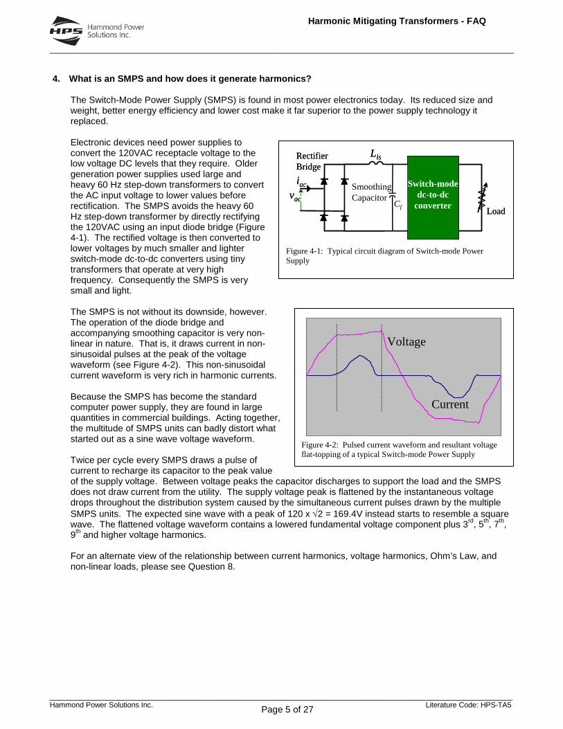
4. What is an SMPS and how does it generate harmonics?
The Switch-Mode Power Supply (SMPS) is found in most power electronics today. Its reduced size and weight, better energy efficiency and lower cost make it far superior to the power supply technology it replaced. Electronic devices need power supplies to convert the 120VAC receptacle voltage to the low voltage DC levels that they require. Older generation power supplies used large and heavy 60 Hz step-down transformers to convert the AC input voltage to lower values before rectification. The SMPS avoids the heavy 60 Hz step-down transformer by directly rectifying the 120VAC using an input diode bridge (Figure 4-1). The rectified voltage is then converted to lower voltages by much smaller and lighter switch-mode dc-to-dc converters using tiny transformers that operate at very high frequency. Consequently the SMPS is very small and light. The SMPS is not without its downside, however. The operation of the diode bridge and accompanying smoothing capacitor is very non-linear in nature. That is, it draws current in non-sinusoidal pulses at the peak of the voltage waveform (see Figure 4-2). This non-sinusoidal current waveform is very rich in harmonic currents. Because the SMPS has become the standard computer power supply, they are found in large quantities in commercial buildings. Acting together, the multitude of SMPS units can badly distort what started out as a sine wave voltage waveform. Twice per cycle every SMPS draws a pulse of current to recharge its capacitor to the peak value of the supply voltage. Between voltage peaks the capacitor discharges to support the load and the SMPS does not draw current from the utility. The supply voltage peak is flattened by the instantaneous voltage drops throughout the distribution system caused by the simultaneous current pulses drawn by the multiple SMPS units. The expected sine wave with a peak of 120 x √2 = 169.4V instead starts to resemble a square wave. The flattened voltage waveform contains a lowered fundamental voltage component plus 3rd, 5th, 7th, 9th and higher voltage harmonics. For an alternate view of the relationship between current harmonics, voltage harmonics, Ohm’s Law, and non-linear loads, please see Question 8.

______________________________________________________________________________________________________________________________
_________________________________________________________________________________________________________________ Hammond Power Solutions Inc. Literature Code: HPS-TA5
Harmonic Mitigating Transformers - FAQ
Page 6 of 27
5. Can equipment manufacturers design their products to be free of harmonics?
Yes they can, but lowering the current distortion levels at the input to the SMPS in a computer will add to the cost of the computer. This is not a step that computer manufacturers wish to take because of the continuous and intense cost cutting in the computer industry. Actually it is less costly overall to provide a harmonic mitigating transformer to feed several hundred computers than it is to improve the operation of the SMPS in each computer. This is especially true when we consider that the added cost of the improved SMPS will reappear every three years when a new computer system is purchased.
______________________________________________________________________________________________________________________________
_________________________________________________________________________________________________________________ Hammond Power Solutions Inc. Literature Code: HPS-TA5
Harmonic Mitigating Transformers - FAQ
Page 7 of 27
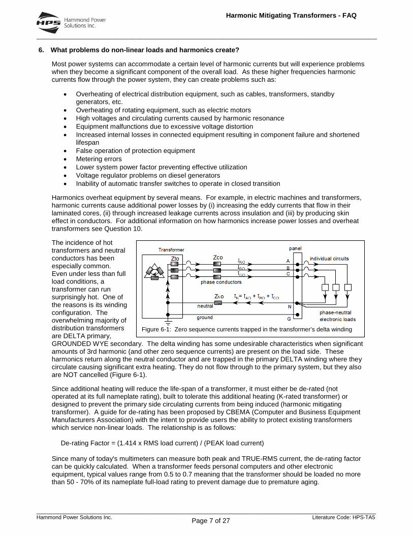
Figure 6-1: Zero sequence currents trapped in the transformer’s delta winding
6. What problems do non-linear loads and harmonics create?
Most power systems can accommodate a certain level of harmonic currents but will experience problems when they become a significant component of the overall load. As these higher frequencies harmonic currents flow through the power system, they can create problems such as:
• Overheating of electrical distribution equipment, such as cables, transformers, standby generators, etc.
• Overheating of rotating equipment, such as electric motors • High voltages and circulating currents caused by harmonic resonance • Equipment malfunctions due to excessive voltage distortion • Increased internal losses in connected equipment resulting in component failure and shortened
lifespan • False operation of protection equipment • Metering errors • Lower system power factor preventing effective utilization • Voltage regulator problems on diesel generators • Inability of automatic transfer switches to operate in closed transition
Harmonics overheat equipment by several means. For example, in electric machines and transformers, harmonic currents cause additional power losses by (i) increasing the eddy currents that flow in their laminated cores, (ii) through increased leakage currents across insulation and (iii) by producing skin effect in conductors. For additional information on how harmonics increase power losses and overheat transformers see Question 10. The incidence of hot transformers and neutral conductors has been especially common. Even under less than full load conditions, a transformer can run surprisingly hot. One of the reasons is its winding configuration. The overwhelming majority of distribution transformers are DELTA primary, GROUNDED WYE secondary. The delta winding has some undesirable characteristics when significant amounts of 3rd harmonic (and other zero sequence currents) are present on the load side. These harmonics return along the neutral conductor and are trapped in the primary DELTA winding where they circulate causing significant extra heating. They do not flow through to the primary system, but they also are NOT cancelled (Figure 6-1). Since additional heating will reduce the life-span of a transformer, it must either be de-rated (not operated at its full nameplate rating), built to tolerate this additional heating (K-rated transformer) or designed to prevent the primary side circulating currents from being induced (harmonic mitigating transformer). A guide for de-rating has been proposed by CBEMA (Computer and Business Equipment Manufacturers Association) with the intent to provide users the ability to protect existing transformers which service non-linear loads. The relationship is as follows: De-rating Factor = (1.414 x RMS load current) / (PEAK load current) Since many of today's multimeters can measure both peak and TRUE-RMS current, the de-rating factor can be quickly calculated. When a transformer feeds personal computers and other electronic equipment, typical values range from 0.5 to 0.7 meaning that the transformer should be loaded no more than 50 - 70% of its nameplate full-load rating to prevent damage due to premature aging.

______________________________________________________________________________________________________________________________
_________________________________________________________________________________________________________________ Hammond Power Solutions Inc. Literature Code: HPS-TA5
Harmonic Mitigating Transformers - FAQ
Page 8 of 27
The fact that harmonic currents create voltage distortion as they flow through the power system’s impedance makes their impact even more serious. It is voltage distortion, not current distortion that will affect the connected equipment on the power system. For more on how non-linear loads create voltage distortion and how this can affect connected equipment, see Questions 8 and 9.

______________________________________________________________________________________________________________________________
_________________________________________________________________________________________________________________ Hammond Power Solutions Inc. Literature Code: HPS-TA5
Harmonic Mitigating Transformers - FAQ
Page 9 of 27
Phase A Current
Phase B Current
Phase C Current
Neutral Current
Ground Wire
Transformer
LinearLoad
Phase A Current
Phase B Current
Phase C Current
Neutral Current
Ground Wire
Transformer
LinearLoad
Transformer Phase A Current
Phase B Current
Phase C Current
Neutral Current
Ground Wire
Non-linearLoad
Transformer Phase A Current
Phase B Current
Phase C Current
Neutral Current
Ground Wire
Transformer Phase A Current
Phase B Current
Phase C Current
Neutral Current
Ground Wire
Non-linearLoad
Figure 7-1: How non-linear load currents add in the neutral
7. Why do 3rd harmonic currents overload neutral conductors?
Figure 7-1 shows how the sinusoidal currents on the phases of a 3-phase, 4-wire system with linear loads sum to return on the neutral conductor. The 120° phase shift between the sinusoidal load currents causes their vector sum to be quite small. In fact it will be zero if the linear loads are perfectly balanced. Examining the dashed vertical lines in Figure 7-1 clearly demonstrates that the instantaneous sum of the currents in the three phases taken at any moment will also be zero if the linear loads are perfectly balanced. If they are not, then there will be a small residual neutral current as shown. With linear loads, the neutral conductor can be the same size as the phase conductors because the neutral current will not be larger than the highest phase current. Unfortunately, this is definitely not true for non-linear phase-to-neutral loads. 120VAC non-linear loads like the SMPS used in computers and in monitors draw current in two distinct pulses per cycle. Because each pulse is narrow (less than 60 degrees), the currents in the second and third phases are zero when the current pulse is occurring in the first phase. Hence no cancellation can occur in the neutral conductor and each pulse of current on a phase becomes a pulse of current on the neutral. Even if the phase currents of the SMPS loads are perfectly balanced in RMS amperes, the RMS value of the neutral current can be as much as √3 times the RMS value of the phase current because there are 3 times as many pulses of current in the neutral than in any one phase. If the phase current pulses do overlap because they exceed 60 degrees in width, then there will be some cancellation so that the neutral current will be less than √3 times the phase current. Overlapped or not, because there are 3 times as many pulses in the neutral than in a phase, the predominant component of the neutral current will be the 3rd harmonic (180Hz for a 60Hz system). This is evident in the waveforms of Figure 7-1 since the linear current completes only 2 cycles in the same time period that the non-linear neutral current completes 6 cycles or 3 times the fundamental. Often, in new construction this situation is addressed by simply doubling the neutral conductor ampacity. In existing facilities however, it is most often very difficult and too costly to implement this solution, therefore an alternate method is usually necessary. Question 11 describes how Zero Sequence Harmonic Filters can be used very effectively to reduce 3rd harmonic currents in the neutral conductor.
______________________________________________________________________________________________________________________________
_________________________________________________________________________________________________________________ Hammond Power Solutions Inc. Literature Code: HPS-TA5
Harmonic Mitigating Transformers - FAQ
Page 10 of 27
At the load, Vh = Ih x (ZCh + ZTh + ZSh)At the transf., Vh = Ih x (ZTh + ZSh)At the source, Vh = Ih x (ZSh)
Where, Vh = hth harmonic voltage Ih = hth harmonic current Zh = Impedance at hth harmonic Vthd = Voltage total harmonic distortion
ZCh
ZTh
ZSh
^̂
Source
Transf.
Cable
Non-linearload
Ih
Vthd = V + V +....+V22 2 2
3 h
1V
x 100%
hI
Harmonic Current Source
Non-linearload
SinusoidalVoltage Source(f1 = 60 Hz)
ZSh
ZCh
~^̂Vthd
@ SourceVthd@ Transf.
Vt hd@ Load
ZTh
Ohm's LawV = I x Z h h h
Figure 8-2: Relationship between System Impedance and Voltage Distortion
• Pulsed Current– Switch-mode draws current only while
capacitor is charging• Voltage Flat-topping
– Pulsed current creates voltage drop at peak of voltage waveform
Voltage Current
Typical Circuit Diagram of Switch-mode Power Supply
Load
Lls
vac
iac
RectifierBridge
Switch-modedc-to-dc
converter
SmoothingCapacitor
Cf
• Pulsed Current– Switch-mode draws current only while
capacitor is charging• Voltage Flat-topping
– Pulsed current creates voltage drop at peak of voltage waveform
Voltage CurrentVoltage Current
Typical Circuit Diagram of Switch-mode Power Supply
Load
Lls
vac
iac
RectifierBridge
Switch-modedc-to-dc
converter
SmoothingCapacitor
Cf
Figure 8-1: Switch-mode Power Supply and Voltage Flat-topping
8. How do non-linear loads create current and voltage harmonics?
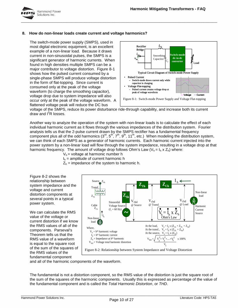
The switch-mode power supply (SMPS), used in most digital electronic equipment, is an excellent example of a non-linear load. Because it draws current in non-sinusoidal pulses, the SMPS is a significant generator of harmonic currents. When found in high densities multiple SMPS can be a major contributor to voltage distortion. Figure 8-1 shows how the pulsed current consumed by a single-phase SMPS will produce voltage distortion in the form of flat-topping. Since current is consumed only at the peak of the voltage waveform (to charge the smoothing capacitor), voltage drop due to system impedance will also occur only at the peak of the voltage waveform. A flattened voltage peak will reduce the DC bus voltage of the SMPS, reduce its power disturbance ride-through capability, and increase both its current draw and I2R losses. Another way to analyze the operation of the system with non-linear loads is to calculate the effect of each individual harmonic current as it flows through the various impedances of the distribution system. Fourier analysis tells us that the 2-pulse current drawn by the SMPS rectifier has a fundamental frequency component plus all of the odd harmonics (3rd, 5th, 7th, 9th, 11th, etc.) When modeling the distribution system, we can think of each SMPS as a generator of harmonic currents. Each harmonic current injected into the power system by a non-linear load will flow through the system impedance, resulting in a voltage drop at that harmonic frequency. The amount of voltage drop follows Ohm’s Law (Vh = Ih x Zh) where: Vh = voltage at harmonic number h Ih = amplitude of current harmonic h Zh = impedance of the system to harmonic h. Figure 8-2 shows the relationship between system impedance and the voltage and current distortion components at several points in a typical power system. We can calculate the RMS value of the voltage or current distortion if we know the RMS values of all of the components. Parseval’s Theorem tells us that the RMS value of a waveform is equal to the square root of the sum of the squares of the RMS values of the fundamental component and all of the harmonic components of the waveform. The fundamental is not a distortion component, so the RMS value of the distortion is just the square root of the sum of the squares of the harmonic components. Usually this is expressed as percentage of the value of the fundamental component and is called the Total Harmonic Distortion, or THD.

______________________________________________________________________________________________________________________________
_________________________________________________________________________________________________________________ Hammond Power Solutions Inc. Literature Code: HPS-TA5
Harmonic Mitigating Transformers - FAQ
Page 11 of 27
Voltage total harmonic distortion (Vthd) is calculated as:
V thd = V 22 +V 3
2 +V 42 +V 5
2 +....V 1
x 100%
Similarly, current total harmonic distortion is calculated as:
I thd = I 22 +I 3
2 +I 42 +I 5
2 +....I 1
x 100%
Voltage distortion then is a function of both the system impedance and the amount of harmonic current in the system. The higher the system impedance, (i.e. long cable runs, high impedance transformers, the use of diesel generators or other weak sources) the higher the voltage distortion. In Figure 8-2, we see that voltage distortion is greatest at the loads themselves, since the harmonic currents are subjected to the full system impedance (cables, transformer and source) at that point. This is a characteristic most often misunderstood. It means that even if voltage distortion levels are low at the service entrance, they can be unacceptably high at the loads themselves. It also emphasizes the importance of keeping system impedances relatively low when servicing non-linear loads. Voltage distortion can be minimized by removing the harmonic currents (Ih) and/or lowering the system impedance (Zh) to the harmonics. (For further information on the relationship between voltage drop & voltage distortion and how to minimize them, and on how Harmonic Mitigating Transformers reduce voltage distortion see Question 13.

______________________________________________________________________________________________________________________________
_________________________________________________________________________________________________________________ Hammond Power Solutions Inc. Literature Code: HPS-TA5
Harmonic Mitigating Transformers - FAQ
Page 12 of 27
-200
-150
-100
-50
0
50
100
150
200
Volta
ge
DC Bus Voltage with: Sinusoidal Input Voltage (blue)Flat-topped Input Voltage (red)
• Voltage flat-topping reduces DC bus voltage
• Lower DC voltage, increases current and I2R losses (heat)
• Pre-mature component failure results from higher operating temperatures
10% drop in peak voltage produces
11% increase in current and
23% increase in I2R losses
P = V IIf V = 0.9 pu, I = P = 1.0 = 1.11 pu
V 0.9
PLoss = I2R = (1.11)2 (1) = 1.23 pu
-200
-150
-100
-50
0
50
100
150
200
Volta
ge
DC Bus Voltage with: Sinusoidal Input Voltage (blue)Flat-topped Input Voltage (red)
-200
-150
-100
-50
0
50
100
150
200
Volta
ge
DC Bus Voltage with: Sinusoidal Input Voltage (blue)Flat-topped Input Voltage (red)
• Voltage flat-topping reduces DC bus voltage
• Lower DC voltage, increases current and I2R losses (heat)
• Pre-mature component failure results from higher operating temperatures
10% drop in peak voltage produces
11% increase in current and
23% increase in I2R losses
P = V IIf V = 0.9 pu, I = P = 1.0 = 1.11 pu
V 0.9
PLoss = I2R = (1.11)2 (1) = 1.23 pu Figure 9-1: How voltage flat-topping affects DC bus voltage and equipment over-heating
• Voltage flat-topping reduces DC bus voltage
-200
-150
-100
-50
0
50
100
150
200
Volta
ge
Power Interruption
DC Bus Voltage with: Sinusoidal Input Voltage (blue)Flat-topped Input Voltage (red)
V=70%
• With less stored energy ride-through capability is reduced
• Lower charging voltage on smoothing capacitor, reduces stored energy
Energy recovered from capacitor during ride-through: WR = 1/2 C (V1
2 – V22)
With drop-out voltage = 70% (V2 = 0.7 pu)V1 = 1 pu, V1 = 0.9 pu
WR = (12 – 0.7 2) WR = (0.92 – 0.7 2)= 0.51 pu = 0.32 pu
(0.51 – 0.32) x 100% = 37%0.51
10% drop in peak voltagereduces
ride-through capabilityby 37%
Figure 9-2: How voltage flat-topping affects equipment ride-through capability
9. What ill effects do harmonics created by the computer power supplies have on themselves?
As voltage becomes more and more distorted, it will begin to have a negative effect on the connected equipment. A flat-topped voltage waveform can affect a switch-mode power supply (SMPS) in at least 2 major ways:
• A reduced peak voltage will translate to a lower DC bus voltage in the SMPS. Input current to the SMPS will increase because the computer or other electronic load still requires the same amount of power. Increased I2R losses in the SMPS accelerate the aging of its components.
• Power disturbance ride-through capability is reduced since the reduced peak voltage means the large filter capacitor on the DC bus of the SMPS will be able to store much less energy.
When an SMPS is supplied by a voltage waveform with a flattened peak (red trace in Figure 9.1) rather than a nearly pure sinusoidal voltage (blue trace), the DC bus voltage is reduced proportionately (red trace). With a lower DC bus voltage, the SMPS will need to draw more current in order to deliver the same amount of power required by the load (I = P/V). This increase in current will result in increased component heating from higher I2R losses and a reduced life expectancy of the components due to their higher operating temperature. For example, a 10% decrease in peak voltage (from 169V to 153V) will increase the SMPS line current by about 11% which will in turn increase the I2R portion of the SMPS losses by about 23%. The correlation of SMPS failures with increased voltage distortion is usually subtle because equipment aging takes time to accumulate.
The first purpose of the large filter capacitor on the DC bus of an SMPS is to reduce the voltage ripple. The second purpose is to support its electronic load during a power disturbance that produces a momentary power interruption or major power dip. Since a typical SMPS is capable of operating for short periods at voltage levels as low as 70%, we can calculate the reduction in ride-through time if the initial voltage stored in the capacitor is below its rated peak voltage. For instance, if the peak voltage supplied to the SMPS is flat-topped by 30%, the ride-through capability is essentially zero and the I2R losses are twice those present at rated peak voltage.
With the correct initial peak voltage, the stored energy in the capacitor will often provide several cycles of ride-through capability before its voltage is reduced to 70% of nominal. This is dramatically reduced however, when the SMPS supply voltage is flat-topped because the energy stored in the capacitor is proportional to the square of the voltage. Figure 9-2 shows how a 10% reduction in the peak voltage supplied to computer equipment will reduce the power dip ride-through time by about 37%. Without the correct peak voltage, the smoothing capacitor in the SMPS will not be fully charged. Initially lower stored energy means that the capacitor will support the load for a much shorter period during a power interruption.

______________________________________________________________________________________________________________________________
_________________________________________________________________________________________________________________ Hammond Power Solutions Inc. Literature Code: HPS-TA5
Harmonic Mitigating Transformers - FAQ
Page 13 of 27
When voltage flat-topping becomes severe enough, brief power interruptions such as those characterized by the lights flickering, will begin to affect equipment that would otherwise be unaffected. In order to ensure reliable operation of power electronic equipment as well as other equipment on the power system, it is important to simultaneously maintain the correct level of both RMS voltage and peak voltage. This can best be achieved by using harmonic mitigation equipment that minimizes voltage distortion throughout the system by removing the harmonic currents from interacting with the upstream supply and distribution equipment.
______________________________________________________________________________________________________________________________
_________________________________________________________________________________________________________________ Hammond Power Solutions Inc. Literature Code: HPS-TA5
Harmonic Mitigating Transformers - FAQ
Page 14 of 27
∑=
−=max
1
221
h
hhECEC hIPP
10. How do harmonics increase power losses and overheat transformers?
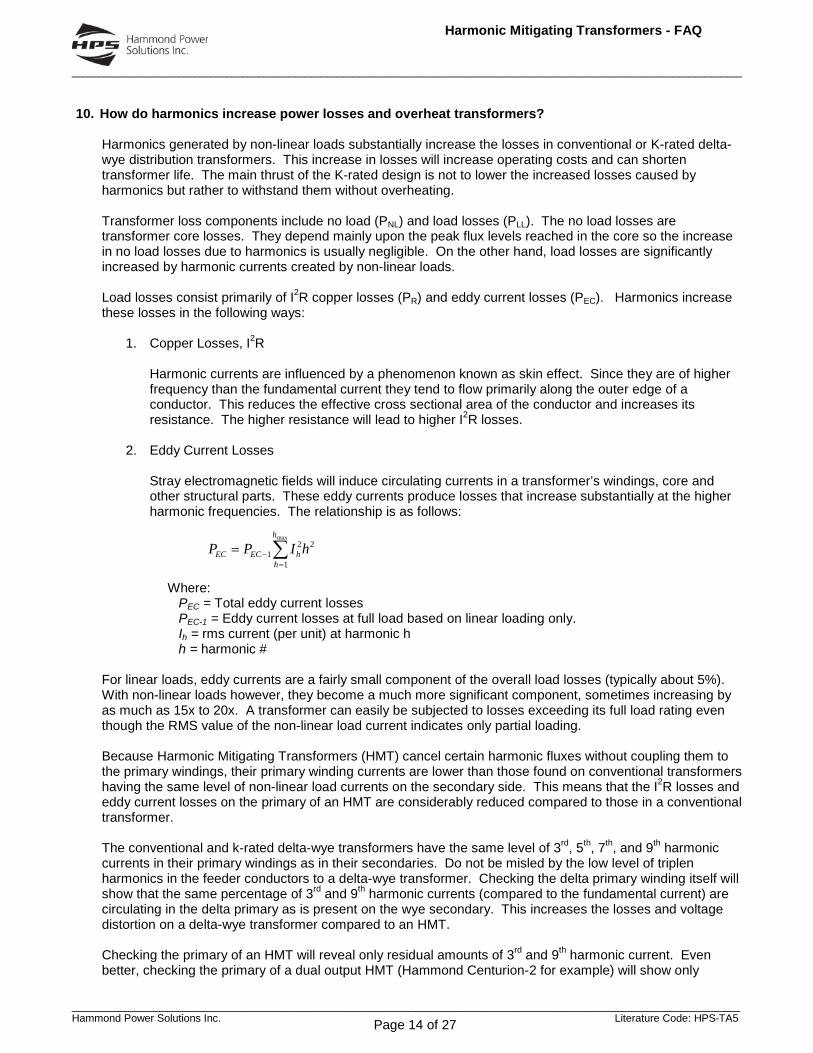
Harmonics generated by non-linear loads substantially increase the losses in conventional or K-rated delta-wye distribution transformers. This increase in losses will increase operating costs and can shorten transformer life. The main thrust of the K-rated design is not to lower the increased losses caused by harmonics but rather to withstand them without overheating. Transformer loss components include no load (PNL) and load losses (PLL). The no load losses are transformer core losses. They depend mainly upon the peak flux levels reached in the core so the increase in no load losses due to harmonics is usually negligible. On the other hand, load losses are significantly increased by harmonic currents created by non-linear loads. Load losses consist primarily of I2R copper losses (PR) and eddy current losses (PEC). Harmonics increase these losses in the following ways:
1. Copper Losses, I2R
Harmonic currents are influenced by a phenomenon known as skin effect. Since they are of higher frequency than the fundamental current they tend to flow primarily along the outer edge of a conductor. This reduces the effective cross sectional area of the conductor and increases its resistance. The higher resistance will lead to higher I2R losses.
2. Eddy Current Losses
Stray electromagnetic fields will induce circulating currents in a transformer’s windings, core and other structural parts. These eddy currents produce losses that increase substantially at the higher harmonic frequencies. The relationship is as follows:
Where: PEC = Total eddy current losses PEC-1 = Eddy current losses at full load based on linear loading only. Ih = rms current (per unit) at harmonic h h = harmonic #
For linear loads, eddy currents are a fairly small component of the overall load losses (typically about 5%). With non-linear loads however, they become a much more significant component, sometimes increasing by as much as 15x to 20x. A transformer can easily be subjected to losses exceeding its full load rating even though the RMS value of the non-linear load current indicates only partial loading. Because Harmonic Mitigating Transformers (HMT) cancel certain harmonic fluxes without coupling them to the primary windings, their primary winding currents are lower than those found on conventional transformers having the same level of non-linear load currents on the secondary side. This means that the I2R losses and eddy current losses on the primary of an HMT are considerably reduced compared to those in a conventional transformer. The conventional and k-rated delta-wye transformers have the same level of 3rd, 5th, 7th, and 9th harmonic currents in their primary windings as in their secondaries. Do not be misled by the low level of triplen harmonics in the feeder conductors to a delta-wye transformer. Checking the delta primary winding itself will show that the same percentage of 3rd and 9th harmonic currents (compared to the fundamental current) are circulating in the delta primary as is present on the wye secondary. This increases the losses and voltage distortion on a delta-wye transformer compared to an HMT. Checking the primary of an HMT will reveal only residual amounts of 3rd and 9th harmonic current. Even better, checking the primary of a dual output HMT (Hammond Centurion-2 for example) will show only

______________________________________________________________________________________________________________________________
_________________________________________________________________________________________________________________ Hammond Power Solutions Inc. Literature Code: HPS-TA5
Harmonic Mitigating Transformers - FAQ
Page 15 of 27
residual amounts of 3rd, 5th, 7th, and 9th. Hence lower harmonic losses and lower voltage distortion when HMTs are used to feed non-linear loads.

______________________________________________________________________________________________________________________________
_________________________________________________________________________________________________________________ Hammond Power Solutions Inc. Literature Code: HPS-TA5
Harmonic Mitigating Transformers - FAQ
Page 16 of 27
A B C N
Zero Sequence Currents
A0
C0
B0 C0
B0A0A0 B0 C0
A B C NA B C N
Zero Sequence Currents
A0
C0
B0 C0
B0A0A0 B0 C0
Zero Sequence Currents
A0A0A0
C0C0C0
B0B0B0 C0C0C0
B0B0B0A0A0A0A0A0A0 B0B0B0 C0C0C0
Figure 11-1: Simple Zero Sequence Harmonic Filter
phase conductors
neutral ground
Zco Zto
phase - neutral electronic loads
panel individual circuits A
B C
N G
NCE
Transformer
Z N o
A B C
phase conductors
neutral ground
Zco Zto
phase - neutral electronic loads
panel individual circuits A
B C
N G
NCE
Transformer
Z N o phase conductors
neutral ground
Zco Zto
phase - neutral electronic loads
panel individual circuits A
B C
N G
Filter
Transformer
Z N o
A B C A B C
Figure 11-2: 3rd Harmonic and other zero sequence currents diverted through a zero
11. What are zero sequence harmonic filters and how do they reduce 3rd harmonic currents and
prevent neutral conductor overheating? Zero sequence currents, in simple terms, are those found in the neutral conductor. They include the unbalanced 60 Hz currents and the 3rd, 9th, 15th and other triplen harmonic currents. Zero sequence currents appear in the neutral because they do not cancel in the way that 60Hz currents cancel. This is due to the fact that the zero sequence component on one phase is always in phase with the zero sequence components of the other 2 phases (for further explanation of this see Question 7). 60 Hz current on one phase, on the other hand, is always 120° out of phase with the other phases 60 Hz current which causes their balanced portions to cancel in the neutral. The windings of a zero sequence filter (ZSF) are connected in a manner that exploits the fact that zero sequence currents are always in phase. Figure 11-1 shows the windings of a simple ZSF. Here the coils on each phase are split between two core legs and wound in opposite polarity. Since the zero sequence current vectors (A0, B0 and C0) are always in phase, the flux produced on one coil in each leg will cancel with the flux produced in the second coil on the same leg. Since the zero sequence flux is cancelled, the impedance to the flow of zero sequence currents will be extremely low. When connected in parallel at a power panel or busduct on the power distribution system, the low zero sequence impedance of the ZSF will attract the zero sequence harmonic currents and provide an alternate path back to the loads. This off-loads the neutral conductor and upstream transformer of these currents (see Figure 11-2).

______________________________________________________________________________________________________________________________
_________________________________________________________________________________________________________________ Hammond Power Solutions Inc. Literature Code: HPS-TA5
Harmonic Mitigating Transformers - FAQ
Page 17 of 27
12. What is a Harmonic Mitigating Transformer and how is it different than a K-Rated Transformer?
Harmonic Mitigating Transformers, or HMTs, are specifically designed to minimize the voltage distortion and power losses that result from the harmonics generated by non-linear loads such as personal computers. K-rated transformers, on the other hand, are simply designed to prevent their overheating when subjected to heavy non-linear loading, but do very little to reduce the harmonic losses themselves. And as for voltage distortion, they perform virtually no better than conventional delta-wye transformers.
______________________________________________________________________________________________________________________________
_________________________________________________________________________________________________________________ Hammond Power Solutions Inc. Literature Code: HPS-TA5
Harmonic Mitigating Transformers - FAQ
Page 18 of 27
13. How do Harmonic Mitigating Transformers reduce voltage distortion?
Delta-wye transformers, even those with a high K-factor rating, generally present high impedance to the flow of harmonic currents created by the non-linear loads. Question 8 showed that the non-linear loads are current sources that push the harmonic currents through the impedances of the system. Any voltage drop across the impedance of the transformer at other than the fundamental frequency (60 Hz) is a component of voltage distortion. Because of its higher impedance to harmonic currents, the voltage distortion at the output of a delta-wye transformer often reaches the 5% maximum voltage distortion limit recommended by IEEE Std. 519-1992 by the time that the secondary side load has reached just one-half of full-load RMS current. At closer to full-load, these transformers can produce critically high levels of voltage distortion and flat-topping at their outputs and at the downstream loads. To minimize the voltage distortion rise due to the transformer itself, Harmonic Mitigating Transformers (HMTs) are designed to reduce the impedance seen by the harmonic currents. This is accomplished through zero sequence flux cancellation and through phase shifting - a combined strategy pioneered by Hammond. The secondary winding configuration of the HMT cancels the zero sequence fluxes (those produced by the 3rd, 9th, 15th (triplen) current harmonics) without coupling them to the primary windings. This prevents the triplen current harmonics from circulating in the primary windings as they do in a delta-wye transformer. The flux cancellation also results in much lower impedance to the zero sequence currents and hence lower voltage distortion at these harmonics. In addition, the reduced primary winding circulating current will lower losses and allow the transformer to run cooler. The remaining major harmonics (5th, 7th, 11th, 13th, 17th & 19th) are treated to varying degrees through the introduction of phase shifts in the various HMT models. Single output HMTs are offered in 0° and 30° models to provide upstream cancellation of 5th, 7th, 17th and 19th harmonic currents on the primary feeder. In a dual output HMT, 5th, 7th, 17th and 19th harmonic current fluxes are cancelled by the 30° phase shift between the secondary windings so that only residual amounts of 5th, 7th, 17th, and 19th current harmonics will be found in the primary side windings. A three output HMT is configured such that the relative phase shift between the three sets of secondary windings will cancel 5th, 7th, 11th and 13th harmonic fluxes without coupling them to the primary windings.
______________________________________________________________________________________________________________________________
_________________________________________________________________________________________________________________ Hammond Power Solutions Inc. Literature Code: HPS-TA5
Harmonic Mitigating Transformers - FAQ
Page 19 of 27
02000400060008000
10000
Conv. K-13 H-1 H-1E H-2
Transformer Type
Loss
es (W
) Full75%50%35%No Load
Figure 14-1: 112.5 kVA Transformer losses at various loading conditions with non-linear K-9 load profile.
14. How do Harmonic Mitigating Transformers save energy?
Harmonic Mitigating Transformers reduce harmonic losses in the following ways: 1. Zero phase sequence harmonic fluxes are cancelled by the transformers secondary windings. This
prevents triplen harmonic currents from being induced into the primary windings where they would circulate. Consequently, primary side I2R and eddy current losses are reduced.
2. Multiple output HMTs cancel the balanced portion of the 5th, 7th and other harmonics within their secondary windings. Only residual, unbalanced portions of these harmonics will flow through to the primary windings. Again I2R and eddy current losses are reduced.
3. EnergyStar compliant models are available. Designed for optimum efficiency at 35% loading, EnergyStar compliant designs reduce core losses to further improve efficiencies under lightly loaded conditions.
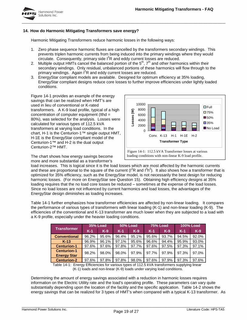
Figure 14-1 provides an example of the energy savings that can be realized when HMT’s are used in lieu of conventional or K-rated transformers. A K-9 load profile, typical of a high concentration of computer equipment (Ithd = 80%), was selected for the analysis. Losses were calculated for various types of 112.5 kVA transformers at varying load conditions. In the chart, H-1 is the Centurion-1™ single output HMT, H-1E is the EnergyStar compliant model of the Centurion-1™ and H-2 is the dual output Centurion-2™ HMT. The chart shows how energy savings become more and more substantial as a transformer’s load increases. This is logical since it is the load losses which are most affected by the harmonic currents and these are proportional to the square of the current (I2R and I2h2). It also shows how a transformer that is optimized for 35% efficiency, such as the EnergyStar model, is not necessarily the best design for reducing harmonic losses. (For more on EnergyStar see Question 15). Obtaining high efficiency designs at 35% loading requires that the no load core losses be reduced – sometimes at the expense of the load losses. Since no load losses are not influenced by current harmonics and load losses, the advantages of the EnergyStar design diminishes as loading increases. Table 14-1 further emphasizes how transformer efficiencies are affected by non-linear loading. It compares the performance of various types of transformers with linear loading (K-1) and non-linear loading (K-9). The efficiencies of the conventional and K-13 transformer are much lower when they are subjected to a load with a K-9 profile, especially under the heavier loading conditions.
K-1 K-9 K-1 K-9 K-1 K-9 K-1 K-9Conventional 96.2% 95.6% 96.4% 95.1% 95.6% 93.7% 94.5% 92.0%
K-13 96.9% 96.1% 97.1% 95.6% 96.6% 94.4% 95.9% 93.0%Centurion-1 97.6% 97.6% 97.8% 97.7% 97.6% 97.5% 97.3% 97.1%Centurion-1Energy StarCenturion-2 97.6% 97.8% 97.8% 98.0% 97.6% 97.9% 97.3% 97.6%
35% Load 50% Load 75% Load 100% Load
98.2% 98.0% 98.0% 97.9% 97.7% 97.9% 97.3% 97.0%
Transformer
Table 14-1: Energy Efficiencies for various types of 112.5 kVA transformers supplying linear
(K-1) loads and non-linear (K-9) loads under varying load conditions. Determining the amount of energy savings associated with a reduction in harmonic losses requires information on the Electric Utility rate and the load’s operating profile. These parameters can vary quite substantially depending upon the location of the facility and the specific application. Table 14-2 shows the energy savings that can be realized for 3 types of HMT’s when compared with a typical K-13 transformer. As

______________________________________________________________________________________________________________________________
_________________________________________________________________________________________________________________ Hammond Power Solutions Inc. Literature Code: HPS-TA5
Harmonic Mitigating Transformers - FAQ
Page 20 of 27
in the previous examples, the transformers are all 112.5 kVA and the non-linear load profile is that of a typical K-9 load. The monetary savings are based on the equipment operating 12 hours per day, 260 days per year at an average Utility rate of $0.07 per kWhr. The calculation is as follows: Annual Energy Savings = (Energy Savings in kW) x (hrs/day) x (days/yr) x (rate in $/kWhr) It is worthwhile noting that if the transformer were located in air conditioned space, additional savings in reduced cooling costs (30% - 40%) would be realized. In summary, the inherent ability of Harmonic Mitigating Transformers to cancel harmonic currents within their windings can result in quantifiable energy savings when compared with the losses that would exist if conventional or K-rated transformers were used. If we consider the average premium cost of an HMT over a K-13 transformer, the typical payback in energy savings is 3 – 4 years when loading is expected to be in the 50% - 75% range.
%Load (Watts) ($ / yr)50% n/a n/a
K-13 75% n/a n/a100% n/a n/a50% 1249 $273
Centurion-1 75% 2783 $608100% 4930 $1,077
Centurion-1 50% 1331 $29175% 2745 $600100% 4723 $1,03250% 1363 $298
Centurion-2 75% 3027 $661100% 5356 $1,170
Energy Savings
1603
(Watts)28525610
Energy Star152128654747
9470
LossesTransformer
25834114
1489
28274540
Table 14-2: HMT energy savings comparing various
types of 112.5 kVA HMT’s to a typical K-13 transformer
______________________________________________________________________________________________________________________________
_________________________________________________________________________________________________________________ Hammond Power Solutions Inc. Literature Code: HPS-TA5
Harmonic Mitigating Transformers - FAQ
Page 21 of 27
15. What constitutes an EPA EnergyStar Transformer and is it important when supplying non-linear
loads? The EnergyStar program is sponsored by the US Environmental Protection Agency (EPA) and is designed to encourage the use of energy efficient products. The EnergyStar logo is found on many household appliances and other products identifying that they’ve been designed to specific energy efficiency standards. For transformers, the EnergyStar program is based upon the NEMA TP-1 ‘Guide for Determining Energy Efficiency for Distribution Transformers’. NEMA TP-1 defines minimum efficiency levels for transformers with linear loads at 35% loading. This criteria was chosen based on surveys which indicated that the average loading on distribution transformers in North America is about 35%. The efficiency limits vary by transformer size but are generally in the 98% range. In choosing 35% loading, NEMA TP-1 puts extra emphasis on no-load (core) losses rather than load (copper) losses. Because of its emphasis on no-load losses, NEMA TP-1 specifically exempts transformers which service non-linear loads. The following are taken from its exemption list: c. Drives transformers, both AC and DC
d. All rectifier transformers and transformers designed for high harmonics g. Special impedance, regulation and harmonic transformers The reason that transformers designed for high harmonics are exempted is that harmonics will dramatically increase load losses (I2R and eddy current) and have very little effect on no-load losses. Therefore, NEMA TP-1’s emphasis on no-load losses can be counter productive when supplying non-linear loads. To meet the efficiency limits, a manufacturer must optimize for lower no-load losses, sometimes at the expense of higher load losses. For example, one common way of reducing no-load losses is to add more steel to the transformers core. With a larger core, each turn of the transformers windings must cover a larger circumference. The extra length of copper winding adds resistance which increases I2R load losses. This can significantly INCREASE losses and REDUCE efficiencies when supplying non-linear loads at load levels above 50%. Although Hammond Power Solutions Inc. offers EnergyStar compliant models, we do not promote their use in applications where loading has the possibility of exceeding 50%. Figure 14-1 in Question 14 shows transformer losses under non-linear loading at various load conditions. Here it can be seen that the EnergyStar model Centurion-1 has slightly lower losses than our standard Centurion-1 without EnergyStar constructed model when loading is less than 50% but has higher losses at 75% and 100% loading. Even if the loading is expected to be less than 50%, the higher cost of the EnergyStar compliant model will normally extend the payback period. The choice of a Harmonic Mitigating Transformer for a non-linear load application is already an energy efficient one. There is no need to require EnergyStar compliance as well.

______________________________________________________________________________________________________________________________
_________________________________________________________________________________________________________________ Hammond Power Solutions Inc. Literature Code: HPS-TA5
Harmonic Mitigating Transformers - FAQ
Page 22 of 27
16. How reliable are transformer energy efficiency measurements under non-linear loading? Accurately determining the energy efficiency of a transformer through measurements is very difficult for non-linear loading.
The obvious approach of applying a non-linear load bank and then simply measuring the transformer input power and output power in order to calculate the efficiency is inadequate because of the sensitivity of the calculation to instrument errors. Incidentally, this obvious method is equally inadequate for both non-linear and linear loads.
For example, a transformer that is truly 97% efficient could be reported at 98%, a 1% positive error even though the measurements themselves were accurate within +/- 0.5%.
True Output Power = 97 kW True Input Power = 100 kW, True Efficiency = 97 / 100 or 97%.
But with +/- 0.5% accuracy in power measurements, the result could be:
Measured Output Power = 97kW + 0.5kW = 97.5 kW Measured Input Power = 100kW – 0.5kW = 99.5kW Calculated Efficiency = 97.5 / 99.5 = 98%, a full 1% error despite measurement accuracy within +/- 0.5%.
Similarly, the calculated result could have been 96% if the errors were reversed.
The efficiency levels that transformers must attain to be eligible for the EPA EnergyStar Program in the United States are based upon NEMA Standard TP-1. That standard requires that transformer losses be measured directly so as to permit calculation of Efficiency = Output Power / (Output Power + Transformer Losses).
The above calculation is equivalent to Efficiency = Output Power / Input Power but produces more accurate and repeatable results because now the losses are measured directly.
Repeating the above example, this time with a +/- 1.0% accuracy in measuring the transformer losses themselves, shows that the highest error in efficiency is +/- 0.03%.
Output Power = 97kW Measured Losses = 3kW – 0.01 x 3 kW = 2.97 kW Efficiency = 97/ (97 + 2.97) = 97 / 99.97 = 97.03%
Similarly, the calculated result could have been 96.97% if the errors were reversed. The classic techniques for measuring transformer total losses accurately are the Open Circuit and Short Circuit Tests. The Open Circuit or No-load Test measures core losses (iron losses). The Short Circuit Test or Load Test measures load losses which are also called I2R losses or copper losses. Unfortunately this more accurate method of directly measuring the losses themselves per Standard TP-1 inherently applies only to transformer operation with a linear load. For non-linear load we must revert to the much less accurate method of calculating efficiency based on direct measurements of Output and Input Power. Claims by any party of highly accurate transformer testing with non-linear loads should not be accepted without reviewing their complete test report that must include documentation on measurement techniques and certified instrumentation accuracy. The best way to ensure that the transformer you select is highly efficient under non-linear loading is to specify a harmonic mitigating transformer that has been (1) accurately tested for your required linear load efficiency and (2) employs flux cancellation techniques for triplen harmonics so that it has a very low zero sequence impedance. Your choice of either the Hammond standard Centurion Series HMTs or the Hammond EnergyStar compliant Centurion Series HMTs should depend upon the percent load expected as explained in Question 14 titled, ‘How Do Harmonic Mitigating Transformers Save Energy?’. Those interested in looking further at the source of the instrumentation errors and how large they can be should refer to a paper by Dr. Alexander Emanuel in IEEE Transactions on Industry Applications, Vol. 33 No.

______________________________________________________________________________________________________________________________
_________________________________________________________________________________________________________________ Hammond Power Solutions Inc. Literature Code: HPS-TA5
Harmonic Mitigating Transformers - FAQ
Page 23 of 27
6 Nov./Dec. 1997 titled ‘True and False Energy-Saving Devices’. This paper is quite mathematical, but the essence is (1) watch out for changing current wave shapes with non-linear loading and (2) the accuracy of clamp-on ammeters is often far from adequate. Incidentally the article deals with TVSS and Power Factor Correction devices but is applicable to power measurements in general.

______________________________________________________________________________________________________________________________
_________________________________________________________________________________________________________________ Hammond Power Solutions Inc. Literature Code: HPS-TA5
Harmonic Mitigating Transformers - FAQ
Page 24 of 27
17. Am I not safe from harmonics if I use K-Rated transformers and oversized neutrals?
K-Rated transformers made their appearance several years ago as a means of preventing transformers from failing when subjected to heavy non-linear loading. They are essentially ‘beefed up’ transformers with extra steel in their cores and copper in their windings to allow for better dissipation of the excessive losses produced by harmonic currents. They are not designed to cancel harmonics or their fluxes and therefore, do nothing but protect themselves from overheating. Harmonic losses are normally not significantly reduced and voltage distortion will typically remain quite high under more heavily loaded conditions. To improve power quality in the form of reduced voltage distortion and to save energy costs, the use of a transformer designed to cancel harmonics is necessary. Over-sizing neutrals, on the other hand, can be a reasonably low cost method for the prevention of neutral conductor overheating. It is important to remember that the non-linear loads are the source of the harmonic currents. They must flow from the loads back to the transformer. Because the 3rd and 9th current harmonics created by the 120 VAC switch-mode power supplies are flowing back on the neutral, the neutral current is usually larger than the phase currents (see Question 7). This is of minimal consequence provided the neutral has suitable ampacity to carry the extra current and the 120/208V 4-wire run length is not too long. When selecting phase and neutral conductor sizes in a non-linear load application, the electrical code requires that an ampacity adjustment or correction factor be applied. This is because the neutral conductor is considered to be a current carrying conductor along with PhA, PhB and PhC. With more than 3 current carrying conductors in a conduit or raceway, a 0.8 factor must be applied. To minimize harmonic problems in new installations, avoid the old approach of using a large central transformer with a 120/208V secondary and long 4-wire risers or radial runs through the building. The impedances of these long runs are high so that harmonic currents flowing through these impedances will create high levels of voltage distortion and neutral-to-ground voltage. To prevent these problems, an effective rule of thumb is to limit each 120/208V run length to that which would produce a 60Hz voltage drop not greater than 1/2% to 3/4%. For a typical 200 amp feeder this would be < 50 ft. Combining the use of Harmonic Mitigating Transformers with short 120/208V feeder runs and double ampacity neutrals will ensure compatibility between the distribution system and the non-linear loads. Generally this will keep voltage distortion safely below the maximum of 5% as recommended for sensitive loads in IEEE Std 519-1992.

______________________________________________________________________________________________________________________________
_________________________________________________________________________________________________________________ Hammond Power Solutions Inc. Literature Code: HPS-TA5
Harmonic Mitigating Transformers - FAQ
Page 25 of 27
18. Are there standards that can help in addressing harmonics?
The standard most commonly applied to the control of harmonics in Power Systems is IEEE standard 519, ‘IEEE Recommended Practices and Requirements for Harmonic Control in Electrical Power Systems‘. This standard recommends maximum acceptable limits for both voltage and current harmonics to prevent problems that can result from heavy non-linear loading. The limits for harmonic currents are designed to minimize the amount of voltage distortion these currents would produce in the power system.

______________________________________________________________________________________________________________________________
_________________________________________________________________________________________________________________ Hammond Power Solutions Inc. Literature Code: HPS-TA5
Harmonic Mitigating Transformers - FAQ
Page 26 of 27
19. Can neutral currents, such as the 3rd harmonic, be reduced by the use of 3rd harmonic blocking
filters? Some manufacturers are promoting the use of 3rd harmonic (180 Hz) blocking filters for the treatment of high neutral currents caused by non-linear loads such as personal computers. These devices are parallel L-C filters tuned to 180 Hz and are connected in the neutral of 4-wire systems between the transformer secondary and the neutral-to-ground connection. Their high impedance to the flow of 3rd harmonic current forces all connected equipment to draw current that does not contain the 3rd harmonic. Although their use will result in a significant reduction in 3rd harmonic current, it is achieved at the risk of rather severe consequences.
Figure 14: Typical installation of 3rd Harmonic Blocking Filter
Some reasons for concern are as follows: 1. The installation raises questions with respect to NEC 2002 compliance. NEC 250.30(A)(2)(a) states that
“a grounding electrode conductor for a single separately derived system … shall be used to connect the grounded conductor of the derived system to the grounding electrode…” In addition, “the grounding electrode conductor shall be installed in one continuous length without a splice or joint…” [Italics added. See NEC 250.64(C)]. If a simple splice connection is not allowed, then certainly the L-C circuit of the 3rd harmonic blocking filter should not be allowed either. Also, the installation results in an impedance grounded wye system rather than a solidly grounded system. The only reference in NEC that allows for the introduction of impedance between the neutral and the grounding electrode is found in Section 250.36, High-Impedance Grounded Neutral Systems. However, these systems are permitted only at 480V and higher and only if they do not serve line-to-neutral loads. They also require the use of ground fault detectors. None of these requirements is met in the normal application of the 3rd harmonic blocking filter where the loads are primarily 120V, phase-to-neutral connected computer or other power electronic equipment.
2. Although tuned to 180 Hz, the L-C circuit will introduce some impedance at 60 Hz as well. The consequences are:
a. Line-neutral short circuit current will be reduced which will limit a circuit breakers ability to clear a line-neutral fault. This can be very dangerous because an uninterrupted fault (commonly referred to as an arcing fault) will often result in an electrical fire.
b. The neutral point at the transformers wye secondary can shift. This can result in 120V line-neutral voltages that rise and fall unpredictably as the load balance between the phases varies.
3. High impedance to the flow of 3rd harmonic current will produce voltage distortion in the form of flat-topping - a dramatic reduction in peak to peak voltage. This will:
a. Significantly reduce the ride-through capability of switch-mode power supplies (SMPS) since the DC smoothing capacitors will not be allowed to fully charge.
b. Reduce the SMPS DC bus voltage, thereby increasing the current demand and the associated I2R losses. Component reliability will be reduced due to higher operating temperatures.
c. Often cause 1-ph UPS systems to switch to battery back-up. d. Force connected equipment to operate without 3rd harmonic current – an operating mode for
which they have not been intended or tested.
______________________________________________________________________________________________________________________________
_________________________________________________________________________________________________________________ Hammond Power Solutions Inc. Literature Code: HPS-TA5
Harmonic Mitigating Transformers - FAQ
Page 27 of 27
Figure 2: Voltage Flat-topping caused by 3rd Harmonic
Blocking Filter
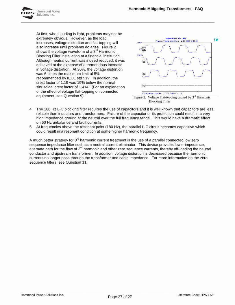
At first, when loading is light, problems may not be extremely obvious. However, as the load increases, voltage distortion and flat-topping will also increase until problems do arise. Figure 2 shows the voltage waveform of a 3rd Harmonic Blocking Filter installation at a financial institution. Although neutral current was indeed reduced, it was achieved at the expense of a tremendous increase in voltage distortion. At 30%, the voltage distortion was 6 times the maximum limit of 5% recommended by IEEE std 519. In addition, the crest factor of 1.19 was 19% below the normal sinusoidal crest factor of 1.414. (For an explanation of the effect of voltage flat-topping on connected equipment, see Question 9).
4. The 180 Hz L-C blocking filter requires the use of capacitors and it is well known that capacitors are less
reliable than inductors and transformers. Failure of the capacitor or its protection could result in a very high impedance ground at the neutral over the full frequency range. This would have a dramatic effect on 60 Hz unbalance and fault currents.
5. At frequencies above the resonant point (180 Hz), the parallel L-C circuit becomes capacitive which could result in a resonant condition at some higher harmonic frequency.
A much better strategy for 3rd harmonic current treatment is the use of a parallel connected low zero sequence impedance filter such as a neutral current eliminator. This device provides lower impedance, alternate path for the flow of 3rd harmonic and other zero sequence currents, thereby off-loading the neutral conductor and upstream transformer. In addition, voltage distortion is decreased because the harmonic currents no longer pass through the transformer and cable impedance. For more information on the zero sequence filters, see Question 11.