Hardware Manual for use with PCI-GPIB, ISA-GPIB · Chapter One: INTRODUCTION 1.1 HISTORY The GPIB...
17
User's Guide http://www.omega.com e-mail: [email protected] GPIB HARDWARE MANUAL FOR USE WITH PCI-GPIB, ISA-GPIB
Transcript of Hardware Manual for use with PCI-GPIB, ISA-GPIB · Chapter One: INTRODUCTION 1.1 HISTORY The GPIB...

User's Guide
http://www.omega.come-mail: [email protected]
GPIB HARDWARE MANUALFOR USE WITHPCI-GPIB, ISA-GPIB

142.6 CPCI-GPIB. . . . . . . . . . . . . . . . . . . . . . . . . . . . . . . . . . . . . . . .122.5 PC104-GPIB. . . . . . . . . . . . . . . . . . . . . . . . . . . . . . . . . . . . . . .112.4.2 Windows 3.1. . . . . . . . . . . . . . . . . . . . . . . . . . . . . . . . . . .112.4.1 Windows 95. . . . . . . . . . . . . . . . . . . . . . . . . . . . . . . . . . . .102.4 PCM-GPIB . . . . . . . . . . . . . . . . . . . . . . . . . . . . . . . . . . . . . . . .82.3 ISA-GPIB/LC . . . . . . . . . . . . . . . . . . . . . . . . . . . . . . . . . . . . . . .62.2 ISA-GPIB . . . . . . . . . . . . . . . . . . . . . . . . . . . . . . . . . . . . . . . . . .52.1 PCI-GPIB . . . . . . . . . . . . . . . . . . . . . . . . . . . . . . . . . . . . . . . . . .5CHAPTER TWO: INSTALLATION . . . . . . . . . . . . . . . . . . .31.2.3 Connection Configurations. . . . . . . . . . . . . . . . . . . . . . . . .21.2.2 GPIB Electrical Signal Configuration. . . . . . . . . . . . . . . .11.2.1 Talkers, Listeners, and Controllers. . . . . . . . . . . . . . . . . .11.2 GPIB SYSTEM DESCRIPTION. . . . . . . . . . . . . . . . . . . . . . . .11.1 HISTORY . . . . . . . . . . . . . . . . . . . . . . . . . . . . . . . . . . . . . . . . . .1CHAPTER ONE: INTRODUCTION . . . . . . . . . . . . . . . . . . . . . .

Chapter One: INTRODUCTION
1.1 HISTORY
The GPIB (General Purpose Interface Bus) has become the worldwide standard forconnecting instruments to computers. Invented in the 1960s by Hewlett Packard andoriginally designated as HPIB, the bus specification was eventually adopted by a widevariety of both instrument and computer manufacturers. The original specification wasdocumented and sanctioned by the Institute of Electrical and Electronic Engineers asIEEE-488.
The advent of the inexpensive and powerful personal computer has driven the GPIBmarket through explosive growth. As GPIB bus usage expanded, there arose the needfor some additional capability and standardization, so in 1987, IEEE-488.2 wasadopted. IEEE-488.2 was revised/ammended in 1992 and represents the current GPIBspecification. The new specification provides some standardization among compliantinstruments. These standardization greatly simplifies the job of the GPIB systemdesigner since 488.2 compliant instruments share common programming conventions.
1.2 GPIB SYSTEM DESCRIPTION
1.2.1 Talkers, Listeners, and ControllersA GPIB device can be a Talker, Listener, and/or Controller . As the name implies aTalker sends data to one or more Listeners, A Listener accepts data from a Talker anda Controller manages the flow of information over the bus. A GPIB Digital Voltmeteris acting as a Listener as its input configurations and ranges are set, and then as aTalker when it actually sends its readings to the computer.
The Controller is in charge of all communications over the bus. The Controller’s jobis to make sure only one device tries to talk at a time, and make sure the correct Lis-teners are paying attention when the Talker talks. Each GPIB system has a single sys-tem controller. The system controller is ultimately in charge of the bus, and is incontrol as the bus is powered up. There can be more than one Controller on the busand the System Controller can pass active control to another controller capable device,though only one can be Controller In Charge at a given time. The GPIB board is usually designated as the System Controller.
1.2.2 GPIB Electrical Signal Configuration
1
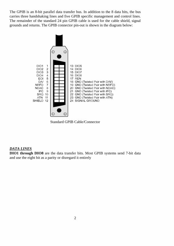
The GPIB is an 8-bit parallel data transfer bus. In addition to the 8 data bits, the buscarries three handshaking lines and five GPIB specific management and control lines.The remainder of the standard 24 pin GPIB cable is used for the cable shield, signalgrounds and returns. The GPIB connector pin-out is shown in the diagram below:
Standard GPIB Cable/Connector
DATA LINESDIO1 through DIO8 are the data transfer bits. Most GPIB systems send 7-bit dataand use the eight bit as a parity or disregard it entirely
2
HANDSHAKING LINESThere are three handshaking lines that control the data transfer between devices.
NRFD (Not Ready For Data): this bit is used to indicate the readiness (or lackthereof) of a device to accept data
DAV (Data Valid): bit is used to indicate to receiving devices that data has beenplaced on the bus and is available to read.
NDAC (Not Data Accepted): is asserted by the receiving device to indicate that datahas been read and may now be removed from the bus.
SYSTEM MANAGEMENT LINESATN (Attention): is used by the controller to specify how data on the DIO lines isinterpreted and which devices must respond to the data
IFC (Interface Clear): is used by the system controller to place the entire system in aknown quiescent (Cleared) state and to assert itself as Controller In Charge (CIC).
SRQ (Service Request): is used by a device on the bus to indicate the need for atten-tion and requests an interrupt of the current event sequence.
REN (Remote Enable): is used by the controller in conjunction with other messagesto place a device on the bus into either remote or local mode
EOI (End or Identify): Is used by Talkers to indicate the end of a message string, oris used by the Controller to command a polling sequence.
1.2.3 Connection ConfigurationsThe GPIB specification is quite definitive regarding the number of devices and cablelengths allowed in a GPIB system. There can be no more than 15 devices on a singlecontiguous GPIB bus. Larger systems are possible by installing additional GPIB inter-face boards in your computer
The maximum, total length of all cables on a single GPIB system is 20 meters. Inaddition, cable length between consecutive devices may be no greater than 4 meters,and average cable length must be 2 meters or less. Stated another way, the total cablelength (in meters) in the system may not be longer than 2 times the number of devices(up to 20 meters). Longer length systems are possible, but only with the use of a GPIBextender card.
In addition to the above rules, at least two thirds of all devices on the bus should bepowered on for proper operation.
3

Keeping the above constraints in mind, there is no limitation on the actual connectionscheme used to connect the GPIB devices together. Star, Linear or any combination ofboth may be used. These are shown in the following diagrams.
4
,QVWUXPHQW &,QVWUXPHQW '
,QVWUXPHQW $
,QVWUXPHQW %
L inear C onnectionC on figura tion
,QVWUXPHQW '
,QVWUXPHQW & ,QVWUXPHQW (,QVWUXPHQW $
,QVWUXPHQW %
S tar C on nectionC on figu ra tio n

Chapter Two: INSTALLATION
The following sections describe the hardware installation procedure for GPIB boards.After hardware installation, please refer to your GPIB software installation guide foradditional setup and operation details.
2.1 PCI-GPIB
The PCI-GPIB board is completely plug and play. To install this board into your sys-tem follow the simple steps shown below.
1. Turn your computer off2. Open your computer case3. Insert the PCI-GPIB into any available PCI slot4. Put your computer’s case back on.5. Turn your computer back on, and follow the instructions in the GPIB software manual you received with your board.
5

2.2 ISA-GPIB
The only hardware configuration required prior to installing the ISA-GPIB/LC is set-ting the board’s Base Address switch. The location of the Base Address switch isshown in the photograph above, while the switch itself is shown in the diagram on thefollowing page.
Most computers will have Base Address 300 Hex (768 decimal) free and the defaultsetting of the board is 300 Hex. If there is already a board in your system usingaddress 300 HEX (768 Decimal), you will have to change the board’s base addressprior to installing it in your computer. Other typically free addresses include 310 Hexand 330 Hex.
6

The following diagram shows the base address in its default 300 Hex setting.
The address values corresponding to each of the switches are shown in the followingtable.
Hex Dec.Switch Value Value Default9 200 512 up (200 Hex)8 100 256 up (100 Hex)
7 80 128 down (0 Hex)6 40 64 down (0 Hex)5 20 32 down (0 Hex)4 10 16 down (0 Hex)
----------------- total 300 Hex
Note: On this base address switch, Up is on, Down is off. This con-figuration is the opposite of most ISA baseddata acquisition boards.
7
9 8 7 6 5 4
S V65L

2.3 ISA-GPIB/LC
The only hardware configuration required prior to installing the ISA-GPIB/LC is set-ting the board’s Base Address switch. The location of the Base Address switch isshown in the photograph above, while the switch itself is shown in the diagram on thefollowing page.
Most computers will have Base Address 300 Hex (768 decimal) free and the defaultsetting of the board is 300 Hex. If there is already a board in your system usingaddress 300 HEX (768 Decimal), you will have to change the board’s base addressprior to installing it in your computer. Other typically free addresses include 310 Hexand 330 Hex.
8

The following diagram shows the base address in its default 300 Hex setting.
The address values corresponding to each of the switches are shown in the followingtable.
Hex Dec.Switch Value Value Default9 200 512 up (200 Hex)8 100 256 up (100 Hex)
7 80 128 down (0 Hex)6 40 64 down (0 Hex)5 20 32 down (0 Hex)4 10 16 down (0 Hex)
----------------- total 300 Hex
Note: On this base address switch, Up is on, Down is off. This con-figuration is the opposite of most ISA based data acquisitionboards.
9
9 8 7 6 5 4
S V65L

2.4 PCM-GPIB
The installation procedure is different for Windows 95 and DOS/Windows 3.1. Theseprocedures are described below:
10

������:LQGRZV���
The PCM-GPIB board is completely plug and play. There are no switches or jumpersto set prior to installation in your computer. Simply follow the steps shown below toinstall you PCM-GPIB hardware. Once your hardware is installed, please refer to theGPIB-488.2 software manual.
1. Start Windows 952. Insert the card into a free PC Card/PCMCIA slot. You do not have to turn the computer off. The system is designed for power on installation.3. Windows 95 will automatically detect the card and depending on the
version of Windows 95 you have, you will either see a New Hardware Found dialog box or a Update Device Driver Wizard box.
4. Insert PCM-GPIB Disk 1 into your A drive and follow the instructions provided by the dialog box/wizard.
.
If no New Hardware Found dialog box appears, check that you computer’s 32-bitPCMCIA drivers are enabled. This can be checked using the following Windows 95sequence. Start>Settings>Control Panel>System and look in Performance section.It should read 32-bit. If not, enable 32-bit, shut down your computer and try the aboveprocedure again.
������:LQGRZV����
Most users are now installing boards on systems with at least Windows 95 operatingsystems. However, if you wish to install the PCM-GPIB board in a machine runningWindows 3.1 and/or DOS, you will need to use the DOS based Card & Socket serv-ices routine. This is included with most newer computers. However, if you need topurchase these routines, they are available as part number PCM-C&SS from Com-puterBoards for a nominal price. To run the C&SS installation routines, place thePCM-C&SS disk in drive a:, from your boot drive (usually C:) type A:Install and hitenter. Then simply follow the instructions on your screen.
The PCM-GPIB hardware is completely plug and play. There are no switches orjumpers to set prior to installation in your computer. Once your hardware is installed,please refer to the GPIB-488.2 software manual.
11

2.5 PC104-GPIB
The only hardware configuration required prior to installing the ISA-GPIB/LC is set-ting the board’s Base Address switch. The location of the Base Address switch isshown in the photograph above, while the switch itself is shown in the diagram on thefollowing page.
Most computers will have Base Address 300 Hex (768 decimal) free and the defaultsetting of the board is 300 Hex. If there is already a board in your system usingaddress 300 HEX (768 Decimal), you will have to change the board’s base addressprior to installing it in your computer. Other typically free addresses include 310 Hexand 330 Hex.
12

The following diagram shows the base address in its default 300 Hex setting.
The address values corresponding to each of the switches are shown in the followingtable.
Hex Dec.Switch Value Value Default9 200 512 up (200 Hex)8 100 256 up (100 Hex)
7 80 128 down (0 Hex)6 40 64 down (0 Hex)5 20 32 down (0 Hex)4 10 16 down (0 Hex)
----------------- total 300 Hex
Note: On this base address switch, Up is on, Down is off. This con-figuration is the opposite of most PC104 based data acquisitionboards.
13
9 8 7 6 5 4
S V65L

2.6 CPCI-GPIB
The CPCI-GPIB board is completely plug and play. To install this board install thisboard into you system follow the simple steps shown below.
1. Turn your computer off2. Open your computer front panel (if enclosed)3. Insert the CPCI-GPIB into any available 3U CPCI slot4. Put your computer’s case back on (optional).5. Turn your computer back on, and follow the instructions in the GPIB software manual you received with your board.
14

EC Declaration of Conformity
DescriptionPart Number
Computer to GPIB interfaceComputer to GPIB interfaceComputer to GPIB interfaceComputer to GPIB interfaceComputer to GPIB interfaceComputer to GPIB interface
ISA-GPIBISA-GPIB/LCPCI-GPIBPC104-GPIBPCM-GPIBCPCI-GPIB
to which this declaration relates, meets the essential requirements, is in conformitywith, and CE marking has been applied according to the relevant EC Directives listedbelow using the relevant section of the following EC standards and other normativedocuments:
EU EMC Directive 89/336/EEC: Essential requirements relating to electromagneticcompatibility.
EU 55022 Class B: Limits and methods of measurements of radio interferencecharacteristics of information technology equipment.
EN 50082-1: EC generic immunity requirements.
IEC 801-2: Electrostatic discharge requirements for industrial process measurementand control equipment.
IEC 801-3: Radiated electromagnetic field requirements for industrial processmeasurements and control equipment.
IEC 801-4: Electrically fast transients for industrial process measurement and controlequipment.
Carl Haapaoja, Director of Quality Assurance