HANSA · DIN 51603, Teil 1 Fuel oil extra light DIN 57116 Electr. equipment of heating systems...
24
HANSA HANSA HB 21/40/50/70 Oilburner Output: 10-70 kW HB 21/40/50/70 Oilburner Output: 10-70 kW Efficient Oil- and Energy use! Long Life!
Transcript of HANSA · DIN 51603, Teil 1 Fuel oil extra light DIN 57116 Electr. equipment of heating systems...

HANSAHANSA
HB 21/40/50/70Oilburner
Output: 10-70 kW
HB 21/40/50/70Oilburner
Output: 10-70 kW
Efficient Oil- and Energy use! Long Life!

2
Contents
260608S
page
1. Norms and Regulations 1.1 Norms and Guidelines 31.2 Flue gas system and effective heat requirement 31.3 Selection of nozzles 3
2. General instructions2.1 The flame makes up the difference 42.2 Saving of energy 42.3 Tendering 5 3. Installation
3.1 Dimensions of bore of boiler's door 63.2 Recirculation 63.3 Tips for mounting 63.4 Check of installation 63.5 Burner operation 63.6 Special areas of operation 6 4. Commissioning
4.1 Commissioning and setting 74.2 Adjustment of pump pressure 74.3 Modifying the burner output 74.4 Blowers pressing 74.5 Air intake nozle adjustment 84.6 Air intake nozzle 84.7 Circulation of air 8 5. Maintenance
5.1 Maintenance 105.2 Flame surveillance 10
6. Troubleshooting
6.1 Troubleshooting 11-12
7. Technical documentation
7.1 Technical data and electrical connection 137.2 Definition of oil pipe 137.3.1 Output diagram for HB 21/40.1/40.2 1-step 137.3.2 Output diagram for HB 21/40.1/40.2 2-step 137.4.1 Output diagram HB 50 1-step 147.4.2 Output diagram HB 70 2-step 147.5 Wiring diagram (LOA14) + (LMO14) 157.6 Wiring diagram (LOA24 + LMO24) 167.8 Error code for LMO 24 / LMO 14 177.9 Measuring fields 177.10.1 Exploded view 187.10.2 Legend 197.11 Warranty7.12 Oil tank and pipes 197.13 Spare parts 19 7.14 Dimensions 20
8. Manufacturer certification
8.1 Manufacturers - Declaration 218.2 Declaration of conformity 21

0. xxxxxxxxxxx
0.0 xxxxxxxxxxxxx xxxxxxxxxUnserer l
Security Advice
Please read this manual carefully before installation. Damages resulting from disregard of this manual will not be covered by liability and guarantee obligations! Improperly executed work might cause bodily harms or material damage!
Working on the heating system! - Installation, puttung into operation, maintenance and servicing of the burner has to be carried out by an authorized heating systems' enterprise.
Working on the boiler! - Switch off emergency-stop of heating and safeguard against power up again
- Shut off oil supply line and safeguard against unintentional opening!
3
Safety first!!!
1.1 Norms and Guidelines
The following norms and guidelines are to be obser-ved during installation and commissioning.
HEIZAnIVHeating systems regulation
FeuVoRegulation for firing equip-ment by federal states
1. BImSchVFirst regulation for execution of Federal Immission Control Act
VDI 2035Guidelines for the prevention of damage by corrosion and deposits in hot water heating systems
VDERegulations and special requirements of energy sup-ply companies
EN 303, part 1 und part 2Boiler with forced air burner
EN 60335, part 1Safety of electrical devices in the household and for similar purposes
DIN 4705Calculation of chimney dimensions
DIN 4751 Hot water heating systems- Safety-related requirements
DIN 4755Oil firing plant – construction, realization, safety-related requirements
DIN EN 267Atomising oil burner – Terms and definitions, requirements, construction and testing
DIN 51603, Teil 1Fuel oil extra light
DIN 57116Electr. equipment of heating systems
Please observe regional valid federal state building regulations.
1.2 Flue gas system and ffective heat requirement
Boiler, burner and flue gas system (chimney) constitute an operational unit. Low exhaust gas temperature must be taken into acount when reducing the output.
Having exhaust gas tempera-tures below 160°C requires a dimensioning of the plant to prevent damage by conden-sate.
To achieve consistent combu-stion values and a reduction of possible humidity the inte-gration of a draught limiter is recommended(Supplementary air installa-ton).This should be installed in the chimney if possible to prevent possible noise in the flue tube.
1.3 Selection of nozzlesPlease observe, that a real environmentally friendly com-bustion is only to be achieved by using nozzles carefully matching the burner. For the HB burner all approved noz-zles are listed on page13. All specifications on page 13 have veen established at maximum gauge pressure.
HB 21/40.1/40.2/50/70 10 - 70 kW 1. Norms and Regulations
!

4
2.1 The flame makes up the difference
Due to many years of expe-rience in the development of blueburners, we could develop a product which does not just fulfill the high require-ments of today‘s heating technology but surpass them by far. In the phase of development we were looking for entire new ways of construction. Using a new body in conjunc-tion with a heavy duty blower, enabling a pressure of 9-16 mbar behind the nozzle, we succeeded to develop a per-fectly functionning oil gasifi-cation system.. This system provides for an absolute blue flame combustion and silent operation which is a further step towards environmental friendliness.
Exhaust-gas-temperature
The exhaust gas temperature will be measured by a ther-mometer available at speciali-sed dealers.There is a metering point for the chimney sweeper to use for a performance test. If, after putting into operation, the exhaust temperature rises for more than 30°C, you might proceed on the assumption that there is a deposit in the combustion chamber, which will even-tually lead to uneconomical operation.Cleaning and inspection of the boiler should be carried out at your earliest conveni-ence.
Operational hours counter
Oil consumption can be read from this counter and compa-red with last year‘s consump-tion to get an approx. control of efficiency.
Comparing measurements have to take into account the actual outer temperature of the year concerned.
Smoke shutoff damper
Smoke gas shutoff damper will be used sometimes to prevent too great a cooling down while down time.When absolutely airtight it might happen that, because of the interrupted air flow, boiler and chimney generate condensate. By a shutoff damper or an auxiliary ven-tilation facility however you can guarantee a satisfying aeration of the chimney and prevent too much a cooling down of the boiler.
2.2 Saving of Energy
Acquisition of this burner already means a great step concerning saving costs in gas and electricity ( only 40 Watt of power input! )
In addition, according to DIN 4755, control and mainte-nance of heating system by an expert is recommended at regular intervals.
Control of exhaust gas tem-perature and running time of burner also provides valuable evidence on quality of combu-stion and gas consumption.
Air Gasket Oil Recirculation
Principle of recirculation
2. General instructions HB 21/40.1/40.2/50/70
Inspection hole for flame detector
Ignition elektrode

5
2.3 Tendering
One step regulation with preheating and pre-aeration, admitted for intermitting ope-ration on cast iron and steel boilers.
Components of burner:
Spiral casing (Aluminium)
Burner tube (high tempera-tur resistant steel)
Curbed noise combustion system with thermodynamic mixture preparation
Electric motor with opera-
ting capacitor
Oil pump with integrated magnetic valve
Oil automatic firing device for intermittent operation
according to DIN EN 230.
Flame surveillance
Ignition transformer
Ignition electrodes
Nozzle holder
Oil preheater with thermo-stat and dropstop
Cover
Connectors
Oil pipes with cap nut
Flange
Burner gasket and connec-ting screws.
The burner is tried and tested. Quality of combustion is ensured by commisionning certificate.
HB 21/40.1/40.2/50/70 3. Montage
The burner will be put into the boiler in quite a simple way
HB-Burner
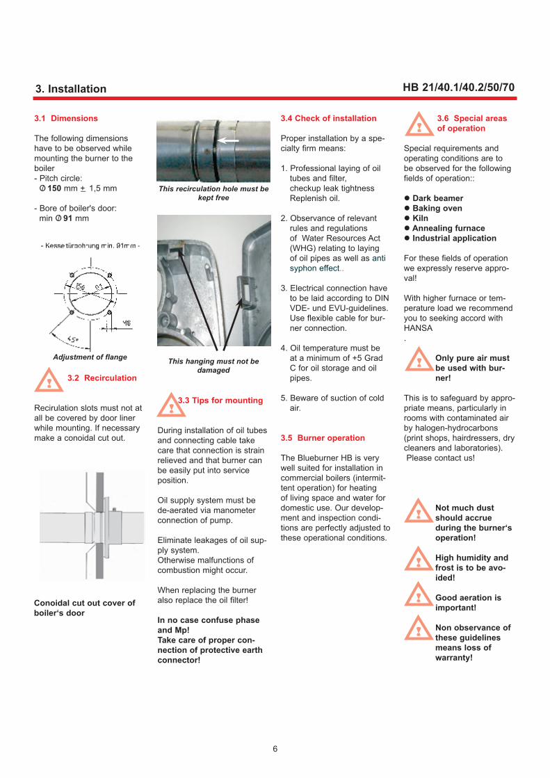
3.1 Dimensions
The following dimensions have to be observed while mounting the burner to the boiler- Pitch circle: O/ 150 mm +_ 1,5 mm
- Bore of boiler's door: min O/ 91 mm
3.2 Recirculation
Recirulation slots must not at all be covered by door liner while mounting. If necessary make a conoidal cut out.
! 3.3 Tips for mounting
During installation of oil tubes and connecting cable take care that connection is strain relieved and that burner can be easily put into service position.
Oil supply system must be de-aerated via manometer connection of pump.
Eliminate leakages of oil sup-ply system. Otherwise malfunctions of combustion might occur.
When replacing the burner also replace the oil filter!
In no case confuse phase and Mp! Take care of proper con-nection of protective earth connector!
3.4 Check of installation
Proper installation by a spe-cialty firm means:
1. Professional laying of oil tubes and filter, checkup leak tightness
Replenish oil.
2. Observance of relevant rules and regulations of Water Resources Act (WHG) relating to laying of oil pipes as well as anti syphon effect..
3. Electrical connection have to be laid according to DIN VDE- und EVU-guidelines. Use flexible cable for bur-ner connection.
4. Oil temperature must be at a minimum of +5 Grad C for oil storage and oil pipes.
5. Beware of suction of cold air.
3.5 Burner operation
The Blueburner HB is very well suited for installation in commercial boilers (intermit-tent operation) for heating of living space and water for domestic use. Our develop-ment and inspection condi-tions are perfectly adjusted to these operational conditions.
3.6 Special areas of operation
Special requirements and operating conditions are to be observed for the following fields of operation::
Dark beamer Baking oven Kiln Annealing furnace Industrial application
For these fields of operation we expressly reserve appro-val!
With higher furnace or tem-perature load we recommend you to seeking accord with HANSA.
Only pure air must be used with bur-ner!
This is to safeguard by appro-priate means, particularly in rooms with contaminated air by halogen-hydrocarbons(print shops, hairdressers, dry cleaners and laboratories). Please contact us!
Not much dust should accrue during the burner‘s operation!
High humidity and frost is to be avo-ided!
Good aeration is important!
Non observance of these guidelines means loss of warranty!
Adjustment of flange
Conoidal cut out cover of boiler‘s door
!
This recirculation hole must be kept free
!
!
!
!
!
!
6
This hanging must not be damaged
3. Installation HB 21/40.1/40.2/50/70

After adjustment to a CO2-value of 13-14% you have to check CO value.Getting a result of measure-ment of more than 40 mg/kW of CO value means that CO2 value is no loger correct because a distortion has occurred by air-inleakage on boiler or boiler tube connexi-on. Seal the boiler and repeat your measurements.Poor combustion might also be caused by insufficient per-formance of spraying of the nozzle. Possibly also the oil pressure is too high.
Important: In boiler plants CO-values can be influenced by combustion residue.
Boiler must be sealed and boiler tube connexion must be there
to measure CO2-value cor-rectly, because air -inleaka-ge is distorting the results of measurement!
4.2 Adjustment of pump pressure
Adjustment is done at the pressure regulation plug.Turn right: Pressure rise; turn left: Pressure reduction.
In no case you may turn the pressure regulation plug before deaeration
pump.!
4.3 Modifying the burner output
The burner has a preadjust-ment as shown in the dia-gram and can be modified by +_ 8 %.
4.4 Blower's pressing
Blowers pressing must be measured for adjustment con-trol. For that the plug has to be loosened.
7
4.1 Commissioning and setting
To maintain durable high burner efficiency and safe running a qualified expert has to adjust the settings.
The oil-preheater is switched on and after reaching the required temperature the bur-ner is starting.
Ignition and oil release are carried out automatically via oil firing device.
Some pumps are indicating oil pressure only if magnetic valve has opened!
In case there is no oil deli-vered at first time suction of oil this procedure has to be aborted after 3 minutes at most for not to damage the pump. The operating condi-tion has been reached when oil filter is filled up with oil.
Oil pressure has to be read-justed to boiler and chimney conditions internal to the plant (vgl. Abb.).
Drought should not exceed 0,1 mbar.
Combustion values are to be checked under hot running conditions, to start with the control of CO2 value.This value determines how much the oil flow rate has to be changed at a fixed preset amount of air.
CO2 < 13,5 %,: Oil pressure can be heigh-tened
CO2 > 13,5%:Oil pressure can be reduced
Pump flow Pump returnAdjustment of pressure
X = Pressure regulation plug V = Vacuum gauge connectionP = Pressure gauge connection
x
!
!
!
4. CommissioningHB 21/40.1/40.2/50/70
Test port for determining blowers pressing. Please switch off power
when working on the burner!
Please do not operate adjusting screw on penstock!

4.5 Air intake nozzle adjustment
The amount of air is preset. Modifying the amount of air means that the adjustment-plug has to be loosened from the air intake nozle.By moving the air intake nozzle (see table p.14) it is possible to increase or decrease fan pressure.
In case of an output reduction please pay attention to the oil pressure not being below 10 bar.(At burner start-up oil pressu-re is higher).
4.6 Air intake nozzle
The air intake nozzle is pre-set.
Should the burners output be considerably altered- e.g. by the size of the mixing system-you proceed as follows:
1. Remove burner from boiler,2. Loosen fixation screw from
air intake nozzle, readjust air intake nozzle.
then tighten again fixation screw.
3. Mounting again burner to boiler.
Tine tuning is done via dam-per.
4.7 Circulation of air
Openings for recirculaton must be clear, see pic. p. 6.
8
Air-intake silencer with cover andintake nozzle for air independent operation
4. Commissioning HB 21/40.1/40.2/50/70
Air intake nozzle
9
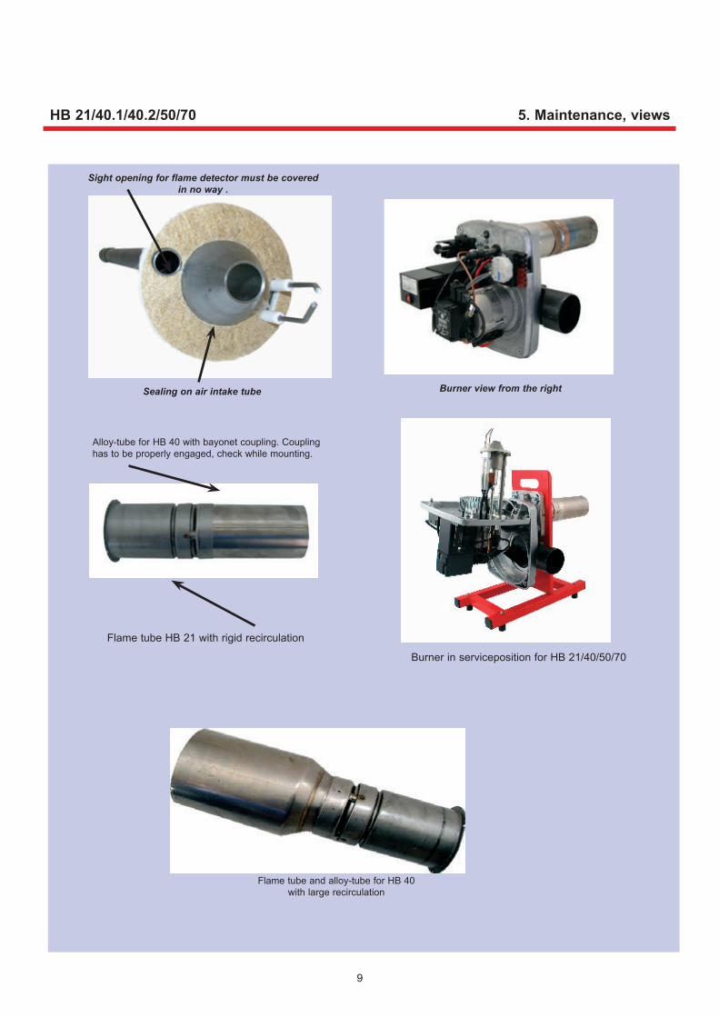
5. Maintenance, views
Burner view from the right
Flame tube and alloy-tube for HB 40 with large recirculation
Sealing on air intake tube
Sight opening for flame detector must be covered in no way .
HB 21/40.1/40.2/50/70
Alloy-tube for HB 40 with bayonet coupling. Coupling has to be properly engaged, check while mounting.
Flame tube HB 21 with rigid recirculation
Burner in serviceposition for HB 21/40/50/70
Rezirkulation

10
Attachment for servicing Service position for mainte-nance work on mixing system
Test port for flame surveillance
Replacing the DROP-STOP:When replacing DROP-STOP, e.g. bei in case of soiling etc.
use a M5-screw fine pitch thread to screw into DROP-STOP and pull it out after-
wards.
Serviceposition
Air sleeve in detail
5.1 Maintenance
An annual inspection of the oil firing plant by an expert is recommended– if only for sheer keeping the legal pre-scriptions.Clean up the burner: impel-ler, mixing system, ignition device and as the case may be replace nozzle and DROP-STOP, as well as gasket of mixing system. There after-check measurements again.When replacing the nozzle it is imperative to use only those nozzles mentionned in the table p. 13.
5.2 Flame surveillance
DIN EN 267: Check of flame detector. Use test port by means of an amperemeter or multimeter. Signal current should not exceed 5,5 µA during pre-ventilation phase. Otherwise position of ignition electrodes has to be checked. In operation measurement signal must be in the range of > 90µA. Otherwise fault shut-down might occur. For fault-less functionning the flame detector should be withdrawn and obfuscated so that the flame extinguishes.The automatic oil firing device repeats and changes into fault mode.
5. Maintenance HB 21/40.1/40.2/50/70

11
0.0 xxxxxxxxxxxxx xxxxxxxxxUnserer l
Burner is function-ning, but there is no generation of flame; it changed from actu-al operation into fault mode!!
Clean up flame detector or if necessary replace it
Check electrical connections and if necessary renew them
Replace automatic firing device
Error Cause Trouble shooting
6. Troubleshooting
Magnetic valve does not open
Oil pipe blocked; Nozzle blocked; Oil tubes blocked
Oil tank empty; Oil pump defective
Suction hose leaky
Suction hoses not vented
Mixing system dirty
Ignition electrode burnt off from one side
Adjustment of ignition electrode to noz-zle not correct
Adjustment of burner not in order
Check electrical connectons; if necessary replace magne-tic valve
Check mentionned components on passability (filter etc.)
Check oil pump and oil tank; if necessary replace or fill up
Check suction hoses and if necessary retightening fittings
Deaerate suction hoses on manometer connection
Check mixing system and if necessary clean it up.
Replace ignition electrode
Make adjustments according to manual
Check burner settings and if necessary readjust them
Burner is function-ningt, but does not adopt flame!!
Flame detector is dirty or defective
Elektrical connection from automatic firing device to flame detector is inter-rupted
Automatic firing device is defective
Increase pressureCombustion chamber resistance of boi-ler is too high
Burner pulsates duri-ng operation!!
After-injection or afterburning after burner shutoff being effected
Inadequate ventilation of oil pipes Deaerate oil pipes
Deposit on top of ignition electrodes!!
Temperatures are too high
Nozzle possibly defective
Eliminate source of leak air
Replace nozzle
Burner is not star-ting!!
Power failure
Regulation switched off
Burner in fault mode
Restore power
Switch on regulation (STB; KTR; Automatik)
Reset automatic firing device of burner
HB 21/40.1/40.2/50/70

12
0.0 xxxxxxxxxxxxx xxxxxxxxxUnserer l
Error Cause Troubleshooting
Burner is starting but no generation of flame (fault shut-down) and inspection glass of oil filter is just half empty or empty
Closing plug not removed when putting into operation for the first time ever
Oil pipe has not been filled up before initial operation. It could last for several minutes before oil is drawn.
No fuel oil in the tank
Oil pump not working
Coupling between motor and ol pump defective
Oil pipe is bent
Existing outer valve to fueling facility is closed
Magnetic valve does not open up
Remove closing plug
Fill up oil pipe at initial operationIMPORTANT:Never run oil pump for longer than three minuteswithout ol
Fill up tank
Check electrical connection if necessary replace oil pump
Replace coupling
Check oil pipe and if necessary replace it
Check of possibly existing outer valve
Check electrical connections if necessary replace solenoid coil
Check of primary connecting cable of ignition transformer and if necessary replace it
Replace ignition electrode
Readjust ignition electrode
Eliminate incidence of extraneous light, if necessary replace flame detector
Replace automatic firing device
Burner is starting, but there is no igni-tion. Oil inspection glass is filled up with oil. There is a fault shut-down.
Ignition transformer or ignition cables defective or not connected
Ignition electrode burnt off from one side
False adjustment of ignition electrode
Flame detector detects extraneous light
Automatic firing device is defective
6. Troubleshooting HB 21/40.1/40.2/50/70
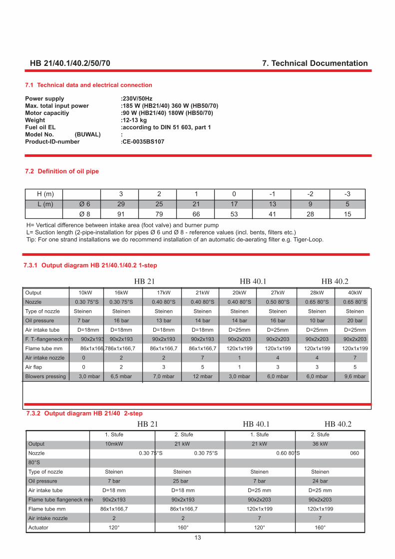
Output 10kW 16kW 17kW 21kW 20kW 27kW 28kW 40kW
Nozzle 0.30 75°S 0.30 75°S 0.40 80°S 0.40 80°S 0.40 80°S 0.50 80°S 0.65 80°S 0.65 80°S
Type of nozzle Steinen Steinen Steinen Steinen Steinen Steinen Steinen Steinen
Oil pressure 7 bar 16 bar 13 bar 14 bar 14 bar 16 bar 10 bar 20 bar
Air intake tube D=18mm D=18mm D=18mm D=18mm D=25mm D=25mm D=25mm D=25mm
F. T.-flangeneck mm 90x2x193 90x2x193 90x2x193 90x2x193 90x2x203 90x2x203 90x2x203 90x2x203
Flame tube mm 86x1x166,7 86x1x166,7 86x1x166,7 86x1x166,7 120x1x199 120x1x199 120x1x199 120x1x199
Air intake nozzle 0 2 2 7 1 4 4 7
Air flap 0 2 3 5 1 3 3 5
Blowers pressing 3,0 mbar 6,5 mbar 7,0 mbar 12 mbar 3,0 mbar 6,0 mbar 6,0 mbar 9,6 mbar
13
7.1 Technical data and electrical connection
Power supply :230V/50HzMax. total input power :185 W (HB21/40) 360 W (HB50/70) Motor capacitiy :90 W (HB21/40) 180W (HB50/70)Weight :12-13 kgFuel oil EL :according to DIN 51 603, part 1Model No. (BUWAL) :Product-ID-number :CE-0035BS107
Error Cause Troubleshooting
Burner is starting but no generation of flame (fault shut-down) and inspection glass of oil filter is just half empty or empty
Closing plug not removed when putting into operation for the first time ever
Oil pipe has not been filled up before initial operation. It could last for several minutes before oil is drawn.
No fuel oil in the tank
Oil pump not working
Coupling between motor and ol pump defective
Oil pipe is bent
Existing outer valve to fueling facility is closed
Magnetic valve does not open up
Remove closing plug
Fill up oil pipe at initial operationIMPORTANT:Never run oil pump for longer than three minuteswithout ol
Fill up tank
Check electrical connection if necessary replace oil pump
Replace coupling
Check oil pipe and if necessary replace it
Check of possibly existing outer valve
Check electrical connections if necessary replace solenoid coil
Check of primary connecting cable of ignition transformer and if necessary replace it
Replace ignition electrode
Readjust ignition electrode
Eliminate incidence of extraneous light, if necessary replace flame detector
Replace automatic firing device
Burner is starting, but there is no igni-tion. Oil inspection glass is filled up with oil. There is a fault shut-down.
Ignition transformer or ignition cables defective or not connected
Ignition electrode burnt off from one side
False adjustment of ignition electrode
Flame detector detects extraneous light
Automatic firing device is defective
7. Technical Documentation
7.3.1 Output diagram HB 21/40.1/40.2 1-step
7.2 Definition of oil pipe
H= Vertical difference between intake area (foot valve) and burner pumpL= Suction length (2-pipe-installation for pipes Ø 6 und Ø 8 - reference values (incl. bents, filters etc.)Tip: For one strand installations we do recommend installation of an automatic de-aerating filter e.g. Tiger-Loop.
7.3.2 Output diagram HB 21/40 2-step
HB 21/40.1/40.2/50/70
1. Stufe 2. Stufe 1. Stufe 2. Stufe
Output 10mkW 21 kW 21 kW 36 kW
Nozzle 0.30 75°S 0.30 75°S 0.60 80°S 060
80°S
Type of nozzle Steinen Steinen Steinen Steinen
Oil pressure 7 bar 25 bar 7 bar 24 bar
Air intake tube D=18 mm D=18 mm D=25 mm D=25 mm
Flame tube flangeneck mm 90x2x193 90x2x193 90x2x203 90x2x203
Flame tube mm 86x1x166,7 86x1x166,7 120x1x199 120x1x199
Air intake nozzle 2 2 7 7
Actuator 120° 160° 120° 160°
H (m) 3 2 1 0 -1 -2 -3 L (m) Ø 6 29 25 21 17 13 9 5 Ø 8 91 79 66 53 41 28 15
HB 21 HB 40.1 HB 40.2
HB 21 HB 40.1 HB 40.2

14
7. Technical documentation HB 21/40.1/40.2/50/70)
HB 50 HB 70Output 37 kW 52 kW 49 kW 70 kWNozzle 0.75 80° S 1.00 80° S 1.00 80° S 1.25 80°Type of nozzle Steinen Steinen Steinen SteinenOil pressure 14 bar 23 bar 13 bar 17 barAir intake tube D=27 mm D=27 mm D=31 mm D=31 mmFlame tube flangeneck mm 100x1,5x199 100x1.5x199 100x1,5x202 100x1,5x202Flame tube mm 120x1x190 120x1x199 150x1x199 150x1x199Air intake nozzle 3 7 4 7Air flap 1 5 3 5Blowers pressure 8 mbar 11 mbar 8 mbar 11 mbar
HB 50 HB 70HB 50 1.-step 2.-step 1.-step 2.-stepOutput 37 kW 52 kW 49 kW 70 kWNozzle 0.85 80° S 1.10 80° S 1.10 80° S 1.10 80° SType of nozzle Steinen Steinen Steinen SteinenOil pressure 12 bar 20 bar 13 bar 25 barAir intake tube D=27 mm D=27 mm D=31 mm D=31 mmFlame tube flangeneck mm 100x1,5x199 100x1.5x202 100x1,5x202 100x1.5x202Flame tube mm 120x1x199 120x1x199 150x1x199 150x1x199Air intake nozzle 7 7 7 7Actuator 125° 160° 125° 160°
7.4.1 Output diagram HB 50/70 1-step
7.4.2 Output diagram HB 50/70 2-step

15
HB 21/40.1/40.1/50/70
7.5 Wiring diagram LOA 14
Wiring diagram LMO14
7. Technical documentation
Local EVU- and VDE-regulations are to be observed !

16
HB 21/40.1/40.2/50/70 7. Technical documentation
7.6 Wiring diagram HB 2-step LOA 24 / LMO 24
Wiring diagram HB 1-step with relay LOA 14 / LMO 14

17
7. Technical documentation
During diagnosis of error control outlets are dead-voltage - burner remains switched off - exception, error-signal <AL> clip 10
resetting of burner is carried out only after lock-out release - After each fault shutdown an immediate lock- out release is possible Dafür Entriegelungs- taster min. 0,5s, max. jedoch 3s gedrückt halten!
HB 21/40.1/40.2/50/70
7.8 Error code LMO 24/LMO 14
7.9 Measuring fields HB 21 / 40.1 / 40.2
Flash signal code 2x signal no flame generation towards the end of <TSA> - defective or dirty combustible valves - defective or dirty flame detector - poor adjustment of burner - defective ignition device 3x signal free 4x signal Extraneous light at burner's start 5x signal free 6x signal free 7x signal flame loss during operation too often - defective or dirty combustible valves - defective or dirty flame detector - poor adjustment of burner 8x signal time monitoring oil preheater 9x signal free 10x signal wiring error or internal error, output contacts
Measuring fields HB 50 / HB 70
Measuring field fuel oil ELType HB 21 (10-21kW)
Measuring field fuel oil ELType HB 40.1 (21-27 kW) HB 40.2 (27-40 kW
Measuring field fuel oil EL-Type HB 50 (35-50 kW)
Measuring field fuel oil ELType HB 70 (50-70 kW)
0,60,5 0,4 0,3 0,2 0,1 0,0-0,1-0,2
0,7 0,9 1,1 1,3 1,5 1,7 1,9
Throughput of oil: from 0.80 kg/h – 1,82 kg/h
Com
bust
ion
spac
e pr
essu
re
m
1,5 1,7 1,9 2,1 2,3 2,5 2,7 2,9 3,1 3,3 3,5
0,70,60,50,40,30,20,10,0
-0,1-0,2
Throughput of oil: from 1.65 kg/h – 3,37 kg/h
Com
bust
ion
spac
e pr
essu
re
HB 40.1 HB 40.2
0,9 0,8 0,7 0,6 0,5 0,4 0,3 0,2 0,1 0,0-0,1
3,0 3,2 3,4 3,6 3,8 4,0 4,2 4,4
Throughput of oil: from 3,1 kg/h – 4,4 kg/h
Com
bust
ion
spac
e pr
essu
re
Com
bust
ion
spac
e pr
essu
re 0,80,70,60,50,40,30,20,10,0
- 0,1- 0,2
4,1 4,3 4,5 4,7 4,9 5,1 5,3 5,5 5,7 5,9
Throughput of oil: from 4,2 kg/h – 5,9 kg/h
18
HB 21/40.1/40.2/50/70 7. Technical documentation
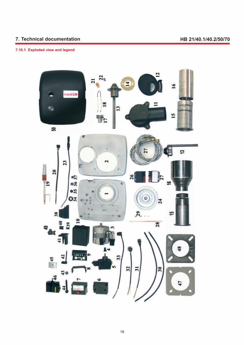
7.10.1 Exploded view and legend

19
7. Technical documentationHB 21/40.1/40.2/50/70
7.10.2 Legend
7.11 Warranty
This oil burner works perfectly if professionally installed and putting into operation and if fuel oil EL according to DIN 51 603, part 1 iwas used.
We come up with a gua-rantee for 24 months after commissioning, however not longer than 27 months after date of sale and is limited to replacement of defective com-ponents.
For further particulars please refer to pass card.
Inappropriate use of fuel oil additives voids all warranty claims
7.12 Oil tank and pipes
When filling up the tank shut off burner and leave him offfor about threee hours so that particulate matter might be settling.
Leaky oil pipes and tanks which have been running dry might lead to deflagration by
air bubbling.Never tolerate oil leakages! Fire hazard!
Soot free combustion might also be achieved without adding combustion ameli-orants. We are raising no objections against use of fuel oil additives containing no ashes, like e.g. floating ame-liorants.
7.13 Spare parts
In case of replacement use only original HANSA spare parts:Some componen ts like e.g. flame detector, oil pump and preheater are special-ly laid out, construed and manufactured for HANSA..
For your order of spare parts, please always provi-de burner number!
!
!
Pos Item Article-No.: Pos Item Artikel-Nr.: 1 Upper case section 1160 29 Screw nut BON 05 M4LL 1511 2 Lower case section HB 21/40 1103 30 High voltage wiring 1065 Lower case section HB 50/70 1103G 31 Cable connector 3-pole, square 3400 3 Motor EB 95C 28 90W HB 21/40 3431 32 Connector cable 3-pole 3429 4 Coupling two-dimensional without. plate 1048 33 Primary cable ignition transformer 3308 5 One-step oil pump ALE 35 C 9329-6 3939 34 Gasket sight opening 4139 Two-step.oil pump ATE 2 55D 93534 3938 35 Gasket chart display 300815 6 Ignition transformer Danfoss EBI 3309 36 Gasket penstock 4153 Ignition transformer COFI TRK2-35 3519D 37 Cable feedthrough high voltage wiring 3346 7 Automatic oil firing device LMO 14 3168 38 Air clap 300805 8 Socket LOA PG fastener AGK66 3071 39 Gasket - Air clap regulation 300814 9 Device socket AGK 11 3070 40 Fastener - Air clap regulation small 300812 10 Socket-Control 300813 41 Fastener - Air clap regulation 300811 Socket control small 2-step 300816 42 Air clap regulation 300810 11 Air intake box 300803 43 Hexagonal screw nut 934 M10x1 left 3372 12 Air intake nozzle HB 21/40 300804 44 Adjusting screw - Air flap 300809 Air intake nozzle large HB 50/70 300817 45 Air clap actuator 2990 13 Air sleeve D18 2171 46 Actuator 2990 Air sleeve D24 2149 47 Flange gasket HB21/40.1/40.2 1072 14 Gasket for air sleeve 4103 48 burner flange HB21/40.1/40.2 1102K 15 Flame tube flangeneck 193,3 HB 21 2180 47 Flange gasket HB 50/70 1227 Flame tube flangeneck 203,3 HB 40 2189 48 Burner flange HB 50/70 1214 16 Flame tube 86x1x166,7 HB 21 1110 49 Rapa cut-off valve 2-step 3631 Flame tube 120x1x199 HB 40 2167 50 Cover 300806 17 Turbolator centre HB 21/40 1092 3 Motor EB 95C 52/2 180W HB 50/70 3438 18 Double ignition electrode 4176 7 aotomatic oil firing device LMO 24 3172 19 Oil preheater FPHB-LE 3652 13 Air sleeve 27 HB 50 2190 20 Cable for FPHB 4131 13 Air sleeve 31 HB 70 2191 21 Oil nozzle 0.30 75°S 5463 At extra charge 2-step 3164 Oil nozzle 0.60 80°S 5404 15 Flame tube flangeneck HB 50 2145 22 Anti-twist protection 1093 15 Flame tube flangeneck HB 70 2146 23 Flame detectorQRC 1A1 3094 16 Flame tube HB 50 2147 24 Fan wheel 133x42 HB 21/40 1242 16 Flame tube HB 70 2148 Fan wheel 133x62 HB 50/70 1262 25 Euro-plug 7-pole boiler side 4123 26 Euro-plug 7-pole burner side 4124 27 Oil tube 4175 28 Copper tube 186 mm 1020

20
HB 21/40.1/40.2/50/70 7. Technical documentation
7.14 Dimensions
HB 21 HB 40.1 HB 40.2 HB 50 HB 70
A 292,5 292,5 292,5 292,5 292,5
B 280 280 300 300
C 193 203 199 202
D 90 120 120 150
E 166,7 199 199 199 199
F 230 230 230 230 230
21
HB 21/40.1/40.2/50/70 7. Manufacturer certification
8.1 Manufacturer's declaration
Manufacturer certificationAccording to § 7 (2) 1. BimSchV.
The enterprise Hansa Öl- und Gasbrenner GmbH hereby confirms for the oil burners mentionned below :
Product Oil burner Trade name HB 21/40/50/70 Type / Model number (BUWAL/VKF) Test standards DIN EN 267 Test centre TÜV - Rheinland Quality management DIN EN ISO 9001 Certification Dekra-ITS Product-ID-number CE 0035BS107These products are matching the requirements of the above mentionned norms and regulations and are correspon-ding with models examined by the aforementionned testing centre. This declaration, however, does not mean any formal guarantee of features.
Moreover these burners will fall below the admitted nitrogen oxide proportion of max. 120 mg/kWh permitted by the regulation in §7 (2) 1. BimSchV. .
The aforementionned oil burners are solely designated for installation in boilers likewise approved according relevant guidelines and norms.
The installer has to ensure, that all valid regulations for fully functionning and collaboration of oil burner and boiler are observed.
The enterprise Hansa Öl- und Gasbrenner GmbH hereby confirms for the oil burners mentionned below :
Product Oilburner Trade name HBV 21/40/50/70 Type HBV 21/40/50/70
were tested in consideration of the following norms and guidelines:
Low Voltage Directive 73/23 EWG - 01.1973 EMV - Directive 89/337 EWG 05.1989
Machinery Directive 87/392 EWG - 05.1989 bearing reference to the oil burner norm DIN EN 267
Hansa Öl- und Gasbrenner GmbH
Jörg Hoffmann GF Dirk Hoffmann TL
DIN EN ISO 9001
Technical modifications reserved. No liability for misprints and errors
8.2 Declaration of conformity

22

23

Hansa Öl- und Gasbrenner GmbHBurgdamm 3 - D-27404 Rhade
Main office +49 - (0)4285-9307-0Fax: +49 - (0)4285-1653email: [email protected] [email protected]: www.hansa-brenner.de