Hans R. Moritz 1260 Northeast Greenway Drive …sdi.odu.edu/mbin/addams/mdfate/mdfate.pdfCHAPTER 2:...
43
U S E R S G U I D E F O R T H E _MULTIPLE DUMP FATE MODEL FINAL REPORT Hans R. Moritz 1260 Northeast Greenway Drive Gresham, OR 97030 Prepared for U. S. Army Corps of Engineers Waterways Experiment Station 3909 Halls Ferry Road Vicksburg, MS 39180-6199 Contract Number DACW39-94-M-1304 JULY 1994
Transcript of Hans R. Moritz 1260 Northeast Greenway Drive …sdi.odu.edu/mbin/addams/mdfate/mdfate.pdfCHAPTER 2:...

U S E R S G U I D E F O R T H E
_MULTIPLE DUMP FATE MODEL
FINAL REPORT
Hans R. Moritz
1260 Northeast Greenway DriveGresham, OR 97030
Prepared for
U. S. Army Corps of EngineersWaterways Experiment Station
3909 Halls Ferry RoadVicksburg, MS 39180-6199
Contract Number DACW39-94-M-1304
JULY 1994

PREFACE
This report describes a numerical simulation for open waterdredged material disposal sites, and is the result of researchconducted during the period from 1 January 1994 through 31 June1994. The principal investigator is Mr. Hans R. Moritz, anindependent research hydraulic engineer.
The numerical simulation was developed under contract numberDACW39-94-M-1304 between the U.S. Army Corps of EngineerWaterways Experiment Station (WES), Vicksburg, MS and Mr. Hans R.Moritz, Gresham, OR. The technical project officer at theWaterways Experiment Station is Dr. Billy H. Johnson of theHydraulics Laboratory.
2

TABLE OF CONTENTS
PREFACE . . . . . . . . . . . . . . . . . . . . . . . . . . . . . . . . . . . . . . . . . . . . . . . . . . . . . . . . . . . . . . . . . . . . . . . . . . . . . . . . . . . . . . . . . . . . . . . . . 2
List of Tabless . . . . . . . . . . . . . . . . . . . . . . . . . . . . . . . . . . . . . . . . . . . . . . . . . . . . . . . . . . . . . . . . . . . . . . . . . . . . . . . . . . . . . . . . . . 4
List of Figures . . . . . . . . . . . . . . . . . . . . . . . . . . . . . . . . . . . . . . . . . . . . . . . . . . . . . . . . . . . . . . . . . . . . . . . . . . . . . . . . . . . . . . . . . 4
CHAPTER 1: INTRODUCTION . . . . . . . . . . . . . . . . . . . . . . . . . . . . . . . . . . . . . . . . . . . . . . . . . . . . . . . . . . . . . . . . . . . . . . . . . . . . . . . 5
Open Water Disposal of Dredged Sediments - Background . . . . . . . . . . . . . . . . . . . . . . . . . . . . . . . . . . . . . . . . . . . 5Formulation of MDFATE . . . . . . . . . . . . . . . . . . . . . . . . . . . . . . . . . . . . . . . . . . . . . . . . . . . . . . . . . . . . . . . . . . . . . . . . . . . 5Overview of MDFATE Capabilities . . . . . . . . . . . . . . . . . . . . . . . . . . . . . . . . . . . . . . . . . . . . . . . . . . . . . . . . . . . . . . . . . 6
Discretizing an Ocean Dredged Material Disposal Site . . . . . . . . . . . . . . . . . . . . . . . . . . . . . . . . . . . . 6Simulating a Dredged Material Disposal Operation . . . . . . . . . . . . . . . . . . . . . . . . . . . . . . . . . . . . . . . 7Other MDFATE Support Options . . . . . . . . . . . . . . . . . . . . . . . . . . . . . . . . . . . . . . . . . . . . . . . . . . . . . . . . . . . . 8
Organization of Report . . . . . . . . . . . . . . . . . . . . . . . . . . . . . . . . . . . . . . . . . . . . . . . . . . . . . . . . . . . . . . . . . . . . . . . . . . 8
CHAPTER 2: GETTING STARTED. . . . . . . . . . . . . . . . . . . . . . . . . . . . . . . . . . . . . . . . . . . . . . . . . . . . . . . . . . . . . . . . . . . . . . . . . . . . 10
MDFATE Hardware Requirements . . . . . . . . . . . . . . . . . . . . . . . . . . . . . . . . . . . . . . . . . . . . . . . . . . . . . . . . . . . . . . . . . . 10Software Requirements . . . . . . . . . . . . . . . . . . . . . . . . . . . . . . . . . . . . . . . . . . . . . . . . . . . . . . . . . . . . . . . . . . . . . . . . . 10MDFATE Software Installation . . . . . . . . . . . . . . . . . . . . . . . . . . . . . . . . . . . . . . . . . . . . . . . . . . . . . . . . . . . . . . . . . . 10Input and Output Data Files for MDFATE . . . . . . . . . . . . . . . . . . . . . . . . . . . . . . . . . . . . . . . . . . . . . . . . . . . . . . . . 11
MDFATE Generated Support Files . . . . . . . . . . . . . . . . . . . . . . . . . . . . . . . . . . . . . . . . . . . . . . . . . . . . . . . . . 11Optional Data Files - User Supplied . . . . . . . . . . . . . . . . . . . . . . . . . . . . . . . . . . . . . . . . . . . . . . . . . . . . 12
MDFATE User Interface . . . . . . . . . . . . . . . . . . . . . . . . . . . . . . . . . . . . . . . . . . . . . . . . . . . . . . . . . . . . . . . . . . . . . . . . . 13Prompted Input . . . . . . . . . . . . . . . . . . . . . . . . . . . . . . . . . . . . . . . . . . . . . . . . . . . . . . . . . . . . . . . . . . . . . . . . . 13Menu Format . . . . . . . . . . . . . . . . . . . . . . . . . . . . . . . . . . . . . . . . . . . . . . . . . . . . . . . . . . . . . . . . . . . . . . . . . . . . 14
MDFATE Options . . . . . . . . . . . . . . . . . . . . . . . . . . . . . . . . . . . . . . . . . . . . . . . . . . . . . . . . . . . . . . . . . . . . . . . . . . . . . . . . 14Create an Open Water Disposal Site Grid - ASM Option 1 <F1> . . . . . . . . . . . . . . . . . . . . . . . . . . . 16Update or Edit Site Grid Bathymetry - ASM Option 2 <F2> . . . . . . . . . . . . . . . . . . . . . . . . . . . . . . 19Simulate Dredged Material Disposal - ASM Option 3 <F3> . . . . . . . . . . . . . . . . . . . . . . . . . . . . . . . 21
Simulate Only Long-term Fate of Sediments . . . . . . . . . . . . . . . . . . . . . . . . . . . . . . . . . . . . . . . 22Simulate Short- and Long-term Fate of Dredged Material . . . . . . . . . . . . . . . . . . . . . . . . . . 22
View MDFATE Output and Bathymetry Data - ASM Option 4 <F4> . . . . . . . . . . . . . . . . . . . . . . . . . . . 23Utilities: Mounds, Volumes, Transport Rates - ASM Option 5 <F5> . . . . . . . . . . . . . . . . . . . . . . 25Quit MDFATE - < E S C >0 . . . . . . . . . . . . . . . . . . . . . . . . . . . . . . . . . . . . . . . . . . . . . . . . . . . . . . . . . . . . . . . . . . 26
CHAPTER 3: EXAMPLE APPLICATION OF MDFATE. . . . . . . . . . . . . . . . . . . . . . . . . . . . . . . . . . . . . . . . . . . . . . . . . . . . . . . . . . . . . . 26
Description of a Hypothetical Disposal Area . . . . . . . . . . . . . . . . . . . . . . . . . . . . . . . . . . . . . . . . . . . . . . . . . . . 26Operational Concerns for Open Water Placement of Dredged Material at the ODMDS Site ... 27MDFATE Sediment Transport Sensitivity Testing . . . . . . . . . . . . . . . . . . . . . . . . . . . . . . . . . . . . . . . . . . 29
Utilization of MDFATE to Analyze Dredged Material Placement . . . . . . . . . . . . . . . . . . . . . . . . . . . . . . . . . . . 33Creation of the ODMDS Grid . . . . . . . . . . . . . . . . . . . . . . . . . . . . . . . . . . . . . . . . . . . . . . . . . . . . . . . . . . . . . 33Simulating Dredged Material Disposal at the ODMDS using MDFATE . . . . . . . . . . . . . . . . . . . . . . . . 33
Results of Example MDFATE Execution . . . . . . . . . . . . . . . . . . . . . . . . . . . . . . . . . . . . . . . . . . . . . . . . . . . . . . . . . . . 38
CHAPTER 4: CONCLUSIONS REGARDING BENEFITS OF THE MDFATE MODEL. . . . . . . . . . . . . . . . . . . . . . . . . . . . . . . . . . . . . . . . . 42
REFERENCES . . . . . . .................................. . . . . . . . . ...... ......... . . . . . . . . . . . . . . . . . . .... ..... .. . . . ... 43
3

LIST OF TABLES
Page
MDFATE generated filename description according to file extension ................................ 12
Optional data files accessed by MDFATE according to file extension....................................... 13
Number
1
2
Number
1
2
3
4
5
6
7
8
9
10
11
12
13
14
15
16
17
LIST OF FIGURES
Phases of dredged material behavior when the material is discharged subaqueously . . . . . . . . . . . . . . . . 9
MDFATE - Activity Selection Menu . . . . . . . . . . . . . . . . . . . . . . . . . . . . . . . . . . . . . . . . . . . . . . . . . . . . . . . . . . . . . . . . . 15
Open Water Disposal Area Grid Generation Menu . . . . . . . . . . . . . . . . . . . . . . . . . . . . . . . . . . . . . . . . . . . . . . . . . . . . 15
MDFATE grid and coordinate system orientation convention . . . . . . . . . . . . . . . . . . . . . . . . . . . . . . . . . . . . . . . . . 17
Open Water Disposal Area Grid Editor Menu . . . . . . . . . . . . . . . . . . . . . . . . . . . . . . . . . . . . . . . . . . . . . . . . . . . . . . . . 20
Simulation of Open Water Disposal Dredged Material Disposal Menu . . . . . . . . . . . . . . . . . . . . . . . . . . . . . . . . . 20
Viewing Utility Menu . . . . . . . . . . . . . . . . . . . . . . . . . . . . . . . . . . . . . . . . . . . . . . . . . . . . . . . . . . . . . . . . . . . . . . . . . . . . . 24
MDFATE - Utilities Menuu . . . . . . . . . . . . . . . . . . . . . . . . . . . . . . . . . . . . . . . . . . . . . . . . . . . . . . . . . . . . . . . . . . . . . . . . . . 24
Project site map - Fictitious Ocean Dredged Material Disposal Site (ODMDS). . . . . . . . . . . . . . . . . . . . . . 28
MDFATE predicted sediment transport rates . . . . . . . . . . . . . . . . . . . . . . . . . . . . . . . . . . . . . . . . . . . . . . . . . . . . . . . . 30
Pre-disposal survey data (ASCII) for ODMDS. . . . . . . . . . . . . . . . . . . . . . . . . . . . . . . . . . . . . . . . . . . . . . . . . . . . . . . 31
MDFATE generated pre-disposal bathymetry for ODMDS . . . . . . . . . . . . . . . . . . . . . . . . . . . . . . . . . . . . . . . . . . . . . . 32
Simulated time series wave environment at ODMDS for November 1992 - March 1993 . . . . . . . . . . . . . . . . . . 35
Characterization of tidal environment at ODMDS for November 1992 - March 1993 . . . . . . . . . . . . . . . . . . . . 36
Topographic and orthographic views of the MDFATE generated post-disposal bathymetry . . . . . . . . . . . . . 37
Summary of simulation for “radial” placement of silt at ODMDS - ODMDS.ACT file . . . . . . . . . . . . . . . . . . 39
Summary of simulation for “transect” placement of silt at ODMDS - ODMDS.ACT file . . . . . . . . . . . . . . . . 40
18 Topographic and orthographic views difference surface between pre- and post-disposal bathymetry . 41
4

U S E R S G U I D E F O R T H E
MULTIPLE DUMP FATE MODEL
1-- INTRODUCTION
Open Water Disposal of Dredged Sediments - Background
While often more cost effective than upland disposal, theoption of placing clean dredged material within the open watermay introduce additional concerns to the overall management ofdisposed dredged material. The management of ocean dredgedmaterial disposal Sites (ODMDS) includes environmentalconsiderations such as obtaining and maintaining regulatoryapproval for site use and operational constraints concerningnavigation issues and disposal efficiency. In order to satisfythese constraints, the project manager of the open water disposalsite is required to:
a) Ensure that dredged material placed offshore does notaccumulate in a fashion which would pose a navigationalhazard,
b) Demonstrate that the placed dredged material stays withinthe site boundaries,
c) Attain maximum utilization of site volumetric capacity.
The common link between the above concerns is the ability toaccurately predict and track the placement of dredged materialwithin a given disposal site. This issue is further emphasizedwhen one considers that approximately 95 to 99% of dredgedmaterial placed within non-dispersive sites reaches the seafloor(Tavolaro 1984, Truitt 1989). The proper management of an ODMDSrequires a sophisticated methodology to quantitativelypredict/asses the bathymetric behavior of dredged material placedwithin the open water disposal site.
Formulation of MDFATE
A dredging project which includes open water disposal ofdredged sediment typically consists of numerous dredged materialplacements ranging from a few to more than 1000. The operationalduration of such projects can range from days to months. Thelife-cycle of an ODMDS may be greater than 10 years.
5

A new multiple dredged material placement model has beendeveloped to predict post-disposal bathymetry for ocean dredgedmaterial disposal sites. This new PC-driven numericalsimulation, named Multiple Dump FATE (MDFATE), incorporatesexisting numerical models to simulate the overall (short- andlong-term) behavior of dredged material placed within an openwater disposal site. The MDFATE model spatially accounts forbathymetric changes within an offshore disposal area and can beused to assist with selection of the most efficient layout for aproposed disposal site, or provide guidance for optimizingdredged material placement operations. The MDFATE model hasevolved from several earlier concepts (Moritz and Randall 1992).
MDFATE defines an ocean dredged material disposal site interms of a numerical grid and incorporates two existing computermodels, STFATE and LTFATE, to predict or verify ODMDS bathymetryresulting from a series of disposal cycles or "dumps". In thisregard, STFATE and LTFATE are used independently within theMDFATE simulation. STFATE (Johnson 1990) and LTFATE (Scheffneret al 1994) are numerical models developed at the U.S. ArmyEngineer Waterways Experiment Station.
This manual provides an overview of MDFATE, focussing onapplication and implementation of the model within the userinterface.
Overview of MDFATE Capabilities
Discretizing an Ocean Dredged Material Disposal Site
As a first step in simulating a disposal operation, MDFATEis used to produce a discretized representation (rectangulargrid) of the ODMDS which is of interest. All that is requiredfrom the user is the ODMDS corner coordinates. Horizontalcontrol (x,y) is manifested in terms of the coordinate systemactually used at the site. State plane (feet) and lat-long(degrees) coordinates are currently supported. Up to 9,500nodal points can be used to represent a given ODMDS in terms of aMDFATE grid. This is sufficient to represent a 9,000 x 9,000 ftODMDS in terms of a 100-foot grid interval.
Bathymetric (z) data are represented in terms of theelevation reference datum used at the site. Subsequentmodification of an ODMDS grid's bathymetry is performed withrespect to the datum established during the creation of thedisposal area grid. MDFATE can either automatically generate theODMDS grid bathymetry (flat or sloping), or overlay survey data(ASCII format) consistent with the actual sites's coordinatesystem. Survey data is adapted to the grid domain by a multi-point polynomial interpolant scheme.
6

Simulating a Dredged Material Disposal Operation
Once a particular ODMDS grid has been created, MDFATE can beused to simulate a given disposal operation which may extend overa year and consist of hundreds of disposal cycles or "dumps". A"dump"' consists of one load of dredged material being releasedinto open water from either a barge/scow or a hopper dredge.
During MDFATE execution, the disposal operation is dividedinto separate week-long episodes over which long-term fateprocesses governing dredged material behavior on the seafloor aresimulated using a modified version of the LTFATE model. Resultsare modeled in a cumulative manner. Long-term processes includeself-weight consolidation, sediment transport by waves-currents,and mound avalanching.
Within each episode, a modified version of STFATE simulatesshort-term fate processes which govern each " d u m p " occurringinside the ODMDS grid of interest. Short-term processes arethose which influence disposed dredged material up to the pointat which all momentum imparted to the material from the "d u m p "activity is expended through convection, diffusion, and bottomfriction (Figure 1).
MDFATE utilizes HPDSIM and TIDE (portions of the LTFATEmodel), to generate wave and tidal information for every 3-hourinterval during the disposal operation. This information isutilized by the modified STFATE model, within MDFATE, to simulatewave-current affects acting upon each "d u m p " as dredged materialpasses through the water column and comes to rest on theseafloor. STFATE produces a characteristic foot-print for eachtype of dredged material type/disposal method involved thedisposal operation. The resultant disposal foot-print is used torepresent each dredged material placement.
MDFATE specification of the disposal operation isperformed through a menu-driven format in which the userspecifies basic data defining: (A) tidal and wave information,(B) volume of dredged material to be disposed, (C) duration ofdisposal, (D) disposal equipment characteristics(type/size/bearing), (E) dredged material properties(composition/etc), and (F) water column (residual) current.Positioning and control of disposal vessel during materialplacement is specified according to one of the following options:
(1) within a specified radial distance of a pre-determinedgeographic location (i.e. coordinates defininga disposal buoy location). Dumps are placed in arandom manner weighted in the direction of disposalvessel approach.
(2) along a pre-determined transect line based onbeginning and ending coordinates.
7

(3) each dump location defined by user entered coordinates.
(4) dump locations are based upon pre-recorded coordinatesfor each load. Coordinates (x,y) are contained in anASCII data file queued by MDFATE.
The simulated disposal operation is concluded when all"dumps" for the disposal operation have been superimposed and thelong-term fate simulation has been completed for the specifiedtime interval.
Other MDFATE Support Options
Within MDFATE are a variety of viewing, sensitivity testing,and post-processing utilities. These options can be used toedit/update MDFATE grid bathymetry, develop 2- and 3-dimensionalviews of ODMDS bathymetry, quantify nominal sediment transportrates, calculate sediment volumes, and determine relativedifferences between grids.
Organization of Report
Chapter 1 describes operational considerations for openwater disposal of clean dredged sediments and background of theMDFATE model. Chapter 2 provides information for getting startedwith the MDFATE model. Information includes target hardwarerequirements, loading MDFATE onto a hard disc, description ofinterface structure/assumptions/requirements, and guidance formodel input. Chapter 3 is a user tutorial illustrated through acase study example. Chapter 4 presents conclusions regarding theMDFATE model.
8


2- GETTING STARTED
Text that is to be typed on a keyboard is printed in boldand enclosed in square brackets [COPY]. Non-character keyboardentries are in bold and enclosed in angular brackets <ENTER>.
MDFATE Hardware Requirements
The source code for the MDFATE program was written inFORTRAN and intended for use on an Intel 80486 CPU based IBM (orequivalent) PC with a math co-processor, or PENTIUM based PC. Theoperating system of the PC should be (disk operating system) DOS5.0 or higher.
A VGA monitor, and 526KB of uncommitted (free) DOScontrolled RAM (random access memory) are required for MDFATEexecution. Pre-existing resident software may compete with theMDFATE RAM requirements. Therefore, the CONFIG.SYS and/orAUTOEXEC.BAT files may require modification if resident softwareprevents MDFATE execution. Minimum hard-disc storage capacityrequired by MDFATE is 8 MB.
Software Requirements
Software required to fully utilize MDFATE are; A) DOS PCoperating system, B) the MDFATE software package. Itemsincluded in the MDFATE package are:
b MDFATE Shell programsb Short-- and Longterm modeling programs and datafilesb Grid generation/editing programsb Wave field and tide generating programsb Install program for video and printer accessb Utility programs for viewing, volumes, transport rates
Additional information concerning the MDFATE softwarepackage can be obtained from the Hydraulics Laboratory (Dr. BillyH. Johnson); U.S. Army Corps of Engineers Waterways ExperimentStation, 3909 Halls Ferry Road, Vicksburg, MS 39180-6199.
MDFATE Software Installation
Before the user can execute the MDFATE, several softwareinstallation measures must first be fulfilled. Installation israther easy and performed as follows:
1) On the target computer's hard-drive, make a directoryto store the MDFATE software. Use the DOS [MD] commandto make a directory. The directory should be made on a"disc-drive"t which has at least 8 MB of free space.
10

2) Use the DOS [COPY] command to copy the MDFATEfiles onto the new directory. Assuming the MDFATEdiskettes are inserted into drive A:, and the targetdirectory (say MODEL) is located on the C-drive. Issuethe command: [copy A:*.* C:\MODEL\*.*]. Repeat thisoperation for all of the MDFATE diskettes.
3) If necessary, use the INSTALL utility to configurethe LOOK and UT1 programs for the target computersystem. Do this by typing [INSTALL] at the DOS promptwhile in C:\MODEL\. The INSTALL program will ask theuser the name of the file to install; the user respondswith [LOOK.EXE], and answers the prompts accordingly.The same process is repeated for UT1. As default, LOOKand UT1 are configured for VGA video graphics formatand Hewlett-Packard printing.
The MDFATE model is executed by:
. Gaining access to the MDFATE target directory, i.e. C:\MODEL.
. Typing [MDFATE] at the DOS prompt and hitting <RETURN>.
Input and Output Data Files for MDFATE
During execution of MDFATE, the model may access or create avariety of data files. Some of the data files are "permanent"and must be accessed by the program in order to edit, view, orsimulate disposal for a particular ODMDS grid of interest. Otherdata files are considered temporary and are relevant only to thepresent disposal site configuration and MDFATE simulationactivity.
MDFATE Generated Support Files
Data files created during MDFATE program execution are givenfilenames which conform to a particular format. These filenamesare composed of three segments; disc-drive and directoryspecification, root name, and extension. Examples of eachfilename segment are given below:
Disc-drive & directory specification = Drive:\Directory\(i.e. C:\MODEL\). If no directory is to bespecified, then only C:\
Root name = six (6) characters, or less, naming thedisposal area grid (i.e. MONITR)
Extension = three characters indicating data file type(i.e. . IN for ODMDS grid data file)
11
The above format must be followed whenever the program user isentering MDFATE data file names. Within the operationalenvironment of the MDFATE, file name extensions are appendedautomatically to the root name when file name entries are made bythe user.
File names with extensions .IN, .OUT, .DAT, .TNS, .TIMand .ACT are created by MDFATE when generating a new disposalarea grid, or simulating disposal activities within an existingdisposal area grid. A description of the above filenameextensions is given in Table 1.
Table 1. MDFATE generated filename description according tofile extension.
.IN -> designates a file which contains grid-adapted bathymetric data in X (across grid), Y (upgrid), and Z (elevation) format.
.TNS -> designates a *.IN file which has been converted to the LTFATE and MDFATE viewing utilityformat.
.OUT -> designates a file which describes overall disposal area grid parameters and bathymetricdistribution.
.DAT -> designates a file containing data as contained in the .IN file, but in ASCII format whichenables post processing of the MDFATE ODMDS grid by other imaging software.
.TIM -> designates a file specifying the duration (days) of the preceding Short-/Long-termsimulation.
.ACT -> designates a file which describes the most recent disposal activities within a simulateddisposal area grid and documents locations where horizontal and vertical tolerances have beenexceeded.
All files shown in Table 1 are "permanent" and must not bedeleted, unless the particular ODMDS grid (root-name) is nolonger used by MDFATE.
Optional Data Files - User Supplied
During MDFATE execution, several opportunities arise wherethe user may specify options which require access to informationcontained on specific pre-existing data files. MDFATE optionswhich require access to these user supplied files are; A) Use ofsurvey (ASCII) bathymetry data during creation/editing of aMDFATE grid, B) Specification of dump coordinates for individualdisposal locations during disposal simulation, C) Generation of
12

wave field using Wave Information Study (WIS) correlationcoefficient matrix for use during disposal simulation, D)Generation tide elevation/current time series from pre-determinedconstituents for use during disposal simulation. A summarydescription of the above "optional" data files is shown in Table2.
Table 2. Optional data files accessed by MDFATE according tofile extension.
6CHAR.3CHAR -> (any six character root name.any three characters extension) -> Survey informationused to create/edit ODMDS grid bathymetry. Data is columnar (EASTING,NORTHING,ELEVATION or anycombination), each of three columns set apart by spaces.
6CHAR.3CHAR -> (any six character root name.any three characters extension) -> Coordinates definingindividual disposal locations. Data is used in one of four positioning/control options duringsimulation of dredged material disposal. Data is columnar (EASTING,NORTHING or any combination) eachof two columns set apart by spaces.
HPDPRE.OUT -> WIS datafile describing the 32 (or 20) -year hindcast for the geographic location ofinterest. Data file is approximately 1.4 MB is size and is accessed by MDFATE to generate a syntheticwave environment during disposal simulation. If this file is unavailable, the user can elect tospecify mean wave parameters, or ignore wave effects. If this file is available, it should belocated in the same directory as the MDFATE software.
TIDAL.DAT -> Datafile containing tidal constituents for the geographic location of interest.Accessed by MDFATE to generate tidal-induced water elevations/currents. If this file is unavailable,then the user can choose to ignore tidal effects. If this file is available, it should be locatedin the same directory as the MDFATE software.
MDFATE User Interface
Execution of MDFATE is controlled by a menu and prompt-inputinterface similar to that used by ADDAMS (Automated Dredging andDisposal Alternatives Management Simulation, WES). The MDFATEinterface contains range checking, defaults, and suggested valuesfor prompted data entry.
Prompted Input
If an incorrect numeric entry is made, error checkingconsists of the menu being redisplayed until the correct entry ismade. A key rule which must always be followed when operatingMDFATE, is that all ALPHA character entries must be typed inUPPER CASE. When using MDFATE it is suggested that the <CAPSLOCK> key be initiated.
13

MDFATE is operated from a series of menu oriented screens,of which the first is Activity Selection Menu that appears whenthe command [MDFATE] <ENTER> is keyed at the DOS prompt withinthe MDFATE target directory.
Menu Format
At the bottom of each menu is a legend which instructs theuser how to move about within each menu and make dataentries/selections.
Arrow keys <t> cl> are used to move from one data lineto another.
. <RETURN> key is used to make data selection.
. <PAGE UP> and <PAGE DOWN> keys are used to move frommenu to menu.
. <ESC> key will return the user to the previousactivity menu.
. <HOME> key will return user to the first of thesecondary menus under the current activity menu.
. <FUNCTION> keys can be used to make selections in somemenus.
The Activity Selection Menu (shown in Figure 2) prompts theuser to select the desired MDFATE action. There are 6 actionsavailable from the Activity Selection Menu. The ActivitySelection Menu (ASM) is the first of three hierarchical menutypes. Selection of any one of the first five options in the ASMwill result in presentation of a menu specific to the desiredoption, but resembling the ASM. Within each of the five ASMoptions, secondary menus are presented, specific to each ASMoption. In a few instances, there are simple third order menuswhich ask for 1 numeric entry with a <RETURN>.
MDFATE Options
Generally, the first MDFATE activity in which to engage isOption #1 (or <F1> key) - "Create an open water disposal sitegrid". Generation of an ODMDS grid must first be performedbefore dredged material disposal can be simulated. After anODMDS grid is generated, various options are available to view<F4> or edit <F2> the bathymetry and obtain volumes above a givenelevation <F5>. Simple geomorphic berm/mound shapes can beeasily superimposed on the ODMDS grid <F5>. Of primaryimportance, is the option of simulating dredged material disposalwithin an existing ODMDS grid <F3>.
14

Create an Open Water Disposal Site Grid - ASM Option 1 <F1>
Selection of the first ASM option <F1> results with thedisplay of a new menu, "Open Water Disposal Area Generation"(Figure 3). This menu allows for generation of a numerical gridto represent the open water disposal area (ODMDS) of interest.
MDFATE generates a rectangular grid which is intended tocoincide with the actual plan configuration of the offshoredisposal site. Grid generation is accomplished by utilizing thedisposal site's effective corner coordinates, principal axisdimensions, and intended monitoring survey interval to create agrid on which to represent the disposal area. If the disposalsite's actual area1 planform is not rectangular, then appropriatecorner coordinates must be selected in order to encompass theactual site boundaries. Individual grid dimensions are uniformand square. If the disposal area is very large (greater than10,000 ft on a side), the user should contemplate partitioningvery large disposal areas into smaller sub-areas in order toobtain better simulation results through improved gridresolution.
The "Open Water Disposal Area Generation" menu requiresdesignation of a filename <F1> (disc drive and directory <F2>,optional) on which to store the data defining the ODMDS grid. Asuccessful entry in this menu will result in an asterisk " * "being placed next to the completed action. After naming theODMDS file, press <F3> to continue specifying grid generationparameters. This results in a secondary menu format in which tospecify data.
The first entry in the secondary menu designates whichgeographic coordinate system (state plane or Latitude-Longitude)to define the disposal area's X and Y data. The second entryconcerns specification of the site's dimensions. The geometry ofthe ODMDS (grid size and axis dimensions) is specified accordingto whether the ODMDS is coincident with the geographic coordinatesystem.
If the principal axis of the ODMDS (grid) are coincidentwith the coordinate system, then the site's northwest cornercoordinates are entered along with principal dimensions of theODMDS (north-south and east-west).
If the principal axis of the ODMDS (grid) are oblique to thecoordinate system, then the coordinates for each one of thesite's four corners (northwestern, northeast, southwest, andsoutheast) are entered according to menu prompt. Figure 4 showsdifferent orientations of grid axis with respect to a coordinatesystem. The disposal site's easterly-westerly and northerly-southerly transect lengths (ft) are calculated. Transects arebased upon averaged orthogonal dimensions of the disposal area.
16


After specification of the site's overall dimensions,another menu is presented for entry of the ODMDS grid dimension.This value corresponds to the intended survey interval at theactual' ODMDS and should be within the range of 50-200 ft. Adefault value is calculated.
Bathymetry (Z, elevation) data is assumed to be representedin terms of a particular reference datum. Any subsequentmodifications of the grid's bathymetry must be with respect tothe datum which is utilized during the creation of the disposalarea grid. There are two methods for producing bathymetry withina new MDFATE grid;
A) automatically generating a flat or sloping sitebathymetry, or
B) to overlay survey data from ASCII format consistentwith the selected coordinate system.
For a flat/sloping bathymetry, the user is prompted to enterthe bathymetric elevation at the "norhtwest corner" of thedisposal area. If there is no bathymetric gradient within thedisposal area, then the "northwest corner" bathymetric elevationis assumed to represent the average bathymetric elevation of theentire disposal area. If the bathymetry of the disposal siteexhibits a gradient, then this gradient is generated throughoutthe grid with respect to the "northwest corner". Negative west-to-east bathymetric gradients are entered as positive values, asis for negative north-to-south gradients.
To adapt survey data to a new MDFATE grid, the user entersthe complete name of the ASCII file containing the survey data.If the survey file, is not successfully located by MDFATE, thespecified name will be cleared from the input field, and the usershould re-specify the proper survey file name. The survey datamust be coincident with the geographic location of the disposalarea and contained in a columnar format. The user specifieswhich column within the ASCII file corresponds to elevation,north coordinate, and south coordinate. The user also specifiesthe survey interval. The survey interval of the data should beno larger than 4 times that of the MDFATE grid.
When all of the prompted values from the ASM option (1)secondary menus have been entered, a save menu is presented.The user specifies the elevation format for the site's .DAT file(used for post-processing by other software). The user specifiesa title for the new MDFATE grid file. The user then types [OK] atthe appropriate prompt and hits <ESC>.
MDFAT-E returns to the main grid generation menu (Figure 5).To generate a new disposal area with the previously defined data,hit <F4>.
18

Successful generation of the new disposal area grid resultsin a short listing of the generated grid support files. Hit<RETURN> to return to the MDFATE ASM.
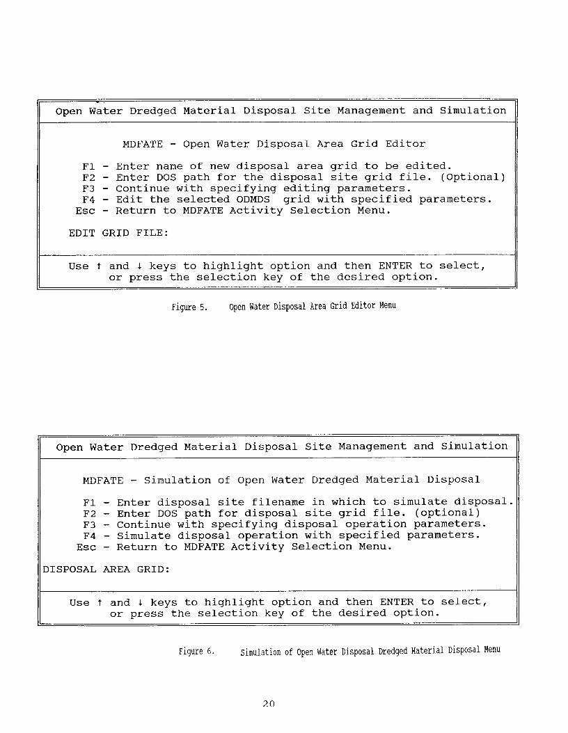
Update or Edit Site Grid Bathymetry - ASM Option 2 <F2>
Selecting the second ASM option <F2> permits the user toedit or update the bathymetry within a disposal area grid ofinterest. Upon selecting this ASM option, the user is presentedwith a secondary action menu , "Open Water Disposal Area GridEditor" (Figure 5).
Before editing can begin, the user must select an existinggrid filename <F1> (drive/directory location <F2>, optional). Asuccessful entry will result in an asterisk " * " being displayednext to the completed action. After successfully naming theODMDS file, press <F3> to continue specifying editing parameters.This results in a secondary menu format in which to specify data.
The user can edit bathymetry on a point-by-point basis, orupdate the disposal site's bathymetry by superimposing surveydata (ASCII file in columnar format).
Should the user select to edit bathymetric grid points on apoint-by-point basis, the user is prompted to enter the number oftotal grid points to be edited. Grid point coordinates and theassociated new bathymetric value are entered for each grid pointto be edited. This is repeated until the number of specified gridpoints has been edited.
If the user elects to update bathymetry by superimposing asurvey datafile, the user is prompted to enter the completefilename containing the imported survey data. If the surveyfile, is not successfully located by MDFATE, the specified namewill be cleared from the input field, and the user should re-specify the proper survey file name. The user specifies whichcolumn within the ASCII file corresponds to elevation, northcoordinate, and south coordinate. The user also specifies thesurvey interval. The survey interval of the data should be nolarger than 4 times that of the MDFATE grid.
When all of the prompted values from the ASM option (2)secondary menus have been entered, a save menu is presented.The user specifies the elevation format for the site's .DAT file(used for post-processing of ODMDS bathymetry by other software).In order to prevent overwriting of the original grid file, theuser can specify an alternate grid file name on which to storethe edited result or the original grid file. The user specifies atitle for the edited MDFATE grid file. The user then types [OK]at the appropriate prompt and hits <ESC>.
MDFATE returns to the main edit menu (Figure 5). Togenerate an edited version of the original disposal area with thepreviously defined editing data, hit <F4>.
19

Successful editing of the disposal area grid results in ashort listing of the new grid support files. Hit <RETURN> toreturn to the MDFATE ASM.
Simulate Dredged Material Disposal - ASM Option 3 <F3>
All ASM options up to this point are intended to eithersupport formation of a disposal area grid. Selection of thethird ASM option <F3> allows the MDFATE to simulate an entiredredged material disposal activity within a pre-existing ODMDSgrid.
Upon selecting this ASM option, the user is presented with asecondary action menu, "Simulation of Open Water Dredged MaterialDisposal" (Figure 6).
Before simulation can begin, the user must select anexisting grid filename <F1> (drive/directory location <F2>,optional). A successful entry will result in an asterisk " * "being displayed next to the completed action. After successfullynaming an existing ODMDS file, press <F3> to continue specifyingdisposal simulation parameters. This results in a secondary menuformat in which to specify data.
Disposal Simulation Timeframe
The first tier of secondary menu pertains to specifyingwhether:
l Only long-term fate processes are of interest - material already on seabed, concernedonly with sediment transport and consolidation, or
l Short- and long-term fate processes are of interest - material is placed at open waterdisposal site and is then subject to long-term processes.
After selecting one of the above options, the user specifieswhether the dredged material of interest originates from new workor is the result of maintenance. The above specification is usedto modify the dredged material avalanching process. New workdredged material may have a steeper angle of repose thanmaintenance material depending upon dredging/disposal equipmentand material type.
Specification of the wave and tidal environment follows theabove menu. The wave environment can either be generated by: A)MDFATE through access to the HPDPRE.OUT datafile for thegeographic location of interest, B) direct user specification ofmean wave parameters, or C) the wave environment is not includedin the MDFATE simulation. The tidal environment is generated byMDFATE through access to the TIDAL.DAT datafile for thegeographic location of interest. If this data file is notavailable, then the user chooses to ignore the effect of tides inthe MDFATE simulation.
21

Following specification of waves and tides at the ODMDS, theuser responds to several menu queues and prompts. The promptedinformation is supplemented with concise explanations andsuggested values, and is error checked for validity.
Simulate Only Long-term Fate of Sediments
Should the user elect to simulate only long-term behavior ofdredged material already on the seabed, a menu will be displayedwhich will require specification of the following data:
l Commencement date to begin longterm simulation.l Number of days to simulate longterm effects.l Residual (non-tidal) water column and direction.. Sediment material type (up to three combined material types) for which to simulate longtermeffects upon.
Simulate Short-- and Long-term Fate of Dredged Material
Should the user elect to simulate short- and long-term fateof dredged material placed at a designated open water disposalsite, then several menus will be displayed to queue forinformation regarding:
Disposal Equipmentl Disposal vessel type:
-> split-hull barge/scow/hopper dredge-> multiple bin hopper dredge
l Disposal vessel operating capacity (average)l Vessel Length and beam. Loaded and unloaded vessel draft (average)l Duration of time required to empty vessel, per load. Disposal vessel speed and heading during placement
If a multiple bin hopper dredge is to be modeled, then the following data is queued by MDFATEl Total number of hopper "bins" present on dredge. Number of bins which are emptied simultaneouslyl Dimensions of individual bin door openingsl Distance separating bin door opens
Disposal Site and Dredged Material Characteristics
l Navigable depth, above which placed dredged material can not exceed.. Distance within disposal site boundaries beyond which placement of dredged material is notpermitted.l Date (month,year) on which to begin simulated disposall Duration (days) of actual disposal operation. Total time frame in which to simulate behavior of dredged material (days).. Residual (non-tidal) current speed and direction. Density of water at dredging site and disposal sitel Dredged material propertiesl Total dredged material to place
22

Disposal Vessel Placement Positioning
l Placement technique used to control positioning of disposal vessel during dredged materialrelease, four options are available.
(1) = Within specified distance (RADIUS) of a pre-determined point (coordinate).User specifies central dump coordinates and allowable disposal radius.
(2) q = Along a pre-determined TRANSECT based on beginning and ending coordinates.User specifies beginning and ending dump coordinates.
(3) = Disposal of individual loads is specified on a POINT-BY-POINT basis by theuser. User specifies number of dumps (or total disposal volume) and is queued foreach dump coordinate location.
(4) = Disposal is controlled by coordinate locations obtained from a specified ASCIIFILE. User specifies file name.
W h e n a l l o f t h e p r o m p t e d v a l u e s f r o m t h e A S M o p t i o n ( 3 )secondary menus have been entered, a save menu is presented.The user specifies the elevation format for the site's .DAT file(used for post-processing of ODMDS bathymetry by other software).In order to prevent overwriting of the original grid file, theuser can specify an alternate grid file name on which to storethe simulated result or the original grid file. The userspecifies a title for the simulated MDFATE grid file. The userthen types [OK] at the appropriate prompt and hits <ESC>.
MDFATE returns to the main disposal simulation menu (Figure6). To begin disposal simulation of the original disposal areawith the previously defined operational data, hit <F4>.
Successful simulation results in a short listing of the newgrid support files. Note that a file with the extension .ACTwill produced, if short-term fate processes were simulated. T h i sfile summarizes the disposal simulation with regard to severalkey parameters. Hit <RETURN> to return to the MDFATE ASM.
View MDFATE Output and Bathymetry Data - ASM Option 4 <F4>
Selecting the fourth ASM option <F4> permits the user toview the (bathymetry or support files) within a disposal areagrid of interest. Upon selecting this ASM option, the user ispresented with a secondary action menu, "MDFATE Viewing Utility"(Figure 7).
Before viewing can begin, t h e u s e r m u s t s e l e c t a n e x i s t i n ggrid filename <F1> (drive/directory location <F2>, optional). Asuccessful entry will result in an astrisk " * " being diplayednext to the completed action. After successfully naming the
23
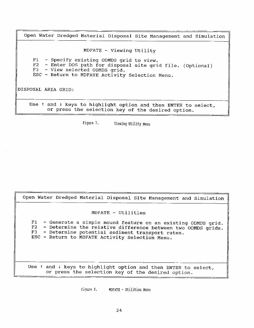

ODMDS file, press <F3> to specify v i e w i n g s e l e c t i o n . Thisr e s u l t s i n a t h i r d o r d e r m e n u f o r m a t i n w h i c h t o s p e c i f y o n e o fthe fo l lowing v iewing choices .
"1" = 2-D CONTOUR plot of the disposal area seabed"2" = 3-D SURFACE plot of the dispasal area seabed"3" = CROSS-SECTION of the disposal area seabed"4" = LISTING of the DISPOSAL operation sequence"5" q = LISTING of the disposal AREA summary DATA
To make a v iewing se lect ion , enter the appropr iate number[number] and hit <RETURN>. After viewing the appropraite file,the user i s re turned to the "MDFATE Viewing Utility“ menu.
Utilit ies: Mounds, Volumes, Transport Rates - ASM Option 5 <F5>
Selecting the fifth ASM option <F5> p e r m i t s t h e u s e r t oaccess utilities of interest. Upon selecting this ASM option,the user is presented with a secondary action menu, "MDFATEUtilities" (Figure 8).
T h e r e a r e t h r e e m a i n utilities a v a i l a b l e . T h e f i r s t t w orequire access to existing ODMDS grids. The third utility,"Determine potential sediment transport r a t e s " , does not requireaccess to an existing grid.
Selecting <F1>, "Generate simple mound feature on ODMDSgrid" , results in diplaying a secondary menu queuing the user forpertinent information. This utility option permits thesuperpostion of an berm or circular mound on the bathymetry of anexisting grid. Information required from the user consists of:
Specification of bathymetry feature type to produce-> circular mound-> elongated berm
For elongated berm:. two coordinate locations to specify ends of berml elevation of berm crest (top). width of berm crestl average sideslope of berm (rise:run)
For circular mound:. coordinate location for center of mound. elevation at top of moundl average sideslope of mound (rise:run)
Selecting <F2>, "Determine difference between two grids",results in diplaying a secondary menu queuing the user forpertinent information. This utility option permits thecalculat ion o f volumes o f sediment above a g iven e levat ion withina given grid, between two grids, or generation of a difference"surface" b e t w e e n t w o g r i d s . In format ion required f rom the userc o n s i s t s o f :
25
Specification of desired volume/differencing option-> determine volume above a given elevation-> determine volume difference between two grids-> generate a surface describing the difference between two grids
For volume above a given elevation:l filename of grid to compute volumel elevation above which to compute volume of sediment
For volume between two grids:l filename of "lower" bathymetry gridl filename of "upper" bathymetry grid
(NOTE: both grids must be of the same format)For difference surface betweem two grids:
l Same asd above
Selecting <F3>, "Determine potentail sediment transportrates", results in diplaying a third order menu queuing the userfor pertinent information. This utility option permits thecalculation of volumetric rates of sediment transport for a rangeof environmental variables. Information required from the userconsists of:
+ Wave height and periodl Water depthl Sediment grain size
Sediment transport rates are calculated for a range ofdepth averaged water column currents. Cohesive and non-cohesivesediment transport relationships are used, depending upon thespecified sediment grain size diameter.
Quit MDFATE - <ESC>
To quit MDFATE, hit <ESC>. The user will be returned to theDOS prompt.
3. - EXAMPLE APPLICATION OF MDFATE
To demonstrate the usefulness of MDFATE, a hypotheticaldisposal area will be used to illustrate the execution of theMDFATE options. Each of the options available through theMDFATE Activity Selection Menu (ASM) are independently discussedwith regard to the example ODMDS application.
Description of a Hypothetical Disposal Area
The data used to describe the disposal area- of interest,originates from actual site conditions obtained from a largeroffshore disposal area located within the Mid-Atlantic coastal
26

region of the US. The disposal area will simply be referred toas: ODMDS (Open Water Dredged Material Disposal Site). The datawas obtained from the report "Quantitative Assessment of the Fateof Dredaed Materials Placed at the Ocean Disposal Area. Cape FearRiver, North Carolina", (Boone and Payonk 1991).
The ODMDS is rectangular in area1 shape, has dimensions ofapproximately 2,100 ft (north-south direction) X 2,300 ft (east-west direction), and is located in approximately 43 ft. (average)water depth (MLW). Figure 9 shows the geographic setting of theODMDS. Other relevant site data include:
a) pre-disposal bathymetric survey of the disposal area with (X,Y) data in terms of state-plane coordinates and (Z) data in HLW ft (positive)
b) state-plane coordinate locations documenting the corner locations of the ODMDS are;
b Northwestern most corner: Easting = 2287700, Northing = 20000) Northeastern most corner: Easting = 2290000, Northing = 20000) Southwestern most corner: Easting = 2287700, Northing = 17900) Southeastern most corner: Easting = 2290000, Northing = 17900
c) pertinent data defining a proposed dredged material disposal activity which is to takeplace at the site
d) WIS information (correlation coefficient matrix) for the ODMDS geographic area.
e) Tidal harmonic constituents for the ODMDS site.
The survey/monitoring interval for the ODMDS pre-disposalsurvey was 250 ft. Horizontal control was estimated not toexceed + 9.8 ft, vertical control was estimated to be within +0 . 5 ft.
Operational Concerns for Open Water Placement of Dredged Materialat the ODMDS Site
T h i s O D M D S h a s b e e n c l a s s i f i e d a s dispersive. The PortD r e d g i n g Authority is concerned that the dredged materialproposed to be placed within the relatively small confines of theODMDS will migrate on to environmentally sensitive bathymetricareas surrounding the site. The ODMDS location was chosen due toits close proximity to the location of dredging. Another disposalarea further away from the dredging site is available, but willcause the dredging project to incur substantial costs due toadditional dredged material hauling constraints. Due to theclose proximity of the ODMDS disposal area to the dredgingproject (channel limits), there is also some concern of dredgedmaterial placed at the ODMDS site migrating back into the channell i m i t s .
27


A depth averaged water column current is present at theODMDS offshore disposal area. The current has been estimated tobe uniform throughout the water column with magnitude of 0.25ft/sec and having direction which oscillates with respect to thewinter/summer seasons. During the summer, the current flows fromnortheast -> southwest. During the winter, the current flowsfrom southwest -> northeast. Dredging disposal activities are totranspire during summer. Since the ODMDS disposal area issituated to the southwest of the dredging project (channelentrance), dredging disposal equipment will be approaching thedisposal area from the northeast.
The total quantity of dredged material to be placed withinthe offshore disposal area is estimated to be 300,000 cubic yards(cy) . The material type to be dredged from the channel shoals
will be composed primarily of fine silt (D50 D= 0.009-0.06 mm).
Two (2) types of placement configurations have been proposedfor the ODMDS:
1) placement of dredged material within a specified distance (500ft) of a fixed/moored buoy(coordinate location specified as Easting = 2288563, Northing = 18675).
2) placement of dredged material in a berm-like formation, with beginning and endingcoordinate locations specified. Beginning coordinates as Easting = 2289712, Northing =18725. Ending coordinates as Easting = 2289712, Northing = 19500.
Each placement geometry is to incorporate 150,000 cy. Thedredged material placement equipment to be used for this projectwill be restricted to bottom-dump scows with capacity of 3,000cy.
The Port Authority investigates whether the two (2) types ofproposed dredged material placement geometries will remain withinthe ODMDS boundaries for one (1) year after project completion.It is assumed that the water column current is out of thesouthwest for the entire duration of the long-term simulation inorder to determine if placed dredged material will migrate backinto the channel limits: as a worst case scenario.
MDFATE Sediment Transport Sensitivity Testing
As a qualitative sensitivity test (first step), MDFATE ASMoption 5 - "Access utilities for transport rates" is invoked <F5>to determine the potential range of sediment transport rates forthe selected ODMDS. Data used in the transport rate predictionutility are:
water depth = 43 - 25 ftwave height = 8 ftwave period q = 6 secsediment diameter q = 0.04 mmcurrent speed = 0 - 3 ft/sec
29


Results of the sediment transport sensitivity test are shownin Figure 10. It is noted that the higher the disposal materialmound, the greater the predicted sediment transport rate. Adisposal mound with crest elevation at -25 ft MLW will experienceapprdximately 5 times the sediment movement than sediments whichmaintain a profile near the ambient seabed elevation of -43 ft.From these preliminary results, it seems advisable not to builddredged material mounds higher than say 10 ft above the ambientseabed elevation.
The MDFATE model is used to help better quantify whetherdredged sediments placed at the ODMDS, as previously stated, willbe operational stable.
Utilization of MDFATE to Analyze Dredged Material Placement
Creation of the ODMDS Grid
The MDFATE ASM option 1, "Create a Open Water Disposal SiteGrid" is invoked <F1>. The disposal area grid is named ODMDS andlocated on drive C:\SHOW\. State plan coordinate system isspecified for the site. The Easting-Northing coordinates definingthe ODMDS disposal area's corners are entered as well as thesimulated monitoring/survey interval, which is specified at 100ft. An irregular site bathymetry was generated, based upon thepre-disposal survey conducted at the actual site. The ASCII datafrom the pre-disposal survey is shown in Figure 11. Figure 12shows the topographic (top) and orthographic (bottom)representation of the pre-disposal ODMDS grid, as produced byMDFATE ASM command <F4>.
Simulating Dredged Material Disposal at the ODMDS using MDFATE
The MDFATE ASM option 3, "Simulate Dredged MaterialDisposal",is invoked <F3>. The disposal area directory locationand filename specified. T h i s r e s u l t s i n t h e d i s p l a y o f d i s p o s a ld a t a e n t r y m e n u s . The following data is entered in order ofencounter. Note that for the MDFATE model must be run separatelyfor the berm and radial placement methods.
Simulation Timeframe of Interest. Simulate: short- and long-term processes
Wave and Tidal Data Specificationl Use WIS HPDPRE.OUT correlation coefficient matrix to generate wave time series.l Use Tidal constituent data file to generate tides/currents
33

Disposal Equipmentl Disposal vessel type q = split-hull barge/scow. Disposal vessel operating capacity = 3000 cyl Vessel Length = 200 ftl Vessel Beam = 50 ftl Loaded vessel draft = 15 ftl Unloaded vessel draft = 7 ftl Duration of time required to empty vessel, per load = 60 secl Disposal vessel speed during placement q = 2 ft secl Disposal vessel heading during placement q = 225
Disposal Site and Dredged Material Characteristics. Navigable depth = (-) 20 ft (MLW)l Placement distance within disposal site boundaries q = 200 ftl Date on which to begin simulated disposal = 06.92l Duration of actual disposal operation = 60 daysl Total time frame in which to simulate behavior of dredged material = 365 daysl Residual (non-tidal) current speed = 0.25 ft/secl Residual current direction = 45l Density of water at dredging site q = 1.010 gr/ccl Density of water at disposal site q = 1.024 gr/ccl Dredged material = SILT
specific gravity = 2.7concentration (vol) = 0.35fall speed =0.05 ft/seccritical shear = 0.02 lb/ft 2
cohesive = yesstripping = no
. Total volume to place = 150,000 + 150,000 q = 300,000 cy
Disposal Vessel Placement Positioning. Radial placement 500 ft about: Easting = 2288563, Northing = 18675)l Transect placement from: Easting = 2289712, Northing q = 18725 to
Easting q = 2289712, Northing = 19500(equivalent transect length of 775 ft)
When all of the prompted values from the ASM option (3)secondary menus have been entered, the save menu is displayed.In order to prevent overwriting of the original grid file(ODMDS), the user can specify an alternate grid file name onwhich to store the simulated result or the original grid file,say ODMDS1. The user specifies a title for the simulated MDFATEgrid file. The user then types [OK] at the appropriate promptand hits <ESC>. MDFATE then returns to the main disposalsimulation menu. To begin disposal simulation of the originaldisposal area with the previously defined operational data, hit<F4>.
34


An example of the simulated wave and tidal data time seriesdata is shown in Figures 13 and 14. Successful MDFATEsimulation results in an on-screen notification where of: A)each placement (dump) of dredged material occurs, B) how manyplacements remain for the specified activity, and C) the statusof long-term simulation.
Results of Example MDFATE Execution
Figure 15 shows a topographic and orthographicrepresentation of the ODMDS1 one year after placement of 300,000cy of silt dredged material. Note that the simulated mounds areabout the same height as the pre-existing bathymetric featuresand that the berm appears to be migrating out of the ODMDSboundaries. Figures 16 and 17 show the ODMDS.ACT filesdocumenting disposal operational criteria for the "radical" and"transect" placements. Note that no disposals occurred outsideof the ODMDS tolerance of 200 ft. There is one grid point whichexceeds the navigable depth criteria of (-) 20 ft (MLW).
To more clearly visualize the effect of the 300,000 cydisposal operation, a difference surface is generated showing thechange between pre-disposal and post-disposal bathymetries. To dothis, MDFATE ASM option 5, "Access utilities for mounds andvolumes" is invoked <F5>. With the appearance of this menu, theoption of "generating a difference surface between two grids" isentered by hitting <F2> in the Utilities menu. The "lower grid"is specified as the pre-disposal bathymetry, ODMDS. The "uppergrid"" is specified as the post-disposal bathymetry, ODMDS1. Theresult can be named anything, say DIFF. The difference surfaceis shown in figure 18.
Some interesting aspects are apparent from Figure 18. The"mounds" formed during the initial placement of dredged materialhave shifted to the Northeast, due to the water column current.Scour areas are clearly evident along the leading edge (current-ward) of each mound configuration. These scour areas are due tothe simulated hydrodynamic flow fields around the "mounds" . The"transect placement" berm has begun to migrate out of the ODMDSdisposal area grid. This particular disposal alternative may notacceptable for navigational and environmental reasons. If aberm-style placement is to transpire at the ODMDS, then it shouldbe conducted at the western end of the disposal area.
The entire simulation required approximately 6 hours to runand process (on a standard "386" PC). Therefore, a more powerfulcomputer is recommended for MDFATE applications, say a "486" orhigher CPU based PC.
38


4. CONCLUSIONS REGARDING BENEFITS OF THE MDFATE MODEL
The manager of an ODMDS must simultaneously address theneeds of obtaining regulatory approval for open water disposal ofdredged sediments, ensure environmental compliance, and maximizedisposal site efficiency. In order to satisfy these constraints,the ODMDS manager must ensure that dredged material placedoffshore does not accumulate in a fashion that would pose anavigational hazard, demonstrate that unacceptable adverseimpacts to significant resources do not occur, and attain maximumutilization of site volumetric capacity.
Given these operational constraints, the proper managementof many disposal sites requires a sophisticated methodology toquantitatively predict and assess the behavior of dredgedmaterial placed in ODMDS's.
MDFATE was developed to bridge the gap between the modelingof individual disposal events or "dumps" (for which the STFATEand LTFATE models perform well) and tracking a myriad ofdisposals that occur within a disposal area over the duration ofa disposal site's operative cycle. With the flexible options ofMDFATE, many aspects of open water dredging and disposaloperations can be examined and predicted at various levels ofquantification. Thus, MDFATE should prove to be a valuable assetin the managing of ODMDS's.
Other potential uses for MDFATE include subaqueous cappingof contaminated sediments, assessment of feeder berms/nearshorebeach nourishment, and assessment of offshore pipeline/cableburying techniques.
42

REFERENCES
Boone, C.G. and Payonk, P.M. 1991. "Quantitative Assessment ofthe Fate of Dredged Materials Placed at the Ocean Disposal Area,Cape Fear River, North Carolina", Technical Paper Presented atthe Corps of Engineers 1991 Surveying Conference, Louisville, KY.
Herbich, J.B., De Hert, D.O., Krafft, K.M., Wilkinson, G.L.,Trivedi, D.R., 1990. "Inventory of Open Water Disposal Sites-Final Report", Submitted through the Center for Dredging Studiesto the U.S. Army Engineer Waterways Experiment Station,Vicksburg, MS.
Johnson, B.H. 1990. "User's Guide for Models of Dredged MaterialDisposal in Open Water", Environmental Laboratory TR D-90-5, U.S.Army Engineer Waterways Experiment Station, Vicksburg, MS.
Pennington, J.C., Higgins, T.R., Folsom, B.L., Brandon, D.L.,1990. "Considerations for Reducing the Cost of Testing DredgedMaterial", Environmental Laboratory TR D-90-7, U.S. Army EngineerWaterways Experiment Station, Vicksburg, MS.
Truitt, L. Clifford, 1988. "Dredged MaterialOpen-Water Disposal",
Behavior DuringJournal of Coastal Research, Volume 4,
Number 3, Summer 1988.
Randall, R.E., 1990. "Development of an Engineering ManagementPlan for Open Water Disposal of Dredged Material", Submittedthrough the Texas A&M Research foundation to the U.S. ArmyEngineer Waterways Experiment Station, Vicksburg, MS.
Scheffner, N.W., Tallent, J.R., 1990. "LONGTERM DREDGE - APersonal Computer Based Dredged Material Placement Site AnalysisProgram", Coastal Engineering Research Center TR DRP-90-00, U.S.Army Engineer Waterways Experiment Station, Vicksburg, MS.
U.S. Army Corps of Engineers, 1988. "Dredging ResearchInformation Exchange Bulletin", U.S. Army Engineer WaterwaysExperiment Station, Vicksburg, MS.
43