
CORMIX3: AN EXPERT SYSTEM FOR MIXING ZONE …sdi.odu.edu/mbin/cormix/dos/cmx-3rpt.pdf · CORMIX3:...
136
August 1996 CORMIX3: AN EXPERT SYSTEM FOR MIXING ZONE ANALYSIS AND PREDICTION OF BUOYANT SURFACE DISCHARGES by Gilbert R. Jones, Jonathan D. Nash and Gerhard H. Jirka DeFrees Hydraulics Laboratory School of Civil and Environmental Engineering Cornell University Ithaca, New York 14853-3501 Cooperative Agreement No. CR 818527 Project Officer: Dr. Hiranmay Biswas OFFICE OF SCIENCE AND TECHNOLOGY U.S. ENVIRONMENTAL PROTECTION AGENCY WASHINGTON, DC 20460
Transcript of CORMIX3: AN EXPERT SYSTEM FOR MIXING ZONE …sdi.odu.edu/mbin/cormix/dos/cmx-3rpt.pdf · CORMIX3:...

August 1996
CORMIX3: AN EXPERT SYSTEM FOR MIXING ZONE ANALYSISAND PREDICTION OF BUOYANT SURFACE DISCHARGES
by
Gilbert R. Jones, Jonathan D. Nash and Gerhard H. Jirka
DeFrees Hydraulics LaboratorySchool of Civil and Environmental Engineering
Cornell UniversityIthaca, New York 14853-3501
Cooperative Agreement No. CR 818527
Project Officer:Dr. Hiranmay Biswas
OFFICE OF SCIENCE AND TECHNOLOGYU.S. ENVIRONMENTAL PROTECTION AGENCY
WASHINGTON, DC 20460


ii
Abstract
In an era of growing environmental concern, accurate prediction of the impacts from aqueousdischarges into our natural waters is essential. To aid the design, analysis, and prediction ofdischarges into watercourses, Cornell Mixing Zone Expert System (CORMIX) has been developed.This software consists of three subsystems: CORMIX1 for submerged single port discharges,CORMIX2 for submerged multiport diffuser discharges, and CORMIX3 for buoyant dischargesreleased at the surface of a receiving water body.
CORMIX3 gives both qualitative and quantitative descriptions of the effluent flow resultingfrom buoyant surface discharges. Given the large number of possible discharge and ambientconditions, it is necessary to develop a classification scheme which properly categorizes the flowaccording to its most significant characteristics. This classification gives the user a qualitative"picture" of the flow. Coupled with the flow classification is a mathematical simulation whichprovides the quantitative predictions of the dilution, trajectory, width, and depth of the effluentstream.
This report describes the mechanics of buoyant surface flows and the parametrization,classification and prediction algorithms used by the CORMIX3 subsystem. In addition to describingthese fundamental aspects of the system, verification with field data and experiment and somesample case studies are also included.
CORMIX3 facilitates the input and analysis of a discharge situation by providing ampleinstructions, explanations of the results, and suggestions for improving the dilution characteristics.However, its greatest advantage over other currently available models developed for surfacedischarges is its ability to predict a wide variety of complex flow phenomena, including interactionwith boundaries, upstream intrusion of highly buoyant flows, and zones of recirculating flows.
The technical background given herein is limited to the mixing processes and application ofCORMIX3 under steady ambient conditions. For the application of any of the three CORMIXelements under highly unsteady ambient conditions, notably in tidal environments with velocityreversals, the user should consult a companion report that describes recent additions to the CORMIXsystem (Jirka, Akar and Nash, 1996). Furthermore, a user's manual (Jirka, Doneker and Hinton,1996) describes general aspects of system use, input data requirements, and output interpretation.

iii
Acknowledgments
This study was conducted at the DeFrees Hydraulics Laboratory, Cornell University, as aCooperative Agreement with the United States Environmental Protection Agency. The authorswould like to extend their appreciation to Dr. Hiranmay Biswas, Project Officer, for his guidance ofthe project.
Additional support for the development, testing and evaluation of specific system elementswas provided by the State of Delaware Department of Natural Resources (Mr. Rick Greene, ProjectOfficer) during 1991, by the Austrian Verbundgesellschaft (Dr. Gerhard Schiller, Project Officer)during 1991/92, and by the State of Maryland Department of Natural Resources (Dr. Paul Miller,Project Officer) during 1992 to 1995.
Cameron Wilkens, Electronics Technician, in the DeFrees Hydraulics Laboratory, generouslyassisted with solutions for computer hardware and software problems.
The initial version of CORMIX3 and the draft version of this report was prepared by GilbertR. Jones, Graduate Research Assistant (now Associate Engineer with ENVIRON InternationalCorporation) for his Master of Science degree project. Jonathan Nash, Graduate Research Assistant,contributed to a revision of that draft report as part of his project in applying CORMIX to unsteadytidal environments. Dr. Gerhard Jirka, Professor of Civil and Environmental Engineering, wasproject supervisor.

iv
Table of Contents
Abstract . . . . . . . . . . . . . . . . . . . . . . . . . . . . . . . . . . . . . . . . . . . . . . . . . . . . . . . . . . . . . . . . . . . . ii
Acknowledgments . . . . . . . . . . . . . . . . . . . . . . . . . . . . . . . . . . . . . . . . . . . . . . . . . . . . . . . . . . . iii
Table of Contents . . . . . . . . . . . . . . . . . . . . . . . . . . . . . . . . . . . . . . . . . . . . . . . . . . . . . . . . . . . . iv
List of Tables . . . . . . . . . . . . . . . . . . . . . . . . . . . . . . . . . . . . . . . . . . . . . . . . . . . . . . . . . . . . . . vii
List of Figures . . . . . . . . . . . . . . . . . . . . . . . . . . . . . . . . . . . . . . . . . . . . . . . . . . . . . . . . . . . . . . viii
List of Symbols . . . . . . . . . . . . . . . . . . . . . . . . . . . . . . . . . . . . . . . . . . . . . . . . . . . . . . . . . . . . . . xi
Chapter IIntroduction and Historical Background . . . . . . . . . . . . . . . . . . . . . . . . . . . . . . . . . . . 11.1. Introduction. . . . . . . . . . . . . . . . . . . . . . . . . . . . . . . . . . . . . . . . . . . . . . . . . . . . . . . . . 2
1.1.1. Motivation for the Development of an Expert System. . . . . . . . . . . . . . . . 31.1.2. CORMIX3 - An Expert System for Mixing Zone Analysis and Prediction of
Buoyant Surface Discharges. . . . . . . . . . . . . . . . . . . . . . . . . . . . . . . . . . . 31.1.2.1. Scope and Objectives. . . . . . . . . . . . . . . . . . . . . . . . . . . . . . . . . . 41.1.2.2. Summary . . . . . . . . . . . . . . . . . . . . . . . . . . . . . . . . . . . . . . . . . . . 4
1.2. History of Length-scale Models. . . . . . . . . . . . . . . . . . . . . . . . . . . . . . . . . . . . . . . . . 51.2.1. Description of Three General Model Types. . . . . . . . . . . . . . . . . . . . . . . . . 61.2.2. Review of Submerged Round Buoyant Jet Expressions. . . . . . . . . . . . . . . 91.2.3. Applying Length-scale Models to Surface Buoyant Jets. . . . . . . . . . . . . . 13
Chapter IITheoretical Background . . . . . . . . . . . . . . . . . . . . . . . . . . . . . . . . . . . . . . . . . . . . . . . . 142.1. General Description of Flow Patterns. . . . . . . . . . . . . . . . . . . . . . . . . . . . . . . . . . . . 15
2.1.1. Free Jets and Wall Jets. . . . . . . . . . . . . . . . . . . . . . . . . . . . . . . . . . . . . . . . 172.1.2. Shoreline Attached Jets. . . . . . . . . . . . . . . . . . . . . . . . . . . . . . . . . . . . . . . 182.1.3. Upstream Intruding Plumes. . . . . . . . . . . . . . . . . . . . . . . . . . . . . . . . . . . . 18
2.2. Length Scales. . . . . . . . . . . . . . . . . . . . . . . . . . . . . . . . . . . . . . . . . . . . . . . . . . . . . . 182.2.1. Discharge Length Scale. . . . . . . . . . . . . . . . . . . . . . . . . . . . . . . . . . . . . . . 202.2.2. Jet-to-Plume Length Scale. . . . . . . . . . . . . . . . . . . . . . . . . . . . . . . . . . . . . 202.2.3. Jet-to-Crossflow Length Scale. . . . . . . . . . . . . . . . . . . . . . . . . . . . . . . . . . 212.2.4. Plume-to-Crossflow Length Scale. . . . . . . . . . . . . . . . . . . . . . . . . . . . . . . 212.2.5. Two-dimensional Length Scales. . . . . . . . . . . . . . . . . . . . . . . . . . . . . . . . 222.2.6. Common Non-dimensional Numbers. . . . . . . . . . . . . . . . . . . . . . . . . . . . 22
2.3. Near-field Flow Regime Analysis. . . . . . . . . . . . . . . . . . . . . . . . . . . . . . . . . . . . . . . 222.3.1. Dimensional Analysis of Surface Buoyant Surface Jets. . . . . . . . . . . . . . 23

v
2.3.2. Buoyant Surface Jet in a Stagnant Ambient Environment. . . . . . . . . . . . . 242.3.2.1. Initial Jet-like Flow Characteristics. . . . . . . . . . . . . . . . . . . . . . 252.3.2.2. Jet-like Flow with Superimposed Buoyant Spreading. . . . . . . . 27
2.3.3. Free Jets in a Crossflow. . . . . . . . . . . . . . . . . . . . . . . . . . . . . . . . . . . . . . . 292.3.3.2. Strongly Deflected Flows. . . . . . . . . . . . . . . . . . . . . . . . . . . . . . 302.3.3.3. Correction for Trajectory Constant. . . . . . . . . . . . . . . . . . . . . . . 31
2.3.4. Wall Jets. . . . . . . . . . . . . . . . . . . . . . . . . . . . . . . . . . . . . . . . . . . . . . . . . . . 352.4. Far-field Flow Regime Analysis. . . . . . . . . . . . . . . . . . . . . . . . . . . . . . . . . . . . . . . . 35
2.4.1. Buoyant Spreading Process. . . . . . . . . . . . . . . . . . . . . . . . . . . . . . . . . . . . 372.4.2. Passive Ambient Diffusion. . . . . . . . . . . . . . . . . . . . . . . . . . . . . . . . . . . . 38
2.4.2.1. Diffusion in Bounded Channel Flow. . . . . . . . . . . . . . . . . . . . . 392.4.2.2. Horizontal Diffusion in Unbounded Channel Flow. . . . . . . . . . 41
Chapter IIIFlow Classification . . . . . . . . . . . . . . . . . . . . . . . . . . . . . . . . . . . . . . . . . . . . . . . . . . . . . 413.1. Ambient and Discharge Data Requirements. . . . . . . . . . . . . . . . . . . . . . . . . . . . . . . 41
3.1.1. Schematization of the Receiving Water Body. . . . . . . . . . . . . . . . . . . . . . 423.1.2. Discharge Configurations. . . . . . . . . . . . . . . . . . . . . . . . . . . . . . . . . . . . . 44
3.2. Flow Classification Scheme. . . . . . . . . . . . . . . . . . . . . . . . . . . . . . . . . . . . . . . . . . . 443.2.1. General Description of Classification Scheme. . . . . . . . . . . . . . . . . . . . . 473.2.2. Classification Criteria. . . . . . . . . . . . . . . . . . . . . . . . . . . . . . . . . . . . . . . . 51
3.3 Flow Class Images. . . . . . . . . . . . . . . . . . . . . . . . . . . . . . . . . . . . . . . . . . . . . . . . . . . 513.3.1 The Free Jet. . . . . . . . . . . . . . . . . . . . . . . . . . . . . . . . . . . . . . . . . . . . . . . . . 533.3.2 Shoreline Attached Flows. . . . . . . . . . . . . . . . . . . . . . . . . . . . . . . . . . . . . . 543.3.3 The Wall Jet. . . . . . . . . . . . . . . . . . . . . . . . . . . . . . . . . . . . . . . . . . . . . . . . 543.3.4 Plume-like Flows. . . . . . . . . . . . . . . . . . . . . . . . . . . . . . . . . . . . . . . . . . . . 57
Chapter IVHydrodynamic Simulation . . . . . . . . . . . . . . . . . . . . . . . . . . . . . . . . . . . . . . . . . . . . . . 574.1. Flow Protocols. . . . . . . . . . . . . . . . . . . . . . . . . . . . . . . . . . . . . . . . . . . . . . . . . . . . . 574.2. Simulation Modules. . . . . . . . . . . . . . . . . . . . . . . . . . . . . . . . . . . . . . . . . . . . . . . . . 61
4.2.1. Discharge Module (MOD301). . . . . . . . . . . . . . . . . . . . . . . . . . . . . . . . . . 624.2.2. Weakly Deflected Near -Field Modules. . . . . . . . . . . . . . . . . . . . . . . . . . 62
4.2.2.1 Weakly Deflected Jet Modules (MOD311, 314, 317). . . . . . . . 654.2.2.2 Weakly Deflected 2-D Jet Modules (MOD312, 315, 318). . . . . 664.2.2.3 Weakly Deflected Plume Modules (MOD313, 316). . . . . . . . . . 674.2.2.4 Adjustment of Trajectory and Dilution Behavior due to Buoyancy,
Recirculation, and Bounded Channel Effects. . . . . . . . . . . . . . . 684.2.3 Strongly Deflected Near -Field Modules. . . . . . . . . . . . . . . . . . . . . . . . . . 68
4.2.3.1 Strongly Deflected Jet Modules (MOD321, 327). . . . . . . . . . . . 694.2.3.3 Strongly Deflected 2-D Jet Modules (MOD328). . . . . . . . . . . . 70
4.2.4. Upstream Intrusion Modules. . . . . . . . . . . . . . . . . . . . . . . . . . . . . . . . . . . 704.2.5. Far-field Modules. . . . . . . . . . . . . . . . . . . . . . . . . . . . . . . . . . . . . . . . . . . . 71

vi
4.3. Transition Rules. . . . . . . . . . . . . . . . . . . . . . . . . . . . . . . . . . . . . . . . . . . . . . . . . . . . 74
Chapter VSystem Verification . . . . . . . . . . . . . . . . . . . . . . . . . . . . . . . . . . . . . . . . . . . . . . . . . . . . 745.1. Comparison with Laboratory Data. . . . . . . . . . . . . . . . . . . . . . . . . . . . . . . . . . . . . . 74
5.1.1. Discharge into Stagnant Environments. . . . . . . . . . . . . . . . . . . . . . . . . . . 775.1.2. Buoyant Surface Discharge into a Crossflow. . . . . . . . . . . . . . . . . . . . . . 77
5.1.2.1. Free Jet Comparisons. . . . . . . . . . . . . . . . . . . . . . . . . . . . . . . . . 815.1.2.2. Shoreline Attached Jet Comparisons. . . . . . . . . . . . . . . . . . . . . 87
5.2. Comparisons with Field Studies. . . . . . . . . . . . . . . . . . . . . . . . . . . . . . . . . . . . . . . . 875.2.1. Point Beach Nuclear Power Plant. . . . . . . . . . . . . . . . . . . . . . . . . . . . . . . 905.2.2. Palisades Nuclear Power Plant. . . . . . . . . . . . . . . . . . . . . . . . . . . . . . . . . . 905.2.3. Connecticut River. . . . . . . . . . . . . . . . . . . . . . . . . . . . . . . . . . . . . . . . . . . 94
Chapter VIApplications of CORMIX3 . . . . . . . . . . . . . . . . . . . . . . . . . . . . . . . . . . . . . . . . . . . . . . 946.1. AB Power Plant Discharge Analysis. . . . . . . . . . . . . . . . . . . . . . . . . . . . . . . . . . . . . 94
6.1.1. Problem Statement. . . . . . . . . . . . . . . . . . . . . . . . . . . . . . . . . . . . . . . . . . . 976.1.2. CORMIX3 Analysis. . . . . . . . . . . . . . . . . . . . . . . . . . . . . . . . . . . . . . . . . . 97
6.1.2.1. Low Tide Scenario. . . . . . . . . . . . . . . . . . . . . . . . . . . . . . . . . . . 976.1.2.2. High Tide Scenario. . . . . . . . . . . . . . . . . . . . . . . . . . . . . . . . . . 101
6.1.3. Comments. . . . . . . . . . . . . . . . . . . . . . . . . . . . . . . . . . . . . . . . . . . . . . . . 1016.2. Limitations and Applicability of CORMIX3. . . . . . . . . . . . . . . . . . . . . . . . . . . . . 101
6.2.1. Limitations of CORMIX3. . . . . . . . . . . . . . . . . . . . . . . . . . . . . . . . . . . . 1056.2.2. Application of CORMIX3 to Non-standard Situations. . . . . . . . . . . . . . 105
Chapter VIIConclusions and Recommendations. . . . . . . . . . . . . . . . . . . . . . . . . . . . . . . . . . . . . . 107
References. . . . . . . . . . . . . . . . . . . . . . . . . . . . . . . . . . . . . . . . . . . . . . . . . . . . . . . . . . . . . . . . . 108
Appendix ADesign Recommendations. . . . . . . . . . . . . . . . . . . . . . . . . . . . . . . . . . . . . . . . . . . . . . 112
Appendix BFlow Class Descriptions. . . . . . . . . . . . . . . . . . . . . . . . . . . . . . . . . . . . . . . . . . . . . . . . 114

vii
������������
���������� �� �������������������������������������������������� �����!��"�� ��
#�������$���������� ���%���������������&���� ��'��� �(
��������)� !�*������� �+��'��� �"�������� ���������� ���������� ���!��"�� ��
#�������$������ �(
��������,� #-���������.�������������������������������������������� ��
��������/� #-���������.������������������������������������������ ��
������,��� +��'�&����� ��������&����������� /0
������/��� &1�234,�!�"��������2���������� 50
�
������/�)� +��'�6��������� 5�
������/�,� .��������"���!�"��������&���������� 7,
������/�/� ������������������� �)
������/�5� ����������������&���������� �,

viii
�������� ������
+� ����)��� 8��������+�� ������� �"��� �������������#�������!�� ����$���� �,
+� ����)�)� !�� ����3������"��� ���+����$���� ��"�9������:����/���� �/
+� ����)�,� ��������#�������!�� ����$��������!�� �����;�<����"����� �7
+� ����)�/� ������������$����� �7
+� ����)�5� !���"������ ���!���������=��������+��'��� ��
+� ����)�7� >������"�3������� �6��"������������;�<����"����:
����!�����'�;�<����"���� ��
+� ����)��� ;?�"����� �@�� ���!������������������ �+��'��� �"��� �����+����$���� )(
+� ����)�0� A��������%��������6�� ����� ���8����������!�� ����$���� )/
+� ����)��� �������&�������������6�� ��������� ����� ���+��'����"����������#������
!������� ��� )7
+� ����)��(� ������������� � � +���� $���� ��� &�"�������� ��� ����������� @�'�� ��� 8��
��������$����� ��"�&�������$��B�:���07�� )0
+� ����)���� %���������� ����������������&��������'��������������+� �C��D��@ C@ � � ,�� � ����
+� ����)��)� ����������� ����� ��� !��������� =�������� +��'�� ���� &�"�������� ��
!��"�� ���$��������������@�'���� ,,
+� ����)��,� #�������!�� ����!������� �6��������� ,7
+� ����)��/� 6����<��="�������� ������6��������� ,0
+� ����,��� !���"���E������� ����������<�� ������#������ /)
+� ����,�)� ������6��������������� ��&�� � ��������� /,
+� ����,�,� 8��� ������������ ��!���"���E������� //
+� ����,�/� &1�234,�&����� ��������!���"��� /5
+� ����,�5� &����� ����������� ��"� ��"�&�������$��B�:���07��� /7

ix
+� ����,�7� 6@3+�3"� ���� �+����$���+��'�&�������+$�:�+$)�����+$, 5)
+� ����,��� 6@3+�3"� ���� ��=��������+��'�&�������!=������!=) 5,
+� ����,�0� 6@3+�3"� ���� ������$���+��'�&�������$������$) 55
+� ����,��� 6@3+�3"� ���� ��>������"�3������� �6��"��+��'�&�������6�������6@) 57
+� ����5��� &�"��������#��'����8��������������#�������������� ��������!�� ����
;�<����"��������&1�234,�6������������ ��"������B������9��:����,�
�5
+� ����5�)� &���������� ��"���������2������"����� ��� ���� #������� ;?����"���� ��
�����B������9�������,�� �7
�
+� ����5�,� %������1�������� ���#�������!�� �������������!�� �����;�<����"�����������
&����������� �&1�234,�6����������� ��"�.�����������!����:���7��� �0
+� ����5�/� &�"��������#��'����&1�234,�6����������������'��!�� ����#�������$��
;?����"������ ��"�������� ��.����������@���������:���0,��� ��
+� ����5�5� &������������"���������2������"�������������&1�234,�6����������� ��
����+����$���;?����"������ ��"���� ��.����������@���������:���0,��� 0(
+� ����5�7� 2��������+����$��������������������&����������� �&1�234,�6����������
� ��"�2��E�����#�������:����(� 0)
+� ����5��� &������������"���������2������"�������������&1�234,�6����������� ��
����+����$���;?����"������ ��"�2��E�����#�������:����(� �0,
+� ����5�0� 3������"��� �!���������=��������+��'����������&����������� �&1�234,
6������������ ��"�������� ��.����������@���������:���0,��� 0/
+� ����5��� &���������� ��"��������� 2������"����� ���� &1�234,� 6����������� ��
!���������=��������;?����"������ ��"���� ��.����������@���������:���0,�
05
+� ����5��(� %������6��"��1�������� ���!���������=��������;?����"����������&1�234,
6������������ ��"�=����'���������&��:���0��� 07
+� ����5���� 3������"�� � � ��� >������"� 3������� � 6��"�� �������� � ��"� �� ������
������� ��;?����"����� ��"�.�*�����$��B�:���0�� ��00
+� ����5��)� 3������"�� � � ��� >������"� 3������� � 6��"�� �������� � ��"� �� &������

x
������� ��;?����"����� ��"�9���"�������6����:����/��� 0�
+� ����5��,� !�� ����3������"��� ���&����� ������������� �� ��"�6�����#�����6�'��
6����:�����&1�234,�6������������ ��"������������:����5�� ��
+� ����5��/� !�� ���� 3������"��� �&����� ������������� �� ��"�6���������8������
6�'���6����:�����&1�234,�6������������2����������#�� �����:���05�� �)
+� ����5��5� &�������������<���6��"��2������"�������������&����������� �&1�234,
6������������ ��"�$�����������:���05�� �,
+� ����7��� 6����%��'�� ��=#�6�'���6�����@�������������;������ �5
+� ����7�)� ���������&������������� ��������� ��&�����������3""�������%�������� �7
+� ����7�,� &������������� �;���������������&1�234,�!���"���E������ �7
+� ����7�/� 6����%��'�� �����&1�234,�6����������� ���@�'������&��������� �0
+� ����7�5� !����%��'�=��� ����������������� �����&1�234,�6����������� ���@�'�����
&��������� ��
+� ����7�7� &���������� ��"��������� ;?����� =��� � ���� ����������� 6��������� ��
&1�234,� ���@�'������&��������� �((
+� ����7��� 6����%��'�� �����&1�234,�6����������� ���.� �������&��������� �()
+� ����7�0� !����%��'�=��� ����������������� �����&1�234,�6����������� ���.� �
�����&��������� �(,
+� ����7��� &���������� ��"��������� ;?����� =��� � ���� ����������� 6��������� ��
&1�234,� ���.� �������&��������� �(/

xi
��������������
��D��� ���<������������
��D�������������������������
�� �D�������� ������������ �����D�� �� � �
���D���� ����'�������"����������� ������
�� �D�������� ����"����������� �������
��D������"�������� ������<�� �'������������������������ �
� �D��"������'�������������
� �D�������� ����������
��D�������� ���� ��
� �D������������<�������
� �D�������� �������
=��D��������������D�� C�� �
�:�#. :�#% �D�'�������������
� �D�����E��������� '������ ����C���"��
� �D�'������ �������� ����������
#!�D�'������ ��"������'���������
� �D�������� ����C���"��
� �D�"�?�"�"� ��'������� ��
&�D�����������������������������������
& �D���� �������� ���� �
& �D���������������� ����������<���<������������

xii
& �D�������� ��������������������������
� �D����"������ ������������ ��
; �D������<������� ���<����
; �D�<���������� ���<����
�D�������������� �������� �����
+� �D��������������"������+��������"����D�� C� �� ��� � � ����
+� �D�������� �������"������+��������"����D�� C� �� �� � � ����
+� ��D��<�����������"������+��������"����D�� C� �� �� � � ���� ���
�D� ��<����������������������
�D����������������� ��<�����������������������D� �� � �C�� � � �
.�D��������"������'����������
. �D��<��� ���"������'�����������
. �D��"������'������������������������� ��
.2F�D����������"���"�?�� �E���
� �D�������� � ��'����������� ����������
� �D�������� � ��'���������� ��������"�����������
� �D�������� ����������� ��?����������������D�$ C.� �
$ �D�������� ����������� ��?�D� �G� � �
$ �D������������������ ����������� ��?�D�$ C)� �� ���
9 �D�������������������
@ �D����"�������� ��'���� ���������D�$ C�� � �
@ �D��������������"�������� ��'���� ���������D�@ C)� �� ���

xiii
@ �D���� ���� �E����� � ��'����������"����
@ �D�������������� ���������
� �D�)��"������������������� ��'���� ���������D�" C�� � ��
� �D�)��"�����������������"����� ���������D�" C�� � ���
@ �D����������� ��'���� ���������D�2 C�� � ����
@ �D��������������������� ��'���� ���������D�@ C�� �� ���
@ �D���������"����� ���������D�2 C$� � ��� ���
� �D�)��"���������������� ����� ���������D�* C"� � ��
@ �D�������� ����� ���������D�G C2� � ����
"��D�������"������"�"����"����������������D�2�C.
2��D�������"������"�"����"
2 �D��?�����"�"����"� ��?�
" �D�������� ��"�"����"� ��?����������������D�2 C.� �
2 �D�������� ��"�"����"� ��?�D�� G� � �
2 �D������������������ ��"�"����"� ��?�D�2 C�� �� ���
* �D����������� �������������� �����������������
* �D�������� ��<���"�� ��?����������������D�G C.� �
G �D�������� ��<���"�� ��?�D�� �� � �
��D�<��������������D�� C�� �
��D�������������� � ��'�����������
�:�! �D������������������
!�D���������

xiv
�:�� �D��������������������
�& �D�������������������������
��D� ��'�<�������
� �D� ��������<��������
� �D��"������<��������
� �D������������ ��'�<��������
� �D�������� ��<��������
< �D�<��������� ����������������� �����
' �D�����<��������� � ���������������������������� �����
?�D�����E��������'������"��������������� ����������������������"
?�:���:�E��D�����������"��������������������"
? �D���� ���� ����������������� ����
? �D���� ���� ��������"�����������
? :�� �D�������������� �<���������� ��� �
��D�����E�������������������� ����������������������"�������������������"����������� ��'�
� �D�������������"�?�"�"�������� � ��'��
� �D����������������� ��������������������������"������'�����
E�D�<���������������������� ����������������������"

1
������������ �������������������������� �
��������� ����
������������������������� ����������������������������������������� ���������������������������������������������������������������������������������������� ���������������������������������������������������������������������������������������������������������������������������������� ����� �� ��� �������� ��������� ��������������� ��� ����� ���������� ��������� ��� ������������������������������ �������������������������������������������������������������������������� ����������������������������� ���� �������������������������������� �������������������������������������������������������������������������������� ���������������������������������� �������!���������������������������� �������� ���������������������������� ���������������������������� ����������������������������������������������������������������� ������������������������� �
����� �������������������������������������������������������������������������������������������������������������"�������������������������������� ������������������������������������������������� ������� ��� ��� ����� ���� �������� ��� ���� � ������ ����� ������ � !����� ���������� ����������������������������������������������������������������������������������������� �����������������������������
#�������������������������������������������������������������������������$������%����������������������������������������������������������#��� ������������������������������������������������������������� �����&������#��������������������������������������������������������� ������������������������������#���������������������� �����&������ ���������������� ������� ����������������������� �����&���������������������������������������������������������������������������������������������������������������"������ �������������������������������������� ����������������� ������������������������������������������������������������ ������������� �����&������������������������������������'$%()#��*++*,������������ ����������������������������� ����&�����������-����������������� ���������'����.�������/��.���*++0,���1���������������������������������������������������������������
������������������������ ��������������������� ������������������������������������������������������������� �������������� ��� ��������� ����������� ����������������� ����� ����������������������� ������ ����������������������������������� ������ ���������������!��������������� ��2�1��34���������������������������������������������������������������������������� ��������
2�1��34������������������������������������� ������� �.�����������������������5���(������%���� ���!����������������� ��2�1��3*������������������������������������������������� ��� ����� ������ ����� ���������� '����.��� ���� /��.��� *++0,�� � !��� ������� �������� �2�1��36����� ����������������������� ���� ��� ����� ������������������� '#.��� ���� /��.��*++*,���
!��� ���������������������������������������� ���������������������&������������������������������������������������������������� �����������������������������������������������

2
��������2�1��34�������� ����
!����� ������������������������������������������������������� ������������������� ��������� ����� ������� � ��������� ��� ���������������� ��������������������������� �������������� ����������������������������������������� ������������������������������������������������� ���������������������������������������������������������������������������������������������� ��
����������������������������������������� ������!"����
7����������������������������������������������� ��������������������������� ����������������������������������������������������������������� �����������������������8������������������������������������������������������������������������������ ���������������������� �������������������������������� �������������������������� ��� �&����������������������������������������
$����������������������������������������������������������������������������������������������������������������������������� �.����������.���������������������������� ����������������� ����� ���� ����������� � !��� �� ��������� ���� ������������� ��� �� �� ������ ���� ������������.��������������������������������� �����������������������������������������������������������������
#������������������������������������������������������ ������������������������ �������� ����������������� ���.�������� ����� ��������������� ������ ������������������������������ ��������� ���� ���� ������ ������� ����� ���� ��� ���� �.��� ���� ���� ��� ����� ������ ��� ���������������������������� �������
���������������������������� ���������������������������������������������������������� ���������������������������������������������� ����������������������������������������������#������������� �������� ���������.����������������������� � ���������������� �.�����������������������9������9�������������� ������������������9.�����������9��������������������������� �������������������������������������������&�������������������������������� ���������� ���������� ����������������������� ������������������� �����������������.��������������������.������������������ ����������������������������������� �������������������
(����������� ����� �������������������������������������.-���-������� ��������� ����������������!���������������������������������������� ���������������������������������.������/��.��'*++0,:
- 9;#�������������� <������������������������������ ��������������������������
- ���������������������� ���������������� ��������������������.������������������� �����
- �������������������������������� ������������������ ����������������
- ��������������������������������������������������������������������������������������������������������������������������������������������� �������������������������������������������� �����

3
- ������������������������������������������������ ������������������������������������������������������������������������������������������������
- ��� ������ �� ����������� ������� ��� ���� .������������ ��� � ������������������ ������������ ����������������������������������������������������������� ������������
- ������������������ ��������������������������.���������������������������������������������������� ������������!���������.�������������������� ������� ������������� ����������������� ����������9����.�����9
- ���������������� ������ ���.�����������������������'����������������,���������������������������������� ��������������������������������������������-��-���-������������� �� ���������������������������
- ����������������������������������������������������������� �����&�����
- "�������������������� ����� ���������������������������������������� ����������������������������������������������������������������������������������������������������������������������������������� ���������������9
����#���$%�&'�(�)� ������!"���������������*���)��"�������+������������� �"��! ����������������
*�*�6�*��%�������������������
!�����������������5����(������%���� �-�%������� �'��'2�1��34,������.������-�������������������������������&���������������������������� ����������������������������������� ����������������������������������������������������������������� �������������������� ������2�1��34� ��� ��� ����� ��� �����&�� �� �������� ��� ����������� ���� ���������� �������� ���������������������������������������������
2�1��34������������������������������������� ������� �.���������2�1��3�(�����%���� �� �!��� ������ �������� ��2�1��3*��������������� ���� ��������������������������������� ��������������������������'����.�������/��.���*++0,���!������������������ ��2�1��36���������������������������������� ����� �������������������'#.�������/��.���*++*,���!��������� ������������������������������*++0���� �2�������$�����������������������-�� ���� �������� �����$%()#�2����������(������ ������#����� �������������#�������7�������������*++0�=����������������������� ������������������������������������-��������������������2�1��3>��������6�0������������������������������*++4����������������������.������������������������������ ������������������������ �����������������������������������
#����������������� ��2�1��34����������-�������������� ��������������������������������������������������������������������������������!����������������������� ��������������������������������������������� �������������������������������������������������������� ������������������������������������������� �����������������������������������������������������������������������������������������9��������������9��������������"������������ ����� ����������������� ����������������������������������������������������������������������� ����������������

4
*�*�6�6��%� ����
!�������� ��������������2�1��34������ ����������������2�1��3*�����2�1��36�'���/��.�������.�������?�������*++@,�����������&������������������� �������>)-(������')�������.%������������,�������������������������� �����&������������ ��������������������������������������!���"������������ �������������������������� ���� ������������� ���������
!����������������.����������������������� ������������ ���������������������������������2�1��34������������"���,���������������"���������������������������������������2�1��3��� ����������������� �����"���,�������������������������������������� ���������������������������� ���� ����� ������� �������� �� �� ������� ������� ����� ���������� ������� ���������� ��� ���2�1��3������ �'/��.���#.������� �����*++@,���"������ ������� ���-���� ���'/��.�������.������?�������*++@,���������������������������������� ������������������������ �������������������������������
2������� ��� ���������� ���� ������������ ������� ���� ��� ���� �������������� ����� ��� ������������ ����� �����������������������������������������������������������������������������������������2�1��34��������������
2����������������������������������������������������������������������������������������������������������������������������������� �������������������������������������������������!����� � �������� ��������� �����)������A����� ��������"������������ ')A�",� ��� ����� ��� �������� �����������������������������������������������������������������������#��������������������2������������������������������������������������������������ ������������ ���&�������������� ������������������������������
2��������>����������������������������������������� ����� ��������������������������������������������������������������������������������������������������������������
2�������>�������������������������������������������������� ����������������������������� ����������������2�1��34������������� ����������������� ��������������� ������ ��������!������� ����������������������������������������������������� �����������������������������������������2�1��34��������������������������������������������
2�������>�� ������������ ���� ���������������2�1��34� ��� ��������������� ���������� �#������������ ���2�������>�� ��� �� ����������� ��� ���� �� ��������� ���2�1��34� ���� �� �� ������������ ���������������������������
��#���������"����.����(������������
!�������������������������������������� ���� �������������������������������������������������� � �������� ������������� ���������������� ��� �������� �������� ������ � ��� ��� �������� ����� �������������������%�������*�6�*����������������������������������� ���� ������� ����������������������������������������%�������*�6�6����������������������������� ���������������������������������������������� ��������������������������%�������*�6�4����������������������� �������������������� ����������������������������������������������������������������� ����������������� ������������� ���������������������������������������������� ��

5
��#������������������/�����0������������/"���
!�������������������� ���� ������� �������������������������������������� ����������������������� ���������������������������������������:����-�������� ������������-�� ���������� ������� �����������9�����-�����9� ��������/��-�������� �����������������������/��.��������'*+B*,����������:
9/��-�������� ��������������������������������������������������������������������� ���������-����������'��� ������������������������,������������������-������������������� ���� � ���� ������������������������( ����������� ���������������������������������������������������� ���������������������������-���������������������'����������������,���������������!����������������� ������������������������������������ ����������- �������� ����������� ���������������������������9
/��-�������� ������ ������ � ��������������� ���� �� ���� ����� ���� ��� ���������� ������������ �������� ����� � ?������� ������ �������������� ��� �� ����� ������� ������� ������ ���� ���� ����������� ����.���������������������������������������������������������������������������� ���.� ������� ������ ������ ��������� � ��� ���������� ���-�������� ������ �������� ����� ���� ���-��.���������������������������������������!����������������������� ��������������-��������������������������������������������������������������'/��.����������*+B*,�
!����-�� ��������� �� ������� ������ ���� ��� ��� ������� ���� ���� ����� � ���1���������������������������������� ����������������������������� �����!����������������������� ������������������������������������������������������������������/��.���������'*+CD,��� ���&������������������������� ������� ���������������:
9!��� ����������� ���� ��������������������������������������������������������������������� ���������������������������������� �������.����������"�� ������������������������� ������������������ ���������������������������.������������������������������������������������������������'�������� ����������&������������,�9
!������������������ ���������������������������������9�����-������ ������9������������������� ���������������&�������������������%�������������������������������������������������������� ���������� �������������������������������������������������������� � ���� ���������������������������� �����������������=�������������� ����������� ������������� ����������� ������ �������������������������������� ��������������������������������� �������������� �������������� ���� ���������������������������������������������������������������������������� ������������ ���������������������!��� ������ ������������������ �����������������������������������9�����-�����9� ����������������������������������������������������������������������������������� ���������������������������������������������������
!����������������������������������������������������� �������������� �������������������������������������������� �������������������������������������������������������������������������������������������� ��������������������������?���������������������������������������������������������������������������

zLb
� fxLb
, Fro ,do
Lb
Fro �
uo
g �
odo
zLb
� f xLb
6
1���2
1��#2
1��'2
��#�#��%����3����! ,�������%� ��� �"���4��� ���������
����������������������.�������������������������������-������ ������������������� ������������ �.�����.���� ���������������������������������������������������������������(�������������������������������%�� ����'*+E*,��8���'*+D*,��1������8��������?� �������'*+D6,�1��������'*+DE,��)�������������F����'*+DD,����������!�����������!������'*+D@,������%���������2�������'*+@C,��������������������� ������������������������ � ���� ������������������������������������������������������������.�������������������-�������������������������&������������������������������������ ��������������������&���� ������������������� ������-������&������
����������������������������� �������������������������������&������������������������
%������'*+DB��*+D+,�������&������������������ ����������������������� � ���� ���� ��%������'*+D+,������������������������������������������� ����� ���������� � ���� ������������������������������������������������$������ ���������������� ����������� ������������������������� �������������������������������������������������������������&���� ��������� � ���� ���
�� ���������� ������&���� �������������������� ���������� ����%� ����������������������������
����&�����������������������-��������� �����%�����G����������������������������������� �������������-������������������������������������������������������
2�������'*+@*,��������������������������������������������������������������������?����������� �-��-����������������������A �H�/ I� �������/ �H�� '� I6, G������ ���������������������� � � � � � � �
� � � � �
���������� � � ��� ���� ��� ����� ��� ���� ��������� �������� ���� G� ��� ���� �������� ������������� �
��������������� ����������������������������� �-��-�������������������������������� ����������������������������� ���������������������������������6 ������:�A �H�6 A ���)������������������'*+D+,��� ��� �
� �
���� ���-�� ���������&��� ���� �������� ���� ���� ����� ������ � I/ �� ����� � � ��� ���� �������� � ��� ���
� ���� ����������/ ��������������������������������!������� ������������������������ � ���� -�
������������������������������������������������&������������������������������������� �2������� ��������� ������� �� ��������� ��������� ����� ���� ����������� ��� �� �������� ���� ���� ����������������� ���:
�����"� �����������������"�������� ��������������:�
#������������������������������&IA �������������������"� ������ IA ����� ���������������������� � � �
����������������� ��������������������:
2������������������������������������� ���������� �������������9�����������������������&� ������������� �������������������G � ���� �����G�9�?���� ������(����*�4������������ ������

zLb
� 2.0 xLb
23
zLm
� K1x
Lm
12 ; z << Lm
zLb
� K2xLb
23 ; z >> Lb & Lm
zLb
� C112
xLb
2
�
Lm
Lb
2xLb
13
7
1��52
1��62
1��72
1��82
��� ������������������������������)���������'*+D@,�����%������'*+D4,�������������������'&IA ,���'�IA , �����'&IA ,���'�IA , ����������������������������������������������������������������� � �
�� ���
�������������������������������
2������G������������������������������F����'*+@D,�����������'*+@@,���F������������� �-��-���������������������������������������������������� ������������������������������������� �������������������?����������������������������������������������������������� ��������������������������������������������������:
?������� ������������ ��������������������� ������������������������������� �-��-�����������������������������������F������������������������������������ �������������� �� ��������������������� ���������������������������������������� ����(����*�4�������������������������������������� �-��-��������������������������������������������������� ����������������������������?��������������������������������������������� ����(����*�4������������������� ���
?������"��������"������'*+@+,���������������������������-��-������������������������������������� ������� ������������� � ���� ��� ���������� ����!����������������-��-���������������������A �H�'� I6,'� I� ,������� ��������� ������������������������������� �-��-�������� � � � �
�
������ ������� A �� ��� ��� ������� �������������� ���������� ��� � ������������� ���� ������� ����
������������ �����������������������������������-��-�������������������������������� ��������-��-����������������������������������� ������������������������������������� ������:�A �H�� A ���� ��� �
!����������&�������������-������������� ������������������������������������������������������������:
!�������������������9����� ������� ����������9�������������� ���������� �������A �J�&�J�A � �
!�������������K �����K ����������������������������� ������������������������������� ����� �
������ ��������� � %���������� ��.� ��� "��� '*+C4,� ���� ����� ��� ������������ ?������ "���� ���"�����G�������������������������� ������������� ������������ ����������������������������.���
2��� ����7������� '*+CE,� ���� ����� ��� ���.� ���� � ���� ��� ������� ���� ���������� ���������� ����������������������������������������������������� �������������������� �������9�������������������������������� ������������������������ ��� ������������������9��!�������������������������������������������������:

bLb
� C212
xLb
2
�
Lm
Lb
2xLb
13
S � C3
uo
ua
12
Lb
Lm
xLm
2
�
xLm
13
zLm
� K1x
Lm
12 ; z << Lm
zLb
� K2xLb
23 ; x >> Lm & Lb
zLb
� K3x
Lm
13 ; z >> Lm
8
1��92
1��:2
weaklydeflected jet 1���;2
�������
���������
��� �
1����2
1���#2�������
�������������
����� %� ��� ���� ��������� ����� ���� ��� �� ������������ �������� ���2I2 ��2������ ���� �����������
��������������������������������������������������������2 ����������������������������������������
���� ���������� � ���� ����� ���� ����������� ������������� �������� ��� (����� *�D� ���� *�@� ���� ���������������� ��� ��� ��� �� �������� � 2��� ���� 7������� ���� ����� ��� ���� �� ������� ���� �������� �����������������������������������
#���������������?������"��������"�����G����.�������������������?���������=����'*+C6,�$���������� �� ���������?������"��������"����������������������������� ������������������������������������� ��������������������������������������������������������� ��:
K ��K ������K ����������������������������� ����������� ����������?���������=����������������� � �
������������������������������������������������������.���������� �����������������������-������������������������������������IA ��� ����?���������=�������� �������A �J�A ������������������� �
�����������������������.���������������� ����� ������� ���������������������� ��������������
?���������=�������������� ���������������������������������������������� �����"������������������������������������������������������������� �������.�����������������������������������������������������������������������A �������������������� �������.�����������������������������
��������������������� ����������������������A IA ������������������ ������������������������ �� �
������� ��������������������������������� �������.�����������������������������������������������������������������������A IA � �
�
=�����'*+CC,��������&���?���������=���G�������-������ ������������ ������������������������ ����������������������������������������������������������=���������������������������:

� � fz
Lm
,Lb
Lm
,LQ
Lm
yLM
� fx
LM
,Lm
Lb
9
1���'2
1���52
�������-��-����������������������A ��������� �-��-����������������������A ������������������ �
�������A �H�L I� �����������-��-��� ���������������A �H�� I/ ���=����������������������� � � � � ���� �� ���
���������������������������������������������������������������������������:
A �������������������(����*�*4����������������� ������������A �����A �����������A �H�'A IA , �� � � �� ���
$������ ���������������� ����������� ��������������������������������������������������������������� ������� �������������������������� ���� �������������������������!�����*�*���!����������� ���������� ���� ��������� ����� ���� ���� ������ ��� �� �������� ������� ��������� ������������������������������������������������������������������� ��������������������������������������������������������� ����� ����?�������������������������������� ���������������������������������������������������2 �-�2 ������ ��������� �������������������������������� �����
�������"���'*+@C,���!�����*�6������������������������� �������� �����������������-�����������A IA � �
%������������������������=����G������������������������������� ����������������������� ������ �����������������������������������������������������������������������������������FM�������� ?���������� '*+C+,� ��������� =������ ��������� ��� �������� ����� ���������� ����&�����������������������������������������.�����������������������=����G������������������������������������� ���������������� �����������������������������������������4-�� �������������������������������������!������������������������������������������������&�����������������'����:���������������������������������,�������������������������� ������A IA ���������������������������������IA : �
FM����� ����?���������� ����� ����� �� �� ����� ��������� ��� ��������� �������� ����� ���������� ������������� ������������� �����
��������������.����K�������'*+BB,����������=����G��'*+CC,���.����������������&���������������������� ���������-��������������������������������?�������K��������������������� � ���� �������� �H�'�IE,� N� '� -� ,�������� ������ �������������������������!�������������� � � � � � �
������� � ���� ������������������������������ � ���� �����������������������������A�������� ������'*+C4,�
!��� ���� ��� ������ �����-������ ������ ����� ������� ����������� ��� ���������� ���� ���.�������������������� �.�����.���� ������������������������� ���������������������������������"��������������'*+C+,���������� ������������������������������������������ ������������������������������-������������������������������ ����A����-��������������������������������������������� ������������������������������������ �����'����.�������/��.���*++0,�� ����������������������� ��'#.�������/��.���*++0,���������������������������'2�������/��.���*+B@,���!�����������������������������������������������-������ �������������������������������
��#�'��)���"���.����(����������������! ������� �"���4���
������#��� �������������������-������ ��������������������������������������������� ������������������������������������������������������������������������������������� �����������������������

zLm
� C1x
Lm
12 S
Qoua
Mo
� C5x
Lm
zLm
� C2x
Lm
13 S
Qoua
Mo
� C6x
Lm
2
zLb
� C3xLb
34 g �
Jo
u5a
� C7xLb
�5/3
zLb
� C4xLb
23 g �
Jo
u5a
� C8xLb
�2
Lm
Lb
>> 1
Lm
Lb
<< 1
Lm
Lb
� 1
*0
Table 1.1Wright's (1977) Trajectory and Dilution Relationships for a
Submerged Buoyant Jet Discharged Vertically in a Crossflow
Flow Regime Trajectory Relationship DilutionRelationship
weaklydeflected jet
stronglydeflected jet
weaklydeflected plume
stronglydeflected plume
Table 1.2Sequence of Flow Regimes as Defined by Wright (1977)
for Submerged Buoyant Jets
momentum dominated: weakly deflected jet �
strongly deflected jet � strongly deflected plume
buoyancy dominated: weakly deflected jet �
weakly deflected plume � strongly deflected plume
small middle region: weakly deflected jet �
strongly deflected plume

yLm
� C9x
Lm
12 z
Lm
� C13
L 1/2m
L 2/3M
x3/2
1/2
yLm
� C10x
Lm
zLm
� C14
L 5/9b
L 2/3M
x3/2
1/2
yLM
� C11zLb
� C15xLb
3/4
yLM
� C12zLb
� C16xLb
2/3
S � C17
L 2M
L 3Q
z
1/3
S � C18
L 4/3M
L 2Q L 1/3
b
z
1/2
S � C191
L 3Q L 2
M
z51/3
**
/�,�����'FM���������?���������G��'*+C+,�!����������1������������
<��3�%����� "(/��=�����"�%����������� �(/��=�����"�%�����������
��.���������������
�����������������
��.��������������� �
�������������������� �
/�,�����5FM���������?���������G��'*+C+,����������1������������
<��3�%����� ���� ����%����������
��.����������������
���������������������
��.���������������� �

S � C201
LQ Lm
z2
yLm
� C1x
Lm
12
yLM
� C2x
Lm
13
<��3�%����� ���� ����%����������
*6
1���62
1���72
��������������������� �
�������������������������������-������ ���������������������������������������������/��.��������'*+B*,���!������ ����������������������������������������������������.�������������������������������������� ���� ��� ��� ��� �� ��� ����� ���� ���� ������ �� ����� ����� ���� �������� ���������������������������������������������������������� ������"�������� ������������������������������������������1���������������������� I� ���!�������������������������.���������������������� �
������������������������������������������������:
��������������������������������� ����������������������:
!���������������������������������2 �����2 ��������������������������������"� I1��� � �
���������� ������� ���� ����� ����� ��������� ��� #��������� ���� 2��� '*+B*,�� � !�������������������� �� ����������� �� ����� � ����������� �.��� ����� ��������� ��������������� ���������������������������������������������������� ������������� ������� �����������������������������������������������������������������������
A���������������������������������������� ����� ������������������������������������� ������������ ���'/�������������*+BD,������������������������������������������������������������'2������#����������*++0,���?����������� �������������������������-������ ������������������������������������������������������ ��������������������������������������������������������������� ����� ������ ����� ���� ��� ��.��� ���� �������� ����� �����-������ ��������� ��� ���������������������=�������������������������������?������������������ �������� ��������������������� �������������������������������&���� ��� ��� ����������� ���������� �������������������� �������������������������������������������������������� �������� ������������������������������������ ��������������������������� ����������������������������������

13
������������������������������� ������������������������������������
� ��������
� ��������������������
�������������������������������������������� ����������������������������������������������������������������������������������� �!"������������������������������#��������������������������������������������� #���������������������������������������������$������������ #�������������������������������������������� ��������������
��������������������������������������������������������%��� �$� � ���� $����������������#���� ��������������&����������������������������������������������� ���������������������������������������������������������� �������������������������������������������������������������������������������������������������������������������$����������$�����������������������$������������ ������������ ��������������� ������������������������'������%��������������(������ �!�
)�������������$�� ���������������$������������$����������$����� ��������������������������� ��� ���� � ����� ��������� ����� �� ����� �� ����� ���� ���� ����� ��� #����*���������������������������������������%��������������������� ����������������������������� ����������������������� �����������������������������(���� ����������������������������������

14
��������+��������������������������$�������������������������������%����������������������������������������
)��������������������������������������� ������������������������������#�����������������������������,������������������������������$���������# ������������������������������� �������������������������������������*���������������������������������������� ��������������������������������� #��������������� �����������������������������������������(������ � �
����������(�������)������ �������������������������������� �-������$�!./0"�
(������ �1����� �0�������������������������������������������%���� ���������������������������������� ����������%��������������������������������%�������������� �������� �2�������������$����������$�����������������������$������������ ������������ ���������������������������������������������������������������������%����������
���������������������������������������
��������������������� ������������������������������������%�������������������������������������� ��� ���� ����� ��������� �������������� ������ ����$� ��������� ��������� ����$� ���

15
������� ������������ ��"�����������'�������%��������������3�������4�2���!.56"������������$���������$�������������������������������������������������������������������������(������ �!�!�����������������������������������������������������������������������������������%��%���
������� ��������!���� ���
������������������������������������������������������������������������������������������������������������� � ������������������������� �����������������������������������������������������������3�������4�2���!.56"���%������������������������������%��������������������������������������������������� ����� � ���� �������������������������������������������������$�������������������������������������������������������������%������������� ��2������������������� �
�����������������%��������������� ������������������� �����������������2��������������� ������������������������������ ����������2���������������� �����������������������������������2�� #��������������������%��������������� ��7����������� �$������� ������������������� ����������������2�� #�������������������������������� ������ $�����%������������������������� ��������������������2���������������� ����������������������������� � ���� �������������������%���� ���������������2��������������������������������(����� �1�1�!�
)�� ���� ��������� ���������� ��� �$� ���� ����� �� ��%������ ��������� ����� ���� � �����������$������������������� ������������ � ���� ��������������������������������������� �����������)��������� �$����� #����������������������� ������ �� ����� ���������������������� ����� ��������������������������������������� ������������������������������������ ��������������������������������������� ������������������������������������2���%��������������������%���� ��������������������������������������������������(������ �1�1� �
)������������ �������%��� ����$�������������2���������������� ���#����������� �1�� ��������������������������������������������������������%��� �����,��������������������2��������������� �$����������������������������������������������������������������������������������������� ���� ����� ����� ���� ��������� �� ������������� ��� �� ����������� ��������� �������������������������2�� #��$����������������� �������������������������������� �������������� ������ ��������������� ��������� ��2��� �%���� ���� ��������� �������� �� ������ �1�����������������������������2���������������� ���������������������������������������������������������%���� ����������� ���� �������������������������������������������������������������������%��� ������������������(������ �1� �
8���� ����������� ����������������������9���%��$�������� ������������������������������������������$��� �������2���������� ���������$�����������������������������������2���������������������� �����)������� ��������������������������������������������������� ���$������������2���������������� �������������������������������� �������#��$������������������ �������� �������� ��������� ����� �������� ��������� �������� �� ������ ���� ��� � ���� ����� � ��������������������������� ��

16
��������"��������������������������������������������%��� ����
���������#������������������������ ����� �����2�����������������������������������������

17
Wall jets can be considered weakly deflected jets which are discharged in a coflow along thebank(see Figure 2.4). The bank then acts as a reflective boundary along which a mirror image canbe created. As with free jets, the initial mixing within the weakly deflected regime is jet-like.However, at the transition to the far-field, this jet-mixing becomes secondary, and buoyant spreadingand/or passive diffusion becomes dominant. The theoretical development for wall jets is discussedin Section 2.3.4.
2.1.2. Shoreline Attached Jets
There are two phenomenon that cause dynamic attachment of the flow to the downstreamshoreline. First, a strong crosscurrent can bend the jet over far enough to cause it to dynamicallyattach to the bank. Second, discharging over the whole depth of the receiving water can effectively"block off" the ambient current causing the flow to be pushed against the downstream shoreline.Characteristic of shoreline attached jets is the recirculation of effluent along the downstream bankcaused by the wake effects in the lee of the jet. This is illustrated in Figure 2.5.
Shoreline attachment reduces the lateral progression of the jet. However, similar flow
Figure 2.5: Schematic of a shoreline attached flow.

LQ �
Qo
M 1/2o
18
$�%
regimes to those found in free jets can be recognized: weakly deflected shoreline attached jet regimeand strongly deflected shoreline attached jet/plume regime. It is unlikely that in the weakly deflectedshoreline attached regime buoyancy will dominate since it is usually very short in extent due to theextreme initial bending. However, in the strongly deflected regime, buoyancy may take overproducing buoyancy-induced lateral spreading. This will occur only in situations with no bottomattachment. The mathematical relationships for these regimes are developed in Section 2.3.5.
2.1.3. Upstream Intruding Plumes
In cases where strongly buoyant effluent is discharged into a slowly moving environment,upstream intrusion may develop. In upstream intruding plumes, a front is formed where the buoyantupstream intrusion is balanced by the shearing force at the head of the plume. The distance the plumeintrudes along the upstream bank is denoted by the symbol x . (see Figure 2.6a). The near-field iss
limited to the area of the plume upstream of the discharge and a short distance downstream. At adistance x downstream from the discharge, the plume exhibits the far-field processes of buoyants
spreading and then passive diffusion.
If the depth at the discharge is shallow and the effluent is discharged with sufficiently highmomentum and buoyancy, the flow may be unstable and full vertical mixing with recirculation mayoccur in the immediate vicinity of the discharge. This is illustrated in Figure 2.6b. Restratificationgenerally occurs just downstream of the point of discharge where far-field processes take over.
2.2. Length Scales
Length scales measure the relative importance of the initial volume flux, momentum flux,buoyancy flux, and crossflow velocity. Four length scales have practical meaning for use in buoyantsurface jets analysis: the discharge length scale, jet-to-plume length scale, jet-to-crossflow lengthscale, and plume-to-crossflow length scale. Two dimensional definitions of the first three lengthscales are also used for situations where there is bottom interaction and the flow can be consideredtwo dimensional. Each of these length scales are described in detail in the following subsections.
2.2.1. Discharge Length Scale
The discharge length scale measures the relative significance of the volume flux as comparedto the momentum flux, and is defined as:
The discharge length scale defines the region for which discharge channel geometry stronglyinfluences the flow characteristics. This comprises the zone of flow establishment, and is generallyinsignificant in extent. Note that this length scale plays a critical role when measured against the jet-to plume length scale (discussed below) in determining whether upstream intrusion occurs or not.

19
Figure 2.6a: Upstream intruding plume in a deep environment.
Figure 2.6b: Unstable upstream intruding plume in a shallow enviroment.

LQ �
M 3/4o
J 1/2o
20
$��%
2.2.2. Jet-to-Plume Length Scale
The jet-to-plume length scale measures the relative importance of initial momentum andinitial buoyancy. It is defined as:
In the region where y << L momentum dominates the flow and therefore jet mixing prevails. WhereMy >> L , buoyancy dominates and strong lateral spreading prevails. For this reason, the jet-to-plumeMlength scale is an important measure of where regimes characterized by jet mixing end and regimescharacterized by buoyancy-induced lateral spreading begin (see Figure 2.7).
2.2.3. Jet-to-Crossflow Length Scale
The jet-to-crossflow length scale measures the relative significance of the initial momentumand the ambient crossflow velocity. It is defined as:
��������&��:#� ����������������������������������������� ������������������

Lm �
M 1/2o
ua
Lb �
Jo
u3a
qo � Q0/H
mo � Mo/H
j0 � Jo/H
lq �
q2o
mo
lM �
mo
j 2/3o
21
$�"%
$�#%
$�'%
$�(%
$�&%
$�)%
$�*%
The jet-to-crossflow length scale is a measure of where the flow changes from the weakly deflectedregime to the strongly deflected regime (see Figure 2.7).
2.2.4. Plume-to-Crossflow Length Scale
The plume-to-crossflow length scale measures the relative importance of the initial buoyancyflux to the ambient crossflow velocity. It is defined as:
The plume-to-crossflow length has a significantly different meaning for surface plumes than forsubmerged buoyant jets. Since this length scale represents an interaction of the initial buoyancy ofthe effluent and the velocity of the crossflow, its most apparent measure is the extent of upstreamspreading that a surface plume may exhibit. It also plays a role in the increased lateral progressionof free jets caused by the thinning of a buoyant surface jet due to buoyancy.
2.2.5. Two-dimensional Length Scales
When a flow is mixed over the entire water depth, it can be considered two-dimensional. Inthis case, all the flow parameters can be defined per unit depth. The appropriate flux definitions fortwo-dimensional situations are as follows:
where H is the characteristic local ambient water depth. Using these two-dimensional fluxes, two-dimensional length scales can be defined as follows:

lm �
mo
u2a
Fr �
o �
u0
g �
oa1/2o
�
LM
LQ
R �
uo
ua
�
Lm
LQ
Fr �
o
R�
Lm
Lb
1/2
22
$�+%
$�%
$��%
$�"%
Note that a two-dimensional plume-to-crossflow length scale is not defined since it cannot exist ondimensional grounds (Akar, 1990).
2.2.6. Common Non-dimensional Numbers
Certain combinations of these length scales give some commonly used non-dimensionalnumbers, specifically the discharge densimetric Froude number, defined as:
and the velocity ratio:
Also, the quantity Fr '/R equals:o
which is an important factor in determining the trajectory of free jets as discussed in Section 2.3.3.3.
2.3. Near-field Flow Regime AnalysisThe following sections provide the theoretical framework on which the analytical expressions
used in the near-field flow regimes are based. These expressions are derived through the use ofsimple dimensional analysis which is discussed in Section 2.3.1. The subsequent section, Section2.3.2, describes the mixing processes of surface buoyant jets discharging into a deep stagnantambient environment. Sections 2.3.3 through 2.3.6 incorporate ambient crossflow and shallow watereffects into the analysis of buoyant free jets, wall jets, shoreline-attached flows, and upstreamintruding plumes respectively.
2.3.1. Dimensional Analysis of Surface Buoyant Surface Jets
The application of dimensional analysis to surface buoyant jets is based on two importantassumptions. First, only fully turbulent flows are considered, and therefore the effects of viscositycan be neglected. Second, the Boussinesq approximation is assumed, that is, the density differencebetween the effluent and the ambient environment is small and is only important in terms ofbuoyancy forces.

� � f ( Qo, Mo, Jo, ua, s, H, ho, bo, � )
� � f ( Qo, Mo, Jo, s, ho, bo )
23
$�#%
$�'%
The nine variables that effect the near-field flow of a surface buoyant jet are: the initialvolume, momentum and buoyancy fluxes, Q , M , and J ; the ambient velocity, u ; the distance alongo o o a
the trajectory, s; the local ambient water depth, H; the width and depth of the discharge channel, bo
and h ; and the discharge angle, �. Therefore any flow variable, �, can be described as a function ofo
these independent variables:
The independent variables may be manipulated into different dimensionless groups which may differfrom regime to regime depending on which parameters are significant to the particular flow. Thenthe form of the solution for a particular regime is obtained by describing only the particular processesthat dominate the flow in that regime and solving the simplified problem.
This is an asymptotic approach which provides solutions that are only valid within certainspecified regimes and require experimentally determined coefficients. However, these solutions maybe linked together so that appropriate expressions are used in succession providing an overallprediction for the entire problem.
The cartesian coordinate system used in this study is oriented with the origin at the mouthof the discharge, the x-axis pointing downstream, and the y-axis pointing across the currentperpendicular to the ambient crossflow. This is illustrated in Figure 2.1.
2.3.2. Buoyant Surface Jet in a Stagnant Ambient Environment
A brief description of a free jet into a stagnant ambient environment is given in Section 2.1.1.As described in that section, the flow is comprised of two regimes: an initial regime of strong jetmixing with growth of the jet in both the vertical and horizontal directions, followed by a regime ofincreased buoyancy induced spreading for which the plume thickness decreases yet retains enoughof the initial momentum to prevent the unstable buoyant pool which develops at the transitiondistance. This exemplified in Figure 2.3.
The transition between these two regimes is characterized by the jet-to-plume length scaleL . As discussed in Section 2.2.2, the jet-to-plume length scale is a relative measure of the initialM
momentum and the initial buoyancy. For y/L << O(1), the flow is dominated by the initialM
momentum and therefore is characterized by strong jet mixing. For y/L >> O(1), the flow isM
dominated by the buoyancy and the lateral plume-like spreading becomes prevalent. In the case thatL << L there will be no momentum dominated flow and the flow will be entirely plume-like.M Q
In applying dimensional analysis to this problem, the ambient velocity u , depth parametera
H, and the discharge angle � are neglected, therefore reducing Eqn. 2.14 to:
The non-dimensionalized form of the flow parameter, � , can then be described as a function of the*
following non-dimensional ratios:

��� f
sLM
,LQ
LM
, AR
24
$�(%
where AR is the discharge channel aspect ratio defined as h /b . Previous experience has indicatedo o
that the aspect ratio plays an insignificant role in flows with high local dilutions (Jirka et al., 1981).
2.3.2.1. Initial Jet-like Flow Characteristics
The initial regime, dominated by strong jet mixing, is analogous to one-half of a roundsubmerged non-buoyant jet. After an initial zone of flow establishment (which will be neglected inthe following analyses), the jet displays a full Gaussian velocity profile in the horizontal directionand a half Gaussian velocity profile in the vertical direction. Figure 2.8 demonstrates these profiles.The pollutant concentration exhibits similar Gaussian profiles. The centerline velocity, u , decreasesc
with increasing distance along the centerline, s. However, total momentum flux, M, is conservedthroughout this region. For jet-like flows with a Gaussian profile, the half-width b and vertical depthh
b of the flow are defined to be where the concentration is 1/e (37%) of the centerline concentration.v
From dimensional considerations, u is found to be a function of the initial momentum, M ,c o
and the distance along the trajectory centerline, s, as follows:
Figure 2.8: Gaussian velocity profile of a non-buoyant surface jet (adapted from Rajaratam andHumphries, 1984)

uc � c1
M 1/2o
s
b � b1s
S � s1
M 1/2o
Qo
s � s1s
LQ
vB �
g �bv
CD
1/2
dbh
ds�
1uc
g �bv
CD
1/2
25
$�&%
$�)%
$�*%
$��+%
$��%
where c is a constant. The only possible expression for the half-width that may be obtained from1
dimensional analysis is:
where b is a constant. If the centerline dilution, S, is defined as C /C, where C is the initial1 o o
discharge concentration and C is the centerline concentration, then the only dimensionally consistentrelationship for S is:
where s is a constant. The constants c , b , and s must be determined experimentally.1 1 1 1
2.3.2.2. Jet-like Flow with Superimposed Buoyant Spreading
The following regime retains the initial momentum, therefore preserving the centerlinevelocity relationship given by Eqn. 2.17. However, the vertical bulk buoyant force acts on the flowthat results in continuous deformation of the jet cross-section, increasing the horizontal spreadingand vertical thinning. This buoyant spreading process can be considered a perturbation which maybe superimposed on the jet-like centerline velocity (see Figure 2.3).
The buoyant spreading perturbation assumes the plume acts as a density current. Densitycurrents generally entrain fluid in the frontal zones located at the edge of the plume, which spreadlaterally with a velocity v . Benjamin (1968) derived an equation for this spreading velocity:B
C is the coefficient of drag for the flow and ranges from 0.5 to 2.0 (Doneker and Jirka, 1990). TheD
density current is modelled as having a top-hat velocity profile. Therefore, the half-width b andh
depth b are defined at the edge of the flow as shown in Figure 2.9. v
Along a streamline the spreading velocity can be written as v = u (db /ds). Substituting thisB c h
into Eqn. 2.20, we obtain:
Since buoyancy flux is conserved according to the identity J = 2u g'b b , the term g' in Eqn. 2.21o c v h
may be replaced by J /(2u b b ). If the centerline velocity relationship for a pure jet as given by Eqn.o c v h
2.17 is substituted in to Eqn. 2.21, the resulting expression is:

bh1/2
dbh
ds� b1bh
1/2� c4
12CD
1/2 J1/2o
M 3/4o
s3/2
bh � (b1s)3/2� bb1
12CD
1/2 1LM
s� si5/2
2/3
bv � bvi
bh
bhi
��1
26
$���%
$��"%
$��#%
Figure 2.9: Cross-sectional view of the top-hat concentration profile as defined for flows dominatedby buoyant spreading.
A perturbation solution on basis of the non-buoyant behavior provides the final horizontal spreadingrelationship:
where b and s are the initial half-width and distance along the trajectory at the beginning of thishi i
region and b is a constant. Comparison to various laboratory results have proven this to be anb1
accurate description of the buoyancy-induced spreading process.
Adapting the entrainment relationship q (s) = �v b where � is a constant within the rangee B v
0.15 and 0.25 (Simpson and Britter, 1979; Jirka and Arita, 1987) and applying them as they are forfar-field processes (Section 2.4.1), the vertical depth of the plume is obtained:

S � Si
bh
bhi
�
uc
ua
�
dydx
yLm
� t3x
Lm
1/2
27
$��'%
$��(%
$��&%
If both buoyancy flux and pollutant flux are conserved, the ratio g'/g ' can be used as an indicator ofo
the dilution. As discussed in Section 2.4.1 for far-field processes, the dilution relationship is asfollows:
where S is the initial dilution.i
2.3.3. Free Jets in a Crossflow
By analogy to submerged buoyant jets, the trajectory of a buoyant free jet can be expectedto pass through two phases (Jirka et al., 1981). The first is the weakly deflected region where thetrajectory of the jet is similar to that of a pure momentum jet which is laterally deflected by thecrossflow. In the second, the crossflow has bent the flow over and the jet/plume behaves like a lineimpulse which is gradually propagating perpendicular to the crossflow. Each of these regions aredetailed in the following subsections 2.3.3.1 and 2.3.3.2.
The proper length scale to measure the transition between these two regions is the jet-to-crossflow length scale, L , discussed in Section 2.2.3. For y/L << O(1), the crossflow is relativelym m
unimportant and is treated as a small perturbation on the two regimes described in the stagnant case.This region is termed the "weakly deflected region." For y/L >> O(1), the crossflow becomes them
primary advecting mechanism for which alternate theories will be developed (Section 2.3.3.2) andis termed the "strongly deflected region."
Similar flow phases have been established for the trajectories of submerged jets. Bycomparing surface buoyant jet trajectory data with the expressions developed for submerged jets,Jirka et al. (1981) showed that it would be reasonable to use similar flow region delineation forsurface buoyant jets. An updated version of this comparison has been duplicated in Figure 2.10. Notethat there appears to be some systematic effect due to the ratio Fr /R = (L /L ) . Correction for thiso m b
1/2
effect is discussed in Section 2.3.3.3.
2.3.3.1. Weakly Deflected Flows
For a weakly deflected jet in a crossflow, the centerline velocity, half-width and dilutionrelationships developed for the initial jet-like mixing region in a stagnant environment (Eqns. 2.17,2.18, and 2.19) still hold for this regime. However, the following perturbation is included to accountfor the downstream advection caused by the crossflow:
Substituting the centerline velocity given by Eqn. 2.17 into this expression and integrating gives thefollowing trajectory relationship:


ylm
� t4xlm
2/3
S � s4ylq
1/2
b � b4 y
M �t
y3� const.
yLm
� t5x
Lm
1/3
b � b5 y 1 � bb5
Lb1/2
Lm2
(y� yi)3/2
��
������
������
������
������
������
�����
��������� ������������� ���������������������������� ��� ������������ ������������ ��� ����� ��� ������������� ���� ��������������� �
���������� ������������������� ������������������ ! ����"#�
���������������� ���� ��� �$�� ��
%���������������& �'�& $����� ���� ������������ ��������� ��������(���������������� �� �
) ����������$�������������*������������� ��������������������������(�����������*���+ ! ����,-$����������������$�������� ������� ������� �������������������������������������������� ���� ����������� ��� ��������� ������������������������ � ������$�� ���������� ���� ! �������$����.$�� ����/������$�� �������$���������������������� � ���!���� ���������� ��������� ��� �����������������*������������������ ����� ������
���������0��� ���1��������%���
) ��������� ����������������� $��������2& �33�4+"-$������������������������ ������������
��������� ������ ��������������� ��5������$������������������������������������ ������������
����������� ����������������������������� �� ��� �� �������������� � ����� ����������������� ���� ����� �� � �� ������� ����� �� ����������� $� ��� ���������� ��� 0������ +"�/�-$� �� � ��������������������������������� ��� ��� �����$�������������� ����� �������������������� �������67$����������� ������������� ��$�� ������������������������������������ ����������� ����
) ������ �������� ��������������*��$�67���������������6 2 �� �������������������2 ������������� � �
� ���������� ������ ��� ����� ����� ����������� �
���������������������������������������� � ����� ��*���������������� ������������� ������� ����� ������������������� �� �%�������"8��9��� $��������������������� �����������*������������������� ������������ �������$���������� ��������� �������������������� ����� ! �����$

S � s5y2
LmLQ
m�t
y3� const.
ylm
� t6xlm
1/2
S � s6y
(lqlm)1/2
b � b6 y
t � 2.0 1 � 3.0 exp�Fr �
o
R
2
�8
�����
������
������
���� �
������
�����
)��������������� �����: ; ���: � � ������������������������ �������� $���� �� ����������� ���������� � � � � �
��������� �0�<�: 2: �������� ����� �
%��������� ��� ������ ������������*���$����������� ������������������������� ��� ��������� �������� �����
�������7��������� ������������ ���������������������$��7�<�6725�����������$��������� ��� 2� �
� ���2 �� ��� ! �����=����������$���������� �������� ������������� ����
��������� ����� ��������������������������� ��� ������������������������ ��� ������ ��� ������������� ���� ������������ ����������� ������������������ ��� ��*��������� �
���������� ��������������!���� �������������� ! ����"#�
�����������!���� ��� �����������*����(�������� ��������� ����������������� $���������� & �'���'�& ��5������$�� ������� ����������������������������� ������ ���� ������������ �� �
���������������� �������� ����������� ����������� $���������� ���3�& �>�& $���������������� �� �
����� ���������� ������������ �0����� ����������������� �������� �������������� �������+ ! ������$����.$�� �����/-��5������$��������*������������� ���������� �������������������������������� ������������*���+ ! ������-�
���������:�������� ��������*�������:� ��� �
?�� ����� ���� ������������ ���������������������� $�������������� ������� �������������� ������������������������ ������� �����������������������������%� 72@�� ��������*�����������
�
�����*����� �%�������"8���������������������� ���������������$�� �������������*��������� ��� ������������������ ���%� 72@�������� �� �%�������""��9����������� ����������� ����� ������������� �����
�
�� ��������������������
������ �������*��������� ��� ��������(� ������8$������������������� ������������������������� � ����� �����*���+5����� ��A��(�$�"�#=-�������������������� ������������ �� �%�������"8��������������� �������������� � ������������������� ���� ����������� ��������������������� ! ���.8�


S � s7x
LQ
S � s8xlq
1/2
bh � b7,8 x
yLm
� t9x
Lm
1/2
yLm
� t10x
Lm
1/3
ylm
� t11xlm
2/3
ylm
� t12xlm
1/2
��
������
������
������
������
������
�����
�����
������� ���� ����� ����������� ��� ����������������������������������������������� ����� �
� ��� ��������������� ������������ �������
������� ���� ����� ������ �
�������� ������������� ��������
��������������������� � �� �� ������ ������� �� ��� �������� ������� ��� ������ �������������� �������!�����!���� ��!����� �������������������� ����� ������������"�����#���������������������#�����������$����������%��������&��
�������#� ����������������������� �� ������"��� �!��������� ����� ��������"���!������������������������� ��� ������� ���� ���'��!� ���(������� �������� ��!����� �������!����������������� � ���#�!��������������� ��$������)� ��� ���� ��������������� ����"��� ������� �������������� ������������� ����� �������"�������!�� ��� ��������������� ������� ����%������� ���* ��(����������������� ������ ������� $�����!����� ������� ���� �������"�����������#� ����� ��!+, �-� ��������� ��������������������#�!��������������� �����!�����!����!�������� ���
�
������������������������"���(�������������� ����� ����!�������������������� �%� .+/��
�����������"��� ����� ���� �������������"�������� � ���� ������"���(����������"��� �!����� �������!���������� �������������� ���� �����������#�!��������������� ������ ��!�������������� (������������!�
������� ���� ����� ������������������!����������������������"���� ��������(��������� � ��
������������ ��0����1������23���% ���������� ��"���(������ �������������� ��� ���� ������"������ ����!�� ��������#�!���������������� ��!��������������� �(������������!�


LI �Jo
�CD1u3a
�
Lb
�CD1
xs
LI
� 3.77LM
LI
2/3
forLM
LI
� 0.356
xs
LI
� 1.9 forLM
LI
< 0.356
Sf �0.81
(�CD1)1/3
L 2/3M
LQ
L 1/3b
hs �
CD2 u2a
g �
hs �
0.405CD2
(�CD1)1/3
LM LQ
Lm
bh,x�0 � 2.6xs
bhf � 4.0xs
bvf �Sf Lm LQ
bhf
��
������
������
�����
�����
������
������
������
������
������
����������� ������������������������������ �������� �������������������������������
���������� ����������� ��������������������
������� ����� ���������������������� �������������������� !!���
��������������"� ��������������������������������������������������# ��������������
����#��� �����������
��������������� �"����� �����������������������$� ������������� �������%������ ��������%��������������#���������� ��# �&�# ��'���������������������#��� ���
� �
�������������"����������� ������������������������������������������� �����
������� ���(�)��*����������������#����������"� ���+�&�� +,*��'���������������������"�� ���������� �
��� �������� ��������-.���/�0 �������������������������� �����.��"�������
'����� ��������������� ������������������ ��� �������#������/�1������������������
��������������������������'����� �������������������� ����������2���� ���������������� ������#��������(# �
�
3���������������"������ ���������������������� ��������������������������� ���

S� s13
H 5/3D
L 2/3M LQ
ua
�bv
�x�
�(vbv)
�y� we
��
������
������
������������������� �������� � ������������������������ �� ��������������� �����������
���������������������������������������� ����������������������������������������� � �������
������������� ���� ��������������������������� ��������������������� ����������� � �������������
������ �������������������������������������������������������!
������ ��� �������������������������������
"� ����������������������������������������� �����#��$�������%� ����� ��������������������
� ��������&������������� ����������������������� ������������������� ���������������������������
�������#������"� ������������������������������� ������� ������������������' ���� �������������
� �������()���$������*��$���+,,-.�������������/�' ��&��� ��������#��������������� ������ �
����� ������������ �� ���������� �������� ������������ ��� �������������
������ ����������������������
&��� ���� � � ������ ������ ��� ���� ���� ����� ���� �������� ������� �������� ��� � ���
���� ������������� ����������������������������������������������������������������
������������������ ������ �������$����������������� �������������������������������������������
���������� ������� � ������ ���� ��� &��� ���������� ���� �� ������ � (0������ � ��1�+� ��� ��1��.
� �������������������������������������� ���������� � 2�������������������������������������
�����������3$������*��$��(+,,1���.��
������������� !�������"��#���
���� ����������������� ������ ���������#����������������� �������������� ������������������
����������&�� �� � ����������������������#������ ����������� �� ���������0������������������
��������#������'������������������#������������ ������������������������������������������������
� ����������� ���������������������������������������������� ��
&����������������������� �������������� ��������������� ����������� ������ ��������
��� ������ � �����������������+���&������������� ������������������ ���$������ ��������������
������� ���������������������4����������4�����������������&���������������� �� ����������������� �����
����������������������������������������������������$���� �����������&��������������������� �
��������� ��� ����&�������� � ������� ��������� ��������� ���������������� ��� ��������0������
��������������������#������ ������������������#�����
&���������������5����������������� ������������� !

ua
d(bhbv)
dx� qe(x)
��
������
���� ���������������� ���������������������
� ��������������������������
������� ��������� �!������������������ ������� �"����������!���!���� ����� �!����#�$��%����
����&����� ��������������� �!����� ��� �!�����%����'�����(&#)#)�������(&#�)#*+����
��������!����!!��� ��������������������! ,������� ��-
������& �"��������!���!�.������������������������ ��� ������������"�����������#�
/���!���!�.���������������� ����������������������������.������& �"��0�1 % ������� � �
1����������������������� ��#�*����#)*��2�����������������3�4����������5�������+3�#
� /��� !�����! ,�����% �����%����� ����������������������"�%����������%�������
������� �����������!���� �0�� �% 6�"�������������(&#�)#*+#� � �

bh � b3/2hi �
32
Lb
2CD
1/2
(x � xi)
2/3
bv � bvi
bh
bhi
��1
S � Si
bh
bhi
�
�2s �
2Ex
ua
��
������
������
������
������
������� ������� ������������������������������ �������� ���������������� �������� ������ ��
������������������������������� ������� �������� �������� �������������� �� �������� ������
������ �� ������ � ����� ! ��"�������#�"���$%%�&��'���(��� ���� ���� �� �� ���������� � �
���������������������) ��� �"� ��*���������+ ������ $%,-&�
'���)��������� ������������� ���)����������������./������%�� � ����0�
!���� �������������������� �������� ����� �������� ��������� ������ �������1����������
����������������������'������"����� ��+���)������� (�����/�)������� �������� �� 1(�1��+���� �
�� ������ ����� � � ���)���� ���� ������� � �1� � �2� � ���������� ��� � ���������� ���� ����� � �
� ��� ��� � ���������� �� ��������� ��� ������ �0
������+ ��������������� ���
������� ��������������� ���
'�����������������������������������)� ��������� �������� �������������������
���������������������������� ��������������� ����3�����������������)������������� ��
�� ��������������������"��� ���4�������$5&���4������� ���������������������������������
� �� �����( �����"�
'��������� �������� ��� �� ������������� ����� ��� ����0�4�������������$%�%&���'��
����������)�� ��� � ��������������������� �� ����������������������� ����������)����
��������������)���.0
���������������������� �� ����������������� ����������� ����������� �����������2�����'��
� �������� �����������)���������� ������������������ ��� ����������)� ����������������
������� �� ����������� ��������6��� &��

Ez � 0.2u�
H
Ey � 0.6u�
H
��
������
������
��� ������������������� ������������������
���������������������������
�� �������������������!������"#���$�%$�&
'�������#���$��$�&� #���(���������� (��������$� �� �� #����� �����$��� (�
� ����� #��#���$��� #�)�
������ ���$���������� (�����
����#���*�� �$���������� (����+#������� �����$��� (����,�����(�� ��-�����.��� �� �&#�������� #������(/� �
�
0�����#������� ������� ����������� ������������ ���(������ (����$���#���$��$�&�� #���������� (���
#�#���*�� �$��� ������������ �����������$$(�$��,�� #��� #���������� (���� #��� ���$����� �������
+#���������� �������$��������12������3 �������34���������,����$���������������$(���������

bv �
�Ez(x�xi)
ua
� b2vi
1/2
bh �
�Ey(x�xi)
ua
� b2hi
1/2
S �
2bvbh
Lm LQ
S �
2Hbh
Lm LQ
Ey � �(3�sh)4/3
bh � bhi 1 �
�
3
Eyi(x�xi)
ua b2hi
3/2
��
������
������
������
������
�����
�����
�������������� ������������������ ���������������������� ������� �� ������ ���������� ������ ��
�� ����� ������ ���� �������������������������� �� ��������� ��!�"�#�$%�
& ���� �� ��'(�� �%��)���� ����� ������������ ����)���� �������� �� )������)����� � ����� �
������������* �����+�������#,������������������������!���� ����������)������ "������������-� � �
)�����* "�� "������ ����������������"������)����"����������� ����������������������������� ������ �� ��
������������ ������ ��������� ����������� ��������������� ������������������� ��. ������������
������� ����������� �� ������� -�� �/������ � ������ �/������ � "������������(���������� �������� ��� ���� �� � ��
������)�������������������� ��������� ������� ��������������*
0������������� ����������(���� ���� � � ���&1 ����������������� �-� � �
2�� ������������������)����������� )���� �����������*����� �/���"����������� ���*���� ���-�
�,���� ��. �����3����� �����4�� ������5�������+� )
6��������� �������� �� )�)��� ������������������ �������� �� �� ���� ��������������� �
�� �����)����"� ������ ��!�"�������*���������������������� ��������������������� )����������� ����
� ��. ������������������ ��������������������� ��������7,�����)7�����+�����������"�#�8��-
���)������������ �����������(����� �99#��� ������� �������� ��������������.�������' �������������
��:�� �;������ ����:��;��<�������� �� ����������������������� ���(���� ��)�����������������' ��������� �
�� ���� ��� ���������� )����2� !"�#�%9"�����+�����������"�#�8��-
����������������� ���� �����������)������ ������ ���' ��������������������� ������������"� ��� ���
'(���89����� ��� ��* -�

Eyi � 0.0015b4/3hi
��
������
������������ � �������� ���� ������������������������������ ������������������������������������� ��
���������������� ��!��"�#$����"�#%�

41
���������� ���������������
��������������� ���� ������������������������ ����������� ����������������������� �������������������� ������������� ������ �������� ������� ������� ������������������������ ������� �� ���� �������� �� ����� �� ������� ��� ����� �� � �������� ������ �� ������������������ �� �� ������ �������������������� �� �� ������ ��������������������������� ����������������������� ��� �������������������� ��� ����� ���������������������� ������ ��
!��� ����� ���� �� �� ���� ������� � "��� �� #�$ � ������� ���� ������� ���� ��������� ������%��������������������&�� �����������������!������������ � �"��� ��#�' ��������������� �������������������������������� ����������� ������ �&�������� ����� ������ ��������(������� ������������������)��������������� ���� �������� ����������� ������ ������"��� �#�#���� ������������ ������������������������������ �������������������(���������� ��������������������������� ������ ��������*�����������+$,,-.�
��������������������������������������������
/���� ������ �������� ���� ������������� ��� ��� ��� ��� ����������������� ��� ���������������� ��������������&�� ������������������ ������ ����� ������������������������ �� ��� �������� ����"��� ��#�$�$���������������������&�� �� ������������������� �������������%�����������������������
!��� ��������� ���� �������� ����� ���� ������ ���� ������ ���� ��� � ��%���� � ���������� ���"��� ��#�$�'������������������������������&�� �������������%���������� ��������������
!��� ���� ������� ������ �� �� ���� �� �� �� ������ �� ���� ������� �� ����� ������� ��� ������������������������� ��������������������� ������� ���� ������ ��� ������� ��� ��������� ��� ������������������������������ ��� ���������������� ������(������������ ������� For the application of any of the three CORMIX elements under highly unsteady ambientconditions, notably in tidal environments with velocity reversals, the user should consult acompanion report that describes recent additions to the CORMIX system (Jirka, Akar and Nash,1996).
0 ����������� ������ ����������������������������������(� �������� ������ �����������������(� �������� ����������������������� ���������������� ��������� ���������������!��� ��������������� ������������ ���� ���������������
������� �������!������������������"����#�����$���
������#��������������������������� ��������������������� ��(���� ��������� ���������� �1" ���������� �2 �+����0�����#�$.������ ���������������� ������������������������
�
� ���������������������� ������������������ ���������%����� ���3������������������������ ���������������������������������� ���� ����� ����� ������������������� ����������� ������

42
Figure 3.1: Schematization of the receiving ambient water body.
�����������������������������4���������� ��4�� �������������������� � ������ ����� ����� �����%����� ��������������������� ��� �� �����������
�
!�������������������������������� �4� �����4������������������������������������������������� ��������� ����������� ������������������ ������������������ ������������������ ��� ����������� ��������4��� �����4��!�������������� ������� �������������� ��������������� ����5��� ������ ������0 ����� ���������� �� ���������������������� ������������������� ���� �,,,,,�,��������
!���������������� �� � �������������������������������������� ���������� ��� �������
����������������� � ������������������������� ������������������������������ ����������������������� �� ���� �������#�������������������� ��������������5������������������������������������������� ���������������3���
����%��������������������������
!��� ������ ��������� � ������� ��� � ������ �� ������#� ���� �� ��� �� 0����� #�'�������#���� ���� ���� ��� ���������������������������������������������+���.����������������������������������� ����������6���������������������������������� �� �������� ��(������������������ �������� ����� ������������������������������������� ��(���� ������� ��������+���7��������� �����������������. ����������%��������������������� ������� ���� �������������������%�����������������������������(� (��������� ��

43
Figure 3.2: Three possible discharge configurations.
/������������������ ��������������������������������� �� ��������������������������� !��� �� � �� �� ����� ���� ��������� �� ���������� �� � �� ����� ��� ������ ���������������������������������������� ����������������������� ������������������ ���� ����������� �� �� ���� ������� ������ ����� ��� ����� ��� � ��� ��� ������� ������ ���� ��� ������������������� ������������������������� ����������� ����������������� 5���
�������������������� �������������� ������������������ ������������������ �2 �����
���� ������������������ ������������������������� �2 ��!���� �������������� ������� ������
����(��������� �� �������������������� ����������������������� ��� �� ������������������ �5��� ��������������� ����������� � ������ �� �� ����������������������� ���������� ������������������5�������������� ������������������������������������� ��� ��������������������� �2 ��!����� �������������&�� ��������������0�����#�#������� ������ �� ���� ��
��
��� ��������� ������ ������ ��������������(������������� �����0 ���������(������ ������ ������������������������������������� ����������������������������
!������������������������������������ ����������� ��8��9���9�$'8��������������� ����������������������������������������������������� ���������� �� �����!���� ���� �� � ������ ��������,8��

44
Figure 3.3: Near-field discharge schematization. The discharge channel shown is rectangular forillustrative purposes. It may also be circular with diamter d .0
!��� ��������� ������ � � � ���� ��� �������� �������� �� � ������� �� �� ���� ���������
�����������������������������������������������0� ���������� �0� ����������������� ����������
��������� ������������������������������ ����������������������������������� ��� ���������#���� ��&�������� �������������������������������������� ��� ���������� ��� �� �����
��%���� ���������������� �����
����������� � ������������������ �� �������� ����������� ���� ����������������+"��� �#�'�$.����������������� ������������������������ ��������������������+"��� ��#�'�'.�
��%����&�������������������������������������� �����
2��� ���������� ��������������� ���� ������������ ������������������������������������ ����������������������������������:���� ����������� ����������������������� ������ ����(� ������ ������� ��������� � !��� ������� �� ������� �� ���� ��������� �������� �� ������� �������������� �����������������0 ��������� ���� �(��� ������� ������������ ��������� ����������� ������ ���� ���� �������������� ���� ���� �� �� ������� ����� �� �� ����� ����� 3������������ �� ������� ������������� ������� �!��� ���������� �� �� ������ ������ � ����������� ��� �������������������������������
* �(����� ������� �� ����������������������� ��������������������'�������������� ������������� �� ������ �������������������������������������������� ������;�5���������+$,<$. ��������� �������������������� ������� �������� ������������������� ��������������� ������������������������������(������������ � ���� ������� �� ������ � � ���� ����������

45
Figure 3.4: Classification diagram for surface discharge flows (Chu and Jirka, 1986).
� ��� ������������������������� ���������!���� �� ������������� ���������������������� �� ��������� � ���������������;�5��+$,<=.������� ����� ����� �� �����������������0����#�>��� ������� ��������������� ����������������������� ���������������������� ��������!����������������� ����������� ���������������������������������� ����������� ������ �������������� ��
������#������������������� ���������������������� ������������������������� �������������� ����!���������#���������� ���������+0�����#�-.���������(�5������������� ������� ��������� ��������� ������ �������� ������������ ����������� ������������������������������


Frch �
uo
go�ho
�
LM
LQ
1
A1/4� C1
47
(1.1)
������������3��(�5���� ������������(�5���� �� �? @? ������������� ������������������� ������� �
�$ ����7�? @?�������������������� ����������� ����������������������������������������
����� ��� ��������+�$ ��' �����.�����������+$.��0 ��������� �!���������������� ���������
���������? @? �A��$�� ��3��(�5���� �������? @? �A��$�� �������(�5���� ����!���������� �� � � �
������� ��������������������!�����#�$��!������ ������ ��������������������������������������
���� � �"��� ��#�'�'�
!������������ �� �������� ������������� ����������5��� ������� ���������� � ��������������� ��� ��������� ������������ ������� �������������� �������������0�����#�> ����� ������� ������������%������ ���� �������������� �� �������� �������������!�������������� �������������������������������� ���������������������������� �������� ���0 ��������� ��������� ������������������"�' �� ����������� �������������� ������ ������������5������� ������������������������������������ �� ������� ������������� ������������������ ������"��� ��'�$�
��%�%�������������������������
"�������������������� �����������5���������������#��� ����������� ���������+���0�����#�-.��)���� �������������������������� �������������������������������� ��
#�'�'�$��;��(�5�����6����(�5��+�$.
!������������������������������ ������������������������ �������3��(�5������ ���� ���� ������� ��������(�5���������������������������������� ����������� ����������������� ���������� ��������������������������������������0� ����������7
!������������� ����� ��+$@� . ���������B� @� ������������ ��? �����? �������������������
� � � �
��������������������� �������� ���������������������� ��!����������� ����������� ����� �� �
��������������;�5��+$,<=.���������� ���������+0�����#�>.���!��������������� ���$�B�$�-�������� ������ ����������5� ����3��(�5����������� ��� ��� ���������� ������������������0� �����������������������)%��#�$�+;�5�������� �$,<$.�
#�'�'�'���� ���� ������ �� ��+�'.
!��� ����� �� �������� ���� �� �������� ���� ������ ����� ��������� � � ���� ���5� �� ��� �������������������������� ����� �������� ����������������� ������ ������������5�����������������������������' ������� �����������������������3������������ ���'�B�'8 ����������������������
������������ ��� ����������������
#�'�'�#��C�����������������6��������"� ��(�������6�����+�#.
� !�������� ��������������������� ������� ����������� ���� ����������������������� ������� �������������������������(�5���� ��������������� �������������������5��������������������!�������� ����������7

LM
LQ
1
A1/4
<> C1
�>< C2
Lb
LQ
A1/2 >< C3
(1�cos� )LQ
Lm
LM
H
3/2>< C4
LM
H>< C5
LM
Lm
>< C6
Lm
H � ho
>< C7
Lb
LQ
A1/2� C3
48
(3.2)
'��������0� ����������� ��������
Criterion Criterion Source orConstant Comments
C1 = 1.5 Buoyant jet behavior(Jirka et al., 1981,
Chu and Jirka, 1986)
C2 = 20 Limiting value foro
Coanda attachment ofpure jet
C3 = 0.83 Small upstreamintrusion of plume(see Section 2.3.2)
C4 = 0.25 Classification by Chuand Jirka (1986) (see
Figure 3.4)
C5 = 3.0 Criteria formaximum surface jetdepth (Jirka et al.,
C6 = 0.86 See Section 3.2.2.6
C7 = 3.5 See Section 3.2.2.7
!�������� ��� ����&������������(� (�� ���� ���������������? �������������������������������? � �
�������������������������������������&������ ���������������������������������������� ����� ������ �!���������? � ������������ �� ������������ � ������ ��������������� ���������
�
��� ���������������� ����������������������� ������? ��������������� �� ���������

(1�cos� )LQ
Lm
LM
H
3/2
� C4
LQ
Lm
12 LM
H
32� C
LQ
Lm
� C where: C � C(LM/H)
49
(3.3)
(3.4)
(3.5)
����� ��� �����������������!������� ��� �����%����������������5������������������������ ����
��� �����������������������������!��� ���������? �������������� ���������� ���������������� �
�������������? @� �������������������� �������� ��� ���������������� ����!��� ����������
��
����� ��������������)%���#�$���������� �������� ����� ��������������� ������ ���� ���������� ��������6?$�������+? @? .� �������� ����� ������������������������ �����+�� ��������6?'.�
� �
��
������� ��������#�B�8�<#����������� �������������������� ����������+����"��� ��'�#�=.����������������������� ����������������3�����%����� �����������������������
#�'�'�>��0����;�������"� ���������������0� ���+�>.
!�������� ��� ���������������������� ���������������3����+0;��������.��� ���� ��������������3����+"���������. ��������������� �� ��7
!��������+$D� ��.������ ����� ��������� ���������� ���� � ���������������;�5��+$,<=.�� ��� ����� ������������������������ ��������E�� ������������ ����������� ����������� 7
!��������������� ������������������ � ��+? @2.�������������������������� ���������������
������������������� ��(������������������ � ������� ���������� ��� ��������>������������������� ����������� ��? @2����� � ���� ��"��� �� #�'�'�# � ���� ������� ������2� �� ����������
�
��� ������ ������ ��� �� �������������� �� �B�#�<,�? ��!����� �� ������������������� � �� �
��������� 7
? ������������� ��������������������������� ���������� ������� ��������������������
�� ���� ������ �����������? �������� ����7�������������������������������������? ����������3�� �
������������������ ������������������� ������ ������������5�������������������� ��������� ��? ������������ ���������5�������������������������� ������3���� ���� �������� �������������
������������� ���� �����������������
!���� ������������������ ������������������������������������������;�5� ��>�B8�'- ������ ������� ���������������2 ���� ������ �����0�����#�> ������������ ��� ����� ��������� ��� ����������������� �����������
#�'�'�-��/�������"���� ��+�-.
;�5���������+$,<$.�� �������������������������� ������ �������������3������� � �� ���� ������������������? 7
�

bv,max � 0.30 LM
LM
H� C5
ymax � 3.89 LM
H � Max ( Ha, HD�ymaxsin�)
LM
Lm
� C6
50
(3.6)
(3.7)
(3.8)
(3.9)
(3.10)
���2���������������������������������� ��� ���������3�������� �������� �
������������������� �������������3������������� �������� ����������������� ����������������������� ���� ���+0;# �"�' �E;'.��� ������������� �����������+0;$ �0;' �"�$ �E;$.���!������������-�B�#�8������������������������������� ��)%��#�=�
0 �������3��� ������������������2�����5������������������������������������� ��� ��������� �2 ��������������(�������� �������� ����������5��0 �������3���������� ��������������
�
3��� ������������������2���������������������� ��� �� ���������3����������;�5���������+$,<$.��������������� ��� �� ���������3���������� ������ � �� ����� �? 7
�
� ���������������� �������!����� �� �� �������3���������� ���������������3��� �������������������������������������� ���
#�'�'�=��� �������/ ����������1� ������/ �������0����;����+�=.
���� ���������� ������ ���������������������� ����3��(�5� ��� ������������������������������ � ��� �� ����������� ���������� ��������������0 �� ���� ���� � � �� �� �� ������ � ��������������� ���� ��������� ����������������� �������� ���������������5��������������� ��+�� ������� �������0;$.��� �������� ������������ ���� ����� ����� ����������������� ������������������ ��+�� ���� ��� �������0;'.�
! ������������������ ������� ���� �� �������� �? @? ������� �����? �������������� �
������ ������������������ ����������������� ������������ �������� ����������������������3��(��������������� ������� �������? �������������������� ���� ���������5������������
��� ��� �������� �������� ���!����� �� �� ��? @? �9��+$. ��� �������������� ������������
���5���������������� ���0 ��? @? �A��+$. �3��(��������������� �������� ������������������ ���
!��� ���������� ����� ���
�����=�B�8�<=��� ��� ������������������ ����������(����@���(����������� ��+����0�����'�$8. ��3���� � ����������� �������������� ���� ������������ ��+)%��#�<.�
#�'�'�F��� ���� ��/ ���� ����"���� ��0� ����������+�F.
���������������� ���� ����������� ���� �������� ������ ������&� ������������������ ����� �������� �����������������������3������������������������!����������������������7

Lm
H�ho
� C7
2 Lm
51
(3.11)
2��� �2(� ��������������������������������� ���������3��������+����� ������� �� �� ������
������������������ ������������� �� �.����������3��(� (�� ���� ��������+? .������������ ����� �
� ���������� ��������� ���������� ������ �������� ��������������������������������� �� �����3�� ��������������������������� �������������������������!��� ���? @+2(� .�������� ���������
�
����� ����������������� �����������+0;$ �0;' �"�$ � ��E;$.���!������������ ����������������FB�#�-��� �����������%������������������� ��� �� ��� ������ ���������� �������3���+�������� ����������������G�8�'.������������������ ��������� ���������� �������3��������� ��(������� G� �
������ ������������
���������������������� ������������� ���� ����� ������������������������������������� ����������������� �����3���������������������������� ������� ������������ �������������� ����������������6������?�������������0�� ���������+6?�0.��� ������&�� �������%���"����� ��������� ��������������=���H�<�������������� �������������/�0�����2��������?�� ��� ��������������������+� �A�$888.������������������� ������������ ���� ����������� �
�
8�'-���@��� �>���@���!���6?�0������������ ������������������� ������������+�� �����(1.������ �����������������������������������������0�� ��������� ������3�����������������������������������������=��������� �� ���������������� 3������3������� ����������������������������������������������������� ������� ��������������� ������ ����� ���� ����� �� ���� ������������ �!������ � � ������������ ��������������*�����������+$,,-.�������������� �� �������������� ������������
���� ��������������������������� ��� ����������������� ����������������������� �����&�� �� ����������������� ���������!���������������������������� ������� ���������������� �� �� � �� ���� � � ���� � ����&��� ������������ ���� + �� � ����&��� � �������� �. ����������� ��� ����� ���� � ���� ������������ ������� !+� �.� �� ���� ����� ��� ���� ���������������������������! ��
�
������'�������(��
!��� ����� 3��� �� ���������&��� ��� �� ��� ��� ����� � ������� ������� � � ���� �������� ���� � ��������������������������������������3��(�5����!���3������������������������������ ����������� �� ������� �� ���� �� � ������� ���� � ��� ����� �� �� ������ � ������ ��� ? �
"������� ���� ��� ���������������3����������� ������� � ������������������������ �������5������ ������������ ������������ ��? ���!���������0;$���������������� ���������������������
�
��������� ��������������������� ������3���+0�����#�=�.���!���0;'��������������������3���������������������������� ����� �������������� ������+0�����#�=�.��
!�������� ������������������ �� ���������3���+0;#.��� ���� �������������������� ������ ���� ���� ��� ��� �� �������� (����� ����3���� ��������� ��������������� � ��� ���������� ������������� �� �������������� ��& �� ��������������� ����0�����#�=���� �������0;#������� � * ��� ����� ���� ���3��� ��� �� ����� ������ ������ � � ���� 0;$� ����� ���� �� ���� ���3��(� (�� ���� ������������������������ �� ��� �� ��������������������������������� ���������� ��� �5������������ (����� ����3�� �0;#��

52
��������)7�0����;����� ����������+0;$ �0;' �0;#.���������������� ����� ��������� �������������� ������� ���� ���� ������������������� �������������� ������ ������ ������� �������� ����� ������������������� ����������������������������B8 ��B8���/�������������

53
�����%� �������������������� �
����� ������������ ���� ���������� �������������������� ��������������������� ����������������������������� ������ ������������5���!������������ ��& ���� ����� ��������� �� ���� ��������� �������� 3��� ���� �� �������� �� ��(����������� �� ��� ��� ���������� � !���� ������ ��������� �� ��� �� ����� ���� ����� �� ������� ���� �� ��� �� 0������ #�F�� ���� #�F������������������������������ �� �������������������� ���� ������� ���� ����� ����������������� ���������� ��������������������������������������!������������ ����� ����������� ���� ��������� �5��� ��������������� ���� ����������� ���������������� �� ���������������2 ���� �������� ����� ���������������������0��� ����������������� �������������������� ���������� ������������ ���� ��� �������������������� �����"�$��������� ��������������������������� ����"�� �� ������� ������������������������������"�$��������� ��� �������������������� ����� ������ ���� ��������� � ���������� � !��� � ���� ��������� �� & ��� � ����� ��� ��� (����� ����3���+"�'.������ ����������������� ������� � ������������ ������������������ ���� �����!������������������������ ������ �������������������������������������������������� ����������������������
��������*+�"� ��������������� �� ���������� +"�$ �"�'.����� ���� ������� ���� ��� ����� ���� ��� ������������ ����������� ���������* ����������������������� ������ �������������������������� ������� ���������������������+��������.���������������� �������������� ������ ����� ������� ������������������������� ��������������������B�8 ��B8���/�������������

54
������'���#����(��
E����3������������� �������� ��������� ������� �� ����� �� ���������������!������������������������ �� ���%������� ����������������3��������������������� ����������������������������� ���� �& ������������ ��� ��������!����� ����������E;$�����E;'�+����0�����#�<.���������������3������ ��������������� ����������������������?��������������� ��������������������������� ������ �������������������������������������������� ������������������ ������������������� ���������� ����!������������� ����� ����������������������������
����,�-����.��/���� �
!����������5���� ������������ �������� ����� �� ��� ���������������� ����������&�����������0� ������������������������������ ���� �������5�+�� ��������6?$. ���������������������������������������������������� �� ����������� ������� ������������������� �������������������� ���� ������� �� ���� �� +0����� #�,�.�� � ��� ��� ����� ������� �� ���� �� � ��� ������������� ������� ������ ���� ���������������� ��������������� �6?'�+0�����#�,�.���!��������� �������������� ������ �������� �� ������(�5���� ������������������ ��������������� ���� ����������������������� ������������������������

55
Figure 3.8: Wall Jet classes (WJ1, WJ2) result from a coflowing discharge geometry. In eachfigure, the ambient velocity flows from left to right, and the discharge is at x=0, y=0 and flowsparallel to the near bank. Distances in cm�

56
Figure 3.9: Plume-like classes (PL1, PL2) result from a small discharge Froude number, andrepresent geophysical flows. In each figure, the ambient velocity flows from left to right, and thedischarge is at x=0, y=0 and flows perpendicular to the near bank. Note the significant upstreamintrusion in a). Distances in cm.

57
���������� �� �����������������
��������������� ���������������������� ��������������������������������������������� ������������������������������������������������������������� �������������� ������������������������������������������������������ �������������������������������������������������������������������������������� ������ �����������
�������������������
������������������� �����������!�����������������"������ ����������� ����#$%&'� �������������(����������������������� ��� ���������������������������������������������������)����������� ��� ���������*��� ��*����� ����������������������������������������� �������������������������������������������������������������������������������������+�����((��������������������������� ��� ������+'&,(-�����������.���� �������������������� ���������/�����"����������������������������������������� ��������������������������������0������������������������������������������������������������������� ������������� ��
1�*������������*����������������������������� ���������� ��������������� ���!��� ���������������������������1������� ��,�� ����2�����3����3������������4��5 �����������������������������������������������������6�����,�� ���2���������������� �������� ��������������� ������������������ �������(����� �� ������������������������"������������������������������ ��������������������������������*���������� ��*����� �����������������
������������������ ����
��������������� ������������������������ �������������������������������������� ��������� �������������������� ���������6����������������� ��� ������ � ������������������������������������� ��������������������������������������#����������� ������������������ ��� �������������� ��������������������� ��������� ����������������������������������������������������������������������������������� ����
������������������������������������������� ������ ������������*�*��������������������������� ������������*�*��)������� �����������������������������7 ��8���������������������������� ����7+������8����������0�������������7� ������ 8�
� �
)������������0�������� ������������������������7�����8������������������������������������ �������������������������������������������������������������������� ���7�����0����������������8������������ ���7�����0����������������8��������� ��������������� ���������������� �����������������7 �� 8���������������������������
� �
������������������������������������������������

58
�� ������+'&,(-����� ������,�� ��
�� ����!�� "����������
�2� %����������� �
��� 9�"�������������0%
��� 9�"�������������0%
��� 9�"����������� �
��� 9��������0%
��: 9��������0%
��4 9������ ���������������
��. 9�"���������������������������0%
��3 9�"���������������������������0%
��� ������������������0%
��� ���������������� �
��. ��������������������������������0%
��3 ��������������������������������0%
��; ������������������������������ �
��� <��������������
��� = �������������
�4� >���������� �������� ������������
�4� >���������� ���������������������

59
�� ������!����>�������
���� �� ��� ��������������� !�� #���
�����$���
�����%���
!?� 9�"�������������0% ��� ��
9�"����������� � ��� �:
���������������� � ��� ��
= ������������� ��� ��
>���������� ���� �4�
!?� 9�"�������������0% ��� ��
������������������0% ��� ��
���������������� � ��� ��
= ������������� ��� ��
>���������� ���� �4�
!?� 9�"�������������0% ��� ��
9�"�������������0% ��� ��
9�"����������� � ��� �:
���������������� � ��� ��
= ������������� ��� ��
>���������� ���� �4�
&����%���
9?� 9��������0% ��� �4
= ������������� ��� ��
>���������� ���� �4�
9?� 9��������0% ��� �2
9��������0% ��: �.
= ������������� ��� ��
>���������� ���� �4�

(x,y) (x �,y �) � (xv,yv)
60
�����
7DEOH������FRQWLQXHG�
)ORZ 0RGXOH 7UDQVLWLRQ&ODVV 1R� 5XOH)ORZ�=RQH
�6KRUHOLQH�DWWDFKHG�)ORZV
6$� :HDNO\�GHIOHFWHG�VKRUHOLQH�DWWDFKHG�MHW����' ��� ��
6WURQJO\�GHIOHFWHG�VKRUHOLQH�DWWDFKHG�MHW����' ��� ��
6WURQJO\�GHIOHFWHG�VKRUHOLQH�DWWDFKHG�SOXPH ��� ��
%XR\DQW�VSUHDGLQJ ��� ��
3DVVLYH�GLIIXVLRQ ���
6$� :HDNO\�GHIOHFWHG�VKRUHOLQH�DWWDFKHG�MHW����' ��� ��
6WURQJO\�GHIOHFWHG�VKRUHOLQH�DWWDFKHG�MHW����' ��� �
6WURQJO\�GHIOHFWHG�VKRUHOLQH�DWWDFKHG�SOXPH ��� ��
%XR\DQW�VSUHDGLQJ� ��� ��
3DVVLYH�GLIIXVLRQ ���
8SVWUHDP�,QWUXGLQJ�3OXPHV
3/� 8SVWUHDP�LQWUXVLRQ ��� ��
%XR\DQW�VSUHDGLQJ ��� ��
3DVVLYH�GLIIXVLRQ ���
3/� %XR\DQW�VSUHDGLQJ ��� ��
3DVVLYH�GLIIXVLRQ ���
7KH�SRVLWLRQ�RI�WKH�YLUWXDO�VRXUFH�LV�FRPSXWHG�E\�WDNLQJ�WKH�GLOXWLRQ�DW�WKH�HQG�RI�WKH�SUHYLRXVPRGXOH�DQG�EDFN�FDOFXODWLQJ�WKH�ORFDWLRQ�RI�WKH�YLUWXDO�RULJLQ�XVLQJ�WKH�GLOXWLRQ�HTXDWLRQ�IRU�WKHSUHVHQW�PRGXOH��7KLV�DVVXUHV�FRQWLQXLW\�RI�GLOXWLRQ�DQG�FRQFHQWUDWLRQ��+RZHYHU��VPDOOGLVFRQWLQXLWLHV�LQ�ZLGWK�DQG�GHSWK�PD\�RFFXU�
'LVFRQWLQXLWLHV�LQ�ZLGWK�DQG�GHSWK�DUH�GXH�WR�WKH�GLIIHUHQW�GHILQLWLRQV�XVHG�WR�GHVFULEHWKH�FRQFHQWUDWLRQ�SURILOH��)RU�MHW�OLNH�IORZV��WKH�FRQFHQWUDWLRQ�SURILOH�LV�*DXVVLDQ�DQG�WKH�ZLGWKDQG�GHSWK�DUH�GHILQHG�WR�EH�ZKHUH�WKH�FRQFHQWUDWLRQ�LV���H�������RI�WKH�FHQWHUOLQH

Le 4LQ (1.0 3.0sin) /R )
)e )o (1.0 1.2sin) /R )
Sf 1.0� 3.0sin) /R
xf Le cos)ave
yf Le sin)ave
Ae 1.7Sf ao /2
bhf Sf [ bo/2� ( 1.71) bo A]bvf ao/bhf
61
(4.2)
(4.3)
(4.4)
(4.5)
(4.6)
FRQFHQWUDWLRQ��+RZHYHU��IRU�IORZV�ZKHUH�EXR\DQF\�LQGXFHG�ODWHUDO�VSUHDGLQJ�GRPLQDWHV��WKHFRQFHQWUDWLRQ�SURILOH�LV�DVVXPHG�WR�EH�D�WRS�KDW�SURILOH��DQG�LQ�WKLV�FDVH�WKH�ZLGWK�DQG�GHSWKGHILQLWLRQV�DUH�VLPSO\�GHILQHG�DW�WKH�OLPLWV�RI�WKH�SURILOH��
)RU�WKH�SDVVLYH�GLIIXVLRQ�UHJLRQ��WKH�FRQFHQWUDWLRQ�SURILOH�LV�DVVXPHG�WR�EH�*DXVVLDQDJDLQ��RQO\�WKH�ZLGWK�DQG�GHSWK�RI�WKH�IORZ�LV�GHILQHG�DW�����RI�WKH�FHQWHUOLQH�YDOXH��ZKLFK�LV�%��� �WLPHV�WKH�VWDQGDUG�GHYLDWLRQ��7KLV�ZLGWK�GHILQLWLRQ�ZDV�FKRVHQ�VR�WKDW�LW�PDWFKHV�WKHô
WRS�KDW�ZLGWK�GHILQLWLRQ�RI�WKH�EXR\DQW�VSUHDGLQJ�UHJLRQ�ZKLOH�PDLQWDLQLQJ�WKH�VDPH�FHQWHUOLQHFRQFHQWUDWLRQ��������'LVFKDUJH�0RGXOH��02'����
7KH�GLVFKDUJH�PRGXOH�LV�WKH�ILUVW�PRGXOH�RI�HYHU\�IORZ�FODVV�SURWRFRO���)RU�WKH�)-��6$�:-�DQG�3/��IORZ�FODVVHV�WKH�IORZ�FRQGLWLRQV�LQ�WKH�]RQH�RI�IORZ�HVWDEOLVKPHQW��=2)(��DUHFDOFXODWHG���7KH�OHQJWK�RI��WKH�=2)(�LV�JLYHQ�E\�
WKH�WUDMHFWRU\�DQJOH�DW�WKH�HQG�RI�WKH�=2)(�E\
DQG�WKH�FHQWHUOLQH�GLOXWLRQ�E\
7KH�DERYH�UHODWLRQV�DUH�DGDSWDWLRQV�RI�WKH�=2)(�UHVXOWV�E\�6FKDW]PDQQ��������IRU�VXEPHUJHGMHWV�LQ�FURVVIORZ���)RU�VWURQJ�FURVVIORZV�D�PD[LPXP�YDOXH�6 � ���LV�DVVXPHG�
IPD[
7KH�SRVLWLRQ�RI�WKH�FHQWHUOLQH�DW�WKH�HQG�RI�WKH�=2)(�LV�JLYHQ�E\
ZKHUH�) � ��) �) �����DQG�WKH�ILQDO�FURVV�VHFWLRQDO�DUHD��ZLGWK��ERWK�GHILQHG�IRU�WKH�KDOI�MHW�DYH R H
DQG�GHSWK�DUH�
7KH�IDFWRU�����DERYH�FRQYHUWV�WKH�FHQWHUOLQH�GLOXWLRQ�WR�D�EXON�GLOXWLRQ�IRU�WKUHH�GLPHQVLRQDOMHWV��'RQHNHU�DQG�-LUND����������(TQ�����E�DOORFDWHV�WKH�ZLGWK�JURZWK�GHSHQGLQJ�RQ�WKH�DVSHFWUDWLRQ��DQG�LV�YDOLG�IRU�KLJK�DVSHFW�UDWLRV��$�!�������)RU�VPDOO�DVSHFW�UDWLRV��DQ�HTXLYDOHQW

bvf HD � yf tan�
xf bo / 2, yf 0Sf 1
bvf ho, bhf Sf Qo / (bvf ua)
x � y �cot) �
y � 2
T2311Lm
bnb B311y �
sin)(nonbuoyant)
S
S311
Lq
y �
sin)
cb 1�
BB311
LM
(y �y �
i)5/2
b3/2nb
2/3
(buoyancyfactor)
62
�����
(4.8)
(4.9)
(4.10)
(4.11)
(4.12)
GHSWK�LQFUHDVH�LV�FRPSXWHG���$OO�RI�WKH�DERYH�HTXDWLRQV�DUH�PDGH�DSSOLFDEOH�WR�WKH�ZDOO�MHWV�E\LQWURGXFLQJ�DQ�LPDJH�IDFWRU��YDOXH�RI����WKDW�PXOWLSOLHV�DOO�IORZ�TXDQWLWLHV�
,I�YHUWLFDO�PL[LQJ�LV�GHWHFWHG�WR�RFFXU�LQ�WKH�=2)(��WKH�YHUWLFDO�GHSWK�LV�VHW�WR�WKH�ORFDODPELHQW�GHSWK�DW�GLVFKDUJH
ZKHUH���LV�WKH�ERWWRP�VORSH�
)RU�WKH�VXUIDFH�SOXPH�ZLWK�UDSLG�GHIOHFWLRQ��3/���WKH�IROORZLQJ�UHODWLRQVKLSV�KROG
�������:HDNO\�'HIOHFWHG�1HDU��)LHOG�0RGXOHV
7KH�WKHRUHWLFDO�GHYHORSPHQW�RI�WKH�UHODWLRQVKLSV�IRU�WKH�ZHDNO\�GHIOHFWHG�IORZ�PRGXOHVKDV�EHHQ��SUHVHQWHG�LQ�6HFWLRQ����������7KH\�XVH�WKH�ORFDO�FRRUGLQDWH�V\VWHP�IRU�WKH�VDNH�RIFODULW\��$OO�EXW�WKH�ZDOO�MHW�UHODWLRQVKLSV�ZHUH�GHYHORSHG�IRU�WKH�WZR�DV\PSWRWLF�FDVHV�RI�)����(�DQG�)����(��ZKLFK�DUH�DSSOLHG�WR�GLVFKDUJHV�ZLWK�)�!���(�DQG�)�����(�UHVSHFWLYHO\��7KHFRQVWDQWV��7 ��6 ��HWF���FRUUHVSRQG�WR�WKH�FRQVWDQWV�XVHG�LQ�WKHRUHWLFDO�GHYHORSPHQW�IRXQG�LQ
��� ���
&KDSWHU�,,��7KH�YDOXHV�RI�WKHVH�FRQVWDQWV�DUH�OLVWHG�LQ�7DEOH�������
���������:HDNO\�'HIOHFWHG�-HW�0RGXOHV��02'��������������
D��&URVV�IORZLQJ�GLVFKDUJH�FRQGLWLRQV�)�! ��� ���7KH�JHRPHWU\�DQG�GLOXWLRQ�FKDUDFWHULVWLFVR
DUH�JLYHQ�E\�WKH�IROORZLQJ�UHODWLRQVKLSV�
$�EXR\DQF\�IDFWRU�FRPSXWHV�WKH�DGGLWLRQDO�VSUHDGLQJ�GXH�WR�EXR\DQF\�LQGXFHG�PRWLRQV��IURP(TQ������

63
�� �����-#��������������� ������+������
���..������'�( ���� ������'�(������������
� ��� ��� � ��2 18�1����������?��"�������7�;3�8������+� �����?��"��� � ��
� ��� 7�;348� �
���������������� ����������������� ������������
� ��� 2��� =8�1����������9�����7�;..8��!�����������7�;.;8��@���� �
7�;3�8��#���������?��"��7�;348������@������7�;3.8
= ��= ��= 2��� ��=�� �� �
== ��== ��== 2�2�: +8�%������ ����/������� ���� �� �
� ��� ��. %8�1"�������?��"��7�;;�8�� ��
���������������� ����������������� ������������
� ��� 2��� ��%�� ��
�! ��������� ����������������� ������������
=# ��=# 2��� ��%�� ��
=# 2�3 )8�!�������0������ �����������������������7������
�������8
=)� 2�: ��)�
� ��� 2��: ��=�� �
�! ��������� ����������������� ������������
= ��= 2��2 ��=�� �
== 2��2 !8�?���������7�;3�8������+� �����?��"��7�;3�8��
=# ��=# 2�2�� ��+� ��
� ��2 ��+��
� 2�4 ��+��
�! ��������� ����������������� ������������
=# 2��: ��+��

bh � bnb cb , bv � bnb / cb
y �� x �tan� �
x � 2
T2311Lm
tan�
S �
S311
LQ
x �
cos�
bnb � B311x �
cos�(non�buoyant)
64
(4.13)
(4.14)
(4.15)
(4.16)
�� �����-�'�������� (
���..������'�( ���� ������'�(������������
+ ��2 ��!��
) 2��: A8�?��"���1"�������6����7�;;48��
> 2�22�: ��A��
! 2�22� ��A��
9 2��� ��A��
&! 2��: ��A��
)D����)D 2��2 ��A��
)$ ��)$ 2�:2 ��A�� ��
)2 ��)2 2�22�: ��A�� ��
& ��2 ��A��
�8�+�0�����������������������������I��: /�

cb � 1�
BB311
LM
(x ��x �
i)5/2
b3/2nb
2/3
(buoyancyfactor)
bh � bnb cb , bv � bnb / cb
x �� y � cot� �
sin12�
T312 l 1/2m
y �
32
S �
S312
l 1/2q
y � 1/2
sin1/2�
bvi
bv
1/2
bh � BH312y �
sin�
bv
bvi
bv � Min ( HD , HDo � y sin� )
y �� x � tan� �
cos2/3�
sin� T312 l 1/2m
x � 2/3
S �
S312
l 1/2q
x �1/2
sin1/2�
bvi
bv
1/2
65
(4.17)
(4.18)
(4.19)
(4.20)
(4.21)
(4.22)
(4.23)
(4.24)
(���������5 ��������� ������������������������������.���������������� ������ ����1������ �������������� ����������������������������������7�0��������������������8��������������������������A� �������������������������1��������������������� ������2����������������������������� ���7�������4����.8������ ������������ �5 ����������� ���������� ������� ���������� ����������������������
��������9�"���%������0%�?�,�� ���7,'%�������:����38
������� ���������������������� ���������0�������������� ����������������������0���������������������
�8�+����0�����������������������������HF��: /��
�8�+�0�����������������������������I��: /��

bh � BH312y �
sin�
bv
bvi
bv � Min ( HD , HDo � y sin� )
x �� y �cot� �
y � 2
T2313 Lm
S � Si
bh
bhi
BET313
bh � bhi3/2
� BH313
b3/4vi
LM
y � 7/4� y � 7/4
i
sin7/4�
2/3
bv � bvi
bhi
bh
BET313� 1
y �� x � tan� �
tan�
T3132 Lm
x �2
S � Si
bh
bhi
BET313
66
(4.25)
(4.26)
(4.27)
(4.28)
(4.29)
(4.30)
(4.31)
(4.32)
��������9�"���%�����>� ��,�� ���7,'%�������48
���������������������� ���������� ������������������� ��������������������������������������� ������������������ �����"��
�8�+����0�����������������������������HF��: /��
�8�+�0�����������������������������I��: /��

bh � bhi3/2
� BH313
b3/4vi
LM
x � 7/4� x � 7/4
i
cos7/4�
2/3
bv � bvi
bhi
bh
BET313� 1
tb � 2.0 1 � 3.0 exp�Fr �
o
R
2
tr � Min (1 , 0.5� e� (fatt�1 )/100.
)
fatt � (1�cos� )LQ
Lm
LM
H
3/2
/ C4
tc �
1
1 � 3.0Lm
Ha Bs
sin�
67
(4.33)
(4.34)
'��-/(
(4.36)
(4.37)
(4.38)
���������1�� ��������������������%�� ����=�������� ���= ��������&���� ����������=� ����+������)����
������������ ������� ���������������E��������� ����������������� ����������� ��
��� ��� �������������+����������������������� ���������������������+'&,(-��������������������������������������������������������������������������� ����������������������� ����� ���������������������
�8�������������� ���/������!������������� ��������������������7��)5������28
������ ��!�� ��������� ��������������� �����
���������� �������������������������������)5����������
)5�����.���� ������������������������������� ���������������������� +�������������������������� �������������� ��7+���������8�������������������������������������������������
�����!�"�"��������������� �������������������
������������������������������ ������������������������������������������������������������B�� ��
�����������������������������������������

tcor � tb tr tc
sr � fatt
y �� T321 L
23
m sin13� x �
13
S � S321y �2
LmLQ
bnb � B321y �
cb � 1� BB321
Lb1/2
L 2m
y � 3/2 (buoyancyfactor)
bh � bnb cb , bv � bnb / cb
68
(4.39)
'���0(
(4.41)
(4.42)
(4.43)
(4.44)
(4.45)
������������������������������������������ ����������"����������������������
���0������������
�8�%�� �������� ���/�������� ��!�� ��������� ������������������������������������������������������
����� �������������� �������������������������������������������
���������������%�����6���0!����,�� ��
����������������������������������������������������� ��������������������������������������������������������������������������������������� ��������������������������������"�������������������������������������������������������E�������������������������������������������������������������������������� �����������������������������������
1��������������� ��������������� ���������������������������������������������7�0��������������������8��������������A� ��������������
�����������������%�����?�,�� ���7,'%�������.8

y �� T323 L
23
m sin13� x �
13
dbh
dx�
� u�
3�
F41 T323ua
3
3
Lm2 sin� 1
x � 2
1/3
�
3 g � bh2
3 CD41 bh � 2 F41 bv
1/21ua
�
P41 ua4
6 g � bv2
dbh
dx�
5
� (E41�1)
dg�
dx�
� �
KSg �
ua bv
�
g �
bv
dbv
dx�
�
g �
bh
dbh
dx�
S � Si
g �
i
g �
y �� T328 lm sin� x � 1/2
69
(4.46)
(4.47)
(4.48)
(4.49)
(4.50)
(4.51)
�����������������%�����>� ��,�� ���7,'%�������;8
����� ������������������� ���������������������������& ��0J ����� ���������������������������5 �����/
����������������"��� ����������5 �������������� ������?��"�������7�;;48����������������������������+'&,(-�����������5 ���������������� ������������� �������������������������������������������������7> 8�������������
��
7) 8���������������7J 8������5 ���������������������������������������������������� �
� ���� �������K ����������������������� ���� �� �
������������ ����������������
!���,'%��;�������������� ���������������� ���0 ������������������������������������������������2�4���������������������������������,'%��;����������� ������������������"�������
�����������������%������0%�?�,�� ���7,'%��38
�����������0������������� ��������������0�����������5 �����������������������������= ����������������������������������������������������������� �������������������������������������� ��������0����������������������� ��

S � S328y �
( lm lQ )1/2
bh � B328y �
bv � Min( HD , HDo � y sin� )
xs � 4.2 LI
LI
LM
�2/3
�
bo
2;
LI
LM
� 2.81
xs � 1.9 �
bo
2;
LI
LM
> 2.81
S �
0.81
(�CD31)1/3
L 2/3M
LQ
L 1/3b
bf � 4.0xs
bvf �QoS
bhf ua
70
(4.52)
(4.53)
(4.54)
(4.55)
(4.56)
(4.57)
(4.58)
(4.59)
�������<������(�� �����,�� ��
������������������������������������������� ��������� ������������ �������������������������4������������������ �������������� ��������������������������������������������� ��������� ��������������������� ��������������������������������������������������������������������������� ��������������������������0���������������������

71
����:��!��0�����,�� ��
����������������������������0�������� ���������������������������������������� ��������� ������� ���������������������������� ��������������������������������������������������������������������������������������#������������� ������������������"�����������������������������"�������������������������������������������E����
���5 ���������������0�������� ���������������������������������+'&,(-�7��%��"������?��"����;;28�����+'&,(-��7��1"�������?��"����;;�8�������������������������������! ������������������?��"�������7�;;48����������������� ����������������������������� ����������������������
��-�������������#����
����������� ���������� ������������ �������������������������������������� ������� ����������������� ������� ��������� ���������� ���������������������������� ��� ������+'&,(-����������� ������������������������������������������������� ���������������������:�����������������������������
��
����� ��������������������������������������.�2��������������& ����:����.����������
������������������������ ������� ������������������������������
) ��������������������������� ������������������������������������������ ������� �������������������������������������� ���������������������� ��������������������������� ������������ ���������������?��"�������7�;;48�
������������������� ��� ���������������������������������� �������������������������(��������������������������������������������������������������� ��������������� ���������������������������������� ���������������������������������������������� ������������������������������������������� ��������������������������������� ������"�����

� � 45� : y �
f �
([ Ha � HDo )�ho ] / 2) sin�
B311
� < 45� : x �
f �
([ Ha � HDo )�ho ] / 2) cos�
B311
� � 45� : y �
f � TC312LM sin�
� < 45� : x �
f � TC312LM cos�
� � 45� : y �
f � TC313Lm sin�
� < 45� : x �
f � TC313Lm cos�
� � 45� : y �
f � TC314 lM3 sin� / Ha
2
� < 45� : x �
f � TC314 lM3 cos� / Ha
2
� � 45� : y �
f � TC315Lm sin�
� < 45� : x �
f � TC315Lm cos�
� � 45� : y �
f � TC319 lm sin�
� < 45� : x �
f � TC319 lm cos�
x �
f � TC322LM2 / Lm
x �
f � TC324Lm
x �
f1 � TC325LM2 / Lm
x �
rec � 7.0tcor ( LM sin� � yB )
x �
f � Min (x �
f1 , x �
rec )
72
�� ����������������& ��
���������� ������� !�1�#��� �� ��� �� ��� 23������
�� ��� ������ ��3��.
�� ��� ��������.
�� ��� ������ ��.��.
�� ��� 000
�: ��� 000
�; ��3 000
�� ��� 000
�� ��� 000
�: ��. 000

x �
f1 � 7.0tc ( LM sin� � yB )
x �
strat � TC326 lM3 / Ha
2
x �
f � Min (x �
f1 , x �
strat )
x �
f � 7.0tcor ( LM sin� � yB )
���������� ������� !�1�#��� �� ��� �� ��� 23������
73
�4 ��3 000
�. ��; 000
�� �����/����������& ��+������
����������#��� ���� ������������������
���������
�+ ��� 18�+������������ �� ��� �����������������?��"��������
7�;3�8
�+ ��2 =8�!����+� �����?��"��7�;348����������������������/�����������
�������"���������������������������7!�� �����28
�+ � 2�2� +8�%��������!�� ��� ������������7��������� �F��8������
����������������������������
�+ ��2 ��=/�������������������"��������������������� ����
�+ 2��: %8�!����1������������+� K������������������������0%��
��
�+ ��2 )8�������������������������������������������������
�� ����%������ ������������� ���
�+ :2 !8�������������������������������� ������������ ������
�����������%������ ������������� ���
�+ ��2 ��)��
�+ 2�2� ��+��

74
Chapter VSystem Verification
In this section CORMIX results are compared with various laboratory experiments and fieldstudies. It is not intended as a comprehensive validation of CORMIX3 subsystem with all availabledata, but rather a test of the more common flow class simulations. These comparisons illustrate theflexibility of CORMIX to provide reasonable predictions for various prevalent flow configurations.
The CORMIX3 subsystem considers many possible flow configurations. Unfortunately,studies on buoyant surface jets are very limited and laboratory experiments of many of the flowclasses do not exist in a form lending themselves to quantitative comparisons. For the more basicflow configurations, sample cases have been chosen which typify the CORMIX3 predictivecapabilities.
This chapter consists of two sections. Section 5.1 discusses several comparisons betweenlaboratory experiments and CORMIX3 predictions. Section 5.2 provides comparisons between threefield studies and the corresponding CORMIX3 predictions.
5.1. Comparison with Laboratory Data
The correlation of CORMIX predictions and laboratory experiments is divided into twosubsections. The first subsection, Section 5.1.1, provides results of buoyant surface jet experimentsin stagnant environments. The second subsection, Section 5.1.2, discusses the results of buoyantsurface discharges into ambient crossflows.
5.1.1. Discharge into Stagnant Environments
CORMIX3 predictions of stagnant cases are compared with experiments run by Wolanskiand Koh (1973) and Hayashi and Shuto (1967). The experiments of Wolanski and Koh illustrate theeffect of buoyancy on the lateral spreading of a surface jet in the near-field. The Hayashi and Shutoexperiment further exemplifies the predictability of the near-field flow and the unsteadiness of theregion beyond the near-field.
The two tests by Wolanski and Koh depicted in Figures 5.1a and 5.1b differ only in thebuoyancy of the discharge. Figure 5.1a shows a non-buoyant discharge while Figure 5.1b is for asurface jet with a density significantly less than the ambient water. It is obvious from these twoexperiments that buoyancy greatly increases the lateral spreading of the jet. Note the non-buoyantjet spreads at a relatively constant and weak rate while the buoyant jet spreads at a much larger non-linear rate. In both cases, CORMIX3 predicts the width of the jet well.
Figure 5.2 shows centerline temperature measurements of the buoyant surface jet experimentby Wolanski and Koh. Note the large initial dilution near the source. This is


77
attributed to the relatively large jet-mixing near the discharge. Further from the source, the rate ofmixing decreases as the buoyant force suppresses the vertical mixing. There is good agreementbetween the CORMIX3 prediction and the observed centerline temperature.
The comparison to Hayashi and Shuto's experiment shown in Figure 5.3 illustrates the effectof the buoyancy-induced spreading in the near-field and provides support for predictive capabilitiesof CORMIX3 for this type of flow. Note that up to the transition distance y , a steady-state jet ist
formed. However, beyond this transition distance an unsteady buoyant pool of effluent is formed thatcontinually spreads outward. CORMIX3 predicts the lateral spreading in the near-field case well, butdoes not deal with the unsteady far-field of the flow.
5.1.2. Buoyant Surface Discharge into a Crossflow
Comparisons of CORMIX3 predictions with laboratory experiments of surface buoyant jetsin a crossflow will be divided according to three of the flow categories: free jets, shoreline attachedjets, and upstream intruding plumes.
5.1.2.1. Free Jet Comparisons
Free jet comparisons are made with data from two investigators: The Delft HydraulicsLaboratory (1983) and Motz and Benedict (1970). The two Delft experiments illustrate the differencein flow trajectories and dilutions if the velocity ratio is kept constant and the discharge temperatureis varied. On the other hand, the Motz and Benedict experiments both have the same dischargetemperature but have different discharge velocities.
Figures 5.4a and 5.4b show the surface isotherms of the two experiments run at the DelftHydraulics Laboratory. For both the experiments, the velocity ratio was maintained at 10. Theexperiment depicted in Figure 5.4a had a higher discharge temperature than the experiment in Figure5.4b and, as a result, penetrates slightly further into the ambient current due to increased thinningof the plume.
In both cases, CORMIX3 slightly underpredicts the penetration into the crossflow. This maybe caused by not accounting for the velocity profile of the ambient flow properly. Because of the no-slip condition at the basin wall, the ambient flow velocity near the wall may be significantly lowerthan the average ambient flow velocity. In addition, the width predictions near the source tend to betoo low. However, this error becomes much less further from the source.
Figures 5.5a and 5.5b show the centerline temperature measurements for the two Delftexperiments. Note that the experiment with the higher discharge buoyancy shown in Figure 5.5a hasslightly lower dilution which may be attributed to increased suppression of the vertical mixingcaused by the larger buoyancy force. The slight effect of increased buoyancy on both trajectory anddilution is reflected in the CORMIX3 predictions which, for both experiments, show reasonablygood agreement.

78
Figure 5.3 Visual outline of successive dye fronts within steady-state buoyant surface jet experimentof Hayashi ans Shuto (1967) compared to CORMIX3 predictions.


80
Figure 5.5: Comparison between two surface buoyant jet experiments in crossflow (Delft HydraulicsLaboratory, 1983) and CORMIX3 predictions: Centerline temperature increases.

81
Figure 5.6 show the measured centerline trajectories for the Motz and Benedict experiments.Figures 5.7a and 5.7b depict the corresponding centerline temperature measurements. These twoexperiments were run with the same initial temperature difference, but with different dischargevelocities. As expected, the flow with the higher discharge velocity penetrates much farther into theambient crossflow. CORMIX3 shows good agreement with both the trajectory and temperature data.
5.1.2.2. Shoreline Attached Jet Comparisons
CORMIX3 predictions of shoreline attached jets are compared with experiments run by theDelft Hydraulics Laboratory (1983) and Abdelwahed and Chu (1981). The two experiments by theDelft Hydraulics Laboratory illustrate the effect of varying the ambient velocity while keeping thedischarge velocity and buoyancy constant. The two Abdelwahed and Chu results are fromexperiments for which several flow parameters were varied.
Figures 5.8a and 5.8b show the surface isotherms of the two Delft experiments. Note thesignificant effect on the trajectory of the plumes caused by increasing the velocity ratio. Thedischarge with a higher velocity ratio shown in Figure 5.8a penetrates further into the crossflow, yetretains a zone of recirculation along the shore in the near-field. The CORMIX3 predictions for thisexperiment compares quite well with the experimental results. The CORMIX3 trajectory predictionfor the experiment with a lower velocity ratio shown in Figure 5.8b overpredicts the lateralpenetration into the crossflow. However, the lateral penetration is within approximately 30% of themeasured trajectory which is reasonable considering the complexity of the flow and the range ofexperimental error.
Figures 5.9a and 5.9b show the centerline temperature measurements and the correspondingCORMIX3 predictions. Again discrepancies between the CORMIX3 predictions and the measuredvalues are acceptable for such complicated flows.
Figures 5.10a and 5.10b present the visual outline of the Abdelwahed and Chu experiments.These experiments have different discharge velocities, initial buoyancy, and ambient currentvelocities. Although the interaction between these parameters is complex, one relationship can beobserved. The run with the lower Froude number shown in Figure 5.10a has a larger width due tothe increased lateral spreading. Note that CORMIX3 satisfactorily predicts the trajectory and widthof these flows.
For all the shoreline flows, a recirculation zone exists along the downstream bank. AlthoughCORMIX3 does not predict the width of these zones, they made be estimated using the jet width inthe near-field. The recirculation zone extends the length of the near-field. This is illustrated inFigures 5.8a, 5.8b, 5.10a, and 5.10b.

82
Figure 5.6: Free buoyant jet trajectories measured in experiments by Motz and Benedict (1970) andcorresponding CORMIX3 predictions.

83
Figure 5.7: Centerline temperature excess measured in experiments by Motz and Benedict (1970)and corresponding CORMIX3 predictions.

84
Figure 5.8: Isotherms of shoreline attached flows measured in experiments by Delft HydraulicsLaboratory (1983) and corresponding CORMIX3 predictions.
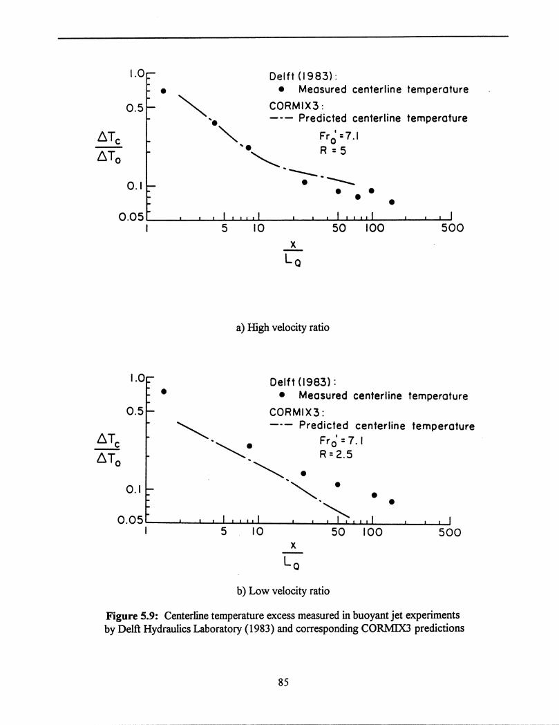


87
5.1.2.3. Upstream-intruding Plume Comparisons
The two upstream-intruding plume experiments discussed in this section were performed byHuq (1983) and Kuhlman and Prahl (1974). Huq performed radial surface discharge experimentssimilar to those used by Jones et al. (1985) whose theory for upstream intruding plumes has beenadopted for use in CORMIX3. Kuhlman and Prahl used a side discharge channel as is assumed forCORMIX3.
Figure 5.11 shows the visual outline and isotherms of Huq's radial discharge experiment.Since CORMIX3 uses a control volume approach in the near-field, only a few key characteristics ofthe flow are calculated for the near-field, including the extent of upstream intrusion and the widthof the plume at the discharge. The plume outline as predicted by CORMIX3 is interpolated betweenthese two values. As shown in Figure 5.11, these two geometric parameters can be used toadequately describe the geometry of the upstream intrusion.
The comparison with the Kuhlman and Prahl experiment is shown in Figure 5.12. CORMIX3appears to provide reasonable predictions of the upstream intrusion. The apparent overprediction ofthe width is most likely due to the limited width of the laboratory receiving water which reduces thehorizontal penetration of the flow. In the CORMIX3 simulation output, the user is warned that thefar-field prediction may be inaccurate because of the interaction of the plume with the far bank inthe near-field.
5.2. Comparisons with Field Studies
Three field studies were chosen to test CORMIX3 against actual discharge situations and toillustrate the applicability of CORMIX3 to realistic conditions. The first field study was performedat the Point Beach Nuclear Power Plant located on the Wisconsin shoreline of Lake Michigan. Thesecond was conducted for the Palisades Nuclear Power Plant, which also discharges into LakeMichigan but from the Michigan shore. The third case illustrates the use of CORMIX3 for predictinga riverine discharge by being applied to the flow of the Connecticut River into the Long IslandSound.
5.2.1. Point Beach Nuclear Power Plant
The Point Beach Nuclear Power Plant is located on the western shore of Lake Michigan. Itdischarges an average of 25.1 m /s of water used to cool condensers in the plant through one of two3
flumes that protrude into the lake about 55 m at angles of 60� and 120�. The heated water isdischarged at an excess temperature of 8.3�C into a shallow ambient environment. The width of thedischarge flumes are 10.7 m and the depth of flow in the flumes during this study was 4.0 m.
The ambient current in this study was reported as 0 m/s. However, it is rare to havecompletely stagnant conditions in a lake as large as Lake Michigan. By observing the isothermsshown in Figure 5.13, it appears that there might have been a small crosscurrent. Since most currentmeters have a minimum threshold of detection of approximately 5 cm/s, it is reasonable to suspect

88
Figure 5.11: Isotherm pattern of an upstream intruding plume resulting from a radial dischargeexperiment (Huq and Jirka, 1987) and corresponding CORMIX3 predictions.

89
Figure 5.12: Isotherms of an upstream intruding plume resulting from a channel dischargeexperiment (Kuhlman and Prahl, 1987) and corresponding CORMIX3 predictions.

90
that a current with the magnitude of several cm/s existed. For this reason, and to get a completeprediction of near and far-field regions, a ambient current of 3 cm/s was used in the CORMIX3prediction.
As seen in Figure 5.13, CORMIX3 shows adequate agreement with the measured field data.Due to the shallow receiving waters, the case is classified as SA2. The slight underprediction of thetrajectory may be due to overestimating the ambient current. The temperature predictions are in goodagreement, with the largest discrepancy between measured and predicted centerline values beingabout 1�C. The width prediction also predicts well the large buoyant spreading that can be observed.
5.2.2. Palisades Nuclear Power Plant
The Palisades Nuclear Power Plant is located on the eastern shore of Lake Michigan anddischarges approximately 25.5 m /s of heated effluent into a shallow ambient environment. In this3
case, cooling water is discharged through a 28.3 m wide man-made channel at a depth of 2.1 m intoa relatively strong ambient current of 0.7 m/s. The channel enters along a straight shoreline at anangle of approximately 90�C. The temperature excess of the effluent was measured at 9.3�C.
Figure 5.14 shows the measured isotherms of the discharge and the CORMIX3 prediction.In this case, the flow is very strongly attached to the downstream bank which reduces the dilutionof the heated effluent. CORMIX3 predicts both the geometry of the flow and the surface temperaturefairly well.
5.2.3. Connecticut River
The study of the Connecticut River discharge into Long Island Sound is described by Garvine(1974). The mouth of the Connecticut River is approximately 1300 m wide and the flow during thisstudy was about 1.8 m deep. This gives an aspect ratio much larger than that allowed by CORMIX3.Therefore, as an approximation of the situation, the discharge area and velocity was kept the same,but the width was reduced to 218.7 m and the depth was increased to 11 m. It is expected that thisschematization of the discharge channel has not effected the results to any great extent sincereasonable predictions were obtained.
The fresh water of the Connecticut River enters the Sound with a velocity of 0.67 m/s,approximately the same velocity as the ambient current. The discharge is positively buoyant due tothe difference between the fresh water of the Connecticut River and the saline ambient environment.
Figure 5.15 shows the CORMIX3 predictions as compared to the measured values of theplume outline as reported by Jones et al. (1985). Although the model appears to slightly overpredictthe spreading of the plume, the discrepancies are well within the range of error of the fieldmeasurements.


93
Figure 5.15: Connecticut River plume measurements (Jones et al., 1985) and correspondingCORMIX3 predicitons.

94
Chapter VIApplications of CORMIX3
The first section of this chapter, Section 6.1, illustrates the use of CORMIX3 with ahypothetical situation involving the discharge of heated effluent from a power plant into a tidalestuary. It exemplifies the schematization of the ambient and discharge conditions, specification oflegal mixing zones, and interpretation of the numerical simulation results. In the second section,Section 6.2, some comments on the applications and limitations of CORMIX3 are discussed.
6.1. AB Power Plant Discharge Analysis
This example considers the effect of tidal variation on the expected trajectory, dilution, andgeometric characteristics of the effluent flow. The discharger is the AB Power Plant, whoseresponsibility is to assure the minimization of any adverse affects arising from the warm waterdischarge on the estuarine environment. First, the parameters of the problem are defined in Section6.1.1 for the two cases in consideration, low tide and high tide. In Section 6.1.2 the use of CORMIX3to analyze these scenarios is discussed.
6.1.1. Problem Statement
The AB Power Plant discharges a constant flow of 25 m /s of heated water into a tidal estuary3
as shown in Figure 6.1. The temperature of the effluent is 26 C. The discharge channel is 10 m in�
width and the depth of flow at the mouth of the channel varies from 2.2 m to 2.5 m from low to hightide, respectively. A detailed cross-section of the outlet of the discharge channel is shown in Figure6.2, also indicating the bathymetric details just in front of the discharge channel.
The estuary is narrow in the region where the plant is located, being only 3 km in width (seeFigure 6.3) and the tidal channel is moderately irregular. During low tide, the current reaches amaximum of 0.30 m/s in the downstream direction. However, as high tide approaches, the flowreverses and reaches a velocity of 0.025 m/s in the opposite direction (see Figure 6.1). The averagedepth of the estuary varies from 7.7 m during low tide to 8 m during high tide. The average ambienttemperature is 15 C, thus giving a discharge temperature excess of 11 C. The typical Manning's n� �
roughness for the estuary is 0.02.
As seen in Figure 6.1, the intake of water for the plant is located just upstream of thedischarge, and it is a primary objective of the plant operators to prevent any discharged effluent frombeing drawn into the intake channel. In addition, state law requires that the temperature rise abovethe natural ambient temperature cannot exceed 3 C outside a radius of 300 m from the discharge�
point.

95
Figure 6.1: Plan view of the AB Power Plant discharge site located at an estuary.

96
Figure 6.2: Detailed cross-section of discharge channel and immediate vicinity.
Figure 6.3: Cross-section of the estuary and schematization used in the CORMIX analysis.

97
6.1.2. CORMIX3 Analysis
Two scenarios will be considered separately. First, low tide conditions are examined inSection 6.1.2.1, and then the high tide predictions are discussed in Section 6.1.2.2. Both conditionswill be analyzed as steady-state assuming the flow conditions are varying sufficiently slowly forwell established plume motions to occur. See further comments in Section 6.1.3.
6.1.2.1. Low Tide Scenario
First, the ambient and discharge geometry must be simplified. Figures 6.1, 6.2, and 6.3 showshow this case can be approximated for CORMIX3 input. Note that generally, ambient conditions arehighly variable and that simplification of this type may not be readily apparent. In all cases,CORMIX3 must be used iteratively, varying the ambient and discharge schematizations to observethe sensitivity to various input parameters.
Once the appropriate input is entered, CORMIX3 classifies the discharge plume under thesehigh velocity ambient conditions as shoreline attached SA1. The SA1 (see Appendix B) flow classdoes not tend to full vertical mixing in the near-field and recirculation zone exists along thedownstream shoreline. In the far-field, the flow spreads laterally due to buoyancy forces.
The results of the mathematical simulation performed by CORMIX are shown in Figures 6.4to 6.6, all of which have been produced directly by the graphics system built into CORMIX Version3.10 or higher. Figure 6.4 shows a recirculation region extends approximately 100 m downstreamto the point where the plume reattaches to the shoreline. A vertical cross-section along the trajectoryof the plume is shown in Figure 6.5 indicating that the plume approaches full vertical mixing, butsome restratification takes place before the plume contacts the bottom again when entering the far-field. The dashed line in Figure 6.5 indicates the location where the water quality standard (3 C) is�
encountered.
Figure 6.6 shows the temperature drop-off, induced by the jet mixing action in the near-field,along the plume trajectory. The standard of �T = 3 C is met at a distance of about 110 m which is�
less than the defined mixing zone of 300 m extent.
The summary element of CORMIX3 gives suggestions on how to improve initial dilution tomeet the legal mixing zone requirements (see Appendix A). However, since there cannot beuniversally applicable rules for increasing dilution characteristics, the analyst must use an iterativeapproach to find the most effective way to optimize the design. Only by changing the parametersand observing the effects on the results can the user be assured of the correct flow simulation andoptimization.
6.1.2.2. High Tide Scenario
The high tide case employs the same discharge and ambient schematization as for the lowtide scenario shown in Figures 6.1, 6.2, and 6.3, but changes the ambient flow velocity, ambientdepth, and discharge depth.

98

99


101
In this case of much smaller ambient velocities, the flow is classified by CORMIX3 as a freejet FJ1. According to the flow description for FJ1 (see Appendix B), the effluent plume does notinteract with the bottom in the near-field, and is deflected by the crossflow. The flow class FJ1 alsoshows no interaction with the near shoreline.
The plume plan view is illustrated for the near-field in Figure 6.7. The crossflow is veryweak, therefore the flow is only slightly deflected. Some lateral spreading occurs in the near-fieldas shown in the figure. Both the extent of the regulatory mixing zone and the location where thewater quality standard is met are plotted. In this near-field region the plume does not interact withthe opposite shore of the estuary that is located 3000 m away.
Figure 6.8 shows a cross-section along the flow trajectory centerline as obtained fromCORMIX3. The plume does not interact with the bottom as the maximum jet depth is only about4.5 m in a water depth of 8.0 m. Figure 6.9 shows the temperature decay along the plume trajectory.In this case also, the flow meets the standard at the edge of the legal mixing zone.
It is interesting to compare the relative temperature drop-offs for the two cases (Figures 6.6and 6.9). In fact, the free jet shows a faster drop-off than the shoreline attached case, despite theconsiderably higher ambient velocity in the latter case. This is somewhat counter-intuitive but aconsequence of several opposing mixing mechanisms in such complex environmental flows.
6.1.3. Comments
The approach used to analyze this tidal situation assumes "quasi-steady" conditions exist.That is, although the ambient conditions change with time, the time-scale of the tidal variations aremuch larger than the time-scale of the near-field mixing processes, therefore, each scenario isassumed to be independent of the previous conditions. One should note, however, that in general thisis not true, especially for far-field predictions. For a more complete assessment of the effects of tidalvariations on surface discharges, see the report on additional developments for the CORMIX system(Jirka et al., 1996).
The importance of iterative use of CORMIX3 must also be stressed. In this example, as withmost discharge situations, significantly different flow patterns are predicted with changes in theambient conditions. Since ambient and discharge conditions are rarely known with absolutecertainty, it is imperative that when using CORMIX3 to analyze any realistic scenario, repeated runsmust be made to determine the sensitivity of the predictions to varying ambient parameters.
6.2. Limitations and Applicability of CORMIX3
CORMIX3 is intended to be a robust modeling program capable of handling a wide varietyof positively and neutrally buoyant surface discharges. However, some limitations still exist. Forexample, CORMIX3 is not intended for application to negatively buoyant discharges. Additionallimitations are discussed in Section 6.2.1.

102

103

104
Figure 6.9: Centerline temperature excess along trajectory in near-field of AB Power Plantplume under high tide conditions.

105
CORMIX3 may, in some instances, be adapted to unusual situations for which directapplication is not intended. For example, CORMIX3 may be "tricked" to predict simple negativelybuoyant discharges. This and other adaptations of CORMIX3 to atypical situations are discussed inSection 6.2.2.
6.2.1. Limitations of CORMIX3
The limitations of CORMIX3 may be categorized into three general groups: (a) flow classscenarios that cannot be quantitatively predicted, (b) odd discharge or ambient geometries thatcannot be schematized, and (c) scenarios with significant ambient stratification.
(a) CORMIX3 is unable to model certain flow classes. One such situation is a dischargeclassified as an upstream intruding plume in a stagnant environment. The resulting flow in this caseis an unsteady pool of effluent that forms at the mouth of the discharge channel. In addition,CORMIX3 can only predict the region of flow near the discharge for all stagnant cases due to theinherent unsteadiness of the far-field in such cases. Also, if strong interaction with a shoreline occursthat may severely disrupt the flow so that prediction of the flow would be difficult or impossible, thesimulation will terminate at the point of this interaction.
(b) Extreme discharge and ambient geometries cannot be accounted for by CORMIX3. Forexample, the aspect ratio of the discharge is limited to a range of 0.05 to 5. Althoughapproximations can be made for discharge channels with aspect ratios that fall outside this rangesuch as described in Section 5.2.3 for the Connecticut River field study, caution should be used indoing so to avoid misrepresentation of the important discharge characteristics. In addition, the depthof the receiving water at the mouth of the discharge, H , cannot be greater than the average ambientD
water depth, H .a
(c) The ability of CORMIX3 to accurately predict the characteristics of a flow that falls onthe borderline between two flow classes usually requires repetitive use in order to appreciate thesensitivity of the results. By examining the sensitivity to certain parameters that are might affect theflow, the user can obtain a "feel" for the true nature of the flow.
6.2.2. Application of CORMIX3 to Non-standard Situations
6.2.2.1. Negatively Buoyant Discharges Issuing at the Bottom of the Water Body
CORMIX3 may be adapted for use on non-buoyant discharges if the bottom geometry of thereceiving water is simple. This implies that the discharge channel is located at the bottom of theambient water body of which there is no significant slope or irregularities. The user must then inessence flip the picture upside down so that the bottom of the receiving water body appears to be the"surface" at which the discharge is located. By specifying a density difference equal to the existingone, but designating the discharge as less dense than the ambient, the flow may be simulated as ifit were a mirror image of the actual flow.

106
In such cases, CORMIX3 will classify the flow and predict the resulting trajectory, dilutionand geometry as if it were a positively buoyant discharge issued at the surface of the water. The usermust then correctly interpret the results as the mirror image and account for any anomalies that thebottom may cause in the prediction. A similar approach is discussed by Doneker and Jirka (1991)for adapting CORMIX1 to submerged single port discharges near the surface of the receiving water.
6.2.2.2. Simplification of Irregular Discharge Geometries
CORMIX3 also allows for both rectangular discharge channels and circular (pipe) dischargesassuming that the pipe is flowing full. In fact, pipe discharges may be slightly submerged, but by nomore than one-half pipe diameter for them to be considered a surface discharge. If the cross-sectionis an odd shape (i.e.: a pipe flowing partially full), then an equivalent rectangular cross sectionshould be used with an equivalent discharge area and width-to-depth ratio.

107
Chapter VIIConclusions and Recommendations
With growing public awareness and tighter governmental regulation of discharges intonatural watercourses, it has become essential to be able to accurately predict and analyze a widevariety of possible flows. However, the broad spectrum of possible discharge configurations, ambientconditions, and resulting flow patterns has made the selection of modelling techniques difficult forpracticing engineers and regulatory agencies without considerable prior experience or expertise. Inaddition, most currently available computer programs have limited applicability, require a highdegree of familiarity with the input and limitations of the system, and offer little help to theinexperienced user. These difficulties seem to justify the development of a user friendly systemcapable of predicting a variety of flows for a wide range of discharge conditions.
CORMIX3 as subsystem of the CORMIX expert system is a tool to facilitate the analysisand prediction of positively and neutrally buoyant surface discharges. It is capable of predicting thetrajectory, dilution and geometry of a variety of flow patterns. It also provides qualitativedescriptions of the flow that give the user a visual picture of the effluent mixing pattern, allowingfor more meaningful application of the numerical results. In addition, the use of ample instructions,simple input structure, and warning messages are vital ingredients in making the system an effectivemeans for novice users to design and analyze surface buoyant discharges.
Comparisons of CORMIX3 predictions with laboratory experiments and field studies showgood to excellent agreement. In addition, CORMIX3 displays a high degree of flexibility inpredicting a wide variety of flow possibilities, including various flow patterns and boundaryinteractions.
Overall, CORMIX3 appears to be a reliable tool for the initial analysis of buoyant surfacejets. However, as more data and experience is obtained in the field, CORMIX3 may requireoccasional adjustments and modifications. Improvements in the predictive capabilities can be madeas further research results become available.

���

108
References
Akar P.J. and G.H. Jirka (1991), "CORMIX2: An Expert System for Hydrodynamic Mixing ZoneAnalysis of Conventional and Toxic Submerged Multiport Diffuser Discharges", U.S.Environmental Protection Agency, Tech. Rep. EPA/600/3-91/073, Environmental Research Lab,Athens, Georgia
Abdelwahed, M. S. T., and V. H. Chu (1981), "Surface Jets and Surface Plumes in Cross-flows,"Technical Report No. 81-1, Fluid Mechanics Laboratory, McGill University, Montreal.
Benjamin, T. B. (1968), "Gravity Currents and Related Phenomena," J. Fluid Mech., Vol. 31, No.2.
Briggs, G. A. (1965), "A Plume Rise Model Compared with Observations," Journ. Air PollutionControl Assoc., Vol. 15, No. 9, pp. 443-438.
Brocard, D.N. (1984), "Surface Buoyant Jets in Reversing and Steady Crossflows", Tech. Report,Alden Research Laboratory, Worcester Polytechnic Institute, Worcester, Mass.
Brooks, N. H. (1960), "Diffusion of Sewage Effluent in an Ocean Current," Proc. Intn'l. Conf. WasteDisposal Marine Environ. 1st., Pergamon Press, Oxford, pp 246-267.
Bühler, J. and W. Hauenstein (1979), "Axisymmetric Jets in a Crossflow," Proc. Congress Int.Assoc. for Hydraulic Research, Vol.4, pp. 257-265, Cagliari, Italy
Chu, V. H., and M. S. T. Abdelwahed (1990), "Shore Attachment of Buoyant Effluent in StrongCrossflow," Journ. Hyd. Eng., ASCE, Vol. 116, No. 2, pp. 157-175.
Chu, V. H., and M. B. Goldberg (1974), "Buoyant Forced-plumes in Crossflow," Journ. Hyd. Div.,ASCE, Vol. 100, No. HY9, pp. 1203-1214.
Chu, V. H., and G. H. Jirka (1986), "Chapter 25: Surface Buoyant Jets," Encyclopedia of FluidMechanics, Gulf Publishing Company, Houston, Texas.
Csanady, G. T. (1961), "Some Observations of Smoke Plumes," Int'l. Journ. Air Pollution, PergamonPress, London, Vol. 4, No. 1/2, pp. 47-51.
Davidson, M. J. (1989), "The Behavior of Single and Multiple, Horizontally Discharged, BuoyantFlows in a Non-Turbulent Coflowing Ambient Fluid," Ph.D. Thesis, Department of CivilEngineering, University of Canterbury, Christchurch, New Zealand.
Delft Hydraulics Laboratory (1983), "Buoyant Surface Jets in Crossflow," Report on ExperimentalInvestigation - S350-II.
Doneker, R. L., and G. H. Jirka (1990), "Expert System for Hydrodynamic Mixing Zone Analysisof Conventional and Toxic Submerged Single Port Discharges (CORMIX1)," Report No.

109
EPA/600/3-90/012, U.S. Environmental Protection Agency, Env. Research Laboratory, Athens,Georgia.
Dunn, W. E., A. J. Policastro, and R. A. Paddock (1975), "Surface Thermal Plumes: Evaluation ofMathematical Models for the Near and Complete Field," Argonne National Laboratory ReportANL/WR-75-3 - Part One.
Fan, L. N. (1967), "Turbulent Buoyant Jets into Stratified or Flowing Ambient Fluids," W. M. KeckLaboratory Report KH-R-15, California Institute of Technology, Pasadena, Calif.
Fay, J. A. (1973), "Buoyant Plumes and Wakes," Ann. Rev. of Fluid Mech., Vol. 5, pp. 151-160.
Fischer, H. B., E. J. List, C. Y. Koh, J. Imberger, and N. H. Brooks (1979), Mixing in Inland andCoastal waters, Academic Press, Inc., Orlando, Florida.
Garvine, R. W. (1974), "Physical Features of the Connecticut River Outflow During HighDischarge," Journ. of Geophys. Res., Vol. 79, No. 6.
Hayashi, T., and N. Shuto (1967), "Diffusion of Warm Water Jets Discharged Horizontally at WaterSurface," Proc. of the 12 Conf. of the Intern'l. Assoc. for Hyd. Res., Fort Collins, Colorado, Vol.th
4, pp.47-59.
Holley, E. R. and G. H. Jirka (1986), "Mixing in Rivers," Technical Report E-86-11, U.S. ArmyCorps of Engineers, Washington, D.C.
Hoult, D. P., and J. C. Weil (1972), "Turbulent Plume in a Laminar Crossflow," AtmosphericEnvironment, Pergamon Press, London, pp. 513-531, Vol. 6.
Hoult, D. P., J. A. Fay, and L. J. Forney (1969), "A Theory of Plume Rise Compared with FieldObservations," Journ. Air Pollution Control Assoc., Vol. 19, No. 8, pp. 585-590.
Huq, I.P. and G.H. Jirka, "Density Currents From a Radial Source in Stratified FlowingEnvironments", in Stratified Flows, E.J. List and G.H. Jirka, Ed.s., American Society of CivilEngineers, 1990
Jirka, G.H., G. Abraham, and D.R.F. Harleman (1975), "An Assessment of Techniques forHydrothermal Prediction," M.I.T. - Ralph M. Parsons Lab. for Water Resources and HydrodynamicsReport No. 203.
Jirka, G.H., E.E. Adams, and K.D. Stolzenbach (1981), "Buoyant Surface Jets," Journ. Hyd. Div.,ASCE, Vol. 107, No. HY11, pp. 1467-1487.
Jirka, G.H., and P. J. Akar (1990), "CORMIX2: Expert System for Multiport Diffuser Discharges,"Proc. Nat'l. Conference on Hyd. Eng., ASCE, San Diego, California.
��������� Akar P.J. and J.D. Nash (1996), "Recent Enhancements to the Cormix Mixing ZoneExpert System: Technical Background", Report No. EPA/600/xxx, U.S. Environmental Protection

110
Agency, Env. Research Laboratory, Athens, Georgia (draft)
������� ��� ��� ������� ���� ��� ����� (1996), "User's Manual for CORMIX: AHydrodynamic Mixing Zone Model and Decision Support System for Pollutant Discharges intoSurface Waters", Report No. EPA/600/xxx, U.S. Environmental Protection Agency, Env. ResearchLaboratory, Athens, Georgia
Jirka, G. H., and M. Arita (1987), "Density Currents or Density Wedges: Boundary Layer Influenceand Control Methods," J. Fluid Mech., Vol 177, pp. 187-206.
Jones, J. M., G. H. Jirka, and D. A. Caughey (1985), "Numerical Techniques for Steady Two-dimensional Transcritical Stratified Flow Problems, with an Application to the Intermediate FieldDynamics of Ocean Thermal Energy Conversion Plants," Argonne National Laboratory Report No.ANL/EES-TM-27\1.
Knudsen, M. (1988), "Buoyant Horizontal Jets In an Ambient Flow," PhD Thesis, University ofCanterbury, Christchurch, New Zealand.
Koester, G. E. (1974), "Experimental Study of Submerged Single-Port Thermal Discharges," M.S.Thesis, Department of Civil Engineering, M.I.T., Cambridge, Massachussetts.
Kuhlman, J. M., and J. M. Prahl (1974), "Laboratory Modeling of Surface Thermal Plumes," ReportNo. FTAS/TR-74-102, School of Engineering, Case Western Reserve University, Cleveland, Ohio.
Larsen, J., and T. Sorensen (1968), "Chapter 89 - Buoyancy Spread of Wastewater in CoastalRegions", Eleventh Conference on Coastal Engineering, London, Vol. 2.
List, E. J., and J. Imberger (1973), "Turbulent Entrainment in Buoyant Jets and Plumes," Journ. Hyd.Div., ASCE, No. HY9, pp. 1461-1474.
Miller, D. S., and B. A. Brighouse (1985), Thermal Discharges - A Guide to Power and Process PlantCooling Water Discharges into Rivers, Lakes, and Seas, British Hydromechanics ResearchAssociation.
Moore, D. J. (1966), "Physical Aspects of Plume Models," Int'l Journ. Air and Water Pollution, Vol.10, pp. 441-417.
Motz, L. H., and B. A. Benedict (1970), "Heated Surface Jet Discharged into a Flowing AmbientStream," Report No. 4, Department of Environmental and Water Resources Engineering, VanderbiltUniversity, Nashville, Tennessee, Aug. 1970.
Morton, B. R. (1959), "Forced Plumes," Journ. of Fluid Mech., Vol. 5, No. 1, pp. 151-163.
Morton, B. R., G. I. Taylor, and J. S. Turner (1956), "Turbulent Gravitational Convection fromMaintained and Instantaneous Sources," Roy. Soc. London A, Vol. 234, No. 1196, pp. 1-23.

111
Priestley, C. H. B. (1956), "A Working Theory of the Bent-over Plume of Hot Gas," Quart. Journ.Roy. Meteorol. Soc., Vol. 82, pp. 165-176.
Priestley, C. H. B., and F. K. Ball (1955), "Continuous Convection from an Isolated Source of Heat,"Quart. Journ. Royal Meteorol. Soc., Vol. 81, No. 348, pp. 144-157.
Railston, W. (1954), Proc. Phys. Soc. B, Vol. 67, p. 42.
Rouse, H., C. S. Yih, and H. W. Humphreys (1952), "Gravitational Convection from a BoundaryLayer," Tellus, Vol. 4, pp. 201-210.
Schatzmann, M. (1979), An Integral Model of Plume Rise", Atmos. Environment, Vol.13, 721-731.
Schmidt, W. (1941), "Turbulente Ausbreitung eines Stromes Erhitzter Luft," Z. agnew. Math Mech.,Vol. 21, pp. 265-278, 351-363.
Scorer, R. S. (1958), Natural Aerodynamics, Pergamon Press, London.
Scorer, R. S. (1959), "Behavior of Chimney Plumes," Int'l. Journ. Air Pollution, Pergamon Press,London, Vol. 1, No. 4, pp. 198-220.
Sharp, J. J. and B. D. Vyas (1977), "The Buoyant Wall Jet", Proceeding of the Institution of CivilEngineers, Part 2, No. 63, September.
Simpson, J. E., and R. E. Britter (1979), "The Dynamics of the Head of a Gravity Current AdvancingOver a Horizontal Surface," Journ. of Fluid Mech., Vol. 94, pp. 477-495.
Slawson, P. R., and G. T. Csanady (1967), "The Mean Path of Buoyant Chimney Plumes," Journ.Fluid Mech., Vol. 28, pp. 311-322.
Sutton, O. G. (1953), Micrometeorology, McGraw Hill, New York.
Tokar, J. V. (1971), "Thermal Plumes in Lakes: Compilations of Field Experience," Report ANL/ES-3, Center for Environmental Studies, Argonne National Laboratory, Argonne, Illinois.
Wolanski, E. J., and R. C. Koh (1973), "Preliminary Report on Secondary Circulation in SurfaceBuoyant Jets," Tech. Memo No. 73-10, W. M. Keck Laboratory of Hydraulics and Water Resources,California Institute of Technology, Pasedena, California.
Wright, S. J. (1977), "Mean Behavior of Buoyant Jets in a Crossflow," Journ. Hyd. Div., ASCE, Vol.103, No. HY5, pp. 499-513.
Wright, S. J., and R. B. Wallace (1979), "Two Dimensional Buoyant Jets in a Stratified Fluids,"Journ. Hyd. Div., ASCE, Vol. 105, No. HY11, pp. 1393-1406.
Yih, C. S. (1951), Proc. 1st U.S. Congr. Appl. Mech., p. 941.

112
Appendix ADesign Recommendations
The following recommendations are supplied to the CORMIX user as an incentive toperform design iterations and sensitivity analyses:
CORMIX3DESIGN RECOMMENDATIONS: BUOYANT SURFACE DISCHARGES:
A reliable environmental analysis and mixing zone prediction is possibleonly if each design case is evaluated through several iterations of CORMIX3.Small changes in ambient or discharge design conditions can sometimes causedrastic shifts in the applicable flow class and the size or appearance of mixing zones. Iterative use of CORMIX3 will give information on the sensi-tivity of predicted results on design and ambient conditions.
Each predictive case should be carefully assessed as to: - size and shape of LMZ - conditions in the TDZ (if present) - bottom impact of the discharge flow - bank attachment, and other factors.
In general, iteration should be conducted in the following order: A) Discharge geometry changes B) Sensitivity to ambient conditions C) Discharge flow changes (process variations)
When investigating these variations the CORMIX3 user will quickly appreciate the fact that mixing conditions at short distances (near- field) are usually quite sensitive and controllable. In contrast, mixing conditions at large distances (far-field) often show little sensitivity unless the ambient conditions change substantially or drastic process variations are introduced.
A) DISCHARGE GEOMETRY CHANGES:
Most of the following recommendations are motivated by the desire of improving conditions in the applicable mixing zones (i.e. minimizing concentrations and/or areal extent).
1) Discharge depth: Increasing the depth of the ambient water body at the discharge location discourages bottom interaction and subsequently downstream bank attachment. The effectiveness if increasing the total depth at the discharge depends on the buoyancy and the initial momentum of the discharge.
2) Aspect ratio: By decreasing the depth of the discharge channel and increasing its width, the discharge is encouraged to propagate further into the channel. This also may lead to a small increase in the initial surface area of the plume. Note, however, that CORMIX3 is limited to discharge channels with aspect ratios between 0.05 and 5.
3) Horizontal angle: The larger the angle between the downstream bank and the discharge channel centerline, the less likely shoreline attachment will occur. This may be desirable since shoreline attachment generally

113
leads to decreased dilutions and higher pollutant concentrations along the near bank.
B) SENSITIVITY TO AMBIENT CONDITIONS:
Variations - of the order of 10 percent - of the following ambient design conditions should be considered: - ambient velocity (or ambient flowrate) - ambient depth (or river/tidal stage) - ambient density structure (notably density differences)
Such variability is important for two reasons: 1) the usual uncertainty in ambient environmental data, 2) the schematization employed by CORMIX3
Please refer to the detailed advice on the specification of environmentaldata, including the density structure, that is available in programelement DATIN3. In particular, note the advisory comments on stagnant ambient conditions.
C) DISCHARGE FLOW CHANGES (PROCESS VARIATIONS):
Actual process changes can result in variations of one or more of threeparameters associated with the discharge: flowrate, density, or pollutantconcentration. In some cases, such process changes may be difficult toachieve or too costly. Note, that "off-design" conditions in which adischarge operates below its full capacity also fall into this category.
1) Pollutant mass flux: The total pollutant mass flux is the product of discharge flow (m**3/s) times the discharge pollutant concentration (in arbitrary units). Thus, decreasing the pollutant mass flux will, in general, decrease the resulting pollutant concentration in the near- field and far-field. This occurs, of course, during off-design conditions.
2) Discharge flow: For a given pollutant mass flux, an increase in discharge flow implies an decrease in discharge pollutant concentration, and vice versa. Although, for the variety of flow classes contained in CORMIX3 there is no universal rule whether high or low volume discharges are preferable for optimizing near-field mixing, increased discharge velocities generally increase initial mixing. Mostly, the sensitivity is small, and even more so for far-field effects.
3) Discharge density: The actual density of the discharge flow controls the buoyancy effects relative to the ambient water. Occasionally, the discharge density is controllable through the amount of process heating or cooling occurring prior to discharge. Near-field mixing may be enhanced or degraded by increasing the total density difference between discharge flow and ambient water. In most cases, however, this effect is minor.

114
Appendix BFlow Class Descriptions
The following flow class descriptions are available on-line to the CORMIX user. Theyprovide detailed information on the hydrodynamic mixing processes that occur and that arecomputed sequentially in the program and displayed in the CORMIX3 prediction file.
FLOW CLASS FJ1
This flow exhibits no bank interaction or bottom interaction in thenear-field. It is oriented at a large enough angle from the down-stream shoreline to prevent Coanda attachment. The buoyancy isrelatively strong and will distort the cross-section of the flow significantly in the near-field.
The flow consists of the following regimes:
1) Weakly deflected 3-dimensional jet: The mixing is dominated by the initial momentum, causing relatively constant spreading in both the horizontal and the vertical directions. The deflection by the ambient crossflow is relatively weak.
2) Weakly deflected plume: The flow cross-section becomes distorted by the buoyancy, resulting in thinning of the flow and increased non-linear lateral spreading. The dilution is reduced in this regime due to suppression of the vertical mixing by buoyancy forces.
3) Strongly deflected plume: The cross-section of the flow is distorted due to buoyancy-induced lateral spreading. This may result in thinning of the plume. The flow is strongly deflected by the ambient current.
4) Far-field buoyant spreading: The plume spreads laterally along the surface while being advected downstream with the ambient current. There is no net change in the centerline trajectory. The mixing rate is relatively small and the thickness may decrease in this regime. The plume may interact with the shoreline.
5) Passive ambient diffusion: The ambient turbulence becomes the predominant mixing process in this regime. The plume will grow in both the vertical and horizontal directions at a rate that is dependent on the magnitude of the ambient turbulence. The flow may interact with the bottom or the shoreline in this regime.
SPECIAL CASE: If the receiving water is stagnant, the simulation will terminate at the end of the weakly deflected plume regime (2).
FLOW CLASS FJ2

115
This flow exhibits no bank interaction or bottom interaction in thenear-field. It is oriented at a large enough angle from the down-stream shoreline to prevent Coanda attachment. The buoyancy isstrong to distort the cross-section of the flow in the near-field.
The flow consists of the following regimes:
1) Weakly deflected 3-dimensional jet: The mixing is dominated by the initial momentum, causing relatively constant spreading in both the horizontal and the vertical directions. The deflection by the ambient crossflow is relatively weak.
2) Strongly deflected 3-dimensional jet: The is dominated by the initial momentum, causing relatively constant spreading in both the horizontal and vertical directions. The flow is strongly deflected by the ambient current.
3) Strongly deflected plume: The cross-section of the flow is distorted due to buoyancy-induced lateral spreading. This may result in thinning of the plume. The flow is strongly deflected by the ambient current.
4) Far-field buoyant spreading: The plume spreads laterally along the surface while being advected downstream with the ambient current. There is no net change in the centerline trajectory. The mixing rate is relatively small and the thickness may decrease in this regime. The plume may interact with the shoreline.
5) Passive ambient diffusion: The ambient turbulence becomes the predominant mixing process in this regime. The plume will grow in both the vertical and horizontal directions at a rate that is dependent on the magnitude of the ambient turbulence. The flow may interact with the bottom or the shoreline in this regime.
SPECIAL CASE: If the effluent is non-buoyant, the strongly deflected plume and far-field buoyant spreading regimes will be omitted.
FLOW CLASS FJ3
This flow exhibits no bank interaction in the near-field. However, the ambient water depth is shallow and the flow will interact with the bottom in the near-field. It is oriented at a large enough discharge angle to prevent Coanda attachment with the downstream shoreline. The buoyancy is relatively strong and will distort thecross-section of the flow significantly in the near-field.
The flow consists of the following regimes:
1) Weakly deflected 3-dimensional jet: The mixing is dominated by the initial momentum, causing relatively constant spreading in both the horizontal and the vertical directions. The deflection by the ambient crossflow is relatively weak.

116
2) Weakly deflected 2-dimensional jet: The flow interacts with the bottom of the receiving water body and is considered to be 2-dimensional (i.e.: fully vertically mixed). The dilution is due to momentum dominated mixing. At the end of this regime, the flow restratifies and becomes 3-dimensional in character. The deflection by the ambient current is relatively weak.
3) Weakly deflected plume: The flow cross-section becomes distorted by the buoyancy, resulting in thinning of the flow and increased non-linear lateral spreading. The dilution is reduced in this regime due to suppression of the vertical mixing by buoyancy forces. The deflection by the ambient current is relatively weak.
4) Strongly deflected plume: The cross-section of the flow is distorted due to buoyancy-induced lateral spreading. This may result in thinning of the plume. The flow is strongly deflected by the ambient current.
5) Far-field buoyant spreading: The plume spreads laterally along the surface while being advected downstream with the ambient current. There is no net change in the centerline trajectory. The mixing rate is relatively small and the thickness may decrease in this regime. The plume may interact with the shoreline.
6) Passive ambient diffusion: The ambient turbulence becomes the predominant mixing process in this regime. The plume will grow in both the vertical and horizontal directions at a rate that is dependent on the magnitude of the ambient turbulence. The flow may interact with the bottom or the shoreline in this regime.
SPECIAL CASE: If the receiving water is stagnant, the simulation will terminate at the end of the weakly deflected plume regime (3).
FLOW CLASS SA1
This flow is dynamically attached to the downstream bank. Along the bank is a zone of recirculating effluent which will reduce the dilution.The penetration into the crossflow is reduced due to this dynamicattachment. For this case, the flow does not interact with the bottomin the near field.
The flow consists of the following regimes:
1) Weakly deflected shoreline attached jet (3-D): The mixing is dominated by the initial momentum causing relatively constant spreading in both the horizontal and the vertical directions. The deflection by the crossflow is relatively weak. This regime tends to be very short or non-existent in shoreline attached flows.
2) Strongly deflected shoreline attached jet (3-D): The mixing in this regime is dominated by the initial momentum, causing relatively constant spreading in both the horizontal and vertical directions.

117
The flow is strongly bent over by the ambient crossflow and is dynamically attached to the shoreline. A zone of recirculating effluent exists between the core of the flow and the shoreline.
3) Strongly deflected shoreline attached plume: The cross-section of the flow becomes distorted due to strong buoyancy-induced lateral spreading. Some of the effluent from this region is recirculated back upstream along the shoreline. However, the overall mixing rate is small and the thickness may decrease in this regime.
4) Far-field buoyant spreading: The plume spreads laterally along the surface while being advected downstream with the ambient current. There is no net change in the centerline trajectory. The mixing rate is relatively small and the thickness may decrease in this regime. The plume remains attached to the shoreline.
5) Passive ambient diffusion: The ambient turbulence becomes the predominant mixing process in this regime. The plume will grow in both the vertical and horizontal directions at a rate that is dependent on the magnitude of the ambient turbulence. The flow may interact with the bottom or the opposite shoreline in this regime.
FLOW CLASS SA2
This flow is dynamically attached to the downstream bank. Along the bank is a zone of recirculating effluent exists which reduces the dilution. The penetration into the crossflow is reduced due to this dynamic attachment. Since the discharge depth is equal or nearly equal to the depth of the receiving water at the discharge point, the flow becomes attached to the bottom. This attachment to the bottom could effectively block off the ambient current and be the cause of the attachment to the downstream shoreline.
The flow consists of the following regimes:
1) Weakly deflected shoreline attached jet (2-D): The mixing is dominated by the initial momentum causing relatively constant spreading in the horizontal direction. The deflection by the crossflow is relatively weak. This regime tends to be very short or non-existent in shoreline attached flows.
2) Strongly deflected shoreline attached jet (2-D): The mixing in this regime is dominated by the initial momentum, causing relatively constant spreading in the horizontal direction. The flow is strongly bent over and is dynamically attached to the shoreline. A zone of recirculating effluent exists between the core of the flow and the shoreline. The flow remains attached to the bottom throughout this regime.
3) Strongly deflected shoreline attached plume: The flow may lift off the bottom if it contains sufficient buoyancy. The cross-section of the flow becomes distorted due to strong buoyancy-induced lateral

118
spreading. Some of the effluent from this region is recirculated back upstream along the shoreline. However, the overall mixing rate is small and the thickness may decrease in this regime.
4) Far-field buoyant spreading: The plume spreads laterally along the surface while being advected downstream with the ambient current. There is no net change in the centerline trajectory. The mixing rate is relatively small and the thickness may decrease in this regime. The plume remains attached to the shoreline.
5) Passive ambient diffusion: The ambient turbulence becomes the predominant mixing process in this regime. The plume will grow in both the vertical and horizontal directions at a rate that is dependent on the magnitude of the ambient turbulence. The flow may interact with the bottom or the opposite shoreline in this regime.
FLOW CLASS WJ1
Because this discharge is issued at or near parallel to the down-stream bank, it will remain attached to the shoreline. The receiving water is relatively deep in the vicinity of the discharge so no interaction with the bottom will take place in the near-field. The shoreline will act as a reflective boundary to liken the flow to a jet being issued into a coflow.
The flow will consist of the following regimes:
1) Weakly deflected 3-dimensional wall jet: The mixing is dominated by the initial momentum, causing relatively constant jet-like spreading in both the horizontal and the vertical direction. The ambient current has very little effect on the flow in this regime. There is no interaction with the bottom throughout this regime.
2) Far-field buoyant spreading: Further from the source the initial momentum becomes unimportant and far-field processes take over. The plume spreads laterally along the surface while being advected downstream with the ambient current. There is no net change in the centerline trajectory. The mixing rate is relatively small and the thickness may decrease in this regime. The plume remains attached to the shoreline.
3) Passive ambient diffusion: The ambient turbulence becomes the predominant mixing process in this regime. The plume will grow in both the vertical and horizontal directions at a rate that is dependent on the magnitude of the ambient turbulence. The flow may interact with the bottom or the opposite shoreline in this regime.
FLOW CLASS WJ2
Because this discharge is issued at or near parallel to the down-stream bank, it will remain attached to the shoreline. The receiving

119
water is relatively shallow in the vicinity of the discharge and thedischarge interacts with the bottom in the near-field. The shoreline will act as a reflective boundary to liken the flow to a jet being issued into a coflow.
The flow will consist of the following regimes:
1) Weakly deflected 3-dimensional wall jet: The mixing is dominated by the initial momentum, causing relatively constant jet-like spreading in both the horizontal and the vertical direction. The ambient current has very little effect on the flow in this regime. Interaction with the bottom will occur at the end of this regime.
2) Weakly deflected 2-dimensional wall jet: Once bottom interaction occurs, the flow becomes 2-dimensional in form. The mixing is dominated by the initial momentum, causing relatively constant jet-like spreading in the horizontal direction. The ambient current has very little effect on the flow in this regime. There is continuous interaction with the bottom throughout this regime.
3) Far-field buoyant spreading: Further from the source the initial momentum becomes unimportant and far-field processes take over. Liftoff of the flow from the bottom may occur due to buoyancy forces. The plume spreads laterally along the surface while being advected downstream with the ambient current. There is no net change in the centerline trajectory. The mixing rate is relatively small and the thickness may decrease in this regime. The plume remains attached to the shoreline.
4) Passive ambient diffusion: The ambient turbulence becomes the predominant mixing process in this regime. The plume will grow in both the vertical and horizontal directions at a rate that is dependent on the magnitude of the ambient turbulence. The flow may interact with the bottom or the opposite shoreline in this regime.
FLOW CLASS PL1
The discharge is issued with relatively low velocity and high buoyancyinto an environment with a relatively low ambient velocity. For this reason, the effluent will spread upstream along the shoreline againstthe ambient current. The receiving water is relatively deep in the vicinity of the discharge so no significant interaction with the bottom takes place in the near-field.
The flow will consist of the following flow regimes:
1) Upstream intrusion: Upstream of the discharge will be a steady layer of effluent. This upstream spreading is caused by the strong buoyancy of the effluent and a relatively weak ambient crossflow. This regime ends just downstream of the discharge where far-field buoyant spreading takes over.
120
2) Far-field buoyant spreading: The plume spreads laterally along the surface while being advected downstream with the ambient current. The mixing rate is relatively small and the thickness may decrease in this regime. The plume remains attached to the shoreline.
3) Passive ambient diffusion: The ambient turbulence becomes the predominant mixing process in this regime. The plume will grow in both the vertical and horizontal directions at a rate that is dependent on the magnitude of the ambient turbulence. The flow may interact with the bottom or the opposite shoreline in this regime.
FLOW CLASS PL2
The discharge is issued with relatively low discharge momentum intoan environment with a relatively low ambient velocity. For thesereasons, far-field processes are the only important ones.
The flow will consist of the following flow regimes:
1) Far-field buoyant spreading: The plume spreads laterally along the surface while being advected downstream with the ambient current. The mixing rate is relatively small and the thickness may decrease in this regime. The plume remains attached to the shoreline.
2) Passive ambient diffusion: The ambient turbulence becomes the predominant mixing process in this regime. The plume will grow in both the vertical and horizontal directions at a rate that is dependent on the magnitude of the ambient turbulence. The flow may interact with the bottom or the opposite shoreline in this regime.


