
Handling technology
42
Handling technology www.zimmer-group.com Gripper series GEP2000
Transcript of Handling technology

Handling technology
www.zimmer-group.com
Gripper series GEP2000


3
ZIMMER GROUP COMMITTED TO OUR CUSTOMERSWE HAVE SUCCEEDED FOR YEARS BY OFFERING OUR CUSTOMERS INNOVATIVE AND INDIVIDUALIZED SOLUTIONS. ZIMMER HAS GROWN CONTINUOUSLY AND TODAY WE HAVE REACHED A NEW MILESTONE: THE ESTABLISHMENT OF THE KNOW-HOW FACTORY. IS THERE A SECRET TO OUR SUCCESS?
Foundation. Excellent products and services have always been the foundation of our company’s growth. Zimmer is a source of ingenious solutions and important technical innovations. This is why customers with high expectations for technology frequently find their way to us. When things get tricky, Zimmer Group is in its best form.
Style. We have an interdisciplinary approach to everything we do, re-sulting in refined process solutions in six technology fields. This applies not just to development but to production. Zimmer Group serves all industries and stands ready to resolve even the most unique and highly individualized problems. Worldwide.
Motivation. Customer orientation is perhaps the most important factor of our success. We are a service provider in the complete sense of the word. With Zimmer Group, our customers have a single, centralized con-tact for all of their needs. We approach each customer’s situation with a high level of competence and a broad range of possible solutions.
www.zimmer-group.com

4
TECHNOLOGIES
HANDLING TECHNOLOGYMORE THAN 30 YEARS OF EXPERIENCE AND INDUSTRY KNOWLEDGE: OUR PNEUMATIC, HYDRAULIC AND ELECTRICAL HANDLING COMPONENTS AND SYSTEMS ARE GLOBAL LEADERS.
Components. More than 2,000 stan-dardized grippers, swivel units, robotic accessories and much more. We offer a complete selection of technologically superior products that are ready for rapid delivery.
Semi-standard. Our modular approach to design enables custom configura-tions and high rates of innovation for process automation.
DAMPING TECHNOLOGYINDUSTRIAL DAMPING TECHNOLOGY AND SOFT CLOSE PRODUCTS EXEMPLIFY THE INNOVATION AND PIONEERING SPIRIT OF THE KNOW-HOW FACTORY.
Industrial damping technology. Whether standard or customized solu-tions, our products stand for the highest cycle rates and maximum energy absorption with minimal space require-ments.
Soft Close. Development and mass production of pneumatic and fluid dampers with extraordinary quality and rapid delivery.
OEM and direct. Whether they need components, returning mechanisms or complete production lines – we are the trusted partner of many prestigious customers.
LINEAR TECHNOLOGYWE DEVELOP LINEAR COMPONENTS AND SYSTEMS THAT ARE INDIVIDUALLY ADAPTED TO OUR CUSTOMERS’ NEEDS.
Clamping and braking elements. We offer you more than 4,000 types for profiled and round rails as well as for a variety of guide systems from all manufacturers. It makes no difference whether you prefer manual, pneumatic, electric or hydraulic drive.
Flexibility. Our clamping and braking elements ensure that movable com-ponents such as Z-axes or machining tables maintain a fixed position and that machines and systems come to a stop as quickly as possible in an emergency.
www.zimmer-group.com

5
PROCESS TECHNOLOGYMAXIMUM EFFICIENCY IS ESSENTIAL FOR SYSTEMS AND COMPONENTS USED IN PROCESS TECHNOLOGY. HIGH-LEVEL CUSTOM SOLUTIONS ARE OUR TRADEMARK.
A rich reservoir of experience. Our know-how ranges from the develop-ment of materials, processes and tools through product design to production of series products.
Deep production capabilities. The Zimmer Group pairs these capabilities with flexibility, quality and precision, even when making custom products.
Series production. We manufacture demanding products out of metal (MIM), elastomers and plastics with flexibility and speed.
MACHINE TECHNOLOGYZIMMER GROUP DEVELOPS INNOVATIVE METAL, WOOD AND COMPOSITE MATERIAL PROCESSING TOOL SYSTEMS FOR ALL IN-DUSTRIES. NUMEROUS CUSTOMERS CHOOSE US AS THEIR SYSTEMS AND INNOVATION PARTNER.
Knowledge and experience. Industry knowledge and a decades-long devel-opment partnership in exchangeable assemblies, tool interfaces and systems make us bound for new challenges around the world.
Components. We deliver numerous standard components from stock and develop innovative, customized sys-tems for OEM and end customers – far beyond the metal and wood processing industries.
Variety. Whether you have machining centers, lathes or flexible production cells, the power tools, holders, assem-blies and drilling heads of Zimmer Group are ready for action.
SYSTEM TECHNOLOGYZIMMER GROUP IS ONE OF THE LEADING SPE-CIALISTS IN THE DEVELOPMENT OF CUSTOM-IZED SYSTEM SOLUTIONS WORLDWIDE.
Customized. A team made up of more than 20 experienced designers and project engineers develop and produce customized solutions for special tasks in close collaboration with end customers and system integrators. It doesn’t matter if it is a simple gripper and handling solution or a complex system solution.
Solutions. These system solutions are used in many industries, from mechan-ical engineering to the automotive and supplier industries to plastics engineer-ing and consumer goods industries, all the way to foundries. The Know-how Factory helps countless companies to thrive competitively by increasing auto-mation efficiency.
www.zimmer-group.com

6
Series GEP2000
Number of installation sizes
Stroke per jaw [mm] 6 - 16
Gripping force [N] 40 500
Voltage [V] 24
Current consumption max. [A] 2
Weight [kg] 0.18 - 0.9
IL-00 IL-03 IO-00 IO-05
Control
Equipment features
Positionable
Integrated sensing
Gripping force adjustable
Protected against corrosion
Purged air
IP class 40 40 40 40
Options
Magnetic field sensor
Safety characteristics
Spring closing C
Spring opening O
Self locking mechanism
Maintenance
Maintenance-free cycles (max.) 10 million 10 million 10 million 10 million
ELECTRIC GRIPPERS OVERVIEW OF SERIES
Elec
tric
grip
pers
/
Ove
rvie
w o
f Ser
ies
www.zimmer-group.com ► Data, Drawings, 3-D Models, Operating Instructions

7
GEP5000 GED5000 GEH6000IL GED6000IL
6 - 10 6 - 10 40 80 40 80
540 1520 540 1520 10 1800 15 1700
24 24 24 24
5 5 2 A (-31) / 7,5 A (-03) 5
0.79 - 1.66 1.09 - 2.33 0.7 - 2.6 2.8 - 4.9
IL-00 IO-00 IL-00 IO-00
64* 64* 64* 64* 54 54
30 million 30 million 30 million 30 million 5 million 5 million
* with purged air (max. 0,5 bar)
Elec
tric
grip
pers
/
Ove
rvie
w o
f Ser
ies
Data, Drawings, 3-D Models, Operating Instructions ◄ www.zimmer-group.com
► PRODUCT ADVANTAGES
► SERIES CHARACTERISTICS
Installation size Variants
GEP20XX IL-00 IL-03 IO-00 IO-05
Digital I/O
Positionable
10 million maintenance-free cycles (max.)
Magnetic field sensor
Integrated sensing
Gripping force adjustable
Self locking mechanism
IP40
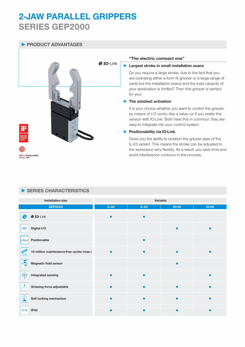
2-JAW PARALLEL GRIPPERS SERIES GEP2000
“The electric compact one” ► Largest stroke in small installation space
Do you require a large stroke, due to the fact that you are operating either a form fit gripper or a large range of parts but the installation space and the load capacity of your application is limited? Then this gripper is perfect for you!
► The simplest activation
It is your choice whether you want to control the gripper by means of I/O ports—like a valve—or if you prefer the version with IO-Link. Both have this in common: they are easy to integrate into your control system.
► Positionability via IO-Link
Gives you the ability to position the gripper jaws of the IL-03 variant. This means the stroke can be adjusted to the workpiece very flexibly. As a result, you save time and avoid interference contours in the process.

6
1
32
4
7
8
5
►BENEFITS IN DETAIL
► TECHNICAL DATA
Stroke per jaw Gripping force Weight IP classInstallation size [mm] [N] [kg]
GEP2006 6 40 - 145 0.18 IP40GEP2010 10 50 - 200 0.31 IP40GEP2013 13 90 - 360 0.54 IP40GEP2016 16 125 - 500 0.9 IP40
► FURTHER INFORMATION
Adjustable gripping force
► Four-level gripping force adjustment via rotary switch for digital gripper control
► For the IO-Link variant, gripping force can be conveniently adjusted using the control system
Operating safety
► Mechanical self-locking mechanism, which means that in the event of a power failure, the workpiece is held securely
► Gripper can be mechanically opened by means of an Allen key
1Control - Via I/O ports (IO) or via IO-Link (IL)
2Mounting and positioning - mounting possible from several sides for versatile positioning
3BLDC motor - wear-resistant brushless DC motor
4Helical worm gear - self locking mechanism in case of power drop
5Synchronization - via rack and pinion
6Position sensing - Permanent magnet for direct query of jaw movement via magnetic field sensors
7Gripper jaw - individual gripper finger mounting
8Removable centering sleeves - quick and economical positioning of the gripper fingers

10
1 ► IO-LINK CONTROL — GEP2000IL
M12
Master
24V
+
- PLC
Field busDigital control data
Status data
2 ►DIGITAL CONTROL — GEP2000IO-00
M8
M8
24V
+
-
Digital control data
Digital sensor feedback
PLC
3 ►DIGITAL CONTROL + INTEGRATED ANALOG SENSING — GEP2000IO-05
10 V
0 V
M8
AI
24V
+
- PLC
PathDigital control data
Analog sensor data
CONTROL GEP2000 SERIES
Serie
s G
EP20
00 /
2-
Jaw
Par
alle
l Grip
pers
/
elec
tric
al /
G
rippe
rs
www.zimmer-group.com ► Data, Drawings, 3-D Models, Operating Instructions

11
1 ► IO-LINK CONTROL — GEP2000IL
► Single-cable solution—control system data, status/sensor data and power supply over a single cable
► Bi-directional data transmission
► Gripping force and gripping speed can be configured using software
► 32 workpieces data sets can be programmed
► Parts detection in range of +/- 0.05 mm with freely teachable area
► Status data such as temperature and cycle number can be read out
► Can be integrated into ZIMMER HMI
► Positionable (only variant IL-03)
2 ►DIGITAL CONTROL — GEP2000IO-00
► Single-cable solution—control system data and power supply over a single cable
► Gripper commissioning by means of digital signals
► Optional digital gripper position feedback via external sensors
► Gripping force adjustment in four levels to the object being gripped, using rotary switch
► Can be integrated into ZIMMER HMI
3 ►DIGITAL CONTROL + INTEGRATED ANALOG SENSING — GEP2000IO-05
► Single-cable solution—control system data, sensor data and power supply over a single cable
► Gripper activation by means of digital signals
► Integrated analog feedback of the gripper position
► Gripping force adjustment in four levels to the object being gripped, using rotary switch
► Can be integrated into ZIMMER HMI
Serie
s G
EP20
00 /
2-
Jaw
Par
alle
l Grip
pers
/
elec
tric
al /
G
rippe
rs
Data, Drawings, 3-D Models, Operating Instructions ◄ www.zimmer-group.com

12
SENSORS
1-point magnetic field sensors – MFSFor non-contact sensing of the piston positionThe sensor is clamped in the C-groove of the gripper and detects the magnet attached to the gripper jaws. The MFS02 is available in versions with 5 m cables with exposed leads and 0,3 m cable with connector.
2-point magnetic field sensors – MFSWith two freely programmable switching pointsUsing the programming unit integrated in the cable, two switch points can be freely defined for this sensor. To do so, the sensor is clamped in the C-groove, the gripper approaches position one and the position is taught in using the teach button. Afterwards, the second position is approached with the gripper and programmed. To ensure use in a wide variety of space conditions, the sensors are available in two variants. While the horizontal MFS02, with straight cable outlet, disappears into the C-groove of the gripper almost completely, the vertical MFS01 is taller, but has a cable outlet that is offset at an angle of 90°. The sensors are available in versions with 5 m cables with exposed leads and 0,3 m cable with connector.
2-JAW PARALLEL GRIPPERS SERIES GEP2000 FUNCTIONAL DESCRIPTION
Serie
s G
EP20
00 /
2-
Jaw
Par
alle
l Grip
pers
/
elec
tric
al /
G
rippe
rs
www.zimmer-group.com ► Data, Drawings, 3-D Models, Operating Instructions

13
CONNECTIONS / OTHER
Plug-in connectorsFor extending and fabricating the connection linesCables with a length of 5 m with exposed leads are available. Depending on the specific needs, the cables can be shortened or fabricated with connectors in sizes M8 and M12. A 5 m long cable with connector / socket is available for the IO-Link connection.
Adapter plateAdditional screw connection optionBy attaching the optional adapter plate, the gripper can also be screwed on vertically (from above) if the fastening options integrat-ed into the gripper housing cannot be used for space reasons.
Serie
s G
EP20
00 /
2-
Jaw
Par
alle
l Grip
pers
/
elec
tric
al /
G
rippe
rs
Data, Drawings, 3-D Models, Operating Instructions ◄ www.zimmer-group.com

14
CONNECTIONS / OTHER
Centering sleevesFor defined position measurement of the gripper fingersThe centering sleeves are inserted into the fits of the gripper jaws to define the position of the gripper fingers. The centering sleeves are comparable to a pin connection.
2-JAW PARALLEL GRIPPERS SERIES GEP2000 FUNCTIONAL DESCRIPTION
Serie
s G
EP20
00 /
2-
Jaw
Par
alle
l Grip
pers
/
elec
tric
al /
G
rippe
rs
www.zimmer-group.com ► Data, Drawings, 3-D Models, Operating Instructions

15Data, Drawings, 3-D Models, Operating Instructions ◄ www.zimmer-group.com

16
► PRODUCT SPECIFICATIONS
► Gripping force diagram ► Forces and moments
60
150
0
30
90
0
120
302010 40 50 60 70
= = = =
[N]
[mm]
Shows the arithmetic total of the individual forces that occur on the gripper fingers, depending on the gripper finger length
Level 1 Level 2 Level 3 Level 4
Displays static forces and moments that can also have an effect, besides the gripping force.
MxMy Mr
Fa
Mr [Nm] 2.5Mx [Nm] 2.5My [Nm] 2Fa [N] 140
► TECHNICAL DATA
Order no. GEP2006IL-00-B GEP2006IL-03-B GEP2006IO-00-B GEP2006IO-05-BControl Positionable Yes Integrated position sensing Using process data Using process data No Analog 0 to 10 VStroke per jaw [mm] 6 6 6 6Gripping force safety device mechanical mechanical mechanical mechanicalControl time [s] 0.03 0.03 0.03 0.03Dead weight of mounted gripper finger max. [kg] 0.05 0.05 0.05 0.05Length of the gripper fingers max. [mm] 60 60 60 60Repetition accuracy +/- [mm] 0.02 0.02 0.02 0.02Operating temperature [°C] 5 ... +60 5 ... +60 5 ... +60 5 ... +60Voltage [V] 24 24 24 24Current consumption max. [A] 1 1 1 1Minimum positioning path per jaw [mm] 0.5 0.5 0.5 0.5Protection to IEC 60529 IP40 IP40 IP40 IP40Weight [kg] 0.18 0.18 0.18 0.18
► Technical data
► TECHNICAL DATA OF THE FORCE LEVELS
Order no. GEP2006IL-00-B GEP2006IL-03-B GEP2006IO-00-B GEP2006IO-05-BGripping force [N] 40 40 40 40Closing time / Opening time [s] 0.21 / 0.21 0.21 / 0.21 0.21 / 0.21 0.21 / 0.21
► Level 1
Order no. GEP2006IL-00-B GEP2006IL-03-B GEP2006IO-00-B GEP2006IO-05-BGripping force [N] 75 75 75 75Closing time / Opening time [s] 0.15 / 0.15 0.15 / 0.15 0.15 / 0.15 0.15 / 0.15
► Level 2
Order no. GEP2006IL-00-B GEP2006IL-03-B GEP2006IO-00-B GEP2006IO-05-BGripping force [N] 110 110 110 110Closing time / Opening time [s] 0.12 / 0.12 0.12 / 0.12 0.12 / 0.12 0.12 / 0.12
► Level 3
Order no. GEP2006IL-00-B GEP2006IL-03-B GEP2006IO-00-B GEP2006IO-05-BGripping force [N] 145 145 145 145Closing time / Opening time [s] 0.1 / 0.1 0.1 / 0.1 0.1 / 0.1 0.1 / 0.1
► Level 4
2-JAW PARALLEL GRIPPERS INSTALLATION SIZE GEP2006
Inst
alla
tion
size
GEP
2006
/
2-Ja
w P
aral
lel G
rippe
rs /
el
ectr
ical
/
Grip
pers
www.zimmer-group.com ► Data, Drawings, 3-D Models, Operating Instructions

16
160.02 ø5H7
2x 5h7
14.3
160.02 ø5H77.
50.
02 ø
5H7
69
85.5
44
28
7
3.5
80.
02
7.5
0.02
160.02 ø5H7 7.
50.
02 ø
5H7
1.21.2
4x
5h7
4x M
3x7
2x
2H7
22
44 7.5
2 x 3.2 1.2
2.4
2x M3x62x 5H7x1.2
1
6
2
2x M3x62x 5H7x1.2
1
47
1
X
6
2x M3x62x 5H7x1.2
1
3 3
3
X
17
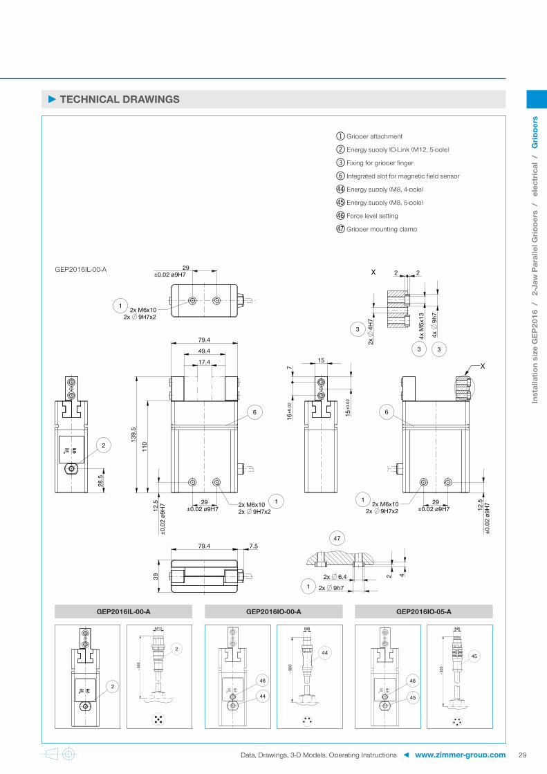
► TECHNICAL DRAWINGS
GEP2006IL
GEP2006IL-00-B GEP2006IO-00-B GEP2006IO-05-B
2
M12
∽300
2
46
44
∽300
M8
44
45
46
∽300
M8
45
1 Gripper attachment
2 Energy supply IO-Link (M12, 5-pole)
3 Fixing for gripper finger
6 Integrated slot for magnetic field sensor
ep Energy supply (M8, 4-pole)
eq Energy supply (M8, 5-pole)
er Force level setting
es Gripper mounting clamp
Inst
alla
tion
size
GEP
2006
/
2-Ja
w P
aral
lel G
rippe
rs /
el
ectr
ical
/
Grip
pers
Data, Drawings, 3-D Models, Operating Instructions ◄ www.zimmer-group.com

18
►ACCESORIES
► INCLUDED IN DELIVERY
6 [piece]Centering Disc
354237
► YOU CAN FIND CONFIGURATION EXAMPLES ON PAGE 32 / 33
2-JAW PARALLEL GRIPPERS INSTALLATION SIZE GEP2006
Inst
alla
tion
size
GEP
2006
/
2-Ja
w P
aral
lel G
rippe
rs /
el
ectr
ical
/
Grip
pers
www.zimmer-group.com ► Data, Drawings, 3-D Models, Operating Instructions
19
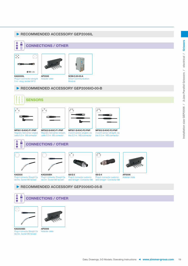
►RECOMMENDED ACCESSORY GEP2006IL
CONNECTIONS / OTHER
KAG500IL AP2006 SCM-C-00-00-APlug-in connector straight 5 m - plug, socket M12
Adapter plate Smart Communication Module
►RECOMMENDED ACCESSORY GEP2006IO-00-B
MFS01-S-KHC-P1-PNP MFS02-S-KHC-P1-PNP MFS01-S-KHC-P2-PNP MFS02-S-KHC-P2-PNPMagnetic field sensor angled, cable 0.3 m - M8 connector
Magnetic field sensor straight, cable 0.3 m - M8 connector
2-point sensor angled, ca-ble 0.3 m - M8 connector
2-point sensor straight, ca-ble 0.3 m - M8 connector
SENSORS
CONNECTIONS / OTHER
KAG500 KAG500B4 S8-G-3 S8-G-4 AP2006Plug-in connector Straight Ca-ble 5m - Socket M8 (female)
Plug-in connector Straight Ca-ble 5m - Socket M8 (female)
Plug-in connector customiz-able Straight - Connector M8
Plug-in connector customiz-able Straight - Connector M8
Adapter plate
►RECOMMENDED ACCESSORY GEP2006IO-05-B
CONNECTIONS / OTHER
KAG500B5 AP2006Plug-in connector Straight Ca-ble 5m - Socket M8 (female)
Adapter plate
Inst
alla
tion
size
GEP
2006
/
2-Ja
w P
aral
lel G
rippe
rs /
el
ectr
ical
/
Grip
pers
Data, Drawings, 3-D Models, Operating Instructions ◄ www.zimmer-group.com

20
► PRODUCT SPECIFICATIONS
► Gripping force diagram ► Forces and moments
100
200
250
300
0
50
150
0302010 40 50 60 70 80
= = = =
[N]
[mm]
Shows the arithmetic total of the individual forces that occur on the gripper fingers, depending on the gripper finger length
Level 1 Level 2 Level 3 Level 4
Displays static forces and moments that can also have an effect, besides the gripping force.
MxMy Mr
Fa
Mr [Nm] 7Mx [Nm] 7My [Nm] 5.5Fa [N] 200
► TECHNICAL DATA
Order no. GEP2010IL-00-B GEP2010IL-03-B GEP2010IO-00-B GEP2010IO-05-BControl Positionable Yes Integrated position sensing Using process data Using process data No Analog 0 to 10 VStroke per jaw [mm] 10 10 10 10Gripping force safety device mechanical mechanical mechanical mechanicalControl time [s] 0.03 0.03 0.03 0.03Dead weight of mounted gripper finger max. [kg] 0.1 0.1 0.1 0.1Length of the gripper fingers max. [mm] 80 80 80 80Repetition accuracy +/- [mm] 0.02 0.02 0.02 0.02Operating temperature [°C] 5 ... +60 5 ... +60 5 ... +60 5 ... +60Voltage [V] 24 24 24 24Current consumption max. [A] 1 1 1 1Minimum positioning path per jaw [mm] 0.5 0.5 0.5 0.5Protection to IEC 60529 IP40 IP40 IP40 IP40Weight [kg] 0.31 0.31 0.31 0.31
► Technical data
► TECHNICAL DATA OF THE FORCE LEVELS
Order no. GEP2010IL-00-B GEP2010IL-03-B GEP2010IO-00-B GEP2010IO-05-BGripping force [N] 50 50 50 50Closing time / Opening time [s] 0.3 / 0.3 0.3 / 0.3 0.3 / 0.3 0.3 / 0.3
► Level 1
Order no. GEP2010IL-00-B GEP2010IL-03-B GEP2010IO-00-B GEP2010IO-05-BGripping force [N] 100 100 100 100Closing time / Opening time [s] 0.25 / 0.25 0.25 / 0.25 0.25 / 0.25 0.25 / 0.25
► Level 2
Order no. GEP2010IL-00-B GEP2010IL-03-B GEP2010IO-00-B GEP2010IO-05-BGripping force [N] 150 150 150 150Closing time / Opening time [s] 0.22 / 0.22 0.22 / 0.22 0.22 / 0.22 0.22 / 0.22
► Level 3
Order no. GEP2010IL-00-B GEP2010IL-03-B GEP2010IO-00-B GEP2010IO-05-BGripping force [N] 200 200 200 200Closing time / Opening time [s] 0.19 / 0.19 0.19 / 0.19 0.19 / 0.19 0.19 / 0.19
► Level 4
2-JAW PARALLEL GRIPPERS INSTALLATION SIZE GEP2010
Inst
alla
tion
size
GEP
2010
/
2-Ja
w P
aral
lel G
rippe
rs /
el
ectr
ical
/
Grip
pers
www.zimmer-group.com ► Data, Drawings, 3-D Models, Operating Instructions

12.8
25±0.02 ø7H7
14.5
32.8
53.8
25±0.02 ø7H77.
5±0
.02
ø7H
7
78
99.5
26
53.8
10±0
.02
4.5
11±0
.02
10
25±0.02 ø7H7 7.
5±0
.02
ø7H
7
2x3H
7
4x7h
7
4x M
4x9
1.51.5
7.5
2x 7h7
2x 5.3 1.5 3
6
2x M4x82x 7H7x1.5
1
2
2x M4x62x 7H7x1.5
1
6
X
2x M4x82x 7H7x1.5
1
X
3 3
3
47
1
21
► TECHNICAL DRAWINGS
GEP2010IL
GEP2010IL-00-B GEP2010IO-00-B GEP2010IO-05-B
2
M12
∽300
2
44
46
∽300
M8
44
45
46
∽300
M8
45
1 Gripper attachment
2 Energy supply IO-Link (M12, 5-pole)
3 Fixing for gripper finger
6 Integrated slot for magnetic field sensor
ep Energy supply (M8, 4-pole)
eq Energy supply (M8, 5-pole)
er Force level setting
es Gripper mounting clamp
Inst
alla
tion
size
GEP
2010
/
2-Ja
w P
aral
lel G
rippe
rs /
el
ectr
ical
/
Grip
pers
Data, Drawings, 3-D Models, Operating Instructions ◄ www.zimmer-group.com

22
►ACCESORIES
► INCLUDED IN DELIVERY
6 [piece]Centering Disc
390677
► YOU CAN FIND CONFIGURATION EXAMPLES ON PAGE 32 / 33
2-JAW PARALLEL GRIPPERS INSTALLATION SIZE GEP2010
Inst
alla
tion
size
GEP
2010
/
2-Ja
w P
aral
lel G
rippe
rs /
el
ectr
ical
/
Grip
pers
www.zimmer-group.com ► Data, Drawings, 3-D Models, Operating Instructions

23
►RECOMMENDED ACCESSORY GEP2010IL
CONNECTIONS / OTHER
KAG500IL AP2010 SCM-C-00-00-APlug-in connector straight 5 m - plug, socket M12
Adapter plate Smart Communication Module
►RECOMMENDED ACCESSORY GEP2010IO-00-B
MFS01-S-KHC-P1-PNP MFS02-S-KHC-P1-PNP MFS01-S-KHC-P2-PNP MFS02-S-KHC-P2-PNPMagnetic field sensor angled, cable 0.3 m - M8 connector
Magnetic field sensor straight, cable 0.3 m - M8 connector
2-point sensor angled, ca-ble 0.3 m - M8 connector
2-point sensor straight, ca-ble 0.3 m - M8 connector
SENSORS
CONNECTIONS / OTHER
KAG500 KAG500B4 S8-G-3 S8-G-4 AP2010Plug-in connector Straight Ca-ble 5m - Socket M8 (female)
Plug-in connector Straight Ca-ble 5m - Socket M8 (female)
Plug-in connector customiz-able Straight - Connector M8
Plug-in connector customiz-able Straight - Connector M8
Adapter plate
►RECOMMENDED ACCESSORY GEP2010IO-05-B
CONNECTIONS / OTHER
KAG500B5 AP2010Plug-in connector Straight Ca-ble 5m - Socket M8 (female)
Adapter plate
Inst
alla
tion
size
GEP
2010
/
2-Ja
w P
aral
lel G
rippe
rs /
el
ectr
ical
/
Grip
pers
Data, Drawings, 3-D Models, Operating Instructions ◄ www.zimmer-group.com

24
► PRODUCT SPECIFICATIONS
► Gripping force diagram ► Forces and moments
100
150
250
350
400
300
0
50
200
0302010 40 50 60 70 80 90 100
= = = =
[N]
[mm]
Shows the arithmetic total of the individual forces that occur on the gripper fingers, depending on the gripper finger length
Level 1 Level 2 Level 3 Level 4
Displays static forces and moments that can also have an effect, besides the gripping force.
MxMy Mr
Fa
Mr [Nm] 13Mx [Nm] 13My [Nm] 10Fa [N] 325
► TECHNICAL DATA
Order no. GEP2013IL-00-A GEP2013IO-00-A GEP2013IO-05-AControl Integrated position sensing Using process data No Analog 0 to 10 VStroke per jaw [mm] 13 13 13Gripping force safety device mechanical mechanical mechanicalControl time [s] 0.055 0.055 0.055Dead weight of mounted gripper finger max. [kg] 0.15 0.15 0.15Length of the gripper fingers max. [mm] 100 100 100Repetition accuracy +/- [mm] 0.02 0.02 0.02Operating temperature [°C] +5 ... +60 +5 ... +60 +5 ... +60Voltage [V] 24 24 24Current consumption max. [A] 2 2 2Minimum positioning path per jaw [mm] 0.5 0.5 0.5Protection to IEC 60529 IP40 IP40 IP40Weight [kg] 0.54 0.54 0.54
► Technical data
► TECHNICAL DATA OF THE FORCE LEVELS
Order no. GEP2013IL-00-A GEP2013IO-00-A GEP2013IO-05-AGripping force [N] 90 90 90Closing time / Opening time [s] 0.42 / 0.42 0.42 / 0.42 0.42 / 0.42
► Level 1
Order no. GEP2013IL-00-A GEP2013IO-00-A GEP2013IO-05-AGripping force [N] 180 180 180Closing time / Opening time [s] 0.32 / 0.32 0.32 / 0.32 0.32 / 0.32
► Level 2
Order no. GEP2013IL-00-A GEP2013IO-00-A GEP2013IO-05-AGripping force [N] 270 270 270Closing time / Opening time [s] 0.26 / 0.26 0.26 / 0.26 0.26 / 0.26
► Level 3
Order no. GEP2013IL-00-A GEP2013IO-00-A GEP2013IO-05-AGripping force [N] 360 360 360Closing time / Opening time [s] 0.23 / 0.23 0.23 / 0.23 0.23 / 0.23
► Level 4
2-JAW PARALLEL GRIPPERS INSTALLATION SIZE GEP2013
Inst
alla
tion
size
GEP
2013
/
2-Ja
w P
aral
lel G
rippe
rs /
el
ectr
ical
/
Grip
pers
www.zimmer-group.com ► Data, Drawings, 3-D Models, Operating Instructions

14
25±0.02 ø7H7
21.5
65
40
118.
5
93.5
7.5
±0.0
2 ø7
H7 25
±0.02 ø7H7
65
32
14±0
.02
5.5
12.5
±0.0
2
12
7.5
25±0.02 ø7H7 7.
5±0
.02
ø7H
7
2x 7h7
2x 5.3
1.5 3
4x
7h7
4x M
4x11
2x
4H7
1.51.5
2x M4x82x 7H7x1.5
1
6
2
X
6
2x M4x82x 7H7x1.5
1
2x M4x62x 7H7x1.5
1
X
3
33
1
47
25
► TECHNICAL DRAWINGS
GEP2013IL-00-A
GEP2013IL-00-A GEP2013IO-00-A GEP2013IO-05-A
2
M12
∽300
2
44
46
∽300
M8
44
46
45
∽300
M8
45
1 Gripper attachment
2 Energy supply IO-Link (M12, 5-pole)
3 Fixing for gripper finger
6 Integrated slot for magnetic field sensor
ep Energy supply (M8, 4-pole)
eq Energy supply (M8, 5-pole)
er Force level setting
es Gripper mounting clamp
Inst
alla
tion
size
GEP
2013
/
2-Ja
w P
aral
lel G
rippe
rs /
el
ectr
ical
/
Grip
pers
Data, Drawings, 3-D Models, Operating Instructions ◄ www.zimmer-group.com

26
►ACCESORIES
► INCLUDED IN DELIVERY
6 [piece]Centering Disc
390677
► YOU CAN FIND CONFIGURATION EXAMPLES ON PAGE 32 / 33
2-JAW PARALLEL GRIPPERS INSTALLATION SIZE GEP2013
Inst
alla
tion
size
GEP
2013
/
2-Ja
w P
aral
lel G
rippe
rs /
el
ectr
ical
/
Grip
pers
www.zimmer-group.com ► Data, Drawings, 3-D Models, Operating Instructions

27
►RECOMMENDED ACCESSORY GEP2013IL-00-A
CONNECTIONS / OTHER
KAG500IL AP2013 SCM-C-00-00-APlug-in connector straight 5 m - plug, socket M12
Adapter plate Smart Communication Module
►RECOMMENDED ACCESSORY GEP2013IO-00-A
MFS01-S-KHC-P1-PNP MFS02-S-KHC-P1-PNP MFS01-S-KHC-P2-PNP MFS02-S-KHC-P2-PNPMagnetic field sensor angled, cable 0.3 m - M8 connector
Magnetic field sensor straight, cable 0.3 m - M8 connector
2-point sensor angled, ca-ble 0.3 m - M8 connector
2-point sensor straight, ca-ble 0.3 m - M8 connector
SENSORS
CONNECTIONS / OTHER
KAG500 KAG500B4 S8-G-3 S8-G-4 AP2013Plug-in connector Straight Ca-ble 5m - Socket M8 (female)
Plug-in connector Straight Ca-ble 5m - Socket M8 (female)
Plug-in connector customiz-able Straight - Connector M8
Plug-in connector customiz-able Straight - Connector M8
Adapter plate
►RECOMMENDED ACCESSORY GEP2013IO-05-A
CONNECTIONS / OTHER
KAG500B5 AP2013Plug-in connector Straight Ca-ble 5m - Socket M8 (female)
Adapter plate
Inst
alla
tion
size
GEP
2013
/
2-Ja
w P
aral
lel G
rippe
rs /
el
ectr
ical
/
Grip
pers
Data, Drawings, 3-D Models, Operating Instructions ◄ www.zimmer-group.com

28
► PRODUCT SPECIFICATIONS
► Gripping force diagram ► Forces and moments
100
600
400
500
0
300
200
020 40 60 80 100 120
= = = =
[N]
[mm]
Shows the arithmetic total of the individual forces that occur on the gripper fingers, depending on the gripper finger length
Level 1 Level 2 Level 3 Level 4
Displays static forces and moments that can also have an effect, besides the gripping force.
MxMy Mr
Fa
Mr [Nm] 28Mx [Nm] 28My [Nm] 20Fa [N] 450
► TECHNICAL DATA
Order no. GEP2016IL-00-A GEP2016IO-00-A GEP2016IO-05-AControl Integrated position sensing Using process data No Analog 0 to 10 VStroke per jaw [mm] 16 16 16Gripping force safety device mechanical mechanical mechanicalControl time [s] 0.055 0.055 0.055Dead weight of mounted gripper finger max. [kg] 0.21 0.21 0.21Length of the gripper fingers max. [mm] 120 120 120Repetition accuracy +/- [mm] 0.02 0.02 0.02Operating temperature [°C] +5 ... +60 +5 ... +60 +5 ... +60Voltage [V] 24 24 24Current consumption max. [A] 2 2 2Minimum positioning path per jaw [mm] 0.5 0.5 0.5Protection to IEC 60529 IP40 IP40 IP40Weight [kg] 0.9 0.9 0.9
► Technical data
► TECHNICAL DATA OF THE FORCE LEVELS
Order no. GEP2016IL-00-A GEP2016IO-00-A GEP2016IO-05-AGripping force [N] 125 125 125Closing time / Opening time [s] 0.44 / 0.44 0.44 / 0.44 0.44 / 0.44
► Level 1
Order no. GEP2016IL-00-A GEP2016IO-00-A GEP2016IO-05-AGripping force [N] 250 250 250Closing time / Opening time [s] 0.39 / 0.39 0.39 / 0.39 0.39 / 0.39
► Level 2
Order no. GEP2016IL-00-A GEP2016IO-00-A GEP2016IO-05-AGripping force [N] 375 375 375Closing time / Opening time [s] 0.35 / 0.35 0.35 / 0.35 0.35 / 0.35
► Level 3
Order no. GEP2016IL-00-A GEP2016IO-00-A GEP2016IO-05-AGripping force [N] 500 500 500Closing time / Opening time [s] 0.3 / 0.3 0.3 / 0.3 0.3 / 0.3
► Level 4
2-JAW PARALLEL GRIPPERS INSTALLATION SIZE GEP2016
Inst
alla
tion
size
GEP
2016
/
2-Ja
w P
aral
lel G
rippe
rs /
el
ectr
ical
/
Grip
pers
www.zimmer-group.com ► Data, Drawings, 3-D Models, Operating Instructions
17.4
29±0.02 ø9H7
28.5
11013
9.5
12.5
±0.0
2 ø9
H7 29
±0.02 ø9H7
49.4
79.4
79.4 7.5
39
16±0
.02
7
15±0
.02
15
29±0.02 ø9H7 12
.5±0
.02
ø9H
7
22
4x
9h7
4x M
5x13
2x
4H7
2x 9h7
2x 6.4 2 4
6
2x M6x102x 9H7x2
1
2
6
2x M6x102x 9H7x2
1
X
2x M6x102x 9H7x2
1
3
3 3
X
1
47
29
► TECHNICAL DRAWINGS
GEP2016IL-00-A
GEP2016IL-00-A GEP2016IO-00-A GEP2016IO-05-A
2
M12
∽300
2
44
46
∽300
M8
44
45
46
∽300
M8
45
1 Gripper attachment
2 Energy supply IO-Link (M12, 5-pole)
3 Fixing for gripper finger
6 Integrated slot for magnetic field sensor
ep Energy supply (M8, 4-pole)
eq Energy supply (M8, 5-pole)
er Force level setting
es Gripper mounting clamp
Inst
alla
tion
size
GEP
2016
/
2-Ja
w P
aral
lel G
rippe
rs /
el
ectr
ical
/
Grip
pers
Data, Drawings, 3-D Models, Operating Instructions ◄ www.zimmer-group.com

30
►ACCESORIES
► INCLUDED IN DELIVERY
6 [piece]Centering Disc
343453
► YOU CAN FIND CONFIGURATION EXAMPLES ON PAGE 32 / 33
2-JAW PARALLEL GRIPPERS INSTALLATION SIZE GEP2016
Inst
alla
tion
size
GEP
2016
/
2-Ja
w P
aral
lel G
rippe
rs /
el
ectr
ical
/
Grip
pers
www.zimmer-group.com ► Data, Drawings, 3-D Models, Operating Instructions

31
►RECOMMENDED ACCESSORY GEP2016IL-00-A
CONNECTIONS / OTHER
KAG500IL AP2016 SCM-C-00-00-APlug-in connector straight 5 m - plug, socket M12
Adapter plate Smart Communication Module
►RECOMMENDED ACCESSORY GEP2016IO-00-A
MFS01-S-KHC-P1-PNP MFS02-S-KHC-P1-PNP MFS01-S-KHC-P2-PNP MFS02-S-KHC-P2-PNPMagnetic field sensor angled, cable 0.3 m - M8 connector
Magnetic field sensor straight, cable 0.3 m - M8 connector
2-point sensor angled, ca-ble 0.3 m - M8 connector
2-point sensor straight, ca-ble 0.3 m - M8 connector
SENSORS
CONNECTIONS / OTHER
KAG500 KAG500B4 S8-G-3 S8-G-4 AP2016Plug-in connector Straight Ca-ble 5m - Socket M8 (female)
Plug-in connector Straight Ca-ble 5m - Socket M8 (female)
Plug-in connector customiz-able Straight - Connector M8
Plug-in connector customiz-able Straight - Connector M8
Adapter plate
►RECOMMENDED ACCESSORY GEP2016IO-05-A
CONNECTIONS / OTHER
KAG500B5 AP2016Plug-in connector Straight Ca-ble 5m - Socket M8 (female)
Adapter plate
Inst
alla
tion
size
GEP
2016
/
2-Ja
w P
aral
lel G
rippe
rs /
el
ectr
ical
/
Grip
pers
Data, Drawings, 3-D Models, Operating Instructions ◄ www.zimmer-group.com
32
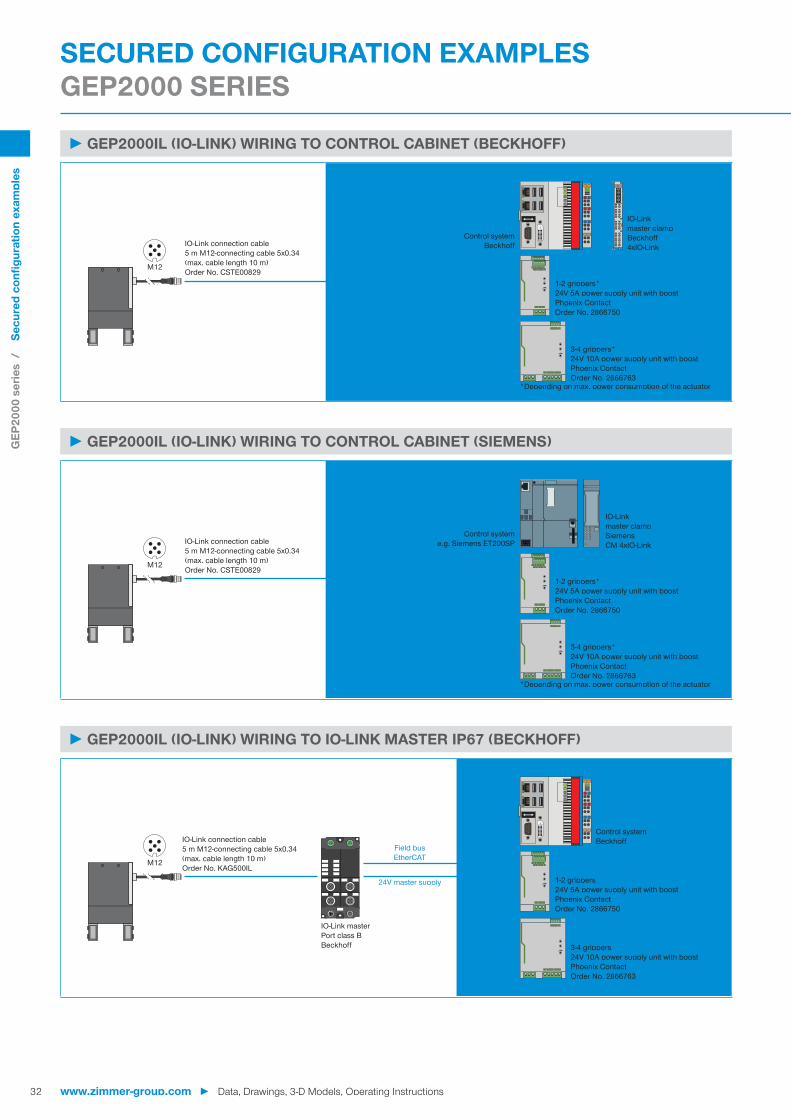
►GEP2000IL (IO-LINK) WIRING TO CONTROL CABINET (BECKHOFF)
M12
IO-Link
PowerTERMINALSTRIP
IO-Linkmaster clampBeckhoff4xIO-Link
1-2 grippers*24V 5A power supply unit with boostPhoenix ContactOrder No. 2866750
3-4 grippers*24V 10A power supply unit with boostPhoenix ContactOrder No. 2866763
Control systemBeckhoffIO-Link connection cable
5 m M12-connecting cable 5x0.34(max. cable length 10 m)Order No. CSTE00829
*Depending on max. power consumption of the actuator
►GEP2000IL (IO-LINK) WIRING TO CONTROL CABINET (SIEMENS)
M12
IO-Link
Power
IO-Link connection cable5 m M12-connecting cable 5x0.34(max. cable length 10 m)Order No. CSTE00829
IO-Linkmaster clampSiemensCM 4xIO-Link
1-2 grippers*24V 5A power supply unit with boostPhoenix ContactOrder No. 2866750
Control systeme.g. Siemens ET200SP
3-4 grippers*24V 10A power supply unit with boostPhoenix ContactOrder No. 2866763
TERMINALSTRIP
*Depending on max. power consumption of the actuator
►GEP2000IL (IO-LINK) WIRING TO IO-LINK MASTER IP67 (BECKHOFF)
M12
IO-Link connection cable5 m M12-connecting cable 5x0.34(max. cable length 10 m)Order No. KAG500IL
IO-Link masterPort class BBeckhoff
24V master supply
Field busEtherCAT
1-2 grippers24V 5A power supply unit with boostPhoenix ContactOrder No. 2866750
3-4 grippers24V 10A power supply unit with boostPhoenix ContactOrder No. 2866763
Control systemBeckhoff
SECURED CONFIGURATION EXAMPLES GEP2000 SERIES
GEP
2000
ser
ies
/
Sec
ured
con
figur
atio
n ex
ampl
es
www.zimmer-group.com ► Data, Drawings, 3-D Models, Operating Instructions

33
►GEP2000IL (IO-LINK) WIRING TO IO-LINK MASTER IP67 (SIEMENS)
M12
IO-Link connection cable5 m M12-connecting cable 5x0.34(max. cable length 10 m)Order No. KAG500IL
IO-Link masterPort class BSiemens
24V master supply
Field busPROFINET
1-2 grippers24V 5A power supply unit with boostPhoenix ContactOrder No. 2866750
3-4 grippers24V 10A power supply unit with boostPhoenix ContactOrder No. 2866763
Control systeme.g. Siemens S7 1200
►GEP2000IO-00 (DIGITAL IO) WIRING TO CONTROL CABINET
DIO
Power
M8
M8
1-2 grippers24V 5A power supply unit with boostPhoenix ContactOrder No. 2866750
3-4 grippers24V 10A power supply unit with boostPhoenix ContactOrder No. 2866763
Control systemBeckhoff / Siemens
Sensor(optional)
Connecting cable5 m M8-connecting cable 4x0.34(max. cable length 10 m)Order No. KAG500B4 TERMINAL
STRIP
►GEP2000IO-05 (DIGITAL IO / ANALOG) WIRING TO CONTROL CABINET
PowerM8
DIO / analog
1-2 grippers24V 5A power supply unit with boostPhoenix ContactOrder No. 2866750
3-4 grippers24V 10A power supply unit with boostPhoenix ContactOrder No. 2866763
Control systemBeckhoff / SiemensConnecting cable
5 m M8 connecting cable 5x0.34(max. cable length 10 m)Order No. KAG500B5 TERMINAL
STRIP
GEP
2000
ser
ies
/
Sec
ured
con
figur
atio
n ex
ampl
es
Data, Drawings, 3-D Models, Operating Instructions ◄ www.zimmer-group.com

W!
#
W"
/
&
$
%
/
34
► PRODUCT ADVANTAGES
► Translates IO-Link to digital inputs and outputs digital I/O) and from digital I/O to IO-Link
► Easy control of intelligent IO-Link grippers via 24 V digital I/O
► Configuration and training take place using the corresponding intuitive guideZ software
► Can be used with one or two grippers depend-ing on the flexibility required
► Up to 15 different workpieces can be trained for one gripper
►BENEFITS IN DETAIL
!Status - Status display of SCM and IO-Link device
"Ethernet RJ45 - Temporary connection for gripper configuration
#Digital input - Digital inputs for controlling the gripper actuators
$IO-Link / Device 1 - Gripper module 1 connection
%Digital output - Digital outputs for monitoring the gripper sensors
&IO-Link / Device 2 - Gripper module 2 connection
/Power supply - Voltage supply SCM and gripper
Order no. SCM-C-00-00-AControl Digital I/OIO logic PNPNumber of grippers, max. 2Number of pins (control system input) 12Number of pins (control system output) 12Configuration for interface Ethernet RJ45Mounting options 35 mm top-hat railVoltage [V] 24Load supply peak current [A] 10Logic supply peak current [A] 1Operating temperature [°C] 5 ... +50Protection to IEC 60529 IP20Weight [kg] 0.19
► Technical Data
IO-LINK MEETS DIGITAL I/O SMART COMMUNICATION MODULEIO-Link meets digital I/O
The Smart Communication Module (SCM) is a master gateway that is suitable for all IO-Link components. With its two channels, the SCM can control two devices and on a functional level, offers the direct implementation of IO-Link to
digital I/O. The module thus makes it possible to integrate IO-Link devices into a digital infrastructure and utilize almost the full extended range of functions of the IO-Link device.
Smar
t Com
mun
icat
ion
Mod
ule
/
IO-L
ink
mee
ts d
igita
l I/O
www.zimmer-group.com ► Data, Drawings, 3-D Models, Operating Instructions

35
expertZ guideZ monitorZ
1 2 3 4 5 6 7 ><
M12
M12
W!
W"
IO-Link connection cable5 m M12-connecting cable 5x0.34(max. cable length 10 m)Order No. KAG500IL
IO-Link - digital I/O Zimmer Group SCM
24V master supply
Temporary Ethernet connection
1-2 grippers24V power supply
Robot control system / PLC
Digital I/O
! Connection W" Confi guration► IO-Link gripper Temporary network connection via PC for use of the
guideZ, expertZ and monitorZ software► Digital I/Os on the robot control system/PLC► Power supply
► FURTHER INFORMATION IS AVAILABLE ONLINE
All information just a click away at: www.zimmer-group.com. Find data, illustrations, 3D models and operating instructions for your installation size using the order number for your desired product. Quick, clear and always up-to-date.
TOPOLOGYCONNECTION
Smar
t Com
mun
icat
ion
Mod
ule
/
IO-L
ink
mee
ts d
igita
l I/O
Data, Drawings, 3-D Models, Operating Instructions ◄ www.zimmer-group.com
Confi guration and operation
Up to two Zimmer IO-Link devices can be connected to one Smart Communication Module. The digital inputs and outputs are wired directly to the robot controller or PLC. Simple digital control enables bidirectional communication. To confi gure the gripper parameters, a temporary network connection is established to a commercially available PC.
As soon as the parameters have been confi gured intuitively, this connection is no longer necessary. Next, the handling unit is automatically controlled directly via robot controller or PLC.

36
Customer number Telephone number
Company Fax number
Contact E-mailMr. Mrs.
Request Desired date Request No.
Order Order No.
Parallel grippers Concentric grippers Angular Grippers
Other / if yes, which type
Drive
Pneumatic Electrical Hydraulic
Operating pressure [bar] Voltage [V]
Required stroke
Per jaw [mm] or Total stroke [mm]
Gripper finger length
Gripper top edge to force application point [mm]
Ambient conditions
Clean / DrySmall amount of swarf / Coolant overspray
Large amount of swarf / Coolant under pressure / Grinding agent
Chemical substances / if yes, which
Temperature [°C] Cycles per minute
Required force
Gripping force [N] or Workpiece weight kg g
Gripping type
Internal gripping External gripping
Frictional fit Form fit
Prism angle [°] Friction coefficient Axis acceleration [m/s²]
Self-locking
Not required In closing In opening Pressure safety valve
CHECKLIST GRIPPERS
www.zimmer-group.com

37
Desired accessories
Inductive sensor Magnetic field sensor With Cable Plugable
Separate cable / if yes, how long [m]
Pressure safety valve
Pneumatic fittings / if yes, which Straight fitting
Angled fitting
Air flow control valve
Notes / Comments
Editor / Date
Attachment
Sketch 3D model Others
www.zimmer-group.com

38
The contents of this catalog are not legally binding and are intended solely for informational purposes. Any final agreement will be in the form of a written order confirmation from Zimmer GmbH, which occurs only subject to the respective current General Terms and Conditions of Sale and Delivery of Zimmer GmbH. These can be found online at www.zimmer-group.com. All of the products listed in this catalog are designed for their intended use, e.g. machines for automation. The recognized technical regulations for safety and professional work must be followed for use and installation. Furthermore, the respective laws, guidelines from TÜV, guidelines from the respective trade association and VDE stipulations shall apply. The technical data listed in this catalog must be observed by the user. The conditions of use may not fall below or exceed the specified data. If information is missing, it cannot be assumed that there are no upper or lower limits or no limitations for specific use cases. Consultation is required in these cases. Disposal is not included in the price, which would have to be taken into account accordingly in the event of return to or dis-posal by Zimmer GmbH.
TECHNICAL DATA AND FIGURESThe technical data and figures have been compiled with great care and to the best of our knowledge. We cannot guarantee that the information is up to date, correct or complete. The specifications and information — such as figures, drawings, descriptions, dimensions, weights, materials, technical and other performance data and the described products and services — contained in general product descriptions, Zimmer GmbH catalogs, brochures and price lists in any form are subject to change and may be modified or updated at any time without prior notification. They are binding only to the extent expressly specified in a contract or order confirmation. Slight deviations from such descriptive product information shall be considered approved and shall not affect fulfillment of agreements insofar as they are reasonable for the customer.
LIABILITYProducts from Zimmer Group are subject to the German Product Liability Act. This catalog does not contain any guarantees, assurances of quality or procurement agreements for the products it depicts, neither expressly nor implied, including for the availability of products. Advertising statements relating to quality features, properties or applications for the products are not legally binding. To the extent permitted by law, Zimmer GmbH is exempt from any liability for direct or indirect damage, subsequent damage and requests of any kind or on any legal basis resulting from the use of information contained in this catalogue.
TRADEMARK, COPYRIGHT AND REPRODUCTIONThe depiction of commercial property rights in this catalog — such as brands, logos, registered trademarks or patents — does not include the granting of licenses or use rights. Their use is not permitted without the expressed written agreement of Zimmer GmbH. All contents of this catalog are the intellectual property of Zimmer GmbH. For the purposes of copyright, any unlawful use of intellectual property, including excerpts, is prohibited. Reprinting, copying or translating (including in the form of excerpts) are permitted only with the prior written consent of Zimmer GmbH.
STANDARDSZimmer Group has a quality management system certified in accordance with ISO 9001:2008. Zimmer Group has an environ-mental management system certified in accordance with ISO 14001:2004.
USAGE NOTEGENERAL
www.zimmer-group.com

39
DECLARATION OF INCORPORATION IN TERMS OF THE EC DIRECTIVE 2006/42/EC ON MACHINERY (AN-NEX II 1 B)We hereby declare that our elements meet the following basic requirements of the Machinery Directive 2006/42/EC as an incomplete machine No.1.1.2., No.1.1.3., No.1.1.5., No.1.3.2, No. 1.3.4, No. 1.3.7, No.1.5.3, No.1.5.4, No.1.5.8., No.1.6.4, No.1.7.1, No.1.7.3, No.1.7.4. We also declare that the specific technical documents were produced in accordance with Annex VII Part B of this Directive. We undertake to provide the market supervisory bodies with electronic versions of the incomplete machine‘s special docu-ments via our documentation department should they have reason to request them. The incomplete machine may only be commissioned if the machine or system in which the incomplete machine is to be installed has been determined to satisfy the conditions of the Machinery Directive 2006/42/EC and the EC Declaration of Conformity has been produced in accordance with Annex II A.
USAGE NOTEINDIVIDUAL
www.zimmer-group.com

40 www.zimmer-group.com

41www.zimmer-group.com

42 www.zimmer-group.com