Remote technology related to the handling, storage and ...
214
IAEA-TECDOC-842 Remote technology related to the handling, storage and disposal of spent fuel Proceedings of a Technical Committee meeting held in Albuquerque, New Mexico, USA, 5-8 December 1994 INTERNATIONAL ATOMIC ENERGY AGENCY
Transcript of Remote technology related to the handling, storage and ...

IAEA-TECDOC-842
Remote technology relatedto the handling, storage
and disposal of spent fuelProceedings of a Technical Committee meeting
held in Albuquerque, New Mexico, USA, 5-8 December 1994
INTERNATIONAL ATOMIC ENERGY AGENCY

The originating Section of this publication in the IAEA was:
Nuclear Materials and Fuel Cycle Technology SectionInternational Atomic Energy Agency
Wagramerstrasse 5P.O. Box 100
A-1400 Vienna, Austria
REMOTE TECHNOLOGY RELATED TO THE HANDLING, STORAGEAND DISPOSAL OF SPENT FUEL
IAEA, VIENNA, 1995IAEA-TECDOC-842ISSN 1011-4289
© IAEA, 1995
Printed by the IAEA in AustriaNovember 1995

FOREWORD
The nuclear industry has always been using remote handling technology forvarious operations. While in the 1980s the accepted opinion was that most activehandling operations could be best performed by men in protective clothing,deploying tools or master-slave manipulators, in the 1990s many operators arebecoming aware that modern remote technology is actually a cost-effective optionfor a wide range of operations. One of the reasons for the major change has beenthe development of a new generation of remote handling products, e.g. robots,manipulators, tools, sensors, and the associated software and hardware. Thismeans that these products are now available more or less off the shelf at lowcost. The adaptation of a proven industrial robot to meet nuclear applicationrequirements offers a significant cost advantage over designing a brand newrobot.
It was the objective of the Technical Committee Meeting on RemoteTechnology Related to the Handling, Storage and/or Disposal of Spent Fuel tobring together specialists working in this field and to collect information on newdevelopments. The meeting showed that such periodic exchange of informationis very useful.
The meeting was held from 5 to 8 December 1994 in Albuquerque, NewMexico, USA, and hosted by Sandia National Laboratories on behalf of the USGovernment. The participation of the experts and their contributions made at themeeting is gratefully acknowledged. Special thanks go to P.C. Bennett, IntelligentSystems & Robotics Center, Sandia National Laboratories, for the organization ofthe meeting.
The IAEA staff member responsible for the meeting and the compilation ofthis TECDOC was F. Takats, Division of Nuclear Fuel Cycle and WasteManagement.

EDITORIAL NOTE
In preparing this publication for press, staff of the IAEA have made up the pages from theoriginal manuscripts as submitted by the authors. The views expressed do not necessarily reflect thoseof the governments of the nominating Member States or of the nominating organizations.
Throughout the text names of Member States are retained as they were when the text wascompiled.
The use of particular designations of countries or territories does not imply any judgement bythe publisher, the IAEA, as to the legal status of such countries or territories, of their authorities andinstitutions or of the delimitation of their boundaries.
The mention of names of specific companies or products (whether or not indicated as registered)does not imply any intention to infringe proprietary rights, nor should it be construed as anendorsement or recommendation on the part of the IAEA.
The authors are responsible for having obtained the necessary permission for the IAEA toreproduce, translate or use material from sources already protected by copyrights.

PLEASE BE AWARE THATALL OF THE MISSING PAGES IN THIS DOCUMENT
WERE ORIGINALLY BLANK

CONTENTS
SUMMARY OF THE TECHNICAL COMMITTEE MEETING . . . . . . . . . . . . . . . 7
Hands on versus remote techniques in cask unloading facilities . . . . . . . . . 15O. Gain, H. Hacard,L. Baillif
The integration of advanced technology: robotics and remote handling . . . . 21G. Harrop
Remote handling and disassembly of light water reactor fuel elements inthe Gorleben Pilot Conditioning Plant . . . . . . . . . . . . . . . . . . . . . . . . . 27R. Jung
Remote Handling of Spent Fuel and High-level Wastes in Back-EndOperations of Nuclear Fuel Cycle . . . . . . . . . . . . . . . . . . . . . . . . . . . . 47T.F. Makarchuk, N.S. Tikhonov, N.S. Dubrovsky, A.A. Shvedov,V.V. Spichev
Dry spent nuclear fuel transfer . . . . . . . . . . . . . . . . . . . . . . . . . . . . . . . 57J.D. Stitzef, B. Gilligan
Automated fuel handling system . . . . . . . . . . . . . . . . . . . . . . . . . . . . . . 65D. C. Wadsworth, J. Carlos Lopez
Modular vault dry store fuel handling machinery technology and safetyconsiderations . . . . . . . . . . . . . . . . . . . . . . . . . . . . . . . . . . . . . . . . 75C.C. Carter
Iraq spent fuel removal progam . . . . . . . . . . . . . . . . . . . . . . . . . . . . . . . 87J.M. Viebrock
A remote equipment design for bolt operations associated with spent fuelpackaging . . . . . . . . . . . . . . . . . . . . . . . . . . . . . . . . . . . . . . . . . . . 97J.S. LEE, J.S. Yoon, H. S. Park
Remote techniques and robotics . . . . . . . . . . . . . . . . . . . . . . . . . . . . . 105M.S. Ramakumar
Remote LWR fuel handling during inspection, repair and transport caskloading . . . . . . . . . . . . . . . . . . . . . . . . . . . . . . . . . . . . . . . . . . . . 111M. Peehs, K. Knecht, J. Banck
CPP-603 Middle Basin SNAP fuel recovery operation . . . . . . . . . . . . . . . 123P. Holmes, J.D. To/man
Development of verification techniques for the rods in a dismantled PWRspent fuel assembly . . . . . . . . . . . . . . . . . . . . . . . . . . . . . . . . . . . . 133Young-Gil Lee, Yong-Bum Chun, Eun-Ka Kirn, Seung-Gy Ro
Remotely constructed truss and robot deployment system for high-levelwaste handling . . . . . . . . . . . . . . . . . . . . . . . . . . . . . . . . . . . . . . . 141P.C. Latour, R. Rio
Implementation of remote maintenance techniques at the La Haguereprocessing plants . . . . . . . . . . . . . . . . . . . . . . . . . . . . . . . . . . . . 153P.M. Saverot, G. Du bois
Prospects for the Use of robotics or remote technology for maintenancepurposes in future nuclear power plants . . . . . . . . . . . . . . . . . . . . . . 163B. Thiebaut

Monitored Retrievable Storage and Multi-Purpose Canister roboticapplications: feasibility, dose savings and cost analysis . . . . . . . . . . . 167P.C. Bennett, J.B. Stringer, R. Eble
Remote handling equipment to robotics - developments within BNFL . . . . 177G.C. Mistry, D. Webster
Design and development of radiation tolerant telerobots . . . . . . . . . . . . . 193D.H. Lewis, K.V. Siva
Computer solid modeling design for remote fuel handling operations atthe Idaho Chemical Processing Plant . . . . . . . . . . . . . . . . . . . . . . . . 203D.T. Clark, F.C. Traxler
Visual Inspection of underwater spent nuclear fuel . . . . . . . . . . . . . . . . 211D.O. Wells
List of Participants . . . . . . . . . . . . . . . . . . . . . . . . . . . . . . . . . . . . . . 221

SUMMARY OF THE TECHNICAL COMMITTEE MEETING
INTRODUCTION
Reduced radiation exposure, greater reliability and cost savings are allpotential benefits of the application of remote technologies to the handling ofspent nuclear fuel. Remote equipment and technologies are used to some extentin all facilities handling fuel and high-level wastes whether they are for interimstorage, processing/repacking, reprocessing or disposal. More stringent operatordose limits and increasing pressure on the economics of the nuclear fuel cycle maybe addressed by recent advances in remote technology. These advances haveconcentrated on more efficient and cost-effective systems that enable loweroperator dose limits to be achieved in both existing and future facilities whilereducing lifecycle costs.
In view of the use and benefits of remote technologies, as well as recenttechnical and economic developments in the area, the IAEA organized theTechnical Committee Meeting (TCM) on Remote Technology Related to theHandling, Storage and/or Disposal of Spent Fuel. Twenty-one papers werepresented at the TCM, divided into five general areas:
1. Choice of technologies;2. Use of remote technologies in fuel handling;3. Use of remote technologies for fuel inspection and characterization;4. Remote maintenance of facilities; and5. Current and future developments.
OVERVIEW
Applications
Applications of remote and robotic equipment were discussed for a widerange of fuel handling activities, container loading and unloading operations,effluent handling, facility maintenance, facility design and tool design. Applicationsand technologies are indexed by topic and paper number in Table I. The status ofthe technology in each application is indicated as either in production (P),demonstration (D), experimental (E) or design (C) mode. The method or mode ofmanipulation is indicated as manual (M), telemanipulation (T), robotic automation(R) or hard automation (H). Distinctions between these methods are defined asfollows: manual is the direct hand manipulation of remote tools; telemanipulationutilizes the intermediary of a manually operated mechanical or electromechanicalmachine to manipulate tools (e.g. master-slave manipulator); robotic impliesflexible automation or the ability to program all or parts of the operation; hardautomation implies automatic machinery that is not programmable. In the casewhere sensors are integrated into the applied systems, the type of sensors areindicated in the third column. The numbers in the Table refer to the numbers ofpapers, according to the List of Papers at the end of the Summary.
Fuel handling activities presented include fuel inspection, fuel movement,production and disassembly of fuel and fuel assemblies, repair and reconstitution

of fuel assemblies, rod consolidation, size reduction, repacking and reprocessing.Fuel movement examples included wet and dry environments both in structuredenvironments such as power plants, fuel storage facilities and reprocessingfacilities, as well as less structured environments in the case of fuel recoveryoperations in bombed Iraqi facilities and temporary storage locations. Condition ofthe fuel handled also ranged widely. Fuel in good structural condition is handledremotely and routinely at reactor sites worldwide, as well as storage andreprocessing facilities such as La Hague (France), RT-1 (Russia), and Sellafield(UK). Handling of disassembled and disintegrating fuel and materials such as theSNAP fuel in the USA as well as fuels contaminated by debris including SNAP andIraqi fuels was also discussed. Fuel inspection applications range from in-coresipping for leak detection to identification, general condition and disposition offuel. Examples of remote and robotic fuel production from India includedinspecting, sorting, and machining 233U- and 239 Pu-containing fuels. Experiencewith automated fuel assembly repair and reconstitution in German power reactorswas presented, as was rod consolidation and repackaging at Gorleben.
Available technologies
Remote technologies available for use include a wide range of hand tools,remote telemanipulators, automated and robotic equipment. How these tools wereapplied in various situations are summarized in Table I.
Where appropriate, sensors were used to enable tasks or augmentcapabilities. Sensors presented in the papers include video (V), stereo video (S),force (F), proximity (P), infrared (IR), ultrasonic (U), gamma (G), neutron (N), tactile(T) and eddy-current sensors (E). Other sensors based on these and other physicalprinciples have been used around the world for similar purposes.
General considerations and selection
Selection of appropriate technologies for nuclear fuel handling is a functionof economics, physical constraints, process volume, flexibility needed,maintenance, system reliability and consequences of failure.
Remote hand tools have been used more readily in unique, relatively low-volume or one-time operations. They are relatively inexpensive and rapidlyfabricated, require little maintenance, and are generally highly specialized. Suchtools are generally reliable and as effective as the skills of the operator within theconstraints of a given environment. Examples of remote manual toolingdevelopment and applications in the USA and Iraq were presented.
Remote hand tools are less desirable where high radiation dose potential ispresent; necessary human presence requires extra shielding and/or extra-longhandles, making manual manipulation more difficult. Because of specialization, alarge number of hand tools may be required to complete a sequence of operations.For these reasons, remote hand tools are used less frequently in productionfacilities, where economies of scale permit cost-effective means of speedingoperations and reducing radiation exposure.
Telemanipulators have been used worldwide in production modes, fuelmovement and other handling activities in production, reprocessing and reactorfacilities, inspections and destructive evaluation of spent fuel. Telemanipulators are

Table I. APPLICATION AND TECHNOLOGY SOLUTION SUMMARY(index by topic and paper number according to the list at the end of the Summary)
Fuel HandlingDryWetFieldProduction/assemblyDisassemblyRepair/reconstitutionDisintegratingCleaning
Fuel InspectionAutomationSubmarineSafeguardsverification
Fuel Dismantling
Fuel RodConsolidation
Fuel Size Reduction
Fuel Repacking
Fuel Reprocessing
Effluent Handling
ContainerLoading/Unloading
Bolting/UnboltingPressurization/DepressurizationWeldingBasket and FuelTransfer
Facility Maintenance
Facility and ToolDesign
STATUSProduction (P)Demonstration (D)Experimental (E)Design (C)
1P,2D,3D,4P,5C,17C1P8P1OP, 10D10PIIP,12P8P, 10P
1 1 P, 1 2P2D, 10D21P13D
3D, 4P, 6E
3D
3D
3D, 12P
2P, 4P
2P, 4P
7P, 8P, 11P, 19P
1P, 4P, 9D, 17C4P,
3D, 17C,1 P, 7P, 8P, 1 7C
1P, 14D, 15P, 16P,18P, 19P
1P, 8P, 15P, 16P, 17C,20P
METHODManual (M)Telemanipulation (T)Robotic (R)Hard automation (H)
1T, 2T, 4T, 5H, 17R1T, 2T8M,10R, 10H10M, 10T11H12M8M, 10H
11M, 11R, 12M2T, 10R21T13M
3H, 3M, 4H, 6R
3H
3H
12M
2T, 4T
4H
5M, 11M, 19R
4T, 9R, 1 7R4T
1T, 17R1T, 4T, 7M, 17R
14R, 15R, 15T, 16R,1ST, 18R, 19R, 19T
8M, 15T, 16R, 17R,20M
SENSORSVideo (V),Force (F),Proximity (P),Infrared (I),Ultrasonic (U),Gamma (G),Neutron (N),Tactile (T),Eddy Current (AC)
2V, 4V2V8V10T
1 1 F, 1 1 AC12V8V
8V, 11V, 11U, 11G2IR, 10G, 10N21V13G
6F
12V
4V, 19F
9V
5F, 7V, 8V
14F, 14V, 14G,18F, 18P, 19F

mechanical or electromechanical machines (e.g. master-slave manipulators) directlycontrolled by human operators. Telemanipulators are generally more complex andexpensive than manual tooling, require periodic maintenance, and are potentiallyless reliable than manual tools. However, over 50 years of continuous use andimprovement has proven telemanipulators generally reliable.
Hard automation includes all automatic machinery that is built for specificpurpose. Optimized for a specific task prior to installation, hard automation usuallyperforms its task reliably. Such machines are not programmable and can only bereconfigured by physical re-arrangement and manual settings. Examples discussedinclude automatic fuel handling and loading machines in Russia and the USA, andcutting and grinding machines in India.
Robotic machinery has been used primarily in production modes andstructured environments, usually for material movement between processes.Examples presented include fuel production and dismantlement in India and theUSA, and automated inspections and fuel reconstitution in Germany. Roboticmachinery has also been installed at reprocessing facilities in France and the UK.
Robotic systems can be significantly more complex than telemanipulators,raising reliability issues and questions of radiation tolerance. In the past, roboticsystems were primarily programmed by laborious teach-and-repeat methods,operating thereafter in autonomous mode. This has not been conducive toapplication beyond the production facility. Further, capital expense of roboticsystems can be significantly higher than manual and teleoperated tools. However,operational experience in France and systems analyses of future US facilities haveshown that robotic systems can have substantially lower operating costs thanmanual operation or telemanipulation, while increasing speed and safety. Thisoperational cost reduction can offset capital costs, in some cases quickly.
More recently, advances in equipment and control capabilities have enableddesign of flexible robotic systems for unstructured environments and off-normalevent recovery. Specifically, the convergence upon telerobotics has put the humaninto the robotic control loop. Telerobotics refers to computer-assisted manualoperations, or conversely, manually-assisted computer operations. Thiscombination allows a human operator to concentrate on the task without concernfor the operating details, resulting in potentially faster and safer execution ofoperations in difficult environments. Telerobotic systems have been developed andapplied to fuel handling operations in for example, France, Germany, the UK, andthe USA.
OBSERVATIONS
Trends foreseen
While manual and telemanipulation techniques as well as hard automationremain in widespread use, increased emphasis on flexible (robotic) automation canbe found in advanced nuclear facilities. The potential increases in speed, safety andeconomic advantages are driving forces in such application. In France,consideration is being given to a requirement for basic robotic infrastructure in allnew nuclear power plants. In the USA, the Monitored Retrievable Storage (MRS)facility design was analyzed and lifecycle costs found to be substantially lowerwhen most of the operations are robotically automated, while dramatically
10

decreasing radiation doses. US power plants have seen increased use of roboticand telerobotic devices in recent years to decrease dose and reduce down-time.
A trend toward telerobotics also appears to be developing. As computingcapabilities improve and new robotic control environments are developed,computer-assisted (telerobotic) operations are becoming more attractive.Telerobotics combines operator knowledge and decisional capability with thecomputer's ability to track details such as configuration, joint limits, collisionpotential and other less intuitive factors that add stress to the operatingenvironment. Computer modeling and animated simulations of robotic fuel handlingenvironments are increasingly used for facility and process planning, operationalpreview immediately prior to execution, and real-time monitoring of equipmentperformance. Examples of such control can be found in Germany, the UK, andUSA. The validated simulations have been used as a basis for costs-benefitanalyses of facilities in the USA.
Ongoing work
Advancement and application of robotics and telerobotics to nuclear fuelhandling is extensive, and is augmented by efforts in the decontamination anddecommissioning arena. In the Republic of Korea, cask closure operations are beingdemonstrated using a robotic machine to reduce radiation exposure during closingand opening of transportation casks. In the European Community, the TELEMANproject was advancing telerobotic capabilities with applications at nuclear facilitiessuch as Sellafield and Kernforschungszentrum Karlsruhe.
In the USA, work continues toward single-robot execution of welding,inspection, and other closure operations for the spent fuel Multi-Purpose Canister.Efforts at Sandia National Laboratories in the USA are leading toward a standardframework upon which unique robotic systems can be rapidly and economicallyassembled from diverse robotic hardware, tools, sensors, computing platforms andsoftware.
CONCLUSIONS AND RECOMMENDATIONS
During the meeting the participants reached the following conclusions andmade the following recommendations concerning the application of remotetechnology in relation to the handling, storage and/or disposal of spent fuel:
1. Further development work is needed in the following areas:
Reliability,Radiation tolerance,Cost reduction.
2. It was suggested to make more information available on existing systemsand applications, research and development. To achieve this goal theparticipants recommended to continue the exchange of information throughthe IAEA, in co-operation with other organizations who organize similarmeetings (i.e. American Nuclear Society (ANS), British Nuclear EnergySociety (BNES)).
11

List of papers by number
1. Hands on Versus Remote Techniques in Casks Unloading Facilities
2. The Integration of Advanced Technology: Robotics and Remote Handling
3. Remote Handling and Disassembly of Light Water Reactor Fuel Elementsin the Gorleben Pilot Conditioning Plant
4. Remote Handling of Spent Fuel and High-level Wastes in Back-EndOperations of Nuclear Fuel Cycle
5. Dry Spent Nucler Fuel Transfer
6. Automated Fuel Handling System
7. Modular Vault Dry Store Fuel Handling Machinery Technology and SafetyConsiderations
8. Iraq Spent Fuel Removal Progam
9. A Remote Equipment Design for Bolt Operations Associated with SpentFuel Packaging
10. Remote Techniques and Robotics
11. Remote LWR Fuel Handling During Inspection, Repair and Transport CaskLoading
12. CPP-603 Middle Basin SNAP Fuel Recovery Operation
13. Development of Verification Techniques for the Rods in a DismantledPWR Spent Fuel Assembly
14. Remotely Constructed Truss and Robot Deployment System for High-Level Waste Handling
15. Implementation of Remote Maintenance Techniques at the La HagueReprocessing Plants
16. Prospects for the Use of Robotics or Remote Technology forMaintenance Purposes in Future Nuclear Power Plants
17. Monitored Retrievable Storage and Multi-Purpose Canister RoboticApplications: Feasibility, Dose Savings and Cost Analysis
18. Remote Handling Equipment to Robotics - Developments within BNFL
19. Design and Development of Radiation Tolerant Telerobots
12

20. Computer Solid Modeling Design for Remote Fuel Handling Operations atthe Idaho Chemical Processing Plant
21. Visual Inspection of Underwater Spent Nuclear Fuel
13

HANDS ON VERSUS REMOTE TECHNIQUES INCASK UNLOADING FACILITIES
0. GAIN, H. HAGARDCogema
L BAILLIFFNUSYS, Paris
France
AbstractThe operation of remote techniques is described in the reprocessing plant at La Hague. Two
cask unloading facilities — one using wet unloading, the other with a dry process — are describedtogether with the operator doses. Remote maintenance operations are also reported.
1. INTRODUCTION
Whatever the back-end policy considered, handling of fuel assemblies andinterim storage of irradiated fuel are key links of spent fuel management. InFrance, more than 1 500 MTU are annually transported from French and foreignNuclear Power Plants to the reprocessing plant at La Hague. As of May 31st 1994,it represents a total of 15 470 MTU of LWR spent fuel already received in the twocask unloading facilities at La Hague - NPH and TO.
The main function of these facilities is to check the spent fuel integritybefore wet storage. Various and numerous operations have to be done on thecasks before and after unloading, and spent fuel handling operations have to berealized to guarantee spent fuel integrity and operators' protection.
While the experience has demonstrated that the doses received by theoperators are mainly due to the operations performed at the contact of the cask,the use of remote processes has been studied for the operations performed onboth casks and spent fuel.
2. LIMITED USE OF REMOTE OPERATIONS IN THE NPH FACILITY
The NPH facility is a part of the UP2 reprocessing plant in operation since1970. Started in 1980, the NPH cask unloading facility, using a wet unloadingprocess, was initially designed and operated with a very limited number of remoteoperations:
cask preparation operations were mainly performed locally, with directcontact with the cask,cask unloading operations were conducted by operators boarded on thecask unloading crane. This mainly meant cask lid opening, spent fueltransfer and basket transfer when filled with spent fuel.
The operating results showed that the personnel exposure was not only dueto a direct contact with the cask but also to the water activity of the unloadingpool, above which operators had to stay more than 5 hours for each caskunloading cycle.
15

3. UP2800 PLANT CONSTRUCTION AND IMPROVEMENTS IN THE NPH FACILITY
In 1989, the upgrading of the UP2 plant was undertaken to improve theproductivity and the safety standards of the installation. This program was carriedout in parallel with the construction of new facilities. The upgraded UP2 plant andthese new facilities now constitute the UP2800 reprocessing plant that combinedwith the UP3 offers a nominal reprocessing capacity of 1600 MTU per year.
In this framework, an extensive program has been undertaken in the NPHfacility since 1991 to upgrade the safety level of the installation. Main objectivesconcerned the functions important for safety (fire, seismic spectrum, ...), thereliability of cask handling equipment, the improvement of the operating conditionsin the facility and the reduction of the doses received by the operators. The useof remote equipment and technologies has been one of the tools utilized to achievethis goal. In addition, the flexibility of the NPH installation, initially designed toreceive all type of casks, had to be maintained even with remote controlledoperations.
Since July 1994, the wet unloading process is remotely performed from acontrol room:
After the preparation of casks in an appropriate cell where local operationshave been kept (mainly cask connection to the process unit), the cask istransferred and immersed in the cask unloading pool. Cask-transfer cranereliability has been improved and semi-automatic sequences have beendefined to reduce the time required for the cask transfer that wasresponsible of operator exposure.When immersed in the pool, cask lid and fuel are remotely transferredrespectively to a storage position and in a storage basket.
These operations previously conducted by two operators boarded on thecrane, are now performed by one operator installed in a control room.
Automatic sequences used for the fuel unloading process are similar tothose developed in 1 985 for the dry unloading process in the TO facility. Due tothe variety of fuels received in the NPH installation, a wide range of automaticsequences have been developed. However, the initial flexibility of the installationhas been maintained.
While the NPH installation is operated on a remotely controlled basis sincelast July, the experience gathered is not extensive enough to present operatingresults.
However, expected trends are confirmed :
(1) time required to perform a complete cask unloading cycle has not beenreduced but remains the same,
(2) operator exposure is significantly reduced,(3) the use of remote operation has not reduced the flexibility of the
installation.
All the operating team is satisfied with these new operating conditions.After 5 months of active operations, 30 casks of 9 different types have beenreceived.
16

4. EXPERIENCE GAINED WITH THE USE OF REMOTE OPERATIONS IN THE DRYUNLOADING FACILITY TO
For the design and operation of the second cask unloading facility TO,operated since 1986, a dry unloading process associated with remote operationswas selected at the design stage. The reasons behind this choice are linked to thelimitation of the doses received by the operators on one hand and to the necessityof increased throughput for the facility with limited solid and liquid wasteproduction on the other hand.
One of the basic design requirements was to receive more than 200 casksper year with one unloading line. While direct contact with the cask was prohibitedto decrease the dose to the operators, all operations were designed to be remotelyperformed and controlled from a control room: cask connection below a dryunloading cell, cask unloading operation, spent fuel handling with a remotelycontrolled crane PMEC, control of the fuel integrity, ... The use of standardizedcasks was required to achieve the reliability of the equipment. Currently, fourdifferent casks of Mark II type can be received in the installation (TN12, TN13,TN17 and LK100).
Presently, the operating performances gathered since more than 10 yearshave demonstrated the benefit of remote techniques from both technical andeconomical point of view: limitation of working team, limitation of dose receivedby the operators as well as significant reduction of liquid and solid wasteproduction have been achieved.
5. IMPLEMENTATION OF REMOTE OPERATIONS TO OPERATE CASKSUNLOADING FACILITIES IN NORMAL CONDITIONS
Whereas remote technologies were not mature enough in 1980 to beselected for the first cask unloading unit (NPH), the implementation of a completeremote process was undertaken in 1986 for an installation designed to receive alimited number of casks type TO. Today and mainly based on the experiencegained, the automatization of the first cask unloading facility NPH has beenachieved while keeping the initial flexibility of the installation.
The example of these two cask unloading units is significant anddemonstrates the benefit of the use of remote operations for normal operatingconditions. Remote operations contribute to the optimization of both working teamand radiation exposure. In the future, a reduction of the doses received in the NPHinstallation is expected.
The doses received in the installations from October 1993 to September1994, that are much below the regulatory limits, are presented in the followingTable.
6. USE OF REMOTE OPERATIONS FOR MAINTENANCE
Radiation exposure limitation is a major concern for maintenance operationsthat are responsible for the main part of doses received by operators. In the caskunloading units, approximately 50 % of the doses are received during maintenanceoperations.
17

Installation description
NPH
TO
1980- 1994 :Cask unloading cyclecontrolled from the poolcraneSince July 1994 :Operations conducted from acontrol room
Process remotely controlledfrom a control room since1986
Regulatory limitsBasic operating requirement at La Hague
Operating results
The highestradiation dose inthe facility
mSv/year
5,7
0,95
Operators averagedose
mSv/year/operator
1,85
0,33
505
In addition, the basic operating requirements considered on the La Haguesite impose a daily radiation exposure limited to 0,2 mSv maximum per operator.This amount has been taken into account in the operating procedures to limit theradiation exposure to 5 mSv received per year for each operator as a maximumvalue.
In this framework, the use of remote operations is an efficient means toachieve these objectives. However, a careful preparation of maintenance workshas to be done to achieve the required efficiency during the maintenanceoperations. In addition, the experience is of vital advantage.
The example of the R7 vitrification facility is significant. Faced withmaintenance operations to be performed on in-cell container handling equipment,two ways were investigated: local work or remote operations. After preliminarystudies, the option of remote operations was preferred. The reasons behind thischoice rely first on the number of operators to be involved and secondly on theradiation exposure expected. In terms of cost comparison, the two options werevery similar.
Maintenance operations have been realized on two similar handlingequipment. While the remote equipment used for the two operations was thesame, the expected results were obtained for the second after intensivepreparatory work and training of the team. The second operation has been realizedwith 21 person.mSv in 4 months, while the first one was realized with100 person.mSv in 8 months.
18

7. CONCLUSION
The experience gathered at La Hague has demonstrated the importance ofremote operations for the back-end of the fuel cycle in terms of dose reductionand operations reliability.
Remote operations may also be a key factor that can efficiently contributeto the implementation of the ALARA principle.
19

THE INTEGRATION OF ADVANCED TECHNOLOGY:ROBOTICS AND REMOTE HANDLING
G. HARROPBritish Nuclear Fuels pic, Springfields Works,Salwick, Preston, Lancashire,United Kingdom
Abstract
Social, economic and environmental issues are placing increasing demands on the NuclearIndustry. There is a consequent need to develop new and existing technologies to respond, in acost-effective manner, to these pressures. This paper deals with some of the specific, key,capabilities required in modern plants, with focus upon: (1) the ability to perform a wider range ofoperations in radioactive or toxic environments, automatically or remotely by intelligent robots, (2)the application and integration of advanced technology, including computer simulation andmodelling, virtual reality, neural networks and expert systems.
1. INTRODUCTION
The design, engineering, construction and commissioning of plants such asthe Thermal Oxide Reprocessing Plant (THORP), and the New Oxide Fuel Complex(NOFC) has provided BNFL with significant skills and experience in the developmentand application of new and advanced technology. To sustain this lead, BNFLactively pursues an intensive programme of generic, and application specific,research and development.
These R&D programmes cover a wide range of science and technology,including Advanced Engineering; a field that includes Robotics and RemoteHandling, Plant Information Technology, Control & Monitoring and AdvancedManufacture.
2. ROBOTICS AND REMOTE HANDLING
Remote Handling & Robotics is one of the enabling technologies to improveperformance, and a long standing work programme has been increasing theknowledge base on advanced robotics, for example in teleoperation andtelerobotics. Demonstrators are used to prove the generated technology, in avariety of applications including Decommissioning.
These demonstrators include:
(a) remote vehicles,(b) telerobotic systems,(c) special purpose manipulators,(d) advanced mobility units,(e) teleoperation to telepresence,(f) radiation imaging,(g) simulation and modelling,(h) manipulator deployment systems,(i) heavy duty manipulators,(j) robot controllers.
21

Certain demonstrators are generic research oriented whilst others are moretechnology driven. The focused application demonstration tasks are taken from,or aligned with, plant requirements. This is typically the final testing ground beforethe technology and equipment is used on plant. Robotic based programmes existwithin BNFL to cover such areas as direct and indirect viewing, posting andtransport systems and cranes and decommissioning work.
Projects currently being worked on include simulation and modelling, realtime world model data capture, sensor based collision avoidance, control ofkinernatically redundant devices, mobile vehicles and telerobotics (includingmanipulators) Associated with this work is extensive computer and softwareUTILIZATION.
Recent completion's include:
(a) An intervention manipulator that was developed to inspect and repair anactive dissolver vessel,
(b) A manipulator and associated equipment to move obstructions, includingactive pipework,
(c) Raffinate equipment that was developed to divert a highly active line,(d) An infra red controlled remote inspection vehicle,(e) Equipment for manipulators being used in decommissioning,(f) A prototype hydraulic underwater bottle opening machine suitable for remote
operation and maintenance,(g) Development of an underwater inspection camera unit; with joy stick
control, pan & tilt, and variable intensity lighting: In support of pondmaintenance activities.
Work is also being carried out on automated manufacturing and inspection,and the investigation of more natural man machine interfaces and means ofcontrolling robots, to provide them with a greater degree of autonomy (autoalignment, soft collision system, force control). Extensive effort has been investedin an Automated Engineering Modelling System (AEMS), and the development ofa new range of advanced function robotic controllers.
3. TECHNOLOGY INTEGRATION
It is a deliberate Advanced Engineering policy that a holistic and integratedapproach be adopted to the development and application of technology, coveringthe complete life cycle and nuclear fuel cycle.
Consequently the BNFL groups that cover such topics as AdvancedManufacturing, Plant Information Technology, Control & Monitoring, and Roboticsare constantly looking for ways to apply and integrate the advances achieved.
4. PLANT INFORMATION TECHNOLOGY
The Plant Information Technology programme is designed to assist in thetotal management of plants, process and information, throughout the project life-cycle; from concept to decommissioning. This unified programme includes anumber of activities that deal with individual stages of this life-cycle, such as workon Expert Systems or Neural Networks.
22

Common areas where advances in Plant Information Technology can assistwith the Robotics programme include Simulation and Computer Modelling.
5. COMPUTER SIMULATION AND MODELLING
The advances in computer graphics and ranging sensors are making itpossible to map and generate accurate models of a plant. It is then practical toincorporate simulated devices within these models -- to simulate tasks, therebyenabling the planning, refinement and validation of intended activities.
It is becoming a reality to connect a computer simulation environment toactual hardware and control it to execute a task, with the capability to update theenvironment on-line. Such computer simulation and modelling capability alsoprovides a cost effective environment for operator training.
6. VIRTUAL REALITY
With the advanced computational systems available, the simulation andmodelling environment work referenced above and the present developments invision systems, the prospect of trials and operation in 'virtual reality' is beingrealized. Within BNFL an active research programme on virtual plants and virtualreality (remote) operation has been underway for some considerable time.
One driving factor is the potential for totally remote operation of the devicesdescribed, with the operator 'immersed' in a complete three dimensional replica ofthe actual plant environment. Significant work has been invested in thedevelopment and use of an appropriate 'head set', ergonomically optimal handtools and feedback.
Another area of involvement is the use of advanced, two and threedimensional models and displays for the design of complex equipment, coupledwith the simulated ability to test various design options or maintenance operationswithout the expensive requirement of hardware construction. Ensuring that glovebox design is fully suitable and effective, with all operations or features beingwithin acceptable reach, is one example of this type of application.
7. NEURAL NETWORKS
The benefits and limitations of neural network based systems are beinginvestigated, for applications such as process or plant control and monitoring, andinspection and surveillance.
Neural nets have been tested or applied on operational plant in predictivecontrol or alpha numeric recognition types of applications.
8. EXPERT SYSTEMS
BNFL became involved in the development of knowledge based technologyin 1983; for the monitoring of process plants. Since that time the research anddevelopment has culminated in the creation and commercial production of a provenexpert system.
This system (known as PROMASS) has been applied to two active BNFLplants:
23

(a) At the Fuel Division's Springfield's works, on the Integrated Dry Routeprocess for the conversion of Uranium Hexaflouride to Uranium Dioxide. ThePROMASS system has been operative since 1989 and continuously monitorsthe process to identify the onset of transgressions that could affect productquality.
(b) At Sellafield's Vitrification Plant, which converts highly active waste into astable glass product for long term storage. The expert system has beenrunning since 1990, operating in a data acquisition and monitoring mannerthat provides specialist (knowledge based) information in the event of, orapproach to, certain abnormal conditions.
9. ADVANCED MANUFACTURING
It is a BNFL objective to enhance it's 'Product Portfolio', which includesconsideration of fuel types & range; capacity & delivery capability, advanced ordifferentiated fuel and range of enrichment levels. This consideration must take intoaccount the business drivers, commercial considerations, the market place andmarket share, the investment required, funding & time frames and the developmentwork needed.
A main theme is 'lean' manufacturing, i.e. manufacture with low manpowerlevels, low work in progress, reduced waste and stocks, flexibility to quicklychange between products; yet at the same time to achieve high quality and highsafety standards with reduced dose uptake: To reduce the capital and/or life timecosts of equivalent plants that would otherwise be based on conventional or oldertechnology.
There is a need for expertise in optioneering methods, particularly whenresponding to commercial enquiries. The purpose of this is to develop conceptualdesigns for manufacturing facilities and to evaluate them quickly and costeffectively - to select the most appropriate. This requires an understanding of theproperties and characteristics of these designs -- e.g. capacity, flexibility, capitaland operating cost etc. This can involve the application of such techniques as plantsimulation and 'Virtual Prototyping'.
As underpinning technology, expertise has been maintained and developedin a number of important technical areas, including:
(a) automated identification technique,(b) welding,(c) material handling technologies,(d) non destructive testing,(e) automated inspection techniques,
There is therefore a clear connection between this work and that undertakenas part of the Robotics and Remote Handling programme.
10. CONCLUSION
BNFL's global objective is "To assist in providing the world with the bestnuclear services, safely, efficiently and with care for the environment". Thisobjective can be significantly assisted by the application and integration ofadvanced technology; to translate the mission statement into real goals and
24

focused programmes, to provide deliverables that satisfy national and internationalbusiness demands.
REFERENCES
[1] HARROP, G., "The Application of Advanced Engineering in the Nuclear FuelCycle." Proc. Recod '94 Conference, London, (1994)
[2] WEBSTER, A.W., "Robotics in the Nuclear Industry: a Review of the BNFLIntegrated Robotics Programme for the Development of Generic Techniquesand Equipment.", ibid
[3] HARPER, W.J., WILSON, P.D., "The Potential for Process Simulation andInformation Technology in Support of BNFL's Development Programme.",ibid
25

REMOTE HANDLING AND DISASSEMBLY OF LIGHT WATER REACTORFUEL ELEMENTS IN THE GORLEBEN PILOT CONDITIONING PLANT
R. JUNGGNS Gesellschaft für Nuclear-Service mbHHannover, Germany
AbstractA brief description of the general concept and the tasks of the Pilot Conditioning Plant are
given, together with the description of the functional process steps for fuel transport, handling,conditioning, and the preparations for disposal.
Since 1979 investigations have been made in the Federal Republic of Germa-ny on direct disposal of spent fuel elements from light water reactors. In 1985, theFederal Government decided to develop this way of disposal technique. Usingsuitable scale-up factors, step by step the required components and processestechniques were developed until the end of 1989.
The Pilot Conditioning Plant has been designed as a multi-purpose facility,in order to be able to demonstrate in a representative scale the performance of alltasks concerning the conditioning of spent fuel elements and radioactive waste.(Fig. 1.)
The scope of tasks to be performed by the Pilot Conditioning Plant includes:
Treatment and packaging of fuel elements and radioactive waste in a mannersuitable for direct disposal,loading of transport and storage casks with fuel elements for interim storage,conditioning of radioactive waste with low decay heat into packages suitablefor interim storage and final disposal,repackaging of packages not appropriate for final disposal,repair and maintenance work on transport and storage casks.
Operational capacity of the plant with regard to conditioning of fuel elementsis 35 tHM per year.
The Pilot Conditioning Plant is under construction and will be erected on thesite of Brennelementlager Gorleben GmbH in Gorleben, Federal State of LowerSaxony. The plant consists of the conditioning building and several small auxiliaryfacilities. The main building is 61 m long, 51 m wide and about 23 m high. (Figs2 and 3)
The disassembly cell is connected to these cells via locks in the lower floorlevel.
At their head-ends, every row of cells are provided with a maintenance roomand a thoroughfare, which is closed with a shielding door.
In the utility and personnel wing, rooms for conventional auxiliary equipment,such as ventilation, utilities, the control-room and the entrance to the controlledarea are located. (Fig. 4.)
Above the hot cells are the intervention and maintenance rooms. Below thedismantling cell, the waste treatment cell is located.
The loading and unloading cell, as well as the disassembly cell are equippedwith one crane and one power manipulator each, the waste treatment cell only witha power manipulator. Visual inspection of the hot cells is possible through corre-
27
spondingly arranged shielding windows. From here the handling equipment isoperated as well (Fig. 5.).
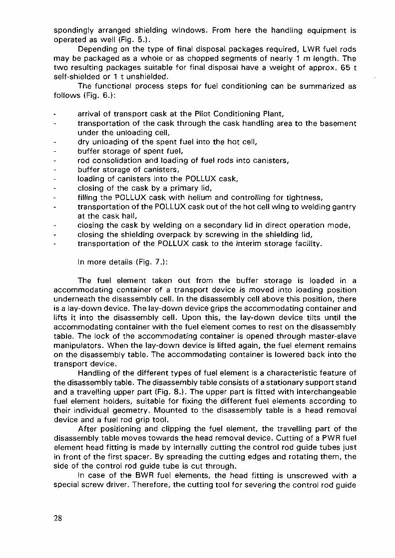
Depending on the type of final disposal packages required, LWR fuel rodsmay be packaged as a whole or as chopped segments of nearly 1 m length. Thetwo resulting packages suitable for final disposal have a weight of approx. 65 tself-shielded or 1 t unshielded.
The functional process steps for fuel conditioning can be summarized asfollows (Fig. 6.):
arrival of transport cask at the Pilot Conditioning Plant,transportation of the cask through the cask handling area to the basementunder the unloading cell,dry unloading of the spent fuel into the hot cell,buffer storage of spent fuel,rod consolidation and loading of fuel rods into canisters,buffer storage of canisters,loading of canisters into the POLLUX cask,closing of the cask by a primary lid,filling the POLLUX cask with helium and controlling for tightness,transportation of the POLLUX cask out of the hot cell wing to welding gantryat the cask hall,closing the cask by welding on a secondary lid in direct operation mode,closing the shielding overpack by screwing in the shielding lid,transportation of the POLLUX cask to the interim storage facility.
In more details (Fig. 7.):
The fuel element taken out from the buffer storage is loaded in aaccommodating container of a transport device is moved into loading positionunderneath the disassembly cell. In the disassembly cell above this position, thereis a lay-down device. The lay-down device grips the accommodating container andlifts it into the disassembly cell. Upon this, the lay-down device tilts until theaccommodating container with the fuel element comes to rest on the disassemblytable. The lock of the accommodating container is opened through master-slavemanipulators. When the lay-down device is lifted again, the fuel element remainson the disassembly table. The accommodating container is lowered back into thetransport device.
Handling of the different types of fuel element is a characteristic feature ofthe disassembly table. The disassembly table consists of a stationary support standand a travelling upper part (Fig. 8.). The upper part is fitted with interchangeablefuel element holders, suitable for fixing the different fuel elements according totheir individual geometry. Mounted to the disassembly table is a head removaldevice and a fuel rod grip tool.
After positioning and clipping the fuel element, the travelling part of thedisassembly table moves towards the head removal device. Cutting of a PWR fuelelement head fitting is made by internally cutting the control rod guide tubes justin front of the first spacer. By spreading the cutting edges and rotating them, theside of the control rod guide tube is cut through.
In case of the BWR fuel elements, the head fitting is unscrewed with aspecial screw driver. Therefore, the cutting tool for severing the control rod guide
28

tubes are exchanged by remote handling against a tool for unscrewing the screwnuts.
The fuel rods screwed into the fuel element bottom fitting are unscrewedwith a special tool upon a remote handled tool exchange. The process of removal,the fuel element top and bottom fittings is operated automatically by theprogrammed control system after pre-selection of the fuel element type.
Upon removal of the fuel element fittings, the upper part of the disassemblytable moves to the fuel rod griping device. The tongs of the griping device wedgethe upper fuel rod layer. The disassembly table with the fuel element is moved intoits rear final position. During this process, the first fuel rod layer is fixed by thegriping device ((Fig. 9.).
In the rear final position, the fuel rods fall into the trough (Fig. 10.). The tipsof the fuel elements also fall into the trough upon release of the griping device. Thepulling process is repeated until all fuel rods are removed from the fuel elementstructure. The griping device is fitted to the disassembly table in such a mannerthat it is interchangeable by remote handling. This exchange allows the applicationof different types in correspondence with each fuel element type.
The trough is filled with the fuel rods of 2 PWR or 6 BWR fuel elements (typeKWU-Siemens 16x16-20 or 8x8-1). In order to reach the highest possible degreeof filling, the trough is jarred after charging by vibrating motors which are mountedunderneath the trough. The loaded trough is then closed with a lid and transportedto the outward pushing device. The trough has the same geometry as the POLLUXcanister into which the fuel rods can be inserted. Upon completion of the rodremoval process, the fuel element structure is passed on to the hydrauliccompactor.
The hydraulic compactor (Fig. 11.) performs the compaction of the partsremaining after removal of the fuel rods, such as head and bottom fittings, spacers,rod guide tubes and fuel channels to a minimum volume.
Through a feeding unit, the fuel element structure is inserted by axialcharging into the press channel. After inserting the counter-plunger, a first pressstroke of 900 mm length is exerted. Altogether, 6 strokes are made and therefore5 extension plungers are inserted.
The mould (Fig. 12.) is pushed out into the transfer shaft. The compactingforce has a maximum of 5,000 kN, the compacting degree is 8:1.
The hydraulic compactor is designed to allow remote handled disassemblyand corresponding maintenance work at components either in situ remote handledor upon decontamination in the repair and maintenance cell affiliated to thedisassembly cell.
In the disassembly cell, a loading caisson is installed. This caisson separatesthe disassembly cell and loading cell with regard to ventilation, and at the sametime it also prevents contamination displacement from the disassembly cell. Intothe front wall of the loading caisson a rotating disk is integrated, provided withsuitable loading openings. These loading openings are designed as double-lidsystems and are arranged on the rotating disk in such a manner that they can beturned into loading position according to the particular requirements.
By means of a docking carriage, a POLLUX-canister is docked to the corre-sponding loading opening of the rotating disk into the loading caisson. Only uponcompletion of this docking process, the double-lid system can be opened. Thetrough is positioned on the outward pushing device and the fuel rods are pushedfrom the trough into the POLLUX canister. For loading the baskets, the transfershaft with the pressed pieces is positioned on the outward pushing device and
29

docked to the rotating disk, after the loading opening has been turned into thecorresponding position. The mould is pushed into the POLLUX basket by means ofa pusher rod. (Figs 13 and 14)
The self-shielded final disposal cask POLLUX is based on a double shell con-cept, consisting of a leak-tight welded steel containment, which assures:
safe containment of spent fuel,protection against mechanical loads and impacts,protection against corrosion, and ashielding overpack which also provides further mechanical protection.
The POLLUX cask is loaded with 4 canisters with fuel rods and with themoulds of the compacted skeletons in the central basket. In this case, the contentof the casks may consist of the rods from 10 PWR- or 30 BWR fuel assemblies.
The shielding overpack (M), the final disposal cask (K), the 4 canisters withfuel rod (I) and the central basket for compacted skeletons or fuel rods (E) can beseen.
The POLLUX cask loaded with basket and canisters is transported to thewelding station after screwing the primary lid into place. In the welding station thesecondary lid with a thickness of approximately 50 mm is inserted and welded intoplace, using WIG welding technique. For this, about 30 welding layers are required.The completed weld is examined by ultrasonic. This weld ensures tight andpermanent retention of activity. The welding system is a conventional device as itis used in construction of nuclear power plants. The shielding lid of the POLLUXcask is screwed into place by a screwing device. Then, the POLLUX cask can betransported to an interim store.
Alternatively to loading the POLLUX cask with full-length fuel rods, the un-shielded POLLUX canister can as well be filled with chopped rod segments(Fig. 1 5.). This process requires modification in the equipment of the disassemblycell and in the loading caisson. The remote handled adjustments for this alternativeloading technique have been considered in design of the components.
First of all, the handling of the incoming casks and the disassembling of thefuel elements takes place in the same way as the packaging of the whole rods intothe POLLUX cask.
Now, the fuel rods are transported to a device, located at the docking wallof the loading caisson, in which they are chopped into segments of nearly 1 mlength and pushed into the canister docked to the loading caisson.
During the chopping and loading process, the canister and the choppingdevice are attached to a vacuum unit. The air is sucked off via a sintered powdermetal filter located in the canister, which is retaining any dust arising duringchopping. Before the evacuated air is fed back into the cell, it is passing aerosoland iodine filters built into the vacuum unit.
After filling, the primary plug is placed into the canister. Then, the canisteris undocked, transferred into the loading cell and positioned in a welding stationwhich welds the lid into place. For the transportation to an interim or final store,the filled and closed POLLUX canisters are loaded to a transport and storage casklike a POLLUX cask.
As mentioned in the beginning of this paper and as shown in the figuresextensive cold test up to 1:1 scale were conducted, particularly with regard to fuelelement disassembly, compaction and loading of POLLUX canister and unshieldedcanisters. The results of these tests were the basis for the design of thecomponents to be used. All these components are designed to allow remote
30

maintenance, the exchange of parts or the complete remote exchange of the wholecomponent.
At the end of this paper, some brief facts on the current status of theproject:
The construction of the Pilot Conditioning Plant was started in February1990, the hot commissioning is scheduled for the second half of 1997. Upto now, the construction of the main process building has been completedand the engineering of services and technical equipment is being carried out.
Production of casks or canisters for finaldisposal of spent— LWR-fuel, in particular:
• reprocessed uranium elements• Mix-oxide elements• High burn-up elements
— fuel elements of the HTRReloading of waste canistersFinal conditioning of off-specificationswaste canistersServicing of casks
Pilot-conditioning plant Gorleben
FIG. 1
31

Existing buildings of theinterim storage Gorleben
A. Transport cask storageB. Waste storageC. Administration
Pilot Conditioning Plantand Interim Storage Gorleben
FIG. 2
32

ACask handling aroa
BHol coll wing
Utility andpersonnel wing
FIG. 3
OJU) Cross section of the conditioning building

t G O O O
»2050
13 00
CASK HANDLINGAREA
tOOO
-400
FIG. 4
Layout of the Conditioning Building

POLLUX-caskApprox 150cm ............................ Diameter ........Approx 550m ............................ Length ..........Approx 651 ............................... Weight ..........8 PWR - Fuel elements ..................... Content ..........<0.2mSv^ ............................... Surface dose rate
POLLUX- Canister........... Approx 43cm.......... Approx 134cm.............. Approx 1 t. 05 PWR-Fuel elements............. <10imSv/h
FIG. 5
PKA: Conditioning Systems
35

A Cask-hallB Hoteeil areaC Utlities and personnel area
AI lockA2 TC-preparation and dispatchingA3 welding of POLLUX, leaktest
and screwing of shielding lidA4 internal decontamination of TC
1 TC - unloading2 FA - intermediate storage
(Bufferstorage lj3 disassembly of FA4 loading of canister and basket5 intermediate storage of canister
and basket (Bufferstorage 2}6 loading of POLLUX ananghtening lid
Transport cask fTC)Fuel assembly (FA)Fuel rod and componentsCanister and basket
CZD POLLUX screwed tight•• POLLUX welded and shielding lid
screwed tightPassage in basement
FIG. 6
PKA: Packaging of ConsolidatedLWR-Fuel into POLLUX Casks
36

A Unloading cellB Loading cellC Disassembly cellD Caisson
E Maintenance cell
FIG. 7
Cross section of hot cells

8 'DU
8£

FIG. 9
39

-t».O
FIG. 10

FIG. 11

FIG. 12
pilot-conditioning plantCompacted fuel element skeleton
42

FIG. 13

FIG. 14

Disassembly cell
Exhaust air (5
Caisson
Fuelrod (FR) Cutting
[T] Cutting of rods
Ejector rotates
Loading of canistersJettison FR-cuttings
1 FR-cutter2 Rotating ejector3 POLLUX-canister4 Suspended particle filters (HEPA)5 Iodine-fitter
to weldingstation
Undocking of loaded canister
FIG. 15
Loading Principle ofUnshielded POUUXCanister
45

REMOTE HANDLING OF SPENT FUEL AND HIGH-LEVELWASTES IN BANK-END OPERATIONS OF NUCLEAR FUEL CYCLE
T.F. MAKARCHUK, N.S. TIKHONOV, V.M. DUBROVSKY,A.A. SHVEDOV, V.V. SPICHEVAll Russian Design and Scientific Research Institute ofComplex Power Technology (VNIPIET)St. Petersburg, Russian Federation
AbstractThe report covers main requirements to the technological operations and equipment related
to the spent fuel (SF) and high-level wastes (HLW) handling at a reprocessing plant. The flow sheetof SF preparation and reprocessing as well as some examples of arranging remotely controlledoperations are also presented.
1. INTRODUCTION
The Russian Program of nuclear energy development is oriented to the closedfuel cycle which involves spent fuel reprocessing and recycling of recovered fissilematerials, uranium and plutonium as nuclear fuel, thus providing for most effectiveutilization of natural uranium reserves. Another reason of closed cycle option is
Spent nuclearfuel1
WER-440 BN-350WER-IOOO BN-600
At-reactor coolingfor > 3 years
RBMK-IOOO
Intermediate sto-rage for 40 years
Transportation toa reprocessingplant
Transportation toa fuel conditio-ning plant
Radlochemlcalreprocessing
Production ofhexanydrate ofuranyl nitrate,RBMK-fuel ele-ments fabrica-tion
Production orPu-dloxide,MOX-fuelfabrication
Fuelconditioning
r1 ———— v ———— 1Radwastesconditioning
Plnal geologi-cal disposal
FIG. 1. Spent fuel management concept.
47

better solution of safety problems connected with the management of mostdangerous radioactive wastes and the possibility of using some radionuclides(contained in SF) in the production of ionizing radiation sources.
The safe management of SF and radioactive wastes is guaranteed by barrierseither engineered or natural (ex., shielding, ventilation of rooms, hermetic sealingof equipment, etc.), which prevent radionuclides migration into the environment,and relieve ionizing radiation impact.
The Russian nuclear power program necessitates the reprocessing of allspent fuel from WWER- and BN-reactors. RBMK-1000 fuel will be stored atintermediate facilities at the nuclear power plant sites and finally disposed of ingeological formation (Fig. 1.).
Spent fuel (SF) from WWER-440, BN-350, BN-600 reactors as well astransport and research reactors has been reprocessed at the reprocessing plantRT-1 since 1977. The plant capacity of 400 Mg U/yr is adequate to satisfy thecurrent as well as future demands for reprocessing all spent fuel from the abovereactors. Fuel from WWER-1000 reactors will be reprocessed at the plant -- RT-2,which is under construction now. The plant will be put into operation by units of1 500 Mg U/yr capacity each.
2. REPROCESSING
2.1. TechnologyThe technology for fuel reprocessing is based on an extraction process
known in the world practice as the Purex-process.
SF reception and storage
Preparing a fuel assembly forshearing; SF dissolution
i i| Clarifying SF solutions-, mixing || SF solutions with high enriched!| uranium reextract, extractive || purification |
i Extractive Pu purification, [ | Deep evaporation of U-re-|| Pu02 production | | extract, production of |'—————————————————' | hexahydrate of uranyl I
I nitrate I
FIG. 2. SF reprocessing process.
48

Basically this boils down to the following (Fig. 2.). Spent fuel to bereprocessed is overloaded from transportation railway cars to an interim storagefacility and then remotely transferred to a fuel preparation cell. Here the end fittingsof fuel assemblies are chopped off, packed into a container and dispatched forlong-term storage. The fuel parts of the assemblies go to a shearing machine,where they are flattened out and cut into pieces which are poured into abatch-operated dissolver.
All operations with fuel assemblies and their end fittings are carried out withremotely controlled manipulators of various types.
The pieces of hulls and other construction elements are washed and aftercontrol dissolution transported to a hulls storage facility.
SF solution undergoes clarification and extractive reprocessing. Uranium andPu purification from fission products and their separation occurs in the 1-stextraction cycle; further purification is carried out independently in uranium andplutonium cycles.
A 30% solution of TBP in a light hydrocarbon diluent is used as an extractantin the U-cycle while tri-isoamyl-phosphate in an inert diluent is used in the Pu-cycle.The total purification coefficient is 1x10+7 and 1x10+8for U and Pu, respectively.Exposure rate for end uranium and Pu-products is 1.7x10+3 //R/s kg and0.1 //R/s kg, respectively.
End products of WWER-440 fuel reprocessing are as follows:
melt of hexahydrate of uranil nitrate, enriched to 2 - 2.4% in 235U, obtainedby mixing reextract with highly enriched uranium and used for RBMK fuelelements fabrication,plutonium dioxide, stored in a special interim storage facility. In the futureit will be used for fabricating MOX - fuel.
2.2 Equipment used
The major technological equipment at the RT-plant includes:
1 tone power manipulators,mechanisms for cutting end fittings of fuel assemblies,annular batch-operated dissolvers,pulsed pneumatic conveyer for transporting pieces of hulls to the storagefacility,equipment for purification of air exhaust (deflegmators, absorbing columns,coarse and fine filters, etc),equipment for clarifying SF solutions (precoat filters, tanks for receiving andsupplying filtrates, pulps and washing solutions, receivers for "shock"regeneration of filter cartridges, measuring tanks for supplying coagulants,etc.),extractors with pulsed and mechanical agitation;shielded cells for Pu - and Np - recovery,evaporators for two-step U-reextract evaporation and melt production,pumps for dosing solutions and reagents,pumps for conveying liquid products,standard and shielded tanks.
The process at the RT plant is 100 % automated and remotely controlled.
49

Crane Q=15t L=9m w- —————————— ~"~ ~ ————-••_ J_ Crane Q=15t L=25m
Adapter
Storage water pool
FIG. 3. SF reception and storage.

All the operations which shall be performed with scrupulous attention to theirsequence and duration have programmable control.
The plant uses a three - zone layout of rooms with independent ventilationof each zone. The air from each canyon follows through a tubular corridor towardsthe filter plant ( a two - step air purification) and then through a 150 m tube isvented to the atmosphere. The activity emissions from the RT-plant are as follows:
a-, ß-, and iodine activities amount to 0.7, 0.2 and 0.07 of activitiesmandated by the standards.
The dose from the plant emissions does not exceed a level of 1 mrem/yr.The first zone accommodates equipment with radioactive materials (behind
shielding), the second zone -- equipment for repairing works, and the third -- roomsfor operators and control panels.
Systems with short operating life are used with redundancy. Failed pumps,valves control and measuring instruments are remotely replaced by specialmechanisms without stopping the technological process.
3. FUEL HANDLING OPERATIONS
The operations of the spent fuel reception and storage at the RT-site serveas examples of remotely controlled fuel handling. The sequence of fuel unloadingoperations is shown in Fig. 3.
Liquid radwastes
Radwastes collect Ion and sorting
HLW MLW LLWhigh salinesolutions
and low salinesolutions
Storage In tanks Storage In tanks Storage In tanks
EvaporationVitrificationDispensing IntotanksCanisterscompleting
EvaporationBltumlnlzatlon1Dispensing intotanks
PrecipitationFiltrationjIon exchange
Storage In ferro-concrete blockswith forcedcoolingStorage In ferro-concrete blockswith naturalconvection
Cleaned waterTor re-use
FIG. 4. Liquid radwastes management.
51

The railway car arrives to the transport corridor of the unloading area. Thedoors on the car roof are opened, the TK-6 transportation cask is depressurized(through special ventilation system), cask lid unbolted and lid bolts removed.
Further unloading operations are remotely controlled from the control boardwith the cask staying in the railway car. The observation of the unloading processis performed with TV cameras. A 15 t crane removes the cask lid, draws the filledbaskets from the cask and puts it on an elevator of 15 t capacity which transfersthe baskets to a storage facility. Here a 15 t crane removes the basket from theelevator and places to a storage position.
Baskets with spent fuel are stored in water pools which have the capacityno less than the annual RT-plant throughput.
4. RADIOACTIVE WASTE HANDLING
Other examples of remotely controlled processes relate to treatment of liquidradwastes (see Fig. 4.).
This technological process involves:
datolite,sandmolassescompressed air
HLW
water
gases for purification
gases for purification
FIG. 5. HLW virtitication1- receiver, 2- tank molasses, 3- pump, 4- mixer, 5- direct arc furnace,6- metal-ceramics alter, 7- container, 8- montejus for HLW.
52

9
rhrn nn n
T" ^ v "V \ / " " V / \/~
7 X x x X X
FIG. 6. Storage facility with forced convection1- fans, 2- gates and filter plant, 3- crane, 4- sectional service ffoor,5- ferroconcrete wells for cans, 6,7 - air chamnels, 8- air intake, 9- exaust shafi.

radwaste collection, sorting, accumulation and intermediate storage;concentration;concentrates solidification;intermediate storage of solidified radwastes in special storage facilities;purification of gaseous and aerosol emissions.
The liquid high-level wastes (HLW) resulting from spent fuel breakdown inextraction cycles are transported for storage in stainless steel tanks, available atthe plant site. Several groups of storage tanks with a capacity of 300 m3 and500 m3 have been in operation for a long time.
The major engineered barriers necessary for safe operation of the tanks arethe followings:
locating the tanks in stainless steel-lined canyons;equipping the tanks with water-cooling systems, which maintain the solutionstored at a level < 50 °C;air blowing for diluting radiolytic hydrogen to safe concentrations;subsequent reducing of the hydrogen content to permissible standards byuse of gas purification systems.
The collection and storage of HLWs is a preliminary stage of wasteconditioning. Later on HLWs are transferred to an accumulator tank forhomogenization of the chemical composition and specific activity and then they arevacuumed off to monte-juses. In these the solution is adjusted for chemicalcomposition and mixed with fluxing additives (73% orthophosphoric acid, NaN03,AI(N03)3). The flushed solution, containing metal oxides in the following proportion:-- monovalent oxides (0.25): multivalent oxides (0.25): phosphorouspentoxide (0.5) -- is dosed to an evaporator for a twofold reduction of the solutionvolume. The evaporator bottom is periodically drained to monte-juses and run offfor reprocessing along with middle-active solutions. The non-condensed gaseousphase goes to the gas purification system. The bottoms from theaccumulator-monte-juses are continuously dosed to a direct arc furnace EP-500.Molasses (150 g/l of solution) are needed to obtain a reducing medium of nitrogenand ruthenium oxides and to decrease solid phase sweeping away to the gaspurification systems. In the furnace the fluxed bottom solution goes through saltsdehydration, oxides calcination and glass mass melting. Vitrification with phosphateglass production occurs at 1100-1150 °C (see Fig. 5.). The glass mass isperiodically run off to a stainless steel 200 I flask. The glass mass capacity of thefurnace is 1.8 m3/d, or 165 m3/a. The total activity of the glass mass thus obtainedamounts to 2.8x10⁸ Ci/a.
The steam-gas phase heated to 600-800 °C goes from the furnace to abubbler-cooler for condensing and cooling. The condensate is collected andperiodically fed for mixing with the initial solutions. The non-condensing gas phasegoes to the gas purification system.
Filled flasks are transferred from the glass mass dispensing cell (equippedwith local suction) to the cell of canister completing. Here the flasks are remotelyloaded into the canisters and the canister lids are welded.
Then the canister is drawn from the cell into the shielded container andtransported to a storage facility located in the same building. The facility consistsof ferro-concrete blocks with tubular wells to accommodate canisters with vitrifiedHLWs (Fig. 6.). The construction of such facility is designed for receiving HLWs
54

shielded cell electric furnace
craneshielded container
supports for canisters
canister
FIG. 7. Storage facility with forced cooling.

with an initial heat release of 5 kW/m3. Loading/unloading operations with canistersare done using a three-item shielded container, which is transferred by a 120 tcrane in the assembly hall. The facility design provides both for forced and naturalcooling of filled canisters. The storage period may range up to several decadeswhen needed (Fig. 7.).
The equipment for HLW vitrification and storage is located in two buildingslinked with each other by a technological platform. The processes are 100%automated and remotely controlled from the control panel.
In conclusion, the technology allows to obtain end products which meet therequirements of the National Standards and provide for environmental andpersonnel safety in compliance with the ALARA principle.
REFERENCES
[1] ABAGYAN A.A., et al, "Status and Problems of Nuclear Power Development inUSSR", Journ. Atomnaya Energia (in Russian) (1990), v. 69, p.2.[2] DUBROVSKY V.M., et al. "On Concept of NPP Fuel Management Adopted inthe USSR and Principles of Radiochemical Reprocessing of Spent Fuel", Proc. 3rdInt. Conf. on Nuclear Fuel Reprocessing and Waste Management, Sendai, Japan,(1991), v. 1, 329-333,[3] DZEKUN E.G., et al. "Commercial Reprocessing of WWER-440 Spent Fuel",ibid, v. 1, 44-48.[4] NIKIPELOV B.V. et al. "On the Management of radioactive Wastes in theCommunity of Independent States; Problems of Long-Lived Nuclides andPartitioning", Proc. Symposium on Waste Management, Tucson, Arizona, (1992),v. 1, 19-22.
56

DRY SPENT NUCLEAR FUEL TRANSFER
J.D. STITZEL, B. GILLIGANNewport News Shipbuilding, Newport News,USA
Abstract
Newport News Shipbuilding, (NNS), has been transferring spent nuclear fuel in a drycondition for over 25 years. It is because of this successful experience that NNS decided to ventureinto the design, construction and operation of a commercial dry fuel transfer project. NNS isdeveloping a remote handling system for the dry transfer of spent nuclear fuel. The dry fuel transfersystem is applicable to spent fuel pool-to-cask or cask-to-cask or both operations. It is designed tobe compatible with existing storage cask technology as well as the developing multi-purposecanister design.
The basis of NNS' design is simple. It must be capable of transferring all fuel designs, itmust be capable of servicing 100 percent of the commercial nuclear plants, it must protect thepublic and nuclear operators, it must be operated cost efficiently and it must be transportable.Considering the basic design parameters, the following are more specific requirements included inthe design:(a) Total weight of transfer cask less than 24 tons,(b) No requirement for permanent site modifications to support system utilization,(c) Minimal radiation dose to operating personnel,(e) Minimal generation of radioactive waste,(f) Adaptability to any size and length fuel or cask,(g) Portability of system allowing its efficient movement from site to site,(h) Safe system; aN possible "off normal" situations are being considered, and resultant safety
systems are being engineered into NNS' design to mitigate problems.The primary focus of this presentation is to provide an overview of NNS' Dry Spent Nuclear
Fuel Transfer System.
1.BACKGROUND
The Nuclear Waste Policy Act of 1982 (NWPA), as amended, assigns theU.S. Department of Energy (DOE) the responsibility of providing for the permanentdisposal of spent nuclear fuel (SNF) and high-level waste (HLW). On April 18,1983, the Standard Contract for Disposal of Spent Nuclear Fuel and/or High-LevelWaste, (10 CFR Part 961} was issued as a final rule. The Standard Contractestablished the contractual mechanism for DOE's acceptance and disposal of SNFand HLW. To meet this contractual requirement the DOE is developing a Multi-purpose Canister (MPC) system to accept the SNF.
The MPC system is comprised of large metallic canisters that will maintainthe SNF in a dry, inert environment during storage, transportation, and disposal.There are two MPC Assembly Subsystem Elements: a Large MPC with a 125-toncrane hook weight limit and a Small MPC with a 75 ton-crane hook weight limit [1 ].The crane hook weight limits include the MPC, SNF, and MPC Transportation Cask[1]. The minimum capacity of the Large MPC is 21 pressure water reactor (PWR)fuel assemblies or 40 boiling water reactor (BWR) fuel assemblies. [1]. Theminimum capacity of the Small MPC is 12 PWR fuel assemblies or 24 BWR fuelassemblies [1].
Due to limited crane capacity and other restraints in their SNF storage poolareas, 19 sites have been identified as unable to accommodate the MPCs [2]. Thisprevents these 19 sites and the DOE from reaping the benefits of a standardizedSNF canister system. The 19 sites must load SNF into truck casks, which in turn,
57

must be unloaded and the SNF transferred into MFCs. The truck casks are to belicensed for transportation-only and for a maximum of four PWR fuel assemblies ornine BWRfuel assemblies [3]. There are numerous benefits from utilizing the largestSNF container possible. These are reduced fuel shipments, reduced fuel handling,reduced MAN-REM, and monetary savings due to economies of scale.
Of the 19 sites unable to accommodate the MFCs, three of the sites arestorage-only sites with their plants shut down. These sites would like to takeadvantage of the MFC system and place their SNF in dry storage, shut down theirstorage pool, and await the acceptance of the SNF from the DOE. This wouldprovide for a considerable cost savings utilizing dry SNF storage in lieu of the morecostly wet pool SNF storage. Sacramento Municipal Utility District has estimatedan annual cost savings of $8.0 million by closing their storage pool and placing theSNF in dry storage [4]. Additionally, Mr. Ivan Selin, Chairman of the U.S. NuclearRegulatory Commission, recently remarked before the Institute of Nuclear MaterialsManagement that "Both pool storage and dry storage are safe technologies. Butthere are significant differences; pool storage requires a greater and moreconsistent operational vigilance and the satisfactory performance of a large numberof active systems, while dry storage is almost passive" [5]. He summarized bystating "... the NRC increasingly views dry storage as the preferred method ofinterim storage of mature spent fuel for plants in permanent shutdown, as well asfor supplementary storage in many operating plants" [5]. With the uncertain SNFacceptance dates by the DOE and the NRC's endorsement of dry SNF storage, webelieve many more sites will opt to place their SNF in dry storage.
2. DRY SPENT NUCLEAR FUEL TRANSFER DEVELOPMENT
Newport News Shipbuilding has been handling spent nuclear fuel in transfercasks for over 25 years. It became apparent that a similar system may be of greatbenefit to the commercial nuclear industry. The NNS Dry Spent Nuclear FuelTransfer System utilizes a remote handling system to transfer SNF from storagepool-to-cask or from cask-to-cask or both.
NNS established design goals for the Dry Spent Nuclear Fuel Transfer (DFT)System based on the needs of the commercial utilities unable to accommodate theMFCs. These criteria were used to ensure that worst-case scenarios would drivea universal design. The design goals are as follows:
(a) Light weight fuel transfer container to allow use at all U.S. commercialnuclear power plants using existing crane capacities,
(b) No permanent site modifications required for system use,(c) Radiation dose to personnel As Low As Reasonably Achievable (ALARA),(d) Minimal generation of radioactive waste,(e) Adaptable to any size fuel or cask,(f) Completely portable system,(g) Inherently safe system,(h) Cost effective system.
To meet these design goals NNS has incorporated remote handlingoperations and automated the processes. The result is increased safety anddecreased transfer container weight, the generation of radioactive waste, themanning required, and the MAN-REM.
58

3. THE DRY SPENT NUCLEAR FUEL TRANSFER SYSTEM
The Dry Spent Nuclear Fuel Transfer (DFT) system is comprised of threemain subassemblies. These are the Transfer Container, the Loading Stand, and theDischarge Stack-up. The system discussed in this presentation is for the transferof SNF from the sites' storage pools to Large MFCs. The same system in a differentconfiguration can be utilized to transfer SNF from cask-to-cask.
The Transfer Container is the heart of the DFT system, providing shieldingand containment of the SNF for transfer to the MPC. The Transfer Container allowsfor the transfer of up to four PWR or BWR fuel assemblies during each transfercycle. The Transfer Container is comprised of the following components:
(a) Integral Hoist
(b) Grapple Assembly
(c) Closure Head
(d) Transfer Container body(e) Shielded Gate
(f) Control Panel
It is attached to the top of the Transfer Containerand lifts and lowers the SNF via a single-failureproof design.Comprised of four Grapples and a liftingarrangement. Each Grapple may be operatedindividually or concurrently to latch or unlatch theSNF.Seals the top of the Transfer Container andprovides penetrations for the lifting cable andgrapple controlling cable.Provides shielding and confinement of the SNF.Comprised of two doors which translatehorizontally to open or close the lower section ofthe Transfer Container.Controls all Transfer Container operationsremotely. Provides information on the hoistoperation, Grapple position, and Shielded Gateoperation.
The Loading Stand is the assembly of components which is placed into thesite's SNF storage pool and allows the SNF to be loaded into the TransferContainer. The Loading Stand is comprised of the following components:
(a) Loading Stand Adapter Plate
(b) Loading Stand Support Columns
(c) SNF Basket
- Provides the mating and supportingsurface for the bottom of the TransferContainer. Houses alignment pins toalign the Transfer Container on theLoading Stand,
- Provides the physical structure for theLoading Stand. Supports the weight ofthe Transfer Container via the LoadingStand Adapter Plate during loadingoperations,
- Provides four locations for the SNF to beplaced to await removal by the TransferContainer. Ensures subcriticality of theSNF. Provides alignment of the SNF withthe Transfer Container,
59

(d) Loading Stand Elevator
(e) Transition Shield
- Raises the SNF Basket out of the storagepool water and lowers the SNF Basketback into the storage pool water,
- Shields the SNF in the SNF Basket as itis raised out of the water by the LoadingStand Elevator.
The Discharge Stack-up is the assembly of components utilized to facilitatethe transfer of the SNF from the Transfer Container into the MPCs. The DischargeStack-up is comprised of the following components:
(a) Multi-Purpose Canister(b) Shield Plug Installation Adapter
(c) Rotating Locator Plate
(d) Loading Stand
(e) Discharge Stack-up Enclosure
- A DOE provided SNF canister,- Allows the remote installation of the
MPC shield plug. Provides shielding ofthe SNF in the MPC. Provides apenetration for the SNF to be passedthrough,
- It is positioned atop the Shield PlugInstallation Adapter and provides themating and supporting surface for theTransfer Container. Provides a shieldedpenetration which provides passage forthe SNF to be lowered from the TransferContainer into the MPC. It rotates toallow access to all SNF locations in theMPC basket. It houses alignment pinswhich align the Transfer Container onthe Discharge Stack-up,
- It supports the weight of the TransferContainer, Shield Plug InstallationAdapter, and Rotating Locator Plate onan adjustable leveling work platform.This ensures that the weight of the DrySpent Nuclear Fuel Transfer equipment isnot applied to the MPC TransportationCask or Transfer Cask. The adjustableleveling work platform can be raised andlowered to allow the MPC to be locatedin the proper location and removed afterloading. The Loading Stand also providesa base for the Discharge Stack-upEnclosure,
- Provides a contained work area for thetransfer of the SNF from the TransferContainer to the MPC.
4. DRY SPENT NUCLEAR FUEL TRANSFER OPERATIONS
Prior to the commencement of SNF transfer operations, the appropriateequipment will be assembled in the wet cask loading area of the site's SNF storagepool and an appropriate dry cask loading area. The Loading Stand will be
60

assembled and lowered into the site's SNF storage pool. The Discharge Stack-upwill be assembled in the designated dry cask loading area.
To commence SNF transfer operations, the SNF will be transferred fromlocations in the fuel storage racks to positions in the SNF basket of the LoadingStand. This transfer is accomplished by the use of the storage pool's fuel handlingcrane. Up to four PWR or BWR fuel assemblies may be transferred into the SNFbasket for each transfer cycle.
The appropriate access hatches or doors to the storage pool building wouldbe opened and the Transfer Container brought into the storage pool area. TheTransfer Container is landed on the Loading Stand while being properly located bythe alignment pins in the Loading Stand Adapter Plate. The movement of theTransfer Container is accomplished by the use of the on-site crane.
Once the Transfer Container is seated on the Loading Stand, power and theremote Control Panel are connected to the Transfer Container and the electronicequipment is allowed to warm-up, while the rigging is removed. The remote ControlPanel is located in a low radiation area away from the transfer container tominimize radiation exposure. Then, the Shielded Gate is opened, via the remoteControl Panel, providing an opening for the Grapple assembly and the Guide Sleeveto pass through. Prior to lowering the Grapple assembly and Guide Sleeve, theLoading Stand Elevator is activated and the SNF Basket with the SNF to betransferred is raised to a height which ensures that the top of the SNF Basket isabove the surface of the storage pool water and within the Transition Shield.
With the SNF Basket in the up position, the Transfer Container Grappleassembly and Guide Sleeve are lowered, via the remote Control Panel, to rest atopthe SNF Basket and SNF. The Grapples are actuated remotely and latched to theSNF. Latching is confirmed by a series of electric sensors and the measurement ofthe proper weight as displayed on the remote Control Panel. The Grapple isdesigned to prevent the latching mechanism from releasing while the Grapple isholding the weight of the SNF. This ensures that inadvertent operation of therelease button on the remote Control Panel, while raising or lowering the SNF, doesnot cause the Grapple to release. Once latched, the Grapple assembly, GuideSleeve, and all the SNF are raised into the Transfer Container. The Guide Sleeve,which travels with the Grapple assembly, ensures that the SNF remains in asubcritical arrangement. In addition, the Guide Sleeve is designed to protect theintegrity of the SNF and minimize any possible interference by immediately guidingthe SNF as it is removed from the SNF basket.
Once the Grapple assembly, Guide Sleeve, and SNF are completely raisedinto the Transfer Container, the Grapple assembly with the SNF attached isautomatically secured in the Transfer Container. The Loading Stand Elevator isactivated to lower the SNF Basket. The Transfer Container Shielded Gate isactivated, via the remote Control Panel, to close and seal the bottom of theTransfer Container. Then, the power and remote Control Panel are disconnectedfrom the Transfer Container and the rigging is attached to the Transfer Container.Once the SNF Basket is in its lower position, the Transfer Container is lifted off ofthe Loading Stand and moved to the MPC loading area by the on-site crane.
The Transfer Container is brought through an access opening in theDischarge Stand Enclosure and landed on the Rotating Locator Plate, while beingpositioned by its alignment pins. Then, the rigging is removed and the remoteControl Panel and power are connected to the Transfer Container. Once the accessopening in the Discharge Stand Enclosure is sealed and the electrical equipment iswarmed-up, the MPC shield plug is retracted by the Shield Plug Installation
61

Adapter. The MPC shield plug rests on a translating base within the Shield PlugInstallation Adapter. The translating base is remotely activated to position theshield plug over the top of the MPC, or as during MPC loading operations, off tothe side of the MPC top and within the Shield Plug Installation Adapter.
Once the MPC shield plug is retracted within the Shield Plug InstallationAdapter, the Shielded Gate is activated to open the bottom of the TransferContainer. With the MPC shield plug retracted and the Transfer Container ShieldedGate opened, there is an unobstructed passage for the SNF to be transferred fromthe Transfer Container to the MPC.
Using the remote Control Panel, the Transfer Container Integral Hoist isactivated to lower the SNF. The Grapple assembly, Guide Sleeve, and SNF arelowered as an assembly from the Transfer Container. Once the Guide Sleeve comesto rest atop the fuel basket in the MPC, the Grapple assembly and SNF continueto lower through the Guide Sleeve until the SNF is seated in the MPC. Seating ofthe SNF is verified by the loss of weight of the SNF and the correct SNF positionas indicated by the readout on the Transfer Container remote Control Panel. TheGrapple assembly is remotely unlatched from the SNF via the remote Control Panel.Once unlatching is confirmed, the Grapple assembly and Guide Sleeve are raisedinto the Transfer Container by activating the Integral Hoist via the TransferContainer remote Control Panel. The Grapple assembly and Guide Sleeve are raisedto the top of the Transfer Container and automatically secured in position.
After the Grapple assembly and Guide Sleeve are raised, the Shield PlugInstallation Adapter is activated to transfer the MPC shield plug to a position overthe MPC top opening. Next, the Shielded Gate is activated to close and seal thebottom of the Transfer Container. Then, the rigging is attached to the TransferContainer and the Transfer Container remote Control Panel and power aredisconnected from the Transfer Container. Once rigged, the empty TransferContainer is removed from the Discharge Stack-up and transferred to the LoadingStand for reloading. This process is repeated until the MPC is completely loadedwith SNF.
Once the MPC is completely loaded, the MPC shield plug is lowered intoposition in the MPC using remote handling tools. The Rotating Locator Plate is thenremoved to allow the installation of the MPC lower lid. The Shield Plug InstallationAdapter is then removed to allow the MPC lower lid to be welded in place. Oncethe lower lid is welded in place, the adjustable leveling work platform of theDischarge Stand is raised to allow removal of the MPC. The MPC with the MPCTransfer Cask or MPC Transportation Cask as an overpack is then removed fromthe Discharge Stand.
To load SNF into another MPC, a new MPC in a Transfer Cask orTransportation Cask is staged in the Discharge Stand and the loading process isrepeated. Once the desired amount of MPCs are loaded, the Loading Stand in theSNF storage pool is removed and decontaminated. Then, the Discharge Stand andLoading Stand are disassembled for transportation off-site. Additionally, theTransfer Container internals, Rotating Locator Plate, and Shield Plug InstallationAdapter are decontaminated and packaged for transport. At the completion of DrySpent Nuclear Fuel Transfer operations the site is returned to its original condition.
5. DRY SPENT NUCLEAR FUEL TRANSFER ADVANTAGES
The use of remote technologies for SNF handling has many benefits over thecurrent technology. Furthermore, the Dry Spent Nuclear Fuel Transfer System
62

provides a means for the 19 sites unable to accommodate the MFCs to takeadvantage of the DOE's MPC system. The advantages of the Dry Spent NuclearFuel Transfer System are:
(a) The cumulative dose incurred by loading MFCs with the Dry Spent NuclearFuel Transfer System is minimal. The following design attributes contributeto the low man-rem values:(1) Remote operation of the Transfer Container via the remote Control
Panel allows the operating personnel to remain in a low radiation area,(2) The Transfer Container is shielded to maintain the on contact dose to
below 20//Sv/h,(3) The remote operation of the Transfer Container requires only one
operator,(4) The process time required to perform the SNF transfer operations
using the Dry Spent Nuclear Fuel Transfer System to load an MPCwith 21 PWR fuel assemblies is less than 35 hours,
(5) Only the Loading Stand is placed in the SNF storage pool and it doesnot need to be removed and decontaminated until all the desiredMPCs are loaded.
(b) This dry fuel transfer design is universal.(1) By adding additional container body sections and using longer Guide
Sleeves, the same Transfer Container can be utilized to transfer longerSNF,
(2) By changing the Guide Sleeve and Loading Stand SNF Basket, theTransfer Container can handle different size SNF and encased bowedand damaged SNF.
(c) The use and life cycle costs of the Dry Spent Nuclear Fuel Transfer Systemare minimal due to the following design attributes:(1) The Dry Spent Nuclear Fuel Transfer System is a portable system.
This allows the same system to be utilized at different sitesrepeatedly,
(2) The Transfer Container weight has been maintained at a designweight that is sufficiently low enough to allow use at every U.S. site,
(3) Due to the system's low weight and compactness, it can be utilizedat every U.S. site without any permanent and costly sitemodifications.
REFERENCES
[1] USDOE CIVILIAN RADIOACTIVE WASTE MANAGEMENT SYSTEMMANAGEMENT AND OPERATING CONTRACTOR "Multi-Purpose Canister(MPC) Subsystem Design Procurement Specification," Rev. 3 (May 17,1994).
[2] U.S. DEPARTMENT OF ENERGY, OFFICE OF CIVILIAN RADIOACTIVEWASTE MANAGEMENT, "Multi-Purpose Canister System Evaluation - ASystems Engineering Approach" (September 1994).
63

[3] U.S. DEPARTMENT OF ENERGY, OFFICE OF CIVILIAN RADIOACTIVEWASTE MANAGEMENT, "Cask Systems Development: GA-4 & GA-9 TruckCask," OCRWM Backgrounder, DOE/RW-0258, (February 1990).
[4] MILLER, K., SHETLER, J., "Experiences from Planning an Interim On-SiteSpent Fuel Storage Facility at Rancho Seco Nuclear Generation Station"Sacramento Municipal Utility District presentation to the Nuclear WasteTechnical Review Board, Dallas, Texas, November 1, 1993.
[5] U.S. NUCLEAR REGULATORY COMMISSION, OFFICE OF PUBLIC AFFAIRS,"News Releases," NUREG/BR-0032, Vol. 14, No. 29; "Remarks by IvanSelin, Chairman, U.S. Nuclear Regulatory Commission before the AnnualMeeting of Institute of Nuclear Materials Management," Naples, Florida (July18, 1994).
64

COMPUTER-AUTOMATED FUEL HANDLING SYSTEM
D.C. WADSWORTH, J. CARLOS LOPEZLockheed Idaho Technologies Company,Idaho National Engineering LaboratoryIdaho Falls, Idaho,USA
AbstractA computer-automated fuel handling system has been engineered and assembled to
demonstrate mechanical separation of Fort Saint Vrain graphite fuel. Separation of the fuel isperformed by drilling into a fuel element at both ends to access the fuel channels and by applyingpressure to the fuel pins with a pneumatic ram, pushing them out of the fuel element. Thedemonstration system comprises two principal components: fuel separation equipment and acomputerized central controller. The separation equipment is composed of several modules ofcommercial equipment designed for remote operation, including a horizontal milling machine, a toolwear monitoring system, a rotating table, a dust collection system, a pneumatic cylinder, and asystem to precisely position the pneumatic cylinder. The central control unit interfaces the controlof each module of the fuel disassembly system and manages a fuel identification database. Thispaper describes the functions of the fuel separation system and central controller and presentsresults of prototype testing of the system.
1. INTRODUCTION
The computer-automated fuel handling system is remotely operated, highlyautomated, and adaptive to a variety of operations. A prototype of the systemdemonstrated removal of surrogate irradiated fuel rods from the Fort Saint Vraingraphite reactor. The Fort St. Vrain Reactor was developed as a research platformfor the development of a high-temperature gas-cooled reactor. The plant beganoperation in 1979 and continued until 1989.
Three types of fuel elements were used in the reactor, all three of whichhave a hexagonal cross section with an effective length of about 31.5 inches anda width of about 14.0 inches across the flats. The elements were manufacturedfrom H-327 nuclear-grade graphite and fueled with 93% uranium 235 [1]. Fig. 1.illustrates the first type of element, the standard fuel element. It has 108 coolantholes drilled through the block from one end to the other. During reactor operation,helium flowing through the holes removed heat from the fuel elements. Thestandard fuel element also has 210 channels drilled from the top surface to withinapproximately 0.5 in. of the bottom of the element for fuel. The highly enricheduranium fuel was first conditioned into a carbon silicate particle, mixed withgraphite, and formed into short rods (pins) about 2 inches in length and slightly lessthan 0.5 inch in diameter [2]. The fuel pins were stacked into the fuel channels anda 0.25-inch graphite wafer was glued in the top of the fuel channel hole to seal thechannel [3].
The second type of element, the control rod element, is similar to thestandard fuel element except for three large holes drilled through the element. Two4-inch holes are for insertion of control rods to moderate the nuclear reaction, andone 3.75-inch hole is for reserve shut down operations. During an off-normal event,borated balls are dumped into the reserve shut down hole. Fig. 2. illustrates acontrol rod element.
The third type of element, called a bottom control rod element, is identicalto the control rod element except that the reserve shutdown hole does not pass
65

Coolant hole0.625 dia. (102)
Coolant hole0.500 dia. (6)Burnable poison0.005 dia. (6)
Fuel hole0.500 dia. (210)
Cementedgraphite plug(typ)
Fuel handlingpickup hole
Heliumflow (typ)
(B)pictorial Dowel
socket
Fig. 1 Schematic of a standard fuel element
66

14.172
(B)pictorial
nR7ccteLnce
""*
Reserve shutdownhôte
Coolant hôte0.500 dia. (6)
Control rodchannel (2)
Fuel note0.500 dia. (120)Coolant note0.625 dia. (52)Burnable poisonnote 0.500 dia. (4)
Cementedgrap(typ)
Fuel handinghole
Heliumflow (typ)
Burnablepoison
Coolantchannel
Fuel rod29.5-in.length
Fig. 2 Schematic of a control rod fuel element
67

through the entire element. This prevents borated balls from falling into the bottomhead of the reactor. At its end of life, a single element contains an average of lessthan 1 kg of uranium. The fuel rods make up approximately 40% of the fuelelement volume [4]; therefore, if the highly radioactive fuel rods were removedfrom the element, only they would need be stored as spent nuclear fuel. Thegraphite carcass could be stored as low-level material, thus, resulting in a 60%volume reduction of high-radiation level storage space. Given that, potentially,2000 graphite fuel elements would be conditioned, and given that operation mustbe remote because of the high radiation fields, it is very desirable to automate theprocess of removing the fuel pins. The prototype equipment has been used toseparate surrogate fuel elements to test the mechanics of the system. Should theprogram proceed, the system will be tested with a number of actual fuel elements.Eventually, the system could be used to separate all 744 irradiated graphite fuelelements currently in dry storage at the Idaho Chemical Processing Plant [5].
2. THE SEPARATION SEQUENCE
The mechanical separation sequence consists of five principal steps: (1)weighing the fuel element, (2) identifying the element and sensing its position; (3)exposing the fuel channel by drilling and collecting dust; (4) extracting the fuel pin;and (5) collecting and weighing the fuel material.
2.1 Weighing the fuel element
At the outset of the process, the fuel element is placed on a scale, weighed,and the weight recorded in a database. Verification that the fuel pin has beenremoved is achieved by comparing the weight of the fuel element before and afterfuel extraction. The fuel element is next placed horizontally on a rotating tablewhere it is drilled and the pin is separated from the element. The process ofweighing the element is still under development and has not been demonstrated.
2.2 Identifying and sensing the element's position
Since each of the three different types of elements requires a specific drillpattern to expose the fuel channels, it is necessary to identify the element typebefore proceeding with drilling. The primary method of identification is visual. Thesecondary method is to use a sensing probe to identify geometric features thatdistinguish the element. This information is sent to the computerized controller,which initiates and controls the proper drilling sequence.
During irradiation, the graphite elements tend to warp and become somewhatdeformed. The probe system adjusts the drilling to compensate for any deformationof the element caused by irradiation or misalignment in the element holding fixture.
2.3 Exposing the fuel channel and collecting dust
Traditional drilling equipment can control drilling only by feed rate androtational speed. In this application, however, a typical tool wear monitoringsystem is used to measure the axial force exerted on the cutter during the drilling
68

SpindleVacuum Attachment
Thrust Washer
Cutter
Rotating SealCoolant RingAssembly
Fig. 3 Schematic of dust evacuation system
operation, not to measure wear but to direct the drilling sequence1. Strain gauges,mounted in the drilling head, monitor the axial drilling force. This force is fairlyconstant as the graphite is drilled; however, as the drill breaks through into the fuelchannel the axial force of drilling is greatly reduced. The monitoring system detectsthe force change and relays a signal to the central controller, which stops forwardmotion of the cutter and issues instructions to continue the drilling sequence on thenext hole. The force detection system is vital to the performance of the fueldisassembly equipment as it allows the milling machine to stop drilling at preciselythe instant at which the graphite sealing the fuel channel is removed, thuspreventing drilling into the fuel. All fuel channels are exposed on a single end of theelement, the element is then rotated 180 degrees, and the fuel hole exposuremethod is repeated for the other end.
During graphite drilling, a very fine dust is produced that is ordinarily difficultto cleanup and contain. A significant innovation implemented on the fueldisassembly equipment is the dust evacuation system, which removes all dustthroughout the drilling process, collecting the debris in a bin for disposal. Fig. 3.outlines the function of the dust evacuation system. A vacuum attached to thehollow shank drill extricates all the graphite dust generated during drilling andconveys it to a dust collection device. This process has direct commercialapplication in machine and manufacturing companies where collection of suchbyproduct can be difficult and messy. In this process, the necessity of collectingall the dust is particularly important as the dust may contain some fuel residue andwould need to classified as high level nuclear material.
2.4 Fuel pin extraction
When drilling is complete, the block is rotated 90 degrees and the push outmechanism is positioned over the exposed fuel channels. Air is supplied to apneumatic cylinder, and the fuel pins are pushed out of the fuel channels. The fuel
1 The tool wear monitoring system was obtained from Sandvik CoromantCorporation, Bloomfield Hills, Michigan
69

Fig. 4 Fuel disassembly equipment
70

Fig. 5 Centralized computer controller

pins are collected in a catch bin and conveyed into the same collection receptaclethat received the graphite dust from the dust evacuation system.
2.5 Fuel material collection and end-of-cycle weight measurement
When all fuel channels have been cleared, the empty graphite carcass isremoved from the table, taken to a scale, and weighed. The weight is recorded inthe fuel element database, and the empty graphite element packaged and preparedfor storage in a low-level storage facility. The collection receptacle containing thegraphite dust and fuel pins is weighed, sealed, and sent to a storage facility forSpecial Nuclear Material. This aspect of the system is not fully operational.
3. PROTOTYPE TESTING
Figs 4 and 5 show the prototype fuel disassembly equipment and the centralcontrol system, respectively. Each module of the disassembly equipment iscontrolled by the central control system, which interfaces, monitors, and controlsthe functions of the milling machine, the tool monitoring system, the rotating table,the push out mechanism, and the fuel and dust collection system. A videomonitoring system aids personnel operating the equipment. Prototype testing of thefuel handling system has proven the equipment to be reliable in successfullyremoving surrogate fuel from the graphite fuel elements. The graphite dustevacuation system and drilling force monitoring system functioned well beyondinitial expectations.
During testing, it became obvious that the pneumatic ram is not adequatefor extracting the fuel pins. If a fuel pin became stuck in the fuel channel, pressurebuilt up in the cylinder, and when the pin was dislodged it shot as a projectile fromthe fuel channel. A better method of extraction would be a mechanical drive suchas a rack and pinion device.
4. CONCLUDING REMARKS
The Computer Automated Fuel Handling System has been successfullydemonstrated on the mechanical separation of surrogate graphite fuel. TheComputer Automated Fuel Handling System will serve to reduce personnelexposure during all stages of the separation cycle should this system be eventuallyplaced into a production environment. The demonstration has been a significantstep toward assuring complete automation so as to effectively minimize entry intoa hot cell environment for any reason other than what is absolutely necessary. Thefunctions of the centralized controller which have been demonstrated indicate thatfurther development is necessary in the dust collection system and fuel blockmaneuverability. For the near future, additional work in areas related to thecentralized computer; including, tagging and logging of the collection receptacle,weight measurements, element handling into and out of a hot cell environment, andhandling of the collection receptacle is planned. A demonstration using actual fuelis not planned for the near future. The need for a full scale production facility hasnot been identified at this time. These efforts have been performed for the purposeof technology development and technology transfer.
72

REFERENCES
[1] FULLER, C.H. to Petrolic, A.A., Transmittal of Spent Fuel Shipping Data(Letter 16805), Platteville, Colorado (February 11, 1991).
[2] U.S. DEPARTMENT OF ENERGY, OFFICE OF CIVILIAN RADIOACTIVEWASTE MANAGEMENT, Washington, D.C. "Characteristics of PotentialRepository Wastes", DOE/RW-0184-R1 (Volume 4, Section 4C), (July,1992).
[3] WADSWORTH, D.C., et al., "Conceptual Design Report for the MechanicalDisassembly of Fort St. Vrain Fuel Elements", Westinghouse Idaho NuclearCompany (WINCO Report 1170), Idaho Falls, Idaho (April, 1993).
[4] GAVALYA, R.A., "Conceptual Design Report for Handling Fort St. Vrain FuelElement Components", Westinghouse Idaho Nuclear Company (WINCOReport 1178), Idaho Falls, Idaho (September, 1993).
[5] BERRY, S.M., "Fort St. Vrain Graphite Fuel Mechanical Separation ConceptSelection", Westinghouse Idaho Nuclear Company (WINCO Report 1159),Idaho Falls, Idaho (September, 1993).
73

MODULAR VAULT DRY STORE FUEL HANDLING MACHINERYTECHNOLOGY AND SAFETY CONSIDERATIONS
C.C. CARTERCEC Alsthom Engineering Systems LtdWhetstone, Leicester,United Kingdom
Abstract
The storage of irradiated nuclear fuel in dry store facilities is now a very well establishedtechnical option within the nuclear fuel cycle. The Modular Vault Dry Store (MVDS) is a licenseddry storage technology that has been applied internationally for the storage of a range of differentfuel types. A critical part of the fuel transfer operation from the reactor pool to the MVDS storageposition requires the use of a Fuel Handling Machine (FHM) at the MVDS facility. These machinesare designed to perform a number of specific operations and also to be able to withstand a varietyof fault or off-normal conditions. This paper briefly reviews the design and operation of the MVDStechnology, showing its relevance to the DOE spent nuclear fuel requirements. In particular thepaper considers the design, development and operation of the various types of Fuel HandlingMachines that have been produced for different fuel types. The Fuel Handling Machines designedfor the MVDS operations have evolved from the reactor refuelling machines that have been usedin the British gas-cooled reactor programmes. Because there is a wide range of spent fuel types,each with their own special design and safety requirements for dry storage, there is a range ofdesigns and safety considerations for the Fuel Handling Machines needed to transfer that fuel into(and ultimately out of) an MVDS.
1. DESIGN AND OPERATION OF THE MVDS
The Modular Vault Dry Store (MVDS) technology was developed directlyfrom the original Magnox fuel dry storage facilities at the Wylfa power station inWales (UK). The Wylfa dry stores were originally commissioned in 1969 and theMVDS can, therefore, rightly claim to be the only dry storage technology that hasan operational and technological heritage of nearly a quarter of a century. TheMVDS technology has been further extensively developed over the last twentyyears so that it can be applied to the storage of a range of alternative fuel types.
The concrete vault type of dry store evolved in the United Kingdom becausethe characteristics of this design were compatible with the needs of the UK gascooled reactor programme. Vault dry stores allow large numbers of fuel assembliesto be stored at low temperatures, at a reasonable capital and operating cost andwith easy retrieval for eventual reprocessing or geologic disposal. Thecharacteristics of vault stores have been developed so as to make them suitable forall types of reactor fuel and high level vitrified nuclear wastes. The MVDS designis particularly relevant to the USDOE fuel storage needs with their very diverseburn-up, enrichment, and decay heat characteristics.
The design and development of the Modular Vault Dry Store have beencarried out by GEC ALSTHOM Engineering Systems Ltd in the UK. The MVDS wasjointly developed for the USA market together with the US licensee Foster WheelerEnergy Corporation of Perryville, NJ. The MVDS has had a USNRC Topical Reportapproved status since 1988 and has been used for the storage of HTGR fuel at theFort St Vrain reactor site in Colorado since December 1991. The MVDS technologyis presently being applied to the storage of AGR fuel in the UK and to the storageof WER fuel in Hungary.
75

COOLING AIR OUTLET DUCTS (6 OFF) >
FUEL HANDLING MACHINE-FHM ,
FHM TROLLEY ,
FHM BRIDGE .
CHARGE HALL
TC HANDLING CRANE
TC LOAD/UNLOAD PORT
TC TRUCK& TRAILER
TC RECEPTION BAY
TRANSFER CASK-TC
TC TROLLEY
FHM MAINTENANCE AREA
FOUNDATIONSLAB
.SHIELDED STORAGETUBES-SST'»IN STORAGE MODULE
MONITORING &CONTROL AREA
OPERATOR ENTRANCE &HEALTH PHYSICS CONTROL
FIG.1 MODULAR VAULT DRY STORE-MVDS TYPICAL200MTU PWR SPENT FUEL FACILITY
The MVDS facility may be located on the reactor site, or away from thereactor site. The NRC recognised in their Topical Report licence approval that theMVDS technology is a fully independent spent fuel storage facility that can beutilized for stand-alone installations.
The MVDS as shown on Fig. 1. was designed and developed as a spent fuelmanagement system. There are two basic variations to the MVDS design and thesediffer primarily in the fuel handling philosophy. Both systems are fully licensableand adaptable for the storage of a wide range of fuel types and nuclear materials.
In one system the fuel is handled as a bare assembly within either thetransfer cask or Fuel Handling Machine through the fuel transfer route. These barefuel assemblies are subsequently placed into sealed storage tubes at the vault. Inthe alternate system the fuel is placed into the transfer cask within sealedcontainers at the reactor pool. The fuel assemblies remain inside the sealedcontainers as they pass through the route in either the cask or Container HandlingMachine. The containers are placed into the vault to provide the storage locationfor the fuel.
The MVDS storage facility, as shown on Fig. 1. consists of three mainsystems:
76

The Reception Bay, where spent fuel is received (and despatched at the endof life),The Storage Modules, where spent fuel is stored,The Fuel Handling Machine, which raises and transfers irradiated fuelassemblies, or containers, from the cask in the Reception Bay to the storageposition in the Storage Modules.
The loading of the fuel at the reactor pool before transfer to the MVDS,either as separate assemblies in the cask, or as containerized assemblies in the
FIG.2 FUEL HANDLING MACHINE (FORT ST VRAIN)
77

INLETDUCT
FUEL HANDLING MACHINE
CHARGE FACESTRUCTURE
STORAGETUBES
SHIELDEDVAULTWALL
FIG.3 MVDS COOLING SYSTEMS NORMAL OPERATION
cask, follows the normal loading sequence. A particular advantage of the MVDSsystem is that the existing pool operations do not have to be modified to allow theMVDS system to be used.
Following the cross-site, or cross-country, transfer of the fuel to the MVDS,the cask is placed in position in the Reception Bay. After venting the cask, the lidbolts are released to allow the removal of the lid. The lid is removed remotely andthe cask is then moved to a position where it is seismically clamped to allowaccess to the fuel assemblies (or containers) by the Fuel Handling Machine.
The Fuel Handling Machine is designed as a heavy shielded structure to allowthe safe transfer of the fuel assemblies or containers from the Reception Bay to thestorage location at the Vault. The Fuel Handling Machine design can be based oneither a bridge-mounted machine or a free-standing machine moved around by anoverhead travelling crane, as shown on Fig. 2. Machines of both types have beenused in the UK gas reactor programme for over 30 years; they are based on verymature technology.
78

A typical MVDS vault cross-section is illustrated in Fig. 3. The MVDS coolingsystem is designed to give very low fuel storage temperatures. The fuel assembliesare stored within the vault in either Fuel Storage Tubes (FST) or Fuel StorageContainers (FSC). The difference between an FST and an FSC is that the FST hasa shielded closure plug that is sealed by elastomeric seals that can be removed bythe Fuel Handling Machine, while the FSC has a bolted closure lid that is sealed bymetallic seals. The two variants are shown on Fig. 4. The FST/FSC can hold eithera single fuel assembly or multiple assemblies. Burn-up credit is not necessary toensure criticality control in the MVDS design for all fuel types.
The primary containment for the stored fuel is the fuel cladding, with theFST/FSC providing the secondary containment boundary. The fuel assemblies arestored in an inert environment within the FST/FSC and the fuel will not degrade atthe storage temperatures achieved by the MVDS cooling system. The ability tomonitor the FST/FSC containment boundary, and/or the FST/FSC internalenvironment, is a fundamental aspect of fuel storage management. Only bymonitoring the FST/FSC containment boundary is it possible to guarantee to therequired safety assurance levels that an oxidising atmosphere cannot come intocontact with the stored fuel during the life of the store.
The FST/FSC are located in the vault by the Charge Face Structure at theirupper end, and in a Support Stool at their lower end. The Charge Face Structureprovides the shielding from the fuel to allow access over the tube top. It is thedesign of the Charge Face Structure that permits the monitoring and inspection ofthe fuel during the store operations. The Charge Face Structure tube pitch matrixhas to be adapted to suit the size of tube as dictated by the type of fuel beingstored.
SHIELD PLUG
CHARGE FACESTRUCTURE
LID BOLTS
FSC CLOSURE LID
FUEL STORAGECONTAINER(FSC)
VAULT FLOOR
CLOSURE SEAL
CLOSURE SEALSFUEL STORAGETUBE (FST)
SUPPORT STOOL
CHARGE FACE SLAB
CHARGE FACE SLABSUPPORT STOOL
SHIELDEDCLOSURE PLUG
CHARGE FACE STRUCTURE
FIG.4 COMPARISON OF FSC AND FST ARRANGEMENTS
79

The Charge Face Structure is covered by a layer of Steel Slabs that aredesigned for two specific purposes, as well as providing a flat working surface forthe store operators. The first design function for the slabs is to provide a missileprotection barrier to the top of the FST/FSC and the second function is to provideadditional shielding in the Charge Hall from the vault contents.
The MVDS system is unique in having the facility to visually monitor thecondition of individual fuel assemblies at any time during storage. This is readilyachieved by raising the fuel assemblies into the Fuel Handling Machine and usinga TV system for exterior examinations. The ability to monitor the fuel condition isan integral part of the fuel management function. Not only can the visual conditionof the fuel be checked, but also the containment boundary and storageenvironment are monitored throughout the life of the store. Each fuel storage tubeis permanently connected to the inert cover gas supply system, as shown in Fig.5. The system enables leakage to be detected from the fuel containment boundaryby monitoring gas movement (flow) or system pressure. In addition, by samplingof individual FST's, evidence of fuel degradation (such as may be witnessed byfission product gases within the cover gas) can also be detected.
At the end of the storage life when the MVDS has to be defuelled, theoperations are the reverse of the loading process. Because the future requirementsfor road and rail transport cannot be accurately predicted today, it cannot beguaranteed that the same transfer cask used for loading the MVDS will be suitablefor the unloading operations. The flexibility of the MVDS Cask Reception Bayenables it to accept a wide range of cask options and in the event that anothertype of cask has to be handled, then a design modification to the Reception Bay
CHARGE FACE SLAB
SERVICE POINTVALVE FILTER
____STACK
MONITOR
NITROGENSYSTEM
FUEL RESTRAINT FEATURE
STORAGE TUBE
SUPPORTSTOOL
FIG.5 MVDS FUEL STORAGE CONTAINER& MONITORING SYSTEM
80

would be relatively simple. Fuel is discharged off-site directly from the MVDS; thereis no requirement for the reactor pool to be available for this operation.
FIG.6 WYLFA DRY STORE FHM
2. DESIGN AND DEVELOPMENT OF THE FUEL HANDLING MACHINES
In the MVDS the Fuel Handling Machine is designed to carry out a numberof relatively simple tasks:
a) At the start of the fuel storage period, the Fuel Handling Machine has to pickup the irradiated fuel assembly (IFA) from out of the Transfer Cask at theTransfer Cask Reception Bay and transfer it to its storage position in theVault Module,
b) The Fuel Handling Machine has to provide the required shielding,containment and cooling features needed to ensure the safe transfer of theIFA,
c) At the end of the fuel storage period, the Fuel Handling Machine has to pickup the IFA from its storage position in the Vault Module and transfer it intothe off-site Transport Cask at the Transfer Cask Reception Bay.
The Fuel Handling Machine must ensure the safe transfer of the IFA from thecask to its storage position and vice versa. The ability to transfer the IFA at the
81

start, end and even during the storage regime is a prime requirement of a fuelmanagement system. The MVDS is not designed to be a "store and forget" systembut recognises the need to be able to recover the fuel at the end of its storage lifeand also to be able to carry out routine recovery and inspection of the fuel duringits storage life. It is only in this way that confidence is generated that fuel in longterm storage (50 - 100 years) is being maintained in a safe and non deterioratingmanner.
The Fuel Handling Machine may also have to recover fuel during off-normalevents such as a leaking container. Although there is a large amount of dataavailable on the performance of conventional metallic and oxide fuel types in drystore, there are fuel variants within the DOE inventory that will benefit from theability to be able to carry out routine inspection of their condition if they were tobe put into dry store. The MVDS system is readily adaptable to provide this routineinspection capability, unlike the sealed cask designs that require a major operationto access the internals.
The Fuel Handling Machines used in the MVDS have been developed fromthe refuelling machines that have been used in the British gas-cooled reactorprogram. The British gas-cooled reactors are routinely refuelled on load (ie while thereactor is pressurised and operating at full power) and therefore the designs of therefuelling machines have had to take account of very arduous safety requirements.For the dry store Fuel Handling Machines the design requirements are far simpler,as there are no high pressures, high temperatures or gas flows to contend with.The design duty for shielding, containment and cooling is, however, still afundamental requirement that has to be implemented in a safe and cost-effectivemanner.
The main features that have to be considered in the design and applicationof a Fuel Handling Machine are tabulated and compared in Table I. The examplesare based on the Fuel Handling Machines for the following MVDS facilities:
• Wylfa Cells 4 and 5 - refer to Fig. 6.• Fort St Vrain MVDS -- refer to Fig. 2.• Torness (Scottish Nuclear) MVDS -- refer to Fig. 7.• Paks MVDS -- refer to Fig. 8.
The table of comparisons shows how the differing types of fuel have eachled to differing types of Fuel Handling Machines being developed to ensure theirsafe handling. Furthermore, the Fuel Handling Machines for the Torness and Paksfacilities provide an additional fuel inspection capability. For these two stores, theoperators have specified that the Fuel Handling Machine must be able to carry outvisual inspection of the fuel. This is achieved by the use of CCTV cameras mountedwithin the body of the Fuel Handling Machine.
All the Fuel Handling Machines are designed to allow them to continueoperation through a number of off normal events and also to facilitate the recovery.The most common fault event is the loss of electrical supplies. In this event therewill be no safety related equipment on the Fuel Handling Machine that will fail toperform. For the event where the mechanical drives of the machine fail, thenmanual hand wind facilities are provided to allow the Fuel Handling Machines to bemoved to a condition or position where the situation can be remedied.
The most onerous off-normal event that the Fuel Handling Machines aredesigned to resist is the seismic event. The case that is considered for the FuelHandling Machine design basis is the situation where the IFA is being transferred
82

TABLE I.COMPARISON OF FUEL HANDLING MACHINE DESIGN AND OPERATIONAL PARAMETERS
Wyffa Cells 4 and 5 Fort St Vraln MVD& Temess Pafee WIVDSFuel type handled: Magnox HTGR AGR Stage 2 VVER-440
Design codes used: British Standards ANSI/ASME, NOG-1 BS2573 ANSI/ASME, NOG-1
Manufacturing codesused:
British Standards ASME/NOG BS5882, BS5750,IS09001
ANSI/ASME
Method used to movethe FHM:
Electric hydraulicmotors
Overhead crane, pickand place
Electric motor-drivengantry crane
Electric motor-drivengantry crane
Weight of the FHM: 73 tonnes 40 tonnes 375 tonnes 220 tonnes
Gamma Shieldingmaterial:
Cast Iron Lead rings Steel Cast Steel
Accuracy ofpositioning over theVault Module:
± 2.5 mm Self-aligning ondowels in the ChargeFace Structure
± 5 mm ± 5 mm
Navigation system: Manual alignmentwith aid of CCTV
Manual alignmentusing overhead crane& charge face dowels
Encoders plus finalalignment with CCTV.
Encoders plus finalalignment with CCTV.
oo

00
3 • Rotk Hoisting Oorw4. Ffo(fc îcanifw Sot)**5 • bd Unbcvllmp Cotton6 * t̂ «td«d Fu«) Or^nfl Plant
Room&
U Ud lidms SlokanIÎ- Fvtl tlaram Carovtfl13U
512?23 £qwîpo*»M Ace»! Shaft34- Aärv* V«n»hrt»« FiltoaÎS Conlrol * ln«Kum»niotion
1 4- fue< Hondl.rv» Modvnt
I ?. FKW Maintenance Crar*1 a* f KM (tunning & Seism«
Inrw Shiolcl Dt»rfv*t Drying ̂ UnloadingCav«
I» .Vaull Vof»,* RC Cuihd«JO- Fuel Storno« Vou»
Ϋ. VeMiloMn Ftonl (Inln)Î7. V«>l,{<ilion Ploul (Oullal)2ft* O«tpotch Otm«V>- Inert Go« Sof»30 ft«l Attw HOKÄ31 •FliMkU.-.iJown Stand31-ArCaxften-ng Plonl Rkjom
FJG.7 THE SCOTTISH NUCLEAR TORNESS MVDS

KEY1 • Cask Rail Transporter2 • Cask Handling Crane3 • Cask Receipt / Preparation /
Decontamination Area4 • Cask Transfer TrolleyS-Fuel Transfer Cask6 • Fuel Drying & Unloading Cave7 • Roller Shutter Door (FDUC)8 • Lid Removal Position9 • Load / Unload Port
10 • Fuel Drying Tube11 • FHM Maintenance. Access12-Charge Fece13 • FHM Long Travel and Seismic
Restraint Rails14 - Fuel Storage Vaults15 • Fuel Storage Tubes16 - Colllmators (it Inlet & Outlet)17 • Cooling Air Outlet Stack18-Fuel Handling Machine '
CO FIG.S PAKS MVDS

from the Fuel Handling Machine into the vault and a seismic event occurs duringthis transfer operation. The Fuel Handling Machine is designed such that even if theIFA (either as bare fuel or in a Container) is part way into the vault when theseismic event occurs, then there will be sufficient rigidity between the FuelHandling Machine and the vault to prevent the IFA being trapped and causingdamage to the fuel. With the heavy shielding associated with the Fuel HandlingMachine, this requires significant design analysis and structural design to ensurethat the condition is achieved.
3. CONCLUSION
The MVDS Fuel Handling Machine has evolved from reactor refuellingmachines that were designed for far more arduous duties. The Fuel HandlingMachine design has therefore taken advantage of the inherent safety andoperational margins in its predecessors to provide a high degree of design flexibilityand reliability that is used to ensure the safe transfer of the many varying type offuel materials being placed into dry store.
In the DOE fuel inventory there are fuels with high burn-up, high enrichment,high decay heat and other radiological properties that are very different tocommercial LWR fuel. These differing radiological properties need to be consideredin the dry store Fuel Handling Machine design. The MVDS Fuel Handling Machinedesign considers these aspects of the storage operation to ensure that even underfault conditions the fuel is not subject to over-temperature faults, criticality faults,radiation shielding faults or mechanical damage. The MVDS Fuel Handling Machineis designed to give efficient transfer rates for moving the fuel to its storagelocations, and throughout the life of the fuel in store to provide a means ofinspection and recovery as and when needed.
86

IRAQ SPENT FUEL REMOVAL PROGRAM
Ü.M. VIEBROCKNAC International,Norcross, Georgia,USA
Abstract
The paper describes the preparation and operations associated with the removal of the 208spent fuel assemblies from Iraq, with emphasis on the technical challenges that were overcome duringthis removal process.
1. INTRODUCTION
As a result of the Persian Gulf War, The United Nations Security Councildecided, in paragraph 12 of resolution 687 of April 12, 1991, that Iraq, inter alia,must "place all its nuclear-weapons-usable materials under exclusive control, forcustody and removal, of the International Atomic Energy Agency (IAEA) with theassistance of the United Nations Special Commission." Pursuant to this resolution,the IAEA on November 12, 1992, solicited proposals from various governmentsfor the removal, transportation, and disposal of the irradiated research reactor fuelassemblies located in Iraq. On June 21, 1993, the Committee of InternationalRelations on behalf of the Ministry of the Russian Federation for Atomic Energy(CIR Minatom) entered into a contract with the IAEA for the removal,transportation, and reprocessing of the irradiated fuel assemblies and permanentstorage of the waste generated from processing the irradiated research reactor fuelassemblies. This contract named Nuclear Assurance Corporation (NAC) as CIRMinatom's principal subcontractor to provide the transportation casks and performthe fuel preparation and transportation activities in Iraq.
The irradiated fuel (spent fuel) to be removed from Iraq was stored in twodifferent locations near Baghdad. The first site, IRT-5000 Reactor Facility, islocated in the Tuwaitha Nuclear Research Centre. The second site, Location B atGarf al Naddaf, is located in a farming area about five kilometers north of theTuwaitha Nuclear Research Centre. Under this contract, 208 spent fuel assembliesstored at these two facilities were removed.
The removal operation of these spent fuel assemblies was performed in twoseparate campaigns: October 5, 1993 through December 4, 1993 and January 6,1994 through February 12, 1994. Each culminated with the air shipment of fourloaded spent fuel casks from Iraq's Habbayinah airport to Russia.
2. SITE DESCRIPTION
2.1. The IRT-5000 Reactor Facility
This water-cooled, pool-type research reactor started operation in 1967.Originally, the reactor power was rated at 2 megawatts-thermal (MWth) and thenwas increased to 5 MWth in 1978. The reactor and other support facilities weredestroyed during the first days of the Persian Gulf War in 1991. Seventy-six (76)
87

IRT-2M spent fuel assemblies located in the damaged 1RT-5000 reactor facilitywere stored in two locations: the reactor pool and the spent fuel pond. Eventhough the IRT-5000 reactor facility and all of its support systems were destroyedduring the bombings, very little damage occurred to the structure of the twostorage facilities and to the fuel contained in these facilities. Prior to the fuelremoval, the surrounding large pieces of concrete and structural debris had beenremoved, allowing good access to this area. However, a significant amount ofdebris remained in both of the pools and in a significant number of the fuelassemblies stored in these pools. Based on initial visual examination and watersamples taken from the two pools, the fuel in these locations at the IRT-5000reactor facility appeared to be intact. Since the water purification system for bothpools was destroyed over two years earlier, water samples were taken todetermine the gross status of the fuel in each pool. The Cs-137 activity of eachpool was low and did not increase over the period of time of the removal. Thiswas a good indication that the fuel integrity was maintained through thedestruction of the IRT-5000 reactor facility.
The fuel assemblies in the reactor pool were located in the reactor core andfive interim storage baskets. Prior to the removal operations, all of the fuel wasaccessible and had been handled by the Iraqis. Due to the poor visibility in thereactor pool, it was difficult to quantify the amount of debris in the individual fuelassemblies.
The fuel assemblies in the spent fuel pond were located in a storage rackthat was partially covered with debris. A certain amount of debris was on top ofthe fuel assemblies and on the rack. A few of the fuel assemblies were lifted afterthe reactor was destroyed and were unable to be placed back in their specificlocations due to the amount of debris that fell into these rack locations. All of thefuel assemblies were accessible, but it was unclear if these fuel assemblies couldbe handled with the existing grapples.
To gain accessibility to the reactor pool and spent fuel pond, a ten-meterpathway had been cleared through the destroyed building directly east of thereactor. This pathway allowed direct access to the reactor pool and spent fuelpond using a mobile crane. Due to the boom length requirements to access theseareas, an 80-ton mobile crane was required to handle the loads associated withthe spent fuel removal operations.
2.2. Location B
During the first days of the war, the Tammuz Reactor Facility was totallydestroyed, including the reactor and storage ponds. Since the Iraqis wereconcerned about exposed spent fuel, a farm site in the Garf al Naddaf districtlocated about 5 kilometers north of the AI-Tuwaitha site (named as "Location B"by the IAEA) was chosen to store the spent fuel from the Tammuz Facility. Thisfacility was built rather quickly to store the IRT-5000 and Tammuz-2 irradiated fuelthat was at the Tammuz Reactor Facility. During the war, the irradiated fuel storedat the Tammuz Reactor Facility and located in the reactor was lifted unshieldedfrom the facility, placed in a water-filled concrete tank and slowly transported toLocation B. The storage baskets containing the fuel were remotely removedunshielded and transferred to another water-filled concrete tank locatedunderground. One hundred and thirty-two (132) spent fuel assemblies and seven

Beryllium reflector blocks were transferred in this manner, and were located in 16underground concrete tanks.
Due to brackish water in-leakage from the water table, it was mutuallydecided by the IAEA and the Iraqis to move the concrete storage tanks aboveground in early 1992 and add dirt around the tanks for additional shielding. Duringthis operation, the number of concrete tanks used to store the fuel and theBeryllium reflector block was reduced to 15.
The facility was rather primitive with no support facilities such as water andelectricity. There were no roads within the facility, however; the roads to thefacility were adequate and had been used to haul heavy equipment. The soil at thefacility was soft clay and would not support heavy equipment for a long period oftime, especially in heavy rains. No decontamination or waste collection facilitieswere available.
There were seven different fuel assembly types in this location; two typesof IRT-2M fuel assemblies, three types of EK fuel assemblies, and two types ofTammuz fuel assemblies. Up to six fuel assemblies were stored in a French-maderectangular aluminum rack which had been placed in a galvanized, carbon basket.Up to two of the baskets were in each of the 15 concrete tanks that containedfuel. Before the fuel removal program, the concrete storage tanks were coveredby a reinforced concrete plate with a hole in the center of the plate. This concreteplate rested on four I-beams. The hole was then covered with metal plate with fourholes and a second smaller concrete plate to allow refilling of the water in the tankwithout removal of the main concrete shielding plate. Natural ventilation wasmaintained through holes in the concrete structure and through holes in themetallic plate above the concrete top and the space between top and cover.
The general radiation levels around the concrete storage tanks were low(about 1 to 3 mR/hr). However, the radiation level above the tanks (2 to1,000 mR/hr) was higher and dependent on the water level above the fuel in theindividual tank. Once the inside of the tanks was exposed by removal of the firstsmall concrete plate, the radiation levels significantly increased (1 to greater than100 R/hr). The design of the basket and tank did not allow for greater than 30 cmof water above the top of the fuel, which was the cause of the high radiationfields. Even with the baskets and tank filled with water, the radiation levels wereonly reduced by 25 to 50 percent.
3. PREPARATION ACTIVITIES
In order to become familiar with the sites and working conditions at the twolocations in Iraq, representatives from CIR Minatom and NAC participated asmembers of various IAEA inspection teams from November 1992 through April1993. This allowed both CIR Minatom and NAC to obtain the necessaryinformation and understanding to not only contract for the fuel removal, but todetermine the necessary equipment and manpower support that would be requiredin Iraq to remove this spent fuel. Since this spent fuel removal operation was tobe a cooperative effort by the Iraqi Government, the IAEA and the IAEAcontractor, an agreement was made between all parties before the work wasstarted. The actual preparation activities were divided into four areas:
89

obtaining the necessary spent fuel shipping cask licensing documents toallow the spent fuel to shipped by air from Iraq to Russia and transportedwithin the two countries;obtaining the specialized fuel-handling and cask-loading tools required inIraq;preparing both sites to allow for the cleaning and removal of the spent fuelfrom each site;obtaining the necessary manpower and support equipment needed at eachsite.
CIR Minatom was responsible for the first two preparation activities and theIraqis were responsible for the second two activities. These activities wereaccomplished during the first three months of the program.
3.1. NAC-LWT Cask Licensing Preparation
The NAC-LWT spent fuel shipping cask was certified by the United StatesNuclear Regulatory Commission (USNRC) (Certificate of Compliance NumberUSA/9225/B(U)F, Rev. 5) to permit shipment of PWR and BWR spent fuelassemblies, and had competent authority certification for international shipmentsfrom the United States Department of Transportation, the designated IAEACompetent Authority for the U.S. The NAC-LWT cask has been designed to satisfythe requirements the IAEA Safety Series No. 6, International Regulations for theTransport of Radioactive Material (1985 Edition, as amended 1990), but wascertified under the 1973 IAEA requirements since the USNRC had not yet adoptedthe 1985 IAEA requirements. At NAC's request, the USNRC conducted a reviewand concluded that the NAC-LWT cask satisfied the current IAEA requirements.
Since the spent fuel was to be shipped from Iraq to Russia, it was necessaryto obtain certification from the Russian regulatory authorities to utilize the NAC-LWT cask for these shipments. The existing Safety Analysis Report (SAR) used forthe USNRC certification and a license amendment addressing the Iraqi fuel under1985 IAEA requirements was submitted to the Russian regulatory authorities fortheir review and certification of the NAC-LWT cask. The license amendment to theRussian regulatory authorities documented the subcriticality of the NAC-LWT caskwhen the Iraqi fuel is transported in the specifically designed transport baskets.The license amendment also showed that the dose rates resulting from shippingof the Iraqi fuel assemblies did not exceed the current IAEA requirements. It alsodocumented that the NAC-LWT cask, with the Iraqi fuel in its specially designedbaskets, satisfies all of the structural requirements imposed by the IAEAregulations and by the Russian authorities for temperatures as low as -50°C.
The Russian regulatory authorities reviewed the safety analysesdocumentation, and concluded that the cask design satisfied the current IAEArequirements, and authorized the use of the NAC-LWT cask for the transport ofIraqi fuel from Iraq to Russia under Russian Certificate RU/062/B(U)F-85.
3.2. Specialized Handling Equipment Preparation
Equipment was designed and procured to handle and transfer the fuel fromthe existing storage facilities into the NAC-LWT spent fuel casks. This equipment
90

included the necessary grapples to pick up the seven different types of fuelassemblies, a transfer cask to handle the individual fuel assemblies, and aninterface adapter between the transfer cask and the NAC-LWT spent fuel shippingcask to allow the individual fuel assemblies to be transferred into the NAC-LWTspent fuel shipping casks. Since there were seven different fuel types at thesefacilities, five grapples were developed to handle the fuel: a universal grapple topick up any fuel assembly containing debris, and individual grapples for the fourdifferent fuel types used during the transfer of the fuel assemblies.
A transfer cask was fabricated to move the fuel from one location toanother location. The transfer cask was large enough to handle any of theindividual fuel assemblies. It was fitted with a bottom ball valve to ensure fuelassembly containment during the on-site transfer operations. A cask interfaceadapter was designed and fabricated to permit the transfer of the individual fuelassemblies in a dry environment from the transfer cask into the NAC-LWT spentfuel shipping cask. This interface adapter was designed to provide adequateshielding during this operation and after the transfer cask was removed from theNAC-LWT shipping cask. The interface adapter also provided storage of the casklid during these loading operations.
Since the spent fuel contained a significant amount of debris, equipmentwas designed and procured to remove this debris before the fuel was loaded intothe NAC-LWT spent fuel shipping cask. The equipment included remote handlingtools to manually remove the larger pieces of debris from the top of the fuelassemblies. To remove the finer pieces of debris and the silt inside the fuelassembly, a cleaning station was designed and procured. This cleaning stationused high pressure water flow from the bottom of the fuel assembly to remove thedebris and silt from the top of the assembly. To maximize the effectiveness of thisoperation, the fuel assembly was first rotated 180 degrees. Also, due to theamount of debris in the fuel assembly, the water used for the cleaning operationwas contained in a closed system to minimize water turbulence in the cleaningtank.
To verify the debris had been removed from the fuel assembly, anunderwater television camera system was procured, along with sufficientunderwater lights for all pool areas. The television system was also used todetermine the integrity of the individual fuel assemblies prior to shipment.
Based on the initial water chemistry results, it was anticipated that very fewof the fuel assemblies were failed. However, in case failures would be identifiedduring the removal process, failed fuel canisters were provided. The failed fuelcanisters were compatible with Russian standards, with the handling equipmentat the Russian facility, and with the NAC-LWT cask baskets.
Two types of NAC-LWT spent fuel cask baskets were designed andfabricated for this program. Due to the height restrictions at the destinated facility,each NAC-LWT spent fuel shipping cask had to hold two baskets rather than onefull length basket. The seven-element basket held up to 14 IRT or EK type fuelassemblies (two layers of seven fuel assemblies). The six-element basket wasdesigned to carry the larger Tammuz fuel types and held up to 12 fuel assemblies(two layers of six fuel assemblies). The six-element basket was also designed tocarry up to two canistered IRT or EK type failed fuel assemblies. Twelve 7-element, and four 6-element baskets were required to handle all of the 208irradiated fuel assemblies at the two locations.
91

3.3. Location B Preparation Activities
Prior to the arrival of the NAC-supplied equipment to Location B, twoconcrete pads with level seating surfaces were prepared. The first reinforcedconcrete pad was capable of supporting the NAC-LWT cask, the interface adapterand the transfer cask (a total weight of about 50 metric tons). This structure wasused for loading the spent fuel from Location B into the NAC-LWT cask. Thesecond reinforced concrete pad, also capable of supporting the weight of a loadedNAC-LWT cask, was used for cask decontamination and preparation of the caskfor shipment.
A steel-lined reinforced concrete tank was prepared at Location B for thecleaning of the fuel. This tank was designed to provide enough space so theindividual spent fuel assemblies could be cleaned and stored on a temporary basisunder water. The inside dimensions of the tank were about 2.0 meters by 2.5meters by 4 meters deep.
The radiation levels on the top of the individual concrete tanks containingthe spent fuel assemblies were too high for normal operations, and the transfercask could not go into the individual concrete storage baskets. Therefore, a seriesof concrete shield rings and lids was prepared to provide the necessary shieldingneeded for safe operation and to allow direct access of the spent fuel for thetransfer cask.
After the concrete structures were prepared, the remainder of the area wasgraded to allow direct access to all areas in Location B. Since there were 1 5concrete storage tanks that contained fuel in Location B, up to four mobile craneswere needed to move the spent fuel from the individual tanks to the cleaningstation. Also, necessary support services such as electricity, water, office spaceand facilities were installed at the Location B site.
3.4. IRT-5000 Reactor Facility Preparation Activities
The preparation activities need at this facility were similar to those activitiespreformed at Location B. Two reinforced level concrete pads were prepared thatcould handle the weight associated with the loading activities for the NAC-LWTcasks. Also, a steel lined concrete tank was prepared for the cleaning and storageof the individual spent fuel assemblies.
The previously cleared pathway near the reactor had to be modified to allowfor the extra weight associated with an 80-ton mobile crane. Also, the roadbetween the reactor and the cleaning station was paved to minimize any problemsduring the rainy season.
4. EQUIPMENT ARRIVAL AND SETUP IN IRAQ
During the preparation phase of the program, various trips were made toIraq to insure that the site preparation activities were on-schedule and ensureinterface compatibility of the equipment with that being procured by NAC. Sincethe NAC supplied equipment had to be air-shipped into Iraq, the necessary permitsfor overflight clearances and necessary permission to transport the suppliedequipment to Iraq and return of the empty aircraft to Russia were obtained.
92

On October 5, 1993, the loaded Antonov-124 aircraft arrived at theHabbaniyah airfield. The four NAC-LWT casks were unloaded from the Antonov124 using four Iraqi-supplied tractors capable of interfacing directly with the NACsupplied trailers. The other equipment was unloaded from the aircraft onto Iraqi-supplied flat bed trailer/tractor combinations. The actual unloading operations wasdone jointly by Iraqi personnel and CIR Minatom personnel under the supervisionof NAC. After the equipment was unloaded from the aircraft, the aircraft wasrefueled and allowed to depart from the Habbaniyah airfield. The NAC-suppliedequipment including the casks was delivered to Location B the same day.
During the next three weeks, the equipment was installed in Location B andthe operation of the equipment checked out before any spent fuel was handled.On October 26, 1993, the first spent fuel assembly was transferred from aconcrete storage tank to the cleaning station. A number of minor problems wereidentified during this check out period and were corrected with the Iraqiassistance.
5. FUEL HANDLING AND LOADING OPERATIONS
With the exception of some minor differences, the fuel handling and caskloading operations were the same at both locations. The typical operationssequence included the following steps:
Prior to removal of the individual fuel assemblies from their tanks at LocationB or pools at the IRT Reactor Facility, the large pieces of rubble from each fuelassembly were first removed using remote hand tools to allow the fuel assemblyto be grappled and secured.
The fuel assembly was then transferred to the cleaning station. At LocationB, the fuel assembly was first lifted from its storage basket location in one of theconcrete tanks through the hole in the concrete top of the tank, through theconcrete shield plug and into the transfer cask using the grapple tool attached toa cable. At IRT-5000, the fuel assembly was lifted from its storage location in thepool, through the shield plug and into the transfer cask using the grapple toolattached to a cable. After the fuel assembly had been inserted into the cask: thebottom ball valve of the transfer cask was closed, the transfer cask was lifted, andmoved to the cleaning station. Depending on the fuel location, up to four craneswere required to complete the movement of the transfer cask to the cleaningstation. After the transfer cask was seated on the cleaning station adapter platedirectly above the upender, the ball valve of the transfer cask was opened and thefuel assembly lowered into the upender. Once the fuel assembly was correctlyseated, the pneumatic grapple was remotely disengaged from the fuel assemblyand withdrawn into the transfer cask. The ball valve of the transfer cask wasclosed and the transfer cask removed.
Each fuel assembly was cleaned by high-pressure water to remove therubble and silt within the fuel assembly. The fuel assembly was first secured in theupender and rotated 180 degrees to remove the large debris particles. Then a high-pressure stream of water was applied through-the lower end fitting of the fuelassembly discharging the water through a filter to remove the remainder of thedebris. Due to the large amount of debris within the fuel assembly, the cleaningprocess was done in a closed system. After cleaning, the fuel assembly was
93

rotated to its original vertical orientation and visually inspected. This was repeateduntil complete cleaning of the fuel assembly was achieved.
The cleaned fuel assembly was then either moved from the upender to thetemporary storage rack within the cleaning station or transferred to the NAC-LWTspent fuel shipping cask using the transfer cask. Prior to movement to eitherlocation, the fuel assembly's serial number was verified. For movement into thespent fuel cask, the fuel assembly was lifted from the upender through the bottomof the transfer cask using a grapple attached to a cable. With the fuel assemblyfully inserted into the cask: the bottom ball valve of the transfer cask was closed,lifted from the cleaning station, moved to the shipping cask area and lowered ontothe adapter plate directly above the shipping cask. After the transfer cask wasseated on the adapter plate in the correct location, the transfer cask ball valve andthe adapter plate shield valve were opened and the fuel assembly was lowered intoits correct basket location in the NAC-LWT shipping cask. After the fuel assemblywas correctly seated, the grapple was remotely disengaged and withdrawn intothe transfer cask. The ball valve of the transfer cask and the adapter plate shieldvalve were closed and the transfer cask removed.
This fuel loading process was repeated until the first basket in the spent fuelshipping cask was loaded with the correct number of fuel assemblies. At thispoint, the cask cavity was partially flooded to allow a lifting bail to be remotelyattached to the loaded basket and secured. The adapter plate was then moved toallow greater access to the cavity. The second basket (empty) was lowered intothe cask cavity and secured in its correct location. The adapter plate was thenmoved back over the cask cavity and the loading process of the basket continueduntil the individual NAC-LWT shipping cask was completely loaded. The cask lidwas then attached to the cask and removed from the adapter plate, the adapterplate was unsecured from its stand and removed.
The NAC-LWT shipping cask was then prepared for shipment. Thenecessary testing requirements, including leak tightness, were first completed andthen the cask was decontaminated to the required shipping levels. After the caskwas decontaminated, it was lifted from the stand and lowered onto the rotationaltrunnions in the open ISO container on a trailer. The cask was then rotated to thehorizontal position and secured in the ISO container. The two shipping impactlimiters were attached to the cask, cask seals installed, and the ISO containercover attached. A final radiation survey was then performed to verify that theloaded cask met the IAEA requirements for shipment of spent fuel. The finalradiation and smearable contamination surveys for the loaded cask prior toshipment were at least a factor of twenty lower than the minimum acceptableIAEA requirements for shipment of radioactive material. This process was repeateduntil the four NAC-LWT shipping casks were loaded and prepared for shipment.
After the four casks were loaded and prepared for shipment, eachcask/trailer was inspected by representatives from the IAEA, CIR Minatom,International Civil Aviation Organization (ICAO), and NAC to ensure that the loadedcargo meets all of requirements by the various organizations for air shipment toRussia. Once this was completed, various security and safeguard seals wereinstalled on the casks and on the containers.
After all of the paperwork for the shipment"was completed, the four loadedNAC-LWT spent fuel casks and trailers were transported in a convoy from theTuwaitha Nuclear Research Centre to the Habbaniyah airfield one day before the
94

arrival of the Antonov 124 aircraft. During these two transports, all roads wereblocked to ensure that the convoy moved expeditiously to the airfield. Theseloaded casks were stored at the airfield under guard until the Antonov 124 aircraftarrived at Habbaniyah. After the aircraft cargo area was opened and prepared, thefour casks and trailers were loaded into the aircraft and secured. Once the fourcask/trailer units were secured in the Antonov 124 and the aircraft was refueled,the aircraft departed Habbaniyah for Russia. Even though the Antonov 124 aircraftis one of the largest aircraft in the world, only four loaded cask and trailercombinations could be handled at one time by the aircraft. This was due to boththe weight and length limits of the aircraft. Each loaded cask and trailercombination weighed about 29 metric tons for a total weight of 11 6 metric tons.The Antonov 124 can handle up to 150 metric tons: however, the actualmaximum payload is dependent on the anticipated range that the loaded aircraftis expected to travel. Also, the cargo length is limited to about 120 feet. Since thelength of the trailer was 41 feet, an additional cask/trailer unit could not beincluded in a given air shipment.
6. SCHEDULE
The fuel removal operations program was completed one week ahead ofschedule, even though, the required specialized equipment arrived in Iraq twoweeks late and a number of minor problems developed during the site operations.Thus, the lost time was made up by all of the site staff working efficiently andlonger hours, as needed, to complete the needed tasks. At no time were theattention to safety or other details neglected. This was evident in the ability of thetransportation packages to meet all regulatory requirements both at the initiationsites and the destination sites.
ACKNOWLEDGMENTS
This program could not have been completed so quickly with the dedicatedeffort of the IAEA, CIR Minatom, the Iraqi Government and United Nations SpecialCommission to support this program. The co-operative effort between the variousorganizations allowed NAC to resolve any difficulties that were encountered in Iraqwithout impacting the overall schedule. Specifically, NAC International would liketo thank Mr. Vitaly Fomenko of CIR Minatom and Mr. Fernando Lopez-Lizana, Mr.Ferenc Takâts, Mr. Robert Ouvrard and Prof. Maurizio Zifferero of the IAEA.Without their dedicated assistance, this program would not have been completed.
95

A REMOTE EQUIPMENT DESIGN FOR BOLT OPERATIONSASSOCIATED WITH SPENT FUEL PACKAGING
J.S. LEE, U.S. YOON, H.S. PARKKorea Atomic Energy Research InstituteYuseong Taejon, Republic of Korea
Abstract
In preparation for long-term storage or permanent disposal of spent nuclear fuel, packagingoperation is considered to be a key step for protection against radioactivity release to theenvironment. Appropriate technical considerations are required in the packaging system design toensure operability and reliability if the packaging operations are to be performed remotely. Atechnical system that accomplishes bolting operation for spent fuel packaging is discussed in thispaper. The system employs remote automation concept with a view to enhancement of positioningaccuracy and bolt handling in hot cell. Deriving from remote maintenance, the technique isapplicable to such operations as opening/closing of spent fuel cask or canister, bolt removal fromspent fuel assemblies, and replacement of some hardwares in hot cell, etc.
1. INTRODUCTION
All operations and maintenance involved in the handling of spent nuclear fuelrequire remote technologies due to its strong radiation field against which adequateshielding must be provided. The spent fuel packaging operation is a typical caserequiring technical ingenuity for remote work.
In the past, most of hot cell work relied mainly on human worker due to thetechnical difficulties inherent in hot cell operation and maintenance. A lot of effortshave also been exercised to work out specific technical problems associated withhot cell resulting in a specialized area of teleoperation. With tightening regulationon control of radiation exposure to workers, further improvements in remotesystems are desired for whatever hot cell work to be carried out.
caskshipping
tUnloading
(Disassembly)
I(Consolidation)
TEmptyCask
Packagingin Canister
Canister
CanisterLoadingin Cask
Cask _Shipout
Fig. 1. Spent Fuel Packaging and Bolt Operation
97

The packaging of spent fuel was one of major functions considered by KoreaAtomic Energy Research Institute (KAERI) in the conceptual design of a pilot facilityfor comprehensive demonstration of technologies associated with long-term storageor disposal of spent fuel [1]. Although the design concept of the facility wasintended for full remote operation and maintenance, further technical details ofspecific functions have remained to be determined.
2. BOLT OPERATIONS ASSOCIATED WITH SPENT FUEL PACKAGING
From receiving of spent fuel transportation cask to shipping out, there areseveral steps that require bolting operation: (Fig.1)
(a) Opening of spent fuel transportation cask (to unload spent fuel assemblies)or closing the cask (to ship out),
(b) Closure of spent fuel canister (in case of bolting, among other sealingmethods),
(c) Bolt removal from some fuel designs for disassembly (in case of rodconsolidation)
Bolt positions are generally in a circular array on the cask lid, circular orsquare on the canister and round pattern on the top plate of spent fuel (Fig.2).These bolt arrays are amenable to automatic operation for tightening and removalof the bolts taking advantage of the symmetric and regular positions.
For this type of remote operation, one can easily think of the industrial-typerobot which is in fact the most flexible [2]. Use of multiple joints robot in highlyradioactive environments must be assessed, however, in terms of practical benefitssuch as cost, reliability, provisions for maintenance, etc. The sophistication of
— Transportation Cask
(Circular)
Fuel Canister
(Circular) (Square)
—— ruci
0 O'O 00°?°0• -O •! -0 -°-olo°o o"o o
1
y-vooc muiy —
oo ooo00900-06T -O-O-O O Q O O°OQOO
Fig. 2. Bolt Arrays on Cask, Canister, and Fuel Assembly
98

robotic system is more failure-prone than simple mechanisms usually employed forradioactive operation. This problem is probably the main reason why robots arerarely used yet in radioactive environments.
3. EQUIPMENT FOR BOLT OPERATION
The equipment design for bolt operation considered in this study is a simplemechanism for bolt tightening and removal. This approach should allow morerobust operation than robots in radioactive environment maintaining, nevertheless,enough operational flexibility for relevant bolt arrays.
The principle of the equipment system and its operational ranges areschematically shown in Fig. 3. The system consists of the following elements:
3.1. Base Transporter and Mast
To cover the positioning range of bolt array, a transporter moving on X-Ydirections is required. It is a typical crane motion or slide table functioning as amovable base to align the end devices on the desired position. The X-Y transporteris to be equipped with an axial mast which transports and rotates the tool assemblyto desired position.
3.2. Tool Assembly
The tool assembly of the equipment system is attached to the mast tip andequipped with two devices of end effectors, i.e., bolt position sensor and wrench.The head assembly can be remotely detachable from the mast tip as a provision forreplacement or repair. The sensor and wrench are fixed on the assembly atopposite sides so that they can be positioned on the bolt head alternately by therotational motion of the mast. The sensor must be attached at a suitable height, ofcourse, relative to the wrench.
the bolt position sensor can be a camera or other simpler sensing device toconfirm bolt position. Camera image processing is very flexible for positioncalculation but the camera system must be radiation tolerant. Simplemeasurement devices of rugged design may be satisfactory for the purposeof positional detection,the wrench can be of various types. The simplest option is the hand tooltype used for tire bolting. For reasons of cost and replacement, hand wrenchis used for most remote maintenance work by manipulator in hot cell and forindustrial robot applications on bolt operation. Some adaptive rigs are usuallyrequired to attach the hand wrench to the end effector [3-4].
Although the hand tool has somehow been used in hot cell without majorproblems, there are some minor points that need improvement. The first of theseis the method for holding bolt in the socket during the equipment movement.Reliable device using magnetic control of on-off type may be the simplest method.This method is being developed at KAERI [5]. Passive mechanism by simplemechanical control may be an alternative. Another improvement is desired forbuffering of the wrench displacement during bolt tightening or disengagement. Asthe bolt screw moves in or out the mate at a fixed position of the base frame, thewrench assembly needs to adapt itself to such bolt motion. A spring mechanism
99

may be the simplest solution. There are some other technical points that needimprovement depending on specific applications, such as wrench power adjustmenton bolt torques and automatic method of precise engagement of socket on thehexagonal form of bolt head.
While there are some sophisticated bolt tighteners and nut runners forfactory automation, improvement on bolt operation for hot cell use is rarely foundin the literature. It has been perceived by KAERI that improved systems arenonetheless possible without much sacrifice in simplicity.
Once the mast of transporter is moved by X-Y carriage to a suitable positionin alignment with the center of circular bolt array and the target bolt, and at adistance equivalent to the sensor side turret of tools assembly, the sensor positionalignment on the bolt head can be checked from the sensor signal. This allows themast to rotate 1 80 degrees (clock or counter-clockwise) to exchange the positionsbetween sensor and wrench automatically as shown in Fig. 3. The wrench socketcan then be moved on to the bolt head in target. After tightening or disengagementof the bolt to and from the mating hole (depending respectively on desired
Side View
wrenchffiI
• mast
sensor
Front ViewFig. 3. Equipment System for Bolt Operation on Transportation Cask
100

Move the X-Y transporter to a desired position(to grip a bolt and/or align with target bolt)
Rotate the mast until the sensor aligns with bolt/hole(wrench in opposite side of the mast center)
ICheck the alignment of sensor on bolt/hole
(N)
Rotate the mast by 180 degrees(to exchange the position of sensor with that of wrench)
Move the wrench to the target bolt/hole(until the wrench socket is mated with bolt/hole)
Apply torque on the wrench socket(until the bolt is tightened to, or removed from, the mate)
Move the wrench from the target bolt/hole(until the wrench socket is suitably off from bort/hole)
(bolttightening)
(boltremoval)
Which work? >—————^ Move to a positionand release bolt
Fig. 4. Operational Sequence of the Equipment
operation), the wrench head is moved off the mating hole and the mast is movedto a suitable position for next action of grasping a new bolt or releasing theremoved bolt. The sequence is repeated for subsequent bolt operation until thewhole work is completed. This sequence is summarized in Fig. 4.
4. APPLICATIONS
The equipment system for bolt operation in previous discussions requiressome more technical details depending on specific applications.
4.1. Cask Operation
Most cask receiving operations in the past have relied on manual work forsurface survey and decontamination upon reception, removal of impact limiter,
101

plunging into pool, removal of cover lids, and even unloading of spent fuels byusing simple tools such as crane. A reverse procedure for shipping the cask out offacility involves similar operations. With stricter regulations, the trend is towardmore automatic and remote system that would replace the manual work.
Bolt operations on the cask lids, among others, are tedious by manual accesswork. Automation would reduce operational time as well as exposure to workers.Furthermore, the regularity of bolt positions (circular pattern, in general) areamenable to automatic operation.
The type of remote equipment for cask handling, and bolt operation inparticular, depends some technical factors to be considered, i.e., cask size,reliability and performance of the equipment, cost, etc. The equipment previouslysuggested has taken these factors into account with simple enough design. It issimple enough to meet the reliability and cost criteria. One technical point ofparticular concern in application may be the bulkness limit of the wrench assemblywhich has to be fitted to the mast without structural unbalance and at the sametime powerful enough to apply required torque on bolt. This problem arises whenconstantly driven motor-type wrench is considered instead of impact type.
4.2. Canister Operation
For the purpose of spent fuel disposal, most canister designs use welding,rather than bolting, to seal the canister lid. For some canister designs for interimstorage, however, bolting is adequate with a future possibility of spent fuelretrieval. Should the bolting revealed to be adequate for disposal, there is no reasonwhy it could not be used for such purpose.
The application of remote bolting technique to canister sealing bears similartechnical features to the cask case except that canister bolting operation is donein highly radioactive hot cell environment and that bolt size and array are smaller.In contrast to the cask bolting operation which is performed usually in verticalposition, the canister operations in hot cell are usually performed horizontally duemainly to the height limitation of hot cell space.
For round canister, a similar technique to the cask operation is usable if theequipment system design is adapted to horizontal operation. In this case, slide tablebase is more suitable to move the tool assembly if adequate space is available onthe hot cell layout. Otherwise, the gantry type transporter may be maintained withan adapter for horizontal motion of the tool assembly attached to the mast tip.Some canister configuration being square, the operational approach applicable tocircular configuration cannot be used as such. In this case, the tool assemblymotion will have to be linear along a parallel lines of bolt array and rotate the mastby 90° for perpendicular operation.
4.3. Spent Fuel Assembly Dismantling
Some spent fuel assemblies are to be dismantled for rod consolidation,reconstitution, or fuel research purposes. Older LWR fuel designs have usedwelding of the guide tubes tip to the top nozzle while newer design use bolting totie. The number and arrays of bolt fittings depend on various fuel designs. The boltfittings can be accessed by wrench socket through openings on the top plate. It ispossible, therefore, to use a wrench tool to remove the bolts remotely providedthat an adequate access motion to the tool is implemented. Some types ofequipment have been known to be developed and used for that purpose [6].
102

The bolt arrays on spent fuel assembly are not directly amenable, however,to the simple operational technique considered in this study. The simple rotation ofmast would not yield the turret symmetry for sensor and wrench positions betweentwo bolt alignment as discussed hitherto. More sophistication would be requiredin the operational technique if the equipment system is to be used withoutmodification. It would nevertheless be possible to adjust the mast motion to detecta reference position to align the sensor in such way as the wrench socket be inalignment with the target bolt, if some more complex positional control is effected.Optimal technique for such operation is being studied at KAERI.
5. CONCLUSION
Spent fuel packaging operations for subsequent storage or disposal involveshandling of cask, canister, and spent fuel assemblies of various types. The openingand closure of these objects by bolt operation are amenable to simple and remoteautomation with a view to improvement of efficiency and safety.
An equipment system that would contribute to the bolt operation is proposedand its applications together with technical problems are discussed. Some testwork to make use of the technique considered in this study is underway todemonstrate the feasibility of such technical approach.
REFERENCES
[1] LEE, U.S. et al., "Concept for an R&D facility for spent fuel dry storage anddisposal technologies", IAEA-SR-171, IAEA, Vienna (1990)
[2] BENNETT, P.C., "Application of robotic handling concepts to spent nuclearfuel storage and transport systems", Proc. of the 5th ANS Topical Meetingon Robotics & Remote Systems, Knoxville TN (1993)
[3] GARIN, J., "Improvement in remote equipment torquing and fastening",Proc. of the 26th Conference on Remote Systems Technology, WashingtonD.C. (1978)
[4] KALK, J.J., "Fastener tightening in a radioactive (hot) cell", Proc. of theInternational Topical Meeting on Remote Systems and Robotics in HostileEnvironments, Pasco (1987)
[5] KWON, S.K., "Design of a remote equipment for opening/closing of spentfuel cask (in Korean)", Proc. of Korea Automatic Control Conference, Taejon(1994)
[6] HILL, R.C., et al., "Dry consolidation of spent fuel rods at the Idaho NationalEngineering Laboratory", Proc. of the 36th Conference on Remote SystemsTechnology, San Diego (1988)
103

REMOTE TECHNIQUES AND ROBOTICS
M.S. RAMAKUMARBhabha Atomic Research CentreBombay, India
AbstractThe Indian Nuclear Programme is comprehensive and includes fuel fabrication, reprocessing,
post irradiation examination and fuel and waste storage. The Division of Remote Handling &Robotics has been involved in the development of various types of Manipulators, Robots and otherremote devices to cater to the needs of various installations. The paper describes Manipulators,Robots, Handling devices, etc. developed by the Division. Some examples are automated inspectiondevices, fuel pellet handling, stacking/inspection, etc. using robots, under water cutting devices andMaster Slave Servo Manipulator among others. The paper also describes the approach tocomponents, sub-system standardization to result in 'building blocks' to integrate different systemsneeded for different applications indigenously.
1. INTRODUCTION
The Department of Atomic Energy operates a number of reactors and otherfacilities, keeping in view its comprehensive programme. Production of nuclearpower, radioisotopes, fuel for reactors, reprocessing of fuel, fabrication of239Plutonium and 233Uranium based fuels and management of waste are being donebased on technologies developed within India. Advanced techniques are used in thearea of inspection and Post Irradiation Examination. Many operations have beenremotised &sophisticated robotic and manipulation systems are being designed anddeveloped for handling irradiated fuel and plutonium from high burn up fuel frompower reactors. The paper describes some of the work done in these areas.
2. DESCRIPTION
The paper describes some systems developed and operated for handlingMetallic Uranium fuel from our research reactors, mixed carbide fuel from the FastBreeder Test Reactor (FBTR) and oxide fuel from the power reactors. While on thesubject of handling fuel from reactors, liberty has been taken to describe somesystems developed to handle fuel pellets (containing Plutonium from powerreactors) in a manufacturing train.
2.1. Tomography
Computer Aided Tomography offers certain aspects of defect detection andvisualization in 3-D which is not matched by any other technique. The beam usedcould be ultrasonic, X-ray, Gamma-ray or a neutron beam. The sample beinginspected will be positioned between the beam source and a digitized imageacquisition system. The position and orientation of the object has to be controlledand acquired to very close dimensional limits. Examination of irradiated fuel withthis system will use a neutron beam. With this purpose in mind, a reactor producinga fast neutron beam "KAMINI" is being set up at Indira Gandhi Centre for AtomicResearch, (IGCAR) Kalpakkam near Madras. A 5-axis robot which can carry up to10 Kg has been developed for handling fuel or other components that are subject
105

to tomography. The robot has three linear (X, Y, Z) motions, angular and tiltmotions. The resolutions of linear and angular motions are as follows:
X, Y, Z linear motions 0.010 mm;Angular 0.5 degree;tilt 0.07 degree.
The robot is driven by stepping motors and is controlled by a PersonalComputer. Initial trials were carried out on bundles of metallic research reactor fuel(before irradiation) using a Gamma-source. The image was acquired by ascintillation detector and the robot moved the component under inspection in apixel by pixel mode. The system is currently being installed at IGCAR. It is plannedto start trials with the neutron beam and image acquisition system in the very nearfuture.
2.2. Spent Fuel Handling & Cutting System Installed in the Water Filled Bays of theReactor DHRUVA
The fuel assembly of the research reactor "DHRUVA" is 9256 mm long andweighs around 100 kg. The irradiated fuel assembly is brought vertically from thereactor building to the Spent Fuel Storage Bay and it is bisected into two pieces toget the fuel part separated from the main assembly. The fuel part is canned andloaded into the shipping cask which carries the fuel for reprocessing. A number ofoperations such as cutting, canning and loading into the shipping cask are carriedout remotely in the bays under water 10 metre deep, with the help of a spent fuelhandling and cutting system designed and built for the purpose. A brief descriptionof the operations and the machines used is given below.
Operation of removal of fuel bundle from fuel buggy and placing it in thecutting machine is done, using a manually operated grappler and an electricallyoperated crane. Bisection of fuel assembly is done with the help of a cuttingmachine. The machine consists of a main frame to support the fuel assemblyvertically, a pair of V-clamps, a swinging bracket and a Titanium Carbide coatedhigh speed steel circular saw, mounted on a shielded/canned submersible motor.Screw drives are provided for actuating the clamps and for feeding the sawforward. The drives are operated manually from the top of the pool through longshafts.
The upper part of the bisected fuel assembly containing the seal and shieldplug is kept aside by swinging the bracket supporting the cut part. The lower partcontaining the irradiated fuel is held and transported to the canning station with thehelp of an under water manipulator. The canned fuel assembly is made horizontalor set into any angle with the help of a tilting machine and is loaded into the caskwith the help of a grappler having 2 pairs of jaws.
2.3. Pile Top Cutting Machine for DHRUVA Reactor
A cutting machine has been designed and assembled for use in the ReactorDHRUVA to meet emergency situations needing cutting the fuel rod assembly. Thiscould happen if the fuel assembly gets stuck mid-way during refuelling operations.
The cutting machine has been designed to remotely cut the assembly fromoutside the fuelling machine which holds the stuck assembly vertically at the centreof its 3450 mm dia. shielding skirt. Cutting is done at the top of the pile in a
106

narrow gap of 31 mm The material to be cut is either stainless steel or aluminiumrod of maximum diameter of 86.5 mm.
The main features of the machine are a cantilever which is pivoted at oneend to a base structure and carries at the other end a high speed steel (HSS)segmental circular saw. Power is transmitted to the saw from the motor mountedat pivoted end of the cantilever through a roller chain drive. The base with thecantilever rests on 4 castor wheels and also carries two electromagnets. Theseelectromagnets are used for clamping/unclamping the base structure to the pile topsurface. A linear actuator is used for rotating the cantilever for feeding the saw.Heavy water spray is used to cool and lubricate the cut and debris is sucked outwith the help of a vacuum pump.
2.4. Fuel Dismantling Machine for the FBTR
Irradiated fuel bundles FBTR at IGCAR, Kalpakkam are brought to a Hot Cellfor dismantling, post irradiation examination and reprocessing. Machiningoperations are required during dismantling and are carried out with the help of aspecial purpose machine built and installed in the hot cell. Handling of fuelassembly or its components and operating the special purpose machine are doneremotely with the help of various types of remote handling equipment installed inthe cell. These are, a pair of Master Slave manipulators, a power manipulator andan incell crane. Viewing is done through the lead glass shielding window. Thespecial purpose machine has been designed to perform linear motions in X,Y,Zdirection and a rotation motion of the spindle. These motions are essential forpositioning and feeding the cutting tool. Provision is made to hold the fuel assemblyin chucks and rotate it around a vertical axis. The fuel bundle can be swung toenable loading and unloading from the machine. The fuel bundle to be dismantledis loaded vertically from top to go through the bores of the spindles carrying thepair of chucks. The X,Y & Z motions of the machine are 350 mm; 1220 mm; and260 mm respectively. Though all motions are screw driven and are operated bygeared electric motors, with push button control. Provision has been made withadditional design features to delink all the motions from push button controls andperform motions including the tool changing operation manually but remotely withthe help of manipulators.
2.5. Handling Fuel Pellets
Fabrication of Mixed Oxide or Carbide fuels containing Plutonium from powerreactors involves handling a large number of fuel pellets & exposure of operatorsto radiation. Robotic and automation systems have been designed, developed &commissioned to operate within constraints of a glove box.
Inspection of the FBTR fuel pellets (Mixed Carbides of Plutonium & Uranium)for dimensions and density is done by a specially designed machine. This systemmeasures diameters, length and linear density of fuel pellets (4 mm dia & 8 mmlong), accepts or rejects pellets based on tolerance parameters. Accepted pelletsare formed into columns of required lengths. The machine is controlled by amicroprocessor and accepts parameters like acceptance limits for dimensions andlinear mass & length of columns to be formed. The system also records and storesall the inspection data. Two versions of the machine have been operated for over10 years and have yielded excellent results and saved operator exposure. It maybe mentioned that the machine operates in a glove box under inert atmosphere.
107

A two axis robot, driven by stepping motors has been developed for thepurpose of unloading green compacted pellets from the compaction press andstacking them in Molybdenum trays for sintering. A Personal Computer is used tocontrol the robot and will record data pertaining to the number of pellets handled,total amount of Plutonium processed and will form part of the Local Area Network(LAN) in the fuel fabricating facility. The system is under trial prior to installationin a glove box in which Plutonium has been handled.
Noting the dose received by operating personnel engaged in decontaminatingfabricated fuel pencils, a hybrid system driven by stepping motors and pneumaticcylinders is being developed, which will be used to decontaminate fuel pins bywiping them repeatedly with tissue paper dipped in a solution.
Fabrication of Mixed Oxide of Plutonium & Uranium fuel for use in powerreactors entail handling Plutonium from high burnup fuel.
Extensive automation of an operating plant, originally designed for limitedautomation is a challenge. A fuel fabricating plant producing Mixed Oxide ofPlutonium & Uranium fuel is being progressively automated by introducing robotics.Robots have been developed which can be dismantled, posted into the glove boxeshousing the fabrication train, reassembled and commissioned. Obviously,commercially available systems will not be suitable. A brief description of thesesystems follows.
Mixed Oxide of Plutonium & Uranium fuel pellets produced in a compactingpress have to be stacked in Molybdenum trays for sintering. After the process ofsintering at appropriate temperatures, the pellets have to be removed from the trayand stacked in wire trays for centreless grinding after which they are examined,measured for diameter and length. Accepted pellets are stacked into columns onlengths with known tolerance limits. The 4-Axis robot driven by stepping motors,developed in the Division of Remote Handling & Robotics has the potential of beinga work horse and satisfy all requirements for installation, operation andmaintenance in a glove box. Being an articulated configuration, it isanthropomorphic and can operate in constrained environments. Additional degreesof freedom can be added and necessary task oriented sensors can be incorporated.In the first instance, a pneumatic pick and place arm lifts the compacted greenpellets from the automatic mechanical press and places them on a specialconveyor. This conveyor has been specially designed to carry the pellets from thelevel of the press plate to a level about 1 m lower without toppling or damaging thepellets. The 4-Axis Robot is located at the bottom of the conveyor where sensorssee four pellets in a row, after which the robot picks them up. The pellets are thenplaced in the Molybdenum tray. The number of rows, arrays and layers in whichthey are placed can be programmed as needed. The personal computer controllingthe robot maintains data pertaining to the number handled, etc. and communicatesit to the LAN, greatly helping fissile material accounting.
While locations of pellets placed in the tray may be known, they will not bevalid after the process of sintering owing to several reasons. Another 4-Axis robotfitted with tactile sensors will be used for lifting pellets from the tray. The vacuumsuction end effector of the robot is surrounded by four tactile sensors. The robotreaches into the tray, "searches and feels" the pellets and lifts them out. The pelletwill then be stacked on wire trays for centreless grinding. Here again, number ofpellets handled is remembered by the system, helping material balance and dataacquisition.
Both the systems mentioned above have undergone trials extensively, priorto dismantling and installation in the operating plant in the very near future. These
108

systems will greatly improve automatic performance of the plant, reduce operatorexposure and help maintenance of records and fissile material accounting.
Centreless grinding controls the diameter of fuel pellets but not their lengthswhich will vary slightly. Stacking pellets into columns prior to loading them intoclad tubes of pressurized heavy water reactor or BWR fuel. Some experiments havebeen done with the intention of using the 4-Axis robot to handle the pellets,measure their length and place them in columns. Statistical size distribution dataof lengths of pellets will be used to aid formation of columns. Several parallelcolumns will be formed and the potential allocation to a column of every pellet(after its length is measured) will be determined knowing the length of the columnsunder formation and the possibility of swapping pellets. An element of AI is usedin this. More experiments have been planned before the system is actually readyfor installation.
2.6. Telemanipulation
We have also developed Master Slave Servo Manipulators to be used in HotCells handling irradiated fuel, nuclear waste and operate reprocessing facilities.Manufacture of these systems for actual use is under way. Computer AidedTelemanipulations providing high orders of transparency, telepresence, sensorycapabilities and control is the objective. Experiment with robots andtelemanipulators on mobile vehicles are also being performed. Safe operation,maintenance, decontamination and decommissioning of nuclear facilities have beenthe driving motives.
3. CONCLUSION
The foregoing is a brief description of some of the work done in our nuclearinstallation to aid handling of irradiated nuclear fuel. Only the more challenging andinteresting aspects have been highlighted. Robotic handling of fuel containingPlutonium has been included as use of robotics in these applications can result ina great reduction of operator exposure to radiation and aid in fissile materialaccounting. Our aim has been to design and develop systems utilizing strongindigenous capabilities in various areas. Control hardware and Robot controlsoftware have been given keen attention. Standardization at components andsub-systems level has helped us to integrate different configurations or systems.It needs to be emphasized that while requirements of different installations differwidely, there are still features common to them where standardization can help.The fact that a specialized remote system could be used occasionally and separatesystem needed for individual installations spurs on efforts to establish in housecapabilities to cater to different requirements, ensure effective rapid maintenanceand replacement.
109

REMOTE LWR FUEL HANDLING DURING INSPECTION,REPAIR AND TRANSPORT CASK LOADING
M. PEEHS, K. KNECHTSIEMENS AG KWU Group, Nuclear Fuel CycleErlangen
J. BANCKSIEMENS AG KWU GROUP, Nuclear Power GenerationOffenbach
Germany
AbstractSiemens is providing extensive fuel support services as well as service equipment to the
customers since the early seventies. Those support services - including remote handling ofirradiated fuel have also been provided increasingly for NPPs not built by Siemens. The scope ofexperience is summarized as follows:
Services have been completed by the end of 1993 all in total for 11 5 NPPs thereof 71 PWRsand 44 BWRs. Those services contain the following service projects and campaigns:
inspections 377reconstitutions 279FA examinations 406others 118
A new in-core sipping is available that allows automatic operation of BWR sipping. TheSIEMENS ULTRATEST system uses ultrasonic fuel inspection techniques to identify individual failedfuel rods. Fuel assembly reconstitution services have been provided to Siemens as well as to non-Siemens fuel in Europe and in the US. Siemens has delivered fuel handling and cask handlingequipment for loading and handling of spent fuel transport and storage casks. About 5000 tHM ofspent fuel has been transported from German NPPs to the reprocessing or interim storage facilities.Siemens also performs loading services of casks in the NPP.
1. INTRODUCTION
Siemens is playing a major role in the development of nuclear power for morethan a quarter of a century. During this time Siemens has contributed substantiallyto the construction and/or operation of commercial nuclear power plants as well asin the back end of the nuclear fuel cycle activities in Europe, the Americancontinents and Asia. Since our earliest involvement in the nuclear energy programs,Siemens has devoted a great deal of attention to the supply of fuel assemblies aswell as fuel-related equipment and services.
It is pointed out that Siemens is actively working in the complete fuel cycleas well us in the design and construction of turn-key ready NPP. Therefore allaspects from the technology as a whole is considered, e.g.: when designing a newFA the related aspects of the back end of the fuel cycle is always reflected.
Qualified personnel with many years of experience in design, engineering,nuclear fuel cycle services and fabrication supported by extensive research anddevelopment, have provided continuous innovations which contributed to thetechnological advancement and economic enhancement of our nuclear fuel supplysystem.
Siemens has provided extensive nuclear fuel service as well as serviceequipment to its customers since the early seventies. These nuclear fuel service
111

have also been provided increasingly for plants not built by Siemens {see Table I).They provide important data for both the owner-operator and the supplier of fuelassemblies.
TABLE I. Fuel service work performed by Siemens (Status: December 1993}
Typeof plant
PWR (Siemens)PWR (non-Siemens)
BWR (Siemens)
BWR (non-Siemens)Total
Numberof plants
22
49
13
31
115
Service projects/campaigns
Inspections(including
sipping, UT)
207
60
81
29
377
Re-constitution
119
62
65
33
279
Fuelexamination andmeasurement
14696
68
96
406
Otherservicework*
54
34
27
3
118
* for example: removal of debris, fuel rod extraction for hot cell examinations andmaintenance work on service equipment
2. REMOTE LWR FUEL HANDLING DURING INSPECTION AND REPAIR
2.1. Sipping Test
As a rule, sipping tests are not performed regularly in all plants, but onlywhen an increase in the radiation level of the coolant, measured continuouslyduring the reactor cycle, indicates a leak in one or more fuel rods. In this case, theobjective is always to prevent increased radiation exposure for the plant personnelduring outage periods through early detection and removal of leaking fuel rods.
Siemens standard sipping station for PWR plants (Fig. 1.) consists of twocans accommodating one fuel assembly each. It has remotely activated lids and isequipped with additional heaters for optimizing the sipping sequence. Theseadditional heaters also permit the testing of fuel assemblies that have alreadydecayed for several years and therefore generate only minimal internal heat.
Instead of cans and lids, the corresponding sipping stations for BWR plants(Fig. 2.) have a hood which is placed over the open reactor by the refuelingplatform, covering up to eight fuel assemblies during the test. The fuel assembliesremain in the reactor core during the tests. Fuel assembly movement is largelyavoided to rule out any risk of damage.
The manual controls commonly used in earlier designs have been replacedin the new, more advanced sipping stations by a largely automated control systemwith integrated industrial PC and printer.
This system:
112

FIG 1 Sipping Station with 2 TestCans and Hydraulic Operated Lids for TestingPWR Fuel Assemblies
• reduces the time required for the sipping test to:less than 34 hours for BWR plants andless than 50 hours for PWR plants,
• simplifies operation and manipulation, and• meets current requirements in terms of the reliability of the test
results and their documentation.
2.2. Visual Inspection
To meet our customer requirements, Siemens supplied innovative inspectionsystems as consistent supplements to available techniques.
The new inspection systems MULTIINSPECTION and ULTRAVISION providefeatures which help to reduce inspection time and personnel radiation exposure.These inspection systems can be installed before reactor unloading and can beused throughout the refueling period. Only one person is needed for performanceof the inspection. In comparison to former methods of inspection, the inspector issubjected to considerably less radiation exposure from the spent fuel storage poolbecause he is kept away from the radiation source. In addition, the new inspectionsystem retains the advantage of being capable of performing numerous taskssimply by attaching various service modules. For example: Measurements of oxidelayers on fuel rod cladding, dimensional measurements, sampling and examinationof CRUD (Chalk River Undefined Deposits), tools to remove debris from fuelassemblies, profilometry and measurements of the diameter of control rods.
2.2.1. MULTIINSPECTION - a system largely independent of the fuel handlingbridge
In many plants MULTIINSPECTION (Fig. 3.) can be combined with the "newfuel"-elevator in the spent fuel storage area. The available closed basket will be
113

FIG 2 Sipping Hood for Testing BWR Fuel Assemblies
replaced with a new basket which is opened from one side. This enables accessto a fuel assembly inserted into the basket from the MULTIINSPECTION manipulatorinstalled in the vicinity of the basket's open side. Inspection work can be performedin parallel with other work in the spent fuel pool because the refueling bridge is freeafter a fuel assembly has been placed in the inspection position. The followingparallel work can then be performed: fuel assembly manipulation for unloading andreloading, sipping test, RCCA change. The new basket retains its old tasks and isequipped with a fuel assembly rotation system which enables inspection of allsurfaces.
The inspection manipulator consists of a long mast which extends from thespent fuel pool rim to the bottom of the pool. A carriage, which travels along the
4 -J
1 Fuel Assembly
2 New Fuel Assembly Elevator Basket
3 , Inspection Manipulator with Underwater TV Camera
4 Control Cabinet
FIG 3 Core Component Inspection with" MULTI INSPECTION"
114

mast is equipped with an x-y table with pivot-mounted underwater TV cameras.Control is performed by a movable control cabinet which is placed in the pool area.Instead of a modified basket, the storage rack can also.be used to take up the fuelassembly to be inspected. It is possible to attach up to two fuel assemblyinspection positions to the available storage racks. Using MULTIINSPECTION timesavings of up to three days can be achieved.
2.2.2. U L TRA VISION - a system making permanent use of the fuel hand/ing bridgeThe inspection system ULTRAVISION (see Fig. 4.) can be placed either onto
the "new fuel"-elevator or onto the fuel storage racks. This system is equipped ina similar way to MULTIINSPECTION with an x-y table to control the pivot-mountedunderwater TV cameras and a control cabinet. During inspection of the fuelassembly or RCCAs the fuel handling bridge is permanently required formanipulation all the time. Therefore, time savings are less compared toMULTIINSPECTION.
FIG4 ULTRAVISION Inspection Device on a Mock up of a FOCUS 16x16 PWR FA
2.3. Ultrasonic Testing of Fuel Assemblies
The location of any defective fuel rods can be detected using ULTRATEST".This can be performed on fuel assemblies pretested either by means of a sippingtest or, if sipping test equipment is not available, by ULTRATEST* alone,
For this Siemens has available the computer-controlled ULTRATEST* defectlocating system with four simultaneously and independently operating ultrasonicprobes (Fig. 5.). ULTRATEST9 is normally set down on the storage rack in the spentfuel pool using the auxiliary hoist of the refueling machine or the reactor buildingcrane, and is installed there by remote control. This system, which is equally well-suited to PWR and BWR fuel assemblies, requires only a few minutes per fuel
115

FIG5 ULTRATEST Defect Locating System with 4 Ultrasonic Probes
F1G6 Set-up of FA Reconstruction Equipment
116

assembly to test all fuel rods, evaluate the results and display the results on-screenand generate a printout. More than 3500 fuel assemblies have already beensuccessfully tested since 1988.
2.4. Fuel Assembly Reconstitution
Siemens has been reconstituting Siemens as well as non-Siemens fuelassemblies in Europe and the US for more than 20 years to upgrade them forreinsertion into the reactor or to prepare them for shipment to reprocessing plants.
In addition to simply replacing failed fuel rods, we have developed methodsfor repairing or replacing the fuel assembly structural components. Damaged spacergrids, for example, have been smoothly cut by electric-discharge machining andspecial sleeves installed to hold the fuel rod in place in the damaged spacerposition. Reconstitution work on fuel assembly structures is aimed at increasing theusefulness of damaged fuel assemblies and keeping the amount of radioactivewaste and associated costs to a minimum.
In cases where the fuel assembly structure has become irreparably damaged,we have supplied the procedures and equipment to transfer the fuel rods to anintact fuel assembly skeleton (Fig. 6.).
In order to exchange the skeleton quickly and cost-effectively, Siemens hasspeeded up the process by automating the fuel rod handling operations. Thisautomation includes equipping the fuel rod exchange device with an electronicspeed control for axial rod movement and enabling precise monitoring of the forcesduring the movement of fuel rods within the fuel assembly skeleton. An x-ypositioning system ensures precise positioning of the fuel rod exchange deviceabove the fuel rods to be moved. All process sequences are controlled by a mastercomputer which records the order of all movements, the results of eddy currentexamination, and the friction forces during rod removal and reinsertion.
TABLE II. Experience with fuel assemblies reconstituted for reuse(Status: December 1993)
Fuel assemblytype
PWR (Siemens)
PWR (non-Siemens)
BWR (Siemens)
BWR (non-Siemens)
Type ofreconstitution work
Replacement of failed fuel rodsInstallation of dummy rods*Upgrading of fuel assemblystructureTransfering fuel rod into newskeletonsReplacement of failed fuel rodsReplacement of failed fuel rodsUpgrading of fuel assemblystructure
Replacement of failed fuel rods
Irradiation cycles (cumulative)
Followingreconstitution
306109153
25
143
183244
55
Total
532261310
48
298
327446
101
* Preventive measure against crossf low fretting damage at the core shroud
117

Table II shows an overview of the reconstitution methods applied and theadditional operating cycles operated using reconstituted fuel assemblies. This tableindicates the benefit of fuel assembly reconstitution. Reconstitution of the damagedfuel assembly allows the design burnup to be attained or exceeded as long as thelicensed burnup limit is not violated.
3. REMOTE LWR FUEL HANDLING DURING TRANSPORT CASK LOADING
3.1. General
For Siemens' Nuclear Power Plants the fuel pool is adjacent to the reactorand serves for storage of about 10 reload batches and for storage of the full corereserve.
The handling of the irradiated fuel remotely underwater is performed by theloading machine. Because unloading of the core for PWR during the outage periodis on the critical path, the unloading process is accelerated by the loading machine,which can travel with high accuracy between the reactor core and the differentstorage positions in the storage racks. Low tolerances (~ 7 mm) of the loadingmachine and the individual storage positions allow remote handling of the fuelwithout manual adjustment and thus reducing the handling time.
For off-site transportation of the spent fuel there is a loading pit for the spentfuel transport cask which is connected with the storage pool by a sluice gate. Thisloading pit is also inside the containment.
Normally the off-site transportation of spent fuel is done during operation ofthe power plant.
The transport cask with an overall weight of about 120 t is uplifted outsidethe reactor building (PWR) horizontally, and travels on a carriage through thecontainment lock. Inside it is upended and set down on the handling floor forpreparation for loading. The cask body is protected by a protection shroud againstcontamination and the outer lids are removed. After placing the transport cask intothe loading pit, the fuel assemblies will be transferred from the storage racks intothe transport cask with the help of a special hoist of the loading machine. Afterloading of the cask it has to be vacuum dried and closed by lids according thelicensed handling procedure. All movements for loading of spent fuel assembliesare performed underwater with remote handling equipment.
3.2. Siemens services in routine operations
For transportation and handling of spent fuel casks, Siemens delivers thenecessary equipment like lifting beams, contamination protection shroud, vacuumdrying units, special tools etc. Off-site transportation of spent fuel assembliespreferably to the reprocessing plants is a routine procedure for the German nuclearpower plants.
About 5,000 tHM of spent fuel has been transported up to this day i.e.about 80 - 100 transport movements of spent fuel assemblies to the reprocessingplants or the interim storage facilities are performed every year. Siemens also offersservices for loading transport casks in the nuclear power plants with its personnel.
Siemens has contracts with the reactor stations in Brunsbüttel and Krümmelfor complete cask loading services since 6 respectively 7 years. The scope of workin Brunsbüttel is 4 - 6 casks per year whereas Krümmel needs the loading of 7 - 10
118

casks per year. The services contains personnel, tooling and licensing. Support forcask loading is provided for the reactor stations in Emsland, Grafenrheinfeld andGundremmingen Unit B and C.
3.3. Siemens services in experimental and demonstration
Beginning with 1982 a program was performed to demonstrate dry storageand transport canister technology. Siemens provided the instrumentation anddeveloped the cask loading and unloading procedures with instrumented spent fuelassembly into the instrumented casks. Table III describes the scope of activity.
TABLE 111. Spent Fuel Storage Experiments
Typeof cask
CASTOR la
CASTOR Ib
CASTOR Ic
TN 1300
Caskfrom
GNSD
GNS
GNS
TN2)
FA type andnumber
4Biblis
4 Stade
16 Würgassen
12Biblis
Location ofstorage
Jülich
Karlsruhe
Würgassen
Biblis
Storage period
9/83-9/85
2/83-5/85
3/82 - 1/84
6/84-7/84
t) Gesellschaft für Nuclear-Service mbH 2) Transnuklear GmbH
3.3.1. InstrumentationWithin the demonstration storage programs it was requested to measure the
temperature distribution in the FA and in the cask during characteristic cask loadingsteps, during cask storage and unloading. Fig. 7. exhibits the instrumentation. Theinstrumentation needs to be fed through 3 lids. In the case of intermediatetransport the instrumentation lines had to be disconnected and connected severaltimes. In order to secure the cask loading process with all the instrumentation apre-running "cold loading" training program was performed to minimize later theradiation dose to the staff and to ensure the performance of all handlingprocedures.
The thermocouples in BWR-FA were fixed mechanically with a clip to thesurface of the fuel rods out of an inner row. The corresponding outer fuel rodswere lifted during instrumenting. For PWR-FA instrumented thermocouple lanceswere inserted into control rod guide tube position.
3.3.2. Characteristic temperature recordsFig. 8. gives on overview of characteristic temperature records in the start-
up phase and during cask unloading process.
119

Temperature recorder
Gas sampling
5505 3660
Second lidNeutron shielding
First lid
Neutron shielding
Fuel assemblies with7X7 rod array
8X8 rod array
Cast steelbody
BWR spent fuelassembly
— —— Cooling fin
Basket
270°
270°-
76S1.Î21 J6S1321
180°
CÜ-Cä) )-(T) Thermocouple locations
FIG7 Schematic Diagram of BWR CASTOR Ic Thermocouple Position
Temperature
Î
Vacuum drying
r He pressure 800 mbarV«-«~.
+"%^
— — — — Q ——————— Q —
Start-up phase
/ ~---—I — l — i — l — l — i — l — i — i — i — i — l — i — i — i — r~
3.3. 4.3. 6.3. 8.3. 10.3. 12.3. 14.3. 16.3. 18.3.
22monthstorageperiod
Caskinsertionintothe pool
*O —— 'D-̂ .
Xî^
i i l l16°° 18°°
17.1.
Thermocouple positions
I Begin of reflood
nTY\o-o o-o 1 \
I 1 1 I I 'T I —— 1 — 1 ——— '
18.1.
1982 1984
FIG8 Temperature Recording during CASTOR I c Demeonstration Test
120

4. CONCLUSIONS
SIEMENS provides the full scope of services for irradiated fuel assemblyhandling, inspection and repair. The improvements of more traditional methods likesipping testing and visual inspection are governed by the request to decreaseinspection time and radiation dose application to the staff. Fast and reliable defectfuel rod detection without fuel rod removal from the bundle is demonstrated on thebasis of ultrasonic testing technology. Fuel assembly reconstitution is based upon20 years experienced. Transport and storage cask loading services is performedroutinely. Successful and reliable instrumentation of transport and storage casksin different demonstration programs show the broad experience together with theability of innovative creation of solutions for difficult technical challenges.
121

CPP-603 MIDDLE BASIN SNAP FUEL RECOVERY OPERATION
P. HOLMES, J.D. TOLMANIdaho Chemical Processing Plant,Idaho National Engineering Laboratory,Lockheed Idaho Technologies Company/Idaho Falls, Idaho,USA
Abstract
During underwater video inspection of spent nuclear fuel at the United States Departmentof Energy's Idaho National Engineering Laboratory (INEL), severe corrosion of fuel storage fixtureswas noted. The storage fixtures consist of carbon steel hangers which suspend stainless steelbuckets containing various types of spent nuclear fuel. The hangers suspend the buckets 5.5 munder water. During the summer of 1992, the corrosion caused a fuel storage fixture to fail,allowing a bucket to drop approximately 0.6 m to the floor of the storage basin. To restore theintegrity of the fuel storage fixtures, additional rigging (or "preventive" rigging) was added to eachcorroding fuel storage fixture. Additional video inspections of the fuel fixtures revealed severecorrosion of the thin wall aluminum cans that were in the buckets. The cans contained SNAP(System for Nuclear Auxiliary Power) fuel. Subsequent criticality evaluations of the SNAP fuelshowed that a KeH higher than that allowed for safe storage could be reached if the cans failed andthe fuel aligned into an optimum configuration. Repackaging of the fuel contained in the aluminumcans was required to ensure continuing safe storage within the fuel storage basin.
1. INTRODUCTION
This report discusses the SNAP fuel repackaging operation in the INEL. TheSNAP was repackaged at the Idaho Chemical Processing Plant building CPP-603middle basin. In addition to the actual repackaging operation, the following itemsare discussed: history of the facility and fuel, corrosion concerns includingcondition of the fuel storage hanger fixture and can condition, preventive rigging,criticality concerns and lessons learned.
1.1. History
The Chemical Processing Plant building CPP-603, is located on the IdahoNational Engineering Laboratory site. Constructed in the early 1950's, the Northand Middle basins of CPP 603 are interim wet storage areas which utilize hangersfor storing spent fuel. A third storage pool (South basin) which utilizes rack storagewas added in the 1960's; a dry storage facility was later added. The CPP-603facility currently contains 43 different types of spent nuclear fuel from the researchreactors and defense program operations.
Fuel in the North and Middle basins is stored in cans within buckets; thebuckets are suspended from hangers which are connected to an overhead trolleyand monorail system (Fig. 1.). The hanger extends through a 38 mm opening in thefloor grating and keeps the fuel approximately 5.5 m below the surface of thewater. The fuels on the monorail system are stored in rows which are spaced 0.61m apart with a 0.3 m wide, 1 m high concrete divider separating the rows. Thefuels in each row are spaced 0.61 m apart by means of bumpers on the monorailhangers. This spacing provides the proper criticality safety storage requirements.The trolley and monorail system allows easy manual storage and movement of the
123

TROLLEY
MONORAIL
FIG. 1. North and middle fuel storage fixture.
fuel. Because of corrosion problems, additional (preventive) rigging was added tothe hangers (Fig. 2.).
The SNAP fuel originated from a program begun in 1955 and was intendedto provide electrical power for satellites. The SNAP fuel is made of highly enricheduranium dispersed in zirconium hydride. These cylindrical fuel rods, ranging from13.6 mm to 30.8 mm in diameter, were shipped to the INEL during the mid 1960's.Once at the INEL, the fuel was declad and placed in 102 mm diameter by 2.1 mm
124

thick wall by 1 m long aluminum cans. During the decladding process, many of thefuel rods were fragmented. Fuel sizes ranged from small pieces to full length rodsof up to 356 mm. The fuel cans that held the fuel pieces were then welded shutand stored in stainless steel buckets suspended by hangers attached to the trolleyand monorail system in CPP-603 Middle basin.
By the early 1970's, only five of these aluminum cans containing SNAP fuelwere stored in the North and Middle basins of CPP 603; the rest of the SNAP fuelhad been transferred to aluminum racks located in the CPP-603 South basin. Thisreport discusses the five SNAP fuel cans suspended from hangers in the North andMiddle basins of CPP 603.
2. CORROSION CONCERNS
The hangers supporting the buckets were fabricated of galvanized carbonsteel. Over the years the protective galvanized coating corroded away allowing the
ALUMINUM FUEL STORAGE
FUEL STORAGE FIXTURE
38 mm
PREVENTIVE RIGGING
HANGER FAILURE AREA
BUCKET
FIG. 2. Fuel storage fixture with preventive rigging.
125

carbon steel to be vulnerable to accelerated corrosion. To make matters worse, agalvanic couple between the stainless steel bucket and carbon steel hangerprovided a local corrosion problem far worse than the general corrosion.Additionally, chlorides had been added to the basins in previous years to controlbacteria; this contributed to the corrosion problems. Inside the bucket, the yearsof galvanic corrosion between the stainless steel bucket and aluminum can causedthe can to deteriorate to the point where fuel containment could not be assured.Additionally, once the can was breached (due to pitting) and water was allowed toenter the can, a galvanic corrosion couple was set up between the zirconium fueland the aluminum can. Subsequently, corrosion attacked the can from the insideand the outside. Video inspection of these five cans indicated that at least onebucket had completely fallen apart and corrosion had consumed large portions ofthe remaining four cans.
3. PREVENTIVE RIGGING
Because of the galvanic corrosion problem, all of the carbon steel hangerswere preventively rigged. One type of hanger and bucket configuration requiredpreventive rigging which involved installing a collapsible bucket assembly aroundthe existing bucket (Fig. 2.). This collapsible bucket assembly was designed toallow the assembly to fit under the fuel bucket. By releasing a disengagingmechanism and pulling upward on new stainless steel cables, the assemblysurrounds the fuel bucket and provides support if the hanger were to fail.Installation of the preventive rigging was performed in the North and Middle basinswhile working through the 38 mm floor grating opening and under approximately5.5 m of water .
4. CRITICALITY CONCERNS
The original criticality analysis for storage of the SNAP fuel assumed the fuelwould stay within the confines of the can. Since this was no longer considered avalid assumption, further safety evaluations were performed. These new analysesdemonstrated that an effective multiplication factor (keff) of 0.95 could be exceededif the fuel were to form an optimum array within the confines of the bucket. Thiskeff exceeded the safety limit set for the facility. Due to this possibility, specialprecautions were needed to repackage the fuel and return it to proper storageconfiguration. This repackaging took place using the repackaging system describedbelow.
5. REPACKAGING SYSTEM DESCRIPTION
The repackaging operation took place in the north transfer bay of the CPP-603 Building (Fig. 3). This part of the building was designed as a receiving area forfuel that was being transferred from fuel casks (which originated outside thefacility) to storage positions inside the basins. This section of the report gives abrief description of the repackaging station and hoisting system, repackaging canand tools, and the actual repackaging operation.
126

NHAND OPERATED WINCHES
FUEL STORAGE FIXTURE-)(MONORAIL NOT SHOWN)
PREVENTIVE RIGGING
SHEAVES
SS CABLES
NEW REPACKAGING CAN
FIG. 3. Section view north transfer station CPP- 603.
5.1 Repackaging Station and Hoisting Mechanism (Figs 3 and 4).
The repackaging station (hereafter referred to as the "station") is 2 m longby 0.6 m wide by 1.5 m high and consists of a stainless steel framework with a47.6 mm thick stainless steel floor (covered with corrugated high densitypolyethylene, HDPE) and 47.6 mm thick HDPE sides. Note that the corrugated floorwas constructed to help prevent fuel from stacking in an optimum array on thestation floor, providing a critically safe configuration. One end of the stationcontains a guillotine style door to allow a hanger and bucket to be moved into the
127

POLY COATED CABLES
CAN SUPPORTPLATE
FIG. 4. Repackaging station.
station. The other end of the station contains an area where new repackaging cansare inserted. The can support plate was designed to be removable to allow fordifferent can designs. The funnel plate is placed over the new can after the can isinserted into the support plate. The can is supported on its' flange by resting on thesupport plate.
The hoisting system consists of 47.4mm polyethylene coated stainless steelcables, hand powered worm gear type industrial winches and sheaves which aredesigned to raise and lower the station to the desired working elevations. Thewinches and sheaves are anchored to the walls of the transfer area with undercuttype anchors. For personnel radiation shielding purposes, cable stops were addedto the system to prevent the floor of the station from being raised any closer than3.7 m from the water surface.
The design mass used for the fuel can was approximately 23 kg. Thehoisting system and station were designed to accommodate a 136 kg static or
128

concentrated load with large factors of safety. Impact loads from dropping a loadedfuel can (and other objects) on the floor of the station and support plate wereanalyzed and found acceptable. Seismic loads on the station were also consideredand found acceptable.
5.2 New Repackaging Can and Tools
The new repackaging can consists of a section of 127 mm diameter 6.6 mmthick wall stainless steel pipe with a 19 mm flange, and a 12.7 mm thick bottom(Fig. 5.). The overall new repackaging can length is 1.3 m. The can cover consistsof a flat 19 mm plate with alignment holes (to match up to the flange alignmentpins) and two captive bolts. The can cover is not sealed to the can. This allowsventing if there are gasses generated as a result of corrosion. The can wasdesigned considering loads being dropped into the can while supported on its'flange inside the station.
LIFTING BAIL
127 mm DIA.-6.6 mm WALL
1.3 m
FIG. 5. New repackaging can.
129

FORKASSEMBLY
HOOKASSEMBLY
FIG. 6. Typical assistance tools.
Several tools were designed to be used to assist with removing the fuel fromthe buckets once they were brought into the station. One tool consisted of a long-handled pole with various attachments to help reach inside the buckets (Fig. 6.).Another tool used was a commercially available gripper tool designed to pick uprelatively light material and was found to be extremely useful (Fig. 7.). Anothertool, the socket tool, was used to screw the captive bolts into the flange of thenew repackaging can. Lastly, a long handled tool with a wire rope snare at the endwas very useful for picking the deteriorated fuel cans out of the buckets.
6. REPACKAGING OPERATION
Once the repackaging station and hoisting system were designed, analyzed,and installed, the actual repackaging operation began after mock-ups and extensiveoperator training was completed. In general, the repackaging operation consistedof the following steps.
130

(a) Using the winch gear assembly, the station was lowered to thebottom of the transfer pit area;
(b) The station door is opened and a new repackaging can is introducedand placed in the can support plate;
(c) The fuel storage fixture is brought in and the door is closed;(d) The fuel storage fixture hanger is removed;(e) The station is raised to working position, 3.7 m below basin water line;(f) The preventive rigging is removed;(g) Using the appropriate tools, the deteriorated can and fuel pieces are
removed from the bucket and placed in new repackaging can withinthe station. It is verified that all fuel pieces have been removed andplaced in the new can;
(h) The new repackaging can lid is secured;(i) The door is opened, and the old fuel storage bucket is removed from station;(j) A new stainless steel storage hanger is brought in; hook is engaged
into bail of new can;(k) The station is lowered, freeing new repackaging can from the station;
the new can is now suspended from the new hanger;(I) The new repackaging can is removed from station and re-stored in basin;(m) A new empty repackaging can is brought into station;(n) The station is raised and the new empty repackaging can is secured in the
pan;(o) The station is lowered and is ready for another repackaging operation.
FIG. 7. Gripping tool.
131

7. LESSONS LEARNED
At the completion of the job a review of the process and equipment wasperformed. This evaluation determined several points which should be stronglyconsidered if another similar activity was performed. Below are some of thesignificant items which were noted.
(a) Make use of dry mockup testing. Several simulated runs were madeusing a dry mock up facility. These runs were valuable in identifyinglast minute modifications desired by the nuclear fuel operators;
(b) Make lengths of remote tools adjustable whenever possible. Most ofthe repackaging tools were designed so the working length could beadjusted by adding or removing threaded sections. Operatorspreferred the adjustable length tools over older fixed length designs;
(c) Use high density polyethylene (HOPE) for lining the repackagingstation. The natural white color of this material provides excellentviewing contrast for both direct and underwater camera observations.The HOPE does not have the glare problems of a bare metal surfaceand does not wear off like a painted surface;
(d) The repackaging station was designed with a "Guillotine-style" slidingdoor. The nuclear fuel operators preferred this style of door ratherthan a conventional door arrangement because it was simple tooperate, and easy to verify proper closure.
8. CONCLUSION
The actual repackaging operation was a success because of all thepreparatory work that went into the design, analysis, procurement, fabrication,installation, training, and conduct of recovery. The end users of the equipment(nuclear fuel operators) were actively involved in the developmental activities. Theactual repackaging took about five -16 hr days; the preparatory work about 9months.
132

DEVELOPMENT OF VERIFICATION TECHNIQUES FOR THERODS IN A DISMANTLED PWR SPENT FUEL ASSEMBLY
YOUNG-GIL LEE, YONG-BUM CHUN, EUN-KA KIM, SEUNG-GY ROKorea Atomic Energy Research InstituteYuseong, Taejon, Republic of Korea
Abstract
A new fuel rod verification method and equipment to be used in the safeguards of spentnuclear fuels has been developed and demonstrated at the post irradiation examination (PIE) facilityof Korea Atomic Energy Research Institute (KAERI). The verification is based on the measuredintensity difference of gamma-ray from the rods(spent fuel rod and dummy rod) in assembly. An airchannel tube of 5 m in length was immersed vertically in the storage pool and aligned with a rodof interest to guide the gamma-rays from the rod to a HPGe detector located outside water. Three14 X 14 PWR fuel assemblies, of which top nozzles were removed and several rods in eachassembly were extracted for PIE, were examined for the demonstration of the setup. The resultsshowed that the distinction of the spent fuel rod from the hole (it was assumed to be equivalent todummy rod) was possible because the measured intensities of gamma-rays from spent fuel rodswere much higher than those of empty holes and instrumentation hole in assembly. Also the spectrafrom those holes did not seem to be interfered by the gamma-rays emitted from the adjacent spentfuel rods. As verification indicators, the gamma-ray intensities of 137Cs and 60Co were useful for thefuels with plenum spring. It was revealed that the gamma-ray intensity ratio of a secondary fissionproduct to direct one can be used as a good indicator for verification even if the intensity fluctuationcaused by the offset alignment between collimator and rod is severe. Thus, the spent fuel rods ina dismantled assembly seems to be verified without pulling them out. Another advantage of thistechnique is that the time required to verify the individual spent fuel rod with this technique is shortcompared to others currently available.
1. INTRODUCTION
From the Safeguards point of view, the un-dismantled spent fuel assemblyis controlled as one assembly-item and the measurement techniques for theevaluation of the assembly are well developed [1-4]. But, the assembly-itemchanges to the individual rod-item after dismantling the assembly. The currentlyavailable verification method for the rod-item in a spent fuel assembly without topnozzle is pulling out the suspected rods (which are usually decided by means of theinformation from a visual inspection) and measuring their gamma-ray activities ordose rates. The main advantage of this method is that the whole length of theextracted rod can be scanned. However, this method needs a considerableoperation time and the number of sampling rods should be controlled strictlyaccording to the storage capacity for the extracted rods.
For these reasons, though the obtainable information are restricted to the topportion of rods in assembly, a new verification technique without extracting rodsfrom assembly was developed and three 14X14 PWR assemblies with differentirradiation and cooling history were examined for the demonstration of thistechnique.
2. EXPERIMENTAL SYSTEM
Fig. 1 shows the arrangement of the verification system installed in the spentfuel storage pool. The system consists of the following components:
133

Pb-SHIELD HPGeDETECTOR
NtMELECTR-ONICS
MCA
RECORDER
BRIDGE
SPENT FUEL STORAGE POOL
^ AIR CHANNEL TUBE
Pb-COLLIMATOR
ROD SELECTING AND COLLIMATORGUIDING INDEX PLATE
EMPTY HOLE OR DUMMY ROD
SPENT FUEL ROD
CONTAINER FOR THE PWRASSEMBLY WITHOUT TOPEND-FITTING
Fig. 1. General Arrangement of the Gamma-Ray Spectrometry System forthe Verification of the Spent Fuel Rod in a Dismantled assembly.
1) An air channel tube with adjustable length according to the depth of poolwater above the assembly. To allow only the gamma-ray from the rod ofinterest can pass through the pool water to detector, it has a long cylindricalPb-collimator (1000 mm in length, 6 mm in inner hole diameter) inside thebottom part of the tube. In this study, the total length of the air channel tubewas fixed to 5 m;
2) The indexing plate for the rod selection and collimator guide with whichevery position of fuel rods and instrumentation hole in PWR fuel assemblycan be aligned;
3) A HPGe detector system encapsulated by the lead plate is incorporated witha multi-channel analyzer; and
4) A working bridge is installed over the storage pool on the guide rails to movethe collimator and detecting part.
Three PWR assemblies -- G23, A39, and A17 -- with different burnup andcooling time were selected and the following experiments were performed on eachassembly to get gamma-ray spectra for the demonstration of the techniques. First,the background spectra of the measuring system were obtained in the condition
134

that the collimator was mounted on the position of empty hole and a cylindricalPb-shield was plugged in the top of the air channel tube. Second, the spectra fromthe hole were collected by aligning the collimator on the positions of the emptyhole (the rod which was extracted for PIE) and the instrumentation hole,respectively. Finally, the spectra of spent fuel rods selected at random in anassembly were obtained.
Fig. 2. shows the typical trend of spectra collected during the measurementon assembly G23 which was irradiated for four-reactor cycles with the averageburnup of about 36 GWD/MTU and was cooled about 7 years. The backgroundspectrum (Fig. 2-{a)) and the spectrum of hole denoted by HOLE G23N02(Fig. 2-(b)) show that both of them are very similar not only to the intensitydistribution along channel number but also to the height of full energy peaks. Bycomparing the ROD G23H03 spectrum (Fig. 2-{c)) taken from spent fuel rod withthe spectra of Figs. 2-{a) and (b), it could be noticed that the 662 keV peak of137Cs located between 605 keV and 796 keV of 134Cs is prominent and the 1173keV and 1333 keV peaks of 6°'Co are higher than the 1461 keV peak of K-40. Inthis figure, the gamma-rays of 134Cs, 137Cs and 154Eu are from the fission productsin the spent fuel, while those of 60Co originate from the structural material ofassembly or the plenum spring of the rod. And that of 40K comes from the ordinaryconstruction material such as concrete or iron.
It should be noticed here that just a few pellets located at the top in a fuelrod can actually contribute to the spectrum, i.e., the other pellets in a fuel rod havenothing to do with the spectrum due to the strong self-shielding effect. Therefore,strictly speaking, the application of this technique is limited to the verification ofthe top portion of rods in assembly.
The live time of the spectral data collection was set for 10 minutes in orderto confirm the feasibility for the quick verification under a worse condition with therelatively high statistical error in peak net area estimation. The only detectablegamma-ray from the spent fuel of the assemblies A39 and A17 in this study wasat 662 keV for 137Cs.
3. RESULTS AND DISCUSSION
The intensities of the peaks at 796 keV, 662 keV, and 1333 keV, of 134Cs,137Cs, and 60Co respectively in terms of counting rate were obtained by subtractinga straight-line Compton continuum between both sides of the full energy peak inthe spectrum. The counting rate of the gamma-ray of the hole and that of the spentfuel rod were subtracted by that of the background to get the net value.
Fig. 3. shows the distribution of the measured net intensity at 1 333 keV for60Co against that of 662 keV for 137Cs. In this figure, the solid circle stands for thecounting rate of the spent fuel rod and the solid triangle means that of the rodextracted-empty hole or the instrumentation hole (actually, the data of these holesare to be equivalent to those of dummy rods). The number in the parentheses ofthe legend denotes the number of the experimentally obtained data. Several ofthese data are resulted from the second measurement at certain positions toconfirm the reproducibility of the detection system.
As shown in Fig. 3., the data of holes are distributed nearly at the origin ofthe coordinates. Thus, it is believed that the spent fuel rods adjacent to the holeof interest did not affect (that is to say, did not increase the intensity of gamma-ray) to the spectrum of the hole. The data of spent fuel rods are located far fromthe origin despite the wide spread in the figure and thus are easily distinguishable
135

ocDOÜ
—CO
LUHZQLUCCZ>CO<LU
100000
10000
1000
100
10
100000
10000
(a)Cs-137(662)
Cs-134(e05) \ Cs-134(796)Co-60(1173) Co«X1333)
K-40(1461)
BACKGROUNDLive Time = 3600 sec.
— 1000
100
10
100000
10000
1000
100
10
(b)Cs-137(662)
Cs-134<605) \ Cs-134(796)Co-600 173) Co-€0(1333)
HOLE G23N02Live Time = 3600 sec
Cs-137(662)
Cs-134(605)
Co«X1173)
Cs-134(796)
ROD G23H03
Live Time = 3600 sec.Eu-154<1274)
Cs-134(136S)
. _____I .
1000 2000 3000
CHANNEL NUMBER4000
Fig. 2. Examples of Gamma-Ray Spectra Obtained by the System Shown in Fig:1((a) : Background Spectrum of the Storage Pool, (b) : Spectrum of Empty HoleN02 in Assembly G23, (c) : Spectrum of Spent Fuel Rod H03 in Assembly G23).
136

3000
l"Ci ocrrvo **"
ÈW 2000ZLU
5 1500
1CO 1000
If 500
' Oo0
c
(a) ASSEMBLY G23 *
A
• • •n*4L, •
• .::rv't•y;«-"*•$ •••
• FUEL ROD (87) |A HOLE (19) |
) 1000 2000 3000 4000 50
1200
900
600
300
000 C
(b) ASSEMBLY A39 «
^ Ä• |
• •» • *
*» •>>*• fj
•JjtAl\*j^*
•• FUEL ROD (107)A HOLE (29)
^^A
) 200 400 «
300
200
100
o -o (
(C) ASSEMBLY A1 7•
H
É^^^ A Ad^3v ^k• •••** * «FUEL ROD (96)
% A HOLE (12)
\ . . . . . . .
) 100 200 300 40
Cs-137(662 keV) INTENSITY [cpm]
U)-j
Fig. 3. Distribution of Co-60(1333 keV) Intensity against Cs-137(662 keV) Intensity((a) : Assembly G23, (b) : Assembly A39, (c) : Assembly A17).

500
0. 400o
V)
UJ
200<D0>
(a)
1000 2000 3000 4000 5000
Cs-137(662 keV) INTENSITY [cpm]
ENSI
TY R
ATIO
- S
(b) ASSEMBLY G23• FUEL ROD (87)
t A HOLE (19)
'
r»«o> n^ütto>N.
1000 2000 3000 4300 5000
Cs-137(662 keV) INTENSITY [cpmj
Fig. 4. Gamma-Ray Intensities of Fission Products and Their Ratios of Assembly G23((a) : Cs-134(796 keV) Intensity against Cs-137(662 keV) Intensity,(b) : Cs-134(796 keV) / Cs-137(662 keV) Intensity Ratio against Cs-137(662 keV)Intensity).
138

with those of holes. The reason of the large data scattering for the spent fuel rodcould be explained as follows:
1 ) The offset alignment of the collimator center to the cross-sectional center ofthe spent fuel rod, which causes the major fluctuation;
2) The irregular burnup distribution among spent fuel rods in assembly; and3) The statistical error from the gamma-ray detection and the peak area
analysis.
Fig. 4. was given by using the measured net intensity at 796 keV and662 keV of 134Cs and 137Cs for assembly G23. Here, 134Cs is a secondary fissionproduct and 137Cs is a direct one. As mentioned in the previous section, theacquisition of net intensity of 134Cs was not available for the assemblies A39 andA17 since the detectable peak of 134Cs from spent fuel was not present due to therelatively short half-life (2.06 years) in comparison with the long cooling time (forA39: 13 years, for A17: 13 years) and the low burnup of the assemblies (A39:25 GWD/MTU, A17: 17 GWD/MTU).
Fig. 4-{a) shows the distribution of intensity at 796 keV for 134Cs against662 keV for 137Cs. The data of 796 keV and 662 keV of 134Cs, and of 137Cs forholes are distributed around 80 cpm (count per minute) and 100 cpm, respectively.And those for rods are distributed above around 150 cpm and 1000 cpm,respectively. Thus, the minimum intensity differences between rods and holes at796 keV for 134Cs are much smaller than those at 662 keV for 137Cs.
The fission product isotopic correlation technique [5-6] was applied toeliminate the intensity variation of the 796 keV peak of 134Cs caused by the offsetalignment during the measurement on spent fuel rods. Fig. 4-(b) shows thecorrelation between 134Cs (796 keV)/137Cs (662 keV) intensity ratio and 137Cs (662keV) intensity. Now, the irregular burnup distribution and statistical counting errorbecome the major factors of vertical scattering in the data of spent fuel rods.
By comparing Fig. 4-(b) with Fig. 4-(a), it could be noticed that the verticalscattering of the data for spent fuel rods was reduced remarkably, and thus theminimum differences of 134Cs (796 keV)/137Cs (662 keV) intensity ratio betweenholes and rods in Fig.4-(b) are larger than the 796 keV intensity of 134Cs betweenrods and holes in Fig.4-(a). Therefore, it is possible to distinguish the hole from thespent fuel rod more easily. Consequently, applying the isotopic correlationtechnique is strongly recommended for the spent fuel verification when themeasurement is performed under the circumstances of unstable geometricalarrangement.
In addition to the verification of the spent fuel rod and the non-spent fuelrod, the identification of the spent fuel rod will be possible by estimating thecooling time [7-8] after discharge from reactor if the gamma-ray of fission productwith a relatively short half-life, such as 144Ce (half life = 285 days) or 95Zr (half life =64 days), is also detectable in the spectrum.
4. CONCLUSIONS
The demonstration of the spent fuel rod verification method in a dismantledfuel assembly was successfully carried out even if there are the long distancebetween gamma-ray source (PWR rod) and detector and the short counting timefor spectrum acquisition. It was possible to distinguish the signal of the spent fuelrod from that of hole (equivalent to dummy rod) easily in spite of the large
139

fluctuation in the signal intensity of the spent fuel rod which might be mainly dueto the offset of the collimator and the spent fuel rod.
The gamma-ray intensity of 60Co against that of 137Cs is one of directmethods for verification. Also, the gamma-ray intensity ratio of 134Cs/137Cs againstthe intensity of 137Cs is an alternative method when the gamma-ray of thesecondary fission product is intensively detectable.
Finally, it is concluded that the spent fuel rods in a dismantled assembly areverified without taking them out, and thus this technique could reduce the timerequired for the verification of the spent fuel rods in comparison with the currentlyavailable conventional methods. And the disadvantage of that the application ofthis techniques is limited to the verification of the top portion of rods in assemblycan be overcome if any verification system for the remaining part in assembly is co-operatively available.
REFERENCES
[1] INTERNATIONAL ATOMIC ENERGY AGENCY "Guidebook on Non-DestructiveExamination of Water Reactor Fuel", IAEA TRS No. 322, IAEA, Vienna (1991).[2] AJ. NELSON, et al., "Underwater Measurement of a 15 X 1 5 MOX PWR-TypeFuel Assembly," Los Alamos National Laboratory Report LA-11850-MS (1990).[3] P.M. RINARD, et al., "Comparison of the Fork and Python Spent-FuelDetectors," Los Alamos National Laboratory report LA-11867-MS (1990).[4] "Nuclear Safeguards Technology 1986", IAEA, Vienna (1987).[5] S.T. HSUE, et al., "Nondestructive Assay Methods for Irradiation NuclearFuels", Los Alamos National Laboratory Report LA-6923 (1978).[6] J.R. PHILLIPS, et al., "Application of Nondestructive Gamma-Ray and NeutronTechniques for the Safeguarding of Irradiated Fuel Materials," Los Alamos NationalLaboratory Report LA-8212 (1980).[7] Y.G. LEE, S.H. EOM and S.G. RO, "Cooling Time Determination of SpentNuclear Fuel by Detection of Activity Ratio Ce-144/Cs-137," Journ. Korean NuclearSociety, Vol. 25, 237-247 (1993).[8] J.R. PHILLIPS, et al., "Nondestructive Verification of Relative Burnup Values andCooling Times of Irradiated MTR Fuel Elements," Los Alamos National LaboratoryReport LA-7949-MS (1979).
140

REMOTELY CONSTRUCTED TRUSS AND ROBOT DEPLOYMENT SYSTEMFOR HIGH-LEVEL WASTE HANDLING
P.C. LATOUR,AT-NUTECHSt.Quentin, Yvelines, Cedex, France
R. RIOFoster Miller, Inc.,Waltham, MA, USA
AbstractNuclear utilities, waste storage and fuel reprocessing plants are large facilities with intricate
piping networks. Due to radiological constraints, many of the areas allow only limited or no humanaccess. Others are completely inaccessible due to safety or structural design. However, contaminatedequipment in the plant may require modification, replacement or dismantling. A malfunction in sometransfer line or process equipment could also necessitate a repair operation. Special purpose robots canbe designed and implemented, but this approach is expensive and the capability of the system islimited. Mobile robots can increase the versatility of the remote operation, but their range is limited bythe complexity of the access areas. The nuclear industry has a need for a versatile robotics system thatcould reach previously inaccessible areas of the plant. At the completion of its mission, that robotsystem has to be disassembled and available for re-deployment in a different area of the plant. Inresponse to this need, AT-NUTECH developed an innovative robot carrier that can remotely constructa truss from a Series of rigid beam segments. The truss is built by a shuttle which is equipped forinterconnecting beam elements. The shuttle transports the beam segments, places them in thepredetermined lateral or longitudinal position, and performs the installation and locking of eachsegment. The shuttle then returns to the loading port and continues the assembly with the next beamsegment. The design of the segments varies to allow for truss extension along a precisely defined path.T-shaped elements allow the network to have alternate branches and intermediate support positions.The manipulator robot can then traverse the beam network to reach previously inaccessible areas andperform inspection, maintenance or repair operations. This paper describes the remotely constructedtruss project which is a demonstration mission of the above described robot system. The system canbe deployed and provide remote inspection, carry special sensors and perform object manipulation.
1. INTRODUCTION
Nuclear plants consist of darkened cells and vaults of large dimensions thatcontain installations of complex physical mechanical, or chemical processes. Manyof the pieces of mechanical equipment, vessels and intricate networks of pipes areplaced in these cells during construction.
This equipment, normally designed and built for the same life duration as theplant, may however, need some repair or modification. Due to radiological con-straints many of these areas allow only limited or no human access.
Special purpose equipment can be implemented, which is developedspecifically for needs of an application. They are often expensive and their lack offlexibility limits their field of application. Usual telemanipulators are more generalpurpose but their working range is limited. Mobile robots increase the workingrange but access to certain areas of the installations is still restricted. (Fig. 1.)
The PML system, whose basic idea was developed by the French CEA,Atomic Energy commission, brings an innovative~and promising response to thistype of problem. This concept was selected by the European Community which
141

supports the LACWAP project and by COGEMA, the French fuel nuclearreprocessing operator. The aim of the PML system development is to provide anoperational tool in case it is needed.
2. THE LACWAP PROJECT, AN EXAMPLE OF INTERVENTION SCENARIO:
The LACWAP project, Long Arm Carrier With Advanced Prehensor, is oneof the projects sponsored by the Commission of European Community in theframework of the TELEMAN programs. It associates COGEMA as user, AT-NUTECH as the robotics manufacturer and CEA as the research organization. Theproject aims to develop necessary technologies for the realization of complexoperations using the PML system.
The aim for the second phase of the TELEMAN project is to demonstrate thesuccessful integration of several complex subsystems working together during realoperations. That's why LACWAP is based on complementary equipment whichallows the performance of difficult operations in nuclear fuel reprocessing cells.
The LACWAP project will culminate with a demonstration that will clearlyillustrate the potential of the system by having several subsystems workingtogether.
fleure 1: example of reprocessing cells.
142

fleure 2: overview of the LACWAP demonstration in phase of smear test with the manipulator and thedextrous prehensor.
The chosen mission that will support this demonstration is inspection missionor welding pipes.
This mission is a realistic intervention example but the interest overall of thischoice resides in the generic character of such operations.
The unfolding of the PML access path allows the robot to set on the workplacea dexterous manipulation system constituted of an advanced gripper attached to amanipulating arm. Manipulations under force control such as smear tests orapplications of measurement probes are undertaken on the periphery of pipes. Thesystem also allows the introduction of an original gamma radiation sensor whose dataare superimposed in the CAD database of the cell to constitute a 3D gamma map.
The demonstration will be set in the passive mockup of a nuclear fuelreprocessing cell reconstituted in the HEF test workshop of COG EM A La Hague plant.
2.1. LACWAP intervention scenario
AT-NUTECH, coordinator of the project, provided the analysis of missions, thegeneral specification of the operation, specifications of sub-systems for overallcompatibility, energy distribution and transmission that will insure the final integrationof the entire project.The theoretical tasks for the LACWAP demonstration is checkingthat there's no leak on pipes, after installation modification in a large area. An
143

inspection is therefore undertaken to confirm the non existence of leaks or todetermine accurately the location and the nature of a possible leakage.
The PML system is chosen for this inspection mission because it can reachinaccessible points. Complementary equipment is necessary for the inspection: amission preparation system, vision, a gamma camera and a light weight manipulator,boarded on a PML shuttle, equipped with a dexterous gripper. (See Fig. 2.: overviewof the LACWAP demonstration in phase of smear test with the manipulator and thedexterous prehensor).
The inspection unfolds in progressive phases:
first of all the vision system is used for a global area visualization. Thesuspected area is then localized by detecting some leakage. However. It is notpossible to identify the concerned pipe with the vision system.the gamma camera is therefore used, in a second step, to find hot points.Collected information is incorporated in the cell CAD database what allows tolocalized hot points in the installation.finally, to confirm the nature of the leak, a smear sample is picked using themanipulator and the dexterous gripper.
Figure 3 PML shuttle transportine a straight segment
144

Fleure 4: installation sequences of a twist segment.
2.2. Mission préparation
The introduction of such a system in an active cell requires rigorouspreparation, and the first phase is a mission analysis.
This phase, contains two steps, it aims to define and to prepare operations onsite and notably to define the PML pathway.
A simulation of the introduction of the device into the cell is undertaken on a3D geometrical model. The as-built CAD data base of the cell is used as the input.
The mission preparation consists of the study, according to the existing cellenvironment and to the tasks to perform, of the necessary configuration of PML andbuilding trajectories.
It consists in defining necessary PML segments as well as their parameters(length, angle...), to ensure safe forwarding of the shuttle and its equipment(manipulator, prehensor, gamma sensor...), to intervention points.
The simulation validates the configuration of the path to be put on site bychecking that no interference exists between the cell equipment and the envelop ofthe device to be introduced.
A problem exists in deformations of the boom. Thus, it has been necessary tocreate a model of the PML elements that integrates deflection of the system both instatic and in dynamic modes.
2.3. The PML system
The principle of PML has been enhanced by CEA from needs of COGEMA.The feasibility of the concept has been enhanced by the realization of a first
prototype. AT-NUTECH is developing an industrial version of the system inanticipation of its future utilization in active cells.
The basic idea consists of building a boom by assembling rigid modularsegments. This boom insures the function of roll path and allows a shuttle that carriesequipment to the cell and to reach areas where modifications are needed. (Fig. 3.)
An installation base situated in a passive zone outside of the cell allows theembedding of the boom starting segment, ensuring the confinement and loading ofelements to be introduced.
145

The .boom is built by a shuttle equipped with a constructing module. Thisconstructor ensures the transportation, the lateral and longitudinal adjustment and theinstallation and the bolting of the segment to fit.
It travels on the installation base and then on previously built parts of the boom.Fig. 4. shows how the constructing shuttle transports a straight element. In the
background, you can see the starting element embedded on a pillar. The shuttle isgoing to turn along a bend element that will allows it to vertically climb along the nextstraight element.
Step by step the boom is going to be build by itself and the diversity ofavailable segments will allow the operator to construct pathways of complex shapelike networks and long reach supports.
The boom extends and the diversity of segments will allow the PML robot toreach any required area within the cell. Thus elements such as simple straightsegments, straight rotary segments that allow the operator to modify the orientationof the circulating plan of the boom, twist elements whose angles can be normalizedor prescribed, and "T" shaped segments allow branching.
T-shaped elements offer interesting possibilities because they allow a networkto be created or accessories to be accommodated in racks set off the mam path.
To increase the range of the boom, clamping modules obtain support from thesurrounding environment and can be put on site to give more rigidity to the complexpath or network. They are set by intermediary "T" segment when it is necessary.
An example of configuration is given with the photo in Fig. 5. This view showsa boom constituted of six elements :
Figure 5: example of PML confieuratiotL
146

Fïsure 6: the dextrous prehensor
the straight starting element,a straight segment,a bend,a straight element,a T shaped segment that allows a derivation,a clamping element to compensate the deflection.
The straight segment in the constructing shuttle is going to take place on thesecond branch of the T element to continue the construction of the boom.
The shuttle performs the loading, the transportation along the boom and theunloading of equipment destined for the area of operation. This equipment can beextremely diverse while remaining compatible with the capacities of the PML and withthe path selected. A specific shuttle is dedicated to the dexterous manipulator system.
2.4. The dexterous manipulator system
VERMAAT Technics, TUD Technical University of Delft and ULB-PRAGMA --Université Libre de Bruxelles, are associated with the development of an advancedmanipulation system composed of a light weight manipulator with a dexterousprehensor at the end.
The light manipulator can be withdrawn in a position allowing its passage andtransported by the shuttle through an aperture arranged for the entry into the cell.
147

Usure 7:the manipulator with the prehensor
This 4 axis manipulator is characterized by its very low weight and its smallaccess dimensions in regard of its long reaching and carrying capacities. Folded intransport position, it stays in a volume of 15x15x22 inches (380x380x550mm),deployed it reaches a length of 26 inches (650 mm) with a payload of 33 Ibs (15 kg).(Fig. 6.)
The dexterous prehensor is equipped with three fingers, each composed of twophalanxes, that are able to turn on their base without limitation. A central palm withpneumatic rotation and hydraulic translation completes the hand. It is therefore a 11degrees of freedom system whose movements are accurately controlled .
The prehensor is able to accomplish tasks under bilateral force control, thus it'sequipped in the fingers' extremities with force sensors.
The man machine interface constitutes a particularly delicate point that is solvedby a master slave system.lt is not possible to base the interface on the human handmorphology because of specifics characteristic of the prehensor. It has therefore beennecessary to develop a device that notably integrates a special glove to get the forcefeedback to the operator. (Fig. 7.)
2.5. The gamma sensor system
The identification of hot points' location in a cell is required before any kind ofoperation. A three-dimensional gamma mapping system has been developed that couldbe used for the characterization and preparation of the mission.
The gamma sensor selected has a set of semi-conductor sensors of Hg I2arranged like a CCD matrix of video camera. A collimator mask as a diaphragm
148

focuses the gamma photons on the sensor to produce a shade. The interaction of thegamma photons with the sensor generates an electrical pulse proportional to theenergy of the photon. A correlation between the matrix of the mask and the obtainedshade gives an image of the observed source to be characterized.
The gamma sensor also has a video camera that allows the sources to belocated in the third dimension. The positioning of hot points is then put into the CADdatabase of the cell.
3. COGEMA APPLICATION:
COGEMA retains the PML system for its own application in the fuelreprocessing cells. An industrial version of the system has been developed by AT-NUTECH. The aim of this application is to get a robotized tool box to perform, forexample, modifications in pipes networks or interventions in radiological environment.
The mission is performed by a remote handling system using the selfconstructing boom of the PML that ensures the pathway necessary to carry a remotehandling arm and tools to the point of the reprocessing cell where the pipe replacingoperation has to be made.
For this application, the PML spread is automatically made. Power is suppliedthrough wiper contacts on conductor rails incorporated in the segment of the beam.In view of the complexity of the environment, the shuttles have their own embeddedelectronics receiving all operators orders via radio transmission system.
The operations consist of :
Fleure 8: clampis tool being set up
149

Cutting the pipe with an orbital cutting tool,Taking off the cut pipe with the manipulator,Placing a new piece of pipe,Welding the new pipe.
The different tools are set by a 5 axis remote handling arm embedded on adedicated shuttle of the PML. A standard interface is fitted on each tool to allowoperating all the tools with the same manipulator interface.
The cutting tool consists of an orbital head that performs cutting with amachining tool. Two clamping devices are used to maintain the pipe when each cutis completed.
The manipulator take off the cut pipe element and set the new pipe element tobe weld. The supporting device maintains and adjusts the part of pipe to be change.(Figs 8 and 9)
The welding orbital tool performs a TIG solding with metal applied under inertgas protection.
Video cameras allow the operator to control the welding operation.
4. UNITED STATES DEPARTMENT OF ENERGY POSSIBLE APPLICATION
For over 40 years, the mission of the department of energy (DOE) nuclearweapons complex has been the manufacturing and stock piling of bombs.
This storehouse of nuclear weapons has acted as a deterrent to futures globalconflicts, with the end of the cold war, the DOE has taken on a new mission whosefocus is in the environmental restoration.
The DOE has several activation, under the environmental management programnot the least of which is the decontamination, decommissioning and dismantlementof obsolete facilities which had been used for nuclear processing. Many of these
figure 9: cutting tool
150

facilities include cells or vaults containing high level of radiation which make theminaccessible for manual operation. In the decommissioning process, it is necessary toperform characterization studies which includes an assay of the cell with visual andradiological sensors.
One of the outcomes of the characterization effort in a course of action whichmay include some operation to confirm or remove the contamination, a decision todecommission in place or some level of facility dismantlement. The PML system couldbe an important tool in the entire decommissioning and dismantlement process. ThePML system has some unique feature which need to be considered for use in thecontinuity of the activities from characterization through dismantlement.
In the characterization of cell or vaults, the PML network could be installed toperform the sensors surveys. At this point, the network can be left in place. Futureoperation may include monitoring, decontamination, removal of element or dismantlingof all the equipment in the cell. The PML installed network can act as the highway forall future equipment needed to enter the cell and be positioned at discrete locations.
The PML system may not be economical for one of there operation. However,when considering all of the activities that might be required in the cell, the PMLnetwork becomes a very economical "highway" for future robotics tools.
5. CONCLUSION
LACWAP project and the COGEMA application are complementary and illustratethe large capability of the PML system.
The LACWAP project will be finalized in mid 1995 by a demonstration in thereal scale in a passive cell mock-up. The current status allows us to conclude that allof the subsystems operating in the retained scenario described in this paper arecompatible.
The mission preparation, directly achievable from the as built drawings ofinstallations in 3D CAD, is an indispensable key step for the optimization of the deviceto spread and to respect safety conditions of intervention.
The PML constitutes an access path and a basis that allows an operator toefficiently perform operations with the light weight manipulator system and thedexterous prehensor.
COGEMA application is now ready to demonstrate complex operations such ascutting and pipes welding.
By now the feasibility of the system is already completed and AT-NUTECH isindustrializing the PML and it's complementary tools to have a large operationalrobotized tool box for other application.
Operation in hazardous waste is a field where PML system and it's associatedtool box could be very useful.
Other applications are possible in space, under water and in the chemicalindustry.
151

IMPLEMENTATION OF REMOTE MAINTENANCE TECHNIQUESAT THE LA HAGUE REPROCESSING PLANTS
P.M. SAVEROTNUSYS, Paris
G. DUBOISCogema, Velizy
France
Abstract
The effective implementation of the safety objectives of the La Hague reprocessing plantscalled for several plant design criteria such as containment of radioactive materials and radiationshielding (both in normal operating conditions and off-normal conditions), equipment designs whichminimize exposure from maintenance operations, and remote automated operations which can becompletely controlled from the central control room. The design of the La Hague reprocessing plantsincorporates innovative maintenance concepts to reduce integrated doses of maintenance personnelto ALARA levels. For instance, shearing-dissolution or vitrification cells have overhead remotemaintenance cells designed for any type of preventive maintenance or repair of equipment, includingreplacement of certain items. Equipment and components are handled with remote wall-mountedmaster-slave manipulators as well as in-cell cranes. When the crane itself requires maintenance, itis brought in a "garage" at the extremity of the maintenance cell it services and separated from itby doors. These cranes have demonstrated good operating performance. Equipment such as pumps,valves, ejectors, vacuum filters, pH meter probes, mixer impellers require periodic maintenanceduring the reprocessing plants operations. This type of equipment is standardized, at La Hague, fora fast turn-around remote replacement without disconnecting process piping. Maintenance isperformed with a Mobile Equipment Replacement Cask (MERC) in a contained area, with temporarybarrier modification but without breaching the containment barrier. A fleet of 19 MERCs servicesthe plant and the MERC system has proved its reliability over the past five years in over 600equipment replacement operations. Occupational dose linked to the operation of the remotemaintenance MERC system is very low, close to the detection threshold and no contamination hasresulted from its use.
1. INTRODUCTION
The outstanding performance of the La Hague plants is the result of anapproach to safety in which safety features are incorporated early in the designphase, particularly those relating to containment not only for normal operations, butfor maintenance and repair operations as well; operating experience, particularly inthe area of waste minimization, is factored into design and operations; and plantmodifications are prepared and implemented in accordance with safetyrequirements.
the La Hague reprocessing plants design concept is based on the existenceof two radioactive containment systems. These systems determine the layout ofthe cells and work stations in the plant. During normal operations, radioactivematerials are contained by the process equipment and related ventilation systems,which together make up the primary barrier. Process off-gases are washed andrelated by exhaust fans through a 100-meter stack. In addition to the natural draftof the stack, an electric propeller at the bottom of the stack with an independentpower supply ensures that a continual draft is created even if the exhaust fans
153

should fail, and prevents pressure inversions between process equipment and workstations.
The secondary barrier of the containment system is formed by the hot cell,with its separate ventilation system, in which process equipment is installed. Theareas surrounding the hot cell are not accessible to personnel during normaloperations; ventilation is supplied to these controlled areas from adjacent non-nuclear areas and flows towards the hot cells by negative air pressure. Cell air isfiltered before release.
2. MAINTENANCE PRINCIPLES
The La Hague reprocessing plants maintenance design makes a cleardistinction between routine or preventive maintenance to keep the facilities inoperations and remedial maintenance to restore normal operating conditions. Afundamental requirement is that all standard and non-exceptional maintenanceoperations on radioactive equipment are remotely performed. The equipment hastherefore been divided into three categories :
a) Fabricated ComponentsThese components (e.g., tanks) have no mobile parts subject to wear.Installed in separate cells, classified according to the radioactivitylevels, they are mostly designed and manufactured for maintenance-free operations throughout the service life of the reprocessing plant.Nonetheless, any necessary intervention for repair or replacement isfacilitated by design arrangements concerning, for example,decontamination, access to equipment and use of roboticmaintenance tools.
b) Standard Process EquipmentThis equipment consists of pumps, valves, ejectors, mixers, heaters,filters, etc... and requires periodic maintenance. Every piece ofequipment is therefore designed as a module that can be replacedunder shielded conditions and without loss of confinement, by meansof a mobile equipment replacement cask (MERC) connected up to thecell in which the component is installed.
c) Specific Mechanical ComponentsThis category consists of process-specific mechanical components,such as fuel shears, calciners and ovens plus all fuel assemblyhandling and transfer facilities. The components are designed asmodules and installed in specially equipped cells with viewingwindows for maintenance using remotely-controlled handlingequipment assisted by master/slave manipulators and, in some cases,heavy-duty remote manipulators.
The technological wastes (process equipment, pumps, valves, ejectors,laboratory equipment, clothing, (etc)) are sorted and collected, at each of thefacilities of the reprocessing plant, in MERC's or Padiracs. The confinedtechnological wastes are then sent to the Waste Processing Facility where they arepackaged (without breaching the containment) for shipment to disposal.
154

Sorting at the source allows for the determination of the condition of thewaste, the alpha contamination level, and the beta-gamma activity level.
3. MODULAR CRANES
Their design results from the consideration of the following basic data :
avoidance of direct manual operations on the crane subassemblies duringmaintenance operations,avoidance or limitation of operator time in the parks during cranemaintenance operations,standardization of the subassemblies of the modules,packageable modules, without exceptional operations, in the technologicalwaste bins of the facilities,improved crane characteristics by reducing the approach dimensions and byenhancing their service accuracy.
The modular cranes are of the twin-beam type. They consist of distinctmodules, each assigned to a function: lifting, travel, chain storage, electric powersupply (for trolley, swivel hook), control (limit switches), viewing (camera).
Since the crane is mainly used not for handling but for the maintenance ofprocess units, it is necessary to achieve high accuracy in its movements.
New ModuleG!
Crane maintenance Cell •
Crane
Uv
L
Ac
Ml-
i5
tive Celli
dni_ \ti
to wastepackaging T
1"1
1
FIG. 1. Handling mechanical diagram
155

Accordingly, the drive systems feature DC motors providing a wide range of speedvariation.
The drive systems of all the movements are duplicated and independent, toallow to terminate an operation under way and to return the crane to the park. Thechoice of duplicate independent drive systems for lifting gains space in terms ofheight and allows for lower heights under the hook.
Lifting is carried out by a chain, which retains less contamination than a wirerope, and which, when stored in a magazine, enhances the non-dissemination ofcontamination and its containment.
The modules are fixed to the crane by automated lock systems actuated bythe lifting beams, and the electric connections for the modules are provided byautomatic built-in connectors (Fig. 1.).
Curative and preventive maintenance operations are carried out in the cranepark. In general, the modules are removed and repositioned using lifting means thatare specific to the different facilities. These lifting means may be equipped withspecial lifting beams to unlock and grab the modules. Since the contractors andpower supply connector feature automatic connection, the modules can bereplaced without direct contact of the operators.
The drive modules to be replaced and the reels mounted on the trolley can,after removal, be placed directly in a waste bin discharged with the MERC system.
The following operations are required for the removal of the chain module :
using special lifting beam, the lifting and reel drive modules are placed on awaiting support, to provide access to the chain module,the lifting chain module is removed using a special lifting beam on a specialsupport, in front of a master/slave manipulator work station, in themaintenance cell, allowing, the unlocking of the chain cogwheel plates andmagazines, the shearing or rapid disassembly of a chain strand, the windingof the chains and their storage in the magazines.
Each subassembly can hence be placed in a bin for disposal with the MERCsystem.
To keep the maintenance cranes at maximum availability, it is planned toreplace the modules preventively at two-year intervals for cranes subject to highirradiation, and at five-year intervals for cranes subject to low irradiation.
4. MECHANICAL CELLS WITH HANDLING CRANES
Crane cells have an interesting layout. Cells for high-activity mechanicalequipment, such as the shearing-dissolution cell of the T1 head-end facility or thevitrification cells of the T7 facility, have overhead remote maintenance cellsdesigned for any type of preventive maintenance or repair of cell equipment,including replacement of certain types of equipment. The equipment andcomponents are handled with remote wall-mounted master-slave manipulators andwith in-cell cranes.
When the crane itself requires maintenance, it is brought into a "garage" atone end of the maintenance cell it services and separated from it by doors. Thecrane cell is ventilated so that:
156

during normal operations, ventilation air circulates from areas with very lowcontamination to areas with high contamination, a principle which is appliedthroughout the plant; andwhen the doors are open, the same principle can be upheld.
Opening and closing of ventilation system flaps is therefore synchronizedwith openings and closings of the crane cell doors and doors to auxiliary areas.
Several large equipment components have been remotely disconnectedwithout incident. For example, operating difficulties were experienced with a fewelectrical connectors for remotely-replaceable modules, and some cable insulationdid not withstand the radiation field; these components were replaced in the cranecell and the systems are back in operation.
The crane cells have demonstrated good operating performance. Ventilationsystems have performed well, ensuring the correct air flow direction, with theresult that no contamination has ever been detected in personnel work areas.Personnel traffic in these areas has no radiological impact; in fact, integrated dosefor operating personnel is practically non-existent.
Proof of the integrity of radioactive containment systems is provided by aninteresting statistic: only a handful of units from the entire site experienced eventstriggering committed dose evaluations in the 1980s, and none in 1993, whetherfor Cogema personnel or for subcontractor personnel.
5. REMOTE REPLACEMENT SYSTEMS
Substantial occupational exposure from radioactive maintenance operationswas once considered unavoidable. Maintenance can be performed in a containedarea without modifying barriers using remote operating methods which are well-known and won't be discussed here. The design of the reprocessing plantsincorporates innovative maintenance concepts to reduce integrated dose ofmaintenance personnel to ALARA levels; at UP3, maintenance is performed in a
Body Cartridge
FIG. 2. Punp basic design.
157

A c t i v e «r««
TJSLi
Reference replaceable pump 'Pump motor removal
Positioning of MERC Removal of equipment Transfer of equipment
FIG. 3. MERC (Mobile Equipment Replacement Cask) operating diagram (hatch type).
158

contained area with temporary barrier modification but without breaching thecontainment barrier.
Equipment such as pumps, valves, ejectors, vacuum filters, pH meter probes,mixer impellers, and heaters require periodic maintenance during operations. Thistype of equipment is standardized in the UP3 plant for fast-turnaround remotereplacement without disconnecting process piping. The outer shell of the equipmentis "hard-piped", i.e. permanently welded to the rest of the process equipment in thecell and installed close to the cell wall near a plug. The internal components of theequipment are connected to the plug and can be remotely removed as a cartridgeusing the MERC. To limit operations in radioactive areas, most of the components,such as motors and sensors, were installed in the work area (Figs 2 and 3). Exceptfor ejectors, the equipment is vertical to simplify maintenance operations.
The MERC is connected to the other side of the plug with a self-sealingdouble-door system. The process equipment cartridge is removed and replaced witha special gripper inside the MERC and without breaching containment. Two typesof MERCs were developed:
the barrel-type MERC can contain both the old and the new equipment in thesame cask, but is reserved for small equipment with diameters of less than135 mm ;the hatch-type MERC was developed for equipment up to 650 mm indiameter and 2 meters high which needs an interface hatch and two double-door systems.
Both the removal of a worn or failed equipment and the insertion of newequipment are performed by the MERC under shielded conditions and without lossof confinement. The principal functions of a MERC are: (Fig. 4.)
PACKAGEDSOLID WASTE
STORE
REPLACEMENTPARTS STORE
MERCMAIN-
TENANCE
SOLID WASTE PROCESSINGUNIT
MERCGARAGE !
_ _ _ _ _ _ J
REPROCESSINGCELLS
FIG. 4. MERC travel paths.
159

removal of worn/failed equipment from the process cell (or removal of abasket containing solid technological wastes from a hot mechanical cell),transfer to the solid Waste Processing Facilityunloading into an overpack (to avoid loss of confinement), ready forimmediate packaging,loading of replacement equipment,transfer to process cell,positioning of the new equipment.
Because the MERC's transport radioactive and contaminated equipment, theyare provided with biological shielding to limit the dose rate to 200 mrem/h incontact and 2.5 mrem/h at 1 meter. Contamination is confined at loading onunloading stations by a triple-seal system and also by placing the inner part of eachMERC under slight negative pressure throughout loading, transfer and unloading.In addition, to minimize internal contamination of the MERC, the process equipmentis designed so that it retains a minimal amount of liquid and can be rinsed andallowed to dry as part of replacement operations.
The MERC system saves times during the replacement of components whichrequire periodic maintenance during operations, such as valves and pumps,transferring discarded components directly to a waste processing facility andreducing dose. About 3,000 pieces of equipment of standardized design areinstalled throughout the UP3 plant. A fleet of 19 MERCs (5 barrel type and 14hatch type) is required to service the plant at full capacity. The MERC system hasproven its reliability over the past 4 years in approximately 600 equipmentreplacement operations. Operating experience with the MERC to date shows thatoccupational dose related to its use is very low, indeed close to the detectionthreshold, and no contamination has resulted from its use. In addition, operatingpersonnel appreciate the clean, radiation-free work conditions that the MERCprovides.
6. OTHER REMOTELY MAINTAINABLE EQUIPMENT
All equipment other than pumps, ejector valves and impellers requiringremote maintenance (chemical process equipment) and more generally allmechanical equipment such as the shearing machines, the calciners, the melters,the spent fuel handling systems, the solid waste handling systems, etc. werespecially designed to facilitate remote maintenance through replacement ofcomplete sub-assemblies. Particular attention was given to facilitating access tosub-assemblies considered to be the least reliable, such as motors and monitoringdevices. Most of these sub-assemblies were designed to be removed using MERCin order to prevent the spread of contamination outside the cell, with the exceptionof certain large components such as the shear magazine, which will be removedand replaced using an air-lock equipped with decontamination and packagingcapabilities.
Remote maintenance is performed in-cell with cranes and remotely operatedtooling, using master/slave type manipulators. Heavy manipulators can also be usedfor special cases. Cranes and manipulators are reserved for maintenance only. Tolimit contamination during normal operations, the cranes and heavy manipulatorsare stored in special cranes maintenance cells.
The design of in-cell cranes with remotely maintainable sub-units furthercontributes to ease of crane maintenance. Sub-units are redundant to permit
160

completion of a lifting operation in the even of an component failure. In general,maintenance cells are associated with on or more process cells where failedprocess sub-assemblies can be removed, cleaned, repaired and temporarily stored.
7. CONCLUSION
With regard to nuclear safety, the principal objective is to protect membersof the public, operating personnel and the environment. Achieving this objectivecalled for several plant design criteria :
containment of radioactive materials and radiation shielding, both in normaloperating conditions and in off-normal conditions, to keep plant releases andoccupational exposure well below allowable thresholds ;safe, in-line solidification of liquid, gaseous and solid wastes ;equipment designs which minimize exposure from maintenance to levels thatare as low as reasonably achievable (ALARA); andremote, automated operations which can be completely controlled from thecentral control room.
The La Hague reprocessing plants operating experience in terms of nuclearsafety and remote maintenance is outstanding and in full compliance with theradioactivecontainmentsystem effectiveness and equipmentreplacement systems,requirements stated in the final safety analysis report.
161

PROSPECTS FOR THE USE OF ROBOTICS OR REMOTETECHNOLOGY FOR MAINTENANCE PURPOSES IN FUTURENUCLEAR POWER PLANTS
B. THIEBAUTElectricité de FranceVilleurbanne Cedex,France
Abstract
The purpose of the presentation is to outline various possibilities concerning the use ofrobotics in the future nuclear power plants of Electricité De France (EOF) for maintenance andoperations. The use of robotics must be built into the design from the inception in order to avoidproblems and to maximize their benefits. EOF uses robotics or remote control technology formaintenance purposes in its nuclear power plants. It has developed specific technology to maintainits equipments and for handling nuclear fuel. EOF believes that future nuclear power plants mustintegrate robotic maintenance operations and functions from the beginning stages. This will avoidcostly structural adaptations at a later date and allow for a higher level of safety. The design offuture nuclear power plants must integrate robotics with the plant layout and the equipment itself.Robots or remote control technology need a proper structure to operate in and around sensitiveequipment. Robotic functions in future nuclear power plants must be part of the overall conceptfrom the beginning, in order to gain their benefits in maintenance, dosimetry, cost, quality andsafety.
1. PRESENT VALUE FOR MAINTENANCE ON FRENCH NUCLEAR POWER PLANTSERIES
a) Total cost of maintenance for refueling and non destructive testing:4,200 MFF (« 800 M$) per year. This represents in 1993, 24 per cent ofthe total operating cost of the Nuclear Power Plant Operation, not includingreplacement of steam generators.
b) Global dosimetry for these activities:110 Sv « 2,04 ManSv/Nuclear power plant unit,
c) Total number of workers:17,000 Persons,
d) Present maximum radiation value:50 mSv/person/year.
2. COMMENT
French nuclear power plants were designed without serious considerationsfor maintenance. This was, in fact normal, because we did not imagine where thefuture difficulties would arise. Now, we have better analyses about specificdifficulties. Economic analyses are done considering about the investment costsfor: decommissioning and maintenance.
Apart from the equivalent safety level, the most important considerations forthe maintenance now, are:
163

to have a low price per electricity unit during all the life duration ofequipment,to reduce the global dosimetry (the objective in the years to come is to reach1.6 ManSv/Nuclear Power Unit),to increase the overall availability of the 54 PWR units (an important part ofthe availability comes from the control of the length of refueling and nondestructive test during the refueling).
Also we study concurring engineering developments to improve the presentsolutions.
One possible solution is robotics.For example: in 1993, concerning the vessel head penetrations,35 vessels were inspected. Doses were reduced by a factor of about10 through the use of robots.
3. FRENCH COMMENT ABOUT PRESENT ROBOTICS
The feed-back from the French experience shows that interventions oncontaminated equipment of nuclear power plant are not easy. The main difficultiesare :1) The equipment is not designed to receive robots :
For example:- no reference for robot path,- no technical plate for clamped robot.
2) Significant logistical support is necessary :For example :- no utilities available (power, network...),- a long time is required for assembling and testing robots and theircontrols.
3) The hazardous layout and complex tasks require sophisticated roboticdesign:
- advanced kinematics,- advanced mechanical joint,- recognized form,- simulation,- dexterity,- many liberty axes,- advanced programming,- calibration.
Furthermore a lot of different robots or tools are now used to adapt, maintainand control the equipments, as shown in Table I.
4. PROPOSAL FOR RESEARCH OF FUTURE PLANTS
In order to solve the difficulties mentioned above in paragraph 3, weconsider it to be critical that robotics must be studied in future projectsimultaneously, with equipment definition and the surrounding layout.
In this process, we try to replicate car manufacture. In the past, carmanufactures tried to develop specific tools to mimic worker movements. But, the
164

TABLE I.THE LIST OF ROBOTS USED IN THE FRENCH NUCLEAR POWER PLANTS
MATERIALS
Steam generator
Reactor coolant pipePressurizerPoolReactor coolantpumpsReactor vessel,Internal equipment,FuelValves
FUNCTION
CarrierControlMaintenanceInspectionCarrierDecontaminationCarrier
CarrierInspectioncontrolInspectionMaintenance
NUMBER OFROBOTS
13214122
47200
APPROXIMATIVENUMBER OF
TOOLS
75
128
3015
74
Many
increases of technical difficulties and costs can be seen in presently designed carsbeing manufactured by "conventional" robots, with better results.
4.1. Basic design
EOF has now decided to introduce specifications for design. Some main andfine features about considerations were written by French and German engineersfor the EPR (European Pressurized Reactor). These features are required for thebasic design.
EOF considers that the refueling duration is a normal situation of a nuclearpower plant. In this case, it is necessary to study equipment and layout facilitieswith robotic considerations. The introduction of a robot control-room, technicalplates for positioning and informatic networks are the structural consequences ofthe use robots to facilitate maintenance periods of nuclear power plants.
However these features are not sufficient in themselves. It is also necessaryto look at logistics.
4.2. Logistic approach
The preparation of the surroundings is necessary. For example, during thedesign, deciding on locating the technical plates near candidate activities for roboticequipment are essential. These clamps must be near utilities (power, network).Mechanical specific connects between tools and robots are also necessary toobtain the best results with robots.
We consider that robots should be installed in containment areas only duringrefueling. Because of this, it is necessary to prepare connecting clamps and robots.To reduce and facilitate these operations, we imagine having a specific control-room for the robots, the tools, and the non destructive test, outside the
165
containment. The robot controller would be placed in this specific room. Thecommunications between controller and robot must use specific networks.
With this architecture, the robot's motors and sensors are connected to theprevious networks via a robot location fieldbus.
4.3. Economic perspectives
An economic approach shows that robotics will be beneficial. The use ofrobots can reduce costs by about (50 %). This profit is obtained by the reductionof the number of workers required.
The dosimetry can be reduced for the same reasons.The investment costs increase by the introduction of robotic adaptations on
layout and/or equipment. The maintenance cost which is valued by the number ofworkers in the plants decreases. The aggregate from these two costs furtherdecrease if you introduce robotics as early as possible in a new project.
4.4. Main features requirement about robotic in a new project:
Respect future European requirements,Reduce global dosimetry of maintenance activities,Reduce refueling duration,Increase quality interventions,Reduce difficult tasks,Reduce waste,Reduce maintenance cost.
4.5. List of French candidate activities for robotic equipment:
Fuel handling,Steam generators (non destructive test and cleaning),Reactor vessel (non destructive test and fuel handling),Internal equipment (non destructive test),Pressurizer,Reactor coolant pump,Reactor coolant pipe,Valves.
The robotisation decision will be accepted after economic studies and ifrobotic specific technologies are affordable (sensors, motors, fieldbus, network,tool,...).
5. CONCLUSION
1) For best results, robotic use in nuclear plants, requires a global conceptionbetween equipment, layout and robots;
2) This global concept allows us to consider the benefits of robotics formaintenance, dosimetry, cost, quality and safety;
3) The present affordable technology available in arm manufacture is notsufficient. However the market and present development could give us thisnecessary technology in the near future;
4) We imagine that these developments will be accessible with internationalresearch and assistance.
166

MONITORED RETRIEVABLE STORAGE AND MULTI-PURPOSECANISTER ROBOTIC APPLICATIONS: FEASIBILITY, DOSE SAVINGSAND COST ANALYSIS*
P.C. BENNETTIntelligent Systems and Robotics Center,Sandia National Laboratories**Albuquerque, New Mexico
J.B. STRINGER, R. EBLETRW Environmental Safety SystemsVienna, Virginia
USA
Abstract
Robotic automation is examined as a possible alternative to manual spent nuclear fuel,transport cask and Multi-Purpose Canister (MPC) handling at a Monitored Retrievable Storage (MRS)facility, and as an alternative to current MPC closure and welding methods at commercial nuclearreactor sites. Automation of key operational aspects is analyzed to determine equipmentrequirements, through-put times and equipment costs. The economic analysis approach is described,and economic and radiation dose impacts resulting from this automation are compared to manualhandling methods.
1. INTRODUCTION
The United States Department of Energy has the responsibility to developand operate a Civilian Radioactive Waste Management System (CRWMS) that willremove spent nuclear fuel (SNF) from commercial reactors in the United States anddispose of the fuel in a permanent geologic repository. Elements of the CRWMSmay include temporary storage facilities, transport capabilities, and the repositoryfacilities. TRW Environmental Safety Systems, Inc. (TESS), the CRWMSManagement and Operating Contractor, has developed conceptual designs for aMulti-Purpose Canister (MPC) system to simplify SNF handling through theseelements, and a Monitored Retrievable Storage (MRS) facility for the interim storageof SNF.
The MPC is a sealed metallic canister conceived for storage, transportationand disposal of SNF assemblies throughout the CRWMS. MFCs are intended to beloaded and sealed at commercial reactor sites to provide a dry, inert environmentfor SNF, and are over-packed separately and uniquely for the various systemelements of storage, transportation, and geologic disposal.
The high volume of SNF to be handled results in undesirably high cumulativeoccupational radiation doses at the commercial and federal facilities. For example,closure operations of a single 125 ton MPC may result in exposures of over10 milli-Sievert (mSv) using available manual techniques (including an existing
* This work performed at Sandia National Laboratories, Albuquerque, New Mexico, supported by the United States Department ofEnergy under Contract OE-AC04-76DP000789."A United States Department of Energy Facility
167

remote welding process), with about 60% of this exposure taken by weldingpersonnel. With anticipated MPC loading rates of up to nearly 400 per year,radiation doses up to 4 Sv may be imparted at the reactor facilities. Reduction ofexposure within the CRWMS is currently valued at $1 Million per Sv. This yieldsbetween $3 Million and $4 Million per year during the 33-year disposal campaignfor activities resulting in the elimination of the related radiation doses. Suchactivities falling within this dollar range would be considered "reasonable" from theeconomic perspective when keeping radiation doses "As Low As ReasonablyAchievable" (ALARA).
Robotic automation has been proposed as a means of substantially reducingoccupational dose at both reactor facilities and the MRS. Remote automationremoves operators from the radiation field. Use of remote robotic machinery offerssufficient flexibility for a single system to perform many normal operations such aswelding, bolting, weld and radiological inspections, and drain and gas portconnecting while adjusting quickly to changes in the task or environment. Thisflexibility also enables off-normal operations such as removal of poor-quality weldsand part recovery. Further, these operations can be carried out in fully automated,fully manual or shared control modes. The advantages of such robotic systemsmake them attractive for CRWMS application.
As a part of the CRWMS design process, graphical simulation tools havebeen used at Sandia National Laboratories (SNL) to help analyze MRS and MPCdesign. Potential robotic handling processes for MPCs, transport casks, SNF, andstorage containers were simulated using primarily commercially-available roboticequipment, augmented by a suite of sensors and an SNL-developed controlstructure to enable the automated, manual and shared control modes. Operationalspeed, equipment requirements, radiation dose savings and layout were determinedfrom the simulations. Capital and operating costs were also derived from thesimulation. This provided cost/benefit information to determine advisability ofrobotic application.
This paper describes the simulation and analysis approaches taken to addresskey operational aspects of the MPC system, and the results of the MRS and MPCsimulations performed by SNL in conjunction with their respective conceptualdesign activities. Economic and radiation dose impacts of automated handlingmethods are compared to existing manual handling methods for MPC closure andwelding operations at commercial reactor sites, and for receiving andstoring/transporting SNF at a MRS facility. Total lifetime costs and cost per person-Sv are calculated and compared for each method.
2. SIMULATION
MRS facility layout and process flow models are based on the MRSconceptual design report (CDR) and amendments. [1] MRS automation is brokeninto four areas (workcells) relative to the MPC for evaluation: Shipping/Receiving,Cask preparation, MPC transfer, and MPC welding. MPC closure and weldingmodels at commercial reactor sites are based on process flow and radiation doseassessments done by TESS. [2]
Modeling and simulation are executed using IGRIP software from DenebRobotics, Inc., on SiliconGraphics workstations. Validation of these models isimperative to producing accurate results. To accomplish this, SNL has takenparameters directly from the commercial equipment, not only geometric informationsuch as the dimensional and kinematic characteristics of a robot, but also
168

FIG. l
performance parameters such as motor torque rates and travel speeds. The sametypes of information for the facility casks and equipment are also included in themodels as applicable to the simulation.
Accurate simulations such as these have been integrated into high-levelrobot control systems operating industrial robots at SNL and other DOE sites.Excellent performance of the robotic systems thus programmed has providedvalidation of the simulation method, and high-confidence estimates of theoperational speed of each robotic workcell described below.
2.1. MRS Shipping/Receiving Bay
The Shipping/Receiving (S/R) bay, shown in Fig. 1., is the venue forreceiving and shipping operations for the transport casks. Transport casks aremoved into the S/R bay and their positions located by robotic machines. Personnelbarriers are removed and the cask is identified and surveyed for radiation andsurface contamination levels. Operations required to release the cask from thetransport platform are carried out in the S/R bay as well, including impact limiterremoval, tie-down release, cask uprighting and lifting. When unloading of the casksis complete, the S/R bay can reverse these operations to prepare the casks forreturn shipment.
The model of the S/R bay is based on the MRS CDR. The equipmentspecified is commercially available and proven in industrial use. This includes two200-ton programmable cranes for lifting the casks, each with a 25-ton auxiliaryhook for lifting impact limiters and other equipment, and two gantry-type robots forexecuting dexterous operations such as cask surveys, tiedown and impact limiterrelease operations. The two cranes reside on one set of rails, providing mutualsupport both in normal operations and in the case of failure of one of the cranes.
169

2.2. MRS Cask Preparation Station
The purpose of the cask preparation station (Fig. 2.) is to prepare thetransportation cask for opening. Operations include cask washdown, location,cavity gas sampling and venting, mating adapter installation, cask lid lifting device(pintle) installation, and bolt removal. These operations are simulated using a PARXR6100 gantry robot, a monorail crane, and a wash ring. After bolt removal, thecask is moved under the transfer cell where it is mated to the transfer port. Atelescoping collar connects to the mating adapter, completing the unloadingpreparation operations.
2.3. MPC Transfer Room at the MRS Facility
The bulk of the MPC operations are executed in the MPC transfer room,illustrated in Fig. 3. The transport cask is moved into the room by automatedguided vehicle (AGV), and located by machine vision. Once the location is verified,the cask is opened by removing cask closure bolts using a 40-ton capacity stewartplatform crane, its dexterous (removable) wrist and modified tooling. Afterattaching lifting adapters, the MPC is removed from the transport cask by thestewart platform crane and transferred to a waiting storage cask. The storage caskis closed and an automated radiation survey conducted. Finally, both casks areremoved from the room by AGVs.
FIG. 2
170

FIG. 3
2.4. MPC Welding at the MRS Facility
Individual SNF assemblies transported to the MRS are transferred to an MPCthrough a transfer cell. The MPC is then welded closed in the storage caskpreparation room (Fig. 4.). The layout consists of a loading station and two caskpreparation stations. In the preparation stations, the casks are prepared for loadingin much the same way as in the transport cask preparation station, includingopening and cavity preparation. The loading station is located below the bare-fueltransfer cell, connecting the cell with the cask. After loading of SNF is complete,the MPC shield plug is installed in the transfer cell, then sealed at the preparationstation by welding an inner lid onto the MPC, placing a layer of honeycomb overthe inner lid, then welding an outer lid onto the MPC. A cask lid is then installedand the cask containing the MPC is moved out of the room for transfer to the casktransporter, which takes the cask to its storage or transport destination.
2.5. MPC Welding at Commercial Reactor Facilities
The reactor site MPC closure and welding workcell is a generic fuel handlingbuilding at a commercial nuclear reactor with a decontamination pit near the fuelstorage pool. Robotic equipment and tooling are mounted on a movable plate nearthe floor, and rotated on the plate into position above the MPC which has beenplaced in the pit by the facility crane (Fig. 5.). The robot chosen for this simulationis a Staubli Unimation NEATER 762 robot. Based upon the Unimation PUMA 762
171

FIG. 4
industrial robot, the NEATER robot has been engineered for radiation tolerance upto 106 Gray (Gy).
Operations include welding inner and outer lids in place, emplacement andremoval of drain/dry/backfill port connectors, welding covers over these ports, athree-step dye penetrant weld inspection for all welds, and a leak check using ahelium mass spectrometer.
3. ECONOMIC ANALYSIS
The economic analysis method used to compare the robotic and manualhandling methods is a Cost-Benefit Analysis using net present value and related
Table 1. Common Assumptions For MRS Workcells
AssumptionProject Life (Years)Annual Labor Cost (Operator)Annual Dose Limit (mSv)Dose Cost per SvDiscount RateAnnual Maintenance CostDown Time (%)Minimum Operators / CellEnergy Cost per kWhEnergy Requirement (kW)
Worst CaseManual Method
34$50,000
10$100,000
3.00%$0
0.00%6
$0.080
Robotic Method34
$75,00010
$100,0003.00%
$18,00020.00%
6$0.08
20
Best CaseManual Method
34$50,000
10$1,000,000
3.00%$0
0.00%6
$0.080
Robotic Method34
$75.00010
$1,000,0003.00%
$18.0005.00%
6$0.08
20
172

outcome measures as defined by the United States Government Office ofManagement and Budget. [3] Cost drivers, such as capital and operating costs forthe life of the project, were derived from the simulations and operational experienceand are the basis for the analysis.
Worst and best case scenarios from the robotic application point of view aregenerated using the range of estimates for each of the drivers. "Worst Case"assumes those values that place robotic handling in the least desirable perspective."Best Case" assumes those values placing robotic handling in its most desirableperspective, thus bounding the results of robotic application.
Table I lists the factors common to four workcells in the MRS facility.Receipt rates (not shown) are based on a 34-year cycle and are given inReference 2. Table II lists the investment cost, dose rate and process timeestimates compiled for each workcell. Dose rates for the GA-4/9 spent fuel casksare based on TESS and SNL studies. [4] Dose rates for the 125 ton MPC weredetermined by TESS [5] and were assumed the same for the 75 ton MPC.
In the case of MPC handling at the reactor facilities, ranges are notconsidered. Labor costs are assumed to be $75,000 for each labor category, costper Sv are $1M, and a minimum crew size of 3 is assumed.
FIG. 5
173

Table 2. Workcell-Specific Investment Costs, Dose Rates and Process Time Estimates
AssumptionMRS S/R BayInvestment CostGA Casks:Dose Rate (mSv/Cask)Process Time (Hrs.)
Worst CaseManual Method
$1,750,000
0.882.00
Robotic Method$4,245,588
0.0004.50
Best CaseManual Method
$1,750,000
2.703.67
Robotic Method$4,245,588
0.0002.28
MRS Cask PrepInvestment CostGA Casks:Dose Rate (mSv/Cask)Process Time (Hrs.)
$1,500,000
0.361.67
$6,259,224
0.0001.08
$1,500,000
4.382.87
$6,259,224
0.0000.72
MRS MPC TransferInvestment CostTransfer MPC-125Casks:Dose Rate (mSv/Cask)Process Time (Hrs.)
$900,000
4.034.18
Transfer MPC-75Casks:Dose Rate (mSv/Cask)Process Time (Hrs.)
4.034.18
$6,052,812
0.0007.77
0.0007.77
$900,000
4.034.18
4.034.18
$6,052,812
0.0004.85
0.0004.85
MRS MPC WeldInvestment CostMPC-125 Casks:Dose Rate (mSv/Cask)Process Time (Hrs.)
$900,000
7.541.17
$1,036,812
0.00041.82
$900,000
7.541.17
$1,036,812
0.00038.40
Reactor MPCClosure/WeldInvestment CostMPC- 125 :Dose Rate(mSv/MPC)Process Time (Hrs.)
$350,000
10.37
38
$648,000
0.73
14.75
$350,000
10.37
38
$648,000
0.37
14.45
4. RESULTS
Results of the combined simulation and analysis are clearly favorable forautomation in most cases examined. Table III shows the results of the MRS benefit-cost analysis. For each of the workcells, a best case and worst case bracket theexpected cost (savings) by using robotic automation over manual handlingmethods. Variance for MRS workcells is due to factors such as uncertainty inradiation dose rates, manual process times and allowable machine speed settings.Variance in the reactor facility MPC closure and welding depends upon treatmentof labor, including employee or contractor retention upon reaching dose limits.
For example, the MRS Shipping/Receiving bay could save $5.6 to$36.3 Million over the facility lifetime, with a savings of 3.5 to 12 person-Sv. Thisamounts to a savings of between $1.6 Million and $2.8 Million per person-Sv,accounting for an accepted cost of $1 Million to eliminate each Sv. The majority
174

of this cost savings is due to reduction in labor requirements. Of the four MRSworkcells examined, all showed the potential to save from $18 Million to$36 Million each over the 34 year life of the facility while saving a combinedradiation exposure of over 42 person-Sv.
Under worst-case conditions, automation costs per Sv for the MRS CaskPreparation Station range from a savings of nearly $3 Million to a cost of over$3.2 Million, roughly three times the design assumption of $1 Million per person-Sv. This range is due to a wide range in estimates of actual exposure and timerequired to execute the preparation operations manually.
5. CONCLUSION
Graphical simulations of MPC handling operations at MRS and commercialreactor sites have been created and executed to identify operations that can beautomated with robotic machinery. The results of these simulations show howthose operations can be executed automatically, identify equipment requirementsand operational characteristics for the automation, and determine potential processtimes for each automated operation. Cost estimates for the identified equipment areused in the economic assessment.
Benefit-cost analyses were performed for each of the workcells based onsimulation results. Drastic reductions in doses can be obtained for the MPChandling operations. At the same time, most scenarios indicate a substantial costsavings potential over facility lifetime when the processes are executed robotically.
The economic justification is a powerful argument for robotic automation infacilities subscribing to the "As Low As Reasonably Achievable" (ALARA) radiationreduction philosophy. This, combined with substantial dose reduction potential anddemonstrated feasibility make a compelling case for robotic MPC welding and
Table 3. Economic Analysis Results By Workcell
MRS Shipping/Receivina Bay
BestWorst
MRS Bare FuelPrep
BestWorst
MRS MPCTransfer
BestWorst
MRS MPC WeldBest
WorstReactor MPCClosure / Welding
BestWorst
Discounted TotalCost (Savings), Robotic Use
($36,000,000)($5,600,000)
($62,000,000)$4,600,000
($31,000,000)($26,400,000)
($19,000,000)($18,000,000)
-($274,000,000)($28,000,000)
Amortization(Years)
1.179.01
1.23-
2.253.06
0.160.17
1.979
Dose Savings(Sv, Project Life)
12.823.51
20.771.44
1.3311.20
7.276.18
61.461.4
Cost(Savings)per Sv
($2,828,000)($1,600,000)
($2,987,000)$3,217,000
($23,295,000)($2,361,000)
($2,595,000)($2,907,000)
($4,500,000)($460,000)
175

closure operations at an MRS, commercial reactor sites, and other high-volumenuclear waste handling facilities.
Recommendations for near-future work include assembling the MPC closureand welding workcell, programming the equipment using the simulation describedhere. DOE-developed and -demonstrated sensor technologies could then beintegrated to provide real-time response to changing weld and other processparameters. A demonstrated prototype system would then be delivered to the fieldfor use in both MPC operations and other existing spent fuel storage systems. TheMRS workcells, particularly the cask preparation and MPC transfer operations,should be similarly demonstrated, in the event that the MRS is returned tomainstream DOE efforts.
REFERENCES
1. U.S. DEPARTMENT OF ENERGY, Office of Civilian Radioactive WasteManagement, Monitored Retrievable Storage (MRS) Facility ConceptualDesign Report, M&O Document No. TSO-92-0323.0257. May 1992.
2. SAWYER, T.H., "Utility Transfer System (UTS) and MRS/MPC TransferFacility Radiation Exposure Portion of the Health and Safety ImpactAnalysis." Duke Engineering & Services, Internal File Number 6050-04-4020.00. September 1993.
3. Circular No. A-94, "Guidelines and Discount Rates for Benefit-Cost Analysisof Federal Programs." U.S. Government Office of Management and Budget,October 1992.
4. BENNETT, P.C., "Preliminary Review Report: MRS Handling Operations."Sandia National Laboratories, April 1993. Unpublished. Submitted to DukeEngineering and Services, April 1993.
5. Dose Assessment for a Single-Purpose Cask, a Transportable Storage CaskSystem, and a Multi-Purpose Canister System," TRW Environmental SafetySystems, Document ID: AOOOOOOO-01717-0200-00002, rev. 00. July 1994.
176

REMOTE HANDLING EQUIPMENT TO ROBOTICS -DEVELOPMENT WITHIN BNFL
G.G. MISTRYBNF picSellafield, Cumbria
D. WEBSTERBNF pic, Risley, Warrington, Cheshire
United Kingdom
Abstract
There are two major distinct activities involved with reprocessing of nuclear fuel. They are: a)Mechanical handling of the fuel in the head end plants, and b) chemical dissolution and separationof unused fuel, useful by-products and waste products. Plants and facilities associated with theformer include significant remote handling equipment that is designed for handling of fuel for normalproduction processes. These equipment are selected and designed to meet the design throughputof the plant taking into consideration ease of their operation and maintenance in conjunction withstatutory regulations on safety and operator dose uptake. Nevertheless, during the life of the plant,there are instances when special equipment is called for to access part of plant and undertake taskssuch as inspection, maintenance and modification to improve the existing process. BNFL has muchexperience in the design and application of remote handling equipment for normal productionoperations and for the intervention tasks as mentioned above. The Company has also supportedthese activities with a large commitment to research and development. This paper will cover theseexperiences and the remote handling and robotics technologies being developed to support nuclearfuel reprocessing business in the future.
1. INTRODUCTION
The Sellafield site of British Nuclear Fuels pic (BNFL) has been in existencefor over forty years and has successfully provided reprocessing services for thenuclear fuel used in nuclear power generation world-wide. During this period avariety of plants were built to provide these services. Use of a variety of remotehandling equipment for inspection and maintenance has contributed significantlyto successful and safe operation of these plants. Also, over this period, a numberof plants were taken out of service which requires a commitment to keep themsafe. The Company has decided to eliminate this ongoing commitment bringingthese plants to a state so that they do not have any radiological significance.Hence decommissioning has become a major activity of the Company.
In the process, the Company has acquired a vast experience in design andapplication of systems for inspection, maintenance, repair and decommissioning.This experience has also highlighted gaps in the remote handling and roboticstechnologies required for efficient and cost effective solution of problems. Hencethe Company initiated a major robotics technologies development programme toaddress the gaps in the technologies for the current and long term business needs.
This paper describes some of the systems that are under development fordecommissioning applications, the robotics technologies being addressed and theprogress made to-date in the Remote Handling and Robotics Programme.
177

2. REMOTE HANDLING SYSTEMS AND TOOLING FOR DECOMMISSIONING
2.1. Remote Handling Systems
A manipulator on it's own has only a limited coverage, typically a full reachof 2 to 3 metres, and so to do useful work in a large plant, some means of movingthe manipulator to the work site is required. In a new plant, this will often be mostconveniently provided by a conventional gantry-mounted mast, giving x,y,zcoverage of a cell. Unfortunately, in many older plants now coming up todecommissioning, no provision was made for access by Remote Handlingequipment. One typical plant, the first magnox fuel Primary Separation Plant [7] atSellafield which operated from the early 50's until the late 60's, has cells 130 fthigh, 75 feet long and 27 feet wide, with no installed crane rails, and no accessholes apart from very small man access doors. Unlike new plant, decommissioningis rarely a "value adding" activity, and required equipment life is likely to be shorterthan for other applications in the nuclear industry. Control of equipment capital costis therefore vital. The manipulator deployment machine shown in Fig. 1. has beendesigned for this job. It has a reach of 5 m and can lift 3 te at full stretch. It isbased on a proprietary telescopic jib crane normally intended to be mounted on theback of a wagon. The major physical modifications have been to the shoulder toimprove it's stiffness and to mount it on a boogie which will be deployed on theexisting man access platforms within the building. A tilting platform has beenprovided at the end of the jib so that the manipulator's azimuth can be kept verticalas the jib lifts up and down. All power and signal supplies to the jib end are
Fig. 1: Remote Handling Machine 1
178

Fig. 2: Remote Handling Machine 2
managed in the drag chain system mounted alongside the jib so that snagginghazards from trailing cables are minimised. All joints are fitted with positionsensors, typically gravity-referenced inclinometers on the revolute joints and a tautwire extensometer on the telescopic function. The control system provides a limitedteach and repeat capability, but it is intended that the machine be controlled jointby joint with a man in the loop most of the time. Repeatability of tip position of theorder of 300 mm will be more than adequate for the task, any fine movement willbe performed by the manipulator. The machine has been made and is presentlyundergoing inactive commissioning.
For plants where alpha contamination is a problem the deployment machineshown in Fig. 2. has been designed. It is similar in concept to the first PrimarySeparation Plant machine mentioned above, but the telescopic member is now aninternally splined hydraulic cylinder. The first development machine will be used todecommission a large glovebox facility. It employs an almost standard proprietarycylinder, but this had limited dynamic torque capacity. A second machine withredesigned cylinder, so that the telescopic motion can be performed with the
179

Schilling manipulator in any orientation, will be used in another application, namelydecommissioning a Caesium plant.
2.2. Remote Tooling
When an acceptably dextrous manipulator has been positioned at the worksite, it needs cutting tools to do it's job. Very few manipulator-friendly heavy dutytools were available, therefore BNFL designed and developed a range of tools. Inthe first Primary Separation Plant there is over 7 km of pipework, 95% of which is
Fig. 3: Shear with Clamp
180

Fig. 4: Heavy Duty Drill
50 mm diameter or smaller. Trials on a proprietary rotary cutter resulted in aredesign to improve various features, mainly to increase blade life and to mount thecontrol valve integral with the tool to ease hydraulic feed requirements. This shearincludes a clamp which holds on to the cut section of pipe so that it can betransferred to the waste box. This tool is shown in Fig. 3. For pipework andstructural sections larger than 50 mm, a shear would become unreasonably heavy,e.g. some vessel supports are 300 mm x 200 mm x 200 mm I-beam. For this dutya proprietary reciprocating saw has been fitted to a purpose designed clamp whichexerts a 1 te force. Attempts to saw without the clamp were unsuccessful; evenwith the saw body pre-loaded against the job unacceptable oscillations resulted.This tool has been demonstrated cutting mild steel sections and stainless pipeworkup to 200 mm section.
Very few of the vessels in older plants have lifting features. It is alsonecessary at times to drill into vessels to ensure they are empty, or to empty themif not. A proprietary heavy duty drill has been fitted with a spring compliancesystem as shown in Fig. 4. This is capable of drilling holes up to 50 mm diameterinto which the purpose designed vessel lifting device can be fitted. Attempts todeploy the drill without the spring compliance from a non-force-feedbackmanipulator were spectacularly unsuccessful. Even with the springs, the ResolvedMotion controller is almost essential.
For cutting flat plates and for cutting, pipework where end closure is notacceptable, the rotary saw has been developed. This is clamped to the job usingeither mechanical clamp, electromagnet or suction feet, and has been showncapable of cutting 80 mm stainless tube and 6 mm mild steel plate.
Where thermal cutting is acceptable, plasma arc is a very attractivetechnique since the equipment is light, has nominal reaction force, and apart fromthe easily changed nozzle, does not have blades etc. with a finite life. Three waysof deploying a plasma torch from a manipulator have been demonstrated. Firstly,a wheeled trolley was designed to keep the torch the required distance from theworkpiece. This had spring compliance to take up any error in the workpiece ornon-linearity of manipulator movement. Although a little crude, this was verysuccessful, an improved version is being designed. The second method was todrive the manipulator parallel to the workpiece using the resolved motion controller,and to take up non linearity using a proprietary arc stand-off controller held in themanipulator jaw. This too was successful. The third method was to mount the arcstand-off controller on a small self-moving trolley which moved along a track heldby the manipulator. Again this was successful, and apart from initial positioning did
181

not require manipulator movement and so could be deployed from a lesssophisticated arm. It is however more cumbersome and less elegant than the firsttwo solutions. Other manipulator tools developed but not shown include nutspliters, nut runners, vacuum cleaners and a magnetic plate lifter.
Where even heavier duty tools are required, it is often the case that lessdexterity is acceptable. For the demolition of brick and concrete walls, a heavyduty core drill, (Fig. 5.), and an electro-pneumatic hammer have been adapted tofit directly on the end of the deployment machine. The core drill has it's own axialfeed system, and the hammer has been fitted with a spring vibration absorber sothat very little vibration is fed back into the deployment machine.
Fig. 5: Heavy Duty Core Drill
3. ROBOTICS RESEARCH AND DEVELOPMENT
A variety of Remote Handling and Robotics Systems (RHRS) were providedon a project by project basis during the 1980s for chemical plant and reactorinspection, repair, modification and decommissioning projects. These includeDIMAIM, RODMAN, REDIMAN, REPMAN, RAFFMAN and manipulators for PileChimney Decommissioning which are reported elsewhere [1-6]. Existing technologywas mainly used to satisfy the needs of these projects with only small elements ofnew technology to service special requirements. At the same time the tasks whichrobotics systems have to perform have become more sophisticated as evident inthe section above describing systems and tooling being developed fordecommissioning. These tasks are very demanding of the operator skill and henceit is recognised that there is a need to provide appropriate robotics technologies toimprove the operator efficiency and to reduce the task execution times.
182

Some of the common features of the remote handling and robotics systemsreferred to above and in the last section are:
they all operate in a radioactive environment which dictates remoteoperation,remote Handling equipment is linked to the control station through trailingumbilicals,the operating environment is usually constrained and has obstacles,manipulators are on a fixed base or on a deployment platform with a fixedbase,manipulators are of no more than 6 degrees of freedom (dof) which allowsonly one spatial position and orientation corresponding to a given set of jointangles,geometric data of the operating environment is very often not known. Thusthe environment cannot be modelled and pre-programming of themanipulator motions is not possible,the operator feedback is either direct view or through CCTV systems,the operator interface is primarily in the form of joysticks without any tactilefeedback,joint control of the manipulator is the common mode of operation. Teach andrepeat has been used in some instances. Resolved motion rate control of themanipulator tip is emerging but in some cases raises safety issues relatingto possible collisions with plant items.
3.1. Technology Gaps
Though much research has been carried out to address many of the abovementioned issues at academic institutions and elsewhere, there are still significantgaps in robotics technologies for the nuclear industry. Specifically we wouldhighlight the following areas:
a) the operator feedback and device control modes that will ease the mentalload and speed up task execution,
b) redundant (or dextrous) manipulators -- manipulators with more than 6 dof -that can be controlled in a cluttered environment with sensor based collision
avoidance, manipulator motion and task planning, sensor based dynamicenvironment mapping, force feedback and manipulator active compliance.These will enable tasks which cannot be carried out with existing systemsfor the reasons mentioned earlier,
c) telerobotic mobile devices that can be used as manipulator deploymentplatform for routine inspection and also for emergency use. Off-the-shelfequipment is not yet in the form suitable for nuclear applications,
d) computer simulation and world modelling interacting dynamically with realenvironment. This will assist in operator training, telerobotic system designand task and motion planning and execution,
e) man-machine interface (MMI) technology. This will enable the operator tocarry out a task in an intuitive/natural way.
183

3.2. Company Initiatives/Programme
From experience of the application of remote handling systems mentionedabove, it is clear that equipment for such tasks will need increasing levels ofautonomy and user-friendly operator/equipment interfaces. Also, BNFL haveidentified that the future remote handling challenges associated with operating andupgrading existing plants and decommissioning redundant facilities will be in lesswell-structured, cluttered and dynamically changing environments.
In 1985/86, an initiative to bring a Company-wide approach to Research andDevelopment (R&D) and to undertake more generic science and technology basedresearch was started. BNFL's Corporate R&D Group, as part of its strategy tosatisfy the Company's future business needs, formalised the structure of roboticswork to address the technology gaps such as those listed above. A co-ordinatedRemote Handling and Robotics Programme (RHRP) was formulated and startedwork in 1990 [8].
3.3. Remote Handling And Robotics Programme
Aims of this programme are:
a) to generate robotics technology to improve safety and efficiency andb) to promote and increase the robotics expertise within the Company.
These are to be achieved through research and development within BIMFLDivisions, use of the expertise at UK Centres for robotics research and participationin international programmes such as the Commission of European Communities(CEC) funded TELEMAN project.
3.4. Generic Techniques And Equipment Developments:
Technologies emerging from the RHRP are briefly described below andgrouped to address the technology gaps identified earlier in the paper.
a) Generic Controllers:The main focus of developments in this area is in the investigation of tools
and techniques for remote size reduction by teleoperation and controllers forrobotics devices with operator in the loop aided by various feedback systems suchas the CCTV and bilateral force reflection. This programme of work is closelyassociated with the remote tooling and is applying the tools to a set of tasks basedaround the decommissioning of gloveboxes described above. This task was chosenbecause a number of facilities have gloveboxes which need to be decommissioned.These tests will form the yardstick against which different control methods can bemeasured, for example, can a simple force control and a fully force reflectingsystem provide any technical or commercial advantage over standard techniquesfor these fairly generic tasks? Also, one other aim of this programme is to developgeneric controllers for a portfolio of standard six dof manipulators, identified as themost likely devices to be called upon for decommissioning applications. To thisend, significant developments have taken place and emerging controllers areincluded in current decommissioning projects, together with the proprietarycontrollers as mentioned in the section above on remote handling systems andtooling for decommissioning.
184

Fig. 6. Dextrous Robot Arm Controller
b) Semi-Autonomy and Dextrous Robot Arm Controller:Kinematically-redundant manipulators have more than 6 joints, 6 being
minimum required for full 6 dof spatial (3 each for cartesian position andorientation) motion at the end-effector, and have several advantages [6] over theconventional manipulators. For example, a redundant manipulator can accessconstrained space maintaining full 6 dof motion at the end-effector. Also, additionaldegree/s of freedom can be exploited to carry out additional tasks such as collisionavoidance maintaining desired end-effector motions.
Despite these advantages, there are few redundant manipulatorscommercially available. This can be attributed to the complex control issuesassociated with the lack of constraints (redundant degrees of freedom) which, ofcourse, gives the kinematically redundant manipulators their desirable properties.Modern control techniques can now provide solutions to this general problem.
The aim of this programme of work is to develop technologies towards theprovision of autonomous, self-protecting, real-time decentralised decision makingcapabilities (together with force feedback and master slave options) for specialpurpose manipulators used for plant inspection, maintenance, repair,decommissioning and waste handling.
The current phase of this programme is engaged in developing an advancedcontroller for dextrous robot arms (Fig. 6.). Its main features are:
185

a) singularity robust control for redundant manipulators with a choice ofprogrammed and teleoperation modes,
b) teleoperation control with a hand "grip" and traditional joystick inputdevices,
c) sensor-based reactive obstacle avoidance, andd) options for manipulator control in world, tool, camera and joint frames of
reference.
It will enable the operator to concentrate on the task and not be concernedwith the position of the rest of the manipulator in the working environment.
The Dextrous Robot Arm Controller with programmed and teleoperationcapability with whole-arm sensor-based reflexive collision avoidance functionalityhas been developed for a seven dof manipulator. It is currently undergoing inactivetrials in a mock facility representing a typical nuclear plant cell.
c) Mobile Systems:There is a growing interest in the use of remote, unmanned vehicles for
surveillance, inspection and handling for applications in long term waste andwaste/product drum stores. Also there is a need for such vehicles with anintervention capability for incident/emergency situations. Key concerns for theseapplications will usually be a) the need to reduce operator dose uptake and b)effect of radiation environments on the life expectancy of electronics and materialsused on the vehicles and their control and communications systems.
Fig 7 MF3 Flexible Geometry Tracked Vehicle
186

Fig. 8: Modified Fork Lift Truck
Additionally, there are special problems that relate to the use and control ofmobile systems. This has recently become the focus of this programme with workbeing undertaken in the following four areas:
i) how to monitor and control the stability of the device so that it does not fallover whilst it is operating,
ii) how to control a multiply-redundant system with two distinct parts, eachwith different static and dynamic performance,
iii) what information does the operator need to be given to operate efficiently,both about vehicle parameters and general views etc.
iv) what assistance can be provided by computers or mechanisms to reduce theload on the operator or to provide additional security against undesirableoccurrences.
187

Some of the developments being undertaken and equipment acquired underthis project are:
i) "flexible geometry" tracked platform (Fig. 7.) fitted with a manipulator. It isintended to identify and develop techniques for remote operation ofvehicle/manipulator systems for incident/accident intervention tasks,
ii) a remotely-controlled fork lift truck (Fig. 8.) has been acquired forapplications involving positioning heavy equipment (e.g. radiation imagingwith Gamma-camera) and aggressive contact tooling. This is targeted fordecommissioning applications.
d) Simulation and Automated Engineering Modelling Systems:Computer systems are now capable of handling and manipulating large
volumes of data in real time. This has resulted in advanced applications ofcomputer simulation and modelling techniques in conjunction with real-life datafrom sensors such as laser scanners and radiation imagers. Some examples ofapplications of such techniques are:
i) robotic simulation and modelling systems with plant walk-through and otherinteractive capabilities,
ii) automated engineering modelling (map plants and equipment and generategeometric models) and gamma radiation imaging (dose visualisation),
iii) software tools for task planning, estimating scheduling, validation, monitoringand accounting,
Fig. 9: Simulation for Operator Assistance
188

iv)
Fig. 10: Simulation and Off-Line Programming
mixed mode capability for the driving, viewing and sensing of RT models andmanipulators in parallel.
This demonstrator was initiated to develop and provide three dimensionalworksite simulation and modelling systems for the design, build, repair,maintenance and decommissioning of plants.
A facility has been set up equipped with computer graphics workstations anda suite of proprietary and in-house developed simulation software. In the first yearof the project three applications were successfully demonstrated:
a) Operator Assistance - use of a 3-D model of the REPMAN manipulator andits work environment being driven in parallel with the equipment to assist theoperator during a task execution (Fig. 9.),
b) operator Training -- this was demonstrated for the inspection manipulatorDIMAN 2 where the trainee operator drove the simulation using a replicacontrol pendant and he received the same feedback information as he wouldhave in practice, and
c) off-line Programming (Fig. 10.) to demonstrate event-driven co-operativeworking between two robots.More recently, development work has been initiated in the area of automated
modelling. For this a scanning laser ranger has been purchased and software hasbeen developed. Generation of inactive facilities and equipment models from laserrange data has been demonstrated.
e) Man Machine Interface (MM/)Teleoperation is one of many ways in which an operator can control a piece
of remote handling equipment in a radioactive environment. This demonstrator
189

Fig. 11 a: Six DOF Hand 'Grip' Input Device
Fig. 1 ib: Six DOF Spaceball Input Device
190

addresses generic teleoperation technologies and techniques in order to create the"feeling" the operator is located at, and interacting directly with, the worksite. Thisis often called "telepresence" and stems from developmerits in Virtual Reality (VR).The aim of the demonstrator is to provide the operator with a natural and intuitivefeel for the job. It is anticipated that this could create a step change in operatorperformance by making inspection, decommissioning and maintenance tasks lesstiring and demanding, whilst requiring less training.
The technologies covered to date are: displaying real time images to a headslaved VR display and intuitive Windows-based interface to make it easy to swapbetween different input devices, manipulator control with respect to in-cellmonochrome cameras frame of reference and modes of operation. Examples of thelast are: force control (to allow auto-alignment, force limitation, comprehensiveprotection of the end effector, cutting in a user-defined plane and drilling along thetool Z direction), co-ordinated movements of a gantry and arm, linear moves onlyand orientation moves only. Input devices include a selection from conventionaljoysticks, hand "grip" (an unrestrained six degree of freedom device - Fig. 11a.)and a six degree of freedom force sensing spaceball (Fig. 11 b.).
4. CONCLUSIONS
A variety of demanding inspection, maintenance and repair tasks have beenundertaken to-date, successfully utilising systems developed from either off-the-shelf or purpose-developed manipulators and tooling. Also, some decommissioningwork has already been carried out. This experience has resulted in initiation of amajor remote handling and robotics research programme to address technologygaps identified from experience to-date.
Significant developments have taken place in these projects and results areencouraging with a keen interest shown by the plant operators, designers anddecommissioning managers. The gradual introduction of these developments isillustrated by take-up of technologies in the projects described for thedecommissioning applications.
The developments to-date within the RHRP programme is proving that thein-house technology developments in parallel with participation at other ResearchCentres and in collaborative projects is a cost-effective and quick way ofdeveloping technology suitable for the Company's specific needs.
REFERENCES
[1 ]. JONES, E.L. "Remote Handling Developments For Inspection And Repair OfHighly Active Reprocessing Plant", Remote Techniques for Inspection andRefurbishment of Nuclear Plants, BNES, London, (1988), 43-48.
[2] JONES, E.L. "Handling and Robotics in the BNFL Sellafield ReprocessingPlants, Proceedings 38th Conference on Remote Systems Technology, v.2,1990, 31-36.
[3] JONES, E.L., WEBSTER, A.W. "Remote Diversion of a Highly Active ProcessLine" Remote Technology for the Nuclear Industry, (Proc. 3rd Conf. 10-11December, 1990.), IBC Technical Services Ltd., London, UK.
[4] WALTERS, C.L., WRIGHT, E.M., LENG, J.H. "Remote dismantling of Nuclear
191

Facilities in the United Kingdom - Experience to Date" Waste Management1991 ( Proc. Int. Symp.), Tucson, Arizona, USA, (1991).
[5] WRIGHT, E.M. "The Remote Dismantling of the Windscale Pile Chimneys"(Proc. Conf. IMechE, 1992), 203-208.(1992)
[6] WEBSTER, A.W., MISTRY, G.G. "Telerobotics Experience Within BNFL'sOperations" Remote Technology for the Nuclear Industry, (Proc. of 5th Int.Conf. 13-14 December, 1993.) IBC Technical Services Ltd., London, UK.
[7] WEBSTER, D.A., CHALLINOR, S.F. "Long Reach manipulators forDecommissioning" Remote Techniques for Nuclear Plant, ( Proc. Int. Conf.10-13 May, 1993.) BNES, London, 344-347, (1993)
[8] WEBSTER, A.W., MISTRY, G.C. "Robotics in the Nuclear Industry: A Reviewof the Remote Handling and Robotics Programme for the Development ofGeneric Techniques and Equipment" Nuclear Fuel Reprocessing and WasteManagement RECOD'94, (Proc. of 4th International Conference 24-28 April,1994), London, UK., vol II., Session 9B, (1994)
192

DESIGN AND DEVELOPMENT OF RADIATION TOLERANTTELEROBOTS
D.H. LEWIS, K.V. SIVAAEA O'Donnell, Inc. (part of AEA Technology, UK),Telerobotic Systems,Pittsburgh, PA, USA
Abstract
AEA Technology has developed a range of 'nuclear engineered' robots which are suitablefor high radiation applications, such as spent fuel handling. The design philosophy adopted by AEAfor its NEATER™ robot range is discussed. The latest developments within this range of robots arereported with particular reference to the NEATER™ 600 series. An extensive radiation qualificationprogramme has been undertaken by AEA during the development of the NEATER™ range. A largenumber of test irradiations were required to supplement the available data to assure radiationtolerance in excess of 1 MGy (108 Rads). In addition to radiation tolerance, safety, reliability,maintainability and ease of decontamination are major design considerations which have beenaddressed. The development of the Bilateral Stewart Platform force reflecting joystick provides thecapability to greatly enhance the dexterity of telerobots. This bilateral control device provides a highlevel of telerobot control enabling complex contact handling tasks to be easily completed. A numberof highly radioactive process and decommissioning projects have successfully established theeffectiveness and functionality of NEATER™ robots in demanding nuclear applications. Operationalexperience relevant to spent fuel applications is outlined.
1. INTRODUCTION
The nuclear industry has been a front runner in the use of remote handlingtechnology for several decades. Functionality, maintainability, ease ofdecontamination and radiation tolerance are some of the key issues to be addressedwhen robotic arms are proposed for remote handling applications in radioactivefacilities. AEA Technology has pioneered the approach of utilizing proven industrialrobot technology to meet these demanding requirements of nuclear applications.
2. DEVELOPMENT OF THE NEATER™ 760The adaptation of a proven industrial robot to meet nuclear application
requirements offers a significant cost advantage over designing a robot fromscratch. Additionally, the reliability demonstrated in industrial applications can betransferred to the nuclear variant. An extensive survey of potentially suitableindustrial robots conducted in the late 1980s established that the Stäubli UnimationPUMA 760 robot was the most appropriate for adaptation to a nuclear role. Anappraisal of the of the PUMA design identified that the following areas requiredmodification:
replacement of components susceptible to radiation damage with radiationtolerant alternatives,modularization so that the arm and component parts could be easilydisassembled and reconnected, allowing posting into cells and easyreplacement of modules,Additional sealing and surface treatment to prevent contamination ingress,Adaptation of fasteners and fixings to improve active maintainability
193

Every component of the robot arm was assessed for radiation andtemperature tolerance. Practical tests were conducted where insufficient publisheddata was available. Over 250 separate test irradiations were conducted withinAEA's Cobalt-60 cells and a spent fuel pond. This exhaustive radiation andtemperature qualification exercise has assured full functionality to 1 MGy(10s Rads) total integrated dose at up to 25 kGy.h-1 dose rate combined withoperating temperatures of 50°C. The resulting test database is a unique resourcewhich has proved invaluable for subsequent robot design initiatives undertaken byAEA.
The following components warranted irradiation tests as insufficient datawas available from suppliers:
motors and brakes,encoders,seals,bearings,limit switches,grease,adhesives,sealants,paint,cable markers,electronic components.
Arm modularity is provided through a design option which enables the robotforearm to be easily removed for maintenance or repair. A series of dowels andfastenings provide mechanical location. The electrical connections are madethrough mating male and female fittings. The existing PUMA seals at the rotatingjoints did not provide adequate protection against contamination and did not permitwashdown decontamination techniques to be used. Labyrinth seals wereconsequently incorporated in the rotating joints throughout the arm and the armcasing seals upgraded.
AEA undertook a practical evaluation to optimize maintenance proceduresin a radioactive environment. Operators wearing protective clothing repeatedlystripped and reassembled the arm. A number of modifications were incorporatedas a result of these reviews, such as the inclusion of larger motor fastenings andthe repositioning of electrical connectors.
The Nuclear Engineered Advanced Telerobot, NEATER™ 760, which resultedfrom this development initiative has been successfully used in a range of nuclearapplications ranging from high level waste processing to D&D. An extensive varietyof end effectors have been developed to compliment the NEATER™ range includinghandling and cutting tools.
In addition to the adaptation of the robot arm, it was essential to equip theNEATER™ 760 control system with the capability for direct human control(teleoperation). The aim was to use standard components wherever possible inorder to keep down costs and to assure reliability. It was consequently decided touse the existing standard industrial robot controller but also to provide a front-endtelerobotic controller to enable the robot to be controlled in real time via twin threedegree-of-freedom joysticks. AEA developed the Harwell Telerobotic Controller(HTC) to provide this teleoperation capability with the option of either unilateral orbilateral operation.
194

Figure 1 NEATER1M 660 Telerobot and Controller
3. EVOLUTION OF NEATER™ RANGE
The success of the NEATER™ 760 has led to an expansion of the NEATER™range. The development of this range has incorporated many proven features fromthe original NEATER™ 760 design. The second generation of NEATER™ robots aredesigned around the same philosophy of proven robot technology as the NEATER™760. The latest NEATERs™, however, are not constrained by the geometry ofexisting industrial robot arm designs. AEA are utilizing proven industrial robotcomponent technology within arm configurations designed specifically for nuclearapplications. The first of this new generation of robots, the NEATER™ 600 series(Fig. 1.), illustrates the successful application of these developments.
Each nuclear robotic application tends to have its own unique functionalrequirements, along with size and cost constraints. System modularity provides amethod of addressing these wide ranging requirements. This translates to a set ofrobot joint modules with a modular arm harness that can be configured intodifferent arm variants, each optimized for a specific application. In addition tolowering the cost of customizing an arm structure, it also facilitates fast on-sitereplacements and repairs. This approach has been successfully adopted for AEA'sARTISAN™ range of hydraulic manipulators which have been deployed extensivelyfor heavy duty nuclear applications. AEA has also adopted this modular designapproach to develop the new NEATER™ 600 series of robots.
195

AEA'sNEATERRobot series
»l « HI» «'«' «I«400 SERIES 600 SERIES
DEXTROUS MANIPULATORS
700 SERIES
ODDDDDOI
CONTROLLER CABINET
800 SERIES 900 SERIES
HEAVY DUTY MANIPULATORS
Figure 2 NEATER™ Telerobot Series

The concept of scaleability has been adopted as another design philosophyin the development of this new range of robots. The NEATER™ 600 series modulesare scaleable so that different sizes of modules using the same family of radiationhardened components can be easily made. The design of the NEATER™ 600 serieshas been used as a basis for the design of smaller and larger variants such as theNEATER™ 400, 800 & 900 series (Fig. 2.).
The robot controller for the new NEATER™ 600 series is based on aproprietary industrial robot controller from ADEPT Technology, Inc. It provides aVME-Bus based open system architecture for easy upgrading or even totalreconfiguration of the system. This level of flexibility is needed for the control ofdifferent arm variants within the NEATER™ 600 series. The robot arm modularityhas therefore been matched by a modular control system architecture. A series ofarm-kinematics software modules are available. New modules can be easilydeveloped and added as application requirements develop. The controller alsoprovides a multi-robot arm programming environment, to allow control of dual armtelerobotic systems. The robot controller can be interfaced to AEA's HTC over anEthernet data communication link, so as to provide an integrated telerobotic controloption.
4. NEATER™ 600: DESIGN OBJECTIVES
In designing the NEATER™ 600 series, the basic design features ofNEATER™ 760 were first reviewed against its use in a series of nuclearapplications. This served as a guideline to draft an initial specification for thedevelopment of the new 600 series robot. The weight and size were the keyparameters chosen for design optimization. Whilst the robot must be light andslender, it must also maintain stiffness for smooth control with no residualvibrations due to flexibility in the structure and the joints. The choice of materials(aluminium, titanium, magnesium, SQ iron, and composites) was used as a designvariable to achieve an optimum design against the size, weight and costconstraints.
The design review concluded that the 6-axis robot must have a reach of atleast 1.25 m and be capable of continuously handling payloads of up to 25 kg. Thearm had to achieve straight line speeds of 1 m.s-1 with 1 5 kg under robotic modeand 0.5 m.s-1 with 25 kg under telerobotic control mode. The arm had to beretrievable from the active facility under all possible modes of failure. This requiresthat the robot joints should be directly or indirectly back-driveable. The arm had tobe easily portable, and postable through a typical MSM port, most of which are 11inches (280 mm) in diameter. Scaleability of the robot design was also required sothat either a smaller or larger arm variant could be produced using the same familyof radiation hardened components - gearboxes, bearings, motors, sensors etc.
A major design objective for the NEATER™ robots was to maximize systemavailability through a high level of reliability and ease of maintenance. Plannedmaintenance of the NEATER™ 600 series requires only visual inspection after1,000 hours operation. This involves the removal of the robot arm covers and areview of the internal components. The control system will also be checked at thistime. After 2,000 hours operation it is recommended that the gearset backlash ischecked and adjusted if necessary.
The arm is designed for ease of maintenance through the modularity of themajor arm joints and at the internal arm component level. Arm modules can beeasily removed and replaced as can components such as motors and gearboxes
197

within the arm. For example the motor and resolver module can be replaced byremoving the arm cover, the four retaining bolts and disconnecting the electricalconnectors. Accurate alignment or setting up is not required during removal orinstallation.
6. NEATER™ 600: ARM KINEMATICS
There are numerous issues involved in the kinematic structure of a robotarm, the main ones being: joint limits, joint offsets, number of joints, redundantjoints, type of joints (rectilinear or revolute) and cross-coupling among joints. ThePUMA arm kinematics were retained as the system basis, with an ability to changelink lengths and add additional joints in order to accommodate different armvariants.
Provisions made in the Inner Link and Outer Link (forearm) to extend the linklengths by using spacers also enable additional joint modules to be used at theselocations. For example, the use of a roll joint module in the Inner Link provides aseven degree-of-freedom arm structure with human arm-like kinematic dexterity.The modular design of the NEATER™ 600 series also facilitates the configurationof a different 6-axis arm structure with shoulder rotate joint after the shoulder bendjoint. This offers a potential solution for applications that may have limitations dueto the long base of a conventional arm layout. The slim arm structure of theNEATER™ range also offers the potential for dual arm configurations.
7. NEATER™ 600: CONTROL SYSTEM
The control system for the NEATER™ 600 series of robots uses afield-proven proprietary industrial robot controller which provides a multiple robotarm programming environment. This system has multi-tasking capability and anopen system VME Bus hardware architecture. This extends performance optionsusing third party VME boards. It can deal with the inverse kinematics of differentarm variants of PUMA robot type arm kinematics. The controller is thereforere-configurable to accommodate changes in link lengths and joint travel limits of agiven arm variant. The control system design also adopts the concept of modularityto offer flexibility in the control of the NEATER™ 600 series robots.
At the lowest level, system control is provided through a manual controlpendant. This gives joint-by-joint control with proportional rate control mode whichis adequate for operation as a power manipulator and also useful for maintenancepurposes. The Teach Pendant provides access to a higher level of control in acartesian co-ordinate frame, world, tool or a tilted work frame enabling straight-linemotion of the end effector. The programmer's graphics terminal and the keyboardprovide access at an even higher level for task programming involving vision andforce sensing. The robot control system can be interfaced to AEA's teleroboticcontroller, the HTC, to provide a unilateral or bilateral teleoperation capability.
The control system incorporates a series of safety measures to protect boththe operator and the robot from error conditions and hardware failures. Thecontroller stops the robot motion if it detects any error conditions, such as excessacceleration or positional disparity, and displays an error message to inform theoperator. Further diagnostics are provided in the digital servo drive to locate thefault and hence minimize downtime.
198

Figure 3 BSP Force Reflecting Joystick
8. BILATERAL TELEROBOTIC CONTROL
The Bilateral Stewart Platform (BSP) is a six-axis force reflecting joystick thatprovides bilateral teleoperation of the NEATER™ range of nuclear engineered robotsand Stäubli Unimation's PUMA 260, 560 and 760 robots. Interfaces are alsoplanned for AEA's ARTISAN™ manipulator and Schilling/GEC's Titan-2.
A force/torque sensor mounted on the slave arm provides information on theforces being experienced by the slave arm. Six motors which sit within the BSP(Fig. 3.) body then translate a proportion of these forces through the StewartPlatform framework to the joystick. The operator, holding the joystick, then 'feels'a relative proportion of the forces being experienced by the slave arm.
The high degree of slave arm control facilitated by the BSP enables a rangeof tasks to be completed easily which were previously very difficult or impossible
199
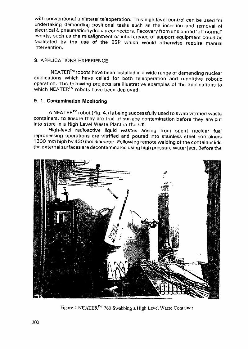
with conventional unilateral teleoperation. This high level control can be used forundertaking demanding positional tasks such as the insertion and removal ofelectrical & pneumatic/hydraulic connectors. Recovery from unplanned 'off normal'events, such as the misalignment or interference of support equipment could befacilitated by the use of the BSP which would otherwise require manualintervention.
9. APPLICATIONS EXPERIENCE
NEATER™ robots have been installed in a wide range of demanding nuclearapplications which have called for both teleoperation and repetitive roboticoperation. The following projects are illustrative examples of the applications towhich NEATER™ robots have been deployed.
9. 1. Contamination Monitoring
A NEATER™ robot (Fig. 4.) is being successfully used to swab vitrified wastecontainers, to ensure they are free of surface contamination before they are putinto store in a High Level Waste Plant in the UK.
High-level radioactive liquid wastes arising from spent nuclear fuelreprocessing operations are vitrified and poured into stainless steel containers1300 mm high by 430 mm diameter. Following remote welding of the container lidsthe external surfaces are decontaminated using high pressure water jets. Before the
Figure 4 NEATER™ 760 Swabbing a High Level Waste Container
200

containers can be taken out of the vitrification plant and placed in a shielded storethey must be checked to ensure they are free from surface contamination. Withvery high radiation levels (approx. 103Gy.hr-1 at the container surf ace) and surfacetemperatures of up to 300°C this contamination checking must be carried outremotely. To ensure consistent coverage of each container surface the process ofmanipulating a swab over the entire container surface is automated.0
The swabbing facility is a key element in the operation of this VitrificationPlant. Any breakdown which could not be rectified quickly may lead to a temporaryshutdown of the Vitrification Plant with serious production and cost implications.This system was installed in May 1991 and has been operational for over 7,000hours. Over 500 containers have been processed by the facility. During theseoperations approximately 10 man.days per year have been required to maintain therobot. Current estimates of the total integrated dose significantly exceed theoriginal specification of 1 MGy.
9.2. D&D of Gloveboxes
Over two hundred plutonium-contaminated gloveboxes have been taken outof service by UKAEA, and require long-term disposal. Because waste disposal costsscale with waste volume, and disposal sites set restrictive conditions on the sizeof packages for disposal, there is a requirement to cut up these boxes and packthem into standard 200 liter disposal containers. Traditionally, this task has beenundertaken manually by pressurized suit workers deploying hand tools. Thisapproach is highly labor-intensive and is not without risk. The packing densityachieved by this technique is typically not very high. A cost/benefit analysisrevealed that it was more cost effective to decommission these gloveboxesemploying telerobotics.
A NEATER™ 760 forms the basis of the system designed to complete thedecommissioning of the gloveboxes. Operators control the telerobot in real-timeusing twin joysticks. A range of cutting and handling tools are deployed to sizereduce the gloveboxes. A stereoscopic TV system has been installed to complimentthe limited direct viewing available. The equipment was retro-fitted to a heavilycontaminated pressurized suit area.
This system was installed in September 1992 and is nearing the completionof the glovebox decommissioning programme. The system has been operational forover 1,200 hours. During this time two entries into the pressurized suit area havebeen required for maintenance and repair operations.
10. CONCLUDING REMARKS
The demanding requirements of nuclear applications dictate that specificdesign criteria need to be addressed which are not appropriate in normal industrialsettings. These include an emphasis on ease of maintenance in contaminated areas,an ability to readily decontaminate equipment and radiation tolerance. These criteriaare, of course, in addition to the requirements of reliability and functionality whichcut across industries. AEA has capitalised on proven robot technology, as far aspossible, which is available from industry and effectively adapted it for use withinnuclear environments.
201

11. ACKNOWLEDGEMENTS
The majority of work reported in this paper has been funded from AEA'sinternal investment program. The development of the seventh axis joint module and7-axis kinematic module are funded partly by the CEC through its TELEMANprogramme and partly by the UK Department of Trade & Industry through itsDRAWMOPS programme. Further support for this work on the development of7-axis arm kinematics software to interface BSP Joystick has been provided byBNFL and by INSYS Ltd as partners in the TELEMAN programme.
BIBLIOGRAPHY
KERSHAW, K., "NEATER Robot carries out remote contamination monitoring of HLVitrified Waste Containers", Remote Techniques for Nuclear Plant, (Proc. Conf.London, 1993) BNES, London, (1993).ELOSEGUI, P., HUNTER, B., LAU, H., and BROWN, M., "Robot Force Control ingNuclear Applications", EURISCON '94 (Proc. Conf.) Malaga, Spain, August 1994,(1994)SIVA, K. V., FISCHER, P. J., HUNTER, B., and BROWN, M. H., "Six axis inputdevice for telerobotic applications", Remote Techniques for Nuclear Plant, (Proc.Conf. London, 1993) BNES, London, (1993)
202

COMPUTER SOLID MODELING DESIGN FOR REMOTE FUELHANDLING OPERATIONS AT THE IDAHO CHEMICALPROCESSING PLANT
D.T. CLARK, F.C. TRAXLERIdaho Chemical Processing Plant,Idaho National Engineering Laboratory,Lockheed Idaho Technologies Company,Idaho Falls, IdahoUSA
Abstract
During an underwater video inspection of nuclear fuel at the Idaho Chemical ProcessingPlant (ICPP) several corroded aluminum cans containing nuclear fuel were observed. Special remoteequipment was needed to recover and repackage the fuel. The use of three dimensional computersolid modeling at the ICPP has improved the ability to verify operational processes concurrent withthe design. The workstation based software supports a concurrent engineering approach for design,analysis, and drafting. The system allows building of all interfacing components, performingtolerance stackups, and animating through the planned operation. Use of the computer built modelshas resulted in rapid resolution of concepts relative to fabrication, function, operation, safety, andtraining. Physical mockups are used for final verification and operator training. The mockups werefabricated from sketches derived directly from the solid models. This fuel recovery overviewprovides a graphic example of the advantages of designing, building, and testing the remotehandling equipment at the workstation prior to fabricating and using actual mockups in the field.The entire recovery was completed in six months, largely due to the improved engineering andteamwork approaches. The ICPP engineering staff has completed several major design efforts whichhave used solid modeling. The system has been used for over 90 designs.
1. COMPANY BACKGROUND
The Idaho Chemical Processing Plant (ICPP) is a part of the Idaho NationalEngineering Laboratory (INEL). The plant's mission is to receive, store, and preparespent nuclear fuels and radioactive wastes for disposition for the Department ofEnergy (DOE).
2. NUCLEAR FUEL PROBLEM
At the end of October of 1993, during an underwater video inspection ofspent nuclear fuel at the ICPP, several severely corroded aluminum cans containingnuclear fuel were observed. After exhaustive review of the inspection videos, itbecame apparent that the nuclear fuel needed to be removed from its presentcorrosive condition and put into a stable storage environment.
The nuclear fuel in question was from the Systems for Nuclear AuxiliaryPower (SNAP) program, which began in 1955. The Air Force wanted to developlightweight power plants that could operate in space by using small nuclearreactors to generate heat for electricity. Early in the program the project wascancelled. The rest of the SNAP fuel was sent to the ICPP for reprocessing -- notfor long term storage. The fuel, however, remained in underwater storage at twoof ICPP water basin facilities for over 25 years. The SNAP fuel was stored onhangers and in racks. This paper addresses the fuel that was stored in racks.
In mid-November, 1993, several employees from a broad spectrum of ICPP
203

I—beams ——— —____~——— Rack Ports
FIG. 1. Cut-away view of SNAP Fuel Storage Rack.
organizations participated in a four-day Value Engineering (VE) session tothoroughly study the problem and identify the best method for safe recovery of theSNAP fuel.
The noncorrosive SNAP type fuel was in the form of various length rods thatranged from approximately 1.37 cm to 3.18 cm in diameter. The SNAP fuel rodswere stored in two types of highly corrosive aluminum cans, but the configurationof most concern was that of a 10.16 cm Outside Diameter (OD) and 9.55 cmInside Diameter (ID) can (0.305 cm wall thickness pipe) which exhibited the mostcorrosion damage. The SNAP fuel and can, weighing up to 13 kg (dry weight),resided in several ports of two 160 cm high aluminum fuel storage racks locatedon the bottom of a 6.1 m water basin. The rack contained several ports (16.83 cmOD, 15.41 cm ID, 0.71 cm wall thickness pipe) that were aligned in rows, asshown in Fig. 1. Each rack port row was centered on top of a 10.16 cm I-beamand secured together with plate material. With the rack ports on the I-beams in thisconfiguration, there were two "crescent" shaped openings of approximately 2.54cm at the widest point at the bottom of each rack port.
If the 10.16 cm SNAP fuel can was centered within its 15.41 cm ID rackport, there would be only 2.63 cm of clearance between each structure wall. Evenif the 10.16 cm SNAP fuel can was positioned against the rack port wall, only 5.25cm of clearance was left to perform recovery functions. There was a concern thatif any "retrieval tool" were lowered over and bumped into the SNAP fuel canprematurely, the can could possibly disintegrate and spill the SNAP fuel rods fromits container. Those fuel pins with diameters equal to or less than 2.54 cm couldthen slip through the port bottom openings and onto the basin floor. Once the fuelrods were under the rack and on the basin floor, it would be very difficult (if notimpossible) to retrieve them without moving the rack itself.
204

Containment Pan
Retrieval Sleeve
Fuel Storage Rack
8346-16(11-3-94)
SNAP Fuel Can
Decoupler Sleeve
SNAP Fuel Recanning ProcessFIG. 2. Retrieval Sleeve removing SNAP fuel cans.
2.1. SNAP Fuel Retrieval Plan-of-Action
Results of the VE session included a two-phase plan to retrieve the SNAPfuel and an aggressive schedule to achieve each aspect of the recovery operation.The first phase installed a minimum number of "Decoupling Sheaths" in carefullyselected rack ports. The Sheaths were placed between the SNAP fuel can and itsrack port and minimized the risk of criticality before and during the SNAP Recoveryphase.
The second phase involved retrieving the SNAP fuel and repackaging it intonew storage cans. The retrieval and repackaging process of a single SNAP fuel canwas completed in a few steps. First a "Containment Pan" was placed on top of thefuel storage rack over a designated fuel port, as shown in Fig. 2. The purpose ofthe Pan was to contain anything which might spill into other ports or onto the basinfloor when the SNAP fuel was retrieved. It served as a small repackaging station.
205

Next "Port Plugs" were installed, through adjacent empty rack ports, to block thecrescent shaped openings at the bottom of SNAP fuel ports, as shown in Fig. 3.The Port Plugs prevented SNAP fuel rods from falling onto the basin floor if a SNAPfuel can ruptured during recovery efforts. Once the Port Plugs were in place, a"Retrieval Sleeve" was lowered into the port position and the SNAP fuel can wasretrieved to the Containment Pan, as shown in Fig. 2. Last, the SNAP fuel can wassecured in a new stainless steel can and moved to another fuel storage rack withinthe water basin area. The SNAP fuel can retrieval process was repeated until all 26corroded cans were repackaged and were secured in safe storage.
3. SNAP RETRIEVAL & SUPPORT TOOL DESIGN
The task of designing and engineering the new equipment and tools tosupport the SNAP fuel recovery effort was aggressively pursued by the ICPP FuelStorage Design (FSD) organization. Thirteen new tool and storage equipment designconfigurations (repackaging pan, fuel handing tools, hooks, storage cans, andmore) were completed by fewer than 10 engineers during a three-month timeperiod. The majority of the design work was completed using FSD's Solid-Modelingand Finite Element Analysis (FEA) engineering workstation system. Two of themore difficult tool designs, the Port Plugs and Retrieval Sleeve, would have beennear impossible to complete on schedule without the aid of solid modeling.
Rack Ports
FIG. 3. Port Plug design at bottom of Rack Ports.
206

Top flange
of I-BEAMS
4.53FIG. 4. Layout of Port Plug Design and SNAP Fuel Storage Rack,
(All dimensions are in centimeters.)

3.1 Port Plug Design
The Port Plug design was used to block the crescent shaped openings at thebottom of the SNAP fuel ports. In the event a SNAP fuel can collapsed during therecovery process, the Port Plugs would prevent any fuel rods from falling onto thebasin floor. The Port Plug design faced several challenges. The design criteria forthe Port Plug called for a device that would cover the port openings such that thesmallest 1.37 cm diameter SNAP fuel rod could not fall past it, while providingenough elastic strength to support a free-fall impact of the largest 3.18 cmdiameter rod without compromising the 1.37 cm opening. This device had to beinstalled through an empty port adjacent to a SNAP fuel port, approximately 10.16cm away. The device had to be self-aligning from 7.6 meters away, since theviewing of the crescent shape opening stoppage could not be seen because thecovering plug portion of the design would be under the SNAP fuel port. Once theSNAP fuel can was retrieved, the device had to be removed and reused for the nextSNAP fuel setting.
Perhaps the biggest challenge of the Port Plug design was to determine howto begin. This was accomplished by using solid modeling to capture the geometricalboundaries of the working environment for the design. As shown in Fig. 4, a smallportion of the fuel storage rack area was modeled to include a "fuel" rack port andan adjacent "empty" rack port. The two rack ports were modeled so that they weregeometrically related with minimum and maximum tolerances applied from rackdrawings. The positions of the rack ports, relative to the I-beams, determined thesize of the crescent shaped openings. The empty rack port position determined thesize of opening the Port Plug had to get through and the fuel rack port positiondetermined the size of opening that needed covering. Dimensional variations of rackport positions created crescent shaped opening widths that ranged from 1.91 cmto 3.18 cm.
The rack ports and I-beams configuration was governed by six independentvariables and any configuration could conceivably be encountered when installingthe Port Plug design. By adjusting the geometrical-related solid model of the rackports, the worst-case tolerance stackups were defined which then captured thedesign envelope of the Port Plug and identified unique functional requirements. Thecircle, shown in Fig. 4., represented the smallest SNAP fuel rod that cannot escapethe Port Plug coverage. By iterating through the worst-case rack port and I-beamassembly tolerance conditions and determining compliance with all other designcriteria, the covering plug optimum shape was defined. Once the covering pluggeometry was determined, the remaining components of the Port Plug design andother supporting equipment (ie. Locking Device, Installation Tool, etc.) weredesigned based on other dimensional tolerance conditions using solid modeling.
3.2 Retrieval Sleeve Design
The Retrieval Sleeve function was to retrieve the SNAP fuel can from itspresent corrosive storage environment after installation of the Port Plugs. Thisdesign was developed with the use of solid modeling as well. The design criteriafor the Retrieval Sleeve was also challenging. The device was to fit inside the rackport ID and contain the 10.16 cm diameter fuel can, without touching the canduring installation. If the SNAP fuel can was positioned over one of the rack portcrescent shaped openings, the device was required to move the fuel can so thatthe can would be centered on the I-beam and provide assistance to the Port Plugs
208

in blocking the rack port openings. The retrieval device had to provide a riggingpoint to pick up the fuel can and ensure containment of the fuel rods should thealuminum can rupture. The device needed to interface with the containment pan,the new storage can, and be as light as possible to minimize the overall weight(Retrieval Sleeve and SNAP fuel can) which the Operators would have to manuallylift.
With the aid of solid modeling, the Retrieval Sleeve design met all criteria.The Retrieval Sleeve interfaces (ie. rack port, 10.16 cm fuel can, containment pan,new stainless steel storage can) were geometrically modeled with worst-caseclearance tolerances, and the design volume of the new design was defined. TheRetrieval Sleeve design approach used solid modeling to iterate quickly andaccurately through complex strength and mass property computations until theoptimal design was attained. The recovery process using the Retrieval Sleevedesign was animated with solid modeling and potential collisions, interferences, andproblem areas were identified and resolved. The final Retrieval Sleeve design, asshown in Fig. 5, was light in weight and easily manipulated, but also delivered thenecessary strength to withstand its design load.
3.3 Solid Modeling Designs
All of the designs completed with solid modeling functioned well with onlyminor enhancements during fabrication and testing. Because solid modeling was
Bottom DoorRelease
SleeveSide Door
fig. 5 RetrievalSleeve Design
Bottom Door
FIG. 5. Retrieval Sleeve Design.
209

used, tolerance stackups and interference studies were performed and theoperation of the designs was animated through the planned operations. Thefabrication of all new tool and storage designs occurred without any significantproblems or stops. All the parts fit as they were designed to fit. All mockupconstruction was fabricated from sketches derived directly from the solid models.After testing, no significant changes to the mockup designs were required.
4. TEAMWORK
Design, fabrication, testing, training, and the nuclear fuel recovery wascompleted in May 1994, six months from the time the corrosion problem wasdiscovered. Fuel handling operators, design and system engineers, safety analysts,procedure writers, and ICPP and DOE management personnel worked together tomake the operation a success. John T. Conway, Chairman for Defense NuclearFacilities Safety Board (DNFSB) wrote a letter to Thomas P. Grumbly, AssistantSecretary for Environmental Management, DOE, where he gave the teamwork efforthigh recognition by applauding the ICPP and DOE-ldaho staff and commended themfor "overseeing this effort on their safe operation."
4.1 Team Member — Solid Modeling
Solid modeling served as a major "player" and important tool in the SNAPfuel recovery operation. Throughout the design and during the follow-up efforts,the solid models not only were used for design, but also were used to defineoperation processes and operator training, perform safety analyses, and provideaccurate illustrations for intermediate and final reports.
A significant contribution the solid modeling tool provided was to help theSNAP Recovery Team eliminate problems associated with communication. Thesharing of technical ideas between disciplines and people was enhanced. The solidmodels were used in design reviews, meetings with craftsmen, quality assurance,procurement, operations, and served to keep upper management and DOE informedof progress and problems. The solid models became the base-line of almost everyfunction. By increasing the involvement and stream-lining the effort of otherdisciplines, traditional conventions of the design process were shaken. Instead ofperforming distinct disciplines in a sequential manner (ie. design, drafting, analysis,fabrication planning, procedure preparation, training, etc.) the new fuel handlingdesigns and operation processes were performed in parallel. At the conceptualdesign phase, fabrication, operation processes, material procurement, etc., dictatedthe design. Therefore, when the designs were fabricated and put into use, therewere no surprises in construction or in function. Solid modeling served as a catalystto a very dedicated and committed team and became the very heart of the SNAPfuel recovery "concurrent engineering" effort.
5. SOLID MODELING AT ICPP
The SNAP fuel recovery effort was an important milestone for using solidmodeling at the ICPP. ICPP engineering has used solid modeling in over 90 designs,starting in 1992. The SNAP fuel recovery operation provided the visibility to gainacceptance of the approach. Since the SNAP fuel recovery effort, solid modelinghas become a standard design practice at the ICPP and continues to provide thecentral theme of "team work" and promote "concurrent engineering" practices.
210

VISUAL INSPECTION OF UNDERWATER SPENT NUCLEAR FUEL
D.C. WELLSLockheed Idaho Technologies Company,Idaho Falls, USA
AbstractThere are many challenges associated with visual inspection of spent nuclear fuel stored in
water. Two of the biggest challenges are high radiation fields and the old adage "water andelectricity don't mix." Two and one half years ago underwater inspections in nuclear fuel storagefacilities were started at the Idaho National Engineering Laboratory. Systems have been operatedaround the clock for several months at a time. Camera systems have been exposed to radiationfields in excess of 10,000 grey per hour and have cumulative doses of several thousand grey. Thevideo systems are crucial for fuel identification, repackaging, mechanical fastener verification,nondestructive examination probe placement and to examine the amount of corrosion to fuel cansand storage racks. Several camera systems fabricated from commercially available components areutilized in the underwater storage facilities. These include: the Rod camera, for steady pictures 7meters deep in the water through a 1 centimeter crack in the floor; the Puppet camera, for closeshots in buckets or rack ports; the Video Probe, for inspecting fuel cans in their storage position;and the Phantom II, submersible vehicle for visual information and parts retrieval. Waterproofingsystems for field deployment provides many learning opportunities. 0-ring placement, pressurizedhousings, hermetically sealed connectors and silica gel contribute to successful visual inspectionsin water. Radiation effects were as expected, browning of the camera lens and fiber optics as wellas the noise seen in the picture due to radiation bombarding the electronics inside the solid statecamera. The waterproof housing provided excellent shielding for the camera system. The camera'sorientation to the fuel and the amount of lighting also play an important part in reducing radiologicaldegradation of the video picture.
1. IDAHO CHEMICAL PROCESSING PLANT
The Chemical Processing Plant (CPP) is operated by Lockheed IdahoTechnologies Company for the United States Department of Energy. Located insoutheast Idaho the CPP began constructing facilities to store and reprocess spentnuclear fuel during the 1950's. Since this time many modern facilities have beenconstructed to replace old, crowded structures.
2.1. Fuel Storage
Many different types of spent nuclear fuel are stored at the CPP including:private power reactor fuel, Department of Energy experimental fuel, and militaryfuel. Some of the fuel is stored in a dry air environment, but the majority is storedunderwater. Regardless of the storage location, the fuel is placed in a can or basketto aid in remote handling.
2. 7.7. Old Storage BasinsThe old fuel storage facility (CPP-603) contains three basins for underwater
storage of spent fuel as well as a loading pool and a transfer channel with acumulative water volume of 5.68 Megaliters.
Both the north and middle basins are 20 meters long, 10 meters wide and7 meters deep. These basins use an overhead monorail system to hold yokes(hangers) which suspend baskets of fuel in the water (Fig. 1.) A fiberglass floor
211

9391-2(11-94)
Figure 1CPP-603 Middle Basin Fuel Basket/Yoke Assembly
grating covered with aluminum clad lead plates is supported above the water.Nearly 1000 fuel units can be stored in each basin.
In contrast, the south basin is an open pool with access to all areas providedby a motorized bridge crane spanning the pools width. This pool uses submersedracks, such as those in Fig. 2., to contain canned fuel. Nearly 8000 fuel units canbe stored in this massive 30 meter long, 15 meter wide, 7 meter deep pool.
2.1.2. New Storage BasinsBuilding CPP-666 houses a new fuel storage basin containing six fuel storage
pools, a transfer channel, two isolation pools, and two unloading pools. Anoverview of the pool area is shown in Fig. 3. Freestanding stainless steel racks areused to store the fuel. Each fuel storage pool is 20 meters long, 10 meters wide,and 10 to 13 meters deep. The facility holds over 13.25 Megaliters of water.
2.2. Challenges
The major challenges for performing inspections in the fuel storage pools arehigh radiation levels and limited space for maneuvering the camera systems.
Radiation levels of the fuel vary from 3 Gy to 10 kGy per hour depending onthe age and type. In areas requiring detailed examination of materials, the cameramust be placed within millimeters of the fuel.
212

toh-*U)
Figure 2CPP-603 South Basin Fuel Rack

Figure 3CPP-666 Fuel Storage Pools
While performing inspections in the north and middle basins of CPP-603 theinspection system must be deployed through small slits 4 centimeters wide in thesupported floor which were designed for moving the fuel hangers throughout thebasin. When maneuvering auxiliary equipment around hangers, the clearance isreduced to less than 1 centimeter.
In the CPP-603 south basin fuel racks, storage ports are 15.25 cm indiameter. Cans stored in the ports have a diameter of 12.7 cm. The resultantaccess to the cans side is an annulus void 1.275 cm wide. Annulus size variesslightly based on the amount of corrosion and placement of the fuel can within theport. To compound the challenge personnel are 6 meters above the annulus whileoperating equipment from the bridge crane.
An additional challenge is provided by the water itself. Because of water'scorrosive and electrically conductive properties it can be difficult to operatesubmersed electronic equipment.
214

3. CAMERA SYSTEMS
Four basic types of camera systems fabricated from commercially availableparts have been installed throughout the basin areas. Each system has a uniquefeature which was exploited to ensure quality pictures were obtained in everycircumstance.
3.1. Puppet Camera
Examination of fuel hangers, buckets, and cans in the CPP-603 middle basinrequired fabrication of a camera inspection system. The original intent was tofashion a system quickly from available equipment. A remote head, color CCDcamera with a fixed focus lens was encased in a small plastic flashlight housing.This "water-proof housing" was supplied by a camera system vendor. Siliconrubber was used to seal the rear of the housing around the camera cable. Thisassembly was inserted in a small piece of stainless steel pipe to increase theweight. Tactile feedback to the operator and assurance the system would sink weregained from the extra weight. A cross section view of this system is shown inFig. 4. This system was used successfully for several days but was eventuallydestroyed when a small amount of water entered the housing.
Position control of the puppet camera comes from hand manipulation of awire rope attached to the front of the housing and the electrical cable connectedto the rear of the housing. This is roughly the same as animating a marionettepuppet.
Concerned that a system more robust than a plastic flashlight housing wasneeded we decided to construct our own housing. The second camera systemutilized an aluminum housing in place of the plastic flashlight body and a wedge-shaped donut to seal around the camera cable. Obtaining a waterproof seal around
Viewing Window Electrical Connector-Camera and Lens
Plastic "Flashlight" Housing
Figure 4Original Puppet Camera Cross Section
215

the electrical cable proved to be very difficult. Inconsistent cable diameter anduneven compression of the interior wires make the seal unpredictable.
One of the most difficult leaks to diagnose involved the cable. As theoperators moved from storage position to storage position the cable would rubagainst the floor grating cutting through the outer insulation. When the cut sectionwas lowered back in the water, water would flow in the cut and run down thecable jackets interior to the housing, damaging the camera electronics. Thesecircumstances dictate the preferred sealing method is to use a waterproof(hermetically sealed) connector mounted directly to the camera housing and a cableassembly with a stronger outer jacket. If a connector is not used to isolate thecamera from the housing you are forced to maintain a sealed system that is severalmeters long rather than maintaining a seal on a small housing only a fewcentimeters in length.
Sealing the viewing window was accomplished with an 'O'-ring placed onthe shoulder of the aluminum housing. A better and more reliable seal can beobtained by placing the 'O'-ring around the body of the housing. With thisconfiguration the housing face does not have to be physically tight to create a seal.
wire RopePower and Video Cable
Electrical Connector
-----Stainless SteelHousing
Camera Lens
Miniature Lights
Figure 5Final Puppet Camera
216

Many small problems culminated in an unreliable system. Although concernfor the fuel's condition dictated demanding time constraints, the original systemswere built upon a poor concept. While the system allowed us to quickly andcheaply meet the immediate concerns, it was clear that a more robust and reliablesystem was needed if underwater video inspection were to continue.
The final version of the puppet camera, shown in Fig. 5. is a vendor supplied30 millimeter diameter stainless steel housing 20 centimeters long, containing aminiature color CCD camera with a fixed lens surrounded by a ring of eightminiature lights. A non-browning quartz viewing window is glued to the front of thehousing and the back end contains a hermetically sealed connector for the electricalconnections.
When placed near spent fuel, some picture degradation occurs in the formof snow (random noise) in the picture. When the camera is facing the fuel theeffect is less noticeable than if the camera is perpendicular to the fuel.
3.2. Overview Camera
Standard manufacturer components were assembled and placed on the endof a long reach rod to create the overview camera system. It is a color solid statecamera with a remotely controllable 6:1 zoom lens encased in a waterproof housingwhich is mounted to a pan and tilt. Two 250 watt quartz halogen lights inwaterproof housings provide illumination for the camera. Multiple lights are usedfor redundancy; not increased illumination.
If the housing has any free air space it is filled with silica gel. The gel willadsorb moisture caused by condensation or from very small leaks in the camerahousing.
A color camera was chosen again because of the additional corrosioninformation gained from the color picture.
3.3. Video Probe
Condition assessment of the fuel cans in the south basin fuel racks requiresphysical access in to the 1.275 cm annulus between the can and rack. For this taska commercially available fiber optic video probe with a pneumatically articulated tipwas chosen.
Because operators are 7 meters above the rack while trying to insert thevideo probe in the small crack, this inspection process is very tedious and difficult.To assist the operators inserting the probe in to the annulus, the video probe wasincased in stainless steel tubing. Additional physical protection for the probe wasalso realized by using the tubing. These engineered changes to the probe causeda dramatic increase in the weight and made deployment of the tool in to the watervery difficult. The second generation system, currently being designed, will utilizean X-Y-Z table set directly on the rack to position the probe tip.
The video probe is the system most susceptible to physical damage as wellas radiation effects. Illumination for the video imaging chip is provided through abundle of optical fibers. Because the probe is oriented parallel to the fuel elementsa large length of the optical fiber is exposed to the radiation field. While any oneportion of the fiber may receive a small dose and brown slightly, the cumulativeeffect to the fiber is significant. Each portion of the fiber that has brownedattenuate the light. Attenuation of the light as it travels through the fiber increasesat a logarithmic rate.
217

Figure 6Submersible Remotely Operated Vehicle
Radiation noise, or snow, in the video picture is most prevalent when usingthe video probe. Ambient light levels have a dramatic affect on the amount of snowin the picture. When a slightly damaged video probe is placed in a 3 Gy per hourfield the resultant video picture is undistinguishable. If an external light source isused to provide additional illumination the picture becomes acceptable. Thisadditional illumination increases the electrical potential within the video imagingchip causing the energy added from the radiation source to have less effect.
3.4. Submersible Remotely Operated Vehicle
The largest system used to examine spent nuclear fuel in water is theSubmersible Remotely Operated Vehicle (SROV). Fig. 6 shows the SROV andcontrol console. Procured from a commercial vendor as a semi-custom system theSROV is narrow enough to fit between the fuel hangers in the north and middlebasin. Although the system is physically capable of operating m the CPP-603basins it has never been used in this facility. Operation of the SROV has beenrestricted to the new fuel storage facility (CPP-666). Safety concerns related to thetether cable disturbing spent fuel or breaking fuel hangers is the most importantreason the SROV is not used in the old facility. Sediment in the bottom of the
218

basins would be disturbed by the turbulence from the SROV's impellers making thewater cloudy enough to blind the camera system.
A rotate and pinch gripper arm was installed on the SROV to aid in retrievingforeign material from the pool. In addition to the up/down, and forward/reversethrusters, there is a pair of thrusters for turning the vehicle left and right or whenrun in unison the thruster will propel the vehicle laterally left or right. This is usefulfor following long weld beads along the wall or floor.
Some minor problems occurred as a result of operating a vehicle designedfor use in salt water in a nuclear environment. Although the vehicle was designedto be zero buoyant it slowly sinks in the pool, this can be overcome by the verticalthruster. Stainless steel lining in the pool disorients the magnetic compass.
4. SUMMARY
Although one of the systems discussed was constructed in-house to fulfilla critical time commitment, the remainder of the systems used are commerciallyavailable from reliable vendors. The reliability of these systems is very reasonable.Cost of the systems versus in-house fabrication falls in favor of commercialvendors. Our most cost effective approach to inspection systems is to mate non-related technologies together to form an application specific solution. Only thoseparts required to interface components or parts not commercially available arefabricated on site.
Radiation hardened camera systems definitely withstand a higher cumulativeexposure and are less susceptible to radiation interference than solid state camerasystems. However, if the application involves repeated movement of the camerasystem, especially by multiple personnel, then the system will become physicallyworn out or damaged before radiation exposure has ruined the camera. This makesthe higher cost of the radiation hardened camera difficult to justify.
219

LIST OF PARTICIPANTS
BelgiumDecreton, M. Research Division of CEN-SCK
Boeretang 200B-2400 Mol
FranceBaillif, L. NUSYS
9, Rue C. ColombF-75008 Paris
Latour, P. At-NutechImmeuble Campus B6, rue Jean-Pierre TimbaudF-78182 St. Quentin Yvelines Cedex
Thiebaut, B. Electricité de France35-37 Rue Louis Guerin, BP 1212F-69611 Villeurbanne Cedex
GermanyJung, R. GNS Gesellschaft für
Nuklear-Service mbHLange Laube 7D-30159 Hannover
Peehs, M. Siemens AG, KWU/BPP.O.Box 3220D-91058 Erlangen
indiaRamakumar, M.S. Bhabba Atomic Research Centre
Trombay,Bombay 400 085
Republic of KoreaKim, E.K. Korea Atomic Energy Research Institute
P.O.Box 105Yusong, Taejon 305 - 600
Lee, J.S. Korea Atomic Energy Research InstituteP.O.Box 105Yusong, Taejon 305 - 600
221

Russian FederationMakartsuk, T. F. All Russian Design and Scientific
Research Institute of Complex PowerTechnology(VNIPIEhT)Dibunovskaja Street 55197228 Saint Peterburg
SwedenPettersson , B. Swedish Nuclear Power Inspectorate
P.O.Box 27106S-10658 Stockholm
United KingdomCarter, C.C. GEC Alsthom Engineering Systems Ltd.
Cambridge Road, WhetstoneLeicester, LES 3LH
Lewis, D.H. AEA TechnologyHarwell, DidcotOxfordshire OX11 ORA
Thomson, J.R. Scottish Nuclear Limited3, Redwood CrescentPeel Park,East Kildbrid, G74 5PR
Webster, D.A. BNFLRisley, WarringtonCheshire WAS 6AS
USABennett, P.C. Sandia National Laboratories
Intelligent Systems and Robotics Center,Dept. 1176Albuquerque, New Mexico 87185-1176
Choi, I. Battelle Northwest LaboratoriesBattelle Boulevard, P.O.Box 999, MS K2-15Richland, Washington 99352
Eble, R. Duke Engineering and Services Inc.2650 Park Tower Dr.Vienna, VA 22180
222

Gilligan, B. Newport News Shipbuilding4101 Washington AvenueNewport News, VA 23607USA
Palmquist, R.D. Sandia National LaboratoriesIntelligent Systems and Robotics CenterDept. 2151Albuquerque, New Mexico 87185
Rio, R. Foster-Miller, Inc.350 Second Avenue, Building 2Waltham, MA 02154-1196
Stewart, L. Office of Civilian RadioactiveWaste Management, RW-40 - DOE1000 Independence Avenue, S.W.Washington, DC 20585
Stitzel, J.D. Newport News Shipbuilding4101 Washington AvenueNewport News, VA 23607-2770
Taylor, S.C. Idaho National Engineering Laboratory(INEL)P.O.Box 1625Idaho Falls, ID 83415-2114
Tjersland G. Nuclear Assurance Corporation655 Engineering DriveSuite 200Norcross, Georgia 30092
Traxler, F.C. Lockheed Idaho Technologies Company(LITCO)P,.O.Box 1625 MS5106Idaho Falls, ID 83415-5106
Wadsworth, D.C. Idaho National Engineering Laboratory(INEL), Lockheed Idaho TechnologiesCompany (LITCO)P.O.Box 16251955 Fremont AvenueIdaho Falls, ID 83415
223

Wells, D.C. Idaho National Engineering Laboratory(INEL), Lockheed Idaho TechnologiesCompany (LITCO)P.O.Box 1625, MS 52351 955 Fremont AvenueIdaho Falls, ID 83415
IAEATakéts, F.(Scientific Secretary)
Nuclear Materials and Fuel CycleTechnology SectionDivision of Nuclear Fuel Cycle andWaste ManagementP.O.Box 100Wagramerstrasse 5A-1400 Vienna, Austria
224

QUESTIONNAIRE ON IAEA-TECDOCs
It would greatly assist the International Atomic Energy Agency in its analysis of the effective-ness of its Technical Document programme if you could kindly answer the following questionsand return the form to the address shown below. Your co-operation is greatly appreciated.
Title: Remote technology related to the handüng, storage and disposal of spent fuelNumber: IAEA-TECDOC-842
1. How did you obtain this TECDOC?
[ ] From the IAEA:[ ] At own request[ ] Without request[ ] As participant at an IAEA meeting
[ ] From a professional colleague[ ] From library
2. How do you rate the content of the TECDOC?
[ ] Useful, includes information not found elsewhere[ ] Useful as a survey of the subject area[ ] Useful for reference[ ] Useful because of its international character[ ] Useful for training or study purposes[ ] Not very useful. If not, why not?
3. How do you become aware of the TECDOCs available from the IAEA?
[ ] From references in:[ ] IAEA publications[ ] Other publications
[ ] From IAEA meetings[ ] From IAEA newsletters[ ] By other means (please specify)[ ] If you find it difficult to obtain information on TECDOCs please tick this box
4. Do you make use of IAEA-TECDOCs?
[ ] Frequently[ ] Occasionally[ ] Rarely
5. Please state the institute (or country) in which you are working:
Please return to: R.F. KelleherHead, Publishing SectionInternational Atomic Energy AgencyP.O. Box 100Wagramerstrasse 5A-1400 Vienna, Austria