Haemonetics ACP™215 Automated Cell Processing System ... · 0123 Haemonetics® ACP™215...
45
0123 Haemonetics ® ACP™215 Automated Cell Processing System – Operation Manual – Printed in France Haemonetics Corporation 400 Wood Road, Braintree, MA 02184, USA P/N 85271-30, Manual revision: C ©2003, Haemonetics International. All rights reserved. January 2003
Transcript of Haemonetics ACP™215 Automated Cell Processing System ... · 0123 Haemonetics® ACP™215...

0123
Haemonetics® ACP™215Automated Cell Processing System
– Operation Manual –
Printed in FranceHaemonetics Corporation400 Wood Road, Braintree, MA 02184, USA P/N 85271-30, Manual revision: C©2003, Haemonetics International. All rights reserved. January 2003

Preface iii
P/N 85271-30, Manual revision: C
CONSUMER INFORMATION
Proprietary rights The contents of this manual are property of the Haemonetics Corporation.Haemonetics® and ACP™215 are registered trademarks of the HaemoneticsCorporation. Any information or descriptions contained in this manual may notbe reproduced and released to any of the general public, or used in conjunctionwith any professional instruction without written consent of Haemonetics Corpo-ration, USA. Please direct any written inquiries to the appropriate address:
International Headquarters Corporate HeadquartersHaemonetics SA Haemonetics CorporationSigny Centre, rue des Fléchères 400 Wood RoadP.O. Box 262, 1274 Signy 2, Switzerland Braintree, MA 02184, USATel. [+41 22] 363 90 11 Tel. [+1 781] 848 7100Fax [+41 22] 363 90 54 Fax [+1 781] 848 5106
Legal disclaimer This manual is intended for use as a guide, uniquely for material as supplied bythe Haemonetics Corporation. It provides the operator with necessary informa-tion to safely carry out specific procedures and satisfactorily maintain Haemo-netics produced equipment. The manual is to be used in conjunction withinstruction and training as supplied by qualified Haemonetics personnel.
Haemonetics guarantees its products when correctly used by a properly trainedoperator. Any failure to respect the procedures as described could result inimpaired function of the equipment, as well as in injury to the operator. Haemon-etics accepts no responsibility for problems resulting from failure to comply withprescriptions as outlined by the company. Any modifications estimated as neces-sary by the customer should be evaluated by a Haemonetics Clinical Specialist.
Safe utilization of Haemonetics material and equipment requires the operator tocorrectly handle and dispose of blood-contaminated material. The operator ofany Haemonetics equipment is responsible for understanding and implementingthe local policies and standard operating procedures concerning the handling ofblood-contaminated material, as well as blood products.
It remains solely the responsibility of the customer to fully assess and ensure thesafety of any products obtained from Haemonetics prescribed procedures, priorto further application or use. Haemonetics declines any responsibility for choicesmade by the customer concerning the utilization of products and by-products.

iv Preface
P/N 85271-30, Manual revision: C
Haemonetics worldwide locations
Haemonetics Asia Inc. Taiwan Branch26F-1, No. 102 Roosevelt Road Sec. 2 Taipei, TaiwanTel. [+886 2] 2369 0722Fax [+886 2] 2364 3698
Haemonetics GesmbHHandelsges.m.b.H.Berlagasse 45/B2-021210 Wien, AustriaTel. [+43 1] 294 29 00Fax [+43 1] 294 29 05
Haemonetics Belgium NVLeuvensesteenweg 542-BP. 14Planet II Complex1930 Zaventem, BelgiumTel. [+32 2] 720 7484Fax [+32 2] 720 7155
Haemonetics BVNaritaweg 16Telestone 81043 BW AmsterdamThe NetherlandsTel. [+31 35] 602 3425Fax [+31 35] 602 4198
Haemonetics Medical Devices(Shanghai) International Trading Co. Ltd.Room 28032, Shanghai HSBC Tower101 Yin Cheng East RoadShangai 200120, PRCTel. [+86 21] 5066 3366Fax [+86 21] 6841 3688
Haemonetics CZ, spol. s r.o.Ptašínského C.860200 Brno, Czech RepublicTel. [+42 05] 4121 2400Fax [+42 05] 4121 2399
Haemonetics France S.A.R.L. 46 bis, rue Pierre CurieZ.I. Les Gatines 78370 Plaisir, FranceTel. [+33 1] 30 81 41 41Fax [+33 1] 30 81 41 30
Haemonetics GmbHRohrauerstrasse 7281477 München, GermanyTel. [+49 89] 785 8070 Fax [+49 89] 780 9779
Haemonetics Hong Kong Ltd. Suite 1314, Two Pacific Place88 Queensway, Hong Kong Tel. [+852] 2868 9218 Fax [+852] 2801 4380
Haemonetics Italia S.R.L.Via Donizetti 3020020 Lainate (MI), ItalyTel. [+39 2] 9357 0113Fax [+39 2] 9357 2132
Haemonetics Japan K.K.Kyodo Building 3F16, Ichiban-cho, Chiyoda-kuTokyo, Japan, 102-0082Tel. [+81 3] 3237 7260Fax [+81 3] 3237 7330
Haemonetics Scandinavia ABBeta Huset, IdeonScheelegatan 17223 70 Lund, SwedenTel. [+46 46] 286 2320Fax [+46 46] 286 2321
Haemonetics (UK) Ltd.Beechwood HouseBeechwood EstateElmete Lane, RoundhayLeeds LS8 2LQ, United KingdomTel. [+44 113] 273 7711Fax [+44 113] 273 4055
Haemonetics SA Signy Centre, rue des FléchèresP.O. Box 2621274 Signy 2, SwitzerlandTel. [+41 22] 363 90 11Fax [+41 22] 363 90 54

P/N 85271-30, Manual revision: C
Table of Contents
Chapter 1 Explaining General InformationProviding an overview . . . . . . . . . . . . . . . . . . . . . . . . . . . . . . . . . . . . . . . . . 1-2
What is the ACP 215 system ? . . . . . . . . . . . . . . . . . . . . . . . . . . . . . . . . 1-2What is the purpose of this manual ? . . . . . . . . . . . . . . . . . . . . . . . . . . . 1-2What is required to perform a procedure ? . . . . . . . . . . . . . . . . . . . . . . . 1-2
Understanding the use of symbols . . . . . . . . . . . . . . . . . . . . . . . . . . . . . . . . 1-3Symbols found in this document. . . . . . . . . . . . . . . . . . . . . . . . . . . . . . . 1-3Symbols found on the device . . . . . . . . . . . . . . . . . . . . . . . . . . . . . . . . . 1-3Symbols found on disposable packaging . . . . . . . . . . . . . . . . . . . . . . . . 1-4
Listing ACP 215 device specifications . . . . . . . . . . . . . . . . . . . . . . . . . . . . . 1-6Dimensions and weight . . . . . . . . . . . . . . . . . . . . . . . . . . . . . . . . . . . . . 1-6Environmental conditions . . . . . . . . . . . . . . . . . . . . . . . . . . . . . . . . . . . . 1-6Power requirements . . . . . . . . . . . . . . . . . . . . . . . . . . . . . . . . . . . . . . . . 1-6
Chapter 2 Presenting the ACP 215 EquipmentDESCRIBING THE ACP 215 CONTROL PANEL. . . . . . . . . . . . . . . . . . . . . . 2-3
Display screen . . . . . . . . . . . . . . . . . . . . . . . . . . . . . . . . . . . . . . . . . . . . 2-3Keypad . . . . . . . . . . . . . . . . . . . . . . . . . . . . . . . . . . . . . . . . . . . . . . . . . . 2-3
DESCRIBING THE ACP 215 CABINET COMPONENTS . . . . . . . . . . . . . . . . 2-4Centrifuge system . . . . . . . . . . . . . . . . . . . . . . . . . . . . . . . . . . . . . . . . . . 2-4Pumps . . . . . . . . . . . . . . . . . . . . . . . . . . . . . . . . . . . . . . . . . . . . . . . . . . 2-5Pressure monitors . . . . . . . . . . . . . . . . . . . . . . . . . . . . . . . . . . . . . . . . . . 2-5Valves. . . . . . . . . . . . . . . . . . . . . . . . . . . . . . . . . . . . . . . . . . . . . . . . . . . 2-6Air detectors . . . . . . . . . . . . . . . . . . . . . . . . . . . . . . . . . . . . . . . . . . . . . . 2-6Optical line sensor . . . . . . . . . . . . . . . . . . . . . . . . . . . . . . . . . . . . . . . . . 2-6Solution bag pole . . . . . . . . . . . . . . . . . . . . . . . . . . . . . . . . . . . . . . . . . . 2-6Power entry module . . . . . . . . . . . . . . . . . . . . . . . . . . . . . . . . . . . . . . . . 2-7Power cord . . . . . . . . . . . . . . . . . . . . . . . . . . . . . . . . . . . . . . . . . . . . . . . 2-7Biohazard waste bag . . . . . . . . . . . . . . . . . . . . . . . . . . . . . . . . . . . . . . . 2-7
DESCRIBING THE SHAKER AND THE PRINTER . . . . . . . . . . . . . . . . . . . . . 2-8Shaker . . . . . . . . . . . . . . . . . . . . . . . . . . . . . . . . . . . . . . . . . . . . . . . . . . 2-8Printer . . . . . . . . . . . . . . . . . . . . . . . . . . . . . . . . . . . . . . . . . . . . . . . . . . 2-9
vi Table of Contents
P/N 85271-30, Manual revision: C
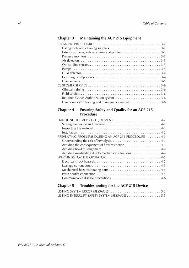
Chapter 3 Maintaining the ACP 215 EquipmentCLEANING PROCEDURES . . . . . . . . . . . . . . . . . . . . . . . . . . . . . . . . . . . . . 3-2
Listing tools and cleaning supplies . . . . . . . . . . . . . . . . . . . . . . . . . . . . . 3-2Exterior surfaces, valves, shaker and printer . . . . . . . . . . . . . . . . . . . . . . 3-3Pressure monitors. . . . . . . . . . . . . . . . . . . . . . . . . . . . . . . . . . . . . . . . . . 3-3Air detectors. . . . . . . . . . . . . . . . . . . . . . . . . . . . . . . . . . . . . . . . . . . . . . 3-3Optical line sensor . . . . . . . . . . . . . . . . . . . . . . . . . . . . . . . . . . . . . . . . . 3-3Pumps . . . . . . . . . . . . . . . . . . . . . . . . . . . . . . . . . . . . . . . . . . . . . . . . . . 3-4Fluid detector. . . . . . . . . . . . . . . . . . . . . . . . . . . . . . . . . . . . . . . . . . . . . 3-4Centrifuge components . . . . . . . . . . . . . . . . . . . . . . . . . . . . . . . . . . . . . 3-4Filter screens . . . . . . . . . . . . . . . . . . . . . . . . . . . . . . . . . . . . . . . . . . . . . 3-5
CUSTOMER SERVICE . . . . . . . . . . . . . . . . . . . . . . . . . . . . . . . . . . . . . . . . . 3-6Clinical training . . . . . . . . . . . . . . . . . . . . . . . . . . . . . . . . . . . . . . . . . . . 3-6Field service. . . . . . . . . . . . . . . . . . . . . . . . . . . . . . . . . . . . . . . . . . . . . . 3-6Returned Goods Authorization system . . . . . . . . . . . . . . . . . . . . . . . . . . 3-6Haemonetics® Cleaning and maintenance record . . . . . . . . . . . . . . . . . 3-8
Chapter 4 Ensuring Safety and Quality for an ACP 215 Procedure
HANDLING THE ACP 215 EQUIPMENT . . . . . . . . . . . . . . . . . . . . . . . . . . 4-2Storing the device and material . . . . . . . . . . . . . . . . . . . . . . . . . . . . . . . 4-2Inspecting the material . . . . . . . . . . . . . . . . . . . . . . . . . . . . . . . . . . . . . . 4-2Installation . . . . . . . . . . . . . . . . . . . . . . . . . . . . . . . . . . . . . . . . . . . . . . . 4-2
PREVENTING PROBLEMS DURING AN ACP 215 PROCEDURE . . . . . . . . 4-3Understanding the risk of hemolysis. . . . . . . . . . . . . . . . . . . . . . . . . . . . 4-3Avoiding the consequences of flow restriction . . . . . . . . . . . . . . . . . . . . 4-3Avoiding bowl misalignment . . . . . . . . . . . . . . . . . . . . . . . . . . . . . . . . . 4-4Avoiding overheating due to mechanical situations . . . . . . . . . . . . . . . . 4-4
WARNINGS FOR THE OPERATOR. . . . . . . . . . . . . . . . . . . . . . . . . . . . . . . 4-5Electrical shock hazards . . . . . . . . . . . . . . . . . . . . . . . . . . . . . . . . . . . . . 4-5Leakage current control . . . . . . . . . . . . . . . . . . . . . . . . . . . . . . . . . . . . . 4-5Mechanical hazards/rotating parts . . . . . . . . . . . . . . . . . . . . . . . . . . . . . 4-5Power outlet connection . . . . . . . . . . . . . . . . . . . . . . . . . . . . . . . . . . . . 4-5Communicable disease precautions . . . . . . . . . . . . . . . . . . . . . . . . . . . . 4-6
Chapter 5 Troubleshooting for the ACP 215 DeviceLISTING SYSTEM ERROR MESSAGES . . . . . . . . . . . . . . . . . . . . . . . . . . . . . 5-2LISTING INTERRUPT SAFETY SYSTEM MESSAGES . . . . . . . . . . . . . . . . . . . 5-5
P/N 85271-30, Manual revision: C
Chapter 1
Explaining General Information
Providing an overview . . . . . . . . . . . . . . . . . . . . . . . . . . . . . . . . . . . . . . . . . 1-2What is the ACP 215 system ? . . . . . . . . . . . . . . . . . . . . . . . . . . . . . . . . . 1-2What is the purpose of this manual ?. . . . . . . . . . . . . . . . . . . . . . . . . . . . 1-2What is required to perform a procedure ? . . . . . . . . . . . . . . . . . . . . . . . 1-2
Understanding the use of symbols . . . . . . . . . . . . . . . . . . . . . . . . . . . . . . . . 1-3Symbols found in this document . . . . . . . . . . . . . . . . . . . . . . . . . . . . . . . 1-3Symbols found on the device . . . . . . . . . . . . . . . . . . . . . . . . . . . . . . . . . 1-3Symbols found on disposable packaging. . . . . . . . . . . . . . . . . . . . . . . . . 1-4
Listing ACP 215 device specifications . . . . . . . . . . . . . . . . . . . . . . . . . . . . . 1-6Dimensions and weight . . . . . . . . . . . . . . . . . . . . . . . . . . . . . . . . . . . . . 1-6Environmental conditions . . . . . . . . . . . . . . . . . . . . . . . . . . . . . . . . . . . . 1-6Power requirements . . . . . . . . . . . . . . . . . . . . . . . . . . . . . . . . . . . . . . . . 1-6
1-2 Explaining General Information
P/N 85271-30, Manual revision: C
PROVIDING AN OVERVIEW
What is the ACP 215 system ?
In the tradition of its innovative technology, Haemonetics has produced theACP 215 - a compact, lightweight, automated cell processing system which issimple to operate.
The ACP 215 system can perform the following types of procedures:
! Prepare collected red blood cell products with glycerol for freezing.
! Deglycerolize thawed red blood cell products, removing extra cellularcomponents, and resuspend the red blood cells in an additive solution.
! Wash red blood cell units stored in commonly used AC and additive solu-tions to remove plasma and extra cellular components.
The ability to process-control the addition and removal of cryroprotectant solu-tion as well as wash banked blood in a closed system significantly improves thesafety and availability of blood products.
What is the purpose of this manual ?
This manual is intended to supply anyone involved in using the ACP 215 equip-ment with information to attain:
! An awareness of the purpose of the device and the implications of itsprocedures.
! An understanding of how to safely operate the system, correctly install theappropriate disposable material, and troubleshoot any difficulties.
! An ability to consistently apply the principles behind safe operation,proper maintenance and correct handling, to ensure optimal results.
What is required to perform a procedure ?
The following material is required to perform an ACP 215 procedure:
! The ACP 215 device, to process the collected red blood cell products.
! A dedicated shaker, to properly mix the blood with procedure-specificsolutions.
! A disposable set designed for the selected procedure.
! Appropriate solutions.
! A printer, to provide the operator with printed procedure data.
! A sterile connection device, to ensure proper tubing welds.
Explaining General Information 1-3
P/N 85271-30, Manual revision: C
UNDERSTANDING THE USE OF SYMBOLS
Symbols found in this document
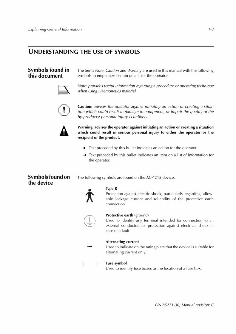
The terms Note, Caution and Warning are used in this manual with the followingsymbols to emphasize certain details for the operator.
Note: provides useful information regarding a procedure or operating techniquewhen using Haemonetics material.
Caution: advises the operator against initiating an action or creating a situa-tion which could result in damage to equipment, or impair the quality of theby-products; personal injury is unlikely.
Warning: advises the operator against initiating an action or creating a situationwhich could result in serious personal injury to either the operator or therecipient of the product.
! Text preceded by this bullet indicates an action for the operator.
" Text preceded by this bullet indicates an item on a list of information forthe operator.
Symbols found on the device
The following symbols are found on the ACP 215 device.
Type B Protection against electric shock, particularly regarding: allow-able leakage current and reliability of the protective earthconnection.
Protective earth (ground)Used to identify any terminal intended for connection to anexternal conductor, for protection against electrical shock incase of a fault.
Alternating currentUsed to indicate on the rating plate that the device is suitable foralternating current only.
Fuse symbolUsed to identify fuse boxes or the location of a fuse box.
~
1-4 Explaining General Information
P/N 85271-30, Manual revision: C
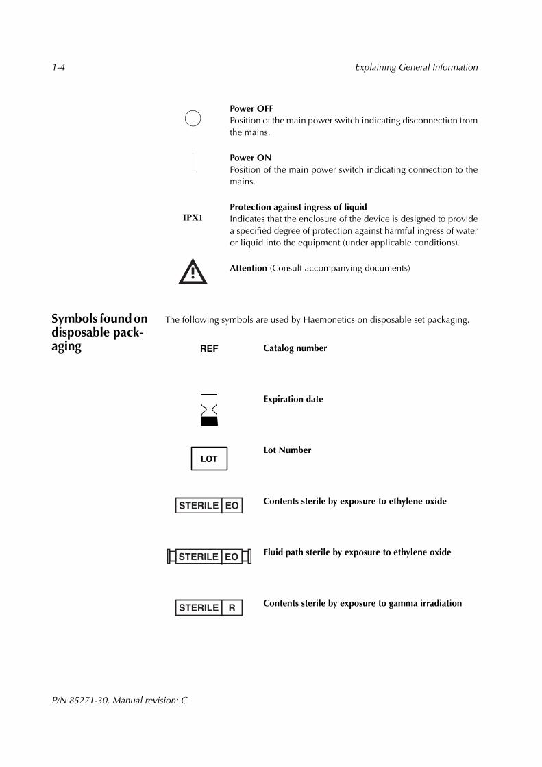
Power OFFPosition of the main power switch indicating disconnection fromthe mains.
Power ONPosition of the main power switch indicating connection to themains.
Protection against ingress of liquidIndicates that the enclosure of the device is designed to providea specified degree of protection against harmful ingress of wateror liquid into the equipment (under applicable conditions).
Attention (Consult accompanying documents)
Symbols found on disposable pack-aging
The following symbols are used by Haemonetics on disposable set packaging.
Catalog number
Expiration date
Lot Number
Contents sterile by exposure to ethylene oxide
Fluid path sterile by exposure to ethylene oxide
Contents sterile by exposure to gamma irradiation
IPX1
REF
LOT
STERILE EO
EOSTERILE
STERILE R
Explaining General Information 1-5
P/N 85271-30, Manual revision: C
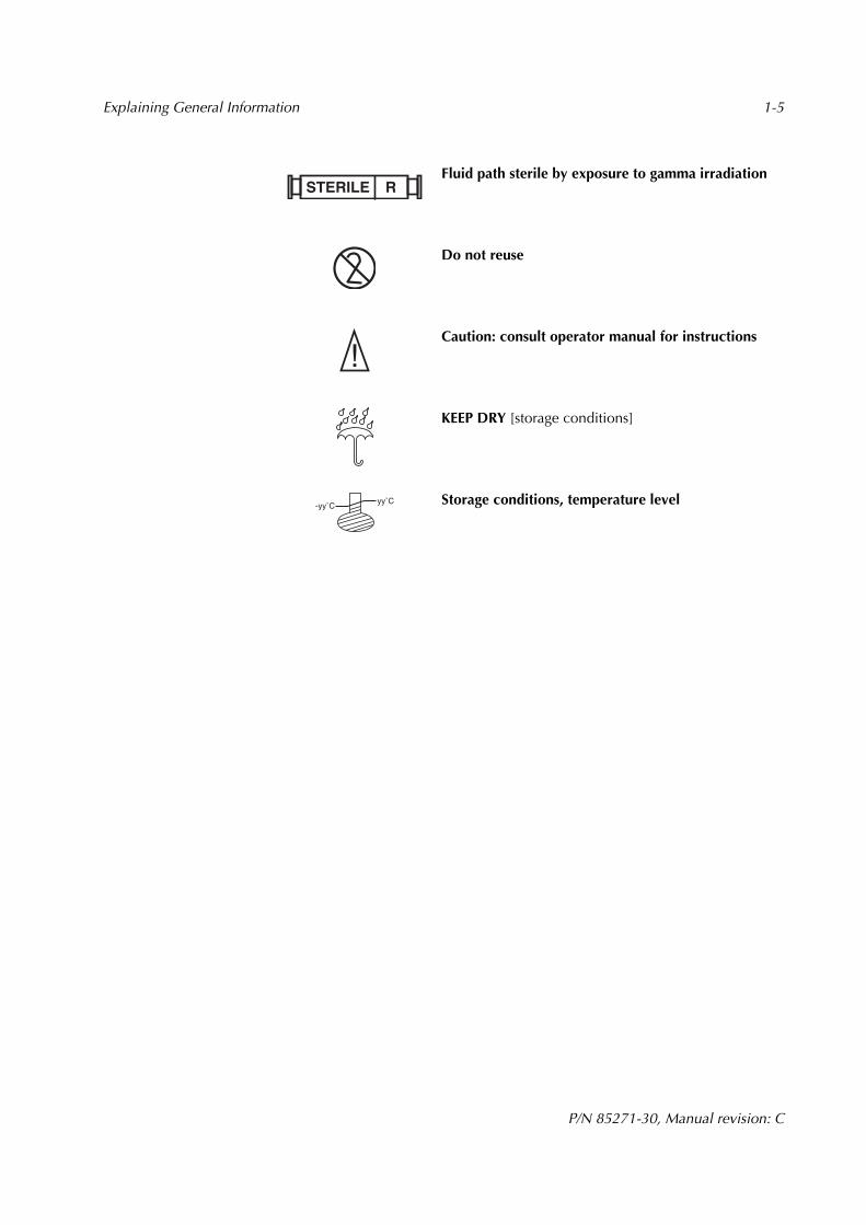
Fluid path sterile by exposure to gamma irradiation
Do not reuse
Caution: consult operator manual for instructions
KEEP DRY [storage conditions]
Storage conditions, temperature level
STERILE R
yy˚C-yy˚C

1-6 Explaining General Information
P/N 85271-30, Manual revision: C
LISTING ACP 215 DEVICE SPECIFICATIONS
Dimensions and weight
The approximate weight and dimensions of the ACP 215 device are as follows:
Environmental conditions
The following environmental conditions should be respected pertaining to oper-ation and storage of the ACP 215 device.
Power require-ments
The power is supplied to the device from an external AC power source. Thepower source must be properly grounded. Haemonetics will regulate the propervoltage setting upon installation.
CharacteristicValue (approximate)
Cabinet cover open Cabinet cover closed
Height 67.5 cm [26.5 inches] 43 cm [17 inches]
Width 55 cm [21.5 inches]
Depth 55 cm [21.5 inches] 30.5 cm [12 inches]
Weight 25 kg [56 lb]
Condition Value
Operating Temperature 18° C to 35° C
Humidity 95% maximum, non-condensing
Tested storage temperature range 5° C to 45° C, non-condensing environ-ment
Characteristics Values (relative to input voltage)
Input voltage 230 VAC ± 10% 110 VAC ± 10%
Operating current ~1.9 A ~ 2.6 A
Maximum input current 2.5 A 5.0 A
Fuse rating F2.5 A @ 250 V F5.0 A @ 250 V
Operating frequency range 50 - 60 Hz 50 - 60 Hz
Maximum leakage current 500 µA 100 µA

Explaining General Information 1-7
P/N 85271-30, Manual revision: C
Caution: The ACP 215 device must be operated in an environment compatible tothe requirements of the IEC 60601-1-2 Standard, Electromagnetic compatibility.
Mobile RF communication equipment not approved by Haemonetics andportable communication equipment can affect the ACP 215 device. Any acces-sories and cables not approved by Haemonetics used in conjunction with thedevice may increase hazards and influence compatibility with EMC require-ments. Therefore, non-approved accessories and cables must not be used.
In addition, the ACP 215 device and accessories must not be placed directly adja-cent to, or top of other equipment, unless specifically approved by Haemonetics.

P/N 85271-30, Manual revision: C
Chapter 2
Presenting the ACP 215 Equipment
DESCRIBING THE ACP 215 CONTROL PANEL . . . . . . . . . . . . . . . . . . . . . . 2-3Display screen . . . . . . . . . . . . . . . . . . . . . . . . . . . . . . . . . . . . . . . . . . . . 2-3Keypad . . . . . . . . . . . . . . . . . . . . . . . . . . . . . . . . . . . . . . . . . . . . . . . . . . 2-3
DESCRIBING THE ACP 215 CABINET COMPONENTS . . . . . . . . . . . . . . . . 2-4Centrifuge system . . . . . . . . . . . . . . . . . . . . . . . . . . . . . . . . . . . . . . . . . . 2-4Pumps. . . . . . . . . . . . . . . . . . . . . . . . . . . . . . . . . . . . . . . . . . . . . . . . . . . 2-5Pressure monitors . . . . . . . . . . . . . . . . . . . . . . . . . . . . . . . . . . . . . . . . . . 2-5Valves . . . . . . . . . . . . . . . . . . . . . . . . . . . . . . . . . . . . . . . . . . . . . . . . . . . 2-6Air detectors . . . . . . . . . . . . . . . . . . . . . . . . . . . . . . . . . . . . . . . . . . . . . . 2-6Optical line sensor . . . . . . . . . . . . . . . . . . . . . . . . . . . . . . . . . . . . . . . . . 2-6Solution bag pole . . . . . . . . . . . . . . . . . . . . . . . . . . . . . . . . . . . . . . . . . . 2-6Power entry module . . . . . . . . . . . . . . . . . . . . . . . . . . . . . . . . . . . . . . . . 2-7Power cord . . . . . . . . . . . . . . . . . . . . . . . . . . . . . . . . . . . . . . . . . . . . . . . 2-7Biohazard waste bag. . . . . . . . . . . . . . . . . . . . . . . . . . . . . . . . . . . . . . . . 2-7
DESCRIBING THE SHAKER AND THE PRINTER . . . . . . . . . . . . . . . . . . . . . 2-8Shaker. . . . . . . . . . . . . . . . . . . . . . . . . . . . . . . . . . . . . . . . . . . . . . . . . . . 2-8Printer. . . . . . . . . . . . . . . . . . . . . . . . . . . . . . . . . . . . . . . . . . . . . . . . . . . 2-9
2-2 Presenting the ACP 215 Equipment
P/N 85271-30, Manual revision: C
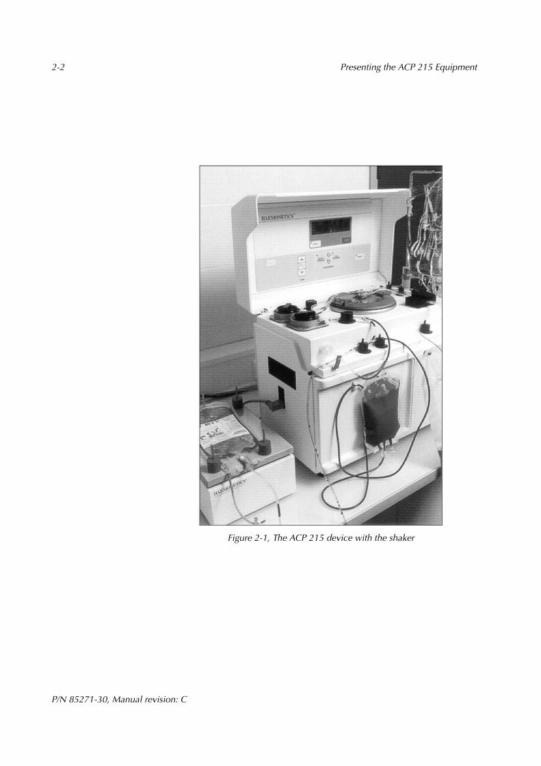
Figure 2-1, The ACP 215 device with the shaker
Presenting the ACP 215 Equipment 2-3
P/N 85271-30, Manual revision: C
DESCRIBING THE ACP 215 CONTROL PANEL
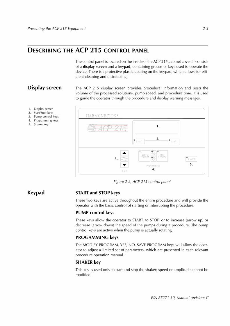
The control panel is located on the inside of the ACP 215 cabinet cover. It consistsof a display screen and a keypad, containing groups of keys used to operate thedevice. There is a protective plastic coating on the keypad, which allows for effi-cient cleaning and disinfecting.
Display screen The ACP 215 display screen provides procedural information and posts thevolume of the processed solutions, pump speed, and procedure time. It is usedto guide the operator through the procedure and display warning messages.
Figure 2-2, ACP 215 control panel
Keypad START and STOP keys
These two keys are active throughout the entire procedure and will provide theoperator with the basic control of starting or interrupting the procedure.
PUMP control keys
These keys allow the operator to START, to STOP, or to increase (arrow up) ordecrease (arrow down) the speed of the pumps during a procedure. The pumpcontrol keys are active when the pump is actually rotating.
PROGAMMING keys
The MODIFY PROGRAM, YES, NO, SAVE PROGRAM keys will allow the oper-ator to adjust a limited set of parameters, which are presented in each relevantprocedure operation manual.
SHAKER key
This key is used only to start and stop the shaker; speed or amplitude cannot bemodified.
1. Display screen2. Start/Stop keys3. Pump control keys4. Programming keys5. Shaker key 1.
2.
3.
4.5.

2-4 Presenting the ACP 215 Equipment
P/N 85271-30, Manual revision: C
DESCRIBING THE ACP 215 CABINET COMPONENTS
Figure 2-3, ACP 215 top deck view
Centrifuge system
The centrifuge chuck, seated in the centrifuge well, is designed to hold thedisposable blow molded bowl (BMB) in place during operation and spin the bowlup to 8000 revolutions per minute (rpm).
The centrifuge lid, referred to as the cover, contains a locking knob; it will securethe disposable bowl in the chuck while isolating the spinning bowl from the oper-ator. The centrifuge drain tube, located at the rear of the device, must beconnected at all times to the biohazard waste bag supplied by Haemonetics.
When installing a bowl, the operator should exert a downward pressure on thehead of the bowl and ensure that the bowl is completely seated. The bowl willbe completely secured once the operator has locked the centrifuge lid. To remove a bowl at the end of a procedure, the operator should open the centri-fuge lid and pull upward on the bowl.
Warning: It is unlikely that a properly installed centrifuge bowl will becomeunaligned as it spins. If the operator does notice anything unusual, under nocircumstances, should the operator attempt to open the centrifuge lid if thebowl is still spinning. The bowl must come to a complete stop before attemptingto open the centrifuge for any reason.
Fluid detector
The centrifuge well is equipped with an electronic fluid detection systemdesigned to detect the presence of liquid. The detector is mounted on the wall ofthe centrifuge well. The ACP 215 safety system will automatically stop the centri-fuge and the pumps if there is contact between liquid of any sort and the fluiddetector.
1. Centrifuge system2. Solution pump3. Blood pump4. DPM5. SPM6. Red valve7. White valve8. Green valve9. Blue valve10. Yellow valve11. Orange valve12. SLAD13. BLAD14. Line Sensor15. Solution bag pole
2.
3.
12.
13.
6. 7. 8.
4. 5.
14.
11.
10.
9.1.
15.

Presenting the ACP 215 Equipment 2-5
P/N 85271-30, Manual revision: C
Pumps Located on the left side of the ACP 215 top deck are two pumps which use peri-staltic movements to displace fluids through the disposable set tubing.
Figure 2-4, ACP 215 pump rotor
Blood Pump
The blood pump will rotate during certain procedures simultaneously with thesolution pump to direct solution to the RBC bag. As the bowl is filling, the bloodpump directs the RBC product to the bowl.
At the end of certain procedures, the blood pump directs the final product fromthe bowl to the final product bag.
Solution Pump
The solution pump will rotate at certain points during the procedures to transfersolution to the RBC bag.
As the bowl is filling, or when transferring the final product from the bowl backto the RBC bag or the final product bag, the solution pump is stopped.
Pressure moni-tors
There are two electronically controlled pressure monitors on the ACP 215 device,which function with the correlating filter on the disposable set to measure pres-sure in the disposable tubing. The pressure monitors provide feedback to thesystem about the flow of blood components.
The draw pressure monitor (DPM), located on the left side of the top deck,measures pressure in the blood line tubing.
The system pressure monitor (SPM), located on the right side of the top deck,measures pressure in the effluent tubing. This measurement verifies that the sterileseal, between the head and the body of the centrifuge bowl, remains intact.
If a pressure monitor detects that pressure is outside of acceptable limits, the ACP215 safety system will interrupt the procedure and provide an explanatorymessage.
2-6 Presenting the ACP 215 Equipment
P/N 85271-30, Manual revision: C
Valves There are six pneumatic pinch valves located on the ACP 215 top deck whichautomatically control the flow of fluids through the disposable set tubing. Thesevalves are color-coded to facilitate accurate tubing installation.
The ACP 215 safety system will control the valves during the self-diagnostic tests.Once the operator has selected a procedure, the appropriate valves will automat-ically open, in preparation for installing the disposable set tubing. In case ofpower failure, the valves revert to a closed status.
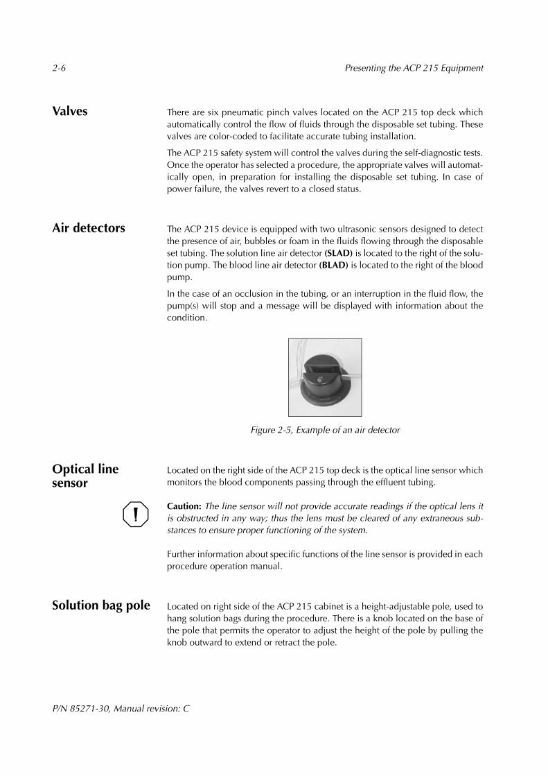
Air detectors The ACP 215 device is equipped with two ultrasonic sensors designed to detectthe presence of air, bubbles or foam in the fluids flowing through the disposableset tubing. The solution line air detector (SLAD) is located to the right of the solu-tion pump. The blood line air detector (BLAD) is located to the right of the bloodpump.
In the case of an occlusion in the tubing, or an interruption in the fluid flow, thepump(s) will stop and a message will be displayed with information about thecondition.
Figure 2-5, Example of an air detector
Optical line sensor
Located on the right side of the ACP 215 top deck is the optical line sensor whichmonitors the blood components passing through the effluent tubing.
Caution: The line sensor will not provide accurate readings if the optical lens itis obstructed in any way; thus the lens must be cleared of any extraneous sub-stances to ensure proper functioning of the system.
Further information about specific functions of the line sensor is provided in eachprocedure operation manual.
Solution bag pole Located on right side of the ACP 215 cabinet is a height-adjustable pole, used tohang solution bags during the procedure. There is a knob located on the base ofthe pole that permits the operator to adjust the height of the pole by pulling theknob outward to extend or retract the pole.
Presenting the ACP 215 Equipment 2-7
P/N 85271-30, Manual revision: C
Power entry module
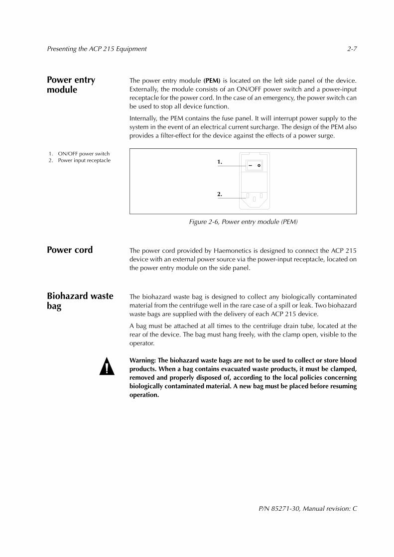
The power entry module (PEM) is located on the left side panel of the device.Externally, the module consists of an ON/OFF power switch and a power-inputreceptacle for the power cord. In the case of an emergency, the power switch canbe used to stop all device function.
Internally, the PEM contains the fuse panel. It will interrupt power supply to thesystem in the event of an electrical current surcharge. The design of the PEM alsoprovides a filter-effect for the device against the effects of a power surge.
Figure 2-6, Power entry module (PEM)
Power cord The power cord provided by Haemonetics is designed to connect the ACP 215device with an external power source via the power-input receptacle, located onthe power entry module on the side panel.
Biohazard waste bag
The biohazard waste bag is designed to collect any biologically contaminatedmaterial from the centrifuge well in the rare case of a spill or leak. Two biohazardwaste bags are supplied with the delivery of each ACP 215 device.
A bag must be attached at all times to the centrifuge drain tube, located at therear of the device. The bag must hang freely, with the clamp open, visible to theoperator.
Warning: The biohazard waste bags are not to be used to collect or store bloodproducts. When a bag contains evacuated waste products, it must be clamped,removed and properly disposed of, according to the local policies concerningbiologically contaminated material. A new bag must be placed before resumingoperation.
1. ON/OFF power switch2. Power input receptacle
2.
1.
2-8 Presenting the ACP 215 Equipment
P/N 85271-30, Manual revision: C
DESCRIBING THE SHAKER AND THE PRINTER
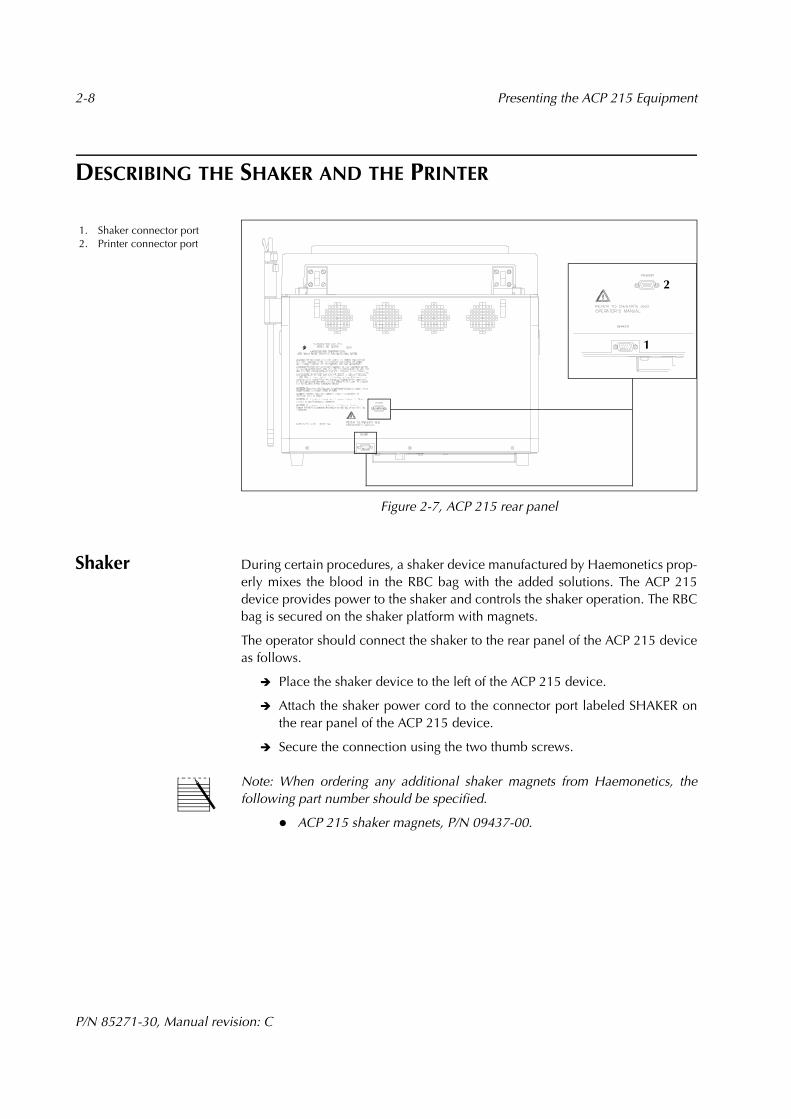
Figure 2-7, ACP 215 rear panel
Shaker During certain procedures, a shaker device manufactured by Haemonetics prop-erly mixes the blood in the RBC bag with the added solutions. The ACP 215device provides power to the shaker and controls the shaker operation. The RBCbag is secured on the shaker platform with magnets.
The operator should connect the shaker to the rear panel of the ACP 215 deviceas follows.
" Place the shaker device to the left of the ACP 215 device.
" Attach the shaker power cord to the connector port labeled SHAKER onthe rear panel of the ACP 215 device.
" Secure the connection using the two thumb screws.
Note: When ordering any additional shaker magnets from Haemonetics, thefollowing part number should be specified.
! ACP 215 shaker magnets, P/N 09437-00.
1. Shaker connector port2. Printer connector port
1
2
Presenting the ACP 215 Equipment 2-9
P/N 85271-30, Manual revision: C
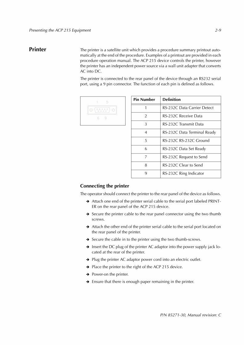
Printer The printer is a satellite unit which provides a procedure summary printout auto-matically at the end of the procedure. Examples of a printout are provided in eachprocedure operation manual. The ACP 215 device controls the printer, howeverthe printer has an independent power source via a wall unit adapter that convertsAC into DC.
The printer is connected to the rear panel of the device through an RS232 serialport, using a 9 pin connector. The function of each pin is defined as follows.
Connecting the printer
The operator should connect the printer to the rear panel of the device as follows.
" Attach one end of the printer serial cable to the serial port labeled PRINT-ER on the rear panel of the ACP 215 device.
" Secure the printer cable to the rear panel connector using the two thumbscrews.
" Attach the other end of the printer serial cable to the serial port located onthe rear panel of the printer.
" Secure the cable in to the printer using the two thumb-screws.
" Insert the DC plug of the printer AC adaptor into the power supply jack lo-cated at the rear of the printer.
" Plug the printer AC adaptor power cord into an electric outlet.
" Place the printer to the right of the ACP 215 device.
" Power-on the printer.
" Ensure that there is enough paper remaining in the printer.
Pin Number Definition
1 RS-232C Data Carrier Detect
2 RS-232C Receive Data
3 RS-232C Transmit Data
4 RS-232C Data Terminal Ready
5 RS-232C RS-232C Ground
6 RS-232C Data Set Ready
7 RS-232C Request to Send
8 RS-232C Clear to Send
9 RS-232C Ring Indicator

2-10 Presenting the ACP 215 Equipment
P/N 85271-30, Manual revision: C
To remove the printer AC adaptor, the operator should:
" Power off the printer first.
" Unplug the AC adaptor and the DC plug.
The operator should not touch the pins of the DC plugs.
Note: Further information about replacing the paper or cleaning the printer isprovided in the Operation Manual for the DPU-414 Thermal Printer, SeikoInstruments Inc.
P/N 85271-30, Manual revision: C
Chapter 3
Maintaining the ACP 215 Equipment
CLEANING PROCEDURES. . . . . . . . . . . . . . . . . . . . . . . . . . . . . . . . . . . . . . 3-2Listing tools and cleaning supplies . . . . . . . . . . . . . . . . . . . . . . . . . . . . . 3-2Exterior surfaces, valves, shaker and printer . . . . . . . . . . . . . . . . . . . . . . 3-3Pressure monitors . . . . . . . . . . . . . . . . . . . . . . . . . . . . . . . . . . . . . . . . . . 3-3Air detectors . . . . . . . . . . . . . . . . . . . . . . . . . . . . . . . . . . . . . . . . . . . . . . 3-3Optical line sensor . . . . . . . . . . . . . . . . . . . . . . . . . . . . . . . . . . . . . . . . . 3-3Pumps. . . . . . . . . . . . . . . . . . . . . . . . . . . . . . . . . . . . . . . . . . . . . . . . . . . 3-4Fluid detector . . . . . . . . . . . . . . . . . . . . . . . . . . . . . . . . . . . . . . . . . . . . . 3-4Centrifuge components . . . . . . . . . . . . . . . . . . . . . . . . . . . . . . . . . . . . . . 3-4Filter screens. . . . . . . . . . . . . . . . . . . . . . . . . . . . . . . . . . . . . . . . . . . . . . 3-5
CUSTOMER SERVICE. . . . . . . . . . . . . . . . . . . . . . . . . . . . . . . . . . . . . . . . . . 3-6Clinical training . . . . . . . . . . . . . . . . . . . . . . . . . . . . . . . . . . . . . . . . . . . 3-6Field service . . . . . . . . . . . . . . . . . . . . . . . . . . . . . . . . . . . . . . . . . . . . . . 3-6Returned Goods Authorization system . . . . . . . . . . . . . . . . . . . . . . . . . . 3-6Haemonetics® Cleaning and maintenance record . . . . . . . . . . . . . . . . . 3-8
3-2 Maintaining the ACP 215 Equipment
P/N 85271-30, Manual revision: C
CLEANING PROCEDURES
To ensure consistent performance of the device, the operator needs to primarilyperform routine cleaning of the components. A record of routine cleaning shouldbe kept along with any routine or preventive service maintenance performed bya Haemonetics representative. An example of a cleaning and routine mainte-nance form is provided at the end of this chapter. Annual preventive mainte-nance should be performed by a Haemonetics service representative.
The frequency and type of cleaning each ACP 215 device will depend on thenumber of procedures performed. Special cleaning needs may arise and shouldbe dealt with promptly. Haemonetics recommends the following routinecleaning schedule for each device, based on an average of three procedures perday, or approximately sixty per month. Adjustments should be made to thecleaning schedule according to the actual number of procedures performed.
! Daily: Clean the exterior surfaces.
! Weekly: Clean the pressure monitors, air detectors, optical sensors (linesensor and optical bowl sensor), the fluid detector and the inside of thecentrifuge well.
! Monthly: Clean the pump rotors and the pump wells.
! Quarterly: Clean the filter screens.
Warning: To eliminate the potential danger of electrical shock, the operatormust clean the ACP 215 device only when it is disconnected from an externalpower source.
Listing tools and cleaning supplies
A tool kit has been included with each device containing the following articles.
! Phillips-head screwdriver, to remove the retainer plate from the air vent.
! Allen (hexagonal head) wrench, to remove the pump heads from the pumpassembly.
! A brush, to remove loose debris within the roller assembly.
! Silicon lubricant, used for the O-ring gasket of the centrifuge chuck.
The following list describes the basic material required for routine cleaning.
! Disinfectant cleaning solution, specific for blood borne pathogens.
! Clear warm water.
! 70% Isopropyl alcohol.
! Lint-free gauze or cloth for cleaning and drying.
! Cotton swabs.
! Protective gloves.
! Spray bottle, recommended for cleaning the centrifuge well.
Maintaining the ACP 215 Equipment 3-3
P/N 85271-30, Manual revision: C
Exterior surfaces, valves, shaker and printer
The exterior cabinet, keypad, display screen, valves, shaker and printer shouldbe wiped daily, as well as following any spill, using an appropriate cleaning solu-tion.
Pressure monitors
The pressure monitors (DPM/SPM) should be cleaned in the following manner.
" Depress and hold the white ring as if installing the disposable filter.
" Wipe the silver tube thoroughly, using a circular motion and warm wateronly.
" Dry the tube and release the pressure on the ring.
Caution: It is very important to use only water on the pressure monitor rod.Alcohol or cleaning solution residue could cause a reaction with the plasticmaterial of the corresponding disposable set filter and affect the function of thefilter.
Air detectors The air detectors (SLAD/DLAD) are designed with a groove to hold the disposabletubing. The contents of the tubing are monitored by the sensors which are locatedinternally on either side of this groove. If a procedure is interrupted due to an airdetector alarm, the operator should remove the tubing and clean the groovebefore continuing the procedure.
The operator should use only warm water and lint-free gauze to clean and dryinside of the tubing grove. The groove should be kept free of any particles, suchas powder residue from disposable gloves, since this could lead to an erroneousdetection of air.
Caution: Alcohol may cause the plastic housing to degrade and must not be usedto clean the air detectors.
Optical line sensor
The line sensor contains two very small lenses which are centered on either sideof the disposable tubing groove. The lenses must be kept completely free of parti-cles or debris which could produce inaccurate readings and influence the deviceperformance.
The operator should carefully pass lint-free gauze moistened with warm wateronly through the groove to clean, then dry the lenses.
Caution: If cleaning solution should come into contact with the optical sensorlenses, the lenses should be cleaned immediately with lint-free gauze and warmwater, then thoroughly dried. Dried cleaning solution can leave an opaque filmon the lens.
3-4 Maintaining the ACP 215 Equipment
P/N 85271-30, Manual revision: C
Pumps The pump rotors should be removed from the well with the Allen/hexagonal-head wrench. Debris should be removed from the rotors and the pump wells ona routine basis, as well as after any spills to contribute to efficient operation.
For routine cleaning, the operator should:
" Remove the pump rotor from the housing, using the hexagonal headwrench to remove the pump screw.
" Wipe the rotor and remove all debris from the rollers, using warm waterand lint-free cloth or gauze.
" Dry with lint free cloth (or compressed air, if available).
" Clean and dry the pump well using the same method.
" Ensure that all of the rollers spin freely and replace the pump rotor in thewell, aligning the cross pin in the rotor with the pump shaft.
" Replace and tighten the hexagonal head screw.
In the case of a fluid spill, the same cleaning method should be followed;however, disinfectant cleaning solution should be used, followed by a clearwater rinse. The pump rotor should not be immersed in water.
Fluid detector The fluid detector is located inside of the centrifuge well. The surface of thedetector should be cleaned using a cotton swab moistened with 70% alcohol.
Centrifuge components
The centrifuge well, chuck, hinged lid and locking knob can be wiped routinelyusing the cleaning solution and a lint-free cloth.
After a major cleaning, the operator should apply a small amount of the siliconlubricant to the O-ring gasket to prevent it from cracking. It is not necessary toremove the gasket when applying the lubricant.
Cleaning after a blood spill
In the case of a blood spill, the operator should:
" Power off the device and disconnect it from the external power sourcebefore cleaning.
" Ensure that the equipment waste bag is attached to the drain tube andhangs freely.
" Wipe the centrifuge lid with cleaning solution.
" Clean the centrifuge chuck and well using the disinfectant solution and alint-free cloth until all traces of blood components are removed.
" Lubricate the O-ring gasket with a small amount of the silicon lubricant.
Haemonetics recommends that the operator wear protective gloves to avoiddirect contact with the cleaning solution and/or any spilled blood which may bepresent.

Maintaining the ACP 215 Equipment 3-5
P/N 85271-30, Manual revision: C
In the case of a larger spill, fluid and/or blood may be evacuated into thebiohazard waste bag. The operator should complete the following additionalsteps and contact the local Haemonetics representative for further instructionsbefore using the device.
" Wipe away as much blood as possible with gauze pads.
" Irrigate the centrifuge drain holes with cleaning solution, until the draintube is rinsed clear of the spilled material.
" Remove the bag and replace it with a new bag.
" Dispose of the used waste bag according to local established policiesconcerning the disposal of biohazard waste.
Note: A 50 ml syringe attached to a 20 cm section of disposable tubing placed inthe drain holes can be used for irrigation. The biohazard waste bag should bemonitored to avoid overfilling.
Warning: An authorized Haemonetics technician should perform a leakagecurrent control after any major fluid spill involving the ACP 215 device. Leakagecurrent represents a primary indication of electrical shock hazard and shouldbe checked according to guidelines as described in local standard operatingprocedures.
Filter screens The ACP 215 device is equipped with filter screens on the bottom of the cabinet,which eliminate dust from incoming cool air. The filters should be cleanedroutinely, especially if dust becomes visible on the screens.
To clean the filters, the operator should:
" Remove the retainer plates using a Phillips-head screwdriver.
" Remove the filter screens from the panel.
" Rinse the screens under running water - DO NOT use any cleaning agents.
" Gently squeeze the screens to remove excess water.
" Place the screens on a clean, dry cloth and allow to dry completely.
" Reinsert the screens into the panel, ensuring that all openings arecompletely covered by the filter.
" Replace the retainer plates and tighten the screws.
Warning: To avoid electrical shock, the filter screen should be completely drybefore it is reinstalled on the ACP 215 cabinet.

3-6 Maintaining the ACP 215 Equipment
P/N 85271-30, Manual revision: C
CUSTOMER SERVICE
Clinical training Haemonetics employs a staff of Clinical Specialists to provide training in the useof the ACP 215 equipment. The local Haemonetics representative will schedulestaff training upon delivery of the ACP 215 equipment and should be contactedto organize further instruction when needed.
Field service Haemonetics maintains a worldwide network of company-trained service repre-sentatives responsible for responding to technical needs concerning equipment.These technical specialists are available to diagnose and repair any malfunctions,as well as provide routine annual or semi-annual maintenance of the equipment,including leakage current tests. If service beyond the routine maintenance andcleaning described in this manual is required, the local Haemonetics representa-tive should be contacted to provide specific instruction.
Returned Goods Authorization system
Haemonetics seeks to provide its customers with equipment and material whichrespects the highest established standards of quality in design and manufacturing.If for any reason merchandise must be returned to the company, the customershould refer to the Haemonetics Returned Goods Authorization (RGA) systemprocedure to ensure proper handling and subsequent analysis of the material.
The customer should contact the local Haemonetics Representative (or theHaemonetics Customer Service Department) and provide the following informa-tion:
! Product list number, lot number and manufacture date.
! Number of articles to be returned.
! Description of defect.
! Number of parcels being shipped.
The Haemonetics Representative may ask for additional details, depending onthe nature of the problem. The customer should be prepared to provide a thor-ough description of the problem encountered, as well as the product informationlisted above.
If a contaminated disposable set must be returned by courier services, theHaemonetics Representative may provide specific instructions concerning prep-aration for shipping blood-contaminated products. In addition to the Haemon-etics guidelines, the consumer should strictly follow the local standard operatingprocedure related to the shipment of blood-contaminated materials and thusminimize any potential health hazards involved.
Maintaining the ACP 215 Equipment 3-7
P/N 85271-30, Manual revision: C
In some cases, it may be necessary to dispose of the contaminated goods afterreporting the problem to the Haemonetics representative. This should be doneaccording to the locally established guidelines pertaining to the disposal ofbiologically contaminated material.
Warning: Haemonetics products must be properly cleaned and packed prior totheir return. It remains an important responsibility of the customer to reducethis serious potential health hazard, by being aware of the risks involved in theshipping, handling and testing of this material.

Hae
mon
etic
s® C
lean
ing
and
mai
nten
ance
rec
ord
Dev
ice
seri
al n
umbe
r: .
......
......
......
......
......
......
......
......
......
......
......
......
......
..Y
ear:
....
......
......
......
......
......
......
......
......
......
......
......
......
......
...
Ann
ual p
reve
ntiv
e m
aint
enan
ce s
houl
d be
sch
edul
ed b
y a
supe
rvis
or w
hen
appr
opri
ate
and
perf
orm
ed b
y a
Hae
mon
etic
s se
rvic
e re
pres
enta
tive
or a
qua
lifie
d en
gine
er.
Ann
ual m
aint
enan
ce p
erfo
rmed
by:
....
......
......
......
......
......
......
......
......
......
......
......
......
......
......
......
..D
ate
perf
orm
ed:
......
......
......
......
......
......
......
......
......
......
......
......
......
......
......
......
Rev
iew
ed b
y: .
......
......
......
......
......
......
......
......
......
......
......
......
......
......
......
......
......
......
......
......
......
...D
ate/
initi
als:
.....
......
......
......
......
......
......
......
......
......
......
......
......
......
......
......
......
.
Act
ion
Janu
ary
Febr
.M
arch
Apr
ilM
ayJu
neJu
lyA
ugus
tSe
pt.
Oct
.N
ov.
Dec
.
Cle
an c
abin
et, c
ontr
ol p
anel
, val
ves,
sha
ker
and
prin
ter
Cle
an a
ir d
etec
tors
Cle
an p
ump
roto
rs
Cle
an c
entr
ifuge
cov
er a
nd w
ell
Cle
an o
ptic
al b
owl s
enso
r
Cle
an o
ptic
al li
ne s
enso
r
Cle
an a
ir fi
lters
Insp
ect O
-rin
g: a
pply
sili
con
lubr
ican
t
Cle
an D
PM a
nd S
PM
Ver
ify b
ioha
zard
was
te b
ag
Mai
nten
ance
per
form
ed b
y:(d
ate
and
initi
als)
Rev
iew
ed b
y:(d
ate
and
initi
als)
P/N 85271-30, Manual revision: C
Chapter 4
Ensuring Safety and Quality for an ACP 215 Procedure
HANDLING THE ACP 215 EQUIPMENT . . . . . . . . . . . . . . . . . . . . . . . . . . . 4-2Storing the device and material. . . . . . . . . . . . . . . . . . . . . . . . . . . . . . . . 4-2Inspecting the material . . . . . . . . . . . . . . . . . . . . . . . . . . . . . . . . . . . . . . 4-2Installation . . . . . . . . . . . . . . . . . . . . . . . . . . . . . . . . . . . . . . . . . . . . . . . 4-2
PREVENTING PROBLEMS DURING AN ACP 215 PROCEDURE . . . . . . . . . 4-3Understanding the risk of hemolysis . . . . . . . . . . . . . . . . . . . . . . . . . . . . 4-3Avoiding the consequences of flow restriction. . . . . . . . . . . . . . . . . . . . . 4-3Avoiding bowl misalignment. . . . . . . . . . . . . . . . . . . . . . . . . . . . . . . . . . 4-4Avoiding overheating due to mechanical situations. . . . . . . . . . . . . . . . . 4-4
WARNINGS FOR THE OPERATOR . . . . . . . . . . . . . . . . . . . . . . . . . . . . . . . 4-5Electrical shock hazards . . . . . . . . . . . . . . . . . . . . . . . . . . . . . . . . . . . . . 4-5Leakage current control . . . . . . . . . . . . . . . . . . . . . . . . . . . . . . . . . . . . . 4-5Mechanical hazards/rotating parts. . . . . . . . . . . . . . . . . . . . . . . . . . . . . . 4-5Power outlet connection . . . . . . . . . . . . . . . . . . . . . . . . . . . . . . . . . . . . . 4-5Communicable disease precautions . . . . . . . . . . . . . . . . . . . . . . . . . . . . 4-6
4-2 Ensuring Safety and Quality for an ACP 215 Procedure
P/N 85271-30, Manual revision: C
HANDLING THE ACP 215 EQUIPMENT
Safe and successful ACP 215 operation will depend in part on the proper routinehandling of the ACP 215 equipment. The operator should be aware of the prob-lems which could result if the device or disposable material is stored, installed orused incorrectly.
Storing the device and material
The ACP 215 device must not be operated or stored in an area where flammablegases or vapors are present. The ACP 215 disposable set material should be keptin a dry, well-ventilated area and isolated from any chemical vapors. The operatorshould handle the disposable set elements with clean, dry hands or gloves.
Inspecting the material
Prior to installation, the operator should complete a visual inspection of thedisposable set elements and control for twisted or flattened sections.
After installing the disposable set, the operator should verify the correct place-ment of the individual elements, prior to initiating a procedure. It is important thatthe tubing remain free of any twists or occlusions which could cause a flowobstruction.
Warning: Upon completion of any procedure, the used disposable should beconsidered as biologically contaminated. It must be disposed of according tolocal standard operating procedure for the removal of such material and shouldnot be mixed with non-biologically contaminated waste.
Installation Installation of the disposable set is explained in detail in each procedure opera-tion manual.

Ensuring Safety and Quality for an ACP 215 Procedure 4-3
P/N 85271-30, Manual revision: C
PREVENTING PROBLEMS DURING AN ACP 215 PROCEDURE
Understanding the risk of hemolysis
Hemolysis involves the destruction of red blood cell membranes, with the releaseof free hemoglobin into the plasma portion of the blood. Free hemoglobin doesnot have the capacity to transport oxygen and can produce serious problems. Theremnants of the red cell can stimulate clot formation and damage the vascularnature of the lungs and the kidneys. This could lead to respiratory complicationsand/or renal failure.
Hemolysis of red cells can occur during a procedure in the rare event of amechanically induced situation, such as overheating or excessive pressure.
Warning: Forcing a pump to work against a severe flow restriction can lead tohemolysis, and thus, consequently high levels of free hemoglobin. It is importantthat the operator remain attentive to this fact in the case of any “high pressure”alarms during operation.
If there is any suspicion that hemolysis has occurred, the operator should followthe local SOP applicable in this type of situation. The operator should alsocontact the local Haemonetics representative if there is any suspicion of amechanically induced problem.
Avoiding the consequences of flow restriction
As the bowl is filling, a flow restriction in the effluent tubing can create pressureon the outlet port of the disposable bowl. This unrelieved pressure can deformthe rotary seal of the disposable bowl. If the functional characteristics of therotary seal are altered, the increased friction and excessive heat can make thecontents of the bowl unsuitable for further use.
As the bowl is emptying, a flow restriction in the effluent tubing can cause thepressure in the centrifuge bowl to drop severely. This sudden drop in pressurecould potentially produce hemolysis.
To eliminate these potential problems, the operator should not clamp the effluenttubing.

4-4 Ensuring Safety and Quality for an ACP 215 Procedure
P/N 85271-30, Manual revision: C
Avoiding bowl misalignment
An improperly installed disposable bowl can become misaligned as it spins. Thiscan create excessive friction, and consequently overheat the bowl contents. Theoperator should follow the bowl seating procedure to ensure proper placementof the bowl in the centrifuge.
Warning: The operator must not use any bowl which cannot be properly seatedin the centrifuge chuck. Overheating can occur, subsequently lead to hemolysisand make any blood being processed unsafe for reinfusion. During operationthe operator should interrupt the ACP 215 procedure if an abnormality or noiseappears, related to the spinning bowl.
Avoiding overheating due to mechanical situations
Overheating could also result from a mechanical or maintenance-relatedproblem, such as a defective bearing or seal within the centrifuge well. In thiscase, the operator should contact the local Haemonetics representative anddiscontinue use of the device until it is serviced.
Warning: If any component of the ACP 215 device has become overheatedduring a procedure, and thus overheats the blood being processed, the bloodcomponents cannot be considered safe for re-infusion.
Ensuring Safety and Quality for an ACP 215 Procedure 4-5
P/N 85271-30, Manual revision: C
WARNINGS FOR THE OPERATOR
Electrical shock hazards
The operator should always use the ACP 215 device with clean, dry hands, orgloves. The internal parts of the device contain various electrical components.Contact with any of these components, when the device is connected to anexternal powered source, could result in an electrical shock to the operator.
The operator should never remove any of the ACP 215 cabinet panels. Mainte-nance requiring access to the inner cabinet remains the responsibility of aHaemonetics-trained technician.
Leakage current control
Each ACP 215 device receives a careful inspection for leakage current prior toleaving the factory. Haemonetics recommends that a control be performed forleakage current by an authorized representative as part of the annual preventativemaintenance. It remains the responsibility of the facility to ensure that this controlis performed.
In the event of any major spill in which fluid may enter the cabinet, or an impor-tant voltage surge, the operator is responsible to ensure that a leakage current testis performed before re-using the device. The control is necessary to avoid the riskof electrical shock and should be conducted by an authorized Haemoneticsrepresentative.
Mechanical hazards/rotating parts
As with any equipment containing rapidly rotating parts, the potential for severeinjury exists if contact is made, or if clothing becomes entangled with the movingparts. The ACP 215 device contains a safety feature, designed to prevent thecentrifuge from spinning if the system has not been properly secured. However,the operator should respect the usual precautions taken when working withequipment containing rotating mechanical parts.
Power outlet connection
It is not permitted to power the device using a power cord not supplied byHaemonetics, a multiple portable socket outlet or an extension cord.
4-6 Ensuring Safety and Quality for an ACP 215 Procedure
P/N 85271-30, Manual revision: C
Communicable disease precautions
Despite testing and screening to detect communicable diseases such as hepatitis,syphilis or HIV, the risk remains that the blood being processed may be infected.The operator must take the appropriate precautions when handling blood prod-ucts and disposing of blood-contaminated material, to ensure personal safety aswell as the safety of others who may come in contact with the material.
Proper handling of blood contaminated material
If a leak or blood spill should occur, it should be cleaned immediately. The oper-ator should follow the local standard operating procedure outlining the steps tofollow and product(s) to be used for the disinfection of blood-contaminated mate-rial.
If any blood-contaminated material must be returned to Haemonetics for furtherinspection, the operator should consult the RGA Procedure as described in thechapter Maintaining the ACP 215 Equipment.
Proper disposal of biologically contaminated materials
Any disposable material used during an ACP 215 procedure is considered asbiologically contaminated. It must be disposed of according to local standardoperating procedure for the removal of such material and should not be mixedwith non-biologically contaminated waste.
P/N 85271-30, Manual revision: C
Chapter 5
Troubleshooting for the ACP 215 Device
LISTING SYSTEM ERROR MESSAGES . . . . . . . . . . . . . . . . . . . . . . . . . . . . . 5-2LISTING INTERRUPT SAFETY SYSTEM MESSAGES . . . . . . . . . . . . . . . . . . . 5-5
5-2 Troubleshooting for the ACP 215 Device
P/N 85271-30, Manual revision: C
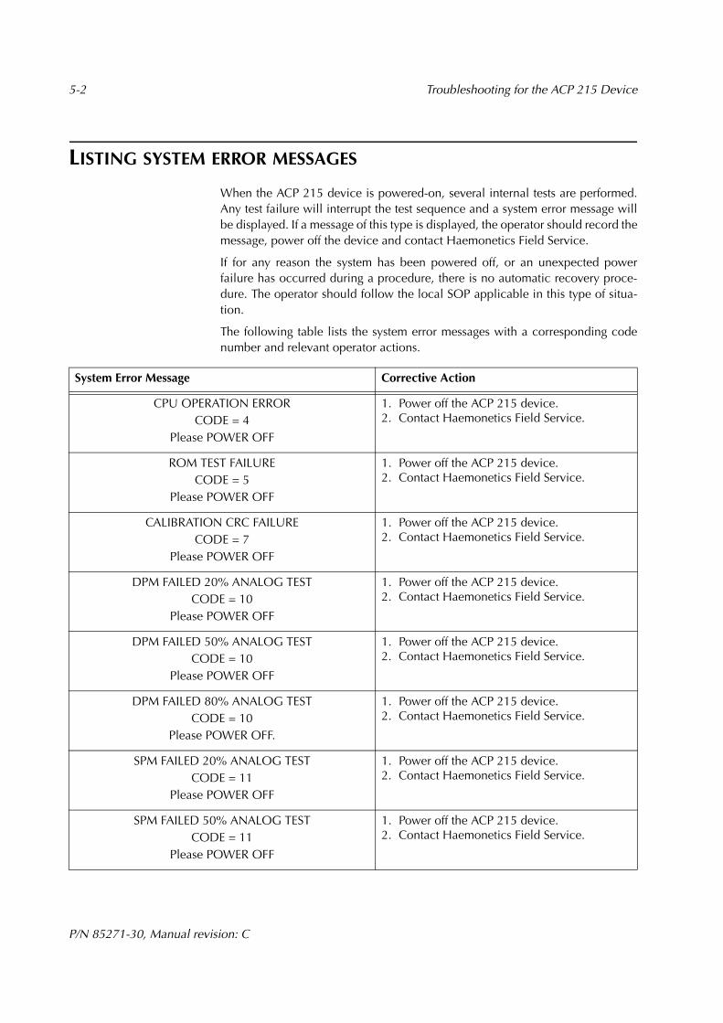
LISTING SYSTEM ERROR MESSAGES
When the ACP 215 device is powered-on, several internal tests are performed.Any test failure will interrupt the test sequence and a system error message willbe displayed. If a message of this type is displayed, the operator should record themessage, power off the device and contact Haemonetics Field Service.
If for any reason the system has been powered off, or an unexpected powerfailure has occurred during a procedure, there is no automatic recovery proce-dure. The operator should follow the local SOP applicable in this type of situa-tion.
The following table lists the system error messages with a corresponding codenumber and relevant operator actions.
System Error Message Corrective Action
CPU OPERATION ERRORCODE = 4
Please POWER OFF
1. Power off the ACP 215 device.2. Contact Haemonetics Field Service.
ROM TEST FAILURECODE = 5
Please POWER OFF
1. Power off the ACP 215 device.2. Contact Haemonetics Field Service.
CALIBRATION CRC FAILURECODE = 7
Please POWER OFF
1. Power off the ACP 215 device.2. Contact Haemonetics Field Service.
DPM FAILED 20% ANALOG TESTCODE = 10
Please POWER OFF
1. Power off the ACP 215 device.2. Contact Haemonetics Field Service.
DPM FAILED 50% ANALOG TESTCODE = 10
Please POWER OFF
1. Power off the ACP 215 device.2. Contact Haemonetics Field Service.
DPM FAILED 80% ANALOG TESTCODE = 10
Please POWER OFF.
1. Power off the ACP 215 device.2. Contact Haemonetics Field Service.
SPM FAILED 20% ANALOG TESTCODE = 11
Please POWER OFF
1. Power off the ACP 215 device.2. Contact Haemonetics Field Service.
SPM FAILED 50% ANALOG TESTCODE = 11
Please POWER OFF
1. Power off the ACP 215 device.2. Contact Haemonetics Field Service.
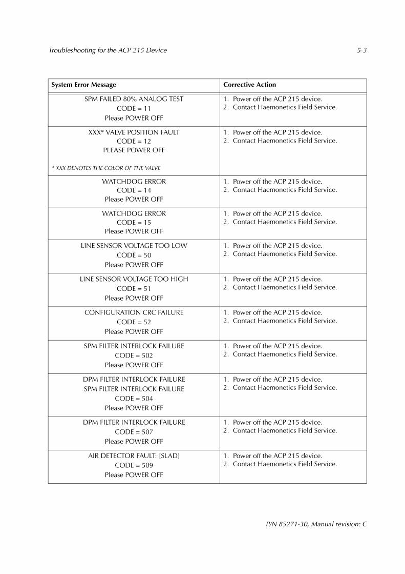
Troubleshooting for the ACP 215 Device 5-3
P/N 85271-30, Manual revision: C
SPM FAILED 80% ANALOG TESTCODE = 11
Please POWER OFF
1. Power off the ACP 215 device.2. Contact Haemonetics Field Service.
XXX* VALVE POSITION FAULTCODE = 12
PLEASE POWER OFF
* XXX DENOTES THE COLOR OF THE VALVE
1. Power off the ACP 215 device.2. Contact Haemonetics Field Service.
WATCHDOG ERRORCODE = 14
Please POWER OFF
1. Power off the ACP 215 device.2. Contact Haemonetics Field Service.
WATCHDOG ERRORCODE = 15
Please POWER OFF
1. Power off the ACP 215 device.2. Contact Haemonetics Field Service.
LINE SENSOR VOLTAGE TOO LOWCODE = 50
Please POWER OFF
1. Power off the ACP 215 device.2. Contact Haemonetics Field Service.
LINE SENSOR VOLTAGE TOO HIGHCODE = 51
Please POWER OFF
1. Power off the ACP 215 device.2. Contact Haemonetics Field Service.
CONFIGURATION CRC FAILURECODE = 52
Please POWER OFF
1. Power off the ACP 215 device.2. Contact Haemonetics Field Service.
SPM FILTER INTERLOCK FAILURECODE = 502
Please POWER OFF
1. Power off the ACP 215 device.2. Contact Haemonetics Field Service.
DPM FILTER INTERLOCK FAILURESPM FILTER INTERLOCK FAILURE
CODE = 504Please POWER OFF
1. Power off the ACP 215 device.2. Contact Haemonetics Field Service.
DPM FILTER INTERLOCK FAILURECODE = 507
Please POWER OFF
1. Power off the ACP 215 device.2. Contact Haemonetics Field Service.
AIR DETECTOR FAULT: [SLAD]CODE = 509
Please POWER OFF
1. Power off the ACP 215 device.2. Contact Haemonetics Field Service.
System Error Message Corrective Action

5-4 Troubleshooting for the ACP 215 Device
P/N 85271-30, Manual revision: C
AIR DETECTOR FAULT: [BLAD]CODE = 510
Please POWER OFF
1. Power off the ACP 215 device.2. Contact Haemonetics Field Service.
DPM OUT OF TOLERANCECODE = 514
Please POWER OFF
1. Power off the ACP 215 device.2. Contact Haemonetics Field Service.
SPM OUT OF TOLERANCECODE = 515
Please POWER OFF
1. Power off the ACP 215 device.2. Contact Haemonetics Field Service.
CPU RELAY CLOSING FAILURECODE = 701
Please POWER OFF
1. Power off the ACP 215 device.2. Contact Haemonetics Field Service.
CPU RELAY OPENING FAILURECODE = 702
Please POWER OFF
1. Power off the ACP 215 device.2. Contact Haemonetics Field Service.
System Error Message Corrective Action
Troubleshooting for the ACP 215 Device 5-5
P/N 85271-30, Manual revision: C
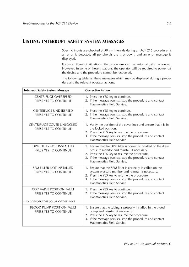
LISTING INTERRUPT SAFETY SYSTEM MESSAGES
Specific inputs are checked at 50 ms intervals during an ACP 215 procedure. Ifan error is detected, all peripherals are shut down, and an error message isdisplayed.
For most these of situations, the procedure can be automatically recovered.However, in some of these situations, the operator will be required to power offthe device and the procedure cannot be recovered.
The following table list these messages which may be displayed during a proce-dure and the relevant operator actions.
Interrupt Safety System Message Corrective Action
CENTRIFUGE OVERSPEED PRESS YES TO CONTINUE
1. Press the YES key to continue.2. If the message persists, stop the procedure and contact
Haemonetics Field Service.
CENTRIFUGE UNDERSPEED PRESS YES TO CONTINUE
1. Press the YES key to continue.2. If the message persists, stop the procedure and contact
Haemonetics Field Service.
CENTRIFUGE COVER UNLOCKEDPRESS YES TO CONTINUE
1. Verify the position of the cover lock and ensure that it is in the locked position.
2. Press the YES key to resume the procedure.3. If the message persists, stop the procedure and contact
Haemonetics Field Service
DPM FILTER NOT INSTALLEDPRESS YES TO CONTINUE
1. Ensure that the DPM filter is correctly installed on the draw pressure monitor and reinstall if necessary.
2. Press the YES key to resume the procedure.3. If the message persists, stop the procedure and contact
Haemonetics Field Service.
SPM FILTER NOT INSTALLEDPRESS YES TO CONTINUE
1. Ensure that the SPM filter is correctly installed on the system pressure monitor and reinstall if necessary.
2. Press the YES key to resume the procedure.3. If the message persists, stop the procedure and contact
Haemonetics Field Service
XXX* VALVE POSITION FAULTPRESS YES TO CONTINUE
* XXX DENOTES THE COLOR OF THE VALVE
1. Press the YES key to continue.2. If the message persists, stop the procedure and contact
Haemonetics Field Service.
BLOOD PUMP POSITION FAULTPRESS YES TO CONTINUE
1. Ensure that the tubing is properly installed in the blood pump and reinstall if necessary.
2. Press the YES key to resume the procedure.3. If the message persists, stop the procedure and contact
Haemonetics Field Service

5-6 Troubleshooting for the ACP 215 Device
P/N 85271-30, Manual revision: C
SOLUTION PUMP POSITION FAULTPRESS YES TO CONTINUE
1. Ensure that the tubing is properly installed in the solution pump and reinstall if necessary.
2. Press the YES key to resume the procedure.3. If the message persists, stop the procedure and contact
Haemonetics Field Service
BLOOD PUMP WRONG DIRECTIONPRESS YES TO CONTINUE
1. Press the YES key to continue.2. If the message persists, stop the procedure and contact
Haemonetics Field Service.
SOLUTION PUMP WRONG DIRECTIONPRESS YES TO CONTINUE
1. Press the YES key to continue.2. If the message persists, stop the procedure and contact
Haemonetics Field Service.
CHECK SHAKER CONNECTIONPRESS YES TO CONTINUE
1. Ensure that the shaker connector is attached to the rear pan-el of the ACP 215 device.
2. Press the YES key to resume the procedure3. If the message persists, stop the procedure and contact
Haemonetics Field Service.
FLUID IN CENTRIFUGE DETECTEDPlease POWER OFF
If there is a spill in the centrifuge, the centrifuge and pump(s) will stop.1. Power off the ACP 215 device.2. Refer to the appropriate section of the manual for guidance
on handling a blood spill.3. Contact Haemonetics Field Service.
WATCHDOG ERRORPlease POWER OFF
1. Power off the ACP 215 device.2. Contact Haemonetics Field Service.
SOFTWARE WATCHDOG FAULTINVALID STATE
CODE = 802Please POWER OFF
1. Power off the ACP 215 device.2. Contact Haemonetics Field Service.
SOFTWARE WATCHDOG FAULTCURRENT MODULE ID = XXX*EXPECTED MODULE ID = XXX
CURRENT STATE = XXXCODE = 800
Please POWER OFF
* XXX DENOTES THE VALUE DISPLAYED
1. Power off the ACP 215 device.2. Contact Haemonetics Field Service.
Interrupt Safety System Message Corrective Action

Troubleshooting for the ACP 215 Device 5-7
P/N 85271-30, Manual revision: C
=============================INTERNAL SOFTWARE ERROR
MODULE: XXX*LINE: XXX
STATE: XXXPARAM: XXX
=============================
* XXX DENOTES THE VALUE DISPLAYED
1. Power off the ACP 215 device.2. Contact Haemonetics Field Service.
INTERNAL SOFTWARE ERRORCALL HAEMONETICS FIELD SERVICE
1. Power off the ACP 212 device.2. Contact Haemonetics Field Service.
Interrupt Safety System Message Corrective Action