
H9MO-LMXE+_user_manual_V1.7.pdf
81
Huahuan Beijing Huahuan Electronics Co., Ltd. H9MO-LMXE+ Manual Ver. 1.7 -1- MetroEdge Express H9MO – LMXE+ User Manual Beijing Huahuan Electronics Co., Ltd.
-
Upload
sunynguyen -
Category
Documents
-
view
197 -
download
50
Transcript of H9MO-LMXE+_user_manual_V1.7.pdf
Huahuan Beijing Huahuan Electronics Co., Ltd.
H9MO-LMXE+ Manual Ver. 1.7 -1-
MetroEdge Express
H9MO – LMXE+
User Manual
Beijing Huahuan Electronics Co., Ltd.

Huahuan Beijing Huahuan Electronics Co., Ltd.
H9MO-LMXE+ Manual Ver. 1.7 -2-
MetroEdge Express
H9MO – LMXE+
User Manual
Beijing Huahuan Electronics Co., Ltd.
2011.11

Huahuan Beijing Huahuan Electronics Co., Ltd.
H9MO-LMXE+ Manual Ver. 1.7 -3-
Disclaimer
The information contained in this document is subject to change without notice and does not represent a commitment on the part of Beijing Huahuan Electronics Co., Ltd. (Huahuan). The information in this document is believed to be accurate and reliable, however, Huahuan assumes no responsibility or liability for any errors or inaccuracies that may appear in the document.
Copyright© 2011, Beijing Huahuan Electronics Co., Ltd. All rights reserved. No part of this publication may be reproduced or distributed in any form or by any means, without prior written permission of Huahuan.
Product Model: H9MO-LMXE+ Manual Version: 1.7 Last Update: 2011.11
BEIJING HUAHUAN ELECTRONICS Co., LTD. Address: No.26, Shangdi 6th Street,
Haidian District, Beijing, 100085 P.R. China
Tel: (8610)62981998, (8610)62988820, (8610)62960985 Fax: (8610)82899800 Web: http://www.huahuan.com;http://www.huahuan.com.cn
E-mail: [email protected];[email protected]

Huahuan Beijing Huahuan Electronics Co., Ltd.
H9MO-LMXE+ Manual Ver. 1.7 -4-
Table of content
1. OVERVIEW ....................................................................................................................................................6
2. PRODUCT DESCRIPTION.........................................................................................................................7
2.1 HARDWARE ARRANGEMENT .......................................................................................................................7 2.2 SERVICE CARDS ............................................................................................................................................8
2.2.1 DC Power Card and AC Power Card............................................................................................................................................8 2.2.2 Network Management Card (NM01/NM02)............................................................................................................................9 2.2.3 Dual STM-1/ STM-4/ STM-16 Aggregation Card and 4 ports STM-1 aggregation card............11 2.2.4 Dual STM-1 Aggregation Electrical Card (EX01) ..........................................................................................................13 2.2.5 SDH Cross Connection Card(DX01)...................................................................................................................................14
2.2.6 DS0 Cross Connection Card (DX02) .......................................................................................................................................15 2.2.7 Dual STM-1/STM-4 Tributary Card (OS01/OS01S/OS04/OS04A)..................................................................16 2.2.8 Dual STM-1+Ethernet Tributary Card and STM-1+Ethernet Tributary Card.....................................17 2.2.9 PDH Tributary Card(OP02/OP03/OP05/OP06) .....................................................................................................18 2.2.10 24×E1 PDH Interface Card and 12×E1 PDH Interface Card .............................................19
2.2.11 E3/DS3 PDH Interface Card (EP02)...........................................................................................................................................21 2.2.12 2 V.35 Card(ED01) ...............................................................................................................................................................................22
2.2.13 OW/Overhead/Clock card(LA01)............................................................................................................................................24 2.2.14 4 Tx Ports Channel Type EOS Card (FE01)..........................................................................................................................26 2.2.15 4 Fx Ports Channel Type EOS Card (FE02).........................................................................................................................27 2.2.16 4 Tx Ports Channel Type EOE Card (FE04).........................................................................................................................28 2.2.17 4 Fx Ports Channel Type EOE Card (FE05) ....................................................................................................................29 2.2.18 2Tx Ports Aggregation Type EOS Card (FE06).................................................................................................................30 2.2.19 Tx Port Aggregation Type EOS Card (FE06A)...................................................................................................................31 2.2.20 2Tx Ports Aggregation Type EOE Card (FE07) ................................................................................................................31 2.2.21 GE Port Aggregation Type EOS Card (GX01/GX01A)...............................................................................................32 2.2.22 GE Port Aggregation Type EOE Card (GX02/GX02A) ..............................................................................................34 2.2.23 Double GE interface 16 channel aggregation EoS card(GX05)................................................................36
2.2.24 63:1 EoE/GE Ethernet aggregation card (GX10)........................................................................................................37 2.2.25 DSL digital subscriber line Ethernet access card (DSL01) ....................................................................................39 2.2.26 DSL digital subscriber line E1 access card (DSL02) ...................................................................................................40 2.2.27 Multifunctional voice card(CHU01) ....................................................................................................................................41
2.2.28 Multi-interface card(CHM01)....................................................................................................................................................42
2.2.29 Local side voice card(CHL01)...................................................................................................................................................44
2.2.30 Remote side voice card(CHR01)..............................................................................................................................................44
2.2.31 4/W audio voice card(CH4W01)..............................................................................................................................................45
2.2.32 Asynchronous data card(SD01/SD02)................................................................................................................................47
2.2.33 64K homonymous data card(CHD01) ................................................................................................................................49
2.2.34 Ring card(RING48V/RING24V/RING220V) ................................................................................................................50 2.2.35 Coarse wavelength division multiplexing card (WDM01/WDM01A)............................................................51 2.2.36 Device identification section................................................................................................................................................................52
2.3 EQUIPMENT INSTALLATION .......................................................................................................................52 2.3.1 Structure of the Card Mounting.........................................................................................................................................................52 2.3.2 Rear Panel ............................................................................................................................................................................................................52 2.3.3 Power connection...........................................................................................................................................................................................53 2.3.4 Network management connection ...................................................................................................................................................53 2.3.5 Alarm Output......................................................................................................................................................................................................54

Huahuan Beijing Huahuan Electronics Co., Ltd.
H9MO-LMXE+ Manual Ver. 1.7 -5-
2.3.6 Fan connection .................................................................................................................................................................................................54 2.3.7 Timing signal connection ........................................................................................................................................................................54 2.3.8 Optical fiber connection...........................................................................................................................................................................54 2.3.9 E1/E3/DS3 interface connection ......................................................................................................................................................54 2.3.10 Ethernet connection......................................................................................................................................................................................55 2.3.11 V.35 interface connection........................................................................................................................................................................55 2.3.12 Audio line connection.................................................................................................................................................................................55 2.3.13 Cable Duct Mounting .................................................................................................................................................................................55
3. OPERATION AND MAINTENANCE ...................................................................................................56
3.1 MANAGEMENT SOFTWARE........................................................................................................................56 3.1.1 IP Address Query and Configuration ..........................................................................................................................................56 3.1.2 H7GMSW Software Intro.........................................................................................................................................................................57 3.1.3 Topology Management...............................................................................................................................................................................58 3.1.4 Enquire and Change Node Info.........................................................................................................................................................61 3.1.5 NE Explorer .........................................................................................................................................................................................................61
3.2 NETWORKING ..............................................................................................................................................62 3.2.1 Management Channel.................................................................................................................................................................................62 3.2.2 Clock Setting.......................................................................................................................................................................................................66 3.2.3 Channel Provision .........................................................................................................................................................................................67 3.2.4 Service Protection..........................................................................................................................................................................................68 3.2.5 PCM service configuration ...................................................................................................................................................................70 3.2.6 E1 Ber Test Set ..................................................................................................................................................................................................72 3.2.7 OW/Overhead settings ...............................................................................................................................................................................74
4. SPECIFICATIONS.........................................................................................................................................75
4.1 GENERAL......................................................................................................................................................75 4.2 STM-1 OPTICAL/ELECTRICAL PORT .......................................................................................................76 4.3 STM-4 OPTICAL PORT...............................................................................................................................76 4.4 STM-16 OPTICAL PORT.............................................................................................................................76 4.5 PDH OPTICAL INTERFACE.........................................................................................................................76 4.6 E1 PORT ........................................................................................................................................................77 4.7 E3/DS3 PORT...............................................................................................................................................77 4.8 ETHERNET PORT ..........................................................................................................................................77 4.9 V.35 PORT.....................................................................................................................................................77 4.10 CLOCK PORT................................................................................................................................................77 4.11 MANAGEMENT PORT..................................................................................................................................78 4.12 OW/OVERHEAD PORT................................................................................................................................78 4.13 AUDIO AND ASYNCHRONOUS DATA INTERFACE......................................................................................78
4.13.1 Conventional telephone interface and signal.......................................................................................................................78 4.13.2 Special interface ..............................................................................................................................................................................................79
4.14 MECHANICAL/ELECTRICAL ......................................................................................................................80 4.15 REFERENCE STANDARDS ...........................................................................................................................80
5. APPENDIX ........................................................................................................................................................81

Huahuan Beijing Huahuan Electronics Co., Ltd.
H9MO-LMXE+ Manual Ver. 1.7 -6-
1. Overview Thank you for choosing H9MO-LMXE+ SDH platform from Beijing Huahuan Electronics Co., Ltd. To ensure
the best performance of the device, please read this manual carefully.
H9MO-LMXE+ is a member of Huahuan’s Metro-Edge Express SDH/MSTP product family. This family of products is aimed at the network edge, providing TDM and Ethernet services to meet the needs of today’s network evolution. Other members in the Metro-Edge Express include H9MO-LMX, H9MO-LM, H9MO-LMFIT, H9MO-LMV, H9MO-LM63, H9MO-LMA, etc.
H9MO-LMXE+ is a card based compact SDH equipment, designed mainly as a gateway node between the core SDH network and a number of remote CPE boxes. It may also be used as a multi service SDH ADM node in a typical ring or mash network. The 3RU high 19 inch wide chassis of the H9MO-LMXE+ has 19 card positions, with 2 slots for the 1+1 power cards, 1 slot for network management card, 2 slots for network interface unit(NIU) cards, and 14 slots for local interface unit(LIU) cards. The plug-in cards for the H9MO-LMXE+ are listed in Table 1-1.
Table 1-1 Available cards on H9MO-LMXE
Card Slot Type Description Note
PWR01/PWR02 PWR Power card, 1+1 redundancy supported NM01 NM Network management card
OX01 NIU Dual STM-1 fiber optic NIU card With cross-connect and timing
OX04 NIU Dual STM-4 fiber optic NIU card With cross-connect and timing
DX01 NIU SDH cross connection card LA01 LIU Order wire card OS01 LIU Dual STM-1 fiber optic LIU card
OS02/OS02A LIU Dual STM-1 Ethernet LIU card
OS03 LIU STM-1 Ethernet LIU card EP01/EP01A LIU 24 E1 interface card Occupies 2 slot positions EP03/EP03A LIU 12×E1 (75Ω or 120Ω)
EP02 LIU E3/DS3 interface card Jumper select ED01 LIU Dual V.35 interface card FE01 LIU 4 Tx over 4 VCG trunk EoS card FE02 LIU 4 Fx over 4 VCG trunk EoS card FE04 LIU 4 FE over 1~16E1 (EoE) FE05 LIU 4 Fx over 1~16E1 (EoE)
FE06A LIU 2Tx interface switch EoS card GX01/GX01A LIU 8:1 EoS aggregation card, GE output GX02/GX02A LIU 8:1 EoE aggregation card, GE output
GX05 LIU 16:1 EoS aggregation card, GE output GX06 LIU 16:1 EoE aggregation card, GE output GX10 LIU 63:1 EoE aggregation card, GE output
DX01/DX02 LIU DS0 cross connection card DSL01/DSL02 LIU DSL Ethernet/E1 access card
WDM01/WDM01A LIU Coarse wavelength division multiplexing card
CHU01 Multifunctional voice card CHM01 Slot 8-13 Multi-interface card (CHM01) CHL01 LIU Local side voice card
Huahuan Beijing Huahuan Electronics Co., Ltd.
H9MO-LMXE+ Manual Ver. 1.7 -7-
CHR01 LIU Remote side voice card CH4W01 LIU 4/W audio voice card SD01/2 LIU Asynchronous data card
RING48V/RING24V/ RING220V Slot 14 Ring card
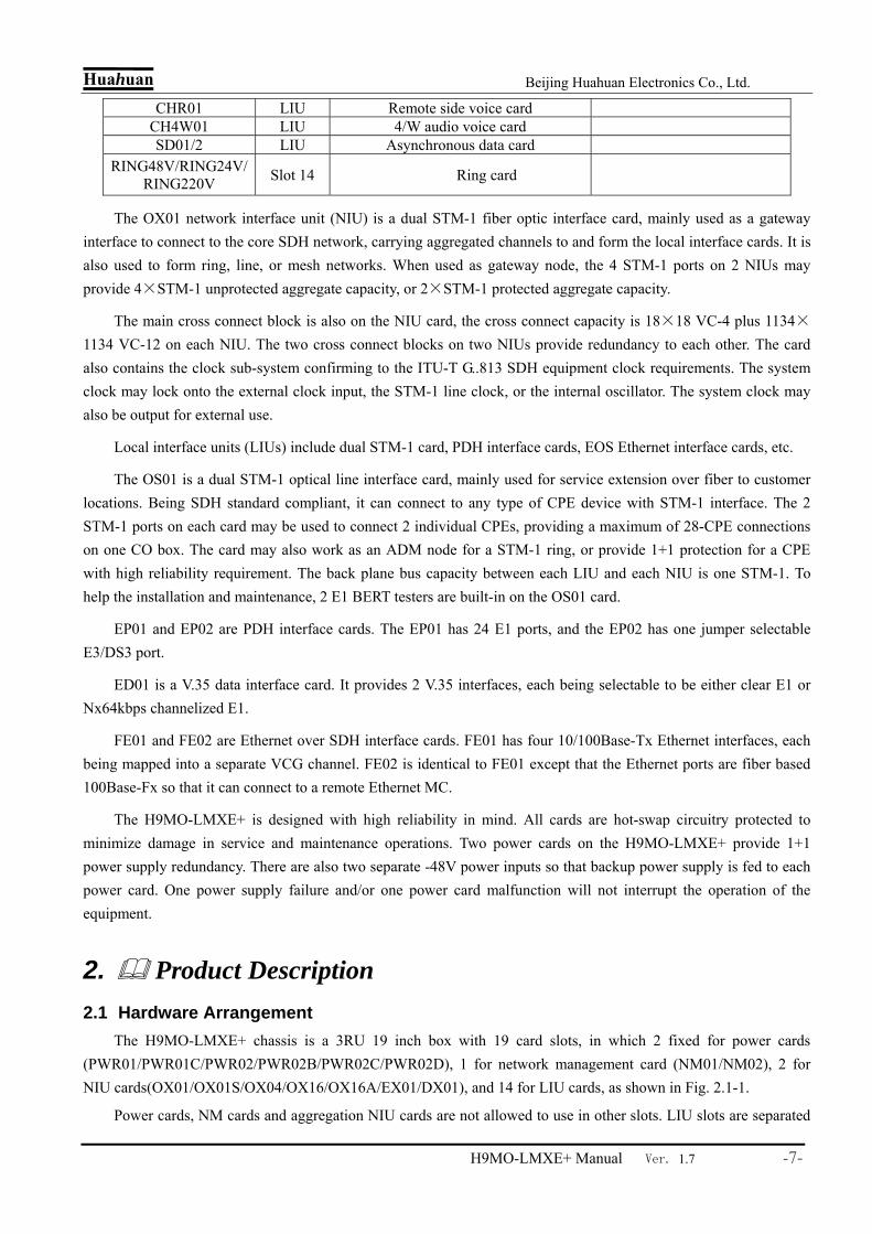
The OX01 network interface unit (NIU) is a dual STM-1 fiber optic interface card, mainly used as a gateway interface to connect to the core SDH network, carrying aggregated channels to and form the local interface cards. It is also used to form ring, line, or mesh networks. When used as gateway node, the 4 STM-1 ports on 2 NIUs may provide 4×STM-1 unprotected aggregate capacity, or 2×STM-1 protected aggregate capacity.
The main cross connect block is also on the NIU card, the cross connect capacity is 18×18 VC-4 plus 1134×1134 VC-12 on each NIU. The two cross connect blocks on two NIUs provide redundancy to each other. The card also contains the clock sub-system confirming to the ITU-T G..813 SDH equipment clock requirements. The system clock may lock onto the external clock input, the STM-1 line clock, or the internal oscillator. The system clock may also be output for external use.
Local interface units (LIUs) include dual STM-1 card, PDH interface cards, EOS Ethernet interface cards, etc.
The OS01 is a dual STM-1 optical line interface card, mainly used for service extension over fiber to customer locations. Being SDH standard compliant, it can connect to any type of CPE device with STM-1 interface. The 2 STM-1 ports on each card may be used to connect 2 individual CPEs, providing a maximum of 28-CPE connections on one CO box. The card may also work as an ADM node for a STM-1 ring, or provide 1+1 protection for a CPE with high reliability requirement. The back plane bus capacity between each LIU and each NIU is one STM-1. To help the installation and maintenance, 2 E1 BERT testers are built-in on the OS01 card.
EP01 and EP02 are PDH interface cards. The EP01 has 24 E1 ports, and the EP02 has one jumper selectable E3/DS3 port.
ED01 is a V.35 data interface card. It provides 2 V.35 interfaces, each being selectable to be either clear E1 or Nx64kbps channelized E1.
FE01 and FE02 are Ethernet over SDH interface cards. FE01 has four 10/100Base-Tx Ethernet interfaces, each being mapped into a separate VCG channel. FE02 is identical to FE01 except that the Ethernet ports are fiber based 100Base-Fx so that it can connect to a remote Ethernet MC.
The H9MO-LMXE+ is designed with high reliability in mind. All cards are hot-swap circuitry protected to minimize damage in service and maintenance operations. Two power cards on the H9MO-LMXE+ provide 1+1 power supply redundancy. There are also two separate -48V power inputs so that backup power supply is fed to each power card. One power supply failure and/or one power card malfunction will not interrupt the operation of the equipment.
2. Product Description 2.1 Hardware Arrangement
The H9MO-LMXE+ chassis is a 3RU 19 inch box with 19 card slots, in which 2 fixed for power cards (PWR01/PWR01C/PWR02/PWR02B/PWR02C/PWR02D), 1 for network management card (NM01/NM02), 2 for NIU cards(OX01/OX01S/OX04/OX16/OX16A/EX01/DX01), and 14 for LIU cards, as shown in Fig. 2.1-1.
Power cards, NM cards and aggregation NIU cards are not allowed to use in other slots. LIU slots are separated

Huahuan Beijing Huahuan Electronics Co., Ltd.
H9MO-LMXE+ Manual Ver. 1.7 -8-
to two kinds: A type and B type. What’s more, slot4 and slot11 are Ethernet aggregation slots, which can do Ethernet aggregation when equipped with Ethernet aggregation cards. There are many types of LIU cards: duel STM-4 cards (OS04/OS04A); duel STM-1 cards (OS01/OS01S); duel STM-1 plus Ethernet cards (OS02/OS02A); STM-1 plus Ethernet card (OS03); PDH optical cards (OP02/OP03/OP05/OP06); PDH E1 cards (EP01/EP01A/EP03/EP03A); PDH E3/DS3 card (EP02); 4Tx Ethernet over VC-12 (EoS) card (FE01); 4Fx EoS optical card (FE02); 4Tx Ethernet over E1 (EoPDH/EoE) card (FE04); 4Fx EoE card (FE05);Tx EoS aggregation card (FE06A); 2Tx EoS aggregation card(FE06); 2Tx EoE aggregation card (FE07); GE EoS aggregation card (GX01/GX01A); GE EoE aggregation card (GX02/GX02A); DSL Ethernet access card (DSL01); V.35 card (ED01); multifunction voice channel card (CHU01); multi interface card (CHM01); FXO interface card (CHL01); FXS interface card (CHR01); 4 wire voice card (CH4W01); asynchronous data interface card (SD01/SD02); ring card (RING48V); OW/Overhead/Clock card(LA01); SDH cross connection card (DX01); DS0 cross connection card(DX02).
When using STM-1 and STM-4 aggregation cards in NIU slots, A slots’ backboard bandwidth to NIU is 2 VC-4; B slots’ backboard to NIU is 1 VC-4.
When using STM-16 aggregation cards in NIU slots, A slots can use STM-4 tributary cards (OS04/OS04A); and each STM-4 tributary card has 8 VC-4 bandwidth to the NIU slots. STM-1 tributary cards have 1 VC-4 bandwidth to NIU slots, no matter A or B slots they are using.
Except ring card, all the other cards are hot swappable. The 2 power cards are identical and provide 1+1 redundancy. On top of the chassis, is a removable cable duct for cable wiring.
Fig. 2.1-1 Chassis and card positions
2.2 Service Cards This section describes service cards available on H9MO-LMXE.
2.2.1 DC Power Card(PWR01/PWR01C)and AC Power Card(PWR02/PWR02B/PWR02C/ PWR02D)
The power cards (PWR01/PWR01C/ PWR02/PWR02B/PWR02C/ PWR02D) are used to supply power to the equipment operation and the system fan. Every single power card is sufficient to provide power for the entire fully loaded system. Therefore the 2 pcs power cards can provide 1+1 protection. AC+AC, AC+DC, DC+DC are available options. There is a fan on the back board for cooling purpose.
PWR01’s and PWR01C’s input is DC-48V. PWR01’s output is 100W, while PWR02C’s output is 200W. PWR02’s and PWR02C’s input is AC~220V. PWR02’s output is 100W, while PWR02C’s output is 200W. PWR02B’s and PWR02D’s input is AC~110V. PWR02B’s output is 100W, while PWR02D’s output is 200W. Apart from a 5A fuse on the DC power card PWR01 and PWR01C above the switch that may require
replacement in case of burn out, there are no other user serviceable parts on the card.
PW R
N MN IU
LIU

Huahuan Beijing Huahuan Electronics Co., Ltd.
H9MO-LMXE+ Manual Ver. 1.7 -9-
H9MO-LMXE+ has 2 separate -48V power-in sockets, both are fed to each of the power cards. Where backup -48V power is available at the site, it will work even only one power card is available. The power cards are the only heat intensive cards in the equipment.
Each DC power card (PWR01/PWR01C) has one switch, one DC socket, three LEDs on the panel. AC power card (PWR02/PWR02B/PWR02C/PWR02D)has one standard AC socket and two LEDs, as shown in Fig 2.2-1.
Fig 2.2-1 Power card (PWR01/PWR01C/PWR02/PWR02B/PWR02C/PWR02D) panel Table 2.2-1 Power card LED definitions
Label Color Description Note
+5V G 5V indicator On: Working, Off: Fail or switched off
-48V1FAIL R First -48V power input status indicator Off: OK, On: Fail or not connected
-48V2FAIL R Second -48V power input status indicator Off: OK, On: Fail or not connected
DC power card (PWR01/ PWR01C) indictor
220VFAIL R AC~220V power status indication Off: OK, On: Fail or not connected
AC power card (PWR02 /PWR02C) indictor
110V FAIL R AC~110V power status indication Off: OK, On: Fail or not connected
AC power card (PWR02B/ PWR02D) indictor
Notice: Equipment should be well earthed. Earthing bolt is on the backboard. And do not mix AC~110V and AC~220V.
2.2.2 Network Management Card (NM01/NM02)
The NM card hosts the microcontroller subsystem. It provides management to the equipment. The NM card interfaces with a management workstation through the Ethernet ports on the panel. All sub units’ information can be displayed by NM cards, including PWR cards and fan. And the service configuration is stored in NM card’s flash.
NM cards support on-line upgrading. NM cards also support backup service configuration to main aggregation cards. If the NM card is down, customer can first back up the service to main aggregation cards, change a new NM card and then copy back the service configuration back from the aggregation card with special dip switch setting.
The node may also be remotely managed through DCC channels (D1~D12) or through dedicated VC-12.
NM01 has one Ethernet port, one alarm output socket, two buttons, 4-dip switch and 4 LEDs.
P W R 0 1
+ 5 V
- 4 8 V 1 F A I L
- 4 8 V 2 F A I L
DC 48V
-+
1
P W R 0 1 C
+ 5 V
- 4 8 V 1 F A I L
- 4 8 V 2 F A I L
DC 48V
-+
1
P W R 0 2
+ 5 V
2 2 0 V F A I L
P W R 0 2 B
+ 5 V
1 1 0 V F A I L
P W R 0 2 C
+ 5 V
2 2 0 V F A I L
P W R 0 2 D
+ 5 V
1 1 0 V F A I L

Huahuan Beijing Huahuan Electronics Co., Ltd.
H9MO-LMXE+ Manual Ver. 1.7 -10-
NM02 has two Ethernet port, one alarm output socket, two buttons, 4-dip switch and 4 LEDs.
The LEDs and the push button switches are described in Table 2.2-2, Table 2.2-3 and Table 2.2-4 . There are no user serviceable parts on the card.
Fig 2.2-2 NM Card (NM01/NM02) Panel
Table 2.2-2 LEDs on NM card Label Color Description Note RUN G Operation indicator. Flashing when working normally
MASK Y Alarm mask indicator. On when MASK switch is pushed down ALM-P R Prompt alarm indicator. On when prompt alarm events occur ALM-D Y Deferred alarm indicator. On when deferred alarm events occur
Alarm types are software defined
Table 2.2-3 Push buttons on NM card Label Description
MASK Push button with lock. When pushed in, the alarm output and the internal buzzer are disabled, otherwise alarms will be output on alarm outputs on the back panel, and a buzzer inside the card will give alarm sound.
AUTO Push button without lock. Each time it is pushed, the current alarm will be cleared from causing buzzing and alarm output. New alarms will not be blocked.
Table 2.2-4 Dip switches on NM card Label Description Note
1 ON (down): use IP address 192.192.192.192 OFF (up): use primary IP address
2 ON (down): NM card is in standby status; equipment status can be
enquired, but cannot set system register. OFF (up): NM card is well managed, can be enquired and set.
3
ON (down): Dip switch confirm equipment configuration, when dip switches is set down, embedded software can confirm current configuration automatically, mount and delete cards.
OFF (up): software cannot recognize new configuration when settings are changed.
Except dip2, dip 1 and 3 are all valid when it is switched, that is to say, when dip are switched, the equipment will carry out its relative function in the table, it is independent with dip status.
4
ON (down): Upload the equipment configuration information from the aggregation card to NM card.
OFF (up): NM card does not upload configuration from the aggregation card.
Dip4 takes effect only when system booting. So please make the setting before boot the system.
Service configuration download and upload
N M 0 1
A L M - D
M A S K
A U T O
N M
A L M - P
R U N
M A S K
C T R L
1234
A L M
N M 0 2
A L M - D
M A S K
A U T O
N M
A L M - P R U N
M A S K
C T R L
1234
A L M

Huahuan Beijing Huahuan Electronics Co., Ltd.
H9MO-LMXE+ Manual Ver. 1.7 -11-
1. Download means back up the service configuration information from NM card to main aggregation card, which is indicated by LED MA. This function is disabled when leaving factory. You can enable this option in NMS software. When it is enabled, the service configuration information will be automatically backed up to the main aggregation card. When the information changes in NM, the information in aggregation card will be updated after 1 minute. If the NM card is removed or the power supply gets trouble when downloading, the information in aggregation card may get lost.
2. Upload means copy the service configuration information from main aggregation card to NM card. Before changing new NM card or reboot system, switch on the 4th dip switch. The information will be copied when plug in the new NM card or system boots. LED RUN and MASK will blink when uploading. If you do not want to interrupt current service, please turn on the second dip switch. 1 minute later switch back dip2.
3. Download and upload need newer embedded software version: OX01/OX01S V1.3; OX04 V1.4; OX16 V1.1; OX16 V1.2.
Notice: if the download function is disabled, no upload operation will be taken out when you insert the new NM card, because there is no backup data in main aggregation card.
Ethernet Port:
NM01 has 1 FE port and NM02 has 2 switching FE ports.
Ethernet NM ports (labeled NM in the front panel) are 100Base-Tx standard RJ45 ports, with HP auto-MDIX function, The port is HP auto-MDIX compliant, it will automatically adapt to MDI or MDI-X interfaces. That is, either parallel or crossover cables can be used to connect to any 10/100Base-T port.
Two LEDs are located at the Ethernet port sockets, the green one is for LINK indication, on indicates cable connected well, off indicates cable link error; the yellow one is for duplex indication, on indicates full-duplex, off indicates half-duplex, blink indicates conflict. RJ45 socket is defined as table 2.2-5.
Table 2.2-5 RJ45 socket definition
Pin 1 2 3 4 5 6 7 8
Definition TxD+ TxD- RxD+ RxD-
Note: The definitions of (Rx)and (Tx)are in relation to this port. Default IP address is 192.192.4.2.In the actual network, equipment of each end should be allocated an IP address
and the address should be written into the equipment by NM Ethernet console port. Steps are as follows: Connect the cross line to the monitored computer and query by Telnet. If the IP address of
the device is unknown, you can use the virtual IP address as 192.192.192.192 by set down dip1 in front panel, while the mask code of the host computer should be changed to 255.255.0.0. For details, please refer to section 4.1.1. Set up the dip switch after the query.
Alarm output port:
The alarm output ports in NM01/NM02 in front panel is as same as the ones in the rear panel, used for single side connection. The two pins of alarm output ends corresponding to system PAL-P and ALM-D, used for connecting to rack alarm units. The PAL-P is the urgent alarm output, and ALM-D is the deferred alarm output. Both outputs are of the dry contact type. Normally, the output pin is floated. Alarms are depends on alarm codes set by NMS. If alarm codes are set, the relative alarm items will be shielded, equipment will not alarm when corresponding alarm occurred. PALM and DALM property are defined by NMS.
2.2.3 Dual STM-1/ STM-4/ STM-16 Aggregation Card (OX01/ OX01A/ OX01S/ OX04/ OX04A/
OX16/ OX16A) and 4 ports STM-1 aggregation card (OX01Q)
The aggregation cards are the core units of the H9MO-LMXE. They not only provide uplink SDH interface but also have cross connection matrix and SEC (SDH equipment clock) block. Each H9MO-LMXE can have 2 aggregation NIU cards in aggregation slots (slot X1 and slot X2). Aggregation cards

Huahuan Beijing Huahuan Electronics Co., Ltd.
H9MO-LMXE+ Manual Ver. 1.7 -12-
OX01/OX01A/OX01S/OX04/OX04A/OX16/OX16A provide 2 STM-1/STM-4/STM-16 ports, while OX01Q support 4 STM-1 ports. The 2 cards’ cross connection matrixes and clock units work as 1+1 protection. They can either be used to connect to the core network nodes, or form a ring network of H9MO-LMXEs.
There are TUPP and powerful cross connection capacity embedded in the aggregation card, STM-1 aggregation card (OX01/OX01A/OX01S) have the cross connection capacity of 20 VC-4 and it’s sub-container. The cross connection capacity of STM-1 aggregation card OX01Q is 24 VC-4 and it’s sub-container. STM-4 aggregation card (OX04/OX04A) have the cross connection capacity of 32 VC-4 and it’s sub-container. STM-16 aggregation card (OX16/OX16A) have 96 VC-4 full cross connection and 32 VC-4 capacity’s VC-3, VC-12 level cross connection. Cross connection support directions of aggregation to tributary, tributary to aggregation, aggregation to aggregation and tributary to tributary. The types of cross connection supported are unidirectional, bidirectional, multicast and loopback.
Aggregation card (OX01/OX01A/OX01S/OX01Q/OX04/OX04A) support revertive and non- revertive SNCP protection, OX16/OX16A support non-revertive SNCP only.
When using STM-1 and STM-4 aggregation cards in NIU (aggregation) slots, A slots’ backboard bandwidth to NIU is 2 VC-4; B slots’ backboard to NIU is 1 VC-4. When using STM-16 aggregation cards in NIU slots, A slots can use STM-4 tributary cards (OS04/OS04A); and each STM-4 tributary card has 8 VC-4 bandwidth to the NIU slots. STM-1 tributary cards have 1 VC-4 bandwidth to NIU slots, no matter A or B slots they are using. Notice: STM-4 tributary card is not allowed to be used in B slots.
Each aggregation card has 2 embedded E1 BER meters, which can be used to check the uplink channel and downlink channel simultaneously. Each aggregation card can set 2 in-band E1 monitoring channels, to transmit the NMS information which usually is carried by DCC.
The SEC block in aggregation cards (OX01/OX01A/OX01S/OX04/OX16/OX16A) confirms to ITU-T G.813 specifications, with one pair of external clock input and output. The clock interface is on the backplane. Or use the clock interface on OW card. 2MHz or 2Mbps mode is supported.
STM-1 aggregation card OX01 provide SC duel fiber optical interface. Single fiber or FC port is also available. STM-1/STM-4/STM-16 aggregation cards (OX01S/OX01A/OX04/OX16/OX16A) provide LC duel fiber LC SFP interface. Other SFPs are also supported.
Besides, OX01/OX01A/OX01S are 2-port aggregation card, and OX01Q is 4-port aggregation card, but only the first 2 ports provide DCC channel. OX01 and OX01A have the same function. OX04 and OX04A have similar function, the difference is that OX04A support STM-4 tributary card OS04/OS04A, but it can’t be used together with LA01 (engineer phone card). OX04 can be used together with LA01, but doesn’t support STM-4 tributary card OS04/OS04A. STM-16 aggregation card OX16 and OX16A have similar function, the difference is that OX16A support engineer phone and OX16 doesn’t.
There is one more LED, labeled MA, on OX01 than that on OS01, as shown in Table 2.2-6. This LED indicates the working (master) clock of the two aggregation (NIU) cards. There are 6 indicators on OX01Q card and 4 STM-1 optical ports.

Huahuan Beijing Huahuan Electronics Co., Ltd.
H9MO-LMXE+ Manual Ver. 1.7 -13-
Fig 2.2-3 Front Panel of OX01/OX01A/OX01S/OX01Q / OX04/OX16/OX16A card
There are no user serviceable components inside the card. The jumpers are for production testing purposes only, and should not be altered in any way. Improper settings will render the card non-operational.
Table 2.2-6 Definition of indicators on OX01/OX01A/OX01S/OX01Q/OX04/OX16/OX16A
Label Color Indicators definition Note
RUN G Running indication: blink denote running normal
MA G Master/spare indication: On: master Off: spare
Indicate clock unit master/spare status
LOS-1 LOS-2 R
Fiber port status indicator On: Loss of incoming signal Off: Normal
Indicate port1 and port2 respectively
BER3-1 BER3-2 R
Fiber line BER indication: On: Receive bit error exceeds 10-3 Off: Receive bit error within 10-3
Indicate port1 and port2 respectively
BER6-1 BER6-2 Y
Fiber line BER indication: On: Receive bit error exceeds 10-6 Off: Receive bit error within 10-6
Indicate port1 and port2 respectively
2.2.4 Dual STM-1 Aggregation Electrical Card (EX01)
The function of EX01 is as same as OX01, only interface is different. Each unit of H9MO-LMX+ can be mounted 2 pcs aggregation cards (which labeled X1 and X2), each EX01 card provides dual STM-1 electrical ports. At the same time, the cross connection and clock units in the two aggregation cards can make of 1+1 protection. Also, each EX01 cards has 2 built-in E1 BER testers and 2 built-in E1 management channels. E1 BER testers and E1 management channels can be inserted by cross matrix.
The electrical port in EX01 adopts CC4 sockets, there are 4 LEDs, 4 BNC sockets on the panel, shown as Fig 2.2-4,indicators are defined as Table 2.2-7.

Huahuan Beijing Huahuan Electronics Co., Ltd.
H9MO-LMXE+ Manual Ver. 1.7 -14-
Fig 2.2-4 Dual STM-1 aggregation card(EX01)panel Table 2.2-7 Dual STM-1 aggregation card(EX01)indicators definition
Label Color Indicators definition Note RUN G Blink: running normally
MA G Master/spare indication: On: master Off: spare
Indicate the master/spare status of clock unit
LOS-1 LOS-2 R
Electrical port signal indication:On: signal loss Off: normal
Indicate 2 channels electrical signal status
2.2.5 SDH Cross Connection Card(DX01)
Each H9MO-LMXE+ can be mounted two pcs SDH cross connection card (DX01) into the slots marked X1 and X2. SDH cross connection card includes cross connection unit and SDH equipment clock unit, belongs to inner function units. There is no signal output port. Two SDH cross connection card can realize 1+1 protection.
DX01 card can support VC4, VC3 complete cross of 20 STM-1, and VC12 complete cross of 32 STM-1. It provides the cross connection and concatenation of VC12, VC3, VC4 level channels between all tributary cards and cross connection cards. There are one clock input and one clock output channel in the built-in SDH equipment clock units complied with ITU-T G.813. The clock interfaces are located in backboard, or from OW/Overhead card front panel. It supports 2Mbit and 2MHz two kinds of clock mode.
Each DX01 card has 2 built-in E1 BER tester, they can test the optical uplink (aggregation side) and downlink (tributary side) simultaneously. Each SDH cross connection also can be built in 2 E1 monitor channel to transmit management information. E1 BER tester and E1 monitor channel can be inserted by cross matrix.
There are 2 indicators in DX01 front panel, shown as Fig 2.2-5, indicators define as Table 2.2-8.
R U N
E X 0 1
L O S
M A
1 2
1
2

Huahuan Beijing Huahuan Electronics Co., Ltd.
H9MO-LMXE+ Manual Ver. 1.7 -15-
Fig 2.2-5 DX01 front panel
Table 2.2-8 SDH cross connection card(DX01)indicator definition Label Color Indicators definition Note RUN G Flash indicates run normally
MA G Master/slave indication On: master Off: slave
Clock unit master/slave state
2.2.6 DS0 Cross Connection Card (DX02)
Card DX02 include 64kbps timeslot cross matrix, which can realize the 30(not include timeslot 16th) or 31 (include timeslot 16th) 64kbps time slot cross connection of each E1 in 63 E1. DS0 cross connection card also belong to inner function unit, there is no output interface. The card can be inserted in 14 universal slots.
DS0 cross connection is used for 64kbps sub speeding leading. 63 VC12 can realize all the 64k time slot cross connection in this card. For the framed E1 channel adopted CAS, the 16th time slot can realize signaling cross connection automatically; for the framed E1 channel adopted CCS, the 16th time slot also can be set to transmit data, realizing cross connection.
There is one indicator in DS0 cross connection card (DX02) front panel, shown as Fig 2.2-6, the indicator definition is as table 2.2-9.
Fig 2.2-6 DS0 cross connection card (DX02) front panel
Table 2.2-9 DS0 cross connection card (DX02) indicator definition Label Color Indicator definition RUN Green Flash indicate run normally
R U N
D X 0 1M A
R U N
D X 0 2
Huahuan Beijing Huahuan Electronics Co., Ltd.
H9MO-LMXE+ Manual Ver. 1.7 -16-
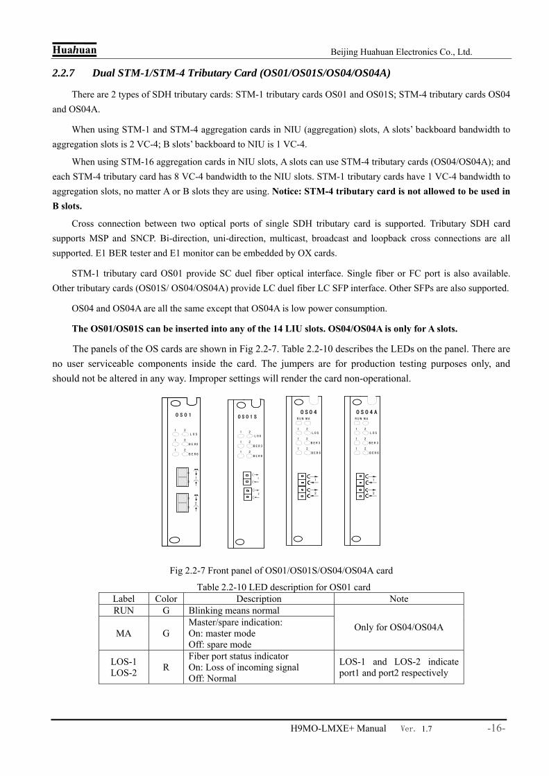
2.2.7 Dual STM-1/STM-4 Tributary Card (OS01/OS01S/OS04/OS04A)
There are 2 types of SDH tributary cards: STM-1 tributary cards OS01 and OS01S; STM-4 tributary cards OS04 and OS04A.
When using STM-1 and STM-4 aggregation cards in NIU (aggregation) slots, A slots’ backboard bandwidth to aggregation slots is 2 VC-4; B slots’ backboard to NIU is 1 VC-4.
When using STM-16 aggregation cards in NIU slots, A slots can use STM-4 tributary cards (OS04/OS04A); and each STM-4 tributary card has 8 VC-4 bandwidth to the NIU slots. STM-1 tributary cards have 1 VC-4 bandwidth to aggregation slots, no matter A or B slots they are using. Notice: STM-4 tributary card is not allowed to be used in B slots.
Cross connection between two optical ports of single SDH tributary card is supported. Tributary SDH card supports MSP and SNCP. Bi-direction, uni-direction, multicast, broadcast and loopback cross connections are all supported. E1 BER tester and E1 monitor can be embedded by OX cards.
STM-1 tributary card OS01 provide SC duel fiber optical interface. Single fiber or FC port is also available. Other tributary cards (OS01S/ OS04/OS04A) provide LC duel fiber LC SFP interface. Other SFPs are also supported.
OS04 and OS04A are all the same except that OS04A is low power consumption.
The OS01/OS01S can be inserted into any of the 14 LIU slots. OS04/OS04A is only for A slots.
The panels of the OS cards are shown in Fig 2.2-7. Table 2.2-10 describes the LEDs on the panel. There are no user serviceable components inside the card. The jumpers are for production testing purposes only, and should not be altered in any way. Improper settings will render the card non-operational.
Fig 2.2-7 Front panel of OS01/OS01S/OS04/OS04A card
Table 2.2-10 LED description for OS01 card Label Color Description Note RUN G Blinking means normal
MA G Master/spare indication: On: master mode Off: spare mode
Only for OS04/OS04A
LOS-1 LOS-2 R
Fiber port status indicator On: Loss of incoming signal Off: Normal
LOS-1 and LOS-2 indicate port1 and port2 respectively
L O S
B E R3
B E R 6
1 2
1 2
1 2
2
1
O S 0 1
1
2
L O S
B E R 3
B E R 6
1 2
1 2
1 2
O S 0 1 S R U N
O S 0 4
L O S
M A
B E R 3
B E R 6
1 2
1 2
1 2
1
2
R U N
O S 0 4 A
L O S
M A
B E R 3
B E R 6
1 2
1 2
1 2
1
2

Huahuan Beijing Huahuan Electronics Co., Ltd.
H9MO-LMXE+ Manual Ver. 1.7 -17-
BER3-1 BER3-2 R
Excess error indicator On: Receive bit error exceeds 10-3 Off: Receive bit error within 10-3
BER3-1 and BER3-2 indicate port1 and port2 respectively
BER6-1 BER6-2 Y
Signal degrade indicator On: Receive bit error exceeds 10-6 Off: Receive bit error within 10-6
BER6-1 and BER6-2 indicate port1 and port2 respectively
Notice: only STM-16 aggregation cards support OS04/OS04A.
2.2.8 Dual STM-1+Ethernet Tributary Card (OS02/OS02A) and STM-1+Ethernet Tributary
Card (OS03)
The OS02/OS01A cards are dual STM-1 Ethernet drop tributary cards. The OS03 card is a single STM-1 Ethernet drop tributary card. They can connect to separate remote CPEs, providing point to multi-point optical access. The difference between OS02/OS02A/OS03 and OS01 is: OS02/OS02A/OS03 realize the Ethernet drop in local card, access Ethernet layer 2 switch chip, and Ethernet service is fixed in 46 VC12 (code from 18~63), getting 100M bandwidth. The VC12 1~17 will be connected to cross connection card via back board SDH trunk.
OS02/OS02A provide 2 STM-1 optical interfaces, dual optical directions. OS03 provide one STM-1 optical interface. Both adopt SC dual-fiber optic modules, single fiber or SC optic modules are optional. OS02 provide 2 100base-Tx Ethernet ports, when VLAN is not set, the two LAN ports are equal, as one two-port Ethernet switch which can providing 100M bandwidth. If VLAN is set, the two LAN ports are independent, they can provide 100M channels respectively. OS03 provide only 1 Ethernet port, providing 100M channel. The two Ethernet ports of OS02A are independent completely, providing 100M bandwidth respectively. Ethernet port support auto-negotiated and manual 100M full-duplex, 100M half-duplex, 10M full-duplex, 10M half-duplex. It can be inserted into any of the 14 LIU slots.
The panel of the OS02/OS03 is shown in Fig 2.2-8. Table 2.2-11 describes the LEDs on the panel. There are no user serviceable components inside the card. The jumpers are for production testing purposes only, and should not be altered in any way. Improper settings will render the card non-operational.
Fig 2.2-8 Front panel of OS02/OS02A/OS03 card
O S 0 2
L O S
2
1
1 2
2
1
O S 0 2 A
L O S
2
1
1 2
2
1
O S 0 3
L O S
S T M - 1
E T H

Huahuan Beijing Huahuan Electronics Co., Ltd.
H9MO-LMXE+ Manual Ver. 1.7 -18-
Table 2.2-11 LED description for OS02/OS02A/OS03card Label Color Description Note
LOS-1 LOS-2 or LOS
R Optical signal status indicator: On: optical signal loss Off: normal
OS02/OS02A card has two LOS LEDs, Indicating 2-chnanel optical interface status; OS03 card has 1 LOS LED, labeled LOS.
ETH-L G Ethernet Link indicator: On: Link normal Off: Link abnormal
ETH-F Y
Ethernet FDX indicator: On: Full-duplex Off: Half-duplex Blink: Conflicted
Located at Ethernet socket
2.2.9 PDH Tributary Card(OP02/OP03/OP05/OP06)
H9MO-LMXE+ supports several kinds of PDH tributary optical card, working with Huahuan PDH stand-alone PDH optic modems, built network as point to point, star topology with E1,V.35, ETH services access. PDH tributary card can be inserted in the 14 universal slots, refer to below table:
Table 2.2-12 PDH tributary
PDH Model Optical number
Service port Services each Optical port supports
Remote Model
OP02 4 None 2×E1 or E1+V.35 H10MOS-30/60 or H10MOS-60AF
OP03 2 2×FE, Ethernet drop in local side
2×E1+ 1×100Base-Tx
H10MOS-60B
OP05 2 2×FE, Ethernet drop in local side
4×E1+ 1×100Base-Tx
H10MO-120B
OP06 2 None 4×E1 H10MO-120+ PDH tributary card with SC connector, FC optional, Ethernet interface with RJ45 connector, definition refers to Table2. Ethernet interface mode can be set to auto-negotiated, manual 100M full duplex, 100M half-duplex, 10M full duplex, 10M half-duplex.
PDH tributary optical front panels are shown as below pictures; Definition refers to Table 2.2-13.
Fig 2.2-9 PDH Tributary Card(OP02/OP03/OP05/OP06)front panel
L O S
1
O P 0 2
B E R
2
3
4
O P 0 3
L OS
2
1
1 2
2
1
O P 0 5
L OS
2
1
1 2
2
1
L O S
B E R3
B E R6
1 2
1 2
1 2
2
1
0 P 0 6

Huahuan Beijing Huahuan Electronics Co., Ltd.
H9MO-LMXE+ Manual Ver. 1.7 -19-
Table 2.2-13 PDH Tributary Card(OP02/OP03/OP05/OP06)indicator definition Indication Color Definition Remark
LOS-1~ LOS-2 LOS-4
Red Optical running status On: optic loss Off :normal
OP02 has 4 Los indicators OP03/OP05/OP06 has 2 LOS indicators
BER or BER3, BER6
Red
Optical Error Code Indication On: error
BER3 10-3
BER6 10-6 Off: no error or error rate is lower than
10-3/10-6
OP02 has 4 BER indicators OP06 has 2 BER3 and 2 BER6 indicators
ETH-L Green Ethernet link status indication On: normal Off: link error
ETH-F Yellow
Ethernet FDX indication: On: full duplex Off: half duplex Blink: conflict
OP03 and OP05 have Ethernet status indication
2.2.10 24 × E1 PDH Interface Card (EP01/EP01A) and 12 × E1 PDH Interface
Card(EP03/EP03A)
The EP01 card is a PDH interface card with 24 E1 ports. This card occupies 2 slot positions, so 14th slot cannot be used. 24E1 PDH interface card (EP01A) and 12E1 PDH interface card (EP03/EP03A) all occupy 1 slot, and if EP01/EP01A/EP03/EP03A is located in 7th or 8th slot, two clock resource input can be selected.
The front panel of EP01/EP01A/EP03/EP03A card is as shown in Fig 2.2-10. RJ45 is used as the physical connectors for the E1 ports in EP01 and EP03, with each connector providing 2 E1 ports. Signal defined as table 2.2-12. E1 ports on EP01A and EP03A adopt DMS-60 connector, signal defined as table 2.2-14.
Fig 2.2-10 Front Panel of EP01/EP03/EP01A/EP03A
Table 2.2-14 EP01/EP03 E1 connector RJ45 socket signal pin-out definition RJ45 pin E1connection Twisted-pair Recommended twisted-pair color
1 E1_IN(1)- Blue 2 E1_IN(1)+ paired Blue-white 3 E1_OUT(1)+ Orange 4 E1_OUT(1)- paired Orange-white 5 E1_IN(2)- Green 6 E1_IN(2)+ paired Green-white 7 E1_OUT(2)+ Brown 8 E1_OUT(2)- paired Brown-white
1
EP01
2
23
24
3
4
5
6
7
8
9
10
11
12
13
14
15
16
17
18
19
20
21
22
E1
E P 0 3
E 1 -1 /1 2
E 1 -1 /1 2
E P 0 1 A
13-2
4
E1
1-12
E1
E P 0 3 A
1-12
E1

Huahuan Beijing Huahuan Electronics Co., Ltd.
H9MO-LMXE+ Manual Ver. 1.7 -20-
Both 75Ω and 120Ω interfaces are provided through the same RJ45 sockets. The port impedance is selected through the 6 sets jumper setting on the card: K1~K6, on to set 75Ω; and down to set 120Ω.
While 120Ω connection cables can be easily made following the pin-out table below, an accessory conversion cable (part number BH4.851.122) is required for 75Ω connections. The cable converts between 1 RJ45 plug and 4 BNC sockets.
When making the 120Ω E1 cables according to Table 2.3-12, pay attention to the twisted pair relationships. Failure to follow the instructed pairing specified in the table, E1 signal transmission will be severely impaired.
Note: The pin out of the RJ45 sockets on the EP01 card is proprietary due to space limitations. Do not confuse with standard 120Ω RJ-48C socket. A standard RJ-48 cable will not work on these sockets, and may cause damage to the port.
Fig 2.2-11 RJ45 connector
Table 2.2-15 EP01A/EP03A E1 connector DMS-60 socket signal pin-out definition
Make: BH4.850.124-B
Pair # Color PIN TYPE SIGNAL
white 17 INPUT E1 Channel 1 Receive Tip(+) 1
Red 14 INPUT E1 Channel 1 Receive Ring(-) purple 47 OUTPUT E1 Channel 1 Transmit Tip(+)
2 Orange 44 OUTPUT E1 Channel 1 Transmit Ring(-) white 13 INPUT E1 Channel 2 Receive Tip(+)
3 Orange 18 INPUT E1 Channel 2 Receive Ring(-) purple 48 OUTPUT E1 Channel 2 Transmit Tip(+)
4 Green 43 OUTPUT E1 Channel 2 Transmit Ring(-) white 12 INPUT E1 Channel 3 Receive Tip(+)
5 yellow 19 INPUT E1 Channel 3 Receive Ring(-)
purple 49 OUTPUT E1 Channel 3 Transmit Tip(+) 6
Blue 42 OUTPUT E1 Channel 3 Transmit Ring(-) white 11 INPUT E1 Channel 4 Receive Tip(+)
7 Green 20 INPUT E1 Channel 4 Receive Ring(-) purple 50 OUTPUT E1 Channel 4 Transmit Tip(+)
8 gray 41 OUTPUT E1 Channel 4 Transmit Ring(-) white 9 INPUT E1 Channel 5 Receive Tip(+)
9 Blue 22 INPUT E1 Channel 5 Receive Ring(-) Red 52 OUTPUT E1 Channel 5 Transmit Tip(+)
10 Orange 39 OUTPUT E1 Channel 5 Transmit Ring(-) white 8 INPUT E1 Channel 6 Receive Tip(+)
11 Brown 23 INPUT E1 Channel 6 Receive Ring(-) Red 53 OUTPUT E1 Channel 6 Transmit Tip(+)
12 Blue 38 OUTPUT E1 Channel 6 Transmit Ring(-)
18

Huahuan Beijing Huahuan Electronics Co., Ltd.
H9MO-LMXE+ Manual Ver. 1.7 -21-
white 7 INPUT E1 Channel 7 Receive Tip(+) 13
black 24 INPUT E1 Channel 7 Receive Ring(-) Red 54 OUTPUT E1 Channel 7 Transmit Tip(+)
14 Green 37 OUTPUT E1 Channel 7 Transmit Ring(-) yellow 6 INPUT E1 Channel 8 Receive Tip(+)
15 Blue 25 INPUT E1 Channel 8 Receive Ring(-)
Red 55 OUTPUT E1 Channel 8 Transmit Tip(+)
16 Brown 36 OUTPUT E1 Channel 8 Transmit Ring(-)
yellow 4 INPUT E1 Channel 9 Receive Tip(+) 17
Brown 27 INPUT E1 Channel 9 Receive Ring(-)
Red 57 OUTPUT E1 Channel 9 Transmit Tip(+) 18
gray 34 OUTPUT E1 Channel 9 Transmit Ring(-)
yellow 3 INPUT E1 Channel 10 Receive Tip(+) 19
gray 28 INPUT E1 Channel 10 Receive Ring(-)
black 58 OUTPUT E1 Channel 10 Transmit Tip(+) 20
Orange 33 OUTPUT E1 Channel 10 Transmit Ring(-)
yellow 2 INPUT E1 Channel 11 Receive Tip(+) 21
Orange 29 INPUT E1 Channel 11 Receive Ring(-)
black 59 OUTPUT E1 Channel 11 Transmit Tip(+) 22
Brown 32 OUTPUT E1 Channel 11 Transmit Ring(-)
yellow 1 INPUT E1 Channel 12 Receive Tip(+) 23
Green 30 INPUT E1 Channel 12 Receive Ring(-)
black 60 OUTPUT E1 Channel 12 Transmit Tip(+) 24
gray 31 OUTPUT E1 Channel 12 Transmit Ring(-)
25 Shield shell GND GND
E1 port impedance of EP01A and EP03A is fixed 120Ω. When the cable is made, please ensure the input and output pair should use the different twisted pair, otherwise, interference will be gotten in.
Note: above table just give one DMS-60 socket, corresponding to 1~12 channels of E1 interface definition, EP01A provide 2 DMS-60 sockets, corresponding to: 1~12, 13~24 channels of E1.
2.2.11 E3/DS3 PDH Interface Card (EP02)
EP02 is PDH interface card with E3/DS3 port which can provide one channel of E3 or DS3.
The front panels of EP02 card are shown as Fig2.2.12. Indicators definition is in Table 2.2-16.

Huahuan Beijing Huahuan Electronics Co., Ltd.
H9MO-LMXE+ Manual Ver. 1.7 -22-
Fig 2.2-12 EP02 card front panel
Table 2.2-16 EP02 indicator definition Label Color Definition
LOS Red Interface signal status indication on:loss of signal off:receive normal
E3/DS3 Green Interface type indication on:E3 Blink:DS3
E3/DS3 interface adopts 75Ω(unbalance)BNC or CC4 sockets, use the dip switch or software to select E3/DS3. The definition of dip switch is given as Table 2.2-17.
Table 2.2-17 EP02 card dip switch definition Dip number Label Description Note
1 K1(1) ON(up): the port is E3 OFF(down): the port is DS3
4 K1(4) ON(up): hardware dip settings port modeOFF(down): software dip settings port mode
1. Dip number and ON direction are labeled.
2. Dip 2 and 3 reserved.
Jumper J1/J2 is used to configure the input port’s and output port’s grounding. J1 is for the input port’s shield grounding while J2 is for the output port’s grounding.
If J1 is in 2/3 pin, output’s shield is grounded. If J1 is in 1/2 pin, output port’s shield is open.
If J2 is in 2/3 pin, input’s shield is grounded. If J2 is in 1/2 pin, input port’s shield is open.
Default setting is J1 and J1 are in 2/3. Both input’s and output’s shield is grounded.
2.2.12 2 V.35 Card(ED01)
Card ED01 provides dual V.35 ports, which can be inserted in one of the 14 universal slots.
Table 2.1 -18 shows the definitions of the 2 V.35 signals for both DCE and DTE modes in the DB25 connector. Accessory cables converting DB25 to standard ISO connectors are available from Huahuan. There are 4 types of conversion cables:
Dual port DCE cable: part number BH4.851.103; Dual port DTE cable: part number BH4.851.104; Single port DCE cable: part number BH4.851.93; Single port DTE cable: part number BH4.851.94;
E P0 2
LO S E3/ D S3
E P0 2
L O S E3 /D S 3
Huahuan Beijing Huahuan Electronics Co., Ltd.
H9MO-LMXE+ Manual Ver. 1.7 -23-
Table 2.2-18 DB25 definition Signal C
GND
1- 103 (A)
1- 103(B)
1-104(A)
1-104(B)
RTS CTS DSR DTR SGND
DCD 1-113(A)
1-113 (B)
1- 114 (A)
1- 114 (B)
1- 115 (A)
1- 115 (B)
ISO-2593DCE pin A P S R T C D E H B F U W Y AA V X DB25-DCE pin 1 3 16 2 14 --- 4 20 --- 7 8 17 9 15 12 24 11 DB25-DTE pin 1 2 14 3 16 4 --- --- 20 7 --- 24 11 15 12 17 9
Source --- DTE DCE DTE DCE DCE DTE --- DCE DTE DCE DCE
Table 2.2-19(continued)
Signal 2-103(A)
2-103(B)
2-104(A)
2-104(B)
2-113(A)
2-113(B)
2-114(A)
2-114(B)
2-115(A)
2- 115 (B)
ISO-2593DCE pin P S R T U W Y AA V X DB25-DCE pin 5 18 6 19 10 23 21 22 13 25 DB25-DTE pin 6 19 5 18 13 25 21 22 10 23
Source DTE DCE DTE DCE DCE
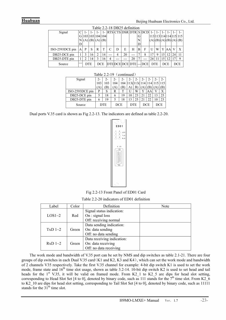
Dual ports V.35 card is shown as Fig 2.2-13. The indicators are defined as table 2.2-20.
Fig 2.2-13 Front Panel of ED01 Card
Table 2.2-20 indicators of ED01 definition
Label Color Definition Note
LOS1~2 Red Signal status indication: On : signal loss Off: receiving normal
TxD 1~2 Green Data sending indication: On: data sending Off: no data sending
RxD 1~2 Green Data receiving indication: On: data receiving Off: no data receiving
The work mode and bandwidth of V.35 port can be set by NMS and dip switches as table 2.1-21. There are four groups of dip switches in each Dual V.35 card(K1 and K2, K3 and K4), which can set the work mode and bandwidth of 2 channels V35 respectively. Take the first V.35 channel for example: 4-bit dip switch K1 is used to set the work mode, frame state and 16th time slot usage, shown as table 3.2-14. 10-bit dip switch K2 is used to set head and tail heads for the 1st V.35, it will be valid on framed mode. From K2_1 to K2_5 are dips for head slot setting, corresponding to Head Slot Set [4 to 0], denoted by binary code, such as 111 stands for the 7th time slot. From K2_6 to K2_10 are dips for head slot setting, corresponding to Tail Slot Set [4 to 0], denoted by binary code, such as 11111 stands for the 31th time slot.
L O S21
E D 0 1
21
21T x D
R x D
V . 3 5
Huahuan Beijing Huahuan Electronics Co., Ltd.
H9MO-LMXE+ Manual Ver. 1.7 -24-
Table 2.2-21 4-bit dip switch K1 definition(4 bits)
Dip Function Description K1_4(S16_en)16th time slot usage 1:included ;0:skipped K1_3(FR_en) Framed/unframed ON: Framed, Nx64kbps. OFF: unframed
K1_1:ON K1_2:ON Software settings K1_1:ON K1_2:OFF DTE(optional) K1_1:OFF K1_2:ON DCE_E1 line clock
K1_2(Mod0) K1_1(Mod1)
Set V35 Work mode
K1_1:OFF K1_2:OFF DCE internal E1 clock Note:when K1_1and K1_2 are set on,V.35 port mode and bandwidth are set by network management software. Otherwise,mode and bandwidth are set by the dip switches, though the management software can still monitor the alarms and status.
2.2.13 OW/Overhead/Clock card(LA01)
LA01 can be configured order wire telephone, other overhead pass and external clock input interface.
LA01 adopts 64 kit/s PCM code, providing order wire telephone functions, supporting ordinary dial-up telephone calls, providing electricity and telephone Ling flow. LA01 can provide user’s access byte F1 overhead access, providing 64 kbit/s data / voice access road, reserved for users for the purpose of the provisional safeguard official contact.
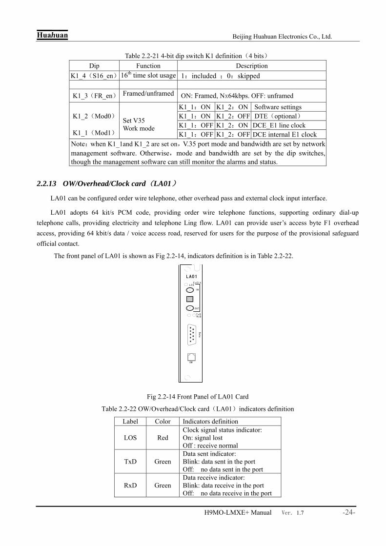
The front panel of LA01 is shown as Fig 2.2-14, indicators definition is in Table 2.2-22.
Fig 2.2-14 Front Panel of LA01 Card
Table 2.2-22 OW/Overhead/Clock card(LA01)indicators definition
Label Color Indicators definition
LOS Red Clock signal status indicator: On: signal lost Off : receive normal
TxD Green Data sent indicator: Blink: data sent in the port Off: no data sent in the port
RxD Green Data receive indicator: Blink: data receive in the port Off: no data receive in the port
RxD
LCS
LA01
IN
OUT
TxD
Data
O W
ExClk
Huahuan Beijing Huahuan Electronics Co., Ltd.
H9MO-LMXE+ Manual Ver. 1.7 -25-
Order wire port:
The RJ11 socket (labeled OW) in front panel is used for order wire telephones can be connected to standard dual-tone multi-frequency telephone as a order wire telephone.
Order wire telephone provides communication between the nodes on ring topology network or chain topology network.. By dial-up it will realize the point to point selectable call. Dial key “#” before the call, and then dial 4 digits called number, namely #NNNN. The telephone number of equipment can be set and query by network software.
Order wire communication can choose overhead E1 or E2, which is used in regenerator section and multiplex section respectively.
Note:Overhead byte E1 should be used when equipment H9MO-LMXE+ and H9MO-LMF, H9MO-LMA communicated with order wire telephones.
Clock port:
In front panel of LA01, there is one 75Ω or 120Ω clock port. By network software, user can set 2MHz or 2Mbit/s clock mode. 75Ω port adopts CC4 socket. IN、OUT denotes the signal input and output. 120Ω port adopts RJ45 socket. The signal definition is shown as Table 2.2-23.
Table 2.2-23 clock connector (RJ45) definition
Pin 1 2 3 4 5 6 7 8
Definition IN+ IN- GND OUT+ OUT- GND - -
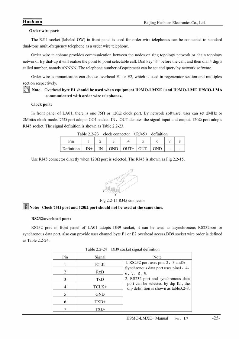
Use RJ45 connector directly when 120Ω port is selected. The RJ45 is shown as Fig 2.2-15.
Fig 2.2-15 RJ45 connector Note:Clock 75Ω port and 120Ω port should not be used at the same time.
RS232/overhead port:
RS232 port in front panel of LA01 adopts DB9 socket, it can be used as asynchronous RS232port or synchronous data port, also can provide user channel byte F1 or E2 overhead access.DB9 socket wire order is defined as Table 2.2-24.
Table 2.2-24 DB9 socket signal definition
Pin Signal Note
1 TCLK-
2 RxD
3 TxD
4 TCLK+
5 GND
6 TXD+
7 TXD-
1. RS232 port uses pins 2、3 and5; Synchronous data port uses pins1、4、6、7、8、9. 2. RS232 port and synchronous data
port can be selected by dip K1, the dip definition is shown as table3.2-8.
18

Huahuan Beijing Huahuan Electronics Co., Ltd.
H9MO-LMXE+ Manual Ver. 1.7 -26-
8 RXD+
9 RXD-
Table 2.2-25 dip switch K1 definition Dip number Definition
K1[1] RS232 Mode select ON:USRT(synchronous);OFF:UART(asynchronous)
K1[2] RJ45/BNC outside cover grounding select ON:grounding;OFF:not grounding
K1[3] asynchronous RS232 enable/disable select ON:enable UART;OFF:disable UART
K1[4] Debugging, should be set OFF during normal use
Note:1. K2 is used for debug; it should be set OFF during normal use. 2. When overhead E2 is used by order wire and user channel data at the same time, order wire first,
then the user channel data will be interrupted. After the order wire hang-up, user channel data will resume again.
2.2.14 4 Tx Ports Channel Type EOS Card (FE01)
The FE01 card is used to provide Ethernet connection to the network through EoS technology. There are 4 100Base-Tx Ethernet ports on the card, as shown in Fig 2.2-16. Traffic from each Ethernet port is adapted to a separate VCG channel through VC-12 virtual concatenation. The process confirms to ITU-T G.7041 and G.7042. Therefore it is interoperable with products from other vendors.
FE01 supports virtual concatenation (VCAT). VCAT member can be any of the 1-63 VC-12. No need to be continuous. 46 VC-12 is 100Mbps. You can set from 1 VC-12 (2M) to 46 VC-12 (100M).
FE01 adopts the GFP encapsulation. It supports GFP alarms.
FE01 supports VC-12 Link Capacity Adjustment Scheme (LCAS). It can automatically remove the broken VC-12 and keep the service. After the VC-12 is ok, FE01 will recover the previous VC-12 channel.
FE01’s FE ports support flow control. In 100M full-duplex mode, when coming data exceed the buffer, FE01 will send out PAUSE frame to other FE equipment.
FE01 supports Link Fault Pass-Through (LFP). When LFP is enabled, FE ports will detect the peer end. It will shut down if peer end is linked down. Moreover if the whole link’s devices all support LFP, the FE01 will propagate the alarm.
Fig 2.2-16 Front Panel of FE01 Card
F E 0 1
E T H - 1
E T H - 4

Huahuan Beijing Huahuan Electronics Co., Ltd.
H9MO-LMXE+ Manual Ver. 1.7 -27-
FE01’s 4 FE ports are RJ45 and 10/100Mbps auto-negotiation.
Green LED indicates ‘Link’ and ‘Active’. On means connection established. Off means no connection. Blinking means data transmitting.
Yellow LED indicates ‘Speed’. On means 100Mbps. Off means 10Mbps. Table 2.2-26 RJ45 pin definition
pin 1 2 3 4 5 6 7 8
definition TxD+ TxD- RxD+ RxD- Notice: Rx and Tx are both for FE01.
The 4 Ethernet ports are of the auto-MDIX type, that is, they can auto adapt to cable crossing with the link partners. It eases Ethernet connections.
Note: Different with optical tributary card (OS01), the FE01cross capability is still 1 VC-4 even it is located in class A slots.
2.2.15 4 Fx Ports Channel Type EOS Card (FE02)
The FE02 card is similar to FE01, and the only difference is the Ethernet interface.
The Ethernet interfaces on this card are 100Base-Fx, which is fiber based. It can connect to 100Base-Fx ports on other equipment, as well as to Fx port on a media converter. The Fx ports use pluggable SFP optical modules, so that the user can chose modules with required optical parameters. Fig 2.2-17 shows the front panel of the card.
FE02 supports Link Fault Pass-Through (LFP). When LFP is enabled, FX ports will detect the peer end. It will shut down if peer end is linked down. Moreover if the whole link’s devices all support LFP, the FE02 will propagate the alarm.
Fig 2.2-17 Front Panel of FE02 Card
The indicators in FE02 definition are shown as below:
Table 2.2-27 FE02 LEDs definition Label Color Indicators definition Note
LOS R Signal status indicator: On: signal lost Off : receive normal
Indicators 1~4 indicate 4 channels Ethernet optical ports respectively.
L O S
1
F E0 2
LNK
2
3
4

Huahuan Beijing Huahuan Electronics Co., Ltd.
H9MO-LMXE+ Manual Ver. 1.7 -28-
LINK G Link connection: On: interface link well Off: interface link wrong
2.2.16 4 Tx Ports Channel Type EOE Card (FE04)
4 Tx ports EoE card (FE04) can accomplish transmission Ethernet service via E1 channels.
FE04 provides four Ethernet ports via four independent transmission channels. Using private agreement, each channel Ethernet frame format will be converted into E1 frame format for transmission, Ethernet packets are encapsulated in N × E1 (1 ≤ N ≤ 16), through the cross-connect can be traded to the transmission to remote side, also can be cross connect to E1 card to remote E1 and then passed into the opposite process to drop Ethernet service to achieving Ethernet data based on the E1 transmission. According to effective E1 channels the bandwidth can be automatically adjusted, even if part of E1 channel failure, only lower data throughput and the data transmission will not be interrupted and resumed later in the channel, the equipment can automatically raise transmission bandwidth.
FE04 supports Link Fault Pass-Through (LFP). When LFP is enabled, FX ports will detect the peer end. It will shut down if peer end is linked down. Moreover if the whole link’s devices all support LFP, the FE04 will propagate the alarm.
Note: 1. Virtual concatenation of Four Ethernet channels is respectively corresponding fixed 1 ~ 16, 17 ~ 32, 33 ~ 48, 49 ~ 64 VC12 numbers. (The 1st, 2nd, 3rd channel support 16 channels of E1 at most, and the 4th channel support 15 channels of E1).
2. Every channel service should be configured from 1~N (1≤N≤16) orderly, not support M~N configuration (1<M≤16, M<N).
3. Both ends channel binding should be identical.
4. Local E1 serial number of the Nth channel should be corresponding with remote end
5. Every E1 channel can transmit management information.
6. Currently FE04 only supports auto-negotiation and mandatory 100 M full-duplex mode.
7. When FE04 is located at kind A slots, its cross connection capacity is one VC-4 4Tx port EOE card FE04 front panel is shown as below Fig 2.2-18. The indicators definition is the same with 4Tx
port EoS card(FE01).
Fig 2.2-18 Front Panel of FE04 Card
F E 0 4
E T H- 1
E T H- 4
Huahuan Beijing Huahuan Electronics Co., Ltd.
H9MO-LMXE+ Manual Ver. 1.7 -29-
2.2.17 4 Fx Ports Channel Type EOE Card (FE05)
4 Fx ports EOE card (FE05) is 100M Ethernet optical interface card, providing Ethernet service in multiple E1 channels, which can be inserted into 14 slots in H9MO-LMXE+. The equipment can work with media converter or other Fx standard optical Ethernet equipment at remote side to transmit data in EOE Ethernet.
FE05 provides four Ethernet ports via four independent transmission channels. Using private agreement, each channel Ethernet frame format will be converted into E1 frame format for transmission, Ethernet packets are encapsulated in N × E1 (1 ≤ N ≤ 16), through the cross-connect can be traded to the transmission to remote side, also can be cross connect to E1 card to remote E1 and then passed into the opposite process to drop Ethernet service to achieving Ethernet data based on the E1 transmission. According to effective E1 channels the bandwidth can be automatically adjusted, even if part of E1 channel failure, only lower data throughput and the data transmission will not be interrupted and resumed later in the channel, the equipment can automatically raise transmission bandwidth.
FE05 supports Link Fault Pass-Through (LFP). When LFP is enabled, FX ports will detect the peer end. It will shut down if peer end is linked down. Moreover if the whole link’s devices all support LFP, the FE05 will propagate the alarm.
Note: 1. Virtual concatenation of Four Ethernet channels is respectively corresponding fixed 1 ~ 16, 17 ~ 32, 33 ~ 48, 49 ~ 64 VC12 numbers. (The 1st, 2nd, 3rd channel support 16 channels of E1 at most, and the 4th channel support 15 channels of E1).
2. Every channel service should be configured from 1~N (1≤N≤16) orderly, not support M~N configuration (1<M≤16, M<N).
3. Both ends channel binding should be unique.
4. Local E1 serial number of the Nth channel should be corresponding with remote end.
5. Every E1 channel can transmit management information.
6. Currently FE05 only supports auto-negotiation and mandatory 100 M full-duplex mode.
7. When FE05 is located at kind A slots, its cross connection capacity is one VC-4
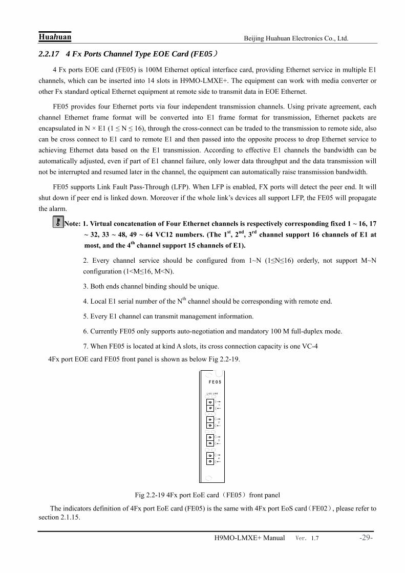
4Fx port EOE card FE05 front panel is shown as below Fig 2.2-19.
Fig 2.2-19 4Fx port EoE card(FE05)front panel
The indicators definition of 4Fx port EoE card (FE05) is the same with 4Fx port EoS card(FE02), please refer to section 2.1.15.
L O S
1
F E 0 5
L N K
2
3
4

Huahuan Beijing Huahuan Electronics Co., Ltd.
H9MO-LMXE+ Manual Ver. 1.7 -30-
2.2.18 2Tx Ports Aggregation Type EOS Card (FE06)
2Tx port aggregation type EOS card (FE06) is 100M Ethernet Tx switch card, realizing Ethernet service aggregation and layer 2 switches. This card can be inserted into any universal slots of H9MO-LMXE+.
FE06 has 3 types of Ethernet channels: a) Out channels (external interfaces). FE06 has 2 FE ports. These ports are out channels, which can be
used to connect other devices. b) In channels (internal virtual concatenation channels). FE06 has 8 VCG channels, which can be used to
take out the Ethernet from VC-12. c) Aggregation channels. These channels are not from SDH/VC-12. But they are from and to other
Ethernet service cards. When in Ethernet aggregation slots (slot4 and slot11), FE06 support 6 aggregation channels. When in other slots, FE06 support 1 aggregation channel.
All these 3 types of channels are connected to each other by the FE06’s inside switch.
The card can fulfill the data switch between 8 internal virtual concatenation channels and 2 external interfaces. 8 internal virtual concatenation channels support VC12 VCAT, the total largest bandwidth can get 1 STM-1. 8 internal VCAT channels can set VLAN, VLAN type could be selected based on ports or based on 802.1Q. VLAN based on ports adopts port transparent transmission mode, that is to say, port can receive the frames with VLAN tag or without VLAN tag, and not filtrate transmit/receive frame according to VLAN. VLAN based on 802.1Q could recognize and handle the outmost 802.1Q tag, configure VLAN ID and 802.1p PRI. When in slot4 (Ethernet aggregation slot), the 6 aggregation channels are for slot1~slot3 and slot5~slot7. When in slot11 (Ethernet aggregation slot), the 6 aggregation channels are for slot8~slot10 and slot12~slot14. FE06’s out ports are switch ports.
Ethernet adopts GFP encapsulation, providing GFP alarm. The LCAS functions can automatically delete failed members from VCAT for a while, when the malfunction is recovered, this member will back to VCAT automatically. Accordingly, we can adjust VCAT capability, realizing zero BER bandwidth adjustment.
FE06 supports Ethernet loopback auto detection. This function is enabled leaving factory. It can be disabled by the NMS software. When it is enabled, FE06 will send out test frame every 300 seconds to check the Ethernet loopback status. The 300 seconds can also be reduced to 12 seconds. When loopback is detected, the test period will be changed to 3 seconds. This function will not automatically shut down the FE port, even if there is loopback detected. User can change the ports status in NMS.
Ethernet port in FE06 card supports auto-negotiated and manual 100M full-duplex, half-duplex, 10M full-duplex and half-duplex.
The panel of FE06 is shown as Fig 2.2-20. The green LED in Ethernet port is for Active indication, blink when data send/receive; the yellow one is for duplex indication, on indicates full-duplex, off indicates half-duplex, blink indicates conflict. RJ45 socket definition is as same as FE01.

Huahuan Beijing Huahuan Electronics Co., Ltd.
H9MO-LMXE+ Manual Ver. 1.7 -31-
Fig 2.2-20 2Tx port aggregation type EOS card(FE06)panel
2.2.19 Tx Port Aggregation Type EOS Card (FE06A)
Tx port aggregation type EOS card (FE06A) is 100M Ethernet Tx switch card, realizing the Ethernet service aggregation and layer 2 switch. This card can be inserted into any universal slot of H9MO-LMXE+.
The card can fulfill the data switch between 4 internal virtual concatenation channels and 1 external interface. 8 internal virtual concatenation channels support VC-12 VCAT. The total largest bandwidth can get 1 STM-1. Other features are all the same with FE06. Moreover FE06A also supports static MAC addressing, multicast configuration and ageing time configuration. Default ageing time is 300 seconds. It can be set as large as 7 days. If the port is link down, the port will learn the MAC address immediately.
The panel of FE06A is shown as Fig 2.2-21. The definition of indicators in Ethernet port and RJ45 socket definition are all as same as FE01.
Fig 2.2-21 Tx Port aggregation type EOS Card(FE06A)panel
2.2.20 2Tx Ports Aggregation Type EOE Card (FE07)
2Tx ports aggregation EOE card (FE07) is 100M Ethernet Tx switch card, realizing aggregation and layer 2 switches of 1 or 6 external Ethernet services from backboard (aggregation side) and 8 internal Ethernet accessed by several E1 channels, converging to 2 FE ports to fulfill EOE Ethernet service switch. This card can be inserted into any universal slots of H9MO-LMXE+ which support 1 aggregation side port. When the card is configured in Ethernet aggregation slot (slot 4 and 11), it support 6 aggregation side ports, and also could fulfill other slots Ethernet services aggregation (need other slots configured interface cards have Ethernet aggregation function and aggregation side port
F E 0 6
E T H
F E 0 6 A
E T H

Huahuan Beijing Huahuan Electronics Co., Ltd.
H9MO-LMXE+ Manual Ver. 1.7 -32-
could be enabled by NMS), connecting with MAN aggregation layer switches or multi-service routers to uplink the tributary Ethernet services.
The FE07 card provide 8 internal EOE Ethernet ports, 1 or 6 aggregation side ports and 2 external ports, the 8 internal EOE Ethernet total largest bandwidth can get 1 STM-1. The difference between FE07 and FE06 is the Ethernet protocol adopted in FE07 is private, EOE encapsulation, that is each internal channel transfer Ethernet frame format to E1 frame for transmission. Ethernet package is encapsulated in N*E1 in order to transmission Ethernet based on E1. And bandwidth could be adjusted automatically by valid E1 channels, even part E1 channels failed, just data throughput is decreased but the transmission will not be interrupted, after the channel resume, the equipment will increase the transmission bandwidth automatically. Ethernet VLAN set and QoS guarantee and aggregation functions are as same as FE06 card.
Note: 1. Virtual concatenation of Eight Ethernet channels is respectively corresponding fixed 1~8, 9~16, 17~24, 25~32, 33~40, 41~48, 49~56, 57~63VC12 numbers. (Each channel supports 8E1s at most)
2. Every channel service should be configured from 1~N (1≤N≤8) orderly, not support M~N configuration (1<M≤8, M<N).
3. Both ends channel binding should be identical.
4. Local E1 serial number of the Nth channel should be corresponding with remote end.
5. Every E1 channel can transmit management information.
2Tx ports aggregation EOE card (FE07) Ethernet ports support auto-negotiated and manual 100M full-duplex, half-duplex, 10M full-duplex and half-duplex.
The panel of FE07 is shown as Fig 2.2-22. The definition of indicators in Ethernet port is as same as FE06; RJ45 socket definition is as same as FE01.
Fig 2.2-22 2 Tx ports aggregation EOE card (FE07) panel
2.2.21 GE Port Aggregation Type EOS Card (GX01/GX01A)
GE port aggregation type EOS card (GX01/GX01A) is 10/100/1000M Ethernet Tx switch card, realizing Ethernet service aggregation and layer 2 switch of 6 Ethernet from backboard and 8 VCG accessed Ethernet data, to 1 GE port. GX01/GX01A could be inserted to Ethernet aggregation slot (universal slot3 and slot11) to get other slots Ethernet service aggregation and provide Ethernet management channel, it also can be inserted into any universal slots of H9MO-LMXE+ to provide 8 internal VCAT channels of Ethernet data aggregation to 1 GE port. The
F E 0 7
E T H

Huahuan Beijing Huahuan Electronics Co., Ltd.
H9MO-LMXE+ Manual Ver. 1.7 -33-
difference between GX01 and GX01A is that GX01 is 1 GE electrical port but GX01A is 1 GE electrical port and 1 GE optical port. GX01A’s electrical port and optical port cannot be used at the same time.
8 internal virtual concatenation channels support VC-12 VCAT, the total largest bandwidth can get 1 STM-1. Each channel bandwidth can be adjusted between 2M~100M by setting the number of VC12 VCAT, 46 VC12 can get 100M bandwidth. 8 internal VCAT channels can set VLAN, VLAN type could be selected based on ports or based on 802.1Q. VLAN based on ports adopts port transparent transmission mode, that is to say, port can receive the frames with VLAN tag or without VLAN tag, and not filtrate transmit/receive frame according to VLAN. VLAN based on 802.1Q could recognize and handle the outmost 802.1Q tag, configure VLAN ID and 802.1p PRI. When VLAN is forbidden, 8 virtual concatenation channels and 1 external port can realize switch function.
When in slot4 (Ethernet aggregation slot), the 6 aggregation channels are for slot1~slot3 and slot5~slot7. When in slot11 (Ethernet aggregation slot), the 6 aggregation channels are for slot8~slot10 and slot12~slot14. FE06’s out ports are switch ports.
Ethernet adopts GFP encapsulation, providing GFP alarm. The LCAS functions can automatically delete failed members from VCAT for a while, when the malfunction is recovered, this member will back to VCAT automatically. Accordingly, we can adjust VCAT capability, realizing zero BER bandwidth adjustment.
GX01/GX01A supports Ethernet loopback auto detection. This function is enabled leaving factory. It can be disabled by the NMS software. When it is enabled, GX01/GX01A will send out test frame every 300 seconds to check the Ethernet loopback status. The 300 seconds can also be reduced to 12 seconds. When loopback is detected, the test period will be changed to 3 seconds. This function will not automatically shut down the FE port, even if there is loopback detected. User can change the ports status in NMS.
GE electrical port in GX01 card supports auto-negotiated and manual 1000M full-duplex; auto-negotiated and manual 100M full-duplex, half-duplex; 10M full-duplex and half-duplex.
GE optical port in GX01A card supports manual 100M full-duplex, half-duplex, 10M full-duplex and half-duplex. The port also supports auto-negotiated 1000M full-duplex.
The panel of GX01/GX01A is shown as Fig 2.2-23.
Fig 2.2-23 GE port aggregation type EOS card (GX01) panel
Table 2.2-28 GE EoS aggregation card(GX01/GX01A)LED definition Label color definition notice
RJ45 port’s green LED
G
Link/Active: On: connection ok Off: no connection Blink: data transmitting
GX01/GX01A
G X 0 1
E T H
G X 0 1 A
L O S L N K
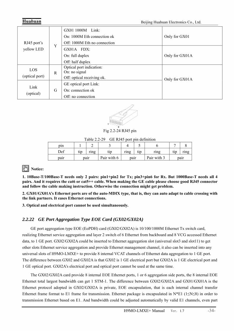
Huahuan Beijing Huahuan Electronics Co., Ltd.
H9MO-LMXE+ Manual Ver. 1.7 -34-
GX01 1000M Link: On: 1000M Eth connection ok Off: 1000M Eth no connection
Only for GX01 RJ45 port’s yellow LED
Y GX01A FDX: On: full duplex Off: half duplex
Only for GX01A
LOS (optical port)
R Optical port indication: On: no signal Off: optical receiving ok.
Link (optical)
G GE optical port Link: On: connection ok Off: no connection
Only for GX01A
Fig 2.2-24 RJ45 pin
Table 2.2-29 GE RJ45 port pin definition pin 1 2 3 4 5 6 7 8 Def tip ring tip ring tip ring tip ring pair pair Pair with 6 pair Pair with 3 pair
Notice:
1. 10Base-T/100Base-T needs only 2 pairs: pin1+pin2 for Tx; pin3+pin6 for Rx. But 1000Base-T needs all 4 pairs. And it requires the cat6 or cat5++ cable. When making the GE cable please choose good RJ45 connector and follow the cable making instruction. Otherwise the connection might get problem.
2. GX01/GX01A’s Ethernet ports are of the auto-MDIX type, that is, they can auto adapt to cable crossing with the link partners. It eases Ethernet connections.
3. Optical and electrical port cannot be used simultaneously.
2.2.22 GE Port Aggregation Type EOE Card (GX02/GX02A)
GE port aggregation type EOE (EoPDH) card (GX02/GX02A) is 10/100/1000M Ethernet Tx switch card, realizing Ethernet service aggregation and layer 2 switch of 6 Ethernet from backboard and 8 VCG accessed Ethernet data, to 1 GE port. GX02/GX02A could be inserted to Ethernet aggregation slot (universal slot3 and slot11) to get other slots Ethernet service aggregation and provide Ethernet management channel, it also can be inserted into any universal slots of H9MO-LMXE+ to provide 8 internal VCAT channels of Ethernet data aggregation to 1 GE port. The difference between GX02 and GX02A is that GX02 is 1 GE electrical port but GX02A is 1 GE electrical port and 1 GE optical port. GX02A’s electrical port and optical port cannot be used at the same time.
The GX02/GX02A card provide 8 internal EOE Ethernet ports, 1 or 6 aggregation side ports, the 8 internal EOE Ethernet total largest bandwidth can get 1 STM-1. The difference between GX02/GX02A and GX01/GX01A is the Ethernet protocol adopted in GX02/GX02A is private, EOE encapsulation, that is each internal channel transfer Ethernet frame format to E1 frame for transmission. Ethernet package is encapsulated in N*E1 (1≤N≤8) in order to transmission Ethernet based on E1. And bandwidth could be adjusted automatically by valid E1 channels, even part
18
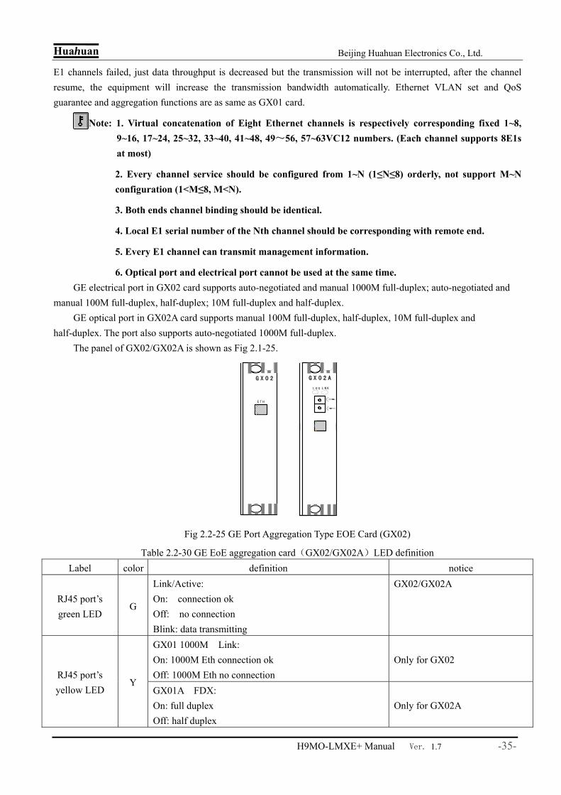
Huahuan Beijing Huahuan Electronics Co., Ltd.
H9MO-LMXE+ Manual Ver. 1.7 -35-
E1 channels failed, just data throughput is decreased but the transmission will not be interrupted, after the channel resume, the equipment will increase the transmission bandwidth automatically. Ethernet VLAN set and QoS guarantee and aggregation functions are as same as GX01 card.
Note: 1. Virtual concatenation of Eight Ethernet channels is respectively corresponding fixed 1~8, 9~16, 17~24, 25~32, 33~40, 41~48, 49~56, 57~63VC12 numbers. (Each channel supports 8E1s at most)
2. Every channel service should be configured from 1~N (1≤N≤8) orderly, not support M~N configuration (1<M≤8, M<N).
3. Both ends channel binding should be identical.
4. Local E1 serial number of the Nth channel should be corresponding with remote end.
5. Every E1 channel can transmit management information.
6. Optical port and electrical port cannot be used at the same time. GE electrical port in GX02 card supports auto-negotiated and manual 1000M full-duplex; auto-negotiated and
manual 100M full-duplex, half-duplex; 10M full-duplex and half-duplex. GE optical port in GX02A card supports manual 100M full-duplex, half-duplex, 10M full-duplex and
half-duplex. The port also supports auto-negotiated 1000M full-duplex. The panel of GX02/GX02A is shown as Fig 2.1-25.
Fig 2.2-25 GE Port Aggregation Type EOE Card (GX02)
Table 2.2-30 GE EoE aggregation card(GX02/GX02A)LED definition Label color definition notice
RJ45 port’s green LED
G
Link/Active: On: connection ok Off: no connection Blink: data transmitting
GX02/GX02A
GX01 1000M Link: On: 1000M Eth connection ok Off: 1000M Eth no connection
Only for GX02 RJ45 port’s yellow LED
Y GX01A FDX: On: full duplex Off: half duplex
Only for GX02A
G X 0 2
E T H
G X 0 2 A
L O S L N K

Huahuan Beijing Huahuan Electronics Co., Ltd.
H9MO-LMXE+ Manual Ver. 1.7 -36-
LOS (optical port)
R Optical port indication: On: no signal Off: optical receiving ok.
Link (optical)
G GE optical port Link: On: connection ok Off: no connection
Only for GX02A
2.2.23 Double GE interface 16 channel aggregation EoS card(GX05)
Double GE interface 16 channel aggregation EoS card(GX05)is 10/100/1000M Ethernet Tx switch card, realizing Ethernet service aggregation and layer 2 switch of 6 Ethernet from backboard and 16 VCG accessed Ethernet data, to 2 GE port. GX05 could be inserted to Ethernet aggregation slot (universal slot4 and slot11) to get other slots Ethernet service aggregation and provide Ethernet management channel, it also can be inserted into any universal slots of H9MO-LMXE to provide 16 internal VCAT channels of Ethernet data aggregation to 2 GE port. GX10 has 2 GE electrical ports and 2 GE optical ports. But the electrical and optical port of GX10 with the same number cannot be used at the same time.
16 internal virtual concatenation channels support VC-12 VCAT, the total largest bandwidth can get 1 STM-1. Each channel bandwidth can be adjusted between 2M~100M by setting the number of VC12 VCAT, 46 VC12 can get 100M bandwidth. Ethernet frame method is GFP, and support GFP alarm.
LCAS , aggregation function of GX10 is the same to GE port aggregation type EOS card (GX01/GX01A) . The 2 GE port of GX05 is switching port, and support VLAN(port based, 802.1Q based on Q in Q based ) . Maximum VLAN number is 512, and the range of tag is 1-4095. Besides, GX05 support Ethernet loop back test function, STP(spanning tree protocol) function and fast STP function, static MAC table setting(64 table items). And GE port support TRUNKING. And the Ethernet loop back monitoring and STP, fast STP bounding can work only when the STP, fast STP function are enabled (default set is enabled). According to STP, only backup ports and replacing port are considered as loop back port and will be deleted (default set is delete automatically).NMS support loop back monitoring and searching of deleted ports, but it cannot configure disabling loop back monitoring and delete loop back port manually.
G X05 has independent MAC and IP address, and user can connect PC to one of the electrical port of the card and upgrade the card. If there is no NM card on the equipment, the initial IP address of GX05 is 192.168.1.2. And if there is a NM card on the equipment, it will set the MAC and IP address of GX05 card after the starting of the equipment. Default setting of GX05’s MAC is the same to H9MO-LMXE itself, and IP address is 10.0.0.1-10.0.0.14(the last byte is in accordance to the slot number of where the card is). And the priority level of the bridge is automatically generated according to the slot number. MAC and IP address of GX05 can be set and saved via NMS.
GE electrical port in GX05 card supports auto-negotiated and manual 1000M full-duplex; auto-negotiated and manual 100M full-duplex, half-duplex; 10M full-duplex and half-duplex. And GE optical port support auto-negotiated mode.
The panel of GX05 is shown as Fig 2.2-26. Definition of indicators is shown in Table 2.2-31. Definition of RJ 45 are the same to GX01/GX01A.

Huahuan Beijing Huahuan Electronics Co., Ltd.
H9MO-LMXE+ Manual Ver. 1.7 -37-
Fig 2.2-26 Panel of double GE interface 16 channel aggregation EoS card(GX05)
Table 2.2-31 Definition of indicators of GX05 card Indicator Color Meaning of the indicator
RJ45 port’s green LED
Green
Link/Active: On: connection ok Off: no connection Blink: data transmitting
RJ45 port’s yellow LED
Yellow
Ethernet port FDX indication: ON: Ethernet ports(electrical and optical) on full-duplex mode OFF : Ethernet ports(electrical and optical) on half-duplex mode
Link (Optical port)
Red Optical port indication: On: no signal Off: optical receiving ok.
Link (Optical port)
Green GE optical port Link: On: connection ok Off: no connection
Notice:
1. Electrical and optical port with the same number of GX05 cannot be used at the same time.
2. When enabling STP function, the equipment will monitor all the ports and this will lead to shutdown of Ethernet service for a while. Please set the ports which do not need to be monitored to edge port or exclude it from the STP tree.
3. Please disable aggregation ports, STP and VLAN function before upgrading GX05 card by directly connecting to its GE port.
2.2.24 63:1 EoE/GE Ethernet aggregation card (GX10)
63:1 EoE/GE Ethernet aggregation card (GX10) is an 10/100/1000M self-adapting electrical and optical card, realizing accessing switch of Ethernet service from 63 internal E1 channels to 1 GE port (external port). It support aggregation ratio of 63:1. GX10 card support one GE interface (electrical or optical), but the electrical and optical interface cannot be used at the same time. It can be inserted into any universal slots.
GX10 support 63 internal EoE channels, and every internal ETH over E1 channel support 1 E1 line, and the total Ethernet band is 63×2=126M. The framing method of GX10 is a private protocol, realizing the transmission of Ethernet packet in E1 channel. The E1 packet then can be cross connected to SDH or E1 channel. GX10 can be connected to remote EoE Ethernet converter (eg: Huahuan H0FL-01100/H0FL-F01100/01100S), and provides monitoring function for remote equipments, including the Ethernet VLAN configuration of these remote equipments. As the internal EoE channel of GX10 only support 1 E1, there are only 1 E1 channel when it is connected multi E1 EoE converter.
GX10 card support GFP framing, adding scrambling, and providing GFP alarm. Ethernet service support VLAN based on 802.1Q and Q in Q, realizing the data independency of EoE channel. When VLAN is enabled, In default condition, Ethernet packet coming into the GE port is tagged, and the GX10 card will not transmit packets without tag. And it allows user add/delete/no action to the Ethernet packet coming from/to the internal EoE channel. The default VLAN ID of the port can be set, and it ranges from 1 to 4094. It does not support priority of VLAN currently. In default condition, VLAN table contain a channel and the GE port. Every channel support a maximum of 4 VLAN ID. And maximum number of VLAN table is 256.
Ethernet port of GX10 card support low level channel loop back test and can detect the loop back condition
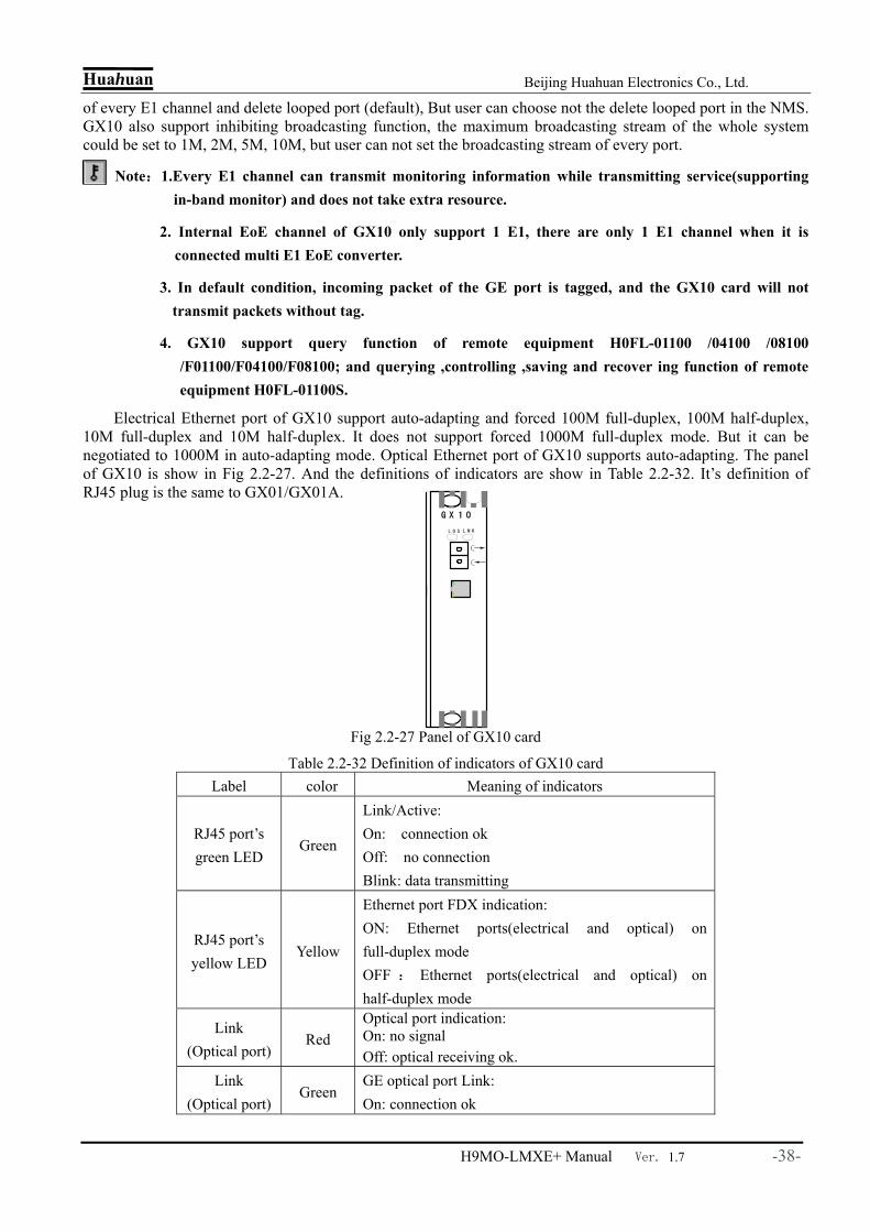
Huahuan Beijing Huahuan Electronics Co., Ltd.
H9MO-LMXE+ Manual Ver. 1.7 -38-
of every E1 channel and delete looped port (default), But user can choose not the delete looped port in the NMS. GX10 also support inhibiting broadcasting function, the maximum broadcasting stream of the whole system could be set to 1M, 2M, 5M, 10M, but user can not set the broadcasting stream of every port.
Note:1.Every E1 channel can transmit monitoring information while transmitting service(supporting in-band monitor) and does not take extra resource.
2. Internal EoE channel of GX10 only support 1 E1, there are only 1 E1 channel when it is connected multi E1 EoE converter.
3. In default condition, incoming packet of the GE port is tagged, and the GX10 card will not transmit packets without tag.
4. GX10 support query function of remote equipment H0FL-01100 /04100 /08100 /F01100/F04100/F08100; and querying ,controlling ,saving and recover ing function of remote equipment H0FL-01100S.
Electrical Ethernet port of GX10 support auto-adapting and forced 100M full-duplex, 100M half-duplex, 10M full-duplex and 10M half-duplex. It does not support forced 1000M full-duplex mode. But it can be negotiated to 1000M in auto-adapting mode. Optical Ethernet port of GX10 supports auto-adapting. The panel of GX10 is show in Fig 2.2-27. And the definitions of indicators are show in Table 2.2-32. It’s definition of RJ45 plug is the same to GX01/GX01A.
Fig 2.2-27 Panel of GX10 card
Table 2.2-32 Definition of indicators of GX10 card Label color Meaning of indicators
RJ45 port’s green LED
Green
Link/Active: On: connection ok Off: no connection Blink: data transmitting
RJ45 port’s yellow LED
Yellow
Ethernet port FDX indication: ON: Ethernet ports(electrical and optical) on full-duplex mode OFF : Ethernet ports(electrical and optical) on half-duplex mode
Link (Optical port)
Red Optical port indication: On: no signal Off: optical receiving ok.
Link (Optical port)
Green GE optical port Link: On: connection ok
G X 1 0
L O S L N K
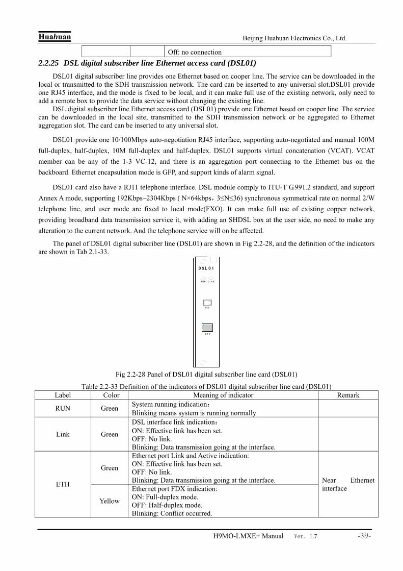
Huahuan Beijing Huahuan Electronics Co., Ltd.
H9MO-LMXE+ Manual Ver. 1.7 -39-
Off: no connection 2.2.25 DSL digital subscriber line Ethernet access card (DSL01)
DSL01 digital subscriber line provides one Ethernet based on cooper line. The service can be downloaded in the local or transmitted to the SDH transmission network. The card can be inserted to any universal slot.DSL01 provide one RJ45 interface, and the mode is fixed to be local, and it can make full use of the existing network, only need to add a remote box to provide the data service without changing the existing line.
DSL digital subscriber line Ethernet access card (DSL01) provide one Ethernet based on cooper line. The service can be downloaded in the local site, transmitted to the SDH transmission network or be aggregated to Ethernet aggregation slot. The card can be inserted to any universal slot.
DSL01 provide one 10/100Mbps auto-negotiation RJ45 interface, supporting auto-negotiated and manual 100M full-duplex, half-duplex, 10M full-duplex and half-duplex. DSL01 supports virtual concatenation (VCAT). VCAT member can be any of the 1-3 VC-12, and there is an aggregation port connecting to the Ethernet bus on the backboard. Ethernet encapsulation mode is GFP, and support kinds of alarm signal.
DSL01 card also have a RJ11 telephone interface. DSL module comply to ITU-T G.991.2 standard, and support Annex A mode, supporting 192Kbps~2304Kbps ( N×64kbps,3≤N≤36) synchronous symmetrical rate on normal 2/W telephone line, and user mode are fixed to local mode(FXO). It can make full use of existing copper network, providing broadband data transmission service it, with adding an SHDSL box at the user side, no need to make any alteration to the current network. And the telephone service will on be affected.
The panel of DSL01 digital subscriber line (DSL01) are shown in Fig 2.2-28, and the definition of the indicators are shown in Tab 2.1-33.
Fig 2.2-28 Panel of DSL01 digital subscriber line card (DSL01)
Table 2.2-33 Definition of the indicators of DSL01 digital subscriber line card (DSL01) Label Color Meaning of indicator Remark
RUN Green System running indication: Blinking means system is running normally
Link Green
DSL interface link indication: ON: Effective link has been set. OFF: No link. Blinking: Data transmission going at the interface.
Green
Ethernet port Link and Active indication: ON: Effective link has been set. OFF: No link. Blinking: Data transmission going at the interface. ETH
Yellow
Ethernet port FDX indication: ON: Full-duplex mode. OFF: Half-duplex mode. Blinking: Conflict occurred.
Near Ethernet interface
D S L 0 1
E T H
R U N
D S L
L i n K

Huahuan Beijing Huahuan Electronics Co., Ltd.
H9MO-LMXE+ Manual Ver. 1.7 -40-
The RJ11 port on DSL01 is standard telephone line interface. The RJ45 interface is Ethernet interface, and it’s definition is the same to 4 Tx Ports Channel Type EOS Card (FE01).
Note: The 10/100Base-Tx interface support HP auto-MDIX function and can detect and adjust to the line serial of send/receive. So it is OK no matter the connected Ethernet port are MDI or MDI-X interface. And the cable user is using can be direct or cross wire.
2.2.26 DSL digital subscriber line E1 access card (DSL02)
DSL02 digital subscriber line provide 2 independent DSL on cooper line, every DSL realize one E1 accessing. Every E1 takes 1 VC12. The 2 E1 service can be transmitted to the SDH transmission network after cross-connection. The card can be inserted to any universal slot.
The DSL module of the DSL02 provide 2.048Mbps synchronous symmetrical rate on normal 2/W telephone line, and user mode are fixed to local mode (FXO). It can make full use of existing copper network, providing E1 rate service, with adding an SHDSL box at the user side, no need to make any alteration to the current network.
Local side and remote side of DSL02 card can be monitored in the NMS, getting information like DSL link status, S/N (signal/noise ratio), DSL working mode, clock mode, loop status, DSL summary working time and CRC correction.
Note:While setting DSL LLB at the local side, it is loop back at the simulation front side of DSL chip (AFE), including DSL part. User may have to hang up the telephone before setting DSL LLB in the circumstance that there is remote equipment connected, for the service would be out when there is a loop at the AFE.
DSL02 card provide 2 standard RJ11 DSL interface, and the definition of the signal is the same to that of DSL01. Panel of the DSL02 is show in Fig 2.2-29. And the definition of indicators is show in table 2.2-34.
Fig 2.2-29 Panel of DSL02 digital subscriber line E1 access card (DSL02)
Table 2.2-34 Definition of the indicators of DSL02 Label Color Meaning of indicator Remark
PWR G Power indicator: ON:Power supply of the card is OK; OFF:Power supply of the card is wrong;
RUN G Running status indicator: Blink:Running fine. ON or OFF:Running abnormal.
LNK1/LNK2 G DSL interface link indicator: ON: Synchronizing status
LNK1/LNK2 stands for the 1st and 2nd DSL respectively
D S L 0 2
P W R R U N
L N K 1 L N K 2
A L M 1 A L M 2
DSL1
DSL2
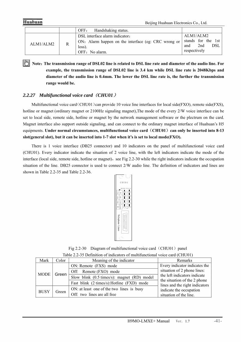
Huahuan Beijing Huahuan Electronics Co., Ltd.
H9MO-LMXE+ Manual Ver. 1.7 -41-
OFF: Handshaking status.
ALM1/ALM2 R
DSL interface alarm indicator: ON:Alarm happen on the interface (eg: CRC wrong or loss). OFF:No alarm.
ALM1/ALM2 stands for the 1st and 2nd DSL respectively
Note:The transmission range of DSL02 line is related to DSL line rate and diameter of the audio line. For example, the transmission range of DSL02 line is 3.4 km while DSL line rate is 2048Kbps and diameter of the audio line is 0.4mm. The lower the DSL line rate is, the further the transmission range would be.
2.2.27 Multifunctional voice card(CHU01)
Multifunctional voice card(CHU01)can provide 10 voice line interfaces for local side(FXO), remote side(FXS), hotline or magnet (ordinary magnet or 2100Hz signaling magnet),The mode of the every 2/W voice interface can be set to local side, remote side, hotline or magnet by the network management software or the plectrum on the card. Magnet interface also support outside signaling, and can connect to the ordinary magnet interface of Huahuan’s H5 equipments. Under normal circumstances, multifunctional voice card(CHU01)can only be inserted into 8-13 slot(general slot), but it can be inserted into 1-7 slot when it’s is set to local mode(FXO).
There is 1 voice interface (DB25 connector) and 10 indicators on the panel of multifunctional voice card (CHU01). Every indicator indicate the situation of 2 voice line, with the left indicators indicate the mode of the interface (local side, remote side, hotline or magnet),see Fig 2.2-30 while the right indicators indicate the occupation situation of the line. DB25 connector is used to connect 2/W audio line. The definition of indicators and lines are shown in Table 2.2-35 and Table 2.2-36.
Fig 2.2-30 Diagram of multifunctional voice card(CHU01)panel
Table 2.2-35 Definition of indicators of multifunctional voice card (CHU01) Mark Color Meaning of the indicator Remarks
ON: Remote (FXS) mode Off: Remote (FXO) mode Slow blink (0.5 times/s): magnet (RD) model
MODE Green
Fast blink (2 times/s):Hotline (FXD) mode
BUSY Green ON: at least one of the two lines is busy Off: two lines are all free
Every indicator indicates the situation of 2 phone lines: the left indicators indicate the situation of the 2 phone lines and the right indicators indicate the occupation situation of the line.
FXS
FXD
FXO
RD
ON
OFF
FAST
SLOW
1
23
45
6
9
1 0
7
8
M O D E
Telephone
Lines
C H U 0 1
B A S Y
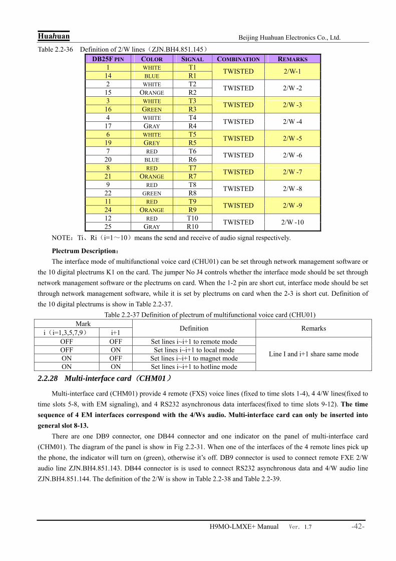
Huahuan Beijing Huahuan Electronics Co., Ltd.
H9MO-LMXE+ Manual Ver. 1.7 -42-
Table 2.2-36 Definition of 2/W lines(ZJN.BH4.851.145) DB25F PIN COLOR SIGNAL COMBINATION REMARKS
1 WHITE T1 14 BLUE R1 TWISTED 2/W-1
2 WHITE T2 15 ORANGE R2 TWISTED 2/W -2
3 WHITE T3 16 GREEN R3 TWISTED 2/W -3
4 WHITE T4 17 GRAY R4 TWISTED 2/W -4
6 WHITE T5 19 GREY R5 TWISTED 2/W -5
7 RED T6 20 BLUE R6 TWISTED 2/W -6
8 RED T7 21 ORANGE R7 TWISTED 2/W -7
9 RED T8 22 GREEN R8 TWISTED 2/W -8
11 RED T9 24 ORANGE R9 TWISTED 2/W -9
12 RED T10 25 GRAY R10 TWISTED 2/W -10
NOTE:Ti、Ri(i=1~10)means the send and receive of audio signal respectively.
Plectrum Description: The interface mode of multifunctional voice card (CHU01) can be set through network management software or
the 10 digital plectrums K1 on the card. The jumper No J4 controls whether the interface mode should be set through network management software or the plectrums on card. When the 1-2 pin are short cut, interface mode should be set through network management software, while it is set by plectrums on card when the 2-3 is short cut. Definition of the 10 digital plectrums is show in Table 2.2-37.
Table 2.2-37 Definition of plectrum of multifunctional voice card (CHU01) Mark
i(i=1,3,5,7,9) i+1 Definition Remarks
OFF OFF Set lines i~i+1 to remote mode OFF ON Set lines i~i+1 to local mode ON OFF Set lines i~i+1 to magnet mode ON ON Set lines i~i+1 to hotline mode
Line I and i+1 share same mode
2.2.28 Multi-interface card(CHM01)
Multi-interface card (CHM01) provide 4 remote (FXS) voice lines (fixed to time slots 1-4), 4 4/W lines(fixed to time slots 5-8, with EM signaling), and 4 RS232 asynchronous data interfaces(fixed to time slots 9-12). The time sequence of 4 EM interfaces correspond with the 4/Ws audio. Multi-interface card can only be inserted into general slot 8-13.
There are one DB9 connector, one DB44 connector and one indicator on the panel of multi-interface card (CHM01). The diagram of the panel is show in Fig 2.2-31. When one of the interfaces of the 4 remote lines pick up the phone, the indicator will turn on (green), otherwise it’s off. DB9 connector is used to connect remote FXE 2/W audio line ZJN.BH4.851.143. DB44 connector is is used to connect RS232 asynchronous data and 4/W audio line ZJN.BH4.851.144. The definition of the 2/W is show in Table 2.2-38 and Table 2.2-39.
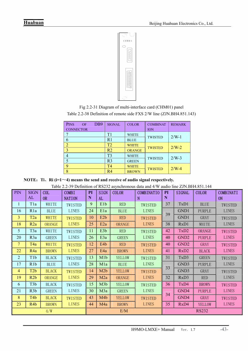
Huahuan Beijing Huahuan Electronics Co., Ltd.
H9MO-LMXE+ Manual Ver. 1.7 -43-
Fig 2.2-31 Diagram of multi-interface card (CHM01) panel Table 2.2-38 Definition of remote side FXS 2/W line (ZJN.BH4.851.143)
NOTE:Ti、Ri (i=1~4) means the send and receive of audio signal respectively.
Table 2.2-39 Definition of RS232 asynchronous data and 4/W audio line ZJN.BH4.851.144 PIN SIGN
AL COL
OR
COMBI
NATION
PIN
SIGN
AL
COLOR COMBINATIO
N
PIN
SIGNAL COLOR COMBINATI
ON
1 T1a WHITE 9 E1b RED 37 TxD1 BLUE
16 R1a BLUE
TWISTED
LINES 24 E1a BLUE
TWISTED
LINES GND1 PURPLE
TWISTED
LINES
3 T2a WHITE 10 E2b RED 39
GND1 GRAY
18 R2a ORANGE
TWISTED
LINES 25 E2a ORANGE
TWISTED
LINES 38 RxD1 WHITE
TWISTED
LINES
5 T3a WHITE 11 E3b RED 42 TxD2 ORANGE
20 R3a GREEN
TWISTED
LINES 26 E3a GREEN
TWISTED
LINES 40 GND2 PURPLE
TWISTED
LINES
7 T4a WHITE 12 E4b RED 40 GND2 GRAY
22 R4a BROWN
TWISTED
LINES 27 E4a BROWN
TWISTED
LINES 41 RxD2 BLACK
TWISTED
LINES
2 T1b BLACK 13 M1b YELLOW 31 TxD3 GREEN
17 R1b BLUE
TWISTED
LINES 28 M1a BLUE
TWISTED
LINES GND3 PURPLE
TWISTED
LINES
4 T2b BLACK 14 M2b YELLOW 33
GND3 GRAY
19 R2b ORANGE
TWISTED
LINES 29 M2a ORANGE
TWISTED
LINES 32 RxD3 RED
TWISTED
LINES
6 T3b BLACK 15 M3b YELLOW 36 TxD4 BROWN
21 R3b GREEN
TWISTED
LINES 30 M3a GREEN
TWISTED
LINES GND4 PURPLE
TWISTED
LINES
8 T4b BLACK 43 M4b YELLOW 34
GND4 GRAY
23 R4b BROWN
TWISTED
LINES 44 M4a BROWN
TWISTED
LINES 35 RxD4 YELLOW
TWISTED
LINES
4/W E/M RS232
PINS OF DB9 CONNECTOR
SIGNAL COLOR COMBINATION
REMARK
7 T1 WHITE 6 R1 BLUE TWISTED 2/W-1
2 T2 WHITE 3 R2 ORANGE
TWISTED 2/W-2
4 T3 WHITE 5 R3 GREEN TWISTED 2/W-3
9 T4 WHITE 8 R4 BROWN TWISTED 2/W-4
C H M 0 1

Huahuan Beijing Huahuan Electronics Co., Ltd.
H9MO-LMXE+ Manual Ver. 1.7 -44-
Note: in Table 3.2-39, Tia、Ria(i=1~4)means output of 4/W; Tib、Rib(i=1~4)means input of 4/W;. Eia、Eib(i=1~4)means input line (signal get into the device) of E signal; Mia、Mib(i=1~4) means output line (signal out equipment) of M signal. TxDi(i=1~4)means output line (signal out device) of RS232 signal; RxDi(i=1~4)means input line (signal out device) of RS232 signal.
Note: 1. EM signaling of the multi-interface card (CHM01) supports 2 E 2 M mode. 2. Different GNDi (i = 1 ~ 4) of the multi-interface card (CHM01) is separate from each other. So the GND of every RS232 signal should be connected to the ground separately.
2.2.29 Local side voice card(CHL01)
Local side voice card (CHL01) provides the function of connecting to 10 switch users. It can be inserted in any general slot.
There are 10 indicators and a DB25 connector on the panel of local side voice card (CHL01), and the diagram of the panel is shown in Fig 2.1.32. Green indicator light on the panel CH1 ~ CH10 corresponds to 10 line voice signal. The indicator light is on when the corresponding line is busy, and it’s off when the phone is free. DB25 connector is used to connect 2/W audio line ZJN.BH4.851.145. Definition of the line is shown in table named “Definition of 2/W audio lines(ZJN.BH4.851.145)”.
Fig 2.2-32 Diagram of local side voice card (CHL01)panel
2.2.30 Remote side voice card(CHR01)
Remote side voice card (CHR01) perform the functions of encoding, decoding, 2-wire / 2- wire conversion, fed to the subscriber line, ring, over voltage protection, and testing of subscriber line for the 10 lines. This card can only be inserted into general slot 8-13.
Panel of the remote side voice card (CHR01) is the same as Local side voice card (CHL01) .The diagram of the panel is shown in as Fig 2.2.33. Green indicator light on the panel CH1 ~ CH10 corresponds to 10 line voice signal. The indicator light is on when the corresponding line is busy, and it’s off when the phone is free. DB25 connector is used to connect 2/W audio line ZJN.BH4.851.145. Definition of the line is shown in table named “Definition of 2/W audio lines(ZJN.BH4.851.145)”.
C H L 0 1
C h 1 C h 2
C h 3 C h 4
C h 5 C h 6
C h 7 C h 8
C h 9 C h 1 0

Huahuan Beijing Huahuan Electronics Co., Ltd.
H9MO-LMXE+ Manual Ver. 1.7 -45-
Fig 2.2-33 Diagram of remote side voice card (CHR01) Panel
2.2.31 4/W audio voice card(CH4W01)
4/W audio voice card (CH4W01) provides the function of encoding, decoding voice signal. Signal level of every telephone line can be set through network management software. This card is usually used as an adapter of 4/W audio. And there is no EM signal interface circuit transformer. 4/W audio voice card (CH4W01) can be inserted into any general slot.
There are one indicator and one DB44 connector on the panel of 4/W audio voice card (CH4W01).Its diagram is shown in Figure 2.1 34. The green PWR indicator indicates the situation of power supply. It’s ON when the power supply is normal, and it’s OFF indicating the absent or abnormal of power supply. DB44 connector is to connect 4-wire audio line ZJN.BH4.851.085-B. Its definition is shown in Table 2.2-40.
Fig 2.2-34 Diagram of 4/W audio voice card (CH4W01) panel
C H R 0 1
C h 1 C h 2
C h 3 C h 4
C h 5 C h 6
C h 7 C h 8
C h 9 C h 1 0
C H 4 W 0 1
P W R

Huahuan Beijing Huahuan Electronics Co., Ltd.
H9MO-LMXE+ Manual Ver. 1.7 -46-
Table 2.2-40 Definition of 4-wire audio line(ZJN.BH4.851. 085-B)
NOTE:Tia、Ria(i=1~10)means output of 4-wire audio;Tib、Rib(i=1~10)means output of 4-wire audio.
Plectrum Description: 10 digital plectrum K1 on the panel of 4/W audio voice card (CH4W01) is used to control the gain of A-D,D-A
level value of the 10 voice lines. Specifically, plectrum 1-2 set the A-D level value of CH1 ~ CH5; plectrum 3-4 to set the D-A level value of CH1-CH5 ; plectrum 5- 6 set the A-D level value of CH5 ~ CH10; plectrum 7-8 to set the D-A level value of CH6 ~ CH10; plectrum 10 set the way of A-D,D-A level value gain setting (software and hardware). Detailed definitions of plectrums are shown in Table 2.2 41. Note: When setting the gain of A-D,D-A level value through network management software, the power level value of sending signal ranges between -4 ~ +9 dBr, and that of the receiving signal is -14 ~ +4 dBr.
Table 2.2-41 Definition of 4-wire audio voice card(CH4W01)plectrum Lable
i(i=1,3,5,7) i+1 1~2 3~4 5~6 7~8 9 10
OFF OFF 0dB 0dB 0dB 0dB OFF ON -3.5dB -3.5dB -3.5dB -3.5dB ON OFF +7 dB -7dB +7 dB -7dB ON ON +4 dB -14 dB +4 dB -14 dB
ON : Software control OFF:Hardware control
Meaning CH1~CH5 A-D level
CH1~CH5 D-A level
CH6~CH10 A-D level
CH6~CH10 D-A level
Control mode of gain choice
Default 0dB 0dB 0dB 0dB
Reserved
Hardware control
PIN COLOR
SIGNAL
COMBINATIO
N PIN COLOR SIGNAL COMBI
NATION PIN COLOR
SIGNAL
COMBINATIO
N
1 WHITE T1a 28 RED T9a 16 YELL
OW T1b
2 BLUE R1a
TWISTED 29 BROW
N R9a
TWISTED 17 BLUE R1b
TWISTED
3 WHITE T2a 24 RED T10a 18 YELL
OW T2b
4 ORANGE R2a
TWISTED 25 GRAY R10a
TWISTED 19 ORAN
GE R2b
TWISTED
5 WHITE T3a 35 YELL
OW T3b
6 GREEN R3a
TWISTED
36 GREE
N R3b
TWISTED
7 WHITE T4a 37 YELL
OW T4b
8 BROWN R4a
TWISTED
38 BROW
N R4b
TWISTED
9 WHITE T5a 15 BLACN GND 39 YELL
OW T5b
10 GRAY R5a
TWISTED 30 GRAY GND
TWISTED 40 GRAY R5b
TWISTED
11 RED T6a 41 PURPLE T6b
12 BLUE R6a
TWISTED 42 BLUE R6b
TWISTED
13 RED T7a 26 PURPLE T9b 43 PURPLE T7b
14 ORANGE R7a
TWISTED 27 BROW
N R9b
TWISTED 44 ORAN
GE R7b
TWISTED
31 RED T8a 22 PURPLE T10b 33 PURPLE T8b
32 GREEN R8a
TWISTED 23 GRAY R10b
TWISTED 34 GREE
N R8b
TWISTED
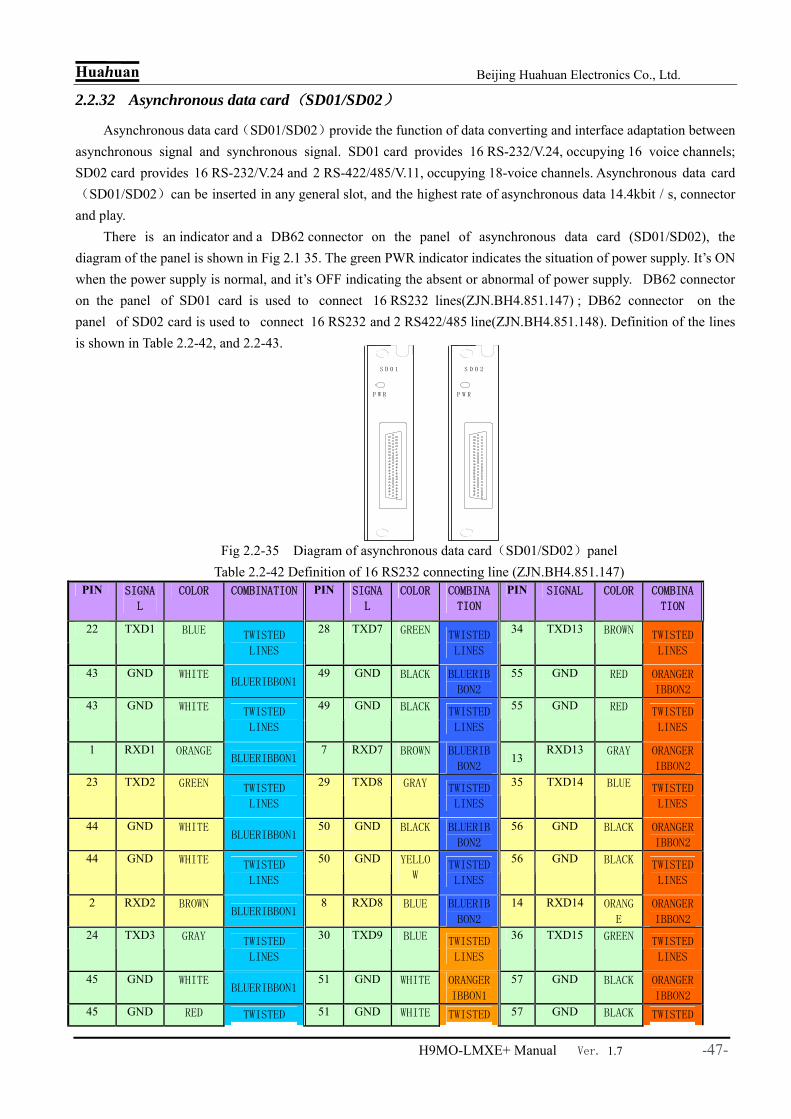
Huahuan Beijing Huahuan Electronics Co., Ltd.
H9MO-LMXE+ Manual Ver. 1.7 -47-
2.2.32 Asynchronous data card(SD01/SD02)
Asynchronous data card(SD01/SD02)provide the function of data converting and interface adaptation between asynchronous signal and synchronous signal. SD01 card provides 16 RS-232/V.24, occupying 16 voice channels; SD02 card provides 16 RS-232/V.24 and 2 RS-422/485/V.11, occupying 18-voice channels. Asynchronous data card(SD01/SD02)can be inserted in any general slot, and the highest rate of asynchronous data 14.4kbit / s, connector and play.
There is an indicator and a DB62 connector on the panel of asynchronous data card (SD01/SD02), the diagram of the panel is shown in Fig 2.1 35. The green PWR indicator indicates the situation of power supply. It’s ON when the power supply is normal, and it’s OFF indicating the absent or abnormal of power supply. DB62 connector on the panel of SD01 card is used to connect 16 RS232 lines(ZJN.BH4.851.147) ; DB62 connector on the panel of SD02 card is used to connect 16 RS232 and 2 RS422/485 line(ZJN.BH4.851.148). Definition of the lines is shown in Table 2.2-42, and 2.2-43.
Fig 2.2-35 Diagram of asynchronous data card(SD01/SD02)panel
Table 2.2-42 Definition of 16 RS232 connecting line (ZJN.BH4.851.147) PIN SIGNA
L
COLOR COMBINATION PIN SIGNA
L
COLOR COMBINA
TION
PIN SIGNAL COLOR COMBINA
TION
22 TXD1 BLUE TWISTED
LINES
28 TXD7 GREEN TWISTED
LINES
34 TXD13 BROWN TWISTED
LINES
43 GND WHITE BLUERIBBON1
49 GND BLACK BLUERIB
BON2
55 GND RED ORANGER
IBBON2
43 GND WHITE TWISTED
LINES
49 GND BLACK TWISTED
LINES
55 GND RED TWISTED
LINES
1 RXD1 ORANGE BLUERIBBON1
7 RXD7 BROWN BLUERIB
BON2 13
RXD13 GRAY ORANGER
IBBON2
23 TXD2 GREEN TWISTED
LINES
29 TXD8 GRAY TWISTED
LINES
35 TXD14 BLUE TWISTED
LINES
44 GND WHITE BLUERIBBON1
50 GND BLACK BLUERIB
BON2
56 GND BLACK ORANGER
IBBON2
44 GND WHITE TWISTED
LINES
50 GND YELLO
W TWISTED
LINES
56 GND BLACK TWISTED
LINES
2 RXD2 BROWN BLUERIBBON1
8 RXD8 BLUE BLUERIB
BON2
14 RXD14 ORANG
E
ORANGER
IBBON2
24 TXD3 GRAY TWISTED
LINES
30 TXD9 BLUE TWISTED
LINES
36 TXD15 GREEN TWISTED
LINES
45 GND WHITE BLUERIBBON1
51 GND WHITE ORANGER
IBBON1
57 GND BLACK ORANGER
IBBON2
45 GND RED TWISTED 51 GND WHITE TWISTED 57 GND BLACK TWISTED
S D 0 1
P W R
S D 0 2
P W R

Huahuan Beijing Huahuan Electronics Co., Ltd.
H9MO-LMXE+ Manual Ver. 1.7 -48-
LINES LINES LINES
3 RXD3 BLUE BLUERIBBON1
9 RXD9 ORANG
E
ORANGER
IBBON1
15 RXD15 BROWN ORANGER
IBBON2
25 TXD4 ORANGE TWISTED
LINES
31 TXD10
GREEN TWISTED
LINES 37
TXD16 GRAY TWISTED
LINES
46 GND RED BLUERIBBON1
52 GND WHITE ORANGER
IBBON1
58 GND BLACK ORANGER
IBBON2
46 GND RED TWISTED
LINES
52 GND WHITE TWISTED
LINES
58 GND YELLO
W TWISTED
LINES
4 RXD4 GREEN BLUERIBBON1
10 RXD10
BROWN ORANGER
IBBON1
16 RXD16 BLUE ORANGER
IBBON2
26 TXD5 BROWN TWISTED
LINES
32 TXD11
GRAY TWISTED
LINES
47 GND RED BLUERIBBON2
53 GND WHITE ORANGER
IBBON1
47 GND RED TWISTED
LINES
53 GND RED TWISTED
LINES
5 RXD5 GRAY BLUERIBBON2
11 RXD11
BLUE ORANGER
IBBON1
27 TXD6 BLUE TWISTED
LINES
33 TXD12
ORANG
E TWISTED
LINES
48 GND BLACK BLUERIBBON2
54 GND RED ORANGER
IBBON1
48 GND BLACK TWISTED
LINES
54 GND RED TWISTED
LINES
6 RXD6 ORANGE BLUERIBBON2
12 RXD12
GREEN ORANGER
IBBON1
NOTE:TXDi(i=1~16) means the output line of RS232 signal (transmit output signal): RXDi(i=1~16)means the input line of RS232 signal (transmit input signal).
Table 2.2-43 16 RS232 and 2 RS422/485 line(ZJN.BH4.851.148)
PIN SIGNA
L COLOR
COMBINAT
ION PIN SIGNAL COLOR COMBINATION PIN
SIGNA
L COLOR COMBINATION
22 TXD1 GREEN TWISTED
LINES 28 TXD7 GREEN TWISTED LINES 34 TXD1
3 BROWNTWISTED
LINES
43 GND WHITE GREEN
RIBBON1 49 GND BLACK GREEN RIBBON2 55 GND RED
ORANGE
RIBBON2
43 GND WHITE TWISTED
LINES 49 GND BLACK TWISTED LINES 55 GND RED
TWISTED
LINES
232-1
1 RXD1 ORANGE GREEN
RIBBON1
232-7
7 RXD7 BROWN GREEN RIBBON2
232-13
13 RXD13 GRAY
ORANGE
RIBBON2
23 TXD2 GREEN TWISTED
LINES 29 TXD8 GRAY TWISTED LINES 35 TXD1
4 GREENTWISTED
LINES
44 GND WHITE GREEN
RIBBON1 50 GND BLACK GREEN RIBBON2 56 GND BLACK
ORANGE
RIBBON2
44 GND WHITE TWISTED
LINES 50 GND YELLOW TWISTED LINES 56 GND BLACK
TWISTED
LINES
232-2
2 RXD2 BROWN GREEN
RIBBON1
232-8
8 RXD8 GREEN GREEN RIBBON2
232-14
14 RXD14
ORANG
E
ORANGE
RIBBON2 232-3
24 TXD3 GRAY TWISTED
LINES
232-9
30 TXD9 GREEN TWISTED LINES
232-15 36 TXD1
5 GREENTWISTED
LINES

Huahuan Beijing Huahuan Electronics Co., Ltd.
H9MO-LMXE+ Manual Ver. 1.7 -49-
45 GND WHITE GREEN
RIBBON1 51 GND WHITE
ORANGE
RIBBON1 57 GND BLACK
ORANGE
RIBBON2
45 GND RED TWISTED
LINES 51 GND WHITE TWISTED LINES 57 GND BLACK
TWISTED
LINES
3 RXD3 GREEN GREEN
RIBBON1 9 RXD9 ORANGE
ORANGE
RIBBON1 15 RXD1
5 BROWNORANGE
RIBBON2
25 TXD4 ORANGE TWISTED
LINES 31 TXD10 GREEN TWISTED LINES 37 TXD1
6 GRAYTWISTED
LINES
46 GND RED GREEN
RIBBON1 52 GND WHITE
ORANGE
RIBBON1 58 GND BLACK
ORANGE
RIBBON2
46 GND RED TWISTED
LINES 52 GND WHITE TWISTED LINES 58 GND YELLO
W
TWISTED
LINES
232-4
4 RXD4 GREEN GREEN
RIBBON1
232-10
10 RXD10 BROWNORANGE
RIBBON1
232-16
16 RXD16 GREEN
ORANGE
RIBBON2
26 TXD5 BROWN TWISTED
LINES 32 TXD11 GRAY TWISTED LINES 18 TXD1
+ ORANG
E
47 GND RED GREEN
RIBBON2 53 GND WHITE
ORANGE
RIBBON1 39 TXD1
-
ORANG
EWHIT
E
TWISTED
47 GND RED TWISTED
LINES 53 GND RED TWISTED LINES 19 RXD1
+ GREEN
232-5
5 RXD5 GRAY GREEN
RIBBON2
232-11
11 RXD11 GREEN ORANGERIBBON1
422-1
40 RXD1-
GREEN
WHITE
TWISTED
27 TXD6 GREEN TWISTED
LINES 33 TXD12 ORANGE TWISTED LINES 20 TXD2
+ BROWN
48 GND BLACK GREEN
RIBBON2 54 GND RED
ORANGE
RIBBON1 41 TXD2
- BROWN
WHITE
TWISTED
48 GND BLACK TWISTED
LINES 54 GND RED TWISTED LINES 21 RXD2
+ GREEN
232-6
6 RXD6 ORANGE GREEN
RIBBON2
232-12
12 RXD12 GREENORANGE
RIBBON1
422-2
42 RXD2-
GREEN
WHITE
TWISTED
NOTE:TXDi(i=1~16) means the output line of RS232 signal (transmit output signal): RXDi(i=1~16)means the input line of RS232 signal (transmit input signal). When some interface work at the RS422 mode, TXDi+/-(i=1~2)means the output line of RS422 signal (transmit output signal): RXDi+/-(i=1~2)means the input line of RS422 signal (transmit output signal); When some interface work at the RS485 mode, the signal line of the outside is RXDi+/-(i=1~2). external connected signal line is RXDi+/-(i=1~2)。
Plectrum Description: The first, second and forth plectrum of 4 digital plectrum K1 and K2 on the panel of SD02 card control mode of RS422/485 interface: K1 and K2 correspond to the 2 RS422/485 interface respectively. The interface work in the mode of RS422(full duplex) when the first, second and forth plectrum of K1 or K2 are all set to OFF (default ), The interface work in the mode of RS485 (half duplex) when the first, second and forth plectrum of K1 or K2 are all set to ON. The third plectrum of K1 and K2 are used to set the of the first three plectrum used to set the line resistance of 120Ωtermination: ON for the12 0Ωterminal balancing resistor resistance of the line: it’s connecting resistance when the plectrum is ON, otherwise it’s off resistance .Setting of terminal balancing resistor is related to the environment of the equipment.
2.2.33 64K homonymous data card(CHD01)
H9MO-LMXE+ support a 64K homonymous data card (CHD01), providing the accessing of 8 channel standard 64K homonymous data complying to ITU-T G.703. It can be used in all the universal slot of H9MO-LMXE+ chassis.
There are 9 indicators and 4 RJ-48C connector in the panel of CHD01 card, and the picture of the panel is showed in Fig 2.2-36. The RUN indicator should be blinking while working fine, and it OFF means it’s working status is abnormal. Red indicators 1-8 show the status of 64K homonymous data. OFF of it means the transmission of

Huahuan Beijing Huahuan Electronics Co., Ltd.
H9MO-LMXE+ Manual Ver. 1.7 -50-
64K data is fine, and ON means loss of signal, and blinking means AIS of the service.
Fig 2.2-36 Panel of 64K homonymous data card (CHD01)
Table 2.2-44 664K homonymous data card(CHD01)RJ-48C
RJ-48C pin 64K homonymous data interface line
Twisted pair Color recommended(UTP5)
1 IN(1)- Blue 2 IN(1)+
Twisted Blue white
3 OUT(1)+ Orange 4 OUT(1)-
Twisted Orange white
5 IN(2)- Green 6 IN(2)+
Twisted Green white
7 OUT(2)+ Grown 8 OUT(2)-
Twisted Grown white
Note:There are 2 channel 64K homonymous data in every RJ-48C port on CHD01 card, and it is a private definition, please do not confuse with the 120Ω standard RJ-48C port. Wrongly plug will destroy the port.
2.2.34 Ring card(RING48V/RING24V/RING220V)
Ring card(RING48V/RING24V/RING220V)provide ring(75V、25Hz) for voice line interface. There are 3 kind of ring card: 48V ring card(RING48V), 24V ring card (RING24V) and AC220V ring card(RING220V), and one can choose one from the 3 depending on the power supply of the equipment. For the sake of safety, the AC220V ring card(RING220V)need a AC power line ZJN.BH4.855.035. When there is a power supply protection of one AC 220V power and a DC-48V power, AC220V ring card will keep working even one of the power supply fails. NOTE: the ring cards do not support hot-plugging or hot swap! RING24V and RING48V only take one slot, and it is fixed to slot 14. But RING220V takes 2 slots, and is fixed to slot 13-14.
There are 2 indicators on the panel of ring card (RING48V/RING24V/RING220V) . And there is one more standard AC power connector on the panel of AC220V ring card (RING220V). Diagram of the panels are Shown in Fig 2.2–37. Definition of the indicators is shown in Table 2.2-45.

Huahuan Beijing Huahuan Electronics Co., Ltd.
H9MO-LMXE+ Manual Ver. 1.7 -51-
Fig 2.2-37 Diagram of ring card RING48V/RING24V/RING220V) panels Table 2.2-45 Definition of the indicators of ring card RING48V/RING24V/RING220V)
Mark Color Meaning of indicators Ring Green ON: Ring card working normally; OFF: Ring card working unmorally
PWR Green ON: Power supply normal,OFF: Power supply unmoral
2.2.35 Coarse wavelength division multiplexing card (WDM01/WDM01A) Coarse wavelength division multiplexing card (WDM01/WDM01A) realizes the multiplexing of 4 different
wavelength (1510nm、1530nm、1550nm、1570nm) to one signal and transmit it on one or a pair of fiber, getting high accessing band with low cost. It can be used in core, edge and access network of broadband optical WAN. It real application, coarse wavelength division multiplexing card should be used in a pair, one end (sending) realize multiplexing and the other end realize de-multiplexing. Coarse wavelength division multiplexing channel realize transparent data transmission, and it is irrelevant to the data transmission ratio and electrical modulation mode and can transmit various format signals. WDM01/WDM01A takes 2 slots and can be inserted into any universal slot except slot 14.
Coarse wavelength division multiplexing card (WDM01/WDM01A) support no power application, meaning it can still realize the multiplexing and de-multiplexing of signal. The card provides 4 tributary optical ports and 1 COM optical port. WDM01 optical port is LC, while WDM02 optical port is FC. The panel of the WDM01 and WDM01A is show in Fig 2.2-38. There is a RUN indicator on the panel, ON means the card is working fine, while OFF means it is abnormal.
R i n g
P W R
R I N G 4 8 V
R i n g
P W R
R I N G 2 4 V
R i n g
P W R
R I N G 2 2 0 V

Huahuan Beijing Huahuan Electronics Co., Ltd.
H9MO-LMXE+ Manual Ver. 1.7 -52-
Fig 2.2-38 Panel of coarse wavelength division multiplexing card (WDM01/WDM01A) 2.2.36 Device identification section
There is a device identification section on the left side of H9MO-LMXE+, with the device model identified on it. The ESD plug at the bottom can be used to connect to antistatic wristlets(optional)The diagram of the device identification section is shown in Fig 2.2 39.
Fig 2.2-39 Device identification section
2.3 Equipment Installation 2.3.1 Structure of the Card Mounting
H9MO-LMXE+ has 19 card positions. The slot labels at the upper edge denote slot types. The PWR slots are used for power cards. The NM slot is used for network management card. Two slots at the middle labeled X1 and X2 are dedicated to NIU cards. The rest of the slots, labeled 01 through 14, are used for LIU cards. Note that the NIU card looks rather like the LIU counterparts, attention should be paid not to mis-insert them.
Each card is fixed onto the chassis by the screw nod at the top of the panel. At the bottom, there is an ejector. Hidden under the ejector is another screw, which is fastened at the time of shipment. When unplugging the card, please make sure that this screw is also loosened.
On top of the chassis, there is a cable duct used for fiber wiring. The duct is fixed at the back of the chassis at shipment, and should be moved to the top at installation. See Fig 2.3-1.
2.3.2 Rear Panel
Auxiliary connections to the H9MO-LMXE+ are on the back of the chassis. Open the rear cover, you can see the
H9MO-LMXE+
E S D

Huahuan Beijing Huahuan Electronics Co., Ltd.
H9MO-LMXE+ Manual Ver. 1.7 -53-
chassis backplane, see Figure 2.3-1. There are two sets of power access ports, 2 fan connector, a fan power connector, a system alarm output interface, a clock input and output interface and sets of indicators. There are 2 fans installed at the rear panel.
At the lower left of the backplane, there is a jumper for CNG and CGND connection. Normally, the two ground planes should be connected at this point by placing the jumper at the left position. But under certain conditions where the CGND is not properly earthed or very noisy, disengaging GND and CGND might be more favorable. This can be decided by experimentation.
FAN connectorGND/CGNDConnector plunger pin
- 48V-1
- 48V-2
CGNDGND
GND
Sys alarm output
INOUT
External Clock interface
Indicator
PWR1 PWR2PWR2
ALARM
PWR1
FAN1 FAN2
FAN power connector
FAN3
Fig 2.3-1 Diagram of H9MO-LMXE+ rear panel
2.3.3 Power connection
Two -48V power input connectors, -48V-1 and -48V-2, are provided on the H9MO-LMXE+, allowing main and backup power to be connected to the equipment. Next to the -48V connectors are the battery ground connectors for the two sets of power supplies respectively. Two sets of -48V power input can withstand reverse polarity.
When making power and ground connections, please make sure that the screws are securely tightened. The wires should have a cross section of at least 1.5mm2. The CGND connection should be as short as possible to reduce the resistance and inductance to ground.
-48V power can also be connected through the front panel of power card (equals to connecting from the rear panel) in the circumstance requiring all the lines coming out from one side of the equipment. Note that the red line means high voltage level, and the level black line means low voltage level. Note the direction of the power connector inserted, the lock lever should be at the top. Pay attention to the orientation while plugging power: the locking pole should be at the upside. Pole at the left-down corner of the DC plug is protection ground. And the yellow-green line together with the equipment is ground line. Make sure the protection ground is rightly connected.
AC power must be connected into to the system through the AC plug at the front panel when using AC power supply card (PWR02/PWR02B/PWR02C/PWR02D). Make sure the protection ground of AC power is properly connected. Note: PWR02/PWR02C card provide ~ 220V input, PWR02B/PWR02D card provide ~ 110V input, and do not confuse them!
NOTE:To protect the safety of equipment and stuff using it, the ground of the equipment should be correctly connected to the protection ground of the machinery-room. 2.3.4 Network management connection
When the H9MO-LMXE+ is to be directly connected to a workstation through Ethernet, the Ethernet port at the back panel are usually used. There are 1 Ethernet port on network management card NM01, and 2 on NM02. The 2 Ethernet port on NM02 can connect to the network management station or cascade network management network.
Only when workstation is physically located near the H9MO-LMXE+ will the Ethernet connection is used to link the two. More often when the WS is remote from the equipment, DCC or VC-12 management channels

Huahuan Beijing Huahuan Electronics Co., Ltd.
H9MO-LMXE+ Manual Ver. 1.7 -54-
embedded in the optical signal are used as the management communication channel, rather than the local Ethernet ports.
Note: Default IP address of the device: 192.192.4.2.
2.3.5 Alarm Output
The system alarm output, labeled PALM and DALM at the rear panel and front of network management card of H9MO-LMXE+, is used for connecting to rack alarm units. The PALM is the prompt alarm output, and DALM is the deferred alarm output. Both outputs are of the dry contact type. Normally, the output pin is floated. When alarm occurs, the pin is connected to CGND through relay contacts. The content of alarm is decided by alarm mask. The stimuli of each alarm type are set through management software.
2.3.6 Fan connection
There are 2 fan connectors(FAN1/FAN2)and a fan power connector(FAN3) at the rear panel of H9MO-LMXE+. The fan is installed at the rear panel, for the sake of efficiency of cooling the equipment, even when several of them pile up. A socket is provided to connect the fan rather than fixed wiring. The network management software will monitor the condition of the FAN.
The power of fan is from the power card when there is a DC/AC power card(PWR02C/PWR02D)on the H9MO-LMXE+. The user only has to connect wire of the fan to fan connector (FAN1/FAN2). There should be an extra power(an AC/DC power converter) for fan when there is a AC power card(PWR02/PWR02B)on the H9MO-LMXE+. In this circumstances, except connecting wire of the fan to fan connector (FAN1/FAN2), user has to connect the output wire of AC/DC power converter to fan connector (FAN3) to make sure the fan work.
2.3.7 Timing signal connection
There is a built-in clock (comply with ITU-T G.813) in the aggregation card (OX01), providing one clock input signal and one clock output signal.
Clock input / output interface is at the back panel of the chassis. It is 75Ω (unbalanced), CC4 coaxial connector, labeled IN and OUT. Network management system can monitor the status of the clock input signal and set clock mode (2MHz or 2Mbit /s). In the circumstances that require timing signal coming out from the front panel, user can use the clock input/output interface on the OW/Overhead/Clock card(LA01).
2.3.8 Optical fiber connection
H9MO-LMXE+ fiber interface is either FC or SC according to purchase options. It can also provide LC (duel fiber) or SFP (single fiber). Optical signal output interface is labeled ( , and optical signal input interface is labeled( .Tx port is the optical output and Rx port is the optical input. For the single fiber duplex option, one fiber is used for transmission to and from both directions, and only one fiber connector is on the fiber optic module. Only SC socket is available for the single fiber duplex option. The single fiber port is labeled with its transmit wavelength. Note that only ports with different transmit wavelengths, namely 1310nm and 1550nm, can communicate with each other over a single fiber. As a general rule, the cards on LMXE will use 1310nm Tx wavelength, and remote CPEs will use 1550nm.
When make fiber connections, make sure to align the notches on the plug and socket. The plug must be pushed firmly to position for reliable connection. The fiber pigtail should not have bents with less than 50mm radius. When unplug the connector, do not pull on the fiber directly. It is recommended that the socket cover be kept aside, and recap the socket whenever the fiber is unplugged to prevent dust. Fiber end may require cleaning from time to time according to environment conditions.
2.3.9 E1/E3/DS3 interface connection
If E1 or E3/DS3 service is configured, connect E1, E3/DS3 cables to their corresponding sockets, please note the

Huahuan Beijing Huahuan Electronics Co., Ltd.
H9MO-LMXE+ Manual Ver. 1.7 -55-
signal input and output relation. For different E1 port impedance, different cables should be adopted. E1 port impedance can be set by the dip
switches in interface card. If E1 port impedance is 120Ω, use twisted pair with RJ45 connector directly. If E1 port impedance is 75Ω, use cable ZJN. BH4.850.123 to convert RJ45 to BNC. For E3/DS3 signal, use NMS or dip switched to select the interface type. E1 interface of EP01A and EP03A card only support impedance 120Ω, using 60芯 interface cable.
For E3/DS3 signals, user can set the mode of interface by the network management software or the tip switches.
2.3.10 Ethernet connection
If Ethernet electrical port card is configured, plug Ethernet cable to ETH socket in the front panel. If Ethernet optical port card is configured, plug Ethernet cable to the optical socket in the front panel. Use NMS to set Ethernet channel VC-12 virtual concatenation, Ethernet control and Ethernet various function on/off set.
2.3.11 V.35 interface connection
If Ethernet electrical port card is configured, plug Ethernet cable to ETH socket in the front panel. If Ethernet optical port card is configured, plug Ethernet cable to the optical socket in the front panel. Use NMS to set Ethernet channel VC-12 virtual concatenation, Ethernet control and Ethernet various function on/off set.
2.3.12 Audio line connection
If there is any PCM or RS232 asynchronous data service in the H9MO-LMXE+ + device, their according line should be connected to the card’s connectors. Details of the lines are shown in the according section of cards. After that, the details of cross connection of every voice line and RS232 asynchronous data service can be set through the network management software.
2.3.13 Cable Duct Mounting
The cable duct is attached to the back of the chassis at the time of shipment to prevent damage. After opening the package, the duct should be detached from the rear panel and mounted at the top edge of the chassis, as shown in Fig 2.3-2.

Huahuan Beijing Huahuan Electronics Co., Ltd.
H9MO-LMXE+ Manual Ver. 1.7 -56-
Fig 2.3-2 H9MO-LMXE+ Cable Duct Mounting
3. Operation and Maintenance 3.1 Management Software
Installation and operation of the H9MO-LMXE+ in a network require the interaction with the network management software, codenamed H7GMSW. It is briefly introduced in this section. For more details, please refer to the software manual and the online help.
H7GMSW is a GUI based NE/SN management software. It is connected to the managed NE through Ethernet, DCC or E1 connections. Each NE in the network must have a unique identification address, which is its IP address. Each unit is given the default IP address when released, which must be changed to a unique address allocated to it for a network at the time of installation.
Note that the IP address of each MUX may not be in the public domain, except the gateway node through which the management messages are passed to other nodes. In other words, on each sub-network, only one public IP is needed.
3.1.1 IP Address Query and Configuration
The IP address, as well as other parameters, is set through the NM Ethernet port on the front panel using Telnet commands. Telnet connection requires prior knowledge of the device IP address. In case it is not known, the dip
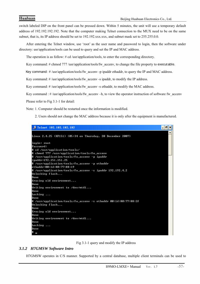
Huahuan Beijing Huahuan Electronics Co., Ltd.
H9MO-LMXE+ Manual Ver. 1.7 -57-
switch labeled DIP on the front panel can be pressed down. Within 5 minutes, the unit will use a temporary default address of 192.192.192.192. Note that the computer making Telnet connection to the MUX need to be on the same subnet, that is, its IP address should be set to 192.192.xxx.xxx, and subnet mask set to 255.255.0.0.
After entering the Telnet window, use ‘root’ as the user name and password to login, then the software under directory: usr/application/tools can be used to query and set the IP and MAC address.
The operation is as follow: # cd /usr/application/tools, to enter the corresponding directory.
Key command: # chmod 777 /usr/application/tools/fw_accenv, to change the file property to executable.
Key command: # /usr/application/tools/fw_accenv -p ipaddr ethaddr, to query the IP and MAC address.
Key command: # /usr/application/tools/fw_accenv -s ipaddr, to modify the IP address.
Key command: # /usr/application/tools/fw_accenv -s ethaddr, to modify the MAC address.
Key command : # /usr/application/tools/fw_accenv –h, to view the operator instruction of software fw_accenv
Please refer to Fig 3.1-1 for detail:
Note: 1. Computer should be restarted once the information is modified.
2. Users should not change the MAC address because it is only after the equipment is manufactured.
Fig 3.1-1 query and modify the IP address
3.1.2 H7GMSW Software Intro
H7GMSW operates in C/S manner. Supported by a central database, multiple client terminals can be used to
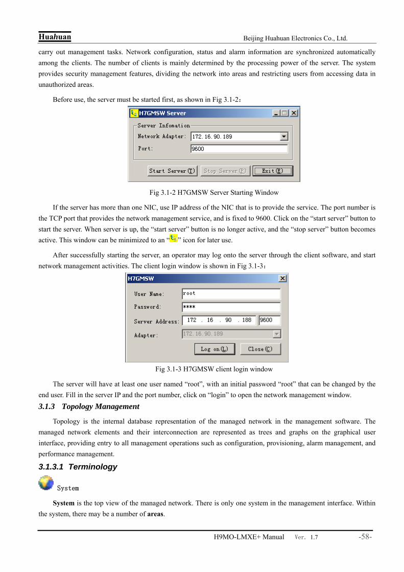
Huahuan Beijing Huahuan Electronics Co., Ltd.
H9MO-LMXE+ Manual Ver. 1.7 -58-
carry out management tasks. Network configuration, status and alarm information are synchronized automatically among the clients. The number of clients is mainly determined by the processing power of the server. The system provides security management features, dividing the network into areas and restricting users from accessing data in unauthorized areas.
Before use, the server must be started first, as shown in Fig 3.1-2:
Fig 3.1-2 H7GMSW Server Starting Window
If the server has more than one NIC, use IP address of the NIC that is to provide the service. The port number is the TCP port that provides the network management service, and is fixed to 9600. Click on the “start server” button to start the server. When server is up, the “start server” button is no longer active, and the “stop server” button becomes active. This window can be minimized to an “ ” icon for later use.
After successfully starting the server, an operator may log onto the server through the client software, and start network management activities. The client login window is shown in Fig 3.1-3:
Fig 3.1-3 H7GMSW client login window
The server will have at least one user named “root”, with an initial password “root” that can be changed by the end user. Fill in the server IP and the port number, click on “login” to open the network management window.
3.1.3 Topology Management
Topology is the internal database representation of the managed network in the management software. The managed network elements and their interconnection are represented as trees and graphs on the graphical user interface, providing entry to all management operations such as configuration, provisioning, alarm management, and performance management.
3.1.3.1 Terminology
System
System is the top view of the managed network. There is only one system in the management interface. Within the system, there may be a number of areas.
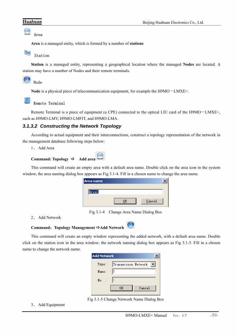
Huahuan Beijing Huahuan Electronics Co., Ltd.
H9MO-LMXE+ Manual Ver. 1.7 -59-
Area
Area is a managed entity, which is formed by a number of stations
Station
Station is a managed entity, representing a geographical location where the managed Nodes are located. A station may have a number of Nodes and their remote terminals.
Node
Node is a physical piece of telecommunication equipment, for example the H9MO-LMXE+.
Remote Terminal
Remote Terminal is a piece of equipment (a CPE) connected to the optical LIU card of the H9MO-LMXE+, such as H9MO-LMV, H9MO-LMFIT, and H9MO-LMA.
3.1.3.2 Constructing the Network Topology
According to actual equipment and their interconnections, construct a topology representation of the network in the management database following steps below:
1、 Add Area
Command: Topology Add area
This command will create an empty area with a default area name. Double click on the area icon in the system window, the area naming dialog box appears as Fig 3.1-4. Fill in a chosen name to change the area name.
Fig 3.1-4 Change Area Name Dialog Box
2、 Add Network
Command:Topology Management Add Network
This command will create an empty window representing the added network, with a default area name. Double click on the station icon in the area window; the network naming dialog box appears as Fig 3.1-5. Fill in a chosen name to change the network name.
Fig 3.1-5 Change Network Name Dialog Box
3、 Add Equipment

Huahuan Beijing Huahuan Electronics Co., Ltd.
H9MO-LMXE+ Manual Ver. 1.7 -60-
Command:Topology Management Add Equipment
Fig 3.1-6 Add Equipment
Fig 3.1-7 H9MO-LMXE+ Icon
This command is only active in the network view. After issuing the command, a dialog box as shown in Fig 3.1-6 pops up for selecting equipment. After choosing the right equipment type, enter appropriate IP address (only of local significance) and sub network mask, click on “OK” to add the equipment. A frame representing the equipment will drag with the mouse pointer, click at a chosen location to place the equipment.
Repeat to add all the remote nodes. 4、 Add Connection Info
Fig 3.1-8 Add Connection Info Dialog Box
To associate a remote node to a specific card on the H9MO-LMXE+, double click the link to the remote in question. A dialog box will appear as shown in Fig 3.1-8. Fill in this dialog box, choosing card number and fiber port, click “OK” to finish.

Huahuan Beijing Huahuan Electronics Co., Ltd.
H9MO-LMXE+ Manual Ver. 1.7 -61-
3.1.4 Enquire and Change Node Info
In the area view, double click on the node name will pop up the equipment info dialog box as shown in Fig. 3.1-9. This may be used to check and/or change the IP address and the node name etc. Note that this change is local to the database; the actual equipment address can only be modified through telnet commands.
Fig 3.1-9 Node Info enquiry dialog box
3.1.5 NE Explorer
H9MO-LMXE+ converge equipment operation to the NE Explorer, including the equipment slot configuration, service configuration, communication, clock, spending, interface status and the management function related to all kinds of cards. In the system tree, enter into NE Explorer through clicking on the H9MO-LMXE+ icon with right mouse button. The alarms, status, configuration information of the H9MO-LMXE+ are shown in the different area. The NE Explorer and function tree are as shown in the Fig 3.1-10.

Huahuan Beijing Huahuan Electronics Co., Ltd.
H9MO-LMXE+ Manual Ver. 1.7 -62-
Fig 3.1-10 NE Explorer
3.2 Networking
H9MO-LMXE+ can be used as an ADM device in a ring or a chain network, or be used as a gateway device (hub) in a star network.
The H9MO-LMXE+ can perform 1+1 multiplex section protection switching between the two NIU STM-1 ports. The switching is non-revertive.
When H9MO-LMXE+s are used as ADM nodes, they support SNCP to protect selected services.
3.2.1 Management Channel
Note that the management channel setting command can take effect only when the control messages can reach the NE in question. That is, it may be necessary to set these parameters locally before the remote management station can communicate with the NE.
DCC Management Channels
In a network of Metro-Edge Express family equipment such as H9MO-LMA, H9MO-LMFIT, and H9MO-
LMXE+, SDH section overhead DCC(D1~D3) channels are used for management messages between NEs. But if the management workstation must cross third party network to reach the Huahuan devices, management channels have to be set up through the alien network. Though D1~D3 could still be used for this purpose, it is likely that this channel is already occupied by the alien network itself, some other channels must be used for management. To adapt to this requirement, the Metro-Edge Express family products can work with other channels for management, namely DCC bytes other than D1~D3, and E1s. NE Explorer->Function Tree->Communication->DCC Management

Huahuan Beijing Huahuan Electronics Co., Ltd.
H9MO-LMXE+ Manual Ver. 1.7 -63-
Fig 3.2-1 DCC Management Channels
E1 Management Channels
Each H9MO-LMXE+ can have up to 2 E1 based management channels, denoted as A and B. An E1 management channel may be from a VC-12 in the STM-1 interface, or from one of the E1 interfaces. The management software selects the E1 channel as shown in Fig. 3.2-2. Once dedicated to management, the channel should not be allocated to provide other services.

Huahuan Beijing Huahuan Electronics Co., Ltd.
H9MO-LMXE+ Manual Ver. 1.7 -64-
Fig 3.2-2E1 Management Channels Embedded Management Network
When Huahuan sub-networks are scattered across the core SDH network, one way to manage all the subnets is to provide a separate IP data network to connect the gateway NE on each sub-network. But this separate packet network may not be available, therefore, an embedded management network is needed within the core SDH network. Depending on the scale (number of subnets), core network capabilities, and operation preference of the operator, different topologies may be used. These topologies can be constructed either with DCC channels, or with E1 channels, or even mix them together.
1. Star Topology, as shown in Fig 3.2-3.
The star topology requires a direct channel to each subnet from the management site. These channels may either be DCC based or E1 based. When the number of subnets is large, DCC channels can easily be used up. E1 channel is a more reasonable choice. However, the total bandwidth occupied by the management increases with the number of subnets. Otherwise, this topology is easier to provision and expand. Protection of the management channels are usually supported by the underlying core network.
In the figure, the LMHUB is a device acting as a hub for the embedded management channels. It has 8 E1s and 1 STM-1 fiber optic interface as well as a management Ethernet port for the MS. The total hub capacity is 63(VC-12) + 8(E1) + 4(DCC), thus can manage up to 75 remote subnets.
Note that the embedded management channel setting is required only to the gateway NEs, other NEs within each sub-network still use the default D1~D3 for management.

Huahuan Beijing Huahuan Electronics Co., Ltd.
H9MO-LMXE+ Manual Ver. 1.7 -65-
LMFIT
LMA
LMA LMA
LMAWS
SDH Core
LMHUB
E1/STM-1
10BaseT
LMA
LMA
LMA
STM-1N11
N12
N13
N21
N22
N23N24
N25
NM Channel
NM Channel
LMA
LMA
LMA
LMX
E+
N31N32
N33
N34
Fig 3.2-3 Embedded Star Management Network 2、Chain and Ring Topology, as shown in Fig 3.2-4..
Compared with star topology, chain topology requires only one cascaded DCC or E1 channel in the underlying core network, regardless the number of subnets. This save on core network bandwidth is the main advantage for this topology. One of the disadvantages is the difficulty associated with the provisioning of the cascade channel. When new subnet is added to the core edge, the chain has to be re-provisioned. Another disadvantage is poor reliability. Although the embedded links may be protected by the core network, the management message is relayed at each intermediate gateway NE. If one fails, the rest of subnets downstream will be cut off from the management channel. A third disadvantage is that the management efficiency is reduced due to bandwidth sharing of all NEs for the single channel, and many hops taken by the messages.
Adding one more channel between the head and the tail creates a ring topology. This partly solves the single NE failure problem, but other disadvantages remain.
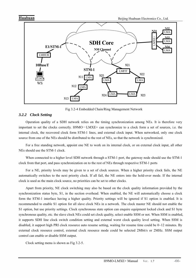
Huahuan Beijing Huahuan Electronics Co., Ltd.
H9MO-LMXE+ Manual Ver. 1.7 -66-
LMFIT
LMA
LMA LMA
LMAWS
SDH Core
LMHUB
E1/STM-1
10BaseT
LMA
LMA
LMA
STM-1
N11
N12
N13
N21
N22
N23N24
N25
NM Channel
LMA
LMA
LMA
LMX
E+
N31N32
N33
N34
Fig 3.2-4 Embedded Chain/Ring Management Network
3.2.2 Clock Setting
Operation quality of a SDH network relies on the timing synchronization among NEs. It is therefore very important to set the clocks correctly. H9MO-LMXE+ can synchronize to a clock form a set of sources, i.e. the internal clock, the recovered clock form STM-1 lines, and external clock input. When networked, only one clock source from one of the NEs should be distributed to the rest of NEs, so that the network is synchronized.
For a free standing network, appoint one NE to work on its internal clock, or on external clock input, all other NEs should use the STM-1 clock.
When connected to a higher level SDH network through a STM-1 port, the gateway node should use the STM-1 clock from that port, and pass synchronization on to the rest of NEs through respective STM-1 ports
For a NE, priority levels may be given to a set of clock sources. When a higher priority clock fails, the NE automatically switches to the next priority clock. If all fail, the NE enters into the hold-over mode. If the internal clock is used as the main clock source, no priorities can be set to other clocks.
Apart from priority, NE clock switching may also be based on the clock quality information provided by the synchronization status byte, S1, in the section overhead. When enabled, the NE will automatically choose a clock form the STM-1 interface having a higher quality. Priority settings will be ignored if S1 option is enabled. It is recommended to enable S1 option for all slave clock NEs in a network. The clock master NE should not enable the S1 option, but use priority settings. Clock synchronous state option can enquire equipment locked clock and S1 byte synchronous quality, etc. the slave clock NEs could set clock quality, select enable SSM or not. When SSM is enabled, it supports SDH line clock switch condition setting and external worst clock quality level setting. When SSM is disabled, it support high PRI clock resource auto resume setting, waiting for resume time could be 0~12 minutes. By external clock resource control, external clock resource mode could be selected 2Mbit/s or 2MHz. SSM output control can enable or disable SSM output.
Clock setting menu is shown as Fig 3.2-5.

Huahuan Beijing Huahuan Electronics Co., Ltd.
H9MO-LMXE+ Manual Ver. 1.7 -67-
Fig 3.2-5 Clock Setting
3.2.3 Channel Provision
The channels are provisioned by setting up the TU-12 cross-connect matrix in each NE. If needed, E1 channels can be protected using SNCP, also by setting the cross-connect tables. The channel provisioning command is “NE Explorer->Function Tree->Configuration->SDH Service Configuration”, which will start the cross connect setup window as shown in Fig 3.2-6.
Fig 3.2-6 Service Configuration Window
Tree View in the left side of the need for business to choose the network elements. Here the Source - Destination, a two-way channel for each other on a reciprocal terms, there is no special meaning.
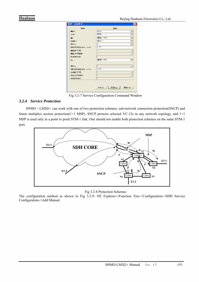
Huahuan Beijing Huahuan Electronics Co., Ltd.
H9MO-LMXE+ Manual Ver. 1.7 -68-
Fig 3.2-7 Service Configuration Command Window
3.2.4 Service Protection
H9MO-LMXE+ can work with one of two protection schemes, sub-network connection protection(SNCP) and linear multiplex section protection(1+1 MSP). SNCP protects selected VC-12s in any network topology, and 1+1 MSP is used only in a point to point STM-1 link. One should not enable both protection schemes on the same STM-1 port.
LMXE+
LMA
LMA LMA
LMA
SDH COREN1
N2
N3N4
N5
E1-1
E1-1
WSTM-1
W
P
MSP
P
E1-2
E1-2 WP
SNCP
Fig 3.2-8 Protection Schemes The configuration method as shown in Fig 3.2-9: NE Explorer->Function Tree->Configuration->SDH Service Configuration->Add Manual.

Huahuan Beijing Huahuan Electronics Co., Ltd.
H9MO-LMXE+ Manual Ver. 1.7 -69-

Huahuan Beijing Huahuan Electronics Co., Ltd.
H9MO-LMXE+ Manual Ver. 1.7 -70-
Fig 3.2-9 SNCP Protection Setting
3.2.5 PCM service configuration 3.2.5.1 Voice interface mode configuration
Multifunctional voice card (CHM01) provide 10 voice lines, and the mode of voice interface and be set to local side(FXO), remote side(FXS), hotline or magnet (RD) through NMS or dip on the equipment. And the mode of line i is the same to line i+1(i=1,3,5,7,9). And the steps to set the mode of voice interface through NMS is: NE attribute CHU01 card function tree configuration CHN config, And enter the window (Fig 3.2-10). User can query and set the mode of the interface, query busy/empty status of the lines and the time slot status.
Fig 3.2-10 Voice interface mode configuration

Huahuan Beijing Huahuan Electronics Co., Ltd.
H9MO-LMXE+ Manual Ver. 1.7 -71-
3.2.5.2 64K time slots cross connection configuration
H9MO-LMXE+ provides 64K time slots cross connection function for PCM voice and asynchronous data service. And the steps are: NE attribute corresponding voice card’s function tree configuration TS cross, And enter the TS cross configuration window (Fig 3.2-11). User can query and set the PCM cross connection relation.
Fig 3.2-11 64K time slot cross connection
Note:64K time slots cross connection configuration is between 7 internal 2M channels and PCM voice lines in the PCM card.
3.2.5.3 Level of 4w voice line configuration
Multi-interface card (CHM01) provides 4 remote side (FXS) voice (fixed to time slot 1-4) , 4 4w audio line(fixed to time slot 5-8) and 4 RS232 asynchronous data interfaces(fixed to time slot 9-12). 4W audio line card (CH4W01) provides audio coding/encoding and level adjustment for 10 audio lines. Every level of 4W audio line of card CHM01 and CH4W01 can be set through NMS, and Tx level is between -4~+9 dBr,and Rx is between -14~+4 dBr. Take CH4W01 for example, the steps of setting are: NE attribute CH4W01 function tree
configuration CHN config And enter the CHN configuration window (Fig 3.2-12). User can query and set the 4w audio line’s level, busy/empty status of remote side lines and time slot status.

Huahuan Beijing Huahuan Electronics Co., Ltd.
H9MO-LMXE+ Manual Ver. 1.7 -72-
Fig 3.2-12 Level of 4W audio line configuration
3.2.6 E1 Ber Test Set
There are 2 E1 ber testers built-in every NIU optical card which can test the transmission state of optical uplinks and downlinks. The E1 ber tester 1 corresponds to the NIU card in slot X1, provided 2 E1 ber testers. The E1 ber tester 1 corresponds to the NIU card in slot X2, also provided 2 E1 ber testers. These testers can be distributed to any one VC12 in NIU or LIU optical card, or 2 special E1 channels in the PDH interface cards. Once the VC12 or E1 interface is set to be ber tester, it will not be used to carry services. Therefore, the configuration of E1 ber test is also under SDH service configuration interface. The operation is as follow: 1) Configure E1 ber test: NE Explorer—function tree—configuration—SDH service configuration. In the right window popped up, click “add”, the interface is shown as Fig 3.2-13.
Note: user should click upload to have a query after the E1 ber test configured and download successfully, then the E1 ber test can be used. 2) E1 ber test: NE—E1 ber test. Then the E1 ber test configuration list will pop up, double click the items in this list to operate E1 ber test, as Fig 3.2-14.

Huahuan Beijing Huahuan Electronics Co., Ltd.
H9MO-LMXE+ Manual Ver. 1.7 -73-
Fig 3.2-13 E1 ber test configuration
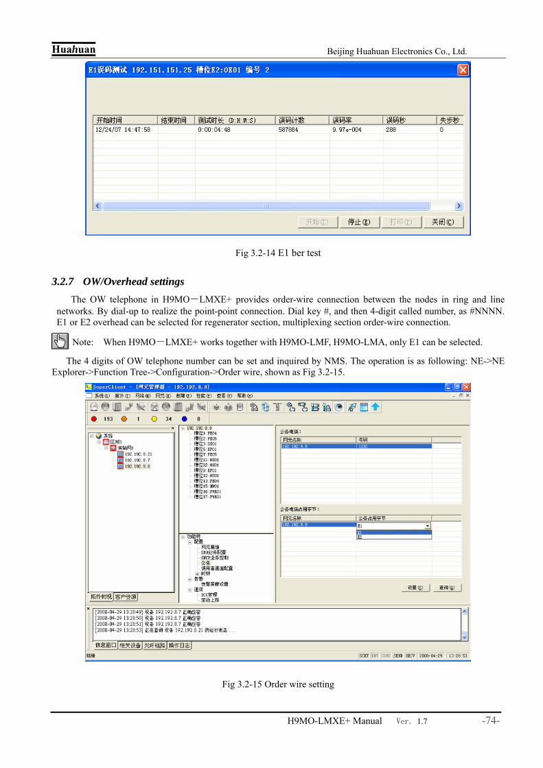
Huahuan Beijing Huahuan Electronics Co., Ltd.
H9MO-LMXE+ Manual Ver. 1.7 -74-
Fig 3.2-14 E1 ber test
3.2.7 OW/Overhead settings The OW telephone in H9MO-LMXE+ provides order-wire connection between the nodes in ring and line
networks. By dial-up to realize the point-point connection. Dial key #, and then 4-digit called number, as #NNNN. E1 or E2 overhead can be selected for regenerator section, multiplexing section order-wire connection.
Note: When H9MO-LMXE+ works together with H9MO-LMF, H9MO-LMA, only E1 can be selected.
The 4 digits of OW telephone number can be set and inquired by NMS. The operation is as following: NE->NE Explorer->Function Tree->Configuration->Order wire, shown as Fig 3.2-15.
Fig 3.2-15 Order wire setting
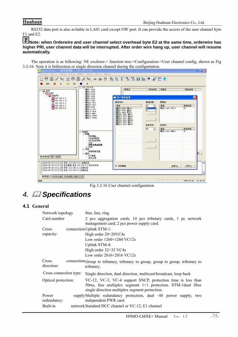
Huahuan Beijing Huahuan Electronics Co., Ltd.
H9MO-LMXE+ Manual Ver. 1.7 -75-
RS232 data port is also avilable in LA01 card except OW port. It can provide the access of the user channel byte F1 and E2.
Note: when Orderwire and user channel select overhead byte E2 at the same time, orderwire has higher PRI, user channel data will be interrupted. After order wire hang up, user channel will resume automatically.
The operation is as following: NE exolorer-> function tree->Configuration->User channel config, shown as Fig
3.2-16. Note it is bidirection or single direction channel during the configurtation.
Fig 3.2-16 User channel configuration
4. Specifications 4.1 General
Network topology Star, line, ring Card number 2 pcs aggregation cards, 14 pcs tributary cards, 1 pc network
management card, 2 pcs power supply card. Cross connection capacity:
Uplink STM-1: High order 20×20VC4s Low order 1260×1260 VC12s Uplink STM-4: High order 32×32 VC4s Low order 2016×2016 VC12s
Cross connection direction:
Group to tributary, tributary to group, group to group, tributary totributary.
Cross connection type: Single direction, dual direction, multicast/broadcast, loop back Optical protection: VC-12, VC-3, VC-4 support SNCP, protection time is less than
50ms, line multiplex segment 1+1 protection. STM-1dual fiber single direction multiplex segment protection.
Power supply redundancy:
Multiple redundancy protection, dual -48 power supply, two independent PWR card.
Built-in network Standard DCC channel or VC-12, E1 channel
Huahuan Beijing Huahuan Electronics Co., Ltd.
H9MO-LMXE+ Manual Ver. 1.7 -76-
management channel: Inner function: Bult-in TUPP and cross connection function, standard SDH
equipment clock units in aggregation card. Built-in E1 ber test unit in aggregation and tributary unit.
Optical direction 4 channels of uplink STM-1, full load 28 STM-1 optical tributary channels.
Tributary service: 12 or 24 channels of E1, 1 or 3 channels of E3/DS3, 100M Ethernetelectrical or optical service, 2 channels of V.35
4.2 STM-1 Optical/Electrical Port Bit rate: 155520kbit/s±4.6ppm Line code: Scrambled NRZ Wavelength: Default: 1310nm Option /5: 1550nm Output power: Default: Min: –12 dBm Option /L: Min: -5dBm Option /S: Min: –14 dBm Option /SL: Min: -5dBm Sensitivity: Default: -36dBm Option /S: -30dBm
Default: SC dual fiber dual directions Optical: Option/S: SC single fiber dual directions
Connector:
Electrical: CC4
4.3 STM-4 Optical Port Bit rate: 622080kbit/s ± 4.6ppm Line code: Scrambled NRZ Wavelength: Default: 1310nm Optional/5: 1550 nm Output power: Default: Min: –12 dBm Sensitivity: Default: -28dBm Connector: Default: LC dual-fiber
dual-direction transimission
4.4 STM-16 Optical Port Bit rate: 2488320kbit/s ± 4.6ppm Line code: Scrambled NRZ Wavelength: I-16:1310nm S-16.1:1310n
m L-16.1:1310nm L-16.2:1550nm
Output power:
I-16: S-16. 1: L-16.1: L-16.2:
-10~-3 dBm -5~0 dBm -2~+3dBm -2~+3dBm Sensitivity: I-16:
<-18dBm S-16: <-18dBm
L-16.1: <-27dBm
L-16.2: <-28dBm
Default: LC dual fiber dual directions Connector: Optical: Option/S: LC single fiber dual directions
4.5 PDH Optical Interface Wavelength: Default: 1310nm Option /5: 1550 nm
Default: Min: –12 dBm Option /L Min: -5dBm Output power: Option /S Min:–14 dBm Option
/SL Min: -5dBm
Sensitivity: Default: -36dBm Option /S -30dBm

Huahuan Beijing Huahuan Electronics Co., Ltd.
H9MO-LMXE+ Manual Ver. 1.7 -77-
OP03/OP05/OP06 Default
SC dual-fiber dual-directin
OP03/OP05/OP06 Option /S
SC single-fiber dual-directin
Connector:
OP02 Default LC dual-fiber dual-directin
4.6 E1 port Bite rate: 2.048 Mbps ± 50 ppm Line code: HDB3 Impedance: 75Ω unbalanced /120Ωbalanced Frame: Unframed Connector: 2×6 RJ45 or 1×6 RJ45 E1 number: 12 or 24
4.7 E3/DS3 port Bite rate: E3: 34.368 Mbps ± 15ppm; DS3:44. 736 Mbps ± 15ppm Line code: HDB3 Impedance: 75Ω unbalanced Frame: Unframed Connector: BNC or CC4 E3 number: 1 or 3
4.8 Ethernet port Bite rate: 2M~100M~100M Work mode: Ethernet Tx port: auto-negotiation, manual 1000M full-duplex.
Ethernet Tx port: auto-negotiation, manual 100M full-duplex. Ethernet Fx port: auto-negotiation, manual 100M full-duplex.
Connector: Ethernet Tx port: RJ45 Ethernet Fx port: LC
Support: VCAT、GFP、LCAS、LFP、VLAN、flow control Frame length: Mini frame length 64 byte, Max frame length 2032 Transmission way: EoS, EoE
Channel number: 1~4 Port number: 1~4
4.9 V.35 port Bite rate: Nx64kbps ± 50 ppm,N≤31 or 2048 kbps Frame: Framed E1 or unframed Interface mode: DCE Interface number:
2
Connector: DB25
4.10 Clock Port Clock resource: Inner clock, STM-1 line clock, external input clock, tributary
clock

Huahuan Beijing Huahuan Electronics Co., Ltd.
H9MO-LMXE+ Manual Ver. 1.7 -78-
External clock input: One 2048kbit/s or 2048kHz external clock, 75Ω unbalanced coaxial socket or 120Ω balanced RJ45 socket
Clock output: One 2048kbit/s or 2048kHz clock, 75Ωunbalanced coaxial socket or 120Ω balanced RJ45 socket
Connector: Backboard CC4; LA01card CC4 or RJ45 socket
Internal: 19440kHz±4.6ppm External: STM-1 Line, 2048kHz/2048kbps input Signal format: 2048 kHz or 2048kbps selectable Impedance: 75Ω Protocol: ITU-T G.704 SSM (2048kbps only) Number of I/O ports: 1
4.11 Management Port Ethernet Q interface: 2 RJ45 port, SNMP, 10/100Base-T Etherent MDI port F interface (RS232): Baud rate :9600, 8 digital bits, 1 stop bit, no checkout, no
flowcontrol Ethernet: RJ45, 10Base-T, MDI port Others: DCC, E1
4.12 OW/Overhead port Wire-order port: RJ11, support dual tone frequency dialing Asynchronous RS232 port DB9, V.11 electrical interface
4.13 Audio and asynchronous data interface
4.13.1 Conventional telephone interface and signal
4.13.1.1 Interface parameter Switch side Off-hook Impedance: < 500Ω Hook Impedance: > 10KΩ User side Loop impedance: ≤ 2000Ω(including the phone) Idle circuit voltage: ≤ 50V Loop current: 25mA Hook threshold: 8mA Polarity reversal time delay: < 50msec Dial-up: Plus dial up single plus distortion < 5msec
In-band dial up total distortion complies to audio interface feature
Hook delay: < 100msec
4.13.1.2 Ring steam Remote side ringing generator Frequency: 25Hz ± 3Hz Amplitude: 75V ± 5Vrms Ringing delay: < 50 ms Total output power: ≤5 W Detection of ringing at local side Amplitude range: Minimum 38Vrms

Huahuan Beijing Huahuan Electronics Co., Ltd.
H9MO-LMXE+ Manual Ver. 1.7 -79-
4.13.1.3 Audio
Impedance: 600Ω or three-address complex impedance,Fig 6.13-1 Audio range: 300 Hz ~ 3400 Hz Encoding Law: ITU-T recommendation G.711 A law 2W interface level: 2W Tx 0dBr ± 0.5dBr
2W Rx -3.5dBr ± 0.5dBr Return Loss: 300-600Hz >12dB
600-3400Hz >15dB Frequency response: 300-3400Hz Comply to ITU G.713 Air Noise: ≤ -65dBm0p Gain: -45dB ~ +3dB (inaccuracy less than±0.5dB) Total S/N: Comply to ITU G.713 sample(Fig 6.13-2)
Fig 6.13-1 Three-address complex impedance
Fig 6.13-2 2W interface Total S/N sample
4.13.2 Special interface
4.13.2.1 4W audio Impedance: 600Ω Encoding Law: ITU-T recommendation G.711 A law Return Loss: 300-600Hz >12dB
600-3400Hz >15dB Frequency response: 300-3400Hz Comply to ITU G.713 Air Noise: ≤ -65dBm0p Total S/N: Comply to ITU G.713 sample Fig6.13-2 Interface level: Factory default 4W Tx 0dBr± 0.5dBr
Factory default 4W Rx 0dBr± 0.5dBr Regulation accuracy: 0.1 dB
4.13.2.2 Magnet phone General magnet Voice indicators: The same to 2W audio

Huahuan Beijing Huahuan Electronics Co., Ltd.
H9MO-LMXE+ Manual Ver. 1.7 -80-
Interface Ring current detection: Min:20Vrms ,detecting time0.5s Signaling Mode: Digital mode(PCM 16 slot a law) Magnetic Interface Carrier
Voice: Second-line interface level: 2W Tx 0dBr ± 0.5dBr 2W Rx -3.5dBr ± 0.5dBr
Other voice indicators: The same to 2W audio Signaling: Ring current detection: The same to 2W audio Signaling Mode: Analogue mode — 2100Hz monotone 2100Hz signal generator range: -6dBm ±1dBm 2100Hz signal generator
frequency: 2100Hz ± 5Hz
Signaling detection rate range: not less than -17dBm Signaling detection frequency
range: 2100Hz ± 50Hz
4.13.2.3 Hotline phone Loop impedance: ≤ 2000Ω(including the telephone) Idle circuit voltage: ≤ 50V Loop current: 25mA Off-hook threshold: 8mA Voice Interface Specifications:
See in 6.13.1.3
4.14 Mechanical/Electrical Dimension: 130mm x 300mm x 440mm (H/D/W) Net weight: 12kg Power: -48 VDC (-36V ~ -72V), 110VAC(85V~140V), 220VAC(165V~265V) Consumption: ≤ 100W Working temp: 0 ~ 45°C Humidity: 0-90%RH (Non-condensing)
4.15 Reference Standards Item Reference standard STM-1、STM-4 SDH optical port: G.957, frame structure G.707
E1/E3/DS3 port: G.703,G.704 Ethernet port: IEEE 802.3 relevant 2Mbit/s、2Mhz clock port: G.823 SDH clock: G.813, G.825, Ministry of Posts and Telecommunication:
YDN121-1999, YDN123-1999 Network structure: G.783, G.798, G.803, G.805 Monitor and management: G.784, G.831, Q.811, Q.812, M.3100, M.3000, Ministry of Posts
and Telecommunication: YDN037-1997, YDN045-1997, YD5080-99
Service protection: G.841, G.842, Ministry of Posts and Telecommunication: YDN028-1997
Built-in E1 Ber test: O.150

Huahuan Beijing Huahuan Electronics Co., Ltd.
H9MO-LMXE+ Manual Ver. 1.7 -81-
5. Appendix H9MO-LMXE+ Multi-service SDH Access Platform user manual (version: 1.9) support:
Embedded software version: V2.2 or above;
NM01/NM02 card FPGA program version: V2.0 or above; OX01 card FPGA program version: V2.0+V1.3 or above;
OX04 card FPGA program version: V1.8+V1.4 or above; EX01 card FPGA program version: V1.2+V1.3 or above;
DX01 card FPGA program version: V2.0+V1.3 or above; DX02 card FPGA program version: V1.6 or above;
OS01 card FPGA program version: V1.6 or above; OS02 card FPGA program version: V1.6 or above;
OS02A card FPGA program version: V1.6 or above; OS03 card FPGA program version: V1.6 or above;
OP02 card FPGA program version: V1.0 or above; OP03 card FPGA program version: V1.0 or above;
OP05 card FPGA program version: V1.0 or above; OP06 card FPGA program version: V1.0 or above;
EP01 card FPGA program version: V1.6 or above; EP02 card FPGA program version: V1.8 or above;
EP03 card FPGA program version: V1.6 or above; ED01 card FPGA program version: V1.2 or above;
LA01 card FPGA program version: V1.7 or above; FE01 card FPGA program version: V2.7 or above;
FE02 card FPGA program version: V1.5 or above; FE04 card FPGA program version: V1.15 or above;
FE05 card FPGA program version: V1.4 or above; FE06A card FPGA program version: V1.6 or above;
FE06 card FPGA program version: V1.8 or above; GX01 card FPGA program version: V1.8 or above;
FE07 card FPGA program version: V1.0 or above; GX02 card FPGA program version: V1.0 or above.


