Guidelines on Design, Construction and Maintenance of Road ...
155
Guidelines on Design, Construction and Maintenance of Road Infrastructure incorporating Climate-resilient Features (December 2019) Department of Roads, MoWHS
Transcript of Guidelines on Design, Construction and Maintenance of Road ...

Guidelines on Design, Construction and Maintenance of
Road Infrastructure incorporating Climate-resilient
Features
(December 2019)
Department of Roads, MoWHS

Guideline on Design, Construction and Maintenance of Climate-resilient Roads Page 2

Guideline on Design, Construction and Maintenance of Climate-resilient Roads Page 3
Acknowledgement
First and foremost, the Department of Roads would like to express our sincere thanks to the
Global Environment Facility (GEF) and the Least Developed Countries Fund (LDCF) for
funding this project. The initiative of building climate resilient roads carried out under the
National Adaptation Programme of Action III (NAPA – III) project titled Enhancing
Sustainability and Climate Resilience of Forest and Agricultural Landscape and Community
Livelihood in Bhutan is the right intervention required at this hour. The developed guidelines
will not only help the engineers from the department, but also the engineers from various
sectors, in incorporating climate resilience in road design, construction and maintenance.
The Department would also like to thank our development partner United Nations
Development Partner (UNDP) and the Project Management Unit (PMU) based with Gross
National Happiness Commission (GNHC), for supporting the Department throughout the
development of this guideline.
The Department would also like to acknowledge the efforts and inputs of the core group
members, Mr. Lungten Jamtsho, Mr. Karma Wangdi, Mr. Karma Tenzin, Ms. Sonam Choden
and Ms. Shreenita Chhetri, who dedicated their time and effort in development of this
guideline.
Finally, the Department would like to thank all the stake holders for their active participation
in all the stake holder meetings. The inputs from various stake holders were crucial and
beneficial in development of this guideline.

Guideline on Design, Construction and Maintenance of Climate-resilient Roads Page 4
Project Background
Countries all over the world are facing challenges of climate change and Bhutan remains no
exception to such effects. Sustainable Environment is accorded the highest priority by the
Royal Government of Bhutan (RGoB). Like many other countries around the world, Bhutan is
considered highly vulnerable to the impacts of climate change. There are several climate
induced hazards which will severely impact the livelihood sources of the rural communities
and disrupt key infrastructures like roads that will immensely affect the access to food and
other basic necessities.
National Adaptation Programme of Action (NAPA) – III Project titled ‘Enhancing
Sustainability and Climate Resilience of Forest and Agricultural Landscape and
Community Livelihoods’ is funded by Global Environment Facility and Least Developed
Countries Fund (GEF-LDCF) and supported by UNDP. The project focuses on three
landscapes that cover 38 gewogs across 12 dzongkhags in the central belt of the country. The
project has three components; Institutional Capacity for Integrated Landscape Management
(ILM) and Climate Change Resilience, Implacement of Biological Corridor (BC) System
Governance and Management System at Pilot Corridors and Climate Adaptive Communities.
The Department of roads is mandated to fulfil an output under the component, Climate
Adaptive Communities, with the outcome ‘Livelihood options for communities are more
climate-resilient through diversification, Sustainable Land Management (SLM) and Climate
Smart Agriculture and supported by enhanced climate resilient infrastructure.’ The
Department’s output under the above stated outcome is ‘Transformation of market access
demonstrated for selected rural communities to enhance their climate-resilience’. Under this
outcome the Department has two broad activities and they are, Activity 3.3.1 - Develop Climate
Resilience Guidelines for Road Infrastructure adapting to Existing Environmental Friendly
Road Construction (EFRC) Guidelines and Standards and Activity 3.3.2 - Improve and
Upgrade Prioritized Gewog Connectivity (GC) Road Stretches for Enhanced Climate
Resilience. The guideline has been developed in house and is allocated with a budget of USD
94,000.00, which also included the capacity development of engineers in the Department. For
improvement of GC road, among various roads proposed, Shingkhar GC road was prioritized
keeping the project landscapes in view. Shingkar GC road is being taken up as the pilot climate
resilient road with a budget of USD 1,130,000.00.

Guideline on Design, Construction and Maintenance of Climate-resilient Roads Page 5
Table of Contents
INTRODUCTION.................................................................................................................. 13
CHAPTER 1 – SURVEY, GEOTECHNICAL STUDIES & DATA COLLECTION .... 16
1.1 Survey ....................................................................................................................... 16
1.1.1 Desktop Study................................................................................................... 16
1.1.2 Pre-feasibility Study......................................................................................... 16
1.1.3 Technical Feasibility ........................................................................................ 17
1.2 Geo-technical studies............................................................................................... 19
1.2.1 Field Investigations .......................................................................................... 20
1.2.2 Laboratory Investigations ............................................................................... 22
1.3 Data Collection ........................................................................................................ 24
1.3.1 Rainfall, flood discharge and temperature data ........................................... 24
1.3.2 Traffic data ....................................................................................................... 29
1.3.3 California Bearing Ratio (CBR) values ......................................................... 30
CHAPTER 2 – DESIGN OF ROAD & PAVEMENT ........................................................ 32
2.1 Geometric Design .................................................................................................... 32
2.1.1 Terrain Classification ...................................................................................... 32
2.1.2 Design Speed ..................................................................................................... 32
2.1.3 Horizontal Alignment ...................................................................................... 33
2.1.4 Road Formation ............................................................................................... 34
2.1.5 Road Classification & Specifications ............................................................. 34
2.1.6 Cross Section .................................................................................................... 35
2.1.7 Sight Distance ................................................................................................... 37
2.1.8 Super-Elevation ................................................................................................ 38
2.1.9 Widening ........................................................................................................... 39
2.1.10 Vertical Alignment ........................................................................................... 39
2.1.11 Horizontal Alignment ...................................................................................... 40
2.2 Pavement Design ..................................................................................................... 42
2.2.1 Flexible Pavement ............................................................................................ 42
2.2.2 Rigid Pavement ................................................................................................ 48
2.2.3 Composite Pavement ....................................................................................... 59

Guideline on Design, Construction and Maintenance of Climate-resilient Roads Page 6
2.3 Drainage Design....................................................................................................... 59
2.3.1 Principles of Good Drainage ........................................................................... 60
2.4 Provision of Surface Drainage ............................................................................... 60
2.5 Cross Drainage ........................................................................................................ 61
2.6 Slope Stabilization (Bio-engineering) .................................................................... 63
CHAPTER 3 – ROAD CONSTRUCTION.......................................................................... 66
3.1 Construction staking ............................................................................................... 66
3.2 Environmental Friendly Road Construction (EFRC) Approach ....................... 66
3.3 Clearing and Grubbing of Road Construction Area ........................................... 67
3.4 General Equipment Considerations ...................................................................... 68
3.5 Road Formation....................................................................................................... 69
3.5.1 Formation Cutting ........................................................................................... 70
3.5.2 Blasting Operation ........................................................................................... 71
3.6 Road Embankment Construction .......................................................................... 75
3.7 Climate Change Adaptation Road Construction ................................................. 75
3.8 Structures and Protective Works........................................................................... 76
3.8.1 Drainage ............................................................................................................ 77
3.8.2 Roadside Drains ............................................................................................... 77
3.8.3 Sub-surface drains: .......................................................................................... 77
3.8.4 Transverse trench/French drains ................................................................... 78
3.8.5 Cross-Drainage ................................................................................................. 78
3.8.6 Retaining walls ................................................................................................. 78
3.9 Road Pavement ........................................................................................................ 83
3.9.1 Flexible Pavement ............................................................................................ 83
3.9.2 Rigid Pavement .............................................................................................. 106
3.10 Bio-engineering .................................................................................................. 125
3.10.1 Sowing of Grasses on Site .............................................................................. 125
3.10.2 Brush Layering, Palisades and Fascines ...................................................... 125
3.10.3 Broadcasting ................................................................................................... 126
3.10.4 Sodding/Turfing ............................................................................................. 126
3.10.5 Shrub or tree planting ................................................................................... 126
3.10.6 Bamboo Plantation......................................................................................... 127
3.10.7 Brush layering or hedge-brush layering ...................................................... 127

Guideline on Design, Construction and Maintenance of Climate-resilient Roads Page 7
3.10.8 Live Check Dams ........................................................................................... 128
3.10.9 Fascines ........................................................................................................... 128
3.10.10 Bioengineering techniques to control slope failure phenomena............. 128
CHAPTER 4 – MAINTENANCE OF CLIMATE RESILIENT ROADS ...................... 133
4.1 Basic objectives of Maintenance: ......................................................................... 133
4.1.1 Routine Maintenance: ................................................................................... 133
4.1.2 Periodic Maintenance: ................................................................................... 135
5.2.2 Emergency Maintenance: .............................................................................. 144
4.1.3 Maintenance of Bio- engineering .................................................................. 147
4.2 Pavement Preservation Techniques ..................................................................... 147
4.2.1 Fog seal ............................................................................................................ 147
4.2.2 Micro-surfacing .............................................................................................. 148
4.2.3 Slurry Seal ...................................................................................................... 148
4.2.4 Chip Seal ......................................................................................................... 149
Annexure I ........................................................................................................................ 151
Pro-forma for Collection of Data on Landslide Occurrence & Clearance ................. 151
5.3 Standard information/data to be collected about the slide: .............................. 151
5.4 Geological Data ...................................................................................................... 151
5.5 Geotechnical data .................................................................................................. 152
5.5.1 Nature of the soil ............................................................................................ 152
5.5.2 Alteration of forces acting ............................................................................. 152
5.5.3 Action of water ............................................................................................... 152
5.5.4 Causes of slide ................................................................................................ 152
5.5.5 Geological Causes........................................................................................... 152
5.5.6 Geotechnical Causes ...................................................................................... 152
5.5.7 Classification of slide ..................................................................................... 153

Guideline on Design, Construction and Maintenance of Climate-resilient Roads Page 8
List of Figures
Figure 1: Boundary and Features of Surveying ....................................................................... 18
Figure 2: Topographic points and Contours ............................................................................ 18
Figure 3: Break-lines................................................................................................................ 19
Figure 4: Examples of a Geological Map ................................................................................ 22
Figure 5: Hydrological Methods for finding Design Discharge .............................................. 28
Figure 6: Super-elevation and horizontal curve transition ....................................................... 38
Figure 7: Pavement widening at a curve .................................................................................. 39
Figure 8: Components of a Flexible Pavement ........................................................................ 43
Figure 9: Pavement Thickness Graph ...................................................................................... 45
Figure 10: Design Charts adopted by DoR for Road Design ................................................... 47
Figure 11: Components of a Rigid Pavement .......................................................................... 48
Figure 12: Design chart for calculation of edge load stress…… ............................................. 53
Figure 13: Design chart for calculation of corner load stress .................................................. 53
Figure 14: Design chart for calculation of edge temperature stress ......................................... 58
Figure 15: V-shaped and Box drain ......................................................................................... 61
Figure 16: Various Slope Stabilization Measures .................................................................... 65
Figure 17:Economic comparison between EFRC & traditional construction method ............ 67
Figure 18: Minimum clearance of 1 to 3m to be maintained ................................................... 68
Figure 19: Bypass road serving as a bench for fill materials ................................................... 68
Figure 20: Volume of cut of different methods ....................................................................... 70
Figure 21: Timber Log barriers to catch falling materials ....................................................... 71
Figure 22: Bench Blasting Plan ............................................................................................... 72
Figure 23: Minimum safe distance to be maintained ............................................................... 73
Figure 24: Smooth Blasting Plan ............................................................................................. 74
Figure 25: Transverse Trench .................................................................................................. 78
Figure 26: A typical RRM drawing ......................................................................................... 79
Figure 27: Timber Crib wall .................................................................................................... 80
Figure 28: Gabion Wall ........................................................................................................... 82
Figure 29: Components of Flexible Pavement......................................................................... 83
Figure 30:Location of contraction and longitudinal joints .................................................... 117
Figure 31:Broadcasting .......................................................................................................... 126
Figure 32: Sodding/Turfing ................................................................................................... 126

Guideline on Design, Construction and Maintenance of Climate-resilient Roads Page 9
Figure 33:Spacing of plants ................................................................................................... 126
Figure 34: Tree planting......................................................................................................... 126
Figure 35:Bamboo plantation ................................................................................................ 127
Figure 36: Brush layering ...................................................................................................... 127
Figure 37: Check-dam............................................................................................................ 128
Figure 38:Fascines ................................................................................................................. 128
Figure 39: Routine Maintenance Calendar for High Altitude Roads .................................... 135
Figure 40: Routine Maintenance Calendar for Low Altitude Roads ..................................... 135
Figure 41: Corrugation and Rutting on road surface ............................................................. 140
Figure 42: Shoving on road surface ....................................................................................... 141
Figure 43:Block cracking and alligator cracking on road surface ......................................... 142
Figure 44: Meandering and Diagonal cracking on road surface ............................................ 142
List of Tables
Table 1: Recommended Design ARI ....................................................................................... 26
Table 2: Design speed for different category of Roads ........................................................... 33
Table 3: Minimum radius of horizontal curves to the design speed ........................................ 33
Table 4: Road Formation Width .............................................................................................. 35
Table 5: Pavement and Shoulder cross-fall ............................................................................. 35
Table 6: Road Classification and its basic components ........................................................... 37
Table 7: Sight distance according to stopping distance ........................................................... 37
Table 8: Length and value of maximum grades ....................................................................... 39
Table 9: Horizontal Sight Distances ........................................................................................ 40
Table 10: A sample design showing the plan, longitudinal section and cross sections of a road
section ...................................................................................................................................... 41
Table 11: Vehicle Damage Factor vs Traffic ........................................................................... 44
Table 12: Minimum thickness of bituminous surface .............................................................. 46
Table 13: Radius of relative stiffness, l, for different values of pavement slab thickness, h, and
foundation reaction modulus, K, for concrete E = 3.0 x 10⁶ kg/cm3 ...................................... 50
Table 14:Radius of equivalent distribution of pressure section, b, in terms of radius of contact,
a, and slab thickness, h ............................................................................................................. 50
Table 15: Values of Co-efficient ‘C’ based on Bradbury’s Chart ........................................... 51
Table 16: Maximum recommended spacing of expansion joints ............................................ 53

Guideline on Design, Construction and Maintenance of Climate-resilient Roads Page 10
Table 17: Contraction Joints Spacing (Based on IRC: 15-1981) ............................................. 54
Table 18: Design details of dowel bars for rigid pavement ..................................................... 55
Table 19: Typical tie bar details for use at central longitudinal joint ...................................... 56
Table 20: Traffic classification ................................................................................................ 59
Table 21: Traffic classification for Rigid Pavement ................................................................ 59
Table 22: Locations of Cross Drainages .................................................................................. 62
Table 23: Selection criteria for slope stabilization methods .................................................... 63
Table 24: Lists of common road construction equipment and their suitability ....................... 69
Table 25: Drill hole against charge concentration ................................................................... 74
Table 26:Tolerances for level and surface regularity .............................................................. 83
Table 27: CBR value for different soil strata ........................................................................... 84
Table 28: Grading Requirements for Capping Layer Materials .............................................. 85
Table 29: Permissible tolerances of surface regularity ............................................................ 86
Table 30: Grading envelope for GSB materials ....................................................................... 87
Table 31: GSB - Minimum Testing Frequency ....................................................................... 89
Table 32: Physical Requirements of Coarse Aggregates for WMM Base Course .................. 90
Table 33: Grading Requirements of Aggregates for Wet Mix Base Course ........................... 90
Table 34: Minimum Testing Frequency .................................................................................. 93
Table 35: Selection Criteria for Viscosity – Grade (VG) Paving Bitumen Based on Climatic
Conditions ................................................................................................................................ 94
Table 36: Mixing, Laying and Rolling Temperatures for Bituminous Mixes (Degree Celsius)
.................................................................................................................................................. 95
Table 37: Quantity of bitumen emulsion for various types of granular surfaces ..................... 96
Table 38:Rate of Application of Tack Coat ............................................................................. 96
Table 39:Physical requirements for coarse aggregate for DBM .............................................. 98
Table 40: Grading of filler material ......................................................................................... 99
Table 41: Grading limits .......................................................................................................... 99
Table 42: Requirements for Dense Bituminous Macadam .................................................... 100
Table 43: Minimum percent voids in mineral aggregate (VMA) .......................................... 100
Table 44: Manufacturing and rolling temperatures ............................................................... 101
Table 45: Physical Requirements for Coarse Aggregate for Bituminous Concrete .............. 103
Table 46: Grading of filler material ....................................................................................... 104
Table 47: Aggregate Grading................................................................................................. 105

Guideline on Design, Construction and Maintenance of Climate-resilient Roads Page 11
Table 48: Requirements for Asphalt Concrete ....................................................................... 105
Table 49: Fine Aggregates Requirements of different Grading Zone ................................... 107
Table 50: Values of Normal Variate for Different Values of Tolerance ............................... 108
Table 51:Recommended thickness of graded gravel layer for capillary cut-off .................... 113
Table 52:Approximate ‘k’ Value Corresponding to CBR Values for Homogeneous Soil
Subgrade ................................................................................................................................ 114
Table 53:‘k’ values Over Granular and Cement Treated Sub-Base ...................................... 114
Table 54:‘k’ Values Over Dry Lean Concrete Sub-Base ....................................................... 114
Table 55: Basic techniques of bio-engineering ...................................................................... 131
Table 56: Types of deformation, causes and remedies .......................................................... 140
Table 57: Types of cracks, their causes and remedies ........................................................... 142
Table 58: Types of surface texture deficiencies, causes and remedies .................................. 143
Table 59: Common cross drainage failures and remedies ..................................................... 144
Table 60: Priority for emergency maintenance ...................................................................... 146
Acronyms and Abbreviations
The following acronyms & abbreviations are used.
AASHTO American Association of State Highway and Transportation Officials
AC Asphalt Concrete
ACV Aggregate Crushing Value
AIV Aggregate Impact Value
ALD Average Least Dimension
ASTM American Society of Testing and Materials
BOQ Bill of Quantities
BS British Standards
BSR Bhutan Schedule of Rates
CBR California Bearing Ratio
c/c centre to centre
Cum Cubic metre
CR Crushing Ratio
DCP Dynamic Cone Penetrometer
DoFPS Department of Forestry and Park Services
DoR Department of Roads
DGM Department of Geology and Mines
Dia diameter
ECOP Environment Code of Practice for Highways and Roads
EMP Environmental Management Plan
FI Flakiness Index

Guideline on Design, Construction and Maintenance of Climate-resilient Roads Page 12
GCC General Conditions of Contract
HMAC Hot mix asphalt concrete
IRC Indian Road Congress (i.e. Recommended Code of Practice by IRC)
IS Indian Standards
ISO International Organization for Standardization
LAA Los Angeles Abrasion Value
LS Linear Shrinkage
MC Moisture Content
MDD Maximum Dry Density
min minute
NEC National Environment Commission
No Number (units), as in 6 no.
No Number (order) as in No 6
OMC Optimum Moisture Content
OPC Ordinary Portland Cement
PCC Particular Conditions of Contract
PI Plasticity Index
PL Plastic Limit
PM Plasticity Modulus (PI x % passing 0.425 mm sieve)
QA Quality Assurance
PS Provisional Sum
QC Quality Control
RGoB Royal Government of Bhutan
RROW Road Right of Way
SE Sand Equivalent
sec second
SG Specific Gravity
SI International Standard Units of Measurements
SSS Sodium Sulphate Soundness test, loss on 5 cycles
STV Standard Tar Viscosity
Sqm Square metre
UC Uniformity Coefficient
UCS Unconfined Compressive Strength
VIM Voids in Mix
w/c Water cement ratio
Wt Weight
% Percent

Guideline on Design, Construction and Maintenance of Climate-resilient Roads Page 13
INTRODUCTION
Bhutan being a mountainous and a land locked country, the road network system plays an
important role in all its developmental activities. It is used as primary means of transportation
due to absence of rail connections and limited air connectivity. The main objective of
Department of Roads (DoR) is to achieve the national goal of poverty reduction and economic
growth through provision of reliable and resilient road infrastructures. It is being realized that
the reliability and quality of Bhutan's road and bridge network plays an important role in
poverty reduction and the subsequent boost in economic prosperity. Despite the above fact,
Bhutan's road network remains vulnerable to the premature failures and susceptible to
increasing threats from climate change hazards and extreme events such as flash floods, floods,
rainfall, glacial lake outburst (GOLF), etc. This is being attributed by many factors: geography,
initial design, quality of construction, performance of the planned preventive maintenance
activities and limitations on other mode of transportation.
As per “The Road Act of Bhutan 2013” the Department of Roads is the National Road
Authority responsible for planning, construction, maintenance and improvement of roads.
Currently, roads and road infrastructures are designed, constructed and maintained using
conventional method. Most of the existing road networks constructed in 1970-80s without
proper design and construction techniques has become obsolete and outlived its design lives.
The road geometrics, pavement and carriageway width are inadequate to the needs of growing
traffic and the existing specifications and standards. In addition, the performance of road
network is severely hampered by climate change effects. Climate change is real and its
consequences observed in the form of severe weather conditions worldwide including Bhutan.
The future climate change projections for Bhutan indicate that as compared to the 1980-2009
periods the mean annual temperature is projected to increase by 0.8°C to 1.0°C by 2010-2039
and further by 2.0°C to 2.4°C for the period 2040-2069. The summer temperatures are projected
to increase by 0.8°C in 2010-2039 and further increase by 2.1°C by 2040-2069. The winter
temperature is projected to increase by much higher range of 1.2°C rise for 2010-2039 and by
2.8°C for the period 2040-2069. With regard to the precipitation, the mean annual precipitation
is expected to increase by 10% for the period 2010-2039 and, further by 20% for the period
2040-2069.
The most prominent and increasing climate change induced hazards relevant to road and
transport sector are landslides, flash floods and soil erosion. Highways and roads get damaged
by excessive heat. Other impacts include temporary or permanent flooding of roads and
bridges; increased maintenance costs due to damage or increased wear and tear; and service
disruption. Its impacts are projected to intensify in the decades to come and as such it is timely
that climate change adaptation is mainstreamed in the transport sector.
Measures to adapt to climate change in the transport sector range from making adjustments to
engineering specifications (design standard) to alignment and master planning, and include
environmental measures, such as bio-engineering works. This publication, Guidelines on
Design, Construction and Maintenance of Climate Resilient Road Infrastructures, presents a

Guideline on Design, Construction and Maintenance of Climate-resilient Roads Page 14
step-by-step methodology to help road engineers incorporate climate change adaptation
measures starting from planning, design, and construction to maintenance of roads.
The methodology presented in this Guidelines is based on the existing procedures for design,
construction and maintenance of roads. In addition, climate proofing measures has been
incorporated based on literature review and relevant international best practices.
The first chapter is on road infrastructure planning which mainly covers surveying, geo-
technical studies and other data collections. In this chapter more emphasis is on hydrological
data collection and its analysis in addition to the conventional method. For the road
infrastructure project, in order to account for climate change, in-depth hydrological studies,
catchment analysis and presence of ground water, etc. has to be accounted for. These studies
will assist in design of drainage structures particularly with regard to design discharges at
various return periods and additional estimation to account for climate change induced
precipitation-runoff events.
The second chapter is on design of road infrastructure. Designs are generally carried out using
Indian Road Congress (IRC) standards. In addition, the design works are carried out keeping
into consideration the Environmental Code of Practice (ECOP) and Environmental Friendly
Road Construction (EFRC) methods. To account for climate change, geometric, pavement and
drainage designs are improved. The number of cross drainages and its sizes are enhanced to
account more water discharge and avoid choking with debris. The design of V-shaped drains
would be avoided as much as possible and replaced with box-shaped drains. Discharge of water
from the outlets of cross drainages would be managed in order to prevent scouring of existing
surfaces.
The third chapter is on construction aspects of road infrastructure. The construction works are
generally carried out as per ECOP and EFRC methods in Bhutan. The climate change adaption
for construction of roads are provision of gentle slopes compared to conventional batter slopes,
bench cutting, temporary restraining walls like log/timer barriers & boulder barriers to protect
from slides, temporary earthen drains & cross drainages to protect valley slope and washing
away of road formation. The retaining structures are to be constructed with rich cement mortar
of not less than 1:4 in order for the structures to be stronger and durable due to severe climate
actions. In addition, subsurface drains and materials like geo-cells and gabion cells are to be
provided below the pavement for the purpose of better drainages.
The final chapter is on maintenance of road infrastructure. With the design and construction of
road infrastructure carried out incorporating climate change adaption techniques, the
performance of road infrastructures is expected to be improved. The recurrent cost would be
reduced bringing in overall economy in construction and maintenance of road infrastructure,
which is the ultimate aim for development of this guideline. In order to further enhance the
performance and design life of pavement, the resurfacing works would be carried out using
asphalt concrete of minimum 30 mm instead of premix carpet and also encourage new
techniques of resurfacing. The old asphalt concrete would be removed and recycled. While

Guideline on Design, Construction and Maintenance of Climate-resilient Roads Page 15
various aspects of climate change adaption measures have been incorporated and recommended
in this guidelines, considering the cost factors, it may not be possible to adopt all for a particular
road work. Design and construction of climate resilient road infrastructure is only to guide the
road engineers and an in-depth analysis and economics has to be worked out before its
adoption.

Guideline on Design, Construction and Maintenance of Climate-resilient Roads Page 16
CHAPTER 1 – SURVEY, GEOTECHNICAL STUDIES &
DATA COLLECTION
1.1 Survey
The three major steps involved in the survey of roads are as follows:
1. Desktop Study
2. Pre-feasibility Study
3. Technical feasibility
1.1.1 Desktop Study
The term 'desktop study' refers to a study that is carried out purely through research, rather than
physical investigations. Desk studies are an essential part of the site investigation process.
These reports are invaluable in assessing the requirements of a ground investigation not only
from an environmental perspective, but also for road designs and geotechnical purposes. A
well-executed desk study can help to formulate investigation work, targeting specific areas of
contamination or geotechnical parameters, culminating in a cost effective and targeted
investigation.
The design engineers are responsible for carrying out the desk study and it is done using Google
Maps and topography sheets. With the advancement in technology, it is also done using drones
and survey scanning features.
1.1.2 Pre-feasibility Study
Pre-feasibility study is a preliminary study undertaken to determine, analyse, and select the
best alignment for roads. In this study, we assume we have more than one alternative
alignments, then we want to know which one is the best, both technically and financially. In
pre-feasibility, the best alignment is selected among several alignments. It will be hard and
takes time if we explore each scenario in depth. Therefore, shortcut method deems acceptable
in this early stage.
If the selected scenario is considered feasible, it is recommended to continue the study to get
deeper analysis of the selected alignment of a road. It mainly involves verification of desktop
study using GPS. Strategic points like river crossings, saddles, old slide areas, marshy areas,
rocky cliffs, etc. can be marked with their coordinates. A temporary batter pegging can be done
to mark the coordinates.
A team comprising the following should take up the task:
Design Engineer (Road and Bridge)
Surveyor
Geotechnical Engineer
As a part of the pre-feasibility study, Environmental and Social Clearances must be processed.
For roads likely to pass through important parks and preserved areas, EIA report
(Environmental Impact Assessment) should be prepared. For details, Environmental Clearance
Guideline from NEC shall be referred.

Guideline on Design, Construction and Maintenance of Climate-resilient Roads Page 17
1.1.3 Technical Feasibility
After the pre-feasibility study is done, a suitable alignment is selected and detailed survey and
geotechnical studies are carried out for the selected alignment.
1.1.3.1 Detailed Topographic Surveying
A Topographic Survey is a survey that gathers data about the elevation of points on a piece of
land and presents them as contour lines on a plot. The purpose of a topographic survey is to
collect survey data about the natural and man-made features of the land, as well as its
elevations.
Topographic survey is used for determining the relative locations of points on the earth's
surface by measuring horizontal distances, differences in elevation and directions. A
Topographical Survey is a 2-D representation of the features present in the real world (3-D).
The characteristics of a topographical survey can vary, but some of the most common elements
include:
Contours - A contour line shows the peaks and the valleys of the land. For example, if
there is a significant slope on a property, contour lines can be shown on the drawing to
represent every time there is a drop of 5 vertical feet. A drop of 3 feet, 2 feet or even 1 foot
can be shown as well; it is all based on the data that the surveyor obtains while at the
project. The smaller the cumulative drop, more detailed the survey becomes.
Vegetation and physical attributes - If there is a stream or creek, or an easily identified
wooded area, those attributes are identified by the surveyor and data regarding the location
of those attributes is obtained. The surveyor can locate individual trees and bushes, the
outer perimeter of a “brushy” area, and more information at the request of the client.
Utilities - Any visible improvement on the lot can be identified and shown on the
topographical survey. Overhead utility lines, street lights, electric boxes, pipeline markers
and any visible evidence can be shown on the drawing. The surveyor can then show those
markings on the drawing.
1.1.3.2 General principles of Surveying
Boundaries - It is important in topographic surveys to record the boundaries of survey, both so
that the data can be spatially located, but also, for the management of point collection.
More often than not, survey boundaries are defined by field boundaries, and it is a good practice
to record these immediately after instrument setup and orientation. 15 m on either sides of the
proposed road centreline is marked except for cliffs and rocky areas. It is proposed to go for
tunnelling (half or full) in case of negative slope areas.

Guideline on Design, Construction and Maintenance of Climate-resilient Roads Page 18
Boundary Features
Figure 1: Boundary and Features of Surveying
Features - Often the survey area comprises certain features which you do not want to include
with the topographic data. Points associated with these features should be recorded separately
and assigned point IDs which are different from the ID of Topographic points.
Topographic points Contours
Figure 2: Topographic points and Contours
Topographic points - The idea behind collecting topographical points is simply to record
elevation data for the entire area of survey. Important points to keep in mind:
Ideally points will be recorded at a high density (close together) over the entire area of the
survey.
In practice this is not often possible and different strategies have to be chosen. Two
possibilities are as follows:
i. Even coverage over survey area - In this option, point spacing should be
approximately equal over the entire area of the survey.
Pros: The theory behind this method is that with a full and even coverage, a true
representation of the topography of the survey area will be generated.

Guideline on Design, Construction and Maintenance of Climate-resilient Roads Page 19
Cons: The drawback is that in practice, it is often hard to record a density of points
over the entire area that will accurately reflect the detailed surface of the ground.
Rather, this method often gives a general idea of the surface of the ground.
ii. Feature oriented Topographic survey - If the survey area covers a number of areas
of significance, a strategy which concentrates on these areas may be chosen. In this
type of survey, points are collected at a high density in the area of the particular
feature, while the surrounding area is surveyed at a lower density.
Pros: This strategy relies on the judgment of the surveyor and has the potential to be
very accurate (the human eye is left to judge where more points are needed based on
the complexity of the ground surface).
Cons: Features which escaped initial observation by the surveyor may be missed.
Areas with very few points can be misinterpreted. Areas which are left out of the
survey for whatever reason must be marked by survey boundaries.
Break lines - Features which have clear boundaries or edges are often surveyed with a specific
point sequence called a Break line. This allows us to accurately reconstruct the surface of the
feature in the office. Surfaces created with topographical points only can sometimes dull the
effects of boundaries of edges. Break lines define edges, boundaries, and sharp changes of
terrain.
Figure 3: Break-lines
1.2 Geo-technical studies
The purposes of a geotechnical investigation are to investigate the soil and geologic conditions
of a property and to provide recommendations and design criteria for construction. The scope
of a geotechnical investigation includes review of available literature; conducting on-site
exploration, mapping/logging and sampling; and laboratory testing of samples obtained in the
field. The collected data is analysed. The criterion chiefly consists of the load bearing capacities
and anticipated lateral forces from the onsite soil and rock. The culmination of the investigation
is a report summarizing the field and laboratory findings; conclusions regarding the
geotechnical impacts of the site; and recommendations for the most geo-technically suitable
road construction.

Guideline on Design, Construction and Maintenance of Climate-resilient Roads Page 20
The depth and seasonal fluctuations of water table also form an important component of data
required for landslide investigations. This information may be obtained from local enquiries,
or by noting the presence of springs, etc. Sometimes, it may be desirable to make borehole and
install a piezometer, to observe the water level over a cycle of seasons.
The causes of slope movements could be geological factors, change in the slope gradient,
surcharge, shocks and vibrations, changes in the water content, changes due to weathering,
influence of developmental activities, etc.
Landslide investigations – Investigation and study of landslide broadly comprises field and
laboratory investigations. Both geological and geotechnical aspects, in the broad sense of
terms, need to be studied. The objective of these studies is to collect data for the evaluation of
the stability of the slope, determine the conditions under which failure may occur and base the
remedial measures on a rational footing. Pro-forma for keeping record of landslides is given in
Annexure I.
1.2.1 Field Investigations
Field investigations may be divided into three stages:
i) Mapping of the area
ii) Geological investigations
iii) Geotechnical investigation
1.2.1.1 Topographical mapping of the area
The slide area should be mapped in detail. Field maps should be prepared giving the plan of
the affected area and typical cross-sections, which can be used for ability analysis. If possible,
the topography may be determined by aerial surveys (photogrammetry) which provides an
overall view of the site features. General observations should be made concerning the condition
of the slope, covering such aspects as the extent and nature of vegetation cover, surface runoff
characteristics, presence of springs, etc. Erosion of the toe and tension cracks in the crown area
may be observed in detail. Topography sheets of the area should be studied as a part of the field
investigation. Any signs or evidences for locating surfaces of failure should be carefully noted.
Data concerning rainfall and intensity should be obtained as a part of field investigation.
1.2.1.2 Geological investigations including geological & geomorphological mapping
Geological map of the area, if available should be studied carefully. Plan of the landslide area
must be prepared incorporating geological data. Structural geological features such as bedding
planes, joint planes, faults, folds, shear zones, unconformity, etc. should be studied in the field
in detail and plotted on the geological map. The influence of these structural geological features
on the stability of the affected slope can be evaluated with the help of stereo nets, etc. The rock
types in the slide area should be identified and their qualities assessed wherever possible. The
minerals in the rocks and their alteration products should be taken into consideration. The
investigation must carefully observe for the presence of any soft pockets or beds or interlayers.
In some instances, geophysical studies may help in detecting such layers or pockets. On the
plan of the area already prepared or on a separate map, the geomorphological features should

Guideline on Design, Construction and Maintenance of Climate-resilient Roads Page 21
be marked. These include such features as elevated and depressed zones, break in slope,
erosional and depositional zones, mass movement vectors, etc.
1.2.1.3 Geotechnical investigation
Geotechnical investigations shall be carried out with the objective of determining the nature
and strength characteristics of the material comprising the slope. If the slope is predominantly
made up of soil or a mixture of soil and rock, disturbed and undisturbed samples should be
collected at a few locations covering the affected area. Soil samples are often categorized as
being either disturbed or undisturbed; however, undisturbed samples are not truly undisturbed.
A disturbed sample is the one in which the structure of the soil has been changed sufficiently
and the tests of structural properties of the soil will not be representative of in-situ conditions.
The only properties of the soil grains (e.g., grain size distribution, Atterberg limits, and possibly
the water content) can be accurately determined. An undisturbed sample is the one where the
condition of the soil in the sample is close enough to the conditions of the soil in-situ.
Therefore, the tests of structural properties of the undisturbed soil can be used to approximate
the properties of the soil in-situ. Undisturbed samples may be collected from open pits or from
boreholes, using appropriate type of sampling tubes. In debris covered slopes, as is very often
the case in landslides affected areas of Himalayas, undisturbed samples of good quality can be
collected only from open pits. Good quality undisturbed samples are a basic requirement for
reliable evaluation of shear strength parameters.

Guideline on Design, Construction and Maintenance of Climate-resilient Roads Page 22
Figure 4: Examples of a Geological Map
1.2.2 Laboratory Investigations
The following represents some of the basic tests that need to be carried out on the soil and rock
samples collected from the slide area.
i) Determination of index properties in case of soil samples.
ii) Determination of shear characteristics of slope material by appropriate type of shear tests.
If the material is by and large, fine-grained, tri-axial shear test may be suitable. If sample
contains relatively high content of gravel or rock fragments, direct shear test could be
conducted more easily on such samples.
iii) Rock sample should be examined to find out the nature of rock, extent of weathering,
presence of any weak inter layer etc. If suitable samples are obtained, strength of rock
samples may also be determined.

Guideline on Design, Construction and Maintenance of Climate-resilient Roads Page 23
The above data are used for stability analysis and formulation of corrective measures.
To obtain information about the soil conditions below the surface, some form of subsurface
exploration is required. Methods of observing the soils below the surface, obtaining samples,
and determining physical properties of the soils and rocks include test pits, trenching
(particularly for locating faults and slide planes), boring, and in situ tests.
1.2.2.1 In-situ Tests
Among the many types of in-situ tests, following are the most commonly used:
A standard penetration test is an in-situ dynamic penetration test designed to provide
information on the properties of soil, while also collecting a disturbed soil sample for
grain-size analysis and soil classification.
A dynamic cone penetrometer test is an in-situ test in which a weight is manually lifted
and dropped on a cone which penetrates the ground. The number of millimetre per hit are
recorded and this is used to estimate certain soil properties. This is a simple test method
and usually needs backing up with laboratory data to get a good correlation.
A Cone Penetration Test (CPT) is performed using an instrumented probe with a conical
tip, pushed into the soil hydraulically at a constant rate. A basic CPT instrument reports
tip resistance and shear resistance along the cylindrical barrel.
A wide variety of laboratory tests can be performed on soils to measure a wide variety of soil
properties. Following are the important tests to be performed to analyse the soil properties:
1.2.2.1.1 Atterberg Limit - The Atterberg limits define the boundaries of several states of
consistency for plastic soils. The boundaries are defined by the amount of water a
soil needs to be at one of those boundaries. The boundaries are called the plastic
limit and the liquid limit, and the difference between them is called the plasticity
index. The shrinkage limit is also a part of the Atterberg limits. The results of this
test can be used to help predict other engineering properties. Atterberg limits must
be obtained using IS: 2720 (Part 5)
1.2.2.1.2 California Bearing Ratio- A test to determine the aptitude of a soil or aggregate
sample as a road subgrade. A plunger is pushed into a compacted sample, and its
resistance is measured. CBR values must be obtained using IS: 2720 (Part 16)
1.2.2.1.3 Direct Shear Test - The direct shear test determines the consolidated, drained
strength properties of a sample. A constant strain rate is applied to a single shear
plane under a normal load, and the load response is measured. If this test is
performed with different normal loads, the common shear strength parameters can
be determined. This test is carried out using IS: 2720 (Part 13).
1.2.2.1.4 Hydraulic Conductivity Tests - There are several tests available to determine a
soil's hydraulic conductivity. They include the constant head, falling head, and
constant flow methods. The soil samples tested can be any type including
remoulded, undisturbed, and compacted samples. This test is carried out as per IS:
2720 (Part 17).

Guideline on Design, Construction and Maintenance of Climate-resilient Roads Page 24
1.2.2.1.5 Oedometer Test - This can be used to determine consolidation and swelling
parameters. This test is carried out as per IS: 2720 (Part 15).
1.2.2.1.6 Particle-size Analysis - This is done to determine the soil gradation. Coarser
particles are separated in the sieve analysis portion, and the finer particles are
analysed with a hydrometer. The distinction between coarse and fine particles is
usually made at 75 μm. The sieve analysis shakes the sample through progressively
smaller meshes to determine its gradation. The hydrometer analysis uses the rate of
sedimentation to determine particle gradation. This test is carried out as per IS: 2720
(Part 4).
1.2.2.1.7 Soil-compaction Tests - Standard Proctor, Modified Proctor, and CBR tests. These
tests are used to determine the maximum unit weight and optimal water content a
soil can achieve for a given compaction effort. This test is carried out as per IS: 2720
(Part 8).
1.2.2.1.8 Tri-axial Shear Test - This is a type of test that is used to determine the shear strength
properties of a soil. It can simulate the confining pressure a soil would see deep into
the ground. It can also simulate drained and un-drained conditions. This test is
carried out as per IS: 2720 (Part 11).
1.2.2.1.9 Unconfined compression test - This test compresses a soil sample to measure its
strength. The modifier "unconfined" contrasts this test to the tri-axial shear test. This
is to be carried out using IS: 2720 (Part 10).
1.2.2.1.10 Water Content - This test provides the water content of the soil, normally expressed
as a percentage of the weight of water to the dry weight of the soil. This test is carried
out as per IS: 2720 (Part 2).
1.3 Data Collection
1.3.1 Rainfall, flood discharge and temperature data
The design of the most appropriate drainage infrastructure at a particular location is dictated
by hydrological conditions and the design criteria. A necessary preliminary data that an
engineer would look for in designing drainage facility is the determination of the quantity of
water (technically called design discharge) the facility must carry or convey. This involves
some hydrologic analysis to establish the quantity of runoff or “design discharge”.
The choice of analytical method is a challenging decision as each hydrologic problem has its
own peculiarity and complexity. Questions such as “What level of hydrologic analysis is
justified?”, “What data are available or must be collected?” as the level of effort depends on
available field data, and “What methods of analysis are available including the relative
strengths and weaknesses in terms of cost and accuracy?” are always a challenge. Unlike many
other aspects of engineering design, the quantification of runoff is not a precise science.
Nonetheless, it is possible to obtain solutions which are functionally acceptable to form the
basis for design of highway drainage facilities.
Precipitation on roads may be in two forms:
(a) Liquid precipitation i.e. rainfall
(b) Frozen precipitation such as

Guideline on Design, Construction and Maintenance of Climate-resilient Roads Page 25
(i) Snow
(ii) Hail
(iii) Sleet
(iv) Freezing
Run-off is that portion of precipitation which does not get evaporated like surface run-off,
interflow or sub-surface run-off and ground water flow or base flow.
1.3.1.1 Measurement of rainfall
The amount of precipitation is expressed as the depth in centimetre which falls on a level
surface and is measured by rain gauge which may be automatic or non-automatic type. Rainfall
data can be obtained from National Center for Hydrology and Meteorology (NCHM).
1.3.1.2 Snow
Run-off from snow varies with its physical characteristics. Snow is classified as crystalline,
granular, powdery pallet snow or mixtures. For run-off purposes, it will be appropriate to
classify snow as dry, damp and wet according to moisture content/density. Snow density varies
from 0.40-0.45 (fresh snow) to 0.70-0.80 (wet snow). The snow with low density is termed as
dry whereas snow having moderate and high density are termed as damp and wet snow
respectively.
1.3.1.3 Specific Tasks to Obtain Rainfall Data
Collect past and current data on rainfall levels in the specific area including occurrence of
extreme rainfall events for 1 in 50 and 1 in 100 years;
Collect primary and secondary (past and current) data on the river flow, pattern, speed,
flood level, geomorphology and others for all streams, rivers and water bodies that exist in
and around the specific area;
Based on the information on future climate scenario in the particular area, assess changes
in future (next 50 and 100 years) rainfall and hydrological patterns in the project area in
comparison with the current conditions;
Analyse the data collected and assess the implications for the design, performance and
maintenance of the roads, bridges and other structures in consultation with the experts.
1.3.1.4 Average Recurrence Interval (ARI)
The ARI which is in units of years, is defined as the average (or expected) period of time
between exceedance of a given rainfall (or discharge) amount over a given duration and
location. For example, 100 mm of rain in 24 hours at a particular location is equivalent to an
ARI of 100 years. This means that 100 mm of rain in 24 hours is expected to occur, on average,
every 100 years. Since ARI is an average, a similar or even larger rainfall (or discharge) could
occur this year, next year or any other year. As such, ARI is approximated as a probability or
percent chance of occurring in any given year. For example, 100-year ARI should be
interpreted as having a 1 in 100 chance or 1% chance of occurring in any given year.
Guideline on Design, Construction and Maintenance of Climate-resilient Roads Page 26
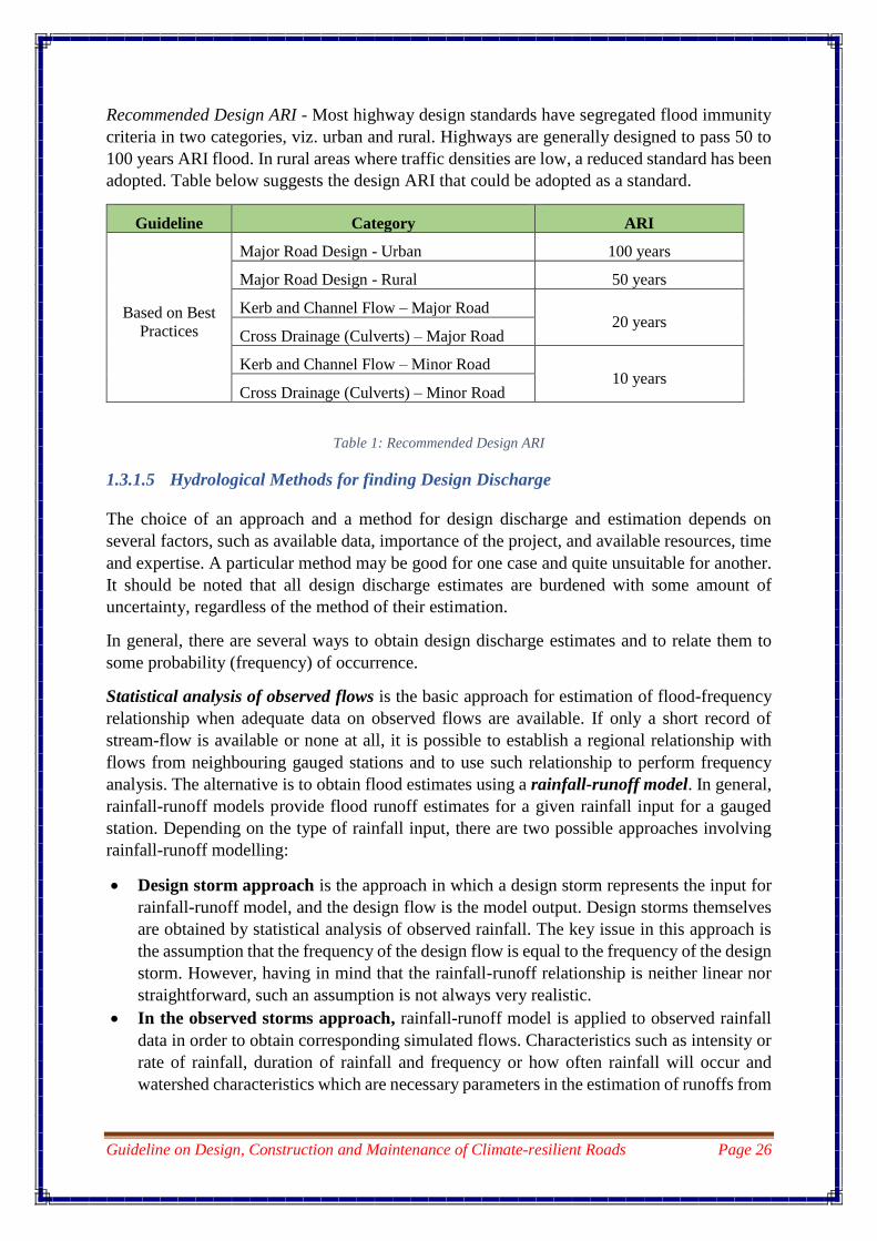
Recommended Design ARI - Most highway design standards have segregated flood immunity
criteria in two categories, viz. urban and rural. Highways are generally designed to pass 50 to
100 years ARI flood. In rural areas where traffic densities are low, a reduced standard has been
adopted. Table below suggests the design ARI that could be adopted as a standard.
Guideline Category ARI
Based on Best
Practices
Major Road Design - Urban 100 years
Major Road Design - Rural 50 years
Kerb and Channel Flow – Major Road 20 years
Cross Drainage (Culverts) – Major Road
Kerb and Channel Flow – Minor Road 10 years
Cross Drainage (Culverts) – Minor Road
Table 1: Recommended Design ARI
1.3.1.5 Hydrological Methods for finding Design Discharge
The choice of an approach and a method for design discharge and estimation depends on
several factors, such as available data, importance of the project, and available resources, time
and expertise. A particular method may be good for one case and quite unsuitable for another.
It should be noted that all design discharge estimates are burdened with some amount of
uncertainty, regardless of the method of their estimation.
In general, there are several ways to obtain design discharge estimates and to relate them to
some probability (frequency) of occurrence.
Statistical analysis of observed flows is the basic approach for estimation of flood-frequency
relationship when adequate data on observed flows are available. If only a short record of
stream-flow is available or none at all, it is possible to establish a regional relationship with
flows from neighbouring gauged stations and to use such relationship to perform frequency
analysis. The alternative is to obtain flood estimates using a rainfall-runoff model. In general,
rainfall-runoff models provide flood runoff estimates for a given rainfall input for a gauged
station. Depending on the type of rainfall input, there are two possible approaches involving
rainfall-runoff modelling:
Design storm approach is the approach in which a design storm represents the input for
rainfall-runoff model, and the design flow is the model output. Design storms themselves
are obtained by statistical analysis of observed rainfall. The key issue in this approach is
the assumption that the frequency of the design flow is equal to the frequency of the design
storm. However, having in mind that the rainfall-runoff relationship is neither linear nor
straightforward, such an assumption is not always very realistic.
In the observed storms approach, rainfall-runoff model is applied to observed rainfall
data in order to obtain corresponding simulated flows. Characteristics such as intensity or
rate of rainfall, duration of rainfall and frequency or how often rainfall will occur and
watershed characteristics which are necessary parameters in the estimation of runoffs from

Guideline on Design, Construction and Maintenance of Climate-resilient Roads Page 27
rainfall events are difficult to obtain and calibrate and are also very sensitive to changes in
input and parameters.
The suggested approach for such assignment is outlined in Figure 5. In the figure, the process
of design discharge estimation begins with the determination of catchment area. This can be
determined from topographical maps using a planimeter (or GIS) after delineating the
catchment boundary with reference to a stream or river of interest. Topographical maps in the
scale 1:50,000 are available for most parts of Bhutan.
1.3.1.6 Run-off
The run-off of catchment area in any specified period is the total quantity of water draining
into a stream or into a reservoir in that period. The principal factors affecting the flow from a
catchment area are: -
a) Precipitation characteristics
b) Shape and size of the catchment
c) Topography
d) Geological characteristics
e) Meteorological characteristics
f) Character of the catchment surface
g) Storage characteristics
1.3.1.6.1 Computation of run-off
Run-off can be computed either by empirical or rationale formulae.
i. Empirical formulae:
(a) Dicken’s formula: Q = CM3/4
Where, Q is the peak run-off in cum/sec and M is the catchment area in square km, C
is a constant depending upon the rainfall.
(b) Ryve’s formula: Q = CM2/3
ii. Rational formula (velocity area method):
V = (1/N) x (R)2/3 x (S)1/2
Where
V = Mean velocity of flow in m/sec
R = Hydraulic mean depth = A/P
A= Cross sectional area in square meter
P = Wetted perimeter in meter
S = Bed slope
N = Co-efficient of Rugosity
Note: The rational formula is the most commonly used in the determination of discharge

Guideline on Design, Construction and Maintenance of Climate-resilient Roads Page 28
Catchment Area Delineation
(1:50,000 Topography Map)
Setting the Reference Point
Rainfall Data Available ?YES NO
Catchment Area
> 20 km2
YES
Specific Discharge
Method
Rainfall-Runoff
Model
Catchment Area
> 20 km 2Rational Method
NO
Selection of
Rainfall Stations
Rainfall Intensity
Duration
Frequency Curve
Design Discharge
Selection of
Hydrological
Region
Specific Discharge
Curve
Unit Hydrograph
(SCS) Method
Rainfall-Runoff Data
Available?
YES
YES
NO
Design Discharge
NO
Design Discharge
Figure 5: Hydrological Methods for finding Design Discharge
A suitable reasoning to adoption of the specific discharge method for drainages above 20 km2
lies in the fact that as the basin size increases, storage or detention effects and unfamiliar
dynamic flow effects dampen the peak flow in a non-linear relationship. It has been recognized
that as the catchment size increases, the specific discharge decreases. For flood frequency
study, only the annual maximum discharges are taken into account.
For regional justification of the hydrology of river flow require methodologies that search for
similarities of physical geographical features. A recognized procedure is by hierarchical
grouping which allows catchments to be classed into relatively homogeneous groups. A
procedure to homogenization would be to segregate drainages by climatic and terrain spatial
variations. For instance, in the subtropical belts of the Himalayas, monsoon is the main cause
of extreme precipitation due to orographic effects of the Himalayas and as such the subtropical
belt is the wettest. The terrain in this region is geologically fragile and is characterized by steep
and unstable mountain slopes which facilitate mass wasting more frequently when intense
precipitation occurs. Rock avalanches and landslides cause this belt to be vulnerable in
economic and ecological terms. Most drainages originating from the Siwalik belt are small and
are rain-fed and dry up during the dry winter months (ephemeral). Medium sized drainages
(100 km2 ~ 1000 km2) are perennial and originate from the lesser Himalayas. There are no

Guideline on Design, Construction and Maintenance of Climate-resilient Roads Page 29
glaciers in the lesser Himalayas and as such risks from glacial lake outburst are not present.
However, landslide dams and their resulting outburst floods (LDOF) are possibilities.
1.3.1.7 Discharge Analysis
The drainage pattern of Bhutan is principally segregated into three hydrological regions and
are tagged as basins I, II and III. These are main rivers flowing north to south, originating from
perennial glaciated regions lying in the north of the country at altitudes over 7000 m. Besides
the main basins, there are several sub-basins with north-south orientation, whose headwaters
lie in the interior of the country and where glaciation has minimal influence. All others are east-
west tributaries of the main drainages that contribute greatly to water budget of the country.
The current knowledge of snow-cover and rainfall distribution in Bhutan is imprecise due to
low density of gauge networks and due to the fact that gauging in scattered locations are recent.
1.3.1.7.1 Discharge Data
There are quite a number of rivers that are gauged on a daily basis. Rainfall data can be
obtained from National Center for Hydrology and Meteorology (NCHM).
1.3.2 Traffic data
Traffic Data Collection and projections thereof of traffic volumes are basic requirements for
planning of road development and design purposes.
The most common method of collecting traffic flow data is the manual method, which consist
of assigning a person to record traffic as it passes. This method of data collection can be
expensive in terms of manpower, but it is nonetheless necessary in most cases where vehicles
are to be classified with a number of movements recorded separately, such as at intersections.
At intersection sites, the traffic on each arm should be counted and recorded separately for each
movement. It is of paramount importance that traffic on roads with more than one lane are
counted and classified by direction of traffic flow.
According to the current practices, traffic count is recorded twice a year for all types of roads
and it is found sufficient for design and other purposes.
The recommended method considers design traffic in terms of the cumulative number of
standard axles (80 KN) to be carried by the pavement during the design life. Axle load spectrum
data are required where cementitious bases are used for evaluating the fatigue damage of such
bases for heavy traffic. Following information is needed for estimating design traffic:
(i) Initial traffic after construction in terms of number of Commercial Vehicles per day
(CVPD).
(ii) Traffic growth rate during the design life in percentage.
(iii) Design life in number of years.
(iv) Spectrum of axle loads.
(v) Vehicle Damage Factor (VDF).
(vi) Distribution of commercial traffic over the carriageway.

Guideline on Design, Construction and Maintenance of Climate-resilient Roads Page 30
Only the number of commercial vehicles having gross vehicle weight of 30 kN or more and
their axle-loading is considered for the purpose of design of pavement.
Assessment of the present day average traffic should be based on seven-day-24-hour count
made in accordance with IRC: 9-1972 “Traffic Census on Non-Urban Roads”.
1.3.2.1 Traffic Growth Rate
The present day traffic has to be projected for the end of design life at growth rates (‘r’)
estimated by studying and analysing the following data:
i) The past trends of traffic growth; and
ii) Demand elasticity of traffic with respect to macro-economic parameters like GDP and
expected demand due to specific developments and land use changes likely to take place
during design life.
The annual growth rate of commercial vehicles is considered as 7% to 7.5%.
1.3.3 California Bearing Ratio (CBR) values
The CBR test is a penetration test meant for the evaluation of subgrade strength of roads and
pavements. The results obtained by these tests are used with the empirical curves to determine
the thickness of pavement and its component layers. This is the most widely used method for
the design of flexible pavement.
The harder the material, the higher the CBR value. A CBR value of 2% is usually found for
clay, high-quality sub-base will have CBR values between 80% and 100%, and some sands
may have values around 10%. The CBR testing can be applied to soils with a maximum particle
size of 20 mm. For soils with bigger particles, other types of bearing capacity can be used like
the Plate Bearing Test. The coarse-grained soils can reach higher CBR values when compared
with those of the fine-grained soils. As expected, with bigger particles the soil may have bigger
CBR values.
For design, the subgrade soil strength is normally assessed in terms of CBR for use in the
flexible pavement design method. The design subgrade strength depends upon the type of soil,
degree of compaction, moisture content and the climatic conditions that the subgrade would
attain during the design life of the road.
The subgrade soils normally vary from hard rock to soft shale with intermediate types having
gravel with different percentage of binder, silty gravels, silty clays, silty sands and boulders
mixed with varying proportions of silty and clayey soils, etc.
The CBR value is ascertained as per a standard test procedure described in IS: 2720 (Part
XVI) “Methods of Test for Soils”.
The subgrade, whether it is in cut or fill should be well compacted to attain thickness of
pavement required. For pavement design, the sub-grade strength in terms of CBR of the sub-
grade soil at the most critical moisture condition likely to occur in-situ is considered. The
pavement design is based on CBR of the sub-grade which is compacted to a stipulated density.

Guideline on Design, Construction and Maintenance of Climate-resilient Roads Page 31
If during construction, the field compaction is lower than stipulated, the pavement thickness
may be reviewed and any extra thickness required provided by an increased thickness of sub-
base.
If the type of soil used in different stretches of the subgrade varies along the length of the
pavement, the CBR value of each type of soil should be the average of at least three specimens
prepared using that soil. 90th percentile subgrade CBR value should be adopted for the design
of high volume roads such as Expressways, National Highways and Urban roads. For other
categories of roads, the design can be done based on the 80th percentile CBR value if the design
traffic is less than 20 msa and based on 90th percentile CBR if the design traffic is 20 msa or
more. CBR values must be obtained for every 250 m in case of National Highways and for
every 500 m in case of other categories of roads.

Guideline on Design, Construction and Maintenance of Climate-resilient Roads Page 32
CHAPTER 2 – DESIGN OF ROAD & PAVEMENT
2.1 Geometric Design
Geometric design has to be carefully done to align the road to provide comfort and safety. The
following parameters have to be considered for design:
1. Classification of Road
2. Design Speed
3. Horizontal Alignment
4. Formation & Cross Section
5. Sight Distance
6. Super elevation
7. Vertical Alignment
8. Grade
In the geometric design, environment friendly approaches have been adopted through
optimization of cut and fill methods in the earthworks. Environment friendly road design aptly
demonstrates that a slight shift of the centreline to the valley side can result in substantial
reduction of earthworks and height of hill side cut.
2.1.1 Terrain Classification
The terrain is generally classified as follows:
1) Plain - 0 to 10º
2) Rolling - 10ºto 25º
3) Mountainous - 25º to 60º
4) Steep - Greater than 60º
2.1.2 Design Speed
While driving along a road the drivers drive at a certain speed at which they feel that they can
overcome any possible obstruction. The speed at which a driver feels most comfortable is
considered as the design speed.
The class of the road and the terrain influence the design speed for the particular section of the
road. The following design speeds are recommended to be used for design.

Guideline on Design, Construction and Maintenance of Climate-resilient Roads Page 33
Class of Road
Minimum Design Speed in km/hr for Terrain Type
(Minimum Curve Radius in meter)
Plain Rolling Mountainous Steep
Primary National Highway 80 (280) 70 (200) 60 (120) 50 (75)
Secondary National Highway 80 (280) 70 (200) 60 (120) 50 (75)
Dzongkhag Road 70 (200) 60 (120) 50 (75) 40 (45)
Farm Road 50 (75) 40 (45) 30 (25)
20 (15)
Table 2: Design speed for different category of Roads
The minimum radius of horizontal curve at a hair pin bend should be 15 m for highways and
10 m for other categories of roads.
2.1.3 Horizontal Alignment
The horizontal alignment of a road comprises of usually a series of straight and circular curves
connected by the transition curves. The radius of the curve is determined by the formula given
below: 𝑒 + 𝑓 = 𝑉2
127𝑅
Where e = Super-elevation
f = Coefficient of friction
V = Speed in Km/Hr.
R = Radius in meter
The maximum super-elevation of 0.08 (8%) may be adopted in the steep sections and 0.07
(7%) in flat section. The maximum value of the coefficient of friction varies from 0.19 at 20 to
40 Km/hr, down to 0.12 at 100 km/hr. The minimum radius of horizontal curves to the design
speed is as follows:
Sl. No. Design Speed km/hr Radius (m)
1 20 15
2 30 25
3 40 45
4 50 75
5 60 120
6 70 200
7 80 280
Table 3: Minimum radius of horizontal curves to the design speed

Guideline on Design, Construction and Maintenance of Climate-resilient Roads Page 34
2.1.4 Road Formation
The width of the pavement and formation is determined by the lane width which depends on:
The dimension of the vehicle
Speed of travel
Traffic volume
Width of shoulder
The desirable minimum width is 3.5 m and this is adopted as the standard width for the single
lane and for two lanes the minimum width is 3.0 m for one lane.
The shoulder is measured from the pavement edge to the end of the usable formation. Wide
shoulders have the following advantages:
Space is available for vehicle to stand clear of the pavement.
Space is available to avoid colliding with other vehicles and to regain control of vehicle.
In cuttings on curves a wide shoulder gives a longer sight distance.
The shoulder can be used for widening the road without cutting in future to widen the
road
The Shoulder can also be used to place the snow cleared from the pavement in snow
bound areas.
Shoulder can be used to park stranded vehicle.
2.1.5 Road Classification & Specifications
Following are the types of roads we have in Bhutan and their specifications:
ROAD CLASS
(Design traffic volume)
DESIGN
FORMATION
(m)
Primary National
Highway
(Double Lane)
Pavement
Shoulder (Valley side)
Drain (On hill side)
Debris collection
Formation
7.5
1.0
1.0
1.0
10.5
Secondary National
Highway
(Double Lane)
Pavement
Shoulder (Valley side)
Drain (On hill side)
Debris collection
Formation
5.5
1.0
1.0
1.0
8.5
Dzongkhag Road
(Single Lane)
Pavement
Shoulder (Valley side)
Drain (On hill side)
3.5
1.0
1.0

Guideline on Design, Construction and Maintenance of Climate-resilient Roads Page 35
Debris collection
Formation
1.0
6.5
Farm Road
(Single Lane)
Pavement
Shoulder
Drain (On hill side)
Formation
3.5
0.5 X 2
0.6
5.1
Table 4: Road Formation Width
2.1.6 Cross Section
Cross fall is the slope of the surface of the formation/carriageway measured at right angle to
the horizontal alignment. It is essential to maintain cross fall in order to drain out the surface
water from the carriageway.
Material Surface Type Pavement Cross-fall Shoulder Cross-fall
Earth, Loam 5 % 6 %
Gravel, Wet Mix Macadam 3 - 4 % 5 %
Asphalt Concrete (AC) 2.5 - 3 % 4 %
Ridge pavement 2 – 3 % 4 %
Table 5: Pavement and Shoulder cross-fall
Primary National Highway

Guideline on Design, Construction and Maintenance of Climate-resilient Roads Page 36
Secondary National Highway
Dzongkhag/GC Road
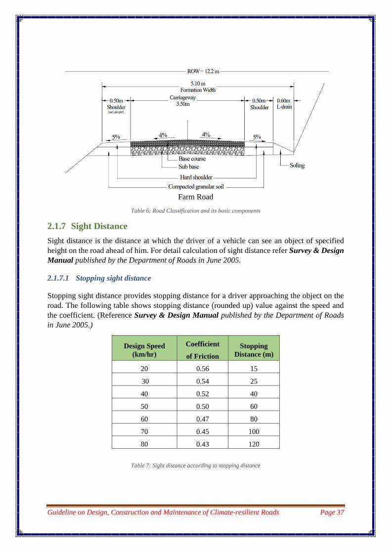
Guideline on Design, Construction and Maintenance of Climate-resilient Roads Page 37
Farm Road
Table 6: Road Classification and its basic components
2.1.7 Sight Distance
Sight distance is the distance at which the driver of a vehicle can see an object of specified
height on the road ahead of him. For detail calculation of sight distance refer Survey & Design
Manual published by the Department of Roads in June 2005.
2.1.7.1 Stopping sight distance
Stopping sight distance provides stopping distance for a driver approaching the object on the
road. The following table shows stopping distance (rounded up) value against the speed and
the coefficient. (Reference Survey & Design Manual published by the Department of Roads
in June 2005.)
Design Speed
(km/hr)
Coefficient
of Friction
Stopping
Distance (m)
20 0.56 15
30 0.54 25
40 0.52 40
50 0.50 60
60 0.47 80
70 0.45 100
80 0.43 120
Table 7: Sight distance according to stopping distance

Guideline on Design, Construction and Maintenance of Climate-resilient Roads Page 38
2.1.8 Super-Elevation
The figure below shows the method of development of super elevation and horizontal curve
transitions. It also shows the positioning of transitions.
Superelevation n
Leveln
Superelevation e
n
n
CL
0.4 Vmetres
Le
Lp
IP
Figure 6: Super-elevation and horizontal curve transition
Legend:
IP Point of intersection of the main tangents
TS Tangent Spiral, common point of tangent and
spiral
TP Tangent point, common point of tangent and
Circular curve
SS Start of super-elevation transition
SC Spiral curve, common point of spiral and circular
curve
Lp Length of spiral between TS and SC
La Length of super-elevation transition
n Norma pavement cross-fall – tangent of angle
e Pavement super-elevation – tangent of angle
V Design speed (Km/Hr.)
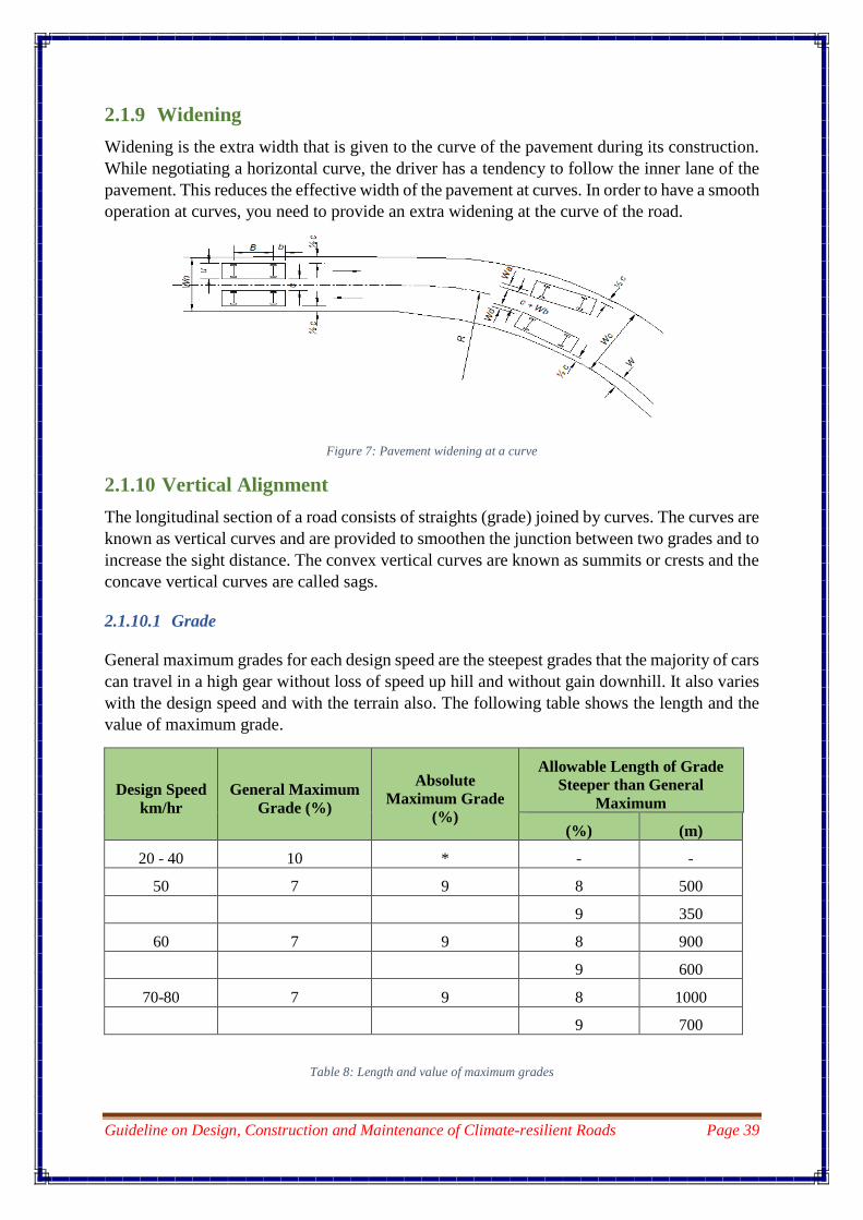
Guideline on Design, Construction and Maintenance of Climate-resilient Roads Page 39
2.1.9 Widening
Widening is the extra width that is given to the curve of the pavement during its construction.
While negotiating a horizontal curve, the driver has a tendency to follow the inner lane of the
pavement. This reduces the effective width of the pavement at curves. In order to have a smooth
operation at curves, you need to provide an extra widening at the curve of the road.
Figure 7: Pavement widening at a curve
2.1.10 Vertical Alignment
The longitudinal section of a road consists of straights (grade) joined by curves. The curves are
known as vertical curves and are provided to smoothen the junction between two grades and to
increase the sight distance. The convex vertical curves are known as summits or crests and the
concave vertical curves are called sags.
2.1.10.1 Grade
General maximum grades for each design speed are the steepest grades that the majority of cars
can travel in a high gear without loss of speed up hill and without gain downhill. It also varies
with the design speed and with the terrain also. The following table shows the length and the
value of maximum grade.
Design Speed
km/hr
General Maximum
Grade (%)
Absolute
Maximum Grade
(%)
Allowable Length of Grade
Steeper than General
Maximum
(%) (m)
20 - 40 10 * - -
50 7 9 8 500
9 350
60 7 9 8 900
9 600
70-80 7 9 8 1000
9 700
Table 8: Length and value of maximum grades

Guideline on Design, Construction and Maintenance of Climate-resilient Roads Page 40
Note: No absolute maximum grade is shown for design speeds of 20 to 40 km/h as in some
circumstances a length of very steep grade may be necessary. The length of grade steeper than
10 % should be kept as short as possible.
2.1.11 Horizontal Alignment
Following are the criterion that need to be looked into in order to achieve a suitable horizontal
alignment:
Widening
Stopping Over-takingSingle
laneStopping
Double
stopping
(m) (Km/h) (%) (m) (m) (m) (m) (m) (m)
15 20 8 15 - 20 0.9 5 15
25 30 8 25 110 30 0.6 5 16
40 3 11
45 40 8 40 140 45 0.6 5 17
70 3 12
75 50 8 60 200 60 - 5 20
110 14
120 60 7 80 300 70 - 6 23
160 5 17
200 4 14
240 3 12
SD - Sight Distance
Transition
Super
elevation
SD offset
Rad
ius
Sp
ee
d
Su
pe
r-
ele
va
tio
n Sight Distance
Table 9: Horizontal Sight Distances
The Road Geometric design is carried out using different Road Design Software such as:
GEOCOMP,
Micro Station 4.1.
AutoCAD Civil 3D. 4.2.
Bentley MX Roads.
SkyCiv Structural 3D
AutoTURN. 4.3
Autodesk InfraWorks 360
Site3D. 4.2
RoadEng Civil Engineer. 4.5
After completion of the Road design the following drawings are produced:
1. Plan (usually at 1: 1000 scale)
2. L-Section (at Horizontal 1:1000 and vertical 1:500 scale)

Guideline on Design, Construction and Maintenance of Climate-resilient Roads Page 41
3. Cross Section (the cross sections are produced at 20m interval on straight lengths and
with cross sections at start of the curve, centre of the curve and at end of the curve at
1:500 scale)
Table 10: A sample design showing the plan, longitudinal section and cross sections of a road section

Guideline on Design, Construction and Maintenance of Climate-resilient Roads Page 42
2.2 Pavement Design
With the rapid growth of traffic plying on our road network, the pavements are required to be
designed for heavy volume of traffic. An ideal pavement design procedure is one which will
predict a thickness and composition which, without being conservative, ensures that the
pavement will not deteriorate beyond a tolerable level of serviceability in less than the design
period.
Pavement design is defined as the process of developing the most economical combination of
pavement layers in relation to both thickness and material type to suit the soil foundation and
the cumulative traffic to be carried during the design life. The different types of pavement are:
1. Flexible Pavement
2. Rigid Pavement and
3. Composite Pavement
2.2.1 Flexible Pavement
Flexible pavement is composition of a bituminous material surface course and underlying base
and sub-base courses. The flexible pavement design (IRC: 37, IRC: 81) is based on the load
distribution characteristics of a layered system; it transmits load to the subgrade through a
combination of layers. The flexible pavement can be either in the form of surface treatment,
such as bituminous surface treatments generally used on low volume roads or, asphalt concrete
surface courses used on high traffic volume highways.
2.2.1.1 Components of a Flexible Pavement
A flexible pavement consists of asphalt surface course built over a base course and sub base
course resting on the sub grade soil.
Sub-grade - The sub grade is normally the in-situ soil over which the pavement is being
constructed. It can also refer to the top of embankment or fill over which the pavement is laid.
Sub-base - The sub base usually consists of granular material either naturally occurring,
stabilised or prepared from crushed aggregates. This can be considered as a layer of weaker
quality and hence cheaper than base course, but in any case sufficiently stronger than sub grade
to help the distribution of wheel load. In certain instances, sub base helps as a drainage layer.
Base course - The base course which is the main load bearing layer is normally the thickest
layer of the flexible pavement underlying the surface course. The materials used in this layer
are invariably of high quality. The base course can be constructed by well graded aggregates
in order to provide mechanical interlocking action and properly compacted. This can be of wet
mix macadam type, water bound macadam type or well graded dry aggregates type. For the
well graded dry aggregate base course, the prime coating should be applied 48 hours prior to
laying of surface course so as to keep the finer aggregates intact. New technologies like
cementitious road base are also used in order to reduce the thickness of the pavement and where
the bearing capacity of the soil is very low.
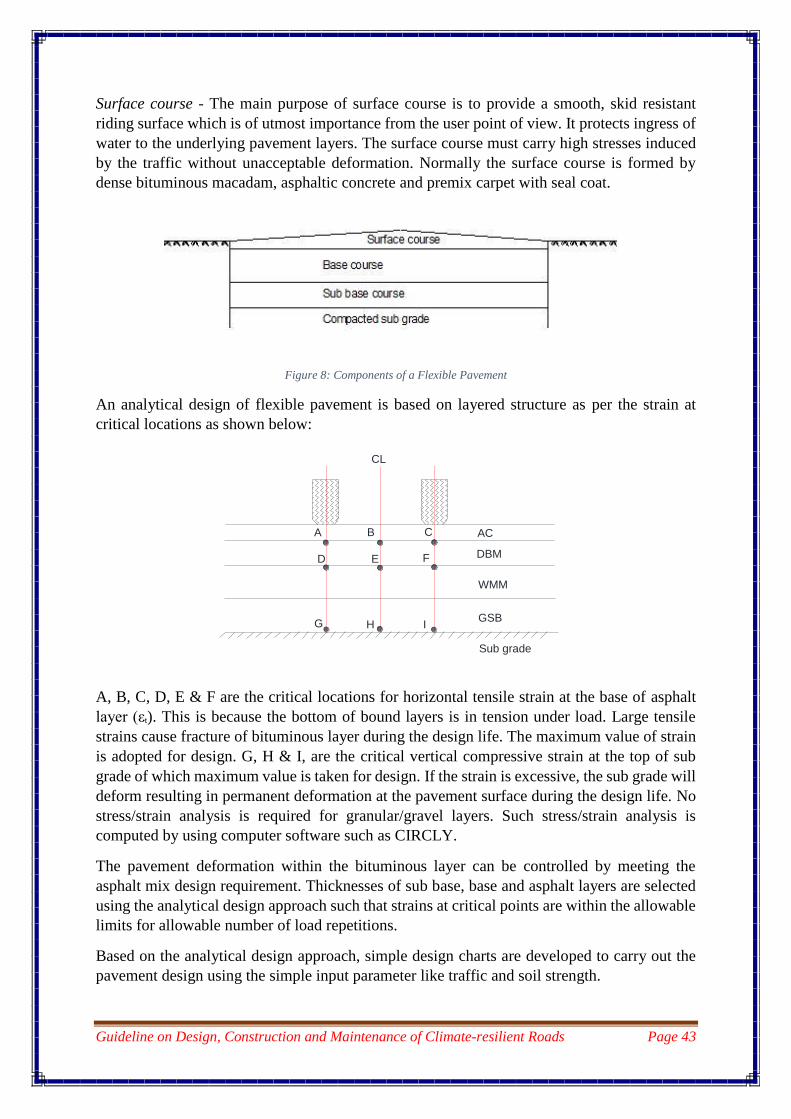
Guideline on Design, Construction and Maintenance of Climate-resilient Roads Page 43
Surface course - The main purpose of surface course is to provide a smooth, skid resistant
riding surface which is of utmost importance from the user point of view. It protects ingress of
water to the underlying pavement layers. The surface course must carry high stresses induced
by the traffic without unacceptable deformation. Normally the surface course is formed by
dense bituminous macadam, asphaltic concrete and premix carpet with seal coat.
Figure 8: Components of a Flexible Pavement
An analytical design of flexible pavement is based on layered structure as per the strain at
critical locations as shown below:
D
A
Sub grade
WMM
HGSB
CL
E
B
F
C
DBM
AC
G I
A, B, C, D, E & F are the critical locations for horizontal tensile strain at the base of asphalt
layer (εt). This is because the bottom of bound layers is in tension under load. Large tensile
strains cause fracture of bituminous layer during the design life. The maximum value of strain
is adopted for design. G, H & I, are the critical vertical compressive strain at the top of sub
grade of which maximum value is taken for design. If the strain is excessive, the sub grade will
deform resulting in permanent deformation at the pavement surface during the design life. No
stress/strain analysis is required for granular/gravel layers. Such stress/strain analysis is
computed by using computer software such as CIRCLY.
The pavement deformation within the bituminous layer can be controlled by meeting the
asphalt mix design requirement. Thicknesses of sub base, base and asphalt layers are selected
using the analytical design approach such that strains at critical points are within the allowable
limits for allowable number of load repetitions.
Based on the analytical design approach, simple design charts are developed to carry out the
pavement design using the simple input parameter like traffic and soil strength.

Guideline on Design, Construction and Maintenance of Climate-resilient Roads Page 44
2.2.1.2 Computation of Design Traffic (Ns)
The design traffic in terms of cumulative number of standard axles (8160kg) to be carried by
the pavement during the design life is estimated by using the equation
𝑁𝑠 = 365 [(1 + 𝑟)𝑛 − 1]
𝑟× 𝐴 × 𝐷 × 𝐹
Where,
i) A = Initial traffic in the year of completion of construction in terms of number of commercial
vehicles per day and 𝐴 = 𝑃(1 + 𝑟)𝑥
Where,
P = Number of commercial vehicles as per last count,
r = Annual growth rate of commercial vehicles. The growth rate should be estimated based
on the past trends of traffic growth. If adequate data are not available, an average annual
growth rate of 7 to 7.5% may be adopted. (for 7%, x = 0.07)
x = Number of years between the last count and the year of completion of construction.
ii) n = Design life of pavement in years. Design load is defined in terms of cumulative number
of standard axles that can be carried before strengthening of the pavement is necessary. The
following design life is recommended for various types of roads.
Expressways and Urban Roads - 20 years
National Highways and Dzongkhag Roads - 15 years
Others Roads -10 years
iii) F = Vehicle damage factor (VDF). It is defined as equivalent number of standard axles per
commercial vehicle. In other words, it is a multiplier to convert the number of commercial
vehicles of different axle load and axle configuration to the number of standard load
repetition given in Table 11.
Initial traffic
(CVPD)
Recommended VDF values
Unsurfaced Thin surfacing Thick surfacing
< 150 0.5 0.75 -
150 - 1500 - 1.00 1.25
>1500 - 1.25 1.50
Table 11: Vehicle Damage Factor vs Traffic
D = Lane distribution factor. The assessment of commercial traffic by direction and by lane
is necessary as it directly affects thickness design.
The following values are recommended.

Guideline on Design, Construction and Maintenance of Climate-resilient Roads Page 45
Single-lane roads = 1.00
Double-lane roads = 0.75
2.2.1.3 Pavement Thickness Design
The design of roads shall basically consist of 3 layer pavements, namely Granular Sub Base
layer(GSB), Wet Mix Macadam (WMM) and bituminous layer. Having calculated the design
CBR and cumulative number of standard axles, the thickness of sub base and base course layer
can be directly read off from the figure below. It is to note that the minimum thickness of sub
base should not be less than 150mm for design traffic less than 10 msa and 200mm for design
traffic of 10 msa and above. The recommended minimum thickness of granular base should be
200 mm for traffic up to 2 msa and 250mm for traffic exceeding 2 msa. For CBR value of 9%
and above, the minimum thickness of base should be 200 mm. Where the CBR value of sub
grade is 2 percent or less, a capping layer of 150mm thickness of material with minimum CBR
of 10% shall be provided in addition to the sub base. However, the thickness design shall not
be based on the strength of capping layer and it should be based on the original sub grade CBR.
Total thickness, mm
Desig
n tra
ffic, m
sa
400
10
20
30
50
100
150
500
600
700
800
900
1000
10%
9%
8%
7%
6%
5%
4%
3%
2%
200
1
300
400
500
600
700
800
900
23
45
67
89
10 2
%
3%
4%
5%
6%
7%
8%
9%
10%
CBR
Total thickness, mm
Desig
n tra
ffic, m
sa
CBR
Figure 9: Pavement Thickness Graph
Bituminous Layer Thickness: The minimum thickness of bituminous surface shall be as per
the table shown below:

Guideline on Design, Construction and Maintenance of Climate-resilient Roads Page 46
Traffic (msa) Wearing course Binder course Remarks
0-0.5 30 mm PMC/AC - Wearing course = surface layer
0.5-2 30 mm PMC/AC - Binder course = Bituminous course
immediately below wearing course
2-5 30 mm AC 50 mm DBM PMC = Pre Mix Carpet
5-10 40 mm AC 60 mm DBM AC = Asphalt Concrete
10-15 40 mm AC 65 mm DBM DBM = Dense Bituminous Macadam
15-20 40 mm AC 80 mm DBM
20-30 40 mm AC 100 mm DBM
Table 12: Minimum thickness of bituminous surface
The Charts adopted by the Department are as below:
For Road with AC and DBM

Guideline on Design, Construction and Maintenance of Climate-resilient Roads Page 47
For Road with AC only
For Roads without bituminous surface
Figure 10: Design Charts adopted by DoR for Road Design

Guideline on Design, Construction and Maintenance of Climate-resilient Roads Page 48
2.2.2 Rigid Pavement
A rigid pavement is constructed from cement concrete or reinforced concrete slabs. The design
of rigid pavement is based on providing a structural cement concrete slab of sufficient strength
to resist the loads from traffic. IRC: 58, IRC: 15, IRC: 76 and IRC: SP62 shall be referred to
for design and construction of rigid pavement.
A “Rigid Pavement” is cement concrete pavement, plain or reinforced laid over a base course.
While using plain concrete, some reinforcement becomes necessary at joints, provided to
relieve stresses due to expansion, contraction, warping or to facilitate construction. On the other
hand, reinforcement may also be used to take due care of the stresses arising due to temperature
fluctuation. In that case it is known as temperature reinforcement. Heavy reinforcement used
without breaks or joints is usually known as continuously reinforced concrete where the
reinforcement is expected to take care of both temperature stresses and also load stresses to
some extent.
Figure 11: Components of a Rigid Pavement
As the name implies, rigid pavements are rigid i.e., they do not flex much under loading like
flexible pavements. They are constructed using cement concrete. In this case, the load carrying
capacity is mainly due to the rigidity and high modulus of elasticity of the slab (slab action).
H. M. Westergaard is considered the pioneer in providing the rational treatment of the rigid
pavement analysis.
2.2.2.1 Design of Slab Thickness
The factors commonly considered for design of pavement thickness are traffic load and
temperature variations. For purpose of analysis, three regions are recognized in a pavement and
they are slab corner, edge and interior which react differently from one another to the effect of
temperature differentials as well as load applications.
The concrete pavement undergoes a daily cyclic change of temperature differentials and more
so due to climate change, the top of the pavement remains hotter than the bottom during day,
and cooler during night. The consequent tendency of the pavement slabs to warp upwards (top
convex) during the day and downwards (top concave) during the night, and restraint offered to
this warping tendency by self-weight of the pavement induces stresses in the pavement,
commonly referred as temperature stresses. These stresses are flexural in nature being tensile
at the bottom during the day and at top during the night. The restraint is maximum in the slab
interior and somewhat less at the edge. Consequently, the temperature stresses induced in the
pavement are negligible in the corner regions and maximum in the interior.

Guideline on Design, Construction and Maintenance of Climate-resilient Roads Page 49
Under the action of load application, maximum stress is induced in the corner region as the
corner is discontinuous in two directions. The edge being discontinuous in one direction only,
has lower stress while the least stress is induced in the interior where the slab is continuous in
all directions. Furthermore, the corner tends to bend like a cantilever, giving tension at the top,
interior like a beam giving tension at bottom. At the edge, main bending is along the edge like
a beam giving maximum tension at the bottom.
The maximum combined tensile stresses in the three regions of the slab will thus be caused
when effects of temperature differentials are such as to be additive to the load effects. This
would occur during the day in case of interior and edge regions, at the time of maximum
temperature differential in the slab. In the corner region, the temperature stress is negligible,
but the load stress is maximum at night when the slab corners have a tendency to lift up due to
warping and lose partly the foundation support. Considering the total combined stress for three
regions, viz., corner, edge and interior, for which the load stress decreases in that order while
the temperature stress increases, the critical stress condition is reached in the edge region where
neither of the load and temperature stresses are the minimum. It is, therefore, felt that both the
corner and the edge regions should be checked for total stresses and design of slab thickness
based on the more critical condition of the two.
2.2.2.1.1 Calculation of Stresses
Edge Stresses
a) Due to load: The load stress in the critical edge region may be obtained as per
Wertergaard analysis and modified by Teller and Sutherland from the following
correlation (metric units):
𝜎𝑙𝑒 = 0.529 𝑃
ℎ2(1 + 0.54 𝜇) [4 log10
1
𝑏− log10 𝑏 − 0.4048]
With 𝜎𝑙𝑒 = load stress in the edge region, kg/cm2,
P = design wheel load, kg,
h = pavement slab thickness, cm,
𝜇 = Poisson’s ratio for concrete,
E = modulus of elasticity for concrete, kg/cm2,
K = reaction modulus of the pavement foundation, kg/cm3,
𝑙𝑒 = radius of relative stiffness, cm
= 4 √𝐸𝑏3
12 (1− 𝜇2)𝐾
b = radius of equivalent distribution of pressure
= a for 𝑎
ℎ> 1.724
= √16𝑎2 + ℎ2 − 0.675ℎ 𝑓𝑜𝑟 𝑎
ℎ < 1.724
And a = radius of load contact, cm, assumed circular

Guideline on Design, Construction and Maintenance of Climate-resilient Roads Page 50
The values of l and b can be ascertained directly from the tables below:
h (cm) Radius of relative stiffness l (cm) for different values of K (kg/cm3)
K = 6 K = 8 K = 10 K = 15 K = 30
15 61.44 57.18 54.08 48.86 41.09
16 64.49 60.02 56.76 51.29 43.31
17 67.49 62.81 59.40 53.67 45.14
18 70.44 65.56 62.01 56.03 47.07
19 73.36 68.28 64.57 58.35 49.06
20 76.24 70.95 67.10 60.63 50.99
21 79.08 73.59 69.60 63.89 52.89
22 81.89 76.20 72.08 65.13 54.77
23 84.66 78.80 74.52 67.33 56.62
24 87.41 81.35 76.94 69.31 58.45
25 90.13 83.88 79.32 71.68 60.28
Table 13: Radius of relative stiffness, l, for different values of pavement slab thickness, h, and foundation reaction modulus,
K, for concrete E = 3.0 x 10⁶ kg/cm3
a/h b/h a/h b/h
0.0 0.325 1.0 0.937
0.1 0.333 1.1 1.039
0.2 0.357 1.2 1.143
0.3 0.387 1.3 1.250
0.4 0.446 1.4 1.358
0.5 0.508 1.5 1.470
0.6 0.580 1.6 1.582
0.7 0.661 1.7 1.695
0.8 0.747 1.724 1.724
0.9 0.840 >1.724 a/h
Table 14:Radius of equivalent distribution of pressure section, b, in terms of radius of contact, a, and slab thickness, h
b) Due to temperature: The temperature stress at the critical edge region may be obtained
as per Westergaard analysis, using Bradbury’s coefficient, from the following
correlation:
𝜎𝑡𝑒 = 𝐸𝛼∆𝑡
2 ∗ 𝐶
With 𝜎𝑡𝑒 = temperature stress in the edge region

Guideline on Design, Construction and Maintenance of Climate-resilient Roads Page 51
∆𝑡 = maximum temperature differential during day between top and bottom of
the slab
𝛼 = coefficient of thermal expansion of concrete,
C = Bradbury’s coefficient, which can be ascertained directly from Bradbury’s
chart against values of L/l and W/l,
L = Slab length, or spacing between consecutive contraction joints,
W = Slab Width, and
l = radius of relative stiffness
Values of the coefficient C, based on the curves given in Bradbury’s chart, are given in the
table below:
L/l or W/l C
1 0.000
2 0.040
3 0.175
4 0.440
5 0.720
6 0.920
7 1.030
8 1.075
9 1.080
10 1.075
11 1.050
12 and above 1.000
Table 15: Values of Co-efficient ‘C’ based on Bradbury’s Chart
Corner Stresses: The load stress in the corner region may be obtained as per Westergaard’s
analysis, as modified by Kelley, from the following correlation:
𝜎𝑙𝑐 = 3𝑃
ℎ2 [1 −
(𝑎√2)1.2
1]
With 𝜎𝑙𝑐 = load stress in the corner region, other notations remaining the same as in the case
of the edge load stress formula.
The temperature stress in the corner region is negligible as the corners are relatively free to
warp, and may be ignored.

Guideline on Design, Construction and Maintenance of Climate-resilient Roads Page 52
2.2.2.2 Design Charts
Figures below give ready-to-use design charts for calculation of load stresses in the edge and
corner regions of rigid pavement:
Figure 12: Design chart for calculation of edge load stress

Guideline on Design, Construction and Maintenance of Climate-resilient Roads Page 53
Figure 13: Design chart for calculation of corner load stress
2.2.2.3 Design of Joints
The maximum recommended spacing of expansion joints are given in the table below:
Expansion Joint Spacing (based on CRRI study) (for 25 mm wide expansion joints)
Period of Construction Degree of foundation
roughness
Maximum expansion joint
spacing (m)
Slab thickness (cm)
15 20 25
Winter (Oct – March) Smooth 50 50 60
Rough 140 140 140
Summer (Apr – Sept) Smooth 90 90 120
Rough 140 140 140
Table 16: Maximum recommended spacing of expansion joints

Guideline on Design, Construction and Maintenance of Climate-resilient Roads Page 54
Slab thickness (cm) Maximum contraction
joint spacing (m)
Weight of reinforcement in
welded fabric (for reinforced
pavements only) (kg m2)
Unreinforced Slabs
10 4.5 -
15 4.5 -
20 4.5 -
Reinforced Slabs
10 7.5 2.2
15 13.0 2.7
20 14.0 3.8
Table 17: Contraction Joints Spacing (Based on IRC: 15-1981)
2.2.2.4 Load Transfer at Transverse Joints
Load transfer to relieve part of the load stresses in edge and corners regions of pavement slab
at transverse joints is provided by means of mild steel dowel bars. The method of design of
dowel bars as per Bradbury’s analysis is recommended.
2.2.2.4.1 Design of Dowel Bars
The dowel bar system may be designed on the basis of Bradbury’s analysis which gives the
following formulae for load transfer capacity of a single dowel bar in shear, in bending and in
bearing on concrete:
𝑃𝑠 = 0.785 𝑑2𝐹𝑠………………………………….Shear
𝑃𝑓 = 2𝑑3𝐹𝑓
𝑟+8.8𝛿 ………………………………….......Bending in the bar
𝑃𝑏 = 𝐹𝑏𝑟2𝑑
12.5 (𝑟+1.5𝑧) …………………………………Bearing on the concrete
With P = load transfer capacity of a single dowel bar,
d = diameter of dowel bar,
r = length of embedment of dowel bar,
z = joint width,
Fs= permissible shear stress in dowel bar,
Ff= permissible flexural stress in dowel bar, and
Fb= permissible bearing stress in concrete.
For balanced design, for equal capacity in bending and bearing, the length of embedment of
dowel is first obtained by equating Pf and Pb values from the above equations as follows, for
the assumed joint width z and dowel diameter d:

Guideline on Design, Construction and Maintenance of Climate-resilient Roads Page 55
𝑟 = 5𝑑 [𝐹𝑓
𝐹𝑏 (𝑟 + 1.5𝑧)
(𝑟 + 8.8𝑧)]
0.5
Knowing z, d and r, the load transfer capacity of a single dowel is determined from the
equations Pf and Pb given above.
To calculate the spacing of dowel bars, the required capacity factor, n, is first determined from:
𝑛 = 𝑙𝑜𝑎𝑑 𝑡𝑟𝑎𝑛𝑠𝑓𝑒𝑟 𝑐𝑎𝑝𝑎𝑐𝑖𝑡𝑦 𝑟𝑒𝑞𝑢𝑖𝑟𝑒𝑑 𝑓𝑟𝑜𝑚 𝑡ℎ𝑒 𝑑𝑜𝑤𝑒𝑙 𝑠𝑦𝑠𝑡𝑚𝑒
𝑙𝑜𝑎𝑑 𝑡𝑟𝑎𝑠𝑛𝑓𝑒𝑟 𝑐𝑎𝑝𝑎𝑐𝑖𝑡𝑦 𝑜𝑓 𝑎 𝑠𝑖𝑛𝑔𝑙𝑒 𝑑𝑜𝑤𝑒𝑙 𝑏𝑎𝑟
The distance on either side of the load position up to which the dowel bars are effective in load
transfer is taken as 1.8 l, where l is the radius of relative stiffness obtained using the formula
𝑙 = 4 √𝐸𝑏3
12 (1− 𝜇2)𝐾
Dowel bars are not satisfactory for slabs of small thickness, and shall not be provided for slab
less than 15 cm thick.
Design loading Slab thickness (cm) Dowel bar details
Diameter (mm) Length (mm) Spacing (mm)
5100 kg
15 25 500 200
20 25 500 250
25 25 500 300 Table 18: Design details of dowel bars for rigid pavement
Typical dowel bar designs for use in 20 mm wide expansion joints for highway pavements, for
40 per cent load transfer is given in the above table.
2.2.2.5 Tie Bars for Longitudinal Joints
In case of heavy traffic and expansive subgrades, tie bars must be provided in accordance with
the recommendations from IRC: 15-1981.
2.2.2.5.1 Design of Tie Bars
The area of steel required per m length of joint may be computed by using the following
formula:
𝐴𝑠 = 𝑏𝑓𝑊
𝑆
Where, 𝐴𝑠 = area of steel in cm2 required per m length of joint.
b = distance between the joint in question and the nearest free joint or edge in m,
f = coefficient of friction between pavement and the subgrade (usually taken as 1.5)
W = weight of slab in kg/m2, and
S = allowable working stress of steel in kg/cm2.

Guideline on Design, Construction and Maintenance of Climate-resilient Roads Page 56
The length of any tie bar should be at least twice that required to develop a bond strength equal
to the working stress of the steel. It is obtained using the formula:
𝐿 = 2𝑆𝐴
𝐵𝑃
Where, L = length of tie-bar (cm)
S = allowable working stress in steel (kg/cm2),
A = cross-sectional area of one tie bar (cm2),
P = perimeter of tie-bar (cm), and
B = permissible bond stress in (i) deformed tie bars – 24.6 kg/cm2, (ii) Plain tie bars –
17.5 kg/cm2
To permit warping at the joint, the maximum diameter in case of tie bars may be limited to 20
mm, and to avoid concentration of tensile forces, they should not be spaced more than 75 cm
apart. The calculated length, L, may be increased by 5-8 cm to account for any inaccuracy in
placement during construction.
Typical tie bar details for use at central longitudinal joint in a double-lane rigid pavement with
a lane width of 3.5 m are given in the table below:
Slab
thickness
(cm)
Tie bar details
Diameter
(mm)
Maximum
spacing (cm)
Minimum length (cm)
Plain bars Deformed
bars
15 8 38 40 30
10 60 45 35
20 10 45 45 35
12 64 55 40
25
10 30 45 35
12 45 55 40
14 62 65 46
Table 19: Typical tie bar details for use at central longitudinal joint
2.2.2.6 Design of Reinforcement
Reinforcement in concrete slabs is designed to counteract the tensile stresses caused by
shrinkage and contraction due to temperature or moisture changes. The maximum tension in
the steel across the crack equals the force required to overcome friction between the pavement
and its foundation, from the crack to the nearest joint or free edge. This force is the greatest
when the crack occurs at the middle of the slab. Reinforcement is designed for this critical
location. However, for practical reasons, reinforcement is kept uniform throughout the length,
for short slabs.

Guideline on Design, Construction and Maintenance of Climate-resilient Roads Page 57
The amount of longitudinal and transverse steel required per m width or length of slab is
computed by the following formula:
𝐴 = 𝐿𝑓𝑊
2𝑆
Where, A = area of steel in cm2 required per m width or length of slab,
L = distance in m between free transverse joints (for longitudinal steel) or free
longitudinal joints (for transverse steel)
f = coefficient of friction between pavement and subgrade (usually taken as 1.5),
W = weight of slab in kg/m2
S = allowable working stress in steel in kg/cm2 (usually taken as 50 to 60 percent of the
minimum yield stress of steel)
Since reinforcement in the concrete slabs is not intended to contribute towards its flexural
strength, its position within the slab is not important except that it should be adequately
protected from corrosion. Since cracks starting with higher tensile stress at the top surface are
more critical when they tend to open, the general preference is for the placing of reinforcement
about 50 mm below the surface.
2.2.2.7 Recommended Design Procedure
Step 1: Stipulate design values for the various parameters.
Step 2: Decide joint spacing and land-widths
Step 3: Select tentative design thickness of pavement slab.
Step 4: Ascertain maximum temperature stress for the critical edge region using
𝜎𝑡𝑒 = 𝐸𝛼∆𝑡
2 ∗ 𝐶
Step 5: Calculate the residual available strength of concrete for supporting traffic loads.
Step 6: Ascertain edge load stress using
𝜎𝑙𝑒 = 0.529 𝑃
ℎ2(1 + 0.54 𝜇) [4 log10
1
𝑏− log10 𝑏 − 0.4048]

Guideline on Design, Construction and Maintenance of Climate-resilient Roads Page 58
Figure 14: Design chart for calculation of edge temperature stress
Step 7: In case the available factor of safety is less than or far in excess of 1, adjust the tentative
slab thickness and repeat steps 3 to 6 till the factor of safety is 1 or slightly more. Denote
the corresponding slab thickness as hs.

Guideline on Design, Construction and Maintenance of Climate-resilient Roads Page 59
Step 8: Check for adequacy of thickness in the corner region by ascertaining corner load stress
using 𝜎𝑙𝑐 = 3𝑃
ℎ2 [1 − (𝑎√2)
1.2
1] and readjust the thickness hs if inadequate.
Step 9: Adjust hs for traffic intensity. The adjusted design thickness, h, maybe obtained from
h = hs + ht
The values of ht may be taken from the table below:
Traffic
classification
A B C D E F G
ht (cm) -5 -5 -2 -2 0 0 +2
Table 20: Traffic classification
Traffic classification for rigid pavement design is as follows:
Traffic
classification
Design Traffic Intensity: Vehicles (laden
weight >3 tonnes) per day at the end of
design life
A 0-15
B 15-45
C 45-150
D 150-450
E 450-1500
F 1500-4500
G Above 4500 and all expressways
Table 21: Traffic classification for Rigid Pavement
2.2.3 Composite Pavement
A composite pavement (IRC: SP 68) is a type of pavement that utilizes both concrete and
asphalt. Typically, a concrete base layer provides structural capacity while the asphalt surface
layer provides a wearing surface. Geo-cell and geo-grids are also used together with asphalt
for constructing road pavement in unstable areas.
2.3 Drainage Design
Drainage is the process of interception and removal of water from over and under the vicinity
of the road surface. Drainage can be surfaced or sub-surface. Surface drainage or pavement
drainage includes the disposal of all water present on the surface of the pavement and adjacent
ground. While the sub-surface drainage includes such as French/trench drains, generally built
below the subgrade to reduces the moisture content so as to keep the moisture as minimum as
possible.

Guideline on Design, Construction and Maintenance of Climate-resilient Roads Page 60
Surface and subsurface drainage of roads critically affect the structural integrity, safety of
users, and is thus important during road design and construction. Road designs therefore have
to provide efficient means for removal of water. Drainage facilities are required to safeguard
the road against damage from surface and subsurface water. Traffic safety is very important as
poor drainage can result in dangerous conditions like hydroplaning. Poor drainage can also
compromise the structural life of the pavement. Drainage system combines various natural and
man-made facilities like open drain, pipe drain and culverts to convey the water safely.
2.3.1 Principles of Good Drainage
Some of the basic principles of drainage design are briefly outlined below
The surface runoff over the pavement surface and the shoulders should be drained away
as quickly as possible, preventing the water from finding entry into the pavement layers
from the top and into the subgrade from the bottom and the sides.
Precipitation over the open land adjoining the road should be led away from the pavement
structure through natural drainage channels or artificial drains. Suitable cross-drainage
channels should be provided to lead the water across the road embankment which may be
cutting across to the natural drainage courses.
Consideration should be given to deal with the precipitation on the embankment and cut
slopes so as to prevent erosion.
Seepage and subsurface water is detrimental to the stability of cut slopes and bearing
power of subgrades. An effective system of subsurface drainage must be provided to
accelerate slope failures.
Landslide-prone zones deserve special investigations for improving drainage.
Relatively poor embankment soils can perform satisfactorily if drainage is considered in
the design.
Water-logged and flood-prone zones demand detailed consideration for improving the
overall drainage pattern of the area through which the road is aligned.
The study has found that the dimensions of the drains and cross drainages need to be
increased by about 20%-25% to incorporate high intensity of rainfall due to climate
change.
2.4 Provision of Surface Drainage
For an effective surface drainage system, it must be ensured that the following measures are
taken on all roads:
a) Cross-fall or camber on the carriageway must be ensured at all times as per the
specifications. The cross-fall of the shoulder should be 1% steeper than the cross-fall of the
carriageway, subject to a minimum of 4%.
b) Sub-surface drains should be provided at marshy areas for better internal drainage of
pavement layers, especially for granular materials. Similarly, along vertical curves, the sub-
surface drainage considerations are of great importance and in some cases, the length of
the vertical curve may have to be adjusted to satisfy drainage requirements. For most
conditions, a minimum of 1% longitudinal gradient should be provided.

Guideline on Design, Construction and Maintenance of Climate-resilient Roads Page 61
c) Side drains should be provided to collect the surface water from the carriageway and lead
it to an identified outlet to prevent saturation of pavement layers. Side drains should be
constructed and maintained in accordance with the following:
provide enough area to accommodate storm flow and deep enough to drain the base
course
protect the surface of side drains from erosion with turf cover or other suitable lining
keep velocities low enough to prevent erosion but great enough to prevent deposition
or silting
maintain a continuous and unobstructed waterway
provide stable outlets for natural channels or by constructing cascade/rip-rap/check
dams for other areas
The design of the side drains can be done in the following step-by-step manner:
From the known soil type, arrive at the value of Manning’s Rugosity coefficient, side
slopes and the maximum permissible velocity.
Determine the slope from the topography.
The design discharge should be enhanced by at least 20% to account for climate change
effects.
For the given discharge, calculate the hydraulic mean depth from Manning’s formula.
Find out the cross-sectional area from the given discharge and the maximum
permissible velocity.
Figure 15: V-shaped and Box drain
2.5 Cross Drainage
Cross drainage requires careful design and construction. Functionally, they must
allow for passage of the maximum amount of water which can reasonably be expected
to occur within the lifetime of the structure and
not degrade water quality or endanger the structure itself or any downstream structures.
It should be pointed out that most road failures are related to inadequate water passage
structures and fill design and placement as well as poor construction practices in such
locations.
The cross drainages are of two types:
a) Submersible

Guideline on Design, Construction and Maintenance of Climate-resilient Roads Page 62
b) Non-submersible.
The appropriate choices of cross drainages depend upon:
(a) Technical
Nature and width of stream and flood flows;
Velocity of flow and bed slope;
Maximum and minimum depth of flow;
Presence of floating sediments and boulder movement.
(b) Economical
Cost of initial construction;
Cost of maintenance or reconstruction;
Cost of delays to vehicles (in case of submersible).
Normally experience and local practice will be helpful in the choice of the appropriate cross
drainages. The table below provides a guideline for the choice of appropriate cross drainages.
Sl. Type of Structure Locations of cross drainages
1 Vented Causeway Shallow streams having permanent dry weather flow exceeding
0.6m in depth
2
Submersible
Causeway or Hume
pipe Culvert
In case where a culvert or bridge is too expensive to construct
3 Box Culvert Areas where there is a clear span up to 6m.
4 Bridge Areas where the clear span is greater than 6.0 m.
Table 22: Locations of Cross Drainages
If there are existing roads in the watershed, examination of the performance of existing culverts
often serves as the best guide to determining the type, size, and accompanying inlet/outlet
improvements needed for the proposed stream crossing. For estimating streamflow on many
forest watersheds, existing culvert installations may be used as "control sections". Flow can be
calculated as the product of water velocity (V) and cross-sectional area (A):
Q = A * V
Cross-sectional area of water flowing in a round- culvert is difficult to measure, however a
rough estimate can be calculated from the following equation:
𝐴 = [(𝜋𝑟2𝛽)
180] − (𝑟2 − 𝑟𝑑)𝑠𝑖𝑛𝛽
where:
r = culvert radius
d = measured depth of flow
ß = angle (°) between radial lines to the bottom of the
culvert and to the water surface = cos-1 [(r-d) / r]

Guideline on Design, Construction and Maintenance of Climate-resilient Roads Page 63
2.6 Slope Stabilization (Bio-engineering)
Slope stability is the potential of soil covered slopes to withstand and undergo movement.
Stability is determined by the balance of shear stress and shear strength. A previously stable
slope may be initially affected by preparatory factors, making the slope conditionally unstable.
Triggering factors of a slope failure can be climatic events which can then make a slope
unstable, leading to mass movements. Mass movements can be caused by increase in shear
stress, such as loading, lateral pressure, and transient forces. Alternatively, shear strength may
be decreased by weathering, changes in pore water pressure, and organic material.
The field of slope stability encompasses static and dynamic stability of slopes of earth and
rock-fill dams, slopes of other types of embankments, excavated slopes, and natural slopes in
soil and soft rock. Slope stability investigation, analysis (including modelling), and design
mitigation is typically completed by geologists, engineering geologists, or geotechnical
engineers. Geologists and engineering geologists can also use their knowledge of earth process
and their ability to interpret surface geomorphology to determine relative slope stability based
simply on site observations.
Table 23: Selection criteria for slope stabilization methods

Guideline on Design, Construction and Maintenance of Climate-resilient Roads Page 64
For protection of slope the following types of mitigations can be provided:
Bioengineering Gabion Wall
RRM Wall RCC Wall
Concrete Crib Wall Reinforced Earth Structures

Guideline on Design, Construction and Maintenance of Climate-resilient Roads Page 65
Boulder Wall – Innovative and effective drainage system
Non-Frame Structure Soil Nailing
Grouting Shot-creting Figure 16: Various Slope Stabilization Measures

Guideline on Design, Construction and Maintenance of Climate-resilient Roads Page 66
CHAPTER 3 – ROAD CONSTRUCTION
For any new road project, EIA shall be carried out and Environmental Clearance processed
with the National Environment Commission/Dzongkhag Environment Section. Proper EMP
shall be prepared to avoid damages to the environment. The road shall be constructed using
appropriate machines such as excavator, back-hoe loader etc. Bull dozer shall be used only if
the road alignment passes through the plain area.
Adequate labour camps, site office with toilet facilities, stores, etc. shall be built at the work
site in line with the TS and the contract document.
3.1 Construction staking
Prior to the construction activity, the design has to be transferred from the design drawings/plan
to the ground. It is done by staking-out and through the batter pegging. Permanent Reference
points (RPs) and Bench Marks (BMs) shall be set-up at such locations/points where there is no
disturbance. RPs should be established at least 3 to 5 m behind the uphill clearing limits. In
case of inevitable disturbance due to the site condition, the permanent points shall be shifted in
accordance with the standard survey procedures and process.
3.2 Environmental Friendly Road Construction (EFRC) Approach
The cost of road construction is comparatively higher than other construction activity. Due to
limited funds, there is a need to adopt “low cost construction approach” and road for all
weather. The modern road construction technique should adopt the climate change effect and
apply the Environmental Codes of Practice (ECoP). EFRC guideline shall be strictly referred
for the construction of roads in the country.
The climatic conditions vary due to the mountainous nature of the country. The country has
monsoon rain in summer, with relatively dry winters. About 70% of the land area is covered
with forest of temperate and sub-tropical varieties that are a natural habitat of a diversity of
flora and fauna. Bhutan has chosen the ‘middle path’ where economic development takes place
while preserving natural resources and preventing environmental degradation. The
Environment Assessment Act of 2000 and the regulation for Environmental Clearance of
Projects, 2002 to ensure that environment assessments are conducted for all development
activities that have potentially significant environmental impact.
Road construction has a large potential negative impact on the environment. Inadequate road
construction techniques cause significant damage to forest, land and water sources and reduce
the quality and lifetime of the road. A maximum effort therefore needs to be made to prevent
and mitigate the negative impacts of roads. Figure below shows the economic comparison
between EFRC & traditional construction method

Guideline on Design, Construction and Maintenance of Climate-resilient Roads Page 67
Figure 17:Economic comparison between EFRC & traditional construction method
There are three methods of road construction as below: -
i) Cut and fill method
creates little or no slope stability problems
for slope angles of not more than 30 degrees (to avoid retaining structures)
ii) Full fill method
for areas with rock joints or when bedding or foliation planes dip out of the slope
In highly erodible soils
In shallow loose scree or similar deposits
In slopes with high water table
iii) Full Cut method
for slope without stability problem
For steep slope angle
For areas where the dipping of surplus material is no problem
3.3 Clearing and Grubbing of Road Construction Area
Preparing the road right-of-way or construction area is referred to as clearing and grubbing.
During the clearing phase, trees are cut and felled. Grubbing refers to the clearing and removal
of stumps and organic debris. For felling of trees, prior approval of the forest department needs
to be obtained. Trees should be felled and cleared a minimum of 1 to 3 m from the top of the
cut or toe of the hill. Figure below shows the minimum clearance to be maintained

Guideline on Design, Construction and Maintenance of Climate-resilient Roads Page 68
Figure 18: Minimum clearance of 1 to 3m to be maintained
Organic overburden or top soil has to be removed over the full construction width in order to
prevent uneven settlement and potential side cast failure. During the grubbing phase or
preparation stage, a pioneer/bypass road is often constructed to facilitate the movement of
equipment and delivery of materials, such as the construction of bridges and culverts. When
pioneer/bypass road is required, they are often built at the top of the construction width with
restricted width, just good enough for machine to manoeuvre. Figure below shows that the
pioneer/bypass road location at bottom of proposed fill provides a bench for fill materials of
completed road.
Figure 19: Bypass road serving as a bench for fill materials
3.4 General Equipment Considerations
The method and equipment used in road construction is an important economic and design
factor in road location and subsequent design. Table 4.1 lists down common road construction
equipment and their suitability for different phases of road construction. For example,
bulldozer can be used in all phases of road construction from formation cutting until final
grading in plain area where the material spillage is not a big concern from the environment
aspect. Front-end loader performs well in soft materials while excavator is very effective in
hilly areas. The table below shows a list of common road construction equipment and their
suitability.

Guideline on Design, Construction and Maintenance of Climate-resilient Roads Page 69
Criteria Bulldozer Front end
loader
Hydraulic
excavator
Dump trucks or
scrapers
Farm
tractors
Excavation
mode (level
of control of
excavated
materials
Digs and
pushes;
adequate
control
(depends on
blade type)
Minor
digging of
soft
material;
good for lift
and carrying
Digs, swings &
deposits with
excellent
control; controls
better in
avoiding mixing
of materials
Scrapers can load
themselves and
used for small
quantities
Minor
digging and
good in
carrying
materials
Suitability
for fill
construction
Adequate Good Good and
excellent
control in
levelling the
materials
Good for
transportation
and larger fills
Not suitable
Clearing
and
grubbing
Good Adequate Excellent Not suitable Handles only
smaller
materials
Operating
cost per
hour
Moderate
depending upon
machine size
Relatively
low
Moderate to
high, but
excellent
productivity
Very high Low
Special
limitations
or
advantages
Widely
available and
can do all
required works
with good
operator
Cannot dig
hard
materials
Widely
available and
good for roads
on steep hill
slopes and can
do all required
jobs
Limited to
moving materials
long distance
Low and
depends on
site
conditions
Hydraulic Excavator is usually used for road formation cutting due to its capability to swing and power
to load the excavated materials.
Table 24: Lists of common road construction equipment and their suitability
3.5 Road Formation
Formation is the finished profile of the road, ready for construction of protective/drainage
works, carriageway/pavement, shoulders, drains, parapets etc. Construction of formation on
roads generally comprises of the following items of works:
Jungle Clearance
Earthwork in excavation
Earthwork in embankment with suitable materials including protection of slopes
Temporary structures like drains, stone revetment, soling in weak soil etc. during initial
construction

Guideline on Design, Construction and Maintenance of Climate-resilient Roads Page 70
3.5.1 Formation Cutting
Environmental friendly method aims to minimize cuts in mountain slopes. Where the slopes
are fragile and prone to landslides, a part of the road width shall be made in fill, by constructing
retaining walls. The “balance cut and fill method” is normally adopted for road construction.
Box cuts are to be avoided as much as possible, unless providing box cut can significantly
reduce the road length. Box cut increases the volume of cut and the height of cut as shown in
the figure below.
Figure 20: Volume of cut of different methods
Marshy areas are drained-out before excavation is allowed through the construction of gravel
drains and other temporary water management structures such as catch drains, earthen drains,
etc.
Barriers to be constructed out of logs or boulders at about 10-15 meters below the road to catch
falling materials and in some cases to allow for controlled dumping of excavated materials.
Wherever possible, trenches are to be built for same purpose and to prevent damage to natural
slope further down.
cut volume
up to 400% cut volume
100%
Cross Section - Box Cut Cross Section - Full Cut
1 m
2 m
cut volume cut volume
65% 35%
Cross Section - 1 m Shift Cross Section - 2 m Shift

Guideline on Design, Construction and Maintenance of Climate-resilient Roads Page 71
Figure 21: Timber Log barriers to catch falling materials
In terms of climate change, side slope should be adjusted from 1:0.5 to 1:1 or flatter to prevent flood
damage and erosion from road surface runoff. Adjusting side slopes from 1:0.5 to 1:1 will also
increase traffic safety of the road. Adjusting side slopes normally requires more land, and if the
existing right of way is not sufficient, it might be difficult to acquire additional land. If it is not
possible to flatten the slope to 1:1, other measures could be considered, such as protection of slopes
with rip-rap or gabion mattresses especially in areas with erosion problems.
When the slope height is more than 5m benching of 1m must be provided. A slope angle of 75 degrees
must be maintained in rocky slopes and 60 degrees must be maintained in slopes which are composed
of soil and gravel.
3.5.2 Blasting Operation
Road construction in the mountainous areas normally requires blasting of hard boulders. In
order to minimize damage to the surrounding hill, environment and to prevent destabilization
of the slopes, controlled blasting techniques are to be adopted. Blasting operation is to be
carried out by a certified and an experienced blaster. The purchase, transport, storage and use
of explosives shall be carried out in accordance with Department of Roads (DoR) “Blasting
Manual” and the by-law issued by the Ministry of Home & Cultural Affairs. Shot hole blasting
is not allowed except when explicitly approved as an exception by the engineer. Slopes
shattered or loosened by blasting shall be taken down and falling of blasted materials along the
valley slope shall be minimized. Only approved explosives brand shall be used.
3.5.2.1 Blasting Plan
The blasting plan is the basis for:
Good blasting work
Safety at site
High economy
Less accidents

Guideline on Design, Construction and Maintenance of Climate-resilient Roads Page 72
The blasting plan contains:
Drilling scheme (pattern) - It is the relation of drilled holes to each other and any free
faces as part of the balst design.
Loading scheme (pattern) - It is the charge that is loaded into the drilled holes and
determined by the type of blasting.
Ignition scheme (pattern) - It is the initial energy source required to detonate an
explosive used for rock blasting. It is also a distribution network to deliver the energy
to each blast hole.
3.5.2.2 Bench Blasting
Bench blasting can be defined as drilling of vertical or angled holes in one or several rows from
a free surface. Bench blasting is the most common and basic method of surface rock
excavation. The Blasting Manual shall be referred for its parameters, explosives charging
calculation, firing method and firing sequences.
Figure 22: Bench Blasting Plan
3.5.2.3 Boulder Blasting
The breaking down of large stones at quarries by small explosive charges is called boulder
blasting. A minimum of 300 m distance needs to be maintained between the structures and site
of blasting operation as shown in the figure below:

Guideline on Design, Construction and Maintenance of Climate-resilient Roads Page 73
Figure 23: Minimum safe distance to be maintained
3.5.2.4 Controlled Blasting Techniques
Controlled blasting will attempt to modify the type of explosives, or the placement of particular
explosives, such that the damage zone created by the perimeter holes does not exceed the
damage zone produced by the holes within the perimeter, or vice-versa.
3.5.2.4.1 Conventional Smooth Blasting
Smooth blasting is a special blasting method to protect the surface of the remaining and
surrounding rock. The idea is not only to obtain a smooth (regular) surface but also to protect
the remaining rock from cracking and to keep it as compact as possible.
Conventional smooth blasting (sometimes also called contour blasting) is carried out after the
main blasting work by using an explosive with a low charge concentration per metre and other
characteristics, which result in a "mild" effect.

Guideline on Design, Construction and Maintenance of Climate-resilient Roads Page 74
Figure 24: Smooth Blasting Plan
3.5.2.4.2 Presplitting
As opposed to smooth blasting, presplitting is used to blast the contour holes before the actual
round is fired. Presplitting produces a crack in the rock between the closely spaced contour
holes. This crack acts like a shock absorber for the ground vibrations, which cannot travel
beyond the crack and, thus, cannot disturb the surrounding rock.
When presplitting is being carried out, it is extremely important to determine the right hole
spacing and charges for the type of rock concerned.
Drill hole
[mm]
Charge concentration
[kg/m drill hole] Explosive
Burden V1
[cm]
Hole spacing E1
[cm]
25 - 32 0.080 Detonating
cord - 25 - 50
Table 25: Drill hole against charge concentration
Before drilling many holes for a long distance, it is advisable to carry out a sample blasting
over a short distance of about five metres. If cracking is too poor, there is usually the possibility
to load the drill holes again for a second round of presplitting with a higher charge. The
remaining presplitting will then be carried out with the adjusted, higher charge.
Controlled blasting methods are used to control blast induced effects such as over-break,
fractures within rock walls and ground vibration. For climate change, controlled technique shall
be adopted in order have minimal effects to the ground and rock surfaces. Some of the
controlled blasting techniques are: (i) Line Drilling (ii) trim blasting, (iii) buffer blasting, (iv)
smooth wall blasting and (v) presplitting and air decking.

Guideline on Design, Construction and Maintenance of Climate-resilient Roads Page 75
3.6 Road Embankment Construction
Filling and embankment construction includes the preparation of areas for embankment, to be
constructed. All materials used for the construction of fillings and embankments shall be
approved by the engineer. Areas to receive fillings and embankments shall be cleared and
grubbed, and all existing structures and other obstruction shall be demolished and cleared away.
Where groundwater or seepage is encountered, proper measures to be taken as specified in the
Technical Specification (TS). Prior to the placing of fill, the sub grade shall be compacted to
95% of the maximum dry density.
Embankment shall be built up evenly over the full width in layers of not more than 200mm
compacted thickness and shall be maintained at all times with a sufficient cross-fall and even
surface to enable surface water to drain readily. All materials used in embankments shall be
compacted as soon as practicable after deposition. Each layer shall be compacted to a density
of not less than 98% of the maximum dry density as determined by the Modified Standard
Proctor Test. The finishing of the road embankment shall be in accordance with the levels and
dimensions provided in the design drawings, including the provision of the temporary side
drains.
3.7 Climate Change Adaptation Road Construction
Climate change is affecting road infrastructure or the level of service, one way or another. Risk
is always there and therefore, proper and effective mitigations need to be incorporated during
the construction phase. Following are the salient features of climate resilience in construction
phase:
Spec bial emphasis must be given to hydrological analysis and geotechnical studies.
Design discharge must be increased by 20 to 25 percent to address increase in rainfall
intensity as a result of climate change.
For proper record keeping of landslides, a Pro-forma (format) has to be maintained
regularly and the format is attached in Annexure I.
A minimum of 5 numbers of cross drainages must be provided per kilometre of road and
the minimum size of the cross drainage to be provided is 1200 mm. This must be done in
order to account for more discharge and to avoid choking with debris.
Discharge of water from the outlets of the cross drainages must be managed by providing
cascading structures in order to prevent scouring of existing surfaces.
Controlled blasting techniques must be adopted as far as possible.
One-sided cross fall shall be provided in single-laned roads to improve drainage of water
from pavement.
Provision of gentle slopes compared to conventional batter slopes, bench cutting,
temporary restraining walls like log/timer barriers & boulder barriers shall be made to
protect the road from slides. Temporary earthen drains & cross drainages shall be provided
to protect valley slope and the washing away of road formation.
The retaining structures are to be constructed with rich cement mortar of not less than 1:4
in order for the structures to be stronger and durable due to severe climate actions.
Subsurface drains and materials like geo-cells, gabion cells and geo-synthetics are to be
provided below the pavement for the purpose of better drainages especially at marshy
areas.

Guideline on Design, Construction and Maintenance of Climate-resilient Roads Page 76
All road side drainages must be constructed using plum concrete.
Wherever flexible pavements are not feasible, it is encouraged to check the possibilities of
constructing rigid pavement and due procedures must be adopted in design and
construction of rigid pavement.
As far as possible, all excavation shall be carried out during dry weather.
In case of marshy areas, ground water table needs to be lowered by constructing sub-
surface drains.
Temporary earthen drains are to be constructed for effective draining of excess water.
The road formation cutting shall be executed true to levels, slopes, shape and pattern as
per the design drawings.
The sides of the excavation shall be dressed or trimmed and bottom shall be levelled or
graded and rammed.
When the cutting has reached to the formation width, temporary V-shaped earthen drain
of size 600mm wide and minimum 300mm deep shall be built and maintained till the
construction of permanent drain is initiated.
For safety of workers, machines and commuters, rock netting and temporary gabion walls
wherever necessary are to be constructed.
During construction, environmental management plans prepared and approved are to be
used to prevent and mitigate environmental hazards.
Animal passing places must be provided in embankment and cut slopes where ever
possible.
Special emphasis on bio-engineering must be given.
In terms of climate change, side slope should be adjusted from 1:0.5 to 1:1 or flatter to
prevent flood damage and erosion from road surface runoff wherever possible.
When the slope height is more than 5m benching of 1m must be provided wherever
possible. A slope angle of 75 degrees must be maintained in rocky slopes and 60 degrees
must be maintained in slopes which are composed of soil and gravel.
Wherever open graded carpet is proposed, a seal coat should be provided.
In areas where annual rainfall is higher than 300cm the entire formation width should be
surfaced without leaving any gap between edge of pavement and drain/parapet.
If sub-grade is salt infested, 225mm sand blanket should be laid on sub-grade before sub-
base is considered.
The resurfacing works must be carried out using asphalt concrete of minimum 30 mm
instead of premix carpet.
The possibilities of recycling and reusing the old asphalt concrete must be explored and
carried out as far as possible.
3.8 Structures and Protective Works
Roads in Bhutan are generally constructed by cutting into the hills and thereby disturbing
natural stability of slopes. Water and soil movement along the slopes tend to disturb the road
formation. The disturbance to the road formation is therefore, protected by provision of
structures to act as retaining, restraining and protective structures.

Guideline on Design, Construction and Maintenance of Climate-resilient Roads Page 77
3.8.1 Drainage
Drains and cross drainages are must for roads due to numerous watercourses, continuous road
gradient and rainfall. Uncontrolled water is the primary cause of problems like soft surfaces,
potholes, rutting, and even complete failure of complete sections of roadway structures. A road
is good if the degree of drainage achieved is good. The drains and cross drainages shall be built
taking into account the effect of climate change.
Drainage problems are generally considered in two categories: surface and sub-surface. Surface
drainage or pavement drainage includes the disposal of all water present on the surface of the
pavement and adjacent ground. While the sub-surface drainage includes such as French/trench
drains, generally built below the subgrade to reduces the moisture content so as to keep the
moisture as minimum as possible.
The cost of controlling water is a significant part of total highway construction cost. It is
therefore, important to plan and develop adequate facilities for drainage and erosion control. A
key rule while planning drainage would be least interference with natural drainage. Minimum
interference with natural drainage will mean stable earth face/surface with some kind of
vegetative cover preventing erosion and allowing free drainage. Water flowing towards the
road surface may be diverted and guided to follow a definite path and the flow on the valley
side controlled so that stability is not affected.
A network of drains helps in confining and controlling flow of water and thus checks adverse
effect on road structures.
3.8.2 Roadside Drains
Roadside drains are very much required on a road. The drains should be invariably taken about
300mm below the road surface. Where cross-fall and super-elevation oppose each other in
valley side curves, proper layout of the drain has to be done. Roadside drains should be
generally of uniform section throughout irrespective of the location of the road on the hill slope.
Road on ridge alignment may not require the same section of drains due to lesser quantity of
flow of water. Roadside drains are constructed to parabolic, trapezoidal, triangular, V-shape,
L-shaped kerb and channel or U-shaped/box cross sections.
L-shaped drain gives extra road width in case of emergencies for vehicles to use. U-shaped/box
drains are generally deep drains and are provided where higher discharge has to be catered and
adequate road width is available. As far as practicable, these drains are to be kept free of debris
or any foreign matters at all times. Soil debris from the drains should be disposed of properly.
The most commonly adopted roadside drains are shown below: -
i) V-shaped drain
ii) Box drains
3.8.3 Sub-surface drains:
Increase in the moisture content of subgrade reduces its strength and bearing capacity and
hence it should be ensured that the moisture content in the sub-grade is kept as minimum as
possible. The entrance of water into the sub-grade soil could be due to one or more of the
following situations:

Guideline on Design, Construction and Maintenance of Climate-resilient Roads Page 78
Water directly percolating through the road surface from above or through the shoulders;
Seepage from higher ground or natural springs;
Water rising from below by capillary action in low lying grounds or swamps;
Leakages from water pipes and irrigation channels and spillages from paddy fields.
3.8.4 Transverse trench/French drains
Transverse trench drains are generally provided below the road pavement in a sinking area to
facilitate the drainage of seepage water from the hill slopes without damaging the road
structure. Sausage blocks of 1.2m x 1.2m in a trench of 1.8m width are constructed on uphill
and downhill site. In between these blocks, boulders are properly packed to take the load of
road structure and traffic over the transverse trench.
Figure 25: Transverse Trench
3.8.5 Cross-Drainage
Cross Drain/culvert is primarily required to reduce overflow of water in the drains and breaking
flow velocity. The surface water from the drains is disposed through the cross drains/culverts
in order to divert the water away from the road to a water-course or valley. Adequate drains in
the form of catch water drains are essential for stability of road. Similarly, the cross drainage
structures have to be provided at the location of streams and seasonal gullies.
3.8.6 Retaining walls
Masonry structures built to support the downhill side unstable strata or fills are called ‘retaining
walls’. Depending on the ground condition and its intended purpose, the retaining walls can be
constructed in stone masonry, cement concrete, reinforced cement concrete, gabion,
wooden/timber/poles etc. Reinforced earth is the latest technology being used now. While the
retaining walls shall be constructed as per the design drawings issued, it is very important to
take special care of the backfill and its materials, size and slope of the weep holes, bond stone
in case of Random Rubble Masonry (RRM).
Based on the types of material, the retaining walls be classified as below:
i) Random Rubble Masonry
ii) Composite wall (DRM and RRM)
iii) RCC

Guideline on Design, Construction and Maintenance of Climate-resilient Roads Page 79
iv) Timber wall
v) Gabion wall
vi) Reinforced Earth wall
vii) Reinforced mesh wall
3.8.6.1 Random Rubble Retaining (RRM) Wall
Figure 26: A typical RRM drawing
The retaining wall shall be constructed as per the design drawings and adjusted as per the site
soil condition; the adjustment to be endorsed by the site/design engineer. Depth of foundation
shall be at least 500mm below the firm ground level. Drainage is an important aspect of
retaining wall construction and therefore, weep holes of 100x100mm opening shall be provided
at 1.5m interval and staggered both horizontally and vertically. Alternatively pipes of
equivalent area may be used. Filter layer of 400-500mm width behind the wall should be
provided for effective drainage and it is normally composed of good quality stones of 50-
100mm sizes. Geo-textile or bamboo mats shall be substituted in absence of good filter media.
A dip of foundation base (6:1 horizontal to vertical) towards hill side increases the factor of
safety against sliding significantly and shall be provided during the construction phase. The
longer wall shall be broken down into 10m panels and a gap of 50-100mm maintained. All
joints to be cut and staggered. Large size stone shall be used at the corner as the corner stone
for stability and aesthetic. Bond or through stone shall be provided at every 1.0m interval both
horizontally and vertically throughout the length and height of the wall. Where there is no
single stone of large size is available, reinforced concrete blocks of 100x100mm size shall be
used as the bond stone.
The retaining wall can be of combination of Dry Random Masonry (DRM) and Random
Rubble Masonry (RRM). For DRM, the stones are to be chiselled dressed and placed closely
and tightly to avoid collapse of wall under the pressure.

Guideline on Design, Construction and Maintenance of Climate-resilient Roads Page 80
3.8.6.2 Timber Crib Wall
Figure 27: Timber Crib wall
Timber crib wall is a temporary wall constructed using timbers, placed both horizontally and
vertically. The maximum single height of timber wall shall be limited to 1.5 – 2.0 m and width
of not less than 1m. The gaps between the timbers to be filled in with selected materials of soil
and gravels and compacted manually at every layer.

Guideline on Design, Construction and Maintenance of Climate-resilient Roads Page 81
3.8.6.3 Gabion Wall

Guideline on Design, Construction and Maintenance of Climate-resilient Roads Page 82
Figure 28: Gabion Wall
Gabion wall is retaining structure made of stacked stone-filled gabions tied together with wire.
For stability the gabion walls to be constructed sloped backward and stepped back with the
slope. For proper bond and cutting of the joints, regular shaped stone of size not more than
200mm to be used for gabion and all voids filled with smaller sizes. Rounded shaped boulder
or stone is not recommended for gabion wall due to large voids and improper cutting of the bed
joints. The maximum single height of gabion shall be 1 m and then stepped with a gap of
minimum 100mm. 1 m crate box gabion is normally used for gabion wall and the wires are tied
properly with the lacing wire.
Reinforced earth/mesh is a composite material formed by the friction between the earth and the
reinforcement. This type of wall is fairly new technique available in the 21st century and
constructed where there is limited space for normal wall construction. The wall consists of
RCC panels at the outer and geotextile materials laid across the width and anchored to the

Guideline on Design, Construction and Maintenance of Climate-resilient Roads Page 83
compacted soil. The filling between the outer RCC panels are done with the selected materials
and compacted to 95% MDD. This type of wall is normally constructed near the bridge
abutment for approaches.
3.9 Road Pavement
Design of road pavement for roads, whether in plains or hills follows the same basic principles
like soil and traffic parameters as also climate change considerations. However, while
designing pavement for roads, specific aspects relevant to the hill regions like terrain and
topographic conditions, extreme of weather conditions, altitude effects etc. have also to be duly
considered and suitably incorporated in the design so that the pavement is able to perform well
for the designed traffic and service life. The different layers of the pavement shall be
constructed as per the designed drawings within permissible tolerances given in the table
below:
Layer Level (mm) Straight edge
(mm)
Slope or cross fall
(%)
DBM/Bituminous wearing course +/- 10 6* +/- 0.25
Bituminous binder course +/- 10 6 +/- 0.25
Base (WMM layer) +/- 10 6 +/- 0.25
Sub-base (GSB layer) +/- 15 10 +/- 0.50
Gravel wearing course +/- 15 15 +/- 0.50
Formation (subgrade) +0
-25
20 +/- 0.50
* In case of asphalt concrete surface it shall be 4 mm
Table 26:Tolerances for level and surface regularity
3.9.1 Flexible Pavement
Flexible pavement is composition of a bituminous material surface course and underlying base
and sub-base courses. The flexible pavement designed (IRC: 37, IRC: 81) is based on the load
distribution characteristics of a layered system; it transmits load to the subgrade through a
combination of layers. The flexible pavement can be either in the form of surface treatment,
such as bituminous surface treatments generally used on low volume roads OR, asphalt
concrete surface courses used on high traffic volume highways.
Figure 29: Components of Flexible Pavement
Wearing Course
Base Course
Sub-base Course
Subgrade

Guideline on Design, Construction and Maintenance of Climate-resilient Roads Page 84
3.9.1.1 Subgrade:
It is the native soil compacted underneath a constructed road pavement. It is also called
formation level. Sometimes, a capping layer (Capping layers are layers of specified materials
to be laid and compacted in the subgrade and below, as required, in replacement of in-situ
materials to achieve CBR). The subgrade soil strength is normally assessed in terms of the
CBR. The conventional procedure for evaluating the sub-grade strength is by determining its
laboratory CBR, an empirical index value representing the resistance to penetrate of the
subgrade soil. The Dynamic Cone Penetrometer (DCP) test is also conducted to determine the
CBR value of the subgrade. For DCP test procedure, refer ASTM-D6951-3 (2003).
In absence of test equipment and result, CBR values of the subgrade can be generally adopted
from the table below:
Sl. No Type of Subgrade Strength Designation (CBR etc)
Range
1 Rocky subgrade, conglomerates, slate High strength – CBR not the criterion
2 Gravel with binder soil less than 20%, hard slate Soaked CBR 8-15
3 Gravel with binder soil more than 20%, shale of
medium hardness, silty sands Soaked CBR 5-10
4 Silty clays and soft shale Soaked CBR 2-5
Table 27: CBR value for different soil strata
Preparation and surface treatment of formation (subgrade) shall be carried out only after
completion of all drainage works unless otherwise agreed by the Engineer and prior to laying
the sub-base or the base where no sub-base is required.
The sequence of operations shall be as follows:
a) Formation of Loose Untreated Materials
Materials for use in the subgrade shall not contain particles larger than 60 mm. In addition,
the material shall have a CBR of not less than 5% measured after a 4-day soak on a
laboratory mix compacted to 95% MDD (heavy compaction), a swell of less than 1%, a
plasticity index of less than 40% and an organic matter content less than 3%. In-situ
material in the subgrade in cutting that does not meet these requirements shall either be
spoiled or, if suitable, placed in the embankment. The spoiled material shall be replaced
with material meeting the requirements for loose material in the subgrade.
The material shall be broken down to the above specified grading and any oversize
material that cannot be broken down to the required size shall be removed and disposed
of. The material shall be scarified and the moisture content shall be adjusted by either
uniformly mixing in water or drying out the material such that the moisture content during
compaction is between 95% and 100% of the Optimum Moisture Content. The moisture
content shall be kept within these limits until compaction is complete except where
otherwise instructed by the Engineer.
Each layer shall be compacted to a dry density equal to at least 95% MDD (heavy
compaction).

Guideline on Design, Construction and Maintenance of Climate-resilient Roads Page 85
Testing to be carried out during the construction of subgrade shall include the
following:
- The MDD (heavy compaction) and OMC shall be determined for each new
material encountered and in every 3000m² or part of it of each layer of compacted
subgrade.
- The field dry density shall be determined at least once per 500m² or part of it of
each layer of compacted subgrade. The test of field density shall be conducted in
staggered manner i.e. at left, at crown and at right in the carriageway.
- The soaked CBR of material in the subgrade shall be determined at least in every
3000m² or part of it of each layer.
b) Formation of Loose Treated Materials
Where in-situ material in the subgrade in cuttings does not meet the requirements, in-situ
materials shall be replaced with selected material from cuttings or borrow pits. Where
materials of differing quality are available for placing in the embankments, the Engineer
may also instruct that certain materials be excluded from the subgrade and that certain
materials be set apart, or obtained from borrow pits for use in the upper layers.
When materials for subgrade are extracted from borrows to form the capping layers shall
be natural material complying with the following requirements:
Materials used in capping layers shall be selected among soils classified as GW, GP, GC,
SW in the Unified Soil Classification. Materials for use in the capping layers shall not
contain particles larger than 60 mm and their percentage passing by weight the 0.075 mm
sieve shall be less than 15%. The grading requirement for capping layer materials shall be
as shown in the table below:
Sieve Size (mm) Percent passing by dry weight
50 100
37.5 80 – 100
20 60 – 100
4.75 30 – 100
1.18 15 – 75
0.3 9 – 5
0.075 5 – 15
Table 28: Grading Requirements for Capping Layer Materials

Guideline on Design, Construction and Maintenance of Climate-resilient Roads Page 86
c) Laying and Compaction of subgrade
The material shall be deposited in the layer of 150 mm compacted depths. Each layer shall
extend over the full width of the embankments or cuttings, and shall be compacted in
accordance with the Technical Specification issued.
d) Proof rolling and Tolerances
All subgrade shall be proof rolled with a power roller of 8 to 12 tonnes. The roller shall
run over the subgrade until the soil is evenly and densely consolidated and behaves as
elastic mass (the roller shall pass a minimum of five runs on the subgrade). All the
undulations in the surface that developed due to rolling shall be made good with material
or quarry spoils and the subgrade is re-rolled.
e) Formations in Rock Cuttings
The subgrade in rock cuttings shall be regulated after trimming the rock excavation. The
finished surface shall be uniform and conform to the lines, grades and typical cross-
sections shown in the drawings. When tested with the template and straight edge, the
variation shall be within the tolerances specified in the table below:
Longitudinal Profile
Maximum permissible undulation when measured with a 3m straight edge
24 mm
Cross Profile
Maximum permissible variation from specified profile when measured with a
camber template
15 mm
Table 29: Permissible tolerances of surface regularity
3.9.1.2 Sub-base:
This consists of a well-drained material placed on the subgrade. The granular sub-base (GSB)
may be made up of granular materials like natural sand, moorum, gravel, crushed stone or
combination of thereof or other materials like stabilized soil which remain static under
saturated conditions. Soil aggregate mixes also are suitable for use in sub-base. The sub-base
may be in more than one layer and in such case nomenclature as lower sub-base and upper sub-
base may be used. Refer pavement design chart of DoR for appropriate thickness of sub-base
in the road pavement.
3.9.1.2.1 Source of materials
Granular Sub base materials shall be obtained from approved roadside excavation in borrow or
cut or from such other sources of supply as may be specified or approved from time to time for
use.
3.9.1.2.2 Material requirement and potential processing
The source may be river bed or pit gravels, rock quarry, alluvial deposits, crusher-run, or other
naturally occurring granular materials meeting the requirements of the Specifications. The

Guideline on Design, Construction and Maintenance of Climate-resilient Roads Page 87
material shall be free from organic or other deleterious constituents and conform to one of the two
grading given in the table below:
IS Sieve Designation % by weight passing the IS Sieve
Grading I Grading II
75.00 mm 100
53.00 mm 80-100 100
26.50 mm 55-90 70-100
9.50 mm 35-65 50-80
4.75 mm 25-55 40-65
2.36 mm 20-40 30-50
0.425 mm 10-25 15-25
0.075 mm 3-10 3-20
Min Strength of GSB in terms of CBR value
after compaction 30 25
Table 30: Grading envelope for GSB materials
Note: The material passing 425-micron sieve for all the three grading when tested shall have
liquid limit and plasticity index not more than 25 and 6% respectively.
The materials shall have 10% fines value of 50 KN or more (for soaked sample condition)
when tested in compliance with BS: 812 (part 111). The water absorption value of the coarse
aggregate shall be determined as per IS: 2386 (part 3); if this value is greater than 2%, the
soundness test shall be carried out on the materials delivered to the site as per IS: 383.
3.9.1.2.3 Compaction Trials
Before commencing construction and from time to time as may be considered necessary
compaction trials shall be carried out on each main type of materials to be compacted in the
Works. The length of the trial section shall be minimum 100 m.
3.9.1.2.4 Preparing Underlying Course
Immediately prior to laying of GSB, the subgrade already finished shall be checked for any
damage or deficiencies. If necessary, the damage shall be rectified, lightly sprinkled with water
and rolled with two passes of 80-100KN smooth wheeled roller.
3.9.1.2.5 Laying
The GSB material shall be spread on the prepared subgrade with the help of a motor grader of
adequate capacity, its blade having hydraulic controls suitable for initial adjustment and for
maintaining the required slope and the grade during the operation or other means. When the
GSB materials consist of combination of materials mentioned above, mixing shall be
mechanically done using Pug mill. Manual mixing shall be permitted only where the width of
laying is not adequate for mechanical operations, as in small sized jobs. Every reasonable effort

Guideline on Design, Construction and Maintenance of Climate-resilient Roads Page 88
shall be made to prevent segregation during mixing, dumping, spreading, trimming and
compacting operations. Moisture content of the loose material shall be checked in accordance
with IS: 2720 (part 2) and suitably adjusted by sprinkling additional water.
3.9.1.2.6 Compaction
The minimum layer thickness shall be 100 mm. For minimum thickness, a smooth wheeled
roller of 80 to 100 KN weigh may be used for compaction. For a compacted single layer up to
225mm the compaction shall be done with the help of a vibratory roller of a minimum 80 to
100Kn static weight or heavy pneumatic tyred roller of minimum 200 to 300 KN weight.
Rolling shall commence at the lower edge and proceed towards the upper edge longitudinally
for portions having unidirectional cross fall and super-elevation and shall commence at the
edges and progress towards the centre for portions having cross fall on both sides. The speed
of the roller shall not exceed 5km per hour. Rolling shall be continued till density is at least
98% of the maximum dry density (MDD) for the material determined as per IS: 2720 (part 8).
On completion of compaction, the surface shall be tight and free from movement under
compaction plant and free from compaction planes, ridges, cracks, loose or segregated material.
All loose, segregated or otherwise defective areas shall be made good to the full thickness of
layer and re-compacted.
3.9.1.2.7 Setting out and Tolerances
The layer shall be set out and constructed to the appropriate tolerances specified in the table
8.3.
3.9.1.2.8 Drainage of subgrade and sub-base
The subgrade and sub-base shall be kept continuously drained and any damage caused by water
accumulating on or running off the surface shall be made good. Water accumulated on any part
of the subgrade or sub-base, shall be removed and disposed off. Any material which becomes
saturated, or cannot then be compacted to the required density, shall be replaced as specified.
3.9.1.2.9 Testing
The minimum testing frequency for the purpose of process control shall be as given in Table
4.9. The GSB generally make up the greatest thickness for the pavement structure and provide
bearing strength and drainage for the pavement structure. Hence, proper size, grading shape
and durability are important attributes to the overall performance of the pavement structure.
The compaction test shall be carried out at the field at regular interval to ensure required MDD
is achieved.
Tests One test in Every:
Minimum no
of tests
per section
Material:
Gradation
Atterberg Limits, Shrinkage
200 m3 or part thereof, and change in source
200 m3 or part thereof, and change in source
1000 m3 or part thereof, and change in source
2

Guideline on Design, Construction and Maintenance of Climate-resilient Roads Page 89
Maximum Dry Density and
Optimum Moisture Content
Field Density and Moisture
Content
500 m2 of each layer
2
2
2
Construction Tolerances:
Surface Levels
Thickness
Width
10 m
25 m
200 m
-
-
-
Table 31: GSB - Minimum Testing Frequency
3.9.1.2.10 Routine Inspection and Testing
Routine inspection and testing shall be carried out by the Engineer to test the quality of
materials and workmanship for compliance with the requirements of this section. Any materials
or workmanship not complying with the specified requirements shall be replaced with materials
and/or workmanship complying with the specified requirements or be repaired to comply with
the specified requirements.
3.9.1.3 Base Course:
The base course consists of granular unbound course placed above sub-base and transmits load
and shear stress on pavement to sub-grade through sub-base. The base may be water bound
macadam (WBM) and wet-mix macadam (WMM).
The work shall consist of laying and compacting clean, graded crushed stone aggregate
material, premixed with water, to a dense mass on a prepared subgrade/sub-base/base or
existing pavement as the case may be in accordance with the requirements of the Technical
Specifications. The material shall be laid in one or more layers as necessary to lines, grades
and cross-sections shown on the Drawings or as directed by the Engineer. The thickness of a
single compacted Wet Mix Macadam layer shall not be less than 75 mm. When vibrating or
other approved types of compacting equipment are used, the compacted depth of a single layer
of the sub-base course may be increased to 200mm upon approval of the engineer.
3.9.1.3.1 Materials
(i) Aggregates
The aggregate shall be either crushed stone or crushed gravel. The fine aggregate shall be
screenings obtained from crushed stone or gravel. The crushed aggregate shall consist of hard,
sound, durable and un-weathered stone, rocks, and boulders crushed to specified sizes and shall
be free from dirt or other objectionable matter and shall not contain soft or disintegrated pieces.
If crushed gravel is used, not less than 90 per cent by weight of the gravel/shingle pieces
retained on 4.75 mm sieve shall have at least two fractured faces. The aggregates shall conform
to the physical requirements set forth in the table below:

Guideline on Design, Construction and Maintenance of Climate-resilient Roads Page 90
Test Test Method Requirements
1 *Los Angeles Abrasion
value or
*Aggregate Impact value
IS: 2386 (Part 4)
IS: 2386 (Part 4) or IS:5640
Maximum 40 per cent
Maximum 30 per cent
2 Flakiness & elongation
Indices (combined)
IS : 2386 (Part 1) Maximum30 per cent**
3 California Bearing Ratio IS : 2720 (Part 16) Minimum 80 per cent
4 Crushing Ratio Manual counting &
weighing
Minimum 80 percent
Table 32: Physical Requirements of Coarse Aggregates for WMM Base Course
* Aggregate shall satisfy requirements of either of the two tests.
** To determine this combined proportion, the flaky stone from a representative sample should first be separated
out. Flakiness index is weight of flaky stone divided by the weight of stone sample. Only the elongated particles
be separated out from the remaining non-flaky stone metal. Elongation index is the weight of elongated particles
divided by total non-flaky particles. The value of flakiness index and elongation index so found are added up.
If the water absorption value of the coarse aggregate is greater than 2 per cent, the soundness test shall be carried
out on the material delivered to the site as per IS: 2386(Part-5).
Grading requirements - The aggregates shall conform to the grading given in the table below:
Sieve Size (mm) Per cent by weight passing
50
37.5
20
12.5
4.75
2.36
0.600
0.075
100
95-100
60-80
40-60
25-40
15-30
8-22
0-8
Table 33: Grading Requirements of Aggregates for Wet Mix Base Course
At least 40% of particles retained on a 12.5 mm screen must be angular, irregular or crushed faces.
Aggregate Hardness Criteria - Aggregate shall have a minimum soaked (overnight) Ten
Percent Fines Value of 50KN or a maximum soaked Aggregate Impact Value of 40.
Plasticity of Fines - The fraction passing the 0.425 mm sieve shall have Plasticity Index
(PI) not more than 6 %. As an alternative to testing of PI, a maximum Linear Shrinkage of
3% is applicable.
If the PI approaches the upper limit of 6% (4.5<PI<6.0), the fines content shall be restricted
to the lower end of the grading range given in a) in accordance with the following criteria:
i) A maximum PP (PI x percentage passing the 0.075mm sieve) of 60, and

Guideline on Design, Construction and Maintenance of Climate-resilient Roads Page 91
ii) A maximum PM (PI x percentage passing the 0.425mm sieve) of 90.
California Bearing Ratio (CBR) - The CBR of the material, after 4 days soaking, shall not
be less than 40% at 95% MDD (Heavy Compaction).
3.9.1.3.2 Crushing, Screening and Mixing
Crushing shall be carried out in two stages. The crushing, screening and proportioning of materials
and their subsequent mixing shall be carried out using methods and machines acceptable to the
Engineer. To avoid segregation, graded crushed stone shall be moistened when being handled and
shall not be stockpiled in heaps higher than 5 m.
Wet Mix Macadam shall be prepared using Pug mill, and shall be mixed to required moisture
content prior to loading and transporting to site.
Optimum moisture for mixing shall be determined in accordance with IS:2720 (Part - 8) after
replacing the aggregate fraction retained on 20 mm sieve with material of 4.75 mm to 20 mm
size. While adding water, due allowance should be made for evaporation losses, However, at
the time of compaction, water in the wet mix should not vary from the optimum value by more
than agreed limits. The mixed material should be uniformly wet and no segregation should be
permitted.
3.9.1.3.3 Preparation of Sub-layer
The surface of the subgrade/sub-base to receive the WMM shall be prepared to the specified
lines and cross fall and made free of dust and other extraneous material. Any ruts or soft
yielding places shall be corrected in an approved manner and rolled until firm surface is
obtained if necessary by sprinkling water.
3.9.1.3.4 Provision of Lateral Confinement of Aggregates
While constructing WMM, arrangement shall be made for the lateral confinement of wet mix.
This shall be done by laying materials in adjoining shoulders along with that of WMM layer
and following the sequence of operations described in the subsequent sections that follow.
3.9.1.3.5 Transportation of Wet Mix
Wet mix crushed stone base materials shall be transported and dumped in such a way that no
segregation occurs.
3.9.1.3.6 Compaction Trials
The Contractor shall carry out compaction trials in the presence of the engineer on each main type
of materials to be compacted in the works. The length of the trail section shall be minimum 100m
unless otherwise specified by the engineer. Following completion of the compaction trails, the
contractor shall submit to the engineer for his approval to go ahead with the work.
3.9.1.3.7 Laying of Wet Mix
The material shall be deposited in such quantity and spread in a uniform layer across the full
width required, so that the final compacted thickness is nowhere less than shown on the
Drawings or instructed by the Engineer. Every reasonable effort shall be made to prevent
segregation during transportation, dumping, spreading, trimming and compacting operations.
In no case should the mix be dumped in heaps directly on the area where these are to be laid
nor shall their hauling over a partly completed stretch be permitted.

Guideline on Design, Construction and Maintenance of Climate-resilient Roads Page 92
The wet mix may be spread either by a paver or a motor grader. The motor grader shall be
capable of spreading the material uniformly all over the surface. The surface of the aggregate
shall be carefully checked with templates and all high or low spots remedied by removing or
adding aggregate as may be required. The layer may be tested by depth blocks during
construction. No segregation of larger and fine particles should be allowed. The aggregates as
spread should be of uniform gradation with no pockets of fine materials.
3.9.1.3.8 Compaction of Wet Mix
After the mix has been laid to the required thickness, grade and cross fall/camber the same shall
be uniformly compacted, to the full depth with suitable roller.
The compacted thickness of any layer laid, processed and compacted at one time shall not exceed
150 mm and when a greater compacted thickness is required, the material shall be laid and
processed in two or more layers. The minimum compacted layer thickness shall be 75 mm. In
portions having unidirectional cross fall/super elevation, rolling shall commence from the
lower edge and progress gradually towards the upper edge. Thereafter, roller should progress
parallel to the centre line of the road, uniformly over-lapping each preceding track by at least
one third width until the entire surface has been rolled.
In portions in camber, rolling should begin at the edge with the roller running forward and
backward until the edges have been firmly compacted. The roller shall then progress gradually
towards the centre parallel to the central line of the road uniformly overlapping each of the
preceding tracks.
Rolling should not be done when the subgrade is soft or yielding or when it causes a wave like
motion in the sub-base/base course or subgrade. If irregularities develop during rolling which
exceed 12 mm when tested with a 3 metre straight edge, the surface should be loosened and
premixed material added or removed as required before rolling again so as to achieve a uniform
surface conforming to the desired grade and cross fall. In no case should the use of unmixed
material be permitted to make up the depressions.
Rolling shall be continued till the density achieved is at least 98% of the maximum dry density
(heavy compaction) for the material as determined by the method as per IS 2720 Part 8.
After completion, the surface of any finished layer shall be well closed, free from movement
under compaction equipment or any compaction planes, ridges, cracks and loose material.
3.9.1.3.9 Testing
The minimum testing frequency for process control shall be as given in the table below:
Tests One test in every Min. no of tests
per section
Materials:
Gradation
Flakiness Index
Los Angeles Abrasion
200 m3 or part of it and change in source
200 m3 or part of it and change in source
200 m3 or part of it and change in source
2
2
Section 300

Guideline on Design, Construction and Maintenance of Climate-resilient Roads Page 93
Table 34: Minimum Testing Frequency
3.9.1.4 Shoulders
The term "shoulder" means the part of the road falling between the edge of the pavement and the
side ditch or embankment slopes above the formation level.
3.9.1.4.1 Material for Construction of Shoulders
Material for construction of shoulders shall be as shown on the Drawing or instructed by the
Engineer. It may consist of and include:
(i) Gravel wearing course or sub base material;
(ii) Wet mix crushed stone material;
(iii) Surface of the shoulder may be sealed with bituminous course.
3.9.1.4.2 Construction of Shoulders
Shoulders shall be constructed concurrently with construction of the adjacent pavement layers and
with the same materials, except in case the base course is a bituminous mix, the "upper shoulder"
shall be constructed subsequent to the base course. Shoulders shall not be constructed ahead of
adjacent pavement layers and the Contractor shall ensure that the method of construction is such
that at no time water gets prevented from draining off the pavement layers.
3.9.1.5 Wearing Course (Bituminous Binder)
All bituminous binders shall comply with the relevant requirements or ASTM D.
In high rainfall areas, where open graded bituminous surface is done, an appropriate seal coat
using ant-stripping agent of 1-1.2% by weight of bitumen to be used;
Aggregate Impact Value
Crushing Ratio
California Bearing Ratio
Sodium Sulphate Soundness
MDD, OMC
Field Density
200 m3 or part of it and change in source
200 m3 or part of it and change in source
500 m3 or part of it and change in source
500 m3 or part of it and change in source
1000 m3 or part of it and change in source
500 m2 of each layer
Section 300
Section 300
Section 300
Section 300
2
Construction Tolerances:
Surface Levels
Thickness
Width
Smoothness
10 m
25 m
200 m
40 m2
-
-
-
-

Guideline on Design, Construction and Maintenance of Climate-resilient Roads Page 94
Selection criteria for bitumen binder shall be in accordance with IRC: SP:53 and given in the
table below:
Lowest Daily Mean Air
temperature, o C
Highest Daily Mean Air Temperature, °C
Less than 20oC 20 to 30oC More than 30oC
More than -10°C VG-10 VG-20 VG-30
-10oC or lower VG-10 VG-10 VG-20
Table 35: Selection Criteria for Viscosity – Grade (VG) Paving Bitumen Based on Climatic Conditions
Both the highest daily mean air temperature and the lowest daily mean air temperatures can be
obtained for the weather station nearest to the project site.
3.9.1.5.1 Storage and Handling of Bituminous Binder
When carried in bulk containers, records of binder temperature during and at the time of storage
shall be kept in a manner acceptable to the Engineer. During storage the temperature of the
bituminous binder shall be kept as low as possible, consistent with reasonable pumping ability.
Where bitumen emulsions are stored on site in drums, the drums shall be regularly "rolled" to
ensure mixing of the contents. Prior to using, all bituminous emulsion drums shall be "rolled"
just before opening and use. Emulsions shall be protected against frost and temperatures below
30 C.
The bitumen storage area and heating station shall be cleared of vegetation, kept neat and tidy.
The drums shall be stacked on their sides in small quantities with gaps between each stack to
reduce fire risk.
Bitumen distributors and boilers shall be kept clean at all times. When changing the grade of
bitumen and at the end of each day’s work, all boilers and distributors shall be thoroughly cleaned
out with a solvent. The flushing from boilers and distributors shall not be poured anywhere
indiscriminately, but shall be led by drainage channels to disposal pits. Care shall be taken that
flushing does not find their way into storm water ditches or streams. All boilers, pre-heating pits,
tools, and plant shall be kept scrupulously clean.
When filling the bitumen distributor from the boilers or bulk containers, the bitumen shall be
passed through a filter of fine wire mesh having opening of not more than 0.6 mm.
Heavy Rainfall Areas – Provision (Climate Change Consideration)
In heavy rainfall areas provision should be made for adequate drainage.
Wherever open graded carpet is proposed, a seal coat should be provided;
In areas where annual rainfall is higher than 300cm the entire formation width be
surfaced without leaving any gap between edge of pavement and drain/parapet;
If sub-grade is salt infested, 225mm sand blanket should be laid on sub-grade
before sub-base is considered;

Guideline on Design, Construction and Maintenance of Climate-resilient Roads Page 95
On completion of the works, the disposal pits and drainage channels shall be filled in and top
soiled. The site shall be left clean and tidy.
3.9.1.5.2 Heating of Bituminous Binder
Pre-mixed bituminons materials shall beprepared in a hot mix plant of adequate capacity and
capable of yielding a mix of proper and uniform quality with thoroughly coated aggregates.
Appropriate mixing temperatures are given in the table below. The difference in temperatur
ebetween the binder and aggregate shall at no time exceed 14°C.
Bitumen
Viscosity
Grade
Bitumen
Temperature
Aggregate
Temperature
Mixed
Material
Temperature
Laying
Temperature
*Rolling
Temperature
VG-30 150-165 150-170 150-165 140 Min 90 Min
VG-20 145-165 145-170 145-165 135 Min 85 Min
VG-10 140-160 140-165 140-160 130 Min 80 Min
Table 36: Mixing, Laying and Rolling Temperatures for Bituminous Mixes (Degree Celsius)
*Rolling must be completed before the mat cools to these minimum temperatures.
If a continuous type mixing plant is used, the Contractor must demonstrate by laboratory
analysis that the cold feed combined grading is within the grading limits specified for that
bituminous bound material. In the case of a designed job mix, the bitumen and filler content
shall be derived using this combined grading.
3.9.1.6 Prime Coat and Tack Coat
A prime coat means a thin layer of low viscosity bituminous binder applied to an absorbent non-
bituminous surface. If the prime coat is to be trafficked, it shall be covered with blinding material.
While a tack coat means a thin layer of bituminous binder applied to a bituminous surface.
For tack coat, the binder shall be a penetration grade bitumen applied hot immediately prior to
laying the bituminous mixture or alternatively a rapid curing cutback RC-800 or medium curing
cutback MC30, MC70 or MC-800 applied at sufficient time before laying the bituminous mixture
to allow the evaporation of the cutter (solvent).
The choice of a bituminous primer shall depend upon the porosity characteristics of the surface
to be primed as classified in IRC: 16.
3.9.1.6.1 Preparation of Surface
The surface to be sprayed shall be thoroughly cleaned by sweeping with mechanical brooms
and/or washing or other approved means. All laitance of soil or binder material, loose and foreign
material shall be removed. No traffic shall be allowed on the prepared surface.
3.9.1.6.2 Spraying of Prime Coat and Tack Coat
Soon after the surface to be sprayed has been prepared, the edges of the area shall be marked out
with a line of string or wire pegged down at intervals not exceeding 15 m on straights or 7.5 m
on curves. The prime coat or tack coat shall be sprayed on to it at the specified rate. Spraying
shall be carried out not later than 12 hours after the surface has been prepared. The primer shall

Guideline on Design, Construction and Maintenance of Climate-resilient Roads Page 96
be cationic bitumen emulsion SS1 grade conforming to1S :8887 as specified in the Contract. Quantity of SS1 grade bitumen emulsion for various types of granular surface shall be as given
in the table below :
Table 37: Quantity of bitumen emulsion for various types of granular surfaces
Table 38:Rate of Application of Tack Coat
3.9.1.6.3 Curing of Tack Coat
The tack coat shall be left to cure until all the volatiles have evaporated before any subsequent
construction is started. No plant or vehicles shall be allowed on the tack coat other than those
essential for the construction.
The correct quantity of primer shall be decided by the Engineer and shall be such that it can be
absorbed by the surface without causing run-off of excessive primer and to achieve desired
penetration of about 8-10mm.
3.9.1.6.4 Weather and Seasonal Limitations
Primer shall not be applied during a dust storm or when the weather is foggy, rainy or windy
or when the temperature in the shade is less than 10oC. Surfaces which are to receive emulsion
primer should be damp, but no free or standing water shall be present. Surface to be just wet
by very light sprinkling of water.
Surfaces which are to receive emulsion primer should be damp but no free or standing water shall
be present. Surface can be just wet by very light sprinkling of water.
3.9.1.6.5 Construction Methodology
Equipment - The primer shall be applied by a self-propelled or towed bitumen pressure sprayer
equipped for spraying the material uniformly at specified rates and temperatures. Hand spraying
shall not be allowed except in small areas, inaccessible to the distributor, or in narrow strips
where primer shall be sprayed with a pressure hand sprayer, or as directed by the Engineer.
Preparation of Road Surface – The granular surface to be primed shall be swept clean by power
brooms or mechanical sweepers and made free from dust. All loose material and other foreign
material shall be removed completely. If soil/moorum binder has been used in the WBM
surface, part of this should be brushed and removed to a depth of about 2mm so as to achieve
good penetration.
Type of Surface Rate of Spray (kg/sqm)
WMM/WBM 0.7-1.0
Stabilized soil bases/Crusher Run Maccadam 0.9-1.2
Type of Surface Rate of Spray of Binder in kg per sqm
Bituminous surfaces 0.20-0.30
Granular Surfaces treated with primer 0.25-0.30
Cement concrete pavement 0.30-0.35

Guideline on Design, Construction and Maintenance of Climate-resilient Roads Page 97
Application of Bituminous Primer - After preparation of the road surface, the primer shall be
sprayed uniformly at the specified rate. The method for application of the primer will depend
on the type of equipment to be used, size of nozzles, pressure at the spray bar and speed of
forward movement. The Contractor shall demonstrate at a spraying trial, that the equipment and
method to be used is capable of producing a uniform spray, within the tolerances specified.
No heating or dilution of SS1 bitumen emulsion shall be permitted at site. Temperature of
bitumen shall be high enough to permit the primer to be sprayed effectively though the jets
of the spray and to cover the surface uniformly.
Curing of Primer/tack coat and Opening to Traffic - A primed surface shall be allowed to cure
for at least 24 hours or such other higher period as is found to be necessary to allow all the
moisture/volatiles to evaporate before any subsequent surface treatment or mix is laid. Any
unabsorbed primer shall first be blotted with a light application of sand, using the minimum
quantity possible. A primed surface shall not be opened to traffic other than that necessary to
lay the next course.
3.9.1.6.6 Tolerances
The actual rate of application of bituminous binder across the width of each spray run shall not
vary by more than ±5% of the rate ordered and the actual rate of application of binder for each
single run of the spray shall not vary from this specified rate by more than 0.03 litre per square
metre.
3.9.1.7 Dense Bituminous Macadam (DBM)
DBM is used as a road base material. The thickness of a single layer shall be 50mm to 100 mm
3.9.1.7.1 Materials
Bitumen –The bitumen shall be viscosity grade paving bitumen complying with the Indian
Standard Specification IS:73 or as otherwise specified in the Contract.
The type and grade of bitumen to be used shall be specified in the Contract.
Coarse Aggregates - The coarse aggregates shall consist of crushed rock, crushed gravel or other
hard material retained on 2.36 mm sieve. They shall be clean, hard, and durable, of cubical shape,
free from dust and soft or friable matter, organic or other deleterious substances. Where the
Contractor's selected source of aggregates has poor affinity for bitumen, the Contractor shall
produce test results that with the use of anti-stripping agents, the stripping value is improved to
satisfy the specification requirements. The Engineer may approve such a source and as a
condition for the approval of that source, the bitumen shall be treated with an approved anti-
stripping agent, as per the manufacturer's recommendations, at the cost of the Contractor. The
aggregates shall satisfy the requirements specified in the table below:
Where crushed gravel is proposed for use as aggregate, not less than 90 percent by weight of
the crushed material retained on the 4.75 mm sieve shall have at least two fractured faces.

Guideline on Design, Construction and Maintenance of Climate-resilient Roads Page 98
Property Test Specification Method of Test
Cleanliness (dust) Grain size analysis Max 5% passing
0.075mm sieve
IS:2386 Part I
Particle shape Combined Flakiness and
Elongation Indices*
Max 35% IS:2386 Part I
Strength Los Angeles Abrasion Value
or
Aggregate Impact Value
Max 35%
Max 27%
IS:2386 Part 1V
Durability Soundness either Sodium
Sulphate or
Magnesium Sulphate
Max 12%
Max 18%
IS:2386 Part V
Water Absorption Water Absorption Max 2% IS:2386 Part III
Stripping Coating and Stripping of
Bitumen Aggregate Mix
Minimum retained
coating 95%
IS:6241
Water Sensitivity Retained Tensile Strength** Min 80% AASTHO 283
Table 39:Physical requirements for coarse aggregate for DBM
* To determine this combined proportion, the flaky stone from representative sample should first be separated
out. Flakiness Index is weight of flaky stone metal divided by weight of stone sample. Only the elongated particles
are separated out from the remaining (non-flaky) stone metal. Elongation index is weight of elongated particles
divided by total non-flaky particles. The values of flakiness index and elongation index so found are added up.
** If the minimum retained tensile test strength falls below 80%, use of anti- stripping agent is recommended to
meet the requirement.
Fine Aggregates - Fine aggregates shall consist of crushed or naturally occurring mineral
material, or a combination of the two, passing the 2.36 mm sieve and retained on the 75-micron
sieve. These shall be clean, hard, durable, dry and free from dust, and soft or friable matter,
organic or other deleterious matter. Natural sand shall not be allowed in binder courses.
However, natural sand up to 50 percent of the fine aggregate may be allowed in base courses.
The fine aggregate shall have a sand equivalent value of not less than 50 when tested in
accordance with the requirement of IS:2720 (Part 37). The plasticity index of the fraction
passing the 0.425mmsieveshallnotexceed4, when tested in accordance with IS:2720 (Part5).
Filler – Filter shall consist of finely divided mineral matter such as rock dust, hydrated lime or
cement approved by the Engineer. The filler shall be graded within the limits indicated in the
table below:
The filler shall be free from organic impurities and have a plasticity Index not greater than 4.
The Plasticity Index requirement shall not apply if filler is cement or lime. Where the
aggregates fail to meet the requirements of the water sensitivity test in Table 39, then 2
percent by total weight of aggregate, of hydrated lime shall be used and percentage of fine

Guideline on Design, Construction and Maintenance of Climate-resilient Roads Page 99
aggregate reduced accordingly.
Table 40: Grading of filler material
Aggregate Grading and Binder Content
When tested in accordance with IS:2386 Part 1 (wet sieving method), the combined
grading of the coarse and fine aggregates and filler for the particular mixture shall fall
within the limits given in the table below for grading 1 or 2 as specified in the Contract.
To avoid gap grading, the combined aggregate gradation shall not vary from the lower
limit on one sieve to higher limit on the adjacent sieve.
Grading 1 2
Normal aggregate size* 37.5 mm 26.5 mm
Layer thickness 75 – 100 mm 50 – 75 mm
IS Sieve (mm) Cumulative % by
Weight of total
45 100 -
37.5 95 - 100 100
26.5 63 - 93 90 - 100
19 - 71 - 95
13.2 55 - 75 56 - 80
9.5 - -
4.75 38 - 54 38 - 54
2.36 28 - 42 28 - 42
1.18 - -
0.6 - -
0.3 7 - 21 7 - 21
0.15 - -
0.075 2 - 8 2 - 8
Bitumen content % by
mass of total mix
Min. 4 ** Min. 4.5 **
Table 41: Grading limits
* The nominal maximum particle size is the largest specified sieve size upon which any of the aggregate
is retained.
** Corresponds to specific gravity of aggregates being 2.7. In case aggregate have specific gravity more
than 2.7, the minimum bitumen content can be reduced proportionately. Further the region where highest
IS Sieve (mm) Cumulative % by weight of total aggregate
0.6 100
0.3 95 - 100
0.075 85 - 100

Guideline on Design, Construction and Maintenance of Climate-resilient Roads Page 100
daily mean air temperature is 30°C or lower and lowest daily air temperature is - 10°C or lower, the
bitumen content may be increased by 0.5 percent
Mixture Design - Requirement for the mixture: Apart from conformity with the grading and
quality requirements for individual ingredients, the mixture shall meet the requirements set out
in the table below:
Properties Viscosity
Grade Paving
Bitumen
Modified bitumen
Test Method Hot climate Cold climate
Compaction level 75 blows on each face of the specimen
Minimum stability (KN
at 600C)
9.0 12
.0
10
.0
AASTHO T245
Marshall flow (mm) 2-4 2.
5-
4
3.5-5 AASTHO T245
Marshall Quotient
(𝑆𝑡𝑎𝑏𝑖𝑙𝑖𝑡𝑦
𝐹𝑙𝑜𝑤)
2-5 2.5-5 MS-2 and ASTM
D2041
% air voids 3-5
% voids filled with
bitumen (VFB) 65-75
Coating of aggregate
particle 95% minimum
IS:6241
Tensile strength ratio 80% minimum AASTHO T283
% Voids in
Mineral Aggregate
(VMA)
Minimum percent voids in mineral aggregate (VMA) are
set out in Table 12.10
Table 42: Requirements for Dense Bituminous Macadam
Nominal
Maximum
Particle Size
(mm)
Minimum VMA Percent Related to Design Percentage Air voids
3.0 4.0 5.0
26.5 11.0 12.0 13.0
37.5 10.0 11.0 12.0
Table 43: Minimum percent voids in mineral aggregate (VMA)
Note: Interpolate minimum voids in the mineral aggregate (VMA) for designed percentage air
voids values between those listed.

Guideline on Design, Construction and Maintenance of Climate-resilient Roads Page 101
3.9.1.7.2 Job mix formula:
The contractor shall inform the engineer in writing, at least 20 days before the start of the work,
of the job mix formula proposed for use in the works. While establishing the job mix formula,
the contractor shall ensure that it is based on a correct and truly representative sample of the
materials that will actually be used in the work and that the mixture and its different ingredients
satisfy the physical and strength requirements of these specifications.
The approved job-mix formula shall remain effective unless and until a revised job mix formula
is approved. Should a change in the source of materials be proposed, a new job mix formula
shall be forwarded to the engineer for approval before placing of the material.
Plant trials – permissible variation in job mix formula: Once the laboratory job mix formula
is approved, the plant trials at the mixer to establish that the plant can be set up to produce a
uniform mix conforming to the approved job mix formula. The permissible variations of the
individual percentages of the various ingredients in the actual mix from the job mix formula to
be used shall be within the limits. Once the plant trials have demonstrated the capacity of the
plant and the trials are approved, the laying operation shall commence.
Bitumen
penetration
Bitumen
mixing (º C)
Aggregate
mixing (º C)
Mixed
Material(º
C)
Rolling (º C) Laying (º C)
35
65
90
160 – 170
150 – 165
140 – 160
160 – 175
150 – 170
140 – 165
170 Max.
165 Max.
155 Max.
100 Min.
90 Min.
80 Min.
130 Min.
125 Min.
115 Min.
Table 44: Manufacturing and rolling temperatures
Laying Trials: Suitable area which is not to form part of the works, unless specifically
approved in writing, by the Engineer. The area of the laying trials shall be a minimum of 100
sqm of construction similar to that of the project road, and shall be in all respects, particularly
compaction, the same as the project construction, on which the bituminous material is to be
laid.
The plant trials shall then establish if the proposed laying plant, compaction plant, and
methodology is capable of producing satisfactory results. The density of the finished paving
layer shall be determined by taking cores, no sooner than 24 hours after laying, or by other
approved method.
Once the laying trials have been approved, the same plant and methodology shall be applied to
the laying of the material on the project, and no variation of either shall be acceptable.
Weather and Seasonal Limitations: Laying shall be suspended while freestanding water is
present on the surface to be covered, or during rain, fog and dust storms. After rain, the
bituminous surface, prime or tack coat shall be blown off with high pressure air jet to remove
excess moisture, or the surface left to dry before laying shall start. Laying of bituminous

Guideline on Design, Construction and Maintenance of Climate-resilient Roads Page 102
mixture shall not be carried out when the air temperature at the surface on which it is laid is
below 100C, or when the wind speed at any temperature exceeds 40 km/h at 2m height.
Preparation of Base, prime coat and tack coat: The base on which the dense Graded
bituminous material is to be laid shall be thoroughly swept clean by a mechanical broom and
the dust removed by compressed air
Mixing and Transportation of the mixture: The premixed bituminous material for DBM/AC
shall be prepared in a hot-mix plant of adequate capacity and capability of yielding a mix of
proper and uniform quality with thoroughly coated aggregates at appropriate mixing
temperatures.
The bituminous material should be transported in clean insulated vehicles, and unless otherwise
agreed by the engineer, shall be covered while in transit or waiting tipping.
Spreading: Except in areas where a mechanical paver cannot access, bituminous materials
shall be spread, levelled and tamped by an approved self-propelled paving machine. As soon
as possible after arrival at site, the materials shall be supplied continuously to the paver and
laid without delay. The rate of delivery of material to the paver shall be regulated to enable the
paver to operate continuously. The travel rate of the paver, and its method of operations, shall
be adjusted to ensure an even and uniform flow of bituminous material across the screed, free
from dragging, tearing and segregation of the material.
Bituminous material shall be kept clean and uncontaminated. The only traffic permitted to run
on bituminous material to be overlaid shall be that engaged in laying and compacting the next
course or, where a binder course is to be sealed or surface dressed, that engaged on such surface
treatment.
Rolling: Bituminous materials shall be laid and compacted in layers which enable the specified
thickness, surface level, regularity requirements and compaction to be achieved. Compaction
of bituminous materials shall commence as soon as possible after laying. Compaction shall be
substantially completed before the temperature falls below the minimum rolling temperature.
Rolling of the longitudinal joints shall be done immediately behind the paving operation. After
this, rolling shall commence at the edges and progress towards the centre longitudinally except
that on super-elevated and uni-directional cambered portions, it shall progress from the lower
to the upper edge parallel to the centre line of the pavement. Rolling shall continue until all
roller marks have been removed from the surface.
Opening to traffic: The newly laid surface shall not be open to traffic for at least 24 hrs after
laying and completion of compaction, without the express approval of the Engineer in writing.
3.9.1.8 Asphalt Concrete (AC)
This work shall consist of construction in a single layer of bituminous concrete on a previously
prepared bituminous macadam surface. A single layer shall be 30mm minimum and 80mm
maximum as the wearing course.

Guideline on Design, Construction and Maintenance of Climate-resilient Roads Page 103
3.9.1.8.1 Materials
Bitumen: The bitumen shall be viscosity graded paving bitumen complying with Indian Standard
Specification for paving bitumen, IS:73 or as specified in the Contract. The type and grade of
bitumen to be used would depend upon the climatic conditions and the traffic.
Coarse Aggregates: The coarse aggregates shall consist of crushed rock, crushed gravel or other
hard material retained on 2.36 mm sieve. It shall be clean, hard, durable and cubical shape, free from
dust and soft organic and other deleterious substances. Before approval of the source, the aggregates
shall be tested for stripping. Where the Contractor's selected source of aggregates has poor affinity
for bitumen, as a condition for the approval of that source, the bitumen shall be treated with
approved anti-stripping agents, as per the manufacturer's recommendations, without additional
payment.
The coarse aggregates shall satisfy the physical requirements given in the table below and where
crushed gravel is proposed for use as aggregate, not less than 95 percent by weight of the crushed
material retained on the 4.75 mm sieve shall have at least two fractured faces.
Property Test Specification Method of Test
Cleanliness (dust) Grain size analysis Max 5% passing
0.075 mm sieve
IS:2386 Part I
Particle shape Combined Flakiness and
Elongation Indices
Max35% IS:2386 Part I
Strength Los Angeles Abrasion Value
or Aggregate Impact Value
Max30%
Max 24%
IS:2386 Part IV
Durability Soundness either Sodium
Sulphate or
Magnesium Sulphate
Max 12%
Max 18%
IS:2386 Part V
Polishing Polished Stone Value Min 55 BS:812-114
Water Absorption Water Absorption Max2% IS:2386 Part Ill
Stripping Coating and Stripping of
Bitumen Aggregate Mix
Minimum retained
coating 95%
IS:6241
Water Sensitivity Retained Tensile Strength* Min 80% AASHTO 283
Table 45: Physical Requirements for Coarse Aggregate for Bituminous Concrete

Guideline on Design, Construction and Maintenance of Climate-resilient Roads Page 104
If the minimum retained tensile test strength falls below 80 percent, use of anti-stripping agent is
recommended to meet the requirement.
Fine Aggregates: Fine aggregates shall consist of crushed or naturally occurring mineral material,
or a combination of the two, passing the 2.36 mm sieve and retained on the 75-micron sieve.
These shall be clean, hard, durable, dry and free from dust, and soft or friable matter, organic or
other deleterious matter. Natural sand shall not be allowed in binder courses. However, natural
sand up to 50 percent of the fine aggregate may be allowed in base courses. The fine aggregate
shall have a sand equivalent value of not less than 50 when tested in accordance with the
requirement of IS:2720 (Part 37). The plasticity index of the fraction passing the 0.425 mm sieve
shall not exceed 4, when tested in accordance with IS: 2720 (Part5).
Filler: Filter shall consist of finely divided mineral matter such as rock dust, hydrated lime or
cement. The filler shall be free from organic impurities and have a Plasticity Index not greater than
4. The Plasticity Index requirement shall not apply if filler is cement or lime. Where the aggregates
fail to meet the requirements of the water sensitivity test, then 2 percent by total weight of
aggregate, of hydrated lime shall be used and percentage of fine aggregate reduced accordingly.
IS Sieve (mm) Cumulative % by weight of total aggregate
0.6 100
0.3 95-100
0.075 85-100
Table 46: Grading of filler material
Aggregate Grading and Binder Content: When tested in accordance with IS:2386 Part 1 (Wet
grading method), the combined grading of the coarse and fine aggregates and filler shall fall within
the limits shown in the table below. The grading shall be as specified in the Contract.
Grading 1 2
Nominal aggregate size* 19 mm 13.2 mm
Layer thickness 50mm 30-40 mm
IS Sieve (mm) Cumulative % by weight of total aggregate passing
45
37.5
26.5 100
19 90-100 100
13.2 59-79 90-100
9.5 52-72 70-88
4.75 35-55 53-71

Guideline on Design, Construction and Maintenance of Climate-resilient Roads Page 105
2.36 28-44 42-58
1.18 20-34 34-48
0.6 15-27 26-38
0.3 10-20 18-28
0.15 5-13 12-20
0.075 2-8 4-10
Bit. content % by mass of total
mix Min 5.2* Min 5.4**
Table 47: Aggregate Grading
* The nominal maximum particle size is the largest specified sieve size up on which any of the
aggregate is retained.
** Corresponds to specific gravity of aggregate being 2.7. In case aggregate have specific gravity
more than 2.7, the minimum bitumen content can be reduced proportionately. Further the region
where highest daily mean air temperature is 30°C or lower and lowest daily air temperature is
- 10°C or lower, the bitumen content may be increased by 0.5 percent
Mixture Design: Requirement for the mixture: Apart from conformity with the grading and
quality requirements for individual ingredients, the mixture shall meet the requirements set out
in the table below:
Table 48: Requirements for Asphalt Concrete
3.9.1.8.2 Job mix formula
The contractor shall inform the engineer in writing, at least 20 days before the start of the work,
of the job mix formula proposed for use in the works. While establishing the job mix formula,
the contractor shall ensure that it is based on a correct and truly representative sample of the
materials that will actually be used in the work and that the mixture and its different ingredients
satisfy the physical and strength requirements of these specifications.
The approved job-mix formula shall remain effective unless and until a revised job mix formula
is approved. Should a change in the source of materials be proposed, a new job mix formula
shall be forwarded to the engineer for approval before placing of the material.
Asphalt Concrete Wearing Course Binder Course,
Regulating/Levelling Course
Marshall Stability (75 blows/face, N) Min 8000 Min 6000
Flow Value (mm) 2 - 6 2 – 6
Voids in total Mix (%)
Compression/Immersion Ratio2
2 - 6
>0.75
3 - 7
>0.75

Guideline on Design, Construction and Maintenance of Climate-resilient Roads Page 106
3.9.2 Rigid Pavement
A rigid pavement is constructed from cement concrete or reinforced concrete slabs. The design
of rigid pavement is based on providing a structural cement concrete slab of sufficient strength
to resist the loads from traffic. IRC: 58, IRC: 15, IRC: 76 and IRC: SP62 shall be referred to
for design and construction of rigid pavement.
A “Rigid Pavement” is cement concrete pavement, plain or reinforced laid over a base course.
While using plain concrete, some reinforcement becomes necessary at joints, provided to
relieve stresses due to expansion, contraction, warping or to facilitate construction. On the other
hand, reinforcement may also be used to take due care of the stresses arising due to temperature
fluctuation. In that case it is known as temperature reinforcement. Heavy reinforcement used
without breaks or joints is usually known as continuously reinforced concrete where the
reinforcement is expected to take care of both temperature stresses and also load stresses to
some extent.
3.9.2.1 Material
Cement: Any of the following types of cement capable of achieving the design strength may
be used with prior approval ofthe Engineer, but the preference should be to use the 43 Grade:
i. Ordinary Portland Cement 53 Grade, IS 1 2269
ii. Ordinary Portland Cement 43 Grade, IS 8112
iii. Portland-Pozzolana Cement IS 1489 (Part 1) (with fly ash content not more
than 20 percent by weight of PPC)
iv. Portland Slag Cement, IS 455 (with Granulated Blast Furnace Slag content not more
than 50 percent by weight of Portland Slag Cement)
Aggregates: Aggregates for pavement concrete shall be natural material complying with IS383
but with a Los Angeles Abrasion Value not more than 35 percent. The limits of deleterious
materials shall not exceed the requirements set out in IS 383.
The aggregates shall be free from chert, flint, chalcedony or silica in a form that can react with
the alkalies in the cement. In addition, the total chlorides content expressed as chloride ion
content shall not exceed 0.06 percent by weight and the total sulphate content expressed as
sulphuric anhydride (S03) shall not exceed 0.25 percent by weight.
Although IS 383 permits in the case of stone crushed sand, the fines passing 75 microns up to
15 percent. However, this provision should be used with caution when crushed stone sand is
used as fine aggregate and when the mix produced in the Laboratory and the field is satisfactory
in all respects and complies with the requirement of Specification. The grading zone of fine
aggregates as per IS 383 shall be within the limits as given in Table below:

Guideline on Design, Construction and Maintenance of Climate-resilient Roads Page 107
IS Sieve Designation Percentage Passing for
Grading
Zone I
Grading Zone
II
Grading
Zone III
Grading
Zone IV
10 mm 100 100 100 100
4.75 mm 90 - 100 90 - 100 90 - 100 95 - 100
2.36 mm 60 - 95 75 - 100 85 - 100 95 - 100
1.18 mm 30 - 70 55 - 90 75 - 100 90 - 100
600 micron 15 - 34 35 - 59 60 - 79 80 - 100
300 micron 5 - 20 8 - 30 12 - 40 15 - 50
150 micron 0 - 10 0 - 10 0 - 10 0 - 15
Table 49: Fine Aggregates Requirements of different Grading Zone
Note: -
i) Where concrete of high strength and good durability is required, fine aggregates
conforming to any one of the four grading zones may be used. From grading zones, I to
IV, the fine aggregate grading becomes progressively finer and therefore the ratio of fine
aggregate to coarse aggregate should be progressively reduced. In all cases concrete mix
should be properly designed as per IRC:44 recommendations. Mix design shall be guided
by the actual grading, particle shape and surface texture of both fine and coarse aggregate.
ii) Where the grading in all Grading Zones falls outside the limits of any particular grading
zone of sieves other than 600 microns IS Sieve by a total amount not exceeding 5 percent,
it shall be regarded as falling within that grading zone. This tolerance shall not be applied
to percentage passing the 600 micron IS Sieve or to percentage passing any other sieve
size on the coarse limit of grading zone I or the final limit of grading zone IV.
iii) For crushed stone sands, the permissible limit on 150-micron IS Sieve is increased to 20
percent. The use of crushed stone sand is permitted in PQC. However, its percentage of
fines passing 75-micron sieve shall not exceed 8percent.
Steel: These shall conform to the requirements of IS 432, and IS 1786 as relevant. The dowel
bars shall conform to Grade S 240 (with yield strength 240 MPa) and tie bars (deformed/plain)
to Grade Fe 500 deformed steel bars as per IS 1 786/IS 432. Tie bars may be plain or deformed.
If steel mesh is used, it shall conform to IS 1 566. The steel shall be coated with epoxy paint
for protection against corrosion, wherever required.
Temperature reinforcement: Whenever the steel bars are used as temperature reinforcement
bars, those shall be deformed steel bars as per IS 1786 and shall preferably be welded. Where
spot welding is not possible these bars can be tied with binding wire to form the mesh. The size
and spacing of bars depends on the design considerations, material properties and climatic
condition of the region, but in any case the weight of the mesh shall not be less than 3.14
kg/sqm. The steel mesh may be placed in the upper half of the slab between say 50-75 mm
below the top surface and to be sufficiently above the dowel bars such as not to cause any
interference to their movement.
Fibers: Fibers may be used subject to the provision in the design/approval by the Engineer to
reduce the shrinkage cracking and post-cracking. The fibers may be steel fiber as per IRC:
SP:46 or polymeric synthetic fibers. The polymeric synthetic fibers will be within the following
range of specifications:
Effective Diameter 10 micron—1000 micron
Length 6-48 mm

Guideline on Design, Construction and Maintenance of Climate-resilient Roads Page 108
Specific gravity more than 1.0
Suggested dosage 0.6-2.0 kg/cu.m (0.2-0.6 percent by weight of cement in mix).
Usage will be regulated as stipulated in IRC:44/IS 456.
Water absorption less than 0.45 percent
Melting point shall not be less than 1 60°C.
The aspect ratio shall vary from 200 to 2000.
Synthetic fibers shall have good alkali and UV light resistance.
When fibers are used, the mix shall be so designed that the slump of concrete at paving site
shall be in the range of 25±10 mm and that in manual construction using needle vibrators for
compaction, the slump shall not be more than 40 ±10 mm.
3.9.2.2 Proportioning of Concrete
3.9.2.2.1 Proportioning on the basis of strength
In case of dry lean concrete, mix design shall be done as per IRC: SP:49 and in case of
Pavement Quality Concrete (PQC), guidance for mix design, may be taken from IRC:44 for
ascertaining the flexural/compressive strength of cement concrete required to match with the
prescribed design strength of concrete. As the stresses induced in concrete pavements are
mainly flexural, it is required that their design is based on the flexural strength of concrete in
all major projects. The mix shall be so designed in the laboratory as to ensure the minimum
flexural strength in the field with the desired tolerance level as per IS 516. To achieve the
desired minimum strength in the field, the mix in the laboratory shall be designed for somewhat
higher strength, making due allowance for the type and extent of quality control likely to be
obtained in the field so as to ensure that minimum strength is achieved in the field. To achieve
the desired minimum flexural strength fcr’, which is known as characteristic strength, the mix
design strength is designed for a target strength fcr’
𝑓′𝑐𝑟 = 𝑓𝑐𝑟 + 𝑍 × 𝜎 Where,
𝑓′𝑐𝑟= Target average flexural strength at 28 days, N/mm2
𝑓𝑐𝑟 = Characteristic flexural strength (design strength) at 28 days, N/mm2
Z = Normal variate for the desired confidence level. The value of Z is given in Table
𝜎 = Standard deviation of field samples, N/mm2
Accepted Tolerance Standard Normal Variate, Z Degree of Control*
1 in 20 1.65 Fair to Good
1 in 40 1.96 Good to Very Good
1 in 100 2.33 Very Good to Excellent
Table 50: Values of Normal Variate for Different Values of Tolerance
* Fair to Good means construction with semi-mechanized methods and site mixed/semi-
automatic batching plant, insertion of tie bar/dowel bars and joint cutting by manual
method/Joint cutting by machine (usually for low traffic roads).
Good to Very Good means construction with semi- mechanized/ fixed form pavingmachines
and batch mixed concrete with semi-automatic/automatic batching plant insertion of tie bars
and dowel bars by manual method usually for medium traffic roads.

Guideline on Design, Construction and Maintenance of Climate-resilient Roads Page 109
Very Good to Excellent means construction with fixed form/slip form paving machines and
batch mixed concrete with automatic batching plant insertion of tie bars and dowel bars by
manual/automatic dowel/tie bar insertion mechanism method usually for heavy traffic
roads/expressway
The value of Z shall depend upon the importance of the road. It may be chosen from Table 49.
It is recommended that for National Highways, it may be kept as 1.96, for expressways, it may
be kept as 2.33 and for lesser important roads, it may be kept as 1 .65. The above are minimum
recommended values. Higher values of variate may be adopted as per the quality requirement
by the agencies concerned.
The mix design may be carried out by using compressive strength values and there after flexural
strength will be determined as per correlation between flexural strength with compressive
strength given in the equation below:
𝑓𝑐𝑟 = 0.7 √(𝑓𝑐𝑘)
Where 𝑓𝑐𝑟 is the flexural strength in MPa or N/mm2 and 𝑓𝑐𝑘 is the characteristic compressive
strength in MPa or N/mm2 as per IS 456-2000.
For design of cement concrete mixes, guidance may be taken from IRC: 44 “Guidelines for
Cement Concrete Mix Design for Road Pavements”, or IS 10262.
3.9.2.2.2 Cement Content
The minimum cement content for the mix corresponding to flexural strength of 4.5 MPa in
the field at 28 days is given as under:
When Ordinary Portland Cement (OPC) is used, the quantity of OPC shall not be less than
360 kg/cum.
PPC quantity shall not be less than 425 kg/cum. However, in case, the target strength is
not achieved, OPC shall be added in adequate quantity to achieve the target strength by
the Contractor at his own cost. It is recommended not to increase the quantity of PPC
prescribed as above, to avoid too much of fines, so that early strength and durability of
concrete are ensured and not adversely impacted.
The laboratory mix designs should satisfy the requirement of workability when mix is produced
through batching plant. Generally, further refinement of the mix becomes necessary in all
project sites which may involve retesting of samples. Therefore, sufficient time should be
allowed for developing a satisfactory mix design.
3.9.2.3 Tools, Equipment and Appliances
3.9.2.3.1 List of tools, plants and equipment for fully mechanized concrete road construction:
a) Subgrade
Compaction equipment (three-wheeled steel static roller or tandem roller,
pneumatic roller, vibratory roller or any other suitable device)
Watering devices (water tanker, water carriers or watering cans)
Motor grader
Rotavator/disc harrow/tillers

Guideline on Design, Construction and Maintenance of Climate-resilient Roads Page 110
b) GSB/WMM
Pug-mill type mixing plant
Tippers
Paver finisher
Motor grader
Vibratory rollers
Levelling instrument
Rotavator, plougher, tiller
c) Dry Lean Concrete Sub-base
Batching plant with more than 4-bin hoppers
Tippers
Paver finisher
Vibratory roller
Pneumatic roller
Plate compactor
Liquid curing compound sprayer
Scabbler for correcting surface irregularity
Levelling instrument
d) Paving Quality Concrete
Batch mix plant with more than 4-bin hoppers
Tippers
Slip form paver for large projects and fixed form paver for small projects
Side forms/side rails for fixed form pavers
Joint cutting machine (concrete saw)
Dowel bar inserter (DBI), if automatic dowel insertion system is adopted as in
slip form paving
Dowel cradles/chairs, for manual dowel placement
Two nos. steel bulk-heads
Tie bar supporting assembly or automatic tie bar inserter
Guide-wires for slip-form pavers and stakes
Finishing and texturing equipment
Liquid curing compound sprayer
Steel mobile bridges
Sealant application extruder with flexible hose and nozzle
Scabbler
Edging tool
Levelling instrument
Digital Vernier callipers
3.9.2.3.2 List of tools, plants and equipment for semi-mechanized concrete road construction
including fixed form paving
a) Subgrade
Compaction equipment (three-wheeled steel static roller or tandem roller,
pneumatic roller, vibratory roller or any other suitable device)

Guideline on Design, Construction and Maintenance of Climate-resilient Roads Page 111
Watering devices (water tanker, water carriers or watering cans)
Motor grader/Rotavator/tillers
b) GSB/WMM
Tippers
Motor grader
Vibratory rollers
Levelling instrument
Rotavator, plougher, tiller
Scratch templates or strike boards
Bulk heads
Pick axes, shovels and spades
Formwork and iron stakes
c) Concrete Manufacture
Shovel and spades
Sieving screens
Weigh batcher
Aggregate measuring boxes
Water pump
Water measures
Concrete mixer
d) Transportation, laying and compaction of concrete
Wheel barrows/iron pans
Rail, form work and wooden bridges
Spades
Concrete vibrators (pocker, surface and vibrating screed)
Wooden hand tampers
Tippers
e) Finishing operation: surface and joints
Wooden bridges
Floats (longitudinal and long handled wooden floats)
Templates
Three-metre long straight edges including one master straight edge
Graduated wedge
Mild steel sections and blocks for making joint grooves
Edging tools including double-edging tools
Canvas belts
Long handled brooms
Saw cutting machines
Scabbler (for grinding local high spots)
Levelling instrument theodolite and total station
f) Curing
Polyethylene sheeting
Watering devices
Liquid curing compound spraying machine

Guideline on Design, Construction and Maintenance of Climate-resilient Roads Page 112
g) Cleaning and Sealing of Joints
Iron raker
Coir brush
Cycle pump/pneumatic air blower/air compressor
Kersosene stove
Thermometer
Transferring pot
Double jacketed melter
Painter’s brush
Pouring kettle
Scraper
Sand paper/sand blasting equipment
Plywood planks to keep on both
Gun for placing polysulphide
Semi-mechanized construction should be used only for small size projects. For major projects
fully mechanized construction is recommended.
Specifications for different tools, equipment and appliances are given in
IRC:43"Recommended Practice for Tools, Equipment and Appliances for Concrete Pavement
Construction". This document also gives a list of other small tools, equipment and appliances,
minimum balanced set of tools, equipment and appliances; their routine maintenance and
upkeep; and details of field laboratory equipment.
3.9.2.4 Preparation of Sub-grade, Sub-base and Laying of Separation Membrane
The cement concrete slabs (PQC) shall be constructed on two layers of sub-base. Granular Sub-
base (GSB) acting as a lower sub-base and dry lean concrete (DLC) acting as upper sub base.
GSB, the lower sub-base shall be laid over a subgrade of minimum 500 mm compacted
thicknesses. Subgrade shall be of selected earth complying the following requirements:
No soft spots are present in the subgrade.
The subgrade shall be of coarse grained material and have a minimum CBR of 8 percent
The camber and super-elevation of subgrade shall be same as that of the concrete slabs.
3.9.2.4.1 Capillary Cut-off
As a result of migration of water by capillarity from the high water table, the soil immediately
below the pavement gets more and more wet and this leads to gradual loss in its bearing
capacity besides unequal support. Several measures, such as, depressing the sub-soil water
table by drainage measures, raising of the embankment and provision of a capillary cut-off are
available for mitigating this deficiency and should be investigated for arriving at the optimum
solution. However, where deleterious salts in excess of the safe limits are present in the
subgrade soil, a capillary cut-off should be provided in addition to other measures.
The capillary cut-off may be a layer of coarse or fine sand, graded gravel, bituminised material,
or an impermeable membrane.
Capillary cut-off/blanket layer, of required thickness may be placed over compacted subgrade
layer. Layer thicknesses recommended for different situations are given in the table below.
Whenever sand is used as cut-off layer, the layer shall not be provided at the edges but should

Guideline on Design, Construction and Maintenance of Climate-resilient Roads Page 113
be replaced with suitable filter of graded granular material with or without non-woven geo-
textile material or it may be stabilized for preventing loss of fines.
Cut-off with bituminised or other materials may be provided in any of the
following ways:
Bituminous impregnation using primer treatment
Bituminous emulsion applied at the rate of 6-1 5 kg per 10 sqm
Heavy-duty tar felt
Enveloping sides and bottom of the roadbed with heavy-duty tar felt.
Bituminous/lime/cement/any other material stabilised soil
Providing stabilised soil in a thickness of at least 40 mm
Geo-filter layer
Geo-filter fabrics recommended to function as capillary cut-off.
Sl. No Situation Minimum Thickness of layer (mm)
Graded
gravel
Fine sand Coarse
sand
Stabilized
layer
1) Subgrade 0.6-1.0 m above HFL 150 350 150 150
2) Subgrade 0.6-1.0 m above HFL, the
subgrade soil being sandy in nature
(PI<5; sand content not less than 50
percent)
150 300 150 150
Table 51:Recommended thickness of graded gravel layer for capillary cut-off
3.9.2.4.2 Sub-Base
The Sub-base provided under the concrete slabs comprises Granular Sub base(GSB) as lower
sub-base and Dry Lean Concrete (DLC) which is provided over GSB as upper sub-base.
Permeability coefficient of GSB shall be at least 30 m/day.
The material to be used for the work shall be natural sand, crushed gravel, crushed stone, or
combination thereof depending upon the grading required. The material shall be free from
organic or other deleterious constituents and shall conform to the quality standards as
prescribed in the specifications.
It shall be ensured prior to actual execution of sub-base that the material used in the sub-grade
satisfies the requirements of minimum CBR of 8 percent along with other physical
requirements like density (98 percent of the modified Proctor lab MDD) when compacted and
finished.
3.9.2.4.3 Modulus of Sub-Grade Reaction
Rigid pavement is designed by using the corresponding "k" value of subgrade/sub-base, as the
case may be. "k" value is normally determined from plate load test as per details given in IRC

Guideline on Design, Construction and Maintenance of Climate-resilient Roads Page 114
58. For the convenience of field engineers, correlation between CBR and 'k' value (the modulus
of subgrade reaction) is given in the following table.
CBR Value (%) 7 10 15 20 50 100
‘k’ value (kg/cm3) 4.80 5.50 6.20 6.90 14.00 22.00
Table 52:Approximate ‘k’ Value Corresponding to CBR Values for Homogeneous Soil Subgrade
3.9.2.4.4 Dry Lean Concrete Sub-base, Modified “k” Value
A dry lean concrete (DLC) conforming to IRC: SP:49 is generally recommended as upper sub-
base for modern concrete pavements, particularly those with high intensity of traffic. The use
of granular sub-base or sub-base constructed out of semi rigid material is also being suggested
for use at some locations. The equivalency of "k" value for different type of upper sub-bases
(like DLC/semi rigid materials/cement treated or stabilized subbase/granular sub-base)
corresponding to "k" value of the subgrade is required to be known for construction of rigid
pavement.
Table below gives the 'k' values of granular and cement treated sub-bases for three types of
subgrade soils.
‘k’ value of
subgrade
Effective ‘k’ (kg/cm3) over untreated
granular layer sub-base of thickness in
mm
Effective ‘k’ (kg/cm3) over cement
treated sub-base of thickness in mm
150 225 300 100 150 200
2.8 3.9 4.4 5.3 7.6 10.8 14.1
5.6 6.3 7.5 8.8 12.7 17.3 22.5
8.4 9.2 10.2 11.9 - - -
Table 53:‘k’ values Over Granular and Cement Treated Sub-Base
Table below gives 'k' values for dry lean concrete (DLC) constructed as perIRC: SP:49 of 100
mm and 150 mm thickness. The thickness and the type of sub-base should be selected
depending upon the 'k'.
‘k’ value of sub-grade kg/cm3 4.8 5.5 6.2
Effective ‘k’ over 100 mm DLC
kg/cm3 20.8 27.8 38.9
Effective ‘k’ over 150 mm DLC
kg/cm3 27.7 41.7 -
Table 54:‘k’ Values Over Dry Lean Concrete Sub-Base
Thickness of DLC sub-base should be minimum 150 mm in case of National highways and for
others it can be 100 mm, the surface finish of the sub-base shall be smooth.
Where the embankment consists of heavy clay (L.L>50 percent), such as, black cotton soil, the
subgrade should be soil stabilised with lime or any other approved stabilizer (having minimum
CBR 15 percent) with a minimum thickness of 500 mm.

Guideline on Design, Construction and Maintenance of Climate-resilient Roads Page 115
3.9.2.4.5 Separation Membrane
A separation membrane shall be used between the concrete slab and the DLC sub-base.
Separation membrane shall be impermeable PVC sheet 125 micron thick transparent or white
in colour laid flat with minimum creases. Before placing the separation membrane, the sub-
base shall be swept clean of all the extraneous materials using air compressor. Wherever
overlap of plastic sheets is necessary, the same shall be at least 300 mm and any damaged
sheathing shall be replaced at the Contractor's cost. The separation membrane may be nailed
to the lower layer with concrete nails. Separation membrane shall be omitted when two layers
of wax-based curing compound, bituminous seal coat is used. In summer (when ambient
temperature is more than 25°C), before placing polythene membrane, the existing DLC surface
shall be wetted with water.
3.9.2.5 Weather Limitations
3.9.2.5.1 Concreting in Hot Weather
No concreting shall be done when the temperature is above 30°C.The location of batching and
mixing units should be as close as possible to the site of placement. The form work should be
covered with earth or sand outside which can be kept wet continuously. The form work and
sub-base shall be sprinkled with cold water, just prior to placement of concrete.
3.9.2.5.2 Concreting in Cold Weather
No concreting shall be done when the temperature drops below 4°C. In regions where
temperature is usually below the stated temperature, equipment to heat the aggregates
(minimum 15°C and not exceeding 30°C) and water (should not exceed 66°C) shall have to be
provided. In addition, use of calcium chloride as an accelerator when so indicated may be
permitted. The amount of calcium chloride solution used shall not exceed about 2 to 3 litres
per bag (50 kg) of cement and this solution shall be considered as a part of the mixing water.
This solution shall be prepared by dissolving 45 kg of granulated or flaked calcium chloride in
about 95 litres of water. Normally Ordinary Portland Cements of any grade alone shall be used,
when calcium chloride is employed as an additive. Also it is recommended that when calcium
chloride is proposed to be used, there should be no steel reinforcement in the concrete
pavement. When concrete contains steel reinforcement, chlorides free accelerators e.g. calcium
nitrite or calcium formate may be used.
During placement of concrete, tarpaulin covers or other readily removable coverings should
closely follow the placing of concrete, so that only a few metres of the finished slab are exposed
to the outside air at any point of time. The coverings may be so arranged that heated air, when
provided, could be freely circulated on top of the pavement. The coverings may be further
covered by layers of straw or other insulating materials; no sooner the wet concrete is strong
enough to take their load.
Any concrete damaged by frost action shall be removed and replaced.
3.9.2.5.3 Frost Affected Areas
In frost affected areas, the sub-base may consist of any of the specifications having the
compressive strength of the stabilised or semi-rigid material cured in wet condition at least 1.7
MPa at 7 days in the laboratory. For moderate conditions, such as, those prevailing in areas at
an altitude of 3,000 m and below, the thickness of frost affected depth will be about 450 mm.

Guideline on Design, Construction and Maintenance of Climate-resilient Roads Page 116
For protection against frost, the balance between the frost depth (450 mm) and total pavement
thickness should be made up with non-frost susceptible material. For extreme conditions, such
as, those prevailing in areas above an altitude of 3,000 m, the foundation may be designed
individually for every location after determining the depth of frost.
The suggested criteria for the selection of non-frost susceptible materials are as follows:
i. Graded gravel: Not more than 8 percent passing 75-micron sieve.
ii. Plasticity index not more than 6. Liquid limit not more than 25.
iii. Poorly graded sands: Generally, 100 percent passing 4.75 mm sieve. Max. 10 percent
passing 75-micron sieve.
iv. Fine uniform sand: Generally, 100 percent passing 425-micron sieve: Max. 18 percent
passing 75-micron sieve.
3.9.2.6 Joints
There are three general types of joints. These are:
i. Expansion Joint: Such a joint provides the space into which pavement can expand thus
relieving compressive stresses due to expansion and inhibiting any tendency towards
buckling of concrete slabs.
ii. Contraction Joint: Such a joint relieves tensile stresses in the concrete and prevents
formation of irregular cracks due to restraint in free contraction of concrete. Contraction
joints also relieve stresses due to warping.
iii. Warping or Longitudinal Joint: Such a joint relieves stresses due to warping. These are
commonly used for longitudinal joints dividing the pavement into lanes when width of
the slab becomes more than 5 m.
iv. Construction Joint: In addition, construction joints are provided whenever day's
construction operations start and stops. These are full depth joints. Construction should
be so planned that day's construction activity may end at the location of contraction
joint.

Guideline on Design, Construction and Maintenance of Climate-resilient Roads Page 117
Figure below shows the location of contraction and longitudinal joints. All joints shall be
carefully installed in accordance with the location and details given in the plans. The details of
different types of joints, sealing groove, their plan, cross section etc. are shown in IRC:57.
Figure 30:Location of contraction and longitudinal joints
3.9.2.6.1 Transverse Joints
Transverse joints can be expansion, contraction or construction joints and shall be placed across
the traffic direction as indicated on the drawing. They shall make a right angle with the centre
line of the pavement and surface of the sub-base/subgrade. Contraction, construction and
expansion joints shall be continuous from edge to edge of the pavement through all lanes
constructed at the same or different times. The maximum joint spacing shall be 5 m.
Dowel bars as per dimensions, location and spacing shown in the drawing are required at
expansion joints to transfer wheel loads to the adjacent slab. For slabs of thickness less than
150 mm, dowel bars may not be provided (IS: 6509-1972). The pre-moulded synthetic
expansion joint filler board, a compressible material shall be used to fill the gap between
adjacent slabs at expansion joint. The height of the filler board shall be such that its top is 25
mm below the surface of the pavement. The accurate placing of dowels at the end of the day
may be achieved by means of sufficiently placing the strong bulkheads made of steel sections
with holes drilled along the centre line to accommodate the dowel bars in a mild steel section.
The bulkhead shall be oiled or greased before placing in position to avoid bonding with
concrete. The top and bottom edges of the bulkheads and mild steel section shall be shaped to
correspond to camber of the pavements at the joint. If considered convenient, two-piece split
bulkheads may also be used. When dowel bars are provided, bulkheads shall be designed such
that they can hold the projecting ends of the dowel bars to maintain their alignment. A box
section normally is adopted for such designs.

Guideline on Design, Construction and Maintenance of Climate-resilient Roads Page 118
Sealing grooves can be formed by placing wooden strips of 20-25 mm x 25 mm sections above
the filler board. This can be pulled out when concrete sufficiently hardens. For easy removal
of the wooden strip without damaging the edges, the sides of the strips may be shaped suitably.
3.9.2.6.2 Transverse Contraction Joints
These shall be placed as shown on the drawing and shall be of the weakened plane of "dummy"
groove type. They shall be constructed by forming in the surface of the slab, a slot not less than
3 mm wide and having a depth equal to one-fourth to one-third the depth of the pavement at
the thinnest part of its section. The groove is formed preferably by a joint cutting saw. This
groove is subsequently widened and sealed with sealant. Alternatively, in manual construction
and minor works, the slot may be formed in a manner approved by the Engineer-in-Charge,
such as, by pushing into the concrete a flat bar or plastic strip or the web of a "T" bar using a
suitable vibratory device, removing the bar subsequently, and keeping the slot open. It shall be
ensured that no spalling of concrete occurs write removing the bar. Such manually formed
grooves are found to affect the riding quality of the pavement.
3.9.2.6.3 Transverse Construction Joints
These shall be placed whenever placing of concrete is suspended for more than 30 minutes.
Except in the case of emergency, construction shall always be suspended at the regular site of
expansion or contraction joint. If the construction joint is located at the site of an expansion
joint, regular expansion joint shall be provided; if at the site of a contraction joint or otherwise,
the construction joint shall be of butt type with dowels. In case of emergency the joint should
be placed only in the middle third of the specified contraction joint interval. At all construction
joints, bulkhead shall be used to retain the concrete and care shall be taken in striking off and
finishing the surface to the top face of the bulkhead. When work is resumed, the surface of
concrete laid subsequently, shall conform to the grade and cross section of previously laid
pavement, and a straightedge 3 m in length shall be used parallel to the centre line, to check
any deviation in the surface of the two sections. Any deviation from the general surface, in
excess of 3 mm, shall be corrected.
3.9.2.7 Dowel Bars
Dowel bars shall be mild steel rounds conforming to IS 432, of Grade S 240 and in accordance
with details/dimensions as indicated in the drawing and free from oil, dirt, loose rust or scale.
These shall be treated preferably by epoxy coating or any approved anti-corrosion treatment.
They shall be straight, free of irregularities and burring restricting free movement in the
concrete. The sliding ends shall be sawn or cropped cleanly with no protrusions outside the
normal diameter of the bar. The dowel bar shall be supported on cradles/dowel chairs in pre-
fabricated joint assemblies positioned prior to the construction of the slabs or mechanically
inserted by a Dowel Bar Inserter (DBI) with vibration into the plastic concrete by a method
which ensures correct placement of the bars besides full re-compaction of the concrete around
the dowel bars.
Unless shown otherwise on the drawings, dowel bars shall be positioned at mid depth of the
slab within a tolerance of ±20 mm, and centred equally about intended line of the joint within
a tolerance of ±25 mm. They shall be aligned parallel to the finished surface of the slab and to
the centre line of the carriageway and to each other within tolerances given hereunder:

Guideline on Design, Construction and Maintenance of Climate-resilient Roads Page 119
For bars supported on cradles prior to the laying of the slab:
a) All bars in a joint shall be within ±3 mm per 300 mm length of bar.
b) 2/3rd of the bars shall be within ±2 mm per 300 mm length of bar.
c) No bar shall differ in alignment from an adjoining bar by more than3 mm per 300 mm
length of bar in either the horizontal or the vertical plane.
d) Cradles supporting dowel bar shall not extend across the line of joint, i.e., no steel bar
of the cradle assembly shall be continuous across the joint.
For all bars inserted after laying of the slab:
Twice the tolerance for alignment as indicated above. Dowel bars, supported on cradles in
assemblies, when subject to a load of 110 N applied at either end and in either the vertical or
horizontal direction (upwards and downwards and both directions horizontally)
shall conform to be within the following limits:
a) Two-thirds of the number of bars of any assembly tested shall not deflect more than 2
mm per 300 mm length of bar.
b) The remainder of the bars in that assembly shall not deflect more than 3 mm per 300
mm length of bar.
3.9.2.8 Longitudinal Joints
These joints known as warping joints can be formed by two different methods: (i) They can be
of the plain butt type and shall be formed by placing the concrete against the face of the slab
concreted earlier. The face of the slab concreted earlier, shall be painted with bitumen before
placing of fresh concrete, (ii) When a pavement of width of more than one lane is laid, the
longitudinal joint may be cut by a joint cutting machine (generally within 6-14 hours).
Longitudinal joint becomes necessary to relieve warping stresses when the pavement width
exceeds 5 m.
Tie bars - Tie bars are used across the joints of concrete pavements wherever it isnecessary or
desirable to ensure firm contact between slab faces or to prevent abutting slabs from separating.
Tie bars are not required for structural reasons, but their only function being to prevent
separation of the slabs, especially at fills or curves. Tie bars are-not designed to act as load
transfer devices. Tie bars are designed to with stand tensile stresses only.
Tie bars shall be laid automatically in a fully mechanised construction using slipform paving
as being followed these days for most rigid pavement construction. For semi mechanised
construction, tie bars in longitudinal joints shall be made up into rigid assemblies with adequate
supports and fixings to remain firmly in position during the construction of the slab.
Alternatively, tie bars at longitudinal joints may be mechanically or manually inserted into the
plastic concrete from above by vibration using a method which ensures correct placement of
the bars and re-compaction of the concrete around the tie bars (tie bar inserter). When the
pavement is constructed in single lane width, tie rods are also inserted mechanically or
manually from sides. During side insertion in fixed form paving, these may be bent so that half-
length remains along the form. After removal of forms, bars shall be straightened using hollow
G.I pipe so that they extend into the concrete placed on the other half of the concrete slab.
Tie bars shall be positioned to remain within the upper middle third of the slab depth as
indicated in the drawings, approximately parallel to the surface and approximately

Guideline on Design, Construction and Maintenance of Climate-resilient Roads Page 120
perpendicular to the line of the joint, with the centre of each bar on the intended line of the
joints within a tolerance of + 50 mm, and with a minimum cover of 30 mm below the joint
groove.
3.9.2.9 Preparation of Joint Grooves for Sealing
Joint grooves are usually not constructed in the first instance to provide the maximum width
specified in the drawings when saw cut joints are adopted. They shall be widened subsequently
by sawing before sealing. Depth/width gauges shall be used to control the dimensions of the
groove during widening process.
3.9.2.10 Sealing with Sealants
When sealants are applied an appropriate primer shall also be used if recommended by the
manufacturer and it shall be applied in accordance with the recommendation of the
manufacturer. The sealant shall be applied within the minimum and maximum drying times of
the primer recommended by the manufacturer. Priming and sealing with applied sealants shall
not be carried out when the naturally occurring temperature in the joint groove to be sealed is
below 7°C.Sealant shall be applied, slightly to a lower level than the slab with a tolerance of
3±1 mm. During sealing operation, it shall be seen that no air bubbles are introduced in the
sealant either by vapours or by the sealing process.
Hot and cold sealants may be applied in accordance with IRC: 57.
3.9.2.11 Construction
3.9.2.11.1 Fully Mechanized Construction
The batching plant shall include minimum four bins, weighing hoppers, and scales for the fine
aggregate and for each size of coarse aggregate. If cement is used in bulk, a separate scale for
cement shall be included. The weighing hoppers shall be properly sealed and vented to preclude
dust during operation. Approved safety devices shall be provided and maintained for the
protection of all personnel engaged in plant operation, inspection and testing. The batch plant
shall be equipped with a suitable non-resettable batch counter which will correctly indicate the
number of batches proportioned.
Bins and Hoppers - Bins with minimum four numbers of adequate separate compartments shall
be provided in the batching plant. In addition, we may have another bin for any mineral
admixture if used.
Automatic weighing devices - Batching plant shall be equipped to proportion aggregates and
bulk cement by means of automatic weighing devices using load cells. The batching plant shall
have facility for injecting at least two admixtures in the mixing pan. The discharging
mechanism shall have appropriate chutes, down pipes, etc. so that the discharged mix will not
get segregated.
Control cabin - An air-conditioned centralised control cabin shall be provided for automatic
operation of the equipment.
Batching by weight only is recommended. However, if batching by volume is permitted, as a
special case, separate measuring boxes shall be provided for the different aggregates. The boxes

Guideline on Design, Construction and Maintenance of Climate-resilient Roads Page 121
shall be of strong construction provided with handles for convenient lifting and loading into
the mixer. They shall be of such size that it should be possible to measure out the requisite
quantity and capable of being lifted by two men. Each box shall be provided with a straight
edge of required length for striking off after filling. In volume batching, suitable allowance
shall be made for the bulking of fine aggregate due to the presence of water. For this purpose,
the bulking shall be determined as per relevant Indian Standard Specification. The location of
the batching plant is an important issue to be looked into while planning the project. As there
is a limitation on using the concrete mix after adding the water within a stipulated time, the
mix shall not normally be carried beyond 1 5 km of lead on a maintained road not requiring
more than 40 minutes of travel time. Therefore, the location of the batching plant in a road
project has to be decided carefully.
Mixers - Mixers shall be pan type, reversible type with single or twin shaft or any other mixer
capable of combining the aggregates, cement, water and admixtures into a thoroughly mixed
and uniform mass within the specific mixing period, and of discharging the mixture, without
segregation. In twin shaft mixer, mixing time is normally very low (about 6 cubic materials
may be mixed in 20-30 seconds). Facility i.e. hydrometers for the measurement of the density
of the admixtures shall be available at site. Each stationary mixer shall be equipped with an
approved timing device which will automatically lock the discharge lever when the drum has
been charged and release it at the end of the mixing period. The device shall be equipped with
a bell or other suitable warning device adjusted to give a clearly audible signal each time the
lock is released. In case of failure of the timing device, the mixer may be used for the balance
of the day while it is being repaired, provided that each batch is mixed for 90 seconds or as per
the manufacturer's recommendation. The mixer shall be equipped with a suitable non-resettable
batch counter which shall correctly indicate the number of batches mixed.
The mixers shall be cleaned at suitable intervals. The pick up and throw-over blades in the
drum or drums shall be repaired or replaced when they are worn down 20 mm or more. The
Contractor shall (1) have at the site a copy of the manufacturer's design, showing dimensions
and arrangements of blades in reference to original height and depth, or (2) provide permanent
marks on blade to show points of 20 mm wear from new conditions. Drilled holes of 5 mm
diameter near each end and at midpoint of each blade are recommended. Batching plant shall
be calibrated for each ingredient up to its maximum quantity being used in the mix at site in
the beginning and thereafter at suitable interval not exceeding 1 month.
Placing of Concrete: Concrete mixed in central mixing plant shall be transported to the site
without delay and the concrete which has been mixed too long before laying will be rejected
and shall be removed from the site. The total time taken from the addition of the water to the
mix, until the completion of the surface finishing and texturing shall not exceed 120 minutes
when concrete temperature is less than 25°C and 100 minutes when the concrete temperature
is between 25°C to 30°C. Trucks/Tippers delivering concrete shall not run directly on plastic
sheet nor shall they run on completed slabs until after 28 days of placing of concrete.
Construction by Slip form paver: The slip form paving train shall consist of power machine
which spreads, compacts and finishes the concrete in a continuous operation. The slip form
paving machine shall compact the concrete by internal vibration and shape it between the side
forms with either a conforming plate or by vibrating and oscillating finishing beams. The
concrete shall be deposited without segregation in front of slip form paver across the whole
width and to a height which at all times is in excess of the required surcharge. The deposited
concrete shall be struck off to the necessary average and differential surcharge by means of the

Guideline on Design, Construction and Maintenance of Climate-resilient Roads Page 122
strike off plate or a screw auger device extending across the whole width of the slab. The
equipment for striking off the concrete shall be capable of being rapidly adjusted for changes
of the average and differential surcharge necessitated by change in slab thickness or cross fall.
Surface Texture:
Tining - After final floating and finishing of the slab and before application of the liquid curing
membrane preferably two coats, the surface of concrete slabs shall be textured either in the
transverse direction (i.e., at right angles to the longitudinal axis of the road) or in longitudinal
direction (i.e., parallel to the centreline of the roadway). The texturing shall be done by tining
the finished concrete surface by using rectangular steel tines. A beam or a bridge mounted with
steel tines shall be equipped and operated with automatic sensing and control devices from
main paver or auxiliary unit. The tining unit shall have facility for adjustment of the downward
pressure on the tines as necessary to produce the desired finish. The tining rakes shall be
cleaned often to remove snots of slurry. The tines will be inspected daily and all the damaged
and bent tines shall be replaced before commencing texturing. Tined grooves shall be 3 mm
wide and3 to 4 mm deep. Before commencing texturing, the bleeding water, if any, shall be
removed and texturing shall be done on a firm surface. Normally, transverse tinning will be
preferred.
a) Transverse Tining: When the texturing is specified in transverse direction, a beam of at
least 3 m length mounted with tines shall be moved in transverse direction to produce the
texture. The grooves produced shall be at random spacing but uniform in width and depth.
The spacing shall conform to a pattern shown below:
Random spacing in mm
10 14 16 11 10 13 15 16 11 10 21 13 10
b) Longitudinal Tining: Longitudinal tinning shall be done, if specified in the Contract. The
texturing bridge shall be wide enough to cover the entire width of the carriageway but
within 75 mm from the pavement edge. The centre to centre spacing between the tines
shall be 18 to 21 mm. The width of tine texture shall be 3 mm and depth shall be 3 to 4
mm. The texture depth shall be measured with gauge and Vernier Calliper(simple/digital).
Brush Texturing - Alternatively on the instructions of the Engineer, the brush texturing may be
applied. The brushed surface texture shall be applied evenly across the slab in one direction by
the use of a wire brush not less than 450 mm wide but wider brushes normally of 3 m length
are preferred. The brush shall be made of 32-gauge tape wires grouped together in tufts placed
at 10 mm centres. The tufts shall contain an average of 14 wires and initially be 100 mm long.
The brush shall have two rows of tufts. The rows shall be 20 mm apart and the tufts in one row
shall be opposite the centre of the gap between tufts in the other row. The brush shall be
replaced when the shortest tuft wears down to 90 mm length.
The texture depth shall be determined by the Sand Patch Test. This test shall be performed at
least once for each day's paving and wherever the Engineer considers it necessary.
3.9.2.11.2 Semi-Mechanized and Labour-Oriented Construction Technique
Use of very sophisticated paving machines and high capacity concrete batch mixer may not be
possible in small concrete road projects and also in remote hilly terrains or near bridge
structures, although with the use of such machines and plants the end product is always of
better quality. Without these advanced equipment, concrete roads can be constructed using

Guideline on Design, Construction and Maintenance of Climate-resilient Roads Page 123
semi-mechanised and labour-oriented constructions but the resulting quality and surface may
not be the same as achieved with mechanised constructions.
Forms - The fixed-forms made of steel channels or fabricated steel sections are generally made
use of. Wooden forms, although, can be used, are liable to get damaged after each usage.
Therefore, wooden forms are to be considered as a last resort. The steel forms shall be mild
steel channel sections of depth equal to the thickness of the pavement or a few millimetres less
than the thickness of the pavement to match with the plus level tolerances specified for sub-
base. In the latter case, the forms shall be levelled by using metal wedges or shims. The
thickness of flange and web shall not be less than 6 mm and shall be capable of resisting all
loads applied in the paving process. The length of form shall not be less than 3 m except in the
case of installations along curves.
Wooden forms may be used only when specifically permitted in the drawing with the exception
that their use is herein approved for all curves having radii of less than 45 m, wooden forms
shall be dressed and planed on the inside face. They shall have minimum base width of 100
mm for slab thickness up to 200 mm and a minimum base width of 150 mm for slabs over 200
mm thick. Their depth shall be equal or slightly less than the thickness of the pavement but it
would be made up by metal shims. These forms when used on straights shall have a minimum
length of 3 m. Forms shall be held by stakes set at intervals not exceeding 2 m. Two stakes,
one on each side, shall be placed at each joint.
Dowels - Transverse joints shall be provided with dowels and of the dimension and at the
spacing and location indicated on the drawing. They shall be firmly supported in place,
accurately aligned parallel to the subgrade/sub-base, parallel to each other and parallel to the
centre line of the pavement, by means of appropriate dowel supports/chairs.
Tie bars - Tie bars are provided in longitudinal joints to prevent opening of such joints and
shall be bonded to the adjacent slabs on both sides of the longitudinal joint. These are installed
by providing appropriate chair or these are installed by providing appropriate (drilled) holes in
the side forms depending on the size and spacing of bars. These are sometimes bent aside
temporarily to avoid obstruction to construction traffic and straightened later at the time of
laying of slab in the adjacent lane.
Hauling of mix - Transporting of concrete mix from mixer to paving site with steel pans is not
permitted in major works. However, these can be permitted in small size works only with the
written permission of the Engineer. The mix tends to get segregated during such handling. It is
desirable to use wheel-barrows or trolleys for carrying mix to the paving site. The workability
of the mix can be controlled better with the use of wheel-barrows.
Placing of concrete - Where semi-mechanised construction technique is adopted, concrete
shall be deposited between the forms directly from head loads or wheel barrows. Where a
certain amount of redistribution is necessary, it shall be done with shovels and not with rakes.
The concrete shall be compacted with needle vibrators and vibrating screeds in semi-
mechanised construction where a paver finisher is not available. Use of vibrator near side forms
is essential to eliminate honey combing. To achieve adequate compaction, the concrete shall
be placed with appropriate surcharge over the final slab thickness. The amount of surcharge
will depend on the mode of placement of concrete and shall be determined by trial. In general,
the required surcharge is about 20 percent of the required slab thickness. Any portion of the

Guideline on Design, Construction and Maintenance of Climate-resilient Roads Page 124
batch of concrete that becomes segregated while depositing it on subgrade/ sub-base shall be
thoroughly mixed with the main body of the batch during the process of spreading.
Compaction - Where semi-mechanized and labour-oriented technique is adopted, compaction
of the pavement shall be accomplished by a vibrating screed supplemented by plate/internal
vibrators. For slabs of thickness more than 125 mm, vibrating screeds may be supplemented
by portable needle vibrators. The vibrating screed shall rest on side forms. It shall be lowered
vertically on to the concrete surface, evenly spread to the appropriate level above the base to
provide the required surcharge for compaction; allowed to remain in position for a few seconds
until compaction is complete, then lifted vertically and lowered to the adjacent strip of non-
compacted concrete. The amplitude of vibration of the screed shall not be less than 1.5 mm and
the speed of travel not more than 0.6 m per minute.
Forms shall not be removed from freshly placed concrete unit it has set, or at least 12 hours,
whichever is later. They shall be carefully removed in such a manner that no damage is done
to the edges of the pavement. After the forms have been removed, the slab edges shall be
cleaned and any limited honey-combed areas pointed with 1:2 cement and sand mortar, after
which the sides of the slab shall be covered with wet hessian for curing. Slabs with excessive
honey-combing as a result of inadequate compaction shall be removed between the nearest
transverse joints and re-laid.
Straight edging - The slab surface shall be retested for trueness, before the concrete begins to
set, with the 3 m long master straight edge and the graduated wedge gauge. The straightedge
shall be placed on the surface in successive positions, parallel to the carriageway centre line.
Irregularities shall be measured with the help of the wedge gauge moved transversely at various
points until it touches both the straight edge and the concrete surface.
Texturing - Just before the concrete becomes non-plastic, the surface shall be textured with an
approved long handled steel or fibre broom conforming to the stipulations laid down inIRC:43.
The broom shall be pulled gently over the surface of the pavement from edge to edge. Adjacent
strokes shall be slightly overlapped. Brooming shall be perpendicular to the centre line of the
pavement and so executed that the corrugations thus produced will be uniform in character and
width, and about 1 .5 mm deep in case of texturing by broom/brush and 3-4 mm texture depth
in case of texturing by tining method.
3.9.2.12 Widening of Road
Where the width of the existing pavement falls short of the width to be concreted and the
condition of the surface is sound enough for receiving the paving concrete, the extra width may
be made up by placing at least 150 mm depth of dry lean concrete or lime-pozzolana concrete
or lime-fly ash concrete or lean cement concrete in trenches of required width at the sides of
the existing pavement after making sure that the bottom of such trenches is well compacted
with 100 mm WBM or WMM layer. The soil below shall be watered to OMC and well
compacted before placing of the new sub-base material. Normal tie bars shall also be used by
drilling and inserting tie bars with epoxy and hardener in the existing PQC to be widened.
3.9.2.13 Work on Gradients
The progress on gradient of all operations of placing, compacting and finishing of concrete
should proceed from the lower to the higher reaches. The concrete mix shall be stiffer than that

Guideline on Design, Construction and Maintenance of Climate-resilient Roads Page 125
used on level reaches. In case of very steep gradient, or where fill up areas/very weak subgrade
is there, reinforcement in single layer or in two layers in the PQC may be provided. Slump of
concrete mix in such situations should be adjusted from field trials.
3.9.2.14 Curing
Immediately after the finishing operations have been completed, the entire surface of the newly
laid concrete shall be covered against rapid drying, and cured.
Curing can be done by one of the following two methods:
a) By application of curing compound followed by spreading of wet hessian and
moistening it regularly. In case of arid areas where water is extremely scarce, two
applications of curing compound with moist curing by wet hessian may be allowed at
the discretion of the Engineer. Curing compound shall be resin based aluminized
reflective type.
b) For small works, curing can be done by manual methods using wet hessian which is
kept moist during curing period. Curing shall be done for a minimum period of 14 days.
In case of blended cement curing shall be done for 16 days.
The water used for curing shall also be free from all injurious chemicals, like, chlorides and
sulphates and shall meet the requirements of IS: 456.
3.9.2.15 Opening to Traffic
In general, traffic shall not use the newly constructed pavement for a minimum period of 28
days. The pavement shall be cleaned and the joints shall be properly sealed before the pavement
is opened to traffic. In any case, the pavement will not be opened to traffic before it attains the
strength of 32 MPa of equivalent cube compressive strength.
3.10 Bio-engineering
Bio-engineering works like spreading of top soil, turfing, sprigging, preparation of seeds and
plant cuttings, nursery construction and operation, slope preparation for planting, site planting
and sowing, jute netting, gabion wire bolsters and wire netting helps in the soil stabilization.
3.10.1 Sowing of Grasses on Site
Immediately before sowing, the ground surface shall be lightly scarified using a rake to ease
early root penetration. Seeds shall then be laid thinly over the surface. Under no circumstances
shall they be broadcasted, because the lightness of perennial grass seeds and the steepness of
the slopes to be treated give a poor cover using such a technique.
After sowing, a mulch of prepared and dried cut herbs shall be laid over the whole seeded area
in a thin layer. If the mulch is too thick it will prevent light from getting to the seed and will
inhibit germination
3.10.2 Brush Layering, Palisades and Fascines
The cuttings collected from the nursery and shall be transported in a wrapped Hessian jute. At
all times, cuttings shall be kept moist and as cool as possible, and shall be wrapped in wet
Hessian or in the thick blanket of mulch material (i.e. Eupatorium adenophorum) between all

Guideline on Design, Construction and Maintenance of Climate-resilient Roads Page 126
operations such as cutting from the parent plant, trimming and planting. Under any
circumstances, all plants supplied shall be planted the same day that they are lifted from the
nursery.
3.10.3 Broadcasting
Seeds of grass and pioneer plants are broadcast on to the
site. It allows easy vegetation coverage of large areas.
This technique is often used in conjunction with
mulching and jute or bamboo netting to aid
establishment. The main engineering functions are to
armour, and later also to reinforce.
Broadcasting is mostly used on any bare site with slopes
up to 450 and on well-drained materials, where increased
infiltration does not give rise to problems.
Figure 31:Broadcasting
3.10.4 Sodding/Turfing
Turf or sods, consisting of a shallow rooting plants and
the soil they are growing in, are placed on the slope. A
technique commonly used on gentle embankment slopes.
Its only engineering function is to armour.
This technique can be used on any gently sloping site
(less than 30º). It is normally used on well-drained
materials, where there is a minimal risk of slumping.
Figure 32: Sodding/Turfing
3.10.5 Shrub or tree planting
Shrubs or trees are planted at regular intervals on the slope. As they grow, they create a dense
network of roots in the soil. The main engineering functions are to reinforce and, later, to
anchor. In the long term, deeply rooting trees can also be used for slope support.
Figure 33:Spacing of plants
Figure 34: Tree planting

Guideline on Design, Construction and Maintenance of Climate-resilient Roads Page 127
This method can be used without adverse effects on almost any slope up to 30º. With care, it
can be used on slopes between 30º and 45º. It can be used on any material and in any site.
The spacing of plants is important. The main considerations are cost and the speed with which
a full cover is required. In most bio-engineering sites a spacing of 1 × 1 metre is necessary,
requiring 10,000 plants per hectare. Plants should be planted in off-set rows unless a different
pattern is needed for specific bio-engineering requirements.
3.10.6 Bamboo Plantation
Large bamboos can reduce movement of material and
stabilise slopes. Large bamboos are usually planted by
one of two methods: (1) the traditional planting method
or (2) to plant rooted culm cuttings from a nursery. Large
clumps of the larger stature bamboos are one of the most
substantial vegetation structures available to reinforce
and support a slope. However, they do not have deeply
penetrating roots and so do not have an anchoring
function; also, they can surcharge upper slope areas.
Mostly used at the base of slopes and in gullies, where
the slope segment has an angle of less than 30º. Any fill
site can be planted. Bamboos do not thrive on very dry
or excessively stony sites. Figure 35:Bamboo plantation
3.10.7 Brush layering or hedge-brush layering
Woody cuttings and live branches are laid in lines across the slope, usually following the
contour. They put out roots and shoots, forming a strong line of vegetation as a barrier,
preventing the development of rills, and trap material
moving down the slope. In the long term, a small terrace
will develop. The main engineering functions are to
catch debris, and to armour and reinforce the slope. In
certain locations, brush layers can be angled to provide
a drainage function.
This technique can be used on a wide range of sites up
to about 45º. It is particularly effective on debris sites,
fill slopes and high embankments. Avoid using the
technique on materials that are poorly drained and are
subject to high rates of small-scale slumping.
Figure 36: Brush layering

Guideline on Design, Construction and Maintenance of Climate-resilient Roads Page 128
3.10.8 Live Check Dams
Large woody cuttings are planted across a gully, usually following the contour. These form a
strong barrier and trap material moving
downwards. In the longer term, a small step
will develop in the floor of the gully. The
main engineering functions are to catch
debris, and to armour and reinforce the
gully floor.
This technique can be used on a wide range
of gully sites, on slopes of up to 45º.
However, materials subject to high rates of
small scale slumping should be avoided.
Figure 37: Check-dam
3.10.9 Fascines
The word “fascine” means a bundle of sticks. In this technique, bundles of live branches are
laid in shallow trenches. After burial in the trenches, they put out roots and shoots, forming a
strong line of vegetation. It is sometimes called live contour wattling. The main engineering
functions are to armour and reinforce the slope, and to catch debris. In certain locations,
fascines can be angled to provide drainage. Where time is at a premium, brush layers may be
more appropriate as these are quicker to establish than fascines.
Figure 38:Fascines
Fascines are best used on consolidated debris or soft cut slopes. If the material is too hard,
growth will be unacceptably slow. The maximum slope is about 45º. On well-drained materials,
contour fascines are used; on poorly drained materials, a herringbone pattern () of
fascines is used to improve drainage.
3.10.10 Bioengineering techniques to control slope failure phenomena
Bioengineering can be used to increase slope stability in a variety of ways), in particular
mechanical reinforcement,
controlling erosion,
increasing the infiltration ratio.
reducing runoff,

Guideline on Design, Construction and Maintenance of Climate-resilient Roads Page 129
and soil moisture adjustment.
3.10.10.1 Reinforcement
The dense network of coarse and fine roots from vegetation can work as a reinforcement
mechanism on the slope by binding and stabilizing loose materials. The stabilizing effect of
roots is even greater when roots are able to connect top soil with underlying bedrock, with the
root tensile strength acting as an anchor. Small dense roots also contribute to the shear strength
of a slope and thus reduce the risk of landslides and debris flows. Trees and bamboos can
stabilize the whole soil layer in slope terrain, whereas bush and shrub roots mainly protect soil
up to 1 m deep, and grasses can conserve top soil to a depth of around 25 cm.
3.10.10.2 Erosion control
Bare soil-covered slopes are easily affected by the splash effect of intense rain leading to heavy
erosion. The surface runoff rate is also very high, and the flowing water can carry the soil
particles away and trigger a debris flow. A dense cover of vegetation protects the soil from
splash effects and reduces runoff velocity, while the roots bind the soil particles, thus hindering
surface erosion.
3.10.10.3 Soil infiltration
As decayed roots shrink, they leave a gap which provides a passage for water seepage, which
leads water away from the surface and reduces the likelihood of surface soil saturation. This
reduces slope instability and hinders the development of debris flows.
3.10.10.4 Reducing runoff
Vegetation can be used to reduce runoff in a number of ways including trapping of moisture in
leaves and branches, slowing the flow of water across the rough surface, increasing infiltration,
and through structures designed to deflect flow away from the top of a slope and channel it
along a desired pathway down the slope.
3.10.10.5 Soil moisture adjustment
Soil moisture is a key factor in slope stability. Vegetation can directly influence soil moisture
through interception and evapotranspiration. In interception, precipitation is captured by the
vegetation canopy and returned directly to the atmosphere through evaporation. The rate of
interception varies according to various factors including leaf type and size, canopy density,
temperature, and humidity. In evapotranspiration, the plants channel moisture from the soil to
the leaves and stems, from where it returns to the air via evaporation. These two processes
combine to reduce the overall soil moisture content.
3.10.10.6 Choice of techniques
Different bioengineering techniques are used to control erosion and slope failure in different
parts of the world. The techniques suitable for a particular area should be selected on the basis
of availability of resources, site condition, and required function.

Guideline on Design, Construction and Maintenance of Climate-resilient Roads Page 130
Basic techniques for bioengineering are given below:
Phenomenon Erosion problem and
condition Suitable bioengineering techniques
Landslide
Deep-rooted landslide
(>3 m depth) Smoothing to a suitable slope gradient Diversion
canals, channel lining, catch drains, waterways Stone
pitching and planting of trees, shrubs, and grass slip
Bamboo fencing with live poles, planting and seeding
grass Terracing and planting with bamboo, trees,
shrubs, grass Live peg fence, wild shrubs, live check
dams Contour strips planted with grass, shrubs, and
pegs Fascines, brush layering, and palisades Planting
bamboo with or without a structure Check dams
planted with deep-rooted species (e.g., bamboo, trees)
Slumping
Planar sliding
Shear failure
Cut and fill area at deep
and shallow-rooted
landslide (<3m depth)
Bare and steep slope or
newly exposed surface
Cracking zone
Bamboo fencing above zone; zone covered with
polythene sheet Catch drain with vegetation Fascines,
brush layering, and palisades
Head scarp of landslide or
slope failure
Slope excavated to an appropriate gradient and
rounded (when high and steep) and planted with deep-
rooted plants (e.g., bamboo, trees) Bamboo fencing,
planting grass, seeding, and mulching Fascines, brush
layering, and palisades Jute netting or straw mat
covering soil, seeds, and compost mixture; turfing
Stone pitching; planting of trees, shrubs, and grass
slip Planting grass slip and seeding grass
Debris flow
Sediment production
zone As for landslides
Sediment transportation
zone
Series of gabion check dams, retaining wall, and side
wall planted with deep-rooted species (e.g., bamboo,
trees) Bamboo fencing; grass planting, seeding, and
mulching
Sediment deposition zone
Diversion canal, channel lining, retaining wall, and
side wall planted with trees, shrubs, and grasses
Plantation of deep-rooted species (e.g., bamboo,
trees)
Soil Erosion
Sheet and rill erosion
Planting of bamboo, trees, shrubs, and grass with or
without terracing Live peg fence, wild shrubs, and
live check dams Contour strips planted with grass,
shrubs, trees, and pegs Fascines, brush layering, and
palisades with wild and thorny shrub species.
Gully erosion
Diversion canals, channel lining, catch drains,
waterways, cascade retaining wall, and side wall,
planted with trees, shrubs, and grasses Bamboo
fencing with live pegs Planting of bamboo, trees, with
or without check dams Series of retaining walls and
plantation Vegetated stone pitching in small gullies
and rill beds
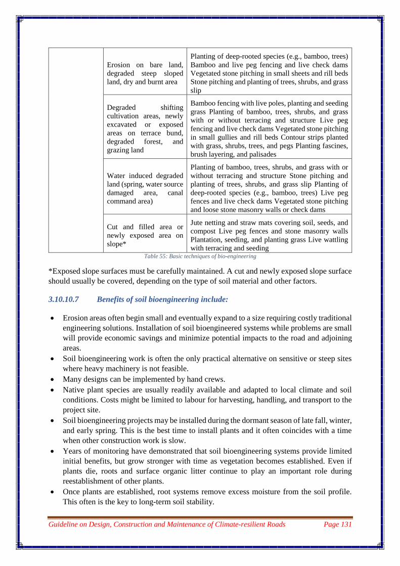
Guideline on Design, Construction and Maintenance of Climate-resilient Roads Page 131
Erosion on bare land,
degraded steep sloped
land, dry and burnt area
Planting of deep-rooted species (e.g., bamboo, trees)
Bamboo and live peg fencing and live check dams
Vegetated stone pitching in small sheets and rill beds
Stone pitching and planting of trees, shrubs, and grass
slip
Degraded shifting
cultivation areas, newly
excavated or exposed
areas on terrace bund,
degraded forest, and
grazing land
Bamboo fencing with live poles, planting and seeding
grass Planting of bamboo, trees, shrubs, and grass
with or without terracing and structure Live peg
fencing and live check dams Vegetated stone pitching
in small gullies and rill beds Contour strips planted
with grass, shrubs, trees, and pegs Planting fascines,
brush layering, and palisades
Water induced degraded
land (spring, water source
damaged area, canal
command area)
Planting of bamboo, trees, shrubs, and grass with or
without terracing and structure Stone pitching and
planting of trees, shrubs, and grass slip Planting of
deep-rooted species (e.g., bamboo, trees) Live peg
fences and live check dams Vegetated stone pitching
and loose stone masonry walls or check dams
Cut and filled area or
newly exposed area on
slope*
Jute netting and straw mats covering soil, seeds, and
compost Live peg fences and stone masonry walls
Plantation, seeding, and planting grass Live wattling
with terracing and seeding Table 55: Basic techniques of bio-engineering
*Exposed slope surfaces must be carefully maintained. A cut and newly exposed slope surface
should usually be covered, depending on the type of soil material and other factors.
3.10.10.7 Benefits of soil bioengineering include:
Erosion areas often begin small and eventually expand to a size requiring costly traditional
engineering solutions. Installation of soil bioengineered systems while problems are small
will provide economic savings and minimize potential impacts to the road and adjoining
areas.
Soil bioengineering work is often the only practical alternative on sensitive or steep sites
where heavy machinery is not feasible.
Many designs can be implemented by hand crews.
Native plant species are usually readily available and adapted to local climate and soil
conditions. Costs might be limited to labour for harvesting, handling, and transport to the
project site.
Soil bioengineering projects may be installed during the dormant season of late fall, winter,
and early spring. This is the best time to install plants and it often coincides with a time
when other construction work is slow.
Years of monitoring have demonstrated that soil bioengineering systems provide limited
initial benefits, but grow stronger with time as vegetation becomes established. Even if
plants die, roots and surface organic litter continue to play an important role during
reestablishment of other plants.
Once plants are established, root systems remove excess moisture from the soil profile.
This often is the key to long-term soil stability.

Guideline on Design, Construction and Maintenance of Climate-resilient Roads Page 132
Soil bioengineering provides improved environmental functions, such as slope
stabilization, storm water retention, and habitat values.

Guideline on Design, Construction and Maintenance of Climate-resilient Roads Page 133
CHAPTER 4 – MAINTENANCE OF CLIMATE RESILIENT
ROADS
To ensure road spending delivers the best possible return and brings lasting development
benefits, it is critical that investment plans take into account the consequences of a changing
climate, as road assets are particularly vulnerable to climate stressors such as higher
temperatures, increased precipitation, and flooding. The damage and accelerated aging of
roads caused by climate change will require increased frequency of maintenance and
rehabilitation.
Climate-resilient roads tend to have higher upfront construction costs, but those are more than
offset by the lower annual cost for maintenance, repairs, and rehabilitation.
Therefore, adequate road maintenance is the most critical and most efficient way of reducing
the impact of a changing climate on the road system.
4.1 Basic objectives of Maintenance:
The basic objectives of maintenance function are to maintain and operate the highway system.
It is done to ensure comfort and safety to the public. There are 3 major types of maintenance
carried out for roads;
1. Routine Maintenance
2. Periodic Maintenance
3. Emergency Maintenance
4.1.1 Routine Maintenance:
Routine maintenance is a set of recurrent activities which caters to the repair of faults and
attention to the road structure and facilities to ensure the preservation of the asset and
convenience and safety to the road users. Routine Maintenance shall be carried out on all roads
including those which are in good and fair condition. Routine maintenance comprises of
following major activities:
4.1.1.1 Maintenance of Road Surface:
It is very important for the service length of a road that the surface of the road is maintained in
a good manner. Road surfaces should be reworked only as necessary to provide a smooth
running surface and a good crown or slope for drainage. All-season roads will require continual
monitoring for surface and sub-grade wear or deterioration. Rutting and loss of ballast often
occur during rainy season. Snow removal equipment can also destroy the road surface by
removing or altering the crown and removing ballast. A plan should be in place to provide
ballast when necessary to maintain continued use of the road.
The surface of the road should be kept clean from foreign materials such as pebbles,
debris etc. at all times.

Guideline on Design, Construction and Maintenance of Climate-resilient Roads Page 134
Rutting, potholes, corrugation, depressions, shoulder failures and other defects of the
surface have to be repaired, especially at the end of the rainy season. Rutting which are
the longitudinal depressions in the wheel paths caused by repeated heavy loads, or
lateral movement of the material, can be corrected by adding suitable material to the
surface. Paved roads are treated by surface dressing and if the ruts are deep, they should
be patched before surface dressing is applied.
Potholes are small depressions in the road surface often caused by poor drainage of the
surface or weak sub grade. Potholes must be fixed as soon as it occurs on road
surface. Potholes may be corrected by patching with well-graded materials and
compacting. For paved roads, the patching shall be covered by surface dressing. Should
the bitumen bleed in hot weather during the repair of potholes, application of grit/sand
must be done.
4.1.1.2 Clearing and Cleaning of Culverts and Drains:
It is very important for roads to have a proper drainage system and to ensure that it functions
well at all times.
Culverts and drains must be maintained regularly so that no debris will block the flow
of water. This is especially important close to forest areas where branches and other
debris from trees can be brought by the water.
In areas with slow water flow, the culverts can easily be blocked by sand deposits that
can considerably reduce the flow area of the culvert. In order to facilitate cleaning of
culverts, no cross-drainage structures smaller than 1.2 m diameter should be used.
Growth of vegetation on culverts and drains must be prevented.
Scouring of drains, culverts and culvert aprons must be prevented and the damages
should be repaired promptly.
Debris in and around culverts should be removed by hand or by tongs rather than by
heavy equipment working directly in the stream.
4.1.1.3 Other activities:
Routine maintenance must also cater to other following activities:
Repair and painting of road signs & markings.
Care and control of roadside vegetation (trees, grasses, etc)
Improve and preserve roadside appearance.
Maintain smooth junction between pavements and decks of bridges, culverts and
causeways/flood ways.
Clear bushes, shrub, weeds and long grasses which interfere with sight distance.
Maintain the sign posts, guide posts, parapet & guard rails and road markings.

Guideline on Design, Construction and Maintenance of Climate-resilient Roads Page 135
4.1.1.4 Routine Maintenance Calendar:
Figure 39: Routine Maintenance Calendar for High Altitude Roads
Figure 40: Routine Maintenance Calendar for Low Altitude Roads
4.1.2 Periodic Maintenance:
Periodic maintenance is group of activities which can normally be predicted and planned based
on its nature, location and extent and are carried out periodically. Periodic maintenance requires
specific identification and planning for implementation as compared to the routine
maintenance. Periodic maintenance comprises of following major activities:
4.1.2.1 Resurfacing works:
Resurfacing is a road maintenance technique in which a new layer of asphalt is laid over the
existing road surface. Resurfacing of the roads can be done in two major ways depending on
the extent of damage caused to the road surface.

Guideline on Design, Construction and Maintenance of Climate-resilient Roads Page 136
4.1.2.2 Surface dressing:
Surface dressing is a cost-effective way of restoring the road surface and sealing it in one
process. Surface dressing improves skidding resistance which makes the roads safer, it also
allows the road to be waterproof and protects the road against frost and water damage.
A film of bitumen binder should be sprayed followed by a layer of 6mm to 10mm stone
chippings for uniform coating and pressed into the surface by a roller. The process of surface
dressing is as explained below;
4.1.2.3 Construction Operations
Preparation of Base:
The base on which the surface dressing is to be laid shall be prepared, shaped and
conditioned to the specified lines, grade and cross section.
Prime coat, where ever is needed, shall be provided. Where the existing surface shows
signs of fattening up, the excess bitumen shall be removed by burning off, or manually, as
specified.
The bituminous surface to be dressed shall be thoroughly cleaned either by using a
mechanical broom and/ or compressed air, or any other approved equipment/ method as
specified. The prepared surface shall be dust free, clean and dry.
4.1.2.4 Application of Binder
The spraying of a uniform thin film of binder shall be provided by a Bitumen Sprayer, the
type of Sprayer depending on the type of binder used.
Immediately after application of the binder, clean, dry chips (in the case of emulsion binder
the chippings may be damp) shall be spread uniformly on the surface so as to cover the
surface completely with a single layer of chips.
4.1.2.5 Rolling
Rolling of the chips shall be carried out by 6/8T smooth-wheeled roller or preferably
by a pneumatic tyre roller.
Traditional steel wheeled rollers tend to crush the aggregates and if their use cannot be
avoided their weight should be limited to 80 kN.
Rolling shall commence at the edges and progress, towards the centre except in super
elevated and unidirectional cambered portions where it shall proceed from the lower
edge to the higher edge.
Each pass of the roller shall uniformly overlap not less than one-third of the track made
in the preceding pass.
While rolling is in progress additional chips shall be spread by hand in necessary
quantities required to make up irregularities. Rolling shall continue until all aggregate
particles are firmly embedded in the binder and present a uniform closed surface.

Guideline on Design, Construction and Maintenance of Climate-resilient Roads Page 137
4.1.2.6 Application of Second Coat of Surface Dressing
Where surface dressing in two coats is specified, the second coat should not be applied
until the first coat has been open to traffic for 2 or 3 weeks.
The surface on which the second coat is laid must be clean and free of dust. The
construction operations for the second coat shall be the same as described above.
4.1.2.7 Opening to Traffic
Traffic shall not be permitted on any newly surface dressed area until the following
day. In special circumstances, the road may be opened to traffic immediately after
rolling, but in such cases, traffic speed shall be limited to 20km per hour until the
following day.
4.1.2.8 Overlay
Overlay of the bituminous surface involves placement of new layer of asphalt. For every stretch
of road that is blacktopped, resurfacing with 30 mm asphalt is normally due in 4 to 5 years and
may be lesser in extreme climatic conditions/heavy traffic areas.
Overlays make up a large portion of the roadway paving done today. The degree of surface
preparation for an overlay is dependent on the condition and type of the existing pavement.
Generally, the existing pavement should be structurally sound, levelled, clean and capable of
bonding to the overlay. To meet these prerequisites, the existing pavement is usually repaired,
levelled (by milling, pre levelling or both), cleaned and then coated with a binding agent.
Before the overlay is carried out the following must be ensured:
Repair
Tack coats
Levelling (both by applying a levelling coarse and by milling)
4.1.2.9 Repair
Generally, pavement overlays are used to restore surface course characteristics such
as smoothness, friction and aesthetics or to add structural support to an existing pavement.
However, even a structural overlay needs to be placed on a structurally sound base. If an
existing pavement is cracked or provides inadequate structural support these defects will often
reflect through even the best-constructed overlay and cause premature pavement failure in the
form of cracks and deformations. To maximize an overlay’s useful life, failed sections of the
existing pavements should be patched or replaced and existing pavement cracks should be
filled.
At most, overlays are designed to add only some structural support; the remaining structural
support must reside in the existing pavement. Therefore, small areas of localized structural
failure in the existing pavement should be repaired or replaced to provide this structural
support. Often, existing pavement failure may be caused by inadequate sub grade support or
poor sub grade drainage. In these cases, the existing pavement over the failed area should be
removed and the sub grade should be prepared as it would be for a new pavement.

Guideline on Design, Construction and Maintenance of Climate-resilient Roads Page 138
Existing pavement crack repair methods depend upon the type and severity of cracks. Badly
cracked pavement sections or severe cracks, must be patched or replaced because these
distresses are often symptoms of more extensive pavement or subgrade structural failure.
Existing cracks other than those symptomatic of structural failure should be cleaned out (blown
out with pressurized air and/or swept) and filled with a crack-sealing material when the cracks
are clean and dry .Cracks less than about 10 mm in width may be too narrow for crack-sealing
material to enter. These narrow cracks can be widened with a mechanical router before sealing.
If the existing pavement has an excessive amount of fine cracks but is still structurally adequate,
it may be more economical to apply a general bituminous surface treatment instead of filling
each individual crack.
4.1.2.10 Tack Coats
Before overlaying of bituminous layer is carried out, a tack coat should be placed on an existing
pavement to ensure adequate bonding of the overlay to the existing pavement surface. Proper
tack coat application can be critical to long-term pavement performance.
4.1.2.11 Levelling
The existing pavement should be made as smooth as possible before being overlaid. It is
difficult to make up elevation differences or smooth out ruts by varying overlay thickness.
Therefore, before applying the final surface course the existing pavement is typically levelled
by one or both of the following methods:
Applying a levelling course - The first lift applied to the existing pavement is used to fill in
ruts and make up elevation differences. The top of this lift, which is relatively smooth, is used
as the base for the wearing course.
Milling - A top layer is milled off the existing pavement to provide a relatively smooth surface
on which to pave. Milling is also commonly used to remove a distressed surface layer from an
existing pavement.
Levelling courses (or pre level) are initial lifts placed directly on to the existing pavement to
fill low spots in the pavement. Typically, pavers are used for this purpose. The pavers are used
to drive over a rough, uneven pavement yet place a relatively smooth lift with extra Hot Mix
Asphalt (HMA) making up for low spots in the existing pavement. Levelling course lifts need
to be as thick as the deepest low spot but not so thick that they are difficult to compact. Because
it is not the final wearing course, levelling course elevation and grade are sometimes not tightly
specified or controlled. However, contractors and inspectors alike should pay close attention
to levelling course thickness because an excessively thick levelling course can lead to large
overruns in HMA and thus large overruns in project budget. Although levelling courses can
help produce a smoother pavement, they suffer from discussed differential compaction and
therefore may not entirely solve the smoothness problem.
Milling can be used to smooth an existing asphalt pavement prior to overlays. Rather than
filling in low spots, as a levelling course does, milling removes the high points in an existing
pavement to produce a relatively smooth surface. For HMA pavements, milling can help
eliminate differential compaction problems.
Guideline on Design, Construction and Maintenance of Climate-resilient Roads Page 139
Milling machines are the primary method for removing old HMA pavement surface material
prior to overlay. They can be fitted with automatic grade control to restore both longitudinal
and transverse grade and can remove most existing pavement distortions such as rutting,
bumps, deteriorated surface material or stripping. The primary advantages of milling:
Eliminates the need for complicated levelling courses and problems with quantity
estimates for irregular levelling course thicknesses used to fill existing pavement
depressions.
Provides Reclaimed Asphalt pavement option for recycling operations.
Allows efficient removal of deteriorated flexible pavement material that is unsuitable for
retention in the pavement structure.
Provides a highly skid resistant surface suitable for temporary use by traffic until the final
surface can be placed.
Allows curb and gutter lines to be maintained or re-established before flexible overlays.
Provides an efficient removal technique for material near overhead structures in order to
maintain clearances for bridge structures, traffic signals and overhead utilities.
The basic components of a milling machine are a cutting drum to mill the existing pavement,
a vacuum to collect the milled particles and a conveyance system to transport the milled
particles to a dump truck for hauling.
After a pavement has been milled the resulting surface is quite dirty and dusty. The surface
should be cleaned off by sweeping or washing before any overlay is placed otherwise the dirt
and dust will decrease the bond between the new overlay and the existing pavement. When
sweeping, more than one pass is typically needed to remove all the dirt and dust. If the milled
surface is washed, the pavement must be allowed to dry prior to paving.
Milling also produces a rough, grooved surface, which will increase the existing pavement
surface area when compared to an un-grooved surface. The surface area increase is dependent
on the type, number, condition and spacing of cutting drum teeth but is typically in the range
of 20 to 30 percent, which requires a corresponding increase in tack coat (20 to 30 percent
more) when compared to an un-milled surface.
Once the existing asphalt surface has been prepared, the asphalt overlay can be paved on
top of the surface. The minimum thickness of asphalt overlay must be 30 mm.

Guideline on Design, Construction and Maintenance of Climate-resilient Roads Page 140
4.1.2.12 Types of defects and their repair
Deformation - Following are the different types of deformation, their probable causes and
remedies:
Table 56: Types of deformation, causes and remedies
Figure 41: Corrugation and Rutting on road surface
Sl.# Defect Description Probable Causes Type of remedies
1 Corrugations Transverse undulations
closely and regularly
spaced wave action on
the surface
Inadequate stability of the
premix surface or pavement
Patch repair
2 Depressions Localized area in a
pavement which is lower
than surrounding area
Consolidation of isolated
areas of poorly compacted
sub-grade. Settlement due to
instability of embankment
Pothole repairs
Strengthening of
weak sections
3 Rutting Longitudinal
deformation in a wheel
path of a road
Inadequate pavement
thickness. Poor compaction
of pavement or sub-grade
Patch repairs,
potholes repairs
4 Shoving Bulging of road surface
and horizontal
displacement of
surfacing materials
Inadequate strength in
pavement
Patch repairs

Guideline on Design, Construction and Maintenance of Climate-resilient Roads Page 141
Figure 42: Shoving on road surface
Cracks - Following are the different types of cracks on road surface, their probable causes and
remedies:
Sl.# Defect Description Probable Causes Repair methods
1 Block Interconnected cracks
forming a series of blocks
approximately rectangular
in shape and usually
distributed over the full
pavement
Shrinkage cracks in the
asphalt surfacing.
Fatigue cracking in
hardened asphalt
wearing course.
Crack Seal
2 Crescent Half-moon or crescent
shaped cracks
Poor bond between
wearing course and
pavement layers. Thin
wearing course.
Patch repair
3 Alligator Interconnected cracks
resembling the skin of a
crocodile generally in the
wheel paths of a road.
Inadequate pavement
thickness. Hardened
wearing course.
Fog Seal if less
severe Patch
repair if highly
severe
4 Diagonal Unconnected cracks on
diagonal across the road.
Differential settlement at
embankments and
cuttings.
Crack Seal
5 Longitudinal Cracks running along the
road in same direction as
vehicles.
Differential settlement
sometimes along the
shoulder edge.
Crack Seal
6 Meandering Unconnected irregular
crack varying in direction.
Weakening of pavement
edge. Entry of moisture.
Reflection shrinkage
crack. Differential
settlement.
Crack Seal

Guideline on Design, Construction and Maintenance of Climate-resilient Roads Page 142
Table 57: Types of cracks, their causes and remedies
Figure 43:Block cracking and alligator cracking on road surface
Figure 44: Meandering and Diagonal cracking on road surface
7 Transverse Unconnected crack
running across the road
Construction joint or
shrinkage crack in
asphalt surfacing
Crack Seal

Guideline on Design, Construction and Maintenance of Climate-resilient Roads Page 143
Surface Texture deficiencies - Following are the different types of surface texture
deficiencies, their probable causes and remedies:
Table 58: Types of surface texture deficiencies, causes and remedies
Sl.
#
Defect Description Probable Causes Repair methods
1 Delamination Surface lifting seal break Inadequate cleaning or
insufficient tack coat on
pavement before placing
premix carpet.
Patch repair
Fog Seal
2 Flushing Black spot, fatty surface,
excess bitumen on surface
Too much bitumen with
respect to aggregate size.
Apply heated sand
and roll
3 Polishing Smoothing/rounding stone
aggregates on wheel
paths.
Stone aggregates too soft
therefore polishing and
rounding. Use of
naturally smooth
uncrushed stone
aggregates.
Apply aggregate
and sand seal coat
4 Ravelling Disintegration of
pavement surface by loss
of bitumen and stone
aggregates.
Deterioration of binder
and/or stone aggregates.
Inadequate compaction,
construction during wet
weather, insufficient
binder, excessively open
graded mix, fracture of
stone aggregates during
rolling.
Patch repair, Fog
Seal
5 Stripping Loss of stone aggregates
in sprayed seal leaving
only bitumen.
Insufficient bitumen
application. Inadequate
rolling of sprayed seal.
Patch repair
6 Potholes Steep deep sided holes in
pavement and wearing
course.
Loss of surface dressing.
Water entering pavement
through cracks.
Pothole repair

Guideline on Design, Construction and Maintenance of Climate-resilient Roads Page 144
Common Cross Drainages/culvert failures - Following are the different types of common
cross drainage or culvert failures, their probable causes and remedies:
Sl.no Damage/Defect Routine Maintenance Periodic Maintenance
1 Siltation Removal of silting
materials and waste
Occasional cleaning
2 Fissures and cracks - Sealing of Fissures and
cracks
3 Displacement/Dislocation - Relocation of misplaced
elements
4 Joint Separation - Relocation of misplaced
elements
5 Spalling Repair of minor spalling Repair of major spalling
(including the passivation of
reinforcement rods)
6 Break - Replacement of
sections/elements
7 Collapse - Replacement of
sections/elements
8 Corrosion - New protection treatment in
the affected areas
9 Scouring - Repair and protection against
scouring
Embankment stabilization
10 Existence of vegetation Clearing of Vegetation Removal of harmful
vegetation
Table 59: Common cross drainage failures and remedies
5.2.2 Emergency Maintenance:
Emergency maintenance is certain activities that is performed in order to restore the roadway
following the damages caused by events such as monsoon rains resulting in floods or landslides
which would be unpredictable.
Activities that have to be carried out as emergency maintenance are as follows:
Snow clearance.
Clearing of landslides.
Repair of culverts and bridges.
Reconstruction or rehabilitation of retaining wall based on the degree of damage caused.
Construction of diversions.
Repair of flood way.

Guideline on Design, Construction and Maintenance of Climate-resilient Roads Page 145
Restoration of road formation width.
4.1.2.13 Snow clearance:
Keeping the roads trafficable during snowfall is very important and challenging as well. Snow
clearance can be done in several ways like:
Clearance by men or machine
Use of chemicals for clearance
Use of grit
4.1.2.14 Clearance by Men or Machine:
The mechanical way of clearing snow is by blading it over the side of the road. The equipment
used for snow clearing are:
Motor grader
Front end loaders
While deploying these machines for snow clearance, care must be taken that there is no damage
caused to the pavement by the blades.
If there is formation of a film of ice on the surface of the road, which usually happens when
snow freezes due to low temperature. Friction between the wheels of the vehicle and the road
surface is lowered by ice on the road surface which causes the vehicle to loose control and slip
off the road.
Ice on road requires treatment with chemicals (salt) to melt ice or by spreading grit (fine stone
chippings) to provide traction for the wheels.
Sodium Chloride (Salt) or Calcium Chloride may be used to melt ice on road surfaces. De-
icing salt works by creating a brine solution that has a lower freezing temperature than the
temperature of the surrounding snow and ice. This brine gets in between the road surface and
ice, preventing a bond that would make removal difficult. When salt is spread before snow fall
or drop in temperature, it can prevent snow accumulation or ice formation. Application of salt
is done manually by spreading it with hands. Though Calcium Chloride also has the same effect
but Sodium Chloride is preferred since it costs lesser than the Calcium Chloride.
It must be noted that salt should not be used on roads under construction where bitumen sealing
is to be carried out in the future, as the salt may damage the seal.
Where the use of salt as de-icing agent is not permissible, or the temperature is so low that a
complete melt is not possible with salt application, grit should be spread to increase traction.
The grit may be spread manually by hand if the area to be treated is small.
The table below provides a guidance for assignment of priorities for various operations and
based on the priority it is identified as follows:
Urgent for activities requiring top priority
Special for activities which are in next order of priority

Guideline on Design, Construction and Maintenance of Climate-resilient Roads Page 146
Periodic for activities which occur recurrently and are next in line to special in order of
priority and
Routine for jobs which are to be attended to in a routine manner
Table 60: Priority for emergency maintenance
Feature Criteria Action Priority
Landslides/slips Any type of slip or slides
blocking the road and
affecting the traffic flow
To be cleared immediately
with available equipment at
the site.
Urgent
Snowfall Road affected by snowfall
compelling suspension of
traffic
To be cleared immediately
with machineries or
chemicals.
Urgent
Minor Cuts, ruts
or blockades
Cuts or blocks that do not
completely obstruct the
traffic but endanger safety
of traffic
Blockades to be removed and
cuts to be repaired
Urgent
Cracking not
accompanied by
rutting
a) Cracking in local areas
equal to or less than 25
percent of the total area
b)Cracking in large areas
exceeding 25 percent of the
total area
a) Local sealing or filling of
the cracks
b) Binder @ 1.5kg/m2 of 1
kg/m2 of cutback for local
sealing.
c) Chippings(6-10mm) for
local surface repairs which
needs surfacing after local
sealing
a) Routine
b) Special attention
c) Special attention.
Stripping a) In local areas exceeding
25 percent of the total area.
b) In larger areas exceeding
25 percent of total area.
Apply Local sealing.
Apply surface dressing
a) Routine
b) Special attention
Bleeding a) In local areas not
exceeding 25 percent of
total area
b)In local areas exceeding
25 percent total area.
a) Spread and roll over 6mm
size aggregate heated to 60°C
b) Apply surface dressing
a) Routine
b)Special attention

Guideline on Design, Construction and Maintenance of Climate-resilient Roads Page 147
4.1.3 Maintenance of Bio- engineering
Bio-engineering is the use of vegetation, either alone or in conjunction with engineering
structures to reduce instability and erosion. Bioengineering involves the use of live plant
materials to perform engineering functions in stabilization of disturbed slopes. These
vegetative structures are flexible and hence absorb movement; being live they recover from
damage and ensure continued stability. The main aim of bio-engineering is to prevent all forms
of erosion and shallow mass movement. Vegetation is carefully selected for the functions it
can serve in stabilising roadside slopes and for its suitability to the site. In order to gain the
maximum benefit, vegetation must be managed and taken care of. Bio-engineering becomes a
part of Routine and periodic off-road maintenance.
Routine maintenance of bio-engineering must cater to simple protection and care of plants,
such as watering, mulching and grass cutting.
Periodic maintenance of bio-engineering requires thinning and pruning of larger plants, repair
of vegetation structures and vegetation enrichment. Vegetation on roadsides must be
maintained on a long-term basis in order to maximize their engineering contribution.
4.2 Pavement Preservation Techniques
4.2.1 Fog seal
A fog seal is an application of a specially formulated asphalt emulsion (a thin liquid oil) to an
existing asphalt pavement surface.
Asphalt emulsions used in fog seal applications contain globules of paving asphalt, water, an
“emulsifying agent” or surfactant. Soap is a common form of a surfactant. In asphalt emulsions,
the surfactant keeps the paving asphalt globules in suspension until it is applied to the pavement
surface when the water in the asphalt emulsion starts to evaporate. A “rejuvenator” is an asphalt
additive which when applied to the existing pavement will slightly soften the pavement it is
applied to creating a better bond.
As asphalt pavement is subjected to traffic loads and as it ages, it oxidizes and cracks develop
in the surface due in part to the pavement becoming more brittle. Oxidation is one of the reasons
asphalt concrete pavement fades in color from the deep, rich black. Fog seal applications serve
to seal narrow cracks, slightly restore lost flexibility to the pavement surface, provide a deep,
rich black pavement surface color, and most importantly help preserve the underlying
pavement structure.
On existing asphalt pavement, fog seals are typically applied on either an intermittent or
cyclical basis. Location, weather, traffic loading, and pavement conditions are factors used to
determine if a fog seal application is appropriate. Roadways selected for fog seal treatment are
commonly those which have minor cracking, faded color, and where a fog seal would help
extend the pavement life until resurfacing becomes necessary. Roadways chosen for cyclical
fog seal applications would typically be treated every three to five years.
Fog seals are applied by a distributor truck. The distributor truck slightly heats the asphalt
emulsion before spraying it onto the pavement. Once applied the surface has the appearance
similar to the pavement having been spray painted black.

Guideline on Design, Construction and Maintenance of Climate-resilient Roads Page 148
4.2.2 Micro-surfacing
Micro-surfacing is a method that consists of the application of a mixture of water, asphalt
emulsion, aggregate (very small crushed rock), and chemical additives to an existing asphalt
concrete pavement surface. Polymer is commonly added to the asphalt emulsion to provide
better mixture properties.
Micro-surfacing is applied in order to help preserve and protect the underlying pavement
structure and provide a new driving surface. Roads chosen for micro-surfacing application
generally have low to moderate distress and narrow crack width.
Micro-surfacing is typically applied on an intermittent, project specific basis. Location,
weather, traffic loading, and pavement conditions are factors used to determine if a micro-
surfacing application is appropriate. Roadways selected for micro-surfacing treatment are
commonly those which have slight to moderate distress, no rutting, generally narrow crack
widths, and in which micro-surfacing treatment would help extend the pavement life until
resurfacing becomes necessary. Roadways chosen for cyclical micro-surfacing applications
would typically be treated every five to seven years.
Micro-surfacing is commonly mixed in, and applied using, a purposely built truck, generally
referred to as a “slurry truck.” If the roadway segments to be micro surfaced are long and don’t
contain sharp curves, a “continuous machine” is sometimes used. The continuous operation
provides the benefit of having few if any seams in the roadway which occur when operation
stops.
Slurry trucks and continuous machines contain various compartments which hold the aggregate
(fine crushed rock), water, polymer modified emulsion, and other additives, which are mixed
in the on-board mixer. The micro surfacing mixture flows out of the rear and onto the pavement
within the confines of a rear-mounted box referred to as a “micro box.” This box contains an
auger which turns to uniformly distribute the mixture across the width. Workers with squeegees
follow behind and assist in spreading the mixture, correcting areas not properly covered.
A piece of burlap is often dragged behind in order to provide a smooth texture while applying
the micro surfacing material. The texture of micro surfacing is different than that of asphalt
pavement. The texture may have faint lines and be somewhat coarse. In addition, when the
micro surfacing is first placed the surface is tender and can be marked up by sudden turning
movements. These impressions on the pavement are temporary as seasonal weather and traffic
smooth out these imperfections over time.
Once placed, micro-surfacing needs 1 to 2 hours to set or harden before the road is open for
traffic.
4.2.3 Slurry Seal
A slurry seal is the application of a mixture of water, asphalt emulsion, aggregate (very small
crushed rock), and additives to an existing asphalt pavement surface. A slurry seal is similar to
a fog seal except the slurry seal has aggregates as part of the mixture. This combined mixture
of the emulsion and aggregates represents “slurry.” Polymer is commonly added to the asphalt

Guideline on Design, Construction and Maintenance of Climate-resilient Roads Page 149
emulsion to provide better mixture properties. The placement of this mixture on existing
pavement is the “seal” as it is intended to seal the pavement surface.
Slurry seal is applied in order to help preserve and protect the underlying pavement structure
and provide a new driving surface. Roads chosen for slurry seal applications generally have
low to moderate distress and narrow crack width. Slurry seal applications serve to seal the
cracks, restore lost flexibility to the pavement surface, provide a deep, rich black pavement
surface color, and help preserve the underlying pavement structure.
Slurry seal is typically applied on either an intermittent or cyclical basis. Location, weather,
traffic loading, and pavement conditions are factors used to determine if a slurry seal
application is appropriate. Roadways selected for slurry seal treatment are commonly those
which have slight to moderate distress, no rutting, and generally narrow crack widths, and
where a slurry seal treatment would help extend the pavement life until resurfacing becomes
necessary.
Roadways chosen for cyclical slurry seal applications would typically be treated every five to
seven years.
The asphalt emulsion and the aggregates are mixed in, and applied using, a purposely built
truck, generally referred to as a “slurry truck.”
Slurry trucks contain various compartments which hold the aggregate (fine crushed rock),
water, polymer modified emulsion, and other additives, which are mixed in the on-board mixer.
The slurry mixture flows out of the rear of the truck and onto the pavement within the confines
of a box attached to the rear of the truck. The box serves to distribute the slurry mixture over
the pavement. Workers with squeegees follow behind and assist in spreading the mixture,
correcting areas not properly covered.
4.2.4 Chip Seal
A chip seal is a two-step process which includes first an application of asphalt emulsion and
then a layer of crushed rock to an existing asphalt pavement surface. Asphalt emulsions used
in chip seal applications contain globules of paving asphalt, water, an “emulsifying agent” or
surfactant, polymer, and sometimes a “rejuvenator.” Soap is a common form of a surfactant. In
asphalt emulsions, the surfactant keeps the paving asphalt globules in suspension until it is
applied to the pavement surface when the water in the asphalt emulsion starts to evaporate. The
chips (small crushed rocks) are immediately applied after the asphalt emulsion is applied to the
pavement surface. The polymer in the asphalt emulsion is a “hardener” which serves to improve
the adhesion to the crushed rock and to the pavement surface. A “rejuvenator” is an asphalt or
additive which when applied to the existing pavement will slightly soften the pavement it is
applied to creating a better bond.
As asphalt pavement is subjected to traffic loads and as it ages, it oxidizes, becomes more
brittle and cracking develops in the pavement structure. A chip seal serves to seal the narrow
cracks, help bind together cracked pavement, provide a wearing (driving) surface, and protect
the underlying pavement structure. Chip seals used as interlayers serve to retard reflective
cracking which develops from the bottom of the pavement structure towards the top.

Guideline on Design, Construction and Maintenance of Climate-resilient Roads Page 150
Chip seals are typically applied on an intermittent or one-time basis. Location, weather, traffic
loading, and pavement conditions are factors used to determine if a chip seal application is
appropriate. Roadways selected for chip seal treatments are commonly those which have
moderate block (or “alligator”) cracking which is not spalling (or “popping out”), no rutting,
an acceptable ride quality, and in which a chip seal would help extend the pavement life until
resurfacing or rehabilitation can be performed.
Roadways chosen for cyclical chip seal applications would typically be treated every seven to
ten years.
A distributor truck first applies the asphalt emulsion to help seal the pavement surface. Using
an asphalt emulsion is considered a “cold applied” chip seal even though the liquid temperature
is typically between 110 and 150 degrees Fahrenheit. No smoke results from the application of
emulsified asphalt. If modified paving asphalt is applied, it is considered a “hot applied” chip
seal as the liquid application temperature is typically between 325 and 375 degrees Fahrenheit.
Smoke will result from the application of modified paving asphalt but should not be of concern.
Immediately following application of the asphalt emulsion, a “chip spreader” follows and
applies crushed rock to the top of the asphalt emulsion. A dump truck dumps crushed rock into
the chip spreader as it travels. Following chip application, rubber tired rollers follow closely
behind. The purpose of the rollers is to push the chips down into the binder and enhance the
bond between them. A steel drum roller commonly follows the rubber tired rollers on “hot
applied” chip seals.
After rolling and once the binder and chips have properly adhered, the surface is swept by
power sweepers. The sweepers sweep the loose crushed rock which has not adhered to the
underlying asphalt emulsion. Loss of crushed rock due to sweeping is a normal part of the
operations. A chip seal would not be successful if the result was areas of the existing pavement
not covered by crushed rock.
The final operation is placement of a “flush coat.” The flush coat consists of the application of
a fog seal (see fog seal) followed by the application of very clean sand. The purpose of the
flush coat is to help “lock down” the chips and absorb any excess asphalt emulsion. The result
is a pavement surface that has a rough texture and a very deep, rich black in color.

Guideline on Design, Construction and Maintenance of Climate-resilient Roads Page 151
Annexure I
Pro-forma for Collection of Data on Landslide Occurrence & Clearance
1. Location
i) Name of Road
ii) Type of Road
2. Location of the Slide:
i) Name of the place:
ii) At Km from:
3. Data to be collected regarding the slide when it is active:
i) Date of sliding:
ii) No. of times sliding has taken place in a year:
iii) Duration for which road was blocked by the slide (No. of days or hours):
iv) Damages to property or persons caused by the slide:
v) Quantity of material cleared:
vi) Method of clearance (Manual or by machine) and the time taken for clearing:
vii) Cost of clearance operation:
viii) Were any permanent stabilising measures executed since last sliding and if so, their
efficacy:
ix) Is the slide preceded by rainfall or snowfall?
x) IS extent of area participating in sliding
xi) Confined to uphill slide of road only
xii) Confined to downhill side of road only
xiii) Covers both
xiv) Is the cause of slide due to man-made causes such as back-cutting, etc.
xv) Does the slide appear to be a surficial one or a deep seated one:
5.3 Standard information/data to be collected about the slide:
a. Prepare a sketch of the slide area covering the slopes both uphill and downhill of the
road and include the following information;
b. Length of the slide from crown to toe, indicating separately the length affected both
above and below the road;
c. Width of the slide (parallel to the road);
d. Maximum depth (normal to the slide);
e. General description of the slide area giving condition of the slopes, presence of erosion
gullies, presence of water springs, tension cracks, etc.
5.4 Geological Data
a. Nature of rock – Indicate whether the slide material is predominantly rock or soil,
decomposed rock or disintegrated rock or a mixture of both;
b. Type of rock and formation;
c. Indicate the type of rocks met within the formation

Guideline on Design, Construction and Maintenance of Climate-resilient Roads Page 152
d. Indicate whether there is any inter-bedding involving especially slide susceptible
formation such as shale or sandstones
e. Dip and strike – Indicate the dip and strikes of the rock formation and note whether
they are favourable or unfavourable for slide formation with reference to the location
of the road at the particular stretch.
f. Weathering – Indicate whether the rock is subject to weathering or other degrading
process due to natural or man-made causes.
5.5 Geotechnical data
5.5.1 Nature of the soil
o Give the classification of soil (or soil fraction of the mantle material) and identification
data according to standard soil mechanics procedure
o Is there any pre-consolidated clay or shale met with?
5.5.2 Alteration of forces acting
o Has there been any increases in the load due to construction of embankments or
structures or accumulation of slide material?
o Has any construction work been carried out that adversely influences the stability, such
as under-cutting the toe etc.?
o Has the slope been subject to vibrating action of either construction equipment or due
to earthquakes or due to blasting?
5.5.3 Action of water
o Has any water or seepage been noticed at the joint planes or along the slide surface or
in clay strata?
o Give a brief description of the drainage conditions prevailing in the slide area.
o Are there any sources of water flow nearby, such as a lake or reservoir or a river, etc?
5.5.4 Causes of slide
Landslides are usually caused by a number of factors rather than a single factor. Indicate which
in your opinion are the predominant causes, and give, if possible, the order of their relative
predominance.
5.5.5 Geological Causes
Weathered rock, disintegrated and/or decomposed rock, due to various reasons like temperature
changes, frost effects, other natural or man-made causes etc.
5.5.6 Geotechnical Causes
Increase in load causing sliding due to any construction or accumulation of slide material or
snow. Reduction in resisting forces caused by excavation at toe. Increase in water content of
clayey layers due to rainfall or seepage, bad drainage, sudden draw-down, rise in water level
in lake upstream. Inter-beds of clay or shale or micaceous matter that are susceptible of being
softened by action of water

Guideline on Design, Construction and Maintenance of Climate-resilient Roads Page 153
5.5.7 Classification of slide
Give the classification of the slide according to the Varness system of classification
Remedial measures
a. Has the slide area been studied for evolving remedial measures?
b. If so, by which organization?
c. Give a summary of the major recommendations
d. Were any/all of the remedial measures implemented? If so, detail them
e. What is the degree of success met with in stabilizing the slide area?
Recommendations
a. Comment on future action you suggest
b. Likely behaviour in future

Guideline on Design, Construction and Maintenance of Climate-resilient Roads Page 154
LITERATURE REFERENCE
1. Field Hand Book – Bio Engineering Works (Edition September 2005)
2. Environment Assessment Act, 2000 and the regulation for Environmental Clearance of
Projects, 2002, National Environment Commission, RGoB
3. Various standards and documents of Department of Roads, RGoB.
4. Roads Planning & Management Strengthening Project, Final Report, June 2002.
5. Transport Sector Note, RGoB and World Bank, draft, September 2003
6. Economic Analysis of EFRC & Transport Network Approach, June 2004, DoR, ITC.
7. Environmental Friendly Road Construction Support Project documents:
8. Survey & Design Manual, DoR, MoWHS, 2005
9. Road Maintenance Manual, DoR, MoWHS, 2005
10. Road Manual IRC: SP:48-1998
11. Climate Resilient Roads - Cambodia Rural Roads Improvement Project: Results from
Climate Change Adaptation, 2009
12. The Vanuatu Climate Resilient Road Standards Project - An initiative funded by the
PACCSAP Program, Australian Department of Environment, in cooperation with the
Government of Vanuatu, 2011-2014
13. Climate Change Vulnerability Assessment and Adaptations, A Final Report of
Dewathang – Nganglam Road by ADB SASEC ROAD CONNECTIVITY PROJECT
2013
14. AASHTO. (2008). Primer on Transportation and Climate Change. Retrieved on June 17,
2009
15. Department for Transport. (2004). The Changing Climate: its Impact on the Department
for Transport. London: Department for Transport. Retrieved on June 12, 2009
16. European Commission. (2006). The European Union Climate Change Program. Retrieved
on June 12, 2009
17. ICF International. (2008). Integrating Climate Change into the Transportation Planning
Process. Federal Highway Administration. Retrieved on June 18, 2009
18. Natural Resources Canada. (2004). Climate Change Impacts and Adaptation: A Canadian
Perspective
19. Climate Change Adaptation and Canadian Infrastructure, 2013
20. The Resilient Road – A road map for research; an element of the forever open road, 2013

Guideline on Design, Construction and Maintenance of Climate-resilient Roads Page 155
21. Measuring the resilience of transport infrastructure, AECOM New Zealand 2013
22. International climate change adaptation framework for road infrastructure-developed by
World Road Association & AECOM, 2015
23. Sanahuja, Harris E. (2011). A Framework for Monitoring and Evaluating Adaptation to
Climate Change. Climate-Eval. Global Environment Facility
24. European Environmental Agency (EEA) (2012). Climate change, impacts and
vulnerability in Europe 2012
25. Brabharan, P (2006) Recent advances in improving the resilience of road networks. New
Zealand Society of Earthquake Engineering Conference 2006
26. Environmental Code of Practice for Highways and Roads, Urs Schaffner & Karma Jimba,
Thimphu, 2000
27. Pictures on the Cover are taken from Google, DoR archive and from the facebook page
‘Inside Bhutan’.