GUIDELINES -...
37
IALA Guidelines for the Design of Leading Lines 1 GUIDELINES FOR THE DESIGN OF LEADING LINES DECEMBER 2001 IALA / AISM – 20ter rue Schnapper – 78100 Saint Germain en Laye – France Tel : +33 1 34 51 70 01 – Fax : +33 1 34 51 82 05 – E-mail : [email protected] Internet : www.iala-aism.org
Transcript of GUIDELINES -...
IALA Guidelines for the Design of Leading Lines
1
GUIDELINES FOR
THE DESIGN OF LEADING LINES
DECEMBER 2001
IALA / AISM – 20ter rue Schnapper – 78100 Saint Germain en Laye – France Tel : +33 1 34 51 70 01 – Fax : +33 1 34 51 82 05 – E-mail : [email protected]
Internet : www.iala-aism.org

IALA Guidelines for the Design of Leading Lines
2
IALA Guidelines for the Design of Leading Lines
3
TABLE OF CONTENTS CHAPTER 1—INTRODUCTION...................................................................................................................................................................5
A. Purpose..............................................................................................................................................................................................5 B. Features.............................................................................................................................................................................................5 C. Program Basis...................................................................................................................................................................................5
CHAPTER 2—BASICS OF LEADING LINE DESIGN ................................................................................................................................6 A. Definition of a Leading Line...........................................................................................................................................................6 B. Views of a Leading Line..................................................................................................................................................................6 C. Channel Length................................................................................................................................................................................7 D. Off-Axis Distance.............................................................................................................................................................................7 E. Lateral Sensitivity—Cross-Track Factor......................................................................................................................................8 F. Beam Width of Leading Lights....................................................................................................................................................10 G. Daymarks or Daytime Lights........................................................................................................................................................10 H. Considerations Regarding Intensities. .......................................................................................................................................11 I. Standard Leading Line Characteristics.......................................................................................................................................11 J. Visibility Values..............................................................................................................................................................................11
CHAPTER 3—PROGRAM OPERATION...................................................................................................................................................12 A. System Requirements....................................................................................................................................................................12 B. Data Input-Preliminary..................................................................................................................................................................12 C. Data Input-Leading Line Analysis..............................................................................................................................................12 D. Data Input-Optional Daytime Leading Lights ......................................................................................................................13 E. Program Output..............................................................................................................................................................................14 F. Single-Point-in-Time Performance Run.......................................................................................................................................15 G. Leading Light Selection................................................................................................................................................................15 H. Sample Leading Line Designs......................................................................................................................................................15
CHAPTER 4—TROUBLE SHOOTING.......................................................................................................................................................16 A. Problem Codes................................................................................................................................................................................16 B. Daymark Problem Codes...............................................................................................................................................................16 C. Problems and Fixes........................................................................................................................................................................17 D. Maximum Intensity less than Minimum Intensity.....................................................................................................................20 E. Maximum Intensity less than Recommended Intensity ...........................................................................................................20 F. Compromises During Leading Line Design...............................................................................................................................20
CHAPTER 5—LEADING LINE CONFIGURATIONS & DESIGN CONSTRAINTS.............................................................................21 A. Introduction....................................................................................................................................................................................21 B. Tower Placement............................................................................................................................................................................21 C. Beacon Placement..........................................................................................................................................................................21 D. Additional Lights...........................................................................................................................................................................21 E. Servicing Considerations..............................................................................................................................................................22 F. Construction Details......................................................................................................................................................................22 G. Safety...............................................................................................................................................................................................22 H. Daymarks.........................................................................................................................................................................................22 Enclosure 1 : Leading Line Category Selection Aid .............................................................................................................................23 Enclosure 2 : Initial Channel Layout Worksheet ..................................................................................................................................25 Enclosure 3: Night Time Leading Line with Daymarks ........................................................................................................................26 Enclosure 4 : Day Time Leading Lights..................................................................................................................................................27 Enclosure 5 : Final Leading Line Configuration Summary...................................................................................................................28 Enclosure 6 : Design Program Methodology ........................................................................................................................................30

IALA Guidelines for the Design of Leading Lines
4

IALA Guidelines for the Design of Leading Lines
5
CHAPTER 1—INTRODUCTION
A. Purpose. The purpose of this publication is to enable a person with little or no knowledge of the fundamentals of leading line design to make use of a computer design program for leading lines. The computer program is attached to the electronic version of the present Guidelines.
B. Features. The computer program has the following features:
1. Runs as a workbook in Microsoft Excel®. This format allows various leading line parameters to be entered and modified in any order.
2. The output is immediately displayed: a change to any of the design parameters results in an immediate update of the program output.
3. Provides recommended intensities in addition to the minimum and maximum intensities, in an effort to provide improved service to the mariner.
4. Allows for evaluation of the performance of both existing and proposed optics.
5. Lateral Sensitivity is expressed as Cross-Track Factor and lends a more physical feel to the performance of the leading line.
6. In addition to evaluating the suitability of proposed nighttime leading lights, the program also provides for the evaluation of the performance of daytime leading lights or leading marks. Note, off-axis distances and cross-track factors provided by the program are based on the performance of light signals only. When leading marks are used, these performance values are based on the nighttime light signals only. The performance of the design using daytime leading lights, however, is evaluated separately from the performance based on nighttime lights. When both light signals and dayboards are to be used, this program presumes the light signals are mounted atop the dayboards. It is possible to consider lower positions of the front signal light relative to the dayboard by taking the additional step of entering the front dayboard as an obstruction to be accounted for in the design of the leading line.
7. Configurations & Constraints. Chapter 5 provides advice on standard configurations and practical constraints on the design of leading lines. Addressing these issues will enable the novice designer to produce leading line designs that perform as expected and can be safely maintained by servicing units. The Leading Line Category Selection Aid, found in enclosure (1), may assist in determining how best to mark the leading line.
C. Program Basis. The equations and evaluation factors used in the design program are taken from the IALA Recommendation for Leading Lights (E-112) and are explained in detail in Enclosure (6). Further references to this document will be made as “the IALA Recommendation.”
IALA Guidelines for the Design of Leading Lines
6
CHAPTER 2—BASICS OF LEADING LINE DESIGN
A. Definition of a Leading Line . A leading line is s defined in the IALA International Dictionary of Aids to Navigation as: “a straight line used for navigation produced by the alignment of marks (leading marks) or lights (leading lights) or by the use of radio transmitters.” This document is limited to the discussion and design of leading lines based on leading marks (daymarks) and leading lights. Vertical alignment of lights or marks defines the centerline of a channel.
B. Views of a Leading Line.
1. Plan View. Figure 2-1 shows a plan view of a leading line and defines some variables.
W
Far End ofUseful Segment
Near End ofUseful Segment
C M R
Observer’s Position
Y
C = Length of useful segment (channel length)W = Channel widthM = Distance to front structure from near end of useful segment R = Distance between leading line structuresY = Distance of observer from center line of channel
Centerline
Figure 2-1. Plan view of a leading line.
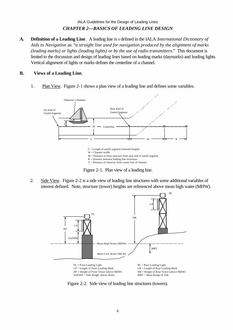
2. Side View. Figure 2-2 is a side view of leading line structures with some additional variables of interest defined. Note, structure (tower) heights are referenced above mean high water (MHW).
LR
Mean High Water (MHW)
Mean Low Water (MLW)
HR
MRT
LFHF
SAFHW
FL = Front Leading LightLF = Length of Front Leading MarkHF = Height of Front Tower (above MHW)SAFHW = Safe Height Above Water
RL = Rear Leading LightLR = Length of Rear Leading MarkHR = Height of Rear Tower (above MHW)MRT = Mean Range of Tide
FL
RL
Figure 2-2. Side view of leading line structures (towers).
IALA Guidelines for the Design of Leading Lines
7
3. Front View. Figure 2-3 is a front view of the leading line structures as seen from a vessel located to the right of the channel centerline. It also shows the horizontal (Θ) and vertical (γ) angles created by the lights as viewed by the observer.
Θ
ã
Θ = Bearing difference between the leading lights γ = Elevation difference between the leading lights
Figure 2-3. Front view of leading line structures.
C. Channel Length. The preliminary decision in designing a leading line is to specify the segment of water to be defined by the leading line. Generally, it is costly to build a leading line to serve a long channel, as the rear leading light must be of sufficient height to be clearly visible above the front structure. Leading marks must also be large enough to be visible from the far end of the channel. Both of these conditions result in increases to the required height of the rear structure marking a long channel. The structures must also be sturdy enough to support the leading mark under wind loads. The use of other aids (fixed beacons or buoys) may reduce the overall cost of marking the waterway by reducing that portion of the channel marked by the leading line.
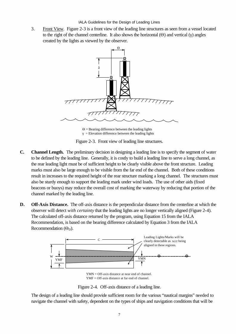
D. Off-Axis Distance. The off-axis distance is the perpendicular distance from the centerline at which the observer will detect with certainty that the leading lights are no longer vertically aligned (Figure 2-4). The calculated off-axis distance returned by the program, using Equation 15 from the IALA Recommendation, is based on the bearing difference calculated by Equation 3 from the IALA Recommendation (ΘD).
YMNYMF
C
W
Leading Lights/Marks will be clearly detectable as NOT being aligned in these regions.
YMN = Off-axis distance at near end of channel.YMF = Off-axis distance at far end of channel.
Figure 2-4. Off-axis distance of a leading line.
The design of a leading line should provide sufficient room for the various “nautical margins” needed to navigate the channel with safety, dependent on the types of ships and navigation conditions that will be
IALA Guidelines for the Design of Leading Lines
8
encountered, between the off-axis distance and the channel edge. This is discussed more thoroughly in Section E, below.
E. Lateral Sensitivity—Cross-Track Factor.
1. Cross-Track Factor. The computer program for leading line design generates a cross-track factor based on the off-axis distance related in the IALA Recommendation for Leading Lights to the bearing difference, ΘD. The cross-track factor is defined to be a ratio of the lateral distance at which a mariner can detect with certainty that a vessel is not on the channel centerline, divided by half the channel width, and expressed as a percentage. A cross-track factor of 25% indicates that a mariner may be as far as 25% of the way towards the edge of the channel when he can detect, with certainty, that he is off centerline. When using cross-track factor as an expression of lateral sensitivity, a higher cross-track factor implies a lower sensitivity, and vice versa.
2. Evaluation of Acceptable Cross-Track Factors. Table 2-1 provides guidelines on the description
and acceptability of various cross-track factors. 3. Instead of setting upper (%) limits on the cross-track factor, the designer should weigh the nautical
margins available against the risk that passing vessels will be overly confined (a small (%) cross-track factor may result in increased risk of collision between passing vessels).
a. If the cross-track factor at the far end is adequate, chances are good that the cross-track
factor at the near end is much smaller. If there are marks at the turning point at the near end, they will allow the mariner to judge the edge of the channel, and the small cross-track factor may be of no concern.
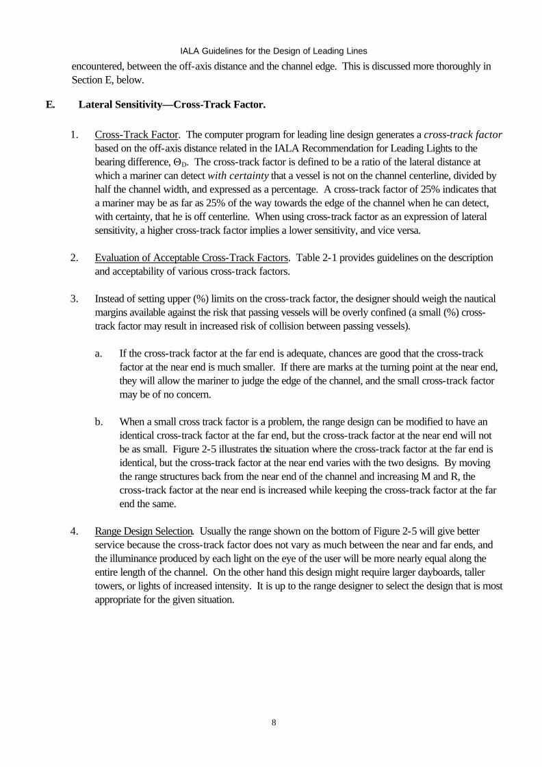
b. When a small cross track factor is a problem, the range design can be modified to have an
identical cross-track factor at the far end, but the cross-track factor at the near end will not be as small. Figure 2-5 illustrates the situation where the cross-track factor at the far end is identical, but the cross-track factor at the near end varies with the two designs. By moving the range structures back from the near end of the channel and increasing M and R, the cross-track factor at the near end is increased while keeping the cross-track factor at the far end the same.
4. Range Design Selection. Usually the range shown on the bottom of Figure 2-5 will give better
service because the cross-track factor does not vary as much between the near and far ends, and the illuminance produced by each light on the eye of the user will be more nearly equal along the entire length of the channel. On the other hand this design might require larger dayboards, taller towers, or lights of increased intensity. It is up to the range designer to select the design that is most appropriate for the given situation.
IALA Guidelines for the Design of Leading Lines
9
1 1
2 2
Table 2-1
Cross-Track Factor* Values of Cross-Track Description Interpretation Factor Over 75% Not Acceptable Range must be improved or it will be unworkable. 50% - 75% Poor Decrease the cross-track factor if physically possible. 30% - 50% Fair Decrease the cross-track factor only if moderate cost involved. 20% - 30% Good Decrease the cross-track factor only if little cost involved. 15% - 20% Very Good Do not expend more funds to decrease the cross- track factor. 10% - 15% Excellent The cross-track factor should not be less than 10% at the far end of the channel.
*Use this table using the cross-track factor at the far end of the channel. Figure 2-5. Two range designs having the same cross-track factor at the far end but different cross-track factors at the near end.
W
W
C
C
M
M
R
R
IALA Guidelines for the Design of Leading Lines
10
F. Beam Width of Leading Lights.
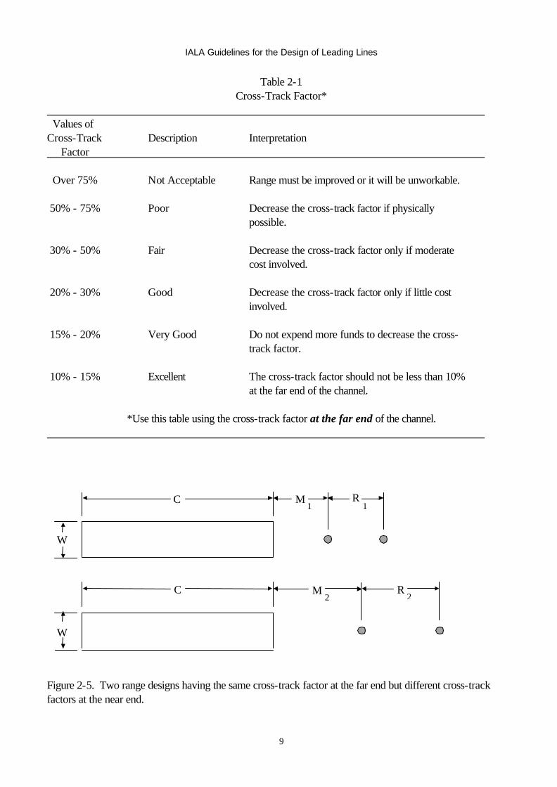
1. Spread Lens. There is often confusion regarding the effect of a narrow spread lens on the sensitivity of a leading line. The beam width of the optic has nothing to do with the lateral sensitivity of a leading line. The beam width is of some concern when a narrow spread lens is used, as care must be taken to ensure that the minimum intensities identified as necessary by the program are provided over the full width of the channel. The angle subtended at the far end of the useful segment, φ, (see Figure 2-6) is given by:
φ (in degrees) = (57.3 degrees/radian) WX
where: X = distance from the light to the far end of the channel, in meters; and W = the width of the channel, in meters.
2. The need for acquisition of the leading lights prior to turning onto a leading line should also be considered when selecting the beam width of the leading lights. In order to reach the first useful segment of the leading line it will often be necessary to observe at least one of the leading lights in a region to seaward and/or to either side of the channel. This is called the “acquisition region.” The selected leading lights should have a beam width (and intensity) sufficient to cover the desired acquisition point.
C
W
M R
X1
X2
φ1 φ2 Figure 2-6. Beam Width of Leading Lights.
G. Daymarks or Daytime Lights. Traditionally leading lights, particularly those powered by batteries, were secured during daylight, with the daytime signal provided by leading marks. Recent efficiency improvements in optics combined with solar power have allowed expanded use of daytime leading lights, even when commercial power is not readily available. The following are some points to consider when deciding on the daytime signal:
1. Marks are simple. Having no moving parts they require little maintenance and so are more reliable than lights. Smaller marks are also easy to maintain, with no special training required for servicing personnel.
2. Daytime leading lights provide a superior signal. In marginal conditions they can be seen further than day marks. Furthermore, substituting lights for large marks may result in less costly tower structures and foundations. Daytime lights, however, require more complex lighting and power systems, which will increase hardware costs and the technical demands on the servicing personnel. The higher initial equipment costs will likely be more than offset by reduced structural costs.

IALA Guidelines for the Design of Leading Lines
11
H. Considerations Regarding Intensities.
1. Nighttime lights should be of sufficient intensity to mark the entire channel length for 90% of the nights. The “Minimum Intensity” values provided by the program will provide adequate signals; however, higher intensities will generally provide better signals. Experience has shown intensity values ten times greater than the minimum values will provide a better signal. Therefore, the program provides a “Recommended Intensity” that is approximately ten times the Minimum Intensity, with good illuminance balance. It is often easy to provide the Recommended Intensities and provide not just an adequate, but a good signal.
2. Daytime lights should be of sufficient intensity to maximize the percentage of time that the channel is adequately marked. If you can meet the “Minimum Intensity” you do not need to go beyond that intensity. If you can not meet the “Minimum Intensity” put in the brightest light possible. The program uses a value of 1000 microlux (1X10⁻³ lux) as the required illuminance for daytime.
I. Standard Leading Line Characteristics. Fixed (F) characteristics should be used sparingly, if at all. Lights displaying a fixed characteristic, especially white light signals, can be difficult to identify against even minimal background lighting. Furthermore, lights displaying a characteristic with a three second flash duration provide approximately 92% of the intensity of a fixed light signal, yield longer lamp service intervals, have lower power consumption, and provide greater conspicuity than the fixed light signal.
J. Visibility Values. The computer program requires entry of three visibility values; Minimum Visibility, Design Visibility, and Maximum Visibility. All three values are computed in nautical miles (a nautical mile is 1852 meters).
1. Minimum Visibility. The minimum visibility is the historic value of meteorological visibility at the site that is met or exceeded 90% of the time. This value is used by the program to establish the minimum luminous intensities required to ensure that the leading lights are usable as leading line signals at least 90% of the time.
2. Design Visibility. The design visibility was originally conceived as the median value of meteorological visibility for the site; that is, the value met or exceeded 50% of the time. Design visibility is used by the program to establish the recommended ratio of luminous intensity of the leading lights. As a practical consideration, use of a fixed value of 10 nm is recommended.
3. Maximum Visibility. The maximum visibility value is used by the program to evaluate the potential for glare produced by the leading lights. As a practical consideration, use of a fixed value of 20 nm is recommended.
IALA Guidelines for the Design of Leading Lines
12
CHAPTER 3—PROGRAM OPERATION
A. System Requirements. The program will run on any computer that has Microsoft Excel® 97 (Windows), Excel® 98 (Mac OS), or later versions.
B. Data Input-Preliminary. You can enter and modify any of the leading line parameters in any order, but when first starting out it is recommended that the input data be entered in the order outlined below. The input cells are shaded and outlined with a box. An Initial Channel Layout Worksheet is included in the workbook to recommend a “very good” leading line design (see Table 2-1) in the event that the locations of the front and rear structures are not initially known. To use this preliminary design tool, click on the “Initial Input” worksheet tab and enter the data indicated below. All input cells require data unless otherwise indicated.
1. Leading Line Name—Enter the name of the leading line. OPTIONAL
2. Length of Channel (C)—Enter the length of the channel, in meters. REQUIRED
3. Width of Channel (W)—Enter the width of the channel, in meters. REQUIRED
Recommended Distance Between Front Light (FL) & Rear Light (RL) Towers (R), and recommended Distance from FL to Near End of the Channel (M) are computed and displayed on the Initial Channel Layout. These values are also shown on the “Leading Line” worksheet adjacent to the data entry cells for these values. The user then elects to use these values, or other values as circumstances may require.
C. Data Input-Leading Line Analysis. Click on worksheet tab “Leading Line.” You can enter and modify any of the leading line parameters in any order, but when first starting out it is recommended that the input data be entered in the order outlined below. All input cells require data unless otherwise indicated. If required input cells are left empty the Cross-Track Factor, Off-Axis Distance, and γ will not be computed correctly. Data is already entered from the previous worksheet for you in the following fields:
Leading Line Name Length of Channel (C) Width of Channel (W) Night or Day Lights (N)
4. Mean Range of Tide (MRT)—Enter the mean range of the tide (difference between mean high water and mean low water), in meters. REQUIRED
5. Background Lighting—Enter the amount of background lighting that is present, either “None,” “Minor,” or “Considerable.” Minor background lighting refers to widely spaced lights and/or dim lights such as residential lighting. Considerable background lighting refers to numerous lights and/or very bright lights such as parking lots, highways, factories, and industrial lighting that compete with the intensity of the range lights. PROGRAM ASSUMES “CONSIDERABLE” IF CELL IS
LEFT BLANK.
6. Height of Eye (HOE)—Enter the height of eye of one to three observers above the water, in meters. (The program can evaluate how well the leading line design works for up to three different vessel types simultaneously.) The input cells for HOE are located in the center of the spreadsheet. AT LEAST ONE ENTRY IS REQUIRED
IALA Guidelines for the Design of Leading Lines
13
7. Minimum Visibility—Enter the minimum visibility for which the leading line is designed, in nautical miles. Generally it is the visibility that occurs 90% of the time for the location of the leading line. REQUIRED
8. Design Visibility—Enter the design visibility, in nautical miles. A value of 10nm is recommended. REQUIRED
9. Maximum Visibility—Enter the maximum visibility for which the leading line is designed, in nautical miles. For practical considerations, a value of 20nm is recommended. REQUIRED
10. Distance Between Front Light & Rear Light (R)—Enter the distance between the structures, in meters. REQUIRED
11. Distance Front Light to Near End Channel (M)—Enter the distance from the near end of the channel to the front structure, in meters. REQUIRED
12. Safe Height Above Water (SAFHW)—Enter the required safe height above water, in meters. It is the minimum height required to keep the front light/mark from being damaged by wave action, spring tides, or vandals. PROGRAM ASSUMES 0.0 METERS IF CELL IS LEFT BLANK.
13. Daymarks To Be Used—Enter a “Y” to use leading marks or an “N” for no leading marks. PROGRAM ASSUMES “NO” IF CELL IS LEFT BLANK.
14. Daytime Lights To Be Used—Enter a “Y” to use daytime lights or an “N” for no daytime lights. PROGRAM ASSUMES “NO” IF CELL IS LEFT BLANK.
15. Obstructions—Enter the distance from the near end of the channel to the obstruction(s), in meters, and the height of the obstruction(s), in meters. OPTIONAL
16. FL Selected Daymark Length—Enter the length of the front leading mark, in meters. Ignore this block if not using leading marks, or enter “None”.
17. RL Selected Dayboard Length—Enter the length of the rear leading mark, in meters. Ignore this block if not using dayboards or enter “None”.
18. FL Selected Intensity—Enter the intensity of the selected signal for the front leading light. REQUIRED
19. RL Selected Intensity—Enter the intensity of the selected signal for the rear leading light. REQUIRED
20. Selected Height FL—Enter the height of the focal plane of the front optic, in meters, above MHW. Note that this value may be different for daytime and nighttime leading lights (see Chapter 5 for more details). REQUIRED
21. Selected Height RL—Enter the height of the focal plane of the rear optic, in meters, above MHW. Note that this value may be different for daytime and nighttime leading lights (see Chapter 5 for more details). REQUIRED
D. Data Input-Optional Daytime Leading Lights. Click on worksheet tab “Leading Line-Day.” Data is already entered from the previous worksheet for you in the following fields:
Leading Line Name Night or Day Lights (D) Length of Channel (C) Width of Channel (W) Mean Range of Tide (MRT) Background Lighting (None)
IALA Guidelines for the Design of Leading Lines
14
Height of Eye (HOE) Minimum Visibility Design Visibility Maximum Visibility Distance Between FL & RL (R) Distance FL to Near End Channel (M) Safe Height Above Water (SAFHW) Daymarks To Be Used Obstructions FL Selected Daymark Length RL Selected Dayboard Length Selected Height FL (Night Light Height plus 1 meter) Selected Height RL (Night Light Height minus 1 meter)
You can enter and modify either of the daytime intensities any order, but when first starting out it is recommended that the input data be entered in the order outlined below. Both cells require data. If required input cells are left empty, the Cross-Track Factor, Off-Axis Distance, and γ will not be computed correctly.
E. Program Output. Samples of the output data are included as enclosures (3), (4) and(5). Enclosures (3) and (4) show the detailed analyses of the leading line performance for all the entered variables and display problems codes if warranted. Enclosure (5) shows a more streamlined summary of the design with generic graphic diagrams. The output data is immediately computed upon entering any variable. Explanations of the outputs:
1. Recommended Daymark Length—The recommended length of the daymark, in meters, based on the minimum visibility.
2. Minimum Intensity—The minimum intensity (in candela) required to ensure the leading light is useable at the far end of the channel for the given minimum visibility. (For daytime leading lights the program only provides values of minimum required intensities.)
3. Recommended Intensity—The recommended intensity (in candela) to assist the mariner in detecting, recognizing, and using the leading lights. This value is approximately ten times the minimum intensity, taking into consideration the recommended illuminance ratio.
4. Maximum Intensity—The maximum intensity (in candela) of the leading lights that can be used without causing glare during conditions of maximum visibility.
5. Recommended IR/IF—The recommended intensity ratio for the rear and front optics where:
IR / IF = Recommended Rear Light IntensityRecommended Front Light Intensity
6. IR/IF for Selected Intensities—The intensity ratio for the selected light signals.
7. Recommended Min Height—The recommended focal plane height of the optic.
8. Distance from Near End—The distance of the observer from the near end of the channel at ten evenly spaced intervals along the entire length of the channel.
9. Cross-Track Factor—The cross-track factor at the indicated distance from the near end of the channel.
IALA Guidelines for the Design of Leading Lines
15
10. Off Axis Distance—The distance perpendicular to the range axis (in meters) needed to indicate to the observer that they are off the leading line axis, at the indicated distance from the near end of the channel.
11. γγ (mrad) (MLW) —The apparent vertical angle subtended by the leading lights (vertical angle separation), in milliradians, at the indicated distance from the near end of the channel.
12. Illuminance Ratios & Values—Provides information on the apparent brightness of the two range optics for the selected design visibility, at the indicated distance from the near end of the channel (values are in microlux).
13. Problem Codes—Chapter 4 discusses Problem Codes and Daymark Problem Codes which may appear on the output sheet. The sample Nighttime/Daymark Design worksheet provided as enclosure (3) shows all the potential problem codes for informational purposes.
F. Single-Point-in-Time Performance Run. To see how the leading line will perform on a given day with a given visibility enter the same visibility for Minimum, Design, and Maximum Visibility. The output is a snapshot of how the leading line will perform for that given visibility.
G. Leading Light Selection. Use the Leading Line Design Program to determine the recommended intensities for the front and rear leading lights. Select the combinations of lanterns, lenses (color/spread), lamps, and rhythms which best meet the desired intensities, and which have adequate beamwidths to cover the required region (see Chapter 2, Section F). When possible, use of omnidirectional lanterns is highly desirable, as the signal can be acquired even when vessels are well off the channel centerline. The use of omnidirectional lanterns also precludes the requirement for passing lights on towers located in navigable waters.
H. Sample Leading Line Designs. Four sample printouts are provided in Enclosure (2) through (5). The
first is a Initial Channel Layout based on two simple inputs. The second is a leading light design analysis which shows a Night time Leading Light with Daymarks for daytime signals. The third sample shows the analysis of the same leading line with daytime light signals added. The forth sample shows a more streamlined summary of the design with generic graphic diagrams.
IALA Guidelines for the Design of Leading Lines
16
CHAPTER 4—TROUBLE SHOOTING
W
C M R
Centerline
FL RL
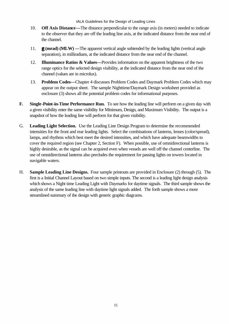
Figure 4-1. Leading Line Diagram.
A. Problem Codes. Below is a list of the possible problem codes that may be displayed while running the leading line design program.
1. Lights will blur. 2. Cross-Track Factor too big. 3. FL not bright enough in min visibility. 4. RL not bright enough in min visibility. 5. FL exceeds glare limit in max visibility. 6. RL exceeds glare limit in max visibility. 7. FL Dayboard too small in min visibility. 8. RL Dayboard too small in min visibility. 9. RL appears lower than RFL. 10. FL below Safe Height Above Water. 11. FL below the horizon. 12. Obstruction #1 obstructs FL. 13. Obstruction #1 obstructs RL. 14. Obstruction #2 obstructs FL. 15. Obstruction #2 obstructs RL.
B. Daymark Problem Codes. Below is a list of the possible daymark problem codes that may be displayed while running the leading line design program.
1. Portion of FL mark below horizon. 2. FL mark below Safe Ht Above Water. 3. FL obscures part of RL mark. 4. FL obstructs more than 1/2 RL mark. 5. Obstruction #1 obstructs FL daymark. 6. Obstruction #1 obstructs RL daymark. 7. Obstruction #2 obstructs FL daymark. 8. Obstruction #2 obstructs RL daymark.
IALA Guidelines for the Design of Leading Lines
17
W
C M R
Centerline
FL RL
Figure 4-2. Leading Line Diagram.
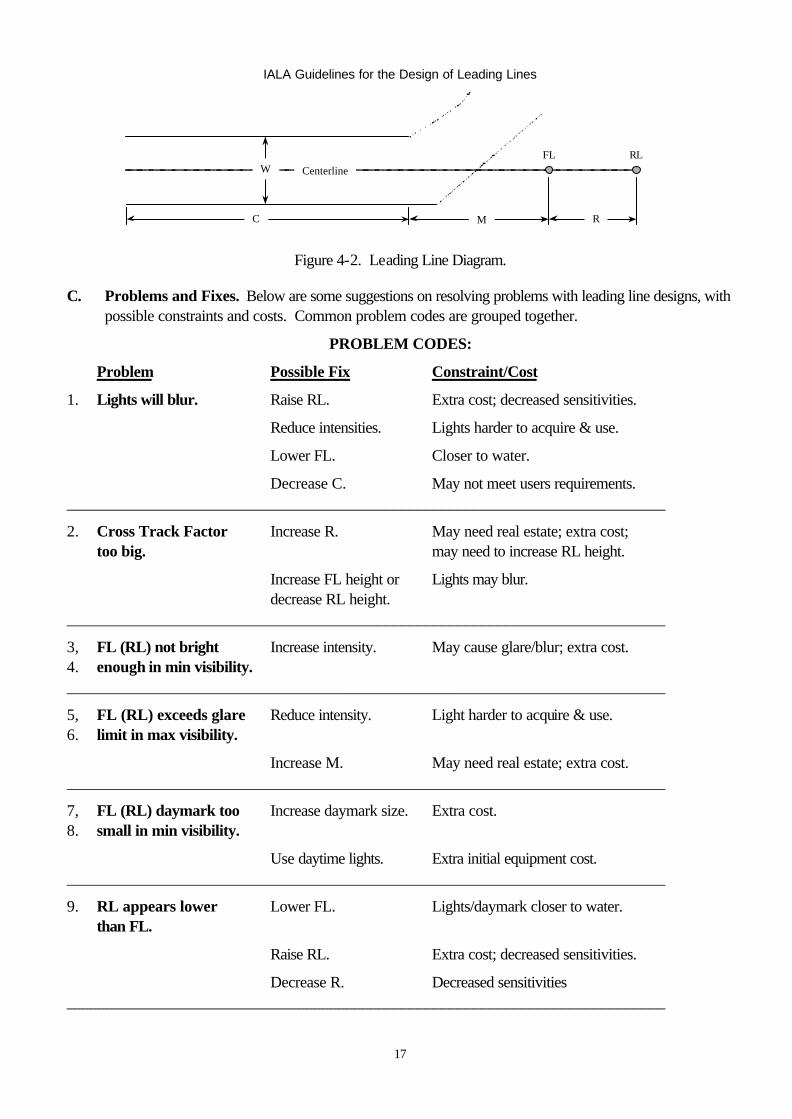
C. Problems and Fixes. Below are some suggestions on resolving problems with leading line designs, with possible constraints and costs. Common problem codes are grouped together.
PROBLEM CODES:
Problem Possible Fix Constraint/Cost
1. Lights will blur. Raise RL. Extra cost; decreased sensitivities.
Reduce intensities. Lights harder to acquire & use.
Lower FL. Closer to water.
Decrease C. May not meet users requirements. ___________________________________________________________________________
2. Cross Track Factor Increase R. May need real estate; extra cost; too big. may need to increase RL height.
Increase FL height or Lights may blur. decrease RL height. ___________________________________________________________________________
3, FL (RL) not bright Increase intensity. May cause glare/blur; extra cost. 4. enough in min visibility. ___________________________________________________________________________
5, FL (RL) exceeds glare Reduce intensity. Light harder to acquire & use. 6. limit in max visibility.
Increase M. May need real estate; extra cost. ___________________________________________________________________________
7, FL (RL) daymark too Increase daymark size. Extra cost. 8. small in min visibility.
Use daytime lights. Extra initial equipment cost. ___________________________________________________________________________
9. RL appears lower Lower FL. Lights/daymark closer to water. than FL.
Raise RL. Extra cost; decreased sensitivities.
Decrease R. Decreased sensitivities ___________________________________________________________________________
IALA Guidelines for the Design of Leading Lines
18
W
C M R
Centerline
FL RL
Figure 4-3. Leading Line Diagram.
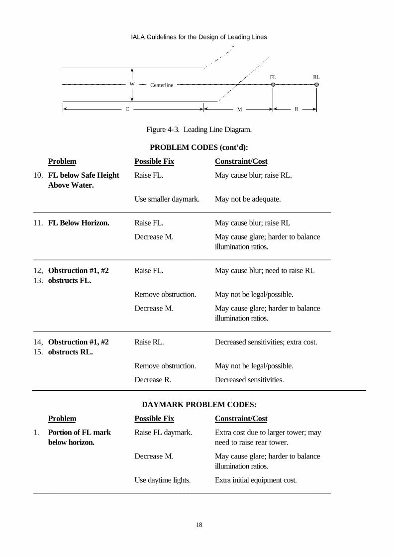
PROBLEM CODES (cont’d):
Problem Possible Fix Constraint/Cost
10. FL below Safe Height Raise FL. May cause blur; raise RL. Above Water.
Use smaller daymark. May not be adequate. ___________________________________________________________________________
11. FL Below Horizon. Raise FL. May cause blur; raise RL
Decrease M. May cause glare; harder to balance illumination ratios. ___________________________________________________________________________
12, Obstruction #1, #2 Raise FL. May cause blur; need to raise RL 13. obstructs FL.
Remove obstruction. May not be legal/possible.
Decrease M. May cause glare; harder to balance illumination ratios. ___________________________________________________________________________
14, Obstruction #1, #2 Raise RL. Decreased sensitivities; extra cost. 15. obstructs RL.
Remove obstruction. May not be legal/possible.
Decrease R. Decreased sensitivities.
DAYMARK PROBLEM CODES:
Problem Possible Fix Constraint/Cost
1. Portion of FL mark Raise FL daymark. Extra cost due to larger tower; may below horizon. need to raise rear tower.
Decrease M. May cause glare; harder to balance illumination ratios.
Use daytime lights. Extra initial equipment cost. ___________________________________________________________________________
IALA Guidelines for the Design of Leading Lines
19
W
C M R
Centerline
FL RL
Figure 4-4. Leading Line Diagram.
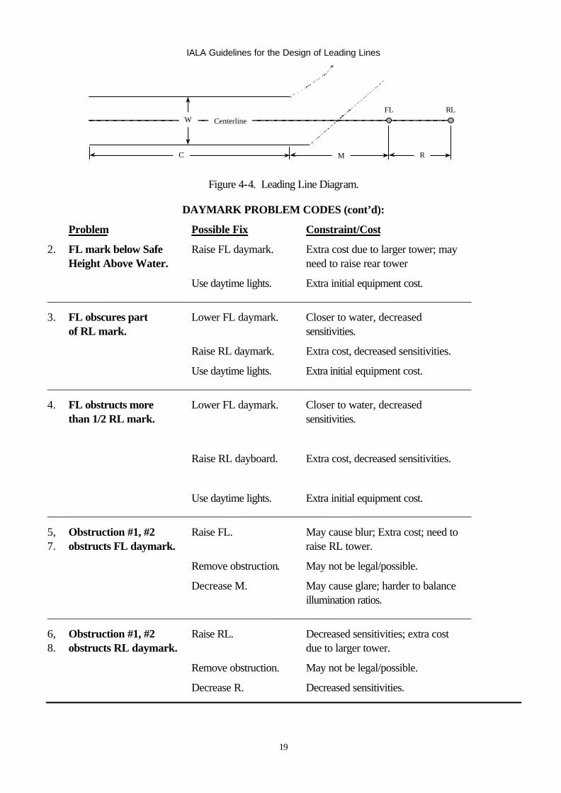
DAYMARK PROBLEM CODES (cont’d):
Problem Possible Fix Constraint/Cost
2. FL mark below Safe Raise FL daymark. Extra cost due to larger tower; may Height Above Water. need to raise rear tower
Use daytime lights. Extra initial equipment cost. ___________________________________________________________________________
3. FL obscures part Lower FL daymark. Closer to water, decreased of RL mark. sensitivities.
Raise RL daymark. Extra cost, decreased sensitivities.
Use daytime lights. Extra initial equipment cost. ___________________________________________________________________________
4. FL obstructs more Lower FL daymark. Closer to water, decreased than 1/2 RL mark. sensitivities.
Raise RL dayboard. Extra cost, decreased sensitivities.
Use daytime lights. Extra initial equipment cost. ___________________________________________________________________________
5, Obstruction #1, #2 Raise FL. May cause blur; Extra cost; need to 7. obstructs FL daymark. raise RL tower.
Remove obstruction. May not be legal/possible.
Decrease M. May cause glare; harder to balance illumination ratios. ___________________________________________________________________________
6, Obstruction #1, #2 Raise RL. Decreased sensitivities; extra cost 8. obstructs RL daymark. due to larger tower.
Remove obstruction. May not be legal/possible.
Decrease R. Decreased sensitivities.
IALA Guidelines for the Design of Leading Lines
20
D. Maximum Intensity less than Minimum Intensity. This situation arises when one or both leading lights (usually the FL) are too close to the channel, creating a glare problem. The best solution is to move the leading lights back from the near end of the channel, increasing M, until the situation is resolved. If that is not possible, then choose a light signal that provides the Minimum Intensity, to alleviate the glare situation as much as possible. Another way to reduce glare is to set the focal heights of the lights so as to be significantly different from the primary HOE for vessels using the channel. This may result in the user being out of the primary portion of the beam, resulting in a reduction in intensity as the vessel approaches the near end of the channel.
E. Maximum Intensity less than Recommended Intensity. This problem is similar to that described above, except that the Minimum Intensity does not result in glare. It is still generally best to move the leading lights back from the near end of the channel, thereby allowing selection of the Recommended Intensity. If that is not possible, than select an intensity between the Minimum and Maximum Intensities for the constrained leading light. The intensity for the remaining light should be selected to try and match the recommended ratio of intensities, so as to provide a good balance of illuminances. Note, in some instances this may result in the selected intensity for the RL being less than the Minimum Intensity. The leading line designer must compromise between the intensity requirements and the recommended ratio of illuminance to optimize marking of the channel.
F. Compromises During Leading Line Design. There is no single correct design for a given leading line. There are multiple successful combinations of optics, lamps, structure locations, optic heights, flash characteristics, colors, etc. With all the different designs possible for a given leading line, there comes a point where the designer must select which design to use. Selecting the design that optimizes the cost/benefit ratio for marking a channel is a trial and error process that requires practice. The selection criteria may include cost of construction, maintenance, cross-track factor, off-axis distance, tower heights, power requirements, HOE of primary user, and user input. This is just a partial list, but indicates that design of a leading line is more of an art than a science.
IALA Guidelines for the Design of Leading Lines
21
CHAPTER 5—LEADING LINE CONFIGURATIONS & DESIGN CONSTRAINTS
A. Introduction. This chapter discusses a few of the constraints and recommended configurations when designing a leading line. These items should be considered during the design phase, to that performance of the aid will be as predicted and that personnel can safely service the lights and marks.
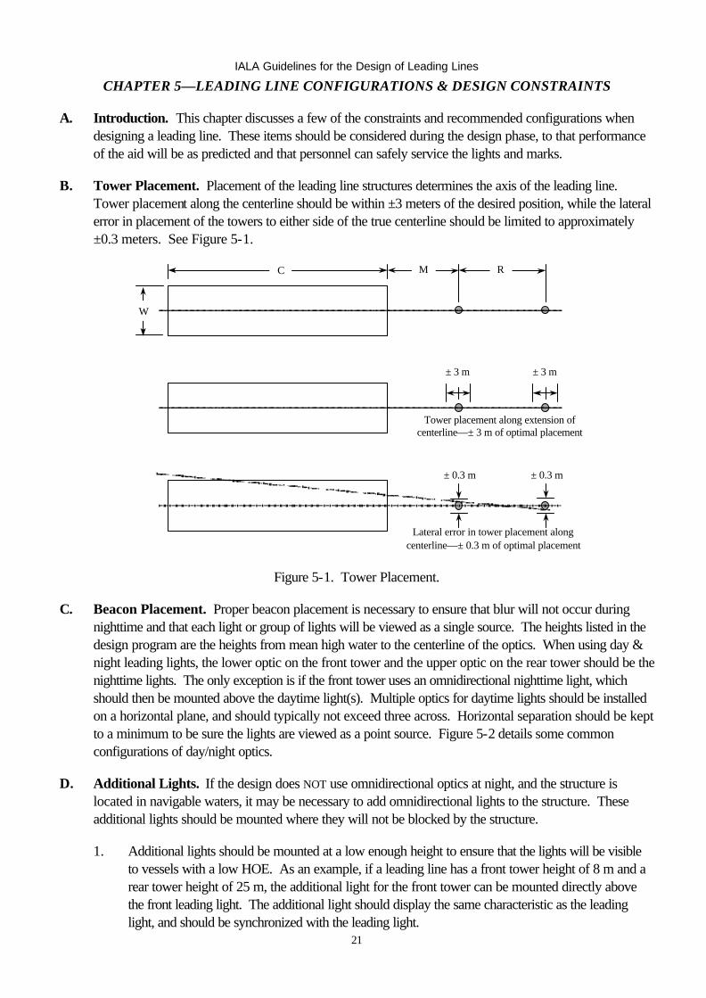
B. Tower Placement. Placement of the leading line structures determines the axis of the leading line. Tower placement along the centerline should be within ±3 meters of the desired position, while the lateral error in placement of the towers to either side of the true centerline should be limited to approximately ±0.3 meters. See Figure 5-1.
C
W
M R
± 3 m ± 3 m
Tower placement along extension ofcenterline—± 3 m of optimal placement
± 0.3 m ± 0.3 m
Lateral error in tower placement alongcenterline—± 0.3 m of optimal placement
Figure 5-1. Tower Placement.
C. Beacon Placement. Proper beacon placement is necessary to ensure that blur will not occur during nighttime and that each light or group of lights will be viewed as a single source. The heights listed in the design program are the heights from mean high water to the centerline of the optics. When using day & night leading lights, the lower optic on the front tower and the upper optic on the rear tower should be the nighttime lights. The only exception is if the front tower uses an omnidirectional nighttime light, which should then be mounted above the daytime light(s). Multiple optics for daytime lights should be installed on a horizontal plane, and should typically not exceed three across. Horizontal separation should be kept to a minimum to be sure the lights are viewed as a point source. Figure 5-2 details some common configurations of day/night optics.
D. Additional Lights. If the design does NOT use omnidirectional optics at night, and the structure is located in navigable waters, it may be necessary to add omnidirectional lights to the structure. These additional lights should be mounted where they will not be blocked by the structure.
1. Additional lights should be mounted at a low enough height to ensure that the lights will be visible to vessels with a low HOE. As an example, if a leading line has a front tower height of 8 m and a rear tower height of 25 m, the additional light for the front tower can be mounted directly above the front leading light. The additional light should display the same characteristic as the leading light, and should be synchronized with the leading light.
IALA Guidelines for the Design of Leading Lines
22
2. On towers greater than about 12 m, the additional lights may be designated as passing lights and installed at a lower level than the leading light. Installation of a passing light requires two optics, as the structure will partially occlude the output from each lantern. The passing lights should be mounted on opposite corners of the structure, and should be synchronized.
E. Servicing Considerations. Towers should be designed to ensure that they can be serviced safely. Since many optics are serviced from the front, there should be 0.75 m of deck space available all around the optic, to allow for easy and safe access. Additionally, lanterns should be elevated a minimum of 0.5 m off the deck. When lanterns are installed more than approximately 1.25 m above the deck, a work platform should be built into the structure to allow personnel to comfortably access the lantern. Optic support structures should take into consideration any doors or servicing hatches on the installed lanterns. Railings should be installed, where appropriate, with either careful placement to prevent obstruction of the light or removable safety chains in front of optics. Operation and maintenance guides, if prepared, should be passed to the assigned servicing unit.
F. Construction Details. Boat landings should be oriented to allow easy boarding under prevailing current and wind conditions. Boarding ladders should have rail extensions to allow easy transition from the deck to the ladder. For towers in excess of 20 m height, the designer should consider installation of a stairway instead of a ladder. All-weather, hand operated winches, with covers, should be installed on the main deck containing power system equipment and on the lantern deck to facilitate easy handling of hardware. Solar panels should be installed so that access to both sides of the array are possible and shall not be shadowed by railings, antennas, towers, shelters, etc., within an arc of ± 90 degrees of panel orientation.
G. Safety. Installations using large batteries should have safety covers on intercell connectors to protect from accidental shorting. Battery rooms should have servicing equipment (hydrometer, tarp for covering solar panel, etc.) and safety equipment (eye wash station, gloves, goggles, etc.) available to servicing personnel in the event they do not bring the equipment with them.
H. Daymarks. Daymark mountings on structures should be strong enough to secure the daymark up to the tower’s designed wind load, while allowing servicing personnel easy replacement. Daymark mountings should not exceed the tower strength (daymark mountings should fail before the structure does). Access to the daymark by ladder or platform is necessary to remove/replace fasteners. Use of day/night lights is encouraged on ranges requiring marks in excess of 3 m in length, as these marks are the most hazardous to replace.

IALA Guidelines for the Design of Leading Lines
23
Leading Line Needed at Night?
LEADING LINE CATEGORY SELECTION AID
Is Daytime Light NeededOr Cost Preferrable?
(See Note 1)
Category: S-N Daymark
Night Only LightPwr: Solar
DAYMARK
Is Commercial Power CostPreferable?
no
yes
Is Day Light Too Bright toUse at Night?
Category: C-24 Single Intensity Lt
24 hoursPwr: Commercial
no
yes
Is Day Light More than 50Times as Bright as Night
Light?
yes
Category:C-D/N Bright Day Lt, Dimmer Night Lt
Pwr :Commercial
no
Category: C-RLC Bright Day, Dim NightSynch Xfer RL &FL
Pwr :Commercial(See Note 3)
Is Day Light More than 50Times as Bright as Night Light?
Category:S-D/N Bright Day Lt, Dimmer Night Lt
Pwr: Solar
no
Category: S-RLC Bright Day, Dim NightSynch Xfer of RL &FL
Pwr: Solar(See Note 3)
Is Commercial Power CostPreferable?
no
no
Category: C-N Daymark
Night Only LightPwr: Commercial
Begin
Is a Single Intensity LightPreferable?(See Note 2)
Category: S-24 Single Intensity Lt
24 hoursPwr: Solar
yes
no
no
yesyes yes
Commercial Powered
C - N Com'l Night (only) LightC - 24 Com'l 24 Hour LightC - D/N Com'l Day & Night LightsC - RLC Com'l Day & Night Lights
(Synch RL & FL Transfer)
Solar Powered
S - N Solar Night (only) LightS - 24 Solar 24 Hour LightS - D/N Solar Day & Night LightsS - RLC Solar Day & Night Lights
(Synch RL & FL Transfer)
yes
Enclosure 1 : Leading Line Category Selection Aid
IALA Guidelines for the Design of Leading Lines
24
LEADING LINE CATEGORY SELECTION AID NOTES
1. There are several factors to consider when deciding whether or not to use daytime lights. The leading line designer should compare the performance characteristics and associated costs of a design using daymarks and one using daytime lights before making a final judgment.
2. Like most aspects of leading line design, choosing between a single intensity, 24-hour signal or a dual intensity, day/night signal for solar applications involves tradeoffs:
a. Factors that favor a single-intensity light include: • Fewer optics (to buy and service). • No need for day/night control switching. • Higher intensity nighttime light usually provides a superior signal. • Simpler system.
b. Factors that favor a separate optics for daytime and nighttime lights • Allows for brighter daytime light and less intense nighttime light: • Requires fewer solar panels than a single (high intensity) 24-hour light. • Requires less battery capacity than single (high intensity) 24-hour light. • Less intense nighttime light will tend to lower required height of RL.
3. Use of a device to synchronize switching of the front and rear leading lights is recommended when daytime and nighttime light signal intensities differ by a factor of 50 or more. If the leading lights do not switch at the same time, the leading line may not be useable during the period when the front and rear lights are not in the same mode.
IALA Guidelines for the Design of Leading Lines
25
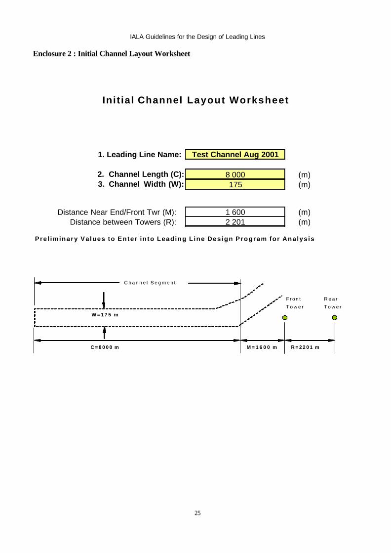
Enclosure 2 : Initial Channel Layout Worksheet
Init ial Channel Layout Worksheet
1. Leading Line Name: Test Channel Aug 2001
2. Channel Length (C): 8 000 (m)3. Channel Width (W): 175 (m)
Distance Near End/Front Twr (M): 1 600 (m)Distance between Towers (R): 2 201 (m)
Prel iminary Values to Enter in to Leading L ine Design Program for Analys is
C h a n n e l S e g m e n t
F r o n t R e a r
T o w e r T o w e r
W = 1 7 5 m
C = 8 0 0 0 m M = 1 6 0 0 m R = 2 2 0 1 m
IALA Guidelines for the Design of Leading Lines
26
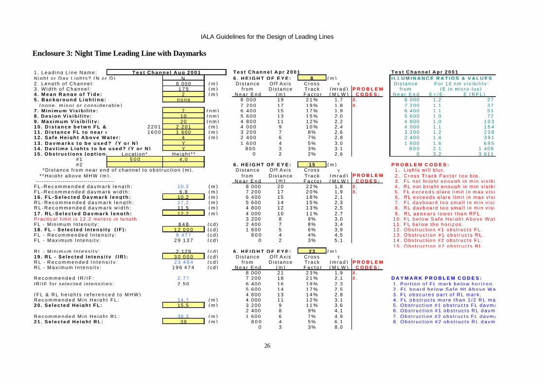
Enclosure 3: Night Time Leading Line with Daymarks
1 . L e a d i n g L i n e N a m e : T e s t C h a n n e l A u g 2 0 0 1 T e s t C h a n n e l A p r 2 0 0 1 T e s t C h a n n e l A p r 2 0 0 1N i g h t o r D a y L i g h t s ? ( N o r D ) N 6 . H E I G H T O F E Y E : 8 ( m ) I L L U M I N A N C E R A T I O S & V A L U E S2 . L e n g t h o f C h a n n e l : 8 0 0 0 ( m ) D i s t ance O f f A x i s C ross γ Dis tance F o r 1 0 n m v i s i b i l i t y :3 . W i d t h o f C h a n n e l : 1 7 5 ( m ) f rom D is tance T r a c k ( m r a d ) P R O B L E M f rom (E in m ic ro - lux )4 . M e a n R a n g e o f T i d e : 2 ( m ) N e a r E n d ( m ) F a c t o r ( M L W ) C O D E S : N e a r E n d E + / E - E ( R F L )5 . B a c k g r o u n d L i g h t i n g : n o n e 8 0 0 0 1 9 2 1 % 1,7 8 , 8 0 0 0 1 ,2 2 7 ( n o n e , m i n o r o r c o n s i d e r a b l e ) 7 2 0 0 1 7 1 9 % 1,8 8 , 7 2 0 0 1 ,1 3 77 . M i n i m u m V i s i b i l i t y : 7 ( n m ) 6 4 0 0 1 5 1 7 % 1,9 6 4 0 0 1 ,1 5 18 . D e s i g n V i s i b i l i t y : 1 0 ( n m ) 5 6 0 0 1 3 1 5 % 2,0 5 6 0 0 1 ,0 7 29 . M a x i m u m V i s i b i l i t y : 2 0 ( n m ) 4 8 0 0 1 1 1 2 % 2,2 4 8 0 0 1 ,0 1 0 31 0 . D i s t a n c e b e t w n F L & R L : 2 2 0 1 2 2 0 1 ( m ) 4 0 0 0 9 1 0 % 2,4 4 0 0 0 1 ,1 1 5 41 1 . D i s t a n c e F L t o n e a r e n d c h a n n e l : 1 6 0 0 1 6 0 0 ( m ) 3 2 0 0 7 8% 2 ,6 3 2 0 0 1 ,2 2 3 81 2 . S a f e H e i g h t A b o v e W a t e r : 4 ( m ) 2 4 0 0 6 7% 2 ,8 2 4 0 0 1 ,4 3 9 11 3 . D a y m a r k s t o b e u s e d ? ( Y o r N ) Y 1 6 0 0 4 5% 3 ,0 1 6 0 0 1 ,6 6 9 51 4 . D a y t i m e L i g h t s t o b e u s e d ? ( Y o r N ) Y 8 0 0 3 3% 3 ,1 8 0 0 2 ,1 1 4 0 91 5 . O b s t r u c t i o n s ( o p t i o n a l ) : Loca t i on * H e i g h t * * 0 2 2% 2 ,6 0 3 ,2 3 6 1 1 # 1 5 0 0 4 ,0 # 2 6 . H E I G H T O F E Y E : 1 5 ( m ) P R O B L E M C O D E S : * D i s t a n c e f r o m n e a r e n d o f c h a n n e l t o o b s t r u c t i o n ( m ) . D i s t ance O f f A x i s C ross γ 1 . L igh ts w i l l b lu r . * * H e i g h t a b o v e M H W ( m ) . f rom D is tance T r a c k ( m r a d ) P R O B L E M 2 . C r o s s T r a c k F a c t o r t o o b i g . -------------------------------------- N e a r E n d ( m ) F a c t o r ( M L W ) C O D E S : 3 . FL no t b r i gh t enough i n m in v i s i b i l i t y .F L - R e c o m m e n d e d d a y m a r k l e n g t h : 10,2 ( m ) 8 0 0 0 2 0 2 2 % 1,8 8 , 4 . RL no t b r i gh t enough i n m in v i s i b i l i t y .F L - R e c o m m e n d e d d a y m a r k w i d t h : 6 ,8 ( m ) 7 2 0 0 1 7 2 0 % 1,9 8 , 5 . F L e x c e e d s g l a r e l i m i t i n m a x v i s i b i l i t y .1 6 . F L - S e l e c t e d D a y m a r k l e n g t h : 10,2 ( m ) 6 4 0 0 1 5 1 8 % 2,1 6 . RL exceeds g la re l im i t i n max v i s ib i l i t y .R L - R e c o m m e n d e d d a y m a r k l e n g t h : 17,2 ( m ) 5 6 0 0 1 4 1 5 % 2,3 7 . F L d a y b o a r d t o o s m a l l i n m i n v i s i b i l t y .R L - R e c o m m e n d e d d a y m a r k w i d t h : 11,5 ( m ) 4 8 0 0 1 2 1 3 % 2,5 8 . R L d a y b o a r d t o o s m a l l i n m i n v i s i b i l t y .1 7 . R L - S e l e c t e d D a y m a r k l e n g t h : 12,2 ( m ) 4 0 0 0 1 0 1 1 % 2,7 9 . R L a p p e a r s l o w e r t h a n R F L .Prac t i ca l l im i t i s 12 .2 mete rs in leng th 3 2 0 0 8 9% 3,0 1 0 . F L b e l o w S a f e H e i g h t A b o v e W a t e r .FL - M in imum In tens i t y : 8 4 8 ( c d ) 2 4 0 0 7 8% 3,4 1 1 . F L b e l o w t h e h o r i z o n .1 8 . F L - S e l e c t e d I n t e n s i t y ( I F ) : 1 2 0 0 0 ( c d ) 1 6 0 0 5 6% 3,9 12 . Obs t r uc t i on #1 obs t r uc t s FL .F L - R e c o m m e n d e d I n t e n s i t y : 8 4 7 7 ( c d ) 8 0 0 4 4% 4,5 1 3 . O b s t r u c t i o n # 1 o b s t r u c t s R L .F L - M a x i m u m I n t e n s i t y : 2 9 1 3 7 ( c d ) 0 2 3% 5,1 14 . Obs t r uc t i on #2 obs t r uc t s FL .
1 5 . O b s t r u c t i o n # 2 o b s t r u c t s R L .R L - M i n i m u m I n t e n s i t y : 2 1 2 9 ( c d ) 6 . H E I G H T O F E Y E : 2 3 ( m )1 9 . R L - S e l e c t e d I n t e n s i t y ( I R ) : 3 0 0 0 0 ( c d ) D i s t ance O f f A x i s C ross γR L - R e c o m m e n d e d I n t e n s i t y : 2 3 4 8 4 ( c d ) f rom D is tance T r a c k ( m r a d ) P R O B L E MR L - M a x i m u m I n t e n s i t y : 1 9 6 4 7 4 ( c d ) N e a r E n d ( m ) F a c t o r ( M L W ) C O D E S :
8 0 0 0 2 1 2 3 % 1,9 8 ,R e c o m m e n d e d I R / I F : 2 ,77 7 2 0 0 1 8 2 1 % 2,1 8 , D A Y M A R K P R O B L E M C O D E S :IR / IF fo r se lec ted in tens i t i es : 2 ,50 6 4 0 0 1 6 1 9 % 2,3 1 . P o r t i o n o f F L m a r k b e l o w h o r i z o n .
5 6 0 0 1 4 1 7 % 2,5 2 . F L b o a r d b e l o w S a f e H t A b o v e W a t e r .( F L & R L h e i g h t s r e f e r e n c e d t o M H W ) 4 8 0 0 1 3 1 4 % 2,8 3 . F L o b s c u r e s p a r t o f R L m a r k .R e c o m m e n d e d M i n H e i g h t F L : 14,7 ( m ) 4 0 0 0 1 1 1 2 % 3,1 4 . F L o b s t r u c t s m o r e t h a n 1 / 2 R L m a r k .2 0 . S e l e c t e d H e i g h t F L : 15,5 ( m ) 3 2 0 0 9 1 1 % 3,6 5 . O b s t r u c t i o n # 1 o b s t r u c t s F L d a y m a r k .
2 4 0 0 8 9% 4,1 6 . O b s t r u c t i o n # 1 o b s t r u c t s R L d a y m a r k .R e c o m m e n d e d M i n H e i g h t R L : 38,3 ( m ) 1 6 0 0 6 7% 4,9 7 . O b s t r u c t i o n # 2 o b s t r u c t s F L d a y m a r k .2 1 . S e l e c t e d H e i g h t R L : 3 9 ( m ) 8 0 0 4 5% 6,1 8 . O b s t r u c t i o n # 2 o b s t r u c t s R L d a y m a r k .
0 3 3% 8,0

IALA Guidelines for the Design of Leading Lines
27
Enclosure 4 : Day Time Leading Lights
Leading Line Name: Test Channel Aug 2001 Test Channel Apr 2001 Test Channel Apr 2001Night or Day Lights? (N or D) D HEIGHT OF EYE: 8 (m) ILLUMINANCE RATIOS & VALUESLength of Channel: 8 000 (m) Distance Off Axis Cross γ Distance For 10 nm visibility:Width of Channel: 175 (m) from Distance Track (mrad) PROBLEM from (E in micro-lux)Mean Range of Tide: 2 (m) Near End (m) Factor (MLW) CODES: Near End E+/E- E (RFL) E (RRL)Background Lighting: none 8 000 18 20% 1,5 8, 8 000 1,2 2 382 2 778 (none for daytime) 7 200 16 18% 1,6 8, 7 200 1,1 3 229 3 643Minimum Visibility: 7 (nm) 6 400 14 16% 1,7 6 400 1,1 4 452 4 827Design Visibility: 10 (nm) 5 600 12 13% 1,8 5 600 1,0 6 262 6 475Maximum Visibility: 20 (nm) 4 800 10 11% 1,9 4 800 1,0 9 029 8 813Distance between FL & RL: 2 201 (m) 4 000 8 10% 2,1 4 000 1,1 13 436 12 206Distance FL to near end channel: 1 600 (m) 3 200 7 8% 2,2 3 200 1,2 20 836 17 266Safe Height Above Water: 4 (m) 2 400 5 6% 2,4 2 400 1,4 34 185 25 075Daymarks to be used? (Y or N) Y 1 600 4 4% 2,5 1 600 1,6 60 856 37 658Obstructions (optional): Location* Height** 800 3 3% 2,4 800 2,1 123 261 59 122 #1 500 4,0 0 1 1% 1,7 0 3,2 315 977 98 697 #2 0 0,0 *Distance from near end of channel to obstruction (m). HEIGHT OF EYE: 15 (m) PROBLEM CODES: **Height above MHW (m). Distance Off Axis Cross γ -------------------------------------- from Distance Track (mrad) PROBLEMFL-Recommended daymark length: 10,2 (m) Near End (m) Factor (MLW) CODES: FL-Recommended daymark width: 6,8 (m) 8 000 18 21% 1,6 8,FL-Selected Daymark length: 10,2 (m) 7 200 16 19% 1,7 8,RL-Recommended daymark length: 17,2 (m) 6 400 14 17% 1,9RL-Recommended daymark width: 11,5 (m) 5 600 13 14% 2,0RL-Selected Daymark length: 12,2 (m) 4 800 11 12% 2,2 8. RL dayboard too small in min visibilty.Practical limit is 12.2 meters in length 4 000 9 11% 2,4FL - Minimum Intensity: 847 171 (cd) 3 200 8 9% 2,718. FL - Selected Intensity (IF): 1 050 000 (cd) 2 400 6 7% 3,0
1 600 5 5% 3,4800 3 4% 3,8
0 2 2% 4,2RL - Minimum Intensity: 2 128 886 (cd)19. RL - Selected Intensity (IR): 2 650 000 (cd) HEIGHT OF EYE: 23 (m)
Distance Off Axis Cross γRecommended IR/IF: 2,77 from Distance Track (mrad) PROBLEMIR/IF for selected intensities: 2,52 Near End (m) Factor (MLW) CODES:
8 000 19 22% 1,8 8,(FL & RL heights referenced to MHW) 7 200 17 20% 1,9 8,Recommended Min Height FL: 14,7 (m) 6 400 15 18% 2,1Selected Height FL: 16,5 (m) 5 600 14 16% 2,3
4 800 12 14% 2,5Recommended Min Height RL: 37,7 (m) 4 000 10 12% 2,8Selected Height RL: 38 (m) 3 200 9 10% 3,2
2 400 7 8% 3,71 600 6 6% 4,4
800 4 5% 5,40 3 3% 7,1
IALA Guidelines for the Design of Leading Lines
28
Enclosure 5 : Final Leading Line Configuration Summary
IALA Guidelines for the Design of Leading Lines
29
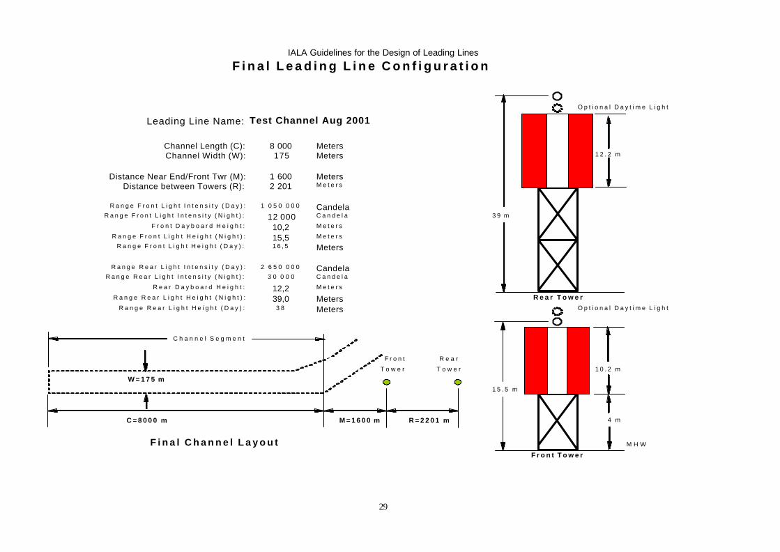
F i n a l L e a d i n g L i n e C o n f i g u r a t i o n
O p t i o n a l D a y t i m e L i g h t
Leading Line Name: Test Channel Aug 2001
Channel Length (C): 8 000 MetersChannel Width (W): 175 Meters 1 2 . 2 m
Distance Near End/Front Twr (M): 1 600 MetersDistance between Towers (R): 2 201 M e t e r s
R a n g e F r o n t L i g h t I n t e n s i t y ( D a y ) : 1 0 5 0 0 0 0 CandelaR a n g e F r o n t L i g h t I n t e n s i t y ( N i g h t ) : 12 000 C a n d e l a 3 9 m
F r o n t D a y b o a r d H e i g h t : 10,2 M e t e r s
R a n g e F r o n t L i g h t H e i g h t ( N i g h t ) : 15,5 M e t e r s
R a n g e F r o n t L i g h t H e i g h t ( D a y ) : 1 6 , 5 Meters
R a n g e R e a r L i g h t I n t e n s i t y ( D a y ) : 2 6 5 0 0 0 0 CandelaR a n g e R e a r L i g h t I n t e n s i t y ( N i g h t ) : 3 0 0 0 0 C a n d e l a
R e a r D a y b o a r d H e i g h t : 12,2 M e t e r s
R a n g e R e a r L i g h t H e i g h t ( N i g h t ) : 39,0 Meters R e a r T o w e rR a n g e R e a r L i g h t H e i g h t ( D a y ) : 3 8 Meters O p t i o n a l D a y t i m e L i g h t
C h a n n e l S e g m e n t
F r o n t R e a r
T o w e r T o w e r 1 0 . 2 m
W = 1 7 5 m1 5 . 5 m
C = 8 0 0 0 m M = 1 6 0 0 m R = 2 2 0 1 m 4 m
F i n a l C h a n n e l L a y o u t M H W
F r o n t T o w e r

IALA Guidelines for the Design of Leading Lines
30
Enclosure 6 : Design Program Methodology
A. Introduction. The IALA Leading Lines Design Program is based on the IALA Recommendation for Leading Lights (E-112), hereafter referred to as the Recommendation. The Recommendation provides specific guidelines for the design of towers and lights. The computer program is in the format of a Microsoft Excel Workbook containing four spreadsheet worksheets. The purpose of this enclosure is to show the linkage between the theory of the Recommendation and the detailed leading line design produced by the spreadsheet program. The locations in the spreadsheets of the described calculations are also provided in order to help users and reviewers to understand in detail the spreadsheet calculation methods (eg.: see cell B15).
B. Initial Channel Layout Worksheet. The Initial Channel Layout Worksheet (click on worksheet tab “Initial Input”) permits the user to establish a beginning position for the leading line towers when they are not otherwise constrained. For these preliminary calculations it is necessary to assume values for vertical separation of the lights, cross-track sensitivity, and a distance from the near end of the channel to the front tower.
1. Bearing Difference. Refer to Recommendation Equation (3b):
θθ’1 = 0.16 * 10-3 + 0.12 γγ for γγ < 5 mrad
for the bearing difference necessary to detect with certainty that the lights are not aligned; on page 1 it is recommended “that if before adopting the final luminous intensities a preliminary investigation of appropriate sites is undertaken, it should be based on a value of γm=1.5 * 10-3 radians.”
∴Assuming γm=1.5 * 10-3 radians and substituting in equation (3b): θ’1 = 0.16 * 10-3 + (0.12) (1.5 * 10-3) for γ < 5 mrad θ’1 = 0.34 mrad ∴θD = 0.34 mrad
2. Off-Axis Distance. Refer to Recommendation Equation 16:
YD = θθD x (1+ x/R)
for the off-axis distance at which a mariner can detect with certainty that a vessel is not on the channel centerline.
Defining the following variables:
R=Distance between the front and rear lights. x=Distance from front light to far end of channel (C+M), where C=Channel length M=Distance between near end and front light W=Channel Width The distance M is assumed to be 0.2C. This value is based on design experience, but may be deemed too low if background lighting or low visibility requires bright lights, which could cause glare at the near end of the channel.
3. Separation of Front and Rear Towers. By substituting known values in Recommendation Equation 16 and solving for the unknown value R we arrive at a relationship to compute the value for R.
By identity, we can divide both sides of equation (16) by (1/2W): (YD / (1/2W)) = [θD x (1+ x/R)] / (1/2W); and In this Guideline’s terms, YD / (1/2W) is defined as the “cross track factor.” The cross track factor is defined to be the lateral distance at which a mariner can detect with certainty that a vessel is not on the channel centerline, divided by half

IALA Guidelines for the Design of Leading Lines
31
the channel width. For these preliminary calculations, we assume a cross-track factor of 20%, inferring a “very good” leading line (see Table 2-1 in this Guideline). Assuming YD / (1/2W) = 0.20 and substituting in above equation:
0.20 = YD / (1/2W) = [θD x (1+ x/R)] / (1/2W) 0.10W = θD x (1+ x/R) W/ (10 θD x) = 1 + x/R W/ (10 θD x) - 1 = x/R R= x / [(W/ (10 θD x)] – 1) But x = M + C; and θD = 0.34 * 10-3
∴R = (M + C) / [W/ (10 (0.34 * 10-3 )( M + C) – 1]
And R, the Distance between the front and rear lights R = (M + C) / [1000W/ (3.4 * 10-3 )( M + C) – 1]
where variables:
R=Distance between the front and rear lights. x=Distance from front light to far end of channel (C+M), where C=Channel length M=Distance between near end and front light
W=Channel Width
This can also be expressed as R=x/((1000W/3.4x)-1); see cell B15
This formula will always yield a cross track factor of 20% for γ = 1.5 mrad.
C. Leading Line Design Worksheet. The detailed design for a leading line is accomplished on the Leading Line Design Worksheet (click on worksheet tab “Leading Line”).
1. Minimum Intensity. The Recommendation suggests that the lights shall provide an illuminance at the eye of the navigator at least equal to 1 x 10⁻⁶ lux, and that the lights shall be sized such that the illuminance be nearly equal as possible while viewing them within the channel segment.
Refer to Recommendation Equation 5 (Allard’s Law):
E = I d-2(0.05) d/V
for the illuminence at the eye of the light signal, where E = Threshold of illuminance in lux I = Intensity in candelas d = Distance from the light to the far end of the channel in meters V = Visibility in meters The minimum nighttime intensity can be calculated by solving Eq.16 for Intensity (I):
I = (E D 2)/(0.05(D'/(V')); see cells D30 & D35 Where : I = Intensity in candelas E = Threshold of illuminance in lux D = Distance from the light to the far end of the channel in meters D' = Distance from the light to the far end of the channel nautical miles V' = Visibility in nautical miles

IALA Guidelines for the Design of Leading Lines
32
The threshold of illuminance (E) increases during nighttime conditions when background lighting is present. The illuminance is multiplied by factors of 1, 10 and 100 for none, minor and considerable background lighting, respectively. For daytime conditions the threshold of illuminance (E) multiplier is set to 1000. See cell C68. A selected intensity value lower than the suggested minimum intensity will result in printing of only a portion of the leading line evaluation. It is assumed that the lights will not be usable in the unprinted portions.
2. Maximum Intensity . Maximum intensity is determined by the glare limit (see Prevention of Glare, p. 4 in Recommendation) using the same equation, as above. Glare occurs when the illuminance at the eye of the navigator (E) exceeds 0.01 lux when viewed at night with no background lighting and 0.1 lux with background lighting in maximum visibility. See cell C69. 3. Equality of Illuminances The illuminances at the eye of the navigator within the useful channel segment provided by the two lights should be as nearly equal as possible. This requires a suggested intensity ratio between the front and rear lights. Allard’s law is used to determine the ideal ratio. Since I = (E D 2)/(0.05)D/V, and since transmissivity and visibility are related by the expression T = 0.05 1/V, then by substitution intensity can also be expressed as:
I = (E D 2)/TD
Also, since the illuminances of both the front and rear lights are to be designed to be equal (Ie.: ER = EF = E), the following
equation applies:
IR/IF =((DR2 * E) / TDR ) / ((DF
2 * E) / TDF ) IR/IF = (DR
2 * TDF) / (DF2 * TDR), where
IR/IF = Intensity ratio DR = Distance from the rear light to the halfway point of the channel in nmi DF = Distance from the front light to the halfway point of the channel in nmi T = Transmissivity E = Illuminance (factors out) The equation determines the ideal intensity ratio to achieve equal illuminance at the halfway point in the channel. An additional calculation is performed at the far end to ensure that the ratio does not exceed 2:1. See cells C88 to C90. 4. Separation of Lights. The rear tower shall be of sufficient height so that the lights do not blur together. The calculation is performed at both the near and far ends using the calculated luminances at these points. The following equation determines the vertical separation in milliradians required to prevent the lights from blurring together. Refer to Recommendation Equation 11 (master blur equation). See cells AA7 to AA17, AA23 to AA33 and AA39 to AA49.
ãm = [2.4 – 0.06 * ABS Log (E2/E1) + 0.26 * ABS Log(E2/E1)2 +
Log E+ * (0.2– 0.02 * ABS Log (E2/E1) –0.02 * ABS Log (E2/E1)2)] * 10-3
Where E2/E1 = the illuminance ratio E+ = the maximum illuminance of either the front or rear lights ãm = vertical separation in milliradians Refer to Recommendation Equation 13. The vertical separation of two lights given the front and rear tower height is expressed as
ã = (H2 – b – c)/(x + R) – (H1 – b – c)/x – 6.75*10-8 * R
Where H2 = rear tower height at mean low water in meters H1 = front tower height at mean low water in meters b = height of eye in meters (the program assumes b is at MLW) c = mean range of tides in meters x = distance from front tower to observer in meters R = distance between towers in meters
IALA Guidelines for the Design of Leading Lines
33
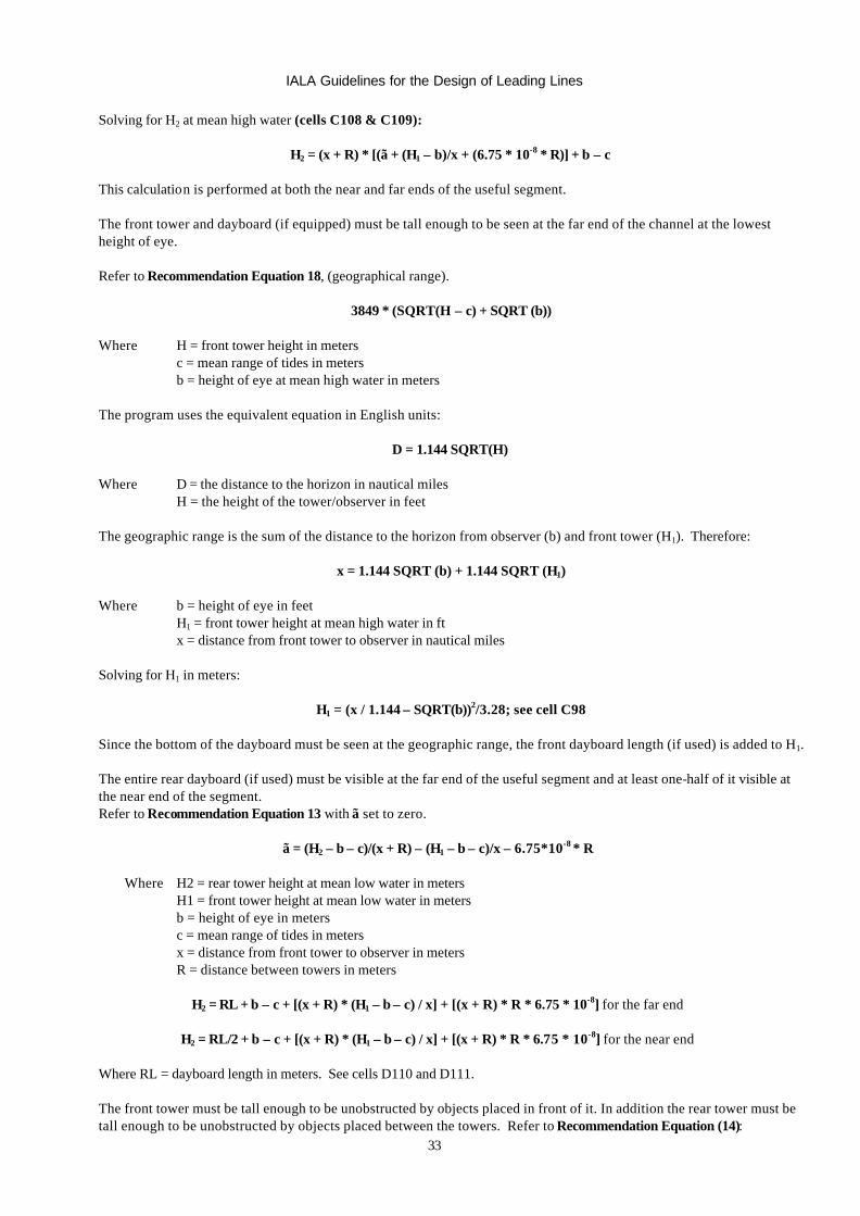
Solving for H2 at mean high water (cells C108 & C109):
H2 = (x + R) * [(ã + (H1 – b)/x + (6.75 * 10-8 * R)] + b – c This calculation is performed at both the near and far ends of the useful segment. The front tower and dayboard (if equipped) must be tall enough to be seen at the far end of the channel at the lowest height of eye. Refer to Recommendation Equation 18, (geographical range).
3849 * (SQRT(H – c) + SQRT (b)) Where H = front tower height in meters c = mean range of tides in meters b = height of eye at mean high water in meters The program uses the equivalent equation in English units:
D = 1.144 SQRT(H) Where D = the distance to the horizon in nautical miles H = the height of the tower/observer in feet
The geographic range is the sum of the distance to the horizon from observer (b) and front tower (H1). Therefore:
x = 1.144 SQRT (b) + 1.144 SQRT (H1) Where b = height of eye in feet H1 = front tower height at mean high water in ft x = distance from front tower to observer in nautical miles Solving for H1 in meters:
H1 = (x / 1.144 – SQRT(b))2/3.28; see cell C98 Since the bottom of the dayboard must be seen at the geographic range, the front dayboard length (if used) is added to H1. The entire rear dayboard (if used) must be visible at the far end of the useful segment and at least one-half of it visible at the near end of the segment. Refer to Recommendation Equation 13 with ã set to zero.
ã = (H2 – b – c)/(x + R) – (H1 – b – c)/x – 6.75*10-8 * R
Where H2 = rear tower height at mean low water in meters
H1 = front tower height at mean low water in meters b = height of eye in meters c = mean range of tides in meters x = distance from front tower to observer in meters R = distance between towers in meters
H2 = RL + b – c + [(x + R) * (H1 – b – c) / x] + [(x + R) * R * 6.75 * 10-8] for the far end
H2 = RL/2 + b – c + [(x + R) * (H1 – b – c) / x] + [(x + R) * R * 6.75 * 10-8] for the near end
Where RL = dayboard length in meters. See cells D110 and D111. The front tower must be tall enough to be unobstructed by objects placed in front of it. In addition the rear tower must be tall enough to be unobstructed by objects placed between the towers. Refer to Recommendation Equation (14):

IALA Guidelines for the Design of Leading Lines
34
(H” – b – c) / (u + S) – (H’ – b – c) / u – 6.75 * 10-8 * S
IALA Guidelines for the Design of Leading Lines
35
Where H” = height of front/rear tower in meters from mean high water H’ = height of obstruction in meters from mean high water b = height of eye in meters c = mean range of tides in meters u = distance between observer and obstruction in meters S = distance between tower and obstruction in meters
Solving for H”
H” = b – c + [(u + S) * (H’ – b – c) / u] + [(u + S) * S * 6.75 * 10-8]; see cells C99 to C102 and C112 to C115.
This calculation is performed at both the near and far ends of the useful segment. Since the entire front dayboard (if used) must be visible at either end of the segment, the dayboard length is added to H” (see cells D99 to D102). Likewise, the entire rear dayboard (if used) must be visible when viewed at the far end of the segment and only one-half of it when viewed at the near end (see cells C112 to C115 and D112 to D115). The program evaluates the tower heights calculated by the safe height above water, necessity to avoid obstructions, ability to see the dayboards, geographic range, and separation of lights (blur) for selected intensities, at either high or low tide (whichever is appropriate), and recommends a front and rear tower height. If the selected tower height values are lower than the recommendations, an error message is posted.
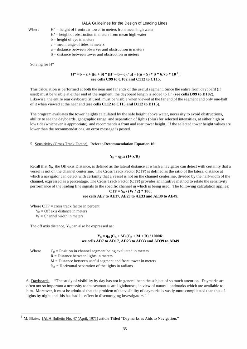
5. Sensitivity (Cross Track Factor). Refer to Recommendation Equation 16:
YD = θθD x (1+ x/R)
Recall that YD , the Off-axis Distance, is defined as the lateral distance at which a navigator can detect with certainty that a vessel is not on the channel centerline. The Cross Track Factor (CTF) is defined as the ratio of the lateral distance at which a navigator can detect with certainty that a vessel is not on the channel centerline, divided by the half-width of the channel, expressed as a percentage. The Cross Track Factor (CTF) provides an intuitive method to relate the sensitivity performance of the leading line signals to the specific channel in which is being used. The following calculation applies:
CTF = YD / (W / 2) * 100; see cells AE7 to AE17, AE23 to AE33 and AE39 to AE49.
Where CTF = cross track factor in percent
YD = Off axis distance in meters W = Channel width in meters
The off axis distance, YD can also be expressed as:
YD = θθD (CD + M) (CD + M + R) / 1000R; see cells AD7 to AD17, AD23 to AD33 and AD39 to AD49
Where CD = Position in channel segment being evaluated in meters R = Distance between lights in meters M = Distance between useful segment and front tower in meters θD = Horizontal separation of the lights in radians
6. Dayboards. “The study of visibility by day has not in general been the subject of so much attention. Daymarks are often not so important a necessity to the seaman as are lighthouses, in view of natural landmarks which are available to him. Moreover, it must be admitted that the problem of the visibility of daymarks is vastly more complicated than that of lights by night and this has had its effect in discouraging investigators.” 1
1 M. Blaise, IALA Bulletin No. 47 (April, 1971) article Titled “Daymarks as Aids to Navigation.”
IALA Guidelines for the Design of Leading Lines
36
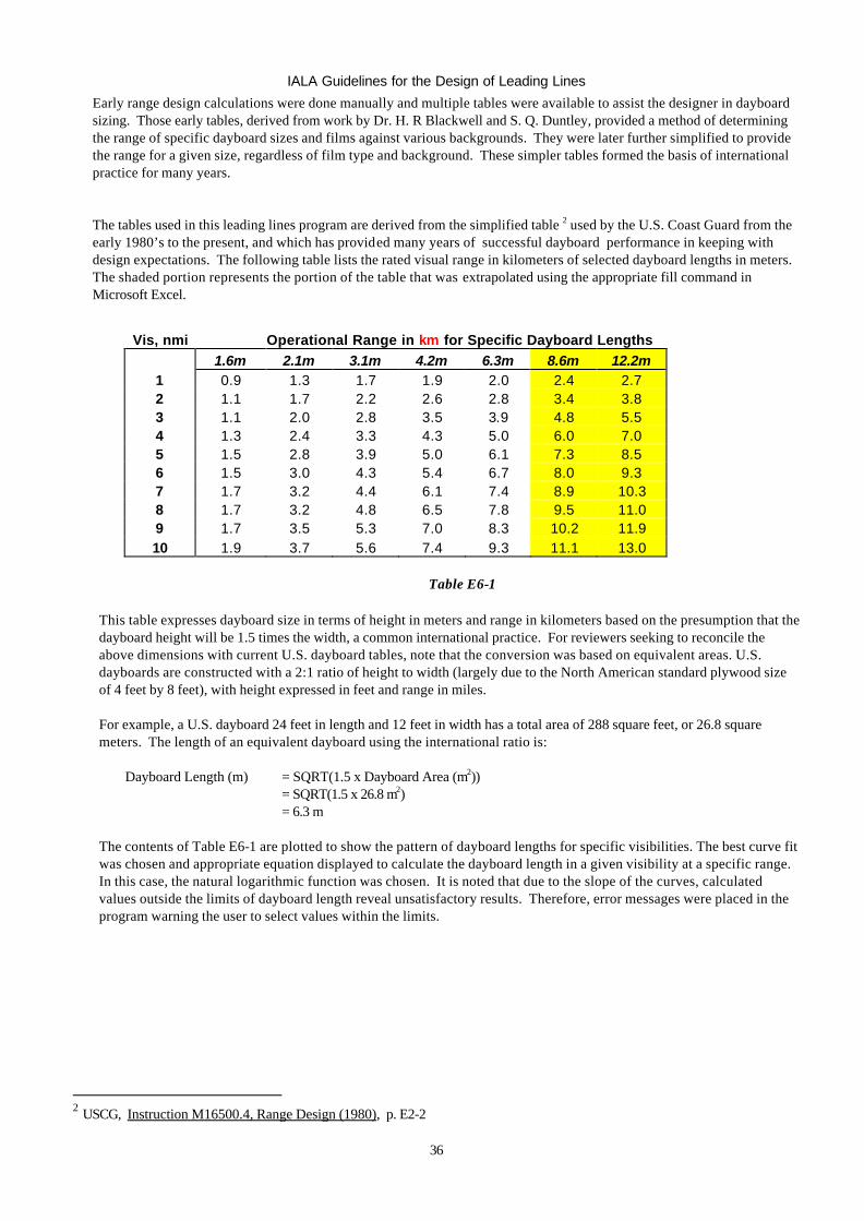
Early range design calculations were done manually and multiple tables were available to assist the designer in dayboard sizing. Those early tables, derived from work by Dr. H. R Blackwell and S. Q. Duntley, provided a method of determining the range of specific dayboard sizes and films against various backgrounds. They were later further simplified to provide the range for a given size, regardless of film type and background. These simpler tables formed the basis of international practice for many years.
The tables used in this leading lines program are derived from the simplified table 2 used by the U.S. Coast Guard from the early 1980’s to the present, and which has provided many years of successful dayboard performance in keeping with design expectations. The following table lists the rated visual range in kilometers of selected dayboard lengths in meters. The shaded portion represents the portion of the table that was extrapolated using the appropriate fill command in Microsoft Excel.
Vis, nmi Operational Range in km for Specific Dayboard Lengths
1.6m 2.1m 3.1m 4.2m 6.3m 8.6m 12.2m 1 0.9 1.3 1.7 1.9 2.0 2.4 2.7 2 1.1 1.7 2.2 2.6 2.8 3.4 3.8 3 1.1 2.0 2.8 3.5 3.9 4.8 5.5 4 1.3 2.4 3.3 4.3 5.0 6.0 7.0 5 1.5 2.8 3.9 5.0 6.1 7.3 8.5 6 1.5 3.0 4.3 5.4 6.7 8.0 9.3 7 1.7 3.2 4.4 6.1 7.4 8.9 10.3 8 1.7 3.2 4.8 6.5 7.8 9.5 11.0 9 1.7 3.5 5.3 7.0 8.3 10.2 11.9 10 1.9 3.7 5.6 7.4 9.3 11.1 13.0
Table E6-1
This table expresses dayboard size in terms of height in meters and range in kilometers based on the presumption that the dayboard height will be 1.5 times the width, a common international practice. For reviewers seeking to reconcile the above dimensions with current U.S. dayboard tables, note that the conversion was based on equivalent areas. U.S. dayboards are constructed with a 2:1 ratio of height to width (largely due to the North American standard plywood size of 4 feet by 8 feet), with height expressed in feet and range in miles.
For example, a U.S. dayboard 24 feet in length and 12 feet in width has a total area of 288 square feet, or 26.8 square meters. The length of an equivalent dayboard using the international ratio is:
Dayboard Length (m) = SQRT(1.5 x Dayboard Area (m2)) = SQRT(1.5 x 26.8 m2) = 6.3 m
The contents of Table E6-1 are plotted to show the pattern of dayboard lengths for specific visibilities. The best curve fit was chosen and appropriate equation displayed to calculate the dayboard length in a given visibility at a specific range. In this case, the natural logarithmic function was chosen. It is noted that due to the slope of the curves, calculated values outside the limits of dayboard length reveal unsatisfactory results. Therefore, error messages were placed in the program warning the user to select values within the limits.
2 USCG, Instruction M16500.4, Range Design (1980), p. E2-2
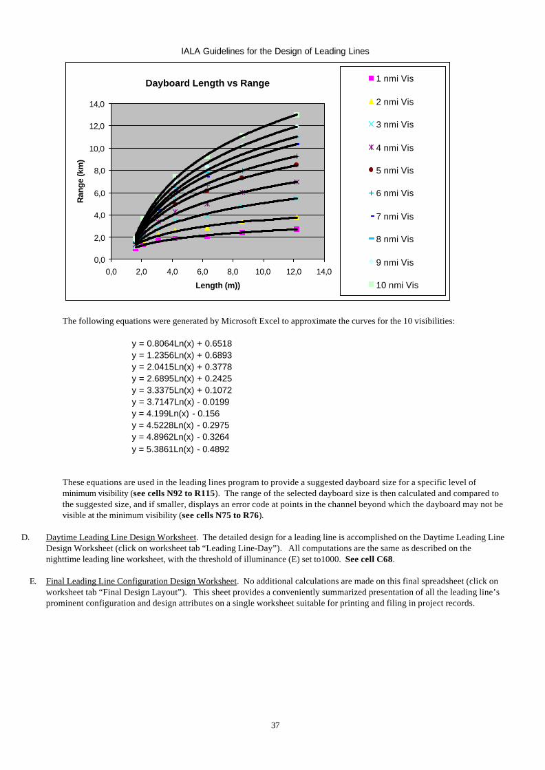
IALA Guidelines for the Design of Leading Lines
37
Dayboard Length vs Range
0,0
2,0
4,0
6,0
8,0
10,0
12,0
14,0
0,0 2,0 4,0 6,0 8,0 10,0 12,0 14,0
Length (m))
Ran
ge (k
m)
1 nmi Vis
2 nmi Vis
3 nmi Vis
4 nmi Vis
5 nmi Vis
6 nmi Vis
7 nmi Vis
8 nmi Vis
9 nmi Vis
10 nmi Vis
The following equations were generated by Microsoft Excel to approximate the curves for the 10 visibilities:
y = 0.8064Ln(x) + 0.6518 y = 1.2356Ln(x) + 0.6893 y = 2.0415Ln(x) + 0.3778 y = 2.6895Ln(x) + 0.2425 y = 3.3375Ln(x) + 0.1072 y = 3.7147Ln(x) - 0.0199 y = 4.199Ln(x) - 0.156 y = 4.5228Ln(x) - 0.2975 y = 4.8962Ln(x) - 0.3264 y = 5.3861Ln(x) - 0.4892
These equations are used in the leading lines program to provide a suggested dayboard size for a specific level of minimum visibility (see cells N92 to R115). The range of the selected dayboard size is then calculated and compared to the suggested size, and if smaller, displays an error code at points in the channel beyond which the dayboard may not be visible at the minimum visibility (see cells N75 to R76).
D. Daytime Leading Line Design Worksheet. The detailed design for a leading line is accomplished on the Daytime Leading Line
Design Worksheet (click on worksheet tab “Leading Line-Day”). All computations are the same as described on the nighttime leading line worksheet, with the threshold of illuminance (E) set to1000. See cell C68.
E. Final Leading Line Configuration Design Worksheet. No additional calculations are made on this final spreadsheet (click on worksheet tab “Final Design Layout”). This sheet provides a conveniently summarized presentation of all the leading line’s prominent configuration and design attributes on a single worksheet suitable for printing and filing in project records.