
GUIDELINES FOR SHIPBORNE POSITION, NAVIGATION AND …
45
I:\CIRC\MSC\01\MSC.1-Circ.1575.docx E 4 ALBERT EMBANKMENT LONDON SE1 7SR Telephone: +44 (0)20 7735 7611 Fax: +44 (0)20 7587 3210 MSC.1/Circ.1575 16 June 2017 GUIDELINES FOR SHIPBORNE POSITION, NAVIGATION AND TIMING (PNT) DATA PROCESSING 1 The Maritime Safety Committee, at its ninety-fifth session (3 to 12 June 2015), adopted resolution MSC.401(95) on Performance standards for multi-system shipborne radio navigation receivers and recognized the need to develop associated guidelines. 2 The Maritime Safety Committee, at its ninety-eighth session (7 to 16 June 2017), approved the Guidelines for shipborne position, navigation and timing (PNT) data processing to the Performance standards for multi-system shipborne radio navigation receivers, developed by the Sub-Committee on Navigation, Communications and Search and Rescue at its fourth session (6 to 10 March 2017), as set out in the annex. 3 Member States are invited to bring these Guidelines to the attention of the appropriate national authorities and all other parties concerned. ***
Transcript of GUIDELINES FOR SHIPBORNE POSITION, NAVIGATION AND …

I:\CIRC\MSC\01\MSC.1-Circ.1575.docx
E
4 ALBERT EMBANKMENT
LONDON SE1 7SR Telephone: +44 (0)20 7735 7611 Fax: +44 (0)20 7587 3210
MSC.1/Circ.1575 16 June 2017
GUIDELINES FOR SHIPBORNE POSITION, NAVIGATION AND TIMING (PNT) DATA PROCESSING
1 The Maritime Safety Committee, at its ninety-fifth session (3 to 12 June 2015), adopted resolution MSC.401(95) on Performance standards for multi-system shipborne radio navigation receivers and recognized the need to develop associated guidelines. 2 The Maritime Safety Committee, at its ninety-eighth session (7 to 16 June 2017), approved the Guidelines for shipborne position, navigation and timing (PNT) data processing to the Performance standards for multi-system shipborne radio navigation receivers, developed by the Sub-Committee on Navigation, Communications and Search and Rescue at its fourth session (6 to 10 March 2017), as set out in the annex. 3 Member States are invited to bring these Guidelines to the attention of the appropriate national authorities and all other parties concerned.
***


MSC.1/Circ.1575 Annex, page 1
I:\CIRC\MSC\01\MSC.1-Circ.1575.docx
ANNEX
GUIDELINES FOR SHIPBORNE POSITION, NAVIGATION AND TIMING (PNT) DATA PROCESSING
Purpose 1 The purpose of these Guidelines is to enhance the safety and efficiency of navigation by improved provision of position, navigation and timing (PNT) data to bridge teams (including pilots) and shipboard applications (e.g. AIS, ECDIS, etc.). 2 The shipborne provision of resilient PNT data and associated integrity (I) and status data (S) is realized through the combined use of onboard hardware (HW) and software (SW) components. The shipborne PNT Data Processing (PNT-DP) is the core repository for principles and functions used for the provision of reliable and resilient PNT data. 3 The PNT-DP specified within these Guidelines is defined as a set of functions facilitating:
.1 multiple sources of data provided by PNT-relevant sensors and services (e.g. GNSS receiver, DGNSS corrections) and further onboard sensors and systems (e.g. radar, gyro, speed and distance measuring equipment (SDME), echo-sounder providing real-time data) to exploit existing redundancy in the PNT-relevant input data; and
.2 multi-system and multi-sensor-based techniques for enhanced provision of
PNT data. 4 These Guidelines aim to establish a modular framework for further enhancement of shipborne PNT data provision by supporting:
.1 consolidation and standardization of requirements on shipborne PNT data
provision considering the diversity of ship types, nautical tasks, nautical applications, and the changing complexity of situations up to customized levels of support;
.2 the identification of dependencies between PNT-relevant data sources
(sensors and services), applicable PNT data processing techniques (methods and thresholds) and achievable performance levels of provided PNT data (accuracy, integrity, continuity and availability);
.3 harmonization and improvement of onboard PNT data processing based on
a modular approach to facilitate changing performance requirements in relation to nautical tasks, variety of ship types, nautical applications, and under consideration of user needs (SN.1/Circ.274);
.4 the consequent and coordinated introduction of data and system integrity as
a smart means to protect PNT data generation against disturbances, errors, and malfunctions (safety) as well as intrusions by malicious actors; and
.5 standardization of PNT output data including integrity and status data.
MSC.1/Circ.1575 Annex, page 2
I:\CIRC\MSC\01\MSC.1-Circ.1575.docx
Scope 5 These Guidelines define principles and functions for onboard PNT data processing, taking into account the scalability of PNT-DP. 6 These Guidelines provide recommendations on how to handle differences regarding installed equipment, current system in use, feasibility of tasks and related functions, performance of data sources as well as usability in specific regions and situations. 7 A structured approach for the stepwise introduction of integrity is developed to achieve resilient PNT data provision in relation to the application grades and supported performance levels. 8 These Guidelines aim to achieve standardized and integrity tested PNT output data to enhance user awareness regarding achieved performance level. Structure of Guidelines 9 These Guidelines have a modular structure, starting with a general section which introduces the purpose, scope and application of the Guidelines. The general section also explains the high-level architecture of PNT-DP and how the PNT-DP can be integrated into onboard navigation systems, e.g. INS1, ECDIS2 and RADAR3. 10 More detailed guidance on the PNT-DP is given as follows:
Module A – data input: sensors, services, and sources;
Module B – functional aspects;
Module C – operational aspects;
Module D – interfaces; and
Module E – documentation. 11 In addition, these Guidelines have three appendices listing definitions, abbreviations and expected operational and technical requirements on PNT/I data output. Application of Guidelines 12 These Guidelines provide prerequisites for harmonized provision of PNT and associated integrity data. 13 These Guidelines are recommended for equipment manufacturers, shipyards, ship owners and managers responsible for onboard equipment and systems used for PNT data provision. Definitions 14 Definitions used in the context of PNT, WWRNS and GNSS are detailed in appendix A.
1 Equipment according to MSC.252(83).
2 Equipment according to MSC.232(82).
3 Equipment according to MSC.92(79).
MSC.1/Circ.1575 Annex, page 3
I:\CIRC\MSC\01\MSC.1-Circ.1575.docx
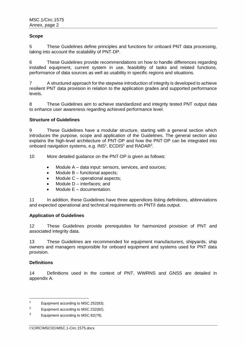
Architecture 15 Generally, a shipborne PNT-DP is made up of three functional blocks:
.1 Pre-processing; .2 Main processing; and .3 Post-processing.
16 The pre-processing function extracts, evaluates, selects and synchronizes input (sensor and service) data (including the associated integrity data) to preselect the applicable techniques to determine PNT and integrity output data. 17 The architecture of the PNT-DP is shown in figure 1.
Figure 1: Architecture of PNT-DP
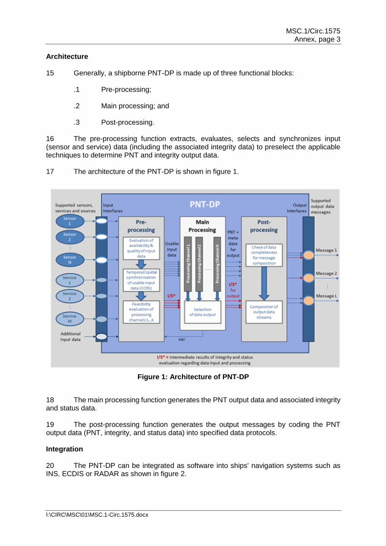
18 The main processing function generates the PNT output data and associated integrity and status data. 19 The post-processing function generates the output messages by coding the PNT output data (PNT, integrity, and status data) into specified data protocols. Integration 20 The PNT-DP can be integrated as software into ships' navigation systems such as INS, ECDIS or RADAR as shown in figure 2.
MSC.1/Circ.1575 Annex, page 4
I:\CIRC\MSC\01\MSC.1-Circ.1575.docx
Figure 2: PNT-DP integrated as software into INS, ECDIS, or RADAR
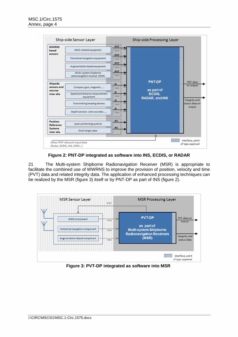
21 The Multi-system Shipborne Radionavigation Receiver (MSR) is appropriate to facilitate the combined use of WWRNS to improve the provision of position, velocity and time (PVT) data and related integrity data. The application of enhanced processing techniques can be realized by the MSR (figure 3) itself or by PNT-DP as part of INS (figure 2).
Figure 3: PVT-DP integrated as software into MSR

MSC.1/Circ.1575 Annex, page 5
I:\CIRC\MSC\01\MSC.1-Circ.1575.docx
Module A – Data input: Sensors, services and sources 22 Different PNT data processing functions need comprehensive input data to keep the PNT-DP running as specified in this document. These Guidelines define how the shipborne PNT-DP should provide output data by processing input data (from sensors and/or services and/or sources) while availability and performance of input data may vary temporally and spatially (see figure 4).
Figure 4: Sensors, services, and sources
23 The desired level of PNT data output depends on currently available inputs that may independently vary over a short or long period of time. These Guidelines aim to specify the demand on needed types of services, sensors, and sources for predefined performance levels of PNT/I data (module B). 24 These Guidelines specify PNT-DP's real-time adjustments of the used data processing functions (module B and C) to applicable methods taking into account the available input data. 25 The PNT-DP processes data from type-approved sensors and recognized services. 26 In a minimum configuration, PNT-DP uses the minimum number and type of sensors as defined in SOLAS (depending on the ship type). The manufacturer may add inputs and outputs to achieve better performance or more information (e.g. with integrity indication) at output of PNT-DP to support additional nautical functions and tasks that require better performance or more information (e.g. with integrity indication).

MSC.1/Circ.1575 Annex, page 6
I:\CIRC\MSC\01\MSC.1-Circ.1575.docx
27 The necessary sensor, service, and source layout is determined by the necessary performance of PNT data provision and integrity evaluation for the subsequent nautical functions and tasks. A.1 Types of services for positioning 28 Services are classified by grade/type as follows:
.1 Radionavigation services provide navigation signals and data which enable the determination of ships' position, velocity and time.
.2 Augmentation services are other services that provide additional correction and/or integrity data to enable improvement of radionavigation-based determination of ships position, velocity and time.
29 Services are classified regarding its geographical coverage:
.1 Global services are characterized by their worldwide coverage. They may have limitations regarding usability for different phases of navigation due to signal disturbances reducing the availability or performance of transmitted signals and/or provided data.
.2 Regional services (and maybe local services) are only available in
dedicated service areas. They may be used to improve the performance of ships' navigational data in terms of accuracy, integrity, continuity and availability even in demanding operations when, for example, higher accuracy and integrity level is required during coast and port navigation.
A.2 Types of sensors and sources 30 The type-approved sensors and data sources are distinguished into the following categories:
.1 Service-dependent sensors rely on any service from outside the ship
provided by human effort. They cannot be used on board without at least a satellite-based or terrestrial communication link to the service provider (shown in figure 4, mainly used to provide data of ships position, velocity and time).
.2 Shipborne sensors and sources:
.1 Primary sensors use a physical principle, e.g. earth rotation or
water characteristics and are independent of any human applied service provision (shown in figure 4, mainly used to provide data of ships attitude and movement);
.2 Secondary sensors and sources may be used to provide additional
data for the verification of PNT data (see figure 4), e.g. water depth at known position from an ENC, line of position, or directions and distances provided by onboard RADAR.
31 The above described sensors are considered to be usable worldwide and free of any rebilling user charge.

MSC.1/Circ.1575 Annex, page 7
I:\CIRC\MSC\01\MSC.1-Circ.1575.docx
A.3 Additional input data 32 In addition to sensors, services and sources listed in A.1 and A.2 further PNT-relevant data may be used for shipborne PNT data provision to increase redundancy or to evaluate plausibility and consistency of data input (ship sensed position, e.g. by position reference systems). Such data may be provided via AIS or VHF Data Exchange System (VDES), see figure 4. A.4 Requirements on input data All sensors, services and data sources used as input for the shipborne PNT-DP should comply with the relevant IMO performance standards. Module B – Functional aspects B.1 General B.1.1 Objective 33 The overarching objective of the shipborne PNT-DP is the resilient provision of PNT data including associated integrity and status data. 34 In this context resilience is:
.1 the ability to detect and compensate against relevant failures and malfunctions in data acquisition and processing to meet the specified performance requirements on PNT data for accuracy and integrity with respect to continuity and availability under nominal conditions; and
.2 the ability to detect, mitigate and compensate malfunctions and failures
based on supported redundancy in data acquisition and processing to avoid loss or degradation in functionality of PNT-DP.
B.1.2 Functional Architecture 35 The architecture of PNT-DP is shown in figure 1. Depicting the principal functions: pre-processing, main processing, and post-processing. 36 The pre-processing of input data: .1 conducts:
.1 analysing of their current availability in relation to their usability for ongoing PNT data processing and selection;
.2 timely and spatial synchronization of input data within the consistent
common reference system (CCRS); and
.3 determining the feasibility of functions in relation to supported methods taking into account the current performance of data input; and;
.2 provides evaluated, selected and synchronized data for the main processing.

MSC.1/Circ.1575 Annex, page 8
I:\CIRC\MSC\01\MSC.1-Circ.1575.docx
37 The main processing:
.1 conducts:
.1 determination of PNT data; .2 determination of associated integrity and status data in relation to
integrity of sensors and services, functional capability of onboard data processing, and estimated integrity of PNT output data; and
.3 selection of PNT output data including integrity and status data and;
.2 provides the selected PNT output data to post-processing. 38 The post-processing:
.1 conducts:
.1 checking the completeness of PNT output data in relation to supported composition of messages; and
.2 the generation of output data streams in the designated
message-coding; and
.2 provides the selected PNT data output.
39 The functional architecture of the shipborne PNT-DP supports the use of numerous processing channels operated in parallel: .1 to enable the application of different processing methods for PNT data
generation in relation to intended accuracy and integrity levels; .2 to improve continuity and availability in PNT data processing and provision
by redundant system layout and/or implemented fall-back option; and .3 to enable reliable detection, mitigation and compensation of failures and
malfunctions in data input and processing. 40 The functional architecture of the shipborne PNT-DP is based on a modular structure to support the adaption of shipborne data processing to: .1 different performance requirements on PNT output data in relation to
navigational situation and nautical tasks in their spatial and temporal context; .2 differences in data input of PNT-DP depending on carriage requirements,
equipment levels, or both; and .3 occurring changes of available/usable sensors, services, and other data
sources during operation.

MSC.1/Circ.1575 Annex, page 9
I:\CIRC\MSC\01\MSC.1-Circ.1575.docx
B.1.3 Requirements4 41 The requirements on data output of PNT-DP are specified by:
.1 the application grade of PNT-DP defining the amount and types of output data; and
.2 the supported performance level of provided PNT data regarding accuracy
and integrity.
Figure 5: Application Grades of PNT-DP (*provided with improved accuracy)
42 The following application grades of a PNT-DP (see figure 5) are used to define different requirements on the amount and types of PNT data output:
.1 Grade I supports the description of position and movement of a single onboard point (e.g. antenna location of a single GNSS receiver);
.2 Grade II ensures that horizontal attitude and movement of ship's hull are
unambiguously described;
.3 Grade III provides additional information for vertical position of a single onboard point and depth; and
.4 Grade IV is prepared for the extended need on PNT data e.g. to monitor or
control ship's position and movement in three-dimensional space. 43 Depending on the supported application grade of an onboard PNT-DP, the following PNT data is provided:
.1 Grade I: horizontal position (latitude, longitude), SOG, COG, and time;
4 Approaches for resilient provision of PNT data can only be discussed in relation to specific requirements,
e.g. accuracy. A sufficient scaling of requirements is considered as an appropriate way to facilitate the diversity of PNT-DP implementations.
MSC.1/Circ.1575 Annex, page 10
I:\CIRC\MSC\01\MSC.1-Circ.1575.docx
.2 Grade II: heading, rate of turn, STW and CTW in addition to Grade I5;
.3 Grade III: altitude, and depth in addition to Grade II; and
.4 Grade IV: heave, pitch, and roll (and may be surge, sway, and yaw with higher performance) in addition to Grade III.
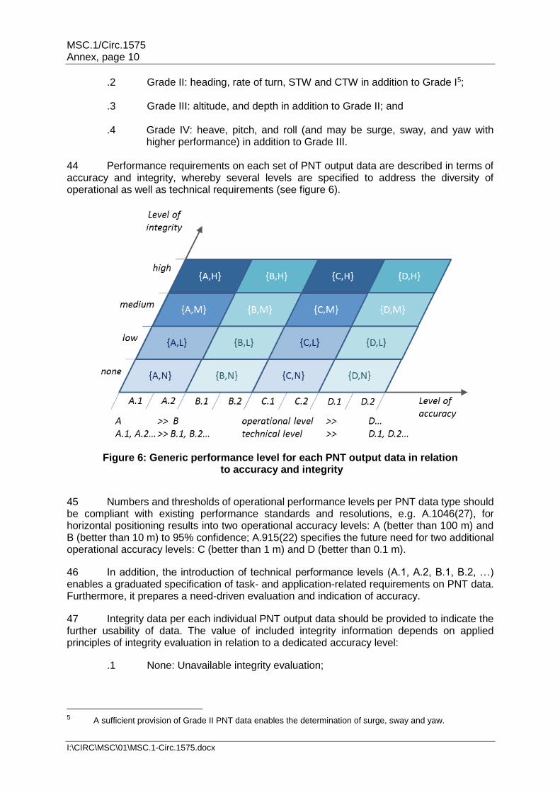
44 Performance requirements on each set of PNT output data are described in terms of accuracy and integrity, whereby several levels are specified to address the diversity of operational as well as technical requirements (see figure 6).
Figure 6: Generic performance level for each PNT output data in relation
to accuracy and integrity
45 Numbers and thresholds of operational performance levels per PNT data type should be compliant with existing performance standards and resolutions, e.g. A.1046(27), for horizontal positioning results into two operational accuracy levels: A (better than 100 m) and B (better than 10 m) to 95% confidence; A.915(22) specifies the future need for two additional operational accuracy levels: C (better than 1 m) and D (better than 0.1 m).
46 In addition, the introduction of technical performance levels (A.1, A.2, B.1, B.2, …) enables a graduated specification of task- and application-related requirements on PNT data. Furthermore, it prepares a need-driven evaluation and indication of accuracy.
47 Integrity data per each individual PNT output data should be provided to indicate the further usability of data. The value of included integrity information depends on applied principles of integrity evaluation in relation to a dedicated accuracy level:
.1 None: Unavailable integrity evaluation;
5 A sufficient provision of Grade II PNT data enables the determination of surge, sway and yaw.
Figure 1: Generic performance level for each PNT output data in relation to accuracy and integrity

MSC.1/Circ.1575 Annex, page 11
I:\CIRC\MSC\01\MSC.1-Circ.1575.docx
.2 Low: Integrity evaluation based on plausibility and consistency checks of data provided by single sensors, systems, services, or sources;
.3 Medium: Integrity evaluation based on consistency checks of data provided by different sensors, systems, services, and sources with uncorrelated error parts6 as far as possible; and
.4 High: Integrity evaluation based on estimated accuracy (protection level).
48 As a result of preceding paragraphs, the performance of an individual PNT output data (requirement as well as result of evaluation) should be defined by specified accuracy and integrity levels.
49 Accuracy and integrity levels should be defined for all PNT data of the supported application grade or a combination of them (see figure 7) to ensure that the requirements on data output of a PNT-DP are comprehensively specified.
50 Figure 8 illustrates the interdependencies between application grade and supported performance levels in relation to current and future nautical tasks and applications (exemplified).
6 See definition of correlation and uncorrelated error parts in appendix A.
Figure 7: Composition of requirements on PNT/I output data
(application grade II as example)

MSC.1/Circ.1575 Annex, page 12
I:\CIRC\MSC\01\MSC.1-Circ.1575.docx
B.2 Pre-processing B.2.1 Objective 51 The pre-processing prepares the input data for main processing and pre-evaluates the feasibility of data processing methods supported by main processing under current conditions. B.2.2 Functional and methodical aspects B.2.2.1 Evaluation of input data 52 Data streams received from input data-providing entities should be time-stamped with the time of reception using system time of the PNT-DP. The system time should be synchronized with a common time base by using the input data of an appropriate source, preferably UTC. 53 Incoming data provided by sensors, systems and services should be evaluated with respect to:
.1 completeness and correctness of transmission; and
.2 plausibility and consistency of data content.
Figure 8: Illustration of interdependencies between application grade, performance
level, and nautical tasks / applications
MSC.1/Circ.1575 Annex, page 13
I:\CIRC\MSC\01\MSC.1-Circ.1575.docx
54 The evaluation of a data stream received from an input data-providing entity should comprise the following methods:
.1 The correctness of transmitted input data should be checked with respect to the rules of the protocol in use (completeness, parity, etc.). Incorrect data should be excluded from further processing.
.2 It should be checked if the expected data update rate, as needed for main
processing, is met. If the determined update rate implies a latency violation, the data should be marked accordingly.
55 The evaluation of data content should comprise the following methods:
.1 Parameters describing the characteristics of the input data-providing entity should be analysed to identify which following processing steps are applicable. Such parameters include performance parameters, such as number and type of measurements (e.g. GPS/DGPS); and status parameter, such as healthy/unhealthy.
.2 Data describing the performance of input data should be analysed to identify
the following processing steps that are applicable. Such parameters include performance parameters like UERE, HPL; and time of data validity, as available, with respect to latency limitations.
.3 Plausibility and consistency of data should be tested with respect to
appropriate value ranges and thresholds. Data failing those tests should be marked accordingly. Data of former epochs may be used to detect dynamic value ranges and thresholds.
56 Input data provided by sensors, systems, and services should be marked as invalid if the data sources (e.g. sensors and services) have indicated that they are invalid. 57 Input data provided by sensors, systems and services should be excluded from further PNT data processing, if:
.1 data is indicated as invalid;
.2 the identified violation of latency, plausibility, or consistency
.1 is in an order which is intolerable for the accuracy level intended in minimum by the PNT-DP; or
.2 cannot be managed by the PNT-DP in a sufficient manner to avoid
unintended degradations of PNT output data. B.2.2.2 Temporal/spatial adjustment of input data 58 Input data which have passed the evaluation tests should be adjusted spatially and temporally within a Consistent Common Reference System (CCRS), where required, to meet the specified accuracy level. 59 The method for the time synchronization should provide a common timescale referenced to the system time of the PNT-DP, preferably given in UTC. The resolution of time synchronization shall not degrade that of input data.

MSC.1/Circ.1575 Annex, page 14
I:\CIRC\MSC\01\MSC.1-Circ.1575.docx
60 The timescale used for time synchronization should also be used to trigger the complete data processing: pre-processing, main processing, and post-processing. All spatially-related information should use a CCRP. If CCRP transformation fails, this should be indicated by corresponding status data. B.2.2.3 Feasibility evaluation of main processing 61 The feasibility of main processing should be assessed in relation to individual processing channels and their requirements on data input. 62 A method performing the feasibility evaluation in relation to an individual main processing channel should include test procedures and thresholds reflecting its requirements on data input. 63 The evaluation results should be provided by internal status data to control the operation of each supported processing channel. 64 The results of the feasibility evaluation enable an early indication of performance degradation in relation to supported performance levels. B.2.3 Results of pre-processing 65 Results of pre-processing should comprise:
.1 input data indicated as usable, time-stamped with a common time base, preferably UTC, and spatially adjusted;
.2 metadata to describe characteristics of usable input data; .3 internal status data describing the current status of pre-processing;
.4 internal status data for controlling of main processing; and
.5 internal integrity data as results of evaluation of input data utilized by main
processing. B.3 Main processing B.3.1 Objective 66 The main processing serves to improve PNT data provision by applying appropriate methods for completion, refinement and/or integrity evaluation. B.3.2 Functional and methodical aspects of PNT data generation 67 Within main processing, the pre-evaluated input data (from sensors, systems and services,) should be used to feed at least one data processing channel. 68 The feasibility evaluation results of pre-processing (B.2.2.3), provided as internal status data, should be used as a control parameter during main processing to activate/deactivate individual processing channels. 69 Each processing channel should be specified by the set of supported methods generating PNT data, integrity data, and status data.
MSC.1/Circ.1575 Annex, page 15
I:\CIRC\MSC\01\MSC.1-Circ.1575.docx
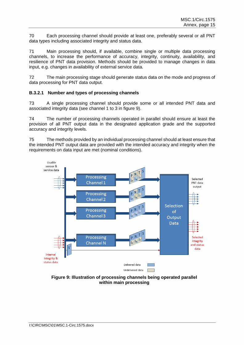
70 Each processing channel should provide at least one, preferably several or all PNT data types including associated integrity and status data. 71 Main processing should, if available, combine single or multiple data processing channels, to increase the performance of accuracy, integrity, continuity, availability, and resilience of PNT data provision. Methods should be provided to manage changes in data input, e.g. changes in availability of external service data. 72 The main processing stage should generate status data on the mode and progress of data processing for PNT data output. B.3.2.1 Number and types of processing channels 73 A single processing channel should provide some or all intended PNT data and associated integrity data (see channel 1 to 3 in figure 9). 74 The number of processing channels operated in parallel should ensure at least the provision of all PNT output data in the designated application grade and the supported accuracy and integrity levels. 75 The methods provided by an individual processing channel should at least ensure that the intended PNT output data are provided with the intended accuracy and integrity when the requirements on data input are met (nominal conditions).
Figure 9: Illustration of processing channels being operated parallel
within main processing
MSC.1/Circ.1575 Annex, page 16
I:\CIRC\MSC\01\MSC.1-Circ.1575.docx
76 More than one processing channel should be supported for the provision of one type of PNT data and associated integrity data (see figure 9), .1 if different accuracy and integrity levels are supported by application of
different methods for data processing, or .2 if an increase of reliability and resilience is aimed by parallel processing of
largely independent input data with the same methods. 77 Parallel processing channels should differ in used input data, or applied methods, or both. These differences may result in measurable differences in PNT data output:
.1 The additional use of augmentation data should improve the accuracy of PNT output data by application of corrections, or should enhance the integrity evaluation with independent evaluation results, or should serve both.
.2 If parallel processing channels are equipped with the same methods and are
fed with largely independent input data, the results of those channels should cover the same types/set of PNT data. The PNT data can be used alternatively for data output due to its independence and should be used internally for integrity evaluation.
.3 Enhanced processing channels should combine multiple types of input data
to enable the application of effective methods during data processing such as:
.1 self-correction (e.g. dual-frequency GNSS signal processing to
correct ionospheric path delays; noise reduction by filtering);
.2 self-controlling (e.g. detection and exclusion of outliers), self-evaluation (e.g. consistency tests or estimation of protection level as overestimate of expected inaccuracies); and/or
.3 self-management (e.g. failure compensation by interpolation or
extrapolation in a common model of movement).
.4 The capability of enhanced processing channels can be increased if redundancy in data input enables the simultaneous and coordinated use of effective methods such as self-correction, self-controlling, self-evaluation, and self-management.
78 The need for the provision of reliable and resilient PNT data requires that at least a parallel processing channel should be implemented as a fall-back solution for an enhanced processing channel, which is more sensitive to availability of data input (Fall-back may not be available after loss of sensitive input data). 79 Ultimately, the number and types of parallel processing channels is determined by:
.1 the supported application grade as well as supported accuracy and integrity levels of aimed PNT data output;
.2 arranging of data processing methods to single channels; and
MSC.1/Circ.1575 Annex, page 17
I:\CIRC\MSC\01\MSC.1-Circ.1575.docx
.3 the aimed level of reliability and resilience of PNT data specifying the residual need for fall-back solutions per application grade and assigned accuracy and integrity levels.
B.3.2.2 Methods to refine PNT data 80 An improvement to accuracy for several or all PNT data types by a processing channel is achieved if one, or a combination of the following methods, is applied:
.1 methods applying augmentation data provided by recognized services and external sources (if available and indicated as usable)
.1 to improve the accuracy of data by error correction (e.g. GNSS
range and range rate corrections);
.2 to exclude faulty or disturbed data taking into account integrity evaluation results (e.g. health indicator of GNSS signals provided by Beacon or SBAS); and
.3 to apply performance indicators provided for individual data to
control its influence on potential PNT data output (e.g. weighting within data processing);
.2 methods utilizing redundancy in the database
.1 for self-determination of corrections and application
(e.g. dual-frequency signal processing to correct ionospheric path delays);
.2 for self-reliant detection and exclusion of faulty data (e.g. FDE by
RAIM); and
.3 for self-determination of performance indicators for used/derived data to weight its influence on potential PNT data output; and
.3 methods utilizing redundancy in database for application of enhanced
algorithm such as
.1 equalization calculus based on an overdetermined set of input data (e.g. 3-dimensional attitude determination with GNSS); and
.2 filtering with adaptive and/or assisted measurement and transition
models (e.g. deeply coupled GNSS/INS positioning). 81 Fall-back solutions should be provided by simultaneously operated processing channel(s) providing the same PNT data with a lower accuracy level by application of:
.1 methods using less input data (to reduce the sensitivity to completeness of data input); and
.2 methods using other input data (to reduce the sensitivity to availability of specific input data).
MSC.1/Circ.1575 Annex, page 18
I:\CIRC\MSC\01\MSC.1-Circ.1575.docx
82 A redundant solution for a single processing channel should be supported by at least one simultaneously operated processing channel providing independent PNT data types with the same accuracy levels by applying:
.1 methods operating with different input data to ensure independency in relation to data input-providing systems, services or sensors; and/or
.2 methods differing in error influences in relation to data input and processing.
83 Both, fall-back and redundant solutions should provide an improved resilience of PNT data provision by:
.1 using fall-back solutions with an acceptable limit of loss of data accuracy; and
.2 using redundant solutions with respect to continuity and reliability of PNT data provision in relation to each supported accuracy level.
B.3.2.3 Methods to evaluate PNT data
84 Integrity evaluation should be based on methods that test the plausibility or consistency of potential PNT output data or methods to estimate the current size and behaviour of its individual errors (e.g. noise), error budgets (e.g. ranging error), or resulting errors (e.g. inaccuracy of SOG). An integrity evaluation should be assigned to each processing channel in relation to the nominally designated PNT data output (taking into account currently used data input).
85 Generally, the applied method of integrity evaluation determines the achieved integrity level:
.1 Level None: Failed, unavailable or incomplete integrity evaluation by the processing channel methods and should be regarded as having no integrity.
.2 Level Low: The integrity evaluation of the processing channels, dealing with the refinement or completion of data provided by single sensors or measuring systems, should only be based on plausibility and consistency tests in relation to models of the individual sensor and system:
.1 Plausibility tests should prove if data types are within an expected value range (e.g. ship's speed). The expected value range should ultimately determine the detectability of errors (e.g. indicated speed over ground is much higher than ship's maximum speed).
.2 Simple consistency tests should prove, either that successive data follows an expected time behaviour (e.g. range and range rate), or that multiple outputs of data are compliant within a common measurement model (e.g. position and speed determined by different methods). Consistency should be assumed if the difference between compared values is smaller than a specified threshold describing the tolerable relative error between both.
.3 Enhanced consistency tests should evaluate the expected consistency between used input data and achieved processing result, whereby thresholds used (e.g. in statistical hypothesis tests) should be conditioned in relation to accuracy requirements on output data.

MSC.1/Circ.1575 Annex, page 19
I:\CIRC\MSC\01\MSC.1-Circ.1575.docx
.4 Enhanced consistency tests should be applied iteratively with methods detecting and excluding most likely faulty input data or intermediate processing results, if supported redundancy of input data enables the application of such tests. This is an appropriate method to improve accuracy and integrity of output data (e.g. RAIM).
.3 Level Medium: If the capability of simple, as well as enhanced consistency
tests should be increased, the tests should be performed with data provided from different sensors and measuring systems with largely uncorrelated error influences:
.1 If the degree of correlation in the error margin as well as in the data
itself is not taken into consideration, the difference of compared values should not be considered as an estimate of absolute accuracy.
.2 If the error margin of compared values is completely uncorrelated,
the difference between both values has to be smaller than the sum of tolerable inaccuracies per considered value. In this case the consistency test serves the evaluation, if pre-specified accuracy levels are met.
Largely uncorrelated data may inherit partially correlated errors. These errors remain undetected by consistency checks. If the thresholds used during evaluation take the existing uncertainties into account the consistency tests should continue as method to evaluate the fulfilment of certain accuracy levels.
.4 Level High: The highest performance of integrity evaluation should provide a
reliable estimate of the inaccuracy of a single PNT data type. This implicates the necessity to determine the absolute magnitude of significant errors and resulting consequences for the accuracy limits of single PNT output data.
86 As described in the previous paragraphs, each integrity evaluation method needs pre-specified and/or instantaneously determined thresholds to enable the evaluation processes. 87 Generally, integrity evaluation methods applied by a processing channel should be able to adapt the used thresholds on the accuracy level of PNT data provision currently supported. 88 As a minimum, a processing channel should provide integrity data in relation to single PNT output data. It should also cover the results of integrity evaluation as well as information on the supported level of integrity evaluation (applied method and current feasibility). B.3.2.4 Methods to complete PNT data 89 Hardware redundancy in sensors, systems, and services enables the application of further methods dealing with alternative generation of standard PNT output data (e.g. heading determination with data from 2 or 3 GNSS receivers) and/or the provision of further data types for PNT output (e.g. torsion monitoring of ship's hull).
MSC.1/Circ.1575 Annex, page 20
I:\CIRC\MSC\01\MSC.1-Circ.1575.docx
90 Methods for alternative generation of standard PNT output data should only be applied, if the resilience of PNT data provision is significantly increased. Aspects of error correlation and propagation should be considered carefully, if methods are being operated on the same database. 91 Any further methods may be applied to generate additional PNT output data, as long as performance degradation of required PNT data provision is avoided. It is recommended to facilitate those methods by implementing additional processing channels.
B.3.2.5 Methods to provide status data
92 Status data should be considered as part of the potential PNT data output; to report current usability of available sensors, systems, and services as well as the feasibility and performance of supported data processing channels and methods. 93 Each processing channel should support the generation of status data at PNT data output by application of own methods to describe or update the status based on:
.1 checking if status data provided by pre-processing is available. In case of:
.1 the unfeasibility of intended data processing the incoming status data should be forwarded; and
.2 degradation of intended data processing the status data should be amended by additional information from performed processing;
.2 checking of tolerated changes in nominal input data in relation to changes in data output; and the reporting of
.1 faults in the augmentation input data resulting in the seamless switching to lower accuracy and/or integrity level (e.g. methods of absolute error estimation are no longer applicable);
.2 loss in redundancy on input data resulting in the seamless switching
to lower accuracy and/or integrity level (e.g. methods for consistency checks and/or plausibility checks are no longer applicable); and
.3 loss in over-determination of input data (e.g. full GNSS processing
is reduced to GNSS processing of four satellites, RAIM FDE is replaced by no RAIM) – Status indications should be raised accordingly;
.3 checking if processing is started or operated by the processing channels as
expected (e.g. watchdog on certain steps during processing to ensure detection of system faults); and
.4 checking if designated output data is supplied in the corresponding time
intervals (nominal update rate is fully available). Testing and reporting should include:
.1 detection of timely incoherent data rates on the input into main
processing; as well as
.2 real-time losses during main processing caused by system failures.

MSC.1/Circ.1575 Annex, page 21
I:\CIRC\MSC\01\MSC.1-Circ.1575.docx
B.3.3 Functional and methodical aspects of PNT data output selection 94 The selection of a PNT data output should be based on data provided by active processing channels that are operated in parallel. 95 The supported combination of processing channels defines the specific method to be applied for selecting the PNT output data including associated integrity and status data.
96 The selection process should comprise:
.1 an evaluation of the results of each individual processing channel regarding its intended performance level of PNT/I data provision;
.2 consistency checks between results of individual processing channels on the basis of a common PNT data model; and
.3 the selection of a single set of PNT/I output data based on predefined assessment rules (redundancy and degradation).
97 The method for performing the selection process requires an unambiguous classification and ranking system of:
.1 intended results of each processing channel under normal operating conditions; and
.2 degraded results of each processing channel in the case of disturbed
operating conditions (as results of degradations and/or breakdowns of data input and processing),
in relation to its potential utilization for PNT data output. The method should analyse associated integrity and status data as real-time indicator for the current functionality and performance of each processing channel. 98 The classification of data performance should be based on accuracy and integrity levels used for the specification of operational and technical requirements per single type of PNT data (see section B.1.3). 99 For each type of PNT data the ranking system defines the relationship between certain accuracy and integrity levels and "best"/"worst" PNT data output:
.1 If a certain accuracy and integrity level is only supported by a single processing channel, the achieved integrity level should dominate the selection, as illustrated in figure 10.
.2 If a certain accuracy and integrity level is supported by more than one
channel,
.1 under nominal operation conditions the selection of data should follow the configured prioritization; and
.2 in case of performance degradations the selection should be in
compliance with the prioritization, as illustrated in figure 7.
.3 If the same accuracy/integrity level is met by two or more processing channels, the priority should be given to the results of the processing channels operated under nominal conditions.

MSC.1/Circ.1575 Annex, page 22
I:\CIRC\MSC\01\MSC.1-Circ.1575.docx
Figure 10: Ranking list for safety-relevant PNT data
100 The selection process should ensure that PNT data and related integrity data are associated by selecting data provided by the same or assigned processing channel. 101 The selection process should be considered as failed,
.1 if the pre-processing detects the unfeasibility of data processing for all supported processing channels; or
.2 if none of the processing channels provide any type of PNT data with an
increase of accuracy and/or integrity. 102 A failed selection process should be indicated by status data marking the current output data as unusable. For this purpose status data provided by pre-processing should be taken into account and updated. 103 The selection process should include methods ensuring that the status reporting of the PNT-DP to connected navigational systems is presented to the bridge-team. 104 External status communication should be restricted to the PNT-DP output data only and should comprise at least of status indications in case of changes of the operational status of the PNT-DP with impacts on:
.1 the available processed "best" data types; .2 the current accuracy and integrity (operational and technical level); and .3 the PNT-DP system status, which may include information on unusable or
degraded input data to support failure detection by the operator.
MSC.1/Circ.1575 Annex, page 23
I:\CIRC\MSC\01\MSC.1-Circ.1575.docx
B.3.4 Results of main processing 105 The results of main processing are:
.1 the selected PNT data for output; .2 associated integrity data; .3 metadata to describe the characteristics of selected output data (e.g. source
and processing identifier);
.4 status data describing the current status of main processing;
.5 internal status data for controlling of post-processing; and
.6 internal integrity data contributing to integrity data at output of PNT-DP. 106 PNT data currently determined by the main processing may be fed back into pre-processing to support the evaluation of the subsequent sensor, system and service data. B.4 Post-processing B.4.1 Objective 107 The post-processing checks completeness of selected PNT output data (PNT data, integrity data, and status data) from main processing and generates output data streams. B.4.2 Functional and methodical aspects B.4.2.1 Completeness check of PNT output data 108 The PNT integrity and status data, which has been selected by main processing for output, should be checked using the following methods:
.1 check of completeness and timeliness of selected output data in accordance with the nominal configuration of the PNT-DP (application grade, accuracy and integrity level, update intervals, intended status reporting);
.2 check if the required update interval is achieved per output data of PNT-DP;
and
.3 check of availability of output data in relation to supported message formats. 109 The results of applied checks should be used to update/complete the status data for output. B.4.2.2 Generation of output data streams 110 Standard messages should be used to provide the selected PNT data output. Proprietary message formats may be used to provide additional data; if used, their format specification should be disclosed.

MSC.1/Circ.1575 Annex, page 24
I:\CIRC\MSC\01\MSC.1-Circ.1575.docx
111 The provision of individual messages is repeated to provide the last valid data set of included PNT data in the following situations:
.1 data is marked as invalid; or .2 data is not available in the expected time interval. 112 Each of the composed messages should contain PNT system time, preferably UTC. 113 A source indication for provided PNT data should be included. 114 If PNT output data streams are provided to external applications, they should, as far as possible, conform to existing maritime interface standards based on the IEC 61162 series. 115 An important benefit of PNT-DP is the provision of integrity data associated with the PNT data at output. Therefore, the messages at output should support the provision of additional integrity data, whereby:
.1 the integrity data per provided PNT data type should include a reference to
the supported accuracy and integrity level;
.2 additional metadata may flag the used integrity method; and
.3 the provided integrity data should include the result of the integrity evaluation process performed. Such data should contain at least parameters of error distribution.
B.4.3 Results of post-processing 116 Results of post-processing should comprise:
.1 messages carrying the selected PNT data together with associated integrity data in a specified message format. Both enable the subsequent connected equipment to identify whether the provided data is usable for its dedicated nautical application (e.g. automated track-control); and
.2 status messages reflecting the health status of the entire PNT-DP.
Module C – Operational aspects C.1 Configuration 117 The configuration of a shipborne PNT-DP is realized by the system integrator before commissioning to ensure compliance between the shipborne PNT-DP and the operational environment. 118 The intended application grade including the required accuracy and integrity level determines the minimum requirements on the data input and configuration of PNT-DP. 119 The configuration should include the specification of thresholds and value ranges used for integrity evaluation and system controlling (e.g. in relation to operational and technical accuracy levels as well as applied integrity evaluation techniques). 120 The PNT-DP is an embedded software integrated into a mothering system. The configuration of the PNT-DP is performed by manufacturer-specific tools.

MSC.1/Circ.1575 Annex, page 25
I:\CIRC\MSC\01\MSC.1-Circ.1575.docx
C.2 Operation management C.2.1 Automatic operation 121 The concept of the PNT-DP is based on automated processing (pre-processing, main processing, and post-processing) to adapt the functionality on current data availability and usability. 122 The PNT-DP is embedded software contributing to the Bridge Alert Management (BAM) of the mothering system by provision of status and integrity data. It does not generate alerts by itself. 123 Since the shipborne PNT-DP has a residual risk regarding total loss of all functionalities, the operational environment, e.g. the mothering system, should ensure, by a bypass, that available sensor and service data are available for applications. C.2.2 User interaction 124 The knowledge of users regarding the usability and integrity of input devices (sensors and services) may result in the user decision to exclude data of these sensors and services from PNT data processing. However, the manual exclusion of input data is only possible on the mothering system by controlling, opening, and closing of data interfaces. 125 Due to automatic operation, there is no difference between a user exclusion of data input or a failed data input for the PNT-DP. 126 The PNT –DP should enable the graphical representation of the horizontal accuracy of position information, including status and integrity data in an integrated navigation display or workstation. Module D – Data communication Interfacing 127 Where possible, standardized and approved communication protocols for interfacing should be used7. D.1 Input data 128 The communication protocol for input data should allow the implementation of the supported functions for the intended application grade and performance level as described in these Guidelines. In particular, this includes:
.1 reception of all PNT relevant data (raw or processed); and
.2 the data received should be marked either by the source itself or with a unique source identifier within the PNT-DP.
D.2 Output data 129 The communication protocol for output interfacing should allow the transmission of selected PNT data including integrity and status data.
7 Refer to publication IEC61162.

MSC.1/Circ.1575 Annex, page 26
I:\CIRC\MSC\01\MSC.1-Circ.1575.docx
130 PNT output data, including status and integrity data used for navigation, as well as PNT data processing configuration data, should be provided as an output to support recording by VDR systems. D.3 Configuration interfacing 131 The manufacturer should provide data interfacing with the mothering system for configuration. Module E – Documentation 132 The documentation of a PNT-DP should cover at least
.1 operating manual;
.2 installation manual;
.3 configuration manual;
.4 failure analysis, and
.5 onboard familiarization material. 133 The documentation should be provided, preferably in an electronic format. E.1 Operating manual 134 The operating manual should include:
.1 the specification of application grades including associated accuracy and integrity levels of data output supported by the specific version of PNT-DP;
.2 a statement on the input data that are necessary for the nominal operation of
PNT-DP;
.3 the functional architecture of PNT-DP;
.4 a statement on which operating modes are supported by the PNT-DP (including fall-back options) with details of applied functions and methods, their arrangement in data processing chains, and resulting implication on PNT data output provision;
.5 relevant information on applied means to achieve spatial and temporal
synchronization of input data coming from different sensors, services and systems;
.6 the description of dependencies between performance of data input
(e.g. availability, accuracy, …), applicable data processing methods including their capability and supported output data provision (application degree, accuracy and integrity level);
.7 a comprehensive description of the internally applied status and integrity
monitoring in relation to
MSC.1/Circ.1575 Annex, page 27
I:\CIRC\MSC\01\MSC.1-Circ.1575.docx
.1 used performance identifiers, test methods, and thresholds for decision finding;
.2 consideration of integrity and status data provided by external
sensors, services as well as systems; and .3 their contribution to integrity and status data at data output of
PNT-DP;
.8 a complete list of internal and external failures and disturbances in accordance with failure analysis (see E.4) including the description of
.1 effects on data processing under consideration of applied methods; .2 supported means for detection and compensation; and .3 effects on the provided PNT data output. 135 Additionally, for further harmonization the manufacturer is encouraged to use the operating manual to inform about
.1 nominal operation conditions for the operating modes of the specific PNT-DP;
.2 reliability of PNT data provision per operating mode under nominal condition
(simulation based and/or experimentally evaluated);
.3 effectiveness of supported integrity monitoring methods regarding detectability of failures and disturbances (internal as well as external error sources); and
.4 the residual integrity risk of the provided integrity data for the intended
accuracy level. E.2 Installation manual 136 The installation manual should include:
.1 a list of input data needed for nominal operation of the PNT-DP; .2 comprehensive specification of data interfacing under consideration of all
supported operating modes of PNT-DP;
.3 a statement on which operating system environments the installation and operation of PNT-DP's software is possible; and
.4 recommendations for software installation and maintenance.
137 Due to its safety-relevance the PNT-DP should be subjected to integration and system tests in the operational environment. For this purpose the installation manual should include:
.1 a description of proposed tests and their importance for quality assurance; and

MSC.1/Circ.1575 Annex, page 28
I:\CIRC\MSC\01\MSC.1-Circ.1575.docx
.2 recommendations for test planning, realization, and analysis. E.3 Configuration manual 138 The configuration of PNT-DP is only realized during installation or maintenance by authorized personnel. The manufacturer of PNT-DP should additionally provide a tool supporting the generation and editing of the configuration as well as samples of configurations containing default values. The configuration manual should include:
.1 recommendations for the use of configuration tool;
.2 a list of configuration parameters; and
.3 a description of all contained configuration parameters including meaning, default values and allowed value ranges.
139 Configuration parameters may be used by the manufacturer to adjust:
.1 deviations from default conditions;
.2 redundancy arrangements;
.3 backup arrangements; and
.4 threshold-influencing data processing and selection. E.4 Failure analysis 140 A failure analysis, at functional level, should be performed and documented for the PNT-DP. The results of the failure analysis serves as evidence that the PNT-DP is designed on "fail-safe" principle. Within the failure analysis the impact of all internal and external failures should be considered in relation to feasibility and performance of operation modes supported by the PNT-DP. E.5 Onboard familiarization material 141 Familiarization material should be provided to explain the used configuration and applied functions in relation to benefit and limitations of the data processing performed by the PNT-DP. 142 The familiarization material should inform about status and integrity data to enable a correct interpretation of their meaning and safety significance.
MSC.1/Circ.1575 Annex, page 29
I:\CIRC\MSC\01\MSC.1-Circ.1575.docx
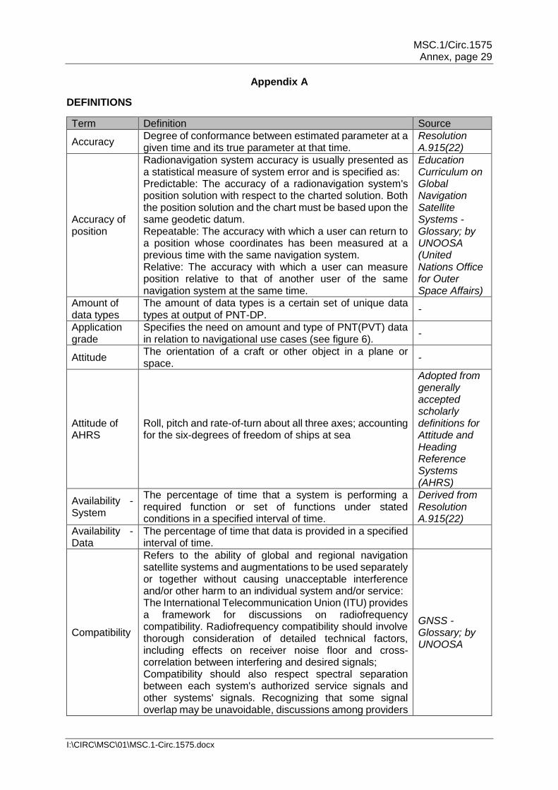
Appendix A
DEFINITIONS
Term Definition Source
Accuracy Degree of conformance between estimated parameter at a given time and its true parameter at that time.
Resolution A.915(22)
Accuracy of position
Radionavigation system accuracy is usually presented as a statistical measure of system error and is specified as: Predictable: The accuracy of a radionavigation system's position solution with respect to the charted solution. Both the position solution and the chart must be based upon the same geodetic datum. Repeatable: The accuracy with which a user can return to a position whose coordinates has been measured at a previous time with the same navigation system. Relative: The accuracy with which a user can measure position relative to that of another user of the same navigation system at the same time.
Education Curriculum on Global Navigation Satellite Systems -Glossary; by UNOOSA (United Nations Office for Outer Space Affairs)
Amount of data types
The amount of data types is a certain set of unique data types at output of PNT-DP.
-
Application grade
Specifies the need on amount and type of PNT(PVT) data in relation to navigational use cases (see figure 6).
-
Attitude The orientation of a craft or other object in a plane or space.
-
Attitude of AHRS
Roll, pitch and rate-of-turn about all three axes; accounting for the six-degrees of freedom of ships at sea
Adopted from generally accepted scholarly definitions for Attitude and Heading Reference Systems (AHRS)
Availability - System
The percentage of time that a system is performing a required function or set of functions under stated conditions in a specified interval of time.
Derived from Resolution A.915(22)
Availability - Data
The percentage of time that data is provided in a specified interval of time.
Compatibility
Refers to the ability of global and regional navigation satellite systems and augmentations to be used separately or together without causing unacceptable interference and/or other harm to an individual system and/or service: The International Telecommunication Union (ITU) provides a framework for discussions on radiofrequency compatibility. Radiofrequency compatibility should involve thorough consideration of detailed technical factors, including effects on receiver noise floor and cross-correlation between interfering and desired signals; Compatibility should also respect spectral separation between each system's authorized service signals and other systems' signals. Recognizing that some signal overlap may be unavoidable, discussions among providers
GNSS - Glossary; by UNOOSA

MSC.1/Circ.1575 Annex, page 30
I:\CIRC\MSC\01\MSC.1-Circ.1575.docx
Term Definition Source
concerned will establish the framework for determining a mutually acceptable solution;
Configuration parameter
Initial settings of a system used to manage and/or control the system operation regarding used input data, realized tasks, used techniques, applied functions and/or aimed output data.
-
Consistency of data
Characteristic of a data set to be compliant with a common model (spatial, temporal, and physical) specifying the relationship among each other.
-
Consistent Common Reference Point (CCRP)
Location on own ship, to which all horizontal measurements such as target range, bearing, relative course, relative speed, closest point of approach (CPA) or time to closest point of approach (TCPA) are referenced, typically the conning position of the bridge.
MSC.252(83)
Consistent Common Reference System (CCRS)
A sub-system or functions for acquisition, processing, storage, surveillance and distribution of data and information providing identical and obligatory reference to sub-systems and subsequent functions to other connected equipment or units as available.
Derived from MSC.252(83)
Control variable
Dynamic value extracted from intra-system status and used for intra-system process controlling (data, tasks, techniques, functions).
-
Continuity
Continuity is the ability of a system to perform uninterruptedly its functions for a specified period of time. More specifically, continuity is the probability that the specified system performance will be maintained for the duration of a phase of operation, presuming that the system was available at the beginning of that phase of operation.
Modified Navipedia
Data Carrier of information.
Degraded condition
Reduction in system functionality and/or performance as a result of deviations from standard conditions induced by e.g. disturbances, malfunctions and failures.
Derived from MSC.252(83)
Ephemeris Parameters, such as Keplerian coefficients, that can be used to compute a satellite's position at a specified time.
GNSS - Glossary; by UNOOSA
Error correlation
Error correlation describes how far the accuracy and integrity of two variables (provided by different sensors or techniques) are influenced by the same errors.
-
Integrity The ability to provide users with information within a specified time when the system should not be used for navigation including measures and/or indicating of trust
Derived from Resolution A.915(22)
Integrity data Result of integrity evaluation characterizing the current performance of the system (e.g. flags) or individual data products (e.g. performance data).
-
Method Used for the realization of a function employing dedicated algorithms.
-
Movement Change of position and/or attitude over time. -
Nautical application(s)
Technical function(s) to assist or support the realization of a nautical task.
-

MSC.1/Circ.1575 Annex, page 31
I:\CIRC\MSC\01\MSC.1-Circ.1575.docx
Term Definition Source
Navigational phase
Spatial characterization of typical navigation scenarios such as navigation at open sea, in coastal areas, restricted waters, port entries, …docking, etc.
-
Navigational situation
Situation of the individual ship taking into account the navigational phase as well as environment (geometric, bathymetric, traffic conditions, etc.
-
Nautical task
Tasks covering nautical aspects, e.g. "Route planning" or "Route monitoring" or "Collision avoidance" or "Navigation control data" or "Status and data display" or "Alert management"
Generalization of INS related definition in MSC.252(83)
Performance class
The set of supported maximum possible performance levels by an individual PNT-DP.
-
Performance level
The degree of merit achieved by each single performance parameter.
-
Performance parameter
Parameters used in relation to data output of PNT-DP are accuracy, integrity, continuity, and availability per individual PNT output data.
-
Plausibility of data
Characteristic of data to be within the defined range for the respective type of data.
Derived from MSC.252(83)
Protection level
The protection level provides an estimate for current data accuracy taking into account error models, error measurements as well as requirements on tolerable residual risk of integrity monitoring (failed evaluation)
-
Resilience
Resilience is the ability of a system to detect and compensate external and internal disturbances, malfunction and breakdowns in parts of the system. This should be achieved without loss of functionalities and preferably without degradation of their performance.
NCSR 1/9 (Annex 1); NAV58/6/1
Scalability Scalability is the ability of a system to adapt its operation to different demands and application conditions.
-
Ship Sensed Position
A position as determined through the use of onboard equipment or information such as visual bearings, radar ranges, depth of water, radio direction finding, etc. This may also include astronomical observation.
AMSA
Source A device (sensor, receiver, transmitter) or a location of generated, stored or recorded data used for required input data.
Generalization of INS related definition in MSC.252(83)
Uncorrelated error
If the influence of same error sources on different sensors or data can be excluded, it can be assumed, that their error parts and behaviour are uncorrelated.

MSC.1/Circ.1575 Annex, page 32
I:\CIRC\MSC\01\MSC.1-Circ.1575.docx
Appendix B ABBREVIATIONS
ADC - Analog-Digital-Converter
AIS - Automatic Identification System
BAM - Bridge Alert Management
BDS - BEIDOU Satellite Navigation System – Chinese GNSS
CCRP - Consistent Common Reference Point
CCRS - Consistent Common Reference System
CMDS - Common Maritime Data Structure
COG - Course over Ground
CTW - CTW – Course Through Water
DGNSS - Differential GNSS
DOP - A statistical measure of the receiver-satellite(s) geometry
ECDIS - Electronic Chart Display and Information System
EDAS - EGNOS Data Access Service
EGNOS - European Geostationary Navigation Overlay Service
eLoran - Enhanced Loran
ENC - Electronic Navigational Chart
EPFS - Electronic Position Fixing System
FDE - Fault Data Exclusion
GAGAN - GPS-aided Geo-augmented Navigation system – Indian SBAS
GAL - Galileo – European GNSS
GBAS - Ground-Based Augmentation System
GLONASS - GLObal NAvigation Satellite System – GNSS provided by Russia
GNSS - Global Navigation Satellite System
GPS - Global Positioning System – GNSS provided by USA
HDG - Heading
HDOP - Horizontal Dilution of Precision
HPE - Horizontal Position Error
HPL - Horizontal Protection Level (as estimate of HPE)
HSC - High-Speed Craft
HW - Hardware
I - Integrity data
IRNSS - Indian Regional Navigation Satellite System
INS - Integrated Navigation System
LF - Low Frequency
Loran - Long Range Navigation
MF - Medium Frequency
MSAS - MTSAT (Multi-functional Transport SATellite) Satellite Augmentation System – Japanese SBAS
MSC - IMO's Maritime Safety Committee
NAV - IMO's Safety of Navigation Sub-Committee
NCSR - IMO's Navigation, Communication and Search and Rescue Sub-Committee
NMEA - National Marine Electronics Association
PDOP - Position Dilution of Precision
PNT - Position, Navigation, and Timing
PNT-DP - Position, Navigation, and Timing Data Processing
PNT/I - Position, Navigation, and Time Data including associated integrity data
PNT/S - Position, Navigation, and Time Data including associated status data
PVT - Position, Velocity, and Timing

MSC.1/Circ.1575 Annex, page 33
I:\CIRC\MSC\01\MSC.1-Circ.1575.docx
PVT-DP - Position, Velocity, and Timing Data Processing
Racon - Radar Beacon
RADAR - Radio Detection and Ranging
RAIM - Receiver Autonomous Integrity Monitoring
ROT - Rate of Turn
RTCM - Radio Technical Commission for Maritime Services
S - Status data
SBAS - Satellite Based Augmentation System
SDCM - System for Differential Corrections and Monitoring – Russian SBAS
SDME - Speed and Distance Measuring Equipment
SOG - Speed over Ground
Sonar - Sound Navigation and Ranging
STW - Speed through Water
SW - Software
UERE - User Equivalent Range Error
UTC - Coordinated Universal Time
VHF - Very High Frequency
VPE - Vertical Position Error
WAAS - Wide Area Augmentation System
WGS84 - World Geodetic System 1984
WWRNS - Worldwide Radionavigation Systems
QZSS - Quasi-Zenith Satellite System – Japanese regional system

MSC.1/Circ.1575 Annex, page 34
I:\CIRC\MSC\01\MSC.1-Circ.1575.docx
Appendix C Operational and technical requirements on PNT/I output data Generally, requirements on data are specified as
(a) amount and types of PNT output data (including integrity and status data),
(b) accuracy and integrity of data content, and
(c) continuity and availability of data provision. Appendix C provides guidance on the specifications for the accuracy and integrity levels intended for PNT output data. 1 Accuracy level 1.1 Accuracy definitions Requirements on accuracy should preferably be specified by the 95% error boundaries regarding the absolute accuracy determined as the difference between the measured and reference (true) values (see figure C-1). Requirements on precision should be defined by the standard deviation to quantify the scattering of measurements around its mean value E(xm). Therefore the standard deviation is only sufficient to specify the absolute accuracy in cases of normal distributed errors with
zero-mean (E(xm)=0). In this case the 95% error boundary corresponds with the 2 value range. Requirements on relative accuracy should take into account the accuracy of used reference.
Figure C-1: Accuracy level of a measurement
MSC.1/Circ.1575 Annex, page 35
I:\CIRC\MSC\01\MSC.1-Circ.1575.docx
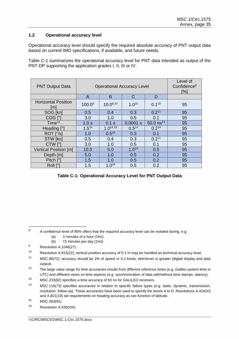
1.2 Operational accuracy level Operational accuracy level should specify the required absolute accuracy of PNT output data based on current IMO specifications, if available, and future needs. Table C-1 summarizes the operational accuracy level for PNT data intended as output of the PNT-DP supporting the application grades I, II, III or IV.
PNT Output Data Operational Accuracy Level Level of
Confidence8 [%]
A B C D
Horizontal Position [m]
100.09 10.09,10 1.010 0.110 95
SOG [kn] 0.5 0.4 0.3 0.211 95
COG [°] 3.0 1.0 0.5 0.1 95
Time12 1.0 s 0.1 s 0.0001 s 50.0 ns13 95
Heading [°] 1.514 1.014,15 0.514 0.214 95
ROT [°/s] 1.0 0.516 0.3 0.1 95
STW [kn] 0.5 0.4 0.3 0.211 95
CTW [°] 3.0 1.0 0.5 0.1 95
Vertical Position [m] 10.0 5.0 1.010 0.5 95
Depth [m] 5.0 1.0 0.5 0.2 95
Pitch [°] 1.5 1.0 0.5 0.2 95
Roll [°] 1.5 1.015 0.5 0.2 95
Table C-1: Operational Accuracy Level for PNT Output Data
8 A confidence level of 95% offers that the required accuracy level can be violated during, e.g.
(a) 3 minutes of a hour (1Hz)
(b) 72 minutes per day (1Hz) 9 Resolution A.1046(27). 10 Resolution A.915(22); vertical position accuracy of 0.1 m may be handled as technical accuracy level.
11 MSC.96(72): accuracy should be 2% of speed or 0.2 knots, whichever is greater (digital display and data
output). 12 The large value range for time accuracies results from different reference times (e.g. Galileo system time or
UTC) and different views on time aspects (e.g. synchronization of data with/without time stamps, latency). 13 MSC.233(82) specifies a time accuracy of 50 ns for GALILEO receivers.
14 MSC.116(73) specifies accuracies in relation to specific failure types (e.g. static, dynamic, transmission,
resolution, follow-up). These accuracies have been used to specify the levels A to D. Resolutions A.424(XI)
and A.821(19) set requirements on heading accuracy as sec-function of latitude. 15 MSC.363(92).
16 Resolution A.526(XIII).
MSC.1/Circ.1575 Annex, page 36
I:\CIRC\MSC\01\MSC.1-Circ.1575.docx
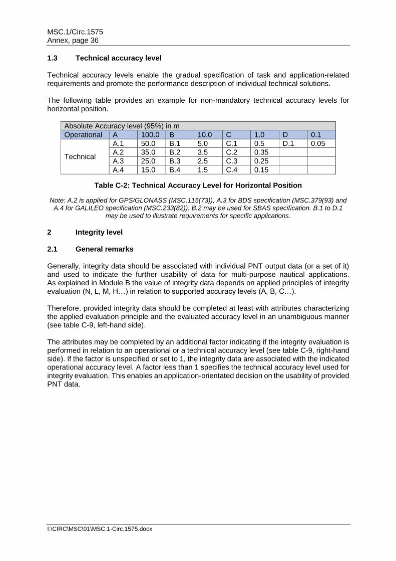
1.3 Technical accuracy level Technical accuracy levels enable the gradual specification of task and application-related requirements and promote the performance description of individual technical solutions. The following table provides an example for non-mandatory technical accuracy levels for horizontal position.
Absolute Accuracy level (95%) in m
Operational A 100.0 B 10.0 C 1.0 D 0.1
Technical
A.1 50.0 B.1 5.0 C.1 0.5 D.1 0.05
A.2 35.0 B.2 3.5 C.2 0.35
A.3 25.0 B.3 2.5 C.3 0.25
A.4 15.0 B.4 1.5 C.4 0.15
Table C-2: Technical Accuracy Level for Horizontal Position
Note: A.2 is applied for GPS/GLONASS (MSC.115(73)), A.3 for BDS specification (MSC.379(93) and A.4 for GALILEO specification (MSC.233(82)). B.2 may be used for SBAS specification. B.1 to D.1
may be used to illustrate requirements for specific applications.
2 Integrity level 2.1 General remarks Generally, integrity data should be associated with individual PNT output data (or a set of it) and used to indicate the further usability of data for multi-purpose nautical applications. As explained in Module B the value of integrity data depends on applied principles of integrity evaluation (N, L, M, H…) in relation to supported accuracy levels (A, B, C…). Therefore, provided integrity data should be completed at least with attributes characterizing the applied evaluation principle and the evaluated accuracy level in an unambiguous manner (see table C-9, left-hand side). The attributes may be completed by an additional factor indicating if the integrity evaluation is performed in relation to an operational or a technical accuracy level (see table C-9, right-hand side). If the factor is unspecified or set to 1, the integrity data are associated with the indicated operational accuracy level. A factor less than 1 specifies the technical accuracy level used for integrity evaluation. This enables an application-orientated decision on the usability of provided PNT data.

MSC.1/Circ.1575 Annex, page 37
I:\CIRC\MSC\01\MSC.1-Circ.1575.docx
Evaluation Principle Factor F
Accuracy level
Example for operational Level B
N L M H
Opera
tiona
l
Accura
cy
Level
O
A {A,N} {A,L} {A,M} {A,H}
F=1 Operational (O)
B
B {B,N} {B,L} {B,M} {B,H} tbd<F<1
Technical (T) T=O.F
C
B< F ≤ 1
C {C,N} {C,L} {C,M} {C,H}
D {D,N} {D,L} {D,M} {D,H}
F=0 Not applicable
-
Table C-3: Attributes of integrity data and factor indicating the evaluated accuracy level
Note: tbd stands for a lower boundary of a factor which results from the associated
operational technical levels. 2.2 Requirements on integrity monitoring 2.2.1 Performance parameters Typically, requirements on functions realizing the integrity monitoring of data in the GNSS sector or aviation are specified by the alert limit, time to alarm (TTA), and the residual integrity risk over a specified time period. Paragraph 122 of Module C states that a PNT-DP is embedded software contributing to the BAM of the mothering system by provision of status and integrity data. Therefore, the use of alert limits and time to alarm may be misleading, if they are used to formulate the requirements on integrity monitoring of the PNT-DP. To avoid misinterpretations with BAM the meaning of performances parameters on integrity monitoring is generalized:
.1 Methods and thresholds used by the PNT-DP for integrity monitoring should be qualified to evaluate if the supported accuracy level of PNT output data has been achieved or not. Therefore the accuracy level (AL) is used as intra-system "alert limit" or threshold value (see A.915(22)) to differ between fulfilled and failed requirements on PNT data output.
.2 A.915(22) specifies the time to alarm as time elapsed between the
occurrence of a failure in the radionavigation system and its presentation on the bridge. A PNT-DP evaluates, if the PNT output data will fulfil the supported accuracy level taking into account the performance of used data input and performed data processing. Therefore, the time to alarm (TTA) is more likely the tolerated time span for accuracy evaluation by the PNT-DP.
.3 Residual integrity risk: Probability defined for a specified period that a positive
evaluation result (estimated inaccuracy is smaller than the applied accuracy level) is faulty (inaccuracy of PNT data output exceeds the required accuracy level).
MSC.1/Circ.1575 Annex, page 38
I:\CIRC\MSC\01\MSC.1-Circ.1575.docx
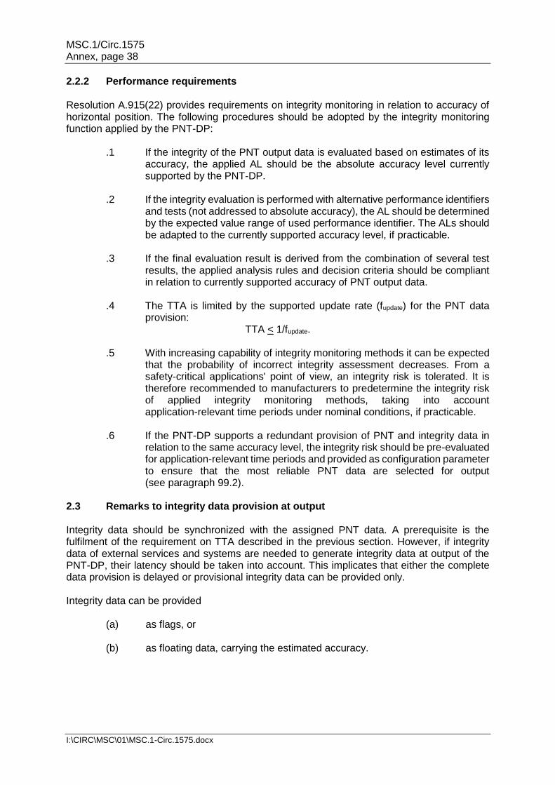
2.2.2 Performance requirements Resolution A.915(22) provides requirements on integrity monitoring in relation to accuracy of horizontal position. The following procedures should be adopted by the integrity monitoring function applied by the PNT-DP:
.1 If the integrity of the PNT output data is evaluated based on estimates of its accuracy, the applied AL should be the absolute accuracy level currently supported by the PNT-DP.
.2 If the integrity evaluation is performed with alternative performance identifiers
and tests (not addressed to absolute accuracy), the AL should be determined by the expected value range of used performance identifier. The ALs should be adapted to the currently supported accuracy level, if practicable.
.3 If the final evaluation result is derived from the combination of several test
results, the applied analysis rules and decision criteria should be compliant in relation to currently supported accuracy of PNT output data.
.4 The TTA is limited by the supported update rate (fupdate) for the PNT data
provision: TTA < 1/fupdate.
.5 With increasing capability of integrity monitoring methods it can be expected
that the probability of incorrect integrity assessment decreases. From a safety-critical applications' point of view, an integrity risk is tolerated. It is therefore recommended to manufacturers to predetermine the integrity risk of applied integrity monitoring methods, taking into account application-relevant time periods under nominal conditions, if practicable.
.6 If the PNT-DP supports a redundant provision of PNT and integrity data in
relation to the same accuracy level, the integrity risk should be pre-evaluated for application-relevant time periods and provided as configuration parameter to ensure that the most reliable PNT data are selected for output (see paragraph 99.2).
2.3 Remarks to integrity data provision at output Integrity data should be synchronized with the assigned PNT data. A prerequisite is the fulfilment of the requirement on TTA described in the previous section. However, if integrity data of external services and systems are needed to generate integrity data at output of the PNT-DP, their latency should be taken into account. This implicates that either the complete data provision is delayed or provisional integrity data can be provided only. Integrity data can be provided
(a) as flags, or
(b) as floating data, carrying the estimated accuracy.

MSC.1/Circ.1575 Annex, page 39
I:\CIRC\MSC\01\MSC.1-Circ.1575.docx
Results of integrity evaluation are provided preferably as estimate of achieved accuracy to support that the final evaluation of usability can be done by multi-purpose nautical applications in relation to own requirements on PNT data output. The provision of flags is sufficient to indicate if the considered accuracy level is most probably achieved, taking into account that the applied tests are passed. 3 Integrity explanations In general, the use of different methods for integrity evaluation results in different values of integrity statements. A logical consequence is the implementation of different integrity levels (see chapter B) to reflect these differences and to avoid the misinterpretation of provided integrity information. The applications of plausibility and consistency tests, which are insufficient to prove the fulfilment of requirements on accuracy, are associated to a low level of integrity: Data is considered plausible, if the data content lies within a specified value range. The limits of the specified value range are determined by technical design parameter, typical behaviour, or both. For example, the shortest and largest distance between possible satellite and user positions as well as typical measurement errors determine the expected value range of GNSS-based distance measurements. As shown in figure C-2, the plausibility tests are not sufficient to evaluate the current accuracy of distance measurement. Another example: the position of a ship in operation is considered plausible, if the ship's position is at sea, not ashore. Often plausibility tests are only applied on various performance identifiers such as number of tracked satellites, ranges and range rates, DOP-values, noise, etc. However, plausibility tests are insufficient to prove that requirements on accuracy are met.
Figure C-2: Value range for plausibility tests
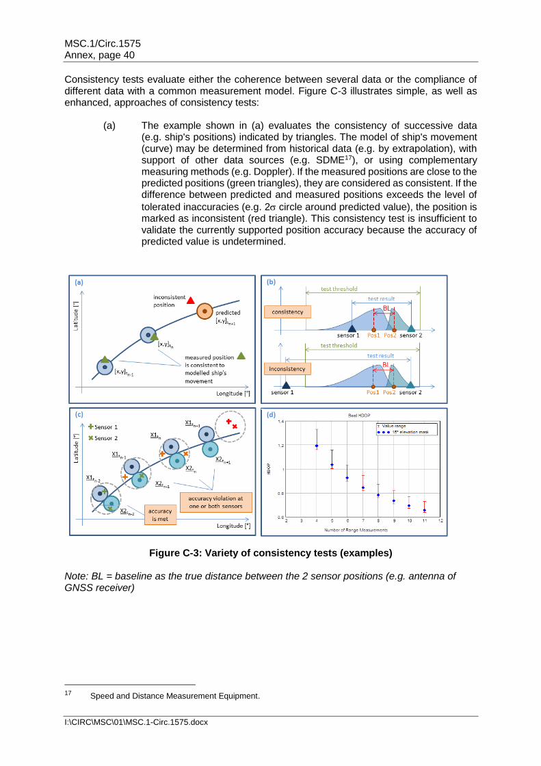
MSC.1/Circ.1575 Annex, page 40
I:\CIRC\MSC\01\MSC.1-Circ.1575.docx
Consistency tests evaluate either the coherence between several data or the compliance of different data with a common measurement model. Figure C-3 illustrates simple, as well as enhanced, approaches of consistency tests:
(a) The example shown in (a) evaluates the consistency of successive data (e.g. ship's positions) indicated by triangles. The model of ship's movement (curve) may be determined from historical data (e.g. by extrapolation), with support of other data sources (e.g. SDME17), or using complementary measuring methods (e.g. Doppler). If the measured positions are close to the predicted positions (green triangles), they are considered as consistent. If the difference between predicted and measured positions exceeds the level of
tolerated inaccuracies (e.g. 2 circle around predicted value), the position is marked as inconsistent (red triangle). This consistency test is insufficient to validate the currently supported position accuracy because the accuracy of predicted value is undetermined.
Figure C-3: Variety of consistency tests (examples) Note: BL = baseline as the true distance between the 2 sensor positions (e.g. antenna of GNSS receiver)
17 Speed and Distance Measurement Equipment.

MSC.1/Circ.1575 Annex, page 41
I:\CIRC\MSC\01\MSC.1-Circ.1575.docx
(b) Example b) illustrates the true position of two sensors (orange points) with different error distribution functions whose means have been adjusted to their true position. It should be remarked that in case of horizontal positioning the error behaviour will be described by a 2-dimensional distribution function. The blue and the cyan triangle represent exemplarily a measured position by sensors 1 and 2 (PosSensor1; PosSensor2). The upper graphic shows the case where the measurement errors of both sensors follow their nominal behaviour. This is assumed, if the difference between both measurements is below the test threshold given by, for example:
2121 SensorSensorSensorSensor kkBLPosPos
with as standard deviation of measuring error at the sensors and k as scaling factor specifying the probability, e.g. k=2 for 95% taken into account. The lower graphic illustrates the case where the increased measuring error at sensor 1 induces that the position difference exceeds the test threshold. However, this consistency test can only attest that both sensors most probably operate according their specified performance. An estimation of absolute accuracy is impossible.
(c) The reliability of the result of such consistency tests decreases if the data of
compared sensors are influenced by the same error sources and the probability increases that the errors at both sensors follow the same magnitude and direction (e.g. GPS receiver with short baseline or at the same antenna). Then it must be expected that the risks of undetected outliers increase. The example in (c) illustrates 4 time points with attested consistency; both positions are located within a common circle (grey line) with a diameter of the test threshold. However, both sensors fulfil only the accuracy requirements at time tn-2. At successive time points one or both measurements violate the accuracy requirements, whereby the large position errors (red crosses) at time tn+1 may remain undetected due to their correlated shift.
(d) Enhanced consistency tests evaluate the achieved processing results in
relation to the used input data. This can be done on a logical level, e.g. it is impossible to provide protection level by RAIM18, if only the signals of 4 GNSS satellites have been tracked. Alternatively, the enhanced consistency test may be performed under consideration of analytical dependencies: The threshold of the best attainable DOP19 per measuring setup is determined by the available number of ranging signals taking into account the applied elevation mask and the current satellite geometry. A DOP value cannot fall below the setup-specific threshold (see graphic (d) in figure C-3). But it is also possible to use statistical hypothesis tests to model the performance of PNT output data in dependence on performance of input data. An example is the precision of position estimated as product of DOP and assumed standard deviation of ranging errors. It should be remarked that precision of position is only a sufficient indicator of position accuracy if the ranging errors follow a normal distribution with zero-mean and assumed standard deviation.
18 Receiver Autonomous Integrity Monitoring. 19 Dilution of Precision.

MSC.1/Circ.1575 Annex, page 42
I:\CIRC\MSC\01\MSC.1-Circ.1575.docx
More recently Performance Standards of maritime radionavigation receivers recommend the use of Receiver Autonomous Integrity Monitoring (RAIM) to evaluate the integrity of provided position solution. RAIM applies consistency tests to answer two hypothesis-testing questions:
1) Does a failure exists in the available range measurements? 2) And if so, which is the failed measurement?
The application of consistency tests and therefore the answering of both questions depends on the availability of redundant range measurements: more than 4 ranges are needed for question 1 and more than 5 for question 2. Integrity of the provided position may only be assumed, if the RAIM has confirmed that the position is calculated with consistent range measurements, may be after iterative answering of both questions in relation to different setups of range measurements. Extended RAIM algorithms are also able to answer a third question:
3) Does the currently provided position meet most probably the specified accuracy requirements?
The question will be answered by calculation of protection level based on range measurements indicated as usable, standard deviation of range inaccuracies (nominal, modelled, or estimated), satellite geometry, as well as probabilities of false alerts and missed detection, whereby the latter should be specified in relation to specific applications. However, a wide variety of RAIM implementations has been developed in the last decades. They are realized as snapshot schemes testing only the consistency of current measurement or as averaging and filtering schemes taking into account previous measurements to compensate effects induced by the vessel's movement. They differ also in applied search strategies for fault detection and isolation; and, if supported, in methods and parameters used for the determination of protection level. Ultimately, the diversity of RAIM implementations makes it impossible to achieve a general assignment of RAIM approaches to a single integrity level. A position determined with consistent range measurements of a single GNSS may be assigned to a low integrity level due to the remaining sensitivity to systemic errors. None integrity is ensured, if the position solution has been determined with ranges without proof of their consistency. A medium integrity level may be met by position solutions using ranges of two or more GNSS, for which consistency is attested in the range as well as the position domain. However, the high integrity level should be assigned to RAIM implementations supporting the determination of realistic protection level (PL) as expected bound of position inaccuracies.

MSC.1/Circ.1575 Annex, page 43
I:\CIRC\MSC\01\MSC.1-Circ.1575.docx
Figure C-4 illustrates exemplarily the determination of PL by RAIM. From 6 satellites in view only 5 measured ranges have passed the consistency tests.
The left graphic shows the 6 position solutions, which can be determined with the 5 consistent ranges: the all-in-view solution (PosAIV, orange rhombus) and the solutions achieved with any set of 4 ranges (dark blue points). The position error per solution is indicated as blue circle, whose radius depends on the expected standard deviation of position error (DOP based projection of expected standard deviation of ranging errors in the position domain) and a factor k. The right graphic illustrates the dependency between factor k and the required integrity risk, if a normal distribution of errors is assumed. In this example the largest distance of an expected position error (here Pos4) to the all-in-view solution (PosAIV) is determined as protection level:
PLσkPosPos 4AIV4
The examples illustrate that the truthfulness of protection level depends on the correctness of error modelling (distribution function and parameters) in relation to current situation (value of range errors) as well as on specified performance requirements (e.g. tolerable integrity risk).
___________
Figure C-4: Exemplary determination of protection level