
DNVGL-RU-SHIP-Pt6Ch3 Navigation, manoeuvring and position ...
317
The content of this service document is the subject of intellectual property rights reserved by DNV GL AS ("DNV GL"). The user accepts that it is prohibited by anyone else but DNV GL and/or its licensees to offer and/or perform classification, certification and/or verification services, including the issuance of certificates and/or declarations of conformity, wholly or partly, on the basis of and/or pursuant to this document whether free of charge or chargeable, without DNV GL's prior written consent. DNV GL is not responsible for the consequences arising from any use of this document by others. The electronic pdf version of this document, available free of charge from http://www.dnvgl.com, is the officially binding version. DNV GL AS RULES FOR CLASSIFICATION Ships Edition October 2015 Part 6 Additional class notations Chapter 3 Navigation, manoeuvring and position keeping
Transcript of DNVGL-RU-SHIP-Pt6Ch3 Navigation, manoeuvring and position ...

The content of this service document is the subject of intellectual property rights reserved by DNV GL AS ("DNV GL"). The useraccepts that it is prohibited by anyone else but DNV GL and/or its licensees to offer and/or perform classification, certificationand/or verification services, including the issuance of certificates and/or declarations of conformity, wholly or partly, on thebasis of and/or pursuant to this document whether free of charge or chargeable, without DNV GL's prior written consent.DNV GL is not responsible for the consequences arising from any use of this document by others.
The electronic pdf version of this document, available free of chargefrom http://www.dnvgl.com, is the officially binding version.
DNV GL AS
RULES FOR CLASSIFICATION
ShipsEdition October 2015
Part 6 Additional class notations
Chapter 3 Navigation, manoeuvring andposition keeping

FOREWORD
DNV GL rules for classification contain procedural and technical requirements related to obtainingand retaining a class certificate. The rules represent all requirements adopted by the Society asbasis for classification.
© DNV GL AS October 2015
Any comments may be sent by e-mail to [email protected]
If any person suffers loss or damage which is proved to have been caused by any negligent act or omission of DNV GL, then DNV GL shallpay compensation to such person for his proved direct loss or damage. However, the compensation shall not exceed an amount equal to tentimes the fee charged for the service in question, provided that the maximum compensation shall never exceed USD 2 million.
In this provision "DNV GL" shall mean DNV GL AS, its direct and indirect owners as well as all its affiliates, subsidiaries, directors, officers,employees, agents and any other acting on behalf of DNV GL.

Part
6 C
hapt
er 3
Cha
nges
- c
urre
nt
Rules for classification: Ships — DNVGL-RU-SHIP-Pt6Ch3. Edition October 2015 Page 3Navigation, manoeuvring and position keeping
DNV GL AS
CHANGES – CURRENT
This is a new document.
The rules enter into force 1 January 2016.

Part
6 C
hapt
er 3
Con
tent
s
Rules for classification: Ships — DNVGL-RU-SHIP-Pt6Ch3. Edition October 2015 Page 4Navigation, manoeuvring and position keeping
DNV GL AS
CONTENTS
Changes – current...................................................................................................... 3
Section 1 Dynamic positioning systems - DYNPOS and DPS..................................... 121 General................................................................................................. 12
1.1 Introduction.......................................................................................121.2 Scope............................................................................................... 121.3 Application.........................................................................................121.4 Class notations.................................................................................. 131.5 Definitions......................................................................................... 141.6 Documentation requirements............................................................... 171.7 Certification....................................................................................... 25
2 Upgrades and class entries...................................................................262.1 Documentation and testing requirements.............................................. 262.2 Class entries not requiring additional verification.................................... 27
3 Survey and test upon completion......................................................... 273.1 General............................................................................................. 273.2 Measuring system.............................................................................. 283.3 Thrusters...........................................................................................283.4 UPS power supply.............................................................................. 283.5 Independent joystick control system.....................................................283.6 Complete DP system test.................................................................... 283.7 Redundancy and failure response tests................................................. 29
4 General arrangement............................................................................304.1 General requirements......................................................................... 304.2 Redundancy and failure modes............................................................ 304.3 Redundancy....................................................................................... 314.4 Failure modes.................................................................................... 324.5 Independence.................................................................................... 334.6 Separation.........................................................................................33
5 System arrangement............................................................................ 345.1 General............................................................................................. 345.2 DP control centre............................................................................... 385.3 Arrangement of positioning control systems..........................................395.4 Arrangement and layout of control panels............................................. 405.5 Arrangement and layout of data communication links..............................41

Part
6 C
hapt
er 3
Con
tent
s
Rules for classification: Ships — DNVGL-RU-SHIP-Pt6Ch3. Edition October 2015 Page 5Navigation, manoeuvring and position keeping
DNV GL AS
5.6 Arrangement and layout of emergency stop systems...............................415.7 Internal communication.......................................................................42
6 Control systems....................................................................................426.1 General requirements......................................................................... 426.2 Independent joystick control system.....................................................426.3 DP-control system.............................................................................. 436.4 Additional for DP-control systems for notation requiring redundancy.......... 446.5 Additional for DP-control systems for notations requiring separation.......... 446.6 Thruster control mode selection........................................................... 456.7 Positioning reference systems.............................................................. 456.8 Position reference system user interface................................................476.9 Sensors.............................................................................................476.10 Display units....................................................................................486.11 Monitoring....................................................................................... 486.12 Monitoring of batteries supplying DP thrusters......................................496.13 Consequence analysis....................................................................... 49
7 Thruster systems.................................................................................. 507.1 Rule application..................................................................................507.2 Thruster configuration.........................................................................517.3 Thruster control................................................................................. 527.4 Indication.......................................................................................... 53
8 Power systems..................................................................................... 548.1 General............................................................................................. 548.2 Number and capacity of generators...................................................... 548.3 Batteries supplying power to DP thrusters............................................. 558.4 Power management............................................................................ 558.5 Technical system configurations based on closed bus-tie(s)...................... 568.6 Main and distribution switchboards arrangement.................................... 578.7 Main and distribution switchboards arrangement for notations requiring
redundancy..........................................................................................578.8 Control system power supply...............................................................58
9 Auxiliary systems................................................................................. 599.1 General............................................................................................. 599.2 Additional for notations requiring redundancy........................................ 599.3 Specific requirements for fuel oil systems..............................................609.4 Specific requirements for fresh water cooling systems............................. 609.5 Specific requirements for pneumatic systems.........................................609.6 Specific requirements for fire dampers and quick closing valves................ 60
10 Environmental regularity numbers......................................................61

Part
6 C
hapt
er 3
Con
tent
s
Rules for classification: Ships — DNVGL-RU-SHIP-Pt6Ch3. Edition October 2015 Page 6Navigation, manoeuvring and position keeping
DNV GL AS
10.1 Concept description.......................................................................... 6111 Appendix A Technical system configurations based on closed bus-
ties....................................................................................................... 6311.1 Special considerations....................................................................... 6311.2 General........................................................................................... 63
12 Appendix B Calculation of environmental regularity numbers – ern*...6412.1 Introduction..................................................................................... 6412.2 Environment.................................................................................... 6512.3 Environmental loads..........................................................................6612.4 Wind loads.......................................................................................6612.5 Current............................................................................................6612.6 Waves............................................................................................. 6712.7 Thrusters......................................................................................... 6812.8 Rudders...........................................................................................6912.9 Thrust allocation...............................................................................7012.10 Tables for specification of hull and thruster data................................. 70
Section 2 Dynamic positioning system with enhanced reliability - DYNPOS (E, ER)...721 General................................................................................................. 72
1.1 Introduction.......................................................................................721.2 Scope............................................................................................... 721.3 Application.........................................................................................721.4 Definitions......................................................................................... 731.5 Documentation...................................................................................771.6 Certification requirements....................................................................84
2 Upgrades and class entries...................................................................862.1 ........................................................................................................862.2 ........................................................................................................862.3 ........................................................................................................862.4 ........................................................................................................86
3 Survey and test upon completion......................................................... 863.1 General............................................................................................. 863.2 Measuring system.............................................................................. 873.3 Thrusters...........................................................................................873.4 Thruster mode selection......................................................................873.5 UPS power supply.............................................................................. 873.6 Complete DP system test.................................................................... 873.7 Redundancy and failure response tests................................................. 88
4 General arrangement............................................................................88

Part
6 C
hapt
er 3
Con
tent
s
Rules for classification: Ships — DNVGL-RU-SHIP-Pt6Ch3. Edition October 2015 Page 7Navigation, manoeuvring and position keeping
DNV GL AS
4.1 General requirements......................................................................... 894.2 Redundancy....................................................................................... 894.3 Failure modes.................................................................................... 914.4 Independence.................................................................................... 924.5 Separation.........................................................................................924.6 Gas in non-hazardous areas................................................................ 93
5 System arrangement............................................................................ 945.1 General............................................................................................. 945.2 DP control centre............................................................................... 955.3 Arrangement and layout of control panels............................................. 965.4 Arrangement and layout of data communication links..............................965.5 Arrangement and layout of emergency stop systems...............................975.6 Internal communication.......................................................................97
6 Control systems....................................................................................976.1 General requirements......................................................................... 976.2 Automatic control systems...................................................................976.3 Main DP-control system...................................................................... 986.4 Alternative DP-control system.............................................................. 996.5 Thruster control mode selection........................................................... 996.6 Positioning reference system..............................................................1006.7 Sensors........................................................................................... 1016.8 Display and indication....................................................................... 1026.9 Monitoring....................................................................................... 1036.10 Monitoring of batteries supplying power to DP thrusters....................... 1046.11 Consequence analysis......................................................................104
7 Thruster systems................................................................................ 1067.1 General requirements........................................................................1067.2 Thruster configuration....................................................................... 1067.3 Thruster control................................................................................1067.4 Indication........................................................................................ 108
8 Power systems................................................................................... 1098.1 General........................................................................................... 1098.2 Number and capacity of generators.................................................... 1098.3 Batteries supplying power to DP thrusters........................................... 1108.4 Power management.......................................................................... 1108.5 Main and distribution switchboards arrangement...................................1128.6 Control system power supply............................................................. 112
9 Auxiliary systems................................................................................1139.1 General........................................................................................... 113

Part
6 C
hapt
er 3
Con
tent
s
Rules for classification: Ships — DNVGL-RU-SHIP-Pt6Ch3. Edition October 2015 Page 8Navigation, manoeuvring and position keeping
DNV GL AS
9.2 Additional requirements for fuel oil systems......................................... 1149.3 Power supply to auxiliary systems...................................................... 114
10 Capability plots and environmental regularity numbers.................... 11510.1 Capability plots...............................................................................11510.2 Environmental regularity numbers.....................................................115
Section 3 Nautical safety - NAUT(OC) and NAUT(AW)............................................1181 General............................................................................................... 118
1.1 Introduction..................................................................................... 1181.2 Scope..............................................................................................1181.3 Application.......................................................................................1181.4 Classification.................................................................................... 1181.5 Definitions....................................................................................... 1211.6 Documentation................................................................................. 1241.7 Tests............................................................................................... 129
2 Design of workplace........................................................................... 1302.1 General........................................................................................... 1302.2 Bridge design...................................................................................1302.3 Wheelhouse arrangement and workstation configuration........................ 1412.4 Workstations for primary bridge functions - location of equipment........... 1462.5 Additional workstations......................................................................1602.6 Requirements specific for class notation NAUT(AW) and NAUT(AW, ICS) 161
3 Workplace environment......................................................................1633.1 General........................................................................................... 1633.2 Environmental factors....................................................................... 1633.3 Lighting........................................................................................... 1643.4 Safety of personnel.......................................................................... 167
4 Bridge equipment - Carriage requirements.........................................1674.1 General........................................................................................... 1674.2 Basic bridge equipment..................................................................... 1674.3 Additional bridge equipment - NAUT(AW).......................................... 1724.4 Network based integration - ICS........................................................ 173
5 Bridge equipment – General requirements......................................... 1735.1 General........................................................................................... 1735.2 Location of equipment.......................................................................1745.3 Electrical power supply......................................................................1765.4 Integration and interfaces..................................................................1775.5 Human machine interface.................................................................. 1795.6 Software..........................................................................................183

Part
6 C
hapt
er 3
Con
tent
s
Rules for classification: Ships — DNVGL-RU-SHIP-Pt6Ch3. Edition October 2015 Page 9Navigation, manoeuvring and position keeping
DNV GL AS
6 Bridge equipment - Specific requirements.......................................... 1836.1 General........................................................................................... 1836.2 Steering control systems................................................................... 1846.3 Heading information system...............................................................1876.4 Speed information system................................................................. 1886.5 Collision avoidance - Decision support systems.....................................1896.6 Grounding avoidance - Decision support systems..................................1926.7 Weather surveillance systems.............................................................1946.8 Bridge navigational watch alarm system (BNWAS)................................ 1956.9 Bridge alert management system....................................................... 1976.10 Nautical internal communication systems........................................... 1986.11 Track control system – NAUT(AW).................................................. 2006.12 Conning information display (CID) – NAUT(AW)................................ 201
7 Network based integration of navigation systems ICS........................2037.1 General........................................................................................... 2037.2 Multi-function-displays (MFD)............................................................. 2037.3 Human-machine interface (HMI).........................................................2047.4 ICS network.....................................................................................2107.5 Malfunctions and restoration.............................................................. 2117.6 Testing............................................................................................ 2117.7 Documentation................................................................................. 2127.8 Quality system................................................................................. 212
8 Ship manoeuvring characteristics....................................................... 2128.1 General........................................................................................... 2128.2 Trials and predictions........................................................................ 2128.3 Course-keeping ability.......................................................................2138.4 Provision of manoeuvring information..................................................2148.5 Presentation of manoeuvring information.............................................216
9 Qualifications and operational procedures..........................................2179.1 General........................................................................................... 2179.2 Watch keeping arrangement...............................................................2189.3 Qualifications....................................................................................2189.4 Bridge watch procedures................................................................... 219
10 Bridge equipment - On-board tests...................................................21910.1 General..........................................................................................21910.2 On board testing of bridge equipment............................................... 219
Section 4 Nautical safety - NAUT(NAV)..................................................................2241 General............................................................................................... 224

Part
6 C
hapt
er 3
Con
tent
s
Rules for classification: Ships — DNVGL-RU-SHIP-Pt6Ch3. Edition October 2015 Page 10Navigation, manoeuvring and position keeping
DNV GL AS
1.1 Introduction..................................................................................... 2241.2 Scope..............................................................................................2241.3 Application.......................................................................................2241.4 Classification.................................................................................... 224
2 Bridge configuration........................................................................... 2282.1 Workstations.................................................................................... 2282.2 Structural arrangements....................................................................2332.3 Working environment........................................................................ 235
3 Bridge equipment............................................................................... 2363.1 General........................................................................................... 2363.2 Arrangement of equipment................................................................ 2393.3 Requirement for instruments and equipment........................................241
Section 5 Nautical safety – NAUT(OSV)................................................................. 2441 General............................................................................................... 244
1.1 Introduction..................................................................................... 2441.2 Scope..............................................................................................2441.3 Application.......................................................................................2451.4 Objectives and safety philosophy........................................................2451.5 Structure of the rules....................................................................... 2471.6 Definitions....................................................................................... 2471.7 Class notations.................................................................................2521.8 Documentation for approval............................................................... 2531.9 Functional tests................................................................................ 256
2 Bridge design and configuration.........................................................2562.1 General........................................................................................... 2562.2 Workstations.................................................................................... 2572.3 Visibility...........................................................................................2592.4 Working environment........................................................................ 262
3 Workstation arrangement...................................................................2683.1 Requirements for the various workstations...........................................2683.2 Workstations for primary bridge functions............................................2713.3 Workstations for navigating and manoeuvring...................................... 2743.4 Workstation for monitoring................................................................ 2803.5 Workstation for offshore operations.....................................................2813.6 Workstation for ship handling.............................................................2863.7 Workstation for aft support................................................................2913.8 Workstation for firefighting (FiFi)........................................................ 2923.9 Workstation for search/rescue operations.............................................293

Part
6 C
hapt
er 3
Con
tent
s
Rules for classification: Ships — DNVGL-RU-SHIP-Pt6Ch3. Edition October 2015 Page 11Navigation, manoeuvring and position keeping
DNV GL AS
3.10 Workstation for communication.........................................................2943.11 Workstation for safety monitoring and emergency operations................296
4 Bridge equipment............................................................................... 2964.1 General bridge equipment requirements.............................................. 2964.2 Equipment requirements....................................................................2994.3 Electrical power supply......................................................................307
5 Ergonomics and human-machine interface......................................... 3085.1 Human - machine interface................................................................3085.2 Controls...........................................................................................3085.3 Presentation of information................................................................3095.4 Readability of information..................................................................311
6 Bridge equipment tests.......................................................................3116.1 Onboard testing of bridge equipment.................................................. 311

Part
6 C
hapt
er 3
Sec
tion
1
Rules for classification: Ships — DNVGL-RU-SHIP-Pt6Ch3. Edition October 2015 Page 12Navigation, manoeuvring and position keeping
DNV GL AS
SECTION 1 DYNAMIC POSITIONING SYSTEMS - DYNPOS AND DPS
1 General
1.1 IntroductionThe additional class notations DPS and DYNPOS set requirements for dynamic positioning for all types ofvessel. For vessels with a requirement for dynamic positioning systems with redundancy and a higher degreeof flexibility, based on utilization of stand-by units and/or change-over mechanisms, is described in Sec.2.
1.2 ScopeThe scope for additional class notations DPS and DYNPOS provides technical requirements for design,documentation, certification and testing of systems for dynamic positioning for all types of vessel. Theserules do not include requirements or recommendations in regard to vessel operation or other characteristics.Requirements additional to these rules may be imposed by the national authority with whom the vessel isregistered and/or by the administration within whose territorial jurisdiction it is intended to operate. Wherenational legislative requirements exist, compliance with such regulations will also be necessary.These rules do not give guidance on the suitability of the different intended technical system configurations,with respect to the vessels various industrial mission(s). Reference is given to the recommended practice:DNVGL-RP-E306 Dynamic positioning vessel design philosophy guidelines.The requirements in these rules are additional to the rules for main class. In particular see the relevantsections of:
— Pt.4 Ch.1 Machinery Systems, General— Pt.4 Ch.2 Rotating Machinery, General— Pt.4 Ch.3 Rotating Machinery, Drivers— Pt.4 Ch.4 Rotating Machinery, Power Transmissions— Pt.4 Ch.5 Rotating Machinery, Driven Units— Pt.4 Ch.8 Electrical Installations— Pt.4 Ch.9 Instrumentation and Automation.
1.3 ApplicationThe additional class notations DPS and DYNPOS apply to all vessels with dynamic positioning systems.This section concerns requirements for two different types of class notation; DPS- series and DYNPOS-series, as defined in Table 2. Both series are characterised and structured in line with the IMO MSC/Circ.645Guidelines for vessels with dynamic positioning systems, see Table 1. The two class notation series differin their specific requirements, and in general the DYNPOS-series notations require a higher degree ofavailability and robustness than compared to the DPS-series. For example: DYNPOS(AUTS)/DPS(1),DYNPOS(AUTR)/DPS(2) and DYNPOS(AUTRO)/DPS(3) are notations requiring contrasting levels ofredundancy and system separation. Qualifier "A" may be added to certain notations, thus indicating arequirement for annual survey. The detailed differences are shown in the specific requirements given in thissection.
Table 1 Correlation IMO equipment classes to DNV GL class notations
IMO equipment class Class notations Additional information
Not applicable DYNPOS(AUTS)Even though IMO MSC/Circ.645 does not specify any equipment classcorresponding to DYNPOS(AUTS) this requirements level is oftenreferred to as IMO equipment class 0.

Part
6 C
hapt
er 3
Sec
tion
1
Rules for classification: Ships — DNVGL-RU-SHIP-Pt6Ch3. Edition October 2015 Page 13Navigation, manoeuvring and position keeping
DNV GL AS
IMO equipment class Class notations Additional information
DPS(1)
IMO equipment class 1DYNPOS(AUT) Additional requirements to achieve higher availability and robustness
as compared to DPS(1) will apply.
DPS(2)
IMO equipment class 2DYNPOS(AUTR) Additional requirements to achieve higher availability and robustness
as compared to DPS(2) will apply.
DPS(3)
IMO equipment class 3DYNPOS(AUTRO) Additional requirements to achieve higher availability and robustness
as compared to DPS(3) will apply.
The DYNPOS-series comprise the DYNPOS(AUTS), DYNPOS(AUT), DYNPOS(AUTR) and DYNPOS(AUTRO)notations.
The DPS-series comprise the DPS(1), DPS(2) and DPS(3) notations.
1.4 Class notationsVessels built and tested in compliance with the requirements in this section and the requirements of the rulesfor relevant main class may be assigned the relevant class notation(s) given in Table 2.
Table 2 Class notations
Notation hierarchy Description
DYNPOS(AUTS) Dynamic positioning system without redundancy.
DPS(1) Dynamic positioning system with an independent joystick system back-up and aposition reference back-up.Notations
not requiringredundancy
DYNPOS(AUT)Dynamic positioning system with an independent joystick system back-up and aposition reference back-up. Additional requirements to achieve higher availabilityand robustness as compared to DPS(1) will apply.
DPS(2) Dynamic positioning system with redundancy in technical design and with anindependent joystick system back-up.Notations
requiringredundancy DYNPOS(AUTR)
Dynamic positioning system with redundancy in technical design and with anindependent joystick system back-up. Additional requirements to achieve higheravailability and robustness as compared to DPS(2) will apply.
DPS(3)
Dynamic positioning system with redundancy in technical design and with anindependent joystick system back-up. Plus a back-up dynamic positioning controlsystem in an back-up dynamic positioning control centre, designed with physicalseparation for components that provide redundancy.
Notationsrequiring
redundancyand
separationof systems DYNPOS(AUTRO)
Dynamic positioning system with redundancy in technical design and with anindependent joystick system back-up. Plus a back-up dynamic positioning controlsystem in an back-up dynamic positioning control centre, designed with physicalseparation for components that provide redundancy. Additional requirements toachieve higher availability and robustness as compared to DPS(3) will apply.

Part
6 C
hapt
er 3
Sec
tion
1
Rules for classification: Ships — DNVGL-RU-SHIP-Pt6Ch3. Edition October 2015 Page 14Navigation, manoeuvring and position keeping
DNV GL AS
1.4.1 Qualifier AA qualifier A can when requested by the vessel owner be assigned to vessels with notation DYNPOS(AUTR)or DYNPOS(AUTRO) or DPS(2) or DPS(3), which then shall undergo annual survey according to theapplicable 5 yearly survey scope. This means that the scope of the annual survey shall also include the scopeof the complete survey.
Guidance note:Example of notations: DYNPOS(AUTR, A) or DPS(2, A).
---e-n-d---of---g-u-i-d-a-n-c-e---n-o-t-e---
1.4.2 Environmental regularity numbers, ern*Vessels with one of the DYNPOS-series class notations, except for notation DYNPOS(AUTS), listed in Table2 will be assigned environmental regularity numbers (ern*). These will be entered as a register notation inthe Society's “Register of vessels” as ern*(a, b, c, d) where a, b, c, d are integer numbers reflecting probableregularity for keeping position in a defined area. See [10] for details on the ern* concept.
Guidance note 1:Upon special request environmental regularity number (ern*) may also be approved and entered as a notation in the “Register ofvessels” also for vessels with the DPS-series notations and for the notation DYNPOS(AUTS).
---e-n-d---of---g-u-i-d-a-n-c-e---n-o-t-e---
Guidance note 2:Environmental regularity numbers approved according to this rule edition will be denoted ern* to reflect that the verification hasbeen performed against the more specific acceptance criteria introduced in Appendix B of this rules.These more specific acceptance criteria were first introduced in the July 2013 edition of the legacy DNV ship rules. Environmentalregularity numbers approved according to prior rule editions are denoted ern.
---e-n-d---of---g-u-i-d-a-n-c-e---n-o-t-e---
1.5 DefinitionsTable 3 Definitions
Term Definition
bulkhead deck see Pt.3 Ch.1 Sec.4 Table 7 for definition
CLE a sailing vessel entering in to class
consequence analysis
a monitoring function in the DP-control system that issue an alarm if the vessel (in its currentoperating mode) in the current weather conditions would not be able to keep the heading andposition in the case that any of the predefined worst case failures should occur.
Guidance note:For detailed information and requirements to the consequence analysis function see [6.13].
---e-n-d---of---g-u-i-d-a-n-c-e---n-o-t-e---
DP Dynamic Positioning.

Part
6 C
hapt
er 3
Sec
tion
1
Rules for classification: Ships — DNVGL-RU-SHIP-Pt6Ch3. Edition October 2015 Page 15Navigation, manoeuvring and position keeping
DNV GL AS
Term Definition
DP-control system
all control systems and components, hardware and software necessary to dynamically positionthe vessel. The DP-control system consists of the following:
— dynamic positioning control computer(s)— sensor system— display system— operator panels— positioning reference system— associated cabling and cable routing— UPS(s) as required by the relevant notation.
Guidance note:The DP-control system will normally consist of one or more computers. This is often referred to asthe DP system, but is only a part of the DP system by rule terminology.
---e-n-d---of---g-u-i-d-a-n-c-e---n-o-t-e---
dynamic positioningsystem (DP system)
the complete installation necessary for dynamically positioning a vessel comprises of thefollowing systems:
— power system— thruster system— DP-control system— independent joystick system (when required).
dynamically positionedvessel (DP vessel)
a vessel which automatically maintains its position and heading (fixed location orpredetermined track) exclusively by means of thruster force.
Guidance note:For the DYNPOS-series an intact vessel should be able to keep position and heading withoutcontribution from transverse thrust generated by the combined use of propellers and rudders. ForDYNPOS(AUTR) and DYNPOS(AUTRO) thruster force may include propulsion and steering (rudder)forces for back-up purposes only (e.g. after loss of one redundancy group), see [7].
---e-n-d---of---g-u-i-d-a-n-c-e---n-o-t-e---
failure
an occurrence in a component or system causing one or both of the following effects:
— loss of component or system function— deterioration of functional capability to such an extent that the safety of the vessel,
personnel, or environment is significantly reduced.
Guidance note:For vessels that should comply with DYNPOS(AUTRO) or DPS(3) requirements, the definition ofsingle failure has no exceptions, and should include incidents of fire and flooding, and all technicalbreak-downs of systems and components, including all electrical and mechanical parts. Loss ofstability (e.g. as a result of flooding) is not a relevant failure mode.For vessels that should comply with DYNPOS(AUTR) or DPS(2) requirements, certain exceptionswill be allowed in the definition of single failure. Flooding and fire should not be considered beyondmain class requirements. Failure of static components, e.g. pipes, manual valves, cables etc. may notneed to be considered if adequate reliability of single component can be documented, and the partis protected from mechanical damage. Specific requirements will apply as given in the following sub-sections of this section. Especially for DYNPOS(AUTR) failure of a wide range of static componentswill be considered as relevant single failures. See also [4].
---e-n-d---of---g-u-i-d-a-n-c-e---n-o-t-e---

Part
6 C
hapt
er 3
Sec
tion
1
Rules for classification: Ships — DNVGL-RU-SHIP-Pt6Ch3. Edition October 2015 Page 16Navigation, manoeuvring and position keeping
DNV GL AS
Term Definition
hidden failure
a failure that is not immediately evident to operations and maintenance personnel.
Guidance note:Equipment that fails to perform an “on demand” function falls into this category. It is necessary thatsuch failures are detected by monitoring and/or revealed through periodical testing/verification inorder to ensure their availability. Protective functions e.g. in power plants and switchboards are typicalexamples of on demand functions where possible hidden failures should be considered.
---e-n-d---of---g-u-i-d-a-n-c-e---n-o-t-e---
HMI Human Machine Interface encompassing User Input Device (UID) and/or Visual Display Unit(VDU).
joystick a device for readily setting of vectorial thrust output including turning moment.
minimum timerequirement
minimum required time duration for which the residual remaining capacity as defined by theworst case failure design intent shall be available.
Guidance note:The time requirement will normally be governed by the maximum time necessary to safely terminatethe on-going operations after the worst case single failure, given the residual remaining capacity. Allrelevant operational scenarios which the vessel performs and/or participates in should be consideredwhen deciding the time requirements. This time requirement should be fulfilled by the design, and theway the vessel is technically configured (technical system configuration) and operated. In addition tothe actual time necessary to terminate the operation, the minimum time requirement includes alsothe time necessary for detection and alarming by the system, and the time needed for the operator(s)to notice, make the appropriate decision(s), and initiate the termination process.
---e-n-d---of---g-u-i-d-a-n-c-e---n-o-t-e---
operational mode
manner of control under which the DP-system may be operated, e.g.:
— automatic mode (automatic position and heading control)— joystick mode (manual position control with selectable automatic or manual heading
control)— manual mode (individual control of thrust, azimuth, start/stop of each thruster)— auto track mode (considered as a variant of automatic position control, with programmed
movement of reference point).
position/headingkeeping
maintenance of a desired position/heading within the normal excursions of the control systemand the environmental conditions.
positioning/headingreference system
all hardware, software and sensors that supply information and or corrections necessary to giveposition/heading reference, including power supply.
power system
all components and systems necessary to supply the DP-system with power. The power systemincludes:
— prime movers with necessary auxiliary systems including piping— generators— switchboards— uninterruptible power supplies (UPS) and batteries— distribution system including cabling and cable routing— for DYNPOS(AUTR) and DYNPOS(AUTRO): power management system (PMS).
redundancyability of a component or system to maintain its function when one failure has occurred.Redundancy can be achieved, for instance, by installation of multiple components, systems oralternative means of performing a function.

Part
6 C
hapt
er 3
Sec
tion
1
Rules for classification: Ships — DNVGL-RU-SHIP-Pt6Ch3. Edition October 2015 Page 17Navigation, manoeuvring and position keeping
DNV GL AS
Term Definition
redundancy designintent
refers to redundant component groups which constitutes the overall system design for a givensystem operational mode and technical system configuration.
redundancy group
all components and systems that is subject to a single failure as specified in [4], for the specificnotations
Guidance note:The redundancy groups will emerge as a consequence of the worst case single failure within eachgroup. The rules do not give requirements to the number of (beyond 2) or ratio between the definedgroups. The groups should be identified in the FMEA, verified by testing and incorporated in theconsequence analysis.
---e-n-d---of---g-u-i-d-a-n-c-e---n-o-t-e---
reliability ability of a component or system to perform its required function without failure during aspecified time interval.
technical systemconfiguration
includes all technical modes (and combinations of the modes) of all systems that may influencethe redundancy and failure tolerance of the vessel. This will typically include but is not limitedto e.g., control system modes, power plant and thruster configuration, switch board (AC andDC) configuration and distribution setup, auxiliary systems setup, valves, breakers, pumps, …).
Guidance note:The technical system configuration(s) are prerequisites for establishing the basis for an FMEA, andshould be specified for all relevant configurations. One example could be that a vessel has differenttechnical system configurations for different vessel operational modes and another example couldbe in case a vessel with DYNPOS(AUTRO) notation is intended to also to have a mode based onDYNPOS(AUTR) acceptance criteria, both modes should be stated, specified, analysed, and testedin the FMEA.
---e-n-d---of---g-u-i-d-a-n-c-e---n-o-t-e---
thruster system
all components and systems necessary to supply the DP system with thrust force and direction.The thruster system includes:
— thruster with drive units and necessary auxiliary systems including piping— thruster control— associated cabling and cable routing— main propellers and rudders if these are under the control of the DP system.
worst case failure
refers to failure modes which, after a failure, results in the largest reduction of the positionand/or heading keeping capacity. This means loss of the most significant redundancy group,given the prevailing operation. Failure modes related to specific class notations are specified in[4],
worst case failuredesign intent
refer to the minimum remaining capacity after any relevant single failure or common cause (fora given operational mode).
zone a confined space with specified fire and flooding boundaries.
1.6 Documentation requirements
1.6.1 The documentation submitted, shall include descriptions and particulars of the vessel and cover therequirements given in Table 4 and Table 5, and [1.6.6] to [1.6.8], as appropriate. These documentationrequirements are in addition to the requirements for main class.

Part
6 C
hapt
er 3
Sec
tion
1
Rules for classification: Ships — DNVGL-RU-SHIP-Pt6Ch3. Edition October 2015 Page 18Navigation, manoeuvring and position keeping
DNV GL AS
1.6.2 Vessel documentation shall be submit as required in Table 4. For vessels with the qualifiers DYNPOS(AUTR),DYNPOS(AUTRO), DPS(2) or DPS(3) the relevant information elements and documentation as specified inDNVGL-OTG-10 Offshore technical guidance for DP-classed vessels with closed bus-ties, Appendix A, shall beincluded in the documentation listed in Table 4 or submitted separately.
Table 4 Documentation requirements - Vessel
Object Documentationtype Additional description Info DYNPOS
qualifiersDPS
qualifiers
Z050 - DP Designphilosophy
The document shall describe the main features of thedesign and identify the redundancy design intent (includingthe separation design intent when required), as a minimumwith respect to:
— thrusters, propellers and rudders— engines,generators and other power sources— main switchboard arrangement— type(s) of fuel
The worst case failure design intent shall be stated.
The intended minimum time requirement shall be stated.
In addition the document shall specify the intendedtechnical system configuration(s) during DP operation, as aminimum for the above listed components.
The DP design philosophy shall be submitted early in theproject. In case the DP design philosophy is not specified,documentation related to other part of the DP system mayneed to be put on hold since the acceptance criteria willvery often be determined based on the specified DP designintent.
FI AUTR,AUTRO 2, 3
I060 – Principalcable routingsketch
The cable routing layout drawing shall indicate all cablesrelevant to the DP system, e.g. power cables, controlcables, cables used for indication etc. The documentationshall also include a list of relevant cables crossing firezones.
For the cable routing layout drawing it is recommendedthat colours are used to indicate the cable routes that aredesigned and physically arranged to provide redundancy.
AP AUTRO 3
Z030 –Arrangement plan
Fire and flooding separation zone plan. This shall be in formof a GA plan indicating, preferably by use of colours, whichspaces that are intended to contain equipment and systemsbelonging to the different redundancy groups. In additionthe drawings shall indicate the passive fire protectionbetween the zones.
AP AUTRO 3
Z071 – Failuremode and effectanalysis (FMEA)
See [1.6.7]. AP AUTR,AUTRO 2, 3
Positioningkeepingsystems
Z253 – Testprocedure forquay or sea trial
Redundancy and failure modes based on FMEA AP AUTR,AUTRO 2, 3

Part
6 C
hapt
er 3
Sec
tion
1
Rules for classification: Ships — DNVGL-RU-SHIP-Pt6Ch3. Edition October 2015 Page 19Navigation, manoeuvring and position keeping
DNV GL AS
Object Documentationtype Additional description Info DYNPOS
qualifiersDPS
qualifiers
Z200 –Environmentalregularity number(ern*) calculation
See [1.6.6]. APAUT,
AUTR,AUTRO
Notapplicable
Positionkeepingcontrolcentres
Z030 –Arrangement plan
For DYNPOS(AUTRO) and DPS(3) also the emergencyDP-control centre shall be covered AP All All
Thrustersemergencystop systems
I150 – Circuitdiagram
Individual thruster emergency stop system required at theDP control centre. This system may be part of the individualmanual lever thruster control system.
AP All All
Electricpower systemgeneral
E040 – Electricalload balance
Alternating current (AC) power consumption balancefor dynamic positioning operation. For vessels with thequalifiers DYNPOS(AUTR), DYNPOS(AUTRO), DPS(2)and DPS(3) the load calculations shall also reflect thesituation after the maximum single failures. May be a partof the power consumption balance as required in Pt.4 Ch.8Electrical Installations. Not applicable for class entry (CLE).
AP All All
Propulsionand steeringarrangements
Manoeuvringthrusterarrangements
Z110 – Data sheet
Including:
— thrust output and power input curves— response time for thrust changes— response time for direction changes— anticipated thrust reductions due to interaction effects.
FI,R All All
I040 – Userinterfacedocumentation
AP,R All All
I050 –Power supplyarrangement
AP,R All All
I070 – Instrumentand equipment list
AP,R All All
I080 – Datasheet withenvironmentalspecifications
AP,R All All
Internalcommunicationsystem
Z253 – Testprocedure forquay and sea trial
AP,R All All
Info: AP: For approval, FI: For information, L: Local handling, R: On request.
1.6.3 For products required to be approved and/or certified, the manufacturer shall submit thedocumentation required by Table 5. For vessels with the qualifiers DYNPOS(AUTR), DYNPOS(AUTRO),DPS(2) or DPS(3) the relevant information elements and documentation as specified in DNVGL-OTG-10

Part
6 C
hapt
er 3
Sec
tion
1
Rules for classification: Ships — DNVGL-RU-SHIP-Pt6Ch3. Edition October 2015 Page 20Navigation, manoeuvring and position keeping
DNV GL AS
Offshore technical guidance for DP-classed vessels with closed bus-ties, Appendix A, shall be included in thedocumentation listed in Table 5 or submitted separately. or submitted separately.
Table 5 Documentation requirements – products required to be approved and/or certified
Object Documentation type Additional description DYNPOSqualifiers
DPSqualifiers
I010 – Control system philosophy AP All All
I020 – Control system functionaldescription AP All All
I030 – Block diagram AP All All
I040 – User interfacedocumentation AP All All
I050 – Power supply arrangement AP All All
I070 – Instrument and equipmentlist FI All All
I080 – Data sheet withenvironmental specifications AP All All
I140 – Software quality planShall be available duringcertification and trials. See alsoPt.4 Ch.9.
FI, R All All
I150 – Circuit diagram AP All All
Z071 – Failure mode and effectanalysis AP AUTR,
AUTRO 2, 3
Z252 – Test procedure atmanufacturer AP All All
Z253 – Test procedure for quay andsea trial AP All All
Z161 – Operation manual
User operating manual for thecontrol system. One copy shallbe submitted to the approvalcentre. Shall be availableduring certification and trials.See also Pt.4 Ch.9.
FI, R All All
Z162 – Installation manualShall be available duringcertification and trials. See alsoPt.4 Ch.9.
FI, R All All
Dynamicpositioningautomaticcontrol systems,main
Dynamicpositioningautomaticcontrol systems,back-up
Z163 – Maintenance manualShall be available duringcertification and trials. See alsoPt.4 Ch.9.
FI, R All All

Part
6 C
hapt
er 3
Sec
tion
1
Rules for classification: Ships — DNVGL-RU-SHIP-Pt6Ch3. Edition October 2015 Page 21Navigation, manoeuvring and position keeping
DNV GL AS
Object Documentation type Additional description DYNPOSqualifiers
DPSqualifiers
Position keepingconsequenceanalysis facility
I020 – Control system functionaldescription
Required for the main DP-control system. Shall describethe functionality of theconsequence analysis functionfor the specific project withreference to the overallredundancy intent and theworst case failure design intent(as described in the DP designphilosophy document (Z050)).
(ref. [6.13])
AP AUTR,AUTRO 2, 3
I020 – Control system functionaldescription AP
AUT,AUTR,AUTRO
1, 2, 3
I030 – Block diagram APAUT,
AUTR,AUTRO
1, 2, 3
I040 – User interfacedocumentation AP
AUT,AUTR,AUTRO
1, 2, 3
I050 – Power supply arrangement APAUT,
AUTR,AUTRO
1, 2, 3
I070 – Instrument and equipmentlist FI
AUT,AUTR,AUTRO
1, 2, 3
I080 – Data sheet withenvironmental specifications AP
AUT,AUTR,AUTRO
1, 2, 3
I140 – Software quality planShall be available duringcertification and trials. See alsoPt.4 Ch.9.
FI, RAUT,
AUTR,AUTRO
1, 2, 3
I150 – Circuit diagram APAUT,
AUTR,AUTRO
1, 2, 3
Z252 – Test procedure atmanufacturer AP
AUT,AUTR,AUTRO
1, 2, 3
Independentjoystick manualcontrol system
Z253 – Test procedure for quay andsea trial AP
AUT,AUTR,AUTRO
1, 2, 3

Part
6 C
hapt
er 3
Sec
tion
1
Rules for classification: Ships — DNVGL-RU-SHIP-Pt6Ch3. Edition October 2015 Page 22Navigation, manoeuvring and position keeping
DNV GL AS
Object Documentation type Additional description DYNPOSqualifiers
DPSqualifiers
Z161 – Operation manual
User operating manual for thecontrol system. One copy shallbe submitted to the approvalcentre. Shall be availableduring certification and trials.See also Pt.4 Ch.9.
FI, RAUT,
AUTR,AUTRO
1, 2, 3
I020 – Control system functionaldescription AP All All
I030 – Block diagram AP All All
I040 – User interfacedocumentation AP All All
I050 – Power supply arrangement AP All All
I070 – Instrument and equipmentlist FI All All
I080 – Data sheet withenvironmental specifications AP All All
I140 – Software quality planShall be available duringcertification and trials. See alsoPt.4 Ch.9.
FI, R All All
I150 – Circuit diagram
For essential hardwiredcircuits (for emergency stop,shutdown, interlocking, modeselection, back-up selectionetc.). Details of input andoutput devices and powersources for each circuit.
AP All All
Z252 – Test procedure atmanufacturer AP All All
Z253 – Test procedure for quay andsea trial AP All All
Thruster controlmode selectionsystem
Z161 – Operation manual
User operating manual for thecontrol system. One copy shallbe submitted to the approvalcentre. Shall be availableduring certification and trials.See also Pt.4 Ch.9.
FI, R All All
I040 – User interfacedocumentation AP All All
I050 – Power supply arrangement AP All All
I070 – Instrument and equipmentlist FI All All
Positionreferencesystems
I080 – Data sheet withenvironmental specifications AP All All

Part
6 C
hapt
er 3
Sec
tion
1
Rules for classification: Ships — DNVGL-RU-SHIP-Pt6Ch3. Edition October 2015 Page 23Navigation, manoeuvring and position keeping
DNV GL AS
Object Documentation type Additional description DYNPOSqualifiers
DPSqualifiers
Z253 – Test procedure for quay andsea trial AP All All
Z161 – Operation manual
User operating manual forthe system. One copy shallbe submitted to the approvalcentre. Shall be availableduring certification and trials.See also Pt.4 Ch.9.
FI, R All All
I040 – User interfacedocumentation AP All All
I050 – Power supply arrangement AP All All
I070 – Instrument and equipmentlist FI All All
I080 – Data sheet withenvironmental specifications AP All All
Verticalreferencesystems
Headingmeasurementsystems
Environmentalmonitoringsystems 1)
Z253 – Test procedure for quay andsea trial AP All All
Main electricpower controland monitoringsystem
Z071 – Failure mode and effectanalysis (FMEA)
Power management system.Not applicable for class entry(CLE).
AP AUTR,AUTRO 2, 3
Info: AP: For approval, FI: For information, L: Local handling, R: On request.
1) Environmental monitoring systems comprise sensors for measurements of for wind and other sensors connected toDP-control, joystick and manual control systems.
1.6.4 For general requirements to documentation, see Pt.1 Ch.3 Sec.2.
1.6.5 For a full definition of the documentation types, see Pt.1 Ch.3 Sec.3.
1.6.6 Environmental regularity numbers, ern*Calculation of the environmental regularity number evaluation, ern*, shall be submitted for approvalfor all notations in the DYNPOS-series, except for class notation DYNPOS(AUTS). The position holdingperformance shall be quantified according to the concept for ern*, see [10]. The calculations shall bepresented in form of a report, which shall include the following information as a minimum:
— Thruster data: Maximum thrust, location, power. The information requested in [12.10] in App. B of theserules shall be included.
— Vessel data used in the calculations to be presented as numerical values together with (simplified) layoutdrawings showing both projected frontal and lateral areas affected by wind and current. Information aboutlength (overall and Lpp), breath, draught shall also be given. The information requested in [12.10] in App.B of these rules shall be included.
— Calculation: Description of mathematical method used in the calculations. Tables giving information foreach calculated point: Environmental forces for wind, wave and current. Thrust output for each thruster,total thruster force and total turning moment
— Conclusion: Environmental regularity numbers, ern*.Guidance note:

Part
6 C
hapt
er 3
Sec
tion
1
Rules for classification: Ships — DNVGL-RU-SHIP-Pt6Ch3. Edition October 2015 Page 24Navigation, manoeuvring and position keeping
DNV GL AS
Environmental regularity numbers approved according to this rule edition will be denoted ern* to reflect that the verification hasbeen performed against the more specific acceptance criteria introduced in[12] Appendix B of this rules.These more specific acceptance criteria were first introduced in the July 2013 edition of the legacy DNV ship rules. Environmentalregularity numbers approved according to prior rule editions are denoted ern.
---e-n-d---of---g-u-i-d-a-n-c-e---n-o-t-e---
1.6.7 Failure mode and effect analysis (FMEA)
a) For vessels with the notations DYNPOS(AUTR), DYNPOS(AUTRO), DPS(2) or DPS(3),documentation of consequences of single failures in accordance with rule requirements is required in theform of a failure mode and effect analysis (FMEA).
b) The purpose of the FMEA is to give a description of the different failure modes of the equipment whenreferred to its functional task. Special attention shall be paid to the analysis of systems that may entera number of failure modes and thus induce a number of different effects on the DP system performance.The FMEA shall include at least the information specified in item c) through j) below.
Guidance note:Description of FMEA systematic can be found in document DNV-RP-D102 Failure mode and effect analysis (FMEA) of redundantsystems. Other sources for information on FMEA systematics is IEC Publication 60812 and IMO HSC Code, Annex 4.
---e-n-d---of---g-u-i-d-a-n-c-e---n-o-t-e---
c) The FMEA shall identify the vessel and provide general vessel information and specify the overallacceptance criteria, i.e. class notation(s).
d) The FMEA shall clearly describe the redundancy design intent(s), worst case failure design intent(s),and minimum time requirement(s). All technical system configuration(s) intended for DP operation(s)shall be described and prerequisites for achieving the required failure tolerance and redundancy shall beincluded.
e) A breakdown of the DP system, into functional blocks shall be made. The functions of each block shallbe described. The breakdown shall be performed to such a level of detail that the functional interfacesbetween the functional blocks are shown.
f) A description of each physically and functionally independent item and the associated failure modes withtheir failure causes related to normal operational modes of the item shall be furnished.
g) A description of the effects of each failure mode alone on other items within the system and on theoverall DP system shall be made. This shall include a closed bus-tie analysis when required.
h) When separation is required, the FMEA shall state the separation design intent and give descriptions ofthe installation of redundant component groups in fire and flooding protected compartments and zones.This includes all relevant systems and components, like e.g. machinery and piping, electrical systemsand control systems, cables and communication lines with associated equipment.
i) A redundancy and failure mode test program specifying tests to verify assumptions and conclusions shallbe developed.
j) The FMEA shall summarise and conclude as a minimum the following:
— for each subsystem analysed, the conclusions shall be stated— for the total system, an overall summary covering the main findings from the most critical
subsystems— a compliance statement referring to the acceptance criterion, and when applicable to the minimum
time requirement(s), shall be stated for the FMEA
k) After FMEA testing is performed the FMEA and FMEA test programs shally be updated to reflect theactual design. This updating shall as a minimum include correction of mistakes, modifications doneto the DP system as a consequence of findings during testing and the actual test results, findings andconclusions.
l) FMEA(s) and redundancy test program(s) shall be kept on board. The FMEA(s) and redundancy testprogram(s) shall at all times be updated to cover alterations to the DP system hardware or software.
Guidance note:

Part
6 C
hapt
er 3
Sec
tion
1
Rules for classification: Ships — DNVGL-RU-SHIP-Pt6Ch3. Edition October 2015 Page 25Navigation, manoeuvring and position keeping
DNV GL AS
This is not to be understood as a requirement for an FMEA for the software. However the FMEA (or other relevant documentation)should include identification of the software version(s) installed, and documentation giving this information should be updated whennew versions are installed.
---e-n-d---of---g-u-i-d-a-n-c-e---n-o-t-e---
1.6.8 Operating manuals for control systems
1) User operating manuals according to Table 5 shall be kept on board. The manuals shall includeinformation on the specified systems, their installation and structure as well as operation andmaintenance.
Guidance note:These manuals cover the technical systems. Manuals for DP operations are not normally included and may be producedseparately, in accordance with operational requirements.
---e-n-d---of---g-u-i-d-a-n-c-e---n-o-t-e---
2) User operating manuals shall at least cover the following:
— definitions of symbols and nomenclature— functional description— operating instructions, normal conditions— operating instructions, failure conditions— man and machine communication systems— back-up systems— monitoring— maintenance and periodical performance test— fault-finding procedures.
Functional description
— different functions including back-up functions shall be explained in detail.
Operating instructions
— description of the normal operation of the equipment, including adjustments and change of limit values,possible modes of presentation, starting and stopping systems
— description of operation of the DP system in different operational modes— description of transition from one operational mode to another.
Fault-finding procedures
— description of fault symptoms with explanation and recommended corrective actions— instructions for tracing faults back to functional blocks or systems.
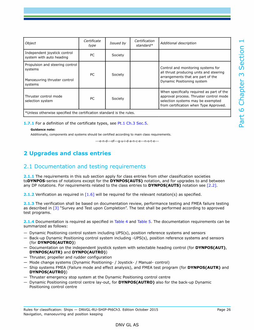
1.7 CertificationProducts in the DP system shall be certified as required in Table 6. All objects are independent productsand the certificates can hence be issued independently or as combined certificates if delivered by the samemanufacturer:
Table 6 Certification requirements
Object Certificatetype Issued by Certification
standard* Additional description
Dynamic positioning controlsystem PC Society
Part
6 C
hapt
er 3
Sec
tion
1
Rules for classification: Ships — DNVGL-RU-SHIP-Pt6Ch3. Edition October 2015 Page 26Navigation, manoeuvring and position keeping
DNV GL AS
Object Certificatetype Issued by Certification
standard* Additional description
Independent joystick controlsystem with auto heading PC Society
Propulsion and steering controlsystems
Manoeuvring thruster controlsystems
PC Society
Control and monitoring systems forall thrust producing units and steeringarrangements that are part of theDynamic Positioning system
Thruster control modeselection system PC Society
When specifically required as part of theapproval process. Thruster control modeselection systems may be exemptedfrom certification when Type Approved.
*Unless otherwise specified the certification standard is the rules.
1.7.1 For a definition of the certificate types, see Pt.1 Ch.3 Sec.5.Guidance note:Additionally, components and systems should be certified according to main class requirements.
---e-n-d---of---g-u-i-d-a-n-c-e---n-o-t-e---
2 Upgrades and class entries
2.1 Documentation and testing requirements
2.1.1 The requirements in this sub section apply for class entries from other classification societiestoDYNPOS-series of notations except for the DYNPOS(AUTS) notation, and for upgrades to and betweenany DP notations. For requirements related to the class entries to DYNPOS(AUTS) notation see [2.2].
2.1.2 Verification as required in [1.6] will be required for the relevant notation(s) as specified.
2.1.3 The verification shall be based on documentation review, performance testing and FMEA failure testingas described in [3] “Survey and Test upon Completion”. The test shall be performed according to approvedtest programs.
2.1.4 Documentation is required as specified in Table 4 and Table 5. The documentation requirements can besummarized as follows:
— Dynamic Positioning control system including UPS(s), position reference systems and sensors— Back-up Dynamic Positioning control system including -UPS(s), position reference systems and sensors
(for DYNPOS(AUTRO))— Documentation on the independent joystick system with selectable heading control (for DYNPOS(AUT),
DYNPOS(AUTR) and DYNPO(AUTRO))— Thruster, propeller and rudder configuration— Mode change systems (Dynamic Positioning- / Joystick- / Manual- control)— Ship systems FMEA (Failure mode and effect analysis), and FMEA test program (for DYNPOS(AUTR) and
DYNPOS(AUTRO))— Thruster emergency stop system at the Dynamic Positioning control centre— Dynamic Positioning control centre lay-out, for DYNPOS(AUTRO) also for the back-up Dynamic
Positioning control centre

Part
6 C
hapt
er 3
Sec
tion
1
Rules for classification: Ships — DNVGL-RU-SHIP-Pt6Ch3. Edition October 2015 Page 27Navigation, manoeuvring and position keeping
DNV GL AS
— For DYNPOS(AUTRO), cable routing layout drawing, system arrangement plan and fire and floodingseparation drawings.
— Environmental regularity numbers (ern*), calculation.
2.1.5 Vessels to be assigned the qualifier A shall carry a valid FMEA, with a corresponding FMEA testprogram.
2.1.6 Any deviations from requirements relevant for the class entry or upgrade notation found as a resultfrom the documentation review and testing required in [2.1.3] to [2.1.4] shall be rectified before the vesselcan be assigned the relevant DYNPOS notation.
2.2 Class entries not requiring additional verification2.2.1 The requirements in this sub section apply for class entries from other classification societies toDPS-series ofnotations and for the DYNPOS(AUTS) notation.
2.2.2 In general, the system design will be accepted based on a corresponding, valid and maintainedDynamic Positioning class notation, from the losing society.
Guidance note:This implies that class entry vessels may have designs based on somewhat different requirements than those given in these rules.
---e-n-d---of---g-u-i-d-a-n-c-e---n-o-t-e---
2.2.3 Documentation review, survey or testing will not be required prior to class assignment, unless theperiodic Dynamic Positioning survey will be due or overdue (based on the date of the last survey or test fromthe losing society) when the vessel is taken into class.
2.2.4 Vessels to be assigned the qualifier A shall have an updated FMEA, with a corresponding FMEA testprogram.
3 Survey and test upon completion
3.1 General
3.1.1 Upon completion, the DP system shall be subjected to final tests according to approved test programs.Functional, redundancy and failure response testing of the DP system shall be performed at sea trials. Theprogram(s) shall contain test procedures and acceptance criteria. Prior to the DP system tests, all systemsand equipment included in the DP system shall be successfully commissioned and tested.
Guidance note:The systems that should be tested prior to DP system tests should at least include:
— load test according to main class
— power management system(s)
— switchboard control and protection
— thruster control and transfer of thruster control
— manual override of thruster control
— emergency stops
— communication systems
— main alarm system as for main class and E0 (if applicable)
— integrated automation systems (if applicable)
— other systems as applicable.

Part
6 C
hapt
er 3
Sec
tion
1
Rules for classification: Ships — DNVGL-RU-SHIP-Pt6Ch3. Edition October 2015 Page 28Navigation, manoeuvring and position keeping
DNV GL AS
---e-n-d---of---g-u-i-d-a-n-c-e---n-o-t-e---
3.1.2 When deemed necessary by the attending surveyor, tests additional to those specified by the testprogram may be required.
3.2 Measuring system
3.2.1 All DP-control systems sensors, peripheral equipment, and position reference systems shall be testedas part of the complete DP system.
3.2.2 Failures of DP-control system sensors and position reference systems shall be simulated to check thealarm system and the switching function.
3.3 Thrusters
3.3.1 Functional tests of control and alarm systems of each thruster shall be carried out.
3.3.2 All signals within the thruster control systems and signals exchanged between each thruster and theDP-control systems shall be checked.
3.3.3 The different modes of thruster control shall be tested. Proper operation of mode selection shall beverified.
3.4 UPS power supplyThe capacity of the UPS batteries shall be tested, in addition to verification of the alarms required in [8].
3.5 Independent joystick control systemAll functions of the independent joystick system shall be tested.
3.6 Complete DP system test
3.6.1 The complete DP system shall be tested in all operational modes, with simulation of different failureconditions, in order to try out e.g. switching modes, back-up systems, fail to safe response (e.g. thrustercontrol system I/O) and alarm systems.
Guidance note:Different operational modes apply to the DP-control system, the power system, thruster systems etc.
---e-n-d---of---g-u-i-d-a-n-c-e---n-o-t-e---
3.6.2 Change of command between the automatic DP-control system, independent joystick system and theindividual thruster lever systems shall be demonstrated.
3.6.3 Position and heading keeping function shall be demonstrated on all possible combinations ofposition reference systems (PRS), and on each PRS as a single system. Position change function shall, ifimplemented, be demonstrated on each PRS as a single system. Selecting and de-selecting of PRS shall alsobe tested.
3.6.4 During sea trials the offset inputs for each position reference system and relevant sensors in the DP-control system should be verified and demonstrated to the attending surveyor by setting out the offsets ondrawings. It should be verified that these fit with the actual placing of the equipment.

Part
6 C
hapt
er 3
Sec
tion
1
Rules for classification: Ships — DNVGL-RU-SHIP-Pt6Ch3. Edition October 2015 Page 29Navigation, manoeuvring and position keeping
DNV GL AS
3.6.5 Manual override, as required by [6.6] and [7.3.2] shall be demonstrated during normal operation andfailure conditions.
3.6.6 A duration test shall be carried out for at least 8 hours with the complete automatic system inoperation. All failures shall be recorded and analysed.
Guidance note:The time spent on DP functional tests may be deducted from the time required for the duration test.
---e-n-d---of---g-u-i-d-a-n-c-e---n-o-t-e---
3.6.7 A high seas trial shall be carried out with full system operation for at least 2 hours. The weatherconditions shall be such that an average load level on the thrusters of 50% or more is achieved.
Guidance note:The test described in [3.6.7] is dependent on weather conditions and may be omitted if satisfactory results were obtained from thetest described in [3.6.6]. Typically this will be required for DP-control systems of novel design.
---e-n-d---of---g-u-i-d-a-n-c-e---n-o-t-e---
3.6.8 Thruster emergency stop function shall be demonstrated.
3.6.9 For notations DYNPOS(AUTR) and DYNPOS(AUTRO), alarm upon loop failure as required by[7.3.7], shall be demonstrated.
3.6.10 For the DYNPOS-series of notations, except for DYNPOS(AUTS), rudder steering gears includedunder DP control a test shall be carried out verifying that maximum design temperature of actuator and allother steering gear components is not exceeded when the rudder is continuously put over from border toborder within the limits set by the DP-control system, until temperature is stabilized.
Guidance note:The test should be carried out with the propeller(s) running with an average propulsion thrust of not less than 50%, unless the controlsystem ensures that rudder operation is performed at zero propulsion thrust only, upon which the test may be carried out withoutthe propeller(s) running. The test may be carried out in any steering gear control mode. Number of steering gear pumps connectedand rotation speed should be the maximum allowed during DP operation.
---e-n-d---of---g-u-i-d-a-n-c-e---n-o-t-e---
3.7 Redundancy and failure response tests
3.7.1 The requirements in this subsection apply to DYNPOS(AUTR), DYNPOS(AUTRO), DPS(2) andDPS(3).
3.7.2 A selection of tests within each system analysed in the FMEA shall be carried out. Specific conclusionsof the FMEA for the different systems shall be verified by tests when redundancy, fail safe response, orindependence is required. The test selection shall cover all specified technical system configurations.
Guidance note:For DYNPOS(AUTRO) and DPS(3) this implies that loss of all systems in relevant fire zones should be tested.
---e-n-d---of---g-u-i-d-a-n-c-e---n-o-t-e---
3.7.3 The test procedure for redundancy shall be based on the simulation of failures and shall be performedunder as realistic conditions as practicable.
Guidance note:It is understood that not all failure modes in all systems are possible to simulate. For such failure modes the acceptance of thesystem will be based on the theoretical FMEA, and hence the documentation analysis of these failure modes should be emphasizedin the FMEA.

Part
6 C
hapt
er 3
Sec
tion
1
Rules for classification: Ships — DNVGL-RU-SHIP-Pt6Ch3. Edition October 2015 Page 30Navigation, manoeuvring and position keeping
DNV GL AS
---e-n-d---of---g-u-i-d-a-n-c-e---n-o-t-e---
3.7.4 For notation DPS(2): In case redundancy is based upon change-over of a single stern thruster asdescribed in [4.3.2], then the functionality of the change over mechanism and availability of the thrusterafter single failure shall be demonstrated at sea-trials.
4 General arrangement
4.1 General requirements
4.1.1 The general requirements for DP system design are presented in Table 7. Comparison of the maindifferences between the DPS-series and the DYNPOS-series of notations are presented in Table 8.
4.1.2 For DYNPOS(AUTR), DYNPOS(AUTRO), DPS(2) and DPS(3), the design and level of redundancyemployed in system arrangements shall be to the extent that the vessel maintains the ability to keep positionafter worst case failure(s).
Guidance note:In general the DYNPOS-series of notations are requiring a higher degree of availability and robustness as compared to the DPS-series of notations. The detailed differences are outlined in the specific requirements given in these rules.
---e-n-d---of---g-u-i-d-a-n-c-e---n-o-t-e---
4.2 Redundancy and failure modes
4.2.1 The requirements in this sub-section apply primarily to DP systems with DYNPOS(AUTR),DYNPOS(AUTRO), DPS(2) and DPS(3) notations. For DYNPOS(AUTS), DYNPOS(AUT) and DPS(1)notations, the redundancy requirements are according to main class, unless specific requirements are stated.
4.2.2 The redundancy design intent(s) and worst case failure design intent(s) based on specified redundancygroups shall be stated, and in addition all the relevant technical system configuration(s) shall be specified.(Reference is made to [1.5] and the required DP Design philosophy document.) Only redundancy designintents that are verified by approval and testing can be incorporated in the consequence analysis required by[6.13].
Guidance note:The redundancy groups will emerge as a consequence of the worst case single failure within each group. The rules do not giverequirements to the number of (beyond 2) or ratio between the defined groups. The groups should be identified in the FMEA, verifiedby testing and incorporated in the consequence analysis.
---e-n-d---of---g-u-i-d-a-n-c-e---n-o-t-e---
4.2.3 Based on the relevant single failure definition in [4.4], [4.5] and [4.6], worst case failures shall bedetermined in the FMEA. The consequence of the identified worst case failure(s) in terms of reduction inposition and heading keeping ability shall be used as the criterion for the consequence analysis described in[6.13].
4.2.4 In order to meet the single failure criteria in [4.4], [4.5] and [4.6], redundancy of components will benecessary as follows:
— for notation DYNPOS(AUTR), redundancy of all active components and specified static components— for notation DPS(2), redundancy of all active components and specified static components, except for
possible exemptions based on the requirements in [4.3.2] and [4.3.5] with guidance notes.— for notation DYNPOS(AUTRO) and DPS(3), redundancy of all components and physical separation of
the components.

Part
6 C
hapt
er 3
Sec
tion
1
Rules for classification: Ships — DNVGL-RU-SHIP-Pt6Ch3. Edition October 2015 Page 31Navigation, manoeuvring and position keeping
DNV GL AS
4.3 Redundancy
4.3.1 For DYNPOS(AUTR), DYNPOS(AUTRO) and DPS(3): The DP system shall be designed withredundancy. A position keeping ability shall be maintained without disruption upon any single failure.
Guidance note:Component and system redundancy, in technical design and physical arrangement, should in principle be immediately available withthe capacity required for the DP system to safely terminate the work in progress. The consequence analysis required in [6.13] willgive an indication whether the position and heading can be maintained after a single failure.
---e-n-d---of---g-u-i-d-a-n-c-e---n-o-t-e---
4.3.2 For DPS(2): The requirement in [4.3.1] also applies to this notation, however it can be accepted thatthe system is dependent on change-over of a single stern thruster in order to maintain position keepingability after loss of one redundancy group. The change over may be based on full stop and restart.
Guidance note:A typical thruster configuration with two bow tunnel thrusters, one single stern tunnel thrusters and two pitch propellers with high-liftrudders, distributed between two redundancy groups will be accepted for DPS(2) notation as long as the single stern tunnel thrusteris arranged for being changed over between the two redundancy groups.When such design is chosen as basis for the redundancy the possibility for hidden failures causing loss of the change-over functionand the possibility for single failures affecting more than one redundancy groups should be carefully considered in order to minimizethe possibility of such failures. Adequate evaluations should be included in the FMEA required in [1.6].
---e-n-d---of---g-u-i-d-a-n-c-e---n-o-t-e---
4.3.3 For DYNPOS(AUTR), DYNPOS(AUTRO) and DPS(3): Redundancy shall be based upon runningmachinery. Automatic or manual intervention arranged to improve the position keeping ability after a failurecan be arranged, but cannot be considered by the consequence analysis.
Guidance note:The redundancy requirements will not be considered as complied with if based upon manual or automatic start or restart of generatorsthrusters or pumps, or if based upon automatic or manual reconfiguration of auxiliary systems e.g. by use of valves.Automatic activation of equipment may be accepted as contributing to redundancy only if their reliability and simplicity of operation issatisfactory so that they can be brought into operation before position and heading keeping performance is degraded. This principleis typically only accepted for transfer of control between redundant controllers and for standby start of sea water cooling pumpsfor DYNPOS(AUTR).
---e-n-d---of---g-u-i-d-a-n-c-e---n-o-t-e---
4.3.4 DYNPOS(AUTR), DPS(2), DYNPOS(AUTRO) and DPS(3): Stop of thrusters and subsequent start-up of available thrusters will not be accepted as contributing to the redundancy. Dual feeding of thrustersfrom different redundancy groups may be accepted as long as all the following conditions are met:
— No failures in the thruster dual feed system shall be able to propagate to both power systems supplyingthe thruster. In order to mitigate the effects of hidden failures, minimum two independent barriers,both capable of isolating upon failures, shall be arranged in each supply line. For DYNPOS(AUTRO)and DPS(3) these barriers shall be outside of the common thruster space and the supply lines shall beseparated by A60 partition.
— The thruster is fully ready with specified power available for DP control without disruption or manualintervention after failure. Available thrust output may be reduced to a specified level when only onesupply is available.
— The thruster is separated from the failed zone and redundancy group.— The availability of both supplies is monitored and communicated to the DP-control systems.— Start and any necessary reset after full stop of thruster is available in DP control centre.— Auxiliary systems are autonomous for each thruster.— Supply to auxiliary and control systems arecontinuously available.

Part
6 C
hapt
er 3
Sec
tion
1
Rules for classification: Ships — DNVGL-RU-SHIP-Pt6Ch3. Edition October 2015 Page 32Navigation, manoeuvring and position keeping
DNV GL AS
— Thruster failure or trip shall prevent automatic re-start.— The discrimination and voltage-dip ride through capabilities shall be documented.— For DYNPOS(AUTRO) and DPS(3): The discrimination and voltage-dip ride through capabilities shall
also be verified by live testing.Guidance note 1:Reference is made to document DNVGL-RP-D102 Failure mode and effect analysis (FMEA) of redundant systems, Appendix D, fordiscussion on the subject and examples of relevant failure modes. See also [8.5.4] with guidance note.
---e-n-d---of---g-u-i-d-a-n-c-e---n-o-t-e---
Guidance note 2:For DYNPOS(AUTRO) and DPS(3) it is utmost important that the design is built and prepared for the required live testing of severefailure modes both at the new building stage and at renewal trials during the vessels entire operational life time.
---e-n-d---of---g-u-i-d-a-n-c-e---n-o-t-e---
4.3.5 For DPS(2): The requirement in [4.3.3] also applies to this notation; however change-over of a singlestern thruster as described in [4.3.2]] can be accepted. In addition automatic change-over of redundantduty-standby pumps in accepted common piping systems will also be accepted.
4.4 Failure modes
4.4.1 For notation DYNPOS(AUTR) the loss of position shall not be allowed to occur in the event of a singlefailure in any active component or system, nor in any static components as specified in these rules. Singlefailure criteria for DYNPOS(AUTR) include:
— any active component or system— static components as specified in the rules— other static components which are not properly documented with respect to protection— a single inadvertent act of operation. If such an act is reasonably probable— systematic failures or faults that can be hidden until a new fault appears— Common cause failures when found relevant— automatic interventions caused by external events, when found relevant.
Guidance note:In order to reduce the probability of inadvertent acts, the following may be used:
— double action
— operation of two separate devices
— using screen based question pop-ups.
---e-n-d---of---g-u-i-d-a-n-c-e---n-o-t-e---
4.4.2 For notation DYNPOS(AUTR) the following components/systems are also considered to fail asconsequence of a single failure:
— coolers— filters— motorised valves— fuel oil service tanks and appurtenant piping supplying the engine(s)— electrical and electronic equipment (this includes all on-board equipment and systems, e.g. any safety
shut-down systems (spurious shut down), vessel control systems, external force measurements, etc.— When considering single failures of switchboards, the possibility of short-circuit of the bus-bars has to be
considered

Part
6 C
hapt
er 3
Sec
tion
1
Rules for classification: Ships — DNVGL-RU-SHIP-Pt6Ch3. Edition October 2015 Page 33Navigation, manoeuvring and position keeping
DNV GL AS
4.4.3 For notation DPS(2) the single failure criteria shall be based on the same criteria as given forDYNPOS(AUTR) as given in [4.4.1]. However, based on proper FMEA, static components like coolers, filtersand piping/tanks may be considered as not failing.
Guidance note:Reference is made to IMO MSC/Circ.645 “Guidelines for vessels with dynamic positioning systems”, dated 6 June 1994 part 2.2.2:For equipment class 2, a loss of position is not to occur in the event of a single fault in any active component or system. Normallystatic components will not be considered to fail where adequate protection from damage is demonstrated, and reliability should thesatisfaction of the Administration. Single failure criteria include:
1) Any active component or system (generators, thrusters, switchboards, remote controlled valves, etc.).
2) Any normally static component (cables, pipes, manual valves, etc.) which is not properly documented with respect toprotection and reliability.
---e-n-d---of---g-u-i-d-a-n-c-e---n-o-t-e---
4.4.4 For class notations DYNPOS(AUTRO) and DPS(3) loss of position shall not be allowed to occur in theevent of a single failure. In addition to the single failures listed under [4.4.1], the single failure criteria forDYNPOS(AUTRO) and DPS(3) include:
— any static components in the DP system— all components in any watertight compartment, from fire and flooding— all components in any one fire-subdivision, from fire or flooding (for cables, see also [4.6.1]).
4.5 Independence
4.5.1 Independence shall take into account all technical functions. Use of shared components may beaccepted if the reliability is sufficiently high and/or the effect of failure is sufficiently low.
Guidance note:Particular attention should be paid to the redundancy and independence of ventilation and cooling facilities for equipment wheretemperature problems are anticipated.
---e-n-d---of---g-u-i-d-a-n-c-e---n-o-t-e---
4.6 Separation
4.6.1 For class notations DYNPOS(AUTRO) and DPS(3) systems that form the designed redundancy intentshall be separated by bulkheads and decks, fire-insulated by A-60 class division, and in addition, watertight ifbelow the bulk-head deck. See also [9].
Guidance note 1:The term “systems” should be understood to also include single components, cabling, and piping.
---e-n-d---of---g-u-i-d-a-n-c-e---n-o-t-e---
Guidance note 2:If two A-0 bulkheads are arranged in areas with low fire risk, this may be accepted based on case-by-case approval.
---e-n-d---of---g-u-i-d-a-n-c-e---n-o-t-e---
Guidance note 3:Cabling to equipment that forms part of the designed redundancy requirement should be separated by bulkheads and decks, fire-insulated by A-60 class division. When this is practically unavoidable, cables can be separated by use of A-60 cable ducts or equivalentfire-protection. This alternative is not accepted in high fire risk areas, e.g. engine rooms and fuel treatment rooms. This, as far aspracticable, also applies to piping.
---e-n-d---of---g-u-i-d-a-n-c-e---n-o-t-e---
Guidance note 4:On open deck, cables in separate pipes that are separately routed may be accepted.
Part
6 C
hapt
er 3
Sec
tion
1
Rules for classification: Ships — DNVGL-RU-SHIP-Pt6Ch3. Edition October 2015 Page 34Navigation, manoeuvring and position keeping
DNV GL AS
---e-n-d---of---g-u-i-d-a-n-c-e---n-o-t-e---
Guidance note 5:Suitable means should be provided to keep the ambient temperature inside of an A-60 cable duct within maximum temperature forthe cables, when necessary, taking into account the temperature rise of cables under full power.
---e-n-d---of---g-u-i-d-a-n-c-e---n-o-t-e---
Guidance note 6:Watertight separation should also be considered in areas above the bulk-head deck where large quantity of liquids may occur as aconsequence of leakage. Special attention should be paid to areas where leakage of flammable liquids may occur. Identification andanalysis of such failure modes should be part of the FMEA.
---e-n-d---of---g-u-i-d-a-n-c-e---n-o-t-e---
Guidance note 7:Separated power systems simultaneous supplying non DP related equipment placed in a non-separated areas or areas with lower firesegregation than A60 may be accepted, provided sufficient measures are taken in order to prevent failure consequences beyond theworst case failure design intent for the DP system. Reference is made to document DNV-RP-D102 Failure mode and effect analysis(FMEA) of redundant rystems, Appendix D, for further discussion and details related to this issue.
---e-n-d---of---g-u-i-d-a-n-c-e---n-o-t-e---
4.6.2 Watertight doors in A60 insulated bulkheads need not to be insulated. See SOLAS Chapter. II-2 Reg.9.4.2.4. In such cases the materials of the doors shall have melting points of not less than 950 °C andcombustible materials shall be installed with a minimum distance of 450 mm from the door.
5 System arrangement
5.1 General5.1.1 The requirements for system arrangement for the different notations DYNPOS-series and the DPS-series aresummarised in Table 7. Specific requirements for each subsystem are presented under the respective sectionheadings.

Rules for classification: S
hips — D
NVG
L-RU
-SH
IP-Pt6Ch3. Edition O
ctober 2015Page 35
Navigation, m
anoeuvring and position keeping
DN
V G
L AS
Part 6 Chapter 3 Section 1
Table 7 System arrangement
Minimum requirements for class notations
DYNPOS(AUT) DYNPOS(AUTR) DYNPOS(AUTRO)Subsystem or componentDYNPOS(AUTS)
DPS(1) DPS(2) DPS(3)
Electrical system No redundancy 3) Noredundancy 3)
Redundancy intechnical design
Redundancy in technicaldesign and physicalseparation (separate
compartments)
Main switchboard 13) 13) 1 2 in separate compartments
Bus-tie breaker 03) 03) 1 2, 1 breaker in each MSB
Distribution system Non-redundant3) Non-redundant 3) Redundant Redundant, through
separate compartments
Electricalpower system
Power management No NoDYNPOS
(AUTR) :Yes
DPS(2): No
DYNPOS (AUTRO): YesDPS(3): No
Arrangement of thrusters No redundancy No redundancy Redundancy intechnical design4)
Redundancy in technicaldesign and physicalseparation (separate
compartments)Thrusters
Single levers for each thrusterat main DP-control centre Yes Yes Yes Yes
Automatic control; numberof computer systems 1 1 2 2 + 1 in back-
up control centrePositioning
control system Manual control; independentjoystick system with
automatic heading control 2)No Yes Yes Yes
Position reference systems 1 2 3 3 whereof 1 in back-up control centre
Wind 1 1DYNPOS
(AUTR):3:
DPS(2): 2
DYNPOS (AUTRO):3 DPS(3): 2
whereof 1 connected toback-up control system
Sensors
External sensors
Headingreferencesystem1)
1 1 3 3 whereof 1 in back-up control centre

Rules for classification: S
hips — D
NVG
L-RU
-SH
IP-Pt6Ch3. Edition O
ctober 2015Page 36
Navigation, m
anoeuvring and position keeping
DN
V G
L AS
Part 6 Chapter 3 Section 1
Minimum requirements for class notations
DYNPOS(AUT) DYNPOS(AUTR) DYNPOS(AUTRO)Subsystem or componentDYNPOS(AUTS)
DPS(1) DPS(2) DPS(3)
Vertical referencesensor (VRS) 1 1
DYNPOS(AUTR):3
DPS(2): 25)
3 whereof 1 in back-up control centre
UPS 0 1 22 + 1 in back-up
control centre
Printer Yes6) Yes6) Yes6) Yes6)
Back-up control centre for dynamicpositioning control back-up system No No No Yes
1) The Heading reference system(s) shall comply with IMO Res. A424(XI) performance standards for gyro-compasses. When three headingreference systems are required one of the three may be replaced by a heading measuring device based upon another principle, as long asthis heading device is type approved as a THD (Transmitting Heading Device) as specified in IMO Res. MSC.116(73). For notations DYNPOS(AUTRO) and DPS(3) this is not to be the gyro placed in the back-up control centre.
Heading sensors based on other principles may be accepted upon special considerations. When such considerations are made the totalheading device installation shall be considered in view of redundancy, robustness and failure tolerance, both with respect to the number ofheading devices installed, principles used, and the installation of the equipment with respect to signal transmission, power supply and physicalinstallation (including separation when required).
2) The heading input may be taken from any of the required heading input devices.3) When this is part of the ship normal electrical power system (i.e. used for normal ship systems, not only the DP system), then Pt.4 Ch.8 applies.4) For DPS(2) see also [4.3.2].5) Where necessary for the correct functioning of position reference systems, at least three vertical reference sensors shall be provided for notation
DPS(2). If the DP-control system can position the ship within the operating limits without VRS corrections, only 2 VRSs are required.6) Dynamic positioning systems. The printer may be replaced by a separate electronic data logger, provided the data is stored on redundant
electronic media (the DP-control system operator stations may be used as redundant storage media) and the data logger has UPS supply incompliance with [8]. The data logger shall have HMI and functionality in place for the operator to access and view the stored date in an efficientmanner. The data logger shall have capacity for storage of data for minimum 7 days of operation. It shall be possible to upload to offline storagemedia, for data storage longer than the logger capacity. (The data logger should preferably be time synchronised with other alarm and loggingsystems to support performance and incident analysis.)

Part
6 C
hapt
er 3
Sec
tion
1
Rules for classification: Ships — DNVGL-RU-SHIP-Pt6Ch3. Edition October 2015 Page 37Navigation, manoeuvring and position keeping
DNV GL AS
5.1.2 In general additional requirements to achieve higher availability and robustness will apply to theDYNPOS-series as compared to the DPS-series of notations. An overview of the main differences betweenthe two series are summarised in Table 8 for quick reference. Specific requirements for each subsystem arepresented under the respective section headings.
Table 8 Comparison table for the main differences between the DPS-series and the DYNPOS-seriesof notations.
(Note: For complete overview of the differences the whole rule section shall be considered.)
Class notations
Technical item: Rulereference
DY
NP
OS
(AU
TS)
DP
S(1
)
DY
NP
OS
(AU
T)
DP
S(2
)
DY
NP
OS
(AU
TR)
DP
S(3
)
DY
NP
OS
(AU
TRO
)
Thruster configuration without stern thrusters,i.e. side thrust based on combination of ruddersand propellers.
[7.1] and[7.2] Yes Yes No No No No No
Redundancy can be based upon change over ofa single stern thruster.
[4.3.2],[4.3.3]
and [4.3.5]NA NA NA Yes No No No
Redundancy can be based upon automaticchange-over of redundant duty-standby pumpsin accepted common piping systems
[4.3.5] NA NA NA Yes No No No
Additional monitoring requirements for steeringgear.
Pt.4 Ch.10Sec.1 [5.8] No No Yes No Yes No Yes
Power Management System required. [8.4] No No No No Yes No Yes
Common static components may be acceptedin redundant fuel oil, fresh water cooling andpneumatic systems.
[6.4] NA NA NA Yes No No No
Number of VRSs required. Table 7above 1 1 1 2*) 3 3 3
Number of wind sensors required Table 7above 1 1 1 2 3 2 3
Loop monitoring of emergency stop loops. [7.3] No No No No Yes No**) Yes
HMI for position reference systems requiredoutside DP-control system operator station(s). [6.8] No No Yes No Yes No Yes
Main DP-control system shall include a joystickmode. [6.3.7] No No Yes No Yes No Yes
ern* required. [1.6.6]and [10] No No Yes No Yes No Yes

Part
6 C
hapt
er 3
Sec
tion
1
Rules for classification: Ships — DNVGL-RU-SHIP-Pt6Ch3. Edition October 2015 Page 38Navigation, manoeuvring and position keeping
DNV GL AS
Class entry from other class societies will bebased on corresponding valid notation fromlosing class society.
[2.2] Yes Yes No Yes No Yes No
Class entry from other class societies requiresdocumentation approval and testing (functionaland FMEA) at entry.
[2.1] No No Yes No Yes No Yes
NA = Not Applicable
*)Where necessary for the correct functioning of position reference systems, at least three vertical reference sensorsshall be provided for notation DPS(2). If the DP-control system can position the ship within the operating limits withoutVRS corrections, only 2 VRSs are required.
**) Note that the DPS(3) integrity requirements shall be complied with for all emergency stop systems. Reference ismade to[5.6].
5.2 DP control centre
5.2.1 The DP vessel shall have its DP control centre designated for DP operations, where at least therequired indicators, displays, alarm panels, control panels and internal communication systems are installed.This equipment shall be arranged with easy access for the operator so that he/she does not need to changeposition when operating the control systems.
Guidance note 1:Changing orientation will be accepted provided that the operator's view of the operating area will not change significantly. This impliesthat the operator should not be forced to turn his back to the operating area when changing between different control systems (DP-control system, manual thruster levers, and independent joystick control system).Manual levers and the independent joystick should be easily accessible from the DP operator work station. Thruster emergency stopsand mode change system should be within reach from both manual lever operator stations and DP operator stations, and easilyaccessible from the independent joystick operator work station. Somewhat longer distances may be accepted case by case.When the systems/equipment are accepted split between more than one work station at the DP control centre (e.g. a manoeuvringand a ship handling station), the required automatic, joystick and manual lever control modes should be available at the workstation(s) being designated for the DP operator.In general all required VDU should be readable from DP, Joystick and manual lever operator stations.
---e-n-d---of---g-u-i-d-a-n-c-e---n-o-t-e---
Guidance note 2:The DP control centre may be a dedicated part of the navigation bridge. System components which do not require frequent orimmediate operator attention may be installed in alternate locations.Systems that are required to be located at the DP control centre includes: DP-control and independent joystick control operatorstations, required position reference systems HMI, manual thruster levers, mode change systems, thruster emergency stops, internalcommunications.
---e-n-d---of---g-u-i-d-a-n-c-e---n-o-t-e---
5.2.2 Installed portable equipment shall have its dedicated fixed location at each work station where it isintended to be used. The orientation of levers and indicators shall be in accordance with the vessel axis at allintended locations.
Guidance note:One typical example of such equipment is portable joystick operator stations. It is assumed that such required equipment is placedat its dedicated location the DP control centre during DP operations.
---e-n-d---of---g-u-i-d-a-n-c-e---n-o-t-e---

Part
6 C
hapt
er 3
Sec
tion
1
Rules for classification: Ships — DNVGL-RU-SHIP-Pt6Ch3. Edition October 2015 Page 39Navigation, manoeuvring and position keeping
DNV GL AS
5.2.3 The location of the DP control centre shall be chosen to suit the main activity of the vessel.
5.2.4 The DP control centre shall be arranged such that the DP operator has a good view of the vessel’sexterior limits and the surrounding area.
5.2.5 For vessels with DYNPOS(AUTRO) and DPS(3) notation, a back-up DP control centre shall bearranged for the location of the back-up DP-control system. This centre shall be separated from the maincentre by A-60 class division, and located with easy access from the main DP control centre.
Guidance note:The back-up DP control centre may be used if the main DP control centre is on fire. This should be considered when the locationof the back-up DP control centre is chosen.
---e-n-d---of---g-u-i-d-a-n-c-e---n-o-t-e---
5.2.6 The back-up DP control centre shall be arranged with similar view to the vessel’s exterior limits and thesurrounding area as the main DP control centre.
Guidance note:For vessels that carry out DP operations where the DP operator’s view of the working area is not considered necessary, the view fromthe DP back-up control centre may not be similar to the view from the main DP control centre. For such vessels it may be acceptedthat the view from the back-up DP control centre is provided by a sufficiently fault tolerant (all failures affecting the possibility toperform automatic DP control from main DP centre should be considered) CCTV system. This will apply e.g. for drilling units.
---e-n-d---of---g-u-i-d-a-n-c-e---n-o-t-e---
5.3 Arrangement of positioning control systems
5.3.1 Notation DYNPOS(AUTS) shall include an automatic control mode and an independent manualposition control mode based on the control levers of each thruster.
5.3.2 Notation DYNPOS(AUT) and DPS(1) shall include:
— an automatic position control mode— an independent joystick system with automatic heading control— manual levers for each thruster.
Guidance note:A joystick and a joystick mode included in the automatic positioning control system will not meet the requirement for an independentjoystick system in notations DYNPOS(AUT), DYNPOS(AUTR), DYNPOS(AUTRO), DPS(1), DPS(2) and DPS(3). See also [6].
---e-n-d---of---g-u-i-d-a-n-c-e---n-o-t-e---
5.3.3 Notation DYNPOS(AUTR) and DPS(2) shall include:
— an automatic position control mode consisting of at least two mutually independent control systems— an independent joystick system with automatic heading control— manual levers for each thruster.
5.3.4 Notation DYNPOS(AUTRO) and DPS(3) shall include:
— an automatic position control mode consisting of at least two mutually independent control systems— an independent joystick system with automatic heading control— manual levers for each thruster— an automatic back-up DP positioning control system.
Guidance note:

Part
6 C
hapt
er 3
Sec
tion
1
Rules for classification: Ships — DNVGL-RU-SHIP-Pt6Ch3. Edition October 2015 Page 40Navigation, manoeuvring and position keeping
DNV GL AS
This guidance note applies for [5.3.1] to [5.3.4]. Use of combined mechanical levers for two or more thrusters may be accepted inaccordance with the following principles:. For notations not requiring redundancy (DYNPOS(AUTS), DYNPOS(AUT) and DPS(1))where the minimum requirement is one aft thruster and one forward thruster and one longitudinal thruster:
— at least one lever for thruster(s) providing transverse thrust forward
— at least one lever for thruster(s) providing transverse thrust aft
— at least one lever for thruster(s) providing longitudinal thrust.
For notations requiring redundancy (DYNPOS(AUTR), DYNPOS(AUTRO), DPS(2) and DPS(3)) where the minimum requirementis two aft thrusters, two forward thrusters and two longitudinal thrusters:
— at least two levers for thrusters providing transverse thrust forward
— at least two levers for thrusters providing transverse thrust aft
— at least two levers for thrusters providing longitudinal thrust.
As an example this means that two bow tunnel thrusters for notation DYNPOS(AUT) can use a common HW lever. Another exampleis two bow tunnel thrusters and one bow azimuth thruster for DYNPOS(AUTR) where the two bow tunnel thrusters can use acombined lever, while the bow azimuth lever is providing the required redundancy. However, on a DYNPOS(AUTR) vessel where theredundancy is provided by two bow tunnel thrusters only, these cannot use a common lever.
---e-n-d---of---g-u-i-d-a-n-c-e---n-o-t-e---
5.3.5 For notations DYNPOS(AUTRO) and DPS(3): The back-up DP-control system shall include anautomatic position control mode, and shall be interfaced with a position reference, VRS and Headingreference system which shall be able to operate independently of the main system of [5.3.4].
5.4 Arrangement and layout of control panels
5.4.1 The information sources like displays, indicators, etc. shall provide information in a readily usable form.Guidance note:Reference is made to Pt.4 Ch.9 Sec.6.
---e-n-d---of---g-u-i-d-a-n-c-e---n-o-t-e---
5.4.2 The operator shall be provided with immediate information of the effect of any actions, preferably withgraphics.
5.4.3 Where applicable, feedback signals shall be displayed, not only the initial command.
5.4.4 Easy switch-over between operational modes shall be provided. Active mode shall be positivelyindicated.
5.4.5 Positive indications of the operational status of the different systems shall be given.
5.4.6 Indicators and controls shall be arranged in logical groups, and shall be co-ordinated with thegeometry of the vessel, when this is relevant.
5.4.7 If control of a sub-system can be carried out from alternate control stations, positive indication of thestation in charge shall be provided. Responsibility transferred from one station to another shall be indicated.
Guidance note:For control transfer arrangements, see Pt.4 Ch.9 Sec.3.
---e-n-d---of---g-u-i-d-a-n-c-e---n-o-t-e---
5.4.8 Precautions shall be taken to avoid inadvertent operation of controls if this may result in a criticalsituation. Such precautions may be proper location of handles etc., recessed or covered switches, or logicalrequirements for operations.

Part
6 C
hapt
er 3
Sec
tion
1
Rules for classification: Ships — DNVGL-RU-SHIP-Pt6Ch3. Edition October 2015 Page 41Navigation, manoeuvring and position keeping
DNV GL AS
5.4.9 Interlocks shall be arranged, if erroneous sequence of operation may lead to a critical situation ordamage of equipment.
5.4.10 Controls and indicators placed on the navigation bridge and the DP control centre(s) shall besufficiently illuminated to permit use at night and shall be provided with dimming facilities.
5.5 Arrangement and layout of data communication links
5.5.1 When two or more thrusters and their manual controls are using the same data communication link,this link shall be arranged with redundancy in the technical design.
5.5.2 The independent joystick may share the redundant communication link described in [5.5.1] with themanual control, but not with the DP-control system.
5.5.3 When the DP-control system uses a data communication link, this link shall be independent from thecommunication link(s) for manual control.
5.5.4 When units (e.g. thruster controllers) are interfaced to data communication links which are requiredto be independent, the interfacing to each of these networks shall be separately arranged in such a way thatcommon mode failures (e.g. network storm) affecting both communication links are eliminated. This includesboth HW and SW failures in the connected units, the interface and the communication links.
5.5.5 The communication link for the DP-control system shall be arranged with redundancy in technicaldesign for DYNPOS(AUTR) and DPS(2), and with redundancy in the technical design and physicalseparation for DYNPOS(AUTRO) and DPS(3).
5.5.6 For DYNPOS(AUTR) no failure mode as specified in [4.4.1] and [4.4.2], for DPS(2) as specified in[4.4.3], for DYNPOS(AUTRO) and DPS(3) as specified in [4.4.4], shall have an effect on the functionalityof both networks.
Guidance note:For DYNPOS(AUTR) and DPS(2) control cables and communication links belonging to different redundancy groups should beseparated as far as practically possible.
---e-n-d---of---g-u-i-d-a-n-c-e---n-o-t-e---
5.6 Arrangement and layout of emergency stop systems
5.6.1 The requirements in this sub-section apply to notations DYNPOS(AUTR), DPS(2),DYNPOS(AUTRO) and DPS(3).
5.6.2 Emergency stop systems shall not violate the redundancy design intent. Single failures relevant for thegiven notation shall not lead to stop of DP related equipment beyond the specified redundancy groups.
5.6.3 Systems for activation of emergency stop of DP related equipment shall be so arranged that it ispossible to activate emergency stop of equipment belonging to different redundancy groups separately.
Guidance note:For requirement to emergency stop of thrusters please refer to [7].For general requirements to emergency stop please refer to Pt.4 Ch.8 Sec.2.
---e-n-d---of---g-u-i-d-a-n-c-e---n-o-t-e---
5.6.4 For DYNPOS(AUTRO) and DPS(3): When systems for emergency stop are placed in a differentfire zone than the system it controls or systems for emergency stop of equipment belonging to more than

Part
6 C
hapt
er 3
Sec
tion
1
Rules for classification: Ships — DNVGL-RU-SHIP-Pt6Ch3. Edition October 2015 Page 42Navigation, manoeuvring and position keeping
DNV GL AS
one zone are placed in the same fire zone, these systems shall be arranged with sufficient fire and floodingintegrity in order to prevent unintended activation.
Guidance note:Systems for emergency stop of equipment belonging to more than one redundancy group will typically be placed in the same space,e.g. thruster emergency stop on the bridge or emergency stops for auxiliary pumps located in an engine control room. When this isthe case protection against unintended activation due to fire or flooding should be implemented. This includes failures of equipmentand cabling including the activation buttons. The required integrity may for example be achieved by use of a combination of loopmonitoring and thermal fuses which will introduce a loop failure before the activation buttons can short circuit and cause unintendedstop. The thermal fuses should then be placed in close proximity to the respective activation buttons and be a part of the loop thatis covered by the loop monitoring required for the DYNPOS-series.
---e-n-d---of---g-u-i-d-a-n-c-e---n-o-t-e---
5.7 Internal communication
5.7.1 A two-way voice communication facility shall be provided between the DP system control centre(s)(both main and back-up centres for DPS(3) and DYNPOS(AUTRO)) and the navigation bridge, ECR andother relevant operation control centres.
5.7.2 The two-way voice communication system shall be supplied by a battery or an uninterruptible powersupply as a stand-by power supply sufficient to operate the system for at least 30 minutes.
Guidance note:Operational Control Centre (applicable to ships and offshore) is any on-board location where key members of the crew cancommunicate decisions in both normal and emergency situations. Operation Control Centres typically include, but is not limited to:the bridge; the engine control room; a cargo control station; the dynamic positioning control centre, the centralised control room[CCR], the back-up dynamic positioning centre, the driller's cabin, or any other location from where normal and emergency situationsmay be controlled.
---e-n-d---of---g-u-i-d-a-n-c-e---n-o-t-e---
6 Control systems
6.1 General requirementsThe operational status of thrusters, sensors and reference systems used in DP operations shall be clearlyindicated. The following information shall typically be presented:
— “running”— “available for DP”— “in DP operation”.
6.2 Independent joystick control system
6.2.1 An independent joystick system is required for notations DYNPOS(AUT), DYNPOS(AUTR),DYNPOS(AUTRO), DPS(1), DPS(2) and DPS(3).
6.2.2 It shall be possible to control the thrusters manually by a common joystick independent of the DP-control system. The independent joystick system shall include selectable automatic heading control.
6.2.3 Upon selection of independent joystick control system, the procedure for enabling the thrusters forjoystick control shall be straightforward.
6.2.4 Any failure in the independent joystick control system shall initiate an alarm.
Part
6 C
hapt
er 3
Sec
tion
1
Rules for classification: Ships — DNVGL-RU-SHIP-Pt6Ch3. Edition October 2015 Page 43Navigation, manoeuvring and position keeping
DNV GL AS
6.2.5 Any failure causing loss of control of the thrusters in the independent joystick control system shallfreeze the thrust commands or set the thrust commands to zero. If the failure affects only a limited numberof thrusters, the command to these affected thrusters may be set to zero, while keeping the other unaffectedthrusters in joystick control.
6.3 DP-control system
6.3.1 The positioning control system shall perform self-check routines, which shall bring the system to astop, or automatically change-over to a standby (slave) system when critical failure conditions are detected.An alarm shall be initiated in case of failure.
6.3.2 Automatic control mode shall include control of position and heading. Set points for position andheading shall be independently selectable. It shall be possible to individually enter new position and headingset points in automatic control mode.
Guidance note:The rules do not give any specific acceptance criteria for vessel positioning performance. However, in moderate weather conditionsand with a fully operational DP system the vessel should generally be able to demonstrate position keeping accuracy typically withina 3 m radius and ± 1° of heading, given sufficient accurate position and heading reference input.
---e-n-d---of---g-u-i-d-a-n-c-e---n-o-t-e---
6.3.3 When stopped, either by automatic or manual means the positioning control system shall set the thrustcommands to zero.
6.3.4 Loss of one or multiple position reference system input and/or one or multiple sensor inputs shall notlead to significant change in thrust output.
Guidance note:This includes the situation when DP-control system loses the last available position reference system input or sensor input. Positionor heading drive off is not accepted after such failures.
---e-n-d---of---g-u-i-d-a-n-c-e---n-o-t-e---
6.3.5 Upon recovery of position and heading reference input the DP-control system shall not automaticallyapply the last position or heading set point (set points before loss of input) when this is significantly differentfrom the actual vessel position and/or heading. If any other set point than the actual vessel position and/orheading is applied then it shall be operator chosen.
6.3.6 When combining position reference systems and/or sensors in one unit were more than one functionor system can be lost upon one common failure, the consequence to the total system upon such a failureshall be evaluated in order to ensure that the redundancy, independency and separation requirements for thegiven notation(s) are complied with. SeeTable 7. See also [6.5.7].
Guidance note:Unit should be understood as one piece of equipment (or one system) for each sensor and position reference system as required inTable 7. The rule is applicable when equipment/systems serving more than one such function are part of the DP system.
---e-n-d---of---g-u-i-d-a-n-c-e---n-o-t-e---
6.3.7 For DYNPOS(AUT), DYNPOS(AUTR) and DYNPOS(AUTRO): It shall be possible to control thethrusters manually by a common joystick in the main DP-control system. For DYNPOS(AUTRO) therequirement also applies to the back-up DP-control system. The joystick mode shall include selectableautomatic and manual heading control.
6.3.8 The DP control centre is the main control station for equipment in the DP-control system whichrequires manual operation.

Part
6 C
hapt
er 3
Sec
tion
1
Rules for classification: Ships — DNVGL-RU-SHIP-Pt6Ch3. Edition October 2015 Page 44Navigation, manoeuvring and position keeping
DNV GL AS
6.3.9 Sensors and/or reference systems may be shared with other systems provided failure in any of theother systems cannot spread to the DP system.
6.4 Additional for DP-control systems for notation requiring redundancy
6.4.1 The requirements in this sub-section apply to notations DYNPOS(AUTR), DYNPOS(AUTRO),DPS(2) and DPS(3).
6.4.2 There shall be at least two automatic positioning control systems. These systems shall be arrangedsuch that, after the occurrence of any single failure within the DP-control system, command output to agroup of thrusters able to position the ship, can still be produced. For DYNPOS(AUTRO) and DPS(3) asingle automatic back-up DP positioning control system shall also be arranged, as required in [5].
6.4.3 One of the controllers in the main system shall be selected as the online controller. This selectionshall be possible by manual means and by automatic action upon failure of the online controller. The othercontroller(s) shall be in standby mode for automatic or manual change over. Alternatively, 3 or morecontrollers can be arranged in an automatic majority voting system. The voting mechanism shall notjeopardize the redundancy requirements. It shall not be possible to automatically or manually select acontroller which is not ready to assume command as the active controller.
6.4.4 Any failure of an online or standby positioning control system, sensor or positioning reference systemselected, shall initiate an alarm.
Guidance note:When more than two position reference systems and/or sensors inputs for the same parameters (excluding wind measurements)are used by the DP-control system then voting mechanisms should be utilised in order to identify incorrect input, take correct actionupon the failure in order to minimize the consequence of failure and to alarm the operator.
---e-n-d---of---g-u-i-d-a-n-c-e---n-o-t-e---
6.4.5 Self-monitoring and comparison between controllers shall be arranged so that alarm is released upondetection of an unexpected difference in thrust command or position or heading. This shall not jeopardise theindependence of each system or risk common mode failures.
6.4.6 Automatic transfer of online responsibility shall not cause thrust changes of such magnitude that it willbe detrimental to the positioning of the vessel.
6.4.7 There shall be identification of the status of the positioning control systems at the operator panel.
6.5 Additional for DP-control systems for notations requiring separation
6.5.1 The requirements in this sub-section apply to notations DYNPOS(AUTRO) and DPS(3).
6.5.2 If three positioning control computers are chosen for the main DP-control system, one of these mayserve as the back-up DP-control system, provided that the necessary separation, as required for the back-upDP-control system, is achieved.
6.5.3 There shall be at least one positioning reference system and one set of sensors connected to the back-up DP positioning control system, in such a way that their operation is ensured, independent of the conditionof the main system.
Guidance note:For wind sensors, GPS antennas, etc. and belonging cabling which cannot possibly be located in the same fire zone as the back-up control centre, the independence and separation between main and back-up DP-control systems, position reference systems andsensors should be ensured by use of physical distance and separation as far as practically possible.

Part
6 C
hapt
er 3
Sec
tion
1
Rules for classification: Ships — DNVGL-RU-SHIP-Pt6Ch3. Edition October 2015 Page 45Navigation, manoeuvring and position keeping
DNV GL AS
---e-n-d---of---g-u-i-d-a-n-c-e---n-o-t-e---
6.5.4 The back-up DP positioning control system shall operate as a “hot back-up”, and shall, at all times, beready to assume command, and maintain the position from the moment of assuming command.
6.5.5 The back-up DP positioning control system shall perform self-check routines and communicate itsstatus to the main system. An alarm shall be initiated if it fails or is not ready to take control.
6.5.6 The back-up DP positioning control system shall be capable of being activated by the operator at theback-up DP control centre. The nature of the switching shall be such that no single failure will render theback-up inoperable together with the main system, or vice versa.
6.5.7 The requirement given in [6.3.6] applies to both the required installation on the main DP control centreand to the required installation on the back-up DP control centre separately.
6.6 Thruster control mode selection
6.6.1 The thruster control modes, i.e. manual, independent joystick and automatic, shall be selectable bya simple device located in the DP control centre. The control mode selector system may consist of a singleselector switch or individual selectors for each thruster.
Guidance note:For vessels with nautical notations, reference is also made to the respective sections for these notations in RU SHIP Pt.6 Ch.3.
---e-n-d---of---g-u-i-d-a-n-c-e---n-o-t-e---
6.6.2 The control mode selection system shall be arranged so that it is always possible to select manualcontrols at the DP control centre after any single failure in the DP control mode or in the independent joystickcontrol mode, included failures in the thruster control mode system itself. This applies also to the controlmode selection system intended to be used by the operator during normal operation. The system shall alsoprovide the required integrity between the DP-control system and the independent joystick system.
6.6.3 For DYNPOS(AUTR), DYNPOS(AUTRO), DPS(2)andDPS(3) notations, mode selection systemsshall not violate redundancy requirements.
Guidance note:A common switch may be accepted as long as each thruster system is electrically independent.
---e-n-d---of---g-u-i-d-a-n-c-e---n-o-t-e---
6.6.4 For DYNPOS(AUTRO) andDPS(3) the back-up DP-control system shall still be selectable even if thecontrol mode selection system is damaged by fire.
Guidance note:The mode selector may consist of a single switch also for DYNPOS(AUTRO)andDPS(3) even if this may be damaged by a fire, orother hazards, provided that the back-up DP-control system is still selectable.
---e-n-d---of---g-u-i-d-a-n-c-e---n-o-t-e---
6.7 Positioning reference systems
6.7.1 Where more than one positioning reference system is required, at least two shall be based on differentprinciples.
Guidance note:For DYNPOS(AUT)andDPS(1) special considerations may be given where the use of two different measuring principles would notbe practicable during DP operation. This means that e.g. two DGPS systems may be accepted for these notations.

Part
6 C
hapt
er 3
Sec
tion
1
Rules for classification: Ships — DNVGL-RU-SHIP-Pt6Ch3. Edition October 2015 Page 46Navigation, manoeuvring and position keeping
DNV GL AS
---e-n-d---of---g-u-i-d-a-n-c-e---n-o-t-e---
6.7.2 Monitoring of positioning reference systems shall include alarms for electrical and mechanicalfunctions, i.e. power, pressure, temperature as relevant.
6.7.3 Positioning reference systems shall provide new position data with a refresh rate and accuracy suitablefor the intended DP operations.
Guidance note 1:Systems that only produce new position data with long intervals relative to the response time of the DP vessel, will not be consideredas positioning reference systems, as required in Table 7, unless it can be demonstrated that the performance is adequate in alloperational modes and operational weather conditions.
---e-n-d---of---g-u-i-d-a-n-c-e---n-o-t-e---
Guidance note 2:The accuracy of the position reference data is generally to be within:
— a radius of 2% of water depth for bottom-based systems
— within a radius of 3 m for surface-based systems.
---e-n-d---of---g-u-i-d-a-n-c-e---n-o-t-e---
Guidance note 3:For satellite based systems, interface and necessary equipment for receiving differential correction signals are required to be installed.
---e-n-d---of---g-u-i-d-a-n-c-e---n-o-t-e---
6.7.4 It shall be simple for the operator to establish the operational status of all position reference systemsat any time. Which systems that is in operation, with data accepted or discarded, shall be clearly identified.
6.7.5 When data from several position references are combined into a mean positioning, by filteringtechniques, the reference position of each shall, be available at the operator's request.
6.7.6 When several systems are combined to provide a mean reference, the mean value used shall notchange abruptly by one system being selected or deselected.
6.7.7 Failures in a positioning reference system that might give degraded quality, loss of position signal orloss of redundancy shall initiate an alarm.
6.7.8 Limit alarms shall be provided for systems, which have defined range limits.
6.7.9 If a positioning reference system can freeze or otherwise produce corrupt data output, a method shallbe provided to enable rejection of the data.
6.7.10 When more than one positioning reference system is required, then each shall be independent withrespect to signal transmission and interfaces.
Guidance note 1:In order for two satellite based systems to be considered as independent it should be possible to set them up with different differentialcorrection signals.
---e-n-d---of---g-u-i-d-a-n-c-e---n-o-t-e---
Guidance note 2:For DYNPOS(AUTR), DYNPOS(AUTRO),DPS(2) andDPS(3): Interfaces to the dynamic positioning computer system shall be inaccordance with the overall redundancy requirement. Systems should be equally distributed between the redundant groups, and soarranged that systems based on the same principle are equally distributed between the redundant groups.
---e-n-d---of---g-u-i-d-a-n-c-e---n-o-t-e---

Part
6 C
hapt
er 3
Sec
tion
1
Rules for classification: Ships — DNVGL-RU-SHIP-Pt6Ch3. Edition October 2015 Page 47Navigation, manoeuvring and position keeping
DNV GL AS
6.7.11 Power supply to the position reference systems shall be from UPS (except for notationDYNPOS(AUTS)). For DYNPOS(AUTR), DYNPOS(AUTRO),DPS(2)andDPS(3) arrangement of powersupplies shall be in accordance with the overall redundancy requirement.
Guidance note 1:For DYNPOS(AUTR), DYNPOS(AUTRO),DPS(2) andDPS(3): Systems power supply should be equally distributed between theUPSs, and so arranged that power supply to systems based on the same principle are equally distributed between the UPSs.
---e-n-d---of---g-u-i-d-a-n-c-e---n-o-t-e---
Guidance note 2:Power supply to units providing correction signal to DGPSs should follow the same redundant distribution principle.
---e-n-d---of---g-u-i-d-a-n-c-e---n-o-t-e---
Guidance note 3:The requirement for UPS supply for position reference systems is not applicable for parts of the systems which are not actively in useduring positioning. E.g. Hydro acoustic positioning reference system transducer hoist systems or taut wire derrick control systems.For taut wire systems, the heave compensation system need not be powered by UPS supply as long as at least one other positionreference system is available and powered from UPS.
---e-n-d---of---g-u-i-d-a-n-c-e---n-o-t-e---
6.7.12 For DYNPOS(AUTRO) and DPS(3) at least one of the positioning reference systems shall beconnected directly to the back-up DP positioning control system and separated by A-60 class division, fromthe other positioning reference systems. This system shall also be available for use by the main DP-controlsystem, by connections not violating the separation requirements.
6.8 Position reference system user interface
6.8.1 The requirements in this sub-section apply to the DYNPOS-series of notations
6.8.2 For DYNPOS(AUT): At least one of the required position reference systems' HMI shall be independentof the DP-control system. This HMI shall be placed at the DP-control centre in view of the DP operator.
6.8.3 For DYNPOS(AUTR) and DYNPOS(AUTRO): At least two of the positioning reference systems' HMIsshall be independent of the DP-control system. These HMIs shall be placed at the main DP control centre inview of the DP operator. The two reference systems fulfilling this requirement shall have their power supplyfrom different UPSs. For DYNPOS(AUTRO) the system required to be placed at the back-up DP controlcentre shall have HMI independent of the DP-control system.
Guidance note:For DYNPOS(AUTRO), this implies that if only one reference system placed on the main DP control centre is equipped with separateHMI, the system placed in the backup control centre should have a slave HMI on the main DP control centre.
---e-n-d---of---g-u-i-d-a-n-c-e---n-o-t-e---
6.9 Sensors
6.9.1 Sensors shall provide new data with a refresh rate and accuracy suitable for the intended DPoperations.
6.9.2 When more than one sensor for a specific function is required, then each shall be independent withrespect to power, signal transmission, and interfaces. For DYNPOS(AUTR), DYNPOS(AUTRO),DPS(2)andDPS(3) arrangement of power supply shall be in accordance with the overall redundancy requirement.For notations where no or only one UPS is required power may be taken from the same distribution/UPS.

Part
6 C
hapt
er 3
Sec
tion
1
Rules for classification: Ships — DNVGL-RU-SHIP-Pt6Ch3. Edition October 2015 Page 48Navigation, manoeuvring and position keeping
DNV GL AS
6.9.3 Monitoring of sensors shall include alarms for electrical and mechanical functions, i.e. power, pressure,temperature as relevant.
6.9.4 It shall be simple for the operator to establish the operational status of all sensors at any time. Whichsystems that is in operation, with data accepted or discarded, shall be clearly identified. Sensor data shall beavailable at the operator's request.
6.9.5 When failure of a sensor is detected, an alarm shall be initiated even if the sensor is in standby at thetime of failure.
Guidance note:During DP operations, it is important that failures of any sensor, whether it is being used or not at the time, is brought to the attentionof the operator.
---e-n-d---of---g-u-i-d-a-n-c-e---n-o-t-e---
6.9.6 For the notation DYNPOS(AUTRO) and DPS(3) the sensors connected directly to the back-uppositioning control system shall in general be installed in the same A-60 fire zone as the back-up DP-controlsystem.
6.10 Display units
6.10.1 The display unit shall present a position plot including the location of the vessel relative to thereference sources. The plot may be vessel relative, or a true motion presentation.
6.10.2 For positioning control systems, designed with redundancy, there shall be at least two DP-controlsystem operator stations.
6.10.3 If the display is used for presentation of warnings or alarms, these shall have priority over otherinformation and not be inhibited by other data currently being displayed.
6.10.4 The display units shall support the operator with necessary information in order to ensure safeoperation in all modes.
6.11 Monitoring
6.11.1 The DP control centre shall receive alarms and warnings reflecting the status of the DP system.Guidance note:The alarms from power and thruster systems may be group alarms for each prime mover, generator, or thruster, as generated bythe general alarm system of the vessel.
---e-n-d---of---g-u-i-d-a-n-c-e---n-o-t-e---
6.11.2 An alarm shall be initiated when the vessel exceeds pre-set position and heading limits.
6.11.3 Any failure of an online or standby positioning control system, sensor or positioning reference systemselected, shall initiate an alarm.
6.11.4 The alarms to be presented in the DP control centre shall be limited to functions relevant to DPoperation.
Part
6 C
hapt
er 3
Sec
tion
1
Rules for classification: Ships — DNVGL-RU-SHIP-Pt6Ch3. Edition October 2015 Page 49Navigation, manoeuvring and position keeping
DNV GL AS
6.12 Monitoring of batteries supplying DP thrusters
6.12.1 When batteries are used as source(s) of power according to the requirements in [8.3] the DPfollowing information shall be provided by the DP-control system:
— remaining available energy in batteries based on state of charge, SOC and state of health SOH. Theindication shall be given in [%] of the batteries original fully charged capacity
— remaining time to discharge based on rate of discharge— for redundant notations DYNPOS(AUTR), DYNPOS(AUTRO), DPS(2) and DPS(3); thecalculated
remaining time the vessel can hold position and heading after worst case single failure. This means thatwhen position and heading keeping are dependent on energy supply from batteries after worst casesingle failure (WCSF), the time assumed by the DP-control system online consequence analysis shallbe indicated. The calculations should be based on the connected batteries and running machinery andthe actual functionality of the power/energy management systems. Alternatively more conservativecalculations may be accepted.Guidance note:For definition of and requirements related to SOC and SOH: See rules for ships Ch.2 Sec.1 Battery Power.
---e-n-d---of---g-u-i-d-a-n-c-e---n-o-t-e---
6.12.2 The DP-control system shall give alarms based on available energy. It is accepted that several limitscan be defined. These alarm levels may be operator set so that they can be adjusted according to the vesselsoperation(s), and for redundant notations also according to the corresponding minimum time requirement.When the remaining time is below any alarm level, this shall be continuously indicated at the DP operatorstation.
Guidance note:The first alarm should be so adjusted that it will provide sufficient time to safely terminate the ongoing operations. A first alarmshould be given e.g. 30 minutes before the battery is expected to be discharged. Any uncertainty in the accuracy of available energyshould be accounted for by conservative adjustments of these alarm levels. In addition it should be carefully considered at whichlevel of charge the battery should be considered to be discharged. It should also be considered if the termination process will resultin additional energy consumption. In such a case this additional consumption needs be taken in to account.
---e-n-d---of---g-u-i-d-a-n-c-e---n-o-t-e---
6.12.3 In case any power section is solely supplied by batteries then this shall be clearly and continuouslyindicated in the DP-control system HMI.
6.13 Consequence analysis
6.13.1 The requirements in this sub-section apply to notations DYNPOS(AUTR), DYNPOS(AUTRO),DPS(2) and DPS(3).
6.13.1.1 The DP-control systems shall perform an analysis of the ability to maintain position after worst casefailures. An alarm shall be initiated, with a maximum delay of 5 minutes, when a failure will cause loss ofposition in the prevailing weather conditions. In case the redundancy is based on limited energy sources likee.g. batteries then the duration of the delay should be considered.
Guidance note:This analysis should verify that the thrusters remaining in operation after the worst case failure can generate the same resultantthruster force and moment as required before the failure.The analysis should consider the average power and thrust consumption. Brief, dynamic effects should be removed by filteringtechniques.For operations which will take a long time to terminate safely, the consequence analysis should include a function which simulatesthe thrust and power remaining after the worst case failure, based on manual input of weather trend.

Part
6 C
hapt
er 3
Sec
tion
1
Rules for classification: Ships — DNVGL-RU-SHIP-Pt6Ch3. Edition October 2015 Page 50Navigation, manoeuvring and position keeping
DNV GL AS
Typically, the worst case failure will be loss of one complete switchboard, one engine room, or a group of thrusters that are subjectto a common failure mode.Limitations in available power and/or thrust relevant for the worst case single failure condition should be taken in to considerationby the consequence analysis.
---e-n-d---of---g-u-i-d-a-n-c-e---n-o-t-e---
6.13.2 The consequence analysis shall be repeated automatically at pre-set intervals. The operator shall beable to monitor that the analysis is in progress.
6.13.3 When limited energy sources like e.g. batteries, are supplying power to thrust producing units, itshall be possible to set the consequence analysis in a mode where the contribution from such sources are notconsidered.
6.13.4 When batteries are considered as a redundant source of power to DP thrusters, the consequenceanalysis alarm shall also be given when the available energy is insufficient for operation according to a giventime limit. This limit may be set by the operator, so that it can be adjusted according to the correspondingminimum time requirement or a more conservative value if chosen. However, it shall not be possible to adjustthis time below a defined minimum level. The calculations shall be based on the prevailing weather conditionsand experienced operating pattern, e.g. mean net power consumption for the actual operation.
Guidance note:The defined minimum time level for the consequence alarm should normally be at least 30 minutes. Any uncertainty in the accuracyof available energy should be accounted for by adjusting these alarm levels. In addition it should also be considered at which level ofcharge the battery should be considered to be empty. It should also be considered if the termination process will result in additionalenergy consumption. In such a case this additional consumption needs be taken in to account as well.
---e-n-d---of---g-u-i-d-a-n-c-e---n-o-t-e---
7 Thruster systems
7.1 Rule application
7.1.1 Thrusters shall comply with main class requirements.
7.1.2 The thrusters shall be designed as “dynamic positioning thrusters” or “propulsion thrusters” accordingto Pt.4 Ch.5. The thruster systems shall be designed for continuous operation.
Guidance note:Generally no restrictions should be put on the starting intervals of electrical machines. If required, the arrangement is subject toapproval in each case.
---e-n-d---of---g-u-i-d-a-n-c-e---n-o-t-e---
7.1.3 When the main propulsion propellers are included under DP control, they shall be considered asthrusters, and all relevant requirements of these rules will apply. When rudders are not included under DPcontrol a “rudder out of zero” alarm shall be given at the DP control centre in case the rudder is not in zerowhen the vessel is under control by the DP-control system.
Guidance note:As for rudders, this principle applies as relevant to any other units supplying thrust in the DP system, e.g. water jets.
---e-n-d---of---g-u-i-d-a-n-c-e---n-o-t-e---
7.1.4 When the main steering system is included under DP control, the steering gear shall be designed forcontinuous operation.
Guidance note:
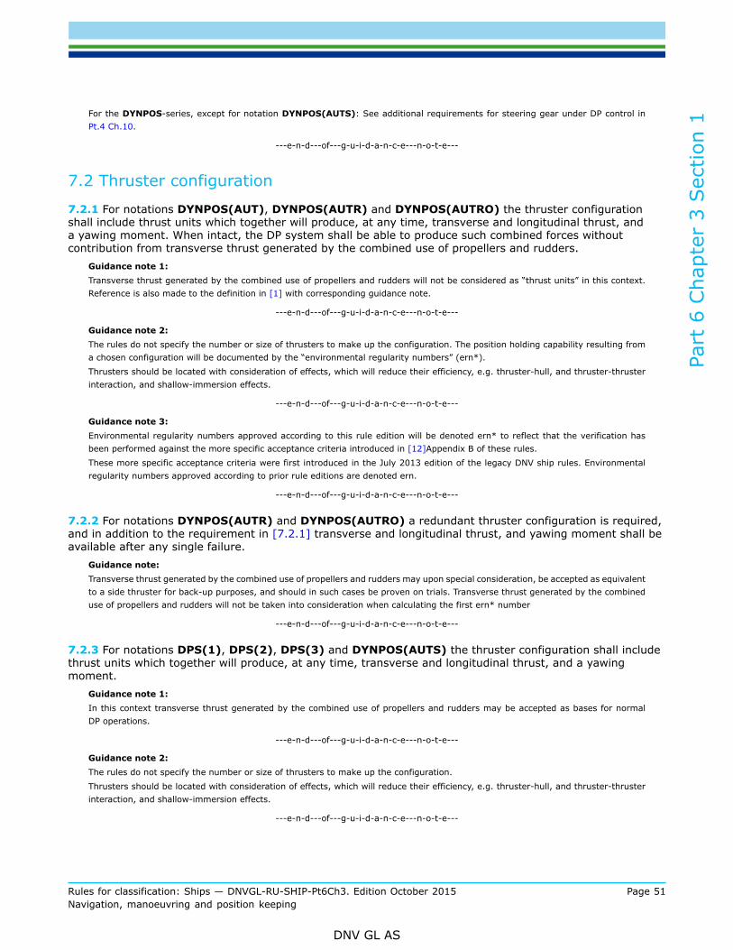
Part
6 C
hapt
er 3
Sec
tion
1
Rules for classification: Ships — DNVGL-RU-SHIP-Pt6Ch3. Edition October 2015 Page 51Navigation, manoeuvring and position keeping
DNV GL AS
For the DYNPOS-series, except for notation DYNPOS(AUTS): See additional requirements for steering gear under DP control inPt.4 Ch.10.
---e-n-d---of---g-u-i-d-a-n-c-e---n-o-t-e---
7.2 Thruster configuration
7.2.1 For notations DYNPOS(AUT), DYNPOS(AUTR) and DYNPOS(AUTRO) the thruster configurationshall include thrust units which together will produce, at any time, transverse and longitudinal thrust, anda yawing moment. When intact, the DP system shall be able to produce such combined forces withoutcontribution from transverse thrust generated by the combined use of propellers and rudders.
Guidance note 1:Transverse thrust generated by the combined use of propellers and rudders will not be considered as “thrust units” in this context.Reference is also made to the definition in [1] with corresponding guidance note.
---e-n-d---of---g-u-i-d-a-n-c-e---n-o-t-e---
Guidance note 2:The rules do not specify the number or size of thrusters to make up the configuration. The position holding capability resulting froma chosen configuration will be documented by the “environmental regularity numbers” (ern*).Thrusters should be located with consideration of effects, which will reduce their efficiency, e.g. thruster-hull, and thruster-thrusterinteraction, and shallow-immersion effects.
---e-n-d---of---g-u-i-d-a-n-c-e---n-o-t-e---
Guidance note 3:Environmental regularity numbers approved according to this rule edition will be denoted ern* to reflect that the verification hasbeen performed against the more specific acceptance criteria introduced in [12]Appendix B of these rules.These more specific acceptance criteria were first introduced in the July 2013 edition of the legacy DNV ship rules. Environmentalregularity numbers approved according to prior rule editions are denoted ern.
---e-n-d---of---g-u-i-d-a-n-c-e---n-o-t-e---
7.2.2 For notations DYNPOS(AUTR) and DYNPOS(AUTRO) a redundant thruster configuration is required,and in addition to the requirement in [7.2.1] transverse and longitudinal thrust, and yawing moment shall beavailable after any single failure.
Guidance note:Transverse thrust generated by the combined use of propellers and rudders may upon special consideration, be accepted as equivalentto a side thruster for back-up purposes, and should in such cases be proven on trials. Transverse thrust generated by the combineduse of propellers and rudders will not be taken into consideration when calculating the first ern* number
---e-n-d---of---g-u-i-d-a-n-c-e---n-o-t-e---
7.2.3 For notations DPS(1), DPS(2), DPS(3) and DYNPOS(AUTS) the thruster configuration shall includethrust units which together will produce, at any time, transverse and longitudinal thrust, and a yawingmoment.
Guidance note 1:In this context transverse thrust generated by the combined use of propellers and rudders may be accepted as bases for normalDP operations.
---e-n-d---of---g-u-i-d-a-n-c-e---n-o-t-e---
Guidance note 2:The rules do not specify the number or size of thrusters to make up the configuration.Thrusters should be located with consideration of effects, which will reduce their efficiency, e.g. thruster-hull, and thruster-thrusterinteraction, and shallow-immersion effects.
---e-n-d---of---g-u-i-d-a-n-c-e---n-o-t-e---
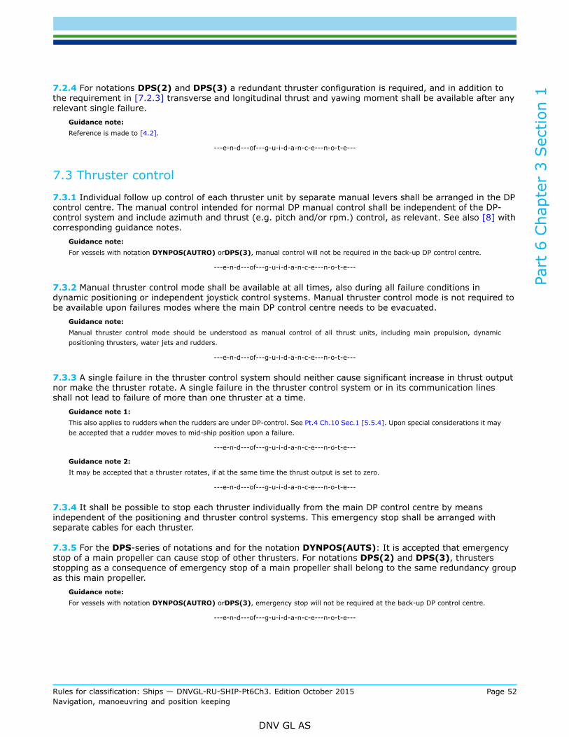
Part
6 C
hapt
er 3
Sec
tion
1
Rules for classification: Ships — DNVGL-RU-SHIP-Pt6Ch3. Edition October 2015 Page 52Navigation, manoeuvring and position keeping
DNV GL AS
7.2.4 For notations DPS(2) and DPS(3) a redundant thruster configuration is required, and in addition tothe requirement in [7.2.3] transverse and longitudinal thrust and yawing moment shall be available after anyrelevant single failure.
Guidance note:Reference is made to [4.2].
---e-n-d---of---g-u-i-d-a-n-c-e---n-o-t-e---
7.3 Thruster control
7.3.1 Individual follow up control of each thruster unit by separate manual levers shall be arranged in the DPcontrol centre. The manual control intended for normal DP manual control shall be independent of the DP-control system and include azimuth and thrust (e.g. pitch and/or rpm.) control, as relevant. See also [8] withcorresponding guidance notes.
Guidance note:For vessels with notation DYNPOS(AUTRO) orDPS(3), manual control will not be required in the back-up DP control centre.
---e-n-d---of---g-u-i-d-a-n-c-e---n-o-t-e---
7.3.2 Manual thruster control mode shall be available at all times, also during all failure conditions indynamic positioning or independent joystick control systems. Manual thruster control mode is not required tobe available upon failures modes where the main DP control centre needs to be evacuated.
Guidance note:Manual thruster control mode should be understood as manual control of all thrust units, including main propulsion, dynamicpositioning thrusters, water jets and rudders.
---e-n-d---of---g-u-i-d-a-n-c-e---n-o-t-e---
7.3.3 A single failure in the thruster control system should neither cause significant increase in thrust outputnor make the thruster rotate. A single failure in the thruster control system or in its communication linesshall not lead to failure of more than one thruster at a time.
Guidance note 1:This also applies to rudders when the rudders are under DP-control. See Pt.4 Ch.10 Sec.1 [5.5.4]. Upon special considerations it maybe accepted that a rudder moves to mid-ship position upon a failure.
---e-n-d---of---g-u-i-d-a-n-c-e---n-o-t-e---
Guidance note 2:It may be accepted that a thruster rotates, if at the same time the thrust output is set to zero.
---e-n-d---of---g-u-i-d-a-n-c-e---n-o-t-e---
7.3.4 It shall be possible to stop each thruster individually from the main DP control centre by meansindependent of the positioning and thruster control systems. This emergency stop shall be arranged withseparate cables for each thruster.
7.3.5 For the DPS-series of notations and for the notation DYNPOS(AUTS): It is accepted that emergencystop of a main propeller can cause stop of other thrusters. For notations DPS(2) and DPS(3), thrustersstopping as a consequence of emergency stop of a main propeller shall belong to the same redundancy groupas this main propeller.
Guidance note:For vessels with notation DYNPOS(AUTRO) orDPS(3), emergency stop will not be required at the back-up DP control centre.
---e-n-d---of---g-u-i-d-a-n-c-e---n-o-t-e---

Part
6 C
hapt
er 3
Sec
tion
1
Rules for classification: Ships — DNVGL-RU-SHIP-Pt6Ch3. Edition October 2015 Page 53Navigation, manoeuvring and position keeping
DNV GL AS
7.3.6 For the DYNPOS-series of notations the emergency stop activation buttons at the DP control centreshall be arranged in a dedicated mimic and in accordance with the thruster location and consistent with thevessel axis and layout, or they may be arranged together with the corresponding thruster levers if these arearranged in accordance with the physical thruster layout.
Guidance note:For the DYNPOS-series of class notations, except for the notation DYNPOS(AUTS), this implies that Power Take Off (PTO)-step upgears for alternators powering other thrusters in the DP system, should be arranged on the primary side of the propulsion clutch,see Figure 1.
---e-n-d---of---g-u-i-d-a-n-c-e---n-o-t-e---
Figure 1 Acceptable and unacceptable clutch arrangement for DYNPOS-series of notations.
7.3.7 For notations DYNPOS(AUTR) and DYNPOS(AUTRO), an alarm shall be initiated upon loop failure,i.e. both broken connections and short-circuit, in the emergency stop system. Such failures shall not causestop of the thruster.
Guidance note:For emergency stop arrangement for other notations, see Pt.4 Ch.8 Sec.2.
---e-n-d---of---g-u-i-d-a-n-c-e---n-o-t-e---
7.4 Indication
7.4.1 Running and stop, pitch, rpm. and azimuth for each thruster shall be displayed at the DP-controlcentre.

Part
6 C
hapt
er 3
Sec
tion
1
Rules for classification: Ships — DNVGL-RU-SHIP-Pt6Ch3. Edition October 2015 Page 54Navigation, manoeuvring and position keeping
DNV GL AS
7.4.2 The displayed information of [7.4.1] shall be continuously visible. At least, display of pitch, rpm. andazimuth shall be readable from the normal position of the DP operator. Otherwise, slave displays shall beinstalled readable from the normal position of DP operator. The indication shall not be based on the samefeedback sensor which is used by the closed-loop control system.
7.4.3 For azimuth thruster used for steering, additional monitoring shall be arranged as required in Pt.4Ch.10 Sec.1 Table 14.
8 Power systems
8.1 General
8.1.1 The power systems shall comply with the relevant rules for main class, for all class notations in thissection. For DYNPOS(AUTR), DYNPOS(AUTRO), DPS(2) andDPS(3) additional requirements will apply inregard to redundancy and with respect to maximum single failure, as specified for each notation. See [4] forthe definition of a single failure.
Guidance note:IMO MSC/Circ.645 “Guidelines for vessels with dynamic positioning systems”Item 3.2.3:“For equipment class 2, the power system should be divisible into two or more systems such that in the event of failure of onesystem at least one other system will remain in operation. The power system may be run as one system during operation, but shouldbe arranged by bus-tie breakers to separate automatically upon failures which could be transferred from one system to another,including overloading and short-circuits.”Item 3.2.4:“For equipment class 3, the power system should be divisible into two or more systems such that in the event of failure of one system,at least one other system will remain in operation. The divided power system should be located in different spaces separated by A-60class division. Where the power systems are located below the operational waterline, the separation should also be watertight. Bus-tiebreakers should be open during class 3 operations unless equivalent integrity of power operation can be accepted according to 3.1.3”.
---e-n-d---of---g-u-i-d-a-n-c-e---n-o-t-e---
8.1.2 Means shall be implemented in order to prevent overloading of the power plant, e.g. by use ofinterlocks, thrust limitations or other means. Means shall also be implemented to prevent reactive overload.This includes overload resulting from failures, e.g. loss of a generator or more than one generator whenthese are subject to common mode failures, or loss of complete switchboard sections.
8.2 Number and capacity of generators
8.2.1 For notation DYNPOS(AUTS), DYNPOS(AUT) and DPS(1), the generator capacity shall be inaccordance with the main class.
Guidance note:It is accepted that all generators are in operation to run all thrusters 100%.Particular attention should be paid to starting conditions of thruster motors, especially with one generator out of service. The effectof voltage drop during starting periods may cause under-voltage trips of control circuits, and main class requirements should beobserved. When starting thrusters on dedicated generators with no other loads connected which would be affected by voltagedeviations, voltage drop in excess of 'the limits of the rules may be accepted.The high reactive load demands, which may occur in DP thruster operation should be considered when selecting number and type ofgenerators, further, the dynamic load variations for diesel engines should be taken into consideration.
---e-n-d---of---g-u-i-d-a-n-c-e---n-o-t-e---
8.2.2 For DYNPOS(AUTR), DYNPOS(AUTRO), DPS(2) andDPS(3), the number of generators shallcomply with the redundancy requirements as defined in the single failure criteria in [4].

Part
6 C
hapt
er 3
Sec
tion
1
Rules for classification: Ships — DNVGL-RU-SHIP-Pt6Ch3. Edition October 2015 Page 55Navigation, manoeuvring and position keeping
DNV GL AS
8.3 Batteries supplying power to DP thrusters
8.3.1 These requirements are applicable to DP systems where batteries are used as source of power tothrust producing units, hereafter named thrusters.
Guidance note:Battery installations not used as a redundant source of power, but only used e.g. for peak shaving, handling of dynamic responsesin the power system, etc. may not have to comply with these requirements.
---e-n-d---of---g-u-i-d-a-n-c-e---n-o-t-e---
8.3.2 Batteries can be accepted as source(s) of power for DP thrusters, but the DP system shall be designedsuch that the vessel also can fulfil the relevant dynamic positioning class notation(s) requirements withoutthe batteries.
Guidance note:The vessels DP position keeping capacity (both before and after failure, i.e. the redundancy design intention) may vary when batteriesare connected or disconnected.
---e-n-d---of---g-u-i-d-a-n-c-e---n-o-t-e---
8.3.3 The vessel shall comply with Ch.2 Sec.1 Battery Power and shall have the class notationBattery(Power).
8.3.4 The battery with its battery management system (BMS) and energy management systems (EMS) shallbe so arranged that the actual available energy can be determined and communicated to the DP-controlsystem for indication and monitoring purposes. See [6.11].
8.3.5 Redundancy shall be based on connected batteries.
8.4 Power management
8.4.1 For DYNPOS(AUTR) and DYNPOS(AUTRO): An automatic power management system shall bearranged, operating with both open and closed bus-bar breakers. This system shall be redundant, and forDYNPOS(AUTRO) in addition A60 separated, so that the functionality is maintained after a failure or,alternatively, one failure will only affect one section of the power system in accordance with the redundancydesign intent. The system shall be capable of performing the following functions:
— load dependent starting of additional generators— block starting of large consumers when there is not adequate running generator capacity, and to start up
generators as required, and hence to permit requested consumer start to proceed— if load dependent stop of running generators is provided, facilities for disconnection of this function shall
be arranged.Guidance note:Exemption from the requirement for an automatic and redundant power management system (PMS) may be granted, provided thatfunctions for blackout prevention, tripping of non-essential consumers and block starting of large consumers are taken care of byother systems. Exemptions will be given to systems where PMS will add few or no benefits.
---e-n-d---of---g-u-i-d-a-n-c-e---n-o-t-e---
8.4.2 A failure in a power management system shall not cause alteration to the power generation, and shallinitiate an alarm in the main DP-control centre.
8.4.3 It shall be possible to operate the switchboards in manual as required for the main class, with thepower management system disconnected.

Part
6 C
hapt
er 3
Sec
tion
1
Rules for classification: Ships — DNVGL-RU-SHIP-Pt6Ch3. Edition October 2015 Page 56Navigation, manoeuvring and position keeping
DNV GL AS
8.4.4 Overload, e.g. caused by the stopping of one or more generators subject to common mode failures,shall not create a black-out.
Guidance note:Reduction in thruster load, i.e. pitch or speed reductions, should be introduced to prevent blackout and enable standby generatorsto come online. If this function is taken care of by the positioning control system, the function should be co-ordinated with the powermanagement system.Load reductions should preferably be achieved through the tripping of unimportant consumers, and the requirement does not exemptsuch means. But, it is common that the relative load proportions will require thruster load reduction, in order to effectively reduceoverload situations.When the system is running with open bus-ties, partial black-out contained within one redundancy group (i.e. one main switchboardsection), may occur in case a failure causes stop of the last connected generator set in that same redundancy group (main switchboardsection).
---e-n-d---of---g-u-i-d-a-n-c-e---n-o-t-e---
8.5 Technical system configurations based on closed bus-tie(s)
8.5.1 For notations DYNPOS(AUTS), DPS(1) and DYNPOS(AUT): No additional requirements apply.
8.5.2 For notations DPS(2), DYNPOS(AUTR): The vessel shall at least have one specified technical systemconfiguration based upon open bus-ties between all electrical power generation system belonging to thedifferent redundancy groups.
8.5.3 For operation with closed bus-tie(s) the power system shall be arranged with bus-tie breaker(s) toseparate automatically upon failures which could be transferred from one system to another.
8.5.4 DYNPOS(AUTR) and DPS(2): When generators in different redundancy groups are running in parallelthis will introduce the possibility that a single failure may propagate between systems. In such cases it isrequired that protective measures are implemented in the system in order to ensure the required integritybetween the redundancy groups. Analysis of relevant failure modes shall be addressed in the FMEA.
Guidance note:Examples of failure modes that will be relevant are given below.*) The analysis and test requirements may be part of the DP FMEAand FMEA test program or other documentation. In case such verification is documented in other documentation the FMEA shouldgive reference to this documentation, and refer/state conclusions based on this.
Failure Modes: Minimum analysis and test requirement for DYNPOS(AUTR) and DPS(2):
Short circuits, earth failuresSelectivity between generator breakers and bus-tie breaker(s) on short circuit and earth failures, inform of a discrimination analysis.
Over loadOverload required to be handled by functionality in control systems (PMS, DP, Switchboard logic),control system documentation, FMEA and functional testing at DP/PMS/FMEA trials. (Can I/O failurebetween DP/PMS/SWB be a hidden failure?)
Governor failuresPower failure, speed pick-up failure, over-fuel, isochronous load sharing lines. Analyse and test allthese.
Overvoltage and automaticvoltage regulator (AVR),failure scenarios
Over excitation/excitation break-down/under excitation, to be analysed in the FMEA analysis. FMEAtest requirement: loss of excitation (power or no output), loss of sense or over excitation (disconnectCT feedback or increase excitation).
Failures related to PMS andactive load sharing
Analysis, functional testing. FMEA test: Power failure, network failure (disconnect), PMS I/O failuretesting required as found necessary in FMEA analysis, load sharing line failure (disconnect).

Part
6 C
hapt
er 3
Sec
tion
1
Rules for classification: Ships — DNVGL-RU-SHIP-Pt6Ch3. Edition October 2015 Page 57Navigation, manoeuvring and position keeping
DNV GL AS
Failure Modes: Minimum analysis and test requirement for DYNPOS(AUTR) and DPS(2):
Transient under voltage(short circuit ride through)(In electrical systemstransient voltage dips mayoccur, e.g. due to shortcircuits and subsequentintended opening of feederor bus-tie breakers fordisconnection of the faultyequipment. In connectionwith operation with closedbus such transients willaffect the whole connecteddistribution system.)
The FMEA should analyse the effect of transient voltage dips in the system and identify measuresnecessary to avoid problems with:
— unintended tripping of frequency converters
— unintended deselecting of thrusters from DP control (e.g. loss of ready signal from drives toDP-control system)
— unintended tripping of motors and other important components, like auxiliary system pumps(tripping of motor starters and/or contactors)
— unintended activation of under voltage protection systems
— DC control power systems, e.g. dual feeding through diodes or automatic change-over.
In relation with the above items, functionality should be checked in order to verify the potentialeffect of this failure mode.
The requirement is that the equipment not belonging to the redundancy group directly affectedby the failure shall ride through the transient period and be immediately available, withoutoperator intervention, when the system voltage is re-established. It should also be evaluated if re-establishment of system voltage could cause unacceptable high voltages (“voltage over-shoot”).
Measures should be implemented as found necessary through analysis.
No “short circuit test”-requirements to verify the conclusions.
(Additionally, or as an alternative, verification of the above mentioned items may also be based ontesting. Such testing should be based upon non-destructive methods for simulating the transientlow voltage period in the system.)
*) It should be understood that this is not an exhaustive list of failure modes relevant for closed bus-tie systems. Reference is madeto document DNV-RP-D102 Failure mode and effect analysis (FMEA) of redundant systems, Appendix D, for discussion on the subjectof closed bus-tie systems.
---e-n-d---of---g-u-i-d-a-n-c-e---n-o-t-e---
8.5.5 For notations DYNPOS(AUTRO) and DPS(3): Technical system configurations based on closed bus-ties may be accepted based upon special considerations. Reference is made to [11] Appendix A for a moredetailed specification of these considerations.
Guidance note:Ref. [8.1.1] and IMO MSC/Circ.645 “Guidelines for vessels with dynamic positioning systems” item 3.2.4: For DYNPOS(AUTRO)and DPS(3): Bus-tie breakers providing redundancy should be open during class 3 operations.
---e-n-d---of---g-u-i-d-a-n-c-e---n-o-t-e---
8.6 Main and distribution switchboards arrangementFor DYNPOS(AUTS), DYNPOS(AUT) and DPS(1) notations the main class requirements are adequate.
8.7 Main and distribution switchboards arrangement for notations requiringredundancy
8.7.1 The requirements in this sub-section apply to notations DYNPOS(AUTR), DYNPOS(AUTRO),DPS(2) and DPS(3).
8.7.2 The switchboard arrangement shall be such that no single failure will give a total black-out. ForDYNPOS(AUTR) and DPS(2) this means equipment failures. For DYNPOS(AUTRO) and DPS(3) thismeans failure of all equipment in any fire and/or watertight subdivision.
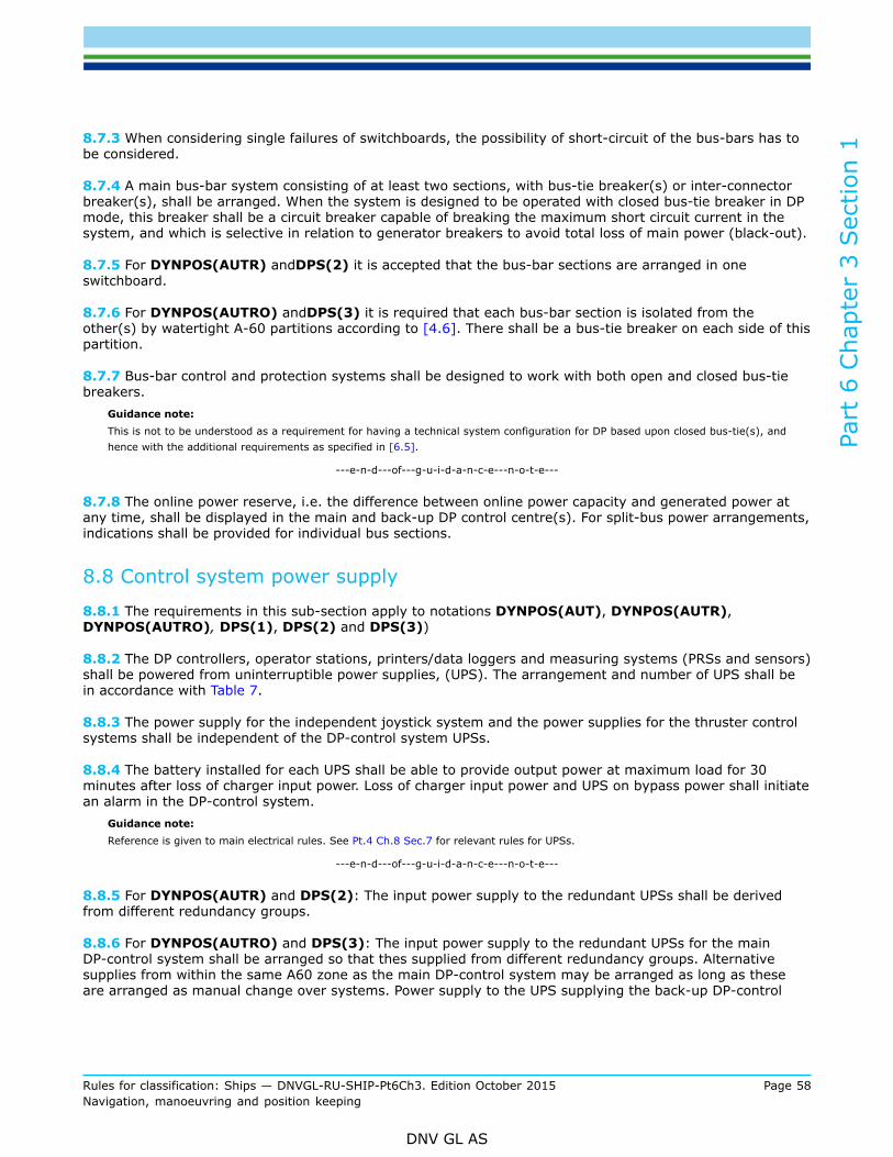
Part
6 C
hapt
er 3
Sec
tion
1
Rules for classification: Ships — DNVGL-RU-SHIP-Pt6Ch3. Edition October 2015 Page 58Navigation, manoeuvring and position keeping
DNV GL AS
8.7.3 When considering single failures of switchboards, the possibility of short-circuit of the bus-bars has tobe considered.
8.7.4 A main bus-bar system consisting of at least two sections, with bus-tie breaker(s) or inter-connectorbreaker(s), shall be arranged. When the system is designed to be operated with closed bus-tie breaker in DPmode, this breaker shall be a circuit breaker capable of breaking the maximum short circuit current in thesystem, and which is selective in relation to generator breakers to avoid total loss of main power (black-out).
8.7.5 For DYNPOS(AUTR) andDPS(2) it is accepted that the bus-bar sections are arranged in oneswitchboard.
8.7.6 For DYNPOS(AUTRO) andDPS(3) it is required that each bus-bar section is isolated from theother(s) by watertight A-60 partitions according to [4.6]. There shall be a bus-tie breaker on each side of thispartition.
8.7.7 Bus-bar control and protection systems shall be designed to work with both open and closed bus-tiebreakers.
Guidance note:This is not to be understood as a requirement for having a technical system configuration for DP based upon closed bus-tie(s), andhence with the additional requirements as specified in [6.5].
---e-n-d---of---g-u-i-d-a-n-c-e---n-o-t-e---
8.7.8 The online power reserve, i.e. the difference between online power capacity and generated power atany time, shall be displayed in the main and back-up DP control centre(s). For split-bus power arrangements,indications shall be provided for individual bus sections.
8.8 Control system power supply
8.8.1 The requirements in this sub-section apply to notations DYNPOS(AUT), DYNPOS(AUTR),DYNPOS(AUTRO), DPS(1), DPS(2) and DPS(3))
8.8.2 The DP controllers, operator stations, printers/data loggers and measuring systems (PRSs and sensors)shall be powered from uninterruptible power supplies, (UPS). The arrangement and number of UPS shall bein accordance with Table 7.
8.8.3 The power supply for the independent joystick system and the power supplies for the thruster controlsystems shall be independent of the DP-control system UPSs.
8.8.4 The battery installed for each UPS shall be able to provide output power at maximum load for 30minutes after loss of charger input power. Loss of charger input power and UPS on bypass power shall initiatean alarm in the DP-control system.
Guidance note:Reference is given to main electrical rules. See Pt.4 Ch.8 Sec.7 for relevant rules for UPSs.
---e-n-d---of---g-u-i-d-a-n-c-e---n-o-t-e---
8.8.5 For DYNPOS(AUTR) and DPS(2): The input power supply to the redundant UPSs shall be derivedfrom different redundancy groups.
8.8.6 For DYNPOS(AUTRO) and DPS(3): The input power supply to the redundant UPSs for the mainDP-control system shall be arranged so that thes supplied from different redundancy groups. Alternativesupplies from within the same A60 zone as the main DP-control system may be arranged as long as theseare arranged as manual change over systems. Power supply to the UPS supplying the back-up DP-control

Part
6 C
hapt
er 3
Sec
tion
1
Rules for classification: Ships — DNVGL-RU-SHIP-Pt6Ch3. Edition October 2015 Page 59Navigation, manoeuvring and position keeping
DNV GL AS
system shall not be from the same sub-distribution switchboard as the normal supply to any of the main DP-control system UPSs, and in addition arranged so that it is A60 separated from the main DP-control system.
8.8.7 Power supply to the thruster control mode selection systems shall be arranged so that the requiredindependency, integrity and redundancy as specified in [6.6] are complied with.
8.8.8 UPS and battery supplies to other control systems relevant for DP shall be derived from the sameredundancy group as the system(s) being served.
Guidance note:When dual supply to thrusters is arranged in accordance with [4.3.4] the power supply to the control systems shall be dual feedin accordance with the main thruster supply through a selective power supply arrangement, or be branched off from the thrustersmain dual feed arrangement.
---e-n-d---of---g-u-i-d-a-n-c-e---n-o-t-e---
8.8.9 In general control systems and equipment shall have power supply from within the redundancy groupthey are serving. In case power supply is arranged from more than one redundancy group special attentionshall be paid to the potential risk of propagation of failure modes due to e.g. lack of discrimination or dueto under/overvoltage affecting more than one redundancy group. Selectivity/barriers for relevant failuremodes shall be documented and verified when such power supply is arranged. This applies especially toDYNPOS(AUTRO) and DPS(3) systems where supplies crossing required separation barriers in generalshould be avoided.
9 Auxiliary systems
9.1 General
9.1.1 For DYNPOS(AUTS), DYNPOS(AUT) and DPS(1) notations the main class requirements areadequate.
9.2 Additional for notations requiring redundancy
9.2.1 The requirements in this sub-section apply to notations DYNPOS(AUTR), DYNPOS(AUTRO),DPS(2) and DPS(3).
9.2.2 The auxiliary systems, serving machinery, thrusters, electrical components and all other systemsand components necessary for supplying the DP system with power and/or thrust, shall be arranged inaccordance with the redundancy and separation requirements as given for the relevant notation(s). See[4.2].
9.2.3 Failure shall be considered for all active components as specified in [4.2] for the relevant notation(s).
9.2.4 For DYNPOS(AUTR): See [9.3], [9.4], [9.5] and [9.6] below for specific requirements to specificsystems. Unless otherwise specified in these rules, fixed piping may be shared by components designed withredundancy. See also [4.4].
9.2.5 For DPS(2) the auxiliary systems shall be based on the same general principles with respect to activecomponents. However, based on proper FMEA, static components like coolers, filters and piping/tanks may beconsidered as not failing, and hence common static components may be accepted in fuel oil systems, freshwater cooling systems and pneumatic systems.
Guidance note 1:Reference is made to IMO MSC/Circ.645 “Guidelines for vessels with dynamic positioning systems”, part 2.2.2, dated 6 June 1994:

Part
6 C
hapt
er 3
Sec
tion
1
Rules for classification: Ships — DNVGL-RU-SHIP-Pt6Ch3. Edition October 2015 Page 60Navigation, manoeuvring and position keeping
DNV GL AS
For equipment class 2, a loss of position is not to occur in the event of a single fault in any active component or system. Normallystatic components will not be considered to fail where adequate protection from damage is demonstrated, and reliability should thesatisfaction of the Administration. Single failure criteria include:
1) Any active component or system (generators, thrusters, switchboards, remote controlled valves, etc.).
2) Any normally static component (cables, pipes, manual valves, etc.) which is not properly documented with respect toprotection and reliability.
---e-n-d---of---g-u-i-d-a-n-c-e---n-o-t-e---
Guidance note 2:Reference is made to [4.2].
---e-n-d---of---g-u-i-d-a-n-c-e---n-o-t-e---
Guidance note 3:Main class requirements to auxiliary piping systems are found in Pt.4 Ch.6.
---e-n-d---of---g-u-i-d-a-n-c-e---n-o-t-e---
9.2.6 For DYNPOS(AUTRO) and DPS(3): Piping for all systems relevant for DP shall be arranged withA-60 separation, and watertight below bulkhead deck, between systems belonging to different redundancygroups. Cross-over pipes are acceptable provided these can be closed at both sides of separating bulkheads.Ventilation ducts shall not have cross-over facilities. See also [9.4] through [9.6] below.
9.3 Specific requirements for fuel oil systems
9.3.1 For DYNPOS(AUTR): The fuel oil supply shall be arranged with full separation between systemsproviding required redundancy. There shall be at least one service tank serving each redundancy group.Cross-over facilities may be arranged, but shall, if arranged, be kept closed in normal operation.
9.3.2 For DYNPOS(AUTR), DYNPOS(AUTRO) and DPS(3): If the fuel system requires heating, then theheating system shall be designed with the appropriate level of redundancy unless fuel which do not requireheating, are arranged so that the requirement in [9.3.1] is fulfilled. Separation by A-60 class division isrequired for DYNPOS(AUTRO) and DPS(3), see [9.2.6].
9.4 Specific requirements for fresh water cooling systemsFor DYNPOS(AUTR): Fresh water cooling systems providing the required redundancy shall be arranged asseparated systems, in view of the risk of severe loss of water or accumulation of gas due to leakage.
Guidance note:Redundant systems for air conditioning and control of ambient temperature, e.g. air condition units, chillers and HVAC, may sharecommon piping for notation DYNPOS(AUTR).
---e-n-d---of---g-u-i-d-a-n-c-e---n-o-t-e---
9.5 Specific requirements for pneumatic systemsFor DYNPOS(AUTR), DYNPOS(AUTRO) and DPS(3): Pneumatic systems in which a relevant singlefailure modes may compromise the required redundancy shall be arranged as separated systems for eachredundancy group. Separation by A-60 class division is required for DYNPOS(AUTRO) and DPS(3), see[9.2.6].
9.6 Specific requirements for fire dampers and quick closing valvesFor DYNPOS(AUTR) and DYNPOS(AUTRO): Fire dampers and quick closing valves which upon activationmay affect power generation and/or thrust shall be so arranged that there is separate activation for each

Part
6 C
hapt
er 3
Sec
tion
1
Rules for classification: Ships — DNVGL-RU-SHIP-Pt6Ch3. Edition October 2015 Page 61Navigation, manoeuvring and position keeping
DNV GL AS
redundancy group. As a minimum there shall be separate activation input devises and valves (in case theactivation system is pneumatic) for each redundancy group. Separation by A-60 class division is required forDYNPOS(AUTRO), see [9.2.6].
10 Environmental regularity numbers
10.1 Concept description
10.1.1 The requirements in this section apply to the notations DYNPOS(AUT), DYNPOS(AUTR) andDYNPOS(AUTRO).
10.1.2 The position keeping ability of the vessel shall be calculated according to the concept of theenvironmental regularity numbers, hereafter called ern*.
Guidance note 1:Vessels that in their operation adjust the heading automatically to give minimum environmental forces, may be exempted.
---e-n-d---of---g-u-i-d-a-n-c-e---n-o-t-e---
Guidance note 2:The ern* represents the static balance of environmental forces and thruster output. ern* is quantified with its basis in the weatherstatistics of a chosen location in the North Sea, the location of the weather ship “M”.
---e-n-d---of---g-u-i-d-a-n-c-e---n-o-t-e---
Guidance note 3:Environmental regularity numbers approved according to this rule edition will be denoted ern* to reflect that the verification hasbeen performed against the more specific acceptance criteria introduced in [12]Appendix B of this rules.These more specific acceptance criteria were first introduced in the July 2013 edition of the legacy DNV ship rules. Environmentalregularity numbers approved according to prior rule editions are denoted ern.
---e-n-d---of---g-u-i-d-a-n-c-e---n-o-t-e---
10.1.3 [12] Appendix B of these rules outlines an explanatory example on how to calculate ern* accordingto the rules set out in this section. The results obtained by using this method will establish the minimumacceptance criteria for evaluating ern*-calculations based upon other recognized methods. Equal or moreconservative results (i.e. lower ern*) obtained by use of other recognized methods will be accepted.
Guidance note:The method should be understood as a non-conservative method for establishment of a minimum acceptance level intended forbenchmarking by use of ern*. The results obtained are not intended to be used in operational planning or design specifications.
---e-n-d---of---g-u-i-d-a-n-c-e---n-o-t-e---
10.1.4 The environmental forces caused by wind, waves, and current shall be calculated by recognizedmethods. Alternatively, environmental forces established by model testing will be considered.
Table 9 ern* wind and wave statistics
P (Hs) Hs(m) V1 (m/s) Tz(s)
2.5 0.66 1.40 3.0
5.0 0.79 2.19 3.0
10.0 1.0 3.30 3.0
20.0 1.35 4.95 4.1
30.0 1.7 6.21 5.1

Part
6 C
hapt
er 3
Sec
tion
1
Rules for classification: Ships — DNVGL-RU-SHIP-Pt6Ch3. Edition October 2015 Page 62Navigation, manoeuvring and position keeping
DNV GL AS
P (Hs) Hs(m) V1 (m/s) Tz(s)
40.0 1.9 7.48 5.7
50.0 2.3 8.74 6.9
60.0 2.6 10.01 7.8
70.0 3.0 11.39 9.0
80.0 3.5 13.11 9.0
90.0 4.2 15.53 9.0
95.0 4.9 17.60 9.0
97.5 5.3 19.32 9.0
98.0 5.6 19.90 9.0
98.5 5.8 20.59 9.0
99.0 6.1 21.51 9.0
The relationship between significant wave height Hs, Tz and 1 minute average wind speed V1 shall be used forcomputation of the ern*.
P(Hs) is based on data from the reference ocean area.
10.1.5 The ern* shall assume coincident forces of wind, waves, and current. Wind and waves shall beconsidered at magnitudes of equal probability, see Table 9.The current shall be taken as a constant value of 0.75 m/s, without differentiation of wind-induced and tidalcomponents.
10.1.6 The ern* is evaluated at the incidence angle of forces which causes the maximum load on the vessel.For mono-hull vessels ern* shall be based on the situation with the weather forces acting concurrently on thebeam.
Guidance note:The ern* is intended to reflect a «worst case situation», which for monohull vessels normally will be the situation with the weatheron the beam. The ern* will be based on this situation regardless of the vessel's ability to select other headings in operation.
---e-n-d---of---g-u-i-d-a-n-c-e---n-o-t-e---
10.1.7 The ern* is evaluated for a balance of forces while the vessel is maintaining both position andheading. Thus there shall at the same time be a balance of forces and a balance of moments, i.e. includingall moments generated by the thrusters, and those caused by environmental forces.
10.1.8 The format of the ern* shall be a series of 4 integer numbers, ranging from 0 to 99. Results shallbe same or exceed numbers in the table to get corresponding ern*. The ern* will be given in the register asinformation: ern*(a, b, c, d).Where:
— a: The first number shall represent optimal use of all thrusters. (Transverse thrust generated by thecombined use of main propellers and rudders shall not be taken into consideration.)
— b: The second number shall represent minimum effect of single-thruster failure.— c: The third figure shall represent the maximum effect single-thruster failure.— d: The fourth number shall represent the effect of the worst case single failure(s).
Guidance note:

Part
6 C
hapt
er 3
Sec
tion
1
Rules for classification: Ships — DNVGL-RU-SHIP-Pt6Ch3. Edition October 2015 Page 63Navigation, manoeuvring and position keeping
DNV GL AS
The fourth number d should represent the failure scenario resulting in the largest reduction of position and heading keeping capacityhas occurred, typically stop of all equipment in the most important redundancy group. For notations not requiring redundancy, thefourth number d will be given as zero, 0.
---e-n-d---of---g-u-i-d-a-n-c-e---n-o-t-e---
10.1.9 The ern* shall be based upon the thrust output that is under control, in the most efficient mode.Guidance note:The calculations should be based on design draft and may be based on the vessel being in its most efficient DP mode, e.g. no cargoand all deck equipment in parked position.In case limited energy sources like e.g. batteries are included in the ern* calculation then the energy source should be able to supplythe power at the considered rate for minimum 30 minutes. For redundant notations the energy source should be able to deliver powerat the considered rate according to the intended minimum time requirement or for 30 minutes, whichever is the longest.Thrust output should be the thrust available to be commanded by the DP-control systems. This implies that e.g.: thruster losses,thruster limitations (e.g. forbidden zones) or power limitations should be considered, as relevant, for each ern* case.The side thrust balance may be optimized by generating a suitable yawing moment. An example of this is using the main propellersfor generating a moment couple with opposing thrust outputs. This is accepted for the ern*, provided that the control is executedautomatically, with satisfactory balance of longitudinal thrust.Side force generated by the combined use of a rudder and a propeller will be taken into account for the ern* when this control modeis included in the DP-control system, except for the first number. See [7].
---e-n-d---of---g-u-i-d-a-n-c-e---n-o-t-e---
11 Appendix A Technical system configurations based on closedbus-ties
11.1 Special considerations
11.1.1 This appendix apply to notations DYNPOS(AUTRO) and DPS(3) when the required integritybetween redundancy groups shall be based on closed bus-ties, i.e. based on technical system configurationswhere generators in different redundancy groups are running in parallel.
11.1.2 Approval shall be specially agreed upon and will be considered as additional work.
11.2 General
11.2.1 The vessels shall in addition to the closed bus-ties mode have at least one specified technicalsystem configuration based upon open bus-ties between all electrical power generation systems belongingto the different redundancy groups. The integration of functional capabilities on a system level shall becontrolled and coordinated by a system integrator. The yard is responsible for this coordination. It is required,therefore, to nominate a dedicated person who has the responsibility for the complete process for gainingDYNPOS(AUTRO) and/or DPS(3) acceptance.
11.2.2 The definition of relevant single failures shall have no limitations and shall be addressed in theapproval process and during testing.
11.2.3 For operation with closed bus-ties the power system shall be arranged with bus-tie breakers toseparate automatically upon failures which could be transferred from one system to another.
11.2.4 The integrity level shall be comparable to a system based on open bus-ties in order to minimize theresidual probability for failure propagation. Protective functions shall be installed in order to achieve therequired equivalent integrity level.

Part
6 C
hapt
er 3
Sec
tion
1
Rules for classification: Ships — DNVGL-RU-SHIP-Pt6Ch3. Edition October 2015 Page 64Navigation, manoeuvring and position keeping
DNV GL AS
11.2.5 The verification shall be based upon approval of additional documentation (as compared to systemsbased on open bus-ties) including, but not limited to, thorough closed bus-tie analysis, calculations anddynamic computer simulations of the power system in normal operation and during all relevant failureconditions. In addition live testing of failure modes including e.g. short circuits, earth faults, automaticvoltage regulators faults, engine governor faults and other severe faults shall be performed.
Guidance note 1:Reference is made to documents DNVGL-OTG-10 Offshore technical guidance for DP-classed vessels with closed bus-ties and DNV-RP-D102 Failure aode and effect analysis (FMEA) of redundant systems, Appendix D, for explanation of acceptance criteria, discussionon the subject, and examples of relevant failure modes.
---e-n-d---of---g-u-i-d-a-n-c-e---n-o-t-e---
Guidance note 2:It is utmost important that the design is built and prepared for the required live testing of severe failure modes both at the newbuilding stage and at renewal trials during the vessels entire operational life time. It should be understood that in order to achieve this,the design will require installation of additional equipment and systems including e.g. advanced protective systems for generatorsand switchboard.
---e-n-d---of---g-u-i-d-a-n-c-e---n-o-t-e---
Guidance note 3:The negative effects of hidden failures should be prevented. This applies both for hardware and software. Hidden failures for allcomponents and systems should be considered, and this will require extensive use of self-diagnostics. However, self-diagnosticscannot be considered to mitigate all hidden failures, and due to this duplication and redundancy will be required.Consequently, protection and safety systems should have back-up. This means that if the first action performed by the protectionsystem does not remove the failure or is not performed (due to hidden failure), then the back-up system should execute alternativeactions to isolate the faulty component or system. After activation of the back-up protection, the consequence of the failure shouldstill be in line with the overall redundancy design intent.
---e-n-d---of---g-u-i-d-a-n-c-e---n-o-t-e---
Guidance note 4:More detailed information on requirements for documentation, calculations, computer simulations and testing can be provided onrequest.
---e-n-d---of---g-u-i-d-a-n-c-e---n-o-t-e---
11.2.6 When generators in different redundancy groups are running in parallel, black-out recovery onindividual switch-board sections by starting of generators and recovery of full automatic thruster control fromDP shall be possible. The DP-control systems shall receive thruster ready signals within maximum 45 secondsafter black-out.
12 Appendix B Calculation of environmental regularity numbers –ern*
12.1 IntroductionThis appendix is outlining an explanatory example on how to calculate ern* according to the rules set out in[10]. The method shall be also understood as a non-conservative method for establishment of a minimumacceptance level intended for benchmarking by use of ern*.
Guidance note 1:The results obtained are not intended to be used in operational planning or design specifications.
---e-n-d---of---g-u-i-d-a-n-c-e---n-o-t-e---
Guidance note 2:Environmental regularity numbers approved according to this rule edition will be denoted ern* to reflect that the verification hasbeen performed against the more specific acceptance criteria introduced in [12] of these rules.

Part
6 C
hapt
er 3
Sec
tion
1
Rules for classification: Ships — DNVGL-RU-SHIP-Pt6Ch3. Edition October 2015 Page 65Navigation, manoeuvring and position keeping
DNV GL AS
These more specific acceptance criteria were first introduced in the July 2013 edition of the legacy DNV ship rules. Environmentalregularity numbers approved according to prior rule editions are denoted ern.
---e-n-d---of---g-u-i-d-a-n-c-e---n-o-t-e---
12.2 Environment
12.2.1 The calculations shall assume coincident wind, wave and current direction on the beam.
12.2.2 The calculations shall assume current of 0.75 m/s.
12.2.3 The calculations shall assume the relationship between ern* number, wind speed, significant waveheight and zero up crossing frequencies as given in Table 10.
Table 10 ern* wind and wave statistics
P(Hs)=ern* V1(m/s) Hs(m) Tz(s)
2.5 1.4 0.66 3.0
5 2.19 0.79 3.0
10 3.3 1 3.0
20 4.95 1.35 4.1
30 6.21 1.7 5.1
40 7.48 1.9 5.7
50 8.74 2.3 6.9
60 10.01 2.6 7.8
70 11.39 3 9.0
80 13.11 3.5 9.0
90 15.53 4.2 9.0
95 17.6 4.9 9.0
97.5 19.32 5.3 9.0
98 19.9 5.6 9.0
98.5 20.59 5.8 9.0
99 21.51 6.1 9.0
The relationship between significant wave height Hs, Tz and 1 minute average wind speed V1 shall be used forcomputation of the ern*. P(Hs) is based on data from the reference ocean area
12.2.4 For wave drift forces a long crested JONSWAP wave spectrum with gamma = 3.3, sig_a = 0.07, sig_b= 0.09 according to document DNV-RP-C205 [3.5.5] Environmental conditions and environmental loads shallbe used. Tp = 1.286 Tz.
12.2.5 The wind and current shall be assumed to be vertically uniformly distributed.
12.2.6 Results shall be same or exceed numbers in the table to get corresponding integer ern*.Guidance note:

Part
6 C
hapt
er 3
Sec
tion
1
Rules for classification: Ships — DNVGL-RU-SHIP-Pt6Ch3. Edition October 2015 Page 66Navigation, manoeuvring and position keeping
DNV GL AS
I.e. if results show that the vessel are able to withstand 20.6 m/s wind speed and 5.8 m significant wave height the ern* is 98because results are higher than 19.9 m/s and 5.6 m and lower than 21.51 m/s and 6.1m, respectively.Please refer to [10.1.8] for the format of the ern*.
---e-n-d---of---g-u-i-d-a-n-c-e---n-o-t-e---
12.2.7 Wind, current and wave forces shall be balanced by the effective thruster forces in order to achievethe corresponding ern*.
12.3 Environmental loads
12.3.1 Multihull vessels are not covered by this section. Relevant data shall be supplied by the manufacturerof the unit.
12.3.2 For monohull vessels, the environmental forces shall be calculated with the method described in thissection.
12.3.3 Zero forward speed, design draft and even keel shall be used. The most favourable operating modecan be used. Projected areas shall include everything on the vessel as if the area was calculated from apicture.
Guidance note:General arrangement drawings are often a good basis.
---e-n-d---of---g-u-i-d-a-n-c-e---n-o-t-e---
12.3.4 Surge forces shall be set to zero.
12.3.5 The yaw moment shall be determined based on the attack point of the sway force.
12.3.6 The forces, moments and thruster locations shall be given in a right handed coordinate system with xpointing forward, y pointing to port and z upwards. The origin shall be at Lpp/2, center line, and water line.
12.4 Wind loadsThe sway force from wind loads shall be calculated with the following formula:
Cd,WIND = 0.9
AWIND = projected longitudinal area (projected in surge-heave plane) above water.
ρAIR = 1.226 kg/m3
The point of attack shall be in the area center of the projected longitudinal area above water.
12.5 Current12.5.1 The sway force from current loads shall be calculated with the following formula:

Part
6 C
hapt
er 3
Sec
tion
1
Rules for classification: Ships — DNVGL-RU-SHIP-Pt6Ch3. Edition October 2015 Page 67Navigation, manoeuvring and position keeping
DNV GL AS
Cd,Current = 0.7
ACurrent = projected longitudinal area (projected in surge-heave plane) below water.
ρWATER = 1026 kg/m3
The point of attack shall be in the area center of the projected longitudinal area below water.
12.6 WavesWave drift forces shall be calculated with the following equations:
Where S(ω) is the wave spectrum as function of frequency and the ARO is defined as:
Where T33 is the heave resonant period, M is the vessel mass, and AWL is the water plane area.
Where B is the vessel width.
Where L is the distance between the foremost and aft most point on the hull below the free surface.

Part
6 C
hapt
er 3
Sec
tion
1
Rules for classification: Ships — DNVGL-RU-SHIP-Pt6Ch3. Edition October 2015 Page 68Navigation, manoeuvring and position keeping
DNV GL AS
Point of attack = area center of under water hull.
12.7 Thrusters
12.7.1 Water jets and cycloid propulsors are not covered by this section. Relevant data should be supplied bythe manufacturer of the units.
12.7.2 The available thrust force from the thrusters shall be calculated as:
Where TEffective is the Effective thrust, TNominal is the Nominal thrust and βT is the thrust loss factor.
12.7.3 The nominal thrust shall be calculated from the following formula:
12.7.4 Where nominal thrust (TNominal) is thrust with no wind, waves or current present, D is propellerdiameter in meter, P is the power applied to the propeller in kW.
Power applied to the propeller = break power × mechanical efficiency
12.7.5 When the break power PB is the MCR break power available in DP mode/bollard pull; i.e. taking powerand torque limitations etc. into account. The break power of the propulsion motor shall be considered. ηM isthe mechanical efficiency.
12.7.6 The thrust loss factor βT accounts for all kinds of thrust losses (thruster-thruster, thruster-hull,variable inflow, ventilation, thrust deduction, tunnel length, grid, inlet losses etc.). This value is set to be0.90. This is assumed to be non-conservative.The η1 is given in Table 11.

Part
6 C
hapt
er 3
Sec
tion
1
Rules for classification: Ships — DNVGL-RU-SHIP-Pt6Ch3. Edition October 2015 Page 69Navigation, manoeuvring and position keeping
DNV GL AS
Table 11 η1
η1
Azimuths, pods and shaft line propellers 800
Tunnel thrusters 900
Contra-rotating propellers 950
Ducted azimuths, pods and shaft line propellers 1200
The η2 is given in Table 12.
Table 12 η2
η2
Tunnel thrusters 1.0
Forward thrust from other type of thrusters with and without duct 1.0
Reversed thrust from other type of thrusters without duct 0.9
Reversed thrust from other type of thrusters with duct 0.7
Guidance note:Reversed thrust should be understood as the thrust when the propeller is rotating opposite of its design-direction.
---e-n-d---of---g-u-i-d-a-n-c-e---n-o-t-e---
The η3 shall be 0.7 unless it can be documented that torque limitations are accounted for in P. In that case η3shall be 1.0.The mechanical efficiency ηM is given in Table 13.
Table 13 mechanical efficiency
ηM
Tunnel thrusters and azimuths 0,93
Shaft line propellers 0.97
Pods 0.98
12.8 Rudders
12.8.1 For a rudder behind a propeller giving positive thrust the effect of rudder shall be accounted for withthe following equations:
Where α is the rudder angle in degrees. For rudder angle above 30 deg. values at 30 deg. shall be used.

Part
6 C
hapt
er 3
Sec
tion
1
Rules for classification: Ships — DNVGL-RU-SHIP-Pt6Ch3. Edition October 2015 Page 70Navigation, manoeuvring and position keeping
DNV GL AS
The lift and drag coefficients CX and CY are given as:
Where Br is the cord length of the rudder behind the shaft and D is the propeller diameter. The value of Br inthe calculations is limited to 1.0D. The rudder shall cover the full propeller height.The factors k1 and k2, shall be taken from Pt.3 Ch.14 Sec.1 [4.1.1].
12.8.2 For a rudder behind a propeller giving negative thrust the effect of the rudder shall be neglected.
12.9 Thrust allocation12.9.1 GeneralThe thrust allocation shall be achievable by the DP-control system. Forbidden zones etc. affecting the ern*calculation shall be specified in the ern* report.
Guidance note:Forbidden zones that will affect the ern* cases (weather forces on the beam) should be considered. This could typically be e.g. anazimuth thrusting in to the skeg/rudder/working thruster.
---e-n-d---of---g-u-i-d-a-n-c-e---n-o-t-e---
12.9.2 Power limitations shall be accounted for. The most favourable operating mode can be used. This shallbe in accordance with the power consumption balance, ref. Table 4.
12.10 Tables for specification of hull and thruster data
12.10.1 Table 14and Table 15 shall be filled in with the requested vessel specific data and submittedtogether with the ern*-calculations. When rudders are part of the DP systems then also Table 16 shall besubmitted.
Table 14 Hull data
Length over all [m]
Length between perpendiculars [m]
Distance between the foremost and aft most point on the hull below the free surface at design drafteven keel.
[m]
Design draft [m]
Maximum breadth at water line [m]
Mass at design draft [tonne]
Water plane area [m2]
Projected longitudinal area (projected in surge-heave plane) above water [m2]
Surge position of area center of the projected longitudinal area above water with respect to Lpp/2 [m]

Part
6 C
hapt
er 3
Sec
tion
1
Rules for classification: Ships — DNVGL-RU-SHIP-Pt6Ch3. Edition October 2015 Page 71Navigation, manoeuvring and position keeping
DNV GL AS
Projected longitudinal area (projected in surge-heave plane) below water [m2]
Surge position of area center of the projected longitudinal area below water with respect to Lpp/2 [m]
Side view picture attached (Yes/No) [-]
Front view picture attached (Yes/No) [-]
Table 15 Thruster data
Parameter Thr. 1 Thr. 2 Thr. 3 Thr. 4 Thr. 5 Thr. 6 Thr. 7 Thr. 8 Thr. 9 Thr.10
Type (Makes name)
Max. power consumption [kW]
Max. power consumption in DP/bollard pull, i.e. with torque andpower limitations.[kW]
Diameter [m]
Type of thruster (Shaft line,azimuth, pod, tunnel thruster,water jet, cycloid)
Fixed pitch (FPP) or Controllablepitch (CPP)
Ducted (Yes/No)
Contra rotating (Yes/No)
Table 16 Rudder data
Rudder 1 Rudder 2
Thruster number
Profile type
Cord length of rudder, Br [m]
Rudder coefficient k2
The profile type and coefficient k2 shall be given in accordance with Pt.3 Ch.14 Sec.1 [2].

Part
6 C
hapt
er 3
Sec
tion
2
Rules for classification: Ships — DNVGL-RU-SHIP-Pt6Ch3. Edition October 2015 Page 72Navigation, manoeuvring and position keeping
DNV GL AS
SECTION 2 DYNAMIC POSITIONING SYSTEM WITH ENHANCEDRELIABILITY - DYNPOS (E, ER)
1 General
1.1 IntroductionThe industry practice for redundant dynamic positioning systems has traditionally rested on an approachwhere the redundancy is based on running machinery, not utilising stand by units or change overmechanisms. Typical examples of standards used are the Society's class notations DYNPOS(AUTR) andDYNPOS(AUTRO), and IMO MSC/Circ. 645 Guidelines for vessels with dynamic positioning systemsequipment class 2 and equipment class 3.These rules are based on somewhat different principles and philosophies which are adapted to, makingit possible to better utilise the latest technology within power generation, power distribution, thrustertechnology and advanced integrated control systems in order to allow for flexible and efficient operation ofthe power and thruster plant.These rules also allow for and set specific requirements for power plants that may be designed for runningwith connected power systems on specific conditions. Standby start and change over, may be used as abases for redundancy, allowing for more flexible, economic and environmental friendly operations.While the DYNPOS(E) notation does not require separation requirements in addition to main class, anew approach is taken towards separation of components and systems providing redundancy for theDYNPOS(ER) notation.Hence, these rules cannot directly compare with the traditional standards for dynamic positioning systems.By applying these rules, the intention is to achieve integrity towards loss of position and heading keepingability, which meets intentions comparable to or exceeding IMO MSC/Circ. 645 equipment class 2 andequipment class 3 (depending on which failure mode is being evaluated). The standard which will be themost suitable for a given vessel and/or operation should therefore be evaluated on a case by case basis.Dynamic positioning systems characterised and structured in line with the IMO MSC/Circ.645 are described inSec.1.
1.2 ScopeThe rules in this section apply to systems for dynamic positioning. These rules do not include requirements orrecommendations in regard to the vessels operation or other characteristics.Requirements, additional to these rules may be imposed by the national authority with whom the vessel isregistered and/or by the administration within whose territorial jurisdiction it is intended to operate. Wherenational legislative requirements exist, compliance with such regulations will also be necessary.Note that these rules do not give guidance on the suitability of the different intended technical systemconfigurations with respect to the vessels various industrial mission(s). Reference is made to the Society'srecommended practice: DNVGL-RP-E306 Dynamic positioning vessel design philosophy guidelines.The requirements in these rules are additional to the rules for main class. In particular see the relevantsections of:
— Pt.4 Ch.1 Machinery Systems, General— Pt.4 Ch.2 Rotating Machinery, General— Pt.4 Ch.3 Rotating Machinery, Drivers— Pt.4 Ch.4 Rotating Machinery, Power Transmissions— Pt.4 Ch.5 Rotating Machinery, Driven Units— Pt.4 Ch.8 Electrical Installations— Pt.4 Ch.9 Instrumentation and Automation.

Part
6 C
hapt
er 3
Sec
tion
2
Rules for classification: Ships — DNVGL-RU-SHIP-Pt6Ch3. Edition October 2015 Page 73Navigation, manoeuvring and position keeping
DNV GL AS
1.3 Application1.3.1 NotationsVessels built and tested in compliance with the requirements in this section and the requirements of the rulesfor main class may be assigned the relevant class notation(s) given in Table 1.
Table 1 Class notations
Notation Description
DYNPOS(E)
The main objectives for the DYNPOS(E) notation shall be to provide a Dynamic Positioning Systemwith the following properties:
— redundancy in technical design— independent single alternative DP-control system— operator stations for main and alternative DP-control systems placed in the same DP control centre
(e.g. the bridge).— flexibility and increased availability of power and thrust by use of connected power systems, standby
start and change-over.
DYNPOS(ER)
The main objectives for the DYNPOS(ER) notation shall be to provide a Dynamic Positioning Systemwith the following properties:
— all the same properties as listed for DYNPOS(E), and in addition:— A-60 separation between redundancy groups in high fire risk area— A-0 separation between redundancy groups in other areas— watertight separation between redundancy groups below bulkhead deck.
A qualifier A can when requested by the vessel owner be assigned to vessels with notation DYNPOS(E) orDYNPOS(ER) which then shall undergo annual survey according to the applicable 5 yearly complete surveyscope. This means that the scope of the annual survey shall also include the scope of the complete survey.Example of notation:DYNPOS(ER,A)
1.3.2 Capability plots and environmental regularity numbers ern*Capability plots and environmental regularity numbers ern* shall be made for the vessel in accordance withthe requirements in [10].Environmental regularity numbers approved according to this rule edition will be denoted ern* to reflect thatthe verification has been performed against the more specific acceptance criteria introduced in Appendix B ofthis rules.These more specific acceptance criteria were first introduced in the July 2013 edition of the legacy DNV shiprules. Environmental regularity numbers approved according to prior rule editions are denoted ern.
1.4 DefinitionsTable 2 Definitions
Term Definition
bulkhead deck see Pt.3 Ch.1 Sec.4 Table 7 for definition
capability plot a graphic illustration of vessel’s position and heading keeping capacity in a specified vesselcondition and specified environmental condition. See [10].
TOCA a sailing vessel entering in to class

Part
6 C
hapt
er 3
Sec
tion
2
Rules for classification: Ships — DNVGL-RU-SHIP-Pt6Ch3. Edition October 2015 Page 74Navigation, manoeuvring and position keeping
DNV GL AS
Term Definition
consequence capabilityanalysis
a monitoring function in the DP-control system that issue an alarm if the vessel (in its currentoperating mode) in the current weather conditions would not be able to keep the heading andposition in the case that any of the predefined worst case failures should occur.
Guidance note:For detailed information and requirements to the consequence analysis function see [6.11].
---e-n-d---of---g-u-i-d-a-n-c-e---n-o-t-e---
DP Dynamic Positioning.
DP-control system
all control systems and components, hardware and software necessary to dynamically positionthe vessel. The DP-control system consists of the following:
— dynamic positioning control computer(s)— sensor system— display system— operator panels— positioning reference system— associated cabling and cable routing— UPSs as required by the relevant notation.
Guidance note:The DP-control system will normally consist of one or more computers. This is often referred to asthe DP system, but is only a part of the DP system by rule terminology.
---e-n-d---of---g-u-i-d-a-n-c-e---n-o-t-e---
dynamic positioningsystem (DP system)
the complete installation necessary for dynamically positioning a vessel comprises of thefollowing systems:
— power system— thruster system— DP-control system— independent joystick system (if installed).
dynamically positionedvessel (DP vessel)
a vessel which automatically maintains its position and heading (fixed location orpredetermined track) exclusively by means of thruster force.
Guidance note:In this context transverse force may be generated by the combined use of propellers and rudders,see [7].
---e-n-d---of---g-u-i-d-a-n-c-e---n-o-t-e---
failure
an occurrence in a component or system causing one or both of the following effects:
— loss of component or system function— deterioration of functional capability to such an extent that the safety of the vessel,
personnel, or environment is significantly reduced.
Guidance note:Certain exceptions will be allowed in the definition of single failure. See [4]. For DYNPOS(ER) singlefailure will include flooding below bulkhead deck and fire in high fire risk areas. Loss of stability (e.g.as a result of flooding) is not a relevant failure mode.
---e-n-d---of---g-u-i-d-a-n-c-e---n-o-t-e---

Part
6 C
hapt
er 3
Sec
tion
2
Rules for classification: Ships — DNVGL-RU-SHIP-Pt6Ch3. Edition October 2015 Page 75Navigation, manoeuvring and position keeping
DNV GL AS
Term Definition
hidden failure
a failure that is not immediately evident to operations and maintenance personnel.
Guidance note:Equipment that fails to perform an “on demand” function falls into this category. It is necessary thatsuch failures are detected by monitoring and/or revealed through periodical testing/verification inorder to ensure their availability. Protective functions e.g. in power plants and switchboards are typicalexamples of on demand functions where possible hidden failures should be considered.
---e-n-d---of---g-u-i-d-a-n-c-e---n-o-t-e---
HMI Human Machine Interface encompassing User Input Device (UID) and/or Visual Display Unit(VDU).
Joystick a device for readily setting of vectorial thrust output including turning moment.
minimum timerequirement
minimum required time duration for which the residual remaining capacity as defined by theworst case failure design intent shall be available.
Guidance note:The time requirement will normally be governed by the maximum time necessary to safely terminatethe on-going operations after the worst case single failure, given the residual remaining capacity. Allrelevant operational scenarios which the vessel performs and/or participates in should be consideredwhen deciding the time requirements. This time requirement should be fulfilled by the design, and theway the vessel is technically configured (technical system configuration) and operated. In addition tothe actual time necessary to terminate the operation, the minimum time requirement includes alsothe time necessary for detection and alarming by the system, and the time needed for the operator(s)to notice, make the appropriate decision(s), and initiate the termination process.
---e-n-d---of---g-u-i-d-a-n-c-e---n-o-t-e---
operational mode
manner of control under which the DPsystem may be operated, e.g.:
— automatic mode (automatic position and heading control)— joystick mode (manual position control with selectable automatic or manual heading
control)— manual mode (individual control of thrust, azimuth, start/stop of each thruster)— auto track mode (considered as a variant of automatic position control, with programmed
movement of reference point).
position/headingkeeping
maintenance of a desired position/heading within the normal excursions of the control systemand the environmental conditions.
positioning/headingreference system
All hardware, software and sensors that supply information and or corrections necessary togive position/heading reference, including power supply.
power system
all components and systems necessary to supply the DPsystem with power. The power systemincludes:
— prime movers with necessary auxiliary systems including piping— generators— switchboards— uninterruptible power supplies (UPS) and batteries— distribution system including cabling and cable routing— power management system (PMS).
redundancyability of a component or system to maintain its function when one failure has occurred.Redundancy can be achieved, for instance, by installation of multiple components, systems oralternative means of performing a function.

Part
6 C
hapt
er 3
Sec
tion
2
Rules for classification: Ships — DNVGL-RU-SHIP-Pt6Ch3. Edition October 2015 Page 76Navigation, manoeuvring and position keeping
DNV GL AS
Term Definition
redundancy designintent
refers to redundant component groups which constitutes the overall system design for a givensystem operational mode and technical system configuration.
redundancy group
all components and systems that is subject to a single failure as specified in [4.3] for thespecific notations
Guidance note:The redundancy groups will emerge as a consequence of the worst case single failure within eachgroup. The rules do not give requirements to the number of (beyond 2) or ratio between the definedgroups. The groups shall be identified in the FMEA, verified by testing and incorporated in theconsequence analysis.
---e-n-d---of---g-u-i-d-a-n-c-e---n-o-t-e---
reliability ability of a component or system to perform its required function without failure during aspecified time interval.
technical systemconfiguration
includes all technical modes (and combinations of the modes) of all systems that may influencethe redundancy and failure tolerance of the vessel. This will typically include but is not limitedto e.g., control system modes, power plant and thruster configuration, switch board (AC andDC) configuration and distribution setup, auxiliary systems setup, valves, breakers, pumps, …).
Guidance note:The technical system configuration(s) are prerequisites for establishing the basis for an FMEA, andshould be specified for all relevant configurations One example could be that a vessel has differenttechnical system configurations for different vessel operational modes and another example couldbe in case a vessel with DYNPOS(ER) notation is intended to also to have a mode based onDYNPOS(AUTRO) acceptance criteria, both modes should be stated, specified, analysed, and testedin the FMEA.
---e-n-d---of---g-u-i-d-a-n-c-e---n-o-t-e---
thruster system
all components and systems necessary to supply the DP system with thrust force and direction.The thruster system includes:
— thruster with drive units and necessary auxiliary systems including piping— thruster control— associated cabling and cable routing— main propellers and rudders if these are under the control of the DP system.
worst case failure
Refers to failure modes which, after a failure, results in the largest reduction of the positionand/or heading keeping capacity. This means loss of the most significant redundancy group,given the prevailing operation.
Guidance note:This will typically be loss of the most significant thruster group(s) and/or generator group(s) subjectto common mode failure(s). Relevant failure modes are specified in [3].
---e-n-d---of---g-u-i-d-a-n-c-e---n-o-t-e---
worst case failuredesign intent
refer to the minimum remaining capacity after any relevant single failure or common cause (fora given operational mode).
zone a confined space with specified fire and flooding boundaries.

Part
6 C
hapt
er 3
Sec
tion
2
Rules for classification: Ships — DNVGL-RU-SHIP-Pt6Ch3. Edition October 2015 Page 77Navigation, manoeuvring and position keeping
DNV GL AS
1.5 Documentation
1.5.1 The documentation submitted shall include descriptions and particulars of the vessel and cover therequirements given in Table 3 and Table 4, and [1.5.6]to [1.5.9], as appropriate. These documentationrequirements are in addition to the requirements for main class.
1.5.2 Vessel documentation shall be submit as required in Table 3. In addition the relevant information elementsand documentation as specified in DNVGL-OTG-10 Offshore technical guidance for DP-classed vessels withclosed bus-ties, Appendix A,be included in the documentation listed in Table 3 or submitted separately.
Table 3 Documentation requirements - Vessel
Object Documentation type Additional description Info
I060 – Principal cable routing sketch
The documentation shall also include a list ofrelevant cables crossing fire zones. For the cablerouting layout drawing it is recommended thatcolours are used to indicate the cable routesthat are designed and physically arranged toprovide redundancy. The cable routing layoutdrawing shall indicate all cables relevant to theDP system, e.g. power cables, control cables,cables used for indication etc. Not required forDYNPOS(E).
AP
Position keepingsystems
Z030 – Arrangement plan
Fire and flooding separation zone plan. This shallbe in form of a GA plan indicating, preferably byuse of colours, which spaces that are intendedto contain equipment and systems belongingto the different redundancy groups. In additionthe drawings shall indicate the passive fireprotection between the zones. Not required forDYNPOS(E).
AP

Part
6 C
hapt
er 3
Sec
tion
2
Rules for classification: Ships — DNVGL-RU-SHIP-Pt6Ch3. Edition October 2015 Page 78Navigation, manoeuvring and position keeping
DNV GL AS
Object Documentation type Additional description Info
Z050 – Design philosophy
The document shall describe the main featuresof the design and identify the redundancy designintent (including the separation design intentwhen required),, as a minimum with respect to:
— thrusters, propellers and rudders— engines, generators and other power sources— main switchboard arrangement.— type(s) of fuel
The worst case failure design intent shall bestated.
The intended minimum time requirement shallbe stated.
In addition the document shall specify theintended technical system configuration(s)during DP operation, as a minimum for theabove listed components.
The DP design philosophy shall be submittedearly in the project. In case the DP designphilosophy is not specified, documentationrelated to other part of the DP system may needto be put on hold since the acceptance criteriawill very often be determined based on thespecified DP design intent.
FI
Z071 – Failure mode and effectanalysis (FMEA) See [1.5.7]. AP
Z200 – Environmental regularitynumber ern* calculation See [1.5.6]. FI
Z201 – Position keeping capability plot See [1.5.6]. FI
Z253 – Test procedure for quay or seatrial
Redundancy and failure modes based on FMEA.See also [3], Survey and test upon completion. AP
Position keepingcontrol centres Z030 – Arrangement plan
Showing the physical arrangement and locationof all key components in the DP control centre,ref. [5] for definition of key components.
AP
Thrustersemergency
stop systemsI150 – Circuit diagram
Individual thruster emergency stop systemrequired at the DP control centre. This systemmay be part of the individual manual leverthruster control system.
AP
E040 – Electrical load balance
For dynamic positioning operation. The loadcalculations shall also reflect the situation afterthe maximum single failures. May be a part ofthe power consumption balance as required inPt.4 Ch.8 Electrical Installations.
AP
Electric powersystem general
Z060 – Functional description
Description of protection, discrimination,interlocks, starting arrangements, magnetisingarrangements, operation modes, undervoltage ride through capability, change-overarrangements etc. as applicable.
AP

Part
6 C
hapt
er 3
Sec
tion
2
Rules for classification: Ships — DNVGL-RU-SHIP-Pt6Ch3. Edition October 2015 Page 79Navigation, manoeuvring and position keeping
DNV GL AS
Object Documentation type Additional description Info
Z265 - Calculation reportDynamic computer simulations of the powersystem in normal operation and during allrelevant failure conditions.
FI, R
Z110 – Data sheet
Including:
— thrust output and power input curves— response time for thrust changes— response time for direction changes— anticipated thrust reductions due to
interaction effects.
FI, RManoeuvring
thrusterarrangements
Z060 – Functional descriptionSystems for re-start and change-over. Time forre-start. Auxiliary systems required for re-startand operation.
AP
I040 – User interface documentation AP, R
I050 – Power supply arrangement AP, R
I070 – Instrument and equipment list AP, R
I080 – Data sheet with environmentalspecifications AP, R
Internalcommunicationsystem
Z253 – Test procedure for quay andsea trial AP, R
Info: AP: For approval, FI: For information, L: Local handling, R: On request.
1.5.3 For products required to be approved and/or certified, the manufacturer shall submit thedocumentation required by Table 4. In addition the relevant information elements and documentation asspecified in DNVGL-OTG-10 Offshore technical guidance for DP-classed vessels with closed bus-ties, AppendixA, shall be included in the documentation listed in Table 4 or submitted separately.
Table 4 Documentation requirements – products required to be approved and/or certified.
Object Documentation type Additional description Info
I010 – Control system philosophy AP
I020 – Control system functionaldescription AP
I030 – System block diagram(topology) AP
I040 – User interface documentation AP
I050 – Power supply arrangement AP
I070 – Instrument and equipment list FI
I080 – Data sheet with environmentalspecifications AP
Dynamicpositioningautomatic controlsystems, main
Dynamicpositioningautomaticcontrol systems,alternative
I140 – Software quality plan Shall be available during certification and trials.See also Pt.4 Ch.9. FI, R
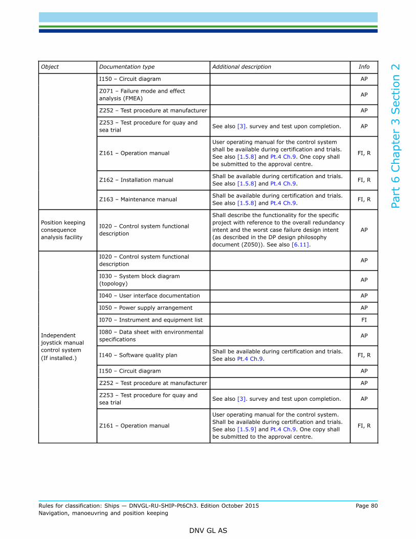
Part
6 C
hapt
er 3
Sec
tion
2
Rules for classification: Ships — DNVGL-RU-SHIP-Pt6Ch3. Edition October 2015 Page 80Navigation, manoeuvring and position keeping
DNV GL AS
Object Documentation type Additional description Info
I150 – Circuit diagram AP
Z071 – Failure mode and effectanalysis (FMEA) AP
Z252 – Test procedure at manufacturer AP
Z253 – Test procedure for quay andsea trial See also [3]. survey and test upon completion. AP
Z161 – Operation manual
User operating manual for the control systemshall be available during certification and trials.See also [1.5.8] and Pt.4 Ch.9. One copy shallbe submitted to the approval centre.
FI, R
Z162 – Installation manual Shall be available during certification and trials.See also [1.5.8] and Pt.4 Ch.9. FI, R
Z163 – Maintenance manual Shall be available during certification and trials.See also [1.5.8] and Pt.4 Ch.9. FI, R
Position keepingconsequenceanalysis facility
I020 – Control system functionaldescription
Shall describe the functionality for the specificproject with reference to the overall redundancyintent and the worst case failure design intent(as described in the DP design philosophydocument (Z050)). See also [6.11].
AP
I020 – Control system functionaldescription AP
I030 – System block diagram(topology) AP
I040 – User interface documentation AP
I050 – Power supply arrangement AP
I070 – Instrument and equipment list FI
I080 – Data sheet with environmentalspecifications AP
I140 – Software quality plan Shall be available during certification and trials.See also Pt.4 Ch.9. FI, R
I150 – Circuit diagram AP
Z252 – Test procedure at manufacturer AP
Z253 – Test procedure for quay andsea trial See also [3]. survey and test upon completion. AP
Independentjoystick manualcontrol system(If installed.)
Z161 – Operation manual
User operating manual for the control system.Shall be available during certification and trials.See also [1.5.9] and Pt.4 Ch.9. One copy shallbe submitted to the approval centre.
FI, R

Part
6 C
hapt
er 3
Sec
tion
2
Rules for classification: Ships — DNVGL-RU-SHIP-Pt6Ch3. Edition October 2015 Page 81Navigation, manoeuvring and position keeping
DNV GL AS
Object Documentation type Additional description Info
I020 – Control system functionaldescription AP
I030 – System block diagram(topology) AP
I040 – User interface documentation AP
I050 – Power supply arrangement AP
I070 – Instrument and equipment list FI
I080 – Data sheet with environmentalspecifications AP
I140 – Software quality plan Shall be available during certification and trials.See also Pt.4 Ch.9. FI, R
I150 – Circuit diagram AP
Z252 – Test procedure at manufacturer AP
Z253 – Test procedure for quay andsea trial See also [3]. survey and test upon completion. AP
Thruster controlmode selectionsystem
Z161 – Operation manual
User operating manual for the control system.Shall be available during certification and trials.See also [1.5.9] and Pt.4 Ch.9. One copy shallbe submitted to the approval centre.
FI, R
I040 – User interface documentation AP
I050 – Power supply arrangement AP
I070 – Instrument and equipment list FI
I080 – Data sheet with environmentalspecifications AP
Z253 – Test procedure for quay andsea trial See also [3] Survey and Test upon Completion. AP
Position referencesystems
Z161 – Operation manual
User operating manual for the control system.Shall be available during certification and trials.See also [1.5.9] and Pt.4 Ch.9. One copy shallbe submitted to the approval centre.
FI, R
I040 – User interface documentation AP
I050 – Power supply arrangement AP
I070 – Instrument and equipment list FI
I080 – Data sheet with environmentalspecifications AP
Vertical referencesystems
Headingmeasurementsystems
Environmentalmonitoringsystems 1)
Z253 – Test procedure for quay andsea trial See also [3]. survey and test upon completion. AP

Part
6 C
hapt
er 3
Sec
tion
2
Rules for classification: Ships — DNVGL-RU-SHIP-Pt6Ch3. Edition October 2015 Page 82Navigation, manoeuvring and position keeping
DNV GL AS
Object Documentation type Additional description Info
Main electricpower control andmonitoring system
Z071 – Failure mode and effectanalysis (FMEA) Power management system AP
Info: AP – For approval, FI: For information, L: Local handling, R: On request.
1)Environmental monitoring systems comprises sensors for measurements of for wind and other sensors connected toDP-control, joystick and manual control systems.
1.5.4 For general requirements to documentation, including definition of the Info codes, see Pt.1 Ch.3 Sec.2.
1.5.5 For a full definition of the documentation types, see Pt.1 Ch.3 Sec.3.
1.5.6 Capability plots and environmental regularity numbers ern*Capability plots shall be submitted for information in accordance with the requirements in [10.1]. Thecapability plots shall be presented in form of a report, which in addition to the required plots, shall includethe following information as a minimum:
— Thruster data: Maximum thrust, location, power. The information requested in Sec.1 [12.10] shall beincluded.
— Vessel data used in the calculations to be presented as numerical values together with (simplified) layoutdrawings showing both projected frontal and lateral areas affected by wind and current. Information aboutlength (overall and Lpp), breath, draught shall also be given. The information requested in Sec.1 [12.10]shall be included.
— Calculation: Description of mathematical method used in the calculations. Tables giving information foreach calculated point: Environmental forces for wind, wave and current. Thrust output for each thruster,total thruster force and total turning moment
— Environmental regularity numbers, ern*, shall be extracted from the capability plots as specified in [10.2].Guidance note:Environmental regularity numbers approved according to this rule edition will be denoted ern* to reflect that the verification hasbeen performed against the more specific acceptance criteria introduced in Appendix B of this rules.These more specific acceptance criteria were first introduced in the July 2013 edition of the legacy DNV ship rules. Environmentalregularity numbers approved according to prior rule editions are denoted ern.
---e-n-d---of---g-u-i-d-a-n-c-e---n-o-t-e---
1.5.7 Failure mode and effect analysis (FMEA)
a) Documentation of consequences of single failures in accordance with rule requirements is required in theform of a failure mode and effect analysis (FMEA).
b) The purpose of the FMEA is to give a description of the different failure modes of the equipment whenreferred to its functional task. Special attention shall be paid to the analysis of systems that may entera number of failure modes and thus induce a number of different effects on the dynamic positioningsystem performance. The FMEA shall include at least the information specified in items c) through j)below.
c) The FMEA shall identify the vessel and provide general vessel information and specify the overallacceptance criteria, i.e. class notation(s).
d) The FMEA shall clearly describe the design intent(s), worst case failure design intent(s), and minimumtime requirement(s). All technical system configuration(s) intended for DP operation(s) shall bedescribed and prerequisites for achieving the required failure tolerance and redundancy shall beincluded.
e) A breakdown of the dynamic positioning system, into functional blocks shall be made. The functionsof each block shall be described. The breakdown shall be performed to such a level of detail that thefunctional interfaces between the functional blocks are shown.

Part
6 C
hapt
er 3
Sec
tion
2
Rules for classification: Ships — DNVGL-RU-SHIP-Pt6Ch3. Edition October 2015 Page 83Navigation, manoeuvring and position keeping
DNV GL AS
f) A description of each physically and functionally independent item and the associated failure modes withtheir failure causes related to normal operational modes of the item shall be furnished.
g) A description of the effects of each failure mode alone, on other items within the system and on theoverall dynamic positioning system shall be made. This shall include a closed bus-tie analysis.
Guidance note:Description of FMEA systematic may be found in document DNV-RP-D102 Failure mode and effect analysis (FMEA) of redundantsystems, IEC Publication 60812 and IMO HSC Code, Annex 4.
---e-n-d---of---g-u-i-d-a-n-c-e---n-o-t-e---
h) When separation is required, the FMEA shall state the separation design intent and give descriptions ofthe installation of redundant component groups in fire and flooding protected compartments and zones.This includes all relevant systems and components, like e.g. machinery and piping, electrical systemsand control systems, cables and communication lines with associated equipment.
i) A redundancy and failure mode test program specifying tests to verify assumptions and conclusions shallbe developed.
j) The FMEA shall summarise and conclude as a minimum the following:
— for each subsystem analysed, the conclusions shall be stated— for the total system, an overall summary covering the main findings from the most critical
subsystems— a compliance statement referring to the acceptance criterion, and when applicable to the minimum
time requirement(s), shall be stated for the FMEA
k) After FMEA testing is performed the FMEA and FMEA test programs shall be updated to reflect the actualdesign. This updating shall as a minimum include correction of mistakes, modifications done to the DPsystem as a consequence of findings during testing and the actual test results, findings and conclusions.
l) FMEA(s) and redundancy test program(s) shall be kept on board. The FMEA(s) and redundancy testprogram(s) shall at all times be updated to cover alterations to the DP system hardware or software.
Guidance note:This is not to be understood as a requirement for an FMEA for the software. However the FMEA (or other relevant documentation)should include identification of the software version(s) installed, and documentation giving this information should be updatedwhen new versions are installed.
---e-n-d---of---g-u-i-d-a-n-c-e---n-o-t-e---
1.5.8 Computer simulationsDynamic computer simulations of the power system in normal operation and during all relevant failureconditions shall also be used for documenting the required failure response. Simulations shall be detailedenough in order to allow for documentation of transient conditions, e.g. failure modes like voltage dip ridethrough as a consequence of a short circuit, synchronising faults, etc.
1.5.9 Operating manuals for control systems
a) User operating manuals according to Table 4 shall be kept on board. The manuals shall includeinformation on the specified systems, their installation and structure as well as operation andmaintenance.
Guidance note:These manuals cover the technical systems. Manuals for DP operations are not normally included and may be producedseparately, in accordance with operational requirements.
---e-n-d---of---g-u-i-d-a-n-c-e---n-o-t-e---
b) User operation manuals shall at least cover the following:
— definitions of symbols and nomenclature— functional description— operating instructions, normal conditions— operating instructions, failure conditions

Part
6 C
hapt
er 3
Sec
tion
2
Rules for classification: Ships — DNVGL-RU-SHIP-Pt6Ch3. Edition October 2015 Page 84Navigation, manoeuvring and position keeping
DNV GL AS
— man and machine communication systems— back-up systems— monitoring— maintenance and periodical performance test— fault-finding procedures.
Functional description
— different functions including back-up, change-over and stand-by start functions shall be explained indetail.
Operating instructions
— description of the normal operation of the equipment, including adjustments and change of limitvalues, possible modes of presentation, starting and stopping systems
— description of operation of the DP system in different operational modes— description of transition from one operational mode to another.
Fault-finding procedures
— description of fault symptoms with explanation and recommended corrective actions— instructions for tracing faults back to functional blocks or systems.
1.6 Certification requirementsProducts in the DP system shall be certified as required in Table 5. All objects are independent productsand the certificates can hence be issued independently or as combined certificates if delivered by the samemanufacturer:
Table 5 Certification required
Object Certificatetype Issued by Certification
standard* Additional description
Dynamic positioning automaticcontrol systems, main
Dynamic positioning automaticcontrol systems, alternative
PC Society
Independent joystick controlsystem with auto heading PC Society
Propulsion and steering controlsystems
Manoeuvring thruster controlsystems
PC Society
Control and monitoring systems forall thrust producing units and steeringarrangements that are part of theDynamic Positioning system
Thruster control modeselection system PC Society
When specifically required as partof the approval process. Thrustercontrol mode selection systems may beexempted from certification when TypeApproved.
*Unless otherwise specified the certification standard is the rules.
For a definition of the certificate types, seePt.1 Ch.3 Sec.5.

Part
6 C
hapt
er 3
Sec
tion
2
Rules for classification: Ships — DNVGL-RU-SHIP-Pt6Ch3. Edition October 2015 Page 85Navigation, manoeuvring and position keeping
DNV GL AS
Guidance note:Additionally, components and systems should be certified according to main class requirements.
---e-n-d---of---g-u-i-d-a-n-c-e---n-o-t-e---
Part
6 C
hapt
er 3
Sec
tion
2
Rules for classification: Ships — DNVGL-RU-SHIP-Pt6Ch3. Edition October 2015 Page 86Navigation, manoeuvring and position keeping
DNV GL AS
2 Upgrades and class entries
2.1 For class entries and upgrades to DYNPOS enhanced reliability notations verification towards the relevantclass notation shall be based on documentation review, performance testing and FMEA failure testing asdescribed in [3] The test shall be performed according to approved test programs.
2.2 Documentation is required as basis for the documentation review as specified in Table 3 and Table 4.
2.3 Vessels to be assigned the qualifier A shall have a valid FMEA, with a corresponding FMEA test program.
2.4 Any deviations from requirements relevant for the class entry found as a result from the documentationreview and testing required in [1.7.1] and [1.7.2] shall be rectified before the vessel can be assigned therelevant DYNPOS enhanced reliability notation.
3 Survey and test upon completion
3.1 General
3.1.1 Upon completion, the dynamic positioning system shall be subjected to final tests according toapproved test programs. Functional, redundancy and failure response testing of the DP system shall beperformed at sea trials. The program shall contain test procedures and acceptance criteria. Prior to the DPsystem tests, all systems and equipment included in the DP system shall be successfully commissioned andtested.
Guidance note:The systems that should be tested prior to DP system tests should at least include:
— load test according to main class
— power management system(s)
— communication systems
— thruster control and transfer of thruster control
— main alarm system as for main class and E0 (if applicable)
— switchboard control and protection
— emergency stops
— safety, control and automation system for power generation, thrusters, steering and propulsion, including their auxiliaries
— other systems as applicable.
---e-n-d---of---g-u-i-d-a-n-c-e---n-o-t-e---
3.1.2 When deemed necessary by the attending surveyor, tests additional to those specified by the testprogram may be required.

Part
6 C
hapt
er 3
Sec
tion
2
Rules for classification: Ships — DNVGL-RU-SHIP-Pt6Ch3. Edition October 2015 Page 87Navigation, manoeuvring and position keeping
DNV GL AS
3.2 Measuring systemAll DP-control system sensors, peripheral equipment, and position reference systems shall be tested as partof the complete DP system. Failures of DP-control system sensors and position reference systems shall besimulated to check the alarm system and the switching function.
3.3 ThrustersThe following shall be tested:
— functional tests of control and alarm systems of each thruster— check all signals exchanged between each thruster and the DP-control systems, including thruster “ready”
signals— manual override of thruster control— transfer of thruster control (mode selection)— function test and loop monitoring alarms for emergency stop— failure in thruster command/feedback signals— check different control modes— any possible change-over arrangements— thruster emergency stop function.
3.4 Thruster mode selectionThe following shall be tested:
— Functional tests— Alarms (if applicable)— Failure simulation.
3.5 UPS power supplyThe following shall be tested:
— capacity of the UPS batteries— Alarms.
3.6 Complete DP system test
3.6.1 The complete DP system shall be tested in all operational modes, with simulation of different failureconditions, in order to try out e.g. switching modes, back-up systems, fail to safe response (e.g. thrustercontrol system I/O) and alarm systems.
Guidance note:Different operational modes apply to the DP-control system, the power system, thruster systems etc.
---e-n-d---of---g-u-i-d-a-n-c-e---n-o-t-e---
3.6.2 Change of command between the automatic DP-control systems, independent joystick system (ifinstalled) and the individual thruster lever systems shall be demonstrated.
3.6.3 Position and heading keeping function shall be demonstrated on all possible combinations ofposition reference systems (PRS), and on each PRS as a single system. Position change function shall bedemonstrated on each PRS as a single system. Selecting and de-selecting of PRS shall also be tested.
Part
6 C
hapt
er 3
Sec
tion
2
Rules for classification: Ships — DNVGL-RU-SHIP-Pt6Ch3. Edition October 2015 Page 88Navigation, manoeuvring and position keeping
DNV GL AS
3.6.4 During sea trials the offset inputs for each position reference system and relevant sensors in thedynamic position control system shall be verified and demonstrated to the attending surveyor by setting outthe offsets on drawings. It shall be verified that these fit with the actual placing of the equipment.
3.6.5 Manual override, as required by [6.5]and [7.3.3] shall be demonstrated during normal operation andfailure conditions.
3.6.6 A duration test shall be carried out for at least 8 hours with the complete automatic system inoperation. All failures shall be recorded and analysed.
Guidance note:The time spent on DP operational tests may be deducted from the time required for the duration test.
---e-n-d---of---g-u-i-d-a-n-c-e---n-o-t-e---
3.6.7 A high seas trial shall be required with full system operation for at least 2 hours. The weatherconditions shall be such that an average load level on the thrusters of 50% or more is achieved.
Guidance note:The test described in [3.6.7] is dependent on weather conditions and may be omitted if satisfactory results were obtained from thetest described in [3.6.6]. Typically this will be required for DP-control systems of novel design.
---e-n-d---of---g-u-i-d-a-n-c-e---n-o-t-e---
3.6.8 For rudder steering gears included under DP control a test shall be carried out verifying that maximumdesign temperature of actuator and all other steering gear components is not exceeded when the rudder iscontinuously put over from border to border within the limits set by the DP-control system, until temperatureis stabilized.
Guidance note:The test should be carried out with the propeller(s) running with an average propulsion thrust of not less than 50%, unless thecontrol system ensures that rudder operation is performed at zero propulsion thrust only, upon which the test may be carried outwithout the propeller(s) running. Number of steering gear pumps connected and rotation speed should be the maximum allowedduring DP operation.
---e-n-d---of---g-u-i-d-a-n-c-e---n-o-t-e---
3.6.9 If an independent joystick system is installed then all functions in it shall be tested.
3.7 Redundancy and failure response tests
3.7.1 A selection of tests within each system analysed in the FMEA shall be carried out. Specific conclusionsof the FMEA for the different systems shall be verified by tests when redundancy, fail safe response, orindependence is required. The tests shall include test to verify proper functionality of the power managementsystem (PMS) generator protection system (GP), detection systems to prevent hidden failures, back-upprotection functions, stand-by start and change-over functionality and other systems that might affect theintegrity of the DP system. The test selection shall cover all specified technical system configurations.
Guidance note:For DYNPOS(ER) this implies that loss of all systems in relevant fire zones or within watertight compartments should be tested.
---e-n-d---of---g-u-i-d-a-n-c-e---n-o-t-e---
3.7.2 The test procedure for redundancy shall be based on the simulation of failures and shall be performedunder as realistic conditions as practicable.
3.7.3 When redundancy is based upon change-over and/or stand-by start, then the functionality andavailability of these mechanisms after failure shall be demonstrated at sea-trials.

Part
6 C
hapt
er 3
Sec
tion
2
Rules for classification: Ships — DNVGL-RU-SHIP-Pt6Ch3. Edition October 2015 Page 89Navigation, manoeuvring and position keeping
DNV GL AS
4 General arrangement
4.1 General requirements
4.1.1 The general requirements for DP system design are presented in Table 6.
4.1.2 The design and level of redundancy employed in system arrangements shall be to the extent that thevessel maintains the ability to keep position after worst case failure(s).
Guidance note:Table 6 gives general requirements only, detailed requirements are given in [6], [7], and [8].
---e-n-d---of---g-u-i-d-a-n-c-e---n-o-t-e---
4.2 Redundancy
4.2.1 The DP system shall be designed with redundancy. A position keeping ability shall be maintainedwithout disruption upon any single failure.
4.2.2 The redundancy design intent(s) and worst case failure design intent(s) based on specified redundancygroups shall be stated, and in addition all the relevant technical system configuration(s) shall be specified.Only redundancy design intents that are verified by approval and testing can be incorporated in theconsequence analysis required by [6.11].
Guidance note:The redundancy groups will emerge as a consequence of the worst case single failure within each group. The rules does not giverequirements to the number of (beyond 2) or ratio between the defined groups. The groups should be identified in the FMEA, verifiedby testing and incorporated in the consequence analysis.
---e-n-d---of---g-u-i-d-a-n-c-e---n-o-t-e---
4.2.3 Automatic start of equipment may be accepted as contributing to redundancy if their reliability andsimplicity of operation is satisfactory so that they can be brought automatically into operation before positionand heading keeping performance is degraded. Monitoring of availability of standby start functions shall beimplemented for the most probable failures for the relevant system, e.g. power failure, wrong mode, loopfailures, etc. Software based systems shall have self-diagnostics.
4.2.4 Full stop of thrusters and subsequent start-up of available thrusters will not be accepted ascontributing to the redundancy. Dual power supply arrangements thrustersfrom different redundancy groupscan be accepted as long as all the following conditions are met:
— The thruster is fully ready with specified power available for DP control withoutdisruption or manualintervention. Available thrust output may be reduced to a specified level after failure of one supply.
— The availability of both supplies is monitored and communicated to the DP-control systems.— The common thruster space is separated from the redundancy groups as required by the relevant
notation(s).— No failures in the system shall be able to propagate to both power systems supplying the thruster. In
order to mitigate the effects of hidden failures, minimum two independent barriers, both capable ofisolating upon failures, shall be arranged in each supply line. For DYNPOS-ER these barriers shall beoutside of the common thruster space and the supply lines shall be separated by A0 partition.
— Any situation when available thrust is reduced due to any control system action is communicated to theDP-control systems.
— Start and any necessary reset after full stop of thruster is available in DP control centre.— Auxiliary systems are autonomous for each thruster according to [9.1.6] and [9.3].— Supply to auxiliary and control systems are autonomous and continuously available.

Part
6 C
hapt
er 3
Sec
tion
2
Rules for classification: Ships — DNVGL-RU-SHIP-Pt6Ch3. Edition October 2015 Page 90Navigation, manoeuvring and position keeping
DNV GL AS
— Thruster failure or trip shall prevent automatic re-start.
4.2.5 Stand-by start or change-over of generators can be accepted to contribute to the redundancy as longas all the following conditions are met:
— Start and connection is automatic.— “Ready for stand-by start” and/or “ready for change-over” signal is communicated to the DP-control
systems.— Single failure does not cause total black-out, full black-out and subsequent standby start is not accepted
as bases for redundancy.— Generator is connected fast enough in order to be able to maintain position and heading keeping ability
as required by the operation. If no specific time can be documented the maximum allowed is 45 secondsafter the need for more power appeared. Auxiliary systems is autonomous according to [9.1.6] and [9.3].
— Supply to generator and prime mover control systems are autonomous and continuously available.— In case of any failure it is assumed that any one of the available stand-by generators may not start.
This means that the power contribution from stand-by generators shall be based on the total numberof available stand-by generators after failure minus one (n-1 principle). This includes also the stand-bygenerator giving the largest contribution to the position keeping ability. This shall be incorporated in theconsequence analysis.Guidance note 1:For specific designs and specific technical system configurations failure of standby-generators to start upon request (n-1 principle)may not have to be considered consecutive to:
— an engine room fire (in another redundancy group)
— busbar-failures (in another redundancy group) in switch-boards with high integrity towards short-circuit
— failure of non-active components in sea-water systems which are not directly cooling generator and/or prime mover
This will apply for systems with autonomous generating sets where only these limited number of failures modes will lead to lossof more than one generator. For generating sets to be considered autonomous, single failures in auxiliary systems shall only affectone generating set. This includes typically, but not limited to, the following auxiliary systems: Fresh water cooling, compressed air,exhaust systems, crank case ventilation, fuel systems, lubrication, starting air, power supply to these services, etc.
---e-n-d---of---g-u-i-d-a-n-c-e---n-o-t-e---
Guidance note 2:It can be accepted that generator sets within the same redundancy group share auxiliary system, however this will reduce the numberof stand-by generator sets that can be considered available by the consequence analysis. This implies that when a redundancy group(containing running and stand-by generator sets) become unavailable due to a single failure, then it should also be considered thatany other stand-by generator set, or group of stand-by generator sets subject to a common mode failure, may not be available dueto a hidden failure. This implies that the possibility to utilize stand-by generator sets as part of the redundancy will be significantlyreduced compared with a system with fully autonomous generator sets. In the consequence analysis the n-1 principle has to considerthe largest group of generator sets subject to a common mode failure.
---e-n-d---of---g-u-i-d-a-n-c-e---n-o-t-e---
Guidance note 3:Component and system redundancy, in technical design and physical arrangement, should be available with the capacity required forthe DP system to safely terminate the work in progress. The consequence analysis required in [6.11] will give an indication whetherthe position and heading can be maintained after a single failure.The transfer to components or systems designed and arranged to provide redundancy, shall be automatic and operator interventionshould be avoided.
---e-n-d---of---g-u-i-d-a-n-c-e---n-o-t-e---
Guidance note 4:Switch-boards with high integrity towards short-circuits may be achieved by use of e.g. insulated bus-bars or SF6 insulated systems.
---e-n-d---of---g-u-i-d-a-n-c-e---n-o-t-e---
4.2.6 In case change over is arranged the arrangement shall be so that neither:

Part
6 C
hapt
er 3
Sec
tion
2
Rules for classification: Ships — DNVGL-RU-SHIP-Pt6Ch3. Edition October 2015 Page 91Navigation, manoeuvring and position keeping
DNV GL AS
— a single failure in one redundancy group, nor— a single failure in the change over arrangement it selves, nor— a single failure in a common power or control system connection, nor— a single failure in the system or component being changed over,
can cause failure of more than one redundancy group
4.2.7 Stand-by start shall also be arranged so that it will not cause failure of the redundancy group it isbeing connected to.
4.3 Failure modes
4.3.1 Loss of position shall not be allowed to occur in the event of a single failure. Single failure criteriainclude:For DYNPOS(E):
— any active component or system— all static components— a single inadvertent act of operation. If such an act is reasonably probable— systematic failures or faults that can be hidden until a new fault appears— common cause failures when found relevant— automatic interventions caused by external events, when found relevant
For DYNPOS(ER):
— all single failure criteria as listed for DYNPOS(E), and in addition:— all components within any fire zone and/or watertight compartment as given in [4.5], (not on the bridge/
DP control centre).Guidance note 1:In order to reduce the probability of inadvertent acts, the following may be used:
— double action
— operation of two separate devices
— using screen based question pop-ups.
---e-n-d---of---g-u-i-d-a-n-c-e---n-o-t-e---
Guidance note 2:In these rules the following are also considered active:
— coolers
— filters
— motorised valves
— fuel oil, fuel oil service tanks and appurtenant piping supplying the engine(s)
— electrical and electronic equipment (this includes all onboard equipment and systems, e.g. any safety shut-down systems(spurious shut down), vessel control systems, external force measurements, etc.)
when considering single failures of switchboards, the possibility of short-circuit of the bus-bars has to be considered.
---e-n-d---of---g-u-i-d-a-n-c-e---n-o-t-e---
Guidance note 3:The DYNPOS(E) and DYNPOS(ER) notations aims for a very high reliability and integrity between redundant groups. In the FMEAspecial attention should be given to verification of integrity where common mode failures between redundant groups may exist.Examples of such systems may be, but are not limited to:
— operation with closed bus-tie breakers
— redundancy is based on change-over and/or stand-by start of thrusters and/or generators
— redundancy and/or separation is based on discrimination

Part
6 C
hapt
er 3
Sec
tion
2
Rules for classification: Ships — DNVGL-RU-SHIP-Pt6Ch3. Edition October 2015 Page 92Navigation, manoeuvring and position keeping
DNV GL AS
— power management systems.
Reference is made to the document DNVGL-RP-D102 Failure mode and effect analysis (FMEA) of redundant systems, Appendix D,for discussion on the subject of operation with closed bus-tie breakers and examples of relevant failure modes.
---e-n-d---of---g-u-i-d-a-n-c-e---n-o-t-e---
4.3.2 Based on the single failure definition, worst case failures shall be determined in the FMEA. Theconsequence of the identified worst case failure(s) in terms of reduction in position and heading keepingability shall be used as the criterion for the consequence analysis described in [6.10]and[6.11].
Guidance note:For detailed information and requirements to the consequence analysis function, see [6.10]and[6.11].
---e-n-d---of---g-u-i-d-a-n-c-e---n-o-t-e---
4.3.3 In order to meet the single failure criteria, redundancy of components will be necessary for allcomponents affecting station keeping and physical separation of these components as required in [4.5].
4.4 IndependenceIndependence shall take into account all technical functions. Use of shared components can be accepted onlyif specifically mentioned.
4.5 Separation
4.5.1 For DYNPOS(ER) systems that form the designed redundancy requirement shall be separated bybulkheads and decks fire insulated by at least A-0 class division. In high fire risk areas A-60 class division isrequired between the redundancy groups.
Guidance note 1:Definition of high fire risk areas: Reference to be made to SOLAS Chapter II-2 Reg. 3.31 Machinery spaces of category A, and MODUCode Chapter 1.3.34.
---e-n-d---of---g-u-i-d-a-n-c-e---n-o-t-e---
Guidance note 2:The term “systems” should be understood to also include components, cabling, and piping.
---e-n-d---of---g-u-i-d-a-n-c-e---n-o-t-e---
Guidance note 3:Cables should be routed and equipment installed such that the risk of failure due to heat exposure of cables and equipment belongingto different redundancy groups is reduced in case of fire in one space.Equipment and cables should generally not be mounted directly on bulkheads separating redundant groups nor should equipment orcables belonging to more than one group be mounted directly on bulkheads to a common adjacent space.On open deck, cables in separate pipes that are separately routed may be accepted.
---e-n-d---of---g-u-i-d-a-n-c-e---n-o-t-e---
4.5.2 It will be accepted that cables from separated power systems supplying the same component mayenter a common space as long as discrimination is in place for both feeders so that the worst case failuredesign intent is not compromised.
4.5.3 Systems that form the designed redundancy requirement shall be separated by watertight bulkheadsif located below the bulk-head deck. Watertight separation shall also be provided in other areas where largequantity of liquids may occur as a consequence of leakage.
Guidance note:Special attention should be paid to areas where leakage of flammable liquids is possible.

Part
6 C
hapt
er 3
Sec
tion
2
Rules for classification: Ships — DNVGL-RU-SHIP-Pt6Ch3. Edition October 2015 Page 93Navigation, manoeuvring and position keeping
DNV GL AS
---e-n-d---of---g-u-i-d-a-n-c-e---n-o-t-e---
4.5.4 Watertight doors in A-60 insulated bulkheads need not to be insulated. See SOLAS Chapter. II-2Reg. 9.4.2.4. In such cases the materials of the doors shall have melting points of not less than 950 °C andcombustible materials shall be installed with a minimum distance of 450 mm from the door.
4.5.5 In the DP control centre separation with bulkheads is not required. Physical separation between mainand alternative DP-control systems shall be provided by installation in separate cabinets and cables installedon separate cable trays.
4.5.6 The main controllers for the main DP-control system shall neither be located in the DP control centrenor in the same space as the main controller for the alternative DP-control system. The separation shall bebulkheads and decks of at least A-0 class. (Location of DP operator stations, see [4.5.7] and [5.2].)
Guidance note:Cabinets installed on raised floor with openings down to a common cable space will be accepted in line with main class requirements.
---e-n-d---of---g-u-i-d-a-n-c-e---n-o-t-e---
4.5.7 Levers, operator stations, HMI and other such equipment necessary for the operator shall be installedin the DP control centre. Other parts of the DP system shall be installed in accordance with the requirementin [4.5.1].
Guidance note:As an example this means that the thruster controllers and appurtenant cabling shall be distributed and separated in accordancewith the redundancy groups as required in [4.5.1].
---e-n-d---of---g-u-i-d-a-n-c-e---n-o-t-e---
4.6 Gas in non-hazardous areasOn vessels where gas release is a possible scenario, air intakes for combustion air shall be separate fromother ventilation systems. The air intakes for separate engine rooms shall be separated as far as practicable.It shall be possible to operate machinery long enough to safely terminate the operation after shut down ofmachinery room ventilation.
Guidance note:This requirement will typically apply to drilling and production units.
---e-n-d---of---g-u-i-d-a-n-c-e---n-o-t-e---

Part
6 C
hapt
er 3
Sec
tion
2
Rules for classification: Ships — DNVGL-RU-SHIP-Pt6Ch3. Edition October 2015 Page 94Navigation, manoeuvring and position keeping
DNV GL AS
5 System arrangement
5.1 General
5.1.1 The requirements for system arrangement is summarised in Table 6. Specific requirements for eachsubsystem are presented under the respective section headings.
Table 6 System arrangement
Subsystem or component Fundamentals for class notations
Generators and prime movers
Redundant in technical design.Additional for DYNPOS(ER): Physical separation. A-60between machinery spaces of category A. Watertight belowbulkhead deck.
Auxiliaries Autonomous systems within each redundancy group
Main switchboardMinimum 2 switchboards in separate compartments.Additional for DYNPOS(ER): A-0 between redundantswitchboards. Watertight below bulkhead deck.
Bus-tie breaker 2, 1 in each switchboard.
Distribution system and thruster groupsRedundant in technical design.Additional for DYNPOS(ER): Physically separated with A-0division. Watertight below bulkhead deck.
Power system
Power management Yes
ArrangementRedundant.Additional for DYNPOS(ER): A-0 and water tightseparation.Thrusters
Auxiliaries Autonomous systems within each thruster group
Manualthruster control
Individual ControlLevers for each Thruster Yes
DP ControlMain DP
Control systemAlternative DPControl system
Automatic Control - Number ofComputers (See also [4.5.6]) 2 1Controllers
and -operatorstations Automatic Control - Number of
operator stations (See also [5.2.2]) 2 1
Position reference system 3 1*)
External Wind Sensors 3 1*)
Vertical Reference Sensor (VRS) 3 1*)
Heading reference sensor***) 3 1*)
Positionreferencesystems
and sensors
Electronic Data logger 1 **)

Part
6 C
hapt
er 3
Sec
tion
2
Rules for classification: Ships — DNVGL-RU-SHIP-Pt6Ch3. Edition October 2015 Page 95Navigation, manoeuvring and position keeping
DNV GL AS
Subsystem or component Fundamentals for class notations
Power Supply Uninterruptible power supply(UPS) for DP-control systems 2 1
*)The main DP-control system shall be able to read all sensors.
**)The data logger for the main DP-control system shall also log the alternative DP-control system, alternatively twologger systems will be accepted.
***)The Heading reference system(s) shall comply with IMO Res. A424(XI) performance standards for gyro-compasses.One of the three required heading reference systems may be replaced by a heading measuring device based uponanother principle, as long as this heading device is type approved as a THD (Transmitting Heading Device) as specified inIMO Res. MSC.116 (73).
Heading sensors based on other principles may be accepted upon special considerations. When such considerations aremade the total heading device installation shall be considered in view of redundancy, robustness and failure toleranceboth with respect to the number of heading devices installed, principles used, and the installation of the equipment withrespect to signal transmission, power supply and physical installation (including separation when required).
5.2 DP control centre
5.2.1 The DP vessel shall have its DP control centre designated for DP operations, where at least therequired indicators, displays, alarm panels, control panels and internal communication systems are installed.This equipment shall be arranged with easy access for the operator so that he does not need to changeposition when operating the control systems.
5.2.2 The operator stations for the main DP-control system shall be located in the DP control centre. Theoperator station for the alternative DP-control system shall be in the same space.
Guidance note 1:Changing orientation can be accepted provided that the operator's view of the operating area will not change significantly. This impliesthat the operator should not be forced to turn his back to the operating area when changing between main DP-control system andmanual thrusters’ levers. The operator station for the alternative DP-control system and any possible independent joystick systemmay be installed with different orientation.Manual levers and the independent joystick should be easily accessible from the DP operator work station. Thruster emergency stopsand mode change system should be within reach from both manual lever operator stations and DP operator stations.When the systems/equipment are accepted split between more than one work station at the DP control centre (e.g. a manoeuvringand a ship handling station), the required main automatic, alternative automatic and manual lever control modes shall be availableat the work station(s) being designated for the DP operator.In general all required VDU should be readable from DP and manual lever operator stations.
---e-n-d---of---g-u-i-d-a-n-c-e---n-o-t-e---
Guidance note 2:The DP control centre may be a dedicated part of the navigation bridge. System components which do not require frequent orimmediate operator attention may be installed in alternate locations.Systems that are normally required to be located at the DP control centre includes: Main DP control operator stations, requiredposition reference systems HMI, manual thruster levers, mode change systems, thruster emergency stops, internal communications.
---e-n-d---of---g-u-i-d-a-n-c-e---n-o-t-e---
5.2.3 The location of the DP control centre shall be chosen to suit the main activity of the vessel.
5.2.4 The DP control centre shall be arranged such that the DP operator has a good view of the vessel’sexterior limits and the surrounding area.
Guidance note:

Part
6 C
hapt
er 3
Sec
tion
2
Rules for classification: Ships — DNVGL-RU-SHIP-Pt6Ch3. Edition October 2015 Page 96Navigation, manoeuvring and position keeping
DNV GL AS
If physical arrangements make it difficult to get direct view to all required areas from one location, camera systems may be used tocompensate for lack of direct view to some areas. At least one monitor should be located at and controlled from the DP control centre.
---e-n-d---of---g-u-i-d-a-n-c-e---n-o-t-e---
5.3 Arrangement and layout of control panels
5.3.1 The information sources like displays, indicators, etc. shall provide information in a readily usable form.
5.3.2 The operator shall be provided with immediate information of the effect of any actions, preferably withgraphics.
5.3.3 Where applicable, feedback signals shall be displayed, not only the initial command.
5.3.4 Easy switch-over between operational modes shall be provided. Active mode shall be positivelyindicated.
5.3.5 Positive indications of the operational status of the different systems shall be given.
5.3.6 Indicators and controls shall be arranged in logical groups, and shall be co-ordinated with thegeometry of the vessel, when this is relevant.
5.3.7 If control of a sub-system can be carried out from alternate control stations, positive indication of thestation in charge shall be provided. Responsibility transferred from one station to another shall be indicated.
Guidance note:For control transfer arrangements, see Pt.4 Ch.9 Sec.3.
---e-n-d---of---g-u-i-d-a-n-c-e---n-o-t-e---
5.3.8 Precautions shall be taken to avoid inadvertent operation of controls if this may result in a criticalsituation. Such precautions may be proper location of handles etc, recessed or covered switches, or logicalrequirements for operations.
5.3.9 Interlocks shall be arranged, if erroneous sequence of operation may lead to a critical situation ordamage of equipment.
5.3.10 Controls and indicators placed on the navigation bridge and the DP control centre shall be sufficientlyilluminated to permit use at night and be provided with dimming facilities.
5.4 Arrangement and layout of data communication links
5.4.1 When the main DP-control system uses a data communication link, this link shall neither be commonwith the communication link(s) for manual control nor the communication link(s) for alternative DP-controlsystem.
5.4.2 The communication link for the main DP-control system shall be arranged with redundancy in thetechnical design and physical separation as specified in [4.5].
5.4.3 When two or more thrusters and their manual controls are using the same data communication link,this link shall be arranged with redundancy in technical design and physical separation as required for thecommunication link for the main DP-control system.
5.4.4 The alternative DP-control system may share a redundant communication link with the manualthruster control and/or indication, but not with the main DP-control system.

Part
6 C
hapt
er 3
Sec
tion
2
Rules for classification: Ships — DNVGL-RU-SHIP-Pt6Ch3. Edition October 2015 Page 97Navigation, manoeuvring and position keeping
DNV GL AS
5.4.5 When units (e.g. thruster controllers) are interfaced to data communication links which are requiredto be independent, the interfacing to each of these networks shall be separately arranged in such a way thatcommon mode failures (e.g. network storm) affecting both communication links are eliminated. This includesboth HW and SW failures in all the connected units, the interface and the communication links.
5.5 Arrangement and layout of emergency stop systems
5.5.1 Emergency stop systems shall not violate the redundancy design intent. Single failures shall not lead tostop of DP related equipment beyond the specified redundancy groups.
5.5.2 Systems for activation of emergency stop of DP related equipment shall be so arranged that it ispossible to activate emergency stop of equipment belonging to different redundancy groups separately.
Guidance note:For requirement to emergency stop of thrusters please refer to [7].For general requirements to emergency stop please refer to Pt.4 Ch.8 Sec.2.
---e-n-d---of---g-u-i-d-a-n-c-e---n-o-t-e---
5.5.3 For DYNPOS(ER): When systems for emergency stop are placed in a different fire zone than thesystem it controls or systems for emergency stop of equipment belonging to more than one zone is placedin the same fire zone, these systems shall be arranged with sufficient fire and flooding integrity in order toprevent unintended activation.
Guidance note:Systems for emergency stop of equipment belonging to more than one redundancy group will typically be placed in the same space,e.g. thruster emergency stop on the bridge or emergency stops for auxiliary pumps located in an engine control room. When this isthe case protection against unintended activation due to fire or flooding should be implemented. This includes failures of equipmentand cabling including the activation buttons. The required integrity may for example be achieved by use of a combination of loopmonitoring and thermal fuses which will introduce a loop failure before the activation buttons can short circuit and cause unintendedstop. The thermal fuses should then be placed in close proximity to the respective activation buttons and be a part of the loop thatis covered by the loop monitoring.
---e-n-d---of---g-u-i-d-a-n-c-e---n-o-t-e---
5.6 Internal communicationFor internal communication requirements see Sec.1 [5.7].
6 Control systems
6.1 General requirementsThe operational status of thrusters, sensors and reference systems used in DP operations shall be clearlyindicated. The following information shall typically be presented:
— “running”— “available for DP”— “in DP operation”.
6.2 Automatic control systems
6.2.1 Unless otherwise specified, all requirements in this section apply both to the main and to thealternative DP-control system.

Part
6 C
hapt
er 3
Sec
tion
2
Rules for classification: Ships — DNVGL-RU-SHIP-Pt6Ch3. Edition October 2015 Page 98Navigation, manoeuvring and position keeping
DNV GL AS
6.2.2 The positioning control systems shall perform self-check routines. An alarm shall be initiated in case offailure.
6.2.3 Automatic control mode shall include control of position and heading. Set points for control of positionand heading shall be independently selectable. It shall be possible to individually enter new position andheading set points in automatic control mode.
Guidance note:The rules does not give any specific acceptance criteria for positioning performance. However, in moderate weather conditions andwith a fully operational DP system the vessel should generally be able to demonstrate position keeping accuracy with a 3 meterradius and ±1° of heading.
---e-n-d---of---g-u-i-d-a-n-c-e---n-o-t-e---
6.2.4 It shall be possible to control the thrusters manually by a common joystick at all DP operator stations.The joystick mode shall include selectable automatic and manual heading control.
6.2.5 It shall be possible to select any combination of manual (joystick and/or heading wheel) and automaticcontrol of surge, sway and yaw.
6.2.6 When stopped, either by automatic or manual means the positioning control system shall set the thrustcommands to zero.
6.2.7 Loss of one or multiple position reference system input and/or one or multiple sensor inputs shall notlead to significant change in thrust output.
Guidance note:This includes the situation when DP-control system loses the last available position reference system input or sensor input. Positionor heading drive off is not accepted after such failures.
---e-n-d---of---g-u-i-d-a-n-c-e---n-o-t-e---
6.2.8 Upon recovery of position and heading reference input the DP-control system shall not automaticallyapply the last position or heading set point (set points before loss of input) when this is significantly differentfrom the actual vessel position and/or heading. If any other set point than the actual vessel position and/orheading is applied then it shall be operator chosen.
6.2.9 When combining position reference systems and/or sensors in one unit were more than one functionor system can be lost upon one common failure, the consequence to the total system upon such a failureshall be evaluated in order to ensure that the redundancy, independency and separation requirements for thegiven notation(s) are complied with. SeeTable 6.
Guidance note:Unit should be understood as one piece of equipment (or one system) for each sensor and position reference system as required inTable 6. The rule is applicable when equipment/systems serving more than one such function are part of the DP system.
---e-n-d---of---g-u-i-d-a-n-c-e---n-o-t-e---
6.2.10 When more than two position reference systems and/or sensors are inputs are used by the DP-control system then voting mechanisms shall be utilised in order to: identify incorrect input, take correctaction upon the failure in order to minimize the consequence of failure and alarm the operator.
6.3 Main DP-control system
6.3.1 The main DP-control system shall be arranged with redundancy such that, after the occurrence of anysingle failure within the DP-control system, command output to a defined group of thrusters able to controlposition and heading of the vessel, can still be produced without disruption. Changeover between redundantcontrollers shall be automatic and bump less.

Part
6 C
hapt
er 3
Sec
tion
2
Rules for classification: Ships — DNVGL-RU-SHIP-Pt6Ch3. Edition October 2015 Page 99Navigation, manoeuvring and position keeping
DNV GL AS
6.3.2 One of the controllers in the main system shall be selected as the online controller. This selectionshall be possible by manual means and by automatic action upon failure of the online controller. The othercontroller(s) shall be ready for automatic or manual change over. Alternatively, 3 or more controllers can bearranged in an automatic majority voting system. The voting mechanism shall not jeopardize the redundancyrequirements. It shall not be possible to automatically or manually select a controller which is not ready toassume command as the active controller.
6.3.3 Self-monitoring and comparison between controllers shall be arranged so that alarm is released upondetection of an unexpected difference in thrust command or position or heading. This shall not jeopardise theindependence of each system or risk common mode failures.
6.3.4 The automatic transfer of online responsibility shall not cause thrust changes of such magnitude that itwill be detrimental to the positioning of the vessel.
6.3.5 All required positioning reference system and sensors connected to the alternative DP-control systemshall also be available to the main DP-control system.
6.4 Alternative DP-control system
6.4.1 The alternative DP-control system shall be able to operate independently of the main system.
6.4.2 There shall be at least one positioning reference system and one set of sensors connected to thealternative DP-control system.
Guidance note:This system should have high availability and be easily available, typically DGPS.
---e-n-d---of---g-u-i-d-a-n-c-e---n-o-t-e---
6.4.3 The alternative DP-control system shall at all times be ready to assume command, and maintain theposition from the moment of assuming command.
6.4.4 The alternative DP-control system shall perform self check routines and communicate its status tothe main DP-control system. An alarm shall be initiated in the main DP-control system if the alternative DP-control system fails or is not ready to take control.
6.5 Thruster control mode selection
6.5.1 The thruster control mode, i.e. manual, main DP and alternative DP, shall be selectable at the DPcontrol centre. The control mode selector system shall be intuitive and simple to operate. It shall only bepossible to select one automatic system at a time. Combined automatic and manual control of individualthrusters is acceptable.
Guidance note:For vessels with nautical notations, reference is also made the respective sections for these notations in RU SHIP Pt.6 Ch.3.
---e-n-d---of---g-u-i-d-a-n-c-e---n-o-t-e---
6.5.2 The control mode selector shall be arranged so that it is always possible to select manual controls afterany single failure in the automatic DP control mode or in the independent joystick control mode (if installed).
6.5.3 The mode selector shall not violate redundancy or independency requirements.Guidance note:A common switch will be accepted, but each system should be electrically independent.
---e-n-d---of---g-u-i-d-a-n-c-e---n-o-t-e---

Part
6 C
hapt
er 3
Sec
tion
2
Rules for classification: Ships — DNVGL-RU-SHIP-Pt6Ch3. Edition October 2015 Page 100Navigation, manoeuvring and position keeping
DNV GL AS
6.5.4 The main and alternative DP-control systems shall be capable of being activated by the operator. Thenature of the switching shall be such that no single failure will render the alternative DP-control systeminoperable together with the main system.
6.6 Positioning reference system
6.6.1 At least four position reference systems are required. These shall be based on at least two differentprinciples and maximum two of the required systems shall be based on the same principle.
Guidance note:This should be understood so that four separate systems based on two different principles will be accepted.
---e-n-d---of---g-u-i-d-a-n-c-e---n-o-t-e---
6.6.2 In order for two satellite based systems to be considered as separate units it shall be possible to setthem up with different differential correction signals.
6.6.3 When more than one satellite based system is installed, at least one system shall be able to utilisea different satellite system than the others, e.g. one DGPS system is also able to utilise GLONASS, and inaddition at least one shall be a dual frequency receiver.
6.6.4 Position reference systems can be utilised by both the main and alternative DP-control systemprovided that the independence requirements between the main and alternative DP-control systems is notcompromised.
6.6.5 Position reference systems shall be independent with respect to signal transmission, and shall beinterfaced to the DP-control systems in accordance with the overall redundancy requirement. Systems shallbe distributed between the redundant groups, and so arranged that systems based on the same principle aredistributed between the redundant groups.
6.6.6 Power supply to the position reference systems shall be from UPS. Arrangement of power supply shallbe in accordance with the overall redundancy requirement.
Guidance note 1:Power supplies should be equally distributed between the UPSs, and so arranged that power supply to systems based on the sameprinciple are equally distributed between the UPSs.
---e-n-d---of---g-u-i-d-a-n-c-e---n-o-t-e---
Guidance note 2:Power supply to units providing correction signal to DGPSs shall follow the same redundant distribution principle.
---e-n-d---of---g-u-i-d-a-n-c-e---n-o-t-e---
Guidance note 3:The requirement for UPS supply for position reference systems is not applicable for parts of the systems which are not actively in useduring positioning. E.g. Hydro acoustic positioning reference system transducer hoist system or taut wire derrick control systems.For taut wire systems, the heave compensation system need not be powered by UPS.
---e-n-d---of---g-u-i-d-a-n-c-e---n-o-t-e---
6.6.7 Positioning reference systems shall comply with the relevant main class rules for electrical, mechanical,and hydraulic components and subsystems.
6.6.8 Monitoring of positioning reference systems shall include alarms for electrical and mechanicalfunctions, i.e. power, pressure, temperature as relevant.
6.6.9 Positioning reference systems shall provide new position data with a refresh rate and accuracy suitablefor the intended DP operations.

Part
6 C
hapt
er 3
Sec
tion
2
Rules for classification: Ships — DNVGL-RU-SHIP-Pt6Ch3. Edition October 2015 Page 101Navigation, manoeuvring and position keeping
DNV GL AS
Guidance note 1:Systems that only produce new position data with long intervals relative to the response time of DP vessels, will not be considered aspositioning reference systems, as required in Table 6 and [6.6.1], unless it can be demonstrated that the performance is adequatein all operational modes and operational weather conditions.
---e-n-d---of---g-u-i-d-a-n-c-e---n-o-t-e---
Guidance note 2:The accuracy of the position reference data is generally to be within:
— a radius of 2% of water depth for bottom-based systems,
— a radius of 3 m for surface-based systems.
---e-n-d---of---g-u-i-d-a-n-c-e---n-o-t-e---
Guidance note 3:For satellite based systems, interface and necessary equipment for receiving differential correction signals are required to be installed.
---e-n-d---of---g-u-i-d-a-n-c-e---n-o-t-e---
6.6.10 It shall be simple for the operator to establish the operational status of all position reference systemsat any time. Which systems that is in operation, with data accepted or discarded, shall be clearly identified.
6.6.11 When data from several position references are combined into a mean positioning, by filteringtechniques, the reference position of each shall, be available at the operator's request.
6.6.12 When several systems are combined to provide a mean reference, the mean value used shall notchange abruptly by one system being selected or deselected.
6.6.13 Failures in a positioning reference system that might give degraded quality, loss of position signal orloss of redundancy shall initiate an alarm.
6.6.14 Limit alarms shall be provided for systems, which have defined range limits.
6.6.15 If a positioning reference system can freeze or otherwise produce corrupt data output, a method shallbe provided to enable rejection of the data.
6.6.16 The DP control centre is the main control station for position reference systems. All position referencesystems connected to the main DP-control system shall have HMI independent of the DP-control systems.
Guidance note:Exemption may be given to systems in excess of the minimum requirements if no separate HMI is available in the market.
---e-n-d---of---g-u-i-d-a-n-c-e---n-o-t-e---
6.6.17 At least one position reference system connected to alternative DP controller shall have HMIindependent of the DP-control systems.
6.7 Sensors
6.7.1 Sensors for the same service shall be independent with respect to power, signal transmission, andinterfaces.
6.7.2 Power supply to the sensors shall be from UPS. Arrangement of power supply shall be in accordancewith the overall redundancy requirement, i.e. sensors for the same service shall be from three different UPSs.
6.7.3 Sensors can be utilised by both the main and alternative DP-control system provided that theindependence requirements between the main and alternative DP-control systems is not compromised.

Part
6 C
hapt
er 3
Sec
tion
2
Rules for classification: Ships — DNVGL-RU-SHIP-Pt6Ch3. Edition October 2015 Page 102Navigation, manoeuvring and position keeping
DNV GL AS
6.7.4 For redundant sensors the possibility for common mode failures shall be minimised.Guidance note:Use of all of the same principle should as far as practical be avoided. Examples of sensors that should not all be based on the sameprinciple is wind sensors and heading reference systems.
---e-n-d---of---g-u-i-d-a-n-c-e---n-o-t-e---
6.7.5 Monitoring of sensors shall include alarms for electrical and mechanical functions, i.e. power, pressure,temperature as relevant.
6.7.6 When failure of a sensor is detected during a DP operation, an alarm shall be released even if thesensor is in standby at the time of failure.
Guidance note:During DP operations, it is important that permanent failures of any sensor, whether it is being used or not at the time, is brought tothe attention of the operator. Temporary trouble of an operational nature, e.g. disturbance of acoustic systems, out of range warnings,in standby sensors do not need to initiate an alarm.
---e-n-d---of---g-u-i-d-a-n-c-e---n-o-t-e---
6.7.7 Sensors and/or reference systems may be shared with other systems provided failure in any of theother systems cannot spread to the DP system.
Guidance note:Sensors and reference systems that are separated electrically are regarded as fulfilling the requirement in [6.7.4].
---e-n-d---of---g-u-i-d-a-n-c-e---n-o-t-e---
6.7.8 The DP control centre is the main control station for sensors in the DP-control system which requiresmanual operation.
Guidance note:Equipment and cables located outdoor should be installed with suitable physical distance in order to reduce the risk of common failure.
---e-n-d---of---g-u-i-d-a-n-c-e---n-o-t-e---
6.8 Display and indication
6.8.1 The display unit shall present a position plot including the location of the vessel relative to thereference sources. The plot may be vessel relative, or a true motion presentation.
6.8.2 For positioning control systems, designed with redundancy, there shall be at least two DP-controlsystem operator stations.
6.8.3 If the display is used for presentation of warnings or alarms, these shall have priority over otherinformation and not be inhibited by other data currently being displayed.
6.8.4 As a minimum the following information shall be available to the operator on the main and alternativeDP-control systems operator station(s):Continuously available:
— Actual or wanted position and heading— Deviation from set points as applicable; e.g. position and heading deviation from position and heading set
point— Operator station in command— Latest unacknowledged alarm— The presence of any active alarm shall be continuously indicated— Active mode

Part
6 C
hapt
er 3
Sec
tion
2
Rules for classification: Ships — DNVGL-RU-SHIP-Pt6Ch3. Edition October 2015 Page 103Navigation, manoeuvring and position keeping
DNV GL AS
— Thrusters and position reference systems in use— Running status of consequence analysis *).
On request (may be in separate or combined display views):
— Vessel mimic with selected positioning reference point for the vessel— Vessel mimic showing thruster location and actual forces and direction for each thruster— Resultant thruster force, direction and turning moment— Thruster allocation mode— Thruster set point and feedback— Position plot including the location of the vessel relative to the reference sources. The plot may be vessel
relative, or a true motion presentation.— Power generation mimic including: Generators, main bus-bars, thrusters, breakers status, consumed
and available power. For split-bus power arrangements, indications shall be provided for individual bussections.
— Selectable trace line of position movement, minimum 30 minutes storage— Online capability plots; shall be able to indicate the online capability as well as drift off simulation and
simulation of the most relevant failure modes, i.e. loss of redundancy groups*)— Alarm list— Possibility to trend the most important parameters*)— Status and value of all position reference systems and sensors, including weighting if implemented— Supporting mimics and indication required for safe operation in all functional modes implemented in the
system— System status, e.g. controller in command, network status— System information; e.g. SW version.
*) Needs not to be available in the alternative DP-control system.Guidance note:Requirements for indication of thrusters are given in [7].
---e-n-d---of---g-u-i-d-a-n-c-e---n-o-t-e---
6.9 Monitoring
6.9.1 The DP control centre shall receive alarms and warnings reflecting the status of the DP system.Guidance note:The alarms from power and thruster systems may be group alarms for each prime mover, generator, or thruster, as generated bythe general alarm system of the vessel.
---e-n-d---of---g-u-i-d-a-n-c-e---n-o-t-e---
6.9.2 The alarms to be presented in the DP control centre shall normally be limited to functions relevant toDP operation.
6.9.3 An alarm shall be initiated when the vessel exceeds pre-set position and heading limits.
6.9.4 Any failure of an online or standby positioning control system, sensor or positioning reference systemselected, shall initiate an alarm.
6.9.5 The following data shall be continuously recorded by a separate data logger:
— operational status of the main and alternative DP-control system— all manual input to main and alternative DP-control system— all automatic input and output to/from main and alternative DP-control system.

Part
6 C
hapt
er 3
Sec
tion
2
Rules for classification: Ships — DNVGL-RU-SHIP-Pt6Ch3. Edition October 2015 Page 104Navigation, manoeuvring and position keeping
DNV GL AS
6.9.6 The data logger shall have capacity for storage of data for minimum 7 days of operation. The data shallbe accessible for the operator. It shall be possible to upload to offline storage media, for data storage longerthan the logger capacity.
Guidance note:The data logger should preferably be time synchronised with other alarm and logging systems to support performance and incidentanalysis.
---e-n-d---of---g-u-i-d-a-n-c-e---n-o-t-e---
6.10 Monitoring of batteries supplying power to DP thrusters
6.10.1 When batteries are used as source(s) of power according to the requirements in [9] the followinginformation shall be provided by the DP-control system:
— remaining available energy in batteries based on state of charge, SOC and state of health, SOH. Theindication shall be given in [%] of the batteries original fully charged capacity
— remaining time to discharge based on rate of discharge— the calculated remaining time the vessel can hold position and heading after worst case single failure.
This means that when position and heading keeping are dependent on energy supply from batteriesafter worst case single failure (WCSF), the time assumed by the DP-control system online consequenceanalysis shall be indicated. The calculations should be based on the actual functionality of the power/energy management systems. Alternatively more conservative calculations may be accepted.Guidance note:For definition of and requirements related to SOC and SOH: See rules for ships Ch.2 Sec.1 Battery power.
---e-n-d---of---g-u-i-d-a-n-c-e---n-o-t-e---
6.10.2 The DP-control system shall give alarms based on available energy. It is accepted that several limitscan be defined. These alarm levels may be operator set so that they can be adjusted according to the vesselsoperation(s), and for redundant notations also according to the corresponding minimum time requirement.When the remaining time is below any alarm level, this shall be continuously indicated at the DP operatorstation.
Guidance note:The first alarm should be so adjusted that it will provide sufficient time to safely terminate the ongoing operations. A first alarmshould be given e.g. 30 minutes before the battery is expected to be discharged. Any uncertainty in the accuracy of available energyshould be accounted for by conservative adjustments of these alarm levels. In addition it should be carefully considered at whichlevel of charge the battery should be considered to be discharged. It should also be considered if the termination process will resultin additional energy consumption. In such a case this additional consumption needs be taken in to account.
---e-n-d---of---g-u-i-d-a-n-c-e---n-o-t-e---
6.10.3 In case any power section is solely supplied by batteries then this shall be clearly and continuouslyindicated in the DP-control system HMI.
6.11 Consequence analysis
6.11.1 The dynamic positioning control systems shall perform an analysis of the ability to maintain positionafter worst case failures. An alarm shall be initiated, with a maximum delay of 5 minutes, when a failure willcause loss of position in the prevailing weather conditions. In case the redundancy is based on limited energysources like e.g. batteries then the duration of the delay should be considered.
Guidance note:This analysis should verify that the thrusters and generators remaining in operation after the worst case failure can generate thesame resultant thruster force and moment as required before the failure.
Part
6 C
hapt
er 3
Sec
tion
2
Rules for classification: Ships — DNVGL-RU-SHIP-Pt6Ch3. Edition October 2015 Page 105Navigation, manoeuvring and position keeping
DNV GL AS
The analysis should consider the average power and thrust consumption. Brief, dynamic effects should be removed by filteringtechniques.Systems for load shedding or tripping may be accepted as contributing to the available power after failure if verified to be reliableand fast enough.For operations which will take a long time to terminate safely, the consequence analysis should include a function which simulatesthe thrust and power remaining after the worst case failure, based on manual input of weather trend.Typically, the worst case failure will be loss of one complete switchboard, one engine room, or a group of thrusters that are subjectto a common failure mode.Limitations in available power and/or thrust relevant for the worst case single failure condition(s) should be taken in to considerationby the consequence analysis.
---e-n-d---of---g-u-i-d-a-n-c-e---n-o-t-e---
6.11.2 The consequence analysis shall be repeated automatically at pre-set intervals. The operator shall beable to monitor that the analysis is in progress.
6.11.3 When limited energy sources like e.g. batteries, are supplying power to thrust producing units, itshall be possible to set the consequence analysis in a mode where the contribution from such sources are notconsidered.
6.11.4 If stand-by start is accepted as contributing to redundancy according to [4.2.5] this shall be includedin the consequence analysis. This means that the consequence analysis can consider the contribution fromstand-by generators available after failure as long as the conditions outlined in [4.2.5] are taken in toconsideration. The number of stand-by generator sets to be considered available (n-1 principle) shall beaccording to the principles set out in [4.2.5] with explanatory guidance notes.
Guidance note:Failure of all generator sets in one A60 enclosed engine room space should always be considered. In case each generator set arefully autonomous the failure to start upon request (n-1 principle) of stand-by generator set belonging to other groups may not needto be considered simultaneously.When generator sets have other common failure modes than listed in [4.2.5] guidance note the (n-1) principle will always applyand in such a way that (n-1) compromises the failure to start upon request for any one groups of stand-by generator sets withsuch a common mode failure.
---e-n-d---of---g-u-i-d-a-n-c-e---n-o-t-e---
6.11.5 The consequence analysis can consider the contribution from change over of thrusters after a failureas long as the conditions outlined in [4.2.4] are taken in to consideration.
6.11.6 When batteries are considered as a redundant source of power to DP thrusters, the consequenceanalysis alarm shall also be given when the available energy is insufficient for operation according to a giventime limit. This limit may be set by the operator, so that it can be adjusted according to the correspondingminimum time requirement or a more conservative value if chosen. However, it shall not be possible to adjustthis time below a defined minimum level. The calculations shall be based on the prevailing weather conditionsand experienced operating pattern, e.g. mean net power consumption for the actual operation.
Guidance note:The defined minimum time level for the consequence alarm should normally be at least 30 minutes. Any uncertainty in the accuracyof available energy should be accounted for by adjusting these alarm levels. In addition it should also be considered at which level ofcharge the battery should be considered to be empty. It should also be considered if the termination process will result in additionalenergy consumption. In such a case this additional consumption needs be taken in to account as well.
---e-n-d---of---g-u-i-d-a-n-c-e---n-o-t-e---

Part
6 C
hapt
er 3
Sec
tion
2
Rules for classification: Ships — DNVGL-RU-SHIP-Pt6Ch3. Edition October 2015 Page 106Navigation, manoeuvring and position keeping
DNV GL AS
7 Thruster systems
7.1 General requirements
7.1.1 Thrusters shall comply with main class requirements.
7.1.2 The thrusters shall be designed as “dynamic positioning thrusters” or “propulsion thrusters” accordingto Pt.4 Ch.5. The thruster systems shall be designed for continuous operation.
Guidance note:Generally no restrictions should be put on the starting intervals of electrical machines. If required, the arrangement is subject toapproval in each case.
---e-n-d---of---g-u-i-d-a-n-c-e---n-o-t-e---
7.1.3 When the main propulsion propellers are included under DP control, they shall be considered asthrusters, and all relevant requirements of these rules will apply. When rudders are not included under DPcontrol a “rudder out of zero” alarm shall be given at the DP control centre in case the rudder is not in zerowhen the vessel is under control by the DP-control system.
Guidance note:As for rudders, this principle applies as relevant to any other units supplying thrust in the DP system, e.g. water jets.
---e-n-d---of---g-u-i-d-a-n-c-e---n-o-t-e---
7.1.4 When the main steering system is included under DP control, the steering gear shall be designed forcontinuous operation.
Guidance note:For requirements for steering gear under DP control, see Pt.4 Ch.10.
---e-n-d---of---g-u-i-d-a-n-c-e---n-o-t-e---
7.2 Thruster configuration
7.2.1 The thruster configuration shall include redundant thrust units so that after any single failure relevantfor the applicable notation; the remaining thrusters in operation together will simultaneously producetransverse and longitudinal thrust, and a yawing moment.
Guidance note 1:Reference is made to the definition of dynamic positioning vessel (DP vessel) in Table 2 with corresponding guidance note.
---e-n-d---of---g-u-i-d-a-n-c-e---n-o-t-e---
Guidance note 2:The rules do not specify the number or size of thrusters to make up the configuration. The position holding capability resulting froma chosen configuration will be indicated by capability plots and “environmental regularity numbers” ern* as required in [10].
---e-n-d---of---g-u-i-d-a-n-c-e---n-o-t-e---
Guidance note 3:Environmental regularity numbers approved according to this rule edition will be denoted ern* to reflect that the verification hasbeen performed against the more specific acceptance criteria introduced in Sec.1 [12]App. B of these rules.These more specific acceptance criteria were first introduced in the July 2013 edition of the legacy DNV ship rules. Environmentalregularity numbers approved according to prior rule editions are denoted ern.
---e-n-d---of---g-u-i-d-a-n-c-e---n-o-t-e---

Part
6 C
hapt
er 3
Sec
tion
2
Rules for classification: Ships — DNVGL-RU-SHIP-Pt6Ch3. Edition October 2015 Page 107Navigation, manoeuvring and position keeping
DNV GL AS
7.3 Thruster control
7.3.1 In the DP control centre, it shall be possible to manually control the thrusters individually by use ofa separate lever for each thruster. This manual mode shall be a closed loop (follow up) control system. Themanual control intended for normal DP manual control shall be independent of the DP-control system andinclude azimuth and thrust (e.g. pitch and/or rpm.) control, as relevant.
7.3.2 This manual control shall be independent of the main DP-control system and shall include the ability tostart/stop the prime mover, azimuth and pitch or rpm. control.
Guidance note:It may be accepted for two or more thrusters to use the same mechanical lever provided that after failure of any one lever, as aminimum, manual thruster control is available in accordance with the designed redundancy intent for the vessel.
---e-n-d---of---g-u-i-d-a-n-c-e---n-o-t-e---
7.3.3 Manual thruster control shall be available at all times, also during all failure conditions in the main DP-control system.
Guidance note:Manual thruster control should be understood as manual control of main propulsion, auxiliary thrusters and rudders.
---e-n-d---of---g-u-i-d-a-n-c-e---n-o-t-e---
7.3.4 A single failure in the thruster control system shall neither cause significant increase in thrust outputnor make the thruster rotate. The intention is that the thruster shall fail to safe so that the vessel does notlose heading or position.
Guidance note 1:This also applies to rudders when the rudders are under DP control. See Pt.4 Ch.10 Sec.1 [5.5.4].
---e-n-d---of---g-u-i-d-a-n-c-e---n-o-t-e---
Guidance note 2:It may be accepted that a thruster rotates, if at the same time the thrust output is set to zero.
---e-n-d---of---g-u-i-d-a-n-c-e---n-o-t-e---
7.3.5 It shall be possible to stop the thrusters individually from the main DP control centre by meansindependent of the positioning and thruster control systems. This emergency stop shall be arranged withseparate cables for each thruster.
7.3.6 An alarm shall be initiated upon loop failure, i.e. both broken connections and short-circuit, in theemergency stop system. Such failures shall not cause stop of the thruster.
7.3.7 The emergency stop activation buttons shall be placed in a dedicated mimic representing the thrusterlocation and which is consistent with the vessel axis and layout, or they may be arranged together with thecorresponding thruster levers if these are arranged in accordance with the physical thruster layout.
Guidance note:This implies that Power Take Off (PTO)-step up gears for alternators powering other thrusters in the DP system, should be arrangedon the primary side of the propulsion clutch, see
---e-n-d---of---g-u-i-d-a-n-c-e---n-o-t-e---

Part
6 C
hapt
er 3
Sec
tion
2
Rules for classification: Ships — DNVGL-RU-SHIP-Pt6Ch3. Edition October 2015 Page 108Navigation, manoeuvring and position keeping
DNV GL AS
Figure 1 Acceptable and unacceptable clutch arrangement
7.4 Indication
7.4.1 Running and stop, pitch and rpm and azimuth for each thruster shall be displayed at the DP controlcentre. This indication shall be independent of the main DP-control system and shall be continuouslyavailable by indicators/screens independent of the main and alternative DP-control systems operatorstations.
7.4.2 At least pitch and rpm and azimuth displays shall be readable from the normal position of the DPoperator. Slave panel meters shall be installed if the displays are not readable from the normal position of DPoperator. The indication shall not be common with the feedback used by the closed-loop control system.
7.4.3 For azimuth thruster used for steering, additional monitoring shall be arranged as required in Pt.4Ch.10 Sec.1 Table 14.
7.4.4 Feedback to main and alternative DP-control systems shall not be common with the feedback used bythe closed-loop thruster control system, unless voting is arranged in the closed-loop thruster control system.

Part
6 C
hapt
er 3
Sec
tion
2
Rules for classification: Ships — DNVGL-RU-SHIP-Pt6Ch3. Edition October 2015 Page 109Navigation, manoeuvring and position keeping
DNV GL AS
8 Power systems
8.1 General
8.1.1 The power systems shall comply with the relevant rules for main class. Additional requirements willapply in regard to redundancy and with respect to maximum single failure. See [4] for the definition of asingle failure.
8.1.2 The power system shall be divisible into two or more systems such that in the event of failure of onesystem at least one other system will remain in operation. The power system shall be prepared for being runboth with open and closed bus-ties between power systems belonging to different redundancy groups. Foroperation with closed bus-ties, it shall be arranged with bus-tie breakers, to separate automatically uponfailures which could be transferred from one system to another.
Guidance note 1:In this context, failures are not limited to only overloading and short circuit, but should include all possible system and componentfailures. This means that for any system, all identified possible system and component failure should be analysed in the FMEA, andall failures should be concluded with an acceptable integrity level.
---e-n-d---of---g-u-i-d-a-n-c-e---n-o-t-e---
Guidance note 2:Note that these rules do not give guidance on the suitability of the different intended technical system configurations with respectto the vessels various industrial mission(s). Reference is made to the Society's recommended practice document: DNV-RP-E306Dynamic positioning vessel design philosophy guidelines.
---e-n-d---of---g-u-i-d-a-n-c-e---n-o-t-e---
8.1.3 When redundancy and/or separation are depending on discrimination (e.g. when a component orsystem has two or more power supplies originating from redundant systems) special attention shall be paidto the design in order to ensure that the discrimination is in place upon any relevant failure mode.
Guidance note:Examples of typical failure modes are transient under voltages (e.g. as a result of a short circuit affecting both power supplies) orother common failures like e.g. voltage spikes.Discrimination is important to maintain integrity between redundant groups when power supplies are entering the same fire zone.The physical installation should as far as possible limit the possibility for a failure to affect both systems.
---e-n-d---of---g-u-i-d-a-n-c-e---n-o-t-e---
8.2 Number and capacity of generators
8.2.1 The number of generators shall comply with the redundancy requirements as defined in the singlefailure criteria in [4].
Guidance note:These rules give no specific requirements with respect to the capacity.Particular attention should be paid to starting conditions of thruster motors, especially with one generator out of service. Thrustersshould have arrangements to prevent large start currents and voltage drop during the start sequence. The effect of voltage dropduring starting periods may cause under-voltage trips of control circuits, and main class requirements should be observed. Whenstarting thrusters on dedicated generators with no other loads connected which would be affected by voltage deviations, voltage dropin excess of the limits of the rules may be accepted.The high reactive load demands, which may occur in DP thruster operation should be considered when selecting number and type ofgenerators, further, the dynamic load variations for diesel engines should be taken into consideration.

Part
6 C
hapt
er 3
Sec
tion
2
Rules for classification: Ships — DNVGL-RU-SHIP-Pt6Ch3. Edition October 2015 Page 110Navigation, manoeuvring and position keeping
DNV GL AS
Attention should also be paid to connection of large transformers where the inrush currents may make it difficult to maintaindiscrimination in the power distribution system. Large transformers should have pre-magnetising system or other equivalentarrangements to prevent large inrush currents.
---e-n-d---of---g-u-i-d-a-n-c-e---n-o-t-e---
8.3 Batteries supplying power to DP thrusters8.3.1 These requirements are applicable to DP systems where batteries are used as source of power to thrustproducing units, hereafter named thrusters.
Guidance note:Battery installations not used as a redundant source of power, but only used e.g. for peak shaving, handling of dynamic responsesin the power system, etc. may not have to comply with these requirements.
---e-n-d---of---g-u-i-d-a-n-c-e---n-o-t-e---
8.3.2 Batteries can be accepted as source(s) of power for DP thrusters, but the DPsystem shall be designedsuch that the vessel also can fulfil the relevant dynamic positioning class notation(s) requirements withoutthe batteries.
Guidance note:The vessels DP position keeping capacity (both before and after failure, i.e. the redundancy design intention) may vary when batteriesare connected or disconnected.
---e-n-d---of---g-u-i-d-a-n-c-e---n-o-t-e---
8.3.3 The vessel shall comply with rules for ships Ch.2 Sec.1 Battery power and shall have the class notationBattery(Power).
8.3.4 The battery with its battery management system (BMS) and energy management systems (EMS) shallbe so arranged that the actual available energy can be determined and communicated to the DP-controlsystem for indication and monitoring purposes. See [6.8].
8.3.5 Redundancy shall be based on connected batteries.
8.4 Power management
8.4.1 An automatic power management system shall be arranged, operating with both open and closedbus-tie breakers. This system shall be redundant, and for DYNPOS(ER) in addition separated, so that thefunctionality is maintained after a failure or, alternatively, one failure will only affect one section of the powersystem in accordance with the redundancy design intent.
8.4.2 This system shall be capable of performing the following automatic functions:
— load dependent starting of additional generators— block starting of large consumers when there is not adequate running generator capacity, and to start up
generators as required, and hence to permit requested consumer start to proceed— if load dependent stop of running generators is provided, facilities for disconnection of this function shall
be arranged— black-out recovery on individual switch-board sections by starting of generators and recovery of full
automatic thruster control from DP within 45 seconds after black-out. This means that the DP-controlsystems shall receive ready signal within 45 seconds.
8.4.3 A failure in the power management system shall not cause alteration to the power generation, andshall initiate an alarm in the DP control centre.

Part
6 C
hapt
er 3
Sec
tion
2
Rules for classification: Ships — DNVGL-RU-SHIP-Pt6Ch3. Edition October 2015 Page 111Navigation, manoeuvring and position keeping
DNV GL AS
Guidance note:Special attention should be paid to ensure redundant distribution of I/O signals so that effects of single failures in the PMS systemwill be in accordance with the overall redundancy requirements.
---e-n-d---of---g-u-i-d-a-n-c-e---n-o-t-e---
8.4.4 It shall be possible to operate the switchboards in manual as required for the main class, with thepower management system disconnected.
8.4.5 Means shall be implemented in order to prevent overloading of the power plant, e.g. by use ofinterlocks, thrust limitations or other means. Means shall also be implemented to prevent reactive overload.In case trust is reduced by any other system than the DP-control system this shall be communicated to theDP-control system.
8.4.6 Overload, caused by the stopping of one or more generators subject to common mode failure, shall notcreate a black-out. Reduction in load, e.g. thruster pitch or speed reduction shall be introduced to preventblackout and enable standby generators to come online.
Guidance note:Load reductions should preferably be achieved through the tripping of unimportant consumers, and the requirement does not exemptsuch means. But, it is common that the relative load proportions will require thruster load reduction, in order to effectively reduceoverload situations.The functions for tripping and load reduction in various control systems should be co-ordinated, e.g. between power managementsystem, DP-control system, thruster control system, drilling control system etc.During load recovery the voltage and frequency variations should be kept within acceptable limits. Maximum allowed variations isspecified in Pt.4 Ch.8.
---e-n-d---of---g-u-i-d-a-n-c-e---n-o-t-e---
8.4.7 When generators are running in parallel there shall be protection systems able to detect failuresthat may result in a full or partial black-out situation and effectuate actions to prevent such incidents. Theeffectuated actions shall be so that the consequence of the failure is minimized. This means that for failureswhere the system has sufficient time the faulty component shall be tripped before a full or partial black-outsituation occurs. Such protection systems shall be independent from automatic voltage regulators (AVRs) andengine governors.
Guidance note:These requirements will be in addition to main class requirements. Typically, but not limited to, this means that the protection systemneed to have the following functionality:
— trip generators upon governor failure
— trip generators upon AVR failure.
Other examples of failure modes that need to be considered are:
— under voltage e.g. as a consequence of short circuit (, and system “ride through” capability)
— overvoltage, including transients
— short circuits and over-current
— earth failures
— negative sequence
— high harmonic distortion (THD)
— failures related to load sharing (active and reactive load, reverse power, communication, I/O…)
— failures in the power management system.
Reference is made to document DNVGL-RP-D102 Failure mode and effect analysis (FMEA) of redundant systems, Appendix D, fordiscussion on the subject of operation with closed bus-tie breakers and more examples of relevant failure modes.
---e-n-d---of---g-u-i-d-a-n-c-e---n-o-t-e---

Part
6 C
hapt
er 3
Sec
tion
2
Rules for classification: Ships — DNVGL-RU-SHIP-Pt6Ch3. Edition October 2015 Page 112Navigation, manoeuvring and position keeping
DNV GL AS
8.4.8 When the system is operating with closed bus-tie breakers between switchboards belonging todifferent redundancy groups and the first action performed by the protection system does not remove thefailure, or it is not performed (e.g. due to hidden failure), the protection system shall be able to executealternative actions to isolate the faulty component or system before the failure effect could propagate fromone system to another.
Guidance note:A typical example should open bus-tie breakers if the faulty generator does not trip or if the failure is still present after trippingone generator.Separation of redundant switchboard sections should be performed by opening of both bus-tie breakers in series.
---e-n-d---of---g-u-i-d-a-n-c-e---n-o-t-e---
8.5 Main and distribution switchboards arrangement
8.5.1 The switchboard arrangement shall be such that no single failure will give a total black-out.
8.5.2 When considering single failures of switchboards, the possibility of short-circuit of the bus-bars has tobe considered.
8.5.3 The main switchboard system shall consist of at least two sections located in separate spaces. It shallbe possible to connect the switchboards with bus-tie breakers or inter-connector breakers.
8.5.4 The system shall be designed to operate with closed bus-tie breakers in DP mode, these breakers shallbe circuit breakers which:
— are capable of breaking the maximum short circuit current in the system, and— provides discrimination towards the generator breakers in case of short circuit, and— shall be arranged to open automatically upon failures which could be transferred from one system to
another.
8.5.5 For DYNPOS(ER) it is required that each bus-bar section is isolated from the other(s) by A-0partitions and in addition watertight if below the bulkhead deck. There shall be a bus-tie breaker on each sideof this partition.
Guidance note:As part of the separation requirement the possibility of leakage of other liquids such as fuel, cooling medium, fire water etc. hasto be considered.
---e-n-d---of---g-u-i-d-a-n-c-e---n-o-t-e---
8.5.6 Bus-bar control and protection systems shall be designed to work with both open and closed bus-tiebreakers.
8.5.7 The online power reserve, i.e. the difference between online power capacity and generated power atany time, shall be displayed in the DP control centre. For split-bus power arrangements, indications shall beprovided for individual bus sections.
8.6 Control system power supply
8.6.1 The DP-control systems shall be powered from uninterruptible power supplies, (UPS). The arrangementand number of UPS shall be in accordance with Table 6.
8.6.2 The UPSs for the main DP-control system shall not be located in the same space as the UPS for thealternative DP-control system, nor shall the cables supplying the main and alternative systems be routedthrough the same spaces.

Part
6 C
hapt
er 3
Sec
tion
2
Rules for classification: Ships — DNVGL-RU-SHIP-Pt6Ch3. Edition October 2015 Page 113Navigation, manoeuvring and position keeping
DNV GL AS
8.6.3 The alternative DP-control system and its sensors and reference systems shall be fed from thededicated UPS only. Dual feeding from a main system UPS is not allowed.
8.6.4 Power supply to the thruster control system shall not be from the either of the DP-control systems(main and alternative) UPSs.
8.6.5 Power supply to the thruster control mode selection systems shall be arranged so that the requiredindependency, integrity and redundancy as specified in [6.5] are complied with.
8.6.6 The battery installed for each UPS shall be able to provide output power at maximum load for 30minutes after loss of charger input power. Loss of charger input power and UPS on bypass power shall initiatean alarm in the DP-control system.
8.6.7 The input power supply to the redundant UPSs for the main DP-control system shall be derived fromdifferent redundancy groups.
Guidance note:The intention with the battery backup in UPS and battery distributions should provide continued supply during voltage drop andblack-outs.
---e-n-d---of---g-u-i-d-a-n-c-e---n-o-t-e---
8.6.8 UPS and battery supplies to other systems relevant for DP shall be derived from the same redundancygroup as the system(s) being served.
8.6.9 In general control systems and equipment shall have power supply from within the redundancygroup they are serving. In case power supply is arranged from more than one redundancy group specialattention shall be paid to the potential risk of propagation of failure modes due to e.g. lack of discriminationor under/overvoltage. Due to such risks supply crossing required separation barriers shall be avoided forDYNPOS(ER).
9 Auxiliary systems
9.1 General
9.1.1 All auxiliary systems that are part of the DP system (Machinery, thrusters, electrical components andall other systems and components necessary for supplying the DP system with power and/or thrust.) shall bearranged in accordance with the redundancy requirements, and failures shall be considered as given in [4.2].
9.1.2 Piping shall not be shared between the redundancy groups. Cross-over pipes with minimum oneseparation valve are acceptable for DYNPOS(E). Separating valves may be manual or remote controlledas long as these fail to safe position. Cross over pipes are acceptable also for DYNPOS(ER), except inventilation ducts, provided these can be closed by valves placed at both sides of separating bulkheads.
Guidance note:These includes at least, but not limited to, the following systems: Sea and fresh water cooling, other cooling systems, ventilationand HVAC, compressed air, combustion air, exhaust systems, crank case ventilation, pneumatic and hydraulic systems, fuel systems,lubrication, etc.
---e-n-d---of---g-u-i-d-a-n-c-e---n-o-t-e---
9.1.3 In addition to the requirement in [9.1.1], pumps within each redundancy group shall be arranged withredundancy such that a failure of one pump will not result in stop of more than one:
— prime mover, or— generator set, or

Part
6 C
hapt
er 3
Sec
tion
2
Rules for classification: Ships — DNVGL-RU-SHIP-Pt6Ch3. Edition October 2015 Page 114Navigation, manoeuvring and position keeping
DNV GL AS
— transformer, or— power converter, or— thruster,
when these components are parts of the DP system. For such non-autonomous systems the redundancy shallbe so arranged that the normal full capacity is not reduced after a single pump failure.
9.1.4 When dual pumps are required they shall be arranged with automatic duty-standby functionality. Theduty pump shall be fed from within the same redundancy group as the component or system it serves.
9.1.5 In any space where components, as listed above (in [9.1.3]), serving more than one thruster and/or generator set are located, ventilation fans and/or air temperature control systems shall be arranged withredundancy so that acceptable temperature can be maintained after any single failure in active components.This requirement also applies for switchboard rooms and instrument rooms containing components that areparts of the DP system.
9.1.6 When redundancy shall be based upon stand-by start or change-over of generator sets and/orthrusters, auxiliary systems that are connected directly on/to the engine, generator or thruster shall beautonomous for each generator set and for each thruster. See [4.2.4] and [4.2.5]. This applies betweengenerator sets and between thrusters that are considered as stand-by, by the consequence analysis.
Guidance note:These means that generator sets/thrusters that are sharing auxiliary systems should not be considered as stand-by for each otherby the consequence analysis. This includes typically, but not limited to, the following systems: Fresh water cooling, compressed air,exhaust systems, crank case ventilation, fuel systems, lubrication, starting air, power supply to these services etc.
---e-n-d---of---g-u-i-d-a-n-c-e---n-o-t-e---
9.1.7 Fire dampers and quick closing valves which upon activation may affect power generation and/orthrust shall be so arranged that there is separate activation for each redundancy group. As a minimum thereshall be separate activation input devises and valves (in case the activation system is pneumatic) for eachredundancy group. Separation by A-0 class division is required for DYNPOS(ER).
9.2 Additional requirements for fuel oil systems
9.2.1 There shall be at least one service tank serving each redundancy group. For DYNPOS(ER) servicetanks belonging to different redundancy groups shall be in A60 separated compartments. Cross-over facilitiesmay be arranged according to [9.1.2], but shall, if arranged, be kept closed in normal operation.
9.2.2 Fuel oil quick closing valves shall be so arranged that there are separate activation for eachredundancy group. As a minimum there shall as a minimum be separate activation input devises and valves(in case the system is pneumatic) for each redundancy group.
9.2.3 If the fuel system requires heating, then the heating system shall be designed with the appropriatelevel of redundancy unless diesel oil tanks, which do not require heating, are arranged as required in [9.1.1].
9.3 Power supply to auxiliary systems
9.3.1 Power shall be taken from within the redundancy group.
9.3.2 When redundancy shall be based upon stand-by start or change-over of generator sets and/orthrusters, power to auxiliary function required to be autonomous by [9.1.6] shall be likewise autonomouslyarranged and taken directly from the main switchboard level or from a dedicated switchboard supplieddirectly from it. This dedicated switchboard shall have an additional alternative supply. Alternatively thesefunctions can be engine driven.

Part
6 C
hapt
er 3
Sec
tion
2
Rules for classification: Ships — DNVGL-RU-SHIP-Pt6Ch3. Edition October 2015 Page 115Navigation, manoeuvring and position keeping
DNV GL AS
10 Capability plots and environmental regularity numbers
10.1 Capability plots
10.1.1 The position keeping ability of the vessel shall be calculated and presented in form of capability plotsas outlined in these rules. The capability plots shall be kept on board.
Guidance note:The International Marine Contractors Association (IMCA) document M 140 “Specification for DP Capability Plots” may be used as aguideline for making capability plots.
---e-n-d---of---g-u-i-d-a-n-c-e---n-o-t-e---
10.1.2 The capability plots shall be produced in polar form, as a static analysis with coincident forces ofwind, waves, and current. In the analysis the vessel shall maintain fixed position and heading, and shall beexposed to forces from a fixed current speed of 0.75 m/s and correlated wind and waves.
10.1.3 Thus there shall at the same time be a balance of forces and a balance of moments, i.e. including allmoments generated by the thrusters, and those caused by environmental forces.
10.1.4 The limiting wind speed where the current, wind and wave forces equals the maximum availablethruster forces shall be plotted at least every 15° around the vessel. Linear interpolation between points isacceptable.
10.1.5 The environmental forces caused by wind, waves, and current shall be calculated by recognizedmethods. Alternatively, environmental forces established by model testing can be used. The correlationbetween wind and waves used for ern* is given in Table 7.
10.1.6 The capability plots shall be based upon available power and the thrust output that is under control,in the most efficient mode.
Guidance note:The calculations may be based on the vessel being in its most efficient DP mode, e.g. ballast mode no cargo and all deck equipmentin parked position.In case limited energy sources like e.g. batteries are included in the ern* calculation then the energy source should be able to supplythe power at the considered rate for minimum 30 minutes. For redundant notations the energy source should be able to deliver powerat the considered rate according to the intended minimum time requirement or for 30 minutes, whichever is the longest.Thrust output shall be the thrust available to be commanded by the DP-control systems. This implies that e.g.: thruster losses,thruster limitations (e.g. forbidden zones) or power limitations shall be considered, as relevant, for each case.
---e-n-d---of---g-u-i-d-a-n-c-e---n-o-t-e---
10.1.7 A minimum of four plots is required:
— Case 1 shall represent optimal use of all thrusters— Case 2 shall represent minimum effect of single-thruster failure— Case 3 shall represent the maximum effect single-thruster failure— Case 4 shall represent the worst case failure modes. There shall be one plot for failure of each redundancy
group.
All plots shall be produced on the same scale.Guidance note:It is recommended that the wind speed scale is 15 mm = 10 m/s and with range 0 to 50 m/s.
---e-n-d---of---g-u-i-d-a-n-c-e---n-o-t-e---

Part
6 C
hapt
er 3
Sec
tion
2
Rules for classification: Ships — DNVGL-RU-SHIP-Pt6Ch3. Edition October 2015 Page 116Navigation, manoeuvring and position keeping
DNV GL AS
10.2 Environmental regularity numbers
10.2.1 Based on the capability plots described in [10.1] the position keeping ability of the vessel shall beestablished according to the concept of the environmental regularity numbers, hereafter called ern*.
Guidance note 1:Vessels that are not encumbered by their operation to maintain a specific heading may be exempted.
---e-n-d---of---g-u-i-d-a-n-c-e---n-o-t-e---
Guidance note 2:The ern* represents the static balance of environmental forces and thruster output. ern* is quantified with its basis in the weatherstatistics of a chosen location in the North Sea, the location of the weather ship “M”.
---e-n-d---of---g-u-i-d-a-n-c-e---n-o-t-e---
Guidance note 3:Environmental regularity numbers approved according to this rule edition will be denoted ern* to reflect that the verification hasbeen performed against the more specific acceptance criteria introduced in Sec.1 [12]Appendix B in the rules.These more specific acceptance criteria were first introduced in the July 2013 edition of the legacy DNV ship rules. Environmentalregularity numbers approved according to prior rule editions are denoted ern.
---e-n-d---of---g-u-i-d-a-n-c-e---n-o-t-e---
Guidance note 4:The rules for ships Sec.1 [12]Appendix B outlines an explanatory example on how to calculate ern*. The results obtained by using thismethod will establish the minimum acceptance criteria for evaluating ern*-calculations based upon other recognized methods. Equalor more conservative results (i.e. lower ern*) obtained by use of other recognized methods will generally be accepted. The methodshould be understood as a non-conservative method for establishment of a minimum acceptance level intended for benchmarking byuse of ern*. The results obtained are not intended to be used in operational planning or design specification.
---e-n-d---of---g-u-i-d-a-n-c-e---n-o-t-e---
Table 7 ern* wind and wave statistics
P (Hs) Hs(m) V1 (m/s) Tz(s)
2.5 0.66 1.40 3.0
5.0 0.79 2.19 3.0
10.0 1.0 3.30 3.0
20.0 1.35 4.95 4.1
30.0 1.7 6.21 5.1
40.0 1.9 7.48 5.7
50.0 2.3 8.74 6.9
60.0 2.6 10.01 7.8
70.0 3.0 11.39 9.0
80.0 3.5 13.11 9.0
90.0 4.2 15.53 9.0
95.0 4.9 17.60 9.0
97.5 5.3 19.32 9.0
98.0 5.6 19.90 9.0

Part
6 C
hapt
er 3
Sec
tion
2
Rules for classification: Ships — DNVGL-RU-SHIP-Pt6Ch3. Edition October 2015 Page 117Navigation, manoeuvring and position keeping
DNV GL AS
P (Hs) Hs(m) V1 (m/s) Tz(s)
98.5 5.8 20.59 9.0
99.0 6.1 21.51 9.0
The relationship between significant wave height Hs and 1 minute average wind speed V1 shall be used for computationof the ern*.
P(Hs) is based on data from the reference ocean area.
10.2.2 The format of the ern* shall be a series of 4 numbers, ranging from 0 to 99. The ern* will be given inthe register as information: ern*(a, b, c, d).
10.2.3 The ern* shall be extracted from the capability plots required in [10.1] at the incidence angle offorces which causes the maximum load on the vessel. The four numbers shall represent:
— a: represent optimal use of all thrusters and shall be extracted from case 1— b: represent minimum effect of single-thruster failure and shall be extracted from case 2— c: represent the maximum effect single-thruster failure and shall be extracted from case 3— d: represent the worst case failure mode(s) and shall be extracted from case 4
Guidance note:The ern* is intended to reflect a “worst case situation”, which for mono-hull vessels normally will be the situation with the weatheron the beam. The ern* will be based on this situation regardless of the vessel's ability to select other headings in operation.
---e-n-d---of---g-u-i-d-a-n-c-e---n-o-t-e---

Part
6 C
hapt
er 3
Sec
tion
3
Rules for classification: Ships — DNVGL-RU-SHIP-Pt6Ch3. Edition October 2015 Page 118Navigation, manoeuvring and position keeping
DNV GL AS
SECTION 3 NAUTICAL SAFETY - NAUT(OC) AND NAUT(AW)
1 General
1.1 IntroductionThe additional class notations NAUT(OC) and NAUT(AW) set requirements for bridge design, workstationarrangement, installation of navigational equipment and provision of manoeuvring documentation inseagoing vessels; thereby reducing the risk of collision, grounding and heavy weather damage. The bridgesystem, in the context of the rules in this section, comprises of four essential elements: technical (system),human (operator), human (machine interface) and operational (procedures). In order to reduce the risk ofmalfunction in the bridge system, it is necessary to regulate the factors affecting the safe performance of thebridge system and ensure reliability, in various modes of operation under different sea-going conditions.
1.2 ScopeThe scope for additional class notations NAUT(OC) and NAUT(AW) adds a level of safety in reducing therisk of collision, grounding and heavy weather damage through enhancement of the reliability of the bridgesystem. The requirements in this section have been established on the supposition that the regulations ofinternational conventions and the rules for main class have been complied with. Within the operational limitsof the applicable class notation, these rules aim to safeguard that the officer of the navigational watch hasfull control of all the primary functions he/she is responsible for, including the look-out function requiredby COLREG 72, [single-handed]. Moreover, the rules acknowledge that the modes of operation and themanning of the bridge varies in accordance with internal and external conditions as, for example; availabilityof technical systems, types of water (ocean, coastal, open), traffic density and weather conditions. Theserules therefore aim to provide a bridge arrangement suitable for an augmented bridge team, when requiredby operational or legislative conditions.
1.3 ApplicationThe additional class notations NAUT(OC) and NAUT(AW) are applicable to vessels operating in ocean,coastal and open waters, where the requirement for an enhanced bridge design, workstation arrangement,installation of navigational equipment and provision of manoeuvring documentation, related to safety ofnavigation, is based on the main class rules and the rules in this section. Ships built and tested in compliancewith the requirements of this section,Sec.4 or Sec.5, and with the requirements of the rules for main class,may be assigned class notation NAUT with following qualifiers: NAV, OC, AW, OSV, ICS, detailed in Table1.
1.4 Classification1.4.1 Objective
1.4.1.1 The objective of the rules for nautical safety is to reduce the risk of collision, grounding and heavyweather damage through enhancement of the reliability of the Bridge System.
1.4.2 The bridge system
1.4.2.1 The bridge system in the context of the rules comprises four essential elements:
— the technical system, which shall deduce and present information as well as enable the proper setting ofcourse and speed
— the human operators, who shall evaluate available information, decide on the actions to be taken andexecute the decisions

Part
6 C
hapt
er 3
Sec
tion
3
Rules for classification: Ships — DNVGL-RU-SHIP-Pt6Ch3. Edition October 2015 Page 119Navigation, manoeuvring and position keeping
DNV GL AS
— the human-machine interface, which shall safeguard that the technical system is designed with due regardto human abilities
— the procedures, which shall ensure that the bridge system performs satisfactorily under differentoperating conditions.
Figure 1 The bridge system
1.4.2.2 Degradation of one element of the bridge system affects the performance of the other elements.In order to reduce the risk of malfunction of the bridge system, the rule requirements aim to regulate thefactors affecting the safe performance of the bridge system to ensure system reliability in various modes ofoperation under different operating conditions.
1.4.2.3 The main attributes of the four elements of the bridge system are considered to comprise, (seeFigure 1):
— qualifications, capacity and quality of the human operator in relation to the functions to be carried out— specification, automation level and condition of the technical system in relation to information needs,
workloads and reliability

Part
6 C
hapt
er 3
Sec
tion
3
Rules for classification: Ships — DNVGL-RU-SHIP-Pt6Ch3. Edition October 2015 Page 120Navigation, manoeuvring and position keeping
DNV GL AS
— physical abilities and information processing capacity of the human operator in relation to workingconditions and the technical systems he is to operate
— tasks to be performed and technical aids available under various operating conditions as basis forestablishing working routines and operating procedures.
1.4.2.4 With the exception of operator qualifications and quality, which are considered to be a matter ofselection of personnel, the attributes mentioned in [1.1.3.3] forms the basis of these rule requirements. It isrecognized that improvements of the attributes mentioned will have a positive effect on the performance ofthe human element.
1.4.3 Class notation and qualifiers
1.4.3.1 Ships built and tested in compliance with the requirements of this section, or Sec.5 and therequirements of the rules for main class may be assigned class notation NAUT and qualifiers as given inTable 1.
1.4.3.2 The NAUT notation has the five qualifiers NAV, OC, AW, OSV, and ICS in order to offerclassification that meets the individual needs of ship operators, related to different types and trades of ships.
Table 1 Class notations and qualifiers
Class notation Description Qualifier DescriptionDesign
requirements,rule reference
Surveyrequirements,rule reference
NAV Basic requirements. Sec.4
OCEnhanced requirements targetingships largely operating on the highseas
[1] to [6]and [10]
AW
— Enhanced requirements targetingvessels largely operating incoastal and narrow waters
— Augmented requirementsfor bridge configuration,instrumentation andautomation and includingdetailed documentation of themanoeuvring characteristics ofthe vessel.
[1] to [6],[8] and [10]
OSV
— Fundamental requirementstargeting ships operating asservice vessels for the offshoreindustry
Sec.5
NAUT
Requirementswithin bridgedesign, bridgeinstrumentation,and workstationarrangement.Vessels withNAUT-notationwill comply withthe principlesand aims ofSOLAS V/15and IMO MSC/Circ.982.
ICS
A multifunction workstationarrangement supporting thenavigational functions of otherqualifiers to the NAUT notation bymeans of network technology
[7]
Pt.7 Ch.1 Sec.6
Guidance note:Example of notation with qualifiers: NAUT(OC, ICS).
---e-n-d---of---g-u-i-d-a-n-c-e---n-o-t-e---

Part
6 C
hapt
er 3
Sec
tion
3
Rules for classification: Ships — DNVGL-RU-SHIP-Pt6Ch3. Edition October 2015 Page 121Navigation, manoeuvring and position keeping
DNV GL AS
1.4.3.3 Ships which have waived one or more of the requirements recognized by the rules as being applicablefor ships in world wide trade only shall have the following additional text entered in the “Appendix to theclassification certificate”:
— the class notation has been granted on the said agreement that the ship will only operate in <insert thearea/waters to be traded and any other conditions of the waiver>.Guidance note:Example: The class notation has been granted on the said agreement that the vessel will only operate in European waters fullycovered by ENC.
---e-n-d---of---g-u-i-d-a-n-c-e---n-o-t-e---
1.4.4 Class assignment
1.4.4.1 The ship will be assigned class notation NAUT(OC) when the relevant requirements given in [1] to[6] and [10] are complied with.
1.4.4.2 The ship will be assigned class notation NAUT(AW) when the relevant requirements given in [1] to[6] and [8] and [10] are complied with.
1.4.4.3 The class notation may upon request be extended with a qualifier ICS when the requirements in [7]are complied with.
1.4.5 Structure of the rules
1.4.5.1 The rule structure establishes functional requirements to the greatest extent possible and givesguidance as to how a functional requirement can be met in the course of a technical solution.
1.4.5.2 A functional requirement is as far as possible expressed without quantification. The functionalrequirements have a principle status and will only be adjusted if the functions to be carried out on the bridgeare altered.
1.5 Definitions1.5.1 Terms and abbreviations
Table 2 Terms and abbreviations
Term Definition
Abnormal operatingconditions
When malfunction of technical system(s) requires operation of backup systems on thebridge, or if malfunction occurs during an irregular operating condition, or when the officerof the watch becomes unfit to perform his duties and has not yet been replaced by anotherqualified officer.
AccommodationThose spaces used for public spaces, corridors, lavatories, cabins, offices, hospitals, cinemas,game and hobby rooms, barber shops, pantries containing no cooking appliances and similarspaces.
Additional bridge functions
Functions related to ship operations which are to be carried out on the bridge in additionto primary functions, and whether or not the OOW is responsible for the allocated tasks.Examples of such functions are:
— extended communication functions— monitoring and control of ballasting and cargo operations— monitoring and control of machinery— monitoring and control of domestic systems.

Part
6 C
hapt
er 3
Sec
tion
3
Rules for classification: Ships — DNVGL-RU-SHIP-Pt6Ch3. Edition October 2015 Page 122Navigation, manoeuvring and position keeping
DNV GL AS
Term Definition
Back-up navigator A navigational officer who has been designated by the ship’s master to be on call ifassistance is needed on the bridge.
BAMS - Bridge AlertManagement System
A system that harmonizes the priority, classification, handling, distribution and presentationof alerts, to enable the bridge team to devote full attention to the safe operation of the shipand to immediately identify any alert situation requiring action to maintain the safe operationof the ship
Blackout period The period suffering loss of electric power from the main and emergency generating plants.
Blind sector An obstruction of the sea surface situated within a required field of vision sector.
Bridge The area from which the navigation and control of the ship are exercised, comprising thewheelhouse and the bridge wings.
Bridge system The total system governing the performance of bridge functions, comprising bridgepersonnel, technical systems, human-machine interface and procedures.
Bridge wing The part of the bridge on each side of the wheelhouse, which extends towards the ship’sside.
CAM-HMI Central Alert Management - Human Machine Interface. The BAMS interface for presentationand handling of alerts on the bridge.
Category A alertAlert for which graphical information at the task station directly assigned to the functiongenerating the alert is necessary, as decision support for the evaluation of the alert-relatedcondition.
Category B alert Alert where no additional information for decision support is necessary besides theinformation which can be presented at the CAM-HMI.
Category C alert Alert that cannot be acknowledged on the bridge but for which information is required aboutthe status and treatment of the alert.
Catwalk A narrow, usually elevated platform arrangement outside the wheelhouse allowing a personsafe access to windows along the front bulkhead(s).
Coastal watersDeep unobstructed waters along a coastline that is extending an equivalent distance of notless than 30 minutes sailing at the relevant speed in all directions to one side of the courseline (opposite the coastline).
COG Course Over Ground. Ship’s course measured relative to earth surface.
Collision avoidancefunctions
Monitoring surrounding traffic and other objects visually and by all appropriate means todetermine dangers of collisions, pertinent responsibilities in accordance with COLREG, andexecute measures to steer clear of the danger.
Commanding viewView without obstructions, which could interfere with the navigator’s ability to perform hismain tasks, at least covering the field of vision required for safe performance of collisionavoidance functions.
Conning informationdisplay
A screen-based information system centralizing ship’s control state parameters, system set/order values and voyage plan data.
Conning station orposition
Place in the wheelhouse with a commanding view providing the necessary information forconning, and which is used by navigators, including pilots, when monitoring and directing theship’s movements.
Docking operations Manoeuvring the ship alongside a berth and supervising the mooring operations.

Part
6 C
hapt
er 3
Sec
tion
3
Rules for classification: Ships — DNVGL-RU-SHIP-Pt6Ch3. Edition October 2015 Page 123Navigation, manoeuvring and position keeping
DNV GL AS
Term Definition
Easily accessible Being both perceptible from and located within 5 m distance from the relevant workingposition.
Easily readable See [2.4.2.3].
ECDIS
Electronic chart display and information system. A navigation information system, whichwith adequate back-up arrangements can be accepted as complying with the up-to-datechart required by regulation 19 of SOLAS Chapter V, and be accepted as meeting the chartcarriage requirements of SOLAS Chapter V, as amended by Res. MSC.99(73), by displayingselected information from a system electronic nautical chart (SENC).
EPFS Electronic Position Fixing System
Emergency situations When incidents affect regular operating conditions and priorities due to grave threats againstthe ship’s safety, integrity or security.
ErgonomicsThe scientific discipline concerned with designing according to the human needs, and theprofession that applies theory, principles, data and methods to design in order to optimizehuman well-being and overall system performance.
FMEAFailure Modes and Effects Analysis. An engineering method of analysis of potential failuremodes within a system to determine the impact that failures, errors and defects incomponents on sub-system level may have on the larger system.
Field of vision Angular size of scenery being observable from a position within the ship’s bridge.
Grounding avoidancefunction
Monitor the ship’s position in relation to the voyage plan, and determine and execute coursealterations to make the ship follow the planned track.
Helmsman Designated person who actuates the rudder and control the heading of the ship under way.
HMI Human Machine Interface.
ICS Network based integration of navigation system.
Irregular operatingconditions When external conditions cause excessive operator workloads.
Manoeuvring Operation of steering and propulsion machinery, as required to alter the ship’s heading,speed and/or directional movement.
MFD Multi-Function-Display. A screen (and pertinent computer) configured for the display ofseveral applications/functions (e.g. ECDIS, radars, BAMS).
MKD (AIS) AIS Minimum Keyboard and Display.
Monitoring Act of constantly checking information from instrument displays and environment in order todetect any irregularities.
Narrow waters Waters with restricted freedom of course setting and where pilotage conventionally is theforemost navigational method.
Navigation The process of planning, reading, and controlling the movement of a ship from one place toanother.
Normal crew workingspaces
Includes spaces where routine maintenance tasks or local control of machinery operated atsea are undertaken and includes special category spaces like ro-ro spaces and vehicle spacesas defined in SOLAS II on all types of ship that carry vehicles.

Part
6 C
hapt
er 3
Sec
tion
3
Rules for classification: Ships — DNVGL-RU-SHIP-Pt6Ch3. Edition October 2015 Page 124Navigation, manoeuvring and position keeping
DNV GL AS
Term Definition
Normal operatingconditions
When all shipboard systems and equipment related to primary bridge functions operatewithin design limits, and weather conditions or traffic, do not cause excessive operatorworkloads.
Ocean areasWaters that encompass navigation beyond the outer limits of coastal waters. Ocean areasdo not restrict the freedom of course setting in any direction for a distance equivalent to 30minutes of sailing with the relevant ship speed.
OOW Officer of the navigational watch. Person responsible for the safety of navigation and bridgeoperations.
Primary bridge functions
Functions related to determination, execution and maintenance of safe course, speed andposition of the ship in relation to the waters, traffic and weather conditions. Such functionsare:
— voyage planning functions— navigation functions— collision avoidance functions— manoeuvring functions— docking functions— monitoring of internal safety systems— external and internal communication related to safety in bridge operation and distress
situations.
SOG Speed Over Ground. Ship’s real time speed measured relative earth surface.
STW Speed Through Water. Ship’s real time speed measured relative water surface.
Superstructure Decked structure, not including funnels, which is on or above the freeboard deck.
UID User Input Device; (example: keyboard, tiller, joystick, helm, pushbutton, etc.).
Voyage planA comprehensive, berth to berth guide, developed and used by the vessel’s bridge team todetermine the most favourable passage, to identify hazards along the track, and to make outthe bridge team management to ensure the vessel’s safe passage.
Voyage planning
Gathering information relevant to the contemplated voyage; the plotting of course linesand turn radii of the intended voyage in appropriate charts: indication of areas of danger,existing ships' routeing and reporting systems, vessel traffic services, areas involving marineenvironmental protection considerations and safe speed.
Wheelhouse Enclosed area of the bridge.
Wheel-over-line The line parallel to the next course line that is passing through the point where the rudderorder has to be initiated for the ship to accurately follow a curved track with a fixed radius.
Wheel-over-pointThe point where the ship has to initiate a rudder order in order to accurately follow a curvedtrack, taking into consideration the distance required for the ship to build up the necessaryturn rate.
Within reach See [2.4.2].
Workstation
A workplace at which one or several tasks constituting a particular activity are carriedout, designed, arranged and located as required to provide the information, systems andequipment required for safe and efficient performance of dedicated tasks and bridge teamco-operations.

Part
6 C
hapt
er 3
Sec
tion
3
Rules for classification: Ships — DNVGL-RU-SHIP-Pt6Ch3. Edition October 2015 Page 125Navigation, manoeuvring and position keeping
DNV GL AS
1.6 Documentation1.6.1 General
1.6.1.1 The builder shall submit the documentation as required by Table 3. The configuration andarrangement drawings submitted for approval shall be shown to scale. All symbols and abbreviations usedshall come with a clarification.
Table 3 Documentation requirements
Object Documentation type Additional description Information
NAUT(OC) and NAUT(AW)
N011 – Bridge designdrawing, extended AP
N021 – Vertical field ofvision drawing, extended AP
N031 – Horizontal field ofvision drawing, extended AP
N040 – Nauticalworkstation arrangementplan
Showing consoles configuration and arrangementof individual equipment UIDs and VDUs within theconsoles
AP
N050 – Navigationbridge windows framingarrangement plan
AP
Z030 – Arrangement planWindow wipers, fresh water wash, sunscreensand de-misting/de-icing system (heating) on thebridge windows.
AP
Navigation bridge
M040 – Coatingspecification
Interior colours for bulkheads, deckheads, framingof windows and consoles indicated by usinginternational standards for colour reference.
AP
Z090 – Equipment list AP
E230 – Power supplyarrangement Including wheelhouse distribution board AP
I030 - Topology drawingShowing inter-connections between all sensors,equipment and systems including their powersupply.
AP
I040 - User interfacedocumentation Drawings/photos R
I090 - I/O-interfacedescription R
Z253 - Test procedure forquay and sea trial
Specifying the test procedure and check items forall the navigational equipment. AP
Z160 - Operation manual R
Navigationsystems
Z162 - Installation manual R

Part
6 C
hapt
er 3
Sec
tion
3
Rules for classification: Ships — DNVGL-RU-SHIP-Pt6Ch3. Edition October 2015 Page 126Navigation, manoeuvring and position keeping
DNV GL AS
Object Documentation type Additional description Information
Bridge alertmanagementand navigationalwatch alarmsystems
I020 – Control systemfunctional description
Including a flow diagram for the total systemconfiguration, BAMS alert list and descriptions ofthe watch monitoring and alarm systems.
AP
Steering controland monitoring
Z060 - Functionaldescription Steering mode selection. AP
Navigation bridgelight Z030 – Arrangement plan Red and white lighting in wheelhouse and all
adjacent corridors, stairways and rooms. AP
Ventilation Z030 – Arrangement plan For wheelhouse, including capacity specification. AP
Externalcommunicationsystems
Z030 – Arrangement plan Antennae for satellite communication systems,radars, VHFs, AIS, GPS, TV etc. AP
E170 - Electrical schematicdrawing Cable diagram and power supply arrangement AP
T010 - Functionaldescription AP, TA
T060 - Data sheetswith environmentalspecificatons
AP, TA
Public addresssystem
Z030 - Arrangement plan Location of centrals, call stations and allloudspeakers AP
NAUT(AW)
Navigationsystems
Z071 – Failure mode andeffect analysis
A document analysing how single failures incomponents and sub-system of the Integratednavigation System (INS) will propagate and howessential systems will operate during failure.Guidance:
Example of FMEA worksheet matrix that coversthe items specified above (and guidance for theuse of FMEA) can be found in IEC 60812.
AP
N060 – Manoeuvringbooklet
A document showing the result of all the individualmanoeuvring trials. Including information onequipment (model) and applied corrections
AP
N070 – Wheelhouse poster AP
N080 – Pilot card AP
Manoeuvring
Z253 - Test procedure forquay and sea trial
Manoeuvring trial test program specifying the testprocedure for all trials. AP
E170 – Electrical schematicdrawing APAutomatic
telephone systemZ030 – Arrangement plan Location of centrals and all subunits. AP
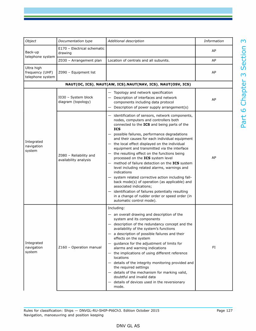
Part
6 C
hapt
er 3
Sec
tion
3
Rules for classification: Ships — DNVGL-RU-SHIP-Pt6Ch3. Edition October 2015 Page 127Navigation, manoeuvring and position keeping
DNV GL AS
Object Documentation type Additional description Information
E170 – Electrical schematicdrawing APBack-up
telephone systemZ030 – Arrangement plan Location of centrals and all subunits. AP
Ultra highfrequency (UHF)telephone system
Z090 – Equipment list AP
NAUT(OC, ICS), NAUT(AW, ICS),NAUT(NAV, ICS), NAUT(OSV, ICS)
I030 – System blockdiagram (topology)
— Topology and network specification— Description of interfaces and network
components including data protocol— Description of power supply arrangement(s)
AP
Integratednavigationsystem
Z080 – Reliability andavailability analysis
— identification of sensors, network components,nodes, computers and controllers bothconnected to the ICS and being parts of theICS
— possible failures, performance degradationsand their causes for each individual equipment
— the local effect displayed on the individualequipment and transmitted via the interface
— the resulting effect on the functions beingprocessed on the ICS system level
— method of failure detection on the ICS systemlevel including related alarms, warnings andindications
— system related corrective action including fall-back mode(s) of operation (as applicable) andassociated indications;
— identification of failures potentially resultingin a change of rudder order or speed order (inautomatic control mode).
AP
Integratednavigationsystem
Z160 – Operation manual
Including:
— an overall drawing and description of thesystem and its components
— description of the redundancy concept and theavailability of the system’s functions
— a description of possible failures and theireffects on the system
— guidance for the adjustment of limits foralarms and warning indications
— the implications of using different referencelocations
— details of the integrity monitoring provided andthe required settings
— details of the mechanism for marking valid,doubtful and invalid data
— details of devices used in the reversionarymode.
FI

Part
6 C
hapt
er 3
Sec
tion
3
Rules for classification: Ships — DNVGL-RU-SHIP-Pt6Ch3. Edition October 2015 Page 128Navigation, manoeuvring and position keeping
DNV GL AS
Object Documentation type Additional description Information
Z162 - Installation manual
Including:
— specification of sensors, components and theinterconnecting equipment forming the system
— details of the interfaces and connections fordata broadcasting and
— interconnection diagrams and interfacingdetails for external parts of the ICS and fordevices to be connected to the network
— details of the power supply arrangementsrequired
— recommendations on the physical layout of thesystem
FI
Info: AP: For approval, FI: For Information, R: On Request, TA: Covered by type approval
1.6.1.2 For general requirements to documentation, see Pt.1 Ch.3 Sec.2.
1.6.1.3 For a full definition of the documentation types, see Pt.1 Ch.3 Sec.3.
1.6.1.4 For navigation equipment and other equipment installed in the wheelhouse, and in the vicinity of thewheelhouse, certification is required.Certification documentation shall be submitted as required by Table 4:
Table 4 Certification requirements
Object Certificate type Issued by* Certification standard** Additional description
Integrated NavigationSystem (INS)
Type Approvalcertificate (TA) Society
Radar equipment Type Approvalcertificate (TA) Society
ECDIS equipment Type Approvalcertificate (TA) Society
Position system Type Approvalcertificate (TA) Society
Gyro/heading system Type Approvalcertificate (TA) Society
Speed measuringsystem
Type Approvalcertificate (TA) Society
Depth measuringsystem
Type Approvalcertificate (TA) Society
Bridge NavigationWatch Alarm System(BNWAS)
Type Approvalcertificate (TA) Society
Bridge AlertManagement System(BAMS)
Type Approvalcertificate (TA) Society

Part
6 C
hapt
er 3
Sec
tion
3
Rules for classification: Ships — DNVGL-RU-SHIP-Pt6Ch3. Edition October 2015 Page 129Navigation, manoeuvring and position keeping
DNV GL AS
Object Certificate type Issued by* Certification standard** Additional description
Automatic IdentificationSystem (AIS)
Type Approvalcertificate (TA) Society
Wiper system Type Approvalcertificate (TA) Society
Conning display system Type Approvalcertificate (TA) Society
Heading control System(autopilot)
Type Approvalcertificate (TA) Society
Track Control system(TCS) (if provided)
Type Approvalcertificate (TA) Society
Sound receptionsystem
Type Approvalcertificate (TA) Society
Internal communication Type Approvalcertificate (TA) Society
Externalcommunication(including GMDSS)
Type Approvalcertificate (TA) Society
*Type approval or MED certificates issued by others showing that the equipment complies with the rule requirementsmay be accepted after a case-by-case evaluation** Unless otherwise specified the certification standard is the rules
1.7 Tests1.7.1 General
1.7.1.1 All tests shall be carried out according to test programs approved by the Society.
1.7.1.2 The tests and visual examinations shall verify that all relevant rule requirements are met. The testsshall cover requirements given by these rules and applicable IMO performance standards. The test programsshall specify in detail how the various functions shall be tested and what shall be observed during the tests.
Guidance note:Reference is made to [10] for further information.
---e-n-d---of---g-u-i-d-a-n-c-e---n-o-t-e---
1.7.2 Testing of network integrity- qualifier (ICS)
1.7.2.1 Testing in accordance with [7.6]. shall be carried out at the manufacturer’s works as far as practicalin order to limit the necessary testing on board to a minimum.
1.7.3 On-board testing
1.7.3.1 The testing to be completed during installation and commissioning shall include:
a) verification of proper interfacing and data protocol of individual equipmentb) establishment of correct parameters for filters, integrity monitoring, alarm limits, control parameters
(time constants, set points, lengths, heights, etc.)

Part
6 C
hapt
er 3
Sec
tion
3
Rules for classification: Ships — DNVGL-RU-SHIP-Pt6Ch3. Edition October 2015 Page 130Navigation, manoeuvring and position keeping
DNV GL AS
c) verification of correct functionality of system applications and integration of components, including theability of the integrated navigation system to keep any controlled process within the specified tolerances
d) verification of fall-back-modes and emergency operation of essential navigational functions.
1.7.3.2 The tests shall demonstrate that the essential navigational functions are available and operable ondesignated back-up means in a situation where the normal navigational system configuration is disabled asfar as practical.
1.7.4 Manoeuvring trials - NAUT(AW)
1.7.4.1 Tests and trials as required to establish and document the ship's manoeuvring characteristics shall becarried out.
2 Design of workplace
2.1 General2.1.1 Scope
2.1.1.1 This section specifies the requirements for bridge design, including field of vision, -wheelhousearrangement, -workstation configuration and location of equipment within workstations.
2.1.2 Application
2.1.2.1 Ships requesting class notation NAUT(OC) shall comply with the basic rules in [2.2] to [2.5].
2.1.2.2 Ships requesting class notation NAUT(AW) shall comply with the basic rules in [2.2] to [2.5] andadditionally the requirements specifically addressing NAUT(AW) in these sub-sections.
Guidance note:A requirement being specific for NAUT(AW) only is identified by inclusion of the notation in the head line as follows:
— Workstations for navigating and manoeuvring – vertical view NAUT(AW).
---e-n-d---of---g-u-i-d-a-n-c-e---n-o-t-e---
2.1.2.3 The requirements being applicable for NAUT(AW) only is additionally gathered in [6] for easyoverview.
2.2 Bridge design2.2.1 Principal requirements
2.2.1.1 The ship’s navigation bridge shall enable the OOW to perform navigational duties unassisted at alltimes during normal operating conditions. He shall be able to maintain a proper lookout by sight and hearingas well as by all available means appropriate in the prevailing circumstances and conditions so as to make fullappraisal of the situation and the risk of collision, grounding and other hazards to navigation.
2.2.1.2 The ship’s navigation bridge shall additionally be designed and arranged with the aim of:
— facilitating the tasks to be performed by the bridge team including a pilot in making full appraisal of thesituation and in navigating the ship safely under all operational conditions
— promoting effective and safe bridge resource management— allowing for expeditious, continuous and effective information processing and decision-making by the
bridge team

Part
6 C
hapt
er 3
Sec
tion
3
Rules for classification: Ships — DNVGL-RU-SHIP-Pt6Ch3. Edition October 2015 Page 131Navigation, manoeuvring and position keeping
DNV GL AS
— preventing or minimizing excessive or unnecessary work and any condition or distraction on the bridgewhich may cause fatigue or interfere with the vigilance of the bridge team.
2.2.1.3 The bridge design shall meet the terms of all relevant regulations of applicable IMO conventions.Guidance note:Applicable conventions in this respect are the International Convention for Safety Of Life At Sea, the International Convention forPreventing Collisions at Sea and the International Convention on Standards of Training, Certification and Watch-keeping for Seafarers,as amended.
---e-n-d---of---g-u-i-d-a-n-c-e---n-o-t-e---
2.2.2 Field-of-vision from within the wheelhouse
2.2.2.1 When designing the bridge, the main factors to be considered are the overall view required from theinside of the wheelhouse and the field of vision required from each workstation.
2.2.2.2 Every effort shall be made to place the bridge above all other decked superstructures in order toobtain the best possible field of vision for safe navigation and manoeuvring of the ship.
2.2.2.3 A horizontal field of vision (FOV) to the horizon of 360° shall be obtained by using not more than2 positions within the confines of the wheelhouse on either side of the workstation for navigating andmanoeuvring and being not more than 15 m apart. (Figure 2). The 360° view shall as a minimum be attained1 nautical mile from the observer’s position.
Figure 2 Two positions combined provide ≥ 360° field of vision from inside the wheelhouse
Guidance note:The maximum distance of 15 m between the two positions inside the wheelhouse may be extended, provided the following conditionsare fulfilled:
— suitable cameras are installed capable of viewing the sector(s) astern not being visible within the required 15 meter andpertinent displays/monitors are installed being viewable from the workstation for navigating and manoeuvring
— the workstations for docking are equipped with appropriate means for course and speed alterations, and
— the FOV sectors should overlap with at least 0.5°.
---e-n-d---of---g-u-i-d-a-n-c-e---n-o-t-e---
2.2.2.4 It shall be possible to observe all external objects of interest for safe navigation, such as ships, buoysand lighthouses in any direction from inside the wheelhouse when the ship is pitching and rolling (eye height1800 mm).
Guidance note:Irrespective of helicopter decks or other structures placed on top of the wheelhouse a vertical angle of view of not less than 5°above a horizontal line extending from eye height in standing position should be available all through the 360º horizontal field of

Part
6 C
hapt
er 3
Sec
tion
3
Rules for classification: Ships — DNVGL-RU-SHIP-Pt6Ch3. Edition October 2015 Page 132Navigation, manoeuvring and position keeping
DNV GL AS
vision when positioned adjacent the windows. The eye height in a standing position is considered to be at least 1800 mm abovethe deck surface for this purpose.
---e-n-d---of---g-u-i-d-a-n-c-e---n-o-t-e---
2.2.3 Field-of-vision from workstations
2.2.3.1 Workstations for monitoring and navigating and manoeuvring –forward vertical viewThe view of the sea surface for a person positioned at the workstations for monitoring and navigating andmanoeuvring shall not be obscured by more than two ship lengths or 500 m, whichever is less, forward of thebow to 10° on either side, under all conditions of draught, trim and deck cargo (eye height 1500 mm). Figure3.
Figure 3 View of sea surface forward of bow
Workstations for monitoring and navigating and manoeuvring - horizontal field of vision2.2.3.2 The horizontal field of vision from the workstations for monitoring and navigating and manoeuvringshall enable the officer of the navigational watch to carry out his functions in compliance with theInternational Regulations for Preventing Collisions at Sea and shall extend over an arc of not less than 225°,that is from dead ahead to not less than 22.5° abaft the beam on either side of the ship. Figure 4.
Figure 4 Horizontal field of vision from the workstations for monitoring and navigating andmanoeuvring
2.2.3.3 Workstations for navigating and manoeuvring – vertical view
a) Above horizontal plane: A vertical angle of view of not less than 5° above a horizontal line, extendingfrom eye height in forward direction, shall be provided irrespective of helicopter decks or other structuresplaced on top of the wheelhouse.
b) Below horizontal plane: Within the 180º sector forward of athwart ship any elevated ship structure orcargo obstructing the sea surface close to the ship in excess of ½ nm is considered to be a blind sectorand shall be included in the blind sector calculation. (eye height 1500 mm).
Guidance note:

Part
6 C
hapt
er 3
Sec
tion
3
Rules for classification: Ships — DNVGL-RU-SHIP-Pt6Ch3. Edition October 2015 Page 133Navigation, manoeuvring and position keeping
DNV GL AS
Reference is made to the blind sector calculation required by -Table 2, N020/N030. The location of elevated structures obstructingthe view of the sea surface may only be acceptable on the provision that [2.2.4.1] is complied with.
---e-n-d---of---g-u-i-d-a-n-c-e---n-o-t-e---
2.2.3.4 Workstations for navigating and manoeuvring – vertical view NAUT(AW)To be able to view objects and river banks in the proximity of the ship, a person standing at the workstationfor navigating and manoeuvring shall be able to observe the sea surface at a distance of no more than 500 mfrom the hull within the sectors from 10º on either side of the bow to 90° on both sides, under all conditionsof draught, trim and deck cargo (eye height 1500 mm).Figure 5.
Figure 5 NAUT(AW): Obstruction of sea surface fwd of athwart ship
Guidance note:Any deck house, superstructure or cargo obstructing the sea surface by more than 500 m should be included in the horizontal blindsector calculation and may only be acknowledged if the total blind sector requirement of [2.2.4.1] is complied with.The eye height in standing position is considered to be not more than 1500 mm above the deck surface for the purpose of verticalview below the horizontal plane (Note: the 50% percentile of South East Asia population is 1520 mm).
---e-n-d---of---g-u-i-d-a-n-c-e---n-o-t-e---
2.2.3.5 Workstations for navigating and manoeuvring - horizontal view astern NAUT(AW)The navigator shall be able to employ leading lights and marks astern of the ship as visual reference forgrounding avoidance, while seated at the workstation for navigating and manoeuvring. A field of visionsector astern shall be available and extend over an arc from dead astern to at least 5º on each side. No blindsectors shall occur within this 10º field of vision sector.
Guidance note:Adequate camera(s) may be accepted for the purpose of achieving the required field of vision astern. The camera system andarrangement should be approved by the Society prior to the installation.Note: Leading lights (or range lights) consist of two lights, separated in distance and elevation, so that when lined up vertically, withone behind the other, they provide a bearing to be used for positioning of the vessel in fairways.
---e-n-d---of---g-u-i-d-a-n-c-e---n-o-t-e---
2.2.3.6 Workstations for navigating and manoeuvring - vertical view astern - NAUT(AW)The vertical view through the aft window pane(s), seen from the workstation for navigating andmanoeuvring, shall enable the navigator to view the sea surface in the wake of the ship at a distance notmore than 2000 m abaft the stern.The upper edge of the window(s) shall not be less than 2000 mm above bridge deck surface.

Part
6 C
hapt
er 3
Sec
tion
3
Rules for classification: Ships — DNVGL-RU-SHIP-Pt6Ch3. Edition October 2015 Page 134Navigation, manoeuvring and position keeping
DNV GL AS
The maximum height from deck to the lower edge of the window(s) shall be 1000 mm or at least fulfil thefollowing condition:
— the lower part of the window panes shall disclose all obtainable sea surfaces aft of the vessel when viewedfrom the navigating and manoeuvring workstation. Only the superstructure/-deck may be concealed whenviewed from normal operating position at this workstation (eye height 1500 mm).
2.2.3.7 Workstation for conningThe horizontal field of vision from the workstation for conning shall offer a commanding view.The vertical field of view shall enable the conning officer (pilot) to monitor the ship's relative position andleeway in the course of a marked fairway or channel.
Workstation for docking operations2.2.3.8 In order to enable the navigator(s) to manoeuvre the ship safely alongside a berth and supervise themooring of the ship, the horizontal field of vision from each workstation on the bridge wings shall extend overan arc of not less than 225º, that is from at least 45º on the opposite bow through to right astern from theworking position. Figure 6.
Figure 6 Field of vision from workstations for docking operations
2.2.3.9 The vertical view shall enable the navigators to monitor the ship’s position relative to the berthincluding observation of the accurate distance from the hull side to the quayside (jetty) at sea level from thedocking workstation.
Guidance note:If [2.2.7.1] cannot be fully satisfied, adequate cameras may be accepted for the purpose of achieving the required vertical view. Thecamera system and arrangement should be approved by the Society prior to the installation.
---e-n-d---of---g-u-i-d-a-n-c-e---n-o-t-e---
2.2.3.10 Workstation for docking operations - vertical view NAUT(AW)The vertical view from the docking workstation shall enable the navigator(s) to observe the “parallel hullside” of both fore ship and stern ship from a standing position besides the console while operating the UIDson hand for manoeuvring of the ship. The hull’s side plates shall be visible over a total length of not less thanL/2 (eye height 1500 mm). Figure 7.
Guidance note:Windows should be arranged in the lower part of the bulwark and deck as appropriate to obtain the required vertical view.Alternatively, adequate cameras may be accepted. The camera system and arrangement should be approved by the Society priorto the installation.
---e-n-d---of---g-u-i-d-a-n-c-e---n-o-t-e---

Part
6 C
hapt
er 3
Sec
tion
3
Rules for classification: Ships — DNVGL-RU-SHIP-Pt6Ch3. Edition October 2015 Page 135Navigation, manoeuvring and position keeping
DNV GL AS
Figure 7 NAUT(AW): View from docking station (LA+LF) ≥ ½LOA
2.2.3.11 Workstation for manual steeringIn order to enable the helmsman to steer the ship safely in narrow channels, the horizontal field of visionfrom the workstation for manual steering shall extend over an arc from dead ahead to at least 60º on eachside. Figure 8.The vertical view shall enable the helmsman to observe steering references in the fore ship (if provided)while standing at the normal working position.
Figure 8 The field of vision from workstation for manual steering
2.2.3.12 Workstations for GMDSS and additional functionsIn order to enable the OOW to operate workstations for safety monitoring, GMDSS equipment and additionalbridge functions for short periods of time, the horizontal field of vision from these workstations shall extendat least over an arc from 90° on port bow, through forward, to 22.5° abaft the beam on starboard. Figure 9.
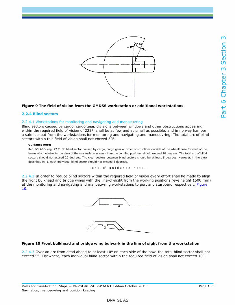
Part
6 C
hapt
er 3
Sec
tion
3
Rules for classification: Ships — DNVGL-RU-SHIP-Pt6Ch3. Edition October 2015 Page 136Navigation, manoeuvring and position keeping
DNV GL AS
Figure 9 The field of vision from the GMDSS workstation or additional workstations
2.2.4 Blind sectors
2.2.4.1 Workstations for monitoring and navigating and manoeuvringBlind sectors caused by cargo, cargo gear, divisions between windows and other obstructions appearingwithin the required field of vision of 225°, shall be as few and as small as possible, and in no way hampera safe lookout from the workstations for monitoring and navigating and manoeuvring. The total arc of blindsectors within this field of vision shall not exceed 30°.
Guidance note:Ref. SOLAS V reg. 22.2. No blind sector caused by cargo, cargo gear or other obstructions outside of the wheelhouse forward of thebeam which obstructs the view of the sea surface as seen from the conning position, should exceed 10 degrees. The total arc of blindsectors should not exceed 20 degrees. The clear sectors between blind sectors should be at least 5 degrees. However, in the viewdescribed in .1, each individual blind sector should not exceed 5 degrees.
---e-n-d---of---g-u-i-d-a-n-c-e---n-o-t-e---
2.2.4.2 In order to reduce blind sectors within the required field of vision every effort shall be made to alignthe front bulkhead and bridge wings with the line-of-sight from the working positions (eye height 1500 mm)at the monitoring and navigating and manoeuvring workstations to port and starboard respectively. Figure10.
Figure 10 Front bulkhead and bridge wing bulwark in the line of sight from the workstation
2.2.4.3 Over an arc from dead ahead to at least 10° on each side of the bow, the total blind sector shall notexceed 5°. Elsewhere, each individual blind sector within the required field of vision shall not exceed 10°.

Part
6 C
hapt
er 3
Sec
tion
3
Rules for classification: Ships — DNVGL-RU-SHIP-Pt6Ch3. Edition October 2015 Page 137Navigation, manoeuvring and position keeping
DNV GL AS
2.2.4.4 The clear sector between two blind sectors caused by obstructions outside of the wheelhouse shall beat least 5°.The clear sector between two blind sectors caused by division between bridge windows shall not be less thanthe size of the broadest blind sector on either side of the clear sector.A clear sector shall be provided from 22.5° abaft the beam and forward on both sides of the ship seen fromthe monitoring and navigating and manoeuvring workstations.
2.2.4.5 Divisions between windows shall be kept to a minimum and not placed in front of any workingposition for operation of steering and manoeuvring UIDs or in front of the radars.
2.2.4.6 Workstations for GMDSS and additional functionsA sustainable lookout shall be possible for shorter periods from the workstations for GMDSS and otherfunctions allocated to the OOW. Additional blind sectors, caused by deck supports and other obstructionslocated inside or outside of the wheelhouse shall be minimized. Each individual blind sector caused by anyobstruction whether inside or outside the wheelhouse shall not exceed 10º.
Guidance note:If curtains are installed, the curtains should be stored in the after part of the console to avoid reducing the FOV, and eventuallycreating a blind sector from the workstation for GMDSS.
---e-n-d---of---g-u-i-d-a-n-c-e---n-o-t-e---
2.2.5 Bridge windows
2.2.5.1 Window height - generalThe minimum height of the upper edge of bridge window panes above the bridge deck surface shall be 2000mm in order to provide a view of the horizon for a person in a standing position at the relevant workingpositions.The maximum height of the lower edge of bridge window panes above the bridge deck shall be 1000 mm inorder to provide view of the nearby sea surface for a person in a sitting position at the workstations.
Guidance note:The maximum height of 1000 mm may be extended, provided the following condition is fulfilled:
— the lower part of the window panes should disclose all obtainable sea surface when viewed from a sitting position at the mostdistant workstation (working position). I.e. that only part of the superstructure or deck may be concealed by the extendedheight as viewed from the most distant workstation (eye height 1500 mm).
---e-n-d---of---g-u-i-d-a-n-c-e---n-o-t-e---
2.2.5.2 Lower edge of front windowsThe navigator shall obtain a good view of the sea surface in the proximity of the ship from dead ahead to 90°on either side of the workstations for navigating and manoeuvring.When the distance between the windows and the viewing point (350 mm aft of the consoles) in sittingposition at the workstations is more than 2300 mm, the height of the lower edge of the windows in thesector from 10° to 90° on each side shall be decreased sufficiently to maintain the line of sight. Figure 11.

Part
6 C
hapt
er 3
Sec
tion
3
Rules for classification: Ships — DNVGL-RU-SHIP-Pt6Ch3. Edition October 2015 Page 138Navigation, manoeuvring and position keeping
DNV GL AS
Figure 11 The height of the lower edge of windows to be decreased when the distance to frontbulkhead exceeds 2300 mm
2.2.5.3 Lower edge of front windows - NAUT(AW)When the distance between the windows and the viewing point 350 mm aft of the consoles in sittingpositions at the workstations for monitoring and navigating and manoeuvring is more than 1500 mm, theheight of the lower edge of the windows in the sector from 10° to 90° on each side shall be decreasedsufficiently to maintain the line of sight. Figure 12.
Figure 12 NAUT(AW): The height of the lower edge of windows to be decreased (lower than 1000mm) when the distance to front bulkhead exceeds 1500 mm
2.2.5.4 Window breadthBridge windows should be as large as practicable to sustain a safe lookout and not less than 1200 mm widewithin the field of vision required from the workstations unless otherwise is stated.
Guidance note:

Part
6 C
hapt
er 3
Sec
tion
3
Rules for classification: Ships — DNVGL-RU-SHIP-Pt6Ch3. Edition October 2015 Page 139Navigation, manoeuvring and position keeping
DNV GL AS
The width of the window directly forward of the centre console may be less than 1200 mm in order to avoid divisions/stiffeners beinglocated in front of any workstations.
---e-n-d---of---g-u-i-d-a-n-c-e---n-o-t-e---
2.2.5.5 Window inclinationGlare in bridge windows caused by internal light sources shall be avoided and not impair the view requiredfor conducting a proper lookout. To help avoid reflection (glare) from lights inside the wheelhouse, the bridgefront windows shall be inclined from the vertical plane top out, at an angle of not less than 15° and not morethan 25°. Light sources, which may cause reflection in the front windows inclined in accordance with thisrequirement, shall be avoided.
2.2.5.6 Side and rear windows shall be inclined from the vertical plane top out at an angle not less than4°~5° as required to avoid glare and specular reflections from instruments and other light sources at theworkstations.
Guidance note:Vertical windows may be accepted provided that the installed equipment, lamps etc. do not cause any glare and reflection in thewindows.
---e-n-d---of---g-u-i-d-a-n-c-e---n-o-t-e---
2.2.5.7 Enclosed bridge wing windowsFor ships with enclosed bridge wings, it shall be possible to open one side window to view the ship's side atwater surface level if:
— the side windows are vertical and there are no windows in the deck providing a downward view— the side windows are inclined but the bridge wing deck is not extended fully to the maximum width of the
ship.
It shall be possible for one person to open the windows fully. Alternative solutions may be acceptable if theview cannot be achieved by opening windows alone.
Guidance note:An adequate camera system may be acceptable for the purpose of achieving the required view. The camera system and arrangementshould be approved by the Society prior to installation.
---e-n-d---of---g-u-i-d-a-n-c-e---n-o-t-e---
2.2.5.8 Window stiffenersDimension of division between windows shall be kept to a minimum. If stiffeners are covered for decorationthis shall not increase the dimensions (width and depth) of the stiffener.
Guidance note:The division between windows, especially within the required field of vision, should not exceed 150 mm. If stiffeners are used, thewidth between window panes should not exceed 100 mm and the depth of the stiffeners should be less than 120 mm.
---e-n-d---of---g-u-i-d-a-n-c-e---n-o-t-e---
2.2.6 Arrangements for clear view through bridge windows
2.2.6.1 From the workstations to be operated by the OOW there shall be a clear view through the bridgewindows within the required field of vision at all times regardless of weather conditions.The following installations are required:
— To ensure a clear view in conditions of rain and sea spray, heavy duty wipers and fresh water washingsystem shall be provided on all front windows within the field of vision required from the monitoring andnavigating and manoeuvring workstations.
— To improve the visibility and reduce eye strain in bright sunshine sun-screens shall be provided on allapplicable bridge windows.

Part
6 C
hapt
er 3
Sec
tion
3
Rules for classification: Ships — DNVGL-RU-SHIP-Pt6Ch3. Edition October 2015 Page 140Navigation, manoeuvring and position keeping
DNV GL AS
— To ensure a clear view in conditions of icing and dew, an efficient de-icing and de-misting system shall beprovided on all applicable bridge windows.
Systems installed shall comply with appropriate international standards. Heated glass panes shall be installedon ships to be assigned one of the Polar or Ice Breaker class notations.
Guidance note:The window wipers should be straight-line and capable of wiping a window area of not less than 70% of the required area of panesand the maximum speed of the blades should not be less than 68 metres/minute. A blade length of 1000 mm is deemed acceptableirrespective of the size of the window pane. Reference: ISO 17899. (CVS may be installed on front windows not being perceptiblefrom the workstations for monitoring and navigating and manoeuvring)The sun screens should be of type roller blinds and offer anti glare and heat rejecting properties. Only the outer surface should behighly reflective while the inner surface should offer a non-reflective appearance. Anti glare effect (reduction) better than 80% andheat rejection better than 60% should be achieved.Applicable windows are commonly all the front and side windows. However, it should be noted though that additional sunscreens maybe required on aft windows to prevent direct sunlight from obscuring information on monitor screens and displays.Reference is made to ISO 8863 and ISO 3434 for specifications of heating by hot-air and heated glass panes respectively.
---e-n-d---of---g-u-i-d-a-n-c-e---n-o-t-e---
2.2.6.2 Clear view through bridge windowsThe glass panes used shall not give any nonlinear or blurred effect to the line of sight.
2.2.6.3 Additional cleaning requirement for totally enclosed bridge wingsIf the bridge wings are totally enclosed, heavy duty wipers and fresh water window washing shall be providedon forward and aft windows within the field of vision required from workstations for docking operations. Ifthere is no window for opening on the bridge wing, window wipers and fresh water washing shall also beprovided for the bridge wing side windows.
2.2.6.4 Additional cleaning requirement - NAUT(AW)Heavy duty wipers and fresh water window washing to be provided on aft window(s) within the view asternsector required from the navigating and manoeuvring workstation
2.2.7 Bridge configuration
2.2.7.1 Bridge wingsBridge wings shall in general extend out to the maximum beam of the ship so as to make the ship's sidevisible from the workstations for docking operations.
2.2.7.2 To sustain the view of the sea surface from the workstations to be operated by the OOW the height ofthe bridge wing bulwark shall not exceed 1000 mm. A suitable handrail shall be fit on top of the bulwark at aheight not less than 1200 mm. The opening between the bulwark and the handrail shall not be less than 120mm.
2.2.7.3 If wind deflectors are fitted in the length of the bridge wing front, the resulting obstruction of seasurface in close proximity shall be minimized. The length of the deflector shall not impede a sector of morethan 10º seen from the operating position at workstations to be operated by the OOW.
Guidance note:The maximum height of the wind deflector above bridge deck should satisfy the following equation:
dw = distance from operating position at workstations to the farthest part of the wind deflector (usually from theGMDSS station) to the outermost part of the wind deflector on port side.

Part
6 C
hapt
er 3
Sec
tion
3
Rules for classification: Ships — DNVGL-RU-SHIP-Pt6Ch3. Edition October 2015 Page 141Navigation, manoeuvring and position keeping
DNV GL AS
he = eye height above sea level at the workstation
---e-n-d---of---g-u-i-d-a-n-c-e---n-o-t-e---
Moreover, the view to starboard from the GMDSS-workstation will usually determine the length of thedeflector based on the ruling “blind sector”.
2.2.7.4 CatwalkA fixed catwalk or similar arrangement with means to prevent an accidental fall shall be fitted in front ofthe bridge windows to enable manual cleaning of windows from the outside and repair work in the event offailure of window wipers or fresh water washing system.
2.2.7.5 Height of deckheadThe clear deckhead height in the wheelhouse shall take into account the installation of deckhead mountedequipment as well as the height of door openings required for easy entrance to the wheelhouse. Thefollowing clear heights for unobstructed passage shall be provided:The clear height between the bridge deck surface and the underside of the deck head covering (ceiling) shallbe at least 2250 mm.
a) The lower edge of deck head-mounted equipment in open areas and passageways, as well as the upperedge of door openings to bridge wings and other open deck areas shall be at least 2100 mm above thedeck.
b) The height of entrances and doors to the wheelhouse from adjacent passageways should not be less than2000 mm.
2.2.7.6 AccessesAll wheelhouse doors shall be operable with one hand. Bridge wing doors shall not be self-closing and meansshall be provided to hold the doors in open position.
2.2.7.7 Ships with fully enclosed bridge wings shall at least have one door allowing direct access to theadjacent bridge deck area.
2.2.7.8 Access to the compass deck shall be provided from the bridge deck in proximity of the wheelhouse.
2.2.7.9 It shall be possible to watch the deck area in front of the bridge superstructure from inside thewheelhouse by providing direct access to at least one front window.
2.2.7.10 Toilet facilities shall be provided on the bridge deck adjacent the wheelhouse.
2.3 Wheelhouse arrangement and workstation configuration2.3.1 General requirements
2.3.1.1 The workstation arrangement shall be designed in accordance with established principles ofergonomics for safe and efficient operations, enabling the navigator to perceive all relevant information andexecute pertinent actions with a minimum workload.
2.3.1.2 The safe control and command of the ship while under way shall be allocated to a certain area ofthe wheelhouse where only instruments, equipment and controls necessary for the performance of primarybridge functions shall be located.
2.3.1.3 From the area allocated safe control and command of the ship the navigator shall have easy accessto equipment related to the safety state of the ship.

Part
6 C
hapt
er 3
Sec
tion
3
Rules for classification: Ships — DNVGL-RU-SHIP-Pt6Ch3. Edition October 2015 Page 142Navigation, manoeuvring and position keeping
DNV GL AS
2.3.1.4 Individual workstations for performance of primary bridge functions under normal, irregular andabnormal operating conditions during the various phases of the voyage from port to port shall be provided.Such workstations shall include:
— workstation for monitoring— workstation for navigating and manoeuvring— workstation for manual steering— workstation for safety monitoring— workstations for docking operations— workstations for conning— workstation for voyage planning— workstation for GMDSS
Figure 13 Design principles – example of wheelhouse arrangement
Guidance note:The workstation for voyage planning and/or workstation for GMDSS may be waived on a particular ship on conditions recognizedin the applicable requirements.The workstation for manual steering may be waived on a particular “special purpose vessel” having extraordinary means for steering(e.g. multiple azipods) requiring special competence by the operator. Two conditions should be fulfilled though:
— manual steering can be exercise at the navigating and manoeuvring workstation and at least one other workstation and
— the pertinent steering UIDs located on the two workstations are autonomous and one UID can be operated by personnel otherthan the OOW without interfering with the navigation of the vessel.
The design of the manual steering arrangement and pertinent UIDs shall be approved by the Society prior to the waiver.Workstation for dynamic positioning (DP) may be included in the above mentioned workstations. If DP workstation is provided, specialdesign requirements is applicable and given in Sec.1 and Sec.2.
---e-n-d---of---g-u-i-d-a-n-c-e---n-o-t-e---
2.3.1.5 The individual workstations allocated primary bridge functions shall be arranged for easy operationby one person as well as allowing close co-operation between personnel at the various workstations whenmanned for individual operations.
Guidance note:The workstations for primary bridge functions, except for docking operations, should be located within an area not more than 10m wide.
---e-n-d---of---g-u-i-d-a-n-c-e---n-o-t-e---
2.3.1.6 Workstations for additional functions may be located on the bridge provided the performance of suchadditional functions does not interfere with the ability of the OOW to carry out the primary bridge functions.Workstations for additional functions may include:
— extended communication functions

Part
6 C
hapt
er 3
Sec
tion
3
Rules for classification: Ships — DNVGL-RU-SHIP-Pt6Ch3. Edition October 2015 Page 143Navigation, manoeuvring and position keeping
DNV GL AS
— monitoring and control of ballasting and cargo operations— monitoring and control of machinery— monitoring and control of hull openings— monitoring and control of domestic systems— dynamic positioning.
2.3.1.7 The height of consoles forming workstations for additional functions located inside the wheelhouseshall not obstruct the sea surface within the required field of vision from sitting position at the workstationsfor monitoring and navigating and manoeuvring.
2.3.1.8 The navigation bridge shall not be used for purposes other than navigation, communications andother functions essential to the safe operation of the ship, its engines and cargo, and workstations should bearranged with the aim of promoting effective and safe bridge resource management
2.3.1.9 It shall be possible for persons at a workstation to communicate with persons at other workstationsof relevance for the function to be performed, under all operating conditions.
2.3.1.10 Means for controlling speed, heading and control modes shall only be located at workstationsproviding the required field of vision and being intended for the related tasks.
2.3.2 Passageways
2.3.2.1 There shall be a clear route across the wheelhouse from bridge wing to bridge wing for two personsto pass each other. The width of the passageway shall in the main be 1200 mm and not less than 700 mm atany single point of obstruction.
2.3.2.2 The distance between separate workstation areas shall be sufficient to allow unobstructed passagefor persons not working at the stations. The width of such passageways shall not be less than 700 mmallowing for persons sitting or standing at their workstations.
2.3.2.3 If the consoles of the monitoring and navigating and manoeuvring workstations are not to be locateddirectly against the front bulkhead of the wheelhouse then the distance between the front bulkhead and theconsoles shall be sufficient for one person to pass a stationary person. The width of this passageway shouldpreferably be 1000 mm and shall not be less than 800 mm.
Guidance note:The Panama Canal Commission (ACP) requires a minimum of 1 metre clearance between the front bulkhead and any adjacentconsoles. Requests for relaxation of this requirement may be considered by ACP on a case-by-case basis.
---e-n-d---of---g-u-i-d-a-n-c-e---n-o-t-e---
2.3.2.4 The distance between bridge wing consoles, when installed, and adjacent bulwarks/bulkheads shallbe as small as possible for easy operation of manoeuvring UIDs while having an optimum view of the ship’shull side and mooring operations, but yet wide enough for one person to pass the console. The width of thepassageway shall preferably be 600 mm.The Panama Canal Commission (ACP) requires a minimum of 1 metre clearance between any consoles andadjacent to bulkheads/-bulwarks
Guidance note:Requests for relaxation of this requirement may be considered by ACP on a case-by-case basis.
---e-n-d---of---g-u-i-d-a-n-c-e---n-o-t-e---
2.3.3 Console configuration
2.3.3.1 Consoles should principally be divided into two separate areas;
— one inclined area for display of information and

Part
6 C
hapt
er 3
Sec
tion
3
Rules for classification: Ships — DNVGL-RU-SHIP-Pt6Ch3. Edition October 2015 Page 144Navigation, manoeuvring and position keeping
DNV GL AS
— one horizontal (desktop) part for the UIDs to be within reach from the working position.
Figure 14 Principle console configuration
2.3.3.2 To provide a functional reach from standing position, the height of console desktops above bridgedeck surface, equipped with UIDs should preferably be 800 mm and not less than 750 mm.
2.3.3.3 Console configuration shall provide the user with the information required to be easily readable atthe workstation within a viewing angle from right ahead to 90° to each side seen from the normal workingposition.
2.3.3.4 The configuration of consoles at the workstations for monitoring and navigating and manoeuvringshall enable easy use of equipment required for safe and efficient performance of the tasks to be performedfrom both standing and sitting positions.
2.3.3.5 Leg room in consoles – NAUT(AW)The console in front of the seated working position (generally the radars) shall provide sufficient leg room asrequired to ease the reach of equipment and controls to be used.
2.3.3.6 The leg room of the console should have a minimum of 450 mm in depth in the lower part.
2.3.3.7 Console heightThe consoles forming the workstations for monitoring and navigating and manoeuvring shall not obstruct thelower part of the window panes as seen from a sitting position behind the consoles (eye height 1500 mm).The height of these consoles shall not exceed 1200 mm.
Guidance note:A console height of 1200 mm is acceptable even if it should interfere with the line of sight from an eye height of 1500 mm providingthe height of the chair can be adjusted to compensate for the obstruction.
---e-n-d---of---g-u-i-d-a-n-c-e---n-o-t-e---
2.3.3.8 The height of consoles forming other workstations that are intended to be operated by the OOW shallnot exceed 1300 mm. If such workstations are located within the horizontal field of vision required from theworkstations for monitoring and navigating and manoeuvring then the console height shall not exceed 1200mm.
2.3.3.9 Chart console (if provided)The height of the chart console desktops shall preferably be 950 mm and not less than 850 mm.
2.3.3.10 The surface of the chart console desktop shall have an effective working area of at least 1 600 mm× 800 mm.
Part
6 C
hapt
er 3
Sec
tion
3
Rules for classification: Ships — DNVGL-RU-SHIP-Pt6Ch3. Edition October 2015 Page 145Navigation, manoeuvring and position keeping
DNV GL AS
2.3.4 Chairs
2.3.4.1 The bridge design and console configuration shall permit installation of chairs at the workstations formonitoring and navigating and manoeuvring even if the ship is not to be equipped with chairs at the time ofdelivery.
Guidance note:The decision on installation of chairs on the bridge is left to the current owners of the ship, considering the trade and type of the shipand the need to mitigate fatigue and promote increased concentration and efficiency of the bridge watch.
---e-n-d---of---g-u-i-d-a-n-c-e---n-o-t-e---
2.3.4.2 When chairs are installed at the monitoring and navigating and manoeuvring workstations it shall beeasy to adjust the vertical level of the seats to suit users of different heights for optimum view and reachingdistance.
2.3.4.3 It shall be possible to regulate the chairs in fore and aft direction for easy reach of the equipment tobe used and to move the chairs away from the consoles completely to achieve good working conditions froma standing position and attain an unobstructed passage next to the consoles.
2.3.4.4 It shall be easy to enter and leave the chairs in any position.
2.3.4.5 Deck rails used to support horizontal movements of the chairs shall be installed level with the decksurface to prevent tripping of personnel.
2.3.4.6 Compulsory chairs - NAUT(AW)Adequate chairs shall be installed at the monitoring and navigating and manoeuvring workstations incompliance with this section. The following additional characteristics shall be attained:
— The vertical adjustment of the seat shall range from at least 600 to 800 mm above deck level.— The chairs shall be fastened to rails, enabling easy reach of relevant equipment while seated and allowing
fore and aft movement as well as the chairs being moved out-of-the-way from the workstation consolesproviding a passage of ≥700 mm.
— The chair shall be equipped with an adjustable footrest.
2.3.5 Wheelhouse surveillance system
2.3.5.1 An active surveillance system shall be arranged in the wheelhouse to ensure the navigational watchbeing attended at all times. Reference is made to [6.8] for detail system requirements.
2.3.5.2 The surveillance system shall be positioned so that it can detect activities on the conning-,monitoring- and navigating and manoeuvring workstations to verify that the OOW is on the lookout.
2.3.5.3 Other workstation areas may be included in the surveillance scheme only if their location support theminimum field-of-vision required by [2.2.3.12].
Guidance note:If BNWAS reset function is provided at workstations in the aft part of the bridge as may be relevant for vessels with an aft bridgeintended for i.e. offshore operations, this bridge area should be deselected while the vessel is “underway” (I.e. selection is providedbetween fore and aft bridge).
---e-n-d---of---g-u-i-d-a-n-c-e---n-o-t-e---

Part
6 C
hapt
er 3
Sec
tion
3
Rules for classification: Ships — DNVGL-RU-SHIP-Pt6Ch3. Edition October 2015 Page 146Navigation, manoeuvring and position keeping
DNV GL AS
2.4 Workstations for primary bridge functions - location of equipment2.4.1 General
2.4.1.1 The arrangement of equipment within the workstations shall take in the frequency of use,the importance of the related task and the ergonomics of the UID while adhering to acknowledgedanthropometric measurements in order to ensure safe and efficient operations from standing or sittingpositions as made applicable by the requirements.
UIDs for manoeuvring2.4.1.2 Where several workstations are equipped with means for control of propulsion, steering and auxiliarymanoeuvring device(s) the arrangement of UIDs shall be consistent on all workstations.
2.4.1.3 Where more than one unit of propulsion, steering and/or auxiliary manoeuvring devices is installed,the arrangement of pertinent UIDs and indicators/displays shall correspond to the physical arrangement ofthe associated power units on the ship.
2.4.1.4 All instruments shall be logically grouped according to their functions within each workstation. Theoperation of UIDs shall not obscure associated indicators which observation is necessary for carrying out thetask.
2.4.1.5 Indicators and displays providing visual information to more than one person shall be located for easyviewing by all personnel concurrently. If this is not achievable, the indicator or display shall be duplicated.
2.4.2 Locating equipment - “within reach” and “easily readable”
2.4.2.1 Within reach from standing positionThe distance the operator can reach and use an UID from a standing position next to a console. This distanceshall be maximum 800 mm in forward direction and 1400 mm sideways from the working position. Figure 15.
Figure 15 Area within reach from standing position
2.4.2.2 Within reach from sitting positionLocation of UIDs for different tasks to be performed in a seated, at a distance of 350 mm from a console, tobe maximum 1000 mm, and maximum 800 mm for frequently used equipment, which shall be within easyreach. The designated areas defined by Figure 16 when being addressed by individual requirements.
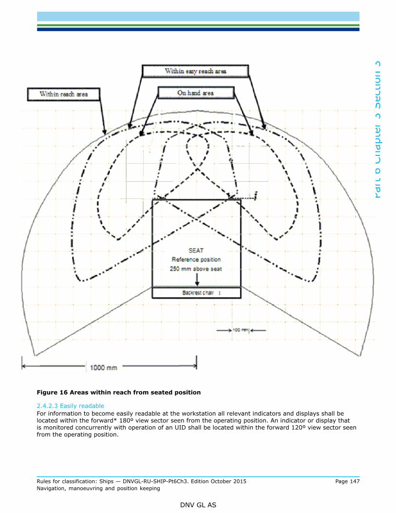
Part
6 C
hapt
er 3
Sec
tion
3
Rules for classification: Ships — DNVGL-RU-SHIP-Pt6Ch3. Edition October 2015 Page 147Navigation, manoeuvring and position keeping
DNV GL AS
Figure 16 Areas within reach from seated position
2.4.2.3 Easily readableFor information to become easily readable at the workstation all relevant indicators and displays shall belocated within the forward* 180º view sector seen from the operating position. An indicator or display thatis monitored concurrently with operation of an UID shall be located within the forward 120º view sector seenfrom the operating position.

Part
6 C
hapt
er 3
Sec
tion
3
Rules for classification: Ships — DNVGL-RU-SHIP-Pt6Ch3. Edition October 2015 Page 148Navigation, manoeuvring and position keeping
DNV GL AS
The indicators and displays shall be placed with its front perpendicular to the navigator's line of sight seenfrom the operating position, or to a mean value (angle) if the information is used by personnel located atmore than one workstation.
Figure 17 Forward view sector
Guidance note 1:The height of letters and figures in mm should be not less than 3.5 times the reading distance in m. Pertinent character width shouldbe approximately 0.7 to 0.9 times the character height, e.g.:
— Letter height for reading distance 2 m: 2 × 3.5 = 7 mm
— Letter width for character height 7 mm: 7 × 0.7(0.9) = 4.9 to 6.3 mm
— Resulting minimum letter size: 7 mm × 5 mm.
---e-n-d---of---g-u-i-d-a-n-c-e---n-o-t-e---
Guidance note 2:* On docking workstations where consoles are arranged for view astern or where consoles are arranged for operation from theoutward side the term “forward” used in this requirement should be understood as “astern” or “inward” respectively.
---e-n-d---of---g-u-i-d-a-n-c-e---n-o-t-e---
2.4.3 Workstations for monitoring and navigating and manoeuvring
2.4.3.1 The workstations for monitoring and navigating and manoeuvring shall be arranged to enable twonavigators to carry out their tasks in close co-operation.
2.4.3.2 Various mutual equipment may be installed to serve the individual tasks allocated both theseworkstations provided the within reach requirement and/or readability requirement are complied with fromthe working positions at both workstations. Figure 18.
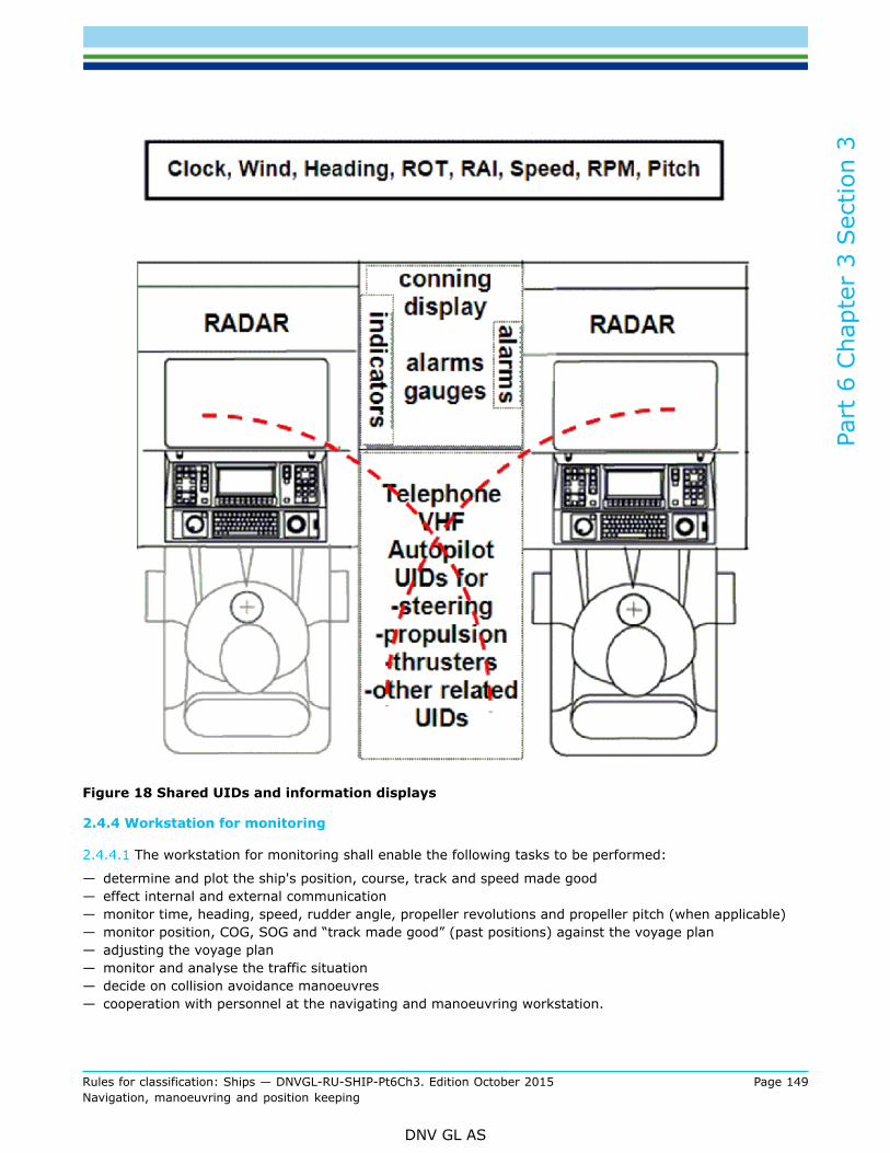
Part
6 C
hapt
er 3
Sec
tion
3
Rules for classification: Ships — DNVGL-RU-SHIP-Pt6Ch3. Edition October 2015 Page 149Navigation, manoeuvring and position keeping
DNV GL AS
Figure 18 Shared UIDs and information displays
2.4.4 Workstation for monitoring
2.4.4.1 The workstation for monitoring shall enable the following tasks to be performed:
— determine and plot the ship's position, course, track and speed made good— effect internal and external communication— monitor time, heading, speed, rudder angle, propeller revolutions and propeller pitch (when applicable)— monitor position, COG, SOG and “track made good” (past positions) against the voyage plan— adjusting the voyage plan— monitor and analyse the traffic situation— decide on collision avoidance manoeuvres— cooperation with personnel at the navigating and manoeuvring workstation.

Part
6 C
hapt
er 3
Sec
tion
3
Rules for classification: Ships — DNVGL-RU-SHIP-Pt6Ch3. Edition October 2015 Page 150Navigation, manoeuvring and position keeping
DNV GL AS
2.4.4.2 Equipment to be installedThe navigation radar shall be located within easy reach from a sitting position at the monitoring workstation.Additionally the following equipment considered essential for operations at the workstation for monitoringshall be located within reach from a sitting position:
— ECDIS— VHF unit— internal communication equipment (auto telephone)— bridge alert management system UIDs.
and the following equipment shall be within reach from a standing position:
— NAVTEX— whistle and manoeuvring light (if provided) push buttons— control of dimmers for indicators and displays at the workstation.
Guidance note:The NAVTEX may be located in another location if it is connected to an integrated navigation system located at the workstation formonitoring and able to show the required messages
---e-n-d---of---g-u-i-d-a-n-c-e---n-o-t-e---
2.4.4.3 Information to be providedInstruments, indicators and displays providing information considered essential for safe and efficientoperations at the workstation for monitoring shall be easily readable from both standing and sitting positionsat the workstation. The equipment includes:
— gyro repeater— rudder angle indicator— speed indicator(s)— distance indicator— rate-of-turn indicator— depth indicator— clock— propeller revolutions indicator— pitch indicator, when provided— wind speed and direction indicator— bridge alert management system - CAM-HMI— indicator warning of surveillance period elapsing— two GNSS-position displays (with access to satellite data).
Guidance note:If both the ECDIS and the radars are separately interfaced with the two GNSS-receivers and the user can access HDOP, mode indicatorand number of satellites in use from either of these displays it may be deemed an acceptable solution and no additional displaysare required at this workstation.
---e-n-d---of---g-u-i-d-a-n-c-e---n-o-t-e---
If the consoles are located directly against the front bulkhead, both an AIS pilot plug, power outlet andfree desktop space for a personal pilot unit (laptop) shall be provided and be within reach from a standingposition.
2.4.4.4 Means to be easily accessibleMeans to be used at intervals for securing safe course and speed and safety of bridge operation shall beeasily accessible from the workstation for monitoring. These means include:
— instruments and equipment installed at the workstation for navigating and manoeuvring— instruments and equipment at the workstation for safety monitoring— window wipers and wash controls for the windows within the required field of vision

Part
6 C
hapt
er 3
Sec
tion
3
Rules for classification: Ships — DNVGL-RU-SHIP-Pt6Ch3. Edition October 2015 Page 151Navigation, manoeuvring and position keeping
DNV GL AS
— light switch and dimmer for workstation illumination— depth recording device.— navigation light distribution panel— whistle fog signal control panel.— speed log control unit
2.4.5 Workstation for navigating and manoeuvring
2.4.5.1 The workstation for navigating and manoeuvring shall enable the following tasks to be performed:
— monitor the traffic by sight and hearing as well as by available means— analyse the traffic situation— manage AIS information and messages— decide on collision avoidance manoeuvres— change course— change speed— change operational steering mode— effect internal and external communication— operate auxiliary manoeuvring devices— monitor time, heading, speed, propeller revolutions, thrust indicator, if the ship is equipped with thrusters,
pitch indicator, if the ship is equipped with pitch propeller, rudder angle and rate of turn— monitor position, COG, SOG and “track made good” (past positions) against the voyage plan— adjusting the voyage plan— acknowledge all navigational alarms— monitor all alarm conditions on the bridge— cooperation with personnel at the monitoring workstation.
Figure 19 Example: -joint arrangement of workstations for monitoring [2.4.4] and navigating andmanoeuvring [2.4.5]
2.4.5.2 Equipment to be installedInstruments and equipment that are operated by the navigator at the workstation for navigating andmanoeuvring and considered essential for safe and efficient performance of his tasks, shall be within reachfrom a sitting position at the workstation, priority given to location of UIDs for radar, course and speed.The following instruments and equipment shall be installed within easy reach from a sitting position:
— navigation radar with radar
Part
6 C
hapt
er 3
Sec
tion
3
Rules for classification: Ships — DNVGL-RU-SHIP-Pt6Ch3. Edition October 2015 Page 152Navigation, manoeuvring and position keeping
DNV GL AS
— propulsion control— manual steering device (with take-over)— heading control— track control, when provided.
The following equipment shall be installed within reach from a sitting position:
— ECDIS— steering mode selector switch— steering control station selection (if provided)— VHF unit— whistle and manoeuvring light (if provided) push buttons— internal communication equipment (auto telephone)— bridge alert management system UIDs— general alarm control— window wiper and wash controls for the windows within the required field of vision.— control of dimmers for indicators and displays at the workstation.
The following equipment shall be within easy reach from either a sitting or standing position at the centreconsole:
— steering UIDs— propulsion— thruster UIDs, when provided— emergency stop for propulsion machinery— emergency stop for thruster(s), when provided.
The following equipment shall be installed within reach from a standing position at the workstation:
— gyro compass selector switch— steering gear pumps (operation panel)
2.4.5.3 Information to be providedInstruments, indicators and displays providing information considered essential for the safe and efficientperformance of tasks at the workstation for navigating and manoeuvring shall be easily readable and audiblefrom the working positions at the workstation and includes:
— propeller revolution indicator(s)— thrust indicator(s), when provided— pitch indicator(s), when provided— speed indicator(s)— wind speed and direction indicator— rudder angle indicator(s)— rate-of-turn indicator— heading indicator— steering mode indicator— steering position in command (when relevant)— depth indicator— clock— conning information display, when provided— bridge alert management system - CAM-HMI— alarm panel related to unmanned machinery space— alarm panel related to steering control system and steering gear— sound reception indicator/display— indicator warning of surveillance period elapsing.

Part
6 C
hapt
er 3
Sec
tion
3
Rules for classification: Ships — DNVGL-RU-SHIP-Pt6Ch3. Edition October 2015 Page 153Navigation, manoeuvring and position keeping
DNV GL AS
2.4.5.4 Means to be easily accessibleMeans to be used at intervals for securing safe course and speed and safety of bridge operation shall beeasily accessible from the workstation for navigating and manoeuvring. The means include:
— instruments and equipment installed at the monitoring workstation— engine automatic control and monitoring system, if provided— public address system— instruments and equipment at the workstation for safety monitoring— searchlight control panel, if provided— light switch and dimmer for workstation illumination— control panel for the sound reception system— navigation light distribution panel— whistle fog signal control panel— anchor winch control panel, if provided.
2.4.5.5 Additional tasks - NAUT(AW)The workstation for navigating and manoeuvring shall enable performance of the following additional tasks:
— monitor the performance and status of the equipment and sensors of the grounding avoidance system— monitor speed over ground in both longitudinal and transversal directions.
2.4.5.6 Additional equipment - NAUT(AW)The additional information displays to be readable and UIDs to be installed within reach at the workstationare:
— conning information display— dual axis speed information display.
2.4.6 Workstations for conning
2.4.6.1 A workstation for conning of the ship shall be arranged to enable navigators (pilots) to assist innavigating and manoeuvring of the ship without interfering with the tasks of the ship's bridge personnel onduty.
2.4.6.2 The workstation for conning shall enable a pilot to observe all relevant external and internalinformation for determination and maintenance of safe course and speed of the ship in narrow waters,harbour areas and during canal passages.
2.4.6.3 The workstation for conning shall be located close to:
— the forward centre window in order to optimise the view of the sea surface close to the sides of the ship,and
— the workstation for monitoring and navigating and manoeuvring to allow good co-operation between allnavigators, each at their workstation.
2.4.6.4 If the view in the centreline is obstructed by large masts, cranes, etc., an additional conning positionproviding a commanding view shall be located on the starboard side as close to the centre line as possible,and not more than 5 m from the centreline.
Guidance note:The Panama Canal Commission requires conning positions directly behind the three centre windows.
---e-n-d---of---g-u-i-d-a-n-c-e---n-o-t-e---
2.4.6.5 The monitoring workstation may serve as the conning workstation if the height of the lower edge offront windows is maintaining the line-of-sight in accordance with [2.2.5.2] for NAUT(OC) or [2.2.5.3] forNAUT(AW).
Part
6 C
hapt
er 3
Sec
tion
3
Rules for classification: Ships — DNVGL-RU-SHIP-Pt6Ch3. Edition October 2015 Page 154Navigation, manoeuvring and position keeping
DNV GL AS
2.4.6.6 An AIS pilot plug and power outlet and desktop space shall be provided for at the monitoringworkstation if it also serves as the conning workstation.
2.4.6.7 Tasks to be performedThe workstation for conning shall enable the following tasks to be performed in narrow waters, harbour areasand during canal passages and anchoring:
— enable a pilot to monitor surrounding traffic and conduct pilotage and direct the ship’s heading and speedin close cooperation with the attending bridge team
— give sound signals— effect external communication— monitor heading, rudder angle, rate-of-turn, propeller revolutions, propeller pitch (if controllable), status
of thrusters (if provided) and speed.
2.4.6.8 Information and equipment to be providedThe instruments and equipment required for safe and efficient performance of the pilot’s tasks shall beavailable from the workstation.
a) The indicators and displays required to be easily readable from the working position include:
— heading indicator— rudder angle indicator— rate-of-turn indicator— propeller revolutions indicator— pitch indicator, when relevant— speed indicator.— auxiliary manoeuvring device indicators (thrust), if provided.
b) Means that shall be available from the working position(s) include:
— Whistle and manoeuvring light (if provided) push buttons— VHF— AIS pilot plug, power outlet and space for a pilot personal unit (e.g. a folding table).
2.4.7 Workstation for voyage planning
2.4.7.1 A workstation for voyage planning shall be provided to enable navigators to carry out passage planning andchart works while taking in nautical publications without interfering with ongoing navigation of the ship. Theworkstation shall be equipped with means for efficient voyage planning and means for direct transfer of theplanned voyage to the monitoring and navigating and manoeuvring workstations.
Guidance note:The workstation for voyage planning may be waived if the vessel is not to be engaged in world wide trade but should operate onlyin regional waters having adequate coverage of ENCs. Ref. [1.1.5.3] for information about the waiver.
---e-n-d---of---g-u-i-d-a-n-c-e---n-o-t-e---
2.4.7.2 Tasks to be performedThe workstation for voyage planning shall enable the following tasks to be performed:
— determine and plot the ship's position— plan the forthcoming voyage on the basis of available information from charts and nautical publications— plotting of the intended track in appropriate charts including: planned courses, radii of turns, wheel-over-
lines, distances, ETAs, as well as identification of all areas of danger, existing ships' routeing and reportingsystems, vessel traffic services, and any areas where marine environmental protection considerationsapply

Part
6 C
hapt
er 3
Sec
tion
3
Rules for classification: Ships — DNVGL-RU-SHIP-Pt6Ch3. Edition October 2015 Page 155Navigation, manoeuvring and position keeping
DNV GL AS
— transferring the voyage plan to the ECDIS’ on the workstations for monitoring and navigating andmanoeuvring.
2.4.7.3 Equipment to be installedIn order to enable efficient performance of the tasks the following means and equipment shall be installed atthe workstation:
— position display— voyage planning terminal interconnected with ECDIS (within easy reach from standing position)— weather information device— clock— a chart console suitable for plotting of the intended track in nautical paper charts— storage space (drawers) for all nautical paper charts— storage appliance for nautical publications (incl. CDs/DVDs).
2.4.8 Workstations for manual steering
2.4.8.1 The workstation for manual steering shall enable the helmsman to carry out the following tasks:
— control the position of the rudder (rudder angle)— maintain a steady heading by compass readings as well as external visual means— maintain a steady rate-of-turn— conduct two-way communication with workstations for conning, navigating and manoeuvring and docking
operations.
2.4.8.2 Information and equipment to be providedThe following equipment, indicators and displays shall be easily readable from the workstation:
— gyro repeater— rudder angle indicator— rudder order indicator, when follow-up steering is provided— magnetic compass display— rate-of-turn indicator.
The following equipment should be located on hand from the working position:
— manual steering UID(s) (helm)— communication equipment— control of dimmers for indicators and displays at the workstation.
Guidance note:The communication equipment may be a suitable wireless system (e.g. UHF) or a PA talk-back system or similar fixed installation.The communication equipment may be waived on vessels with enclosed bridge wings if the distance to the docking workstations is<10 m and the noise level <65 dB(A).
---e-n-d---of---g-u-i-d-a-n-c-e---n-o-t-e---
2.4.8.3 The workstation for manual steering shall preferably be located on the ship's center line and shall notinterfere with the functions to be performed by navigators at the monitoring and navigating and manoeuvringworkstations.
2.4.8.4 If the view ahead is obstructed by large masts, cranes, etc., the workstation for manual steeringshould preferably be located off the centre line to obtain a clear view dead ahead.When the workstation is located off centre line a steering reference (range and light) shall be installed in thefore ship, equally distanced off the center line, and clearly visible from the working position by day and night.If the fore ship (e.g. stem or foremast) cannot be seen from the working position an equivalent steeringreference shall make up a line-of-sight parallel to the ship’s cent line for use by the helmsman.
Part
6 C
hapt
er 3
Sec
tion
3
Rules for classification: Ships — DNVGL-RU-SHIP-Pt6Ch3. Edition October 2015 Page 156Navigation, manoeuvring and position keeping
DNV GL AS
Guidance note:The Panama Canal Authority (ACP) requires all ships >100 m in length to install, at or near the stem, a steering range equipped witha fixed blue light which should be clearly visible from the bridge along the cent line. The height of the light should be as close aspossible to the height of eye level on the bridge. If said range and light so placed would be partially or completely obscured fromConning Position 1, then two such ranges and lights should be installed ahead of Conning Positions 2 and 3.
---e-n-d---of---g-u-i-d-a-n-c-e---n-o-t-e---
2.4.9 Workstation for emergency steering
2.4.9.1 The workstation for manual steering in the steering gear compartment shall enable the followingtasks to be performed from the working position:
— control the position of the rudder (rudder angle)— monitor rudder angle— monitor heading— effect two-way communication with the bridge.
Equipment to be available at the workstation for emergency steering2.4.9.2 The following equipment shall be available and readable from the working position while operatingthe steering UIDs:
— UIDs for controlling the rudder angle (on hand)— hands-free internal communication (headset)— heading indicator— means for reading rudder angle.
2.4.10 Workstation for safety monitoring
2.4.10.1 The workstation for safety monitoring shall enable monitoring of all the equipment and alarm panelsinstalled relating to the safety state of the ship as well as relevant UIDs provided for instant actions andtasks assigned to the OOW at the initial stage of an emergency situation. At least the following tasks areassigned to the OOW:
— observe and deal with equipment installed for monitoring of the safety state and integrity of the ship— take immediate action on alarms and execute relevant measures according to contingency plan— call upon other personnel for assistance and/or communicating situational awareness.
2.4.10.2 Equipment to be providedEquipment installed for monitoring and early detection of internal dangers threatening the integrity of theship shall be centralised in the workstation for safety monitoring together with pertinent UIDs being fitted forurgent follow-up actions.The following equipment shall be easily readable and operable from a standing position at the safetyworkstation when being installed in the wheelhouse:
— fire detection system— smoke detection systems— control panel for fire pumps— control panel for fire doors— control panel for watertight doors— control panel for hull openings and hatches— emergency stop for ventilation fans— gas detection systems— any monitoring, alarm or safety system for additional functions assigned to the OOW— internal communication system (auto telephone)— general emergency alarm system

Part
6 C
hapt
er 3
Sec
tion
3
Rules for classification: Ships — DNVGL-RU-SHIP-Pt6Ch3. Edition October 2015 Page 157Navigation, manoeuvring and position keeping
DNV GL AS
— public address system— fire-fighting local application system(s)— other safety systems if fitted.
2.4.10.3 The location and configuration of this workstation shall:
— enable personnel to carry out the relevant functions at the workstation without interfering with the tasksto be performed at the workstation for navigating and manoeuvring
— enable a person at the workstation to observe the workstation for navigating and manoeuvring andmaintain the field of vision for proper lookout
— enable the navigator at the workstation for navigating and manoeuvring to observe information related tothe safety state of the ship.Guidance note:For passenger ships the workstation for safety monitoring should be separated from workstation for navigation and navigation supportin such a way that management of emergencies can be performed without distracting watch officers from their navigational duties.MSC82/24 Annex 2.
---e-n-d---of---g-u-i-d-a-n-c-e---n-o-t-e---
2.4.10.4 The workstation for safety monitoring shall be located for easy viewing from the workstation fornavigating and manoeuvring. All alarms and warnings appearing on the safety equipment shall be apparentand distinguishable from the normal working position at the workstation for navigating and manoeuvring.
2.4.10.5 Additional means to be providedThe following means to organise and execute emergency operations shall be easily accessible:
— hard copies of safety plans and drawings with desk top space to accommodate study of drawings orcomputer system providing all relevant information
— the GMDSS installed at the workstation for communication.
2.4.11 Workstations for docking operations
2.4.11.1 The workstations for safe docking of the ship shall enable the navigator together with a pilot toobserve all relevant external and internal information to direct the manoeuvring of the ship.
2.4.11.2 Tasks to be performedThe workstation for docking operations shall enable the following tasks to be performed:
— supervision of docking operations— monitor the ship’s heading, rudder angle, propeller revolutions, propeller pitch (if relevant) and thruster(s)
(if relevant)— release sound signals— monitor the relevant mooring operations on board and ashore— govern the mooring operations by having orders effected— effect two-way communication with mooring stations on board and ashore— effect two-way communication with wheelhouse workstations for manual steering and navigating and
manoeuvring.
2.4.11.3 Equipment to be availableEquipment essential for the safe performance of docking operations shall be within reach from a standingposition providing the required field of vision and is including:
— whistle and manoeuvring light (if provided) push buttons— means for two-way communication with mooring stations on board and relevant workstations in the
wheelhouse— VHF unit

Part
6 C
hapt
er 3
Sec
tion
3
Rules for classification: Ships — DNVGL-RU-SHIP-Pt6Ch3. Edition October 2015 Page 158Navigation, manoeuvring and position keeping
DNV GL AS
— control of dimmers for indicators and displays at the workstation.Guidance note:A wireless portable radio system (UHF) enabling hands-free operation may be acceptable as means for two-way communicationbetween personnel involved in mooring operations. See [6].The VHF unit may be a handset enabling selection of channels, or a complete mobile unit. If a handheld or mobile unit is used, aspecific location at the workstation should be provided with means supporting the VHF unit.
---e-n-d---of---g-u-i-d-a-n-c-e---n-o-t-e---
2.4.11.4 Information to be providedInformation essential for safe conduct of the docking operations shall be easily readable from the workstationfor docking operations.The following information indicators shall be easily readable from the workstation:
— propeller revolutions indicator(s), and propeller pitch indicator(s) (when applicable)— thruster indicator(s) (when applicable)— rudder angle indicator— heading indicator.
2.4.11.5 Additional tasks - NAUT(AW)The workstations shall enable the following additional tasks to be performed:
— control the position of the rudder (rudder angle)— control the propulsion (RPM/Pitch)— control the thrusters (if installed)— effect two-way communication with engine control room, steering gear and department offices.
2.4.11.6 Additional equipment - NAUT(AW)The following additional equipment shall be installed within reach from a standing position at the workstationproviding the required field of vision to enable safe performance of the tasks:
— propulsion UID— thruster UID, if provided— steering UID— internal communication (auto telephone)— window wiper and wash controls for the windows within the required field of vision.
The following additional indicators or displays shall be easily readable from the working position:
— starting air pressure— speed indicator displaying longitudinal and transversal speeds— wind speed and direction— CID, BAMS and ECDIS (when provided at the WS or when ICS)— rate-of-turn indicator
Guidance note 1:

Part
6 C
hapt
er 3
Sec
tion
3
Rules for classification: Ships — DNVGL-RU-SHIP-Pt6Ch3. Edition October 2015 Page 159Navigation, manoeuvring and position keeping
DNV GL AS
Figure 20 Examples on arrangement of docking workstation
D: 600 ≤ Distance ≤ 800 mm 3: Thruster UID
H: Passageway ≥ 700 mm 4: Propulsion UID
M: Working position 5: Steering UID
P: Pilot 6: Internal communication
1: VHF 7: Indicators and displays
2: Whistle See also FOV requirement of [2.2.3.10].
---e-n-d---of---g-u-i-d-a-n-c-e---n-o-t-e---
Guidance note 2:*ACP requires a minimum of 1 m clearance from the console to the outer bulwark on the bridge wing. Requests for relaxation of thisdistance may be granted by ACP on a case-by-case basis.
---e-n-d---of---g-u-i-d-a-n-c-e---n-o-t-e---
2.4.11.7 MFD equipment required - NAUT(AW, ICS)The docking workstation shall be provided with two independent MFD-displays supporting applications forradar, ECDIS, conning display and alarm management system.
Guidance note:The MFDs may substitute for the separate indicators/-displays required on these workstations provided the screen type is easilyreadable in bright daylight (sunshine).
---e-n-d---of---g-u-i-d-a-n-c-e---n-o-t-e---
2.4.12 Workstations for GMDSS
2.4.12.1 In order to maintain the safety of navigation, also when the OOW is responsible for GMDSS-operations, pertinent equipment shall be located in a separate workstation for communication in close vicinityof the navigating and manoeuvring workstation.

Part
6 C
hapt
er 3
Sec
tion
3
Rules for classification: Ships — DNVGL-RU-SHIP-Pt6Ch3. Edition October 2015 Page 160Navigation, manoeuvring and position keeping
DNV GL AS
Guidance note:If the workstation for GMDSS is not to be operated by the OOW, it may be located elsewhere but should then be easily accessible fromthe workstation for emergency operations. Both workstations may be waived if their functions are arranged for outside the bridge area.
---e-n-d---of---g-u-i-d-a-n-c-e---n-o-t-e---
2.4.12.2 The GMDSS equipment installed for detection of ships in distress shall be audible and visible to theOOW at the navigating and manoeuvring workstation. The visibility requirement may be renounced though ifthe audible alarm has a characteristic sound being easily identifiable.
2.4.12.3 From the normal working position at the GMDSS workstation it shall be possible to observe theequipment on the workstation for navigating and manoeuvring, monitor the ship's heading and rudder angleas well as maintaining a proper lookout.
2.5 Additional workstations2.5.1 Additional functions assigned the OOW
2.5.1.1 In order to maintain the safety level in bridge operation, also when the officer of the watch performsother functions than those related to primary bridge functions, the following requirements shall be compliedwith:
a) Each additional function shall be designated a separate workstation (separate workstations may beadjacent primary workstations).
b) From workstations for additional functions, it shall be possible to monitor the workstation for navigatingand manoeuvring, the ship's heading and rudder angle, and to maintain the minimum field of vision forefficient lookout.
c) The workload at workstations for additional functions shall not prevent the officer of the watch frommaintaining a proper lookout.
d) In situations where primary functions may require the immediate attention of the OOW, nothing shallprevent abandoning a workstation for additional functions.
e) It shall be possible to operate workstations for additional functions without interfering with the operationof workstations for primary functions.
2.5.2 Other functions located on the bridge
2.5.2.1 Other functions than those related to navigation, manoeuvring, safety and distress may be performedon the bridge by other personnel than the officer of the watch, provided the following requirements arecomplied with:
a) The additional tasks to be carried out at workstations for other functions shall not in any way affectthe performance of primary bridge functions, neither by use of light or noise disturbance nor visual oraudible distractions.
b) Furniture arranged for meetings or relaxation shall preferably not be installed within the area of thenavigating bridge. If still provided, such arrangements shall not to be located within the field of visionsectors required from the workstations for primary bridge functions.
Guidance note:IMO urges governments to ensure that ship's navigation bridge is not used for purposes other than navigation, communication andother functions essential to the safe operation of the ship, its engines and cargo. IMO Res. A.708(17).
---e-n-d---of---g-u-i-d-a-n-c-e---n-o-t-e---

Part
6 C
hapt
er 3
Sec
tion
3
Rules for classification: Ships — DNVGL-RU-SHIP-Pt6Ch3. Edition October 2015 Page 161Navigation, manoeuvring and position keeping
DNV GL AS
2.6 Requirements specific for class notation NAUT(AW) and NAUT(AW,ICS)2.6.1 General
2.6.1.1 This sub-section gives an overview of the requirements specifically addressing NAUT(AW) andNAUT(AW, ICS) in [2.2] to [2.5].
2.6.2 Field-of-vision from workstations
2.6.2.1 Workstations for navigating and manoeuvring – vertical view NAUT(AW)To be able to view objects and river banks in the proximity of the ship, a person standing at the workstationfor navigating and manoeuvring shall be able to observe the sea surface at a distance of no more than 500 mfrom the hull within the sectors from 10º on either side of the bow to 90º on both sides, under all conditionsof draught, trim and deck cargo (eye height 1500 mm). See Figure 5.
2.6.2.2 Workstations for navigating and manoeuvring - horizontal view astern NAUT(AW)The navigator shall be able to employ leading lights and marks astern of the ship as visual reference forgrounding avoidance, while seated at the workstation for navigating and manoeuvring. A field of visionsector astern shall be available and extend over an arc from dead astern to at least 5º on each side. No blindsectors shall occur within this 10º field of vision sector.
Guidance note:Leading lights (or range lights) consist of two lights, separated in distance and elevation, so that when lined up vertically, with onebehind the other, they provide a bearing to be used for positioning of the vessel in fairways.Adequate camera(s) may be accepted for the purpose of achieving the required field of vision astern. The camera system andarrangement should be approved by the Society prior to the installation.
---e-n-d---of---g-u-i-d-a-n-c-e---n-o-t-e---
2.6.2.3 Workstations for navigating and manoeuvring - vertical view astern - NAUT(AW)The vertical view through the aft window pane(s), seen from the workstation for navigating and manoeuvringshall enable the navigator to view the sea surface in the wake of the ship at a distance not more than 2000m abaft the stern.The upper edge of the window(s) shall not be less than 2000 mm above bridge deck surface.The maximum height from deck to the lower edge of the window(s) shall be 1000 mm or at least fulfil thefollowing condition:The lower part of the window panes shall disclose all obtainable sea surfaces aft of the vessel when viewedfrom a sitting position at the navigating and manoeuvring workstation. Only the superstructure/-deck may beconcealed when viewed from seated position at this workstation (eye height 1500 mm).
2.6.2.4 Workstation for docking operations - vertical view NAUT(AW)The vertical view from the docking workstation shall enable the navigator(s) to observe the “parallel” hullside of both fore ship and stern from a standing position besides the console while operating the UIDs onhand for manoeuvring of the ship. The hull’s side plates shall be visible over a total length of not less thanL/2 (eye height 1500 mm). See Figure 7
Guidance note:Windows should be arranged in the lower part of the bulwark and deck as appropriate to obtain the required vertical view.Alternatively, adequate cameras may be accepted. The camera system and arrangement should be approved by the Society priorto the installation.
---e-n-d---of---g-u-i-d-a-n-c-e---n-o-t-e---

Part
6 C
hapt
er 3
Sec
tion
3
Rules for classification: Ships — DNVGL-RU-SHIP-Pt6Ch3. Edition October 2015 Page 162Navigation, manoeuvring and position keeping
DNV GL AS
2.6.3 Bridge windows
2.6.3.1 Lower edge of front windows - NAUT(AW)When the distance between the windows and the viewing point 350 mm aft of the consoles in sittingpositions at the workstations for monitoring and navigating and manoeuvring is more than 1500 mm, theheight of the lower edge of the windows in the sector from 10° to 90° on each side shall be decreasedsufficiently to maintain the line of sight. See Figure 12.
2.6.4 Arrangements for clear view through bridge windows
2.6.4.1 Additional cleaning requirement - NAUT(AW)Heavy duty wipers and fresh water window washing to be provided on aft window(s) within the view asternsector required from the navigating and manoeuvring workstation.
2.6.5 Console configuration
2.6.5.1 Leg room in consoles – NAUT(AW)The console in front of the seated working position (usually the radars) shall provide sufficient leg room asrequired to ease the reach of equipment and controls to be used.
2.6.6 Chairs
2.6.6.1 Compulsory chairs - NAUT(AW)Adequate chairs shall be installed at the monitoring and navigating and manoeuvring workstations incompliance with this section. The following additional characteristics shall be attained:
— The vertical adjustment of the seat shall range from at least 600 to 800 mm above deck level.— The chairs shall be fastened to rails, enabling easy reach of relevant equipment while seated and allowing
fore and aft movement as well as the chairs being moved out-of-the-way from the workstation consolescompletely.
— The chair shall be equipped with an adjustable footrest.
2.6.7 Workstation for navigating and manoeuvring
2.6.7.1 Additional tasks - NAUT(AW)The workstation for navigating and manoeuvring shall enable performance of the following additional tasks:
— monitor the performance and status of the equipment and sensors of the grounding avoidance system— monitor speed over ground in both longitudinal and transversal directions.
2.6.7.2 Additional equipment - NAUT(AW)The additional information displays to be readable and UIDs to be installed within reach at the workstationare:
— conning information display— dual axis speed log display.
2.6.8 Workstations for docking operations
2.6.8.1 Additional tasks - NAUT(AW)The workstations shall additionally enable the following tasks to be performed:
— control the position of the rudder (rudder angle)— control the propulsion (RPM/Pitch)— control the thrusters (if installed)— effect two-way communication with engine control room, steering gear and department offices.

Part
6 C
hapt
er 3
Sec
tion
3
Rules for classification: Ships — DNVGL-RU-SHIP-Pt6Ch3. Edition October 2015 Page 163Navigation, manoeuvring and position keeping
DNV GL AS
2.6.8.2 Additional equipment - NAUT(AW)The following additional equipment shall be installed within reach from the working position to enable safeperformance of the tasks:
— propulsion UID— thruster UID, if provided— steering UID— internal communication (auto telephone).
The following additional indicators or displays shall be easily readable from the working position:
— speed indicator displaying longitudinal and transversal speeds— wind speed and direction— CID, BAMS and ECDIS (when provided at the WS or when ICS).
2.6.8.3 MFD equipment required - NAUT(AW, ICS)The docking workstation shall be provided with two independent MFD-displays supporting applications forradar, ECDIS, conning display and alarm management System.
Guidance note:The MFDs may substitute for the separate indicators/-displays required on these workstations provided the screen type is easilyreadable in bright daylight (sunshine).
---e-n-d---of---g-u-i-d-a-n-c-e---n-o-t-e---
3 Workplace environment
3.1 General3.1.1 Scope and application
3.1.1.1 This section contains human factors design requirements pertaining to the workplace environment inthe wheelhouse.
3.1.2 General
3.1.2.1 Throughout the various design stages of the ship care shall be taken to achieve a good workingenvironment for bridge personnel.
3.1.2.2 Equipment installed to control the workplace environment shall be capable of sustained operationswithin the climatic extremes specified for the ship.
3.2 Environmental factors3.2.1 Vibration
3.2.1.1 Uncomfortable levels of vibration causing short and/or long term effects on human body shall beavoided in the bridge area.
Guidance note:The vibration levels on the bridge deck should not exceed 0.16 m/s2 from 0.5 Hz to 5 Hz, and 5 mm/s from 5 Hz to 100 Hz
---e-n-d---of---g-u-i-d-a-n-c-e---n-o-t-e---

Part
6 C
hapt
er 3
Sec
tion
3
Rules for classification: Ships — DNVGL-RU-SHIP-Pt6Ch3. Edition October 2015 Page 164Navigation, manoeuvring and position keeping
DNV GL AS
3.2.2 Noise
3.2.2.1 Uncomfortable levels of noise, and noise which may affect safe and efficient bridge operation, shallbe avoided in the bridge area. Consideration shall be made to the need for speech, telephone and radiocommunication and for hearing audible alarms and sound signals.
Guidance note:The noise level (sound pressure) for the wheelhouse workplace should not exceed 65 dB(A) while the ship is underway and with allnormal bridge equipment in operation (measured in good weather conditions).
---e-n-d---of---g-u-i-d-a-n-c-e---n-o-t-e---
3.2.3 Climate control system
3.2.3.1 The bridge shall be equipped with a temperature control and ventilation system that allows regulationof the temperature and humidity in the wheelhouse enabling bridge personnel to maintain the workplacethermal environment within the range of the human comfort zone.
3.2.3.2 It shall be possible to maintain the effective temperature range in the wheelhouse within 18°Cto 27°C for an external temperature range of -10°C to +35°C. The temperature gradient inside of thewheelhouse shall not exceed 5°C.
Guidance note:Approximately 45% relative humidity should be provided at 21°C and decrease with rising temperatures.The thermal comfort zone for personnel varies. The optimum range of effective temperature for accomplishing bridge tasks whiledressed appropriately for the climate is 21° to 27°C in a warm climate and 18° to 24°C in a colder climate (DOT/FAA/CT-96/1).
---e-n-d---of---g-u-i-d-a-n-c-e---n-o-t-e---
3.2.3.3 The ventilation system shall ensure a sufficient exchange rate and air movement inside thewheelhouse.
Guidance note:
— In general, air movement should vary with the different temperatures in the wheelhouse: the higher the temperature, thegreater the air movement needed for comfort. With temperature maintained in the range 18°C to 23°C, the air movementshould preferably be 0.3 m/s and not exceed 0.5 m/s.
— The rate of air exchange for the wheelhouse (enclosed space) should be >360 m3/hour and not less than 40% of this volumeshould be an outdoor air supply.
— The exhaust airflow should be at least the same volume as the supply airflow.
— The recommended rate of air circulation for enclosed spaces is depending on the number of personnel in the room and is>0.02 m3/s per person with 40% outdoor supply.
— The weighted sound pressure level specified for the air distributing system measured 1 m from the air discharge should notexceed 55 dB(A).
---e-n-d---of---g-u-i-d-a-n-c-e---n-o-t-e---
3.2.3.4 The ventilation system shall be installed so that air discharges are not directed at personnel locatedat their workstation.
3.3 Lighting3.3.1 General
3.3.1.1 An adequate level of lighting shall be provided, facilitating the performance of all bridge tasks at seaand in port, during daytime and night-time. The lighting shall comprise both general lighting and task relatedlighting to ensure that illumination is compatible with individual operations and tasks.

Part
6 C
hapt
er 3
Sec
tion
3
Rules for classification: Ships — DNVGL-RU-SHIP-Pt6Ch3. Edition October 2015 Page 165Navigation, manoeuvring and position keeping
DNV GL AS
3.3.2 Illumination levels
3.3.2.1 The lighting system shall enable the bridge personnel to adjust the illumination level as required indifferent areas of the bridge and by the needs of individual tasks. Table 5.
Guidance note:Local arrangement for adjustment of illumination level and direction of light should be provided at all workstations. White ceilinglights for general bridge illumination do not require dimming facilities.
Table 5 Illumination levels
Place Colour and illumination
Wheelhouse, general White, at least 200 lux
Workstations (day) White, at least 300 lux
Workstations (night) Red, variable up to 20 lux
Open staircase inside wheelhouse (day) White, at least 200 lux
Open staircase inside wheelhouse (night)Red, variable up to 20 lux (Alt: fixed indirect red or filtered white light may beprovided in the steps)
Chart table (day) White, variable 100-1000 lux
Chart table (night) White filtered, variable up to 20 lux
Toilet (day) White, at least 200 lux
Toilet (night) Red, variable up to 20 lux
Lighting controls should always be arranged at entrances and exits to adjacent rooms. Light controls should preferably be noticeablein darkness.The white illumination levels shall be available on the desktops/consoles, (70 cm above the deck surface in the absence of consoles)on a dark rainy day.The red and filtered illumination levels shall be available during hours of darkness.
---e-n-d---of---g-u-i-d-a-n-c-e---n-o-t-e---
3.3.2.2 During hours of darkness; the lighting provided to discern control devices and read labels andmarkings shall preserve the night vision of the OOW. It shall be possible to dim down the illuminationintensity to nearly zero.
Guidance note:Except at the chart table, red light or filtered white light (CIE coordinates x and y equals 0.330) should be used whenever possible inareas or on items of equipment requiring illumination in the operational mode, including bridge wing instruments. Provision shouldbe made to prevent red lights from being visible from outside of the ship. Local lighting with red dimmable narrow beam light fixturesand minimum horizontal stray light should be arranged at each workstation. An example on local lighting may be “gooseneck” lamps.
---e-n-d---of---g-u-i-d-a-n-c-e---n-o-t-e---
3.3.2.3 The voyage planning workstation shall sustain the required illumination levels independent of thelighting of the rest of the wheelhouse. Lighting of workstations which may be used by personnel other thanOOW shall have separate ON/OFF switch (circuit).The lighting and any glare shall be properly shielded at alltimes. If curtains are provided these shall not obscure the minimum FOV-sectors required for the OOW tomaintain a proper lookout including the 360º view from inside the wheelhouse.

Part
6 C
hapt
er 3
Sec
tion
3
Rules for classification: Ships — DNVGL-RU-SHIP-Pt6Ch3. Edition October 2015 Page 166Navigation, manoeuvring and position keeping
DNV GL AS
3.3.3 Specular reflections and glare
3.3.3.1 Care shall be taken to avoid glare and stray image reflections on windows and deckhead surfaces.High brightness contrast between work areas and surroundings shall be avoided.
Guidance note:Ceiling mounted night time lighting arrangements should be sufficiently screened or retracted into the ceiling to avoid unwantedhorizontal stray of light. A non-reflective surface should be used on the surface of the retraction or screen. Floodlight arrangementshould be fitted with a non-reflective raster screen.
---e-n-d---of---g-u-i-d-a-n-c-e---n-o-t-e---
3.3.3.2 The bridge surface finishes shall have a dull, matt coating and colours with low reflection range inorder to reduce specular reflections and glare to a minimum. Ceiling, bulkheads and consoles are of specialimportance. See Table 6 for information on reflection range for typical colour densities.
Guidance note:The following are recommendations to reduce glare and specular reflections in the wheelhouse:
a) The contrast ratio between the luminance of workstations and adjacent areas in the wheelhouse should not exceed 3:1.
b) Light sources should as far as possible not be placed within the FOV sector through a 30 degrees vertical line of sight whenthe eyes are in the working position.
c) Smooth and polished surfaces shall be avoided inside the wheelhouse.
Table 6 Reflection range for some typical colour densities
Reflectance range Typical colour densities
5% to 10% Dark Green Blue or Brown
15% to 30% Mid Green Blue or Red
50% to 60% Pale Green Blue or Yellow
80% to 90% Off White Pale Yellow
---e-n-d---of---g-u-i-d-a-n-c-e---n-o-t-e---
3.3.3.3 Lighting sources located in adjacent rooms and corridors shall be prevented from illuminating thewheelhouse at night time.
Guidance note:Automatic door switches preventing white light from flooding the bridge area should be fitted on entrances from adjacent roomsand corridors.
---e-n-d---of---g-u-i-d-a-n-c-e---n-o-t-e---
3.3.3.4 It shall be avoided that glaring lights from deck lights and searchlights are dazzling the operator atthe workstations.
3.3.4 Colours
3.3.4.1 Colours shall be chosen to give a calm overall impression and minimise reflections.Guidance note:Bright colours should not be used. Dark or mid green colours are recommended; alternatively, blue or brown may be used. Table 6.
---e-n-d---of---g-u-i-d-a-n-c-e---n-o-t-e---

Part
6 C
hapt
er 3
Sec
tion
3
Rules for classification: Ships — DNVGL-RU-SHIP-Pt6Ch3. Edition October 2015 Page 167Navigation, manoeuvring and position keeping
DNV GL AS
3.4 Safety of personnel3.4.1 General
3.4.1.1 The bridge area shall be free of physical hazards to bridge personnel.Guidance note:There should be no sharp edges or protuberances that could cause injury to personnel. The bridge deck should be free of trip hazards;such as curled up carpet edges, loose gratings or equipment. Means should be provided for properly securing portable equipment.
---e-n-d---of---g-u-i-d-a-n-c-e---n-o-t-e---
3.4.1.2 Hand or grab rails shall be fitted to enable personnel to stand and move safely between workstationsin bad weather. Protection of stairway openings shall be given special consideration.
3.4.1.3 All safety equipment on the bridge shall be clearly marked and easily accessible and have its stowageposition clearly indicated.
3.4.1.4 Refreshment facilities and other amenities provided for the bridge personnel shall include means forpreventing damage to bridge equipment and injury to personnel resulting from the use of such facilities andamenities.
3.4.1.5 Wheelhouse deck, bridge wings and bridge deck shall have a non-slippery surface in both wet and dryconditions.
4 Bridge equipment - Carriage requirements
4.1 General4.1.1 Scope
4.1.1.1 This section contains the minimum range of bridge equipment to be installed for compliance with thissection.
4.1.1.2 It is assumed that all ships shall comply with the equipment carriage requirements of SOLAS.
4.1.2 Application
4.1.2.1 Ships requesting class notation NAUT(OC) shall comply with the carriage requirements of sub-section [4.2]. Ships requesting class notation NAUT(AW) shall comply with the carriage requirements ofboth sub-sections [4.2] and [4.3].
4.1.2.2 Ships applying for the qualifier ICS shall in addition fulfil the supplementary requirements of sub-section [4.4].
4.2 Basic bridge equipment4.2.1 Steering control systems
4.2.1.1 Manual steering controlThe ship shall be equipped with two independent manual steering control systems with pertinent UIDsprovided in the wheelhouse and at least one system shall support follow-up-control.It shall be possible to select the steering mode provided at each workstation.

Part
6 C
hapt
er 3
Sec
tion
3
Rules for classification: Ships — DNVGL-RU-SHIP-Pt6Ch3. Edition October 2015 Page 168Navigation, manoeuvring and position keeping
DNV GL AS
4.2.1.2 Override functionThe steering (azimuth thrusters if provided) shall have a override function (tiller/miniwheel) located asdescribed in [2].
4.2.1.3 Heading control systemA heading control system (HCS) enabling automatic steering of the ship with a minimum use of rudder andbeing adaptive to various loading and weather conditions shall be provided.
4.2.1.4 Rate-of-turn gyroA rate-of-turn-gyro or other approved means for measuring angular rate shall be provided.
Guidance note:The ROT-gyro information may also be derived from the gyro system provided that the requirements of [6] are complied with.
---e-n-d---of---g-u-i-d-a-n-c-e---n-o-t-e---
4.2.1.5 IndicatorsThe ship shall be equipped with at least two independent rudder angle indicating systems.
Guidance note:One of the RAI-systems may share the feedback unit with the heading control system.
---e-n-d---of---g-u-i-d-a-n-c-e---n-o-t-e---
4.2.1.6 A sufficient number of rudder angle indicators and rate-of-turn indicators shall be provided as neededto be readable at all steering control positions as well as all applicable workstations.
Guidance note:Applicable workstations may be Conning, Monitoring, Navigating and Manoeuvring, Manual steering, GMDSS station (RAI),Docking(RAI).
---e-n-d---of---g-u-i-d-a-n-c-e---n-o-t-e---
4.2.2 Heading information systems
4.2.2.1 Main compass systemTwo separate and independent gyrocompasses or other approved means having the capability to determinethe ship's heading in relation to geographic (true) north shall be provided.
Guidance note:Compass A is independent of compass B when any single system failure occurring in system A has no effect on the maintainedoperation of system B and vice versa.
---e-n-d---of---g-u-i-d-a-n-c-e---n-o-t-e---
4.2.2.2 Gyro repeaters shall be provided as needed to provide heading information at all steering controlpositions and being readable at all the applicable workstations. Additional gyro bearing repeaters shall beprovided suitably positioned to cover an azimuth of 360° around the ship.
Guidance note:Applicable workstations may be Conning, Monitoring, Navigating and Manoeuvring, Manual steering, GMDSS station, Docking stationsand other workstations to be operated by the OOW.
---e-n-d---of---g-u-i-d-a-n-c-e---n-o-t-e---
4.2.2.3 Distribution systemThe distribution system shall enable continuous distribution of heading information to repeaters, radarsystems, heading control- and track control systems and ECDIS.Duplicated processing and distribution units are required. Ref. also [6.3.1.3].

Part
6 C
hapt
er 3
Sec
tion
3
Rules for classification: Ships — DNVGL-RU-SHIP-Pt6Ch3. Edition October 2015 Page 169Navigation, manoeuvring and position keeping
DNV GL AS
4.2.3 Speed information systems
4.2.3.1 SDMEA speed log, or other approved means, for measuring the ship’s speed and distance through the watercontinuously shall be provided.
Guidance note:The system should be able to support uninterrupted output of ship's speed through the water (STW) to the radars also when other“speed modes” are selectable (e.g. SOG).
---e-n-d---of---g-u-i-d-a-n-c-e---n-o-t-e---
4.2.3.2 A sufficient number of speed indicators shall be provided as needed to be readable at applicableworkstations.
Guidance note:Applicable workstations may be Conning, Docking, Monitoring and Navigating and Manoeuvring.
---e-n-d---of---g-u-i-d-a-n-c-e---n-o-t-e---
Propulsion and thrust4.2.3.3 A sufficient number of RPM, Pitch, and Thruster indicators when relevant, shall be installed as neededto be readable at applicable workstations.
Guidance note:Applicable workstations may be Conning, Monitoring, Navigating and Manoeuvring and Docking.
---e-n-d---of---g-u-i-d-a-n-c-e---n-o-t-e---
4.2.4 Collision avoidance – decision support systems
4.2.4.1 Radar systemsThe vessel shall be provided with two separate and independent radar systems. One radar shall operate inthe X-band (9 GHz). The other radar shall operate in the S-band (3 GHz).
Guidance note:Where extraordinary operational aspects are deemed to exists, two X-band radars may be justifiable.
---e-n-d---of---g-u-i-d-a-n-c-e---n-o-t-e---
4.2.4.2 Both radar systems shall be equipped with a performance monitor.
4.2.4.3 Both radar systems shall support user selectable inter-switching being operable from relevantworkstations.
4.2.4.4 Both radar systems shall support full CAT 1 functionality.
4.2.4.5 Both radar systems shall be able to display and acquire AIS targets
4.2.4.6 At least one radar system shall be a chart radar.
4.2.4.7 At least one radar system shall support AIS Minimum Keyboard and Display (MKD) functionality.Guidance note:If at least one ECDIS required by the rules are supporting AIS MKD functionality this may be accepted as an equivalent solution
---e-n-d---of---g-u-i-d-a-n-c-e---n-o-t-e---
4.2.4.8 Automatic identification systemThe ship shall be equipped with an Automatic Identification System (AIS) supporting interconnection with thetwo radars and/or ECDIS.
Part
6 C
hapt
er 3
Sec
tion
3
Rules for classification: Ships — DNVGL-RU-SHIP-Pt6Ch3. Edition October 2015 Page 170Navigation, manoeuvring and position keeping
DNV GL AS
4.2.4.9 A1S reported targets on graphical displayBoth radar displays installed in -accordance with this section shall be capable of presenting AIS reportedtargets in accordance with relevant IMO standards and guidelines.
4.2.4.10 Sound reception systemThe ship shall be equipped with a sound reception system.
4.2.5 Grounding avoidance – decision support systems
4.2.5.1 ECDISThe vessel shall be provided with two separate and independent ECDIS.
Guidance note:An interconnection should be provided linking the two ECDIS for exchange of ENC updates and voyage plans without jeopardizingthe integrity of the segregation.
---e-n-d---of---g-u-i-d-a-n-c-e---n-o-t-e---
4.2.5.2 Both ECDIS installations shall be interfaced to the to the radar systems for transferral of chartinformation.
4.2.5.3 Ships engaged in worldwide trade shall additionally be provided with a separate terminal forvoyage planning being interfaced with the ECDIS. The terminal provided for this purpose shall be operableindependent of the two ECDIS required by [4.2.5.2] being in use for navigation.
Guidance note:Reference is also made to [2.4.7.1] for the applicability of this requirement on a particular ship.
---e-n-d---of---g-u-i-d-a-n-c-e---n-o-t-e---
4.2.5.4 Electronic position fixing systemsThe ship shall be equipped with two separate and independent position-fixing systems both being suitable forthe waters to be navigated.Ships engaged in worldwide trade shall carry two separate, independent and augmented global navigationsatellite system (GNSS) receivers.
Guidance note:At present two DGPS-receivers is deemed satisfactory. Alternatively one DGPS-receiver and one combined GPS/GLONASS-receivermay be acceptable.Other combinations of approved receivers involving newly deployed GNSS are satisfactory subsequent to such GNSS reachingoperational capability.
---e-n-d---of---g-u-i-d-a-n-c-e---n-o-t-e---
4.2.5.5 Depth measuring systemThe ship shall be equipped with a depth measuring system providing the water depth under the keel.
4.2.5.6 A sufficient number of depth indicators shall be provided as needed to be readable at workstations forMonitoring and Navigating and Manoeuvring.
4.2.6 Weather surveillance systems
4.2.6.1 The ship shall be equipped with an anemometer providing accurate information about wind speed anddirection.
4.2.6.2 Ships engaged in world-wide trade shall be equipped with a shipboard weather station providinginformation about air temperature, air humidity and barometric pressure.
4.2.6.3 Ships shall be equipped with a weather information system.

Part
6 C
hapt
er 3
Sec
tion
3
Rules for classification: Ships — DNVGL-RU-SHIP-Pt6Ch3. Edition October 2015 Page 171Navigation, manoeuvring and position keeping
DNV GL AS
Guidance note:A marine computer including a software application for receipt and displaying of regular weather forecasts may be acceptable.Ships not engaged in world-wide trade may, if found unreasonable, be exempted from this requirement provided an alternativesuitable system or method for receiving relevant weather information is provided.
---e-n-d---of---g-u-i-d-a-n-c-e---n-o-t-e---
4.2.7 Bridge navigational watch alarm system (BNWAS)
4.2.7.1 The ship’s bridge shall be equipped with a surveillance system continuously monitoring the presenceof an alert OOW.
Guidance note:The surveillance system should be able to detect human activity (motion).
---e-n-d---of---g-u-i-d-a-n-c-e---n-o-t-e---
4.2.8 Bridge alert management system (BAMS)
4.2.8.1 The ship shall be equipped with a bridge alert management system centralising the alert of allnavigational functions.
Guidance note:The central alert display (CAM-HMI) may be an integral part of the conning display.
---e-n-d---of---g-u-i-d-a-n-c-e---n-o-t-e---
4.2.9 Alarm transfer system
4.2.9.1 The ship shall be provided with a system for transferring un-acknowledged BAMS alerts and BNWASalarms to dedicated areas in the accommodation.
4.2.10 Internal communication systems
4.2.10.1 The ship shall be provided with two separate and independent internal communication systems.
4.2.10.2 The ship shall be provided with means enabling the OOW to summon the assisting crew member(look out) to the wheelhouse. The means shall be of hands-free type for the crew member and capable ofattaining his/her attention while working in the accommodation or on open deck and in noisy environment.
Guidance note:A paging system, portable UHFs, a public address system or other means of summoning the supporting crew member to the bridgemay be satisfactory.
---e-n-d---of---g-u-i-d-a-n-c-e---n-o-t-e---
4.2.10.3 The ship shall be provided with a communication system enabling sustainable operations byresponsible personnel at all relevant workstations and deck areas being involved in mooring operations.
Guidance note:Suitable portable wireless transceivers may be provided as means for communication between applicable workstations and areasinvolved in the mooring operations.
---e-n-d---of---g-u-i-d-a-n-c-e---n-o-t-e---
4.2.11 VHF transceivers
4.2.11.1 The wheelhouse shall be provided with two independent and fixed VHF transceivers.

Part
6 C
hapt
er 3
Sec
tion
3
Rules for classification: Ships — DNVGL-RU-SHIP-Pt6Ch3. Edition October 2015 Page 172Navigation, manoeuvring and position keeping
DNV GL AS
4.3 Additional bridge equipment - NAUT(AW)4.3.1 Manoeuvring information
4.3.1.1 Heading-, rudder angle-, RPM/Pitch-, ROT- and speed information shall be presented on each dockingworkstation.
Guidance note:If the gyro bearing repeaters are readable from the working position at the docking workstation then additional digital gyro repeatersmay be waived on vessels <50000 GRT.
---e-n-d---of---g-u-i-d-a-n-c-e---n-o-t-e---
4.3.2 Manoeuvring devices
4.3.2.1 UIDs for control of propulsion and steering shall be installed on each docking workstation.If the ship is equipped with thruster(s) such UIDs shall be installed on each docking workstation.
4.3.3 Speed over ground log
4.3.3.1 The ship shall be fitted with speed measuring equipment providing speed over ground (SOG) in bothlongitudinal and transversal (athwart ship) directions.
Guidance note:The SDME for SOG may be combined with the SDME for STW as required by [4.2.3.1] provided that the requirement for continuousSTW information to the radars is maintained and that the vessel is less than 50.000 GT.
---e-n-d---of---g-u-i-d-a-n-c-e---n-o-t-e---
4.3.4 Chart radar
4.3.4.1 Both radar systems shall be chart radars and provide for interface with ECDIS and superimposition ofthe voyage plan on the display.
4.3.4.2 Both radar systems shall support AIS MKD functionality.Guidance note:If both ECDISs required by the rules are supporting AIS MKD functionality this may be accepted as an equivalent solution.
---e-n-d---of---g-u-i-d-a-n-c-e---n-o-t-e---
4.3.5 Conning information display
4.3.5.1 The ship shall be equipped with a conning information display centralising sensor information, set-values and voyage plan data supporting surveillance of the performance of the grounding avoidance system.
4.3.6 Track control system
4.3.6.1 The ship shall be provided with a track control system (TCS) Category C.
4.3.7 Training course
4.3.7.1 The supplier or manufacturer of the grounding avoidance system shall be able to offer a proficienttraining course for bridge personnel that are at least complying with the knowledge requirements of [9].

Part
6 C
hapt
er 3
Sec
tion
3
Rules for classification: Ships — DNVGL-RU-SHIP-Pt6Ch3. Edition October 2015 Page 173Navigation, manoeuvring and position keeping
DNV GL AS
4.4 Network based integration - ICS4.4.1 Application
4.4.1.1 The requirements of this sub-section are applicable for the qualifier ICS.
4.4.2 Integrating platform
4.4.2.1 The navigational equipment and systems required to be installed on the monitoring and navigatingand manoeuvring workstations, as applicable for the notation, shall be interconnected via redundantnetworks (or equivalent).
4.4.2.2 Each of the navigational equipment shall support an interface capable of both transmitting andreceiving all necessary information by means of the networks.Any converter installed for this purpose is subject to certification unless incorporated in the type approvalcertificate.
4.4.2.3 The integrated navigation system shall comprise minimum five multi-function-displays (MFDs) withsufficiently redundant processing units capable of supporting the following applications:
— Radar— ECDIS— Conning Information Display— BAMS.
The MFD shall be of an approved type including all the applications (functions) being supported.
4.4.3 Additional displays – NAUT(AW)
4.4.3.1 Two MFD displays shall be available on each of the workstations for docking operations. The dualMFDs may substitute for the separate indicators required on the workstations on the condition that thescreens are easily readable in bright sunshine.
5 Bridge equipment – General requirements
5.1 General5.1.1 Scope and application
5.1.1.1 This section contains general requirements pertaining to all bridge equipment to be fitted inaccordance with this section as well as other bridge equipment to be situated in the wheelhouse or in thevicinity of the wheelhouse as deemed applicable.
5.1.2 CertificationAll navigational equipment installed shall be fully compliant with related IMO performance standards.
Guidance note:IMO resolutions A.694(17) and MSC.191(79) is applicable for all navigational equipment irrespective of purpose and carriagerequirements. (SOLAS V/18.7).
---e-n-d---of---g-u-i-d-a-n-c-e---n-o-t-e---
5.1.2.1 All navigational equipment installed shall come with a certificate showing compliance with applicableIMO performance standards.

Part
6 C
hapt
er 3
Sec
tion
3
Rules for classification: Ships — DNVGL-RU-SHIP-Pt6Ch3. Edition October 2015 Page 174Navigation, manoeuvring and position keeping
DNV GL AS
It is assumed that all navigational equipment to be installed for compliance with SOLAS and/or these rulescomes with a valid type approval certificate issued by a recognized certification authority.Any non-type-approved equipment shall be certified in accordance with the systematic of Pt.4 Ch.9, or MEDmodule G if deemed applicable, for verification of compliance with appropriate international standards andthe relevant requirements of this section.
5.1.2.2 Equipment installed in addition to both SOLAS and the carriage requirement of this section shallcomply with performance requirements not inferior to the rules or associated IMO performance standards asdeemed applicable.Navigational equipment or systems that may affect steering or propulsion shall be certified in accordancewith the systematic of Pt.4 Ch.9 (or MED module G if deemed applicable) for verification of compliance withthe rules and relevant international standards unless the applicable function is already incorporated by thetype approval certificate.Additional equipment installed should at least meet the requirements in IEC 60945 or Class GuidelineDNVGL-CG-0339
5.1.2.3 Additional bridge equipment, not required by the rules or international regulations that may have animpact on the safety of main functions (see Pt.1 Ch.1 Sec.1) shall comply with the applicable requirements ofPt.4 Ch.9.Any non-type-approved equipment of this category shall be certified in accordance with the systematic ofPt.4 Sec.9 or MED module G as deemed applicable.
5.2 Location of equipment5.2.1 General
5.2.1.1 All instruments, panels, etc. shall be permanently mounted in consoles or at other appropriateplaces, taking into account both operational and environmental conditions. Portable bridge equipment shallhave a safe storage location in the wheelhouse when not in use. All other items, such as safety equipment,tools, lights, pencils etc. to be used by bridge personnel, shall be stored in designated places.
5.2.1.2 All equipment, sensors and antennae shall be installed in such a manner that their specifiedperformance is not impaired and otherwise follow the instructions detailed by the manufacturer.
Guidance note:Approval of installations that diverges from the arrangement specified in the installation manual (instructions) may only be grantedfollowing a formal endorsement by the manufacturer’s representative and successful testing.
---e-n-d---of---g-u-i-d-a-n-c-e---n-o-t-e---
5.2.1.3 VibrationThe enduring vibration levels of consoles and ship structures supporting equipment and antennae required bythis section shall not exceed the conditions specified for the particular equipment.
Guidance note:While the ship is operating at normal seagoing speed the vibration level at the relevant position should not exceed the test criteria ofIEC60945 or Certification Note No.2.4 unless the equipment has been tested to a tougher standard withstanding the actual vibrationlevel.Equipment may be provided with an additional mount designed to withstand higher vibration levels and dampening the amplitudeof vibration.
---e-n-d---of---g-u-i-d-a-n-c-e---n-o-t-e---
5.2.1.4 TemperatureEquipment shall be located away from excessive heat sources, such as a heating vent or equipment heatexhaust.
Part
6 C
hapt
er 3
Sec
tion
3
Rules for classification: Ships — DNVGL-RU-SHIP-Pt6Ch3. Edition October 2015 Page 175Navigation, manoeuvring and position keeping
DNV GL AS
5.2.1.5 Equipment to be fitted into a console shall be protected from durable high temperature conditionsunless specifically designed for such heat.
Guidance note:If natural ventilation is deemed inadequate then forced ventilation, e.g. fans, should be installed to increase the air flow. If thetemperature inside the console cannot be maintained below 45ºC while the ambient wheelhouse temperature is below 28ºC then theventilation is considered insufficient and additional measures should be implemented.
---e-n-d---of---g-u-i-d-a-n-c-e---n-o-t-e---
5.2.1.6 HumidityEquipment that is not specifically designed for outdoor installation shall not be installed near a doorway, openwindow or hatch opening.
5.2.1.7 Compass safe distanceIn order not to affect the accuracy of the standard magnetic compass, all equipment shall be installed at adistance not less than the minimum safe distance specified for the equipment.
Guidance note:All type approved equipment should be provided with a label indicating the minimum safe installation distance from the standardcompass, alternatively the equivalent distance should be stated in the pertinent equipment manual or type approval certificate. If nosuch distance is stated or obtainable from documentation the minimum compass safe distance should be not less than 5 m.Minimum safe distance in this context is the radius of a sphere where the compass bowl is situated in the origin of the sphere.
---e-n-d---of---g-u-i-d-a-n-c-e---n-o-t-e---
5.2.2 Antennae
5.2.2.1 The antennae for radars, position-fixing receivers, GMDSS equipment, VHFs and othercommunication systems shall be installed in such a manner that interference is avoided and the specifiedperformance is not noticeably impaired.
Guidance note:GMDSS VHF aerials should be installed as high as possible and with at least 2 metres horizontal separation from constructions madeby conductive materials. In addition, the VHF/DSC watch receiver antenna should be installed outside the radar beams. At leastone VHF/DSC watch receiver antenna should be vertically separated (installed on a straight vertical axis) from any VHF transmittingantenna. If vertical separation is not possible, then the distance from the middle of at least one VHF/DSC watch receiver antennaeto the middle of any VHF transmitting antennae should be not less than 5 m.The GNSS antennae should be positioned outside of transmitting beam of any satellite antennae, the main lobe of the radar antennaeand at least 3 meters away from any VHF transmitting antennae.”
---e-n-d---of---g-u-i-d-a-n-c-e---n-o-t-e---
5.2.2.2 Transmitting and receiving antennae cables shall be appropriately separated.Guidance note:Reference is made to Classification Note No.45.1 Table 4.2 for detailed guidance on separation distances of diverse types of cables.
---e-n-d---of---g-u-i-d-a-n-c-e---n-o-t-e---
5.2.2.3 Radiation hazardLocation of transmitting antennae and related components shall include suitable protection so as not toconstitute an inadvertent hazard to personnel.
Guidance note:The seating of radar wave guides, satellite communication and HF transmitter feed lines should be safeguarded, so as to protectpersonnel against open wave-guide radiation power and accidental contact with high voltages, by means of isolating trunks or fences.
---e-n-d---of---g-u-i-d-a-n-c-e---n-o-t-e---

Part
6 C
hapt
er 3
Sec
tion
3
Rules for classification: Ships — DNVGL-RU-SHIP-Pt6Ch3. Edition October 2015 Page 176Navigation, manoeuvring and position keeping
DNV GL AS
5.2.2.4 Satellite communication and radar antennae are required to have a warning label, detailing the safedistances and posted outside the perimeter of this distance, being readable at all access points to the area oflocation.A signboard may be posted next to the access ladder or staircase leading to the compass deck if antennaeare located on this level. If an elevated radar mast is provided then the signboard may be located next tothe ladder of the mast if the safe distance is less than the height to the antennae allowing for the height of aperson.
5.2.2.5 Radar and satellite communication systems are required to have human risk warnings and pertinentinstructions in operator handbooks.
5.3 Electrical power supply5.3.1 Main electrical power supply
5.3.1.1 Navigational equipment shall be individually connected to distribution board(s) being supplied fromboth main and emergency sources of power by separate circuits. Such distribution boards shall be located ator adjacent to the bridge deck.
5.3.1.2 The power supplies to the distribution boards shall be arranged with automatic changeover facilitiesbetween the two sources. Failure of one of the power supplies to the distribution board(s) shall initiate analarm (audible and visual signal) in wheel house (CAM-HMI).
Figure 21 Power supply for navigation equipment operated by AC
5.3.2 Transitional source of power
5.3.2.1 Essential equipment shall be provided with a transitional source of power with a capacity to keepthe equipment running during a loss of main and emergency power of at least 10 minutes. The equipmentregarded essential in this context is at least:

Part
6 C
hapt
er 3
Sec
tion
3
Rules for classification: Ships — DNVGL-RU-SHIP-Pt6Ch3. Edition October 2015 Page 177Navigation, manoeuvring and position keeping
DNV GL AS
— Radar (including the antenna) installed at workstation for navigating and manoeuvring.— ECDIS installed at workstation for navigating and manoeuvring— GNSS— Bridge alert management system— Speed log
5.3.2.2 In addition to the requirements of [5.3.2.1]at least one gyro compass shall be provided with atransitional source of power with capacity to keep it running for 30 minutes.
5.3.2.3 The UPSs used to supply bridge equipment shall have automatic bypass functionality.
5.3.2.4 Appropriate means for bypassing an UPS manually, in case of failure in the automatic bypass, shall beprovided.
5.3.2.5 Failure of an UPS shall initiate an alarm (audible and visual signal) in wheel house at the CAM-HMI.Guidance note:A battery in compliance with the above requirements is considered as equivalent arrangement to UPS.
---e-n-d---of---g-u-i-d-a-n-c-e---n-o-t-e---
5.3.3 Internal communication emergency power supply
5.3.3.1 At least one of the telephone systems as required by [6.10.1.1] and [6.10.1.2] shall be supplied by atransitional source of emergency power sufficient to operate the system for at least 30 minutes.
Guidance note:If sound power telephone system or portable self contained two-way voice communication apparatuses are used for compliance with[6.10.1.2], then [5.3.3.1] is considered to be complied with.
---e-n-d---of---g-u-i-d-a-n-c-e---n-o-t-e---
5.4 Integration and interfaces5.4.1 Circuit integrity
5.4.1.1 The equipment talker drive circuit and the equipment listener circuitry shall support a balancedinterconnection and include appropriate protection in agreement with international standards.
Guidance note:Reference is made to ITU-T X.27/V.11 and IEC61162-standards for detailed guidance.
---e-n-d---of---g-u-i-d-a-n-c-e---n-o-t-e---
5.4.2 Alarm and warning messages
5.4.2.1 All navigational equipment shall be provided with a communication interface suitable for presentationand acknowledgement of their alerts by a CAM-HMI.
Guidance note:The communication interface protocol should include the alarm status message in accordance with IEC 61162-1, i.e. transmitting/receiving $..ALR/ACK messages or the $..ALF/ALC/ACM /ARC messages.
---e-n-d---of---g-u-i-d-a-n-c-e---n-o-t-e---
5.4.3 Data integrity
5.4.3.1 The data output from the equipment shall comply with international standards where such protocolsare provided. Any proprietary protocol shall include measures to preserve the integrity of the information

Part
6 C
hapt
er 3
Sec
tion
3
Rules for classification: Ships — DNVGL-RU-SHIP-Pt6Ch3. Edition October 2015 Page 178Navigation, manoeuvring and position keeping
DNV GL AS
carried by the message applying methods not inferior to those implemented by related internationalstandards.
5.4.3.2 Data received for presentation only shall be checked for validity before being displayed. Data receivedand employed in processing shall be checked for both validity and plausibility before being employed by therelated process. Data which fails the check shall not be used.
Guidance note:Reference is made to [5.5.5.3] for requirements to presentation of information following an alarm condition and resulting modeawareness indication.
---e-n-d---of---g-u-i-d-a-n-c-e---n-o-t-e---
5.4.3.3 False alarm rateThe number of alarms in the wheelhouse milieu shall be minimized and the false-alarm-rate shall be kept aslow as reasonably possible. The validity checks of interfaces and data input shall take into consideration thetransmission rate, data availability, response times and expected bit-error-rate for the data to be received aswell as the urgency and dynamics of the pending process prior to initiating a warning or alarm.
Guidance note:The false alarm rate of the integrity checks should preferably be kept below 10-8. The threshold set for alarms and warning shouldgive some leeway for insignificant incidents. E.g. an erroneous checksum or CRC due to bit-error occurring in a single message shouldnot generate an alarm if the subsequent message is error-free.
---e-n-d---of---g-u-i-d-a-n-c-e---n-o-t-e---
5.4.3.4 Multiple sensor inputWhen the number of sensors and equipment being integrated exceeds the minimum quantity required bythis section or international standards the interface and integration of such additional sensors and equipmentshall comply with all the requirements being applicable to the obligatory configuration.
5.4.4 Networks
5.4.4.1 Bridge equipment being integrated by means of network based communication links shall bedesigned and arranged in compliance with the requirements of Pt.4 Ch.9 Sec.4.
Guidance note:Wireless technologies may be used in systems that are additional or supplementary to those required by main class rules. Any useof wireless technology in systems required by this section is subject to special consideration and case-by-case approval.
---e-n-d---of---g-u-i-d-a-n-c-e---n-o-t-e---
5.4.4.2 Only functions and processes being important for vessel operation may be connected to bridgeequipment or make use of the same network.
Guidance note:Generally, office- and/or entertainment related systems should not be connected. If the navigation equipment is connected toadministrative networks (e.g. for report generation, process analysis, decision support) the connection should ensure that anyfunction or failure in the administrative net cannot harmfully affect the functionality of the navigational systems or its network. Theadministrative functions should be hosted by separate servers and should, if at all necessary, merely have 'read only' access to thenavigation equipment.
---e-n-d---of---g-u-i-d-a-n-c-e---n-o-t-e---
5.4.4.3 Fall-back arrangementIf the navigational equipment required by this section is integrated by means of multiple networks theavailability of essential navigational functions shall continuously be available following a concurrent failureof all networks. Following failure of multiple networks the minimum range of equipment to sustain their fulloperational capability is:
— one radar and

Part
6 C
hapt
er 3
Sec
tion
3
Rules for classification: Ships — DNVGL-RU-SHIP-Pt6Ch3. Edition October 2015 Page 179Navigation, manoeuvring and position keeping
DNV GL AS
— one ECDIS.
Additionally all information required by SOLAS V/19 shall still be easily accessible in the wheelhouse.Guidance note:An exemption from this general fall-back principle may be accepted for completely independent network systems includingindependent software. Approval may only be granted following documented design, failure analysis and testing verifying that anylogical failure, including uncontrolled broadcast of data packets (network storm), of any computer connected to the networks cannotcause a meltdown of more than one of the networks.
---e-n-d---of---g-u-i-d-a-n-c-e---n-o-t-e---
5.4.4.4 AccessIt shall not be possible for unauthorised personnel to connect equipment to the network topology for bridgeequipment or otherwise have access to the network.
Guidance note:This pertains to both communication onboard the vessel as well as remotely via external communication. Any access point tonavigational network should be clearly marked and sufficiently secured e.g. by location with restricted access, a lockable device orpassword access.
---e-n-d---of---g-u-i-d-a-n-c-e---n-o-t-e---
5.4.4.5 Unauthorised access to the operation of bridge equipment from a position outside of the vessel shallin general not be possible.Bridge equipment and networks allowing for remote connection (e.g. via internet for remote diagnosticsor maintenance purposes) shall be secured with sufficient means to prevent unauthorised access and topreserve the security of the navigational functions. The security properties installed shall be documented.
Guidance note:Any remote access to the bridge equipment network should only be possible subsequent to being authorised by responsible personnelonboard. The system should have appropriate virus protection related to the possibility of infection via the remote connection.If remote connection is possible, the integration and interface is subject to special considerations and case-by-case approval.
---e-n-d---of---g-u-i-d-a-n-c-e---n-o-t-e---
5.5 Human machine interface5.5.1 General
5.5.1.1 Equipment and systems shall be designed as simple as possible in line with the prevailing principlesof ergonomics.
Guidance note:Equipment designed with simplicity in mind is generally more reliable and easier for personnel to operate. When different designsare compared from a human factors view, the simplest design usually has less potential for human error.
---e-n-d---of---g-u-i-d-a-n-c-e---n-o-t-e---
5.5.1.2 Equipment installed and their human-machine interface shall be standardized to the degree practicaland compatible with their functions and purposes. Equipment with identical functions shall employ identicalor similar human-machine interfaces.
5.5.1.3 Equipment with different functions shall have distinctive interfaces (UIDs and display features) sothey cannot be interconnected or used erroneously.
5.5.1.4 When designing UIDs and displays, consideration shall be given to the significance of human factorsin an abnormal condition. The amount of information presented in conducting the various tasks, includingthe methods of displaying the information needed, shall give consideration to the capabilities of the humanoperator in regard to both perception and processing of the information presented.

Part
6 C
hapt
er 3
Sec
tion
3
Rules for classification: Ships — DNVGL-RU-SHIP-Pt6Ch3. Edition October 2015 Page 180Navigation, manoeuvring and position keeping
DNV GL AS
5.5.1.5 Equipment shall be designed to facilitate console installation and mounting in a group withinstruments of other makes. Applicable equipment shall facilitate the UID and pertinent display/indicatorbeing separated to attain the most favourable ergonomic solution.
Guidance note:Reference is made to [2.4] for additional information on arrangement of UIDs and indicators in workstations.
---e-n-d---of---g-u-i-d-a-n-c-e---n-o-t-e---
5.5.1.6 The purpose of each UID and indicator shall be indicated by a label in English or clearly illustrated bysymbols (where symbols have been internationally adopted)unless the purpose is unmistakably apparent.
5.5.2 UIDs
5.5.2.1 The shape of UIDs shall indicate their method of operation. The functionality and purpose of the UIDshall be logically co-ordinated with the direction of actuating the device.
Guidance note:The actuating principles according to functions should be in accordance with IEC 447 “Standard directions of movements for actuatorswhich control the operation of electrical apparatus”.Example: Rotary finite-position UIDs (e.g. stepping switches) should employ toggles or levers, whereas rotary continuous positionUIDs (e.g. rheostats) should have knobs or wheels.
---e-n-d---of---g-u-i-d-a-n-c-e---n-o-t-e---
5.5.2.2 Direction of movement of UIDs shall be consistent with any related movement of an associatedprocess, or component. In general, moving a UID forward, clockwise, up, or to the right shall cause aquantity to increase or cause the process, or component to move forward, clockwise, or up.
Guidance note:Examples:UIDs for steering of the ship should rotate clockwise (or be moved towards starboard) to initiate a starboard turn.UIDs for thruster should be moved in the same direction as the reacting thrust force (i.e. the same direction as the hull will move/rotate).One exception is rotary valve controls which should move in a counter clockwise direction to open a valve, e.g. for valve operatedwindow washing.
---e-n-d---of---g-u-i-d-a-n-c-e---n-o-t-e---
5.5.2.3 UIDs shall be designed so that they are not susceptible to being moved accidentally, particularlyUIDs affecting propulsion and steering. Any method of guarding a UID from inadvertent operation shall notpreclude the operation of the control within the time required.
Guidance note:As applicable, one or more of the following methods may be used to guard a UID from accidental actuation.Locate and orient the UID so that the user is not likely to strike or move it accidentally in the normal sequence of movements.Provide the UID with a physical barrier, e.g. a recess or a shield.Cover the UID, but without using safety or lock wire.Provide an audible warning when the UID is being engaged (not an alarm)Provide the control with an interlock so that an extra movement is required.
---e-n-d---of---g-u-i-d-a-n-c-e---n-o-t-e---
5.5.2.4 A push button shall provide positive feedback of operation, for example, a “snap” action, an audibleclick, or an integral light.
Guidance note:If it is imperative that a push button is not to be operated inadvertently, e.g. an engine shutdown button, the push button shouldbe recessed or protected by a barrier or a cover. If a cover is used, the opened cover should not interfere with the operation of itsprotected push button or adjacent UIDs.

Part
6 C
hapt
er 3
Sec
tion
3
Rules for classification: Ships — DNVGL-RU-SHIP-Pt6Ch3. Edition October 2015 Page 181Navigation, manoeuvring and position keeping
DNV GL AS
A pushbutton provided for engagement of the override steering UID may be protected from inadvertent operation by initiating andaudible warning upon initial engagement.
---e-n-d---of---g-u-i-d-a-n-c-e---n-o-t-e---
5.5.2.5 A UID or combined UID and indicator shall be visually and tactually distinguishable from equipmentwhich only indicates.
Guidance note:Rectangular pushbuttons should be used for control elements, and round lights for indicator elements.
---e-n-d---of---g-u-i-d-a-n-c-e---n-o-t-e---
5.5.3 Indicators and displays
5.5.3.1 All indicators and displays shall be designed for the operational environment of the wheelhouseallowing easy and accurate reading by day and by night.
a) Quantitative and comparative readings should be presented by means of:
— digital counter, if subject to rare changes— clockwise moving index on circular scale or horizontally moving index on linear scale, if subject to
frequent changes.
b) Qualitative readings should be presented by means of:
— vertically moving index on linear scale to indicate trend changes— clockwise moving index on circular scale to indicate rate changes.
c) Control readings should be presented by means of:
— moving index on circular scale, preferably with the index in the 12 o'clock position for normalreadings
— for an index moving relative to a circular scale, the index should move clockwise (or the scale anti-clockwise) for increased readings
— for an index moving relative to a linear scale, the scale should be horizontal or vertical and thepointer should move to the right or upwards for increased readings.
— for RAI the zero rudder angle should be in the 6 o'clock position and for ROTI the zero rate-of-turnshould be in the 12 o'clock position.
There may be special cases where these guidelines do not apply, e.g. where the readings may bepositive or negative, or where depth is indicated.
5.5.3.2 A letter type of simple, clear-cut design shall be used for presentation of related information.Guidance note:Internationally used and recommended letter type is Helvetica medium. However, light-emitting diode text matrices are acceptable.In descriptive text, lower case letters are easier to read than capitals.
---e-n-d---of---g-u-i-d-a-n-c-e---n-o-t-e---
5.5.3.3 All information shall be presented on a background of high contrast, emitting as little light as possibleat night.
Guidance note:All ship's bridge instruments should preferably show a light text on a dark non-reflecting background at night. The contrast shouldbe within 1:3 and 1:10.
---e-n-d---of---g-u-i-d-a-n-c-e---n-o-t-e---
5.5.3.4 Scale graduations shall progress by 1, 2, 5, or 10 units or decimal multiples thereof. The number ofminor or intermediate marks between numbered scale marks shall not exceed nine.

Part
6 C
hapt
er 3
Sec
tion
3
Rules for classification: Ships — DNVGL-RU-SHIP-Pt6Ch3. Edition October 2015 Page 182Navigation, manoeuvring and position keeping
DNV GL AS
5.5.3.5 Indicator and display surfaces shall prevent interference by reflections from other illuminationsources. If necessary, shields, filters, or other techniques shall be used to ensure that indicated information isnot degraded.
Guidance note:Where a transparent cover is fitted over an instrument, it should be designed to minimise reflection.
---e-n-d---of---g-u-i-d-a-n-c-e---n-o-t-e---
5.5.3.6 The presentation of graphic or mimic diagrams shall be in accordance with ergonomic principles andeasy to understand and operate. The status of the information displayed shall be clearly indicated.
Guidance note:This applies for example to indications not being updated or an indication of an inhibited alarm.
---e-n-d---of---g-u-i-d-a-n-c-e---n-o-t-e---
5.5.4 Illumination and lighting of instruments
5.5.4.1 All UIDs, indicators and displays shall be fitted with permanent internal or external light source asapplicable to ensure that all required information is readable at all times.
5.5.4.2 To preserve night vision, illumination and lighting of indicators, displays, keyboards and other UIDsshall be adjustable down to virtually zero, except the lighting of warning and alarm indicators and the controlof dimmers, which shall remain visible.
5.5.4.3 The internal illumination of all instruments shall be designed to avoid unnecessary glare and straylight and ensure easy and accurate reading of the information presented during night time without impedingthe night vision.
Guidance note:For the illumination of UIDS, indicators and displays with dark letters on a bright background, red light (wave length 620 nanometresor higher) should be used.For the illumination of UIDs, displays with bright letters on a dark background, low level white lighting from the back may be used.
---e-n-d---of---g-u-i-d-a-n-c-e---n-o-t-e---
5.5.4.4 Each instrument shall be fitted with an individual light adjustment. In addition, groups of instrumentsin use simultaneously should be equipped with common light adjustment.
5.5.5 Alarm and warning indicators
5.5.5.1 Warning and alarm indicators shall be designed to show no light in normal position indicating a safesituation. Means shall be provided to test the lamps.
5.5.5.2 Colour coding of alarms and warnings shall be in accordance with international standards.Guidance note:White and light blue should not be used on indicators in the wheelhouse.
---e-n-d---of---g-u-i-d-a-n-c-e---n-o-t-e---
5.5.5.3 Integrity of information displayedThe presentation of unreliable or failed information on displays and indicators shall support indicationsfor mode awareness. The perception of any failed sensor data or system mode shall be apparent andunambiguous to a navigator being unfamiliar with the particular equipment.
Guidance note:Failure of a data input or a data process, whether it is due to loss of data or failure to pass a check routine, should be made clearlyvisible to the operator on all relevant displays by replacing the related data with a conspicuous message, e.g. -------- or $$$$$$,or by colouring the data red, or similar methods.
Part
6 C
hapt
er 3
Sec
tion
3
Rules for classification: Ships — DNVGL-RU-SHIP-Pt6Ch3. Edition October 2015 Page 183Navigation, manoeuvring and position keeping
DNV GL AS
The importance of instant mode awareness following failure of any steering control mode is particularly emphasized.
---e-n-d---of---g-u-i-d-a-n-c-e---n-o-t-e---
5.6 Software5.6.1 General
5.6.1.1 System software shall be installed and maintained in compliance with Pt.4 Ch.9 Sec.4.
5.6.1.2 MaintenanceSoftware shall be as standardized as possible so that applications that address common functions employthe same user dialogues, human-machine interfaces, and procedures. When software improvements arenecessary, the revised software shall employ the same or similar (but improved) dialogues, interfaces, andprocedures to minimize operator confusion.
5.6.1.3 AccessAccess to equipment’s operating system shall be highly restricted, and any alteration of operating systemor application software after final inspection and testing on board shall be subject to initial approval by theSociety.
Guidance note:Reference is also made to [5.4.4.5] for remote upgrades of software by the manufacturer.
---e-n-d---of---g-u-i-d-a-n-c-e---n-o-t-e---
5.6.1.4 Software and data essential to ensure satisfactory performance of the computer system shall bestored in a non-volatile memory (e.g. FLASH, HDD, etc).
Guidance note:Such data includes at least all ship dependent parameters determined during commissioning and sea trials. A back-up copy shall bemade of such ship specific parameters by means of a suitable device and reside on board.
---e-n-d---of---g-u-i-d-a-n-c-e---n-o-t-e---
6 Bridge equipment - Specific requirements
6.1 General6.1.1 Scope
6.1.1.1 This section contains specific requirements relating to design and installation of the bridge equipmentrequired by this section.
6.1.2 Application
6.1.2.1 Ships requesting class notation NAUT(OC) shall comply with the basic rules in [6.2] to [6.10].
6.1.2.2 Ships requesting class notation NAUT(AW) shall comply with the basic rules in [6.2] to [6.10] andadditionally the requirements specifically addressing NAUT(AW) in these sub-sections and sub-section[6.11]and [6.12].
Guidance note:A requirement being specific for NAUT(AW) only is identified by inclusion of the notation in the head line as in the following example:[6.2.3.6] Dual heading input – NAUT(AW).
---e-n-d---of---g-u-i-d-a-n-c-e---n-o-t-e---

Part
6 C
hapt
er 3
Sec
tion
3
Rules for classification: Ships — DNVGL-RU-SHIP-Pt6Ch3. Edition October 2015 Page 184Navigation, manoeuvring and position keeping
DNV GL AS
6.2 Steering control systems6.2.1 Manual steering control
6.2.1.1 UIDs “human –machine” interfaceThe UIDs for manual steering of the ship shall employ a clockwise rotation of the device to turn the ship tostarboard and anti-clockwise rotation to turn to port.
Guidance note:Steering tillers should be designed to turn the ship to starboard with clockwise movement of the axle regardless of the position ofthe tiller on the axle.Exemption may be given for steering tillers or joysticks used solely for harbour manoeuvring and not for steering the ship whileunderway. This may be applicable to vessels with two or more rudders or azipods and engines, and where the UID(s) are used forsetting a rudder angle only and not with the intention to create a rotation. In such case the UID should indicate the position of therudder. Additionally, when the rudders are used in combined mode a separate UID being easily distinguishable from the individualtillers, should be provided in accordance with this requirement.Exemption may also be given for non-follow-up steering (NFU) consisting of dedicated buttons for port and starboard respectively.
---e-n-d---of---g-u-i-d-a-n-c-e---n-o-t-e---
6.2.1.2 If push-buttons are provided for NFU-operation of the steering gear the buttons shall be properlymarked with port and starboard respectively and also coloured red and green. At night time the buttons shallinclude internal lighting. It shall not be possible to dim the internal light to zero but the buttons shall remaindiscernable at the lowest dimmable level whilst the steering station is in command.
6.2.1.3 UIDs for follow-up steering (FU) shall encompass indication of the rudder order.
6.2.1.4 FU-steering on navigating and manoeuvring workstationThe manual steering device to be installed on the navigating and manoeuvring workstation shall employfollow-up steering control. The UID shall enable the navigator to set a rudder order and the rudder (UID)shall then stay on in the set position unassisted. The rudder amidships position shall be easily obtainable bythe navigator during blind operation.
Guidance note:The UID should be designed with a “snap-on” in the amidships position or a similar attribute being noticeable by the operatorblindfolded. A spring-loaded UID automatically returning the rudder to amidships is not satisfactory.
---e-n-d---of---g-u-i-d-a-n-c-e---n-o-t-e---
6.2.1.5 Take-overA take-over functionality shall be incorporated with the manual steering UID on the navigating andmanoeuvring workstation. The take-over device shall require no more than a single operator action to letthe navigator take on the rudder control/ azimuth control of thrusters (if propulsion thrusters are used forsteering control) irrespective of the steering mode or steering position being in command at the time of take-over. Means shall be incorporated to alert about accidental use.
Guidance note:If the take-over is done directly (automatically) by the sole grip of the UID an audible warning requiring acknowledgement by theoperator should follow the initial operation of the UID. If a switch is provided for take-over preceding the operation of the UID theinadvertent operation of the switch should be protected by an audible warning lasting 2 seconds (no call for acknowledgement isneeded) or a shield or similar physical prevention.It should be possible to select the steering mode provided at each workstation accordingly.A “single operator action” signifies that one operator action in addition to the grip of the UID is acceptable, e.g. like pushing a buttonor turning a toggle.If a toggle switch is used it should have no more than two positions, i.e. resembling ON/OFF.
---e-n-d---of---g-u-i-d-a-n-c-e---n-o-t-e---

Part
6 C
hapt
er 3
Sec
tion
3
Rules for classification: Ships — DNVGL-RU-SHIP-Pt6Ch3. Edition October 2015 Page 185Navigation, manoeuvring and position keeping
DNV GL AS
6.2.1.6 A take-over functionality for control of rudder(s), thruster(s) and propulsion(s) shall be providedon each bridge workstation where steering is provided, and applicable control UID accordingly. It shall bepossible to select all steering modes provided at each respective workstations
6.2.1.7 The take-over functionality shall enable the UID on the navigating and manoeuvring workstationto override all other steering control modes and steering control positions (disregarding the steering gearroom).
6.2.1.8 The take-over device and pertinent steering UID shall be discernable at night time
6.2.2 Information and indicators
6.2.2.1 Steering control modesThe active steering control mode shall at all times be unambiguously presented and easily readable at boththe monitoring and navigating and manoeuvring workstations.
Guidance note:The steering modes to be indicated include:
— manual control
— heading control
— track control
If other steering modes are provided related indication fulfilling the requirement should be provided. The indication of steering modesis not to be mixed with steering positions which requires a separate appearance.
---e-n-d---of---g-u-i-d-a-n-c-e---n-o-t-e---
6.2.2.2 Steering control positionsThe steering position or control station in command shall be unambiguously presented and easily readable atboth the monitoring and navigating and manoeuvring workstations.
Guidance note:Typical steering positions are the docking workstations, manual steering workstation and navigating and manoeuvring workstation.If more than one computer HMI (display) can be selected as UID for manual and/or automatic steering control, e.g. MFDs supportingheading- and/or track control functions, the individual HMIs should be properly marked and the control station in command shouldbe clearly indicated.
---e-n-d---of---g-u-i-d-a-n-c-e---n-o-t-e---
6.2.2.3 If take-over functionality is provided on workstations other than the navigating and manoeuvringworkstation then a characteristic warning shall be sounded whenever take-over is effectuated on suchworkstations. The warning shall be audible at all workstations provided with a take-over device. A clearstatus message shall be displayed on the workstation in command.
Guidance note:Generally each workstation provided with a take-over device should have a pertinent buzzer set off by the operation of the take-over device on either one of the control stations. An exception to this requirement is made for nearby control stations located withinthe wheelhouse where a central buzzer may be sufficient.
---e-n-d---of---g-u-i-d-a-n-c-e---n-o-t-e---
6.2.2.4 Rate of turn indicator (ROT)The scale of the rate-of-turn indicator shall be in accordance with the turning ability of the ship whileproceeding at normal seagoing speed.
Guidance note:The scale of the rate-of turn-indicator should be able to indicate the steady state angular velocity (ROT) that the vessel will achievewhen applying at least a rudder of 20º or an angle providing an equivalent force if other means of steering is provided.
---e-n-d---of---g-u-i-d-a-n-c-e---n-o-t-e---

Part
6 C
hapt
er 3
Sec
tion
3
Rules for classification: Ships — DNVGL-RU-SHIP-Pt6Ch3. Edition October 2015 Page 186Navigation, manoeuvring and position keeping
DNV GL AS
6.2.3 Heading control system
6.2.3.1 The heading control system (HCS) shall be capable of self-tuning and being adaptable to the ship'ssteering characteristics under prevailing weather conditions and various loading conditions while using aminimum of rudder to maintain the heading.
Guidance note:The HCS should be able to maintain the heading with an accuracy of 1º (rms) in fair weather conditions (Beaufort ≤ 5) employingrudder angles < 2º (rms).
---e-n-d---of---g-u-i-d-a-n-c-e---n-o-t-e---
6.2.3.2 The HCS shall be able to carry out course changes employing user selectable turn radii for control ofthe ROT during the course change. It shall be simple to adjust the pre-set turn radius at any time during thecourse change.
6.2.3.3 The off-heading alarm shall not be initiated during a normal course change.
6.2.3.4 The heading control system shall sustain a fail-safe design and the most probable failures in thecontrol loop shall result in the least critical of any possible new conditions.
Guidance note:The heading control system should upon any detectable failures in the control loop maintain the rudder in a position that will bestpossible keep up the set heading (order). Such failures include at least power failure, short circuits and broken connection.
— While keeping a straight course the rudder may gracefully be put amidships or alternatively “freeze” in instant position.
— While executing a course change in ROT or radius mode the rudder should be maintained in the position that will best possiblekeep up the ROT or radius order set by the user. (Relevant data may be obtained from spiral trials, either full-scale trials ormodel test, in accordance with [8].) Alternatively the rudder may “freeze” in instant position at the time of failure.
---e-n-d---of---g-u-i-d-a-n-c-e---n-o-t-e---
6.2.3.5 The most probable type of failures in the command- and feedback loop shall be monitored. Followingdetection of a control loop failure an unambiguous alarm shall be activated and include an unmistakablewarning message.
Guidance note:The method employed for detection of failures in the control loop should provide instant detection and be independent of the positionof the rudder and/or command transmitted by the HCS. E.g. monitoring the difference between the rudder order and the rudderfeedback is not a sound method in a FU-system.
---e-n-d---of---g-u-i-d-a-n-c-e---n-o-t-e---
6.2.3.6 Dual heading input – NAUT(AW)Upon failure of the selected compass system the HCS shall automatically employ the heading informationfrom the second compass system. Any heading difference present at this instant shall not cause any unduerudder order.
Guidance note:If the preset heading of the autopilot is being maintained any heading difference should be smoothly eliminated. Alternatively theautopilot may take the instant heading as new preset heading followed by an informative warning to be acknowledged by the OOW.
---e-n-d---of---g-u-i-d-a-n-c-e---n-o-t-e---
6.2.3.7 Safety system – NAUT(AW)A safety system shall be provided together with the HCS and be so designed that upon failure of the mainprocessing unit the safety system will automatically maintain the instant heading, if on a straight course(leg,) or the instant ROT (radius) if in a turn.
Guidance note:

Part
6 C
hapt
er 3
Sec
tion
3
Rules for classification: Ships — DNVGL-RU-SHIP-Pt6Ch3. Edition October 2015 Page 187Navigation, manoeuvring and position keeping
DNV GL AS
The safety system may be waived if full scale pull-out- or spiral trials reveal that the ship sustain an outstandingly directional stabilityin all loading conditions. The hysteresis loop as determined by such trials should be less than ±3º/min.
---e-n-d---of---g-u-i-d-a-n-c-e---n-o-t-e---
6.2.3.8 Fall-back mode – NAUT(AW)The HCS shall support the interface and memory required for automatic employment of relevant parametersof the planned voyage to conduct a smooth fall-back to heading control mode subsequent to failure of thetrack-control mode.
Guidance note:The HCS should have the necessary attributes to accommodate the planned radius of the turn and the next course to steer followinginitiation of every course change.
---e-n-d---of---g-u-i-d-a-n-c-e---n-o-t-e---
6.3 Heading information system6.3.1 Dual compass systems
6.3.1.1 The two compass systems shall perform in accordance with specifications at normal seagoing speed(NCR) in the latitudes where the ship is to operate.
Guidance note:Generally the accuracy and availability of the individual compass system should not be inferior to the international standards applicableto the gyro compass whilst extended to latitudes up to at least 75º. A waiver may be accepted for ships intended for sole operationin designated areas of lower latitudes. Ref. [1.1.5.3].
---e-n-d---of---g-u-i-d-a-n-c-e---n-o-t-e---
6.3.1.2 The two compass systems shall be arranged for continuous performance in accordance with theirspecifications and at least one of the compasses shall be an autonomous system.
Guidance note:If one of the compasses installed is a GNSS based THD certified in compliance with ISO 22090-3 then the second compass shouldbe able to operate in accordance with its specifications independent of means external to the ship.
---e-n-d---of---g-u-i-d-a-n-c-e---n-o-t-e---
6.3.1.3 The two compass systems and their pertinent distribution systems shall sustain a fault-tolerantdesign and be arranged so that no single failure will cause enduring loss of heading to repeaters and/ornavigational equipment for which heading information is compulsory.
6.3.1.4 The two compass systems shall be able to maintain continues heading output to steering repeatersand essential navigation equipment which performance is dependent on the heading information, subsequentto any single failure in either one of the two systems.
Guidance note:Essential navigation systems in this context are at least the radars and the heading control system (HCS) and track control systemwhich should automatically be provided with heading information from the second compass system following a failure of the selectedcompass system.
---e-n-d---of---g-u-i-d-a-n-c-e---n-o-t-e---
6.3.1.5 The heading information being distributed to repeaters and navigational systems shall enable thereceivers to align with the main compass automatically.
Guidance note:A digital interface should be provided to all heading indicators/displays, radars, ECDIS’, AIS and conning display for NAUT(AW).
---e-n-d---of---g-u-i-d-a-n-c-e---n-o-t-e---

Part
6 C
hapt
er 3
Sec
tion
3
Rules for classification: Ships — DNVGL-RU-SHIP-Pt6Ch3. Edition October 2015 Page 188Navigation, manoeuvring and position keeping
DNV GL AS
6.3.1.6 The heading information being distributed to repeaters and navigational systems shall enable thereceivers to carry out an integrity check of the information received.
Guidance note:The IEC61162-1 message $..THS indicating the autonomous mode is satisfactory. Ref. also [5.4.3] Data integrity.
---e-n-d---of---g-u-i-d-a-n-c-e---n-o-t-e---
6.3.1.7 The heading being distributed to repeaters and essential navigational systems shall be corrected forpredictable errors.
Guidance note:A gyro compass should at least be corrected for speed-latitude errors. In addition to the IEC61162-1 message $..THS, a gyro shouldinclude a proprietary mode indicator in the message(s) to inform about such correction being applied or not.Ref. IEC61162-1(2007) 6.3.5 or 7.3.10 for detailed guidance on protocol.
---e-n-d---of---g-u-i-d-a-n-c-e---n-o-t-e---
6.3.1.8 Failure of input from a single GNSS receiver or a single SDME shall not degrade the accuracy of thedistributed heading from both compasses.
Guidance note:The speed and latitude applied for the purpose of speed-latitude corrections may be derived from dual GNSS receivers, one beinga hot back-up for the other.
---e-n-d---of---g-u-i-d-a-n-c-e---n-o-t-e---
6.3.1.9 The heading outputs of two compasses shall be monitored and an alarm shall be initiated if thedeviation exceeds a pre-set limit selectable by the user.
Guidance note:It should be possible to select the alarm threshold within a range not less than 3º - 6º.
---e-n-d---of---g-u-i-d-a-n-c-e---n-o-t-e---
6.4 Speed information system6.4.1 Speed distance measuring equipment (SDME)
6.4.1.1 The SDME shall measure the speed through the water (STW) relative to a water layer being no morethan 3 metres below the hull.
6.4.1.2 The SDME shall be able to provide the radars with STW continuously. If a single SDME unit is capableof measuring STW and SOG (speed over ground) then these measurements shall be done simultaneously andboth measurements shall be transmitted to applicable navigational equipment.
Guidance note:The message $..VBW should include both STW and SOG so that the receiver may employ either speed irrespective of the speedcategory selected for display on the speed indicators.
---e-n-d---of---g-u-i-d-a-n-c-e---n-o-t-e---
6.4.1.3 MaintenanceAny part of the SDME including parts installed below the waterline shall be easily replaceable when the ship isafloat.
Guidance note:Generally, a gate valve is considered to be an acceptable solution for replacement of the transducer. Technical solutions involvingreplacement employing divers are subject to case-by-case considerations of the simplicity of the method and the procedure toaccomplish the replacement. A confirmation from a diving company about the simplicity may be requested.

Part
6 C
hapt
er 3
Sec
tion
3
Rules for classification: Ships — DNVGL-RU-SHIP-Pt6Ch3. Edition October 2015 Page 189Navigation, manoeuvring and position keeping
DNV GL AS
---e-n-d---of---g-u-i-d-a-n-c-e---n-o-t-e---
6.4.1.4 Dual axis SOG – NAUT(AW)The SDME shall be able to determine and display the longitudinal SOG in fore and aft directions and theathwart ship SOG of both the fore ship and the aft ship.
6.5 Collision avoidance - Decision support systems6.5.1 General
6.5.1.1 Any navigational system providing the functionality of collision avoidance, including the provision ofCPA and TCPA information, shall be certified for compliance with applicable international standards.
Guidance note:The foremost international standard relating to collision avoidance functionality is established by IEC62388 “Ship borne radar”.
---e-n-d---of---g-u-i-d-a-n-c-e---n-o-t-e---
6.5.2 Radar systems
6.5.2.1 The radars shall support a clear an unambiguous presentation of the following modes and targetvectors:
— Sea stabilized mode with graphical indication of targets (true) heading and STW vector— Ground stabilized mode with graphical indication of targets (true) COG and SOG vector— Relative mode with graphical indication of targets relative direction and speed vector.
6.5.2.2 AISAt least one of the displays shall provide a suitable HMI allowing the navigator to manually insert datainto AIS. For NAUT(AW), both displays shall provide such functionality. The HMI shall not be inferior tothe minimum keyboard and display (MKD) of the AIS itself. The display shall be capable of presenting AISreported targets in accordance with relevant IMO standards and guidelines.
6.5.2.3 Performance monitorThe radar systems shall incorporate a performance monitor and the pertinent operation manual shall includecomprehensible instructions how to determine a significant drop (10 dB) in the performance.
6.5.2.4 Inter-switchThe radar systems shall incorporate an inter-switch facility and the pertinent HMI shall be available fromboth radar displays. Failure of the inter-switch shall not reduce the availability of either one of the two radarsystems.
6.5.2.5 InterfacesThe radar systems shall support the interface needed to employ serial information from the followingequipment:
— 2 compass systems— SDME— GNSS— AIS— AMS.
6.5.2.6 NetworkUpon failure of a networked radar system at least one of the radar systems shall continue to be fullyoperational as a radar not inferior to a stand-alone system.
Guidance note:

Part
6 C
hapt
er 3
Sec
tion
3
Rules for classification: Ships — DNVGL-RU-SHIP-Pt6Ch3. Edition October 2015 Page 190Navigation, manoeuvring and position keeping
DNV GL AS
In addition to the network connections, one radar should be directly connected to a gyro and speed log. Reference is made to [5.4.4.3].
---e-n-d---of---g-u-i-d-a-n-c-e---n-o-t-e---
6.5.2.7 Antennae locationBoth antennae shall as far as practicable be mounted clear of any structure that may cause signal reflections,including other antenna, masts, funnel and deck structure or cargo.Blind sectors shall be kept to a minimum, and shall not occur in an arc of the horizon from right ahead to22.5° abaft the beam on either side.The dual antennae installation shall provide coverage over an arc of the horizon of 360° by installing the tworadar antennae so as to avoid common blind sectors.
6.5.2.8 ECDIS interfaceBoth radar installations shall have a bi-directional interface to facilitate communication with ECDIS so thatcourse lines of the voyage plan can be transferred to and displayed on the radar screens. In case the chartradar(s) does not have its own database selected parts of SENC shall be possible to transfer from the ECDISto be displayed on the radar screen(s).
6.5.3 AIS
6.5.3.1 The AIS shall have an interface facilitating communication with both radars as well as a separateinterface located at the conning workstation.
6.5.3.2 The AIS shall have the interface and facilities needed to support the MKD functionality beingconducted by a remote operating unit.
6.5.4 Sound reception system
6.5.4.1 The Sound reception system (SRS) shall be capable of detecting sound signals from ship whistlesoperating in the audio band 70 Hz - 820 Hz whilst suppressing wind and mechanical noise within this bandas well as frequencies outside this band. The SRS performance shall endure microphones being located in aposition having an ambient noise level of 70 dB(A).
6.5.4.2 The SRS shall have means for muting of audio signals up to 75 dB(A) to adjust for more severeambient noise levels in rough weather. If the means provided for muting involves mechanical adjustment bythe operator the pertinent UID shall indicate the muting threshold in steps of no more than 3 dB(A).
6.5.4.3 The SRS shall include filters suppressing background noise from wind and own ship/s machineryletting only sounds having a characteristics reckoned to be a ship’s whistle pass through.
Guidance note:Sufficient noise suppression can normally only be obtained by digital filtering techniques.
---e-n-d---of---g-u-i-d-a-n-c-e---n-o-t-e---
6.5.4.4 The SRS shall be capable of determining the approximate direction to the source of the sound signal.The SRS shall as a minimum indicate the source of the sound signal being to port or starboard side andforward or abaft of the beam.

Part
6 C
hapt
er 3
Sec
tion
3
Rules for classification: Ships — DNVGL-RU-SHIP-Pt6Ch3. Edition October 2015 Page 191Navigation, manoeuvring and position keeping
DNV GL AS
Figure 22 Sectors of ambiguity
6.5.4.5 The accuracy of the determination of the applicable quadrant shall be within ±5º.Guidance note:The sectors of ambiguity (s) along the longitudinal and transversal axis of the ship should either be insignificant (<10º) or bedetermined and indicated as separate directions (sectors).If a higher resolution than the 4 sectors is provided, (typically 4n where n = 2, 4, etc.), then the accuracy requirements appliesanalogous to the separation of the available directions (sectors).
---e-n-d---of---g-u-i-d-a-n-c-e---n-o-t-e---
6.5.4.6 The resolution of direction to the source of the sound signal shall not be lesser than the fourquadrants plus the four sectors of ambiguity.
Guidance note:If a dual axis display (e.g. a CROSS or 4 LEDs) is used for visually presenting the direction to the signal source then two axes ortwo LEDs should be used to represent the accurate quadrant. When the direction to the signal source is within the longitudinal ortransversal sectors of ambiguity only one axis or LED should litght to enhance the perception of the direction by the user.If an SRS makes use of 4 microphones located in a defined configuration comparing the signal time delay involving the two signals(microphones) on the same axis this time difference is a function of the direction of the incidence of the signal and will approachzero when the axis of incidence is near normal to the axis of the microphones. The accuracy with which the SRS can determine thetime delay will determine the sector of ambiguity.
---e-n-d---of---g-u-i-d-a-n-c-e---n-o-t-e---
6.5.4.7 The sound reception display shall give a clear visual indication of the direction for at least theduration of the sound signal plus 2 seconds. The direction (or quadrant) shall be clearly readable by day andby night on a distance of not less than 2 metres.
6.5.4.8 The loudspeaker(s) shall be installed so that incoming sound signals are audible at all workingpositions inside the wheelhouse for which the OOW has been assigned tasks.
6.5.4.9 The microphones shall be installed away from noise sources and in lee of strong wind and otherwiseabide by the instructions of the manufacturer.
6.5.4.10 The system shall be muted upon activation of own ship’s whistle and outdoor PA-system.
6.5.4.11 Sound intensity in the wheelhouseIt shall be possible to adjust the sound intensity level (volume) of the loudspeaker.

Part
6 C
hapt
er 3
Sec
tion
3
Rules for classification: Ships — DNVGL-RU-SHIP-Pt6Ch3. Edition October 2015 Page 192Navigation, manoeuvring and position keeping
DNV GL AS
6.5.4.12 The volume knob of the loudspeaker shall have a mark of the position where the sound level in thewheelhouse is alike the sound level at the outdoor listening post.
Guidance note:The OOW should be able to set the sound intensity of the reproduced signal measured 1 m from the loudspeaker(s) in the wheelhouse(with all bridge windows and doors closed) to the same level as the sound intensity that is measured outside the wheelhouse at alocation near the microphone that is closest to the signal source.
---e-n-d---of---g-u-i-d-a-n-c-e---n-o-t-e---
6.5.4.13 With the volume control adjusted to the outdoor level and in the absence of any intelligible soundsignal the SRS shall be muted.
6.6 Grounding avoidance - Decision support systems6.6.1 Electronic chart display and information system (ECDIS)
6.6.1.1 The ECDIS' shall be interfaced with the AIS for the possibility of AIS information to be added to theECDIS display.
6.6.1.2 The ECDIS’ shall support the necessary interface and configuration for employing at least two EPFS-receivers.
6.6.1.3 The ECDIS’ shall support the necessary interface and configuration for employing at least two gyrocompasses.
6.6.1.4 Inter-ECDIS connectionsBoth ECDISs shall be interconnected and accommodate uploading of voyage plans from a separate voyageplanning station.
Guidance note:The separate ECDIS voyage planning station may be waived on vessels which do not have a separate voyage planning workstation.Reference is made to [2.4.7.1] Guidance note.
---e-n-d---of---g-u-i-d-a-n-c-e---n-o-t-e---
6.6.1.5 The inter-unit connection of the ECDIS’ shall sustain the integrity of the individual ECDIS includingthe planning station.
Guidance note:The connection arrangement should accomplish electrical separation and isolation between the ECDIS stations. The softwareapplication provided for the purpose of inter-unit communication should not be inferior to the requirements of [5.4].In cases where network is employed the fall-back requirement of [5.4.4.3] should be fulfilled.
---e-n-d---of---g-u-i-d-a-n-c-e---n-o-t-e---
6.6.1.6 It shall be possible to edit the parameters of the voyage plan by means of the HMI on both ECDIS’.Subsequent to acceptance of alterations of the voyage plan on one station the voyage plan of all ECDIS’ shallbe automatically updated with the revised voyage plan.
6.6.1.7 Installation of new ENCs and /or updates on one ECDIS shall automatically update the chart portfolioon both ECDIS.
6.6.1.8 The ECDIS shall automatically employ an ENC whenever available at the ship’s position.
6.6.1.9 Voyage planning stationThe voyage planning station shall allow the navigation officer to carry out all the tasks and store all theinformation necessary to accomplish a voyage plan in accordance with international standards.

Part
6 C
hapt
er 3
Sec
tion
3
Rules for classification: Ships — DNVGL-RU-SHIP-Pt6Ch3. Edition October 2015 Page 193Navigation, manoeuvring and position keeping
DNV GL AS
Guidance note:Reference is made to the requirements of IMO’s performance standards for ECDIS (res.MSC.232(82) concerning the HMI-functionsof route planning and IMO’s Guidelines for Voyage Planning (res.A.891(21)) on information to be included.
---e-n-d---of---g-u-i-d-a-n-c-e---n-o-t-e---
6.6.1.10 NetworkUpon failure of a networked ECDIS arrangement at least one of the ECDIS shall continue to be fullyoperational as an ECDIS not inferior to a stand-alone system.
Guidance note:In addition to the network connections one ECDIS should be directly connected to a GPS, gyro and speed log. Reference is madeto [5.4.4.3].
---e-n-d---of---g-u-i-d-a-n-c-e---n-o-t-e---
6.6.2 Electronic position fixing systems
6.6.2.1 The GNSS receivers shall be able to track a minimum of 6 satellites simultaneously.
6.6.2.2 The GNSS receivers shall make use of pseudo-range corrections broadcasted by ground basedaugmentation system.
Guidance note:The correction data formats used around the world for differential satellite navigation for Differential GNSS are the formatsstandardized by the RTCM Committee. The SC-104 standards prescribe formats for publicly supported radio beacon broadcasts ofdifferential GPS and GNSS corrections.
---e-n-d---of---g-u-i-d-a-n-c-e---n-o-t-e---
6.6.2.3 The GNSS receivers shall be provided with a Receiver Autonomous Integrity Monitoring (RAIM)algorithm, or similar Fault Detection and Exclusion (FDE) algorithm.
6.6.2.4 The GNSS installation shall support interface circuitry in accordance with international standardscapable of providing all applicable equipment with the position and system information needed for theirperformance.
Guidance note:A typical range of equipment are 2 ECDIS, 2 radars, 2 gyro compass, AIS, GMDSS, CID, VDR, i.e. a total of 10 listeners.
---e-n-d---of---g-u-i-d-a-n-c-e---n-o-t-e---
6.6.2.5 AntennaeThe GNSS antennae design shall optimize out-of-band rejection and sustain high performance multipathinterference mitigation.
Guidance note:The GPS antenna element should be optimised for right hand circularly polarised signals at the L1-frequency. The antenna gain shouldbe >3 dBic (in zenith) and have a near hemispherical pattern to maximise the number of satellites for tracking while simultaneouslyreducing signals below 5ºof elevation. The axial ratio should be <3dB (for elevation angles >45º).The antenna should also have a narrow bandwidth, a L1-filter and provide for low noise amplification of the received signal.The S/N-ratio attained following installation should not be less than 45 dB for satellite elevation angles > 30º.
---e-n-d---of---g-u-i-d-a-n-c-e---n-o-t-e---
6.6.3 Echo sounding equipment
6.6.3.1 When more than one transducer is provided and located in different positions on board thepresentation of depth on all displays and indicators shall clearly indicate which transducer is currently thesource of information. When changing transducer on the main unit, the indication shall automatically beupdated on all other displays and indicators.

Part
6 C
hapt
er 3
Sec
tion
3
Rules for classification: Ships — DNVGL-RU-SHIP-Pt6Ch3. Edition October 2015 Page 194Navigation, manoeuvring and position keeping
DNV GL AS
6.6.3.2 If the system can display water depths other than under the keel such other depth shall be clearlyindicated on all displays and indicators. When changing transducer on the main unit, the indication shallautomatically be updated on all other displays and indicators.
6.6.3.3 If the transducer is located in a place being shallower than the deepest part of the keel the echosounder shall be properly corrected for the difference and the correction figure shall be stored in a non-volatile memory.
Guidance note:Either the echo sounder should add the correction figure to the measured depth prior to transmitting data to listeners or all receivers(listeners) of the data should be able to employ the negative offset value of the $..DPT message. If manoeuvring device(s) protrudingbeneath the keel is installed (e.g. azipod or azimuth thruster) then the echo sounder should be calibrated to the deepest part ofsuch device. If the datum of the depth measurement is different from keel a label stating the actual datum should be posted at ornear the main unit of the echo sounder.
---e-n-d---of---g-u-i-d-a-n-c-e---n-o-t-e---
6.7 Weather surveillance systems6.7.1 Shipboard weather station
6.7.1.1 Wind speed and directionThe wind speed sensor shall work over a range not less than 0 to 100 knots with accuracy and resolutionbetter than 2.5 knots.
6.7.1.2 The wind direction sensor shall cover an azimuth of 360° with an accuracy and resolution better than5º.
6.7.1.3 The anemometer shall be able to display at least the relative wind speed and direction.
6.7.1.4 If other modes than the relative speed and direction is available the actual presentation mode shallbe explicitly indicated on the display.
6.7.1.5 The anemometer shall have a serial interface to convey the wind speed and direction in accordancewith international standards.
6.7.1.6 The sensors shall be situated in locations where the effects of air flow distortion due to superstructureor other large shipboard structures are being minimized.
Guidance note:Top of the fore mast is the ideal location on ships with its superstructure aft. Sensors located above the compass deck should beplaced as far forward as possible and as high as possible, ideally on a slim mast located at the forward edge of the compass deck. Ifthis is impracticable then the sensor should be located above compass deck at a height, z, according to:z = 0.3(H + x)H = Height of compass deck above sea levelx = horizontal distance from edge of compass deckz = height of sensor above compass deck
---e-n-d---of---g-u-i-d-a-n-c-e---n-o-t-e---

Part
6 C
hapt
er 3
Sec
tion
3
Rules for classification: Ships — DNVGL-RU-SHIP-Pt6Ch3. Edition October 2015 Page 195Navigation, manoeuvring and position keeping
DNV GL AS
Figure 23 Air flow around the bridge on a generic tanker/bulker
6.7.1.7 If a large radar mast or similar structure is located on the same height adjacent the sensor then twosensors shall be installed, one on each side of the ship. The processing unit shall be able to weigh the outputof the two sensors in proportion to the relative wind direction.
6.7.1.8 Relative humidity and air temperatureThe relative humidity shall be measured within a working range from 0 – 100% having accuracy better than5%.
6.7.1.9 The temperature shall be measured within a working range not less than -15°C to 55°C havingaccuracy better than ±0.5°C (with > 10 knots wind speed and sunlight).
6.7.1.10 The pertinent humidity and temperature measurements shall be displayed with a resolution notinferior to the accuracy.
6.7.1.11 Barometric pressureThe barometric pressure shall be measured with accuracy better than 5 mbar (500 Pa) and resolution higherthan 2 mbar.
6.7.2 Weather information system
6.7.2.1 The system shall be able to receive, on regular basis or upon request, weather forecasts for all areasrelevant for the ship, from a recognized weather service.
Guidance note:The service providing the weather forecasts should comply with technical regulations and recommendations made by worldmeteorological Organization.
---e-n-d---of---g-u-i-d-a-n-c-e---n-o-t-e---
6.7.2.2 The weather forecasts shall at least have duration of 5 days, with time steps not exceeding 6 hoursand geographical resolution of not less than 60 km × 60 km.
6.7.2.3 The system shall graphically display the received weather forecasts on a chart in a user friendlymanner.
Guidance note:The user should be able to select, for display, individual weather parameters and logical groups of parameters. The user should alsobe able to select any of the time steps available from the forecasts.
---e-n-d---of---g-u-i-d-a-n-c-e---n-o-t-e---

Part
6 C
hapt
er 3
Sec
tion
3
Rules for classification: Ships — DNVGL-RU-SHIP-Pt6Ch3. Edition October 2015 Page 196Navigation, manoeuvring and position keeping
DNV GL AS
6.8 Bridge navigational watch alarm system (BNWAS)6.8.1 Surveillance of the navigational watch
6.8.1.1 The BNWAS shall be able to maintain continuous supervision of the wheelhouse to ensure thenavigational watch being attended when the ship is underway.
6.8.1.2 Means for activating the BNWAS reset function shall be provided at the workstation for monitoring,workstation for navigating and manoeuvring and workstation for conning and shall be activated by automaticdetection of human motion.
Guidance note:The most common method by which human motion can be detected involves sensors processing infrared images, microwavereflections, ultra sonic sound reflections and/or image recognition systems.Sensors/CPUs should use several of these technologies in combination. Sensors approved for alarm systems for intrusion and hold-up systems according to EN 50131 may be used provided that the BNWAS complies with following functional requirements:
— Timer is reset if a forearm is moving 0.5 to 1 m/s at the working positions.
— Failure of or tampering with the motion sensor is deactivating the timer reset function (resembling no motion detection).
— Timer is not reset due to shifting sunlight, moving objects or warm surfaces as expected in a wheelhouse.
— When masking is needed, proper masking of sensor coverage should be prepared inside the motion sensor enclosure.
---e-n-d---of---g-u-i-d-a-n-c-e---n-o-t-e---
6.8.1.3 Facilities shall be provided for the OOW to select individually any of the navigation officers, includingthe captain, as being the assigned back-up officer for receiving the second stage remote audible alarm.
6.8.1.4 It shall be possible to configure the BNWAS to always include the captain's cabin and captain's officein the second stage remote audible alarm.
Guidance note:The configuration should be protected so that access is restricted to the captain only.
---e-n-d---of---g-u-i-d-a-n-c-e---n-o-t-e---
6.8.1.5 The third stage remote audible alarm shall be activated in the following locations:
— Captains cabin and office— officers' office— officers' mess— officers' day room— cargo control room (if provided)— gymnasium (if provided)— prayer room (if provided)— other public lounges and areas (if provided).
Guidance note:To extend the accessible area for back-up personnel the alarms may additionally be transferred by means of a wireless system tocall the assigned back-up navigator on the condition that it is possible for the assigned person to reach the bridge within 2 minutes.
---e-n-d---of---g-u-i-d-a-n-c-e---n-o-t-e---
6.8.1.6 The BNWAS second and third stage remote audible alarms shall not be acknowledged by the motiondetection system.
Guidance note:Activation of the BNWAS motion detection function should only reset (acknowledge) the first stage audible alarm on bridge.
---e-n-d---of---g-u-i-d-a-n-c-e---n-o-t-e---
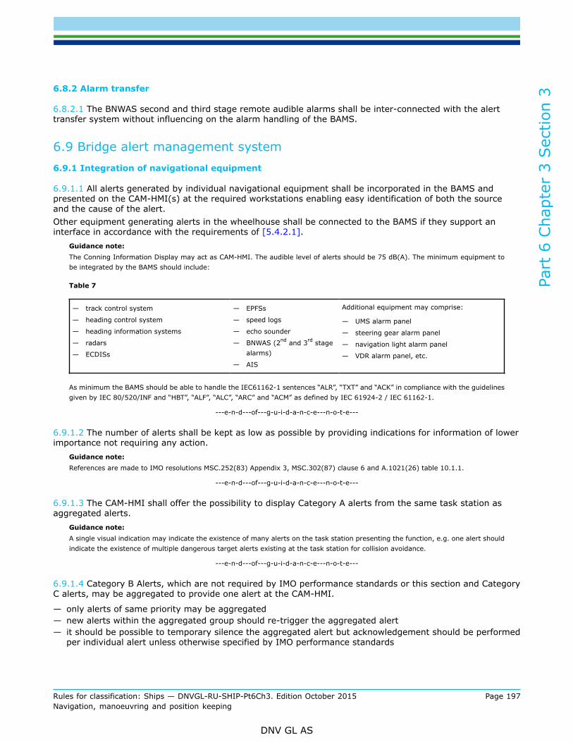
Part
6 C
hapt
er 3
Sec
tion
3
Rules for classification: Ships — DNVGL-RU-SHIP-Pt6Ch3. Edition October 2015 Page 197Navigation, manoeuvring and position keeping
DNV GL AS
6.8.2 Alarm transfer
6.8.2.1 The BNWAS second and third stage remote audible alarms shall be inter-connected with the alerttransfer system without influencing on the alarm handling of the BAMS.
6.9 Bridge alert management system6.9.1 Integration of navigational equipment
6.9.1.1 All alerts generated by individual navigational equipment shall be incorporated in the BAMS andpresented on the CAM-HMI(s) at the required workstations enabling easy identification of both the sourceand the cause of the alert.Other equipment generating alerts in the wheelhouse shall be connected to the BAMS if they support aninterface in accordance with the requirements of [5.4.2.1].
Guidance note:The Conning Information Display may act as CAM-HMI. The audible level of alerts should be 75 dB(A). The minimum equipment tobe integrated by the BAMS should include:
Table 7
— track control system
— heading control system
— heading information systems
— radars
— ECDISs
— EPFSs
— speed logs
— echo sounder
— BNWAS (2nd and 3rd stagealarms)
— AIS
Additional equipment may comprise:
— UMS alarm panel
— steering gear alarm panel
— navigation light alarm panel
— VDR alarm panel, etc.
As minimum the BAMS should be able to handle the IEC61162-1 sentences “ALR”, “TXT” and “ACK” in compliance with the guidelinesgiven by IEC 80/520/INF and “HBT”, “ALF”, “ALC”, “ARC” and “ACM” as defined by IEC 61924-2 / IEC 61162-1.
---e-n-d---of---g-u-i-d-a-n-c-e---n-o-t-e---
6.9.1.2 The number of alerts shall be kept as low as possible by providing indications for information of lowerimportance not requiring any action.
Guidance note:References are made to IMO resolutions MSC.252(83) Appendix 3, MSC.302(87) clause 6 and A.1021(26) table 10.1.1.
---e-n-d---of---g-u-i-d-a-n-c-e---n-o-t-e---
6.9.1.3 The CAM-HMI shall offer the possibility to display Category A alerts from the same task station asaggregated alerts.
Guidance note:A single visual indication may indicate the existence of many alerts on the task station presenting the function, e.g. one alert shouldindicate the existence of multiple dangerous target alerts existing at the task station for collision avoidance.
---e-n-d---of---g-u-i-d-a-n-c-e---n-o-t-e---
6.9.1.4 Category B Alerts, which are not required by IMO performance standards or this section and CategoryC alerts, may be aggregated to provide one alert at the CAM-HMI.
— only alerts of same priority may be aggregated— new alerts within the aggregated group should re-trigger the aggregated alert— it should be possible to temporary silence the aggregated alert but acknowledgement should be performed
per individual alert unless otherwise specified by IMO performance standards

Part
6 C
hapt
er 3
Sec
tion
3
Rules for classification: Ships — DNVGL-RU-SHIP-Pt6Ch3. Edition October 2015 Page 198Navigation, manoeuvring and position keeping
DNV GL AS
— individual alerts should not trigger more than one aggregated alert— alerts required by IMO to be individual should not be aggregated— when a sensor fault results in alerts by several required functions these functions should be presented as
individual alerts— only alerts of same kind, i.e. have same function or source may be aggregated into same aggregated
alert.
6.9.1.5 The CAM-HMI shall present the alert messages in English language using standard maritimeterminology where such exists. Proprietary messages shall be clear text allowing for prompt comprehensionof the message and pertinent actions to be taken.
6.10 Nautical internal communication systems6.10.1 Internal communication equipment
6.10.1.1 Automatic telephone system
a) An automatic telephone system shall be installed and shall provide two-way voice communicationbetween the bridge and:
— all officers cabins— all deck hand cabins— all public rooms— all normal crew working spaces and— all emergency working positions.
b) The telephone network shall be designed with a minimum capacity of four simultaneous calls.
c) The wheelhouse shall be fitted with at least two independent telephone extensions.
d) The telephone extensions in the wheelhouse and engine control room shall have priority function overany other extension.
e) Incoming calls on adjacent telephones shall be distinguishable by lights and/or different ring tones.
f) The automatic telephone system shall be supplied by mains and emergency sources of power.
6.10.1.2 Back-up telephone system
a) A back-up telephone system shall be installed and shall be independent of any failure in the automatictelephone. It shall be provided for two-way voice communication between the wheelhouse and at leastthe following places:
— engine control room (ECR)— local engine operation position(s)— steering gear control position(s)— local thruster control position(s)— emergency generator room(s)— cargo control room (if provided)— captain's living quarters— chief engineer's living quarters— emergency station, fire station (when located outside of the bridge area)— other compartments to be manned in an emergency situation according to the contingency plan.
b) If portable two-way voice communication equipment is used for compliance with the back-up telephonerequirements, then all of the applicable locations shall be provided with transceivers being readilyavailable. The equipment is considered additional to the equipment provided for fulfilment of the

Part
6 C
hapt
er 3
Sec
tion
3
Rules for classification: Ships — DNVGL-RU-SHIP-Pt6Ch3. Edition October 2015 Page 199Navigation, manoeuvring and position keeping
DNV GL AS
requirements of [6.10.1.6] and [6.10.1.7]. The portable two-way voice communication equipment shallcomply with the Society's Statutory Interpretations for internal communication systems.
c) If fixed telephone extensions are used for compliance with the back-up requirements, then theextensions on bridge and ECR shall have priority.The back-up telephone system shall be supplied by mains and emergency sources of powers.
Guidance note 1:The above requirement does not prevent the use of self-contained communication systems, such as sound powered telephones orother battery operated communication systems. Refer to the Society's Statutory Interpretations for internal communication systemsfor power supply, battery and charger requirements for Portable two way voice communication systems.
---e-n-d---of---g-u-i-d-a-n-c-e---n-o-t-e---
Guidance note 2:If sound powered telephones are used for compliance with the back-up requirements, then priority function is not required unlessthe number of the extensions exceeds the required number as listed in [6.10.1.2]a.
---e-n-d---of---g-u-i-d-a-n-c-e---n-o-t-e---
6.10.1.3 Noisy milieuApplicable to the automatic telephone system and the back-up telephone system. In rooms andcompartments with an ambient noise level above 75 dB(A) a headset with a noise cancelling microphone orsimilar facilities suitable for voice communication in noisy environment shall be provided.
Guidance note:Applicable rooms and compartments will as a minimum include steering gear room, engine room and thruster compartment (ifprovided).
---e-n-d---of---g-u-i-d-a-n-c-e---n-o-t-e---
6.10.1.4 Applicable to the automatic telephone system and the back-up telephone system. A reference list ofextensions shall be permanently posted near each telephone being readable while dialling.
6.10.1.5 Public address system
a) The public address system call stations on bridge shall be suitable for flush panel mounting inworkstation consoles.
b) Each PA call station shall be equipped with activation light to indicate communication readiness.c) A reference list of all PA-areas (where different areas are selectable) shall be permanently posted being
readable from the PA call stations.
6.10.1.6 UHF equipment
a) To assist in safety and navigation operations on board, the bridge shall be provided with at least fourportable UHF transceivers operating in the 457 to 467 MHz band.
b) The transceivers shall have a capacity to operate continuously for at least 5 hours.Guidance note:Continuous operation means sequences of 1 minute transmissions followed by 9 minutes reception, without signals at thereceiver input.
---e-n-d---of---g-u-i-d-a-n-c-e---n-o-t-e---
c) A battery charger having sufficient capacity to re-charge all UHF transceivers simultaneously shall beinstalled within the wheelhouse.
d) Portable UHF transceivers used for compliance with the requirement of [6.10.1.7] shall comply with theSociety's Statutory Interpretations for internal communication systems.
6.10.1.7 Communication system for Mooring operations
a) A communication system supporting hands free two-way voice communication between the wheelhouse,bridge wings and all applicable mooring stations on board shall be provided.

Part
6 C
hapt
er 3
Sec
tion
3
Rules for classification: Ships — DNVGL-RU-SHIP-Pt6Ch3. Edition October 2015 Page 200Navigation, manoeuvring and position keeping
DNV GL AS
Guidance note:The communication system may be a fixed installation or alternatively dedicated potable two-way voice communicationapparatuses. A Push To Talk (PTT) activation facility, on portable UHF transceivers used for compliance with the requirementof 108-a, is accepted as an alternative to hands free operation, provided that such portable UHF equipment can be securedfirmly in position to the person operating the apparatus, and that a dedicated headset/earpiece and one hand operated PTTactivation facility be utilised.
---e-n-d---of---g-u-i-d-a-n-c-e---n-o-t-e---
b) If portable UHF transceivers are used for compliance with the requirement of [6.10.1.7] then the totalnumber of transceivers provided, including the four transceivers required by [6.10.1.6], shall not be lessthan 2 times the number of mooring stations onboard.
c) If portable UHF transceivers are used for compliance with the requirement of [6.10.1.7].a then a batterycharger having sufficient capacity to re-charge all UHF transceivers simultaneously shall be installedwithin the wheelhouse.
d) Portable UHF transceivers used for compliance with the requirement of 108a shall comply with theSociety's Statutory Interpretations for internal communication systems.
e) Fixed installations used for compliance with [6.10.1.7].a shall be such that:
— when a member of the mooring team activates a call to any location all other locations also receivethe call.
— it shall be possible for any location to take over the call by a simple operation and continue tocommunicate on a hands-free basis.
6.11 Track control system – NAUT(AW)6.11.1 General
6.11.1.1 The track control system (TCS) in conjunction with their sources of position, heading and speedinformation are intended to keep a ship automatically on a pre-planned route with the accuracy in metresequal to the ship's breadth to either side of the course line under calm weather conditions with minor effectof currents/tidal streams within the limits related to the ship's manoeuvrability.
6.11.1.2 The track control system shall in addition to requirements in IMO Performance standard for Trackcontrol system, comply with the below requirements.
6.11.2 Additional integration
6.11.2.1 The following equipment and systems shall be integrated to make up the TCS:
— two EPFS— two gyro compass— ECDIS— Radar/Chart radar— heading control system (HCS)— conning information display (CID)— bridge alert management system (BAMS).
6.11.3 Additional functional requirements
6.11.3.1 EPFSThe integrity of the position employed by TCS shall be continuously monitored. At least two independentEPFS positions shall be included in the validation algorithm.
6.11.3.2 The individual position fixes shall be properly filtered incorporating own ship’s real time speed vector(DR-position) deduced from gyro and speed log information or equivalent independent sensors.

Part
6 C
hapt
er 3
Sec
tion
3
Rules for classification: Ships — DNVGL-RU-SHIP-Pt6Ch3. Edition October 2015 Page 201Navigation, manoeuvring and position keeping
DNV GL AS
6.11.3.3 Upon failure of the selected EPFS system (e.g. loss of data or invalid data) the TCS shallautomatically employ the EPFS from the second EPFS system and keep up the set course. Any positiondifference at this instant shall be gracefully reduced.
6.11.3.4 Gyro compassThe gyro compass configuration shall sustain continues heading information to TCS equipment whichperformance is dependent on heading information, following any single failure in either one of the two gyrosystems shall not degrade the TCS. See [6.11.3.8].
6.11.3.5 The integrity of the heading employed by TCS shall be continuously monitored.
6.11.3.6 ECDISOne of the two ECDIS shall provide the HMI for the assignment of TCS and engagement of track controlmode. If more than one ECDIS supports the HMI for TCS only one workstation shall be in command at thetime and it shall be clearly perceptible to navigator which workstation is in command.
6.11.3.7 The ECDIS shall support the interface required for timely transmission of relevant parameters of the plannedtrack so the autopilot can conduct a smooth fall-back to heading control mode subsequent to failure of theTCS.
6.11.3.8 HCS/TCSUpon failure of the selected compass system (e.g. loss of data or invalid data) the HCS/TCS shallautomatically employ the heading information from the second compass system and keep up the set course.Any heading difference at this instant shall be gracefully reduced.
6.12 Conning information display (CID) – NAUT(AW)6.12.1 General
6.12.1.1 Information required for efficient monitoring of the TCS performance shall be systematised anddisplayed in a single screen for easy and continuous monitoring by the navigators. Information not related tosafe navigation and manoeuvring shall be avoided on the screen.
6.12.1.2 To enable a straightforward perception, the conning information display shall employ a graphicaldisplay locating relevant sensor data and pertinent set values (orders) appropriately on and around anillustration of own ship. The set value and pertinent sensor value is deemed a logical set of parameters.
6.12.1.3 Additionally, present and impending information related to the voyage plan shall be presented onthe screen together with environmental data which may affect the performance of the TCS.
6.12.1.4 The CID shall present the set and drift vector (magnitude and direction) being experienced. Theaccuracy shall not be inferior to the combined accuracy of the EPFS, gyro and SDME information.
6.12.2 Information categories
6.12.2.1 The information categories to be logically grouped and clearly displayed shall comprise:
— control system data— voyage plan data— depth, wind and set and drift data.
Additional data categories may be included if related to the navigation and manoeuvring of the ship andproviding the perceptibility of the listed information is not impaired with.

Part
6 C
hapt
er 3
Sec
tion
3
Rules for classification: Ships — DNVGL-RU-SHIP-Pt6Ch3. Edition October 2015 Page 202Navigation, manoeuvring and position keeping
DNV GL AS
6.12.2.2 Control system data
a) Present system orders and set-values:
— set heading (heading to steer, e.g. from $..HTC)— set turn radius (only during turn, i.e. subsequent to WOL)— rudder angle order— set speed (only if speed pilot is provided)— present steering control mode.
b) Corresponding sensor data and actual values:
— heading— turn rate— rudder angle— speed over ground— longitudinal— athwart ship— propeller revolutions— pitch indication, when relevant— thruster indication, when relevant.
6.12.2.3 Voyage plan data
a) General:
— identification (name) of selected route.
b) TO-waypoint:
— number (name) of waypoint— planned course— planned turn radius— bearing to WOP— time to go to WOL (h,m,s <24h<d,h,m))— cross-track-limit— cross-track-distance, XTD (m if <0.5nm).
c) NEXT-waypoint:
— planned course— distance to WOP.
6.12.2.4 Wind and current data
a) Graphical and alphanumeric presentation of:
— wind vector (velocity and direction)— set and drift vector (velocity and direction)— present and preceding depth sounding(s) (>30min).
Guidance note:The NEXT waypoint should turn into the TO-waypoint subsequent to passing the WOL.The current vector may be attained from calculus of the SOG- and STW-vectors using information from gyro, speed log and GPS.
---e-n-d---of---g-u-i-d-a-n-c-e---n-o-t-e---
6.12.3 Fall-back information
6.12.3.1 Subsequent to failure of ECDIS all of the information listed in [6.12.2] shall continue to be updatedand displayed on the CID until the course change of the TO-waypoint is completed.

Part
6 C
hapt
er 3
Sec
tion
3
Rules for classification: Ships — DNVGL-RU-SHIP-Pt6Ch3. Edition October 2015 Page 203Navigation, manoeuvring and position keeping
DNV GL AS
7 Network based integration of navigation systems ICS
7.1 General7.1.1 Scope
7.1.1.1 This section covers design, arrangement and testing of network components and equipmentinstalled to perform the functions of collision avoidance, grounding avoidance and alarm management at theworkstations for monitoring and navigating and manoeuvring.
7.1.2 Applications
7.1.2.1 This section is applicable to ships requesting the qualifier ICS. The rule requirements aresupplementary to the rules for any of the other qualifiers to the NAUT notation.
7.1.2.2 Ships complying with the rule requirements may add the qualifier to their class notation; e.g.NAUT(NAV, ICS), NAUT(OC, ICS), NAUT(AW, ICS) or NAUT(OSV, ICS) as appropriate.
7.1.3 Objective
7.1.3.1 The purpose of the requirements is:
— To enhance the availability of essential navigational information at the workstations for monitoring andnavigating and manoeuvring,
— To provide flexible management of tasks being adaptable to various bridge team scenarios,— To provide a consistent and unambiguous human-machine interface on MFDs,— To enhance the level of mode awareness and situation awareness of the bridge team,— To enhance the integrity of essential navigational information displayed,— To ensure proper data management of sensor data and other data being processed and displayed by the
INS.
7.2 Multi-function-displays (MFD)7.2.1 Distribution of functions on workstations
7.2.1.1 The ICS shall comprise minimum five MFDs each with sufficiently redundant processing units capableof supporting the functions of radar, ECDIS, Conning Information Display (CID) and Bridge Alert ManagementSystem (BAMS).
Guidance note:The five MFDs should comply with IMO minimum requirement of Radars and ECDIS/ECDIS back-up as appropriate
---e-n-d---of---g-u-i-d-a-n-c-e---n-o-t-e---
7.2.1.2 The required functions shall be redundantly available on both the workstation for monitoring and theworkstation for navigating and manoeuvring so that following any single failure of any part of the ICS all thefunctions shall continue to be available for selection by navigators on both workstations.
Guidance note:A typical distribution of functions on the workstations for monitoring and navigating and manoeuvring are:

Part
6 C
hapt
er 3
Sec
tion
3
Rules for classification: Ships — DNVGL-RU-SHIP-Pt6Ch3. Edition October 2015 Page 204Navigation, manoeuvring and position keeping
DNV GL AS
---e-n-d---of---g-u-i-d-a-n-c-e---n-o-t-e---
7.2.1.3 The ICS shall be capable of managing the assigned functions simultaneously on the applicable MFDsand all functions being active shall be accessible to the navigator for display by a single operator action.
7.2.1.4 It shall at all times be indicated whether an assigned function is activated or not and this shall beclearly visible irrespective of the function being selected for display at present.
7.2.1.5 When the TCS is in operation at least the ECDIS shall be persistently displayed on the workstation incommand (ref. [7.3.2.4].
Guidance note:If other applications than ECDIS is necessary to fulfil the IMO requirements for “Continuously displayed information” then such otherapplication shall also be persistently displayed (MSC.74(69)6.2.1). An application running in the background of ECDIS may be calledup temporarily, e.g. to acknowledge a Cat A alert, but should automatically return to the ECDIS application within 30s following thelast operator action (keyboard, soft key, etc.).
---e-n-d---of---g-u-i-d-a-n-c-e---n-o-t-e---
7.3 Human-machine interface (HMI)7.3.1 System configuration display
7.3.1.1 Upon user request it shall be possible to display the complete ICS configuration, the availableconfiguration and the configuration in use, as a graphic presentation. The information shall be detailed tothe level of ICS subsystems, sensors, and other equipment connected, ready for providing information to theICS, or being processed by the ICS.
Guidance note:

Part
6 C
hapt
er 3
Sec
tion
3
Rules for classification: Ships — DNVGL-RU-SHIP-Pt6Ch3. Edition October 2015 Page 205Navigation, manoeuvring and position keeping
DNV GL AS
If colour coding is used; green = in use (running), yellow = stand by (ready), red = off (or failed)
---e-n-d---of---g-u-i-d-a-n-c-e---n-o-t-e---
7.3.2 Consistent HMI
7.3.2.1 The displays and UIDs shall adopt a consistent HMI philosophy paying particular attention to overalllayout, menus, wording, symbols, abbreviations, and colour coding.
7.3.2.2 The information shall be displayed using a consistent presentation style and should be clearlyunderstood by an OOW not being familiar with the equipment.
7.3.2.3 Manual inputsManual inputs that may lead to sudden manoeuvres or loss of data shall call for a confirmation by the userproviding the OOW time for a plausibility check.
7.3.2.4 HMI –automatic control functionsWhere multiple stations provide HMI for automatic heading, speed, or track control, only one station shall beassigned command at the time.
Guidance note:A station in this respect is any keyboard or display having HMI for automatic control functions.
---e-n-d---of---g-u-i-d-a-n-c-e---n-o-t-e---
7.3.2.5 It shall be clearly indicated on the station being in command as well as all the latent stationsprovided with such HMI which station is currently in command.
7.3.2.6 When a station includes such HMI it shall be possible for the user to take control at that station.Guidance note:The stations provided with HMI for automatic control functions should support take-over functionality.
---e-n-d---of---g-u-i-d-a-n-c-e---n-o-t-e---
7.3.3 Essential information
7.3.3.1 The ICS shall be capable of accepting multiple sensor inputs and/or sources for provision of thefollowing data:
— heading— STW— SOG— position— time— ENC— radar video.
7.3.3.2 The position, heading and speed information shall be displayed together with the indication of itssource.
Guidance note:Sensor data, e.g. GYR 1, GYR 2, GPS 1, GPS 2, EM log, Doppler log, GPS, radar 1, radar 2 etc.; -or result of calculation or manualinput; -unit if ambiguous, e.g. UTC for time.
---e-n-d---of---g-u-i-d-a-n-c-e---n-o-t-e---
Display of sensor output data7.3.3.3 The ICS shall be capable of displaying non-processed information directly from the output dataavailable from the sensors upon request from the user.
Part
6 C
hapt
er 3
Sec
tion
3
Rules for classification: Ships — DNVGL-RU-SHIP-Pt6Ch3. Edition October 2015 Page 206Navigation, manoeuvring and position keeping
DNV GL AS
Guidance note:It should be possible for the OOW to call upon and read the stream of received IEC61162 messages (ASCII) from sensors in aseparate window.
---e-n-d---of---g-u-i-d-a-n-c-e---n-o-t-e---
7.3.4 Accuracy and performance
7.3.4.1 The ICS processing shall not degrade the attributes of the essential information being provided by thesensors.
Guidance note:Such attributes include accuracy, update rate, range, resolution, validity, etc. as specified in the relevant international standards.
---e-n-d---of---g-u-i-d-a-n-c-e---n-o-t-e---
7.3.4.2 Latency of dataData latency shall be consistent with the data requirements of the individual parts and their relevantinternational standards.
Guidance note:The latency should be less than 1.0 second for information to be displayed only while it should be less than 0.1 seconds for informationbeing critical for the performance of an automatic control system, e.g. heading in HCS.
---e-n-d---of---g-u-i-d-a-n-c-e---n-o-t-e---
7.3.4.3 Consistent common reference systemThe ICS shall ensure that essential sensor information is distributed to the relevant parts of the system,applying a consistent common reference system. The ICS shall ensure that:
— all parts and displays are provided with the same type of data from the same source at any time,— data are referenced to the same position and time and— data is compensated for latency when necessary.
Guidance note:Essential sensor information comprise at least time, position, speed, heading and depth. One of the parts (stations) should be assignedthe command for processing and distributing essential information to all parts of the ICS. Upon failure of the part in command anotherpart should automatically take over the responsibility for processing and distributing information to the remaining parts of the ICS.At least three (3) of processing units comprising parts of the ICS should be capable of automatic take-over of the processing anddistribution responsibility.
---e-n-d---of---g-u-i-d-a-n-c-e---n-o-t-e---
7.3.4.4 Consistent common reference pointFor consistency between observed and measured ranges and bearings, the reference location for suchmeasurements shall be the conning position.
Guidance note:Alternative reference locations may be used where clearly indicated or distinctively obvious.
---e-n-d---of---g-u-i-d-a-n-c-e---n-o-t-e---
7.3.5 Integrity monitoring
7.3.5.1 The ICS shall support mode awareness by providing:
— validation of essential navigation data of all connected navigation sensors— presenting clear indications of sensor status and modes of operation.

Part
6 C
hapt
er 3
Sec
tion
3
Rules for classification: Ships — DNVGL-RU-SHIP-Pt6Ch3. Edition October 2015 Page 207Navigation, manoeuvring and position keeping
DNV GL AS
7.3.5.2 The integrity of essential information shall be monitored and verified automatically before suchinformation is used or displayed by any parts of the ICS.
7.3.5.3 The integrity of data from different sensors shall be evaluated prior to distribution to other parts ofthe ICS and/or to external devices.
7.3.5.4 The ICS shall automatically select the most accurate method of integrity monitoring from theavailable sensors.
7.3.5.5 The ICS shall additionally allow for the user to manually select the sources for integrity monitoringamong the available sensors and parts.
7.3.5.6 A clear indication of the sources of data selected for integrity monitoring shall be available.
7.3.5.7 Plausibility checksReceived or derived data that is used or distributed by the ICS shall be checked for plausible magnitudes ofvalues.
Guidance note:E.g. a heading of 361° is not plausible. Data which fail the plausibility check should not be used by the ICS. If originating frommanual input a re-entry should be called for.
---e-n-d---of---g-u-i-d-a-n-c-e---n-o-t-e---
7.3.5.8 Verification of data integrityThe integrity of information selected for use by the ICS shall automatically be verified by comparison of thedata derived independently from two or more sources whenever available.
Guidance note:E.g. the integrity of time may take on GNSS time data and the ICS internal clock data, depth may be compared with ENC depthsoundings, etc. The ICS may additionally provide for manual setting of the monitoring thresholds.
---e-n-d---of---g-u-i-d-a-n-c-e---n-o-t-e---
7.3.5.9 Integrity monitoring thresholdsThe monitoring thresholds shall taking into account inherent differences in availability, accuracy and responsetimes and the dynamics of ship manoeuvring when applicable.
Guidance note:The threshold for integrity calculations should be based on the applicable specifications of the sensor accuracy (95% probability) incombination with a plausible time out period. The threshold may be determined by the geometric addition of the accuracy values ofthe data being used for integrity monitoring. E.g. the difference threshold for two GPS may be set to 50 m with a time-out periodof 5 seconds or alternatively to 30 m with a time-out period of 10 seconds. For two DGPS such thresholds may be reduced to 10m and 5 m respectively.
---e-n-d---of---g-u-i-d-a-n-c-e---n-o-t-e---
7.3.5.10 The status of the data shall be marked as “integrity uncertain” when the difference between thesources exceeds the pre-defined thresholds.
7.3.5.11 The integrity monitoring thresholds in use shall be available for display by the user.
7.3.6 Integrity marking
7.3.6.1 The data transmitted shall enable subsequent ICS functions to check whether the input datacomplies with their integrity requirements or not. Data with uncertain integrity shall be clearly identified bythe ICS protocol.
Guidance note:Reference is made to IEC61162-1(2007) 7.3.10 for guidance on additions to approved sentences.
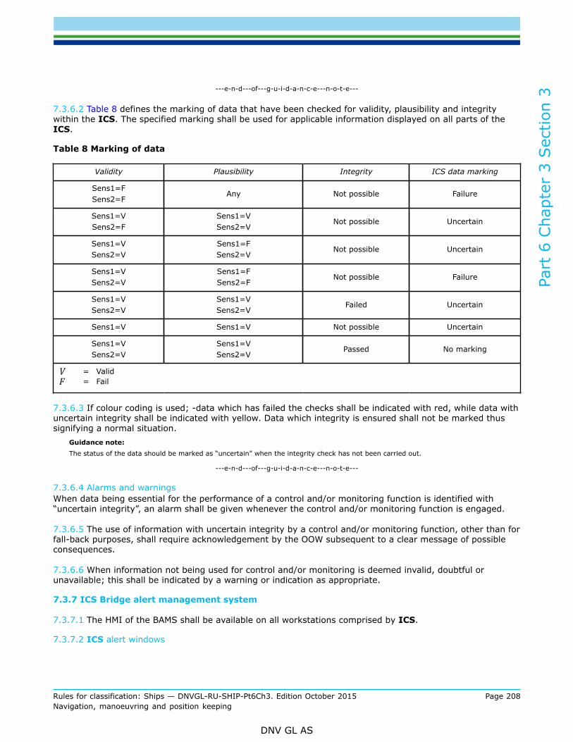
Part
6 C
hapt
er 3
Sec
tion
3
Rules for classification: Ships — DNVGL-RU-SHIP-Pt6Ch3. Edition October 2015 Page 208Navigation, manoeuvring and position keeping
DNV GL AS
---e-n-d---of---g-u-i-d-a-n-c-e---n-o-t-e---
7.3.6.2 Table 8 defines the marking of data that have been checked for validity, plausibility and integritywithin the ICS. The specified marking shall be used for applicable information displayed on all parts of theICS.
Table 8 Marking of data
Validity Plausibility Integrity ICS data marking
Sens1=FSens2=F
Any Not possible Failure
Sens1=VSens2=F
Sens1=VSens2=V
Not possible Uncertain
Sens1=VSens2=V
Sens1=FSens2=V
Not possible Uncertain
Sens1=VSens2=V
Sens1=FSens2=F
Not possible Failure
Sens1=VSens2=V
Sens1=VSens2=V
Failed Uncertain
Sens1=V Sens1=V Not possible Uncertain
Sens1=VSens2=V
Sens1=VSens2=V
Passed No marking
V = ValidF = Fail
7.3.6.3 If colour coding is used; -data which has failed the checks shall be indicated with red, while data withuncertain integrity shall be indicated with yellow. Data which integrity is ensured shall not be marked thussignifying a normal situation.
Guidance note:The status of the data should be marked as “uncertain” when the integrity check has not been carried out.
---e-n-d---of---g-u-i-d-a-n-c-e---n-o-t-e---
7.3.6.4 Alarms and warningsWhen data being essential for the performance of a control and/or monitoring function is identified with“uncertain integrity”, an alarm shall be given whenever the control and/or monitoring function is engaged.
7.3.6.5 The use of information with uncertain integrity by a control and/or monitoring function, other than forfall-back purposes, shall require acknowledgement by the OOW subsequent to a clear message of possibleconsequences.
7.3.6.6 When information not being used for control and/or monitoring is deemed invalid, doubtful orunavailable; this shall be indicated by a warning or indication as appropriate.
7.3.7 ICS Bridge alert management system
7.3.7.1 The HMI of the BAMS shall be available on all workstations comprised by ICS.
7.3.7.2 ICS alert windows

Part
6 C
hapt
er 3
Sec
tion
3
Rules for classification: Ships — DNVGL-RU-SHIP-Pt6Ch3. Edition October 2015 Page 209Navigation, manoeuvring and position keeping
DNV GL AS
The presence of an active alarm, or warning needing acknowledgement, shall be continuously displayedon both the monitoring and navigating and manoeuvring workstations irrespective of the actual functionpresently being activated on the MFDs.
Guidance note:The minimum functions available for display on the MFDs are ECDIS, radar, CID and BAMS. A consistent “alert window” should bepresent on all functions supported by the MFDs.
---e-n-d---of---g-u-i-d-a-n-c-e---n-o-t-e---
7.3.7.3 In as much as the regular alert window may have limited space; when several alerts are activesimultaneously these alerts shall be organized sequentially and the alarm window shall display the “oldest”active alerts message according to the priority of Table 9.
Table 9 Alarm and warning priority
Priority Status
1Alarm - not acknowledged(active)
2Warning - not acknowledged(active)
3 Alarm - acknowledged
4 Warning - acknowledged
7.3.7.4 Alert recordThe BAMS shall maintain a sequential record of all alerts that have occurred from present and at leastthe preceding 24 hours. Additionally the record shall include all alerts which conditions are not rectifiedirrespective of time of event
7.3.7.5 The BAMS-record shall display all unacknowledged alerts on top of the list.
7.3.7.6 The BAMS-record shall be available to the OOW on a separate window following no more than twooperator actions starting from any of the MFD functions.
7.3.7.7 AcknowledgementAcknowledgement of alarms and warnings shall be possible on any HMI supporting the cause of theannouncement and where related information for situation awareness and decision support is available.
7.3.7.8 When acknowledgement is carried out on the equipment which is directly assigned to the functiongenerating the announcement this shall automatically cancel the announcement on all HMIs.
7.3.7.9 The acknowledgement of the announcement shall occur automatically after the function generatingthe announcement is switched off (e.g. when an automatic control mode is switched to manual mode)
7.3.7.10 Alarm limit consistencyThe ICS shall automatically ensure that consistent alarm and warning thresholds are used by differentparts of the ICS. Where thresholds are entered by the OOW in one part of the ICS the other parts shallautomatically adapt the same limits.
7.3.7.11 Alarm suppressionIf manual suppression of separate alerts is an available option the BAMS shall clearly indicate when suchsuppression is employed and identify the alerts being suppressed.

Part
6 C
hapt
er 3
Sec
tion
3
Rules for classification: Ships — DNVGL-RU-SHIP-Pt6Ch3. Edition October 2015 Page 210Navigation, manoeuvring and position keeping
DNV GL AS
7.3.8 Data output from ICS
7.3.8.1 Where data output interfaces with IEC 61162-1 sentences are used, system data and other datachecked for integrity, modified or generated by the ICS shall be transmitted with the talker identifier “IN”;otherwise the talker identifier of the data source shall be used.
Guidance note:The “IN” will identify data generate by the ICS as “system data”.
---e-n-d---of---g-u-i-d-a-n-c-e---n-o-t-e---
7.4 ICS network7.4.1 Independency and integrity
7.4.1.1 The network integrating the ICS shall be designed with adequate redundancy and independency.Guidance note:In this sub-section the term network means any type of LAN or CAN inter-connecting the equipment for transmission of information.The interface layers should to be in accordance with the relevant IEEE 802-standards and/or ISO 11898-standards as applicable.
---e-n-d---of---g-u-i-d-a-n-c-e---n-o-t-e---
7.4.1.2 Cables and network components belonging to redundant networks shall be physically separated;by separate cable routing and installation of network components belonging to the redundant network inseparate cabinets, power supply to such units included.
7.4.1.3 Each network shall function independently and it shall be possible to protect each network fromunnecessary traffic on the other network.
7.4.1.4 All network components controlling the network traffic and nodes communicating over the networkshall be designed with inherent properties to prevent network overload at any time. Neither the nodes northe network components shall be able to generate excessive network traffic or consume extra resources thatmay degrade the network performance.
Guidance note:The nodes and network components should have properties to monitor its own communication through the network, and to be ableto detect, alarm and respond in a predefined manner in case of an excessive traffic event.
---e-n-d---of---g-u-i-d-a-n-c-e---n-o-t-e---
7.4.1.5 The performance of the network shall be continuously monitored, and alarms shall be generated ifmalfunctions or reduced/degraded capacity occurs.
7.4.1.6 Any powered network component controlling the network traffic shall automatically resume to normaloperation upon restoration of power after a power failure.
7.4.1.7 All nodes in the network shall be synchronized to attain a uniform time tagging of alarms (andevents) to enable a proper sequential logging.
7.4.1.8 The network shall be designed to withstand exposure to electromagnetic interference.Guidance note:The wheelhouse is exposed to high voltage equipment and RF transmitters. Reference is made to Classification Note No.45.1 forguidance on EMC measures.
---e-n-d---of---g-u-i-d-a-n-c-e---n-o-t-e---
7.4.1.9 Any CCTV system (Closed Circuit Television) shall not be part of the ICS network.

Part
6 C
hapt
er 3
Sec
tion
3
Rules for classification: Ships — DNVGL-RU-SHIP-Pt6Ch3. Edition October 2015 Page 211Navigation, manoeuvring and position keeping
DNV GL AS
7.5 Malfunctions and restoration7.5.1 Failure effects
7.5.1.1 A failure of one part shall not affect the functionality of other parts except for those processes andfunctions directly dependent upon the information from the defective part.
Guidance note:One “part” in the system should be understood as equipment, network, switch/router etc.
---e-n-d---of---g-u-i-d-a-n-c-e---n-o-t-e---
7.5.1.2 The ICS response to malfunctions shall result in the safest of any other configuration or mode ofoperation.
7.5.1.3 Fall-back arrangementsOne of the servers including at least one MFD shall continue to be available as a stand-alone radar followingfailure of both networks.One of the servers including at least one MFD shall continue to be available as a stand-alone ECDIS followingfailure of both networks.
Guidance note:An exception from this general principle may only be approved for completely independent networks based on documented designfeatures and analysis that is verifying that any logical failure, including uncontrolled broadcast of data packets (network storm), ofany computer connected to the networks cannot cause loss of/failure of more than one of the networks.
---e-n-d---of---g-u-i-d-a-n-c-e---n-o-t-e---
7.5.2 Orderly shutdown
7.5.2.1 If subjected to an orderly shutdown, the ICS shall, upon power on come to an initial default stateready for operation. The orderly shutdown procedure, turn on procedure and the initial default state shall bedeclared by the operating manual.
7.5.3 Power interruption
7.5.3.1 After a power interruption full functionality of the ICS shall be available after recovery of allsubsystems. The ICS shall not increase the recovery time beyond that specified in the standards of theindividual subsystem or its functions after power restoration.
7.5.3.2 If subjected to a power interruption the ICS shall, upon restoration of power maintain theconfiguration and mode previously in use and continue operation as specified in the individual equipmentstandard.
7.6 Testing7.6.1 Network test and verification
7.6.1.1 The network functionality shall be verified in a test where at least the following items shall beverified:
— The main observations from the FMEA— Self-diagnostics— Worst-case scenarios – network storm— Network segregation – autonomous operation of network— Individual controller node integrity – workstations working without network communication.

Part
6 C
hapt
er 3
Sec
tion
3
Rules for classification: Ships — DNVGL-RU-SHIP-Pt6Ch3. Edition October 2015 Page 212Navigation, manoeuvring and position keeping
DNV GL AS
7.7 Documentation7.7.1 Network documentation requirements
7.7.1.1 For additional documentation required for the NAUT(OC, ICS) and NAUT(AW, ICS) class notationssee Table 3.
7.8 Quality system7.8.1 Quality assurance
7.8.1.1 The integrator of the ICS and the manufacturers of the navigational aids being parts of the ICS shallhave a production Quality Control System being audited by a competent authority.
8 Ship manoeuvring characteristics
8.1 General8.1.1 Scope
8.1.1.1 This section gives requirements for the provision of documentation establishing the manoeuvringcharacteristics of the ship.
8.1.1.2 Additionally, minimum requirements relating to the ship’s course keeping performance is specified in[8.3].
8.1.2 Application
8.1.2.1 Ships requesting class notation NAUT(AW) shall comply with the requirements of this section.
8.1.3 Standards
8.1.3.1 The methods of tests and trials employed to determine the ships manoeuvring performance shall bein accordance with recognized international standards.
Guidance note:The conduct of trials and use of mathematical models providing manoeuvring information should not be inferior to the principles ofMSC/Circ.1053 “Explanatory notes to the standards for ship manoeuvrability”.Note: In this section the term trial should read any of the methods stated in [8.2.1.1] unless the requirement specifically identifiesonly one of the methods as being applicable.
---e-n-d---of---g-u-i-d-a-n-c-e---n-o-t-e---
8.2 Trials and predictions8.2.1 General
8.2.1.1 The ships manoeuvring characteristics shall be demonstrated based on the results of full-scale trialsor calculations by means of scale model tests and/or computer predictions using mathematical models.

Part
6 C
hapt
er 3
Sec
tion
3
Rules for classification: Ships — DNVGL-RU-SHIP-Pt6Ch3. Edition October 2015 Page 213Navigation, manoeuvring and position keeping
DNV GL AS
8.2.1.2 Validation of scale model tests and/or computer predictions shall be done by performing full scaletrials and comparing the results of these trials with the results of model tests and/or computer predictionsperformed for the equivalent “trial loading condition”.
Guidance note:The characteristic parameters should be within 15% of the parameters obtained from the full-scale trials. If deviation exceeds thisfigure, the whole full-scale trial program should be completed.
---e-n-d---of---g-u-i-d-a-n-c-e---n-o-t-e---
8.2.1.3 The ship shall as a minimum complete the following full scale trials for at least one loading conditionto demonstrate that its manoeuvring performance is in accordance with the requirements of this section:
— 10º/10º and 20º/20º zig-zag trials at full speed ahead— full astern stopping trial from full speed ahead— turning circle trials at full speed ahead to both port and starboard and completed by a pull out trial.
Guidance note:At least one turning circle trial should complete a full 720º course change to ascertain the prevailing current vector. Reference ismade to MSC/Circ.1053 for details.
---e-n-d---of---g-u-i-d-a-n-c-e---n-o-t-e---
8.2.1.4 The full-scale manoeuvring trials shall be conducted in deep water and during calm weatherconditions.
Guidance note:Trials should be conducted in conditions within the following limits:
— Depth: more than 4 times the mean draught.
— Wind: not to exceed Beaufort 5.
— Waves: not to exceed sea state 4.
— Current: uniform distribution only.
---e-n-d---of---g-u-i-d-a-n-c-e---n-o-t-e---
8.2.2 Sister ships
8.2.2.1 For ships built in series according to identical drawings and parameters, only one ship of the seriesshall have to undertake a complete trial program according to this section. The “sister ships” of the seriescan adopt the information from these trials provided a full-scale 10º/10º zig-zag trial at full speed ahead issatisfactory completed by all the ships of the series.
Guidance note:The characteristic parameters should be within 10% of the parameters obtained from the original vessel. If deviation exceeds thisfigure; completion of the whole full-scale trial program may be required.
---e-n-d---of---g-u-i-d-a-n-c-e---n-o-t-e---
8.3 Course-keeping ability8.3.1 General
8.3.1.1 The ship design shall take in course keeping and yaw checking abilities aiming to reduce the averageuse of rudder during normal operation.
Guidance note:The ship should comply with the following yaw-checking and course-keeping abilities;
1) The value of the first overshoot angle of the 10º/10º zigzag test should not exceed:
— 10º if L/V is less than 10 seconds;

Part
6 C
hapt
er 3
Sec
tion
3
Rules for classification: Ships — DNVGL-RU-SHIP-Pt6Ch3. Edition October 2015 Page 214Navigation, manoeuvring and position keeping
DNV GL AS
— 20º if L/V is 30 seconds or more; and
— (5 + 1/2(L/V))º if L/V is 10 s or more, but less than 30 s, where L and V are expressed in m and m/s, respectively.
2) The value of the second overshoot angle of the 10º/10º zigzag test should not exceed:
— 25º if L/V is less than 10 s;
— 40º, if L/V is 30 s or more; and
— (17.5 + 0.75(L/V))º if L/V is 10 s or more, but less than 30 s.
3) The value of the first overshoot angle of the 20º/20º zigzag test should not exceed 25º.
— L = Lpp, V = ships speed
For ships with non-conventional steering and propulsion systems, the Society may permit the use of comparative steering anglesto the rudder angles specified above.The vessel is deemed to comply with this requirement if the documentation of [4.5] is found to be satisfactory.
---e-n-d---of---g-u-i-d-a-n-c-e---n-o-t-e---
8.4 Provision of manoeuvring information8.4.1 General
8.4.1.1 Information about the ship's manoeuvring characteristics shall be provided giving the navigator thebest decision support available when deciding on speed and rudder angle needed to execute a manoeuvreunder prevailing conditions.
8.4.1.2 The manoeuvring documentation shall include information about the speed ability, stopping ability,turning ability, course change ability, low steering ability, course stability, the effectiveness of auxiliarymanoeuvring devices and a rational man-overboard rescue manoeuvre.
8.4.2 Speed ability
8.4.2.1 Information about speed ability in terms of the actual speed potential of the ship at various enginesettings shall be provided for fully loaded and ballast conditions. Information shall be provided for at leastthree engine settings identifying the percentage used related to the maximum continuous power rating,(MCR):
— at full speed ahead (>90%)— at half speed ahead (60%)— at slow speed ahead.(40%).
8.4.3 Stopping ability
8.4.3.1 Information about the ship's stopping abilities shall be provided for fully loaded and ballastconditions. Information shall at least comprise stopping from an initial full speed ahead and with applicationof the following astern powers:
— constant full astern power— with propulsion and engine stopped.
8.4.4 Turning ability
8.4.4.1 Information about the ship's turning ability to port and to starboard shall be determined for fullyloaded and ballast conditions applying full speed ahead and using maximum rudder angle available at thisspeed.

Part
6 C
hapt
er 3
Sec
tion
3
Rules for classification: Ships — DNVGL-RU-SHIP-Pt6Ch3. Edition October 2015 Page 215Navigation, manoeuvring and position keeping
DNV GL AS
8.4.4.2 Information about the ship's turning ability to port and starboard following an engine shut down shallbe provided; -from initial full speed ahead and stopping the engine at the start of the turn (coasting turn)using maximum rudder angle available.
8.4.4.3 Information about the ship's turning ability when accelerating from a resting position to half speedahead shall be provided. Turning information shall be made to both port and to starboard; -initial conditionshall be standstill with propeller stopped; -then apply half speed ahead using maximum rudder angleavailable (accelerated turn).
8.4.5 Yaw checking and course-keeping ability
8.4.5.1 Information about the ship's initial turning ability and course keeping ability shall be provided for fullyloaded and ballast conditions. Zigzag trials shall be made for rudder angles/course changes equal to 10°/10°and 20°/20°.
8.4.6 Low speed steering abilities
8.4.6.1 Information about the lowest constant engine revolutions or lowest pitch control setting at which theship can safely be steered in ballast and loaded conditions shall be provided.
8.4.7 Heading stability
8.4.7.1 Information about the heading stability (directional stability) of the ship shall be provided. A pullouttrial shall be made to port and starboard. A spiral trial shall be made if the pullout trial indicates that the shipis unstable.
8.4.8 Auxiliary manoeuvring device trial
8.4.8.1 Information about the performance and effect of auxiliary devices installed to improve themanoeuvring abilities of the ship shall be provided. The performance and limitations of such manoeuvringdevices shall be determined for the following conditions:
— the time required to turn the ship 90º to each side at full thrust while the ship is lying dead in the watershould be determined
— the forward speed at which the device ceases to be effective should be determined.
8.4.9 Man-overboard rescue manoeuvre
8.4.9.1 Information about how to perform an effective man-overboard rescue manoeuvre shall be provided.Manoeuvring trials to establish the most effective manoeuvre procedure in case of man over board shall becarried out.
Guidance note:For large ships with conventional rudder systems, the characteristics of a “Williamson turn” are recommended to be confirmed:The initial trial should apply full rudder until a course deviation of 60° has been achieved and then apply full rudder to the oppositeside to complete a 180º turn and steadying on the opposite course (heading down its own wake). The trial should be repeated asneeded with different course deviation angles until the vessel’s opposite track is within 50 meters of the original wake.
---e-n-d---of---g-u-i-d-a-n-c-e---n-o-t-e---
8.4.10 Corrections
8.4.10.1 The documentation of ship manoeuvring characteristics and trajectories when obtained from full-scale trials shall be corrected for any current vector being present during such trials.
Guidance note:

Part
6 C
hapt
er 3
Sec
tion
3
Rules for classification: Ships — DNVGL-RU-SHIP-Pt6Ch3. Edition October 2015 Page 216Navigation, manoeuvring and position keeping
DNV GL AS
Position (xli, yli, tli) and (x2i, y2i, t2i) in the figure below are the positions of the ship measured after a heading rotation of 360° with asteady ROT. By defining the local current velocity Vi as the difference between any two corresponding positions the estimated currentvelocity can be obtained from the following equation:
---e-n-d---of---g-u-i-d-a-n-c-e---n-o-t-e---
8.4.11 Information from sister ships
8.4.11.1 All information, which is merely duplicated from a sister ship shall be marked with a statement tothis effect together with the identification of the sister ship (hull no.).
8.5 Presentation of manoeuvring information8.5.1 Wheelhouse poster
8.5.1.1 A summary of manoeuvring information shall be presented in the format of a wheelhouse postercontaining general ship particulars and data describing the key manoeuvring characteristics of the ship, bothgraphical and numerical, to support ease of use. The poster shall be of sufficient size to be easily readable.
Guidance note:The wheelhouse poster should not be less than A3 format. As regards information content and layout reference is made to IMOResolution A.601(15), Appendix 2 for details.
---e-n-d---of---g-u-i-d-a-n-c-e---n-o-t-e---
8.5.1.2 The wheelhouse poster shall be permanently posted in the wheelhouse.
8.5.1.3 The wheelhouse poster shall include a warning that the manoeuvring performance of the ship maydiffer from that shown on the poster due to environmental, hull and loading conditions.

Part
6 C
hapt
er 3
Sec
tion
3
Rules for classification: Ships — DNVGL-RU-SHIP-Pt6Ch3. Edition October 2015 Page 217Navigation, manoeuvring and position keeping
DNV GL AS
8.5.2 Manoeuvring booklet
8.5.2.1 The ship shall be provided with a manoeuvring booklet. The booklet shall contain all the details of theship's manoeuvring characteristics together with all relevant data from trials and scale model tests and/orcomputer predictions.
8.5.2.2 Trajectories shall be shown graphically together with a scale sample of the ship. The trial trajectoriesshall always be corrected for current but also for influence of wind and waves if the conditions of [8.2.1.4]are exceeded.
8.5.2.3 The booklet shall contain note fields (space) enabling the information of the booklet to besupplemented in the course of the ship's life.
Guidance note:The information recommended to be included in the manoeuvring booklet is specified in IMO Resolution A.601(15), Appendix 3.
---e-n-d---of---g-u-i-d-a-n-c-e---n-o-t-e---
8.5.2.4 A diagram showing the double turn circle of 720° and supplementary data demonstrating the effectof current setting and wind drift registered during the performance of the manoeuvring trials shall beincluded.
8.5.3 Pilot card
8.5.3.1 The ship shall be provided with appropriate pilot card(s). The pilot card(s) shall be suitable forconveying information to the pilot about the current condition of the ship with regard to its loading condition,availability of propulsion and manoeuvring equipment as well as other relevant equipment.
Guidance note:The pilot card should either be made of a material suitable for both writing and re-use. A card made of plastic material, or an adequateamount of paper copies supporting a year in operation or an electronic version in a printable format (e.g. PDF-file) should be readablyavailable on board. An example of information content and layout of a pilot card is given in IMO Resolution A.601(15), Appendix 1.
---e-n-d---of---g-u-i-d-a-n-c-e---n-o-t-e---
9 Qualifications and operational procedures
9.1 General9.1.1 Introduction
9.1.1.1 Modern technology has the potential to improve the situational awareness of the officer in charge ofthe navigational watch, hereafter called OOW. But this potential can only be realised if the OOW has gainedthe knowledge and skills necessary for using the technology safely and efficiently.
9.1.2 Scope
9.1.2.1 This section specifies requirements for competence and navigational procedures related to equipmentand systems required by this section.
9.1.3 Application
9.1.3.1 Although the requirements of this section are merely informative the Society encourages the shipoperator to ensure that the navigation officers on board their ships is provided with adequate training andtools attending to the principles outlined below.

Part
6 C
hapt
er 3
Sec
tion
3
Rules for classification: Ships — DNVGL-RU-SHIP-Pt6Ch3. Edition October 2015 Page 218Navigation, manoeuvring and position keeping
DNV GL AS
9.2 Watch keeping arrangement9.2.1 Operational assumptions
9.2.1.1 The following assumptions are made:
— the master ensures that the manning of the bridge watch is in accordance with national regulations in thecountry of registration and for the waters the ship is navigating
— the master ensures that pre-planning and watch-keeping arrangements are adequate for maintaining asafe navigational watch in accordance with STCW
— the master ensures that the OOW has received the required training prior to being assigned thenavigational watch
— the master designates individuals who shall provide assistance when needed by the OOW— the OOW maintain a navigational watch in compliance with STCW— the OOW carefully assesses that the workload is well within his capacity to maintain full control of the
operational situation while carrying out all the tasks assigned to the bridge watch— the OOW immediately summons assistance to the bridge in case of irregular operational conditions
including situations causing excessive workloads.
9.2.1.2 It is assumed that the ship operator and ship master ensures that all the requirements of this sectionare complied with.
9.3 Qualifications9.3.1 General
9.3.1.1 All officers being assigned the responsibility of the navigational watch should be fully qualified tooperate the navigational equipment and systems installed on the particular ship. The master and all OOWshould hold a certificate of competence documenting completion of TCS training.
9.3.1.2 The OOW should have attained the required competence prior to be assigned a single-man watch.
9.3.1.3 It is the responsibility of the ship operator to make certain that the master and the navigation officershave completed the necessary training and courses prior to their full assignment.
9.3.1.4 The master, holding a certificate of competence issued by the manufacturer of the TCS and havingsufficient practical experience, may train and certify navigators through a systematic on board trainingprogram prior to their full assignment. The on board training should cover all parts of the manufacturer basedtraining course, and include a statement of competence upon completion of the training.
Guidance note:The course should at least comprise the following:
— system design
— operational modes
— training in daily operation of the system
— the capabilities and limitations of TCS as well as the individual instruments
— effect of failure in any of the bridge equipment and sensors constituting the grounding avoidance system and the resulting fall-back or fail-to-safety mode of operation.
---e-n-d---of---g-u-i-d-a-n-c-e---n-o-t-e---

Part
6 C
hapt
er 3
Sec
tion
3
Rules for classification: Ships — DNVGL-RU-SHIP-Pt6Ch3. Edition October 2015 Page 219Navigation, manoeuvring and position keeping
DNV GL AS
9.4 Bridge watch procedures9.4.1 Procedures for safe watch-keeping
9.4.1.1 Procedures for bridge team management and safe watch-keeping should be established and be easilyavailable on the bridge.
9.4.1.2 Procedures and instructions for irregular and abnormal operating conditions should be establishedbased on the failure modes and effect analysis for the grounding avoidance system and heavy workloadsituations caused by external conditions and combination of external conditions and system failures.
9.4.1.3 The length of dormant intervals of the bridge watch surveillance system should be set with dueconsideration of the time needed for the back-up officer to get to the bridge (response time), and theexternal conditions to be experienced, including the time to danger of grounding along the route and trafficdensity. The parameters for setting the intervals should be known to the watch officer and included in theprocedures for safe watch-keeping.
10 Bridge equipment - On-board tests
10.1 General10.1.1 Application
10.1.1.1 The requirements in this sub-section is applicable for NAUT(OC) and NAUT(AW).
10.2 On board testing of bridge equipment10.2.1 General
10.2.1.1 On-board testing of the bridge equipment shall be performed in order to ascertain that theequipment installed operates satisfactorily.
10.2.2 Test preparations
10.2.2.1 To facilitate a successful sea trial the performance and accuracy of bridge equipment shall beverified while the ship is moored. Prior to the sea trial commence a survey confirming the accurate calibrationof at least the following equipment shall be done:
— Gyro compass and repeaters— Radars— Echo sounder— EPFS— ECDIS— Rudder angle indicators.
10.2.2.2 Prior to testing, all equipment shall have completed the commissioning and be calibrated inaccordance with manufacturer’s specification.
10.2.2.3 Prior to a survey; all instruments and tools necessary for inspection and measurements shall beavailable.
Guidance note:

Part
6 C
hapt
er 3
Sec
tion
3
Rules for classification: Ships — DNVGL-RU-SHIP-Pt6Ch3. Edition October 2015 Page 220Navigation, manoeuvring and position keeping
DNV GL AS
The shipyard should prepare for the following:
— At least 8 hours of uninterrupted power supply should be provided to the gyro compass prior to inspection and maintainedduring the whole survey.
— ENCs covering the area where the ship is moored should be available. If ENCs are unavailable then a large scale (>1:10000)raster chart or another digital chart may be acceptable upon surveyor’s satisfaction
— A bearing dioptre (azimuth device) should be available.
— The true bearing of the quay (with an accuracy of 0.2°) where the ship is moored.
— Additional tools that are needed may be audio-metre/signal generator, lux-metre as applicable.
---e-n-d---of---g-u-i-d-a-n-c-e---n-o-t-e---
10.2.3 General requirements for the testing of bridge equipment
10.2.3.1 Failure conditions shall be simulated on all applicable equipment and systems.Guidance note:These tests should verify the results of previous failure modes and effect analysis.
---e-n-d---of---g-u-i-d-a-n-c-e---n-o-t-e---
10.2.3.2 A demonstration of start-up of the individual systems shall be carried out.
10.2.3.3 The bridge equipment shall be subject to a complete power failure (both main and emergency PS)causing a blackout period enduring not less than 10 minutes.
10.2.3.4 The testing shall be to the surveyor’s satisfaction and tests in addition to the approved test programmay be requested.
10.2.3.5 If the ship is not assigned the additional class notation E0, tests of the remote control system forpropulsion machinery as well as blackout tests, shall be carried out as required in Ch.2 Sec.2 [5]
10.2.4 Gyro compass
10.2.4.1 The settle point error of the master compass(es) and the alignment with the ship's centre line shallbe determined.
10.2.4.2 The bearing repeaters' alignment with the ship's centre line shall be checked.
10.2.4.3 The monitoring functions of the compass system shall be tested.
10.2.4.4 The means for correcting errors caused by speed and latitude shall be tested.
10.2.5 Heading control system
10.2.5.1 The course-keeping performance of the autopilot shall be tested at full sea speed. Adaptiveautopilots shall also be tested at reduced speed. The use of the rudder shall be observed.
10.2.5.2 The performance of the autopilot shall be checked for course changes of 10° and not less than 60ºto both sides. The overshoot angle shall be observed.
Guidance note:The overshoot angle should in these cases be less than 2º and 5º respectively
---e-n-d---of---g-u-i-d-a-n-c-e---n-o-t-e---
10.2.5.3 The off-heading and heading difference alarms shall be tested.
10.2.5.4 The performance of the autopilot in turn radius mode shall be tested.

Part
6 C
hapt
er 3
Sec
tion
3
Rules for classification: Ships — DNVGL-RU-SHIP-Pt6Ch3. Edition October 2015 Page 221Navigation, manoeuvring and position keeping
DNV GL AS
Guidance note:For the segment of the turn where a steady ROT is possible the actual ROT should be within 10% of the ROT calculated from thereal speed/set radius#.
---e-n-d---of---g-u-i-d-a-n-c-e---n-o-t-e---
10.2.5.5 Change of operational steering mode shall be tested.
10.2.5.6 The take-over of steering control function at the navigating and manoeuvring workstation shallbe tested in all steering modes. It shall be verified that all steering modes and steering positions can beoverridden from this workstation
10.2.6 Rudder indicator(s)
10.2.6.1 The rudder indicators on the bridge shall be checked against the indicator on the rudderstock.
10.2.7 Rate-of-turn indicator
10.2.7.1 The rate-of-turn indicator shall be checked during a turn with fixed ROT.
10.2.8 Speed log
10.2.8.1 The speed log accuracy shall be checked during double run speed trials.
10.2.9 Echo sounder
10.2.9.1 Function testing of the echo sounder shall be carried out. Depth shall be measured at a fixedposition in shallow waters for exact comparison of accuracy and additionally at full speed ahead on all rangescales available.
10.2.10 Radar system
10.2.10.1 Function testing of the radar shall be carried out. The various ranges, presentation modes and thebasic radar functions shall be tested.
10.2.10.2 The accuracy of relative and true radar bearings shall be verified while the ship is moored.
10.2.10.3 The accuracy of distance measurement at short range shall be verified as being within ±30 magainst a target located at a known distance. To be checked while the ship is moored.
10.2.10.4 The heading marker shall be checked against a visible target dead ahead and be within 0.5º of theobserved direction.
10.2.10.5 Inter-switching facilities, including bypass function, if relevant, shall be tested.
10.2.10.6 Performance monitors shall be checked against the instructions in the operating manual.
10.2.10.7 Self-check programs shall be run.
10.2.10.8 The configuration of sensors shall be checked. The data for alignment with common referencesystem shall be verified.
10.2.10.9 The alignment of the electronic chart overlay shall be checked.
10.2.10.10 The interface and data transfer to the ECDIS shall be tested.
10.2.10.11 The AIS HMI shall be checked.

Part
6 C
hapt
er 3
Sec
tion
3
Rules for classification: Ships — DNVGL-RU-SHIP-Pt6Ch3. Edition October 2015 Page 222Navigation, manoeuvring and position keeping
DNV GL AS
10.2.10.12 The acquisition and tracking functions shall be tested during manoeuvring of the ship. At least arapid course change of 60º shall be executed.
10.2.10.13 Indication on the display of the bearing and distance to the object, as well as the heading of ownship, shall be checked.
10.2.10.14 The trial manoeuvre function of the radars shall be tested.
10.2.10.15 Tests shall be carried out to verify that the system gives warning when the limits of CPA and TCPAare exceeded and that a warning is given when the object enters the automatic acquisition zone.
10.2.10.16 Identification of input from speed sensors shall be checked.
10.2.11 Electronic position-fixing systems
10.2.11.1 All electronic position-fixing systems shall be function-tested.
10.2.11.2 The accuracy of the electronic position-fixing systems shall be verified while the ship is moored.The S/N ratio shall be checked
10.2.11.3 The configuration of the transmission protocol (interface) should be checked.
10.2.12 Bridge navigational watch alarm system (BNWAS)
10.2.12.1 The functionality and time settings of the BNWAS shall be checked and transfer of 2nd and 3rd
stage BNWAS alarms to the accommodation shall be tested.
10.2.13 Bridge alert management system (BAMS)
10.2.13.1 The interconnections to the BAMS shall be tested. The CAM-HMI shall be checked.
10.2.13.2 The alert transfer system shall be tested.
10.2.14 Communication systems
10.2.14.1 The automatic telephone system and internal communication system between workstations shallbe tested.
10.2.14.2 The priority function for the telephones in the wheelhouse and engine control room over the otherextensions shall be tested.
10.2.14.3 VHF systems shall be tested.
10.2.15 Sound reception system
10.2.15.1 The sound reception system shall be tested. The system shall be calibrated so that it is alwaysmuted in the absence of other ship’s whistle signals.
Guidance note:The fundamental frequency of the sound signal used in testing the system should be within the range 70 to 820 Hz.
---e-n-d---of---g-u-i-d-a-n-c-e---n-o-t-e---
10.2.16 Electronic chart display and information system (ECDIS)
10.2.16.1 Function testing of the attributes of the ECDIS shall be carried out.The following features should be checked:

Part
6 C
hapt
er 3
Sec
tion
3
Rules for classification: Ships — DNVGL-RU-SHIP-Pt6Ch3. Edition October 2015 Page 223Navigation, manoeuvring and position keeping
DNV GL AS
— The configuration of a common reference system for all sensors— The data protocol from the GPS including different datum— Alignment of radar targets and AIS targets (as applicable)— Sensor monitoring and alarming— Update and transfer of voyage plan between ECDIS’ and radars— ECDIS system failures to be tested to verify redundancy requirements and the continuing availability of
the activated route.
10.2.16.2 Self-check programs shall be run.
10.2.17 Track control system (TCS)
10.2.17.1 The track control system and additional functions/requirements, including alarm or warningfunctions, shall be tested along a pre-planned route consisting of different courses.
10.2.17.2 The route shall consist of both straight legs and course changes as needed to verify the systemperformance and configuration. The route shall include turns to port and starboard respectively with themaximum course change accepted in route planning mode. The minimum turn radius shall be set for boththese turns.Additionally at least the following tests and checks shall be carried out:
— Turn with maximum radius— Turn with minimum course change— Turn where autopilot fails— Position jump— Position failure— Heading failure— ECDIS failure.
The track keeping performance in a turn during speed reduction shall be tested.The entire route should be run and completed as one continuous test to the surveyor’s satisfaction.
10.2.18 Conning display
10.2.18.1 The performance of the conning display following ECDIS failure shall be verified as well as theaccuracy and readability of the data displayed.
10.2.19 Weather information system
10.2.19.1 The weather information system shall be subject to a simple function check of software andpertinent subscription of the applicable services.
Part
6 C
hapt
er 3
Sec
tion
4
Rules for classification: Ships — DNVGL-RU-SHIP-Pt6Ch3. Edition October 2015 Page 224Navigation, manoeuvring and position keeping
DNV GL AS
SECTION 4 NAUTICAL SAFETY - NAUT(NAV)
1 General
1.1 IntroductionThe additional class notation NAUT(NAV) sets requirements for compliance within the principles andaims of SOLAS V/15 and IMO MSC/Circ.982. This notation comprises the technical requirements for anergonomic bridge design and arrangement in seagoing vessels; in providing ergonomic solutions for thebridge equipment and layout, in order to provide for consistent, reliable and efficient bridge operations.
1.2 ScopeThe scope for additional class notationNAUT(NAV) is related to the ergonomic and technical design of thebridge. This notation has been developed to realize a successful ergonomic design of the bridge and theequipment on the bridge, which will improve the reliability and efficiency of navigation. Additionally, theserules contain ergonomic requirements as well as a functionally oriented bridge layout to support watch-keeping personnel in their tasks by a user-centered design of the bridge equipment and layout.
1.3 ApplicationThe additional class notation NAUT(NAV) has been established on the supposition that the regulations ofinternational conventions, and the rules for main class have been complied with, and may be assigned whenthe navigation bridge is configured, arranged and equipped in compliance with these rules. See Sec.3 Table1 for details of NAUT qualifiers. Applicable to all main workstations, for optimum visibility [field of vision],integrated presentation of information, work environment, presentation of alarms and interactive control.
1.4 Classification1.4.1 Class notation
1.4.1.1 The vessel may be assigned class notation NAUT(NAV) when the navigation bridge is configured,arranged and equipped in compliance with these rules. See Sec.3 Table 1 for details on NAUT qualifiers
1.4.2 References
1.4.2.1 Mandatory references (normative):
— International Convention for the Safety of Life at Sea (SOLAS), 1974/ Chapter V, as amended— International Regulations for Preventing Collisions at Sea (COLREG), 1972 as amended— MSC.191(79) Performance standards for the presentation of navigation-related information on shipborne
navigational displays— A.694(17) General requirements for shipborne radio equipment forming part of the global maritime
distress and safety system (GMDSS) and for electronic navigational aids.

Part
6 C
hapt
er 3
Sec
tion
4
Rules for classification: Ships — DNVGL-RU-SHIP-Pt6Ch3. Edition October 2015 Page 225Navigation, manoeuvring and position keeping
DNV GL AS
1.4.3 Definitions
Table 1 Definitions
Term Definition
Alarm transfer systemFunctionality of the Bridge Navigational Watch Alarm System (BNWAS) to actuate the“emergency call” in case of an unacknowledged alarm after a time defined by the userunless otherwise specified by IMO.
BAMS - Bridge AlertManagement System
A system that harmonizes the priority, classification,handling, distribution and presentation of alerts, to enable the bridge team to devotefull attention to the safe operation of the ship and to immediately identify any alertsituation requiring action to maintain the safe operation of the ship.
Bridge The area from which the navigation and control of the ship are exercised, comprisingthe wheelhouse and the bridge wings.
Bridge wing The part of the bridge on each side of the wheelhouse, which extends towards the ship´s side.
CAM - Central alertmanagement system
Harmonized system for the monitoring, handling, distribution and presentation ofalerts on the bridge from equipment and systems used for navigation. The CAM maybe a stand-alone system or part of an INS. The CAM may be part of a bridge alertmanagement system for the monitoring, handling, distribution and presentation of allmandatory alarms to be displayed on the navigating bridge.
CAM-HMI – Central AlertManagement – Human MachineInterface
The BAMS interface for presentation and handling of alerts on the bridge.
Category A alertAlert for which graphical information at the task station directly assigned to thefunction generating the alert is necessary, as decision support for the evaluation of thealert-related condition.
Category B alert Alert where no additional information for decision support is necessary besides theinformation which can be presented at the CAM-HMI.Category.
Commanding view Location on the bridge from where the visibility criteria of SOLAS V/22 are fulfilled andwhere the required navigational indicators can be observed.
Conning position (as required bySOLAS V/22)
Place in the wheelhouse with a commanding view providing the necessary informationfor conning, and which is used by navigators, including pilots, when monitoring anddirecting the ship’s movements.
COG Course Over Ground. Ship’s course measured relative to the earth surface.
DGPS Differential Global Positioning System
Docking workstation Workstation in the bridge wings, from which the ship can be operated during berthing,lock passage, pilot transfer, etc.
EPFS Electronic Position Fixing System
Easily readable
For information to become easily readable at the workstation all relevant indicatorsand displays are located within the forward 180º view sector seen from the operatingposition. The indicators and displays are placed with its front perpendicular to thenavigator's line of sight seen from the operating position, or to a mean value (angle) ifthe information is to be used by personnel located at more than one workstation.
Field of vision Angular size of scenery being observable from a position within the ship’s bridge.

Part
6 C
hapt
er 3
Sec
tion
4
Rules for classification: Ships — DNVGL-RU-SHIP-Pt6Ch3. Edition October 2015 Page 226Navigation, manoeuvring and position keeping
DNV GL AS
Term Definition
GNSS Global Navigation Satellite System
Helmsman Designated person who actuates the rudder and controls the heading of the ship underway.
INS - Integrated NavigationSystem
Composite navigation system which performs at least the following tasks: collisionavoidance, route monitoring thus providing “added value” for the operator to plan,monitor and safely navigate the progress of the ship.
HCS Heading Control System
HMI Human Machine Interface
Manual steering workstation Workstation from which the ship can be steered by a helmsman.
Monitoring workstation
Workstation from where equipment and environment can be checked constantly; whenseveral crew are working on the bridge it serves for relieving the navigator at thenavigating and manoeuvring workstation and/or for carrying out control and advisoryfunctions by the master, back-up officer and/or pilot.
Navigating and manoeuvringworkstation
Main workstation for ship's command 350 mm behind the radar console. It isconceived for working in seated /standing position with optimum visibility andintegrated presentation of information and operating equipment. It is designed tooperate the ship safely and efficiently, in particular when a fast sequence of action isrequired.
OOW - Officer of thenavigational watch Person responsible for safety of navigation and bridge operations.
Planning and documentationworkstation
Workstation at which voyages are planned and where all facts of ship’s operation aredocumented.
Radio communicationworkstation Workstation for external communication distress, safety and general communication.
Safety workstation Workstation at which monitoring displays and operation elements of systems servingthe ship's own safety are concentrated.
SDME (WT) Speed and Distance Measuring Device (Water Track)
SDME (BT) Speed and Distance Measuring Device (Bottom Track)
Ships length Length over all
SOG Speed Over Ground: Ship’s real time speed measured relative to the earth surface.
STW Speed Though Water: Ship’s real time speed measured relative to the water surface.
Totally enclosed bridge A bridge without open bridge wings, meaning that bridge wings form an integral partof an enclosed wheelhouse.
UID User Input Device (example: keyboard, tiller, joystick, pushbutton etc.).
Wheelhouse Enclosed area of the bridge.
Within the reach of the officer ofthe watch
Operation and control units within the reach of the officer of the watch shall be withina radius of 1000 mm around the seated officer (see Figure 1).

Part
6 C
hapt
er 3
Sec
tion
4
Rules for classification: Ships — DNVGL-RU-SHIP-Pt6Ch3. Edition October 2015 Page 227Navigation, manoeuvring and position keeping
DNV GL AS
Figure 1
1.4.4 Documentation
1.4.4.1 Documentation shall be submitted as required by Table 2.
Table 2 Documentation requirements
Object Documentation type Additional description Information
NAUT(NAV)
N011 – Bridge designdrawing, extended AP
N021 – Vertical field ofvision drawing, extended
Calculation from a position 350 mm abaft the radarat the navigating and manoeuvring workstationapplying an eye height of 1800 mm.
AP
N031 – Horizontal field ofvision drawing, extended
Calculation from a position 350 mm abaft the radarat the navigating and manoeuvring workstation andmonitoring workstation applying an eye height of1800 mm
AP
N040 – Nauticalworkstation arrangementplan
Showing consoles configuration and arrangementof individual equipment UIDs and VDUs within theconsoles
AP
N050 – Navigationbridge windows framingarrangement plan
AP
Navigation bridge
Z030 – Arrangement planWindow wipers, fresh water wash, sun-screens andde-misting/de-icing system (heating) on the bridgewindows.
AP

Part
6 C
hapt
er 3
Sec
tion
4
Rules for classification: Ships — DNVGL-RU-SHIP-Pt6Ch3. Edition October 2015 Page 228Navigation, manoeuvring and position keeping
DNV GL AS
Object Documentation type Additional description Information
Z090 – Equipment list Type, manufacturer, model name, TA-ref. AP
E230 – Power supplyarrangement AP
I030 - System blockdiagram (topology)
Showing inter-connections between all maincomponents and equipment AP
Z160 - Operation manual FI(L)
Navigationsystems
Z162 - Installation manual FI(L)
For additional qualifier ICS documentation requirements are listed in Sec.3 [1.6]
Info: AP: For approval, FI: For Information, L: Local handling
1.4.4.2 For general requirements to documentation, see Pt.1 Ch.3 Sec.2.
1.4.4.3 For a full definition of the documentation types, see Pt.1 Ch.3 Sec.3.
1.4.5 Tests
1.4.5.1 On-board testingInitial on-board testing of the bridge equipment shall be performed in order to ascertain that the equipmentis installed in accordance with approved drawings and operates satisfactorily.
2 Bridge configuration
2.1 Workstations2.1.1 Workstations
2.1.1.1 These rules apply to the navigating and manoeuvring workstation, the monitoring workstation, theworkstation for manual steering and the docking workstations.
Guidance note 1:Ships which from the nature of their work are undertaking berthing operations should be equipped with docking workstations. For theplanning and documentation workstation, the safety workstation and the radio communication workstation, the requirements andguidelines of ISO 8468, IACS REC.95 and MSC/Circ.982 are recommended.
---e-n-d---of---g-u-i-d-a-n-c-e---n-o-t-e---
Guidance note 2:A combination of workstations may be permitted if reasonable and practical.
---e-n-d---of---g-u-i-d-a-n-c-e---n-o-t-e---
2.1.1.2 At each workstation all information shall be displayed, and all units and appliances be installed, whichare required for safe performance of all tasks dedicated to the workstation.
2.1.1.3 Workstations for navigating and manoeuvring and for monitoring should be arranged within an areaspacious enough for two persons to carry out the tasks in close cooperation, but sufficiently close togetherto enable the watch officer to control and safely carry out all the tasks from one working area under normaloperating conditions.

Part
6 C
hapt
er 3
Sec
tion
4
Rules for classification: Ships — DNVGL-RU-SHIP-Pt6Ch3. Edition October 2015 Page 229Navigation, manoeuvring and position keeping
DNV GL AS
2.1.2 Field of vision
2.1.2.1 Line of sightThe view of the sea surface from the navigating and manoeuvring workstation and the monitoringworkstation shall not be obscured by more than two ship lengths, or 500 m, whichever is the less, forwardof the bow to 10° on either side under all conditions of draught, trim and deck cargo, e.g. Containers (seeFigure 2).
Figure 2 Line of sight
2.1.2.2 Horizontal field of visionA field of vision around the vessel of 360° shall be obtained by an observer with an eye height of 1800 mmmoving within the confines of the wheelhouse.
Guidance note:A suitable camera system covering any blind sectors aft of the 225° sector may be acceptable on a case-to- case basis, providedpertinent displays/monitors are installed being viewable from the workstation for navigating and manoeuvring.
---e-n-d---of---g-u-i-d-a-n-c-e---n-o-t-e---
2.1.2.3 The horizontal field of vision from the navigating and manoeuvring workstation shall extend over anarc of not less than 225°, that is from right ahead to not less than 22,5° abaft the beam on either side of theship (see Figure 5).
Figure 3 Field of vision at navigating andmanoeuvring workstation (example for off-centre location on stb.-side)
Figure 4 Field of vision from monitoringworkstation (example for off-centre location onport-side)

Part
6 C
hapt
er 3
Sec
tion
4
Rules for classification: Ships — DNVGL-RU-SHIP-Pt6Ch3. Edition October 2015 Page 230Navigation, manoeuvring and position keeping
DNV GL AS
2.1.2.4 The horizontal field of vision from the monitoring workstation shall extend over an arc of not lessthan 202,5°, that is from 22.5° abaft the beam on one side of the ship through right ahead and to abeam onthe other side of the ship (see Figure 6).
2.1.2.5 The 225° field of vision shall not be limited by curtains or other unnecessary obstructions inside thewheelhouse.
2.1.2.6 The straight view directly ahead from the navigating and manoeuvring workstation and monitoringworkstation shall not be obscured by obstructions inside or outside of the wheelhouse.
2.1.2.7 From each docking workstation (bridge wing) the horizontal field of vision should extend over an arcof at least 225°, that is at least 45° on the opposite bow through right ahead to right astern.
2.1.2.8 The ship’s side should be visible from the bridge wing.Guidance note 1:Bridge wings should be provided out to the maximum beam of the ship. This requirement is accomplished when the bridge wings areextended up to 400 mm less than the maximum beam of the ship and the bridge crew can lean over the side to have an unobstructedview. The requirement should also be fulfilled when the sea surface at the lowest draught and a transverse distance of 500 mmand more from the maximum beam throughout the ship’s length is visible from the side of the bridge wing (see Figure 7). Ships ofspecific construction are exempted – see MSC.1/Circ.1350.
---e-n-d---of---g-u-i-d-a-n-c-e---n-o-t-e---
Guidance note 2:Bridge wings which are extending beyond the vessel’s hull are considered as protrusions by the Panama Canal Authority (ACP). Suchprotrusions may interfere with the safe Panama Canal transit and are therefore subject to all applicable regulations and limitations.
---e-n-d---of---g-u-i-d-a-n-c-e---n-o-t-e---
Figure 5 Max. permitted blind sectors at the view of the ships side

Part
6 C
hapt
er 3
Sec
tion
4
Rules for classification: Ships — DNVGL-RU-SHIP-Pt6Ch3. Edition October 2015 Page 231Navigation, manoeuvring and position keeping
DNV GL AS
2.1.2.9 From the main steering position (workstation for manual steering) the horizontal field of vision shallextend over an arc from right ahead to at least 60° on each side of the ship. No obstruction by cargo, cargogear or window frames shall be directly ahead of the manual steering workstation.
2.1.2.10 The workstation for manual steering shall preferably be located on the ship’s centre-line. If the viewahead is obstructed by large masts, cranes, etc., the steering station shall be located a distance to starboardof the centre-line, sufficient to obtain a clear view ahead. If the workstation for manual steering is located offthe centre-line, special steering references for use by day and night shall be provided, e.g. sighting marksforward.
2.1.2.11 No blind sector caused by cargo, cargo gear or other obstructions outside of the wheelhouse forwardof the beam which obstructs the view of the sea surface as seen from the navigating and manoeuvringworkstation, shall exceed 10°. The total arc of blind sectors shall not exceed 20°. The clear sectors betweenblind sectors shall be at least 5°. However, in the view described in [2.1.2.1],each individual blind sectorshall not exceed 5°. The total arc of additional blind sectors between the beam and 22.5° abaft the beam oneither side should not exceed 10°, allowing a total of 30° within the required total field of vision of 225°. Aclear sector of at least 5° shall extend from 22.5° abaft the beam and forward on either side of the ship (seeFigure 8).
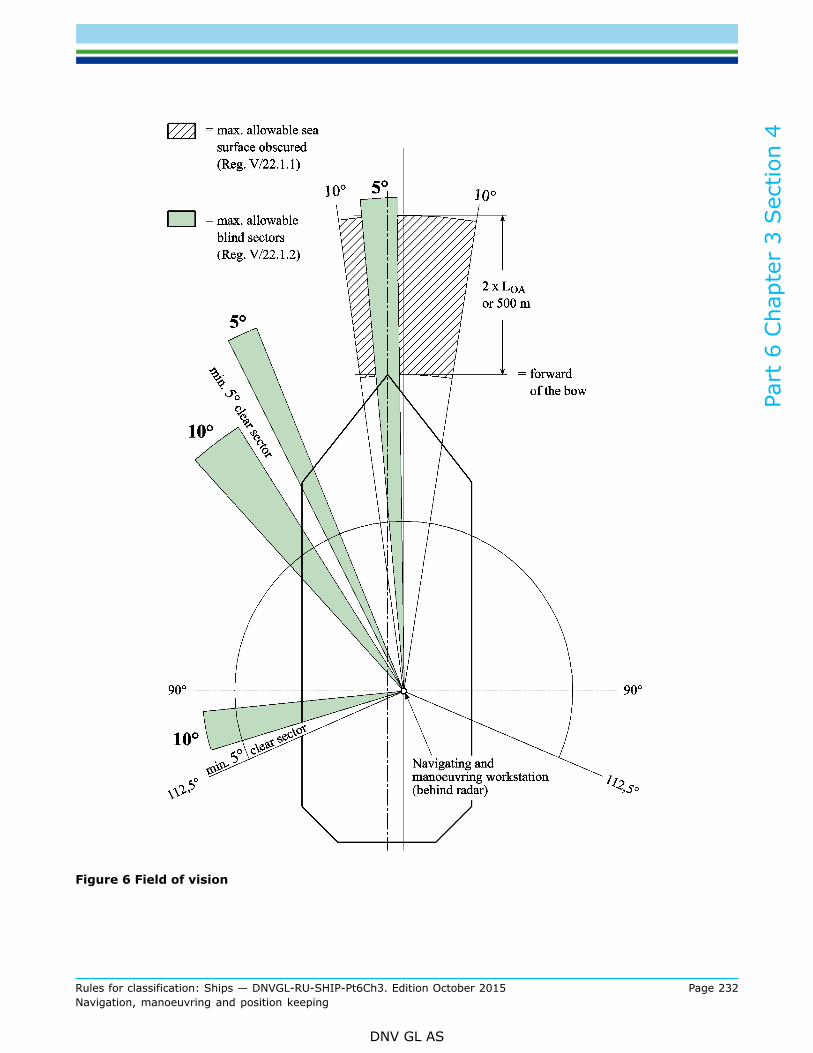
Part
6 C
hapt
er 3
Sec
tion
4
Rules for classification: Ships — DNVGL-RU-SHIP-Pt6Ch3. Edition October 2015 Page 232Navigation, manoeuvring and position keeping
DNV GL AS
Figure 6 Field of vision

Part
6 C
hapt
er 3
Sec
tion
4
Rules for classification: Ships — DNVGL-RU-SHIP-Pt6Ch3. Edition October 2015 Page 233Navigation, manoeuvring and position keeping
DNV GL AS
2.1.2.12 The view point to be used for calculation of the required view and field of vision (see Figure 2 andFigure 5) shall be the workstation navigating / manoeuvring which is 350 mm behind the radar screen andbased on an eye height of 1800 mm (see Figure 9).
Guidance note:The Panama Canal pilot conning positions No.1 – No.5, required by the Panama Canal Regulations may be at different locations andare not relevant for SOLAS or NAUT(NAV).
---e-n-d---of---g-u-i-d-a-n-c-e---n-o-t-e---
2.1.2.13 Visibility shall not be obstructed by regular container stowage above the line of visibility, forward ofthe bridge. Only blind sectors that cannot be avoided due to unusual structure and size of the cargo units ondeck and fixed structures necessary for cargo handling or the operation of the ship may be included in theblind sector limits allowed by SOLAS V/22 and [2.1.2.11] of this Section.
2.2 Structural arrangements2.2.1 Wheelhouse height
2.2.1.1 The clear height between the bridge deck surface covering and the underside of the deck head beamsshall be at least 2250 mm. The lower edge of deck head mounted equipment shall be at least 2100 mmabove the deck in open areas, passageways and at standing workstations.
2.2.2 Windows
2.2.2.1 The height of the lower edge of the front windows above the deck shall allow a forward view overthe bow in accordance with B.1. for a person in a sitting position at the workstation for navigating andmanoeuvring or monitoring and should not be more than 1000 mm.
2.2.2.2 The upper edge of the front windows shall allow a forward view of the horizon for a person in astanding position with an eye height of 1800 mm at the navigating and manoeuvring workstation and themonitoring workstation when the ship is pitching in heavy seas (see Figure 9). The minimum height of theupper edge of front windows above the deck surface shall be 2000 mm.
2.2.2.3 Framing between windows shall be kept to a minimum and not be installed immediately forward ofany workstation. If stiffeners between windows are to be covered, this shall not cause further obstructions ofthe field of vision from any position inside the wheelhouse.
2.2.2.4 Windows, especially those in front of the navigating and manoeuvring workstations and themonitoring workstations, shall be as wide as possible. The divisions (plate strip) between front windows shallnot exceed 150 mm, greater breadths up to 200 mm are acceptable if it is proved that this is necessary forreasons of strength or to avoid vibrations. If stiffeners are used, divisions shall not exceed 100 mm in widthand 120 mm in depth.
2.2.2.5 All bridge windows within the required field of vision (225°) from the navigating and manoeuvringworkstation and the monitoring workstation shall be inclined from the vertical plane to avoid reflections.Bridge front windows shall be inclined from the vertical plane top out, at an angle of not less than 15° andnot more than 25°. Bridge side windows shall be inclined from the vertical plane top out, at an angle of notless than 5°. Windows in the bridge wing doors may be arranged vertically. Windows outside the 225° field ofvision, and aft facing windows shall also be inclined not less than 4°~ 5°, if they may cause reflections.
2.2.2.6 The windows shall be of clear glass. The use of polarized or tinted glass or glass causingunreasonable refraction is not permitted.
2.2.2.7 All bridge front windows shall be provided with efficient cleaning, de-icing and de-misting devices. Incase of a totally enclosed bridge also the aft facing windows and the side windows (except sliding windows)

Part
6 C
hapt
er 3
Sec
tion
4
Rules for classification: Ships — DNVGL-RU-SHIP-Pt6Ch3. Edition October 2015 Page 234Navigation, manoeuvring and position keeping
DNV GL AS
at the docking stations shall be provided with such devices. The use of clear view screens (rotating windows)is not required. However, if fitted, they shall not be installed in windows in front of any workstation. Onwindows in the front bulkhead, which are in line with the view from the workstations, wipers may be omitted(Figure 8), unless required for the manual steering workstation and/or the pilot's conning position.
2.2.2.8 To ensure a clear view and to avoid reflections in bright sunshine, sun-screens with minimum colourdistortion should be provided at all bridge windows. Such screens should be readily removable and notpermanently installed.
2.2.2.9 It shall be possible to watch the area in front of the bridge superstructure from the wheelhouse.Therefore a close approach to at least one front window shall be possible.
2.2.3 Consoles
2.2.3.1 Consoles within the required field of vision of the workstation for navigating and manoeuvring andthe workstation for monitoring shall not obstruct the horizontal line of sight in seated position.
Guidance note:The upper edge of the consoles should not exceed 1200 mm (see Figure 9).
---e-n-d---of---g-u-i-d-a-n-c-e---n-o-t-e---
2.2.3.2 If there are any consoles or installations placed away from the bridge front bulkhead or if a console isseparated from other installations, the distance to the front bulkhead or any other console shall be sufficientfor two persons to pass each other. The distance of a passageway between the front bulkhead and anyconsoles should preferably be at least 1000 mm, but in no case less than 800 mm.
2.2.3.3 If access ways are provided between different workstation, these shall in general have a clear widthof not less than 700 mm. The workstation operating area shall be part of the workstation and not of theaccess way.
2.2.3.4 If chairs are provided for the navigating and manoeuvring workstation and the monitoringworkstation, they shall be capable of rotating with the foot rest being arrested and adjustable in height andbe capable of being arrested on the floor.
Guidance note:The chairs should also be capable of being moved clear of the operating areas.
---e-n-d---of---g-u-i-d-a-n-c-e---n-o-t-e---

Part
6 C
hapt
er 3
Sec
tion
4
Rules for classification: Ships — DNVGL-RU-SHIP-Pt6Ch3. Edition October 2015 Page 235Navigation, manoeuvring and position keeping
DNV GL AS
Figure 7 Minimum size of the bridge front window and visibility from the navigating andmanoeuvring workstation and monitoring workstation
Figure 8 Requirements for cleaning devices (windows wipers)

Part
6 C
hapt
er 3
Sec
tion
4
Rules for classification: Ships — DNVGL-RU-SHIP-Pt6Ch3. Edition October 2015 Page 236Navigation, manoeuvring and position keeping
DNV GL AS
2.3 Working environment2.3.1 Working environment
2.3.1.1 Toilet facilities shall be provided on the bridge or within easy access of the navigation bridge deck,primarily for those on duty.
2.3.1.2 Wheelhouse and bridge wing floors shall be on one level, without steps and should have a non-slipsurface.
2.3.1.3 There shall be no sharp edges, protuberances, pillars, tripping hazards or other obstacles, whichcould cause injury to personnel.
2.3.1.4 Sufficient hand or grab rails shall be fitted to enable personnel to move or stand safely in badweather. Means for securing of stairway openings shall be given special consideration.
2.3.1.5 Red light shall be used to maintain dark adaption whenever possible in areas or on items ofequipment, other than the chart table, requiring illumination in the operational mode. This light should bevariable from 0 to 20 lux and be provided at all workplaces.
Guidance note:The requirements and guidelines of MSC/Circ.982 for work environment are recommended.
---e-n-d---of---g-u-i-d-a-n-c-e---n-o-t-e---
3 Bridge equipment
3.1 General3.1.1 GeneralShips shall be equipped in accordance with SOLAS 1974, as amended, Chapter V, as applicable.
3.1.2 Additional equipment
3.1.2.1 In addition to SOLAS carriage requirements, the ship shall be fitted with:
— Second Electronic Position Fixing System (EPFS – e.g. GPS, GLONASS, GALILEO, etc.)— Central alert management system including alarm transfer system— Electronic Chart Display and Information System - ECDIS and backup ECDIS— Second gyro compass, ships of 10.000 GT and upwards— Heading control system (HCS)— Weather information system— Wind speed and direction indicator
3.1.3 Additional sensor requirements
3.1.3.1 The following sensors and functions shall be provided independent of SOLAS carriage requirements:
— ARPA functionality shall be provided for all installed radars on the bridge.— At least one of the radars shall be capable of displaying parts of Electronic Navigation Charts (ENC) and
other vector chart information to aid safety of navigation and position monitoring. Alternatively at leastone ECDIS shall be capable of displaying radar overlay.
— At least one of the EPFS shall be a DGPS or other GNSS receiver with the same or better accuracy andavailability.
— Anemometer to indicate the relative and true wind speed and direction information.

Part
6 C
hapt
er 3
Sec
tion
4
Rules for classification: Ships — DNVGL-RU-SHIP-Pt6Ch3. Edition October 2015 Page 237Navigation, manoeuvring and position keeping
DNV GL AS
3.1.3.2 A loss or a failure of one sensor shall not result in a loss of the redundant sensor or fall-backarrangement.
3.1.3.3 A bidirectional alert interface shall be provided by each required sensor to indicate any requiredalert on an external central alert management system. Each sensor shall have the capability for animmediate remote acknowledgement, except category A alerts, and temporarily silence from an externalalert management system.

Part
6 C
hapt
er 3
Sec
tion
4
Rules for classification: Ships — DNVGL-RU-SHIP-Pt6Ch3. Edition October 2015 Page 238Navigation, manoeuvring and position keeping
DNV GL AS
3.1.3.4 The following back-up and fall-back arrangements of Table 3 shall be observed.
Table 3 Back-up and fall-back arrangements
Sensor Data Back-upFall-back (equipment whichmay be available in case of acomplete sensor loss)
Gyro Heading Gyro 2 Magnetic compass*
EPFSPositionTime, Date
EPFS 2 Dead reckoning and radarbearing
SDME (WT) Speed SDME (BT) if provided EPFS
Echo sounder Depth ECDIS and/or Paper Chart
RADAR RADAR2 AIS
Data interface (if provided) Data interface (if provided)
*not to be used for radar and track control
Guidance note:
Figure 9 Example for a sensor configuration
---e-n-d---of---g-u-i-d-a-n-c-e---n-o-t-e---

Part
6 C
hapt
er 3
Sec
tion
4
Rules for classification: Ships — DNVGL-RU-SHIP-Pt6Ch3. Edition October 2015 Page 239Navigation, manoeuvring and position keeping
DNV GL AS
3.2 Arrangement of equipment3.2.1 Navigating and manoeuvring workstation
3.2.1.1 The following tasks and control functions shall be accessible and within the reach of the officer of thewatch from his bridge chair (see Figure 1):
— 9 GHz ARPA radar with operation controls The 9 GHz radar shall be inter switchable with the 3 GHz radarat the monitoring workstation and shall be supported by an UPS.
— ECDIS with operation controls and radar overlay— HCS with manual override— Control of main engine(s), incl. emergency manoeuvre and emergency stop— Control of thruster(s)— Steering mode selector switch for steering gear— Rudder pump selector switch for steering gear— Intercom to docking workstations (if distance > 10 m)— Call system for master and navigation officers (telephone / internal communication system)— VHF equipment including GMDSS distress alarm management (external communication)— Automatic Identification System (AIS) terminal, if it’s a stand-alone system. If the AIS information is
shown in the radar or ECDIS it may be positioned within the perception area of the officer of the watch.— Control of whistle and manoeuvring light— Acknowledge push button for BNWAS— Control of centralized alert management system— Control of general alarm— Control of wipers for windows in front of workstation— Control of console lighting.
3.2.1.2 The following information shall be easily readable from the navigating and manoeuvring workstationfor the officer of the watch. This can be achieved by stand-alone instruments in the bridge console or by acentralized multifunctional conning display, which is recommended:
— Gyro compass heading— Rate-of-turn, if available— Rudder angle— Propeller revolutions— Pitch, if a pitch propeller if fitted— Thrust: force and direction— Speed (longitudinal and lateral if provided)— Water depth— Position— Time— Wind: direction and speed— Sound reception device, if totally enclosed bridge— NAVTEX, if provided without printer.
3.2.1.3 The following instruments, indicators and displays providing information shall be easily readable forthe officer of the watch sitting or standing at the navigating and manoeuvring workstation:
— Whistle automatic control system— Navigation- and signal light controller— Emergency stop of installations to be stopped in case of fire (air condition, ventilation and refrigerating
installation)
Part
6 C
hapt
er 3
Sec
tion
4
Rules for classification: Ships — DNVGL-RU-SHIP-Pt6Ch3. Edition October 2015 Page 240Navigation, manoeuvring and position keeping
DNV GL AS
— Remote control and monitoring of watertight doors, external openings and fire doors (open/closed), ifavailable
— Remote control of emergency fire pump— Anti-rolling device, if available.
3.2.2 Monitoring workstation
3.2.2.1 The following tasks and control functions shall be provided within the reach of the officer from hisbridge chair (see Figure 1):
— GHz ARPA radar with operation controls. This radar shall be inter-switchable with the 9 GHz radar at thenavigating and manoeuvring workstation.
— Control of whistle and manoeuvring light— Acknowledge push button for watch alarm system (BNWAS)— Control of window wipers in front of workstation— Intercom to docking workstations, (if distance > 10 m)— Call system for master and navigation officers (telephone / internal communication system)— VHF equipment (external communication)
3.2.2.2 The following information shall be easily readable from the monitoring workstation:
— Gyro compass heading— Rate-of-turn, if available— Rudder angle— Propeller revolutions— Pitch if a pitch propeller is fitted— Thrust force and direction— Speed (longitudinal and lateral if provided)— Water depth— Time— Wind direction and speed— Sound reception device, if totally enclosed bridge— Central alert management system.
3.2.2.3 Instruments, indicators or displays mentioned under paragraphs [3.2.1.1] to [3.2.2.2] and which arerequired at more than one workstation, shall be arranged so that they can be easily reached, respectivelyeasily readable from all relevant workstations. If this is not achievable such equipment shall be duplicated.
3.2.3 Manual steering workstation
3.2.3.1 The following equipment shall at least be provided within the reach of the helmsman:
— Steering wheel or other means of controlling the heading of the ship manually— Control of window wiper in front of workstation— Intercom to docking workstations (if distance >10 m), suitable for hands-free operation.
Guidance note:The communication equipment may be a suitable wireless system (e.g. UHF) or a PA talk-back system or similar fixed installation.
— Dimmer for indicators listed in [3.2.3.2].
---e-n-d---of---g-u-i-d-a-n-c-e---n-o-t-e---
3.2.3.2 The following indicators shall at least be easily readable for the helmsman, when manually steeringthe vessel:
— Rudder angle

Part
6 C
hapt
er 3
Sec
tion
4
Rules for classification: Ships — DNVGL-RU-SHIP-Pt6Ch3. Edition October 2015 Page 241Navigation, manoeuvring and position keeping
DNV GL AS
— Gyro compass heading— Magnetic compass heading— Rate-of-turn, if available.
3.2.4 Docking workstation
3.2.4.1 The following equipment shall at least be provided within the reach of the operating officer:
— Control of main engine(s)— Control of thruster(s)— Control of rudder(s)— Control of whistle and manoeuvring light— Intercom to enable two-way communication with wheelhouse workstations for manual steering, navigating
and manoeuvring, monitoring and to manoeuvring stations. The intercom shall be capable of hands-freeoperation.
— Acknowledge push button for BNWAS— Control of wipers for front and rear windows of workstation (if the ship has a totally enclosed bridge).
3.2.4.2 The following information shall be easily readable from the docking workstation:
— rudder angle— propeller revolutions— pitch, if a pitch propeller is fitted— thruster speed and direction— gyro compass heading— rate-of-turn, if available— speed (longitudinal and lateral if provided)— wind direction and speed, if totally enclosed bridge.
Guidance note:A conning display or multi-function display may be used and is recommended.
---e-n-d---of---g-u-i-d-a-n-c-e---n-o-t-e---
3.2.5 General bridge equipment within wheelhouse
3.2.5.1 Following general equipment shall be provided within the wheelhouse:
1) BNWAS main control unit2) Control of window washing and heating system3) Control of wheelhouse heating and cooling4) Main control unit of whistle5) Weather information system
Guidance note:A weather fax or a marine computer including a software application for receipt and displaying of regular weather forecasts maybe acceptable.
---e-n-d---of---g-u-i-d-a-n-c-e---n-o-t-e---
3.3 Requirement for instruments and equipment3.3.1 General
3.3.1.1 With reference to SOLAS V 18.1, all required navigational systems and equipment shall be of anapproved type.

Part
6 C
hapt
er 3
Sec
tion
4
Rules for classification: Ships — DNVGL-RU-SHIP-Pt6Ch3. Edition October 2015 Page 242Navigation, manoeuvring and position keeping
DNV GL AS
3.3.1.2 All electrical and electronic equipment on the bridge or in the vicinity of the bridge, where a typeapproval is not required, shall be tested for electromagnetic compatibility.
3.3.1.3 Switches, keys and other operating elements shall be designed and fitted so as to ensure their safeand easy operation and to preclude confusion. The direction of motion of operating elements for manoeuvringequipment shall correspond to the direction of the effect on the ship caused by the installations controlled.
3.3.2 Radar installations
3.3.2.1 For the ship borne radar equipment the requirements of the “Guidelines for the Installation of ShipBorne Radar Equipment” (SN1/Circ.271) shall apply. Special attention shall be paid on the radar visibility andthe reduced blind sectors.
3.3.3 Central alert management system
3.3.3.1 The centralized alert management system shall comply with module C of MSC.252(83) (PerformanceStandards for Integrated Navigation Systems) or MSC.302(87) (Performance Standard for Bridge AlertManagement).
3.3.3.2 The general requirements from the IMO Resolution MSC.1021(26) (Code on Alerts and Indicators)shall be observed.
3.3.3.3 The classification of alerts shall be in compliance with MSC.252(83) Table 2. It shall be possible toacknowledge all alarms and warnings by a single operator action, except for category A (danger of collision ordanger of grounding). A temporarily silence of an audible alert should be possible for all alerts.
3.3.4 Master and navigation officers’ call-system
3.3.4.1 A call-system shall be fitted by which master and navigation officers can be summoned in theiraccommodation and public rooms from the navigating and manoeuvring workstation. This call-system maybe the general telephone, the internal communication system and or the public address system. The call-system shall be provided with priority control on the bridge.
3.3.5 Bridge navigational watch alarm system
3.3.5.1 A Bridge Navigational Watch Alarm System (BNWAS) complying with MSC.128(75) PerformanceStandards for Bridge Navigational Watch Alarm systems (BNWAS) and IEC Test Standards, IEC 60945,61924, 62288 and 61162 as amended, including alarm transfer system shall be provided for the followingunacknowledged alerts:
— Failure HCS— System failure gyro compass— Loss of position EPFS— System failure SDME— Depth alarm from echo sounder— Aggregated steering gear alarm— Imminent slow-down or shut-down of propulsion system— Failure / loss of navigation lights
3.3.6 Power supply
3.3.6.1 The radio and navigational equipment and systems shall be directly supplied from both the mainsource of electrical power and the emergency source of electrical power with automated changeover byseparate power supply circuits with provision to preclude inadvertent shut-down.

Part
6 C
hapt
er 3
Sec
tion
4
Rules for classification: Ships — DNVGL-RU-SHIP-Pt6Ch3. Edition October 2015 Page 243Navigation, manoeuvring and position keeping
DNV GL AS
3.3.6.2 In addition the following equipment / systems should be supplied from a transitional source ofelectrical power for a duration of not less than 45 s:
— one 9 GHz (X-Band) radar including transceiver and antenna— Gyro compass systems— EPFSs— ECDIS— SDME

Part
6 C
hapt
er 3
Sec
tion
5
Rules for classification: Ships — DNVGL-RU-SHIP-Pt6Ch3. Edition October 2015 Page 244Navigation, manoeuvring and position keeping
DNV GL AS
SECTION 5 NAUTICAL SAFETY – NAUT(OSV)
1 General
1.1 IntroductionThe additional class notation NAUT(OSV) aims to reduce the risk of collision, contact, grounding, anddamage during heavy weather, by regulating the various elements that make up the total bridge system,related to the variety of missions Offshore Service Vessels (OSV) carry out. Certain operations will beperformed from both the navigational and the operational bridge, while other operations may be performedfrom only one of these positions. In order to achieve optimum safety and efficiency in bridge operations,the philosophy addressed in this section includes the technical, human operator, man machine interface andprocedural aspects.
1.2 ScopeThe scope for additional class notation NAUT(OSV) adds an increased level of safety concerning bridgeoperations and safety of navigation related to: design of the bridge and the working environment, equipmentperformance and reliability, ergonomic principles and tests and trials. The rules in this section address theelements of the bridge system affecting the safety of navigation, both for the total bridge system, see Figure1, and for those elements related to bridge system failure, see Figure 2 - Overview of bridge system areasaffecting safe and efficient operations.
Figure 1 Overview of bridge system areas affecting safe and efficient operations

Part
6 C
hapt
er 3
Sec
tion
5
Rules for classification: Ships — DNVGL-RU-SHIP-Pt6Ch3. Edition October 2015 Page 245Navigation, manoeuvring and position keeping
DNV GL AS
1.3 ApplicationThe additional class notation NAUT(OSV) extends the basic requirements for bridge design andinstrumentation, and, in addition, requires further means for safe operation in all waters including areas withharsh operational and environmental conditions, such as the North Sea. In order to offer classification thatmeets the individual needs of ship owners, related to different types and trades of ships, the notation hastwo qualifiers: OSV and ICS. Ships built and equipped in compliance with this section may be assigned theadditional class notation NAUT(OSV).
1.4 Objectives and safety philosophy1.4.1 Objectives of rules
1.4.1.1 The objective of the rules for nautical safety is to reduce the risk of failure in bridge operation causingcollision, contact and grounding, and heavy weather damage and in this context, include:
— requirements to specified bridge system elements— relevant requirements and recommendations adopted by the International Maritime Organization (IMO)— relevant international standards within the subjects of the rules or indicating the points in which they
differ.
1.4.2 Safety philosophy
1.4.2.1 In order to achieve optimum safety and efficiency in bridge operation, the philosophy applied addressthe total bridge system. The total bridge system is considered to comprise four essential parts, see Figure 2:
— the technical system, which shall deduce and present information as well as enable the proper handling ofthe ship, including setting of course and speed
— the human operator, who shall evaluate available information, decide on the actions to be taken andexecute the decisions
— the man and machine interface, which shall safeguard that the technical system is designed with dueregard to human abilities
— the procedures, which shall ensure that the total bridge system performs satisfactorily under differentoperating conditions.

Part
6 C
hapt
er 3
Sec
tion
5
Rules for classification: Ships — DNVGL-RU-SHIP-Pt6Ch3. Edition October 2015 Page 246Navigation, manoeuvring and position keeping
DNV GL AS
Figure 2 The total bridge system
1.4.2.2 The various elements considered making up the main parts (see Figure 2) of the bridge system are:
— qualifications, capacity and quality of the human operator in relation to the functions to be carried out— specification, automation level and condition of the technical system in relation to information needs,
workloads and reliability— physical abilities and information processing capacity of the human operator in relation to working
conditions and the technical systems he shall operate— tasks to be performed and technical aids available under various operating conditions as basis for
establishing working routines and operating procedures.

Part
6 C
hapt
er 3
Sec
tion
5
Rules for classification: Ships — DNVGL-RU-SHIP-Pt6Ch3. Edition October 2015 Page 247Navigation, manoeuvring and position keeping
DNV GL AS
With the exception of operator quality, the elements mentioned form the basis for the rules given.
1.4.2.3 The rules take into consideration that the modes of operation and the manning of the bridge willvary in accordance with the condition of internal technical systems and the availability of relevant externalsystems, and that operating conditions can be influenced by the waters to be navigated, traffic and weatherconditions.
1.4.2.4 The rules aim at safeguarding that the officer of the watch, at his workstation, has full control of allthe functions he is responsible for. Furthermore, that the bridge enables safe and efficient co-operation bytwo navigators when required.
Guidance note:It should be noted that the manning of the navigational watch at all times should be in accordance with the national regulations ofthe flag state and for the waters in which the ship is operating.
---e-n-d---of---g-u-i-d-a-n-c-e---n-o-t-e---
1.5 Structure of the rules
1.5.1 The rules are structured to:
— establish functional requirements to the greatest possible extent— give guidance as to how functional requirements can be met by technical solutions or other remedies that
safeguard the performance of the function.
1.5.2 A Guidance note gives solutions that can be approved, but does not exclude the application ofalternative solutions provided the functional requirements are met.
1.5.3 Where rule requirement apply to vessels intended for specified operations such as anchor handling,towing operations, supply operations, oil recovery and fire fighting, the Society will base the approval onthe information given in the class request. For vessels designed and prepared for operations that are notvisible from class request, such as Rescue, relevant rules for such operations will be applied unless writtenconfirmation received from yard and owner.
1.6 Definitions1.6.1 Terms and abbreviations
Table 1 Terms and abbreviations
Term Definition
Abnormal operatingconditions:
When internal technical system failures require operation of back-up systems on the bridgeor when they occur during an irregular operating condition, or when the officer of the watchbecomes unfit to perform his duties and has not yet been replaced by another qualified officer.
Additional functions Additional functions requiring work tasks not directly related to primary bridge functions oroffshore operations.
AH Anchor handling.
AHTS Anchor Handling, Tug Supply.
Back-up navigator A navigational officer who has been designated by the ship’s master to be on call to assist orreplace the officer of the watch when required.

Part
6 C
hapt
er 3
Sec
tion
5
Rules for classification: Ships — DNVGL-RU-SHIP-Pt6Ch3. Edition October 2015 Page 248Navigation, manoeuvring and position keeping
DNV GL AS
Term Definition
BAMS
Bridge Alert Management System. A system that harmonizes the priority, classification,handling, distribution and presentation of alerts, to enable the bridge team to devote fullattention to the safe operation of the ship and to immediately identify any alert situationrequiring action to maintain the safe operation of the ship
Blind sector An obstruction in a field of vision caused by window divisions, bridge structure or outsideconstruction with a clear sector on both sides.
BNWAS Bridge Navigational Watch Alarm System
Bridge system The total system for the performance of bridge functions, comprising bridge personnel,technical systems, human and machine interface and procedures.
Bridge wing The part of the bridge on each side of the wheelhouse, which extends to the ship’s side.
Bridge The area from which the navigation and/or control of the ship are exercised, comprising thewheelhouse and the bridge wings.
CAM-HMI Central Alert Management - Human machine interface for presentation and handling of BAMSalerts on the bridge.
Category A alertAlert for which graphical information at the task station directly assigned to the functiongenerating the alert is necessary, as decision support for the evaluation of the alert-relatedcondition.
Category B alert Alert where no additional information for decision support is necessary besides the informationwhich can be presented at the CAM-HMI.
Category C alert Alert that cannot be acknowledged on the bridge but for which information is required aboutthe status and treatment of the alert.
Cargo OperationsOperations related to transferring or receiving general mixed cargo or liquid cargo between shipand offshore installation, included control and monitoring of own ship and cargo gear. Shipsonly designed for cargo operation is named Platform Supply Vessel (see PSV).
Catwalk Arrangement outside the wheelhouse allowing a person safe access to windows along thebulkhead(s).
CCTV Closed Circuit Television
Coastal waters
Waters that encompass navigation along a coast at a distance less than the equivalence of30 minutes of sailing with the relevant ship speed. The other side of the course line allowsfreedom of course setting in any direction for a distance equivalent to at least 30 minutes ofsailing with the relevant speed.
Collision avoidancefunctions
Detection and plotting of other ships and moving objects; determination and execution ofcourse and speed deviations to avoid collision.
Commanding viewView without obstructions, which could interfere with the navigator’s ability to perform his maintasks, at least covering the field of vision required for safe performance of collision avoidancefunctions.
Conning informationdisplay
A screen-based information system that clearly presents information from sensor inputsrelevant to navigation and manoeuvring, as well as all corresponding and upcoming ordersgiven by an automatic navigation system to steering and propulsion systems if connected.
Conning station orposition
Place in the wheelhouse with a commanding view providing the necessary information forconning, and which is used by navigators when monitoring and directing the ship’s movements.
Control Either effectuate actions or have orders effectuated.

Part
6 C
hapt
er 3
Sec
tion
5
Rules for classification: Ships — DNVGL-RU-SHIP-Pt6Ch3. Edition October 2015 Page 249Navigation, manoeuvring and position keeping
DNV GL AS
Term Definition
Display An observable illustration of an image, scene or data on a screen.
Distress situations Loss of propulsion and/or steering, or when the ship is not seaworthy due to other reasons(situation prior to abandon ship situation).
Docking Manoeuvring the ship alongside a berth and controlling the mooring operations.
DP Dynamic Positioning.
DPO Dynamic Positioning system Operator.
Easily accessible Within 5 m distance from working position.
Easily readable Within the horizontal angle of 90 degrees to each side and vertical angle of 90 degrees below –to 60 degrees above the horizon from the normal line of sight for the operator.
ECDIS
Electronic chart display and information system. A navigation information system, which withadequate back-up arrangements can be accepted as complying with the up-to-date chartrequired by regulation 19 of SOLAS Chapter V, and be accepted as meeting the chart carriagerequirements of SOLAS Chapter V, as amended by Res. MSC.99(73), by displaying selectedinformation from a system electronic nautical chart (SENC).
ENC Electronic nautical chart. The database, standardised as to content, structure and format,issued for use with ECDIS on the authority of government authorised hydro graphic offices.
Emergency situations When incidents seriously affect internal operating conditions of the ship and the ability tomaintain safe course and speed (fire, technical failure, structural damage).
Ergonomics Application of the human factors implication in the analysis and design of the workplace andequipment.
External safetyoperations Assisting other in emergency situations
FOV Field of vision. Angular size of a scene that can be observed from a position on the ship’sbridge.
FiFi Fire Fighting
Hand-grasp area For equipment/ control units continuous used. See [3.5.5] for guidance of area.
Helmsman Person who steers the ship under way.
Irregular operatingconditions When external conditions cause excessive operator workloads.
Manoeuvring Operation of thrusters, steering systems and propulsion machinery as required to move theship into predetermined directions, positions or tracks.
Monitoring Act of constantly checking information from instrument displays and environment in order todetect any irregularities.
Narrow waters Waters that do not allow the freedom of course setting to any side of the course line for adistance equivalent to 30 minutes of sailing with the relevant ship speed.
Navigation Planning of the ship’s route and determination of position and course of the ship, execution ofcourse alterations and speed changes.
Navigational bridge The area of the bridge where transit operation is performed.
Normal operatingconditions
When all shipboard systems and equipment related to primary bridge functions operate withindesign limits, and weather conditions or traffic, do not cause excessive operator workloads.

Part
6 C
hapt
er 3
Sec
tion
5
Rules for classification: Ships — DNVGL-RU-SHIP-Pt6Ch3. Edition October 2015 Page 250Navigation, manoeuvring and position keeping
DNV GL AS
Term Definition
Ocean areasWaters that encompass navigation beyond the outer limits of coastal waters. Ocean areasdo not restrict the freedom of course setting in any direction for a distance equivalent to 30minutes of sailing with the relevant ship speed.
OOW Officer of the navigational watch. Person responsible for the safety of navigation and bridgeoperations until relieved by another qualified officer.
Oilrec Oil recovery.
On Hand For equipment/ control units used frequently or special important. See [3.5.5] for specificationof area.
Operational bridge The area of the bridge where workstations for offshore operations are located.
Operational bridgefunctions
Functions related to ship handling in relation to the operation the vessel is engaged in. Suchfunctions are:
— manoeuvring functions— deck equipment operation (for anchor handling, oil recovery and cargo transfer operations)— rescue operation— monitoring of internal safety systems— external and internal communication related to safety in bridge operation and distress
situations— docking functions.
Popliteal height The vertical distance from the footrest to the underside of the thigh.
Primary bridgefunctions
Functions related to determination, execution and maintenance of safe course, speed andposition of the ship in relation to the waters, traffic and weather conditions. Such functions are:
— route planning functions— navigation functions— collision avoidance functions— manoeuvring functions— docking functions— monitoring of internal safety systems— external and internal communication related to safety in bridge operation and distress
situations.
PSV Platform Supply Vessel. A PSV is a vessel carrying out cargo operations.
Readable Within a horizontal sector of 225° and vertical sector from 90° below to 60° above the horizonfrom the operators normal eye position.
RescueAn operation where a defined vessel is, either bringing own personnel being in distress inthe water to safety, or is assisting an offshore platform, barge, production module/vessel oranother ship in bringing their personnel being in distress in the water to safety.
Route monitoring Continuous surveillance of the ship’s sailing (position and course) in relation to a pre-plannedroute and the waters.
Rudder angle Rudder angle mean thruster angle when main propulsion is azimuth thrusters.
Route planning Pre-determination of course lines, radius turns and speeds in relation to the waters to benavigated.
Safety operation Handling of emergency and distress situations on board own ship or assisting other vessels andoffshore installations in such situations.

Part
6 C
hapt
er 3
Sec
tion
5
Rules for classification: Ships — DNVGL-RU-SHIP-Pt6Ch3. Edition October 2015 Page 251Navigation, manoeuvring and position keeping
DNV GL AS
Term Definition
SAR Search And Rescue.
Screen A device used for presenting visual information based on one or several displays.
SOLAS The International Convention for the Safety of Life at Sea, 1974.
Superstructure Decked structure, not including funnels, which is on or above the freeboard deck
SENCSystem electronic navigational chart. A database resulting from the transformation of the ENCby ECDIS for appropriate use, updates to the ENC by appropriate means and other data addedby the mariner.
Towing operationsAn operation including one or more offshore service vessels capable to assist offshoreplatforms, barges and production modules/vessels in moving from one position to another, or inkeeping their defined position.
Wheelhouse Enclosed area of the bridge.
Wheel-over-lineThe line parallel to the new course line where the ship has to initiate a curved track to eliminatethe effect of any offset with respect to the new course, taking into consideration the distancerequired for the ship to build up the necessary turn rate.
Wheel-over-point The point where the ship has to initiate a curved track, taking into consideration the distancerequired for the ship to build up the necessary turn rate.
Within easy reach For equipment/ control units used at the workstation. See [3.5.5] for specification of area.
Within reach
The distance the operator can reach and use a control unit. See [3.5.5] for specification ofareas. For other workstations than workstations for offshore operations the area may beincreased to:
— From a standing position this distance is regarded to be maximum 800 mm in forwarddirection and 1400 mm sideways.
— From a seated position, at a distance of 350 mm from a console, this distance is regardedto be maximum 1000 mm, and maximum 800 mm for frequently used equipment, whichshall be within easy reach.
Workstation (WS) A work place at which one or several tasks constituting a particular activity are carried out andwhich provides the information and equipment required for safe performance of the tasks.
Workstation forcommunication
A work place for operation and control of equipment for distress and safety communication(GMDSS), and shipboard communication for ship operations.
Workstation for primarybridge functions
A workplace with commanding view used by navigators when carrying out navigation, routemonitoring, traffic surveillance and manoeuvring functions, and which enables monitoring ofthe safety state of the ship.
Workstation for safetyoperations
A workplace dedicated organisation and control of internal emergency and distress operations,and which provides easy access to information related to the safety state of the ship.

Part
6 C
hapt
er 3
Sec
tion
5
Rules for classification: Ships — DNVGL-RU-SHIP-Pt6Ch3. Edition October 2015 Page 252Navigation, manoeuvring and position keeping
DNV GL AS
1.7 Class notations1.7.1 General
1.7.1.1 The rules for nautical safety offshore service vessels have the two qualifiers , OSV and ICS in orderto offer classification that meets the individual needs of ship owners, related to different types and trades ofships.
1.7.1.2 The class notation NAUT(OSV) extends the basic requirements for bridge design andinstrumentation, and, in addition, requires further means for safe operation in all waters including areas withharsh operational and environmental conditions such as the North Sea.
Table 2 Class notations and qualifiers
Class notation Description Qualifier DescriptionDesign
requirements,rule reference
Survey requirements,rule reference
OSV
Fundamentalrequirements targetingships operating asservice vessels foroffshore industry.
NAUT
Requirements withinbridge design, bridgeinstrumentation,and workstationarrangement. Vesselswith NAUT-notationwill comply with theprinciples and aims ofSOLAS V/15 and IMOMSC/Circ.982.
ICS
A multifunctionworkstationarrangementsupporting thenavigational functionsof other NAUTqualifier by means ofnetwork technology
Sec.3 [7]
Pt.7 Ch.1 Sec.6
1.7.2 Contents of class notations and extensions
1.7.2.1 The class notations NAUT(OSV) cover the following main areas:
— mandatory and additional workstations— field of vision from workstations— location of instruments and equipment— ergonomics and human machine interface— range of instrumentation— alarm management, including watch monitoring and alarm transfer system.— instrument and system tests.
1.7.2.2 The class notation may upon request be extended with a qualifier ICS when the requirements inSec.3 [7] are complied with.
1.7.3 Documentation of compliance
1.7.3.1 The class notations NAUT(OSV) imply that the ship is built and equipped in compliance with therelevant sections of this section.

Part
6 C
hapt
er 3
Sec
tion
5
Rules for classification: Ships — DNVGL-RU-SHIP-Pt6Ch3. Edition October 2015 Page 253Navigation, manoeuvring and position keeping
DNV GL AS
1.7.4 Class assignment
1.7.4.1 The ship will be assigned class notation NAUT(OSV) when the relevant requirements given in thissection are complied with.
1.8 Documentation for approval1.8.1 General
1.8.1.1 The configuration and arrangement drawings submitted for approval shall be shown to scale. Allsymbols and abbreviations used shall come with a clarification.Documentation shall be submitted as required by Table 3.
Table 3 Documentation requirements
Object Documentation type Additional description Information
Vesselarrangement
Z010 – General arrangementplan
including description of the vessel, propulsionand thrusters configuration, all requested classnotations and a list of the operations the vesselis intended for (towing operations, search andrescue, fire fighting, cargo operations, anchorhandling, safety operations, rescue, oil recovery)
FI, ACO
N011 – Bridge designdrawing, extended AP
N021 – Vertical field of visiondrawing, extended AP
N031 – Horizontal field ofvision drawing, extended AP
N040 – Nautical workstationarrangement plan AP
N050 – Navigationbridge windows framingarrangement plan
AP
Z030 – Arrangement planWindow wipers, fresh water wash, sunscreensand de-misting system (heating) on the bridgewindows.
AP
Navigation bridge
M040– Coating specification
Interior colours for bulkheads, deckheads,framing of windows and consoles indicatedby using international standards for colourreference.
AP
Z090 – Equipment list AP
Navigation systems E230 – Power supplyarrangement Including wheelhouse distribution board AP

Part
6 C
hapt
er 3
Sec
tion
5
Rules for classification: Ships — DNVGL-RU-SHIP-Pt6Ch3. Edition October 2015 Page 254Navigation, manoeuvring and position keeping
DNV GL AS
Object Documentation type Additional description Information
Z030 System arrangementplan
A document describing how the navigationsystems are connected including data interfacesetc. for the equipment as follows:
— Heading measuring systems— Steering control system and propulsion
control.— Steering mode selection system— Heading control system (Autopilot)/ Track
control system— Radar system— ECDIS and ECDIS back-up:— Conning Display system— CCTV system:— GNSS— BNWAS/AMS
AP
Z253 - Test procedure forquay and sea trial AP
Bridge alertmanagement andnavigational watchalarm systems
I020 – Control systemfunctional description
Including a flow diagram for the total systemconfiguration, BAMS alert list, connectedequipment, data interfaces and descriptions ofthe watch monitoring and alarm managementsystem.
AP
Steeringcontrol andmonitoringSteering
Z060 – Functionaldescription Steering mode selection. AP
Navigation bridgelight Z030 Arrangement plan Red and white lighting in wheelhouse and all
adjacent corridors, stairways and rooms. AP
Ventilation systems Z030 Arrangement plan For wheelhouse, including capacity specification. AP
Externalcommunicationsystems
T030 – Antennaearrangement plan
For satellite communication systems,radars,VHFs, AIS, GPS, TV etc. AP
E170 – Electrical schematicDrawing APAutomatic
telephone systemZ030 – Arrangement plan Location of centrals and all subunits. AP
Ultra highfrequency (UHF)telephone system
Z090 – Equipment list AP
For additional qualifier ICS documentation requirements are listed in Sec.3 [1.6]
Info: AP: For approval, FI: For information, L: Local handling, R: On request., ACO: As carried out
1.8.1.2 For general requirements to documentation, see Pt.1 Ch.3 Sec.2.
1.8.1.3 For a full definition of the documentation types, see Pt.1 Ch.3 Sec.3.

Part
6 C
hapt
er 3
Sec
tion
5
Rules for classification: Ships — DNVGL-RU-SHIP-Pt6Ch3. Edition October 2015 Page 255Navigation, manoeuvring and position keeping
DNV GL AS
1.8.1.4 For navigation equipment and other equipment installed in the wheelhouse, and in the vicinity of thewheelhouse, certification is required. See [4.1].Certification documentation shall be submitted as required by Table 4.
Table 4 Certification required
Object Certificate type Issued by* Certification standard** Additional description
Radar equipment Type Approvalcertificate (TA) Society
ECDIS equipment Type Approvalcertificate (TA) Society
Position system Type Approvalcertificate (TA) Society
Gyro/heading system Type Approvalcertificate (TA) Society
Speed measuringsystem
Type Approvalcertificate (TA) Society
Depth measuringsystem
Type Approvalcertificate (TA) Society
Bridge NavigationWatch Alarm System(BNWAS)
Type Approvalcertificate (TA) Society
Bridge AlertManagement System(BAMS)
Type Approvalcertificate (TA) Society
AutomaticIdentification System(AIS)
Type Approvalcertificate (TA) Society
Wiper system Type Approvalcertificate (TA) Society
Conning displaysystem
Type Approvalcertificate (TA) Society
Heading controlSystem (autopilot)
Type Approvalcertificate (TA) Society
Track Control system(TCS) (if provided)
Type Approvalcertificate (TA) Society
Sound receptionsystem
Type Approvalcertificate (TA) Society
Internalcommunication
Type Approvalcertificate (TA) Society
Externalcommunication(including GMDSS)
Type Approvalcertificate (TA) Society

Part
6 C
hapt
er 3
Sec
tion
5
Rules for classification: Ships — DNVGL-RU-SHIP-Pt6Ch3. Edition October 2015 Page 256Navigation, manoeuvring and position keeping
DNV GL AS
Object Certificate type Issued by* Certification standard** Additional description
*Type approval or MED certificates issued by others showing that the equipment complies with the Society's rulerequirements may be accepted after a case-by-case evaluation** Unless otherwise specified the certification standard is the rules
1.9 Functional tests1.9.1 The following tests shall be carried out
1.9.1.1 Tests, which give evidence of the satisfactory operation of instruments and integrated navigationand control systems in accordance with the rules, shall be carried out. Failure modes shall be tested asrealistically as possible. The tests shall be based on test programmes approved by the Society, see Table 3.
2 Bridge design and configuration
2.1 General2.1.1 Bridge operations
2.1.1.1 Based on the variety of missions Offshore Service Vessels (OSV) carries out, different operations willbe performed from the navigational and the operational bridge. Some operations may be performed fromboth the operational and the navigational bridge depending on the character of the operation.
Guidance note:The basis for these rules is the traditional offshore service vessel with the deck aft of the vessel superstructure and rule wordingreflect this. Other vessel designs are possible and will be considered to meet these rules when the functional requirements are meet.
---e-n-d---of---g-u-i-d-a-n-c-e---n-o-t-e---
2.1.1.2 Performance of the following operations shall, as applicable, be facilitated from the navigationalbridge:
— transit— docking operations— towing operations— search/rescue operations— fire-fighting (FiFi)— seismic operations.
2.1.1.3 Performance of the following operations shall, as applicable, be facilitated from the operationalbridge:
— docking operations— cargo operations— anchor handling— towing operations— safety operations— search/rescue operations— oil recovery (Oilrec)— fire-fighting (FiFi) well intervention operations— cable/pipe laying operations— windmill installation

Part
6 C
hapt
er 3
Sec
tion
5
Rules for classification: Ships — DNVGL-RU-SHIP-Pt6Ch3. Edition October 2015 Page 257Navigation, manoeuvring and position keeping
DNV GL AS
— subsea operations.
2.2 Workstations2.2.1 Navigational bridge
2.2.1.1 The design and location of the workstations shall enable the ship to be navigated and manoeuvredsafely and efficiently by one navigator in ocean areas and coastal waters under normal operating conditions,as well as by two navigators in close co-operation when the workload exceeds the capacity of one person,and when under pilotage.
2.2.1.2 The following workstations for primary bridge functions shall be arranged at the navigational bridgeas a minimum to achieve safe and efficient operation under all conditions:
— workstations for navigating and manoeuvring— workstations for monitoring— workstation for route planning— workstation for docking/search/rescue operations.
Guidance note:Workstation for route planning may be combined with workstation for monitoring or workstations for navigating and manoeuvring.Workstation for docking operations may be part of workstation for rescue or workstations for navigating and manoeuvring and/ orworkstation for ship handling.
---e-n-d---of---g-u-i-d-a-n-c-e---n-o-t-e---
2.2.2 Operational bridge
2.2.2.1 In addition to normal bridge functions carried out on a conventional ship in connection with watchduty on the bridge, arrangement for several other functions will have to be taken into consideration on anoffshore service vessel serving in multi-roles. These functions are normally carried out from the operationalpart of the bridge on an offshore service vessel. Separate workstations are required in order to facilitatethese functions.
2.2.2.2 The design and location of the workstations shall enable safe and efficient positioning/ manoeuvringof the ship and safe and efficient operation/ monitoring of all deck equipment needed for carrying out thedifferent operations relevant for the ship.
2.2.2.3 The configuration of the workstations shall facilitate performance by one operator under normaloperating conditions, as well as by two operators in close co-operation when the workload exceeds thecapacity of one person.
2.2.2.4 To allow operations either by one operator alone or by two operators in close co-operation, thefollowing workstations are required at the operational bridge:
— workstation for ship handling— workstation for aft support.
2.2.3 Additional workstations
2.2.3.1 When functions additional to the primary functions and functions related to cargo operation shall beperformed, workstations shall be arranged for these.Such workstations may include:
— workstation for docking/rescue operations— workstation for fire fighting— workstation for safety monitoring and emergency operations

Part
6 C
hapt
er 3
Sec
tion
5
Rules for classification: Ships — DNVGL-RU-SHIP-Pt6Ch3. Edition October 2015 Page 258Navigation, manoeuvring and position keeping
DNV GL AS
— workstation for communication.Guidance note:Workstation for safety monitoring and emergency operations may be combined with workstation for communication. Workstation forFiFi may be mobile or located in several different places.
---e-n-d---of---g-u-i-d-a-n-c-e---n-o-t-e---
2.2.4 Required workstations for different types of vessels
2.2.4.1 Based upon the operations the vessel is designed to perform, according to [2.1.1], the followingworkstations shall be provided:
Table 5 Workstations
Workstation for: All Rescue FiFi Seismic vessels
Navigating and manoeuvring X
Monitoring X
Route planning X* X**
Docking X* X**
Ship handling X X**
Aft support X X**
Search/Rescue X X**
Fire fighting X X**
Communication X
Safety X
* The workstations for route planning and docking may be combined with other workstations.** Workstations may not be applicable for seismic vessels
Guidance note:Requirement for workstations Fire Fighting and Rescue will be based upon the information required in Table 3 with respect to intendedoperation.
---e-n-d---of---g-u-i-d-a-n-c-e---n-o-t-e---

Part
6 C
hapt
er 3
Sec
tion
5
Rules for classification: Ships — DNVGL-RU-SHIP-Pt6Ch3. Edition October 2015 Page 259Navigation, manoeuvring and position keeping
DNV GL AS
Figure 3 Example of bridge configuration and arrangement of workstations
2.3 Visibility2.3.1 General
2.3.1.1 The bridge shall be planned with the aim to optimise its location and layout to achieve continuousaccess to visual information from outside the wheelhouse and easy co-operation between bridge personnel,promoting effective and safe bridge resource management. Particular attention shall be given to optimisingthe view of the working deck, location of funnel(s), location of workstations and field of vision fromworkstations.
Figure 4 Example of a bridge configuration and possible location of workstations

Part
6 C
hapt
er 3
Sec
tion
5
Rules for classification: Ships — DNVGL-RU-SHIP-Pt6Ch3. Edition October 2015 Page 260Navigation, manoeuvring and position keeping
DNV GL AS
Figure 5 Example of a bridge configuration and possible location of workstations for seismicvessel
2.3.2 Window arrangement
2.3.2.1 Field of vision shall be optimized from each workstation. Bulkheads and window divisions shallas far as possible be arranged in one line seen from relevant workstations. Priority shall be given to theworkstations for navigation and ship handling.
Figure 6 Bridge bulkheads aligned with line of sight from workplaces to minimise blind sectors
See also examples Figure 3 and Figure 4.
2.3.3 Windows
2.3.3.1 Internal light sources shall not cause glare in bridge windows or affect the view required for safeperformance of bridge operations. To help avoid reflection (glare) from lights in wheelhouse consoles, allbridge windows shall, as far as practicable, be inclined from the vertical plane top out, at an angle of not lessthan 15º and not more than 25º.
2.3.3.2 Windows shall be as wide as possible and not less than 1200 mm wide at a height of 1600 mm abovethe wheelhouse deck within the required field of vision from the workstations for navigation and navigationsupport. Windows shall not be less than 1000 mm wide at a height of 1600 mm above the wheelhouse deckwithin the required field of vision from other workstations.
Guidance note:

Part
6 C
hapt
er 3
Sec
tion
5
Rules for classification: Ships — DNVGL-RU-SHIP-Pt6Ch3. Edition October 2015 Page 261Navigation, manoeuvring and position keeping
DNV GL AS
The width of the windows directly forward of the centre consoles may be less than 1200 mm in order to avoid that those windowdivisions/ stiffeners are located in front of any workstations.
---e-n-d---of---g-u-i-d-a-n-c-e---n-o-t-e---
2.3.3.3 Windows within any required field of vision area shall in general have a minimum height of 2000 mmabove the wheelhouse deck and the lower edge shall be maximum 1 000 mm above the wheelhouse deck.See also [3.3.2] and [3.6.2] for additional requirements depending of workstation arrangement.
2.3.4 Blind sectors
2.3.4.1 Blind sectors caused by cargo, cargo gear, divisions between windows and other obstructionsappearing in the required field of vision, shall be as few and as small as possible, and in no way hamper asafe lookout from the workstations for primary bridge functions and offshore operations.
Guidance note:The blind sector calculations should be originated 350 mm aft of the console workstation as defined in [3.3.2], [3.4.2], [3.6.2] and[3.7.2] for the different workstations. The blind sector calculations may be performed with a distance between eyes of 60 mm takeninto account.
---e-n-d---of---g-u-i-d-a-n-c-e---n-o-t-e---
2.3.4.2 The front/ aft bulkhead of bridge wings shall be aligned with the line of sight from the relevantworkstations in order to avoid excessive blind sectors. See Figure 3, Figure 4 and Figure 5.
2.3.4.3 Divisions and stiffeners between windows shall be kept to a minimum and not be placed immediatelyin front of any workstation, for example chairs at workstations.
2.3.4.4 The width of divisions between windows, especially within the required field of vision, shall, as far aspracticable, not exceed 150 mm. If stiffeners are used, the width between window glasses shall, as far aspracticable, not exceed 100 mm and the depth of the stiffeners shall, as far as practicable, be less than 120mm. If stiffeners between windows shall be covered, this shall not cause further obstruction of the field ofvision from any position inside the wheelhouse.
2.3.4.5 Horizontal divisions between windows shall be avoided in required field of vision sectors.
2.3.5 Clear view through windows
2.3.5.1 A clear view through bridge windows within the field of vision required from the workstations forprimary bridge functions, offshore operations, rescue and FiFi shall be provided at all times regardless ofweather conditions. The following installations are required:
— Sunscreens shall be provided. The sunscreens shall be of type roller blinds and offer anti-glare and heatrejecting properties. Only the outer surface shall be highly reflective while the inner surface shall offer anon-reflective appearance. Anti-glare effect (reduction) better than 80% and heat rejection better than60% should be achieved.
— Heavy duty wipers and fresh water window washing system to ensure a clear view in rain and stormyseas.
— Efficient de-icing and de-misting systems to ensure a clear view in all operating conditions. Heated glasspanels panes shall be used on board ships to be assigned class notation for navigation in ice.
— If two sets of wipers are needed to cover the required wiping area, the wipers shall be arranged withoverlap to not cause blind sector in the required wiping area.
— Window wipers to be connected to the main and emergency power system.— Window wipers to be provided within the 225° FOV arc from docking/rescue workstations when
manoeuvring is possible e.g. regardless of rescue notation.— Above systems installed shall comply with appropriate ISO standards.
Guidance note:

Part
6 C
hapt
er 3
Sec
tion
5
Rules for classification: Ships — DNVGL-RU-SHIP-Pt6Ch3. Edition October 2015 Page 262Navigation, manoeuvring and position keeping
DNV GL AS
It should be noted that sunscreens might also be required for other windows to prevent direct sunlight from obscuring informationon monitor screens and displays.The window wipers should comply with ISO 17899 and be capable of wiping the window centre at a frequency of 0.5 Hz. The windowwipers should, as far as practicable, cover 85%, in both vertical and horizontal direction, of the window area necessary to meet thefield of vision requirements. (E.g. window size: 200 cm × 120 cm - minimum wiped area: 170 cm × 102 cm).Reference is also made to ISO 8863 and ISO 3434 for specifications for de-icing/de-misting by hot air and heated glass panesrespectively.Class notations for navigation in ice include Ice, PC and Winterized. Window panes for vessels with class notation Winterized shallmeet the appropriate power loading in ISO 3434 in accordance with the design temperature.
---e-n-d---of---g-u-i-d-a-n-c-e---n-o-t-e---
2.3.5.2 The glass panes used shall not give any blurred effect to the line of sight. The linearity of the viewthrough the windows shall not be adversely affected by the design of window.
Guidance note:Taking bearings through the glass pane should not result in more than 0.5° distortion seen within angles of +/- 60°.
---e-n-d---of---g-u-i-d-a-n-c-e---n-o-t-e---
2.3.5.3 A fixed catwalk or similar arrangement with means to prevent an accidental fall shall be fitted at thewindows without adjacent deck to enable cleaning of windows and repair work in the event of failure of thecleaning systems.
2.4 Working environment2.4.1 General
2.4.1.1 Throughout the various design stages of the ship, care shall be taken to achieve an optimal workingenvironment for bridge personnel.
2.4.1.2 Toilet facilities shall be provided on or adjacent to the bridge.
2.4.1.3 Refreshment facilities and other amenities provided for the bridge personnel shall include means forpreventing damage to bridge equipment and injury to personnel resulting from the use of such facilities andamenities.
2.4.2 Deckhead height
2.4.2.1 The clear deckhead height in the wheelhouse shall take into account the installation of deckheadpanels and instruments as well as the height of door openings required for easy entrance to the wheelhouse.The following clear heights for unobstructed passage shall be provided:
— clear deckhead height between the wheelhouse flooring and the deckhead shall be at least 2250 mm— the lower edge of deckhead mounted equipment in open areas and passageways, as well as the upper
edge of door openings to open deck areas, shall be at least 2100 mm above the deck— the height of entrances and doors to the wheelhouse from adjacent passageways shall be at least 2000
mm above the deck— the lower edge of deckhead mounted equipment shall not degrade the vertical field of vision in the
required horizontal sector.

Part
6 C
hapt
er 3
Sec
tion
5
Rules for classification: Ships — DNVGL-RU-SHIP-Pt6Ch3. Edition October 2015 Page 263Navigation, manoeuvring and position keeping
DNV GL AS
Figure 7 Deckhead height
2.4.2.2 It shall be possible to secure doors to open deck areas in the open position, and it shall be possible toopen doors with one hand.
2.4.2.3 Ships with fully enclosed bridge wings shall have at least one door providing direct access to theadjacent area outside the wheelhouse.
2.4.3 Passageways
2.4.3.1 There shall be a clear route between the fore and aft bridge. The width of the passageway shall be1200 mm and not less than 700 mm at any single point of obstruction.
2.4.3.2 There shall be no obstructions between the points of entry to the bridge from lower decks and theclear route referred to above. This passageway shall be at least 700 mm wide.
2.4.3.3 There shall be a clear route from the workstation(s) for rescue operations to the clear route betweenthe fore and aft bridge defined above. The width of this passageway shall be 1200 mm and not less than 700mm at any single point of obstruction.
2.4.3.4 If consoles at workstations for primary functions or other consoles are located away from the frontbulkhead with the purpose of giving passageway, the width of the passageway shall be sufficient for oneperson to pass a stationary person and in general, shall not be less than 600 mm.
Guidance note:The distance may be less for service access to consoles
---e-n-d---of---g-u-i-d-a-n-c-e---n-o-t-e---
2.4.3.5 The distance between separate workstation areas shall be sufficient to allow unobstructed passagefor persons not working at the stations. The width of such passageways shall not be less than 700 mm, alsoconsidering persons sitting or standing at their workstation.

Part
6 C
hapt
er 3
Sec
tion
5
Rules for classification: Ships — DNVGL-RU-SHIP-Pt6Ch3. Edition October 2015 Page 264Navigation, manoeuvring and position keeping
DNV GL AS
Figure 8 Passageways between workstations
2.4.3.6 Entries to workstations shall be sufficiently wide to allow operators easy access to aft workstations,and their width shall not be less than 700 mm.
2.4.3.7 If a passageway/opening between the WS for navigating/manoeuvring and monitoring is provided foreasy movement between the WS's, such passage may be accepted 400 mm wide.
2.4.3.8 If the entries to workstations are between the bridge bulkhead and the workstation consoles, theirwidth shall not be less than 300 mm at deck level and 600 mm at 1000 mm above deck level.
2.4.3.9 Direct access shall be provided for each individual workstation (aft workstations).
Figure 9 Passageway between console and aft windows

Part
6 C
hapt
er 3
Sec
tion
5
Rules for classification: Ships — DNVGL-RU-SHIP-Pt6Ch3. Edition October 2015 Page 265Navigation, manoeuvring and position keeping
DNV GL AS
2.4.4 Safety of personnel
2.4.4.1 The bridge area shall be free of physical hazards to bridge personnel. There shall be no sharp edgesor protuberances that could cause injury to personnel.
2.4.4.2 The bridge deck shall be free of trip hazards such as curled up carpet edges, loose gratings orequipment. See also [3.1.5.3].
2.4.4.3 The bridge deck covering shall be of anti-slip type.
2.4.4.4 Means shall be provided for properly securing portable equipment.
2.4.4.5 Hand or grab rails shall be fitted to enable personnel to stand and move safely between workstationsat navigation bridge, at the aft bridge and in between fore and aft bridge in bad weather. Protection ofstairway openings shall be given special consideration.
2.4.4.6 All safety equipment on the bridge shall be clearly marked and easily accessible and have its stowageposition clearly indicated.
2.4.5 Vibration and noise
2.4.5.1 Uncomfortable levels of noise, or noise which may affect safe and efficient bridge operation, shall notoccur in the bridge area.
Guidance note:Bridge equipmentThe noise level for the workplace should not exceed 65 dB(A) in good weather, with workplace instruments in operation.Noise from ventilation and air intake fans and other noise sources should be excluded from the workplace by suitable situating ofthe fans and associated trunking.The vessel's sirens or whistles should be placed as high as practicable and, if possible, forward of any workplace, so that the noiselevel does not exceed 100 dB(A).
---e-n-d---of---g-u-i-d-a-n-c-e---n-o-t-e---
2.4.5.2 The noise level produced by individual bridge equipment shall not exceed 60 dB(A)/1m.
2.4.5.3 Uncomfortable levels of vibration causing both short and long term effects shall be avoided in thebridge area.
Guidance note:The workplace should ideally be sited clear of the nodes and antinodes of the fundamental mode of vertical hull vibration in orderto avoid longitudinal and vertical vibration.The fundamental frequency of vibration of the superstructure block should not be close to the propeller blade frequency or itsharmonics at service speed.Table 6 lists the vibration ranges which should be avoided.
Table 6 Vibration ranges
Range Effect
0.1 to 0.5 Hz Motion sickness, particularly around 0.25 Hz
1.5 to 30 Hz Vision blur, particularly 10 to 25 Hz
10-20 HzInvoluntary increase in muscle tone, leading to difficulty in controllingposture and movement
Sum: 0 to 30 Hz major source of problems Magnitude of effects depends upon vibration amplitude
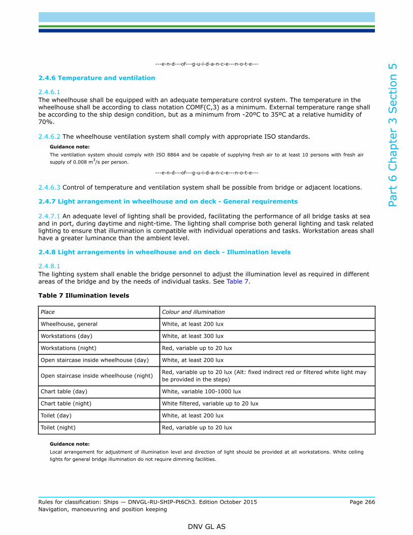
Part
6 C
hapt
er 3
Sec
tion
5
Rules for classification: Ships — DNVGL-RU-SHIP-Pt6Ch3. Edition October 2015 Page 266Navigation, manoeuvring and position keeping
DNV GL AS
---e-n-d---of---g-u-i-d-a-n-c-e---n-o-t-e---
2.4.6 Temperature and ventilation
2.4.6.1 The wheelhouse shall be equipped with an adequate temperature control system. The temperature in thewheelhouse shall be according to class notation COMF(C,3) as a minimum. External temperature range shallbe according to the ship design condition, but as a minimum from -20ºC to 35ºC at a relative humidity of70%.
2.4.6.2 The wheelhouse ventilation system shall comply with appropriate ISO standards.Guidance note:The ventilation system should comply with ISO 8864 and be capable of supplying fresh air to at least 10 persons with fresh airsupply of 0.008 m3/s per person.
---e-n-d---of---g-u-i-d-a-n-c-e---n-o-t-e---
2.4.6.3 Control of temperature and ventilation system shall be possible from bridge or adjacent locations.
2.4.7 Light arrangement in wheelhouse and on deck - General requirements
2.4.7.1 An adequate level of lighting shall be provided, facilitating the performance of all bridge tasks at seaand in port, during daytime and night-time. The lighting shall comprise both general lighting and task relatedlighting to ensure that illumination is compatible with individual operations and tasks. Workstation areas shallhave a greater luminance than the ambient level.
2.4.8 Light arrangements in wheelhouse and on deck - Illumination levels
2.4.8.1 The lighting system shall enable the bridge personnel to adjust the illumination level as required in differentareas of the bridge and by the needs of individual tasks. See Table 7.
Table 7 Illumination levels
Place Colour and illumination
Wheelhouse, general White, at least 200 lux
Workstations (day) White, at least 300 lux
Workstations (night) Red, variable up to 20 lux
Open staircase inside wheelhouse (day) White, at least 200 lux
Open staircase inside wheelhouse (night) Red, variable up to 20 lux (Alt: fixed indirect red or filtered white light maybe provided in the steps)
Chart table (day) White, variable 100-1000 lux
Chart table (night) White filtered, variable up to 20 lux
Toilet (day) White, at least 200 lux
Toilet (night) Red, variable up to 20 lux
Guidance note:Local arrangement for adjustment of illumination level and direction of light should be provided at all workstations. White ceilinglights for general bridge illumination do not require dimming facilities.
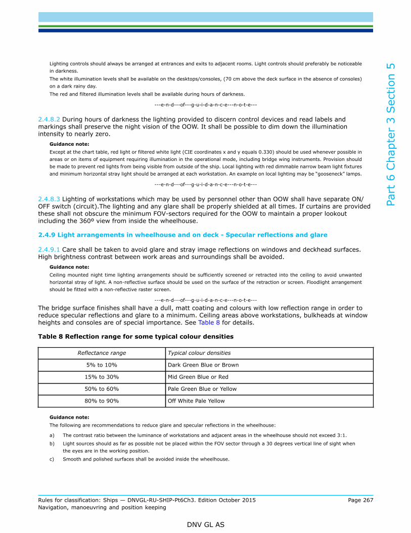
Part
6 C
hapt
er 3
Sec
tion
5
Rules for classification: Ships — DNVGL-RU-SHIP-Pt6Ch3. Edition October 2015 Page 267Navigation, manoeuvring and position keeping
DNV GL AS
Lighting controls should always be arranged at entrances and exits to adjacent rooms. Light controls should preferably be noticeablein darkness.The white illumination levels shall be available on the desktops/consoles, (70 cm above the deck surface in the absence of consoles)on a dark rainy day.The red and filtered illumination levels shall be available during hours of darkness.
---e-n-d---of---g-u-i-d-a-n-c-e---n-o-t-e---
2.4.8.2 During hours of darkness the lighting provided to discern control devices and read labels andmarkings shall preserve the night vision of the OOW. It shall be possible to dim down the illuminationintensity to nearly zero.
Guidance note:Except at the chart table, red light or filtered white light (CIE coordinates x and y equals 0.330) should be used whenever possible inareas or on items of equipment requiring illumination in the operational mode, including bridge wing instruments. Provision shouldbe made to prevent red lights from being visible from outside of the ship. Local lighting with red dimmable narrow beam light fixturesand minimum horizontal stray light should be arranged at each workstation. An example on local lighting may be “gooseneck” lamps.
---e-n-d---of---g-u-i-d-a-n-c-e---n-o-t-e---
2.4.8.3 Lighting of workstations which may be used by personnel other than OOW shall have separate ON/OFF switch (circuit).The lighting and any glare shall be properly shielded at all times. If curtains are providedthese shall not obscure the minimum FOV-sectors required for the OOW to maintain a proper lookoutincluding the 360º view from inside the wheelhouse.
2.4.9 Light arrangements in wheelhouse and on deck - Specular reflections and glare
2.4.9.1 Care shall be taken to avoid glare and stray image reflections on windows and deckhead surfaces.High brightness contrast between work areas and surroundings shall be avoided.
Guidance note:Ceiling mounted night time lighting arrangements should be sufficiently screened or retracted into the ceiling to avoid unwantedhorizontal stray of light. A non-reflective surface should be used on the surface of the retraction or screen. Floodlight arrangementshould be fitted with a non-reflective raster screen.
---e-n-d---of---g-u-i-d-a-n-c-e---n-o-t-e---
The bridge surface finishes shall have a dull, matt coating and colours with low reflection range in order toreduce specular reflections and glare to a minimum. Ceiling areas above workstations, bulkheads at windowheights and consoles are of special importance. See Table 8 for details.
Table 8 Reflection range for some typical colour densities
Reflectance range Typical colour densities
5% to 10% Dark Green Blue or Brown
15% to 30% Mid Green Blue or Red
50% to 60% Pale Green Blue or Yellow
80% to 90% Off White Pale Yellow
Guidance note:The following are recommendations to reduce glare and specular reflections in the wheelhouse:
a) The contrast ratio between the luminance of workstations and adjacent areas in the wheelhouse should not exceed 3:1.
b) Light sources should as far as possible not be placed within the FOV sector through a 30 degrees vertical line of sight whenthe eyes are in the working position.
c) Smooth and polished surfaces shall be avoided inside the wheelhouse.

Part
6 C
hapt
er 3
Sec
tion
5
Rules for classification: Ships — DNVGL-RU-SHIP-Pt6Ch3. Edition October 2015 Page 268Navigation, manoeuvring and position keeping
DNV GL AS
---e-n-d---of---g-u-i-d-a-n-c-e---n-o-t-e---
2.4.9.2 Lighting sources located in adjacent rooms and corridors shall be prevented from illuminating thewheelhouse at night time.
Guidance note:Automatic door switches preventing white light from flooding the bridge area should be fitted on entrances from adjacent roomsand corridors.
---e-n-d---of---g-u-i-d-a-n-c-e---n-o-t-e---
2.4.9.3 It shall be avoided that glaring lights from deck lights and searchlights are dazzling the operator atthe workstations.
2.4.10 Colours in wheelhouse
2.4.10.1 Colours shall be chosen to give a calm overall impression and minimise reflections.Guidance note:Bright colours should not be used. Dark or mid green colours are recommended; alternatively, blue or brown may be used. See Table 8.
---e-n-d---of---g-u-i-d-a-n-c-e---n-o-t-e---
3 Workstation arrangement
3.1 Requirements for the various workstations3.1.1 General
3.1.1.1 This section gives the functional requirements for the various workstations and defines the tasks tobe carried out at each workstation. Minimum field of vision, required equipment and information necessaryfor safe performance of the tasks are given for each workstation as relevant.
3.1.2 General workstation requirements
3.1.2.1 Workstations and consoles shall be arranged and ergonomically designed to optimise the user’sworking conditions and to minimise excessive or unnecessary work.
3.1.2.2 A functional workstation designed in accordance with the established overall operational andergonomic requirements for safe operation must provide:
— a sufficient area for performance of the tasks to be carried out by the number of people that may berequired to attend
— providing individual workplaces in accordance with the distribution of tasks at maximum bridge manning— consoles designed for operations at specific workplaces in standing and/ or seated position— enabling installation of equipment to be within reach from the working position— avoiding obstruction of the view through bridge windows from operators position— chairs, if installed, designed in accordance with ergonomic requirements for efficient use of the equipment
installed in workstation consoles and adjustable for maintenance of the required fields of vision.
3.1.3 General workstation consoles requirements
3.1.3.1 In principle, consoles shall be divided into two separate areas:
— one for the display of information located in the upper (vertical) part of the console— one for the location of equipment necessary for taking action on the information located in the lower
(horizontal) part

Part
6 C
hapt
er 3
Sec
tion
5
Rules for classification: Ships — DNVGL-RU-SHIP-Pt6Ch3. Edition October 2015 Page 269Navigation, manoeuvring and position keeping
DNV GL AS
3.1.3.2 The height of desktops to be used from sitting positions only shall not be less than 750 mm.
3.1.3.3 The height of desktops to be used from sitting and standing positions shall not be less than 800 mm.
3.1.3.4 The general height of consoles forming a workstation for radio communication or other additionaltasks that are to be used by the officer shall not obstruct the field of vision required for maintaining a properlookout from a sitting position at the console. The height of consoles located at workstations for additionalfunctions, including equipment (e.g. printers) installed on top of the console, shall not exceed 1300 mm.
3.1.4 General overhead consoles requirements
3.1.4.1 Consoles installed in ceiling shall not obstruct required vertical field of vision from the workstationsseen from an operator with eye height of 1800 mm. See Figure 10.
Guidance note:Use eye height of 1800 mm for calculation purposes in order to secure that the lower edge of overhead consoles does not conflictwith the field of vision for operators with above average height.
---e-n-d---of---g-u-i-d-a-n-c-e---n-o-t-e---
3.1.4.2 Overhead consoles shall primarily be used for location of indicators and information displays.Consoles with pertinent and important information shall be located within the easily readable field of visionfor the operator.
3.1.4.3 If it is necessary with overhead consoles for the mounting of equipment to be operated frequently,these shall be located within reach from a seated position at the workstation and be available when standingor moving the chair to enable access to other equipment. See Figure 10.
Guidance note:Within reach in this context mean a radius of 800 mm from eye position 1500 mm above deck.
---e-n-d---of---g-u-i-d-a-n-c-e---n-o-t-e---
Figure 10 Overhead consoles abeam

Part
6 C
hapt
er 3
Sec
tion
5
Rules for classification: Ships — DNVGL-RU-SHIP-Pt6Ch3. Edition October 2015 Page 270Navigation, manoeuvring and position keeping
DNV GL AS
3.1.4.4 The overhead consoles shall be tilted to suit the line of sight from the working position. See Figure 11
Figure 11 Overhead consoles aft
3.1.5 General chair requirements
3.1.5.1 Chairs shall be installed at the workstations for navigating and manoeuvring, workstations formonitoring, ship handling and aft support. See also [3.2.4] and [3.5.4]
3.1.5.2 It shall be easy to enter and leave the chairs in any position.
3.1.5.3 Deck rails for backward/forward adjustments of the chairs shall be installed flush with the decksurface or with anti-trip skirting board if installed in a passageway area.
3.1.5.4 Backrest inclination shall be within the interval of 102° and 108°.
3.1.5.5 Chair foot-rest shall be provided.Guidance note:The chair foot-rest height shall be adjustable according to a popliteal (relating to the area behind the knee joint) height in the intervalof 380 mm to 580 mm.
---e-n-d---of---g-u-i-d-a-n-c-e---n-o-t-e---
3.1.6 Field of vision requirements
3.1.6.1 The Field of Vision requirements are included in the requirements for each workstation.
3.1.6.2 When controls for steering and manoeuvring of the vessel is installed at the bridge wings the Field ofVision requirements will be as for WS for Search/Rescue Operations (see [3.9.2]).

Part
6 C
hapt
er 3
Sec
tion
5
Rules for classification: Ships — DNVGL-RU-SHIP-Pt6Ch3. Edition October 2015 Page 271Navigation, manoeuvring and position keeping
DNV GL AS
3.2 Workstations for primary bridge functions3.2.1 Principle
3.2.1.1 The design and location of the workstations for navigating and manoeuvring and the workstation formonitoring shall enable safe and efficient traffic surveillance, navigation and manoeuvring of the vessel underall circumstances. The configuration of the workstations shall facilitate performance by one navigator undernormal operating conditions, as well as by two navigators in close co-operation when the workload exceedsthe capacity of one person.
3.2.1.2 Workstations for navigating and manoeuvring shall facilitate all functions related to trafficsurveillance, navigation and manoeuvring during normal operating conditions.
3.2.1.3 The workstation for monitoring shall facilitate navigation functions during periods with high workload,during degraded functionality at the workstations for navigating and manoeuvring or work as a pilot’sworkstation when under pilotage.
3.2.2 Layout for workstations for primary bridge functions
3.2.2.1 The workstations for primary bridge functions shall have working positions for navigation,manoeuvring and traffic surveillance as close together as possible for efficient use by the officer of the watch,but also enabling the tasks to be performed by two navigators in close co-operation. The working position foroperating the radar with collision avoidance functions shall be regarded as the main working position at theseworkstations and shall be within reach from a seated position.
3.2.2.2 Controls for heading and speed adjustments shall be located within reach from working position atworkstations for navigating and manoeuvring to enable collision avoidance manoeuvres without losing viewof the traffic, and ECDIS for position-fixing and route monitoring shall be readily available.
3.2.2.3 Manoeuvring functions from seated position are related to heading and speed adjustments forcollision and grounding avoidance. Manoeuvring also requiring the use of thrusters may be carried out instanding position at the workstation.
Figure 12 Principle location of main equipment in relation to seated and standing workingpositions
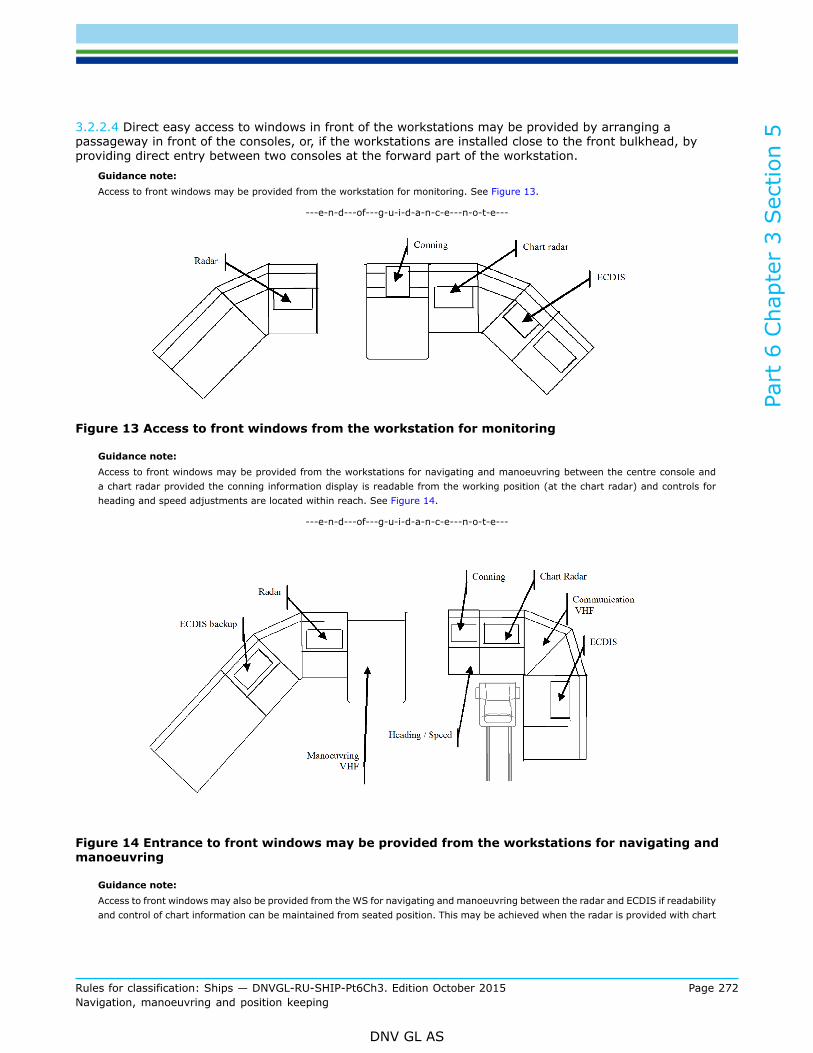
Part
6 C
hapt
er 3
Sec
tion
5
Rules for classification: Ships — DNVGL-RU-SHIP-Pt6Ch3. Edition October 2015 Page 272Navigation, manoeuvring and position keeping
DNV GL AS
3.2.2.4 Direct easy access to windows in front of the workstations may be provided by arranging apassageway in front of the consoles, or, if the workstations are installed close to the front bulkhead, byproviding direct entry between two consoles at the forward part of the workstation.
Guidance note:Access to front windows may be provided from the workstation for monitoring. See Figure 13.
---e-n-d---of---g-u-i-d-a-n-c-e---n-o-t-e---
Figure 13 Access to front windows from the workstation for monitoring
Guidance note:Access to front windows may be provided from the workstations for navigating and manoeuvring between the centre console anda chart radar provided the conning information display is readable from the working position (at the chart radar) and controls forheading and speed adjustments are located within reach. See Figure 14.
---e-n-d---of---g-u-i-d-a-n-c-e---n-o-t-e---
Figure 14 Entrance to front windows may be provided from the workstations for navigating andmanoeuvring
Guidance note:Access to front windows may also be provided from the WS for navigating and manoeuvring between the radar and ECDIS if readabilityand control of chart information can be maintained from seated position. This may be achieved when the radar is provided with chart

Part
6 C
hapt
er 3
Sec
tion
5
Rules for classification: Ships — DNVGL-RU-SHIP-Pt6Ch3. Edition October 2015 Page 273Navigation, manoeuvring and position keeping
DNV GL AS
facilities. Alternatively, remote control facilities for operation of ECDIS may be used, provided the chart information is easily readablefrom seated position. Another alternative may be to locate ECDIS in the centre console and the conning display above front windowsif monitor screens are readable from seated position. See Figure 15.
---e-n-d---of---g-u-i-d-a-n-c-e---n-o-t-e---
Figure 15 Access to front windows from workstations for navigating and manoeuvring, betweenchart radar and ECDIS
Figure 16 Principle location of main equipment for a vessel engaged in seismic operations,overhead consoles may also be used
3.2.3 Workstation consoles for primary functions
3.2.3.1 For front workstations an eye height of 1500 mm is used. In order not to obstruct the line of sightfrom a position of 350 mm behind a console of average depth and any passageway in front of consoles,giving a total horizontal distance of maximum 2300 mm between the operator and the steel bulkhead, theconsole height, including foundation, shall not exceed 1200 mm. See Figure 10.

Part
6 C
hapt
er 3
Sec
tion
5
Rules for classification: Ships — DNVGL-RU-SHIP-Pt6Ch3. Edition October 2015 Page 274Navigation, manoeuvring and position keeping
DNV GL AS
3.2.3.2 The height of console desktops at bridge workstations shall enable easy use of equipment requiredfor safe performance of the tasks to be performed from sitting position. The console height shall not obstructthe required field of vision.
3.2.3.3 A standard console height of 1200 mm is acceptable even if the top of the console interferes with theline of sight from a sitting eye height of 1500 mm.
3.2.4 Chairs at workstations for primary functions
3.2.4.1 Chairs shall be installed at the workstation for monitoring and at the workstations for navigating andmanoeuvring, and it shall be easy to adjust the vertical position of the chairs to suit an eye height of 1500mm. The seated location shall be 350mm from the console See Figure 10.
Guidance note:The vertical adjustment of the seat rest should range from 600 mm to 800 mm above the deck surface.See also [3.1.5].
---e-n-d---of---g-u-i-d-a-n-c-e---n-o-t-e---
3.2.4.2 It shall be possible to move the chairs for easy reach of the equipment to be used and to move thechairs away from the consoles to achieve good working conditions from a standing position.
Guidance note:It should be possible to adjust chairs to a position close to the front console (distance from chair back-rest to console front shouldbe not more than 550 mm) and away from the workstation area to facilitate a passage of 600 mm between chair front and workingarea including operator.
---e-n-d---of---g-u-i-d-a-n-c-e---n-o-t-e---
3.3 Workstations for navigating and manoeuvring3.3.1 Workstation tasks
3.3.1.1 The workstations for navigating and manoeuvring shall enable the following tasks to be performed:
— determine and plot the ship's position, heading, track and speed— monitor the traffic by sight and hearing as well as by all available means— analyse the traffic situation— decide on collision avoidance manoeuvres— alter heading— change speed— carry out a change of operational steering mode— effect internal and external communication related to manoeuvring— handle other external communication available on the bridge— operate docking aid systems— monitor time, heading, speed, track, propeller revolutions, thrust indicator (when available), pitch
indicator (if the ship is equipped with pitch propeller), rudder order and rudder angle— monitor all alarm conditions on the bridge.
3.3.2 Field of vision
3.3.2.1 In order to enable the officer of the watch to carry out his functions in compliance with theinternational regulations for preventing collisions at sea, the horizontal field of vision from the workingposition at the workstation for monitoring and from the seated position at the workstations for navigating andmanoeuvring shall extend over an arc of not less than 225°, that is from dead ahead to not less than 22.5°abaft the beam on either side of the ship.

Part
6 C
hapt
er 3
Sec
tion
5
Rules for classification: Ships — DNVGL-RU-SHIP-Pt6Ch3. Edition October 2015 Page 275Navigation, manoeuvring and position keeping
DNV GL AS
Figure 17 Horizontal field of vision
3.3.2.2 A horizontal field of vision to the horizon of 360° shall be obtained by using not more than 2 positionsinside the wheelhouse on either side of the workstations for navigating and manoeuvring, being not morethan 15 m apart.
3.3.2.3 In order to be able to perform manoeuvres timely to avoid critical situations, the view of the seasurface from the workstations for navigating and manoeuvring, using an eye height of 1500 mm above deck,shall not be obscured by more than two ship lengths or 500 m, whichever is less, forward of the bow to 10°on either side, under all conditions of draught and trim.
Figure 18 Vertical field of vision forward of the bow
3.3.2.4 When the distance between the windows and the viewing point 350 mm aft of the consoles at theworkstations navigating and manoeuvring is more than 2300 mm, the height of the lower edge of thewindows in the sector from ahead to 90° on each side shall be decreased sufficiently to maintain the line ofsight from an eye height of 1500 mm above deck.
Guidance note:The lower edge of window needed to obtain the required field of vision as required in [3.2.3], shall be maintained in the sector fromahead to 90° on each side.
---e-n-d---of---g-u-i-d-a-n-c-e---n-o-t-e---

Part
6 C
hapt
er 3
Sec
tion
5
Rules for classification: Ships — DNVGL-RU-SHIP-Pt6Ch3. Edition October 2015 Page 276Navigation, manoeuvring and position keeping
DNV GL AS
Figure 19 Vertical field of vision over consoles
3.3.2.5 Blind sectors caused by cargo, cargo gar, divisions between windows and other obstructionsappearing in the required field of vision of 225° shall be as few and as small as possible, and in no wayhamper a safe lookout from the workstations for navigating and manoeuvring. The total arc of blind sectorswithin this field of vision shall not exceed 30°.
Figure 20 Blind sectors seen from workstations for navigating and manoeuvring
3.3.2.6 Over an arc from dead ahead to at least 10º on each side of the bow, seen from the workstations fornavigating and manoeuvring, no blind sector shall exceed 5º. Elsewhere, each individual blind sector withinthe required field of vision shall not exceed 10º.
Guidance note:

Part
6 C
hapt
er 3
Sec
tion
5
Rules for classification: Ships — DNVGL-RU-SHIP-Pt6Ch3. Edition October 2015 Page 277Navigation, manoeuvring and position keeping
DNV GL AS
See also [2.3.4] for calculation of blind sectors.
---e-n-d---of---g-u-i-d-a-n-c-e---n-o-t-e---
3.3.2.7 The clear sector between two blind sectors shall be at least 5º and not less than the size of thebroadest blind sector on either side of the clear sector.
3.3.2.8 If helicopter deck or other platforms are installed above and in front of wheelhouse obstructing thevertical field of vision, a vertical angle of view of not less than 5° above the horizontal plane, extending fromeye height in forward direction, shall be provided irrespective of helicopter deck or other structures placed ontop of the wheelhouse.
3.3.2.9 It shall be possible to observe the ship bow for reference of ship position/ heading from theworkstation.
Guidance note:If direct observation of the ship bow/ forecastle is hampered, a mast can be used as reference.
---e-n-d---of---g-u-i-d-a-n-c-e---n-o-t-e---
3.3.2.10 It shall be possible to visually monitor the workstations for offshore operations.
3.3.3 Additional requirement for Offshore service vessel with qulifiers Anchor handling, Towingand AHTS
3.3.3.1 From the working position at the workstation it shall be possible to see the sea surface within 600meters from the ship’s stern for monitoring of towing units.
Figure 21 Monitoring of tow
3.3.3.2 The horizontal field of vision from the normal working position aft shall cover a sector not less thanship stern breadth and it shall be possible to see wire stoppers.
Figure 22 Horizontal field of vision
3.3.3.3 It shall be possible to monitor the spooling of the wire, the towing guide and the relative horizontalangle of the tow wire at the stern roll.
Guidance note:These requirements may be obtained with use of CCTV system.These additional requirements are not applicable from workstation monitoring.
---e-n-d---of---g-u-i-d-a-n-c-e---n-o-t-e---

Part
6 C
hapt
er 3
Sec
tion
5
Rules for classification: Ships — DNVGL-RU-SHIP-Pt6Ch3. Edition October 2015 Page 278Navigation, manoeuvring and position keeping
DNV GL AS
3.3.4 Additional requirement for seismic vessels:
3.3.4.1 From the working position at the workstation it shall be possible to see the sea surface not less than1000 meters from the ship's stern for monitoring of towing units.
Figure 23 Monitoring of tow for seismic vessels
3.3.4.2 The horizontal field of vision from the normal working position in front shall enable the operator tomonitor the start of streamers in a sector not less than ±30°.
Guidance note:These requirements may be obtained with use of CCTV system.
---e-n-d---of---g-u-i-d-a-n-c-e---n-o-t-e---
Figure 24 Monitoring of tow for seismic vessels
3.3.5 Equipment to be available
3.3.5.1 Instruments and equipment that shall be operated by the navigator at the workstations for navigatingand manoeuvring, and considered essential for safe and efficient performance of the operator’s tasks, shallbe within reach from a sitting position at the workstation. Priority shall be given to location of controls forradars, heading and speed.
3.3.5.2 The following instruments and equipment shall be installed within reach from a sitting position:
— chart radar— ECDIS— propulsion control— propulsion back-up control (when provided)— heading control system or track control system (as provided)— manual steering control with override control of automatic systems— mode selector switch and means for take command at workstation (steering, propulsion, thrusters)— VHF

Part
6 C
hapt
er 3
Sec
tion
5
Rules for classification: Ships — DNVGL-RU-SHIP-Pt6Ch3. Edition October 2015 Page 279Navigation, manoeuvring and position keeping
DNV GL AS
— UHF— automatic telephone— whistle push button— emergency stop for propellers/ thrusters— CAM-HMI (BAMS)— BNWAS— engine alarm panel (engine alarm panel/ E0 alarm panel might be included in central alarm panel)— window wiper and wash controls for the windows within the required field of vision— searchlight controls (when provided).
3.3.5.3 The following equipment shall be installed within reach from a standing position at the workstationwhere also controls for propulsion and steering can be operated:
— thruster control(s)— thruster back-up control(s) (when provided)— joystick control (when provided).
Figure 25 Example of location of important equipment
3.3.5.4 Means to be used at intervals for securing safe heading and speed in the waters to be navigated andfor safety of bridge operation shall be easily accessible from the workstations for navigating and manoeuvringand include:
— instruments and equipment installed at the workstation for monitoring— alarm panel for additional functions, such as fire, emergency, etc.— dimmer controls for lights to be used at the workstation— controls for the sound reception system.
3.3.5.5 Additional requirement for AH, AHTS, towing and seismic operations:
— controls for CCTV system (if applicable) shall be installed within reach from a sitting position at theworkstations for navigating and manoeuvring.

Part
6 C
hapt
er 3
Sec
tion
5
Rules for classification: Ships — DNVGL-RU-SHIP-Pt6Ch3. Edition October 2015 Page 280Navigation, manoeuvring and position keeping
DNV GL AS
3.3.6 Information to be provided
3.3.6.1 Information considered essential for the safe and efficient performance of tasks at the workstationsfor navigating and manoeuvring shall be easily readable, and audible when relevant, from the workingposition at the workstation. Essential information includes:
— propeller revolution and engine rpm/ load as relevant— thrust indication or alternatively thruster pitch and RPM (as provided)— propeller pitch (when provided)— rudder angle— rudder order, if the steering system is a follow-up system— ship’s heading (steering repeater with compass card)— ship’s speed— water depth— wind direction and speed— time— alarms and warnings— sound from navigational aids and ship’s whistles— conning display— gyro compass monitoring system.— Magnetic compass (if provided).
3.3.6.2 Additional requirements for AH, AHTS and Towing operations:
— winch tension, wire length and wire speed indication (may be part of conning display)— monitor(s) for supporting view of tow or wire (if applicable).
3.4 Workstation for monitoring3.4.1 Workstation tasks
3.4.1.1 The workstation for monitoring support shall enable the following tasks to be performed:
— determine and plot the ship's position, heading, track and speed— effect internal and external communication related to navigation— monitor time, heading, speed and track, rudder angle, propeller— revolutions and propeller pitch (when applicable)— adjustment of pre-planned route during the voyage.
3.4.2 Field of vision
3.4.2.1 Same requirements as for workstations for navigating and manoeuvring, except the additionalrequirements for AH, AHTS and Towing operations. See [3.3.2].
3.4.3 Equipment to be available
3.4.3.1 The following instruments and equipment that shall be operated by the navigator at the workstationfor monitoring, and considered essential for safe operations, shall be within reach from a standing position atthe workstation:
— radar— ECDIS backup arrangement— chart table (if relevant)*— relevant position-fixing systems (GPS)

Part
6 C
hapt
er 3
Sec
tion
5
Rules for classification: Ships — DNVGL-RU-SHIP-Pt6Ch3. Edition October 2015 Page 281Navigation, manoeuvring and position keeping
DNV GL AS
— VHF— automatic telephone— whistle push button— BNWAS— CAM-HMI (BAMS).
* Ships solely using ECDIS as the official chart system and are not required to carry any paper navigationalcharts, may not install a front chart table.
3.4.4 Information to be provided
3.4.4.1 Information considered essential for operations at the monitoring workstation shall be easily readablefrom the working position at the workstation. Essential information includes:
— propeller revolutions and engine rpm/ load as relevant— propeller pitch (when provided)— rudder angle— ship’s heading— ship’s speed— water depth— time— distance run— conning display.
3.5 Workstation for offshore operations3.5.1 Principle
3.5.1.1 The design and location of the workstation for ship handling and the workstation for aft support shallenable safe and efficient manoeuvring of the vessel under all circumstances and shall facilitate command andcontrol of the vessel’s offshore operations.
3.5.1.2 Workstation for ship handling and workstation for aft support shall be so arranged and designedthat two qualified operators can work either separately or in close co-operation if the workload exceeds thecapacity of one operator or the nature of the operation requires two operators.
3.5.1.3 Workstation for ship handling shall facilitate all functions related to manoeuvring and commandduring normal operating conditions.
3.5.1.4 The workstation for aft support shall facilitate control of offshore operations and serve as backup formanoeuvring functions if operator at workstation for ship handling becomes inoperative.
3.5.2 Layout for workstations for offshore operations
3.5.2.1 The workstations for offshore operations shall be located close together to allow close co-operationbetween the two workstations and for efficient use of console space, thereby avoiding duplicate installation ofequipment and indicators.
3.5.2.2 Both workstations shall have access to the back-up controllers for manoeuvring.
3.5.2.3 Any consoles/panels located between operator and aft windows shall not obstruct the view of cargodeck and shall be possible to remove instantly if prime access to workstation is hampered by the console.

Part
6 C
hapt
er 3
Sec
tion
5
Rules for classification: Ships — DNVGL-RU-SHIP-Pt6Ch3. Edition October 2015 Page 282Navigation, manoeuvring and position keeping
DNV GL AS
3.5.2.4 The width of consoles shall be kept as narrow as possible in order to avoid operator stretching overthe console in order to reach equipment mounted outside normal reachable area and thus risking unintendedactivation/ movement of controls.
Guidance note:The width of consoles intended for use from one side only should not exceed 700 mm. For consoles to be used from both sides,the width may be increased to 800 mm provided that equipment mounted on the far side is not relevant for the operator at theadjacent workstation.
---e-n-d---of---g-u-i-d-a-n-c-e---n-o-t-e---
3.5.2.5 To ensure optimum area for installed equipment that shall be within reach, the space provided for thechair seat and the operator shall be kept to a minimum.
Guidance note:The space provided for the chair seat and the operator should not be more than 600 mm wide, chair armrests with equipment arenot included in this 600 mm.
---e-n-d---of---g-u-i-d-a-n-c-e---n-o-t-e---
Figure 26 Size of consoles when common centre console is used
3.5.3 Workstation consoles for offshore operations
3.5.3.1 Workstation consoles shall not obstruct the view through windows required for monitoring aft deckoperations from sitting position at the workstations for offshore operations. Consoles located in athwart shipdirection shall not obstruct the required field of vision from the workstation.
3.5.3.2 The relationship between the total height of the console, the height of desktop for equipmentinstallations and the sitting height is decisive for achieving optimum vertical field of vision, optimum reachingdistance and efficient use of equipment when seated. The distance to side windows and the size of windowsaffect the vertical view. A vertical angle of view not less than +/- 5° in relation to the horizontal line of visionshall be provided by adjusting the size of windows if necessary.

Part
6 C
hapt
er 3
Sec
tion
5
Rules for classification: Ships — DNVGL-RU-SHIP-Pt6Ch3. Edition October 2015 Page 283Navigation, manoeuvring and position keeping
DNV GL AS
Figure 27 Location of workstation consoles and window size in the FOV arc between abeam and30° aft of abeam
3.5.4 Chairs at workstations for offshore operations
3.5.4.1 Chairs, with armrests or equivalent, shall be installed at the workstation for ship handling and theworkstation for aft support. It shall be easy to adjust the vertical position of the chairs to obtain an elbowheight of 50 mm above the level of adjacent consoles.
Guidance note:It should be possible to adjust the vertical distance between chair seat and adjacent console desktops in the range of +/- 100 mm.This may be obtained by adjusting the height of the chair or the adjacent consoles.See also [3.1.5].
---e-n-d---of---g-u-i-d-a-n-c-e---n-o-t-e---
3.5.4.2 Chairs and consoles at WS for offshore operations shall be arranged as integrated design in order toobtain the required level of ergonomics and availability of equipment.
3.5.4.3 If it is necessary to move the chair for operation of essential equipment located outside easy reacharea, it shall be possible to move the chair instantly without having to leave the chair.
3.5.5 Priority zones for location of equipment and indicators
3.5.5.1 Required equipment and indicators at workstations for ship handling and aft support shall be locatedaccording to importance and frequency of operation.
Guidance note:Tables and figure below indicates priority of some of the equipment and indicators at workstations for ship handling and aft support.Required equipment and information at the workstations are listed in paragraph [3.6] and [3.7].Priority zones explanation (P):Indicators meant for readingA - Easily readable Within a horizontal sector of 180° and vertical in the area up 60° and down 90° from the operators normal lineof sight. See Pt.4 Ch.9 Sec.6. See also [5.4].B - Readable Within an horizontal sector of 225° and vertical in the area up 60° and down 90° from the operator’s normal eye position.Equipment meant to be operated
1) On hand
2) Within easy reach
3) Within reach (Possible to reach while seated in working position)
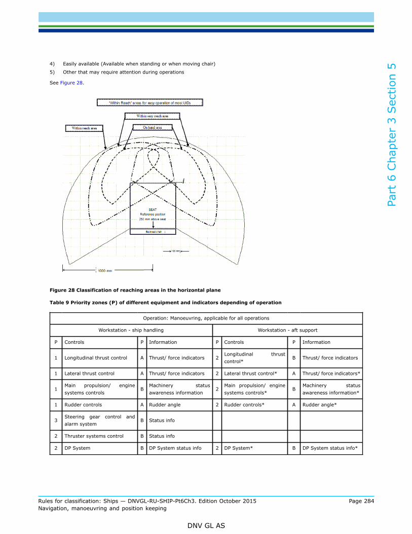
Part
6 C
hapt
er 3
Sec
tion
5
Rules for classification: Ships — DNVGL-RU-SHIP-Pt6Ch3. Edition October 2015 Page 284Navigation, manoeuvring and position keeping
DNV GL AS
4) Easily available (Available when standing or when moving chair)
5) Other that may require attention during operations
See Figure 28.
Figure 28 Classification of reaching areas in the horizontal plane
Table 9 Priority zones (P) of different equipment and indicators depending of operation
Operation: Manoeuvring, applicable for all operations
Workstation - ship handling Workstation - aft support
P Controls P Information P Controls P Information
1 Longitudinal thrust control A Thrust/ force indicators 2Longitudinal thrustcontrol*
B Thrust/ force indicators
1 Lateral thrust control A Thrust/ force indicators 2 Lateral thrust control* A Thrust/ force indicators*
1Main propulsion/ enginesystems controls
BMachinery statusawareness information
2Main propulsion/ enginesystems controls*
BMachinery statusawareness information*
1 Rudder controls A Rudder angle 2 Rudder controls* A Rudder angle*
3Steering gear control andalarm system
B Status info
2 Thruster systems control B Status info
2 DP System B DP System status info 2 DP System* B DP System status info*
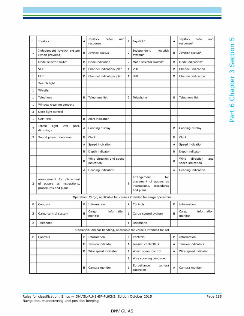
Part
6 C
hapt
er 3
Sec
tion
5
Rules for classification: Ships — DNVGL-RU-SHIP-Pt6Ch3. Edition October 2015 Page 285Navigation, manoeuvring and position keeping
DNV GL AS
1 Joystick AJoystick order andresponse
2 Joystick* AJoystick order andresponse*
1Independent joystick system(when provided)
B Joystick status 2Independent joysticksystem*
B Joystick status*
1 Mode selector switch B Mode indication 2 Mode selector switch* B Mode indication*
1 VHF B Channel indication/ plan 1 VHF B Channel indication
1 UHF B Channel indication/ plan 1 UHF B Channel indication
1 Search light
1 Whistle
1 Telephone B Telephone list 2 Telephone B Telephone list
1 Window cleaning controls
3 Deck light control
1 CAM-HMI B Alert indication
3Intern light ctrl (incl.dimming)
A Conning display B Conning display
3 Sound power telephone B Clock B Clock
A Speed indication A Speed indication
B Depth indicator B Depth indicator
BWind direction and speedindication
BWind direction andspeed indication
A Heading indication A Heading indication
3arrangement for placementof papers as instructions,procedures and plans
3
arrangement forplacement of papers asinstructions, proceduresand plans
Operation: Cargo, applicable for vessels intended for cargo operations
P Controls P Information P Controls P Information
2 Cargo control system BCargo informationmonitor
1 Cargo control system BCargo informationmonitor
2 Telephone 1 Telephone
Operation: Anchor handling, applicable for vessels intended for AH
P Controls P Information P Controls P Information
B Tension indicator 1 Tension controllers A Tension indicators
B Wire speed indicator 1 Winch speed control A Wire speed indicator
1 Wire spooling controller
B Camera monitor 1Surveillance cameracontroller
A Camera monitor

Part
6 C
hapt
er 3
Sec
tion
5
Rules for classification: Ships — DNVGL-RU-SHIP-Pt6Ch3. Edition October 2015 Page 286Navigation, manoeuvring and position keeping
DNV GL AS
1 Jaw shaft controller 1 Jaw shaft controller
1 Towing pins 1 Wire lock controller
3 Chart radar controller B Chart radar
2Anchor handling positionsurveillance system control
BAnchor handling positionsurveillance systemmonitor
3 DGPS
Operation: Fire fighting, applicable for vessels intended for FiFi
P Controls P Information P Controls P Information
1 Fire monitor controllers B Pressure indicator
B Wind indicator
1 Longitudinal thrust control A Thrust/ force indicators 2Longitudinal thrustcontrol*
B Thrust/ force indicators
*The main principle is that the workstation for aft support shall always be able to instantly take over the manoeuvring functionfrom workstation for ship handling and this may be either by joystick, DP or by manual means.
---e-n-d---of---g-u-i-d-a-n-c-e---n-o-t-e---
3.6 Workstation for ship handling3.6.1 Workstation tasks
3.6.1.1 The workstation for ship handling shall, as applicable, facilitate the following tasks:
— control main propulsion— control of thrusters not being part of the main propulsion, e.g. side thrusters— monitor status on main and auxiliary machinery— control and monitor DP system (when provided)— communicate with other ships, platforms and internally on own ship— monitor and silence alarms from equipment serving other functions located on the bridge requiring action
or attention from the operator (e.g. fire alarms, GMDSS alarms, engine alarms)— visually monitor cargo operations— monitor workstation for aft support— monitor workstations for navigating and manoeuvring and ship handling— berth the ship— operate necessary supporting equipment.
3.6.2 Field of vision
3.6.2.1 In order to enable the operator(s) at the workstations for offshore operations to carry out therequired functions, the horizontal field of vision from the workstation shall extend over an arc of not less than180° that is from right astern to not less than the beam on either side of the ship.
3.6.2.2 For monitoring of vessels side by side, platforms when lying alongside and other relevant situations,it shall be possible to monitor a horizontal field of not less than 5° beside the broadest part of thewheelhouse.
Guidance note:

Part
6 C
hapt
er 3
Sec
tion
5
Rules for classification: Ships — DNVGL-RU-SHIP-Pt6Ch3. Edition October 2015 Page 287Navigation, manoeuvring and position keeping
DNV GL AS
This 5° field of vision may either be before or behind the broadest part of the wheelhouse, see Figure 29.
---e-n-d---of---g-u-i-d-a-n-c-e---n-o-t-e---
Figure 29 Horizontal field of vision from workstations for offshore operations
3.6.2.3 In order to maintain a horizontal field of vision when the ship is rolling in heavy seas, there shall bean unobstructed view at an angle of at least 5° above and below the horizontal plane from the workstationfor offshore operations in the sector from abeam to 30° abaft the beam. The height of the upper edge of thewindows shall be at least 2000 mm under all circumstances.
3.6.2.4 The heights of consoles and lower edge of windows above the bridge deck shall not obstruct theline of sight passing 5° below the horizontal plane. The height of the lower edge of the windows shall bemaximum 1000 mm above deck under all circumstances.
Figure 30 Vertical field of vision in the sector from abeam to 30° aft
3.6.2.5 From the workstations for offshore operations there shall be a view of the cargo rail and workingdeck. Any obstructions in this view shall be kept to a minimum. Over an arc of not less than 120°, i.e. fromright astern to not less than 30° abaft the beam on either side of the ship, the height of the lower edge ofthe windows above the bridge deck shall be so that the bulkhead below the windows does not obstruct theview of the cargo deck.

Part
6 C
hapt
er 3
Sec
tion
5
Rules for classification: Ships — DNVGL-RU-SHIP-Pt6Ch3. Edition October 2015 Page 288Navigation, manoeuvring and position keeping
DNV GL AS
3.6.2.6 In order to see cargo arriving at the aft deck from cranes and other nearby constructions, there shallbe view at an angle of at least 20° above the horizontal plane from the workstation for offshore operationsover an arc of 120°, that is from right astern to not less than 30° abaft the beam on either side of the ship.See Figure 31 and Figure 32. For ships not engaged in cargo handling to/ from platforms, or other operationsrequiring equivalent vertical view, the above vertical view can be reduced to not less than 10° above thehorizontal plane.
Figure 31 Vertical field of vision in the sector of 120° astern
3.6.2.7 No blind sector caused by cargo, cargo gear, divisions between windows and other obstructionsappearing in the required field of vision shall exceed 10°.The total arc of blind sectors within the required 180° field of vision at the workstation for offshore operationsshall not exceed 20°.
3.6.2.8 The clear sector between two blind sectors shall be at least 5º and not less than the size of thebroadest blind sector on either side of the clear sector.

Part
6 C
hapt
er 3
Sec
tion
5
Rules for classification: Ships — DNVGL-RU-SHIP-Pt6Ch3. Edition October 2015 Page 289Navigation, manoeuvring and position keeping
DNV GL AS
Figure 32 Overview of the fields of vision required from workstations for offshore operations
3.6.2.9 The applied eye position of the operator(s) at the workstations shall be 1600 mm above deck withthe seat in the normal working position (for calculation purposes).
3.6.2.10 From workstation for ship handling it shall be possible to visually monitor the workstations fornavigating and manoeuvring.
3.6.3 Equipment to be available
3.6.3.1 The following instruments and equipment that shall be operated by the navigator at the workstationfor ship handling, and considered essential for safe and efficient performance of his tasks, shall be withinreach from a sitting position at the workstation:
— dynamic positioning system (when provided)— joystick— independent joystick system (when provided)— manual steering control (including any back-up mode)— steering gear control and alarm system— longitudinal thrust control— lateral thrust control— propulsion control— propulsion back-up control (when provided)— thruster control(s)— thruster back-up control(s) (when provided)— extension alarm panel— mode selector switch and means for take command at workstation (steering, propulsion, thrusters)— whistle push button— VHF— UHF— automatic telephone— search light controls

Part
6 C
hapt
er 3
Sec
tion
5
Rules for classification: Ships — DNVGL-RU-SHIP-Pt6Ch3. Edition October 2015 Page 290Navigation, manoeuvring and position keeping
DNV GL AS
— window wiper and wash controls for the windows within the required field of vision— deck light controls— CAM-HMI (BAMS)— means for controlling the chart radar (or radar and ECDIS) See [4.2.6.9]*— means for controlling towing pins and jaw (when provided)— arrangement for placement of papers as instructions, procedures and plans.
* Not required for pure platform supply vessels.
3.6.3.2 Main manoeuvring controls shall be defined by the owner and these controls together withcommunication controls shall be “on hand” when seated.
3.6.3.3 Priority shall be given to location of controls for joystick, DP (if installed), propulsion throttles, ruddercontrols, thrusters and necessary communication (UHF, VHF and telephone systems).See [3.5.5] for priority of equipment.
3.6.3.4 Equipment that might require attention from the operator during operation shall be installedsufficiently close to the operator’s working position, so that it is not necessary to leave the chair for takingappropriate action. The following equipment shall be considered:
— alarm panel for additional functions, such as fire, emergency, cargo, etc.— GMDSS equipment that may require attention.— alarm systems included in the bridge alert management system may not necessarily be located at the
workstation.
3.6.3.5 Additional requirements for AH and AHTS:
— anchor handling position surveillance system control (system for aiding the ship to find the correct anchorposition, often received from rig before operation).
3.6.4 Information to be provided
3.6.4.1 Information considered essential for safe and efficient performance of tasks at the WS for shiphandling shall be easily readable, and audible when relevant, from the working position at the workstation.Essential information includes:
— propeller revolution and engine rpm/ load as relevant— propeller pitch (when provided)— thrust indication or alternatively thruster pitch and RPM (as provided)— rudder angle— rudder order, if the steering system is a follow-up system— ship’s heading— ship’s speed— water depth— wind direction and speed— time— essential status information of main and auxiliary machinery, as relevant— alarms and warnings— conning display— chart information*— traffic information*— collision warning *— grounding warning*.
* Not required for pure platform supply vessels.

Part
6 C
hapt
er 3
Sec
tion
5
Rules for classification: Ships — DNVGL-RU-SHIP-Pt6Ch3. Edition October 2015 Page 291Navigation, manoeuvring and position keeping
DNV GL AS
See [3.5.5] for priority of information.
3.6.4.2 Additional requirements for Offshore service vessels with qualifiers Anchor handling, Towingand AHTS:
— essential winch information (tension, length, wire speed)— CCTV monitors for monitoring of winch equipment and spooling apparatus.
3.7 Workstation for aft support3.7.1 Workstation tasks
3.7.1.1 The workstation for aft support shall facilitate the following tasks:
— control main propulsion for backup of manoeuvring function— control of thrusters not being part of the main propulsion, e.g. side thrusters, for backup of manoeuvring
function— monitor status on main and auxiliary machinery, as relevant— communicate with other ships, platforms and internal on vessel— monitor and control cargo operations— emergency stop of cargo operations— control and monitor winch operations, as relevant— monitor workstation for ship handling.
3.7.2 Field of vision
3.7.2.1 Same requirements as for workstation for ship handling, see [3.6.2].
3.7.3 Equipment to be available
3.7.3.1 The following instruments and equipment that shall be operated by the navigator at the workstationfor aft support, and considered essential for safe and efficient performance of his tasks, shall be within reachfrom a sitting position at the workstation:
— joystick *— manual steering control (including any back-up mode)*— propulsion control *— propulsion back-up control (when provided)*— thruster control*— mode selector switch and means for take command at workstation (steering, propulsion, thrusters)*— VHF— UHF— automatic telephone— CAM-HMI (BAMS)— means for controlling towing pins and jaw (when provided)— cargo operation system (when provided)— auxiliary equipment needed for the relevant operations— arrangement for placement of papers as instructions, procedures and plans.
* The main principle is that the workstation for aft support shall always be able to instantly take over themanoeuvring function from workstation for ship handling and this may be either by joystick, DP or by manualmeans.

Part
6 C
hapt
er 3
Sec
tion
5
Rules for classification: Ships — DNVGL-RU-SHIP-Pt6Ch3. Edition October 2015 Page 292Navigation, manoeuvring and position keeping
DNV GL AS
3.7.3.2 Priority shall be given to location of controls for propulsion, steering and thrusters and equipmentnecessary for the relevant operations. Equipment shall be prioritized in order of frequency in use andimportance.See [3.5.5] for priority of equipment.
3.7.3.3 Equipment that might require attention from the operator during operation shall be installedsufficiently close to the operator’s position so that it is not necessary to leave the workstation for takingappropriate action.
3.7.3.4 Additional requirements for AH, AHTS and Towing:
— winch control system— auxiliary systems for use during AH, AHTS and Towing operations— controls for CCTV monitors for winch and spooling apparatus monitoring.
3.7.4 Information to be provided
3.7.4.1 Information considered essential for safe and efficient performance of tasks at the WS for aft supportshall be easily readable, and audible when relevant, from the working position at the workstation. Essentialinformation includes:
— propeller revolution and engine rpm/ load as relevant— propeller pitch (when provided)— thrust indication or alternatively thruster pitch and RPM (as provided)— rudder angle— rudder order, if the steering system is a follow-up system— ship’s heading— ship’s speed— water depth— wind direction and speed— time— conning display.
See [3.5.5] for priority of information.
3.7.4.2 In addition, information regarded necessary for the relevant operations shall be easily readable fromthe operator’s position at the workstation.
3.7.4.3 Additional requirements for AH, AHTS and Towing:
— relevant winch information for safe operation of winch system— CCTV monitors for winch and spooling apparatus.
3.8 Workstation for firefighting (FiFi)3.8.1 Workstation tasks
3.8.1.1 The workstation for fire fighting shall facilitate the following tasks:
— monitor the vertical and horizontal sectors where the fire monitors are effective— operate controls for FiFi equipment— co-operate with the workstation for ship handling or workstations for navigating and manoeuvring (visual
view of operator at workstation).

Part
6 C
hapt
er 3
Sec
tion
5
Rules for classification: Ships — DNVGL-RU-SHIP-Pt6Ch3. Edition October 2015 Page 293Navigation, manoeuvring and position keeping
DNV GL AS
3.8.1.2 The workstation may be mobile or located at several different places for covering the field of visionrequirement.
3.8.2 Field of vision
3.8.2.1 In order to enable the officer at the workstation for FiFi to carry out his tasks in a safe manner, thefield of vision from the workstation(s) shall extend over an arc equivalent to the sector the fire monitors aremeant to operate.
3.8.2.2 In addition, it shall be possible to monitor the workstations for navigating and manoeuvring andworkstation for ship handling.
3.8.3 Equipment to be available
3.8.3.1 Operational controls for the FiFi monitors shall be either fixed at one designated location, or thecontrols may be portable if the acquired field of vision demands alternative working positions. Portableequipment shall have fixed stands at the workplace, ensuring correct direction when in use.
Guidance note:If the portable “Fi-Fi panel” has clear indication of the direction of the ship, the fixed stands may be omitted.
---e-n-d---of---g-u-i-d-a-n-c-e---n-o-t-e---
3.8.4 Information to be provided
3.8.4.1 Displays, instruments and indicators providing information considered essential for safe and efficientperformance of the tasks at the workstation for FiFi shall be easily readable, and audible when relevant, fromthe working position at the workstation.
3.9 Workstation for search/rescue operations3.9.1 Workstation tasks
3.9.1.1 The workstation for rescue operations shall facilitate the following tasks:
— monitor the rescue area along the ship side— control main propulsion— control of thrusters not being part of the main propulsion, e.g. side thrusters— communicate with other ships, platforms, and internally on ship— co-operate with workstation for ship handling or workstations for navigating and manoeuvring (visual view
of operator at workstation).
3.9.1.2 If co-operation with workstation for ship handling or workstation for navigation is impracticable, alltasks necessary for carrying out rescue operations safely and efficiently shall be carried out from workstationfor rescue operations.
3.9.2 Field of vision
3.9.2.1 In order to enable the officer at the workstation for rescue operations to carry out his tasks in a safemanner, the field of vision from this workstation shall extend over an arc of not less than 225°, that is fromright ahead to right astern through the side of the ship on which the workstation is located and then to 45°on the opposite stern.

Part
6 C
hapt
er 3
Sec
tion
5
Rules for classification: Ships — DNVGL-RU-SHIP-Pt6Ch3. Edition October 2015 Page 294Navigation, manoeuvring and position keeping
DNV GL AS
Figure 33 Horizontal field of vision
3.9.2.2 From the workstation for rescue operations there shall be an unobstructed view of the ship’s side andthe water surface along the ship’s side, particularly with respect to monitoring of the rescue area.
3.9.2.3 In addition it shall be possible to monitor the workstations for navigating and manoeuvring orworkstation for ship handling.
3.9.3 Equipment to be available
3.9.3.1 The following instruments and equipment that shall be operated by the navigator at the workstationfor rescue operations, and considered essential for safe and efficient performance of his tasks, shall be withinreach from a standing, or sitting position if a chair is installed, at the workstation:
— searchlight controls— manual steering control*— propulsion control*— thruster control*— mode selector switch and means for take command to workstation (steering, propulsion, thrusters)*— emergency stop of propellers/ thrusters— VHF— UHF— automatic telephone— CAM-HMI (BAMS).
* A joystick control system may replace individual steering, propulsion and thruster control units, if thejoystick control enables de-activation of individual propellers and thrusters by the navigator.
3.9.3.2 Priority shall be given to location of the manoeuvring controls (steering, propulsion and thrusters)and search light controls.
3.9.4 Information to be provided
3.9.4.1 Information considered essential for safe and efficient performance of the tasks at the WS for rescueoperation shall be easily readable, and audible when relevant, from the working position at the workstation.Essential information includes:
— propeller revolution— propeller pitch (when provided)— thrust indicator or alternatively thruster pitch and RPM (as provided)— ship’s speed— wind direction and speed— rudder angle.

Part
6 C
hapt
er 3
Sec
tion
5
Rules for classification: Ships — DNVGL-RU-SHIP-Pt6Ch3. Edition October 2015 Page 295Navigation, manoeuvring and position keeping
DNV GL AS
3.10 Workstation for communication3.10.1 Workstation tasks
3.10.1.1 Where other external communication equipment than that related to the safe operation of the vesselis installed on the bridge, it shall be located in a separate workstation for communication. Other functionsrelated to safe and efficient operation of the vessel may be located adjacent to this workstation.
3.10.2 Field of vision
3.10.2.1 In order to enable the officer of the watch to use workstations for communication and additionalbridge functions for short periods of time, the field of vision from these workstations shall extend at leastover an arc from 90° on port bow, through forward, to 22.5° abaft the beam on starboard side.
Figure 34 Field of vision from workstation for communication
3.10.2.2 The arrangement at the workstation shall facilitate effective lookout and the minimum operator eyeheight shall be considered to be 1500 mm. above wheelhouse deck. If the workstation is lowered comparedto wheelhouse deck, the chair(s) at the workstation shall be of a long-legged type allowing for equivalent eyeheight.
Guidance note:Maximum lowering of the workstation is 200 mm.
---e-n-d---of---g-u-i-d-a-n-c-e---n-o-t-e---
3.10.2.3 Blind sectors caused by deck supports and other obstructions located inside or outside of thewheelhouse shall be minimized. Each individual blind sector caused by any obstruction whether inside oroutside of the wheelhouse shall not exceed 10°.
3.10.3 Equipment to be available
3.10.3.1 All communication equipment required for GMDSS shall be provided at this workstation andadditional communication equipment supplied shall preferably be available at this workstation. Provisionsshall be made to provide the operator at workstation for ship handling with means for accepting GMDSSalarms remotely. Navtex shall be located at this workstation.
3.10.4 Information to be provided
3.10.4.1 Information such as telephone directories, channel plans, emergency contacts and other relevantcontact points shall be provided.

Part
6 C
hapt
er 3
Sec
tion
5
Rules for classification: Ships — DNVGL-RU-SHIP-Pt6Ch3. Edition October 2015 Page 296Navigation, manoeuvring and position keeping
DNV GL AS
3.11 Workstation for safety monitoring and emergency operations3.11.1 Workstation tasks
3.11.1.1 The workstation for safety monitoring and emergency operations shall enable monitoring of thesafety state of the ship as well as planning and management of emergency operations. The workstation shallenable storage and use of relevant drawings, safety plans, ship safety systems and internal communicationequipment. The workstation shall be located close to the workstation for communication/ GMDSS equipmentenabling use of all available means for external communication. Direct visual and audible contact with theworkstations from which the vessel is manoeuvred shall be provided.
3.11.2 Equipment to be available
3.11.2.1 Equipment and means to be available include:
— bookshelves and drawers of sufficient size— internal communication systems— navigation light controls.
3.11.3 Information to be provided
3.11.3.1 Information related to safety operations shall include:
— fire alarm status— emergency procedures— safety plans— watertight doors— fire doors (if applicable).
4 Bridge equipment
4.1 General bridge equipment requirements4.1.1 Scope and application
4.1.1.1 This section contains general requirements pertaining to all bridge equipment to be fitted inaccordance with this section as well as other bridge equipment to be situated in the wheelhouse or in thevicinity of the wheelhouse as deemed applicable.
4.1.2 Certification
4.1.2.1 All navigational and radio equipment installed shall comply with IMO Res. A.694(17) “Generalrequirements for ship borne radio equipment forming part of the GMDSS and for electronic navigational aids”.See also Table 3.
Guidance note:Equipment should meet the requirements specified in IEC 60945.
---e-n-d---of---g-u-i-d-a-n-c-e---n-o-t-e---
4.1.2.2 All navigational equipment installed shall come with a certificate showing compliance with applicableIMO performance standards.
Guidance note:

Part
6 C
hapt
er 3
Sec
tion
5
Rules for classification: Ships — DNVGL-RU-SHIP-Pt6Ch3. Edition October 2015 Page 297Navigation, manoeuvring and position keeping
DNV GL AS
It is assumed that all navigational equipment to be installed for compliance with SOLAS and/or these rules comes with a valid typeapproval certificate issued by a recognized certification authority.Any non-type-approved equipment is to be certified in accordance with the systematic of Pt.4 Ch.9, or MED module G if deemedapplicable, for verification of compliance with appropriate international standards.
---e-n-d---of---g-u-i-d-a-n-c-e---n-o-t-e---
4.1.2.3 Equipment installed in addition to both SOLAS and the carriage requirement of this section shallcomply with performance requirements not inferior to the rules or associated IMO performance standards asdeemed applicable.
Guidance note:Navigational equipment or systems that may affect the steering or propulsion shall be certified in accordance with the systematic ofPt.4 Ch.9 (or MED module G if deemed applicable) for verification of compliance with the rules and relevant international standardsunless the applicable function is already incorporated by the type approval certificate. Additional equipment installed should at leastmeet the requirements in IEC 60945 or DNVGL-CG-0339.
---e-n-d---of---g-u-i-d-a-n-c-e---n-o-t-e---
4.1.2.4 Additional bridge equipment, not required by the rules or international regulations that may have animpact on the safety of main functions shall comply with the applicable requirements of Pt.4 Ch.9.
Guidance note:Any non-type-approved equipment of this category is to be certified in accordance with the systematic of Pt.4 Ch.9 or MED moduleG as deemed applicable. Note: Main functions are listed in Pt.1 Ch.1 Sec.1.
---e-n-d---of---g-u-i-d-a-n-c-e---n-o-t-e---
4.1.3 Location and installation of equipment
4.1.3.1 All instruments, panels, etc. shall be permanently mounted in consoles or at other appropriateplaces, taking into account both operational and environmental conditions. All other items, such as safetyequipment, tools, lights, pencils etc. to be used by bridge personnel, shall be stored in designated places.
4.1.3.2 Any equipment, antennas and arrangement shall be installed in such a manner that the designedefficiency is not substantially impaired and, unless otherwise specified, follow the instructions andrecommendations detailed by the manufacturer.
4.1.3.3 Radar antennas shall be installed to enable detection of targets within 360°. Blind sectors occurringin one radar system shall, as far as practicable, not occur in the other system.
4.1.4 Interference
4.1.4.1 When placing equipment that shall be used in an exposed position, special care shall be taken toensure that the location does not impair the performance of the equipment.
4.1.4.2 The antennas for radars, position-fixing receivers and VHF communication systems shall be installedin such a manner that interference is avoided and the designed efficiency is not substantially impaired.
Guidance note:VHF operating performance is highly dependent upon antenna location and height, and each antenna should be erected as highas possible, away from obstacles, wires, radar beams, etc. To avoid direct VHF-to-VHF radiation, the antennas should be verticallyseparated from each other at a distance not causing harmful interference.The antennas for navigation receivers should be mounted in a location permitting a high degree of vertical or horizontal polarisedisolation against MF/HF transmitter antenna configuration. The GPS antenna should be positioned outside the main lobe of INMARSAT-C, VHF and transmitting radar antennas.The S-band radar antenna should preferably be located at heights, which do not interfere with other shipboard obstructions. Nearbylocation of satellite communication antenna should not degrade the radar performance.
---e-n-d---of---g-u-i-d-a-n-c-e---n-o-t-e---

Part
6 C
hapt
er 3
Sec
tion
5
Rules for classification: Ships — DNVGL-RU-SHIP-Pt6Ch3. Edition October 2015 Page 298Navigation, manoeuvring and position keeping
DNV GL AS
4.1.4.3 Transmitting and receiving antenna cables shall be widely separated.
4.1.5 Radiation hazard
4.1.5.1 Antenna units shall be located so as not to constitute a hazard to personnel working in the vicinity.Guidance note:The site of radar wave guides, satellite communication and HF transmitter feed lines should be safeguarded, so as to protect personnelagainst open wave-guide radiation power and accidental contact with high voltages, by means of isolating trunks or fences.
---e-n-d---of---g-u-i-d-a-n-c-e---n-o-t-e---
4.1.5.2 Satellite communication or radar antenna units are required to have a warning label, detailing safedistances, posted in the vicinity or on the equipment.
4.1.6 Vibration and shock isolation
4.1.6.1 Above deck equipment shall be sited so as to prevent the installation from being affected byvibration.
4.1.6.2 The antenna system and instrument installation shall withstand vibration to an extent that includesknown standards for vibration environment according to the ship's construction, speed trim and the seastate.
4.1.6.3 Antenna systems including active elements shall be provided with a mount design configured towithstand potential shock damage.
4.1.7 Temperature protection
4.1.7.1 Instruments to be installed shall be located away from excessive heat sources, such as a heating ventor equipment heat exhaust.
4.1.7.2 Instruments to be fitted into a bridge instrument console shall be protected from excessive heat byconduction or, if necessary, by forced air flow.
Guidance note:Redundant systems should be installed in consoles where two or more systems are located and forced air flow is necessary to ensureproper function of the equipment.
---e-n-d---of---g-u-i-d-a-n-c-e---n-o-t-e---
4.1.8 Interface to bridge alert management system (BAMS)
4.1.8.1 All equipment that gives audible alarms or audible warning signals shall be provided with acommunication interface suitable for presentation and acknowledgement of their alerts by a central BAMSCAM-HMI.
Guidance note:The communication interface protocol should include the alarm status message in accordance with IEC 61162-1, i.e. transmitting/receiving $..ALR/ACK messages or the $..ALF/ALC/ACM /ARC messages.
---e-n-d---of---g-u-i-d-a-n-c-e---n-o-t-e---

Part
6 C
hapt
er 3
Sec
tion
5
Rules for classification: Ships — DNVGL-RU-SHIP-Pt6Ch3. Edition October 2015 Page 299Navigation, manoeuvring and position keeping
DNV GL AS
4.2 Equipment requirements4.2.1 Heading information system
4.2.1.1 Two separate and independent gyro compasses or other means having the capability to determinethe ship’s heading in relation to geographic (true) North shall be provided. At least one of the compassesshall be a gyro compass.
Guidance note:One of the gyro compasses can be replaced by a Transmitting heading devices type approved according to ISO 22090.
---e-n-d---of---g-u-i-d-a-n-c-e---n-o-t-e---
4.2.1.2 The system shall enable distribution of heading information to other systems.
4.2.1.3 The system shall identify which of the compass that is in use.
4.2.1.4 The Gyro compass system shall be provided with means for automatic correction of the errors causedby speed and latitude.
4.2.1.5 Means shall be provided for comparing the two compasses and an alarm shall be given if thedifference between the compasses exceeds the set value.
4.2.1.6 The heading information system and the distribution system shall be so arranged that no singlefailure in power supply or distribution units may cause loss of heading information to consumers dependingof heading information for function.
Guidance note:The following equipment is depending of heading information for normal function:
— heading/ bearing repeaters
— heading control system/ track control system
— joystick system
— DP system
— radar system
— ECDIS.
---e-n-d---of---g-u-i-d-a-n-c-e---n-o-t-e---
4.2.2 Position system
4.2.2.1 Two separate and independent position fixing systems shall be provided. At least one of the positionreceivers shall be a GPS.
Guidance note:The independence of the two position-fixing systems may be achieved by separate antenna systems, display/ control units, powersupply and digital interface output/ distribution units.
---e-n-d---of---g-u-i-d-a-n-c-e---n-o-t-e---
4.2.2.2 At least one of the position-fixing systems shall be capable of receiving and decoding of differentialdata broadcasted for navigational purposes by maritime radio beacons.
4.2.2.3 The position system and the distribution system shall be so arranged that no single failure in powersupply or distribution units may cause continuous loss of position information to consumers depending ofposition information for function.
Guidance note:

Part
6 C
hapt
er 3
Sec
tion
5
Rules for classification: Ships — DNVGL-RU-SHIP-Pt6Ch3. Edition October 2015 Page 300Navigation, manoeuvring and position keeping
DNV GL AS
The following equipment is depending of position information for function:
— track control system
— DP system
— chart radar system
— ECDIS.
---e-n-d---of---g-u-i-d-a-n-c-e---n-o-t-e---
4.2.3 Steering and manoeuvring systems
4.2.3.1 The ship shall be equipped with means for manual and automatic steering of the ship.
4.2.3.2 The automatic steering system may be either heading control system, track control system, joystickor Dynamic Positioning system.
4.2.3.3 Seismic vessels:For seismic vessels, a low speed (1 to 5 kn) track control is required to enable the ship to automaticallyfollow a pre-planned seismic route.The system shall at least give;
— cross track limit alarm (XTE)— new course change alarm— failure of sensors alarm.
4.2.3.4 Steering override control enabling instant take-over in case of failure in any of the automatic steeringsystems mentioned in [4.2.3.2] including the mode switch itself, shall be provided adjacent to the automaticsteering control position.
4.2.3.5 A Common mode selector switch controlling all propulsion and thrusters shall be provided asapplicable at each workstation. Means shall be provided for controlling steering, propulsion and thrusters asapplicable.
Guidance note:It shall be possible to take command at workstations where steering and/or manoeuvring is arranged for. The mode selector shallenable the operator to select mode of all propulsion and thrusters with one action. E.g. when selecting Autopilot, Manual mode(transit or manoeuvring as applicable for any azimuth thrusters system), Joystick or DP with this selector switch, all the propellersand thrusters should be controlled in the selected mode. Settings should be the same as on the previous workstation in commandor with neutral settings.This switch shall be approved according to Pt.4 Ch.9.
---e-n-d---of---g-u-i-d-a-n-c-e---n-o-t-e---
4.2.3.6 It shall be a clear indication when a workstation is in command. A characteristic warning shall besounded whenever command is taken on a workstation. The warning shall be audible at all workstationsprovided with a common mode selector switch. A clear status message shall be displayed on the workstationin command.
4.2.3.7 Any back-up control of thrusters and propulsion shall have same user interface as the normalcontrols.
4.2.3.8 If any steering/propulsion means is provided not required by these rules, this shall be selectable andnecessary indicators for operation to be installed at this location.
4.2.4 Speed measuring system
4.2.4.1 A speed log measuring speed through water shall be provided.

Part
6 C
hapt
er 3
Sec
tion
5
Rules for classification: Ships — DNVGL-RU-SHIP-Pt6Ch3. Edition October 2015 Page 301Navigation, manoeuvring and position keeping
DNV GL AS
4.2.4.2 Sensor(s) for speed log shall have means for ice protection or be fitted with gate valve for sensorreplacing at sea without need for dry docking.
4.2.5 Depth measuring system
4.2.5.1 Echo sounder system for measuring the water depth under the keel shall be provided.
4.2.5.2 Sensor(s) for echo sounder shall have means for ice protection or be fitted with gate valve for sensorreplacing at sea without need for dry docking.
4.2.6 Radar systems
4.2.6.1 Two separate and independent radar systems enabling inter-switching of the main components shallbe provided.
Guidance note:See [4.1.2.3] with respect to radar antenna installation.
---e-n-d---of---g-u-i-d-a-n-c-e---n-o-t-e---
4.2.6.2 One of the radars shall operate in X-band. The second radar shall operate in S-band or, whereconsidered appropriate based on operational aspects, in X-band.
4.2.6.3 Each individual radar system installed shall be equipped with a performance monitor.
4.2.6.4 If the radar inter-switching is so designed that one single failure may have an impact on both radars,then sufficient bypass facilities shall be provided and user instruction for by-passing shall be posted adjacentto the inter-switch.
4.2.6.5 Both radars shall be CAT 1 radars.
4.2.6.6 The radar at workstations for navigating and manoeuvring shall be interfaced to AIS for graphicaldisplay of AIS reported targets in accordance with relevant IMO standards and guidelines.
4.2.6.7 The radar at workstations for navigating and manoeuvring shall be a Chart radar with the ability todisplay selected parts of SENC. This radar shall also be able to display the ship's position and the route usedon the ECDIS.
Guidance note:A Chart radar is a radar able to display selected parts of Electronic Navigational Chart (ENC) in accordance with IEC 62388.
---e-n-d---of---g-u-i-d-a-n-c-e---n-o-t-e---
4.2.6.8 One of the radar systems shall be provided with additional slave display (for installation atworkstation for ship handling) with possibility for displaying selected parts of ENC in accordance with[4.2.6.7]. This slave system shall have means for controlling the range and adjust tuning, anti sea clutter,anti rain clutter and gain.
Guidance note:This requirement is not applicable for pure platform supply vessels.This requirement is related to workstation for ship handling in [3.6]. Alternative means to chart radar, can be slave radar + slaveECDIS.Radar display shall have a daylight display with a minimum effective diameter of not less than 250 mm.
---e-n-d---of---g-u-i-d-a-n-c-e---n-o-t-e---
4.2.6.9 Seismic vessels: The radar installation shall provide coverage of the seismic tow without blindsectors. This may be achieved by the required navigation radar installation or by installing additional radarfor such purposes.

Part
6 C
hapt
er 3
Sec
tion
5
Rules for classification: Ships — DNVGL-RU-SHIP-Pt6Ch3. Edition October 2015 Page 302Navigation, manoeuvring and position keeping
DNV GL AS
4.2.7 ECDIS
4.2.7.1 Electronic chart display and information system (ECDIS) shall be provided.
4.2.7.2 Electronic back-up for ECDIS shall be provided and shall be independent of ECDIS.Guidance note:Conning display, a second chart radar or a second ECDIS may serve the ECDIS back-up function when located at workstationmonitoring.See IEC 61174 Annex G for further details about ECDIS Back-up.
---e-n-d---of---g-u-i-d-a-n-c-e---n-o-t-e---
4.2.7.3 ECDIS shall be able to transfer route information to chart radar for enabling display of active route onthe chart radar.
Guidance note:Route information shall be in accordance with IEC 61162 and shall be possible to send directly to chart radar without use of externalmedia such as diskettes.
---e-n-d---of---g-u-i-d-a-n-c-e---n-o-t-e---
4.2.8 AIS MKD
4.2.8.1 The ECDIS and/or the radar installed at the workstation for navigating and manoeuvring shallsupport the AIS MKD (possibility to operate the AIS from the workstation).
4.2.9 Bridge navigational watch alarm system (BNWAS)
4.2.9.1 The ship's wheelhouse shall be equipped with a surveillance system continuously monitoringthe presence of an alert OOW. The BNWAS shall maintain supervision of the wheelhouse to ensure thenavigational watch being attended when the ship is underway at sea. The BNWAS system shall be typeapproved according to requirements in IMO Performance standard for Bridge navigational Watch AlarmSystem, an in addition comply with the requirements in these rules.
Guidance note:The surveillance system should be able to detect human activity (motion).
---e-n-d---of---g-u-i-d-a-n-c-e---n-o-t-e---
4.2.9.2 Surveillance of the navigational watchMeans for activating the BNWAS reset function by automatic detection of human motion shall be providedat workstation for navigating and manoeuvring, workstation for monitoring and workstation for conning. Ifmotion detection is provided at workstation for offshore operation and workstation for offshore support, itshall be possible to select/deselect the bridge area in use (I.E select between fore and aft bridge).
Guidance note:The most common method by which motion can be automatically detected employs use of sensors processing infrared images,microwave reflections, ultra sonic sound reflections or image recognitions systems.Sensors may use one or several of these technologies in combination. Sensors approved for alarms systems for intrusion and hold-up systems according to EN 50131 may be used provided that the BNWAS can comply to following functional requirements
— Timer is reset if a forearm is moving 0.5 to 1 m/s at the working position.
— Failure or tamper of the motion sensor is deactivating the timer reset function due to automatic motion detection.
— Timer are not reset due to shifting sunlight, moving objects or surfaces as expected onboard a moving ship.
— Potential masking of sensor detection area to obtain detection in areas providing proper outlook only is done internally in thesensor.
---e-n-d---of---g-u-i-d-a-n-c-e---n-o-t-e---

Part
6 C
hapt
er 3
Sec
tion
5
Rules for classification: Ships — DNVGL-RU-SHIP-Pt6Ch3. Edition October 2015 Page 303Navigation, manoeuvring and position keeping
DNV GL AS
4.2.9.3 Facilities shall be provided for the OOW to select individually any of the navigation officers, includingthe captain, as being the assigned back-up officer for receiving the second stage remote audible alarm.
4.2.9.4 It shall be possible to configure the BNWAS to always include the captain's cabin and captain's officein the second stage remote audible alarm.
Guidance note:The configuration shall be protected so that access is restricted to the Captain only.
---e-n-d---of---g-u-i-d-a-n-c-e---n-o-t-e---
4.2.9.5 The third stage remote audible alarm shall be activated in the following locations:
— Captain’s cabin and office— officers' office— officers' mess— officers' day room— cargo control room (if provided)— gymnasium (if provided)— sky lobby (if provided)— other public lounges and areas (if provided).
Guidance note:To extend the accessible area for back-up personnel the alarms may additionally be transferred by means of a wireless system tocall the assigned back-up navigator on the condition that it is possible for the assigned person to reach the bridge within 2 minutes.
---e-n-d---of---g-u-i-d-a-n-c-e---n-o-t-e---
4.2.9.6 The BNWAS second and third stage remote audible alarms shall not be acknowledged by the motiondetection system.
Guidance note:Activation of the BNWAS motion detection function should only reset (acknowledge) the first stage audible alarm on bridge.
---e-n-d---of---g-u-i-d-a-n-c-e---n-o-t-e---
4.2.9.7 Alarm transfer:The BNWAS second and third stage remote audible alarms shall be inter-connected with the alert transfersystem without influencing on the alarm handling of the BAMS.
4.2.10 Bridge alert management system (BAMS)
4.2.10.1 Integration of equipment:An Bridge alert management system (BAMS) enabling all alarms generated by individual navigationalequipment and other equipment generating alarms in wheelhouse to be centralised in one common CAM-HMIdisplay. This panel shall be located at the required workstations enabling easy identification of the source andcause of the alarms and rapid acknowledgement of category B alarms and cancellation of audible category Aalarm signals shall be provided.
Guidance note:The Conning Information Display may act as CAM-HMI.The audible level of alerts should be 75 dB(A). The minimum equipment to be integrated by the BAMS should include:
— track control system (ifrelevant)
— EPFSs Additional equipment may comprise:
— heading control system — speed logs — UMS alarm panel
— heading information systems — echo sounder — steering gear alarm panel

Part
6 C
hapt
er 3
Sec
tion
5
Rules for classification: Ships — DNVGL-RU-SHIP-Pt6Ch3. Edition October 2015 Page 304Navigation, manoeuvring and position keeping
DNV GL AS
— radars — BNWAS (2nd and 3rd stage alarms) — navigation light alarm panel
— ECDISs — GMDSS — VDR alarm panel, etc.
— — AIS— Other sources giving alarms and
warnings in wheelhouse
As minimum the BAMS should be able to handle the IEC 61162-1 sentences “ALR”, “TXT” and “ACK” in compliance with the guidelinesgiven by IEC 80/520/INF and “HBT”, “ALF”, “ALC”, “ARC” and “ACM” as defined by IEC 61924-2 / IEC 61162-1.
---e-n-d---of---g-u-i-d-a-n-c-e---n-o-t-e---
4.2.10.2 The number of alerts shall be kept as low as possible by providing indications for information oflower importance not requiring any action.
Guidance note:References are made to IMO resolutions MSC.252(83) Appendix 3, MSC.302(87) clause 6 and A.1021(26) Table 10.1.1.
---e-n-d---of---g-u-i-d-a-n-c-e---n-o-t-e---
4.2.10.3 The CAM-HMI shall offer the possibility to display Category A alerts from the same task station asaggregated alerts.
Guidance note:A single visual indication may indicate the existence of many alerts on the task station presenting the function, e.g. one alert shallindicate the existence of multiple dangerous target alerts existing at the task station for collision avoidance.
---e-n-d---of---g-u-i-d-a-n-c-e---n-o-t-e---
4.2.10.4 Category B Alerts, which are not required by IMO performance standards or this section andCategory C alerts, may be aggregated to provide one alert at the CAM-HMI.
Guidance note:
— only alerts of same priority may be aggregated
— new alerts within the aggregated group should retrigger the aggregated alert
— it should be possible to temporary silence the aggregated alert but acknowledgement should be performed per individual alertunless otherwise specified by IMO performance standards
— individual alerts should not trigger more than one aggregated alert
— alerts required by IMO to be individual should not be aggregated.
— when a sensor fault results in alerts by several required functions these functions should be presented as individual alerts.
— only alerts of the same kind, i.e. have same function or source may be aggregated into same aggregated alert.
---e-n-d---of---g-u-i-d-a-n-c-e---n-o-t-e---
4.2.10.5 The CAM-HMI shall present the alert messages in English language using standard maritimeterminology where such exists. Proprietary messages shall be clear text allowing for prompt comprehensionof the message and pertinent actions to be taken.
4.2.11 Conning display system
4.2.11.1 Conning displays shall be provided.Guidance note:Conning displays shall provide the operator with information about the operational status of the vessel. Conning information aspart of DP displays can be accepted at workstations for offshore operations provided readability for operators and that the conninginformation is available continuously.
---e-n-d---of---g-u-i-d-a-n-c-e---n-o-t-e---
Part
6 C
hapt
er 3
Sec
tion
5
Rules for classification: Ships — DNVGL-RU-SHIP-Pt6Ch3. Edition October 2015 Page 305Navigation, manoeuvring and position keeping
DNV GL AS
4.2.11.2 Information required for efficient monitoring of the status of the operation and safe performanceof bridge functions, shall be systematised and displayed for easy and continuous viewing from the positionswhere navigation and manoeuvring are performed. Information not related to safe operation shall beavoided.
Guidance note:Conning display shall, as a minimum, display the following information:
— steering mode (manual, autopilot, DP, joystick, transit/ docking mode, as applicable.)
— essential information from the power management system or equivalent information
— heading
— speed
— rudder angle
— water depth
— thruster status indications
— individual thruster indications or alternatively individual thruster pitch and RPM (as provided)
— propulsion status indication
— propeller revolutions
— pitch indication, when relevant
— winch load (and available force), wire length and wire speed, when relevant
— wind indication.
If the vessel is equipped with track control system, see IMO performance standard for additional information.
---e-n-d---of---g-u-i-d-a-n-c-e---n-o-t-e---
4.2.11.3 To enable easy viewing, the conning information display shall utilise graphical display technique andlocate relevant sensor input data appropriately around and on a symbol illustrating own ship.
4.2.11.4 The orientation of the conning picture shall be consistent with the ship orientation as seen from theoperator position.
4.2.11.5 Parts of the display area might be dedicated to user interface for the BAMS (CAM-HMI).
4.2.11.6 Provision of independent indicators for equipment (typically rudder, propulsion, thrusters) may beomitted when the required information is provided in mutually redundant conning displays at the requiredworkstations. See the rules Pt.4 Ch.9.
Guidance note:Rudder, pitch and RPM indicators are required to be type approved as such and use of conning display to replace such indicators willimply that the conning need to be approved for this. For vessels applicable for EC MED this implies wheel marking.
---e-n-d---of---g-u-i-d-a-n-c-e---n-o-t-e---
4.2.12 Internal communication equipment
4.2.12.1 Automatic telephone system
a) an automatic telephone system shall be installed and shall provide two-way voice communicationbetween the bridge and:
— all officers cabins— all deck hand cabins— all public rooms— all normal working spaces and— all emergency working positions.
b) The telephone network shall be designed with a minimum capacity of four simultaneous calls.

Part
6 C
hapt
er 3
Sec
tion
5
Rules for classification: Ships — DNVGL-RU-SHIP-Pt6Ch3. Edition October 2015 Page 306Navigation, manoeuvring and position keeping
DNV GL AS
c) The wheelhouse shall be fitted with at least two independent telephone extensions.
d) The telephone extensions in the wheelhouse and engine control room shall have priority function overany other extension.
e) Incoming calls on adjacent telephones shall be distinguishable by lights and/or different ring tones.
f) The automatic telephone system shall be supplied by mains and emergency sources of power.
4.2.13 External communication system
4.2.13.1 At least two fixed independent VHF systems shall be provided for simultaneously use from relevantworkstations.
4.2.13.2 At least two fixed independent UHF systems shall be provided for simultaneously use from relevantworkstations.
4.2.14 CCTV systems
4.2.14.1 CCTV system shall provide the operator with true colour pictures of relevant areas for compensatinglack of direct visual viewing.
4.2.14.2 CCTV system used for compensating lack of direct visual viewing shall be connected to the main andemergency power system.
4.2.14.3 The monitor size shall be adequate for easy viewing from the operator’s position.Guidance note:Picture size should be: The minimum length of the shortest side of the picture should be 1/9 of the reading distance in cm. i.e.if the distance from the operator to the monitor is 3 meters, the monitor’s shortest side should be 33 cm (33 × 33 cm display ifsquare and 33 × 44 cm if 4:3 format).
---e-n-d---of---g-u-i-d-a-n-c-e---n-o-t-e---
4.2.14.4 All cameras which are required by these rules and which are mounted on open deck exposed to seawater mist, shall be equipped with fresh water lens wash and wipers for cleaning.
4.2.15 Weather information system
4.2.15.1 The ship shall be equipped with an anemometer providing information about wind speed anddirection.
4.2.15.2 Ships engaged in worldwide trade shall be equipped with a shipboard weather station providinginformation about air temperature, air humidity and barometric pressure.
4.2.15.3 Ships shall be equipped with a weather information systemGuidance note:A marine computer including a software application for receipt and displaying of regular weather forecasts, or a weather fax maybe acceptable.Ships not engaged in worldwide trade may, if found unreasonable, be exempted from this requirement provided an alternative suitablesystem or method for receiving relevant weather information is provided.
---e-n-d---of---g-u-i-d-a-n-c-e---n-o-t-e---
4.2.16 Search lights
4.2.16.1 At least 2 remotely controlled searchlights shall be provided to illuminate areas of interest in ahorizontal sector of 360° around the vessel with vertical adjustment allowing view of the sea close to theship’s side and up to 20° above the horizon.

Part
6 C
hapt
er 3
Sec
tion
5
Rules for classification: Ships — DNVGL-RU-SHIP-Pt6Ch3. Edition October 2015 Page 307Navigation, manoeuvring and position keeping
DNV GL AS
4.3 Electrical power supply4.3.1 Main electrical power supply
4.3.1.1 Navigational equipment shall be individually connected to distribution board(s) being supplied fromboth main and emergency sources of power by separate circuits. Such distribution boards shall be located ator adjacent to the bridge deck.
4.3.1.2 The power supplies to the distribution boards shall be arranged with automatic changeover facilitiesbetween the two sources. Failure of one of the power supplies to the distribution board(s) shall initiate analarm (audible and visual signal) in the wheelhouse (CAM-HMI).
Figure 35 Power supply for navigation equipment operated by AC
4.3.2 Transitional source of power
4.3.2.1 Essential equipment shall be provided with a transitional source of power with a capacity to keepthe equipment running during a loss of main and emergency power of at least 10 minutes. The equipmentregarded essential in this context is at least:
— Radar (including the antenna) installed at workstation for navigating and manoeuvring— ECDIS installed at workstation for navigating and manoeuvring— GNSS— Bridge alert management system— Speed log.
4.3.2.2 In addition to the requirements of [4.3.2.1]at least one gyro compass shall be provided with atransitional source of power with a capacity to keep it running for 30 minutes.
4.3.2.3 The UPSs used to supply bridge equipment shall have automatic bypass functionality.

Part
6 C
hapt
er 3
Sec
tion
5
Rules for classification: Ships — DNVGL-RU-SHIP-Pt6Ch3. Edition October 2015 Page 308Navigation, manoeuvring and position keeping
DNV GL AS
4.3.2.4 Appropriate means for bypassing an UPS manually, in case of failure in the automatic bypass, shall beprovided.
4.3.2.5 Failure of an UPS shall initiate an alarm (audible and visual signal) in wheel house at the CAM-HMI.Guidance note:A battery in compliance with the above requirements is considered as equivalent arrangement to UPS.
---e-n-d---of---g-u-i-d-a-n-c-e---n-o-t-e---
5 Ergonomics and human-machine interface
5.1 Human - machine interface5.1.1 General
5.1.1.1 All equipment and indicators shall be designed with due regard to the human operator. Controls andindicators shall be in accordance with relevant rules in Pt.4 Ch.9 and be so constructed that they can beefficiently operated by suitably qualified personnel.
5.1.1.2 Human factor principles shall be an integrated part of engineering from early design phase forequipment, controls and indicators.
5.1.1.3 During all operations, it shall be possible to observe the ship’s status, the state of systems in use andother essential data.
5.1.1.4 Operation of controls and equipment shall either give the user feedback of the action through thecontrol itself or through an indicator/ display adjacent to or in the natural vicinity of where the operationtakes place.
5.1.1.5 Information and controls shall be arranged in logical groups, and shall be co-ordinated with thegeometry of the vessel, when this is relevant.
5.2 Controls5.2.1 Control devices
5.2.1.1 The number of operational controls, their design and manner of function, location, arrangement andsize shall provide for simple, quick and effective operation.
5.2.1.2 Controls shall be arranged in functional groups.
5.2.1.3 Revolving controls for changing values up or down shall be designed so that clockwise turn increasevalue and vice versa. If push buttons are used, the push button at right shall increase value and vice versa.
5.2.1.4 Controls shall give clear feedback when passing stepwise positions or neutral positions.Guidance note:Levers should give noticeable resistance when passing neutral position. Switches should give clear feedback when in new position.
---e-n-d---of---g-u-i-d-a-n-c-e---n-o-t-e---
5.2.1.5 Controls for thrusters and propulsion shall use consistent user interface.

Part
6 C
hapt
er 3
Sec
tion
5
Rules for classification: Ships — DNVGL-RU-SHIP-Pt6Ch3. Edition October 2015 Page 309Navigation, manoeuvring and position keeping
DNV GL AS
5.2.1.6 For main control devices regulating the ship’s heading during normal navigation in transit mode, aclockwise or starboard movement shall turn the ship’s bow towards starboard and vice versa. For thrustersbeing used during manoeuvring, the control device movement shall correspond to the resulting thrust force.
Guidance note:When azimuth thrusters are main propulsion system, means should be provided for control of these in transit mode as describedabove and this tiller, lever or joystick should be clearly distinguish in shape/ form from the main azimuth thruster control. This meansmay not necessarily control the thruster(s) more than +/- 35°.
---e-n-d---of---g-u-i-d-a-n-c-e---n-o-t-e---
5.2.2 Operation of controls
5.2.2.1 All operational controls shall permit normal adjustments to be easily performed and shall be arrangedin a manner which minimises the possibility of inadvertent operation. Controls not required for normaloperation shall not be readily accessible.
5.2.2.2 The operation of a control shall not obscure the related indicator where observation of the indicator isnecessary for making the adjustment.
5.2.2.3 In all operations, there shall be a clearly marked or consistent simple action to recover from amistaken choice or to leave an unwanted state. It shall be possible for the user to start, interrupt, resumeand end an operation. Incomplete or interrupted manual inputs shall not inhibit the operation of theequipment.
5.2.2.4 Controls shall be designed and arranged to avoid inadvertent operation. If controls are designedwith special operation (e.g. double click or long time press) they shall be clearly distinct from other similarcontrols with similar design.
5.2.3 Identification of controls
5.2.3.1 All operational controls and indicators shall be easy to identify and to read from the position at whichthe equipment is normally operated. The controls and indicators shall be identified in English and marineterminology shall be used.
Guidance note:Symbols as specified in IEC 60417 or in the other relevant standards may be used in addition to the identification in English.
---e-n-d---of---g-u-i-d-a-n-c-e---n-o-t-e---
5.3 Presentation of information5.3.1 General
5.3.1.1 Displays and indicators shall present the simplest information consistent with their function,information irrelevant to the task shall not be displayed, and extraneous text and graphics shall not bepresent.
5.3.1.2 During all operations, the system’s state shall be observable with essential data displayed.
5.3.1.3 All information required by the user to perform an operation shall be available on the current display.
5.3.1.4 The mode of the systems in use shall be displayed.
5.3.1.5 It shall be possible at any step of a screen supported operation to return to the original display statusprior to initiation of operations by single operator action.

Part
6 C
hapt
er 3
Sec
tion
5
Rules for classification: Ships — DNVGL-RU-SHIP-Pt6Ch3. Edition October 2015 Page 310Navigation, manoeuvring and position keeping
DNV GL AS
5.3.1.6 Feedback timing shall be consistent with the task requirements. There shall be clear feedback fromany action within a short time. Where a perceptible delay in response occurs, visible indication shall be given.
5.3.2 Menus
5.3.2.1 Menus shall be grouped according to the task.
5.3.2.2 Items of any kind which appear the same shall behave consistently.
5.3.2.3 The user shall not have to remember information when moving from one part of a menu to another.
5.3.2.4 Frequently used operations shall be available in the upper menu level, on dedicated software orhardware buttons.
5.3.2.5 Main display shall be available with a single operator action.
5.3.3 Text/ symbols
5.3.3.1 Displayed text shall be clearly legible to the user and easy to understand.
5.3.3.2 Simple natural language shall be used wherever possible. The equipment shall employ marineterminology.
5.3.3.3 Where additional on-line help is available it shall be in task dependent form, easy to search and listthe steps to be carried out.
5.3.4 Illumination
5.3.4.1 All information shall be presented on a background of high contrast, emitting as little light as possibleat night, so that it does not degrade the night vision of the officer on watch.
Guidance note:All ship’s bridge instruments should show a light text on a dark non-reflecting background at night. The contrast should be within1:3 and 1:10.
---e-n-d---of---g-u-i-d-a-n-c-e---n-o-t-e---
5.3.4.2 Each instrument shall be fitted with an individual light adjustment. In addition, groups of instrumentsnormally in use simultaneously may be equipped with common light adjustment.
5.3.4.3 Warning and alarm indicators shall be designed to show no light in normal position that is indicationof a safe situation. Means shall be provided to test the lamps.
Guidance note:Alarm indicator lights should be equipped with red lights of wavelength 620 nanometres or higher.
---e-n-d---of---g-u-i-d-a-n-c-e---n-o-t-e---
5.3.4.4 Colour coding of functions and signals shall be in accordance with international standards.Guidance note:ISO 2412 “Shipbuilding: Colours of indicator lights”, Table A4 lists recommended colour codes for system functions.
---e-n-d---of---g-u-i-d-a-n-c-e---n-o-t-e---
5.3.4.5 Means for adjusting the display and operating panel brightness shall be provided. Operator panelsand other functional controls shall be illuminated to ensure ease of operation in the dark. Night vision shallbe secured by considering the following:
Part
6 C
hapt
er 3
Sec
tion
5
Rules for classification: Ships — DNVGL-RU-SHIP-Pt6Ch3. Edition October 2015 Page 311Navigation, manoeuvring and position keeping
DNV GL AS
— warning and alarm indicators shall show no light in normal position (indication of a safe situation). Allinstruments shall be fitted with permanent internal or external light source to ensure that all necessaryinformation is visible at all times
— means shall be provided to avoid light and colour changes upon, e.g. start-up and mode changes, whichmay affect night vision
— all information shall be presented on a background of high contrast, emitting as little light as possible bynight.
5.4 Readability of information5.4.1 General
5.4.1.1 Instruments or displays providing visual information to more than one person shall be located foreasy viewing by all users concurrently. If this is not possible, the instruments or displays shall be duplicated.
5.4.1.2 The operation of a control shall not obscure indicator elements where observation of these elementsis necessary for adjustments to be made.
5.4.2 Location
5.4.2.1 The information presented shall be clearly visible to the user and permit easy and accurate reading ata practicable distance in the light conditions normally experienced at the location of the workstation by dayand by night.
5.4.2.2 Instruments meant to be operated or fitted in connection with controls shall be readable from adistance of at least 1 000 mm. All other instruments shall be readable from a distance of at least 2 000 mm.
Guidance note:Character height in mm should be not less than 3.5 times the reading distance in m. Letter width should be 0.7 times the letterheight, e.g.:
— Character height for reading distance 2 m: 2 × 3.5 = 7 mm
— Character width for letter height 7 mm: 7 × 0.7 = 4.9, i.e. 5 mm
— Resulting minimum character size: 7 mm × 5 mm.
---e-n-d---of---g-u-i-d-a-n-c-e---n-o-t-e---
5.4.2.3 Each instrument shall be placed with its face normal to the navigator's line of sight, or to the meanvalue if the navigator's line of sight varies through an angle.
5.4.2.4 Instrument letter type shall be of simple, clear-cut design.
a) Internationally used and recommended letter type is Helvetica medium. However, light-emitting diodetext matrices are acceptable.
b) In descriptive text, lower case letters are easier to read than capitals.
6 Bridge equipment tests
6.1 Onboard testing of bridge equipment6.1.1 General
6.1.1.1 On-board testing of the equipment shall be performed after it is installed in order to ascertain thatthe equipment, as installed, operates satisfactorily.

Part
6 C
hapt
er 3
Sec
tion
5
Rules for classification: Ships — DNVGL-RU-SHIP-Pt6Ch3. Edition October 2015 Page 312Navigation, manoeuvring and position keeping
DNV GL AS
6.1.1.2 It should be noted that reliable figures for all aspects of equipment performance or accuracy cannotbe established by the on board testing required for classification. Therefore, to ensure that equipmentperformance is in accordance with specifications, ship owners and ship yards are advised to chooseequipment that is type approved.
6.1.2 Test program
6.1.2.1 A detailed program for the on board testing of this equipment shall be submitted for approval at theearliest possible stage before sea trials.
6.1.2.2 The test program shall be in accordance with the requirements for on board testing given in thissection, and shall specify in detail the tests to be performed for each type of equipment.
6.1.3 General requirements for the testing of all types of bridge equipment
6.1.3.1 Prior to testing, all equipment shall be checked and calibrated by a representative of themanufacturer or the equipment supplier.
6.1.3.2 Prior to testing, all equipment, etc., necessary for the observation and recording of test results, shallbe made available. Charts for the area where the sea trials shall take place must be available. Large-scalecharts for the area where the ship is berthed must be available.
6.1.3.3 Equipment and systems that shall be subject to the tests are required to ascertain that all controls,indicators, displays, etc. operate in accordance with their specifications and meet the rule requirements.
6.1.3.4 Failure conditions shall be simulated on equipment and systems.
6.1.3.5 Power supply alarms, UPS capacity/ battery discharge test and bypass functionality shall be tested.
6.1.3.6 A demonstration including start-up of the individual systems and changeover from normal conditionsto failure conditions shall be carried out.
6.1.3.7 Failure conditions of computer system(s), especially power failure, shall be simulated as realisticallyas possible. Manual re-starts and, if relevant, automatic re-start and automatic back-up shall be tested.Successive power breaks shall be simulated.
6.1.3.8 If computer system(s) is used to carry out secondary functions, testing of the system shall becarried out with all primary functions in operation and with maximum load from both primary and secondaryfunctions.
6.1.3.9 Tests, additional to the approved test program, may be required carried out by the surveyor.
6.1.4 Heading measuring and information system
6.1.4.1 The settle point error of the master compass(es) and the alignment with the ship's centre line shallbe determined using e.g. the bearing (direction) of the quay at which the ship is berthed.
6.1.4.2 The bearing repeaters' alignment with the ship's centre line shall be checked. A bearing dioptre mustbe available.
6.1.4.3 The divergence between No. 1 master compass and the gyro repeaters shall be checked. Afterswitching to No. 2 master compass, the divergence with the gyro repeaters shall be checked again.
6.1.4.4 The monitoring functions of the compass system shall be tested.
6.1.4.5 The means for correcting errors caused by speed and latitude shall be tested.

Part
6 C
hapt
er 3
Sec
tion
5
Rules for classification: Ships — DNVGL-RU-SHIP-Pt6Ch3. Edition October 2015 Page 313Navigation, manoeuvring and position keeping
DNV GL AS
6.1.5 Steering system
6.1.5.1 Proper functioning, including ergonomics/ HMI and effect of failures, of the following shall be tested:
— take command functionality at workstations— steering mode selector(s) in all modes at all workstations— manual steering devices— joystick (if installed).
6.1.6 Automatic steering system
6.1.6.1 The heading-keeping/ track keeping performance of the autopilot/ Track control system shall betested at full sea speed. Adaptive autopilots shall also be tested at reduced speed.
6.1.6.2 The performance of the autopilot shall be checked for a change in heading of 10° and 60° to bothsides. The overshoot angle shall be observed.
6.1.6.3 The off heading alarm/ off track alarm shall be tested.
6.1.6.4 The rate-of-turn or radius function shall be tested.
6.1.6.5 Change of operational steering mode shall be tested.
6.1.6.6 The override function shall be tested in all steering modes.
6.1.6.7 The low speed track control system shall be tested at speed for seismic operations (typically 2 to 5knots).
6.1.7 Rudder indicator(s)
6.1.7.1 The rudder indicator(s) on the bridge shall be checked against the indicator on the rudderstock.
6.1.8 Speed log
6.1.8.1 The speed log shall be checked for accuracy and, if necessary, calibrated.
6.1.9 Echo sounder
6.1.9.1 Function testing of the echo sounder shall be carried out. Depth shall be measured at a fixed positionfor exact comparison of accuracy and at full speed ahead on all range scales available.
6.1.9.2 The depth warning or alarm shall be tested.
6.1.10 Radar system
6.1.10.1 Function testing of the radar shall be carried out. The various ranges, presentation modes and thebasic radar functions shall be tested.
6.1.10.2 Testing of the Chart radar functionality shall be performed to verify consistent reference position,orientation and scale. Official ENC data shall be loaded before testing.
6.1.10.3 The accuracy of bearing of the radars shall be tested by the reading of at least 4 fixed positions onthe display at a known position of the ship.
6.1.10.4 The accuracy of range measurement shall be tested by measuring the distance to at least 2 fixedpositions at each range while the ship is in a known position.
Part
6 C
hapt
er 3
Sec
tion
5
Rules for classification: Ships — DNVGL-RU-SHIP-Pt6Ch3. Edition October 2015 Page 314Navigation, manoeuvring and position keeping
DNV GL AS
6.1.10.5 The heading marker shall be checked against a visible target dead ahead and adjusted if necessary.
6.1.10.6 Failure mode by disconnecting a fuse shall be observed.
6.1.10.7 Inter-switching facilities, including bypass function, shall be tested.
6.1.10.8 Performance monitors shall be checked.
6.1.10.9 Self-check programs shall be run.
6.1.10.10 Indication on the display of the bearing and distance to the object, as well as the heading of ownship, shall be tested.
6.1.10.11 When manoeuvring the ship, the normal functioning of the radars, including automatic acquisition,shall be checked.
6.1.10.12 The trial manoeuvre function of the radars shall be tested.
6.1.10.13 Tests shall be carried out to verify that the system gives warning when the limits of CPA and TCPAare exceeded and that a warning is given when the object enters the guard ring.
6.1.10.14 Input from speed sensors shall be checked.
6.1.10.15 Coverage of the sector for seismic tow shall be checked (seismic vessels).
6.1.11 Sound reception system
6.1.11.1 The sound reception system shall be tested by measuring and comparing the sound level outsideand inside the wheelhouse. The directional indication shall be tested.
Guidance note:The fundamental frequency of the sound signal used in testing the system should be within the range 70 to 820 Hz.
---e-n-d---of---g-u-i-d-a-n-c-e---n-o-t-e---
6.1.12 Electronic position-fixing systems
6.1.12.1 All electronic position-fixing fitted system(s) shall be function-tested.
6.1.12.2 The accuracy of the electronic position-fixing system(s) shall be checked.
6.1.12.3 Interference from transmitting systems such as VHF’s, radars, active VHF TV antennas shall betested.
6.1.13 Automatic Identification System (AIS)
6.1.13.1 The AIS shall be function tested to verify proper interconnection to own ship navigational sensors.
6.1.13.2 The correct setting of static information (Ship Name, Call sign, MMSI number etc.) shall be verified.
6.1.14 Electronic chart display and information system (ECDIS)
6.1.14.1 The accuracy, functionality and the alarm or warning functions of the ECDIS shall be tested.Performance of automatic functions, such as positioning of the ship by means of dead reckoning and GPS,plotting of the track and updating of the data base, shall be included in the tests together with the followingoperations:
— route planning

Part
6 C
hapt
er 3
Sec
tion
5
Rules for classification: Ships — DNVGL-RU-SHIP-Pt6Ch3. Edition October 2015 Page 315Navigation, manoeuvring and position keeping
DNV GL AS
— altering of the route while underway— positioning by bearings and ranges— manual adjustment of the ship’s position on the screen— scale changes and zooming functions.
Official ENC data to be loaded before testing.
6.1.14.2 The ECDIS back-up system shall be tested for proper interconnection with the primary ECDIS. Routeplanning, route monitoring, including alarms, shall be tested.
6.1.14.3 Self-check programs shall be run.
6.1.15 Conning display
6.1.15.1 The performance of conning display(s) function shall be tested, including the accuracy andreadability of the data displayed.
6.1.16 Propulsion System
6.1.16.1 Proper functioning, including ergonomics/ HMI and effect of failures, of the propulsion system shallbe tested.
6.1.17 Communication systems
6.1.17.1 The communication systems shall be tested for proper function.
6.1.17.2 The automatic telephone system and internal communication system between workstations shall betested.
6.1.17.3 The priority function for the telephones in the wheelhouse and engine control room over the otherextensions shall be tested.
6.1.17.4 VHF systems shall be tested.
6.1.17.5 UHF systems shall be tested.
6.1.18 Bridge alert management system (BAMS)
6.1.18.1 The alarm announcement function of the BAMS shall be tested for verifying correct alarm syntax,audibility level and acknowledgement function.
6.1.18.2 It shall be tested that all equipment providing alerts on the bridge is connected to the BAMS andprovides two-way communication for silencing of audible alarms in accordance with approved drawings andschematics.
6.1.18.3 It shall be tested that the alert transfer of un-acknowledged Cat.A alerts from the BAMS aretransferred to the BNWAS for initiation of the BNWAS 2nd and 3rd stage alarms.
6.1.19 Watch monitoring and alarm transfer system (BNWAS)
6.1.19.1 The functionality and time settings of the BNWAS shall be checked.
6.1.19.2 Transfer of 2nd and 3rd stage BNWAS alarms to the applicable parts of the accommodation ref.[4.2.9]and the motion sensor(s) shall be tested.
6.1.20 CCTV system

Part
6 C
hapt
er 3
Sec
tion
5
Rules for classification: Ships — DNVGL-RU-SHIP-Pt6Ch3. Edition October 2015 Page 316Navigation, manoeuvring and position keeping
DNV GL AS
6.1.20.1 The CCTV system shall be tested for verifying appropriate reproduction on the indoor monitor,including colour correctness, brightness, dimming facilities (if the monitor can degrade the OOW’s nightvision) and display size. It shall further be verified that the picture is free of flickering.
6.1.20.2 Means for cleaning the camera lens to be tested for cameras located in areas exposed to salt-mist.
6.1.21 Window clear view devices
6.1.21.1 The means for maintaining clear view through bridge windows shall be tested.

DNV GLDriven by our purpose of safeguarding life, property and the environment, DNV GL enablesorganizations to advance the safety and sustainability of their business. We provide classification andtechnical assurance along with software and independent expert advisory services to the maritime,oil and gas, and energy industries. We also provide certification services to customers across a widerange of industries. Operating in more than 100 countries, our 16 000 professionals are dedicated tohelping our customers make the world safer, smarter and greener.
SAFER, SMARTER, GREENER


