Guide Wincc
124
Configuration Guide SIMATIC BATCH for WinCC V7.1 SP1 ___________________________________________________________________________________________ __________ _ __________ __________________________________________________________________________________________SIMATIC BATCH Configuration Guide SIMATIC BATCH for WinCC V7.1 SP1 Programming and Operating Manual 05/2010 A5E02829586-02 Preface 1 Introduction to the Configuration Guide 2 Overview of the configuration tasks 3 Configuration steps in the SIMATIC Manager 4 Configuration steps in the WinCC Explorer 5 Configuration tasks in MS Excel with the WinCC Configuration Tool 6 Configuration tasks in the SIMATIC Manager configuration dialog 7 Process picture for units and equipment phases 8 Example of a Batch Configuration 9 Interface description 10 SIMATIC IT Historian 11 Abbreviations 12
description
siemens wincc
Transcript of Guide Wincc
�Configuration Guide SIMATIC BATCH
for WinCC V7.1 SP1�
___________________
___________________
___________________
___________________
___________________
___________
______________________________
___________________
___________________
___________________
___________________
SIMATIC
BATCH Configuration Guide SIMATIC BATCH for WinCC V7.1 SP1
Programming and Operating Manual
05/2010 A5E02829586-02
Preface 1
Introduction to the Configuration Guide
2
Overview of the configuration tasks
3
Configuration steps in the SIMATIC Manager
4
Configuration steps in the WinCC Explorer
5
Configuration tasks in MS Excel with the WinCC Configuration Tool
6
Configuration tasks in the SIMATIC Manager configuration dialog
7
Process picture for units and equipment phases
8
Example of a Batch Configuration
9
Interface description
10
SIMATIC IT Historian
11
Abbreviations
12

Legal information
Legal information Warning notice system
This manual contains notices you have to observe in order to ensure your personal safety, as well as to prevent damage to property. The notices referring to your personal safety are highlighted in the manual by a safety alert symbol, notices referring only to property damage have no safety alert symbol. These notices shown below are graded according to the degree of danger.
DANGER indicates that death or severe personal injury will result if proper precautions are not taken.
WARNING indicates that death or severe personal injury may result if proper precautions are not taken.
CAUTION with a safety alert symbol, indicates that minor personal injury can result if proper precautions are not taken.
CAUTION without a safety alert symbol, indicates that property damage can result if proper precautions are not taken.
NOTICE indicates that an unintended result or situation can occur if the corresponding information is not taken into account.
If more than one degree of danger is present, the warning notice representing the highest degree of danger will be used. A notice warning of injury to persons with a safety alert symbol may also include a warning relating to property damage.
Qualified Personnel The product/system described in this documentation may be operated only by personnel qualified for the specific task in accordance with the relevant documentation for the specific task, in particular its warning notices and safety instructions. Qualified personnel are those who, based on their training and experience, are capable of identifying risks and avoiding potential hazards when working with these products/systems.
Proper use of Siemens products Note the following:
WARNING Siemens products may only be used for the applications described in the catalog and in the relevant technical documentation. If products and components from other manufacturers are used, these must be recommended or approved by Siemens. Proper transport, storage, installation, assembly, commissioning, operation and maintenance are required to ensure that the products operate safely and without any problems. The permissible ambient conditions must be adhered to. The information in the relevant documentation must be observed.
Trademarks All names identified by ® are registered trademarks of the Siemens AG. The remaining trademarks in this publication may be trademarks whose use by third parties for their own purposes could violate the rights of the owner.
Disclaimer of Liability We have reviewed the contents of this publication to ensure consistency with the hardware and software described. Since variance cannot be precluded entirely, we cannot guarantee full consistency. However, the information in this publication is reviewed regularly and any necessary corrections are included in subsequent editions.
Siemens AG Industry Sector Postfach 48 48 90026 NÜRNBERG GERMANY
A5E02829586-02 Ⓟ 05/2010
Copyright © Siemens AG 2010. Technical data subject to change

Configuration Guide SIMATIC BATCH for WinCC V7.1 SP1 Programming and Operating Manual, 05/2010, A5E02829586-02 3
Table of contents
1 Preface ...................................................................................................................................................... 7 2 Introduction to the Configuration Guide ................................................................................................... 11
2.1 Installation of the Software Components .....................................................................................11 2.2 Additional Information for the Configuration Example .................................................................12 0 Basics...........................................................................................................................................13 2.2.1 System Components....................................................................................................................13 2.2.2 PC Configurations........................................................................................................................14 2.2.3 Communication ............................................................................................................................15 2.2.4 Time synchronization ...................................................................................................................16
3 Overview of the configuration tasks ......................................................................................................... 17 4 Configuration steps in the SIMATIC Manager.......................................................................................... 19
4.1 Basic procedure ...........................................................................................................................19 4.2 Standard blocks of the SIMATIC BATCH library .........................................................................20 4.3 User function block for the control of an equipment phase .........................................................21 4.4 User function block for the control of a unit class ........................................................................34 4.5 User instance data block for a unit class .....................................................................................36 4.6 Calling the Blocks ........................................................................................................................36 4.7 Downloading Blocks to the AS.....................................................................................................37
5 Configuration steps in the WinCC Explorer.............................................................................................. 39 5.1 Creating a WinCC project ............................................................................................................39 5.2 Creating message classes and message types ..........................................................................39 5.3 Add channel .................................................................................................................................42 5.4 Create connection........................................................................................................................43 5.5 Set up WinCC user ......................................................................................................................45
6 Configuration tasks in MS Excel with the WinCC Configuration Tool....................................................... 47 6.1 Introduction ..................................................................................................................................47 6.2 Structure types in WinCC.............................................................................................................48 6.2.1 Structure type for the Batch interface blocks ...............................................................................48 6.2.2 Create structure types..................................................................................................................48 6.3 Creating structure tags in WinCC ................................................................................................54 6.3.1 Introduction ..................................................................................................................................54 6.3.2 Organization of the Delivery Table ..............................................................................................55 6.3.3 Naming Convention .....................................................................................................................56 6.3.4 Determining Addresses from the Instance Data Block ................................................................56 6.3.5 Create structure tags ...................................................................................................................58 6.3.6 Creating internal tags for the visualization...................................................................................62

Table of contents
Configuration Guide SIMATIC BATCH for WinCC V7.1 SP1 4 Programming and Operating Manual, 05/2010, A5E02829586-02
7 Configuration tasks in the SIMATIC Manager configuration dialog .......................................................... 67 7.1 Introduction ................................................................................................................................. 67 7.2 Overview of the configuration tasks ............................................................................................ 67 7.3 Step 1 - Configuration of the Batch process cell......................................................................... 68 7.3.1 Configuration of the Batch process cell and importing the process cell instances..................... 68 7.3.2 Create batch types ...................................................................................................................... 70 7.3.3 Delivery Table for the Batch Configuration ................................................................................. 72 7.3.3.1 Information about the MS Excel delivery spreadsheet "sb_deliverytable.xls" ............................ 72 7.3.3.2 Organization of the delivery table "sb_DeliveryTable.xls"........................................................... 73 7.4 Step 2 - Configuration of the Batch stations ............................................................................... 75 7.5 Step 3 - Configuration of the WinCC stations ............................................................................. 76 7.6 Step 4 - Distribution of the Batch process cell data .................................................................... 78 7.7 Validation..................................................................................................................................... 79
8 Process picture for units and equipment phases ..................................................................................... 81 8.1 Introduction ................................................................................................................................. 81 8.2 Creating a process picture .......................................................................................................... 81 8.3 Dynamizing a process picture..................................................................................................... 83 8.3.1 Dynamizing a unit........................................................................................................................ 83 8.3.2 Dynamizing an equipment phase................................................................................................ 87 8.4 Operator control and monitoring of the units and equipment phases......................................... 92
9 Example of a Batch Configuration............................................................................................................ 93 10 Interface description ................................................................................................................................ 97
10.1 Information about the SIMATIC BATCH interface blocks V7.1 SP1........................................... 97 10.2 AS interface description for SIMATIC BATCH............................................................................ 97 10.2.1 Principle structure of a user program for a unit with an equipment phase ................................. 97 10.2.2 Unit .............................................................................................................................................. 99 10.2.2.1 Description of functions............................................................................................................... 99 10.2.2.2 Unit interfaces to BATCH and WinCC ...................................................................................... 100 10.2.2.3 Flowchart................................................................................................................................... 101 10.2.3 Equipment phase / equipment operation .................................................................................. 101 10.2.3.1 Description of functions............................................................................................................. 101 10.2.3.2 Function / operation interfaces to BATCH and WinCC............................................................. 102 10.2.3.3 Command parameter ICTRL and status parameter QUSTAT_L.............................................. 103 10.2.3.4 Flow diagrams for the user block of the equipment phase ....................................................... 104 10.2.3.5 Startup flow chart ...................................................................................................................... 104 10.2.3.6 Flow chart for the "START" command ...................................................................................... 106 10.2.3.7 Flow chart for the command "HOLD"........................................................................................ 108 10.2.3.8 Flow chart for the "ABORT" command ..................................................................................... 109 10.2.3.9 Flow chart for the "STOP" command ........................................................................................ 111 10.2.3.10 Flow chart for the "COMPLETE" command......................................................................... 112 10.2.4 Parameters of the equipment phase......................................................................................... 114 10.2.4.1 Description of functions............................................................................................................. 114 10.2.4.2 Parameter interfaces to BATCH and WinCC............................................................................ 114 10.2.4.3 Flowchart................................................................................................................................... 115

Table of contents
Configuration Guide SIMATIC BATCH for WinCC V7.1 SP1 Programming and Operating Manual, 05/2010, A5E02829586-02 5
11 SIMATIC IT Historian............................................................................................................................. 117 11.1 Installation of the Software Components ...................................................................................117 11.2 Configuration of SIMATIC IT Historian ......................................................................................117
12 Abbreviations......................................................................................................................................... 119 Index...................................................................................................................................................... 121

Table of contents
Configuration Guide SIMATIC BATCH for WinCC V7.1 SP1 6 Programming and Operating Manual, 05/2010, A5E02829586-02
Configuration Guide SIMATIC BATCH for WinCC V7.1 SP1 Programming and Operating Manual, 05/2010, A5E02829586-02 7
Preface 1Purpose of the "SIMATIC BATCH Configuration Guide" documentation
● What is it about? The Configuration Guide provides a structured configuration for a SIMATIC BATCH project with WinCC and STEP 7.
● What is the purpose of this documentation? The purpose of this documentation is to illustrate the interface mechanisms between SIMATIC BATCH, WinCC, STEP 7 and an automation system (SIMATIC S7-400). The Configuration Guide can also be used for SIMATIC S7-300.
● What is the result of the configuration? At the end of the configuration you are able to generate BATCH Control Center recipes and to start batches. To this purpose a unit with an equipment phase and a parameter is available to you.
Requirements for the Configuration Guide ● What are the software requirements for the configuration?
The software components to be installed are listed in the "Installation of the Software Components" section.
● What additional data is required for the configuration? All the data required for the configuration and the Configuration Guide itself is available following installation in the folder "..\\SIEMENS\BATCH\sbscadaexa" and its subfolders.
Notes about the Configuration Guide ● For which control systems is the example configuration represented?
The configuration represents the connection of a SIMATIC S7-400. The following is required for the configuration: – SIMATIC BATCH – SIMATIC WinCC – SIMATIC STEP 7 – S7-400 or S7-300 automation systems
● What is the procedure for third-party systems? The configuration of third-party systems is not described in this documentation. However, given sufficient knowledge about such a third-party system, a controller from another manufacturer could be used in the SIMATIC environment based on the configuration. In this case, it is important to read the "Interface description (Page 97)" section.
● What is the challenge? This represents a complex configuration with numerous programs and supplied files. This documentation will help you maintain an overview.
● What are the possible error diagnostics? Some sections provide information about error diagnostics in addition to procedural instructions.

Preface
Configuration Guide SIMATIC BATCH for WinCC V7.1 SP1 8 Programming and Operating Manual, 05/2010, A5E02829586-02
Required Basic knowledge You should have basic knowledge about the following fields: ● SIMATIC STEP 7 configuration or equivalent third-party systems ● SIMATIC WinCC configuration ● SIMATIC BATCH configuration ● Programming knowledge in C++
Structure of the documentation This documentation is organized in the following chapters: ● Preface ● Introduction to the Configuration Guide ● Overview of the Configuration Tasks ● Configuration tasks in the SIMATIC Manager ● Configuration tasks in the WinCC Explorer ● Configuration tasks in MS Excel with the WinCC Configuration Tool ● Configuration tasks in the SIMATIC Manager configuration dialog ● Process picture for units and equipment phases ● BATCH configuration ● Interface description ● SIMATIC IT Historian ● Abbreviations
Preface
Configuration Guide SIMATIC BATCH for WinCC V7.1 SP1 Programming and Operating Manual, 05/2010, A5E02829586-02 9
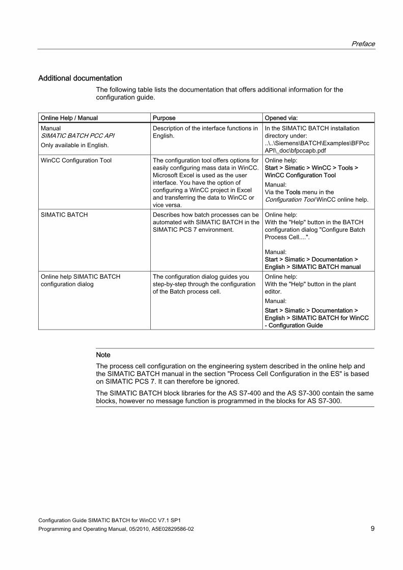
Additional documentation The following table lists the documentation that offers additional information for the configuration guide.
Online Help / Manual Purpose Opened via: Manual SIMATIC BATCH PCC API Only available in English.
Description of the interface functions in English.
In the SIMATIC BATCH installation directory under: ..\..\Siemens\BATCH\Examples\BFPccAPI\_doc\bfpccapb.pdf
WinCC Configuration Tool The configuration tool offers options for easily configuring mass data in WinCC. Microsoft Excel is used as the user interface. You have the option of configuring a WinCC project in Excel and transferring the data to WinCC or vice versa.
Online help: Start > Simatic > WinCC > Tools > WinCC Configuration Tool Manual: Via the Tools menu in the Configuration Tool WinCC online help.
SIMATIC BATCH
Describes how batch processes can be automated with SIMATIC BATCH in the SIMATIC PCS 7 environment.
Online help: With the "Help" button in the BATCH configuration dialog "Configure Batch Process Cell....". Manual: Start > Simatic > Documentation > English > SIMATIC BATCH manual
Online help SIMATIC BATCH configuration dialog
The configuration dialog guides you step-by-step through the configuration of the Batch process cell.
Online help: With the "Help" button in the plant editor. Manual: Start > Simatic > Documentation > English > SIMATIC BATCH for WinCC - Configuration Guide
Note The process cell configuration on the engineering system described in the online help and the SIMATIC BATCH manual in the section "Process Cell Configuration in the ES" is based on SIMATIC PCS 7. It can therefore be ignored. The SIMATIC BATCH block libraries for the AS S7-400 and the AS S7-300 contain the same blocks, however no message function is programmed in the blocks for AS S7-300.

Preface
Configuration Guide SIMATIC BATCH for WinCC V7.1 SP1 10 Programming and Operating Manual, 05/2010, A5E02829586-02

Configuration Guide SIMATIC BATCH for WinCC V7.1 SP1 Programming and Operating Manual, 05/2010, A5E02829586-02 11
Introduction to the Configuration Guide 22.1 Installation of the Software Components
Overview of software requirements You must have installed the following software components for the example configuration on your PC: ● One of the following operating systems:
– Windows XP Professional with Service Pack 2 – Microsoft Windows Server 2003 R2 with Service Pack 2
● Microsoft SQL Server 2005 SP2 ● Microsoft Excel 2003 with Service Pack 2 ● SIMATIC STEP 7 V5.4 with SP5 HF4 ● SIMATIC WinCC V7.0 SP1 HF4 with the "Smart Tools" components and the "WinCC
Configuration Tool". ● SIMATIC BATCH V7.1 SP1 HF3 with the Automation License Manager V4.0 incl. SP5,
SIMATIC Logon V1.4 SP2 and Acrobat Reader 9.0.
Note The installation of WinCC incl. hotfix is not carried out during the installation of SIMATIC BATCH for WinCC V7.1 SP1. The installation files are located in the folders "WinCC_V70SP1" and "WinCC_V70SP1HF4".
SIMATIC BATCH Installation 1. Insert the SIMATIC BATCH installation DVD in your drive and double-click the
"Setup.exe" file. 2. For this example configuration, select "BATCH Single Station" option in the "Program
Package" setup dialog box. 3. If programs are already installed a blue check mark appears in front of the components.
During the setup you are prompted by a dialog box to specify the security settings for your firewall.
4. Select an installation path using the "Browse" button or confirm the suggested path. 5. In the next dialog box, enter an installation path for SIMATIC BATCH Backup. Specify a
path using the "Browse" button or confirm the suggested path. 6. Follow the instructions provided by the Wizard and close the Setup.

Introduction to the Configuration Guide 2.2 Additional Information for the Configuration Example
Configuration Guide SIMATIC BATCH for WinCC V7.1 SP1 12 Programming and Operating Manual, 05/2010, A5E02829586-02
2.2 Additional Information for the Configuration Example
Introduction The data required for the configuration are available in the folder "..\BATCH\SBSCADAEXA" following the installation from the data medium you have chosen.
Data for the configuration example You will find the following folders in the installation directory of BATCH: ● "SBSCADAEXA" folder ● "Examples" subfolder ● "Manual" subfolder ● "Setup" subfolder
"SBSCADAEXA" folder with the SIMATIC BATCH configuration dialog This folder contains the configuration dialog with the name "sbfwsbbatchwzrdx.exe". This folder additionally contains the Configuration Guide in the form of online help. You can call up the online help from the configuration dialog by using the "Help" button or directly from this folder.
"Examples" subfolder The "Examples" folder contains the following files: ● sb_deliverytable.xls (delivery spreadsheet) ● sb_wincctypes.xls (structure types) ● SPOSATemplate.dcf (distribution configuration file for SIMATIC IT) The Excel files "sb_deliverytable.xls" and "sb_wincctypes" also serve as templates. The "sb_deliverytable.xls" file contains the data for WinCC and for the configuration dialog. The "sb_wincctypes.xls" file contains all the necessary structure types for WinCC. For further information please refer to the sections "Organization of the delivery spreadsheet (Page 73)" and "Structure types of the batch interface blocks (Page 48)". The *.dcf file serves as the template for the communication link with SIMATIC IT.
"Manual" subfolder This folder contains the Configuration Guide in PDF format in German and English with following names: ● projektierungsleitfaden.pdf ● engineeringguide.pdf Print the document in the desired language to perform the configuration.

Introduction to the Configuration Guide 2.2 Additional Information for the Configuration Example
Configuration Guide SIMATIC BATCH for WinCC V7.1 SP1 Programming and Operating Manual, 05/2010, A5E02829586-02 13
"Setup" subfolder This folder contains the readme files in German and English.Basics
2.2.1 System Components
Overview The system components included in the configuration are shown in the following graphic.
Introduction to the Configuration Guide 2.2 Additional Information for the Configuration Example
Configuration Guide SIMATIC BATCH for WinCC V7.1 SP1 14 Programming and Operating Manual, 05/2010, A5E02829586-02
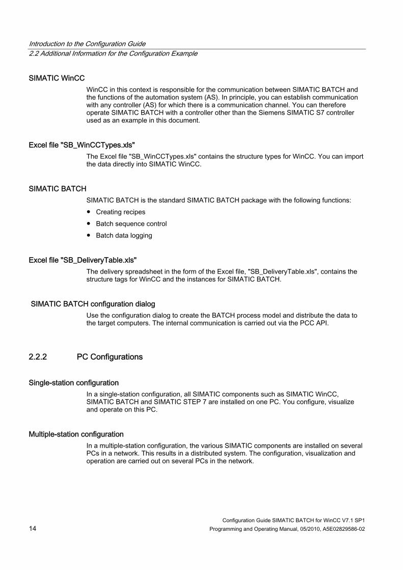
SIMATIC WinCC WinCC in this context is responsible for the communication between SIMATIC BATCH and the functions of the automation system (AS). In principle, you can establish communication with any controller (AS) for which there is a communication channel. You can therefore operate SIMATIC BATCH with a controller other than the Siemens SIMATIC S7 controller used as an example in this document.
Excel file "SB_WinCCTypes.xls" The Excel file "SB_WinCCTypes.xls" contains the structure types for WinCC. You can import the data directly into SIMATIC WinCC.
SIMATIC BATCH SIMATIC BATCH is the standard SIMATIC BATCH package with the following functions: ● Creating recipes ● Batch sequence control ● Batch data logging
Excel file "SB_DeliveryTable.xls" The delivery spreadsheet in the form of the Excel file, "SB_DeliveryTable.xls", contains the structure tags for WinCC and the instances for SIMATIC BATCH.
SIMATIC BATCH configuration dialog Use the configuration dialog to create the BATCH process model and distribute the data to the target computers. The internal communication is carried out via the PCC API.
2.2.2 PC Configurations
Single-station configuration In a single-station configuration, all SIMATIC components such as SIMATIC WinCC, SIMATIC BATCH and SIMATIC STEP 7 are installed on one PC. You configure, visualize and operate on this PC.
Multiple-station configuration In a multiple-station configuration, the various SIMATIC components are installed on several PCs in a network. This results in a distributed system. The configuration, visualization and operation are carried out on several PCs in the network.

Introduction to the Configuration Guide 2.2 Additional Information for the Configuration Example
Configuration Guide SIMATIC BATCH for WinCC V7.1 SP1 Programming and Operating Manual, 05/2010, A5E02829586-02 15
Redundant configuration A configuration is considered redundant when there are redundant BATCH servers and/or WinCC servers in a distributed system. The appropriate redundancy mechanisms are offered for BATCH and WinCC servers.
2.2.3 Communication
Overview
Communication between WinCC and the Controllers The communication with the controllers takes place via SIMATIC WinCC. WinCC has special, optimized channel drivers for connection to Siemens controllers such as S7. All other controllers can be connected via OPC (OLE for Process Control).
Communication between SIMATIC BATCH and WinCC The communication between SIMATIC BATCH and SIMATIC WinCC takes place through an integrated Siemens format.
Additional information You can find additional information about this in the section "Configuration steps in the WinCC Explorer > add channel". (Page 42)

Introduction to the Configuration Guide 2.2 Additional Information for the Configuration Example
Configuration Guide SIMATIC BATCH for WinCC V7.1 SP1 16 Programming and Operating Manual, 05/2010, A5E02829586-02
2.2.4 Time synchronization
Synchronization of the time The time-of-day between the various stations (SIMATIC BATCH Server/Client, WinCC OS) and the AS needs to be synchronized. You can find additional information on time synchronization in the "Time Synchronization" section of the online help for WinCC.
Configuration Guide SIMATIC BATCH for WinCC V7.1 SP1 Programming and Operating Manual, 05/2010, A5E02829586-02 17
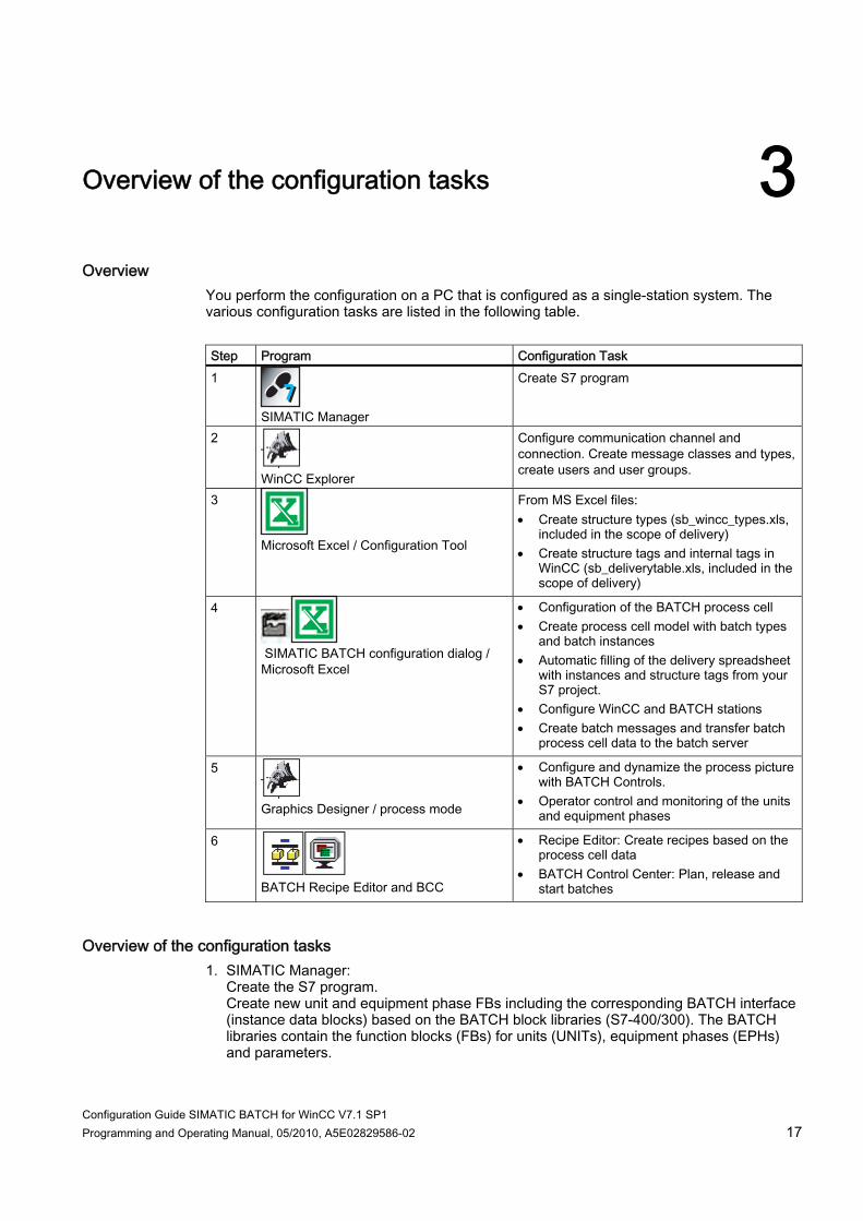
Overview of the configuration tasks 3Overview
You perform the configuration on a PC that is configured as a single-station system. The various configuration tasks are listed in the following table. Step Program Configuration Task 1
SIMATIC Manager
Create S7 program
2
WinCC Explorer
Configure communication channel and connection. Create message classes and types, create users and user groups.
3
Microsoft Excel / Configuration Tool
From MS Excel files: Create structure types (sb_wincc_types.xls,
included in the scope of delivery) Create structure tags and internal tags in
WinCC (sb_deliverytable.xls, included in the scope of delivery)
4
SIMATIC BATCH configuration dialog / Microsoft Excel
Configuration of the BATCH process cell Create process cell model with batch types
and batch instances Automatic filling of the delivery spreadsheet
with instances and structure tags from your S7 project.
Configure WinCC and BATCH stations Create batch messages and transfer batch
process cell data to the batch server
5
Graphics Designer / process mode
Configure and dynamize the process picture with BATCH Controls.
Operator control and monitoring of the units and equipment phases
6
BATCH Recipe Editor and BCC
Recipe Editor: Create recipes based on the process cell data
BATCH Control Center: Plan, release and start batches
Overview of the configuration tasks 1. SIMATIC Manager:
Create the S7 program. Create new unit and equipment phase FBs including the corresponding BATCH interface (instance data blocks) based on the BATCH block libraries (S7-400/300). The BATCH libraries contain the function blocks (FBs) for units (UNITs), equipment phases (EPHs) and parameters.
Overview of the configuration tasks
Configuration Guide SIMATIC BATCH for WinCC V7.1 SP1 18 Programming and Operating Manual, 05/2010, A5E02829586-02
2. Configuring in WinCC Create a new WinCC project. Configure message classes and message types in the OS Project Editor. Add a communication connection in the WinCC tag management.
3. Generate the structure types and structure tags Generate the structure types using the WinCC Configuration Tool implemented in MS Excel and the supplied "sb_wincc_types.xls" Excel spreadsheet. Generate the structure tags in WinCC manually using the custom "sb_deliverytable.xls" file with units, equipment phases and parameters including the associated addresses from the Batch interface.
4. Configuring in the SIMATIC BATCH configuration dialog In the configuration dialog the configuration of the BATCH process cell, the process model with the batch types and batch instances are created, all the BATCH and WinCC stations of the process cell configured and subsequently distributed to the stations. In addition the messages in WinCC are generated automatically.
5. A process picture created and dynamized in the Graphics Designer provides the possibility of manually operating the unit, the equipment phase and a setpoint.
6. Based on the process cell data that was generated and distributed in step 4, you can create recipes in the BATCH Recipe Editor and generate batches in the BATCH Control Center.
Configuration Guide SIMATIC BATCH for WinCC V7.1 SP1 Programming and Operating Manual, 05/2010, A5E02829586-02 19
Configuration steps in the SIMATIC Manager 44.1 Basic procedure
Blocks of the BATCH library You assemble the user program from the blocks of the installed BATCH block library. All the function blocks (FBs) required for the configuration are contained in the BATCH block libraries for an AS S7-400/300. User blocks can be created in the statement list (STL) based on these blocks. You can freely choose a structure, block names and the block numbers in STEP 7 from the symbol table. The following data and logic blocks are created in this documentation: ● OB 32 ● Reactor (FB) ● Reactor (DB) ● Heating (FB)

Configuration steps in the SIMATIC Manager 4.2 Standard blocks of the SIMATIC BATCH library
Configuration Guide SIMATIC BATCH for WinCC V7.1 SP1 20 Programming and Operating Manual, 05/2010, A5E02829586-02
The diagram below illustrates the structure of the blocks.
4.2 Standard blocks of the SIMATIC BATCH library
Blocks of the installed library SIMATIC BATCH Blocks (S7-400/S7-300) To create the SIMATIC S7 interface you use the following standard blocks from the installed SIMATIC BATCH block library.
Source / symbolic name Object name and block
type Comment
IEOP FB253 Interface Equipment Operation Block (IEOP) IEPH FB254 Interface Equipment Phase Block (IEPH) NOTIFY_8P SFB31 IEPAR_DINT FB255 Interface Equipment Parameter Module for Data Type Integer IEPAR_BOOL FB256 Interface Equipment Parameter Module for Data Type Boolean IEPAR_REAL FB257 Interface Equipment Parameter Module for Data Type Real IEPAR_STR FB258 Interface Equipment Parameter Module for Data Type String

Configuration steps in the SIMATIC Manager 4.3 User function block for the control of an equipment phase
Configuration Guide SIMATIC BATCH for WinCC V7.1 SP1 Programming and Operating Manual, 05/2010, A5E02829586-02 21
Source / symbolic name Object name and block type
Comment
IEPAR_ENUM FB259 Interface Equipment Parameter Module for Parameter Type ENUM
IEPAR_PI FB260 Interface Equipment Parameter Module for Process Input IEPAR_PO FB261 Interface Equipment Parameter Module for Process Output IEPAR_SOURCE FB262 Interface Equipment Parameter Module for Data Type
SOURCE IEPAR_DEST FB263 Interface Equipment Parameter Module for Data Type DEST IEPAR_VIA FB264 Interface Equipment Parameter Module for Data Type VIA IEPAR_TKEY FB265 Interface Equipment Parameter Module for Data Type TKEY IUNIT_BLOCK FB251 Interface IUNIT Block TAG_COLL FB252 Tag Collection Block
4.3 User function block for the control of an equipment phase
Introduction A function type is created as a function block. Create a function block for each function type. It contains the following: ● Instance data of the function block IEPH / IEOP ● Instances of the IEPAR_DINT parameters (depending on the type)
Handling of the STL source file as a template You can use the enclosed STL source for the "Heating" equipment phase in order to implement your equipment phases. To do so, copy the entire program code into the clipboard using the "Screen selection" function provided in the HTML help. Insert a new object (STL source) into the "Source" S7 program folder. Open the STL source and insert the content from the clipboard into the STL source. Save and compile the STL source. The program parts that you have to adapt to your process are highlighted in bold in the following template.
Note Set the mnemonic! For the translation of the STL source available to you English is required under Settings, Language tab, for the mnemonic in the SIMATIC Manager.

Configuration steps in the SIMATIC Manager 4.3 User function block for the control of an equipment phase
Configuration Guide SIMATIC BATCH for WinCC V7.1 SP1 22 Programming and Operating Manual, 05/2010, A5E02829586-02
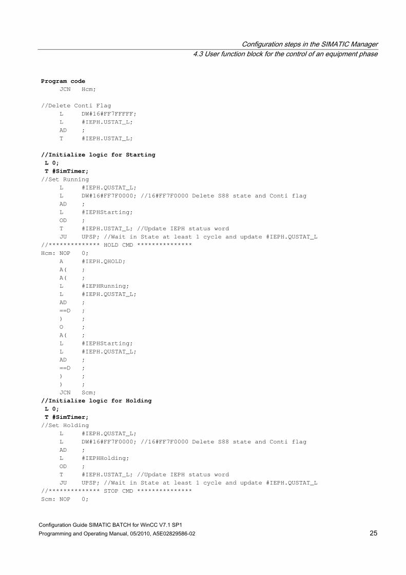
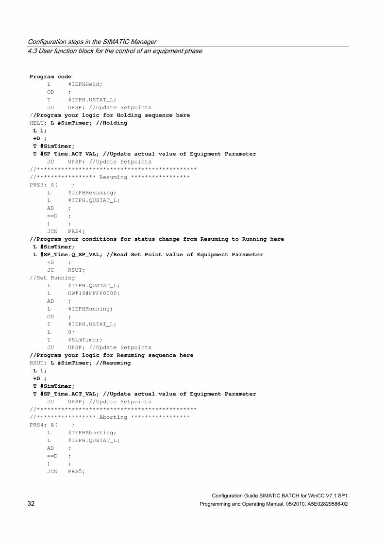
STL source for the "Heating (FB)" equipment phase The status transitions implemented in the program code correspond to those in the flow diagram for the function block "IEPH (Page 104)". The implemented program code corresponds to the user logic to be executed for the individual command, for example START, area marked red in the flow diagram for the "START" command (Page 106). In this template a timer simulates the process. The setpoint of the "SP_Time" equipment phase controls how long the equipment phase is to remain in a status. The "SELFCOM" block parameter decides whether the equipment phase is self-terminating or not self-terminating. For further information refer to Chapter 5.11 in the documentation of SIMATIC BATCH.
Rule Take into account when creating the block of the equipment phase that the Batch function blocks IEPH or IEOP may only be declared once per type.
Note The symbolic block name assigned by you for the equipment phase as well as the tag name of the function parameters are used during the automatic WinCC structure tag creation.
Note MSG_EVID_1 and _2 only have to be declared for blocks of the S7-400, not for blocks of the S7-300.
Program code FUNCTION_BLOCK "Heating" TITLE = VERSION : 0.1 VAR_INPUT MSG_EVID_1 { S7_server := 'alarm_archiv'; S7_a_type := 'notify_8p' }: DWORD; MSG_EVID_2 { S7_server := 'alarm_archiv'; S7_a_type := 'notify_8p' }: DWORD; END_VAR VAR IEPH: "IEPH"; SP_Time : "IEPAR_DINT"; //Declaration of Equipment Parameters SELFCOMP : BOOL ; SimTimer : DINT ; END_VAR VAR_TEMP IEPHIdle : WORD ; IEPHRunning : WORD ; IEPHReady : WORD ; IEPHCompleting : WORD ; IEPHCompleted : WORD ; IEPHResuming : WORD ; IEPHHolding : WORD ; IEPHHeld : WORD ; IEPHStopping : WORD ;

Configuration steps in the SIMATIC Manager 4.3 User function block for the control of an equipment phase
Configuration Guide SIMATIC BATCH for WinCC V7.1 SP1 Programming and Operating Manual, 05/2010, A5E02829586-02 23
Program code IEPHStopped : WORD ; IEPHAborting : WORD ; IEPHAborted : WORD ; IEPHUninit : WORD ; IEPHStarting : WORD ; END_VAR BEGIN NETWORK TITLE =Initialization of Local Variables //Idle L B#16#1; T #IEPHIdle; //Starting L W#16#200; T #IEPHStarting; //Runnig L B#16#2; T #IEPHRunning; //Ready L B#16#20; T #IEPHReady; //Completing L W#16#800; T #IEPHCompleting; //Completed L B#16#4; T #IEPHCompleted; //Holding L W#16#1000; T #IEPHHolding; //Held L B#16#8; T #IEPHHeld; //Resuming L W#16#400; T #IEPHResuming; //Aborting L W#16#2000; T #IEPHAborting; //Aborted L W#16#10; T #IEPHAborted; //Stopping L W#16#4000; T #IEPHStopping; //Stopped L B#16#40; T #IEPHStopped; //Uninit L 0; T #IEPHUninit;

Configuration steps in the SIMATIC Manager 4.3 User function block for the control of an equipment phase
Configuration Guide SIMATIC BATCH for WinCC V7.1 SP1 24 Programming and Operating Manual, 05/2010, A5E02829586-02
Program code //Initialize EPH L #IEPH.QUSTAT_L; L DW#16#7E7F; AW ; L 0; <>I ; JC IOK; L DW#16#60001; T #IEPH.USTAT_L; IOK: NOP 0; NETWORK TITLE =Initial call of IEPH copies SB commands from block IN to OUT CALL #IEPH ( MSG_EVID_1 := #MSG_EVID_1, MSG_EVID_2 := #MSG_EVID_2); NETWORK TITLE = Call of IEPAR block copies SP_VAL value written by BCS from IN to OUT CALL #SP_Time ; //Call all Equipment Parameter blocks here NETWORK TITLE =EPH Commands processing //************Set/Reset Occupy*********** AN #IEPH.Q_OCCUPI; JC ROCC; L DW#16#1000000; L #IEPH.USTAT_L; OD ; T #IEPH.USTAT_L; JU EPHR; ROCC: L DW#16#FEFFFFFF; L #IEPH.USTAT_L; AD ; T #IEPH.USTAT_L; //Update IEPH status word EPHR: NOP 0; //************** START CMD ************** A #IEPH.QSTART; A( ; A( ; L #IEPHIdle; L #IEPH.QUSTAT_L; AD ; ==D ; ) ; O ; A( ; L DW#16#800000; //Restart in Conti L #IEPH.QUSTAT_L; AD ; L DW#16#800000; //Conti ==D ; ) ; ) ;
Configuration steps in the SIMATIC Manager 4.3 User function block for the control of an equipment phase
Configuration Guide SIMATIC BATCH for WinCC V7.1 SP1 Programming and Operating Manual, 05/2010, A5E02829586-02 25
Program code JCN Hcm; //Delete Conti Flag L DW#16#FF7FFFFF; L #IEPH.USTAT_L; AD ; T #IEPH.USTAT_L; //Initialize logic for Starting L 0; T #SimTimer; //Set Running L #IEPH.QUSTAT_L; L DW#16#FF7F0000; //16#FF7F0000 Delete S88 state and Conti flag AD ; L #IEPHStarting; OD ; T #IEPH.USTAT_L; //Update IEPH status word JU UPSP; //Wait in State at least 1 cycle and update #IEPH.QUSTAT_L //************** HOLD CMD *************** Hcm: NOP 0; A #IEPH.QHOLD; A( ; A( ; L #IEPHRunning; L #IEPH.QUSTAT_L; AD ; ==D ; ) ; O ; A( ; L #IEPHStarting; L #IEPH.QUSTAT_L; AD ; ==D ; ) ; ) ; JCN Scm; //Initialize logic for Holding L 0; T #SimTimer; //Set Holding L #IEPH.QUSTAT_L; L DW#16#FF7F0000; //16#FF7F0000 Delete S88 state and Conti flag AD ; L #IEPHHolding; OD ; T #IEPH.USTAT_L; //Update IEPH status word JU UPSP; //Wait in State at least 1 cycle and update #IEPH.QUSTAT_L //************** STOP CMD *************** Scm: NOP 0;

Configuration steps in the SIMATIC Manager 4.3 User function block for the control of an equipment phase
Configuration Guide SIMATIC BATCH for WinCC V7.1 SP1 26 Programming and Operating Manual, 05/2010, A5E02829586-02
Program code A #IEPH.QSTOP; A( ; A( ; L #IEPHStarting; L #IEPH.QUSTAT_L; AD ; ==D ; ) ; O ; A( ; L #IEPHRunning; L #IEPH.QUSTAT_L; AD ; ==D ; ) ; O ; A( ; L #IEPHHolding; L #IEPH.QUSTAT_L; AD ; ==D ; ) ; O ; A( ; L #IEPHHeld; L #IEPH.QUSTAT_L; AD ; ==D ; ) ; O ; A( ; L #IEPHCompleting; L #IEPH.QUSTAT_L; AD ; ==D ; ) ; ) ; JCN Acm; //Initialize logic for Stopping L 0; T #SimTimer; //Set Stopping L #IEPH.QUSTAT_L; L DW#16#FF7F0000; //16#FF7F0000 Delete S88 state and Conti flag AD ; L #IEPHStopping; OD ; T #IEPH.USTAT_L; //Update IEPH status word JU UPSP; //Wait in State at least 1 cycle and update #IEPH.QUSTAT_L //************** ABORT CMD ************** Acm: NOP 0;

Configuration steps in the SIMATIC Manager 4.3 User function block for the control of an equipment phase
Configuration Guide SIMATIC BATCH for WinCC V7.1 SP1 Programming and Operating Manual, 05/2010, A5E02829586-02 27
Program code A #IEPH.QABORT; A( ; A( ; L #IEPHStarting; L #IEPH.QUSTAT_L; AD ; ==D ; ) ; O ; A( ; L #IEPHRunning; L #IEPH.QUSTAT_L; AD ; ==D ; ) ; O ; A( ; L #IEPHHolding; L #IEPH.QUSTAT_L; AD ; ==D ; ) ; O ; A( ; L #IEPHHeld; L #IEPH.QUSTAT_L; AD ; ==D ; ) ; O ; A( ; L #IEPHCompleting; L #IEPH.QUSTAT_L; AD ; ==D ; ) ; ) ; JCN RScm; //Initialize logic for Aborting L 0; T #SimTimer; //Set Aborting L #IEPH.QUSTAT_L; L DW#16#FF7F0000; //16#FF7F0000 Delete S88 state and Conti flag AD ; L #IEPHAborting; OD ; T #IEPH.USTAT_L; //Update IEPH status word JU UPSP; //Wait in State at least 1 cycle and update #IEPH.QUSTAT_L //************** RESET CMD ************** RScm: NOP 0;

Configuration steps in the SIMATIC Manager 4.3 User function block for the control of an equipment phase
Configuration Guide SIMATIC BATCH for WinCC V7.1 SP1 28 Programming and Operating Manual, 05/2010, A5E02829586-02
Program code A #IEPH.QRESET; A( ; A( ; L #IEPHStopped; L #IEPH.QUSTAT_L; AD ; ==D ; ) ; O ; A( ; L #IEPHAborted; L #IEPH.QUSTAT_L; AD ; ==D ; ) ; O ; A( ; L #IEPHCompleted; L #IEPH.QUSTAT_L; AD ; ==D ; ) ; ) ; JCN Rcm; //Reset logic for EPH L 0; T #SimTimer; //Set Idle L #IEPH.QUSTAT_L; L DW#16#FF7F0000; //16#FF7F0000 Delete S88 state and Conti flag AD ; L #IEPHIdle; OD ; T #IEPH.USTAT_L; //Update IEPH status word JU UPSP; //Wait in State at least 1 cycle and update #IEPH.QUSTAT_L //************* RESUME CMD ************** Rcm: NOP 0; A #IEPH.QSTART; A( ; L #IEPHHeld; L #IEPH.QUSTAT_L; AD ; ==D ; ) ; JCN Ccm; //Initialize logic for Resuming L 0; T #SimTimer; //Set Resuming L #IEPH.QUSTAT_L; L DW#16#FF7F0000; //16#FF7F0000 Delete S88 state and Conti flag

Configuration steps in the SIMATIC Manager 4.3 User function block for the control of an equipment phase
Configuration Guide SIMATIC BATCH for WinCC V7.1 SP1 Programming and Operating Manual, 05/2010, A5E02829586-02 29
Program code AD ; L #IEPHResuming; OD ; T #IEPH.USTAT_L; //Update IEPH status word JU UPSP; //Wait in State at least 1 cycle and update #IEPH.QUSTAT_L //************ COMPLETE CMD ************* Ccm: NOP 0; A #IEPH.QTERM; A( ; L #IEPHReady; L #IEPH.QUSTAT_L; AD ; ==D ; ) ; JCN PROC; //Initialize logic for Completing L 0; T #SimTimer; //Set Completing L #IEPH.QUSTAT_L; L DW#16#FF7F0000; //16#FF7F0000 Delete S88 state and Conti flag AD ; L #IEPHCompleting; OD ; T #IEPH.USTAT_L; //Update IEPH status word JU UPSP; //Wait in State at least 1 cycle and update #IEPH.QUSTAT_L NETWORK TITLE =State Processing //***************** Starting ********************** PROC: A( ; L #IEPHStarting; L #IEPH.QUSTAT_L; AD ; ==D ; ) ; JCN PRS0; //Program your conditions for status change from Starting to Running here L #SimTimer; L #SP_Time.Q_SP_VAL; //Read Set Point value of Equipment Parameter <D ; JC STRT; //Initialization of Running sequence L 0; T #SimTimer; //RPH status change from Starting to Running L #IEPH.QUSTAT_L; L DW#16#FFFF0000; AD ; L #IEPHRunning; OD ; T #IEPH.USTAT_L; //Update IEPH status word

Configuration steps in the SIMATIC Manager 4.3 User function block for the control of an equipment phase
Configuration Guide SIMATIC BATCH for WinCC V7.1 SP1 30 Programming and Operating Manual, 05/2010, A5E02829586-02
Program code JU UPSP; //Update Setpoints //Program your logic for Starting sequence here STRT: L #SimTimer; //Starting L L#1; +D ; T #SimTimer; T #SP_Time.ACT_VAL; //Update actual value of Equipment Parameter JU UPSP; //Update Setpoints //********************************************** //***************** Running ********************** PRS0: A( ; L #IEPHRunning; L #IEPH.QUSTAT_L; AD ; ==D ; ) ; JCN PRS1; //Program your conditions for status change from Running to Completing or READY here L #SimTimer; L #SP_Time.Q_SP_VAL; //Read Set Point value of Equipment Parameter <D ; JC RUNT; SET; S #SELFCOMP; A #SELFCOMP; JC SELF; //None Self completing EPH. Set Ready and wait for SB cmd Complete //Initialization of READY sequence L 0; T #SimTimer; L #IEPH.QUSTAT_L; L DW#16#FFFFFFDF; AD ; L #IEPHReady; OD ; T #IEPH.USTAT_L; //Update IEPH status word JU UPSP; //Update Setpoints //Self completing EPH. EPH can complete itself //Initialization of Completing sequence SELF: L 0; T #SimTimer; L #IEPH.QUSTAT_L; L DW#16#FFFF0000; AD ; L #IEPHCompleting; OD ; T #IEPH.USTAT_L; JU UPSP; //Update Setpoints //Program your logic for Running sequence here RUNT: L #SimTimer; //Running L L#1;

Configuration steps in the SIMATIC Manager 4.3 User function block for the control of an equipment phase
Configuration Guide SIMATIC BATCH for WinCC V7.1 SP1 Programming and Operating Manual, 05/2010, A5E02829586-02 31
Program code +D ; T #SimTimer; T #SP_Time.ACT_VAL; //Update actual value of Equipment Parameter JU UPSP; //Update Setpoints //********************************************** //***************** Completing ***************** PRS1: A( ; L #IEPHCompleting; L #IEPH.QUSTAT_L; AD ; ==D ; ) ; JCN PRS2; //Program your conditions for status change from Completing to Completed here L #SimTimer; L #SP_Time.Q_SP_VAL; //Read Set Point value of Equipment Parameter <D ; JC CMPT; //Set Completed L #IEPH.QUSTAT_L; L DW#16#FFFF0000; AD ; L #IEPHCompleted; OD ; T #IEPH.USTAT_L; JU UPSP; //Update Setpoints //Program your logic for Completing sequence here CMPT: L #SimTimer; //Completing L 1; +D ; T #SimTimer; T #SP_Time.ACT_VAL; //Update actual value of Equipment Parameter JU UPSP; //Update Setpoints //********************************************** //***************** Holding ***************** PRS2: A( ; L #IEPHHolding; L #IEPH.QUSTAT_L; AD ; ==D ; ) ; JCN PRS3; //Program your conditions for status change from Holding to Held here L #SimTimer; L #SP_Time.Q_SP_VAL; //Read Set Point value of Equipment Parameter <D ; JC HELT; //Set Held L #IEPH.QUSTAT_L; L DW#16#FFFF0000; AD ;
Configuration steps in the SIMATIC Manager 4.3 User function block for the control of an equipment phase
Configuration Guide SIMATIC BATCH for WinCC V7.1 SP1 32 Programming and Operating Manual, 05/2010, A5E02829586-02
Program code L #IEPHHeld; OD ; T #IEPH.USTAT_L; JU UPSP; //Update Setpoints //Program your logic for Holding sequence here HELT: L #SimTimer; //Holding L 1; +D ; T #SimTimer; T #SP_Time.ACT_VAL; //Update actual value of Equipment Parameter JU UPSP; //Update Setpoints //********************************************** //***************** Resuming ***************** PRS3: A( ; L #IEPHResuming; L #IEPH.QUSTAT_L; AD ; ==D ; ) ; JCN PRS4; //Program your conditions for status change from Resuming to Running here L #SimTimer; L #SP_Time.Q_SP_VAL; //Read Set Point value of Equipment Parameter <D ; JC RSUT; //Set Running L #IEPH.QUSTAT_L; L DW#16#FFFF0000; AD ; L #IEPHRunning; OD ; T #IEPH.USTAT_L; L 0; T #SimTimer; JU UPSP; //Update Setpoints //Program your logic for Resuming sequence here RSUT: L #SimTimer; //Resuming L 1; +D ; T #SimTimer; T #SP_Time.ACT_VAL; //Update actual value of Equipment Parameter JU UPSP; //Update Setpoints //********************************************** //***************** Aborting ***************** PRS4: A( ; L #IEPHAborting; L #IEPH.QUSTAT_L; AD ; ==D ; ) ; JCN PRS5;

Configuration steps in the SIMATIC Manager 4.3 User function block for the control of an equipment phase
Configuration Guide SIMATIC BATCH for WinCC V7.1 SP1 Programming and Operating Manual, 05/2010, A5E02829586-02 33
Program code //Program your conditions for status change from Aborting to Aborted here L #SimTimer; L #SP_Time.Q_SP_VAL; //Read Set Point value of Equipment Parameter <D ; JC ABRT; //Set Aborted L #IEPH.QUSTAT_L; L DW#16#FFFF0000; AD ; L #IEPHAborted; OD ; T #IEPH.USTAT_L; JU UPSP; //Update Setpoints //Program your logic for Aborting sequence here ABRT: L #SimTimer; //Aborting L 1; +D ; T #SimTimer; T #SP_Time.ACT_VAL; //Update actual value of Equipment Parameter JU UPSP; //Update Setpoints //********************************************** //***************** Stopping ***************** PRS5: A( ; L #IEPHStopping; L #IEPH.QUSTAT_L; AD ; ==D ; ) ; JCN PRS6; //Program your conditions for status change from Stopping to Stopped here L #SimTimer; L #SP_Time.Q_SP_VAL; //Read Set Point value of Equipment Parameter <D ; JC STPT; //Set Stopped L #IEPH.QUSTAT_L; L DW#16#FFFF0000; AD ; L #IEPHStopped; OD ; T #IEPH.USTAT_L; JU UPSP; //Update Setpoints //Program your logic for Stopping sequence here STPT: L #SimTimer; //Stopping L 1; +D ; T #SimTimer; T #SP_Time.ACT_VAL; //Update actual value of Equipment Parameter JU UPSP; //Update Setpoints //********************************************** //***************** Set/Reset Continue *********
Configuration steps in the SIMATIC Manager 4.4 User function block for the control of a unit class
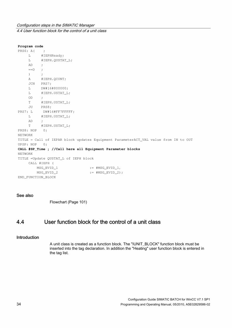
Configuration Guide SIMATIC BATCH for WinCC V7.1 SP1 34 Programming and Operating Manual, 05/2010, A5E02829586-02
Program code PRS6: A( ; L #IEPHReady; L #IEPH.QUSTAT_L; AD ; ==D ; ) ; A #IEPH.QCONT; JCN PRS7; L DW#16#800000; L #IEPH.USTAT_L; OD ; T #IEPH.USTAT_L; JU PRS8; PRS7: L DW#16#FF7FFFFF; L #IEPH.USTAT_L; AD ; T #IEPH.USTAT_L; PRS8: NOP 0; NETWORK TITLE = Call of IEPAR block updates Equipment ParameterACT_VAL value from IN to OUT UPSP: NOP 0; CALL #SP_Time ; //Call here all Equipment Parameter blocks NETWORK TITLE =Update QUSTAT_L of IEPH block CALL #IEPH ( MSG_EVID_1 := #MSG_EVID_1, MSG_EVID_2 := #MSG_EVID_2); END_FUNCTION_BLOCK
See also Flowchart (Page 101)
4.4 User function block for the control of a unit class
Introduction A unit class is created as a function block. The "IUNIT_BLOCK" function block must be inserted into the tag declaration. In addition the "Heating" user function block is entered in the tag list.

Configuration steps in the SIMATIC Manager 4.4 User function block for the control of a unit class
Configuration Guide SIMATIC BATCH for WinCC V7.1 SP1 Programming and Operating Manual, 05/2010, A5E02829586-02 35
Handling of the STL source file You can use the enclosed STL source for the "Reactor" unit class in order to implement your unit class. To do so, copy the entire program code into the clipboard using the "Program code" function provided in the HTML help. Insert a new object (STL source) into the "Source" S7 program folder. Open the STL source and insert the content from the clipboard into the STL source. Save and compile the STL source. The program parts that you have to adapt to your process are highlighted in bold.
Note Set the mnemonic! For the translation of the STL source available to you English is required under Settings, Language tab, for the mnemonic in the SIMATIC Manager.
Rule Take into account when creating the block of the unit class that the Batch function block IUNIT_BLOCK only has to be declared once.
Note The symbolic block name assigned by you for the unit class is used during the automatic WinCC structure tag creation.
Reactor example Program code FUNCTION_BLOCK "Reactor" TITLE = VERSION : 0.1 VAR_INPUT Reactor_MSG_EVID_1 { S7_server := 'alarm_archiv'; S7_a_type := 'notify_8p' }: DWORD; Heating_MSG_EVID_1 { S7_server := 'alarm_archiv'; S7_a_type := 'notify_8p' }: DWORD; Heating_MSG_EVID_2 { S7_server := 'alarm_archiv'; S7_a_type := 'notify_8p' }: DWORD; END_VAR VAR Heating : "Heating"; //Declaration all user defined Equipment Phases IUNIT : "IUNIT_BLOCK"; END_VAR BEGIN NETWORK TITLE = CALL #IUNIT ( MSG_EVID_1 := #Reactor_MSG_EVID_1); CALL #Heating ( MSG_EVID_1 := #Heating_MSG_EVID_1, MSG_EVID_2 := #Heating_MSG_EVID_2); //Call all Equipment Phase blocks here END_FUNCTION_BLOCK

Configuration steps in the SIMATIC Manager 4.5 User instance data block for a unit class
Configuration Guide SIMATIC BATCH for WinCC V7.1 SP1 36 Programming and Operating Manual, 05/2010, A5E02829586-02
4.5 User instance data block for a unit class
Instance block for the unit class You can now create the unit instance as an instance data block for the unit class in the SIMATIC Manager. To do so, select Insert new object > Data block in the block container of your project. Enter the symbolic name "Reactor001" and select "Instance DB" as the type. Select the FB number of the corresponding unit class IUNIT_BLOCK (FB).
Note The symbolic data block name assigned by you for the unit class instance is used during the automatic WinCC structure tag creation.
4.6 Calling the Blocks
Call In order for the one unit instance to process a controlling function block in the AS, you must position a call in a cyclic block, e.g. in the OB32. The unit block must not be called cyclically in less than 1 second intervals
Note Set the mnemonic! For the translation of the STL source available to you English is required under Settings, Language tab, for the mnemonic in the SIMATIC Manager.
OB32 example Program code ORGANIZATION_BLOCK OB 32 TITLE = "Main Program Sweep (1-sec cycle)" VERSION : 0.1 VAR_TEMP EV_CLASS : BYTE ; //Bits 0-3 = 1 (Coming event), Bits //4-7 = 1 (Event class 1) SCAN_1 : BYTE ; //1 (Cold restart scan 1 of OB 32), 3 //(Scan 2-n of OB 32) PRIORITY : BYTE ; //Priority of OB Execution OB_NUMBR : BYTE ; //32 (Organization block 32, OB32) RESERVED_1 : BYTE ; //Reserved for system
Configuration steps in the SIMATIC Manager 4.7 Downloading Blocks to the AS
Configuration Guide SIMATIC BATCH for WinCC V7.1 SP1 Programming and Operating Manual, 05/2010, A5E02829586-02 37
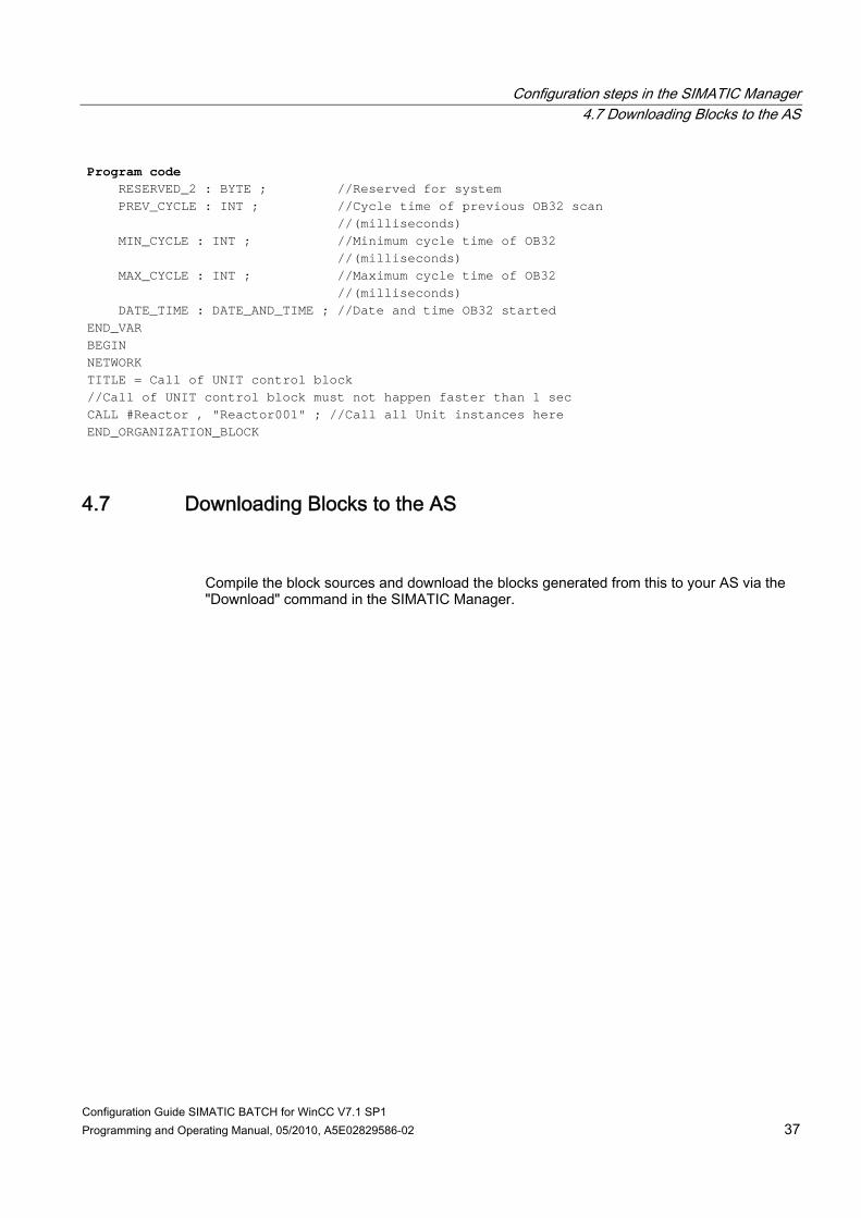
Program code RESERVED_2 : BYTE ; //Reserved for system PREV_CYCLE : INT ; //Cycle time of previous OB32 scan //(milliseconds) MIN_CYCLE : INT ; //Minimum cycle time of OB32 //(milliseconds) MAX_CYCLE : INT ; //Maximum cycle time of OB32 //(milliseconds) DATE_TIME : DATE_AND_TIME ; //Date and time OB32 started END_VAR BEGIN NETWORK TITLE = Call of UNIT control block //Call of UNIT control block must not happen faster than 1 sec CALL #Reactor , "Reactor001" ; //Call all Unit instances here END_ORGANIZATION_BLOCK
4.7 Downloading Blocks to the AS
Compile the block sources and download the blocks generated from this to your AS via the "Download" command in the SIMATIC Manager.

Configuration steps in the SIMATIC Manager 4.7 Downloading Blocks to the AS
Configuration Guide SIMATIC BATCH for WinCC V7.1 SP1 38 Programming and Operating Manual, 05/2010, A5E02829586-02

Configuration Guide SIMATIC BATCH for WinCC V7.1 SP1 Programming and Operating Manual, 05/2010, A5E02829586-02 39
Configuration steps in the WinCC Explorer 55.1 Creating a WinCC project
Introduction The WinCC project is created in WinCC Explorer. In this configuration, you will create a multi-user project.
Requirement SIMATIC WinCC is installed with options (BPC=Basic Process Control).
Procedure 1. Open the WinCC Explorer. 2. Select the menu command File > New. 3. Select the option button "Multi-User Project" and click "OK" to close the dialog box. 4. In the next dialog box enter the desired project name, select the project path and the
desired destination drive, and click the "Create" button.
Result The multi-user project is created and displayed in the WinCC Explorer.
Further information You can find further information about this in the "WinCC Information System" online help under Start > SIMATIC > WinCC.
5.2 Creating message classes and message types
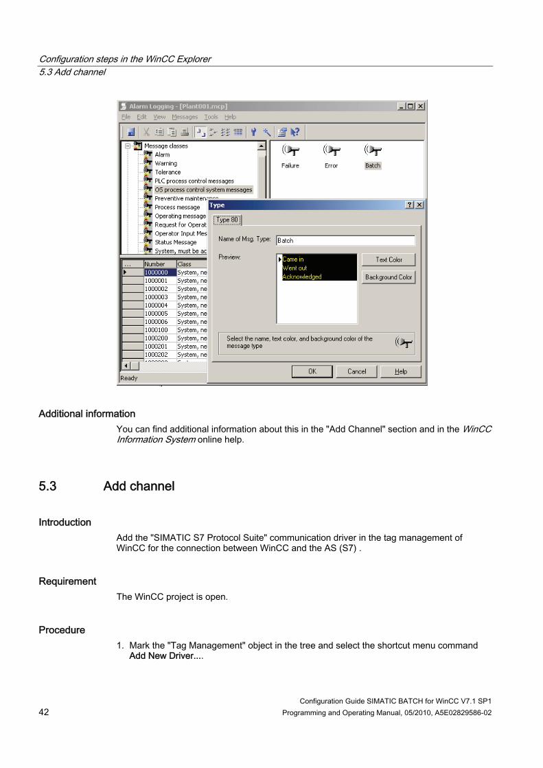
Introduction The OS Project Editor configures the WinCC message system and creates message classes and message types. To begin, open the OS Project Editor in the WinCC Explorer. Then check the message configuration for SIMATIC BATCH in the Alarm Logging.
Configuration steps in the WinCC Explorer 5.2 Creating message classes and message types
Configuration Guide SIMATIC BATCH for WinCC V7.1 SP1 40 Programming and Operating Manual, 05/2010, A5E02829586-02
Requirements ● WinCC Setup is installed with the "Options" and the "Basic Process Control" components
are selected. ● The WinCC Explorer is open.
Procedure 1. Double-click on "OS Project Editor" in the tree of the WinCC Explorer.
The Project Editor opens. 2. Change to the "Message Configuration" tab. 3. Leave the standard settings unchanged and click on the "OK" button to close the
message configuration in the OS Project Editor. 4. Double-click on "Alarm Logging" in the tree of the WinCC Explorer. 5. In the tree view double-click on the "Message Classes" data folder and double-click on
the object "OS Control Messages". 6. Double-click on the "Batch" object in the detail window to check the message type of the
"Batch" message class in the "Type" dialog box. The "Type 80" message type must be created in the OS Project Editor.
7. Close the dialog box. 8. Close the Alarm Logging.

Configuration steps in the WinCC Explorer 5.2 Creating message classes and message types
Configuration Guide SIMATIC BATCH for WinCC V7.1 SP1 Programming and Operating Manual, 05/2010, A5E02829586-02 41
Result The following figures show the important configuration tasks.
Configuration steps in the WinCC Explorer 5.3 Add channel
Configuration Guide SIMATIC BATCH for WinCC V7.1 SP1 42 Programming and Operating Manual, 05/2010, A5E02829586-02
Additional information You can find additional information about this in the "Add Channel" section and in the WinCC Information System online help.
5.3 Add channel
Introduction Add the "SIMATIC S7 Protocol Suite" communication driver in the tag management of WinCC for the connection between WinCC and the AS (S7) .
Requirement The WinCC project is open.
Procedure 1. Mark the "Tag Management" object in the tree and select the shortcut menu command
Add New Driver....

Configuration steps in the WinCC Explorer 5.4 Create connection
Configuration Guide SIMATIC BATCH for WinCC V7.1 SP1 Programming and Operating Manual, 05/2010, A5E02829586-02 43
2. Select the "SIMATIC S7 Protocol Suite.chn" driver by expanding it or double-clicking.
Result The communication channel is created.
Additional information You can find additional information about this in the "Create Connection" section and in the WinCC Information System online help.
5.4 Create connection
Introduction Create one or more connections for the respective connection route depending on the number of automation systems involved. Configure these connections in the WinCC tag management.
Requirement A new driver is added.

Configuration steps in the WinCC Explorer 5.4 Create connection
Configuration Guide SIMATIC BATCH for WinCC V7.1 SP1 44 Programming and Operating Manual, 05/2010, A5E02829586-02
Procedure 1. In the "SIMATIC S7 PROTOCOL SUITE" communication driver, mark the communication
route through which you wish to communicate with the AS and open the shortcut menu. Example: MPI or Industrial Ethernet.
2. In the shortcut menu, select "New connection". 3. Enter a name for the connection in the "Connection Properties" dialog and click on the
"Properties" button. 4. In the "Connection Parameters" dialog box, assign the parameters for the connection
between WinCC and the AS. Enter the Ethernet address of the AS, the rack number and the slot number of the CPU and click on the "OK" button.
5. Mark the communication route in your communication driver once again and open the shortcut menu. Select "System parameter" from the shortcut menu.
6. Open the "Unit" tab. In the drop-down list, select the "Logical device name" that was assigned during the installation of the communication tab.
Result The connection from WinCC to the AS is established.

Configuration steps in the WinCC Explorer 5.5 Set up WinCC user
Configuration Guide SIMATIC BATCH for WinCC V7.1 SP1 Programming and Operating Manual, 05/2010, A5E02829586-02 45
Additional information You can find additional information about this in the WinCC Information System online help.
5.5 Set up WinCC user
Introduction Create a new user in the User Administrator for process mode logon. It is also possible to authenticate the user via the SIMATIC logon. You can find additional information about this in the SIMATIC logon or WinCC Information System online help.
Requirement The WinCC Explorer is open.
Procedure 1. Mark the "User Administrator" object in the tree view and select the shortcut menu
command Open. 2. In the User Administrator, open the shortcut menu for the "Administrator Group" and
select the menu command New User.

Configuration steps in the WinCC Explorer 5.5 Set up WinCC user
Configuration Guide SIMATIC BATCH for WinCC V7.1 SP1 46 Programming and Operating Manual, 05/2010, A5E02829586-02
3. Enter the logon and password in the "Create New User" dialog box and then enter the password again. Activate the "Copy group settings also" check box. All authorizations for this user are set.
4. Click on the "OK" button.
Result You have created a new user for runtime logon.

Configuration Guide SIMATIC BATCH for WinCC V7.1 SP1 Programming and Operating Manual, 05/2010, A5E02829586-02 47
Configuration tasks in MS Excel with the WinCC Configuration Tool 66.1 Introduction
Creating structure types in WinCC An MS Excel spreadsheet with the data of the created units, equipment phase and their parameters with the addresses is required for the configuration of the structure types in WinCC. Create the structure types in your WinCC project by using the WinCC configuration tool implemented in MS Excel and the supplied MS Excel spreadsheet "sb_wincctypes.xls".
Creating structure tags in WinCC An MS Excel spreadsheet with the WinCC structure tags is also required for the configuration of the structure tags in WinCC. The empty MS Excel spreadsheet "sb_deliverytable.xls" is provided to this purpose. This spreadsheet can be filled manually or automatically. The following section describes both variants. The aim of both procedures is a worksheet "STRUCTURE_TAGS_FOR_WINCC" filled with the WinCC tag names. Create the structure tags in your WinCC project using the WinCC Configuration Tool implemented in MS Excel and the filled out MS Excel "sb_deliverytable.xls" spreadsheet.
Manual filling of the MS Excel delivery spreadsheet The data for the MS Excel delivery spreadsheet result from the S7 program.
Note Copy both MS Excel files from the installation folder ..\SIEMENS\BATCH\sbsadaexa\examples into the Batch folder of your WinCC project. If the "Batch" subfolder was not created by the SIMATIC BATCH configuration dialog, you need to create this folder manually.

Configuration tasks in MS Excel with the WinCC Configuration Tool 6.2 Structure types in WinCC
Configuration Guide SIMATIC BATCH for WinCC V7.1 SP1 48 Programming and Operating Manual, 05/2010, A5E02829586-02
6.2 Structure types in WinCC
6.2.1 Structure type for the Batch interface blocks
Introduction The "sb_wincctypes.xls" Excel spreadsheet is located in the "Batch" WinCC project folder. All structure types required for the Batch interface are listed in the "Structure types" worksheet.
Structure types for the configuration The structure types required for the Batch interface in the configuration are listed in the "Name" column. The following structure types are shown in the supplied delivery spreadsheet: Name Description Structure in STEP 7 IUNIT_BLOCK Structure type for the unit interface IUNIT_BLOCK IEPH Structure type for the equipment phase interface IEPH IEPAR_DINT Structure type for a "32-bit integer" type parameter IEPAR_DINT IEPAR_BOOL Structure type for a "Boolean" type parameter IEPAR_BOOL IEPAR_STR Structure type for "String" type parameter IEPAR_STR IEPAR_PI Structure type for a parameter of the "Process Input"
type IEPAR_PI
IEPAR_REAL Structure type for a "Real" type parameter IEPAR_REAL IEPAR_PO Structure type for a parameter of the "Process Output"
type IEPAR_PO
IEPAR_ENUM Structure type for a parameter of the "Enumeration" type
IEPAR_ENUM
IEPAR_SOURCE Structure type for a parameter of the "Source" type IEPAR_SOURCE IEPAR_VIA Structure type for a parameter of the "Via" type IEPAR_VIA IEPAR_DEST Structure type for a parameter of the "Destination"
type IEPAR_DEST
6.2.2 Create structure types
Introduction The structure types used in your STEP 7 project must have been created in the WinCC Explorer using the WinCC Configuration Tool implemented in Microsoft Excel.
Configuration tasks in MS Excel with the WinCC Configuration Tool 6.2 Structure types in WinCC
Configuration Guide SIMATIC BATCH for WinCC V7.1 SP1 Programming and Operating Manual, 05/2010, A5E02829586-02 49
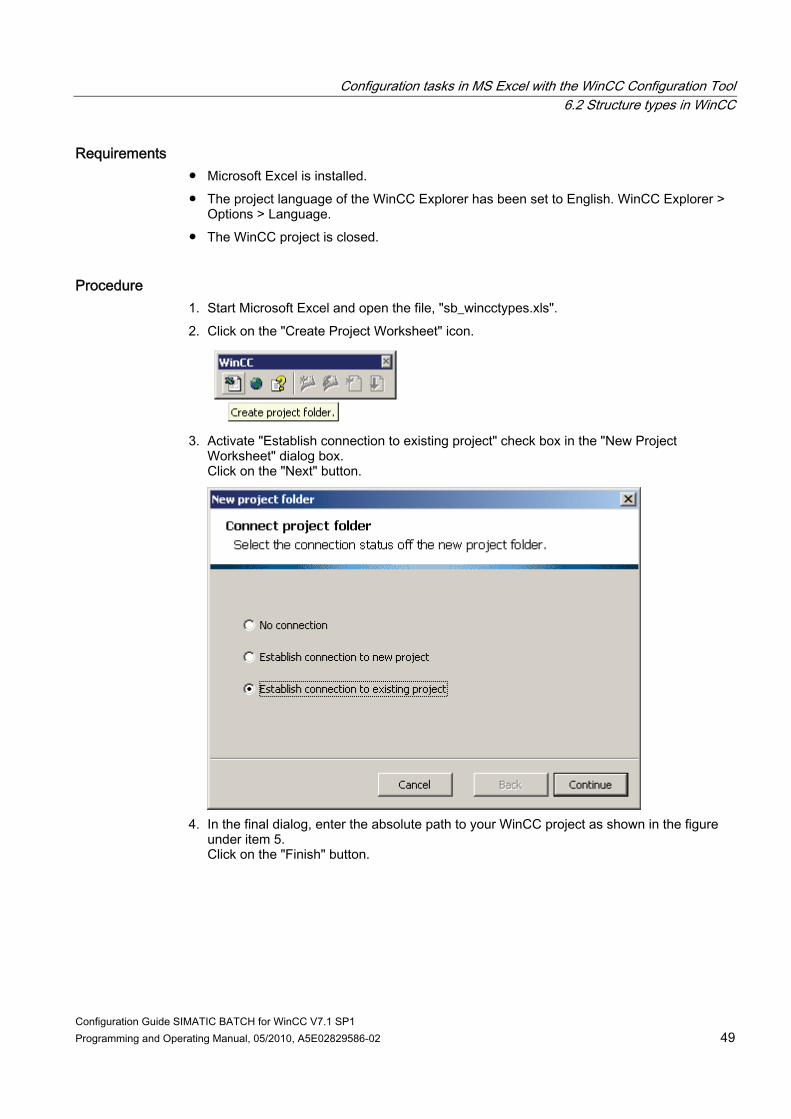
Requirements ● Microsoft Excel is installed. ● The project language of the WinCC Explorer has been set to English. WinCC Explorer >
Options > Language. ● The WinCC project is closed.
Procedure 1. Start Microsoft Excel and open the file, "sb_wincctypes.xls". 2. Click on the "Create Project Worksheet" icon.
3. Activate "Establish connection to existing project" check box in the "New Project
Worksheet" dialog box. Click on the "Next" button.
4. In the final dialog, enter the absolute path to your WinCC project as shown in the figure
under item 5. Click on the "Finish" button.

Configuration tasks in MS Excel with the WinCC Configuration Tool 6.2 Structure types in WinCC
Configuration Guide SIMATIC BATCH for WinCC V7.1 SP1 50 Programming and Operating Manual, 05/2010, A5E02829586-02
5. In the "Project Properties" worksheet of the newly created project folder, select "No" to "Use Default Values" in the drop-down list in the "Data Entry" group. Double-click on the corresponding cell for this. A selection menu is then shown to the right of the cell. Click on the icon and select "No". After selecting "No", click again in any cell to apply the selection.
Note The "No" option for the "Use default value" setting is important because otherwise the information from external tags is lost when data is copied.

Configuration tasks in MS Excel with the WinCC Configuration Tool 6.2 Structure types in WinCC
Configuration Guide SIMATIC BATCH for WinCC V7.1 SP1 Programming and Operating Manual, 05/2010, A5E02829586-02 51
6. Mark all the structures of a type from the file "sb_wincctypes.xls", "Structure Types" worksheet and copy them into the Clipboard.
7. Change to the newly created project worksheet and select the "Structure Types"
worksheet. Select row 18 and the "Paste" command from the shortcut menu to insert the contents.

Configuration tasks in MS Excel with the WinCC Configuration Tool 6.2 Structure types in WinCC
Configuration Guide SIMATIC BATCH for WinCC V7.1 SP1 52 Programming and Operating Manual, 05/2010, A5E02829586-02
8. Repeat steps 7 and 8 for each structure type listed in the "sb_wincctypes.xls"
spreadsheet. 9. Click within the MS Excel menu bar on the command WinCC > Write structure types.
Configuration tasks in MS Excel with the WinCC Configuration Tool 6.2 Structure types in WinCC
Configuration Guide SIMATIC BATCH for WinCC V7.1 SP1 Programming and Operating Manual, 05/2010, A5E02829586-02 53
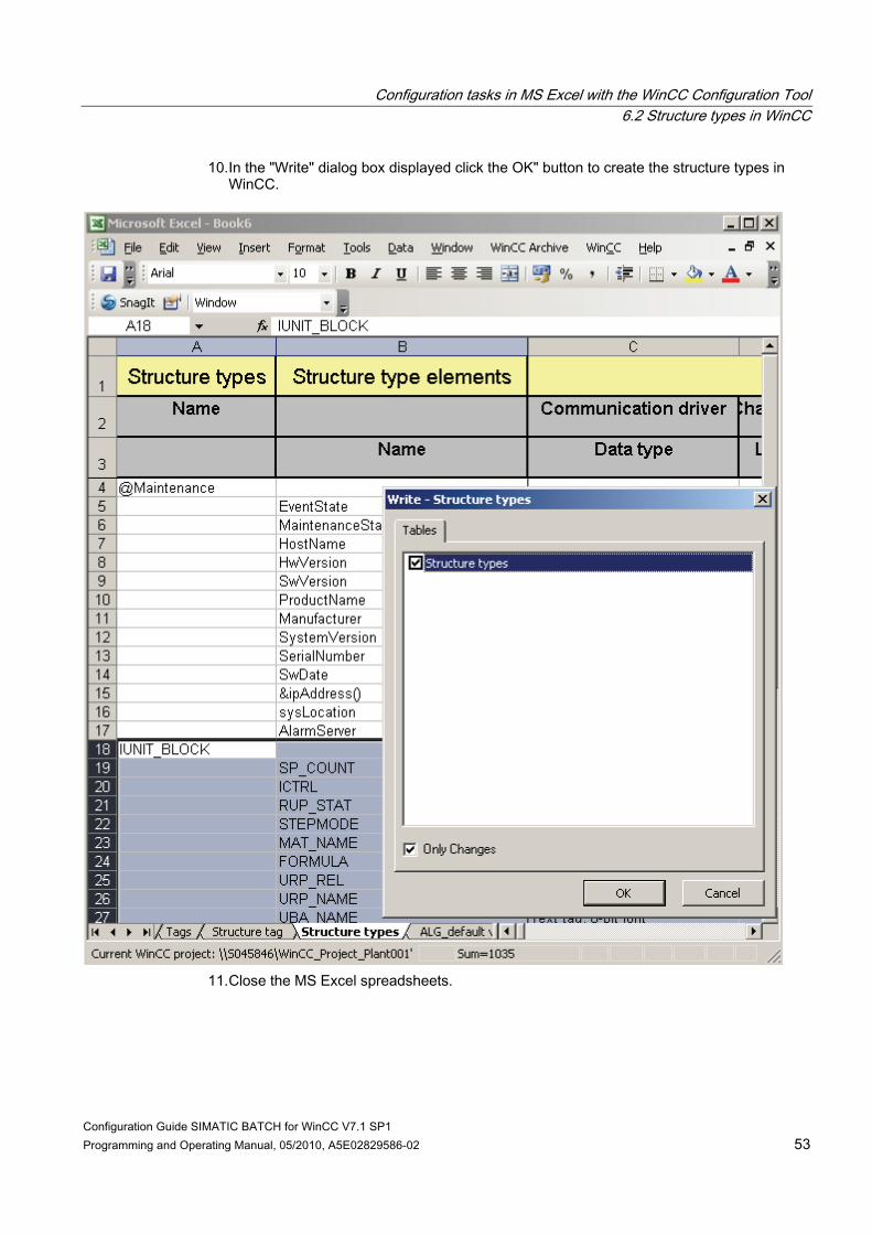
10. In the "Write" dialog box displayed click the OK" button to create the structure types in WinCC.
11. Close the MS Excel spreadsheets.

Configuration tasks in MS Excel with the WinCC Configuration Tool 6.3 Creating structure tags in WinCC
Configuration Guide SIMATIC BATCH for WinCC V7.1 SP1 54 Programming and Operating Manual, 05/2010, A5E02829586-02
Result You have now transferred the structure types used in your STEP 7 project from the Excel project worksheet to the WinCC project. In the opened WinCC project you can check in the "Structure properties" dialog box whether the individual structure elements have been created correctly.
6.3 Creating structure tags in WinCC
6.3.1 Introduction
Creating tags in the WinCC tag management In this chapter you transfer the tags contained in a delivery spreadsheet to the WinCC tag management. An empty delivery spreadsheet is made available to you in the "..\BATCH\SBSCADAEXA\Examples" installation folder.
Automatic and manual filling of the delivery spreadsheet "sb_deliverytable.xls" You have the possibility of using the SIMATIC BATCH configuration dialog the have the delivery spreadsheet filled automatically with the data originating from your configuration. The advantage is that typing errors is avoided. In this case you can start at this point with the chapter "Configuration tasks in the SIMATIC BATCH configuration dialog" (Page 67) and then carry out the two steps of this chapter "Creating structure tags" and "Creating internal tags for the visualization" . In the case of manual data filling of the two worksheets "STRUCTURE_TAGS_FOR_WINCC" and "INSTANCES_FOR_CLIPBOARD" of the delivery spreadsheet and their storage in the BATCH folder of your WinCC project carry out the further configuration steps in the following sections of this chapter chronologically.

Configuration tasks in MS Excel with the WinCC Configuration Tool 6.3 Creating structure tags in WinCC
Configuration Guide SIMATIC BATCH for WinCC V7.1 SP1 Programming and Operating Manual, 05/2010, A5E02829586-02 55
6.3.2 Organization of the Delivery Table
Delivery spreadsheet The structure tags in WinCC are created in the "STRUCTURE_TAGS_FOR_WINCC" worksheet via the delivery spreadsheet, "sb_deliverytable.xls". You have the completed "SB_DeliveryTable.xls" as a template.
Legend for figure Column name Meaning WinCC structure tag Name of the WinCC structure tags.
Example: Plant001/Reactor001 WinCC structure type The names of the WinCC structure types have to be entered here. For
further information refer to the "Structure types for Batch interface blocks" section.
Connection name This entry must match the one in the connection configuration in WinCC Explorer. In our configuration "AS1".
WinCC tag group Name of the tag group in WinCC. This box is not mandatory. Address DBxxx, DDyyy This is where you enter the S7 address in the form "DBxxx" and
"Ddyyy". xxx Data block number yyy Byte address Additional information is available in the next two sections.
Comment This is where you can enter a comment about the unit, function or parameters.

Configuration tasks in MS Excel with the WinCC Configuration Tool 6.3 Creating structure tags in WinCC
Configuration Guide SIMATIC BATCH for WinCC V7.1 SP1 56 Programming and Operating Manual, 05/2010, A5E02829586-02
6.3.3 Naming Convention
Assign hierarchical tag names in your WinCC project. Separate the individual tag names with the "/" character.
Suggested Hierarchy Assign tag names based on the following principle, for example: 1. Name of a line or a unit. 2. Name of the unit (symbolic name of the data block). 3. Name of the equipment phase (symbolic name of the function block of the equipment
phase). 4. Name of the parameter of the equipment phase (tag name of the phase parameters).
Example Plant001/Reactor001/Heating/SP_Time
Further information You can find additional information about this in the WinCC Information System online help; "Illegal Characters" section.
6.3.4 Determining Addresses from the Instance Data Block
Procedure For the delivery spreadsheet you determine the block addresses within the application "LAD/FBD/STL: Programming S7 blocks". You require the addresses of the following blocks: ● IUNIT_BLOCK ● IEPH ● IEPAR
Requirements Your blocks are opened in the editor.
Searching for block addresses 1. Open the function block of the unit class, in our configuration "Reactor". 2. In the tag overview click the "STAT" section.

Configuration tasks in MS Excel with the WinCC Configuration Tool 6.3 Creating structure tags in WinCC
Configuration Guide SIMATIC BATCH for WinCC V7.1 SP1 Programming and Operating Manual, 05/2010, A5E02829586-02 57
3. In the detailed view search in the "Data type" column for the address of IUNIT_BLOCK and the address of your "Heating" equipment phase. In our configuration these are the following addresses. IUNIT_BLOCK = 524.0 and Heating = 12.0.
4. In the detailed view double-click the "Heating" equipment phase and then "STAT". Here
the addresses of the data types IEPH and IEPAR_DINT are listed in the address column in the detailed view. In our configuration the values are IEPH = 8.0 and IEPAR_DINT = 478.0. Add the static address of the equipment phase, Heating =12.0, to these two addresses,
5. This results in the following byte block addresses for the delivery spreadsheet.
IUNIT_BLOCK = 524.0, IEPH = 20.0 and IEPAR_DINT = 490.0. The data block number in our configuration is DB1.

Configuration tasks in MS Excel with the WinCC Configuration Tool 6.3 Creating structure tags in WinCC
Configuration Guide SIMATIC BATCH for WinCC V7.1 SP1 58 Programming and Operating Manual, 05/2010, A5E02829586-02
Result Enter the determined addresses of the tags in the "Address" column of the delivery table, "STRUCTURE_TAGS_FOR_WINCC" worksheet, in the following form: DBx,DDy, for example: WinCC structure tag for IUNIT_BLOCK = DB1,DD524.0. Meaning: Data block 1, Data double word 524.0.
6.3.5 Create structure tags
Introduction After you have entered all the tag parameters for WinCC required for the Batch interface in the supplied MS Excel spreadsheet, "sb_deliverytable.xls", "STRUCTUR_TAGS_FOR_WINCC" worksheet, you can use a new MS Excel project worksheet to create structure tags in the WinCC tag management. If you have the MS Excel spreadsheet with the two worksheets filled automatically with data using the SIMATIC BATCH configuration dialog, you cannot carry out this step "Creating structure tags" until all the steps in the SIMATIC BATCH configuration dialog have been completed.
Requirements ● In the WinCC Explorer the language "English (USA)" is set exclusively for the import of
the structure tags. After importing has been completed, the project language can be chosen freely.
● The WinCC project is closed.
Procedure 1. Open the "sb_deliverytable.xls" Excel table.
Configuration tasks in MS Excel with the WinCC Configuration Tool 6.3 Creating structure tags in WinCC
Configuration Guide SIMATIC BATCH for WinCC V7.1 SP1 Programming and Operating Manual, 05/2010, A5E02829586-02 59
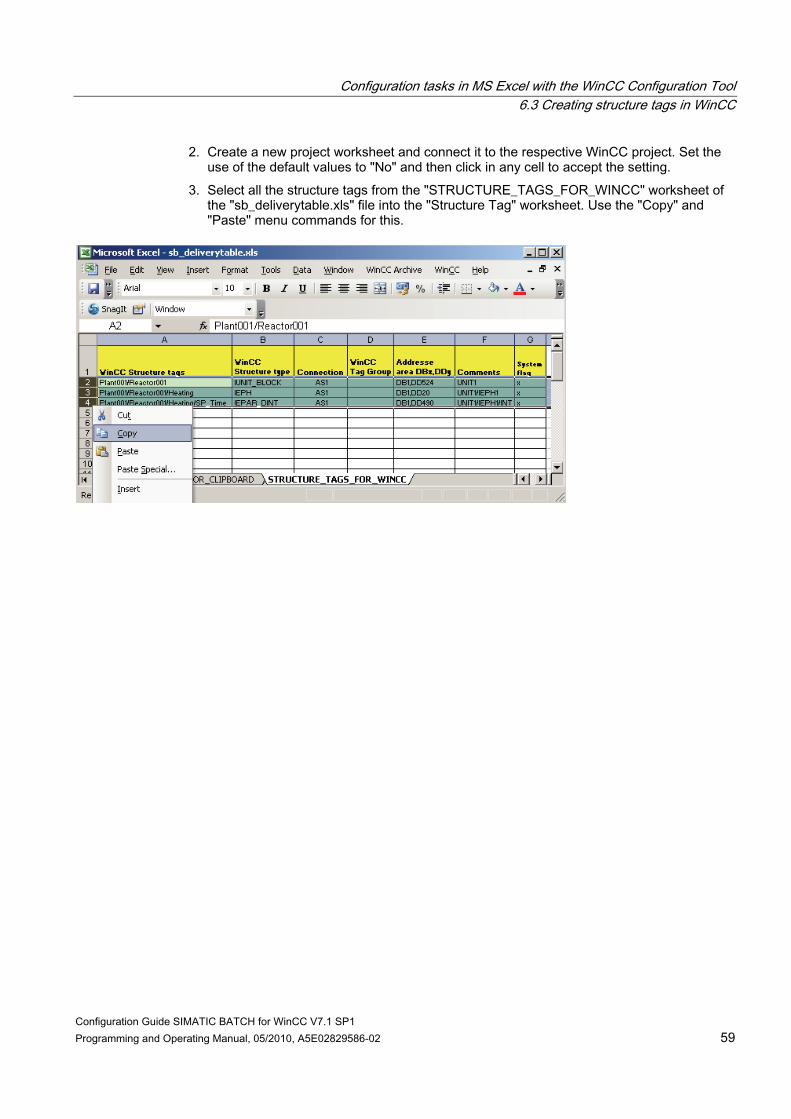
2. Create a new project worksheet and connect it to the respective WinCC project. Set the use of the default values to "No" and then click in any cell to accept the setting.
3. Select all the structure tags from the "STRUCTURE_TAGS_FOR_WINCC" worksheet of the "sb_deliverytable.xls" file into the "Structure Tag" worksheet. Use the "Copy" and "Paste" menu commands for this.

Configuration tasks in MS Excel with the WinCC Configuration Tool 6.3 Creating structure tags in WinCC
Configuration Guide SIMATIC BATCH for WinCC V7.1 SP1 60 Programming and Operating Manual, 05/2010, A5E02829586-02
4. In the MS Excel menu bar click WinCC > Write tags.

Configuration tasks in MS Excel with the WinCC Configuration Tool 6.3 Creating structure tags in WinCC
Configuration Guide SIMATIC BATCH for WinCC V7.1 SP1 Programming and Operating Manual, 05/2010, A5E02829586-02 61
5. In the "Write - tags" dialog box click the "OK" button. 6. Save and close the MS Excel sheet and the MS Excel file "sb_deliverytable.xls".
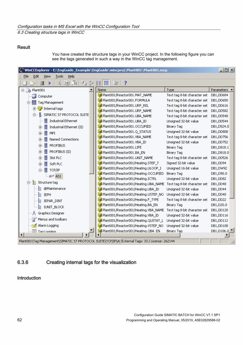
Configuration tasks in MS Excel with the WinCC Configuration Tool 6.3 Creating structure tags in WinCC
Configuration Guide SIMATIC BATCH for WinCC V7.1 SP1 62 Programming and Operating Manual, 05/2010, A5E02829586-02
Result You have created the structure tags in your WinCC project. In the following figure you can see the tags generated in such a way in the WinCC tag management.
6.3.6 Creating internal tags for the visualization
Introduction
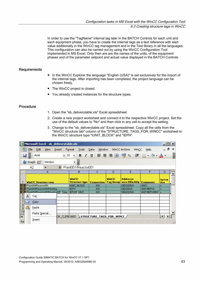
Configuration tasks in MS Excel with the WinCC Configuration Tool 6.3 Creating structure tags in WinCC
Configuration Guide SIMATIC BATCH for WinCC V7.1 SP1 Programming and Operating Manual, 05/2010, A5E02829586-02 63
In order to use the "TagName" internal tag later in the BATCH Controls for each unit and each equipment phase, you have to create the internal tags as a text reference with start value additionally in the WinCC tag management and in the Text library in all the languages. This configuration can also be carried out by using the WinCC Configuration Tool implemented in MS Excel. Only then are are the names of the units, of the equipment phases and of the parameter setpoint and actual value displayed in the BATCH Controls.
Requirements ● In the WinCC Explorer the language "English (USA)" is set exclusively for the import of
the internal tags. After importing has been completed, the project language can be chosen freely.
● The WinCC project is closed. ● You already created instances for the structure types.
Procedure 1. Open the "sb_deliverytable.xls" Excel spreadsheet. 2. Create a new project worksheet and connect it to the respective WinCC project. Set the
use of the default values to "No" and then click in any cell to accept the setting. 3. Change to the "sb_deliverytable.xls" Excel spreadsheet. Copy all the cells from the
"WinCC structure tab" column of the "STRUCTURE_TAGS_FOR_WINCC" worksheet to the WinCC structure type "IUNIT_BLOCK" and "IEPH".
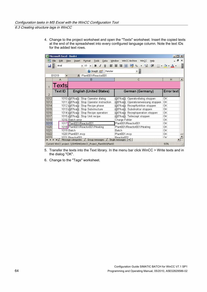
Configuration tasks in MS Excel with the WinCC Configuration Tool 6.3 Creating structure tags in WinCC
Configuration Guide SIMATIC BATCH for WinCC V7.1 SP1 64 Programming and Operating Manual, 05/2010, A5E02829586-02
4. Change to the project worksheet and open the "Texts" worksheet. Insert the copied texts at the end of the spreadsheet into every configured language column. Note the text IDs for the added text rows.
5. Transfer the texts into the Text library. In the menu bar click WinCC > Write texts and in
the dialog "OK". 6. Change to the "Tags" worksheet.

Configuration tasks in MS Excel with the WinCC Configuration Tool 6.3 Creating structure tags in WinCC
Configuration Guide SIMATIC BATCH for WinCC V7.1 SP1 Programming and Operating Manual, 05/2010, A5E02829586-02 65
7. For each tag called "TagName" of your units and equipment phases transfer the IDs to the "Tags" worksheet in the "Start value" column. The corresponding Text ID results from the instance names of the structure tags.

Configuration tasks in MS Excel with the WinCC Configuration Tool 6.3 Creating structure tags in WinCC
Configuration Guide SIMATIC BATCH for WinCC V7.1 SP1 66 Programming and Operating Manual, 05/2010, A5E02829586-02
8. Transfer the start values to the WinCC tag management. In the menu bar click WinCC > Write tags and in the dialog "OK".
9. Close the MS Excel files.
Result You have configured the internal structure tags "TagName" of the Text reference type for use in process mode.
Configuration Guide SIMATIC BATCH for WinCC V7.1 SP1 Programming and Operating Manual, 05/2010, A5E02829586-02 67
Configuration tasks in the SIMATIC Manager configuration dialog 77.1 Introduction
Use of the SIMATIC BATCH configuration dialog The SIMATIC BATCH configuration dialog guides you step-by-step through the configuration of the Batch process cell.
Requirements for starting the SIMATIC BATCH configuration dialog ● You must have completed the configurations in SIMATIC STEP 7 and in SIMATIC WinCC
before the start. ● All Batch stations must be available per network, since the data is to be transferred there
directly at the end of the configuration phase. ● You can only start the configuration dialog when the corresponding WinCC project and
the WinCC Explorer is open.
Start of the SIMATIC BATCH configuration dialog You can start the SIMATIC BATCH configuration dialog in the WinCC Explorer with a right mouse click on the "SIMATIC BATCH" component and then clicking on "Configuration dialog".
7.2 Overview of the configuration tasks
Introduction The following overview lists the required configuration tasks that are to be performed in the configuration dialog. The section that follows provides a detailed description of the tasks.

Configuration tasks in the SIMATIC Manager configuration dialog 7.3 Step 1 - Configuration of the Batch process cell
Configuration Guide SIMATIC BATCH for WinCC V7.1 SP1 68 Programming and Operating Manual, 05/2010, A5E02829586-02
Configuration tasks with a link to the chapter Link to the configuration task
Description
- Welcome, start dialog of the configuration dialog 1 (Page 68) Configuration of the BATCH process cell 2 (Page 75) Configuration of the Batch stations 3 (Page 76) Configuration of the WinCC stations 4 (Page 78) Distribution of the process cell data
7.3 Step 1 - Configuration of the Batch process cell
7.3.1 Configuration of the Batch process cell and importing the process cell instances
Introduction In the first step of the SIMATIC BATCH configuration dialog select the BATCH process cell name and edit the Batch types in the BATCH project configuration dialog. Afterwards the instances of the BATCH process cell (STEP 7) from the two MS Excel worksheets of the file "sb_deliverytable.xls" (delivery spreadsheet) are imported to SIMATIC BATCH. Depending on your configuration you can trigger automatic creation of the delivery spreadsheet in the configuration dialog or not. To do so select the path to your STEP 7 project and subsequently click the button and "Create spreadsheet". The delivery spreadsheet with the two filled out worksheets is stored in the Batch folder of your WinCC project.
Note Automatic creation of the delivery spreadsheet with its two worksheets Please note that you still have to carry out the step "Creating structure tags" after all the wizard steps have been carried out, if you have used the automatic creation of the delivery spreadsheet from the configuration dialog.

Configuration tasks in the SIMATIC Manager configuration dialog 7.3 Step 1 - Configuration of the Batch process cell
Configuration Guide SIMATIC BATCH for WinCC V7.1 SP1 Programming and Operating Manual, 05/2010, A5E02829586-02 69
Requirements ● SIMATIC BATCH is installed. ● The corresponding WinCC project is open in the WinCC Explorer. The WinCC OS should
not be activated ("in Run"). ● The content of the "sb_deliverytable.xls" and "sb_wincctypes.xls" files were edited or
updated as described above and the two files have been copied into or created in the WinCC "Batch" project folder.
● The configuration dialog is open in the WinCC Explorer.
Procedure 1. Enter a name for the new Batch process cell (PCell). 2. Open the dialog for configuring the Batch process cell by clicking on the "Processing
batch types" button in the "Name of the process cell" area. 3. Configure all the required Batch types for your process in this dialog. You can find
detailed instructions on this in the section "Creating Batch types (Page 70)". The online help in the Batch project configuration dialog is also available to you. You can open it by using the Help button.

Configuration tasks in the SIMATIC Manager configuration dialog 7.3 Step 1 - Configuration of the Batch process cell
Configuration Guide SIMATIC BATCH for WinCC V7.1 SP1 70 Programming and Operating Manual, 05/2010, A5E02829586-02
4. Select the path to your STEP 7 project (*.s7p) by using the "Open file" button. 5. Click the "Create table" button. The two MS Excel worksheets of the
"sb_delivery_table.xls" file are then filled with the instance data for BATCH and WinCC. 6. Open the Excel file "sb_deliverytable.xls" for your opened WinCC project by clicking
"Open Excel" in the "Import process cell Instances via Excel" area. Edit the entries corresponding to your project there. For detailed instructions see the section "Delivery spreadsheet for the batch configuration (Page 72)." The instance descriptions are imported to SIMATIC BATCH from the displayed Excel worksheet. Save and close the Excel file.
7. Before importing the data from the Excel file, "INSTANCES_FOR_CLIPBOAD" worksheet, select if you want to delete any existing Batch instances ("Delete instances") or only merge the entries during the import ("Only import") in the configuration dialog.
8. Click "Import" to import the Batch instances from the Excel file. You can now perform a validation. You can find more detailed information about this in the section "Validity check (Page 79)".
9. Click "Next" to apply the settings made and continue with the next task.
Result Configuration files (PlausiResul.xml, pcc_batch.eqm, ombat_logform.xslt) have been created in the "Batch" folder in the project path of your current WinCC project and the settings you have made during this task are saved.
Errors and warnings Error and warnings that occur during configuration of the Batch process cell in the configuration dialog will be documented in the "PlausiResult.xml" file. The file will be saved in the "Batch" folder in your WinCC project path. Double-click the file to open it in the Internet Explorer for error analysis. The file is created during editing in the configuration dialog (step 1) and can be continuously updated with the F5 key.
7.3.2 Create batch types
Introduction The batch types have to be created before the batch instances can be imported with the "Clipboard" function in the configuration dialog. Batch types are created in the BATCH project configuration dialog that is opened from the BATCH configuration dialog. In the BATCH project configuration dialog you have three options at the Batch types: ● Creating Batch types ● Changing existing Batch types ● No changes to the existing Batch types, because for example all of them are available
and up-to-date.

Configuration tasks in the SIMATIC Manager configuration dialog 7.3 Step 1 - Configuration of the Batch process cell
Configuration Guide SIMATIC BATCH for WinCC V7.1 SP1 Programming and Operating Manual, 05/2010, A5E02829586-02 71
In our configuration a new function type and a parameter "SP_Time" have to be created for the "Heating" equipment phase with the function parameter "SP_Time". The unit "Seconds" is required for the "SP_Time" parameter.
Requirement The configuration dialog and the "Configure Batch Process Cell...." dialog box is open.
Procedure 1. Create a unit for "SP_Time": Open the "Batch Types" folder. Select the "Units of
measure" folder and click on the shortcut menu command "New". Rename the folder "TECHUNITS" shown under "Units" to "Seconds".
2. Create a new function type "Heating": Mark the "Function Types" folder in the "Phase Types" folder and click the "New" button. Rename the folder "EQUCLASS" shown under the "Function types" to "Heating". Leave the predefined block type IEPH/EPH-SFC type.
3. Create a new function parameter: Mark the "Heating" folder and click the "New" button. Rename the folder "EQUCLASSPARAM" to "SP_Time". Select "Floating-point number" in the "Assigned data type" row and "Seconds" in the "Assigned unit of measure" row.
4. Click "OK" and close the dialog with "OK".
Result You have fulfilled the requirements for importing the Batch instances from the MS Excel worksheet "INSTANCES_FOR_CLIPBOARD" in the SIMATIC BATCH configuration dialog. The result in the BATCH project configuration dialog is as follows.

Configuration tasks in the SIMATIC Manager configuration dialog 7.3 Step 1 - Configuration of the Batch process cell
Configuration Guide SIMATIC BATCH for WinCC V7.1 SP1 72 Programming and Operating Manual, 05/2010, A5E02829586-02
Additional information To access SIMATIC BATCH online help: Press the <F1> key or click on the "Help" button in the "Configure Batch Process Cell" dialog box.
7.3.3 Delivery Table for the Batch Configuration
7.3.3.1 Information about the MS Excel delivery spreadsheet "sb_deliverytable.xls"
Manual and automatic filling In the case of manual filling of the MS Excel "INSTANCES_FOR_CLIPBOARD" worksheet you must have entered the delivery data into the worksheet so that importing to SIMATIC BATCH using the configuration dialog is possible. Information about the delivery spreadsheet is provided in the chapter on the organization of the delivery spreadsheet "sb-deliverytable.xls".
Rules for the automatic filling of the worksheets The following rules apply for the automatic generation of the delivery spreadsheet: ● "STRUCTURE_TAGS_FOR_WINCC" worksheet
The "Connection" column is filled with a standard value. The "WinCC tag group" column is not filled. Both columns can be adapted by you. These two columns are not updated when the spreadsheet is generated again. All the other columns are always refilled with the up-to-date project data.
● "INSTANCES_FOR_CLIPBOARD" worksheet The columns "Server-prefix", "Def Value", "Lower Limit" and "Upper Limit" can or have to be adapted by you and are not updated during the next spreadsheet generation.
Note Automatic spreadsheet generation can only be carried out correctly if all the manual entries in the delivery spreadsheet have been created in accordance with this documentation.
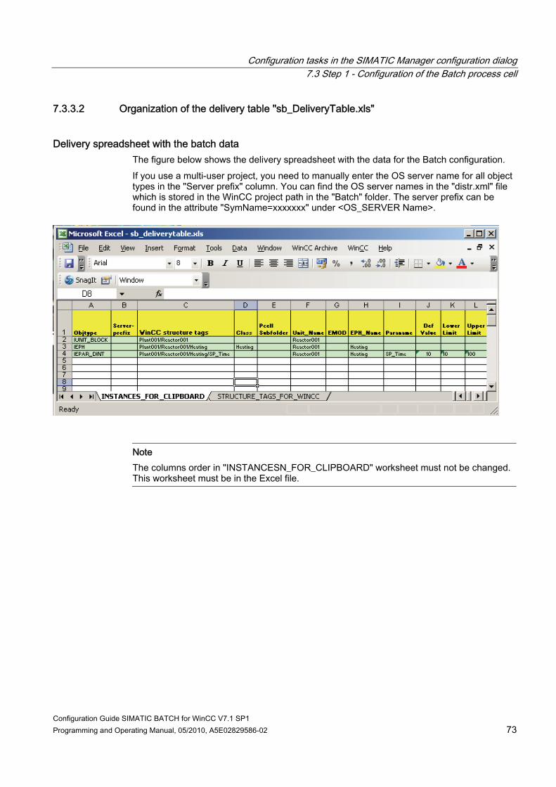
Configuration tasks in the SIMATIC Manager configuration dialog 7.3 Step 1 - Configuration of the Batch process cell
Configuration Guide SIMATIC BATCH for WinCC V7.1 SP1 Programming and Operating Manual, 05/2010, A5E02829586-02 73
7.3.3.2 Organization of the delivery table "sb_DeliveryTable.xls"
Delivery spreadsheet with the batch data The figure below shows the delivery spreadsheet with the data for the Batch configuration. If you use a multi-user project, you need to manually enter the OS server name for all object types in the "Server prefix" column. You can find the OS server names in the "distr.xml" file which is stored in the WinCC project path in the "Batch" folder. The server prefix can be found in the attribute "SymName=xxxxxxx" under <OS_SERVER Name>.
Note The columns order in "INSTANCESN_FOR_CLIPBOARD" worksheet must not be changed. This worksheet must be in the Excel file.
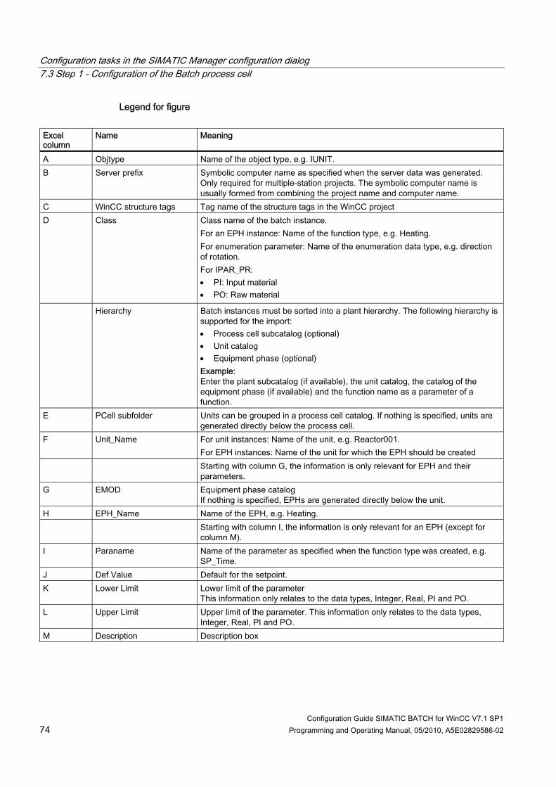
Configuration tasks in the SIMATIC Manager configuration dialog 7.3 Step 1 - Configuration of the Batch process cell
Configuration Guide SIMATIC BATCH for WinCC V7.1 SP1 74 Programming and Operating Manual, 05/2010, A5E02829586-02
Legend for figure Excel column
Name Meaning
A Objtype Name of the object type, e.g. IUNIT. B Server prefix Symbolic computer name as specified when the server data was generated.
Only required for multiple-station projects. The symbolic computer name is usually formed from combining the project name and computer name.
C WinCC structure tags Tag name of the structure tags in the WinCC project D Class Class name of the batch instance.
For an EPH instance: Name of the function type, e.g. Heating. For enumeration parameter: Name of the enumeration data type, e.g. direction of rotation. For IPAR_PR: PI: Input material PO: Raw material
Hierarchy Batch instances must be sorted into a plant hierarchy. The following hierarchy is supported for the import: Process cell subcatalog (optional) Unit catalog Equipment phase (optional) Example: Enter the plant subcatalog (if available), the unit catalog, the catalog of the equipment phase (if available) and the function name as a parameter of a function.
E PCell subfolder Units can be grouped in a process cell catalog. If nothing is specified, units are generated directly below the process cell.
F Unit_Name For unit instances: Name of the unit, e.g. Reactor001. For EPH instances: Name of the unit for which the EPH should be created
Starting with column G, the information is only relevant for EPH and their parameters.
G EMOD Equipment phase catalog If nothing is specified, EPHs are generated directly below the unit.
H EPH_Name Name of the EPH, e.g. Heating. Starting with column I, the information is only relevant for an EPH (except for
column M). I Paraname Name of the parameter as specified when the function type was created, e.g.
SP_Time. J Def Value Default for the setpoint. K Lower Limit Lower limit of the parameter
This information only relates to the data types, Integer, Real, PI and PO. L Upper Limit Upper limit of the parameter. This information only relates to the data types,
Integer, Real, PI and PO. M Description Description box
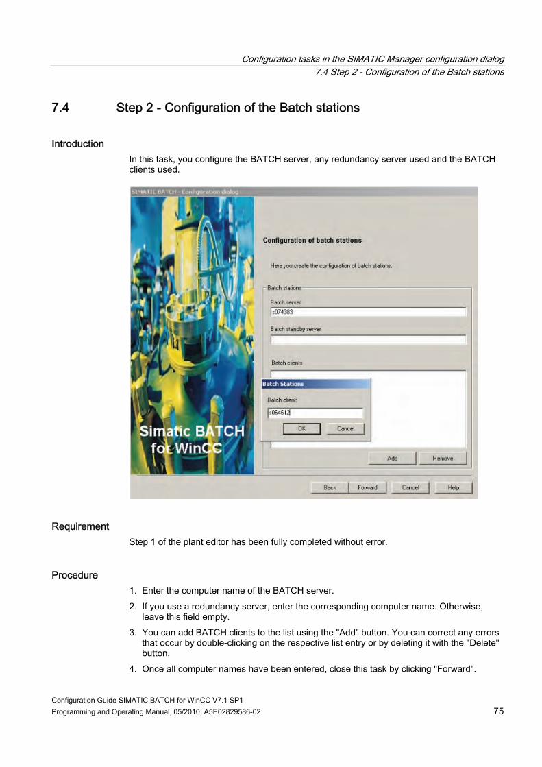
Configuration tasks in the SIMATIC Manager configuration dialog 7.4 Step 2 - Configuration of the Batch stations
Configuration Guide SIMATIC BATCH for WinCC V7.1 SP1 Programming and Operating Manual, 05/2010, A5E02829586-02 75
7.4 Step 2 - Configuration of the Batch stations
Introduction In this task, you configure the BATCH server, any redundancy server used and the BATCH clients used.
Requirement Step 1 of the plant editor has been fully completed without error.
Procedure 1. Enter the computer name of the BATCH server. 2. If you use a redundancy server, enter the corresponding computer name. Otherwise,
leave this field empty. 3. You can add BATCH clients to the list using the "Add" button. You can correct any errors
that occur by double-clicking on the respective list entry or by deleting it with the "Delete" button.
4. Once all computer names have been entered, close this task by clicking "Forward".
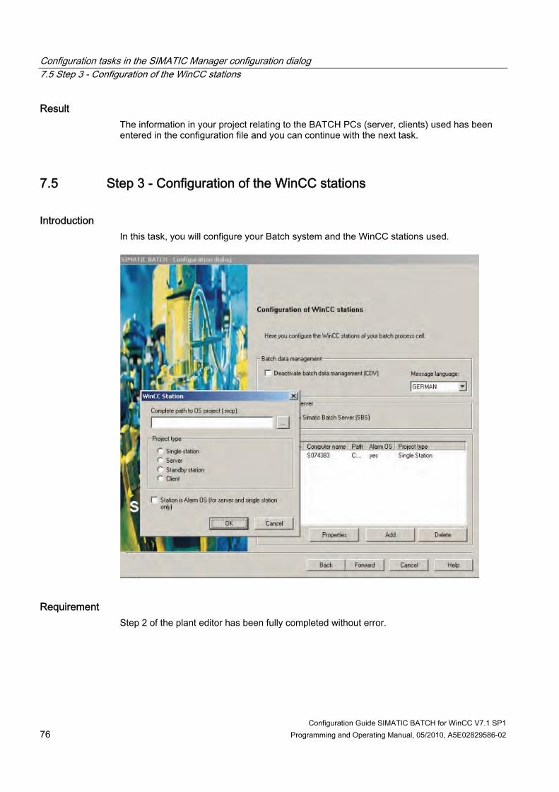
Configuration tasks in the SIMATIC Manager configuration dialog 7.5 Step 3 - Configuration of the WinCC stations
Configuration Guide SIMATIC BATCH for WinCC V7.1 SP1 76 Programming and Operating Manual, 05/2010, A5E02829586-02
Result The information in your project relating to the BATCH PCs (server, clients) used has been entered in the configuration file and you can continue with the next task.
7.5 Step 3 - Configuration of the WinCC stations
Introduction In this task, you will configure your Batch system and the WinCC stations used.
Requirement Step 2 of the plant editor has been fully completed without error.

Configuration tasks in the SIMATIC Manager configuration dialog 7.5 Step 3 - Configuration of the WinCC stations
Configuration Guide SIMATIC BATCH for WinCC V7.1 SP1 Programming and Operating Manual, 05/2010, A5E02829586-02 77
Procedure 1. Simatic Batch Server: If you select the check box, the BATCH component "SBS" will be
deactivated. Communication between SIMATIC BATCH and the Historian is then not possible. This is the default setting. If the check box is not selected, the SBS is activated and communication is possible.
2. Batch data management (CDV): If you select the check box, the BATCH component "CDV" will be deactivated. This is the default setting of the option. This means that no BATCH messages and no tag archive data will be collected. This setting is not changed over in running operation. Restart the CDV server application. If the check box is not selected, batch data management is activated; BATCH messages and tag archive data will be collected.
3. Message language Select the message language in which the batch data management (CDV) will collect the BATCH messages from a drop-down list box.
4. Click "Add…" to insert a WinCC station in the list. 5. First, enter the UNC path for your WinCC project file (*.mcp). For example:
\\WinCCServer\WinCCProject\Project.mcp). 6. Select the type of WinCC station involved. 7. If your WinCC server is intended as an alarm OS, activate the corresponding check box. 8. Enter the new server in the list with the "OK" button. 9. Add all WinCC PCs used in the same way. 10. You can use the "Properties…" button to check the individual entries and change them if
needed. 11. When all WinCC stations have been entered, you can close this task by clicking
"Forward".
Result The information in your project relating to the WinCC stations used has been entered in the configuration file and you can continue with the next task.

Configuration tasks in the SIMATIC Manager configuration dialog 7.6 Step 4 - Distribution of the Batch process cell data
Configuration Guide SIMATIC BATCH for WinCC V7.1 SP1 78 Programming and Operating Manual, 05/2010, A5E02829586-02
7.6 Step 4 - Distribution of the Batch process cell data
Introduction In this task, you will distribute the configuration to the previously specified Batch stations.
Requirements ● Step 3 of the configuration dialog has been fully completed without error. ● All configured Batch stations are available per network.
Procedure 1. Click "Distribute" to download the configuration to the Batch stations. This may take some
time, depending on the number of Batch stations and the network connection. 2. Once the distribution and download have been performed without error, close the
configuration dialog by clicking "Exit".
Configuration tasks in the SIMATIC Manager configuration dialog 7.7 Validation
Configuration Guide SIMATIC BATCH for WinCC V7.1 SP1 Programming and Operating Manual, 05/2010, A5E02829586-02 79
Result You have transferred the configuration to the Batch stations and are finished with this part of the project configuration.
Errors and warnings The "bfTransOS.xml" file is generated during the transfer of the Batch messages to the Operation Station (OS) and is stored in the project directory. It contains the errors and warnings that occurred during the transfer. The file "PlausiResult.xml" contains errors and warnings that occurred during the BATCH configuration, for example a missing runtime name corresponds to a warning. Double-clicking the files opens them in the Internet Explorer for error analysis.
7.7 Validation
Introduction After importing the Batch instances, check your Batch configuration in the "Configure Batch Process Cell..." BATCH project configuration dialog.
Requirements ● The Batch instance have been successfully imported. ● If the configuration dialog is no longer open, start it again.
Procedure 1. Click the "Processing batch types" button again in Step 1 of the configuration dialog to
open the "Configure Batch Process Cell" BATCH project configuration dialog. 2. In the dialog box, select the "Batch Instances" folder and click "Validate".
No error or warning should appear in the "Log" area. 3. Click "OK" to close the dialog box.
Result The imported Batch data match the configured Batch types.

Configuration tasks in the SIMATIC Manager configuration dialog 7.7 Validation
Configuration Guide SIMATIC BATCH for WinCC V7.1 SP1 80 Programming and Operating Manual, 05/2010, A5E02829586-02

Configuration Guide SIMATIC BATCH for WinCC V7.1 SP1 Programming and Operating Manual, 05/2010, A5E02829586-02 81
Process picture for units and equipment phases 88.1 Introduction
Visualizing and generating status changes In order to visualize and to generate BATCH status changes on an Operation Station in process mode, create a process picture with different BATCH Controls in your WinCC project in the Graphics Designer.
8.2 Creating a process picture
Introduction The WinCC process picture is created in the Graphics Designer. The following BATCH Controls are used:
BATCH Control name What does the Control provide? Process picture areas BF_UNIT_Batch_Ctrl Representation and operation of the unit
Representation of batch data. This Control is used for the operation and representation of the unit.
BF_EPH_Batch_Ctrl Representation of batch data with link to the BATCH Control Center.
BF_EPH_Function_Ctrl Operation of equipment phases. BF_EPH_Parameter_Ctrl Representation of function parameters (setpoints)
These three Controls are used for the operation and representation of the equipment phase.
Requirements ● A new process picture is opened in the Graphics Designer. ● The object palette is opened.
Procedure 1. Click "Control" in the object palette in the "Smart objects" folder. 2. Drag a free rectangle while holding the left-hand mouse button pressed in the graphics
working area and release the left-hand mouse button. In the "Insert Control" dialog that opens select "BF_UNIT_BATCH Control".
3. Use this method to insert all the further BATCH Controls, the BF_EPH_BATCH Control, the BF_EPH_Function Control and the BF_EPH_Parameter Control into your process picture.

Process picture for units and equipment phases 8.2 Creating a process picture
Configuration Guide SIMATIC BATCH for WinCC V7.1 SP1 82 Programming and Operating Manual, 05/2010, A5E02829586-02
4. Arrange all the inserted BATCH Controls as shown in the graphic below. Adapt their sizes and move them together.
5. Store your process picture, for example under the name "Plant001.pdl".

Process picture for units and equipment phases 8.3 Dynamizing a process picture
Configuration Guide SIMATIC BATCH for WinCC V7.1 SP1 Programming and Operating Manual, 05/2010, A5E02829586-02 83
Result The "Plant001.pdl" process picture can have an appearance as follows.
8.3 Dynamizing a process picture
8.3.1 Dynamizing a unit
Introduction You have to dynamize the BATCH Control for the unit "Plant001". To do so, edit the properties and events of the "BF_UNIT_Batch_Ctrl" Control in the Graphics Designer. With the help of the Dynamic Wizard, you can conveniently link the control to the corresponding tag structure for "IUNIT_BLOCK". This means that you can transfer the tag names for the Control properties and Control events from the template pictures or spreadsheets directly into your project configuration. The Wizard automatically fills the tag names with the selected structure instance names.

Process picture for units and equipment phases 8.3 Dynamizing a process picture
Configuration Guide SIMATIC BATCH for WinCC V7.1 SP1 84 Programming and Operating Manual, 05/2010, A5E02829586-02
Requirements ● The "Plant001.pdl" process picture is open in the Graphics Designer. ● The corresponding program code for the C-actions can be copied directly via the
clipboard into the editing field at the corresponding operating steps.
Table 8- 1 Program code for the object event "Start BCC"
Program code #pragma code ("ssmrt.dll") #include "ssmrt.h" #pragma code () #define KEY_SIZE 260 char Screen = '1'; char RegEntry[KEY_SIZE] = ""; char ProgramName[] = "bfbatchccx.EXE /W WinCC"; CMN_ERROR Err; /* check registry entry for installed batch-application */ SSMRTGetRegistryString ("SOFTWARE\\Siemens\\AUTSW\\BATCH", "Path", "@", RegEntry, KEY_SIZE, &Err); if ( RegEntry[0] != '@' ) { if ( RegEntry[strlen(RegEntry)-1] != '\\' ) strcat( RegEntry, "\\" ); strcat( RegEntry, ProgramName ); SSMProgramStart(lpszPictureName, lpszObjectName, RegEntry); } }
Table 8- 2 Program code for the property of the "PermissionLevel" attribute
Program code long levelretval = 0; if ( SSMCheckAreaLevelPermission( lpszPictureName, 5)) {levelretval = 5; return levelretval ;} if ( SSMCheckAreaLevelPermission( lpszPictureName, 6)) {levelretval = 6; return levelretval ;} }

Process picture for units and equipment phases 8.3 Dynamizing a process picture
Configuration Guide SIMATIC BATCH for WinCC V7.1 SP1 Programming and Operating Manual, 05/2010, A5E02829586-02 85
Note For better performance, it is always recommended to use the "Tag trigger" rather than the default trigger. Open the "Change Trigger" dialog by clicking the trigger symbol. Ensure that the event name is set to "Tag" and that the "@CurrentUser" tag is used as the trigger name. The standard cycle should be set to "Upon change".
Procedure 1. Right-click the "BF_UNIT_BATCH Control" Control in your process picture and select
"Properties" from the shortcut menu. 2. If not already displayed, change to the "Properties" tab. Enter the corresponding WinCC
tag from the following template graphic for all the attributes marked in bold in the "Attribute" column and all the dynamics marked in green in the "Dynamic" column.
Note Ensure that a dot precedes every tag name. The preceding dot is not required for system tags with a preceding @ character. In order to access the BATCH Controls (Permission Level) you require at least a user who has the Permission Levels 5 (Operator Process Controls) and 6 (Higher-Order Process Controls).
3. Change to the "Event" tab and click "Object events". 4. Double-click the first specified action in the "Execution at" column. The "Direct
connection" dialog is then opened.

Process picture for units and equipment phases 8.3 Dynamizing a process picture
Configuration Guide SIMATIC BATCH for WinCC V7.1 SP1 86 Programming and Operating Manual, 05/2010, A5E02829586-02
5. Enter the tags entered in the following table, again with preceding dot, and constants in the "Direct connection" dialog. The configuration of the direct connection is shown in the graphic below. Close the "Direct connection" dialog with the "OK" button.
Carry out an object event at: Constant Tag EnableBatch 1 .BA_EN DisableBatch 0 .BA_EN OccupyUnit 1 .OCCUPIED ReleaseUnit 0 .OCCUPIED MaintenanceSignOn 1 .PEND_OOS MaintenanceSignOff 0 .PEND_OOS
6. Open the Wizard for "Link a prototype to a structure or rename an existing link" listed
under standard dynamics in the window of the dynamics Wizard. Click "Next".

Process picture for units and equipment phases 8.3 Dynamizing a process picture
Configuration Guide SIMATIC BATCH for WinCC V7.1 SP1 Programming and Operating Manual, 05/2010, A5E02829586-02 87
7. In the next Wizard dialog "Structure instance name", click the button for the search dialog. This opens the tag selection dialog. Click "List of all tags" in the navigation window and click the structure for the "IUNIT_BLOCK" type in the data window. Click "OK". In the Wizard click "Next" and "Finish".
8. Close the "Object properties" dialog and save your process picture.
Result You have dynamized the Control for the unit in your process picture.
8.3.2 Dynamizing an equipment phase
Introduction The three BATCH Controls for the "Heating" equipment phase have to be dynamized, as already described in the "Reactor001" unit.
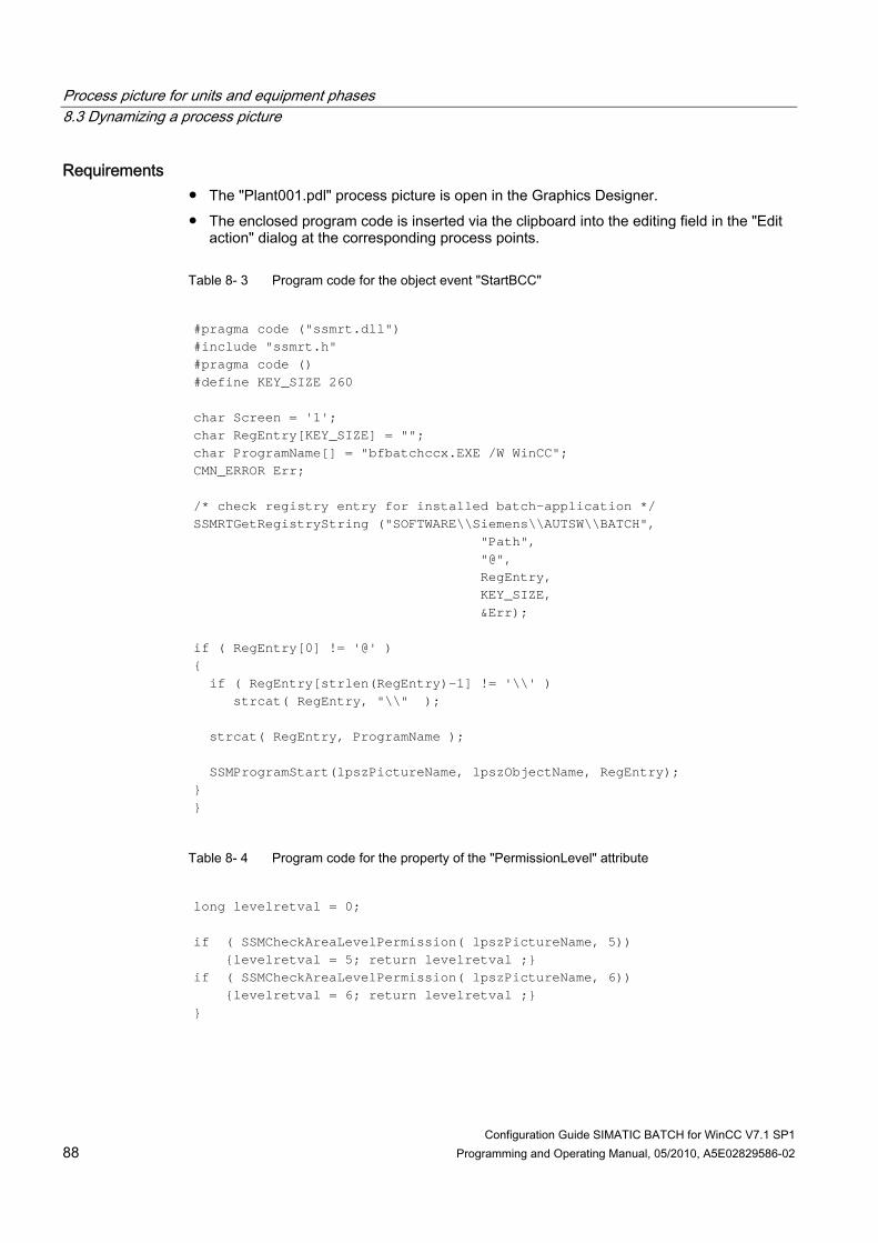
Process picture for units and equipment phases 8.3 Dynamizing a process picture
Configuration Guide SIMATIC BATCH for WinCC V7.1 SP1 88 Programming and Operating Manual, 05/2010, A5E02829586-02
Requirements ● The "Plant001.pdl" process picture is open in the Graphics Designer. ● The enclosed program code is inserted via the clipboard into the editing field in the "Edit
action" dialog at the corresponding process points.
Table 8- 3 Program code for the object event "StartBCC"
#pragma code ("ssmrt.dll") #include "ssmrt.h" #pragma code () #define KEY_SIZE 260 char Screen = '1'; char RegEntry[KEY_SIZE] = ""; char ProgramName[] = "bfbatchccx.EXE /W WinCC"; CMN_ERROR Err; /* check registry entry for installed batch-application */ SSMRTGetRegistryString ("SOFTWARE\\Siemens\\AUTSW\\BATCH", "Path", "@", RegEntry, KEY_SIZE, &Err); if ( RegEntry[0] != '@' ) { if ( RegEntry[strlen(RegEntry)-1] != '\\' ) strcat( RegEntry, "\\" ); strcat( RegEntry, ProgramName ); SSMProgramStart(lpszPictureName, lpszObjectName, RegEntry); } }
Table 8- 4 Program code for the property of the "PermissionLevel" attribute
long levelretval = 0; if ( SSMCheckAreaLevelPermission( lpszPictureName, 5)) {levelretval = 5; return levelretval ;} if ( SSMCheckAreaLevelPermission( lpszPictureName, 6)) {levelretval = 6; return levelretval ;} }
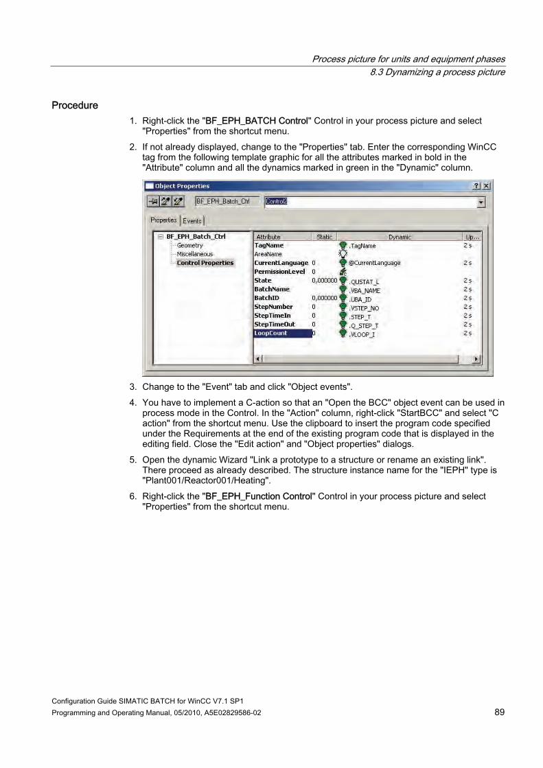
Process picture for units and equipment phases 8.3 Dynamizing a process picture
Configuration Guide SIMATIC BATCH for WinCC V7.1 SP1 Programming and Operating Manual, 05/2010, A5E02829586-02 89
Procedure 1. Right-click the "BF_EPH_BATCH Control" Control in your process picture and select
"Properties" from the shortcut menu. 2. If not already displayed, change to the "Properties" tab. Enter the corresponding WinCC
tag from the following template graphic for all the attributes marked in bold in the "Attribute" column and all the dynamics marked in green in the "Dynamic" column.
3. Change to the "Event" tab and click "Object events". 4. You have to implement a C-action so that an "Open the BCC" object event can be used in
process mode in the Control. In the "Action" column, right-click "StartBCC" and select "C action" from the shortcut menu. Use the clipboard to insert the program code specified under the Requirements at the end of the existing program code that is displayed in the editing field. Close the "Edit action" and "Object properties" dialogs.
5. Open the dynamic Wizard "Link a prototype to a structure or rename an existing link". There proceed as already described. The structure instance name for the "IEPH" type is "Plant001/Reactor001/Heating".
6. Right-click the "BF_EPH_Function Control" Control in your process picture and select "Properties" from the shortcut menu.
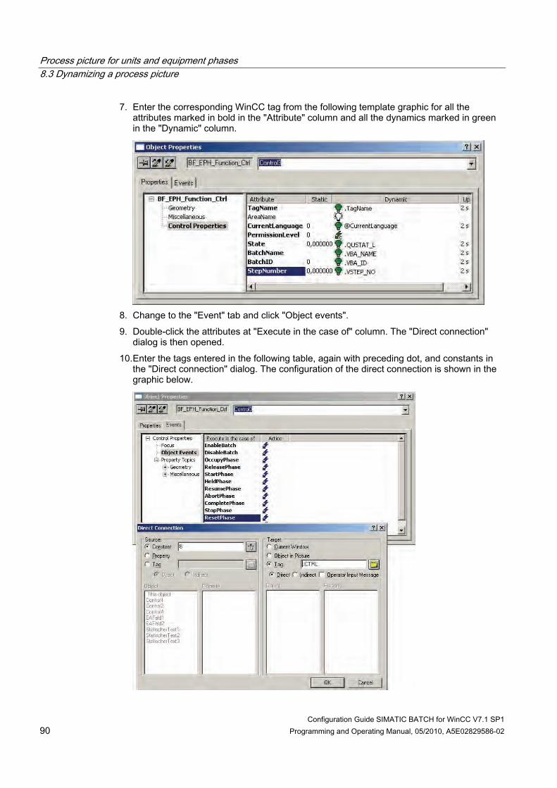
Process picture for units and equipment phases 8.3 Dynamizing a process picture
Configuration Guide SIMATIC BATCH for WinCC V7.1 SP1 90 Programming and Operating Manual, 05/2010, A5E02829586-02
7. Enter the corresponding WinCC tag from the following template graphic for all the attributes marked in bold in the "Attribute" column and all the dynamics marked in green in the "Dynamic" column.
8. Change to the "Event" tab and click "Object events". 9. Double-click the attributes at "Execute in the case of" column. The "Direct connection"
dialog is then opened. 10. Enter the tags entered in the following table, again with preceding dot, and constants in
the "Direct connection" dialog. The configuration of the direct connection is shown in the graphic below.
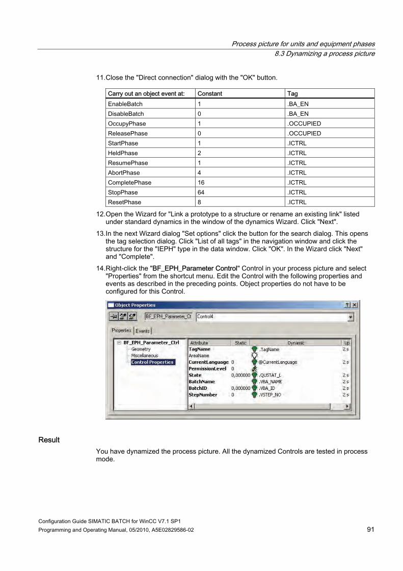
Process picture for units and equipment phases 8.3 Dynamizing a process picture
Configuration Guide SIMATIC BATCH for WinCC V7.1 SP1 Programming and Operating Manual, 05/2010, A5E02829586-02 91
11. Close the "Direct connection" dialog with the "OK" button.
Carry out an object event at: Constant Tag EnableBatch 1 .BA_EN DisableBatch 0 .BA_EN OccupyPhase 1 .OCCUPIED ReleasePhase 0 .OCCUPIED StartPhase 1 .ICTRL HeldPhase 2 .ICTRL ResumePhase 1 .ICTRL AbortPhase 4 .ICTRL CompletePhase 16 .ICTRL StopPhase 64 .ICTRL ResetPhase 8 .ICTRL
12. Open the Wizard for "Link a prototype to a structure or rename an existing link" listed under standard dynamics in the window of the dynamics Wizard. Click "Next".
13. In the next Wizard dialog "Set options" click the button for the search dialog. This opens the tag selection dialog. Click "List of all tags" in the navigation window and click the structure for the "IEPH" type in the data window. Click "OK". In the Wizard click "Next" and "Complete".
14. Right-click the "BF_EPH_Parameter Control" Control in your process picture and select "Properties" from the shortcut menu. Edit the Control with the following properties and events as described in the preceding points. Object properties do not have to be configured for this Control.
Result You have dynamized the process picture. All the dynamized Controls are tested in process mode.

Process picture for units and equipment phases 8.4 Operator control and monitoring of the units and equipment phases
Configuration Guide SIMATIC BATCH for WinCC V7.1 SP1 92 Programming and Operating Manual, 05/2010, A5E02829586-02
8.4 Operator control and monitoring of the units and equipment phases
Operating the BATCH Control When you activate your process picture, you have the following possibilities of operating and monitoring the Controls for the unit and the equipment phase.
Unit In the Control for the unit you can enable the unit for BATCH and reset the enable. If the unit is enabled for BATCH, SIMATIC BATCH can reserve this unit afterwards. Afterwards, when the unit is reserved by SIMATIC BATCH, the batch data, such as the batch name, product and further data, are displayed in the Control.
Equipment phase If the equipment phase is not enabled for SIMATIC BATCH, you can control the equipment phase by using the command buttons displayed in the Control, e.g. Start, Hold, Reset and Stop. All the setpoints of the configured equipment phase are displayed row-by-row in the lower part of the Control. The current recipe values are displayed in the "Setpoint" and "Actual value" columns. You can only change the setpoints in manual mode, when the enable for SIMATIC BATCH is not set, Double-click the corresponding setpoint row and enter the new value in the dialog under "Setpoint".
Note Reading the values from the block The setpoint is read from the IEPAR_DINT block, Q_SP_VAL output and the actual value from the QACT_VAL output and displayed.

Configuration Guide SIMATIC BATCH for WinCC V7.1 SP1 Programming and Operating Manual, 05/2010, A5E02829586-02 93
Example of a Batch Configuration 9Introduction
The following configuration is carried out in the BATCH Control Center. In order to have the configured unit and the equipment phase controlled by SIMATIC BATCH, you will create a recipe in the recipe editor and on this basis create and start a batch. With the BATCH Controls you have a possibility in addition to the BATCH Control Center to visualize the batch control process. The online help is available for configurations in the BATCH Control Center and in the recipe editor.
Requirements ● The operating mode of the CPU is RUN. ● The connection between the AS and OS is established. ● WinCC Runtime has been started and the user-defined process picture with the BATCH
Controls for the unit and equipment phase is displayed. ● The "Enable for Batch" check box is set in the two Controls.
Procedure 1. Start the BATCH Launch Coordinator by using Start > SIMATIC > BATCH > BATCH
Launch Coordinator. This starts the BATCH Start Coordinator, the Batch Control Server and BATCH CDV from the right area of the task bar.
2. Start the BATCH Control Center with the command Start > SIMATIC > BATCH > BATCH Control Center.
3. On the toolbar, click Program > New process cell. Select your process cell and confirm by clicking on the "OK" button.
4. Create a new material, for example water, in the "Materials" folder in the editing window. Use it for example as the input and output material.
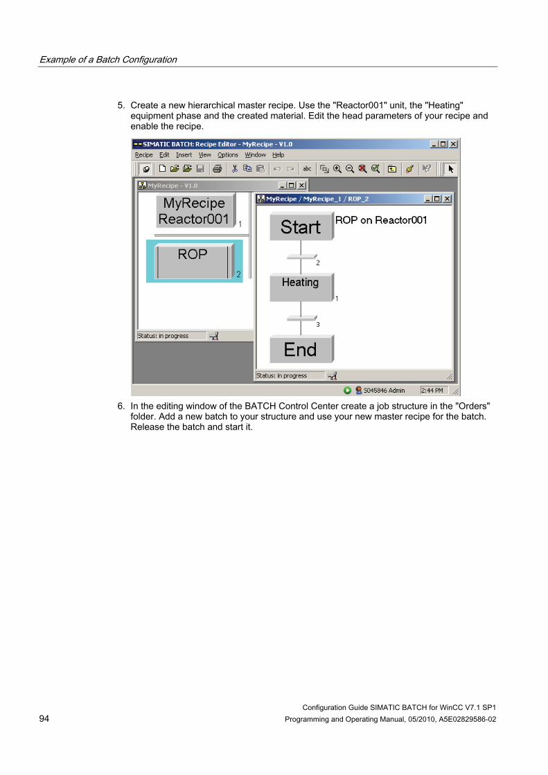
Example of a Batch Configuration
Configuration Guide SIMATIC BATCH for WinCC V7.1 SP1 94 Programming and Operating Manual, 05/2010, A5E02829586-02
5. Create a new hierarchical master recipe. Use the "Reactor001" unit, the "Heating" equipment phase and the created material. Edit the head parameters of your recipe and enable the recipe.
6. In the editing window of the BATCH Control Center create a job structure in the "Orders"
folder. Add a new batch to your structure and use your new master recipe for the batch. Release the batch and start it.
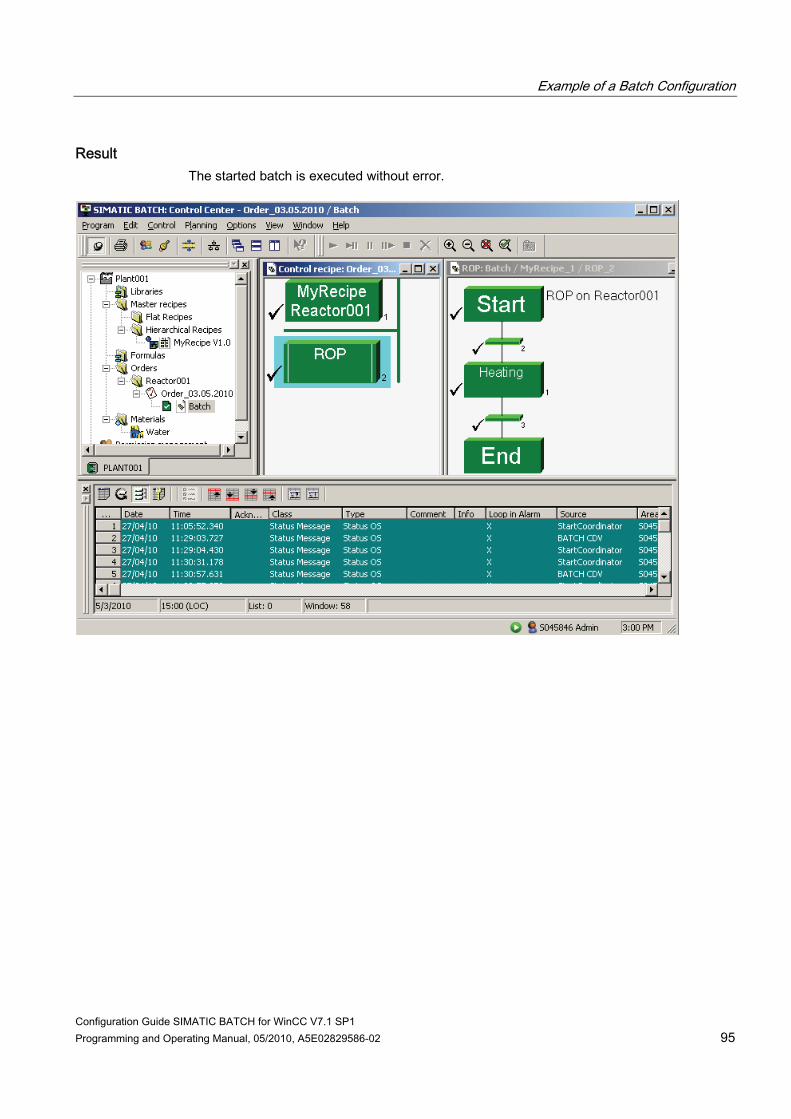
Example of a Batch Configuration
Configuration Guide SIMATIC BATCH for WinCC V7.1 SP1 Programming and Operating Manual, 05/2010, A5E02829586-02 95
Result The started batch is executed without error.

Example of a Batch Configuration
Configuration Guide SIMATIC BATCH for WinCC V7.1 SP1 96 Programming and Operating Manual, 05/2010, A5E02829586-02
At the same time you can use SIMATIC BATCH to monitor the batch control on the Operator Station.
Configuration Guide SIMATIC BATCH for WinCC V7.1 SP1 Programming and Operating Manual, 05/2010, A5E02829586-02 97
Interface description 1010.1 Information about the SIMATIC BATCH interface blocks V7.1 SP1
SIMATIC BATCH interface blocks V7.1 SP1 The description of the SIMATIC BATCH interface blocks is available under Start > SIMATIC > Documentation > English > SIMATIC BATCH - Interface Blocks.
10.2 AS interface description for SIMATIC BATCH
10.2.1 Principle structure of a user program for a unit with an equipment phase
Introduction You can use the descriptions in this chapter to create own interfaces for SIMATIC BATCH with WinCC for all AS systems.
Basic structure of the user program The graphic below shows the sequence in which the interfaces have to be installed. The structure of a unit with equipment phases (1 to m) with parameters (1 to n) is shown.
Note Processing cycle in the AS The period of time between two unit calls must amount to at least 1 second.
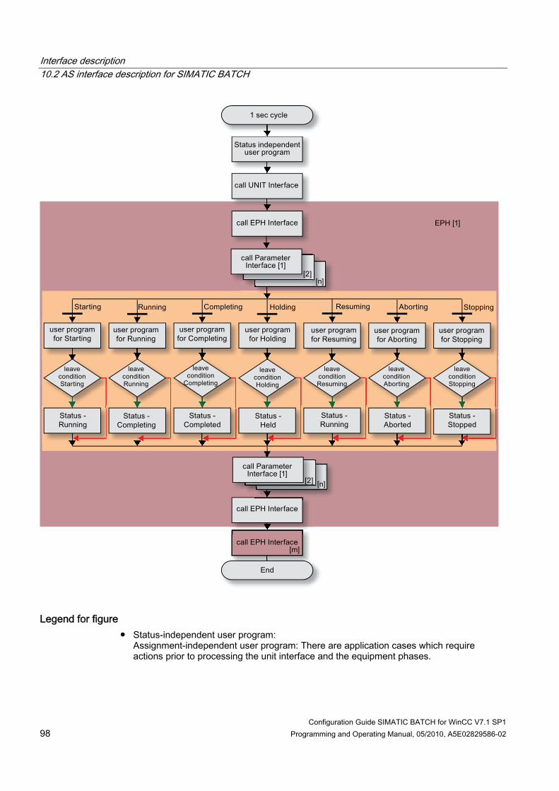
Interface description 10.2 AS interface description for SIMATIC BATCH
Configuration Guide SIMATIC BATCH for WinCC V7.1 SP1 98 Programming and Operating Manual, 05/2010, A5E02829586-02
Legend for figure ● Status-independent user program:
Assignment-independent user program: There are application cases which require actions prior to processing the unit interface and the equipment phases.

Interface description 10.2 AS interface description for SIMATIC BATCH
Configuration Guide SIMATIC BATCH for WinCC V7.1 SP1 Programming and Operating Manual, 05/2010, A5E02829586-02 99
● Call UNIT Interface: Calling of the interface for the unit. This processes the latest batch data of SIMATIC BATCH.
● Call EPH Interface: Calling of the interface for the equipment phase. With the first call the new commands of SIMATIC BATCH are processed and passed on to the user program. The second call updates the status of the equipment phase.
● Call Parameter Interface: Calling of the interface for the parameters of the equipment phase. With the first call the new setpoints written by SIMATIC BATCH are passed on to the user program. The second call updates the parameter actual values of the equipment phase.
● User program: Status processing in the user program
Note The characters used in square brackets mean that this is an instance of the interface function.
10.2.2 Unit
10.2.2.1 Description of functions
Unit interface Using the unit interface, the batch control coordinates the assignment of the individual units of the active batches. One instance of the unit must be available in the AS for each unit. The interface may not be called up faster than once per second.

Interface description 10.2 AS interface description for SIMATIC BATCH
Configuration Guide SIMATIC BATCH for WinCC V7.1 SP1 100 Programming and Operating Manual, 05/2010, A5E02829586-02
10.2.2.2 Unit interfaces to BATCH and WinCC
Communication of the unit interface The interface is used by SIMATIC BATCH to assign and enable a unit. The batch interface described in "Standard Interface Blocks" section is essential for the communication with external systems. The communication between SIMATIC BATCH, the WinCC data manager and the unit interface in the AS is shown in the following figure.
Further information Further information about the interface of the unit is available in Section 2.4 IUNIT_BLOCK unit allocation - BATCH interface in the document SIMATIC BATCH - interface blocks.

Interface description 10.2 AS interface description for SIMATIC BATCH
Configuration Guide SIMATIC BATCH for WinCC V7.1 SP1 Programming and Operating Manual, 05/2010, A5E02829586-02 101
10.2.2.3 Flowchart
10.2.3 Equipment phase / equipment operation
10.2.3.1 Description of functions
Interface of the equipment phase
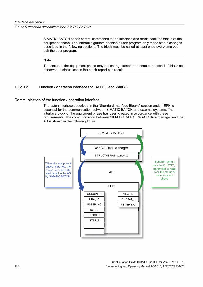
Interface description 10.2 AS interface description for SIMATIC BATCH
Configuration Guide SIMATIC BATCH for WinCC V7.1 SP1 102 Programming and Operating Manual, 05/2010, A5E02829586-02
SIMATIC BATCH sends control commands to the interface and reads back the status of the equipment phase. The internal algorithm enables a user program only those status changes described in the following sections. The block must be called at least once every time you edit the user program.
Note The status of the equipment phase may not change faster than once per second. If this is not observed, a status loss in the batch report can result.
10.2.3.2 Function / operation interfaces to BATCH and WinCC
Communication of the function / operation interface The batch interface described in the "Standard Interface Blocks" section under IEPH is essential for the communication between SIMATIC BATCH and external systems. The interface block of the equipment phase has been created in accordance with these requirements. The communication between SIMATIC BATCH, WinCC data manager and the AS is shown in the following figure.
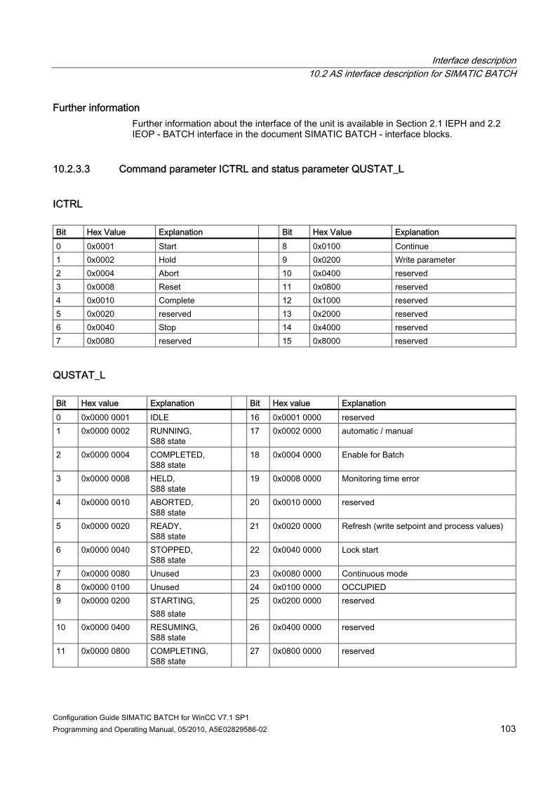
Interface description 10.2 AS interface description for SIMATIC BATCH
Configuration Guide SIMATIC BATCH for WinCC V7.1 SP1 Programming and Operating Manual, 05/2010, A5E02829586-02 103
Further information Further information about the interface of the unit is available in Section 2.1 IEPH and 2.2 IEOP - BATCH interface in the document SIMATIC BATCH - interface blocks.
10.2.3.3 Command parameter ICTRL and status parameter QUSTAT_L
ICTRL Bit Hex Value Explanation Bit Hex Value Explanation 0 0x0001 Start 8 0x0100 Continue 1 0x0002 Hold 9 0x0200 Write parameter 2 0x0004 Abort 10 0x0400 reserved 3 0x0008 Reset 11 0x0800 reserved 4 0x0010 Complete 12 0x1000 reserved 5 0x0020 reserved 13 0x2000 reserved 6 0x0040 Stop 14 0x4000 reserved 7 0x0080 reserved 15 0x8000 reserved
QUSTAT_L Bit Hex value Explanation Bit Hex value Explanation 0 0x0000 0001 IDLE 16 0x0001 0000 reserved 1 0x0000 0002 RUNNING,
S88 state 17 0x0002 0000 automatic / manual
2 0x0000 0004 COMPLETED, S88 state
18 0x0004 0000 Enable for Batch
3 0x0000 0008 HELD, S88 state
19 0x0008 0000 Monitoring time error
4 0x0000 0010 ABORTED, S88 state
20 0x0010 0000 reserved
5 0x0000 0020 READY, S88 state
21 0x0020 0000 Refresh (write setpoint and process values)
6 0x0000 0040 STOPPED, S88 state
22 0x0040 0000 Lock start
7 0x0000 0080 Unused 23 0x0080 0000 Continuous mode 8 0x0000 0100 Unused 24 0x0100 0000 OCCUPIED 9 0x0000 0200 STARTING,
S88 state 25 0x0200 0000 reserved
10 0x0000 0400 RESUMING, S88 state
26 0x0400 0000 reserved
11 0x0000 0800 COMPLETING, S88 state
27 0x0800 0000 reserved

Interface description 10.2 AS interface description for SIMATIC BATCH
Configuration Guide SIMATIC BATCH for WinCC V7.1 SP1 104 Programming and Operating Manual, 05/2010, A5E02829586-02
Bit Hex value Explanation Bit Hex value Explanation 12 0x0000 1000 HOLDING,
S88 state 28 0x1000 0000 reserved
13 0x0000 2000 ABORTING, S88 state
29 0x2000 0000 reserved
14 0x0000 4000 STOPPING, S88 state
30 0x4000 0000 reserved
15 0x0000 8000 unused 31 0x8000 0000 General error
Note QUSTAT_L can include several statuses. In doing so, the hex values are added together. The added value is located in the instance.
10.2.3.4 Flow diagrams for the user block of the equipment phase
Overview of the flow diagrams for an equipment phase The following diagrams show the sequence of the various commands, operating states and status changes in the user block. Adhere to the sequence of the flow diagrams in order to program this interface.
10.2.3.5 Startup flow chart
Startup diagram The relevant positions are labeled for status changes for which appropriate execution algorithms are required in the user program. The legends stipulated in the bottom left flow chart apply for all the other flow charts.
Note This also applies to all diagrams: When resetting "Reset all S88 status in QUSTAT_L": the statuses QCMOD (automatic), BATCH ENABLE and OCCUPIED are not reset. OCCUPIED can only be reset after COMPLETED. In QUSTAT_L, several statuses (BA_EN, QCMOD and OCCUPIED) are set at the same time in addition to the current status.
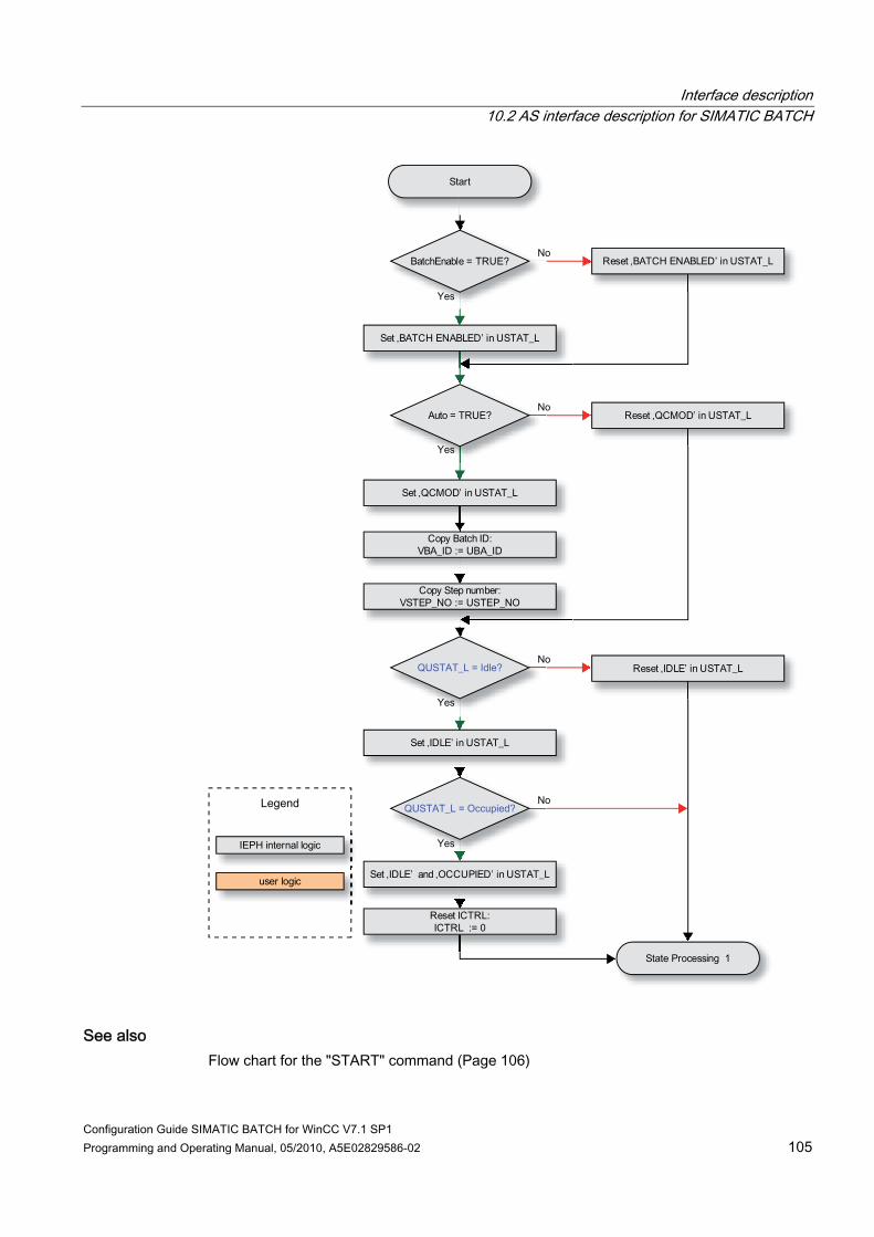
Interface description 10.2 AS interface description for SIMATIC BATCH
Configuration Guide SIMATIC BATCH for WinCC V7.1 SP1 Programming and Operating Manual, 05/2010, A5E02829586-02 105
See also Flow chart for the "START" command (Page 106)

Interface description 10.2 AS interface description for SIMATIC BATCH
Configuration Guide SIMATIC BATCH for WinCC V7.1 SP1 106 Programming and Operating Manual, 05/2010, A5E02829586-02
10.2.3.6 Flow chart for the "START" command
The following screens show the sequence for the "START" command and the status changes "Starting", "Running", "Completing" and "Completed" that result from it.

Interface description 10.2 AS interface description for SIMATIC BATCH
Configuration Guide SIMATIC BATCH for WinCC V7.1 SP1 Programming and Operating Manual, 05/2010, A5E02829586-02 107
See also Flow chart for the command "HOLD" (Page 108)

Interface description 10.2 AS interface description for SIMATIC BATCH
Configuration Guide SIMATIC BATCH for WinCC V7.1 SP1 108 Programming and Operating Manual, 05/2010, A5E02829586-02
10.2.3.7 Flow chart for the command "HOLD"
Flow chart for the command "HOLD" The following figure shows the sequence for the "HOLD" command and the resulting "Holding", "Held" and "Resuming" status transitions.
See also Flow chart for the "ABORT" command (Page 109)

Interface description 10.2 AS interface description for SIMATIC BATCH
Configuration Guide SIMATIC BATCH for WinCC V7.1 SP1 Programming and Operating Manual, 05/2010, A5E02829586-02 109
10.2.3.8 Flow chart for the "ABORT" command
The following screen shows the sequence for the "ABORT" command and the status changes "Aborting" and "Aborted" that result from it.

Interface description 10.2 AS interface description for SIMATIC BATCH
Configuration Guide SIMATIC BATCH for WinCC V7.1 SP1 110 Programming and Operating Manual, 05/2010, A5E02829586-02
See also Flow chart for the "STOP" command (Page 111)

Interface description 10.2 AS interface description for SIMATIC BATCH
Configuration Guide SIMATIC BATCH for WinCC V7.1 SP1 Programming and Operating Manual, 05/2010, A5E02829586-02 111
10.2.3.9 Flow chart for the "STOP" command
The following screen shows the sequence for the "STOP" command and the status changes "Stopping" and "Stopped" that result from it.
See also Flow chart for the "COMPLETE" command (Page 112)
Interface description 10.2 AS interface description for SIMATIC BATCH
Configuration Guide SIMATIC BATCH for WinCC V7.1 SP1 112 Programming and Operating Manual, 05/2010, A5E02829586-02
10.2.3.10 Flow chart for the "COMPLETE" command
End flow chart The following screen shows the sequence for the "COMPLETE" command for an equipment phase that does not end itself, if the status "Ready to Complete" has been reached. The sequence for the "CONTINUE" mode is also shown.

Interface description 10.2 AS interface description for SIMATIC BATCH
Configuration Guide SIMATIC BATCH for WinCC V7.1 SP1 Programming and Operating Manual, 05/2010, A5E02829586-02 113

Interface description 10.2 AS interface description for SIMATIC BATCH
Configuration Guide SIMATIC BATCH for WinCC V7.1 SP1 114 Programming and Operating Manual, 05/2010, A5E02829586-02
10.2.4 Parameters of the equipment phase
10.2.4.1 Description of functions
Parameter interface Phase parameters are mapped by means of tags. The corresponding blocks for each data type such as Binary, Integer, Real, String and Material are contained in the SIMATIC BATCH block library.
10.2.4.2 Parameter interfaces to BATCH and WinCC
Communication of the parameter interface The interface is used by SIMATIC BATCH to write and read back a parameter of an equipment phase. The blocks of the type "IEPAR_*" are required for the communication between SIMATIC BATCH and an external control system. The communication between SIMATIC BATCH, the WinCC data manager and the parameter interface in the AS is shown in the following figure.
Setpoint The setpoint is transferred from the SIMATIC BATCH to the "SP_VAL" parameter of a parameter structure. The setpoint is written before the "Starting" state of the equipment phase.

Interface description 10.2 AS interface description for SIMATIC BATCH
Configuration Guide SIMATIC BATCH for WinCC V7.1 SP1 Programming and Operating Manual, 05/2010, A5E02829586-02 115
Actual value Once one of the statuses "COMPLETED", "ABORTED" or "STOPPED" has been reached, the setpoint "Q_SP_VAL" and the actual value "QACT_VAL" are read by the SIMATIC BATCH and made available in a suitable form for further processing in SIMATIC BATCH.
Note We recommend that you use the IEPAR_ENUM data type to implement modes of operation. If you have used the "New" button in the SIMATIC BATCH project configuration dialog to create a new data type, you can assign it to the interface IEPAR_ENUM.
Further information Further information about the interface of the parameters is available in Chapter 3 Equipment parameter module in the document SIMATIC BATCH - interface blocks.
10.2.4.3 Flowchart
Flow diagram of the parameter interface

Interface description 10.2 AS interface description for SIMATIC BATCH
Configuration Guide SIMATIC BATCH for WinCC V7.1 SP1 116 Programming and Operating Manual, 05/2010, A5E02829586-02
Configuration Guide SIMATIC BATCH for WinCC V7.1 SP1 Programming and Operating Manual, 05/2010, A5E02829586-02 117
SIMATIC IT Historian 1111.1 Installation of the Software Components
Overview of software requirements You must install the following software components on your PC for the SIMATIC IT Historian: ● One of the following operating systems:
– Windows XP Professional with Service Pack 2 – Windows Server 2003 R2
● SIMATIC IT Historian ● SIMATIC Common Interface. The setup files are located on the product DVD in the
"setup" folder under "04_COMCIF_V7.1+SP1".
Installation of SIMATIC IT Historian 1. Insert the installation DVD in your drive and double-click the "Setup.exe" file. 2. For this example configuration, select "SIT Integration" add-on in the "Program Package"
setup dialog box. 3. Follow the instructions provided by the Wizard and close the Setup.
Result The installation has been successfully completed. You can now begin the configuration of the SIMATIC IT Historian.
11.2 Configuration of SIMATIC IT Historian
Introduction The following configuration steps must be performed for using SIMATIC BATCH with WinCC in conjunction with SIMATIC IT Historian.
Requirements ● PC on which the installation of the SIMATIC IT Historian was carried out. ● PC on which the SIMATIC BATCH configuration dialog was installed.
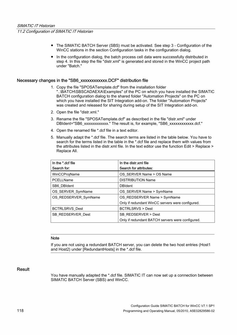
SIMATIC IT Historian 11.2 Configuration of SIMATIC IT Historian
Configuration Guide SIMATIC BATCH for WinCC V7.1 SP1 118 Programming and Operating Manual, 05/2010, A5E02829586-02
● The SIMATIC BATCH Server (SBS) must be activated. See step 3 - Configuration of the WinCC stations in the section Configuration tasks in the configuration dialog.
● In the configuration dialog, the batch process cell data were successfully distributed in step 4. In this step the file "distr.xml" is generated and stored in the WinCC project path under "Batch."
Necessary changes in the "SB6_xxxxxxxxxxxx.DCF" distribution file 1. Copy the file "SPOSATemplate.dcf" from the installation folder
"..\BATCH\SBSCADAEXA\Examples" of the PC on which you have installed the SIMATIC BATCH configuration dialog to the shared folder "Automation Projects" on the PC on which you have installed the SIT Integration add-on. The folder "Automation Projects" was created and released for sharing during setup of the SIT Integration add-on.
2. Open the file "distr.xml." 3. Rename the file "SPOSATemplate.dcf" as described in the file "distr.xml" under
DBIdent="SB6_xxxxxxxxxxxx." The result is, for example, "SB6_xxxxxxxxxxxx.dcf." 4. Open the renamed file *.dcf file in a text editor. 5. Manually adapt the *.dcf file. The search terms are listed in the table below. You have to
search for the terms listed in the table in the *.dcf file and replace them with values from the attributes listed in the distr.xml file. In the text editor use the function Edit > Replace > Replace All.
In the *.dcf file Search for:
In the distr.xml file Search for attributes:
WinCCProjName OS_SERVER Name > OS Name PCELLName DISTRIBUTION Name SB6_DBIdent DBIdent OS_SERVER_SymName OS_SERVER Name > SymName OS_REDSERVER_SymName OS_REDSERVER Name > SymName
Only if redundant WinCC servers were configured. BCTRLSRVS_Dest BCTRLSRVS > Dest SB_REDSERVER_Dest SB_REDSERVER > Dest
Only if redundant BATCH servers were configured.
Note If you are not using a redundant BATCH server, you can delete the two host entries (Host1 and Host2) under [RedundantHosts] in the *.dcf file.
Result You have manually adapted the *.dcf file. SIMATIC IT can now set up a connection between SIMATIC BATCH Server (SBS) and WinCC.
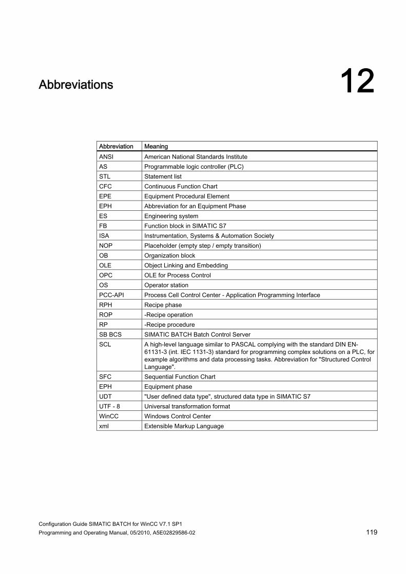
Configuration Guide SIMATIC BATCH for WinCC V7.1 SP1 Programming and Operating Manual, 05/2010, A5E02829586-02 119
Abbreviations 12
Abbreviation Meaning ANSI American National Standards Institute AS Programmable logic controller (PLC) STL Statement list CFC Continuous Function Chart EPE Equipment Procedural Element EPH Abbreviation for an Equipment Phase ES Engineering system FB Function block in SIMATIC S7 ISA Instrumentation, Systems & Automation Society NOP Placeholder (empty step / empty transition) OB Organization block OLE Object Linking and Embedding OPC OLE for Process Control OS Operator station PCC-API Process Cell Control Center - Application Programming Interface RPH Recipe phase ROP -Recipe operation RP -Recipe procedure SB BCS SIMATIC BATCH Batch Control Server SCL A high-level language similar to PASCAL complying with the standard DIN EN-
61131-3 (int. IEC 1131-3) standard for programming complex solutions on a PLC, for example algorithms and data processing tasks. Abbreviation for "Structured Control Language".
SFC Sequential Function Chart EPH Equipment phase UDT "User defined data type", structured data type in SIMATIC S7 UTF - 8 Universal transformation format WinCC Windows Control Center xml Extensible Markup Language

Abbreviations
Configuration Guide SIMATIC BATCH for WinCC V7.1 SP1 120 Programming and Operating Manual, 05/2010, A5E02829586-02

Configuration Guide SIMATIC BATCH for WinCC V7.1 SP1 Programming and Operating Manual, 05/2010, A5E02829586-02 121
Index
A Abbreviations, 119 ABORT command, 109 Actual values, 92 Add, 42
Channel, 42 Address, 56
Determining, 56 Alarm logging, 39 ANSI, 119 AS, 119 Assembling, 19
User program, 19 Assignment-independent user program, 97 Automatic generation
of the delivery spreadsheet, 72
B Basic knowledge, 7 BATCH client, 75 BATCH configuration, 93 BATCH Control
For equipment phase, 87 for the unit, 83 Operating, 92
BATCH Control Center, 93 BATCH Controls, 81 BATCH Launch Coordinator, 93 Batch process cell
Configuring, 69 BATCH server, 75 Batch stations, 78 Batch types, 69, 70 BDM (CDV), 77 Block
S7 Library, 20 block numbers, 19 Blocks
Calling, 36 Cyclic blocks, 36 Download to the AS, 37
Byte address, 56
C Call, 36
Blocks, 36 CFC, 119 Channel, 42
Add, 42 Command parameter ICTRL, 103 Communication, 15
Function / operation interface, 102 Parameter interface, 114 Structure types, 48 Unit interface, 100
Communication driver, 42 Communication of the function / operation interface, 102 Communication of the parameter interface, 114 Communication of the unit interface, 100 COMPLETE command, 112 Computer name, 75 Configuration, 14
Redundant, 14 Configuration dialog, 12, 67
Configuration tasks, 68 Configuration file, 77 Configuration Guide, 7
Requirements, 7 Configuration tasks, 68 Configuration Tool, 47 Configuring BATCH stations, 75 Configuring WinCC stations, 76 Connection, 43
Creating, 43 Create, 21, 39, 43
Connection, 43 Function type, 21 Message classes and message types, 39 Units, 34
Create structure tags, 58 Create structure types, 48 Creating, 43 Creating a batch, 93 Creating a process picture, 81 Creating a recipe, 93 Creating internal tags, 62 Cyclic blocks, 36
Calling, 36
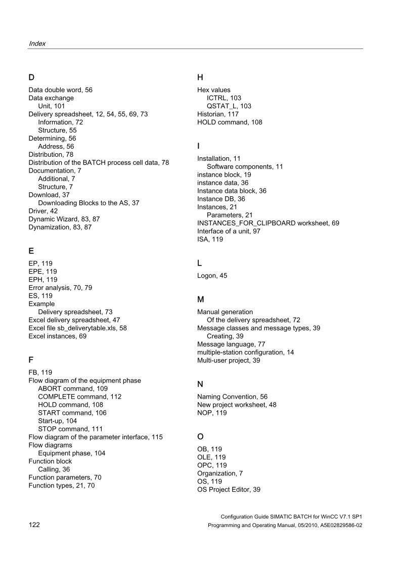
Index
Configuration Guide SIMATIC BATCH for WinCC V7.1 SP1 122 Programming and Operating Manual, 05/2010, A5E02829586-02
D Data double word, 56 Data exchange
Unit, 101 Delivery spreadsheet, 12, 54, 55, 69, 73
Information, 72 Structure, 55
Determining, 56 Address, 56
Distribution, 78 Distribution of the BATCH process cell data, 78 Documentation, 7
Additional, 7 Structure, 7
Download, 37 Downloading Blocks to the AS, 37
Driver, 42 Dynamic Wizard, 83, 87 Dynamization, 83, 87
E EP, 119 EPE, 119 EPH, 119 Error analysis, 70, 79 ES, 119 Example
Delivery spreadsheet, 73 Excel delivery spreadsheet, 47 Excel file sb_deliverytable.xls, 58 Excel instances, 69
F FB, 119 Flow diagram of the equipment phase
ABORT command, 109 COMPLETE command, 112 HOLD command, 108 START command, 106 Start-up, 104 STOP command, 111
Flow diagram of the parameter interface, 115 Flow diagrams
Equipment phase, 104 Function block
Calling, 36 Function parameters, 70 Function types, 21, 70
H Hex values
ICTRL, 103 QSTAT_L, 103
Historian, 117 HOLD command, 108
I Installation, 11
Software components, 11 instance block, 19 instance data, 36 Instance data block, 36 Instance DB, 36 Instances, 21
Parameters, 21 INSTANCES_FOR_CLIPBOARD worksheet, 69 Interface of a unit, 97 ISA, 119
L Logon, 45
M Manual generation
Of the delivery spreadsheet, 72 Message classes and message types, 39
Creating, 39 Message language, 77 multiple-station configuration, 14 Multi-user project, 39
N Naming Convention, 56 New project worksheet, 48 NOP, 119
O OB, 119 OLE, 119 OPC, 119 Organization, 7 OS, 119 OS Project Editor, 39

Index
Configuration Guide SIMATIC BATCH for WinCC V7.1 SP1 Programming and Operating Manual, 05/2010, A5E02829586-02 123
Overview Interface for the equipment phase, 104
Overview of the configuration tasks, 17
P Parameter actual value, 115 Parameter interface, 114 Parameter setpoint, 114 Password, 45 PC Configurations, 14 PCC-API, 119 PCell, 69 Phase types
Creating, 21 Preface, 7 Process mode, 45 Process picture, 81 Program code, 83, 87
Q QSTAT_L status parameter, 103
R Recipe Editor, 93 Redundant configuration, 14 Requirements, 7
Configuration Guide, 7 Software, 11
ROP, 119 RP, 119 RPH, 119
S S7 addresses, 56 S7 Library
Block, 20 SB BCS, 119 SB_DeliveryTable.xls, 47, 55 SB_WinCCTypes.xls, 47 SBS, 77 SCL, 119 Set up, 45
User, 45 WinCC user, 45
Setpoints, 92 SFC, 119
SIMATIC BATCH configuration dialog, 67 SIMATIC IT, 117 SIMATIC IT Historian, 117 SIMATIC Manager, 37 SIMATIC S7 Protocol Suite.chn, 42 Single-station configuration, 14 Software, 11
Requirements, 11 Software components, 11
Installation, 11 Standard blocks, 20 START command, 106 Start-up
Equipment phase, 104 Statement list (STL), 19 Static tag list, 34 STL, 19, 119 STOP command, 111 Structure
Documentation, 7 Structure tags, 47 Structure types, 48
For communication types, 48 Structure Types worksheet, 48 System components, 13
T Tag declaration, 34 Tag list, 34
Static, 34 Tag management, 42 Tag name, 56 TagName, 62 Text library, 62 Time stamp, 16 Time synchronization, 16
U Unit
Calling the blocks, 36 Creating, 34 Sequence of the data exchange, 101
Unit instance data block, 36 Unit interface, 100 Units, 34 User, 19
Set up, 45 User Administrator, 45 User blocks, 19

Index
Configuration Guide SIMATIC BATCH for WinCC V7.1 SP1 124 Programming and Operating Manual, 05/2010, A5E02829586-02
User program, 19 Assembling, 19
UTF - 8, 119
V Validity, 79
Checking, 79 Variables, 83 Visualizing and generating status changes, 81
W WinCC, 76 WinCC project, 39 WinCC project file, 77 WinCC structure tag, 55 WinCC structure tags, 56 WinCC structure type, 55 WinCC user, 45
Set up, 45
X xml, 119