
GUIDE SPECIFICATIONS - Geothermal Energygeothermalenergy.com/wp-content/uploads/2011/06/CE... ·...
16
GENERAL Units shall be performance certified to ISO standard 13256-1 for Water Loop Heat Pump, Ground Water Heat Pump and Ground Loop Heat Pump applications. Units shall be Underwriter Laboratories (UL and ULc) listed for safety on all models. Each unit shall be run tested at the factory. Each unit shall be pallet mounted and stretch wrapped. The units shall be manufactured in an ISO9001:2000 certified facility. The units shall be warranted by the manufacturer against defects in materials and workmanship for a period of i) in the case of residentially sold units having the last digit of the serial number as a 'T'; five years on all parts and 10 years on the refrigerant circuit components ii) on all other units; five years on the compressor and one year on all other parts. The units shall be designed to operate with entering fluid temperatures between 50˚F (10˚C) and 110˚F (43.3˚C) in cooling and temperatures between 25˚F (-3.9˚C) and 80oF (27˚C) in heating as manufactured by Bosch in Fort Lauderdale, Florida. CASING & CABINET The cabinet shall be fabricated from heavy-gauge steel finished with Galvalume ® plus, an aluminum-zinc alloy with a clear acrylic coating for additional corrosion protection. The interior shall be insulated with ½” (12.7mm) thick, multi density, coated, glass fiber. All units shall allow sufficient service access to replace the compressor without unit removal. One blower and two compressor compartment access panels shall be removable with supply and return ductwork in place. A duct collar shall be provided on the supply air opening. A filter rack with 1" (25.4mm) thick disposable filters and a 1" (25.4mm) return air duct collar shall be provided with each unit. The units shall have an insulated divider panel between the air handling section and the compressor section to minimize the transmission of compressor noise, and to permit service testing without air bypass. Units shall have a stainless steel condensate drain pan. REFRIGERATION CIRCUITS All units shall contain a sealed refrigerant circuit including a hermetic two stage scroll compressor, bi-directional thermal expansion valve metering device, finned tube air-to-refrigerant heat exchanger, refrigerant reversing valve and service ports. Compressor shall be high efficiency scroll type, designed for heat pump duty, quiet operation and mounted on rubber vibration isolators. Compressor motors shall be equipped with overload protection. Refrigerant reversing valves shall be pilot operated sliding piston type with replaceable encapsulated magnetic coils energized only during the cooling cycle. The finned tube coil shall be constructed of lanced aluminum fins not exceeding fourteen fins per inch bonded to rifled copper tubes in a staggered pattern not less than three rows deep and have a 600 Psig (4140 Kpa)) working pressure. Coils shall have a baked polyester enamel coating for protection against most airborne chemicals. Coil end plates shall be aluminum. The coaxial water-to-refrigerant heat exchanger shall be constructed of a convoluted copper (optional cupronickel) inner tube and steel outer tube with a designed refrigerant working pressure of 600 Psig (4140 Kpa) and a designed water side working pressure of no less than 400 PSIG (2750 kPa). The water-to-refrigerant heat exchanger shall be insulated to prevent condensation at low fluid temperatures. FAN MOTOR & ASSEMBLY The fan shall be direct drive centrifugal forward curved type with a dynamically balanced wheel. The housing and wheel shall be designed for quiet low velocity operation. The fan housing shall be removable from the unit without disconnecting the supply air ductwork for servicing of the fan motor. The fan motor shall be an ECM-2 microprocessor controlled DC type motor with internal programming factory set for the specific unit and featuring soft start/ stop and a delay off feature for maximum efficiency and quiet operation. Air flow rates shall be varied according to the staging of the unit. There will further be provisions for adjusting the air delivery of the motor and blower by +/- 15% from rated air flow. ELECTRICAL Controls and safety devices will be factory wired and mounted within the unit. Controls shall include compressor contactor, 24V transformer, reversing valve coil and solid state lock-out controller (UPM). The UPM controller shall include the following features: diagnostic LED's, low pressure bypass time delay (to prevent nuisance low pressure lock-outs during operation with low fluid temperatures), anti short cycle time delay, random start time delay and one time intelligent reset. When the safety controls are activated the lock-out circuit shall reset itself the first time. If the safety controls are subsequently activated, then the lock-out circuit shall disable the compressor until it is reset at the thermostat or main circuit breaker to prevent compressor operation during fault conditions. A lock-out indicating terminal shall be provided in the low voltage circuit. Safety devices include a low pressure cutout set a 40 PSIG (280 kPa) for loss of charge protection (freezestat and/or high discharge gas temperature sensor is not acceptable) and a high pressure cutout control set at 600 PSIG (4100 Kpa). The ECM motor interface board shall provide a screw type terminal block for thermostat connection, LED's to indicate thermostat status and air delivery. It shall also provide a means of changing the motor program to any of up to four pre-programmed options. Direct wiring of the motor control harness to the thermostat is not acceptable. A terminal block with screw terminals shall be provided for control wiring. An optional condensate overflow device shall be factory installed to stop compressor operation if drain pan overflow is imminent. An optional energy management relay to allow unit control by an external source shall be factory installed. PIPING Supply, return water and condensate drain connections shall be brass female pipe thread fittings and mounted flush to cabinet exterior. INTERNAL ELECTRIC HEAT 208/230-1-60 volt units shall be equipped with optional installed internal electric resistance heat for auxiliary and emergency heat. Electric heater must be Underwriter's Laboratories (UL and ULc) approved for safety when installed in the unit. External heater packages or heater packages not specifically listed for use with the unit are unacceptable. Electric heater packages shall include a heater collar mounted to the blower outlet, individual thermal overload protected heater elements no greater than 5kW each and magnetic contactors. Heater packages shall have a separate power supply connection from the compressor and this power supply shall also power the unit blower motor and control transformer for safe operation. HEAT RECOVERY PACKAGE 208/230 volt units shall be equipped with a optional factory installed internal heat recovery kit for domestic hot water production. This kit shall include an internally protected pump, double walled coaxial water-to-refrigerant heat exchanger, 140˚F (60˚C) hot water temperature limit switch and an on/off switch/circuit breaker. LOOP PUMP PACKAGE - CONSULT FACTORY 208/230-1-60 volt units shall be equipped with an optional factory installed ground loop pump kit. This kit shall include a 1/6 HP loop pump, isolation valves and a set of purge connections for purging and pressurizing the ground loop with the unit in place. The pump, all piping and valves shall be internal to the unit. GUIDE SPECIFICATIONS CE Series Two Stage R-410A CESPECS.INDD REV: 03-11 Catalog (CE Technical Data Sheet)
Transcript of GUIDE SPECIFICATIONS - Geothermal Energygeothermalenergy.com/wp-content/uploads/2011/06/CE... ·...

GENERALUnits shall be performance certified to ISO standard 13256-1 for Water Loop Heat Pump, Ground Water Heat Pump and Ground Loop Heat Pump applications. Units shall be Underwriter Laboratories (UL and ULc) listed for safety on all models. Each unit shall be run tested at the factory. Each unit shall be pallet mounted and stretch wrapped. The units shall be manufactured in an ISO9001:2000 certified facility.
The units shall be warranted by the manufacturer against defects in materials and workmanship for a period of i) in the case of residentially sold units having the last digit of the serial number as a 'T'; five years on all parts and 10 years on the refrigerant circuit components ii) on all other units; five years on the compressor and one year on all other parts.
The units shall be designed to operate with entering fluid temperatures between 50˚F (10˚C) and 110˚F (43.3˚C) in cooling and temperatures between 25˚F (-3.9˚C) and 80oF (27˚C) in heating as manufactured by Bosch in Fort Lauderdale, Florida.
CASING & CABINETThe cabinet shall be fabricated from heavy-gauge steel finished with Galvalume® plus, an aluminum-zinc alloy with a clear acrylic coating for additional corrosion protection. The interior shall be insulated with ½” (12.7mm) thick, multi density, coated, glass fiber. All units shall allow sufficient service access to replace the compressor without unit removal. One blower and two compressor compartment access panels shall be removable with supply and return ductwork in place. A duct collar shall be provided on the supply air opening. A filter rack with 1" (25.4mm) thick disposable filters and a 1" (25.4mm) return air duct collar shall be provided with each unit. The units shall have an insulated divider panel between the air handling section and the compressor section to minimize the transmission of compressor noise, and to permit service testing without air bypass. Units shall have a stainless steel condensate drain pan.
REFRIGERATION CIRCUITSAll units shall contain a sealed refrigerant circuit including a hermetic two stage scroll compressor, bi-directional thermal expansion valve metering device, finned tube air-to-refrigerant heat exchanger, refrigerant reversing valve and service ports. Compressor shall be high efficiency scroll type, designed for heat pump duty, quiet operation and mounted on rubber vibration isolators. Compressor motors shall be equipped with overload protection. Refrigerant reversing valves shall be pilot operated sliding piston type with replaceable encapsulated magnetic coils energized only during the cooling cycle. The finned tube coil shall be constructed of lanced aluminum fins not exceeding fourteen fins per inch bonded to rifled copper tubes in a staggered pattern not less than three rows deep and have a 600 Psig (4140 Kpa)) working pressure. Coils shall have a baked polyester enamel coating for protection against most airborne chemicals. Coil end plates shall be aluminum. The coaxial water-to-refrigerant heat exchanger shall be constructed of a convoluted copper (optional cupronickel) inner tube and steel outer tube with a designed refrigerant working pressure of 600 Psig (4140 Kpa) and a designed water side working pressure of no less than 400 PSIG (2750 kPa). The water-to-refrigerant heat exchanger shall be insulated to prevent condensation at low fluid temperatures.
FAN MOTOR & ASSEMBLYThe fan shall be direct drive centrifugal forward curved type with a dynamically balanced wheel. The housing and wheel shall be designed for quiet low velocity operation. The fan housing shall be removable from the unit without disconnecting the supply air ductwork for servicing of the fan motor. The fan motor shall be an ECM-2 microprocessor controlled DC type motor with internal programming factory set for the specific unit and featuring soft start/stop and a delay off feature for maximum efficiency and quiet operation.
Air flow rates shall be varied according to the staging of the unit. There will further be provisions for adjusting the air delivery of the motor and blower by +/- 15% from rated air flow.
ELECTRICALControls and safety devices will be factory wired and mounted within the unit. Controls shall include compressor contactor, 24V transformer, reversing valve coil and solid state lock-out controller (UPM). The UPM controller shall include the following features: diagnostic LED's, low pressure bypass time delay (to prevent nuisance low pressure lock-outs during operation with low fluid temperatures), anti short cycle time delay, random start time delay and one time intelligent reset. When the safety controls are activated the lock-out circuit shall reset itself the first time. If the safety controls are subsequently activated, then the lock-out circuit shall disable the compressor until it is reset at the thermostat or main circuit breaker to prevent compressor operation during fault conditions. A lock-out indicating terminal shall be provided in the low voltage circuit. Safety devices include a low pressure cutout set a 40 PSIG (280 kPa) for loss of charge protection (freezestat and/or high discharge gas temperature sensor is not acceptable) and a high pressure cutout control set at 600 PSIG (4100 Kpa).
The ECM motor interface board shall provide a screw type terminal block for thermostat connection, LED's to indicate thermostat status and air delivery. It shall also provide a means of changing the motor program to any of up to four pre-programmed options. Direct wiring of the motor control harness to the thermostat is not acceptable.
A terminal block with screw terminals shall be provided for control wiring. An optional condensate overflow device shall be factory installed to stop compressor operation if drain pan overflow is imminent. An optional energy management relay to allow unit control by an external source shall be factory installed.
PIPINGSupply, return water and condensate drain connections shall be brass female pipe thread fittings and mounted flush to cabinet exterior.
INTERNAL ELECTRIC HEAT208/230-1-60 volt units shall be equipped with optional installed internal electric resistance heat for auxiliary and emergency heat. Electric heater must be Underwriter's Laboratories (UL and ULc) approved for safety when installed in the unit. External heater packages or heater packages not specifically listed for use with the unit are unacceptable. Electric heater packages shall include a heater collar mounted to the blower outlet, individual thermal overload protected heater elements no greater than 5kW each and magnetic contactors. Heater packages shall have a separate power supply connection from the compressor and this power supply shall also power the unit blower motor and control transformer for safe operation.
HEAT RECOVERY PACKAGE208/230 volt units shall be equipped with a optional factory installed internal heat recovery kit for domestic hot water production. This kit shall include an internally protected pump, double walled coaxial water-to-refrigerant heat exchanger, 140˚F (60˚C) hot water temperature limit switch and an on/off switch/circuit breaker.
LOOP PUMP PACKAGE - CONSULT FACTORY208/230-1-60 volt units shall be equipped with an optional factory installed ground loop pump kit. This kit shall include a 1/6 HP loop pump, isolation valves and a set of purge connections for purging and pressurizing the ground loop with the unit in place. The pump, all piping and valves shall be internal to the unit.
GUIDE SPECIFICATIONSCE Series Two Stage R-410A
CESPECS.INDD REV: 03-11 Catalog (CE Technical Data Sheet)

Rig
ht H
and
Ret
urn
(FR
T)
Left
Han
dR
etur
n(F
LT)
NO
TE
S: A
ll di
men
sion
s w
ithin
+/-
0.1
25".
A
ll co
nden
sate
dra
in c
onne
ctio
ns a
re 3
/4"
FP
T.
All
Hea
t Rec
over
y K
it co
nnec
tions
are
1/2
" F
PT.
In
tern
al e
lect
ric h
eat a
vaila
ble
on 2
08-2
30/1
/60
top
disc
harg
e un
its o
nly
In
tern
al H
eat R
ecov
ery
Kit
avai
labl
e on
208
-230
vol
t uni
ts o
nly.
S
peci
ficat
ions
sub
ject
to c
hang
e w
ithou
t not
ice.
CE
VT
DG
IP IN
T II
.P65
R
EV
: 03-
11
FH
P M
anu
fact
uri
ng
Co
.60
1 N
.W. 6
5th
Cou
rtF
ort L
aude
rdal
e, F
L 33
309
Pho
ne: (
954)
776
-547
1F
ax: (
800)
776
-552
9ht
tp://
ww
w.b
osch
-clim
ate.
us
CE Tw
o St
age
Serie
s Ver
tical
Dim
ensio
ns
A
B
C
D
E
F
G
H
J K
M
N
P
Q
C
onde
nser
R
ecom
men
ded
M
OD
EL
R/A
Duc
t R
/A D
uct
Filte
r Rac
k
Wat
er
Rep
lace
men
t
W
idth
D
epth
H
eigh
t
Flg
Wid
th F
lg H
eigh
t H
eigh
t
Con
nect
ions
N
omin
al F
ilter
Siz
eC
E02
5, 0
35
21.5
0 26
.00
47.2
5 13
.75
15.7
5 6.
13
5.25
2.
50
8.00
13
.50
22.0
0 22
.25
24.0
0 4.
00
3/4"
F.P
.T.
24 X
24
X 1
C
E04
9 24
.00
32.7
5 47
.25
15.7
5 15
.75
8.38
5.
50
2.50
8.
00
14.7
5 28
.50
22.2
5 24
.00
4.00
1"
F.P
.T.
24 X
30
X 1
C
E06
1 26
.00
33.2
5 51
.25
17.7
5 17
.75
7.13
6.
25
2.50
8.
00
14.7
5 28
.50
22.2
5 24
.00
4.00
1"
F.P
.T.
24 X
30
X 1
C
E07
1 26
.00
33.2
5 58
.25
17.7
5 17
.75
8.00
7.
75
2.50
8.
00
14.7
5 28
.50
30.2
5 32
.00
1.50
1"
F.P
.T.
16 X
30
X 1
(2)
EV
HZ
DG
IP.P
65
RE
V: 0
3-11
CE
Two
Stag
e Se
ries
H
oriz
onta
l Dim
ensi
ons
Left
Han
d R
etur
nE
nd B
low
(F
LE)
Left
Han
d R
etur
nS
trai
ght T
hrou
gh (
FLS
)
Rig
ht H
and
Ret
urn
End
Blo
w (
FR
E)
Rig
ht H
and
Ret
urn
Str
aigh
t Thr
ough
(F
RS
)
A
B
C
D
E
F
G
H
J K
M
N
P
Q
R
T
C
onde
nser
R
ecom
men
ded
M
OD
EL
R/A
Duc
t
Filte
r Rac
k R
/A D
uct
Wat
er
Rep
lace
men
t
W
idth
D
epth
H
eigh
t
Flg
Wid
th
Hei
ght
Flg
Hei
ght
Con
nect
ions
Nom
. Filt
er S
ize
CE
025,
035
26
.00
54.5
0 21
.75
2.00
30
.00
22.5
0 2.
50
13.5
0 4.
50
13.7
5 3.
00
15.7
5 4.
50
3.00
20
.50
18.5
0 3/
4" F
.P.T
. 18
X 3
0 X
1 (1
)C
E04
9 30
.00
68.0
0 21
.75
2.50
33
.50
32.0
0 2.
50
14.5
0 5.
81
15.7
5 3.
00
15.7
5 5.
81
2.00
20
.50
18.5
0 1"
F.P
.T.
18 X
20
X 1
(2)
CE
061
30.0
0 68
.00
21.7
5 2.
50
33.5
0 32
.00
2.50
14
.50
7.66
17
.75
2.00
17
.75
7.66
2.
00
20.5
0 18
.50
1" F
.P.T
. 18
X 2
0 X
1 (2
) C
E07
1 30
.00
78.0
0 21
.75
2.50
44
.00
31.5
0 2.
50
14.5
0 3.
50
17.7
5 2.
75
17.7
5 7.
66
1.00
20
.25
18.5
0 1"
F.P
.T.
20x2
4x1
(22
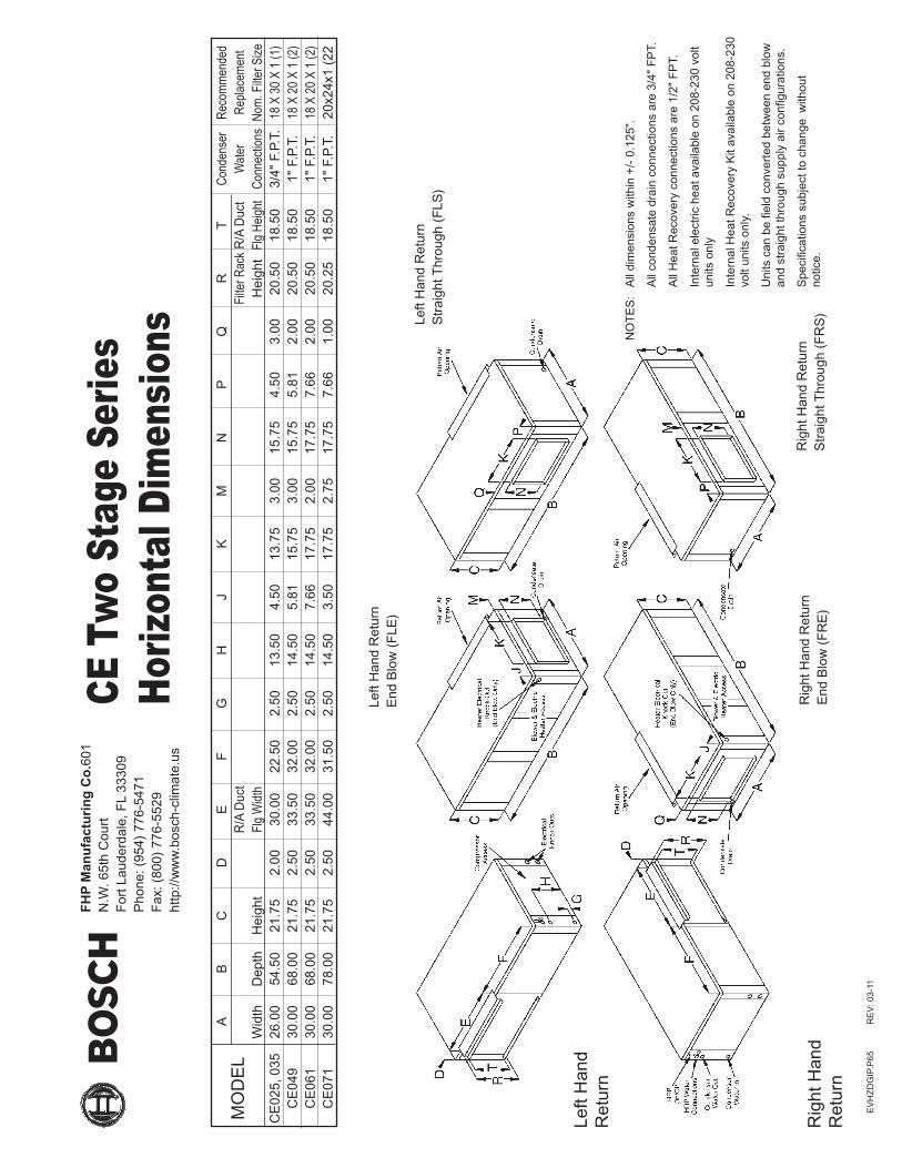
NO
TE
S:
All
dim
ensi
ons
with
in +
/- 0
.125
".
All
cond
ensa
te d
rain
con
nect
ions
are
3/4
" F
PT.
All
Hea
t Rec
over
y co
nnec
tions
are
1/2
" F
PT.
Inte
rnal
ele
ctric
hea
t ava
ilabl
e on
208
-230
vol
t un
its o
nly
Inte
rnal
Hea
t Rec
over
y K
it av
aila
ble
on 2
08-2
30
volt
units
onl
y.
Uni
ts c
an b
e fie
ld c
onve
rted
bet
wee
n en
d bl
ow
and
stra
ight
thro
ugh
supp
ly a
ir co
nfigu
ratio
ns.
Spe
cific
atio
ns s
ubje
ct to
cha
nge
with
out
notic
e.
Left
Han
d R
etur
n
Rig
ht H
and
Ret
urn
FH
P M
anu
fact
uri
ng
Co
.601
N
.W. 6
5th
Cou
rtF
ort L
aude
rdal
e, F
L 33
309
Pho
ne: (
954)
776
-547
1F
ax: (
800)
776
-552
9ht
tp://
ww
w.b
osch
-clim
ate.
us

A
B
C
D
E
F
G
H
J K
M
N
P
C
onde
nser
R
ecom
men
ded
M
OD
EL
B
low
er
Blo
wer
R/A
Duc
t R
/A D
uct
Filte
r Rac
k W
ater
R
epla
cem
ent
Wid
th
Dep
th
Hei
ght
Ope
ning
Ope
ning
Flg
Wid
th F
lg H
eigh
t H
eigh
t C
onne
ctio
ns
Nom
inal
Filt
er S
ize
CE
025,
035
21
.50
26.0
0 47
.25
9.25
10
.25
6.00
5.
50
8.50
19
.50
9.75
22
.00
22.0
0 24
.00
3/4"
F.P
.T.
24 X
24
X 1
C
E04
9 24
.00
32.7
5 47
.25
10.7
5 11
.50
11.1
3 6.
88
7.50
18
.50
8.75
28
.00
22.0
0 24
.00
1" F
.P.T
. 24
X 3
0 X
1
CE
061
26.0
0 33
.25
51.2
5 12
.00
12.5
0 8.
38
5.00
9.
75
21.7
5 10
.50
28.0
0 22
.00
24.0
0 1"
F.P
.T.
24 X
30
X 1
C
E07
1 26
.00
33.2
5 58
.25
12.7
5 13
.50
9.75
4.
50
7.00
20
.25
11.0
0 28
.00
30.0
0 32
.00
1" F
.P.T
. 16
X 3
0 X
1 (
2)
CE
CF
DG
IP IN
T II
.P65
R
EV
: 03-
11
Left
Han
d R
etur
n(F
LB)
Rig
ht H
and
Ret
urn
(FR
B)
NO
TE
S: A
ll di
men
sion
s w
ithin
+/-
0.1
25".
A
ll co
nden
sate
dra
in c
onne
ctio
ns a
re 3
/4"
FP
T.
All
Hea
t Rec
over
y K
it co
nnec
tions
are
1/2
" F
PT.
In
tern
al e
lect
ric h
eat a
vaila
ble
on 2
08-2
30/1
/60
botto
m d
isch
arge
uni
ts o
nly
In
tern
al H
eat R
ecov
ery
Kit
avai
labl
e on
208
-230
vol
t uni
ts o
nly.
S
peci
ficat
ions
sub
ject
to c
hang
e w
ithou
t not
ice.
CE Tw
o St
age
Serie
sCo
unte
rflow
Dim
ensio
ns
FH
P M
anu
fact
uri
ng
Co
.601
N
.W. 6
5th
Cou
rtF
ort L
aude
rdal
e, F
L 33
309
Pho
ne: (
954)
776
-547
1F
ax: (
800)
776
-552
9ht
tp://
ww
w.b
osch
-clim
ate.
us

Entering Entering Heat Fluid Air Total Power of Temp. Temp. Capacity Input Abs. COP (oF) (oF) (MBtuH) (kW) (MBtuH) 50o 60o
60o
70o
80o
50o
60o 70o
70o
80o
50o
60o 80o
70o
80o
19.07 1.19 15.02 4.720.53 1.21 16.41 5.021.98 1.22 17.80 5.323.43 1.24 19.20 5.518.04 1.21 13.91 4.419.41 1.23 15.22 4.620.78 1.25 16.53 4.922.15 1.26 17.84 5.116.81 1.24 12.60 4.018.09 1.25 13.81 4.219.37 1.27 15.03 4.520.65 1.29 16.24 4.7
Fluid Pressure Flow Drop (GPM) (FOH) (PSIG) 5.0 3.1 1.3 7.0 5.7 2.5 9.0 8.9 3.8 11.0 12.8 5.6 12.0 15.0 6.5
Compressor Blower Loop Pump Min. Max. Circuit Fuse/ RLA LRA FLA HP FLA HP Amps Breaker
208/230-1-60 -1 10.3 52.0 2.8 1/3 - - 15.7 25 265-1-60 -2 9.0 67.0 2.6 1/3 - - 13.9 20
Electrical Elect. Characteristics Symbol
0.10 0.20 0.30 0.40 0.50 0.60 0.70 0.80 0.90 1.00 1.10 1.20
CAPACITY DATA - PART LOAD
ELECTRICAL SPECIFICATIONS
BLOWER PERFORMANCE
COOLING All performance at 500 CFM and 6.0 GPM HEATING
Available External Static Pressure (Inches of Water, Gauge. Wet Coil and Filter Included)
BlowerSpeed
+ 575 Norm 500
- 425
Water Loop Ground Water Ground Loop Cooling Heating Cooling Heating Cooling Heating Capacity EER Capacity COP Capacity EER Capacity COP Capacity EER Capacity COP 18,800 17.5 20,500 5.1 21,000 30.0 18,000 4.6 20,000 24.5 15,500 4.0
ISO 13256-1 CERTIFIED PERFORMANCE DATA Rated at 500 CFM and 6.0 GPM
Refrigerant: R-410AAir Coil
Square Rows Tube Fins/ Feet Deep O.D. Inch 3.5 3 3/8 14 Water Coil Type Work Press Coaxial 450 psig Blower Size Compr Type 9 x 7 DD Scroll Net Weight Ship Weight 290 lbs 315 lbs
MECHANICAL SPECIFICATIONS
Entering Entering Sensible Heat Fluid Air Total Sensible to Power of Temp. Temp. Capacity Capacity Total Input Reject EER (oF) (oF) (MBtuH) (MBtuH) Ratio (kW) (MBtuH)
50o
60o 70odb 70o 61owb 85o
100o
50o
60o 75odb 70o 63owb 85o
100o
50o
60o 80odb 70o 67owb 85o
100o
50o
60o 85odb 70o 71owb 85o
100o
Units are complete packages containing compressor, reversing valve, expansion valve metering device, ECM fan motor and heat exchangers. Also included are safety controls: Overload protection for motors, high and low refrigerant pressure switches and solid state lock-out circuit. Optional UL approved internal electric heater, factory installed with primary thermal overload protection and magnetic contactors (208/230-1-60 only) optional UL approved internal Heat Recovery Package and/or Ground Loop Pump with purge connections available.
Performance based on ARI/ISO rated air flow, fluid flow and voltage. For conditions other than rated, consult the Bosch EAD selection software. Due to variations in installation actual performance may vary marginally from tabulated values.
As a result of continuing research and development, specifications are subject to change without notice.
CE025.1IP60 Rev: 03-11
FLUID PRESSURE DROP
18.47 11.91 0.64 0.61 20.56 30.117.80 11.57 0.65 0.74 20.32 24.117.13 11.28 0.66 0.86 20.08 19.816.13 10.90 0.68 1.05 19.72 15.315.13 10.58 0.70 1.24 19.36 12.219.79 14.23 0.72 0.62 21.89 32.019.07 13.83 0.73 0.74 21.61 25.718.36 13.48 0.73 0.87 21.32 21.117.28 13.03 0.75 1.06 20.89 16.316.21 12.65 0.78 1.25 20.46 13.021.72 15.71 0.72 0.62 23.84 34.920.93 15.27 0.73 0.75 23.49 28.020.15 14.88 0.74 0.88 23.14 23.018.97 14.39 0.76 1.07 22.61 17.817.80 13.97 0.78 1.26 22.08 14.223.65 17.21 0.73 0.63 25.78 37.722.79 16.73 0.73 0.75 25.37 30.221.94 16.30 0.74 0.88 24.95 24.920.66 15.76 0.76 1.07 24.33 19.219.38 15.30 0.79 1.27 23.70 15.3
EFT Range (Standard) 25oF to 80oF
EFT Range (Standard) 50oF to 100oF
25o 30o 60o
40o
25o
30o 70o
40o
25o
30o 80o
40o
LOW TEMP HEATING15.14 1.14 11.24 3.9
15.85 1.15 11.92 4.0 17.28 1.17 13.28 4.3 14.32 1.16 10.34 3.6 14.99 1.17 10.99 3.7 16.34 1.19 12.27 4.0 13.35 1.19 9.29 3.3 13.98 1.20 9.89 3.4 15.23 1.22 11.08 3.7
Antifreeze Required
PACKAGED UNITS
SPECIFICATION DATA SHEET CE025
FHP Manufacturing Company601 N.W. 65th Court - Fort Lauderdale, FL 33309Phone: (954) 776-5471 - Fax: (800) 776-5529http://www.bosch-climate.us

Entering Entering Heat Fluid Air Total Power of Temp. Temp. Capacity Input Abs. COP (oF) (oF) (MBtuH) (kW) (MBtuH)
50o 60o
60o
70o
80o
50o
60o 70o
70o
80o
50o
60o 80o
70o
80o
26.03 1.63 20.48 4.7 29.23 1.71 23.38 5.0 32.42 1.80 26.27 5.3 35.62 1.89 29.17 5.5 24.61 1.66 18.96 4.4 27.63 1.75 21.67 4.6 30.64 1.84 24.38 4.9 33.66 1.92 27.09 5.1 22.94 1.69 17.16 4.0 25.75 1.78 19.66 4.2 28.56 1.88 22.15 4.5 31.37 1.97 24.65 4.7
Fluid Pressure Flow Drop (GPM) (FOH) (PSIG) 5.0 3.1 1.3 7.0 5.7 2.5 9.0 8.9 3.8 11.0 12.8 5.6 12.0 15.0 6.5
Compressor Blower Loop Pump Min. Max. Circuit Fuse/ RLA LRA FLA HP FLA HP Amps Breaker
208/230-1-60 -1 10.3 52.0 2.8 1/3 - - 15.7 25 265-1-60 -2 9.0 67.0 2.6 1/3 - - 13.9 20
Electrical Elect. Characteristics Symbol
0.10 0.20 0.30 0.40 0.50 0.60 0.70 0.80 0.90 1.00 1.10 1.20
CAPACITY DATA - FULL LOAD
ELECTRICAL SPECIFICATIONS
BLOWER PERFORMANCE
COOLING All performance at 800 CFM and 6.0 GPM HEATING
Available External Static Pressure (Inches of Water, Gauge. Wet Coil and Filter Included)
BlowerSpeed
+ 920 Norm 800 - 680
Water Loop Ground Water Ground Loop Cooling Heating Cooling Heating Cooling Heating Capacity EER Capacity COP Capacity EER Capacity COP Capacity EER Capacity COP 26,000 16.0 30,000 5.0 29,000 24.0 25,000 4.6 27,500 18.7 19,000 3.8
ISO 13256-1 CERTIFIED PERFORMANCE DATA Rated at 800 CFM and 6.0 GPM
Refrigerant: R-410AAir Coil
Square Rows Tube Fins/ Feet Deep O.D. Inch 3.5 3 3/8 14 Water Coil Type Work Press Coaxial 450 psig Blower Size Compr Type 9 x 7 DD Scroll Net Weight Ship Weight 290 lbs 315 lbs
MECHANICAL SPECIFICATIONS
Entering Entering Sensible Heat Fluid Air Total Sensible to Power of Temp. Temp. Capacity Capacity Total Input Reject EER (oF) (oF) (MBtuH) (MBtuH) Ratio (kW) (MBtuH)
50o
60o 70odb 70o 61owb 85o
100o
50o
60o 75odb 70o 63owb 85o
100o
50o
60o 80odb 70o 67owb 85o
100o
50o
60o 85odb 70o 71owb 85o
100o
Units are complete packages containing compressor, reversing valve, expansion valve metering device, ECM fan motor and heat exchangers. Also included are safety controls: Overload protection for motors, high and low refrigerant pressure switches and solid state lock-out circuit. Optional UL approved internal electric heater, factory installed with primary thermal overload protection and magnetic contactors (208/230-1-60 only) optional UL approved internal Heat Recovery Package and/or Ground Loop Pump with purge connections available.
Performance based on ARI/ISO rated air flow, fluid flow and voltage. For conditions other than rated, consult the Bosch EAD selection software. Due to variations in installation actual performance may vary marginally from tabulated values.
As a result of continuing research and development, specifications are subject to change without notice.
CE025.2IP60 Rev: 03-11
FLUID PRESSURE DROP
25.58 16.95 0.66 1.10 29.35 23.224.66 16.47 0.67 1.25 28.94 19.723.74 16.06 0.68 1.40 28.52 17.022.36 15.52 0.69 1.62 27.90 13.820.98 15.07 0.72 1.85 27.28 11.4
27.40 20.24 0.74 1.11 31.19 24.726.42 19.67 0.74 1.26 30.71 21.025.43 19.18 0.75 1.41 30.24 18.123.96 18.54 0.77 1.63 29.53 14.722.48 18.00 0.80 1.86 28.82 12.130.06 22.33 0.74 1.12 33.88 26.928.98 21.71 0.75 1.27 33.31 22.827.91 21.16 0.76 1.42 32.75 19.726.29 20.46 0.78 1.65 31.90 16.024.67 19.86 0.81 1.87 31.05 13.232.73 24.44 0.75 1.13 36.57 29.131.55 23.76 0.75 1.28 35.91 24.730.38 23.16 0.76 1.43 35.26 21.228.61 22.39 0.78 1.66 34.28 17.326.85 21.75 0.81 1.89 33.29 14.2
EFT Range (Standard) 25oF to 80oF
EFT Range (Standard) 50oF to 100oF
25o 30o 60o
40o
25o
30o 70o
40o
25o
30o 80o
40o
LOW TEMP HEATING
17.69 1.41 12.90 3.7 19.26 1.45 14.31 3.9 22.39 1.54 17.14 4.3 16.73 1.43 11.84 3.4 18.21 1.48 13.17 3.6 21.17 1.57 15.82 4.0 15.60 1.46 10.60 3.1 16.97 1.51 11.82 3.3 19.73 1.60 14.27 3.6
Antifreeze Required
FHP Manufacturing Company601 N.W. 65th Court - Fort Lauderdale, FL 33309Phone: (954) 776-5471 - Fax: (800) 776-5529http://www.bosch-climate.us
PACKAGED UNITS
SPECIFICATION DATA SHEET CE025

Entering Entering Heat Fluid Air Total Power of Temp. Temp. Capacity Input Abs. COP (oF) (oF) (MBtuH) (kW) (MBtuH) 50o 60o
60o
70o
80o
50o
60o 70o
70o
80o
50o
60o 80o
70o
80o
24.80 1.56 19.48 4.726.69 1.57 21.35 5.028.58 1.57 23.22 5.330.47 1.58 25.09 5.723.46 1.59 18.04 4.325.24 1.59 19.80 4.627.02 1.60 21.57 5.028.81 1.60 23.33 5.321.87 1.62 16.34 4.023.53 1.63 17.98 4.225.20 1.63 19.62 4.526.86 1.64 21.26 4.8
Fluid Pressure Flow Drop (GPM) (FOH) (PSIG) 5 3.1 1.32 7 5.6 2.42 9 8.8 3.81 11 12.6 5.74 13 17.1 7.38
Compressor Blower Loop Pump Min. Max. Circuit Fuse/ RLA LRA FLA HP FLA HP Amps Breaker
208/230-1-60 -1 16.7 82.0 4.3 1/2 - - 25.2 40 208/230-3-60 -3 11.2 58.0 4.3 1/2 - - 18.3 25 460-3-60 -4 4.5 29.0 4.1 1/2 - - 9.7 15
Note: 460 Volt Units (-4) Require Both Ground and Neutral Wires
Electrical Elect. Characteristics Symbol
0.10 0.20 0.30 0.40 0.50 0.60 0.70 0.80 0.90 1.00 1.10 1.20
CAPACITY DATA - PART LOAD
ELECTRICAL SPECIFICATIONS
BLOWER PERFORMANCE
COOLING All performance at 800 CFM and 9.0 GPM HEATING
Available External Static Pressure (Inches of Water, Gauge. Wet Coil and Filter Included)
BlowerSpeed
+ 900 Norm 800
Water Loop Ground Water Ground Loop Cooling Heating Cooling Heating Cooling Heating Capacity EER Capacity COP Capacity EER Capacity COP Capacity EER Capacity COP 24,000 17.0 27,000 5.3 27,000 28.0 22,500 4.5 27,000 24.5 20,500 4.0
ISO 13256-1 CERTIFIED PERFORMANCE DATA Rated at 800 CFM and 9.0 GPM
Refrigerant: R-410AAir Coil
Square Rows Tube Fins/ Feet Deep O.D. Inch 3.5 3 3/8 14 Water Coil Type Work Press Coaxial 450 psig Blower Size Compr Type 9 x 7 DD Scroll Net Weight Ship Weight 290 lbs 315 lbs
MECHANICAL SPECIFICATIONS
Entering Entering Sensible Heat Fluid Air Total Sensible to Power of Temp. Temp. Capacity Capacity Total Input Reject EER (oF) (oF) (MBtuH) (MBtuH) Ratio (kW) (MBtuH)
50o
60o 70odb 70o 61owb 85o
100o
50o
60o 75odb 70o 63owb 85o
100o
50o
60o 80odb 70o 67owb 85o
100o
50o
60o 85odb 70o 71owb 85o
100o
Units are complete packages containing compressor, reversing valve, expansion valve metering device, ECM fan motor and heat exchangers. Also included are safety controls: Overload protection for motors, high and low refrigerant pressure switches and solid state lock-out circuit. Optional UL approved internal electric heater, factory installed with primary thermal overload protection and magnetic contactors (208/230-1-60 only) optional UL approved internal Heat Recovery Package and/or Ground Loop Pump with purge connections available.
Performance based on ARI/ISO rated air flow, fluid flow and voltage. For conditions other than rated, consult the Bosch EAD selection software. Due to variations in installation actual performance may vary marginally from tabulated values.
As a result of continuing research and development, specifications are subject to change without notice.
CE035.1IP60 Rev: 03-11
FLUID PRESSURE DROP
23.89 15.37 0.64 0.88 26.90 27.023.07 14.97 0.65 1.03 26.59 22.322.25 14.62 0.66 1.18 26.28 18.821.02 14.18 0.67 1.41 25.82 15.019.80 13.82 0.70 1.63 25.35 12.225.60 18.39 0.72 0.89 28.63 28.824.72 17.91 0.72 1.04 28.26 23.823.85 17.49 0.73 1.19 27.90 20.122.53 16.97 0.75 1.41 27.35 15.921.22 16.54 0.78 1.64 26.81 13.028.10 20.31 0.72 0.89 31.15 31.427.14 19.78 0.73 1.05 30.71 26.026.18 19.32 0.74 1.20 30.26 21.924.74 18.74 0.76 1.42 29.60 17.423.30 18.27 0.78 1.65 28.93 14.130.60 22.25 0.73 0.90 33.68 34.029.56 21.67 0.73 1.05 33.15 28.128.52 21.17 0.74 1.21 32.63 23.726.95 20.53 0.76 1.43 31.84 18.825.38 20.02 0.79 1.66 31.06 15.3
EFT Range (Standard) 25oF to 80oF
EFT Range (Standard) 50oF to 100oF
25o 30o 60o
40o
25o
30o 70o
40o
25o
30o 80o
40o
LOW TEMP HEATING
19.69 1.55 14.42 3.720.62 1.55 15.33 3.922.47 1.55 17.16 4.218.63 1.57 13.26 3.519.50 1.58 14.12 3.621.25 1.58 15.85 3.917.37 1.61 11.89 3.218.19 1.61 12.69 3.319.82 1.62 14.30 3.6
Antifreeze Required
FHP Manufacturing Company601 N.W. 65th Court - Fort Lauderdale, FL 33309Phone: (954) 776-5471 - Fax: (800) 776-5529http://www.bosch-climate.us
PACKAGED UNITS
SPECIFICATION DATA SHEET CE035

Entering Entering Heat Fluid Air Total Power of Temp. Temp. Capacity Input Abs. COP (oF) (oF) (MBtuH) (kW) (MBtuH)
50o 60o
60o
70o
80o
50o
60o 70o
70o
80o
50o
60o 80o
70o
80o
37.90 2.42 29.63 4.642.26 2.55 33.56 4.946.61 2.67 37.49 5.150.97 2.80 41.42 5.335.84 2.47 27.42 4.339.96 2.59 31.11 4.544.07 2.72 34.79 4.748.19 2.85 38.47 5.033.42 2.52 24.82 3.937.26 2.65 28.21 4.141.09 2.78 31.60 4.344.92 2.91 34.99 4.5
Fluid Pressure Flow Drop (GPM) (FOH) (PSIG) 5.0 3.1 1.32 7.0 5.6 2.42 9.0 8.8 3.81 11.0 12.6 5.47 13.0 17.1 7.38
208/230-1-60 -1 16.7 82.0 4.3 1/2 - - 25.2 40 208/230-3-60 -3 11.2 58.0 4.3 1/2 - - 18.3 25 460-3-60 -4 4.5 29.0 4.1 1/2 - - 9.7 15Note: 460 Volt Units (-4) Require Both Ground and Neutral Wires
Electrical Elect. Characteristics Symbol
0.10 0.20 0.30 0.40 0.50 0.60 0.70 0.80 0.90 1.00 1.10 1.20
CAPACITY DATA - FULL LOAD
ELECTRICAL SPECIFICATIONS
BLOWER PERFORMANCE
COOLING All performance at 1200 CFM and 9.0 GPM HEATING
Available External Static Pressure (Inches of Water, Gauge. Wet Coil and Filter Included)
BlowerSpeed
+ 1380 Norm 1200
- 1020
Water Loop Ground Water Ground Loop Cooling Heating Cooling Heating Cooling Heating Capacity EER Capacity COP Capacity EER Capacity COP Capacity EER Capacity COP 36,000 14.6 43,000 4.8 42,000 21.6 36,000 4.2 38,000 17.2 28,000 3.8
ISO 13256-1 CERTIFIED PERFORMANCE DATA Rated at 1200 CFM and 9.0 GPM
Refrigerant: R-410AAir Coil
Square Rows Tube Fins/ Feet Deep O.D. Inch 3.5 3 3/8 14 Water Coil Type Work Press Coaxial 450 psig Blower Size Compr Type 9 x 7 DD Scroll Net Weight Ship Weight 290 lbs 315 lbs
MECHANICAL SPECIFICATIONS
Entering Entering Sensible Heat Fluid Air Total Sensible to Power of Temp. Temp. Capacity Capacity Total Input Reject EER (oF) (oF) (MBtuH) (MBtuH) Ratio (kW) (MBtuH)
50o
60o 70odb 70o 61owb 85o
100o
50o
60o 75odb 70o 63owb 85o
100o
50o
60o 80odb 70o 67owb 85o
100o
50o
60o 85odb 70o 71owb 85o
100o
Units are complete packages containing compressor, reversing valve, expansion valve metering device, ECM fan motor and heat exchangers. Also included are safety controls: Overload protection for motors, high and low refrigerant pressure switches and solid state lock-out circuit. Optional UL approved internal electric heater, factory installed with primary thermal overload protection and magnetic contactors (208/230-1-60 only) optional UL approved internal Heat Recovery Package and/or Ground Loop Pump with purge connections available.
Performance based on ARI/ISO rated air flow, fluid flow and voltage. For conditions other than rated, consult the Bosch EAD selection software. Due to variations in installation actual performance may vary marginally from tabulated values.
As a result of continuing research and development, specifications are subject to change without notice.
CE035.2IP60 Rev: 03-11
FLUID PRESSURE DROP
37.18 24.24 0.65 1.86 43.53 20.035.27 23.18 0.66 2.04 42.23 17.333.36 22.20 0.67 2.22 40.94 15.030.50 20.82 0.68 2.49 39.00 12.227.63 19.52 0.71 2.76 37.06 10.039.84 28.99 0.73 1.87 46.22 21.337.80 27.73 0.73 2.05 44.80 18.435.75 26.56 0.74 2.23 43.38 16.032.69 24.92 0.76 2.51 41.24 13.029.62 23.37 0.79 2.78 39.11 10.743.73 32.01 0.73 1.88 50.17 23.241.49 30.63 0.74 2.07 48.55 20.139.25 29.33 0.75 2.25 46.94 17.435.89 27.53 0.77 2.53 44.51 14.232.53 25.82 0.79 2.80 42.09 11.6
47.63 35.07 0.74 1.90 54.11 25.145.19 33.55 0.74 2.08 52.30 21.742.75 32.14 0.75 2.27 50.50 18.939.10 30.16 0.77 2.54 47.79 15.435.44 28.30 0.80 2.82 45.08 12.6
EFT Range (Standard) 25oF to 80oF
EFT Range (Standard) 50oF to 100oF
25o 30o 60o
40o
25o
30o 70o
40o
25o
30o 80o
40o
LOW TEMP HEATING
26.48 2.11 19.27 3.728.62 2.18 21.20 3.932.89 2.30 25.04 4.225.05 2.15 17.72 3.427.07 2.21 19.52 3.631.11 2.34 23.12 3.923.38 2.20 15.88 3.125.25 2.26 17.54 3.329.01 2.39 20.85 3.6
Antifreeze Required
FHP Manufacturing Company601 N.W. 65th Court - Fort Lauderdale, FL 33309Phone: (954) 776-5471 - Fax: (800) 776-5529http://www.bosch-climate.us
PACKAGED UNITS
SPECIFICATION DATA SHEET CE035Compressor Blower Loop Pump Min. Max.
Circuit Fuse/ RLA LRA FLA HP FLA HP Amps Breaker

Entering Entering Heat Fluid Air Total Power of Temp. Temp. Capacity Input Abs. COP (oF) (oF) (MBtuH) (kW) (MBtuH)
50o 60o
60o
70o
80o
50o
60o 70o
70o
80o
50o
60o 80o
70o
80o
34.88 2.02 27.98 5.137.93 2.04 30.97 5.440.98 2.06 33.95 5.844.02 2.08 36.94 6.232.96 2.06 25.94 4.735.84 2.08 28.75 5.138.72 2.10 31.57 5.441.60 2.12 34.38 5.830.71 2.10 23.53 4.333.40 2.12 26.15 4.636.08 2.14 28.76 4.938.76 2.16 31.38 5.2
Fluid Pressure Flow Drop (GPM) (FOH) (PSIG)
6.0 2.9 1.27 7.0 3.9 1.67 9.5 6.7 2.90 12.0 10.2 4.42 16.0 17.1 7.41
208/230-1-60 -1 21.2 96.0 6.8 3/4 - - 33.3 50 208/230-3-60 -3 13.5 88.0 6.8 3/4 - - 23.7 35 460-3-60 -4 6.4 41.0 5.5 3/4 - - 13.5 15Note: 460 Volt Units (-4) Require Both Ground and Neutral Wires
Electrical Elect. Characteristics Symbol
0.10 0.20 0.30 0.40 0.50 0.60 0.70 0.80 0.90 1.00 1.10 1.20
CAPACITY DATA - PART LOAD
ELECTRICAL SPECIFICATIONS
BLOWER PERFORMANCE
COOLING All performance at 1000 CFM and 12.0 GPM HEATING
Available External Static Pressure (Inches of Water, Gauge. Wet Coil and Filter Included)
BlowerSpeed
+ 1150 Norm 1000 - 850
Water Loop Ground Water Ground Loop Cooling Heating Cooling Heating Cooling Heating Capacity EER Capacity COP Capacity EER Capacity COP Capacity EER Capacity COP 34,000 16.0 39,000 5.4 38,000 24.0 32,000 4.6 36,000 21.8 28,500 4.0
ISO 13256-1 CERTIFIED PERFORMANCE DATA Rated at 1000 CFM and 12.0 GPM
Refrigerant: R-410AAir Coil
Square Rows Tube Fins/ Feet Deep O.D. Inch 4.5 3 3/8 14 Water Coil Type Work Press Coaxial 450 psig Blower Size Compr Type 10x 8 DD Scroll Net Weight Ship Weight 318 lbs 348 lbs
MECHANICAL SPECIFICATIONS
Entering Entering Sensible Heat Fluid Air Total Sensible to Power of Temp. Temp. Capacity Capacity Total Input Reject EER (oF) (oF) (MBtuH) (MBtuH) Ratio (kW) (MBtuH)
50o
60o 70odb 70o 61owb 85o
100o
50o
60o 75odb 70o 63owb 85o
100o
50o
60o 80odb 70o 67owb 85o
100o
50o
60o 85odb 70o 71owb 85o
100o
Units are complete packages containing compressor, reversing valve, expansion valve metering device, ECM fan motor and heat exchangers. Also included are safety controls: Overload protection for motors, high and low refrigerant pressure switches and solid state lock-out circuit. Optional UL approved internal electric heater, factory installed with primary thermal overload protection and magnetic contactors (208/230-1-60 only) optional UL approved internal Heat Recovery Package and/or Ground Loop Pump with purge connections available.
Performance based on ARI/ISO rated air flow, fluid flow and voltage. For conditions other than rated, consult the Bosch EAD selection software. Due to variations in installation actual performance may vary marginally from tabulated values.
As a result of continuing research and development, specifications are subject to change without notice.
CE049.1IP60 Rev: 03-11
FLUID PRESSURE DROP
33.66 22.07 0.66 1.32 38.17 25.532.44 21.44 0.66 1.49 37.54 21.731.21 20.89 0.67 1.67 36.90 18.729.37 20.17 0.69 1.92 35.94 15.327.53 19.56 0.71 2.18 34.98 12.636.05 26.33 0.73 1.33 40.59 27.134.74 25.58 0.74 1.50 39.86 23.133.42 24.92 0.75 1.68 39.14 19.931.45 24.07 0.77 1.94 38.06 16.229.48 23.34 0.79 2.20 36.98 13.439.54 29.04 0.73 1.34 44.11 29.538.10 28.21 0.74 1.51 43.27 25.236.66 27.49 0.75 1.69 42.42 21.734.50 26.55 0.77 1.95 41.16 17.732.34 25.75 0.80 2.21 39.89 14.643.03 31.77 0.74 1.35 47.64 31.941.46 30.87 0.74 1.53 46.67 27.239.90 30.08 0.75 1.70 45.71 23.437.55 29.05 0.77 1.97 44.26 19.135.20 28.18 0.80 2.23 42.81 15.8
EFT Range (Standard) 25oF to 80oF
EFT Range (Standard) 50oF to 100oF
25o 30o 60o
40o
25o
30o 70o
40o
25o
30o 80o
40o
LOW TEMP HEATING
26.72 1.97 19.99 4.0 28.22 1.98 21.45 4.2 31.20 2.00 24.37 4.6 25.26 2.01 18.40 3.7 26.67 2.02 19.78 3.9 29.49 2.04 22.53 4.2 23.53 2.06 16.52 3.4 24.85 2.07 17.80 3.5 27.48 2.08 20.36 3.9
Antifreeze Required
FHP Manufacturing Company601 N.W. 65th Court - Fort Lauderdale, FL 33309Phone: (954) 776-5471 - Fax: (800) 776-5529http://www.bosch-climate.us
PACKAGED UNITS
SPECIFICATION DATA SHEET CE049Compressor Blower Loop Pump Min. Max.
Circuit Fuse/ RLA LRA FLA HP FLA HP Amps Breaker

Entering Entering Heat Fluid Air Total Power of Temp. Temp. Capacity Input Abs. COP (oF) (oF) (MBtuH) (kW) (MBtuH)
50o 60o 60o
70o
80o
50o
60o 70o
70o
80o
50o
60o 80o
70o
80o
50.51 3.28 39.32 4.556.32 3.42 44.65 4.862.12 3.56 49.99 5.167.93 3.70 55.32 5.447.74 3.34 36.34 4.253.22 3.48 41.34 4.558.71 3.62 46.35 4.764.20 3.76 51.35 5.044.48 3.41 32.82 3.849.59 3.56 37.44 4.154.70 3.70 42.05 4.359.81 3.85 46.67 4.6
Fluid Pressure Flow Drop (GPM) (FOH) (PSIG) 6.0 2.9 1.27 7.0 3.9 1.67 9.5 6.7 2.90 12.0 10.2 4.42 16.0 17.1 7.41
208/230-1-60 -1 21.2 96.0 6.8 3/4 - - 33.3 50 208/230-3-60 -3 13.5 88.0 6.8 3/4 - - 23.7 35 460-3-60 -4 6.4 41.0 5.5 3/4 - - 13.5 15Note: 460 Volt Units (-4) Require Both Ground and Neutral Wires
Electrical Elect. Characteristics Symbol
0.10 0.20 0.30 0.40 0.50 0.60 0.70 0.80 0.90 1.00 1.10 1.20
CAPACITY DATA - FULL LOAD
ELECTRICAL SPECIFICATIONS
BLOWER PERFORMANCE
COOLING All performance at 1600 CFM and 12.0 GPM HEATING
Available External Static Pressure (Inches of Water, Gauge. Wet Coil and Filter Included)
BlowerSpeed
+ 1840 Norm 1600
- 1360
Water Loop Ground Water Ground Loop Cooling Heating Cooling Heating Cooling Heating Capacity EER Capacity COP Capacity EER Capacity COP Capacity EER Capacity COP 48,000 13.5 58,000 4.8 54,000 19.0 48,000 4.2 49,000 15.5 38,000 3.6
ISO 13256-1 CERTIFIED PERFORMANCE DATA Rated at 1600 CFM and 12.0 GPM
Refrigerant: R-410AAir Coil
Square Rows Tube Fins/ Feet Deep O.D. Inch 4.5 3 3/8 14 Water Coil Type Work Press Coaxial 450 psig Blower Size Compr Type 10x 8 DD Scroll Net Weight Ship Weight 318 lbs 348 lbs
MECHANICAL SPECIFICATIONS
Entering Entering Sensible Heat Fluid Air Total Sensible to Power of Temp. Temp. Capacity Capacity Total Input Reject EER (oF) (oF) (MBtuH) (MBtuH) Ratio (kW) (MBtuH)
50o
60o 70odb 70o 61owb 85o
100o
50o
60o 75odb 70o 63owb 85o
100o
50o
60o 80odb 70o 67owb 85o
100o
50o
60o 85odb 70o 71owb 85o
100o
Units are complete packages containing compressor, reversing valve, expansion valve metering device, ECM fan motor and heat exchangers. Also included are safety controls: Overload protection for motors, high and low refrigerant pressure switches and solid state lock-out circuit. Optional UL approved internal electric heater, factory installed with primary thermal overload protection and magnetic contactors (208/230-1-60 only) optional UL approved internal Heat Recovery Package and/or Ground Loop Pump with purge connections available.
Performance based on ARI/ISO rated air flow, fluid flow and voltage. For conditions other than rated, consult the Bosch EAD selection software. Due to variations in installation actual performance may vary marginally from tabulated values.
As a result of continuing research and development, specifications are subject to change without notice.
CE049.2IP60 Rev: 03-11
FLUID PRESSURE DROP
47.65 31.22 0.66 2.56 56.38 18.645.68 30.18 0.66 2.80 55.24 16.343.70 29.23 0.67 3.05 54.09 14.340.73 27.96 0.69 3.41 52.37 11.9
37.77 26.83 0.71 3.78 50.66 10.051.03 37.26 0.73 2.57 59.81 19.848.92 36.01 0.74 2.82 58.53 17.446.80 34.88 0.75 3.06 57.25 15.343.62 33.37 0.77 3.43 55.33 12.740.45 32.02 0.79 3.80 53.41 10.655.97 41.10 0.73 2.59 64.83 21.653.65 39.72 0.74 2.84 63.35 18.951.33 38.48 0.75 3.09 61.87 16.647.86 36.82 0.77 3.46 59.66 13.844.38 35.32 0.80 3.83 57.44 11.6
60.92 44.97 0.74 2.61 69.84 23.358.39 43.47 0.74 2.86 68.17 20.455.87 42.11 0.75 3.11 66.50 17.952.09 40.29 0.77 3.49 63.99 14.948.30 38.66 0.80 3.86 61.48 12.5
EFT Range (Standard) 25oF to 80oF
EFT Range (Standard) 50oF to 100oF
25o 30o 60o
40o
25o
30o 70o
40o
25o
30o 80o
40o
LOW TEMP HEATING
35.28 2.93 25.28 3.538.13 3.00 27.89 3.743.82 3.14 33.11 4.133.35 2.99 23.16 3.336.04 3.06 25.61 3.541.42 3.20 30.51 3.831.08 3.05 20.67 3.033.59 3.12 22.92 3.138.60 3.27 27.44 3.5
Antifreeze Required
FHP Manufacturing Company601 N.W. 65th Court - Fort Lauderdale, FL 33309Phone: (954) 776-5471 - Fax: (800) 776-5529http://www.bosch-climate.us
PACKAGED UNITS
SPECIFICATION DATA SHEET CE049Compressor Blower Loop Pump Min. Max.
Circuit Fuse/ RLA LRA FLA HP FLA HP Amps Breaker

Entering Entering Heat Fluid Air Total Power of Temp. Temp. Capacity Input Abs. COP (oF) (oF) (MBtuH) (kW) (MBtuH)
50o 60o
60o
70o
80o
50o
60o 70o
70o
80o
50o
60o 80o
70o
80o
43.50 2.54 34.82 5.046.98 2.55 38.29 5.450.47 2.55 41.75 5.853.95 2.56 45.22 6.241.11 2.59 32.27 4.744.40 2.60 35.55 5.047.69 2.60 38.82 5.450.99 2.61 42.09 5.738.31 2.65 29.27 4.241.37 2.65 32.32 4.644.44 2.66 35.36 4.947.50 2.66 38.41 5.2
Fluid Pressure Flow Drop (GPM) (FOH) (PSIG) 8 3.5 1.51 12 7.2 3.13 16 12.1 5.25 18 15.0 6.49 22 21.5 9.32
208/230-1-60 -1 25.6 118.0 6.8 3/4 - - 38.8 60 208/230-3-60 -3 17.6 123.0 6.8 3/4 - - 28.8 45 460-3-60 -4 9.0 62.0 5.5 3/4 - - 16.8 25
Note: 460 Volt Units (-4) Require Both Ground and Neutral Wires
Electrical Elect. Characteristics Symbol
0.10 0.20 0.30 0.40 0.50 0.60 0.70 0.80 0.90 1.00 1.10 1.20
CAPACITY DATA - PART LOAD
ELECTRICAL SPECIFICATIONS
BLOWER PERFORMANCE
COOLING All performance at 1400 CFM and 14.0 GPM HEATING
Available External Static Pressure (Inches of Water, Gauge. Wet Coil and Filter Included)
BlowerSpeed
+ 1600 Norm 1400
- 1200
Water Loop Ground Water Ground Loop Cooling Heating Cooling Heating Cooling Heating Capacity EER Capacity COP Capacity EER Capacity COP Capacity EER Capacity COP 42,000 17.0 48,000 5.4 48,000 26.0 40,000 4.6 45,000 23.5 36,500 4.0
ISO 13256-1 CERTIFIED PERFORMANCE DATA Rated at 1400 CFM and 14.0 GPM
Refrigerant: R-410AAir Coil
Square Rows Tube Fins/ Feet Deep O.D. Inch 4.5 3 3/8 14 Water Coil Type Work Press Coaxial 450 psig Blower Size Compr Type 11x 9 DD Scroll Net Weight Ship Weight 390 lbs 415 lbs
MECHANICAL SPECIFICATIONS
Entering Entering Sensible Heat Fluid Air Total Sensible to Power of Temp. Temp. Capacity Capacity Total Input Reject EER (oF) (oF) (MBtuH) (MBtuH) Ratio (kW) (MBtuH)
50o
60o 70odb 70o 61owb 85o
100o
50o
60o 75odb 70o 63owb 85o
100o
50o
60o 80odb 70o 67owb 85o
100o
50o
60o 85odb 70o 71owb 85o
100o
Units are complete packages containing compressor, reversing valve, expansion valve metering device, ECM fan motor and heat exchangers. Also included are safety controls: Overload protection for motors, high and low refrigerant pressure switches and solid state lock-out circuit. Optional UL approved internal electric heater, factory installed with primary thermal overload protection and magnetic contactors (208/230-1-60 only) optional UL approved internal Heat Recovery Package and/or Ground Loop Pump with purge connections available.
Performance based on ARI/ISO rated air flow, fluid flow and voltage. For conditions other than rated, consult the Bosch EAD selection software. Due to variations in installation actual performance may vary marginally from tabulated values.
As a result of continuing research and development, specifications are subject to change without notice.
CE061.1IP60 Rev: 03-11
FLUID PRESSURE DROP
42.78 27.69 0.65 1.56 48.12 27.4 40.94 26.72 0.65 1.76 46.95 23.3 39.10 25.84 0.66 1.96 45.79 20.0 36.34 24.64 0.68 2.26 44.04 16.1 33.58 23.56 0.70 2.55 42.29 13.2 45.82 33.04 0.72 1.57 51.18 29.2 43.85 31.89 0.73 1.77 49.89 24.8 41.88 30.83 0.74 1.97 48.60 21.3 38.92 29.41 0.76 2.27 46.67 17.2 35.97 28.12 0.78 2.57 44.73 14.0 50.26 36.45 0.73 1.58 55.66 31.7 48.10 35.17 0.73 1.79 54.19 26.9 45.94 34.01 0.74 1.99 52.71 23.1 42.70 32.44 0.76 2.29 50.50 18.7 39.46 31.02 0.79 2.59 48.29 15.2 54.69 39.88 0.73 1.60 60.14 34.3 52.34 38.49 0.74 1.80 58.48 29.1 49.99 37.22 0.74 2.00 56.83 25.0 46.47 35.51 0.76 2.31 54.34 20.2 42.95 33.95 0.79 2.61 51.85 16.5
EFT Range (Standard) 25oF to 80oF
EFT Range (Standard) 50oF to 100oF
25o 30o 60o
40o
25o
30o 70o
40o
25o
30o 80o
40o
LOW TEMP HEATING
34.10 2.53 25.47 4.035.81 2.53 27.17 4.139.23 2.54 30.57 4.532.24 2.58 23.44 3.733.85 2.58 25.05 3.837.08 2.58 28.26 4.230.04 2.63 21.05 3.331.54 2.64 22.54 3.534.55 2.64 25.53 3.8
Antifreeze Required
FHP Manufacturing Company601 N.W. 65th Court - Fort Lauderdale, FL 33309Phone: (954) 776-5471 - Fax: (800) 776-5529http://www.bosch-climate.us
PACKAGED UNITS
SPECIFICATION DATA SHEET CE061Compressor Blower Loop Pump Min. Max.
Circuit Fuse/ RLA LRA FLA HP FLA HP Amps Breaker

Entering Entering Heat Fluid Air Total Power of Temp. Temp. Capacity Input Abs. COP (oF) (oF) (MBtuH) (kW) (MBtuH)
50o 60o
60o
70o
80o
50o
60o 70o
70o
80o
50o
60o 80o
70o
80o
63.83 4.16 49.63 4.5 70.51 4.32 55.77 4.8 77.19 4.48 61.91 5.1 83.87 4.64 68.05 5.3 60.33 4.24 45.86 4.2 66.64 4.40 51.62 4.4 72.95 4.56 57.38 4.7 79.26 4.72 63.14 4.9 56.21 4.33 41.42 3.8 62.09 4.50 46.73 4.0 67.97 4.66 52.05 4.3 73.84 4.83 57.36 4.5
Fluid Pressure Flow Drop (GPM) (FOH) (PSIG) 8 3.5 1.51 12 7.2 3.13 16 12.1 5.25 18 15.0 6.49 22 21.5 9.32
208/230-1-60 -1 25.6 118.0 6.8 3/4 - - 38.8 60 208/230-3-60 -3 17.6 123.0 6.8 3/4 - - 28.8 45 460-3-60 -4 9.0 62.0 5.5 3/4 - - 16.8 25
Note: 460 Volt Units (-4) Require Both Ground and Neutral Wires
Electrical Elect. Characteristics Symbol
0.10 0.20 0.30 0.40 0.50 0.60 0.70 0.80 0.90 1.00 1.10 1.20
CAPACITY DATA - FULL LOAD
ELECTRICAL SPECIFICATIONS
BLOWER PERFORMANCE
COOLING All performance at 2000 CFM and 14.0 GPM HEATING
Available External Static Pressure (Inches of Water, Gauge. Wet Coil and Filter Included)
Blower Speed + 2200 Norm 2000 - 1700
Water Loop Ground Water Ground Loop Cooling Heating Cooling Heating Cooling Heating Capacity EER Capacity COP Capacity EER Capacity COP Capacity EER Capacity COP 60,000 14.0 72,000 4.7 68,000 19.7 61,000 4.3 62,000 15.7 49,000 3.6
ISO 13256-1 CERTIFIED PERFORMANCE DATA Rated at 2000 CFM and 14.0 GPM
Refrigerant: R-410A Air Coil Square Rows Tube Fins/ Feet Deep O.D. Inch 4.5 3 3/8 14 Water Coil Type Work Press Coaxial 450 psig Blower Size Compr Type 11x 9 DD Scroll Net Weight Ship Weight 390 lbs 415 lbs
MECHANICAL SPECIFICATIONS
Entering Entering Sensible Heat Fluid Air Total Sensible to Power of Temp. Temp. Capacity Capacity Total Input Reject EER (oF) (oF) (MBtuH) (MBtuH) Ratio (kW) (MBtuH)
50o
60o 70odb 70o 61owb 85o
100o
50o
60o 75odb 70o 63owb 85o
100o
50o
60o 80odb 70o 67owb 85o
100o
50o
60o 85odb 70o 71owb 85o
100o
Units are complete packages containing compressor, reversing valve, expansion valve metering device, ECM fan motor and heat exchangers. Also included are safety controls: Overload protection for motors, high and low refrigerant pressure switches and solid state lock-out circuit. Optional UL approved internal electric heater, factory installed with primary thermal overload protection and magnetic contactors (208/230-1-60 only) optional UL approved internal Heat Recovery Package and/or Ground Loop Pump with purge connections available.
Performance based on ARI/ISO rated air flow, fluid flow and voltage. For conditions other than rated, consult the Bosch EAD selection software. Due to variations in installation actual performance may vary marginally from tabulated values.
As a result of continuing research and development, specifications are subject to change without notice.
CE061.2IP60 Rev: 03-11
FLUID PRESSURE DROP
60.21 38.97 0.65 3.15 70.96 19.1 57.62 37.60 0.65 3.44 69.37 16.7 55.03 36.36 0.66 3.74 67.78 14.7 51.14 34.68 0.68 4.18 65.40 12.2 47.26 33.15 0.70 4.62 63.02 10.2 64.48 46.50 0.72 3.17 75.29 20.4 61.71 44.87 0.73 3.46 73.52 17.8 58.93 43.39 0.74 3.76 71.76 15.7 54.77 41.39 0.76 4.20 69.11 13.0 50.61 39.57 0.78 4.65 66.47 10.9 70.72 51.29 0.73 3.19 81.62 22.2 67.68 49.49 0.73 3.49 79.60 19.4 64.64 47.86 0.74 3.79 77.58 17.1 60.08 45.65 0.76 4.24 74.54 14.2 55.52 43.66 0.79 4.68 71.51 11.9 76.97 56.12 0.73 3.22 87.95 23.9 73.66 54.16 0.74 3.52 85.67 20.9 70.36 52.38 0.74 3.82 83.39 18.4 65.40 49.97 0.76 4.27 79.97 15.3 60.44 47.78 0.79 4.72 76.55 12.8
EFT Range (Standard) 25oF to 80oF
EFT Range (Standard) 50oF to 100oF
25o 30o 60o
40o
25o
30o 70o
40o
25o
30o 80o
40o
LOW TEMP HEATING
46.21 3.76 33.36 3.6 49.48 3.84 36.37 3.8 56.03 4.00 42.37 4.1 43.68 3.83 30.59 3.3 46.77 3.92 33.41 3.5 52.96 4.08 39.04 3.8 40.71 3.92 27.32 3.0 43.59 4.00 29.92 3.2 49.35 4.17 35.12 3.5
Antifreeze Required
FHP Manufacturing Company601 N.W. 65th Court - Fort Lauderdale, FL 33309Phone: (954) 776-5471 - Fax: (800) 776-5529http://www.bosch-climate.us
PACKAGED UNITS
SPECIFICATION DATA SHEET CE061Compressor Blower Loop Pump Min. Max.
Circuit Fuse/ RLA LRA FLA HP FLA HP Amps Breaker

Entering Entering Heat Fluid Air Total Power of Temp. Temp. Capacity Input Abs. COP (oF) (oF) (MBtuH) (kW) (MBtuH)
50o 60o
60o
70o
80o
50o
60o 70o
70o
80o
50o
60o 80o
70o
80o
50.90 3.48 39.03 4.354.67 3.56 42.51 4.558.45 3.65 46.00 4.762.22 3.73 49.48 4.948.13 3.54 36.04 4.051.69 3.63 39.31 4.255.26 3.71 42.58 4.458.83 3.80 45.85 4.544.87 3.62 32.52 3.648.19 3.71 35.54 3.851.51 3.80 38.56 4.054.83 3.88 41.58 4.1
Fluid Pressure Flow Drop (GPM) (FOH) (PSIG) 8 3.5 1.5 12 7.2 3.1 16 12.1 5.3 18 15.0 6.5 22 21.5 9.3
208/230-1-60 -1 27.2 150.0 6.8 .75 - - 40.8 60 208-230-3-6 -3 19.7 123.0 6.8 .75 - - 31.4 50 460-3-60 -4 9.9 62.0 6.9 1.0 - - 19.3 25
Electrical Elect. Characteristics Symbol
0.10 0.20 0.30 0.40 0.50 0.60 0.70 0.80 0.90 1.00 1.10 1.20
CAPACITY DATA - PART LOAD
ELECTRICAL SPECIFICATIONS
BLOWER PERFORMANCE
COOLING All performance at 1400 CFM and 18.0 GPM HEATING
Available External Static Pressure (Inches of Water, Gauge. Wet Coil and Filter Included)
BlowerSpeed
+ 1600 Norm 1400
- 1200
Water Loop Ground Water Ground Loop Cooling Heating Cooling Heating Cooling Heating Capacity EER Capacity COP Capacity EER Capacity COP Capacity EER Capacity COP 51,000 15.8 55,000 4.4 57,000 25.2 47,000 4.0 56,000 21.8 42,000 3.6
ISO 13256-1 CERTIFIED PERFORMANCE DATA Rated at 1400 CFM and 18.0 GPM
Refrigerant: R-410A Air Coil Square Rows Tube Fins/ Feet Deep O.D. Inch 6.0 3 3/8 14 Water Coil Type Work Press Coaxial 450 psig Blower Size Compr Type 12 x 9 DD Scroll Net Weight Ship Weight 450 lbs 495 lbs
MECHANICAL SPECIFICATIONS
Entering Entering Sensible Heat Fluid Air Total Sensible to Power of Temp. Temp. Capacity Capacity Total Input Reject EER (oF) (oF) (MBtuH) (MBtuH) Ratio (kW) (MBtuH)
50o
60o 70odb 70o 61owb 85o
100o
50o
60o 75odb 70o 63owb 85o
100o
50o
60o 80odb 70o 67owb 85o
100o
50o
60o 85odb 70o 71owb 85o
100o
Units are complete packages containing compressor, reversing valve, expansion valve metering device, ECM fan motor and heat exchangers. Also included are safety controls: Overload protection for motors, high and low refrigerant pressure switches and solid state lock-out circuit. Optional UL approved internal electric heater, factory installed with primary thermal overload protection and magnetic contactors (208/230-1-60 only) optional UL approved internal Heat Recovery Package and/or Ground Loop Pump with purge connections available.
Performance based on ARI/ISO rated air flow, fluid flow and voltage. For conditions other than rated, consult the Bosch EAD selection software. Due to variations in installation actual performance may vary marginally from tabulated values.
As a result of continuing research and development, specifications are subject to change without notice.
CE071.1IP60 Rev: 03-11
FLUID PRESSURE DROP
50.33 32.44 0.64 1.90 56.82 26.548.62 31.60 0.65 2.22 56.22 21.946.92 30.88 0.66 2.55 55.61 18.444.36 29.97 0.68 3.03 54.71 14.641.81 29.23 0.70 3.52 53.80 11.9
53.92 38.78 0.72 1.91 60.45 28.252.10 37.78 0.73 2.24 59.73 23.350.27 36.92 0.73 2.56 59.02 19.647.54 35.83 0.75 3.05 57.94 15.644.80 34.95 0.78 3.53 56.87 12.759.18 42.81 0.72 1.93 65.76 30.757.18 41.71 0.73 2.25 64.88 25.455.18 40.76 0.74 2.58 63.99 21.452.18 39.56 0.76 3.07 62.67 17.049.18 38.59 0.78 3.56 61.34 13.864.44 46.89 0.73 1.94 71.07 33.262.27 45.69 0.73 2.27 70.02 27.460.09 44.64 0.74 2.60 68.97 23.156.83 43.33 0.76 3.10 67.39 18.453.56 42.27 0.79 3.59 65.82 14.9
EFT Range (Standard) 25oF to 80oF
EFT Range (Standard) 50oF to 100oF
25o 30o 60o
40o
25o
30o 70o
40o
25o
30o 80o
40o
LOW TEMP HEATING
40.65 3.26 29.51 3.642.50 3.31 31.21 3.846.20 3.39 34.62 4.038.44 3.32 27.10 3.440.19 3.37 28.70 3.543.69 3.45 31.90 3.735.85 3.40 24.26 3.137.48 3.44 25.74 3.240.73 3.53 28.69 3.4
Antifreeze Required
FHP Manufacturing Company601 N.W. 65th Court - Fort Lauderdale, FL 33309Phone: (954) 776-5471 - Fax: (800) 776-5529http://www.bosch-climate.us
PACKAGED UNITS
SPECIFICATION DATA SHEET CE071Compressor Blower Loop Pump Min. Max.
Circuit Fuse/ RLA LRA FLA HP FLA HP Amps Breaker

Entering Entering Heat Fluid Air Total Power of Temp. Temp. Capacity Input Abs. COP (oF) (oF) (MBtuH) (kW) (MBtuH)
50o 60o 60o
70o
80o
50o
60o 70o
70o
80o
50o
60o 80o
70o
80o
71.17 4.78 54.85 4.4 79.01 5.08 61.67 4.6 86.86 5.38 68.48 4.7 94.70 5.68 75.30 4.9 67.30 4.87 50.69 4.0 74.71 5.17 57.05 4.2 82.12 5.48 63.42 4.4 89.53 5.79 69.78 4.5 62.76 4.98 45.78 3.7 69.66 5.29 51.61 3.9 76.56 5.60 57.44 4.0 83.45 5.91 63.28 4.1
Fluid Pressure Flow Drop (GPM) (FOH) (PSIG) 8 3.5 1.5 12 7.2 3.1 16 12.1 5.3 18 15.0 6.5 22 21.5 9.3
0.10 0.20 0.30 0.40 0.50 0.60 0.70 0.80 0.90 1.00 1.10 1.20
CAPACITY DATA - FULL LOAD
ELECTRICAL SPECIFICATIONS
BLOWER PERFORMANCE
COOLING All performance at 2200 CFM and 18.0 GPM HEATING
Available External Static Pressure (Inches of Water, Gauge. Wet Coil and Filter Included)
Blower Speed + 2300 Norm 2200 - 1900
Water Loop Ground Water Ground Loop Cooling Heating Cooling Heating Cooling Heating Capacity EER Capacity COP Capacity EER Capacity COP Capacity EER Capacity COP 72,000 14.5 80,000 4.5 77,000 19.6 68,000 4.2 74,000 16.3 53,000 3.7
ISO 13256-1 CERTIFIED PERFORMANCE DATA Rated at 2200 CFM and 18.0 GPM
Refrigerant: R-410A Air Coil Square Rows Tube Fins/ Feet Deep O.D. Inch 6.0 3 3/8 14 Water Coil Type Work Press Coaxial 450 psig Blower Size Compr Type 12x 9 DD Scroll Net Weight Ship Weight 450 lbs 495 lbs
MECHANICAL SPECIFICATIONS
Entering Entering Sensible Heat Fluid Air Total Sensible to Power of Temp. Temp. Capacity Capacity Total Input Reject EER (oF) (oF) (MBtuH) (MBtuH) Ratio (kW) (MBtuH)
50o
60o 70odb 70o 61owb 85o
100o
50o
60o 75odb 70o 63owb 85o
100o
50o
60o 80odb 70o 67owb 85o
100o
50o
60o 85odb 70o 71owb 85o
100o
Units are complete packages containing compressor, reversing valve, expansion valve metering device, ECM fan motor and heat exchangers. Also included are safety controls: Overload protection for motors, high and low refrigerant pressure switches and solid state lock-out circuit. Optional UL approved internal electric heater, factory installed with primary thermal overload protection and magnetic contactors (208/230-1-60 only) optional UL approved internal Heat Recovery Package and/or Ground Loop Pump with purge connections available.
Performance based on ARI/ISO rated air flow, fluid flow and voltage.For conditions other than rated, consult the Bosch EAD selection software. Due to variations in installation actual performance may vary marginally from tabulated values.
As a result of continuing research and development, specifications are subject to change without notice.
CE071.2IP60 Rev: 03-11
FLUID PRESSURE DROP
66.48 42.79 0.64 3.67 79.02 18.1 64.92 42.13 0.65 4.04 78.70 16.1 63.35 41.63 0.66 4.41 78.38 14.4 61.00 41.15 0.67 4.95 77.90 12.3 58.64 40.96 0.70 5.50 77.42 10.7 71.25 51.19 0.72 3.69 83.85 19.3 69.57 50.41 0.72 4.06 83.43 17.1 67.89 49.81 0.73 4.43 83.01 15.3 65.37 49.24 0.75 4.98 82.37 13.1 62.85 49.01 0.78 5.53 81.74 11.4 78.21 56.53 0.72 3.72 90.92 21.0 76.37 55.67 0.73 4.09 90.34 18.7 74.53 55.01 0.74 4.46 89.77 16.7 71.77 54.38 0.76 5.02 88.91 14.3 69.01 54.13 0.78 5.58 88.04 12.4 85.18 61.93 0.73 3.75 97.98 22.7 83.18 60.98 0.73 4.12 97.25 20.2 81.17 60.27 0.74 4.50 96.53 18.0 78.17 59.58 0.76 5.06 95.44 15.5 75.17 59.30 0.79 5.62 94.35 13.4
EFT Range (Standard) 25oF to 80oF
EFT Range (Standard) 50oF to 100oF
25o 30o 60o
40o
25o
30o 70o
40o
25o
30o 80o
40o
LOW TEMP HEATING
50.56 4.04 36.79 3.7 54.41 4.19 40.12 3.8 62.09 4.48 46.79 4.1 47.83 4.11 33.81 3.4 51.46 4.26 36.92 3.5 58.72 4.56 43.14 3.8 44.62 4.19 30.30 3.1 48.00 4.35 33.15 3.2 54.77 4.66 38.85 3.4
Antifreeze Required
FHP Manufacturing Company601 N.W. 65th Court - Fort Lauderdale, FL 33309Phone: (954) 776-5471 - Fax: (800) 776-5529http://www.bosch-climate.us
PACKAGED UNITS
SPECIFICATION DATA SHEET CE071
208/230-1-60 -1 27.2 150.0 6.8 .75 - - 40.8 60 208-230-3-6 -3 19.7 123.0 6.8 .75 - - 31.4 50 460-3-60 -4 9.9 62.0 6.9 1.0 - - 19.3 25
Electrical Elect. Characteristics Symbol
Compressor Blower Loop Pump Min. Max. Circuit Fuse/ RLA LRA FLA HP FLA HP Amps Breaker


601 N.W. 65th Court, Ft. Lauderdale, FL 33309Phone: 954-776-5471 | Fax: 954-776-5529www.boschtaxcredit.com | www.fhp-mfg.com