Guidance for the Preparation of Technical Manuals FOR THE PREPARATION OF TECHNICAL MANUALS 1....
28
DEPARTMENT OF THE ARMY U. S. Army Corps of Engineers Washington, DC 20314-1000 GUIDANCE FOR THE PREPARATION OF TECHNICAL MANUALS (TM) Prepared By: CEHNC-ED-ES-G MAY 1996
Transcript of Guidance for the Preparation of Technical Manuals FOR THE PREPARATION OF TECHNICAL MANUALS 1....

DEPARTMENT OF THE ARMYU. S. Army Corps of Engineers
Washington, DC 20314-1000
GUIDANCE FOR THE PREPARATIONOF
TECHNICAL MANUALS (TM)
Prepared By: CEHNC-ED-ES-G MAY 1996

GUIDANCE FOR THE PREPARATIONOF
TECHNICAL MANUALS
1. Introduction. This guidance has been developed to provide instruction on themechanics of preparing manuscripts for the U.S. Army Corps of Engineers 5-800 seriestechnical manuals. The guidance reflects the requirements of AR 25-30 which is thegoverning document for preparation of Department of the Army technical manuals. Forconvenience and in order to save time for technical manual authors, excerpts from AR25-30 are included in Attachment A. The U.S. Government Printing Office (GPO) StyleManual should be consulted for word forms, abbreviations and other matters of basicpresentation.
2. General Requirements. Technical manuals in the 5-800 series establish criteria andguidance for the design of facilities for the Army. In preparing technical manuals theauthor should recognize the role of regulations in establishing policy, the role ofspecifications in establishing contract requirements, the role of training schools inproviding technical training, and the role of research in advancing innovations. Technicalmanuals should be in tune with policy, but should not be used to establish new policy.Technical manuals should be consistent with established practices of contractadministration, but should not attempt to establish detailed contract requirements orprocedures. Technical manuals should be consistent with teaching methods, but shouldnot be devised solely as teaching textbooks. Technical manuals should permit limitedinnovation on selected projects, but should not advocate broad innovation on all projects.The author should also recognize that a technical manual published in final form is aDepartment of Army document and must comply with DA requirements regarding format,coordination, publication, and distribution.
3. Style and Format.
a. Writing Style. The style of writing should be appropriate for the user and for thepurpose intended. "Will" is used to indicate mandatory requirements. "Can" and "may"are used to permit a choice or express a guideline. "Should" is advisory and indicatesa desirable procedure. Personal pronouns (I, you, we) are not to be used. Neutrallanguage will be used when either male or female is intended.
b. Abbreviations and Acronyms. Use of abbreviations and acronyms will be heldto a minimum and will be defined the first time they appear in a chapter. Use abbreviationsand acronyms only for terms that appear repeatedly. As an alternative, abbreviations andacronyms used in the manual may be listed in a separate paragraph or in a glossary.
- 1 -

c. Units of Measure. The International System of Units (SI) will be used when the inch-pound (IP) units do not control the subject matter, text, tables, figures, formulas, andnumeric example problems, except where metrication conflicts with codes and standards.
d. References. Reference to other manuals or other parts of the same manual willbe kept to a minimum and will be made only when necessary to help users betterunderstand the subject. Excessive references make a manual difficult to use. Whenreferences are needed:
(1) Use only references that are readily available to the user.
(2) Make references specific. Do not use general references, such as"current directives," "Department of the Army instructions," "existing regulations" and"pertinent publications."
(3) Agency or command publications and forms generally are not validreferences.
(4) Publications cited in the text must be listed in a reference paragraph orappendix.
e. Organization. A manual may be divided to improve readability; for example,parts, chapters, sections, paragraphs, and subparagraphs (to the third subdivision, whichis a letter enclosed in parentheses). When subdividing an element, at least two of thesame subdivision must be used e.g., if a paragraph has a subparagraph (a), it must alsohave a subparagraph (b). All parts, chapters, sections, and paragraphs must have a title(except for paragraphs in an appendix, which need not be titled). Subparagraphs mayor may not be titled. However, if one subparagraph has a title, all subparagraphs withinthat paragraph at the same level must have titles. Keep organization simple. A small TMmay consist of numbered paragraphs with no other subdivisions. More complex TM's aredivided into chapters, and paragraphs are numbered by chapter (1-1, 1-2; 2-1, 2-2, etc.).
f. Table of Contents. At the beginning of a manual, list parts, chapters, sections,paragraphs, appendixes, bibliography, glossary, and index when included in the manual.When preparing the table of contents list the title and number of each part, chapter,section, paragraph, and appendix exactly as given in the text and in the same order.
g. Index. An alphabetical index will be prepared only for complex manuals. Theindex will not be repetition of paragraph titles; an index is a list of important subjects thatthe users are most likely to look for and where those subjects are covered in the manual.
- 2 -
h. List of Illustrations. Technical manuals containing ten or more illustrations(including charts and graphs assigned figure numbers) will have a list of illustrationsfollowing the table of contents, and showing the figure number and title of each figure.
i. List of Tables. Technical manuals containing ten or more tables will have a listof tables following the list of illustrations, and showing the table number and title of eachtable.
j. Forms. Avoid forms or data sheets that look like forms. Established forms maybe referenced by their form number. New forms require approval which will usually delaypublication of the TM.
4. Electronic Media Requirements. TM text will be developed using WordPerfect or otherapproved word processing software which can be easily and accurately converted to PDF(Portable Document Format). Drafts for review as well as the final manuscript must havefigures and tables in proper position within the electronic file so that documents printedfrom the file will accurately represent the product from the software used. Following finalapproval of the manuscript, the source word processor files and the PDF file for thecomplete document will be provided on 3 ½ - inch diskettes.
5. Writing and Formatting. Attachment A provides general guidance on writing andformatting technical manuals.
6. Example Manuscript. Attachment B is an example manuscript compiled from variousexisting manuscripts to show how normal situations are handled.
7. Copyright Releases. Copyright releases will be provided for any copyrighted materialsused in the TM. Copyright credits should be prepared as part of the figure or table to whichthey pertain and not as part of the title since this provides less chance of the figure or tablebeing used without proper credit. When a manual includes both copyrighted material(figures and/or tables) and non-copyrighted material, it is usually desirable to also identifythe source (usually Corps of Engineers) of the non-copyrighted material to assure allmaterials have been properly evaluated. Attachment C provides guidance on obtainingcopyright releases.
8. Example SI Units. Attachment D provides examples of the use of metric measurementsin technical manuals.
9. Problems to Avoid. Attachment E provides a list of problem areas frequentlyencountered and guidance on how they can be avoided.
- 3 -

IDENTIFYING THE PARTS OF A PUBLICATION_______________________________________________________________________________Parts Looseleaf Format___________________________________________________________________________________1. Chapters Number consecutively throughout the publication using Arabic
numbers (for example, CHAPTER 1, CHAPTER 2). ____________________________________________________________________________________2. Paragraphs Number consecutively within chapters, using two-part Arabic
numbers. The first number represents the chapter, the second represents the numerical sequence of the paragraph within the chapter (for example, 1-1, 1-2; 2-1, 2-2).
____________________________________________________________________________________3. Subparagraphs First level: Identify within each paragraph using lower-
case letters in alphabetical sequence (forexample, a, b, c,...z; aa, ab, ac).
Second level: Number consecutively within each subparagraph , using Arabic numbers in
parentheses ( for example withinsubparagraph
a, (1), (2); within subparagraph b, (1), (2))
Third level: Identify within each subparagraph, using lower-case letters in parentheses and in alphabeticalsequence (for example, within subparagraph a(1), (a), (b); a(2), (a), (b)).
____________________________________________________________________________________4. Illustrations and tables Number consecutively within each chapter, using two-part
Arabic numbers. The first number represents the chapter, the second number represents the numerical sequence of the illustration or table within the chapter (for example, Figure 1-1, Figure 1-2; Figure 2-1, Figure 2-2; Table 1-1, Table 1-2; Table 2-1, Table 2-2).
____________________________________________________________________________________5. Appendixes Identify with capital letters in alphabetical sequence (for
example APPENDIX A, APPENDIX B)
a. Paragraphs within an Identify with a capital letter and an Arabic number. Theletter appendix represents the appendix; the number represents the numerical
sequence of the paragraph within appendix (for example, A-1, A-2; B-1, B-2).
b. Subparagraphs within Same as item 3. above.an appendix
c. Illustrations and tables Identify with a capital letter and an Arabic number. The letterwithin an appendix represents the appendix. The number represents the numercial
sequence of the illustration or table in the appendix (for example, Figure A-1, Figure A-2; Table A-1, A-2).
___________________________________________________________________________________6. Glossary Unnumbered
7. Bibliography Unnumbered____________________________________________________________________________________
PAGE 1 ATTACHMENT A

STYLE OF WRITING
The paramount consideration in preparing a technical publication is its technical content.This should be presented in language free of vague and ambiguous terms, using thesimplest words and phrases which will convey the intended meaning. All essentialinformation must be included, either by direct statements or by reference. For maximumclarity and usefulness, there must be consistency in terminology within the samepublication or series of publications. To the extent that the nature of the data beingpresented will allow, there must be consistency of organization among like-typepublications. Sentences must be short and concise. Punctuation shall be used in amanner which aids in reading and prevents misreading. Well planned word order requiresa minimum of punctuation. When extensive punctuation is necessary for clarity, sentenceswill be rewritten. The U.S. Government Printing Office Style Manual must be used as ageneral guide for capitalization, punctuation, compounding of words, numerals in text, andspelling of non-technical words. Technical words must be used only when no other wordingwill convey the intended meaning. Quotation marks and underscoring must not be usedfor emphasis. Level of writing used in technical manuals will be determined at the timeof application of a technical content specification. Technical publications published inaccordance with this guidance will make no reference to age, sex, race or national origin.
PAGE 2 ATTACHMENT A
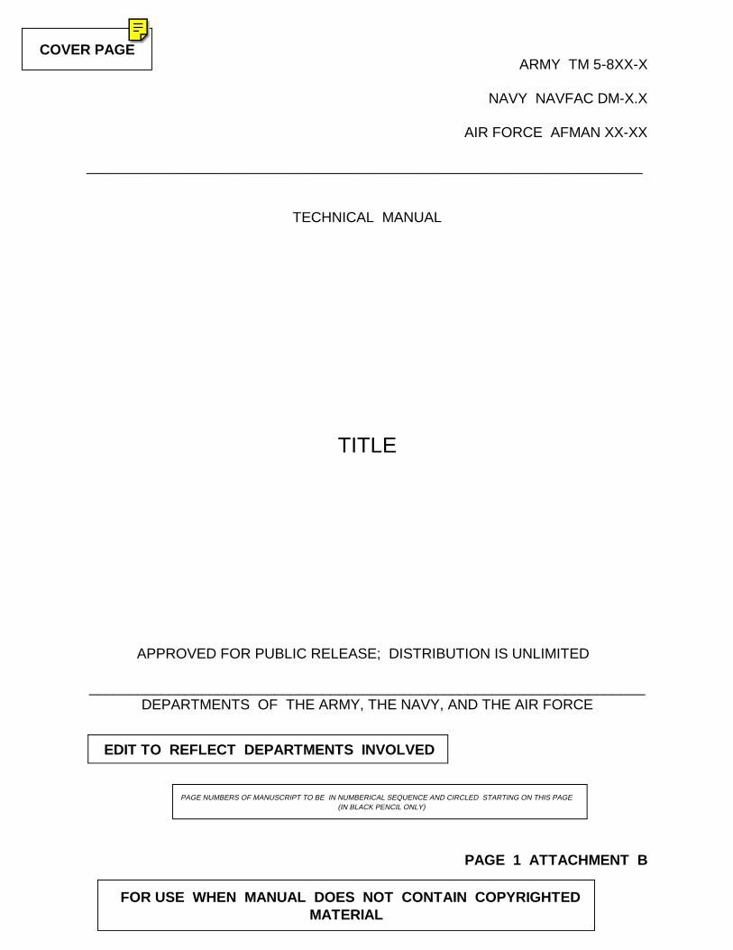
COVER PAGE
EDIT TO REFLECT DEPARTMENTS INVOLVED
PAGE NUMBERS OF MANUSCRIPT TO BE IN NUMBERICAL SEQUENCE AND CIRCLED STARTING ON THIS PAGE (IN BLACK PENCIL ONLY)
FOR USE WHEN MANUAL DOES NOT CONTAIN COPYRIGHTEDMATERIAL
ARMY TM 5-8XX-X
NAVY NAVFAC DM-X.X
AIR FORCE AFMAN XX-XX
_____________________________________________________________________
TECHNICAL MANUAL
TITLE
APPROVED FOR PUBLIC RELEASE; DISTRIBUTION IS UNLIMITED
_____________________________________________________________________DEPARTMENTS OF THE ARMY, THE NAVY, AND THE AIR FORCE
PAGE 1 ATTACHMENT B
COVER PAGE

MANUAL IS NOT JOINTLY PREPARED, USE THE FOLLOWING :
WHEN MANUAL IS TRI-SERVICE, USE THE FOLLOWING:
FOR USE WHEN MANUAL CONTAINS COPYRIGHTED MATERIAL
REPRODUCTION AUTHORIZATION/RESTRICTIONS
This manual has been prepared by or for the Government and is public property andnot subject to copyright.Reprint or republications of this manual should include a credit substantially as follows: "Joint Departments of the Army and Air Force, TM 5-8XX-X/AFM XX-X, Chapter X,TITLE, _____." PRINTER ENTER DATE
" Department of the Army Technical Manual 5-8XX-X, TITLE_____."
"Joint Departments of the Army, Navy, and the Air Force, TM 5-8XX-X/NAVFAC XX-XX/AFMAN XX-X,TITLE,______."
PAGE 2 ATTACHMENT B

WHEN MANUAL IS NOT JOINTLY PREPARED
WHEN MANUAL IS TRI-SERVICE
REPRODUCTION AUTHORIZATION/RESTRICTIONS
This manual has been prepared by or for the Government and, except to the extentindicated below, is public property and not subject to copyright.
Copyrighted material included in the manual has been used with the knowledge andpermission of the proprietors and is acknowledged as such at point of use. Anyonewishing to make further use of any copyrighted material, by itself and apart from thistext, should seek necessary permission directly from the proprietors.
Reprint or republication of this manual should include a credit substantially as follows: "Joint Departments of the Army and Air Force, TM 5-8XX-X/AFMANXX-X,ChapterX,TITLE, ______." PRINTER ENTER DATE
If the reprint or republication includes copyrighted material, the credit should alsostate: "Anyone wishing to make further use of copyrighted material, by itself and apartfrom the text, should seek necessary permission directly from the proprietor."
(SEE PAGE 2)
(SEE PAGE 2)
PAGE 3 ATTACHMENT B

TABLE OF CONTENTS WITHOUT CHAPTER SUBDIVISIONS
LIST DOCUMENT NUMBER ACROSS TOP OF EVERY PAGE IN THIS ORDER. AN " * " WILL BE PLACED NEXTTO THE DOCUMENT NUMBER ON THIS PAGE ONLY TOINDICATE THAT A SUPERSEDURE NOTICE APPEARS
AT THE BOTTOM OF THE PAGE.
USE THIS HEADING WHEN ARMY ONLY
USE ONLY WHEN NECESSARY
IF THIS MANUAL IS BEING SUPERSEDED, THE INFORMATION WILL BE LOCATED AT THE BOTTOM OF THIS PAGE
* TM 5-8XX-X
TECHNICAL MANUAL HEADQUARTERSNo. 5-8XX-X DEPARTMENT OF THE ARMY
Washington, DC_________ PRINTER ENTER DATE
TITLE
Paragraph PageSTANDARD FIRST THREE PARAGRAPHS
PURPOSE...........................................................................................................1
SCOPE.................................................................................................................2
REFERENCES.....................................................................................................3
UNITS OF MEASUREMENT................................................................................4
SCHEDULE FOR EVALUATION..........................................................................5
DISTRIBUTION OF EVALUATION......................................................................6
APPENDIX A. PAVEMENT EVALUATION REPORT
BIBLIOGRAPHY
GLOSSARYPAGES NUMBERED BY PRINTER
APPROVED FOR PUBLIC RELEASE; DISTRIBUTION IS UNLIMITED
____________
* This manual supersedes TM 5-8XX-X, dated XX XXXX, 19XX
PAGE 4 ATTACHMENT B

TABLE OF CONTENTS WITH CHAPTER DIVISIONS
IF BI-SERVICE OR TRI-SERVICE MANUAL, USE THIS HEADING(EDIT FOR SERVICES PARTICIPATING)
* TM 5-8XX-X/NAVFAC DM X.XX/AFM XX-X
TECHNICAL MANUAL HEADQUARTERS No. 5-8XX-X DEPARTMENTS OF THE ARMY,NAVY MANUAL THE NAVY, AND THE AIR FORCENAVFAC DM XX.X Washington, DC_____________AIR FORCE MANUALNo. XX-XX
TITLE
Paragraph page
CHAPTER 1. GENERAL
Purpose................................................................................................................1-1
Scope...................................................................................................................1-2
References...........................................................................................................1-3
Units of Measurement..........................................................................................1-4
Design Requirements...........................................................................................1-5
CHAPTER 2. PLANNING FACTORS
General................................................................................................................2-1
Justification..........................................................................................................2-2
General Planning Considerations........................................................................2-3
Planning Studies..................................................................................................2-4
CHAPTER 3. HELICOPTER LANDING FACILITIES
Helicopter Runways............................................................................................3-1
Helipads..............................................................................................................3-2APPROVED FOR PUBLIC RELEASE; DISTRIBUTION IS UNLIMITED
___________ * This manual supersedes TM 5-8XX-X/NAVFAC DM X.XX/AFM XX-XX dated XX XXX
PAGE 5 ATTACHMENT B

IF MANUAL CONTAINS FIGURES, LIST THEM
FOLLOWING THE TABLE OF CONTENTS .
IF MANUAL CONTAINS TABLES, LIST THEM
FOLLOWING THE LIST OF FIGURES .
TM 5-8XX-XTABLE OF CONTENT (CONT'D)
Paragraph Page
CHAPTER 4. AIRCRAFT MAINTENANCE HANGARS - SPACE ALLOWANCES
Types of Hangar Space..........................................................................................4-1
Allowances..............................................................................................................4-2
Calculation of Authorized Space.............................................................................4-3
CHAPTER 5. PARKING APRONS
General....................................................................................................................5-1
Fixed Wing Aircraft Parking Apron..........................................................................5-2
Rotary Wing Aircraft Wing Parking Apron...............................................................5-3
APPENDIX A. REFERENCES
LIST OF FIGURES
Figures 3-1. Accident Potential Zone Guidelines
3-2. Airfield runway, Taxiway, Apron, and Overrun Grades.
3-3. Airfield Primary Surface End Details.
4-1. Helicopter VFR Runway.
4-2. Helicopter IFR Runway.
LIST OF TABLES
Table 2-1. Class "A" Runways.
2-2. Taxiways.
2-3. Parking Aprons.
3-1. Holding (Engine Runup) Aprons.
3-2. Overrun.
PAGE 6 ATTACHMENT B
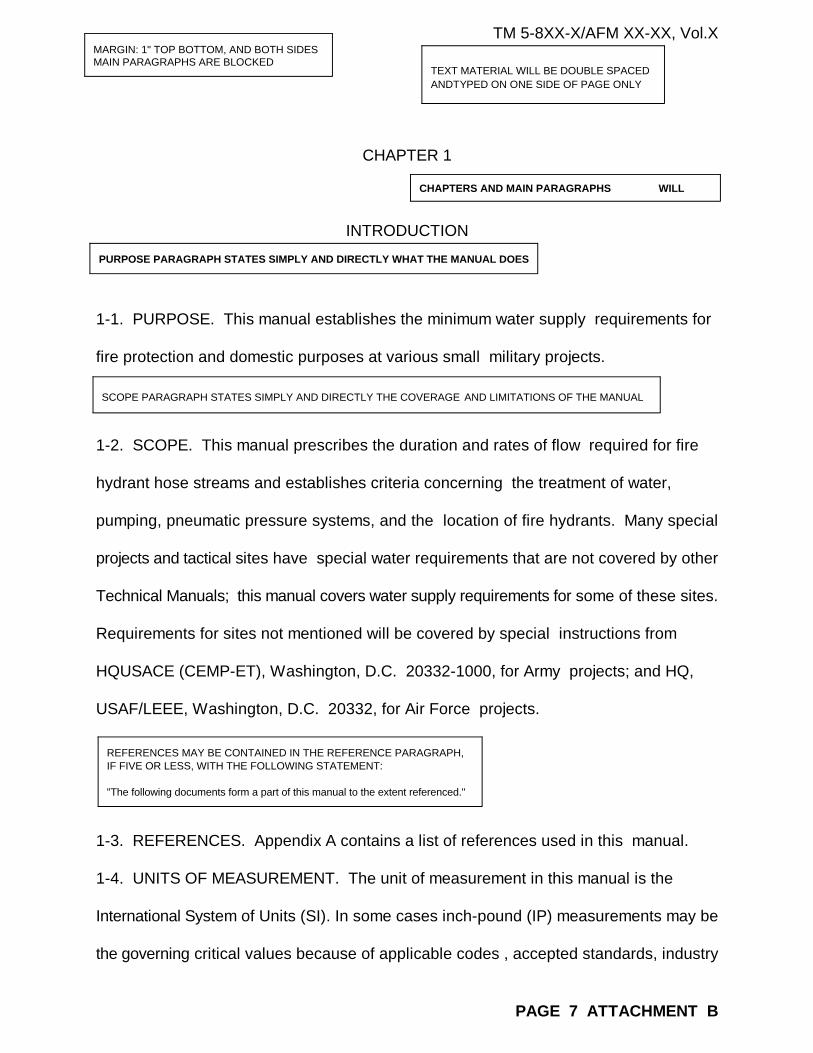
MARGIN: 1" TOP BOTTOM, AND BOTH SIDESMAIN PARAGRAPHS ARE BLOCKED
TEXT MATERIAL WILL BE DOUBLE SPACEDANDTYPED ON ONE SIDE OF PAGE ONLY
CHAPTERS AND MAIN PARAGRAPHS WILL
PURPOSE PARAGRAPH STATES SIMPLY AND DIRECTLY WHAT THE MANUAL DOES
SCOPE PARAGRAPH STATES SIMPLY AND DIRECTLY THE COVERAGE AND LIMITATIONS OF THE MANUAL
REFERENCES MAY BE CONTAINED IN THE REFERENCE PARAGRAPH,IF FIVE OR LESS, WITH THE FOLLOWING STATEMENT:
"The following documents form a part of this manual to the extent referenced."
TM 5-8XX-X/AFM XX-XX, Vol.X
CHAPTER 1
INTRODUCTION
1-1. PURPOSE. This manual establishes the minimum water supply requirements for
fire protection and domestic purposes at various small military projects.
1-2. SCOPE. This manual prescribes the duration and rates of flow required for fire
hydrant hose streams and establishes criteria concerning the treatment of water,
pumping, pneumatic pressure systems, and the location of fire hydrants. Many special
projects and tactical sites have special water requirements that are not covered by other
Technical Manuals; this manual covers water supply requirements for some of these sites.
Requirements for sites not mentioned will be covered by special instructions from
HQUSACE (CEMP-ET), Washington, D.C. 20332-1000, for Army projects; and HQ,
USAF/LEEE, Washington, D.C. 20332, for Air Force projects.
1-3. REFERENCES. Appendix A contains a list of references used in this manual.
1-4. UNITS OF MEASUREMENT. The unit of measurement in this manual is the
International System of Units (SI). In some cases inch-pound (IP) measurements may be
the governing critical values because of applicable codes , accepted standards, industry
PAGE 7 ATTACHMENT B

KEEP QUOTATIONS TO A MINIMUM
ACRONYMS ARE TO BE IDENTIFIED THEFIRST TIME THEY APPEAR IN THE TEXT
TM 5-8XX-X/AFM XX-XX, Vol.X
practices, or other considerations. Where the IP measurements govern, the IP values
may be shown in parenthesis following a comparative SI value or the IP value may be
shown without a corresponding SI value.
1-5. EXPLANATION OF ABBREVIATIONS AND TERMS. Abbrevitions and special
terms used in this manual are explained in the glossary.
approach departure zone - A trapezoidal area, symnetrical about the extended runway
center line and expanding outward from the ends of the primary surface or the clear areaof hoverpoints. Provide for the "straight-in" approach "straight-out" departure to insure
a satisfactory level of safety and regulation for aircraft.
autorotation lane - A helicopter landing lane or designated area on a runway for the
purpose of practicing landings under simulated engine failure or certain other simulated
emergency conditions.
aviation intermediate maintenance (AVIM) - Units that provide mobile, esponsive
"one-stop" maintenance and repair of equipment for return to user.
aviation unit maintenance (AVUM) - Activities staffed and equipped to perform high
frequency "on aircraft" maintenance tasks required to retain or return aircraft
to a serviceable condition. aviation runup area (holding apron) - A paved area adjacent
to the taxiway near the runway end where final preflight warmup and engine and
instrument checks are performed.
ground point of intercept (GPI) - A point in the vertical plane of the runway centerline or
PAGE 8 ATTACHMENT B

UNDERLINED MATERIAL IN MANUSCRIPT APPEAR IN ITALICS IN PRINTED DOCUMENT
THERE MUST AT LEASE 2 OF ANY SUBDIVISION.DO NOT DIVIDE LOWER THAN THE THIRD LEVEL.INDENT SUBDIVISIONS AS FOLLOWS:
1-1 LEFT MARGIN (MAIN PARAGRAPH)
a. INDENT 3 SPACES
(1) INDENT 6 SPACES
(a) INDENT 9 SPACES
TM 5-8XX-X/AFM XX-XX, Vol. 6
center of a helipad at which it is assumed that the straight line extension of the glide
scope (flight path) intercepts the approach surface base line.
b. Family Housing at Tactical Sites,
(1) When the maximum single-floor area of the largest building does not
exceed 92.9 square meters, the water supply system will be designed to simultaneously
supply a fire flow rate of 31.5 liters per seconds (500 gallons per minute) and the
domestic demand for 2-hour duration.
(2) When the single-floor area of a building exceeds 465 square meters,
refer to MIL-HDBK 1008 for ARMY users and AFM 88-10, Vol. 6 for Air Force user for
fire protection water supply requirements for that building.
c. Air Control and Warning Stations. The water supply will be designed to
simultaneously provide a 31.5 L/s (500) gpm fire flow rate and domestic water demand
for a 2-hour duration.
d. Reserve Centers.
(1) When the reserve center is of noncombustible construction with a
maximum floor area of 1,100 square meters or of heavy timber, ordinary, or wood
frame construction with a maximum floor area of 740 square meters, the water supply
PAGE 9 ATTACHMENT B

SHORT LISTINGS CAN BE USED IN TEXT WITHOUT NUMBER SIMLPLY INDENTING
TM 5-8XX-X/AFM XX-XX, Vol. 6
system will be designed to simultaneously provide a 63 L/s (1,000 gpm) fire flow rate and
the domestic demand for a 2-hour duration.
(2) When the building floor area exceeds these limits, refer to MIL-HDBK
1008 for Army users and AFM 88-10, Vol. 6 for Air Force users for fire protection water
supply requirements.
2-6 DESIGN AND SELECTION OF PAVEMENTS FOR ARMY AIRFIELDS.
a. Army airfield pavements will be designed according to the mission requirementsof each airfield. Airfield pavements may consist entirely of one or a combination of thefollowing classes of pavements:
CLASS PLANNED AIRCRAFT TRAFFIC DESIGN BASIS
I Rotary- and fixed-wing aircraft with Note 1 maximum gross weights equal to or less
than 9,070 kg (20,000 lb.)
II Rotary-wing aircraft with maximum gross Note 2
weights between 9,071 and 22,680 kg
( 20,001 and 50,000 lb.)
III Fixed-wing aircraft with maximum gross Note 3
weights between 9,070 and 79,380 kg
(20,001 and 175,000 lb.)
and having one of the gear configurations
related in Note 3.
IV Multiple wheel fixed-wing and rotary-wing Note 4
PAGE 10 ATTACHMENT B TM 5-8XX-X

FIGURE REFERENCE IS SHOWN IMMEDIATELYAFTER PARAGRAPH IN WHICH FIRST MENTIONED
LOWER CASE FULL SPELLING REFERENCE TO SPECIFIC CHAPTER,PARAGEAPH, TABLE OR FIGURE. ABBREVIATIONS AND LOWER CASEFOR PARENTHETICAL REFERENCE: (chap 5) (para 16) (fi g 2-1) etc.
aircraft other than those considered for
Class III pavement.
Note 1. Class I pavement design is based on the standard service vehicles used at all
Army airfields. This pavement class will accommodate all Army fixed-wing and
rotary-wing aircraft except the CH-47 and CH-54's. This pavement design will be used
for all airfield facilities other than where Class II, III, or IV pavement design is required.
The design is based on 50,000 passes of the most critical aircraft in this class.
5-4 HELICOPTER HOVERPOINTS.
a. General Information. A hoverpoint is a prepared and marked surface used as
a reference or control point for arriving or departing helicopters.
b. Layout Criteria. A hoverpoint consists of a paved area 9.1 meters in diameter,domed to a 150 mm height at the center. If a hoverpoint is established on existing
pavement, the 150 mm dome need not be constructed. A typical layout of a hoverpoint
is illustrated in figure 5-7.
1-1/2" (10 SPACES)
Figure 5-7. Helicopter Hoverpoint.
1-1/2" (10 SPACES)
PAGE 11 ATTACHMENT BTM 5-8XX-X/AFM XX-X

1-1/2" (10 SPACES)
1-1/2" (10 SPACES)
EQUATION IDENTIFICATION
COMPLEX EQUATIONS SHOULD BE FURNISHED CAMERA-READY
Table 4-2. Domestic Hot-Water Temperatures.
Table 4-3. Hot-Water Demand Per Fixture.
Table 4-4. Hot-Water Demand Per Capita.
(1) The gallons of water per person to be heated each day, the number
of hours assumed for the duration of the average heating load, and the number of hours
assumed to determine peak hourly requirements will conform with local conditions. The
water heating and storage requirements may be determined on the per capita per day
basis by using the equation 4-1.
GN
A = ---------- (eq 4-1)B
PAGE 12 ATTACHMENT B TM 5-8XX-X/AFM XX-XX, Vol. X

INCLUDE SIMPLE TABLES AS PART OF THE MANUSCRIPT
FURNISH COMPLEX TABLES OR HANDWRITTEN MATERIALS CAMERA-READY AND PROVIDE A COPY AT THE END OF THE MANUSCRIPT. INDICATION OF LOCATION OF TABLE FOLLOWS PARAGRAPH IN WHICH TABLE IS FIRSTMENTIONED.
For mixture of two or more seed kinds, compute as shown in the example in table 7-1
for a 50-50 mixture of Kentucky bluegrass and chewing fescue:
Table 7-1. Mixture Rate.____________________________________________________________________________________
Percent Percent Percentkind by Pure Live Pure LiveWeight in Seed of Seed in
Seed Kind Mixture Each Kind Mixture
Kentucky bluegrass 50 68 34
Chewing fescue 50 78 39
Total pure live seed in mixture, % 73 Other than pure live seed, % 27
100 ____________________________________________________________________________________
e. Seed Rates. For single, unmixed species, the data for seeding rate shown
in table 7-2 are normally adequate without further computation.
Table 7-2. Seeding Rates.
PAGE 13 ATTACHMENT B TM 5-8XX-X/AFM XX-XX, Vol.X

USE ALPHA-NUMERIC ORDER WHENLISTING PUBLICATIONS UNDER AN ORGANIZATION
LIST ONLY DOCUMENTS REFERENCED IN THE TEXT
AGENCIES DOCUMENTS ARE NOT TO BE REFERENCEDIN DEPARTMENT OF THE ARMY TECHNICAL MANUALS
PUBLICATIONS DATES ARE REQUIREDFOR NONMILITARY DOCUMENTS
FOR PUBLICATIONS OTHER THAN ARMY, NAVY, AND AIRFORCE,PROVIDE SOURCE ADDRESS TO ASSIST USER IN FINDINGPUBLICATIONS
USE ALPHA-NUMERIC ORDER WHEN LISTINGPUBLICATIONS UNDER AN ORGANIZATION.
APPENDIX A
REFERENCES
Government PublicationsDATES ARE NOT USED FOR
Departments of the Army and the Air Force PUBLICATIONS OF THE MILITARYSERVICES
TM 5-811-1/AFM 88-9, Ch. 1 Electric Power Supply and Distribution TM 5-811-4 Electrical Design Corrosion Control
TM 5-812-1 Fire Prevention Manual
TM 5-814-3/AFM 88-11, Vol.1 Sanitary and Industrial Wastewater Collection Gravity Sewers and
Appurtenances
National Bureau of Standards (NBS)
National Technical Information Service, 5285 Port Royal Road, Springfield, VA 22161 Publication COM 75-1045 (52 pages) Monograph 31 (July 3, 1661)
PAGE 14 ATTACHMENT BTM 5-8XX-X/AFM XX-XX, Vol.X

REFERENCES CAN BE IDENTIFIED IN ONE OR TWO WAYS DEPENDINGON THE NUMBER AND COMPLEXITY OF THE REFERENCES:
(1) SEPARATE PARAGRAPH LISTING IN REFERENCES PARAGRAPH IN CHAPTER 1 WHEN FIVE OR LESS REFERENCES ARE USED.
(2) LIST IN APPENDIX A WHEN 6 OR MORE REFERENCES ARE USED.
KEEP REFERENCES IN TEXT TO A MINIMUM AND LIMIT TO READILYAVAILABLE PUBLICATIONS.
BIBLIOGRAPHY CONTAINS SOURCE MATERIAL ANDANYADDITIONAL READING MATERIALS PERTAINING TO THEMANUAL. USE ONLY WHEN NECESSARY TO GIVECREDIT.
Nongovernment Publications
American Society for Testing and Materials (ASTM), 1916 Race St.,Philadelphia, PA 19103
C 500 - 81 Testing Asbestos-Cement Pipe
American Water Works Association (AWWA), 6666 Quincy, Denver, CO 80235 Manual No. M9 Concrete Pressure Pipe (1979)
Manual No. M11 Steel Pipe Design and Insulation (1964)
Cast Iron Pipe Research Association (CIPRA), 1301 West 22nd St., Oak Brook, IL
60521
Handbook of Ductile Iron Pipe, Cast Iron Pipe (1979)
Water Pollution Control Federation (WPCF), 2626 Pennsylvania Ave., NW, Washington DC 20037
Manual of Practice No. 17 Paints and Protective Coatings for Wastewater Treatment Facilities (1969)
PAGE 15 ATTACHMENT BTM 5-8XX-X/AFM XX-XX, Chap. X

SAMPLE AUTHENTICATION PAGE FOR TECHNICAL MANUALS
BIBLIOGRAPHY
Babbitt, H.E. and Bauman, E.R., Sewerage and Sewage Treatment, 8th Ed.,John Wiley and Son, New York,1958
Brater, E.F. and King, H.W. Handbook of Hydraulic, 6th Ed., McGraw-Hill New York, 1976
Fair, G.M., Greyer, J.C. and Okun, D.A., Elements of Water Supply and Wastewater Disposal, 2nd Ed., JohnWiley and Sons, New York, 1971
Gehm, H.W. and Bregman, J.I., Handbook of Water Resources and Pollution Control, van NostrandReinhold, New York, 1976
PAGE 16 ATTACHMENT B TM 5-8XX-X/NAVFAC DM-X.X/AFM XX-X, Chapter X

FORM LETTER FOR REQUESTING COPYRIGHTED RELEASE
EDIT TO REFLECT DEPARTMENTS INVOLVED
The proponent agency of this publication is the Office of the Chief of Engineers, UnitedStates Army. Users are invited to send comments and suggested improvements on DAForm 2028 (Recommended Changes to Publications and Blank Forms) to HQUSACE(CEMP-ET) , WASH, DC 20314-1000.
By order of the Secretaries of the Army, the Navy, and the Air Force:
GORDON R. SULLIVAN
General, United States Army Chief of StaffOfficial:
MILTON H. HAMILTONAdministrative Assistant to theSecretary of the Army
MERRILL A. McPEAKGeneral, United States Air ForceChief of Staff
Official:
EDWARD A. PARDINIColonel, United States Air ForceDirector of Information Management
J.P. JONES, JR. Rear Admiral, CEC, U.S. Navy Commander, Naval Facilities Engineering Command Distribution:
Army: To be distributed in accordance with DA Form 12-34-E, Block_____, requirements nonequipment technical manuals.
Navy
Air Force: F
PAGE 17 ATTACHMENT B

LETTERHEAD (Name of Company)
(Address)
(Salutation)
RELEASE
This Office is preparing a manuscript for publication to be issued for defense purposes under the title(insert title when known).
Permission is requested to include in this publication the following material: (insert specific informationregarding the pages and lines of illustrations and/or text matter to be released) from the work entitled____________________, written by _____________________, which was published by your company.
Would you please indicate on one copy of this letter, in the space provided below. Whether thismaterial may be used in this publication this office is preparing and whether an appropriate credit line is desired. A self-adderessed envelope is enclosed for your use.
___________________________________ Signature of Requester
___________________________________ Title PUBLISHER'S PREMISSION
RELEASE to use requested material is hereby granted, royalty free.
The material covered by this release (may ) (may not)* be placed on sale by the US Government PrintingOffice.
If the Government publication is made available to the public for inspection and copying in accordancewith the Freedom of Information Act or any other law, the material covered by this release may besimilarly made available for inspection and copying in context.
Credit Line (is) (is not)* requested
___________________________________Name of copyright owner or authorized agent
By ___________________________________ Company Officer
Date_______________ ___________________________________ Title
_________*Line out response applicable
PAGE 1 ATTACHMENT C

PERMISSION LETTER MUST BE EASILY ANDPOSITIVELY IDENTIFIED WITH THE
COPYRIGHT PERMISSION LETTER, TOGETHER WITHA COPY CONTAINING THE COPYRIGHTED MATERIALMUST ACCOMPANY THE MANUSCRIPT
WRITE TM FIGURE OR TABLE NUMBER ON FACE OFPERMISSION LETTER AND ATTACH A COPY OF THETM PAGE CONTAINING THE COPYRIGHTED
Prentice Hall, Inc.Englewood Cliffs, NJ 07632
January 25, 1995 Telex No. 13-6425
Harland Bartholomew & AssociatesMs. Eloise Shalstrom7745 CarondeletSt. Louis, Missouri 63105-1000
Dear MS. Shalstrom:
We are very glad to give you permission to quote from our book(s), TURFGRASS: Science and Culture,James B. Beard, in accordance with the conditions outlined in your letter of May 7th.
Please give credit to the authors(s), the title(s), and the publisher with copyright year date(s). Our usualcredit line appears below: Science and Culture @1973, pp. 225, 250. Reprinted by permission ofPrentice-Hall, Inc., Englewood Cliffs, New Jersey.
Sincerely,
(Mrs) Barbara A. Schuliar, Asst.Permission Editor
PAGE 2 ATTACHMENT C

SAMPLE CREDIT LINES
When the copyright holder requests a certain credit line, use that wordingWhen a credit line is not supplied by the copyright holder, use the following
example:
Reprint with permission from Smith and Jones, Elements of Electricity,p.25, @1984 by Johnson Corporation.
When noncopyrighted material is used, it is desirable to acknowledge the source by a credit such as the following:
Courtesy of the ABC Corporation, noncopyrighted
or
Source: National Institute of Science and Technology
PAGE 3 ATTACHMENT C

ATTACHMENT D
METRIC
1. UNITS OF MEASURE
The International System of Units (SI) will be used unless it is contrary to either thestandard practice within the design discipline, or to the product being specified. Detailguidance is available in 8 December 1994 CEMP-E document titled REQUIREMENTSFOR THE USE OF METRIC IN CRITERIA AND GUIDANCE DOCUMENTS, which isavailable on CCB and TECHINFO in the CEGS database as file METRIC.DOC.
a. When consistent with codes, standards, and industry practices, and where SIproducts are determined to be practical, economically feasible, and unlikely to causesignificant inefficiencies, metric designations used in technical manuals shall be hard SIvalues, and the corresponding IP values will not shown.
b. Dual SI and IP units will only be used when approved or directed by CEMP-Eand where measurements are governed by critical IP values, that is, where IP values arerequired to comply with applicable codes and standards that have not been converted tothe SI system. In such cases, the SI unit will be a conservatively rounded conversion ofthe IP value unless an exact conversion is required by the code, standard or practice.When dual units are used, the IP unit will govern, and the SI unit will always appear first;for example: 25 millimeters (0.98 inch). 2. FIGURES AND TABLES
For graphics, figures and tables other than scaled drawings, critical IP units may becombined with SI units in a format that is clear and concise. Otherwise, separate SI andIP figures and tables should be developed when IP measurements are critical.
b. A table will retain IP values only when IP units govern. If IP units govern (softmetric conversion) two tables one with the SI values and one with IP values may be usedfor clarity if necessary.
HARD METRIC TABLE_____________________________________________________________________
Duct Size Diagonal Angles Horizontal Angles Bolt Size
150 sq mm 50x50x1.5 mm 50x50x1.5 mm 6 mm
1375 sq mm 64x64x1.5 mm 64x64x1.5 mm 10 mm_____________________________________________________________________
PAGE 1 ATTACHME NT D

SOFT METRIC TABLE_______________________________________________________________
Duct Size Diagonal Angles Horizontal Angles Bolt Size
150 sq mm 50x50x1.5 mm 50x50x1.5 mm 6 mm(30 in sq) (2x2x16 gauge) (2x2x16 gauge) (1/4 in)
1375 sq mm 64x64x1.5 mm 64x64x1.5 mm 10 mm(54 sq in) (2-1/2x2-1/2x16 (2-1/2x2-1/2x16 (3/8 in)
gauge) gauge)_____________________________________________________________________
3. PIPING.
Piping, pipe fittings and valves will be indicated in dual units so that the IP units can beused to relate back to the referenced industry standard.
4. CONTROL FOR HVAC.
Control equipment and devices including theromostats meters, gauges, operatingranges, setpoints, actuator signals and pressures will be shown in IP units only.