Guía de Ventilación de Tanques
31
Transcript of Guía de Ventilación de Tanques


Page 1 • Morrison Venting Guide
Contents
I. Background Information Page Introduction 2 Defi nitions 2II. Example Calculations for Vent Selection Horizontal Cylindrical Storage Tank 3 Vertical Cylindrical Storage Tank 4 Horizontal Rectangular Storage Tank 5III. Calculation Tables Precalculated-Horizontal Cylindrical Tanks 6 Precalculated-Vertical Cylindrical Storage Tanks 7 Precalculated-Horizontal Rectangular Storage Tanks 8 Wetted Areas for Horizontal Cylindrical Tanks 9 Wetted Areas for Vertical Cylindrical Tanks 10 Emergency Venting Capacity 11 Gallon Capacity per Foot of Length 12IV. Vent Selection Morrison Vents-Capacities 13 Vent Combination Examples 14 Morrison Equipment 15V. Aboveground Fuel Storage Diagrams Pressure Systems 24 Suction Systems 26 Bulk Storage 28
References
NFPA 30 “Flammable and Combustible Liquids Code” 2003 Edition National Fire Protection Association, 1 Batterymarch Park, Quincy, MA 02269
UL 142 “Steel Aboveground Tanks” 9th Edition, December 28, 2006 UL Standards for Safety—UL Publication Stock, 333 Pfi ngsten Road, Northbrook, IL 60062, Tel (847) 272-8800
API Std 2000 “Venting Atmospheric & Low Pressure Storage Tanks” American Petroleum Institute—Fifth Edition, April 1998 1120 L Street, Northwest, Washington, DC 20005 Order #822-20000
PEI RP200 “Recommended Practices for Installation of Aboveground Storage Systems for Motor Vehicle Fueling” Petroleum Equipment Institute, 2003 Edition, P.O. Box 2380. Tulsa, OK, Tel (918) 494-9696
Morrison 325 East 24th Street, Dubuque, Iowa 52001. Tel (563) 583-5701

Page 2 • Morrison Venting Guide
Background Information
The Morrison Venting Guide was created to assist in equipment selection for aboveground storage tanks. Examples on the next two pages illustrate a vent selection process. It is best to work through the examples before attempting to use any of the tables in this book.
Tables include examples for standard sized tanks. The venting capacity charts and wetted area tables were taken directly from NFPA 30 and UL 142.
The vent selection chapter includes venting capacities of specifi c Morrison vents. This data was obtained from results of laboratory testing and engineering calculations. Catalog pages of the Morrison equipment follow the vent capacity chart.
Defi nitions
Emergency Venting — Venting suffi cient to relieve excessive internal pressure in storage tanks caused by exposure fi res. Venting rate may exceed requirements of normal atmo-spheric and product transfer effects. In such cases, the construction of the tank will deter-mine if additional venting capacity must be provided.
Atmospheric Tank — A storage tank that has been designed to operate at pressures from atmospheric through 1.0 PSIG (760 mm Hg through 812 mm Hg) measured at the top of the tank (NFPA 30 Pg. 30-13). Pressure not to exceed 1.0 PSIG under normal operation, and 2.5 PSIG under emergency conditions (PEI RP-200).
Pressure Relieving Devices — Defi ned in NFPA 30 4.2.5.2.3, where entire depen-dence for emergency relief is placed upon pressure relieving devices, the total venting capacity of both normal and emergency vents shall be enough to prevent rupture of
the shell or bottom of the tank if vertical, or of the shell or heads if horizontal.
Wetted Area — Exposed surface or shell area of a tank used in determining the vent-ing requirements needed for that size tank in event of an exposure fi re. In a horizontal tank, the wetted area is calculated as 75% of the exposed surface area. In a vertical tank, the wetted area is calculated as the fi rst 30 ft. above grade of the exposed shell area of the tank.
CFH — Abbreviation for Cubic Feet per Hour used to quantify or measure the airfl ow and degree of pressure relief for venting calculations.
Vent Capacity — The maximum rate of air-fl ow (CFH) recorded under test conditions at a maximum pressure of 2.5 PSI for specifi c sized emergency vents. This capacity rating is often required to be indicated on the vent itself.

Page 3 • Morrison Venting Guide
STEP 1 Precalculated Data for Common Sizes
Find tank size on Table A which can be found on page 5. Table lists wetted area and CFH for common sized horizon-tal tanks. For a 10’ x 17’ tank – wetted area = 518 sq. ft. and required vent capacity = 360,840 CFH. Proceed to Step 5.
STEP 2 Wetted Area Table
If tank size is NOT listed on Table A, page 5, wetted area can also be found on Table D, page 8. Follow grid for this example – 10’ diameter x 17’ length = 518 sq. ft. Proceed to Step 4.
STEP 3 Calculate Wetted Area
If the tank size is NOT on either chart, wetted area can be calculated. For Horizontal Tanks, wetted area = 75% of the total exposed surface area.
For a 10’ x 17’ tank: 0.75[2(area of each end) + (area of shell)] = wetted area
π = 3.14, d = diameter, L = length, WA = wetted area
WA = 0.75[(πd2 ÷ 2) +(πdL)] 0.75[((3.14)(102) ÷ 2) + (3.14)(10)(17)]
WA = 518 sq. ft.
STEP 4 Determine CFH Requirement
Use Table F: Venting Capacity Chart on page 10. Wetted area must be known (518 sq. ft.). Since 518 is between 500 and 600 on the chart, interpolation is needed and is done as follows:
600 sq. ft. 392,000 CFH 500 sq. ft. 354,000 CFHDifference = 100 sq. ft. 38,000 CFH
38,000 = x 100 (518-500) x = 6,840 CFH
Total CFH Required: (6,840 + 354,000) = 360,840 CFH
Vent Selection/Capacity Example 1
STEP 5 Vent Selection
Options based on size of piping, type of product, fl ow requirements, required venting capacity and mounting. For the sake of this example, use 2” piping, Class 1B liquid. The normal vent size should be no smaller than the system piping, so a Morrison 2” Fig. 548 (20,200 CFH) is selected.
Total required venting capacity for this tank example was determined to be 360,840 CFH. Normal venting and emergency venting may be combined to reach this total. Morrison Vent Capacities are listed on Table H, page 12. Since the 6” Emergency Vent (246,130 CFH) can not pro-vide enough additional capacity to meet the requirement, an 8” Emergency Vent (462,000 CFH) is selected. In specify-ing pressure settings, it is recommended that the Emergency Vent NOT be less than the normal vent. Therefore, the vent specifi cation for this example is as follows:
Normal Vent - 2” Fig 548 20,200 CFH(8 oz pressure - 1 oz vacuum)
Emergency Vent - 8” Fig 244 462,000 CFH (16 oz pressure)
Total Venting Provided 482,200 CFH
STEP 6 Verifi cation
Refer to Table I on page 13 showing vent combinations and verify the total CFH fi gure. Also refer to the product illustra-tions on pages 23-28 and verify the selection for correct option on material compatibility and mounting requirements.
Horizontal Cylindrical Storage Tank
TANK CAPACITY 10,000 gallons
TANK SIZE 10 ft. dia x 17 ft. long

Page 4 • Morrison Venting Guide
STEP 1 Precalculated Data for Common Sizes
Find tank size on Table A which can be found on page 5. Table lists wetted area and CFH for common sized vertical tanks. For a 10’ x 17’ tank – wetted area = 534 sq. ft. and required vent capacity = 366,920 CFH. Proceed to Step 5.
STEP 2 Wetted Area Table
If tank size is NOT listed on Table A, page 5, wetted area can also be found on Table D, page 8. Follow grid for this example – 10’ diameter x 17’ height = 534 sq. ft. Proceed to Step 4.
STEP 3 Calculate Wetted Area
If the tank size is NOT on either chart, wetted area can be calculated. For Vertical Tanks, wetted area = area of shell to elevation not more than 30 ft. above the bottom.
For a 10’ x 17’ tank: Wetted Area = (area of shell)
π = 3.14, d = diameter, L = length, WA = wetted area
WA = (πd)L(3.14)(10)(17)
WA = 534 sq. ft.
STEP 4 Determine CFH Requirement
Use Table F: Venting Capacity Chart on page 10. Wetted area must be known (534 sq. ft.). Since 534 is between 500 and 600 on the chart, interpolation is needed and is done as follows:
600 sq. ft. 392,000 CFH 500 sq. ft. 354,000 CFHDifference = 100 sq. ft. 38,000 CFH
38,000 = x 100 (534-500) x = 12,920 CFH
Total CFH Required: (12,920 + 354,000) = 366,920 CFH
Vent Selection/Capacity Example 2
STEP 5 Vent Selection
Options based on size of piping, type of product, fl ow requirements, required venting capacity and mounting. For the sake of this example, use 2” piping, Class 1B liquid. The normal vent size should be no smaller than the system piping, so a Morrison 2” Fig. 548 (20,200 CFH) is selected.
Total required venting capacity for this tank example was determined to be 366,920 CFH. Normal venting and emergency venting may be combined to reach this total. Morrison Vent Capacities are listed on Table H, page 12. Since the 6” Emergency Vent (246,130 CFH) can not pro-vide enough additional capacity to meet the requirement, an 8” Emergency Vent (462,000 CFH) is selected. In specify-ing pressure settings, it is recommended that the Emergency Vent NOT be less than the normal vent. Therefore, the vent specifi cation for this example is as follows:
Normal Vent - 2” Fig 548 20,200 CFH(8 oz pressure - 1 oz vacuum)
Emergency Vent - 8” Fig 244 462,000 CFH (16 oz pressure)
Total Venting Provided 482,200 CFH
STEP 6 Verifi cation
Refer to Table I on page 13 showing vent combinations and verify the total CFH fi gure. Also refer to the product illustra-tions on pages 23-28 and verify the selection for correct option on material compatibility and mounting requirements.
Vertical Cylindrical Storage Tank
TANK CAPACITY 10,000 gallons
TANK SIZE 10 ft. dia x 17 ft. high

Page 5 • Morrison Venting Guide
STEP 1 Precalculated Data for Common Sizes
Find tank size on Table C which can be found on page 7. Table lists wetted area and CFH for common sized tanks. For a 274”L x 130”W x 65”H (22’10”L x 10’-10”W x 5’5”H) tank – wetted area = 612 sq. ft. and required vent capacity = 396,320 CFH. Proceed to Step 4.
STEP 2 Wetted Area Table
If tank size is NOT listed on Table C, page 7, wetted area can be calculated. For Horizontal Rectangular Tanks, wetted area = exposed shell area excluding the top surface of the tank.
For a 274”L x 130”W x 65”H tank:
Wetted area = (L x W) = 2(L x H) = 2 (W x H) 144
L = length, W = width, H = height
(274 x 130) + 2(274 x 65) + 2(130 x 65) 144
Wetted Area = 612 Sq. ft.
STEP 3 Determine CFH Requirement
Use Table F: Venting Capacity Chart on page 10. Wetted area must be known (612 sq. ft.). Since 534 is between 600 and 700 on the chart, interpolation is needed and is done as follows:
700 sq. ft. 428,000 CFH 600 sq. ft. 392,000 CFHDifference = 100 sq. ft. 36,000 CFH
36,000 = x 100 (612-600) x = 4,320 CFH
Total CFH Required: (4,320 + 392,000) = 396,320 CFH
Vent Selection/Capacity Example 3
STEP 5 Vent Selection
Options based on size of piping, type of product, fl ow requirements, required venting capacity and mounting. For the sake of this example, use 2” piping, Class 1B liquid. The normal vent size should be no smaller than the system piping, so a Morrison 2” Fig. 548 (20,200 CFH) is selected.
Total required venting capacity for this tank example was determined to be 396,320 CFH. Normal venting and emergency venting may be combined to reach this total. Morrison Vent Capacities are listed on Table H, page 12. Since the 6” Emergency Vent (246,130 CFH) can not pro-vide enough additional capacity to meet the requirement, an 8” Emergency Vent (462,000 CFH) is selected. In specifying pressure settings, it is recommended that the Emergency Vent NOT be less than the normal vent. Therefore, the vent specifi cation for this example is as fol-lows:
Normal Vent - 2” Fig 548 20,200 CFH(8 oz pressure - 1 oz vacuum)
Emergency Vent - 8” Fig 244 462,000 CFH (16 oz pressure)
Total Venting Provided 482,200 CFH
STEP 6 Verifi cation
Refer to Table I on page 13 showing vent combinations and verify the total CFH fi gure. Also refer to the product illustrations on pages 23-28 and verify the selection for correct option on material compatibility and mounting requirements.
Horizontal Rectangular Storage Tank
TANK CAPACITY 10,000 gallons
TANK SIZE 274”L x 130”W x 65”H
(22’-10”L x 10’-10”W x 5’5”H)

Page 6 • Morrison Venting Guide
Table A: Pre-Calculated DataHorizontal Cylindrical Tanks
TANK WETTED REQ’D VENT EMERGENCY
CAPACITY DIAMETER LENGTH AREA CAPACITY VENT SIZE
(Gallons) (Ft or In) (Ft-In) (Sq Ft) (CFH) (Inches)
280 36” 5’-2” 47 49,520 3
300 38” 5’-0” 49 51,640 3
500 48” 5’-5” 69 72,650 4
530 46” 6’-0” 71 74,750 4
550 48” 6’-0” 75 78,950 4
1,000 48” 10’-8” 119 124,950 6
1,000 64” 6’-0” 109 114,450 4
1,500 64” 9’-0” 147 154,350 6
2,000 64” 12’-0” 184 193,200 6
2,500 64” 15’-0” 222 223,320 6
3,000 64” 18’-0” 259 243,680 6
3,000 6’-0” 14’-0” 240 233,400 6
4,000 64” 24’-0” 335 281,100 6H
4,000 6’-0” 19’-0” 311 270,060 6H
5,000 8’-0” 13’-4” 326 276,960 6H
6,000 8’-0” 16’-0” 376 300,480 8
8,000 8’-0” 21’-4” 477 344,340 8
10,000 8’-0” 27’-0” 584 385,920 8
10,000 9’-0” 21’-0” 540 369,200 8
10,000 10’-0” 17’-0” 518 360,840 8
10,000 10’-6” 15’-7” 515 359,700 8
12,000 8’-0” 32’-0” 678 420,080 8
12,000 9’-0” 25’-0” 625 401,000 8
12,000 10’-0” 20’-6” 600 392,000 8
12,000 11’-0” 17’-0” 583 385,540 8
15,000 8’-0” 40’-0” 829 470,990 8FL
15,000 10’-6” 23’-5” 703 429,020 8
20,000 10’-0” 34’-2” 922 499,820 8FL
20,000 10’-6” 31’-0” 896 491,760 8FL
20,000 11’-0” 28’-0” 868 483,080 8FL
25,000 10’-6” 38’-6” 1,082 537,530 10
30,000 10’-6” 46’-3” 1,274 568,100 10

Page 7 • Morrison Venting Guide
Table B: Pre-Calculated DataVertical Cylindrical Tanks
TANK WETTED REQ’D VENT EMERGENCY
CAPACITY DIAMETER LENGTH AREA CAPACITY VENT SIZE
(Gallons) (Ft or In) (Ft-In) (Sq Ft) (CFH) (Inches)
280 36” 5’-2” 48 50,580 3
300 38” 5’-0” 49 51,640 3
500 48” 5’-5” 68 71,600 4
530 46” 6’-0” 72 75,800 4
550 48” 6’-0” 75 78,950 4
1,000 48” 10’-8” 134 140,700 6
1,000 64” 6’-0” 100 105,000 4
1,500 64” 9’-0” 151 158,550 6
2,000 64” 12’-0” 201 213,100 6
2,500 64” 15’-0” 251 239,520 6
3,000 64” 18’-0” 301 265,460 6H
3,000 6’-0” 14’-0” 263 245,760 6
4,000 64” 24’-0” 402 312,840 8
4,000 6’-0” 19’-0” 358 291,840 6H
5,000 8’-0” 13’-4” 335 281,100 6H
6,000 8’-0” 16’-0” 402 312,840 8
8,000 8’-0” 21’-4” 536 367,680 8
10,000 8’-0” 27’-0” 678 420,080 8
10,000 9’-0” 21’-0” 593 389,340 8
10,000 10’-0” 17’-0” 534 366,920 8
10,000 10’-6” 15’-7” 514 359,320 8
12,000 8’-0” 32’-0” 754 446,360 8
12,000 9’-0” 25’-0” 706 430,040 8
12,000 10’-0” 20’-6” 644 407,840 8
12,000 11’-0” 17’-0” 587 387,060 8
15,000 8’-0” 40’-0” 754 446,360 8
15,000 10’-6” 23’-5” 764 449,760 8
20,000 10’-0” 34’-2” 942 506,020 10
20,000 10’-6” 31’-0” 990 520,900 10
20,000 11’-0” 28’-0” 967 513,770 10
25,000 10’-6” 38’-6” 990 520,900 10
30,000 10’-6” 46’-3” 990 520,900 10

Page 8 • Morrison Venting Guide
Table C: Pre-Calculated DataHorizontal Rectangular Tanks
TANKWETTEDAREA(Sq Ft)
REQ’D VENTCAPACITY
(CFH)
EMERGENCYVENT SIZE
(Inches)
CAPACITY LENGTH WIDTH HEIGHT
(Gallons) (Ft-In) (Ft-In) (Ft-In)
125 6’-8” 2’-9” 1’-0” 37 38,950 3
186 2’-8” 2’-8” 3’-6” 44 46,340 3
250 4’-4” 4’-0” 1’-11” 49 51,640 3
250 6’-8” 2’-9” 1’-11” 54 56,900 3
500 7’-6” 3’-0” 3’-0” 86 90,560 4
500 10’-0” 3’-6” 2’-0” 89 93,740 4
1,000 9’-8” 4’-8” 3’-0” 131 137,550 6
1,000 10’-0” 4’-7” 3’-0” 133 139,650 6
2,000 10’-2” 6’-11” 3’-10” 201 211,560 6
2,000 10’-8” 6’-4” 4’-0” 204 213,240 6
2,500 10’-2” 6’-11” 4’-9” 233 229,480 6
3,000 8’-6” 6’-10” 7’-2” 278 253,560 6H
3,000 13’-9” 5’-5” 5’-5” 282 255,640 6H
4,000 11’-4” 6’-10” 7’-2” 338 282,480 6H
4,000 18’-2” 5’-5” 5’-5” 354 289,920 6H
5,000 22’-9” 5’-5” 5’-5” 428 323,760 8
6,000 13’-8” 10’-10” 5’-5” 413 317,460 8
6,000 16’-5” 6’-10” 7’-2” 445 330,900 8
6,000 27’-4” 5’-5” 5’-5” 503 355,140 8
8,000 18’-2” 10’-10” 5’-5” 511 358,180 8
8,000 21’-11” 6’-10” 7’-2” 562 377,560 8
10,000 22’-10” 10’-10” 5’-5” 612 396,320 8
10,000 27’-5” 6’-10” 7’-2” 678 420,080 8
12,000 27’-4” 10’-10” 5’-5” 710 431,400 8
12,000 32’-11” 6’-10” 7’-2” 795 460,300 8 FL

Page 9 • Morrison Venting Guide
Table D: Approximate Wetted AreasHorizontal Cylindrical Tanks
SI Units: 1 Ft = 0.30 m; 1 sq ft = 0.09 sq mSource for Chart: NFPA 30, 2003 Edition, Table B-4
Tank Diameter
3 Ft 4 Ft 5 Ft 6 Ft 7 Ft 8 Ft 9 Ft 10 Ft 11 Ft 12 Ft Tank Diameter
3 Ft 4 Ft 5 Ft 6 Ft 7 Ft 8 Ft 9 Ft 10 Ft 11 Ft 12 Ft
3 Ft 32 38 Ft 685 791 902 1013 1129 1244
4 Ft 39 55 39 Ft 701 810 923 1036 1155 1272
5 Ft 46 65 88 40 Ft 718 828 944 1060 1181 1301
6 Ft 53 74 100 128 41 Ft 734 847 966 1083 1207 1329
7 Ft 60 84 112 142 173 42 Ft 751 866 987 1107 1233 1357
8 Ft 67 93 124 156 190 226 43 Ft 767 885 1008 1130 1259 1385
9 Ft 74 102 136 170 206 245 286 44 Ft 904 1029 1154 1284 1414
10 Ft 81 112 147 184 223 264 308 353 45 Ft 923 1051 1178 1310 1442
11 Ft 88 121 159 198 239 283 329 377 428 46 Ft 941 1072 1201 1336 1470
12 Ft 95 131 171 213 256 301 350 400 454 509 47 Ft 960 1093 1225 1362 1498
13 Ft 102 140 183 227 272 320 371 424 480 537 48 Ft 979 1114 1248 1388 1527
14 Ft 109 150 194 241 289 339 393 447 506 565 49 Ft 998 1135 1272 1414 1555
15 Ft 116 159 206 255 305 358 414 471 532 594 50 Ft 1157 1295 1440 1583
16 Ft 123 169 218 269 322 377 435 495 558 622 51 Ft 1178 1319 1466 1612
17 Ft 130 178 230 283 338 395 456 518 584 650 52 Ft 1199 1342 1492 1640
18 Ft 137 188 242 298 355 414 477 542 610 678 53 Ft 1220 1366 1518 1668
19 Ft 197 253 312 371 433 499 565 636 707 54 Ft 1246 1389 1544 1696
20 Ft 206 265 326 388 452 520 589 662 735 55 Ft 1263 1413 1570 1725
21 Ft 216 277 340 404 471 541 612 688 763 56 Ft 1437 1593 1753
22 Ft 225 289 354 421 490 562 636 714 792 57 Ft 1460 1622 1781
23 Ft 235 300 368 437 508 584 659 740 820 58 Ft 1484 1648 1809
24 Ft 244 312 383 454 527 605 683 765 848 59 Ft 1507 1674 1839
25 Ft 324 397 470 546 626 706 791 876 60 Ft 1531 1700 1866
26 Ft 336 411 487 565 647 730 817 905 61 Ft 1726 1894
27 Ft 347 425 503 584 668 754 843 933 62 Ft 1752 1923
28 Ft 359 440 520 603 690 777 869 961 63 Ft 1778 1951
29 Ft 371 454 536 621 711 801 895 989 64 Ft 1803 1979
30 Ft 383 468 553 640 732 824 921 1018 65 Ft 1829 2007
31 Ft 395 482 569 659 753 848 947 1046 66 Ft 1855 2036
32 Ft 496 586 678 775 871 973 1074 67 Ft 2064
33 Ft 510 602 697 796 895 999 1103 68 Ft 2092
34 Ft 524 619 715 817 918 1025 1131 69 Ft 2120
35 Ft 539 635 734 838 942 1051 1159 70 Ft 2149
36 Ft 553 652 753 860 966 1077 1187 71 Ft 2177
37 Ft 567 668 772 881 989 1103 1216 72 Ft 2205
Approximate Wetted Area of Tanks With Flat Heads, Square FeetTankLength Approximate Wetted Area of Tanks With Flat Heads, Square Feet
TankLength

Page 10 • Morrison Venting Guide
Table E: Approximate Wetted AreasVertical Cylindrical Tanks
(Area of Shell to Elevation Not More Than 30 Ft. Above Bottom)
SI Units: 1 Ft = 0.30 m; 1 sq ft = 0.09 sq mSource for Chart: UL 142, 9th Edition, Table A-3
Tank Diameter
3 Ft 4 Ft 5 Ft 6 Ft 7 Ft 8 Ft 9 Ft 10 Ft 11 Ft 12 Ft
Tank Wetted Area, Square Feet
3 Ft 28
4 Ft 38 50
5 Ft 47 63 79
6 Ft 56 76 94 113
7 Ft 66 88 110 132 154
8 Ft 75 101 127 151 176 201
9 Ft 85 113 141 170 198 226 255
10 Ft 94 126 157 189 220 251 283 314
11 Ft 103 139 173 208 242 276 311 345 381
12 Ft 113 151 188 227 264 301 340 377 415 452
13 Ft 164 204 246 286 326 368 408 450 490
14 Ft 176 220 265 308 351 396 440 484 528
15 Ft 189 236 284 330 377 424 471 519 566
16 Ft 202 251 302 352 402 453 502 554 603
17 Ft 267 321 374 427 481 534 588 641
18 Ft 283 340 396 452 510 565 623 679
19 Ft 298 359 418 477 538 597 657 716
20 Ft 314 378 440 502 566 628 692 754
21 Ft 397 462 527 594 659 727 792
22 Ft 416 484 552 623 691 761 829
23 Ft 435 506 577 651 722 796 867
24 Ft 454 528 602 679 757 830 905
25 Ft 550 628 708 785 865 943
26 Ft 572 653 736 816 900 980
27 Ft 594 678 764 848 934 1018
28 Ft 616 703 792 879 969 1056
29 Ft 728 821 911 1003 1093
30 Ft 753 849 942 1038 1131

Table F: Emergency Venting Capacity
• At 14.7 psia and 60° F (101.4 kPa and 16° C) • Interpolate for intermediate values. • These values taken from NFPA 30, Table 4.2.5.2.3 • These pipe sizes apply only to open vent pipes to the specifi ed diameter not more than 12 inches (0.3m) long and a pressure in tank of not more than 2.5 psig (17.1 kPa). • If tank is to be equipped with a venting device or fl ame arrestor, the vent opening is to accommodate the venting device or fl ame arrestor in accordance with the listed CFH.
NFPA 30 — 20034.2.5.1.2 Normal vents shall be sized to be at least as large as the fi lling or withdrawal connection, whichever is larger, but in no case less than 1-1/4 in. (3 cm) nominal inside diameter.
Normal Venting Recommendations
Wetted Surface
(Sq Ft.)
Venting Capacity
(CFH)
Minimal OpeningNominal Pipe Size
(Inches)
20 21,100 230 31,600 240 42,100 350 52,700 360 63,200 370 73,700 480 84,200 490 94,800 4100 105,000 4120 126,000 5140 147,000 5160 168,000 5180 190,000 5200 211,000 6250 239,000 6300 265,000 6350 288,000 8400 312,000 8500 354,000 8600 392,000 8700 428,000 8800 462,000 8900 493,000 81000 524,000 101200 557,000 101400 587,000 101600 614,000 101800 639,000 102000 662,000 102400 704,000 10
2800 and over 742,000 10

Page 12 • Morrison Venting Guide
Table G: Gallon Capacity Per Foot of Length
Diameter U.S. Gallons Diameter U.S. Gallons Diameter U.S. Gallons(Inches) Per Ft Length (Inches) Per Ft Length (Inches) Per Ft Length
24 23.50 65 172.38 106 458.3025 25.50 66 177.72 107 467.7026 27.58 67 183.15 108 475.8927 29.74 68 188.66 109 485.0028 31.99 69 194.25 110 493.7029 34.31 70 199.92 111 502.7030 36.72 71 205.67 112 511.9031 39.21 72 211.51 113 521.4032 41.78 73 217.42 114 530.2433 44.43 74 223.42 115 540.0034 47.16 75 229.50 116 549.5035 49.98 76 235.66 117 558.5136 52.88 77 241.90 118 568.0037 55.86 78 248.23 119 577.8038 58.92 79 254.63 120 587.5239 62.06 80 261.12 121 597.7040 65.28 81 267.69 122 607.2741 68.58 82 274.34 123 617.2642 71.97 83 281.07 124 627.0043 75.44 84 287.88 125 638.2044 78.99 85 294.78 126 647.7445 82.62 86 301.76 127 658.6046 86.33 87 308.81 128 668.4747 90.13 88 315.95 129 678.9548 94.00 89 323.18 130 690.3049 97.96 90 330.48 131 700.1750 102.00 91 337.86 132 710.9051 106.12 92 345.33 133 721.7152 110.32 93 352.88 134 732.6053 114.61 94 360.51 135 743.5854 118.97 95 368.22 136 754.6455 123.42 96 376.01 137 765.7856 127.95 97 383.89 138 776.9957 132.56 98 391.84 139 788.3058 137.25 99 399.88 140 799.6859 142.02 100 408.00 141 811.1460 146.88 101 416.00 142 822.6961 151.82 102 424.48 143 834.3262 156.83 103 433.10 144 846.0363 161.93 104 441.8064 167.12 105 449.82
Page 13 • Morrison Venting Guide
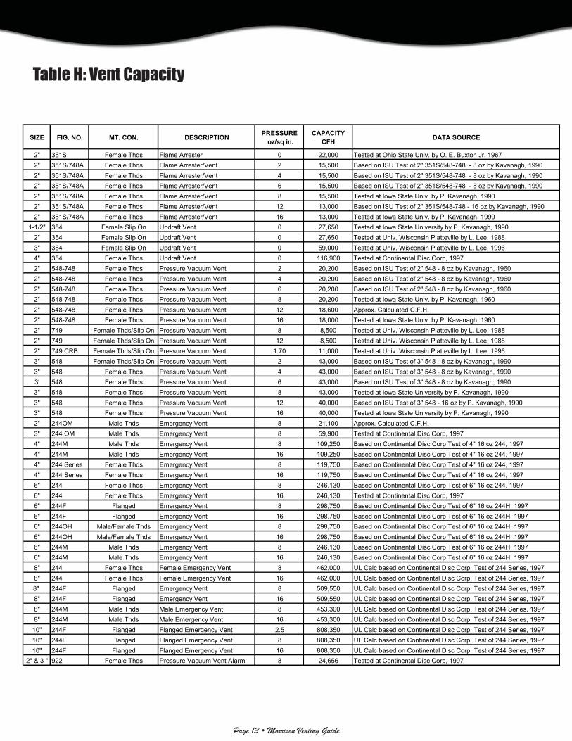
Table H: Vent Capacity
SIZE FIG. NO. MT. CON. DESCRIPTION PRESSURE oz/sq in.
CAPACITYCFH DATA SOURCE
2" 351S Female Thds Flame Arrester 0 22,000 Tested at Ohio State Univ. by O. E. Buxton Jr. 19672" 351S/748A Female Thds Flame Arrester/Vent 2 15,500 Based on ISU Test of 2" 351S/548-748 - 8 oz by Kavanagh, 19902" 351S/748A Female Thds Flame Arrester/Vent 4 15,500 Based on ISU Test of 2" 351S/548-748 - 8 oz by Kavanagh, 19902" 351S/748A Female Thds Flame Arrester/Vent 6 15,500 Based on ISU Test of 2" 351S/548-748 - 8 oz by Kavanagh, 19902" 351S/748A Female Thds Flame Arrester/Vent 8 15,500 Tested at Iowa State Univ. by P. Kavanagh, 19902" 351S/748A Female Thds Flame Arrester/Vent 12 13,000 Based on ISU Test of 2" 351S/548-748 - 16 oz by Kavanagh, 19902" 351S/748A Female Thds Flame Arrester/Vent 16 13,000 Tested at Iowa State Univ. by P. Kavanagh, 1990
1-1/2" 354 Female Slip On Updraft Vent 0 27,650 Tested at Iowa State University by P. Kavanagh, 19902" 354 Female Slip On Updraft Vent 0 27,650 Tested at Univ. Wisconsin Platteville by L. Lee, 19883" 354 Female Slip On Updraft Vent 0 59,000 Tested at Univ. Wisconsin Platteville by L. Lee, 19964" 354 Female Thds Updraft Vent 0 116,900 Tested at Continental Disc Corp, 19972" 548-748 Female Thds Pressure Vacuum Vent 2 20,200 Based on ISU Test of 2" 548 - 8 oz by Kavanagh, 19602" 548-748 Female Thds Pressure Vacuum Vent 4 20,200 Based on ISU Test of 2" 548 - 8 oz by Kavanagh, 19602" 548-748 Female Thds Pressure Vacuum Vent 6 20,200 Based on ISU Test of 2" 548 - 8 oz by Kavanagh, 19602" 548-748 Female Thds Pressure Vacuum Vent 8 20,200 Tested at Iowa State Univ. by P. Kavanagh, 19602" 548-748 Female Thds Pressure Vacuum Vent 12 18,600 Approx. Calculated C.F.H.2" 548-748 Female Thds Pressure Vacuum Vent 16 18,000 Tested at Iowa State Univ. by P. Kavanagh, 19602" 749 Female Thds/Slip On Pressure Vacuum Vent 8 8,500 Tested at Univ. Wisconsin Platteville by L. Lee, 19882" 749 Female Thds/Slip On Pressure Vacuum Vent 12 8,500 Tested at Univ. Wisconsin Platteville by L. Lee, 19882" 749 CRB Female Thds/Slip On Pressure Vacuum Vent 1.70 11,000 Tested at Univ. Wisconsin Platteville by L. Lee, 19963" 548 Female Thds/Slip On Pressure Vacuum Vent 2 43,000 Based on ISU Test of 3" 548 - 8 oz by Kavanagh, 19903" 548 Female Thds Pressure Vacuum Vent 4 43,000 Based on ISU Test of 3" 548 - 8 oz by Kavanagh, 19903' 548 Female Thds Pressure Vacuum Vent 6 43,000 Based on ISU Test of 3" 548 - 8 oz by Kavanagh, 19903" 548 Female Thds Pressure Vacuum Vent 8 43,000 Tested at Iowa State University by P. Kavanagh, 19903" 548 Female Thds Pressure Vacuum Vent 12 40,000 Based on ISU Test of 3" 548 - 16 oz by P. Kavanagh, 19903" 548 Female Thds Pressure Vacuum Vent 16 40,000 Tested at Iowa State University by P. Kavanagh, 19902" 244OM Male Thds Emergency Vent 8 21,100 Approx. Calculated C.F.H.3" 244 OM Male Thds Emergency Vent 8 59,900 Tested at Continental Disc Corp, 19974" 244M Male Thds Emergency Vent 8 109,250 Based on Continental Disc Corp Test of 4" 16 oz 244, 19974" 244M Male Thds Emergency Vent 16 109,250 Based on Continental Disc Corp Test of 4" 16 oz 244, 19974" 244 Series Female Thds Emergency Vent 8 119,750 Based on Continental Disc Corp Test of 4" 16 oz 244, 19974" 244 Series Female Thds Emergency Vent 16 119,750 Based on Continental Disc Corp Test of 4" 16 oz 244, 19976" 244 Female Thds Emergency Vent 8 246,130 Based on Continental Disc Corp Test of 6" 16 oz 244, 19976" 244 Female Thds Emergency Vent 16 246,130 Tested at Continental Disc Corp, 19976" 244F Flanged Emergency Vent 8 298,750 Based on Continental Disc Corp Test of 6" 16 oz 244H, 19976" 244F Flanged Emergency Vent 16 298,750 Based on Continental Disc Corp Test of 6" 16 oz 244H, 19976" 244OH Male/Female Thds Emergency Vent 8 298,750 Based on Continental Disc Corp Test of 6" 16 oz 244H, 19976" 244OH Male/Female Thds Emergency Vent 16 298,750 Based on Continental Disc Corp Test of 6" 16 oz 244H, 19976" 244M Male Thds Emergency Vent 8 246,130 Based on Continental Disc Corp Test of 6" 16 oz 244H, 19976" 244M Male Thds Emergency Vent 16 246,130 Based on Continental Disc Corp Test of 6" 16 oz 244H, 19978" 244 Female Thds Female Emergency Vent 8 462,000 UL Calc based on Continental Disc Corp. Test of 244 Series, 19978" 244 Female Thds Female Emergency Vent 16 462,000 UL Calc based on Continental Disc Corp. Test of 244 Series, 19978" 244F Flanged Emergency Vent 8 509,550 UL Calc based on Continental Disc Corp. Test of 244 Series, 19978" 244F Flanged Emergency Vent 16 509,550 UL Calc based on Continental Disc Corp. Test of 244 Series, 19978" 244M Male Thds Male Emergency Vent 8 453,300 UL Calc based on Continental Disc Corp. Test of 244 Series, 19978" 244M Male Thds Male Emergency Vent 16 453,300 UL Calc based on Continental Disc Corp. Test of 244 Series, 199710" 244F Flanged Flanged Emergency Vent 2.5 808,350 UL Calc based on Continental Disc Corp. Test of 244 Series, 199710" 244F Flanged Flanged Emergency Vent 8 808,350 UL Calc based on Continental Disc Corp. Test of 244 Series, 199710" 244F Flanged Flanged Emergency Vent 16 808,350 UL Calc based on Continental Disc Corp. Test of 244 Series, 1997
2" & 3 " 922 Female Thds Pressure Vacuum Vent Alarm 8 24,656 Tested at Continental Disc Corp, 1997
Page 14 • Morrison Venting Guide
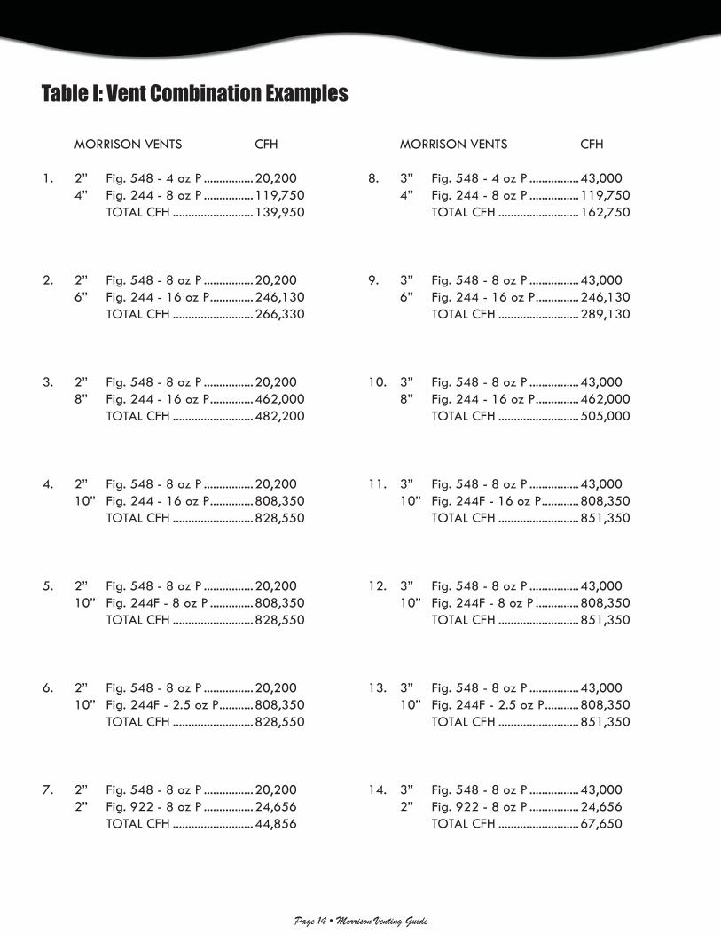
Table I: Vent Combination Examples
MORRISON VENTS CFH
1. 2” Fig. 548 - 4 oz P ................20,200 4” Fig. 244 - 8 oz P ................119,750 TOTAL CFH ..........................139,950
2. 2” Fig. 548 - 8 oz P ................20,200 6” Fig. 244 - 16 oz P ..............246,130 TOTAL CFH ..........................266,330
3. 2” Fig. 548 - 8 oz P ................20,200 8” Fig. 244 - 16 oz P ..............462,000 TOTAL CFH ..........................482,200
4. 2” Fig. 548 - 8 oz P ................20,200 10” Fig. 244 - 16 oz P ..............808,350 TOTAL CFH ..........................828,550
5. 2” Fig. 548 - 8 oz P ................20,200 10” Fig. 244F - 8 oz P ..............808,350 TOTAL CFH ..........................828,550
6. 2” Fig. 548 - 8 oz P ................20,200 10” Fig. 244F - 2.5 oz P ...........808,350 TOTAL CFH ..........................828,550
7. 2” Fig. 548 - 8 oz P ................20,200 2” Fig. 922 - 8 oz P ................24,656 TOTAL CFH ..........................44,856
MORRISON VENTS CFH
8. 3” Fig. 548 - 4 oz P ................43,000 4” Fig. 244 - 8 oz P ................119,750 TOTAL CFH ..........................162,750
9. 3” Fig. 548 - 8 oz P ................43,000 6” Fig. 244 - 16 oz P ..............246,130 TOTAL CFH ..........................289,130
10. 3” Fig. 548 - 8 oz P ................43,000 8” Fig. 244 - 16 oz P ..............462,000 TOTAL CFH ..........................505,000
11. 3” Fig. 548 - 8 oz P ................43,000 10” Fig. 244F - 16 oz P ............808,350 TOTAL CFH ..........................851,350
12. 3” Fig. 548 - 8 oz P ................43,000 10” Fig. 244F - 8 oz P ..............808,350 TOTAL CFH ..........................851,350
13. 3” Fig. 548 - 8 oz P ................43,000 10” Fig. 244F - 2.5 oz P ...........808,350 TOTAL CFH ..........................851,350
14. 3” Fig. 548 - 8 oz P ................43,000 2” Fig. 922 - 8 oz P ................24,656 TOTAL CFH ..........................67,650

Page 15 • Morrison Venting Guide
Emergency VentEmergency vent (pressure relief only) used on aboveground storage tanks, as a code require-ment that helps prevent the tanks from becoming over-pressurized and rupturing if exposed to fi re. UL listed except for 2".
DescriptionThe 244 emergency vent consists of a body and a black powder coated cover (2" not powder coated) that moves up and down on a center pin. Pressure inside the tank forces the cover to lift up off the vent seat, allowing air to exhaust. The center pin guides the movement. When pressure falls the cover lowers back down onto seat and the vent is automatically reset.
Code ComplianceWhen properly sized for the tank, this vent will conform to the requirements of NFPA 30, 30A, UL 142, UL 2244, API 2000, and PEI RP200.
Material and Confi guration OptionsAluminum Body or Iron Body…suffi x (I) indicates iron.
Metal-to-Metal Seat (brass) or Soft Seat (Viton®)…suffi x (O) indicates o-ring.
Male/Female NPT/BSP or Flanged Mounting Connection…suffi x (M) indicates male, and suffi x (F) indicates fl anged.
Opening Pressure Setting…settings indicated are approximate.
T=Tall Body...8" only order for use on tite wrapped tanks.
Opening Pressure Ship Venting MountingFig. No. Size Setting Weight Capacity Connection (oz/sq in) (lbs) (*Estimated CFH @ 2.5 PSI)244 &244O 4" 8.0 10.65 119,750 Female NPT/BSP 16.0 21.00 119,750 Female NPT 6" 8.0 15.50 246,130 Female NPT/BSP 16.0 33.15 246,130 Female NPT 8" 8.0 34.70 462,000 Female NPT 16.0 68.00 462,000 Female NPT244F&244OF 6" 8.0 24.8 298,750 Flanged 16.0 44.2 298,750 Flanged 8" 8.0 42.00 509,550 Flanged 16.0 75.00 509,550 Flanged 10" 2.5 32.00 808,350 Flanged 8.0 71.00 808,350 Flanged 16.0 125.00 808,350 Flanged
244M & (2" and 3" OM only)244OM 2" 8.0 1.0 21,100* Male NPT/BSP 3" 8.0 5.75 59,900 Male NPT/BSP 4" 8.0 11.55 119,750 Male NPT 16.0 21.25 119,750 Male NPT/BSP 6" 8.0 19.45 246,130 Male NPT 16.0 35.00 246,130 Male NPT/BSP 8" 8.0 34.00 453,300 Male NPT 16.0 68.00 453,300 Male NPT
244OH 6" 8.0 21.50 298,750 Female NPT 16.0 41.40 298,750 Female NPT
244OMH 6" 8.0 23.00 298,750 Male NPT 16.0 42.9 298,750 Male NPT
Opening Pressure Ship Venting MountingFig. No. Size Setting Weight Capacity Connection (oz/sq in) (lbs) (*Estimated CFH @ 2.5 PSI)244OI 4" 8.0 13.65 119,750 Female NPT 16.0 24.00 119,750 Female NPT 6" 8.0 20.63 246,130 Female NPT 16.0 38.28 246,130 Female NPT 8" 8.0 44.33 462,000 Female NPT 16.0 77.63 462,000 Female NPT
244OMI (3" OMI only) 3" 8.0 8.00 59,900 Male NPT 4" 8.0 16.36 119,750 Male NPT 16.0 26.06 119,750 Male NPT 6" 8.0 27.76 246,130 Male NPT 16.0 43.31 246,130 Male NPT 8" 8.0 34.63 453,300 Male NPT 16.0 75.36 453,300 Male NPT
244OMT 8" 8.0 40.5 453,300 Male NPT 16.00 71.5 453,300 Male NPT
Fig.244 Fig.244FFig.244M
WARNING...The 244 emergency vent must be properly sized and selected for each specifi c tank application in order to meet the
proper “venting capacity” requirements. See the Morrison Vent Guide for further instructions.
WARNING...The 244 emergency vent is for “emergency pressure relief only” and must be used in conjunction with
a “normal vent” or pressure vacuum vent such as a Morrison Fig. 354, 548, 748 or 749.
Use 16 oz. o-ring to comply with pressure decay test. Contact factory for assistance.
Emergency vent should be set higher than the normal vent so the normal vent operates fi rst.
244 Series244 Series
WARNING…Do not fi ll or unload fuel from a storage tank unless it is certain that the tank vents will operate properly. Morrison tank vents are designed only for use on shop fabricated atmospheric tanks which have been built and tested in accordance with UL 142, NFPA 30 & 30A, and API 650 and in accordance with all applicable local, state and federal laws. In normal operation, dust and debris can accumulate in vent openings and block air passages. Certain atmospheric conditions such as a sudden drop in temperature, below freezing temperatures, and freezing rain can cause moisture to enter the vent and freeze which can restrict internal movement of vent mechanisms and block air passages. All storage tank vent air passages must be completely free of restriction and all vent mechanisms must have free movement in order to insure proper operation. Any restriction of airfl ow can cause excessive pressure or vacuum to build up in the storage tank, which can result in struc-tural damage to the tank, fuel spillage, property damage, fi re, injury, and death. Monthly inspection, and immediate inspection during freezing conditions, by someone familiar with the proper operation of storage tank vents, is required to insure venting devices are functioning properly before fi lling or unloading a tank. Normal vents such as pressure vacuum and updraft vents for aboveground storage tanks should be sized according to NFPA 30 (2008) 21.4.3

Page 16 • Morrison Venting Guide
244A244A
Fig. 244C
Flanged AdaptorThe 244A can be used with either Fig. 244F or Fig. 143A.
Construction DetailsCarbon steel welded rim and skirt.
Pipe NippleAvailable (T.O.E.) Threaded One End or (T.B.E.) Thread-ed Both Ends.
Construction DetailsCarbon steel —NPT
Fig. 244N
Construction DetailsCast iron with NPT “center port” I.D.
Companion FlangeThe 244C can be used with either Fig. 244F or Fig. 143A.
Size Weight6" (eight 7/8" holes on 9½" B.C.) 12.0 lbs8" (eight 7/8" holes on 11¾" B.C.) 19.0 lbs10" (twelve 1" holes on 14¼" B.C.) 20.0 lbs
Size Weight4" x 8" 7.00 lbs6" x 8" 13.0 lbs8" x 8" 20.0 lbs8" x 12" 28.0 lbs
244C244C
244N244N
Size Weight8" (eight 7/8" holes on 11¾" B.C. w/8" NPT I.D.) 27.0 lbs10" (twelve 1" holes on 14¼" B.C. w/10" NPT I.D.) 36.0 lbs

Page 17 • Morrison Venting Guide
Fig. 748ALT
Construction DetailsFig. 548…brass body and hood Brass (raised) metal-to-metal seats/poppets. Fig. 548A…aluminum body and hood. Brass (raised) metal-to-metal seats/poppets. 2" available with British Pipe Threads.
Standard Features1. Threaded gauge hatch for manual gauging access.2. Horizontal discharge with fi eld-adjustable, tripolar
orientation.
Pressure Vacuum Ship Venting Setting Setting Weight Capacity (oz/sq in) (oz/sq in) (lbs) (CFH) (@ 2.5 PSI) 8.0 1.0 5.5 20,200 16.0 1.0 5.5 18,000 32.0 1.0 5.5 NA
Pressure/Vacuum VentFor “normal” venting of aboveg-round storage tanks. Allows tank to “breathe” during fi lling and discharging operations. Pressure/vacuum poppets seal vapors in the tank when pressure is equalized. This vent must be used in conjunction with an emergency vent and it is RECOMMENDED that the opening pressure setting is set below that of the emergency vent so the normal vent operates fi rst. Settings are approximate.
Construction DetailsBrass (raised) metal-to-metal seats/poppets; Aluminum body and hood.
Standard Features1. Horizontal discharge with fi eld-adjustable, tripolar orienta-
tion.2. Optional pressure discharge NPT hood.
Fig. 748A Venting Pressure Vacuum Ship Capacity Size Setting Setting Weight (CFH) (oz/sq in) (oz/sq in) (lbs) (@2.5 PSI) 2" 2.0 1.0 6.75 20,200 4.0 1.0 7.5 20,200 6.0 1.0 8.25 20,200 8.0 1.0 9.25 20,200 12.0 1.0 10.50 18,600 16.0 1.0 11.00 18,600
Size…2" NPTBody and Cap…aluminumPoppets…Tefl on® coated aluminumScreens…stainless steel
Option (must specify)…male NPT connection for dryer applicationOption…pressure discharge NPT hood
Construction Details
Pressure-Vacuum VentFor Ag-Chemical…vent valve used with aqua-ammonia and ag-chemical products allowing tank to “breathe” during fi lling/discharging operations. Poppets seal vapors in the tank when pressure is equalized. Settings are approximate.
Pressure/Vaccum Emergency Vents
Fig. 548 Fig. 548A Venting Pressure Vacuum Ship Ship Capacity
Size Setting Setting Weight Weight (CFH) (oz/sq in) (oz/sq in) (lbs) (lbs) (@2.5 PSI)
2" 2.0 1.0 13.25 7.00 20,200 4.0 1.0 13.75 8.75 20,200 6.0 1.0 14.25 8.50 20,200 8.0 1.0 14.75 9.50 20,200 12.0 1.0 15.75 10.50 18,600 16.0 1.0 17.00 11.25 18,600
3" 2.0 1.0 26.25 12.25 43,000 4.0 1.0 27.25 13.75 43,000 6.0 1.0 28.25 15.00 43,000 8.0 1.0 28.75 15.75 43,000 12.0 1.0 29.25 15.75 40,000 16.0 1.0 33.25 20.50 40,000
Fig. 748
Pressure/Vacuum VentWith Gauge Hatch…for “normal” venting of aboveg-round storage tanks. Allows tank to “breathe” during fi lling and discharging operations. Pressure/vacuum poppets seal vapors in the tank when pres-sure is equalized. This vent must be used in conjunction with an emergency vent and it is RECOMMENDED that the opening pressure setting is set below that of the emergency vent so the normal vent operates fi rst. Settings are approximate.
548 Series548 Series 748A Series748A Series
748ALT748ALT
Fig. 548
WARNING…Do not fi ll or unload fuel from a storage tank unless it is certain that the tank vents will operate properly. Morrison tank vents are designed only for use on shop fabricated atmospheric tanks which have been built and tested in accordance with UL 142, NFPA 30 & 30A, and API 650 and in accordance with all applicable local, state and fed-eral laws. In normal operation, dust and debris can accumulate in vent openings and block air passages. Certain atmospheric conditions such as a sudden drop in temperature, below freezing temperatures, and freezing rain can cause moisture to enter the vent and freeze which can restrict internal movement of vent mechanisms and block air passages. All storage tank vent air passages must be completely free of restric-tion and all vent mechanisms must have free movement in order to insure proper operation. Any restriction of airfl ow can cause excessive pressure or vacuum to build up in the storage tank, which can result in structural damage to the tank, fuel spillage, property damage, fi re, in-jury, and death. Monthly inspection, and immediate inspection during freezing conditions, by someone familiar with the proper operation of storage tank vents, is required to insure venting devices are function-ing properly before fi lling or unloading a tank.
Normal vents such as pressure vacuum and updraft vents for aboveg-round storage tanks should be sized according to NFPA 30 (2008) 21.4.3

Page 18 • Morrison Venting Guide
Pressure Vacuum Ship VentingFig. No. Setting Setting Weight Capacity (oz/in2) (oz/in2) (lbs) (CFH) (@ 2.5 PSI)
749 8.0 0.5 1.0 8,500749S 12.0 0.5 1.0 8,500
749CRB 3"W.C. 8" W.C. 1.45 11,000 749CRBS 8 oz 5 oz 1.45
749BSP 8.0 0.5 1.0 8,500 12.0 0.5 1.0 8,500
Pressure/Vacuum VentVent valve used on underground and low volume aboveground tanks for motor fueling. Vent allows tank to “breathe” during fi lling and discharging operations. Poppets seal vapors in the tanks when pressure is equalized. Settings are approximate.
Fig. 749…2" NPTFig. 749S…2" slip-on styleFig. 749CRB…2" NPT CARB approval (95-15A) for stage I and II (8 oz for stage I only).Viton® o-rings on pressure poppet. Fig. 749CRBS…2" slip-on style CARB approval (95-15A) for stage I and II (8 oz for stage I only). Viton® o-rings on pressure poppet.Fig. 749BSP…same as Fig. 749, but with British pipe threads.
Fig. 749
WARNING…Fig. 749 P/V vent must only be used in conjunction with motor fueling and/or low capacity fl ow. Fluid handling in lines larger than that used for retail service stations
can cause tank to rupture or implode.
Construction DetailsBody…aluminumPressure Poppet…aluminumVacuum Poppet…brassPipe Seal…Buna-NScreen…brass
Combination Vent/Overfi ll AlarmThe Fig. 922 Combination Vent/Overfi ll Alarm is a fully mechanical, high intensity audible alarm that alerts you when your tank is near full while also allowing your tank to breathe during fi lling and dispensing operations. The unit is equipped with a whistle which incorporates a 2” or 3” full port pressure/vacuum vent. The unit can be set to activate at 90% fi ll height by adjusting the cable length to the fl oat device. The adjustment tool is provided. The unit attaches to a 2” or 3” N.P.T. pipe mounted on the tank. Minimum fi ll rate for alarm to operate is 20 GPM.
2” Pressure relief setting ...... 6 oz/in2 or 8 oz/in2
2” Vacuum relief setting ...... 1 oz/in2
2” Venting capacity (CFH) ... 30,120 or 30,300
2” Weight ................................ 7.5 lbs
Construction DetailsBody…anodized aluminumScreens…stainless steelRainguard…anodized aluminumSeals…Viton®
Ball…Tefl onFloat…stainless steel
NOTE…922 not for use on vapor recovery systems.
749 Series749 Series
922922
3” Pressure relief setting ...... 6 oz/in2 or 8 oz/in2
3” Vacuum relief setting ...... 1 oz/in2
3” Venting capacity (CFH) ... 43,020 or 44,160
3” Weight ................................ 5.25 lbs
Fig. 922
WARNING…Do not fi ll or unload fuel from a storage tank unless it is certain that the tank vents will operate properly. Morrison tank vents are designed only for use on shop fabricated atmospheric tanks which have been built and tested in accordance with UL 142, NFPA 30 & 30A, and API 650 and in accordance with all applicable local, state and federal laws. In normal operation, dust and debris can accumulate in vent openings and block air passages. Certain atmospheric conditions such as a sudden drop in temperature, below freezing temperatures, and freezing rain can cause moisture to enter the vent and freeze which can restrict internal movement of vent mechanisms and block air passages. All storage tank vent air passages must be completely free of restriction and all vent mechanisms must have free movement in order to insure proper operation. Any restriction of airfl ow can cause excessive pressure or vacuum to build up in the storage tank, which can result in struc-tural damage to the tank, fuel spillage, property damage, fi re, injury, and death. Monthly inspection, and immediate inspection during freezing conditions, by someone familiar with the proper operation of storage tank vents, is required to insure venting devices are functioning properly before fi lling or unloading a tank. Normal vents such as pressure vacuum and updraft vents for aboveground storage tanks should be sized according to NFPA 30 (2008) 21.4.3
WARNING…In order for the Fig. 922 to function properly all emergency vents, fi ll connections, tank openings and piping connections must be airtight. Emergency vent should be set at least 2 oz. higher than the Fig. 922.

Page 19 • Morrison Venting Guide
351S & 748A351S & 748AFlame ArresterOpen (non-pressure vacuum type) fl ame arrester to help prevent the transmission of heat and/or an ignition source into the tank.
Construction DetailsBody…cast ironCover…cast ironCap…brassArrester Plates…stainless steel
Standard Features1. Gauge opening cap.2. Vapor relief capacity at 2.5
PSI = 22,000 CFH
Restrictions and Warning1. Do not use with acetylene, carbon disulfi de, etheleneoxide
or hydrogen gases. For use with normal hydrocarbon fl ames such as gasoline in air.
2. Routine inspection is required to ensure airways are clear and free of debris. Blocked airways can cause structural deformation of the tank.
Fig. 351S Flame ArresterWith 748A Vent…pres-sure vacuum type fl ame arrester to help prevent the transmission of heat and/or an ignition source into the tank.
Fig. 748A…same vent featured in pressure/vac-uum vent section.
Construction DetailsFig.351S…Flame arresterFig. 748A…Pressure/vacuum vent
Ship Venting Size Weight Capacity (slip-on) (lbs) (CFH) 1½"* 0.75 27,650 2"* 0.75 27,650 3" 1.50 59,000 4" 2.25 116,900
Fig. 351S w/748A
WARNING…Do not fi ll or unload fuel from a storage tank unless it is certain that the tank vents will operate properly. Morrison tank vents are designed only for use on shop fabricated atmospheric tanks which have been built and tested in accordance with UL 142, NFPA 30 & 30A, and API 650 and in accordance with all applicable local, state and federal laws. In normal operation, dust and debris can accumulate in vent openings and block air passages. Certain atmospheric conditions such as a sudden drop in temperature, below freezing temperatures, and freezing rain can cause moisture to enter the vent and freeze which can restrict internal movement of vent mechanisms and block air passages. All storage tank vent air passages must be completely free of restriction and all vent mechanisms must have free movement in order to insure proper operation. Any restriction of airfl ow can cause excessive pressure or vacuum to build up in the storage tank, which can result in struc-tural damage to the tank, fuel spillage, property damage, fi re, injury, and death. Monthly inspection, and immediate inspection during freezing conditions, by someone familiar with the proper operation of storage tank vents, is required to insure venting devices are functioning properly before fi lling or unloading a tank. Normal vents such as pressure vacuum and updraft vents for aboveground storage tanks should be sized according to NFPA 30 (2008) 21.4.3
Updraft Vent“Open” vent used on underground and aboveg-round tanks for motor fueling. Vent allows tank to “breathe” during fi lling/dispensing operations.
Construction DetailsBody…aluminumCap…aluminumScreen…40 mesh brass
Fig. 748 Venting Pressure Vacuum Ship Capacity Size Setting Setting Weight (CFH) (oz/sq in) (oz/sq in) (lbs) (@2.5 PSI) 2" 2.0 1.0 42.00 15,500 4.0 1.0 42.50 15,500 6.0 1.0 42.75 15,500 8.0 1.0 43.50 15,500 12.0 1.0 44.50 13,000 16.0 1.0 45.75 13,000
DoubleOutlet VentAluminum T-style vent used primarily on small fuel oil storage tanks. Outlet ports on either side of the inlet with 20 mesh stain-less steel screen keeps debris out of the airway.
Fig. 155…threaded (NPT)
Fig. 155BSP…2" with British Pipe Threads
Fig. 155FA…2" with fl ash arrestor
Fig. 155S…slip-on
NOTE…Open vents will allow unrestricted evaporation of product.
Fig. 354
Size Weight¾" .25 lbs1" .50 lbs1¼" .50 lbs1½" .75 lbs2" 1.0 lbs3" 2.5 lbs
Size Weight2" NPT 31.0 lbs
Fig. 155S
351S351S
354354 155S155S
NOTE…Open vents will allow unrestricted evaporation of product.
Page 20 • Morrison Venting Guide
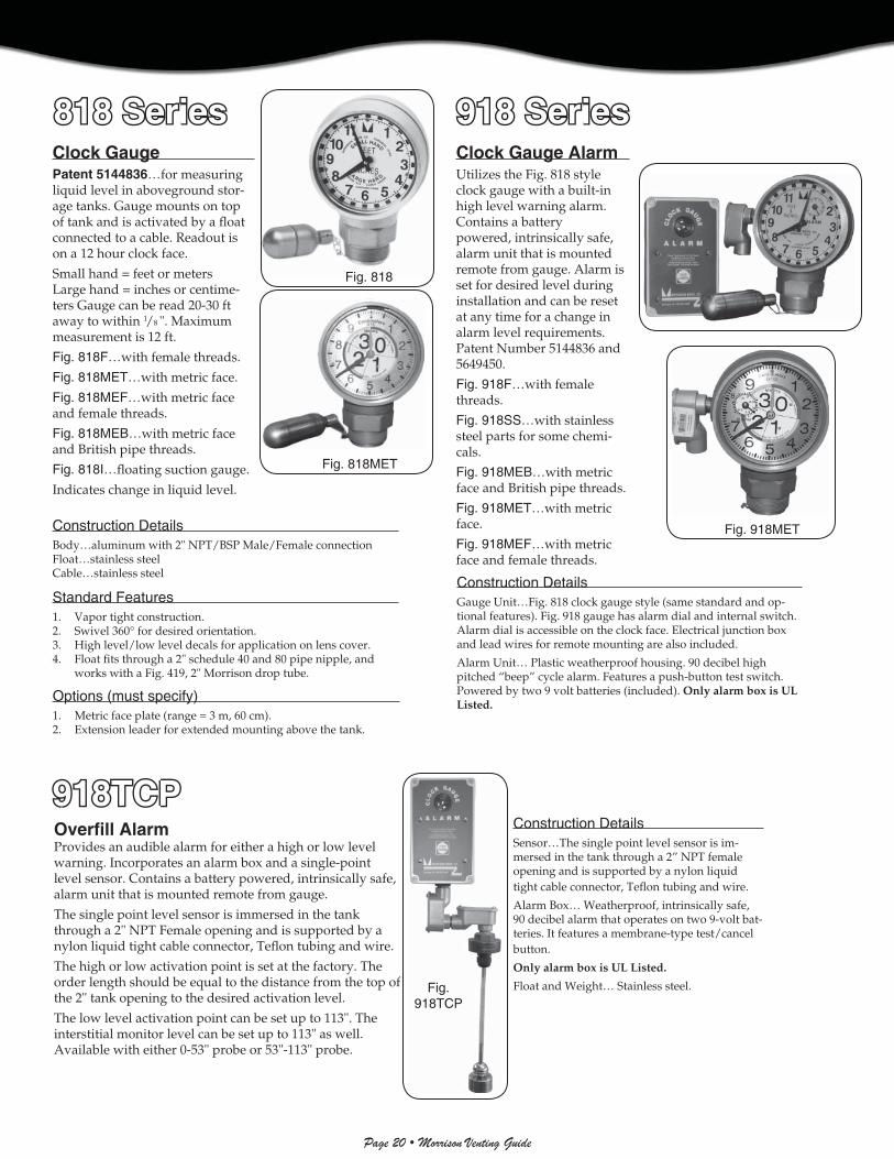
Clock Gauge AlarmUtilizes the Fig. 818 style clock gauge with a built-in high level warning alarm. Contains a battery powered, intrinsically safe, alarm unit that is mounted remote from gauge. Alarm is set for desired level during installation and can be reset at any time for a change in alarm level requirements. Patent Number 5144836 and 5649450.
Fig. 918F…with female threads.
Fig. 918SS…with stainless steel parts for some chemi-cals.
Fig. 918MEB…with metric face and British pipe threads.
Fig. 918MET…with metric face.
Fig. 918MEF…with metric face and female threads.
Construction DetailsGauge Unit…Fig. 818 clock gauge style (same standard and op-tional features). Fig. 918 gauge has alarm dial and internal switch. Alarm dial is accessible on the clock face. Electrical junction box and lead wires for remote mounting are also included.
Alarm Unit… Plastic weatherproof housing. 90 decibel high pitched “beep” cycle alarm. Features a push-button test switch. Powered by two 9 volt batteries (included). Only alarm box is UL Listed.
Construction DetailsBody…aluminum with 2" NPT/BSP Male/Female connectionFloat…stainless steelCable…stainless steel
Standard Features1. Vapor tight construction.2. Swivel 360° for desired orientation.3. High level/low level decals for application on lens cover.4. Float fi ts through a 2" schedule 40 and 80 pipe nipple, and
works with a Fig. 419, 2" Morrison drop tube.
Options (must specify)1. Metric face plate (range = 3 m, 60 cm).2. Extension leader for extended mounting above the tank.
Fig. 818
Clock GaugePatent 5144836…for measuring liquid level in aboveground stor-age tanks. Gauge mounts on top of tank and is activated by a fl oat connected to a cable. Readout is on a 12 hour clock face.
Small hand = feet or meters Large hand = inches or centime-ters Gauge can be read 20-30 ft away to within 1/8 ". Maximum measurement is 12 ft.
Fig. 818F…with female threads.
Fig. 818MET…with metric face.
Fig. 818MEF…with metric face and female threads.
Fig. 818MEB…with metric face and British pipe threads.
Fig. 818I…fl oating suction gauge.
Indicates change in liquid level.
Fig. 918
Overfi ll AlarmProvides an audible alarm for either a high or low level warning. Incorporates an alarm box and a single-point level sensor. Contains a battery powered, intrinsically safe, alarm unit that is mounted remote from gauge.
The single point level sensor is immersed in the tank through a 2" NPT Female opening and is supported by a nylon liquid tight cable connector, Tefl on tubing and wire.
The high or low activation point is set at the factory. The order length should be equal to the distance from the top of the 2" tank opening to the desired activation level.
The low level activation point can be set up to 113". The interstitial monitor level can be set up to 113" as well. Available with either 0-53" probe or 53"-113" probe.
Fig. 818MET
Construction DetailsSensor…The single point level sensor is im-mersed in the tank through a 2” NPT female opening and is supported by a nylon liquid tight cable connector, Tefl on tubing and wire.
Alarm Box… Weatherproof, intrinsically safe, 90 decibel alarm that operates on two 9-volt bat-teries. It features a membrane-type test/cancel button.
Only alarm box is UL Listed.
Float and Weight… Stainless steel.
Fig. 918MET
Fig. 918TCP
818 Series818 Series 918 Series918 Series
918TCP918TCP

Page 21 • Morrison Venting Guide
Overfi ll Prevention Valve forUsed Oil SystemsPatent 5007450…valve with optional alarm for use on used oil evacuation systems which use an air operated pump.
Operation1. Valve installs in 2" bung opening at the top
of the tank. Air supply is routed through the valve before going to the pump.
2. The valve will close off air supply to the pump when liquid level reaches 90% of tank capacity. Air is diverted to the audible signal on models FMMASO-91S and FMMASO-91EXS.
3. The valve will reset as liquid is removed from the tank and air pressure to the valve is turned off.
Specifi cationsValve Body and Collar…anodized aluminumFloat…polypropyleneFloat Rod and Valve Spool…brassO-ring seals…Viton®
Hardware… stainless and plated steel
Installation Collar…2" NPTAir inlet and outlet…¼" NPTOverall length (including fl oat and audible sig-nal)…20"Shipping weight…2.0 lbsShipping weight (Fig. FMMASO-91EX)…4.5 lbs
ModelsFig. (FMMASO-91)…standard valve without audible signal.Fig. (FMMASO-91S)…standard valve with audible signal. BSP Part Num-ber FMMASOB-91S.Fig. (FMMASO-91EX)…same as Fig. FMMASO-91, but with extended body for use on double wall or vaulted tanks.Fig. (FMMASO-91EXS)…same as Fig. FMMASO-91EX, but with audible signal.Fig. (FMMATO-91)…high level turn-on for sump applications (no signal).
Fig. FMMASO-91S
Simplex Tank GaugeUsed for measuring liquid level in aboveground storage tanks. Best suited for vertical tanks over 12 ft high. Gauge readout by tape which passes over an indicator mounted at 3 ft height on the side of the tank. Activated mechanically by a fl oat that rests on the liquid level. Float is connected to a cable that runs up through the top of the tank, across two pulleys, and down the side of the tank to the indicator position.
Construction DetailsTape sizes available: tape for up to 31' tank and tape for 31' to 50' tank
Standard Features1. Round copper fl oat2. Tape3. Stainless steel cable4. Vapor seal
Options (must specify)1. Round stainless steel fl oat with swivel (101/8 " diameter).2. Brass cylindrical fl oat (1¾" diameter, 32" long) with center
swivel.3. Stainless steel cylindrical fl oat (1¾" diameter, 32" long) with
center swivel.4. Metric not available.
NOTE…Cylindrical fl oats will pass through a 2" opening.
NOTE…Installation instructions are included, piping is not included.
FMMASO-91 SeriesFMMASO-91 Series
618618

Page 22 • Morrison Venting Guide
Fig. 9095A
AST Overfi ll Prevention ValvePatent 5832953…installed at the fi ll port of an aboveground storage tank. Used in a tight fi ll application, the valve terminates fl ow of product when the liquid level reaches a preset warning level (90-95% full). The valve is installed on a standard NPT male connection when used with the quick disconnect or female adaptor. The 2" valve can be used in conjunc-tion with the Morrison Fig. 518 and 515 lines of AST spill containers for added spill protection. When installed to manufacturers requirements, the OPV valve can help eliminate environmen-tally hazardous spills. All models are supplied with an adaptor to mount to Morrison Fig. 419 aluminum drop tubes. A test mechanism is also sold separately. The test mechanism allows a technician to pull on the test line at any time during the fi lling process to actuate the fl oat and stop the fi ll. This allows a technician to verify the valve is working properly.ULC listed.
Fig 9095A-AV…compatible with aviation fuel
Construction DetailsAdaptor…aluminum (hard-coat anodized)Female adaptor…ductile ironBody…anodized aluminumPlunger and dashpot…brass or nickel platedShaft, linkages and hardware…stainless steelPiping…steel (epoxy coated)
Features1. Adjustable fl oat (1½")…for setting the precise level of
shutoff in the fi eld and allowing it to be done using standard length pipe nipples.
2. Immediate and cushioned shutoff…full fl ow up to within 1-2 seconds of closing and no abrupt kickback or jolt, or startling noise in the line when valve closes.
3. One piece adaptor/coupler casting…no extra seams and joints to leak when top portion is under pressure from closing.
4. Dry disconnect…after shut off product is allowed to automatically drain from the highest point so fi ll nozzle can be removed without spilling.
5. Simple mechanics…minimum moving parts. Shutoff is activated by basic hydraulic principle with no springs, levers or complicated sequence leading to closure.
Code ComplianceNFPA 30, 30A, UFC, BOCA, SBCCI/SFC and PEI RP200.
AST Overfi ll Prevention ValveDesigned for use on low profi le tanks that require a high level shut-off. The valve terminates the fi ll when the product reaches the preset level. The valve can be retrofi tted on existing tanks and fi ts into a 2” opening. A tight fi ll connection is required for operation.
Sold with either a 2" Part F Male Threaded Adap-tor or a 2" Part A Female Threaded Adaptor.
Typical fl ow rate is 53 GPM at 30 PSI.
Fig. 9095S
Size Weight2" valve w/2" male quick disconnect x 4" female threads* 14.1 lbs2" valve w/2" female threads x 4" female threads 14.1 lbs2" valve w/2" male quick disconnect remote fi ll adaptor 12.6 lbs2" valve w/3" male quick disconnect x 4" female threads 14.1 lbs2" valve w/3" female threads x 4" female threads 14.1 lbs3" valve w/3" male quick disconnect x 6" female threads* 29.0 lbs3" valve w/3" female threads x 6" female threads 38.0 lbs3" valve w/3" male quick disconnect remote fi ll adaptor 26.0 lbs*BSP Threads Available
NOTE…For use on clean product only. Not suitable for motor oil.
Size Maximum Pressure Maximum Flow Maximum Viscosity
2" 100PSI 125gpm 150 Centistokes
3" 100PSI 300gpm 60 Centistokes
Construction DetailsAdaptor…aluminum (hard-coat anodized)Body…anodized aluminumFloat...polypropylenePlunger and dashpot…brassUpper tube and fl oat guard...brassShut off mechanism...anodized aluminum
Features1. Adjustable fl oat…for setting the precise level of shutoff
in the fi eld. The vertical fl oat allows for installation in openings in proximity to the tank walls.
2. Immediate and cushioned shutoff…full fl ow up to within 1-2 seconds of closing and no abrupt kickback or jolt, or startling noise in the line when valve closes.
3. Dry disconnect…after shut off product is allowed to automatically drain from the highest point so fi ll nozzle can be removed without spilling.
4. Simple mechanics…minimum moving parts. Shutoff is activated by basic hydraulic principle with no springs, levers or complicated sequence leading to closure.
Size Maximum Maximum Pressure Viscosity
2" 100PSI 150 Centistokes
NOTE…For use on clean product only. Not suitable for motor oil.
9095A9095A
9095S9095S
NOTE…Cannot be installed in a drop tube.

Page 23 • Morrison Venting Guide
���������
Fig. 517
3½ Gallon AST Spill ContainerInstalled on aboveground storage tanks for the purpose of containing small spills and drips from the fi ll nozzle. 3½ gallon capacity. Steel construction. Lockable and white powder coated. ULC listed.
Fig. 517…spill containment. Male (NPT) x Male (NPT) connection.
Fig. 517F…spill containment. Female (NPT) x Female (NPT) connection.
Fig. 517WO…waste oil containment–Removable screen on inside of container so used fi lters, etc. can be allowed to drain. Male NPT riser connection.
7½ Gallon ASTSpill ContainerInstalled on aboveground storage tanks for the purpose of containing small spills and drips from the fi ll nozzle. 7½ gallon capacity. Lockable with drain valve and vented lid. Connects to 4" male (NPT) riser, and is white powder coated. Female NPT x Female NPT.
Fig. 518CC…same as 518 only with center tank mount opening.
Fig. 518M…2" or 4" Male.
Construction DetailsBody and lid (14 ga.)…steelDrain Valve…brassDrain O-ring…Viton®
AST Remote Spill ContainerFor use on aboveground storage tanks for the purpose of containing fuel spillage during remote tank fi lling opera-tions. 15 gallon capacity. 12 gauge steel construction. Lock-able lid, and powder coated white for durability. 1" NPT drain with locking ball valve included. Choice of one or two fi ll ports, 2", 3", 4" or combination. 2" bung for pump. Single column base is easily adjustable.
Fig. 515OEM…same as 515 but without the pedestal and no rear ports, with top fi ll openings and with 4, ½" weld taps on the back. The 515OEM is not ULC Listed.
Fig. 518
Fig. 515
Front SideBack(Single)
Back(Double)
Size Weight2" (517, 517F, and 517WO) 10.5 lbs4" (517, 517F, and 517WO) 11.0 lbs
Size Weight2" 20.0 lbs 4" 26.0 lbs
517 Series517 Series 518 Series518 Series
515 Series515 Series

Page 24 • Morrison Venting Guide
��������
����
��
�� �
����
� � �
��
��������
����
����
����
����
���������
����
����
�������
����� ��
!
������
"�������
#$������
��� ��
����� %
��&'�
�(���
���'
� ���
���
�'�
����
��� �
����
��
�����)%�
��������
$������)�
����)�
����
���'�
�����"�%
#��� �
�*��
�'�
����
� ��
�� ��
�����+)+
����
��
#,��-�((���
�'�
��������
./����
�-����(
.��� ���
�'�
�����)�)
0�)�
)���
$��
1���
'���
�*�$
���
23��
�$
�������
.��$
�4�5
�
�����)�+
#����
�6
��� ��
����
��
���'�
�5�'����� *������#�������-����������#����
��� ���
���� � �!� �����
�"�# $
����% ����
�!����
���! ��
����
�
���� �
���&�����'����(���
�)��&
�*��+�
��(��,
���-
��.�/0��1
�22�
��(���
$3�14+
�1�+
�152
��(��*
3�14+
�1�+
�12�
�
��������
7� �
#���� ��

Page 25 • Morrison Venting Guide
��������
����
��
�� �
��������
����
����
����
����
�
����� ��
����
����
��23����
����� %
��&'�
�(���
���'
� ���
��
�'�
����
��� �
����
��
������)�
����)�
����
���'�
�����"�%
#��� �
�*��
�'�
�����)�)
�0�)�)
���
$���1
���'
���
�*�$
����2
3���$
�������
.��$
�4�5
�
�����)�+�#�����
6��� ��
����
��
���'�
����
� ��
�� ��
������ � �
����6
��!�
���7
��
, ��
����
�
��������
1�����#$
�����
��� �
�
������%%
�0��%
%.�
�*�$
����2
3.�
�����$
��������
����
��
�� �
�/ ����������!
�����+ �
87�
��� �
8������
�'�
�������+
�,��
���
�'�
����� ��
&'�
�(���
����
�5�'����� *������#�������-����������#����
8��
��9
�����!��
����#������
"�# $
����
���% ����
�!�� !�����
��!
�! ���
����
�����+)+
����
��
#,��-�((���
�'�
���� �
���&�����'����(���
�)��&
�*��+�
��(��,
���-
��.�/0��1
�22�
��(���
$3�14+
�1�+
�152
��(��*
3�14+
�1�+
�12�
�
��������
7� �
#���� ��

Page 26 • Morrison Venting Guide
��������
����
��
�� �
����
� � �
��
��������
����
����
��
������
"���
����#$
�����
��� �
������ %
��&'�
�(���
���'
� ���
���
�'�
�����)%�
��������
$
��������
./����
�-����(
.��� ���
�'�
�������
.��$
�4�5
�
�5�'����� *������#�������-�#����� �#����
��� ���
���� � �!� �����
�"�# $
����% ����
�!��
�����
��!
����
�
���� �
���&�����'����(���
�)��&
�*��+�
��(��,
���-
��.�/0��1
�22�
��(���
$3�14+
�1�+
�152
��(��*
3�14+
�1�+
�12�
�
�������"
#����� ���$�
#���� ��
����� ��
���
5� �
���
����
��������
��
�� ��3�&'�
�(��������
��� �����
��

Page 27 • Morrison Venting Guide
�5�'�
���� *������#�������-�#����� �#����
8��
��9
�����,��
����:����;��
"�: $
�8��
��� �����!
�8��
������
�

Page 28 • Morrison Venting Guide
/ ��� ������� ������'�
�*���� ��8�� �%�%���������#���*�������������!�������������9� ��������!���"�����"�
0���#��#������������%���"������!�� ��!��%%����� �������!���� �� !�$����"��$����
0���� ��$���%%��%���!���%��#� ��7����%�% ����!<��� ����������� ������!� �� !���"�
����������(�.��� ����'�
��������'��2��,6$� ��� �1����(
9�����
9��1+1
9���5�
0���#����"����*$�����*���� 7���������� %��*����!��������% ������ �������!���� ��!�� ���"�� �����!� ���
0���#����"�������$��!�� �9��������% �� �9��!�# $!��# �9������ ���������$�7��� �����% �����!�# $!��#���� � �9�
���� ����� ��=;$���!�!�������9�!>
9�������3�!��� ��-���!�# $������0������
#�$��6�4� �������
9��4��
+��%�2�%12�%
/�! ����� -� !���7��= �7���� > ��$����"�/��%�����! ��$���
���$���
� ���? ��������$� 9$�� � ���
� ���? ����������9��0!����
9����� 9�����
9��1�� 9��+1���<�5��0
�#4�8����#������

Page 29 • Morrison Venting Guide
��������
����
��
�� �
����
�����
���������������&��
#����� �#����
���� �
���&�����'����(���
�)��&
�*��+�
��(��,
���-
��.�/0��1
�22�
��(���
$3��22
�11+
����
2�(��*
3�14+
�1�+
�12�
�
������
"�������
#$������
��� ��
����� %
��&'�
�(���
���'
� ���
���
�'�
�������
.��$
�4�5
�
��������
��� ��
����
����
����������
����
��
�� �
��������
����
��
�� �
�/ ����������!
�������"
#����� ���$�
#���� ��
�������+
�#2
� ���,
���
������)
.�((�
���
������)
.�((�
���
=8����>
=���
�� >
=6��
���������&� ���>
�����)��
�����
����
����
5� �
���
����
��������
��
������ � �
����6
��!�
���7
��
�����)%�
�0)%
���:���
;����
.���
� �
���0
��$
������)�
���
�)������
���'�
��������
7� �
#���� ��
�����)�+�#�����
6��� ��
����
��
���'�
�����"�%
#��� �
�*��
�'�
�����"�.
/6
$� �
��
1����
(����'�