
Guard-based Model Order Reduction for Switched Linear Systems
12
Guard-based Model Order Reduction for Switched Linear Systems Klaus J. Diepold, Rudy Eid Institute of Automatic Control, Technische Universit¨ at M¨ unchen Boltzmannstr. 15, 85748 Garching E-Mail: [email protected], [email protected] The principle of model order reduction (MOR) is well-known for enhancing the manageabil- ity of large-scale and complex systems. As hybrid dynamical systems are of rising spread and complexity, the application of MOR to such models is of high interest. However, a straight- forward applicability is nowadays limited and often of weak performance. In this article, a new performance-improving framework for the reduction of switched linear systems based on conventional MOR methods is presented. By introducing auxiliary systems for the switching signals (guards), the approximation of the transition dynamics between the subsystems can be conducted independently from their own dynamics. This offers a large flexibility in the reduc- tion parameters and methods to be employed in order to achieve a satisfactory overall system performance. The effectivity and suitability of the new approach is illustrated by two simulation examples. 1 Introduction Motivated by the rising complexity of engineered systems (e. g. flight control, manufacturing, transportation and product service systems), many modeling and control methods were devel- oped for handling large-scale and complex systems [7]. Hybrid dynamical formulations are widely used, as they enable an interconnection of continuous and discrete dynamics. In [2] for instance, a hybrid model of a common rail fuel injection system is presented. The fuel’s flow is considered as continuous dynamics while the dynamics of the injectors is modeled using discrete state variables (e. g. open, close). Although hybrid dynamical systems are powerful models for complex embedded processes, they generally require a large number of degrees of freedom to capture the underlying system dynamics. In addition, most of the control and analy- sis methods that are proposed so far for this class of systems require such a high computational effort that their feasibility is limited to low and very low dimensional systems. Conventionally, these complexity problems can be tackled by model order reduction (MOR) techniques, which approximate the dynamics of the original high-order system by a system of lower order, while preserving essential features for further analysis and control (e.g. stability, passivity) [1]. Standard MOR techniques, for instance, Truncated Balanced Realization (TBR) [11] or Krylov subspace methods [8], were developed for systems of differential or difference equations. Consequently, when directly applied to hybrid dynamical systems, they become either non-applicable or they are of weak performance [5, 12]. These facts motivated the exten- sion of MOR to hybrid and switched linear systems in the last few years. The research in the field of MOR for switched systems is currently following two main strategies: First, it is aimed at developing methods for a holistic order reduction of the overall switched system [13, 12] and second, each involved subsystem is reduced separately and additionally taking care of their con- nections [10]. While the first strategy is able to guarantee stability, such a proof is still missing for the second one. Conversely, linear matrix inequalities (LMI) have to be solved in the first approach, which makes it computational inefficient for high-order systems and even unfeasible
Transcript of Guard-based Model Order Reduction for Switched Linear Systems

Guard-based Model Order Reduction for Switched LinearSystems
Klaus J. Diepold, Rudy EidInstitute of Automatic Control, Technische Universitat Munchen
Boltzmannstr. 15, 85748 GarchingE-Mail: [email protected], [email protected]
The principle of model order reduction (MOR) is well-known forenhancing the manageabil-ity of large-scale and complex systems. As hybrid dynamicalsystems are of rising spread andcomplexity, the application of MOR to such models is of high interest. However, a straight-forward applicability is nowadays limited and often of weak performance. In this article, anew performance-improving framework for the reduction of switched linear systems based onconventional MOR methods is presented. By introducing auxiliary systems for the switchingsignals (guards), the approximation of the transition dynamics between the subsystems can beconducted independently from their own dynamics. This offers a large flexibility in the reduc-tion parameters and methods to be employed in order to achieve a satisfactory overall systemperformance. The effectivity and suitability of the new approach is illustratedby two simulationexamples.
1 Introduction
Motivated by the rising complexity of engineered systems (e. g. flight control, manufacturing,transportation and product service systems), many modeling and control methods were devel-oped for handling large-scale and complex systems [7]. Hybrid dynamical formulations arewidely used, as they enable an interconnection of continuous and discrete dynamics. In [2] forinstance, a hybrid model of a common rail fuel injection system is presented. The fuel’s flowis considered as continuous dynamics while the dynamics of the injectors is modeled usingdiscrete state variables (e. g.open, close). Although hybrid dynamical systems are powerfulmodels for complex embedded processes, they generally require a large number of degrees offreedom to capture the underlying system dynamics. In addition, most of the control and analy-sis methods that are proposed so far for this class of systemsrequire such a high computationaleffort that their feasibility is limited to low and very low dimensional systems.Conventionally, these complexity problems can be tackled bymodel order reduction(MOR)techniques, which approximate the dynamics of the originalhigh-order system by a system oflower order, while preserving essential features for further analysis and control (e. g. stability,passivity) [1]. Standard MOR techniques, for instance,Truncated Balanced Realization(TBR)[11] or Krylov subspacemethods [8], were developed for systems of differential or differenceequations. Consequently, when directly applied to hybrid dynamical systems, they becomeeither non-applicable or they are of weak performance [5, 12]. These facts motivated the exten-sion of MOR to hybrid and switched linear systems in the last few years. The research in thefield of MOR for switched systems is currently following two main strategies: First, it is aimedat developing methods for a holistic order reduction of the overall switched system [13, 12] andsecond, each involved subsystem is reduced separately and additionally taking care of their con-nections [10]. While the first strategy is able to guarantee stability, such a proof is still missingfor the second one. Conversely,linear matrix inequalities(LMI) have to be solved in the firstapproach, which makes it computational inefficient for high-order systems and even unfeasible
when a high amount of subsystems is involved. Because of the holistic system’s reduction, thefirst family of methods can not ensure a subsystem’s approximation which is comparable to aseparate reduction of each of these subsystems. A common drawback of both strategies, is thedifficulty to ensure an appropriate ”hitting” of the guard, i. e. right time of switching.In this article, an approach tackling the problem of hittingthe right switching time for the secondfamily of methods is proposed. Guard auxiliary systems are introduced to allow the reductionof the subsystems and the guards separately and thus, to focus on the approximation of eachof these models which, in general, do not have similar dynamics. This general extension isapplicable to all conventional MOR methods and to all categories of switching signals, namely,time, state and output-based ones. The remainder of the paper is organized as follows: InSection 2, a short introduction to switched linear systems is given and in Section 3 the arisingchallenges for MOR of these systems are discussed and illustrated by a simple example. Section4 describes the new proposed approach on the example used in Section 3. Section 5 substantiatesthe effectivity of the introduced approach showing simulation results of a high-order benchmarkexample.
2 Switched linear dynamical systems
Hybrid dynamical systems can be classified based on several attributes [3]. One often con-sidered category are switched linear continuous dynamicalsystems which arise from a hybridsystem when reducing the discrete dynamics to switching events. Specifically, these systemsconsists of a finite amountk ∈ N of continuous dynamical LTI-subsystems, which are activatedand deactivated depending on a switching signalα ∈ {1,2, . . . , k}.The corresponding state-space representation is given by
Σα :=
x(t) = Aαx(t) + Bαu(t),
y(t) = Cαx(t) + Dαu(t),(1)
wherex ∈ Rn andy ∈ R
p are the state and output vectors, respectively, andu ∈ Rm is the
input vector. The matrix tuple{Aα,Bα,Cα,Dα} defines the currently active subsystemΣα. Theparameterα is a piecewise constant switching function called switching signal or guard, andcan be classified into two categories [14]:
• time-dependent switching: The switching signal is extrinsically driven, depending onlyon the timet
α(t) : t 7→ {1,2, . . . , k} (2)
• state and/or output-dependent switching: The switching signal is intrinsically driven, byits latest valueα− and a functionσ depending on specific state and/or output variables
α(σ(x(t), y(t)), α−(t)) : (σ, α−) 7→ {1,2, . . . , k} , with
σ : Rn ×Rp 7→ R(3)
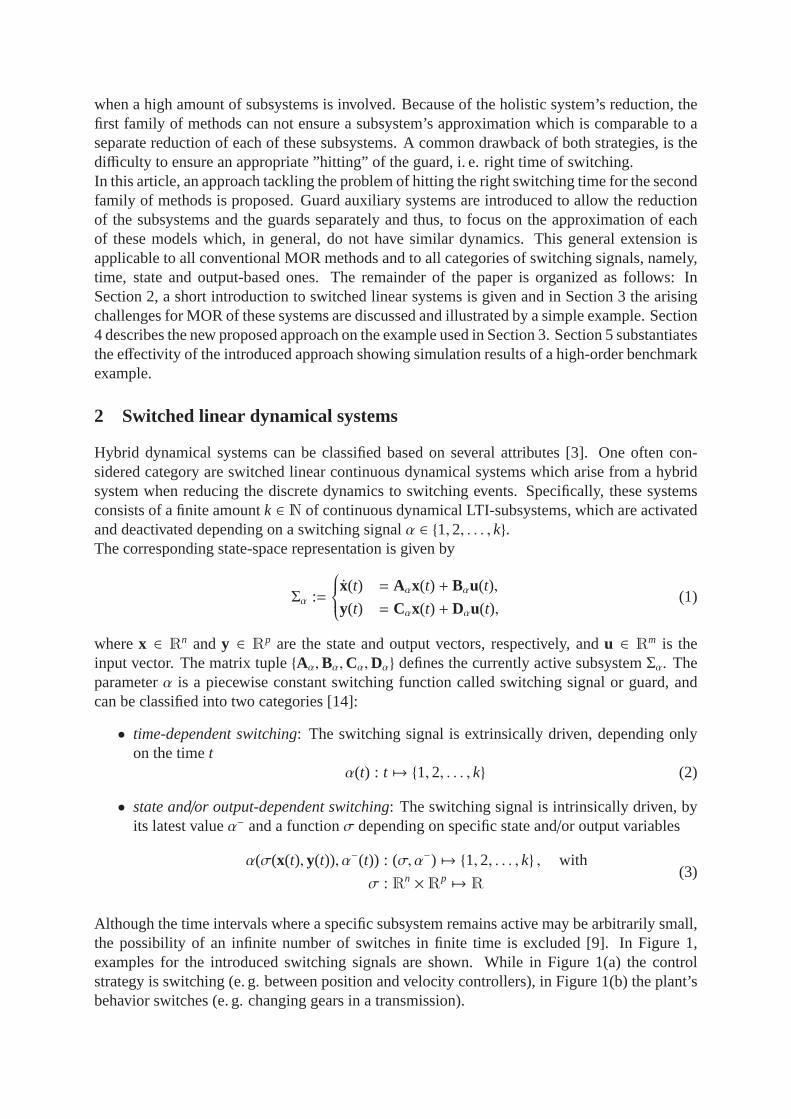
Although the time intervals where a specific subsystem remains active may be arbitrarily small,the possibility of an infinite number of switches in finite time is excluded [9]. In Figure 1,examples for the introduced switching signals are shown. While in Figure 1(a) the controlstrategy is switching (e. g. between position and velocity controllers), in Figure 1(b) the plant’sbehavior switches (e. g. changing gears in a transmission).
-
y(t)w(t)
x(t)
σ, α−
plant
αα = 1
α = 2
α = k
controller 1
controller 2
controllerk
x
(a) Output-dependent switching
α
α = 1
α = 2
α = k
x = f1(x,u)
x = f2(x,u)
x = fk(x,u)
α(t)
u(t)
t
(b) Time-dependent switching
Figure 1: Example for switched linear systems.
As they allow the use of linear system theory, switched linear systems are an advantageousformat for a wide class of hybrid and nonlinear systems for the purpose of modeling, analysisand control [4, 9, 14].
3 Challenges for standard model order reduction techniques
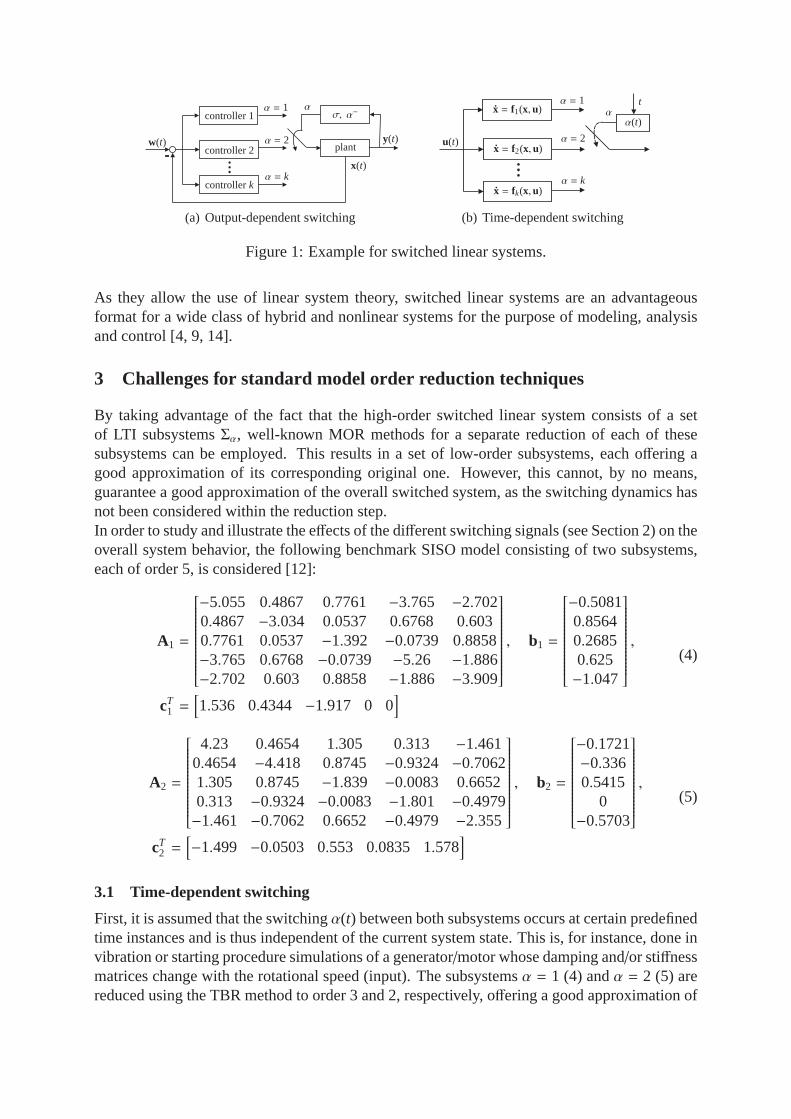
By taking advantage of the fact that the high-order switched linear system consists of a setof LTI subsystemsΣα, well-known MOR methods for a separate reduction of each of thesesubsystems can be employed. This results in a set of low-order subsystems, each offering agood approximation of its corresponding original one. However, this cannot, by no means,guarantee a good approximation of the overall switched system, as the switching dynamics hasnot been considered within the reduction step.In order to study and illustrate the effects of the different switching signals (see Section 2) on theoverall system behavior, the following benchmark SISO model consisting of two subsystems,each of order 5, is considered [12]:
A1 =
−5.055 0.4867 0.7761 −3.765 −2.7020.4867 −3.034 0.0537 0.6768 0.6030.7761 0.0537 −1.392 −0.0739 0.8858−3.765 0.6768 −0.0739 −5.26 −1.886−2.702 0.603 0.8858 −1.886 −3.909
, b1 =
−0.50810.85640.26850.625−1.047
,
cT1 =[
1.536 0.4344 −1.917 0 0]
(4)
A2 =
4.23 0.4654 1.305 0.313 −1.4610.4654 −4.418 0.8745 −0.9324 −0.70621.305 0.8745 −1.839 −0.0083 0.66520.313 −0.9324 −0.0083 −1.801 −0.4979−1.461 −0.7062 0.6652 −0.4979 −2.355
, b2 =
−0.1721−0.3360.5415
0−0.5703
,
cT2 =[
−1.499 −0.0503 0.553 0.0835 1.578]
(5)
3.1 Time-dependent switching
First, it is assumed that the switchingα(t) between both subsystems occurs at certain predefinedtime instances and is thus independent of the current systemstate. This is, for instance, done invibration or starting procedure simulations of a generator/motor whose damping and/or stiffnessmatrices change with the rotational speed (input). The subsystemsα = 1 (4) andα = 2 (5) arereduced using the TBR method to order 3 and 2, respectively, offering a good approximation of

105
104
103
102
101
100
10-1
10-2
10-3
90
135
180
225
270-100
-80
-60
-40
-20
0
ampl
itude
[dB
]ph
ase
[deg
]
frequency [rads ]
original system: order 5reduced system: order 3
(a) Subsystemα = 1
45
135
180-100
-80
-60
-40
-20
0
90
104
103
102
101
100
10-1
10-2
ampl
itude
[dB
]ph
ase
[deg
]
frequency [rads ]
original system: order 5reduced system: order 3
(b) Subsystemα = 2
Figure 2: Frequency response of the benchmark SISO model.
their corresponding high-order models. The frequency responses are depicted in Figure 2. Thesimulation of the overall switched system has been conducted according to the time-dependentswitching signal shown in Figure 3(a). The step responses ofthe original and the reducedoverall system are depicted in Figure 3(b), where it is clearto see that, under the assumptionthat accurate reduced subsystems are at hand, the approximation of the switched system overthe complete time interval is satisfactory.Accordingly, the conventional reduction of time-dependent switched systems leads to a goodoverall system performance.
0 10 20 30 40 50 60
1
2
time [s]
activ
esu
bsys
temα
(a) Switching signal
0 10 20 30 40 50 60
−0.5
−0.6
−0.4
−0.3
−0.2
−0.1
0
time [s]
y(t)
original systemreduced system
(b) Step resposone of the switched system
Figure 3: Time-dependent switching.
3.2 Output-dependent switching
Now, it is assumed that the switchingα(σ(y(t)), α−(t)) occurs based on the system’s outputvalues and thus depending on the dynamics of the subsystems.This is a common scenariowhen e. g. simulating the opening and closing of an electromagnetic valve, where the systemmatrices change in a discrete manner depending on the position of the anchor.For the considered example, the switching function has beenchosen to be:
α(y(t), α−(t)) =
1 fory = −0.5,
2 fory = −0.02,
α− otherwise
(6)
For the comparison of the step responses of the original and the reduced system, the reducedsubsystems (order 3 and 2) introduced in the previous subsection have been adopted. The resultsof a complete system simulation are shown in Figure 4(a), where the discrepancy between thereduced and the original system is notable. In fact, the approximation error sums up with the

0 10 20 30 40 50 60
−0.6
−0.4
−0.2
0
time [s]
y(t)
original systemreduced system
(a) Systems’ order:α = 1 order 3,α = 2 order 2
0 10 20 30 40 50 60
−0.6
−0.4
−0.2
0
time [s]
y(t)
(b) Systems’ order:α = 1 order 4,α = 2 order 4
Figure 4: Step response of the switched system with output-dependent switching.
time and leads to a drift between both step responses. For this class of switching signals, thereduction results can be considerably improved by increasing the order of both involved reducedmodels as depicted in Figure 4(b). This leads to a better approximation of the outputs, wherebythe switching functions (equation (6) here) and thus the switching times are ”hit” more precisely.Nevertheless, the approximation error remains proportional to the simulation time.Hence, the only way of improving the overall system performance is by increasing the reductionorder.
3.3 State-dependent switching
The most challenging switching for the task of order reduction is the state-based one whereα(σ(x(t)), α−(t)) depends on the state(s) of the currently active subsystem. This is mostly thecase for system simulations where the state(s) in question can not be directly measured, butapproximated by a state-observer.For the considered example, the following function has beenchosen so that a periodic switchingbetween the subsystemsα1 andα2 takes place:
α(x1(t), α−(t)) =
1 for x1 = 0.15,
2 for x1 = −0.25,
α− otherwise
(7)
Unlike the two previous cases, neither the reduced systems of order 3 and 2 (see Figure 5(a)) northose of order 4 (Figure 5(b)) resulted in an acceptable approximation of the step response. Thiscan be easily explained by the fact that states which are playing a major role in the switchingsignal, may be of no importance for the input-output behavior of their corresponding subsystemand thus deleted by the order reduction step. Consequently, the switching signalα(x1(t), α−(t))can not be accurately approximated.
0 10 20 30 40 50 60
−0.6
−0.4
−0.2
0
time [s]
y(t)
original systemreduced system
(a) Systems’ order:α = 1 order 3,α = 2 order 2
0 10 20 30 40 50 60
−0.6
−0.4
−0.2
0
time [s]
y(t)
(b) Systems’ order:α = 1 order 4,α = 2 order 4
Figure 5: Step response of the switched system with state-dependent switching.

As a conclusion, it can be stated that standard order reduction methods applied to every involvedsubsystem (with a sufficiently high reduced order) result in a good approximation of the overallswitched system behavior for the case of a time-dependent and output-dependent switching.However, for the case of state-dependent switching, increasing the order of the reduced systemcan not offer a satisfactory approximation and thus there is a need to improve or modify theexisting reduction methods to make them suitable for the reduction of this important class ofswitched linear systems.
4 Auxiliary system
Order reduction of switched linear systems consists of delivering a set of reduced systems thatnot only approximate the output signal but also the switching one. This challenge has beenshown to be specially important for the case of state-dependent switching where not only theimportance of a certain state for the input-output behaviorneeds to be considered but also forthe switching dynamics.Based on these facts and in order to remain within the framework of the standard MOR methodsfor linear systems, it is suggested to introduce several auxiliary systems having the switchingsignals (guards) as output (one auxiliary system per switching state per subsystem). In otherwords, the switching of the linear system will be now controlled by the output of these newlyintroduced systems. Accordingly, a system with state-dependent switching sketched in Figure6(a) is now reformulated as a combination of a set of systems having the switching signalas output (guard auxiliary systemsΣg) and a modified main systemΣαg (Figure 6(b)). Themodified main system consists of the same original switched linear systemΣα, however nowwith an extrinsically driven switching signal (the output fromΣg), wherebyα is changed toαg:
Σαg :
{
x(t) = Aαgx(t) + Bαgu(t),y(t) = Cαgx(t) + Dαgu(t)
(8)
Hence, the switching functionσg(x) for the new switching signalαg(σg(x), α−g) is separatelycalculated in the auxiliary system. The guard auxiliary systems share the same state equations asthe original switched one, but with an output equation corresponding to the switching function:
Σg :
{
x(t) = Aαg x(t) + Bαg u(t),σg(t) = cT
αgx(t), (9)
wherecTαg
builds the state-dependent switching function.Accordingly, the calculation of the switching signal does not take place within the main systemanymore but within the guard auxiliary systems. Thus, unlike the original switched system, a
y(t)u(t)Σα
state-dependent switching
(a) Original switched system
y(t)u(t)Σαg
Σg
switchingoutput-depending
time-depending switching
αg(σg(x(t), α−(t))
(b) Guard auxiliary extended system
Figure 6: Architecture of the switched system.

103
102
101
100
10-1
10-2
90
135
180
-60
-40
-20
0
ampl
itude
[dB
]ph
ase
[deg
]
frequency [rads ]
original system: order 5reduced system: order 4
(a) Subsystemα = 1
-60
-40
-20
0
103
102
101
100
10-1
10-2
90
180
360
ampl
itude
[dB
]ph
ase
[deg
]
frequency [rads ]
original system: order 5reduced system: order 4
(b) Subsystemα = 2
Figure 7: Frequency response of the auxiliary guard systemsof the benchmark SISO model.
state-depended switching signal is bypassed by an extrinsically driven (time-dependent) switch-ing signal according to equation (2) and an output-dependent switching (equation (3)) of theguard auxiliary systems. The systemsΣαg andΣg can now be reduced independently offeringthe required flexibility and transparency for a simultaneous and accurate approximation of theinput-output behavior as well as the switching signal dynamics. This benefits are not directlygiven when setting the states responsible for the switchingas outputs of the original system, forthe purpose of a multi-output order reduction, for two reasons: First, only one reduction methodcan be applied and second, a common projector is obtained leading to a coupling of the reducedsystems’ matrices whereby less accurate results may be achieved, meaning that the order of thereduced subsystems has to be increased in order to achieve anacceptable overall system sim-ulation. The mentioned effects rise with diverging dynamics of input-output behaviorand theswitching signals.As the introduced guard auxiliary systems share the same state equations with the modifiedswitched system (8), the numerical costs of a reduction compared to the case without modifi-cation remain acceptable. Moreover, forΣg to remain a linear system, the switching functionitself should be a linear function of the states. Otherwise it would not be possible to calculatethe switching signal using the vectorcT
αgand the corresponding states.
The suitability of the new approach is illustrated using thelow-order example introduced in Sec-tion 3. Here, the subsystems of the auxiliary switching system are reduced by the TBR methodto order 4, while the original systems to order 3 and 2 as in theprevious Section. In Figure7 the frequency response of the auxiliary switching system is shown. The curves are almostsuperimposed, which implies a good approximation of the switching dynamics. In Figure 8, thestep responses of the original and the reduced system are compared. A significant approxima-tion improvement can be seen, especially in comparison to the results without a guard auxiliaryswitching system (Figure 5(a)). There is almost no drift in the step response of the reduced sys-
0 10 20 30 40 50 60
−0.6
−0.4
−0.2
0
time [s]
y(t)
original systemreduced system
Figure 8: Step responses of the new approach with state-dependent switching.
tem which obviously suggests that the switching signals have been perfectly approximated bythe reduced guard auxiliary systems. Hence, only a very goodapproximation of the responsiblestates for switching leads to a satisfactory result.
5 Simulation results
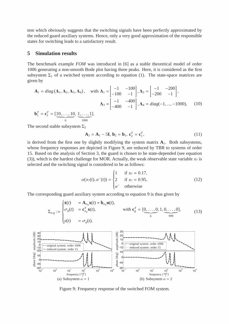
The benchmark exampleFOM was introduced in [6] as a stable theoretical model of order1006 generating a non-smooth Bode plot having three peaks. Here, it is considered as the firstsubsystemΣ1 of a switched system according to equation (1). The state-space matrices aregiven by
A1 = diag(Λ1,Λ2,Λ3,Λ4) , with Λ1 =
[
−1 −100−100 −1
]
,Λ2 =
[
−1 −200−200 −1
]
,
Λ3 =
[
−1 −400−400 −1
]
,Λ4 = diag(−1, ...,−1000),
bT1 = cT
1 = [10, . . . ,10︸ ︷︷ ︸
6
, 1, . . . ,1︸ ︷︷ ︸
1000
].
(10)
The second stable subsystemΣ2
A2 = A1 − 5I , b2 = b1, cT2 = cT
1 , (11)
is derived from the first one by slightly modifying the systemmatrix A1. Both subsystems,whose frequency responses are depicted in Figure 9, are reduced by TBR to systems of order15. Based on the analysis of Section 3, the guard is chosen to bestate-depended (see equation(3)), which is the hardest challenge for MOR. Actually, the weak observable state variablex7 isselected and the switching signal is considered to be as follows:
α(x7(t), α−(t)) =
1 if x7 = 0.17,
2 if x7 = 0.95,
α− otherwise
(12)
The corresponding guard auxiliary system according to equation 9 is thus given by
Σα,g :=
x(t) = Aαgx(t) + bαgu(t),
σg(t) = cTαg
x(t), with cTg = [0, . . . ,0
︸ ︷︷ ︸
6
,1,0, . . . ,0︸ ︷︷ ︸
999
],
y(t) = σg(t).
(13)
-20
-10
0
10
20
30
40
10-1
100
101
102
103
104
-90
-45
0
45
ampl
itude
[dB
]ph
ase
[deg
]
frequency [rads ]
original system: order 1006reduced system: order 15
(a) Subsystemα = 1
-10
0
10
20
30
100
101
102
103
104
-90
-45
0
45
10-1
ampl
itude
[dB
]ph
ase
[deg
]
frequency [rads ]
original system: order 1006reduced system: order 15
(b) Subsystemα = 2
Figure 9: Frequency response of the switched FOM system.

-40
-20
0
10-2
10-1
100
101
102
-90
-45
0
ampl
itude
[dB
]ph
ase
[deg
]
frequency [rads ]
original system: order 1006reduced system: order 1
(a) Subsystemα = 1
-40
-30
-20
10-1
100
101
102
-90
-45
0
ampl
itude
[dB
]ph
ase
[deg
]
frequency [rads ]
original system: order 1006reduced system: order 1
(b) Subsystemα = 2
Figure 10: Frequency response of the auxiliary guard system.
0 10 20 30 40 500
0.2
0.4
0.6
0.8
1
x 7(t
)
time [s]
original systemreduced system
(a) Without guard auxiliary system
0 10 20 30 40 500
0.2
0.4
0.6
0.8
1
x 7(t
)
time [s]
(b) With guard auxiliary system
Figure 11: Approximation of the guard variablex7: subsystems’ order 15.
In Figure 10 the frequency responses of the two guard auxiliary systems and of their corre-sponding reduced models (TBR) of first order are shown.Now, for both the reduced switched system with and without the guard auxiliary systems, thestep response is simulated and compared to the one of the original switched system. In addition,the time response of the guard state variablex7 is shown in Figure 11. Due to the weak observ-ability of x7, the conventional reduction (without guard auxiliary system) in Figure 11(a) hits theswitching condition earlier than it should do, leading to a divergence of the system responsesover the time in contrast to the here introduced reduction framework (Figure 11(b)). Hence,although the subsystems are well approximated, the output signals of the overall switched sys-tems diverge which is avoided by the here introduced reduction framework. The correspondingoutput signalsy(t) are depicted in Figure 12. The output errorsǫy = yo(t) − yr(t), where theindexo represents the original andr the reduced system signals, are shown in Figure 13. Whilethe error in Figure 13(a) increases and reaches its maximum possible value (difference between
0 10 20 30 40 504
5
6
7
8
time [s]
y(t)
original systemreduced system
(a) Without guard auxiliary system
0 10 20 30 40 504
5
6
7
8
time [s]
y(t)
(b) With guard auxiliary system
Figure 12: Approximation of the output signal: subsystems’order 15.

0 10 20 30 40 50
−1
0
1
2
time [s]
ǫy(
t)
(a) Without guard auxiliary system
0 10 20 30 40 50
−1
0
1
2
x 10−3
time [s]
ǫy(
t)
(b) With guard auxiliary system
Figure 13: Output error: subsystems’ order 15.
-20
0
20
40
10-1
100
101
102
103
104
-90
-45
0
45
90
frequency [rads ]
phas
e[d
eg]
ampl
itude
[dB
]
original system: order 1006reduced system: order 8
(a) Subsystemα = 1
-20
0
20
10-1
100
101
102
103
104
-90
-45
0
45
frequency [rads ]
phas
e[d
eg]
ampl
itude
[dB
]
original system: order 1006reduced system: order 8
(b) Subsystemα = 2
Figure 14: Frequency response of the switched FOM system.
maximumymax and minimumymin), the result with the guard auxiliary systems keeps a verylow and non-increasing error according to Figure 13(b). Accordingly, a reduction of the outputapproximation error of 99% has been achieved in the considered simulation time by the guardauxiliary system extended reduction.Now, the two subsystems are further reduced to order 8. The obtained frequency responses areshown in Figure 14. The auxiliary guard systems are again reduced to order 1 (see Figure 10and 11(b)). Figure 15 shows the output signaly and the errorǫy of the here introduced reductionframework. This error is still 50% lower than the one of the conventional TBR reduction toorder 15 (Figure 13(a)) although the reduction order has been almost halved. In contrast, aconventional TBR of the subsystems to an order of 8 is unrewarding. It leads to an insufficientapproximation of the guard state variablex7, which does not reach the exact switching valuesaccording to equation (12) as depicted in Figure 16. Hence, the reduced switched linear systemremains within one subsystem for all time.The introduced framework for model order reduction of switches linear systems enables a lower-order of the reduced subsystems in comparison to the conventional reduction methods in addi-tion to a better approximation of the overall switched system’s behavior.
0 10 20 30 40 500
2
4
6
8
time [s]
y(t)
original systemreduced system
(a) Output signal
0 10 20 30 40 50−0.8
−0.6
−0.4
−0.2
0
0.2
time [s]
ǫy(
t)
(b) Error of the output signal
Figure 15: Output of guard auxiliary system extended TBR: subsystems’ order 8.

0 10 20 30 40 500
0.2
0.4
0.6
0.8
1
x 7(t
)time [s]
original systemreduced system
(a) Error of switching guard
Figure 16: TBR without guard auxiliary system extension: subsystems’ order 8.
6 Conclusion and Outlook
A new framework for the reduction of switched linear systemsby conventional MOR meth-ods has been presented. By introducing a guard auxiliary system, the task of approximatingthe output and the states relevant for the calculation of theswitching sequence has been dis-sociated. This allows a transparent and flexible calculation of separate reduced models for theapproximation of the switching signal dynamics and the output of the original switched linearsystem. The introduced approach allows the simultaneous use of different reduction methodsand settings and offers a good approximation of the overall switched system. Thebenefit of thisguard-based model order reduction has been shown by comparing it with conventionalTrun-cated Balanced Realization(TBR) for two benchmark examples. Thereby, a reduction of theoutput signal’s error as well as a lower-order of the reducedswitched subsystems have beenachieved.Interesting future work involve the extension of the presented framework to nonlinear switchingdynamics and to networked systems. Investigations relatedto stability preserving and errorbounds are also of high interest.
Acknowledgement
The first author thanks the German Research Foundation (DFG) for funding this research as part of thecollaborative research ”Managing cycles in innovation processes - Integrated development of productservice systems based on technical products” (SFB 768).
References
[1] A. C. Antoulas.Approximation of Large-Scale Dynamical Systems. Society of Industrial an AppliedMathematics, Philadelphia, 2005.
[2] A. Balluchi, A. Bicchi, E. Mazzi, A.L.S. Vincentelli, and G. Serra. Hybrid modelling and controlof the common rail infection system. In J. Hespanha and A. Tiwari, editors,Hybrid Systems:Computation and Control, LNCS 3927, pages 79 – 92. 2006.
[3] M. S. Branicky. Studies in Hybrid Systems: Modeling, Analysis, and Control. Ph.d. diss., MIT,Boston, USA, 1995.
[4] M. S. Branicky. Multiple lyapunov functions and other analysis tools for switched and hybridsystems.IEEE Transaction on Automatic Control, 43(4):475 – 482, 1998.
[5] Y. Chahlaoui. Model reduction of switched dynamical systems. InProc. International Conferenceon Trends in Applied Mathematics, Kenitra, Morocco, 2009.
[6] Y. Chahlaoui and P. Van Dooren. A collection of benchmark examplesfor model reduction of lineartime invariant dynamical systems. SLICOT Working Note 2002-2, 2002.
[7] F.-G. Filip and K. Leiviska. Large-scale complex systems. In S. Y. Nof, editor,Springer Handbookof Automation. Springer, 2009.
[8] E. J. Grimme. Krylov Projection Methods for Model Reduction. PhD thesis, Dep. of ElectricalEng., Uni. Illinois at Urbana Champaign, 1997.
[9] D. Liberzon.Switching in Systems and Control. Birkhauser, 2003.
[10] E. Mazzi, A. S. Vincentelli, A. Balluchi, and A. Bicchi. Hybrid system reduction. InProc. IEEEConference on Decision and Control, pages 227 – 232, Cancun, Mexico, 2008.
[11] B. C. Moore. Principal Component Analysis in Linear Systems: Controllability, Observability andModel Reduction.IEEE Trans. Aut. Control, AC-26:17–32, 1981.
[12] H. R. Shaker.Model Reduction of Hybrid Systems. Ph.d. diss., Aalborg University, Denmark, 2010.
[13] L. Wu and W. Xing Zheng. Weightedhin f model reduction for linear switched systems with time-varying delay.Automatica, 45:186 – 193, 2009.
[14] K. Wulff. Quadratic and Non-Quadratic Stability Criteria for Switched Linear Systems. Ph.d. diss.,National University of Ireland, Maynooth, Ireland, 2004.