GT1524 manual -...
52
Perfect Communication through Technology, Service, and Education. TM Installation & Operations Manual Single Channel Echo Canceller GT1524
Transcript of GT1524 manual -...

Perfect Communication through Technology, Service, and Education.TM
Installation & Operations Manual
Single Channel Echo Canceller
GT1
52
4

GT1524 Installation and Operations ManualGentner Part No. 800-114-101January 2000 (Rev 1.1)
©2000 Gentner Communications Corporation. All Rights Reserved. Gentner Communications Corporationreserves specification privileges Information in this manual is subject to change without notice or obligation.Manual Development: Scott Sorenson, Wayne Whiteley, Mike RaymondArtwork and Illustrations: Laurie Lingmann, Mike Raymond
The international unit, part no. 910-114-102, complies with the requirements of the European guidelines:
89/336/EEC "Electromagnetic Compatibility"73/23/EEC "Electrical operating material for use within specific voltage limits"
98/482/EC "Single terminal connection to the public switched telephone network."
Conformity of the equipment with the above guidelines is attested by the CE mark.

TECHNICAL SUPPORT: 1.800.283.5936 (USA) OR 1.801.974.3760
1. Introduction . . . . . . . . . . . . . . . . . . . . . . . . . . . . . . . . . . . . . . .3Unpacking . . . . . . . . . . . . . . . . . . . . . . . . . . . . . . . . . . . . . . . . . . . . . . . . . . . . . . . . . . . . . . . . . . . . . .4
2. Overview . . . . . . . . . . . . . . . . . . . . . . . . . . . . . . . . . . . . . . . . .5About the GT1524 . . . . . . . . . . . . . . . . . . . . . . . . . . . . . . . . . . . . . . . . . . . . . . . . . . . . . . . . . . . . . . . . . . . . . . .5Applications . . . . . . . . . . . . . . . . . . . . . . . . . . . . . . . . . . . . . . . . . . . . . . . . . . . . . . . . . . . . . . . . . . . . . . . . . . . .6Product description . . . . . . . . . . . . . . . . . . . . . . . . . . . . . . . . . . . . . . . . . . . . . . . . . . . . . . . . . . . . . . . . . . . . .6
Front Panel . . . . . . . . . . . . . . . . . . . . . . . . . . . . . . . . . . . . . . . . . . . . . . . . . . . . . . . . . . . . . . . . . . . . .91. LCD Window . . . . . . . . . . . . . . . . . . . . . . . . . . . . . . . . . . . . . . . . . . . . . . . . . . . . . . . . . . . . . . . . . . . . . . . . .92. Enter Button . . . . . . . . . . . . . . . . . . . . . . . . . . . . . . . . . . . . . . . . . . . . . . . . . . . . . . . . . . . . . . . . . . . . . . . . .93. Up/Down Buttons . . . . . . . . . . . . . . . . . . . . . . . . . . . . . . . . . . . . . . . . . . . . . . . . . . . . . . . . . . . . . . . . . . . .94. Escape Button . . . . . . . . . . . . . . . . . . . . . . . . . . . . . . . . . . . . . . . . . . . . . . . . . . . . . . . . . . . . . . . . . . . . . . .95. LED Meter . . . . . . . . . . . . . . . . . . . . . . . . . . . . . . . . . . . . . . . . . . . . . . . . . . . . . . . . . . . . . . . . . . . . . . . . . . .96. Meter Button . . . . . . . . . . . . . . . . . . . . . . . . . . . . . . . . . . . . . . . . . . . . . . . . . . . . . . . . . . . . . . . . . . . . . . . . .97. On Button . . . . . . . . . . . . . . . . . . . . . . . . . . . . . . . . . . . . . . . . . . . . . . . . . . . . . . . . . . . . . . . . . . . . . . . . . . . .98. Off Button . . . . . . . . . . . . . . . . . . . . . . . . . . . . . . . . . . . . . . . . . . . . . . . . . . . . . . . . . . . . . . . . . . . . . . . . . .10
Back Panel . . . . . . . . . . . . . . . . . . . . . . . . . . . . . . . . . . . . . . . . . . . . . . . . . . . . . . . . . . . . . . . . . . . .101. Power . . . . . . . . . . . . . . . . . . . . . . . . . . . . . . . . . . . . . . . . . . . . . . . . . . . . . . . . . . . . . . . . . . . . . . . . . . . . . . .102. Line Out, Aux Out . . . . . . . . . . . . . . . . . . . . . . . . . . . . . . . . . . . . . . . . . . . . . . . . . . . . . . . . . . . . . . . . . . . .103. 4-wire Video Codec In/Out . . . . . . . . . . . . . . . . . . . . . . . . . . . . . . . . . . . . . . . . . . . . . . . . . . . . . . . . . .104. Mic/Line In, Aux In . . . . . . . . . . . . . . . . . . . . . . . . . . . . . . . . . . . . . . . . . . . . . . . . . . . . . . . . . . . . . . . . . .105. RS232 . . . . . . . . . . . . . . . . . . . . . . . . . . . . . . . . . . . . . . . . . . . . . . . . . . . . . . . . . . . . . . . . . . . . . . . . . . . . . .106. Control/Status . . . . . . . . . . . . . . . . . . . . . . . . . . . . . . . . . . . . . . . . . . . . . . . . . . . . . . . . . . . . . . . . . . . . . .107. Speaker . . . . . . . . . . . . . . . . . . . . . . . . . . . . . . . . . . . . . . . . . . . . . . . . . . . . . . . . . . . . . . . . . . . . . . . . . . . . .118. Telco Line . . . . . . . . . . . . . . . . . . . . . . . . . . . . . . . . . . . . . . . . . . . . . . . . . . . . . . . . . . . . . . . . . . . . . . . . . .119. Telco Set . . . . . . . . . . . . . . . . . . . . . . . . . . . . . . . . . . . . . . . . . . . . . . . . . . . . . . . . . . . . . . . . . . . . . . . . . . .11Equipment Placement . . . . . . . . . . . . . . . . . . . . . . . . . . . . . . . . . . . . . . . . . . . . . . . . . . . . . . .11Telephone Line Requirements . . . . . . . . . . . . . . . . . . . . . . . . . . . . . . . . . . . . . .11
3. Installation . . . . . . . . . . . . . . . . . . . . . . . . . . . . . . . . . . . . . .13Room Planning . . . . . . . . . . . . . . . . . . . . . . . . . . . . . . . . . . . . . . . . . . . . . . . . . . . . . . . . . . . . . . . . . . . . . . . .13Acoustics . . . . . . . . . . . . . . . . . . . . . . . . . . . . . . . . . . . . . . . . . . . . . . . . . . . . . . . . . . . . . . . . . . . . . . . . . . . . .13Reverberation . . . . . . . . . . . . . . . . . . . . . . . . . . . . . . . . . . . . . . . . . . . . . . . . . . . . . . . . . . . . . . . . . . . . . . . . .14Acoustic Echo . . . . . . . . . . . . . . . . . . . . . . . . . . . . . . . . . . . . . . . . . . . . . . . . . . . . . . . . . . . . . . . . . . . . . . . . .14Ambient Noise . . . . . . . . . . . . . . . . . . . . . . . . . . . . . . . . . . . . . . . . . . . . . . . . . . . . . . . . . . . . . . . . . . . . . . . . .14Acoustic Room Treatment . . . . . . . . . . . . . . . . . . . . . . . . . . . . . . . . . . . . . . . . . . . . . . . . . . . . . . . . . . . . . .14Microphone Selection . . . . . . . . . . . . . . . . . . . . . . . . . . . . . . . . . . . . . . . . . . . . . . . . . . . . . . . . . . . . . . . . . .15Tabletop . . . . . . . . . . . . . . . . . . . . . . . . . . . . . . . . . . . . . . . . . . . . . . . . . . . . . . . . . . . . . . . . . . . . . . . . . . . . . .15
able of ContentsT
TECHNICAL SUPPORT: 1.800.283.5936 (USA) OR 1.801.974.3760
TABLE OF CONTENTS2
Podium . . . . . . . . . . . . . . . . . . . . . . . . . . . . . . . . . . . . . . . . . . . . . . . . . . . . . . . . . . . . . . . . . . . . . . . . . . . . . . . .15Lavaliere . . . . . . . . . . . . . . . . . . . . . . . . . . . . . . . . . . . . . . . . . . . . . . . . . . . . . . . . . . . . . . . . . . . . . . . . . . . . . .15Microphone Placement . . . . . . . . . . . . . . . . . . . . . . . . . . . . . . . . . . . . . . . . . . . . . . . . . . . . . . . . . . . . . . . .16Conference Room Layout . . . . . . . . . . . . . . . . . . . . . . . . . . . . . . . . . . . . . . . . . . . . . . . . . . . . . . . . . . . . . .16Equipment Interconnections . . . . . . . . . . . . . . . . . . . . . . . . . . . . . . . . . . . . . . . . . . . . . . . . . . . . . . . . . . .17Back Panel Connections . . . . . . . . . . . . . . . . . . . . . . . . . . . . . . . . . . . . . . . . . . . . . . . . . . . . . . . . . . . . . . .18LCD Programming . . . . . . . . . . . . . . . . . . . . . . . . . . . . . . . . . . . . . . . . . . . . . . . . . . . . . . . . . .20Menu Trees . . . . . . . . . . . . . . . . . . . . . . . . . . . . . . . . . . . . . . . . . . . . . . . . . . . . . . . . . . . . . . . . . . . . . . . . . . . .20Moving Among Menu Items . . . . . . . . . . . . . . . . . . . . . . . . . . . . . . . . . . . . . . . . . . . . . . . . . . . . . . . . . . . .20Adjusting a Value . . . . . . . . . . . . . . . . . . . . . . . . . . . . . . . . . . . . . . . . . . . . . . . . . . . . . . . . . . . . . . . . . . . . . .21
Menu Tree Diagram . . . . . . . . . . . . . . . . . . . . . . . . . . . . . . . . . . . . . . . . . . . . . . . . . . . . . . . . . . . .22Parameters Worksheet . . . . . . . . . . . . . . . . . . . . . . . . . . . . . . . . . . . . . . . . . . . . . . . . . . . . . . . . .23Input Parameters . . . . . . . . . . . . . . . . . . . . . . . . . . . . . . . . . . . . . . . . . . . . . . . . . . . . . . . . . . . . . . .24
Gain Adjust . . . . . . . . . . . . . . . . . . . . . . . . . . . . . . . . . . . . . . . . . . . . . . . . . . . . . . . . . . . . . . . . . . . . . . . . . . . .24Mic/Line Input . . . . . . . . . . . . . . . . . . . . . . . . . . . . . . . . . . . . . . . . . . . . . . . . . . . . . . . . . . . . . . . . . . . . . . . . .24Mute . . . . . . . . . . . . . . . . . . . . . . . . . . . . . . . . . . . . . . . . . . . . . . . . . . . . . . . . . . . . . . . . . . . . . . . . . . . . . . . . . . .24Phantom Power . . . . . . . . . . . . . . . . . . . . . . . . . . . . . . . . . . . . . . . . . . . . . . . . . . . . . . . . . . . . . . . . . . . . . . .24AGC . . . . . . . . . . . . . . . . . . . . . . . . . . . . . . . . . . . . . . . . . . . . . . . . . . . . . . . . . . . . . . . . . . . . . . . . . . . . . . . . . . .24High-Pass Filter . . . . . . . . . . . . . . . . . . . . . . . . . . . . . . . . . . . . . . . . . . . . . . . . . . . . . . . . . . . . . . . . . . . . . . . .24Echo Canceller . . . . . . . . . . . . . . . . . . . . . . . . . . . . . . . . . . . . . . . . . . . . . . . . . . . . . . . . . . . . . . . . . . . . . . . . .24NLP Adjust . . . . . . . . . . . . . . . . . . . . . . . . . . . . . . . . . . . . . . . . . . . . . . . . . . . . . . . . . . . . . . . . . . . . . . . . . . . . .24From Telco and 4-Wire In . . . . . . . . . . . . . . . . . . . . . . . . . . . . . . . . . . . . . . . . . . . . . . . . . . . . . . . . . . . . . . .24Gain Adjust . . . . . . . . . . . . . . . . . . . . . . . . . . . . . . . . . . . . . . . . . . . . . . . . . . . . . . . . . . . . . . . . . . . . . . . . . . . .24Mute . . . . . . . . . . . . . . . . . . . . . . . . . . . . . . . . . . . . . . . . . . . . . . . . . . . . . . . . . . . . . . . . . . . . . . . . . . . . . . . . . . .25AGC . . . . . . . . . . . . . . . . . . . . . . . . . . . . . . . . . . . . . . . . . . . . . . . . . . . . . . . . . . . . . . . . . . . . . . . . . . . . . . . . . . .25
Output Parameters . . . . . . . . . . . . . . . . . . . . . . . . . . . . . . . . . . . . . . . . . . . . . . . . . . . . . . . . . . . . .25Gain Adjust . . . . . . . . . . . . . . . . . . . . . . . . . . . . . . . . . . . . . . . . . . . . . . . . . . . . . . . . . . . . . . . . . . . . . . . . . . . .25Mute . . . . . . . . . . . . . . . . . . . . . . . . . . . . . . . . . . . . . . . . . . . . . . . . . . . . . . . . . . . . . . . . . . . . . . . . . . . . . . . . . . .25
System Parameters . . . . . . . . . . . . . . . . . . . . . . . . . . . . . . . . . . . . . . . . . . . . . . . . . . . . . . . . . . . . .25Lock Panel . . . . . . . . . . . . . . . . . . . . . . . . . . . . . . . . . . . . . . . . . . . . . . . . . . . . . . . . . . . . . . . . . . . . . . . . . . . . .25Set Passcode . . . . . . . . . . . . . . . . . . . . . . . . . . . . . . . . . . . . . . . . . . . . . . . . . . . . . . . . . . . . . . . . . . . . . . . . . .26RS232 . . . . . . . . . . . . . . . . . . . . . . . . . . . . . . . . . . . . . . . . . . . . . . . . . . . . . . . . . . . . . . . . . . . . . . . . . . . . . . . . .26Baud . . . . . . . . . . . . . . . . . . . . . . . . . . . . . . . . . . . . . . . . . . . . . . . . . . . . . . . . . . . . . . . . . . . . . . . . . . . . . . . . . .26Flow control . . . . . . . . . . . . . . . . . . . . . . . . . . . . . . . . . . . . . . . . . . . . . . . . . . . . . . . . . . . . . . . . . . . . . . . . . . . .26Telco . . . . . . . . . . . . . . . . . . . . . . . . . . . . . . . . . . . . . . . . . . . . . . . . . . . . . . . . . . . . . . . . . . . . . . .26Auto Answer On/Off . . . . . . . . . . . . . . . . . . . . . . . . . . . . . . . . . . . . . . . . . . . . . . . . . . . . . . . . . . . . . . . . . . . .26Auto Disconnect . . . . . . . . . . . . . . . . . . . . . . . . . . . . . . . . . . . . . . . . . . . . . . . . . . . . . . . . . . . . . . . . . . . . . . .26Unit ID . . . . . . . . . . . . . . . . . . . . . . . . . . . . . . . . . . . . . . . . . . . . . . . . . . . . . . . . . . . . . . . . . . . . . . . . . . . . . . . . .26
Meter Parameters . . . . . . . . . . . . . . . . . . . . . . . . . . . . . . . . . . . . . . . . . . . . . . . . . . . . . . . . . . . . . .27Timeout . . . . . . . . . . . . . . . . . . . . . . . . . . . . . . . . . . . . . . . . . . . . . . . . . . . . . . . . . . . . . . . . . . . .27
4. Operation . . . . . . . . . . . . . . . . . . . . . . . . . . . . . . . . . . . . . . . .29Front Panel . . . . . . . . . . . . . . . . . . . . . . . . . . . . . . . . . . . . . . . . . . . . . . . . . . . . . . . . . . . . . . . . . . . . .29
Controlling Volume . . . . . . . . . . . . . . . . . . . . . . . . . . . . . . . . . . . . . . . . . . . . . . . . . . . . . . . . . . . . . . . . . . . . .29Muting . . . . . . . . . . . . . . . . . . . . . . . . . . . . . . . . . . . . . . . . . . . . . . . . . . . . . . . . . . . . . . . . . . . . . . . . . . . . . . . . .29Muting/Unmuting Input/Output . . . . . . . . . . . . . . . . . . . . . . . . . . . . . . . . . . . . . . . . . . . . . . . . . . . . . . . .29

TECHNICAL SUPPORT: 1.800.283.5936 (USA) OR 1.801.974.3760
TABLE OF CONTENTS 3
Answering a Call . . . . . . . . . . . . . . . . . . . . . . . . . . . . . . . . . . . . . . . . . . . . . . . . . . . . . . . . . . . . . . . . . . . . . . .30Making a Call . . . . . . . . . . . . . . . . . . . . . . . . . . . . . . . . . . . . . . . . . . . . . . . . . . . . . . . . . . . . . . . . . . . . . . . . . .30Disconnecting a Call . . . . . . . . . . . . . . . . . . . . . . . . . . . . . . . . . . . . . . . . . . . . . . . . . . . . . . . . . . . . . . . . . . .30Custom Controller Options . . . . . . . . . . . . . . . . . . . . . . . . . . . . . . . . . . . . . . . . . . . . . . . . . . . . . . . . . . . . .30
Appendices . . . . . . . . . . . . . . . . . . . . . . . . . . . . . . . . . . . . . . .33Appendix A: Specifications . . . . . . . . . . . . . . . . . . . . . . . . . . . . . . . . . . . . . . . . . . . . . . . . . . . . . . . . . . . . .33Appendix B: Connector Pinouts . . . . . . . . . . . . . . . . . . . . . . . . . . . . . . . . . . . . . . . . . . . . . . . . . . . . . . . . .35Appendix C: Serial Port Commands . . . . . . . . . . . . . . . . . . . . . . . . . . . . . . . . . . . . . . . . . . . . . . . . . . . . .36Appendix D: Compliance Statement . . . . . . . . . . . . . . . . . . . . . . . . . . . . . . . . . . . . . . . . . . . . . . . . . . . . .48

TECHNICAL SUPPORT: 1.800.283.5936 (USA) OR 1.801.974.3760
TABLE OF CONTENTS4

TECHNICAL SUPPORT: 1.800.283.5936 (USA) OR 1.801.974.3760
1Sophisticated equipment makes the difference between an average (oreven frustrating) meeting and a productive, effectively managed meeting.The GT1524 provides advanced, easy-to-use conferencing capabilities tomake distance conferencing seamless and simple.
The GT1524 provides the highest possible audio quality available in a single channel echo canceller. It features an integrated telephone interface that enables telephone participants of an audio- or videoconference to sound as if they are actually in the same room. Plus, itfeatures simultaneous two-wire/four-wire operation so you canaudioconference and videoconference at the same time. And there’s no
white noise set-up—the GT1524 adapts automatically.
The GT1524 performs a variety of complex, integrated audio functionsusing digital signal processors (DSPs). Adjustments in level and other functions can be made via front panel programming, activation through aclosure on the rear panel, or an RS232 serial interface.
The integrated telephone interface provides the GT1524’s audioconferencing capability and can be customized to suit your needs. Itcan be set to automatically answer upon detection of a valid ring and automatically disconnect on loop drop or call progress tones. The GT1524includes a built-in five-watt power amp.
If you need technical help on setting up your GT1524, please contact us at: Telephone: 1.800.283.5936 (USA) or 1.801.974.3760Fax: 1.800.933.5107 (USA) or 1.801.977.0087Internet: www.gentner.com E-mail: [email protected]
Gentner Communications Corporation1825 Research Way, Salt Lake City, UT 84119
Introduction
INTRODUCTION 5

TECHNICAL SUPPORT: 1.800.283.5936 (USA) OR 1.801.974.3760
INTRODUCTION • UNPACKING6
Gentner Communicationsis not responsible forproduct damage incurred
during shipment. You must makeclaims directly with the carrier.Inspect your shipment carefullyfor obvious signs of damage. Ifthe shipment appears damaged,retain the original boxes andpacking material for inspectionby the carrier. Contact your carrier immediately.
ACPower CordPar t 699-150-006
GT1524 Installationand Operations Manual CDPart 800-114-101
Optional
GT1524Part 910-114-101
SpeakerPart 910-103-010
MicrophonesPart 910-103-160 or910-103-161Mic Cables included (shown below)
12-foot Telephone CablePart 830-000-012
Meter
+12+8+4
0-4
-10-30
EscEnterGT1524 On Off
Telephone
Phoenix Push-OnBlocks (x6)Part 673-016-003
Installation & Operations Manual
Single Channel Echo Canceller
GT1
52
4
Ensure that the following items were received with your shipment:
!
Figure 1. Unpacking Your GT1524
Please register your GT1524 online by visiting Gentner TechnicalSupport on the World Wide Web at http://www.gentner.com. When yourproduct is properly registered, Gentner Communications will be able toserve you better should you require technical assistance or desire toreceive upgrades, new product information, etc.
Unpacking

TECHNICAL SUPPORT: 1.800.283.5936 (USA) OR 1.801.974.3760
2· Easy to install, simple to operate.
· No white noise set-up.
· Easy design, programming, installation and maintenance.
· Simultaneous two-wire/four-wire capability enables video and telephone participants to communicate simultaneously with full-duplexaudio.
· Each input incorporates automatic gain control to compensate for loudor soft talkers, while the mic/line input offers high-pass filtering toreduce unwanted low frequency noise.
• Integrated touch-tone dialing for easy dialing through remote control.
• Gentner’s Digital Signal Processing technology ensures crystal-clearaudio with the deepest, most reliable hybrid null.
• 8kHz sampling rate allows continual adaptation to telephone-line conditions.
• Acoustic EC (single channel) >120 mS. DSP bases.
• Full-time Telco echo cancellation with 31 millisecond tail time.
• Selectable auto-answer and auto-disconnect enables integrators tochoose auto-disconnect without auto-answer and vice versa.
Overview
About the GT1524
OVERVIEW • FEATURES 7

TECHNICAL SUPPORT: 1.800.283.5936 (USA) OR 1.801.974.3760
OVERVIEW • FEATURES8
• Lockout front panel access for security.
• Phoenix™ push-on blocks make pin-for-pin wiring easier.
• Worldwide compliance includes FCC, CSA and CE.
• Mountable in a single 19˝ rack space.
ApplicationsThe GT1524 is perfect for audioconferencing or for providing audio forvideoconferencing with a single microphone. Specific user-programmable capabilities make the GT1524 suitable for many applications including distance learning, boardrooms, conferencerooms, courtrooms, and telemedicine.
Product DescriptionThe GT1524 performs a variety of complex, integrated audio functions,all implemented using digital signal processors (DSPs). Adjustments inlevel and all other functions can be made in one of three ways: frontpanel programming, activation through a closure on the rear panel, orRS232 serial interface. An integrated telephone interface provides theGT1524’s audioconferencing capability and can be customized according to your needs.
The telephone interface can be set to automatically answer, and automatically disconnect on loop drop or call progress tones. Finally, aspart of its self-contained audio conferencing design, the GT1524includes a built-in power amp. The amp delivers 5W of output powerinto a 4 ohm speaker, eliminating the need to provide external amps forthe speakers.
The GT1524 provides local room audio capabilities through themic/line input, for connecting a mic or mixer; and a line output, for connecting an amplifier. A speaker can also be connected to the speaker terminals. The GT1524 handles distant-site conferencing with afour-wire line-level input/output, which connects to a codec.
The aux input and output terminals allow connection of a VCR or otherplayback or recording device.

TECHNICAL SUPPORT: 1.800.283.5936 (USA) OR 1.801.974.3760
OVERVIEW • PRODUCT DESCRIPTION 9
Front PanelThe GT1524 front-panel LCD window and the push-button controls(Figure 2) enable you to view or modify current GT1524 status and settings. The numbered items in Figure 2 correspond to the followingdescriptions.
For more detail on using the front panel controls, refer to the Installationsection.
1. LCD window: The two-line, 16-character-per-line LCD display is usedfor the GT1524 setup. Level adjustments are made through a menu system and four front-panel buttons [2, 3, and 4]. Functions that can beaccessed through the front-panel LCD include setup, programming,troubleshooting, and numeric audio level and gain readouts.
2. Enter: This button is used to move deeper within a menu, or to editor store a selected parameter.
3. Up/Down: These buttons scroll up and down through menu optionswithin a specific parameter. These buttons also increase or decrease anumeric value.
4. Esc: This button backs out of a selected parameter without changingits value, or moves the display to the next higher menu level.
5. LED Meter: The LED bar meter displays the audio level of any inputor output of the GT1524 as well as the Echo Return Loss (ERL) andEcho Return Loss Enhancement (ERLE) between the Speaker/Line Outand the Mic/Line audio input channel. The LED meter also displaysTelco Echo Return Loss (TERL) and Telco Echo Return LossEnhancement (TERLE) for the telephone hybrid.
6. Meter: This button displays the Meter branch of the GT1524’s LCDmenu tree from which you can view or enter settings.
7. On: The On switch connects and adapts the GT1524 to the telephone line. Pressing and holding the On button for more than twoseconds while the GT1524 is active sends a noise burst to readapt theunit to the phone line. A short tone (1000Hz) is sent out the Speakerand Line outputs to indicate that the GT1524 is connected to the line.
Meter
+12+8+4
0-4
-10-30
EscEnterLCD DISPLAY On Off
Telephone
1 2 3 4 5 6 7 8
Figure 2. GT1524 Front Panel Controls

TECHNICAL SUPPORT: 1.800.283.5936 (USA) OR 1.801.974.3760
OVERVIEW • PRODUCT DESCRIPTION10
Back PanelPower and all auxiliary equipment connects to the GT1524 through connectors on the back panel, as shown in Figure 3.
1. Power. This power module accommodates power ranging from100–240VAC, 50/60Hz, 30W. No switching is required.
2. Line Out, Aux Out. This bank enables connection of line-level outputs with the three terminal Phoenix™ push-on connectors. The LineOutput can be used for connection to an external power amplifier orsound reinforcement system. The Aux Out is used for connection torecording equipment, such as a VCR. The nominal output level is 0dBu.
3. 4 Wire/Video Codec In/Out. Connects four-wire transmission systems, such as a video codec.
4. Mic/Line In, Aux In. The Mic/Line input is for connection of a localmicrophone or input from a local sound system or mixer. The Aux Inallows input from other audio sources, such as a VCR or CD player.Nominal input is 0dBu.
5. RS232. This female DB9 serial port is for interconnection betweenthe GT1524 and a PC or custom remote control. See Appendix C forserial port commands.
6. Control/Status. This female DB25 connector is used to interfaceparallel control and status to the GT1524. Control pins on this connector are used to perform functions via a momentary closure toground. Each status pin on this connector show the state of the functionhandled by the pin. Status pins are open collector outputs. When active,the output is pulled to ground; otherwise, the output is an open circuit.See Table 2 in Appendix B for control/status port pinout information.
8. Off: The Off switch disconnects the GT1524 from the telephone lineand mutes all transmit audio to and from the telephone line. A shorttone (400hz) is sent out the Speaker and Line Outputs to notify the userthat the GT1524 is disconnected from the line.
LINE OUT AUX OUT
4 WIRE/VIDEO CODEC
OUTIN AUX INMIC/LINE IN
1 2 3 4 5 6
7 8 9
Figure 3. GT1524 Back PanelConnectors

TECHNICAL SUPPORT: 1.800.283.5936 (USA) OR 1.801.974.3760
OVERVIEW • PRODUCT DESCRIPTION 11
7. Speaker. One 5W, 4-16 ohm speaker can be directly connected tothe GT1524, eliminating the need for a power amplifier.
8. Telco Line. Connects to your telephone line source.
9. Telco Set. Connects to your telephone handset.
Equipment PlacementThe GT1524 is designed for mounting in a 19-inch equipment rack. (Donot block any of the ventilation holes.) With a desktop kit, the GT1524can be modified for tabletop placement.
Telephone Line RequirementsThe GT1524 Telephone Interface operates on a standard analog telephone line and connects to the telephone system with a standardRJ11C modular jack. If you do not have an RJ11C jack where you wantto install the GT1524, call your telephone company for installation.

TECHNICAL SUPPORT: 1.800.283.5936 (USA) OR 1.801.974.3760
OVERVIEW • PRODUCT DESCRIPTION12

TECHNICAL SUPPORT: 1.800.283.5936 (USA) OR 1.801.974.3760
13
3Installation
Before You Install
INSTALLATION • BEFORE YOU INSTALL
The GT1524 is designed to work in almost any acoustic environment.However, to maximize your audio quality, we recommend that you prepare your site by taking the following factors into consideration:
Room PlanningBefore installing your GT1524, we recommend that you carefully planyour installation to ensure that you achieve the best possible results.Having a basic understanding of room acoustics and conference roomdesign will not only help you install and operate your GT1524, but willalso assist you in the installation and operation of other equipment usedin your conference.
AcousticsConference and broadcasting rooms have unique acoustic environments. Each room has a different acoustic makeup (Figure 4).The acoustic makeup of the room determines how sound travels withinthe room. Wall fabrics, windows or other hard surfaces, room size, foot traffic, and the audio equipment used are all factors that impact aroom’s acoustic conditions.
Directly related to the room’s acoustic makeup are several problemscommon to all conferencing and broadcast situations: reverberation,acoustic echo, and ambient noise. The objective is to minimize theimpact these conditions have on your audioconference.

TECHNICAL SUPPORT: 1.800.283.5936 (USA) OR 1.801.974.3760
INSTALLATION • BEFORE YOU INSTALL14
Reverberation. Reverberation is the persistence of sound due torepeated reflections from walls, ceiling, floor, furniture, and occupantsin a room. Reverberation dissipates over a fixed period of time determined by the room’s environment.
Acoustic Echo. Acoustic echo is the sudden return of sound (ratherthan a smooth decay) caused primarily by a delay in the network orenvironment. It occurs before or after a signal leaves a speaker andenters a microphone for the return transmission, being relayed to theoriginating site later. In other words, listeners at the remote locationhear their own voices echoed back to them through the speakers andmicrophones at the opposite location.
Ambient Noise. Ambient noise, also known as room noise, is unwanted background noise picked up by the conference room microphones. Air conditioning, heating fans, and noises created outsidethe room but still audible inside the room are all examples of ambientnoise.
Acoustic Room TreatmentConference room treatment is recommended to improve audio quality.Rooms that have large areas of windows, white boards, hard floors, etc.are acoustically "live." These areas increase the amount of audio reverberation.
You can improve room acoustics by installing acoustic panels, drapes,and other wall fabrics. Another way to improve overall room acoustics isto keep ambient noise to a minimum.
Figure 4. Room Acoustics

TECHNICAL SUPPORT: 1.800.283.5936 (USA) OR 1.801.974.3760
INSTALLATION • BEFORE YOU INSTALL 15
Microphone SelectionThe type of microphone you select can have a dramatic impact on theaudio quality of your conference. In particular, the type of microphoneused affects the voice pick-up pattern, audio level, and amount of noiseintroduced into the entire system. Typically, a unidirectional microphonewith a cardioid pattern is the preferred choice for teleconferencingapplications. Its design allows for maximum pickup from the front of themicrophone and minimum pickup from the rear. Cardioid microphonesare available in several styles, including tabletop, podium and lavaliere.
TabletopTabletop (boundary) microphones are designed for large, flat surfacesother than the ceiling. They are most commonly placed on the centerof the table, facing outward.
PodiumPodium (gooseneck) microphones are typically used in a lectern application. They are gaining acceptance in some ceiling-type applications and are sometimes used on conference room tables.
LavaliereLavaliere microphones are used when speaker mobility is a major concern. They are inconspicuous and can be adapted to a wireless configuration.
120 o
100%
50%
10%
100%
100%
100%
Top view pickup pattern(standard cardioid pattern)
Top view pickup pattern
Side pickup pattern(standard cardioid pattern)when placed on a boundary
(i.e. a table)
view
Unidirectional Microphone
60o
Omnidirectional Microphone
100%
Optimum -Pick up Area
Optimum
PickupA
r ea
Side pickup patternwhen placed on a boundary
(i.e. a table)
viewFigure 5. Microphone Isolation

TECHNICAL SUPPORT: 1.800.283.5936 (USA) OR 1.801.974.3760
INSTALLATION • BEFORE YOU INSTALL16
Microphone PlacementOne of the most effective ways to minimize the problems encounteredwith audioconferencing is to position the speakers and microphones sothat you achieve the maximum amount of acoustic isolation (isolationbetween loudspeaker audio and microphone audio). This can beaccomplished using unidirectional microphones and placing the loudspeaker out of the optimum pickup area (Figure 5).
Conference Room LayoutFigure 6 (below) illustrates a basic audioconferencing installation usingthe GT1524. The GT1524 cancels echo and directs the audio to a videocodec and the telephone line. Audio from the video codec and the telephone line is routed to the GT1524 and sent to the speaker(s). Astandard telephone set is used to place calls to the remote conferenceroom.
TelephoneSet
AnalogTelephone
Line
Speaker
VideoCODEC VCR
ControlDevice
Microphoneor
Microphone Mixer
Meter
+12+8+4
0-4
-10-30
EscEnterLCD DISPLAY On Off
Telephone
Figure 6. Conference Room Setup

TECHNICAL SUPPORT: 1.800.283.5936 (USA) OR 1.801.974.3760
INSTALLATION • EQUIPMENT INTERCONNECTIONS 17
EquipmentInterconnectionsThe following section provides step-by-step instructions for installing
your GT1524 system. Figure 7 (below) shows the back panel connections of a fully-installed GT1524 system.
LINE OUT AUX OUT
4 WIRE/VIDEO CODEC
OUTIN AUX INMIC/LINE IN
VCR
ExternalPower Amp Codec
Logic OutStatus and
Control
Analog Telephone
Line
5W, 8 ohm Speaker
VCR
Microphoneor
MicrophoneMixer
Figure 7. Sample GT1524 Installation

TECHNICAL SUPPORT: 1.800.283.5936 (USA) OR 1.801.974.3760
INSTALLATION • EQUIPMENT INTERCONNECTIONS18
Step 1 • Complete Back Panel ConnectionsYou should connect the power cord last. Otherwise, the order in whichyou connect the cables is not important. The connections are discussedin the order they are numbered in Figure 8, above. Individual connectors are also shown in the margin.
1. Power. Connect the power cable after making all other connections.As soon as power is supplied to the unit, the GT1524 initializes and allfront-panel LEDs and the LCD light. The power module accommodates100–240Vac, 50/60Hz, 22-30W.
2. Line Out, Aux Out. Connect an external amplifier or sound reinforcement system to Line Out. Use Aux Out to connect recordingequipment, such as a VCR. Nominal output is 0dBu.
3. 4 Wire Video Codec In/Out. Connect a 4-wire transmission system, such as a video codec. Nominal input/output is 0dBu.
4. Mic/Line In, Aux In. Connect a local microphone or input from alocal sound system or mixer to Mic/Line In. Aux In allows you to connectan input from another audio source such as a VCR or CD player.Nominal input is 0dBu.
5. RS232. Connect the GT1524 to a PC or custom remote control withthis female DB9 serial port.
6. Control/Status. This female DB25 connector is used to interfaceparallel control and status to the GT1524. Each status pin on this connector show the state of the function handled by the pin. Status pinsare open collector outputs. When active, the output is pulled to ground;otherwise, the output is an open circuit. See Table 2 in Appendix B forcontrol/status port pinout information.
LINE OUT AUX OUT
4 WIRE/VIDEO CODEC
OUTIN AUX INMIC/LINE IN
1 2 3 4 5 6
7 8 9
Figure 8. Back Panel Connections
LINE OUT AUX OUT
4 WIRE/VIDEO CODEC
OUTIN
5 1
9 6
13
25
1
14
AUX INMIC/LINE IN

TECHNICAL SUPPORT: 1.800.283.5936 (USA) OR 1.801.974.3760
INSTALLATION • EQUIPMENT INTERCONNECTIONS 19
7. Speaker. Connect a 5W, 4-16 ohm speaker.
8. Telco Line. Connect your telephone line source.
9. Telco Set. Connect a telephone handset.
TECHNICAL SUPPORT: 1.800.283.5936 (USA) OR 1.801.974.3760
INSTALLATION • LCD PROGRAMMING20
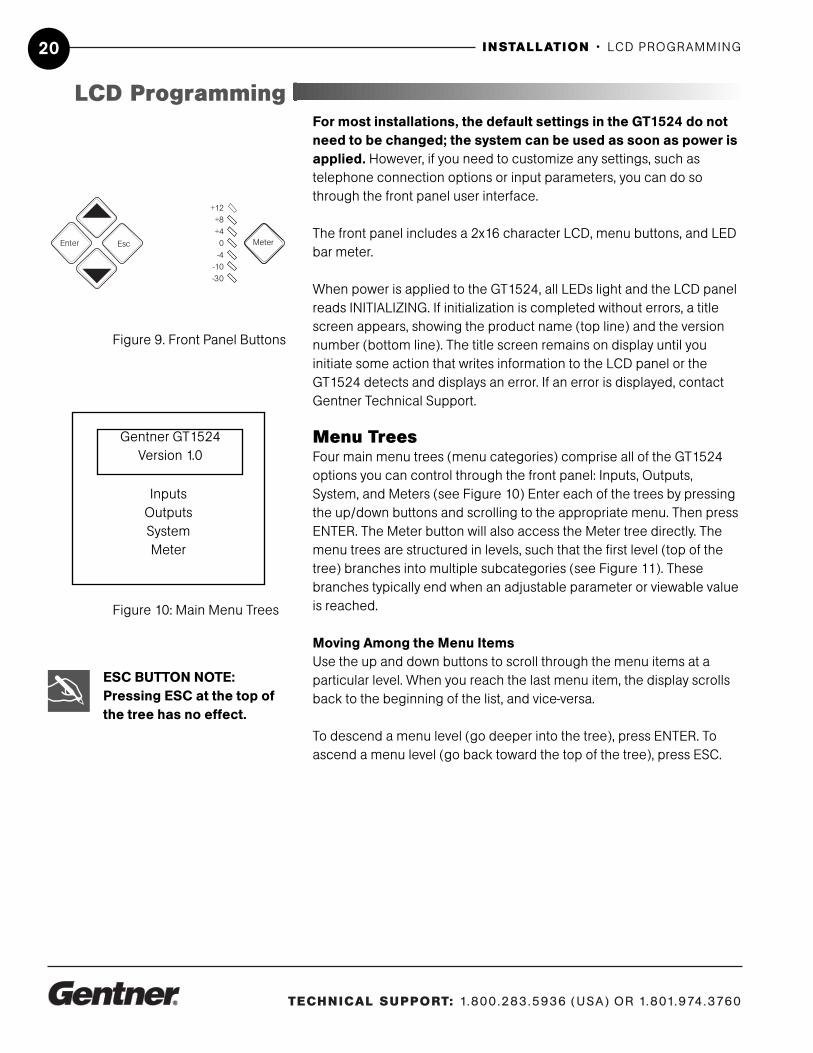
For most installations, the default settings in the GT1524 do notneed to be changed; the system can be used as soon as power isapplied. However, if you need to customize any settings, such as telephone connection options or input parameters, you can do sothrough the front panel user interface.
The front panel includes a 2x16 character LCD, menu buttons, and LEDbar meter.
When power is applied to the GT1524, all LEDs light and the LCD panelreads INITIALIZING. If initialization is completed without errors, a titlescreen appears, showing the product name (top line) and the versionnumber (bottom line). The title screen remains on display until you initiate some action that writes information to the LCD panel or theGT1524 detects and displays an error. If an error is displayed, contactGentner Technical Support.
Menu TreesFour main menu trees (menu categories) comprise all of the GT1524options you can control through the front panel: Inputs, Outputs,System, and Meters (see Figure 10) Enter each of the trees by pressingthe up/down buttons and scrolling to the appropriate menu. Then pressENTER. The Meter button will also access the Meter tree directly. Themenu trees are structured in levels, such that the first level (top of thetree) branches into multiple subcategories (see Figure 11). Thesebranches typically end when an adjustable parameter or viewable valueis reached.
Moving Among the Menu ItemsUse the up and down buttons to scroll through the menu items at a particular level. When you reach the last menu item, the display scrollsback to the beginning of the list, and vice-versa.
To descend a menu level (go deeper into the tree), press ENTER. Toascend a menu level (go back toward the top of the tree), press ESC.
LCD Programming
Meter
+12+8+4
0-4
-10-30
EscEnter
Figure 9. Front Panel Buttons
InputsOutputsSystemMeter
Figure 10: Main Menu Trees
ESC BUTTON NOTE:Pressing ESC at the top ofthe tree has no effect.
✍
Gentner GT1524Version 1.0

TECHNICAL SUPPORT: 1.800.283.5936 (USA) OR 1.801.974.3760
INSTALLATION • LCD PROGRAMMING 21
Adjusting a ValueTo adjust a parameter, first verify that it is flashing. If the parameter is notflashing, it cannot be adjusted until you press ENTER. If the parameter isflashing, adjust the value with the Up and Down buttons. As the value isadjusted, the parameter is updated immediately. For example, if youadjust input gain, you should be able to hear the difference as itchanges. To store the new value, press ENTER. To discard the changeand revert back to the old value, press ESC. In general, while adjustingparameters, numerical values do not wrap around when the end isreached. However, parameters that toggle between two values (or are alist of values) will wrap around. When adjusting a parameter and an Upor Down button is held for more than two seconds, the parameter willscroll through its values at a faster rate.

TECHNICAL SUPPORT: 1.800.283.5936 (USA) OR 1.801.974.3760
INSTALLATION• MENU TREE22
Ve rsio n .0
O u tp u ts
In p u ts
S yste m
Gentner GT15241
Mic/Line In
Aux In
From Telco
4 Wire In
Spkr/ Line Out
To Telco
4 Wire Out
Lock Panel
Set Passcode
Telco
RS232
Output To
ERL/TERL
ERLE/TERLE
Gain AdjustMic/Line Input
MutePhantom Power
AGCHigh Pass Filter Echo Canceller
NLP
Gain AdjustMuteAGC
Power-Up Screen
Gain AdjustMute
Unit ID
Baud RateFlow Control
Auto AnswerAuto Disconnect
Input FromMic/Line
Aux4 Wire Telco
Spkr/LineAux
4 WireTelco
ERLTERL
Ring Indication
Spkr/Line OutFrom Telco
4 Wire InAux In
Mic/Line InTo Telco
4-Wire Out Aux Out
Mic/Line InAux In
Gain AdjustMuteAux Out
Default Meter
ERLETERLE
Meters
Aux Out Mix
Figure 11. LCD Menu Tree and Defaults

TECHNICAL SUPPORT: 1.800.283.5936 (USA) OR 1.801.974.3760
INSTALLATION • PARAMETERS WORKSHEET 23
Figure 12. Parameters Worksheet
GT1524 Parameters Worksheet
Program Parameter Selection RangeLock Panel On, Off
Set Passcode Any 5 Front Panel Keys (Enter)
RS232 Baud Rate 9.6, 19.2, 38.4 kbps
RS232 Flow Control On, Off
Telco Auto Answer On, Off
Telco Auto Disconnect Off, Loop Drop, Call Prog, LD + CP
Telco Ring Indication Off, 1, 2, 3, 4
Unit ID No. Factory Programmed
*Timeout 0 - 15 (10)
*Telco Adapt Mode Auto, Burst
*Hook Duration 50 ms, 500 ms*Receive Reduction On, Off
Program Parameter Selection RangeDefault Meter Any Input/Output (Spkr/Line Out)
Mic/Line In Aux In 4 Wire In From TelcoProgram Parameter Selection RangeGain Adjust -20dB to 20dB (0)
Mic/Line Input Mic 55dB, Mic 25 dB, Line
Mute On, Off
Phantom Power On, Off
AGC On, Off
High-Pass Filter On, Off
Echo Cancellation On, OffNLP Adjust Off, Soft, Medium, Aggressive
Spkr/Line Out Aux Out 4 Wire Out To TelcoProgram Parameter Selection RangeGain Adjust -20dB to 20dB (0)
Mute On, Off
Aux Out Mix (Mic/Line In) On, OffAux Out Mix (Aux In) On, Off
* et up only by seri l port
Output Channel
System-Wide Parameters
Input Channel
Meter

TECHNICAL SUPPORT: 1.800.283.5936 (USA) OR 1.801.974.3760
INSTALLATION • LCD PROGRAMMING24
Input ParametersThere are four main submenus under the Inputs menu tree: Mic/Line In,Aux In, 4 Wire In, and From Telco (see Figure 13).
Mic/Line In Gain Adjust. This adjusts the Mic/Line In submenus, including the levelfor the Input’s gain (ranging between -20dB and 20dB). The default setting is 0dB.
Mic/Line Input. This input defaults as a line-level input (0dB gain) butcan be switched to a mic level input (55dB or 25dB gain).
Mute. This parameter mutes the input channel.
Phantom Power. Defaults with 24V phantom power disabled, but maybe switched on to accommodate input devices requiring phantompower.
AGC. The input can use automatic gain control (AGC). This featurekeeps softer and louder talkers at a consistent transmit level. This feature is disabled when shipped from the factory. The target gain is0dB and adjusts at 2dB per second. The AGC start adjustment is -20dB,but will adjust only +6dB. Adjustments will not be made at .5dB oneither side of the target (0dB).
High-Pass Filter. A high-pass filter may be selected on the Mic/Lineinput to reduce unwanted noise. The filter has a break frequency at250Hz, and -3dB down at 200Hz, then rolls off at 6dB per octave.This feature is disabled when shipped from the factory.
Echo Canceller. Activate or deactivate the echo cancellation featurefor this input. Factory default is ON.
NLP Adjust. Non-linear processing (NLP) has four settings: soft (6dB),medium (12dB), aggressive (18dB), and OFF. NLP adds more echo cancelling “horsepower” in difficult acoustical environments. Use carewhen increasing NLP, because of the corresponding trade-offs whichcan include suppression and half-duplex operation. Factory default isSOFT.
From Telco and 4-Wire InThree input parameters can be applied to the inputs: Gain Adjust, Mute,and AGC.
Gain Adjust. This adjusts each input’s gain (ranging between -20dBand 20dB) in conjunction with the LCD readout and the LED bar graph.The default setting is 0dBu.
Mic/Line InAux In
4-Wire InFrom Telco
Gentner GT1524Version 1.0
Inputs
Figure 13. Input-level LCD Parameters

TECHNICAL SUPPORT: 1.800.283.5936 (USA) OR 1.801.974.3760
INSTALLATION • LCD PROGRAMMING 25
Mute. This parameter mutes the input channel.
AGC. The input can use automatic gain control (AGC). This featurekeeps softer and louder talkers at a consistent transmit level. This feature is disabled when shipped from the factory. The target gain is0dB and adjusts at 2dB per second. The AGC start adjustment is -20dB,but will adjust only +6dB. Adjustments will not be made at .5dB oneither side of the target (0dB).
Output ParametersThere are four main submenu under the Outputs menu tree:Speaker/Line Out, Aux Out, 4 Wire Out, and To Telco. Each of thesesubmenus contain the same menus at the next menu depth: GainAdjust and Mute. Aux Out also features an Aux Out Mix parameter,described below. Each parameter is applied to the respective outputs.
Gain Adjust. This adjusts each output’s gain (ranging between -20dBand 20dB), in conjunction with the LCD readout and the LED bar meter.Default is 0dB.
Mute. This parameter mutes a particular output channel. Default isOFF.
Aux Out Mix. This parameter selects Mic/Line In and/or Aux In to AuxOut.
System ParametersThe System menu allows you to view five parameters: Lock Panel, SetPasscode, RS232, Telco, and Unit ID. The first four may also be adjusted.
Lock PanelThe GT1524 can be secured from unauthorized adjustments by lockingthe front panel and establishing a user passcode. Menu items can stillbe viewed when the panel is locked, but settings cannot be altered orentered until the panel is unlocked by entering the appropriate passcode.To lock the front panel:1. Enter the SYSTEM menu2. Scroll through the menu items to select LOCK PANEL, and pressENTER.3. Select ON, and press ENTER again.
To unlock the front panel:1. Attempt to adjust a parameter. The GT1524 prompts you for the passcode.2. Begin entering the passcode. Once you have correctly entered the
LOCK PANEL NOTE:If you enter a passcodeand unlock the system,
you must lock it again after making any changes. Otherwisethe panel will remain unlockedand accessible to anyone.
✍
Lock PanelSet Passcode
RS232Telco
Unit ID
Gentner GT1524Version 1.0
System
Figure 15. System-level LCD Parameters
Spkr/Line Out4 Wire Out
To TelcoAux Out
Gain or Mute
Gentner GT1524Version 1.0
Outputs
Figure 14. Output-level Parameters

TECHNICAL SUPPORT: 1.800.283.5936 (USA) OR 1.801.974.3760
INSTALLATION • LCD PROGRAMMING26
fifth character, the front panel unlocks. (The default passcode forall units is Up, Up, Down, Down, ENTER.)
Set PasscodeOnce you have unlocked the GT1524, you can change the passcode.Before the GT1524 allows passcode changes, the new passcode mustbe entered, then re-entered to validate it. The passcode must be fivefront panel buttons (in any combination or multiple).
RS232Two RS232 parameters can be adjusted through the front panel LCD:baud rate and flow control. If data is lost during serial access throughthe RS232 port, a serial overrun error will occur. This is indicated on theLCD display. This parameter sets the GT1524’s RS232 port communication rate at 9,600 (default), 19,200, or 38,400 baud (bps).
BaudTo set the baud rate, scroll through the settings to select the desiredbaud rate, then press ENTER.
Flow ControlThe flow control parameter allows activation and deactivation of hardware flow control. The two options are ON and OFF (default). Toactivate the flow control, scroll to ON and press ENTER. To deactivate it,scroll to OFF and press ENTER.
TelcoAuto Answer On/OffThis parameter sets the telephone interface to automatically answer anincoming call (AUTO ANSWER ON), or allow the call to be handledmanually (AUTO ANSWER OFF).
Auto DisconnectThe interface can also be set to disconnect upon LOOP DROP, CALLPROGRESS, LOOP DROP + CP (call progress), or to disconnect manually (AUTO DISCONNECT OFF). An audible ring indicator, sentto the PA output, can also be enabled or disabled under this menu.
Unit ID NumberThe UNIT ID # allows you to view the read-only unit address set at thefactory. This unique ID number identifies that particular unit and cannotbe changed.

TECHNICAL SUPPORT: 1.800.283.5936 (USA) OR 1.801.974.3760
INSTALLATION • LCD PROGRAMMING 27
Meter ParametersThere are five main submenus under the meter menu tree: Inputs,Outputs, ERL/TERL, ERLE/TERLE, and Default Meter. The first four submenus are all handled in the same way.
Referencing the LCD, press the METER button, then scroll through theoptions (Inputs, Outputs, ERL/TERL and ERLE/TERLE) to specify whichis to be metered by the front-panel LED meter. When the appropriateoption is visible, press ENTER to begin monitoring its status on the frontpanel LCD. All items under this menu can be scrolled through by pressing the UP/DOWN arrows.
The default meter parameter determines what is being displayed on theLED meter when the GT1524 times out.
Timeout. The GT1524 has a system mode called TIMEOUT. Thisparameter may be adjusted through the RS232 port only using theTOUT command. TIMEOUT controls the delay time (in minutes) beforethe LCD panel will automatically switch back to the title screen anddefault meter. The range is 0–15 minutes. Default is 10 minutes; 0 disables this mode.
Input, Output, ERL, ERLE, orDefault
Meter
Gentner GT1524Version 1.0
Figure 16. Meter-level Parameters
TIMEOUT NOTE:Disabling the timeout willallow the GT1524 to remain
in the same position in the LCDmenu until the LCD menu is manipulated again.
✍

TECHNICAL SUPPORT: 1.800.283.5936 (USA) OR 1.801.974.3760
INSTALLATION • LCD PROGRAMMING28

TECHNICAL SUPPORT: 1.800.283.5936 (USA) OR 1.801.974.3760
4Operation
Front Panel
OPERATION • FRONT PANEL 29
A correctly installed GT1524 virtually runs by itself. Typical operationsinvolve changing volume of an output, muting an input or output, orhandling calls on the connected telephone handset. For most installations, a custom remote control (optional) would be used.
Controlling VolumeWhen participating in a conference, you may find it necessary toincrease or decrease the volume of a particular output. For instance,when the audio at a distant location is too soft, adjust the output to thespeakers so that the level is comfortable.
To adjust the volume:1. Determine which output needs to be adjusted.2. Scroll to the OUTPUTS menu, select the appropriate output, andscroll to GAIN ADJUST. Press ENTER.3. Adjust the gain level using the Up and Down buttons. You should beable to hear the volume level adjust while increasing or decreasing thegain.4. Press ENTER when you reach the desired volume level.
The volume adjust procedure is the same for all channels.
MutingWhen participating in a conference, you may find it necessary to mute(or un-mute) a particular input or output.
Muting or Unmuting Channel (Input or Output)1. Determine the input or output you want to mute.
Note: For optimum performance, adjust allinputs to 0dBu before
calibrating outputs.
✍

TECHNICAL SUPPORT: 1.800.283.5936 (USA) OR 1.801.974.3760
OPERATION • FRONT PANEL30
2. Scroll to the desired input or output Press ENTER.3. Scroll through the input or output parameters until you see MUTE.Press ENTER.4. Use the UP/DOWN buttons to select ON, then press ENTER.The input or output is now muted. To unmute the input or output, followthe same procedure, but select OFF to deactivate the mute function.
Answering a CallAn incoming call rings on the telephone set connected to the GT1524(and speaker, if one is connected to the GT1524) and causes the ONLED to flash. There are four ways to answer an incoming call:1. Set AUTO ANSWER ON to answer the call automatically.2. Set AUTO ANSWER OFF and press the Telephone/ON button toanswer the call manually.3. Send a serial command (for example, TE 1) through the RS232 port(see GT1524 Serial Commands on page 36).4. Pick up the telephone handset to answer manually. When you’reready to connect the call to the GT1524, press the Telephone/ON button or send the "TE 1" serial command.
To answer a call on the GT1524, press the ON button on either the frontpanel or from the RS232 port (TE 1) or just pick up the handset. Thegreen ON LED lights. The red OFF LED turns off.
Making a CallCall the party using your handset. After the other party has answered,route the call through the GT1524 by pressing the ON button.
The ON LED lights and the GT1524 takes control of the call, disablingthe telephone set. You may now safely hang up the handset without disconnecting the call or access the DTMF dialer in the GT1524 via aremote control system.
Disconnecting a CallIf the call is routed through the GT1524 (the ON LED glows green),press the OFF button on the front panel or send a command throughthe RS232 port (TE 0). The OFF LED glows red, and the ON LED turnsoff.
Custom Controller OptionsThe GT1524 is designed to function with remote control systems. Thecontroller is connected to the GT1524 through the RS232 port. The APIR Remote also functions with the GT1524.
You can perform all actions through the custom controller:· Turn GT1524 telephone connection on or off
AUTO-ANSWER NOTE:If AUTO ANSWER is turnedON under SYSTEM settings,
the GT1524 answers the call afterthe second complete ring. A ringingtone is provided to the Line andSpeaker output if Ring Indication isturned on.
✍
NOTE: When using the DIALserial port command, theGT1524 automatically
engages the hybrid. You do notneed to press the ON button.
✍
AUTO-DISCONNECT NOTE:If auto-disconnect is turnedON in SYSTEM settings, the
GT1524 disconnects upon sensingloop drop or call progress tones.
✍

TECHNICAL SUPPORT: 1.800.283.5936 (USA) OR 1.801.974.3760
OPERATION • FRONT PANEL 31
· Mute transmitted and received audio
· Generate DTMF tones
· Adjust volume on received audio
· Re-null the telephone hybrid
· Meter input and output
· Read TERL and TERLE
· Control any function on the unit
REMOTE CONTROL NOTE:Gentner Communicationsrecommends use of a
custom remote controller for userinterface. Refer to the manufacturer’s documentation foryour particular custom remote controller.
✍

TECHNICAL SUPPORT: 1.800.283.5936 (USA) OR 1.801.974.3760
OPERATION • FRONT PANEL32
TECHNICAL SUPPORT: 1.800.283.5936 (USA) OR 1.801.974.3760
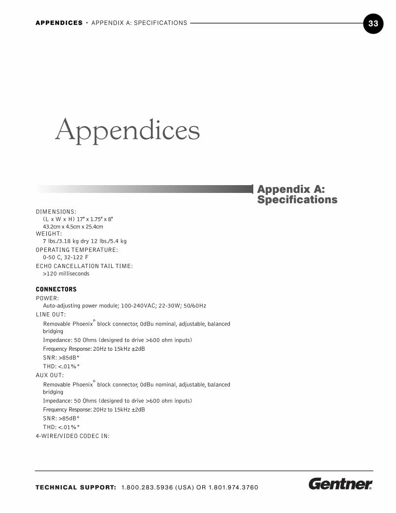
DIMENSIONS:(L x W x H) 17" x 1.75" x 8" 43.2cm x 4.5cm x 25.4cm
WEIGHT:7 lbs./3.18 kg dry 12 lbs./5.4 kg
OPERATING TEMPERATURE:0-50 C, 32-122 F
ECHO CANCELLATION TAIL TIME:>120 milliseconds
CONNECTORSPOWER:
Auto-adjusting power module; 100-240VAC; 22-30W; 50/60Hz
LINE OUT:
Removable Phoenix®
block connector, 0dBu nominal, adjustable, balancedbridging
Impedance: 50 Ohms (designed to drive >600 ohm inputs)
Frequency Response: 20Hz to 15kHz ±2dB
SNR: >85dB*
THD: <.01%*
AUX OUT:
Removable Phoenix®
block connector, 0dBu nominal, adjustable, balancedbridging
Impedance: 50 Ohms (designed to drive >600 ohm inputs)
Frequency Response: 20Hz to 15kHz ±2dB
SNR: >85dB*
THD: <.01%*
4-WIRE/VIDEO CODEC IN:
Appendices
APPENDICES • APPENDIX A: SPECIFICATIONS 33
Appendix A:Specifications

TECHNICAL SUPPORT: 1.800.283.5936 (USA) OR 1.801.974.3760
APPENDICES • APPENDIX A: SPECIFICATIONS34
Removable Phoenix®
block connector, 0dBu nominal, adjustable, balancedbridging
Impedance: 20kOhms
Frequency Response:20Hz to 15kHz ±2dB
SNR: >85dB*
THD: <.01%*
4-WIRE/VIDEO CODEC OUT:Removable Phoenix
®
block connector, 0dBu nominal, adjustable, balancedbridgingImpedance: 50 Ohms (designed to drive >600 ohm inputs)
Frequency Response: 20Hz to 15kHz ±2dB
SNR: >85dB*
THD: <.01%*
MIC/LINE IN:Removable Phoenix
®
block connector, -55 or 0dBu nominal, adjustable,balanced bridging
Impedance: 4kOhms
Frequency Response:20Hz to 15kHz ±2dB
Phantom Power: 24VDC input, selectable
Noise: EIN 20Hz to 15kHz - 125dBu
THD: <.03%*
AUX IN:Removable Phoenix® block connector, 0dBu nominal, adjustable, balancedbridging
Impedance: 20kOhmsFrequency Response:20Hz to 15kHz ±2dB
SNR: >85dB*
THD: <.01%*SPEAKER OUT:
Binding Post 5W max into 4 Ohms
RS232:DB9 female, 9,600/19,200/38,400 (bps) baud selectable
TELCO LINE:RJ11 connector—POTS (Plain Old Telephone Service) line or analog extensionfrom PBX
TELCO SET:RJ11 connector—analog telephone set
CONTROL/STATUS:DB25 female; (2) +5VDC pins, 100mA each (8) open collector statusoutputs, 20V max, 40mA each (8) momentary control inputs, active low
TELCO AUDIO PERFORMANCEFrequency Response: ±2dB from 250Hz to 3.3kHz (AGC disabled)SNR: >60dB (referenced at –15dBm on/off the telephone line)THD: <2%, 250Hz to 3.3kHz (ACG disabled) referenced at –15dBm on/off the
phone linePre Emphasis: +4dB at 2kHzTelco Cancellation Tail Time:
31 milliseconds
* All measurements are referenced to maximum output level with a bandpass of20Hz to 20kHz unless otherwise specified.

TECHNICAL SUPPORT: 1.800.283.5936 (USA) OR 1.801.974.3760
APPENDICES • APPENDIX B: CONNECTOR PINOUTS 35
Appendix B:Connector PinoutsTable 1. RS232 COM DCE Port Pinout
Pin Number Control1 DCD 6 DSR2 TXD 7 CTS3 RXD 8 RTS4 DTR 9 No connection5 Ground
Table 2. Control/Status Port PinoutPin Number Default Description1 Aux In to Aux Out Toggle2 Status of Aux into Aux Out3 Mute Mic/Line In Toggle4 Status of Mic/Line In Mute5 Telephone On/Off Toggle6 Status Telephone On/Off7 Auto Answer Toggle8 Status of Auto Answer9 Mute Line Out Toggle10 Status of Line Out Mute11 Mute 4-wire In Toggle12 Status of 4-wire In Mute13 Volume Up Speaker/Line (1dB)14 no connection15 Volume Down Speaker Line (1dB)16 no connection17 no connection18 no connection19 no connection20 no connection21 Ring Indication22 no connection23 +5Vdc24 +5Vdc25 Ground
5 1
9 6
13
25
1
14
NOTE: All commands aremomentary.✍

TECHNICAL SUPPORT: 1.800.283.5936 (USA) OR 1.801.974.3760
APPENDICES • APPENDIX C: SERIAL PORT COMMANDS36
Serial Port CommandsThe GT1524 accepts serial commands through the serial port. The commands provide the same control as the LCD menu structure, plussome additional controls. The following commands pertain only to theGT1524. RS232 Serial Port Protocol is 9,600 (default), 19,200 or 38,400baud, 8bits, 1 stop bit, no parity. Refer to the Serial Port Commandstable (Figure 17) for the GT1524’s serial commands.
The structure of serial commands is as follows:
Command, then any additional options in the order that they appear inthe command descriptions on the following pages. Commands can beeither UPPER CASE or lower case. Return values are always in uppercase. For a command to be recognized by the serial port, the commandmust be terminated by a carriage return.
Command SyntaxThe serial command line uses the following typographic conventions:<X> Parameters enclosed in "< >" indicate a mandatory parameter[X] Parameters enclosed in "[ ]" indicate an optional parameter1-8 Parameters separated by a "-" indicate a range between the values4, 7, 9 Parameters separated by a "," indicate a list of available valuesMREF Words in ALL CAPS bold indicate command text
Error CodesThe following lists possible error messages and their explanations:
ERROR 1 (Future)ERROR 2 Could not extract a command from the string receivedERROR 3 Serial overrunERROR 4 ReservedERROR 5 Invalid parameterERROR 6 Unrecognized command
The command string will then be explained (where necessary), followedby the returned values and (where necessary) an example.
The first 16 pins of theControl/Status port areprogrammable through
direct serial port commands.
✍
Appendix C:Serial PortCommands

TECHNICAL SUPPORT: 1.800.283.5936 (USA) OR 1.801.974.3760
APPENDICES • APPENDIX C: SERIAL PORT COMMANDS 37
GT1524 Serial Commands
Command Function
AA Selects/Reports Auto Answer for Telco Port
AD Selects/Reports Auto Disconnnect for Telco Port
AGC Enables/Disables AGC†
AUXMIX Enables/Disables Mic/Line In and Aux In to Aux Out
BAUD Sets/Reports RS232 Port Baud Rate
DFLTM Sets/Reports Default Meter
DIAL Sends Dial String to Telco Port
EC Enables/Disables Echo Canceller
ERL Returns ERL for the Mic/Line In Channel
ERLE Returns ERLE for the Mic/Line In Channel
FLOW Enables/Disables Flow Control
FPP Sets/Reports Front Panel Passcode
GAIN Sets/Reports Gain Setting†
HOOK Sends Hook/Flash Command
HOOKD Selects/Reports Hook Duration Time
LFP Enables/Disables Front Panel Lock
LVL Reports Level†
MHP Sets/Reports High Pass Filter Status
MLINE Sets/Reports Mic Gain
MUTE Sets/Reports Mute†
NLP Sets/Reports Non-Linear Mic Processing
NULL Sends Noise Burst, Adapting Unit to Phone Line
PP Sets/Reports Phantom Power for Mic/Line In
RING Reports Presence of a Ring on Telco Port
RINGEN Selects/Reports Ring Indication
RXRD Sets/Reports Receive Reduction to Telco Port
TAMODE Sets/Reports Telco Adapt Mode
TE Sets/Reports Telco Off Hook Status
TERL Returns Echo Return Loss for Telco Channel
TERLE Returns Echo Return Loss Enhancement for Telco Channel
TOUT Sets/Reports Inactivity Timeout
UID Returns ID Number of Unit
VER Returns Current Version of Software
†Applied to a specific channel Figure 17. Serial Commands

TECHNICAL SUPPORT: 1.800.283.5936 (USA) OR 1.801.974.3760
APPENDICES • APPENDIX C: SERIAL PORT COMMANDS38
Serial Command Parameters and Explanations
AAThis command activates and deactivates the auto answer feature.AA <X>Explanation
<X>X=0 Parameter disables auto-answerX=1 Parameter enables auto-answerX=2 Parameter to toggle the state from one state to the other(regardless of current state)X= Null Parameter to report back the current state
Return ValuesThe command will return the updated condition (On=1, Off=0) ofthe auto answer in the same format as the command.
ADThis command changes the state of the auto disconnect function.AD <X>Explanation
<X>X=0 Parameter to set Auto Disconnect to OFFX=1 Parameter to set Auto Disconnect to LOOPX=2 Parameter to set Auto Disconnect to Call Progress (CP)X=3 Parameter to set Auto Disconnect to LOOP+CPX=Null Parameter to report back the current state
Return ValuesThe command will return the updated connection state of the unit in thesame format as the command. If the sent command changes the stateof the unit, the updated state is returned.
If: Command Returns:current disconnect state is OFF AD 0current disconnect state is LOOP AD 1current disconnect state is CP AD 2current disconnect state is LOOP+CP AD 3
AGCThis command changes or reports back the state of the AGC for amicrophone or line input.AGC <CH> <X>Explanation
<CH>CH= 1 Mic./Line inputCH= 2 Aux. inputCH= 3 4wire inputCh=4 telco input<X>

TECHNICAL SUPPORT: 1.800.283.5936 (USA) OR 1.801.974.3760
APPENDICES • APPENDIX C: SERIAL PORT COMMANDS 39
X=0 Parameter to set the state to OFFX=1 Parameter to set the state to ONX=2 Parameter to toggle the state from one state to the other(regardless of current state)X= Null Parameter to return the current state
Return ValuesThe command will return the updated condition (On=1, Off=0) ofthe AGC in the same format as the command.
AUXMIXThis command changes or reports back the state of the Aux Mix Out.AUXMIX <CH> <X>Explanation
<CH>CH=1 Mic/Line InCH=2 Aux In<X>X=0 Parameter to set the state to OFFX=1 Parameter to set the state to ON
Return ValuesThe command will return the updated condition of the Aux Mix inthe same format as the command.
BAUDThis command selects or returns the baud rate for the RS232 port onthe GT1524.BAUD <X>Explanation
<X>X=1 Selects 9,600 baud (bps) rateX=2 Selects 19,200 baud (bps) rateX=3 Selects 38,400 baud (bps) rateX= Null Parameter to return the baud (bps) rate
Return ValuesThe command will return the updated condition (1=9,600 baud,2=19,200 baud, 3=38,400 baud) of the RS232 baud rate in thesame format as the command.
DFLTMThis command changes and reports back the status of the defaultmeter.DFLTM <CH> <W>Explanation
<CH>CH= 1 Mic./Line input, Line outputCH= 2 Aux. input, Aux outputCH= 3 4 wire input, 4 wire output

TECHNICAL SUPPORT: 1.800.283.5936 (USA) OR 1.801.974.3760
APPENDICES • APPENDIX C: SERIAL PORT COMMANDS40
Ch=4 telco input, telco output<W>W= I Parameter to specify an input channelW= O Parameter to specify an output channel
Return ValuesThe command will return the current default meter in the same format as the command.
DIALThis command generates DTMF tones. This capability remains activeafter the call is placed so tones can be issued for use with voice mailand pagers.DIAL <STRING>Explanation
<STRING> is any valid combination of touch tone characters. Acomma indicates a two-second pause. STRING has a maximumlength of 15 characters. Valid characters are 0 through 9, A throughD, *, # and ",".
Return ValuesDIAL returns the dialed string of numbers. For example, the following command dials the number 801-975-7200. A "9" and apause are generated to get an outside line on a PBX:The number to be dialed: The following is returned out the serialport:DIAL 9,8019757200 DIAL 9,8019757200
ECThis command changes or reports back the state of the echo canceller.EC <X>Explanation
<X>X=0 Parameter to set the state to OFFX=1 Parameter to set the state to ONX=Null Parameter to return the current state
Return ValuesThe command will return the updated condition (On=1, Off=0) ofthe echo canceller in the same format as the command.
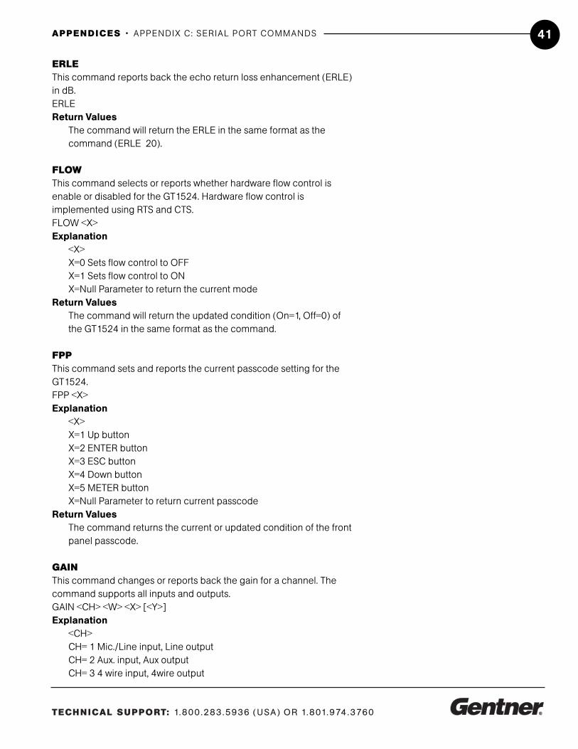
ERLThis command reports back the echo return loss (ERL) in dB.ERL Return Values
The command will return the ERL in the same format as the command (ERL 20).
TECHNICAL SUPPORT: 1.800.283.5936 (USA) OR 1.801.974.3760
APPENDICES • APPENDIX C: SERIAL PORT COMMANDS 41
ERLEThis command reports back the echo return loss enhancement (ERLE)in dB.ERLE Return Values
The command will return the ERLE in the same format as the command (ERLE 20).
FLOWThis command selects or reports whether hardware flow control isenable or disabled for the GT1524. Hardware flow control isimplemented using RTS and CTS.FLOW <X>Explanation
<X>X=0 Sets flow control to OFFX=1 Sets flow control to ONX=Null Parameter to return the current mode
Return ValuesThe command will return the updated condition (On=1, Off=0) ofthe GT1524 in the same format as the command.
FPPThis command sets and reports the current passcode setting for theGT1524.FPP <X>Explanation
<X>X=1 Up buttonX=2 ENTER buttonX=3 ESC buttonX=4 Down buttonX=5 METER buttonX=Null Parameter to return current passcode
Return ValuesThe command returns the current or updated condition of the frontpanel passcode.
GAINThis command changes or reports back the gain for a channel. Thecommand supports all inputs and outputs.GAIN <CH> <W> <X> [<Y>]Explanation
<CH>CH= 1 Mic./Line input, Line outputCH= 2 Aux. input, Aux outputCH= 3 4 wire input, 4wire output

TECHNICAL SUPPORT: 1.800.283.5936 (USA) OR 1.801.974.3760
APPENDICES • APPENDIX C: SERIAL PORT COMMANDS42
Ch=4 telco input, telco output<W>W=I Parameter to set inputW= O Parameter to set output<X>X= -20 to 20 Parameter to set the levelX= Null Parameter to return the current level<Y>Y=R Parameter to indicate relativeY=A Parameter to set the level absoluteY=Null Parameter will default to R (relative)
Return ValuesThe command will return the updated level of the channel in thesame format as the command. The level returned is alwaysabsolute.
ExamplesThe following command lowers the gain 3dB on the Mic/Line inputchannel.GAIN 1 I -3
HOOKThis command sends a momentary interruption in the line seizure(hook flash) to the telephone line.HOOKReturn Values
If hook flash succeeded, the following is returned out the port:HOOK 0
HOOKDThis command controls and reports the Hook Duration of the unit.HOOKD <X>Explanation
<X>X=1 Parameter to set Hook Duration to 50 ms.X=2 Parameter to set Hook Duration to 500 ms.X=Null Parameter to report back the current state.
Return ValuesThe command will return the current hook duration of the unit in thesame format as the command. If the sent command changes thehook duration of the unit, the updated hook duration is returned.
LFPThis command locks, unlocks, or returns the current state of the frontpanel from the serial port.LFP <X>Explanation
<X>

TECHNICAL SUPPORT: 1.800.283.5936 (USA) OR 1.801.974.3760
APPENDICES • APPENDIX C: SERIAL PORT COMMANDS 43
X=0 Parameter to unlock the front panel.X=1 Parameter to lock the front panelX=2 Parameter to toggle the state from one state to the other(regardless of current state)X=Null Parameter to return the current state of the front panel
Return ValuesThe command will return the updated condition of the front panel.
LVLThis command reports back the level for a given channel.LVL <CH> <W>Explanation
<CH>CH= 1 Mic./Line input, Line output CH= 2 Aux. input, Aux outputCH= 3 4 wire input, 4wire output Ch=4 telco input, telco outputW= I Parameter to specify an input meterW= O Parameter to specify an output meter
Return ValuesThe command will return the input level of the channel in the sameformat as the command.
MHPThis command changes or reports back the state of the high pass filterfor the Mic/Line input.MHP <X>Explanation
<X>X=0 Parameter to set the state to OFFX=1 Parameter to set the state to ONX=Null Parameter to return the current state
Return ValuesThe command will return the updated condition (On=1, Off=0) ofthe high pass filter in the same format as the command.
MLINEThis command changes or reports back how much gain is applied tothe Mic/Line input. The three settings are 0dB, 25dB, and 55dB.MLINE <X>Explanation
X=1 Parameter to set the state to 55dB gainX=2 Parameter to set the state to 25dB gainX=3 Parameter to set the state to 0dB (line level)X= Null Parameter to return the current state

TECHNICAL SUPPORT: 1.800.283.5936 (USA) OR 1.801.974.3760
APPENDICES • APPENDIX C: SERIAL PORT COMMANDS44
Return ValuesThe command will return the updated condition of the gain appliedin the same format as the command.
MUTEThis command changes or reports the state of mute for a given channel.MUTE <CH> <W> <X>Explanation
<CH>CH= 1 Mic./Line input, Line outputCH= 2 Aux. input, Aux outputCH= 3 4 wire input, 4wire outputCh=4 telco input, telco output<W>W=I Parameter to set inputW=O Parameter to set output<X>X=0 Set mute to OFFX=1 Set mute to ON (mute the selected channel)X=2 Parameter to toggle the state from one state to the other(regardless of current state)X=NULL Report the current state of mute for the selected channel
Return ValuesThe command will return the mute status (On=1, Off=0) in the sameformat as the command.
NLPThis command changes or reports back the state of the nonlinear processing for the echo canceller.NLP > <X>Explanation
X=0 Parameter to set the state to OFFX=1 Parameter to set the state to softX=2 Parameter to set the state to mediumX=3 Parameter to set the state to aggressiveX= Null Parameter to return the current state
Return ValuesThe command will return the updated condition (0=Off, 1=Soft,2=Medium, 3=Aggressive) of the nonlinear processing in the sameformat as the command.
NULLThis command sends a short noise burst down the telephone line andadapts the GT1524 to the telephone line.NULL

TECHNICAL SUPPORT: 1.800.283.5936 (USA) OR 1.801.974.3760
APPENDICES • APPENDIX C: SERIAL PORT COMMANDS 45
Return ValuesNULL is returned out the serial port when the command has beenexecuted.
PPThis command changes or reports back the state of the phantompower for a microphone.PP <X>Explanation
<X>X=0 Parameter to set the state to OFFX=1 Parameter to set the state to ONX=Null Parameter to return the current state
Return ValuesThe command will return the updated condition (On=1, Off=0) ofthe phantom power in the same format as the command.
RINGThis command reports the presence of a Ring on the Telco port. (This isan indication only.)RINGReturn Value
The Ring is sent if a valid ring has been sensed on the Telco line:RING
RINGENThis command changes or reports back the state of the Ring Indication.RINGEN <X>Explanation
<X>X=0 Parameter to set the state to OFFX=1 Parameter to set the state to RING 1X=2 Parameter to set the state to RING 2X=3 Parameter to set the state to RING 3X=4 Parameter to set the state to RING 4X= Null Parameter to return the current state
Return ValuesThe command will return the updated condition of the RingIndication in the same format as the command.
RXRDThis command controls or reports the Receive Reduction control of theunit.RXRD <X>Explanation
<X>X=0 Parameter to set Receive Reduction to OFF

TECHNICAL SUPPORT: 1.800.283.5936 (USA) OR 1.801.974.3760
APPENDICES • APPENDIX C: SERIAL PORT COMMANDS46
X=1 Parameter to set Receive Reduction to ONX=2 Parameter to toggle the current stateX=Null Parameter to report back the current state
Return ValuesThe command returns the updated connection state of the unit inthe same format as the command.
TAMODEThis command controls or reports the Telephone Adapt Mode control ofthe unit.TAMODE <X>Explanation
<X>X=0 Parameter to set Telephone Adapt Mode to AutoX=1 Parameter to set Telephone Adapt Mode to BurstX=Null Parameter to report back the current state
Return ValuesThe command returns the updated connection state of the unit inthe same format as the command.
TEThis command controls or reports the connection status of the unit.TE <X>Explanation
<X>X=0 Parameter to set the unit to disconnect from the lineX=1 Parameter to set the unit to connect to the lineX=2 Parameter to toggle the state from one state to the otherX=Null Parameter to report back the current state
Return ValueIf the current state is ON, the following is returned. If the currentstate is OFF, the following is returned out the serial port:TE 1 TE 0
TERLThis command reports back the telephone echo return loss (TERL) forthe GT1524 in decibels.TERLExample:If the current TERL level is 10 dB, the following is returned out the serialport:TERL 10
TERLEThis command reports back the telephone echo return loss enhance-ment (TERLE) for the GT1524 in decibels.TERLE
TECHNICAL SUPPORT: 1.800.283.5936 (USA) OR 1.801.974.3760
APPENDICES • APPENDIX C: SERIAL PORT COMMANDS 47
ExampleIf the current TERLE level for the telephone canceller is 20dB, the following is returned out the serial port:TERLE 20
TOUTThis command sets or reports the current inactivity timeout beforereturning to the title screen used by the unit.TOUT <X>Explanation
<X>X=0 Disables inactivity timeoutX=1-15 Sets the number of minutes specifiedX=Null Parameter to return the current number of minutes
Return ValuesThe command will return the current timeout value. If the commandchanged the timeout, the updated timeout is returned.
UIDThis command returns the unique ID number, the device type, and thedevice number of the GT1524. This command is read only. The uniqueID number is preprogrammed at the factory and is unique to the unit.UIDReturn Values
UID returns the device type and unique ID number. The unique ID iscomposed of an eight-digit hex number assigned at the factory touniquely identify the unit.
ExampleThe following command requests the unit IDfrom device: The following is returned out the serial port:UID UID A4EF906C
VERThis command returns the current version of software. This version isunique to a released version of software and is comprised of the DSP,the FPGA, and HC11 software. This command is read only.VERReturn Values
VER returns the version of software in the same format as the command. The Version is composed of a major version numberfollowed by a period and a minor version number.
Example:The following command requests the software version: The following isreturned out the serial port:VER 2.0

TECHNICAL SUPPORT: 1.800.283.5936 (USA) OR 1.801.974.3760
APPENDICES • APPENDIX D: COMPLIANCE STATEMENTS48
FCC Part 15 ComplianceThis device complies with part 15 of the FCC rules. Operation is subjectto the following two conditions: (1) This device may not cause harmfulinterference, and (2) this device must accept any interference received,including interference that may cause undesired operation.
FCC Part 68 ComplianceA label containing, among other information, the FCC registration num-ber and Ringer Equivalence Number (REN) for this equipment is promi-nently posted on the equipment. If requested, this information must beprovided to your telephone company.
USOC Jacks: This device uses RJ11C and RJ21X terminal jacks.
The REN is used to determine the quantity of devices which may beconnected to the telephone line. Excessive RENs on the telephone linemay result in the devices not ringing in response to an incoming call. Inmost, but not all areas, the sum of the RENs should not exceed five (5).To be certain of the number of devices that may be connected to theline, as determined by the total RENs, contact the telephone companyto obtain the maximum RENs for the calling area.
If this equipment causes harm to the telephone network, the telephonecompany will notify you in advance that temporary discontinuance ofservice may be required. If advance notice is not practical, the tele-phone company will notify the customer as soon as possible. Also, youwill be advised of your right to file a complaint with the FCC if youbelieve it is necessary. The telephone company may make changes inits facilities, equipment, operations, or procedures that could affect theoperation of the equipment. If this happens, the telephone company willprovide advance notice for you to make the necessary modifications inorder to maintain uninterrupted service.
If you experience problems with this equipment, contact GentnerCommunications Corporation, 1825 Research Way, Salt Lake City, Utah84119, or by phone at (801) 975-7200 for repair and warranty informa-tion. If the trouble is causing harm to the telephone network, the tele-phone company may request you remove the equipment from the net-work until the problem is resolved.
Appendix D:ComplianceStatements

TECHNICAL SUPPORT: 1.800.283.5936 (USA) OR 1.801.974.3760
APPENDICES • APPENDIX D: COMPLIANCE STATEMENTS 49
Industry Canada ComplianceThe Industry of Canada label identifies certified equipment. This certifi-cation means that the equipment meets certain telecommunicationsnetwork protective operational and safety requirements. TheDepartment does not guarantee the equipment will operate to theuser's satisfaction.
Before installing this equipment, users should ensure that it is permissi-ble to be connected to the facilities of the local telecommunicationscompany. The equipment must also be installed using an acceptablemethod of connection. In some cases, the company's inside wiringassociated with a single line individual service may be extended bymeans of a certified connector assembly (telephone extension cord).The customer should be aware that compliance with the above condi-tions may not prevent degradation of service in some situations.
Repairs to certified equipment should be made by an authorizedCanadian maintenance facility designated by GentnerCommunications. Any repairs or alterations made by the user to thisequipment, or equipment malfunctions, may give the telecommunica-tions company cause to request the user to disconnect the equipment.
Users should ensure for their own protection that the electrical groundconnections of the power utility, telephone lines and internal metallicwater pipe system, if present, are connected together. This precautionmay be particularly important in rural areas.
European Compliance (for international unit part no. 910-114-102 only)This equipment has been approved in accordance with CouncilDecision 98/482/EC for pan-European single terminal connection tothe public switched telephone network (PSTN). However, due to differ-ences between the individual PSTNs provided in different countries, theapproval does not, of itself, give an unconditionally assurance of suc-cessful operation on every PSTN network termination point.In the event of problems, you should contact your equipment supplier inthe first instance.
Gentner Communications Corporation of 1825 Research way, Salt LakeCity, Utah 84119, U.S.A. declares that this equipment is designed to becompatible with the following networks: Austria, Belgium, Denmark,Finland, France, Germany, Greece, Iceland, Ireland, Italy, Liechtenstein,Luxembourg, The Netherlands, Norway, Portugal, Spain, Sweden,Switzerland, and United Kingdom

Gentner Communications Corporation1825 Research Way, Salt Lake City, UT 84119
Phone:1.800.945.7730 / +1.801.975.7200Fax: 1.801.977.0087Web: www.gentner.com
Manual Part No. 800-114-101
Perfect Communication through Technology, Service, and Education.™


![Welcome [pdf.textfiles.com]pdf.textfiles.com/manuals/STARINMANUALS/BenQ/Manuals/Archive/PB... · The projector integrates high-performance optical engine projection and a user-friendly](https://static.fdocuments.in/doc/165x107/5bf7309409d3f2941d8ce31a/welcome-pdf-pdf-the-projector-integrates-high-performance-optical-engine.jpg)