
STEREO POWERED MIXER PSX1000 PSX1600 PSX2200pdf.textfiles.com/manuals/STARINMANUALS/Bosch -...
29
STEREO POWERED MIXER OWNER’S MANUAL PSX1000 PSX1600 PSX2200
-
Upload
truonghanh -
Category
Documents
-
view
225 -
download
0
Transcript of STEREO POWERED MIXER PSX1000 PSX1600 PSX2200pdf.textfiles.com/manuals/STARINMANUALS/Bosch -...
STEREO POWERED MIXER
OWNER’S MANUAL
PSX1000PSX1600PSX2200
CONTENTSIntroduction . . . . . . . . . . . . . . . . . . . . . . . . . . . . . . . . . . . . . . . . . . . . . . . . . . . . . . 3Input/Mono . . . . . . . . . . . . . . . . . . . . . . . . . . . . . . . . . . . . . . . . . . . . . . . . . . . . . . 4Input/Stereo . . . . . . . . . . . . . . . . . . . . . . . . . . . . . . . . . . . . . . . . . . . . . . . . . . . . . 8Effect . . . . . . . . . . . . . . . . . . . . . . . . . . . . . . . . . . . . . . . . . . . . . . . . . . . . . . . . . . 10AUX3 . . . . . . . . . . . . . . . . . . . . . . . . . . . . . . . . . . . . . . . . . . . . . . . . . . . . . . . . . . 12Phones + Mono Out + Standby . . . . . . . . . . . . . . . . . . . . . . . . . . . . . . . . . . . . . . . 13Master + Power Amplifier . . . . . . . . . . . . . . . . . . . . . . . . . . . . . . . . . . . . . . . . . . . 14Rear panel . . . . . . . . . . . . . . . . . . . . . . . . . . . . . . . . . . . . . . . . . . . . . . . . . . . . . . 18Standard installation + Master patchbay and installation alternatives . . . . . . . . . . 19Specifications . . . . . . . . . . . . . . . . . . . . . . . . . . . . . . . . . . . . . . . . . . . . . . . . . . . . 26Block diagram . . . . . . . . . . . . . . . . . . . . . . . . . . . . . . . . . . . . . . . . . . . . . . . . . . . . 27Dimensions . . . . . . . . . . . . . . . . . . . . . . . . . . . . . . . . . . . . . . . . . . . . . . . . . . . . . . 28Warranty . . . . . . . . . . . . . . . . . . . . . . . . . . . . . . . . . . . . . . . . . . . . . . . . . . . . . . . . 32
1. Security regulations as stated in the EN 60065 (VDE 0860 / IEC 65) and the CSA E65 - 94 have to be obeyed when servicing theappliance.
2. Use of a mains separator transformer is mandatory during maintenance while the appliance is opened, needs to be operated andis connected to the mains
3. Switch off the power before retrofitting any extensions, changing the mains voltage or the output voltage.4. The minimum distance between parts carrying mains voltage and any accessible metal piece (metal enclosure), respectively
between the mains poles has to be 3 mm and needs to be minded at all times. The minimum distance between parts carrying mains voltage and any switches or breakers that are not connected to the mains (secondary parts) has to be 6 mm and needs to be minded at all times.
5. Replacing special components that are marked in the circuit diagram using the security symbol (Note) is only permissible whenusing original parts.
6. Altering the circuitry without prior consent or advice is not legitimate.7. Any work security regulations that are applicable at the location where the appliance is being serviced have to be strictly obeyed.
This applies also to any regulations about the work place itself.8. All instructions concerning the handling of MOS - circuits have to be observed.
Note: SAFETY COMPONENT (HAS TO BE REPLACED WITH ORIGINAL PART ONLY)
IMPORTANT SERVICE INSTRUCTIONSCAUTION: These servicing instructions are for use by qualified personnel only. To reduce the risk of
electric shock, do not perform any servicing other than that contained in the Operating Instructions unless you are qualified to do so. Refer all servicing to qualified service personnel.
1. Read these instructions.2. Keep these instructions. 3. Heed all warnings.4. Follow all instructions.5. Do not use this apparatus near water.6. Clean only with a dry cloth.7. Do not block any of the ventilation openings. Install in accordance with the manufactures instructions.8. Do not install near any heat sources such as radiators, heat registers, stoves, or other apparatus that produce heat.9. Only use attachments/accessories specified by the manufacturer.10. Refer all servicing to qualified service personnel. Servicing is required when the apparatus has been damaged in any
way, such as power-supply cord or plug is damaged, liquid has been spilled or objects have fallen into the apparatus,the apparatus has been exposed to rain or moisture, does not operate normally, or has been dropped.
For US and CANADA only: Do not defeat the safety purpose of the grounding-type plug. A grounding type plug has two blades and a third grounding prong.The wide blade or the third prong are provided for your safety. When the provided plug does not fit into your outlet, consult anelectrican for replacement of the absolete outlet.
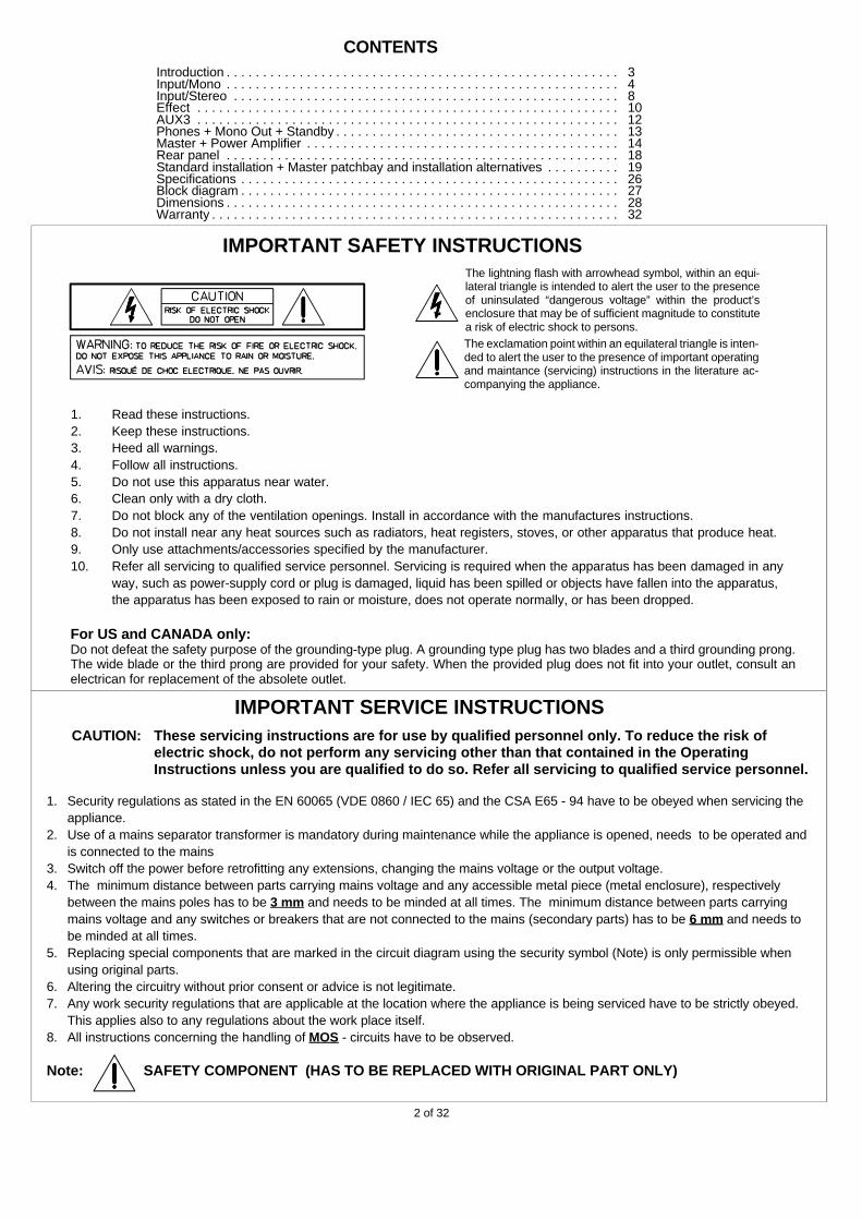
The lightning flash with arrowhead symbol, within an equi-lateral triangle is intended to alert the user to the presenceof uninsulated “dangerous voltage” within the product’senclosure that may be of sufficient magnitude to constitutea risk of electric shock to persons.
The exclamation point within an equilateral triangle is inten-ded to alert the user to the presence of important operatingand maintance (servicing) instructions in the literature ac-companying the appliance.
IMPORTANT SAFETY INSTRUCTIONS
2 of 32
FIRST OF ALL, WE WOULD LIKE TO THANK YOU AND CONGRATULATE YOU TO YOUR PURCHASE OF A ELECTRO-VOICEPOWER MIXER.
The design of the PSX compact power mixers is based on decades of experience, research and development as well client inter-communi-cation in the professional audio market. With the PSX you own a power mixer that offers a wide range of functionality in a very compact frame.All the troubling experiences with cabling and matching mixers, amplifiers, FX units, and equalizers is history. You now own a device withoptimally matched components.
The mixer’s ergonomic shape and clearly structured controls allow instant access at all times. Also during the transport you will quickly learnto appreciate the PSX’s superiority: recessed handles on both sides, compact dimensions and low weight. Additionally, a sturdy dust hoodprotects the controls against damaging.
Through its multiple functions, its high dynamic capacity, and extremely low-noise design in combination with the 18bit-Dual-Stereo effectsunit and the high-performance power amplifier, the PSX is best equipped for universal use. No matter, whether on-stage, in a home recordingenvironment or in a permanent installation, Electro-Voice’s PSX is the ideal partner to meet your expectations of a professional audio device- effective and reliable.
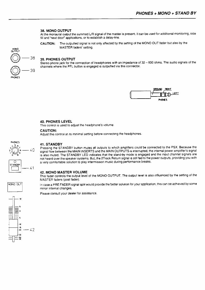
Of course, you want to operate your new PSX as quickly as possible. But please, take your time to read about all connections, functions, andcontrols, first. Every section is explained systematically and in detail within this owner’s manual: the input channels, the effects and the mastersection as well as the built-in power amplifier. Through the careful perception of the manual you will learn a great deal about all functions andfind some useful and practical tips for the daily operation of the PSX. Even more important, you will find some adjustment instructions thatshould be painstakingly carried out; plus the description of a typical sound reinforcement installation, the block diagram, specifications,connection guidelines, etc... So, take your time and keep on reading.
UNPACKING AND WARRANTY
Open the packaging and take out the PSX. Detach the protective foil of the FX unit’s display. In addition to this owner’s manual you will findthe mains supply cord and the warranty card. Please check, if the warranty registration form is filled out correctly. Only when this form iscompleted, you will be able to apply for warranty claims. We grant 36 months of warranty, starting with the date of purchase. Therefore, weask you to also keep the original certificate of purchase together with the warranty certificate.
INSTALLATION AND CONNECTIONS
Always install the PSX on an even surface to allow for sufficient airflow during the operation. The device is equipped with electronicallycontrolled fans to protect the power amplifier against thermal overload. The direction of the airflow is front to rear. Fresh, cold air enters themixer at its front side and warm air leaves the device through the ventilation louvres in the rear panel. Do not cover the frontal or the rearventilation louvres, since otherwise, the PSX would automatically enter the protect mode to prevent the occurrence of thermal overload. Whenthe protect mode is engaged, the device is not going to be damaged. But during this period of time regular operation is not possible.
Before establishing the mains connection, please make sure that the device matches the voltage and frequency of your local mains supply.Check the label next to the mains switch. When switching the power on, the internal ventilators will run for about 2 seconds at full speed togive you an acoustical signal that the PSX entered the operation mode. In addition dust particles that might have gotten into the enclosureare blown out.
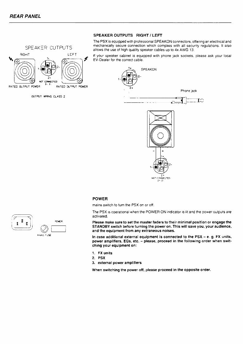
The SPEAKER OUTPUTS on the rear panel of the PSX are provided through professional standard Speakon connectors which offer anabsolutely secure connection. The pin assignment of these sockets is 1+ (hot) and 1- (cold).
INTRODUCTION
3 of 32
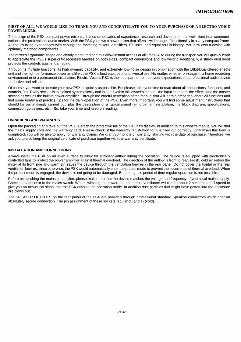
1. MICElectronically balanced XLR-type inputs for the connection of low impedance microphones, like the ones that arefeatured in big studio -and live mixing consoles. This type of input stage provides extraordinary low- noise signalamplification with extremely low distortion (typical <0.002%) even in the high frequency range. Generally, any type of microphone can be connected as long as its pin assignment isin accordance with the diagram shown aside. When condenser microphones areconnected, you have to press the PHANTOM button which is located in the mastersection. The microphone gets its operational voltage (+24Vdc) through the mixer soyou can forget about battery replacement .
CAUTION: Make sure to always connect the microphones before turning on the phantom power or switching the PSX on with phantom power activated. This is the only way to prevent yourmicrophones from damage. Also be sure to engage the stand-by button in the master section to prevent nastypower-on transients.The connection of condenser type microphones and dynamic microphone models at the same time is possible andshould generally not lead to any problems. Before you do so, please refer to the microphone’s manual to makesure that this kind of operation is in accordance to the manufacturer’s guidelines.The MIC input is designed for levels between –60dBu … +11dBu – depending on the setting of the correspondinggain control. Because of their low impedance design and the phantom power these XLR-type inputs are not meantfor cascading other mixing consoles or the connection of FX units, keyboards or other electronic equipment. Whenconnecting this type of equipment, please use the LINE level inputs.
2. LINEElectronically balanced inputs for the connection of electronic instruments, such as keyboards, drum machines,electric guitars and basses with active outputs, as well as all other high-level signal sources, like additional mixers,FX units, CD players, etc.The LINE input is designed for levels between –40dBu and +30dBu. The connection of balanced or unbalancedsignal sources is handled with monaural or stereo phone plugs, wired according to the diagram below. If the devicethat you want to connect has a balanced output stage, the use of balanced cables with stereo phone plugs ispreferable. This type of connection greatly lowers the induction of external noise or HF interference.
Do not connect signal sources to the MIC and the LINE inputs at the same time, since the signals would interferewith each other, resulting in level reduction.One more note: Please, do not connect electric guitars or basses with passive, high impedance outputs directlyto one of the LINE inputs. The LINE inputs of the PSX – like the line level inputs of mixers from all othermanufacturers – are meant for the connection of relatively low source impedance of electronic instruments or audioequipment. The reproduction of the instrument’s original sound characteristics will be unsatisfactory – unless thiseffect is intended. Those instruments should be connected using a special transformer, direct box or pre-amplifierwith very high input impedance. Musical instruments that are equipped with an active electronic output stage(battery powered) can be connected without problems.
When connecting signal sources, please make sure that the corresponding channel faders or the masterfaders are at their minimal settings or that the STANDBY button is engaged. This will save you, youraudience, and speakers from unpleasant pop noise.
3. INSERT Stereo phone jack with breaker function. The low impedance output is assigned to the tip (send) and the highimpedance input (return) is assigned to the ring (body). This jack allows the connection of external compressors,limiters, EQs, etc. into the corresponding channel’s signal path. The insertion point is post gain controls, low-cutfilters, and voicing-filter stage and pre-EQ section and faders. You have to use a stereo phone plug wired accordingto the following diagram – in case you intend to use this jack as a true insert bus.
INSERT
INPUT/MONO
4 of 32
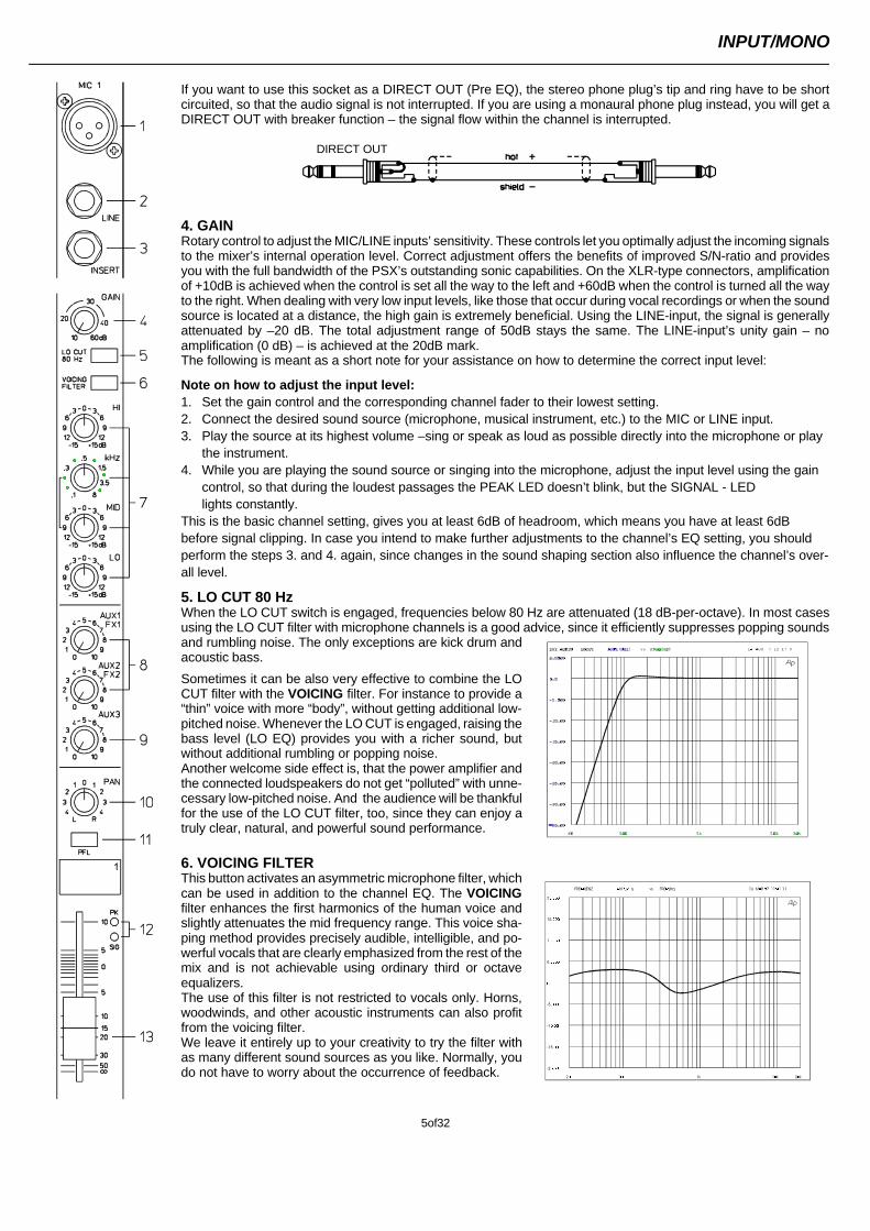
If you want to use this socket as a DIRECT OUT (Pre EQ), the stereo phone plug’s tip and ring have to be shortcircuited, so that the audio signal is not interrupted. If you are using a monaural phone plug instead, you will get aDIRECT OUT with breaker function – the signal flow within the channel is interrupted.
4. GAIN Rotary control to adjust the MIC/LINE inputs’ sensitivity. These controls let you optimally adjust the incoming signalsto the mixer’s internal operation level. Correct adjustment offers the benefits of improved S/N-ratio and providesyou with the full bandwidth of the PSX’s outstanding sonic capabilities. On the XLR-type connectors, amplificationof +10dB is achieved when the control is set all the way to the left and +60dB when the control is turned all the wayto the right. When dealing with very low input levels, like those that occur during vocal recordings or when the soundsource is located at a distance, the high gain is extremely beneficial. Using the LINE-input, the signal is generallyattenuated by –20 dB. The total adjustment range of 50dB stays the same. The LINE-input’s unity gain – noamplification (0 dB) – is achieved at the 20dB mark.The following is meant as a short note for your assistance on how to determine the correct input level:
Note on how to adjust the input level:1. Set the gain control and the corresponding channel fader to their lowest setting.2. Connect the desired sound source (microphone, musical instrument, etc.) to the MIC or LINE input.3. Play the source at its highest volume –sing or speak as loud as possible directly into the microphone or play
the instrument.4. While you are playing the sound source or singing into the microphone, adjust the input level using the gain
control, so that during the loudest passages the PEAK LED doesn’t blink, but the SIGNAL - LED lights constantly.
This is the basic channel setting, gives you at least 6dB of headroom, which means you have at least 6dB before signal clipping. In case you intend to make further adjustments to the channel’s EQ setting, you shouldperform the steps 3. and 4. again, since changes in the sound shaping section also influence the channel’s over-all level.
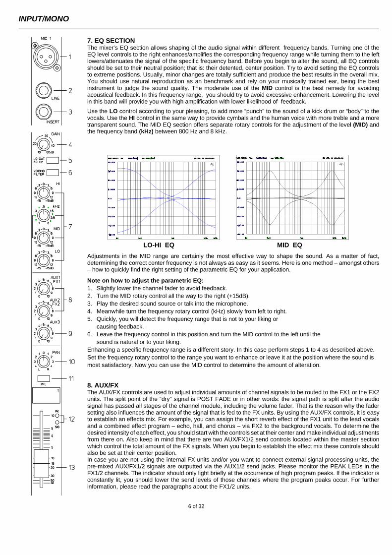
5. LO CUT 80 HzWhen the LO CUT switch is engaged, frequencies below 80 Hz are attenuated (18 dB-per-octave). In most casesusing the LO CUT filter with microphone channels is a good advice, since it efficiently suppresses popping soundsand rumbling noise. The only exceptions are kick drum andacoustic bass.
Sometimes it can be also very effective to combine the LOCUT filter with the VOICING filter. For instance to provide a“thin” voice with more “body”, without getting additional low-pitched noise. Whenever the LO CUT is engaged, raising thebass level (LO EQ) provides you with a richer sound, butwithout additional rumbling or popping noise.Another welcome side effect is, that the power amplifier andthe connected loudspeakers do not get “polluted” with unne-cessary low-pitched noise. And the audience will be thankfulfor the use of the LO CUT filter, too, since they can enjoy atruly clear, natural, and powerful sound performance.
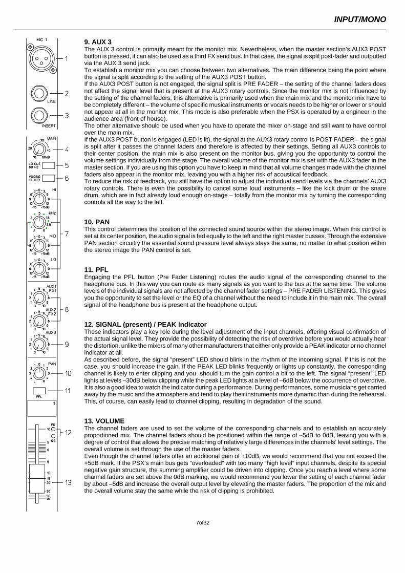
6. VOICING FILTERThis button activates an asymmetric microphone filter, whichcan be used in addition to the channel EQ. The VOICINGfilter enhances the first harmonics of the human voice andslightly attenuates the mid frequency range. This voice sha-ping method provides precisely audible, intelligible, and po-werful vocals that are clearly emphasized from the rest of themix and is not achievable using ordinary third or octaveequalizers.The use of this filter is not restricted to vocals only. Horns,woodwinds, and other acoustic instruments can also profitfrom the voicing filter.We leave it entirely up to your creativity to try the filter withas many different sound sources as you like. Normally, youdo not have to worry about the occurrence of feedback.
DIRECT OUT
INPUT/MONO
5of32
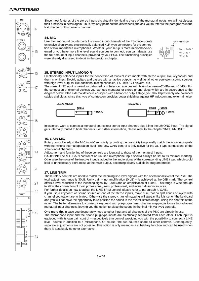
7. EQ SECTIONThe mixer’s EQ section allows shaping of the audio signal within different frequency bands. Turning one of theEQ level controls to the right enhances/amplifies the corresponding frequency range while turning them to the leftlowers/attenuates the signal of the specific frequency band. Before you begin to alter the sound, all EQ controlsshould be set to their neutral position; that is: their detented, center position. Try to avoid setting the EQ controlsto extreme positions. Usually, minor changes are totally sufficient and produce the best results in the overall mix.You should use natural reproduction as an benchmark and rely on your musically trained ear, being the bestinstrument to judge the sound quality. The moderate use of the MID control is the best remedy for avoidingacoustical feedback. In this frequency range, you should try to avoid excessive enhancement. Lowering the levelin this band will provide you with high amplification with lower likelihood of feedback.
Use the LO control according to your pleasing, to add more “punch” to the sound of a kick drum or “body” to thevocals. Use the HI control in the same way to provide cymbals and the human voice with more treble and a moretransparent sound. The MID EQ section offers separate rotary controls for the adjustment of the level (MID) andthe frequency band (kHz) between 800 Hz and 8 kHz.
LO-HI EQ MID EQ
Adjustments in the MID range are certainly the most effective way to shape the sound. As a matter of fact,determining the correct center frequency is not always as easy as it seems. Here is one method – amongst others– how to quickly find the right setting of the parametric EQ for your application.
Note on how to adjust the parametric EQ: 1. Slightly lower the channel fader to avoid feedback.2. Turn the MID rotary control all the way to the right (+15dB).3. Play the desired sound source or talk into the microphone.4. Meanwhile turn the frequency rotary control (kHz) slowly from left to right.5. Quickly, you will detect the frequency range that is not to your liking or
causing feedback.6. Leave the frequency control in this position and turn the MID control to the left until the
sound is natural or to your liking. Enhancing a specific frequency range is a different story. In this case perform steps 1 to 4 as described above.Set the frequency rotary control to the range you want to enhance or leave it at the position where the sound ismost satisfactory. Now you can use the MID control to determine the amount of alteration.
8. AUX/FXThe AUX/FX controls are used to adjust individual amounts of channel signals to be routed to the FX1 or the FX2units. The split point of the “dry” signal is POST FADE or in other words: the signal path is split after the audiosignal has passed all stages of the channel module, including the volume fader. That is the reason why the fadersetting also influences the amount of the signal that is fed to the FX units. By using the AUX/FX controls, it is easyto establish an effects mix. For example, you can assign the short reverb effect of the FX1 unit to the lead vocalsand a combined effect program – echo, hall, and chorus – via FX2 to the background vocals. To determine thedesired intensity of each effect, you should start with the controls set at their center and make individual adjustmentsfrom there on. Also keep in mind that there are two AUX/FX1/2 send controls located within the master sectionwhich control the total amount of the FX signals. When you begin to establish the effect mix these controls shouldalso be set at their center position.In case you are not using the internal FX units and/or you want to connect external signal processing units, thepre-mixed AUX/FX1/2 signals are outputted via the AUX1/2 send jacks. Please monitor the PEAK LEDs in theFX1/2 channels. The indicator should only light briefly at the occurrence of high program peaks. If the indicator isconstantly lit, you should lower the send levels of those channels where the program peaks occur. For furtherinformation, please read the paragraphs about the FX1/2 units.
INPUT/MONO
6 of 32
9. AUX 3The AUX 3 control is primarily meant for the monitor mix. Nevertheless, when the master section’s AUX3 POSTbutton is pressed, it can also be used as a third FX send bus. In that case, the signal is split post-fader and outputtedvia the AUX 3 send jack. To establish a monitor mix you can choose between two alternatives. The main difference being the point wherethe signal is split according to the setting of the AUX3 POST button.If the AUX3 POST button is not engaged, the signal split is PRE FADER – the setting of the channel faders doesnot affect the signal level that is present at the AUX3 rotary controls. Since the monitor mix is not influenced bythe setting of the channel faders, this alternative is primarily used when the main mix and the monitor mix have tobe completely different – the volume of specific musical instruments or vocals needs to be higher or lower or shouldnot appear at all in the monitor mix. This mode is also preferable when the PSX is operated by a engineer in theaudience area (front of house).The other alternative should be used when you have to operate the mixer on-stage and still want to have controlover the main mix. If the AUX3 POST button is engaged (LED is lit), the signal at the AUX3 rotary control is POST FADER – the signalis split after it passes the channel faders and therefore is affected by their settings. Setting all AUX3 controls totheir center position, the main mix is also present on the monitor bus, giving you the opportunity to control thevolume settings individually from the stage. The overall volume of the monitor mix is set with the AUX3 fader in themaster section. If you are using this option you have to keep in mind that all volume changes made with the channelfaders also appear in the monitor mix, leaving you with a higher risk of acoustical feedback.To reduce the risk of feedback, you still have the option to adjust the individual send levels via the channels’ AUX3rotary controls. There is even the possibility to cancel some loud instruments – like the kick drum or the snaredrum, which are in fact already loud enough on-stage – totally from the monitor mix by turning the correspondingcontrols all the way to the left.
10. PANThis control determines the position of the connected sound source within the stereo image. When this control isset at its center position, the audio signal is fed equally to the left and the right master busses. Through the extensivePAN section circuitry the essential sound pressure level always stays the same, no matter to what position withinthe stereo image the PAN control is set.
11. PFLEngaging the PFL button (Pre Fader Listening) routes the audio signal of the corresponding channel to theheadphone bus. In this way you can route as many signals as you want to the bus at the same time. The volumelevels of the individual signals are not affected by the channel fader settings – PRE FADER LISTENING. This givesyou the opportunity to set the level or the EQ of a channel without the need to include it in the main mix. The overallsignal of the headphone bus is present at the headphone output.
12. SIGNAL (present) / PEAK indicator These indicators play a key role during the level adjustment of the input channels, offering visual confirmation ofthe actual signal level. They provide the possibility of detecting the risk of overdrive before you would actually hearthe distortion, unlike the mixers of many other manufacturers that either only provide a PEAK indicator or no channelindicator at all.As described before, the signal “present” LED should blink in the rhythm of the incoming signal. If this is not thecase, you should increase the gain. If the PEAK LED blinks frequently or lights up constantly, the correspondingchannel is likely to enter clipping and you should turn the gain control a bit to the left. The signal “present” LEDlights at levels –30dB below clipping while the peak LED lights at a level of –6dB below the occurrence of overdrive.It is also a good idea to watch the indicator during a performance. During performances, some musicians get carriedaway by the music and the atmosphere and tend to play their instruments more dynamic than during the rehearsal.This, of course, can easily lead to channel clipping, resulting in degradation of the sound.
13. VOLUME The channel faders are used to set the volume of the corresponding channels and to establish an accuratelyproportioned mix. The channel faders should be positioned within the range of –5dB to 0dB, leaving you with adegree of control that allows the precise matching of relatively large differences in the channels’ level settings. Theoverall volume is set through the use of the master faders. Even though the channel faders offer an additional gain of +10dB, we would recommend that you not exceed the+5dB mark. If the PSX’s main bus gets “overloaded” with too many “high level” input channels, despite its specialnegative gain structure, the summing amplifier could be driven into clipping. Once you reach a level where somechannel faders are set above the 0dB marking, we would recommend you lower the setting of each channel faderby about –5dB and increase the overall output level by elevating the master faders. The proportion of the mix andthe overall volume stay the same while the risk of clipping is prohibited.
INPUT/MONO
7of32
Since most features of the stereo inputs are virtually identical to those of the monaural inputs, we will not discusstheir functions in detail again. Thus, we only point out the differences and ask you to refer to the paragraphs in thefirst chapter of this owner’s manual.
14. MICLike their monaural counterparts the stereo input channels of the PSX incorporateextensive circuitry and electronically balanced XLR-type connectors for the connec-tion of low impedance microphones. Whether your setup is more microphone-ori-ented or you have more line level sound sources to connect, you can always usethe full amount of input channels, provided by your PSX. The functioning principleswere already discussed in detail in the previous chapter.
15. STEREO INPUT L/MONO RElectronically balanced inputs for the connection of musical instruments with stereo output, like keyboards anddrum machines, Electric guitars and basses with an active outputs, as well as all other equivalent sound sourceswith high level outputs, like additional mixing consoles, FX units, CD players, etc.The stereo LINE input is meant for balanced or unbalanced sources with levels between –20dBu and +30dBu. Forthe connection of external devices you can use monaural or stereo phone plugs which are in accordance to thediagram below. If the external device is equipped with a balanced output stage, you should preferably use balancedcables and plugs, since this type of connection provides better shielding against HF induction and external noise.
In case you want to connect a monaural source to a stereo input channel, plug it into the L/MONO input. The signalgets internally routed to both channels. For further information, please refer to the chapter “INPUT/MONO”.
16. GAIN MICRotary control to adjust the MIC inputs’ sensitivity, providing the possibility to optimally match the incoming signalswith the mixer’s internal operation level. The MIC GAIN control is only active for the XLR-type connections of thestereo input channels.Adjustment and functioning of these controls are identical to those of the monaural inputs.CAUTION: The MIC GAIN control of an unused microphone input should always be set to its minimal marking.Otherwise the noise of the inactive input is added to the audio signal of the corresponding LINE input, which couldlead to unnecessary extra noise at the main output, becoming clearly audible in program breaks.
17. LINE TRIMThese rotary controls are used to match the incoming line level signals with the operational level of the PSX. Thetotal adjustment range is 30dB. Unity gain – no amplification (0 dB) – is achieved at the 0dB mark. The controloffers a level reduction of the incoming signal by –20dB and an amplification of +20dB. This range is wide enoughto allow the connection of most professional, semi professional, and even hi-fi audio sources.For further details on how to adjust the LINE TRIM control, please refer to paragraph 4. GAIN.If you use a keyboard as sound source on one of the stereo inputs, make sure that no split zones or layers withchannel separation are activated. Otherwise the stereo channel mapping will appear like it is set on the keyboardand you will not have the opportunity to re-position the sound in the overall stereo image, using the controls of themixer. The better alternative to connect a keyboard with pre-programmed channel mapping is to use two adjacentmonaural input channels, leaving you the option to place the sound in the final mix via PAN controls.
One more tip, in case you desperately need another input and all channels of the PSX are already in use:The microphone input and the phone plug-type inputs are electrically separated from each other. Each input isequipped with its own gain control – respectively trim control, providing you with the possibility to connect a LINElevel source in addition to a microphone. Of course, the two sources share all other controls. Consequently,separate adjustments are not possible. This option is only meant as a subsidiary function and can be used whenthere is absolutely no other alternative.
INPUT/STEREO
8 of 32
18. EQ SECTIONThe mixer’s EQ section allows very differentiated shaping of the incoming audio signal within miscellaneousfrequency bands. Turning one of the EQ level controls to the right enhances/amplifies the corresponding frequencyrange while turning them to the left lowers/attenuates the signal of the specific frequency band. Before you beginto alter the sound, all EQ controls should be set to their neutral position; that is: their marker points straight up(locked in place). Try to avoid setting EQ controls to extreme positions. Usually, minor changes are totally sufficientand produce the best results in the overall sound. You should use the natural reproduction as an orientation markand rely on your musically trained ear to judge the sound quality. The moderate use of the MID control is the bestremedy to avoid acoustical feedback. In this frequency range, you should try to avoid excessive enhancement.Lowering the level in this band will provide you with high amplification rates without feedback.
The HI and LO controls of the STEREO channels’ EQ section provide a degree of control that is equally adequatefor LINE level inputs and microphones. The MID control is active in a comparably wide frequency band around 2.4kHz. With most microphones this is the critical range, where a slight attenuation offers excellent results.
19. AUX/FXThese controls determine the amount of the summed L/R signal that is send to the AUX/FX bus. The signal routingis POST FADER. For more details on the functioning of these controls, please refer to the INPUT/MONO sectionof this owner’s manual.
20. AUX3This control determines the amount of the summed L/R signal that is send to the AUX3 bus. Depending on thesetting of the AUX3 POST switch within the PSX master section you can choose if the signal is routed PRE orPOST FADER.
21. BALThe function of the BAL control of the stereo channels is equivalent to the PAN control’s function of the monauralchannels. If you turn the rotary control all the way to the right, the signal is routed to the right output while the signalof the left channel is muted. When the control is set to its center position, the signal is present with equal intensityat the corresponding L/R outputs. Whenever stereo sound sources are connected to a stereo channel, you shouldleave the BAL control at the center position or make only minor adjustments in either direction. In case a microphoneor another monaural sound source is connected, the BAL controls function absolutely identical to the PAN controlsof the monaural input section.
22. PFLEngaging the PFL button routes the audio signal of the corresponding input channel to the headphone bus wherethe stereo signal is outputted to the headphone output. You can route as many channels as you want to the busat the same time. The volume levels of the individual signals are not affected by the setting of the correspondingchannel faders – PRE FADER LISTENING. This gives you the opportunity to set the level and the EQ of a channelwithout the need to include it in the main mix.
23. SIGNAL/PEAKFor the stereo SIGNAL/PEAK indicator function, the left and the right channels are monitored separately. Therespective highest level reading is indicated, assuring that neither one is already driven into clipping. For furtherdescriptions on how to use this indicator most efficiently, please refer to paragraph 12 of the previous chapter.
24. VOLUMEThe channel fader is used to simultaneously adjust both channels of the stereo signal. Functioning and specifica-tions are totally similar to the monaural channel fader, as previously described.
INPUT/STEREO
9 of 32
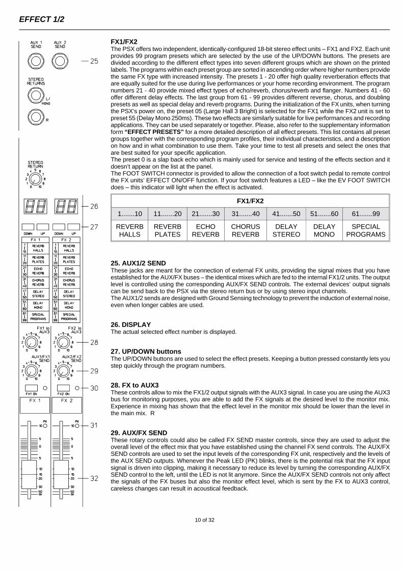
FX1/FX2The PSX offers two independent, identically-configured 18-bit stereo effect units – FX1 and FX2. Each unitprovides 99 program presets which are selected by the use of the UP/DOWN buttons. The presets aredivided according to the different effect types into seven different groups which are shown on the printedlabels. The programs within each preset group are sorted in ascending order where higher numbers providethe same FX type with increased intensity. The presets 1 - 20 offer high quality reverberation effects thatare equally suited for the use during live performances or your home recording environment. The programnumbers 21 - 40 provide mixed effect types of echo/reverb, chorus/reverb and flanger. Numbers 41 - 60offer different delay effects. The last group from 61 - 99 provides different reverse, chorus, and doublingpresets as well as special delay and reverb programs. During the initialization of the FX units, when turningthe PSX’s power on, the preset 05 (Large Hall 3 Bright) is selected for the FX1 while the FX2 unit is set topreset 55 (Delay Mono 250ms). These two effects are similarly suitable for live performances and recordingapplications. They can be used separately or together. Please, also refer to the supplementary informationform “EFFECT PRESETS” for a more detailed description of all effect presets. This list contains all presetgroups together with the corresponding program profiles, their individual characteristics, and a descriptionon how and in what combination to use them. Take your time to test all presets and select the ones thatare best suited for your specific application.The preset 0 is a slap back echo which is mainly used for service and testing of the effects section and itdoesn’t appear on the list at the panel.The FOOT SWITCH connector is provided to allow the connection of a foot switch pedal to remote controlthe FX units’ EFFECT ON/OFF function. If your foot switch features a LED – like the EV FOOT SWITCHdoes – this indicator will light when the effect is activated.
FX1/FX2
1.......10 11.......20 21.......30 31.......40 41.......50 51.......60 61.......99
REVERBHALLS
REVERBPLATES
ECHOREVERB
CHORUSREVERB
DELAYSTEREO
DELAYMONO
SPECIALPROGRAMS
25. AUX1/2 SENDThese jacks are meant for the connection of external FX units, providing the signal mixes that you haveestablished for the AUX/FX buses – the identical mixes which are fed to the internal FX1/2 units. The outputlevel is controlled using the corresponding AUX/FX SEND controls. The external devices’ output signalscan be send back to the PSX via the stereo return bus or by using stereo input channels.The AUX1/2 sends are designed with Ground Sensing technology to prevent the induction of external noise,even when longer cables are used.
26. DISPLAYThe actual selected effect number is displayed.
27. UP/DOWN buttonsThe UP/DOWN buttons are used to select the effect presets. Keeping a button pressed constantly lets youstep quickly through the program numbers.
28. FX to AUX3These controls allow to mix the FX1/2 output signals with the AUX3 signal. In case you are using the AUX3bus for monitoring purposes, you are able to add the FX signals at the desired level to the monitor mix.Experience in mixing has shown that the effect level in the monitor mix should be lower than the level inthe main mix. R
29. AUX/FX SENDThese rotary controls could also be called FX SEND master controls, since they are used to adjust theoverall level of the effect mix that you have established using the channel FX send controls. The AUX/FXSEND controls are used to set the input levels of the corresponding FX unit, respectively and the levels ofthe AUX SEND outputs. Whenever the Peak LED (PK) blinks, there is the potential risk that the FX inputsignal is driven into clipping, making it necessary to reduce its level by turning the corresponding AUX/FXSEND control to the left, until the LED is not lit anymore. Since the AUX/FX SEND controls not only affectthe signals of the FX buses but also the monitor effect level, which is sent by the FX to AUX3 control,careless changes can result in acoustical feedback.
EFFECT 1/2
10 of 32
30. FX ONThese switches are used to turn the internal FX units on – the green LED is lit. Please keep in mind thatyou also can use an external foot switch to turn the FX units on. In this case the LED also shows theactual state of operation. If you want to use a foot switch, the FX ON switch has to be engaged first. Thecorresponding FX unit is activated and you can use the foot switch to turn the selected effect programon or off.
31. PEAK LEDThese indicators show if the input stages of the internal FX units or the AUX 1/" SEND signals are driveninto clipping. To achieve an adequate S/N ratio, please adjust the FX units’ input level as follows:
Note on how to adjust the FX input signal:
1. Establish a “dry” mix – without effect settings – according to the previous descriptions.2. Set the AUX/FX send controls of the effect channels to their center position.3. Position the effect return faders of the effect channels at the –5dB marks.4. Use the UP/DOWN buttons to select the desired FX program preset.5. Press the FX ON switch.6. Play the sound source of the desired input channel and adjust the desired
amount of the FX signal, using the AUX/FX controls of this input channel. Repeat this step for all input channels that you want to include in your effect mix.
7. Adjust the AUX/FX SEND controls, so that the Peak LED only lights frequently at highly dynamic signal peaks.
8. Use the FX to AUX3 control to add the effect mix to the monitor mix. Use the FX return faders to add the desired amount of the FX signal to the main mix.
In case you are using a different effect setting for the second FX unit, you have to repeat the step 2 - 8,respectively. Pay some attention to the peak indicators when operating your PSX to quickly interact whenthe signal levels exceed the normal range and enter clipping.
32. EFFECT RETURNThese stereo faders are used to determine the effect amount of the main mix. In case you have to setthese faders at a position above the +5dB mark, please check if the FX units input signals are adjustedproperly. Otherwise use the AUX/FX SEND controls to increase the input levels.
EFFECT 1/2
11 of 32
Typically, the AUX3 channel is used as monitor bus. Depending on the setting of the AUX3 POST switch, it is alsopossible to configure the bus for the connection of an additional, external FX unit.
33. AUX3 SENDThis output is meant for the connection of an external FX unit, a power amplifier or active stage monitor speakersystems, when the AUX3 bus is used for monitoring purposes. Using the AUX3 fader, the output level can be adjustedover a wide range up to +20dBu. The AUX3 send is designed with Ground Sensing technology to prevent the inductionof external noise, even when long cables are used.
34. FEEDBACK FILTERThe feedback filter is a very narrow band notch filter which is only active over a range that is extremely susceptibleto acoustical feedback. The frequency band is set using the corresponding rotary control. The filter is activated bypressing the corresponding ON switch. Acoustical feedback occurs when the sound system becomes the largestacoustical source at a microphone. Or in other words: the speaker signal hits the microphone and gets amplified againand again, resulting in escalating oscillation, and is audible as a high pitched whistle or loud humming sound. Thefollowing guidelines are meant to assist you in avoiding feedback and you should take them into consideration evenbefore you activate the feedback filter.
1. Do not position the main speaker systems behind the microphones.2. Turn off all unused microphones.3. Also consider the microphones’ different polar patterns and characteristics, when placing
the monitor speakers.4. Do not turn up the monitor system’s volume higher than really necessary.5. Try to avoid extensive equalization on channels that you want to include in your monitor mix.6. Keep in mind, that microphones “behave” different when somebody stands right in front of
them. In fact, the amount and intensity of first reflections changes things drastically.7. Position the microphones as close as possible to the sound source.
If you still need more volume from the monitor system, after trying the above mentioned precautions, you can usethe feedback filter to notch the frequency that tends to affect feedback the most. Therefore, you need to perform thefollowing steps:Increase the AUX3 (monitor) level until the point where feedback starts. The “sound” you hear is generated within thesystem. Turn on the feedback filter and adjust the rotary control at the point where the “ringing” disappears. Switchingthe filter on and off lets you easily check if you tuned in the correct frequency. The feedback filter attenuates thecorresponding frequency band by about 9dB. Since the filtered band is extremely narrow, an alteration in the soundof your monitor system is hardly audible.CAUTION: Please be extremely careful when you increase the level up to the feedback limit. Careless operation,resulting in feedback at high SPL, can severely damage your speaker systems and – even more important – thehuman ear.
35. AUX3 POSTAs mentioned before, this switch determines if the AUX3-mix signal is PRE or POST FADER. When the switch isengaged and the yellow LED lights, the signals of all AUX3 controls in the input channels are sent after theircorresponding channel faders.
36. PFLWith this button you can route the pre-fader AUX3 signal to the headphones bus. The signal is outputted via theheadphone output. The setting of the AUX3 fader is not relevant for the signal’s volume (PRE FADER LISTEN),leaving you with the opportunity to adjust its level and equalization without the need to route it to the AUX3 SENDbus.
37. AUX3 VOLUMEThis fader controls the AUX3 SEND output level. When the AUX3 bus is used for monitoring, this fader lets you controlthe volume of the monitor system.
AUX 3
12 of 32
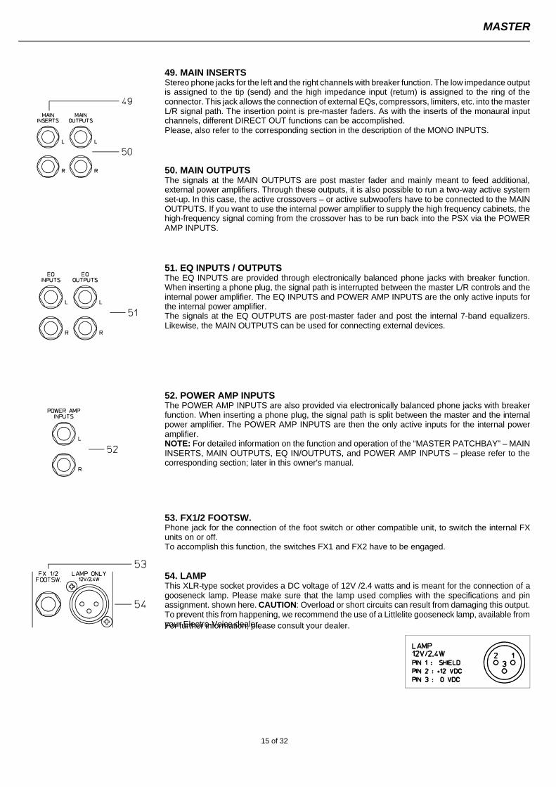
49. MAIN INSERTSStereo phone jacks for the left and the right channels with breaker function. The low impedance outputis assigned to the tip (send) and the high impedance input (return) is assigned to the ring of theconnector. This jack allows the connection of external EQs, compressors, limiters, etc. into the masterL/R signal path. The insertion point is pre-master faders. As with the inserts of the monaural inputchannels, different DIRECT OUT functions can be accomplished.Please, also refer to the corresponding section in the description of the MONO INPUTS.
50. MAIN OUTPUTSThe signals at the MAIN OUTPUTS are post master fader and mainly meant to feed additional,external power amplifiers. Through these outputs, it is also possible to run a two-way active systemset-up. In this case, the active crossovers – or active subwoofers have to be connected to the MAINOUTPUTS. If you want to use the internal power amplifier to supply the high frequency cabinets, thehigh-frequency signal coming from the crossover has to be run back into the PSX via the POWERAMP INPUTS.
51. EQ INPUTS / OUTPUTSThe EQ INPUTS are provided through electronically balanced phone jacks with breaker function.When inserting a phone plug, the signal path is interrupted between the master L/R controls and theinternal power amplifier. The EQ INPUTS and POWER AMP INPUTS are the only active inputs forthe internal power amplifier.The signals at the EQ OUTPUTS are post-master fader and post the internal 7-band equalizers.Likewise, the MAIN OUTPUTS can be used for connecting external devices.
52. POWER AMP INPUTSThe POWER AMP INPUTS are also provided via electronically balanced phone jacks with breakerfunction. When inserting a phone plug, the signal path is split between the master and the internalpower amplifier. The POWER AMP INPUTS are then the only active inputs for the internal poweramplifier.NOTE: For detailed information on the function and operation of the “MASTER PATCHBAY” – MAININSERTS, MAIN OUTPUTS, EQ IN/OUTPUTS, and POWER AMP INPUTS – please refer to thecorresponding section; later in this owner’s manual.
53. FX1/2 FOOTSW.Phone jack for the connection of the foot switch or other compatible unit, to switch the internal FXunits on or off.To accomplish this function, the switches FX1 and FX2 have to be engaged.
54. LAMPThis XLR-type socket provides a DC voltage of 12V /2.4 watts and is meant for the connection of agooseneck lamp. Please make sure that the lamp used complies with the specifications and pinassignment. shown here. CAUTION: Overload or short circuits can result from damaging this output.To prevent this from happening, we recommend the use of a Littlelite gooseneck lamp, available fromyour Electro-Voice dealer.For further information, please consult your dealer.
MASTER
15 of 32
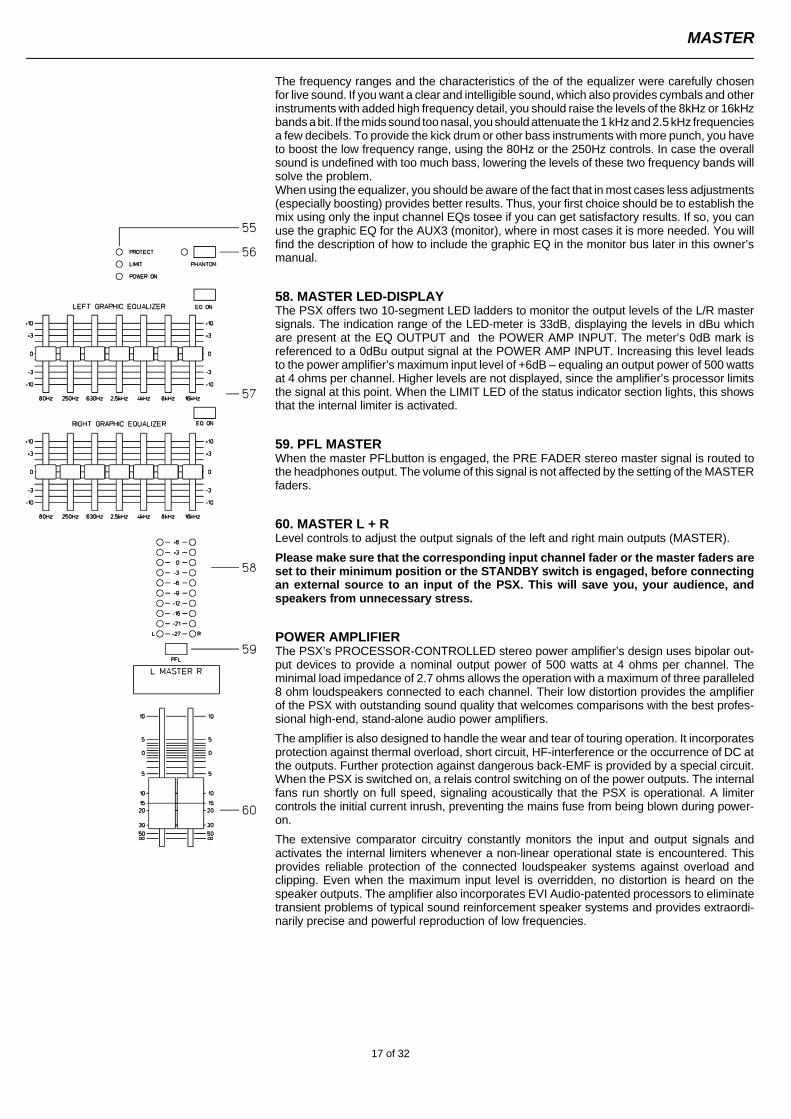
55. POWER AMP STATUS indicatorsThese indicators inform you about the momentary operational status of the PSX’s internalpower amplifier.
The POWER ON indicator is always lit when the PSX is in operational mode. If the LED is notlit after you have turned the power on, please make sure that the PSX’s power cable is correctlyplugged in. If this is the case and the LED is still not lit, please contact your dealer.
The LIMIT indicator signals that you are operating the PSX at the internal amplifier’s limit.Frequent blinking of the LED is acceptable, since the amplifier’s incorporated limiter preventsserious distortion. Continuous illumination indicates that you should be aware of a degradationin sound quality. In that case, the master level should be reduced.
The PROTECT indicator is lit when one of the PSX ’s extensive protection circuits is guardingagainst thermal overload, HF-induction, DC at the outputs, or short circuits is activated. Whenthe PSX is in protect mode, the speaker outputs are muted and the amplifier’s inputs areshorted to prevent the amplifier from being damaged. In this case you should first check tosee if the ventilation louvres are blocked. Another cause could be that you have more thanthree 8 ohm speaker systems per output channel connected. You should also disconnect theSPEAKON output connectors and check the speaker cables for short circuits.During normal power-on operation, the PROTECT LED always lights for about two seconds,signaling that the PSX’s protection circuitry is operational.
56. PHANTOM POWERWhen this switch is engaged, all MIC inputs are supplied with +24V phantom power.Please make sure prior to engaging phantom power that the PSX is switched off or instand-by mode. With active phantom power the connection of unbalanced signalsources (keyboards, mixer, etc.) to XLR inputs is not advisable, because this couldlead to severe damaging of your equipment.
ATTENTION! IMPORTANT NOTICE!In general, the operation of phantom-powered condenser microphones and balanceddynamic microphones at the same time does not lead to any problems.Nevertheless, some balanced dynamic microphones are extremely sensitive to this.Some models could get damaged when used on mixers with active phantom power.Please refer to the microphones’ owner’s manuals to make sure that this operation ispermissible.To be on the safe side, you should switch the PHANTOM POWER off, when usingbalanced dynamic microphones, only.
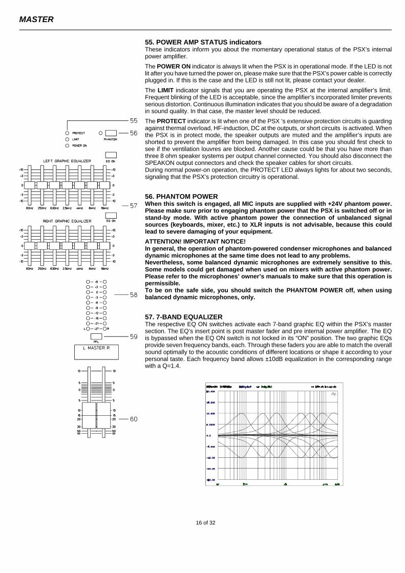
57. 7-BAND EQUALIZERThe respective EQ ON switches activate each 7-band graphic EQ within the PSX’s mastersection. The EQ’s insert point is post master fader and pre internal power amplifier. The EQis bypassed when the EQ ON switch is not locked in its “ON” position. The two graphic EQsprovide seven frequency bands, each. Through these faders you are able to match the overallsound optimally to the acoustic conditions of different locations or shape it according to yourpersonal taste. Each frequency band allows ±10dB equalization in the corresponding rangewith a Q=1.4.
MASTER
16 of 32
The frequency ranges and the characteristics of the of the equalizer were carefully chosenfor live sound. If you want a clear and intelligible sound, which also provides cymbals and otherinstruments with added high frequency detail, you should raise the levels of the 8kHz or 16kHzbands a bit. If the mids sound too nasal, you should attenuate the 1 kHz and 2.5 kHz frequenciesa few decibels. To provide the kick drum or other bass instruments with more punch, you haveto boost the low frequency range, using the 80Hz or the 250Hz controls. In case the overallsound is undefined with too much bass, lowering the levels of these two frequency bands willsolve the problem.When using the equalizer, you should be aware of the fact that in most cases less adjustments(especially boosting) provides better results. Thus, your first choice should be to establish themix using only the input channel EQs tosee if you can get satisfactory results. If so, you canuse the graphic EQ for the AUX3 (monitor), where in most cases it is more needed. You willfind the description of how to include the graphic EQ in the monitor bus later in this owner’smanual.
58. MASTER LED-DISPLAYThe PSX offers two 10-segment LED ladders to monitor the output levels of the L/R mastersignals. The indication range of the LED-meter is 33dB, displaying the levels in dBu whichare present at the EQ OUTPUT and the POWER AMP INPUT. The meter’s 0dB mark isreferenced to a 0dBu output signal at the POWER AMP INPUT. Increasing this level leadsto the power amplifier’s maximum input level of +6dB – equaling an output power of 500 wattsat 4 ohms per channel. Higher levels are not displayed, since the amplifier’s processor limitsthe signal at this point. When the LIMIT LED of the status indicator section lights, this showsthat the internal limiter is activated.
59. PFL MASTERWhen the master PFLbutton is engaged, the PRE FADER stereo master signal is routed tothe headphones output. The volume of this signal is not affected by the setting of the MASTERfaders.
60. MASTER L + RLevel controls to adjust the output signals of the left and right main outputs (MASTER).
Please make sure that the corresponding input channel fader or the master faders areset to their minimum position or the STANDBY switch is engaged, before connectingan external source to an input of the PSX. This will save you, your audience, andspeakers from unnecessary stress.
POWER AMPLIFIERThe PSX’s PROCESSOR-CONTROLLED stereo power amplifier’s design uses bipolar out-put devices to provide a nominal output power of 500 watts at 4 ohms per channel. Theminimal load impedance of 2.7 ohms allows the operation with a maximum of three paralleled8 ohm loudspeakers connected to each channel. Their low distortion provides the amplifierof the PSX with outstanding sound quality that welcomes comparisons with the best profes-sional high-end, stand-alone audio power amplifiers.
The amplifier is also designed to handle the wear and tear of touring operation. It incorporatesprotection against thermal overload, short circuit, HF-interference or the occurrence of DC atthe outputs. Further protection against dangerous back-EMF is provided by a special circuit.When the PSX is switched on, a relais control switching on of the power outputs. The internalfans run shortly on full speed, signaling acoustically that the PSX is operational. A limitercontrols the initial current inrush, preventing the mains fuse from being blown during power-on.
The extensive comparator circuitry constantly monitors the input and output signals andactivates the internal limiters whenever a non-linear operational state is encountered. Thisprovides reliable protection of the connected loudspeaker systems against overload andclipping. Even when the maximum input level is overridden, no distortion is heard on thespeaker outputs. The amplifier also incorporates EVI Audio-patented processors to eliminatetransient problems of typical sound reinforcement speaker systems and provides extraordi-narily precise and powerful reproduction of low frequencies.
MASTER
17 of 32
CABLINGThe ac power cord comes with the PSX. The quality of all other cables are your responsibility. Carefully chosen high quality cables are thebest precaution to prevent problems during operation. The following wiring alternatives are recommended to provide a trouble free operationof your setup.
SPEAKER CABLESFrom our experience as a manufacturer of loudspeaker systems we’ve learned that flexible speaker cables with a rubber jacket (10 - 16gauge, depending on length) used in combination with NEUTRIK SPEAKON plugs and sockets, are the best choice to guarantee optimalconnection of loudspeaker systems. In accordance to the corresponding diagram, the SPEAKON plugs are connected on the PSX rear panel.You can also consider the use of 4-wire cables where pins 2+ and 2- are also connected. This provides you with the possibility of using thesecables with active 2-way system configurations, as well. Professional-quality speaker cables with SPEAKON connectors and all other cables,plugs, and sockets are available at your Electro-Voice dealer.
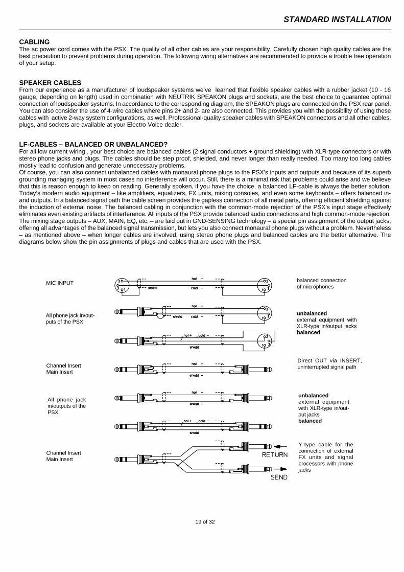
LF-CABLES – BALANCED OR UNBALANCED?For all low current wiring , your best choice are balanced cables (2 signal conductors + ground shielding) with XLR-type connectors or withstereo phone jacks and plugs. The cables should be step proof, shielded, and never longer than really needed. Too many too long cablesmostly lead to confusion and generate unnecessary problems.Of course, you can also connect unbalanced cables with monaural phone plugs to the PSX’s inputs and outputs and because of its superbgrounding managing system in most cases no interference will occur. Still, there is a minimal risk that problems could arise and we believethat this is reason enough to keep on reading. Generally spoken, if you have the choice, a balanced LF-cable is always the better solution.Today’s modern audio equipment – like amplifiers, equalizers, FX units, mixing consoles, and even some keyboards – offers balanced in-and outputs. In a balanced signal path the cable screen provides the gapless connection of all metal parts, offering efficient shielding againstthe induction of external noise. The balanced cabling in conjunction with the common-mode rejection of the PSX’s input stage effectivelyeliminates even existing artifacts of interference. All inputs of the PSX provide balanced audio connections and high common-mode rejection.The mixing stage outputs – AUX, MAIN, EQ, etc. – are laid out in GND-SENSING technology – a special pin assignment of the output jacks,offering all advantages of the balanced signal transmission, but lets you also connect monaural phone plugs without a problem. Nevertheless– as mentioned above – when longer cables are involved, using stereo phone plugs and balanced cables are the better alternative. Thediagrams below show the pin assignments of plugs and cables that are used with the PSX.
MIC INPUT
All phone jack in/out-puts of the PSX
Channel InsertMain Insert
All phone jackin/outputs of thePSX
Channel InsertMain Insert
balanced connectionof microphones
unbalanced external equipment withXLR-type in/output jacksbalanced
Direct OUT via INSERT,uninterrupted signal path
Y-type cable for theconnection of externalFX units and signalprocessors with phonejacks
unbalanced external equipmentwith XLR-type in/out-put jacks balanced
STANDARD INSTALLATION
19 of 32
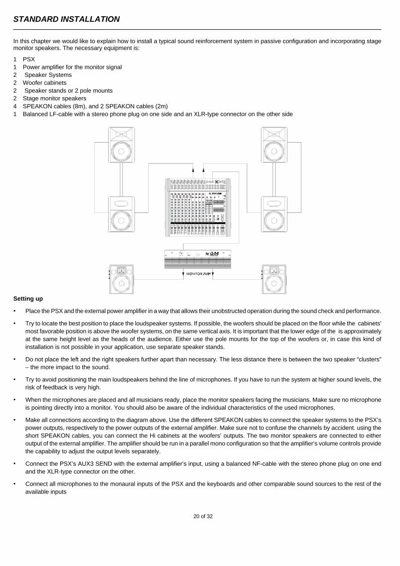
In this chapter we would like to explain how to install a typical sound reinforcement system in passive configuration and incorporating stagemonitor speakers. The necessary equipment is:
1 PSX 1 Power amplifier for the monitor signal2 Speaker Systems2 Woofer cabinets 2 Speaker stands or 2 pole mounts2 Stage monitor speakers4 SPEAKON cables (8m), and 2 SPEAKON cables (2m)1 Balanced LF-cable with a stereo phone plug on one side and an XLR-type connector on the other side
Setting up
• Place the PSX and the external power amplifier in a way that allows their unobstructed operation during the sound check and performance.
• Try to locate the best position to place the loudspeaker systems. If possible, the woofers should be placed on the floor while the cabinets’most favorable position is above the woofer systems, on the same vertical axis. It is important that the lower edge of the is approximatelyat the same height level as the heads of the audience. Either use the pole mounts for the top of the woofers or, in case this kind ofinstallation is not possible in your application, use separate speaker stands.
• Do not place the left and the right speakers further apart than necessary. The less distance there is between the two speaker “clusters”– the more impact to the sound.
• Try to avoid positioning the main loudspeakers behind the line of microphones. If you have to run the system at higher sound levels, therisk of feedback is very high.
• When the microphones are placed and all musicians ready, place the monitor speakers facing the musicians. Make sure no microphoneis pointing directly into a monitor. You should also be aware of the individual characteristics of the used microphones.
• Make all connections according to the diagram above. Use the different SPEAKON cables to connect the speaker systems to the PSX’spower outputs, respectively to the power outputs of the external amplifier. Make sure not to confuse the channels by accident. using theshort SPEAKON cables, you can connect the Hi cabinets at the woofers’ outputs. The two monitor speakers are connected to eitheroutput of the external amplifier. The amplifier should be run in a parallel mono configuration so that the amplifier’s volume controls providethe capability to adjust the output levels separately.
• Connect the PSX’s AUX3 SEND with the external amplifier’s input, using a balanced NF-cable with the stereo phone plug on one endand the XLR-type connector on the other.
• Connect all microphones to the monaural inputs of the PSX and the keyboards and other comparable sound sources to the rest of theavailable inputs
STANDARD INSTALLATION
20 of 32
• Pull all faders down and engage the PSX’s STANDBY button to prevent unwanted feedback.
• First, switch the PSX on and then the external amplifier.
• In case you have condenser microphones connected to the PSX, you can now turn on the phantom power by pressing the PHANTOMswitch.
• Activate the PSX’s by pressing the STANDBY button again.
SOUND CHECK
• First, adjust the input levels of the microphones that are connected to the PSX. Please proceed as follows:
1. Set the corresponding gain controls and the channel faders to their lowest position.
2. Speak or sing as loud as possible into the microphone.
3. Use the gain control to adjust the level, so that even at loud passages the red PEAK LED is not lit but the green SIGNAL present LED lights constantly.
• Adjust the EQ of the monaural input channels:
1. Slide the channel fader and the master faders up a bit, so that the sound is heard coming from the main speakers.
2. Turn the MID control carefully all the way to the right (+15dB). You should not hear any feedback.
3. Play the sound source or speak into the connected microphone.
4. Turn the frequency control (kHz) slowly from left to right.
5. You will detect the frequency range that is not to your liking or causing the feedback.
6. Leave the frequency control in this position and turn the MID control to the left until the sound is natural or to your liking.
7. If necessary, adjust the Hi and LOW controls, starting from their centered position, until the sound is pleasing to you.
8. Repeat the steps 1 - 7 for all monaural input channels in use.
• In case you are also using the stereo input channels, you can adjust the levels in a similar way:
1. Set the LINE TRIM controls, the MIC gain controls, and the channel fader to their lowest setting.
2. Play the corresponding sound source at the highest volume that is to be expected during the performance.
3. Use the LINE TRIM control to adjust the level, so that even at loud passages the red PEAK LED is not lit but the green SIGNAL present LED lights constantly.
• Adjust the EQ of the stereophonic input channels:
1. Slide the channel fader and the master faders a bit up, so that you can hear the sound through the main speakers.
2. Adjust the EQ controls at their center position.
3. Play the corresponding sound source.
4. Starting from the center position, you can adjust the controls until the sound is to your liking. Please, keep in mind that major alteration of the EQ-setting does not necessarily result in the improvement of the overall sound. Especially when sound shaping is concerned, less can be more.
5. Repeat the steps 1 - 4 for all stereo input channels in use.
• If musical instruments are connected directly to the monaural inputs, follow the descriptions above for adjustment of the microphones.
• Make sure, that all channel faders, gain controls, and LINE TRIM controls of unused input channels are at their minimal setting. In thisway you avoid unnecessary noise.
STANDARD INSTALLATION
21 of 32
MAIN MIX
• Position the master faders in the range between –30dB and –20dB.
• Establish a basic mix, using the channel faders, so that the individual sound levels relate to each other according to your personal taste.
• The best range for the channel faders to be set to is in the area of –5dB to 0dB. In this way you are provided with enough tolerance forlater adjustments.
• Use the master faders to adjust the overall volume.
• In case you are using the FX units, please proceed like this:
1. Adjust the AUX1/FX1 send controls at their center position.
2. Adjust the FX1 return fader at the –5dB mark.
3. Use the UP/DOWN buttons to select the desired effect preset.
4. Press the FX ON button.
5. Play the sound source of the desired input channel and adjust the desired amount of the FX signal, using the AUX/FX controls of this input channel. Repeat this step for all input channels that you want to include in your effect mix.
6. Adjust the AUX/FX SEND controls, so that the Peak LED only lights frequently at highly dynamic signal peaks.
If necessary, repeat steps 1 - 6 for the second internal FX unit (FX2).
MONITOR MIX
• To successfully adjust your stage monitors, turn off your audience mix on the PSX but keep the on-stage mix alive.
• Lower the setting of the AUX3 fader within the master section.
• Engage the AUX3 POST button within the master section.
• Adjust the AUX3 faders of all input channels that are momentarily in use at their center position. In this way the main mix and the monitormix are completely identical.
• Push the AUX3 fader up until low-level feedback is heard.
• Activate the FEEDBACK FILTER and adjust its control, so that the feedback disappears.
• Use the AUX3 fader to reduce the AUX3 level by about –6dB. This will provide you with enough “headroom” to avoid feedback duringthe performance, even when some microphone positions are changed for the worse.
• Use the FX to AUX3 control to add the effects mix to the monitor without influencing the main mix. Normally, the monitor mix uses a smaller amount of effects than the main mix.
Let the artists perform some and check the sound of the system from different angles and distances. If you come to the conclusion that somecorrections in the overall sound are necessary, activate the 7-band equalizer and adjust the sound to your liking. By doing so, you shouldkeep in mind, that during the performance the sound will be changed when the audience is present and has a major effect on the acousticalcondition of the room, the degree of first reflections, and the absorption of low frequencies. If possible, you should check the sound “in thehouse” during the performance and – if necessary – adjust it to the changed conditions.
We wish you lots of fun and success with your new PSX mixer.
STANDARD INSTALLATION
22 of 32
All inputs and outputs in the master section are referred to as the MASTER PATCHBAY.
The mixer’s LINE OUTPUTS, RETURNS, and INSERTS are found here. To provide you with a wide variety of connection possibilities, theMASTER INSERTS, MAIN OUTPUTS, EQ INPUTS and EQ OUTPUTS, POWER AMP INPUTS, and the AUX SENDS and AUX RETURNScan be independently connected with each other or routed to external devices. In the basic configuration – when no plugs are inserted intoany of the MASTER INPUT connectors – the signals are patched internally and fed to the internal power amplifier. Once you connect a plugto the INSERTS, EQ INPUTS, or the POWER AMP INPUTS, the internal signal path is interrupted, providing you with the opportunity toinclude external signals. We would like to show you some examples of how to use the MASTER PATCHBAY.
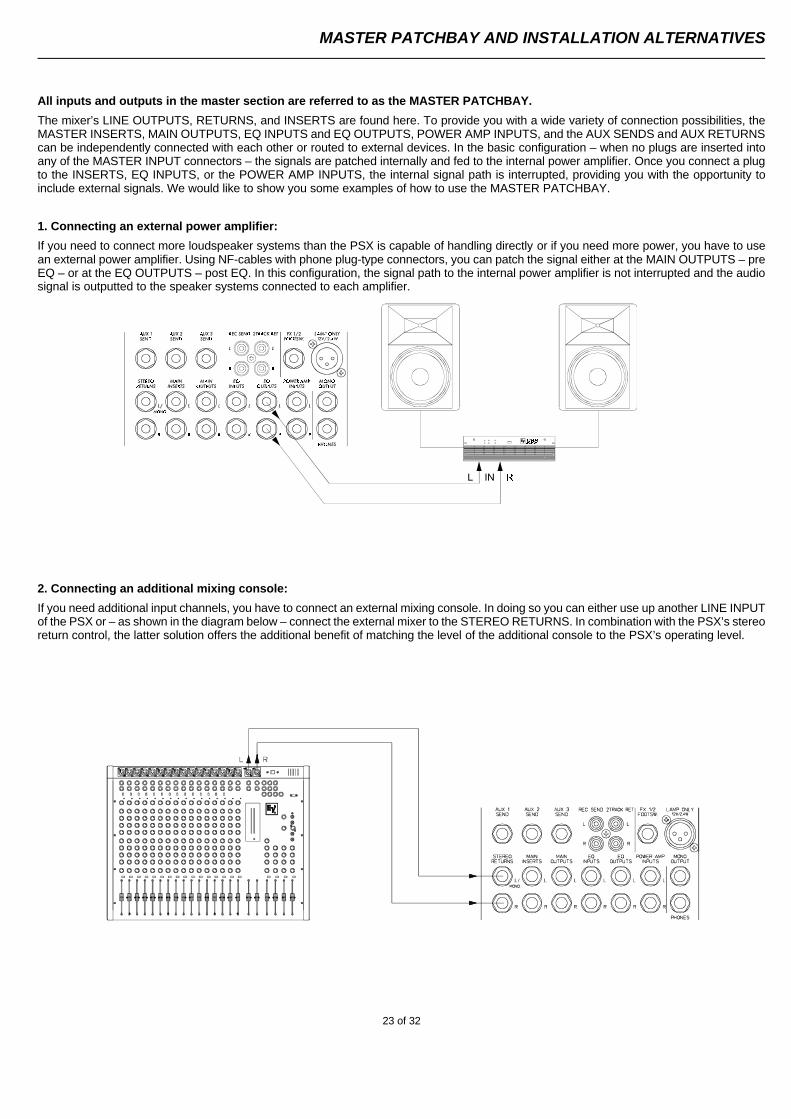
1. Connecting an external power amplifier:
If you need to connect more loudspeaker systems than the PSX is capable of handling directly or if you need more power, you have to usean external power amplifier. Using NF-cables with phone plug-type connectors, you can patch the signal either at the MAIN OUTPUTS – preEQ – or at the EQ OUTPUTS – post EQ. In this configuration, the signal path to the internal power amplifier is not interrupted and the audiosignal is outputted to the speaker systems connected to each amplifier.
2. Connecting an additional mixing console:
If you need additional input channels, you have to connect an external mixing console. In doing so you can either use up another LINE INPUTof the PSX or – as shown in the diagram below – connect the external mixer to the STEREO RETURNS. In combination with the PSX’s stereoreturn control, the latter solution offers the additional benefit of matching the level of the additional console to the PSX’s operating level.
MASTER PATCHBAY AND INSTALLATION ALTERNATIVES
23 of 32
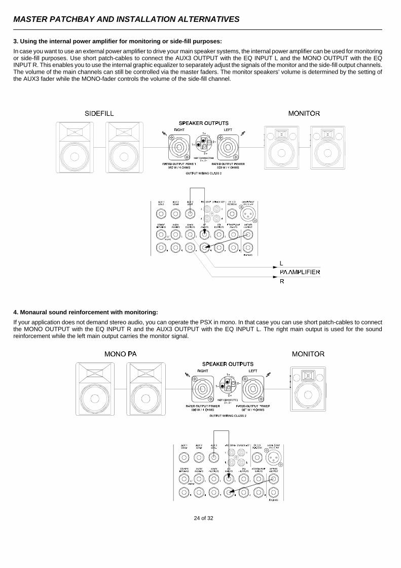
3. Using the internal power amplifier for monitoring or side-fill purposes:
In case you want to use an external power amplifier to drive your main speaker systems, the internal power amplifier can be used for monitoringor side-fill purposes. Use short patch-cables to connect the AUX3 OUTPUT with the EQ INPUT L and the MONO OUTPUT with the EQINPUT R. This enables you to use the internal graphic equalizer to separately adjust the signals of the monitor and the side-fill output channels.The volume of the main channels can still be controlled via the master faders. The monitor speakers’ volume is determined by the setting ofthe AUX3 fader while the MONO-fader controls the volume of the side-fill channel.
4. Monaural sound reinforcement with monitoring:
If your application does not demand stereo audio, you can operate the PSX in mono. In that case you can use short patch-cables to connectthe MONO OUTPUT with the EQ INPUT R and the AUX3 OUTPUT with the EQ INPUT L. The right main output is used for the soundreinforcement while the left main output carries the monitor signal.
MASTER PATCHBAY AND INSTALLATION ALTERNATIVES
24 of 32
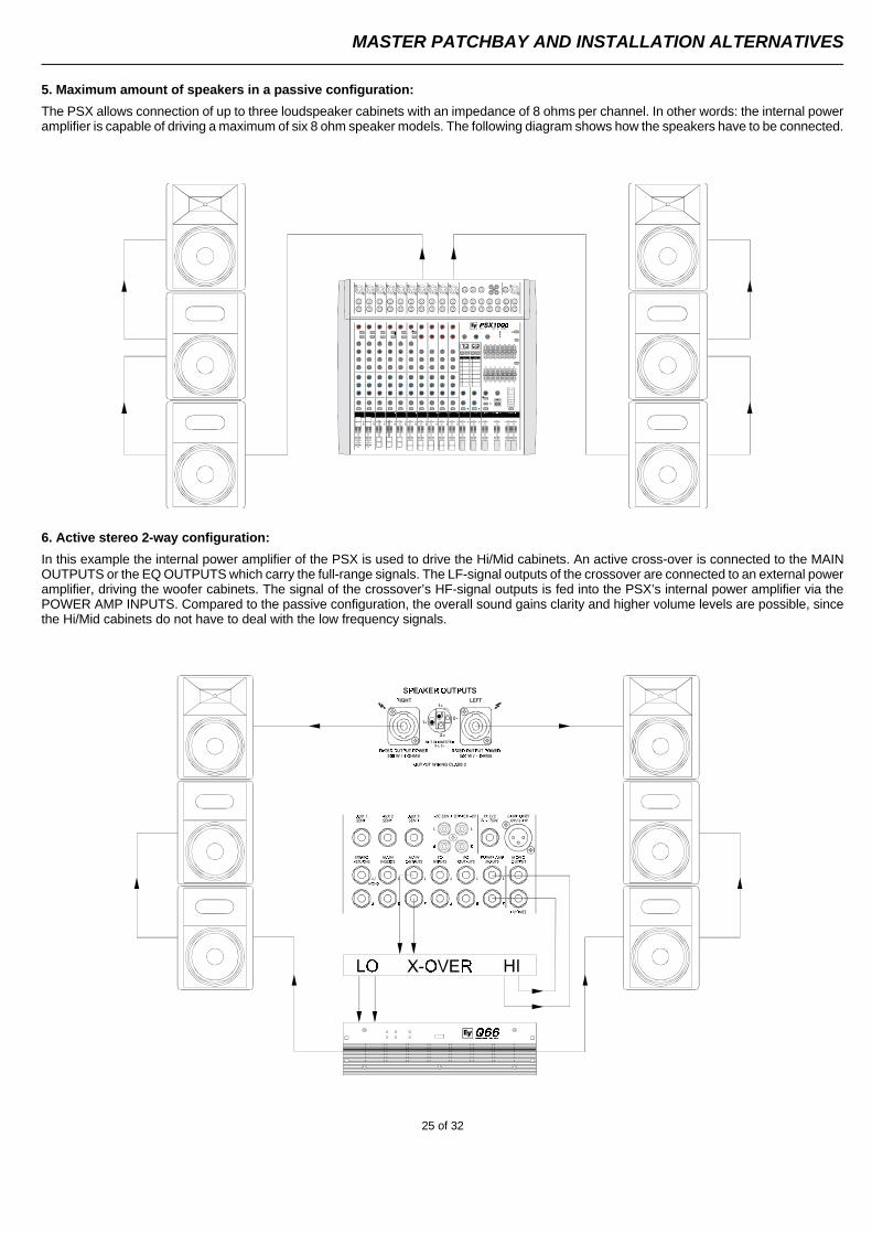
5. Maximum amount of speakers in a passive configuration:
The PSX allows connection of up to three loudspeaker cabinets with an impedance of 8 ohms per channel. In other words: the internal poweramplifier is capable of driving a maximum of six 8 ohm speaker models. The following diagram shows how the speakers have to be connected.
6. Active stereo 2-way configuration:
In this example the internal power amplifier of the PSX is used to drive the Hi/Mid cabinets. An active cross-over is connected to the MAINOUTPUTS or the EQ OUTPUTS which carry the full-range signals. The LF-signal outputs of the crossover are connected to an external poweramplifier, driving the woofer cabinets. The signal of the crossover’s HF-signal outputs is fed into the PSX’s internal power amplifier via thePOWER AMP INPUTS. Compared to the passive configuration, the overall sound gains clarity and higher volume levels are possible, sincethe Hi/Mid cabinets do not have to deal with the low frequency signals.
MASTER PATCHBAY AND INSTALLATION ALTERNATIVES
25 of 32
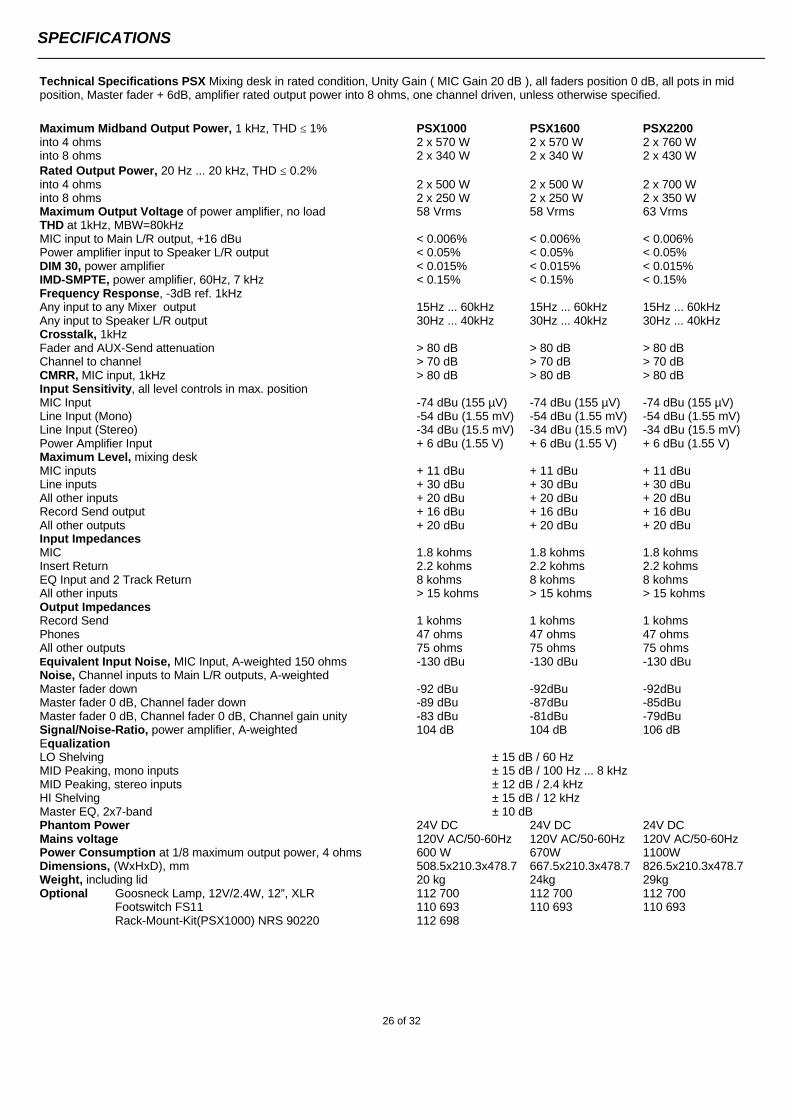
Technical Specifications PSX Mixing desk in rated condition, Unity Gain ( MIC Gain 20 dB ), all faders position 0 dB, all pots in mid position, Master fader + 6dB, amplifier rated output power into 8 ohms, one channel driven, unless otherwise specified.
Maximum Midband Output Power, 1 kHz, THD ≤ 1% PSX1000 PSX1600 PSX2200into 4 ohms 2 x 570 W 2 x 570 W 2 x 760 Winto 8 ohms 2 x 340 W 2 x 340 W 2 x 430 WRated Output Power, 20 Hz ... 20 kHz, THD ≤ 0.2%into 4 ohms 2 x 500 W 2 x 500 W 2 x 700 Winto 8 ohms 2 x 250 W 2 x 250 W 2 x 350 WMaximum Output Voltage of power amplifier, no load 58 Vrms 58 Vrms 63 VrmsTHD at 1kHz, MBW=80kHzMIC input to Main L/R output, +16 dBu < 0.006% < 0.006% < 0.006%Power amplifier input to Speaker L/R output < 0.05% < 0.05% < 0.05%DIM 30, power amplifier < 0.015% < 0.015% < 0.015%IMD-SMPTE, power amplifier, 60Hz, 7 kHz < 0.15% < 0.15% < 0.15%Frequency Response, -3dB ref. 1kHzAny input to any Mixer output 15Hz ... 60kHz 15Hz ... 60kHz 15Hz ... 60kHzAny input to Speaker L/R output 30Hz ... 40kHz 30Hz ... 40kHz 30Hz ... 40kHzCrosstalk, 1kHzFader and AUX-Send attenuation > 80 dB > 80 dB > 80 dBChannel to channel > 70 dB > 70 dB > 70 dBCMRR, MIC input, 1kHz > 80 dB > 80 dB > 80 dBInput Sensitivity, all level controls in max. positionMIC Input -74 dBu (155 µV) -74 dBu (155 µV) -74 dBu (155 µV)Line Input (Mono) -54 dBu (1.55 mV) -54 dBu (1.55 mV) -54 dBu (1.55 mV)Line Input (Stereo) -34 dBu (15.5 mV) -34 dBu (15.5 mV) -34 dBu (15.5 mV)Power Amplifier Input + 6 dBu (1.55 V) + 6 dBu (1.55 V) + 6 dBu (1.55 V)Maximum Level, mixing deskMIC inputs + 11 dBu + 11 dBu + 11 dBuLine inputs + 30 dBu + 30 dBu + 30 dBuAll other inputs + 20 dBu + 20 dBu + 20 dBuRecord Send output + 16 dBu + 16 dBu + 16 dBuAll other outputs + 20 dBu + 20 dBu + 20 dBuInput ImpedancesMIC 1.8 kohms 1.8 kohms 1.8 kohmsInsert Return 2.2 kohms 2.2 kohms 2.2 kohmsEQ Input and 2 Track Return 8 kohms 8 kohms 8 kohmsAll other inputs > 15 kohms > 15 kohms > 15 kohmsOutput ImpedancesRecord Send 1 kohms 1 kohms 1 kohmsPhones 47 ohms 47 ohms 47 ohmsAll other outputs 75 ohms 75 ohms 75 ohmsEquivalent Input Noise, MIC Input, A-weighted 150 ohms -130 dBu -130 dBu -130 dBuNoise, Channel inputs to Main L/R outputs, A-weightedMaster fader down -92 dBu -92dBu -92dBuMaster fader 0 dB, Channel fader down -89 dBu -87dBu -85dBuMaster fader 0 dB, Channel fader 0 dB, Channel gain unity -83 dBu -81dBu -79dBuSignal/Noise-Ratio, power amplifier, A-weighted 104 dB 104 dB 106 dBEqualizationLO Shelving ± 15 dB / 60 HzMID Peaking, mono inputs ± 15 dB / 100 Hz ... 8 kHzMID Peaking, stereo inputs ± 12 dB / 2.4 kHzHI Shelving ± 15 dB / 12 kHzMaster EQ, 2x7-band ± 10 dBPhantom Power 24V DC 24V DC 24V DCMains voltage 120V AC/50-60Hz 120V AC/50-60Hz 120V AC/50-60HzPower Consumption at 1/8 maximum output power, 4 ohms 600 W 670W 1100WDimensions, (WxHxD), mm 508.5x210.3x478.7 667.5x210.3x478.7 826.5x210.3x478.7Weight, including lid 20 kg 24kg 29kgOptional Goosneck Lamp, 12V/2.4W, 12”, XLR 112 700 112 700 112 700
Footswitch FS11 110 693 110 693 110 693Rack-Mount-Kit(PSX1000) NRS 90220 112 698
SPECIFICATIONS
26 of 32
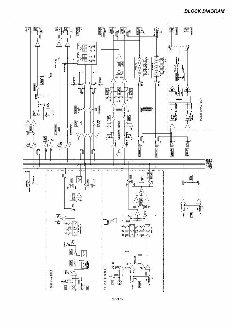
BLOCK DIAGRAM
27 of 32
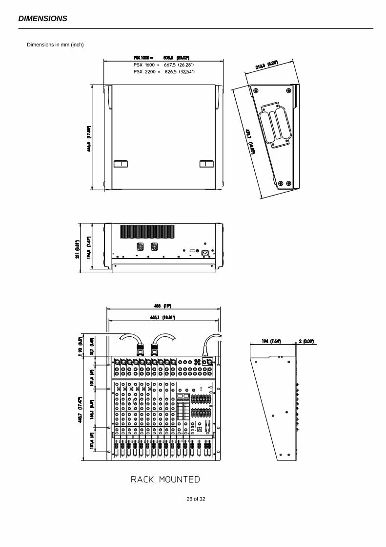
Dimensions in mm (inch)
DIMENSIONS
28 of 32
WARRANTY (Limited)
Electro-Voice products are guaranteed against malfunction due to defects in materials or workmanship for a specified period, as noted in theindividual product-line statement(s) below, or in the individual product data sheet or owner’s manual, beginning with the date of originalpurchase. If such malfunction occurs during the specified period, the product will be repaired or replaced (at our option) without charge. Theproduct will be returned to the customer prepaid.
Exclusions and Limitations: The Limited Warranty does not apply to: (a) exterior finish or appearance; (b) certain specific items describedin the individual product-line statement(s) below, or in the individual product data sheet or owner’s manual; (c) Malfunction resulting from useor operation of the product other than as specified in the product data sheet or owner’s manual; (d): malfunction resulting from misuse orabuse of the product; or (e): malfunction occurring at any time after repairs have been made to the product by anyone other than Electro-Voiceor any of its authorized service representatives.
Obtaining Warranty Service: To obtain warranty service, a customer must deliver the product, prepaid, to Electro-Voice or any of itsauthorized service representatives together with proof of purchase of the product in the form of a bill of sale or receipted invoice. A list ofauthorized service representatives is available from Electro-Voice at 600 Cecil Street, Buchanan, MI 49107 (616-695-6831) and/or Electro-Voice West at 9130 Glenoaks Boulevard, Sun Valley, CA 91532 (213-875-1900).
Incidental and Consequential Damages Excluded: Product repair or replacement and return to the customer are the only remediesprovided to the customer. Electro-Voice shall not be liable for any incidental or consequential damages including, without limitation, injury topersons or property or loss of use. Some states do not allow the exclusion or limitation of incidental or consequential damages so the abovelimitation or exclusion may not apply to you. Other Rights: This warranty gives you specific legal rights, and you may have other rights whichvary from state to state.
Electro-Voice Electronics are guaranteed against malfunction due to defects in materials or workmanship for a period of three (3) yearsfrom the date of original purchase. Additional details are included in the Uniform Limited Warranty Statement.
Specifications subject to change without notice.
600 Cecil Street, Buchanan, Michigan 49107, Phone 616/695-6831, Fax: 616/695-1304 TELEX/EVI Audio Canada, 705 Progress Ave. Unit 46 Toronto, Onatario, M1H 2x1, Canada , Phone: 800/881-1685, Fax: 877/522-2242TELEX Communications A.G., Keltenstrasse 11, CH-2563 IPSACH, Switzerland, Phone: 011-41/32-51-6833, Fax: 011-41/32-51-1221EVI Audio Deutschland GmbH, Hirschberger Ring 45, D-94315, Straubing, Germany, Phone: 011-49/9421-7060, Fax: 011-49/9421-706265EVI Audio France S.A., Parc de Courcerin-Allee Lech Walesa, Lognes, f-77185 Marne La Vallee, France, Phone: 011-33/1-6480-0090, Fax: 011-33/1-6006-5103EVI Audio Japan Ltd., 2-5-60 Izumi, Suginami-ku, Tokyo, Japan 168, Phone: 011-81/3-3325-7900, Fax: 011-81/3-3325-7789EVI Audio (Aust.) Pty., Unit 23, Block C, Slough Business Park, Slough Ave., Silverwater, N.S.W 2141, Australia, Phone 011-61/2-648-3455, Fax: 011-61/2-648-5585EVI Audio (Hong Kong) Limited, Unit E & F, 21 /F., Luk Hop Industrial Bldg., 8 Luk Hop St., San Po Kong, Kowloon, Hong
(358 173) 18.01.2000


![Welcome [pdf.textfiles.com]pdf.textfiles.com/manuals/STARINMANUALS/BenQ/Manuals/Archive/PB... · The projector integrates high-performance optical engine projection and a user-friendly](https://static.fdocuments.in/doc/165x107/5bf7309409d3f2941d8ce31a/welcome-pdf-pdf-the-projector-integrates-high-performance-optical-engine.jpg)

