

GSM Dialler OH/GSM - BPT Group - BPT Group 24854401 03_09.pdfThe device must be programmed through...
28
Installer and User manual GSM Dialler OH/GSM 24854401 - 03/09
Transcript of GSM Dialler OH/GSM - BPT Group - BPT Group 24854401 03_09.pdfThe device must be programmed through...

Installer and User manual
GSM DiallerOH/GSM
24854401 - 03/09
OH_GSM_GB 24854401 03_09.indd 1 17/03/09 13:34
2
Use and Applications
OH/GSM telephone dialler is a device connected to the BPT bus line through a Hoasis+ home automation system, which remotely allows only via SMS to: • Activatescenarios(upto16)• Queryandmodifythestatusandtemperatureofthethermalzones(upto20)• Beadvisedintheeventoftechnicalalarmsinthehomeautomationsystem(upto6)• Beadvisedincaseofdamage(outage)andresetofhomeelectricalpower• Carryoutasystemcheckevery12/24hours• ThedeviceisalsoequippedwithanormallyopenrelaycontactwhichcanbeusedtoactivateTHBptheatregulatorsdesignedforremotecontroloranyotherdevicesetupforthispurpose,controlledthroughtheopeningorclosingofacontact.
Thedevicemustbeprogrammedthroughtheprogrammingsoftware.
m Important!• Theupdatedversionoftheprogrammingsoftwarecanbedownloadedfromthewebsite: www.bpt.itsection“Download”>“Software”. The download password is OHSW2K7GSM
OH_GSM_GB 24854401 03_09.indd 2 17/03/09 13:34
3
Index
Use and Applications . . . . . . . . . . . . . . . . . Pag. 2
Safety warnings . . . . . . . . . . . . . . . . . . . . . . Pag. 4
Installer instructionsGeneral technical characteristics . . . . Pag. 6Contentsofpackage . . . . . . . . . . . . . . . . . . . . . . . . 6
SIM Card assembly . . . . . . . . . . . . . . . . . . . Pag. 7
Positioning of the device ............. Pag. 8Assemblyoftheantenna. . . . . . . . . . . . . . . . . . . . 8Module assembly on DIN rail . . . . . . . . . . . . . . . . 8
Terminal boards and connectors . . . . Pag. 9
Commissioning . . . . . . . . . . . . . . . . . . . . . . . Pag.10
Connection diagrams . . . . . . . . . . . . . . . . Pag.11
Programming of the dialler through programming software . . . . . Pag.14Activate/deactivateSystemstatusinformation. . . . . . . . . . . . . . . . . . . . 15Createanaddressbook. . . . . . . . . . . . . . . . . . . . . . 15Special telephone numbers intheaddressbook. . . . . . . . . . . . . . . . . . . . . . . . . . 15Thermalzones. . . . . . . . . . . . . . . . . . . . . . . . . . . . . . . 16Technical alarms . . . . . . . . . . . . . . . . . . . . . . . . . . . . . 16Scenarios . . . . . . . . . . . . . . . . . . . . . . . . . . . . . . . . . . . . 17
Programming of the dialler through SMS. . . . . . . . . . . . . . . . . . . . . . . . . . . Pag.18Createanaddressbook. . . . . . . . . . . . . . . . . . . . . . 18Addatelephonenumber totheaddressbook. . . . . . . . . . . . . . . . . . . . . . . . . 19Modifyatelephonenumber intheaddressbook.......................... 19Delete a telephone number intheaddressbook.......................... 19Special telephone numbersintheaddressbook. . . . . . . . . . . . . . . . . . . . . . . . . . 19Find out your remaining SIM credit . . . . . . . . . . . 19Deactivate SMS reception byanumberintheaddressbook............. 20Activate/Deactivateinformation on the system status . . . . . . . . . . . . . . . . . . . . . . . . . 20
User instructionsCommands performed by the User via SMS . . . . . . . . . . . . . . . . . . . Pag.22Insert a scenario . . . . . . . . . . . . . . . . . . . . . . . . . . . . . 22Commandcustomisation thatcanbeperformedviaSMS. . . . . . . . . . . . . . . 22Requestinformation on the system status . . . . . . . . . . . . . . . . . . . . . . . . . 22SMSmessagesfromOH/GSMdialler. . . . . . . . . . 24Find out your remaining SIM credit . . . . . . . . . . . 25
Reminder of the Dialler settings . . . . . . . . . . . . . . . . . . . . . . . . Pag.27
OH_GSM_GB 24854401 03_09.indd 3 17/03/09 13:34
4
Safety Warnings
m ATTENTION • Afterremovingthepackaging,checktheconditionoftheunit.• Thepackagingitems(plasticbags,expandedpolystyrene,etc.)mustnotbehandledbychildrenastheymaybedangerous.
• Carefullyreadtheinstructionsbeforestartinginstallation.Performworkasspecifiedbythemanu-facturer.
• Beforeconnectingtheequipment,makesurethattheratingplatedatacorrespondstothatofthedistributionnetwork.
• Anomnipolarswitch,withcontactsseparatedbyatleast3mm,mustbeinstalledupstreamontheequipment,ontheelectricsystemofthebuilding.
• Themanufacturerdeclinesallliabilityforanydamageasaresultofimproper,incorrectorunreason-ableuse.
• Beforeperforminganycleaningormaintenanceoperation,disconnect theequipment fromthepowersupplynetworkbyopeningthesystemswitch.
• Incaseoffailureand/ormalfunctionofthedevice,detachit fromthepowersupplyanddonottamperwithit.
• Useoriginalspareparts.• Installation, programming, commissioning andmaintenance of the productmust only be per-formed by qualified technicians who have been properly trained in compliance with currentstandardsincludingcompliancewithaccidentprevention.
• Operateinsufficientlylightedareasthatareconducivetohealthandusetools,utensilsandequip-mentthatareingoodworkingorder.
• Uponcompletionofinstallation,alwayscheckforcorrectoperationoftheunitandthesystemasawhole.
• Donotinstallthedeviceoutdoorsorinareaswhereitisexposedtoseepageorsplashesofwater.• Handlethedevicewithcare.Itcontainselectronicpartsthatarefragileandsensitivetohumidity.• Theelectroniccardscanbeseriouslydamagedbydischargesofstaticelectricity.Iftheyaretobehandled,wear suitable clothing and anti-static footwear, or at least, ensure static electricity hasbeendischargedbytouchingwiththefingertipametallicsurfaceconnectedtotheearthsystem(e.g.thechassisofahouseholdappliance).
• Weldthejointsbetweenwirestopreventfalsealarmscausedbyoxidationofthewires.• Theelectricalsystemmustcomplywithcurrentstandardsinthecountryofinstallation.• Failuretocomplywiththeaboveinstructionsmaycompromisetheunit’ssafety.• Theinstallermustmakesurethattheinformationfortheuser,whereapplicable,ispresentonthedevices.
• Disposeoftheunitinaccordancewithcurrentstandards.
OH_GSM_GB 24854401 03_09.indd 4 17/03/09 13:34
Installer instructions
OH_GSM_GB 24854401 03_09.indd 5 17/03/09 13:34
6
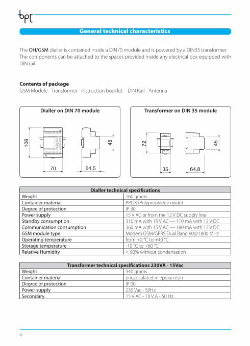
The OH/GSMdialleriscontainedinsideaDIN70moduleandispoweredbyaDIN35transformer.ThecomponentscanbeattachedtothespacesprovidedinsideanyelectricalboxequippedwithDINrail.
Contents of packageGSMModule-Transformer-Instructionbooklet-DINRail-Antenna
Dialler technical specifications Weight 160gramsContainer material PPOX(Polypropyleneoxide)Degree of protection IP 30Power supply 15VACorfromthe12VDCsupplylineStandby consumption 310mAwith15VAC––110mAwith12VDCCommunication consumption 360mAwith15VAC––180mAwith12VDCGSM module type ModemGSM/GPRSDualBand900/1800MHzOperating temperature from+0°Cto+40°CStorage temperature -10°Cto+60°CRelative Humidity < 90% without condensation
Transformer technical specifications 230VA - 15Vac Weight 340 gramsContainer material encapsulatedinepoxyresinDegree of protection IP 00Power supply 230Vac-50HzSecondary 15VAC-10VA-50Hz
45
70
106
64,5 35 64,8
72 45
General technical characteristics
45
70
106
64,5 35 64,8
72 45
Dialler on DIN 70 module Transformer on DIN 35 module
OH_GSM_GB 24854401 03_09.indd 6 17/03/09 13:34

7
SIM Card assembly
Inordertooperate,thedevicemustbeequippedwithaSIMcard,not included in the package,to beinsertedintheappropriatehousing.Todothis,unscrewthetwofasteningscrewsandremovethediallercover.Dothismakingsurethatyoudopullouttheantennawire.
m ATTENTION !• IftheSIMcardisnew,priortoinsertingit intothedialler,makeacallbyinsertingit intoa
mobile phone thus allowing the mobile telephone operator to register the card. • ThedevicerequiresthattheSIMcardsareactivatedonlyvocallyandbySMS(No SIM Data!)• Beforecarryingouttheprogrammingoperation,deactivate the SIM card PIN code.
c ATTENTION !Theelectroniccardscanbeseriouslydamagedbydischargesofstaticelectricity. If theyaretobehandled,wearsuitableclothingandanti-staticfootwear,oratleast,ensurestaticelectricityhasbeendischargedbytouchingwiththefingertipametallicsurfaceconnectedtotheearthsystem(e.g.thechassisofahouseholdappliance).
SIM card housing SIM card not included
OH_GSM_GB 24854401 03_09.indd 7 17/03/09 13:34
8
Positioning of the device
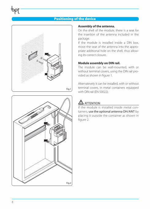
Assembly of the antenna.Ontheshellofthemodule,there isaseatforthe insertion of the antenna included in thepackage.If the module is installed inside a DIN box,movetheseatoftheantennaintotheappro-priate additional hole on the shell, thus allow-ingitscorrectclosure. Module assembly on DIN rail.The module can be wall-mounted, with or without terminal covers, using the DIN rail pro-videdasshowninfigure1.
Alternatevelyitcanbeinstalled,withorwithoutterminal covers, inmetal containers equippedwithDINrail(EN50022).
m ATTENTION If themodule is installed insidemetal con-tainers, use the optional antenna OH/ANT by placing it outside the container as shown in figure2.
Fig.1
Fig.2
OH_GSM_GB 24854401 03_09.indd 8 17/03/09 13:34

9
Terminal boards and connections
LA
M1
M2
DL1
CN1 CN4
CN5
32
B2 C NO TAMPER
BUSLA
BUSB2
C N0 TAMP
SIM Card
RS 232 connector to interface the module with a PC
SW2
LCK
SW1
TMP
SW3
DFT
SW4
BTL
Optional auxiliary battery connector
Green LEDVoltage present
Yellow LEDGSM transmission/reception
in progress
Red LEDOn HOASIS systemsthe LED is always on
Connection for antenna
Jumper SW1TAMPER disabled
Jumper SW2address book protection
Jumper SW4boot loader
Jumper SW3default reset
SIM Card housing
Terminals Meaning
M1
BUS-LA TerminalboardforBptBUSHoasisconnection
BUS-B2 TerminalboardforBUSB2BRAHMSconnection(terminals not to be used in Hoasis systems)
C,NO Relaycontact12V1A(normallyopen)
TAMP TerminalboardforTAMPERcontactconnection(terminals not to be used in Hoasis systems)
M2Terminalboardforearthconnection
Terminalboardforconnectiontopowersupplyfrompowersupplier
SW1 TMP Whenthejumperisconnectedthetampercontactisdisconnected
SW2 LCK WhenthejumperisdisconnectedtheaddressbookcannotbemodifiedviaSMS
SW3 DFT Bypoweringthemodulewithoutjumperthedefaultconfigurationisreset
SW4 BTL Boot-loader (jumper reserved for the Technical Service not to be removed)
OH_GSM_GB 24854401 03_09.indd 9 17/03/09 13:34
10
Commissioning
m ATTENTION Beforeinstallingthemoduleitisimportanttoverifythatthereisanadequateradioreceivingsignalfromthedeviceintheareawherethedeviceneedstobeinstalled.Todothis,simplyinserttheSIMinamobilephoneandcheckreception. If reception is poor the device will have to be installed in another location with a better signal. BPT S.p.A. declines all liability in the event of:• failedtransmission,failedreception,delayedtransmissionordelayedreceptionofSMSmes-sagesbythedialler,whentheseareduetothequalityofthereceptionsignalortoanyotherproblem related to the mobile telephone operator’s activities.
• chargingcostonthediallerreaminingSIMcreditresultingfrommessagessentbythemobiletelephone operator or from other services carried out by the mobile telephone operator.
Once the module has been placed in the appropriate containers, as described in the previous pages,proceedasfollows:• Ensurevoltagehasbeenremovedtothesystem.• Connecttheterminal oftheGSMmoduletothetransformer.• ConnectthediallertotheBPT HOASIS home automation system through the BUS LAterminal.• ConnecttheOH/B008auxiliarybatterytotheappropriateconnector(CN1).• Connectthetransformertotheelectricalmains.• Nowrestorevoltagetothesystem.• Thelightingofthegreen LEDindicatesthatthemoduleispowered.• Theyellow LED,willremainonforafewseconds,duringwhichtheGSMdevicewillverifymobilereception.
Ifafterafewsecondstheyellow LEDswitchesofftheoperationwassuccessful.If,onthecon-trary, the yellow LED remains on this may indicate that there are GSM communication problems, relatedtoreceptionfailureorSIMregistration(seechapter“MontaggiodellaSIMCard”).
Once the installation has been completed the yellow LEDwillflashonlyincaseofdatatransmis-sion/receptionontheGSMnetwork.
. Note: In Hoasis systems the red LEDblinks.
OH_GSM_GB 24854401 03_09.indd 10 17/03/09 13:34

11
OH/GSM connection in a HOASIS system
OH/A.01
LA
LA
M3
OH/GSM
TRANSFORMER
OH/B008
BUS LA
BUS B2
230 V
15 V
M1
CN1
M2
230Vac
OH/RI
LA
OH/MA
LA
OH/T.01
+–
The OH/GSMmoduleisdesignedforconnectiontoa12VOH/B008 battery that allows the tran-smissionandreceptionofSMSmessagesintheeventofanelectricalpoweroutage(Fig.3).WithanOH/B008batteryaruntimeofafewhoursinreceptionandthetransmissionofapproxima-telytenmessagesisguaranteed.
m ATTENTION ConnecttheBPThomeautomationBUStotheterminalsLA,nottotheterminalsB2.
Fig. 3
OH_GSM_GB 24854401 03_09.indd 11 17/03/09 13:34
12
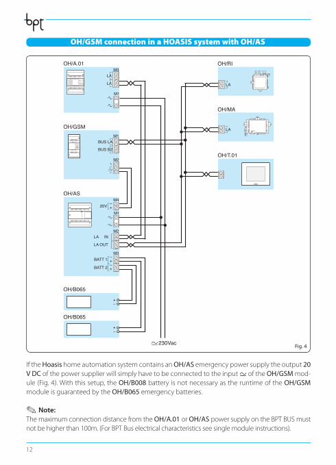
OH/GSM connection in a HOASIS system with OH/AS
OH/A.01
LA
LA
M3
OH/GSM
OH/AS
BUS LA
BUS B2
BATT 1 –+
–+
–+BATT 2
LA OUT
LA IN
20V
M1
M2
M3
M2
M4
OH/T.01
OH/RI
LA
OH/MA
LA
230Vac
OH/B065
OH/B065
+–
+–
IftheHoasis home automation system contains an OH/AS emergency power supply the output 20 V DCofthepowersupplierwillsimplyhavetobeconnectedtotheinput oftheOH/GSM mod-ule(Fig.4).Withthissetup,theOH/B008batteryisnotnecessaryastheruntimeoftheOH/GSM module is guaranteed by the OH/B065emergencybatteries.
. Note: ThemaximumconnectiondistancefromtheOH/A.01 or OH/ASpowersupplyontheBPTBUSmustnotbehigherthan100m.(ForBPTBuselectricalcharacteristicsseesinglemoduleinstructions).
Fig. 4
OH_GSM_GB 24854401 03_09.indd 12 17/03/09 13:34
13
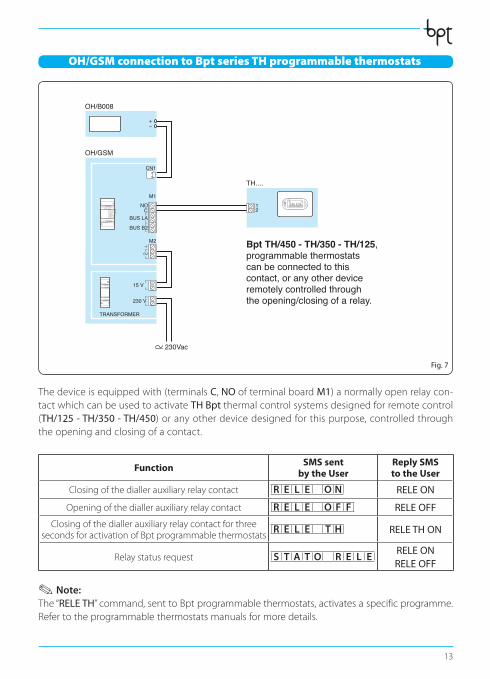
OH/GSM connection to Bpt series TH programmable thermostats
OH/GSM
TRANSFORMER
OH/B008
230 V
15 V
CN1
M2
230Vac
+–
BUS LAC
NO
BUS B2
M1
TH....
Bpt TH/450 - TH/350 - TH/125,programmable thermostats can be connected to this contact, or any other device remotely controlled through the opening/closing of a relay.
TH450
12
Fig. 7
Thedeviceisequippedwith(terminalsC, NOofterminalboardM1)anormallyopenrelaycon-tact which can be used to activate TH Bptthermalcontrolsystemsdesignedforremotecontrol(TH/125 - TH/350 - TH/450)oranyotherdevicedesignedforthispurpose,controlledthroughtheopeningandclosingofacontact.
Function SMS sent by the User
Reply SMS to the User
Closingofthediallerauxiliaryrelaycontact R E L E O N RELE ON
Openingofthediallerauxiliaryrelaycontact R E L E O F F RELE OFF
ClosingofthediallerauxiliaryrelaycontactforthreesecondsforactivationofBptprogrammablethermostats
R E L E T H RELE TH ON
Relaystatusrequest S T A T O R E L ERELE ONRELE OFF
. Note: The “RELE TH”command,senttoBptprogrammablethermostats,activatesaspecificprogramme.Refertotheprogrammablethermostatsmanualsformoredetails.
OH_GSM_GB 24854401 03_09.indd 13 17/03/09 13:34
14
Programming of the dialler through programming software
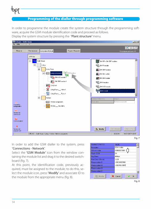
In order to programme the module create the system structure through the programmingsoft-ware,acquiretheGSMmoduleidentificationcodeandproceedasfollows.Display the system structure by pressing the “Plant structure”menu.
In order to add the GSM dialler to the system, press “Connections - Network”.Select the “GSM Module” icon from thewindow con-taining the module list and drag it to the desired switch-board(fig.7).At this point, the identification code, previously ac-quired,mustbeassignedtothemodule;todothis,se-lect the module icon, press “Modify” and associate ID to themodulefromtheappropriatemenu(fig.8).
Fig. 7
Fig. 8
c
OH_GSM_GB 24854401 03_09.indd 14 17/03/09 13:34
15
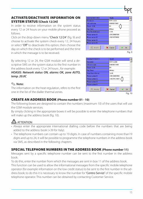
ACTIVATE/DEACTIVATE INFORMATION ON SYSTEM STATUS (Check 12/24)In order to receive information on the system statusevery 12 or 24 hours on your mobile phone proceed as follows.Clickonthedrop-downmenu“Check 12/24”(fig.9)andchoosetoactivatethesystemcheckevery12,24hoursor select “Off”todeactivatethisoption;thenchoosethedayonwhichthecheckistobeperformedandthetimeinwhichthemessageistobereceived.
By selecting 12 or 24, the GSM module will send a de-scriptiveSMSonthesystemstatustothefirstnumberintheaddressbookevery12or24hours,forexample:HOASIS: Network status ON, alarms OK, zone AUTO, temp. 20.0C
. Note: Theinformationontheheatregulation,referstothefirstoneinthelistofthediallerthermalzones.
CREATE AN ADDRESS BOOK (Phone number 01 - 10)Thefollowingboxesaredesignedtocontainthenumbers(maximum10)oftheusersthatwillusetheGSMmoduleservices.Bysimplyclickingintheappropriateboxesitwillbepossibletoenterthetelephonenumbersthatwillmakeuptheaddressbook(fig.10).
m ATTENTION • Always enter the appropriate international dialling code before the numbers that are beingaddedtotheaddressbook(+39forItaly).
• Thetelephonenumberscancontainupto19digits.Incaseofnumberscontainingmorethan19digitsandupto24,itwillbepossibletoprogrammethetelephonenumbersintheaddressbookviaSMS,asdescribedinthefollowingchapters.
SPECIAL TELEPHONE NUMBERS IN THE ADDRESS BOOK (Phone number 11)Messages sentby a specific telephonenumber canbe sent to thefirst number in the addressbook.Todothis,enterthenumberfromwhichthemessagesaresentinbox11oftheaddressbook.Thisfunctioncanbeusedtoallowtheinformationalmessagesfromthespecificmobiletelephoneoperator(forexampleinformationonthelowcreditstatus)tobesenttothefirstnumberinthead-dressbook;todothisitisnecessarytoknowthenumberfor“Centro Servizi”ofthespecificmobiletelephoneoperator.ThisnumbercanbeobtainedbycontactingCustomerService.
Fig. 9
Fig. 10
c
c
OH_GSM_GB 24854401 03_09.indd 15 17/03/09 13:34

16
Forexample:Telecom Italia Mobile +393359609600 +393359608000Vodafone Italia +393492000200
THERMAL ZONES (Thermal zone 01 - 20)Through the dialler it is possible to manage up to 20 ther-malzones;todothisassociatethethermalzonescreatedthroughprogrammingsoftwaretothespecificboxescon-tainedintheprogrammingwindowoftheGSMModule.Bysimplyclickingintheappropriateboxesitwillbepos-sibletochooseoneoftheavailableThermalZonesfromadrop-downmenu(Fig.11).
TECHNICAL ALARMS (Alarm 01 - 06)TheGSMmodulecansendawarningSMSintheeventofan“TechnicalAlarm”;thisalarmmustbeprogrammedfirstthroughprogrammingsoftware,asfollows:Display the system structure by pressing the menu “Plant structure”;selecttheentry“Security” on thelefthandsideofthescreenandclickontheicon“Alarms”;choosetheiconofthealarmthat
Fig. 11
Fig. 12
OH_GSM_GB 24854401 03_09.indd 16 17/03/09 13:34
17
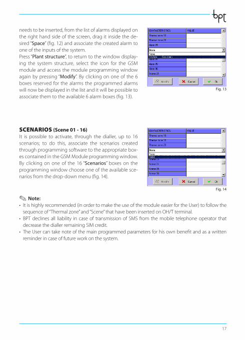
needstobeinserted,fromthelistofalarmsdisplayedontherighthandsideofthescreen,dragit insidethede-sired “Space”(fig.12)andassociatethecreatedalarmtooneoftheinputsofthesystem.Press “Plant structure”, to return to the window display-ing the system structure, select the icon for the GSMmodule and access the module programming window again by pressing “Modify”.Byclickingononeofthe6boxes reserved for thealarms theprogrammedalarmswill now be displayed in the list and it will be possible to associatethemtotheavailable6alarmboxes(fig.13).
SCENARIOS (Scene 01 - 16)It is possible to activate, through the dialler, up to 16scenarios; to do this, associate the scenarios createdthroughprogrammingsoftwaretotheappropriatebox-escontainedintheGSMModuleprogrammingwindow.By clickingononeof the 16“Scenarios” boxeson theprogrammingwindowchooseoneoftheavailablesce-nariosfromthedrop-downmenu(fig.14).
. Note: • Itishighlyrecommended(inordertomaketheuseofthemoduleeasierfortheUser)tofollowthesequenceof“Thermalzone”and“Scene”thathavebeeninsertedonOH/Tterminal.
• BPTdeclinesall liability in caseof transmissionof SMS from themobile telephoneoperator thatdecreasethediallerremainingSIMcredit.
• TheUsercantakenoteofthemainprogrammedparametersforhisownbenefitandasawrittenreminderincaseoffutureworkonthesystem.
Fig. 13
Fig. 14
OH_GSM_GB 24854401 03_09.indd 17 17/03/09 13:34

18
Programming of the dialler via SMS
TheOH/GSMdiallerallowsremotecontrolandsignallingfunctionsviathereceiptandsendingofSMSmessagesfromandtothetelephonenumberscontainedintheaddressbooksavedontheinternalmemoryofthedialleritself.
.Note: All the following settings can be programmed simply and intuitevely through the use of programming software by connecting the system to a PC through the OH/SW interface without SMS.
m Important!• BeforestartingprogrammingtheaddressbookviaSMSmakesurethat the jumperSW2(LCK)isconnected.Withadisconnectedjumpertheprogrammingoftheaddressbookcanonlybeperformedthroughprogrammingsoftware.
• Itisimportant to enter the appropriate international diallingcodebeforethenumbersthatarebeingsavedintheaddressbook(+39forItaly).
• The dialler, when purchased, can receive programming messages sent by any telephonenumber. It is thereforeadvisable,once theprogrammingof theaddressbookhasbeencom-pleted,todisconnectthejumperSW2.
CREATE AN ADDRESS BOOKTheaddressbookcanbeeasilycreatedvia SMS messages structured in such a way that they carry theinformationnecessaryforprogrammingthemodule.Theaddressbookcan contain up to10 telephone numbers.EveryprogrammingSMScansendupto5numberstotheaddressbook.TheseSMSmessagesmusthavethefollowingstructure:
SMS n°1 P R O G N U M T E L 1 . first telephone number . second telephone number .
third telephone number . fourth telephone number . fifth telephone number .
SMS n°2 P R O G N U M T E L 2 . sixth telephone number . seventh telephone number .
eighth telephone number . ninth telephone number . tenth telephone number .
ExampleIf theGSMdiallermustsendor receivemessages to/fromonly twonumbers, theaddressbookprogrammingmessagewillhavethefollolwingstructure:P R O G N U M T E L 1 . + 3 9 3 4 7 1 2 3 4 5 6 7 . + 3 9 3 3 3 3 4 5 6 7 8 9 .
m Important!The address book that is created via SMS will totally overwrite any pre-existing address book.
OH_GSM_GB 24854401 03_09.indd 18 17/03/09 13:34
19
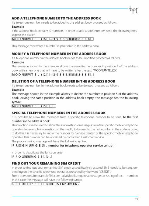
ADD A TELEPHONE NUMBER TO THE ADDRESS BOOKIfatelephonenumberneedstobeaddedtotheaddressbookproceedasfollows:ExampleIftheaddressbookcontains5numbers,inordertoaddasixthnumber,sendthefollowingmes-sage to the dialler:M O D N U M T E L ( 6 ) + 3 9 3 3 3 8 8 8 8 8 8 8 .
Thismessageoverwritesanumberinposition6intheaddressbook.
MODIFY A TELEPHONE NUMBER IN THE ADDRESS BOOKIfatelephonenumberintheaddressbookneedstobemodifiedproceedasfollows:ExampleThemessageshownintheexampleallowstooverwritethenumberinposition2oftheaddressbookwithanewonethatwillhavetobewrittenafterthetext“MODNUMTEL(2)”.M O D N U M T E L ( 2 ) + 3 9 3 3 3 5 5 5 5 5 5 5 .
DELETION OF A TELEPHONE NUMBER IN THE ADDRESS BOOKIfatelephonenumberintheaddressbookneedstobedeletedproceedasfollows:ExampleThe message shown in the example allows to delete the number in position 5 of the address book leaving the same position in the address book empty; the message has the following syntax:M O D N U M T E L ( 5 ) _ .
SPECIAL TELEPHONE NUMBERS IN THE ADDRESS BOOKIt is possible to allow themessages froma specific telephonenumber tobe sent to the first number in the address book.Thisfunctioncanbeusedtoallowtheinformationalmessagesfromthespecificmobiletelephoneoperator(forexampleinformationonthecredit)tobesenttothefirstnumberintheaddressbook;todothisitisnecessarytoknowthenumberfor“ServiceCenter”ofthespecificmobiletelephoneoperator.ThisnumbercanbeobtainedbycontactingCustomerService.Theprogrammingmessagewillhavethefollowingsyntax:P R O G N U M G E S . number for telephone operator service centre .
InordertodeactivatethefunctionenterP R O G N U M G E S . 0 .
FIND OUT YOUR REMAINING SIM CREDITInordertofindoutyourremainingSIMcreditaspecificallystructuredSMSneedstobesent,de-pendingonthespecifictelephoneoperator,precededbytheword“CREDIT”.Someoperators,forexampleTelecomItaliaMobile,requireamessageconsistingoftext+number;inthiscasethemessagewillhavethefollowingsyntax:C R E D I T “ P R E C R E S I N “ 4 9 1 6 .
OH_GSM_GB 24854401 03_09.indd 19 17/03/09 13:34
20
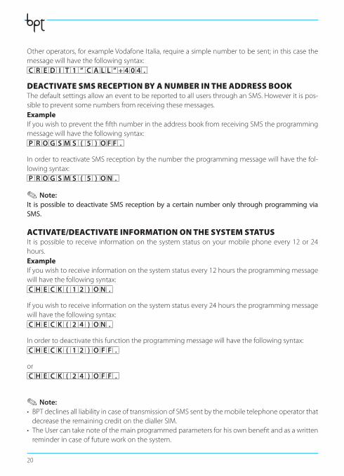
Otheroperators,forexampleVodafoneItalia,requireasimplenumbertobesent;inthiscasethemessagewillhavethefollowingsyntax:C R E D I T 1 “ C A L L “ + 4 0 4 .
DEACTIVATE SMS RECEPTION BY A NUMBER IN THE ADDRESS BOOK ThedefaultsettingsallowaneventtobereportedtoallusersthroughanSMS.Howeveritispos-sibletopreventsomenumbersfromreceivingthesemessages.ExampleIfyouwishtopreventthefifthnumberintheaddressbookfromreceivingSMStheprogrammingmessagewillhavethefollowingsyntax:P R O G S M S ( 5 ) O F F .
InordertoreactivateSMSreceptionbythenumbertheprogrammingmessagewillhavethefol-lowingsyntax:P R O G S M S ( 5 ) O N .
. Note: It is possible to deactivate SMS reception by a certain number only through programming via SMS.
ACTIVATE/DEACTIVATE INFORMATION ON THE SYSTEM STATUSIt ispossible to receive informationonthesystemstatusonyourmobilephoneevery12or24hours.ExampleIfyouwishtoreceiveinformationonthesystemstatusevery12hourstheprogrammingmessagewillhavethefollowingsyntax:C H E C K ( 1 2 ) O N .
Ifyouwishtoreceiveinformationonthesystemstatusevery24hourstheprogrammingmessagewillhavethefollowingsyntax:C H E C K ( 2 4 ) O N .
Inordertodeactivatethisfunctiontheprogrammingmessagewillhavethefollowingsyntax:C H E C K ( 1 2 ) O F F .
or C H E C K ( 2 4 ) O F F .
. Note: • BPTdeclinesallliabilityincaseoftransmissionofSMSsentbythemobiletelephoneoperatorthatdecreasetheremainingcreditonthediallerSIM.
• TheUsercantakenoteofthemainprogrammedparametersforhisownbenefitandasawrittenreminderincaseoffutureworkonthesystem.
OH_GSM_GB 24854401 03_09.indd 20 17/03/09 13:34

User instructions
OH_GSM_GB 24854401 03_09.indd 21 17/03/09 13:34
22
Commands performed by the User via SMS
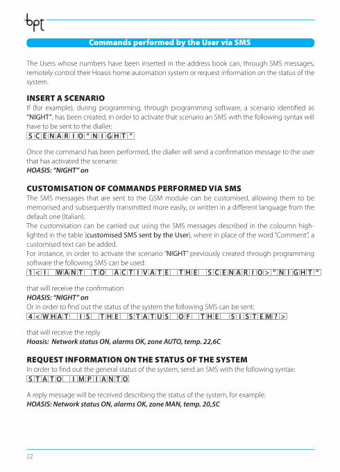
TheUserswhosenumbershavebeeninsertedintheaddressbookcan,throughSMSmessages,remotelycontroltheirHoasishomeautomationsystemorrequestinformationonthestatusofthesystem.
INSERT A SCENARIOIf (for example), during programming, through programming software, a scenario identified as“NIGHT”,hasbeencreated,inordertoactivatethatscenarioanSMSwiththefollowingsyntaxwillhave to be sent to the dialler:S C E N A R I O “ N I G H T “
Oncethecommandhasbeenperformed,thediallerwillsendaconfirmationmessagetotheuserthat has activated the scenario: HOASIS: “NIGHT” on
CUSTOMISATION OF COMMANDS PERFORMED VIA SMSThe SMS messages that are sent to the GSM module can be customised, allowing them to be memorisedandsubsequentlytransmittedmoreeasily,orwritteninadifferentlanguagefromthedefaultone(Italian).The customisation can be carried out using the SMS messages described in the coloumn high-lightedinthetable(customised SMS sent by the User),whereinplaceoftheword“Comment”,acustomisedtextcanbeadded.For instance, in order to activate the scenario “NIGHT” previously created through programming softwarethefollowingSMScanbeused:1 < I W A N T T O A C T I V A T E T H E S C E N A R I O > “ N I G H T “
thatwillreceivetheconfirmationHOASIS: “NIGHT” onOrinordertofindoutthestatusofthesystemthefollowingSMScanbesent:4 < W H A T I S T H E S T A T U S O F T H E S I S T E M ? >
that will receive the reply Hoasis: Network status ON, alarms OK, zone AUTO, temp. 22,6C
REQUEST INFORMATION ON THE STATUS OF THE SYSTEMInordertofindoutthegeneralstatusofthesystem,sendanSMSwiththefollowingsyntax:S T A T O I M P I A N T O
Areplymessagewillbereceiveddescribingthestatusofthesystem,forexample:HOASIS: Network status ON, alarms OK, zone MAN, temp. 20,5C
OH_GSM_GB 24854401 03_09.indd 22 17/03/09 13:34
23
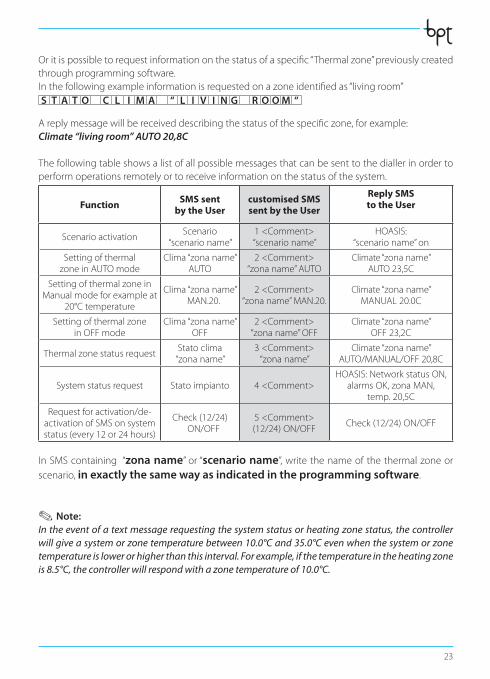
Oritispossibletorequestinformationonthestatusofaspecific“Thermalzone”previouslycreatedthrough programmingsoftware.Inthefollowingexampleinformationisrequestedonazoneidentifiedas“livingroom”S T A T O C L I M A “ L I V I N G R O O M “
Areplymessagewillbereceiveddescribingthestatusofthespecificzone,forexample:Climate “living room” AUTO 20,8C
Thefollowingtableshowsalistofallpossiblemessagesthatcanbesenttothediallerinordertoperformoperationsremotelyortoreceiveinformationonthestatusofthesystem.
Function SMS sent by the User
customised SMS sent by the User
Reply SMS to the User
Scenario activationScenario
“scenario name”1<Comment>“scenario name”
HOASIS:“scenario name” on
SettingofthermalzoneinAUTOmode
Clima“zonaname”AUTO
2<Comment>“zonaname”AUTO
Climate“zonaname” AUTO23,5C
SettingofthermalzoneinManualmodeforexampleat
20°Ctemperature
Clima“zonaname”MAN.20.
2<Comment>“zonaname”MAN.20.
Climate“zonaname”MANUAL20.0C
Settingofthermalzone in OFF mode
Clima“zonaname”OFF
2<Comment>“zonaname”OFF
Climate“zonaname”OFF23,2C
ThermalzonestatusrequestStato clima“zonaname”
3<Comment>“zonaname”
Climate“zonaname”AUTO/MANUAL/OFF20,8C
Systemstatusrequest Stato impianto 4<Comment>HOASIS:NetworkstatusON,
alarmsOK,zonaMAN,temp.20,5C
Requestforactivation/de-activationofSMSonsystemstatus(every12or24hours)
Check(12/24)ON/OFF
5<Comment>(12/24)ON/OFF
Check(12/24)ON/OFF
In SMS containing “zona name” or “scenario name”,writethenameofthethermalzoneorscenario, in exactly the same way as indicated in the programming software.
. Note: In the event of a text message requesting the system status or heating zone status, the controller will give a system or zone temperature between 10.0°C and 35.0°C even when the system or zone temperature is lower or higher than this interval. For example, if the temperature in the heating zone is 8.5°C, the controller will respond with a zone temperature of 10.0°C.
OH_GSM_GB 24854401 03_09.indd 23 17/03/09 13:34
24
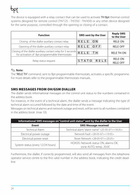
ThedeviceisequippedwitharelaycontactthatcanbeusedtoactivateTH Bpt thermal control systemsdesignedforremotecontrol(TH/125-TH/350-TH/450)oranyotherdevicedesignedforthesamepurpose,controlledthroughtheopeningorclosingofacontact.
Function SMS sent by the User Reply SMS to the User
Closingofthediallerauxiliarycontactrelay R E L E O N RELE ON
Openingofthediallerauxiliarycontactrelay R E L E O F F RELE OFF
Closingofthediallerauxiliarycontactrelayfor3secondsforactivationofBptprogrammablethermostats
R E L E T H RELE TH ON
Relaystatusrequest S T A T O R E L ERELE ONRELE OFF
. Note: The “RELE TH”command,senttoBptprogrammablethermostats,activatesaspecificprogramme.Formoredetailsrefertotheprogrammablethermostatsmanuals.
SMS MESSAGES FROM OH/GSM DIALLERThediallersendsinformationalmessagesonthecontrolunitstatustothenumberscontainedintheaddressbook.Forinstance,intheeventofatechnicalalarm,thediallersendsamessageindicatingthetypeoftechnicalalarmoccurredfollowedbythedateandtimeoftheevent.Messagesontechnicalalarmsandnetworkoutageandreset,willbesenttoallnumberscontainedintheaddressbook(max10).
Informational SMS messages on “control unit status” sent by the dialler to the User
Event SMS Message received
TechnicalAlarm Technicalalarm“alarmname”<25-05-07><18:35>
Electricalpoweroutage NetworkFault<28-05-07><19:35>
Electricalpowerreset ResetNetwork<28-05-07><20:35>
Systemstatus(every12/24hours)HOASIS:NetworkstatusON,alarmsOK,
zoneAUTO,temp.20.0C
Furthermore,thedialler,ifcorrectlyprogrammed,willalsosendallmessagesfromthetelephoneoperatorservicecentretothefirstvalidnumberintheaddressbook,indicatingthecreditdead-line.
OH_GSM_GB 24854401 03_09.indd 24 17/03/09 13:34
25
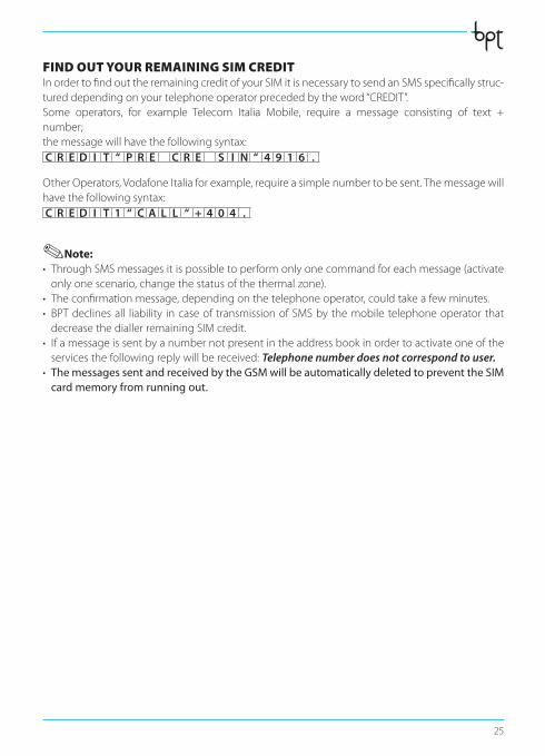
FIND OUT YOUR REMAINING SIM CREDITInordertofindouttheremainingcreditofyourSIMitisnecessarytosendanSMSspecificallystruc-tureddependingonyourtelephoneoperatorprecededbytheword“CREDIT”.Some operators, for example Telecom Italia Mobile, require a message consisting of text +number;themessagewillhavethefollowingsyntax:C R E D I T “ P R E C R E S I N “ 4 9 1 6 .
OtherOperators,VodafoneItaliaforexample,requireasimplenumbertobesent.Themessagewillhavethefollowingsyntax:C R E D I T 1 “ C A L L “ + 4 0 4 .
.Note:• ThroughSMSmessagesitispossibletoperformonlyonecommandforeachmessage(activateonlyonescenario,changethestatusofthethermalzone).
• Theconfirmationmessage,dependingonthetelephoneoperator,couldtakeafewminutes.• BPTdeclinesall liability incaseof transmissionofSMSbythemobile telephoneoperator thatdecreasethediallerremainingSIMcredit.
• Ifamessageissentbyanumbernotpresentintheaddressbookinordertoactivateoneoftheservicesthefollowingreplywillbereceived:Telephone number does not correspond to user.
• The messages sent and received by the GSM will be automatically deleted to prevent the SIM card memory from running out.
OH_GSM_GB 24854401 03_09.indd 25 17/03/09 13:34

26
OH_GSM_GB 24854401 03_09.indd 26 17/03/09 13:34
27
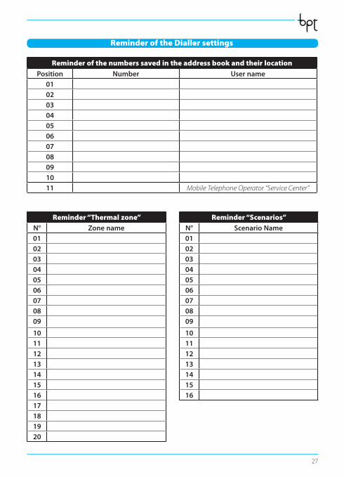
Reminder of the numbers saved in the address book and their locationPosition Number User name
0102030405060708091011 Mobile Telephone Operator “Service Center”
Reminder “Thermal zone”N° Zone name010203040506070809
1011121314151617181920
Reminder “Scenarios”N° Scenario Name010203040506070809
10111213141516
Reminder of the Dialler settings
OH_GSM_GB 24854401 03_09.indd 27 17/03/09 13:34