GSM-12 EMERGENCY SHUTDOWN SYSTEM CONTROLLER
26
INT-0301-XX Rev. A Page 1-1 GSM-12 EMERGENCY SHUTDOWN SYSTEM CONTROLLER for ESO PROTECTED GAS SOURCE EQUIPMENT Operations Manual
Transcript of GSM-12 EMERGENCY SHUTDOWN SYSTEM CONTROLLER
INT-0301-XX Rev. A Page 1-1
GSM-12 EMERGENCY SHUTDOWN SYSTEM CONTROLLER
for
ESO PROTECTED GAS SOURCE EQUIPMENT
Operations Manual

INT-0301-XX Rev. A Page 1-2
TABLE OF CONTENTS 1 SAFETY 1-4
1.1 Emergency Response 1-4 1.2 Fire Response 1-4 1.3 Basic Safety Requirements 1-4 1.4 Monitoring the Personnel Area 1-5 1.5 Security Information 1-5 1.6 Gases 1-5 1.6.1 Inert Gases 1-5 1.6.2 Flammable Gases 1-6 1.6.3 Pyrophoric Gases 1-6 1.6.4 Toxic Gases 1-7 1.6.5 Corrosive Gases 1-7 1.6.6 Liquefied Gases 1-7 1.6.7 Table 1-2 1-98 1.7 Gas Delivery Equipment 1.9 1.7.1 Excess Flow Sensors 1.9 1.8 Start-Up 1-1010 1.8.1 Inspection and Mounting 1-10 1.8.2 Typical Utilities Requirements 1-10 1.8.2.1 ESS Controller Typical Required Utilities 1-10 1.8.3 Environmental Characteristics 1-10 1.9 Initial Gas Delivery 1-11
2 GSM-12 CONTROLLER 2-1 2.1 Emergency Shutdown System Description 2-1 2.2 Emergency Shutdown System Operation 2-2 2.3 Installation of the Emergency Shutdown System 2-2 2.4 Pneumatics 2-2 2.5 Sensor Connections 2-2 2.6 Remote Digital Inputs and Relay Outputs 2-3 2.7 AC Power Entry 2-3 2.8 GSM-12 Design 2-4 2.9 Front Panel Preparation 2-5 2.10 Operation of the Emergency Shutdown System 2-5 2.11 The Sensor Indication Panel 2-6
3 ESO PROTECTED GAS SYSTEM OPERATION 3-1

INT-0301-XX Rev. A Page 1-3
4 SYSTEM DRAWINGS 4-1 4.1 Standard Wiring Diagram 4-1 4.2 Standard With ACV Control Wiring Diagram 4-2
5 WARRANTY 5-1 5.1 MATHESON Design 5-1 5.2 Customer Design 5-1 5.3 In-Warranty Repairs 5-1 5.4 Out-Of-Warranty Repairs 5-2 5.5 Shipments to MATHESON 5-2
INT-0301-XX Rev. A Page 1-4
SEMI-AUTOMATED GAS SYSTEM WITH ESS CONTROLLER
1 SAFETY
Do not operate the gas cabinet until you read and understand the operating and maintenance instructions included in this manual. Material Safety Data Sheets (MSDS) from the specialty gas supplier should be obtained. Personnel, who will be working with or in the vicinity of the equipment, should understand and follow all safety guidelines contained in the MSDS, in addition, all government and facility safety regulations should be followed. MATHESON specializes in the design, manufacture and installation of ultra high purity gas delivery systems. These systems are designed to meet all of the applicable codes and incorporate generally accepted practices. 1.1 EMERGENCY RESPONSE
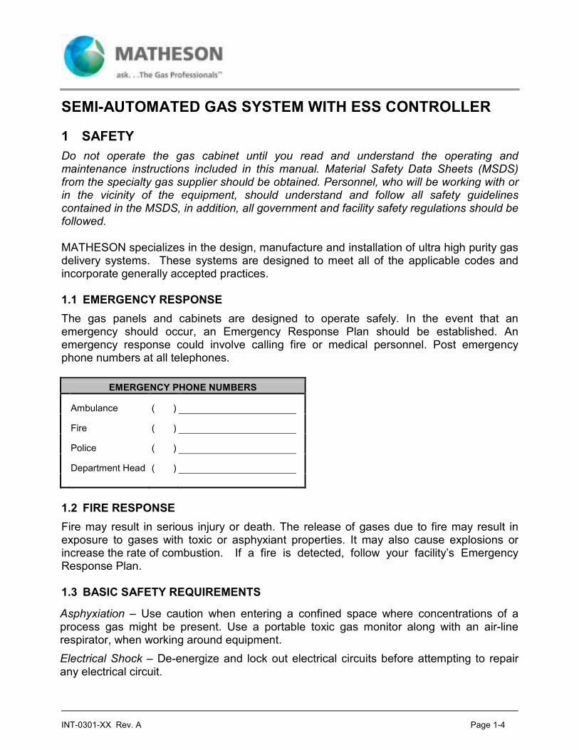
The gas panels and cabinets are designed to operate safely. In the event that an emergency should occur, an Emergency Response Plan should be established. An emergency response could involve calling fire or medical personnel. Post emergency phone numbers at all telephones.
EMERGENCY PHONE NUMBERS
Ambulance ( )
Fire ( )
Police ( )
Department Head ( )
1.2 FIRE RESPONSE
Fire may result in serious injury or death. The release of gases due to fire may result in exposure to gases with toxic or asphyxiant properties. It may also cause explosions or increase the rate of combustion. If a fire is detected, follow your facility’s Emergency Response Plan. 1.3 BASIC SAFETY REQUIREMENTS
Asphyxiation – Use caution when entering a confined space where concentrations of a process gas might be present. Use a portable toxic gas monitor along with an air-line respirator, when working around equipment.
Electrical Shock – De-energize and lock out electrical circuits before attempting to repair any electrical circuit.
INT-0301-XX Rev. A Page 1-5
Fires or Explosions – Do not permit open flames or sources of ignition near compressed gas equipment. Follow MSDS instructions for proper chemical storage.
Injury – Follow MSDS Personnel Protective Equipment (PPE) recommendations. Ensure that all tools and equipment are in good working condition. Be aware that high velocity gas may be released at vents.
Posted Precautions – Read all cylinder, warning, and precautionary labels before handling equipment.
Evacuation Routes – An evacuation plan should be developed and posted.
1.4 MONITORING THE PERSONNEL AREA
Continuously monitor toxic gas levels in personnel areas, with a toxic gas analyzer. If toxic gases are detected, evacuate the area immediately, open doors to promote ventilation. Do not re-enter area until acceptable toxic gas levels are present. During a power outage, use a portable unit to confirm safe conditions before entering an area. 1.5 SECURITY INFORMATION
To ensure proper operation of the gas cabinet, keys are required to operate the controller and cabinet. Without keys, operation of equipment is denied. This ensures that authorized personnel will operate the equipment. The gas cabinet should never be unlocked, except for a cylinder change. 1.6 GASES
The gases that are used in the delivery systems provided by MATHESON are of various gas types. Please note that some gases may fall under multiple gas types.
In addition to understanding the type of the gas that is being used, it is also important to understand the Hazard Rating of the gas as defined by NFPA (National Fire Protection Association) 704. NFPA Ratings for gases provide information on the Health, Fire, and Reactivity dangers associated with each gas. A rating of 0-4 is provided in each category. Gases with ratings of 3-4, in any category, are classified by the Uniform Fire Code (UFC) Article 80, to be Hazardous Production Materials (HPM’s), and required by code to have special safety control and monitoring equipment.
The Toxic Gas Ordinance (T.G.O.) also rates the risk of various gases by a Material Hazard Index, which is a function of the vapor pressure and toxicity of each particular gas. It is important the user read the MSDS from your gas supplier, and be familiar with the safety measures described, the various reactions that can occur and any other important information. 1.6.1 Inert Gases
Inert gases include Argon, Helium, Neon, Krypton, and Nitrogen. Inert gases are those gases that do not have a high-risk reaction and cannot cause any degradation of the gas
INT-0301-XX Rev. A Page 1-6
panel as long as any entrained particulate is filtered out. Particulates can become lodged in valve seats and regulators and cause leakage and regulator creep. 1.6.2 Flammable Gases
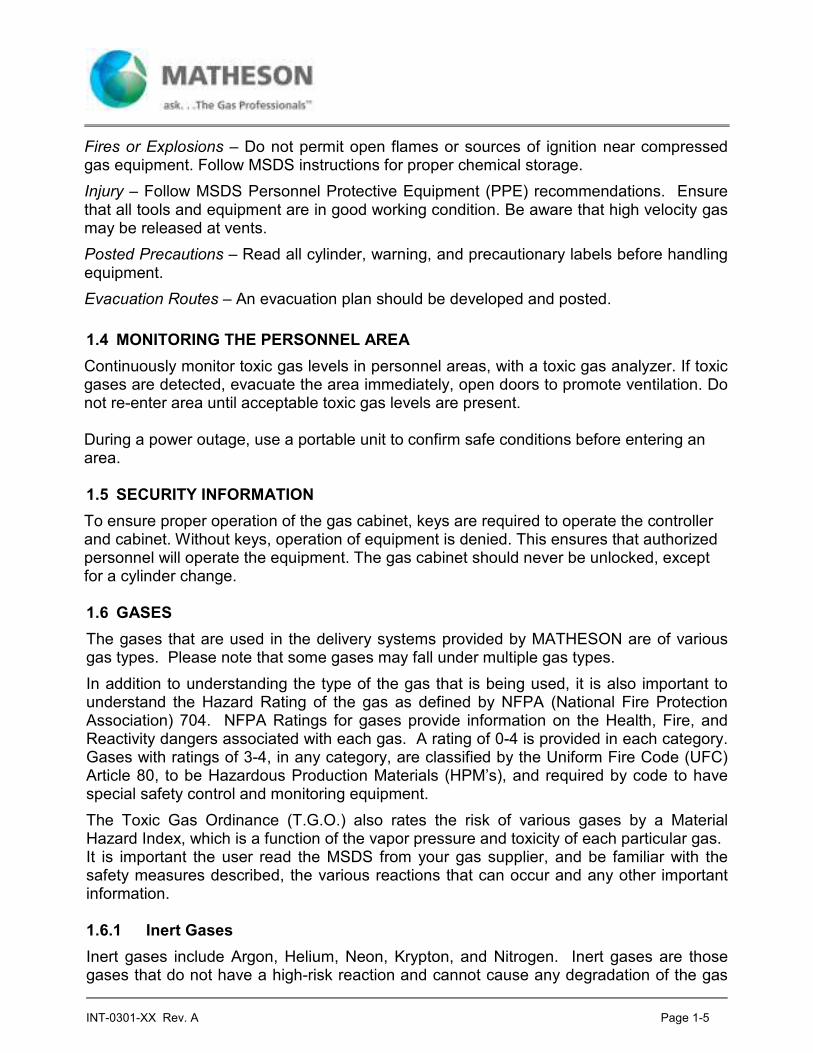
Flammable gases are those gases that pose the threat of fire. Hydrogen is an example of a flammable gas. Flammable gas may or may not generate solid particulates upon combustion. If a reaction occurs within the gas panels, it can be detrimental to the operation as indicated in the “Inert Gas” sections.
Table 1-1
Flammability Ranges
Product Flammable Range (in air)
Ammonia (NH3) 15-28% (DOT classified as non-flammable)
Arsine (AsH3) 4.5 - 78%
Carbon Monoxide (CO) 12.5 - 74.2%
Diborane (B2H6) 0.8 - 98% - treat as pyrophoric
Dichlorosilane (SiH2Cl2) 4.6 - 98%
Disilane (Si2H6) treat as pyrophoric
Germane (GeH4) Unknown
Halocarbon 32 (Diflorocyclobutane) 14 - 31%
Hydrogen (H2) 4 - 75%
Hydrogen Selenide (H2Se) Unknown
Hydrogen Sulfide (H2S) 4 - 46%
Methane (CH4) 5 - 15%
Phosphine (PH3) 4 - 50% - treat as pyrophoric
Silane (SiH4) 1 - 96% - pyrophoric
Trichlorosilane (SiHCl3) 6.9 - 86%
Trimethylboron [(CH3)3-B] treat as pyrophoric
1.6.3 Pyrophoric Gases
Pyrophoric Gases will spontaneous combust in the presence of air or oxygen. Silane is a typical example. When dispensing pyrophoric gases it is important to follow the proper procedures to assure that there is no air in the system prior to process gas delivery and that all of the process gas is removed from the system prior to disconnecting the cylinder. Reactions these gases have with air or oxygen typically produce by-products that are detrimental to the operation of the gas delivery system.

INT-0301-XX Rev. A Page 1-7
1.6.4 Toxic Gases
Toxic gases are poisonous to man and great care should be taken when dispensing these gases. It is extremely important for the operator to be familiar with the M.S.D.S., and have the proper facility safety measures in place. Many toxic gases are also reactive, Pyrophoric or flammable. 1.6.5 Corrosive Gases
Corrosive gases are those gases that typically, in the presence of moisture, can cause corrosion in metals including stainless steels. This corrosion can take place in the gas cabinet and associated ducting, on the gas panel’s components or at the delivery point. If ambient moisture is permitted inside the gas panel, a reaction can take place that will produce various acids that can attack the free iron in the stainless steel components. Regulators made with Hastelloy internals can extend the life of the gas panel. Sometimes Monel components can also be used. Typically, gases that fall into this category include HF, Cl2, HCl, SiCl4, F2 and HBr. 1.6.6 Liquefied Gases
Liquefied gases are those gases that are in a liquid state as delivered in the cylinders. There is a wide variation in the vapor pressure of these gases. Cylinder scales should be used to verify cylinder contents, although, sometimes if the process does not use much gas, a pressure gauge can be used to monitor when a cylinder has finished vaporizing all of the liquid and the pressure begins to decay. Some liquefied gases have very low vapor pressure and must have cylinder temperature controls and process line heat tracing to assure gaseous delivery. If these low vapor pressure gases are allowed to cool in the gas delivery piping, they may condense causing corrosion or unintended hydraulic effects. Typical gases include HF and BCl3 among others. On many low pressure gases, care must be taken when setting the nitrogen purge pressure, as the shock of excessive nitrogen pressure entering a process gas system can create localized condensation which often causes regulator and mass flow controller problems.

INT-0301-XX Rev. A Page 1-8
Table 1-2
Summary of Specialty Gas Hazards
Category Process Gas Health Hazards
Nonflammable Argon (Ar) Inert gases can cause rapid suffocation.
Noncorrosive Carbon Dioxide (CO2) Oxidizing gases vigorously accelerate combustion.
Low Toxicity Halocarbon 14 (CF4)
(Tetrafluoromethane)
Halocarbon 23 (CHF3)
(Trifluoromethane)
Halocarbon 115 (C2ClF5)
(Chloropentafluoroethane)
Halocarbon 116 (C2H6)
(Hexafluoroethane)
Halocarbon 125 (C2HF5)
(Pentafluoroethane)
Halocarbon 218 (C3F8)
(Octafluoropropane)
Halocarbon C318 (C4F8)
(Octafluorocyclobutane)
Helium (He)
Krypton (Kr)
Neon (Ne)
Nitrogen (N2)
Oxygen (O2)
Sulfur Hexafluoride (SF6)
Xenon (Xe)
Flammable Deuterium (D2) May form explosive mixtures with air.
Noncorrosive Halocarbon 32 (CH2F2)
Low Toxicity (Difluoromethane)
Halocarbon 41(CH3F)
(Methylfluoride)
Hydrogen (H2)
Methane (CH4)
Methylsilane (CH3-SiH3)
Flammable Ammonia (NH3) May form explosive mixtures with air.
Corrosive Carbon Monoxide (CO) Harmful if inhaled.
and/or Toxic Dichlorosilane (SiH2Cl2) Causes eye and skin burns.
Germane (GeH4)
Hydrogen Sulfide (H2S)
Trichlorosilane (SiHCl3)
Toxic and/or Boron Trichloride (BCl3) Harmful if inhaled.
Corrosive Boron Trifluoride (BF3) Causes eye and skin burns.
Nonflammable Chlorine (Cl2) Oxidizing gases vigorously accelerate combustion.
Chlorine Trifluoride (ClF3)
Diethyltelluride (C4H10Te)
INT-0301-XX Rev. A Page 1-9
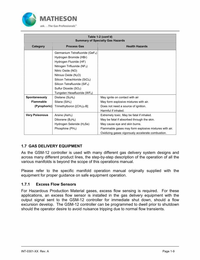
Table 1-2 (cont’d)
Summary of Specialty Gas Hazards
Category Process Gas Health Hazards
Germanium Tetrafluoride (GeF4)
Hydrogen Bromide (HBr)
Hydrogen Fluoride (HF)
Nitrogen Trifluoride (NF3)
Nitric Oxide (NO)
Nitrous Oxide (N2O)
Silicon Tetrachloride (SiCl4)
Silicon Tetrafluoride (SiF4)
Sulfur Dioxide (SO2)
Tungsten Hexafluoride (WF6)
Spontaneously Disilane (Si2H6) May ignite on contact with air
Flammable Silane (SiH4) May form explosive mixtures with air.
(Pyrophoric) Trimethylboron [(CH3)3-B] Does not need a source of ignition.
Harmful if inhaled.
Very Poisonous Arsine (AsH3) Extremely toxic. May be fatal if inhaled.
Diborane (B2H6) May be fatal if absorbed through the skin.
Hydrogen Selenide (H2Se) May cause eye and skin burns.
Phosphine (PH3) Flammable gases may form explosive mixtures with air.
Oxidizing gases vigorously accelerate combustion.
1.7 GAS DELIVERY EQUIPMENT
As the GSM-12 controller is used with many different gas delivery system designs and across many different product lines, the step-by-step description of the operation of all the various manifolds is beyond the scope of this operations manual. Please refer to the specific manifold operation manual originally supplied with the equipment for proper guidance on safe equipment operation. 1.7.1 Excess Flow Sensors
For Hazardous Production Material gases, excess flow sensing is required. For these applications, an excess flow sensor is installed in the gas delivery equipment with the output signal sent to the GSM-12 controller for immediate shut down, should a flow excursion develop. The GSM-12 controller can be programmed to dwell prior to shutdown should the operator desire to avoid nuisance tripping due to normal flow transients.

INT-0301-XX Rev. A Page 1-10
1.8 START-UP
Please review the operation of the GSM-12 controller discussed in Section 2.0. 1.8.1 Inspection and Mounting
Upon receipt, unpack the controller, and inspect for any shipping damage. 1.8.2 Typical Utilities Requirements
1.8.2.1 GSM-12 Controller Typical Required Utilities
Pneumatic Supply
Gas: Nitrogen (N2) or Clean Dry Air (CDA), filtered to <10 µm
Pressure Range: 80 to 95 psig (5.3 to 6.0 kg/cm2)
Connection: 1/8” OD x 1/16” ID Nylon or High-Durometer PolyTubing to 1/8” One-Touch Tube Fitting at rear of controller
Note: Excessive pressures (over 100 psig) can cause leakage in the solenoids or blow out gaskets in the solenoids. Too low a pressure will not be sufficient to open the valves.
Power Supply
Line Voltage: 110-125 or 220-250 VAC Selectable, single phase
Frequency: 50 +/-0.1% or 60 +/-0.1% Hz
Power Consumption: 25 Watts Maximum
Current (typical): Internally fused at 2 A
Fuse Rating: 2 A, 250 V, 3AG
Connection: Molded power cord connector at rear of controller enclosure
Note: Provide an Emergency Power Shutoff switch for the electric power circuit supplying the controller and all associated equipment. This switch must be accessible from all typical operating and maintenance locations and have lock-out/tag-out (LOTO) capabilities. (ref OSHA 29CFR 1910.147)
Note: Power cord is to be used as means of supplemental disconnect only. Local electrical codes may require a primary means of disconnect other than the power cord. Review installation requirements with local code and ordinanace authorities.
1.8.3 Environmental Characteristics
Operating Temperature: 32F (0C) – 100F (40C)
Relative Humidity: 5-95% Non-Condensing

INT-0301-XX Rev. A Page 1-11
NOTE: Equipment is not intended for outside installation. Equipment that must be installed outside a building should be protected from direct sun and precipitation using overhead covers and partial walls as necessary to adequately shield the equipment.
1.9 INITIAL GAS DELIVERY
After all inspection and testing procedures have been performed, the cylinders can be installed. Please review all information defined in Sections 2.0, 3.0 and 4.0 to assure proper understanding of controller and manifold operations. It is recommended that on-site gas managers perform several manual “Purge Up” and “Purge Down” procedures to verify the system operation.
Note: Purging should be performed with a cap on the CGA fitting on the pigtail, or with the PIGTAIL CONNECTED TO THE CYLINDER AND THE CYLINDER VALVE CLOSED. If purging is not done with the pigtail capped or connected to the cylinder, ambient air could be drawn in the system through the pigtail.

Page 2-1
2 GSM-12 CONTROLLER
Process gas delivery equipment may be fitted with an excess flow sensor, which is purchased to trip at a flow rate set by the manufacturer. The trip point is calibrated in consideration of the exact process gas to be used and the operating pressure conditions. This sensor sends an electrical signal to the GSM-12 control box to initiate shut down upon sensing an excess flow condition. During cylinder replacement and system purging, the excess flow sensor can be locked-out by turning the key lock switch on the GSM-12 box to the “Purge” position. 2.1 EMERGENCY SHUTDOWN SYSTEM DESCRIPTION
The GSM-12 Electronic Shutdown System is designed to provide the ultimate in safety when using toxic or reactive gases. The GSM-12 consists of an electronic control station, solenoid valves which activate pneumatic valves in the gas system, and a system of sensors which read various conditions. The controller is programmed to monitor a large number of sensors and will automatically alarm, or alarm and shutdown, if a particular condition warrants an action. The controller also has an ABORT button on the front panel for manual shutdown. The specific sensor shutdown conditions are programmed into the system at the factory. Delay times between when a fault condition is first sensed and when an actual shutdown or alarm occurs, have been programmed to avoid any nuisance alarm tripping. Typical sensors offered with this system are listed below.
Typical Sensors
HI DELIVERY PRESSURE
EXCESS FLOW
EXHAUST FAIL
LOW CYLINDER CONTENTS
(PRESS/WEIGHT)
PROCESS LINE CONTAINMENT
GAS DETECTOR WARNING
GAS DETECTOR ALARM
FIRE DETECTOR
REMOTE START
REMOTE SHUTDOWN
Table 2-1
MATHESON can provide any or all of these sensors in a system on an optional basis. Either “Shutdown” or “Warning” can be the GSM-12 response depending on the Customer’s specification.

Page 2-2
2.2 EMERGENCY SHUTDOWN SYSTEM (GSM-12) OPERATION
The GSM-12 electrically operates a solenoid valve, which in turn operates the pneumatic Emergency Shutoff Valve (ESO), typically installed at the inlet of the process manifold where connected to the cylinder pigtail. At the lower right corner of the front panel overlay is a red membrane switch labeled ABORT. This switch provides a manual override, which closes all pneumatic valves. Shutoff can be initiated manually via the red ABORT switch on the GSM-12 box, or automatically based on the status of sensors. 2.3 INSTALLATION OF THE EMERGENCY SHUTDOWN SYSTEM (GSM-12)
See Figure 2-2 for locations of connections. See Section 1.8.2.1 for all GSM-12 Utility Requirements. 2.4 PNEUMATICS
A 2-position pneumatic connector is provided at the lower left corner of the rear panel for access to the internal pilot solenoid valve. The top 1/8” tubing quick-disconnect fitting is the control output for the Emergency Shutoff Valve (ESO). The lower 1/8” tubing quick-disconnect fitting provides air pressure to the internal pilot solenoids. 2.5 SENSOR CONNECTIONS
Sensors are installed in the gas cabinet according to customer specification or in some cases may be installed by the user. The user may opt to provide certain sensors that are positioned outside the gas cabinet. Two 14-pin electrical connectors at the bottom of the rear panel provide for signal connection to the sensor inputs. Each wire terminal has a setscrew above it. Strip signal wires about 1/4”, insert into the terminal, and securely tighten the setscrew to complete the connection. Connections numbered 1 through 10 are for the sensor ground or “common” wires. Terminals 15 through 23 are for +Signal leads from the sensors. See Figure 1 (Section 3) for a depiction of the front of an GSM-12 controller. If MATHESON has not configured the sensor system, the user fills in the label card for the front of the controller depending on the sensors in use. For example, if a “Hi Delivery Pressure” sensor is in use, connect the +Signal lead from this sensor to Terminal 15 and the ground lead to Terminal 1. Then fill in the top label for the front panel with the legend “Hi Delivery Pressure.”
NOTE: Any sensors not used must be jumpered to the common terminal, except remote start, which should be a normally open momentary contact. Failure to jumper unused sensors will prevent alarms from being cleared. Also jumper Remote Shutdown if not used.

Page 2-3
2.6 REMOTE DIGITAL INPUTS AND RELAY OUTPUTS
External outputs to any type of readout device can be connected to the back of the GSM-12 controller (see Figure 2-2). Power outputs are available to trigger remote alarms, and inputs for Remote Abort (Shutdown).
(3) Relay Outputs are provided, each capable of switching 2 Amps @ 30VDC. Each output is a Normally Open contact (unless a special software configuration is provided). The COMMON contacts of all (3) relays are routed to Terminal 12.
Though the relays may be wired to switch any voltage within the 30VDC limits of the relay contacts and printed circuit board traces, when using the GSM-12 controller DC voltage to power an external device, the manufacturer recommends that the relay common on Terminal 12 be connected to the return side of the internal 24-volt power supply on any of Terminals 1-11. Each external device would then have its positive terminal connected to either Terminal 26 or 28, and its negative terminal connected to an appropriate output terminal (13, 14, or 27).
Standard Digital Input/Output wiring is as follows:
DIGITAL INPUTS / RELAY OUTPUTS
Signal Signal Type Relay Common Terminal
Signal Terminal Common Terminal (-24 VDC)
Remote Abort Input - 24 10
Remote Start Input - 21 11
Low Cylinder Output 12 13 -
Cyl On-Line/Valve Open
Output 12 14 -
Alarm Output 12 27 -
Table 2-2
2.7 AC POWER ENTRY
An AC power entry module is provided at the top left corner of the rear panel. This module combines three functions: • Power entry (via 3-pin molded power cord connection) • Fuse for over-current protection • Line voltage selection (120 or 240 VAC)

Page 2-4
2.8 GSM-12 DESIGN
The following figures show the front and rear panels of the GSM-12 controller. Subsequent sections describe usage of the controls.
Figure 2-1 – GSM-12 Controller Front Panel
Figure 2-2 – GSM-12 Controller Rear Panel
PURGESHUTDOWN
HI DELIVERY PRESS
EXCESS FLOW
EXHAUST FAIL
LOW CYLINDER
PROCESS LINE CONTAINMENT
GAS DETECTOR WARNING
GAS DETECTOR ALARM
FIRE DETECTOR
REMOTE START

Page 2-5
2.9 FRONT PANEL PREPARATION
If the sensors installed have not been labeled on the GSM-12 controller by MATHESON, the user will have to fill in the label card on the front panel indicating the sensors in use. 2.10 OPERATION OF THE EMERGENCY SHUTDOWN SYSTEM
Power-Up
After all electrical and pneumatic connections have been made and power is supplied to the system, the GSM-12 controller immediately goes into a test mode, checking all LED’s and functions. The “System Failure” LED on the right side of the panel will light if a problem is indicated, and the solenoid valve is de-energized, closing the process ESO valve. NOTE: Upon initial power-up, it is necessary to use the key switch to cycle between the NORMAL mode to PURGE mode and back to NORMAL mode to allow operation of the ESO valve. The controls and displays on the right side of the front panel of the GSM-12 Controller and their functions are as follows: Controls
• Key Switch to select “Purge” or “Normal” operating modes Turning the key switch from the “Normal” to the “Purge” position will selectively override certain sensor and signal inputs (such as Excess Flow).
NOTE: In “Purge” Mode, current alarms that are bypassed and would cause an ESO valve closure in “Normal” Mode will still be displayed. The alarm LED will flash rapidly to indicate the “Purge” Mode software interlock is preventing the alarm from triggering an ESO valve closure.
Turning the key switch from “Purge” to “Normal” will cause the ESO valve to close (if open) and will cause the controller to monitor all sensor and signal inputs.
Turning the key switch from “Normal” to “Purge” will also cause the ESO valve to close (if open).
The Station Reset Switch can be pressed to re-open the ESO after the operating mode is changed.
When the key switch is in the “Purge” position, the “Purge” LED will light, the “Alarm” LED will blink, and the Horn will beep to indicate that the unit is in “Purge” mode. The periodic beeping can be silenced by pressing the Alarm Silence Switch.
NOTE: In “Purge” Mode, the ESO valve will automatically close 15 minutes after being opened. This is to prevent Normal operation in “Purge” mode with sensor alarms being bypassed.
• Alarm Silence Switch silences both local and remote alarms. Sensor alarm LED’s will continue to display current alarms.

Page 2-6
• Station Reset Switch silences both local and remote alarms, and, if sensor inputs are normal, clears current alarm LED’s and triggers the process ESO valve to open. All alarms must be in their normal state for the ESO valve to open.
• Abort or “Emergency Shut-Off” Switch closes the process ESO valve and initiates alarms at local and optional remote sites.
System Status LED’s
• Valve Open – is continuously lit whenever the process ESO valve is open. The Valve Open LED will flash rapidly if there is no alarm present but there is a software interlock preventing the ESO valve from opening.
• Alarm - lights whenever the alarm is sounding, to permit visual identification of the alarming GSM-12 controller.
• System Failure - lights when a microprocessor or system failure has occurred.
• Power - when lit, indicates the GSM-12 controller has power.
2.11 THE SENSOR INDICATION PANEL
Located to the left side of the front panel and on both sides of the sensor channel labels are LED's. CURRENT Alarm Conditions LED’s to the left of the sensor channel labels, when illuminated, indicate a CURRENT fault condition, where that sensor or signal input is currently in an alarm state. Individual alarms may be configured as either Warning only or for Shutdown.
The CURRENT alarm LED’s may light under two different conditions: 1) If a WARNING type alarm is triggered, the CURRENT alarm LED for that signal
will illuminate and the audible alarm will sound. The LED will remain illuminated until corrective action is taken to remove the fault condition or the alarm condition corrects itself. The Alarm Silence button may be pressed to terminate the audible alarm, but the LED will remain illuminated until the alarm is cleared. Warning alarms to not cause the ESO valve(s) to close.
2) If a SHUTDOWN type alarm is triggered, the CURRENT alarm LED for that signal will illuminate and the audible alarm will sound. The LATCHED LED for that signal will also illuminate. The LED will remain illuminated until corrective action is taken to remove the fault condition or the alarm condition corrects itself. The Alarm Silence button may be pressed to terminate the audible alarm, but the LED will remain illuminated until the alarm is cleared. If an alarm condition is cleared and it is a LATCHING alarm, the CURRENT LED will be extinguished but the LATCHED LED will remain illuminated until the Station Reset button is pushed. Shutdown alarms cause the ESO valve(s) to close.

Page 2-7
LATCHED Alarm Conditions
1) LED’s to the right of the sensor channel labels, when illuminated, indicate a LATCHED fault condition, where that sensor or signal input is currently in a latched alarm state and intervention is required to clear a fault condition and place the system back in service. The ESO valve(s) is closed when any latched alarm is present. All latching alarms are Shutdown alarms.
2) A LATCHED alarm LED will light after a Shutdown alarm has been triggered. If a SHUTDOWN type alarm is triggered, both the CURRENT and LATCHED alarm LED’s for that signal will illuminate and the audible alarm will sound. If an alarm condition is cleared and it is a LATCHING alarm, the CURRENT LED will be extinguished but the LATCHED LED will remain illuminated until the Station Reset button is pushed. Shutdown alarms cause the ESO valve(s) to close.

Page 3-8
3 ESO PROTECTED GAS SYSTEM OPERATION
As the GSM-12 controller is used with many different gas manifold designs and across many different product lines, the step-by-step description of the operation of all the various ESO protected manifolds is beyond the scope of this operations manual. Please refer to the specific manifold operation manual originally supplied with the equipment for proper guidance on safe equipment operation.

Page 4-1
4 SYSTEM DRAWINGS
4.1 STANDARD WIRING DIAGRAM
(800-0610-1160 EPROM)
Figure 4-1 – Sheet 1 of 1

Page 4-2
4.2 STANDARD WITH ACV CONTROL WIRING DIAGRAM
(800-0610-1160 EPROM)
Figure 4-2 – Sheet 1 of 4

Page 4-3
Figure 4-2 – Sheet 2 of 4
Page 4-4
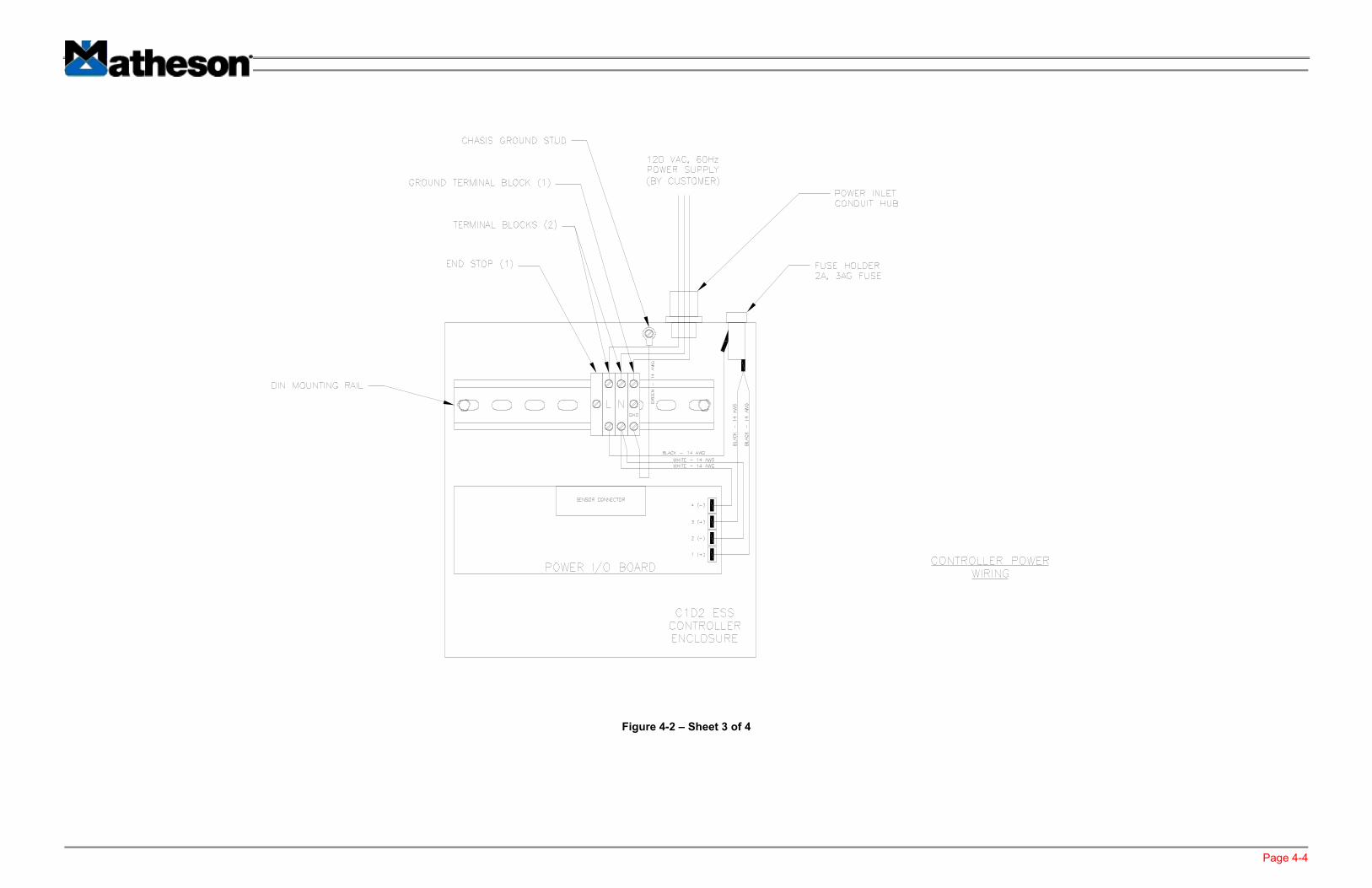
Figure 4-2 – Sheet 3 of 4
Page 4-5
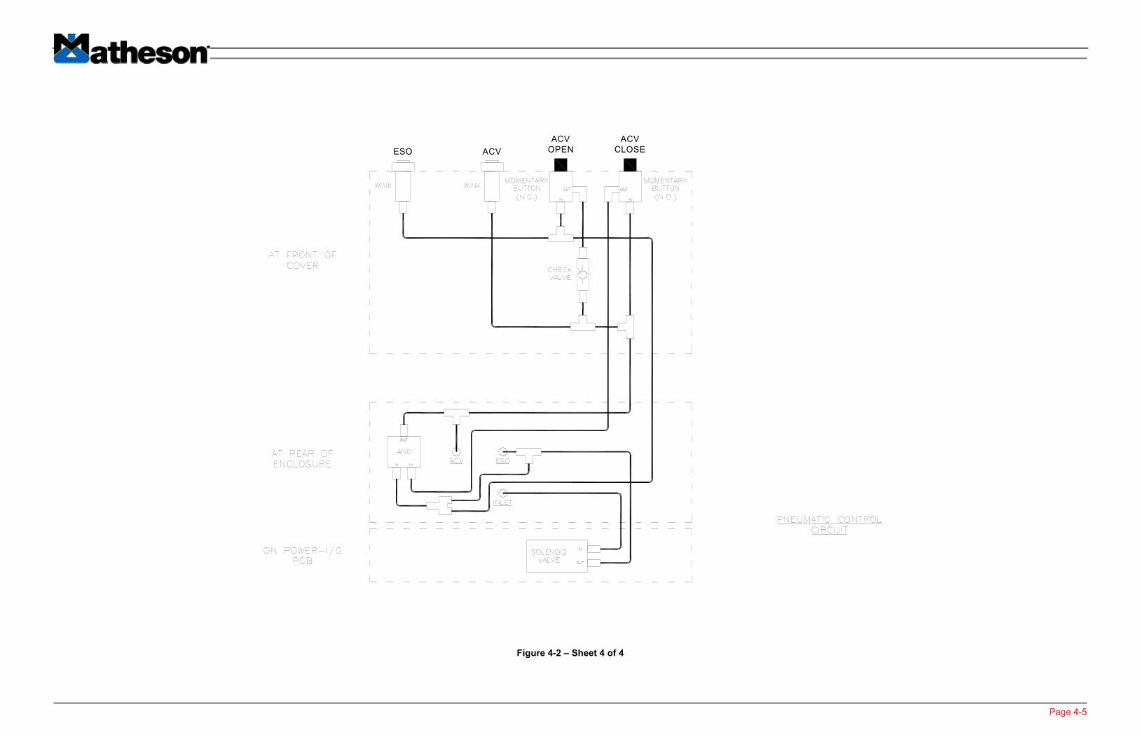
ESO ACV
ACV
OPEN
ACV
CLOSE
Figure 4-2 – Sheet 4 of 4

Page 5-1
5 WARRANTY
5.1 MATHESON DESIGN
Matheson warrants to the original purchaser that the equipment is free from defects in material and workmanship under normal use and service. Matheson’s obligation under this warranty shall be limited to the repair or exchange of any part or parts which may prove defective under such normal use and service within 12 months from date of installation or 18 months from the date of shipment, whichever period expires first, by the Buyer and which Matheson’s examination shall disclose to be thus defective. This warranty is limited to incurred labor and repair or replacement of parts. Not covered under this warranty are equipment failures caused by misapplication, improper installation or operation, internal or external contamination, abuse, and failure of equipment not purchased from MATHESON. In no event shall MATHESON liability include special, incidental, or consequential loss or damage, even if so appraised of the potential for such loss or damage. Warranty claims may be filed with the MATHESON Customer Service Department. THIS WARRANTY IS EXPRESSLY IN LIEU OF ALL OTHER WARRANTIES EXPRESSED OR IMPLIED INCLUDING THE WARRANTIES OF MERCHANTIABILITY AND FITNESS FOR USE AND OF ALL OTHER OBLIGATIONS OR LIABILITIES ON SELLER’S PART AND SELLER NEITHER ASSUMES NOR AUTHORIZES ANY OTHER PERSON TO ASSUME ON SELLER’S BEHALF ANY OTHER LIABILITY IN CONNECTION WITH THE SALE OF THIS EQUIPMENT. THIS WARRANTY SHALL NOT APPLY TO THIS EQUIPMENT OR ANY PART THEREOF WHICH HAS BEEN SUBJECT TO ACCIDENT, NEGLIGENCE, ALTERATION, ABUSE OR MISUSE. SELLER MAKES NO WARRANTY WHATSOEVER IN RESPECT TO ACCESSORIES OR PARTS NOT SUPPLIED BY SELLER EXCEPT THAT WARRANTIES, IF ANY, OF THE MANUFACTURER OF SUCH ACCESSORIES OR PARTS SHALL TO THE EXTENT AVAILABLE WITHOUT COST TO OR ACTION BY SELLER, BE APPLICABLE TO THE BUYER. THE TERM “BUYER” AS USED IN THIS WARRANTY SHALL BE DEEMED TO MEAN THAT PERSON FOR WHOM THE EQUIPMENT IS ORIGINALLY INSTALLED.
5.2 CUSTOMER DESIGN
FOR EQUIPMENT THAT IS MANUFACTURED IN ACCORDANCE WITH PLANS SUPPLIED BY THE BUYER, THE SELLER MAKES NO WARRANTY THAT THE EQUIPMENT IS MERCHANTABLE OR FIT FOR ANY PARTICULAR PURPOSE. THE SOLE RESPONSIBILITY OF THE SELLER SHALL BE THAT IT WILL MANUFACTURE THE GOODS IN ACCORDANCE WITH THE PLANS OF THE BUYER AND THAT THE EQUIPMENT WILL BE FREE FROM DEFECTS IN MATERIALS AND WORKMANSHIP. THIS WARRANTY IS EXPRESSLY MADE IN LIEU OF ANY AND ALL WARRANTIES INCLUDING WARRANTIES OF MERCHANTABILITY AND FITNESS FOR USE AND THE SOLE LIABILITY OF THE SELL SHALL BE TO REPLACE ANY PART NOT IN CONFORMITY WITH THE PLANS. THE WARRANTY CONTAINED HEREIN IS IN LIEU OF ANY AND ALL OTHER WARRANTIES INCLUDING THOSE OF MERCHANTABILITY AND FITNESS FOR USE.
5.3 IN-WARRANTY REPAIRS
For equipment under warranty, repair charges are waived. Repaired equipment is returned freight prepaid.

Page 5-2
5.4 OUT-OF-WARRANTY REPAIRS
For equipment out-of-warranty, repair charges typically include parts, labor, freight, and insurance. Equipment that can not be economically restored to satisfactory operating condition will be returned un-repaired freight collect or discarded at the owner’s option. 5.5 SHIPMENTS TO MATHESON
Please contact the MATHESON Customer Service Department for consultation prior to returning suspected defective goods for inspection and repair. All returns must be shipped with freight prepaid and accompanied by a Return Material Authorization (RMA) number.