
growth in a typical shell subjected to internal pressuremln/ltrs-pdfs/NASA-aiaa-2001-1395.pdf ·...
19
1 American Institute of Aeronautics and Astronautics THE NONLINEAR RESPONSE OF CRACKED ALUMINUM SHELLS SUBJECTED TO COMBINED LOADS Cheryl A. Rose, * Richard D. Young, * and James H. Starnes, Jr. † NASA Langley Research Center Hampton, Virginia 23681-2199 * Aerospace Engineer, Mechanics and Durability Branch. Member, AIAA. † Chief Engineer, Structures and Materials Competency. Fellow, AIAA. Copyright © 2001 by the American Institute of Aeronautics and Astronautics, Inc. No copyright is asserted in the United States under Title 17, U. S. Code. The U. S. Government has a royalty-free license to exercise all rights under the copy- right claimed herein for Governmental Purposes. All other rights are reserved by the copyright owner. AIAA-2001-1395 Abstract The results of a numerical study of the nonlinear re- sponse of thin unstiffened aluminum cylindrical shells with a longitudinal crack are presented. The shells are analyzed with a nonlinear shell analysis code that accu- rately accounts for global and structural response phe- nomena. The effects of initial crack length on the prebuckling, buckling and postbuckling responses of a typical shell subjected to axial compression loads, and subjected to combined internal pressure and axial com- pression loads are described. Both elastic and elas- tic-plastic analyses are conducted. Numerical results for a fixed initial crack length indicate that the buckling load decreases as the crack length increases for a given pres- sure load, and that the buckling load increases as the in- ternal pressure load increases for a given crack length. Furthermore, results indicate that predictions from an elastic analysis for the initial buckling load of a cracked shell subjected to combined axial compression and inter- nal pressure loads can be unconservative. In addition, the effect of crack extension on the initial buckling load is presented. Introduction The fail-safe design philosophy, when applied to transport aircraft fuselage structure, requires that these structures retain adequate structural integrity in the pres- ence of discrete-source damage or fatigue cracks. One type of damage frequently associated with the structural integrity of fuselage shell structures is a longitudinal crack in the fuselage skin that is subjected to circumfer- ential stresses resulting from the internal pressure loads, and to axial stresses resulting from the vertical bending and shearing of the fuselage that are induced by normal flight loads. The structural response of a transport fuse- lage structure with a crack is influenced by the local stress and displacement gradients near the crack and by the internal load distribution in the shell. Local fuselage out-of-plane skin displacements near a crack can be large compared to the fuselage skin thickness, and these dis- placements can couple with the internal stress resultants in the shell to amplify the magnitudes of the local stress- es and displacements near the crack. In addition, the stiffness and internal load distributions in a shell with a crack will change as the crack grows and when the skin buckles, and these changes will affect the local stress and displacement gradients near the crack. Furthermore, crack growth may influence shell buckling, and shell buckling may influence crack growth. This compound nonlinear response and interaction must be understood and predicted accurately in order to determine the struc- tural integrity and residual strength of current fuselage structures with damage, and to develop more efficient damage tolerant designs for future aerospace structures. Recent studies (e.g., Refs. 1-4) have shown that the structural response and structural integrity of a shell with a crack can be studied analytically with a nonlinear struc- tural analysis procedure that can model crack growth in the shell. The magnitudes of the mechanical loads used in these studies are representative of loads that do not buckle the skin of the fuselage. To maximize structural efficiency, fuselage shells are usually designed to allow the fuselage skin to buckle above a specified design load that is less than the design limit load for the shell. During the design of the fuselage, it is assumed that the design limit load can occur anytime during the service life of the aircraft. As a result, a long crack could exist in the fuse- lage shell after a considerable amount of flight service, and loading conditions could occur that cause the shell with the long crack to buckle. These cracks can act as ef- fective geometric imperfections and significantly reduce the load carrying capacity of the shell. Most nonlinear-response and residual-strength analyses that have been conducted to date for fuselage shells with long cracks have been limited to an unbuck- led fuselage shell response. 1-4 Recently, nonlinear nu- merical and experimental studies of the effects of longitudinal cracks on the nonlinear response of thin, un- stiffened laboratory-scale aluminum cylindrical shells subjected to internal pressure loads and axial compres- sion loads indicate that the behavior of a shell can be in- fluenced significantly by the initial length of the crack. 5-7 In particular, the effect of initial crack length on the initiation of stable tearing and unstable crack
Transcript of growth in a typical shell subjected to internal pressuremln/ltrs-pdfs/NASA-aiaa-2001-1395.pdf ·...
1 American Institute of Aeronautics and Astronautics
THE NONLINEAR RESPONSE OF CRACKED ALUMINUM SHELLS SUBJECTED TO COMBINED LOADS
Cheryl A. Rose,
*
Richard D. Young,
*
and James H. Starnes, Jr.
†
NASA Langley Research CenterHampton, Virginia 23681-2199
*
Aerospace Engineer, Mechanics and Durability Branch. Member, AIAA.
†
Chief Engineer, Structures and Materials Competency. Fellow, AIAA.
Copyright © 2001 by the American Institute of Aeronautics and Astronautics, Inc. No copyright is asserted in the United States under Title 17, U. S. Code. The U. S. Government has a royalty-free license to exercise all rights under the copy-right claimed herein for Governmental Purposes. All other rights are reserved by the copyright owner.
AIAA-2001-1395
Abstract
The results of a numerical study of the nonlinear re-sponse of thin unstiffened aluminum cylindrical shellswith a longitudinal crack are presented. The shells areanalyzed with a nonlinear shell analysis code that accu-rately accounts for global and structural response phe-nomena. The effects of initial crack length on theprebuckling, buckling and postbuckling responses of atypical shell subjected to axial compression loads, andsubjected to combined internal pressure and axial com-pression loads are described. Both elastic and elas-tic-plastic analyses are conducted. Numerical results fora fixed initial crack length indicate that the buckling loaddecreases as the crack length increases for a given pres-sure load, and that the buckling load increases as the in-ternal pressure load increases for a given crack length.Furthermore, results indicate that predictions from anelastic analysis for the initial buckling load of a crackedshell subjected to combined axial compression and inter-nal pressure loads can be unconservative. In addition,the effect of crack extension on the initial buckling loadis presented.
Introduction
The fail-safe design philosophy, when applied totransport aircraft fuselage structure, requires that thesestructures retain adequate structural integrity in the pres-ence of discrete-source damage or fatigue cracks. Onetype of damage frequently associated with the structuralintegrity of fuselage shell structures is a longitudinalcrack in the fuselage skin that is subjected to circumfer-ential stresses resulting from the internal pressure loads,and to axial stresses resulting from the vertical bendingand shearing of the fuselage that are induced by normalflight loads. The structural response of a transport fuse-lage structure with a crack is influenced by the localstress and displacement gradients near the crack and bythe internal load distribution in the shell. Local fuselageout-of-plane skin displacements near a crack can be large
compared to the fuselage skin thickness, and these dis-placements can couple with the internal stress resultantsin the shell to amplify the magnitudes of the local stress-es and displacements near the crack. In addition, thestiffness and internal load distributions in a shell with acrack will change as the crack grows and when the skinbuckles, and these changes will affect the local stress anddisplacement gradients near the crack. Furthermore,crack growth may influence shell buckling, and shellbuckling may influence crack growth. This compoundnonlinear response and interaction must be understoodand predicted accurately in order to determine the struc-tural integrity and residual strength of current fuselagestructures with damage, and to develop more efficientdamage tolerant designs for future aerospace structures.
Recent studies (e.g., Refs. 1-4) have shown that thestructural response and structural integrity of a shell witha crack can be studied analytically with a nonlinear struc-tural analysis procedure that can model crack growth inthe shell. The magnitudes of the mechanical loads usedin these studies are representative of loads that do notbuckle the skin of the fuselage. To maximize structuralefficiency, fuselage shells are usually designed to allowthe fuselage skin to buckle above a specified design loadthat is less than the design limit load for the shell. Duringthe design of the fuselage, it is assumed that the designlimit load can occur anytime during the service life of theaircraft. As a result, a long crack could exist in the fuse-lage shell after a considerable amount of flight service,and loading conditions could occur that cause the shellwith the long crack to buckle. These cracks can act as ef-fective geometric imperfections and significantly reducethe load carrying capacity of the shell.
Most nonlinear-response and residual-strengthanalyses that have been conducted to date for fuselageshells with long cracks have been limited to an unbuck-led fuselage shell response.
1-4
Recently, nonlinear nu-merical and experimental studies of the effects oflongitudinal cracks on the nonlinear response of thin, un-stiffened laboratory-scale aluminum cylindrical shellssubjected to internal pressure loads and axial compres-sion loads indicate that the behavior of a shell can be in-fluenced significantly by the initial length of thecrack.
5-7
In particular, the effect of initial crack lengthon the initiation of stable tearing and unstable crack
2 American Institute of Aeronautics and Astronautics
growth in a typical shell subjected to internal pressureloading was predicted using elastic-plastic finite-elementanalyses. The results of these analyses indicate that thepressure required to initiate stable and unstable tearing ina shell subjected to internal pressure decreases as thecrack length increases. In addition, the effects of cracklength on the prebuckling, buckling, and postbucklingresponses of a typical shell subjected to axial compres-sion were predicted using elastic finite-element analyses.The results of these analyses indicate that a crack in ashell structure subjected to axial compression loads cancause a significant reduction in the buckling load of theshell, and that the initial buckling loads decrease as thecrack length increases. Furthermore, the initial localpostbuckling response near the crack is characterized bylarge local deformations and stresses, which may causethe material to yield locally, and is not accurately repre-sented by an elastic analysis.
6
In addition, studies of theelastic response of cylindrical shells with longitudinalcracks and subjected to internal pressure and axial com-pression loads, e.g., Ref. 5, indicate that the interactionbetween the internal pressure and axial compressionloads can have a significant effect on the local responseof the shell.
The present paper extends the studies describedabove by including the effect of nonlinear material be-havior on the numerical buckling response predictions ofthin, unstiffened, laboratory scale, aluminum shells withcentrally located longitudinal cracks and subjected to in-ternal pressure and axial compression loads. The inter-nal-pressure level is varied to determine the effects ofcrack length and the magnitude of the internal pressureload on the response of these shells. In addition, the in-teraction between crack extension and initial local buck-ling is addressed; that is, the cracks are allowed to growalong a predefined path during the stability analysis.Geometric parameters varied in the study include theshell wall thickness and the initial crack length. Predict-ed prebuckling, buckling, and postbuckling results ofmaterial linear and material nonlinear analyses are pre-sented and compared for cylindrical shells subjected toaxial compression loads and combined internal pressureand axial compression loads. The results presented dem-onstrate the influence of the loading condition and initialcrack length on shell buckling instabilities.
Shell Geometry and Analysis Procedure
Shell Geometry
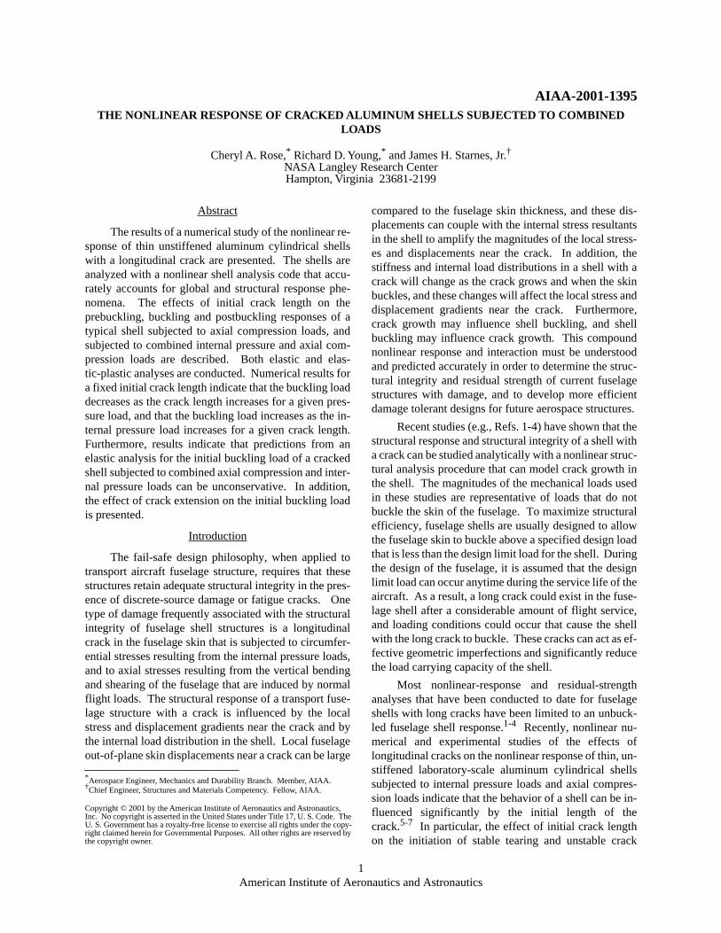
The geometry of the shells analyzed in this study isdefined in Fig. 1. The shells have a 9.0-inch radius,
R
, a0.020- or 0.040-inch-thick wall,
t
, and a 36.0-inch length,
L
. A longitudinal crack is located at and atshell midlength. The initial crack length,
a
, ranges from1.0 to 4.0 inches. The shells are typical laboratory-scale
cylindrical shells and are made of 2024-T3 aluminum al-loy with the sheet rolling direction oriented in the cir-cumferential direction. A piecewise linear representationwas used for the uniaxial stress-strain curve for 2024-T3aluminum (Fig. 2).
8
The Young’s modulus and Pois-son’s ratio of the material are 10.35 msi, and 0.30, re-spectively. The loading conditions for the shells consistsof axial compression loads and combined internal pres-sure and axial compression loads.
Nonlinear Analysis Procedure
The shell responses were predicted numerically us-ing the STAGS (STructural Analysis of General Shells)nonlinear shell analysis code.
9
STAGS analysis capabil-ities include stress, nonlinear response, stability, vibra-tion and transient response analyses, with both materialand geometric nonlinearities represented. The code usesboth the modified and full Newton methods for its non-linear solution algorithms, and accounts for large rota-tions in a shell by using a co-rotational algorithm at theelement level. The Riks pseudo arc-length path follow-ing method
10,11
is used to continue a solution past limitpoints in a nonlinear response. For situations where thestandard arc-length method fails to converge to solutionsbeyond instability points, a nonlinear transient analysismethod can be used.
12
The transient analysis option inSTAGS uses proportional structural damping and an im-plicit numerical time-integration method developed byPark.
13
STAGS can also perform crack-propagation analy-ses, and can represent the effects of crack growth on non-linear shell response. A nodal release method and aload-relaxation technique are used to extend a crackwhile the shell is in a nonlinear equilibrium state.
14
Thecondition for crack extension is based on a fracture crite-rion. When a crack is to be extended, the forces neces-sary to hold the current crack-tip nodes together arecalculated. The crack is extended by releasing the nodalcompatibility condition at the crack tip, applying theequivalent crack-tip forces, and then releasing these forc-
θ 0°=
Figure 1. Shell geometry.
LtR
Longitudinal crack (θ = 0o)
xz
θ
2a

3 American Institute of Aeronautics and Astronautics
es to establish a new equilibrium state, which corre-sponds to the longer crack. The changes in the stiffnessmatrix and the internal load distribution that occur duringcrack growth are accounted for in the analysis, and thenonlinear coupling between the internal forces andin-plane and out-of-plane displacement gradients thatoccurs in a shell are properly represented. Output fromSTAGS, associated with a crack, includes the strain-en-ergy-release rate in an elastic analysis, and thecrack-tip-opening angle (CTOA) in a material nonlinearanalysis.
2,14
These quantities can then be used as part ofa fracture criterion in an elastic analysis or a materialnonlinear analysis to predict the stable crack growth be-havior and residual strength of a damaged shell.
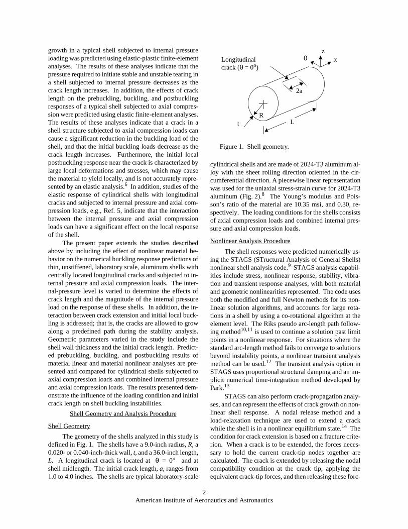
Typical finite element models used to simulate theresponse of the cracked shells are shown in Fig. 3. Themodels shown in Fig. 3a were used for analyses of theaxial compression and combined axial compression andinternal pressure load cases, respectively, when the inter-action between crack extension and local buckling wasnot addressed; that is, the material was assumed to be in-finitely tough and crack propagation during loading wasnot considered. The finite element model shown inFig. 3b was used for the combined load case to study theinteraction between crack extension and local buckling.Cracks with initial lengths of 1.0 to 4.0 inches were de-fined in the model along . Straight cracks wereassumed, so that crack extension was self-similar. Meshrefinement was used to provide elements with sidelengths equal to 0.040 inches along the line of crack ex-tension. This mesh density was required to predict accu-rately the yielding at the crack tip and crack extensionusing the critical CTOA fracture criterion.
15
The shells were modeled using STAGS standard
410 quadrilateral shell elements, and 510 and 710
mesh-transition elements, where needed. The elementsare flat facet-type elements and are based on Kir-choff-Love shell theory and the nonlinear Lagrangianstrain tensor.
9,16
Each of the shell element nodes has sixdegrees of freedom, including three translational degreesof freedom,
u
,
v
, and
w
, and three rotational degrees offreedom, and about the axes
x
,
y
, and
z,
re-spectively (see Fig. 3). Radial and circumferentialtranslational and rotational displacement constraintswere imposed on the ends of the shells during the loadapplication.
The loading conditions on the shells included axialcompression and combined axial compression and inter-nal pressure loads. For the case of an axial compressionload only, the compression load was applied to the endsof the shell by specifying a uniform end displacement.For the combined internal pressure and axial compres-sion load cases, a live internal pressure load was appliedto the shell first and then increased until the desired loadlevel was obtained. After this load level was attained, anincreasing axial compression load was applied. The in-ternal pressure load was simulated by applying a uniformlateral pressure to the shell wall and by applying an axialtensile force to account for bulkhead pressure loads tothe ends of the shell. Multi-point constraints were usedto enforce a uniform end displacement. The axial com-pression load for the combined load case was applied tothe ends of the shell by specifying an additional axialforce while retaining the multi-point constraints to en-force a uniform end displacement.
Both elastic and elastic-plastic analyses were con-ducted. For the elastic-plastic analyses the material non-linearity was represented by the White-Besseling
17,18
ormechanical sub-layer model, distortional-energy plastic-ity theory available in STAGS. The critical
0.00 0.05 0.10 0.15 0.200
20
40
60
80
Figure 2. Piecewise linear representation for the uniaxial stress-strain curve for 2024-T3 aluminum (L-T orientation).
Stress (ksi) Strain(in./in.)
0.00 0.00
50.0 0.0048
56.6 0.015
62.3 0.040
68.2 0.100
71.1 0.160
E = 10.35 Msiν = 0.3
0 0.05 0.10 0.15 0.200
20
40
60
80
Stress,ksi
Strain, in./in.
θ 0°=
ru, rv, rw
4 American Institute of Aeronautics and Astronautics
crack-tip-opening angle (CTOA) fracture criterion
8,15
was used to simulate stable crack growth for the com-bined load case analyses in which crack extension wasconsidered. The critical CTOA criterion uses the crackopening angle as the fracture parameter. The CTOA,evaluated at a fixed distance from the moving crack tip,is defined as the angle made by the upper crack surface,the crack tip, and the lower crack surface. In the presentstudy, the CTOA was evaluated at a distance of 0.04inches behind the crack tip. Newman
15
has shown thisdistance to be adequate for analyzing stable crack growthin a variety of materials. The criterion assumes thatcrack growth will occur when the angle reaches a criticalvalue, CTOA
cr
, and that the critical value will remainconstant as the crack extends. The value of the criticalangle is dependent on the sheet material, the sheet thick-ness, and the crack orientation relative to the rolling di-rection. The critical angle for a particular material andthickness can be obtained by numerically simulating thefracture behavior of a laboratory specimen, using anelastic-plastic analysis, and determining the angle thatbest describes the experimentally observed fracture be-havior. The critical angle of 5.36
o
used in the presentstudy was determined by matching STAGS predictions,for the fracture behavior of a shell with the geometry de-scribed above and with a 4.0-inch-long longitudinalcrack, with the experimentally observed behavior of analuminum shell of the same geometry and subjected tointernal pressure loads.
The prebuckling, buckling, and postbuckling re-sponses of the shells were determined using a combina-tion of the quasi-static and transient analysis capabilities
available in STAGS. The prebuckling responses andsome postbuckling responses were determined using thestandard arclength projection method available inSTAGS. For cases where convergence difficulties wereencountered beyond instability points using the standardarclength method, the transient analysis option of thecode was used. The transient analysis was initiated at anunstable equilibrium state just beyond the instabilitypoint by applying an increment to the end-shortening dis-placement. The transient analysis was continued untilthe kinetic energy in the system damped out to a negligi-ble level. A load relaxation procedure was then appliedto the system to establish a stable equilibrium state. Thesubsequent stable postbuckling response of the shell wascomputed using a standard nonlinear, quasi-static analy-sis.
Results and Discussion
The nonlinear analysis results for thin unstiffenedaluminum cylindrical shells with a longitudinal crack arepresented in this section. Results have been generatedfor two loading conditions: axial compression load only,and combined internal pressure and axial compressionloads. Results for these loading conditions are presentedfor shells with a longitudinal crack at shell midlength andwith initial crack lengths of 1.0, 2.0, 3.0 and 4.0 inches.For the axial compression loading case, the axial com-pression load was increased from zero to the maximumaxial load that the shell could support. An initial outwardgeometric imperfection, in the form of the lowest eigen-mode, was used in all of the nonlinear analyses for axialcompression loads to initiate local deformations in thevicinity of the crack. For the combined internal pressure
Longitudinal crack (θ = 0o)
Figure 3. Finite element models for axial compression and combined internal pressure and axial compression loading cases.
-4
-2
0
2
4
xz
θ xz
θ
0.040 in. square elements
local crack detail
(a) Finite element model for axial compressionand combined internal pressure and axialcompression loads, without crack extension
(b) Finite element model for combined internalpressure and axial compression loads with crackextension

5 American Institute of Aeronautics and Astronautics
and axial compression loading cases, a live internal pres-sure load was applied to the shell first and then increaseduntil the desired load level was obtained. After this loadlevel was attained, an increasing axial compression loadwas applied. Results have been generated for internalpressure load levels of 10.0, 30.0, and 50.0 psi. Shellswith both 0.020- and 0.040-inch wall thicknesses wereconsidered for the axial compression load case, but onlyshells with a 0.040-inch wall thickness were consideredfor the combined internal pressure and axial compressionload case. Typical results are presented to illustrate theeffects of crack length and internal pressure load level onthe prebuckling, buckling and postbuckling responses ofa shell subjected to axial compression loads, and com-bined internal pressure and axial compression loads. Theeffect of material nonlinear behavior on the response pre-dictions is also assessed.
Axial Compression Loads
Results for 0.020- and 0.040-inch-thick aluminumshells with initial crack lengths of 1.0, 2.0, 3.0 and 4.0inches are presented in Figs. 4-17 to identify typical re-sponse characteristics of a compression loaded shell witha longitudinal through crack. Predicted load shorteningresponse curves and load-radial displacement responsecurves for shells with 1.0-, 2.0-, 3.0-, and 4.0-inch-longcracks are provided in Figs. 4a-7a, and Figs. 4b-7b, re-spectively, to demonstrate the overall compression re-sponse of the shells. Results for the 0.040-inch-thickshell are presented in Figs. 4 and 5 and results for the0.020-inch-thick shell are presented in Figs. 6 and 7. Theapplied compression and end-shortening values are nor-malized by the corresponding classical buckling valuesfor a shell without a crack, and the radial displacement atthe crack center is normalized by the shell wallthickness,
t
. The results in Figs. 4-7 indicate that the overall
compression response predicted from both the elasticand elastic-plastic analyses is qualitatively the same forthe 0.020- and 0.040-inch-thick shells, and is dependenton the initial crack length. For the 0.020- and0.040-inch-thick shells with a 1.0-inch-long crack, thecrack introduces an effective imperfection that causesgeneral instability to occur at the load indicated by the
X
on the curves for a shell with a 1.0-inch-long crack inFigs. 4a-7a. These shells cannot support additionalcompression load after buckling. For a shell with a long-er crack, local buckling near the crack precedes shell col-lapse. The open symbols in Figs. 4a-7a identify the loadsthat correspond to initial local buckling near the crack forthe 0.040-inch-thick shell with the 2.0-, 3.0-, and4.0-inch-long initial cracks, and for the 0.020-inch-thickshell with the 2.0-, and 3.0-inch-long initial cracks. Thelocal crack prebuckling and buckling responses are qual-
itatively similar to the response of plates loaded in com-pression. The predictions from an elastic and anelastic-plastic analysis, respectively, for the normalizedradial displacement at the center of the crack edgesfor the 0.040-inch-thick shell are shown in Figs. 4b and5b. The corresponding predictions for the0.020-inch-thick shell are shown in Figs. 6b and 7b. Pri-or to buckling the radial displacement at the center ofthe crack edges is nearly equal to zero. Once the criticalload is reached, increases rapidly with increase inload. Initial local buckling is followed by a stable post-buckling response, and the load can be further increasedafter local buckling has occurred near the crack edges.
As the load is increased after initial local bucklinghas occurred, the 0.040-inch-thick shell with the2.0-inch-long crack, collapse, as indicated by the
X
onthe curve for a shell with a 2.0-inch-long crack in Figs.4a and 5a. The 0.040-inch-thick shells with the 3.0- and4.0-inch-long cracks, and the 0.020-inch-thick shellswith the 2.0- and 3.0-inch-long cracks experience achange in the local buckling mode. The filled symbolsin Figs. 4-7 identify the loads that correspond to second-ary buckling, or the change in the local buckling modenear the crack. The initial postbuckling response of theshells is unstable after the mode change, and as a result,the axial load decreases after buckling occurs. The mag-nitude of the load decrease, the postbuckling deforma-tion pattern and the overall axial postbuckling stiffnessof the shell is dependent on the material behavior, as de-scribed subsequently. The unstable transition region inthe response predictions is indicated by the broken linesin Figs. 4a-7a. The unstable transition from the stableinitial buckled configuration to the stable postbucklingconfiguration was determined by using the transientanalysis capability in STAGS. The transient analysiswas continued until the kinetic energy in the system wasnegligible. Once a stable equilibrium state was deter-mined from the transient analysis, the nonlinear staticanalysis was resumed to compute the stable postbucklingequilibrium response results shown in Figs 4a-7a. Thestable postbuckling segments in the response curves areaccompanied by an increase in the magnitude of the localdeformations in the shell near the crack. In addition, theslope of the postbuckling stable equilibrium segment ofthe response curve decreases as loading continues in thepostbuckling range, indicating a reduction in the effec-tive axial compressive stiffness of the shell. This reduc-tion in stiffness is due to increasing deformations in thevicinity of the crack as the compression load is increased,which results in significant load redistribution in theshell away from the crack. The overall collapse of the0.040-inch-thick shells with the 3.0- and 4.0-inch-longcracks and the 0.020-inch-thick shells with the 2.0- and3.0-inch-long cracks occurs at the
X
on the associated
wo t⁄
wo
wo

6 American Institute of Aeronautics and Astronautics
0.0 1.0 2.0 3.00.0
0.2
0.4
0.6
0.8
1.0
Figure 4. Effect of longitudinal crack length on the linear-elastic response of 0.040-inch-thick cylindrical shells subjected to axial compression loads.
0.0 0.2 0.4 0.6 0.8 1.00.0
0.2
0.4
0.6
0.8
1.0
(a) Load-shortening response (b) Load-normal displacement response
P Pcr⁄ P Pcr⁄
u ucr⁄ w0 t⁄0 1 2 3
0.0
0.2
0.4
0.6
0.8
1.0
P
uwo
2a = 1.0 in.
2a = 2.0 in.
2a = 3.0 in.
2a = 4.0 in.
2a = 4.0 in.
2a = 3.0 in.
2a = 2.0 in.
2a = 1.0 in.
global collapse point
0.0 1.0 2.0 3.00.0
0.2
0.4
0.6
0.8
1.0
Figure 5. Effect of longitudinal crack length on the elastic-plastic response of 0.040-inch-thick cylindrical shells subjected to axial compression loads.
(a) Load-shortening response (b) Load-normal displacement response
0.0 0.2 0.4 0.6 0.8 1.00.0
0.2
0.4
0.6
0.8
1.0
P
uwo
0 1 2 30.0
0.2
0.4
0.6
0.8
1.0
u ucr⁄ w0 t⁄
P Pcr⁄ P Pcr⁄
2a = 1.0 in.
2a = 2.0 in.
2a = 3.0 in.
2a = 4.0 in.
2a = 4.0 in.
2a = 3.0 in.
2a = 2.0 in.
2a = 1.0 in.
global collapse point

7 American Institute of Aeronautics and Astronautics
0.0 1.0 2.0 3.00.0
0.2
0.4
0.6
0.8
1.0
Figure 6. Effect of longitudinal crack length on the linear-elastic response of 0.020-inch-thick cylindrical shells subjected to axial compression loads.
(a) Load-shortening response (b) Load-normal displacement response
0.0 0.2 0.4 0.6 0.8 1.00.0
0.2
0.4
0.6
0.8
1.0
0.0
0.2
0.4
0.6
0.8
1.0
0 1 2 3w0 t⁄u ucr⁄
P Pcr⁄ P Pcr⁄
P
uwo
2a = 1.0 in.
2a = 3.0 in.
2a = 2.0 in.
global collapse point
2a = 3.0 in.
2a = 2.0 in.
2a = 1.0 in.
0.0 1.0 2.0 3.00.0
0.2
0.4
0.6
0.8
1.0
Figure 7. Effect of longitudinal crack length on the elastic-plastic response of 0.020-inch-thick cylindrical shells subjected to axial compression loads.
(a) Load-shortening response (b) Load-normal displacement response
0.0 0.2 0.4 0.6 0.8 1.00.0
0.2
0.4
0.6
0.8
1.0
0.0
0.2
0.4
0.6
0.8
1.0
0 1 2 3u ucr⁄ w0 t⁄
P Pcr⁄ P Pcr⁄
P
uwo
2a = 1.0 in.
2a = 3.0 in.
2a = 2.0 in.
2a = 3.0 in.
2a = 2.0 in.
2a = 1.0 in.
global collapse point

8 American Institute of Aeronautics and Astronautics
curve. The unstable collapse response is represented bythe dotted lines in the figures and is characterized by asignificant reduction in the axial compression load andthe development of the general instability mode in theshell.
The initial local buckling load, secondary bucklingload, and shell collapse load predictions obtained fromelastic and elastic-plastic analyses for the 0.040- and0.020-inch-thick shells are summarized in Fig. 8, and inTables 1 and 2, respectively. Buckling load predictionsfor an undamaged shell are also provided in Fig. 8.These results indicate that the magnitudes of the initialbuckling loads and secondary buckling loads decrease asthe initial crack length increases. Furthermore, the initialbuckling load and secondary buckling load predictionsobtained from the elastic and the elastic-plastic analysesare basically the same. For the 0.040-inch-thick shells,with 2.0-, 3.0-, and 4.0-inch-long cracks, local yieldingoccurs at the crack center and at the crack tips after initialbuckling and as the radial displacements become large.However, the yielding is extremely localized and doesnot affect the secondary buckling load. For the0.020-inch-thick shells, yielding does not occur until af-ter the change in the local buckling mode. Consequently,as shown in Fig. 9, the initial local buckling load resultsand the secondary local buckling load results obtainedfrom an elastic and an elastic-plastic analysis for the0.020- and 0.040-inch-thick shells are represented very
well by a characteristic curve that is based on the curva-ture parameter
The collapse load predictions, however, are notrepresented by a characteristic curve that is based on thecurvature parameter Collapse load predictionsobtained from both an elastic analysis and an elas-tic-plastic analysis for the 0.020-inch-thick shell indicatethat, although the initial and secondary buckling loadsfor the 0.020-inch-thick shell with a 2.0-inch-long crackare larger than the corresponding buckling loads for theshell with a 3.0-inch-long crack, the collapse load issmaller. This behavior is a consequence of the initialpostbuckling deformations in the 0.020-inch-thick shellwith a 2.0-inch-long crack extending circumferentiallyover a larger portion of the shell than the initial postbuck-ling deformations in the shell with a 3.0-inch-long crack.The initial postbuckling deformations from an elas-tic-plastic analysis of a 0.020-inch-thick shell with a2.0-inch-long and a 3.0-inch-long crack are provided inFig. 10. Predictions obtained from an elastic analysiswere basically the same. The more extensive deforma-tions in the shell with a 2.0-inch-long crack results in sig-nificant stress redistribution away from the crack, and alarger reduction in the effective postbuckling axial stiff-ness of the shell with the 2.0-inch-long crack, as indicat-ed by the reduction in the slope of the postbucklingportion of the response curves shown in Figs. 6 and 7. Inaddition, comparison of the predictions from an elastic
0.0 1.0 2.0 3.0 4.00.0
0.2
0.4
0.6
0.8
1.0
0.0 1.0 2.0 3.0 4.00.0
0.2
0.4
0.6
0.8
1.0
Figure 8. Buckling load as a function of the total crack length, for shells with thicknesses equal to 0.040 in. and 0.020 in.
Pcr = 63.86 kips
P Pcr⁄
0.0
0.2
0.4
0.6
0.8
1.0
P Pcr⁄
0.0
0.2
0.4
0.6
0.8
1.0
0 1 2 3 4 0 1 2 3 4
2a 2a
(a) t = 0.040 in. (b) t = 0.020 in.
Pcr = 15.96 kips
Collapse,elastic-plastic analysis
Collapse,elastic analysis
Initial buckling,elastic analysis
Initial buckling,elastic-plasticanalysis
Secondarybuckling, elasticand elastic-plasticanalysis
Initial buckling,elastic, andelastic-plasticanalysis
Secondarybuckling, elasticand elastic-plasticanalysis
Collapse,elastic analysis
Collapse,elastic-plasticanalysis
a Rt⁄ .
a Rt⁄ .

9 American Institute of Aeronautics and Astronautics
Table 1. Buckling load predictions for a 0.040-inch-thick shell
Initial Buckling
P/Pcra
Secondary Buckling
P/Pcr
Collapse
P/Pcr
Crack Length, 2a(in.) Elastic
Elastic-Plastic Elastic
Elastic-Plastic Elastic
Elastic-Plastic
1.0 0.833 0.819 0.819 0.854 0.853 0.854 0.853
2.0 1.667 0.530 0.530 0.575 0.573 0.575 0.573
3.0 2.500 0.389 0.365 0.476 0.471 0.503 0.589
4.0 3.333 0.313 0.306 0.422 0.422 0.501 0.579
a Pcr = 63.86 kips
Table 2. Buckling load predictions for a 0.020-inch-thick shell
Initial Buckling
P/Pcra
Secondary Buckling
P/Pcr
Collapse
P/Pcr
Crack Length, 2a(in.) Elastic
Elastic-Plastic Elastic
Elastic-Plastic Elastic
Elastic-Plastic
1.0 1.178 0.731 0.731 0.735 0.735 0.735 0.735
2.0 2.357 0.407 0.407 0.484 0.484 0.419 0.438
3.0 3.535 0.301 0.301 0.406 0.406 0.532 0.566
a P/Pcr = 15.96 kips
0.0 1.0 2.0 3.0 4.00.0
0.2
0.4
0.6
0.8
1.0
0.0 1.0 2.0 3.0 4.00.0
0.2
0.4
0.6
0.8
1.0
Figure 9. Buckling load as a function of the shell parameter, , for shells with thicknesses equal to 0.040 in. and 0.020 in.
a Rt⁄
P Pcr⁄
0.0
0.2
0.4
0.6
0.8
1.0
P Pcr⁄
0.0
0.2
0.4
0.6
0.8
1.0
0 1 2 3 4 0 1 2 3 4
a Rt⁄ a Rt⁄(a) Initial and secondary buckling load (b) Collapse load
Initial buckling,
Initial buckling,elastic-plasticanalysis
Secondarybuckling, elasticand elastic-plasticanalysis
Collapse,elastic analysis
Collapse,elastic-plasticanalysis
elastic analysis
Pcr = 63.86 kips Pcr = 15.96 kips
a Rt⁄
a Rt⁄

10 American Institute of Aeronautics and Astronautics
and an elastic-plastic analysis for the compression re-sponse of the 0.020-inch-thick shells with 2.0- and3.0-inch-long cracks, and the 0.040-inch-thick shellswith 3.0- and 4.0-inch-long cracks indicates that the col-lapse loads predicted by an elastic-plastic analysis aregreater than those predicted by an elastic analysis. Fur-thermore, the results from the elastic-plastic analysis in-dicate that for the 0.040-inch-thick shells with 3.0-, and4.0-inch-long cracks the decrease in load associated withthe unstable local buckling event that occurs near thecrack is smaller than that obtained from the elastic anal-ysis, and a larger postbuckling stiffness is predicted bythe elastic-plastic analysis.
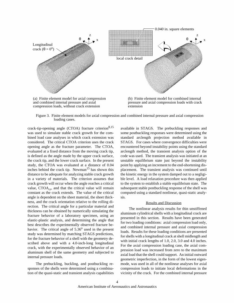
Typical results of the load-shortening predictions,deformation pattern predictions, and stress resultant pre-dictions obtained from a linear elastic and an elas-tic-plastic analysis for the 0.040-inch-thick shell with a3.0-inch-long crack are shown in Figs. 11-14 to illustratethe differences in the material linear and material nonlin-ear analysis predictions. The load-shortening responsecurves from an elastic and an elastic-plastic analysis aregiven in Fig. 11a and provide an overall comparison ofthe compression response predictions from the two anal-yses. The load-time history of the unstable local buck-ling response is shown in Fig. 11b. Initial yieldingoccurs for an applied load corresponding to =0.43, which is approximately 90 percent of the bucklingload associated with the local mode change. Deformedshapes obtained from an elastic analysis and an elas-tic-plastic analysis are provided in Figs. 12 and 13, re-spectively, to show the development of the shell’spostbuckling response. The deformed shapes in Figs. 12
and 13 correspond to the points A, B, C, and D on theload-shortening curves shown in Fig. 11.
The load-shortening predictions based on an elasticanalysis and an elastic-plastic analysis, and the deforma-tion pattern prediction at point A, just prior to the localmode change, indicate that the shell response prior to thelocal mode change is adequately predicted by an elasticanalysis. The initial buckling deformation pattern,shown as deformation pattern A in Figs. 12 and 13, istypical of the shape of the initial buckling deformationpattern for the 0.040-inch-thick shell with the 2.0-, 3.0-and 4.0-inch-long cracks, and for the 0.020-inch-thickshell with the 2.0-, and 3.0-inch-long cracks. The initialbuckling deformation is characterized by inward bucklesat the crack tips, and outward deformations along thecrack edges. As the postbuckling response progressesfrom point A to point B, the buckle pattern rotates aroundthe radial coordinate axis. In the elastic case, the bucklerotates 90 degrees around the radial coordinate axis, re-sulting in a deformation pattern with high circumferen-tial curvature, that apparently stiffens the skinlongitudinally near the crack enough to stabilize the shelland to increase the amount of axial compression load thatcan be supported by the shell after the local mode changeoccurs. The initial postbuckling pattern obtained fromthe elastic-plastic analysis, however, is significantly dif-ferent, as shown in Fig. 13 (deformation pattern B). Theinitial postbuckling deformation pattern predicted by theelastic-plastic analysis is very similar to the deformationpattern labeled A* in Fig. 12 and predicted by the elastic,transient analysis. These results suggest that for the shellstudied, yielding of the aluminum prevents the postbuck-
Figure 10. Comparison of initial postbuckling deformation patterns from an elastic-plastic analysis of a 0.020-inch-thick shell with a 2.0-inch-long and a 3.0-inch-long longitudinal crack and subjected to axial compression loads.
(b) 3.0-inch-long longitudinal crack(a) 2.0-inch-long longitudinal crack
P Pcr⁄

11 American Institute of Aeronautics and Astronautics
ling deformation pattern, B, predicted by the elastic anal-ysis from developing. This result is consistent with theexperimentally observed response.6
As shown in Fig. 11, the elastic-plastic analysispredicts a less severe decrease in the load associated withthe unstable local buckling event that occurs near crackthan is predicted by the elastic analysis. Furthermore,the elastic-plastic analysis predicts greater axial post-buckling stiffness than is predicted by the elastic analy-sis. This behavior is a result of the local yielding near thecrack, caused by large bending deformations, that effec-tively constrains the initial buckling pattern from rotat-ing as far around the radial coordinate as predicted by theelastic analysis. As a consequence, a smaller portion ofthe shell is disturbed by the postbuckling deformations.In addition, the magnitude of the collapse load predictedby the elastic-plastic analysis is larger than the magni-tude predicted by the elastic analysis. This difference isexplained by comparing predictions from the elastic andelastic-plastic analyses for the axial and circumferentialstress resultants just before shell collapse occurs. Con-tour plots of the axial and circumferential stress result-ants corresponding to point C on the load shorteningcurves in Fig. 11, are provided in Fig. 14. Stress result-ant distributions obtained from an elastic analysis and anelastic-plastic analysis are shown in Figs. 14a and 14b,respectively. These results indicate that the local post-buckling deformations have a significant influence on
the load distribution in the shell. In addition, the resultsindicate that regions of large destabilizing in-plane biax-ial compression stress resultants develop near the crack,particularly in the elastic case. In the elastic case, theshell deformations with large circumferential curvatureinduce large circumferential compressive stresses, andresult in the formation of longitudinal ‘stiffener like’ re-gions which support large amounts of axial compressionload. In the elastic-plastic case, yielding in the vicinityof the local postbuckling deformations causes load to beredistributed to the opposite side of the shell, as shown inFig. 14c, and the biaxial compression state near the crackis not as severe as for the elastic case. Consequently, theelastic-plastic shell can support more load before col-lapsing. However, as shown in Fig. 14c, the axial com-pression and circumferential compression stresses nearthe crack required to cause the shell to collapse are lowerfor the elastic-plastic case than they are for the elasticcase, due to a ‘softening’ of the material behavior in theplastic region near the crack.
A similar comparison of the elastic and elas-tic-plastic response predictions for the 0.020-inch-thickshell with a 3.0-inch-long is provided in Figs. 15-17.The load-shortening response curves from an elastic andan elastic-plastic analysis are given in Fig. 15 as an over-all comparison of the compression response predictionsfrom the two analyses. An extensive postbuckling re-sponse is indicated by several stable and unstable seg-
0.000 0.005 0.010 0.015 0.0200.0
0.2
0.4
0.6
Figure 11. Comparison of load-shortening response predictions and load-time history of unstable local mode change obtained from an elastic analysis and an elastic-plastic analysis for a 0.040-inch-thick shell with a 3.0-inch-long longitudinal crack.
P Pcr⁄
0.0
0.2
0.4
0.6
0.8
0.0 0.2 0.4 0.6 0.8u ucr⁄
Elastic-plasticanalysis
Elasticanalysis
Initial yielding
A
B
C
D
Pcr = 63.86 kips
0.0
0.2
0.4
0.6
0.0 0.005 0.010 0.015 0.020
P Pcr⁄
Time, seconds
Elastic-plasticanalysis
Elasticanalysis
A
B
A*
(a) Load-shortening response (b) Load-time history response
12 American Institute of Aeronautics and Astronautics
Figure 12. Selected deformation pattern predictions from an elastic analysis of a 0.040-inch-thick shell with a 3.0-inch-long longitudinal crack and subjected to axial compression loads (refer to Fig. 11 for selected points).
A A*
CB
D

13 American Institute of Aeronautics and Astronautics
ments in the load-shortening response curve. Unstableresponse segments are indicated by dotted lines. Theseresults indicate that the shell response prior to the localmode change, and the shell response throughout the ma-jority of the postbuckling range, is adequately predictedby an elastic analysis. For these thin shells, yielding doesnot start until after the local mode change and is very lo-calized, developing only at the crack-tips and crack edg-es, and at the nodes in the deformed shell where the axialcompression and circumferential stresses are large. Theeffect of plastic deformations on the overall response ofthese shells is therefore not as significant as for the0.040-inch-thick shells.
The initial postbuckling deformation pattern pre-dicted at point B on the load-shortening response curvesby both an elastic and an elastic-plastic analysis is shownin Fig. 10b. As the load is increased further into the post-buckling response range, the deformation pattern gradu-
ally moves around the circumference of the shell,developing into patterns similar to those shown by pointsC and D in Fig. 12 for the elastic 0.040-inch-thick shell.For the 0.020-inch-thick shell, the circumferentialhalf-wave length is shorter than for the 0.040-inch-thickshells. The shell is able to support significant load afterinitial postbuckling because the shell deformations withlarge circumferential curvature and regions of large out-ward radial deformations, introduce ‘stiffener like’ re-gions in the shell that support large amounts of axialcompression load. This response behavior is demon-strated in Fig. 16 which shows the circumferential varia-tion of the radial displacement and axial stress resultantat the shell midlength at selected points in the elas-tic-plastic response predictions. Curves in Fig. 16 desig-nated A, B, F, and J correspond to points on theload-shortening curve in Fig. 15. Large axial stresses de-velop along the outward ridges in the deformed shell, and
Figure 13. Selected deformation pattern predictions from an elastic-plastic analysis of a 0.040-inch-thick shell with a 3.0-inch-long longitudinal crack and subjected to axial compression loads (refer to Fig. 11 for selected points).
A
D
Shaded areas representyielded regions
C
Yielded regions
B
Yielded regions

14 American Institute of Aeronautics and Astronautics
-20 -15 -10 -5 0 5 10 15 20-160
-140
-120
-100
-80
-60
-40
-20
0
20
40
60
80
100
120
140
160
-20 -15 -10 -5 0 5 10 15 20-160
-140
-120
-100
-80
-60
-40
-20
0
20
40
60
80
100
120
140
160
-20.0 0.0 20.0 40.0 60.0 80.0 100.0 120.0 140.0 160.0 180.0-1500.0
-1000.0
-500.0
0.0
500.0 Ny resultants, x = 0, ls = 360
Ny resultants, x2.5, ls 534
-20 -15 -10 -5 0 5 10 15 20-160
-140
-120
-100
-80
-60
-40
-20
0
20
40
60
80
100
120
140
160
-20.0 0.0 20.0 40.0 60.0 80.0 100.0 120.0 140.0 160.0 180.0-2500.0
-2000.0
-1500.0
-1000.0
-500.0
0.0
500.0 Nx resultants, x = 0, ls = 360
Nx resultants, x2.5, ls 534
0 20 60 100 180140-20 0 20 60 100 180140-20-2500
-2000
-1500
-1000
-500
0
500
-1500
-1000
-500
0
500
Nx,lb/in
Ny,lb/in
Elastic
PlasticPlastic
Elastic
θ, degrees θ, degrees
−20 −10 0 10 20 −20 −10 0 10 20
−20 −10 0 10 20
−160−120
160120
0
−80
4080
−40
−160−120
160120
0
−80
4080
−40
−160−120
160120
0
−80
4080
−40
Nx,lb/in.
x, in. x, in.
x, in.
-20 -15 -10 -5 0 5 10 15 20-160
-140
-120
-100
-80
-60
-40
-20
0
20
40
60
80
100
120
140
160
−20 −10 0 10 20−160−120
160120
0
−80
4080
−40
Nθ,lb/in.
x, in.
(b) Stress resultant distributions, just before collapse, elastic-plastic analysis
(a) Stress resultant distributions, just before collapse, elastic analysis
θ
642- 2- 2-4- 7- 9- 1- 1 642- 2- 2-4- 7- 9- 1- 1 642-2-2-4-7-9-1-1
θ
Nx,lb/in. 642-2-2-4-7- 9-1- 1
Figure 14. Comparison of stress resultant predictions from an elastic-plastic analysis and an elastic analysis of a 0.040-inch-thick shell with a 3.0-inch-long longitudinal crack and subjected to axial compression loads.
(c) Stress resultants along A-A, just before collapse, elastic analysis and elastic-plastic analysis
A
A
A
A
A
A
A
A
Nθ,lb/in.-1200 1200 -400 400
-1200 1200 -400 400
θ θ

15 American Institute of Aeronautics and Astronautics
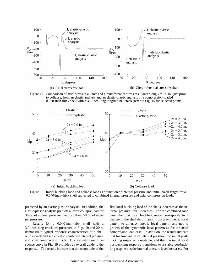
increase as the applied axial compression load increases.An indication of the effect of plasticity on the destabiliz-ing biaxial in-plane compression resultants that developin the deformed shell is provided in Fig. 17. Point I cor-responds to the response just before predicted collapseby the elastic analysis, and Point J corresponds to the re-sponse just before predicted collapse by the elastic-plas-tic analysis. For the elastic-plastic case, yielding in thevicinity of the local postbuckling deformations causes
the destabilizing biaxial compression state to be less se-vere than for the elastic case. Consequently, the elas-tic-plastic shell can support more load before collapsingthan can the elastic shell.
Internal Pressure and Axial Compression Loads - No Crack Extension
A summary of the effects of combined internalpressure and axial compression loads on the initial buck-ling load and collapse load for a 0.040-inch-thick shellwith initial crack lengths of 2.0, 3.0 and 4.0 inches isshown in Fig. 18a and Fig. 18b, respectively for 0, 10,30, and 50 psi of internal pressure. Predictions based onboth an elastic analysis and an elastic-plastic analysis areprovided. The results in Fig. 18a indicate that the initialbuckling load of the shells increases as the internal pres-sure increases for a given crack length. The initial buck-ling load increases because of the larger tensilecircumferential stress resultants near the crack for largermagnitudes of internal pressure, which tend to stabilizethe shell. Results of the elastic-plastic analysis, howev-er, show a less significant increase in the buckling loadwith increase in pressure, particularly at higher magni-tudes of internal pressure and for shells with shortercrack lengths, where higher axial stresses are required tocause buckling of the shell to occur. These results indi-cate that the buckling load predictions from an elasticanalysis may be unconservative. The results also indi-cate that the buckling load decreases as the crack lengthincreases for a given value of internal pressure. The re-sults in Fig. 18b indicate that the collapse load of theshells, in general, increases as the internal pressure in-creases for a given crack length, and that the increasepredicted by an elastic analysis is larger than the increase
A
B
C
D
E
F
G
H
IJ
Elasticanalysis
Elastic-plasticanalysis
0.0 0.2 0.4 0.6 0.80.0
0.2
0.4
0.6
0.8
Figure 15. Comparison of load-shortening response predictions obtained from an elastic analysis and an elastic-plastic analysis of a 0.020-inch-thick shell with a 3.0-inch-long longitudinal crack and subjected to axial compression loads.
P Pcr⁄
u ucr⁄
Pcr = 13.84 kips
-20.0 0.0 20.0 40.0 60.0 80.0 100.0 120.0 140.0 160.0 180.0
-0.4
-0.2
0.0
0.2
0.4
-20.0 0.0 20.0 40.0 60.0 80.0 100.0 120.0 140.0 160.0 180.0-600.0
-500.0
-400.0
-300.0
-200.0
-100.0
0.0
100.0
Figure 16. Radial displacements and axial stress resultants along x = 0.0 in. at selected points in the elastic-plastic response predictions for a compression-loaded 0.020-inch-thick shell with a 3.0-inch-long longitudinal crack (refer to Fig. 15 for selected points).
0 20 60 100 180140-20
-100
100
Nx,lb/in.
0 20 60 100 180140-20θ, degrees
0
-200
-300
-400
-500
-600
F
J
B
A
J
F
A
B
0.0
0.4
0.2
-0.2
-0.4
-0.6
w,in.
(a) Radial displacements (b) Axial stress resultant
θ, degrees
16 American Institute of Aeronautics and Astronautics
predicted by an elastic-plastic analysis. In addition, theelastic-plastic analysis predicts a lower collapse load for30 psi of internal pressure than for 10 and 50 psi of inter-nal pressure.
Results for a 0.040-inch-thick shell with a3.0-inch-long crack are presented in Figs. 19 and 20 todemonstrate typical response characteristics of a shellwith a crack and subjected to combined internal pressureand axial compression loads. The load-shortening re-sponse curve in Fig. 19 provides an overall guide to theresponse. The results indicate that the magnitude of the
first local buckling load of the shells increases as the in-ternal pressure level increases. For the combined loadcase, the first local buckling mode corresponds to achange in the shell deformation from a symmetric localpattern to an unsymmetric local pattern, and not togrowth of the symmetric local pattern as for the axialcompression load case. In addition, the results indicatethat for low values of internal pressure, the initial post-buckling response is unstable, and that the initial localpostbuckling response transitions to a stable postbuck-ling response as the internal pressure level increases. For
-20.0 0.0 20.0 40.0 60.0 80.0 100.0 120.0 140.0 160.0 180.0-600.0
-500.0
-400.0
-300.0
-200.0
-100.0
0.0
100.0
-20.0 0.0 20.0 40.0 60.0 80.0 100.0 120.0 140.0 160.0 180.0-400.0
-300.0
-200.0
-100.0
0.0
100.0
Figure 17. Comparison of axial stress resultants and circumferential stress resultants along x = 0.0 in., just prior to collapse, from an elastic analysis and an elastic-plastic analysis of a compression-loaded 0.020-inch-thick shell with a 3.0-inch-long longitudinal crack (refer to Fig. 15 for selected points).
0 20 60 100 180140-200 20 60 100 180140-20θ, degrees θ, degrees
-100
100
Nx,lb/in.
0
-200
-300
-400
-500
-600
-100
100
Nθ,lb/in.
0
-200
-300
-400
J, elastic-plastic
I, elasticanalysis
I, elastic-plasticanalysis
analysisI, elastic-plastic
I, elasticanalysis
J, elastic-plasticanalysis
analysis
(a) Axial stress resultant (b) Circumferential stress resultant
0.0 10.0 20.0 30.0 40.0 50.020.0
30.0
40.0
50.0
0.0 10.0 20.0 30.0 40.0 50.020.0
30.0
40.0
50.0
Figure 18. Initial buckling load and collapse load as a function of internal pressure and initial crack length for a 0.040-inch-thick shell subjected to combined internal pressure and axial compression loads.
(a) Initial buckling load (b) Collapse load
0 10 20 30 40 5020
30
40
50
P,kips
20
30
40
50
0 10 20 30 40 50
P,kips
Elastic
Elastic-plasticElastic
Elastic-plastic
2a = 2.0 in.
2a = 3.0 in.
2a = 4.0 in.
2a = 2.0 in.2a = 3.0 in.2a = 4.0 in.2a = 2.0 in.2a = 3.0 in.2a = 4.0 in.
p, psi p, psi

17 American Institute of Aeronautics and Astronautics
the results presented in Fig. 19, shells with an internalpressure level equal to or greater than 30 psi exhibit a sta-ble local postbuckling response. The results also showthat the general instability load for the shells increaseswith increases in internal pressure, and that the amountof reduction in load associated with collapse decreases asthe internal pressure level increases.
Representative initial postbuckling and general in-stability deformed shape plots are provided in Fig. 20 fora shell with a 3.0-inch-long crack and subjected to 30 psiof internal pressure. The local crack prebuckling defor-mation pattern is similar to that shown in Fig. 13 (pointA), for the axial compression case, but it has significant-ly larger deformations. Furthermore, for the cases con-sidered here, the prebuckling deformation pattern isalways symmetrical with respect to the planes and . Therefore, the crack behavior in the preb-uckled state can be characterized by the Mode I crack-opening fracture mode. The stable postbuckling defor-mation shape, after the local mode change, is shown inFig. 20a. The deformation pattern in Fig. 20a indicatesthat the shell deforms into an unsymmetric local patternwith high circumferential curvature gradients at thecrack tips. The crack behavior in the postbuckling statetherefore cannot be characterized by a simple Mode Icrack-opening response. Consequently, only the interac-tion between crack extension and initial local buckling isaddressed in the next section. The general instability de-formation pattern, shown in Fig. 20b, indicates that anincrease in internal pressure results in a deformation witha shorter circumferential half-wave length than for theunpressurized case.
Internal Pressure and Axial Compression Loads - Crack Extension
Results are presented in Fig. 21 for a0.040-inch-thick shell with a 3.0-inch-long initial crackto provide a preliminary indication of the effect of crackgrowth on the initial buckling load. Crack growth wassimulated using the critical CTOA criterion, and a criti-cal angle equal to . The results shown in Fig. 21were generated from an elastic-plastic analysis by firstapplying a live internal pressure load of the desired loadlevel to the shell. After this load level was attained, anincreasing axial compression load was applied. The ef-fect of load sequence on the results was not investigated.The bottom curve in the figure corresponds to the com-bination of internal pressure and axial compression loadsrequired to initiate stable crack growth. For this shell,crack propagation initiates for internal pressure only, atan internal pressure level of 30 psi. The top curve indi-cates the effect of internal pressure on the initial bucklingload for a shell with a fixed crack length. The dashedcurve shows the effect of crack growth on the initialbuckling load. These results show that for the shell con-sidered, and for internal pressure load magnitudes lessthan 30 psi, crack growth reduces the buckling load by10% or less. For larger magnitudes of internal pressure,the effect of crack growth on the initial buckling load isexpected to be more significant. Crack growth for inter-nal pressure loads greater than 30 psi extends to theboundaries of the refined mesh shown in Fig. 3b, and theinteraction between crack growth and initial bucklingcould not be evaluated with this model.
Figure 19. Predictions from an elastic-plastic analysis of the effect of internal pressure on the load-shortening response of a 0.040-inch-thick shell with a 3.0-inch-long longitudinal crack.
(a) Load-shortening response (b) Magnified view of local and global buckling points
-0.2 0.0 0.2 0.4 0.6 0.8 1.0-0.2
0.0
0.2
0.4
0.6
0.8
1.0
P Pcr⁄
u ucr⁄
P Pcr⁄
u ucr⁄0.3 0.4 0.5 0.6 0.7 0.8 0.9
0.2
0.3
0.4
0.5
0.6
0.7
0.8
0.90 psi10 psi30 psi50 psi
Internal Pressure
x 0=θ 0°=
5.36°

18 American Institute of Aeronautics and Astronautics
Concluding Remarks
The results of an analytical study of the effects of alongitudinal crack on the nonlinear response of thin un-stiffened aluminum cylindrical shells subjected to axialcompression, and to combined internal pressure and axi-al compression loads are presented. The results indicatethat the nonlinear interaction between the in-plane stressresultants and the out-of-plane displacements near acrack in a thin shell can significantly affect the structuralresponse of the shell. Large local stress and displace-ment gradients exist near a crack in a shell for all loadingconditions considered in the present study. The resultsindicate that the nonlinear response of the shell dependson the loading condition applied to the shell and the ini-tial crack length. The initial buckling load of a shell sub-jected to axial compression loads decreases as the initialcrack length increases. Initial buckling causes generalinstability or collapse of the shell for shorter initial cracklengths. Initial buckling is a stable local response forlonger initial crack lengths. This stable local bucklingresponse is followed by a stable postbuckling response,which is followed by general or overall instability of theshell. The results for combined internal pressure and ax-ial compression loads indicate that the initial bucklingload of a shell increases as the magnitude of the internalpressure increases, but decreases as the inital cracklength increases. Furthermore, results indicate that pre-dictions from an elastic analysis for the initial bucklingload of a cracked shell subjected to combined axial com-pression and internal pressure can be unconservative.
Figure 20. Selected deformation patterns for a 0.040-inch-thick shell with a 3.0-inch-long longitudinal crack and subjected to 30 psi of internal pressure and an axial compression load.
(a) Initial postbuckling deformation pattern (b) General instability deformation pattern
0.000 10.000 20.000 30.0000.000
10.000
20.000
30.000
40.000
50.000
Figure 21. Interaction between crack growth and initial buckling for a 0.040-inch-thick shell with a 3.0-inch-long crack and subjected to combined internal pressure and axial compression loads.
0 10 20 300
10
20
30
40
50
p, psi
P,kips
Initialcrack growth
Initial bucklingwithout crack growth
Initial bucklingwith crack growth

19 American Institute of Aeronautics and Astronautics
References
1Riks, E., “Bulging Cracks in Pressurized Fuselages:A Numerical Study,” NLR MP 87058 U, NLR NationalAerospace Laboratory, The Netherlands, September1987.
2Rankin, C. C., Brogan, F. A., and Riks, E., “SomeComputational Tools for the Analysis of ThroughCracks in Stiffened Fuselage Shells,” ComputationalMechanics, Springer International, Vol. 13, No. 3,December 1993, pp. 143-156.
3Starnes, J. H., Jr., Britt, V. O., and Rankin, C. C.,“Nonlinear Response of Damaged Stiffened Shells Sub-jected to Combined Internal Pressure and MechanicalLoads,” AIAA Paper 95-1462, April 1995.
4Starnes, J. H., Jr., Britt, V. O., Rose, C. A., andRankin, C., C., “Nonlinear Response and ResidualStrength of Damaged Stiffened Shells Subjected toCombined Loads,” AIAA Paper No. 96-1555, April1995.
5Starnes, J. H., Jr., and Rose, C. A., “NonlinearResponse of Thin Cylindrical Shells with LongitudinalCracks and Subjected to Internal Pressure and AxialCompression Loads,” AIAA Paper No. 97-1144, April,1997.
6Starnes, J. H., Jr., and Rose, C. A., “Buckling andStable Tearing Responses of Unstiffened AluminumShells with Long Cracks,” AIAA Paper No. 98-1191,April 1998.
7Estekanchi, H. E., and Vafai, A., “On the Bucklingof Cylindrical Shells with Through Cracks Under AxialLoad,” Thin-Walled Structures, Vol. 35, 1999, pp.255-274.
8Dawicke, D. S., Sutton, M. A., Newman, J. C., Jr.,and Bigelow, C. A., “Measurement and Analysis of Crit-ical CTOA for Aluminum Allow Sheet,” NASATM-109024, September, 1993.
9Brogan, F. A., Rankin, C. C., and Cabiness, H. D.,“STAGS User Manual,” Lockheed Palo Alto ResearchLaboratory, Report LMSC P032594, 1994.
10Riks, E., “Some Computational Aspects of the Sta-bility Analysis of Nonlinear Structures,” ComputationalMethods in Applied Mechanics and Engineering, Vol.47, 1984, pp. 219-259.
11Riks, E., “Progress in Collapse Analysis,” Journalof Pressure Vessel Technology, Vol. 109, 1987, pp.27-41.
12Riks, E., Rankin, C. C., and Brogan, F. A., “On theSolution of Mode Jumping Phenomena in Thin-WalledShell Structures,” Computational Methods in AppliedMechanics and Engineering, September 1996, pp.59-92.
13Park, K. C., “An Improved Stiffly Stable Methodfor Direct Integration of Nonlinear Structural Dynam-ics,” Journal of Applied Mechanics, Vol. 42, June 1975,pp. 464-470.
14Riks, E., Brogan, F. A., and Rankin, C. C., “Bulg-ing of Cracks in Pressurized Fuselages: A Procedure forComputation,” in Analytical and Computational Modelsof Shells, Noor, A. K., Belytschko, T., and Simo, J. C.,Editors, The American Society of Mechanical Engi-neers, ASME-CED Vol. 3, 1989.
15Newman, J. C., Jr., “An Elastic-Plastic Finite Ele-ment Analysis of Crack Initiation, Stable Crack Growthand Instability,” ASTM STP 833, 1984, pp. 93-117.
16Rankin, C. C., and Brogan, F. A., “The Computa-tional Structural Mechanics Testbed Structural ElementProcessor ES5: STAGS Shell Element,” NASA Con-tractor Report 4358, May 1991.
17Besseling, J. F., “A Theory of Elastic, Plastic andCreep Deformations on an Initially Isotropic MaterialShowing Anisotropic Strain-Hardening, Creep Recov-ery, and Secondary Creep,” ASME Journal of AppliedMechanics, 1958, pp. 529-536.
18Zienkiewicz, O. C., Nayak, G. C. and Owen, D. R.J., “Composite and ‘Overlay’ Models in NumericalAnalysis of Elasto-Plastic Continua,” Foundations ofPlasticity, A. Sawczok Ed. Nordhoff Press, pp. 107-122,1972.