growth and characterisation of low-k dielectric material using spin ...
25
GROWTH AND CHARACTERISATION OF LOW-K DIELECTRIC MATERIAL USING SPIN-ON PROCESS By AW KEAN CHIN Thesis submitted in fulfilment of the requirements for the degree of Doctor of Philosophy November 2002 1
Transcript of growth and characterisation of low-k dielectric material using spin ...

GROWTH AND CHARACTERISATION OF LOW-K DIELECTRIC
MATERIAL USING SPIN-ON PROCESS
By
AW KEAN CHIN
Thesis submitted in fulfilment of the requirements
for the degree of Doctor of Philosophy
November 2002
1

Chapter 1. Acknowledgements
I would like to thank Associate Prof. Dr. Mat Johar, Encik Badrul, Encik Muthalib,
Encik Jamil and Miss Ee Bee Choo of University Science Malaysia for their help with
the CV-meter measurement, laboratory and clean-room support. I would also like to
thank the management of Altera Corporation, Penang for the use of micro probing, HP
Semiconductor Parameter Analyser, FESEM/EDX, Chemical Lab facility and etc. Last
but not least, I like to extend my greatest sincere appreciation and thanks to Prof Dr.
Kamarulazizi Ibrahim who has been a helpful and supportive supervisor throughout the
duration of this research.
2

PENUMBUHAN DAN PENCIRIAN FILEM NIPIS DIELEKTRIK K-RENDAH MENGUNAKAN PROSES PUTARAN
Abstrak
Dimensi didalam peranti mickro VLSI semakin berkurangan dengan satu objektif, iaitu
untuk meningkatkan laju pengendalian. Tetapi terdapat komponen parasitik yang
terkandung didalam peranti-mikro yang boleh membawa kesan terhadap laju
pengendalian. Jika ketelusan relatif (k) dielektrik lapisan antara boleh dikurangkan, laju
pengendalian akan ditingkatkan. Dengan ini filem nipis dielektrik k-rendah
diperkenalkan. Filem nipis dielektrik k-rendah ialah bahan yang mempunyai ketelusan
relatif, k kurang daripada 3.0. Kajian ini mengunakan filem nipis dielektrik k-rendah
jenis Methylsilsesquioxane (MSQ). Pemendapan MSQ mengunakan proses putaran
yang berkos rendah. Pencirian kapasitor MOS yang difabrikasikan telah dilakukan
untuk menentukan mekanisma yang terkandung bila diintegrasikan dengan logam Al
dan Cu yang diendapkan dengan kaedah sejatan atau percikan. Kajian ini membawa
kesimpulan yang kaedah pememendapan logam membawa kesan yang buruk terhadap
MSQ berbanding dengan kaedah percikan. Manakala, kaedah percikan menyebabkan
perbentukan “trap sites” di dalam MSQ yang akan menjerat ion-ion logam yang
terpecik. Kesan Cu+ dan Al+ terhadap MSQ dikaji dan dua model gambarajah jalur
tenaga diperkenalkan di dalam tesis ini untuk menerangkan mekanisma yang
diperhatikan. Kajian ini juga menunjukan yang peresapan terma boleh disekat oleh
lapisan SiO2 tetapi tidak dapat menyekat suntikan ion-ion logam. Dengan yang
sedemikian satu lapisan sawar yang berlainan diperlukan. Tenaga pengaktifan yang
menyebabkan peresapan terma juga dapat ditentukan dengan secara ringkas didalam
kajian ini.
3

Pada keseluruhannya, MSQ ialah sesuatu bahan dielectrik k-rendah yang berpotensi
tetapi memerlukan proses yang bersuhu rendah, iaitu 450ºC dan ke bawah supaya MSQ
tidak akan terurai dan juga sifat-sifat dan ciri-cirinya perlu difahami dengan lebih
mendalam sebelum ia dapat diintegrasikan di dalam peranti mikro VLSI untuk
pengeluaran besar-besaran.
4
Abstract
Device dimension in VLSI circuit constantly shrink with one main objective, i.e.
increase in speed. However, there are other parasitic components in the VLSI circuit
other than device dimension that can affect the speed of VLSI circuits. The reduction of
dielectric constant of interlayer dielectric (ILD) material can improve the speed due to
reduction in parasitic capacitance. Therefore, low dielectric constant (k) materials are
being introduced. Low-k dielectric material is categorised as material having dielectric
constant of less than 3.0. In this research Methylsilsesquioxane (MSQ), which is a type
of spin-on glass (SOG), is being used as it offers low fabrication cost. MOS capacitor
structures were fabricated and electrically characterise to understand the underlying
mechanism when integrated with evaporated or sputtered aluminium and copper metal.
It was observed that evaporated metal in direct contact with MSQ is disastrous
compared to sputtering technique due to high evaporation temperature. On the other
hand, sputtered metal in direct contact with MSQ create trap sites close to the silicon
interface, which can trap injected metal ions. Effect of Cu+ and Al+ were also studied
and two band-diagram models were used to explain the observed mechanisms of
evaporated and sputtered metal have been proposed as an outcome of these
observations. It was also found that SiO2 is not capable to prevent charge injection into
MSQ layer to achieve a reliable VLSI circuit but is capable of preventing thermal
diffusion through MSQ. The activation energy of diffusivity through MSQ was also
approximately determined in this research using simple technique.
5

Therefore, a different barrier layer other than SiO2 is still necessary. In addition, “low
thermal budget” fabrication technique (450ºC and below) is necessary to ensure that
MSQ do not degrade or decompose which affects the quality and reliability of the
fabricated VLSI circuit. In summary, MSQ SOG has proven to be a promising low-k
dielectric, although there are still a lot of researches that need to continue to fully
understand the properties and characteristics of this material before it can be integrated
for mass production.
6

Table of Contents
CHAPTER 1. INTRODUCTION...................................................................................................... 1 1.1. RC CONSTANT.............................................................................................................................. 2 1.2. WHY LOW-K DIELECTRIC?............................................................................................................ 3 1.3. WHY COPPER? .............................................................................................................................. 5 1.4. RESEARCH OBJECTIVES ................................................................................................................ 8
CHAPTER 2. LITERATURE REVIEW........................................................................................ 10 2.1. OVERVIEW .................................................................................................................................. 10 2.2. TYPICAL SOG LOW-K DIELECTRIC............................................................................................. 11
2.2.1. Xerogel ............................................................................................................................... 12 2.2.2. Hydrogensilsesquioxane (HSQ) ......................................................................................... 13 2.2.3. Methylsilsesquioxane (MSQ).............................................................................................. 15
2.3. WHY USE MSQ IN THIS RESEARCH?........................................................................................... 16 CHAPTER 3. THEORY................................................................................................................... 17
3.1. DIFFUSION .................................................................................................................................. 17 3.2. THERMAL ACTIVATION ENERGY................................................................................................. 18 3.3. CV CURVES AND TRAPPED CHARGES......................................................................................... 20
3.3.1. Flat-band Voltage and Work Functions ............................................................................. 23 3.3.2. Interface Traps ................................................................................................................... 28
3.4. I-V RELATIONSHIP...................................................................................................................... 30 3.5. I-T RELATIONSHIP ....................................................................................................................... 31 3.6. DIELECTRIC BREAKDOWN VOLTAGE .......................................................................................... 32
CHAPTER 4. PROCESS AND EQUIPMENT .............................................................................. 33 4.1. OVERVIEW .................................................................................................................................. 33 4.2. MOS CAPACITOR FABRICATION PROCESS AND EQUIPMENT....................................................... 33
4.2.1. RCA Clean.......................................................................................................................... 35 4.2.2. MSQ Deposition ................................................................................................................. 36 4.2.3. Soft Bake............................................................................................................................. 37 4.2.4. MSQ Cure........................................................................................................................... 38 4.2.5. Metal Deposition ................................................................................................................ 40
4.2.5.1. Thermal Evaporation Systems.................................................................................... 40 4.2.6. Post Deposition Annealing................................................................................................. 45 4.2.7. Silicon Dioxide Growth ...................................................................................................... 46
4.3. MEASUREMENT AND ANALYSIS EQUIPMENT .............................................................................. 48 4.3.1. Physical Analysis Equipment ............................................................................................. 48 4.3.2. Electrical Analysis Equipment ........................................................................................... 50
4.3.2.1. I-V Curve.................................................................................................................... 50 4.3.2.2. Breakdown Voltage.................................................................................................... 51 4.3.2.3. I – t Curve................................................................................................................... 51 4.3.2.4. C-V Curve .................................................................................................................. 51
4.3.3. Support Equipment ............................................................................................................. 52 4.3.3.1. Diamond Saw and Polisher ........................................................................................ 52 4.3.3.2. Micromanipulator Station........................................................................................... 53
7

List of Figures
Figure 1-1: Total Interconnect Wiring Capacitance Figure 1-2: Illustration on the effects of parasitic RC Figure 1-3: Microprocessor Clock Frequency versus Interconnect Metal and ILD
choices Figure 2-1: Ladder-structure HSQ Figure 2-2: Cage-structure HSQ Figure 2-3: General Chemical Structures of MSQ Figure 3-1: Plot of two different reaction rate of different mechanisms Figure 3-2: A typical C-V Curve of MOS with p-substrate Figure 3-3: Energy band and block charge diagram for p-type silicon under flat-band,
accumulation, depletion and inversion condition Figure 3-4: Type of charges in an Oxide or Dielectric Figure 3-5: Ohmic contact’s I-V characteristics Figure 4-1: Cross-section of MOSC with Metal/MSQ/Si structure Figure 4-2: Cross-section of MOSC with Metal/MSQ/SiO2/Si structure Figure 4-3: MOS Capacitor Fabrication Process Steps Figure 4-4: Chemical Fume Hood used in this research Figure 4-5: Photo-resist spinner used in this research Figure 4-6: Programmable Hot Plate used in this research Figure 4-7: High temperature furnace used in this research Figure 4-8: Thermal Evaporator used in this research Figure 4-9: Evaporation from a boat source Figure 4-10: Vapour Pressure Curves for selected materials versus Temperature Figure 4-11: Evaporation from a filament source
8

Figure 4-12: Sputtering Equipment used in this research Figure 4-13: A cross section of a magnetron-sputtering configuration Figure 4-14: Oxide thickness as a function of time with temperature as parameter. Figure 4-15: FESEM/EDX system used in this research Figure 4-16: High Magnification Microscope used in this research Figure 4-17: Diamond Cutter by Buehler used in this research Figure 4-18: Polisher by Buehler used in this research Figure 4-19: Micromanipulator in a dark metal probe box used in this research Figure 5-1: Film thickness versus spin speed Figure 5-2. Cross-section view of MOSC used in this experiment. Figure 6-1: Wavelength versus Refractive Index used by Filmetrics Figure 6-2: MSQ film thickness across wafer Figure 6-3: Cracked MSQ film due to temperature shock during soft bake Figure 6-4: Poor Surface texture due to inconsistent spinner speed Figure 6-5: Good MSQ surface texture Figure 6-6: Elemental Spectrum of MSQ using EDX Figure 6-7: Surface structure using FESEM of cured MSQ Figure 6-8: Cross section of the MOS capacitor structure at 1000x (optical) Figure 6-9: Leakage versus bake time for MOS capacitor with Al gate Figure 6-10: Arrhenius Plot of MSQ Thermal Degradation Figure 6-11: Leakage versus bake time for MOS capacitor with Cu gate Figure 6-12: Ileak of MOS capacitor with Al gate versus operating temperature Figure 6-13: Ileak of MOS capacitor with Cu gate versus operating temperature Figure 6-14: I-t curve of BTS on MOS capacitors with Al and Cu gate annealed at 250ºC Figure 6-15: I-t curve of BTS on MOS capacitors with Al and Cu gate annealed at 350ºC
9

Figure 6-16: C-V curve of MOS with evaporated Cu gate annealed at 250ºC Figure 6-17: Ileak versus t of MOSC-1 under BTS Figure 6-18: Ileak versus t for MOSC-2 (Al gate) and MOSC-3 (Cu gate) under BTS Figure 6-19: C-V curve in FVS mode of MOSC-2 Figure 6-20: C-V curve in FVS mode of MOSC-3 Figure 6-21: C-V Curve of MOSC-2 after voltage stress Figure 6-22: C-V Curve of MOSC-3 after voltage stress Figure 6-23: Ileak with respect to temperature Figure 6-24: I versus t for MOSC-E and MOSC-S during BTS Figure 6-25: C-V-curve of MOSC-S after +20V stress at the gate Figure 6-26: C-V-curve of MOSC-S after –20V stress at the gate Figure 6-27: Comparison of Yield Trend of various MOSC structure Figure 6-28: I-V curves of MOS capacitor failures Figure 6-29: I-V characteristics of MOSC failures (type a) after 350°C annealing Figure 6-30: Electrical circuit model of MOSC failures Figure 6-31: Comparison of MOS capacitor annealed (evaporated) at 350ºC under BTS Figure 6-32: Melting temperature versus relative BTS leakage current of evaporated
MOSC Figure 7-1: Graphical illustration comparing thermal diffusion of Al and Cu atoms Figure 7-2: Graphical illustration to compare Al and Cu diffusion during annealing Figure 7-3: Energy band diagram illustrating proposed Cu+ injection under positive
gate voltage. Figure 7-4: Illustration of the effective insulation thickness (deff). Figure 7-5: Energy band diagram describing the injection of inversion electrons and
trapped in the SiO2 layer. Figure 7-6: C-V curve to demonstrate stretched-out effect of interface trap Figure 7-7: Graphical illustration of Al+ in evaporated and sputtered MOSC
10

Figure 7-8: MOSC-E after Al Gate Removal under FESEM Figure 7-9: MOSC-S after Al gate Removal under FESEM Figure 7-10: Band diagram used in depicting the kinetics of Al+ injection under
positive gate voltage being trapped in the MSQ by the interface traps.
11

List of Tables
Table 1-1: Cost model for SOD and CVD process to deposit low-k dielectric Table 5-1: Typical spin-on process steps Table 6-1: Measured Thickness versus Required Thickness Table 6-2: Refractive Index used by Filmetrics for Thickness measurement Table 6-3: Measured Dielectric Strength of various MOS capacitors structures Table 6-4: Yield for Different Metal Deposition Process Table 6-5: Yield equation for different type of Gate Metal
12

Chapter 2. Introduction
Low dielectric constant material is necessary in view of the quest to achieve higher
speed. With the spacing between two metal lines becoming closer, the coupling
capacitance of the metal wiring will become larger assuming that dielectric is still
maintained as SiO2 (k = 4.0). As device dimensions shrink to less that 0.25µm,
propagation delay, cross-talk noise and power dissipation due to resistance-capacitance
(RC) coupling become significant due to increased wiring capacitance, especially
interline capacitance between the metal lines on the same level. These factors all depend
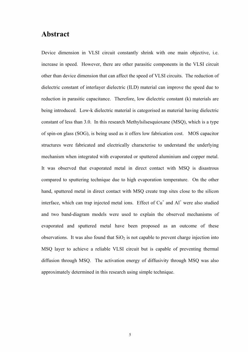
critically on the dielectric constant of the separating insulator. Figure 1-1 (Materials
Research Society, Oct 1997) shows the capacitance versus the spacing for different
values of dielectric constant and it is clear that the capacitance increases tremendously
when the spacing is 0.25µm and below.
Figure 1-1: Total Interconnect Wiring Capacitance
13
To illustrate the point, refer to Figure 1-1 with k = 4, the wiring capacitance is
approximately 2.2pF/cm with 0.5µm spacing. In order to reduce the spacing to 0.25µm
and keep the wiring capacitance constant, the k has to be reduced to 3. If the spacing is
to be reduced further to 0.15µm and maintaining the capacitance at 2.2pF/cm, the k has
to be reduced to 2. Reducing only the capacitance is not sufficient as the spacing will
continue to become smaller and therefore the resistance of the wiring has to be reduced
in order to reduce or maintain the RC constant.
2.1. RC Constant
Since coupling capacitance is affected by the dielectric constant (k) of the material in
between the two metal lines, low-k dielectric material will reduce this coupling
capacitance. Reducing this capacitance will therefore reduces the RC constant and in
turn increases the switching speed of the VLSI circuits. However, as discussed earlier
there is a limit where the capacitance can be reduced. The other parameter then need to
be considered is the metal wiring resistance as both capacitance and resistance form the
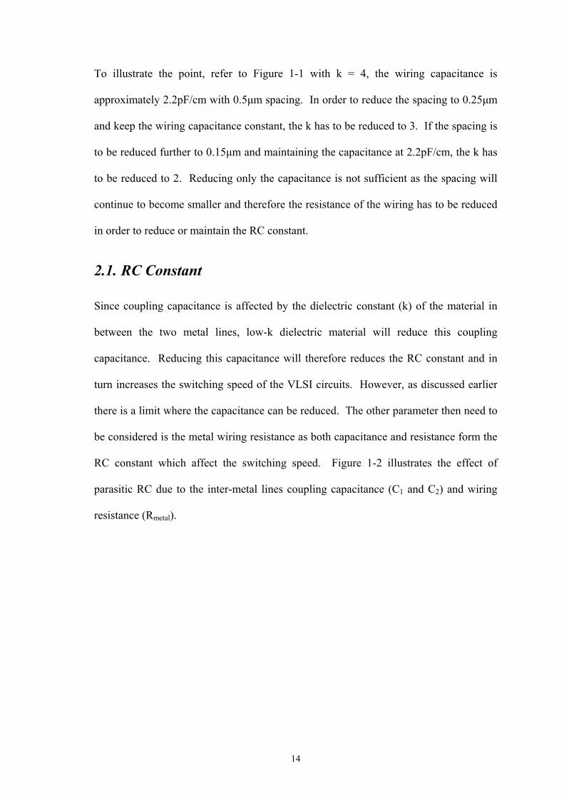
RC constant which affect the switching speed. Figure 1-2 illustrates the effect of
parasitic RC due to the inter-metal lines coupling capacitance (C1 and C2) and wiring
resistance (Rmetal).
14

d2
trise and tfall will be longer due to higher RC tfall trise
Assumption These metals are at ground potential
Rmetal2
C1
C2
C2
C1
C1 = εokA1/d1 C2 = εokA2/d2 when d1 and d2 gets smaller, C1 and C2 will increase if k still remains constant. Therefore, C1 and C2 can be reduced by reducing k.Metal 1
Metal 2 Metal 2
d1
Figure 1-2: Illustration on the effects of parasitic RC
From Figure 1-2, the rise and fall time of the square wave will be longer due to the
parasitic RC constant and this limits the maximum frequency. Therefore, it is necessary
to reduce the dielectric constant (k) and wiring resistance to reduce the RC constant as
the spacing dimension and the metal wiring cross sectional area become smaller. The
solution is to use low-k dielectric material to replace SiO2 and Cu to replace Al.
2.2. Why Low-k Dielectric?
There are three categories of low-k dielectric, i.e. low-k dielectric (k < 3), extra low-k
dielectric ( k < 2.5) and ultra low-k dielectric (< 2.0). In addition, these low-k materials
are also categorised according to the deposition method, i.e. chemical vapour deposition
(CVD) and spin on dielectric or spin-on glass (SOD or SOG).
15

In this research, SOD is use as it does not require expensive equipment and easy to use
and it is a low cost application compare to CVD type. Table 1-1 shows the comparison
of various SOD/SOG and CVD process in terms of cost and output rate.
Table 1-1: Cost model for SOD and CVD process to deposit low-k dielectric (Korczynski Ed, May 1999)
Process Throughput (wafer/hour)
Precursor + clean
($/wafer)
System cost ($ millions)
Zero defect cost
($/wafer) SOD standard 80 3.0 1.0 5.0 SOD porous 60 3.0 1.2 5.5 PECVD SiOC 50 0.75 2.2 3.3 PECVD α-CF 25 0.75 2.2 5.2 PECVD cap 85 0.10 2.2 1.8
SOD has higher wafer throughput and lower equipment cost. However, it has higher
defect and also requires higher wafer cleaning and precursor cost.
There are several properties similar to the SiO2 that is required to enable low-k
dielectric material to be consider for integration into VLSI circuit fabrication and is
listed as follows: -
• High mechanical strength
• Good dimensional stability
• High thermal stability
• Ease of pattern and etch for sub-micron features
• Low moisture absorption and permeation
• Good adhesion
• Low stress
• Good etch selectivity to metal
• High thermal conductivity
16

• High dielectric strength
• Low leakage current
• Good gap filling and planarisation capability
This research concentrates on the study of MSQ produced by Filmtronics. Filmtronics
400F Methylsilsesquioxane spin-on glass is based on a unique chemistry that yields a
polymer with Si-CH3 and Si-O bonds and has a low dielectric (k) of 2.6.
The several advantages of using spin-on dielectric (SOD) that has contributed to its
selection for this research are summarised as follows: -
• Economical processing,
• Fast processing and higher throughput,
• No handling of toxic gases
2.3. Why Copper?
Metal-Oxide-Semiconductor (MOS) capacitors were used in this research, as it is easy
to fabricate. Metal gate used were aluminium (Al) and copper (Cu) and the
semiconductor material is p-type <100> silicon in the form of 2” wafer. Al or Cu
together with MSQ were being research, as these are the commonly used metals in
VLSI circuits with copper becoming more popular due to its lower resistivity compared
to aluminium. Comparisons of microprocessor clock frequency versus interconnect
metal and ILD choices are shown in Figure 1-3 (Sematech, Nov 1999).
17

Figure 1-3: Microprocessor Clock Frequency versus Interconnect Metal and ILD choices
Assuming a100nm (0.1µm) minimum feature size (which will be available for mass
production in year 2003) in Figure 1-3, Al/low-k and Cu/low-k integration provides a
speed performance increase of 28% and 42% over Al/SiO2 respectively. However, Cu
has been increasing popular over Al because in comparison to Al it has lower resistance
(2Ω-cm for Cu versus 3Ω-cm for Al) and better resistance to electro-migration that has
led it to be the main material for the semiconductor industries’ interconnect. Such a low
resistant is vital for high-performance microprocessor and fast static RAMS, since this
results in lower RC time delay, implying faster flow of signals. The advantages of
using Cu are as follows: -
1. Copper enables the reduction of capacitance by making the metal lines thinner
Cu (or Cu/low-k combination) makes it possible to reduce the number of levels of metal
because copper is more conductive than Al. This make it possible to make interconnect
lines smaller yet still provides the same current- carrying capability. The positive
implication is reduction of power consumption by at least 30% since copper resistance
18

is 30% lower than aluminium. This means improved performance in battery-powered
applications, such as notebook computers and other mobile applications.
2. Copper enables a significant improvement in chip speed
The improvement will even be greater when copper is combined with low-k dielectrics
shows a reduction in time delays with the copper/low-k approach compared to
traditional Al/SiO2 interconnects. At 0.13µm size, the delay for copper is half of Al,
which implies speed enhancement with no sacrifice of device reliability
3. Superior resistance to electro-migration, a common problem faced in the Al
interconnects.
Because copper can handle higher power densities, such as those in high-powered
transistors, widens the application to a whole new range of analogue devices.
4. Copper helps in cost reduction
Because it is difficult to etch Cu, early Cu developers were forced into what has become
known as damascene or in-laid integration to interconnect formation. In interconnect
lines are created by first etching a trench or canal in a planar dielectric and then filling
that trench with metal. The metal is then planarised with chemical-mechanical
polishing.
Using low-k dielectrics between the metal lines makes even tighter packing density
possible per layer and, therefore, allows the use of fewer layers. This leads to lower
manufacturing costs and higher yields. Switching from Al to Cu would enable those 14
levels to be reduced to 12 levels; switching to both copper and low-k would enable a
more realistic eight or nine or even maybe six levels of metals.
19

In dual damascene processing, a second level is involved where a series of holes (i.e.,
contacts or via holes) are etched and filled in addition to the trench. While experience is
limited, researchers are now saying that the damascene approach, which eliminates
metal etch and dielectric gap fill, will actually be 20% less expensive than traditional
interconnect fabrication techniques.
2.4. Research Objectives
There are many researches that have been conducted and are still being conducted today
to either search for a suitable low-k dielectric material or to improve their integration
through understanding of the problems that arises. MSQ as ILD do posses several
concerns as reported by many researchers that need to be addressed and understood
through detail characterisation and research. However, there were many publications on
the material and mechanical properties of MSQ, but, there are little work done on the
electrical properties of MSQ. Therefore, this research main concentration is related to
the electrical characterisation study of MSQ. This research aims to achieve the
following objectives: -
(a) To understand the effect of fabrication processes such as post deposition-
annealing temperature towards the quality and reliability of MSQ.
(b) To study the different properties and electrical characteristics of Aluminium and
Copper gate deposited using evaporation and sputtering process.
(c) To understand the quality and reliability problems of MSQ as ILD by subjecting
to elevated stress conditions.
(d) Finally, to propose model(s) that explain the observations made in this research
based on the observations described above.
20

The outcome of this research is based on the availability of the facilities and equipment
that were available for this research. This research has established sufficient
understanding and background theory for the further continuation of this material
(MSQ) and also development of various methods of integration. Some suggested future
research is proposed in the Recommendation for Future Work section in the Conclusion
chapter.
21

Chapter 3. Literature Review
3.1. Overview
There are many types of low-k dielectric and in general as presented in year 2001 by Dr
Victor Ku of IBM at the J. Watson Research Centre that there are many problems with
low-k dielectric materials. The problems ranges from fabrication process, mechanical
properties to the reliability of devices utilising these low-k material as interlayer
dielectric (ILD) material. However, the major problem of low-k dielectric material is
due to the porosity. It has been reported that a rough surface on the dielectric
contributes to barrier film failure, making it critical to have the pore size as small as
possible and uniform.
The literature review conducted prior to this research is limited to the spin-on dielectric
type as it offers great potential due to lower dielectric constant than its CVD counterpart
and does not require expensive equipment and handling of toxic gases. However, due to
the higher porosity, many problems arises that need to be understood. In addition, little
reference to spin-on dielectric in the area of semiconductor physics is available, in
which this research aims to establish.
The research on low-k dielectric material has started since the early 1990s. There were
several achievements since 1996 as reported by S.C. Sun et al, “Thermally Stable Spin-
on Low Dielectric Constant Films for ULSI Multilevel Interconnection” where he
demonstrated the ability of spin-on dielectric for deep sub-micron CMOS process.
The mechanical properties and fabrication process integration with Cu with low-k
dielectric has been widely studied such as reported by B. Zhoa et al, “Dual Damascene
Interconnect of Copper and Low Permittivity Dielectric for High Performance
Integrated Circuits”, Electrochem and Solid States Letter, 1998 where he demonstrated
22

the possibility of integrating low-k dielectric material with Cu wiring. However, this
paper only concentrates on via resistances and leakage current as evidence of its
suitability and reliability.
In another paper by Abbe T. Kohl at all, “Low k, Porous Methyl Silsesquioxane and
Spin-on Glass”, Electrochem and Solid States Letter, 1999 where his work only
concentrates on the possibility of lowering the relative permittivity (k) by increasing the
number of pores and only demonstrated that it’s material properties is stable.
Alvin L.S. Loke et all, “Kinetics of Copper Drift in Low-k Polymer Interlevel
Dielectric”, IEEE Trans on Electron Devices, 1999 proposed a model on the drift of
copper ions to identify that copper barrier is required for reliable integration on non-
SOG low-k dielectric material.
There is a recent paper by Kwang-Hua Kim et all, “Preparation and Characterisation of
Low Dielectric Methyl Silsesquioxane (MSSQ) Thin Film”, Journal of the Korean
Physical Society, 2001. This paper only demonstrated the electrical characteristic by
studying the dielectric electrical breakdown voltage and leakage current over time.
Therefore, it is essential to conduct a research to fully characterise the low-k dielectric
when integrated with Al and Cu deposited with different metal deposition method and
to propose a comprehensive model to explain the mechanism, which is the main
objective of this research. However, in this research the metal deposition method used
were limited to thermal evaporation and sputtering only.
3.2. Typical SOG Low-k Dielectric
This research only concentrates on the low-k dielectric material that is of spin-on
dielectric or spin-on glass (SOD or SOG) type due to the various reasons discussed
earlier. There are several types of SOG low-k dielectric material that is commercially
23

available such as Xerogel, Hydrogensislesquioxane (HSQ), Methysilsesquioxane
(MSQ) and fluorinated and non-flourinated poly-arylene ether (PAE) as reported by Ed
Korczynski in the Millennium Series in the Solid State Technology, May 1999. Despite
the wide variety, they all use a similar process flow; spin, soft bake and then cure.
Thus, though they have different microstructures and material properties, they can all be
considered within the same process family. Xerogels and other SODs with overly
porous structures require tightly controlled molecular cross-linking to produce two-
phase films. This step occurs within the solvent evaporation soft-bake series, and
chemical and thermal ambient control may necessitate more expensive tooling. This, it
is assumed that this hardware will be physically located inside the spin-on tool with
only minimal additional expense. Parylene, though a potentially useful material, will
not be discussed here because it is still in the preliminary stage. Below are the brief
details of SOD/SOG type of low-k dielectric material: -
3.2.1. Xerogel
Xerogel (also termed nanogels and nanofoams) is a micro porous network of silica with
high thermal stability and a low thermal expansion coefficient. Its porosity can be tuned
in the deposition process to deliver a dielectric constant from near 1 to 3. Significant
lowering of the dielectric constant can be obtained with increased porosity in which a
greater fraction of the bulk volume contains air. Porosity in solid can be achieved in a
variety of ways but the preferred method would directly have uniform porosity and
small spatial entities.
The SiO2-based chemical nature is appealing in that it is familiar to the integrated circuit
community and represents a logical extension of existing SiO2 and spin-on-glass
materials. Xerogel precursor is TEOS. Recent Xerogel process improvements have
produced an ILD (inter-layer dielectric) film with low-k value, low electrical leakage,
24

high breakdown strength, high thermal stability, good adhesion, low moisture
absorption and high mechanical strength.
However, there are some unanswered questions associated with Xerogel such as: -
• Are all pores smaller than microelectronic features?
• What are their mechanical properties?
• What is their thermal stability?
3.2.2. Hydrogensilsesquioxane (HSQ)
Low dielectric inorganic polymers are usually based on siloxane chemistry and have an
O-Si-O backbone. The appeal of the siloxane-based polymers is that they are more like
silicon dioxide than carbon-based (organic) polymers. The inorganic materials have the
advantages of high transition temperature (Tg) hardness and toughness as compared to
organic polymers. However, they are too brittle to manufacture which is a challenging
job. Hydrogensilsesquioxanes (HSQ) is a siloxane-based polymer in which the silicon
atoms are directly attached to oxygen and hydrogen. In the ladder-structure HSQ, each
silicon atom is attached to three oxygen atoms and a hydrogen atom as shown in Figure
2-1.
Figure 2-1: Ladder-structure HSQ
25