Group H: Expandable Brush
58
Washington University in St. Louis Washington University in St. Louis Washington University Open Scholarship Washington University Open Scholarship Mechanical Engineering Design Project Class Mechanical Engineering & Materials Science Fall 2016 Group H: Expandable Brush Group H: Expandable Brush Aaron Hall Washington University in St. Louis Michael Roznik Washington University in St. Louis Follow this and additional works at: https://openscholarship.wustl.edu/mems411 Part of the Mechanical Engineering Commons Recommended Citation Recommended Citation Hall, Aaron and Roznik, Michael, "Group H: Expandable Brush" (2016). Mechanical Engineering Design Project Class. 59. https://openscholarship.wustl.edu/mems411/59 This Final Report is brought to you for free and open access by the Mechanical Engineering & Materials Science at Washington University Open Scholarship. It has been accepted for inclusion in Mechanical Engineering Design Project Class by an authorized administrator of Washington University Open Scholarship. For more information, please contact [email protected].
Transcript of Group H: Expandable Brush

Washington University in St. Louis Washington University in St. Louis
Washington University Open Scholarship Washington University Open Scholarship
Mechanical Engineering Design Project Class Mechanical Engineering & Materials Science
Fall 2016
Group H: Expandable Brush Group H: Expandable Brush
Aaron Hall Washington University in St. Louis
Michael Roznik Washington University in St. Louis
Follow this and additional works at: https://openscholarship.wustl.edu/mems411
Part of the Mechanical Engineering Commons
Recommended Citation Recommended Citation Hall, Aaron and Roznik, Michael, "Group H: Expandable Brush" (2016). Mechanical Engineering Design Project Class. 59. https://openscholarship.wustl.edu/mems411/59
This Final Report is brought to you for free and open access by the Mechanical Engineering & Materials Science at Washington University Open Scholarship. It has been accepted for inclusion in Mechanical Engineering Design Project Class by an authorized administrator of Washington University Open Scholarship. For more information, please contact [email protected].

1
This is an overview of our project to design an expandable brush. This brush is designed to be versatile
and able to clean a variety of vessels with narrow necks, wide bases, and complex geometries. Our
prototype consisted of two parts: an outer sleeve with a deflector and a handle with a head piece to hold
our bristle filaments. This design allows the user to insert the brush into a vessel and then control how far
outward the bristles expand for easy cleaning.
MEMS 411
Design
Expandable Brush
Aaron Hall & Michael Roznik

MEMS 411 Final Report Expandable Brush
2
TABLE OF CONTENTS
List of Figures ........................................................................................................................................... 6
List of Tables ............................................................................................................................................ 7
1 Introduction ........................................................................................................................................... 8
1.1 Project problem statement ............................................................................................................. 8
1.2 List of team members .................................................................................................................... 8
2 Background Information Study – Concept of Operations ..................................................................... 8
2.1 A short design brief description that describes the problem ......................................................... 8
2.2 Summary of relevant background information ............................................................................. 8
3 Concept Design and Specification – Design requirements ................................................................. 10
3.1 Operational requirements allocated and decomposed to design requirements............................ 10
3.1.1 Trees of identified operational and design requirements .................................................... 10
3.1.2 Functional allocation and decomposition............................................................................ 11
3.2 ........................................................................................................................................................... 12
3.3 concept selection process ............................................................................................................ 15
3.3.1 Preliminary analysis of each concept’s physical feasibility based on design requirements,
function allocation, and functional decomposition ............................................................................. 15
3.3.2 Concept scoring................................................................................................................... 17
3.3.3 Design requirements for selected concept ........................................................................... 17
3.3.4 Final summary .................................................................................................................... 17
3.4 Proposed performance measures for the design .......................................................................... 18
3.5 Design constraints ....................................................................................................................... 18
3.5.1 Functional ........................................................................................................................... 19
3.5.2 Safety .................................................................................................................................. 19
3.5.3 Quality ................................................................................................................................. 19
3.5.4 Manufacturing ..................................................................................................................... 20
3.5.5 Timing ................................................................................................................................. 20
3.5.6 Economic ............................................................................................................................ 20
3.5.7 Ergonomic ........................................................................................................................... 20
3.5.8 Ecological ........................................................................................................................... 20
3.5.9 Aesthetic ............................................................................................................................. 20
3.5.10 Life cycle ............................................................................................................................ 20
3.5.11 Legal ................................................................................................................................... 20
4 Embodiment and fabrication plan ....................................................................................................... 21

MEMS 411 Final Report Expandable Brush
3
4.1 Embodiment drawing .................................................................................................................. 21
4.2 Parts List ..................................................................................................................................... 22
4.3 Draft detail drawings for each manufactured part ....................................................................... 23
4.4 Description of the design rationale for the choice/size/shape of each part ................................. 25
4.5 Gantt chart ................................................................................................................................... 26
5 Engineering analysis ........................................................................................................................... 27
5.1 Engineering analysis proposal .................................................................................................... 27
5.1.1 A form, signed by your section instructor ........................................................................... 27
5.2 Engineering analysis results ........................................................................................................ 27
5.2.1 Motivation ........................................................................................................................... 27
5.2.2 Summary statement of analysis done .................................................................................. 27
5.2.3 Methodology ....................................................................................................................... 28
5.2.4 Results ................................................................................................................................. 28
5.2.5 Significance ......................................................................................................................... 28
5.2.6 Summary of code and standards and their influence........................................................... 30
5.3 Risk Assessment ......................................................................................................................... 30
5.3.1 Risk Identification ............................................................................................................... 30
5.3.2 Risk Impact or Consequence Assessment ........................................................................... 31
5.3.3 Risk Prioritization ............................................................................................................... 31
6 Working prototype .............................................................................................................................. 32
6.1 A preliminary demonstration of the working prototype ............................................................. 32
6.2 A final demonstration of the working prototype ......................................................................... 32
6.3 At least two digital photographs showing the prototype ............................................................. 32
6.4 A short videoclip that shows the final prototype performing...................................................... 33
6.5 Photographs showing the second prototype (deflector redesign) ................................................ 35
7 Design documentation......................................................................................................................... 37
7.1 Final Drawings and Documentation ........................................................................................... 37
7.1.1 Engineering drawings ......................................................................................................... 37
7.2 Final Presentation ........................................................................................................................ 41
7.2.1 A live presentation in front of the entire class and the instructors ...................................... 41
7.2.2 A link to a video clip ........................................................................................................... 41
7.3 Teardown .................................................................................................................................... 41
8 Discussion ........................................................................................................................................... 42

MEMS 411 Final Report Expandable Brush
4
8.1 Using the final prototype produced to obtain values for metrics, evaluate the quantified needs
equations for the design. How well were the needs met? Discuss the result. ....................................... 42
8.2 Discuss any significant parts sourcing issues? Did it make sense to scrounge parts? Did any
vendor have an unreasonably long part delivery time? What would be your recommendations for
future projects?........................................................................................................................................ 43
8.3 Discuss the overall experience: ................................................................................................... 43
8.3.1 Was the project more of less difficult than you had expected? ........................................... 43
8.3.2 Does your final project result align with the project description? ...................................... 43
8.3.3 Did your team function well as a group? ............................................................................ 43
8.3.4 Were your team member’s skills complementary? ............................................................. 44
8.3.5 Did your team share the workload equally? ........................................................................ 44
8.3.6 Was any needed skill missing from the group? .................................................................. 44
8.3.7 Did you have to consult with your customer during the process, or did you work to the
original design brief? .......................................................................................................................... 45
8.3.8 Did the design brief (as provided by the customer) seem to change during the process? ... 45
8.3.9 Has the project enhanced your design skills? ..................................................................... 45
8.3.10 Would you now feel more comfortable accepting a design project assignment at a job?... 45
8.3.11 Are there projects that you would attempt now that you would not attempt before? ......... 45
9 Appendix A – Parts List ...................................................................................................................... 46
10 Appendix B - Bill of Materials ....................................................................................................... 47
11 solid works report on single brush filament .................................................................................... 48
Description .................................................................................................................................................. 48
Assumptions ................................................................................................................................................ 49
Model Information ...................................................................................................................................... 49
Study Properties .......................................................................................................................................... 50
Units ............................................................................................................................................................ 50
Material Properties ...................................................................................................................................... 51
Loads and Fixtures ...................................................................................................................................... 51
Mesh information ........................................................................................................................................ 53
Mesh information - Details ..................................................................................................................... 53
Resultant Forces .......................................................................................................................................... 54
Reaction forces........................................................................................................................................ 54
Reaction Moments .................................................................................................................................. 54
Study Results .............................................................................................................................................. 55

MEMS 411 Final Report Expandable Brush
5
MEMS 411 Final Report Expandable Brush
6
LIST OF FIGURES
Figure 1 List of team members. 8
Figure 2 Wine enthusiast competing product 9
Figure 3 Cuisipro's competing product 9
Figure 4 Operational requirement tree 10
Figure 5 Design requirement tree 11
Figure 6 Magnetic wand concept drawing 12
Figure 7 Expanding brush concept drawing 13
Figure 8 Hydraulic cleaning tube concept drawing 14
Figure 9 Hydraulically agitated balls concept drawing 15
Figure 10 Wine decanter dimensions 19
Figure 11 Embodiment assembly drawing 21
Figure 12 Exploded view and parts list 22
Figure 13 Bristle handle 23
Figure 14 Outer sleeve drawing 24
Figure 15 Deflector drawing 25
Figure 16 Gantt chart 26
Figure 17 PET fiber simulation 28
Figure 18 Original deflector design 29
Figure 19 Revised deflector design 30
Figure 20 Heat map 31
Figure 21 Prototype maximum bristle expansion 32
Figure 22 Prototype overview 33
Figure 23 "Hard to clean" locations 34
Figure 23A New deflectors to reach “hard to clean” locations 36
Figure 24 Brush expanded in decanter 36
Figure 25 View of outer sleeve 36
Figure 26 Brush head and filament detail 36
Figure 27 Deflector redesign 36
Figure 28 Deflector schematic 37
Figure 29 Brush handle schematic 38
Figure 30 Outer sleeve top piece schematic 39
Figure 31 Outer sleeve mid piece schematic 39
Figure 32 Outer sleeve bottom piece schematic 40
Figure 33 Completed teardown form 41

MEMS 411 Final Report Expandable Brush
7
LIST OF TABLES
Table 1 Design metrics of alternate designs 17
Table 2 Predictive metric evaluation of expandable brush 42
Table 3 Actual metric evaluation of expandable brush 42

MEMS 411 Final Report Expandable Brush
8
1 INTRODUCTION
1.1 PROJECT PROBLEM STATEMENT
Fine restaurants around the world look for ways to make their venue unique and memorable. One way
they do this is by using custom serving wares. In particular, artistic wine carafes are very
common. However, the unique designs of these carafes can make cleaning them a chore. Our design is an
expandable brush for scrubbing the inside of carafes and other shaped glassware. The brush will start as a
compact cylinder that is inserted into the neck of the glassware. We will then incorporate a mechanism
that allows the user to expand the brush’s bristles to reach to the sides of the glassware for a more
thorough clean. This would provide superior cleaning ability to flimsy wire brushes.
1.2 LIST OF TEAM MEMBERS
Group H
Aaron Hall
Michael Roznik
Fig. 1 Group H: Expandable Brush is composed of Aaron Hall and Michael Roznik
2 BACKGROUND INFORMATION STUDY – CONCEPT OF OPERATIONS
2.1 A SHORT DESIGN BRIEF DESCRIPTION THAT DESCRIBES THE PROBLEM
Currently, the most significant risk for our design process is going to be designing a device that
incorporates reliable use and a small enough size. With our design, we need to keep the mechanism
simple to allow for successful scaling. Since we will be 3D printing our design, maintaining clearances at
the necessary size will be a challenge. Our brush design needs to be producible at a small enough size
that it can fit into a variety of vessels for cleaning to solve the problem we are trying to address.
2.2 SUMMARY OF RELEVANT BACKGROUND INFORMATION
The following figures are screen shots are from an initial websearch of products that aim to clean
decanters.

MEMS 411 Final Report Expandable Brush
9
Fig. 2 Wine Enthusiast’s ball bearings for decanter cleaning.
Fig. 3 Cuisipro’s magnetic decanter cleaning device.

MEMS 411 Final Report Expandable Brush
10
3 CONCEPT DESIGN AND SPECIFICATION – DESIGN REQUIREMENTS
3.1 OPERATIONAL REQUIREMENTS ALLOCATED AND DECOMPOSED TO DESIGN
REQUIREMENTS
3.1.1 Trees of identified operational and design requirements
Fig. 4 Operational requirement tree.

MEMS 411 Final Report Expandable Brush
11
Fig. 5 Design requirement tree
3.1.2 Functional allocation and decomposition
Outer Sleeve: serves as the housing for our brush. This part will define the minimum diameter our brush
can fit through
Deflector: this part is attached at the base of the outer sleeve and will deflect the bristles outward radial
Brush head: is attached to a handle and holds the bristle filaments. This part will need to be able to fit and
move within the outer sleeve
Bristle filament: attached within the brush head and will be deflected outward by the deflector. These
parts will perform the scrubbing action of the brush
Handle: attached to the brush head and allows the user to push the bristles into the deflector

MEMS 411 Final Report Expandable Brush
12
3.2
Fig. 6 Balls with magnetic wand concept drawing

MEMS 411 Final Report Expandable Brush
13
Fig. 7 Expanding brush concept drawing.

MEMS 411 Final Report Expandable Brush
14
Fig. 8 Hydraulic cleaning tube concept drawing

MEMS 411 Final Report Expandable Brush
15
Fig. 9 Balls with hydraulic agitation concept drawing.
3.3 CONCEPT SELECTION PROCESS
3.3.1 Preliminary analysis of each concept’s physical feasibility based on design requirements, function
allocation, and functional decomposition
Balls with magnetic wand: The benefit of the magnetic wand is that the ball size is the only limiting factor
for the minimum vessel neck size. In other words, the smallest neck size that could be cleaned is only
determined by the size of the largest balls. A large draw back from the magnetic wand solution is that
strong magnets are expensive. This large cost has a significant impact on this solution’s feasibility.
Additionally, the strength of the magnetic field generated is proportional to r-2. Thus, the decay in strength
is exponentially negative. This raises significant concerns for the magnetic force’s ability to agitate the
balls enough to produce significant cleaning motion. On the other hand, the magnetic wand design could
offer the most compact option for cleaning vessels with small necks and large bodies. This is because the
wand could be used on the inside or outside of the vessel to magnetically cause motion in the cleaning
balls.

MEMS 411 Final Report Expandable Brush
16
Expanding brush: This design incorporates two separate pieces that, once combined, can adjust bristles to
various radii. The outer sleeve is a hollow cylinder with an insert attached in the middle. At the bottom,
the insert flairs outward. The bristles in this design are removable from the system. These bristles are
attached along the outer perimeter of part b. in the concept drawing shown in Fig. 5. This allows for part
b. to be inserted into part a. When part b. is pressed down inside part a. the bristles are deflected by the
bottom insert and extend outward. The extension length of the bristles is adjusted by changing the height
of part b. In order for this design to work, the bristles need to be flexible enough to bend when deflected
by the base, but also rigid enough to maintain a perpendicular position once deflected. One advantage of
this design is its simplicity and ease of replaceable parts. Because the bristle component is removable,
cleaning of the components is also easy. However, this design is manual and would require a person to
change and move the brush around the vessel. It will also be difficult to find a suitable material for the
bristle holders because they must be very thin. This brush will also only be able to reach relatively
common shapes with narrow necks and wide bases because the bristles can only extend perpendicular to
the outer cylinder's base.
Hydraulic cleaning tube: This design uses water and pressure to create a forceful stream that would clean
the inside of a vessel. A hose would need to connect the device to a sink or faucet head. This water flow
would then be distributed to three or four semi-flexible hoses. These hoses will be a resilient material that
will allow the user to bunch them together for insertion. Once inside, the hoses will expand back to their
extended positions. The hoses have a number of small holes along them to allow water to be sprayed out
in forceful streams. There are also adjusters toward the top of the device that will allow the user to cover
up holes as needed in order to increase the force of the streams towards the bottom. The advantage of this
design is it will not get dirty while cleaning the vessel, which makes it very reusable. It also only uses
water to clean, so there are less issues with material selection. One issue with this design is that there is
no component to collect the waste after it has been removed from the walls of the vessel, which could re-
adhere to the walls. There is also the issue of designing a hose that will be universal for all faucet head
types.
Balls with hydraulic agitation: This design represents a combination of the hydraulic cleaning tube and
the magnetic wand alternatives. Instead of using magnetic forces to move cleaning balls around the body
of a small necked vessel, this solution uses the velocity of water exiting a rotating sleeve on the head of
the device. This rotating sleeve has internal angled tubes that spin as water exits the wand. The benefits of
this is that there is no cost of magnets. Unfortunately, the possible strength of the water may still not
provide adequate agitation for the cleaning balls to work. Additionally, using water to propel and agitate
the balls will cause the vessel to fill with water which would slow down the movement of the cleaning
balls.
MEMS 411 Final Report Expandable Brush
17
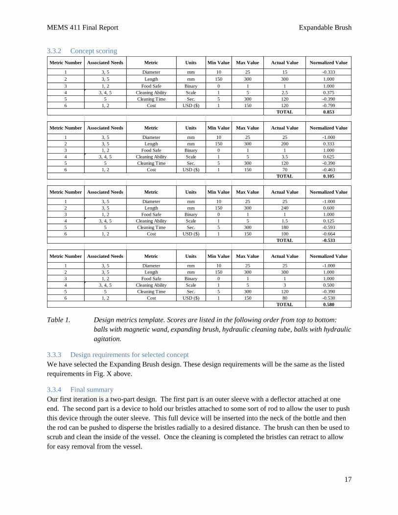
3.3.2 Concept scoring
Table 1. Design metrics template. Scores are listed in the following order from top to bottom:
balls with magnetic wand, expanding brush, hydraulic cleaning tube, balls with hydraulic
agitation.
3.3.3 Design requirements for selected concept
We have selected the Expanding Brush design. These design requirements will be the same as the listed
requirements in Fig. X above.
3.3.4 Final summary
Our first iteration is a two-part design. The first part is an outer sleeve with a deflector attached at one
end. The second part is a device to hold our bristles attached to some sort of rod to allow the user to push
this device through the outer sleeve. This full device will be inserted into the neck of the bottle and then
the rod can be pushed to disperse the bristles radially to a desired distance. The brush can then be used to
scrub and clean the inside of the vessel. Once the cleaning is completed the bristles can retract to allow
for easy removal from the vessel.
Metric Number Associated Needs Metric Units Min Value Max Value Actual Value Normalized Value
1 3, 5 Diameter mm 10 25 15 -0.333
2 3, 5 Length mm 150 300 300 1.000
3 1, 2 Food Safe Binary 0 1 1 1.000
4 3, 4, 5 Cleaning Ability Scale 1 5 2.5 0.375
5 5 Cleaning Time Sec. 5 300 120 -0.390
6 1, 2 Cost USD ($) 1 150 120 -0.799
TOTAL 0.853
Metric Number Associated Needs Metric Units Min Value Max Value Actual Value Normalized Value
1 3, 5 Diameter mm 10 25 25 -1.000
2 3, 5 Length mm 150 300 200 0.333
3 1, 2 Food Safe Binary 0 1 1 1.000
4 3, 4, 5 Cleaning Ability Scale 1 5 3.5 0.625
5 5 Cleaning Time Sec. 5 300 120 -0.390
6 1, 2 Cost USD ($) 1 150 70 -0.463
TOTAL 0.105
Metric Number Associated Needs Metric Units Min Value Max Value Actual Value Normalized Value
1 3, 5 Diameter mm 10 25 25 -1.000
2 3, 5 Length mm 150 300 240 0.600
3 1, 2 Food Safe Binary 0 1 1 1.000
4 3, 4, 5 Cleaning Ability Scale 1 5 1.5 0.125
5 5 Cleaning Time Sec. 5 300 180 -0.593
6 1, 2 Cost USD ($) 1 150 100 -0.664
TOTAL -0.533
Metric Number Associated Needs Metric Units Min Value Max Value Actual Value Normalized Value
1 3, 5 Diameter mm 10 25 25 -1.000
2 3, 5 Length mm 150 300 300 1.000
3 1, 2 Food Safe Binary 0 1 1 1.000
4 3, 4, 5 Cleaning Ability Scale 1 5 3 0.500
5 5 Cleaning Time Sec. 5 300 120 -0.390
6 1, 2 Cost USD ($) 1 150 80 -0.530
TOTAL 0.580

MEMS 411 Final Report Expandable Brush
18
The performance goals that we have chosen to assess our design are:
1. Clean all types of mess (water soluble and oil soluble)
2. Reliable (mechanism constantly expands bristles as desired)
3. Reusable
4. Food safe
5. Follow project budget
6. Must fit into a neck with diameter of 2 in. or smaller
7. Must be able to clean 10 in. downward into a vessel
8. Cleaning time under 5 minutes
9. Brush components easily cleaned
3.4 PROPOSED PERFORMANCE MEASURES FOR THE DESIGN
For our performance measures, we need to select something that is not easily cleaned by hand. It must
also be a relatively common item for use with food. For this reason, we selected a wine decanter. A
typical wine decanter has a neck opening of less than 2 in. and a height of about 10 in. This is a perfect
performance measure because it aligns well with our performance goals. A wine decanter also has a very
wide base, which will require good design and execution of our brush for thorough cleaning.
3.5 DESIGN CONSTRAINTS
The wine decanter selected for performance measurement is shown in Figure X.

MEMS 411 Final Report Expandable Brush
19
This decanter has a height of 11 in. a base width of 8.5 in. and a neck opening of 1.75 in. All of these
dimensions are smaller than our initial performance goals. However, we think that cleaning this vessel is
a very good assessment of the brush’s design and functionality.
3.5.1 Functional
The device must be able to clean vessels of a variety of shapes and materials. Versatility is very
important for our design.
3.5.2 Safety
This brush will likely be used in a domestic setting with food contact. For this reason, we need our brush
to be food safe. We also want to avoid any small pieces or materials that may chip so that we can ensure
safe usage.
3.5.3 Quality
The brush must be reusable. A one use brush will not meet our performance requirements. For this
reason we selecting parts and materials that are sturdy and resilient.
Fig. 10 The wine decanter shown will be used for performance measurement of our expandable brush. It
is of glass and has a geometry that make it impossible to clean by hand.

MEMS 411 Final Report Expandable Brush
20
3.5.4 Manufacturing
We must make the brush as simple as possible. Fewer and more simple parts correlate with shorter print
times and easy reproducibility.
3.5.5 Timing
If the brush can’t clean in a reasonable amount of time, it will not be successful. This brush must clean in
a similar timespan to any other cleaning brush.
3.5.6 Economic
A market analysis will be required to understand the full range of the expandable brush’s use. So far,
people we have met see that the expandable brush can be useful in the domestic settings like kitchens and
micro-brewing.
3.5.7 Ergonomic
Ease of use is a big part of the expandable brush. A simple design will be best for everyday users as well
as production. The ability to use the brush with one hand would be very beneficial.
3.5.8 Ecological
The materials that this is constructed out of must be dishwasher safe, so that it doesn’t harm users or put
deadly chemicals into the grey water sewer. The biggest hurdle will be ensuring that the adhesive used is
dishwasher safe and ecologically friendly.
3.5.9 Aesthetic
The design of the device must be aesthetically pleasing enough to be stored in a kitchen drawer and used
regularly. Current trends in kitchenware use metallic coloring
3.5.10 Life cycle
This constraint goes along with quality. We want our brush to be reusable and reliable. Therefore, we
need to suitable materials for production. The brush must be easily taken apart for cleaning. The brush
should be designed to be dishwasher safe.
3.5.11 Legal
By keeping this device safe for domestic use, we will abide by multiple regulatory agencies. We will be
seeking to meet with the IP office of Washington University in St. Louis to attempt to get ownership of
our idea.

MEMS 411 Final Report Expandable Brush
21
4 EMBODIMENT AND FABRICATION PLAN
4.1 EMBODIMENT DRAWING
Fig. 11 This is the assembly drawing of the expandable brush with the brush head and
handle (left) and the sleeve with the deflector (right)

MEMS 411 Final Report Expandable Brush
22
4.2 PARTS LIST
Fig. 12 The exploded view of the assembly that is annotated with the parts list

MEMS 411 Final Report Expandable Brush
23
4.3 DRAFT DETAIL DRAWINGS FOR EACH MANUFACTURED PART
Fig. 13 This is the bristle handle used in the assembly

MEMS 411 Final Report Expandable Brush
24
Fig. 14 This is the sleeve used to guide the brush and hold the deflector

MEMS 411 Final Report Expandable Brush
25
Fig. 15 This is the first draft of the deflector used in the expandable brush
4.4 DESCRIPTION OF THE DESIGN RATIONALE FOR THE CHOICE/SIZE/SHAPE OF
EACH PART
The sleeve has been chosen to be made 18” long with a key notch on the end. The long length will allow a
variety of vessels sizes to be accessed and cleaned by the device. It is currently listed as having a 1.5”
diameter in the preliminary drawings. This size will be reduced to 3/4” once the design team has noted all
modifications it wishes to complete to the first draft. The key notch will be attached with the tab using
epoxy. The sleeve will be 3D printed.
The deflector will be 2.75” long with a conical deflecting end. The cone will push the nylon filament
bristles outward to allow cleaning to occur. The deflector has a tab on the cylindrical end that will slide
into the key notch and secured there with epoxy, thereby securing the deflector to the sleeve. The
deflector will be 3D printed.
The brush handle will be 20” long to ensure that no matter how far down the brushes are pushed, there
will always be a handle available for the user to hold on to. At the end of the handle is the plunger like
base that will secure the brush bristles. The bush handle will be 3D printed.
The bristles will be approximately 12” long. This will give the bush the ability to expand about 9”
radially, enabling it to clean large and complex vessels with skinny necks. Nylon is the primary material
which we are investigating right now. These will be ordered in bulk from Alibaba.

26
4.5 GANTT CHART
Fig. 16 The Gantt chart used to track the progress of the project and the tasks that needed to be preformed

27
5 ENGINEERING ANALYSIS
5.1 ENGINEERING ANALYSIS PROPOSAL
5.1.1 A form, signed by your section instructor
This section may be left blank.
5.2 ENGINEERING ANALYSIS RESULTS
5.2.1 Motivation
Describe why and how the analysis chosen is the most important thing to study at this
time.
We have chosen two different SolidWorks analyses to study the brush portion of our system. The
first is a test of a single brush fiber to ensure that the fiber is stiff enough to clean the inside of
our test vessel, a wine decanter, while still having a small size. The stress and deflection were
measured in our simulation. We found that PLA and PET Nylon fibers deflected relatively small
amounts, making them ideal fibers for our brush.
Our second test modeled the deflection of the brush bristles when they contacted the deflector. It
was important to study this to model the angle that our bristles would extend outward from the
deflector. It is important to study this aspect of our prototype, because our brush needs to be able
to reach upwards to reach hard to clean surfaces once inside the vessel. This was run as a static
and dynamic nonlinear simulation. The computer was unable to run it, even on the coarsest mesh
settings. No solution could be generated even when consulting with the course instructors.
How does it facilitate carrying the project forward?
These simulations allow us to have confidence in the cleaning ability of our brush and the ability
of the assembly to reach upwards to reach hard to clean surfaces.
5.2.2 Summary statement of analysis done
To simulate our brush being pushed against a glass surface to clean we fixed our brush at one
end. We then applied an axial force at the opposite end as well as gravity to the entire fiber. We
can see in the figure below that a brush bristle with 0.01 N applied axially, a PET fiber only
deflects 0.4 mm.

MEMS 411 Final Report Expandable Brush
28
Fig. 17 A PET fiber undergoing a deformation due to an applied force at the right end
and gravity in conjunction with its left end being fixed
5.2.3 Methodology
How, exactly, did you get the analysis done?
The analysis was carried out with SolidWorks and experimentation.
Was any experimentation required?
Yes, experimentation was used to verify bush cleaning ability. Where our brush contacted was
cleaned easily. The biggest issue for us was properly angling the bristles. The deflector angle
was varied in experiments to maximize its cleaning ability.
Did you have to build any type of test rig?
We built a prototype and used it to clean wine and other liquid stains from a decanter.
5.2.4 Results
What are the results of your analysis study?
We found through the bristle simulations that PLA and PET filaments worked best by
minimizing bristle size and maximizing its stiffness.
Do the results make sense?
These results on SolidWorks were corroborated with our experimentation.
Do the results support moving forward with your current design concept?
The results do indicate moving forward with the material selected. However, we need to lessen
the angle and clearance of our deflector to ensure more lateral brush expansion.
5.2.5 Significance
How will the results influence the final prototype, i.e. which differences between the
embodiment and final CAD drawings are the result of your engineering analysis?
The results of these studies will validate our material selection and help us redesign our angle
and clearance of the deflector to allow the bristles to reach upwards.

MEMS 411 Final Report Expandable Brush
29
What dimensions and material choices will be affected by results of your simulation, if
any?
The angular dimension and clearance between the tube and deflector will be altered based on our
experimentation and SolidWorks simulations. Primarily, our bristle material selection will be
altered based off of our SolidWorks simulation.
This should be shown with some type of revised embodiment drawing. Ideally, you would
show a “before/after” analysis pair of embodiment drawings.
Fig. 18 The original deflector design

MEMS 411 Final Report Expandable Brush
30
Fig. 19 The new deflector design after the engineering analysis and first prototype
5.2.6 Summary of code and standards and their influence
The codes and standards have relatively low impact on the changes in our design. The revisions
are for the functionality of the deflector. If the revision included a material change, the standards
may be useful. However, the material has not been impacted by the changes informed by this
engineering analysis.
5.3 RISK ASSESSMENT
5.3.1 Risk Identification
There are a few risks that we need to mitigate in our design. The first of these is our Solidworks design.
We initially drafted all our parts in AutoCAD, which was difficult to convert for 3D printing. Another
risk for us is 3D printing. We are trying to minimize the size of our design, but we need to balance this
with print time and the machine’s resolution. There is a decently chance if we design our brush too small,
the parts won’t maintain the necessary clearances for proper assembly and usage. The last issues relate to
the filaments in our brush. There was a risk that the filaments wouldn’t be stiff enough to clean a vessel
when fully extended. There is also a chance that the filaments we ordered won’t arrive in time for our
prototype.

MEMS 411 Final Report Expandable Brush
31
5.3.2 Risk Impact or Consequence Assessment
The Solidworks drafting is a minor risk because the impact and likelihood of this occurring are very low.
The 3D printing issues could have a very severe impact. Each print of our parts takes hours to complete,
so the number of redesigns and prints we are able to test is limited. If we are not able to get the
clearances for our required size, our prototype will not achieve our goal of easy production. The filament
stiffness issue is probably the most significant risk we face. This is because we have very limited options
for the size and material of our filaments because we are purchasing a relatively small quantity. If the
filaments we order are too stiff or too flexible, we won’t have time to find replacements
5.3.3 Risk Prioritization
Our prioritization of risks is as follows:
1. Filament stiffness
2. 3D printing issues
3. Filaments arriving
4. Solidworks design.
Fig. 20 The heat map used to visualize the risk posed by a problem based on impact and
likelihood
After identifying these risks, we made a plan to help us control or eliminate them. For the filament
stiffness, we created a SolidWorks motion model to test the filament deflection when fully extended.
This was done by modelling the filament with both and applied force and gravitational force acting on it.
3D printing issues
Filament stiffness
Solidworks design
Filaments arriving
0
1
2
3
4
5
0 1 2 3 4 5
LIK
ELIH
OO
D
IMPACT
Risk Assessment Heat Map
Insignificant
Low
Hig
h

MEMS 411 Final Report Expandable Brush
32
This was repeated for multiple filaments of different sizes and materials. We ordered our filaments as
soon as we completed our Solidworks analysis to try to ensure a timely arrival. For 3D printing issues,
we started our design larger than desired and only printed critically interlocking pieces. This allowed us
to determine the required clearances without reprinting our full design each time, ultimately saving us
time. We also started this process early to allow for as many modifications or reprints as necessary.
Similarly, we redrafted our initial designs into Solidworks early in the process to give ourselves time to
get accustomed to the interface and make modifications as needed.
6 WORKING PROTOTYPE
6.1 A PRELIMINARY DEMONSTRATION OF THE WORKING PROTOTYPE
This section may be left blank
6.2 A FINAL DEMONSTRATION OF THE WORKING PROTOTYPE
This section may be left blank
6.3 AT LEAST TWO DIGITAL PHOTOGRAPHS SHOWING THE PROTOTYPE
Fig. 21 This image shows the maximum reach of the first prototype. The reach of this brush was
measured to be around 9.5 to 10 in.

MEMS 411 Final Report Expandable Brush
33
Fig. 22 The two pieces of our brush are shown above. The top piece is the outer sleeve, which
has a height of just over 15 in. and a width of 1.5 in. The lower piece is our brush head
and handle. This design is completely removable and makes the product easy to wash by
hand or in a dishwasher
6.4 A SHORT VIDEOCLIP THAT SHOWS THE FINAL PROTOTYPE PERFORMING
A link to our prototype cleaning our test vessel (the wine decanter) is posted below. The decanter
was wetted and filled with various sawdust and debris.
https://www.youtube.com/watch?v=GkFxNubMALs
There are some key things to point out from this video. First, when the brush is fully
splayed out, the bristles easily reach the outer walls of the decanter. We measured the maximum
reach of this first prototype to be between 9.5 and 10 in. This is significantly farther than any
brushed currently on the market. The versatility of the brush is also shown. At one point in the
video you can see the bristles are contracted for a smaller reach. This allowed the brush to easily
clean the lower lip of the decanter used. The brush is then easily contracted and removed from
the vessel.
Our first prototype was successful in the fact that it was able to extend as designed and
easily clean most of the vessel. However, we noticed that the upper portion of the decanter base
was hard to clean with our current design. An image of the hard to clean area is specified in Fig.
23.

MEMS 411 Final Report Expandable Brush
34
Fig. 23 The hardest area for the current brush to reach is outlined in orange. Some debris can
still be seen on this portion of the decanter
Based on this test, we realized there was a need to redesign our deflector. We also want to continue to
decrease the diameter of our outer sleeve. This would allow the user more space to tilt the brush once
inside the vessel, allowing it to more easily clean the hard to reach areas. The filaments could also be
improved. We think that having slightly stiffer filaments and a greater filament density for the brush
would improve the cleaning ability of our brush completely. The last change we would like to implement
is to add a sponge or scrubbing pad to the base of the brush’s deflector. This would allow the brush to be
used as an extended scrubbing tool, making it easy to clean the base of the vessel.

MEMS 411 Final Report Expandable Brush
35
6.5 PHOTOGRAPHS SHOWING THE SECOND PROTOTYPE (DEFLECTOR REDESIGN)
The three redesigned deflector are shown in Fig. 23A below.
Fig. 23A The three redesigned deflector are picture here. The middle deflector will be used with a
redesigned outer sleeve, while the other two fit into our first prototype’s outer sleeve.
The first design shown (far left) is a modification of our first deflector. Half of the original surface is
unchanged. Around the edge of the other half, we added ramps that will redirect the bristles upward.
This will give our brush two different angles of deflection to clean at, which would allow it to reach the
upper and lower portions of a vessel simultaneously. There are also sidewalls added to keep the bristles
partitioned during the cleaning process. This will ensure that the both of the deflection types will have
bristles at all times. One risk for this design is having two extreme angles of deflection and not being able
to reach the area between them. This redesign seems to have the most potential currently.
The second design (middle) is a completely new deflector. Unlike our initial design, this deflector will be
attached to the outside of the outer sleeve. The brush is then operated in the same way as the first
prototype. The advantage of this deflector is that it would allow us to minimize the size of our brush
because we would no longer need to work about clearances for the deflector’s tab. The downside of this
design is that it becomes much hard to get the bristles to deflect well, so the curvature on the topside of
the deflector is critical and will require tedious adjustments and testing.
The third design (far right) was the simplest redesign. We decreased the original deflector’s angle from
35° to 20°. The idea behind this is that it will allow the bristle to be directed outward at a sharper angle,
allowing the bristles to reach across perpendicular to the base. This design resulted in a slight
improvement in the brushes performance, but it did not get the brush to perform to our satisfaction.

MEMS 411 Final Report Expandable Brush
36
Below are four images of the prototype and our most successful redesigned deflector.
Fig 24 This image shows the first prototype brush
extended within our test vessel. The
bristles easily reach the outer edge of the
test vessel.
Fig 27 One of the redesigned deflectors. The
raised lips are shown in this image. The
height of these lips will likely need to be
increased to get the desired performance. Fig. 26 The first prototypes filaments were hand
threaded through our brush head.
Fig. 25 Decreasing the difference between the
inner and outer diameters of the sleeve
will allow us to greatly reduce the overall
size of our brush.

MEMS 411 Final Report Expandable Brush
37
7 DESIGN DOCUMENTATION
7.1 FINAL DRAWINGS AND DOCUMENTATION
7.1.1 Engineering drawings
Fig. 28 The deflector used in the prototype
MEMS 411 Final Report Expandable Brush
38
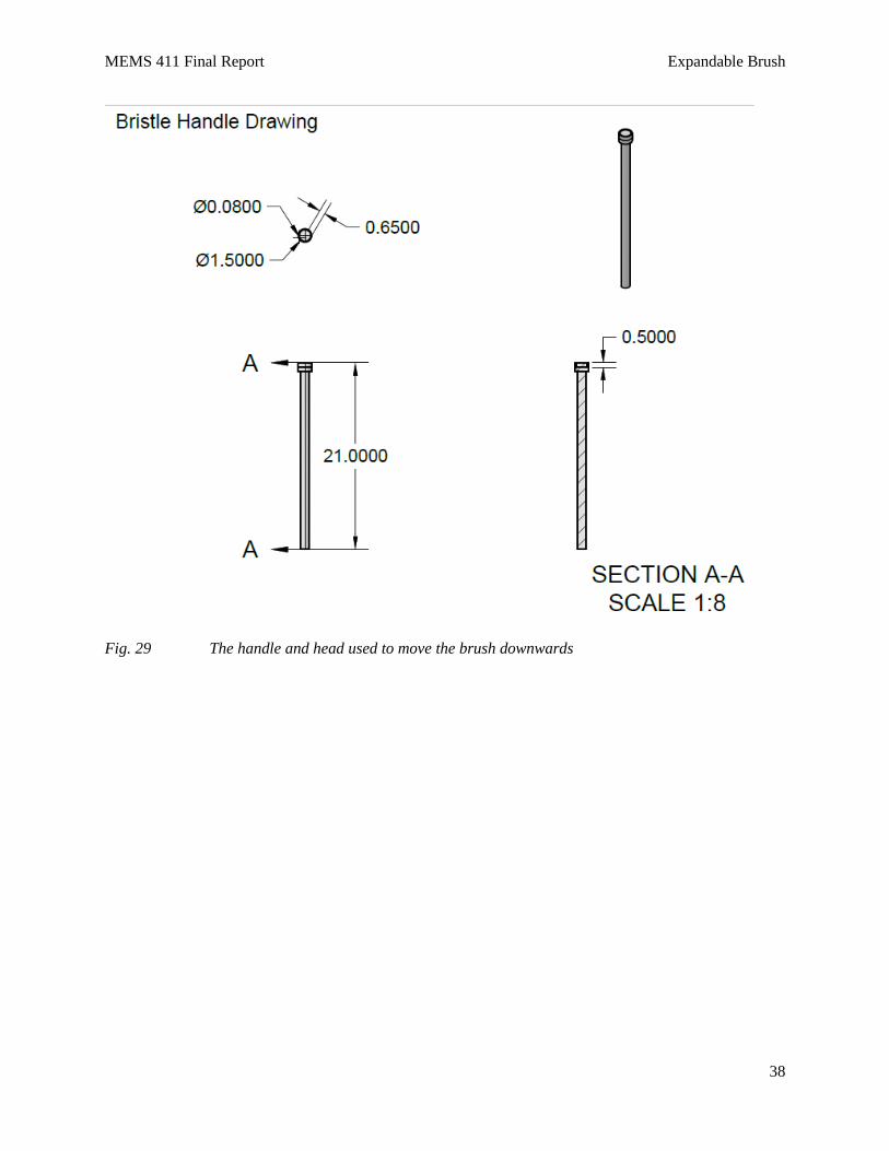
Fig. 29 The handle and head used to move the brush downwards

MEMS 411 Final Report Expandable Brush
39
Fig. 30 Top piece of the sleeve
Fig. 31 The mid piece of the sleeve

MEMS 411 Final Report Expandable Brush
40
Fig. 32 The bottom piece of the sleeve that attaches to the deflector

MEMS 411 Final Report Expandable Brush
41
7.2 FINAL PRESENTATION
7.2.1 A live presentation in front of the entire class and the instructors
N/A
7.2.2 A link to a video clip
This is a video of the final presentation slide show for the external review board.
https://youtu.be/iAf3T6h1Mtk
7.3 TEARDOWN
The work place has been cleaned up and the prototypes have been taken home with the group. Evidence
of this can be seen below in Fig. 33
Fig. 33 The completed teardown form

MEMS 411 Final Report Expandable Brush
42
8 DISCUSSION
8.1 USING THE FINAL PROTOTYPE PRODUCED TO OBTAIN VALUES FOR METRICS,
EVALUATE THE QUANTIFIED NEEDS EQUATIONS FOR THE DESIGN. HOW WELL
WERE THE NEEDS MET? DISCUSS THE RESULT.
Table 2 The predictive metric evaluation for the expandable brush
Table 3 The actual metric evaluation for the expandable brush prototype
We selected the expandable brush design to be the alternative that we pursued. Its original score when we
were estimating its evaluation metrics was 0.105. After evaluating our prototype, it was scored at 1.178.
We were accurate in predicting its diameter, food safeness, and its cleaning ability. However, we
overestimated the cleaning time and cost. The cost was lower, because most of it was 3D-printed for free.
Most of the cost of the design was for test vessels and materials that ended up failing. The total cost of
material that went into the prototype cost about $10. Another flaw in our prediction was that we
underestimated the possible length of the expandable brush. By shortening the length of the deflector
hand sketched in Fig. 7, which imposed a height limit, we could make the length of the prototype as large
as we wanted. Realistically, the brush bristle and handle sizes limited the maximum height, but this
maximum height was far greater than any application the prototype could be used for. The big takeaway
from this metric evaluation is the fact that our prototype can clean a taller vessel more quickly than
anticipated and cost less results in the drastic increase in its evaluation score.
A major area for improvement is the ability for the bristles to reach upwards and clean the upper surface.
While this may not be necessary for wine decanters, since they generally don’t get stains on the bottom,
the brush needs to reach upwards with its bristles if it is to be able to clean a variety of vessels. To address
this we have developed new prototypes for the bristle deflector seen in section 6. In addition, we hope to
try a new material for the bristles that is more rigid and will deflect perpendicularly outwards more easily.
Discussion of possible improvements can be read about in detail in section 6.
Metric Number Associated Needs Metric Units Min Value Max Value Actual Value Normalized Value
1 3, 5 Diameter mm 10 25 25 -1.000
2 3, 5 Length mm 150 300 200 0.333
3 1, 2 Food Safe Binary 0 1 1 1.000
4 3, 4, 5 Cleaning Ability Scale 1 5 3.5 0.625
5 5 Cleaning Time Sec. 5 300 120 -0.390
6 1, 2 Cost USD ($) 1 150 70 -0.463
TOTAL 0.105
Metric Number Associated Needs Metric Units Min Value Max Value Actual Value Normalized Value
1 3, 5 Diameter mm 10 25 25 -1.000
2 3, 5 Length mm 150 300 300 1.000
3 1, 2 Food Safe Binary 0 1 1 1.000
4 3, 4, 5 Cleaning Ability Scale 1 5 3.5 0.625
5 5 Cleaning Time Sec. 5 300 20 -0.051
6 1, 2 Cost USD ($) 1 150 60 -0.396
TOTAL 1.178

MEMS 411 Final Report Expandable Brush
43
8.2 DISCUSS ANY SIGNIFICANT PARTS SOURCING ISSUES? DID IT MAKE SENSE TO
SCROUNGE PARTS? DID ANY VENDOR HAVE AN UNREASONABLY LONG PART
DELIVERY TIME? WHAT WOULD BE YOUR RECOMMENDATIONS FOR FUTURE
PROJECTS?
The straight PLA filaments from JPSon did not arrive on time for our prototype. Fortunately, we
had a contingency plan to gather nylon brush filaments from a broom that we had acquired.
These nylon filaments weren’t as stiff as we would have liked, but were frayed at the end which
enhanced its cleaning ability. I would recommend that future projects investigate Chinese
shipping times more, they were not correct in our case. Additionally, I would have contingency
parts and plans for most areas of the design in the case that something gets lost, destroyed, or is
delivered late.
8.3 DISCUSS THE OVERALL EXPERIENCE:
8.3.1 Was the project more of less difficult than you had expected?
The project was far more difficult than expected. Our group realized this while brainstorming possible
ideas to work on. It was difficult to settle down on a single problem that we wanted to solve. This
brainstorming required far more work than we thought. The other portion that we found challenging was
designing the minutia of the prototype and revising it based on tests. The minutia was characterized
primarily by part clearances and deflector angles. Creating, testing, and revising these was much more
time consuming and difficult than expected. Finally, working on our final SolidWorks model that displays
the brush filaments getting splayed out when contacting a deflector was extremely hard. Even with the
coarsest mesh settings, running a nonlinear static study of the system is too great for a School of
Engineering computer to handle. Future projects should keep in mind that honing the scope of the
problem, improving the small pieces of the project, and complex SolidWorks models are likely to be tasks
which make the project more difficult than expected.
8.3.2 Does your final project result align with the project description?
The expandable brush does fulfill the project description. It can be inserted into a vessel with a small neck
of 1.5 in. with a large complex base and expand up to 10 in. in diameter. It was able to clean every surface
inside the wine decanter that we evaluated its performance with, except the upper wall. As discussed in
the prototype section, we have proposed some redesigns to be able to reach upwards and clean the upper
walls of the decanter. Wine decanters rarely get stained on the upper surface, but to make our design
applicable to many other vessels that do get stained on the upper surface. On balance, our expandable
brush proved the design concept and description that we desired to investigated this semester and we have
identified the next goal to fully improve its performance.
8.3.3 Did your team function well as a group?
Despite only having 2 members, our group functioned well and was very productive. Our class schedules
did not optimally align, which posed a small issue. However, both of us were willing to make sacrifices
for the success of the project. The possibility of eventually have intellectual property of our own
motivated both of us to make progress throughout the semester.
Our personalities complimented each other well too. Having both taken the leadership course in the
School of Engineering, we thought it important to know our Myers-Briggs and Enneagram types. Michael

MEMS 411 Final Report Expandable Brush
44
is an ISTJ and Enneagram type 5. These types indicate that Michael is alert, insightful, and curious. He
works very well alone and with people, but under stress can isolate himself too much [A]. Aaron on the
other hand is an ENTJ and Enneagram type 7. These types indicate that Aaron is high-spirited, practical,
and a good leader. It also shows that he prefers working in a group. Under stress, he can take on too much
and overextend himself. Together, our team balanced each other out with Michael’s intense focus and
Aaron’s practicality and sense of direction. In addition to having complimentary personalities, the
members of the team have worked together since the first semester of freshman year. This long
professional history provided the other insights into the other’s tendencies and how to optimize their
performance under stress.
Any disadvantage posed by having only two members was overcome with a combination of motivation,
personality agreement, and professional history. With these strengths, we were able to know exactly what
type of project we wanted to tackle. We wanted to develop a product that solved a common problem with
a clever answer. We focused on choosing a product that would benefit from our strengths. Eventually, we
settled on developing a product for cleaning vessels with small openings and large complex bases.
8.3.4 Were your team member’s skills complementary?
In addition to this collective motivation, our skills complimented each other well. We believe that
together we are the perfect mechanical engineer. Michael Roznik’s proficiency with solid works along
with Aaron Hall’s hand drawn designs proved to be an ideal combination for prototyping. Both of us were
not only good with technical communication among ourselves, but we excelled at verbal communication
and PowerPoint presentations. Our ability to communicate to the course directors and judges at the
External Review Board Presentation positively impacted the outcome of our product.
8.3.5 Did your team share the workload equally?
While each member of the team preformed a different set of duties, the workload was shared equally.
Aaron generally came up with general designs and together with Michael the ideas were refined. Michael
was the most proficient with AutoCAD and SolidWorks, so he did most of the drafting. Presentation
workloads were shared exactly equally. Both of us would give each other critiques on what to improve
whether it was content or speaking style. In the case of sharing the workload, having only two members
was advantageous. The low number of members meant that to get the amount of work done that was
required, everyone had to pitch in. Each due date was characterized by an “all hands on deck” mentality.
8.3.6 Was any needed skill missing from the group?
Originally a few skills were missing from the group, since we only had two people. However, we
overcame this by working together to learn the necessary skills. Our lack of skill was our collective
unfamiliarity with part drafting on SolidWorks, since both of us had been trained on Solid Edge software.
It took about two and a half weeks for us to be comfortable on the software. Simulating the bristles
splaying out was still difficult for us. However, even with the help of course instructors the static
nonlinear SolidWorks simulation would not run properly. The other hurdle that our team encountered
skill-wise was our knowledge of 3D printing. With the help of instructors and teaching assistants we
learned how to print and do it efficiently.

MEMS 411 Final Report Expandable Brush
45
8.3.7 Did you have to consult with your customer during the process, or did you work to the original
design brief?
We worked to the original design brief. This was possible, because we did an excellent job at defining the
scope of our project. It was precise enough to have a clear set of evaluation metrics, but fulfilled a broad
enough need to be a versatile product. One of the judges foresees our product being useful in the craft and
home brewing industry to clean a type of processing canister. For applications like this a full market study
will be required and then we must meet one on one with customers interested in purchasing it for various
applications. The design can be altered to cater to their specific needs.
8.3.8 Did the design brief (as provided by the customer) seem to change during the process?
The design brief remained constant since the scope of our project was well defined early on.
8.3.9 Has the project enhanced your design skills?
As previously discussed in section 8.3.6, our knowledge of SolidWorks for design and analysis has
greatly increase along with our ability to create accurate hand sketches and 3D print. Having a real project
that we decided ourselves has been extremely beneficial for our general design skills. In fact with these
enhanced skills, our group plans on continuing work on the project next semester.
8.3.10 Would you now feel more comfortable accepting a design project assignment at a job?
We would both be more confident in our ability to solve a problem with a design that we have scoped and
generated ourselves. This is semester has been very useful in not only developing our design skills, but
also growing our confidence so that we can accept new projects in our future careers. This project has
taught us how to adapt our designs to new challenges and build solutions to real world problems. With
this experience under our belts, we feel ready to accept a design project assignment in our next jobs.
8.3.11 Are there projects that you would attempt now that you would not attempt before?
Neither of us had ever attempted a product development project before. Aaron had worked on small and
large scale projects at a petrochemical company last summer. Michael had optimization projects for an
industrial food production company. Neither of us had any experience developing a product, but thought
it would be a good experience to try for senior design. Now, both of us would readily accept a product
development project. We liked developing this product so much this semester that we intend to continue
work on our expandable brush next semester.

MEMS 411 Final Report Expandable Brush
46
9 APPENDIX A – PARTS LIST
1
4
5
6
3
2

MEMS 411 Final Report Expandable Brush
47
10 APPENDIX B - BILL OF MATERIALS
Part Source Model No./Name Quantity Unit Cost
Sleeve 3D Printer NA 1 0 (if printed at WUSTL)
Deflector 3D Printer NA 1 0 (if printed at WUSTL)
Bristle handle 3D Printer NA 1 0 (if printed at WUSTL)
Brush bristles Alibaba Nylon filaments 350 $1.50/kg

MEMS 411 Final Report Expandable Brush
48
11 SOLID WORKS REPORT ON SINGLE BRUSH FILAMENT
Simulation of PET
Filament 2
Date: Thursday, December 08, 2016
Designer: Aaron Hall and Michael Roznik
Study name: Static 1
Analysis type: Static
TABLE OF CONTENTS Description 48
Assumptions 49
Model Information 49
Study Properties 50
Units 50
Material Properties 51
Loads and Fixtures Error! Bookmark not
defined.
Connector Definitions Error! Bookmark not
defined.
Contact Information Error! Bookmark not
defined.
Mesh information 53
Sensor Details Error! Bookmark not defined.
Resultant Forces 54
Beams Error! Bookmark not defined.
Study Results 55
Conclusion Error! Bookmark not defined.
DESCRIPTION This is a static deformation and stress test of a PET filament that
will be used as a brush bristle in the expandable brush project for
MEMS 411

MEMS 411 Final Report Expandable Brush
49
ASSUMPTIONS
MODEL INFORMATION
Model name: PET Filament 2
Current Configuration: Default
Solid Bodies
Document Name and
Reference Treated As Volumetric Properties
Document Path/Date
Modified
Boss-Extrude1
Solid Body
Mass:0.00171646 lb
Volume:0.0334587 in^3
Density:0.0513008 lb/in^3
Weight:0.00171529 lbf
H:\My Documents\Senior
Fall\PET Filament 2.SLDPRT
Nov 14 21:51:19 2016

MEMS 411 Final Report Expandable Brush
50
STUDY PROPERTIES
Study name Static 1
Analysis type Static
Mesh type Solid Mesh
Thermal Effect: On
Thermal option Include temperature loads
Zero strain temperature 298 Kelvin
Include fluid pressure effects from
SOLIDWORKS Flow Simulation
Off
Solver type FFEPlus
Inplane Effect: Off
Soft Spring: Off
Inertial Relief: Off
Incompatible bonding options Automatic
Large displacement On
Compute free body forces On
Friction Off
Use Adaptive Method: Off
Result folder SOLIDWORKS document (H:\My
Documents\Senior Fall)
UNITS
Unit system: English (IPS)
Length/Displacement mm
Temperature Kelvin
Angular velocity Rad/sec
Pressure/Stress psi

MEMS 411 Final Report Expandable Brush
51
MATERIAL PROPERTIES
Model Reference Properties Components
Name: PET Model type: Linear Elastic Isotropic
Default failure criterion: Unknown Tensile strength: 8310.66 psi
Compressive strength: 13474 psi Elastic modulus: 429312 psi
Poisson's ratio: 0.37 Mass density: 0.0513008 lb/in^3
SolidBody 1(Boss-
Extrude1)(PET Filament 2)
Curve Data:N/A
LOADS AND FIXTURES
Load name Load Image Load Details
Force-1
Entities: 1 face(s)
Type: Apply normal force
Value: 0.01 N
Gravity-1
Reference: Right Plane
Values: 0 0 -386.22
Units: English (IPS)

MEMS 411 Final Report Expandable Brush
52
Fixture name Fixture Image Fixture Details
Fixed-1
Entities: 1 face(s)
Type: Fixed Geometry
Resultant Forces
Components X Y Z Resultant
Reaction force(lbf) 0.00171427 0.00223063 1.71516e-006 0.00281326
Reaction Moment(lbf.in) 0 0 0 0

MEMS 411 Final Report Expandable Brush
53
MESH INFORMATION
Mesh type Solid Mesh
Mesher Used: Standard mesh
Automatic Transition: Off
Include Mesh Auto Loops: Off
Jacobian points 4 Points
Element Size 0.026194 in
Tolerance 0.0013097 in
Mesh Quality High
MESH INFORMATION - DETAILS
Total Nodes 26295
Total Elements 14593
Maximum Aspect Ratio 3.7747
% of elements with Aspect Ratio < 3 99.9
% of elements with Aspect Ratio > 10 0
% of distorted elements(Jacobian) 0
Time to complete mesh(hh;mm;ss): 00:00:03
Computer name: URB218-26

MEMS 411 Final Report Expandable Brush
54
RESULTANT FORCES
REACTION FORCES
Selection set Units Sum X Sum Y Sum Z Resultant
Entire Model lbf 0.00171427 0.00223063 1.71516e-006 0.00281326
REACTION MOMENTS
Selection set Units Sum X Sum Y Sum Z Resultant
Entire Model lbf.in 0 0 0 0

MEMS 411 Final Report Expandable Brush
55
STUDY RESULTS
Name Type Min Max
Stress1 VON: von Mises Stress 0.0186145 psi
Node: 2407
270.852 psi
Node: 2758
PET Filament 2-Static 1-Stress-Stress1
Name Type Min Max
Displacement1 URES: Resultant Displacement 0 mm
Node: 348
9.86323 mm
Node: 26293

MEMS 411 Final Report Expandable Brush
56
PET Filament 2-Static 1-Displacement-Displacement1
Name Type Min Max
Strain1 ESTRN: Equivalent Strain 8.87462e-008
Element: 10958
0.000473247
Element: 2374
PET Filament 2-Static 1-Strain-Strain1

MEMS 411 Final Report Expandable Brush
57
Name Type
Displacement1{1} Deformed shape
PET Filament 2-Static 1-Displacement-Displacement1{1}